Stability Analysis of Parametric Roll Resonance B.J.H. van Laarhoven DCT 2009.062 Traineeship report Coach: prof.dr. T.I. Fossen Supervisor: prof.dr. H. Nijmeijer Eindhoven University of Technology Department Mechanical Engineering Dynamics and Control Group Eindhoven, June 2009

Welcome message from author
This document is posted to help you gain knowledge. Please leave a comment to let me know what you think about it! Share it to your friends and learn new things together.
Transcript

Stability Analysis of Parametric Roll
Resonance
B.J.H. van Laarhoven
DCT 2009.062
Traineeship report
Coach: prof.dr. T.I. Fossen
Supervisor: prof.dr. H. Nijmeijer
Eindhoven University of Technology
Department Mechanical Engineering
Dynamics and Control Group
Eindhoven, June 2009
1
Abstract
For investigation and developing fundamental knowledge about how and why ships and structures behave
in an ocean environment Norway started the Centre for Ships and Ocean Structures. One of the research
topics of this centre of excellence is parametric roll resonance. Parametric roll resonance is a phenomenon
that causes a roll motion to a ship due to longitudinal waves. This roll motion can become so large that
capsizing can occur. It is dangerous for ships to encounter this phenomenon. Even when capsizing does not
happen this roll motion could cause damage to the ship and can be a threat for the cargo and crew.
Although there are very specific conditions when parametric roll resonance can occur there are several
examples where it did happen and caused significant damage to the ship and cargo for millions of euro’s.
To describe this phenomenon the coupled 3 DOF model proposed by Neves and Rodríguez is used. The
pitch angle and vertical displacement are assumed to be harmonic and therefore and uncoupled 1 DOF
model is derived to describe the roll motion of the ship. For control it is interesting to have an indication
what the values of the control parameters could be to prevent parametric roll resonance to occur. To
determine these values of the control parameters first the stability regions of the uncoupled 1 DOF are
determined. These simulations can easily be used as an indication for the control parameters since it is easy
to see what the value of the control parameters should be to reduce the roll angle. Since in this study only
an uncoupled 1 DOF model is used, results can be more accurate when a higher degree of freedom model is
used to describe the roll motion.
Also attention has been paid to a simple velocity controller. One of the control parameters used is the
forwards velocity of the ship. Simulations show that an increase or decrease of the forward velocity would
lead to a reduction of the roll angle. Decreasing the velocity always leads to a reduction of the roll angle.
But increasing the velocity does not always lead to a reduction of the roll angle. The reduction of the roll
angle when increasing the velocity seems to be highly dependent on the forward acceleration of the ship.
No explanation for this has been found and further investigation is needed.
2
List of symbols
symbol description
t time φω natural roll frequency wρ density of water
g gravitational constant
∇ water displacement
bGM constant part metacentric height
xI ship inertia in roll direction
44A added mass in roll direction
eω encounter frequency 0ω wave frequency
U forward velocity
β heading angle
φ roll angle
z heave displacement
θ pitch angle
1d linear damping constant
2d nonlinear damping constant
aGM varying part metacentric height
3K nonlinear moment in roll direction
3
Contents
1 Introduction 4
2 Parametric resonance 6
2.1 Resonance in mechanical systems 6
2.2 Parametric resonance in mechanical systems 7
2.3 Parametric resonance in ships 8
3 Ship model 14
3.1 Ship model 14
3.2 Equilibrium point 15
3.3 Nonlinearities 16
4 Numerical analysis 18
4.1 Detection method 18
4.2 Simulation 18
4.3 Results 19
4.4 Simulation with simple speed controller 21
4.5 Results 22
5 Conclusions and recommendations 26
A Extended explanation used ship model 27
B Simulations near the equilibrium point 29
C M-files used for simulation 30
D Results of simulation done with varying ship parameters 34
E MATLAB simulink model 35
F Main characteristics of the container ship 36
References 37

4
Chapter 1
Introduction
The Centre for Ships and Ocean Structures is located in Trondheim Norway. It is a centre of excellence that
is founded to investigate and develop fundamental knowledge about how ships and structures behave in the
ocean environment, using analytical, numerical and experimental studies, [21].
One of the research topics nowadays is parametric roll resonance in ship. Parametric roll resonance in ships
is a resonance phenomenon that gives a roll motion due to longitudinal waves acting on the ship. This roll
motion, which can achieve roll angles so high that the ship could capsize, can be dangerous for the ship.
Even when parametric resonance does not lead to capsizing this can be dangerous for the crew, cargo and
ship itself. This phenomenon has been known by the maritime society since the fifties. In those days only
small ships, like fishing vessels, encountered this phenomenon. Nowadays there are examples of accidents
with container vessels that cause significant damage to cargo and ship for millions of euro’s, [11]. For
example in October 1998 the APL China sailed from Taiwan to Seattle and during this trip it experienced
parametric roll resonance. When the vessel arrived in Seattle more than sixty percent of its cargo was lost at
sea or damaged, see figure 1.1. A more recent example of ships encountering parametric roll resonance is
the Maersk Carolina. In January 2003 the ships encounters a storm at the Atlantic sea. It alternates course
to minimize roll, in other words the ship was heading into the sea. In a few cycles the roll angle increased
up to 47 degrees and lasted a few minutes. The ships lost 133 containers and another fifty experienced
severe water damage. The cargo claims reached up to almost 4 million dollars, see figure 1.2.
Figure 1.1: The APL China arriving at Seattle [2]

5
Figure 1.2: The Maersk Carolina encountering parametric roll resonance [2]
To see what parametric roll resonance is and what could happen to a cruise ship the reader may visit [22].
Because not only container vessels but also destroyers, cruise ships and roll on roll off paxes encounter
parametric roll, this phenomenon recently attracted scientists, to understand the physics, detect parametric
roll resonance during sailing and eventually prevent large motions of the ship by active control. For
controlling this phenomenon it is interesting to know what the influence is of certain ship parameters on the
stability of the ship. The main goal of this study is to define the stability regions of the ship model proposed
by Neves and Rodríguez [8]. In other words define for which values of the ship parameters the ship
encounters parametric roll resonance and for which not. The results can be used as an indication for the size
of the control parameters.
In the second chapter it is explained what parametric roll resonance is and under which conditions a ship
can encounter this phenomenon. Also previous studies according to parametric roll resonance are
discussed. Then the used ship model is presented and analytical analysis to this model is done. In the fourth
chapter numerical analysis are presented and an analysis according to the control of parametric resonance
using a velocity controller is done.
6
Chapter 2
Parametric resonance
In this chapter attention is paid to parametric resonance in mechanical systems. It is explained what it is,
why and under which conditions this phenomenon happens. Specific attention will be paid to parametric
roll resonance in ships sailing in head seas. A list of empirical criteria is given to indicate when ships
encounter parametric roll resonance. Also different models that describe this phenomenon are showed
together with detection and stabilizing methods.
2.1 Resonance in mechanical systems
In mechanical systems often oscillations and resonances occur due to for example actuators in the system.
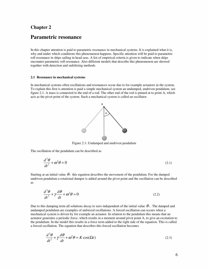
To explain this first is attention is paid a simple mechanical system an undamped, undriven pendulum, see
figure 2.1. A mass is connected to the end of a rod. The other end of the rod is pinned at to point A, which
acts as the pivot point of the system. Such a mechanical system is called an oscillator.
Figure 2.1: Undamped and undriven pendulum
The oscillation of the pendulum can be described as
02
2
2
=+ θωθ
dt
d (2.1)
Starting at an initial value 0θ this equation describes the movement of the pendulum. For the damped
undriven pendulum a rotational damper is added around the pivot point and the oscillation can be described
as
02
2
2
=++ θωθ
γθ
dt
d
dt
d (2.2)
Due to this damping term all solutions decay to zero independent of the initial value 0θ . The damped and
undamped pendulum are examples of unforced oscillations. A forced oscillation can occurs when a
mechanical system is driven by for example an actuator. In relation to the pendulum this means that an
actuator generates a periodic force, which results in a moment around pivot point A, to give an excitation to
the pendulum. In the model this results in a force term added to the right side of the equation. This is called
a forced oscillation. The equation that describes this forced oscillation becomes
)cos(2
2
2
tKdt
d
dt
dΩ=++ θω
θγ
θ (2.3)

7
Resonance occurs when K is large or when the frequency of the driven force Ω is near one of the
resonance frequencies of the system. This means that the system oscillates with high amplitude. The
resonance frequencies of a system are the natural frequency eω of the system and multiples of that
frequency. When the frequency of the driven force is near the natural frequency of the system, eω≈Ω ,
the oscillation is called primary or main resonance. In mechanical systems it is preferred to avoid resonance
due to the fact that a small driving force can cause large amplitude vibrations and therefore could cause
damage to the system.
2.2 Parametric resonance in mechanical systems
Resonance as described in the previous section, leads to differential equations with constant or slowly
varying parameters. Parametric resonance differs from resonance, because it is an instability phenomenon.
This instability is caused because parametric resonance gives differential equations with rapidly changing
system parameters. This leads to large variations in restoring forces and therefore instability. Parametric
resonance occurs when a system is parametrically excited by a periodic force and the frequency of this
force is near one of the resonance frequencies of the system. Faraday (1831) was the first who recognized
parametric resonance. During experiments with surface waves in a fluid-filled cylinder he noted that when
the cylinder was vertically excited the surface waves had half the frequency of the vertical excitation. In
1859 Melde did the first experiments relating to parametric resonance. He tied a string between a rigid
support and the extremity of the prong of a massive tuning fork of low pitch. For several combinations of
mass and tension of the string and frequency and loudness of the fork, he noted that the string could
oscillate laterally while the exciting forces work in longitudinal direction at twice the time period of the
fork, [1].
In the example of the pendulum parametric resonance occurs when instead of actuating the pendulum by a
moment around turning point A, now point A is periodically translated in vertical direction see figure 2.2.
Figure 2.2: Parametrically excited pendulum
Figure 2.3: Definition of ship motions [2]
The oscillation can be described by die following equation
8
0)cos(2
2
=++ θθ
tqpdt
d (2.4)
Where p is a function of the ratio of the forcing and natural frequency and q represents the amplitude of the
parametric excitation. This equation is generally know as the Mathieu equation and was discovered by
Mathieu in 1868 while studying vibrations of an elliptic membrane. The Mathieu equation can be used for
describing the response of many mechanical systems under the influence of parametric excitation, [1].
2.3 Parametric resonance in ships
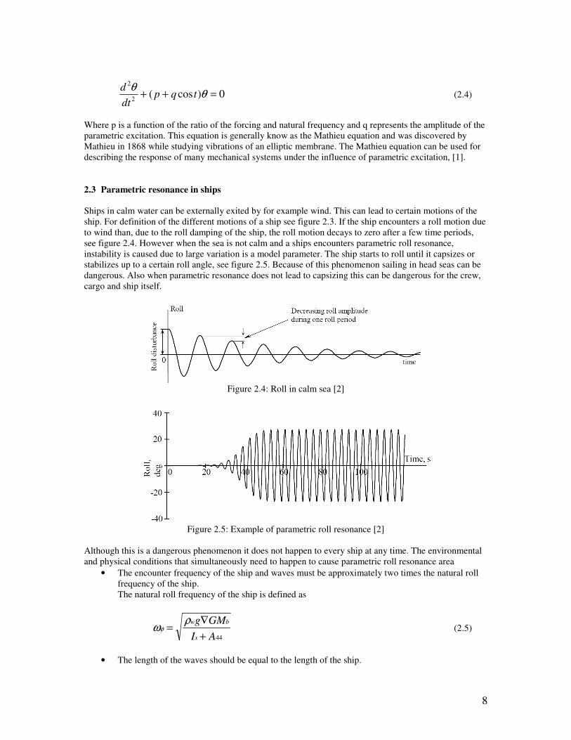
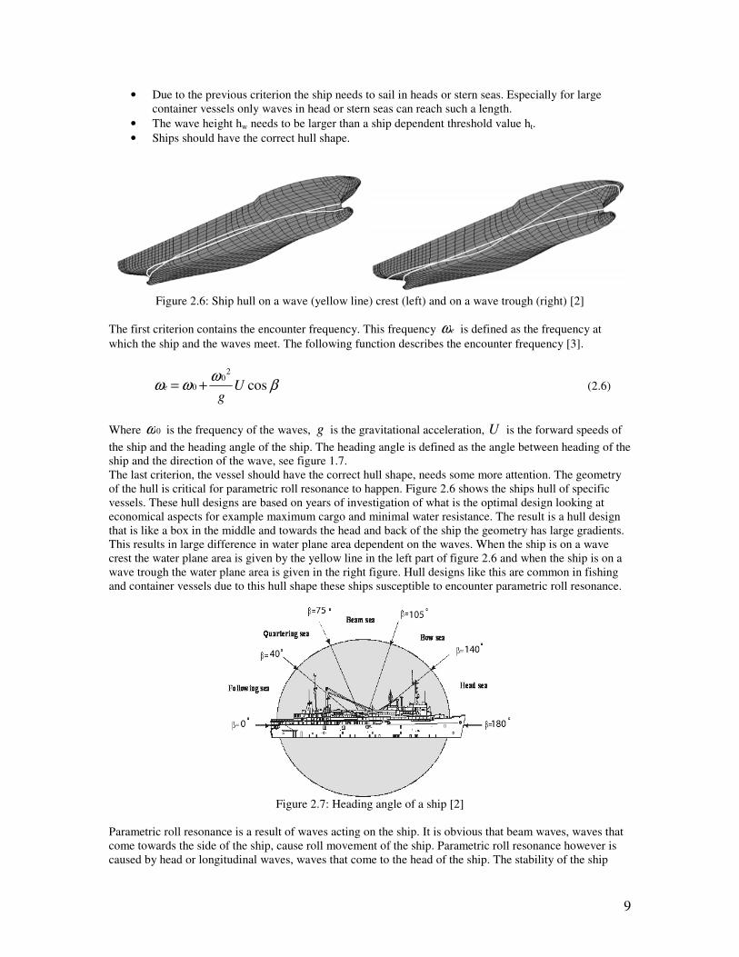
Ships in calm water can be externally exited by for example wind. This can lead to certain motions of the
ship. For definition of the different motions of a ship see figure 2.3. If the ship encounters a roll motion due
to wind than, due to the roll damping of the ship, the roll motion decays to zero after a few time periods,
see figure 2.4. However when the sea is not calm and a ships encounters parametric roll resonance,
instability is caused due to large variation is a model parameter. The ship starts to roll until it capsizes or
stabilizes up to a certain roll angle, see figure 2.5. Because of this phenomenon sailing in head seas can be
dangerous. Also when parametric resonance does not lead to capsizing this can be dangerous for the crew,
cargo and ship itself.
Figure 2.4: Roll in calm sea [2]
Figure 2.5: Example of parametric roll resonance [2]
Although this is a dangerous phenomenon it does not happen to every ship at any time. The environmental
and physical conditions that simultaneously need to happen to cause parametric roll resonance area
• The encounter frequency of the ship and waves must be approximately two times the natural roll
frequency of the ship.
The natural roll frequency of the ship is defined as
44AI
GMg
x
bw
+
∇=
ρωφ (2.5)
• The length of the waves should be equal to the length of the ship.
9
• Due to the previous criterion the ship needs to sail in heads or stern seas. Especially for large
container vessels only waves in head or stern seas can reach such a length.
• The wave height hw needs to be larger than a ship dependent threshold value ht.
• Ships should have the correct hull shape.
Figure 2.6: Ship hull on a wave (yellow line) crest (left) and on a wave trough (right) [2]
The first criterion contains the encounter frequency. This frequency eω is defined as the frequency at
which the ship and the waves meet. The following function describes the encounter frequency [3].
βω
ωω cos2
00 U
ge += (2.6)
Where 0ω is the frequency of the waves, g is the gravitational acceleration, U is the forward speeds of
the ship and the heading angle of the ship. The heading angle is defined as the angle between heading of the
ship and the direction of the wave, see figure 1.7.
The last criterion, the vessel should have the correct hull shape, needs some more attention. The geometry
of the hull is critical for parametric roll resonance to happen. Figure 2.6 shows the ships hull of specific
vessels. These hull designs are based on years of investigation of what is the optimal design looking at
economical aspects for example maximum cargo and minimal water resistance. The result is a hull design
that is like a box in the middle and towards the head and back of the ship the geometry has large gradients.
This results in large difference in water plane area dependent on the waves. When the ship is on a wave
crest the water plane area is given by the yellow line in the left part of figure 2.6 and when the ship is on a
wave trough the water plane area is given in the right figure. Hull designs like this are common in fishing
and container vessels due to this hull shape these ships susceptible to encounter parametric roll resonance.
Figure 2.7: Heading angle of a ship [2]
Parametric roll resonance is a result of waves acting on the ship. It is obvious that beam waves, waves that
come towards the side of the ship, cause roll movement of the ship. Parametric roll resonance however is
caused by head or longitudinal waves, waves that come to the head of the ship. The stability of the ship

10
depends on the waterline of the ship. Due to the specific hull shape shown in figure 2.6 the waterline
changes when sailing in longitudinal waves. This can be explained by mean of figure 2.8. In situation 1 due
to a wide waterline there is more stability than in a still water situation (this means that it a bigger force is
needed to push the ship away from it’s equilibrium point 0=ϕ ) so the push back force, the force that is
generated to get the ship back in its equilibrium point 0=ϕ is large. A half time period later the ship is in
situation 2 where the stability is decreased, the push back force is smaller so the roll speed increases. At last
the ship ends up in situation 3 where the stability is again large which lead to a large push back force but
because the roll speed was increased in situation 2 the ship rolls more over which leads to a larger roll
angle. This repeats itself until the ship capsizes or stabilizes up to a certain roll angle.
Figure 2.8: The effect of waves on a ship [2]
2.3.1 Modeling
For better understanding of the physical behavior, the detection of parametric roll resonance and to reduce
this phenomenon by active or passive control this calls for the development of mathematical models that
describe the ship behavior in head seas. In the past few years several mathematical model are suggested by
scientists. Most of the proposed models are based on the Mathieu equation, see (2.4). For ships it is
common to, under certain assumptions, decouple body motions in longitudinal modes (surge, heave and
pitch) and lateral motes (sway, roll and yaw). This leads to uncoupled one degree of freedom models to
analyze parametric roll resonance. France et al. [4] and Shin et al. [5] point out that a Mathieu type one
degree of freedom model can easily be used to show when ships encounter parametric resonance. In 2006
Bulian [6] came up with a 1.5 DOF model where the assumption of quasi-static heave and pitch leaded to
an analytical description of the GZ curve. This model is valid for moderate ships speed in head seas and
gives reasonable results for the prediction of parametric roll resonance.
To get better understanding of the ship behavior Neves [7] derived a 3-DOF nonlinear model where heave,
roll and pitch were coupled. By using Taylor expansion up to second order the restoring forces and
moments in heave, roll and pitch were described. This model however predicted a roll angle that was too
large compared to experimental results. These results are obtained by experiments done with a 1:45 ship
model in a towing tank. Therefore in 2005 Neves and Rodríguez [8] expanded the model found in 2002 by
using Taylor expansion up to third order. In this model the nonlinear coupling coefficients are derived as
functions of the characteristics of the hull shape. This model was designed to predict roll motions of a
fishing vessel. Also papers of Neves and Rodríguez [9, 10] show that this model matches the experimental

11
results better than the earlier proposed second order model. Holden et al. [11] used the third order model
from Neves and Rodríguez for the prediction of the roll angle of container vessels. The validation discussed
in the paper showed good agreement between the third order model and the experimental results for the
situation where parametric roll resonance occurred and as well where it did not occur.
2.3.2 Detection
To prevent ships from encountering parametric roll resonance there are several options, discussed in the
next section. However how perfect these options will be, maybe the most important issue is the detection of
parametric roll resonance. It is nice if there are systems which can reduce parametric resonance when it
already visually happens but usually the ship and cargo are already damaged. In the example shown in
figure 2.5, parametric resonance is build up in a few time periods. While long before it is visually
noticeable, parametric resonance already starts to evolve. The problem with this is when is certain behavior
classified as parametric resonance and when as normal roll disturbance. To reduce or avoid damage to ship,
cargo and crew it is obvious that fast detection is needed so the observation of the skipper is not good
enough. An automatic detection system is needed to detect parametric roll resonance sufficiently early
enough to take suitable precautions. Nowadays ships use on-line detection schemes that use numerical
calculations to predict parametric roll resonance [12]. For the detection of parametric roll resonance two
studies have been done one by Christian Holden about frequency-motivated observer design and another
one by Roberto Galeazzi about the prediction of the encounter frequency.
Frequency-motivated observer design for the prediction of parametric roll resonance
This detection scheme is based on the power spectral densities of data series that describe the ship roll
behavior. In the situation when parametric roll resonance does occur, the PSD shows one major frequency
component and in the situation that parametric roll resonance does not occur the PSD shows two
frequencies. Based on this observation the output of the system is modeled as a linear second-order
oscillatory time-varying system, with time dependent system parameters, driven by white noise. This
system is discretized to a discrete-time model for further analysis. Since the system is linear-time-varying
this method shows, at best, when parametric roll resonance is probable. For estimation of the time
dependent systems parameters three different methods are used, a discrete Kalman Filter, the method of
Recursive Least Squares and a Particle Filter. Then the eigenvalues of the system matrix are determined. A
conclusion according to the probability of parametric roll resonance can be drawn based on changes in the
eigenvalues. These methods have been validated using a 1:45 scale model of a 294 m tanker. The ship
model was exposed to regular en irregular waves in a towing tank. In regular waves all method where able
to predict the occurrence of parametric roll resonance with an accuracy of 100% while in irregular waves
the accuracy of the best method was 87.5% The Recursive Least Squares method is the fastest method
while the Particle Filter appeared to be the most accurate one, [12].
Prediction of the encounter frequency
Since it takes a long time to build up parametric roll resonance it is unlikely to provide an early warning
just by looking at the roll angle. Therefore also the heave and pitch motions (see figure 2.3 for definition of
these motions) of the ship are taken into account to get more information about parametric roll resonance.
Based on these time series of the heave and pitch motion of the ship an estimation of the encounter
frequency is made. Parametric roll resonance detection is based upon sinusoidal detection in white
Gaussian noise. This method is validated with the same experiments used to validate the methods of
Holden. In regular waves also an accuracy of 100% is reached but in irregular waves it is hard to predict
parametric roll resonance, [13].
2.3.3 Avoidance/Reducing parametric roll resonance
Avoidance or reducing of parametric roll resonance can be achieved in several ways. The most convenient
way is to reduce the likelihood of parametric roll resonance. This can be done by making sure that not all of
the conditions, explained in section 2.3, occur at the same time. This can be done for example by
modifications on the hull form in terms of reducing the large gradients at the stern and bow of the ship and
12
adding roll damping to the ship by placing keels at the ship hull. Because modifying ship hulls is quite
expensive most research has been done on stabilization of a ship by active systems. Roberto Galeazzi looks
at stabilization of a ship by using fins and a combination of fins and modifying ship speed, [14, 16].
Christian Holden does research at stabilization by using a U-tank, [15].
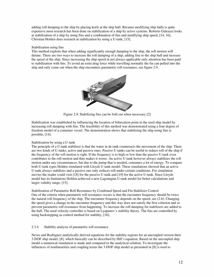
Stabilization using fins
This method exploits that when adding significantly enough damping to the ship, the roll motion will
detune. There are two ways to increase the roll damping of a ship, adding fins to the ship hull and increase
the speed of the ship. Since increasing the ship speed in not always applicable only attention has been paid
to stabilization with fins. To avoid an extra drag force while travelling normally the fin can pulled into the
ship and only come out when the ship encounters parametric roll resonance, see figure 2.9.
Figure 2.9: Stabilizing fins can be fold out when necessary [2]
Stabilization was established by influencing the location of bifurcation point in the used ship model by
increasing roll damping with fins. The feasibility of this method was demonstrated using a four degree of
freedom model of a container vessel. The demonstration shows that stabilizing the ship using fins is
possible, [14].
Stabilization by using a U-tank
The principle of a U-tank stabilizer is that the water in de tank counteracts the movement of the ship. There
are two kinds of U-tanks, active and passive ones. Passive U-tanks can be useful to reduce roll of the ship if
the frequency of the roll motion is right. If the frequency is to high or low than the passive U-tank even
contributes to the roll motion and thus makes it worse. An active U-tank however always stabilizes the roll
motion under any circumstances, but due to the pump that is needed, consumes a lot of energy. To compare
both U-tank types Holden simulated with Lloyds U-tank model. These simulations showed that an active
U-tank always stabilizes and a passive one only reduces roll under certain conditions. For simulation
movies the reader could visit [18] for the passive U-tank and [19] for the active U-tank. Since Lloyds
model has its limitations Holden achieved a new Lagrangian U-tank model for better calculations and
larger validity range, [15].
Stabilization of Parametric Roll Resonance by Combined Speed and Fin Stabilizer Control
One of the criteria when parametric roll resonance occurs is that the encounter frequency should be twice
the natural roll frequency of the ship. The encounter frequency depends on the speed, see (2.6). Changing
the speed gives a change in the encounter frequency and this way does not satisfy the first criterion and so
prevent parametric roll resonance from happening. To increase the roll damping fin stabilizers are added to
the hull. The used velocity controller is based on Lyapunov’s stability theory. The fins are controlled by
using backstepping as control method for stability, [16].
2.3.4 Stability analysis of parametric roll resonance
Neves and Rodrìguez analytically derived equations for the stability regions for an uncoupled version their
3-DOF ship model, [8], which basically can be described by Hill’s equation. Based on the uncoupled ship
model a numerical simulation is made and compared to the analytical solution. To investigate the
influences of nonlinearities and coupling terms the 3-DOF ship model as presented in [8] is used to
13
numerically define the stability regions for parametric resonance. In both cases, uncoupled and coupled
simulations, there is looked at the influences of the encounter frequency and wave height on the stability
regions. The nonlinear terms have little effect on the shape of the stability limits. The nonlinear coupling
terms however are relevant in determination of the roll amplitude. Initial conditions play an important role
and there is evidence of typical nonlinear behavior: jump effect and bifurcation, [20].

14
Chapter 3
Ship model
In the first chapter an introduction to parametric roll resonance was made and clarified previous and current
research topic of the scientific community. In this chapter the ship model used for the numerical analysis is
explained and an analysis according to the stability of this ship model is done.
3.1 Ship model
To analyze parametric roll resonance in ships a mathematical model is needed. Parametric resonance occurs
in systems that can be describes as an autoparametric system. An autoparametric system consists of two
subsystems, a primary and secondary system. The primary system can be externally forced, self-excited,
parametrically excited or a combination of those. The secondary system on the other hand is coupled to the
primary system in a nonlinear way and not under the influence of any external force.
To describe parametric roll resonance as an autoparametric system, the model proposed by Neves and
Rodríguez [8] is used. It is a three degree of freedom model that combines the primary (heave and pitch)
and secondary (roll) system into one model. The primary system is externally exited by wave motion. The
secondary system is parametrically excited by the primary system. Holden et al. [11] showed that this
model, which was originally designed for describing the motions of a fishing vessel, also can describes the
motions of a container vessel in head seas. The model is shortly presented. For a more detailed description
the reader should read references [8, 11].
The generalized coordinate vector is defined as
Ttttzt ])()()([)( θφ=s (3.1)
Where )(tz , )(tφ and )(tθ represent respectively the heave, roll and pitch motions of the ship which are
defined according to figure 2.3. The equations of motion for heave, roll and pitch are defined as
),,(),()()( ζζζζφ &&&&&&& extres cscsBsAM =+++ (3.2)
Where M is the diagonal rigid body generalized mass matrix. A is the generalized hydrodynamic added
mass matrix. B describes the hydrodynamic damping which is nonlinear in roll movement. Cres contains the
nonlinear restoring forces and moments as functions of the relative motions between the ship hull and the
wave elevation )(tζ . Cext contains the external wave excitation dependent on the wave heading, encounter
frequency, wave amplitude and time. Definitions and expressions for M, A, B, cres and cext can be found in
papers of Neves and Rodríguez [8], Holden et al. [11] and appendix A. Considering expressions for M, A,
B, cres and cext, (3.2) can be expressed as a nonlinear set of coupled equation for heave, roll and pitch
motions that describe a container vessel encountering longitudinal waves. The equation describing the roll
motion of the ship can be expressed as
0)()()()(2
1
6
1
2
1)(
2
32
=++++++
+++++++
φθφφφφθφθ
φφφφφφφφ
ζφθφζζζφζφφθθθφ
φφφφφφφφφφ
tKztKtKtKzKK
KzKzKKKKKJ
zz
zzzxx&&&&& &&&&&
(3.3)
15
In this study parametric roll resonance is investigated using an uncoupled version of (3.3). This is because
the vertical displacement )(tz and pitch angle )(tθ are assumed to be purely harmonic and the waves are
purely sinusoidal, so can be described as
)cos(),( tkxAtx ew ωζ += (3.4)
with wA as the wave amplitude, k as the wave number and eω as the encounter frequency. In fact this is
the worst case scenario since the variation in water plane area is largest when the waves purely sinusoidal,
see figure 2.8. The simplified model can be derived from (3.3) by setting the coupling terms to zero. This
leads to the following ship model
0)cos()( 332144 =++∇++++ φφωρφφφφ KtGMGMgddAI eabwx
&&&&& (3.5)
with βω
ωω cos)(2
00 tU
ge += (3.6)
The parameters look different but that is because the parameters in (3.5) are determined experimentally and
therefore can be referred back ship parameters. The parameters together with their values are given in table
3.1. The values are obtained by experiments with a 1:45 container ship model in a towing tank. The main
characteristics of the container ship can be found in appendix F. Data was achieved by varying ship
forward velocity, wave frequency and wave height. The values of the parameters obtained by these
experiments are calculated to full scale and used here. So the data achieved here is valid for a full scale
vessel.
parameter value description
44AIx + 1.62e10 ship inertia and added mass in roll direction
1d 3.20e8 linear roll damping
2d 2.99e8 nonlinear roll damping
wρ 1000 density of water
g 9.81 gravitational constant
∇ 7.65e4 water displacement
eω 0.6031 encounter frequency
3K 2.97e9 nonlinear moment in roll direction
aGM 0.84 varying part of metacentric height
bGM 1.91 constant part of metacentric height
0ω 0.4764 wave frequency
U 5.477 forward velocity
β 0 heading angle
Table 3.1: Numerical values ship parameters
3.2 Equilibrium point
For determination of the equilibrium point(s) first the ship model is rewritten in the state-space form
21 xx =& (3.7)
313122221
44
2 ))cos(((1
xKxtGMGMgxdxdAI
x eabwx
x
++∇+++
−= ωρ& (3.8)
16
with x defined as
=
φ
φ&
x .
An equilibrium is defined by as the position where all velocities are zero, so
=
=
0
0
φ
φ&&
&
&x . From (3.7) it
follows directly that 02 =x . Rewriting (3.8) and taking 02 =x into consideration gives
)))cos(((0 21311 xKxtGMGMgx eabw ++∇= ωρ (3.9)
This gives
01 =x (3.10)
or
3
1))cos((
K
tGMGMgx
eabw ωρ +∇±= (3.11)
(3.11) does not make sense because this that point varies in time what implies that the velocity 02 ≠x& .
The definition of an equilibrium point is that 021 == xx && so (3.11) is nonsense. Therefore the unique
equilibrium point is determined as 021 == xx . Since this is a time-varying system the stability of the
equilibrium point can not be characterized simply by the location of the eigenvalues of system, Khalil [17].
Also a suitable Lyapunov function was not found, so no conclusion can be drawn according to stability.
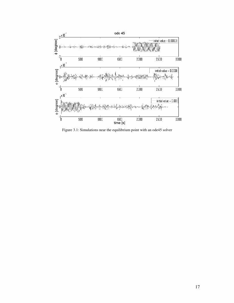
To draw any conclusion about the stability of the unique equilibrium point numerical simulations are
needed. The ship model (3.5), (3.6) is simulated around the equilibrium point starting at an initial value
near the equilibrium point. Since this is a numerical simulation no exact conclusion can be drawn but when
the roll angle decays to zero is highly unlikely that the equilibrium point is unstable. In figure 3.1 a
graphical presentation is given of the ship model simulated around the equilibrium point. As can be seen
three different solutions are shown starting from three different initial values. It can be concluded that the
equilibrium point is unstable because none of the solutions decays to zero but fluctuates in a small region
around zero. These fluctuations also can be an error of the solver method, therefore two other solver
methods are used to check this and they show the same kind of behavior. The used solver here based an
explicit Runge-Kutta (4,5), the Dormand-Prince pair, ode 45 command in MATLAB. One of the other two
solvers is an implementation of an explicit Runge-Kutta (2,3) pair of Bogacki and Shampine, ode23
command in MATLAB. The other one is a variable order Adams-Bashforth-Moulton PECE solver, ode113
command in MATLAB. Plots of the solution simulated with the last two solvers can be found in appendix
B.
3.3 Nonlinearities
The model as presented by (3.5) and (3.6) is a nonlinear time-varying system. In linear time-varying
systems the solution is not limited and grows until the system is destroyed. Usually mechanical systems
possess some kind of nonlinearity that contributes to the response. [1] concludes that the effects of
nonlinearities on parametrically exited systems have the tendency to limit the amplitude of the motion. This
model has two nonlinear terms nonlinear roll damping ( φφ &&2d ) and the righting moment of roll (
33φK ).
So the presence of these nonlinearities occur that the model does exhibit unbounded and with that
unrealistic prediction of the ship behavior. Basically these nonlinearities limit the amplitude of the roll
motion.
17
Figure 3.1: Simulations near the equilibrium point with an ode45 solver
18
Chapter 4
Numerical analysis
In the previous chapter the model is determined. In this chapter the model is analyzed to determine the
maximum roll angles for certain values of different model parameters. Also a short simulation is done
according to the control of parametric resonance.
4.1 Detection method
Since no explicit solution is given for the stability of this model detection method needs to be designed. In
section 3.3 is shown that every solution is bounded, so the amplitude is limited. For this reason the
following detection method is designed. The model for the roll angle is simulated for a certain time period.
This gives a graphically presentation of the roll angle in time, for example see figure 2.4. The average of
the absolute value of the last ten extremes of this solution is taken and compared to a threshold value. Since
the amplitude or decays to zero (stable) or grows up to a certain value (unstable) the threshold value is
chosen close to zero to classify the stable and unstable solutions. The threshold value used here is 0.1
degrees. Since under certain conditions it takes a long time to build up and discover parametric roll
resonance, a short simulation time could lead to wrong prediction of parametric roll resonance. Therefore
the simulation time is set to 3000 seconds to predict parametric roll resonance.
4.2 Simulation
It is common in stability analysis to show a kind of Ince-Strut diagram where the stability regions are
presented. In this study there is chosen to show the maximum roll angle instead of the stability regions or
certain model parameters. The advantage of this is that the figure contains more information than only
stability or instability.
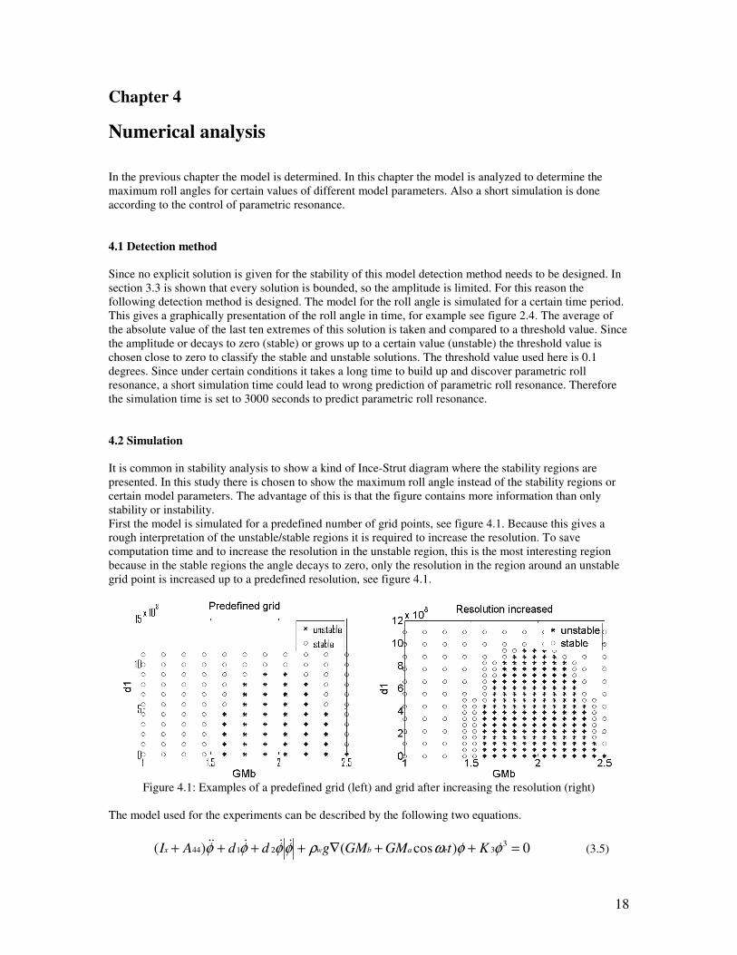
First the model is simulated for a predefined number of grid points, see figure 4.1. Because this gives a
rough interpretation of the unstable/stable regions it is required to increase the resolution. To save
computation time and to increase the resolution in the unstable region, this is the most interesting region
because in the stable regions the angle decays to zero, only the resolution in the region around an unstable
grid point is increased up to a predefined resolution, see figure 4.1.
Figure 4.1: Examples of a predefined grid (left) and grid after increasing the resolution (right)
The model used for the experiments can be described by the following two equations.
0)cos()( 332144 =++∇++++ φφωρφφφφ KtGMGMgddAI eabwx
&&&&& (3.5)
19
with βω
ωω cos)(2
00 tU
ge += (3.6)
This is the model presented in section 3.1. This model has the following ship parameters xI , 44A , 2d , ∇ ,
xI , GMa and 3K . These parameters can not or can hardly be changed during sailing so are not useful for
control. bGM , 1d and eω however can be influenced by using a PD ( bGM , 1d ) or speed/heading ( eω )
controller. For example 1d can be influenced by stabilizing fins at the hull of the ship. It is not necessary to
introduce control parameters like Kd or Kp because variation in bGM , 1d and eω will lead to the same
conclusion. Therefore there is chosen to vary bGM , 1d and eω , and show the maximum angle in a
graphical presentation. Simulations are done with MATLAB, the m-file to generate figure 4.2 can be found
in appendix C. The results of these simulations are presented in the next section. Also simulations are done
with variation of the ship parameters, these can be found in appendix D.
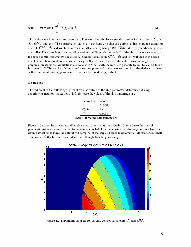
4.3 Results
The red point in the following figures shows the values of the ship parameters determined during
experiments mentions in section 3.1. In this case the values of the ship parameters are
parameters value
1d 3.20e8
bGM 1.91
eω 0.6031
Table 4.1: Values ship parameters
Figure 4.2 shows the maximum roll angle for variations in 1d and bGM . In relation to the control
parametric roll resonance from the figure can be concluded that increasing roll damping does not have the
desired effect since twice the natural roll damping of the ship still leads to parametric roll resonance. Small
variation in bGM however can reduce the roll angle less dangerous angles.
Figure 4.2: maximum roll angle for varying control parameters 1d and bGM

20
In figure 4.3 the results are shown while varying parameters bGM and eω . Looking at the red dot a
relative small variation in bGM as well as in eω could prevent parametric roll resonance to happen.
Figure 4.3: maximum roll angle for varying control parameters bGM and eω
Figure 4.4: maximum roll angle for varying control parameters 1d and eω
In figure 4.4 the maximum roll angle is shown when varying 1d and eω . Note that instead of displaying
eω along the horizontal axes the ratio φωωe is shown. This is because according to one of the criteria,
mentioned in section 2.3, the encounter frequency eω should be approximately twice the natural roll
frequency of the ship. The figure shows that around 2≈φωωe parametric roll resonance occurs and gives
high roll angles. Also it can be noted that there is a small peak around 1≈φωωe . This indicates that there
21
also is a subharmonic response that causes parametric roll resonance. Looking at the red dot it seems to be
more obvious to increase or decrease eω than to increase of decrease 1d to get to the stable region, since
doubling the damping is not even enough to get to the stable region.
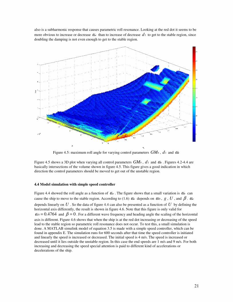
Figure 4.5: maximum roll angle for varying control parameters bGM , 1d and eω
Figure 4.5 shows a 3D plot when varying all control parameters bGM , 1d and eω . Figures 4.2-4.4 are
basically intersections of the volume shown in figure 4.5. This figure gives a good indication in which
direction the control parameters should be moved to get out of the unstable region.
4.4 Model simulation with simple speed controller
Figure 4.4 showed the roll angle as a function of eω . The figure shows that a small variation is eω can
cause the ship to move to the stable region. According to (1.6) eω depends on 0ω , g , U , and β . eω
depends linearly on U . So the data of figure 4.4 can also be presented as a function of U by defining the
horizontal axis differently, the result is shown in figure 4.6. Note that this figure is only valid for
4764.00 =ω and 0=β . For a different wave frequency and heading angle the scaling of the horizontal
axis is different. Figure 4.6 shows that when the ship is at the red dot increasing or decreasing of the speed
lead to the stable region so parametric roll resonance does not occur. To test this, a small simulation is
done. A MATLAB simulink model of equation 3.5 is made with a simple speed controller, which can be
found in appendix E. The simulation runs for 600 seconds after that time the speed controller is initiated
and linearly the speed is increased or decreased. The initial speed is 4 m/s. The speed is increased or
decreased until it lies outside the unstable region. In this case the end speeds are 1 m/s and 9 m/s. For both
increasing and decreasing the speed special attention is paid to different kind of accelerations or
decelerations of the ship.
22
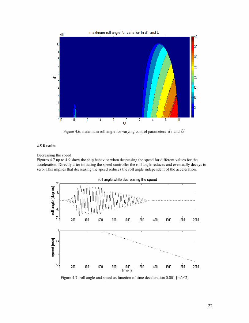
Figure 4.6: maximum roll angle for varying control parameters 1d and U
4.5 Results
Decreasing the speed
Figures 4.7 up to 4.9 show the ship behavior when decreasing the speed for different values for the
acceleration. Directly after initiating the speed controller the roll angle reduces and eventually decays to
zero. This implies that decreasing the speed reduces the roll angle independent of the acceleration.
Figure 4.7: roll angle and speed as function of time deceleration 0.001 [m/s^2]

23
Figure 4.8: roll angle and speed as function of time deceleration 0.01 [m/s^2]
Figure 4.9: roll angle and speed as function of time deceleration 0.1 [m/s^2]

24
Increasing the speed
Figure 4.10: roll angle and speed as function of time acceleration 0.1 [m/s^2]
Figure 4.11: roll angle and speed as function of time acceleration 0.01 [m/s^2]
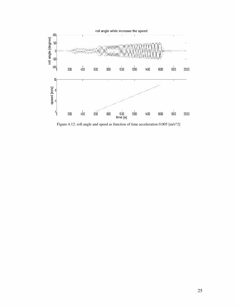
Figures 4.10 up to 4.12 show the ship behavior of a ship when the speed is increased up to 9 m/s for
different accelerations. Compared to the plots where the speeds have been decreased these plots show
totally different behavior. When accelerating with 0.1 m/s, figure 4.10, the roll angle decays to zero. But
when acceleration slower than 0.1, figures 4.11 and 4.12, the ship behavior in unpredictable for an
acceleration of 0.01, figure 4.11, the ship never get to the stable region even not when the speed, 9 m/s, is
far inside the stable region. While, figure 4.12, an acceleration of 0.005 m/s first increases the roll angle but
eventually does go to zero. The reason why this happens is not known and further research is needed to
explain why this happens.
25
Figure 4.12: roll angle and speed as function of time acceleration 0.005 [m/s^2]
26
Chapter 5
Conclusions and recommendations
5.1 Conclusions
Color plots
For controlling parametric roll resonance it is important to know the influences of certain ship parameters
on the stability of the ship. In this report the stability regions of a 1 DOF ship model are presented. This
simplified 1 DOF ship model is derived from a 3 DOF ship model proposed by Neves and Rodríguez, [8],
to describe the roll motion of the ship. The stability regions are given by color plots. These plots show the
roll angle for different values of two or three different ship parameters. The plots give a good indication of
the ship behavior for different ship parameters. The stability regions are well defined and easy to determine
in the color plots. In this way the plots can be used as an indication for the amplitude of the control
parameters. Since the stability regions are well defined it is easy to see how much a certain control
parameter needs to be increased to get outside the unstable region. So an indication of the amplitude of the
control parameters is possible.
Simple velocity controller
To check if the results give a good indication of the control parameters a simple velocity controller is used
to see if this could lead to a stabilization of the roll motion. In other words to see what happens if a ship
parameters is in- or decreased to get in the stable region. The velocity controller used here is linearly
increasing or decreasing in time up to a certain final value. This velocity controller shows that a reduction
of the roll motion of the ship is possible. Decreasing the forward velocity of the ship always leads to a
reduction of the roll movement. However increasing the forwards velocity shows different kind of
behavior. Increasing the forwards velocity does not always lead to a reduction of the roll motion.
Simulations show that, while increasing the forwards velocity, the behavior of the roll motion seems to
depend on the forwards acceleration of the ship.
5.2 Recommendations
Color plots
The results shown in this report are only valid for the used ship parameters, in other words for one ship
represented by these ship parameters. Every ship parameter is highly dependent on the design of the ship
and therefore the results will look differently for other ships. Unfortunately there was only data available
for one ship so no comparison can be made between the results of two or more different ships. To get better
understanding of parametric roll resonance it could be interesting to get the results for more than one ship.
In this way more general conclusions can be drawn according to parametric roll resonance.
In this report a simplified 1 DOF ship model derived from a 3 DOF ship model is used to describe the roll
motion of the ship. In this report only an indication of the control parameters was sufficient enough but for
actual determination of these parameters it is necessary to use a higher degree of freedom ship model to
describe the roll motion of a ship. Further research should focus on implementing such a higher degree of
freedom model, for example the 3 DOF ship model proposed by Neves and Rodríguez [8], to get more
accurate results that make it possible to get an actual value for a control parameter.
Simple velocity controller
The behavior of the roll motion, when increasing the forwards velocity, seems to depend on the forward
acceleration. However no further explanation is found in this report why this is and if it can be avoided.
Therefore further research is needed to give for an explanation for this and determine if the ship is
controllable by a simple velocity controller by decreasing as well as increasing the forwards velocity.

27
Appendix A
Definitions and expressions for M, A, B, cres and cext. These definitions can also be found in [8] and [11].
=
y
x
I
I
m
00
00
00
M
Where m is the ship mass, Ix is the inertia in roll and Iy the inertia in pitch.
−−
−
−−
=
−−
−
−−
=
θ
φ
θ
θ
φ
θ
φ
&&
&
&&
&&&&
&&
&&&&
&
MM
K
ZZ
MM
K
ZZ
z
z
z
z
0
0)(0
0
0
00
0
B
A
Where all coefficients except )(φφ &&K can be evaluated by mean of potential theory [11]. )(φφ &&K can be
expressed as
φφφφφ φφφφ &&&&& &&&& KKK +=)(
Where the coefficients φ&K and φφ &&K represent the linear and nonlinear roll damping.
)(),(),( , ζζζ FKextposres cscsc −=
The vector of restoring forces and moments ),( ζscpos can be written up to 3rd
order as
322322
,,,,,,,,, ζζζζζζ pospospospospospospospospospos cccccccccc ssssss ++++++++≈
Where
ji
ji
posji
posji ζ
ζζ s
s
cc s
∂∂
∂=
+
,
)(, ζFKextc are Froude-Krylov forces which are caused by incident waves. )(, ζFKextc can be written as
32
,,,, )( ζζζζ posposposFKext cccc ++=
The restoring forces and moments in each degree of freedom can be constructed. Beneath the forces and
moments up to 3rd
order are given in the roll direction.
1st order body motion in roll direction ( sc ,pos )
θφ θφ KKzKK zb ++=)1(
28
2nd
order body motion in roll direction (2
, scpos )
)222(2
1 222)2( θφφθθφ θθφφφθθφ KKKzKzKzKK zzzzb +++++=
2nd
order hull-wave interaction in roll direction ( ζsc ,pos )
θφ ζθζφζ )()()()2(/ tKtKztKK zwh ++=
3rd
order body motion in roll direction (3
, scpos )
)6
333333
(6
1
222222
333)3(
φθ
φθθθφφθφ
θφ
φθ
θθφθθφφθφφθφ
θθθφφφ
zK
KzKKzKzKzK
KKzKK
z
zzzzzz
zzzb
+
++++++
++=
3rd
order hull-wave interaction in roll direction (22
,, ζζ ss cc pospos + )
θφ
φθθφ
θφ
ζζθζζφζζ
ζφθθζφζ
ζθθζφφζ
)()()(
)()()(
)()()( 222)3(/
tKtKztK
tKztKztK
tKtKztKK
z
zz
zzwh
+++
+++
++=
The external forces and moments are given by
wext 1),,( τζζζ =&&&c
The wave excitation forces are defined by the wave force response operator this is defined as
)](arg[1
1
~)(
)( ewijewiei eF
ωτ
ζ
ωτω =
With these force response amplitude operators it is possible to obtain the wave excitation load in each
degree of freedom as
)](arg[cos()()(1 eieweiwi FtAFt ωωωτ +=
Here i = 3, 4, 5 represents respectively the heave roll and pitch motions of the ship.

29
Appendix B
Simulations near the equilibrium point of model (3.5) as presented in section 3.1.
Figure B.1: Solution simulated with a Runge-Kutta (2,3) pair of Bogacki and Shampine, ode23 command
in MATLAB
Figure B.2: Solution simulated with a variable order Adams-Bashforth-Moulton PECE solver, ode113
command in MATLAB
30
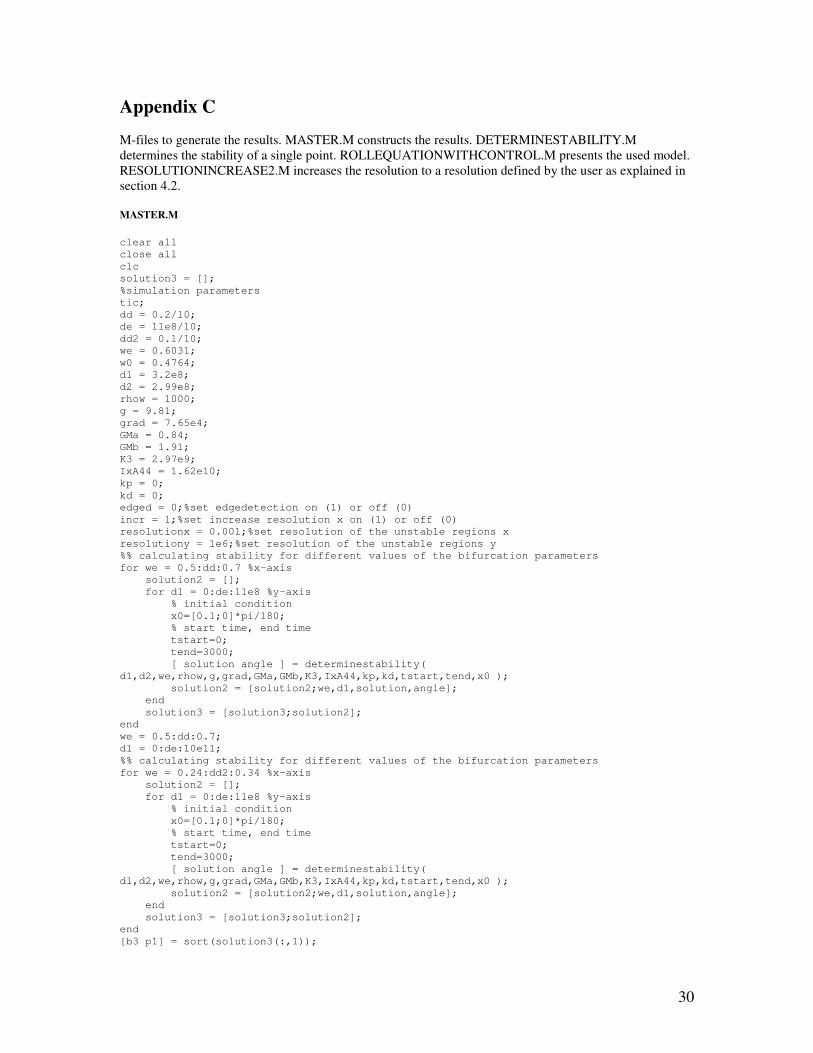
Appendix C
M-files to generate the results. MASTER.M constructs the results. DETERMINESTABILITY.M
determines the stability of a single point. ROLLEQUATIONWITHCONTROL.M presents the used model.
RESOLUTIONINCREASE2.M increases the resolution to a resolution defined by the user as explained in
section 4.2.
MASTER.M
clear all
close all
clc
solution3 = [];
%simulation parameters
tic;
dd = 0.2/10;
de = 11e8/10;
dd2 = 0.1/10;
we = 0.6031;
w0 = 0.4764;
d1 = 3.2e8;
d2 = 2.99e8;
rhow = 1000;
g = 9.81;
grad = 7.65e4;
GMa = 0.84;
GMb = 1.91;
K3 = 2.97e9;
IxA44 = 1.62e10;
kp = 0;
kd = 0;
edged = 0;%set edgedetection on (1) or off (0)
incr = 1;%set increase resolution x on (1) or off (0)
resolutionx = 0.001;%set resolution of the unstable regions x
resolutiony = 1e6;%set resolution of the unstable regions y
%% calculating stability for different values of the bifurcation parameters
for we = 0.5:dd:0.7 %x-axis
solution2 = [];
for d1 = 0:de:11e8 %y-axis
% initial condition
x0=[0.1;0]*pi/180;
% start time, end time
tstart=0;
tend=3000;
[ solution angle ] = determinestability(
d1,d2,we,rhow,g,grad,GMa,GMb,K3,IxA44,kp,kd,tstart,tend,x0 );
solution2 = [solution2;we,d1,solution,angle];
end
solution3 = [solution3;solution2];
end
we = 0.5:dd:0.7;
d1 = 0:de:10e11;
%% calculating stability for different values of the bifurcation parameters
for we = 0.24:dd2:0.34 %x-axis
solution2 = [];
for d1 = 0:de:11e8 %y-axis
% initial condition
x0=[0.1;0]*pi/180;
% start time, end time
tstart=0;
tend=3000;
[ solution angle ] = determinestability(
d1,d2,we,rhow,g,grad,GMa,GMb,K3,IxA44,kp,kd,tstart,tend,x0 );
solution2 = [solution2;we,d1,solution,angle];
end
solution3 = [solution3;solution2];
end
[b3 p1] = sort(solution3(:,1));
31
solution3 = solution3(p1(:,1),:);
we = [0.24:dd2:0.34 0.5:dd:0.7];
d1 = 0:de:11e8;
a = find(solution3(:,3)<1);
a2 = find(solution3(:,3)>0);
wphi = sqrt((rhow*g*grad*GMb)/IxA44);
%% increasing resolution unstable regions
if incr==1
[ smatrixnew ] =
resolutionincrease2(solution3,d1,d2,we,rhow,g,grad,GMa,GMb,K3,IxA44,kp,kd,tstart,tend,x0,
resolutionx,resolutiony);
solutionmatrix1 = smatrixnew;%[solution3;smatrixnew];
[b3 p1] = sort(solutionmatrix1,1);
solutionmatrix = solutionmatrix1(p1(:,1),:);
save reso
valuewe = [];
valued1 = [];
%defeining number of points in x and y direction
for k = 1:length(solutionmatrix(:,1))
if k+1<=length(solutionmatrix(:,1)) && solutionmatrix(k,1)==solutionmatrix(k+1,1)
else
valuewe = [valuewe solutionmatrix(k,1)];
end
end
[b3 p1] = sort(solutionmatrix(:,2));
solutionmatrixd1 = solutionmatrix(p1(:,1),:);
for k = 1:length(solutionmatrixd1(:,2))
if k+1<=length(solutionmatrixd1(:,2)) &&
solutionmatrixd1(k,2)==solutionmatrixd1(k+1,2)
else
valued1 = [valued1 solutionmatrixd1(k,2)];
end
end
a = find(solutionmatrix(:,3)<1);
a2 = find(solutionmatrix(:,3)>0);
else
end
toc
save color2
%% edge and stability of the edge detection
if edged==1
[ps pu] = pointdetection(solution3,we,d1);
edge2 = [];
for h = 1:length(ps)
if ps(h,2)-pu(h,2)==0
edgepointdata = edgedetectionx(ps(h,:),pu(h,:),tend,x0);
edge2 = [edge2; edgepointdata];
elseif ps(h,1)-pu(h,1)==0
edgepointdata = edgedetectiony(ps(h,:),pu(h,:),tend,x0);
edge2 = [edge2; edgepointdata];
else
end
end
solution32 = [solution3;edge2];
[b3 p1] = sort(solution32,1);
solution4 = solution32(p1(:,1),:);
[b2 p] = sort(edge2,1);
edge = edge2(p(:,1),1:2);
else
end
%% calculating colormatrix
if incr==1
colormatrix1 = zeros(length(valued1),length(valuewe));
for n=1:length(valuewe)
for m = 1:length(valued1)
colormatrix1(m,n) = solutionmatrix((n-1)*length(valued1)+m,4);
end
end
else
colormatrix1 = zeros(length(d1),length(we));

32
for n=1:length(we)
for m = 1:length(d1)
colormatrix1(m,n) = solution3((n-1)*length(d1)+m,4);
end
end
end
save color
%% show strutt diagram and color plot for d1-we
figure(5)
if incr==1
plot(solutionmatrix(a,1)/wphi,solutionmatrix(a,2),'*',solutionmatrix(a2,1)/wphi,solutionm
atrix(a2,2),'o');hold on
else
plot(solution3(a,1)/wphi,solution3(a,2),'*',solution3(a2,1)/wphi,solution3(a2,2),'o');hol
d on
end
if edged==1
plot(edge(:,1)/wphi,edge(:,2),'dr-');
else
end
xlabel('\omega_e/\omega_\phi');ylabel('d1');
legend('unstable','stable');
figure(6)
if incr==1
contourf(valuewe/wphi,valued1,colormatrix1);colorbar;
else
contourf(we/wphi,d1,colormatrix1);colorbar;
end
title('maximum roll angle for variation in d1 and
\omega_e');xlabel('\omega_e/\omega_\phi');ylabel('d1');
resolutionwe = [resolutionx;resolutiony]
%% show strutt diagram and color plot for d1-U
figure(7)
if incr==1
plot(((solutionmatrix(a,1)-
w0)*g)/w0^2,solutionmatrix(a,2),'*',((solutionmatrix(a2,1)-
w0)*g)/w0^2,solutionmatrix(a2,2),'o');hold on
else
plot(solution3(a,1)/wphi,solution3(a,2),'*',solution3(a2,1)/wphi,solution3(a2,2),'o');hol
d on
end
if edged==1
plot(edge(:,1)/wphi,edge(:,2),'dr-');
else
end
xlabel('U');ylabel('d1');
legend('resonance region','preferred region');
figure(8)
if incr==1
contourf(((valuewe-w0)*g)/w0^2,valued1,colormatrix1);colorbar;
else
contourf(((we-w0)*g)/w0^2,d1,colormatrix1);colorbar;
end
title('maximum angle for variation in d1 and U');xlabel('U');ylabel('d1');
resolutionU = [((resolutionx-w0)*g)/w0^2;resolutiony]
DETERMINESTABILITY.M function [ solution angle ] =
determinestability(d1,d2,we,rhow,g,grad,GMa,GMb,K3,IxA44,kp,kd,tstart,tend,x0)
%STABILITYCHECK Summary of this function goes here
% Detailed explanation goes here
[t,s]=ode45(@(t,y)
rollequationwithcontrol(t,y,d1,d2,we,rhow,g,grad,GMa,GMb,K3,IxA44,kp,kd),[tstart
tend],x0);
%% determining if the solution is stable(1) or unstable(0)
33
extrMaxIndex = find(diff(sign(diff(s(:,1))))==-2)+1;
extrMinIndex = find(diff(sign(diff(s(:,1))))==+2)+1;
extr = sort([extrMaxIndex;extrMinIndex]);
steadyangle = (abs(s(extr(end-3),1))+abs(s(extr(end-2),1))+abs(s(extr(end-
1),1))+abs(s(extr(end),1)))/4;
if steadyangle>x0(1)
solution = 0;
else
solution = 1;
end
angle = max(s(:,1))*180/pi;
ROLLEQUATIONWITHCONTROL.M function xprime = rollequation(t,x,d1,d2,we,rhow,g,grad,GMa,GMb,K3,IxA44,kp,kd)
%x(1) = phi
%x(2) = z
xprime(1) = x(2);%phi dot
xprime(2) = -
((d1+kd)*x(2)+d2*abs(x(2))*x(2)+(kp+rhow*g*grad*(GMb+(GMa)*cos(we*t)))*x(1)+K3*x(1)^3)/(I
xA44);%phi double dot
xprime = xprime(:);
RESOLUTIONINCREASE2.M
function [ smatrixnew ] =
resolutionincrease(smatrix,d1,d2,we,rhow,g,grad,GMa,GMb,K3,IxA44,kp,kd,tstart,tend,x0,res
olutionx,resolutiony)
%unstable increase
b = length(d1);
smatrixnew = [];
for k = 1:length(smatrix(:,3))
solution3 = [];
if k-b>=1 && k+1<=length(smatrix(:,3)) && smatrix(k,3)>0 && smatrix(k-b,3)>0&&
smatrix(k+1,3)>0&& smatrix(k-b+1,3)>0
for we = smatrix(k-b,1):resolutionx:smatrix(k,1)-resolutionx %x-axis
solution2 = [];
for d1 = smatrix(k,2):resolutiony:smatrix(k+1,2)-resolutiony %y-axis
solution2 = [solution2;we,d1,1,0.1];
end
solution3 = [solution3;solution2];
end%increase met nullen
elseif k-b>=1 && k+1<=length(smatrix(:,3))
for we = smatrix(k-b,1):resolutionx:smatrix(k,1)-resolutionx %x-axis
solution2 = [];
for d1 = smatrix(k,2):resolutiony:smatrix(k+1,2)-resolutiony %y-axis
[ solution angle ] = determinestability(
d1,d2,we,rhow,g,grad,GMa,GMb,K3,IxA44,kp,kd,tstart,tend,x0 );
solution2 = [solution2;we,d1,solution,angle];
end
solution3 = [solution3;solution2];
end%increase resolution
else
end
smatrixnew = [smatrixnew;solution3];
end
34
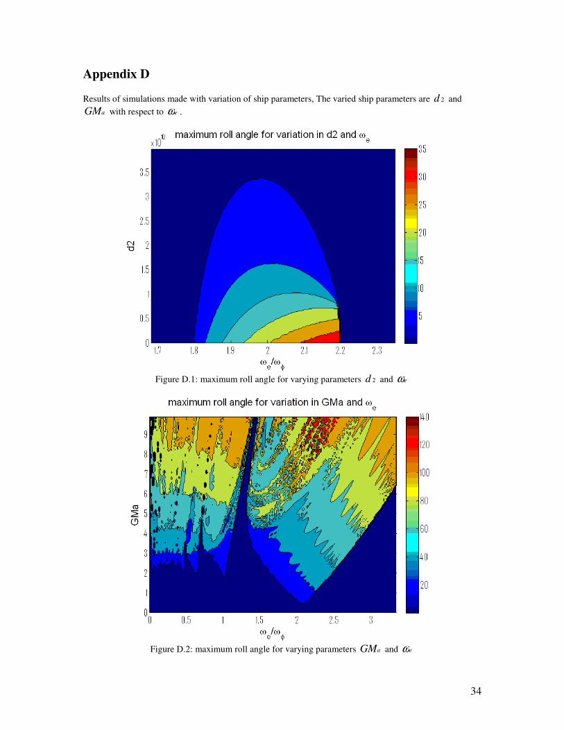
Appendix D
Results of simulations made with variation of ship parameters, The varied ship parameters are 2d and
aGM with respect to eω .
Figure D.1: maximum roll angle for varying parameters 2d and eω
Figure D.2: maximum roll angle for varying parameters aGM and eω

35
Appendix E
MATLAB Simulink model of the ship model.

36
Appendix F
Main characteristic of the container ship
quantity value
length of the ship 281 m
beam amidships 32.26 m
draught amidships 11.75 m
water displacement 76468 m3
roll radius of gyration 12.23 m
transverse metacentric height 1.84 m
37
References
[1] Nayfey, A.H., Mook D.T. Nonlinear Oscillations. WILEY-VCH, 1995.
[2] Fossen, T.I. Modeling and Control of Parametric Roll. Presentation at Workshop Parametric roll
resonance, December 2008, www.student.tue.nl/q/b.j.h.v.laarhoven.
[3] Lloyd, A.R.J.M. Seakeeping: Ship Behaviour in Rough Weather. Ellis Horwood Ltd, 1998.
[4] France, W. N., Levadou, M., Treakle, T. W., Paulling, J. R., Michel, R. K., Moore, C. An
investigation of head-sea parametric rolling and its influence on container lashing systems. In
SNAME Annual Meeting, 2001.
[5] Shin, Y. S., Belenky, V. L., Paulling, J. R., Weens, K. M., Lin, W. M. Criteria or parametric roll
of large containerships in longitudinal seas. Transactions of SNAME, 2004.
[6] Bulian, G. Development of analytical nonlinear models for parametric roll and hydrostatic
restoring variations in regular and irregular waves. PhD thesis, 2006.
[7] Neves, M. A. S. On the excitation of combination modes associated with parametric resonance in
waves. In Proceedings of the sixth International Ship Stability Workshop, 2002.
[8] Neves, M. A. S., Rodríguez, C. A. A coupled third order model of roll parametric resonance.
Maritime Transportation and Exploitation of Ocean and Coastal Resources, 2005.
[9] Neves. M. A. S., Rodríguez, C. A. An investigation on roll parametric resonance in regular
waves. In proceedings of the ninth International Conference on Stability of Ships and Ocean
Vehicles, 2006a.
[10] Neves, M. A. S., Rodríguez, C. A. On unstable ship motions resulting from strong nonlinear
coupling. Ocean Engineering, 2006b.
[11] Holden, C., Galeazzi, R., Rodríguez, C. A., Perez, T., Fossen, T. I., Blanke, M., Neves, M. A. S.
Nonlinear Container Ship Model for the Study of Parametric Roll Resonance. Modeling,
Identification and Control, volume 28, number 4, 2007.
[12] Holden, C., Perez, T., Fossen, T. I., Frequency-Motivated Observer Design for the Prediction of
Parametric Roll Resonance.
http://www.itk.ntnu.no/ansatte/Holden_Christian/prof/files/cams07b.pdf, IFAC2007.
[13] Galeazzi, R. Detection of Parametric Roll. Presentation at Workshop Parametric roll resonance,
December 2008, www.student.tue.nl/q/b.j.h.v.laarhoven
[14] Galeazzi, R., Blanke, M. On the Feasibility of Stabilizing Parametric Roll with Active Bifurcation
Control. Conference on Control Applications in Marine Systems, IFAC 2007.
[15] Holden, C., Fossen, T. I. Active Control of U-tanks. Submitted to European Control Conference
2009.
[16] Galeazzi, R., Holden, C., Blanke, M., Fossen, T. I. Stabilization of Parametric Roll Resonance by
Combined Speed and Fin Stabilizer Control. Submitted to European Control Conference 2009.
[17] Khalil, H. K., Nonlinear Systems third edition. Prentice Hall, 2002.
[18] http://www.itk.ntnu.no/ansatte/Holden_Christian/prof/files/passive.mov
[19] http://www.itk.ntnu.no/ansatte/Holden_Christian/prof/files/plant.mov
[20] Neves, M. A. S., Rodríguez, C. A. A coupled non-linear mathematical model of parametric
resonance in head seas. Applied Mathematical modeling 33 2630-2645, 2009.
[21] http://www.cesos.ntnu.no/
[22] http://www.itk.ntnu.no/ansatte/Holden\_Christian/prof/files/voyager.mov
Related Documents


![Untitled-1 []€¦ · AGRICASIA2013 Prof.Dr. Mehmet Rüştü KARAMAN Prof.Dr. A.Vahap KATKAT Prof.Dr. Batyr A. KHASANOV Prof.Dr. Ahmet KORKMAZ Prof.Dr. Ramazan K. KUZLEV Prof.Dr.](https://static.cupdf.com/doc/110x72/5ad37a017f8b9abd6c8dff61/untitled-1-agricasia2013-profdr-mehmet-rst-karaman-profdr-avahap-katkat.jpg)


![Simulation of a Parametric Resonance Circuit - Aias · Simulation of a Parametric Resonance Circuit ... achieved SCR [1]. In this paper, ... Figure 1: Parallel & Series Circuit.](https://static.cupdf.com/doc/110x72/5b2f2f617f8b9ac06e8d1a8e/simulation-of-a-parametric-resonance-circuit-simulation-of-a-parametric-resonance.jpg)

