Stability analysis of an aerodynamically shaped high- altitude-balloon tether H.M. Costello, K.A. Kuo, H.E.M Hunt University of Cambridge, Department of Engineering, Trumpington Street, CB2 1PZ, Cambridge, UK e-mail: [email protected] Abstract A high-altitude tethered balloon (HATB) attaining an altitude of 20 km would be useful in a number of applications including communications, meteorological monitoring, surveillance and, for the current paper, climate engineering. The HATB would have a 20 km long tether rising up from the ground and through the troposphere, where the wind-regime can be turbulent and include high-wind velocities. Consequently, the high wind velocities correspond to significant drag forces on the tether. Minimising these drag forces would be beneficial as the required tensile tether strength and the overall balloon size could be reduced. Therefore, this paper presents an evaluation of the use of an aerodynamic tether cross-section in order to decrease the overall drag loading on the tether. The benefits of an the aerodynamic cross-section, in terms of blow-over are quantified using a numerical model of the tethered balloon system. Then, because an aerodynamic tether shape introduces vibrational instabilities such as flutter, a method of incorporating a quasi-steady stability analysis into the lumped-mass model is proposed. 1 Introduction High altitude balloons can be used for a number of applications such as surveillance, communication and meteorological monitoring. The dynamics of high-altitude tethered balloon systems have been studied by a number of authors including Nahon [1], Coulombe-Pontbriand [2], Redi [3], Aglietti [4] and Badesha [5]. The Stratospheric Particle Injection for Climate Engineering (SPICE) project is also investigating the fea- sibility of using tethered balloons to reach an altitude of 20 km for climate engineering. The potential of using a streamlined tether in order to reduce drag on the tether is being explored. The following analysis discusses some of the potential problems and benefits associated with using a streamlined cross-section. A lumped-mass model is created and used to perform an initial analysis comparing the difference in the static equilibrium profile of a circular and streamlined tether subject to atmospheric wind conditions. Furthermore, a method of incorporating quasi-static flutter dynamics into the model is proposed and outlined. 2 Benefits and problems with a streamlined section The main advantage of a streamlined tether shape is the decrease in drag and suppression of vortex induced vibrations (VIV). However, the streamlined shape of the tether may also introduce problems such as flutter, added weight and tether flipping. Some of these benefits and potential problems are explored and briefly discussed below. A method for analysing the stability behaviour is outlined in section 8. 3003

Welcome message from author
This document is posted to help you gain knowledge. Please leave a comment to let me know what you think about it! Share it to your friends and learn new things together.
Transcript

Stability analysis of an aerodynamically shaped high-altitude-balloon tether
H.M. Costello, K.A. Kuo, H.E.M HuntUniversity of Cambridge, Department of Engineering,Trumpington Street, CB2 1PZ, Cambridge, UKe-mail: [email protected]
AbstractA high-altitude tethered balloon (HATB) attaining an altitude of 20 km would be useful in a number ofapplications including communications, meteorological monitoring, surveillance and, for the current paper,climate engineering. The HATB would have a 20 km long tether rising up from the ground and through thetroposphere, where the wind-regime can be turbulent and include high-wind velocities. Consequently, thehigh wind velocities correspond to significant drag forces on the tether. Minimising these drag forces wouldbe beneficial as the required tensile tether strength and the overall balloon size could be reduced. Therefore,this paper presents an evaluation of the use of an aerodynamic tether cross-section in order to decrease theoverall drag loading on the tether. The benefits of an the aerodynamic cross-section, in terms of blow-overare quantified using a numerical model of the tethered balloon system. Then, because an aerodynamic tethershape introduces vibrational instabilities such as flutter, a method of incorporating a quasi-steady stabilityanalysis into the lumped-mass model is proposed.
1 Introduction
High altitude balloons can be used for a number of applications such as surveillance, communication andmeteorological monitoring. The dynamics of high-altitude tethered balloon systems have been studied by anumber of authors including Nahon [1], Coulombe-Pontbriand [2], Redi [3], Aglietti [4] and Badesha [5].
The Stratospheric Particle Injection for Climate Engineering (SPICE) project is also investigating the fea-sibility of using tethered balloons to reach an altitude of 20 km for climate engineering. The potential ofusing a streamlined tether in order to reduce drag on the tether is being explored. The following analysisdiscusses some of the potential problems and benefits associated with using a streamlined cross-section. Alumped-mass model is created and used to perform an initial analysis comparing the difference in the staticequilibrium profile of a circular and streamlined tether subject to atmospheric wind conditions. Furthermore,a method of incorporating quasi-static flutter dynamics into the model is proposed and outlined.
2 Benefits and problems with a streamlined section
The main advantage of a streamlined tether shape is the decrease in drag and suppression of vortex inducedvibrations (VIV). However, the streamlined shape of the tether may also introduce problems such as flutter,added weight and tether flipping. Some of these benefits and potential problems are explored and brieflydiscussed below. A method for analysing the stability behaviour is outlined in section 8.
3003

2.1 Drag and vortex induced vibrations
A streamlined shaped tether, when aligned with the wind, can significantly reduce the drag on the tether.Hoerner [9] depicts this advantage with a scale drawing of a circular and streamlined section of equivalentdrag. Figure 1 recreates this scale drawing to show the potential advantage of streamlining a tether.
CDo
=0.04
CDo
=0.3
Figure 1: Hoerner’s [9] scale representation of a cylinder and a NACA 0025 aerofoil of equal drag at aReynolds number between 106 and 107.
Further to decreasing the overall drag, streamlining the tether is also a means of avoiding VIV associatedwith cables of circular cross-section. For example, Taggart and Tognarelli [12] experimentally investigatevarious fairing designs for VIV suppression in offshore risers. The authors also discuss the use of helicalstrakes and find that although helical strakes are effective at suppressing VIV they increase the overall dragwhich leads to the need for a more robust structure.
2.2 Tether flipping
A streamlined tether can significantly reduce the drag on the tether when aligned with the wind; however,if the tether flips and becomes perpendicular to the wind direction the drag will increase and the bendingstiffness will decrease. Figure 2 shows a summary of the coefficient of drag and bending stiffness of thecross-section when aligned and perpendicular to the wind direction.
Bending axis
Figure 2: Approximate values of the drag coefficient and second moment of area for NACA 0012 [10] andcircular cross-sections. The drag coefficient is scaled with respect to area tL where t is as depicted and L isa length into the page.
This combination of higher drag and lower bending stiffness means that if a streamlined tether does flip andbecome perpendicular to the wind direction the tension and displacements will both increase.
3004 PROCEEDINGS OF ISMA2012-USD2012

2.3 Decreased drag versus added weight
Compared to offshore streamlined cable structures, a streamlined balloon tether is more sensitive to addedweight since it operates in air instead of water which reduces the buoyancy force acting on the cable. For atethered balloon system the required force of buoyancy from the balloon, for a given free lift, is proportionalto the weight of the tether. Therefore, a streamlined tether would need to be carefully designed in order tominimise weight.
Figures 3 and 4 illustrate the general relationship between drag and weight for circular and 4 digit NACAaerofoil cross-sections. The tether drag will be proportional to the drag coefficient which, for varying chordto thickness ratio, is taken from Hoerner [9] and shown in Figure 3.
0 1 2 3 4 5 6 7 8 9 10 11 120
0.2
0.4
0.6
0.8
1
Ratio of chord to thickness (c/t)
Coe
ffici
ent o
f Dra
g (C
D)
c/t=7c/t=4
c/t=2
c/t=11
Coefficient of drag on a circular cross−section varies significantly withReynolds number.
For Re<105.5, CD
=1. For Re~105.7, CD
=0.3
Figure 3: Coefficient of drag given the ratio of the chord to thickness [9]. The aerofoil drag is given for aReynolds number of 106.
As an initial indication, the difference in weight of the various cross-sections can be assumed to vary pro-portionally with the cross-sectional area. This assumes that tethers of varying cross-sectional geometry havethe same essential components – such as a fluid conveying pipe and tension resisting material – and that theincrease in weight is due to the additional cross-sectional area, which would consist of an internal supportingmaterial structure. Figure 4 shows that the cross-sectional area for NACA aerofoils with equal thickness butvarying chord length follows a linear relationship.
0 1 2 3 4 5 6 7 8 9 10 11 120
0.05
0.1
0.15
0.2
0.25
0.3
0.35
Ratio of chord to thickness (c/t)
Are
a (m
2 )
c/t=4
c/t=2
c/t=8
c/t=11
Figure 4: Change in cross-sectional area for NACA aerofoils of varying chord to thickness ratio, in the figureshown the aerofoils and the circular cross-section are considered to have a thickness of 0.2m.
SELF-EXCITED VIBRATIONS 3005

3 Lumped-mass model
In order to analyse and quantify some of the benefits and problems explored in section 2 a numerical 3Dnonlinear lumped-mass model of the tethered balloon system was constructed.
3.1 Reference frames
Two frames of reference, similar to those used by Nahon et al. [1] for a tethered balloon system, are usedto describe the position of the tethered balloon. Cartesian axes {X , Y , Z} are used to describe the positionof the nodes, and all the system mass is lumped at these nodes. The orientation of each element is definedusing a body-fixed reference frame, which facilitates the calculation of quantities such as tension, lift anddrag since the reference frame is always orthogonal with the element itself. This body-fixed reference frameis specified using Euler angles {θ, φ, ψ} following the procedure outlined by Likins [11]. Figure 5 illustratesthe position and orientation of the nth node and nth element in the two reference frames. These two referenceframes are similar to those used by Nahon et al. [1]; however, note that in the current paper all Euler anglesare specified as positive rotations about the intermediary axes.
n
Y
Z
zn
xn
yn
X
θ
ψ
ϕ
n
n+1
Y
Z
X
Figure 5: Spatial and body-fixed reference frames describing node and element positions.
4 Internal forces and deformation
The lumped mass model accounts for tension T , bending in two directions (Mx and My) and torsion Q.Equation 1 relates the internal forces and strain {ε, κx, κy, κz} of an elastic, homogeneous, prismatic,isotropic beam through the stiffness matrix [K].
TMx
My
Q
=
EA 0 0 00 EIyy 0 00 0 EIxx 00 0 0 GJ
εκx
κy
κz
=[K]
εκx
κy
κz
(1)
The above stiffness matrix exhibits no coupling between tension, bending and torsion. This may not be thecase for a asymmetric and inhomogeneous cross-section because the centres of tension and shear may not becoincident. To use the above diagonal stiffness matrix the reference line is taken as the tension centre, whichis the location on the cross-section where if an axial force is applied there is no induced bending, and if amoment is applied there is no induced tension. Relations described by Hartsuijker and Welleman [8] wereused to determine the tension centre and elastic properties of inhomogeneous and asymmetric cross-sections.
3006 PROCEEDINGS OF ISMA2012-USD2012

4.1 Equations of motion
The use of both a spatial and body-fixed reference frame simplifies the calculation of internal and externalforces. Knowing the nodal positions, elongation and bending deformations can be calculated. The Eulerangles are used to form a transform matrix, which allows vector quantities to be transformed easily betweenreference frames.
In the body-fixed frame, the tension and bending of an individual element is easily calculated using Equation1, where the strains are determined from knowing the difference in orientation of two adjacent body-fixedframes. These internal forces are oriented with respect to the element and therefore conveniently alignedwith the body-fixed frame.
Experimentally measured wind speeds, given in the Cartesian spatial frame, are transformed to the body-fixed coordinate system. This simplifies drag calculations as the resultant wind velocity and angle of attack,in a plane orthogonal to the element length, are easily calculated.
In addition to drag, the HATB system is subject to external forces due to buoyancy and self-weight. Theseforces are easily calculated in the spatial reference frame as they act in the Z direction. Once all the internaland external forces are known, they are all transformed into the spatial frame of reference. Then, a secondorder differential equation describing the 3D motion of the nth node is given by,
mnr = Fn+1internal − Fn
internal + Fnaero + Fn
buoyancy + Fnweight (2)
where mn is the mass of the element lumped at the node and r is a vector comprised of the x, y and zcomponents of acceleration. These differential equations are solved using a numerical ordinary differentialequation solver in Matlab.
5 System design criterion
Although a HATB could be used for various purposes, the specifications used to compare the circular andstreamlined sections are based on the SPICE project. The work comprised in the SPICE project includesassessing important questions such as what particle should be used, how much of it and where should itbe dispersed. However, in order to complete a comparative study of two tether profiles, some hard designconstraints must be established. Table 5 outlines values of these hard design requirements.
Global mass flow rate m 320 kg/sDispersion altitude htarget 20 km
Aerosol liquid SO2
Payload mp 100 kgMaximum pumping pressure PT 600 MPa
Table 1: Hard design requirements for SPICE HATB system
6 Wind model
The lumped-mass model accounts for changes in air density and pressure with altitude. The relationshipbetween atmospheric pressure pa and height z above sea level is given by Wallace and Hobbs [13] as,
pa = p0e−zH (3)
SELF-EXCITED VIBRATIONS 3007

where p0 is taken as the pressure at sea level (101.325 kPa) and H is the scale height, which is dependenton temperature. However, on earth below atmospheric heights of 100 km, the scale height varies betweenapproximately 7 to 8 km therefore the scale height was taken as 7.5 km. The same relationship holds fordensity where pa ≡ ρa and p0 ≡ ρ0 = 1.25 kgm−3.
The HATB system could be located at a number of sites all with varying wind conditions. As an estimateof conditions up to an altitude of 20km wind data from the European Centre for Medium-Range WeatherForecasts [7] was used to build an atmospheric wind model. From a statistical analysis the mean and standarddeviation were determined. A maximum wind speed profile was formed by taking the maximum wind speedas three standard deviations away from the mean. Figure 6 shows the mean and maximum wind profiles inboth the XZ and Y Z planes.
−20 0 20 400
5
10
15
20
25
Wind Speed (m/s)
Alti
tude
(km
)
XZ plane − Location A
MeanMaximum
−20 0 20 400
5
10
15
20
25YZ plane − Location A
MeanMaximum
Figure 6: Mean and maximum wind speeds up to an altitude of 20km.
7 Model results
7.1 Benefit of decreased drag
Using the described lumped-mass HATB model a comparison of two HATB systems – one with a streamlinedcross-section and one with a circular cross-section – having the same internal pipe diameter, balloon size,linear mass, fibre-area and tether length was completed. Note that for the cross-sections to have the samelinear mass the trailing edge of the streamlined section needs to be filled with a very light foam or supportingstructure. The convergence of the model was verified by subjecting the system to the maximum wind profiledescribed in Section 6. Figure 7 shows the equilibrium position of the tether over an increasing number ofelements; the model shows good convergence between 100 to 140 elements.
This initial analysis shows that in terms of blowover there is benefit in using an aerodynamic tether. For theparticular wind profile used in the analysis, the aerodynamic tether decreases the horizontal displacement ofthe balloon by approximately 1 km. This particular analysis was at a static equilibrium position; however,for changing input wind conditions the described lumped-mass model can be used to solve for and analysethe dynamic tether behaviour.
8 Stability
The benefit of the decreased drag of a streamlined tether is dependent on the tether aligning itself with thewind and being stable. Compared to conventional aeroelastic analysis, a streamlined high-altitude balloon
3008 PROCEEDINGS OF ISMA2012-USD2012

N=20 to 140N=20 to 140 N=20 to 140N=20 to 140 N=20 to 140
Figure 7: Convergence of the lumped mass model over a range of 20 to 140 elements for a circular andstreamlined tether cross-section (not to scale).
tether will be under significant tension. Furthermore, compared to other streamlined structures such asairplane wings and helicopter blades the ratio between the structure length compared to its cross-sectionaldimensions is much greater. A method for analysing the stability of a streamlined tether by incorporating thetorsional equation of motion into the lumped-mass model is proposed and outlined below.
8.1 Lumped-mass model - torsional stability
Having a lumped-mass model of the system, high angle of attack static aerodynamic forces and momentscan be incorporated into the model. This allows for a quasi-steady analysis of the flutter characteristics ofthe tethered balloon system. At each time step in the simulation, the coefficients of lift, drag and moment,corresponding to the given angle of attack due to the wind and relative motion of the tether, are determined.The torsional stability will be affected by the magnitude and location of the forces acting at 4 centres – thecentres of tension, shear, mass and lift.
8.2 Aerodynamic properties
For the streamlined tether, CL as a function of the angle of attack was calculated from a Fourier seriesfit of experimental data gathered for a NACA 0012 aerofoil by Critzos et al. [6]. Figure 8 shows theexperimental data and a 30th order Fourier series fit. Even a 30th order fit does not completely capture thestall characteristics of the aerofoil; if needed, the order can be increased but at the expense of computationefficiency.
−180 −135 −90 −45 0 45 90 135 180−1.5
−1
−0.5
0
0.5
1
1.5
Angle of attack, α
Coe
ffici
ent o
f lift
, CL
Critzos et al.Fourier series fit
Figure 8: Coefficient of lift determined from Fourier series fit to NACA 0012 experimental data.
SELF-EXCITED VIBRATIONS 3009

The coefficient of drag CD at varying angle of attack α was determined from Equation 4, which was derivedby Leishman [10]. The equation is based on experimental data from a number of sources, including Critzoset al., Figure 9 shows the variation of CD with α.
CD = 1.135− 1.05 cos 2α (4)
−180 −135 −90 −45 0 45 90 135 1800
0.5
1
1.5
2
2.5
Angle of attack, α
Coe
ffici
ent o
f dra
g, C
D
Figure 9: Coefficient of drag over a range of angles of attack.
For a symmetric aerofoil at an angle of attack prior to stall, the aerodynamic centre is located at quarter chordand the pitching moment is zero. Beyond stall, at extreme angles of attack these conditions no longer hold.Leishman [10] derives Equation 5, which describes CM as a function of α. Equation 5 does not account forthe zero moment at low angle of attack, as seen in Figure 10. However, for the purposes of an initial analysisthis representation was deemed acceptable. In future work, if the model is used to investigate stability a moreaccurate representation may be required.
CM = −0.5 sinα+ 0.11 sin 2α (5)
−180 −135 −90 −45 0 45 90 135 180
−0.6
−0.4
−0.2
0
0.2
0.4
0.6
Angle of attack, α
Coe
ffici
ent o
f mom
ent,
CM
Figure 10: Coefficient of moment over a range of angles of attack.
Once the coefficients of lift, drag and moment are known the aerodynamic forces acting on an element canbe calculated knowing the frontal area, air density and wind speed.
8.3 Torsional equation of motion
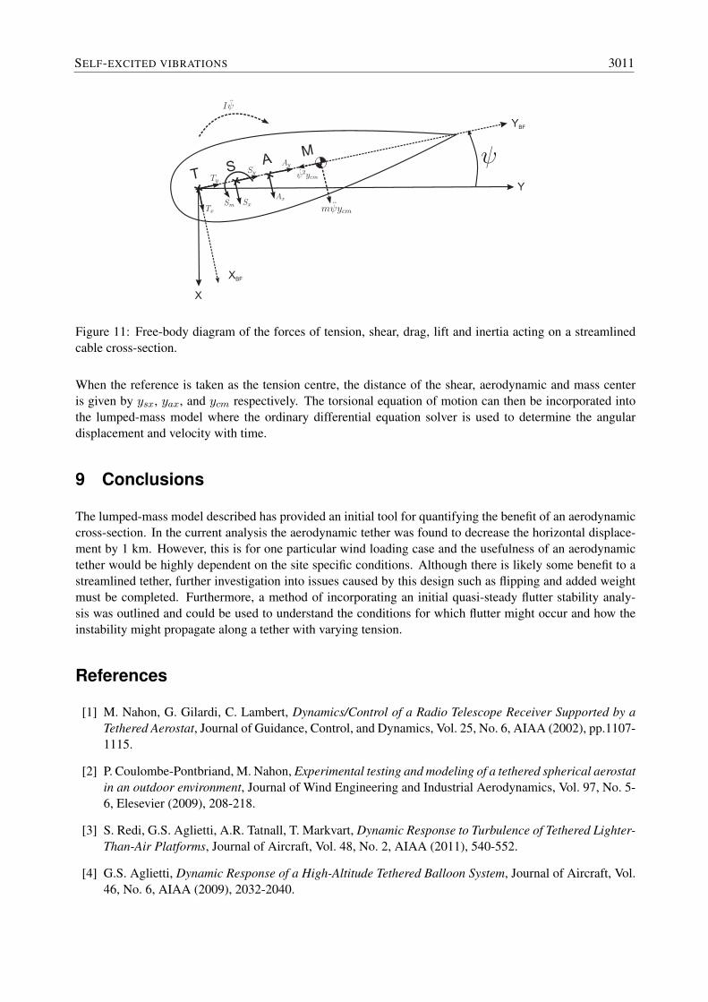
Figure 11 shows the forces due to tension, shear, aerodynamic loading and inertia acting along the tethercross-section.
Knowing the forces of tension, shear and wind loading from the lumped-mass model, a torsional equation ofmotion can be formed.
− Sxysx −Axyax + Sm − ψ(I +my2cm) = 0 (6)
3010 PROCEEDINGS OF ISMA2012-USD2012
+T
SA
M
+ +
XBF
YBF
Y
X
Figure 11: Free-body diagram of the forces of tension, shear, drag, lift and inertia acting on a streamlinedcable cross-section.
When the reference is taken as the tension centre, the distance of the shear, aerodynamic and mass centeris given by ysx, yax, and ycm respectively. The torsional equation of motion can then be incorporated intothe lumped-mass model where the ordinary differential equation solver is used to determine the angulardisplacement and velocity with time.
9 Conclusions
The lumped-mass model described has provided an initial tool for quantifying the benefit of an aerodynamiccross-section. In the current analysis the aerodynamic tether was found to decrease the horizontal displace-ment by 1 km. However, this is for one particular wind loading case and the usefulness of an aerodynamictether would be highly dependent on the site specific conditions. Although there is likely some benefit to astreamlined tether, further investigation into issues caused by this design such as flipping and added weightmust be completed. Furthermore, a method of incorporating an initial quasi-steady flutter stability analy-sis was outlined and could be used to understand the conditions for which flutter might occur and how theinstability might propagate along a tether with varying tension.
References
[1] M. Nahon, G. Gilardi, C. Lambert, Dynamics/Control of a Radio Telescope Receiver Supported by aTethered Aerostat, Journal of Guidance, Control, and Dynamics, Vol. 25, No. 6, AIAA (2002), pp.1107-1115.
[2] P. Coulombe-Pontbriand, M. Nahon, Experimental testing and modeling of a tethered spherical aerostatin an outdoor environment, Journal of Wind Engineering and Industrial Aerodynamics, Vol. 97, No. 5-6, Elesevier (2009), 208-218.
[3] S. Redi, G.S. Aglietti, A.R. Tatnall, T. Markvart, Dynamic Response to Turbulence of Tethered Lighter-Than-Air Platforms, Journal of Aircraft, Vol. 48, No. 2, AIAA (2011), 540-552.
[4] G.S. Aglietti, Dynamic Response of a High-Altitude Tethered Balloon System, Journal of Aircraft, Vol.46, No. 6, AIAA (2009), 2032-2040.
SELF-EXCITED VIBRATIONS 3011
[5] S.S. Badesha, J.C. Bunn, Dynamic simulation of high altitude tethered balloon system subject to thun-derstorm windfield, Atmospheric Flight Mechanics Conference and Exhibit, Vol. 13, AIAA (2002),512-522.
[6] C.C. Crıtzos, H.H. Heyson, R.W.Jr. Boswınlde, Robert W. Jr. Aerodynamic characteristics of NACA0012 airfoil section at angles of attack from 0 to 180, National Advisory Committee for Aeronautics,Langley Aeronautical Laboratory, Technical Note 3361, Langley Field (1955).
[7] European Centre for Medium-Range Weather Forecasts. ECMWF ERA-Interim Re-Analysis data,[Internet], NCAS British Atmospheric Data Centre. 2009-, December 2011. Available fromhttp://badc..nerc.ac.uk/view/badc.nerc.ac.uk ATOM dataent 12458543158227759.
[8] C. Hartsuijker, J.W. Welleman, Engineering mechanics Volume 2: Stresses, Strains, Displacements,[Internet], Springer (2007).
[9] S.F. Hoerner, Fluid-dynamic drag : practical information on aerodynamic drag and hydrodynamicresistance, S.F. Hoerner, New Jersey (1965).
[10] J.G. Leishman, Principles of helicopter aerodynamics, Cambridge University Press, Cambridge (2000).
[11] P.W. Likins, Elements of Engineering Mechanics, McGraw-Hill, New York (1973).
[12] S. Taggart, M.A. Tognarelli, Offshore Drilling Riser VIV Suppression Devices What’s Available toOperators?, Proceedings of The 27th Internaional Conference on Offshore Mechanics an Artic Engi-neering, Estoril, Portugal, 2008 June 15-20, Estoril (2008), pp. 1-11.
[13] J.M. Wallace, Atmospheric science : an introductory survey, Elsevier Academic Press, London (2006).
3012 PROCEEDINGS OF ISMA2012-USD2012
Related Documents