82050-IM-C ST3453H Helicopter Terrain Awareness Warning System Installation Manual Sandel Avionics 2401 Dogwood Way Vista, CA 92081 Phone (760) 727-4900 FAX (760) 727-4899 Website: www.sandel.com Email: [email protected]

Welcome message from author
This document is posted to help you gain knowledge. Please leave a comment to let me know what you think about it! Share it to your friends and learn new things together.
Transcript

82050-IM-C
ST3453H
Helicopter
Terrain Awareness
Warning System
Installation Manual
Sandel Avionics 2401 Dogwood Way
Vista, CA 92081 Phone (760) 727-4900 FAX (760) 727-4899
Website: www.sandel.com
Email: [email protected]

82050-IM-C ST3453H INSTALLATION MANUAL Page ii
[This page intentionally left blank]
82050-IM-C ST3453H INSTALLATION MANUAL Page iii
Revision History
Revision Date Comments
C 26-APR-2013 Updated for AR 1294 Updated TOC. All references to 1553B have been updated to 1553. Section 1.1: Introduction updated. Section 1.4: Data recording description updated. Section 1.9: Installation Kit P/N added. Section 1.7: Updated for MIL-STD-1553 for Airdata and Radalt. Section 3.1.2: Updated to add overlay data. Windows OS version updated. Section 3.9.1: External switch description updated. Section 4.2: Cooling considerations updated. Section 4.4: AC 43-13 reference updated. Section 4.5: Pin U description updated. Section 5.2: Maintenance menu access instructions updated. Section 5.6 CM Failure information updated. Section 5.7: Fatal System Error message added. Section 6: Maintenance menu access instructions updated. Note added. Section 6.2: Image updated. Table updated. DB/SW conflict message table added. Section 6.3: Table updated. Section 6.4: Table updated. Section 6.6: Table updated. Section 6.11: TCAS Configuration description updated. Table updated. Table added. Section 6.13: Section title updated. Image updated. Table updated. Section 6.16: Image updated. Description updated. Message table added. Section 7.6: Table updated. Section 7.8: Air data test step updated. Section 8: Sensor Compatibility tables updated. ARINC 429 Master Label List updated. Section 10.4: Updated for data/event recording capability. Section 10.7: URL updated.
82050-IM-C ST3453H INSTALLATION MANUAL Page iv
B 18-DEC-2012
Updated for AR 1290. Updated TOC. Section 1.5.1: Updated Note. Section 1.7: Updated interface characteristics. Section 1.9: Updated table. Section 2.1: Schematic section number reference updated. Section 3.2: Position interface description updated. Section 4.2: Typo corrected. Section 4.5: Updated section reference. Updated table. Section 4.7: Section number added. Section 5.4: Updated section reference. Section 5.6: Updated message and image. Added message list. Sections 6.0 – 6.17: Images updated. Section 6.3: Table updated Section 6.4 Table updated Section 6.8: Table updated Section 6.9: Table updated, description updated. Section 6.10: Section moved to next page. Remainder of Section 6 repaginated. Section 7.5: Table update for overlay revision Sections 7.6 and 7.7 renumbered. Section 7.6: Configuration record table updated. Section 7.8: Test steps updated for PRI/SEC PA sources. Section 7.9: Test steps updated for PRI/SEC HDG sources. Section 7.12: Test steps updated for PRI/SEC RA sources. Section 7.13: Updated section title. Section 7.14: Updated for optional display feature. Section 7.15: New section. Remainder of section renumbered. Section 8.1: Updated for 1553. Section 8.2: Updated for 1553. Section 8.3: Table updated. Section 11 – Updated List of Effective Drawings
A 21-AUG-2012 INITIAL RELEASE

82050-IM-C ST3453H INSTALLATION MANUAL Page v
[This page intentionally left blank]
82050-IM-C ST3453H INSTALLATION MANUAL Page vi
TABLE OF CONTENTS
1 GENERAL INFORMATION ....................................................................... 1-1 1.1 Introduction ...................................................................................................................... 1-1 1.2 LIMITATIONS ................................................................................................................ 1-1 1.3 Radalt Indicator Replacement .......................................................................................... 1-1 1.4 Equipment Description .................................................................................................... 1-1 1.4.1 Features ..................................................................................................................................... 1-2 1.4.2 FAA HTAWS Requirement ...................................................................................................... 1-2 1.5 Databases ......................................................................................................................... 1-3 1.5.1 Coverage area ............................................................................................................................ 1-3 1.5.2 Keeping the databases current ................................................................................................... 1-3 1.6 Technical Specifications .................................................................................................. 1-4 1.6.1 Approval Data ........................................................................................................................... 1-4 1.6.2 Physical Dimensions ................................................................................................................. 1-4 1.6.3 Operational Characteristics ....................................................................................................... 1-5 1.7 Interface Characteristics ................................................................................................... 1-5 1.8 System Part Number ........................................................................................................ 1-6 1.9 Installation Kit Part Number 90263-IK ........................................................................... 1-6 1.10 Configuration Module P/N .............................................................................................. 1-6 1.11 License Requirements ...................................................................................................... 1-6 1.12 Installation and Operational Approval Procedures - Commercial ................................... 1-6
2 INSTALLATION PLANNING ..................................................................... 2-1 2.1 General Information ......................................................................................................... 2-1 2.2 Supported Sensor Configurations .................................................................................... 2-1 2.2.1 Required Sensors ...................................................................................................................... 2-1 2.2.2 Optional Sensors ....................................................................................................................... 2-1 2.3 Pre-installation Planning .................................................................................................. 2-1 2.4 Post Installation Procedures ............................................................................................. 2-1
3 INTERFACE FUNCTIONS ......................................................................... 3-1 3.1 Power ............................................................................................................................... 3-1 3.2 GPS/FMS/INS ................................................................................................................. 3-1 3.3 Heading System ............................................................................................................... 3-1 3.4 Radar Altimeter ................................................................................................................ 3-1 3.5 Glideslope ........................................................................................................................ 3-2 3.6 Air Data Computer ........................................................................................................... 3-2 3.7 Traffic .............................................................................................................................. 3-2 3.8 Landing Gear ................................................................................................................... 3-2 3.9 External Switches and Annunciators ............................................................................... 3-2 3.9.1 External Switch + Annunciator Functions ................................................................................ 3-2 3.9.2 External Annunciator-Only Functions ...................................................................................... 3-3 3.9.3 External Control Discrete Outputs ............................................................................................ 3-3 3.9.4 Annunciator Default Functions ................................................................................................. 3-3 3.10 NVIS Control ................................................................................................................... 3-3 3.11 Audio Output ................................................................................................................... 3-4 3.12 Uploading Equipment ...................................................................................................... 3-4 3.13 Display Dimming ............................................................................................................. 3-4
4 INSTALLATION ......................................................................................... 4-1 4.1 Unpacking and Inspecting Equipment ............................................................................. 4-1 4.2 Cooling Considerations .................................................................................................... 4-1
82050-IM-C ST3453H INSTALLATION MANUAL Page vii
4.3 Mechanical Installation Considerations ........................................................................... 4-1 4.3.1 Instrument Location in the Cockpit ........................................................................................... 4-1 4.3.2 Assembly and Mounting Instructions ....................................................................................... 4-1 4.4 Electrical Installation Considerations .............................................................................. 4-2 4.5 Connector P1 .................................................................................................................... 4-3 4.6 Configuration Module Connector .................................................................................... 4-7 4.7 Electrical Characteristics by Signal Type ........................................................................ 4-8
5 SETUP PROCEDURES ............................................................................. 5-1 5.1 General ............................................................................................................................. 5-1 5.2 Accessing Maintenance Menus ........................................................................................ 5-1 5.3 Locked Items .................................................................................................................... 5-1 5.4 Equipment/Configuration Selections ............................................................................... 5-1 5.5 Configuration Module ...................................................................................................... 5-1 5.6 Configuration Module Failure ......................................................................................... 5-2 5.7 Fatal System Error ........................................................................................................... 5-3
6 POST INSTALLATION PROCEDURES .................................................... 6-1 6.1 Page 1: INDEX ................................................................................................................ 6-4 6.2 Page 2: SYSTEM ............................................................................................................. 6-5 6.3 Page 3: AIR DATA .......................................................................................................... 6-6 6.4 Page 4: HDG .................................................................................................................... 6-7 6.5 Page 5: DISCRETES ....................................................................................................... 6-8 6.6 Page 6: OUTPUT PINS ................................................................................................... 6-9 6.7 Page 7: NAV / ILS ......................................................................................................... 6-10 6.8 Page 8: RADALT .......................................................................................................... 6-11 6.9 Page 9: POS PRI (Position/Flight plan) ......................................................................... 6-14 6.10 Page 10: POS SEC (Position) ........................................................................................ 6-15 6.11 Page 11: TCAS .............................................................................................................. 6-16 6.12 Page 12: STATUS ......................................................................................................... 6-18 6.13 Page 13: OTHER SETTINGS ....................................................................................... 6-19 6.14 Page 14: CALLOUTS .................................................................................................... 6-20 6.15 Page 15: POWER ........................................................................................................... 6-21 6.16 Page 16: SFTWR CRC .................................................................................................. 6-21 Text Message .............................................................................................................................. 6-22 Description .................................................................................................................................. 6-22 Comment ..................................................................................................................................... 6-22 GEO OVLY FILE CRC .............................................................................................................. 6-22 6.17 Page 17: CS STATUS .................................................................................................... 6-23
7 CHECKOUT PROCEDURES..................................................................... 7-1 7.1 Power-On Self-Test ......................................................................................................... 7-1 7.2 ST3453H HeliTAWS ....................................................................................................... 7-1 7.3 Install ST3453H HeliTAWS into aircraft ........................................................................ 7-1 7.4 Record the following Aircraft Information ...................................................................... 7-1 7.5 Record the following system information:....................................................................... 7-1 7.6 ST3453H Configuration................................................................................................... 7-2 7.7 Required Test Equipment: ............................................................................................... 7-3 7.8 Air Data Input .................................................................................................................. 7-4 7.9 Heading Input .................................................................................................................. 7-4 7.10 Discrete Inputs ................................................................................................................. 7-5 7.11 NAV& ILS Input ............................................................................................................. 7-5
82050-IM-C ST3453H INSTALLATION MANUAL Page viii
7.12 Radar Altimeter ................................................................................................................ 7-6 7.13 GPS/FMS/INS Position (POS PRI) ................................................................................. 7-7 7.14 FMS Flight Plan (Optional) ............................................................................................. 7-7 7.15 GPS/FMS/INS Position (POS SEC) ................................................................................ 7-7 7.16 Traffic .............................................................................................................................. 7-8 7.17 MUTE switch ................................................................................................................... 7-9 7.18 Sensitivity switch ............................................................................................................. 7-9 7.19 HTAWS self-test .............................................................................................................. 7-9 7.20 External Annunciators ..................................................................................................... 7-9 7.21 Display ............................................................................................................................. 7-9 7.22 Manual brightness ............................................................................................................ 7-9 7.23 Visibility and Accessibility ............................................................................................ 7-10
8 SENSOR COMPATIBILITY ....................................................................... 8-1 8.1 Air Data ............................................................................................................................ 8-1 8.2 Heading System / AHRS ................................................................................................. 8-2 8.3 Navigation Receiver......................................................................................................... 8-2 8.4 Radar Altimeter ................................................................................................................ 8-2 8.5 Position - Primary ............................................................................................................ 8-3 8.6 Position - Secondary ........................................................................................................ 8-3 8.7 Traffic .............................................................................................................................. 8-3 8.8 ARINC 429 Master Label List ......................................................................................... 8-3
9 ENVIRONMENTAL QUALIFICATION FORM ........................................... 9-1
10 INSTRUCTIONS FOR CONTINUED AIRWORTHINESS ........................ 10-1 10.1 Periodic Maintenance ..................................................................................................... 10-1 10.2 Cleaning the Front Panel ................................................................................................ 10-1 10.3 Display Light Source ..................................................................................................... 10-1 10.4 Trouble Shooting Information ....................................................................................... 10-1 10.5 Removal and Replacement ............................................................................................ 10-2 10.6 Database Updates ........................................................................................................... 10-2 10.7 Software Updates ........................................................................................................... 10-2
11 LIST OF EFFECTIVE DRAWINGS AND ATTACHMENTS ..................... 11-1

1 GENERAL INFORMATION
1.1 Introduction
The information contained within this Installation Manual describes the features, functions, technical characteristics, components, approval procedures, installation considerations, setup procedures, checkout procedures and instructions for continued airworthiness for the Sandel Avionics ST3453H Helicopter Terrain Awareness Warning System. For an explanation of the operating controls and operational details of the ST3453H, refer to the Pilot’s Guide for the ST3453H, Sandel Avionics P/N 82050-PG.
The ST3453H has FAA TSO authorization and has been tested to RTCA DO-160F and MIL-STD-810G environmental standards.
Sandel Avionics ST3453H HTAWS may be covered by one or more U.S. and foreign patents and pending patent applications, including U.S. Patent Nos. 6,259,378, 6,489,916, 6,507,288, 6,591,170, 6,670,892, 6,683,556, 6,780,788, 6,889,124, 6,972,695, 6,999,023, 7,057,549, 7,187,304 and foreign counterparts.
1.2 LIMITATIONS
The following stipulation as presented is required by the Federal Aviation Administration for articles approved under Technical Standard Order. This statement does not preclude multiple installation and operational approvals in regard to specific aircraft make, model, or type:
The conditions and tests required for TSO approval of this article are minimum performance standards. Those installing this article, on or in a specific type or class of aircraft, must determine that the aircraft installation conditions are within TSO standards. TSO articles must have separate approval for installation in an aircraft. The article may be installed only according to 14 CFR Part 43 or applicable airworthiness requirements.
1.3 Radalt Indicator Replacement
The ST3453H Radalt function is provided to allow the ST3453H to replace an existing Radar Altitude display. Both the current Radar altitude and the selected Minimums alerting altitude are displayed in digital format.
If a Radar altimeter is not installed in the helicopter or is installed but display of the Radar Altimeter is not enabled, the Radar Altitude will not be displayed on the screen. The MINS display will be present (if display of the Radar altimeter is enabled) and may be used by the pilot as a reference.
1.4 Equipment Description
The Sandel ST3453H is a self-contained HTAWS (Terrain Awareness Warning System) solution specifically for helicopters that includes an advanced HTAWS computer and an integrated full-color screen built within a standard 3-inch instrument chassis.

82050-IM-C ST3453H INSTALLATION MANUAL Page 1-2
The ST3453H uses Sandel’s patented rear-projection display technology. The projector uses a miniature active-matrix LCD display that produces a high-resolution image that is rear-projected directly to the face of the instrument. This technology allows the displayed image to extend to the edges of the instrument’s bezel. The advantage of this edge-to-edge technology is that it eliminates the unusable area surrounding conventional LCD and CRT displays. Even though the Sandel display is in a 3-inch form factor, its image is near the size of a 4” primary display, and can remain directly in the pilot’s field-of-view.
It can be used as a direct replacement for a currently installed Radar altimeter indicator. It includes a MINS setter, MINS discrete output, and a Radalt Test discrete output. In some configurations, the ST3453H may not display a MINS setting window, Radalt display, and may not provide a MINS discrete output or Radalt Test discrete output.
The ST3453H includes built-in warning and caution annunciation. The unit also supports optional external warning or caution annunciation as well as optional collective mounted momentary switches to control certain functions such as alert muting and modes.
The ST3453H may be installed in a single or dual installation.
The ST3453H has an internal data and event recorder that automatically records up to 100 record files (total maximum = 100MB) of flight data and events. This data can be reviewed for content in the event of a system malfunction.
1.4.1 Features
HeliTAWS is the enhanced terrain warning technology for helicopters that uses GPS position along with databases of terrain and obstacles to reduce or eliminate CFIT accidents. It is similar to the Sandel ST3400 fixed-wing TAWS, with feature enhancements specific to helicopter operations close to the ground.
Increased vertical accuracy Separate obstacle database On-screen obstacle display 3 arc-second terrain data Provision for user-defined obstacles and landing zones
The following 5 standard GPWS functional modes (modified for helicopter) are provided for when equipped with supported Radar altimeter and airdata computer:
ERD (excessive rate of descent) ALAT (altitude loss after takeoff) FITNL (flight into terrain when not in landing configuration) EDGSD (excessive downward glide slope deviation). 300 feet and below Voice Callouts
1.4.2 FAA HTAWS Requirement
The ST3453H exceeds the FAA requirements for HTAWS alerting, annunciation, and display for installation in Part 27 and Part 29 helicopters
82050-IM-C ST3453H INSTALLATION MANUAL Page 1-3
1.5 Databases
1.5.1 Coverage area
The internal Terrain and Obstacle databases include terrain, charted man-made obstacles, airports, and heliports.
The Terrain and Airport databases are provided by geographical area. The coverage area of the database installed in the ST3453H is shown as part of the sign-on screen after a power cycle.
Note: There is no guarantee that all obstacles including transmission lines are charted or that every charted obstacle or transmission line is in the database.
1.5.2 Keeping the databases current
Updated databases can be loaded into the equipment using a Sandel supplied Windows loader program, USB cable and a laptop computer. This is done through a high-speed USB port located on the front right corner.
The databases can be updated during normal maintenance to the helicopter.
82050-IM-C ST3453H INSTALLATION MANUAL Page 1-4
1.6 Technical Specifications
The following section describes the technical characteristics, which include the appliance approval basis, physical and electrical properties, electrical connector pin allocation which details function and gradient or equipment protocol, and MIL1553 and ARINC label support. Also included is the description of the ST3453H installation components, other equipment and installation requirements. A review of the installation approval procedures is provided for filing with authorities.
1.6.1 Approval Data
Technical Standard Orders:
Non-TSO Functions:
TSO-C87 Airborne Low-Range Radio Altimeter
TSO-C113 Airborne Multipurpose Electronic Display
TSO-C118 Traffic Alert and Collision Avoidance System (TCAS-I) TSO-C194 Helicopter Terrain Awareness and Warning System (HTAWS) NVIS Mode
TOPO Display
Selective Muting
Flight Plan Display
Airport Display
Helicopter GPWS
Data Recording
WireWatch®
Software Certification: DO-178B Level C
Environmental: DO-160F / MIL-STD-810G
Databases: DO-200A
1.6.2 Physical Dimensions
The ST3453H is enclosed in an ARINC 408, 3ATI form factor enclosure and is mounted to an instrument panel.
Form Factor: 3ATI (ARINC 408)
Width: 3.175 inches
Height: 3.175 inches
Length: 7.8 inches
ST3453H Weight:
Config Module Weight:
3.0 lbs
0.06 lbs
82050-IM-C ST3453H INSTALLATION MANUAL Page 1-5
Connector Weight:
Mounting:
0.12 lbs
3 ATI Clamp
Display: 200dpi
1.6.3 Operational Characteristics
Temperature/Altitude: -40° C to +55° C / up to 55,000 feet including display. CPU and alerting system temperature range operational to -40° C
Power Input: 28VDC nominal, 1.0A nominal at 100% brightness. Operating range 22VDC – 33VDC
Cooling Requirements: None
1.7 Interface Characteristics
The ST3453H is software configurable and configuration data is stored internally and in an airframe-resident configuration module.
Configuration Module: Rear mounted MS38999 type 6 pin connector
Data Loading: Front panel USB
GPS Position: MIL-STD-1553
GPS Flight plan: MIL-STD-1553 (Optional - Must be GAMA compliant)
Air Data: MIL-STD-1553, ARINC 429, or Analog
Heading: MIL-STD-1553, ARINC 429 or ARINC 407 (XYZ)
Gear: Discrete: active high or low
Glideslope: MIL-STD-1553, ARINC 429 or low-level deviation and flag
Localizer: MIL-STD-1553, ARINC 429 or low-level deviation and flag
Audio Output: 500 ohm, 125mw
External Annunciators: Open/GND (Open Drain) GND=Active
250ma maximum (installation optional)
External Switches: Momentary action, Open/GND
GND to activate (installation optional)
Radar Altimeter: MIL-STD-1553, ARINC 429, or Analog
Traffic: ARINC 429, RS232, RS422
82050-IM-C ST3453H INSTALLATION MANUAL Page 1-6
1.8 System Part Number
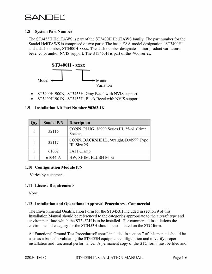
The ST3453H HeliTAWS is part of the ST3400H HeliTAWS family. The part number for the Sandel HeliTAWS is comprised of two parts: The basic FAA model designation “ST3400H” and a dash number, ST3400H-xxxx. The dash number designates minor product variations, bezel color and/or NVIS support. The ST3453H is part of the -900 series.
ST3400H-900N, ST3453H, Gray Bezel with NVIS support ST3400H-901N, ST3453H, Black Bezel with NVIS support
1.9 Installation Kit Part Number 90263-IK
Qty Sandel P/N Description
1 32116 CONN, PLUG, 38999 Series III, 25-61 Crimp Socket,
1 32117 CONN, BACKSHELL, Straight, D38999 Type III, Size 25
1 61062 3ATI Clamp
1 61044-A HW, SHIM, FLUSH MTG
1.10 Configuration Module P/N
Varies by customer.
1.11 License Requirements
None.
1.12 Installation and Operational Approval Procedures - Commercial
The Environmental Qualification Form for the ST3453H included in section 9 of this Installation Manual should be referenced to the categories appropriate to the aircraft type and environment into which the ST3453H is to be installed. For commercial installations the environmental category for the ST3453H should be stipulated on the STC form.
A “Functional Ground Test Procedures/Report” included in section 7 of this manual should be used as a basis for validating the ST3453H equipment configuration and to verify proper installation and functional performance. A permanent copy of the STC form must be filed and
ST3400H - xxxx
Model Minor Variation

82050-IM-C ST3453H INSTALLATION MANUAL Page 1-7
maintained by the installing agency. Another copy must be presented to the aircraft owner for entry into the aircraft maintenance records, as well as a copy forwarded to Sandel Avionics along with the Warranty Registration Form, to be filed after completion and installation acceptance.
If any difficulty is experienced with the functionality or operational performance of the ST3453H, contact Sandel for assistance.
2 INSTALLATION PLANNING
The ST3453H has been designed to ensure maximum interoperability with external avionics. Contact Sandel with any questions about interfacing to specific avionics equipment not covered in the installation drawings in this manual.
2.1 General Information
To simplify installation, after signals are wired to the ST3453H pins, on-screen setups are used in a post-installation procedure. Maintenance menu pages provide a function selection capability. For most equipment, selections are made by equipment make and model.
Refer to the installation schematics in section 11 of this manual for details on connecting required components.
2.2 Supported Sensor Configurations
2.2.1 Required Sensors
GPS position Gear (only if the helicopter has retractable gear). Heading Display: Provides no-track terrain display Radar Altitude GPWS: Provides callouts;
2.2.2 Optional Sensors
GPS Flight plan Display: displays flight plan line Airdata GPWS: improves accuracy of certain modes LOC/GS GPWS: adds Glideslope alert
2.3 Pre-installation Planning
The installation planning cycle is summarized as follows:
Compile an equipment list for the helicopter. If the desired equipment is not listed in the installation manual diagrams, contact Sandel for interoperability
Review the installation considerations given in the Installation Considerations section of this manual.
Study the installation drawings to determine a basic interconnect scheme and check for conflicts.
Develop the specific wiring diagrams unique to the aircraft. Assemble required tools.
2.4 Post Installation Procedures
Post installation procedures are summarized as follows:
Prior to power-up, review correct wiring by using industry accepted ohmmeter and voltage checks. Pay particular attention to presence of +28V on only the correct pins; 0

82050-IM-C ST3453H INSTALLATION MANUAL Page 2-2
ohm resistance check on ground pins to airframe ground; and presence of inverter 400Hz (if used) only on the appropriate pins.
Review any special items particular to the subject helicopter installation. Power up the ST3453H in maintenance mode and sequentially access each maintenance
page to select the installed equipment. In some cases, the ability to edit fields will be locked by the configuration module.
Allow the unit to operate for 30 minutes. Perform Ground Test procedures. Perform Flight Test procedures if required.
3 INTERFACE FUNCTIONS
3.1 Power
The primary power is 28 volt dc on J1-P and is supplied from the aircraft avionics buss through a circuit breaker. Ground is provided on J1-R and should be attached to an approved airframe ground.
A 26 volt 400Hz excitation input is available at J1 - W. It is only used in the case of an XYZ heading source. If the installation of the ST3453H does not use an XYZ (ARINC407) signal source, the inverter input is not required and should be grounded.
3.2 GPS/FMS/INS
A position input is required. The port is configurable in the Maintenance Menu pages for MIL-STD-1553. A list of supported labels is listed in section 8.8 .
3.3 Heading System
A Heading input permits the terrain display to remain operational during hover operations. It is highly recommended. The port is configurable on the maintenance page for MIL-STD-1553, ARINC 429, or ARINC 407 (XYZ).
3.4 Radar Altimeter
The ST3453H has provisions for a Radar Altimeter input. Radar Altimeter input may be from MIL-STD-1553, ARINC 429 or DC analog sources. The Radar Altimeter input is used to obtain height above terrain for GPWS alerting and for altitude callouts.
The Radar Altimeter always produces a single ‘300’ or ‘100’ mandatory audio callout, depending on NORM/LOW sensitivity selected by the pilot. Optionally the installer may enable any or all of the following additional audio callouts:
300’, 200’, 100’, 50’, 40’, 30’, 20’, 10’
These callouts are a great safety feature and their use is encouraged.
When the Radar Altimeter is lower than the MINS setting a MINS discrete output is activated and an audio callout “MINIMUMS” occurs.
When the Radar Altimeter is not configured, the MINS setting may be retained on the display for use as a visual reference by the pilot. The MINS discrete and callout will be disabled.
The MINS setting knob on the front panel has a push button function. This operates the momentary discrete on J1-MM, RADALT TEST if enabled.

82050-IM-C ST3453H INSTALLATION MANUAL Page 3-2
3.5 Glideslope
This input provides the GPWS mode-5 glideslope alert. MIL-STD-1553, ARINC 429 or low level analog inputs for Glideslope deviation, Glideslope flag status, and Localizer and Localizer Flag are provided.
An additional discrete input is available for Back Course from the HSI, which acts to disable Glideslope alerting while on a Back Course approach.
3.6 Air Data Computer
Airdata input is recommended. MIL-STD-1553, ARINC 429, and analog pressure altitude are supported.
3.7 Traffic
The ST3453H supports Traffic input via single ARINC 429 input. Traffic data is overlaid on terrain.
Some traffic processors require remote switches. See Traffic interface drawings in this manual for these requirements.
3.8 Landing Gear
The ST3453H has provisions on J1-FF for Gear Down input discrete to indicate that the gear is in the “DOWN” position for helicopters equipped with retractable landing gear.
The configuration is performed in the Maintenance Menu pages given in the Setup Procedures section of this manual. If the system is installed in a helicopter without retractable landing gear, select “NONE” on maintenance page configuration item.
3.9 External Switches and Annunciators
All external switches and annunciators are optional.
External switches are momentary contact OPEN/GND, normally open.
External annunciators, if used, must be properly labeled and colored.
Discrete outputs are OPEN/GND and capable of sinking a maximum of 250 milliamps to ground when active. They can drive incandescent lamps and/or relays. Dimming of external annunciators is accomplished by sourcing the annunciators from the helicopter day/night bus.
3.9.1 External Switch + Annunciator Functions
These switch/annunciator functions are available:
GS Inh Mute Note: HOLD invokes TAWS INH function Sensitivity Note: HOLD invokes OFF APT function
82050-IM-C ST3453H INSTALLATION MANUAL Page 3-3
The external switches perform the same functions as their related front panel switches. If power to the unit drops below 20VDC, external switch functions will be inoperative.
3.9.2 External Annunciator-Only Functions
These annunciator discrete outputs are available:
Caution Alert Warning Alert TAWS Inhibit
3.9.3 External Control Discrete Outputs
These control outputs are available:
Radalt Test TCAS Inhibit
3.9.4 Annunciator Default Functions
ANNUNCIATORS
Marking Color Description
G/S INH YELLOW Same function as on-screen G/S INH annunciation.
MUTE YELLOW Same function as on-screen MUTE annunciation.
SENS WHITE OR CYAN
Alert sensitivity is LOW SENSE.
TAWS YELLOW Same as on-screen TAWS Yellow Caution.
TAWS RED Same as on-screen TAWS Red Warning.
TAWS INH YELLOW TAWS INH function has been enabled or one or more alerts have been disabled due to a fault.
CONTROL OUTPUTS
Signal Description
RADALT TEST GND when the RA TEST pushbutton has been activated (if enabled).
TCAS INH GND when either CAUT or WARN are active. Used to mute the TCAS audio.
3.10 NVIS Control
The NVIS CTRL discrete is an OPEN/GND input which controls the NVIS mode and is intended to be connected to a sustained toggle or sustained pushbutton switch. In the default configuration GND=NVIS ON and OPEN=NVIS OFF. In this configuration a wire break to the switch would result in NVIS OFF.
The input configuration can be changed by the installer in the SYSTEM maintenance page to reverse the logic so that GND=NVIS OFF and OPEN=NVIS ON. In this configuration a wire break to the switch would result in NVIS ON.

82050-IM-C ST3453H INSTALLATION MANUAL Page 3-4
3.11 Audio Output
The audio output produces all advisories and alerts which utilize audio.
A headphone output is provided. Connection to this output is required.
The headphone output, if used, must connect to the un-switched input of the helicopter audio system. A volume level trim adjustment is present on the AUDIO maintenance page.
3.12 Uploading Equipment
A USB interface is available on the front of the ST3453H to upload system software, terrain data, obstacle data, airport data, overlay data, and configuration data into memory and to download configuration data from memory.
Data is loaded from a PC or laptop computer with Microsoft Windows XP (or later) operating system software to the ST3453H. Drivers, the loader program, and loading instructions are supplied with the applicable software or data.
3.13 Display Dimming
The ST3453H screen dimmer is controlled from the front panel knob using the PULL position.
External annunciator dimming may be accomplished using the existing aircraft day/night buss by connecting the high-side of the annunciator lamps day/night buss.
82050-IM-C ST3453H INSTALLATION MANUAL Page 4-1
4 INSTALLATION
The ST3453H should be installed in accordance with standards established by the customer’s installing agency, and existing conditions as to unit location and type of installation.
4.1 Unpacking and Inspecting Equipment
Exercise extreme care when unpacking the equipment. Make a visual inspection of the unit for evidence of damage incurred during shipment. If a claim for damage is made, save the shipping container to substantiate the claim. The claim should be promptly filed with the carrier. It would be advisable to retain the container and packaging material after all equipment has been removed in the event that equipment storage or reshipment should become necessary.
4.2 Cooling Considerations
Cooling should be verified in the post-installation checkout by monitoring the temperature on the POWER maintenance page. For additional cooling or special requirements, air from an external avionics blower may be directed towards the unit.
In helicopter installations, it may be desirable to introduce a small amount of cooled (air conditioned) air into the avionics bay if it is completely sealed. In these installations it is not uncommon for the internal ambient temperature of the avionics bay to exceed the ratings of the equipment if cooling air is not supplied. In the unit gets too hot, the display will dim automatically.
4.3 Mechanical Installation Considerations
4.3.1 Instrument Location in the Cockpit
The Sandel ST3453H is a direct replacement for a currently installed 3ATI Radar altimeter indicator. Installation should conform to customer requirements and airworthiness standards affecting the location and type of installation.
4.3.2 Assembly and Mounting Instructions
Refer to the ST3453H Installation Diagrams for specific assembly and mounting instructions and appropriate notes.

82050-IM-C ST3453H INSTALLATION MANUAL Page 4-2
4.4 Electrical Installation Considerations
The installing agency fabricates and supplies all wiring harnesses. Refer to the ST3453H Interconnect Wiring Diagrams for detailed wiring information and appropriate notes.
Refer to the Functional Pinout Descriptions for explanations of pin functions. The length and routing of wires must be carefully planned before starting the installation. Avoid sharp bends in the harness. Do not locate the harness near aircraft controls. Observe all recommended wire sizes and types and subscribe to appropriate FAR Parts
23, 25, 27, and 29, as well as AC 43.13-1(B) and –2(B). MIL-C27500 shielded wire and MIL-W-22759 single conductor wire is recommended.
The use of ferrules or grounding blocks for signal ground and digital ground returns is satisfactory; however, each ground return must be electrically separated.
In order to ensure optimum performance, the ST3453H and associated wiring must be kept a minimum of three feet from high noise sources and not routed with cables from high power sources.
Prior to installation, verify proper wiring by completing a point-to-point continuity check of the wiring harness.
Use the Functional Pinout Descriptions to determine installation requirements.
Ground Bonding. In order to assure installation characteristics match the DO-160 RF and Lightning test conditions, ensure that two ground wires of at least the recommended size are installed in accordance with the installation drawings and these wires are connected to a bonded aircraft ground.
Power Wiring. To assure that the ST3453H will operate properly down to its rated minimum input voltage, ensure that power wires of at least the recommended size are connected in accordance with the installation drawings.
82050-IM-C ST3453H INSTALLATION MANUAL Page 4-3
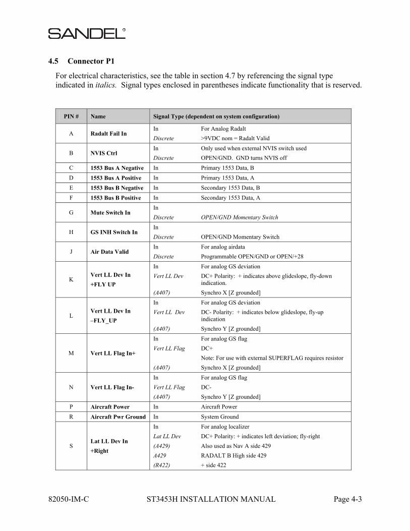
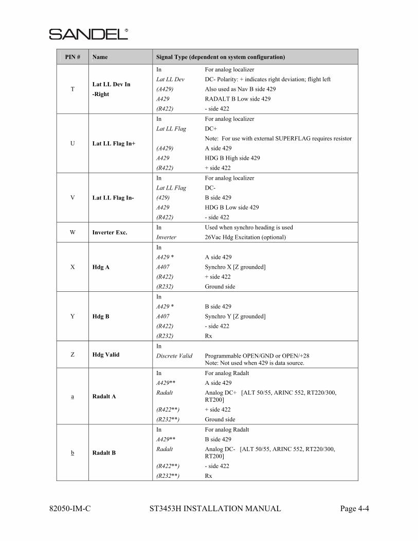
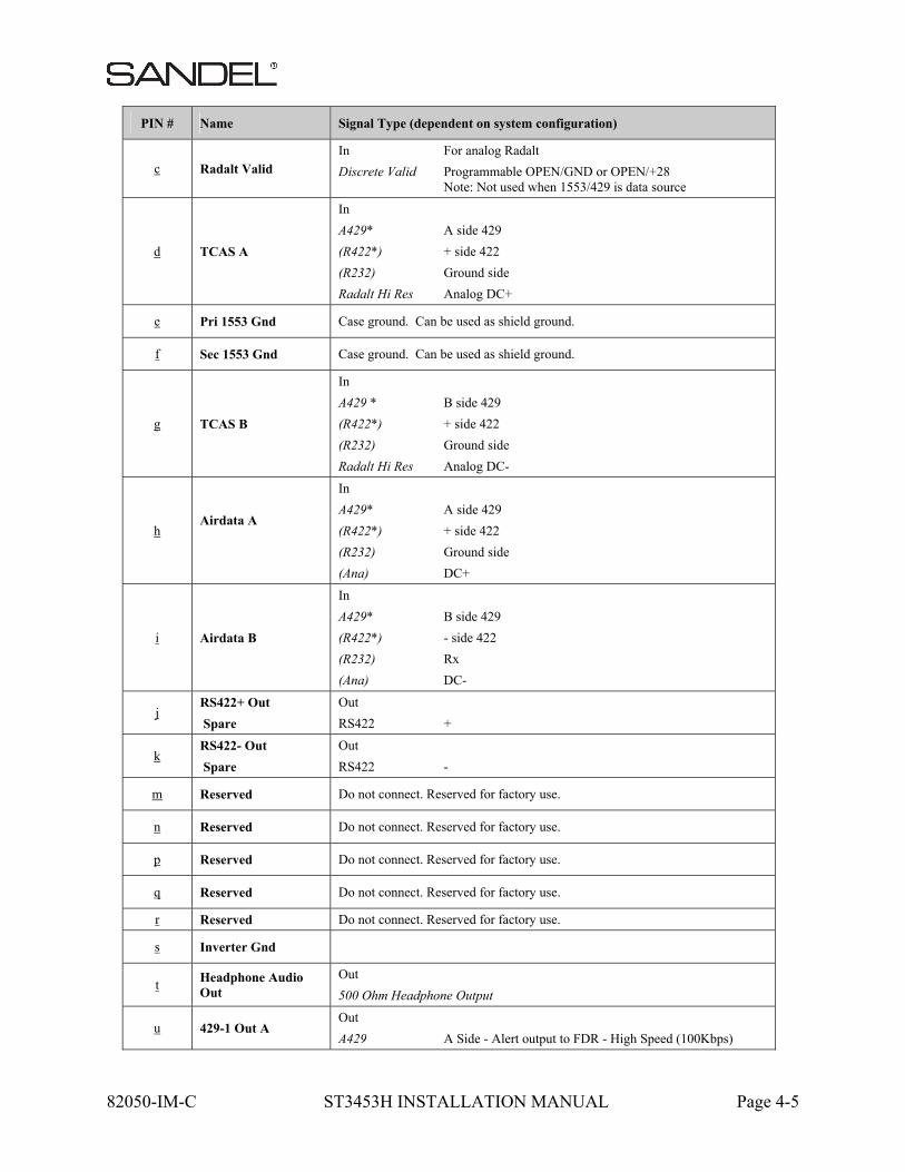
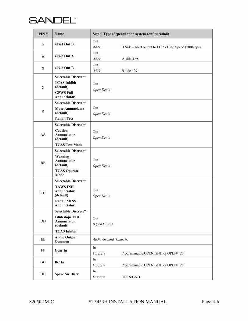
4.5 Connector P1
For electrical characteristics, see the table in section 4.7 by referencing the signal type indicated in italics. Signal types enclosed in parentheses indicate functionality that is reserved.
PIN # Name Signal Type (dependent on system configuration)
A Radalt Fail In In For Analog Radalt
Discrete >9VDC nom = Radalt Valid
B NVIS Ctrl In Only used when external NVIS switch used
Discrete OPEN/GND. GND turns NVIS off
C 1553 Bus A Negative In Primary 1553 Data, B
D 1553 Bus A Positive In Primary 1553 Data, A
E 1553 Bus B Negative In Secondary 1553 Data, B
F 1553 Bus B Positive In Secondary 1553 Data, A
G Mute Switch In In
Discrete OPEN/GND Momentary Switch
H GS INH Switch In In
Discrete OPEN/GND Momentary Switch
J Air Data Valid In For analog airdata
Discrete Programmable OPEN/GND or OPEN/+28
K Vert LL Dev In
+FLY UP
In For analog GS deviation
Vert LL Dev DC+ Polarity: + indicates above glideslope, fly-down indication.
(A407) Synchro X [Z grounded]
L Vert LL Dev In
–FLY_UP
In For analog GS deviation
Vert LL Dev DC- Polarity: + indicates below glideslope, fly-up indication
(A407) Synchro Y [Z grounded]
M Vert LL Flag In+
In For analog GS flag
Vert LL Flag DC+
Note: For use with external SUPERFLAG requires resistor
(A407) Synchro X [Z grounded]
N Vert LL Flag In-
In For analog GS flag
Vert LL Flag DC-
(A407) Synchro Y [Z grounded]
P Aircraft Power In Aircraft Power
R Aircraft Pwr Ground In System Ground
S Lat LL Dev In
+Right
In For analog localizer
Lat LL Dev DC+ Polarity: + indicates left deviation; fly-right
(A429) Also used as Nav A side 429
A429 RADALT B High side 429
(R422) + side 422
82050-IM-C ST3453H INSTALLATION MANUAL Page 4-4
PIN # Name Signal Type (dependent on system configuration)
T Lat LL Dev In
-Right
In For analog localizer
Lat LL Dev DC- Polarity: + indicates right deviation; flight left
(A429) Also used as Nav B side 429
A429 RADALT B Low side 429
(R422) - side 422
U Lat LL Flag In+
In For analog localizer
Lat LL Flag DC+
Note: For use with external SUPERFLAG requires resistor
(A429) A side 429
A429 HDG B High side 429
(R422) + side 422
V Lat LL Flag In-
In For analog localizer
Lat LL Flag DC-
(429) B side 429
A429 HDG B Low side 429
(R422) - side 422
W Inverter Exc. In Used when synchro heading is used
Inverter 26Vac Hdg Excitation (optional)
X Hdg A
In
A429 * A side 429
A407 Synchro X [Z grounded]
(R422) + side 422
(R232) Ground side
Y Hdg B
In
A429 * B side 429
A407 Synchro Y [Z grounded]
(R422) - side 422
(R232) Rx
Z Hdg Valid
In
Discrete Valid Programmable OPEN/GND or OPEN/+28 Note: Not used when 429 is data source.
a Radalt A
In For analog Radalt
A429** A side 429
Radalt Analog DC+ [ALT 50/55, ARINC 552, RT220/300, RT200]
(R422**) + side 422
(R232**) Ground side
b Radalt B
In For analog Radalt
A429** B side 429
Radalt Analog DC- [ALT 50/55, ARINC 552, RT220/300, RT200]
(R422**) - side 422
(R232**) Rx
82050-IM-C ST3453H INSTALLATION MANUAL Page 4-5
PIN # Name Signal Type (dependent on system configuration)
c Radalt Valid
In For analog Radalt
Discrete Valid Programmable OPEN/GND or OPEN/+28 Note: Not used when 1553/429 is data source
d TCAS A
In
A429* A side 429
(R422*) + side 422
(R232) Ground side
Radalt Hi Res Analog DC+
e Pri 1553 Gnd Case ground. Can be used as shield ground.
f Sec 1553 Gnd Case ground. Can be used as shield ground.
g TCAS B
In
A429 * B side 429
(R422*) + side 422
(R232) Ground side
Radalt Hi Res Analog DC-
h Airdata A
In
A429* A side 429
(R422*) + side 422
(R232) Ground side
(Ana) DC+
i Airdata B
In
A429* B side 429
(R422*) - side 422
(R232) Rx
(Ana) DC-
j RS422+ Out
Spare
Out
RS422 +
k RS422- Out
Spare
Out
RS422 -
m Reserved Do not connect. Reserved for factory use.
n Reserved Do not connect. Reserved for factory use.
p Reserved Do not connect. Reserved for factory use.
q Reserved Do not connect. Reserved for factory use.
r Reserved Do not connect. Reserved for factory use.
s Inverter Gnd
t Headphone Audio Out
Out
500 Ohm Headphone Output
u 429-1 Out A Out
A429 A Side - Alert output to FDR - High Speed (100Kbps)
82050-IM-C ST3453H INSTALLATION MANUAL Page 4-6
PIN # Name Signal Type (dependent on system configuration)
v 429-1 Out B Out
A429 B Side - Alert output to FDR - High Speed (100Kbps)
w 429-2 Out A Out
A429 A side 429
x 429-2 Out B Out
A429 B side 429
y
Selectable Discrete*
TCAS Inhibit (default)
GPWS Fail Annunciator
Out
Open Drain
z
Selectable Discrete*
Mute Annunciator (default)
Radalt Test
Out
Open Drain
AA
Selectable Discrete*
Caution Annunciator (default)
TCAS Test Mode
Out
Open Drain
BB
Selectable Discrete*
Warning Annunciator (default)
TCAS Operate Mode
Out
Open Drain
CC
Selectable Discrete*
TAWS INH Annunciator (default)
Radalt MINS Annunciator
Out
Open Drain
DD
Selectable Discrete*
Glideslope INH Annunciator (default)
TCAS Inhibit
Out
(Open Drain)
EE Audio Output Common
Audio Ground (Chassis)
FF Gear In In
Discrete Programmable OPEN/GND or OPEN/+28
GG BC In In
Discrete Programmable OPEN/GND or OPEN/+28
HH Spare Sw Discr In
Discrete OPEN/GND
82050-IM-C ST3453H INSTALLATION MANUAL Page 4-7
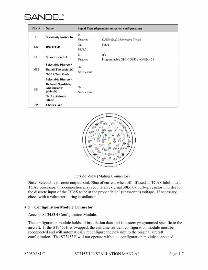
PIN # Name Signal Type (dependent on system configuration)
JJ Sensitivity Switch In In
Discrete OPEN/GND Momentary Switch
KK RS232TxD Out Spare
RS232
LL Spare Discrete 1 In n/c
Discrete Programmable OPEN/GND or OPEN/+28
MM
Selectable Discrete*
Radalt Test (default)
TCAS Test Mode
Out
Open Drain
NN
Selectable Discrete*
Reduced Sensitivity Annunciator (default)
TCAS Altitude Mode
Out
Open Drain
PP Chassis Gnd
Outside View (Mating Connector)
Note: Selectable discrete outputs sink 50ua of current when off. If used as TCAS Inhibit to a TCAS processor, this connection may require an external 30k-50k pull-up resistor in order for the discrete input of the TCAS to be at the proper ‘high’ (unasserted) voltage. If necessary, check with a voltmeter during installation.
4.6 Configuration Module Connector
Accepts ST3453H Configuration Module.
The configuration module holds all installation data and is custom programmed specific to the aircraft. If the ST3453H is swapped, the airframe resident configuration module must be reconnected and will automatically reconfigure the new unit to the original aircraft configuration. The ST3453H will not operate without a configuration module connected.
82050-IM-C ST3453H INSTALLATION MANUAL Page 4-8
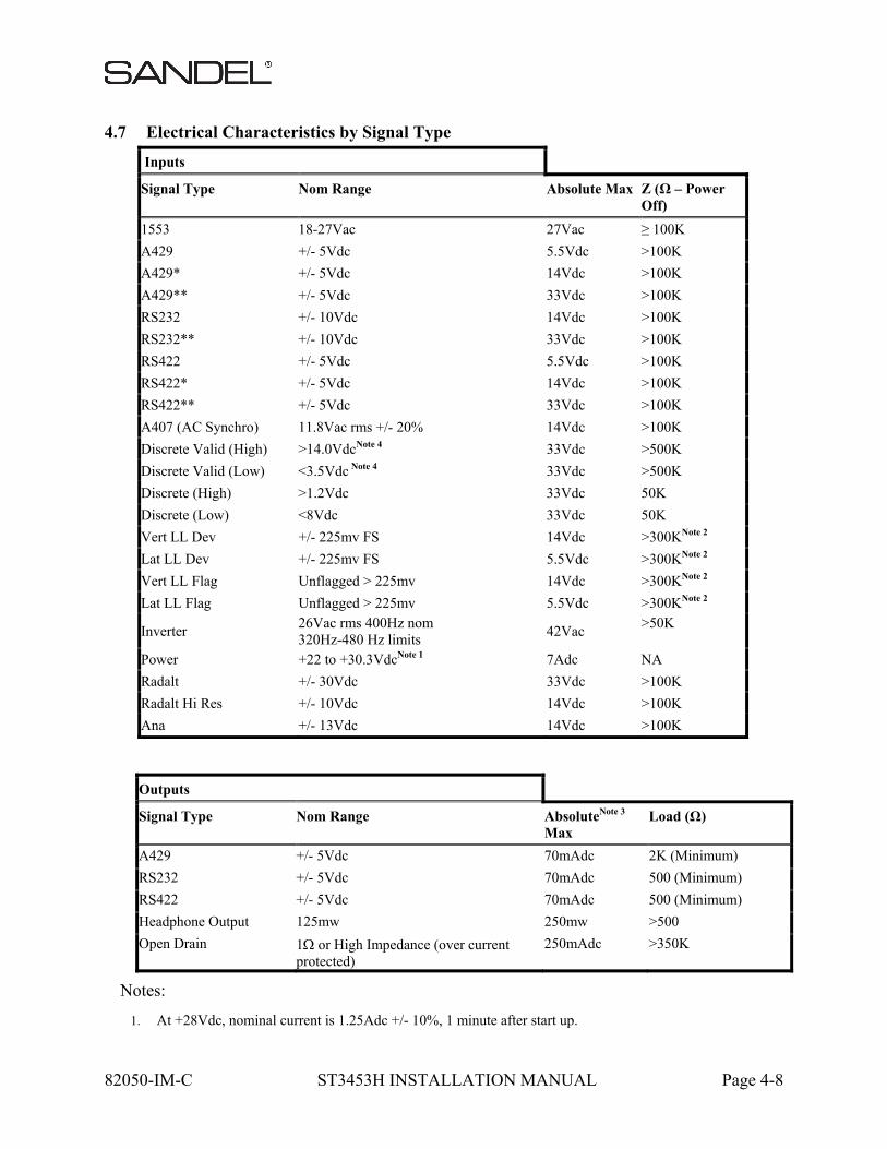
4.7 Electrical Characteristics by Signal Type
Inputs
Signal Type Nom Range Absolute Max Z (Ω – Power Off)
1553 18-27Vac 27Vac ≥ 100K
A429 +/- 5Vdc 5.5Vdc >100K
A429* +/- 5Vdc 14Vdc >100K
A429** +/- 5Vdc 33Vdc >100K
RS232 +/- 10Vdc 14Vdc >100K
RS232** +/- 10Vdc 33Vdc >100K
RS422 +/- 5Vdc 5.5Vdc >100K
RS422* +/- 5Vdc 14Vdc >100K
RS422** +/- 5Vdc 33Vdc >100K
A407 (AC Synchro) 11.8Vac rms +/- 20% 14Vdc >100K
Discrete Valid (High) >14.0VdcNote 4 33Vdc >500K
Discrete Valid (Low) <3.5Vdc Note 4 33Vdc >500K
Discrete (High) >1.2Vdc 33Vdc 50K
Discrete (Low) <8Vdc 33Vdc 50K
Vert LL Dev +/- 225mv FS 14Vdc >300KNote 2
Lat LL Dev +/- 225mv FS 5.5Vdc >300KNote 2
Vert LL Flag Unflagged > 225mv 14Vdc >300KNote 2
Lat LL Flag Unflagged > 225mv 5.5Vdc >300KNote 2
Inverter 26Vac rms 400Hz nom 320Hz-480 Hz limits
42Vac >50K
Power +22 to +30.3VdcNote 1 7Adc NA
Radalt +/- 30Vdc 33Vdc >100K
Radalt Hi Res +/- 10Vdc 14Vdc >100K
Ana +/- 13Vdc 14Vdc >100K
Outputs
Signal Type Nom Range AbsoluteNote 3 Max
Load (Ω)
A429 +/- 5Vdc 70mAdc 2K (Minimum)
RS232 +/- 5Vdc 70mAdc 500 (Minimum)
RS422 +/- 5Vdc 70mAdc 500 (Minimum)
Headphone Output 125mw 250mw >500
Open Drain 1 or High Impedance (over current protected)
250mAdc >350K
Notes:
1. At +28Vdc, nominal current is 1.25Adc +/- 10%, 1 minute after start up.

82050-IM-C ST3453H INSTALLATION MANUAL Page 4-9
2. Power On Load = 60.4K. For Vert/Lat Deviation there may need to be a 1K load somewhere else in the system to meet the receiver load requirements. Check installation instructions for the interfaced receiver.
3. Outputs are protected against shorts to ground. Shorts to power supply may cause damage to components.
4. Discrete inputs actively pulled to 27.5v through 30k ohms when selected ‘active low’ or actively pulled to 0v through 30k ohms when selected ‘active high’ in the maintenance pages. This ensures the input is in the ‘inactive’ state if an external connection fails. If interfacing to discrete signals which do not supply a “hard” 0Vdc/27.5Vdc transition, any input network may be used that ensures that the discrete input pin is not within 1.0v from its nominal threshold shown in the table either in the active or inactive state.
5. All discrete outputs sink 50ua current when off.

82050-IM-C ST3453H INSTALLATION MANUAL Page 5-1
5 SETUP PROCEDURES
5.1 General
Setup procedures for the ST3453H are described along with the Maintenance menu below. The Maintenance Menu is accessed and addressed through the use of pushbuttons and the BRT/MINs knob. No external connector programming is required.
5.2 Accessing Maintenance Menus
To access the Maintenance Menus perform the following operations:
Prior to applying power to the ST3453H, depress and hold the [MUTE] and [SENS] pushbuttons, then apply power to the unit. Continue to hold until the first maintenance menu appears – this may take approximately 60 seconds.
Once the Maintenance Menu is entered, press the [NEXT] or [PREV] soft-keys to cycle the MAINTENANCE MENU pages. To jump to a specific page, from the INDEX page, press the [UP] or [DOWN] soft-keys or rotate the BRT/MINS knob to move the cursor. Press the [SELECT] soft-key to jump to that page. On some menus additional soft-key legends will appear as prompts.
Escape the maintenance menus by pressing and holding the “M” button. This will allow normal operation of the unit to test the effects of the settings. Re-enter the maintenance pages by pressing and holding the “M” button.
To disable the maintenance menu operation, power down and restart normally. All configured items are stored in non-volatile memory.
5.3 Locked Items
Items may be custom programmed from the factory and therefore are locked. Locked items on the maintenance pages are not editable. These locked items appear in gray text.
5.4 Equipment/Configuration Selections
The choices of compatible equipment contained in the ST3453H menus are listed in section 6. For types not listed, consult the factory.
5.5 Configuration Module
The Configuration Module (CM) stores installation configurations. The physical Configuration Module is directly mounted to the rear of the instrument. A configuration module is required and must be used when installing a new ST3453H or replacing an existing ST3453H.
82050-IM-C ST3453H INSTALLATION MANUAL Page 5-2
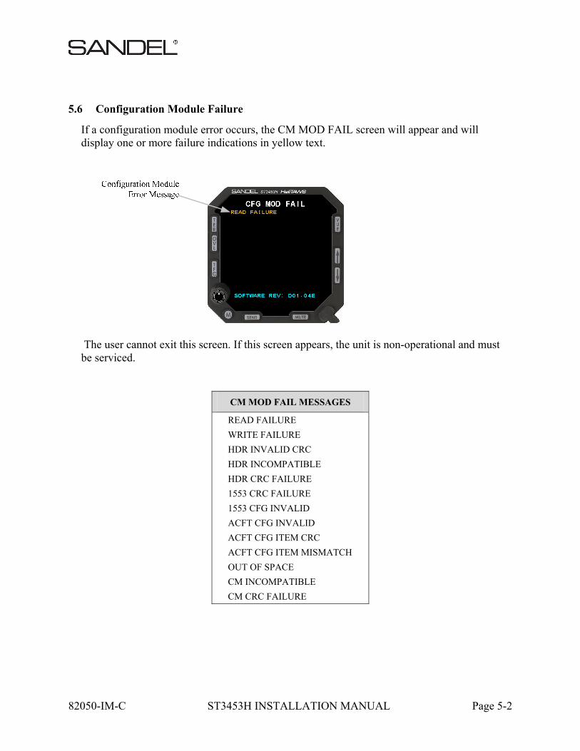
5.6 Configuration Module Failure
If a configuration module error occurs, the CM MOD FAIL screen will appear and will display one or more failure indications in yellow text.
The user cannot exit this screen. If this screen appears, the unit is non-operational and must be serviced.
CM MOD FAIL MESSAGES
READ FAILURE
WRITE FAILURE
HDR INVALID CRC
HDR INCOMPATIBLE
HDR CRC FAILURE
1553 CRC FAILURE
1553 CFG INVALID
ACFT CFG INVALID
ACFT CFG ITEM CRC
ACFT CFG ITEM MISMATCH
OUT OF SPACE
CM INCOMPATIBLE
CM CRC FAILURE

82050-IM-C ST3453H INSTALLATION MANUAL Page 5-3
5.7 Fatal System Error
If the ST3453H displays a fatal system error message screen, the unit must be restarted. This message will occur only during startup and may be caused by one of the reasons listed below. If the message persists, the unit should not be used. Report the message and accompanying cause (if displayed) to maintenance.

82050-IM-C ST3453H INSTALLATION MANUAL Page 6-1
6 POST INSTALLATION PROCEDURES
After all wiring has been verified and the ST3453H has been installed into the panel, the maintenance pages must be accessed to properly configure the ST3453H for the installed equipment. Prior to applying power to the ST3453H, press and hold the [MUTE] and [SENS] buttons, and then apply power to the unit. Continue to press the buttons until the first maintenance menu appears – this may take approximately 60 seconds.
Depending on the configuration module P/N, maintenance items may be locked (i.e. preconfigured source selection). Configuration items that are locked will appear in gray text and soft keys used for editing or setting the configuration item will be removed from the display.
Locked Configuration
Item
Once the Maintenance Menu is entered, press the [NEXT] or [PREV] soft-keys to cycle the MAINTENANCE MENU pages. To jump to a specific page, from the INDEX page, press the [UP] or [DOWN] soft-key or rotate the knob to move the cursor. Press the [SELECT] soft-key to jump to that page. On some menus additional soft-key legends will appear as prompts.
Escape the maintenance menus by pressing and holding the “M” button. This will allow normal operation of the unit to test the effects of the settings. Re-enter the maintenance pages by pressing and holding the “M” button.
To disable the maintenance menu operation, power down and restart normally. All configured items are stored in non-volatile memory.
NOTE: Maintenance page depictions shown in the following pages of section 6 are representative of the actual maintenance pages. Because of the presence or absence of equipment installed in your aircraft or the CM configuration specified at the time of your purchase, the maintenance pages in your ST3453H may be configured differently.

82050-IM-C ST3453H INSTALLATION MANUAL Page 6-2
The Maintenance Page Number/Title is displayed on every maintenance page showing the maintenance page number and title.
The Cursor points to the item, which may be modified or selected. If there are no selectable items on the currently displayed maintenance page, the Current Line Indicator is not displayed.
The [UP] and [DOWN] soft-keys are used to move the through the list. The soft-keys are labeled to convey the context sensitive function of each button as
required.
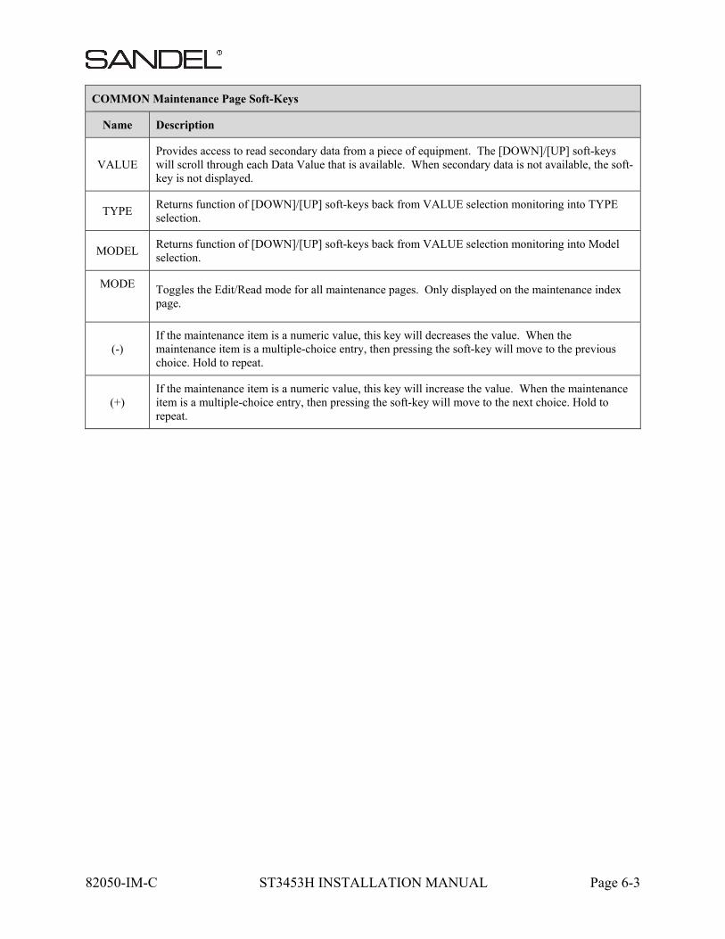
COMMON Maintenance Page Soft-Keys
Name Description
PREV Returns to the prior maintenance page. When the first maintenance page is being displayed, moves to the last maintenance page.
NEXT Advances to the next maintenance page. When the last maintenance page is being displayed, then moves to the first maintenance page.
SELECT From the index page, jump directly to the indicated page.
OPER From a maintenance page, When pressed once, will jump to the Maintenance Index page. When pressed and held in, will transition into the Flight Operation display.
MAINT From a flight operations, return to the Maintenance Index page. The Cursor will point to the maintenance page listing that was displayed prior to transitioning to the Flight Operation display.
UP Moves the Cursor to the previous (up) selectable item. Hold key down to automatically repeat. When there are no selectable items, the key is disabled.
DOWN Moves the Cursor to the next (down) selectable item. Hold key down to automatically repeat. When there are no selectable items, the key is disabled.
82050-IM-C ST3453H INSTALLATION MANUAL Page 6-3
COMMON Maintenance Page Soft-Keys
Name Description
VALUE Provides access to read secondary data from a piece of equipment. The [DOWN]/[UP] soft-keys will scroll through each Data Value that is available. When secondary data is not available, the soft-key is not displayed.
TYPE Returns function of [DOWN]/[UP] soft-keys back from VALUE selection monitoring into TYPE selection.
MODEL Returns function of [DOWN]/[UP] soft-keys back from VALUE selection monitoring into Model selection.
MODE
Toggles the Edit/Read mode for all maintenance pages. Only displayed on the maintenance index page.
(-) If the maintenance item is a numeric value, this key will decreases the value. When the maintenance item is a multiple-choice entry, then pressing the soft-key will move to the previous choice. Hold to repeat.
(+) If the maintenance item is a numeric value, this key will increase the value. When the maintenance item is a multiple-choice entry, then pressing the soft-key will move to the next choice. Hold to repeat.
82050-IM-C ST3453H INSTALLATION MANUAL Page 6-4
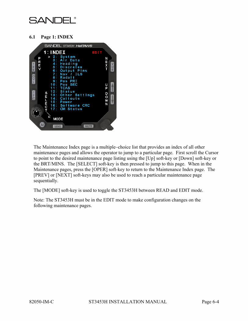
6.1 Page 1: INDEX
The Maintenance Index page is a multiple–choice list that provides an index of all other maintenance pages and allows the operator to jump to a particular page. First scroll the Cursor to point to the desired maintenance page listing using the [Up] soft-key or [Down] soft-key or the BRT/MINS. The [SELECT] soft-key is then pressed to jump to this page. When in the Maintenance pages, press the [OPER] soft-key to return to the Maintenance Index page. The [PREV] or [NEXT] soft-keys may also be used to reach a particular maintenance page sequentially.
The [MODE] soft-key is used to toggle the ST3453H between READ and EDIT mode.
Note: The ST3453H must be in the EDIT mode to make configuration changes on the following maintenance pages.
82050-IM-C ST3453H INSTALLATION MANUAL Page 6-5
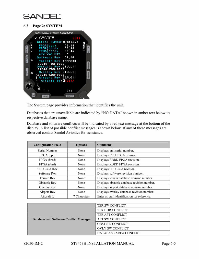
6.2 Page 2: SYSTEM
The System page provides information that identifies the unit.
Databases that are unavailable are indicated by “NO DATA” shown in amber text below its respective database name.
Database and software conflicts will be indicated by a red text message at the bottom of the display. A list of possible conflict messages is shown below. If any of these messages are observed contact Sandel Avionics for assistance.
Configuration Field Options Comment
Serial Number None Displays unit serial number.
FPGA (cpu) None Displays CPU FPGA revision.
FPGA (bbrd) None Displays BBRD FPGA revision.
FPGA (rbrd) None Displays RBRD FPGA revision.
CPU CCA Rev None Displays CPU CCA revision.
Software Rev None Displays software revision number.
Terrain Rev None Displays terrain database revision number.
Obstacle Rev None Displays obstacle database revision number.
Overlay Rev None Displays airport database revision number.
Airport Rev None Displays overlay database revision number.
Aircraft Id 7 Characters Enter aircraft identification for reference.
Database and Software Conflict Messages
TER SW CONFLICT
TER HDR CONFLICT
TER APT CONFLICT
APT SW CONFLICT
OBST SW CONFLICT
OVLY SW CONFLICT
DATABASE AREA CONFLICT
82050-IM-C ST3453H INSTALLATION MANUAL Page 6-6
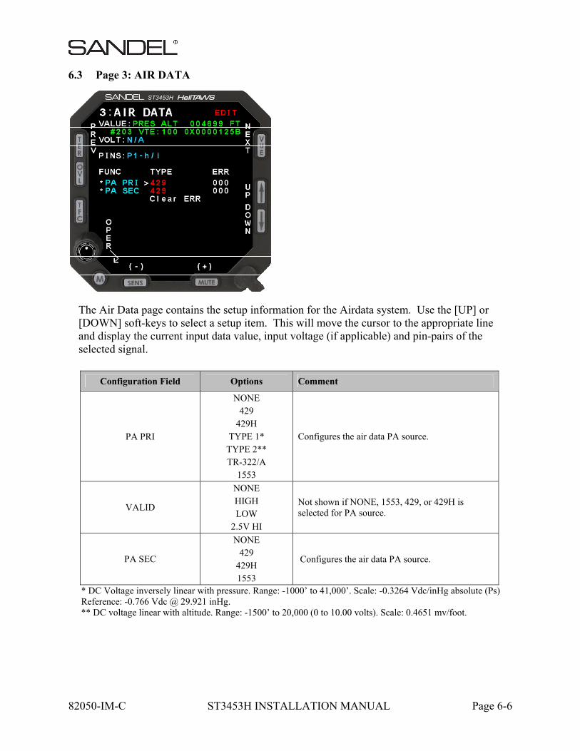
6.3 Page 3: AIR DATA
The Air Data page contains the setup information for the Airdata system. Use the [UP] or [DOWN] soft-keys to select a setup item. This will move the cursor to the appropriate line and display the current input data value, input voltage (if applicable) and pin-pairs of the selected signal.
* DC Voltage inversely linear with pressure. Range: -1000’ to 41,000’. Scale: -0.3264 Vdc/inHg absolute (Ps) Reference: -0.766 Vdc @ 29.921 inHg. ** DC voltage linear with altitude. Range: -1500’ to 20,000 (0 to 10.00 volts). Scale: 0.4651 mv/foot.
Configuration Field Options Comment
PA PRI
NONE 429
429H TYPE 1*
TYPE 2** TR-322/A
1553
Configures the air data PA source.
VALID
NONE HIGH LOW
2.5V HI
Not shown if NONE, 1553, 429, or 429H is selected for PA source.
PA SEC
NONE 429
429H 1553
Configures the air data PA source.
82050-IM-C ST3453H INSTALLATION MANUAL Page 6-7
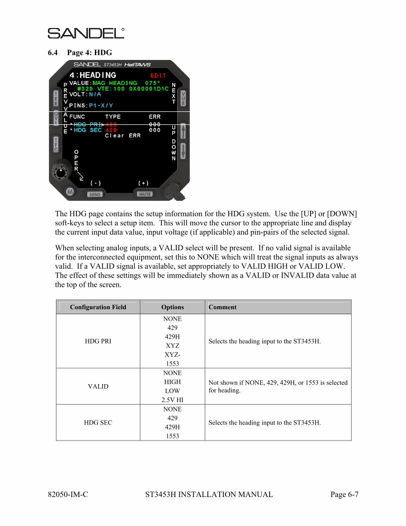
6.4 Page 4: HDG
The HDG page contains the setup information for the HDG system. Use the [UP] or [DOWN] soft-keys to select a setup item. This will move the cursor to the appropriate line and display the current input data value, input voltage (if applicable) and pin-pairs of the selected signal.
When selecting analog inputs, a VALID select will be present. If no valid signal is available for the interconnected equipment, set this to NONE which will treat the signal inputs as always valid. If a VALID signal is available, set appropriately to VALID HIGH or VALID LOW. The effect of these settings will be immediately shown as a VALID or INVALID data value at the top of the screen.
Configuration Field Options Comment
HDG PRI
NONE 429
429H XYZ XYZ- 1553
Selects the heading input to the ST3453H.
VALID
NONE HIGH LOW
2.5V HI
Not shown if NONE, 429, 429H, or 1553 is selected for heading.
HDG SEC
NONE 429
429H 1553
Selects the heading input to the ST3453H.
82050-IM-C ST3453H INSTALLATION MANUAL Page 6-8
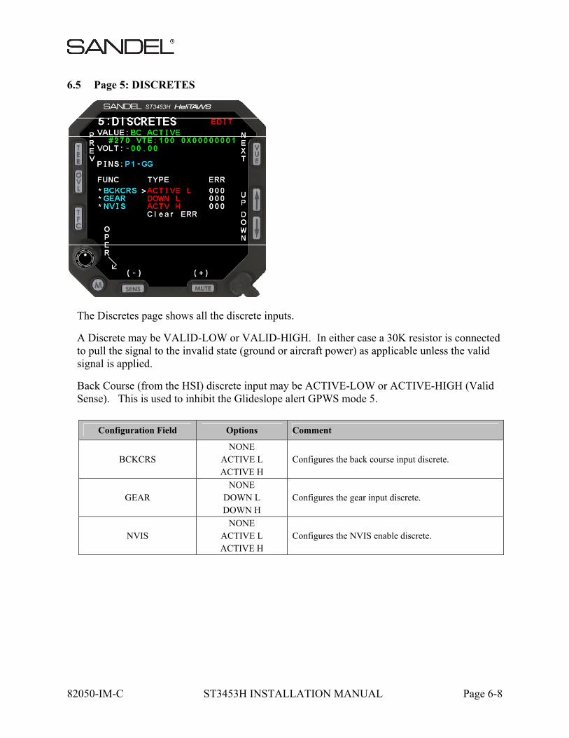
6.5 Page 5: DISCRETES
The Discretes page shows all the discrete inputs.
A Discrete may be VALID-LOW or VALID-HIGH. In either case a 30K resistor is connected to pull the signal to the invalid state (ground or aircraft power) as applicable unless the valid signal is applied.
Back Course (from the HSI) discrete input may be ACTIVE-LOW or ACTIVE-HIGH (Valid Sense). This is used to inhibit the Glideslope alert GPWS mode 5.
Configuration Field Options Comment
BCKCRS NONE
ACTIVE L ACTIVE H
Configures the back course input discrete.
GEAR NONE
DOWN L DOWN H
Configures the gear input discrete.
NVIS NONE
ACTIVE L ACTIVE H
Configures the NVIS enable discrete.
82050-IM-C ST3453H INSTALLATION MANUAL Page 6-9
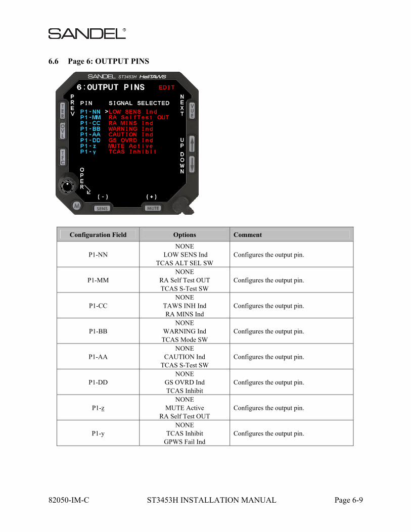
6.6 Page 6: OUTPUT PINS
Configuration Field Options Comment
P1-NN NONE
LOW SENS Ind TCAS ALT SEL SW
Configures the output pin.
P1-MM NONE
RA Self Test OUT TCAS S-Test SW
Configures the output pin.
P1-CC NONE
TAWS INH Ind RA MINS Ind
Configures the output pin.
P1-BB NONE
WARNING Ind TCAS Mode SW
Configures the output pin.
P1-AA NONE
CAUTION Ind TCAS S-Test SW
Configures the output pin.
P1-DD NONE
GS OVRD Ind TCAS Inhibit
Configures the output pin.
P1-z NONE
MUTE Active RA Self Test OUT
Configures the output pin.
P1-y NONE
TCAS Inhibit GPWS Fail Ind
Configures the output pin.
82050-IM-C ST3453H INSTALLATION MANUAL Page 6-10
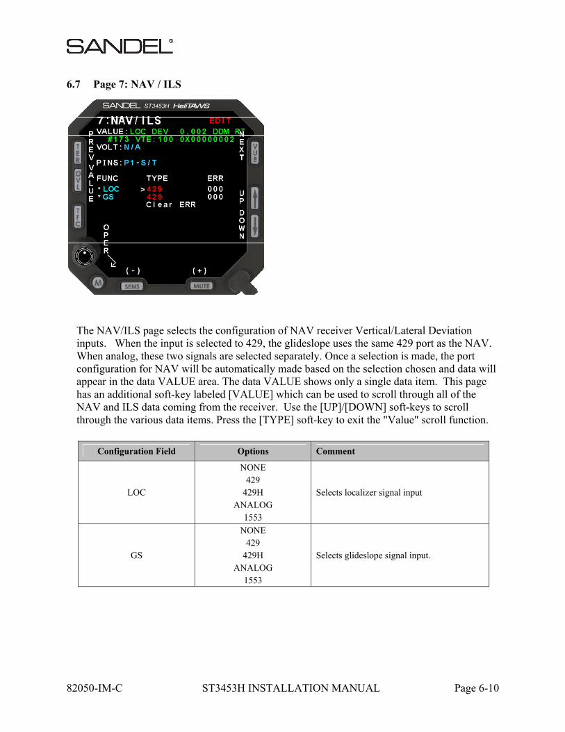
6.7 Page 7: NAV / ILS
The NAV/ILS page selects the configuration of NAV receiver Vertical/Lateral Deviation inputs. When the input is selected to 429, the glideslope uses the same 429 port as the NAV. When analog, these two signals are selected separately. Once a selection is made, the port configuration for NAV will be automatically made based on the selection chosen and data will appear in the data VALUE area. The data VALUE shows only a single data item. This page has an additional soft-key labeled [VALUE] which can be used to scroll through all of the NAV and ILS data coming from the receiver. Use the [UP]/[DOWN] soft-keys to scroll through the various data items. Press the [TYPE] soft-key to exit the "Value" scroll function.
Configuration Field Options Comment
LOC
NONE 429
429H ANALOG
1553
Selects localizer signal input
GS
NONE 429
429H ANALOG
1553
Selects glideslope signal input.

82050-IM-C ST3453H INSTALLATION MANUAL Page 6-11
6.8 Page 8: RADALT
The Radalt page selects the configuration of Radar altimeter input. If no Radar altimeter is installed set configuration of RALT to NONE.
Radar altimeters are selected by equipment type, i.e. ALT55 for Collins ALT55 altimeter, etc.
Once the equipment is selected, the Radar altitude can be read from the data VALUE line to check for correct operation.
For analog inputs, a corresponding VALID input is present. Ensure that this item is VALID during normal operation and INVALID during TEST of the RA or when the RA is powered off.
For some configurations, RA and MINS indications are not displayed to the flight crew.
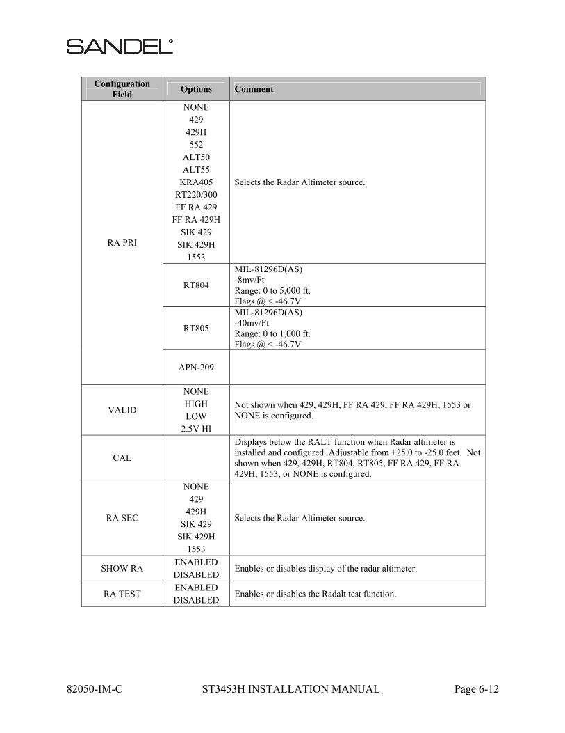
82050-IM-C ST3453H INSTALLATION MANUAL Page 6-12
Configuration Field
Options Comment
RA PRI
NONE 429
429H 552
ALT50 ALT55
KRA405 RT220/300 FF RA 429
FF RA 429H SIK 429
SIK 429H 1553
Selects the Radar Altimeter source.
RT804
MIL-81296D(AS) -8mv/Ft Range: 0 to 5,000 ft. Flags @ < -46.7V
RT805
MIL-81296D(AS) -40mv/Ft Range: 0 to 1,000 ft. Flags @ < -46.7V
APN-209
VALID
NONE HIGH LOW
2.5V HI
Not shown when 429, 429H, FF RA 429, FF RA 429H, 1553 or NONE is configured.
CAL
Displays below the RALT function when Radar altimeter is installed and configured. Adjustable from +25.0 to -25.0 feet. Not shown when 429, 429H, RT804, RT805, FF RA 429, FF RA 429H, 1553, or NONE is configured.
RA SEC
NONE 429
429H SIK 429
SIK 429H 1553
Selects the Radar Altimeter source.
SHOW RA ENABLED DISABLED
Enables or disables display of the radar altimeter.
RA TEST ENABLED DISABLED
Enables or disables the Radalt test function.

82050-IM-C ST3453H INSTALLATION MANUAL Page 6-13
82050-IM-C ST3453H INSTALLATION MANUAL Page 6-14
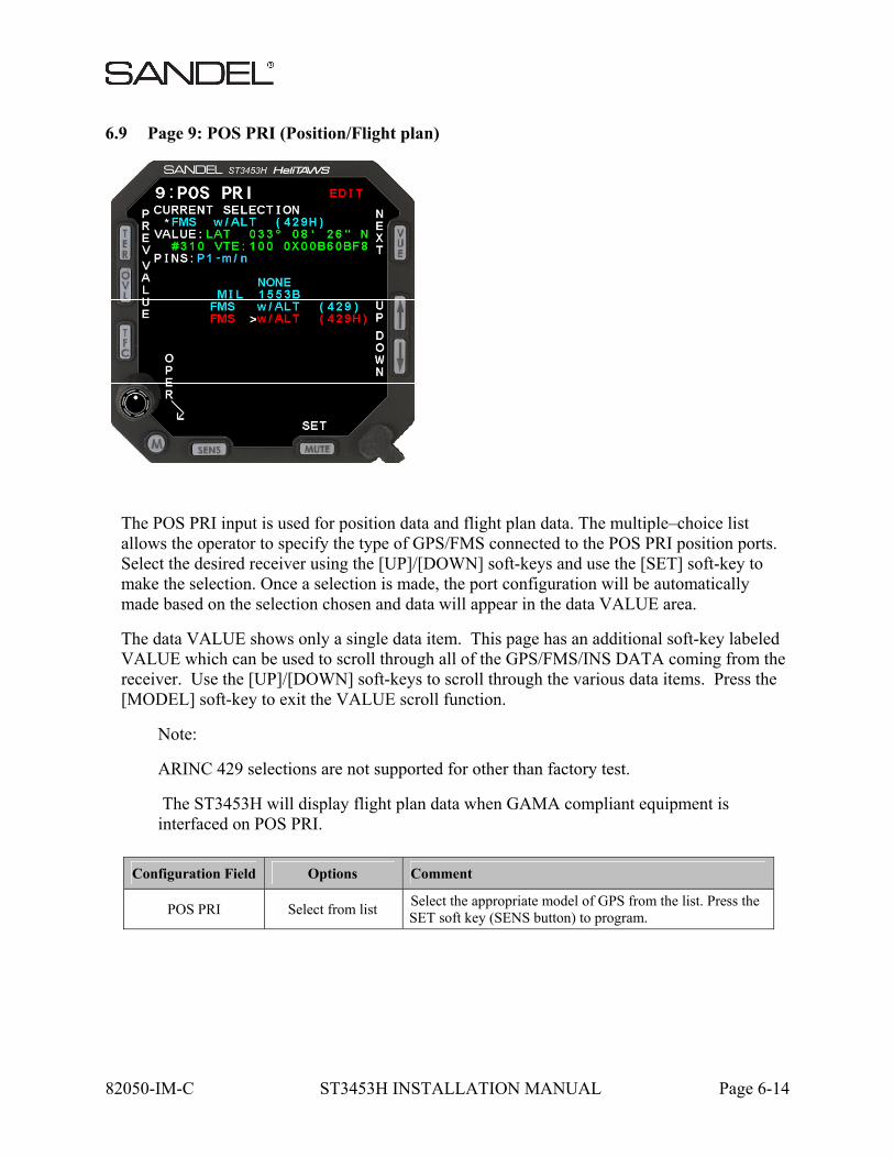
6.9 Page 9: POS PRI (Position/Flight plan)
The POS PRI input is used for position data and flight plan data. The multiple–choice list allows the operator to specify the type of GPS/FMS connected to the POS PRI position ports. Select the desired receiver using the [UP]/[DOWN] soft-keys and use the [SET] soft-key to make the selection. Once a selection is made, the port configuration will be automatically made based on the selection chosen and data will appear in the data VALUE area.
The data VALUE shows only a single data item. This page has an additional soft-key labeled VALUE which can be used to scroll through all of the GPS/FMS/INS DATA coming from the receiver. Use the [UP]/[DOWN] soft-keys to scroll through the various data items. Press the [MODEL] soft-key to exit the VALUE scroll function.
Note:
ARINC 429 selections are not supported for other than factory test.
The ST3453H will display flight plan data when GAMA compliant equipment is interfaced on POS PRI.
Configuration Field Options Comment
POS PRI Select from list Select the appropriate model of GPS from the list. Press the SET soft key (SENS button) to program.
82050-IM-C ST3453H INSTALLATION MANUAL Page 6-15
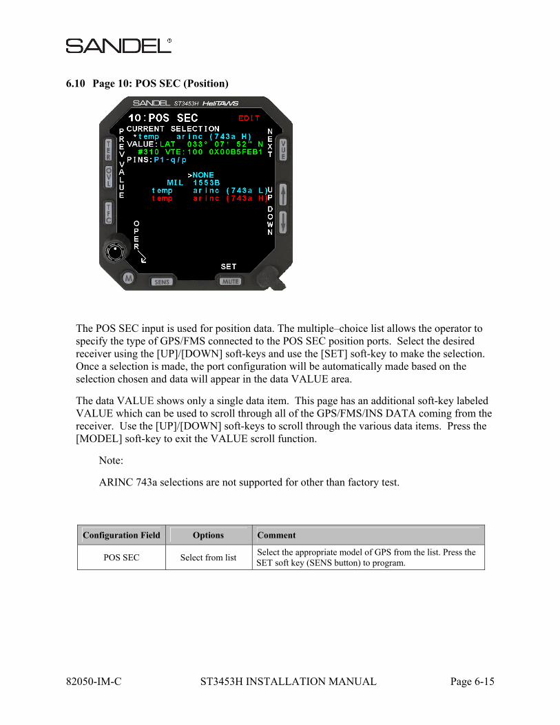
6.10 Page 10: POS SEC (Position)
The POS SEC input is used for position data. The multiple–choice list allows the operator to specify the type of GPS/FMS connected to the POS SEC position ports. Select the desired receiver using the [UP]/[DOWN] soft-keys and use the [SET] soft-key to make the selection. Once a selection is made, the port configuration will be automatically made based on the selection chosen and data will appear in the data VALUE area.
The data VALUE shows only a single data item. This page has an additional soft-key labeled VALUE which can be used to scroll through all of the GPS/FMS/INS DATA coming from the receiver. Use the [UP]/[DOWN] soft-keys to scroll through the various data items. Press the [MODEL] soft-key to exit the VALUE scroll function.
Note:
ARINC 743a selections are not supported for other than factory test.
Configuration Field Options Comment
POS SEC Select from list Select the appropriate model of GPS from the list. Press the SET soft key (SENS button) to program.

82050-IM-C ST3453H INSTALLATION MANUAL Page 6-16
6.11 Page 11: TCAS
The TCAS page shows selections available for Traffic.
The multiple–choice list allows the operator to specify the type of Traffic processor connected to the Traffic port. Select using the [UP]/[DOWN] soft-keys and use the [SET] soft-key to make the selection.
Once a selection is made, the port configuration for Traffic will be automatically made based on the selection chosen and data will appear in the data VALUE area. When the TCAS selection is set to NONE, the TCAS KEY text will not be displayed and the VALUE field will be blank.
This page has an additional soft-key labeled VALUE which can be used to scroll through all of the TCAS DATA coming from the processor. Use the [UP]/[DOWN] soft-keys to scroll through the various data items. Press the [MODEL] soft-key to exit the VALUE scroll function.
The MORE indicator indicates more choices than the listings currently displayed on the screen. An arrow pointing down indicates that more choices exist below the last listing currently being displayed.
82050-IM-C ST3453H INSTALLATION MANUAL Page 6-17
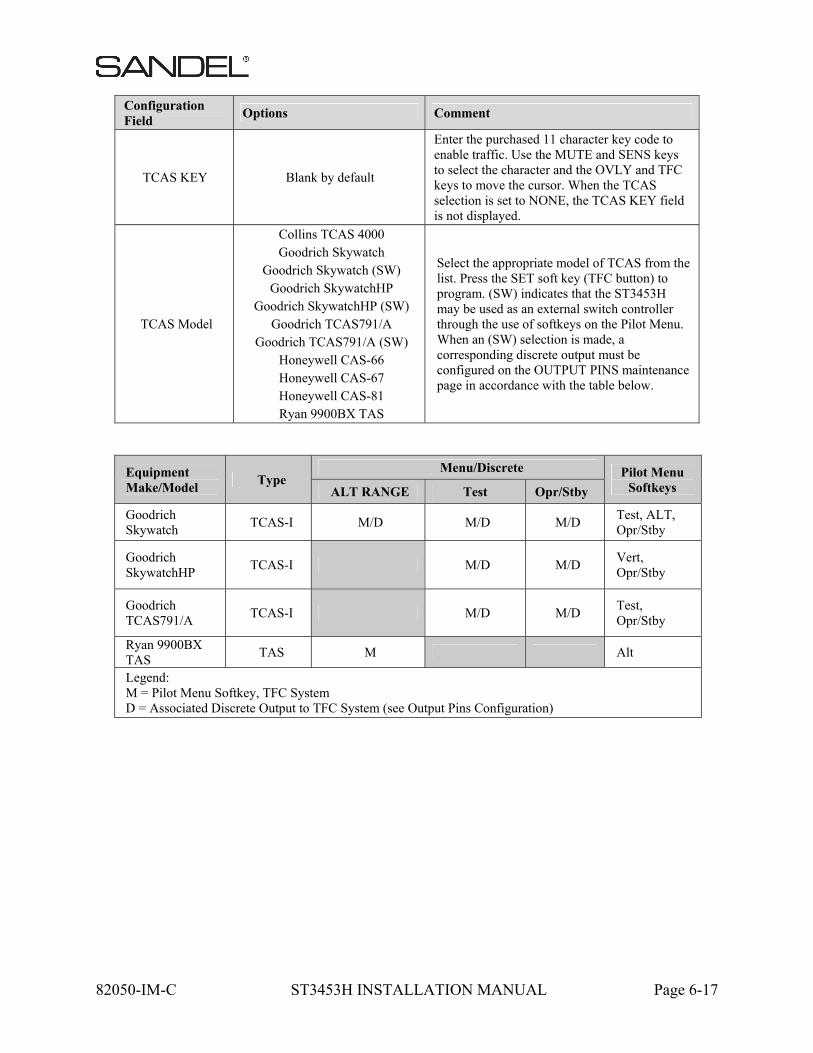
Configuration Field
Options Comment
TCAS KEY Blank by default
Enter the purchased 11 character key code to enable traffic. Use the MUTE and SENS keys to select the character and the OVLY and TFC keys to move the cursor. When the TCAS selection is set to NONE, the TCAS KEY field is not displayed.
TCAS Model
Collins TCAS 4000 Goodrich Skywatch
Goodrich Skywatch (SW) Goodrich SkywatchHP
Goodrich SkywatchHP (SW) Goodrich TCAS791/A
Goodrich TCAS791/A (SW) Honeywell CAS-66 Honeywell CAS-67 Honeywell CAS-81 Ryan 9900BX TAS
Select the appropriate model of TCAS from the list. Press the SET soft key (TFC button) to program. (SW) indicates that the ST3453H may be used as an external switch controller through the use of softkeys on the Pilot Menu. When an (SW) selection is made, a corresponding discrete output must be configured on the OUTPUT PINS maintenance page in accordance with the table below.
Equipment Make/Model
Type Menu/Discrete Pilot Menu
Softkeys ALT RANGE Test Opr/Stby
Goodrich Skywatch
TCAS-I M/D M/D M/D Test, ALT, Opr/Stby
Goodrich SkywatchHP
TCAS-I M/D M/D Vert, Opr/Stby
Goodrich TCAS791/A
TCAS-I M/D M/D Test, Opr/Stby
Ryan 9900BX TAS
TAS M Alt
Legend: M = Pilot Menu Softkey, TFC System D = Associated Discrete Output to TFC System (see Output Pins Configuration)
82050-IM-C ST3453H INSTALLATION MANUAL Page 6-18
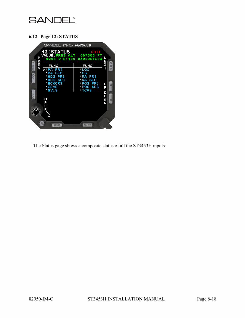
6.12 Page 12: STATUS
The Status page shows a composite status of all the ST3453H inputs.
82050-IM-C ST3453H INSTALLATION MANUAL Page 6-19
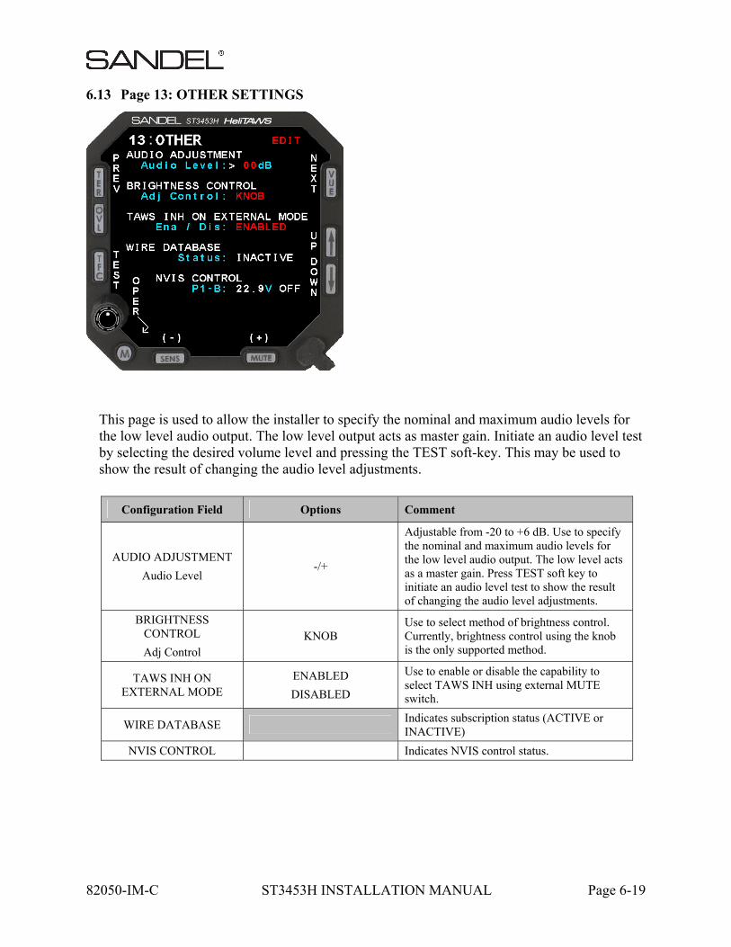
6.13 Page 13: OTHER SETTINGS
This page is used to allow the installer to specify the nominal and maximum audio levels for the low level audio output. The low level output acts as master gain. Initiate an audio level test by selecting the desired volume level and pressing the TEST soft-key. This may be used to show the result of changing the audio level adjustments.
Configuration Field Options Comment
AUDIO ADJUSTMENT
Audio Level -/+
Adjustable from -20 to +6 dB. Use to specify the nominal and maximum audio levels for the low level audio output. The low level acts as a master gain. Press TEST soft key to initiate an audio level test to show the result of changing the audio level adjustments.
BRIGHTNESS CONTROL
Adj Control KNOB
Use to select method of brightness control. Currently, brightness control using the knob is the only supported method.
TAWS INH ON EXTERNAL MODE
ENABLED
DISABLED
Use to enable or disable the capability to select TAWS INH using external MUTE switch.
WIRE DATABASE Indicates subscription status (ACTIVE or INACTIVE)
NVIS CONTROL Indicates NVIS control status.
82050-IM-C ST3453H INSTALLATION MANUAL Page 6-20
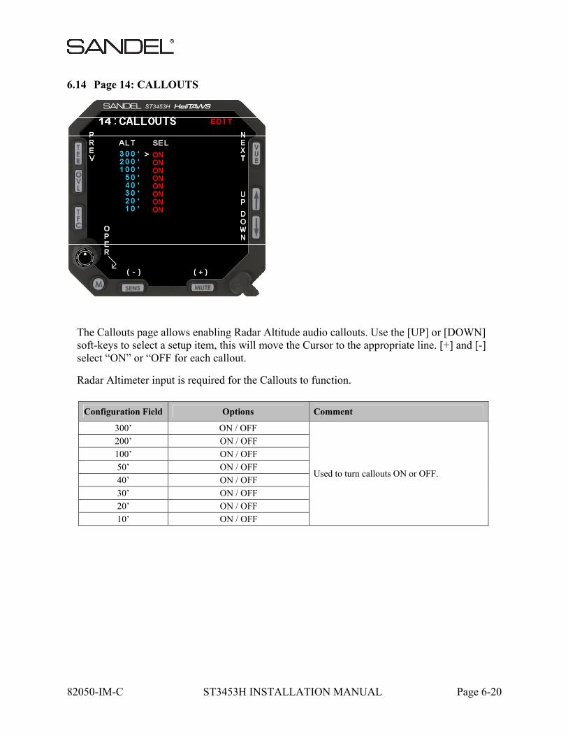
6.14 Page 14: CALLOUTS
The Callouts page allows enabling Radar Altitude audio callouts. Use the [UP] or [DOWN] soft-keys to select a setup item, this will move the Cursor to the appropriate line. [+] and [-] select “ON” or “OFF for each callout.
Radar Altimeter input is required for the Callouts to function.
Configuration Field Options Comment
300’ ON / OFF
Used to turn callouts ON or OFF.
200’ ON / OFF
100’ ON / OFF
50’ ON / OFF
40’ ON / OFF
30’ ON / OFF
20’ ON / OFF
10’ ON / OFF

82050-IM-C ST3453H INSTALLATION MANUAL Page 6-21
6.15 Page 15: POWER
The Power maintenance page consists of readouts that monitor the unit’s internal environment and the unit’s power measurements for reference.
Any of these items that are outside normal operating limits will post an on-screen error by way of the systems built-in-test processes.
6.16 Page 16: SFTWR CRC
Displays CRC values for the software and databases. Press the [UPDATE] soft-key to recalculate. The PASS/FAIL status reflects the status of the last CRC update, therefore an
82050-IM-C ST3453H INSTALLATION MANUAL Page 6-22
[UPDATE] must be done following the installation of any new software or databases. The CRC update process may take up to 60 minutes. This operation may be canceled if desired by pressing the cancel softkey. Contact Sandel if “FAIL” is annunciated for any of the values.
If any of the CRC related messages shown below appear when viewing the normal flight display while in the maintenance mode, contact Sandel Avionics for assistance.
Following a CRC update and a subsequent power cycle, the values in the “COMPUTED” column for databases will be shown as “--------”. If the CRC operation is canceled for any reason the values in the CRC column for items that were not checked will be shown as “++++“.
ADVISORY MESSAGES REQUIRING ACKNOWLEDGE
Text Message Description Comment
TERRAIN FILE CRC Database file CRC failure Contact Sandel Avionics for assistance
AIRPORT FILE CRC Database file CRC failure Contact Sandel Avionics for assistance
OBSTACLE FILE CRC Database file CRC failure Contact Sandel Avionics for assistance
PILOT MENU ONLY MESSAGES
Text Message Description Comment
GEO OVLY FILE CRC Database file CRC failure Contact Sandel Avionics for assistance

82050-IM-C ST3453H INSTALLATION MANUAL Page 6-23
6.17 Page 17: CS STATUS
Displays information about the Configuration Module.

82050-IM-C ST3453H INSTALLATION MANUAL Page 6-24
[This page intentionally left blank]
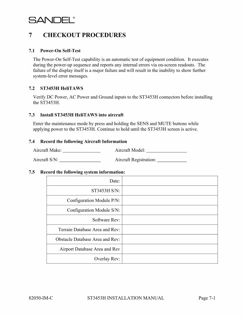
82050-IM-C ST3453H INSTALLATION MANUAL Page 7-1
7 CHECKOUT PROCEDURES
7.1 Power-On Self-Test
The Power-On Self-Test capability is an automatic test of equipment condition. It executes during the power-up sequence and reports any internal errors via on-screen readouts. The failure of the display itself is a major failure and will result in the inability to show further system-level error messages.
7.2 ST3453H HeliTAWS
Verify DC Power, AC Power and Ground inputs to the ST3453H connectors before installing the ST3453H.
7.3 Install ST3453H HeliTAWS into aircraft
Enter the maintenance mode by press and holding the SENS and MUTE buttons while applying power to the ST3453H. Continue to hold until the ST3453H screen is active.
7.4 Record the following Aircraft Information
Aircraft Make: Aircraft Model:
Aircraft S/N: Aircraft Registration:
7.5 Record the following system information:
Date:
ST3453H S/N:
Configuration Module P/N:
Configuration Module S/N:
Software Rev:
Terrain Database Area and Rev:
Obstacle Database Area and Rev:
Airport Database Area and Rev
Overlay Rev:
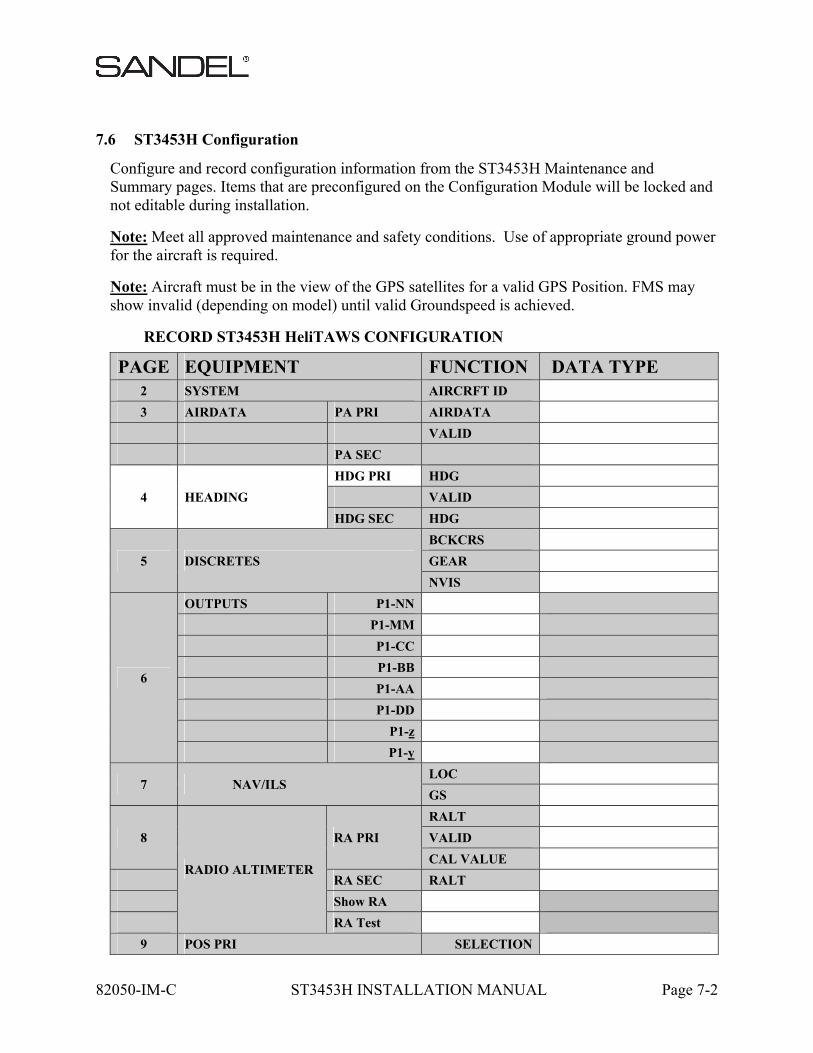
82050-IM-C ST3453H INSTALLATION MANUAL Page 7-2
7.6 ST3453H Configuration
Configure and record configuration information from the ST3453H Maintenance and Summary pages. Items that are preconfigured on the Configuration Module will be locked and not editable during installation.
Note: Meet all approved maintenance and safety conditions. Use of appropriate ground power for the aircraft is required.
Note: Aircraft must be in the view of the GPS satellites for a valid GPS Position. FMS may show invalid (depending on model) until valid Groundspeed is achieved.
RECORD ST3453H HeliTAWS CONFIGURATION
PAGE EQUIPMENT FUNCTION DATA TYPE 2 SYSTEM AIRCRFT ID
3 AIRDATA PA PRI AIRDATA
VALID
PA SEC
4 HEADING
HDG PRI HDG
VALID
HDG SEC HDG
5 DISCRETES
BCKCRS
GEAR
NVIS
6
OUTPUTS P1-NN
P1-MM
P1-CC
P1-BB
P1-AA
P1-DD
P1-z
P1-y
7 NAV/ILS LOC
GS
8
RADIO ALTIMETER
RA PRI
RALT
VALID
CAL VALUE
RA SEC RALT
Show RA
RA Test
9 POS PRI SELECTION
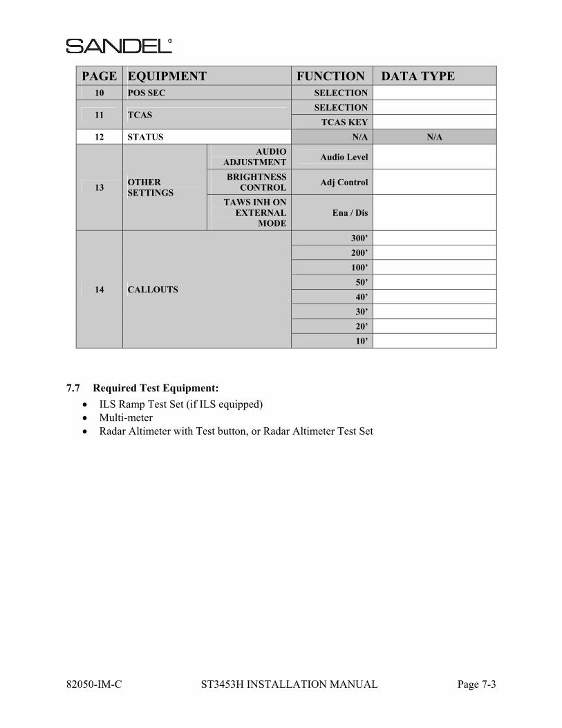
82050-IM-C ST3453H INSTALLATION MANUAL Page 7-3
PAGE EQUIPMENT FUNCTION DATA TYPE 10 POS SEC SELECTION
11 TCAS SELECTION
TCAS KEY
12 STATUS N/A N/A
13 OTHER SETTINGS
AUDIO ADJUSTMENT
Audio Level
BRIGHTNESS CONTROL
Adj Control
TAWS INH ON EXTERNAL
MODE Ena / Dis
14 CALLOUTS
300’
200’
100’
50’
40’
30’
20’
10’
7.7 Required Test Equipment:
ILS Ramp Test Set (if ILS equipped) Multi-meter Radar Altimeter with Test button, or Radar Altimeter Test Set
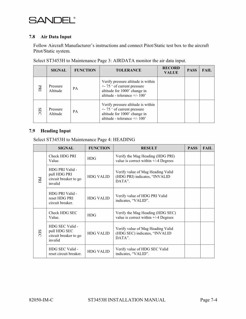
82050-IM-C ST3453H INSTALLATION MANUAL Page 7-4
7.8 Air Data Input
Follow Aircraft Manufacturer’s instructions and connect Pitot/Static test box to the aircraft Pitot/Static system.
Select ST3453H to Maintenance Page 3: AIRDATA monitor the air data input.
SIGNAL FUNCTION TOLERANCE RECORD VALUE
PASS FAIL
PR
I
Pressure Altitude
PA
Verify pressure altitude is within +- 75 ‘ of current pressure altitude for 1000’ change in altitude - tolerance +/- 100’
SE
C
Pressure Altitude
PA
Verify pressure altitude is within +- 75 ‘ of current pressure altitude for 1000’ change in altitude - tolerance +/- 100’
7.9 Heading Input
Select ST3453H to Maintenance Page 4: HEADING
SIGNAL FUNCTION RESULT PASS FAIL
PR
I
Check HDG PRI Value.
HDG Verify the Mag Heading (HDG PRI) value is correct within +/-4 Degrees
HDG PRI Valid - pull HDG PRI circuit breaker to go invalid
HDG VALID Verify value of Mag Heading Valid (HDG PRI) indicates, “INVALID DATA”.
HDG PRI Valid - reset HDG PRI circuit breaker.
HDG VALID Verify value of HDG PRI Valid indicates, “VALID”.
SE
C
Check HDG SEC Value.
HDG Verify the Mag Heading (HDG SEC) value is correct within +/-4 Degrees
HDG SEC Valid - pull HDG SEC circuit breaker to go invalid
HDG VALID Verify value of Mag Heading Valid (HDG SEC) indicates, “INVALID DATA”.
HDG SEC Valid - reset circuit breaker.
HDG VALID Verify value of HDG SEC Valid indicates, “VALID”.
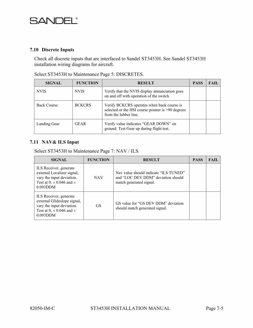
82050-IM-C ST3453H INSTALLATION MANUAL Page 7-5
7.10 Discrete Inputs
Check all discrete inputs that are interfaced to Sandel ST3453H. See Sandel ST3453H installation wiring diagrams for aircraft.
Select ST3453H to Maintenance Page 5: DISCRETES.
SIGNAL FUNCTION RESULT PASS FAIL
NVIS NVIS Verify that the NVIS display annunciation goes on and off with operation of the switch
Back Course BCKCRS Verify BCKCRS operates when back course is selected or the HSI course pointer is >90 degrees from the lubber line.
Landing Gear GEAR Verify value indicates “GEAR DOWN” on ground. Test Gear up during flight test.
7.11 NAV& ILS Input
Select ST3453H to Maintenance Page 7: NAV / ILS.
SIGNAL FUNCTION RESULT PASS FAIL
ILS Receiver, generate external Localizer signal, vary the input deviation. Test at 0, ± 0.046 and ± 0.093DDM
NAV Nav value should indicate “ILS TUNED” and “LOC DEV DDM” deviation should match generated signal.
ILS Receiver, generate external Glideslope signal, vary the input deviation. Test at 0, ± 0.046 and ± 0.093DDM
GS GS value for “GS DEV DDM” deviation should match generated signal.
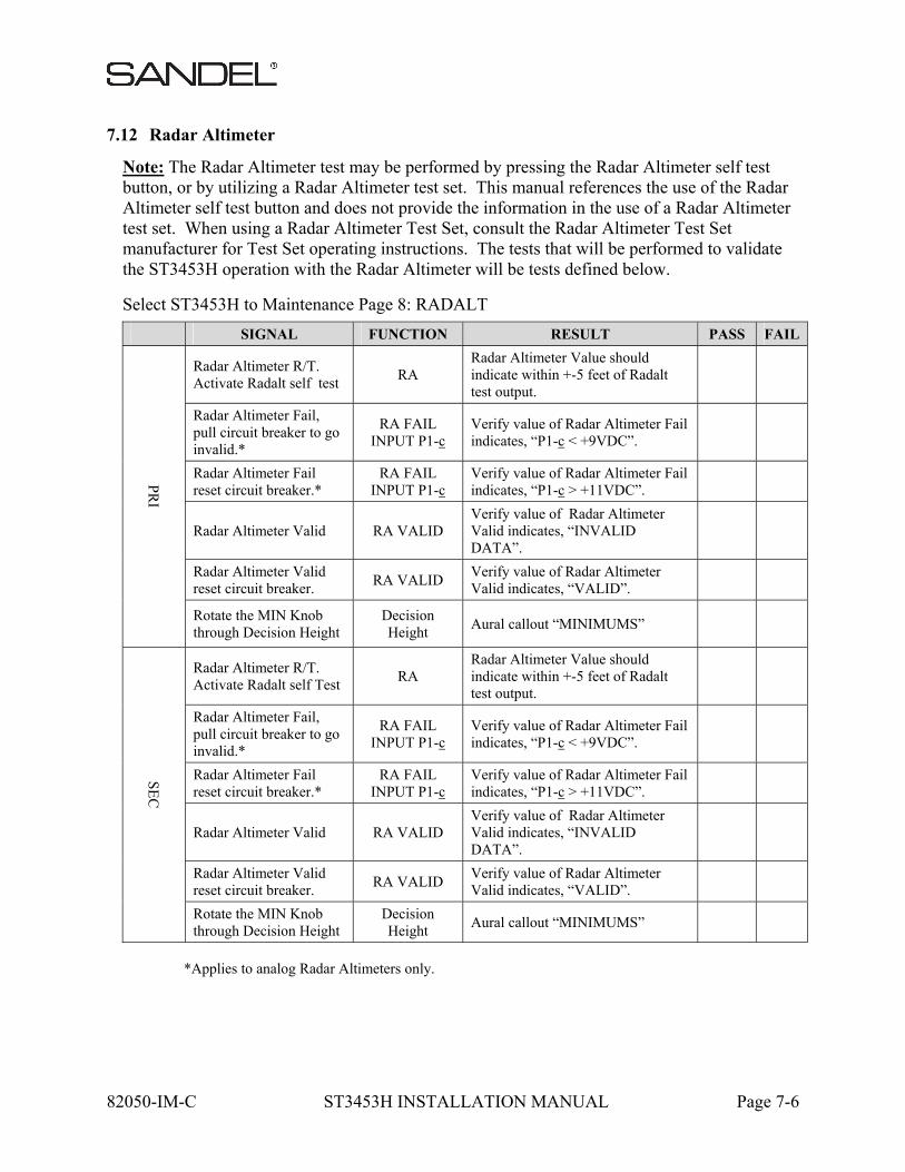
82050-IM-C ST3453H INSTALLATION MANUAL Page 7-6
7.12 Radar Altimeter
Note: The Radar Altimeter test may be performed by pressing the Radar Altimeter self test button, or by utilizing a Radar Altimeter test set. This manual references the use of the Radar Altimeter self test button and does not provide the information in the use of a Radar Altimeter test set. When using a Radar Altimeter Test Set, consult the Radar Altimeter Test Set manufacturer for Test Set operating instructions. The tests that will be performed to validate the ST3453H operation with the Radar Altimeter will be tests defined below.
Select ST3453H to Maintenance Page 8: RADALT
SIGNAL FUNCTION RESULT PASS FAIL
PR
I
Radar Altimeter R/T. Activate Radalt self test
RA Radar Altimeter Value should indicate within +-5 feet of Radalt test output.
Radar Altimeter Fail, pull circuit breaker to go invalid.*
RA FAIL INPUT P1-c
Verify value of Radar Altimeter Fail indicates, “P1-c < +9VDC”.
Radar Altimeter Fail reset circuit breaker.*
RA FAIL INPUT P1-c
Verify value of Radar Altimeter Fail indicates, “P1-c > +11VDC”.
Radar Altimeter Valid RA VALID Verify value of Radar Altimeter Valid indicates, “INVALID DATA”.
Radar Altimeter Valid reset circuit breaker.
RA VALID Verify value of Radar Altimeter Valid indicates, “VALID”.
Rotate the MIN Knob through Decision Height
Decision Height
Aural callout “MINIMUMS”
SE
C
Radar Altimeter R/T. Activate Radalt self Test
RA Radar Altimeter Value should indicate within +-5 feet of Radalt test output.
Radar Altimeter Fail, pull circuit breaker to go invalid.*
RA FAIL INPUT P1-c
Verify value of Radar Altimeter Fail indicates, “P1-c < +9VDC”.
Radar Altimeter Fail reset circuit breaker.*
RA FAIL INPUT P1-c
Verify value of Radar Altimeter Fail indicates, “P1-c > +11VDC”.
Radar Altimeter Valid RA VALID Verify value of Radar Altimeter Valid indicates, “INVALID DATA”.
Radar Altimeter Valid reset circuit breaker.
RA VALID Verify value of Radar Altimeter Valid indicates, “VALID”.
Rotate the MIN Knob through Decision Height
Decision Height
Aural callout “MINIMUMS”
*Applies to analog Radar Altimeters only.
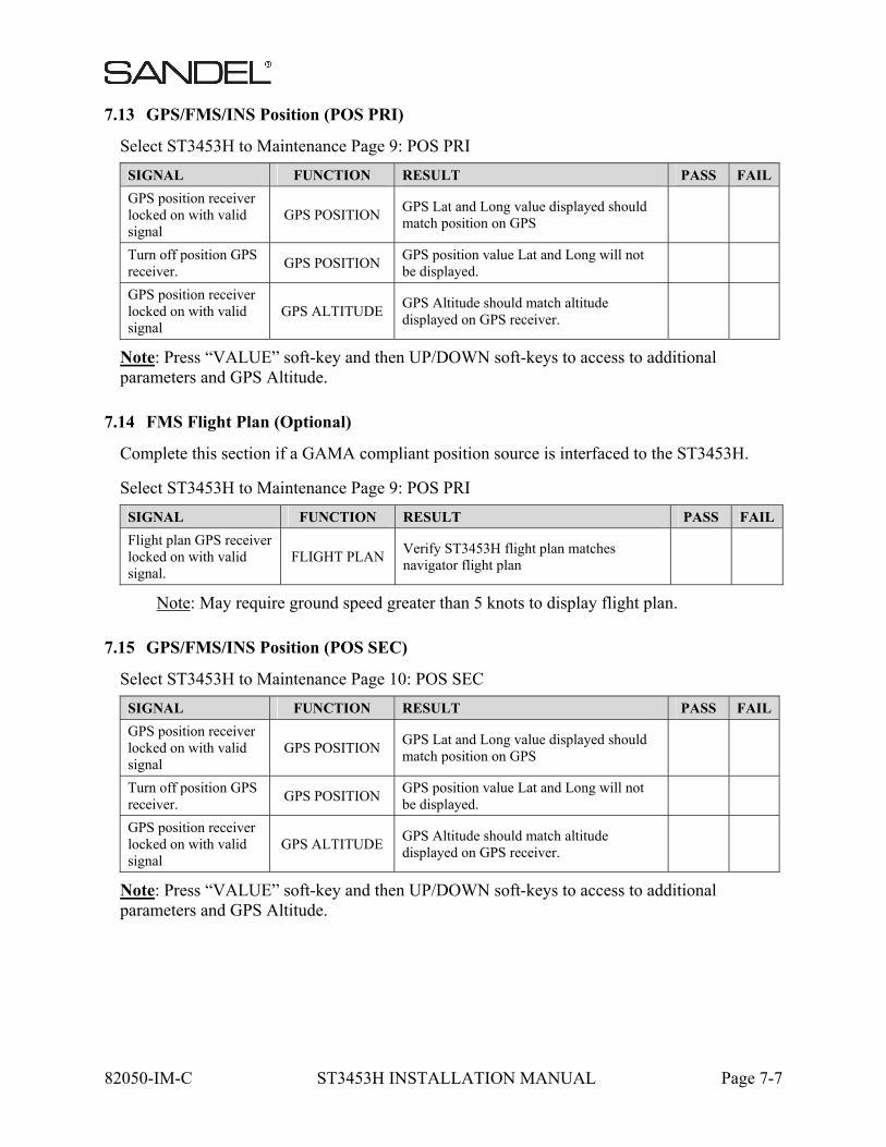
82050-IM-C ST3453H INSTALLATION MANUAL Page 7-7
7.13 GPS/FMS/INS Position (POS PRI)
Select ST3453H to Maintenance Page 9: POS PRI
SIGNAL FUNCTION RESULT PASS FAIL
GPS position receiver locked on with valid signal
GPS POSITION GPS Lat and Long value displayed should match position on GPS
Turn off position GPS receiver.
GPS POSITION GPS position value Lat and Long will not be displayed.
GPS position receiver locked on with valid signal
GPS ALTITUDE GPS Altitude should match altitude displayed on GPS receiver.
Note: Press “VALUE” soft-key and then UP/DOWN soft-keys to access to additional parameters and GPS Altitude.
7.14 FMS Flight Plan (Optional)
Complete this section if a GAMA compliant position source is interfaced to the ST3453H.
Select ST3453H to Maintenance Page 9: POS PRI
SIGNAL FUNCTION RESULT PASS FAIL
Flight plan GPS receiver locked on with valid signal.
FLIGHT PLAN Verify ST3453H flight plan matches navigator flight plan
Note: May require ground speed greater than 5 knots to display flight plan.
7.15 GPS/FMS/INS Position (POS SEC)
Select ST3453H to Maintenance Page 10: POS SEC
SIGNAL FUNCTION RESULT PASS FAIL
GPS position receiver locked on with valid signal
GPS POSITION GPS Lat and Long value displayed should match position on GPS
Turn off position GPS receiver.
GPS POSITION GPS position value Lat and Long will not be displayed.
GPS position receiver locked on with valid signal
GPS ALTITUDE GPS Altitude should match altitude displayed on GPS receiver.
Note: Press “VALUE” soft-key and then UP/DOWN soft-keys to access to additional parameters and GPS Altitude.
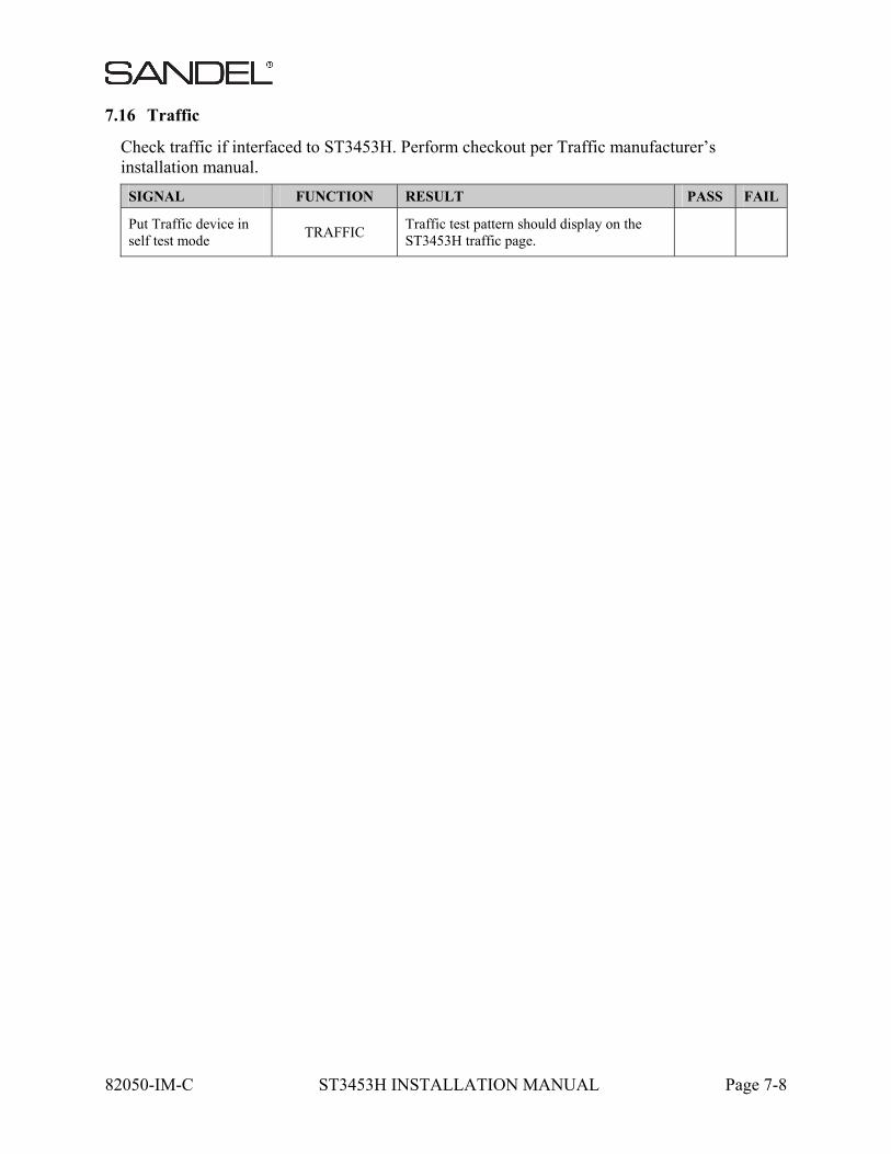
82050-IM-C ST3453H INSTALLATION MANUAL Page 7-8
7.16 Traffic
Check traffic if interfaced to ST3453H. Perform checkout per Traffic manufacturer’s installation manual.
SIGNAL FUNCTION RESULT PASS FAIL
Put Traffic device in self test mode
TRAFFIC Traffic test pattern should display on the ST3453H traffic page.

82050-IM-C ST3453H INSTALLATION MANUAL Page 7-9
7.17 MUTE switch
If installed, verify that the external MUTE pushbutton operates the mute function. Holding the MUTE pushbutton for 2 seconds will perform the TAWS INH function and terrain will be removed from the display
Pass / Fail:
Remarks: ______________________________________________________
7.18 Sensitivity switch
If installed, verify that the external Sensitivity pushbutton operates the Sensitivity mode function. Holding the Sensitivity pushbutton for 2 seconds will change the mode to “Off Airport”.
Pass / Fail:
Remarks: ______________________________________________________
7.19 HTAWS self-test
Verify aural annunciations are acceptable in clarity and volume (both loudspeaker and headphone aural annunciations).
Pass / Fail:
Remarks: ______________________________________________________
7.20 External Annunciators
Check operation of any external annunciators.
Pass / Fail:
Remarks: ______________________________________________________
7.21 Display
Verify display is viewable under all expected cockpit ambient light conditions (this test should be performed in bright daylight, and again at night or in a simulated dark cockpit).
Pass / Fail:
Remarks: ______________________________________________________
7.22 Manual brightness
Verify manual display brightness lighting control is operating, and provides display brightness control over the full range for all normal cockpit lighting conditions.

82050-IM-C ST3453H INSTALLATION MANUAL Page 7-10
Pass / Fail:
Remarks: ______________________________________________________
7.23 Visibility and Accessibility
Verify visibility and accessibility of the ST3453H display and controls from the pilot’s seat. View the display from normal, expected viewing angles. This should include viewing the display from all viewing angles that might be encountered during normal cockpit operations.
Pass / Fail:
Remarks: ______________________________________________________
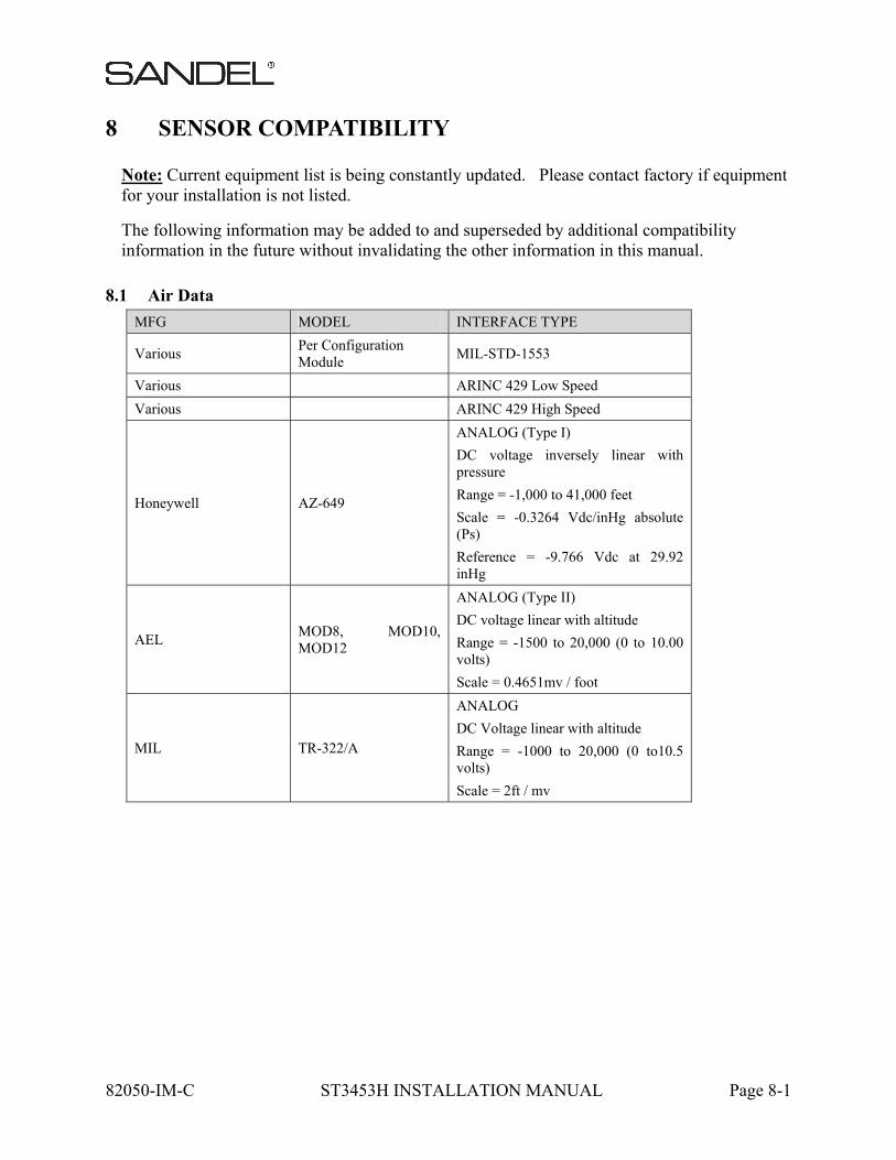
82050-IM-C ST3453H INSTALLATION MANUAL Page 8-1
8 SENSOR COMPATIBILITY
Note: Current equipment list is being constantly updated. Please contact factory if equipment for your installation is not listed.
The following information may be added to and superseded by additional compatibility information in the future without invalidating the other information in this manual.
8.1 Air Data
MFG MODEL INTERFACE TYPE
Various Per Configuration Module
MIL-STD-1553
Various ARINC 429 Low Speed
Various ARINC 429 High Speed
Honeywell AZ-649
ANALOG (Type I)
DC voltage inversely linear with pressure
Range = -1,000 to 41,000 feet
Scale = -0.3264 Vdc/inHg absolute (Ps)
Reference = -9.766 Vdc at 29.92 inHg
AEL MOD8, MOD10, MOD12
ANALOG (Type II)
DC voltage linear with altitude
Range = -1500 to 20,000 (0 to 10.00 volts)
Scale = 0.4651mv / foot
MIL TR-322/A
ANALOG
DC Voltage linear with altitude
Range = -1000 to 20,000 (0 to10.5 volts)
Scale = 2ft / mv
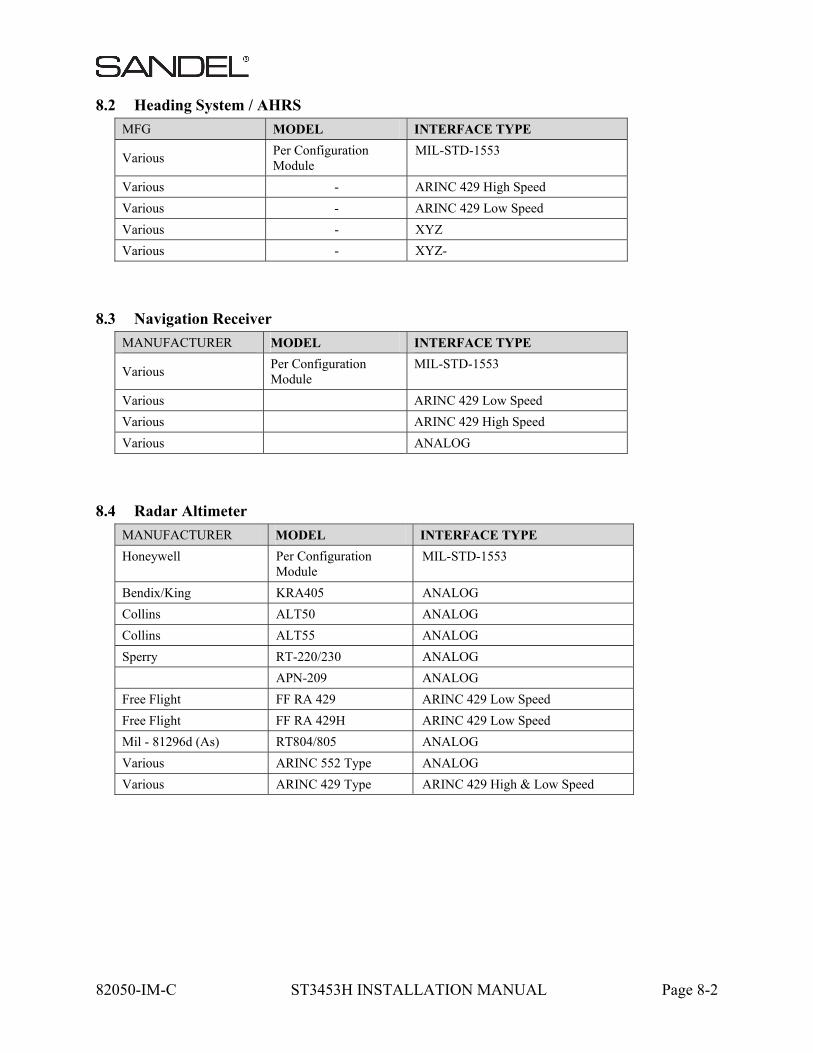
82050-IM-C ST3453H INSTALLATION MANUAL Page 8-2
8.2 Heading System / AHRS
MFG MODEL INTERFACE TYPE
Various Per Configuration Module
MIL-STD-1553
Various - ARINC 429 High Speed
Various - ARINC 429 Low Speed
Various - XYZ
Various - XYZ-
8.3 Navigation Receiver
MANUFACTURER MODEL INTERFACE TYPE
Various Per Configuration Module
MIL-STD-1553
Various ARINC 429 Low Speed
Various ARINC 429 High Speed
Various ANALOG
8.4 Radar Altimeter
MANUFACTURER MODEL INTERFACE TYPE
Honeywell Per Configuration Module
MIL-STD-1553
Bendix/King KRA405 ANALOG
Collins ALT50 ANALOG
Collins ALT55 ANALOG
Sperry RT-220/230 ANALOG
APN-209 ANALOG
Free Flight FF RA 429 ARINC 429 Low Speed
Free Flight FF RA 429H ARINC 429 Low Speed
Mil - 81296d (As) RT804/805 ANALOG
Various ARINC 552 Type ANALOG
Various ARINC 429 Type ARINC 429 High & Low Speed
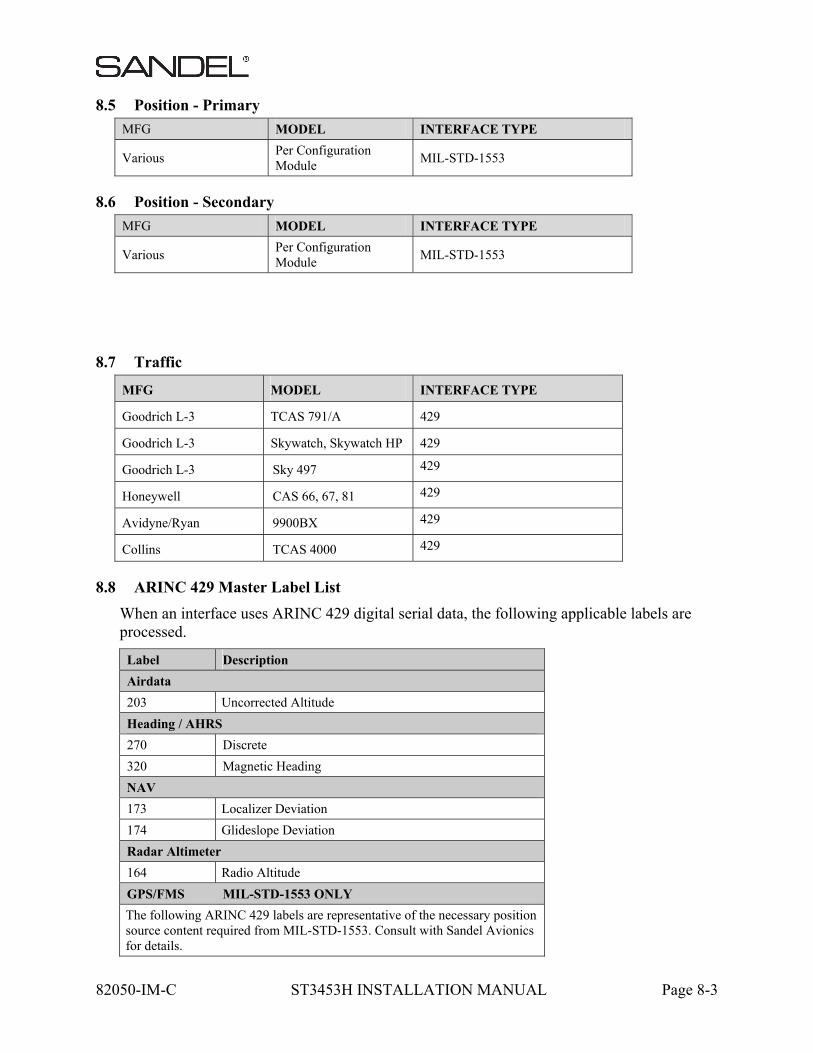
82050-IM-C ST3453H INSTALLATION MANUAL Page 8-3
8.5 Position - Primary
MFG MODEL INTERFACE TYPE
Various Per Configuration Module
MIL-STD-1553
8.6 Position - Secondary
MFG MODEL INTERFACE TYPE
Various Per Configuration Module
MIL-STD-1553
8.7 Traffic
MFG MODEL INTERFACE TYPE
Goodrich L-3 TCAS 791/A 429
Goodrich L-3 Skywatch, Skywatch HP 429
Goodrich L-3 Sky 497 429
Honeywell CAS 66, 67, 81 429
Avidyne/Ryan 9900BX 429
Collins TCAS 4000 429
8.8 ARINC 429 Master Label List
When an interface uses ARINC 429 digital serial data, the following applicable labels are processed.
Label Description
Airdata
203 Uncorrected Altitude
Heading / AHRS
270 Discrete
320 Magnetic Heading
NAV
173 Localizer Deviation
174 Glideslope Deviation
Radar Altimeter
164 Radio Altitude
GPS/FMS MIL-STD-1553 ONLY
The following ARINC 429 labels are representative of the necessary position source content required from MIL-STD-1553. Consult with Sandel Avionics for details.
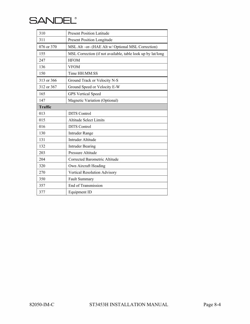
82050-IM-C ST3453H INSTALLATION MANUAL Page 8-4
310 Present Position Latitude
311 Present Position Longitude
076 or 370 MSL Alt –or- (HAE Alt w/ Optional MSL Correction)
155 MSL Correction (if not available, table look up by lat/long
247 HFOM
136 VFOM
150 Time HH:MM:SS
313 or 366 Ground Track or Velocity N-S
312 or 367 Ground Speed or Velocity E-W
165 GPS Vertical Speed
147 Magnetic Variation (Optional)
Traffic
013 DITS Control
015 Altitude Select Limits
016 DITS Control
130 Intruder Range
131 Intruder Altitude
132 Intruder Bearing
203 Pressure Altitude
204 Corrected Barometric Altitude
320 Own Aircraft Heading
270 Vertical Resolution Advisory
350 Fault Summary
357 End of Transmission
377 Equipment ID
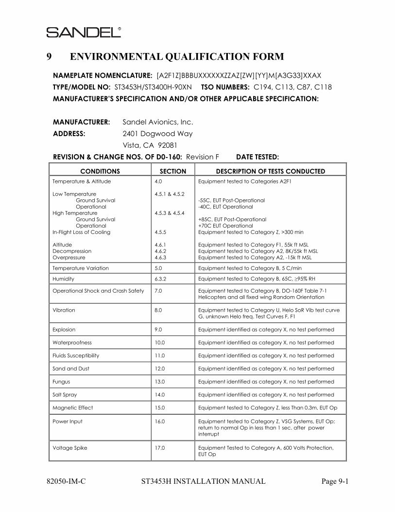
82050-IM-C ST3453H INSTALLATION MANUAL Page 9-1
9 ENVIRONMENTAL QUALIFICATION FORM
NAMEPLATE NOMENCLATURE: [A2F1Z]BBBUXXXXXXZZAZ[ZW][YY]M[A3G33]XXAX TYPE/MODEL NO: ST3453H/ST3400H-90XN TSO NUMBERS: C194, C113, C87, C118 MANUFACTURER’S SPECIFICATION AND/OR OTHER APPLICABLE SPECIFICATION: MANUFACTURER: Sandel Avionics, Inc. ADDRESS: 2401 Dogwood Way Vista, CA 92081 REVISION & CHANGE NOS. OF D0-160: Revision F DATE TESTED:
CONDITIONS SECTION DESCRIPTION OF TESTS CONDUCTED Temperature & Altitude Low Temperature
Ground Survival Operational
High Temperature Ground Survival Operational
In-Flight Loss of Cooling Altitude Decompression Overpressure
4.0 4.5.1 & 4.5.2 4.5.3 & 4.5.4 4.5.5 4.6.1 4.6.2 4.6.3
Equipment tested to Categories A2F1 -55C, EUT Post-Operational -40C, EUT Operational +85C, EUT Post-Operational +70C EUT Operational Equipment tested to Category Z, >300 min Equipment tested to Category F1, 55k ft MSL Equipment tested to Category A2, 8K/55k ft MSL Equipment tested to Category A2, -15k ft MSL
Temperature Variation 5.0 Equipment tested to Category B, 5 C/min
Humidity 6.3.2 Equipment tested to Category B, 65C, ≥95% RH
Operational Shock and Crash Safety 7.0 Equipment tested to Category B, DO-160F Table 7-1 Helicopters and all fixed wing Random Orientation
Vibration 8.0 Equipment tested to Category U, Helo SoR Vib test curve G, unknown Helo freq. Test Curves F, F1
Explosion 9.0 Equipment identified as category X, no test performed
Waterproofness 10.0 Equipment identified as category X, no test performed
Fluids Susceptibility 11.0 Equipment identified as category X, no test performed
Sand and Dust 12.0 Equipment identified as category X, no test performed
Fungus 13.0 Equipment identified as category X, no test performed
Salt Spray 14.0 Equipment identified as category X, no test performed
Magnetic Effect 15.0 Equipment tested to Category Z, less Than 0.3m, EUT Op
Power Input 16.0 Equipment tested to Category Z, VSG Systems, EUT Op; return to normal Op in less than 1 sec. after power interrupt
Voltage Spike 17.0 Equipment Tested to Category A, 600 Volts Protection, EUT Op
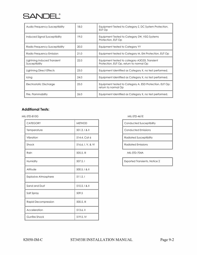
82050-IM-C ST3453H INSTALLATION MANUAL Page 9-2
Audio Frequency Susceptibility 18.0 Equipment Tested to Category Z, DC System Protection, EUT Op
Induced Signal Susceptibility 19.0 Equipment Tested to Category ZW, VSG Systems Protection, EUT Op
Radio Frequency Susceptibility 20.0 Equipment tested to Category YY
Radio Frequency Emission 21.0 Equipment tested to Category M, EM Protection, EUT Op
Lightning Induced Transient Susceptibility
22.0 Equipment tested to category A3G33, Transient Protection, EUT Op, return to normal Op
Lightning Direct Effects 23.0 Equipment identified as Category X, no test performed.
Icing 24.0 Equipment identified as Category X, no test performed.
Electrostatic Discharge 25.0 Equipment tested to Category A, ESD Protection, EUT Op; return to normal Op
Fire, Flammability 26.0 Equipment identified as Category X, no test performed.
Additional Tests:
MIL-STD-810G MIL-STD-461E
CATEGORY METHOD Conducted Susceptibility
Temperature 501.3, I & II Conducted Emissions
Vibration 514.4, Cat 6 Radiated Susceptibility
Shock 516.6, I, V, & VI Radiated Emissions
Rain 505.5, III MIL-STD-704A
Humidity 507.5, I Exported Transients, Notice 2
Altitude 500.5, I & II
Explosive Atmosphere 511.5, I
Sand and Dust 510.5, I & II
Salt Spray 509.5
Rapid Decompression 500.5, III
Acceleration 513.6, II
Gunfire Shock 519.5, IV
82050-IM-C ST3453H INSTALLATION MANUAL Page 10-1
10 INSTRUCTIONS FOR CONTINUED AIRWORTHINESS
Normal maintenance activities performed on the ST3453H should follow standard industry practices. Re-programming the Configuration Module and updating the Databases, are addressed in specific sections of this installation manual.
10.1 Periodic Maintenance
The ST3453H is designed to detect some internal failures. A thorough self-test is executed automatically upon application of power to the unit, and Built-In-Test (BIT) is continuously executed. Detected errors are indicated on the equipment via failure messages and maintenance is on-condition. Operation of the ST3453H is not permitted unless an inspection as described in this section has been completed within the preceding 12 calendar months. Conduct a visual inspection on the ST3453H and its wire harness to insure installation integrity:
Inspect the unit for security of attachment. Inspect buttons for legibility. Inspect condition of wiring, routing and attachment/clamping. Inspect knob operation. Inspect front panel and clean as necessary
10.2 Cleaning the Front Panel
The front bezel, keypad, and display can be cleaned with a soft cotton cloth dampened with “Edmund Scientific TECH SPEC Lens Cleaner” or equivalent. Care should be taken to avoid scratching the surface of the display.
10.3 Display Light Source
The display light source is rated by the manufacturer as having a usable life of 20,000 hours. This life may be more or less than the rated time depending on the operating conditions of the ST3453H. Over time, the light source may dim and the display may not perform as well in direct sunlight conditions. The user must determine by observation when the display brightness is not suitable for its intended use. Contact the Sandel Customer Service if the light source requires service.
10.4 Trouble Shooting Information
If the ST3453H fails to properly operate, consult a local authorized Sandel dealer for repair. The ST3453H has an internal data and event recorder that automatically records up to 100 record files (total maximum = 100MB) of flight data and events. This data can be used by Sandel Customer Support to analyze recent alert and failure message activity. The ST3453H does not contain any user serviceable components.
82050-IM-C ST3453H INSTALLATION MANUAL Page 10-2
10.5 Removal and Replacement
If the ST3453H is removed for repair and reinstalled, or removed and replaced with a different ST3453H, follow Post Installation Configuration and Checkout Procedures contained in the manual.
If any work has been done on the aircraft that could affect the system wiring or interconnected equipment, verify the ST3453H operates properly, follow the Post Installation Configuration and Checkout Procedures contained in this manual.
To remove the ST3453H from the mounting clamp, use a standard #2 Philips screwdriver to loosen the clamping screws until the ST3453H can be freely pulled from the panel.
The ST3453H is installed by connecting the cable harnesses and then sliding it straight in the clamping mechanism until the front bezel meets the aircraft instrument panel. Tighten all four (4) clamp screws.
10.6 Database Updates
Database updates are not required. Information regarding new database releases and the content details of the databases may be obtained by visiting the Sandel website (www.sandel.com ). Database updates may be ordered on-line. It is up to the ST3453H customer to determine if a specific database is applicable to their operations.
10.7 Software Updates
Software updates are released via a Service Information Letter (SIL) or a Service Bulletin (SB). The SIL or SB will contain links to the software and the related software installation files and instructions necessary to perform the update. Software updates must be performed by a Sandel authorized dealer or repair station.
It is the user/owners responsibility to periodically check for SIL’s and or SB’s relating to the ST3453H. SIL’s and SB’s can be found at: www.sandel.com/products/resources/ST3453H-documents.
82050-IM-C ST3453H INSTALLATION MANUAL Page 11-1
11 LIST OF EFFECTIVE DRAWINGS AND ATTACHMENTS
Drawing Rev Title
82050-05 A LAYOUT, ST3453H INSTALLATION
82050-07 D2 LAYOUT, ST3453H HeliTAWS
82050-10, Sheet 1 A POWER & AUDIO
82050-10, Sheet 2 B GPS INTERFACE 429/232
82050-10, Sheet 3 B RADALT ANALOG
82050-10, Sheet 4 B RADALT ARINC 429
82050-10, Sheet 5 B HEADING ARINC 429
82050-10, Sheet 6 B HEADING XYZ
82050-10, Sheet 7 A NAV & LOC ANALOG
82050-10, Sheet 8 A NAV & LOC ARINC 429
82050-10, Sheet 9 B ANALOG AIRDATA
82050-10, Sheet 10 B AIRDATA ARINC 429
82050-10, Sheet 11 B ANNUNCIATORS
82050-10, Sheet 12 A TCAS / TRAFFIC
82050-10, Sheet 13 A DISCRETE INPUTS
82050-10, Sheet 14 A MIL-STD-1553 INTERFACE
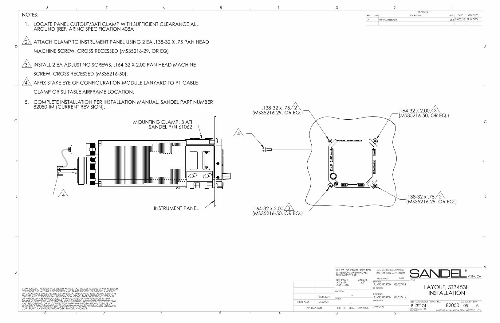
.138-32 x .75 2(MS35216-29, OR EQ.)
.138-32 x .75 2(MS35216-29, OR EQ.)
.164-32 x 2.00 3(MS35216-50, OR EQ.)
.164-32 x 2.00 3(MS35216-50, OR EQ.)
4
MOUNTING CLAMP, 3 ATISANDEL P/N 61062
INSTRUMENT PANEL
4
D
C
B
AA
B
C
D
CAD GENERATED DRAWING,DO NOT MANUALLY UPDATE
SCALE 1:2& NOTED
SIZE CAGE CODE
BSHEET 1 OF 2
REV.
LAYOUT, ST3453H INSTALLATION
DATEAPPROVALSDRAWN
CHECKED
RESP ENG
MFG ENG
APPROVAL
UNLESS OTHERWISE SPECIFIEDDIMENSIONS ARE IN INCHESTOLERANCES ARE:
DECIMALS ANGLES.XX .01 .5.XXX .005
MATERIAL
FINISH-
DO NOT SCALE DRAWINGAPPLICATION
USED ONNEXT ASSY
12345678
8 7 6 5 4 3 2 1REVISIONS
REV. DESCRIPTION APPROVED
VISTA, CA
A82050
T. MORRISON
DWG. NO.
3T1Z4-
NOTES:
LOCATE PANEL CUTOUT/3ATI CLAMP WITH SUFFICIENT CLEARANCE ALL 1.AROUND (REF. ARINC SPECIFICATION 408A
ATTACH CLAMP TO INSTRUMENT PANEL USING 2 EA .138-32 X .75 PAN HEAD 2.
MACHINE SCREW, CROSS RECESSED (MS35216-29, OR EQ)
INSTALL 2 EA ADJUSTING SCREWS, .164-32 X 2.00 PAN HEAD MACHINE 3.
SCREW, CROSS RECESSED (MS35216-50).
AFFIX STAKE EYE OF CONFIGURATION MODULE LANYARD TO P1 CABLE 4.
CLAMP OR SUITABLE AIRFRAME LOCATION.
COMPLETE INSTALLATION PER INSTALLATION MANUAL, SANDEL PART NUMBER 5.82050-IM (CURRENT REVISION).
T. MORRISON
08/07/12
08/07/12
82050-05 INSTALLATION, ST3453H
CONFIDENTIAL: PROPRIETARY RIGHTS NOTICE: ALL RIGHTS RESERVED. THIS MATERIALCONTAINS THE VALUABLE PROPERTIES AND TRADE SECRETS OF SANDEL AVIONICSOF CALIFORNIA, UNITED STATES OF AMERICA, EMBODYING SUBSTANTIAL CREATIVEEFFORTS AND CONFIDENTIAL INFORMATION, IDEAS, AND EXPRESSIONS, NO PARTOF WHICH MAY BE REPRODUCED OR TRANSMITTED IN ANY FORM OR BY ANYMEANS, ELECTRONIC, MECHANICAL OR OTHERWISE, INCLUDING PHOTOCOPYINGAND RECORDING, OR IN CONNECTION WITH ANY INFORMATION STORAGE ORRETRIEVAL SYSTEM WITHOUT THE PERMISSION IN WRITING FROM SANDEL AVIONICS.COPYRIGHT AN UNPUBLISHED WORK. SANDEL AVIONICS CAD FILE
-
INITIAL RELEASEA
ZONE
ST3453H
G. BLOCK 08/07/12
CATEGORY
05
DATEA/R
1252
TITLE
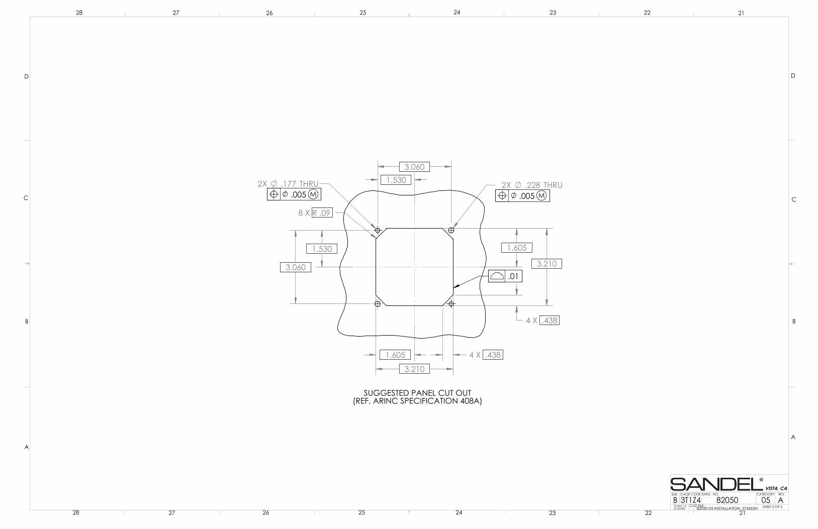
3.210
8 X R .09
3.210
2X .228 THRU2X .177 THRU
3.060
3.060
1.605
1.605
4 X .438
4 X .438
1.530
1.530
SUGGESTED PANEL CUT OUT(REF. ARINC SPECIFICATION 408A)
.005 M
.01
.005 M
D
C
B
AA
B
C
D
SCALE 1:2& NOTED
SIZE CAGE CODE
BREV.
2122232425262728
28 27 26 25 24 23 22 21
VISTA, CA
82050 ADWG. NO.
3T1Z4SHEET 2 OF 2CAD FILE:
82050-05 INSTALLATION, ST3453H
05CATEGORY
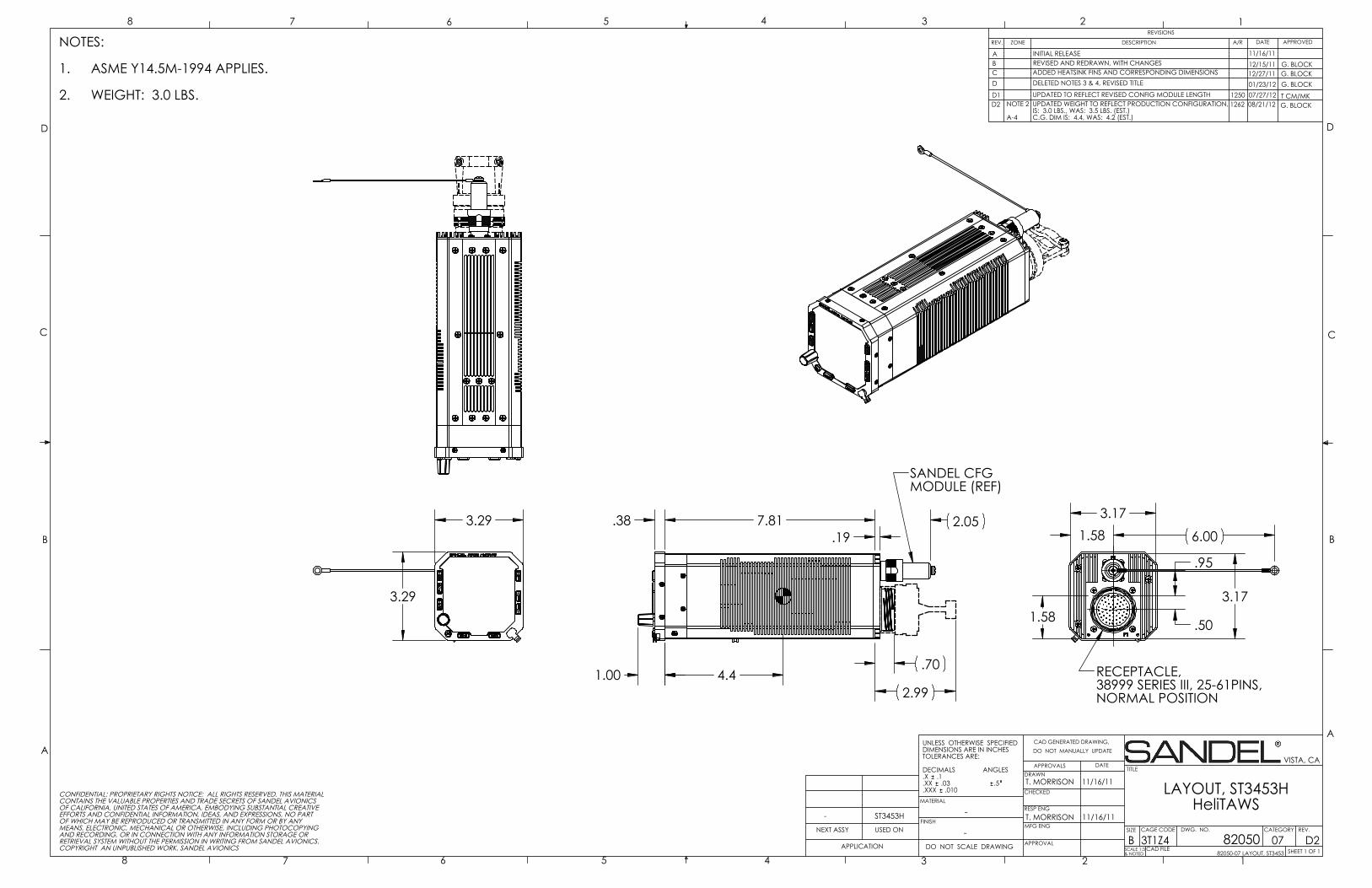
3.29
3.29
7.81 .38
2.99 1.00
2.05
.70
.19
4.4
SANDEL CFG MODULE (REF)
3.17
3.17
1.58
1.58
6.00
.95
.50
RECEPTACLE, 38999 SERIES III, 25-61PINS,NORMAL POSITION
D
C
B
AA
B
C
D
CAD GENERATED DRAWING,DO NOT MANUALLY UPDATE
SCALE 1:3& NOTED
SIZE CAGE CODE
BSHEET 1 OF 1
REV.
LAYOUT, ST3453H HeliTAWS
DATEAPPROVALSDRAWN
CHECKED
RESP ENG
MFG ENG
APPROVAL
UNLESS OTHERWISE SPECIFIEDDIMENSIONS ARE IN INCHESTOLERANCES ARE:
DECIMALS ANGLES.X .1.XX .03 .5.XXX .010
MATERIAL
FINISH-
DO NOT SCALE DRAWINGAPPLICATION
USED ONNEXT ASSY
12345678
8 7 6 5 4 3 2 1REVISIONS
REV. DESCRIPTION APPROVED
VISTA, CA
D282050
T. MORRISON
DWG. NO.
3T1Z4-
NOTES:
ASME Y14.5M-1994 APPLIES.1.
WEIGHT: 3.0 LBS.2.
T. MORRISON
11/16/11
11/16/11
82050-07 LAYOUT, ST3453
CONFIDENTIAL: PROPRIETARY RIGHTS NOTICE: ALL RIGHTS RESERVED. THIS MATERIALCONTAINS THE VALUABLE PROPERTIES AND TRADE SECRETS OF SANDEL AVIONICSOF CALIFORNIA, UNITED STATES OF AMERICA, EMBODYING SUBSTANTIAL CREATIVEEFFORTS AND CONFIDENTIAL INFORMATION, IDEAS, AND EXPRESSIONS, NO PARTOF WHICH MAY BE REPRODUCED OR TRANSMITTED IN ANY FORM OR BY ANYMEANS, ELECTRONIC, MECHANICAL OR OTHERWISE, INCLUDING PHOTOCOPYINGAND RECORDING, OR IN CONNECTION WITH ANY INFORMATION STORAGE ORRETRIEVAL SYSTEM WITHOUT THE PERMISSION IN WRITING FROM SANDEL AVIONICS.COPYRIGHT AN UNPUBLISHED WORK. SANDEL AVIONICS CAD FILE
-
INITIAL RELEASE
ZONE
ST3453H
11/16/11
CATEGORY
07
DATEA/R
TITLE
AB REVISED AND REDRAWN, WITH CHANGES 12/15/11 G. BLOCKC G. BLOCK12/27/11ADDED HEATSINK FINS AND CORRESPONDING DIMENSIONS
DELETED NOTES 3 & 4, REVISED TITLE 01/23/12 G. BLOCKD
D1 T CM/MK07/27/12UPDATED TO REFLECT REVISED CONFIG MODULE LENGTH 1250D2 1262UPDATED WEIGHT TO REFLECT PRODUCTION CONFIGURATION,
IS: 3.0 LBS., WAS: 3.5 LBS. (EST.)C.G. DIM IS: 4.4, WAS: 4.2 (EST.)
08/21/12 G. BLOCKNOTE 2
A-4
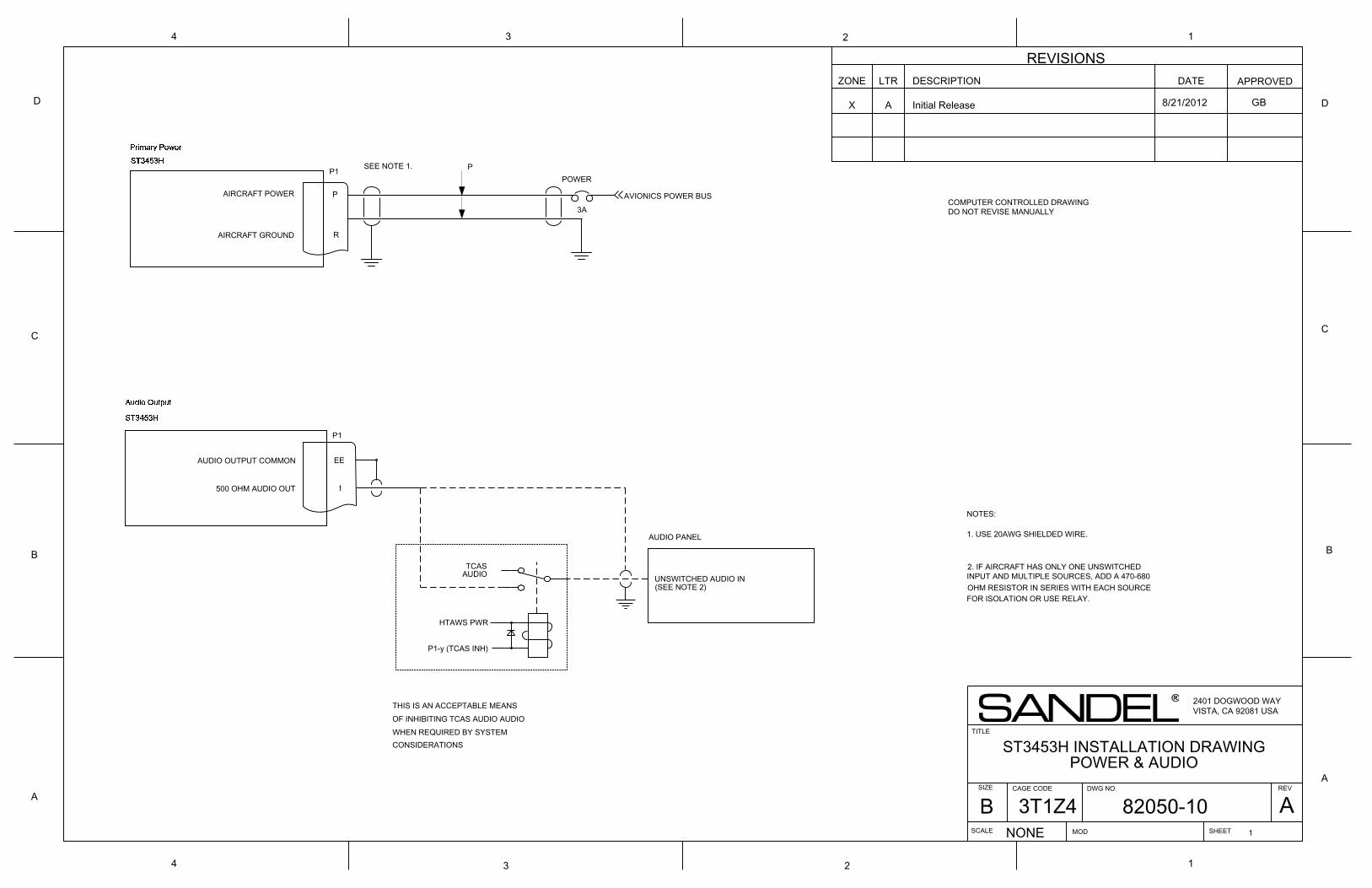
4 3 2
REVISIONSZONE LTR DESCRIPTION DATE APPROVED
TITLE
SIZE DWG NO.
SCALE SHEET
REVA
B
C
D
134
D
C
B
A
1
NONE
A
2401 DOGWOOD WAYVISTA, CA 92081 USA
CAGE CODE
2
X Initial Release
ST3453H INSTALLATION DRAWINGPOWER & AUDIO
AVIONICS POWER BUS
P1
AIRCRAFT POWER
AIRCRAFT GROUND
P
R
POWER
3A
SEE NOTE 1.
UNSWITCHED AUDIO IN(SEE NOTE 2)
t
HTAWS PWR
THIS IS AN ACCEPTABLE MEANSOF INHIBITING TCAS AUDIO AUDIOWHEN REQUIRED BY SYSTEMCONSIDERATIONS
P1-y (TCAS INH)
500 OHM AUDIO OUT
AUDIO PANEL
P1
AUDIO OUTPUT COMMON EE
TCAS AUDIO
1. USE 20AWG SHIELDED WIRE.
2. IF AIRCRAFT HAS ONLY ONE UNSWITCHEDINPUT AND MULTIPLE SOURCES, ADD A 470-680OHM RESISTOR IN SERIES WITH EACH SOURCEFOR ISOLATION OR USE RELAY.
NOTES:
8/21/2012
MOD
P
1
COMPUTER CONTROLLED DRAWINGDO NOT REVISE MANUALLY
GB
4 3 2
REVISIONS
ZONE LTR DESCRIPTION DATE APPROVED
TITLE
SIZE DWG NO.
SCALE SHEET
REVA
B
C
D
134
D
C
B
A
1
NONE
82050-102
A
COMPUTER CONTROLLED DRAWINGDO NOT REVISE MANUALLY
CAGE CODE
B 3T1Z4
2
X Initial Release
ST3453H INSTALLATION DRAWING
2401 DOGWOOD WAYVISTA, CA 92081 USA
MOD
8/21/2012 GB
ALL B ARINC 429 position sources not supported. Drawing removed. RFU 12/18/2012
ARINC 429 POSITION SOURCES ARE NOT SUPPORTED.
GB
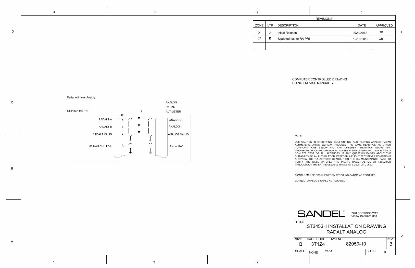
4 3 2
REVISIONS
ZONE LTR DESCRIPTION DATE APPROVED
TITLE
SIZE DWG NO.
SCALE SHEET
REVA
B
C
D
134
D
C
B
A
1
NONE
82050-103
A
COMPUTER CONTROLLED DRAWINGDO NOT REVISE MANUALLY
CAGE CODE
B 3T1Z4
2
X Initial Release
2401 DOGWOOD WAYVISTA, CA 92081 USA
MOD
ST3453H INSTALLATION DRAWINGRADALT ANALOG
RADALT B
RADALT A
A#1 RAD ALT FAIL Pwr or Ref
ST3453H RA PRI
cRADALT VALID
ANALOGRADARALTIMETER
ANALOG -
ANALOG VAILID
ANALOG +a
b
P1
Radar Altimeter Analog
NOTE:
USE CAUTION IN SPECIFYING, CONFIGURING, AND TESTING ANALOG RADAR ALTIMETERS. ARINC 552 MAY PRODUCE THE SAME READINGS AS OTHER CONFIGURATIONS BELOW 480' AND DIFFERENT READINGS ABOVE 480'. THEREFORE, IF CONFIGURATION IS MIS-SET A SIMPLE GROUND TEST IS NOT A COMLETE TEST OF ALL ALTITUDES. IF ANY QUESTION EXISTS ABOUT THE SUITABILITY OF AN INSTALLATION, PERFORM A FLIGHT TEST IN VFR CONDITIONS A REVIEW THE RA ALTITUDE READOUT ON THE RA MAINTENANCE PAGE TO VERIFY THE DATA MATCHES THE PILOT’S RADAR ALTIMETER INDICATOR THROUGHOUT THE ENTIRE USEABLE RANGE OF 0-2000' OR 0-2500'.
SIGNALS MAY BE OBTAINED FROM R/T OR INDICATOR, AS REQUIRED.
CONNECT ANALOG SIGNALS AS REQUIRED
T
8/21/2012 GB
C4 Updated text to RA PRI 12/18/2012 GB
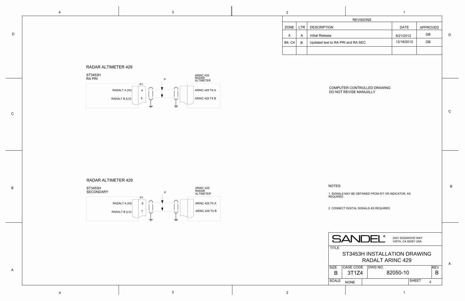
ST3453H INSTALLATION DRAWINGRADALT ARINC 429
RADALT A (HI)
RADALT B (LO)
ST3453H
P1
b
a ARINC 429 TX A
ARINC 429 TX B
ARINC 429RADARALTIMETER
NOTES:
1. SIGNALS MAY BE OBTAINED FROM R/T OR INDICATOR, ASREQUIRED.
2. CONNECT DIGITAL SIGNALS AS REQUIRED.
RADAR ALTIMETER 429
RA PRI P
RADALT A (HI)
RADALT B (LO)
ST3453H
P1
T
S ARINC 429 TX A
ARINC 429 TX B
ARINC 429RADARALTIMETER
RADAR ALTIMETER 429
SECONDARY P
2401 DOGWOOD WAYVISTA, CA 92081 USA
REVISIONS
ZONE LTR DESCRIPTION DATE APPROVED
TITLE
SIZE DWG NO.
SCALE SHEET
REVA
B
C
D
134
D
C
B
A
1
NONE
82050-10 B4
A
COMPUTER CONTROLLED DRAWINGDO NOT REVISE MANUALLY
CAGE CODE
B 3T1Z4
2
X Initial Release
4 3 2
8/21/2012 GB
B4, C4 B Updated text to RA PRI and RA SEC 12/18/2012 GB
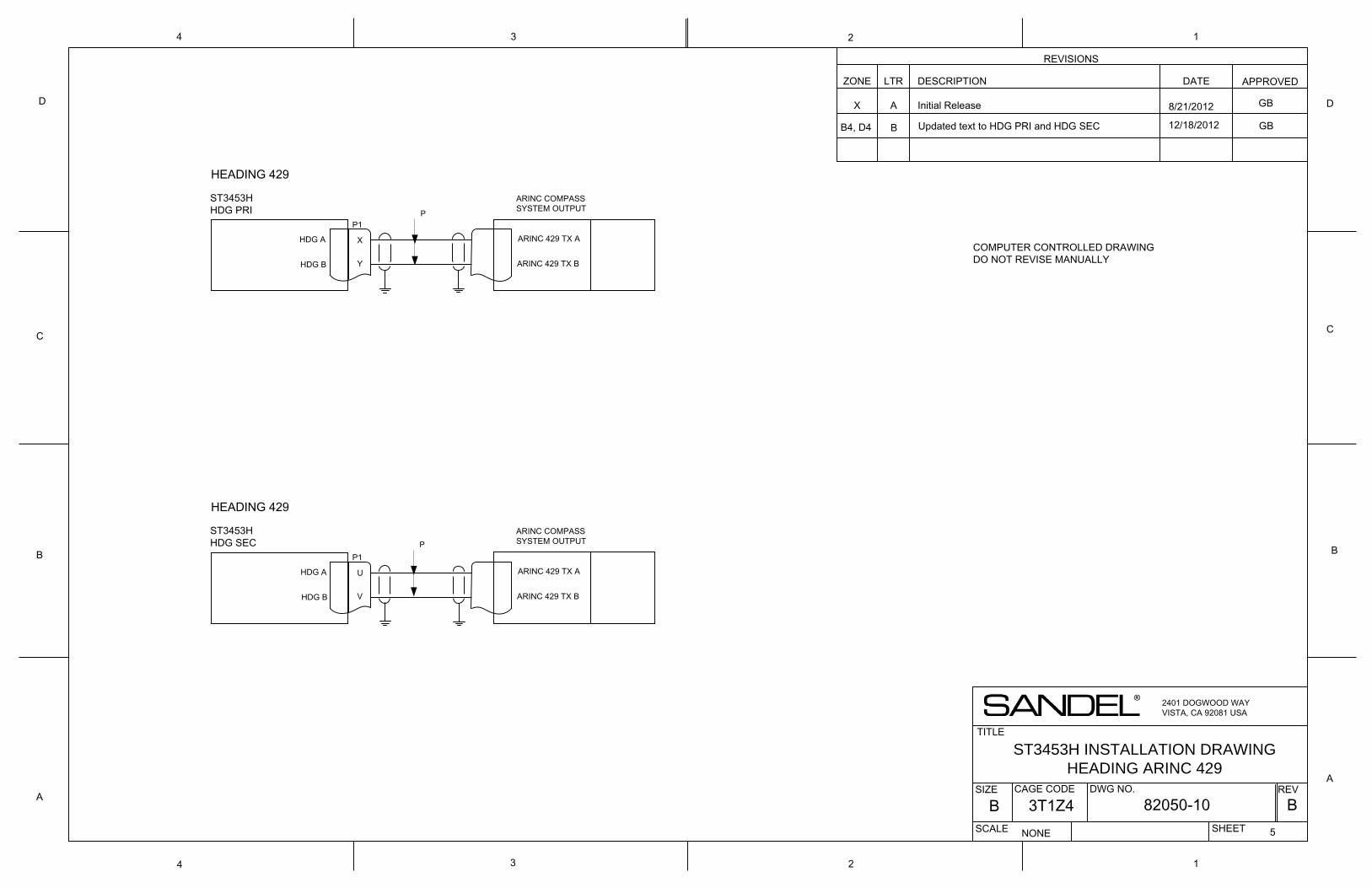
ST3453HHDG PRI
ARINC 429 TX B
ARINC 429 TX AP1
HDG A
HDG B
X
Y
ARINC COMPASS SYSTEM OUTPUT
HEADING 429
ST3453H INSTALLATION DRAWINGHEADING ARINC 429
2401 DOGWOOD WAYVISTA, CA 92081 USA
REVISIONS
ZONE LTR DESCRIPTION DATE APPROVED
TITLE
SIZE DWG NO.
SCALE SHEET
REVA
B
C
D
134
D
C
B
A
1
NONE
82050-10 B5
A
CAGE CODE
B 3T1Z4
2
X Initial Release
4 3 2
ST3453HHDG SEC
ARINC 429 TX B
ARINC 429 TX AP1
HDG A
HDG B
U
V
ARINC COMPASS SYSTEM OUTPUT
HEADING 429
COMPUTER CONTROLLED DRAWINGDO NOT REVISE MANUALLY
P
P
8/21/2012 GB
BB4, D4 Updated text to HDG PRI and HDG SEC 12/18/2012 GB
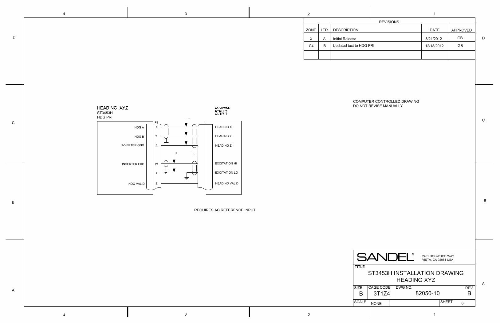
ST3453H HDG PRI
HEADING Y
HEADING XP1
HDG A
HEADING Z
HDG B
X
Y
INVERTER EXC EXCITATION HIW
EXCITATION LO
HEADING VALIDZHDG VALID
REQUIRES AC REFERENCE INPUT
ST3453H INSTALLATION DRAWINGHEADING XYZ
2401 DOGWOOD WAYVISTA, CA 92081 USA
REVISIONS
ZONE LTR DESCRIPTION DATE APPROVED
TITLE
SIZE DWG NO.
SCALE SHEET
REVA
B
C
D
134
D
C
B
A
1
NONE
82050-10 B6
A
CAGE CODE
B 3T1Z4
2
X Initial Release
4 3 2
INVERTER GND
s
T
P
COMPUTER CONTROLLED DRAWINGDO NOT REVISE MANUALLY
8/21/2012
s
GB
BC4 Updated text to HDG PRI 12/18/2012 GB
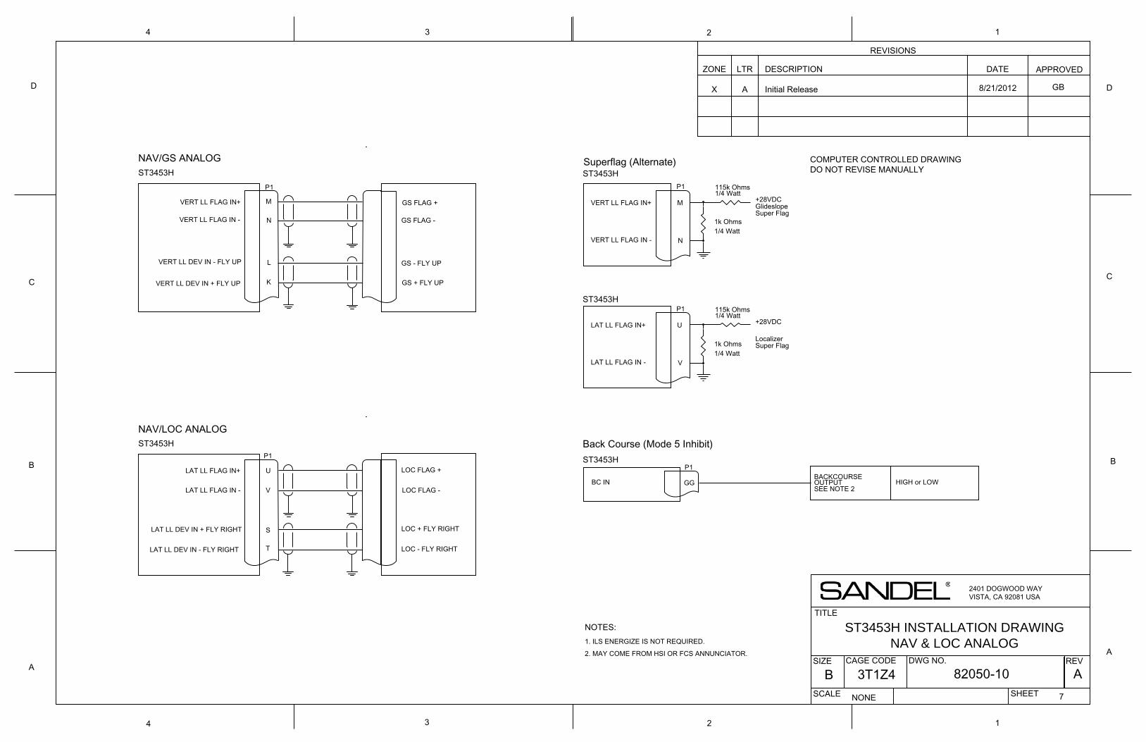
1k Ohms
115k Ohms
VERT LL FLAG IN -
ST3453HP1
VERT LL FLAG IN+ M
N
VERT LL DEV IN - FLY UP
K
L
GS FLAG +
GS FLAG -
GS + FLY UP
GS - FLY UP
+28VDCGlideslopeSuper Flag
P1
ST3453H
M
N1/4 Watt
1/4 Watt
NOTES:1. ILS ENERGIZE IS NOT REQUIRED.
2. MAY COME FROM HSI OR FCS ANNUNCIATOR.
P1
GGBC IN
ST3453H
BACKCOURSEOUTPUT HIGH or LOWSEE NOTE 2
Back Course (Mode 5 Inhibit)
Superflag (Alternate)NAV/GS ANALOG
VERT LL DEV IN + FLY UP
VERT LL FLAG IN+
VERT LL FLAG IN -
NAV/LOC ANALOG
LAT LL DEV IN - FLY RIGHT
LAT LL FLAG IN -
ST3453HP1
LAT LL FLAG IN+ U
V
LAT LL DEV IN + FLY RIGHT
T
S
LOC FLAG +
LOC FLAG -
LOC + FLY RIGHT
LOC - FLY RIGHT
ST3453H INSTALLATION DRAWINGNAV & LOC ANALOG
2401 DOGWOOD WAYVISTA, CA 92081 USA
REVISIONS
ZONE LTR DESCRIPTION DATE APPROVED
TITLE
SIZE DWG NO.
SCALE SHEET
REVA
B
C
D
134
D
C
B
A
1
NONE
82050-10 A7
A
CAGE CODE
B 3T1Z4
2
X Initial Release
4 3 2
1k Ohms
115k Ohms
+28VDC
LocalizerSuper Flag
P1ST3453H
U
V1/4 Watt
1/4 WattLAT LL FLAG IN+
LAT LL FLAG IN -
COMPUTER CONTROLLED DRAWINGDO NOT REVISE MANUALLY
8/21/2012 GB
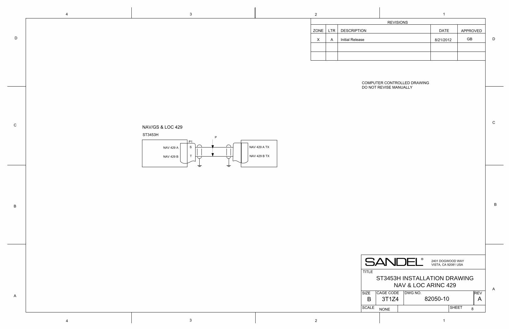
NAV 429 A TX
T
ST3453H
NAV 429 B TX
S
NAV 429 B
NAV 429 A
P1
NAV/GS & LOC 429
ST3453H INSTALLATION DRAWINGNAV & LOC ARINC 429
2401 DOGWOOD WAYVISTA, CA 92081 USA
REVISIONS
ZONE LTR DESCRIPTION DATE APPROVED
TITLE
SIZE DWG NO.
SCALE SHEET
REVA
B
C
D
134
D
C
B
A
1
NONE
82050-10 A8
A
CAGE CODE
B 3T1Z4
2
X Initial Release
4 3 2
COMPUTER CONTROLLED DRAWINGDO NOT REVISE MANUALLY
P
8/21/2012 GB
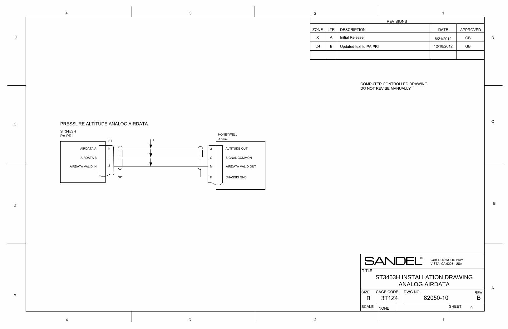
PRESSURE ALTITUDE ANALOG AIRDATA
SIGNAL COMMON
J M
ST3453H PA PRI
ALTITUDE OUT
P1
AIRDATA VALID IN
J
AIRDATA VALID OUT
Gi
h
HONEYWELL AZ-649
AIRDATA A
AIRDATA B
CHASSIS GNDF
ST3453H INSTALLATION DRAWINGANALOG AIRDATA
2401 DOGWOOD WAYVISTA, CA 92081 USA
REVISIONS
ZONE LTR DESCRIPTION DATE APPROVED
TITLE
SIZE DWG NO.
SCALE SHEET
REVA
B
C
D
134
D
C
B
A
1
NONE
82050-10 B9
A
CAGE CODE
B 3T1Z4
2
X Initial Release
4 3 2
COMPUTER CONTROLLED DRAWINGDO NOT REVISE MANUALLY
8/21/2012
T
GB
C4 B Updated text to PA PRI 12/18/2012 GB
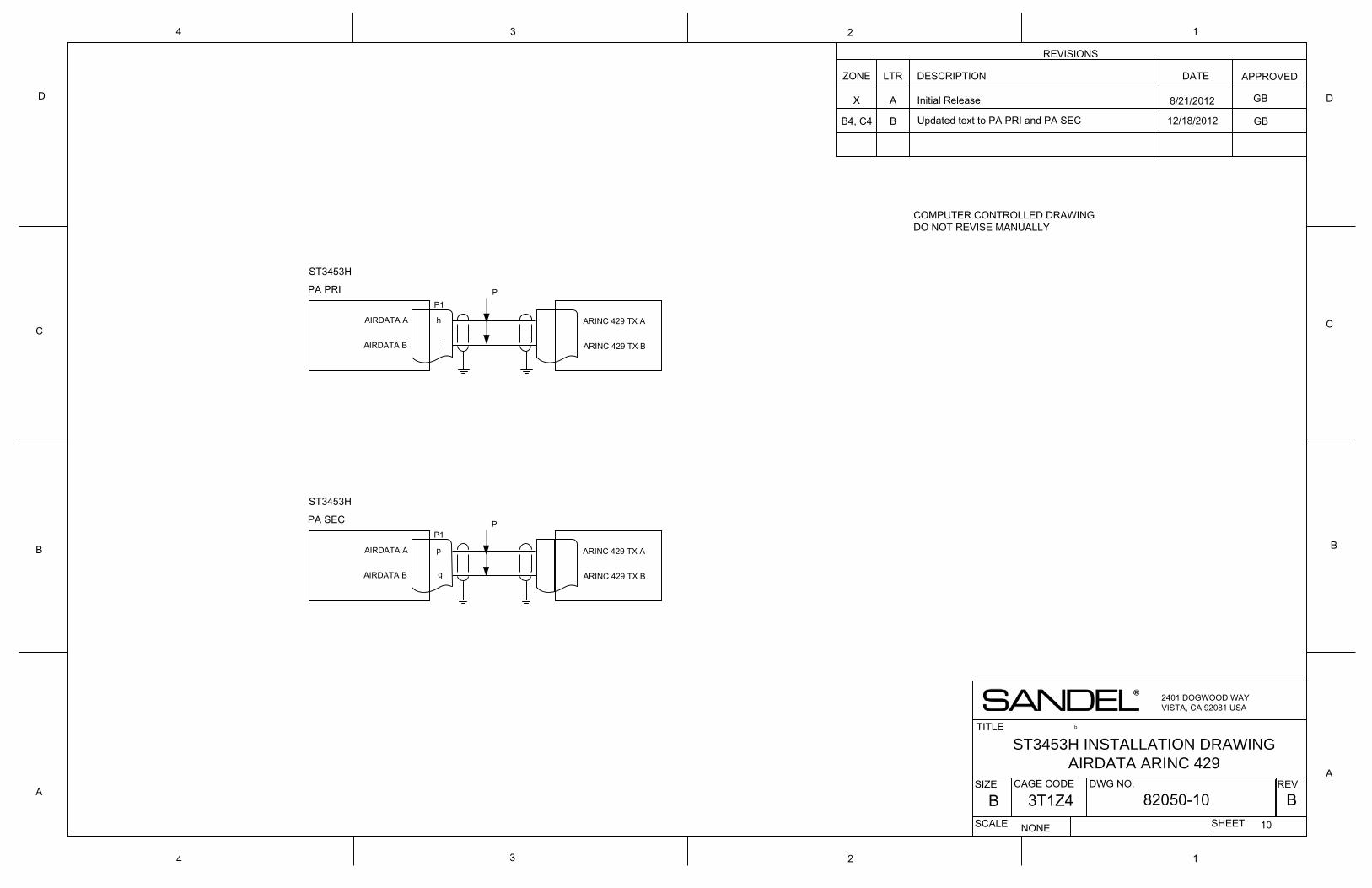
b
ST3453H
P1
i
AIRDATA A
AIRDATA B
h
ARINC 429 TX B
ARINC 429 TX A
ST3453H INSTALLATION DRAWINGAIRDATA ARINC 429
2401 DOGWOOD WAYVISTA, CA 92081 USA
REVISIONS
ZONE LTR DESCRIPTION DATE APPROVED
TITLE
SIZE DWG NO.
SCALE SHEET
REVA
B
C
D
134
D
C
B
A
1
NONE
82050-10 B10
A
CAGE CODE
B 3T1Z4
2
X Initial Release
4 3 2
PA PRI
ST3453H
P1
q
AIRDATA A
AIRDATA B
p
ARINC 429 TX B
ARINC 429 TX A
PA SEC
COMPUTER CONTROLLED DRAWINGDO NOT REVISE MANUALLY
P
P
8/21/2012 GB
B4, C4 B Updated text to PA PRI and PA SEC GB12/18/2012
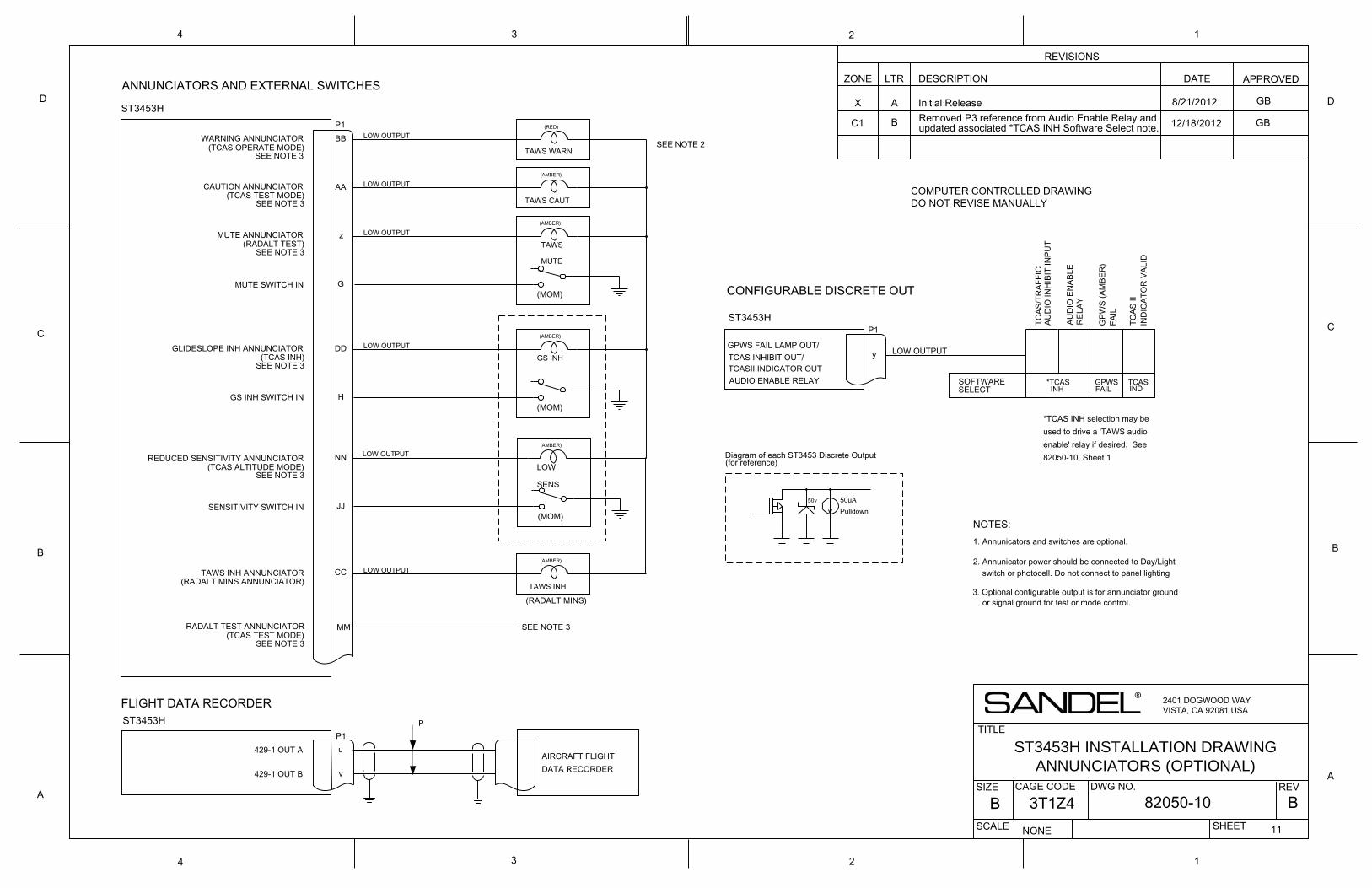
50v
1. Annunicators and switches are optional.
NOTES:
WARNING ANNUNCIATOR
CAUTION ANNUNCIATOR
BB
AA
TAWS WARN
(RED)
ST3453H
ST3453HP1
MUTE ANNUNCIATOR z
LOW OUTPUT
(AMBER)
TAWS INH ANNUNCIATOR
GLIDESLOPE INH ANNUNCIATOR DD
REDUCED SENSITIVITY ANNUNCIATOR
GS INH SWITCH IN
SENSITIVITY SWITCH IN
MUTE SWITCH IN
P1u
v
429-1 OUT AAIRCRAFT FLIGHTDATA RECORDER
GPWS FAIL LAMP OUT/y LOW OUTPUT
2. Annunicator power should be connected to Day/Light switch or photocell. Do not connect to panel lighting
dimmer.
P1ST3453H
SEE NOTE 2
TCAS
IIIN
DIC
ATO
R V
ALID
GPW
S (A
MBE
R)
FAIL
TCAS INHIBIT OUT/TCASII INDICATOR OUT
SOFTWARESELECT
CC
H
NN
JJ
LOW
SENS
(MOM)
(AMBER)
GS INH
(AMBER)
(MOM)
(AMBER)
(MOM)
TAWS
MUTE
G
TAWS CAUT
LOW OUTPUT
LOW OUTPUT
LOW OUTPUT
LOW OUTPUT
ANNUNCIATORS AND EXTERNAL SWITCHES
FLIGHT DATA RECORDER
CONFIGURABLE DISCRETE OUT
GPWS FAIL
TCAS IND
AUDIO ENABLE RELAY
*TCAS INH selection may beused to drive a 'TAWS audioenable' relay if desired. See82050-10, Sheet 1
*TCASINH
TCAS
/TR
AFFI
CAU
DIO
INH
IBIT
INPU
T
AUD
IO E
NAB
LER
ELAY
50uAPulldown
Diagram of each ST3453 Discrete Output(for reference)
TAWS INH
(AMBER)
LOW OUTPUT
429-1 OUT B
ST3453H INSTALLATION DRAWINGANNUNCIATORS (OPTIONAL)
2401 DOGWOOD WAYVISTA, CA 92081 USA
REVISIONS
ZONE LTR DESCRIPTION DATE APPROVED
TITLE
SIZE DWG NO.
SCALE SHEET
REVA
B
C
D
134
D
C
B
A
1
NONE
82050-10 B11
A
CAGE CODE
B 3T1Z4
2
X Initial Release
4 3 2
MMRADALT TEST ANNUNCIATOR
(TCAS OPERATE MODE)
(TCAS TEST MODE)
(RADALT TEST)
(TCAS INH)
(TCAS ALTITUDE MODE)
(RADALT MINS ANNUNCIATOR)
(TCAS TEST MODE)
COMPUTER CONTROLLED DRAWINGDO NOT REVISE MANUALLY
P
8/21/2012
SEE NOTE 3
SEE NOTE 3
SEE NOTE 3
SEE NOTE 3
SEE NOTE 3
SEE NOTE 3
SEE NOTE 3
(RADALT MINS)3. Optional configurable output is for annunciator ground
or signal ground for test or mode control.
GB
B Removed P3 reference from Audio Enable Relay and updated associated *TCAS INH Software Select note. 12/18/2012C1 GB
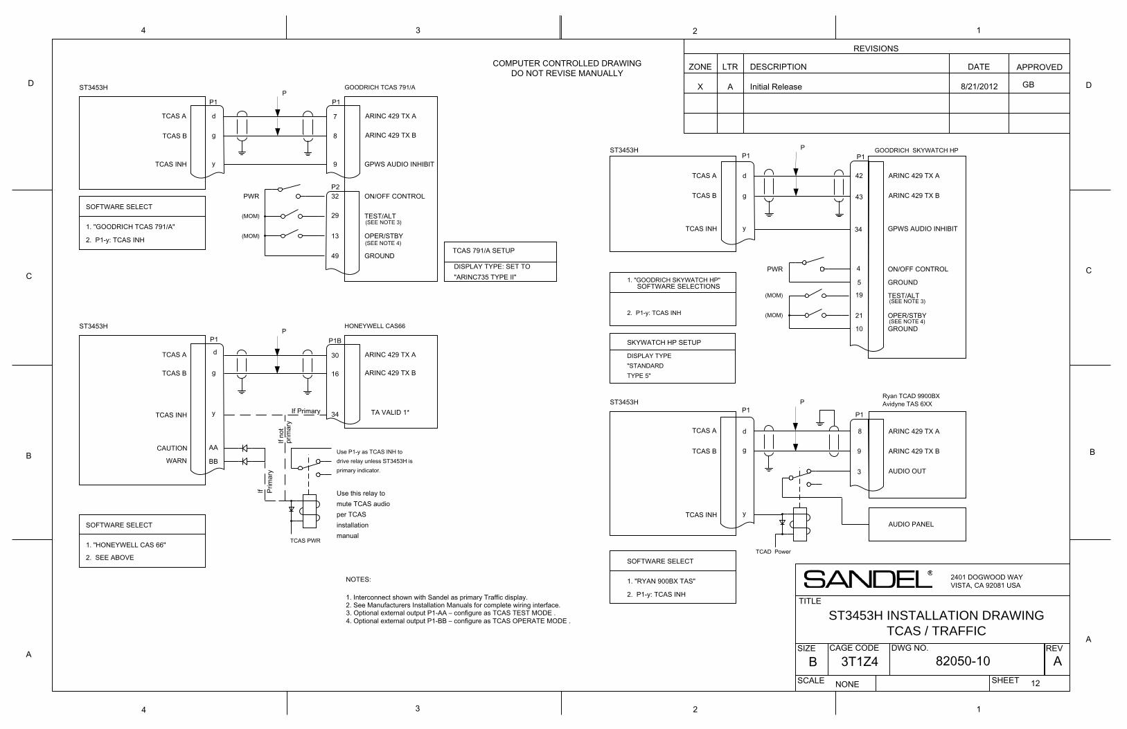
TCAS A
8
7
GOODRICH TCAS 791/A
P1
g
d ARINC 429 TX A
ARINC 429 TX BTCAS B
13
TEST/ALT
OPER/STBY
SOFTWARE SELECT
1. "GOODRICH TCAS 791/A"29
49 GROUND
ON/OFF CONTROL32
TCAS 791/A SETUP
DISPLAY TYPE: SET TO"ARINC735 TYPE II"
P1
NOTES:
yTCAS INH 9 GPWS AUDIO INHIBIT
P2
1. Interconnect shown with Sandel as primary Traffic display.2. See Manufacturers Installation Manuals for complete wiring interface.
2. P1-y: TCAS INH
16
30
HONEYWELL CAS66
P1
g
d ARINC 429 TX A
ARINC 429 TX B
SOFTWARE SELECT
1. "HONEYWELL CAS 66"
P1B
yTCAS INH 34 TA VALID 1*
2. SEE ABOVE
Use P1-y as TCAS INH todrive relay unless ST3453H isprimary indicator.
AACAUTION
WARN BB
TCAS PWR
Use this relay tomute TCAS audioper TCASinstallationmanual
ST3453H
ST3453H
PWR
(MOM)
(MOM)
If Primary
If Prim
ary
If no
tpr
imar
y
4
TCAS INH
19
ARINC 429 TX A
1. "RYAN 900BX TAS"
ST3453HRyan TCAD 9900BXAvidyne TAS 6XX
TEST/ALT
ARINC 429 TX B
TCAD Power
9
AUDIO PANEL
2. P1-y: TCAS INH
ARINC 429 TX A
d
P1
34
OPER/STBY
3
8
ON/OFF CONTROL
SOFTWARE SELECT
SOFTWARE SELECTIONS GROUND
43
TCAS INH
(MOM)
DISPLAY TYPE "STANDARDTYPE 5"
10
g
GOODRICH SKYWATCH HP
GROUND
(MOM)
P1
P1
1. "GOODRICH SKYWATCH HP"
g
5
21
AUDIO OUT
PWR
ST3453H
GPWS AUDIO INHIBIT
P1
d 42
SKYWATCH HP SETUP
y
2. P1-y: TCAS INH
ARINC 429 TX B
y
TCAS A
TCAS B
TCAS A
TCAS B
TCAS A
TCAS B
ST3453H INSTALLATION DRAWINGTCAS / TRAFFIC
2401 DOGWOOD WAYVISTA, CA 92081 USA
REVISIONS
ZONE LTR DESCRIPTION DATE APPROVED
TITLE
SIZE DWG NO.
SCALE SHEET
REVA
B
C
D
134
D
C
B
A
1
NONE
82050-10 A12
A
CAGE CODE
B 3T1Z4
2
X Initial Release
4 3 2
COMPUTER CONTROLLED DRAWINGDO NOT REVISE MANUALLY
8/21/2012P
P
P
P
(SEE NOTE 3)
(SEE NOTE 4)
(SEE NOTE 3)
(SEE NOTE 4)
3. Optional external output P1-AA – configure as TCAS TEST MODE .4. Optional external output P1-BB – configure as TCAS OPERATE MODE .
GB
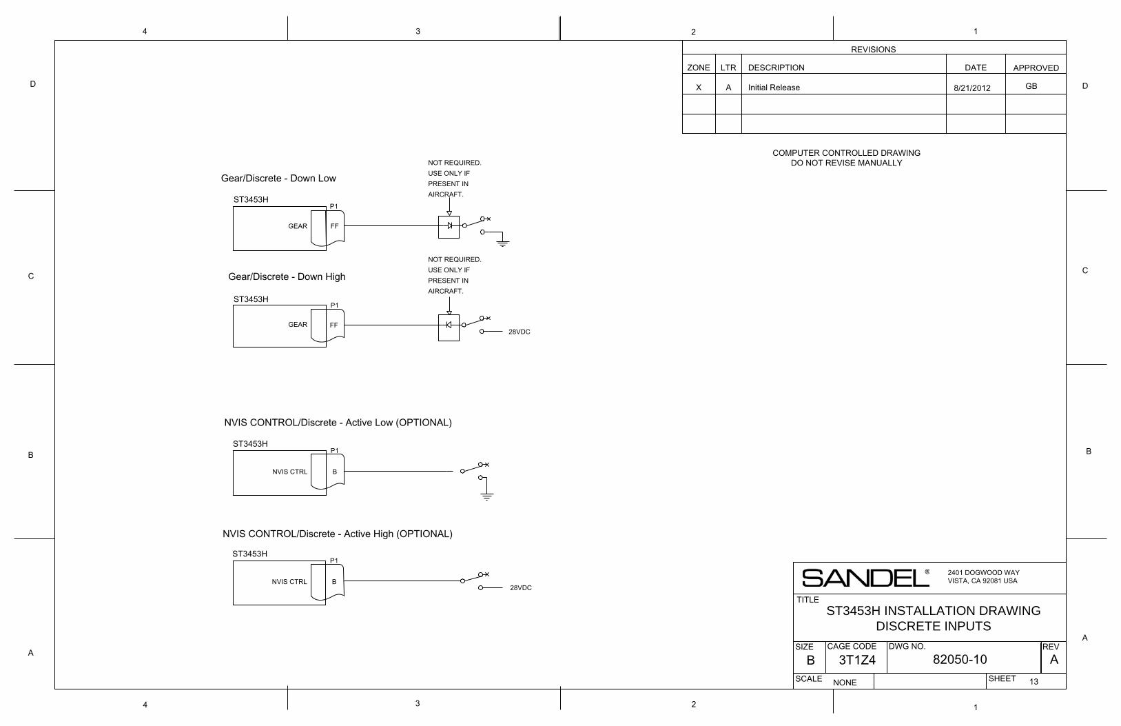
ST3453H
FFGEAR
ST3453H
FFGEAR28VDC
NOT REQUIRED. USE ONLY IFPRESENT INAIRCRAFT.
NOT REQUIRED. USE ONLY IFPRESENT INAIRCRAFT.
P1
P1
Gear/Discrete - Down Low
Gear/Discrete - Down High
P1ST3453H
BNVIS CTRL
NVIS CONTROL/Discrete - Active Low (OPTIONAL)
ST3453H INSTALLATION DRAWINGDISCRETE INPUTS
2401 DOGWOOD WAYVISTA, CA 92081 USA
REVISIONS
ZONE LTR DESCRIPTION DATE APPROVED
TITLE
SIZE DWG NO.
SCALE SHEET
REVA
B
C
D
134
D
C
B
A
1
NONE
82050-10 A13
A
CAGE CODE
B 3T1Z4
2
X Initial Release
4 3 2
COMPUTER CONTROLLED DRAWINGDO NOT REVISE MANUALLY
8/21/2012
P1ST3453H
BNVIS CTRL28VDC
NVIS CONTROL/Discrete - Active High (OPTIONAL)
GB
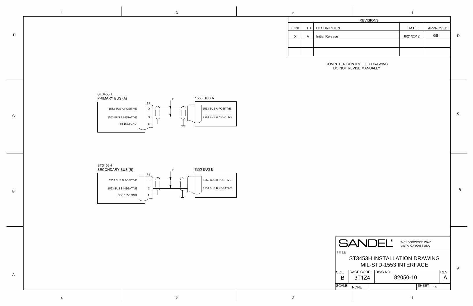
ST3453H INSTALLATION DRAWINGMIL-STD-1553 INTERFACE
2401 DOGWOOD WAYVISTA, CA 92081 USA
REVISIONS
ZONE LTR DESCRIPTION DATE APPROVED
TITLE
SIZE DWG NO.
SCALE SHEET
REVA
B
C
D
134
D
C
B
A
1
NONE
82050-10 A14
A
CAGE CODE
B 3T1Z4
2
X Initial Release
4 3 2
COMPUTER CONTROLLED DRAWINGDO NOT REVISE MANUALLY
ST3453HPRIMARY BUS (A)
P1
D
C
e
ST3453HSECONDARY BUS (B)
P1
F
E
f
1553 BUS A
1553 BUS B
1553 BUS A POSITIVE
1553 BUS A NEGATIVE
PRI 1553 GND
SEC 1553 GND
1553 BUS B NEGATIVE
1553 BUS B POSITIVE
1553 BUS A POSITIVE
1553 BUS A NEGATIVE
1553 BUS B POSITIVE
1553 BUS B NEGATIVE
8/21/2012
P
P
GB
Related Documents