ST3283N SCSI Interface Drive Product Manual 36184-001, Rev. A November 9, 1991

Welcome message from author
This document is posted to help you gain knowledge. Please leave a comment to let me know what you think about it! Share it to your friends and learn new things together.
Transcript
ST3283NSCSI Interface Drive
Product Manual
36184-001, Rev. ANovember 9, 1991
Copyright Notice
Seagate®, Seagate Technology® and the Seagate logo are registeredtrademarks of Seagate Technology, Inc. This publication is copyrightedwith all rights reserved and may not be copied, in whole or part, withoutwritten permission from Seagate Technology, Inc.
© Copyright 1991 Seagate Technology, Inc. 920 Disc Drive Scotts Valley, California 95066-4544, USATelephone: 408/438-6550
Publication Number: 36184-001, Rev. A
The products referenced in this publication are trademarks of theirrespective owners.
Table of Contents
1.0 Specifications Summary . . . . . . . . . . . . . . . . . . . 1
1.1 Formatted Capacity . . . . . . . . . . . . . . . . . . . . . 1
1.2 Drive Performance Specifications . . . . . . . . . . . . . . 2
1.2.1 Multi-Segment Read Look-Ahead Buffer . . . . . . . . 2
1.2.2 Seek Time Definition and Specifications . . . . . . . . 2
1.2.2.1 Thermal Compensation . . . . . . . . . . . . . . 3
1.2.3 Format Drive . . . . . . . . . . . . . . . . . . . . . . 3
1.2.4 Start/Stop Time . . . . . . . . . . . . . . . . . . . . . 3
1.2.5 Typical Power-Up/Power-Down Sequence . . . . . . . 4
1.2.5.1 Power-Up Sequence . . . . . . . . . . . . . . . . 4
1.2.5.2 Power-Down Sequence . . . . . . . . . . . . . . 4
1.2.5.3 Read/Write Head Auto-Park . . . . . . . . . . . . 5
1.3 Reliability . . . . . . . . . . . . . . . . . . . . . . . . . . 5
1.4 Physical Dimensions . . . . . . . . . . . . . . . . . . . . 5
1.5 Environmental . . . . . . . . . . . . . . . . . . . . . . . . 5
1.5.1 Ambient Temperature . . . . . . . . . . . . . . . . . 5
1.5.2 Temperature Gradient . . . . . . . . . . . . . . . . . 6
1.5.3 Relative Humidity . . . . . . . . . . . . . . . . . . . . 6
1.5.4 Altitude . . . . . . . . . . . . . . . . . . . . . . . . . 6
1.6 Acoustics . . . . . . . . . . . . . . . . . . . . . . . . . . 6
1.7 Shock and Vibration . . . . . . . . . . . . . . . . . . . . . 6
1.8 DC Power . . . . . . . . . . . . . . . . . . . . . . . . . . 7
ST3283N SCSI Interface Drive Product Manual, Rev. A iii
1.8.1 Power Mode Descriptions . . . . . . . . . . . . . . . . 8
1.8.2 Power Consumption . . . . . . . . . . . . . . . . . . 9
1.9 Agency Listings . . . . . . . . . . . . . . . . . . . . . . 11
1.9.1 UL Recognition . . . . . . . . . . . . . . . . . . . . 11
1.9.2 CSA Listing . . . . . . . . . . . . . . . . . . . . . . 11
1.9.3 VDE Listing . . . . . . . . . . . . . . . . . . . . . . 11
1.9.4 FCC Verification . . . . . . . . . . . . . . . . . . . . 11
1.10 Drive Mounting . . . . . . . . . . . . . . . . . . . . . . 13
1.10.1 Handling and Static Discharge Precautions . . . . . 14
1.10.2 Hot-plugging . . . . . . . . . . . . . . . . . . . . . 14
2.0 Interface Description and Options . . . . . . . . . . . . . 17
2.1 SCSI-2 Compatibility . . . . . . . . . . . . . . . . . . . . 17
2.2 SCSI Connector . . . . . . . . . . . . . . . . . . . . . . 17
2.2.1 SCSI Connector Requirements . . . . . . . . . . . . 17
2.2.1.1 SCSI Connector Pin Assignments . . . . . . . . 19
2.3 Cable Requirements . . . . . . . . . . . . . . . . . . . . 20
2.3.1 Single-Ended Cable . . . . . . . . . . . . . . . . . . 20
2.3.2 Fast Synchronous Data Transfer . . . . . . . . . . . 20
2.4 Terminators . . . . . . . . . . . . . . . . . . . . . . . . 21
2.4.1 Active Termination . . . . . . . . . . . . . . . . . . 21
2.4.2 Passive Termination . . . . . . . . . . . . . . . . . 22
2.4.2.1 Single-Ended Drivers/Receivers . . . . . . . . . 22
2.5 Configuration Jumpers . . . . . . . . . . . . . . . . . . . 23
2.5.1 Parity/Remote Start Jumper Block . . . . . . . . . . 24
iv ST3283N SCSI Interface Drive Product Manual, Rev. A
2.5.1.1 Parity Enable Option . . . . . . . . . . . . . . . . 24
2.5.1.2 Start/Stop Option . . . . . . . . . . . . . . . . . 24
2.5.2 Active/Passive Termination Jumper Block . . . . . . . 24
2.5.3 Terminator Power Source Jumper Block . . . . . . . . 24
2.5.4 SCSI ID Address Jumper Block . . . . . . . . . . . . 25
2.5.5 Options Jumper Block . . . . . . . . . . . . . . . . . 25
2.6 External Spindle Synchronization Option . . . . . . . . . . 27
3.0 SCSI Bus . . . . . . . . . . . . . . . . . . . . . . . . . . . . 29
3.1 SCSI ID Bits . . . . . . . . . . . . . . . . . . . . . . . . . 31
3.2 SCSI Bus Signals . . . . . . . . . . . . . . . . . . . . . . 32
3.2.1 Signal Values . . . . . . . . . . . . . . . . . . . . . . 33
3.2.2 OR-Tied Signals . . . . . . . . . . . . . . . . . . . . 33
3.2.3 Signal Sources . . . . . . . . . . . . . . . . . . . . . 33
3.3 SCSI Bus Timing . . . . . . . . . . . . . . . . . . . . . . 35
3.4 Fast Synchronous Transfer Rates . . . . . . . . . . . . . 37
4.0 Logical Characteristics . . . . . . . . . . . . . . . . . . . . 39
4.1 SCSI Bus Phases . . . . . . . . . . . . . . . . . . . . . . 39
4.1.1 Bus Free Phase . . . . . . . . . . . . . . . . . . . . 39
4.1.2 Arbitration Phase . . . . . . . . . . . . . . . . . . . . 40
4.1.3 Selection Phase . . . . . . . . . . . . . . . . . . . . 41
4.1.3.1 Nonarbitrating Systems . . . . . . . . . . . . . . 41
4.1.3.2 Arbitrating Systems . . . . . . . . . . . . . . . . 42
4.1.3.3 All Systems . . . . . . . . . . . . . . . . . . . . 42
4.1.3.4 Single Initiator Option . . . . . . . . . . . . . . . 42
ST3283N SCSI Interface Drive Product Manual, Rev. A v
4.1.3.5 Selection Time-out Procedure . . . . . . . . . . 43
4.1.4 Reselection Phase . . . . . . . . . . . . . . . . . . 43
4.1.4.1 Reselection Procedure . . . . . . . . . . . . . . 43
4.1.4.2 Reselection Time-out Procedure . . . . . . . . . 44
4.1.5 Information Transfer Phases . . . . . . . . . . . . . 45
4.1.5.1 Asynchronous Data Transfer . . . . . . . . . . . 46
4.1.5.2 Synchronous Data Transfer . . . . . . . . . . . 46
4.1.6 Command Phase . . . . . . . . . . . . . . . . . . . 47
4.1.7 Data Phases . . . . . . . . . . . . . . . . . . . . . 48
4.1.7.1 Data In Phase . . . . . . . . . . . . . . . . . . 48
4.1.7.2 Data Out Phase . . . . . . . . . . . . . . . . . 48
4.1.8 Status Phase . . . . . . . . . . . . . . . . . . . . . 48
4.1.9 Message Phases . . . . . . . . . . . . . . . . . . . 48
4.1.9.1 Message In Phase . . . . . . . . . . . . . . . . 48
4.1.9.2 Message Out Phase . . . . . . . . . . . . . . . 48
4.1.10 Signal Restrictions Between Phases . . . . . . . . 49
4.2 SCSI Bus Conditions . . . . . . . . . . . . . . . . . . . . 50
4.2.1 Attention Condition . . . . . . . . . . . . . . . . . . 50
4.2.2 Reset Condition . . . . . . . . . . . . . . . . . . . . 51
4.3 SCSI Bus Phases . . . . . . . . . . . . . . . . . . . . . 51
4.3.1 Arbitration Transfer Phases . . . . . . . . . . . . . . 52
4.3.1.1 Systems with Arbitration . . . . . . . . . . . . . 52
4.3.1.2 Systems without Arbitration . . . . . . . . . . . 52
4.4 SCSI Pointers . . . . . . . . . . . . . . . . . . . . . . . 52
vi ST3283N SCSI Interface Drive Product Manual, Rev. A
4.5 Message System Specification . . . . . . . . . . . . . . . 54
4.5.1 Message Protocol . . . . . . . . . . . . . . . . . . . 54
4.5.2 Single-Byte Messages . . . . . . . . . . . . . . . . . 55
4.5.3 Extended Messages . . . . . . . . . . . . . . . . . . 59
4.5.3.1 Synchronous Data Transfer Request Message . . 60
5.0 SCSI Commands . . . . . . . . . . . . . . . . . . . . . . . 61
5.1 Command Implementation Requirements . . . . . . . . . . 61
5.1.1 Reserved Addresses . . . . . . . . . . . . . . . . . . 61
5.1.2 Unit Attention Condition . . . . . . . . . . . . . . . . 62
5.1.3 Command Queuing . . . . . . . . . . . . . . . . . . 62
5.2 Command Descriptor Block (CDB) . . . . . . . . . . . . . 63
5.2.1 Operation Code . . . . . . . . . . . . . . . . . . . . 64
5.2.1.1 Operation Code Format for CDB Byte 0 . . . . . . 64
5.2.1.2 Typical 6-Byte Command Descriptor Block . . . . 64
5.2.1.3 Typical 10-Byte Command Descriptor Block . . . 65
5.2.2 Logical Unit Number (LUN) . . . . . . . . . . . . . . . 65
5.2.3 Logical Block Address . . . . . . . . . . . . . . . . . 66
5.2.4 Relative Address Bit . . . . . . . . . . . . . . . . . . 66
5.2.5 Transfer Length . . . . . . . . . . . . . . . . . . . . 66
5.2.6 Control Byte . . . . . . . . . . . . . . . . . . . . . . 67
5.3 Command Examples . . . . . . . . . . . . . . . . . . . . 68
5.3.1 Single-Command Example . . . . . . . . . . . . . . . 68
5.3.2 Disconnect Example . . . . . . . . . . . . . . . . . . 68
5.4 Timing Examples . . . . . . . . . . . . . . . . . . . . . . 71
ST3283N SCSI Interface Drive Product Manual, Rev. A vii
5.5 Status . . . . . . . . . . . . . . . . . . . . . . . . . . . 88
5.5.1 Status Byte . . . . . . . . . . . . . . . . . . . . . . 88
5.5.2 Command Completion Status Values . . . . . . . . . 88
6.0 Command Set . . . . . . . . . . . . . . . . . . . . . . . . 89
6.1 Group 0 Command Descriptions . . . . . . . . . . . . . . 89
6.1.1 Test Unit Ready (00H) . . . . . . . . . . . . . . . . 90
6.1.2 Rezero Unit Command (01H) . . . . . . . . . . . . . 91
6.1.3 Request Sense Command (03H) . . . . . . . . . . . 92
6.1.3.1 Extended Sense Data Format . . . . . . . . . . 93
6.1.3.2 Sense Key Descriptions . . . . . . . . . . . . . 95
6.1.3.3 Additional Sense Codes . . . . . . . . . . . . . 96
6.1.4 Format Unit Command (04H) . . . . . . . . . . . . . 100
6.1.4.1 Format Unit Parameter Definition . . . . . . . . 103
6.1.4.2 Defect List Header and Defect List . . . . . . . . 104
6.1.4.3 Defect List Header Bit Interpretation . . . . . . . 105
6.1.4.4 Defect Descriptor: Bytes from Index . . . . . . . 106
6.1.4.5 Defect Descriptor: Physical Sector Number . . . 107
6.1.5 Reassign Blocks Command (07H) . . . . . . . . . . 108
6.1.5.1 Reassign Block Defect List . . . . . . . . . . . . 109
6.1.6 Read Command (08H) . . . . . . . . . . . . . . . . 110
6.1.6.1 Check Condition Status (Read Command) . . . . 111
6.1.7 Write Command (0AH) . . . . . . . . . . . . . . . . 112
6.1.7.1 Check Condition Status (Write Command) . . . . 113
6.1.8 Seek Command (0BH) . . . . . . . . . . . . . . . . 114
viii ST3283N SCSI Interface Drive Product Manual, Rev. A
6.1.9 Inquiry Command (12H) . . . . . . . . . . . . . . . 114
6.1.9.1 Inquiry Data Summary . . . . . . . . . . . . . . 116
6.1.9.2 Inquiry Data Summary Field Definitions . . . . . 116
6.1.10 Mode Select Command (15H) . . . . . . . . . . . . 118
6.1.10.1 Mode Select Parameter List . . . . . . . . . . 119
6.1.10.2 Page Descriptor Header . . . . . . . . . . . . 120
6.1.10.3 Page Code Descriptions . . . . . . . . . . . . 121
6.1.10.4 Parameter List Length . . . . . . . . . . . . . 122
6.1.11 Reserve Command (16H) . . . . . . . . . . . . . . 123
6.1.11.1 Logical Unit Reservation . . . . . . . . . . . . 123
6.1.11.2 Extent Reservation . . . . . . . . . . . . . . . 124
6.1.11.3 Third-Party Reservation Option . . . . . . . . 124
6.1.11.4 Superseding Reservations . . . . . . . . . . . 124
6.1.12 Release Command (17H) . . . . . . . . . . . . . . 125
6.1.12.1 Logical Unit Release . . . . . . . . . . . . . . 125
6.1.12.2 Extent Release . . . . . . . . . . . . . . . . . 125
6.1.12.3 Third-Party Release . . . . . . . . . . . . . . 126
6.1.13 Mode Sense Command (1AH) . . . . . . . . . . . 126
6.1.13.1 Mode Sense CDB Setup . . . . . . . . . . . . 128
6.1.13.2 Mode Sense Data . . . . . . . . . . . . . . . 130
6.1.13.3 Mode Sense Page Descriptor Header . . . . . 132
6.1.14 Start/Stop Unit Command (1BH) . . . . . . . . . . 133
6.1.15 Receive Diagnostic Results Command (1CH) . . . 134
6.1.15.1 Diagnostics Error Codes . . . . . . . . . . . . 136
ST3283N SCSI Interface Drive Product Manual, Rev. A ix
6.1.16 Send Diagnostic Command (1DH) . . . . . . . . . . 137
6.2 Group 1 Commands . . . . . . . . . . . . . . . . . . . . 138
6.2.1 Read Capacity Command (25H) . . . . . . . . . . . 139
6.2.2 Read Extended Command (28H) . . . . . . . . . . . 140
6.2.2.1 Sense Keys . . . . . . . . . . . . . . . . . . . . 141
6.2.3 Write Extended Command (2AH) . . . . . . . . . . . 142
6.2.4 Seek Extended Command (2BH) . . . . . . . . . . . 143
6.2.5 Write and Verify Command (2EH) . . . . . . . . . . . 144
6.2.6 Verify Command (2FH) . . . . . . . . . . . . . . . . 145
6.2.7 Read Defect Data Command (37H) . . . . . . . . . . 146
6.2.8 Write Data Buffer Command (3BH) . . . . . . . . . . 148
6.2.8.1 Write Combined Header and Data . . . . . . . . 149
6.2.8.2 Reserved . . . . . . . . . . . . . . . . . . . . . 149
6.2.8.3 Data Mode . . . . . . . . . . . . . . . . . . . . 150
6.2.8.4 Download Microcode and Save Mode . . . . . . 150
6.2.8.5 Write Data Buffer Header . . . . . . . . . . . . 151
6.2.9 Read Data Buffer Command (3CH) . . . . . . . . . . 151
6.2.9.1 Read Combined Header and Data . . . . . . . . 152
6.2.9.2 Reserved . . . . . . . . . . . . . . . . . . . . . 153
6.2.9.3 Data Mode . . . . . . . . . . . . . . . . . . . . 153
6.2.10 Read Long Command (3EH) . . . . . . . . . . . . . 154
6.2.11 Write Long Command (3FH) . . . . . . . . . . . . . 155
6.3 Group 2-4 Commands . . . . . . . . . . . . . . . . . . . 156
6.4 Group 5 and 6 Commands . . . . . . . . . . . . . . . . 156
x ST3283N SCSI Interface Drive Product Manual, Rev. A
6.5 Group 7 Commands . . . . . . . . . . . . . . . . . . . . 156
6.5.1 Read Long Command (E5H) . . . . . . . . . . . . . 156
6.5.2 Write Long Command (E6H) . . . . . . . . . . . . . 157
6.5.3 Read Long Command (E8H) . . . . . . . . . . . . . 157
6.5.4 Write Long Command (EAH) . . . . . . . . . . . . . 157
7.0 Mode Pages . . . . . . . . . . . . . . . . . . . . . . . . . 159
7.1 Error Recovery Page . . . . . . . . . . . . . . . . . . . 160
7.2 Disconnect/Reconnect Page . . . . . . . . . . . . . . . 163
7.3 Format Device Page . . . . . . . . . . . . . . . . . . . 164
7.4 Rigid Disc Geometry Page . . . . . . . . . . . . . . . . 168
7.5 Caching Page . . . . . . . . . . . . . . . . . . . . . . . 170
7.6 Notch Page . . . . . . . . . . . . . . . . . . . . . . . . 174
7.7 Power Condition Page . . . . . . . . . . . . . . . . . . 176
7.8 Cache Control Page . . . . . . . . . . . . . . . . . . . . 179
7.9 Soft ID Page (EEPROM) . . . . . . . . . . . . . . . . . 180
7.10 Operating Page . . . . . . . . . . . . . . . . . . . . . 181
Appendix . . . . . . . . . . . . . . . . . . . . . . . . . . . . . 183
A.1 Seek Errors (09H or 15H) . . . . . . . . . . . . . . . . . 183
A.2 Data Field Write Fault (03H) . . . . . . . . . . . . . . . 183
A.3 Sync Byte Error (12H) . . . . . . . . . . . . . . . . . . . 184
A.4 Data Field ECC Error (11H or 18H) . . . . . . . . . . . . 184
A.5 Alternate Sector Processing . . . . . . . . . . . . . . . 184
ST3283N SCSI Interface Drive Product Manual, Rev. A xi
List of Figures
Figure 1: Typical Start-up Current Profile . . . . . . . . . . . . . . 10
Figure 2: Drive Mounting Orientations . . . . . . . . . . . . . . . . 13
Figure 3: Drive Dimensions . . . . . . . . . . . . . . . . . . . . . 15
Figure 4: Nonshielded Cable Connector . . . . . . . . . . . . . . . 18
Figure 5: Active Termination . . . . . . . . . . . . . . . . . . . . . 22
Figure 6: Single-Ended Transmitters and Receivers . . . . . . . . 23
Figure 7: Configuration Jumpers . . . . . . . . . . . . . . . . . . 26
Figure 8: External Spindle Clock Timing Diagram . . . . . . . . . . 27
Figure 9: Sample SCSI Configurations . . . . . . . . . . . . . . . 30
Figure 10: Phase Sequences with Arbitration . . . . . . . . . . . . 53
Figure 11: Phase Sequences without Arbitration . . . . . . . . . . 53
Figure 12: Single-Command Example . . . . . . . . . . . . . . . . 69
Figure 13: Disconnect Example . . . . . . . . . . . . . . . . . . . 69
Figure 14: Arbitration, Selection (without ATN), and Command Phase . . . . . . . . . . . . . . . . . . . . . . . . . . 71
Figure 15: Arbitration, Selection (with ATN), and Message Out . . . 72
Figure 16: Identify MSG Out to Command Phase . . . . . . . . . . 73
Figure 17: Command Descriptor Block Transfer . . . . . . . . . . 74
Figure 18: Command, Status, Command Complete Message,and Bus Phase . . . . . . . . . . . . . . . . . . . . . . 75
Figure 19: Last Command Byte, Disconnect Message, Bus Free and Reselection . . . . . . . . . . . . . . . . . . 76
xii ST3283N SCSI Interface Drive Product Manual, Rev. A
Figure 20: Arbitration, Reselection, and Message In . . . . . . . . 77
Figure 21: Reselection, Status Phase, Command Complete and Bus Free . . . . . . . . . . . . . . . . . . . . . . . . . 78
Figure 22: Last Command Byte to Data In Phase . . . . . . . . . 79
Figure 23: Last Command Byte to Data Out Phase . . . . . . . . 80
Figure 24: Reselect Identify Message to Data In Phase . . . . . . 81
Figure 25: Data In Block Transfer . . . . . . . . . . . . . . . . . . 82
Figure 26: Data Out Block Transfer . . . . . . . . . . . . . . . . . 83
Figure 27: Last Data Byte, Save Ptr. Message, and DisconnectMessage . . . . . . . . . . . . . . . . . . . . . . . . . 84
Figure 28: Data In, Status Phase, Command CompleteMessage, and Bus Free . . . . . . . . . . . . . . . . . 85
Figure 29: Synchronous Read Timing . . . . . . . . . . . . . . . 86
Figure 30: Synchronous Write Timing . . . . . . . . . . . . . . . 87
Figure 31: Power Modes Flowchart . . . . . . . . . . . . . . . . . 178
ST3283N SCSI Interface Drive Product Manual, Rev. A xiii

1.0 Specifications Summary
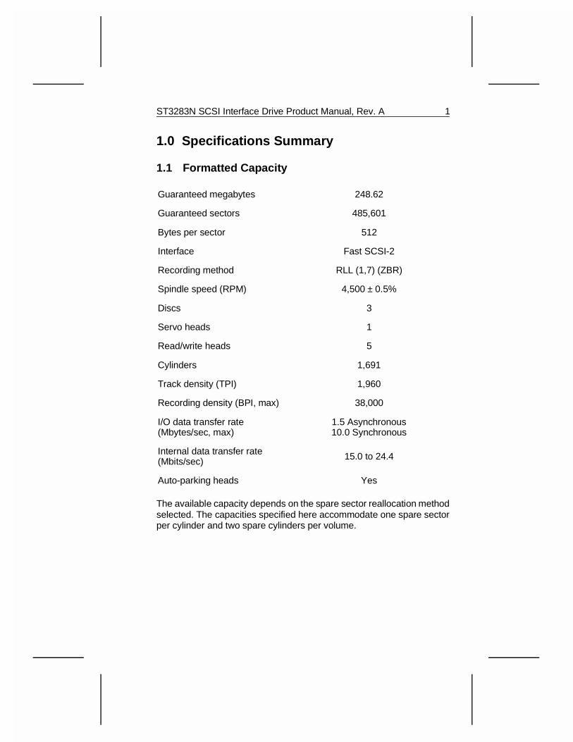
1.1 Formatted Capacity
Guaranteed megabytes 248.62
Guaranteed sectors 485,601
Bytes per sector 512
Interface Fast SCSI-2
Recording method RLL (1,7) (ZBR)
Spindle speed (RPM) 4,500 ± 0.5%
Discs 3
Servo heads 1
Read/write heads 5
Cylinders 1,691
Track density (TPI) 1,960
Recording density (BPI, max) 38,000
I/O data transfer rate(Mbytes/sec, max)
1.5 Asynchronous10.0 Synchronous
Internal data transfer rate(Mbits/sec) 15.0 to 24.4
Auto-parking heads Yes
The available capacity depends on the spare sector reallocation methodselected. The capacities specified here accommodate one spare sectorper cylinder and two spare cylinders per volume.
ST3283N SCSI Interface Drive Product Manual, Rev. A 1
1.2 Drive Performance Specifications
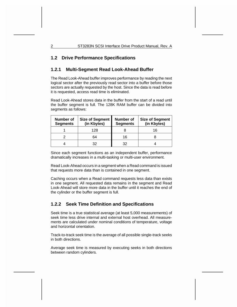
1.2.1 Multi-Segment Read Look-Ahead Buffer
The Read Look-Ahead buffer improves performance by reading the nextlogical sector after the previously read sector into a buffer before thosesectors are actually requested by the host. Since the data is read beforeit is requested, access read time is eliminated.
Read Look-Ahead stores data in the buffer from the start of a read untilthe buffer segment is full. The 128K RAM buffer can be divided intosegments as follows:
Number ofSegments
Size of Segment(in Kbytes)
Number of Segments
Size of Segment(in Kbytes)
1 128 8 16
2 64 16 8
4 32 32 4
Since each segment functions as an independent buffer, performancedramatically increases in a multi-tasking or multi-user environment.
Read Look-Ahead occurs in a segment when a Read command is issuedthat requests more data than is contained in one segment.
Caching occurs when a Read command requests less data than existsin one segment. All requested data remains in the segment and ReadLook-Ahead will store more data in the buffer until it reaches the end ofthe cylinder or the buffer segment is full.
1.2.2 Seek Time Definition and Specifications
Seek time is a true statistical average (at least 5,000 measurements) ofseek time less drive internal and external host overhead. All measure-ments are calculated under nominal conditions of temperature, voltageand horizontal orientation.
Track-to-track seek time is the average of all possible single-track seeksin both directions.
Average seek time is measured by executing seeks in both directionsbetween random cylinders.
2 ST3283N SCSI Interface Drive Product Manual, Rev. A
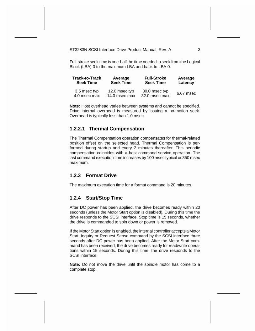
Full-stroke seek time is one-half the time needed to seek from the LogicalBlock (LBA) 0 to the maximum LBA and back to LBA 0.
Track-to-TrackSeek Time
AverageSeek Time
Full-StrokeSeek Time
AverageLatency
3.5 msec typ4.0 msec max
12.0 msec typ14.0 msec max
30.0 msec typ32.0 msec max 6.67 msec
Note: Host overhead varies between systems and cannot be specified.Drive internal overhead is measured by issuing a no-motion seek.Overhead is typically less than 1.0 msec.
1.2.2.1 Thermal Compensation
The Thermal Compensation operation compensates for thermal-relatedposition offset on the selected head. Thermal Compensation is per-formed during startup and every 2 minutes thereafter. This periodiccompensation coincides with a host command service operation. Thelast command execution time increases by 100 msec typical or 350 msecmaximum.
1.2.3 Format Drive
The maximum execution time for a format command is 20 minutes.
1.2.4 Start/Stop Time
After DC power has been applied, the drive becomes ready within 20seconds (unless the Motor Start option is disabled). During this time thedrive responds to the SCSI interface. Stop time is 15 seconds, whetherthe drive is commanded to spin down or power is removed.
If the Motor Start option is enabled, the internal controller accepts a MotorStart, Inquiry or Request Sense command by the SCSI interface threeseconds after DC power has been applied. After the Motor Start com-mand has been received, the drive becomes ready for read/write opera-tions within 15 seconds. During this time, the drive responds to theSCSI interface.
Note: Do not move the drive until the spindle motor has come to acomplete stop.
ST3283N SCSI Interface Drive Product Manual, Rev. A 3
1.2.5 Typical Power-Up/Power-Down Sequence
The following typical power-up/power-down sequence is provided toassist in evaluating drive performance. This information is for referenceonly.
Note: There is no power control switch on the drive.
1.2.5.1 Power-Up Sequence
1. Power is applied to the disc drive.
2. When power is applied, one of two sequences can occur:
A. If the Motor Start jumper is not installed, the option is notselected. (See Figure 7.) In this case, the LED is on for about 2seconds. Then, it turns off while the motor spins up. The drivedoes not respond to the SCSI interface until the LED is off.
B.B. If the Motor Start jumper is installed, the option is selected. Inthis case, the LED glows when power is applied, and stopsglowing after two seconds. Then, the drive controller respondsto the SCSI interface. The host commands the motor to start.While the motor is coming up to speed, the LED is on.
3. The drive begins to lock in speed control circuits.
4. The actuator lock solenoid releases the actuator, producing anaudible sound.
5. The spindle motor reaches operating speed in about 5 seconds. After5 seconds, there are no speed variations.
6. The drive performs velocity adjustment seeks.
7. The drive seeks Track 0 and becomes ready.
1.2.5.2 Power-Down Sequence
1. The power cable is unplugged from the drive, or the drive is com-manded to spin down.
2. Within 3 seconds after the motor begins to spin down, the actuatorlock engages, producing an audible sound.
4 ST3283N SCSI Interface Drive Product Manual, Rev. A
3. The spindle stops in 15 seconds, whether the power cable is un-plugged from the drive or the drive receives the power-down com-mand.
1.2.5.3 Read/Write Head Auto-Park
Upon power-down, the read/write heads automatically move to theshipping zone. All portions of the head/slider assembly park inboard ofthe maximum data cylinder. When power is applied, the heads recalibrateto Track 0.
1.3 Reliability
Read error rates are measured with automatic retries and data correctionwith ECC enabled and all flaws reallocated. MTBF is measured atnominal power, sea level, and 40 °C ambient temperature.
Nonrecoverable Read Errors 1 per 1013 bits transferred
Seek Errors 1 per 107 physical seeks
MTBF 200,000 power-on hours
Preventative Maintenance Not Required
Service Life 5 Years
1.4 Physical Dimensions
Height 1.00 inches (25.4 mm)
Width 4.02 inches (102.1 mm)
Depth 5.77 inches (146.6 mm)
Weight 1.5 lbs (0.68 Kg)
1.5 Environmental
1.5.1 Ambient Temperature
Operating 5 °C to 55 °C (41 °F to 131 °F)
Nonoperating -40 °C to 70 °C (-40 °F to 158 °F)
ST3283N SCSI Interface Drive Product Manual, Rev. A 5
1.5.2 Temperature Gradient
Operating 20 °C/hour (36 °F/hour)
Nonoperating 30 °C/hour (54 °F/hour)
1.5.3 Relative Humidity
Operating 8% to 80% Noncondensing
Maximum Wet Bulb 26 °C (79 °F)
Nonoperating 5% to 95% Noncondensing
1.5.4 Altitude
Operating -1,000 ft to 10,000 ft (-305 m to 3,048 m)
Nonoperating -1,000 ft to 40,000 ft (-305 m to 12,192 m)
1.6 Acoustics
34 dBA typical sound pressure at 1 meter, in Idle mode.38 dBA maximum sound pressure at 1 meter, in Idle mode.
1.7 Shock and Vibration
All shock and vibration specifications assume that the drive is mounted inan approved orientation with the input levels measured at the drive mountingscrews. Shock measurements are based on a 11 msec, half sine-waveshock pulse, not to be repeated more than two times per second.
During normal operating shock and vibration, there is no performancedegradation or physical damage to the drive.
During abnormal operating shock and vibration, there is no physicaldamage to the drive, although performance may be degraded during theshock or vibration episode. When normal operating shock levels resume,the drive meets its performance specifications.
All nonoperating shock and vibration specifications assume that theread/write heads are positioned in the shipping zone.
6 ST3283N SCSI Interface Drive Product Manual, Rev. A
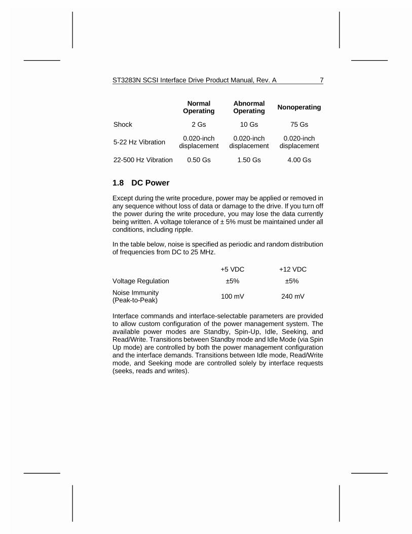
NormalOperating
AbnormalOperating Nonoperating
Shock 2 Gs 10 Gs 75 Gs
5-22 Hz Vibration 0.020-inchdisplacement
0.020-inchdisplacement
0.020-inchdisplacement
22-500 Hz Vibration 0.50 Gs 1.50 Gs 4.00 Gs
1.8 DC Power
Except during the write procedure, power may be applied or removed inany sequence without loss of data or damage to the drive. If you turn offthe power during the write procedure, you may lose the data currentlybeing written. A voltage tolerance of ± 5% must be maintained under allconditions, including ripple.
In the table below, noise is specified as periodic and random distributionof frequencies from DC to 25 MHz.
+5 VDC +12 VDC
Voltage Regulation ±5% ±5%
Noise Immunity(Peak-to-Peak) 100 mV 240 mV
Interface commands and interface-selectable parameters are providedto allow custom configuration of the power management system. Theavailable power modes are Standby, Spin-Up, Idle, Seeking, andRead/Write. Transitions between Standby mode and Idle Mode (via SpinUp mode) are controlled by both the power management configurationand the interface demands. Transitions between Idle mode, Read/Writemode, and Seeking mode are controlled solely by interface requests(seeks, reads and writes).
ST3283N SCSI Interface Drive Product Manual, Rev. A 7
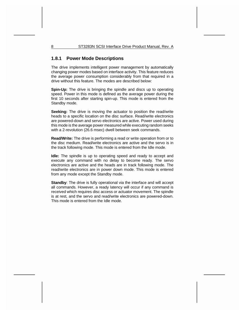
1.8.1 Power Mode Descriptions
The drive implements intelligent power management by automaticallychanging power modes based on interface activity. This feature reducesthe average power consumption considerably from that required in adrive without this feature. The modes are described below:
Spin-Up: The drive is bringing the spindle and discs up to operatingspeed. Power in this mode is defined as the average power during thefirst 10 seconds after starting spin-up. This mode is entered from theStandby mode.
Seeking: The drive is moving the actuator to position the read/writeheads to a specific location on the disc surface. Read/write electronicsare powered-down and servo electronics are active. Power used duringthis mode is the average power measured while executing random seekswith a 2-revolution (26.6 msec) dwell between seek commands.
Read/Write: The drive is performing a read or write operation from or tothe disc medium. Read/write electronics are active and the servo is inthe track following mode. This mode is entered from the Idle mode.
Idle: The spindle is up to operating speed and ready to accept andexecute any command with no delay to become ready. The servoelectronics are active and the heads are in track following mode. Theread/write electronics are in power down mode. This mode is enteredfrom any mode except the Standby mode.
Standby : The drive is fully operational via the interface and will acceptall commands. However, a ready latency will occur if any command isreceived which requires disc access or actuator movement. The spindleis at rest, and the servo and read/write electronics are powered-down.This mode is entered from the Idle mode.
8 ST3283N SCSI Interface Drive Product Manual, Rev. A
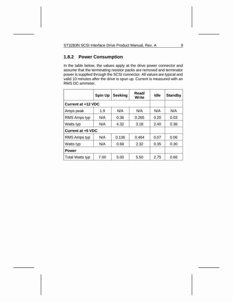
1.8.2 Power Consumption
In the table below, the values apply at the drive power connector andassume that the terminating resistor packs are removed and terminatorpower is supplied through the SCSI connector. All values are typical andvalid 10 minutes after the drive is spun up. Current is measured with anRMS DC ammeter.
Spin Up Seeking Read/Write Idle Standby
Current at +12 VDC
Amps peak 1.9 N/A N/A N/A N/A
RMS Amps typ N/A 0.36 0.265 0.20 0.03
Watts typ N/A 4.32 3.18 2.40 0.36
Current at +5 VDC
RMS Amps typ N/A 0.136 0.464 0.07 0.06
Watts typ N/A 0.68 2.32 0.35 0.30
Power
Total Watts typ 7.00 5.00 5.50 2.75 0.66
ST3283N SCSI Interface Drive Product Manual, Rev. A 9
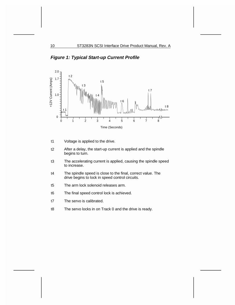
Figure 1: Typical Start-up Current Profile
t1 Voltage is applied to the drive.
t2 After a delay, the start-up current is applied and the spindlebegins to turn.
t3 The accelerating current is applied, causing the spindle speedto increase.
t4 The spindle speed is close to the final, correct value. Thedrive begins to lock in speed control circuits.
t5 The arm lock solenoid releases arm.
t6 The final speed control lock is achieved.
t7 The servo is calibrated.
t8 The servo locks in on Track 0 and the drive is ready.
t 1
t 2
t 3t 5
t 4
t 6
t 7
t 8
0
1.0
1.7
2.0
0 21 43 65 87
+12
V C
urre
nt (
Am
ps)
Time (Seconds)
10 ST3283N SCSI Interface Drive Product Manual, Rev. A
1.9 Agency Listings
1.9.1 UL Recognition
The ST3283N disc drive is recognized in accordance with UL 478 andUL 1950.
1.9.2 CSA Listing
The ST3283N disc drive is certified to CSA C22.2 No. 220-M1986.
1.9.3 VDE Listing
The ST3283N disc drive is certif ied to VDE 0806/8.81 andEN 60950/1.88, as tested by VDE.
1.9.4 FCC Verification
Note: This equipment has been tested with a Class B computing deviceand has been found to comply with Part 15 of the FCC rules. These limitsare designed to provide reasonable protection against harmful interfer-ence in residential installations. This equipment generates, uses, andcan radiate radio frequency energy, and if not installed and used inaccordance with the instructions, may cause harmful interference to radiocommunications. However, there is no guarantee that interference willnot occur in a particular installation.
If this equipment does cause interference to radio or television equipmentreception, which can be determined by turning the equipment off and on,the user may attempt to correct the interference by one or more of thefollowing measures:
• Reorient or relocate the receiving antenna.
• Move the equipment away from the receiver.
• Plug the equipment into an outlet on a circuit different from that towhich the receiver is connected.
• If necessary, the user should consult the dealer or an experiencedradio/television technician for additional suggestions.
ST3283N SCSI Interface Drive Product Manual, Rev. A 11
Caution: Any changes or modifications to the equipment by the user notexpressly approved by the grantee or manufacturer could void the user’sauthority to operate such equipment.
Note: This digital apparatus does not exceed the Class B limits for radionoise emissions from digital apparatus as set out in the radio interferenceregulations of the Canadian Department of Communications.
Le présent appareil numérique n′émet pas de bruits radioélectriquesdépassant les limites applicables aux appareils numériques de Classe Bprescrites dans le règlement sur le brouillage radioélectrique édicté parle Ministère des Communications du Canada.
Sicherheitsanleitung
1. Das Gerrät ist ein Einbaugerät, das für eine maximale Umegebung-stemperatur von 55 °C vorgesehen ist.
2. Zur Befestigung des Laufwerks werden 4 Schrauben 6-32 UNC-2Abenötigt. Bei seitlicher Befestigung darf die maximale Länge derSchrauben im Chassis nicht mehr als 3,3 mm und bei Befestigungan der Unterseite nicht mehr als 5,08 mm betragen.
3. Als Versorgungsspannugen werden benötigt:
+5 V ± 5% 0,6 A
+12 V ± 5 % 0,8 A (2,0 A fur ca. 30 Sek)
4. Die Versorgungsspannung muβ SELV entsprechen.
5. Alle Arbeiten dürfen nur von ausgebildetem Servicepersonaldurchgeführt werden.
6. Der Einbau des Drives muβ den Anforderungen gemäβ DIN IEC950V DC 0806/8.81 entsprechen.
12 ST3283N SCSI Interface Drive Product Manual, Rev. A
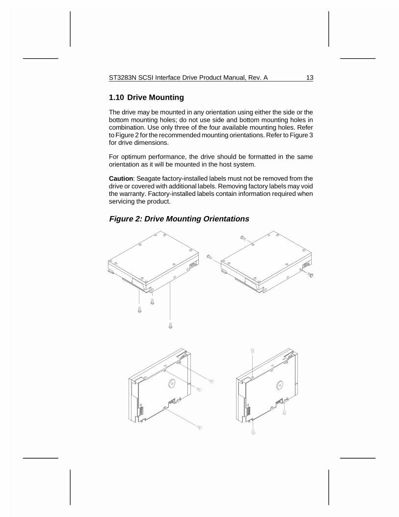
1.10 Drive Mounting
The drive may be mounted in any orientation using either the side or thebottom mounting holes; do not use side and bottom mounting holes incombination. Use only three of the four available mounting holes. Referto Figure 2 for the recommended mounting orientations. Refer to Figure 3for drive dimensions.
For optimum performance, the drive should be formatted in the sameorientation as it will be mounted in the host system.
Caution : Seagate factory-installed labels must not be removed from thedrive or covered with additional labels. Removing factory labels may voidthe warranty. Factory-installed labels contain information required whenservicing the product.
Figure 2: Drive Mounting Orientations
ST3283N SCSI Interface Drive Product Manual, Rev. A 13
1.10.1 Handling and Static Discharge Precautions
After unpacking the drive, and before you have installed the drive in thesystem, be careful not to expose the drive to handling or ESD hazards.Observe the following standard static-discharge precautions:
• Wear a grounded wrist-strap.
• Handle the drive by its edges.
• Do not put any pressure on the top or bottom of the drive.
• Do not touch the PC board.
• Always rest the drive on a padded surface until it is mounted in thehost system.
1.10.2 Hot-plugging
If there is more than one SCSI device daisy-chained on the bus, you canconnect and disconnect the drive I/O and power connector if the followingconditions are met:
• The drive you are disconnecting (or connecting) is not the devicesupplying terminator power or terminating resistance to the bus.
• Terminator power and resistance must not be added or removedfrom the bus during hot-plugging.
• The bus must not be used for I/O transactions during hot-plugging.If you are installing a drive on the bus, there must be no I/Otransactions until the drive is connected and ready. If you areremoving a drive from the bus, there must be no I/O transactions untilthe drive is completely disconnected.
To avoid damage to the disc and head, the spindle must be completelystopped and the heads must be parked before you remove the drive fromthe system. There are two ways to stop the spindle and park the heads:
• If the drive is not configured to use the remote start/stop feature,disconnect the DC power cable from the drive DC power connectorand wait 30 seconds.
• If the drive is configured to use the remote start/stop feature, issuethe SCSI stop command and wait 30 seconds.
14 ST3283N SCSI Interface Drive Product Manual, Rev. A
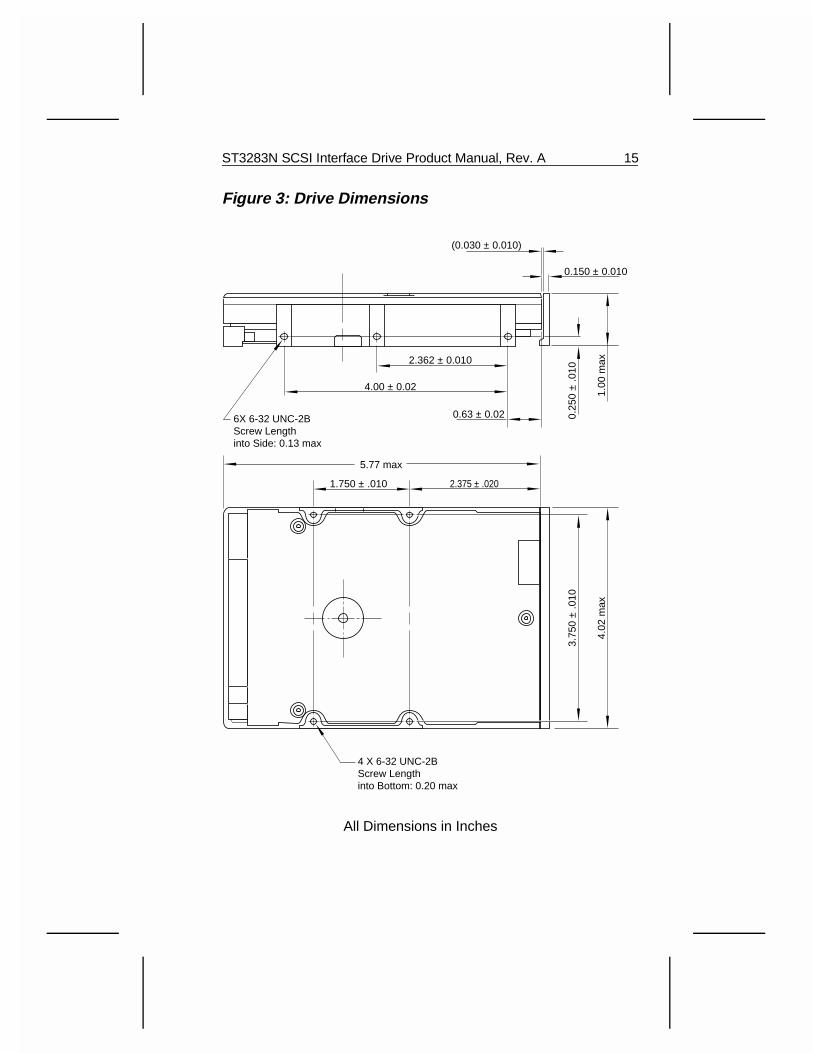
Figure 3: Drive Dimensions
4 X 6-32 UNC-2BScrew Lengthinto Bottom: 0.20 max
2.362 ± 0.010
4.02
max
5.77 max
3.75
0 ±
.010
2.375 ± .0201.750 ± .010
4.00 ± 0.02
0.63 ± 0.026X 6-32 UNC-2BScrew Lengthinto Side: 0.13 max
0.25
0 ±
.010
1.00
max
0.150 ± 0.010
(0.030 ± 0.010)
All Dimensions in Inches
ST3283N SCSI Interface Drive Product Manual, Rev. A 15

16 ST3283N SCSI Interface Drive Product Manual, Rev. A
2.0 Interface Description and OptionsThe SCSI-2 interface consists of a 9-bit bi-directional bus (8 data bits and1 parity bit) plus 9 control signals supporting multiple initiators, discon-nect/reconnect, and self-configuring host software. Logical block ad-dressing is used.
The physical interface consists of single-ended drivers and receiversusing asynchronous or synchronous communication protocols that sup-port cable lengths of up to 6 meters (3 meters for Fast SCSI) and a businterface transfer rate up to 1.5 Mbytes/sec asynchronous and 10.0 Mby-tes/sec synchronous. The bus protocol supports multiple initiators, dis-connect/reconnect, additional messages, and 6-byte and 10-byteCommand Descriptor Blocks. The drive is always a target on the SCSIbus.
2.1 SCSI-2 Compatibility
The drive interface is compatible with the mandatory subset of the ANSISCSI-2 Interface. The Fast SCSI-2 interface is based on the ANSI SmallComputer System Interface-2 (SCSI-2): Document Number ANSIX3.131-1986 (X3T9.2/86-109 Rev. 10E).
2.2 SCSI Connector
The drive may be daisy-chained with other SCSI devices that havesingle-ended drivers and receivers using a common cable. All signalsare common between all SCSI devices. The SCSI devices at both endsof the daisy-chain are to be terminated. Intermediate SCSI devices arenot to be terminated.
A maximum of 8 SCSI devices (including the host) may be daisy-chainedtogether. SCSI ID 7, by convention, is reserved for the host adapter. Nodrive can have the same SCSI ID as the host adapter.
2.2.1 SCSI Connector Requirements
The drive connector is a nonshielded, 50-pin connector consisting of tworows of 25 pins with adjacent pins 0.100 inches apart. The connector iskeyed with a slot. See Figure 4.
ST3283N SCSI Interface Drive Product Manual, Rev. A 17
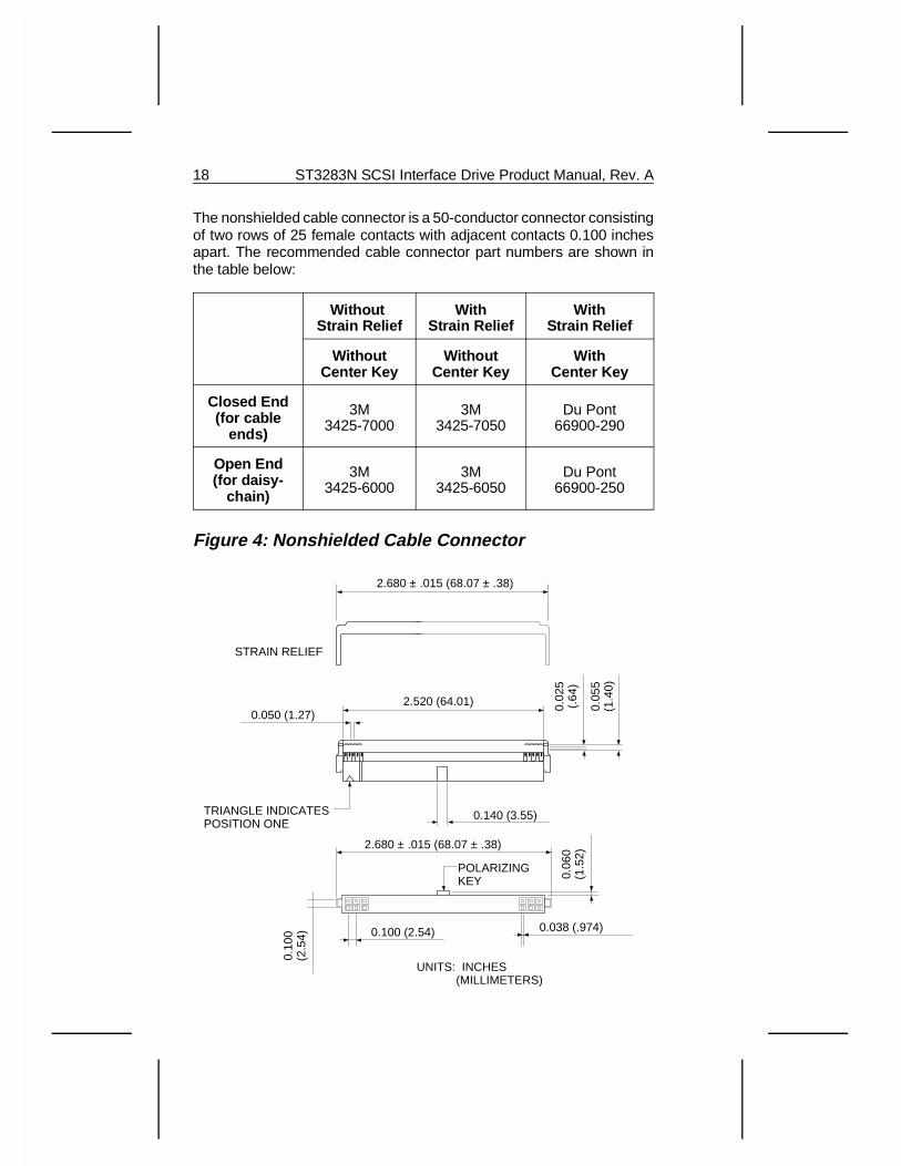
The nonshielded cable connector is a 50-conductor connector consistingof two rows of 25 female contacts with adjacent contacts 0.100 inchesapart. The recommended cable connector part numbers are shown inthe table below:
Without Strain Relief
WithStrain Relief
WithStrain Relief
WithoutCenter Key
WithoutCenter Key
WithCenter Key
Closed End(for cable
ends)
3M3425-7000
3M3425-7050
Du Pont66900-290
Open End(for daisy-
chain)
3M3425-6000
3M3425-6050
Du Pont66900-250
Figure 4: Nonshielded Cable Connector
2.680 ± .015 (68.07 ± .38)
STRAIN RELIEF
0.140 (3.55)
0.050 (1.27)2.520 (64.01) 0.
025
(.64
)
0.05
5(1
.40)
TRIANGLE INDICATESPOSITION ONE
0.038 (.974)0.100 (2.54)
POLARIZINGKEY
2.680 ± .015 (68.07 ± .38)
0.06
0(1
.52)
0.10
0(2
.54)
UNITS: INCHES (MILLIMETERS)
18 ST3283N SCSI Interface Drive Product Manual, Rev. A
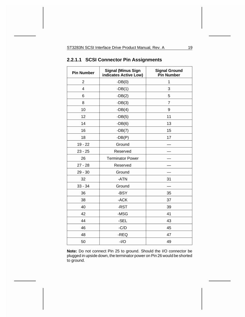
2.2.1.1 SCSI Connector Pin Assignments
Pin Number Signal (Minus Signindicates Active Low)
Signal GroundPin Number
2 -DB(0) 1
4 -DB(1) 3
6 -DB(2) 5
8 -DB(3) 7
10 -DB(4) 9
12 -DB(5) 11
14 -DB(6) 13
16 -DB(7) 15
18 -DB(P) 17
19 - 22 Ground —
23 - 25 Reserved —
26 Terminator Power —
27 - 28 Reserved —
29 - 30 Ground —
32 -ATN 31
33 - 34 Ground —
36 -BSY 35
38 -ACK 37
40 -RST 39
42 -MSG 41
44 -SEL 43
46 -C/D 45
48 -REQ 47
50 -I/O 49
Note: Do not connect Pin 25 to ground. Should the I/O connector beplugged in upside down, the terminator power on Pin 26 would be shortedto ground.
ST3283N SCSI Interface Drive Product Manual, Rev. A 19
2.3 Cable Requirements
The characteristic impedance of the cable should be between 90 Ohmsand 140 Ohms. However, most available cables have a somewhat lowercharacteristic impedance. To minimize discontinuities and signal reflec-tions, do not use cables of different impedances in the bus.
Your design may require trade-offs in shielding effectiveness, cablelength, the number of loads, and transfer rates. If your design uses bothshielded and nonshielded cables within the same SCSI bus, you mustallow for the effects of impedance mismatch.
A minimum conductor size of 28 AWG should be used to minimize noiseeffects. Use nonshielded cable connectors only. Use a 50-conductor flatcable or 25-conductor twisted-pair cable.
2.3.1 Single-Ended Cable
When using a single-ended SCSI cable, the following requirements mustbe met:
• The cable cannot be longer than 6.0 meters.
• A cable stub cannot be longer than 0.1 meter, from the mainlineinterconnection to any device.
• Stubs must be separated by at least 0.3 meter.
2.3.2 Fast Synchronous Data Transfer
When using a fast synchronous data transfer SCSI-2 cable, the followingadditional requirements must be met:
• The cable cannot be longer than 3.0 meters.
• A characteristic impedance of 90 Ohms to 132 Ohms is recom-mended for nonshielded flat cable or twisted-pair ribbon cable.
• The signal attenuation at 5 MHz must not be greater than 0.095 dBper meter.
• The DC resistance at 20 °C must not exceed 0.230 Ohms per meter.
• The propagation delay delta of a shielded, twisted-pair cable mustnot exceed 20 nsec per meter.
20 ST3283N SCSI Interface Drive Product Manual, Rev. A
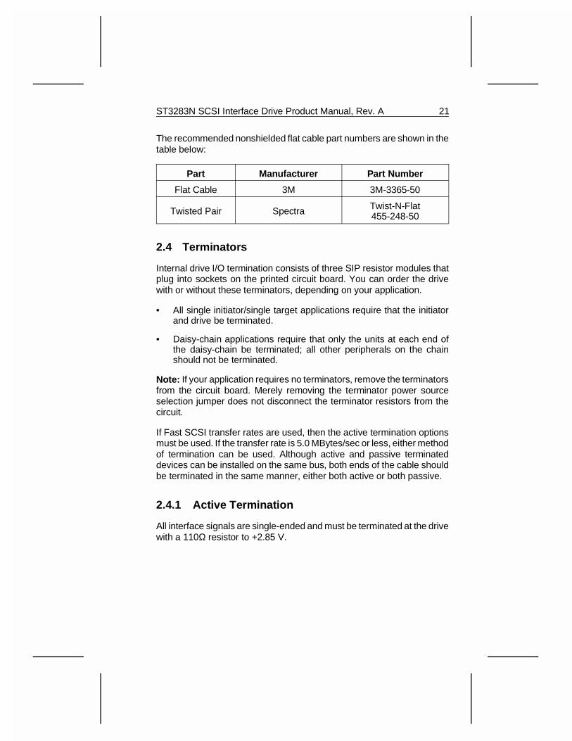
The recommended nonshielded flat cable part numbers are shown in thetable below:
Part Manufacturer Part Number
Flat Cable 3M 3M-3365-50
Twisted Pair Spectra Twist-N-Flat455-248-50
2.4 Terminators
Internal drive I/O termination consists of three SIP resistor modules thatplug into sockets on the printed circuit board. You can order the drivewith or without these terminators, depending on your application.
• All single initiator/single target applications require that the initiatorand drive be terminated.
• Daisy-chain applications require that only the units at each end ofthe daisy-chain be terminated; all other peripherals on the chainshould not be terminated.
Note: If your application requires no terminators, remove the terminatorsfrom the circuit board. Merely removing the terminator power sourceselection jumper does not disconnect the terminator resistors from thecircuit.
If Fast SCSI transfer rates are used, then the active termination optionsmust be used. If the transfer rate is 5.0 MBytes/sec or less, either methodof termination can be used. Although active and passive terminateddevices can be installed on the same bus, both ends of the cable shouldbe terminated in the same manner, either both active or both passive.
2.4.1 Active Termination
All interface signals are single-ended and must be terminated at the drivewith a 110Ω resistor to +2.85 V.
ST3283N SCSI Interface Drive Product Manual, Rev. A 21
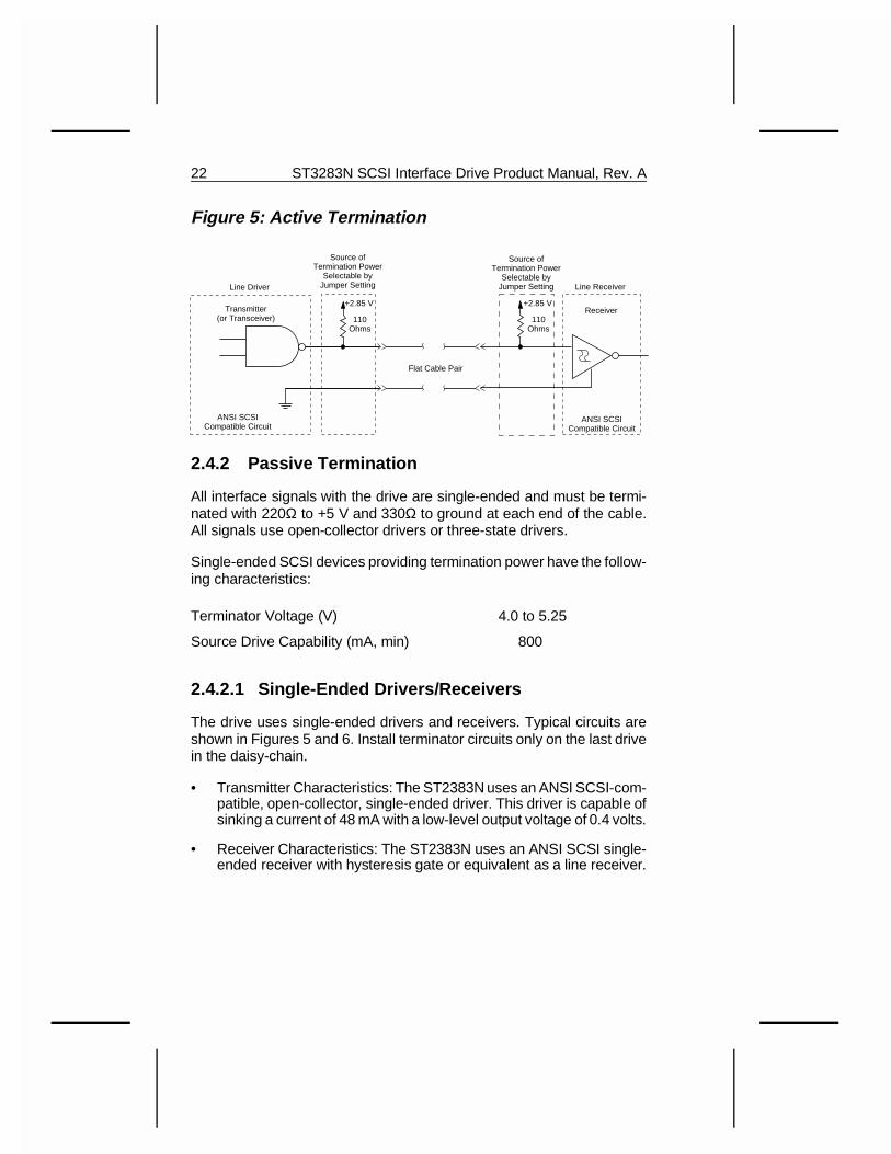
Figure 5: Active Termination
2.4.2 Passive Termination
All interface signals with the drive are single-ended and must be termi-nated with 220Ω to +5 V and 330Ω to ground at each end of the cable.All signals use open-collector drivers or three-state drivers.
Single-ended SCSI devices providing termination power have the follow-ing characteristics:
Terminator Voltage (V) 4.0 to 5.25
Source Drive Capability (mA, min) 800
2.4.2.1 Single-Ended Drivers/Receivers
The drive uses single-ended drivers and receivers. Typical circuits areshown in Figures 5 and 6. Install terminator circuits only on the last drivein the daisy-chain.
• Transmitter Characteristics: The ST2383N uses an ANSI SCSI-com-patible, open-collector, single-ended driver. This driver is capable ofsinking a current of 48 mA with a low-level output voltage of 0.4 volts.
• Receiver Characteristics: The ST2383N uses an ANSI SCSI single-ended receiver with hysteresis gate or equivalent as a line receiver.
Line Driver
Transmitter(or Transceiver)
+2.85 V
110Ohms
+2.85 V
110Ohms
Flat Cable Pair
Line Receiver
Receiver
ANSI SCSICompatible Circuit
ANSI SCSICompatible Circuit
Source ofTermination Power
Selectable byJumper Setting
Source ofTermination Power
Selectable byJumper Setting
22 ST3283N SCSI Interface Drive Product Manual, Rev. A
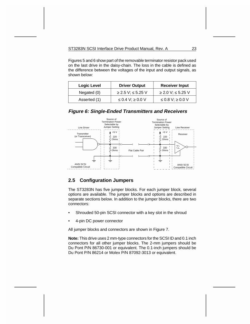
Figures 5 and 6 show part of the removable terminator resistor pack usedon the last drive in the daisy-chain. The loss in the cable is defined asthe difference between the voltages of the input and output signals, asshown below:
Logic Level Driver Output Receiver Input
Negated (0) ≥ 2.5 V; ≤ 5.25 V ≥ 2.0 V; ≤ 5.25 V
Asserted (1) ≤ 0.4 V; ≥ 0.0 V ≤ 0.8 V; ≥ 0.0 V
Figure 6: Single-Ended Transmitters and Receivers
2.5 Configuration Jumpers
The ST3283N has five jumper blocks. For each jumper block, severaloptions are available. The jumper blocks and options are described inseparate sections below. In addition to the jumper blocks, there are twoconnectors:
• Shrouded 50-pin SCSI connector with a key slot in the shroud
• 4-pin DC power connector
All jumper blocks and connectors are shown in Figure 7.
Note: This drive uses 2 mm-type connectors for the SCSI ID and 0.1 inchconnectors for all other jumper blocks. The 2-mm jumpers should beDu Pont P/N 86730-001 or equivalent. The 0.1-inch jumpers should beDu Pont P/N 86214 or Molex P/N 87092-3013 or equivalent.
Line Driver
Transmitter(or Transceiver)
+5 V
220Ohms
330Ohms
+5 V
220Ohms
330OhmsFlat Cable Pair
Line Receiver
Receiver
ANSI SCSICompatible Circuit
ANSI SCSICompatible Circuit
Source ofTermination Power
Selectable byJumper Setting
Source ofTermination Power
Selectable byJumper Setting
ST3283N SCSI Interface Drive Product Manual, Rev. A 23
2.5.1 Parity/Remote Start Jumper Block
2.5.1.1 Parity Enable Option
This option is used to determine whether the parity bit is used. When ajumper is installed on Pins 1 and 2 of the Parity/Remote Start jumperblock, the parity bit is used. The default is no jumper installed.
2.5.1.2 Start/Stop Option
When a jumper is installed on Pins 3 and 4 of the Remote Start/Parityjumper block, the drive waits for a Start/Stop Unit command from theHost before starting or stopping the spindle motor. The default is nojumper installed.
2.5.2 Active/Passive Termination Jumper Block
To select active termination, install a jumper on Pins 1 and 2 of theActive/Passive Termination jumper block. To select passive termination,install jumpers on Pins 5 and 6 and Pins 2 and 4 of the Active/PassiveTermination jumper block.
2.5.3 Terminator Power Source Jumper Block
To select the termination power source install jumpers as follows:
• To select the SCSI connector as the termination power source, installa jumper on Pins 1 and 2 of the Terminator Power jumper block.
• To select the drive power connector as the termination power sourcefor the resistor packs, install a jumper on Pins 1 and 3 of theTerminator Power jumper block.
• To provide terminator power to the SCSI connector from the drivepower connector only, install a jumper on Pins 3 and 4 of theTerminator Power jumper block.
• To provide terminator power to the SCSI connector and the driveterminator packs, install jumpers on Pins 1 and 2 and Pins 3 and 4of the Terminator Power jumper block.
24 ST3283N SCSI Interface Drive Product Manual, Rev. A
2.5.4 SCSI ID Address Jumper Block
Select the SCSI ID of the drive by installing jumpers on the SCSI IDAddress jumper block according to the table in Figure 7.
2.5.5 Options Jumper Block
To synchronize the drive spindles, connect a twisted pair to Pins 9 and10 of the Options jumper block. External spindle synchronization imple-mentation and timing is described in Section 2.6.
To power a remote LED, connect a twisted pair to Pins 13 and 14 of theOptions jumper block.
ST3283N SCSI Interface Drive Product Manual, Rev. A 25
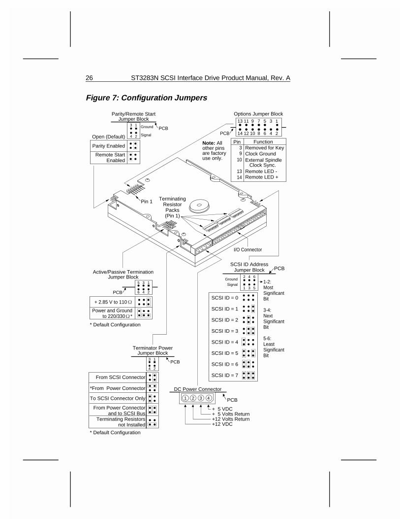
Figure 7: Configuration Jumpers
2
1
4
3
6
5
SCSI ID = 0
SCSI ID = 1
SCSI ID = 2
SCSI ID = 3
SCSI ID = 7
SCSI ID = 4
SCSI ID = 5
SCSI ID = 6
1-2:MostSignificantBit
3-4: NextSignificantBit
5-6: LeastSignificantBit
SCSI ID AddressJumper Block
11
12
9
10
7
8
5
6
3
4
13
14
1
2
Options Jumper Block
I/O Connector
Parity/Remote StartJumper Block
Ground
Signal PCB
3
4
1
2Open (Default)
Parity Enabled
Remote StartEnabled
PCB
Terminator PowerJumper Block
PCB
From SCSI Connector
*From Power Connector
To SCSI Connector Only
From Power Connector and to SCSI Bus
Terminating Resistorsnot Installed
3
4
1
2
PCB
DC Power Connector
+ 5 VDC+ 5 Volts Return+12 Volts Return+12 VDC
1 2 3 4
39
10
1314
FunctionRemoved for KeyClock GroundExternal Spindle Clock Sync.Remote LED - Remote LED +
PCB
Active/Passive TerminationJumper Block
PCB
+ 2.85 V to 110
Power and Ground to 220/330 *
3
4
1
2
5
6
GroundSignal
Pin 1 TerminatingResistorPacks(Pin 1)
Pin
* Default Configuration
* Default Configuration
Note: All other pins are factory use only.
26 ST3283N SCSI Interface Drive Product Manual, Rev. A
2.6 External Spindle Synchronization Option
The drive spindle can be synchronized to an external index signal so thatseveral drives can be arrayed together to achieve a coordinatedread/write capability. The ST3283 spindle synchronization is auto-detect-ing/auto-configuring and requires no jumpers or other reconfigurationexcept the installation of the cable providing (or supplying) the synchro-nization signal. This is a two-conductor cable, and the connections aresingle-ended. The drive connector is keyed, and is on 0.1-inch centers.
The SCSI interface version options that are programmable by the inter-face using the Mode Select command (Page 4, Byte 17, RPL optionsbits).
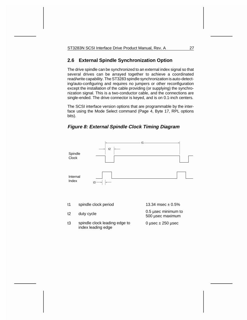
Figure 8: External Spindle Clock Timing Diagram
t1 spindle clock period 13.34 msec ± 0.5%
t2 duty cycle 0.5 µsec minimum to 500 µsec maximum
t3 spindle clock leading edge to index leading edge
0 µsec ± 250 µsec
t1
t2
t3
SpindleClock
InternalIndex
ST3283N SCSI Interface Drive Product Manual, Rev. A 27

28 ST3283N SCSI Interface Drive Product Manual, Rev. A
3.0 SCSI BusCommunication on the SCSI bus is allowed between only two SCSIdevices at a time. There can be a maximum of eight SCSI devices,including the host computer, connected to the SCSI bus. The hostadapter/initiator must be identified by one of the eight SCSI deviceaddresses.
The host adapter, by convention, typically is set to SCSI ID 7. No drivecan have the same SCSI ID as the host adapter. Each SCSI device hasa SCSI ID bit assigned, as shown in Section 3.1.
When two SCSI devices communicate on the SCSI bus, one acts as aninitiator and the other acts as a target. The initiator, typically the host,starts an operation and the target performs the operation. The drivealways operates as a target.
Certain SCSI bus functions are assigned to the initiator and certain SCSIbus functions are assigned to the target. The initiator selects a particulartarget. The target requests the transfer of Command, Data, Status orother information on the data bus.
Information transfers on the data bus are asynchronous and follow adefined REQ/ACK handshake protocol. One byte of information is trans-ferred with each handshake. The synchronous data transfer option isdescribed in Section 4.5.3.1.
The drive supports single initiator/single target; single initiator/multipletarget; or multiple initiator/multiple target bus configurations. See Fig-ure 9.
ST3283N SCSI Interface Drive Product Manual, Rev. A 29
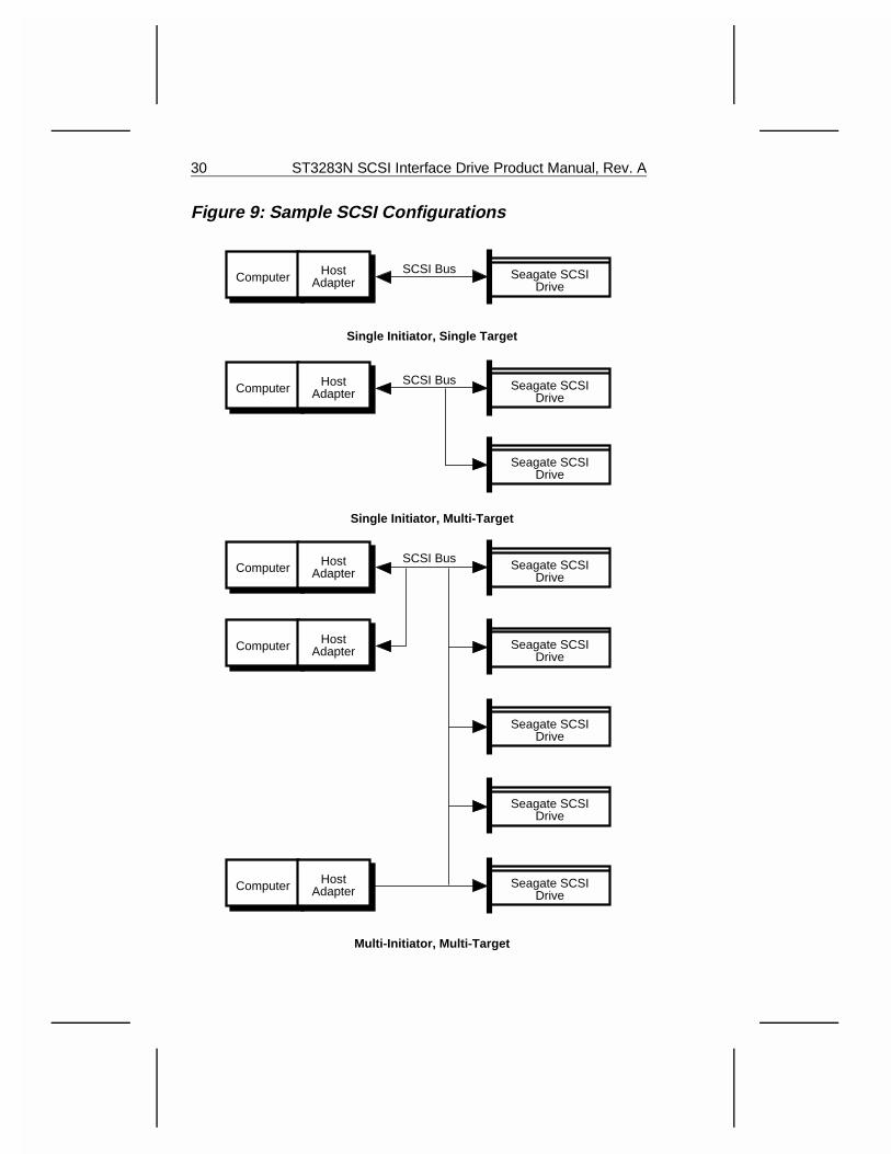
Figure 9: Sample SCSI Configurations
Computer HostAdapter
Seagate SCSIDrive
Computer HostAdapter
Seagate SCSIDrive
Seagate SCSIDrive
Computer HostAdapter
Seagate SCSIDrive
Computer HostAdapter Seagate SCSI
Drive
Seagate SCSIDrive
Seagate SCSIDrive
Seagate SCSIDrive
Computer HostAdapter
SCSI Bus
SCSI Bus
SCSI Bus
Single Initiator, Single Target
Single Initiator, Multi-Target
Multi-Initiator, Multi-Target
30 ST3283N SCSI Interface Drive Product Manual, Rev. A
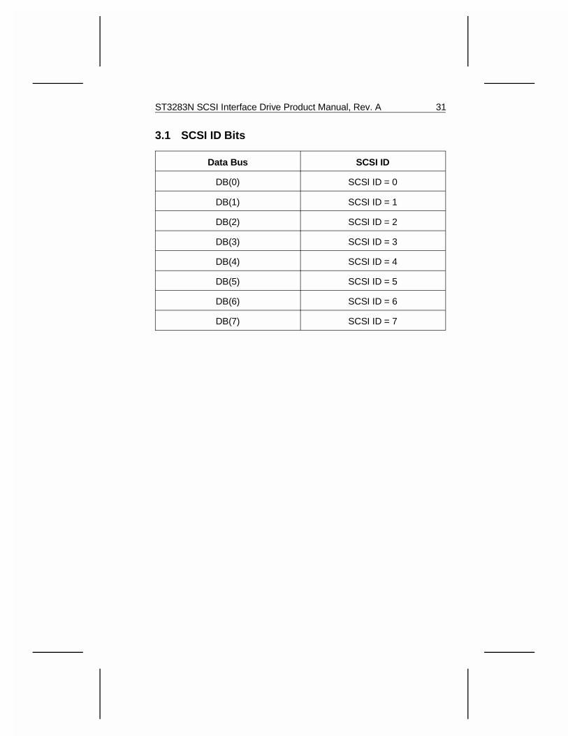
3.1 SCSI ID Bits
Data Bus SCSI ID
DB(0) SCSI ID = 0
DB(1) SCSI ID = 1
DB(2) SCSI ID = 2
DB(3) SCSI ID = 3
DB(4) SCSI ID = 4
DB(5) SCSI ID = 5
DB(6) SCSI ID = 6
DB(7) SCSI ID = 7
ST3283N SCSI Interface Drive Product Manual, Rev. A 31

3.2 SCSI Bus Signals
There are nine control and nine data signals, as described below:
BSY (BUSY): An OR-tied signal to indicate the bus is being used.
SEL (SELECT): A signal used by an initiator to select a target, or by a target to reselect an initiator.
C/D (CONTROL/DATA): A signal driven by the drive to indicate whetherControl or Data information is on the Data Bus. Assertion indicatesControl.
I/O (INPUT/OUTPUT): A signal driven by a drive to control the directionof data movement on the Data Bus with respect to an initiator. Assertionindicates input to the initiator. This signal is also used to distinguishbetween Selection and Reselection phases.
MSG (MESSAGE): A signal driven by the drive during the Messagephase.
REQ (REQUEST): A signal driven by a target to indicate a request forREQ/ACK data transfer handshake.
ACK (ACKNOWLEDGE): A signal driven by an initiator to indicate anacknowledgment for a REQ/ACK data transfer handshake.
ATN (ATTENTION): A signal driven by an initiator to indicate the Atten-tion condition.
RST (RESET): An OR-tied signal that indicates the Reset condition.
DB(7-0,P) (DATA BUS): Eight data bit signals, plus a parity bit signalform a Data Bus. DB(7) is the most significant bit and has the highestpriority during the Arbitration phase. Bit number significance, and prioritydecrease downward to DB(0). A data bit is defined as one when the signalis asserted and zero when the signal is negated. Data parity DB(P) isodd. The use of parity is a system option. The drive always generatesparity, but can be configured to enable/disable parity detection. (SeeFigure 7.) Parity is not valid during the Arbitration phase.
32 ST3283N SCSI Interface Drive Product Manual, Rev. A
3.2.1 Signal Values
Signals may assume true or false values. There are two methods ofdriving these signals. In both cases, the signal is actively driven true, orasserted. In the case of OR-tied drivers, the driver does not drive thesignal to the false state, rather the bias circuitry of the bus terminatorspulls the signal false whenever it is released by the drivers at every SCSIdevice. If any driver is asserted, then the signal is true. In the case ofnon-OR-tied drivers, the signal may be actively driven false, or negated.Negated means that the signal may be actively driven false, or maysimply be released (in which case the bias circuitry pulls it false), at theoption of the implementor.
3.2.2 OR-Tied Signals
The BSY and RST signals are OR-tied only. In the ordinary operation ofthe bus, these signals are simultaneously driven true by several drivers.No signals other than BSY, RST, and DB(P) are simultaneously drivenby two or more drivers, and any signal other than BSY and RST mayemploy OR-tied or non-OR-tied drivers. DB(P) are not driven false duringthe Arbitration phase. There is no operational problem in mixing OR-tiedand non-OR-tied drivers on signals other than BSY and RST.
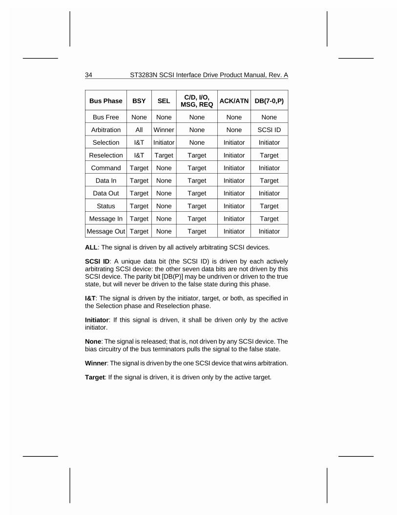
3.2.3 Signal Sources
The table that follows indicates which type of SCSI device is allowed tosource each signal. All SCSI device drivers that are not active sourcesmust be in the passive state. Note that the RST signal may be sourcedby any SCSI device at any time. The drive functions as a target, neveras an initiator, and is capable of performing only the reselection function.
ST3283N SCSI Interface Drive Product Manual, Rev. A 33
Bus Phase BSY SEL C/D, I/O,MSG, REQ ACK/ATN DB(7-0,P)
Bus Free None None None None None
Arbitration All Winner None None SCSI ID
Selection I&T Initiator None Initiator Initiator
Reselection I&T Target Target Initiator Target
Command Target None Target Initiator Initiator
Data In Target None Target Initiator Target
Data Out Target None Target Initiator Initiator
Status Target None Target Initiator Target
Message In Target None Target Initiator Target
Message Out Target None Target Initiator Initiator
ALL : The signal is driven by all actively arbitrating SCSI devices.
SCSI ID: A unique data bit (the SCSI ID) is driven by each activelyarbitrating SCSI device: the other seven data bits are not driven by thisSCSI device. The parity bit [DB(P)] may be undriven or driven to the truestate, but will never be driven to the false state during this phase.
I&T: The signal is driven by the initiator, target, or both, as specified inthe Selection phase and Reselection phase.
Initiator : If this signal is driven, it shall be driven only by the activeinitiator.
None : The signal is released; that is, not driven by any SCSI device. Thebias circuitry of the bus terminators pulls the signal to the false state.
Winner : The signal is driven by the one SCSI device that wins arbitration.
Target : If the signal is driven, it is driven only by the active target.
34 ST3283N SCSI Interface Drive Product Manual, Rev. A
3.3 SCSI Bus Timing
Unless otherwise indicated, the delay time measurements for each SCSIdevice are calculated from signal conditions existing at that SCSI de-vice’s own SCSI bus connection. Thus, these measurements (exceptskew delay) can be made without considering delays in the cable.
Arbitration Delay (2.2 µsec min, no max): The minimum time a SCSIdevice waits between the time BSY is asserted for arbitration until thetime the data bus can be examined to see if arbitration is won.
Assertion Period (90 nsec min): The minimum time a target assertsREQ while using synchronous data transfers. Also, the minimum time aninitiator asserts ACK during synchronous data transfers.
Bus Clear Delay (800 nsec max): The maximum time for a SCSI deviceto stop driving all bus signals after:
1. The Bus Free phase is detected (BSY and SEL are both negated fora bus settle delay).
2. The maximum time for a SCSI device to clear the bus is 1200 nsecfrom the time BSY and SEL are both negated. If a SCSI devicerequires more than a bus settle delay to detect the Bus Free phase,it clears the bus within a duration equal to the Bus Clear delay minusthe excess time.
3. SEL is received from another SCSI device during the Arbitrationphase.
4. The transition of RST to assertion.
Bus Free Delay (800 nsec min): The minimum time that a SCSI devicewill wait from its detection of the Bus Free phase (BSY and SEL bothnegated for a bus settle delay) until its assertion of BSY when going tothe arbitration phase.
Bus Set Delay (1.8 µsec max): The maximum time for a SCSI deviceto assert BSY and its SCSI ID bit on the Data Bus after it detects BusFree phase (BSY and SEL both negated for a bus settle delay) for thepurpose of entering the Arbitration phase.
Bus Settle Delay (400 nsec min): The time taken for the bus to settleafter changing certain control signals as specified in the protocol defini-tions.
ST3283N SCSI Interface Drive Product Manual, Rev. A 35
Cable Skew Delay (10 nsec max): The maximum difference in propa-gation time allowed between any two SCSI bus signals when measuredbetween any two SCSI bus signals.
Data Release Delay (400 nsec max): The maximum time for an initiatorto release the Data Bus signals following the transition of the I/O signalfrom negation to assertion.
Deskew Delay (45 nsec min): The minimum time required for deskewof certain signals.
Disconnection Delay (200 µsec min): The minimum time a target waitsafter releasing BSY before participating in an Arbitration phase whenhonoring a Disconnect message from the initiator.
Hold Time (45 nsec min): The minimum time added between theassertion of REQ or ACK and the changing of the data lines to providehold time in the initiator or target, respectively, while using synchronousdata transfers.
Negation Period (90 nsec min): The minimum time that a target negatesREQ while using synchronous data transfers. Also, the minimum timethat an initiator negates ACK while using synchronous data transfers.
Reset Hold Time (25 µsec min, no max): The minimum time that RSTis asserted.
Selection Abort Time (200 µsec max): The maximum time between themoment a target (or initiator) most recently detects being selected (orreselected) and the moment BSY is asserted. This timeout ensures thata target (or initiator) does not assert BSY after a Selection (or Reselec-tion) phase has been aborted. This is not the selection timeout period;see Sections 4.1.3.5 and 4.1.4.2 for a complete description.
Selection Timeout Delay (250 msec min recommended): The mini-mum time an initiator (or target) should wait for a BSY response duringthe Selection (or Reselection) phase before starting the timeout proce-dure. Note that this is only a recommended time period. The driveimplements this 250 msec selection timeout delay.
36 ST3283N SCSI Interface Drive Product Manual, Rev. A
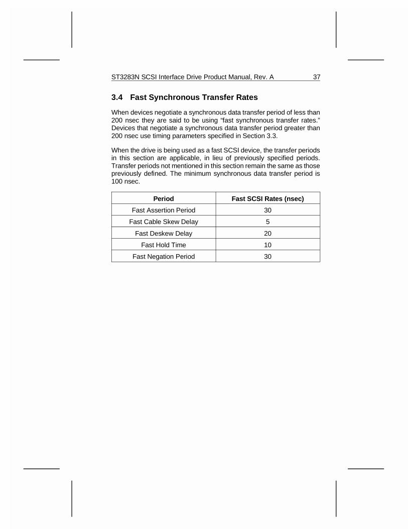
3.4 Fast Synchronous Transfer Rates
When devices negotiate a synchronous data transfer period of less than200 nsec they are said to be using “fast synchronous transfer rates.”Devices that negotiate a synchronous data transfer period greater than200 nsec use timing parameters specified in Section 3.3.
When the drive is being used as a fast SCSI device, the transfer periodsin this section are applicable, in lieu of previously specified periods.Transfer periods not mentioned in this section remain the same as thosepreviously defined. The minimum synchronous data transfer period is100 nsec.
Period Fast SCSI Rates (nsec)
Fast Assertion Period 30
Fast Cable Skew Delay 5
Fast Deskew Delay 20
Fast Hold Time 10
Fast Negation Period 30
ST3283N SCSI Interface Drive Product Manual, Rev. A 37

38 ST3283N SCSI Interface Drive Product Manual, Rev. A
4.0 Logical CharacteristicsAll the operations of the SCSI bus described in this chapter are supportedby the drive, unless otherwise stated. The drive always functions as thetarget, never the initiator.
4.1 SCSI Bus Phases
The SCSI architecture includes eight distinct bus phases. The SCSI buscan never be in more than one phase at a time.
1. Bus Free phase
2. Arbitration phase
3. Selection phase
4. Reselection phase
5. Command phase*
6. Data (In and Out) phase*
7. Status (In Only) phase*
8. Message (In and Out) phase*
* These phases are collectively termed the Information Transfer Phase.
4.1.1 Bus Free Phase
The Bus Free phase indicates that no SCSI device is actively using theSCSI bus and it is available for subsequent users.
SCSI devices detect the Bus Free phase after SEL and BSY are bothfalse for at least a bus settle delay.
SCSI devices must release all SCSI bus signals within a bus clear delayafter BSY and SEL are continuously negated for a bus settle delay. If aSCSI device requires more than a bus settle delay to detect the Bus Freephase, it must release all SCSI bus signals within a bus clear delay minusthe excess time to detect the Bus Free phase. The total time to clear theSCSI bus must not exceed a bus settle delay plus a bus clear delay.
ST3283N SCSI Interface Drive Product Manual, Rev. A 39
If the initiator detects the Bus Free phase (except as a result of a Resetcondition, an Abort message, or a Bus Device Reset message) withoutfirst receiving a Disconnect or Command Complete message, it isconsidered to be an error condition. If the target intentionally creates thiscondition, the target:
1. Clears the current I/O process, if any, for that initiator.
2. Sets up Request Sense data with the appropriate Sense Key andError Code if the LUN is known.
Whenever an initiator detects an unexpected Bus Free, it should attemptto select and issue Request Sense to determine if the previous I/Oprocess was:
1. Aborted with valid Request Sense data, or
2. Aborted without any valid Request Sense data.
4.1.2 Arbitration Phase
The Arbitration phase allows one SCSI device to gain control of the SCSIbus so that it can assume the role of an initiator or target. The drivearbitrates for the bus only as a target implementing reselection. The drivesupports arbitration by multiple SCSI devices.
The procedure for a SCSI device to obtain control of the SCSI bus is asfollows:
1. The SCSI device waits for Bus Free phase. The Bus Free phase isdetected when BSY and SEL are simultaneously and continuouslynegated for a minimum of a bus settle delay.
Note: This bus settle delay is necessary because a transmission linephenomenon known as a “wired-OR glitch” may cause BSY to brieflyappear negated, even though it is being asserted.
2. The SCSI device waits a minimum of a bus free delay after detectionof the Bus Free phase (i.e. after BSY and SEL are both negated fora bus settle delay) before driving any signal.
3. The SCSI device may arbitrate for the SCSI bus by asserting bothBSY and its own SCSI ID, however the SCSI device does notarbitrate (i.e. assert BSY and its SCSI ID) if more than a bus set delayhas passed since the Bus Free phase was last observed.
40 ST3283N SCSI Interface Drive Product Manual, Rev. A
Note: There is no maximum delay before asserting BSY and theSCSI ID following the bus free delay as long as the bus remains inthe Bus Free phase. However, SCSI devices that delay longer thana bus settle delay plus a bus set delay from the time when BSY andSEL are first negated may fail to participate in arbitration whencompeting with faster SCSI devices.
4. After waiting at least an arbitration delay (measured from its asser-tion of BSY) the SCSI device examines the Data Bus. If a higherpriority SCSI ID bit is true on the Data Bus [DB(7) is the highest], theSCSI device has lost the arbitration and must release its signals andreturn to the first step. If no higher priority SCSI ID bit is true on theData Bus, the SCSI device has won the arbitration and it will assertSEL. Any other SCSI device that is participating in the Arbitrationphase has lost the arbitration and releases BSY and its SCSI ID bitwithin a bus clear delay after SEL becomes true. A SCSI device thatloses arbitration may return to the first step.
The SCSI device that wins arbitration waits at least a bus clear delayplus a bus settle delay after asserting SEL before changing anysignals.
Note: The SCSI ID bit is a single bit on the Data Bus that correspondsto the SCSI device’s unique SCSI address. The other seven databus bits are released by the SCSI device. Parity is not valid duringthe Arbitration phase, DB(P) may be undriven, or driven true, but notdriven false.
4.1.3 Selection Phase
The Selection phase allows an initiator to select a target for the purposeof initiating some target function, for example a Read or a Write com-mand.
Note: During the Selection phase, the I/O signal is negated so this phasecan be distinguished from the Reselection phase.
4.1.3.1 Nonarbitrating Systems
In systems that do not implement the Arbitration phase, the initiatordetects the Bus Free phase, and then waits a minimum of a bus cleardelay. Then, except in certain single initiator environments with initiatorsemploying the single initiator option, the initiator asserts the desiredtarget’s SCSI ID and its own initiator SCSI ID on the data bus. After twodeskew delays, the initiator asserts SEL.
ST3283N SCSI Interface Drive Product Manual, Rev. A 41
4.1.3.2 Arbitrating Systems
In systems with the Arbitration phase implemented, the SCSI device thatwon the arbitration has both BSY and SEL asserted and has delayed atleast a bus clear delay plus a bus settle delay before ending theArbitration phase.
The SCSI device that won the arbitration becomes an initiator by releas-ing I/O. Except in certain single initiator environments with initiatorsemploying the single initiator option (see Section 4.1.3.4), the initiatorsets the Data Bus signal to a value that is the OR of its SCSI ID bit andthe target’s SCSI ID bit. The initiator waits at least two deskew delaysand release BSY. The initiator then waits at least a bus settle delay beforelooking for a response from the target.
4.1.3.3 All Systems
In all systems, the target determines that it is selected when SEL andits SCSI ID bit are true and BSY and I/O are false for at least a bus settledelay. The selected target examines the Data Bus to determine the SCSIID of the selecting initiator unless the initiator employed the single initiatoroption. The selected target then asserts BSY before the selection abortexpires; this is required for correct operation of the time-out procedure.
In systems with parity implemented, the target does not respond to aselection if bad parity is detected. Also, if more than two SCSI ID bits areon the data bus, the target does not respond to selection. If at least twodeskew delays transpire before the initiator asserts BSY, it releases SELand changes the Data Bus signal.
4.1.3.4 Single Initiator Option
Initiators that do not implement the Reselection phase, and do notoperate in the multiple initiator environment, are allowed to set only thetarget’s SCSI ID bit during the Selection phase. This makes it impossiblefor the target to determine the initiator’s SCSI ID.
42 ST3283N SCSI Interface Drive Product Manual, Rev. A
4.1.3.5 Selection Time-out Procedure
A selection time-out procedure is specified for clearing the SCSI bus:
• If the initiator waits a minimum of a selection time-out delay and therehas been no BSY response from the target, the initiator continuesasserting SEL and releases the data bus.
• If the initiator has not detected BSY to be asserted after at least aselection abort time plus two deskew delays, the initiator releasesSEL and ATN, allowing the SCSI bus to go to the Bus Free phase.SCSI devices ensure, when responding to selection, that the selec-tion was still valid within a selection abort time of their assertion ofBSY.
Note: Failure to comply with this requirement could result in animproper selection, for example: two targets connected to the sameinitiator; wrong target connected to an initiator; or a target that is notconnected to an initiator.
4.1.4 Reselection Phase
Reselection is a phase that allows a target to reconnect to an initiator forthe purpose of continuing some operation that was previously started bythe initiator but was suspended by the target. For example, the targetdisconnected by allowing a Bus Free phase to occur before the operationwas complete.
Reselection can be used only in systems that have the Arbitration phaseimplemented.
The drive implements the Reselection phase if the host system is capableof supporting Reselection.
4.1.4.1 Reselection Procedure
Upon completing the Arbitration phase, the winning SCSI device has bothBSY and SEL asserted and has delayed at least a bus clear delay plusa bus settle delay. The winning SCSI device becomes a target byasserting the I/O signal. That device also sets the Data Bus to a valuethat is the OR of its SCSI ID bit and the initiator’s SCSI ID bit. The targetwaits at least two deskew delays and releases BSY. The target then waitsat least a bus settle delay before looking for a response from the initiator.
ST3283N SCSI Interface Drive Product Manual, Rev. A 43
The initiator determines that it is reselected when SEL, I/O, and its SCSIID bit are true and BSY is false for at least a bus settle delay. Thereselected initiator may examine the Data Bus to determine the SCSI IDof the reselecting target.
The reselected initiator then asserts BSY within a selection abort time ofits most recent detection of being reselected; this is required for correctoperation of the time-out procedure. In systems with parity implemented,the initiator does not respond to Reselection if bad parity is detected. Theinitiator does not respond to a Reselection if more than two SCSI ID bitsare on the Data Bus.
After the target detects the BSY signal is true, it asserts BSY and waitsat least two deskew delays and then releases SEL. The target may thenchange the I/O signal and the Data Bus. When the reselected initiatordetects SEL false, it releases BSY. The target continues asserting BSYuntil the target is ready to relinquish the SCSI bus.
Note: When the target is asserting BSY, a transmission line phenomenonknown as a “wired-OR glitch” may cause BSY to appear false for up toa round trip propagation delay following the release of BSY by theinitiator. Therefore, the Bus Free phase is recognized only after both BSYand SEL are continuously false for a minimum of a bus settle delay.
Note: Do not use a cable longer than previously specified, even if thechosen driver, receiver, and cable provide adequate noise margins. Theincreased length increases the duration of the wired-OR glitch and couldcause SCSI devices to inadvertently detect the Bus Free phase.
4.1.4.2 Reselection Time-out Procedure
The Reselection time-out procedure is specified for clearing the SCSIbus during a Reselection phase:
• If the target waits a minimum of a selection time-out period and therehas been no BSY response from the initiator, the target continuesasserting SEL and I/O and releases all Data Bus signals.
• If the target has not detected BSY to be true after at least a selectionabort time plus two deskew delays, the target releases SEL and I/Oallowing the SCSI bus to go to the Bus Free phase.
44 ST3283N SCSI Interface Drive Product Manual, Rev. A
SCSI devices that respond to reselection must ensure that the reselec-tion was still valid within a selection abort time of their assertion of BSY.If not, an improper reselection may result. For example, two initiators maybe connected to the same target or the wrong initiator may be connectedto a target.
If reselection fails, the current command is aborted. If an initiator timesout while waiting to be reselected, the initiator should attempt to selectand issue Request Sense to determine if the previous I/O process is:
• Still in process (Busy Status will be returned)
• Aborted with valid Request Sense data
• Aborted without valid Request Sense data
4.1.5 Information Transfer Phases
Note: The Command, Data, Status, and Message phases are groupedtogether as information transfer phases because they are used to trans-fer data or control information via the Data Bus. The actual contents ofthe information is beyond the scope of this section.
The C/D, I/O, and MSG signals are used to distinguish between thedifferent information transfer phases. The target drives these threesignals and therefore controls all changes from one phase to another.The initiator can request a Message Out phase by asserting ATN, whilethe target can cause the Bus Free phase by releasing MSG, C/D, I/O,and BSY.
The information transfer phases use one or more REQ/ACK handshakesto control transfers. Each REQ/ACK handshake allows the transfer ofone byte of information. During the information transfer phases:
• BSY must remain true and SEL must remain false.
• The target must continuously envelope the REQ/ACK handshake(s)with C/D, I/O, and MSG so that these control signals are valid for abus settle delay before the assertion of REQ of the first handshake,and remain valid until the negation of ACK at the end of the lasthandshake.
ST3283N SCSI Interface Drive Product Manual, Rev. A 45
4.1.5.1 Asynchronous Data Transfer
The target use the I/O signal to control the direction of data transfer:
• When I/O is true, information is transferred from the target to theinitiator.
The target drives DB(7-0,P) to their desired values, delays at leastone deskew delay plus a cable skew delay, then asserts REQ.DB(7-0,P) must remain valid until ACK is true at the target. Theinitiator reads DB(7-0,P) after REQ is true, and then signals itsacceptance of the data by asserting ACK.
When ACK becomes true at the target, the target may change orrelease DB(7-0,P) and negate REQ. After REQ is false the initiatornegates ACK. After ACK is false, the target may continue the transferby driving DB(7-0,P) and asserting REQ, as described above.
• When I/O is false, information is transferred from the initiator to thetarget.
The target requests information by asserting REQ. The initiatordrives DB(7-0,P) to their desired values, delays at least one deskewdelay plus a cable skew delay, and asserts ACK. The initiatorcontinues to drive the DB(7-0,P) until REQ is false.
When ACK becomes true at the target, the target reads DB(7-0,P),then negate REQ. When REQ becomes false at the initiator, theinitiator may change or release DB(7-0,P) and negate ACK. Thetarget may continue the transfer by asserting REQ, as describedabove.
4.1.5.2 Synchronous Data Transfer
Synchronous data transfer may be used only in the data phase ifpreviously agreed to by the initiator and the target through the messagesystem. The messages determine the use of synchronous mode by bothdevices and establishes a REQ/ACK offset and a transfer period. SeeSection 4.5.3.1 for an explanation of synchronous extended messages.
The REQ/ACK offset specifies the maximum number of REQ pulses thatcan be sent by the target in advance of the number of ACK pulsesreceived from the initiator, establishing a pacing mechanism. If thenumber of REQ pulses exceeds the number of ACK pulses by theREQ/ACK offset, the target does not assert REQ until the next ACK pulseis received. To successfully complete the data phase, the number of ACKand REQ pulses must be equal.
46 ST3283N SCSI Interface Drive Product Manual, Rev. A
Before asserting the REQ signal, the drive waits at least:
• the greater of a transfer period from the last transition of the REQsignal to true,
• or a minimum of a negation period from the last transition of the REQsignal to false.
The initiator must send one pulse on the ACK signal for each REQ pulsereceived. The initiator asserts the ACK pulse for a minimum of anassertion period. Before asserting the ACK signal, the initiator waits atleast the greater of a transfer period from the last transition of ACK totrue or a minimum of a negation period from the transition of ACK to false.
• When I/O is true, information is transferred from the target to theinitiator.
The target drives DB (7-0,P) to their desired values, and then waitsat least one deskew delay plus one cable skew delay plus one holdtime after the assertion of REQ. The target must assert REQ for aminimum of an assertion period. The target may then negate REQand change or release DB (7-0,P). The initiator reads the value ofDB (7-0,P) within one hold time of the transition of REQ to true. Theinitiator then responds with an ACK pulse.
• When I/O is false, information is transferred from the initiator to thetarget.
The initiator transfers one byte for each REQ pulse received. Afterreceiving the REQ pulse, the initiator drives DB (7-0,P) to theirdesired values, and then delays at least one deskew delay plus onecable delay before asserting ACK. The initiator must hold DB (7-0,P)valid for at least one deskew delay plus one cable skew delay plusone hold time after the assertion of ACK. The initiator asserts ACKfor a minimum of an assertion period. The initiator may then negateACK and change or release DB (7-0,P). The target reads the valueof DB (7-0,P) within one hold time of the transition of the ACK signalto true.
4.1.6 Command Phase
The Command phase allows the target to request command informationfrom the initiator. The target must assert the C/D signal and negate theI/O and MSG signals during the REQ/ACK handshake(s) of this phase.
ST3283N SCSI Interface Drive Product Manual, Rev. A 47
4.1.7 Data Phases
The Data Phase is a term that encompasses both the Data In and theData Out phase.
4.1.7.1 Data In Phase
The Data In phase allows the target to request that it send data to theinitiator. The target must assert the I/O signal and negate the C/D andMSG signals during the REQ/ACK handshake.
4.1.7.2 Data Out Phase
The Data Out phase allows the target to request that data be sent to itfrom the initiator. The drive negates the C/D, I/O, and MSG signals duringthe REQ/ACK handshake.
4.1.8 Status Phase
The Status phase allows the target to request that it send status infor-mation to the initiator. See Section 5.5 for a detailed table of the availablestatus information. The target must assert C/D and I/O and negate theMSG signal during the REQ/ACK handshake.
4.1.9 Message Phases
Multiple-byte messages can be sent during a single phase of MessageIn and Message Out phases. The first byte transferred is either asingle-byte message or the first byte of a multiple-byte message.
4.1.9.1 Message In Phase
The Message In phase allows the target to request that it send messagesto the initiator. The target must assert C/D, I/O, and MSG during theREQ/ACK handshake.
4.1.9.2 Message Out Phase
The Message Out phase allows the target to request that message(s) besent from the initiator to the target. The target can invoke this phase inresponse to the Attention condition created by the initiator. The drive
48 ST3283N SCSI Interface Drive Product Manual, Rev. A
asserts C/D and MSG and negates I/O during the REQ/ACK handshake.The drive handshakes bytes in this phase until ATN goes false, unlessan error occurs.
If the target detects a parity error on the message bytes received, it canattempt to retry the message by asserting REQ after detection ATN hasgone false and before changing to any other phase. In response, theinitiator resends all of the previous message bytes sent during this phase.When resending more than one message byte, the initiator asserts ATNat least two deskew delays before asserting ACK on the first byte andmaintains ATN asserted until the last byte is sent.
If the target receives all of the message bytes without parity errors, itindicates that it does not wish to retry by changing to any informationtransfer phase other than the Message Out phase and transfers at leastone byte. The target may also indicate that it has successfully receivedthe message bytes by changing to the Bus Free phase, for example,Abort or Bus Device Reset messages.
The first message sent by the initiator after the selection phase must bean Identify, Abort, or Bus Device Reset message. If the target receivesany other message, it goes to the Bus Free phase.
4.1.10 Signal Restrictions Between Phases
When the SCSI bus is between two information transfer phases, thefollowing restrictions apply to the SCSI bus signals:
1. The BSY, SEL, REQ, and ACK signals must not change.
2. The C/D, I/O, MSG, and Data Bus signals may change. Whenswitching the Data Bus signal direction from Out (initiator driving) toIn (target driving), the target delays driving the Data Bus by at leasta data release delay plus the bus settle delay after asserting the I/Osignal, and the initiator releases the Data Bus signal no later than adata release delay after the transition of the I/O signal to true. Whenswitching the Data Bus direction from In (target driving) to Out(initiator driving), the target releases the Data Bus signal no later thana deskew delay after negating the I/O signal.
3. The ATN and RST signals may change as defined under the descrip-tions for the Attention condition (Section 4.2.1) and Reset condition(Section 4.2.2).
ST3283N SCSI Interface Drive Product Manual, Rev. A 49
4.2 SCSI Bus Conditions
The SCSI bus has two asynchronous conditions: the Attention conditionand the Reset condition. These conditions cause the SCSI device toperform certain actions and can alter the phase sequence.
4.2.1 Attention Condition
The initiator uses the Attention condition to tell the target that the initiatorhas a message ready. The target gets this message by performing aMessage Out phase.
The initiator creates the Attention condition by asserting ATN at any time,except during the Arbitration or Bus Free phase.
The initiator must assert the ATN signal before negating ACK for the lastbyte transferred in a bus phase for the Attention condition to be honoredbefore transition to a new bus phase. An ATN asserted later may not behonored until a later bus phase. The drive responds with the MessageOut phase as follows:
1. If ATN occurs during a Data phase, Message Out occurs at aconvenient time. It may not occur until several logical blocks afterATN is first asserted.
2. If ATN occurs during a Command phase, Message Out occurs aftertransfer of all Command Descriptor Block bytes has been completed.
3. If ATN occurs during a Status phase, Message Out occurs after thestatus byte has been acknowledged by the initiator.
4. If ATN occurs during a Message In phase, Message Out occurs afterthe last byte of the current message has been acknowledged by theinitiator.
5. If ATN occurs during a Selection phase, Message Out occurs imme-diately after that Selection phase.
6. If ATN occurs during a Reselection phase, Message Out occursimmediately after the Identify message.
50 ST3283N SCSI Interface Drive Product Manual, Rev. A
The initiator must keep ATN asserted if more than one byte is to betransferred. The initiator may negate the ATN signal at any time exceptwhile the ACK signal is asserted during a Message Out phase. Recom-mended practice is that the initiator negates ATN while REQ is true andACK is false during the last REQ/ACK handshake of the Message Outphase.
4.2.2 Reset Condition
The Reset condition is used to clear all SCSI devices from the bus. Resettakes precedence over all other phases and conditions. During the Resetcondition, the states of all SCSI bus signals, except RST, are not defined.After the Reset condition, the bus always goes to the Bus Free phase.
All SCSI devices must release all bus signals (except RST) within a busclear delay of the transition of RST to true. The drive never asserts theReset signal. The drive implements only the “hard” Reset option. Uponreceipt, the drive:
1. Clears all uncompleted commands.
2. Releases all SCSI device reservations.
3. Returns any SCSI device operating modes to default conditions. Themode parameters will be returned to their saved values if the savedvalue can be retrieved. Otherwise, the mode values will be returnedto their default values.
4. Activates Unit Attention Condition for all initiators.
4.3 SCSI Bus Phases
SCSI bus phases follow a prescribed sequence. The Reset condition canabort any phase and is always followed by the Bus Free phase. Also,any other phase can be followed by the Bus Free phase.
ST3283N SCSI Interface Drive Product Manual, Rev. A 51
4.3.1 Arbitration Transfer Phases
The arbitration transfer phases can be in any sequence. A phase of aspecific type can be followed by any phase, even of the same type.
4.3.1.1 Systems with Arbitration
For systems with Arbitration, the allowable sequences are shown inFigure 10 The normal progression is from the Bus Free phase toArbitration, from Arbitration to Selection or Reselection, and from Selec-tion or Reselection to one or more of the information transfer phases:Command, Data, Status, or Message.
4.3.1.2 Systems without Arbitration
For systems without Arbitration, the allowable sequences are shown inFigure 11. The normal progression is from the Bus Free phase toSelection, and from Selection to an information transfer phase: Com-mand, Data, Status, or Message.
4.4 SCSI Pointers
The SCSI architecture provides for two sets of three pointers for eachI/O process within each initiator. The pointers are part of the initiator pathcontrol. The first set of pointers are known as the active pointers. Thesepointers represent the state of the interface and point to the nextcommand, data, or status byte to be transferred between the initiator’smemory and the target. There is only one set of pointers in each initiator.The active pointers are used by the target currently connected to theinitiator.
The second set of pointers are known as the saved pointers. There isone set of saved pointers for each command that is currently active(whether or not it is currently connected). The saved command pointeralways points to the start of the Command Descriptor Block (see Sec-tion 5.2) for the current command. The saved status pointer alwayspoints to the start of the status area for the current command. At thebeginning of each command, the saved data pointer points to the startof the data area. It remains at this value until the target sends a SaveData Pointer message (see Section 4.5.2) to the initiator. In response tothis message, the initiator stores the value of the active data pointer intothe saved data pointer. The target may restore the active pointers to theirsaved values by sending a Restore Pointer Message to the initiator. (See
52 ST3283N SCSI Interface Drive Product Manual, Rev. A
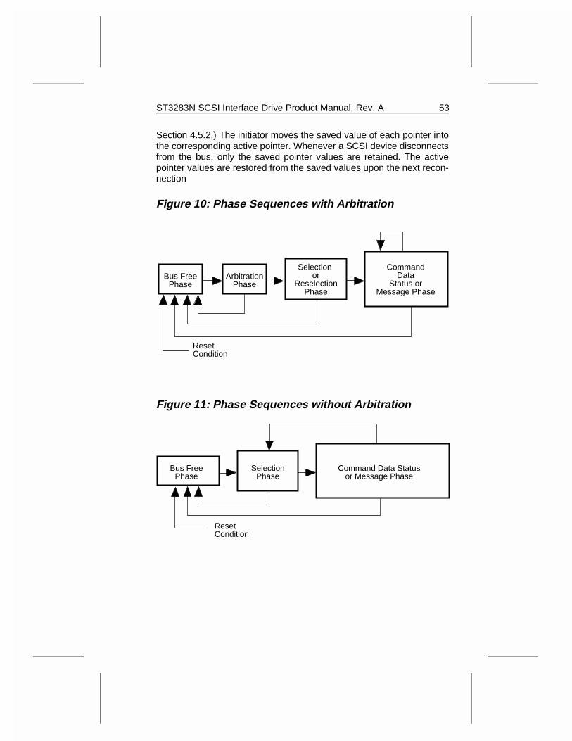
Section 4.5.2.) The initiator moves the saved value of each pointer intothe corresponding active pointer. Whenever a SCSI device disconnectsfrom the bus, only the saved pointer values are retained. The activepointer values are restored from the saved values upon the next recon-nection
Figure 10: Phase Sequences with Arbitration
Figure 11: Phase Sequences without Arbitration
Bus FreePhase
SelectionPhase
Command Data Statusor Message Phase
ResetCondition
Bus FreePhase
ArbitrationPhase
Selection or
ReselectionPhase
CommandData
Status orMessage Phase
ResetCondition
ST3283N SCSI Interface Drive Product Manual, Rev. A 53
4.5 Message System Specification
The message system allows communication between an initiator andtarget for the purpose of physical path management.
4.5.1 Message Protocol
The drive supports systems that accommodate the Command Completemessage or systems that accommodate additional messages. The driveis always Logical Unit (LUN) address zero.
SCSI devices indicate their ability to accommodate more than theCommand Complete message by asserting or responding to the ATNsignal. The initiator indicates this in the Selection phase by asserting ATNbefore the SCSI bus condition of SEL true, and BSY false. If the targethas not received ATN by this point, it will assume that the initiator doesnot support disconnection or messages other than Command Complete.If the ATN signal is asserted later, it is ignored until after the next BusFree phase. The target indicates its ability to accommodate more mes-sages by responding to the Attention condition with the Message Outphase after going through the Selection phase.
For SCSI devices that support messages other than Command Com-plete, the first message sent by the initiator after the Selection phasemust be the Identify, Abort or Bus Device Reset message. This allowsthe establishment of the physical path for a particular logical unit specifiedby the initiator.
The first message sent by the target after the Reselection phase is theIdentify message. This allows the physical path to be reestablished forthe target’s specified logical unit number (always zero).
Whenever a physical path is established in an initiator that can accom-modate disconnection and reconnection, the initiator must ensure thatthe active pointers of the physical path are equal to the save pointers forthat particular logical unit number. (An implied restore pointers operationoccurs as a result of connect or reconnect.)
54 ST3283N SCSI Interface Drive Product Manual, Rev. A
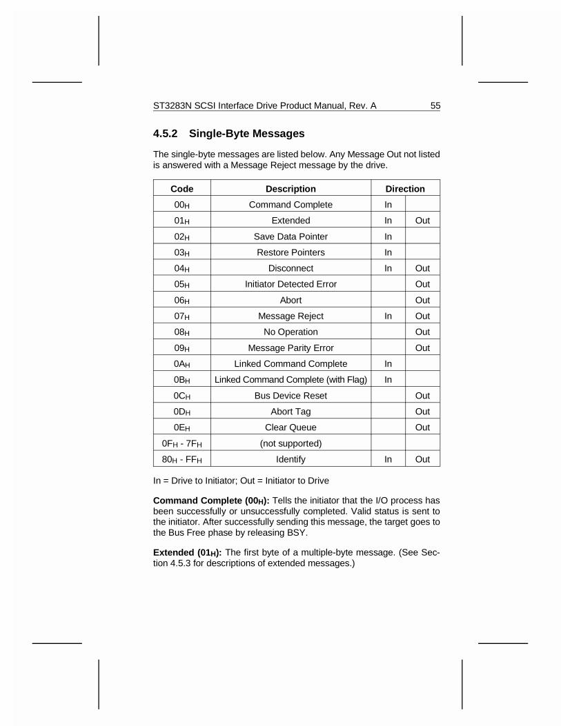
4.5.2 Single-Byte Messages
The single-byte messages are listed below. Any Message Out not listedis answered with a Message Reject message by the drive.
Code Description Direction
00H Command Complete In
01H Extended In Out
02H Save Data Pointer In
03H Restore Pointers In
04H Disconnect In Out
05H Initiator Detected Error Out
06H Abort Out
07H Message Reject In Out
08H No Operation Out
09H Message Parity Error Out
0AH Linked Command Complete In
0BH Linked Command Complete (with Flag) In
0CH Bus Device Reset Out
0DH Abort Tag Out
0EH Clear Queue Out
0FH - 7FH (not supported)
80H - FFH Identify In Out
In = Drive to Initiator; Out = Initiator to Drive
Command Complete (00 H): Tells the initiator that the I/O process hasbeen successfully or unsuccessfully completed. Valid status is sent tothe initiator. After successfully sending this message, the target goes tothe Bus Free phase by releasing BSY.
Extended (01 H): The first byte of a multiple-byte message. (See Sec-tion 4.5.3 for descriptions of extended messages.)
ST3283N SCSI Interface Drive Product Manual, Rev. A 55
Save Data Pointer (02 H): Tells the initiator to copy the currently activedata pointer to the saved data pointer for the current I/O process. (SeeSection 4.4 for a definition of pointer.)
Restore Pointers (03 H): Directs the initiator to restore the active pointersfrom the most recently saved pointers for the currently attached drive.Pointers to the command, data, and status locations for the logical unitare restored to the active pointers. Command and status pointers arerestored to the beginning of the present command and status areas. Thedata pointer is restored to the value at the beginning of the data area inthe absence of a Save Data Pointer message or to the value at the pointat which the last Save Data Pointer message occurred for the currentlyattached drive.
Disconnect (04 H): Tells the initiator that the present physical path isbroken, causing the target to disconnect by releasing BSY. Later, areconnect is required to complete the current I/O process.
If the initiator detects the Bus Free phase (other than as a result of aReset condition) without first receiving a Disconnect, Command Com-plete or after sending Abort, Abort Tag, Bus Device Reset or aClear Queue message, the initiator considers this a catastrophic error.The initiator does not save the data pointer.
If Disconnect messages are used to break a long data transfer into twoor more shorter transfers, then a Save Data Pointer message is issuedbefore each Disconnect message. The drive disconnects when a sub-stantial delay is anticipated. These situations occur after receipt of aCommand Descriptor Block or during a data transfer. The initiator maysend this message to the target to tell it to disconnect from the SCSI bus.
After the target receives the Disconnect message, it switches to theMessage In phase, sends the Save Data Pointer and Disconnect mes-sages to the initiator, and disconnects by releasing BSY. After releasingthe BSY signal, the target does not participate in another arbitrationphase for at least a disconnection delay.
Initiator Detected Error (05 H): Tells the target that an error (for example,a parity error) has occurred that does not preclude the target from retryingthe I/O process. Since present pointer integrity is not assured, a RestorePointers message is sent by the target to cause the pointers to berestored to their defined prior state. An initiator should not issue thismessage unless it will accept the Restore Pointers message. If the targetis not sure it can recover properly, Check Condition status will be createdwith Sense Key of Aborted Command.
56 ST3283N SCSI Interface Drive Product Manual, Rev. A
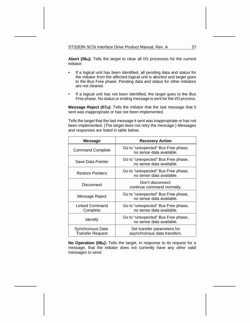
Abort (06 H): Tells the target to clear all I/O processes for the currentinitiator:
• If a logical unit has been identified, all pending data and status forthe initiator from the affected logical unit is aborted and target goesto the Bus Free phase. Pending data and status for other initiatorsare not cleared.
• If a logical unit has not been identified, the target goes to the BusFree phase. No status or ending message is sent for the I/O process.
Message Reject (07 H): Tells the initiator that the last message that itsent was inappropriate or has not been implemented.
Tells the target that the last message it sent was inappropriate or has notbeen implemented. (The target does not retry the message.) Messagesand responses are listed in table below.
Message Recovery Action
Command Complete Go to “unexpected” Bus Free phase,no sense data available.
Save Data Pointer Go to “unexpected” Bus Free phase,no sense data available.
Restore Pointers Go to “unexpected” Bus Free phase,no sense data available.
Disconnect Don’t disconnect:continue command normally.
Message Reject Go to “unexpected” Bus Free phase,no sense data available.
Linked CommandComplete
Go to “unexpected” Bus Free phase,no sense data available.
Identify Go to “unexpected” Bus Free phase,no sense data available.
Synchronous Data Transfer Request
Set transfer parameters forasynchronous data transfers.
No Operation (08 H): Tells the target, in response to its request for amessage, that the initiator does not currently have any other validmessages to send.
ST3283N SCSI Interface Drive Product Manual, Rev. A 57
Message Parity Error (09 H): Tells the target that one or more bytes inthe last message it received had a parity error. The drive retries theoriginal message once. If the retry also results in a parity error, the targetgoes to Bus Free phase.
The initiator indicates its intention to send this message by asserting theATN signal before it releases ACK for the REQ/ACK handshake of themessage that has the parity error. This provides an interlock, allowingthe target to determine which message has the parity error.
Linked Command Complete (0A H): Tells the initiator that a linkedcommand is completed and that the status has been sent. Then, theinitiator sets the pointers to the initial state for the next linked command.
Linked Command Complete (with flag) (0B H): Tells the initiator thata linked command has been completed (with the flag bit set to one) andthat the status has been sent. Then, the initiator sets the pointers to theinitial state for the next linked command. Typically, this message wouldbe used to cause an interrupt in the initiator between two linked com-mands.
Bus Device Reset (0C H): Tells the target to clear all I/O processes anddrives it to an initial state with no operations pending for any initiator.When received, the target goes to the Bus Free phase. This messageforces a hard reset condition on the drive. The drive then creates a unitattention condition for all initiators.
Abort Tag (0D H ): Tells the target to abort the current I/O process withoutany ending message, status, or sense data, though the data on the discmay have been modified. The target goes to Bus Free phase. No otherI/O processes are affected. Mode parameters, extended contingentallegiance, and reservations are not affected.
Clear Queue (0E H): Tells the target to abort the current I/O processwithout any ending message, status, or sense data, though the data onthe disc may have been modified. The target goes to Bus Free phase.All other queued I/O processes, from all initiators for the specified LUN,are cleared. Unit Attention is set for any initiators having active or queuedI/O processes for the specified LUN with an additional sense of com-mands cleared by another initiator.
58 ST3283N SCSI Interface Drive Product Manual, Rev. A
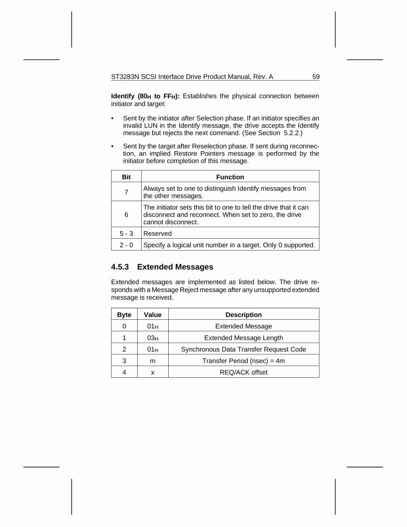
Identify (80 H to FFH): Establishes the physical connection betweeninitiator and target:
• Sent by the initiator after Selection phase. If an initiator specifies aninvalid LUN in the Identify message, the drive accepts the Identifymessage but rejects the next command. (See Section 5.2.2.)
• Sent by the target after Reselection phase. If sent during reconnec-tion, an implied Restore Pointers message is performed by theinitiator before completion of this message.
Bit Function
7 Always set to one to distinguish Identify messages fromthe other messages.
6The initiator sets this bit to one to tell the drive that it candisconnect and reconnect. When set to zero, the drivecannot disconnect.
5 - 3 Reserved
2 - 0 Specify a logical unit number in a target. Only 0 supported.
4.5.3 Extended Messages
Extended messages are implemented as listed below. The drive re-sponds with a Message Reject message after any unsupported extendedmessage is received.
Byte Value Description
0 01H Extended Message
1 03H Extended Message Length
2 01H Synchronous Data Transfer Request Code
3 m Transfer Period (nsec) = 4m
4 x REQ/ACK offset
ST3283N SCSI Interface Drive Product Manual, Rev. A 59
4.5.3.1 Synchronous Data Transfer Request Message
A pair of synchronous data transfer request messages are exchangedbetween an initiator and a target whenever a SCSI device capable ofsynchronous data transfer recognizes that it has not communicated withthe other SCSI device since receiving the last hard reset condition or abus device reset message. The SCSI devices may also exchangemessages to establish synchronous data transfer upon request. Anyproblem that precludes the successful exchange of the synchronous datatransfer request message shall cause the initiator and drive to default toasynchronous data transfers.
The message exchange establishes the transfer period and theREQ/ACK offset:
• The transfer period is the minimum time between leading edges ofsuccessive REQ and ACK pulses. This value, times four nsec, is thedata transfer period. The minimum value supported by the drive is25 (100 nsec).
• The REQ/ACK offset is the maximum number of REQ pulses thatmay be outstanding before its corresponding ACK pulse is receivedat the target. A REQ/ACK offset value of zero indicates asynchro-nous mode. The maximum offset supported by the drive is six.
If the initiator recognizes that negotiation is required, it asserts ATN andsends a synchronous data transfer request message indicating aREQ/ACK offset and minimum transfer period. The REQ/ACK offset ischosen to prevent initiator buffer overflows, while the minimum transferperiod is chosen to meet the data handling requirements of the initiator.The drive responds with a REQ/ACK offset of zero, which indicates anasynchronous transfer only.
60 ST3283N SCSI Interface Drive Product Manual, Rev. A
5.0 SCSI CommandsThis section defines the SCSI command structure and describes a typicalSCSI bus procedure involving a command, status return, and messageinterchange.
The command structure provides a contiguous set of logical blocks ofdata to be transferred across the interface. The number of logical datablocks to be transferred are defined in the command. Initiator commandsto the drive are structured in accordance with the requirements imposedby the drive’s physical characteristics. These physical characteristics arereported to the initiator in response to an Inquiry command or ModeSense command.
A single command may transfer one or more logical blocks of data. Thedrive may disconnect from the SCSI bus to allow activity by other SCSIdevices while the drive performs its own operations.
When the drive has successfully or unsuccessfully completed a com-mand, it returns a status byte to the initiator. Because most error andexception conditions cannot be adequately described with a single statusbyte, the drive issues the Check Condition status byte, which indicatesthat additional information is available. The initiator may issue a RequestSense command to request additional information as part of the Data-Inphase of the Request Sense command.
5.1 Command Implementation Requirements
The first byte of any SCSI command contains an operation code asdefined in this document. Three bits (bits 7 - 5) of the second byte of eachSCSI command specify the logical unit if it is not specified using theIdentify Message command. (See Section 4.5.2.) Only a logical unitnumber of zero is valid for the drive. The last byte of all SCSI commandsalways contains a control byte as defined in Section 5.2.6.
5.1.1 Reserved Addresses
Reserved bits, bytes, fields, and code values are set aside for future use.A reserved bit, field, or byte is always set to zero. If the drive receives areserved code value other than zero, it terminates the command with aCheck Condition status.
ST3283N SCSI Interface Drive Product Manual, Rev. A 61
5.1.2 Unit Attention Condition
The Unit Attention condition begins for each initiator if a power-onsequence occurs, if there is an internally generated reset (caused by apower failure), if the drive is reset by a bus device reset message or ahard reset condition, if a microcode download operation occurs, or if oneor more Mode Select parameters affecting the initiator were changed byanother initiator or if spindle synchronization is enabled and the spindlegoes into or out of synchronization. The Unit Attention condition persistsfor each initiator until that initiator clears the condition.
If an Inquiry command is received from an initiator with a pending UnitAttention condition before the drive reports the Unit Attention CheckCondition status, the drive performs the command and does not clearthe Unit Attention condition for that initiator. If a Request Sense commandis received from an initiator with a pending Unit Attention condition, thedrive discards any pending sense data, reports the Unit Attention condi-tions and then clears the Unit Attention condition for that initiator.
If an initiator issues a command other than Inquiry or Request Sensewhile a Unit Attention condition exists for that initiator, the drive shall notperform the command and shall report Check Condition status and setup the sense data to report the Unit Attention Check Condition for ananticipated Request Sense command. If a Request Sense command isissued next, the Unit Attention condition will be reported in the sensedata. If a command other than Request Sense is issued following thereporting of the Unit Attention Check Condition, the drive shall performthe command and return the appropriate status for the completion of thecommand. The Unit Attention condition sense data for that initiator iscleared or overwritten by the results of the last command causing theUnit Attention condition to be lost.
5.1.3 Command Queuing
The drive supports untagged command queuing which means the driveis capable of accepting and queuing one command from each initiatorfor up to seven possible initiators. When commands are queued, afterthe drive is selected it will accept the message and command bytes, senda Disconnect message, go to Bus Free phase, and continue commandexecution. If the command cannot be queued, the drive will allow itselfto be selected and will accept the command bytes for this command. Thedrive will then go to the Status Phase and send Busy status back to theinitiator.
62 ST3283N SCSI Interface Drive Product Manual, Rev. A
Command queuing can be done only for initiators that support Arbitrationand Reselection phases, send an Identify message after Selection, andallow disconnection. If the initiator does not support these options, thedrive will allow itself to be selected and will accept the command bytesfor a new command if the command queue is full. It will then go to theStatus phase and send Busy status to the initiator (see Section 5.5). Aftera Command Complete message and going to Bus Free phase, the drivesresumes execution of its current command. An initiator that receivedBusy status in this manner will have to resend the command later in orderto have it executed.
All commands that are queued are executed in the order received, unlessa hard Reset, a Power-on Reset, or a Bus Device Reset message isreceived. In these cases, all queued commands are cleared. Somecommands are cleared when a Clear Queue or Abort message isreceived. Refer to the descriptions for these messages. In all cases, nostatus is sent to the initiator.
5.2 Command Descriptor Block (CDB)
A request by an initiator to a drive is performed by sending a CommandDescriptor Block (CDB) to the drive. For several commands, the requestis accompanied by a list of parameters sent during the Data Out phase.See the specific commands for detailed information.
The Command Descriptor Block always has an operation code as thefirst byte of the command. This is followed by a logical unit number,command parameters (if any), and a control byte.
For all commands, if there is an invalid parameter in the CommandDescriptor Block, the drive shall terminate the command without alteringthe medium.
The format description for the Command Descriptor Block is shown inthe tables that follow.
ST3283N SCSI Interface Drive Product Manual, Rev. A 63
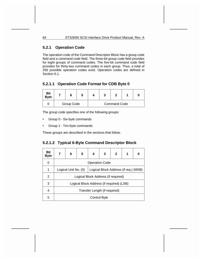
5.2.1 Operation Code
The operation code of the Command Descriptor Block has a group codefield and a command code field. The three-bit group code field providesfor eight groups of command codes. The five-bit command code fieldprovides for thirty-two command codes in each group. Thus, a total of256 possible operation codes exist. Operation codes are defined inSection 6.1.
5.2.1.1 Operation Code Format for CDB Byte 0
BitByte 7 6 5 4 3 2 1 0
0 Group Code Command Code
The group code specifies one of the following groups:
• Group 0 - Six-byte commands
• Group 1 - Ten-byte commands
These groups are described in the sections that follow.
5.2.1.2 Typical 6-Byte Command Descriptor Block
BitByte 7 6 5 4 3 2 1 0
0 Operation Code
1 Logical Unit No. (0) Logical Block Address (if req.) (MSB)
2 Logical Block Address (if required)
3 Logical Block Address (if required) (LSB)
4 Transfer Length (if required)
5 Control Byte
64 ST3283N SCSI Interface Drive Product Manual, Rev. A
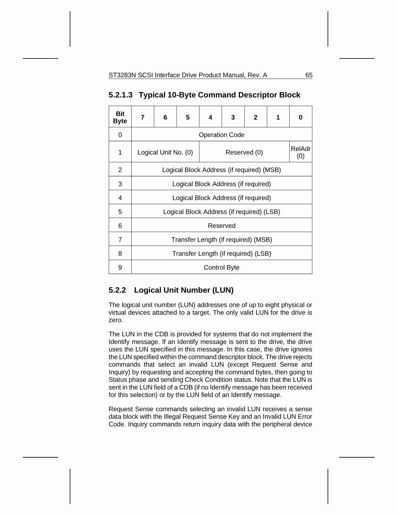
5.2.1.3 Typical 10-Byte Command Descriptor Block
BitByte 7 6 5 4 3 2 1 0
0 Operation Code
1 Logical Unit No. (0) Reserved (0) RelAdr(0)
2 Logical Block Address (if required) (MSB)
3 Logical Block Address (if required)
4 Logical Block Address (if required)
5 Logical Block Address (if required) (LSB)
6 Reserved
7 Transfer Length (if required) (MSB)
8 Transfer Length (if required) (LSB)
9 Control Byte
5.2.2 Logical Unit Number (LUN)
The logical unit number (LUN) addresses one of up to eight physical orvirtual devices attached to a target. The only valid LUN for the drive iszero.
The LUN in the CDB is provided for systems that do not implement theIdentify message. If an Identify message is sent to the drive, the driveuses the LUN specified in this message. In this case, the drive ignoresthe LUN specified within the command descriptor block. The drive rejectscommands that select an invalid LUN (except Request Sense andInquiry) by requesting and accepting the command bytes, then going toStatus phase and sending Check Condition status. Note that the LUN issent in the LUN field of a CDB (if no Identify message has been receivedfor this selection) or by the LUN field of an Identify message.
Request Sense commands selecting an invalid LUN receives a sensedata block with the Illegal Request Sense Key and an Invalid LUN ErrorCode. Inquiry commands return inquiry data with the peripheral device
ST3283N SCSI Interface Drive Product Manual, Rev. A 65
type field set to logical unit not present (7FH). Request Sense and Inquirycommands do not send Check Condition status in response to an invalidLUN selection.
5.2.3 Logical Block Address
The Logical Block Address on logical units shall begin with block zeroand be contiguous up to the last logical block on that logical unit.
Group 0 CDBs contain 21-bit logical block addresses. Group 1 CDBscontain 32-bit logical block addresses.
The Logical Block concept implies that the initiator and target shall havepreviously established the number of data bytes per logical block. Thismay be established through the use of the Read Capacity command orthe Mode Sense command, or by prior arrangement.
The maximum Logical Block Address which is accessible by the initiator,is defined in the Read Capacity data. See Section 6.2.1.
5.2.4 Relative Address Bit
The relative address bit of the Group 1 (and Group 5) commands is setto one to indicate that the logical block address portion of the commanddescriptor block is a two’s complement displacement. This displacementis to be added to the logical block address last accessed on the drive toform a new logical block address for the current command. This featureis only available when linking commands.
5.2.5 Transfer Length
The transfer length specifies the amount of data to be transferred, usuallythe number of blocks. For several commands, the transfer length indi-cates the requested number of bytes to be sent as defined in thecommand description. For these commands the transfer length field maybe identified by a different name. See the following descriptions and theindividual command descriptions for further information.
Commands that use one byte for transfer length allow up to 256 blocksof data to be transferred by one command. A transfer length value of 1to 255 indicates the number of blocks that shall be transferred. A valueof zero indicates 256 blocks.
66 ST3283N SCSI Interface Drive Product Manual, Rev. A
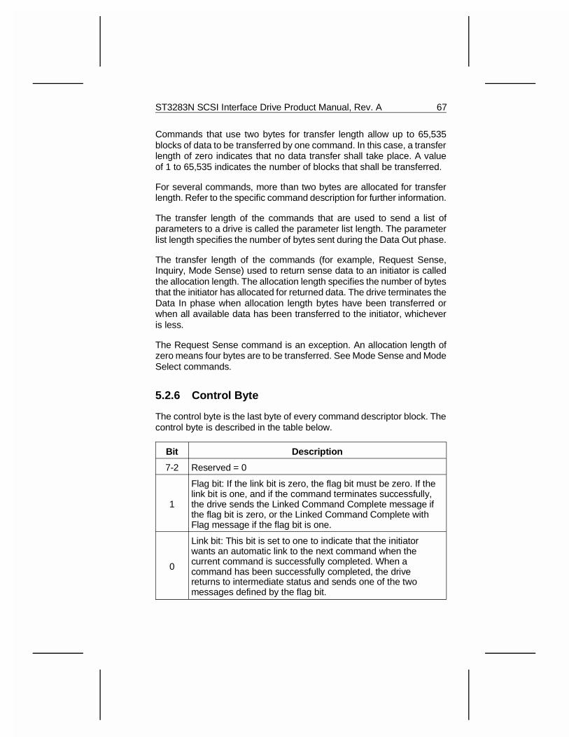
Commands that use two bytes for transfer length allow up to 65,535blocks of data to be transferred by one command. In this case, a transferlength of zero indicates that no data transfer shall take place. A valueof 1 to 65,535 indicates the number of blocks that shall be transferred.
For several commands, more than two bytes are allocated for transferlength. Refer to the specific command description for further information.
The transfer length of the commands that are used to send a list ofparameters to a drive is called the parameter list length. The parameterlist length specifies the number of bytes sent during the Data Out phase.
The transfer length of the commands (for example, Request Sense,Inquiry, Mode Sense) used to return sense data to an initiator is calledthe allocation length. The allocation length specifies the number of bytesthat the initiator has allocated for returned data. The drive terminates theData In phase when allocation length bytes have been transferred orwhen all available data has been transferred to the initiator, whicheveris less.
The Request Sense command is an exception. An allocation length ofzero means four bytes are to be transferred. See Mode Sense and ModeSelect commands.
5.2.6 Control Byte
The control byte is the last byte of every command descriptor block. Thecontrol byte is described in the table below.
Bit Description
7-2 Reserved = 0
1
Flag bit: If the link bit is zero, the flag bit must be zero. If thelink bit is one, and if the command terminates successfully,the drive sends the Linked Command Complete message ifthe flag bit is zero, or the Linked Command Complete withFlag message if the flag bit is one.
0
Link bit: This bit is set to one to indicate that the initiatorwants an automatic link to the next command when thecurrent command is successfully completed. When acommand has been successfully completed, the drivereturns to intermediate status and sends one of the twomessages defined by the flag bit.
ST3283N SCSI Interface Drive Product Manual, Rev. A 67
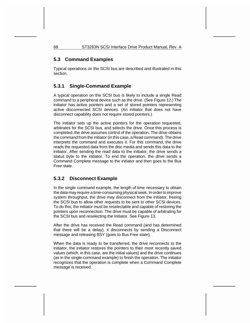
5.3 Command Examples
Typical operations on the SCSI bus are described and illustrated in thissection.
5.3.1 Single-Command Example
A typical operation on the SCSI bus is likely to include a single Readcommand to a peripheral device such as the drive. (See Figure 12.) Theinitiator has active pointers and a set of stored pointers representingactive disconnected SCSI devices. (An initiator that does not havedisconnect capability does not require stored pointers.)
The initiator sets up the active pointers for the operation requested,arbitrates for the SCSI bus, and selects the drive. Once this process iscompleted, the drive assumes control of the operation. The drive obtainsthe command from the initiator (in this case, a Read command). The driveinterprets the command and executes it. For this command, the drivereads the requested data from the disc media and sends this data to theinitiator. After sending the read data to the initiator, the drive sends astatus byte to the initiator. To end the operation, the drive sends aCommand Complete message to the initiator and then goes to the BusFree state.
5.3.2 Disconnect Example
In the single command example, the length of time necessary to obtainthe data may require a time-consuming physical seek. In order to improvesystem throughput, the drive may disconnect from the initiator, freeingthe SCSI bus to allow other requests to be sent to other SCSI devices.To do this, the initiator must be reselectable and capable of restoring thepointers upon reconnection. The drive must be capable of arbitrating forthe SCSI bus and reselecting the initiator. See Figure 13.
After the drive has received the Read command (and has determinedthat there will be a delay), it disconnects by sending a Disconnectmessage and releasing BSY (goes to Bus Free state).
When the data is ready to be transferred, the drive reconnects to theinitiator, the initiator restores the pointers to their most recently savedvalues (which, in this case, are the initial values) and the drive continues(as in the single-command example) to finish the operation. The initiatorrecognizes that the operation is complete when a Command Completemessage is received.
68 ST3283N SCSI Interface Drive Product Manual, Rev. A
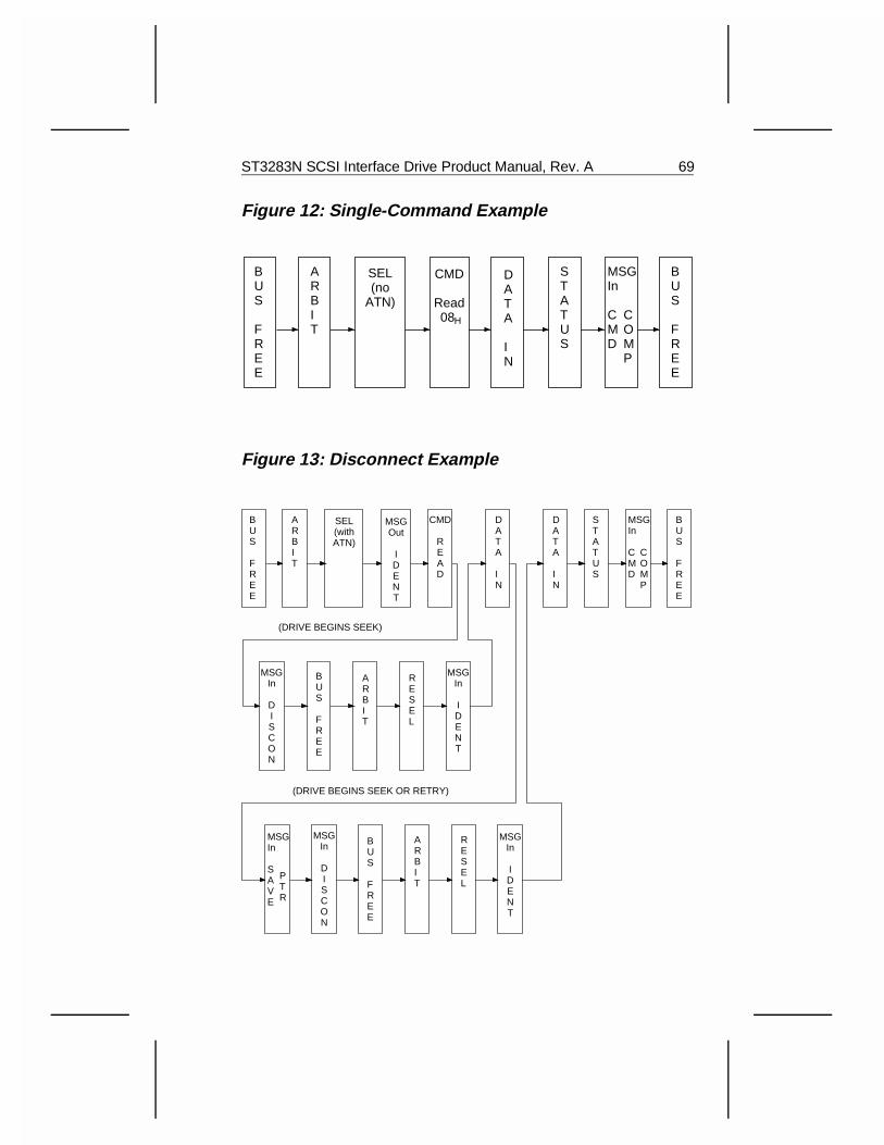
Figure 12: Single-Command Example
Figure 13: Disconnect Example
BUS
FREE
BUS
FREE
ARBIT
SEL(withATN)
MSGOut
IDENT
CMD
READ
DATA
IN
DATA
IN
STATUS
MSGIn
C M D
COMP
BUS
FREE
BUS
FREE
ARBIT
MSGIn
DISCON
MSGIn
IDENT
RESEL
(DRIVE BEGINS SEEK)
(DRIVE BEGINS SEEK OR RETRY)
ARBIT
RESEL
MSGIn
IDENT
MSGIn
DISCON
MSGIn
S AVE
PTR
BUS
FREE
BUS
FREE
ARBIT
SEL(no
ATN)
CMD
Read08
DATA
IN
STATUS
MSGIn
C M D
COMP
H
ST3283N SCSI Interface Drive Product Manual, Rev. A 69
If the drive wishes to disconnect after transferring part of the data (e.g.while crossing a cylinder boundary), it may do so by sending a Save DataPointer message and a Disconnect message to the initiator and thendisconnecting. When reconnection is completed, the current data pointeris restored to its value immediately before the Save Data Pointer mes-sage.
On those occasions when an error or exception condition occurs and thedrive elects to repeat the information transfer, the drive may repeat thetransfer by issuing a Restore Pointers message or by disconnectingwithout issuing a Save Data Pointer message. When reconnection iscompleted, the most recently saved pointer values are restored.
70 ST3283N SCSI Interface Drive Product Manual, Rev. A
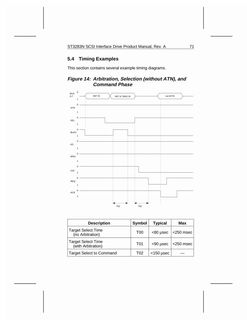
5.4 Timing Examples
This section contains several example timing diagrams.
Figure 14: Arbitration, Selection (without ATN), and Command Phase
Description Symbol Typical Max
Target Select Time (no Arbitration) T00 <80 µsec <250 msec
Target Select Time (with Arbitration) T01 <90 µsec <250 msec
Target Select to Command T02 <150 µsec —
1
0
1
0
1
0
1
0
1
0
1
0
1
0
1
0
1
0BUS0-7
-ATN
-SEL
-BUSY
-I/O
-MSG
-C/D
-REQ
-ACK
T01 T02
INIT ID INIT & TARG ID 1st BYTE
ST3283N SCSI Interface Drive Product Manual, Rev. A 71
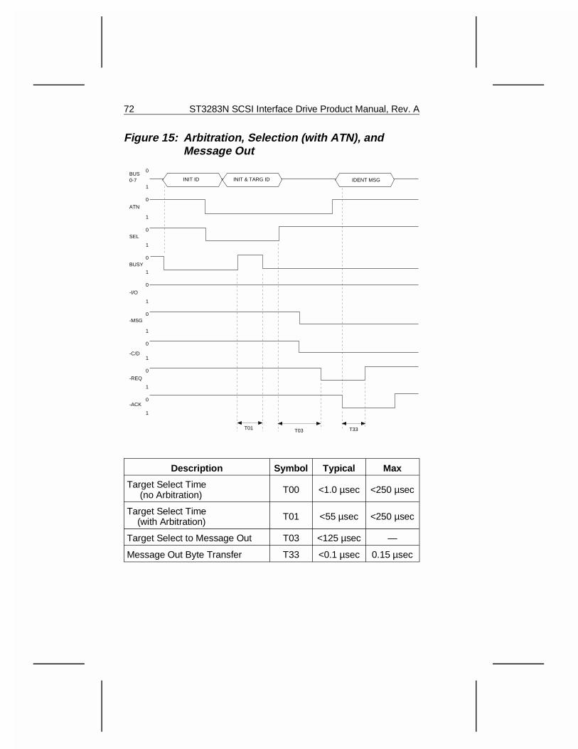
Figure 15: Arbitration, Selection (with ATN), and Message Out
Description Symbol Typical Max
Target Select Time (no Arbitration) T00 <1.0 µsec <250 µsec
Target Select Time (with Arbitration) T01 <55 µsec <250 µsec
Target Select to Message Out T03 <125 µsec —
Message Out Byte Transfer T33 <0.1 µsec 0.15 µsec
1
0
1
0
1
0
1
0
1
0
1
0
1
0
1
0
1
0BUS0-7
ATN
SEL
BUSY
-I/O
-MSG
-C/D
-REQ
-ACK
INIT ID INIT & TARG ID
T01 T03 T33
IDENT MSG
72 ST3283N SCSI Interface Drive Product Manual, Rev. A
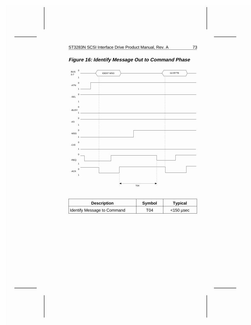
Figure 16: Identify Message Out to Command Phase
Description Symbol Typical
Identify Message to Command T04 <150 µsec
1
0
1
0
1
0
1
0
1
0
1
0
1
0
1
0
1
0BUS0-7
-ATN
-SEL
-BUSY
-I/O
-MSG
-C/D
-REQ
-ACK
T04
1st BYTEIDENT MSG
ST3283N SCSI Interface Drive Product Manual, Rev. A 73
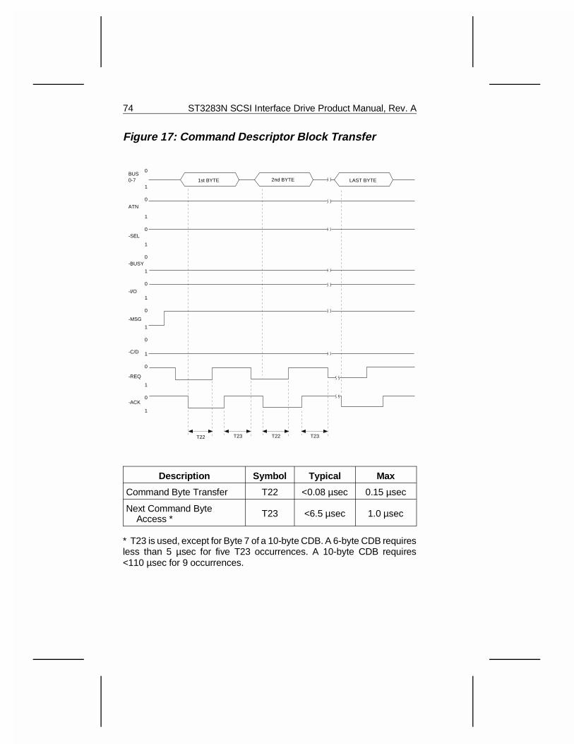
Figure 17: Command Descriptor Block Transfer
Description Symbol Typical Max
Command Byte Transfer T22 <0.08 µsec 0.15 µsec
Next Command Byte Access * T23 <6.5 µsec 1.0 µsec
* T23 is used, except for Byte 7 of a 10-byte CDB. A 6-byte CDB requiresless than 5 µsec for five T23 occurrences. A 10-byte CDB requires<110 µsec for 9 occurrences.
1
0
1
0
1
0
1
0
1
0
1
0
1
0
1
0
1
0BUS0-7
ATN
-SEL
-BUSY
-I/O
-MSG
-C/D
-REQ
-ACK
T22 T23 T22 T23
1st BYTE 2nd BYTE LAST BYTE
74 ST3283N SCSI Interface Drive Product Manual, Rev. A
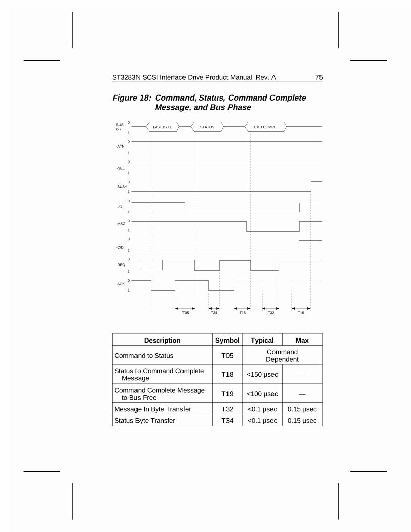
Figure 18: Command, Status, Command CompleteMessage, and Bus Phase
Description Symbol Typical Max
Command to Status T05 CommandDependent
Status to Command Complete Message T18 <150 µsec —
Command Complete Message to Bus Free T19 <100 µsec —
Message In Byte Transfer T32 <0.1 µsec 0.15 µsec
Status Byte Transfer T34 <0.1 µsec 0.15 µsec
1
0
1
0
1
0
1
0
1
0
1
0
1
0
1
0
1
0BUS0-7
-ATN
-SEL
-BUSY
-I/O
-MSG
-C/D
-REQ
-ACK
T05
LAST BYTE CMD COMPLSTATUS
T34 T18 T32 T19
ST3283N SCSI Interface Drive Product Manual, Rev. A 75
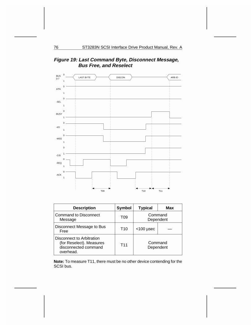
Figure 19: Last Command Byte, Disconnect Message, Bus Free, and Reselect
Description Symbol Typical Max
Command to Disconnect Message T09 Command
Dependent
Disconnect Message to Bus Free T10 <100 µsec —
Disconnect to Arbitration (for Reselect). Measures disconnected command overhead.
T11 CommandDependent
Note: To measure T11, there must be no other device contending for theSCSI bus.
1
0
1
0
1
0
1
0
1
0
1
0
1
0
1
0
1
0BUS0-7
ATN
-SEL
BUSY
-I/O
-MSG
-C/D
-REQ
-ACK
T09
LAST BYTE
T10 T11
DISCON ARB ID
76 ST3283N SCSI Interface Drive Product Manual, Rev. A
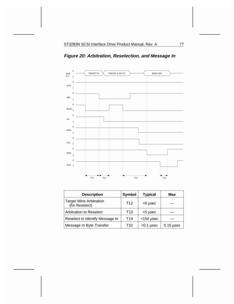
Figure 20: Arbitration, Reselection, and Message In
Description Symbol Typical Max
Target Wins Arbitration (for Reselect) T12 <6 µsec —
Arbitration to Reselect T13 <5 µsec —
Reselect to Identify Message In T14 <150 µsec —
Message In Byte Transfer T32 <0.1 µsec 0.15 µsec
1
0
1
0
1
0
1
0
1
0
1
0
1
0
1
0
1
0BUS0-7
-ATN
-SEL
-BUSY
-I/O
-MSG
-C/D
-REQ
-ACK
T13
TARGET ID TARGET & INIT ID IDENT MG
T12 T14 T32
ST3283N SCSI Interface Drive Product Manual, Rev. A 77
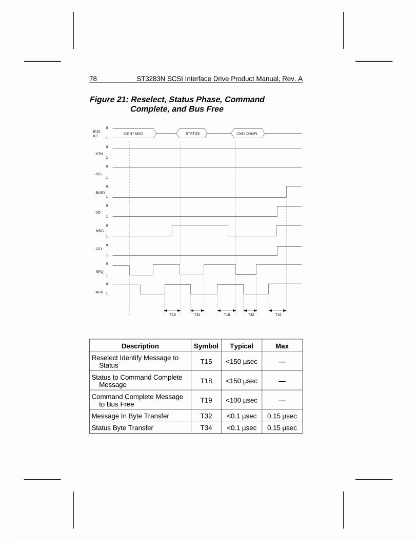
Figure 21: Reselect, Status Phase, Command Complete, and Bus Free
Description Symbol Typical Max
Reselect Identify Message to Status T15 <150 µsec —
Status to Command Complete Message T18 <150 µsec —
Command Complete Message to Bus Free T19 <100 µsec —
Message In Byte Transfer T32 <0.1 µsec 0.15 µsec
Status Byte Transfer T34 <0.1 µsec 0.15 µsec
1
0
1
0
1
0
1
0
1
0
1
0
1
0
1
0
1
0BUS0-7
-ATN
-SEL
-BUSY
-I/O
-MSG
-C/D
-REQ
-ACK
T15
IDENT MSG CMD COMPLSTATUS
T34 T18 T32 T19
78 ST3283N SCSI Interface Drive Product Manual, Rev. A
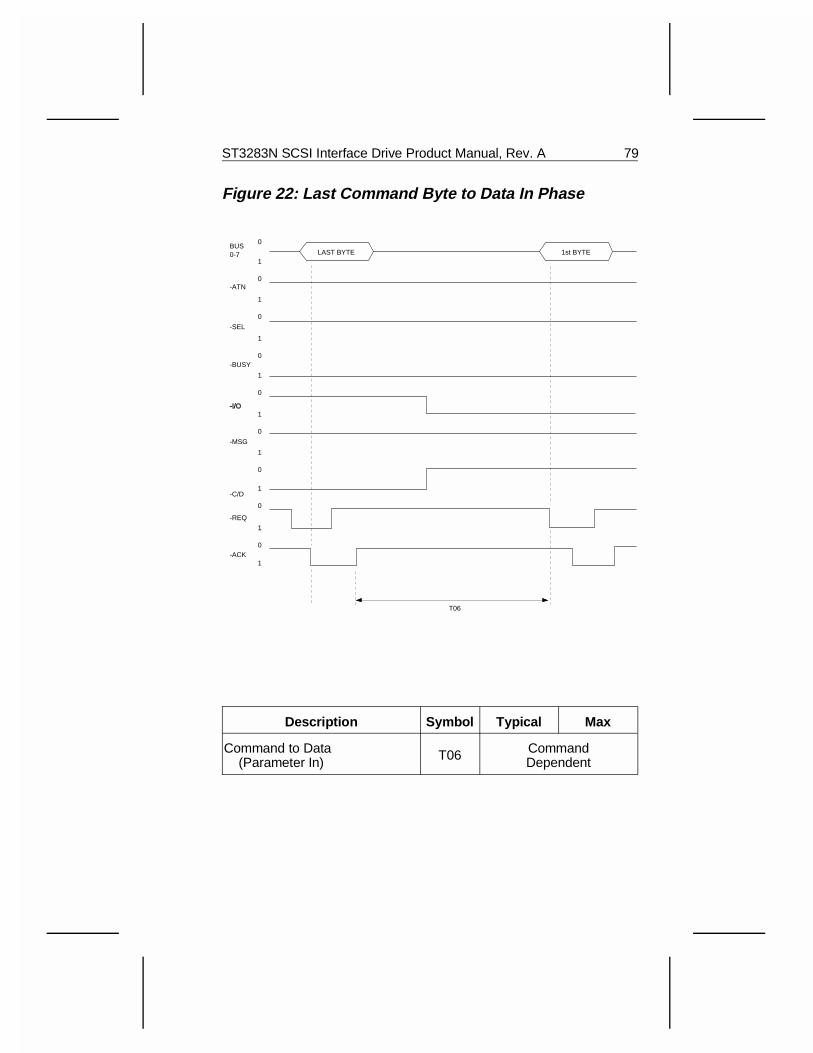
Figure 22: Last Command Byte to Data In Phase
Description Symbol Typical Max
Command to Data (Parameter In) T06 Command
Dependent
1
0
1
0
1
0
1
0
1
0
1
0
1
0
1
0
1
0BUS0-7
-ATN
-SEL
-BUSY
-I/O
-MSG
-C/D
-REQ
-ACK
T06
LAST BYTE 1st BYTE
ST3283N SCSI Interface Drive Product Manual, Rev. A 79
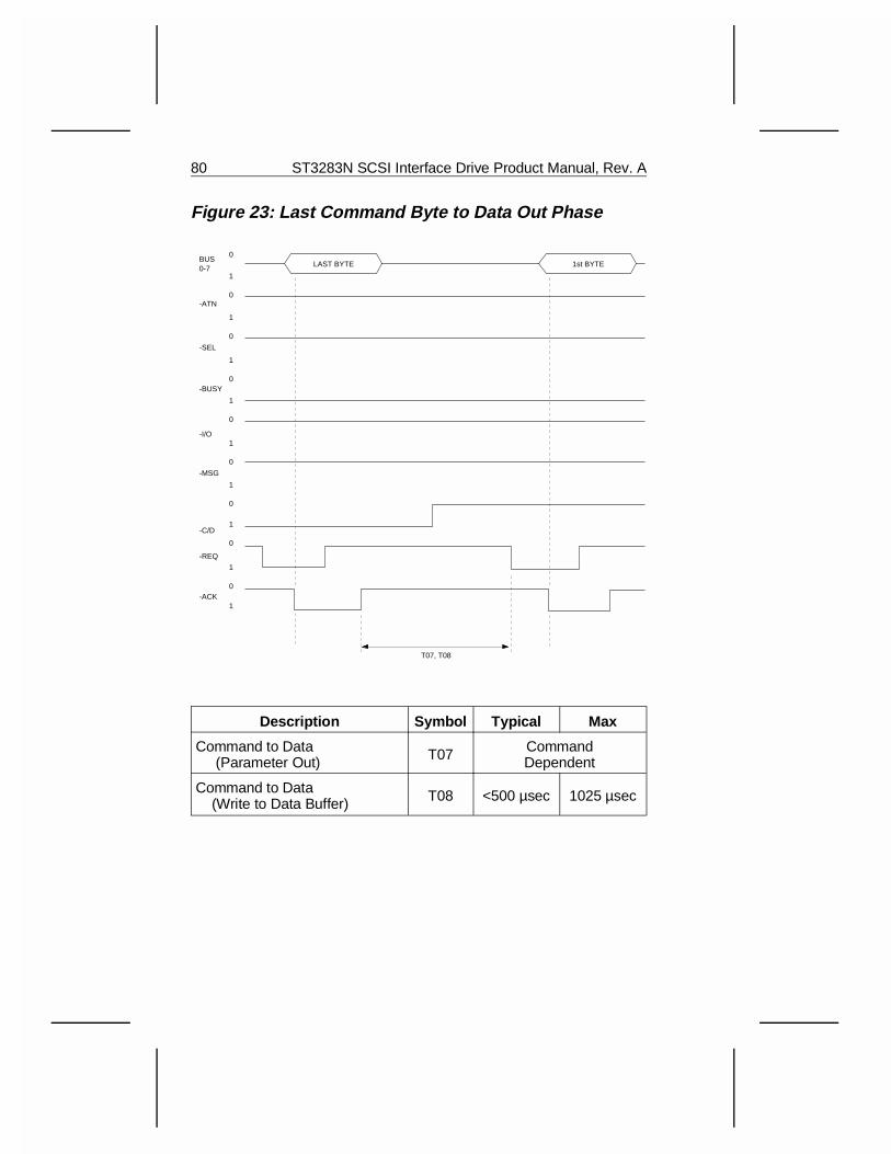
Figure 23: Last Command Byte to Data Out Phase
Description Symbol Typical Max
Command to Data (Parameter Out) T07 Command
Dependent
Command to Data (Write to Data Buffer) T08 <500 µsec 1025 µsec
1
0
1
0
1
0
1
0
1
0
1
0
1
0
1
0
1
0BUS0-7
-ATN
-SEL
-BUSY
-I/O
-MSG
-C/D
-REQ
-ACK
T07, T08
LAST BYTE 1st BYTE
80 ST3283N SCSI Interface Drive Product Manual, Rev. A
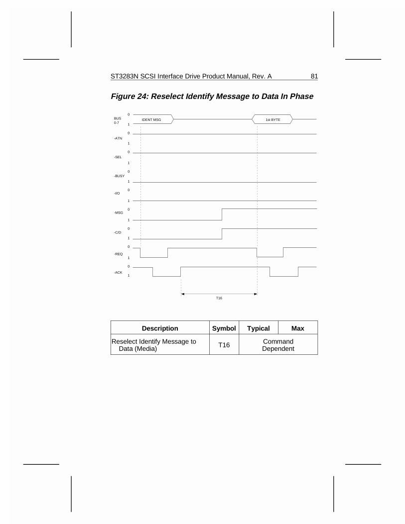
Figure 24: Reselect Identify Message to Data In Phase
Description Symbol Typical Max
Reselect Identify Message to Data (Media) T16 Command
Dependent
1
0
1
0
1
0
1
0
1
0
1
0
1
0
1
0
1
0BUS0-7
-ATN
-SEL
-BUSY
-I/O
-MSG
-C/D
-REQ
-ACK
T16
IDENT MSG 1st BYTE
ST3283N SCSI Interface Drive Product Manual, Rev. A 81
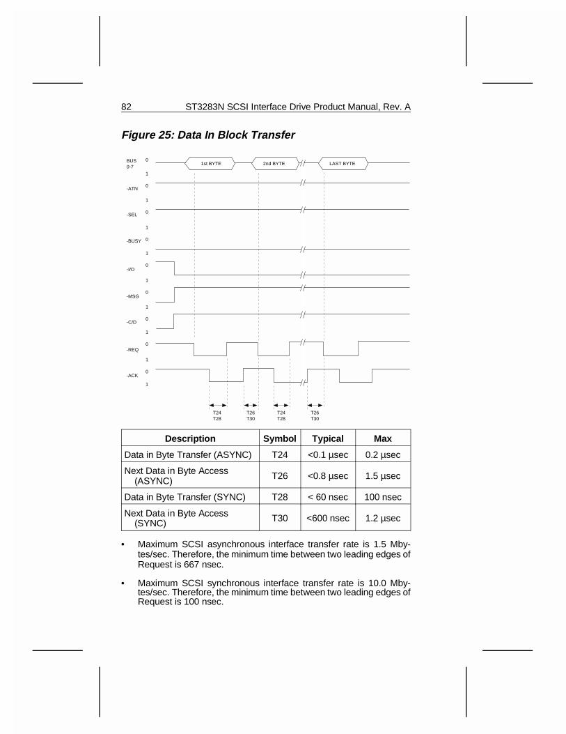
Figure 25: Data In Block Transfer
Description Symbol Typical Max
Data in Byte Transfer (ASYNC) T24 <0.1 µsec 0.2 µsec
Next Data in Byte Access (ASYNC) T26 <0.8 µsec 1.5 µsec
Data in Byte Transfer (SYNC) T28 < 60 nsec 100 nsec
Next Data in Byte Access (SYNC) T30 <600 nsec 1.2 µsec
• Maximum SCSI asynchronous interface transfer rate is 1.5 Mby-tes/sec. Therefore, the minimum time between two leading edges ofRequest is 667 nsec.
• Maximum SCSI synchronous interface transfer rate is 10.0 Mby-tes/sec. Therefore, the minimum time between two leading edges ofRequest is 100 nsec.
1
0
1
0
1
0
1
0
1
0
1
0
1
0
1
0
1
0BUS0-7
-ATN
-SEL
-BUSY
-I/O
-MSG
-C/D
-REQ
-ACK
1st BYTE
T24T28
T26T30
T24T28
T26T30
2nd BYTE LAST BYTE
82 ST3283N SCSI Interface Drive Product Manual, Rev. A
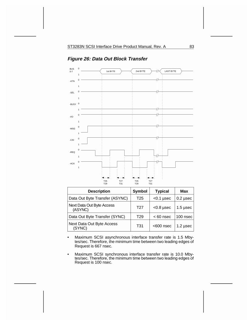
Figure 26: Data Out Block Transfer
Description Symbol Typical Max
Data Out Byte Transfer (ASYNC) T25 <0.1 µsec 0.2 µsec
Next Data Out Byte Access (ASYNC) T27 <0.8 µsec 1.5 µsec
Data Out Byte Transfer (SYNC) T29 < 60 nsec 100 nsec
Next Data Out Byte Access (SYNC) T31 <600 nsec 1.2 µsec
• Maximum SCSI asynchronous interface transfer rate is 1.5 Mby-tes/sec. Therefore, the minimum time between two leading edges ofRequest is 667 nsec.
• Maximum SCSI synchronous interface transfer rate is 10.0 Mby-tes/sec. Therefore, the minimum time between two leading edges ofRequest is 100 nsec.
1
0
1
0
1
0
1
0
1
0
1
0
1
0
1
0
1
0BUS0-7
-ATN
-SEL
-BUSY
-I/O
-MSG
-C/D
-REQ
-ACK
1st BYTE
T25T29
T27T31
T25T29
T27T31
2nd BYTE LAST BYTE
ST3283N SCSI Interface Drive Product Manual, Rev. A 83
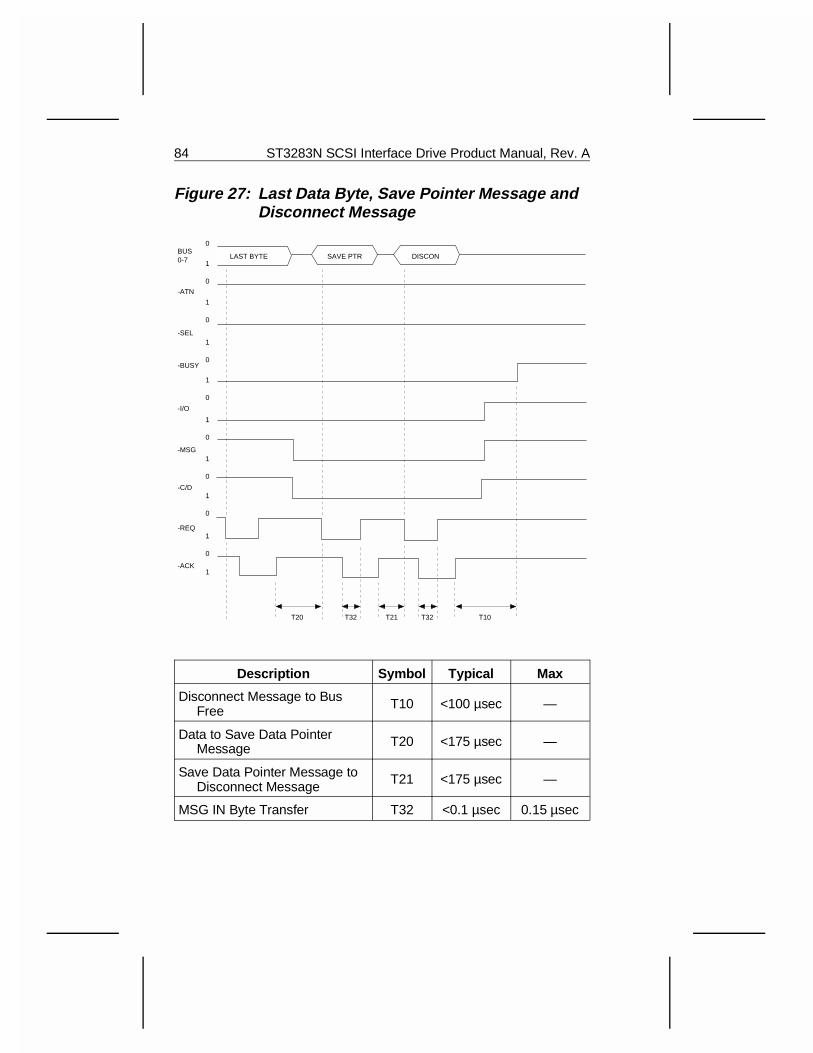
Figure 27: Last Data Byte, Save Pointer Message andDisconnect Message
Description Symbol Typical Max
Disconnect Message to Bus Free T10 <100 µsec —
Data to Save Data Pointer Message T20 <175 µsec —
Save Data Pointer Message to Disconnect Message T21 <175 µsec —
MSG IN Byte Transfer T32 <0.1 µsec 0.15 µsec
1
0
1
0
1
0
1
0
1
0
1
0
1
0
1
0
1
0BUS0-7
-ATN
-SEL
-BUSY
-I/O
-MSG
-C/D
-REQ
-ACK
LAST BYTE
T32
SAVE PTR DISCON
T21 T32 T10T20
84 ST3283N SCSI Interface Drive Product Manual, Rev. A
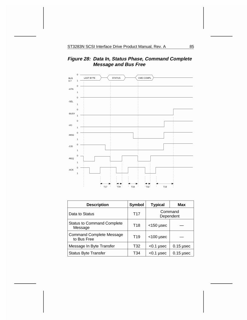
Figure 28: Data In, Status Phase, Command CompleteMessage and Bus Free
Description Symbol Typical Max
Data to Status T17 CommandDependent
Status to Command Complete Message T18 <150 µsec —
Command Complete Message to Bus Free T19 <100 µsec —
Message In Byte Transfer T32 <0.1 µsec 0.15 µsec
Status Byte Transfer T34 <0.1 µsec 0.15 µsec
1
0
1
0
1
0
1
0
1
0
1
0
1
0
1
0
1
0
BUS0-7
-ATN
-SEL
-BUSY
-I/O
-MSG
-C/D
-REQ
-ACK
T34
STATUS CMD COMPLLAST BYTE
T32 T19T17 T18
ST3283N SCSI Interface Drive Product Manual, Rev. A 85
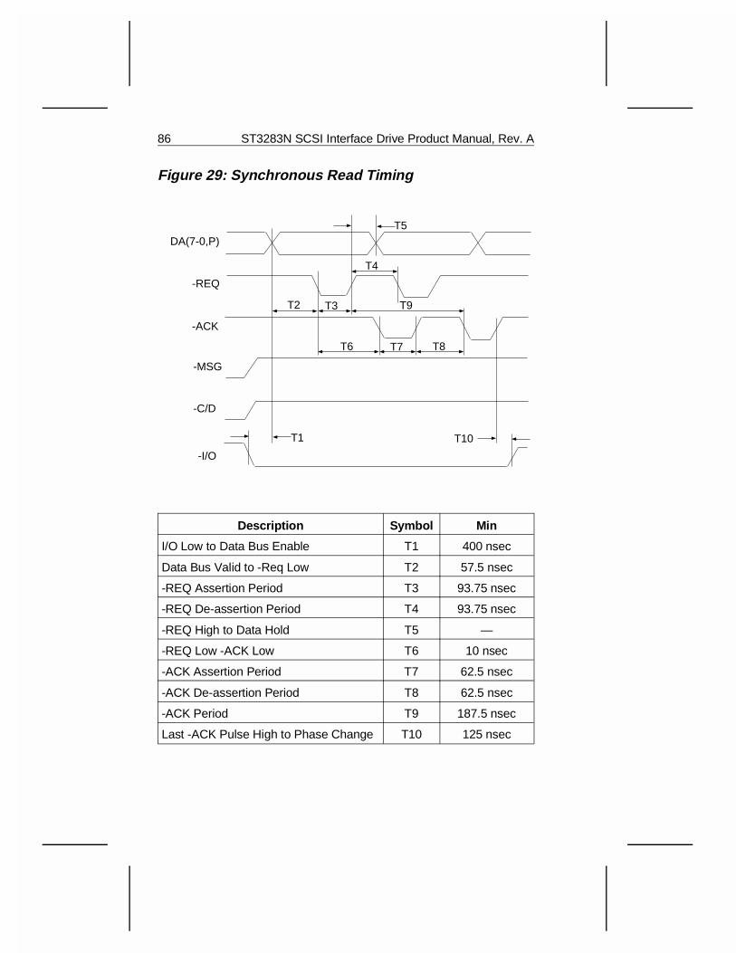
Figure 29: Synchronous Read Timing
Description Symbol Min
I/O Low to Data Bus Enable T1 400 nsec
Data Bus Valid to -Req Low T2 57.5 nsec
-REQ Assertion Period T3 93.75 nsec
-REQ De-assertion Period T4 93.75 nsec
-REQ High to Data Hold T5 —
-REQ Low -ACK Low T6 10 nsec
-ACK Assertion Period T7 62.5 nsec
-ACK De-assertion Period T8 62.5 nsec
-ACK Period T9 187.5 nsec
Last -ACK Pulse High to Phase Change T10 125 nsec
T1
T2 T3
T4
T5
T6 T7 T8
T9
T10
DA(7-0,P)
-REQ
-ACK
-MSG
-C/D
-I/O
86 ST3283N SCSI Interface Drive Product Manual, Rev. A
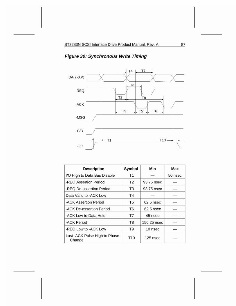
Figure 30: Synchronous Write Timing
Description Symbol Min Max
I/O High to Data Bus Disable T1 — 50 nsec
-REQ Assertion Period T2 93.75 nsec —
-REQ De-assertion Period T3 93.75 nsec —
Data Valid to -ACK Low T4 — —
-ACK Assertion Period T5 62.5 nsec —
-ACK De-assertion Period T6 62.5 nsec —
-ACK Low to Data Hold T7 45 nsec —
-ACK Period T8 156.25 nsec —
-REQ Low to -ACK Low T9 10 nsec —
Last -ACK Pulse High to Phase Change T10 125 nsec —
T1 T10
DA(7-0,P)
-REQ
-ACK
-MSG
-C/D
-I/O
T2
T3
T4
T5 T6
T7
T8
T9
ST3283N SCSI Interface Drive Product Manual, Rev. A 87
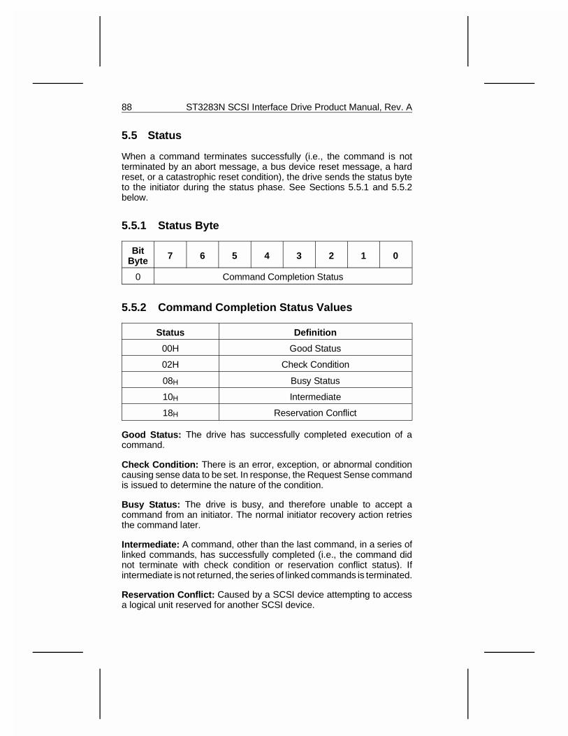
5.5 Status
When a command terminates successfully (i.e., the command is notterminated by an abort message, a bus device reset message, a hardreset, or a catastrophic reset condition), the drive sends the status byteto the initiator during the status phase. See Sections 5.5.1 and 5.5.2below.
5.5.1 Status Byte
BitByte 7 6 5 4 3 2 1 0
0 Command Completion Status
5.5.2 Command Completion Status Values
Status Definition
00H Good Status
02H Check Condition
08H Busy Status
10H Intermediate
18H Reservation Conflict
Good Status: The drive has successfully completed execution of acommand.
Check Condition: There is an error, exception, or abnormal conditioncausing sense data to be set. In response, the Request Sense commandis issued to determine the nature of the condition.
Busy Status: The drive is busy, and therefore unable to accept acommand from an initiator. The normal initiator recovery action retriesthe command later.
Intermediate: A command, other than the last command, in a series oflinked commands, has successfully completed (i.e., the command didnot terminate with check condition or reservation conflict status). Ifintermediate is not returned, the series of linked commands is terminated.
Reservation Conflict: Caused by a SCSI device attempting to accessa logical unit reserved for another SCSI device.
88 ST3283N SCSI Interface Drive Product Manual, Rev. A
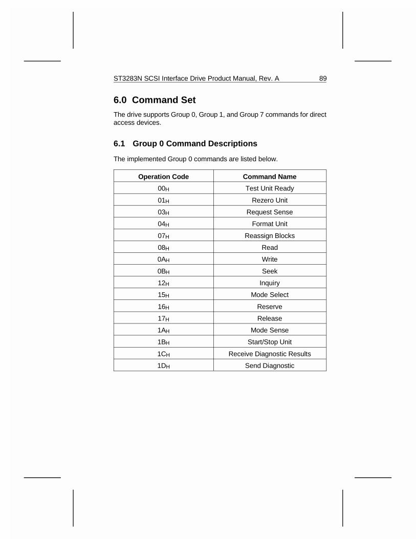
6.0 Command Set The drive supports Group 0, Group 1, and Group 7 commands for directaccess devices.
6.1 Group 0 Command Descriptions
The implemented Group 0 commands are listed below.
Operation Code Command Name
00H Test Unit Ready
01H Rezero Unit
03H Request Sense
04H Format Unit
07H Reassign Blocks
08H Read
0AH Write
0BH Seek
12H Inquiry
15H Mode Select
16H Reserve
17H Release
1AH Mode Sense
1BH Start/Stop Unit
1CH Receive Diagnostic Results
1DH Send Diagnostic
ST3283N SCSI Interface Drive Product Manual, Rev. A 89
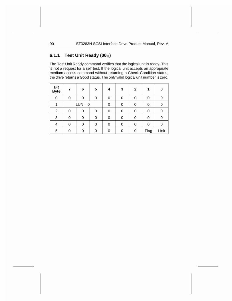
6.1.1 Test Unit Ready (00 H)
The Test Unit Ready command verifies that the logical unit is ready. Thisis not a request for a self test. If the logical unit accepts an appropriatemedium access command without returning a Check Condition status,the drive returns a Good status. The only valid logical unit number is zero.
BitByte 7 6 5 4 3 2 1 0
0 0 0 0 0 0 0 0 0
1 LUN = 0 0 0 0 0 0
2 0 0 0 0 0 0 0 0
3 0 0 0 0 0 0 0 0
4 0 0 0 0 0 0 0 0
5 0 0 0 0 0 0 Flag Link
90 ST3283N SCSI Interface Drive Product Manual, Rev. A
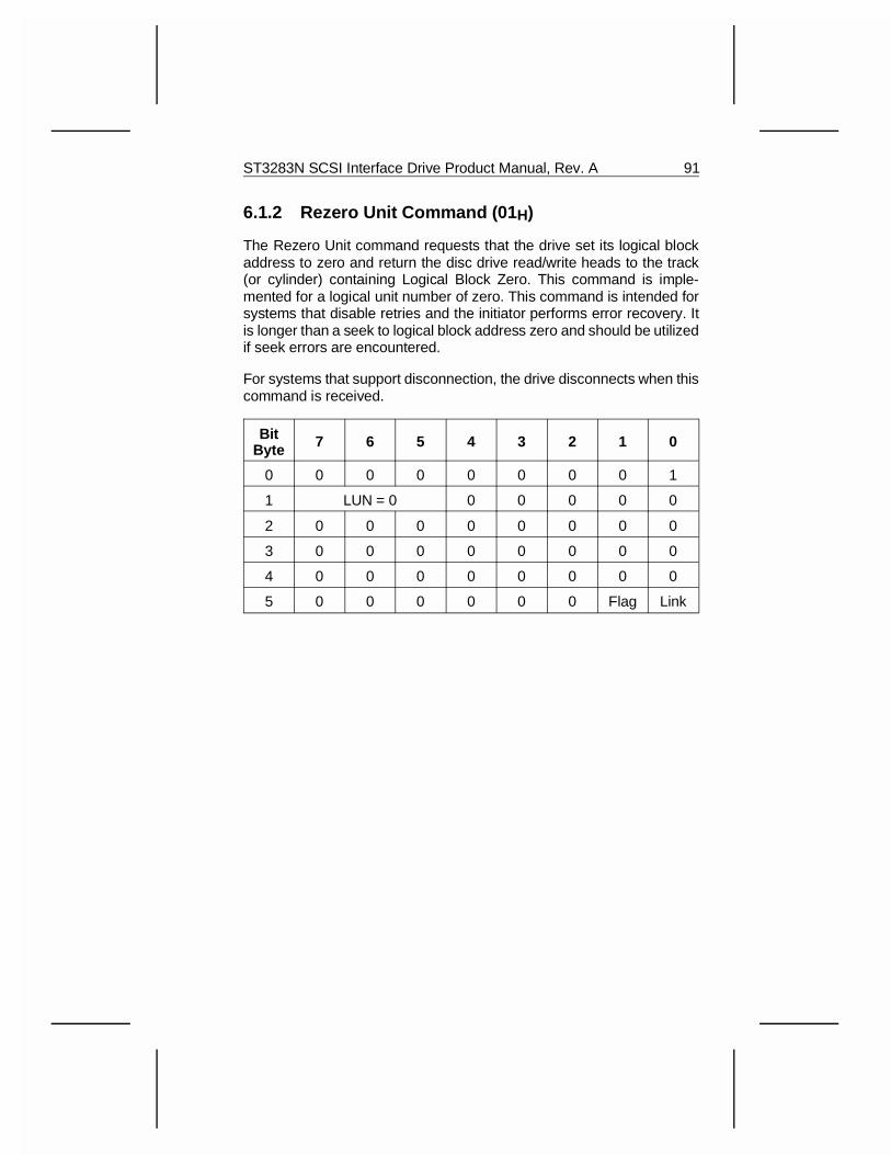
6.1.2 Rezero Unit Command (01 H)
The Rezero Unit command requests that the drive set its logical blockaddress to zero and return the disc drive read/write heads to the track(or cylinder) containing Logical Block Zero. This command is imple-mented for a logical unit number of zero. This command is intended forsystems that disable retries and the initiator performs error recovery. Itis longer than a seek to logical block address zero and should be utilizedif seek errors are encountered.
For systems that support disconnection, the drive disconnects when thiscommand is received.
BitByte 7 6 5 4 3 2 1 0
0 0 0 0 0 0 0 0 1
1 LUN = 0 0 0 0 0 0
2 0 0 0 0 0 0 0 0
3 0 0 0 0 0 0 0 0
4 0 0 0 0 0 0 0 0
5 0 0 0 0 0 0 Flag Link
ST3283N SCSI Interface Drive Product Manual, Rev. A 91
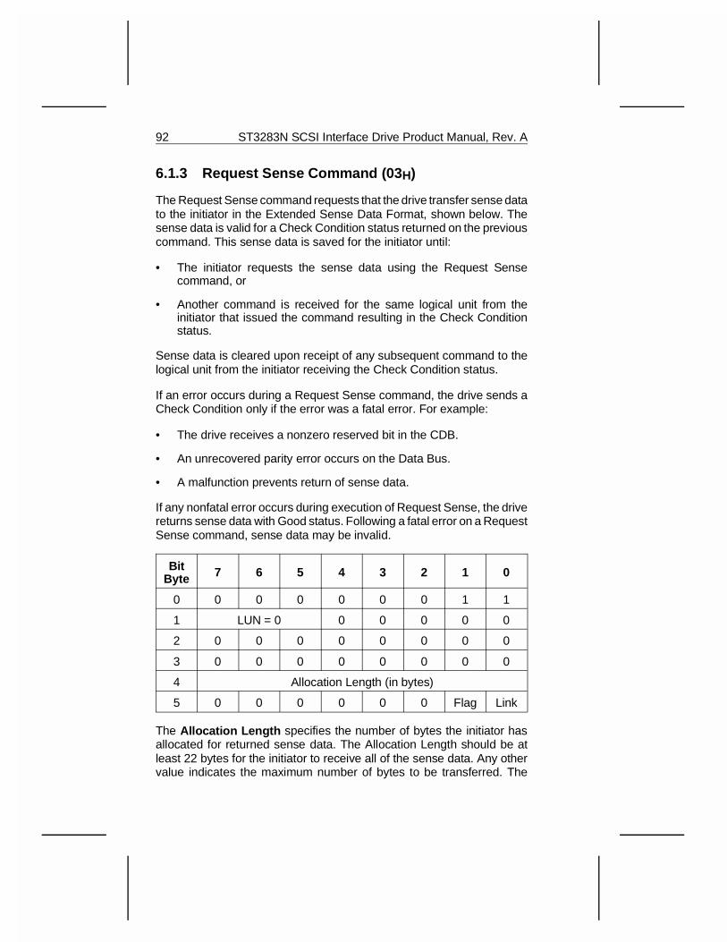
6.1.3 Request Sense Command (03 H)
The Request Sense command requests that the drive transfer sense datato the initiator in the Extended Sense Data Format, shown below. Thesense data is valid for a Check Condition status returned on the previouscommand. This sense data is saved for the initiator until:
• The initiator requests the sense data using the Request Sensecommand, or
• Another command is received for the same logical unit from theinitiator that issued the command resulting in the Check Conditionstatus.
Sense data is cleared upon receipt of any subsequent command to thelogical unit from the initiator receiving the Check Condition status.
If an error occurs during a Request Sense command, the drive sends aCheck Condition only if the error was a fatal error. For example:
• The drive receives a nonzero reserved bit in the CDB.
• An unrecovered parity error occurs on the Data Bus.
• A malfunction prevents return of sense data.
If any nonfatal error occurs during execution of Request Sense, the drivereturns sense data with Good status. Following a fatal error on a RequestSense command, sense data may be invalid.
BitByte 7 6 5 4 3 2 1 0
0 0 0 0 0 0 0 1 1
1 LUN = 0 0 0 0 0 0
2 0 0 0 0 0 0 0 0
3 0 0 0 0 0 0 0 0
4 Allocation Length (in bytes)
5 0 0 0 0 0 0 Flag Link
The Allocation Length specifies the number of bytes the initiator hasallocated for returned sense data. The Allocation Length should be atleast 22 bytes for the initiator to receive all of the sense data. Any othervalue indicates the maximum number of bytes to be transferred. The
92 ST3283N SCSI Interface Drive Product Manual, Rev. A
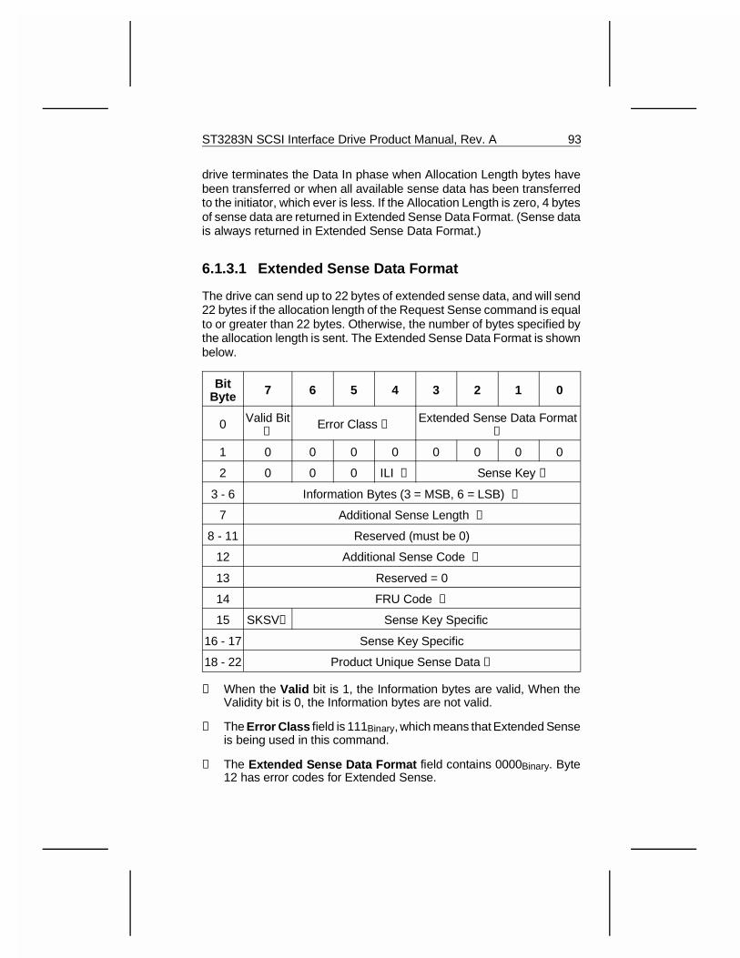
drive terminates the Data In phase when Allocation Length bytes havebeen transferred or when all available sense data has been transferredto the initiator, which ever is less. If the Allocation Length is zero, 4 bytesof sense data are returned in Extended Sense Data Format. (Sense datais always returned in Extended Sense Data Format.)
6.1.3.1 Extended Sense Data Format
The drive can send up to 22 bytes of extended sense data, and will send22 bytes if the allocation length of the Request Sense command is equalto or greater than 22 bytes. Otherwise, the number of bytes specified bythe allocation length is sent. The Extended Sense Data Format is shownbelow.
BitByte 7 6 5 4 3 2 1 0
0 Valid Bit➀
Error Class ➁ Extended Sense Data Format➂
1 0 0 0 0 0 0 0 0
2 0 0 0 ILI ➃ Sense Key ➄
3 - 6 Information Bytes (3 = MSB, 6 = LSB) ➅
7 Additional Sense Length ➆
8 - 11 Reserved (must be 0)
12 Additional Sense Code ➇
13 Reserved = 0
14 FRU Code ➈
15 SKSV➉ Sense Key Specific
16 - 17 Sense Key Specific
18 - 22 Product Unique Sense Data ➊
➀ When the Valid bit is 1, the Information bytes are valid, When theValidity bit is 0, the Information bytes are not valid.
➁ The Error Class field is 111Binary, which means that Extended Senseis being used in this command.
➂ The Extended Sense Data Format field contains 0000Binary. Byte12 has error codes for Extended Sense.
ST3283N SCSI Interface Drive Product Manual, Rev. A 93

➃ An Incorrect Length Indicator (ILI) bit of one indicates that therequested logical block length did not match the logical block lengthof the data on the medium. This bit may be set with a Read Long orWrite Long command.
➄ The Sense Key indicates nine general error categories. These arelisted in Section 6.1.3.2. The code given in Byte 12 provides addi-tional clarification of errors.
➅ When the Valid bit is 1, the Information Bytes contain the unsignedLogical Block Address of the current logical block associated withthe Sense Key. For example, if the Sense Key is Media Error, theInformation Bytes contain the Logical Block Address of the block inerror.
➆ The Additional Sense Length specifies that additional sense bytesare to follow. This is limited to a maximum of 0EH additional bytes.If the Allocation Length of the Command Descriptor Block is too smallto accommodate all of the additional sense bytes, the AdditionalSense Length is not adjusted to reflect the truncation.
➇ The Additional Sense Code provides further detail of errors andexceptions whenever the Sense Key is valid. The additional sensecodes are defined in Section 6.1.3.3.
➈ The FRU (Field Replaceable Unit) Code is reserved for field serviceuse only.
➉ The SKSV (Sense-Key Specific Valid) bit is set to zero, meaningthe sense key specific fields are not used.
➊ When the Valid bit is one, the Product-Unique Sense Data bytesare valid. (When the Valid bit is zero, these bytes are not used.)These bytes contain the physical address of the information bytes.
94 ST3283N SCSI Interface Drive Product Manual, Rev. A
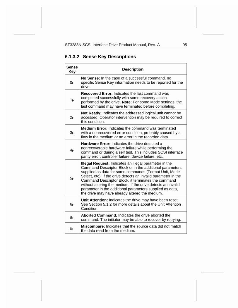
6.1.3.2 Sense Key Descriptions
SenseKey Description
0H
No Sense: In the case of a successful command, nospecific Sense Key information needs to be reported for thedrive.
1H
Recovered Error: Indicates the last command wascompleted successfully with some recovery actionperformed by the drive. Note: For some Mode settings, thelast command may have terminated before completing.
2H
Not Ready: Indicates the addressed logical unit cannot beaccessed. Operator intervention may be required to correctthis condition.
3H
Medium Error: Indicates the command was terminatedwith a nonrecovered error condition, probably caused by aflaw in the medium or an error in the recorded data.
4H
Hardware Error: Indicates the drive detected anonrecoverable hardware failure while performing thecommand or during a self test. This includes SCSI interfaceparity error, controller failure, device failure, etc.
5H
Illegal Request: Indicates an illegal parameter in theCommand Descriptor Block or in the additional parameterssupplied as data for some commands (Format Unit, ModeSelect, etc). If the drive detects an invalid parameter in theCommand Descriptor Block, it terminates the commandwithout altering the medium. If the drive detects an invalidparameter in the additional parameters supplied as data,the drive may have already altered the medium.
6H
Unit Attention: Indicates the drive may have been reset.See Section 5.1.2 for more details about the Unit AttentionCondition.
BHAborted Command: Indicates the drive aborted thecommand. The initiator may be able to recover by retrying.
EHMiscompare: Indicates that the source data did not matchthe data read from the medium.
ST3283N SCSI Interface Drive Product Manual, Rev. A 95
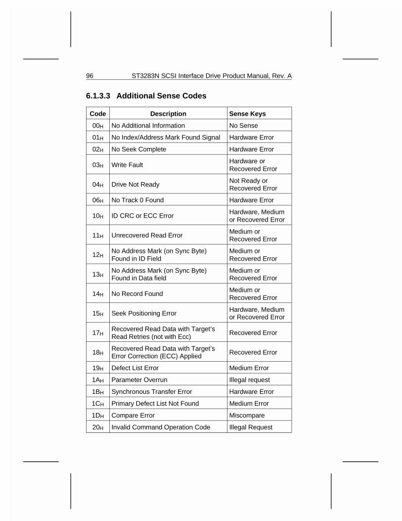
6.1.3.3 Additional Sense Codes
Code Description Sense Keys
00H No Additional Information No Sense
01H No Index/Address Mark Found Signal Hardware Error
02H No Seek Complete Hardware Error
03H Write Fault Hardware orRecovered Error
04H Drive Not Ready Not Ready orRecovered Error
06H No Track 0 Found Hardware Error
10H ID CRC or ECC Error Hardware, Mediumor Recovered Error
11H Unrecovered Read Error Medium orRecovered Error
12HNo Address Mark (on Sync Byte)Found in ID Field
Medium orRecovered Error
13HNo Address Mark (on Sync Byte)Found in Data field
Medium orRecovered Error
14H No Record Found Medium orRecovered Error
15H Seek Positioning Error Hardware, Mediumor Recovered Error
17HRecovered Read Data with Target’sRead Retries (not with Ecc)
Recovered Error
18HRecovered Read Data with Target’s Error Correction (ECC) Applied Recovered Error
19H Defect List Error Medium Error
1AH Parameter Overrun Illegal request
1BH Synchronous Transfer Error Hardware Error
1CH Primary Defect List Not Found Medium Error
1DH Compare Error Miscompare
20H Invalid Command Operation Code Illegal Request
96 ST3283N SCSI Interface Drive Product Manual, Rev. A
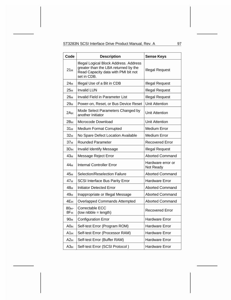
Code Description Sense Keys
21H
Illegal Logical Block Address. Addressgreater than the LBA returned by theRead Capacity data with PMI bit notset in CDB.
Illegal Request
24H Illegal Use of a Bit in CDB Illegal Request
25H Invalid LUN Illegal Request
26H Invalid Field in Parameter List Illegal Request
29H Power-on, Reset, or Bus Device Reset Unit Attention
2AHMode Select Parameters Changed byanother Initiator Unit Attention
2BH Microcode Download Unit Attention
31H Medium Format Corrupted Medium Error
32H No Spare Defect Location Available Medium Error
37H Rounded Parameter Recovered Error
3DH Invalid Identify Message Illegal Request
43H Message Reject Error Aborted Command
44H Internal Controller Error Hardware error orNot Ready
45H Selection/Reselection Failure Aborted Command
47H SCSI Interface Bus Parity Error Hardware Error
48H Initiator Detected Error Aborted Command
49H Inappropriate or Illegal Message Aborted Command
4EH Overlapped Commands Attempted Aborted Command
80H-8FH
Correctable ECC(low nibble = length) Recovered Error
90H Configuration Error Hardware Error
A0H Self-test Error (Program ROM) Hardware Error
A1H Self-test Error (Processor RAM) Hardware Error
A2H Self-test Error (Buffer RAM) Hardware Error
A3H Self-test Error (SCSI Protocol ) Hardware Error
ST3283N SCSI Interface Drive Product Manual, Rev. A 97
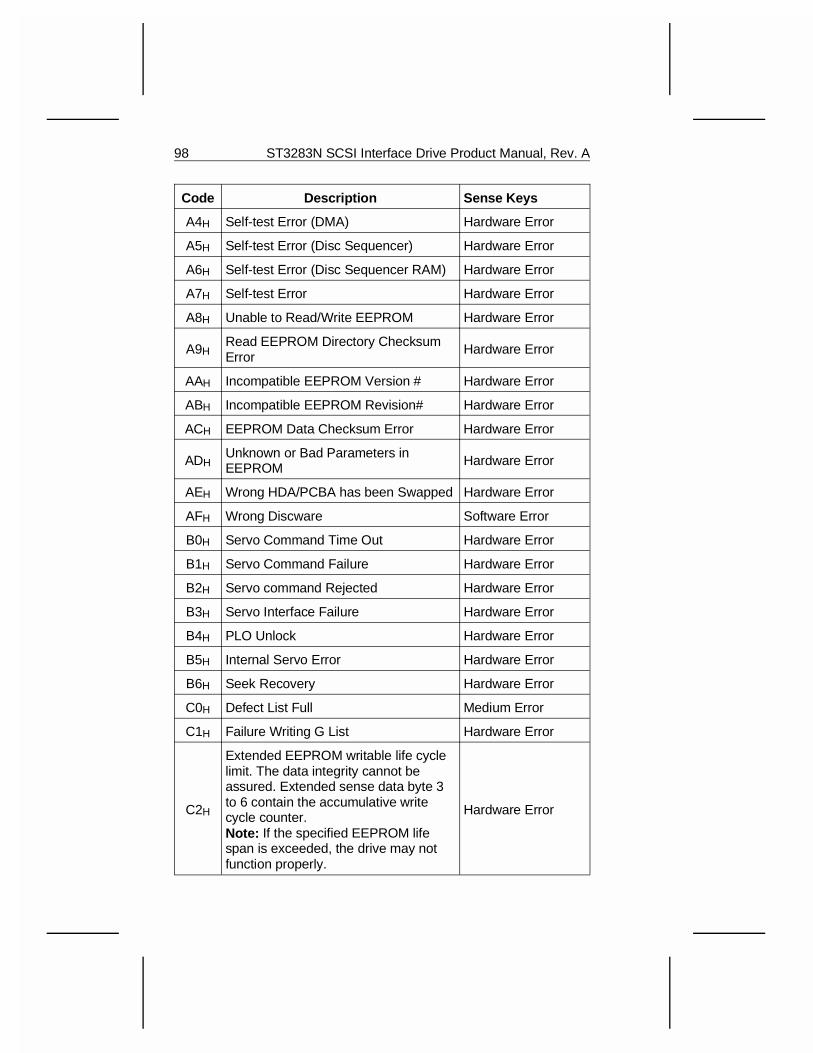
Code Description Sense Keys
A4H Self-test Error (DMA) Hardware Error
A5H Self-test Error (Disc Sequencer) Hardware Error
A6H Self-test Error (Disc Sequencer RAM) Hardware Error
A7H Self-test Error Hardware Error
A8H Unable to Read/Write EEPROM Hardware Error
A9HRead EEPROM Directory ChecksumError
Hardware Error
AAH Incompatible EEPROM Version # Hardware Error
ABH Incompatible EEPROM Revision# Hardware Error
ACH EEPROM Data Checksum Error Hardware Error
ADHUnknown or Bad Parameters inEEPROM Hardware Error
AEH Wrong HDA/PCBA has been Swapped Hardware Error
AFH Wrong Discware Software Error
B0H Servo Command Time Out Hardware Error
B1H Servo Command Failure Hardware Error
B2H Servo command Rejected Hardware Error
B3H Servo Interface Failure Hardware Error
B4H PLO Unlock Hardware Error
B5H Internal Servo Error Hardware Error
B6H Seek Recovery Hardware Error
C0H Defect List Full Medium Error
C1H Failure Writing G List Hardware Error
C2H
Extended EEPROM writable life cyclelimit. The data integrity cannot beassured. Extended sense data byte 3to 6 contain the accumulative writecycle counter. Note: If the specified EEPROM lifespan is exceeded, the drive may notfunction properly.
Hardware Error
98 ST3283N SCSI Interface Drive Product Manual, Rev. A
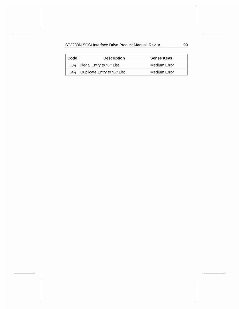
Code Description Sense Keys
C3H Illegal Entry to “G” List Medium Error
C4H Duplicate Entry to “G” List Medium Error
ST3283N SCSI Interface Drive Product Manual, Rev. A 99
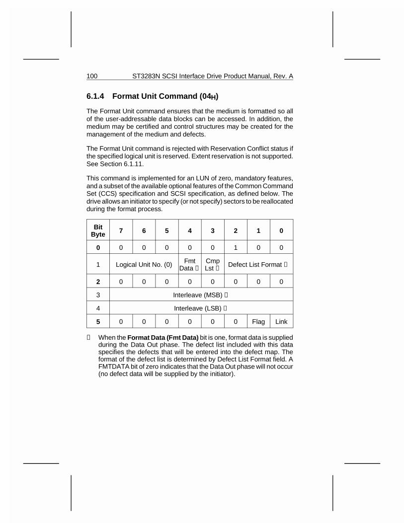
6.1.4 Format Unit Command (04 H)
The Format Unit command ensures that the medium is formatted so allof the user-addressable data blocks can be accessed. In addition, themedium may be certified and control structures may be created for themanagement of the medium and defects.
The Format Unit command is rejected with Reservation Conflict status ifthe specified logical unit is reserved. Extent reservation is not supported.See Section 6.1.11.
This command is implemented for an LUN of zero, mandatory features,and a subset of the available optional features of the Common CommandSet (CCS) specification and SCSI specification, as defined below. Thedrive allows an initiator to specify (or not specify) sectors to be reallocatedduring the format process.
BitByte 7 6 5 4 3 2 1 0
0 0 0 0 0 0 1 0 0
1 Logical Unit No. (0) FmtData ➀
CmpLst ➁ Defect List Format ➂
2 0 0 0 0 0 0 0 0
3 Interleave (MSB) ➃
4 Interleave (LSB) ➃
5 0 0 0 0 0 0 Flag Link
➀ When the Format Data (Fmt Data) bit is one, format data is suppliedduring the Data Out phase. The defect list included with this dataspecifies the defects that will be entered into the defect map. Theformat of the defect list is determined by Defect List Format field. AFMTDATA bit of zero indicates that the Data Out phase will not occur(no defect data will be supplied by the initiator).
100 ST3283N SCSI Interface Drive Product Manual, Rev. A
➁ When the Complete List (Cmp Lst) bit is one, the data supplied isto be the complete list of Grown defects. Any previous Grown orCertification defect data will be erased. The drive may add to this listas it formats the medium. The result is to purge any previous Grownor Certification defect list and to build a new defect list. A CmpLst bitof zero indicates the data supplied is in addition to the existing Growndefect list.
➂ The Defect List Format field specifies additional information relatedto the defect list.
➃ The Interleave field requests that logical blocks be related in aspecific fashion to the physical blocks to facilitate speed matching.An interleave value of zero requests that the target use its defaultinterleave. An interleave value of one requests that consecutivelogical blocks be placed in consecutive physical order. Values of twoor greater indicate that one or more (respectively) physical blocksseparate consecutive logical blocks. The only acceptable interleavevalue is 1. (An interleave other than 0 defaults to an interleave of 1.)
The Read Look-Ahead function reads all of the data from the startingblock address to buffer full, regardless of the block count specifiedin the Read command. All data from the starting Logical BlockAddress to the end of the physical track is read into the bufferregardless of the transfer length in the CDB specified. This data isavailable for subsequent sequential disc reads without having toaccess the disc medium. This increases performance without theneed for an interleave during format. (See Section 6.1.6.)
The categories of flawed sectors are listed below:
• P (Primary Defect) Type: These sectors are identified at the time ofshipment in a list of defects (permanent flaws) supplied by Seagateand stored on the disc in an area that is not directly accessible bythe user. (This list may be referred to as an ETF List.) This defect listis not modified or changed by the drive (or initiator) after shipment.
• C (Certification Defect) Type: These sectors fail a Format Verifyduring the format function. The use of this defect list is controlled byByte 1 of the defect list header described later in this section.
• D (Data Defect) Type: These sectors are identified in a list suppliedto the target by the initiator during a Data Out phase of the currentFormat Unit command. The D List follows a four byte defect listheader and is referred to as Defect Descriptor Bytes.
ST3283N SCSI Interface Drive Product Manual, Rev. A 101
• G (Grown Defect) Type: These sectors contain media flaws and havebeen reallocated as a result of receiving a Reassign Blocks com-mand, or certification defects (C type) reallocated during a previousFormat Unit command, or Data Defects (D type) reallocated duringa previous Format Unit command or defects that have been auto-matically reallocated by the drive. This G list is recorded on the mediaand may be referenced for the current (and subsequent) Format Unitcommands. This G list does not include the P type defects.
102 ST3283N SCSI Interface Drive Product Manual, Rev. A
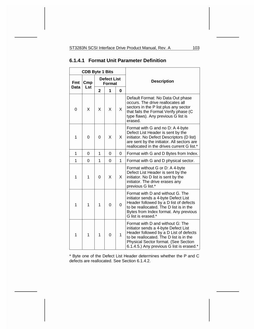
6.1.4.1 Format Unit Parameter Definition
CDB Byte 1 Bits
DescriptionFmtData
Cmp Lst
Defect ListFormat
2 1 0
0 X X X X
Default Format: No Data Out phaseoccurs. The drive reallocates allsectors in the P list plus any sectorthat fails the Format Verify phase (Ctype flaws). Any previous G list iserased.
1 0 0 X X
Format with G and no D: A 4-byteDefect List Header is sent by theinitiator. No Defect Descriptors (D list)are sent by the initiator. All sectors arereallocated in the drives current G list.*
1 0 1 0 0 Format with G and D Bytes from Index.
1 0 1 0 1 Format with G and D physical sector.
1 1 0 X X
Format without G or D: A 4-byteDefect List Header is sent by theinitiator. No D list is sent by theinitiator. The drive erases anyprevious G list.*
1 1 1 0 0
Format with D and without G. Theinitiator sends a 4-byte Defect ListHeader followed by a D list of defectsto be reallocated. The D list is in theBytes from Index format. Any previousG list is erased.*
1 1 1 0 1
Format with D and without G: Theinitiator sends a 4-byte Defect ListHeader followed by a D List of defectsto be reallocated. The D list is in thePhysical Sector format. (See Section6.1.4.5.) Any previous G list is erased.*
* Byte one of the Defect List Header determines whether the P and Cdefects are reallocated. See Section 6.1.4.2.
ST3283N SCSI Interface Drive Product Manual, Rev. A 103
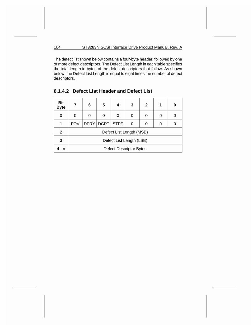
The defect list shown below contains a four-byte header, followed by oneor more defect descriptors. The Defect List Length in each table specifiesthe total length in bytes of the defect descriptors that follow. As shownbelow, the Defect List Length is equal to eight times the number of defectdescriptors.
6.1.4.2 Defect List Header and Defect List
BitByte 7 6 5 4 3 2 1 0
0 0 0 0 0 0 0 0 0
1 FOV DPRY DCRT STPF 0 0 0 0
2 Defect List Length (MSB)
3 Defect List Length (LSB)
4 - n Defect Descriptor Bytes
104 ST3283N SCSI Interface Drive Product Manual, Rev. A
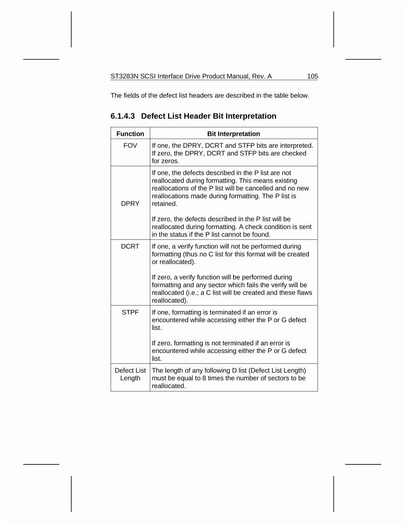
The fields of the defect list headers are described in the table below.
6.1.4.3 Defect List Header Bit Interpretation
Function Bit Interpretation
FOV If one, the DPRY, DCRT and STFP bits are interpreted.If zero, the DPRY, DCRT and STFP bits are checkedfor zeros.
DPRY
If one, the defects described in the P list are notreallocated during formatting. This means existingreallocations of the P list will be cancelled and no newreallocations made during formatting. The P list isretained.
If zero, the defects described in the P list will bereallocated during formatting. A check condition is sentin the status if the P list cannot be found.
DCRT If one, a verify function will not be performed duringformatting (thus no C list for this format will be createdor reallocated).
If zero, a verify function will be performed duringformatting and any sector which fails the verify will bereallocated (i.e.; a C list will be created and these flawsreallocated).
STPF If one, formatting is terminated if an error isencountered while accessing either the P or G defectlist.
If zero, formatting is not terminated if an error isencountered while accessing either the P or G defectlist.
Defect ListLength
The length of any following D list (Defect List Length)must be equal to 8 times the number of sectors to bereallocated.
ST3283N SCSI Interface Drive Product Manual, Rev. A 105
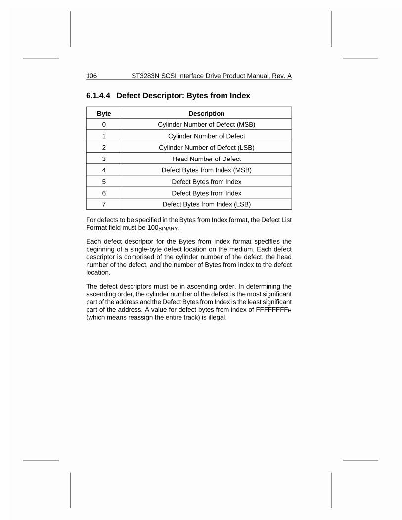
6.1.4.4 Defect Descriptor: Bytes from Index
Byte Description
0 Cylinder Number of Defect (MSB)
1 Cylinder Number of Defect
2 Cylinder Number of Defect (LSB)
3 Head Number of Defect
4 Defect Bytes from Index (MSB)
5 Defect Bytes from Index
6 Defect Bytes from Index
7 Defect Bytes from Index (LSB)
For defects to be specified in the Bytes from Index format, the Defect ListFormat field must be 100BINARY.
Each defect descriptor for the Bytes from Index format specifies thebeginning of a single-byte defect location on the medium. Each defectdescriptor is comprised of the cylinder number of the defect, the headnumber of the defect, and the number of Bytes from Index to the defectlocation.
The defect descriptors must be in ascending order. In determining theascending order, the cylinder number of the defect is the most significantpart of the address and the Defect Bytes from Index is the least significantpart of the address. A value for defect bytes from index of FFFFFFFFH(which means reassign the entire track) is illegal.
106 ST3283N SCSI Interface Drive Product Manual, Rev. A
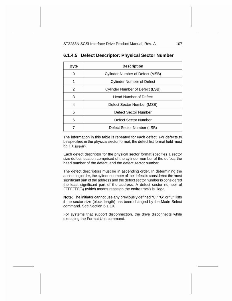
6.1.4.5 Defect Descriptor: Physical Sector Number
Byte Description
0 Cylinder Number of Defect (MSB)
1 Cylinder Number of Defect
2 Cylinder Number of Defect (LSB)
3 Head Number of Defect
4 Defect Sector Number (MSB)
5 Defect Sector Number
6 Defect Sector Number
7 Defect Sector Number (LSB)
The information in this table is repeated for each defect. For defects tobe specified in the physical sector format, the defect list format field mustbe 101BINARY.
Each defect descriptor for the physical sector format specifies a sectorsize defect location comprised of the cylinder number of the defect, thehead number of the defect, and the defect sector number.
The defect descriptors must be in ascending order. In determining theascending order, the cylinder number of the defect is considered the mostsignificant part of the address and the defect sector number is consideredthe least significant part of the address. A defect sector number ofFFFFFFFFH (which means reassign the entire track) is illegal.
Note: The initiator cannot use any previously defined “C,” “G” or “D” listsif the sector size (block length) has been changed by the Mode Selectcommand. See Section 6.1.10.
For systems that support disconnection, the drive disconnects whileexecuting the Format Unit command.
ST3283N SCSI Interface Drive Product Manual, Rev. A 107
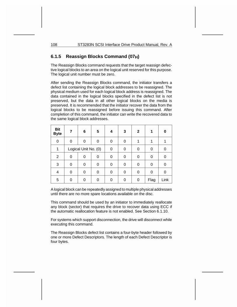
6.1.5 Reassign Blocks Command (07 H)
The Reassign Blocks command requests that the target reassign defec-tive logical blocks to an area on the logical unit reserved for this purpose.The logical unit number must be zero.
After sending the Reassign Blocks command, the initiator transfers adefect list containing the logical block addresses to be reassigned. Thephysical medium used for each logical block address is reassigned. Thedata contained in the logical blocks specified in the defect list is notpreserved, but the data in all other logical blocks on the media ispreserved. It is recommended that the initiator recover the data from thelogical blocks to be reassigned before issuing this command. Aftercompletion of this command, the initiator can write the recovered data tothe same logical block addresses.
BitByte 7 6 5 4 3 2 1 0
0 0 0 0 0 0 1 1 1
1 Logical Unit No. (0) 0 0 0 0 0
2 0 0 0 0 0 0 0 0
3 0 0 0 0 0 0 0 0
4 0 0 0 0 0 0 0 0
5 0 0 0 0 0 0 Flag Link
A logical block can be repeatedly assigned to multiple physical addressesuntil there are no more spare locations available on the disc.
This command should be used by an initiator to immediately reallocateany block (sector) that requires the drive to recover data using ECC ifthe automatic reallocation feature is not enabled. See Section 6.1.10.
For systems which support disconnection, the drive will disconnect whileexecuting this command.
The Reassign Blocks defect list contains a four-byte header followed byone or more Defect Descriptors. The length of each Defect Descriptor isfour bytes.
108 ST3283N SCSI Interface Drive Product Manual, Rev. A
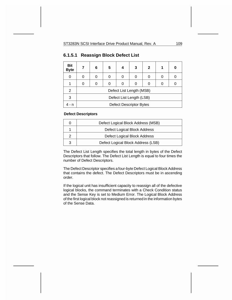
6.1.5.1 Reassign Block Defect List
BitByte 7 6 5 4 3 2 1 0
0 0 0 0 0 0 0 0 0
1 0 0 0 0 0 0 0 0
2 Defect List Length (MSB)
3 Defect List Length (LSB)
4 - n Defect Descriptor Bytes
Defect Descriptors
0 Defect Logical Block Address (MSB)
1 Defect Logical Block Address
2 Defect Logical Block Address
3 Defect Logical Block Address (LSB)
The Defect List Length specifies the total length in bytes of the DefectDescriptors that follow. The Defect List Length is equal to four times thenumber of Defect Descriptors.
The Defect Descriptor specifies a four-byte Defect Logical Block Addressthat contains the defect. The Defect Descriptors must be in ascendingorder.
If the logical unit has insufficient capacity to reassign all of the defectivelogical blocks, the command terminates with a Check Condition statusand the Sense Key is set to Medium Error. The Logical Block Addressof the first logical block not reassigned is returned in the information bytesof the Sense Data.
ST3283N SCSI Interface Drive Product Manual, Rev. A 109
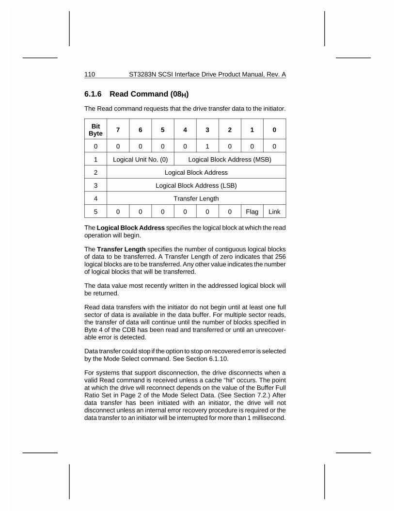
6.1.6 Read Command (08 H)
The Read command requests that the drive transfer data to the initiator.
BitByte 7 6 5 4 3 2 1 0
0 0 0 0 0 1 0 0 0
1 Logical Unit No. (0) Logical Block Address (MSB)
2 Logical Block Address
3 Logical Block Address (LSB)
4 Transfer Length
5 0 0 0 0 0 0 Flag Link
The Logical Block Address specifies the logical block at which the readoperation will begin.
The Transfer Length specifies the number of contiguous logical blocksof data to be transferred. A Transfer Length of zero indicates that 256logical blocks are to be transferred. Any other value indicates the numberof logical blocks that will be transferred.
The data value most recently written in the addressed logical block willbe returned.
Read data transfers with the initiator do not begin until at least one fullsector of data is available in the data buffer. For multiple sector reads,the transfer of data will continue until the number of blocks specified inByte 4 of the CDB has been read and transferred or until an unrecover-able error is detected.
Data transfer could stop if the option to stop on recovered error is selectedby the Mode Select command. See Section 6.1.10.
For systems that support disconnection, the drive disconnects when avalid Read command is received unless a cache “hit” occurs. The pointat which the drive will reconnect depends on the value of the Buffer FullRatio Set in Page 2 of the Mode Select Data. (See Section 7.2.) Afterdata transfer has been initiated with an initiator, the drive will notdisconnect unless an internal error recovery procedure is required or thedata transfer to an initiator will be interrupted for more than 1 millisecond.
110 ST3283N SCSI Interface Drive Product Manual, Rev. A
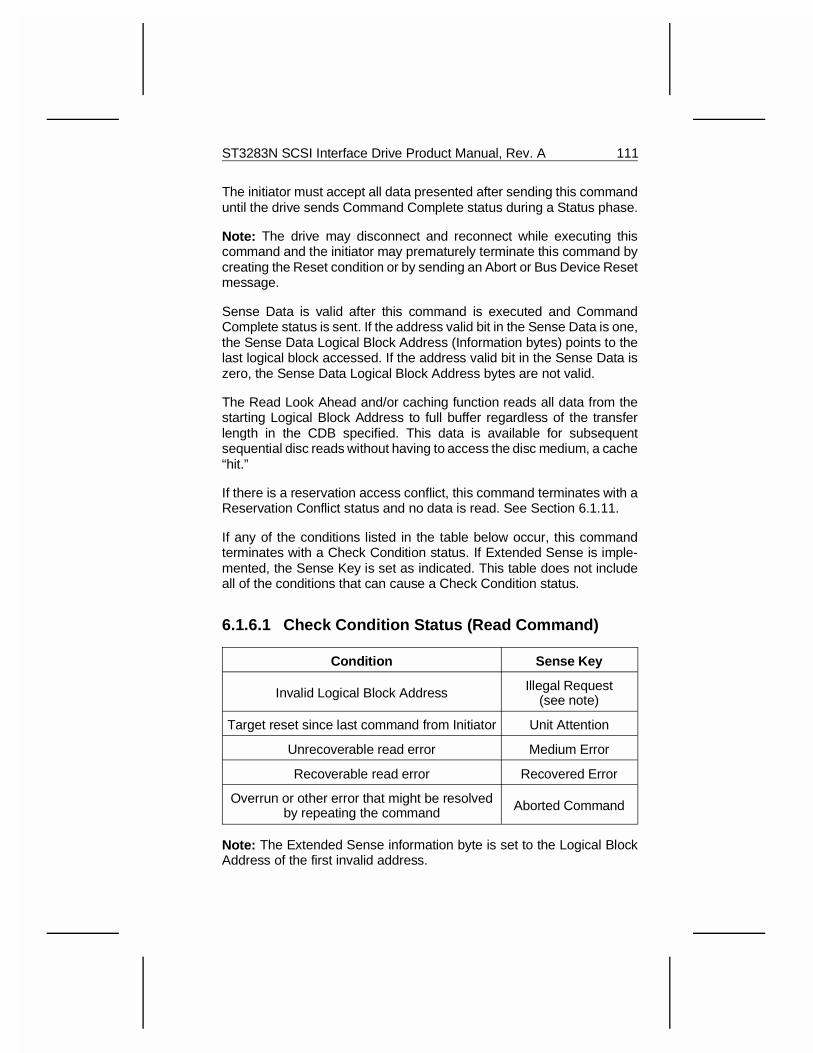
The initiator must accept all data presented after sending this commanduntil the drive sends Command Complete status during a Status phase.
Note: The drive may disconnect and reconnect while executing thiscommand and the initiator may prematurely terminate this command bycreating the Reset condition or by sending an Abort or Bus Device Resetmessage.
Sense Data is valid after this command is executed and CommandComplete status is sent. If the address valid bit in the Sense Data is one,the Sense Data Logical Block Address (Information bytes) points to thelast logical block accessed. If the address valid bit in the Sense Data iszero, the Sense Data Logical Block Address bytes are not valid.
The Read Look Ahead and/or caching function reads all data from thestarting Logical Block Address to full buffer regardless of the transferlength in the CDB specified. This data is available for subsequentsequential disc reads without having to access the disc medium, a cache“hit.”
If there is a reservation access conflict, this command terminates with aReservation Conflict status and no data is read. See Section 6.1.11.
If any of the conditions listed in the table below occur, this commandterminates with a Check Condition status. If Extended Sense is imple-mented, the Sense Key is set as indicated. This table does not includeall of the conditions that can cause a Check Condition status.
6.1.6.1 Check Condition Status (Read Command)
Condition Sense Key
Invalid Logical Block Address Illegal Request(see note)
Target reset since last command from Initiator Unit Attention
Unrecoverable read error Medium Error
Recoverable read error Recovered Error
Overrun or other error that might be resolvedby repeating the command Aborted Command
Note: The Extended Sense information byte is set to the Logical BlockAddress of the first invalid address.
ST3283N SCSI Interface Drive Product Manual, Rev. A 111
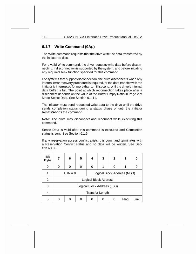
6.1.7 Write Command (0A H)
The Write command requests that the drive write the data transferred bythe initiator to disc.
For a valid Write command, the drive requests write data before discon-necting, if disconnection is supported by the system, and before initiatingany required seek function specified for this command.
For systems that support disconnection, the drive disconnects when anyinternal error recovery procedure is required, or the data transfer with theinitiator is interrupted for more than 1 millisecond, or if the drive’s internaldata buffer is full. The point at which reconnection takes place after adisconnect depends on the value of the Buffer Empty Ratio in Page 2 ofMode Select Data. See Section 6.1.11.
The initiator must send requested write data to the drive until the drivesends completion status during a status phase or until the initiatorResets/Aborts the command.
Note: The drive may disconnect and reconnect while executing thiscommand.
Sense Data is valid after this command is executed and Completionstatus is sent. See Section 6.1.6.
If any reservation access conflict exists, this command terminates witha Reservation Conflict status and no data will be written. See Sec-tion 6.1.11.
BitByte 7 6 5 4 3 2 1 0
0 0 0 0 0 1 0 1 0
1 LUN = 0 Logical Block Address (MSB)
2 Logical Block Address
3 Logical Block Address (LSB)
4 Transfer Length
5 0 0 0 0 0 0 Flag Link
112 ST3283N SCSI Interface Drive Product Manual, Rev. A
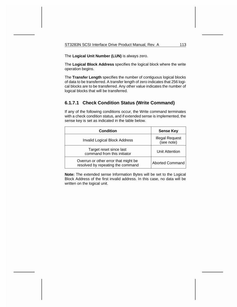
The Logical Unit Number (LUN) is always zero.
The Logical Block Address specifies the logical block where the writeoperation begins.
The Transfer Length specifies the number of contiguous logical blocksof data to be transferred. A transfer length of zero indicates that 256 logi-cal blocks are to be transferred. Any other value indicates the number oflogical blocks that will be transferred.
6.1.7.1 Check Condition Status (Write Command)
If any of the following conditions occur, the Write command terminateswith a check condition status, and if extended sense is implemented, thesense key is set as indicated in the table below.
Condition Sense Key
Invalid Logical Block Address Illegal Request(see note)
Target reset since last command from this initiator Unit Attention
Overrun or other error that might be resolved by repeating the command Aborted Command
Note: The extended sense Information Bytes will be set to the LogicalBlock Address of the first invalid address. In this case, no data will bewritten on the logical unit.
ST3283N SCSI Interface Drive Product Manual, Rev. A 113
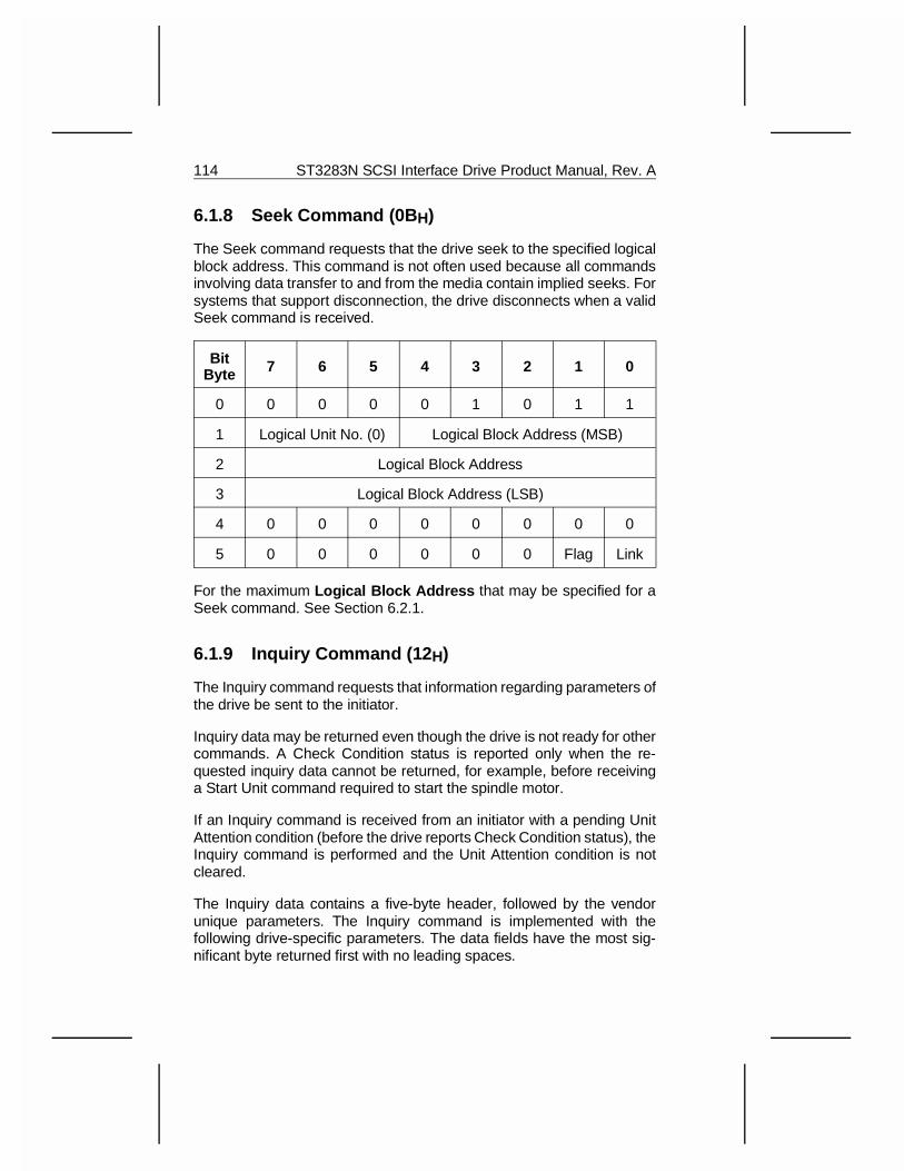
6.1.8 Seek Command (0B H)
The Seek command requests that the drive seek to the specified logicalblock address. This command is not often used because all commandsinvolving data transfer to and from the media contain implied seeks. Forsystems that support disconnection, the drive disconnects when a validSeek command is received.
BitByte 7 6 5 4 3 2 1 0
0 0 0 0 0 1 0 1 1
1 Logical Unit No. (0) Logical Block Address (MSB)
2 Logical Block Address
3 Logical Block Address (LSB)
4 0 0 0 0 0 0 0 0
5 0 0 0 0 0 0 Flag Link
For the maximum Logical Block Address that may be specified for aSeek command. See Section 6.2.1.
6.1.9 Inquiry Command (12 H)
The Inquiry command requests that information regarding parameters ofthe drive be sent to the initiator.
Inquiry data may be returned even though the drive is not ready for othercommands. A Check Condition status is reported only when the re-quested inquiry data cannot be returned, for example, before receivinga Start Unit command required to start the spindle motor.
If an Inquiry command is received from an initiator with a pending UnitAttention condition (before the drive reports Check Condition status), theInquiry command is performed and the Unit Attention condition is notcleared.
The Inquiry data contains a five-byte header, followed by the vendorunique parameters. The Inquiry command is implemented with thefollowing drive-specific parameters. The data fields have the most sig-nificant byte returned first with no leading spaces.
114 ST3283N SCSI Interface Drive Product Manual, Rev. A
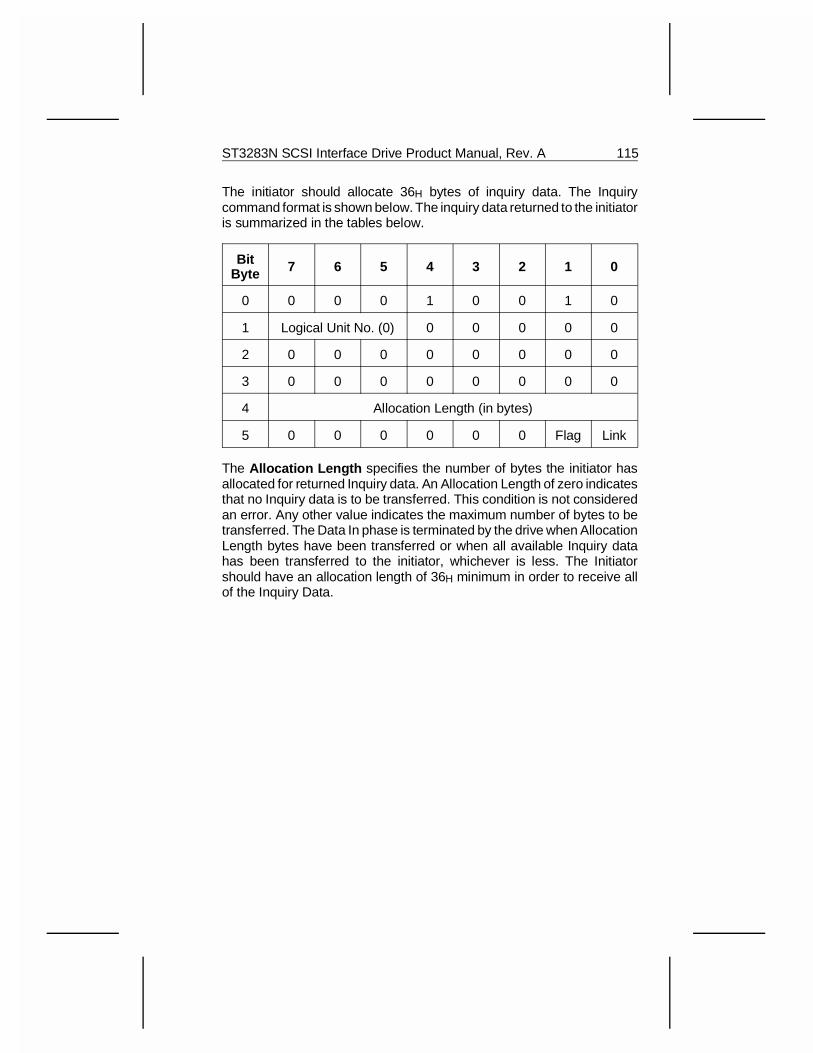
The initiator should allocate 36H bytes of inquiry data. The Inquirycommand format is shown below. The inquiry data returned to the initiatoris summarized in the tables below.
BitByte 7 6 5 4 3 2 1 0
0 0 0 0 1 0 0 1 0
1 Logical Unit No. (0) 0 0 0 0 0
2 0 0 0 0 0 0 0 0
3 0 0 0 0 0 0 0 0
4 Allocation Length (in bytes)
5 0 0 0 0 0 0 Flag Link
The Allocation Length specifies the number of bytes the initiator hasallocated for returned Inquiry data. An Allocation Length of zero indicatesthat no Inquiry data is to be transferred. This condition is not consideredan error. Any other value indicates the maximum number of bytes to betransferred. The Data In phase is terminated by the drive when AllocationLength bytes have been transferred or when all available Inquiry datahas been transferred to the initiator, whichever is less. The Initiatorshould have an allocation length of 36H minimum in order to receive allof the Inquiry Data.
ST3283N SCSI Interface Drive Product Manual, Rev. A 115
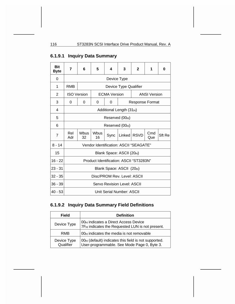
6.1.9.1 Inquiry Data Summary
BitByte 7 6 5 4 3 2 1 0
0 Device Type
1 RMB Device Type Qualifier
2 ISO Version ECMA Version ANSI Version
3 0 0 0 0 Response Format
4 Additional Length (31H)
5 Reserved (00H)
6 Reserved (00H)
7 RelAdr
Wbus32
Wbus16 Sync Linked RSVD Cmd
Que Sft Re
8 - 14 Vendor Identification: ASCII “SEAGATE”
15 Blank Space: ASCII (20H)
16 - 22 Product Identification: ASCII “ST3283N”
23 - 31 Blank Space: ASCII (20H)
32 - 35 Disc/PROM Rev. Level: ASCII
36 - 39 Servo Revision Level: ASCII
40 - 53 Unit Serial Number: ASCII
6.1.9.2 Inquiry Data Summary Field Definitions
Field Definition
Device Type 00H indicates a Direct Access Device7FH indicates the Requested LUN is not present.
RMB 00H indicates the media is not removable
Device TypeQualifier
00H (default) indicates this field is not supported.User-programmable. See Mode Page 0, Byte 3.
116 ST3283N SCSI Interface Drive Product Manual, Rev. A
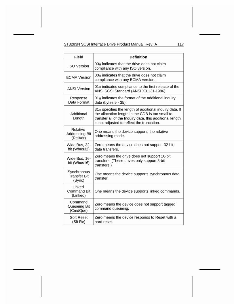
Field Definition
ISO Version 00H indicates that the drive does not claimcompliance with any ISO version.
ECMA Version 00H indicates that the drive does not claimcompliance with any ECMA version.
ANSI Version 01H indicates compliance to the first release of theANSI SCSI Standard (ANSI X3.131-1986)
ResponseData Format
01H indicates the format of the additional inquirydata (bytes 5 - 35).
AdditionalLength
31H specifies the length of additional inquiry data. Ifthe allocation length in the CDB is too small totransfer all of the Inquiry data, this additional lengthis not adjusted to reflect the truncation.
Relative Addressing Bit
(RelAdr)
One means the device supports the relativeaddressing mode.
Wide Bus, 32-bit (Wbus32)
Zero means the device does not support 32-bitdata transfers.
Wide Bus, 16-bit (Wbus16)
Zero means the drive does not support 16-bittransfers. (These drives only support 8-bittransfers.)
SynchronousTransfer Bit
(Sync)
One means the device supports synchronous datatransfer.
Linked Command Bit
(Linked)One means the device supports linked commands.
CommandQueueing Bit(CmdQue)
Zero means the device does not support taggedcommand queueing.
Soft Reset(Sft Re)
Zero means the device responds to Reset with ahard reset.
ST3283N SCSI Interface Drive Product Manual, Rev. A 117
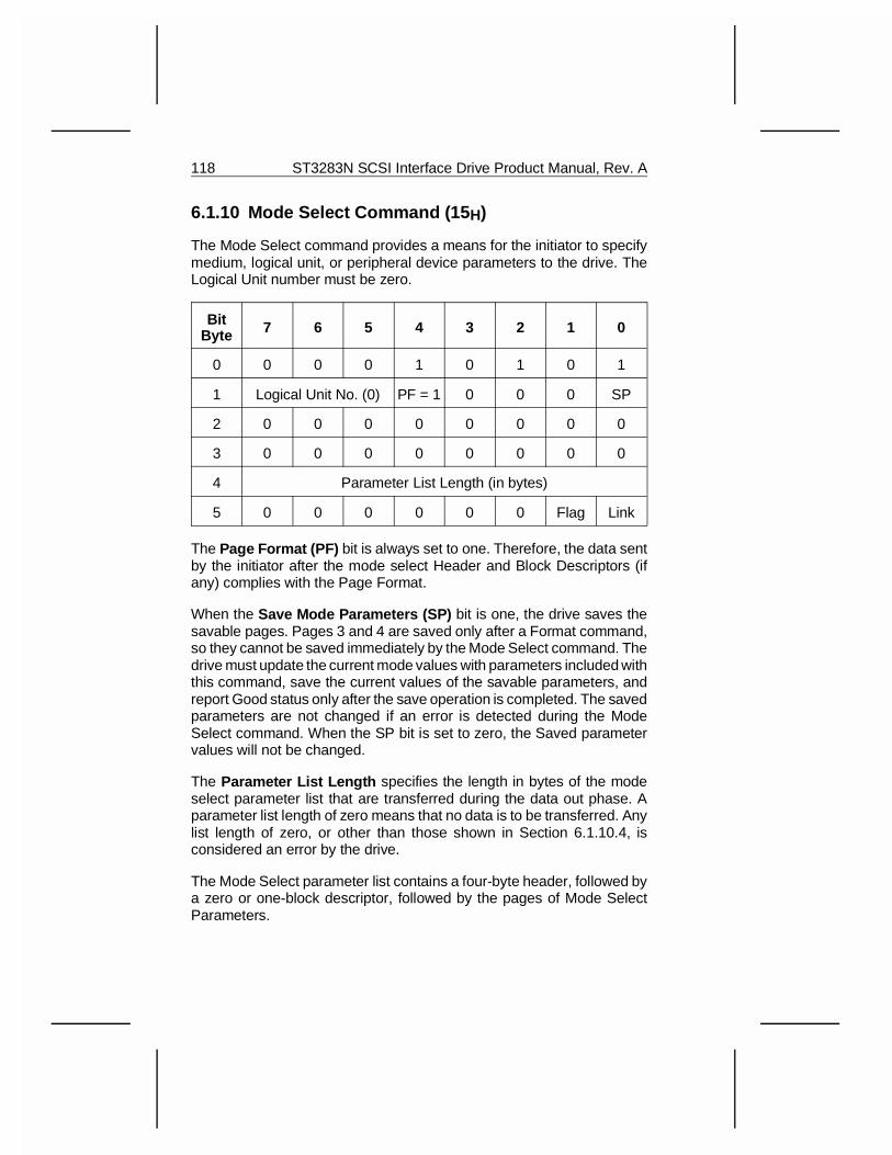
6.1.10 Mode Select Command (15 H)
The Mode Select command provides a means for the initiator to specifymedium, logical unit, or peripheral device parameters to the drive. TheLogical Unit number must be zero.
BitByte 7 6 5 4 3 2 1 0
0 0 0 0 1 0 1 0 1
1 Logical Unit No. (0) PF = 1 0 0 0 SP
2 0 0 0 0 0 0 0 0
3 0 0 0 0 0 0 0 0
4 Parameter List Length (in bytes)
5 0 0 0 0 0 0 Flag Link
The Page Format (PF) bit is always set to one. Therefore, the data sentby the initiator after the mode select Header and Block Descriptors (ifany) complies with the Page Format.
When the Save Mode Parameters (SP) bit is one, the drive saves thesavable pages. Pages 3 and 4 are saved only after a Format command,so they cannot be saved immediately by the Mode Select command. Thedrive must update the current mode values with parameters included withthis command, save the current values of the savable parameters, andreport Good status only after the save operation is completed. The savedparameters are not changed if an error is detected during the ModeSelect command. When the SP bit is set to zero, the Saved parametervalues will not be changed.
The Parameter List Length specifies the length in bytes of the modeselect parameter list that are transferred during the data out phase. Aparameter list length of zero means that no data is to be transferred. Anylist length of zero, or other than those shown in Section 6.1.10.4, isconsidered an error by the drive.
The Mode Select parameter list contains a four-byte header, followed bya zero or one-block descriptor, followed by the pages of Mode SelectParameters.
118 ST3283N SCSI Interface Drive Product Manual, Rev. A
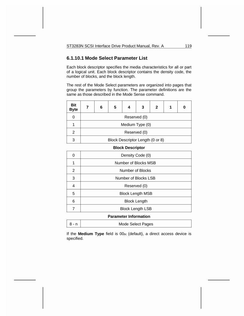
6.1.10.1 Mode Select Parameter List
Each block descriptor specifies the media characteristics for all or partof a logical unit. Each block descriptor contains the density code, thenumber of blocks, and the block length.
The rest of the Mode Select parameters are organized into pages thatgroup the parameters by function. The parameter definitions are thesame as those described in the Mode Sense command.
BitByte 7 6 5 4 3 2 1 0
0 Reserved (0)
1 Medium Type (0)
2 Reserved (0)
3 Block Descriptor Length (0 or 8)
Block Descriptor
0 Density Code (0)
1 Number of Blocks MSB
2 Number of Blocks
3 Number of Blocks LSB
4 Reserved (0)
5 Block Length MSB
6 Block Length
7 Block Length LSB
Parameter Information
8 - n Mode Select Pages
If the Medium Type field is 00H (default), a direct access device isspecified.
ST3283N SCSI Interface Drive Product Manual, Rev. A 119
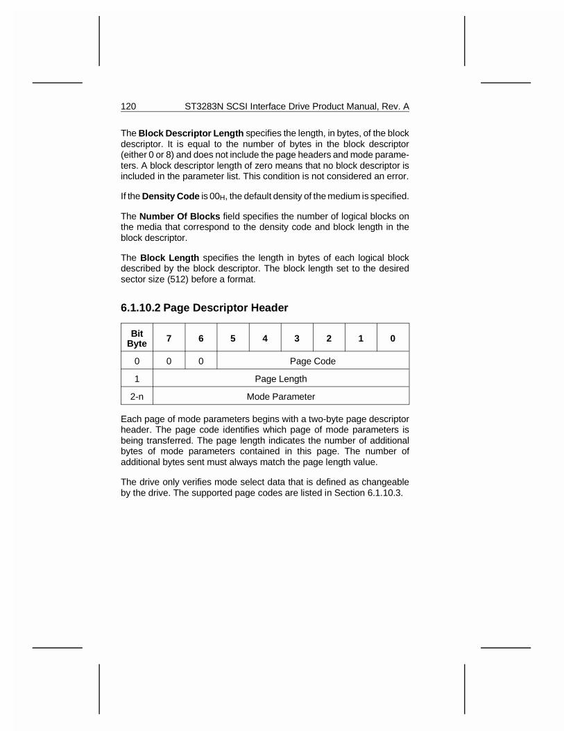
The Block Descriptor Length specifies the length, in bytes, of the blockdescriptor. It is equal to the number of bytes in the block descriptor(either 0 or 8) and does not include the page headers and mode parame-ters. A block descriptor length of zero means that no block descriptor isincluded in the parameter list. This condition is not considered an error.
If the Density Code is 00H, the default density of the medium is specified.
The Number Of Blocks field specifies the number of logical blocks onthe media that correspond to the density code and block length in theblock descriptor.
The Block Length specifies the length in bytes of each logical blockdescribed by the block descriptor. The block length set to the desiredsector size (512) before a format.
6.1.10.2 Page Descriptor Header
BitByte 7 6 5 4 3 2 1 0
0 0 0 Page Code
1 Page Length
2-n Mode Parameter
Each page of mode parameters begins with a two-byte page descriptorheader. The page code identifies which page of mode parameters isbeing transferred. The page length indicates the number of additionalbytes of mode parameters contained in this page. The number ofadditional bytes sent must always match the page length value.
The drive only verifies mode select data that is defined as changeableby the drive. The supported page codes are listed in Section 6.1.10.3.
120 ST3283N SCSI Interface Drive Product Manual, Rev. A
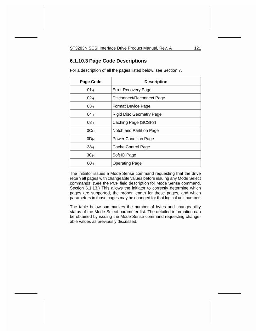
6.1.10.3 Page Code Descriptions
For a description of all the pages listed below, see Section 7.
Page Code Description
01H Error Recovery Page
02H Disconnect/Reconnect Page
03H Format Device Page
04H Rigid Disc Geometry Page
08H Caching Page (SCSI-3)
0CH Notch and Partition Page
0DH Power Condition Page
38H Cache Control Page
3CH Soft ID Page
00H Operating Page
The initiator issues a Mode Sense command requesting that the drivereturn all pages with changeable values before issuing any Mode Selectcommands. (See the PCF field description for Mode Sense command,Section 6.1.13.) This allows the initiator to correctly determine whichpages are supported, the proper length for those pages, and whichparameters in those pages may be changed for that logical unit number.
The table below summarizes the number of bytes and changeabilitystatus of the Mode Select parameter list. The detailed information canbe obtained by issuing the Mode Sense command requesting change-able values as previously discussed.
ST3283N SCSI Interface Drive Product Manual, Rev. A 121
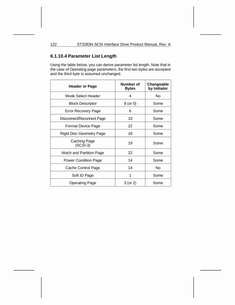
6.1.10.4 Parameter List Length
Using the table below, you can derive parameter list length. Note that inthe case of Operating page parameters, the first two bytes are acceptedand the third byte is assumed unchanged.
Header or Page Number ofBytes
Changeableby Initiator
Mode Select Header 4 No
Block Descriptor 8 (or 0) Some
Error Recovery Page 6 Some
Disconnect/Reconnect Page 10 Some
Format Device Page 22 Some
Rigid Disc Geometry Page 18 Some
Caching Page(SCSI-3) 19 Some
Notch and Partition Page 22 Some
Power Condition Page 14 Some
Cache Control Page 14 No
Soft ID Page 1 Some
Operating Page 3 (or 2) Some
122 ST3283N SCSI Interface Drive Product Manual, Rev. A
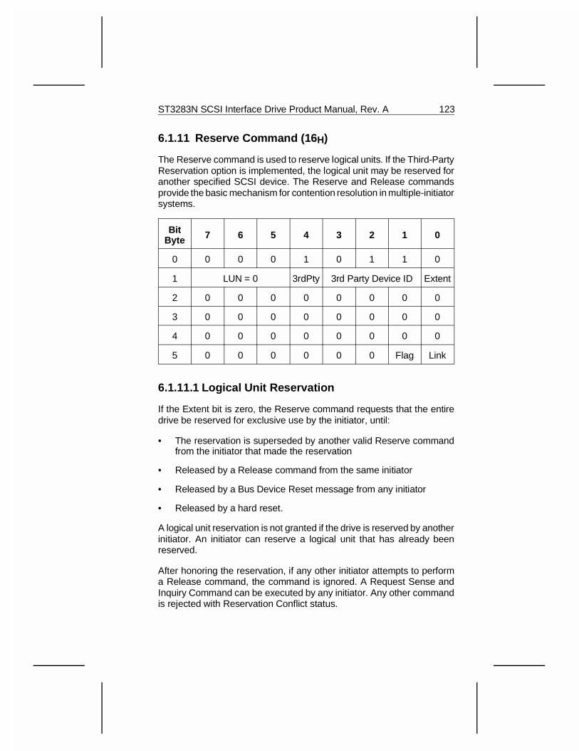
6.1.11 Reserve Command (16 H)
The Reserve command is used to reserve logical units. If the Third-PartyReservation option is implemented, the logical unit may be reserved foranother specified SCSI device. The Reserve and Release commandsprovide the basic mechanism for contention resolution in multiple-initiatorsystems.
BitByte 7 6 5 4 3 2 1 0
0 0 0 0 1 0 1 1 0
1 LUN = 0 3rdPty 3rd Party Device ID Extent
2 0 0 0 0 0 0 0 0
3 0 0 0 0 0 0 0 0
4 0 0 0 0 0 0 0 0
5 0 0 0 0 0 0 Flag Link
6.1.11.1 Logical Unit Reservation
If the Extent bit is zero, the Reserve command requests that the entiredrive be reserved for exclusive use by the initiator, until:
• The reservation is superseded by another valid Reserve commandfrom the initiator that made the reservation
• Released by a Release command from the same initiator
• Released by a Bus Device Reset message from any initiator
• Released by a hard reset.
A logical unit reservation is not granted if the drive is reserved by anotherinitiator. An initiator can reserve a logical unit that has already beenreserved.
After honoring the reservation, if any other initiator attempts to performa Release command, the command is ignored. A Request Sense andInquiry Command can be executed by any initiator. Any other commandis rejected with Reservation Conflict status.
ST3283N SCSI Interface Drive Product Manual, Rev. A 123
6.1.11.2 Extent Reservation
The drive does not support Extent reservations. The extent bit mustalways be zero. If the Extent bit is a one, Check Condition status isgenerated and the sense key is Illegal Request.
6.1.11.3 Third-Party Reservation Option
The Third-Party Reservation option for the Reserve command allows aninitiator to reserve a logical unit for another SCSI device. This option isintended for use in multiple initiator systems that use the Copy command.
Third-Party Bit: If zero, then the Third-Party Reservation option is notrequested. If one, the Reserve command reserves the drive for the SCSIdevice specified in the third party device ID field.
The drive preserves the reservation until it is superseded by another validReserve command from the initiator of the reservation or until it isreleased by the same initiator, by a Bus Device Reset message from anyinitiator, or a hard reset. The drive ignores any attempt to release thereservation made by any other initiator.
6.1.11.4 Superseding Reservations
An initiator holding a current reservation can modify that reservation byissuing another Reserve command to the same logical unit. The super-seding Reserve command releases the previous reservation state whenthe new reservation request is granted. The previous reservation is notmodified if the new reservation request cannot be granted.
Note: This option is intended for use in multiple initiator systems that usethe Copy command.
Note: Superseding reservations are principally intended to allow theSCSI device ID to be changed on a reservation using Third-PartyReservation option. This capability is sometimes necessary when usingthe Copy command.
124 ST3283N SCSI Interface Drive Product Manual, Rev. A
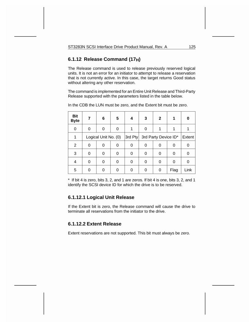
6.1.12 Release Command (17 H)
The Release command is used to release previously reserved logicalunits. It is not an error for an initiator to attempt to release a reservationthat is not currently active. In this case, the target returns Good statuswithout altering any other reservation.
The command is implemented for an Entire Unit Release and Third-PartyRelease supported with the parameters listed in the table below.
In the CDB the LUN must be zero, and the Extent bit must be zero.
BitByte 7 6 5 4 3 2 1 0
0 0 0 0 1 0 1 1 1
1 Logical Unit No. (0) 3rd Pty 3rd Party Device ID* Extent
2 0 0 0 0 0 0 0 0
3 0 0 0 0 0 0 0 0
4 0 0 0 0 0 0 0 0
5 0 0 0 0 0 0 Flag Link
* If bit 4 is zero, bits 3, 2, and 1 are zeros. If bit 4 is one, bits 3, 2, and 1identify the SCSI device ID for which the drive is to be reserved.
6.1.12.1 Logical Unit Release
If the Extent bit is zero, the Release command will cause the drive toterminate all reservations from the initiator to the drive.
6.1.12.2 Extent Release
Extent reservations are not supported. This bit must always be zero.
ST3283N SCSI Interface Drive Product Manual, Rev. A 125
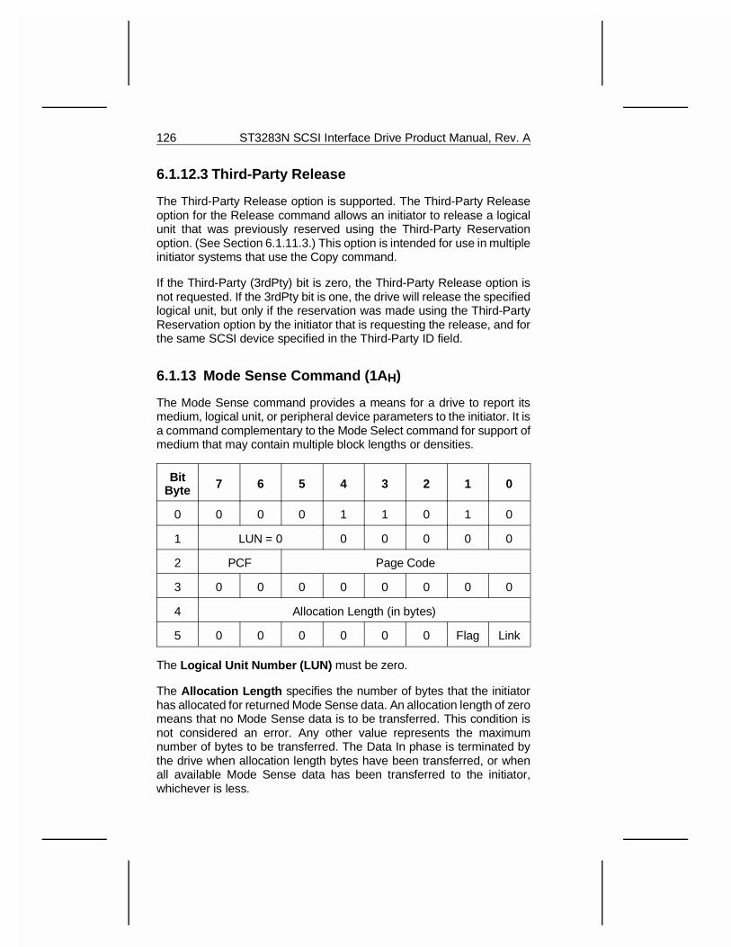
6.1.12.3 Third-Party Release
The Third-Party Release option is supported. The Third-Party Releaseoption for the Release command allows an initiator to release a logicalunit that was previously reserved using the Third-Party Reservationoption. (See Section 6.1.11.3.) This option is intended for use in multipleinitiator systems that use the Copy command.
If the Third-Party (3rdPty) bit is zero, the Third-Party Release option isnot requested. If the 3rdPty bit is one, the drive will release the specifiedlogical unit, but only if the reservation was made using the Third-PartyReservation option by the initiator that is requesting the release, and forthe same SCSI device specified in the Third-Party ID field.
6.1.13 Mode Sense Command (1A H)
The Mode Sense command provides a means for a drive to report itsmedium, logical unit, or peripheral device parameters to the initiator. It isa command complementary to the Mode Select command for support ofmedium that may contain multiple block lengths or densities.
BitByte 7 6 5 4 3 2 1 0
0 0 0 0 1 1 0 1 0
1 LUN = 0 0 0 0 0 0
2 PCF Page Code
3 0 0 0 0 0 0 0 0
4 Allocation Length (in bytes)
5 0 0 0 0 0 0 Flag Link
The Logical Unit Number (LUN) must be zero.
The Allocation Length specifies the number of bytes that the initiatorhas allocated for returned Mode Sense data. An allocation length of zeromeans that no Mode Sense data is to be transferred. This condition isnot considered an error. Any other value represents the maximumnumber of bytes to be transferred. The Data In phase is terminated bythe drive when allocation length bytes have been transferred, or whenall available Mode Sense data has been transferred to the initiator,whichever is less.
126 ST3283N SCSI Interface Drive Product Manual, Rev. A
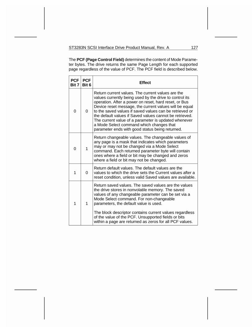
The PCF (Page Control Field) determines the content of Mode Parame-ter bytes. The drive returns the same Page Length for each supportedpage regardless of the value of PCF. The PCF field is described below.
PCFBit 7
PCFBit 6 Effect
0 0
Return current values. The current values are thevalues currently being used by the drive to control itsoperation. After a power on reset, hard reset, or BusDevice reset message, the current values will be equalto the saved values if saved values can be retrieved orthe default values if Saved values cannot be retrieved.The current value of a parameter is updated whenevera Mode Select command which changes thatparameter ends with good status being returned.
0 1
Return changeable values. The changeable values ofany page is a mask that indicates which parametersmay or may not be changed via a Mode Selectcommand. Each returned parameter byte will containones where a field or bit may be changed and zeroswhere a field or bit may not be changed.
1 0Return default values. The default values are thevalues to which the drive sets the Current values after areset condition, unless valid Saved values are available.
1 1
Return saved values. The saved values are the valuesthe drive stores in nonvolatile memory. The savedvalues of any changeable parameter can be set via aMode Select command. For non-changeableparameters, the default value is used.
The block descriptor contains current values regardlessof the value of the PCF. Unsupported fields or bitswithin a page are returned as zeros for all PCF values.
ST3283N SCSI Interface Drive Product Manual, Rev. A 127
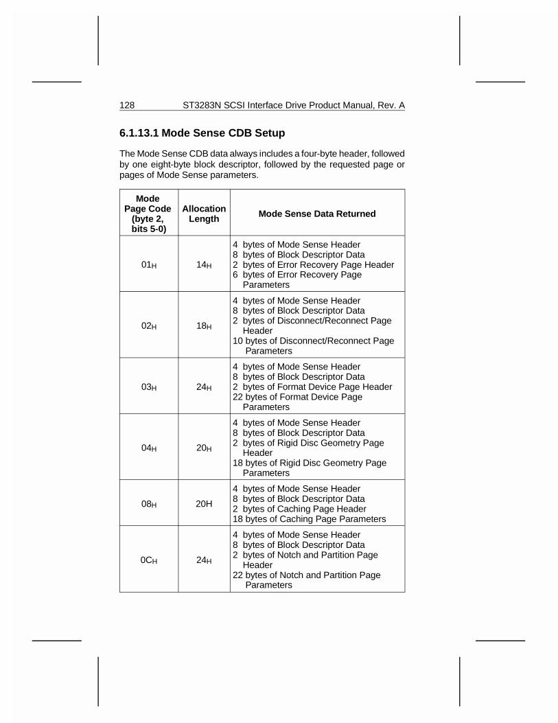
6.1.13.1 Mode Sense CDB Setup
The Mode Sense CDB data always includes a four-byte header, followedby one eight-byte block descriptor, followed by the requested page orpages of Mode Sense parameters.
Mode Page Code
(byte 2, bits 5-0)
AllocationLength Mode Sense Data Returned
01H 14H
4 bytes of Mode Sense Header8 bytes of Block Descriptor Data2 bytes of Error Recovery Page Header6 bytes of Error Recovery Page Parameters
02H 18H
4 bytes of Mode Sense Header8 bytes of Block Descriptor Data2 bytes of Disconnect/Reconnect Page Header10 bytes of Disconnect/Reconnect Page Parameters
03H 24H
4 bytes of Mode Sense Header8 bytes of Block Descriptor Data2 bytes of Format Device Page Header22 bytes of Format Device Page Parameters
04H 20H
4 bytes of Mode Sense Header8 bytes of Block Descriptor Data2 bytes of Rigid Disc Geometry Page Header18 bytes of Rigid Disc Geometry Page Parameters
08H 20H
4 bytes of Mode Sense Header8 bytes of Block Descriptor Data2 bytes of Caching Page Header18 bytes of Caching Page Parameters
0CH 24H
4 bytes of Mode Sense Header8 bytes of Block Descriptor Data2 bytes of Notch and Partition Page Header22 bytes of Notch and Partition Page Parameters
128 ST3283N SCSI Interface Drive Product Manual, Rev. A
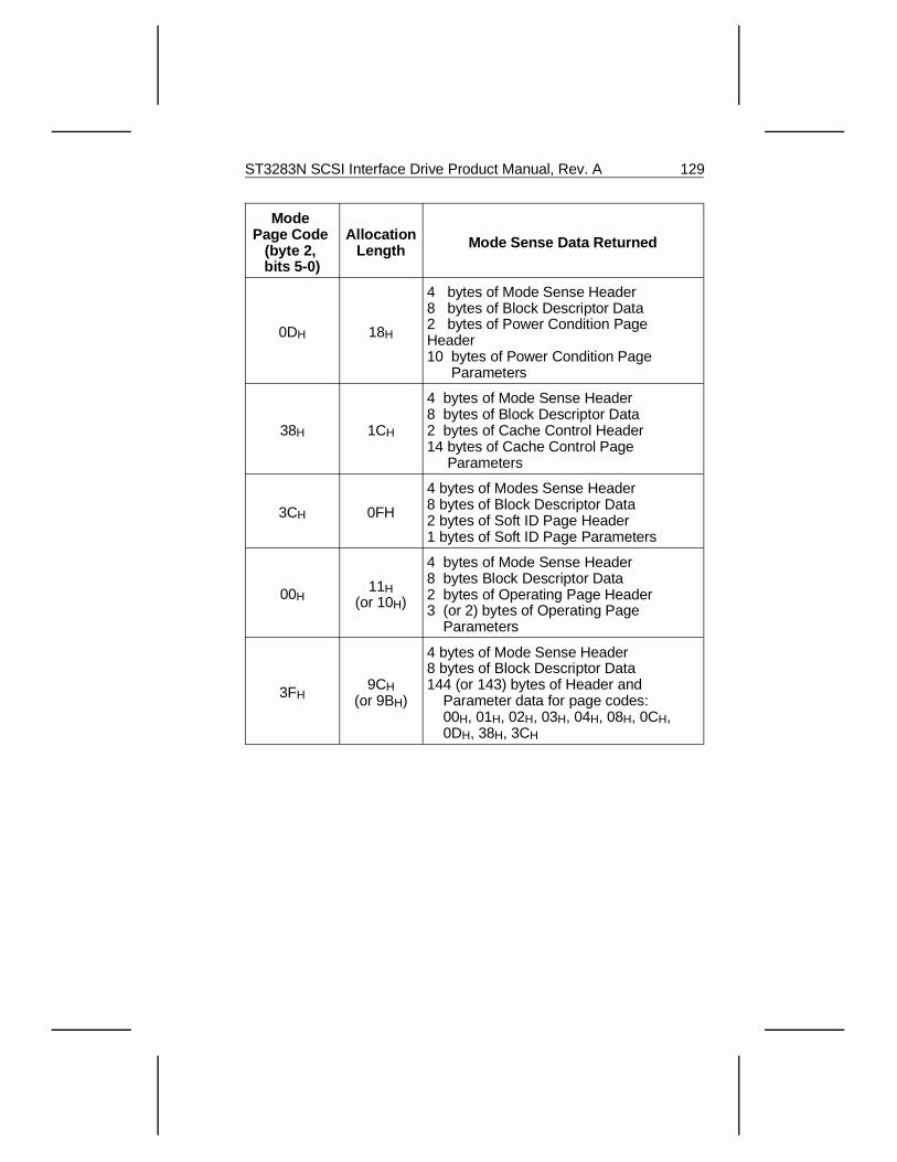
Mode Page Code
(byte 2, bits 5-0)
AllocationLength Mode Sense Data Returned
0DH 18H
4 bytes of Mode Sense Header8 bytes of Block Descriptor Data2 bytes of Power Condition PageHeader10 bytes of Power Condition Page Parameters
38H 1CH
4 bytes of Mode Sense Header8 bytes of Block Descriptor Data2 bytes of Cache Control Header14 bytes of Cache Control Page Parameters
3CH 0FH
4 bytes of Modes Sense Header8 bytes of Block Descriptor Data2 bytes of Soft ID Page Header1 bytes of Soft ID Page Parameters
00H11H
(or 10H)
4 bytes of Mode Sense Header 8 bytes Block Descriptor Data2 bytes of Operating Page Header3 (or 2) bytes of Operating Page Parameters
3FH9CH
(or 9BH)
4 bytes of Mode Sense Header8 bytes of Block Descriptor Data144 (or 143) bytes of Header and Parameter data for page codes: 00H, 01H, 02H, 03H, 04H, 08H, 0CH, 0DH, 38H, 3CH
ST3283N SCSI Interface Drive Product Manual, Rev. A 129
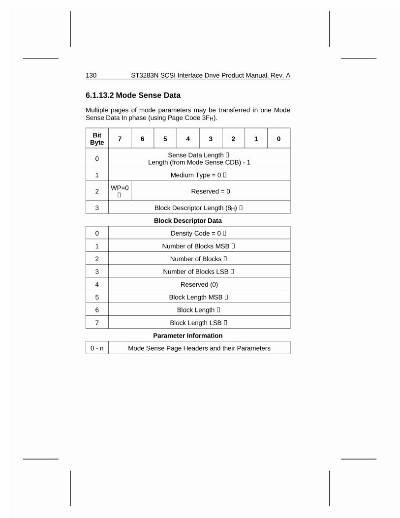
6.1.13.2 Mode Sense Data
Multiple pages of mode parameters may be transferred in one ModeSense Data In phase (using Page Code 3FH).
BitByte 7 6 5 4 3 2 1 0
0 Sense Data Length ➀Length (from Mode Sense CDB) - 1
1 Medium Type = 0 ➁
2 WP=0➂
Reserved = 0
3 Block Descriptor Length (8H) ➃
Block Descriptor Data
0 Density Code = 0 ➄
1 Number of Blocks MSB ➅
2 Number of Blocks ➅
3 Number of Blocks LSB ➅
4 Reserved (0)
5 Block Length MSB ➆
6 Block Length ➆
7 Block Length LSB ➆
Parameter Information
0 - n Mode Sense Page Headers and their Parameters
130 ST3283N SCSI Interface Drive Product Manual, Rev. A

➀ The Sense Data Length specifies the length in bytes of the followingMode Sense data that is available to be transferred during the DataIn phase. The Sense Data Length does not include itself.
➁ The Medium Type field must contain zero, the default media.
➂ When the Write Protect (WP) bit is always zero, which means themedia is write-enabled.
➃ The Block Descriptor Length is always 8H; It specifies the numberof bytes in the Block Descriptor. This value does not include the pageheaders and mode parameters, if any.
One Block Descriptor is sent by the drive. Each Block Descriptorspecifies the medium characteristics for the logical unit. The BlockDescriptor contains a Density Code, a Number of Blocks, and a BlockLength.
➄ Only 00H (default) is supported in the Density Code field.
➅ The Number of Blocks field specifies the number of logical blocksof the media that meets the Density Code and Block Length in theBlock Descriptor. The drive always returns the total number of blocksavailable.
➆ The Block Length is always 512. It specifies the length, in bytes, ofeach logical block described by the Block Descriptor.
ST3283N SCSI Interface Drive Product Manual, Rev. A 131
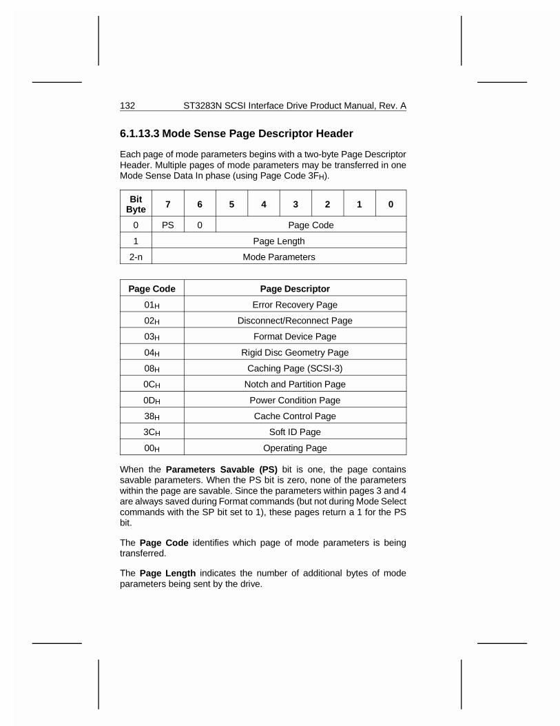
6.1.13.3 Mode Sense Page Descriptor Header
Each page of mode parameters begins with a two-byte Page DescriptorHeader. Multiple pages of mode parameters may be transferred in oneMode Sense Data In phase (using Page Code 3FH).
BitByte 7 6 5 4 3 2 1 0
0 PS 0 Page Code
1 Page Length
2-n Mode Parameters
Page Code Page Descriptor
01H Error Recovery Page
02H Disconnect/Reconnect Page
03H Format Device Page
04H Rigid Disc Geometry Page
08H Caching Page (SCSI-3)
0CH Notch and Partition Page
0DH Power Condition Page
38H Cache Control Page
3CH Soft ID Page
00H Operating Page
When the Parameters Savable (PS) bit is one, the page containssavable parameters. When the PS bit is zero, none of the parameterswithin the page are savable. Since the parameters within pages 3 and 4are always saved during Format commands (but not during Mode Selectcommands with the SP bit set to 1), these pages return a 1 for the PSbit.
The Page Code identifies which page of mode parameters is beingtransferred.
The Page Length indicates the number of additional bytes of modeparameters being sent by the drive.
132 ST3283N SCSI Interface Drive Product Manual, Rev. A
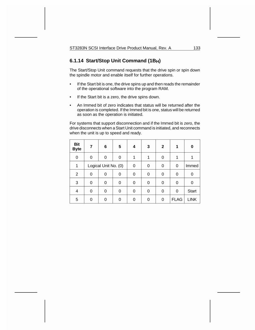
6.1.14 Start/Stop Unit Command (1B H)
The Start/Stop Unit command requests that the drive spin or spin downthe spindle motor and enable itself for further operations.
• If the Start bit is one, the drive spins up and then reads the remainderof the operational software into the program RAM.
• If the Start bit is a zero, the drive spins down.
• An Immed bit of zero indicates that status will be returned after theoperation is completed. If the Immed bit is one, status will be returnedas soon as the operation is initiated.
For systems that support disconnection and if the Immed bit is zero, thedrive disconnects when a Start Unit command is initiated, and reconnectswhen the unit is up to speed and ready.
BitByte 7 6 5 4 3 2 1 0
0 0 0 0 1 1 0 1 1
1 Logical Unit No. (0) 0 0 0 0 Immed
2 0 0 0 0 0 0 0 0
3 0 0 0 0 0 0 0 0
4 0 0 0 0 0 0 0 Start
5 0 0 0 0 0 0 FLAG LINK
ST3283N SCSI Interface Drive Product Manual, Rev. A 133
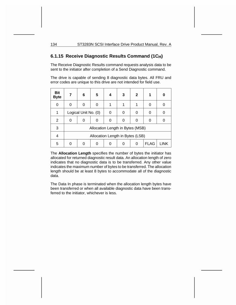
6.1.15 Receive Diagnostic Results Command (1C H)
The Receive Diagnostic Results command requests analysis data to besent to the initiator after completion of a Send Diagnostic command.
The drive is capable of sending 8 diagnostic data bytes. All FRU anderror codes are unique to this drive are not intended for field use.
BitByte 7 6 5 4 3 2 1 0
0 0 0 0 1 1 1 0 0
1 Logical Unit No. (0) 0 0 0 0 0
2 0 0 0 0 0 0 0 0
3 Allocation Length in Bytes (MSB)
4 Allocation Length in Bytes (LSB)
5 0 0 0 0 0 0 FLAG LINK
The Allocation Length specifies the number of bytes the initiator hasallocated for returned diagnostic result data. An allocation length of zeroindicates that no diagnostic data is to be transferred. Any other valueindicates the maximum number of bytes to be transferred. The allocationlength should be at least 8 bytes to accommodate all of the diagnosticdata.
The Data In phase is terminated when the allocation length bytes havebeen transferred or when all available diagnostic data have been trans-ferred to the initiator, whichever is less.
134 ST3283N SCSI Interface Drive Product Manual, Rev. A
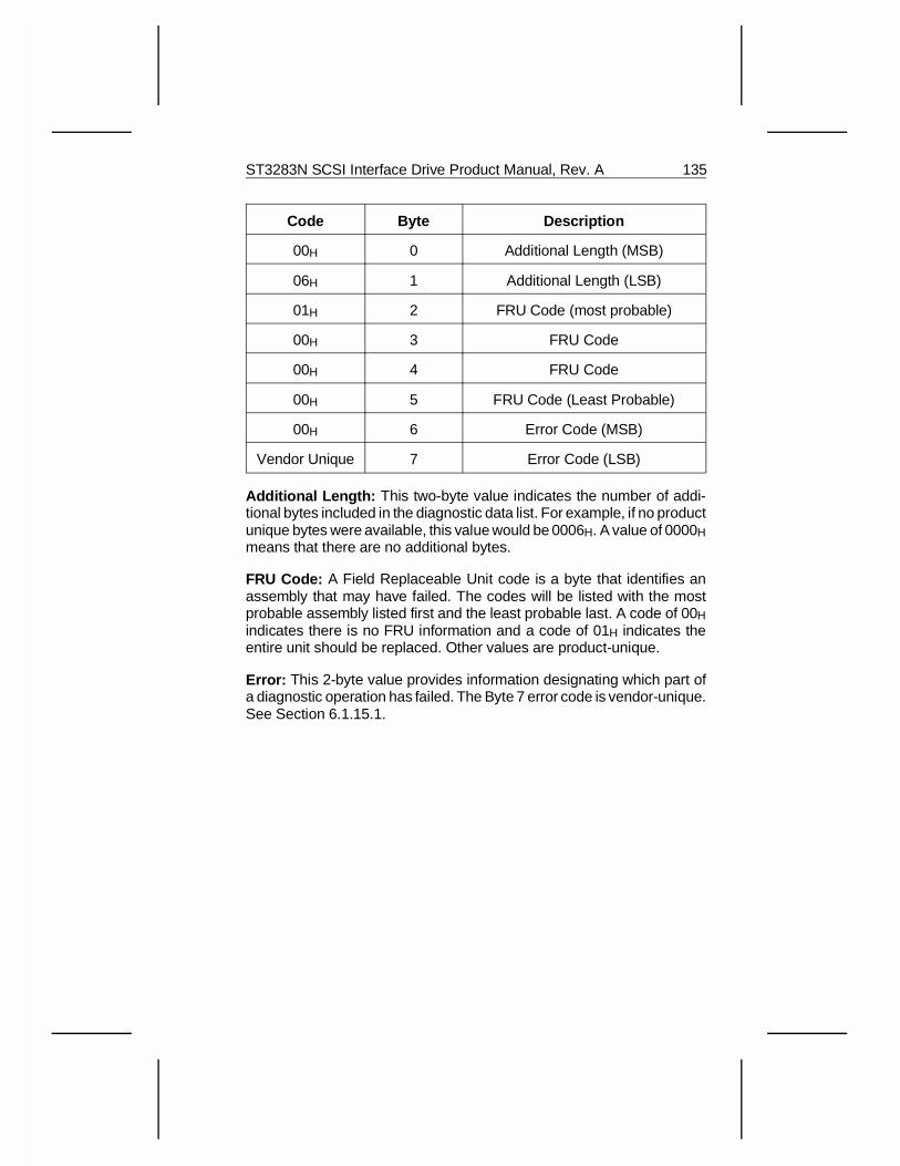
Code Byte Description
00H 0 Additional Length (MSB)
06H 1 Additional Length (LSB)
01H 2 FRU Code (most probable)
00H 3 FRU Code
00H 4 FRU Code
00H 5 FRU Code (Least Probable)
00H 6 Error Code (MSB)
Vendor Unique 7 Error Code (LSB)
Additional Length: This two-byte value indicates the number of addi-tional bytes included in the diagnostic data list. For example, if no productunique bytes were available, this value would be 0006H. A value of 0000Hmeans that there are no additional bytes.
FRU Code: A Field Replaceable Unit code is a byte that identifies anassembly that may have failed. The codes will be listed with the mostprobable assembly listed first and the least probable last. A code of 00Hindicates there is no FRU information and a code of 01H indicates theentire unit should be replaced. Other values are product-unique.
Error: This 2-byte value provides information designating which part ofa diagnostic operation has failed. The Byte 7 error code is vendor-unique.See Section 6.1.15.1.
ST3283N SCSI Interface Drive Product Manual, Rev. A 135
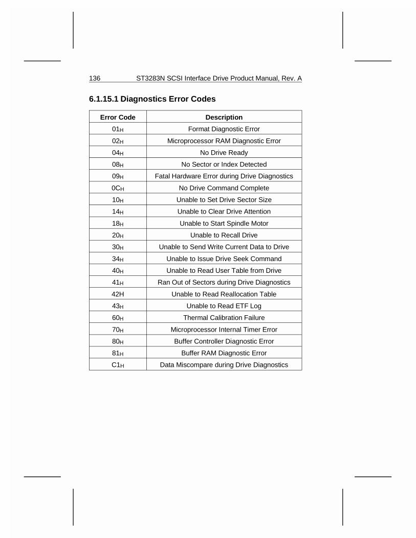
6.1.15.1 Diagnostics Error Codes
Error Code Description
01H Format Diagnostic Error
02H Microprocessor RAM Diagnostic Error
04H No Drive Ready
08H No Sector or Index Detected
09H Fatal Hardware Error during Drive Diagnostics
0CH No Drive Command Complete
10H Unable to Set Drive Sector Size
14H Unable to Clear Drive Attention
18H Unable to Start Spindle Motor
20H Unable to Recall Drive
30H Unable to Send Write Current Data to Drive
34H Unable to Issue Drive Seek Command
40H Unable to Read User Table from Drive
41H Ran Out of Sectors during Drive Diagnostics
42H Unable to Read Reallocation Table
43H Unable to Read ETF Log
60H Thermal Calibration Failure
70H Microprocessor Internal Timer Error
80H Buffer Controller Diagnostic Error
81H Buffer RAM Diagnostic Error
C1H Data Miscompare during Drive Diagnostics
136 ST3283N SCSI Interface Drive Product Manual, Rev. A
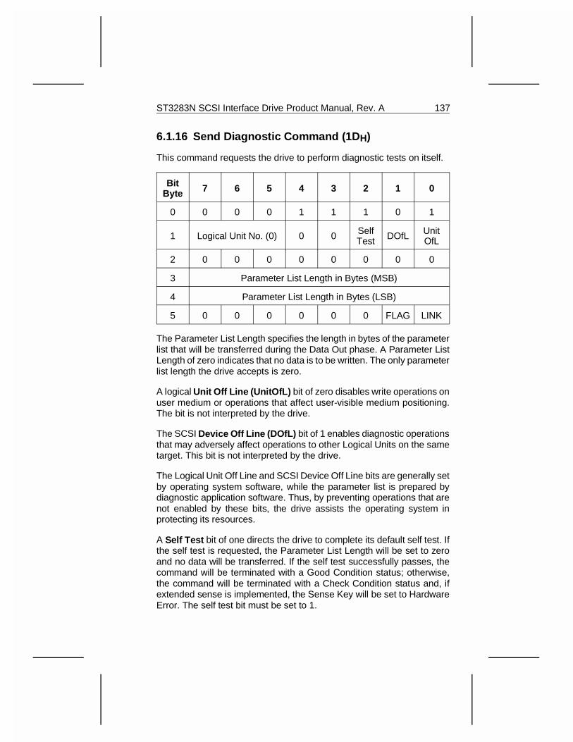
6.1.16 Send Diagnostic Command (1D H)
This command requests the drive to perform diagnostic tests on itself.
BitByte 7 6 5 4 3 2 1 0
0 0 0 0 1 1 1 0 1
1 Logical Unit No. (0) 0 0 SelfTest DOfL Unit
OfL
2 0 0 0 0 0 0 0 0
3 Parameter List Length in Bytes (MSB)
4 Parameter List Length in Bytes (LSB)
5 0 0 0 0 0 0 FLAG LINK
The Parameter List Length specifies the length in bytes of the parameterlist that will be transferred during the Data Out phase. A Parameter ListLength of zero indicates that no data is to be written. The only parameterlist length the drive accepts is zero.
A logical Unit Off Line (UnitOfL) bit of zero disables write operations onuser medium or operations that affect user-visible medium positioning.The bit is not interpreted by the drive.
The SCSI Device Off Line (DOfL) bit of 1 enables diagnostic operationsthat may adversely affect operations to other Logical Units on the sametarget. This bit is not interpreted by the drive.
The Logical Unit Off Line and SCSI Device Off Line bits are generally setby operating system software, while the parameter list is prepared bydiagnostic application software. Thus, by preventing operations that arenot enabled by these bits, the drive assists the operating system inprotecting its resources.
A Self Test bit of one directs the drive to complete its default self test. Ifthe self test is requested, the Parameter List Length will be set to zeroand no data will be transferred. If the self test successfully passes, thecommand will be terminated with a Good Condition status; otherwise,the command will be terminated with a Check Condition status and, ifextended sense is implemented, the Sense Key will be set to HardwareError. The self test bit must be set to 1.
ST3283N SCSI Interface Drive Product Manual, Rev. A 137

For systems that support disconnection, the drive will disconnect whileexecuting this command.
6.2 Group 1 Commands
The Group 1 commands implemented are listed in the table below.
Command Opcode
Read Capacity 25H
Read Extended 28H
Write Extended 2AH
Seek Extended 2BH
Write and Verify 2EH
Verify 2FH
Read Defect Data 37H
Write Data Buffer 3BH
Read Data Buffer 3CH
Read Long 3EH
Write Long 3FH
138 ST3283N SCSI Interface Drive Product Manual, Rev. A
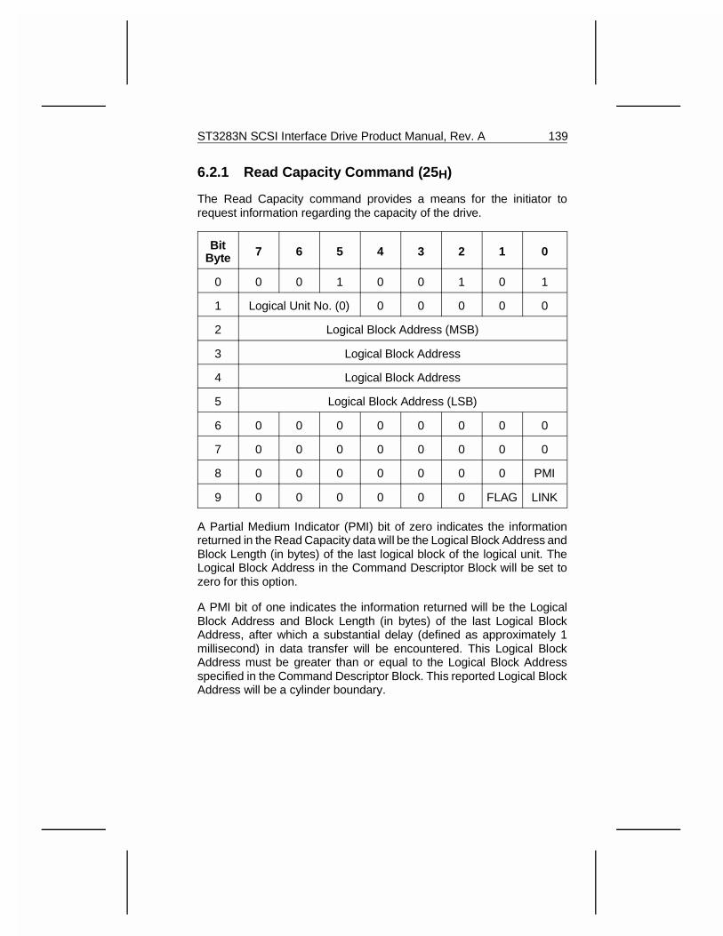
6.2.1 Read Capacity Command (25 H)
The Read Capacity command provides a means for the initiator torequest information regarding the capacity of the drive.
BitByte 7 6 5 4 3 2 1 0
0 0 0 1 0 0 1 0 1
1 Logical Unit No. (0) 0 0 0 0 0
2 Logical Block Address (MSB)
3 Logical Block Address
4 Logical Block Address
5 Logical Block Address (LSB)
6 0 0 0 0 0 0 0 0
7 0 0 0 0 0 0 0 0
8 0 0 0 0 0 0 0 PMI
9 0 0 0 0 0 0 FLAG LINK
A Partial Medium Indicator (PMI) bit of zero indicates the informationreturned in the Read Capacity data will be the Logical Block Address andBlock Length (in bytes) of the last logical block of the logical unit. TheLogical Block Address in the Command Descriptor Block will be set tozero for this option.
A PMI bit of one indicates the information returned will be the LogicalBlock Address and Block Length (in bytes) of the last Logical BlockAddress, after which a substantial delay (defined as approximately 1millisecond) in data transfer will be encountered. This Logical BlockAddress must be greater than or equal to the Logical Block Addressspecified in the Command Descriptor Block. This reported Logical BlockAddress will be a cylinder boundary.
ST3283N SCSI Interface Drive Product Manual, Rev. A 139
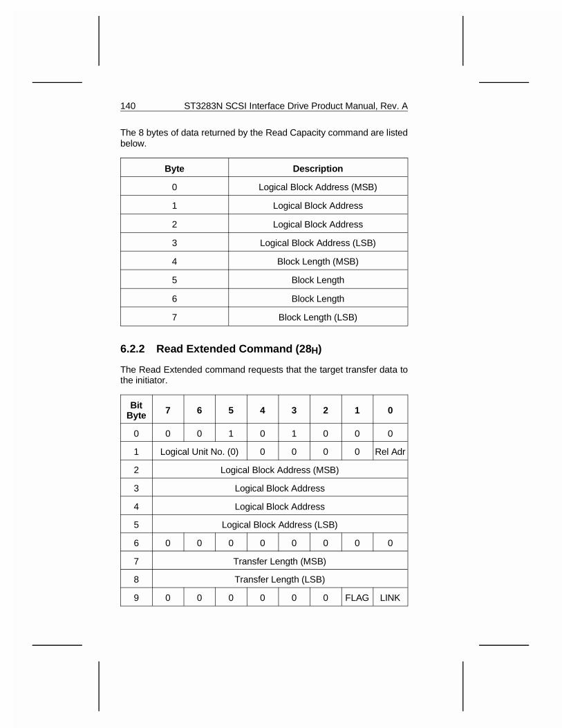
The 8 bytes of data returned by the Read Capacity command are listedbelow.
Byte Description
0 Logical Block Address (MSB)
1 Logical Block Address
2 Logical Block Address
3 Logical Block Address (LSB)
4 Block Length (MSB)
5 Block Length
6 Block Length
7 Block Length (LSB)
6.2.2 Read Extended Command (28 H)
The Read Extended command requests that the target transfer data tothe initiator.
BitByte 7 6 5 4 3 2 1 0
0 0 0 1 0 1 0 0 0
1 Logical Unit No. (0) 0 0 0 0 Rel Adr
2 Logical Block Address (MSB)
3 Logical Block Address
4 Logical Block Address
5 Logical Block Address (LSB)
6 0 0 0 0 0 0 0 0
7 Transfer Length (MSB)
8 Transfer Length (LSB)
9 0 0 0 0 0 0 FLAG LINK
140 ST3283N SCSI Interface Drive Product Manual, Rev. A
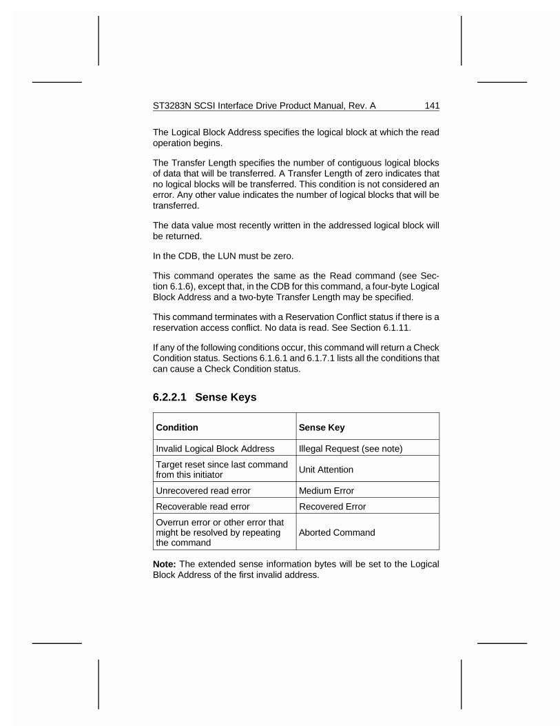
The Logical Block Address specifies the logical block at which the readoperation begins.
The Transfer Length specifies the number of contiguous logical blocksof data that will be transferred. A Transfer Length of zero indicates thatno logical blocks will be transferred. This condition is not considered anerror. Any other value indicates the number of logical blocks that will betransferred.
The data value most recently written in the addressed logical block willbe returned.
In the CDB, the LUN must be zero.
This command operates the same as the Read command (see Sec-tion 6.1.6), except that, in the CDB for this command, a four-byte LogicalBlock Address and a two-byte Transfer Length may be specified.
This command terminates with a Reservation Conflict status if there is areservation access conflict. No data is read. See Section 6.1.11.
If any of the following conditions occur, this command will return a CheckCondition status. Sections 6.1.6.1 and 6.1.7.1 lists all the conditions thatcan cause a Check Condition status.
6.2.2.1 Sense Keys
Condition Sense Key
Invalid Logical Block Address Illegal Request (see note)
Target reset since last commandfrom this initiator Unit Attention
Unrecovered read error Medium Error
Recoverable read error Recovered Error
Overrun error or other error thatmight be resolved by repeatingthe command
Aborted Command
Note: The extended sense information bytes will be set to the LogicalBlock Address of the first invalid address.
ST3283N SCSI Interface Drive Product Manual, Rev. A 141
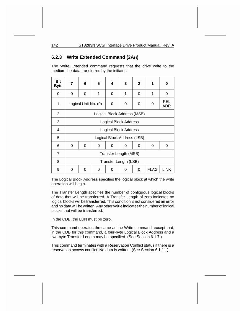
6.2.3 Write Extended Command (2A H)
The Write Extended command requests that the drive write to themedium the data transferred by the initiator.
BitByte 7 6 5 4 3 2 1 0
0 0 0 1 0 1 0 1 0
1 Logical Unit No. (0) 0 0 0 0 RELADR
2 Logical Block Address (MSB)
3 Logical Block Address
4 Logical Block Address
5 Logical Block Address (LSB)
6 0 0 0 0 0 0 0 0
7 Transfer Length (MSB)
8 Transfer Length (LSB)
9 0 0 0 0 0 0 FLAG LINK
The Logical Block Address specifies the logical block at which the writeoperation will begin.
The Transfer Length specifies the number of contiguous logical blocksof data that will be transferred. A Transfer Length of zero indicates nological blocks will be transferred. This condition is not considered an errorand no data will be written. Any other value indicates the number of logicalblocks that will be transferred.
In the CDB, the LUN must be zero.
This command operates the same as the Write command, except that,in the CDB for this command, a four-byte Logical Block Address and atwo-byte Transfer Length may be specified. (See Section 6.1.7.)
This command terminates with a Reservation Conflict status if there is areservation access conflict. No data is written. (See Section 6.1.11.)
142 ST3283N SCSI Interface Drive Product Manual, Rev. A
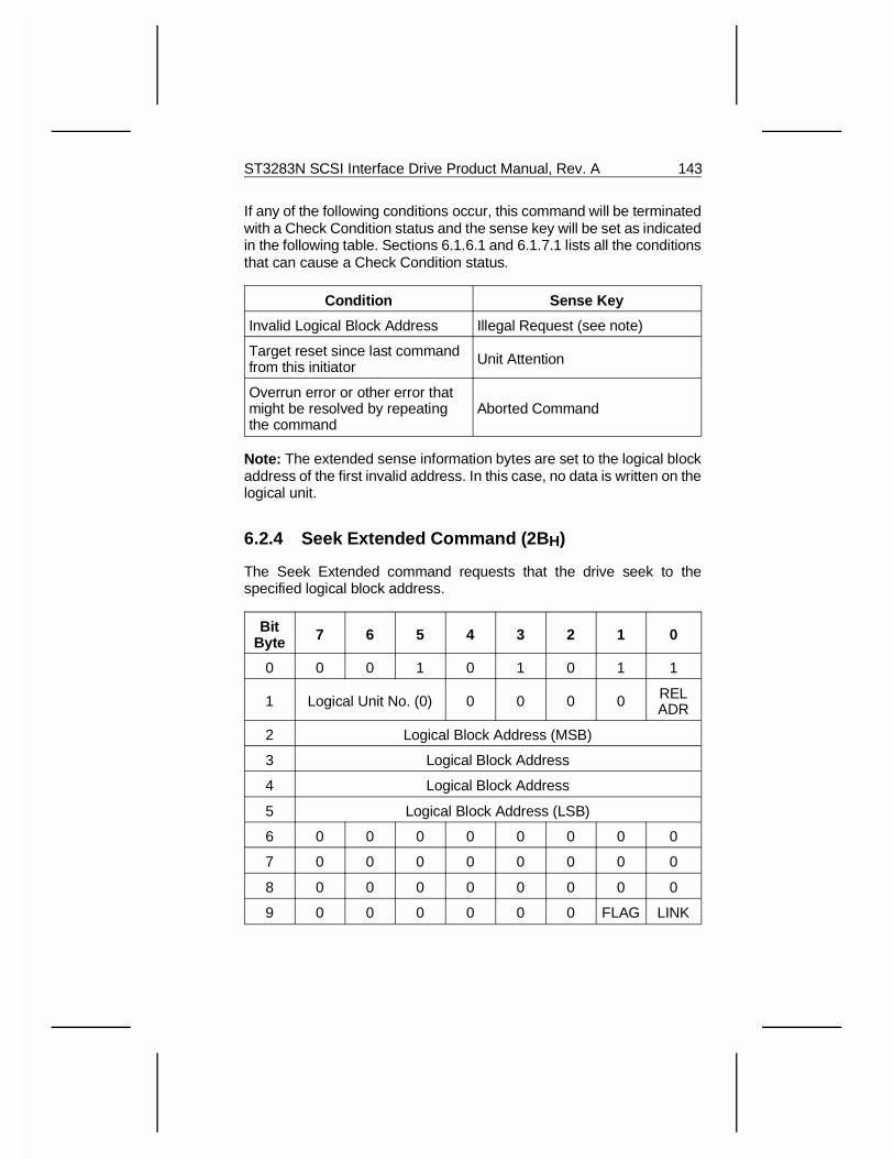
If any of the following conditions occur, this command will be terminatedwith a Check Condition status and the sense key will be set as indicatedin the following table. Sections 6.1.6.1 and 6.1.7.1 lists all the conditionsthat can cause a Check Condition status.
Condition Sense Key
Invalid Logical Block Address Illegal Request (see note)
Target reset since last commandfrom this initiator Unit Attention
Overrun error or other error thatmight be resolved by repeatingthe command
Aborted Command
Note: The extended sense information bytes are set to the logical blockaddress of the first invalid address. In this case, no data is written on thelogical unit.
6.2.4 Seek Extended Command (2B H)
The Seek Extended command requests that the drive seek to thespecified logical block address.
BitByte 7 6 5 4 3 2 1 0
0 0 0 1 0 1 0 1 1
1 Logical Unit No. (0) 0 0 0 0 RELADR
2 Logical Block Address (MSB)
3 Logical Block Address
4 Logical Block Address
5 Logical Block Address (LSB)
6 0 0 0 0 0 0 0 0
7 0 0 0 0 0 0 0 0
8 0 0 0 0 0 0 0 0
9 0 0 0 0 0 0 FLAG LINK
ST3283N SCSI Interface Drive Product Manual, Rev. A 143
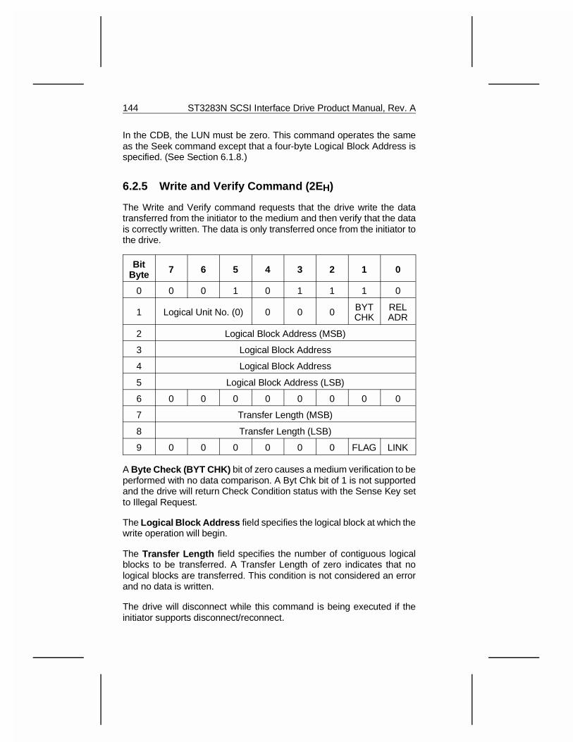
In the CDB, the LUN must be zero. This command operates the sameas the Seek command except that a four-byte Logical Block Address isspecified. (See Section 6.1.8.)
6.2.5 Write and Verify Command (2E H)
The Write and Verify command requests that the drive write the datatransferred from the initiator to the medium and then verify that the datais correctly written. The data is only transferred once from the initiator tothe drive.
BitByte 7 6 5 4 3 2 1 0
0 0 0 1 0 1 1 1 0
1 Logical Unit No. (0) 0 0 0 BYTCHK
RELADR
2 Logical Block Address (MSB)
3 Logical Block Address
4 Logical Block Address
5 Logical Block Address (LSB)
6 0 0 0 0 0 0 0 0
7 Transfer Length (MSB)
8 Transfer Length (LSB)
9 0 0 0 0 0 0 FLAG LINK
A Byte Check (BYT CHK) bit of zero causes a medium verification to beperformed with no data comparison. A Byt Chk bit of 1 is not supportedand the drive will return Check Condition status with the Sense Key setto Illegal Request.
The Logical Block Address field specifies the logical block at which thewrite operation will begin.
The Transfer Length field specifies the number of contiguous logicalblocks to be transferred. A Transfer Length of zero indicates that nological blocks are transferred. This condition is not considered an errorand no data is written.
The drive will disconnect while this command is being executed if theinitiator supports disconnect/reconnect.
144 ST3283N SCSI Interface Drive Product Manual, Rev. A
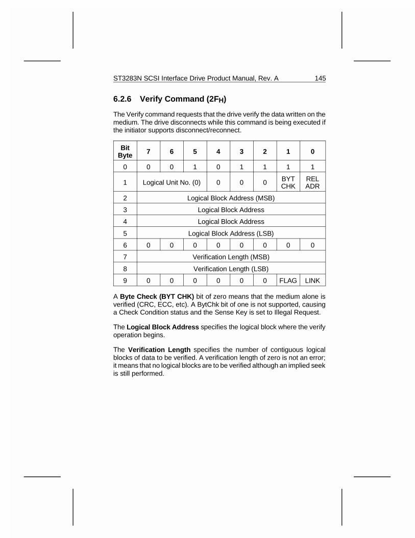
6.2.6 Verify Command (2F H)
The Verify command requests that the drive verify the data written on themedium. The drive disconnects while this command is being executed ifthe initiator supports disconnect/reconnect.
BitByte 7 6 5 4 3 2 1 0
0 0 0 1 0 1 1 1 1
1 Logical Unit No. (0) 0 0 0 BYTCHK
RELADR
2 Logical Block Address (MSB)
3 Logical Block Address
4 Logical Block Address
5 Logical Block Address (LSB)
6 0 0 0 0 0 0 0 0
7 Verification Length (MSB)
8 Verification Length (LSB)
9 0 0 0 0 0 0 FLAG LINK
A Byte Check (BYT CHK) bit of zero means that the medium alone isverified (CRC, ECC, etc). A BytChk bit of one is not supported, causinga Check Condition status and the Sense Key is set to Illegal Request.
The Logical Block Address specifies the logical block where the verifyoperation begins.
The Verification Length specifies the number of contiguous logicalblocks of data to be verified. A verification length of zero is not an error;it means that no logical blocks are to be verified although an implied seekis still performed.
ST3283N SCSI Interface Drive Product Manual, Rev. A 145
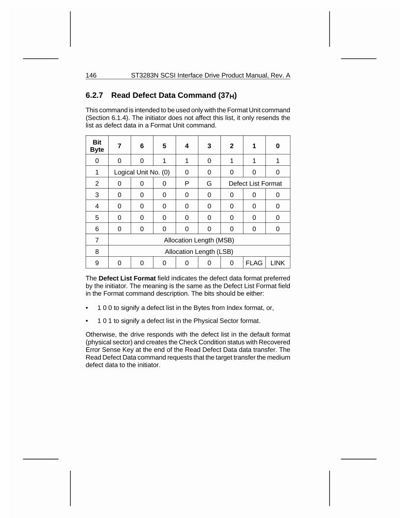
6.2.7 Read Defect Data Command (37 H)
This command is intended to be used only with the Format Unit command(Section 6.1.4). The initiator does not affect this list, it only resends thelist as defect data in a Format Unit command.
BitByte 7 6 5 4 3 2 1 0
0 0 0 1 1 0 1 1 1
1 Logical Unit No. (0) 0 0 0 0 0
2 0 0 0 P G Defect List Format
3 0 0 0 0 0 0 0 0
4 0 0 0 0 0 0 0 0
5 0 0 0 0 0 0 0 0
6 0 0 0 0 0 0 0 0
7 Allocation Length (MSB)
8 Allocation Length (LSB)
9 0 0 0 0 0 0 FLAG LINK
The Defect List Format field indicates the defect data format preferredby the initiator. The meaning is the same as the Defect List Format fieldin the Format command description. The bits should be either:
• 1 0 0 to signify a defect list in the Bytes from Index format, or,
• 1 0 1 to signify a defect list in the Physical Sector format.
Otherwise, the drive responds with the defect list in the default format(physical sector) and creates the Check Condition status with RecoveredError Sense Key at the end of the Read Defect Data data transfer. TheRead Defect Data command requests that the target transfer the mediumdefect data to the initiator.
146 ST3283N SCSI Interface Drive Product Manual, Rev. A
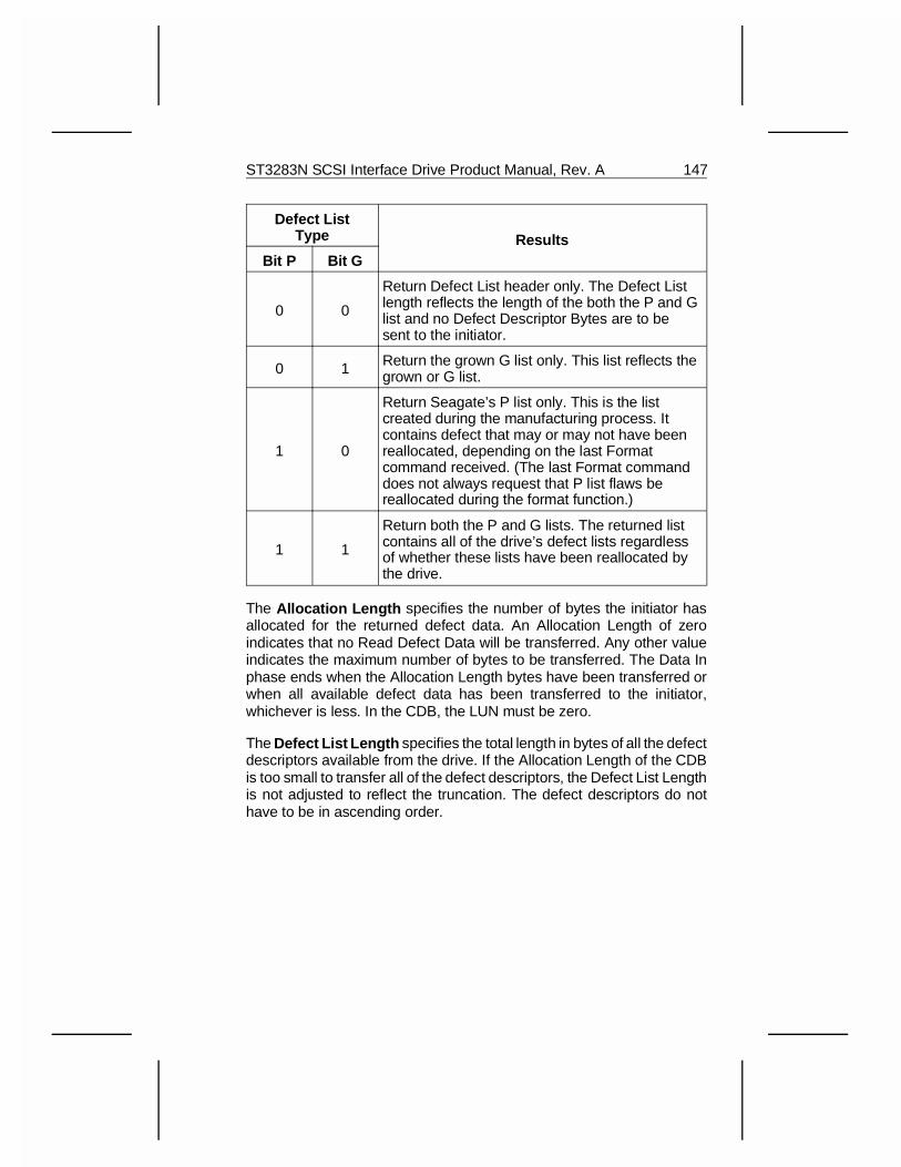
Defect ListType Results
Bit P Bit G
0 0
Return Defect List header only. The Defect Listlength reflects the length of the both the P and Glist and no Defect Descriptor Bytes are to besent to the initiator.
0 1 Return the grown G list only. This list reflects thegrown or G list.
1 0
Return Seagate’s P list only. This is the listcreated during the manufacturing process. Itcontains defect that may or may not have beenreallocated, depending on the last Formatcommand received. (The last Format commanddoes not always request that P list flaws bereallocated during the format function.)
1 1
Return both the P and G lists. The returned listcontains all of the drive’s defect lists regardlessof whether these lists have been reallocated bythe drive.
The Allocation Length specifies the number of bytes the initiator hasallocated for the returned defect data. An Allocation Length of zeroindicates that no Read Defect Data will be transferred. Any other valueindicates the maximum number of bytes to be transferred. The Data Inphase ends when the Allocation Length bytes have been transferred orwhen all available defect data has been transferred to the initiator,whichever is less. In the CDB, the LUN must be zero.
The Defect List Length specifies the total length in bytes of all the defectdescriptors available from the drive. If the Allocation Length of the CDBis too small to transfer all of the defect descriptors, the Defect List Lengthis not adjusted to reflect the truncation. The defect descriptors do nothave to be in ascending order.
ST3283N SCSI Interface Drive Product Manual, Rev. A 147
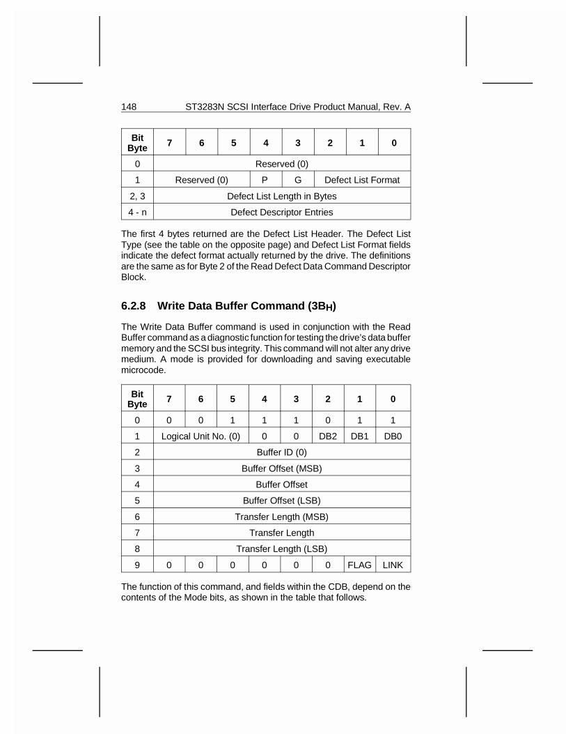
BitByte 7 6 5 4 3 2 1 0
0 Reserved (0)
1 Reserved (0) P G Defect List Format
2, 3 Defect List Length in Bytes
4 - n Defect Descriptor Entries
The first 4 bytes returned are the Defect List Header. The Defect ListType (see the table on the opposite page) and Defect List Format fieldsindicate the defect format actually returned by the drive. The definitionsare the same as for Byte 2 of the Read Defect Data Command DescriptorBlock.
6.2.8 Write Data Buffer Command (3B H)
The Write Data Buffer command is used in conjunction with the ReadBuffer command as a diagnostic function for testing the drive’s data buffermemory and the SCSI bus integrity. This command will not alter any drivemedium. A mode is provided for downloading and saving executablemicrocode.
BitByte 7 6 5 4 3 2 1 0
0 0 0 1 1 1 0 1 1
1 Logical Unit No. (0) 0 0 DB2 DB1 DB0
2 Buffer ID (0)
3 Buffer Offset (MSB)
4 Buffer Offset
5 Buffer Offset (LSB)
6 Transfer Length (MSB)
7 Transfer Length
8 Transfer Length (LSB)
9 0 0 0 0 0 0 FLAG LINK
The function of this command, and fields within the CDB, depend on thecontents of the Mode bits, as shown in the table that follows.
148 ST3283N SCSI Interface Drive Product Manual, Rev. A
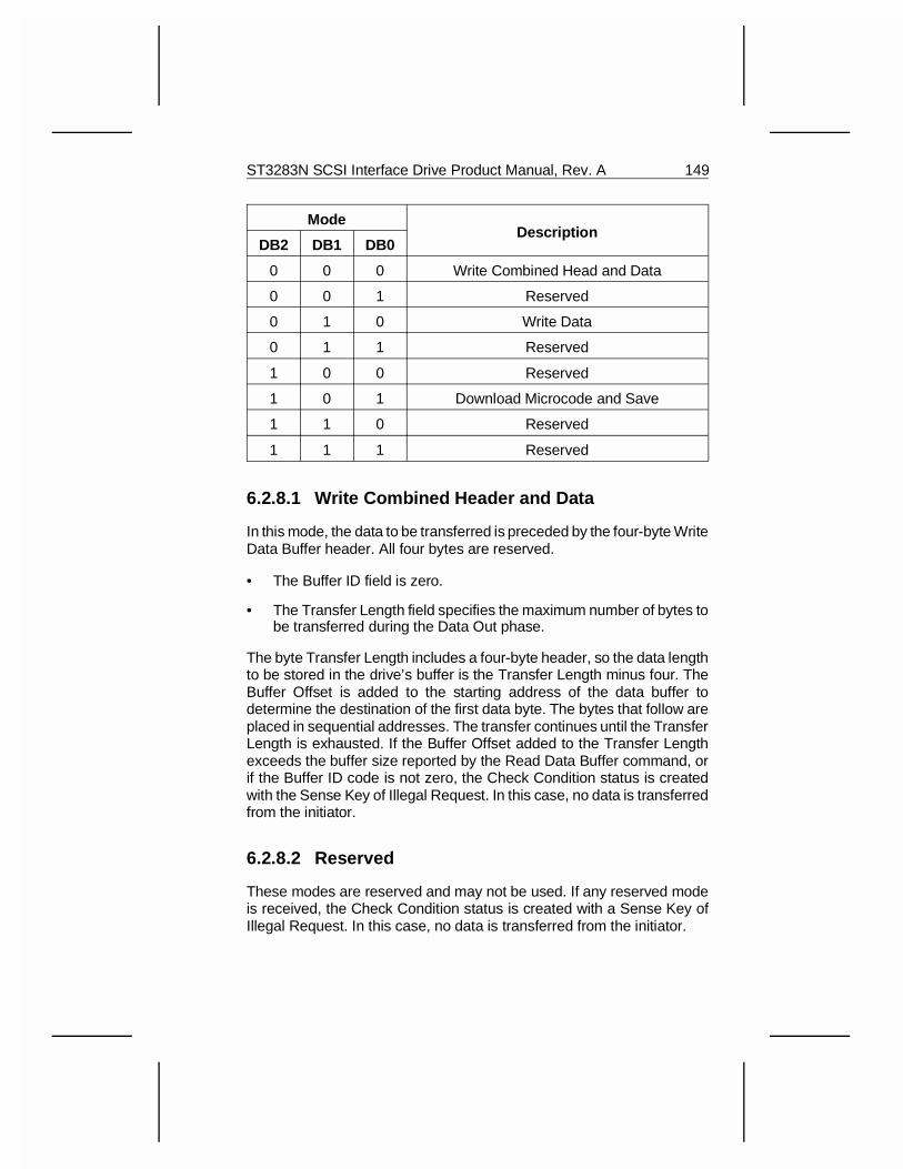
ModeDescription
DB2 DB1 DB0
0 0 0 Write Combined Head and Data
0 0 1 Reserved
0 1 0 Write Data
0 1 1 Reserved
1 0 0 Reserved
1 0 1 Download Microcode and Save
1 1 0 Reserved
1 1 1 Reserved
6.2.8.1 Write Combined Header and Data
In this mode, the data to be transferred is preceded by the four-byte WriteData Buffer header. All four bytes are reserved.
• The Buffer ID field is zero.
• The Transfer Length field specifies the maximum number of bytes tobe transferred during the Data Out phase.
The byte Transfer Length includes a four-byte header, so the data lengthto be stored in the drive’s buffer is the Transfer Length minus four. TheBuffer Offset is added to the starting address of the data buffer todetermine the destination of the first data byte. The bytes that follow areplaced in sequential addresses. The transfer continues until the TransferLength is exhausted. If the Buffer Offset added to the Transfer Lengthexceeds the buffer size reported by the Read Data Buffer command, orif the Buffer ID code is not zero, the Check Condition status is createdwith the Sense Key of Illegal Request. In this case, no data is transferredfrom the initiator.
6.2.8.2 Reserved
These modes are reserved and may not be used. If any reserved modeis received, the Check Condition status is created with a Sense Key ofIllegal Request. In this case, no data is transferred from the initiator.
ST3283N SCSI Interface Drive Product Manual, Rev. A 149
6.2.8.3 Data Mode
In the Data Mode, the Data Out phase contains only buffer data (noheader). The Buffer ID must be zero. The Buffer Offset is added to thestarting address of the data buffer to determine the destination of the firstdata byte. The bytes that follow are placed in sequential addresses.
The transfer continues until the Transfer Length is exhausted. If theBuffer Offset added to the Transfer Length exceeds the buffer sizereported by the Read Data Buffer command, or if the Buffer ID code isnot zero, the Check Condition status is created with a Sense Key of IllegalRequest. In this case, no data is transferred from the initiator.
Note: In the Write (Read) Combined Header and Data and the DataMode, the buffer is treated as a single segment regardless of the numberof segments specified in Mode Page 08H. (See Section 7.5.) The singlesegment only applies to the Read Data Buffer and Write Data Buffercommands. Subsequent reads or writes still have the same number ofsegments, as specified in Mode Page 08H. The Write Data Buffercommand causes all cached data to be invalidated and lost.
6.2.8.4 Download Microcode and Save Mode
This mode is used to download executable software to the controlmemory of the drive, and then save the downloaded software in thesystem configuration data stored on the medium. This new softwareversion is to be used by the drive for all future operations, including powercycles, and resets until it is supplanted by another Write Data Buffercommand which uses a Download Microcode and Save operation
The Link, Flag, and Buffer ID fields must be zero. The Buffer Offset isused as an offset into the control memory. When the data is transferredfrom the data buffer to the control memory, the first data byte is trans-ferred to the address that is the sum of the start of the control memoryplus the Buffer Offset. The Transfer Length indicates the number of bytesto be transferred during the Data Out phase. If the Buffer Offset addedto the Transfer Length exceeds the control memory size, or if the BufferID, Link, or Flag fields are not zero, a Check Condition status is createdwith a Sense Key of Illegal Request. In this case, no data is transferredfrom the initiator.
When the microcode has been successfully downloaded, the drivegenerates a Unit Attention condition for all initiators except the one thatissued the current Write Data Buffer command. The Unit Attentioncondition is set to “Microcode has been Downloaded.”
150 ST3283N SCSI Interface Drive Product Manual, Rev. A
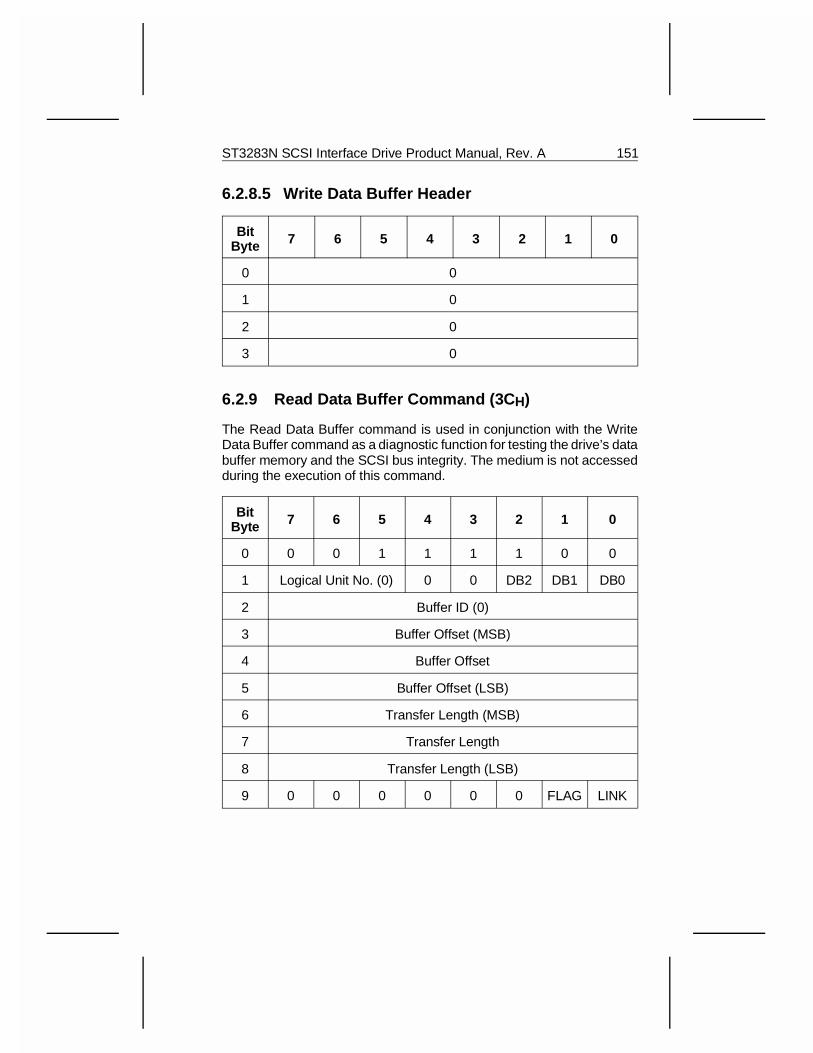
6.2.8.5 Write Data Buffer Header
BitByte 7 6 5 4 3 2 1 0
0 0
1 0
2 0
3 0
6.2.9 Read Data Buffer Command (3C H)
The Read Data Buffer command is used in conjunction with the WriteData Buffer command as a diagnostic function for testing the drive’s databuffer memory and the SCSI bus integrity. The medium is not accessedduring the execution of this command.
BitByte 7 6 5 4 3 2 1 0
0 0 0 1 1 1 1 0 0
1 Logical Unit No. (0) 0 0 DB2 DB1 DB0
2 Buffer ID (0)
3 Buffer Offset (MSB)
4 Buffer Offset
5 Buffer Offset (LSB)
6 Transfer Length (MSB)
7 Transfer Length
8 Transfer Length (LSB)
9 0 0 0 0 0 0 FLAG LINK
ST3283N SCSI Interface Drive Product Manual, Rev. A 151
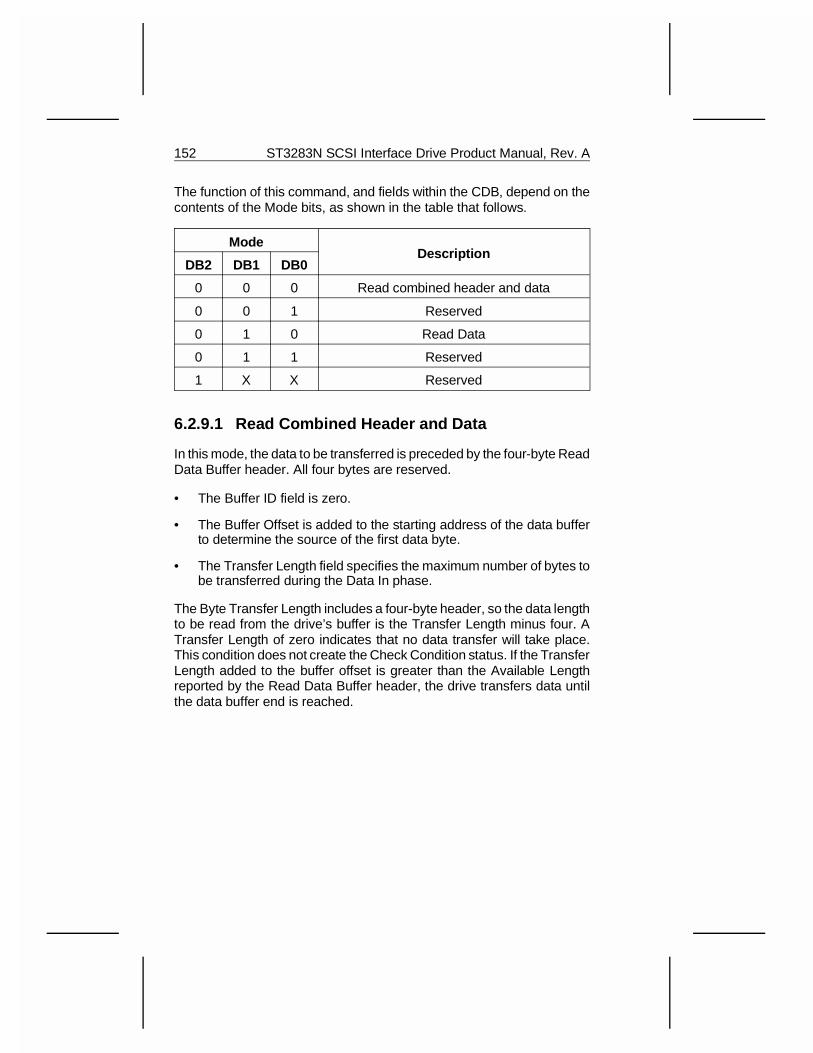
The function of this command, and fields within the CDB, depend on thecontents of the Mode bits, as shown in the table that follows.
ModeDescription
DB2 DB1 DB0
0 0 0 Read combined header and data
0 0 1 Reserved
0 1 0 Read Data
0 1 1 Reserved
1 X X Reserved
6.2.9.1 Read Combined Header and Data
In this mode, the data to be transferred is preceded by the four-byte ReadData Buffer header. All four bytes are reserved.
• The Buffer ID field is zero.
• The Buffer Offset is added to the starting address of the data bufferto determine the source of the first data byte.
• The Transfer Length field specifies the maximum number of bytes tobe transferred during the Data In phase.
The Byte Transfer Length includes a four-byte header, so the data lengthto be read from the drive’s buffer is the Transfer Length minus four. ATransfer Length of zero indicates that no data transfer will take place.This condition does not create the Check Condition status. If the TransferLength added to the buffer offset is greater than the Available Lengthreported by the Read Data Buffer header, the drive transfers data untilthe data buffer end is reached.
152 ST3283N SCSI Interface Drive Product Manual, Rev. A
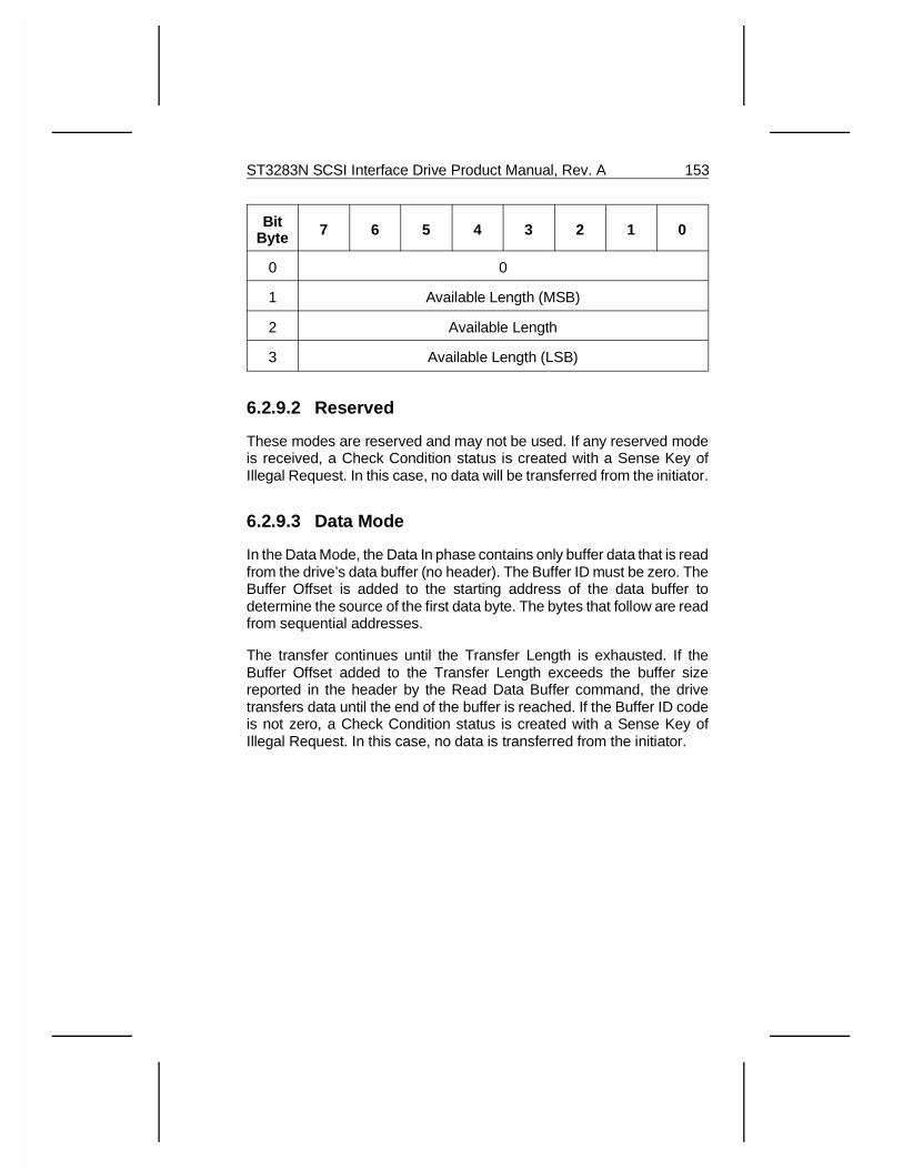
BitByte 7 6 5 4 3 2 1 0
0 0
1 Available Length (MSB)
2 Available Length
3 Available Length (LSB)
6.2.9.2 Reserved
These modes are reserved and may not be used. If any reserved modeis received, a Check Condition status is created with a Sense Key ofIllegal Request. In this case, no data will be transferred from the initiator.
6.2.9.3 Data Mode
In the Data Mode, the Data In phase contains only buffer data that is readfrom the drive’s data buffer (no header). The Buffer ID must be zero. TheBuffer Offset is added to the starting address of the data buffer todetermine the source of the first data byte. The bytes that follow are readfrom sequential addresses.
The transfer continues until the Transfer Length is exhausted. If theBuffer Offset added to the Transfer Length exceeds the buffer sizereported in the header by the Read Data Buffer command, the drivetransfers data until the end of the buffer is reached. If the Buffer ID codeis not zero, a Check Condition status is created with a Sense Key ofIllegal Request. In this case, no data is transferred from the initiator.
ST3283N SCSI Interface Drive Product Manual, Rev. A 153
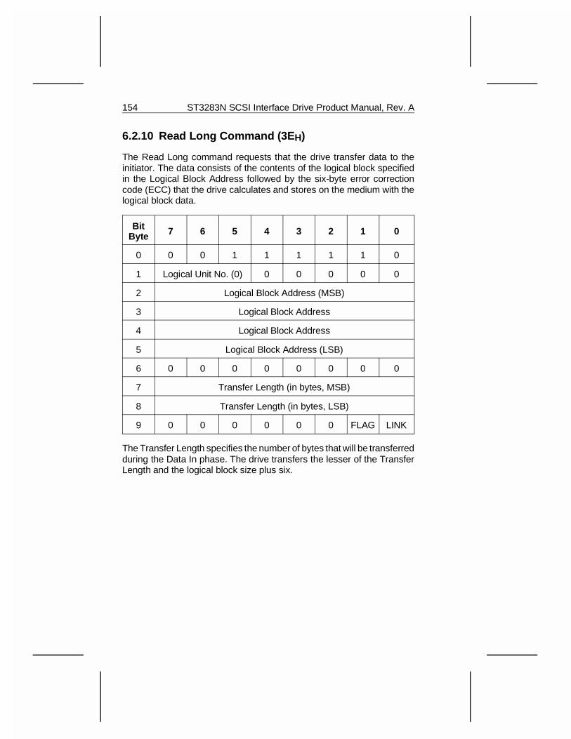
6.2.10 Read Long Command (3E H)
The Read Long command requests that the drive transfer data to theinitiator. The data consists of the contents of the logical block specifiedin the Logical Block Address followed by the six-byte error correctioncode (ECC) that the drive calculates and stores on the medium with thelogical block data.
BitByte 7 6 5 4 3 2 1 0
0 0 0 1 1 1 1 1 0
1 Logical Unit No. (0) 0 0 0 0 0
2 Logical Block Address (MSB)
3 Logical Block Address
4 Logical Block Address
5 Logical Block Address (LSB)
6 0 0 0 0 0 0 0 0
7 Transfer Length (in bytes, MSB)
8 Transfer Length (in bytes, LSB)
9 0 0 0 0 0 0 FLAG LINK
The Transfer Length specifies the number of bytes that will be transferredduring the Data In phase. The drive transfers the lesser of the TransferLength and the logical block size plus six.
154 ST3283N SCSI Interface Drive Product Manual, Rev. A
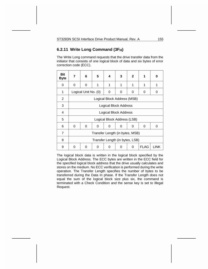
6.2.11 Write Long Command (3F H)
The Write Long command requests that the drive transfer data from theinitiator that consists of one logical block of data and six bytes of errorcorrection code (ECC).
BitByte 7 6 5 4 3 2 1 0
0 0 0 1 1 1 1 1 1
1 Logical Unit No. (0) 0 0 0 0 0
2 Logical Block Address (MSB)
3 Logical Block Address
4 Logical Block Address
5 Logical Block Address (LSB)
6 0 0 0 0 0 0 0 0
7 Transfer Length (in bytes, MSB)
8 Transfer Length (in bytes, LSB)
9 0 0 0 0 0 0 FLAG LINK
The logical block data is written in the logical block specified by theLogical Block Address. The ECC bytes are written in the ECC field forthe specified logical block address that the drive usually calculates andstores on the medium. No ECC verification is performed during the writeoperation. The Transfer Length specifies the number of bytes to betransferred during the Data In phase. If the Transfer Length does notequal the sum of the logical block size plus six, the command isterminated with a Check Condition and the sense key is set to IllegalRequest.
ST3283N SCSI Interface Drive Product Manual, Rev. A 155
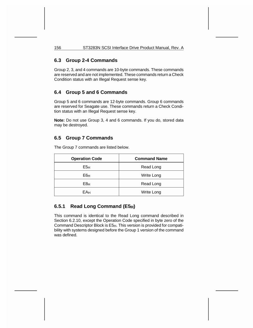
6.3 Group 2-4 Commands
Group 2, 3, and 4 commands are 10-byte commands. These commandsare reserved and are not implemented. These commands return a CheckCondition status with an Illegal Request sense key.
6.4 Group 5 and 6 Commands
Group 5 and 6 commands are 12-byte commands. Group 6 commandsare reserved for Seagate use. These commands return a Check Condi-tion status with an Illegal Request sense key.
Note: Do not use Group 3, 4 and 6 commands. If you do, stored datamay be destroyed.
6.5 Group 7 Commands
The Group 7 commands are listed below.
Operation Code Command Name
E5H Read Long
E6H Write Long
E8H Read Long
EAH Write Long
6.5.1 Read Long Command (E5 H)
This command is identical to the Read Long command described inSection 6.2.10, except the Operation Code specified in byte zero of theCommand Descriptor Block is E5H. This version is provided for compati-bility with systems designed before the Group 1 version of the commandwas defined.
156 ST3283N SCSI Interface Drive Product Manual, Rev. A
6.5.2 Write Long Command (E6 H)
This command is identical to the Write Long command described inSection 6.2.11, except the Operation Code specified in byte zero of theCommand Descriptor Block is E6H. This version is provided for compati-bility with systems designed before the Group 1 version of the commandwas defined.
6.5.3 Read Long Command (E8 H)
This command is identical to the Read Long command described inSection 6.2.10, except the Operation Code specified in byte zero of theCommand Descriptor Block is E8H. This version is provided for compati-bility with systems designed before the Group 1 version of the commandwas defined.
6.5.4 Write Long Command (EA H)
This command is identical to the Write Long command described inSection 6.2.11, except the Operation Code specified in byte zero of theCommand Descriptor Block is EAH. This version is provided for compati-bility with systems designed before the Group 1 version of the commandwas defined.
ST3283N SCSI Interface Drive Product Manual, Rev. A 157

158 ST3283N SCSI Interface Drive Product Manual, Rev. A
7.0 Mode PagesThe pages used by the Mode Sense and Mode Select commands aredescribed in this section.
For all pages, when the changeable value is zero, this bit function is notdirectly changeable by an initiator. A changeable value of one indicatesthe bit function is directly changeable by an initiator.
For all pages, the Page Savable (PS) bit is used in Mode Sensecommands. PS is set to one to show the page is savable on the medium.This location is reserved in Mode Select commands and must be zero.All reserved fields are not changeable.
ST3283N SCSI Interface Drive Product Manual, Rev. A 159
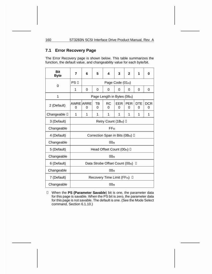
7.1 Error Recovery Page
The Error Recovery page is shown below. This table summarizes thefunction, the default value, and changeability value for each byte/bit.
BitByte 7 6 5 4 3 2 1 0
0PS ➀ Page Code (01H)
1 0 0 0 0 0 0 0
1 Page Length in Bytes (06H)
2 (Default) AWRE0
ARRE0
TB0
RC0
EER0
PER0
DTE0
DCR0
Changeable ➁ 1 1 1 1 1 1 1 1
3 (Default) Retry Count (1BH) ➂
Changeable FFH
4 (Default) Correction Span in Bits (0BH) ➃
Changeable 00H
5 (Default) Head Offset Count (00H) ➄
Changeable 00H
6 (Default) Data Strobe Offset Count (00H) ➅
Changeable 00H
7 (Default) Recovery Time Limit (FFH) ➆
Changeable 00H
➀ When the PS (Parameter Savable ) bit is one, the parameter datafor this page is savable. When the PS bit is zero, the parameter datafor this page is not savable. The default is one. (See the Mode Selectcommand, Section 6.1.10.)
160 ST3283N SCSI Interface Drive Product Manual, Rev. A
➁ When the Automatic Write Reallocation Enabled (AWRE) bit isone, the drive automatically reallocates bad blocks detected duringwrite operations. When the AWRE bit is zero, automatic reallocationis not be performed but Check Condition status will be created withSense Key of Medium Error instead. This function does not apply tothe Format Unit command.
When the Automatic Read Reallocation Enabled (ARRE) bit isone, the drive automatically reallocates bad blocks detected duringread operations. When the ARRE bit is zero, the drive does notautomatically reallocate bad blocks. Instead, a Check Conditionstatus is created with a Medium Error sense key.
When the Transfer Block (TB) bit is one, the failing data block istransferred to the initiator. When the TB bit is zero, the failing datablock is not transferred.
When the Read Continuous (RC) bit is one, the drive will send alldata without doing any corrections. This function supersedes otherbits in this byte. When the RC bit is zero, the correction is performedaccording to the other bits in this byte.
An Enable Early Recovery (EER) bit of one indicates that the targetuses the most expedient form of error recovery first. This bit onlyapplies to data error recovery and it does not affect positioning retriesand the message system error recovery procedures. An EER bit ofzero indicates that the target uses an error recovery procedure thatminimizes the risk of mis-detection or mis-correction.
When the Post Error (PER) bit is one, the drive reports the CheckCondition status and the appropriate sense key for any recoverederrors encountered. When the PER bit is zero, any errors recoveredwithin the limits established by the other error recovery flags are notreported. Any unrecoverable errors are reported.
The Disable Transfer on Error (DTE) bit is valid only when the PERbit is set to one. When the DTE bit is one, the drive terminates datatransfer even for recoverable errors. When the DTE bit is zero, thedrive continues transferring data if recoverable errors are encoun-tered; recoverable errors are reported, if the PER bit is one, after allthe data has been transferred. The TB bit determines whether theblock in error is to be transferred.
The Disable Correction (DCR) bit, when set to one, indicates ECCcorrection is not applied to the data even if correction is possible.
ST3283N SCSI Interface Drive Product Manual, Rev. A 161
➂ The Retry Count is the maximum number of times the drive attemptsits read recovery algorithms. The Retry Count is changeable be-tween 0 and 27, inclusive. A Retry Count of zero means that noretries are performed. If the EER bit is set, the number of retriesspecified by the Retry Count, up to a maximum of nine retries, isperformed before ECC is applied.
➃ The Correction Span is the size of the largest read data error, inbits, on which ECC correction is to be attempted. Longer errors arereported as unrecoverable.
➄ The Head Offset Count is zero, by default, and not changeable. Thisfeature is not programmable by the initiator. Head offsets are per-formed as part of the drive’s retry algorithms.
➅ The Data Strobe Offset Count is a default of zero and not change-able to signify that this feature is not programmable by the initiator.
➆ The Recovery Time Limit always has an FFH value, which meansthat the recovery time is unlimited.
162 ST3283N SCSI Interface Drive Product Manual, Rev. A
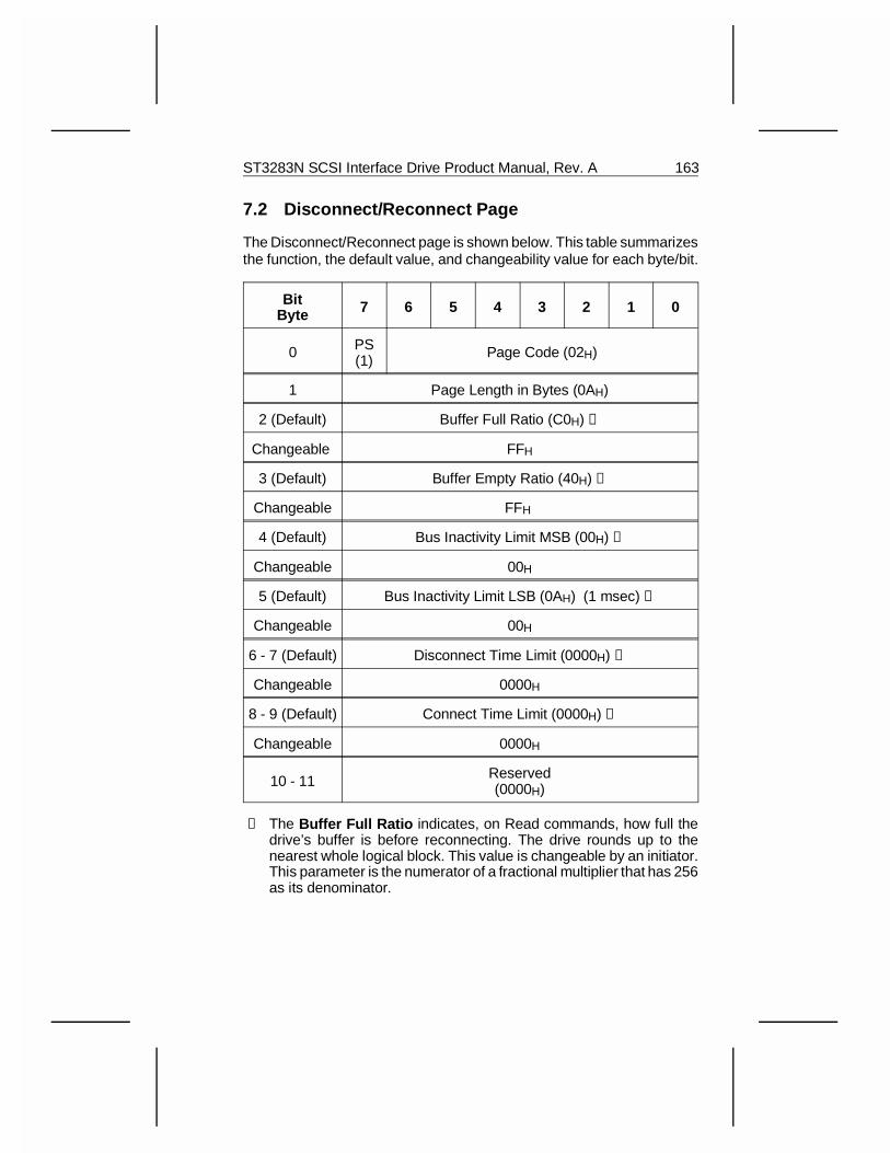
7.2 Disconnect/Reconnect Page
The Disconnect/Reconnect page is shown below. This table summarizesthe function, the default value, and changeability value for each byte/bit.
BitByte 7 6 5 4 3 2 1 0
0 PS(1) Page Code (02H)
1 Page Length in Bytes (0AH)
2 (Default) Buffer Full Ratio (C0H) ➀
Changeable FFH
3 (Default) Buffer Empty Ratio (40H) ➁
Changeable FFH
4 (Default) Bus Inactivity Limit MSB (00H) ➂
Changeable 00H
5 (Default) Bus Inactivity Limit LSB (0AH) (1 msec) ➂
Changeable 00H
6 - 7 (Default) Disconnect Time Limit (0000H) ➃
Changeable 0000H
8 - 9 (Default) Connect Time Limit (0000H) ➄
Changeable 0000H
10 - 11 Reserved(0000H)
➀ The Buffer Full Ratio indicates, on Read commands, how full thedrive’s buffer is before reconnecting. The drive rounds up to thenearest whole logical block. This value is changeable by an initiator.This parameter is the numerator of a fractional multiplier that has 256as its denominator.
ST3283N SCSI Interface Drive Product Manual, Rev. A 163
➁ The Buffer Empty Ratio indicates, on Write commands, how emptythe drive’s buffer is before reconnecting to fetch more data. The driverounds up to the nearest whole logical block. This value is change-able by an initiator. This parameter is the numerator of a fractionalmultiplier that has 256 as its denominator.
➂ The Bus Inactivity Limit field (Bytes 4 and 5) indicates the time, in100-µsec increments, that the drive can assert the Busy signalwithout handshakes until it disconnects. The drive may round downto its nearest capable value. The default value of OAH allows thedrive to maintain the Busy signal for 1 msec without handshakes.This value is not changeable by the initiator.
➃ The Disconnect Time Limit field (Bytes 6 and 7) indicates theminimum time, in 100-µsec increments, the drive will remain discon-nected until it attempts to reconnect. A value of zero indicates thedrive is allowed to reconnect immediately. This is always zero andthe changeable code is always zero.
➄ The Connect Time Limit field (Bytes 8 and 9) indicates the maxi-mum time, in 100 µsec increments, that the target should remainconnected until it attempts to disconnect. The target may round toits nearest capable value. A value of zero means that the drive canremain connected indefinitely until it tries to disconnect.
7.3 Format Device Page
The Format Device page is shown below. This table summarizes thefunction, the default value, and changeability value for each byte/bit.Thispage can only be sent immediately before sending a Format Unit com-mand to the drive.
The current parameters for this page are updated immediately, but anychanges between these current parameters and the existing mediaformat are not in effect until after the Format Unit command is completed.
164 ST3283N SCSI Interface Drive Product Manual, Rev. A
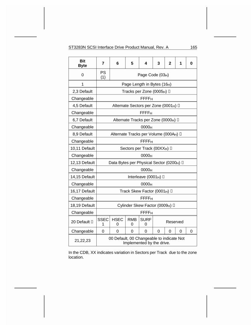
BitByte 7 6 5 4 3 2 1 0
0 PS(1) Page Code (03H)
1 Page Length in Bytes (16H)
2,3 Default Tracks per Zone (0005H) ➀
Changeable FFFFH
4,5 Default Alternate Sectors per Zone (0001H) ➁
Changeable FFFFH
6,7 Default Alternate Tracks per Zone (0000H) ➂
Changeable 0000H
8,9 Default Alternate Tracks per Volume (000AH) ➃
Changeable FFFFH
10,11 Default Sectors per Track (00XXH) ➄
Changeable 0000H
12,13 Default Data Bytes per Physical Sector (0200H) ➅
Changeable 0000H
14,15 Default Interleave (0001H) ➆
Changeable 0000H
16,17 Default Track Skew Factor (0001H) ➇
Changeable FFFFH
18,19 Default Cylinder Skew Factor (0009H) ➈
Changeable FFFFH
20 Default ➉ SSEC1
HSEC0
RMB0
SURF0 Reserved
Changeable 0 0 0 0 0 0 0 0
21,22,23 00 Default, 00 Changeable to indicate NotImplemented by the drive.
In the CDB, XX indicates variation in Sectors per Track due to the zonelocation.
ST3283N SCSI Interface Drive Product Manual, Rev. A 165
This page of parameters may be sent only immediately before sending aFormat Unit command to the drive. The Current parameters for this pagewill be updated immediately, but any changes between these currentparameters and the existing media format will not be in effect until afterthe Format Unit command is completed.
➀ The Tracks per Zone field indicates the number of tracks the drive willallocate to each defect management zone. Spare sectors or tracks willbe placed at the end of each defect management zone. Valid values forTracks per Zone are 1 (Zone = Track), or number of heads in the drive,5 (Zone = Cylinder).
➁ The Alternate Sectors per Zone field indicates the number of sparesectors to be reserved at the end of each defect management zone.The drive defaults to one spare sector per zone (Zone = Track).Allowable values for Alternate Sectors per Zone if Zone = Track is 1.If Zone = Cylinder, spare sectors may be changed by the initiator toany value between 1 and 3.
➂ The Alternate Tracks per Zon e field indicates the number of sparetracks to be reserved at the end of each defect management zone.A value of zero indicates that no spare tracks are to be reserved ineach zone for defect management by the drive. This field is notchangeable.
➃ The Alternate Tracks per Volume field indicates the number ofspare tracks to be reserved at the end of the logical unit. The drivewill use these locations for replacing sectors. A value of zero indi-cates that no spare tracks are to be reserved at the end of the unitfor defect management. The drive defaults to two times the numberof read/write heads in the drive. The initiator may change this valueto any number between 0 and 256. This number must be a multipleof 5, which is the number of read/write heads.
➄ The Sectors per Track field indicates the number of physical sectorsthe drive will allocate per track. A value of zero indicates that thenumber of sectors per track may be variable, or that the drive is todetermine the best value. The drive will report the average numberof physical sectors per track since the number of sectors per trackvaries between the outer and inner tracks. This field will not beverified on a Mode Select command.
166 ST3283N SCSI Interface Drive Product Manual, Rev. A
➅ The Bytes per Physical Sector field indicates the number of databytes allocated per physical sector. This value will equal the blocklength reported in the block descriptor. The bytes per physical sectoris not directly changeable by the initiator and will not be verified ona Mode Select command. The block size is changed by setting thebits in the block descriptor.
➆ The Interleave field is the interleave value sent to the drive duringthe last Format Unit command. This field is valid only for Mode Sensecommands. The drive ignores this field during Mode Select com-mands. The interleave is always 1:1.
➇ The Track Skew Factor field indicates the number of physicalsectors on the media between the last logical block of one track andthe first logical block of the next sequential track of the same cylinder.A value of zero indicates no skew. The default value is 01H for512-byte sectors, with Tracks per Zone and Alternate Sectors perZone set to one. This value is not changeable by the initiator.
➈ The Cylinder Skew Factor field indicates the number of physicalsectors between the last logical block of one cylinder and the firstlogical block of the next cylinder. A value of zero indicates no skew.The default value is not changeable by the initiator.
➉ The Drive Type field bits are defined as follows:
The Soft Sectoring (SSEC) bit is set to one. Although this bit isreported as non-changeable, it can be set according to the systemsrequirements and have no affect upon drive performance.
The Hard Sectoring (HSEC) bit is set to Zero. Although this bit isreported as non-changeable, it can be set according to the systemsrequirements and have no affect upon drive performance.
The Removable Media (RMB) bit is always set to zero, indicatingthat the drive does not support removable media. This same bit isalso returned in the Inquiry parameters.
The Surface Map (SURF) bit is set to zero, indicating that the driveallocates successive logical blocks to all sectors within a cylinderbefore allocating logical blocks to the next cylinder.
ST3283N SCSI Interface Drive Product Manual, Rev. A 167
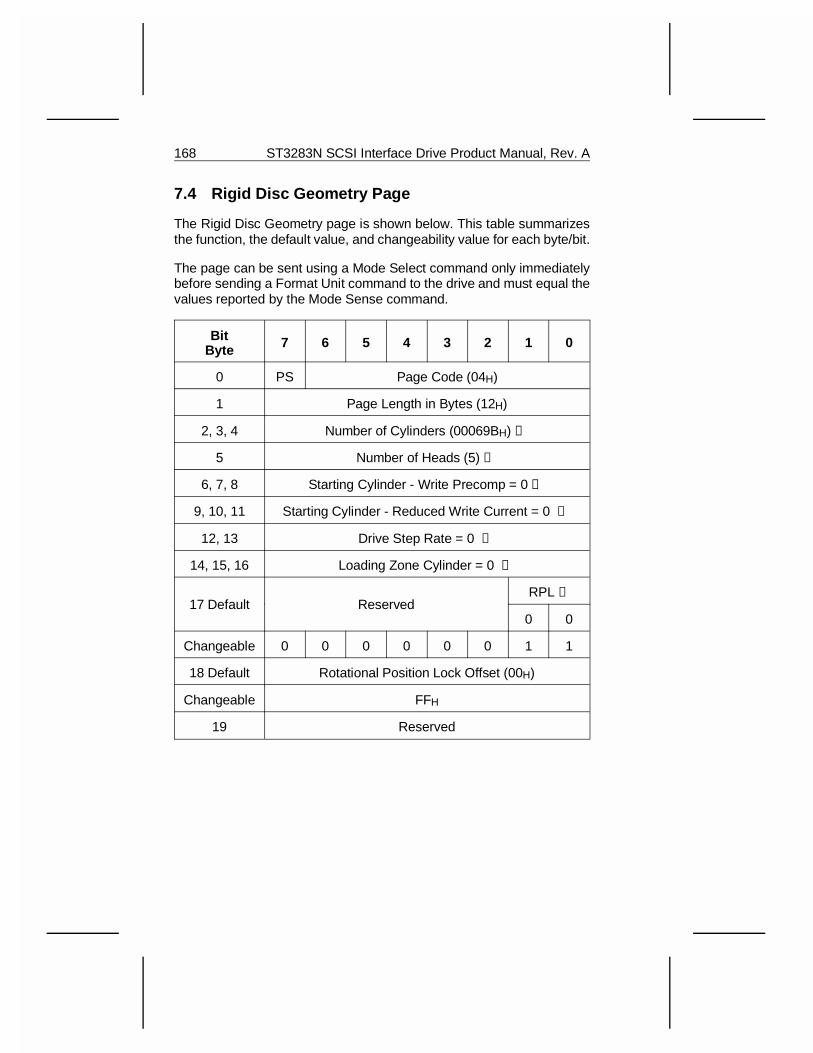
7.4 Rigid Disc Geometry Page
The Rigid Disc Geometry page is shown below. This table summarizesthe function, the default value, and changeability value for each byte/bit.
The page can be sent using a Mode Select command only immediatelybefore sending a Format Unit command to the drive and must equal thevalues reported by the Mode Sense command.
BitByte 7 6 5 4 3 2 1 0
0 PS Page Code (04H)
1 Page Length in Bytes (12H)
2, 3, 4 Number of Cylinders (00069BH) ➀
5 Number of Heads (5) ➁
6, 7, 8 Starting Cylinder - Write Precomp = 0 ➂
9, 10, 11 Starting Cylinder - Reduced Write Current = 0 ➂
12, 13 Drive Step Rate = 0 ➂
14, 15, 16 Loading Zone Cylinder = 0 ➂
17 Default ReservedRPL ➃
0 0
Changeable 0 0 0 0 0 0 1 1
18 Default Rotational Position Lock Offset (00H)
Changeable FFH
19 Reserved
168 ST3283N SCSI Interface Drive Product Manual, Rev. A
➀ The Number of Cylinders field specifies the number of user-acces-sible cylinders, with two spare cylinders or set aside for defects. Themaximum number of usable cylinders is 1689. The drive uses theadditional cylinders for storing parameters and defect lists, or fordiagnostic purposes.
➁ The Number of Heads field specifies the number of read/write headson the drive. The Number of Heads is always 5.
➂ The Starting Cylinder , Drive Step Rate , and Loading Zone Cyl-inder bytes are not used by the drive.
➃ When the Rotational Position Locking (RPL) bits are 00BINARY,rotational position locking is changeable. The external reference isnot checked and no reference signal is transmitted. This is the defaultvalue. All drives arbitrate at power-up to see which will be the master.Once the master is determined, all other drives will synchronize theirspindles to the master. When a drive has just powered-up and iscalibrating the heads, it checks the Reference signal line for areference pulse. If no pulse is detected, the drive takes over as themaster and begins sending the reference pulse.
When the RPL bits are 01BINARY, the drive operates as a synchro-nized-spindle slave.
When the RPL bits are 10BINARY or 11BINARY, the drive operates asa synchronized-spindle master.
ST3283N SCSI Interface Drive Product Manual, Rev. A 169
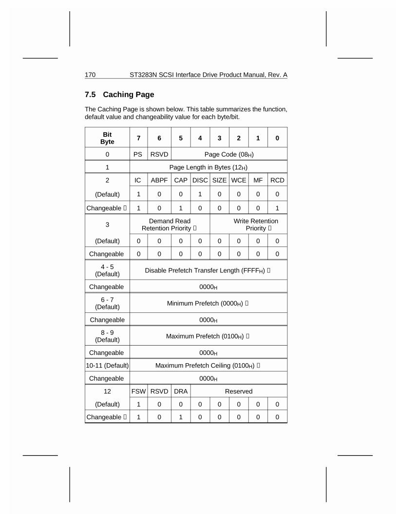
7.5 Caching Page
The Caching Page is shown below. This table summarizes the function,default value and changeability value for each byte/bit.
BitByte 7 6 5 4 3 2 1 0
0 PS RSVD Page Code (08H)
1 Page Length in Bytes (12H)
2
(Default)
IC ABPF CAP DISC SIZE WCE MF RCD
1 0 0 1 0 0 0 0
Changeable ➀ 1 0 1 0 0 0 0 1
3 Demand ReadRetention Priority ➁
Write RetenPriority
tion➂
(Default) 0 0 0 0 0 0 0 0
Changeable 0 0 0 0 0 0 0 0
4 - 5(Default) Disable Prefetch Transfer Length (FFFFH) ➃
Changeable 0000H
6 - 7(Default) Minimum Prefetch (0000H) ➄
Changeable 0000H
8 - 9(Default) Maximum Prefetch (0100H) ➅
Changeable 0000H
10-11 (Default) Maximum Prefetch Ceiling (0100H) ➆
Changeable 0000H
12 FSW RSVD DRA Reserved
(Default) 1 0 0 0 0 0 0 0
Changeable ➇ 1 0 1 0 0 0 0 0
170 ST3283N SCSI Interface Drive Product Manual, Rev. A
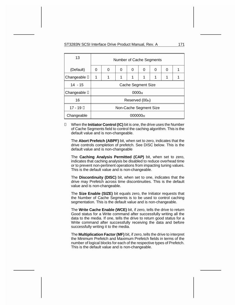
13 Number of Cache Segments
(Default) 0 0 0 0 0 0 0 1
Changeable ➈ 1 1 1 1 1 1 1 1
14 - 15 Cache Segment Size
Changeable ➉ 0000H
16 Reserved (00H)
17 - 19 ➊ Non-Cache Segment Size
Changeable 000000H
➀ When the Initiator Control (IC) bit is one, the drive uses the Numberof Cache Segments field to control the caching algorithm. This is thedefault value and is non-changeable.
The Abort Prefetch (ABPF) bit, when set to zero, indicates that thedrive controls completion of prefetch. See DISC below. This is thedefault value and is non-changeable
The Caching Analysis Permitted (CAP) bit, when set to zero,indicates that caching analysis be disabled to reduce overhead timeor to prevent non-pertinent operations from impacting tuning values.This is the default value and is non-changeable.
The Discontinuity (DISC) bit, when set to one, indicates that thedrive may Prefetch across time discontinuities. This is the defaultvalue and is non-changeable.
The Size Enable (SIZE) bit equals zero, the Initiator requests thatthe Number of Cache Segments is to be used to control cachingsegmentation. This is the default value and is non-changeable.
The Write Cache Enable (WCE) bit, if zero, tells the drive to returnGood status for a Write command after successfully writing all thedata to the media. If one, tells the drive to return good status for aWrite command after successfully receiving the data and beforesuccessfully writing it to the media.
The Multiplication Factor (MF) bit, if zero, tells the drive to interpretthe Minimum Prefetch and Maximum Prefetch fields in terms of thenumber of logical blocks for each of the respective types of Prefetch.This is the default value and is non-changeable.
ST3283N SCSI Interface Drive Product Manual, Rev. A 171

The Read Cache Disable (RCD) bit of zero specifies that the drivemay return data requested by a Read command by accessing eitherthe cache or the media. If RCD is one, the cache will not be used.
➁ The Demand Read Retention Priority field is not used. No specialretention priority may be assigned by the initiator.
➂ The Write Retention Priority field is not used. No special retentionpriority may be assigned by the initiator.
➃ The Disable Prefetch Transfer Length fields selectively disablesanticipatory Prefetch on long transfer lengths. A value of FFH indi-cates that the drive is advised that it should attempt an anticipatoryprefetch for all Read commands. This is the default value and isnon-changeable.
➄ The Minimum Pre-fetch field is an advisory parameter. It is inter-preted as specifying a number of blocks. The number of blocks is thenumber the host tells the drive to prefetch regardless of the delaysit might cause in executing subsequent commands. By setting thisfield to zero, the host is advising the drive that prefetching should beterminated whenever another command is ready to be executed. Thehost can advise the drive to ignore this consideration by setting theMinimum Prefetch equal to Maximum Prefetch.
➅ The Maximum Pre-fetch field specifies a number of blocks. Thenumber of blocks is the number that the host advises the drive toprefetch if there are no delays in executing subsequent commands.This field tells the drive the maximum amount of data to prefetch intothe cache for any single Read command.
➆ The Maximum Pre-fetch Ceiling field is a control parameter andshould be equal to the Maximum Pre-fetch. The Maximum Pre-fetchCeiling and Maximum Pre-fetch fields are indistinguishable if the MFbit is zero.
➇ The Force Sequential Write (FSW) bit, when set to one, indicatesthat multiple block writes are to be transferred over the SCSI bus andwritten to the media in an ascending, sequential, logical block order.This is the default value and is non-changeable.
172 ST3283N SCSI Interface Drive Product Manual, Rev. A
The Disable Read-Ahead (DRA) bit, when set to one, requests thatthe target not read into the buffer any logical blocks beyond theaddressed logical blocks. When the DRA bit equals zero, the targetmay continue to read logical blocks into the buffer beyond theaddressed logical blocks. This is the default value.
Note : By definition, if RCD is one, no read ahead is performedregardless of the value of the DRA.
➈ The Number of Cache Segments advises the target how manysegments the host requests that the cache be divided into. Validvalues are 1, 2, 4, 8, 16 and 32.
➉ The Cache Segment Size field indicates the segment size in bytes.This standard assumes that the Cache Segment Size field is validonly when the SIZE bit is one. This field is ignored on Mode Selectcommands.
➊ The Non-Cache Segment Size is zero to indicate that the entirebuffer is available for caching.
ST3283N SCSI Interface Drive Product Manual, Rev. A 173

7.6 Notch Page
The Notch page is shown below. This table summarizes the function, thedefault value, and changeability value for each byte/bit.
This page contains parameters for direct-access devices that implementa variable number of blocks per cylinder. Each section of the logical unitwith a different number of blocks per cylinder is referred to as a notch.
Each notch spans a set of consecutive logical blocks on the logical unit.Notches do not overlap. No logical block is excluded from a notch.
BitByte 7 6 5 4 3 2 1 0
0 PS(1)
RSVD Page Code (0CH)
1 Page Length in Bytes (16H)
2 ND LPN Reserved
Default 1 0 0 0 0 0 0 0
Changeable ➀ 0 0 0 0 0 0 0 0
3 Reserved
4 - 5 ➁ Maximum Number of Notches (0013H)
6 - 7 Active Notch
Changeable ➂ 001FH
8 - 11 Starting Boundary
Changeable ➃ 00000000H
12 - 15 Ending Boundary
Changeable ➄ 00000000H
16 - 23Pages Notched
0000000000000008H
Changeable ➅ 0000000000000000H
174 ST3283N SCSI Interface Drive Product Manual, Rev. A
➀ When the Notched Drive (ND) bit is one, the device is notched. Foreach supported active notch value, this page defines the starting andending boundaries of the notch. This is the default value and isnon-changeable.
When the Logical or Physical Notch (LPN) bit is one, the notchboundaries are based on logical blocks of the logical unit. Thecylinder is considered most significant, the head is least significant.This is the default value and is non-changeable.
➁ The Maximum Number of Notches field indicates the maximumnumber of notches supported by the logical unit.
➂ The Active Notch field indicates the notch that this and all sub-sequent Mode Select and Mode Sense commands refer to, until theactive notch is changed by a later Mode Select command. The valueof the Active Notch field must be greater than or equal to zero andless than or equal to the Maximum Number of Notches. An activenotch value of zero indicates that this and subsequent Mode Selectand Mode Sense commands refer to the parameters that applyacross all notches.
➃ The Starting Boundary field indicates the beginning of the activenotch, if the active notch is not zero, or the starting boundary of thelogical unit, if the active notch is zero. This field is not changeable.This field is ignored by the Mode Select command.
When the LPN bit is zero, the three most significant bytes representthe cylinder number and the least significant byte represents thehead number.
➄ The Ending Boundary field indicates the end of the active notch, ifthe active notch is not zero, or the end of the logical unit, if the activenotch is zero. This field is not changeable. This field is ignored bythe Mode Select command.
When the LPN bit is zero, the three most significant bytes representthe cylinder number and the least significant byte represents thehead number.
➅ The Pages Notched field is a bit map of the mode page codes. Thisfield indicates which pages may contain different parameters foreach notch. When a bit is one, the corresponding mode page maycontain different parameters for each notch. When a bit is zero, thecorresponding mode page contains the same parameters for all thenotches. The most significant bit of this field corresponds to PageCode 3FH and the least significant bit corresponds to Page Code00H. This field is unchangeable.
ST3283N SCSI Interface Drive Product Manual, Rev. A 175
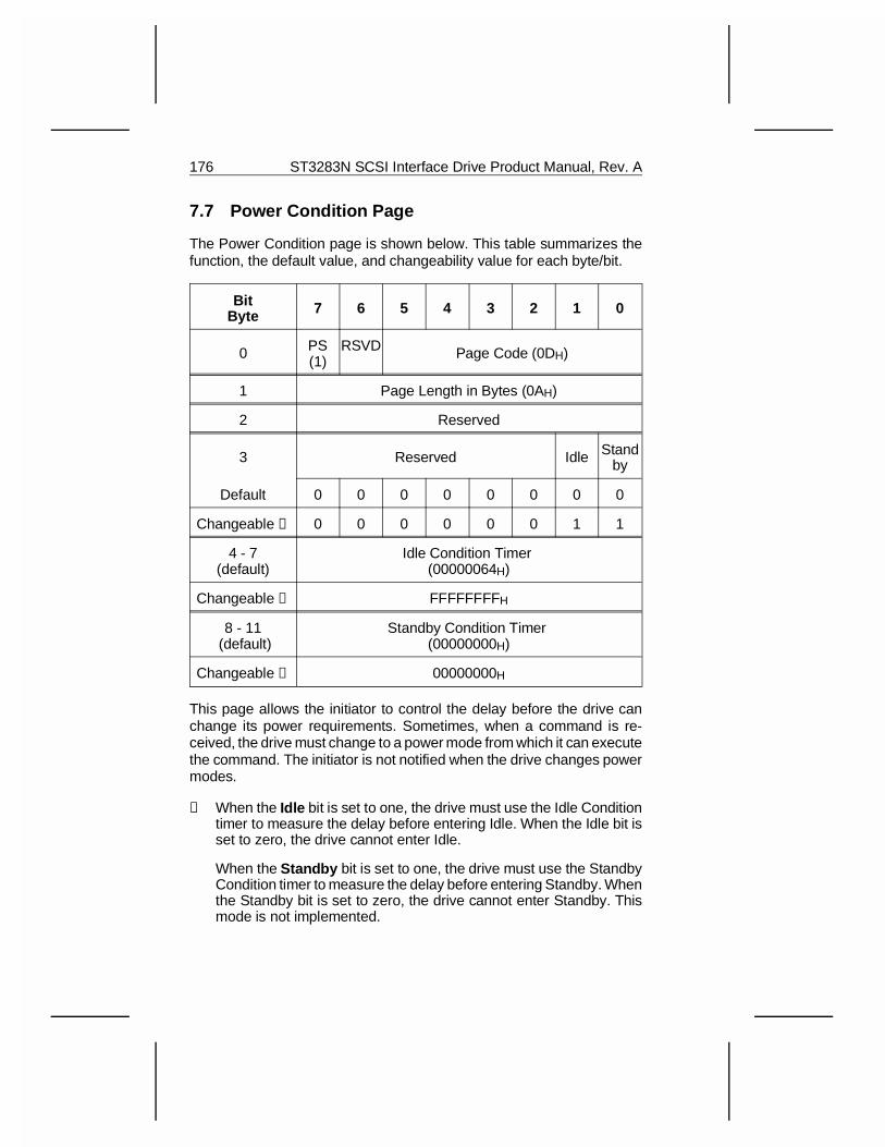
7.7 Power Condition Page
The Power Condition page is shown below. This table summarizes thefunction, the default value, and changeability value for each byte/bit.
BitByte 7 6 5 4 3 2 1 0
0 PS(1)
RSVD Page Code (0DH)
1 Page Length in Bytes (0AH)
2 Reserved
3 Reserved Idle Standby
Default 0 0 0 0 0 0 0 0
Changeable ➀ 0 0 0 0 0 0 1 1
4 - 7(default)
Idle Condition Timer (00000064H)
Changeable ➁ FFFFFFFFH
8 - 11 (default)
Standby Condition Timer (00000000H)
Changeable ➂ 00000000H
This page allows the initiator to control the delay before the drive canchange its power requirements. Sometimes, when a command is re-ceived, the drive must change to a power mode from which it can executethe command. The initiator is not notified when the drive changes powermodes.
➀ When the Idle bit is set to one, the drive must use the Idle Conditiontimer to measure the delay before entering Idle. When the Idle bit isset to zero, the drive cannot enter Idle.
When the Standby bit is set to one, the drive must use the StandbyCondition timer to measure the delay before entering Standby. Whenthe Standby bit is set to zero, the drive cannot enter Standby. Thismode is not implemented.
176 ST3283N SCSI Interface Drive Product Manual, Rev. A
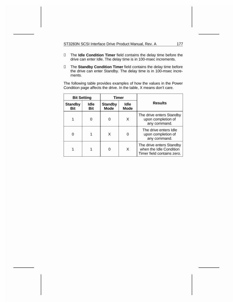
➁ The Idle Condition Timer field contains the delay time before thedrive can enter Idle. The delay time is in 100-msec increments.
➂ The Standby Condition Timer field contains the delay time beforethe drive can enter Standby. The delay time is in 100-msec incre-ments.
The following table provides examples of how the values in the PowerCondition page affects the drive. In the table, X means don’t care.
Bit Setting TimerResultsStandby
BitIdleBit
StandbyMode
IdleMode
1 0 0 XThe drive enters Standby
upon completion ofany command.
0 1 X 0The drive enters Idleupon completion of
any command.
1 1 0 XThe drive enters Standbywhen the Idle Condition
Timer field contains zero.
ST3283N SCSI Interface Drive Product Manual, Rev. A 177
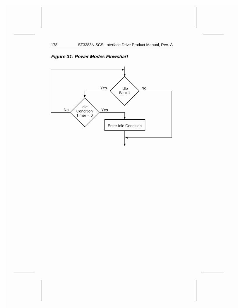
Figure 31: Power Modes Flowchart
IdleBit = 1
Yes No
IdleConditionTimer = 0
No Yes
Enter Idle Condition
178 ST3283N SCSI Interface Drive Product Manual, Rev. A
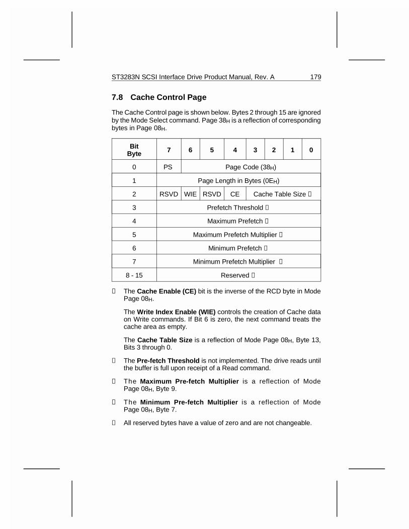
7.8 Cache Control Page
The Cache Control page is shown below. Bytes 2 through 15 are ignoredby the Mode Select command. Page 38H is a reflection of correspondingbytes in Page 08H.
BitByte 7 6 5 4 3 2 1 0
0 PS Page Code (38H)
1 Page Length in Bytes (0EH)
2 RSVD WIE RSVD CE Cache Table Size ➀
3 Prefetch Threshold ➁
4 Maximum Prefetch ➂
5 Maximum Prefetch Multiplier ➂
6 Minimum Prefetch ➃
7 Minimum Prefetch Multiplier ➃
8 - 15 Reserved ➄
➀ The Cache Enable (CE) bit is the inverse of the RCD byte in ModePage 08H.
The Write Index Enable (WIE) controls the creation of Cache dataon Write commands. If Bit 6 is zero, the next command treats thecache area as empty.
The Cache Table Size is a reflection of Mode Page 08H, Byte 13,Bits 3 through 0.
➁ The Pre-fetch Threshold is not implemented. The drive reads untilthe buffer is full upon receipt of a Read command.
➂ The Maximum Pre-fetch Multiplier is a reflection of ModePage 08H, Byte 9.
➃ The Minimum Pre-fetch Multiplier is a reflection of ModePage 08H, Byte 7.
➄ All reserved bytes have a value of zero and are not changeable.
ST3283N SCSI Interface Drive Product Manual, Rev. A 179
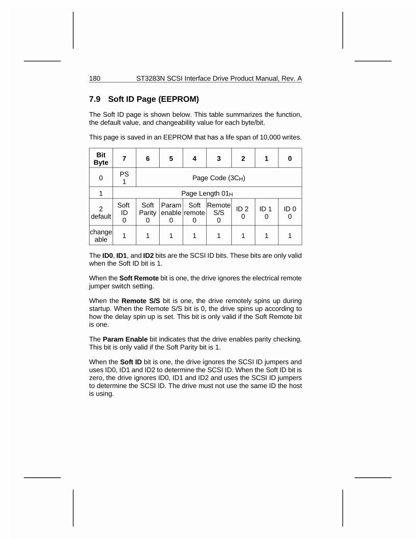
7.9 Soft ID Page (EEPROM)
The Soft ID page is shown below. This table summarizes the function,the default value, and changeability value for each byte/bit.
This page is saved in an EEPROM that has a life span of 10,000 writes.
BitByte 7 6 5 4 3 2 1 0
0 PS1 Page Code (3CH)
1 Page Length 01H
2default
Soft ID0
SoftParity
0
Paramenable
0
Softremote
0
RemoteS/S0
ID 2 0
ID 1 0
ID 00
changeable 1 1 1 1 1 1 1 1
The ID0, ID1, and ID2 bits are the SCSI ID bits. These bits are only validwhen the Soft ID bit is 1.
When the Soft Remote bit is one, the drive ignores the electrical remotejumper switch setting.
When the Remote S/S bit is one, the drive remotely spins up duringstartup. When the Remote S/S bit is 0, the drive spins up according tohow the delay spin up is set. This bit is only valid if the Soft Remote bitis one.
The Param Enable bit indicates that the drive enables parity checking.This bit is only valid if the Soft Parity bit is 1.
When the Soft ID bit is one, the drive ignores the SCSI ID jumpers anduses ID0, ID1 and ID2 to determine the SCSI ID. When the Soft ID bit iszero, the drive ignores ID0, ID1 and ID2 and uses the SCSI ID jumpersto determine the SCSI ID. The drive must not use the same ID the hostis using.
180 ST3283N SCSI Interface Drive Product Manual, Rev. A
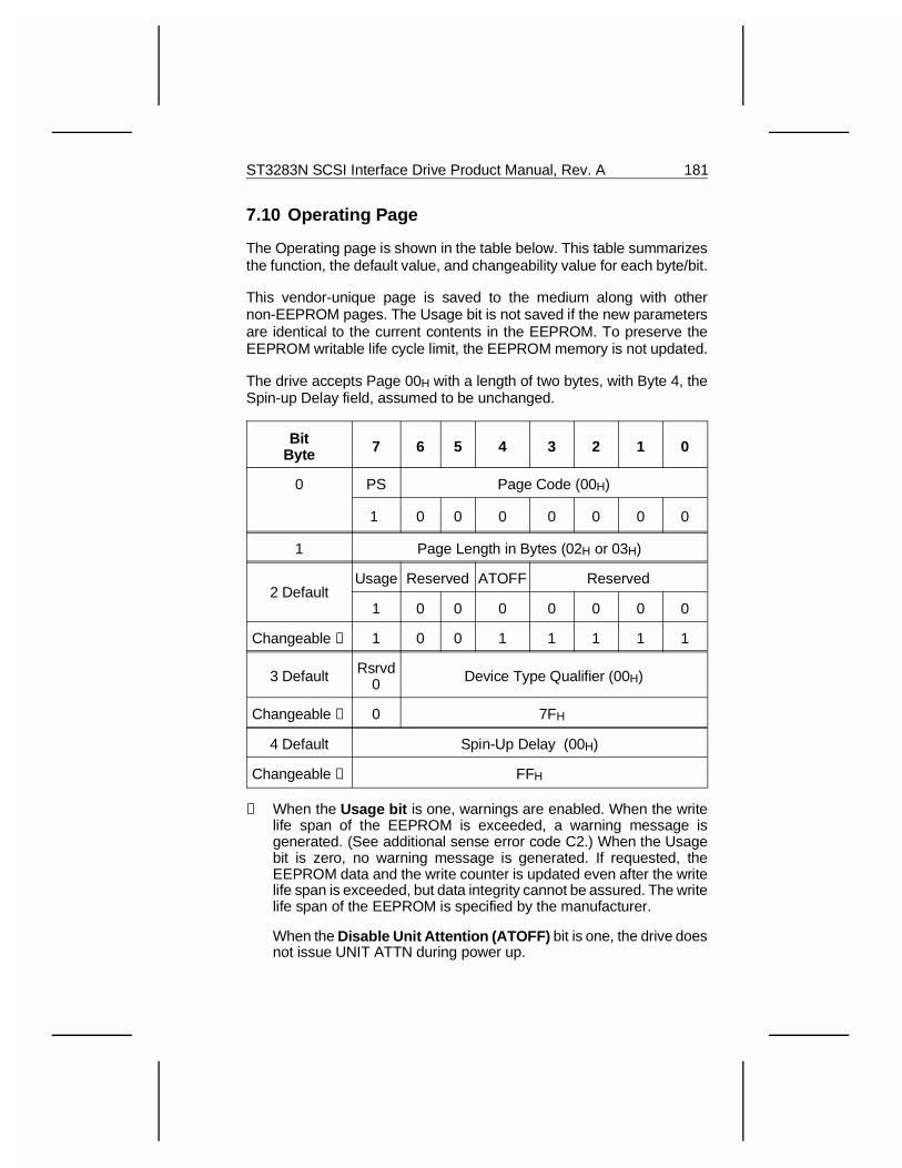
7.10 Operating Page
The Operating page is shown in the table below. This table summarizesthe function, the default value, and changeability value for each byte/bit.
This vendor-unique page is saved to the medium along with othernon-EEPROM pages. The Usage bit is not saved if the new parametersare identical to the current contents in the EEPROM. To preserve theEEPROM writable life cycle limit, the EEPROM memory is not updated.
The drive accepts Page 00H with a length of two bytes, with Byte 4, theSpin-up Delay field, assumed to be unchanged.
BitByte 7 6 5 4 3 2 1 0
0 PS Page Code (00H)
1 0 0 0 0 0 0 0
1 Page Length in Bytes (02H or 03H)
2 DefaultUsage Reserved ATOFF Reserved
1 0 0 0 0 0 0 0
Changeable ➀ 1 0 0 1 1 1 1 1
3 Default Rsrvd0 Device Type Qualifier (00H)
Changeable ➁ 0 7FH
4 Default Spin-Up Delay (00H)
Changeable ➂ FFH
➀ When the Usage bit is one, warnings are enabled. When the writelife span of the EEPROM is exceeded, a warning message isgenerated. (See additional sense error code C2.) When the Usagebit is zero, no warning message is generated. If requested, theEEPROM data and the write counter is updated even after the writelife span is exceeded, but data integrity cannot be assured. The writelife span of the EEPROM is specified by the manufacturer.
When the Disable Unit Attention (ATOFF) bit is one, the drive doesnot issue UNIT ATTN during power up.
ST3283N SCSI Interface Drive Product Manual, Rev. A 181
➁ The Device Type Qualifier is the host-programmable field in theEEPROM non-volatile memory. The field can have a value from 00Hto 7FH. This field can be read back by the host in Inquiry data, Byte 1.See Section 6.1.9.1.
➂ The Spin Up Delay field controls the drive when it is not in theremote mode. When the value is 00H, the drive spins up withoutdelay. When the value is FFH, the drive delays spin-up to a duration,in seconds, equal to the drive’s SCSI bus ID number times 5. Whenthe value is between 01H and FEH, the drive delays spin-up for thecorresponding decimal duration, in seconds.
182 ST3283N SCSI Interface Drive Product Manual, Rev. A
Appendix: Error Recovery
The error recovery procedures varies according to parameter values andthe states of “flags” stored in error recovery parameter storage locationsin the drive control memory. The drive control firmware error recoveryroutines reference these parameters when an error recovery procedureis performed. These error recovery parameters are changeable by ModeSelect commands from the initiator. See Sections 6.1.10 and 7.1.
In general, when a read error occurs, the drive attempts to recover usingretries and application of ECC. If the error still exists, the drive reportsCheck Condition in the status returned to the initiator. The initiator maythen issue the Request Sense command. The drive replies with a DataIn phase with extended sense data containing information about theerror. If the error is recovered, it is reported only if the PER bit is set. Seethe section on the Request Sense command in Section 6.1.3 for a list ofsense key, error key codes.
A.1 Seek Errors (09 H or 15H)
If a seek error occurs, up to three retries are attempted by positioning theheads to track zero and re-issuing the seek. If all retries fail, error code09H or 15H is reported in the extended sense data.
A.2 Data Field Write Fault (03 H)
If a write fault is detected while writing the data field, the operation willbe immediately suspended. If the internal write fault can be cleared, thedrive will automatically perform a rewrite of the sector (up to 3 attemptswill be made to clear the write fault and rewrite the sector).
If the Write Fault condition cannot be cleared, the Write Fault error (03H)will be reported in the extended sense data.
ST3283N SCSI Interface Drive Product Manual, Rev. A 183
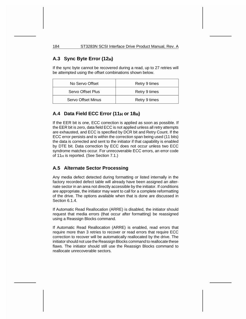
A.3 Sync Byte Error (12 H)
If the sync byte cannot be recovered during a read, up to 27 retries willbe attempted using the offset combinations shown below.
No Servo Offset Retry 9 times
Servo Offset Plus Retry 9 times
Servo Offset Minus Retry 9 times
A.4 Data Field ECC Error (11 H or 18H)
If the EER bit is one, ECC correction is applied as soon as possible. Ifthe EER bit is zero, data field ECC is not applied unless all retry attemptsare exhausted, and ECC is specified by DCR bit and Retry Count. If theECC error persists and is within the correction span being used (11 bits)the data is corrected and sent to the initiator if that capability is enabledby DTE bit. Data correction by ECC does not occur unless two ECCsyndrome matches occur. For unrecoverable ECC errors, an error codeof 11H is reported. (See Section 7.1.)
A.5 Alternate Sector Processing
Any media defect detected during formatting or listed internally in thefactory recorded defect table will already have been assigned an alter-nate sector in an area not directly accessible by the initiator. If conditionsare appropriate, the initiator may want to call for a complete reformattingof the drive. The options available when that is done are discussed inSection 6.1.4.
If Automatic Read Reallocation (ARRE) is disabled, the initiator shouldrequest that media errors (that occur after formatting) be reassignedusing a Reassign Blocks command.
If Automatic Read Reallocation (ARRE) is enabled, read errors thatrequire more than 3 retries to recover or read errors that require ECCcorrection to recover will be automatically reallocated by the drive. Theinitiator should not use the Reassign Blocks command to reallocate theseflaws. The initiator should still use the Reassign Blocks command toreallocate unrecoverable sectors.
184 ST3283N SCSI Interface Drive Product Manual, Rev. A
If Automatic Write Reallocate (AWRE) is disabled, the drive will report aNo Record Found status if a header cannot be recovered. The initiatorshould request that bad sector(s) be reallocated using the ReassignBlocks command and then rewrite the record.
If Automatic Write Reallocation (AWRE) is enabled, the drive will auto-matically reallocate the sector and rewrite the data field if a header cannotbe recovered. The initiator should not use the Reassign Blocks commandor rewrite the sectors if AWRE is a 1 and it receives a Record Not Foundstatus.
ST3283N SCSI Interface Drive Product Manual, Rev. A 185
Related Documents


