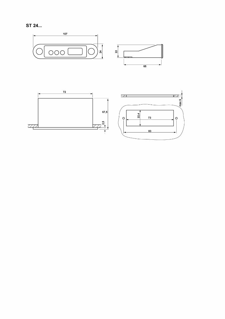
ST24-FX1TAR.102 PID controller Order number 900410.008 Wiring diagram Product description The controller ST24-FX1TAR.102 serves for temperature control at high measuring accuracy. The unit disposes of a connection for resistance sensor PTC or Pt100. It is supplied with a voltage of 230V AC. The installed relay has a maximum electric Ohm load of 16A. Inductive loads can be connected with up to max 2.2A permanent current. In addition there is a voltage output to control an external SSR relay. The PID regulation and/or thermostat regulation can be activated via para- meter setting. Networking of the controller takes place via the ST-Bus interface. Sensor: Multi resistance input Measuring range: dependent on type of sensor Front size: 107mm x 24mm Panel cut-out: 73mm x 22.4mm Tightness: Front IP65 Connector: screw terminal

Welcome message from author
This document is posted to help you gain knowledge. Please leave a comment to let me know what you think about it! Share it to your friends and learn new things together.
Transcript

ST24-FX1TAR.102
PID controller
Order number 900410.008
Wiring diagram
Product description
The controller ST24-FX1TAR.102 serves for temperature control at high measuring accuracy. Theunit disposes of a connection for resistance sensor PTC or Pt100. It is supplied with a voltage of230V AC. The installed relay has a maximum electric Ohm load of 16A. Inductive loads can beconnected with up to max 2.2A permanent current. In addition there is a voltage output to controlan external SSR relay. The PID regulation and/or thermostat regulation can be activated via para-meter setting.Networking of the controller takes place via the ST-Bus interface.
Sensor: Multi resistance inputMeasuring range: dependent on type of sensorFront size: 107mm x 24mmPanel cut-out: 73mm x 22.4mmTightness: Front IP65Connector: screw terminal
1
2
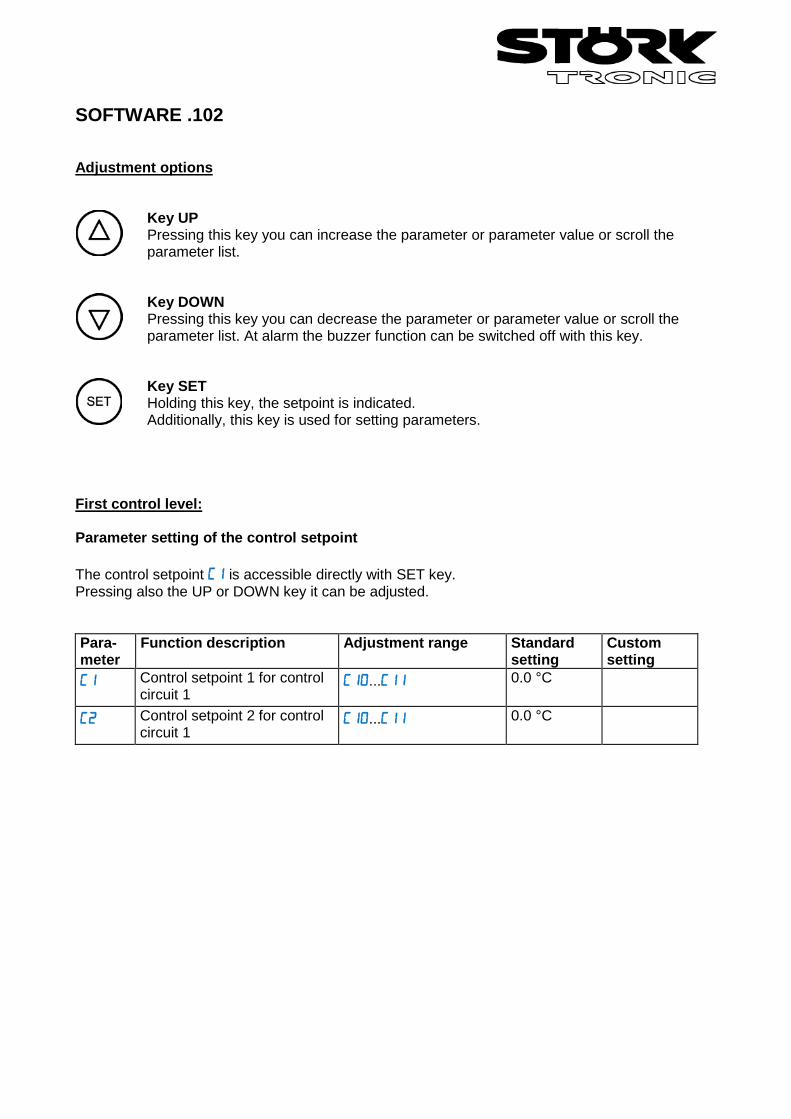
SOFTWARE .102 Adjustment options
Key UP Pressing this key you can increase the parameter or parameter value or scroll the parameter list. Key DOWN Pressing this key you can decrease the parameter or parameter value or scroll the parameter list. At alarm the buzzer function can be switched off with this key. Key SET Holding this key, the setpoint is indicated. Additionally, this key is used for setting parameters.
First control level: Parameter setting of the control setpoint The control setpoint is accessible directly with SET key. Pressing also the UP or DOWN key it can be adjusted. Para- meter
Function description Adjustment range Standard setting
Custom setting
Control setpoint 1 for control circuit 1
...
0.0 °C
Control setpoint 2 for control circuit 1
...
0.0 °C
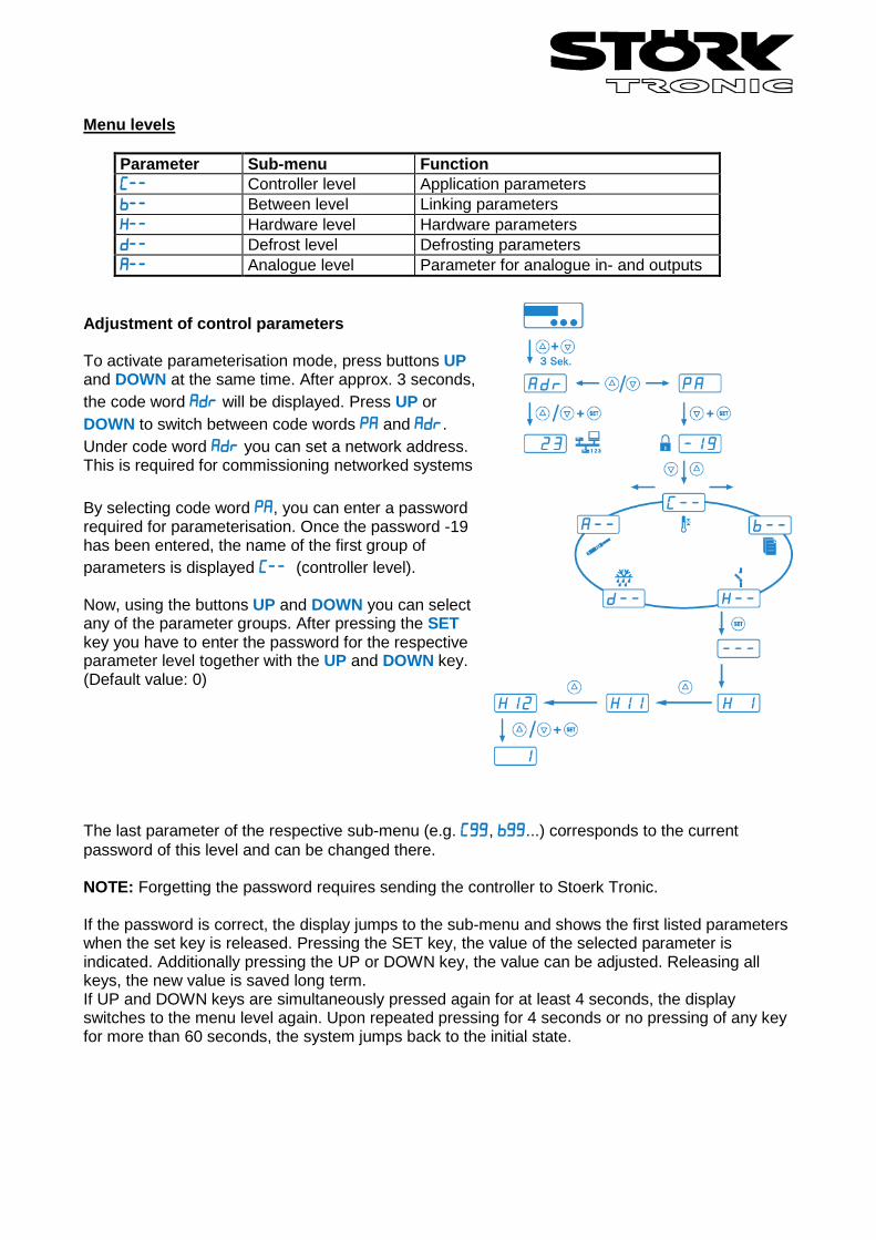
Menu levels
Parameter Sub-menu Function Controller level Application parameters Between level Linking parameters Hardware level Hardware parameters Defrost level Defrosting parameters Analogue level Parameter for analogue in- and outputs
Adjustment of control parameters To activate parameterisation mode, press buttons UP and DOWN at the same time. After approx. 3 seconds, the code word will be displayed. Press UP or DOWN to switch between code words and . Under code word you can set a network address. This is required for commissioning networked systems By selecting code word , you can enter a password required for parameterisation. Once the password -19 has been entered, the name of the first group of parameters is displayed (controller level). Now, using the buttons UP and DOWN you can select any of the parameter groups. After pressing the SET key you have to enter the password for the respective parameter level together with the UP and DOWN key. (Default value: 0) The last parameter of the respective sub-menu (e.g. , ...) corresponds to the current password of this level and can be changed there. NOTE: Forgetting the password requires sending the controller to Stoerk Tronic. If the password is correct, the display jumps to the sub-menu and shows the first listed parameters when the set key is released. Pressing the SET key, the value of the selected parameter is indicated. Additionally pressing the UP or DOWN key, the value can be adjusted. Releasing all keys, the new value is saved long term. If UP and DOWN keys are simultaneously pressed again for at least 4 seconds, the display switches to the menu level again. Upon repeated pressing for 4 seconds or no pressing of any key for more than 60 seconds, the system jumps back to the initial state.
The C-level (controller) This level contains the application parameters. Thermostat 1 Para- meter
Function Adjustment range Standard setting
Custom setting
Setpoint control circuit 1 ... 0.0°C Setpoint control circuit 1 (*) ... 0.0°C Offset for C1/C2 -99.0 ... 99.0°K 0.0°K Switching sense
control circuit 1 0: heating function 1: cooling function
0
Hysteresis control circuit 1 0.1 ... 99.9°K 1.0°K Hysteresis mode
control circuit 1 0: symmetrical 1: one-sided
0
Minimum action time control circuit 1"ON"
0 ... 400 sec. 0 sec.
Minimum action time control circuit 1"OFF"
0 ... 400 sec. 0 sec.
Function control circuit 1 at sensor error
0: relay off 1: relay on
0
Control range limitation, minimum Setpoint 1, 2, 3
-99.0°C ... -99°C
Control range limitation, maximum Setpoint 1, 2, 3
... 999.0°C 999°C
* The activation of the second setpoint is indicated on the display with a flashing point to the right. It can be activated with a specified key 1 (depending on parameter , or ). Thermostat 2 Para- meter
Function Adjustment range Standard setting
Custom setting
Setpoint control circuit 2 (=0) ... 0°C Delta W2 (=1) -99...99°K 0°K Switching sense
control circuit 2 0: heating function 1: cooling function
0
Hysteresis control circuit 2 0.1 ... 99.9°K 1°K Hysteresis mode
control circuit 2 0: symmetrical 1: one-sided
0
Minimum action time control circuit 2 "ON"
0...400 sec. 0 sec.
Minimum action time control circuit 2 "OFF""
0...400 sec. 0 sec.
Function control circuit 2 at sensor error
0: relay off 1: relay on
0
Thermostat 3 Para- meter
Function Adjustment range Standard setting
Custom setting
Sollwert control circuit 3 (=0) ... 0.0°C Delta W3 (=1) -99.0 ... 99.0°K 0.0°K Switching sense
control circuit 3 0: heating function 1: cooling function
0
Hysteresis control circuit 3 0.1 ... 99.9°K 1.0°K Hysteresis mode
control circuit 3 0: symmetrical 1: one-sided
0
Minimum action time control circuit 3 "ON"
0...400 sec. 0 sec.
Minimum action time control circuit 3 "OFF""
0...400 sec. 0 sec.
Function control circuit 3 at sensor error
0: relay off 1: relay on
0
Alarm circuit Para- meter
Function Adjustment range Standard setting
Custom setting
Lower alarm value -99.0 ... -10.0 Upper alarm value ... 999.0 10.0 Alarm functions 0: Boundary alarm,
relative boundaries 1: Boundary alarm, absolute boundaries 2: Range alarm, relative boundaries 3: Range alarm, absolute boundaries 4: Boundary alarm, relative boundaries, alarm inverse 5: Boundary alarm, absolute boundaries, alarm inverse 6: Range alarm, relative boundaries, alarm inverse 7: Range alarm, absolute boundaries, alarm inverse
0
Special function at boundary alarm
0: not active 1: flashing display 2: buzzer 3: buzzer + flashing display 4: like 3, buzzer can be cancelled 5: like 4, restarts after 10 min. 6: like 4, restarts after 30 min.
4
Hysteresis alarm circuit 0.1 ... 9.9°K 1.0°K
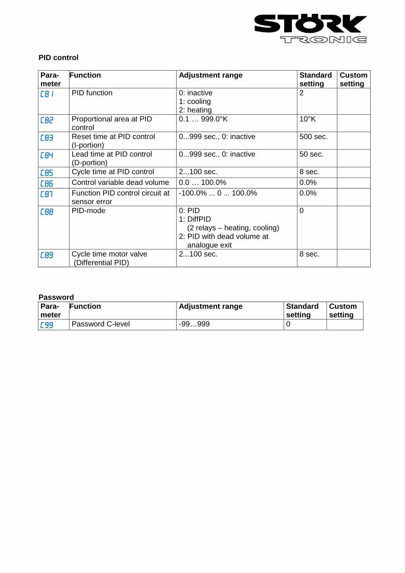
PID control Para- meter
Function Adjustment range Standard setting
Custom setting
PID function 0: inactive 1: cooling 2: heating
2
Proportional area at PID control
0.1 … 999.0°K 10°K
Reset time at PID control (I-portion)
0...999 sec., 0: inactive 500 sec.
Lead time at PID control (D-portion)
0...999 sec., 0: inactive 50 sec.
Cycle time at PID control 2...100 sec. 8 sec. Control variable dead volume 0.0 … 100.0% 0.0% Function PID control circuit at
sensor error -100.0% ... 0 ... 100.0% 0.0%
PID-mode 0: PID 1: DiffPID (2 relays – heating, cooling) 2: PID with dead volume at analogue exit
0
Cycle time motor valve (Differential PID)
2...100 sec. 8 sec.
Password Para- meter
Function Adjustment range Standard setting
Custom setting
Password C-level -99…999 0
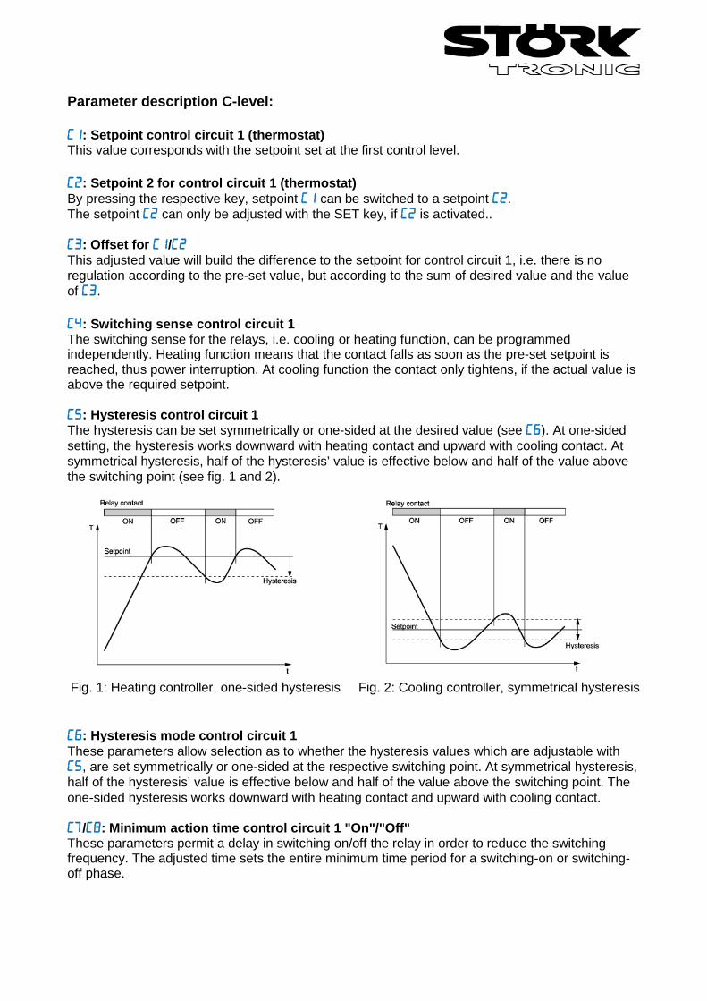
Parameter description C-level: : Setpoint control circuit 1 (thermostat) This value corresponds with the setpoint set at the first control level. : Setpoint 2 for control circuit 1 (thermostat) By pressing the respective key, setpoint can be switched to a setpoint . The setpoint can only be adjusted with the SET key, if is activated.. : Offset for / This adjusted value will build the difference to the setpoint for control circuit 1, i.e. there is no regulation according to the pre-set value, but according to the sum of desired value and the value of . : Switching sense control circuit 1 The switching sense for the relays, i.e. cooling or heating function, can be programmed independently. Heating function means that the contact falls as soon as the pre-set setpoint is reached, thus power interruption. At cooling function the contact only tightens, if the actual value is above the required setpoint. : Hysteresis control circuit 1 The hysteresis can be set symmetrically or one-sided at the desired value (see ). At one-sided setting, the hysteresis works downward with heating contact and upward with cooling contact. At symmetrical hysteresis, half of the hysteresis’ value is effective below and half of the value above the switching point (see fig. 1 and 2). Fig. 1: Heating controller, one-sided hysteresis Fig. 2: Cooling controller, symmetrical hysteresis : Hysteresis mode control circuit 1 These parameters allow selection as to whether the hysteresis values which are adjustable with , are set symmetrically or one-sided at the respective switching point. At symmetrical hysteresis, half of the hysteresis’ value is effective below and half of the value above the switching point. The one-sided hysteresis works downward with heating contact and upward with cooling contact. /: Minimum action time control circuit 1 "On"/"Off" These parameters permit a delay in switching on/off the relay in order to reduce the switching frequency. The adjusted time sets the entire minimum time period for a switching-on or switching-off phase.
: Function control circuit 1 at sensor error At sensor error the selected relay (see , , ) falls back into the condition pre-set here. : Setpoint limit (minimum) setpoint 1 : Setpoint limit (maximum) setpoint 1 The adjustment range of the setpoint can be limited in both directions. This is to prevent the end user of a unit from setting inadmissible or dangerous setpoints. : Setpoint control circuit 2 (thermostat) (=0) If b1=1, this value is ineffective. : Value deltaW2 (=1) If =1, the setpoints for control circuit 1 and 2 are linked with one another via switching difference deltaW2 () (operation with deltaW). The following applies: Setpoint thermostat 2 = setpoint control circuit 1 (/) + deltaW2. This difference can take positive or negative values. Thus, a leading or following contact can be realised. : Switching sense control circuit 2 The switching sense for the relays, i.e. cooling or heating function, can be programmed independently at works. Heating function means that the contact falls as soon as the pre-set setpoint is reached, thus power interruption. At cooling function the contact only tightens, when the actual value is above the required setpoint. : Hysteresis control circuit 2 The hysteresis can be set symmetrically or one-sided at the setpoint (see ). At one-sided setting, the hysteresis works downward with heating contact and upward with cooling contact. At symmetrical hysteresis, half of the hysteresis’ value is effective below and half of the value above the switching point (see fig. 1 and 2). : Hysteresis mode control circuit 2 These parameters allow selection as to whether the hysteresis values which are adjustable with , are set symmetrically or one-sided at the respective switching point. At symmetrical hysteresis, half of the hysteresis’ value is effective below and half of the value above the switching point. The one-sided hysteresis works downward with heating contact and upward with cooling contact. : Minimum action time control circuit 2 "On" : Minimum action time control circuit 2 "Off" These parameters permit a delay in switching on/off the relay, in order to reduce the switching frequency. The adjusted time sets the entire minimum time period for a switching-on or switching-off phase. : Function control circuit 2 at sensor error At sensor error the selected relay (see , , ) falls back into the condition pre-set here. : Setpoint thermostat 3 (=0) If =1, this value is ineffective.
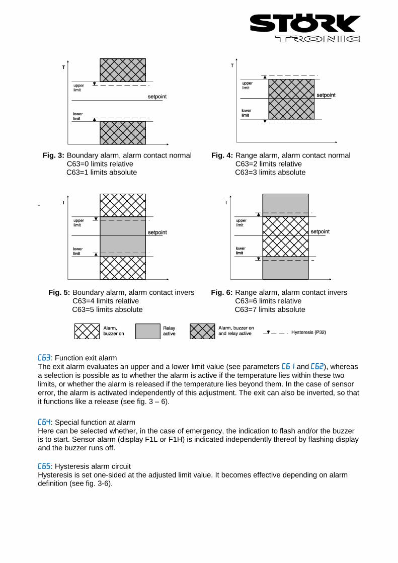
: Value deltaW3 (=1) If =1, the setpoints for thermostat 1 and 3 are linked with one another via switching difference deltaW3 (operation with deltaW). The following applies: Setpoint thermostat 3 = setpoint thermostat 1 (/) + deltaW3. This difference can take positive or negative values. Thus a leading or following contact can be realised. : Switching sense control circuit 3 The switching sense for the relays, i.e. cooling or heating function, can be programmed independently at works. Heating function means that the contact falls as soon as the pre-set setpoint is reached, thus power interruption. At cooling function the contact only tightens, if the actual value is above the required setpoint. : Hysteresis control circuit 3 The hysteresis can be set symmetrically or one-sided at the setpoint (see ). At one-sided setting, the hysteresis works downward with heating contact and upward with cooling contact. At symmetrical hysteresis, half of the hysteresis’ value is effective below and half of the value above the switching point (see fig. 1 and 2). : Hysteresis mode control circuit 3 These parameters allow selection as to whether the hysteresis values which are adjustable with , are set symmetrically or one-sided at the respective switching point. At symmetrical hysteresis, half of the hysteresis’ value is effective below and half of the value above the switching point. The one-sided hysteresis works downward with heating contact and upward with cooling contact. : Minimum action time control circuit 3 "On" : Minimum action time control circuit 3 "Off" These parameters permit a delay in switching on/off the relay in order to reduce the switching frequency. The adjusted time sets the entire minimum time period for a switching-on or switching-off phase. : Function control circuit 3 at sensor error At sensor error the selected relay (see , , ) falls back into the condition pre-set here. : Lower alarm value : Upper alarm value The exit alarm is a boundary alarm or a range alarm with one-sided hysteresis (see parameter ). Both at the boundary alarm and the range alarm, limit values can be relative, i.e. going along with the setpoint /, or absolute, i.e. independent of the setpoint /. At boundary alarm the hysteresis works one-sided inwardly, and at range alarm outwardly (see fig. 3-6, next side).
-
: Function exit alarm The exit alarm evaluates an upper and a lower limit value (see parameters and ), whereas a selection is possible as to whether the alarm is active if the temperature lies within these two limits, or whether the alarm is released if the temperature lies beyond them. In the case of sensor error, the alarm is activated independently of this adjustment. The exit can also be inverted, so that it functions like a release (see fig. 3 – 6). : Special function at alarm Here can be selected whether, in the case of emergency, the indication to flash and/or the buzzer is to start. Sensor alarm (display F1L or F1H) is indicated independently thereof by flashing display and the buzzer runs off. : Hysteresis alarm circuit Hysteresis is set one-sided at the adjusted limit value. It becomes effective depending on alarm definition (see fig. 3-6).
Fig. 5: Boundary alarm, alarm contact invers C63=4 limits relative C63=5 limits absolute
Fig. 6: Range alarm, alarm contact invers C63=6 limits relative C63=7 limits absolute
Fig. 3: Boundary alarm, alarm contact normal C63=0 limits relative C63=1 limits absolute
Fig. 4: Range alarm, alarm contact normal C63=2 limits relative C63=3 limits absolute
PID - control : Proportional band at PID regulation The proportional band works in such a way that with approximation of the actual value to the setpoint the variable is reduced linearly from +-100% to 0%. : Reset time at PID regulation (I-portion) : Lead time at PID regulation (D-portion) The proportional controller as such has a remaining deviation of the actual value from the setpoint. The integral portion provides for a complete compensation of this offset. The reset time is a measure for the period of time needed to adjust a remaining temperature deviation of the size of the proportional range. If a small reset time is set, a fast post-adjustment will take place. At a too small reset time, however, the system may tend to vibrate. The differential portion dampens temperature changes. If lead time is set for long, damping is strong. At too long lead time, however, the system may tend to vibrate. At setting 0 the values are ineffective. It is therefore possible to realise a pure PI or PD regulation. : Cycle time at PID regulation During the cycle time the control exit runs through one switching period, i.e. once switched out and once switched on. The smaller the cycle time, the faster the regulation. By consequence, however, there is also an increased switching frequency of the output, which can lead to rapid wear of relay contacts. For very fast control ways with the respective high switching frequency a voltage output is therefore of advantage. : Control variable dead volume
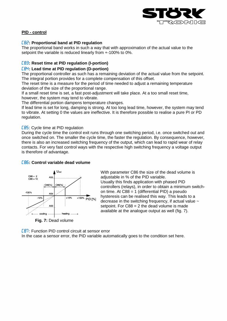
With parameter C86 the size of the dead volume is adjustable in % of the PID variable. Usually this finds application with phased PID controllers (relays), in order to obtain a minimum switch-on time. At C88 = 1 (differential PID) a pseudo hysteresis can be realised this way. This leads to a decrease in the switching frequency, if actual value ~ setpoint. For C88 = 2 the dead volume is made available at the analogue output as well (fig. 7).
Fig. 7: Dead volume : Function PID control circuit at sensor error In the case a sensor error, the PID variable automatically goes to the condition set here.
: PID-Mode [C88 = 0] PID standard [C88 = 1] PID differential (see below) [C88 = 2] PID standard with dead volume at analogue exit PID differential: The differential mode is particularly suitable for the use of control valves (e.g. K1=OPEN, K2=CLOSED). As long as the value computed by the PID circuit remains constant, both exits remain inactive, i.e. the valve stops at the current position.
PID standard (C88=0/2) PID differential (C88=1) PID K1: heating K2: cooling DiffPID K1: heating K2: cooling 1 20% 20% 0% +20% 20% 0% 2 25% 25% 0% +5% 5% 0% 3 25% 25% 0% ±0 0% 0% 4 10% 10% 0% -15% 0% 15% 5 -20% 0% 20% -30% 0% 30%
Thus, control valves almost show the same controlling results as analogue valves. The table shows the different behaviour of both modes within the same control system. : Cycle time control valve (DiffPID) This parameter sets the time the control valve needs to go from 0% to 100%. If C88=1, the PID variable is converted to this interval. The PID cycle time (C85) remains unaffected by this. When this time is defined, indication with a rounded up value in seconds is recommended. Furthermore C85 should be > = C89. At ± 100% the respective exit remains durably active (synchronisation). : Password This parameter is to set the password for the C—level.
b-level (between) This level contains the parameters for different combinations. Para- meter
Function Adjustment range Standard setting
Custom setting
Activation setpoint combination for thermostat 1 and 2 ( = deltaW2)
0: no combination 1: Setpoint thermostat 2 = / +
0
Activation setpoint combination for thermostat 1 and 3 ( = deltaW3)
0: no combination 1: setpoint thermostat 3 = / +
0
Delay control circuit 1, 2, 3 after "Power-On"
0...400 sec. 0 sec.
Mutual delay control circuit 1, 2, 3 0...400 sec. 0 sec. Alarm suppression after "Power-On",
"setpoint" 0...60 min. 20 min.
Linking analogue exit 0: actuating variable 1: actual value 1: setpoint
0
Password b-level -99 ... 999 0 Parameter description b-level: : Activation setpoint combination for thermostat 1 and thermostat 2 (deltaW2) This parameter determines whether the setpoints for thermostat 1 and 2 independently adjustable (parameter ) or whether they are tied with one another via a switching offset deltaW2 (parameter ). : Activation setpoint combination for thermostat 1 and thermostat 3 (deltaW3) This parameter determines whether the setpoints for thermostat 1 and 3 independently adjustable (parameter ) or whether they are tied with one another via a switching offset deltaW2 (parameter ). : Delay control circuit 1, 2, 3 after "Power-On" This parameter allows a switching-on delay of relays after switching-on the mains voltage. This delay corresponds with the time set here. : Mutual delay control circuit 1, 2, 3 This parameter makes a mutual switching-on delay of relays possible, depending on whichever contact is switched first. : Alarm suppression after "Power-On", "setpoint" This parameter allows a switching-on delay of the alarm contact after switching on the mains voltage. This delay corresponds with the time set here. : Password This parameter is to set the password for the b—level.
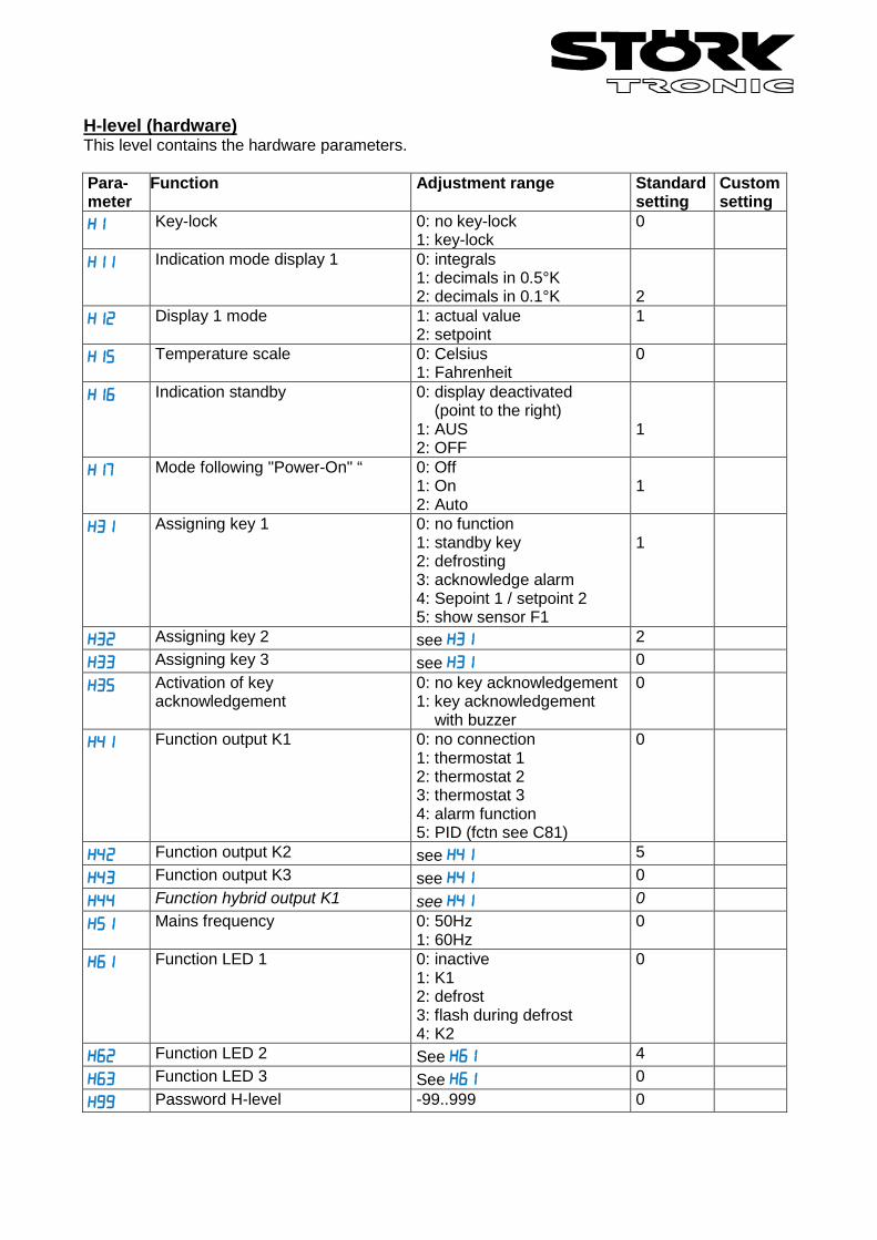
H-level (hardware) This level contains the hardware parameters. Para- meter
Function Adjustment range Standard setting
Custom setting
Key-lock 0: no key-lock 1: key-lock
0
Indication mode display 1 0: integrals 1: decimals in 0.5°K 2: decimals in 0.1°K
2
Display 1 mode 1: actual value 2: setpoint
1
Temperature scale 0: Celsius 1: Fahrenheit
0
Indication standby 0: display deactivated (point to the right) 1: AUS 2: OFF
1
Mode following "Power-On" “ 0: Off 1: On 2: Auto
1
Assigning key 1 0: no function 1: standby key 2: defrosting 3: acknowledge alarm 4: Sepoint 1 / setpoint 2 5: show sensor F1
1
Assigning key 2 see 2 Assigning key 3 see 0 Activation of key
acknowledgement 0: no key acknowledgement 1: key acknowledgement with buzzer
0
Function output K1 0: no connection 1: thermostat 1 2: thermostat 2 3: thermostat 3 4: alarm function 5: PID (fctn see C81)
0
Function output K2 see 5 Function output K3 see 0 Function hybrid output K1 see 0 Mains frequency 0: 50Hz
1: 60Hz 0
Function LED 1 0: inactive 1: K1 2: defrost 3: flash during defrost 4: K2
0
Function LED 2 See 4 Function LED 3 See 0 Password H-level -99..999 0
Parameter description H-level: : Key-lock The key-lock allows blocking of the control keys. In locked condition parameter adjustments with keys is not possible. At the attempt to adjust the parameters despite key-lock the message "===" appears in the display. : Indication mode display 1 The value can be indicated in integrals or with decimals in 0.5°K or 0.1°K. At indication in 0.5°K the value is rounded up or down. In general, all parameter indications are presented in 0.1°K. : Display 1 mode =1 indicates the actual value and =2 indicates the setpoint or in the display. Therefore, the current actual value can only be indicated with parameter . : Temperature scale Indication can be switched between Fahrenheit and Celsius. At conversion, the parameters and setpoints maintain their numerical value and adjustment range. (Example: A controller with the setpoint of 0°C is switched to Fahrenheit. The new setpoint is then interpreted as 0°F, which corresponds to a temperature of -18°C). NOTE: Indication limits with °F can be smaller than the actual measuring range! : Indication standby In standby mode the here set value appears in the display. : Mode following "Power-On" After switching on the mains voltage the controller automatically goes to the condition set here. =2 applies to the condition prior to the separation from the net. : Assigning function key 1 (UP) : Assigning function key 2 (DOWN) : Assigning function key 3 (SET) The standard function of the keys (imprint on the front panel) remains always active. With these parameters, a function can be programmed to be active only when the button is pressed sole. Eventually, the button must be pressed longer.
0 no additional function defined 1 for more than 3 sec., Standby 2 Defrosting, only effective with cooling controller 3 Acknowledge alarms, switches off the buzzer (if available) 4 for more than 3 sec, change-over setpoint C1 / C2 5 indicate value of sensor F1, as long as the key is pressed
: Activation of key acknowledgement This parameter permits to switch the internal buzzer on/off by key confirmation. -: Function output K1-3 : Function hybrid output K1 Generally, the exits are exchangeable with parameter adjustments, in order to achieve an optimal relation of the existing hardware with regard to contact rating, kind of contact and cycle number. Therefore, these parameters first assign the exits to the controller function.

: Mains frequency This parameter is to select the mains frequency. -: Function LED1-LED3 Assignment of the status LEDs. : Password This parameter is to adjust the password for the H—level.
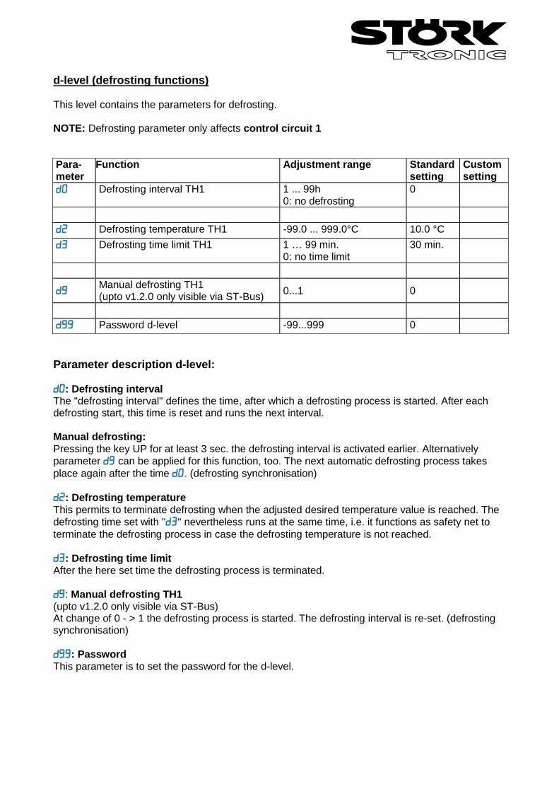
d-level (defrosting functions) This level contains the parameters for defrosting. NOTE: Defrosting parameter only affects control circuit 1 Para- meter
Function Adjustment range Standard setting
Custom setting
Defrosting interval TH1 1 ... 99h 0: no defrosting
0
Defrosting temperature TH1 -99.0 ... 999.0°C 10.0 °C Defrosting time limit TH1 1 … 99 min.
0: no time limit 30 min.
Manual defrosting TH1 (upto v1.2.0 only visible via ST-Bus) 0...1 0
Password d-level -99...999 0 Parameter description d-level: : Defrosting interval The "defrosting interval" defines the time, after which a defrosting process is started. After each defrosting start, this time is reset and runs the next interval. Manual defrosting: Pressing the key UP for at least 3 sec. the defrosting interval is activated earlier. Alternatively parameter can be applied for this function, too. The next automatic defrosting process takes place again after the time . (defrosting synchronisation) : Defrosting temperature This permits to terminate defrosting when the adjusted desired temperature value is reached. The defrosting time set with "" nevertheless runs at the same time, i.e. it functions as safety net to terminate the defrosting process in case the defrosting temperature is not reached. : Defrosting time limit After the here set time the defrosting process is terminated. : Manual defrosting TH1 (upto v1.2.0 only visible via ST-Bus) At change of 0 - > 1 the defrosting process is started. The defrosting interval is re-set. (defrosting synchronisation) : Password This parameter is to set the password for the d-level.
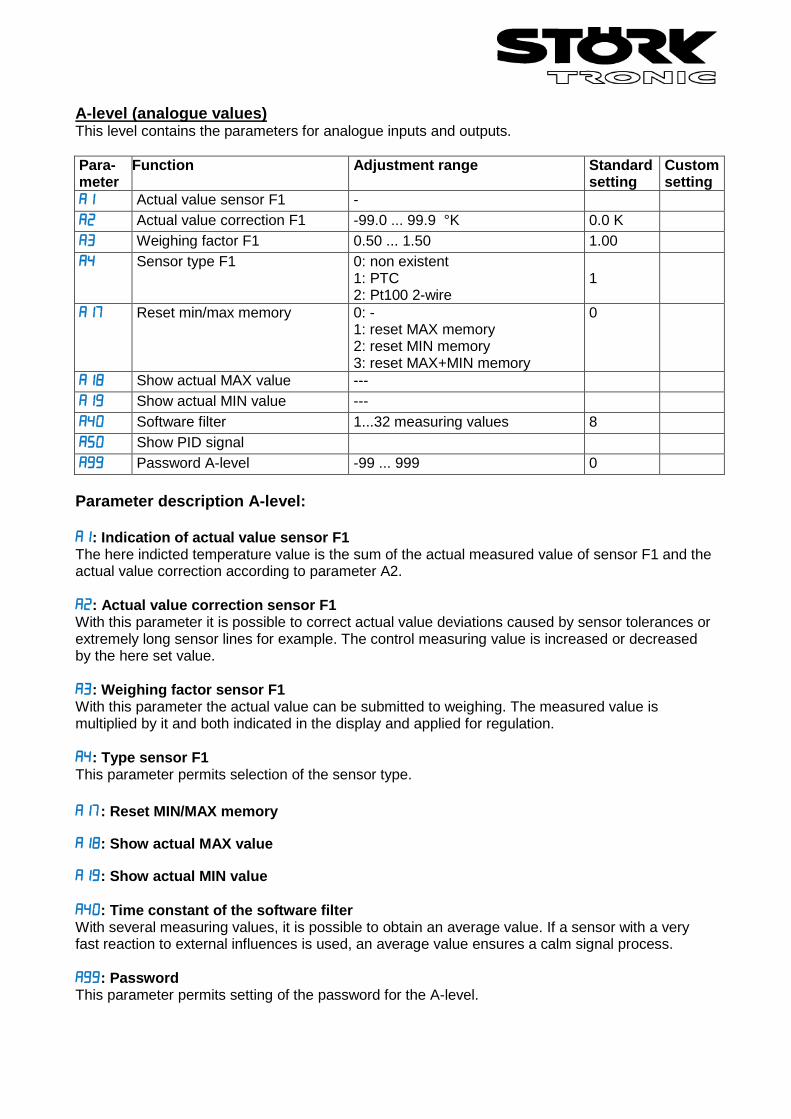
A-level (analogue values) This level contains the parameters for analogue inputs and outputs. Para- meter
Function Adjustment range Standard setting
Custom setting
Actual value sensor F1 - Actual value correction F1 -99.0 ... 99.9 °K 0.0 K Weighing factor F1 0.50 ... 1.50 1.00 Sensor type F1 0: non existent
1: PTC 2: Pt100 2-wire
1
Reset min/max memory 0: - 1: reset MAX memory 2: reset MIN memory 3: reset MAX+MIN memory
0
Show actual MAX value --- Show actual MIN value --- Software filter 1...32 measuring values 8 Show PID signal Password A-level -99 ... 999 0 Parameter description A-level: : Indication of actual value sensor F1 The here indicted temperature value is the sum of the actual measured value of sensor F1 and the actual value correction according to parameter A2. : Actual value correction sensor F1 With this parameter it is possible to correct actual value deviations caused by sensor tolerances or extremely long sensor lines for example. The control measuring value is increased or decreased by the here set value. : Weighing factor sensor F1 With this parameter the actual value can be submitted to weighing. The measured value is multiplied by it and both indicated in the display and applied for regulation. : Type sensor F1 This parameter permits selection of the sensor type. : Reset MIN/MAX memory
: Show actual MAX value
: Show actual MIN value : Time constant of the software filter With several measuring values, it is possible to obtain an average value. If a sensor with a very fast reaction to external influences is used, an average value ensures a calm signal process. : Password This parameter permits setting of the password for the A-level.
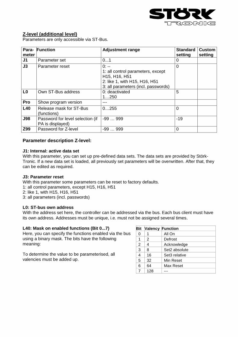
Z-level (additional level) Parameters are only accessible via ST-Bus. Para- meter
Function Adjustment range Standard setting
Custom setting
J1 Parameter set 0...1 0 J3 Parameter reset 0: --
1: all control parameters, except H15, H16, H51 2: like 1, with H15, H16, H51 3: all parameters (incl. passwords)
0
L0 Own ST-Bus address 0: deactivated 1…250
5
Pro Show program version --- L40 Release mask for ST-Bus
(functions) 0…255 0
J98 Password for level selection (if PA is displayed)
-99 … 999 -19
Z99 Password for Z-level -99 … 999 0 Parameter description Z-level: J1: Internal: active data set With this parameter, you can set up pre-defined data sets. The data sets are provided by Störk-Tronic. If a new data set is loaded, all previously set parameters will be overwritten. After that, they can be edited as required. J3: Parameter reset With this parameter some parameters can be reset to factory defaults. 1: all control parameters, except H15, H16, H51 2: like 1, with H15, H16, H51 3: all parameters (incl. passwords) L0: ST-bus own address With the address set here, the controller can be addressed via the bus. Each bus client must have its own address. Addresses must be unique, i.e. must not be assigned several times. L40: Mask on enabled functions (Bit 0...7) Here, you can specify the functions enabled via the bus using a binary mask. The bits have the following meaning: To determine the value to be parameterised, all valencies must be added up.
Bit Valency Function 0 1 All On 1 2 Defrost 2 4 Acknowledge 3 8 Set2 absolute 4 16 Set3 relative 5 32 Min Reset 6 64 Max Reset 7 128 ---
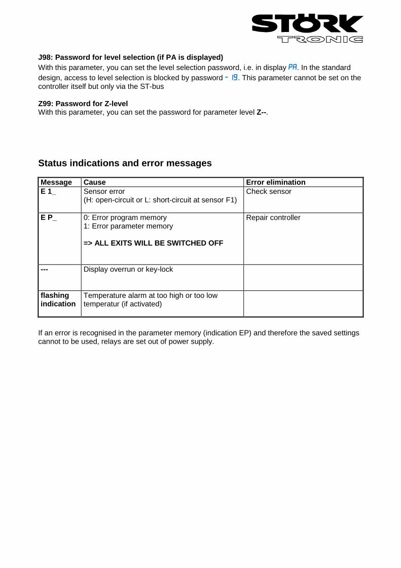
J98: Password for level selection (if PA is displayed) With this parameter, you can set the level selection password, i.e. in display . In the standard design, access to level selection is blocked by password . This parameter cannot be set on the controller itself but only via the ST-bus Z99: Password for Z-level With this parameter, you can set the password for parameter level Z--. Status indications and error messages Message Cause Error elimination E 1_ Sensor error
(H: open-circuit or L: short-circuit at sensor F1)
Check sensor
E P_ 0: Error program memory 1: Error parameter memory => ALL EXITS WILL BE SWITCHED OFF
Repair controller
--- Display overrun or key-lock
flashing indication
Temperature alarm at too high or too low temperatur (if activated)
If an error is recognised in the parameter memory (indication EP) and therefore the saved settings cannot to be used, relays are set out of power supply.
Order No.: 900410.008
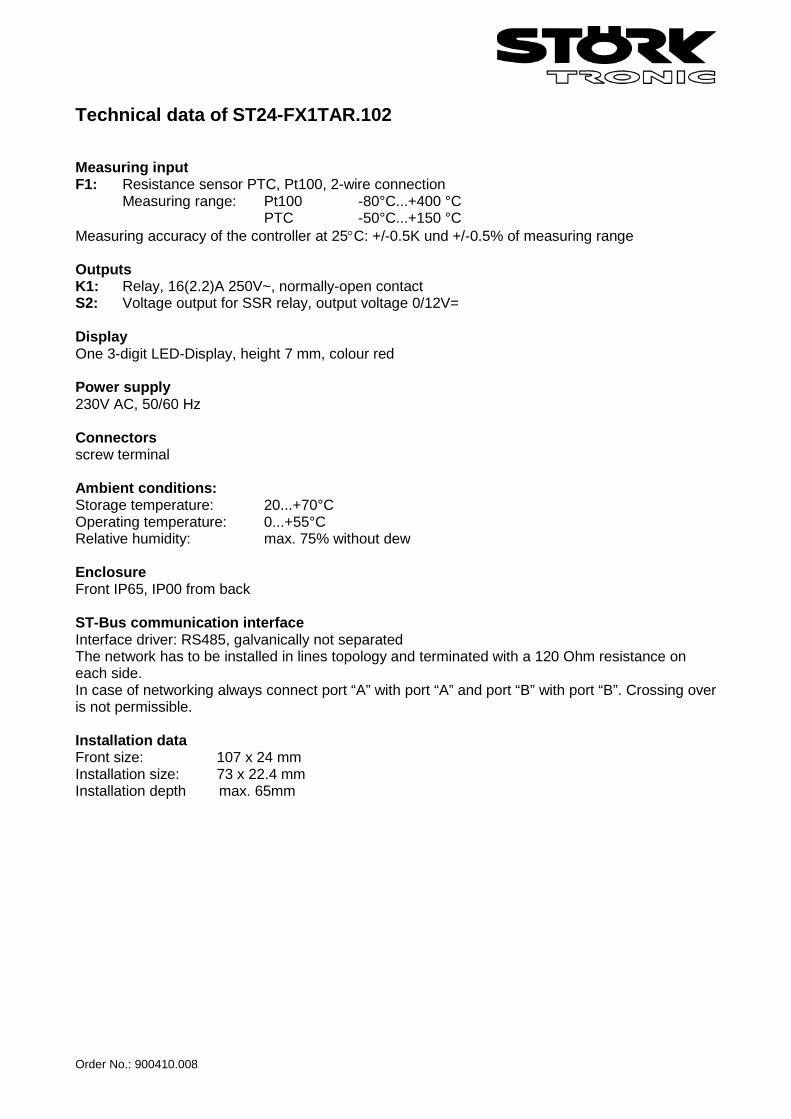
Technical data of ST24-FX1TAR.102 Measuring input F1: Resistance sensor PTC, Pt100, 2-wire connection Measuring range: Pt100 -80°C...+400 °C PTC -50°C...+150 °C Measuring accuracy of the controller at 25°C: +/-0.5K und +/-0.5% of measuring range Outputs K1: Relay, 16(2.2)A 250V~, normally-open contact S2: Voltage output for SSR relay, output voltage 0/12V= Display One 3-digit LED-Display, height 7 mm, colour red Power supply 230V AC, 50/60 Hz Connectors screw terminal Ambient conditions: Storage temperature: 20...+70°C Operating temperature: 0...+55°C Relative humidity: max. 75% without dew Enclosure Front IP65, IP00 from back ST-Bus communication interface Interface driver: RS485, galvanically not separated The network has to be installed in lines topology and terminated with a 120 Ohm resistance on each side. In case of networking always connect port “A” with port “A” and port “B” with port “B”. Crossing over is not permissible. Installation data Front size: 107 x 24 mm Installation size: 73 x 22.4 mm Installation depth max. 65mm
Related Documents