- am Bad O_ HOW TO CONNECT YOUR VCR TO MORE THAN ONE TV SET VIDEOTEX DELIVERY r. . l ST s.aN Nwr s. r.M1M1 <t) 1 T.I.p1roM t. 'IVE T.o-y abates. MweriU cubldt.Lpnun 00,01 fiber se Next TV revolution VIDEOTEX Information explosion Build this -aGs 1 Ih15 r9''9 sp.clfirat.trtx 2 Your. Carfax report 3 To leave Corfne Easy to build RUMBLE FILTER For your hi-fi CBS's new CX NOISE REDUCTION For phono records Superscope's PIANOCORDER Turn your piano into a player piano 90S09 90£ TT 'd I FXPANDEP SCALF VOLTMETER For your workbench All about TEMP MEASUREMENT Circuits and systems - i W N,nit, State Mash : Turkey.. T S- Ei" t:, T Ceprus y 1/ L erss7MYYr bag ag I r'csr5 .ltu- doe t EgyNt Sudan ydOanH AH ör-l9H9 156 WHyO 1d390d dW 0 T 3ArIN ti b9 £60r14660 n mll 71896 48783 14H1O 9i:.06L r uaocr i t Aft3on I T.%ti Pca:,.+..:)t1 1 Europe. N 1d -east i N Africa 2 M)rst, i ons of the wor l d Alexander The Grit 356-323 BC A pupil of the Gree philosopher Aristotle. of 28 he sup at h thehis father. phi' i p II of Macedon. ,Iá6 to Z throne. He united th Creek -cited - ptates are Cc.c_onomered the Persian empfre . Egypt and Northern India. Alexander rule ever- the greatest empire of the tier' and forded the city of Alexandria - Press 1 People.who mode history 2 World Book T Panas www.americanradiohistory.com

Welcome message from author
This document is posted to help you gain knowledge. Please leave a comment to let me know what you think about it! Share it to your friends and learn new things together.
Transcript
-
am Bad O_ HOW TO CONNECT YOUR VCR
TO MORE THAN ONE TV SET
VIDEOTEX DELIVERY
r. . l ST s.aN Nwr
s. r.M1M1 <t)
1 T.I.p1roM t. 'IVE
T.o-y abates.
MweriU cubldt.Lpnun 00,01 fiber
se
Next TV revolution
VIDEOTEX Information explosion
Build this
-aGs 1 Ih15 r9''9 sp.clfirat.trtx 2 Your. Carfax report 3 To leave Corfne
Easy to build
RUMBLE FILTER For your hi-fi
CBS's new
CX NOISE REDUCTION For phono records
Superscope's
PIANOCORDER Turn your piano
into a player piano
90S09 90£
TT
'd I
FXPANDEP SCALF VOLTMETER For your workbench
All about
TEMP MEASUREMENT Circuits and systems
- i
W
N,nit,
State Mash :
Turkey.. T S- Ei" t:, T
Ceprus y 1/ L erss7MYYr bag ag I r'csr5
.ltu- doe t
EgyNt
Sudan
ydOanH AH ör-l9H9 156
WHyO 1d390d dW
0 T 3ArIN ti b9 £60r14660
n mll 71896 48783
14H1O 9i:.06L
r uaocr i t
Aft3on I T.%ti
Pca:,.+..:)t1
1 Europe. N 1d -east i N Africa 2 M)rst, i ons of the wor l d Alexander The Grit
356-323 BC A pupil of the Gree philosopher Aristotle.
of 28 he sup at h
thehis father. phi'
i p II of Macedon. ,Iá6 to Z throne. He united th Creek -cited - ptates are Cc.c_onomered the Persian empfre . Egypt and Northern India. Alexander rule ever- the greatest empire of the tier' and forded the city of Alexandria
-
Press 1 People.who mode history 2 World Book
T
Panas
www.americanradiohistory.com
In one year our KQ. antenna has become the largest selling
CB antenna in the world! 1. It's more
expensive...
$42.5° And when you pay more, you expect more!
suggested retail
MORE PERFORMANCE: The K40 is guaranteed to transmit further or receive clearer than any antenna it replaces. We know it will. We've tested it with 771 CB'ers just like you for one year.
MORE FLEXIBILITY: You can fit your K40 to any mounting surface. It will fit any vehicle you'll ever own! That includes choppers, dune buggies, gutters, mirror mounts, luggage racks, trunks, hatchbacks, through roofs, semis, pick ups and RV's.
MORE QUALITY: It's not imported. It's not made in Taiwan, Korea or Japan. It's American made in
an American town. It's made with better materials that cost more and by profession- al people we pay more. And we designed it right here in the U.S.A.
'Including option- al mounts at extra cost.
...This Antenna
is so DYNAMITE you receive a ...
GUARANTEE 1 : The K-40 will transmit farther and re -
cerve more clearly than the antenna it replaces or the custom- er receive a prompt and full refund from the Registered K-40 Dealer who installed and tuned it.
GUARANTEE 11: Unconditionally guaranteed tot 12 months Guaranteed against cracking. chipping. or rusting Guaranteed against mechanical failure Guaranteed against electrical failure Guaranteed against accidental breakage. No exclusions No gimmicks For a full 12 months p
2. It's made 1. It's proven best! better.. ...Here's what the leading CB
publications said. CB TIMES: "... it's not often that a product bursts onto the mar- ket scene, dominates and improves CB'ing for everyone. American Antenna and the K40 are doing it-repeated tests showed the K40 could out -perform the major competitive brands." RADIO -ELECTRONICS: "The results of our tests showed that, in three different positions of the monitoring receiver, the model K40 equaled or out -performed the competitive antenna. Apparently, American Antenna's advertising ;e. not merely Madison Avenue showmanship." PERSONAL COMMUNICATIONS: ". . . an impressive 95% of the trials, the K40 out -performed the existing mobile anten- nas. We had to try one for ourselves. "... in every case, the K40 either equaled or out -performed its competitor.
"No ifs, ands, or buts! The K40 Antenna from American Antenna would have to be iust about the best antenna around. CB MAGAZINE: "Introduced in October, 1977, the K40 quickly became the top seller and in mid 1978, became the number one selling antenna in the nation."
corno.'"" l. ..=
...Here's what CB'ers all across the country said.
ANTENNA SPECIALISTS: "... truck driver and CB'er for 10 years ... 50% further than my M410 'Big Momma'."
-J.H. Collett, 207 McFee, Bastrop, LA
AVANTI: "I'm an electronic technician with a Second Class FCC license ... I was able to transmit 70% further and tune the SWR 75% lower than my Avanti."
-H.R. Castro, VRB, Monserrante D-67, Salinas, Puerto Rico
PAL: ". . . 20% better in transmission and reception than my 5/8 wave Pal Firestik."
-John A. Blum, Box 446, Zelienolple, PA
SHAKESPEARE: "... I've been a CB'er for three years and the K40 is the best I've ever had. Better in reception and transmission than my Shakespeare."
-H. Bachert, Jr., 15 King Rd., Park Ridge, NJ
HUSTLER: "Compared to my Hustler XBLT- 4, the K40 can consistently transmit 40% further and the reception was better. The K40 is the perfect way to complete a CB system."
-Jerome R. Brown, 7800 S. Linder, Burbank, IL
COPYRIGHT AMERICAN ANTENNA 1979
GOOD STUFF
FOR PROS ONLY! (SPECIAL NOTE)
IF YOU'RE A BEGINNER:
Our K40 Dealers will be hap- py to sell you any of the older style and less expensive an- tennas that are great bar -
POWER! 1 exclusively by American KW Dealers throughout the U.S. C? Canada.
CIRCE O ON FREE INFORMATION CARD www.americanradiohistory.com
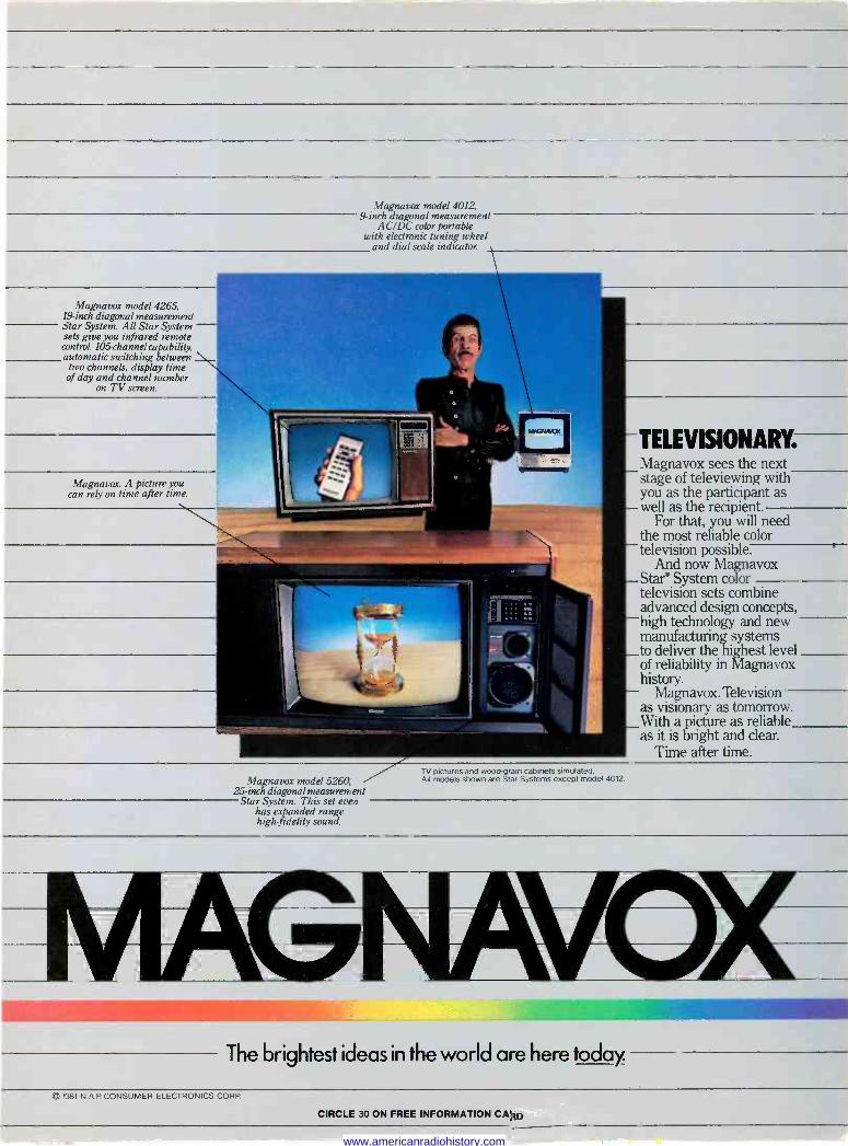
Magnavox model 4012, 9 -inch diagonal measurement
AC/DC color portable with electronic tuning. wheel
and dial scale indicator.
Magnavox model 4265, 19 -inch diagonal measurement Star System. All Star System sets give you infrared remote
control, 105 -channel capability automatic switching between
two channels, display time of day and channel number
on TV screen.
Magnavox. A picture you can rely on time after time.
Magnavox model 5260, 25 -inch diagonal measurement
Star System. This set even has expanded range high-fidelity sound.
TELEVISIONARY. Magnavox sees the next stage of televiewing with you as the participant as well as the recipient.
For that, you will need the most reliable color television possible.
And now Magnavox Star° System color television sets combine advanced design concepts, high technology and new manufacturing systems to deliver the highest level of reliability in Magnavox history.
Magnavox. Television as visionary as tomorrow. With a picture as reliable as it is bright and clear.
Time after time. TV pictures and wood -grain cabinets simulated. All models shown are Star Systems except model 4012.
The brightest ideas in the world are here today.
c: 1981 N A CONSUMER ELECTRONICS CORP
CIRCLE 30 ON FREE INFORMATION CALO
www.americanradiohistory.com
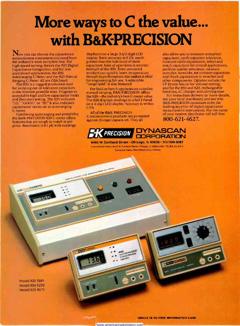
More ways to C the value. with B&KPRECISION
ow you can choose the capacitance measurement instrument you need from the industry's most complete line. For high-speed sorting, there's the 835 Digital Capacitance Comparitor; and for less specialized applications, the 830 Autoranging C -Meter and the 820 Manual Ranging C -Meter. All are GSA listed.
The 835 is a rugged production tool for isolating out -of -tolerance capacitors in the shortest possible time. Program -in acceptable high and low capacitance limits and then start testing. The 835 indicates "LO," "GOOD" or "HI." It also indicates capacitance values on an autoranging C -meter.
Combining autoranging and portability, the B&K-PRECISION 830 C -meter offers features that are tough to match at any price. Resolution is 0.1 pF, with readings
Model 820 $185
Model 830 $229 Model 835 $675
displayed on a large 3 -1/2 -digit LCD display. Basic accuracy is 0.2%,. much greater than the tolerance of most capacitors. Ease of operation is another strength of the 83e. Even untrained workers can quickly learn its operation, though its performance also nukes it ideal for engineering lab use. A selectable "range hold" is also featured.
For field or bench applications suited to manual ranging, B&K-PRECISION offers the 820-the industry's best C -meter value. The 820 displays readings to a full 1 Farad on a 4 -digit LED display Accuracy is within 0.5%.
All of the B&K-PRECISION C -measurement products are protected against charged capacitors. They all
jeKrPREC/S/0N
also allow you to measure unmarked capacitors, verify capacitor tolerance, measure cable capacitance, select and match capacitors for critical applications, perform quality assurance, measure complex networks, set trimmer capacitors and check capacitance in switches and other components. Options include the CF -10 test fimure for volume sorting; and for the 830 and 820, rechargeabl batteries, AC charger and carrying case.
For immediate delivery or more detai see your local distributor, and see why B&K-PRECISION continues to be the leading supplier of digital capacitanc measurement instruments. For the narn of your nearest distributor call toll -free
800-621-4627.
' DYNASCAN CORPORATION
6460 W. Cortland Street Chicago IL 60635.312/ 389-9087 International Sales, 646O W. Cr,i nand Street. Chicago. IL 60635 USA: TELEX: 25-3475
Canadian Sales. Atlas Sert,: onics. Ontario
MRCLE 58 ON FREE INFORMATION CARD
www.americanradiohistory.com
Radio- Elecironic:. Electronics publishers since 1908
THE MAGAZINE FOR NEW IDEAS IN ELECTRONICS
NOVEMBER 1981 Vol. 52 No. 11
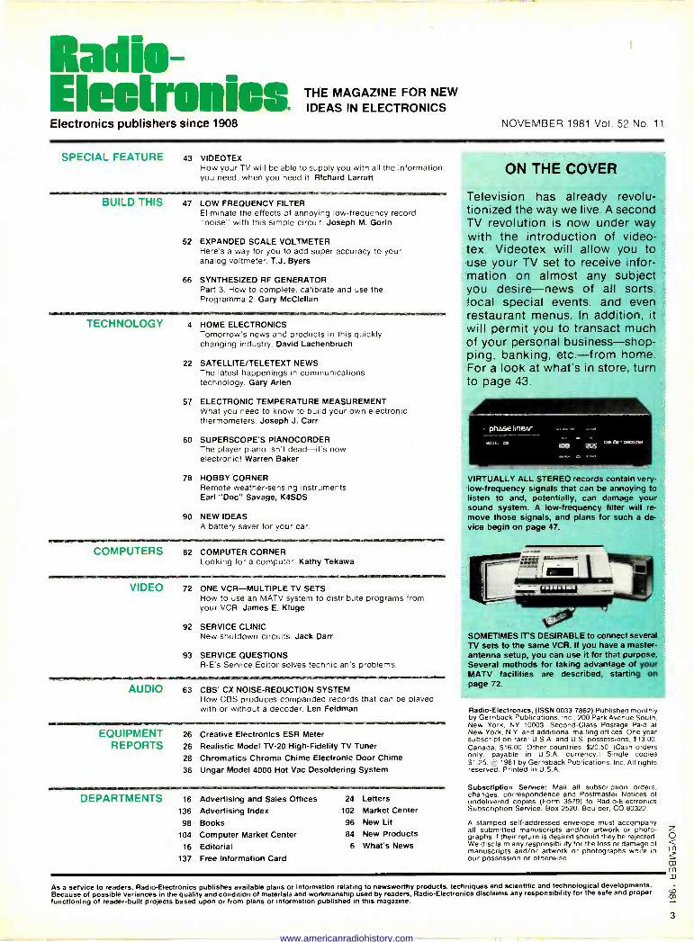
SPECIAL FEATURE 43 VIDEOTEX How your TV will be able to supply you with all the information you need, when you need it. Richard Larratt
BUILD THIS 47 LOW FREQUENCY FILTER Eliminate the effects of annoying low -frequency record "noise.' with this simple circuit. Joseph M. Gorin
52 EXPANDED SCALE VOLTMETER Here's a way for you to add super accuracy to your analog voltmeter. T.J. Byers
66 SYNTHESIZED RF GENERATOR Part 3. How to complete. calibrate and use the Programma -2. Gary McClellan
TECHNOLOGY 4 HOME ELECTRONICS Tomorrow's news and products in this quickly changing industry. David Lachenbruch
22 SATELLITE/TELETEXT NEWS The latest happenings in communications technology. Gary Arlen
57 ELECTRONIC TEMPERATURE MEASUREMENT What you need to know to build your own electronic thermometers. Joseph J. Carr
60 SUPERSCOPE'S PIANOCORDER The player piano isn't dead-it's now electronic! Warren Baker
78 HOBBY CORNER Remote weather -sens ng instruments. Earl "Doc" Savage, K4SDS
90 NEW IDEAS A battery saver for your car.
MISIIM8111111.111111111«10101
COMPUTERS 82 COMPUTER CORNER Looking for a computer. Kathy Tekawa
VIDEO 72 ONE VCR-MULTIPLE TV SETS How to use an MATV system to distribute programs from your VCR. James E. Kluge
92 SERVICE CLINIC New shutdown circuits. Jack Darr
93 SERVICE QUESTIONS R -E's Service Editor solves technicians problems.
AUDIO 63 CBS' CX NOISE -REDUCTION SYSTEM How CBS produces companded records that can be played with or without a decoder. Len Feldman
EQUIPMENT REPORTS
26 Creative Electronics ESR Meter
26 Realistic Model TV -20 High -Fidelity TV Tuner
28 Chromatics Chroma Chime Electronic Door Chime
36 Ungar Model 4000 Hot Vac Desoldering System
DEPARTMENTS 16 Advertising and Sales Offices 136 Advertising Index
98 Books 104 Computer Market Center
16 Editorial 137 Free Information Card
24 Letters 102 Market Center
96 New Lit
84 New Products 6 What's News
ON THE COVER
Television has already revolu- tionized the way we live. A second TV revolution is now under way with the introduction of video- tex. Videotex will allow you to use your TV set to receive infor mation on almost any subject you desire-news of all sorts. local special events, and even restaurant menus. In addition, it will permit you to transact much of your personal business-shop- ping. banking. etc.-from home For a look at what's in store. turn to page 43.
phase linear
,.roOEi dC
VIRTUALLY ALL STEREO records contain very - low -frequency signals that can be annoying to listen to and, potentially, can damage your sound system. A low -frequency filter will re- move those signals, and plans for such a de- vice begin on page 47.
SOMETIMES IT'S DESIRABLE to connect several TV sets to the same VCR. If you have a master - antenna setup, you can use it for that purpose. Several methods for taking advantage of your MATV facilities are described. starting on page 72.
Radio -Electronics, (ISSN 0033-7862) Published monthly by Gernback Publications. Inc.. 200 Park Avenue South. New York. NY 10003. Second -Class Postage Paid at New York. N.Y. and additional mailing offices. One-year subscription rate: U.S.A. and U.S. possessions, $13.00. Canada. $16.00. Other countries. $20.50. (Cash orders only. payable in U.S.A. currency.) Single copies $1.25 c 1981 by Gernsback Publications, Inc. All rights reserved. Printed in U.S.A.
Subscription Service: Mail all subscription orders, changes. correspondence and Postmaster Notices of undelivered copies (Form 3579) to Radio -Electronics Subscription Service. Box 2520. Boulder, CO 80322.
A stamped self-addressed envelope must accompany all submitted manuscripts and/or artwork or photo- graphs if their return is desired should they be rejected. We disclaim any responsibility for the loss or damage of manuscripts and/or artwork or photographs while in our possession or otherwise.
As a service to readers, Radio -Electronics publishes available plans or information relating to newsworthy products, techniques and scientific and technological developments. Because of possible variances in the quality and condition of materials and workmanship used by readers, Radio -Electronics disclaims any responsibility for the safe and proper functioning of reader -built projects based upon or from plans or information published in this magazine.
www.americanradiohistory.com
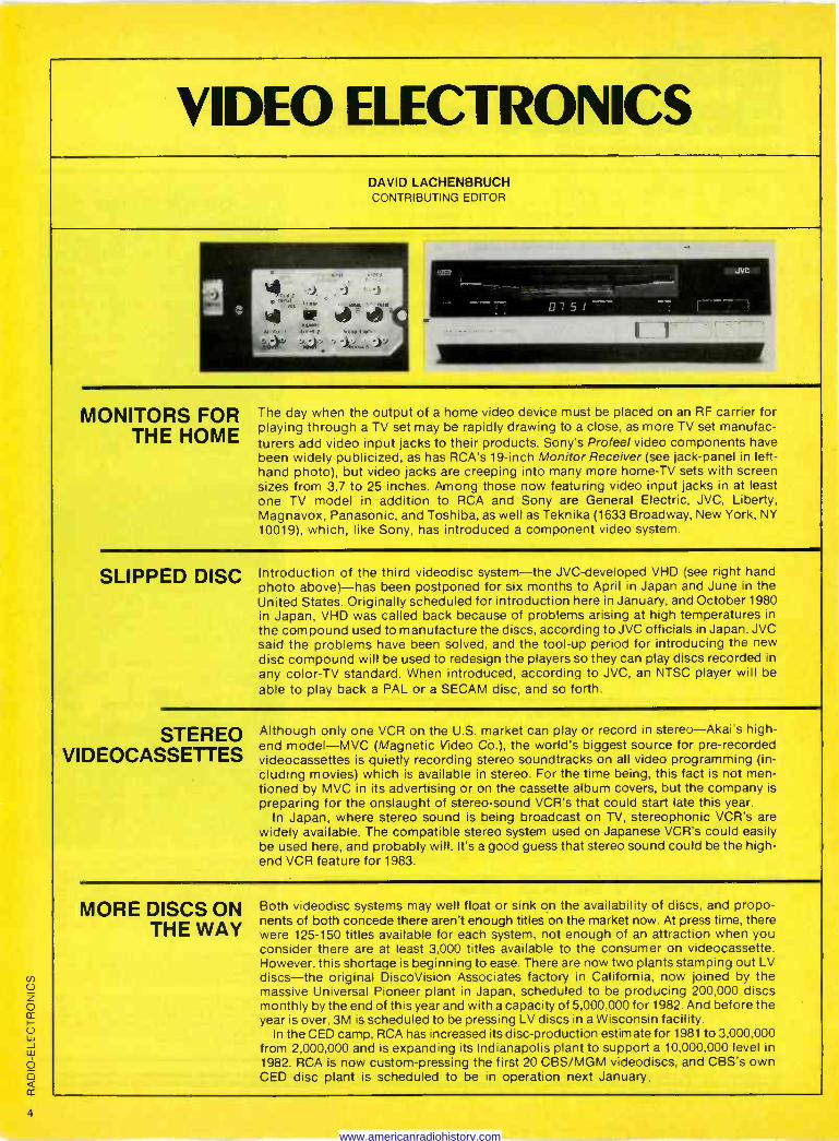
VIDEO ELECTRONICS DAVID LACHENBRUCH CONTRIBUTING EDITOR
r, 7 u 5' . : I_.._..........
1111111111111111111111111111111111111111111111111111111
MONITORS FOR THE HOME
The day when the output of a home video device must be placed on an RF carrier for playing through a TV set may be rapidly drawing to a close, as more TV set manufac- turers add video input jacks to their products. Sony's Pro feel video components have been widely publicized, as has RCA's 19 -inch Monitor Receiver (see jack -panel in left- hand photo), but video jacks are creeping into many more home -TV sets with screen sizes from 3.7 to 25 inches. Among those now featuring video input jacks in at least one TV model in addition to RCA and Sony are General Electric, JVC, Liberty, Magnavox, Panasonic, and Toshiba, as well as Teknika (1633 Broadway, New York, NY 10019), which, like Sony, has introduced a component video system.
SLIPPED DISC Introduction of the third videodisc system-the JVC-developed VHD (see right hand photo above)-has been postponed for six months to April in Japan and June in the United States. Originally scheduled for introduction here in January, and October 1980 in Japan, VHD was called back because of problems arising at high temperatures in
the compound used to manufacture the discs, according to JVC officials in Japan. JVC said the problems have been solved, and the tool -up period for introducing the new disc compound will be used to redesign the players so they can play discs recorded in any color -TV standard. When introduced, according to JVC, an NTSC player will be
able to play back a PAL or a SECAM disc, and so forth.
STEREO VIDEOCASSETTES
Although only one VCR on the U.S. market can play or record in stereo-Akai's high - end model-MVC (Magnetic Video Co.), the world's biggest source for pre-recorded videocassettes is quietly recording stereo soundtracks on all video programming (in- cluding movies) which is available in stereo. For the time being, this fact is not men- tioned by MVC in its advertising or on the cassette album covers, but the company is preparing for the onslaught of stereo -sound VCR's that could start late this year.
In Japan, where stereo sound is being broadcast on TV, stereophonic VCR's are widely available. The compatible stereo system used on Japanese VCR's could easily be used here, and probably will. It's a good guess that stereo sound could be the high - end VCR feature for 1983.
MORE DISCS ON THE WAY
Both videodisc systems may well float or sink on the availability of discs, and propo- nents of both concede there aren't enough titles on the market now. At press time, there were 125-150 titles available for each system, not enough of an attraction when you consider there are at least 3,000 titles available to the consumer on videocassette. However, this shortage is beginning to ease. There are now two plants stamping out LV discs-the original DiscoVision Associates factory in California, now joined by the massive Universal Pioneer plant in Japan, scheduled to be producing 200,000 discs monthly by the end of this year and with a capacity of 5,000,000 for 1982. And before the year is over, 3M is scheduled to be pressing LV discs in a Wisconsin facility.
In the CED camp, RCA has increased its disc -production estimate for 1981 to 3,000,000 from 2,000,000 and is expanding its Indianapolis plant to support a 10,000,000 level in 1982. RCA is now custom -pressing the first 20 CBS/MGM videodiscs, and CBS's own CED disc plant is scheduled to be in operation next January.
4
www.americanradiohistory.com
Facts from Fluke on low-cost DMM's
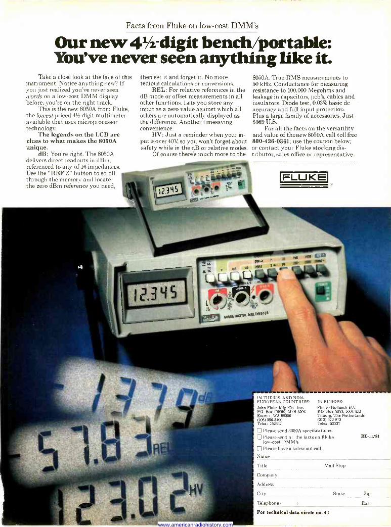
then set it and forget it. No more tedious calculations or conversions.
REL: For relative references in the dB mode or offset measurements in all other functions. Lets you store any input as a zero value against which all others are automatically displayed as the difference. Another timesaving convenience.
HV: Just a reminder when your in- put is over 40V, so you won't forget about safety while in the dB or relative modes.
Of course there's much more to the
Our new 41/2 -digit bench/portable: You've never seen anything like it.
Take a close look at the face of this instrument. Notice anything new? If you just realized you've never seen words on a low-cost DMM display before, you're on the right track.
This is the new 8050A from Fluke, the lowest priced 41/2 -digit multimeter available that uses microprocessor technology.
The legends on the LCD are clues to what makes the 8050A unique.
dB: You're right. The 8050A delivers direct readouts in dBm, referenced to any of 16 impedances. Use the "REF Z" button to scroll through the memory and locate the zero dBm reference you need,
8050A. True RMS measurements to 50 kHz. Conductance for measuring resistance to 100,000 Megohms and leakage in capacitors, pcb's, cables and insulators. Diode test, 0.03% basic dc accuracy and full input protection. Plus a large family of accessories. Just $369 U.S.
For all the facts on the versatility and value of thenew8050A,call toll free 800-426-0361; use the coupon below; or contact your Fluke stocking dis- tributor, sales office or representative.
FLUKE
IN THE U.S. AND NON -
EUROPEAN COUNTRIES: John Fluke Mfg. Co., Inc. P.O. Box C9090, M/S 250C Everett, WA 98206 (206) 356-5400 Telex: 152662
IN EUROPE: Fluke (Holland) B.V. P.O. Box 5053, 5004 EB Tilburg, The Netherlands (013) 673 973 Telex: 52237
Please send 8050A specifications. Please send all the facts on Fluke low-cost DMM's. Please have a salesman call.
Name
REI -11/81
Title Mail Stop
Company
Address
City State Zip
Telephone ( Ext.
For technical data circle no. 43
www.americanradiohistory.com
o follow economy line
Business computers priced under $20,000 will show a high- er rate of growth between now and 1984 than any other seg- ment of the business computer line, according to Venture De- velopment Corp., a market re- search concern of Wellesley, MA. Shipments of those sys- tems, says VDC, will increase 35.5% annually, accounting for 45% of shipments by 1984. Sys- tems priced between $20,000 and $50,000 will increase by 26% annually, amounting to 35% of the market, and those between $50,000 and $100,000 are expected to increase about 27% each year, holding 20% of the market in 1984.
According to Karen Horowitz, VDC analyst, future technologi- cal advances, lower -priced printers, and less expensive storage devices will enable the owner of one of the lower -priced computer setups to obtain the performance of today's middle - priced systems.
TV a,e`,i
Downlink, Inc.. of Putnam. CT, has announced a reduction of its home -satellite TV system to $3595.00. "the lowest price in
the industry. At the same time. the company announced ex- panded production capabilities and a distributor program aimed at marketing a thousand systems a month.
The system includes a 12 -foot spherical antenna, a low -noise amplifier. the Downlink model D2X receiver, and all of the re- quired cabling.
Downlink introduced other models and combinations, in- cluding the model D -2S and model D-3 receivers, as well as the Skyview Ill parabolic anten- na, at the Chicago Consumer Electronics Show that was held last June.
information, control:
The growth of home informa- tion services, video, and con- trol electronics will completely alter the face of the consumer electronics industry by 1995. The market, now $7.8 billion an- nually, will reach $28 billion by 1995. Thus believes Venture De- velopment Corp., of Wellesley, MA. The home electronics field, once dominated by radio, and now getting most of its revenue from television, will find itself chiefly involved with the hard- ware and software of home in- formation services, says the
DOWNLINK'S SKYVIEW I TV ANTENNA AND D-2 RECEIVER
Massachusetts market research firm.
The key challenge facing manufacturers will be to orches- trate product development and introduction to coincide with
evolving consumer demand. says Venture Development. Cor- rect calculation of consumer demand, and especially the timing of a product's introduc- tion, will be critical.
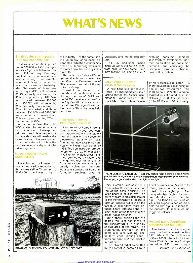
Laser sight improves infrared thermometer
A new handheld portable in- frared (IR) thermometer uses a laser sight for fast, precise focal - distance range -finding. The model 44L infrared thermometer
primary concave reflector. It is then focused on a secondary re- flector and transmitted from there to an IR detector. A digital readout is calibrated in either Celsius (0° to 600°) or Fahrenheit (0° to 1000') with 5% accuracy.
THE TELATEMP'S LASER SIGHT not only makes focal -distance range -finding precise and rapid, but also facilitates temperature measurement by illuminating the target, a great aid under poor light or no light.
from Telatemp, is equipped with a 0.5-milliwatt laser, mounted on top of the basic housing. The laser beam is split in two. The primary beam is projected parallel to the thermometer's IR optics to form an intense red spot on the target. A secondary, more dif- fused beam intersects the pri- mary beam at the thermometer's preset focal distance.
By properly aligning the two beams the user can measure the temperature of a precisely known area of the target. The illumination provided by the beam also aids sighting, par- ticularly when lighting condi- tions are poor or if the target is in darkness.
The infrared radiation emitted by the target is captured by a
Focal distances are 24 inches to infinity, preset at the factory.
With laser sighting, unlike using rifle -type sights, the user can literally "shoot from the hip." The temperature detected while the trigger is depressed is held on the digital readout for the operator to read after the trigger is released.
P'hotofacts utl c 7 het No 2.000
The Howard W. Sams com- pany reached a milestone this past July with the publication of their 2000th Photo fact folder. Sams Photo fact folders first ap- peared in 1946. introducing a
continued on page 12
www.americanradiohistory.com
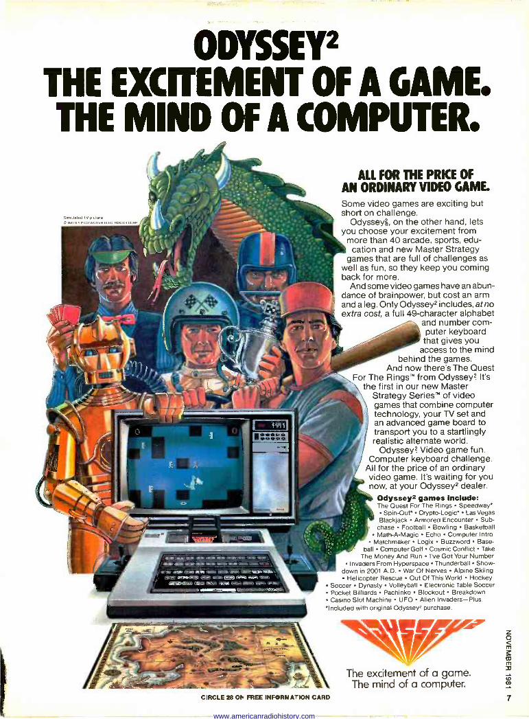
ODYSSEY2 THE EXCITEMENT Of A GAME. THE MIND OF A COMPUTER.
S,mulated TV pieve r MI N n P CONSUMER ELFO FOwC3 CORP
u;
ALL FOR THE PRICE OF AN ORDINARY VIDEO GAME. Some video games are exciting but short on challenge.
Odyssey¡, on the other hand, lets you choose your excitement from
more than 40 arcade, sports, edu- cation and new Master Strategy
games that are full of challenges as well as fun, so they keep you coming back for more.
And some video games have an abun- dance of brainpower, but cost an arm and a leg. Only Odyssey2 includes, at no extra cost, a full 49 -character alphabet
and number com- puter keyboard
that gives you access to the mind
behind the games. And now there's The Quest
For The Rings" from Odyssey? It's the first in our new Master
Strategy SeriesTT of video games that combine computer technology, your TV set and an advanced game board to transport you to a startlingly realistic alternate world.
Odyssey? Video game fun. Computer keyboard challenge.
All for the price of an ordinary video game. It's waiting for you now, at your Odyssey2 dealer.
Odyssey2 games include: The Ouest For The Rings Speedway*
Spin -Out* Crypto-Logic* Las Vegas Blackjack Armored Encounter Sub -
chase Football Bowling Basketball Math -A -Magic Echo Computer Intro
Matchmaker Logix Buzzword Base- ball Computer Golf Cosmic Conflict Take
The Money And Run I've Got Your Number Invaders From Hyperspace Thunderball Show-
down in 2001 A.D. War Of Nerves Alpine Skiing Helicopter Rescue Out Of This World Hockey
Soccer Dynasty Volleyball Electronic Table Soccer Pocket Billiards Pachinko Blockout Breakdown Casino Slot Machine UFO Alien Invaders-Plus.
*Included with original Odyssey' purchase.
rn
m 33
The excitement of a game. The mind of a computer.
CIRCLE 28 ON FREE INFORMATION CARD 7
www.americanradiohistory.com
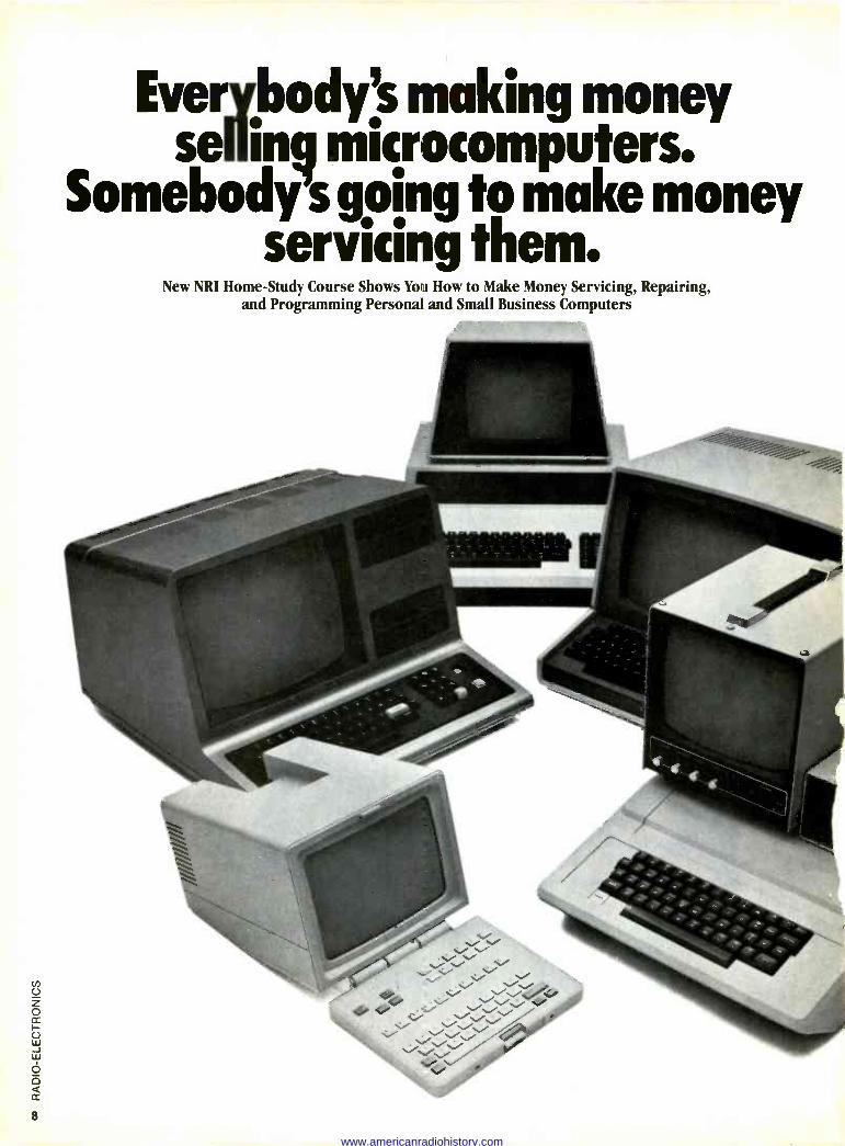
Everjyjbodys making money seuuun microcomputers.
Somebody s going to make money servicing them.
New NRI Home -Study Course Shows You How to Make Money Servicing, Repairing, and Programming Personal and Small Business Computers
www.americanradiohistory.com
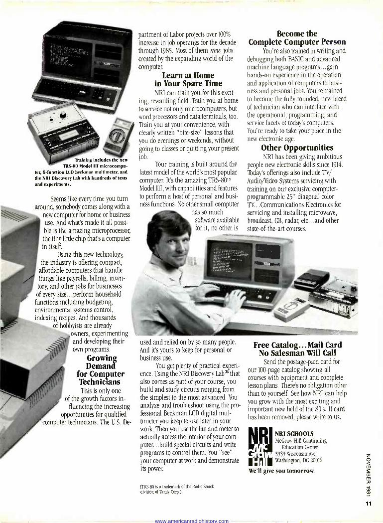
'paining includes the new TRS-80 Model Ill microcompu-
ter, 6 -function LCD Beckman multimeter, and the NRI Discovery Lab with hundreds of tests and experiments.
Seems like every time you turn around, somebody comes along with a
new computer for home or business
use. And what's made it all possi-
ble is the amazing microprocessor, the tiny little chip that's a computer in itself.
Using this new technology,
the industry is offering compact, affordable computers that handle things like payrolls, billing, inven- tory, and other jobs for businesses of every size...perform household functions including budgeting, environmental systems control, indexing recipes. And thousands
of hobbyists are already owners, experimenting and developing their own programs.
Growing Demand
for Computer Technicians This is only one
of the growth factors in- fluencing the increasing
opportunities for qualified computer technicians. The U.S. De-
partment of Labor projects over 100%
increase in job openings for the decade
through 1985. Most of them new jobs
created by the expanding world of the
computer.
Learn at Home in Your Spare Time NRI can train you for this excit-
ing, rewarding field. Train you at home
to service not only microcomputers, but word processors and data terminals, too.
Thin you at your convenience, with
clearly written "bite -size" lessons that you do evenings or weekends, without going to classes or quitting your present job.
Your training is built around the latest model of the world's most popular computer. It's the amazing TRS-80TH
Model III, with capabilities and features to perform a host of personal and busi- ness functions. No other small computer
has so much software available for it, no other is
used and relied on by so many people. And it's yours to keep for personal or business use.
You get plenty of practical experi- ence. Using the NRI Discovery Lab® that also comes as part of your course, you build and study circuits ranging from the simplest to the most advanced. You
analyze and troubleshoot using the pro- fessional Beckman LCD digital mul- timeter you keep to use later in your work. Then you use the lab and meter to
actually access the interior of your com- puter...build special circuits and write
programs to control them. You "see"
your computer at work and demonstrate its power.
(TRS-80 is a trademark of the Radio Shack division of Tandy Corp.)
Become the Complete Computer Person
You're also trained in writing and debugging both BASIC and advanced machine language programs... gain hands-on experience in the operation and application of computers to busi- ness and personal jobs. You're trained to become the fully rounded, new breed of technician who can interface with the operational, programming, and service facets of today's computers. You're ready to take your place in the new electronic age.
Other Opportunities NRI has been giving ambitious
people new electronic skills since 1914.
Tbday's offerings also include TV/
Audio/Video Systems servicing with training on our exclusive computer - programmable 25" diagonal color TV... Communications Electronics for
servicing and installing microwave, broadcast, CB, radar, etc... and other state-of-the-art courses.
Free Catalog...Mail Card No Salesman Will Call
Send the postage -paid card for
our 100 -page catalog showing all courses with equipment and complete lesson plans. There's no obligation other than to yourself. See how NRI can help you grow with the most exciting and important new field of the 80's. If card has been removed, please write to us.
NRI SCHOOLS McGraw-Hill Continuing
AI Ij a Education Center . 3939 Wisconsin Ave.
Y Washington, DC 20016
We'll give you tomorrow.
NRI
www.americanradiohistory.com
continued from page 6
revolutionary new type of ser- vice information. Each piece of equipment described was dis- assembled, so that all data would be complete and accurate for the parts and circuits actually appearing in the equipment. (The "official service manuals" of the time-Gernsback's, Rider's, and Beitman's-merely reprinted the manufacturer's schematic, often with extracts from manu- facturers service information.
PHOTOFACT FOLDER NO. 2000 has a gold cover, to mark an era in ser- vice information publishing.
The Sams approach resultea in the Photo fact Standard Nota- tion schematic; complete align- ment and adjustment instruc- tions; chassis and waveform photographs; comprehensive parts lists with replacement parts, and test measurements. The sequence and format of the information has been presented in the same consistent, stan- dardized and clear manner from Folder No. 1.
Number 2,000 was reached with a folder containing infor- mation on the Hitachi NPX-L and the Sears 564-44150050/4200050 color -TV receivers, and on the Realistic 12-1524 Chronomatic 219 radio. The cover for this special set is printed in gold to mark the occasion.
Initially, Photofact folders provided service information for radios; their coverage was later expanded to include television receivers, as well as a variety of other consumer electronics equipment. Recently, coverage has been expanded to include video -cassette recorders, and
videodisc players will soon be covered. Currently, seven Photo - fact sets are published every month. Some technicians have been members of the Photofact- of-the- Month Club from the beginning and have received all 2000 sets. Beginning with No. 2000 the publisher states that Photofacts has been updated and streamlined graphically.
RCA, Columbia, uniting to market home video ahr
RCA Corporation and Colum- bia Pictures Industries, Inc., have formed a joint venture to market home -video entertainment pro- grams throughout the world, excepting the United States and Canada. The participants will develop an organization with offices in all principal countries, to market existing and future theatrical and television pro- grams produced by the two companies and other producers,
as well as original productions created specifically for the home -video market.
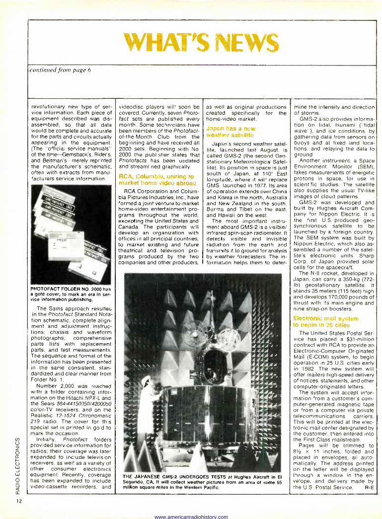
Japçn has a new weather satellite
Japan's second weather satel- lite, launched last August, is called GMS-2 (the second Geo - stationary Meteorological Satel- lite). Its position in space is just south of Japan, at 140' East longitude, where it will replace GMS, launched in 1977. Its area of operation extends over China and Korea in the north, Australia and New Zealand in the south, Burma and Tibet on the east, and Hawaii on the west.
The most important instru- ment aboard GMS-2 is a visible/ infrared spin -scan radiometer. It detects visible and invisible radiation from the earth and transra is it to ground for analysis by weather forecasters. The in- formation helps them to deter -
,4 4 di
/.f.+r,/ a
4.44. 44,4t® 4444 4444 4 4 ,t 44444 It, 4
.l1.4,,r ' /,/,RR,, .i 44
THE JAPANESE GMS-2 UNDERGOES TESTS at Hughes Aircraft in El Segundo, CA. It will collect weather pictures from an area of some 65 million square miles in the Western Pacific.
mine the intensity and direction of storms.
GMS-2 also provides informa- tion on tidal, tsunami ("tidal wave"), and ice conditions, by gathering data from sensors on buoys and at fixed land loca- tions, and relaying the data to ground.
Another instrument, a Space Environment Monitor (SEM), takes measurements of energetic protons in space, for use in scientific studies. The satellite also supplies the usual TV -like images of cloud patterns.
GMS-2 was developed and built by Hughes Aircraft Com- pany for Nippon Electric. It is the first U.S.-produced geo- synchronous satellite to be launched by a foreign country. The SEM system was built by Nippon Electric, which also as- sembled a number of the satel- lite's electronic units. Sharp Corp. of Japan provided solar cells for the spacecraft.
The N -II rocket, developed in Japan, can carry a 350 -kg (772 - lb) geostationary satellite. It stands 35 meters (115 feet) high and develops 170,000 pounds of thrust with its main engine and nine strap -on boosters.
lectronic mail system '1 ire ` cities
The United States Postal Ser- vice has placed a $31 -million contract with RCA to provide an Electronic -Computer Originated Mail (E-COM) system, to begin operation in 25 U.S. cities early in 1982. The new system will offer mailers high-speed delivery of notices, statements, and other computer -originated letters.
The system will accept infor- mation from a customer's com- puter -generated magnetic tape or from a computer via private telecommunications carriers. This will be printed at the elec- tronic mail center designated by the customer, then entered into the First Class mailstream.
Pages will be trimmed to 81/2 x 11 inches, folded and placed in envelopes, all auto- matically. The address printed on the letter will be displayed through a window in the en- velope, and delivery made by the U.S. Postal Service. R -E
www.americanradiohistory.com
Synthesized Hand -Held Scanner!
Chances are the police, fire and weather emergencies you'll read about in tomor- row's paper are coming through on a scanner right now. All scanners sold by Communications Electronics bring the real live excitement of action news into your home or car. With your scanner, you can monitor the exciting two-way radio conversations of police and fire depart- ments, intelligence agencies, mobile tele- phones, energy/oil exploration crews, drug enforcement agencies and more.
Some scanners can even monitor aircraft transmissions! You can actually hear the news before it's news. If you do not own a scanner for yourself, now's the time to buy your new scanner from Communications Electronics. Choose the scanner that's right for you, then call our toll -free number to place your order with your Visa or Master Charge card.
We give you excellent service because CE distributes more scanners worldwide than anyone else. Our warehouse facilities are equipped to process thousands of scanner orders every week. We also export scanners to over 300 countries and military instal- lations. Almost all items are in stock for quick shipment, so if you're a person who prefers fact to fantasy and who needs to know what's really happening around you, order your scanner today from CE!
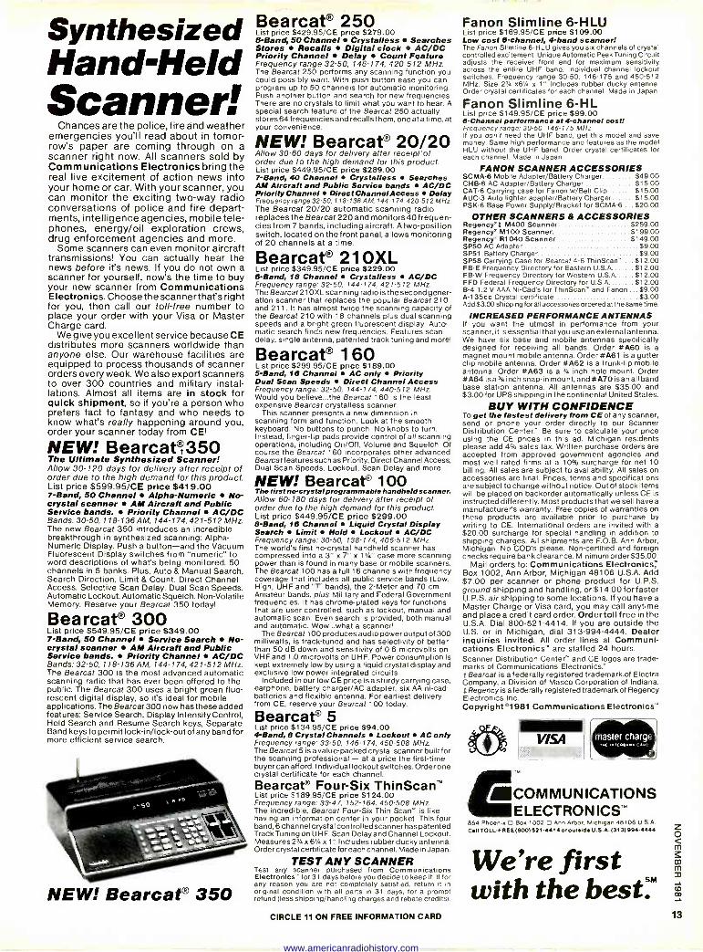
NEW! Bearcat°350 The Ultimate Synthesized Scanner: Allow 30-120 days for delivery after receipt of order due to the high demand for this product. List price $599.95/CE price $419.00 7 -Band, 50 Channel Alpha -Numeric No - crystal scanner AM Aircraft and Public Service bands. Priority Channel AC/DC Bands: 30-50,118-136 AM, 144-174, 421-512 MHz. The new Bearcat 350 introduces an incredible breakthrough in synthesized scanning: Alpha - Numeric Display. Push a button -and the Vacuum Fluorescent Display switches from "numeric" to word descriptions of what's being monitored. 50 channels in 5 banks. Plus, Auto & Manual Search, Search Direction, Limit & Count. Direct Channel Access. Selective Scan Delay. Dual Scan Speeds. Automatic Lockout. Automatic Squelch. Non -Volatile Memory. Reserve your Bearcat 350 today!
Bearcat° 300 List price $549.95/CE price $349.00 7 -Band, 50 Channel Service Search No - crystal scanner AM Aircraft and Public Service bands. Priority Channel AC/DC Bands: 32-50, 118-136 AM, 144-174, 421-512 MHz. The Bearcat 300 is the most advanced automatic scanning radio that has ever been offered to the public. The Bearcat 300 uses a bright green fluo- rescent digital display, so it's ideal for mobile applications. The Bearcat 300 now has these added features: Service Search, Display Intensity Control, Hold Search and Resume Search keys, Separate Band keys to permit lock-in/lock-out of any band for more efficient service search.
NEW! Bearcat® 350
Bearcat° 250 List price $429.95/CE price $279.00 6 -Band, 50 Channel Crystalless Searches Stores Recalls Digital clock AC/DC Priority Channel Delay Count Feature Frequency range 32-50, 146-174, 420-512 MHz The Bearcat 250 performs any scanning function you could possibly want. With push button ease you can program up to 50 channels for automatic monitoring. Push another button and search for new frequencies. There are no crystals to limit what you want to hear. A special search feature of the Bearcat 250 actually stores 64 frequencies and recalls them, one at a time, at your convenience.
NEW! Bearcat° 20/20 Allow 30-60 days for delivery after receipt of order due to the high demand for this product. List price $449.95/CE price $289.00 7 -Band, 40 Channel Crystalless Searches AM Aircraft and Public Service bands AC/DC Priority Channel Direct Channe/ Access Delay Frequency range 32-50, 118-136 AM, 144-174, 420-512 MHz. The Bearcat 20/20 automatic scanning radio replaces the Bearcat 220 and monitors40 frequen- cies from 7 bands, including aircraft. A two -position switch, located on the front panel, allows monitoring of 20 channels at a time.
Bearcat® 210XL List price $349 95/CE price $229.00 6 -Band, 18 Channel Crystalless AC/DC Frequency range: 32-50, 144.174, 421-512 MHz The Bearcat 210XL scanning radio is the second gener- ation scanner that replaces the popular Bearcat 210 and 211. It has almost twice the scanning capacity of the Bearcat 210 with 18 channels plus dual scanning speeds and a bright green fluorescent display. Auto- matic search finds new frequencies. Features scan delay, single antenna, patented track tuning and more!
Bearcat° 160 List price $299.95/CE price $189.00 5 -Band, 18 Channel AC only Priority Dual Scan Speeds Direct Channel Access Frequency range: 32-50, 144-174, 440-512 MHz. Would you believe...the Bearcat 160 is the least expensive Bearcat crystalless scanner.
This scanner presents a new dimension in scanning form and function. Look at the smooth keyboard. No buttons to punch. No knobs to turn. Instead, finger-tip pads provide control of all scanning operations, including On/Off, Volume and Squelch. Of course the Bearcat 160 incorporates other advanced Bearcat features such as Priority, Direct Channel Access, Dual Scan Speeds, Lockout, Scan Delay and more.
NEW! Bearcat° 100 The first no -crystal programmable handheld scanner. Allow 60-180 days for delivery after receipt of order due to the high demand for this product. List price $449.95/CE price $299.00 8 -Band, 16 Channel Liquid Crystal Display Search Limit Hold Lockout AC/DC Frequency range: 30-50, 138-174, 406-512 MHz. The world's first no -crystal handheld scanner has compressed into a 3" x 7" x 11/4" case more scanning power than is found in many base or mobile scanners. The Bearcat 100 has a full 16 channels with frequency coverage that includes all public service bands (Low, High, UHF and "T' bands), the 2 -Meter and 70 cm. Amateur bands, plus Military and Federal Government frequencies. It has chrome -plated keys for functions that are user controlled, such as lockout, manual and automatic scan. Even search is provided, both manual and automatic. Wow...what a scanner!
The Bearcat 100 produces audio power output of 300 milliwatts, is track -tuned and has selectivity of better than 50 dB down and sensitivity of 0.6 microvolts on VHF and 1.0 microvolts on UHF. Power consumption is kept extremely low by using a liquid crystal display and exclusive low power integrated circuits.
Included in our low CE price isa sturdy carrying case, earphone, battery charger/AC adapter, six AA ni -cad batteries and flexible antenna. For earliest delivery from CE, reserve your Bearcat 100 today.
Bearcat® 5 List price $134.95/CE price $94.00 4 -Band, 8 Crystal Channels Lockout AC only Frequency range: 33-50, 146-174, 450-508 MHz The Bearcat 5 is a value -packed crystal scanner built for the scanning professional - at a price the first-time buyer can afford. I ndividual lockout switches. Order one crystal certificate for each channel.
Bearcat® Four -Six ThinScan List price $189.95/CE price $124.00 Frequency range: 33-47, 152-164, 450-508 MHz. The incredible, Bearcat Four -Six Thin Scan" is like having an information center in your pocket. This four band, 6 channel crystal control led scanner has patented Track Tuning on UHF. Scan Delay and Channel Lockout. Measures 21 x 61/4 x l ' Includes rubber ducky antenna. Order crystal certificate for each channel. Made in Japan.
TEST ANY SCANNER Test any scanner purchased from Communications Electronics- for 31 days before you decide to keep it. If for any reason you are not completely satisfied, return it in original condition with all parts in 31 days, for a prompt refund (less shipping/handling charges and rebate credits).
TPA
Fanon Slimline 6-HLU List price $169.95/CE price $109.00 Low cost 6 -channel, 4 -band scanner! The Fanon Slimline 6-HLU gives you six channels of crystal controlled excitement. Unique Automatic Peak Tuning Circuit adjusts the receiver front end for maximum sensitivity across the entire UHF band. Individual channel lockout switches. Frequency range 30-50, 146-175 and 450-512 MHz. Size 23/4 x6y. x U' Includes rubber ducky antenna. Order crystal certificates for each channel. Made in Japan.
Fanon Slimline 6 -HL List price $149.95/CE price $99.00 6 -Channel performance at 4 -channel coati Frequency range: 30-50, 146-175 MHz If you don't need the UHF band, get this model and save money. Same high performance and features as the model HLU without the UHF band. Order crystal certificates for each channel. Made in Japan.
FANON SCANNER ACCESSORIES SCMA-6 Mobile Adapter/Battery Charger $49.00 CHB-8 AC Adapter/Battery Charger $15.00 CAT -6 Carrying case for Fanon w/Belt Clip $15.00 AUC -3 Auto lighter adapter/Battery Charger $15.00 PSK-6 Base Power Supply/Bracket for SCMA-6 $20.00
OTHER SCANNERS & ACCESSORIES $259.00 $199.00 $149.00
$9.00 $9.00
Regency°t M400 Scanner Regency" M100 Scanner Regency* R1040 Scanner SP50 AC Adapter SP51 Battery Charger SP58 Carrying Case for Bearcat 4-6 ThinScan' ... $12.00 FB -E Frequency Directory for Eastern U.S.A....... $12.00 FB -W Frequency Directory for Western U.S A $12.00 FFD Federal Frequency Directory for U.S A $12.00 B-4 1.2 V AAA Ni -Cad's for ThinScan" and Fanon ... $9.00 A-135cc Crystal certificate $3.00 Add $3.00 shipping for all accessories ordered at the same time.
INCREASED PERFORMANCE ANTENNAS If you want the utmost in performance from your scanner, it is essential that you use an external antenna. We have six base and mobile antennas specifically designed for receiving all bands. Order #A60 is a magnet mount mobile antenna. Order *A61 is a gutter clip mobile antenna. Order #A62 is a trunk -lip mobile antenna. Order #A83 is a 34 inch hole mount. Order #A64 isa aye inch snap -in mount, and#A70 is an all band base station antenna. All antennas are $35.00 and $3.00 for UPS shipping in the continental United States.
BUY WITH CONFIDENCE To get the fastest delivery from CE of any scanner, send or phone your order directly to our Scanner Distribution Center" Be sure to calculate your price using the CE prices in this ad. Michigan residents please add 4% sales tax. Written purchase orders are accepted from approved government agencies and most well rated firms at a 10% surcharge for net 10 billing. All sales are subject to availability. All sales on accessories are final. Prices, terms and specifications are subject to change without notice. Out of stock items will be placed on backorder automatically unless CE is instructed differently. Most products that we sell have a manufacturer's warranty. Free copies of warranties on these products are available prior to purchase by writing to CE. International orders are invited with a $20.00 surcharge for special handling in addition to shipping charges. All shipments are F.O.B. Ann Arbor, Michigan. No COD's please. Non -certified and foreign checks require bank clearance. Minimum order$35.00.
Mail orders to: Communications Electronics; Box 1002, Ann Arbor, Michigan 48106 U.S.A. Add $7.00 per scanner or phone product for U.P.S. ground shipping and handling, or $14.00 for faster U.P.S. air shipping to some locations. If you have a Master Charge or Visa card, you may call anytime and place a credit card order. Order toll free in the U.S.A. Dial 800-521-4414. If you are outside the U.S. or in Michigan, dial 313-994-4444. Dealer inquiries invited. All order lines at Communi- cations Electronics" are staffed 24 hours. Scanner Distribution Center" and CE logos are trade- marks of Communications Electronics" t Bearcat is a federally registered trademark of Electra Company, a Division of Masco Corporation of Indiana t Regency isa federally registered trademark of Regency Electronics Inc. Copyright °1981 Communications Electronics"
master charge Net cart..» c
COMMUNICATIONS ELECTRONICS -
854 Phoenix O Box 1002 O Ann Arbor. Michigan 48106 U. 5.A GII TOLL-FREE(800)521.4414 s,oatafdU.S.A.1313)94-4444
We're first with the best:M
CIRCLE 11 ON FREE INFORMATION CARD 13
www.americanradiohistory.com
New Portable Digital Capacitance Meter
0HITACHI KEITH LEY
ItNon -Linear Systems
HICKOK FLUKE
VIZ RñiA TRIPLETT
-6- PHILIPS WESTON
e :cPRECISION
LEADER DORIC .
DATA PRECISION
ESI, r.ZI
THE TEST EQUIPMENT SPECIALISTS
TOLL FREE HOT LINE 800-223-0474
54 WEST 45th STREET, NEW YORK, N.Y. 10036 IN NEW YORK STATE 212-687-2224
eKPIrfC/S/ON
KEITH LEY Model 169 BENCH/PORTABLE DMM
31/2 Digit liquid crystal display
0.25% basic accuracy 26 Ranges
$189.00
80MHz Counter with Period Function
Cat For Our Price
MODEL 1820 5Hz to 80MHz reading guaranteed- 100MHz typical
Period measurements from 5Hz to 1MHz.
Period average, auto and manual positions
One PPM resolution
Totalizes to 999999 plus overflow
Elapsed time measurements from .01 to 9999.99 seconds plus overflow
One-megohm input resistance
Bright 43" high LED readouts
New Low Distortion Function Generator MODEL 3010
Generates sine, square and triangle waveforms
Variable amplitude and fixed TTL square -
wave outputs
0. 1 Hz to 1MHz in six ranges
Push button range and function selection
Typical sine wave distortion under 0.5% from 0.1 Hz to 100kHz
Variable DC offset for engineering applications
VCO external input for sweep -frequency tests
New Sweep/Function Generator MODEL 3020
Four instruments in one package-sweep generator, func- tion generator, pulse generator. tone -burst generator.
Covers 0.02Hz-2MHz 1000: 1 tuning range
Low -distortion high -accuracy outputs
Three -step attenuator plus vernier control
Internal linear and log sweeps
Tone -burst output is front -panel or externally programmable
V-1518 15 MHz Single Trace
V-1528 15 MHz Dual Trace
V-202 20 MHz Dual Trace
V-301 30 MHz Single Trace
V-3028 30 MHz Dual Trace
V-352 35 MHz Dual Trace
V -550B 50 MHz Dual Trace,
Dual Time Base
V-1050 100 MHz Dual Trace,
Dual Time Base
Call For Special Intro Price Offer
HITACHI
We carry a full line of multimeters, oscilloscopes, frequency counters, audio and RF generators, power supplies and accessories.
Just call our Toll -Free number and one of our experts will answer all your questions about test equipment.
www.americanradiohistory.com
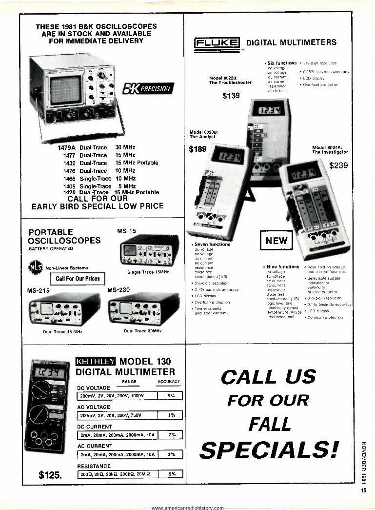
THESE ARE
________.._.. ems'
1981 B&K IN STOCK
FOR IMMEDIATE
OSCILLOSCOPES AND
DELIVERY
é s
AVAILABLE FLUKE DIGITAL MULTIMETERS
Six functions 31/2 -digit resolution dc voltage ac voltage 0.25% basic dc accuracy
Model 8022B: dc current LOD display The Troubleshooter ac current
resistance Overload protection
diode test
$139
iffli arr..
Model 8020B: The Analyst r tit $1ß9 Model 8024A:
= The Investigator
- $239 pr.µ
.,. i lNr -.' lr +! ..:,.,
, :«PREC/S/ON
I
EARLY
lii ® -sr-
1479A Dual -Trace
1477 Dual -Trace
1432 Dual -Trace
1476 Dual -Trace
1466 Single -Trace
1405 Single -Trace 1420 Dual Trace
CALL FOR OUR BIRD SPECIAL
30 MHz 15 MHz 15 MHz Portable
10 MHz 10 MHz
5 MHz 15 MHz Portable
LOW PRICE
PORTABLE MS
OSCILLOSCOPES BATTERY OPERATED
Non -Linear Systems ' -15., i i
b I *I
Single Trace 15MHz
j,yt Seven fions ions NEW
W
dc voltage ac voltage
4111.1. dc current ac current resistance Nine functions Peak hold on voltage diode test dc voltage and current functions conductance (1/A) ac voltage Selectable audible 31/2 -digit resolution
dc current indicator for ac current continuity 0.1 % basic dc accuracy resistance
or level detection LCD display diode test
conductance (1/R) 31/2áigit resolution Overload logic level and 0.1 % basic dc accuracy Two year parts continuity detect and labor warranty temperature (K -type LCD display
Overload protection
Call For Our Prices
MS -215 MS -230
a.
Dual
®
rN # # .ro LL.
Trace 15 MHz
DMFv di4
4 M op , wivthermocouple) Dual Trace 30MHz
CALL FOR
FALL SIE.dI4
US OUR
.. ,._ KEITHLEY MODEL 130 DIGITAL MULTIMETER
RANGE ACCURACY
DC VOLTAGE
- 200mV, 2V, 20V, 200V, 1000V .5%
AC VOLTAGE
200mV, 2V, 20V, 200V, 750V 1
DC CURRENT
2mA, 20mA, 200mA, 2000mA, 10A 2%
AC CU
2mÁ, 200mÁmA,, 200mÁ, 2000mÁ, 10A 30/2
RESISTANCE
$ 125. 200Q, 2kQ, 20kQ, 200kQ, 20M Q .5
www.americanradiohistory.com
EDITORIAL
Just Another Technological Advance?
Electronics technology plays a vital role in almost every industry. Every day, in medicine and energy conservation, to name just two. electronics is making an important and continuing contribution.
One industry greatly changed and influenced by electronics is photography. The portable all -in -one video camera/VCR combina- tion is encroaching upon and often replacing home -movie camera/ projector/screen combinations. Photographic still -picture cameras have also felt the impact of electronics. Integrated circuits have made possible such features as automatic exposure, LED metering, and even auto -focusing.
Now Sony has announced the all -electronic still camera. Called the MAVICA (MAgnetic Video CAmera), it looks very much like a
conventional 35 -mm SLR. It weighs 13/4lbs. and measures 51/8 u
31/2 '< 21/16 inches. It is a single-lens reflex camera with inter- changeable lenses. Shutter speeds range from 1/60 to 1/1000 on manual and 1/60 to 1/2000 on automatic.
Here the similarity ends. The MAVICA does not use photographic film. Instead, it uses a CCD image sensor with about 280,000 picture elements (570 horizontal and 490 vertical). The images are recorded on a magnetic disk that rotates inside a flat cassette (very much like a floppy disk). The magnetic cassette sits inside the camera and records up to 50 color pictures. Pictures can be selectively erased and re-recorded.
To see the pictures you've taken, the cassette is removed from the camera and placed into a viewer that is connected to a TV set. A transmitter/receiver combination will be available that attaches to the viewer. With this, pictures can be transmitted over telephone lines. In addition, the camera provides output signals for direct connection to a VCR. Now when the camera is switched to a continuous mode. it becomes a video camera.
Specifications include a 1 -MHz bandwidth, an image S/N ratio of 45 dB and a horizontal resolution equivalent to 350 TV lines. The price of the camera will be around $650 and the viewer about $230. Each magnetic cassette is expected to sell for $2.65.
Commercial introduction is scheduled for the fall of 1983. Although I haven't seen any pictures from this camera, Sony claims that they are somewhat disappointed in the picture quality and resolution. However, they are working feverishly to improve the quality before introduction. Sony is also working on a hard - copy color printer for the system.
Although this latest development won't have a profound effect on our day-to-day lives, it is one more reason why I feel proud to be a member of the electronics industry. It also prompts me to ask why this, like so many other recent advances, comes from abroad instead of from our own research and development labs?
ART KLEIMAN Managing Editor
Radio - Electronics® Hugo Gernsback (1884-1967) founder M. Harvey Gemsback, editor -in -chief
Larry Steckler, CET, publisher Arthur Kleiman, managing editor
Josef Bernard, K2HUF, technical editor Carl Laron, WB2SLR, assistant editor Jack Darr, CET, service editor Leonard Feldman
contributing high-fidelity editor Karl Savon, semiconductor editor Herb Friedman, communications editor Gary H. Arlen, contributing editor David Lachenbruch, contributing editor Earl "Doc" Savage, K4SDS, hobby editor Ruby Yee, production manager
Robert A. W. Lowndes, production associate
Joan Burwick, production assistant
Gabriele Margules, circulation director Arline R. Fishman,
advertising coordinator Cover photo by Robert Lewis
Radio -Electronics is indexed in Applied Science & Technology Index and Readers Guide to Periodical Literature.
Gernsback Publications, Inc. 200 Park Ave. S., New York, NY 10003 President: M. Harvey Gernsback Vice President: Larry Steckler Secretary/Treasurer: Carol A. Gernsback
ADVERTISING SALES 212-777-6400 Larry Steckler Publisher
EAST Stanley Levitan Radio -Electronics 200 Park Ave. South New York, NY 10003 212-777-6400
MIDWEST/Texas/Arkansas/Okla. Ralph Bergen The Ralph Bergen Co. 540 Frontage Road-Suite 361-A Northfield, Illinois 60093 312-446-1444
PACIFIC COAST Mountain States Marvin Green Radio -Electronics 413 So. La Brea Ave. Los Angeles, Ca 90036 213-938-0166-7
SOUTHEAST Paul McGinnis Paul McGinnis Company 60 East 42nd Street New York, N.Y. 10017 212-490-1021
www.americanradiohistory.com
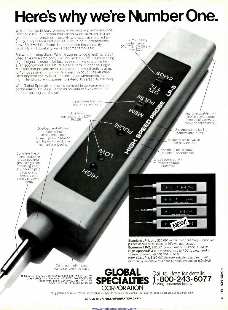
Here's why we're Number One. When it comes to logic probes, more people purchase Global Specialties! Because you can spend twice as much ana not get the speed, precision, flexibility and accuracy offered by our four logically -priced probes-including our remarkable new 150 MHz ECL Probe. Not to mention the versatility, reliability and durability we've become famous for.
But we don't stop there. When it comes to logic testing, Global Specialties does the complete job. With our DP -1 auto -sensing digital signal injector-for fast, easy stimulus -response testing. at an economical $83.00*. Plus a line of multi -channel Logic Monitors that provide an inside picture of circuit activity at up to 40 nodes simultaneously. And each product has an idea - filled applications manual-as well as an unmatched line of highly -functional accessories, to extend its versatility still more.
With Global Specialties, there's no need to compromise on performance. Or value. Discover for yourself why we're the number -one logical choice!
Easy -to -use Memory and Pulse functions
Full readout indications-HI, LOW.
PULSE
Overload and AC -line - protected high - impedance input
Linear input impedance eliminates errors due to
non -uniform loading
True multi -family performance:
DTL, TTL, CMOS and now EC!_!
Interchangeable thin - profile power cords (instead of awkward,
heavy or coiled cords)
Unsurpassed reliability- performance proven
All specs conservative and guaranteed
Half the price for equal Complete line of (or better) performance interchangeable probe tips and Circuit -powered with
grounding wires, reverse -voltage including easy protection
clip, banana plug, alligator clip jumpers and
variety of power cords
Compact, high -impact. human -engineered case
70 Fulton Terr, New Haven, CT 06509 (203) 624-3103, TWX 710-465-1227 OTHER OFFICES: San Francisco(415) 648-0611. TWX 910-372-7992
Europe: Phone Saffron -Walden 0799-21682, TLX 817477 Canada: Len Finkler Ltd., Downsview, Ontario
Standard LP -1, only $50.00*, with latching memory-captures pulses as fast as 50 nsec, to 10MHz, guaranteed Economy LP -2, $32.00*,, guaranteed to 50 nsec, 1.5 MHz High-speed LP -3 with memory, only $77.00*, guaranteed to 10 nsec (6 nsec, typical) and 50 MHz! New ECL LP -4, $150.00*, the new industry standard-with memory, guaranteed to 4 nsec (2 nsec, typical) at 150 MHz!
GLOBAL Call toll -free for details
SPECIALTIES -800 243- 6077 Duri
CORPORATION *Suggested U.S. resale. Prices, specifications subject to cnanr)e without notice. C Copyright 1981 Global Specialties Corporation.
CIRCLE 78 ON FREE INFORMATION CARD
www.americanradiohistory.com
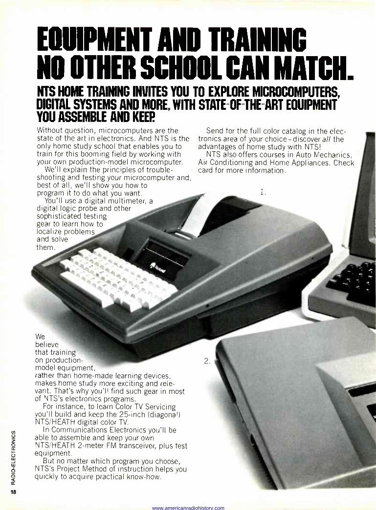
EOUIPMENT AND TRAINING NO 0111Eß SCHOOL CAN MATCH. NTS HOME TRAINING INVITES YOU TO EXPLORE
DIGITAL SYSTEMS AND MORE, WITH STATE-OF-THE-ART YOU ASSEMBLE AND KEEP.
MICROCOMPUTERS
Without question, microcomputers are the state of the art in electronics. And NTS is the only home study school that enables you to train for this booming field by working with your own production -model microcomputer.
We'll explain the principles of trouble- shooting and testing your microcomputer and, best of all, we'll show you how to program it to do what you want.
You'll use a digital multimeter, a digital logic probe and other sophisticated testing gear to learn how to localize problems and solve them.
We believe that training on production - model equipment, rather than home-made learning devices, makes home study more exciting and rele- vant. That's why you'll find such gear in most of NTS's electronics programs.
For instance, to learn Color TV Servicing you'll build and keep the 25 -inch (diagonal) NTS/HEATH digital color TV.
In Communications Electronics you'll be able to assemble and keep your own NTS/HEATH 2 -meter FM transceiver, plus test equipment.
But no matter which program you choose, NTS's Project Method of instruction helps you quickly to acquire practical know-how.
EQUIPMENT ,
Send for the full color catalog in the elec- tronics area of your choice-discover all the advantages of home study with NTS!
NTS also offers courses in Auto Mechanics, Air Conditioning and Home Appliances. Check card for more information.
1
www.americanradiohistory.com
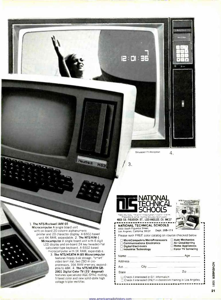
1. The NTS/Rockwell AIM 65 Microcomputer A single board unit
with on -board 20 column alphanumeric printer and 20 character display. A 6502 -based
unit 4K RAM, expandable. 2. The NTS/KIM-1 Microcomputer A single board unit with 6 digit
LED display and on -board 24 key hexadecimal calculator -type keyboard. A 6502 based
microcomputer with 1K RAM, expandable. 3. The NTS/HEATH H-89 Microcomputer
features floppy disk storage, "smart" video terminal, two Z80 miicro- processors, 16K RAM memory, expand- able to 48K. 4. The NTS/HEATH GR -
2001 Digital Color TV (25" diagonal) features specialized AGC-SYNC muting, filtered color and new solid-state high voltage tripler rectifier.
fr
I.
/ 3.
Simulated TV Reception 4.
NATIONAL TECHNICAL SCHOOLS
TECHNICAL -TRADE TRAINING SINCE "ISC n Resident and Home -Study Schools
4000 SO. FIGUEROA ST., LOS ANGELES, CA. 91(37
NATIONAL TECHNICAL SCHOOLS 4000 South Figueroa Street, Los Angeles, California 90037 Dept. 206-111
NTS Training Proryrama in er and
industr aarÉ ect-onica
Please rush FREE color catalog on course checked below
E MicroComputers/MIcroProcessors Communications Electronics Digital Electronics
E Industrial Technology
Name
Address
Apt. City
State Zip
E Check if interested in G.I. information. Check if interested ONLY in classroom training in Los Angeles.
Auto Mechanics Air Conditioning Home Appliances
E Color TV Servicing
Age
www.americanradiohistory.com
SATELLITE/TELETEXT NEWS GARY ARLEN
CONTRIBUTING EDITOR
B EwaTH STATI°R RECVVEa
60A9
l°NOG.TDIAtI! .M9?z e
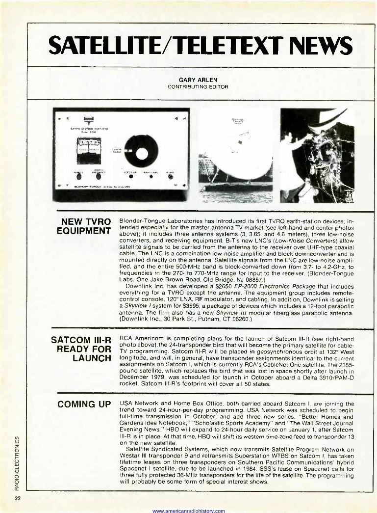
NEW TVRO EQUIPMENT
Blonder -Tongue Laboratories has introduced its first TVRO earth -station devices, in- tended especially for the master -antenna TV market (see left-hand and center photos above); it includes three antenna systems (3, 3.65, and 4.6 meters), three low -noise converters, and receiving equipment. B -T's new LNC's (Low -Noise Converters) allow satellite signals to be carried from the antenna to the receiver over UHF -type coaxial cable. The LNC is a combination low -noise amplifier and block downconverter and is mounted directly on the antenna. Satellite signals from the LNC are low -noise ampli- fied, and the entire 500 -MHz band is block -converted down from 3.7- to 4.2 -GHz, to frequencies in the 270- to 770 -MHz range for input to the receiver. (Blonder -Tongue Labs. One Jake Brown Road, Old Bridge. NJ 08857.)
Downlink Inc. has developed a $2650 EP -2000 Electronics Package that includes everything for a TVRO except the antenna. The equipment group includes remote - control console, 120° LNA, RF modulator, and cabling. In addition. Downlink is selling a Skyview I system for $3595, a package of devices which includes a 12 -foot parabolic antenna. The firm also has a new Skyview Ill modular fiberglass parabolic antenna. (Downlink Inc., 30 Park St., Putnam, CT 06260.)
SATCOM III -R READY FOR
LAUNCH
RCA Americom is completing plans for the launch of Satcom III -R (see right-hand photo above), the 24 -transponder bird that will become the primary satellite for cable - TV programming. Satcom III -R will be placed in geosynchronous orbit at 132° West longitude, and will, in general, have transponder assignments identical to the current assignments on Satcom I, which is currently RCA's CableNet One satellite. The 2385 - pound satellite, which replaces the bird that was lost in space shortly after launch in December 1979, was scheduled for launch in October aboard a Delta 3910/PAM-D rocket. Satcom Ill -R's footprint will cover all 50 states.
COMING UP USA Network and Home Box Office. both carried aboard Satcom I. are joining the trend toward 24 -hour -per -day programming. USA Network was scheduled to begin full-time transmission in October, and add three new series, "Better Homes and Gardens Idea Notebook," "Scholastic Sports Academy" and "The Wall Street Journal Evening News." HBO will expand to 24 -hour daily service on January 1. after Satcom III -R is in place. At that time. HBO will shift its western time -zone feed to transponder 13 on the new satellite.
Satellite Syndicated Systems, which now transmits Satellite Program Network on Westar Ill transponder 9 and retransmits Superstation WTBS on Satcom I. has taken lifetime leases on three transponders on Southern Pacific Communications' hybrid Spacenet I satellite, due to be launched in 1984. SSS's lease on Spacenet calls for three fully protected 36 -MHz transponders for the life of the satellite. The programming will probably be some form of special interest shows.
www.americanradiohistory.com
w
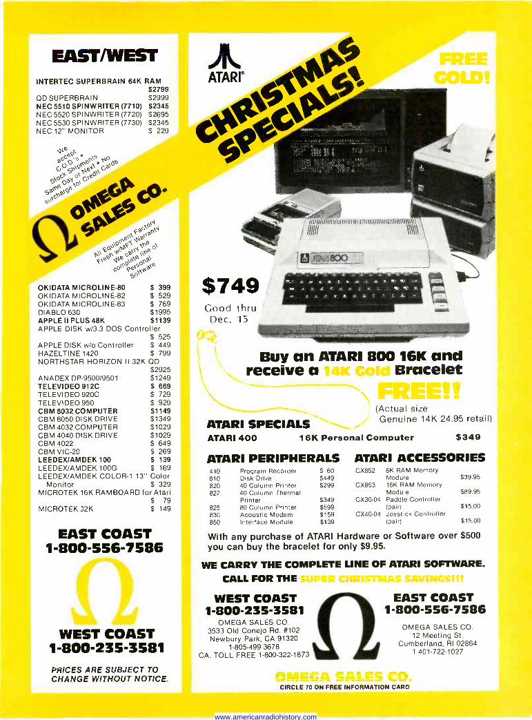
EAST/WEST INTERTEC SUPERBRAIN 64K RAM
$2799 QD SUPERBRAIN $2999 NEC 5510 SPINWRITER (7710) $2345 NEC 5520 SPINWRITER (7720) $2695 NEC 5530 SPINWRITER (7730) $2345 NEC 12" MONITOR $ 229
ae Ge, e o
o - ' o Geea a\`a Cra eO tot ee
9V`G
9
O* `ot`i 5 '\e eil
Q\).\9.,,o ire of
Fveciiiiiiiiii4 r`l e eeeea\ Go`e9e,..Na`e
got
OKIDATA MICROLINE-80 $ 399 OKIDATA MICROLINE-82 $ 529 OKIDATA MICROLINE-83 $ 769 DIABLO 630 $1995 APPLE II PLUS 48K $1139 APPLE DISK w13.3 DOS Controller
$ 525 APPLE DISK w/o Controller $ 449 HAZELTINE 1420 $ 799 NORTHSTAR HORIZON II 32K QD
$2925 $1249 $ 669 $ 729 $ 929 $1149 $1349 $1029 $1029 $ 649 $ 269 $ 139
ANADEX DP -9500/9501 TELEVIDEO 912C TELEVIDEO 920C TELEVIDEO 950 CBM 8032 COMPUTER CBM 8050 DISK DRIVE CBM 4032 COMPUTER CBM 4040 DISK DRIVE CBM 4022 CBM VIC-20 LEEDEX/AMDEK 100
to
LEEDEX/AMDEK 100G $ 169 LEEDEX/AMDEK COLOR -1 13" Color
Monitor $ 329 MICROTEK 16K RAMBOARD for Atari
$ 79 MICROTEK 32K $ 149
EAST COAST 1-800-556-7586 dam
WEST COAST 1-800-235-3581 PRICES ARE SUBJECT TO CHANGE WITHOUT NOTICE.
teve6 064 *se tee
rírri/ír/ItlitttllltIltiU-1
$749 Good thru
Dec. 15
ltt4tt)tt44§,11\)111,
Buy an ATARI 800 16K and receive a !foil IsfltIl Bracelet
ATARI SPECIALS
mi"e- (Actual size Genuine 14K 24.95 retail)
ATARI 400 16K Personal Computer $349
ATARI PERIPHERALS ATARI ACCESSORIES 410 Program Recorder $ 60 CX852 810 820
Disk Drive 40 Column Printer
$449 $299 CX853
822 40 Column Thermal Printer $349 CX30-04
825 80 Column Printer $599 830 Acoustic Modem $159 CX40-04 850 Interface Module $139
8K RAM Memory Module 16K RAM Memory Module Paddle Controller (pair) Joystick Controller (pair)
$39.95
$89.95
$15.00
$15.00
With any purchase of ATARI Hardware or Software over $500 you can buy the bracelet for only $9.95.
WE CARRY THE COMPLETE LINE OF ATARI SOFTWARE.
CALL FOR THE
WEST COAST 1-800-235-3581
OMEGA SALES CO. 3533 Old Conejo Rd. #102 Newbury Park, CA 91320
1-805-499-3678 CA. TOLL FREE 1-800-322-1873
EAST COAST 1-800-556-7586
OMEGA SALES CO. 12 Meeting St.
Cumberland, RI 02864 1-401-722-1027
CIRCLE 70 ON FREE INFORMATION CARD
www.americanradiohistory.com
LETTERS
TELEVISION MODULATION case you're interested. of devices like radar detectors and pay -TV
In reference to two letters you pub -Mr. Rogers properly points out the con- decoders, I wonder if he would also in-
lished on television modulation (Mr. fusion between the IRE scale (which runs clude VCR's that can play back a tape
Davis, January 1981; Mr. Rogers, May from 0 to -40 IRE units and 0 to +120 IRE without generating royalties. And what "commercial 1981): Neither letter is correct, although I
units, with 0 being clamped at the blanking about -killer" devices? Once
would give Mr. Rogers credit for coming close.
level), and the percent scale. However, one must also differentiate between per-
you start on that kind of list, it's hard to stop.
Mr. Rogers stated that tip of peak sync cent of peak carrier level and percent Yes-probably some rules do need
is 100% modulation. That is incorrect. Tip of sync is 100% of peak carrier level, which is also 0% modulation. Thus, 100%
modulation; they are complements of each other.
Mr. Roger's comments on television
changing. But where some rule -changes, like baseball's "designated hitter" rule, are intended to enhance the game, others
"oh of peak carrier level corresponds to 0% output power are well taken. For an all- are just -poor -me" reactions, like
modulation and -40 IRE units; 75% of black picture, the ratio of peak power to casinos excluding card -counters (dear
peak carrier level (blanking level) cor- average power for an NTSC system M me, they're likely to win!) or restrictions
responds to 25% modulation and 0 IRE television signal is 1.68 to 1; but for an all- on imported cars.
units; 12.5% of peak carrier level (refer- white picture the ratio is different; it Not that we should all be lawyers, but
ence white) corresponds to 87.5% modu- changes to 5.99 to 1. perhaps Radio -Electronics can keep us
lation and +100 IRE units, and 0% of peak carrier level (carrier cutoff) corresponds to 100% modulation and +120 IRE units.
DANE E. ERICKSEN, FCC Field Operations Bureau, San Francisco, CA
posted on these interminable issues. ALEX ESTEVE
Increasing depth of modulation of the THE "FREEDOM PHONE" luminance signal beyond 87.5% (i.e., be- "ILLEGAL" DEVICES
I just finished the July 1981 issue of low 12.5% of the peak carrier level) is prohibited by FCC regulations. That's
In response to D.T. Horn's letter in the June Radio -Electronics, wherein he de-
Radio -Electronics and was, of course, pleased to see the cordless -phone cover
Title 47 CFR, Section 73.682 (a) (13), in plored the manufacture and possession feature with the inclusion of material
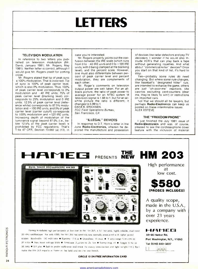
H A M E PRESENTS ilkirg HM 2
Hameg introduces high performance at low cost in the HM 203, a full featured, highly reliable, dual trace
20 MHz oscilloscope. For only 8580, the HM 203 has specifications normally associated with higher priced
scopes. Bandwidth - DC -.20 MHz Risetime 17.5 ns Overshoot 1% max. Y amp range 5 my/cm to
20 v/cm Max. input voltage 500V Timebase .5 µs/cm to .2s /cm Sweep mag. x5 Trigger 5 Hz to
30 MHz X:Y plot Built-in probe calibrator and more. Its sturdy construction and light weight (13.2 lbs.)
make the HM 203 equally at home in the field and on the test bench.
CIRCLE 13 ON FREE INFORMATION CARD
High performance at
low cost.
$580 (PROBES INCLUDED)
A quality scope, made in the U.S.A., by a company with over 23 years experience.
11--1 Ft EE 88-90 Harbor Rd.
Port Washington, N.Y 11050
Tet (518) 883-3837
www.americanradiohistory.com
about Electra's "Freedom Phone." However, there's a technical error in the
story that needs correction. It is absolutely not true that "Freedom Phone" cordless phones use "one channel in the 49 -MHz band...". That implies, of course, that Electra's phones are of the low-cost sim- plex variety. Not true! Electra uses 1.7
MHz and 49 MHz for its "Freedom Phone" phones, just like all other full -duplex sys- tems on the market.
The big news we've been trying to tell is the development of a brand new cordless phone with full -duplex operation within the 49 -MHz band using two frequencies. The significance of that breakthrough is that it eliminates the limitations of 1.7 MHz in terms of range and noise. That techno- logical feat was totally lost in the story, I'm afraid. ROBERT A. HANSON, Vice President, MicKinney/Mid America
SUBSCRIPTION TV I admire your editorial on "subscrip-
tion" TV (Radio -Electronics, December 1980) and public ownership of the airways. However, I believe that one further logical step remains to be stated in your develop- ment of that issue. If, indeed, the airways belong to the public (which I most certain- ly believe), then those using the airways do so with the "consent" of the public. There- fore, is it not those (subscription -TV broadcasters) who charge for the use of the public airways that are guilty of theft of service? Are not those broadcasters the real "pirates" rather than the decoder
builders and the microwave receiver builders? Maybe "we, the people" should prosecute them (subscription -TV broad- casters) instead of they us. MELVIN L. WILLIS, Jr. Mesquite, TX
00000000PS! In reference to the article entitled "The
Incredible Shrinking IC" in the August 1981 issue. I believe that the caption for Fig. 2 is incorrect. The circuit is indeed TTL logic, but it is an open -collector three - input NAND gate. The schematic (Fig. 1) for
FIG. 1
that circuit is shown here. Note that the base of each transistor is brought out for external connection to bonding pads. That was common in early circuits, espe- cially experimental ones, as transistor parameters varied widely and were often measured to provide better quality control in manufacturing. BARRY L. ORNITZ Kingsport, TN
CABLE TV Although I see the advantage of a cable -
ready TV with its built-in converter and decoder (editorial, Radio -Electronics, June 1981), I do not share your hope that the cable companies will necessarily re- duce their subscription fees, just because they no longer have to supply such equip- ment themselves. Do telephone rates go down because one is able to buy a tele- phone set from other manufacturers than Ma Bell?
As for the consumer having a "choice," the problem is not whether the converter comes with the TV set or from the cable company-or whether the cable company attaches some gizmo to the subscriber's set. The problem arises from the manner in which free competition for the viewer's dollar is hindered by local governments which give monopoly rights to cable com- panies in their jurisidictions. Such cable companies should no more have monopo- lies on rights to sell electric signals than McDonalds have to sell hamburgers.
In my view, the only consumers who now have a real choice are those who con- struct their own decoders and intercept signals from pay -TV, because they recog- nize that the idea of a private company charging a fee for picking up electromag- netic waves from the air, which is public property, is not too different from the idea of allowing some private profit -making firm to set up toll booths along inter- state highways. BUD DAMNJANOVITCH, Utica, Ml R -E
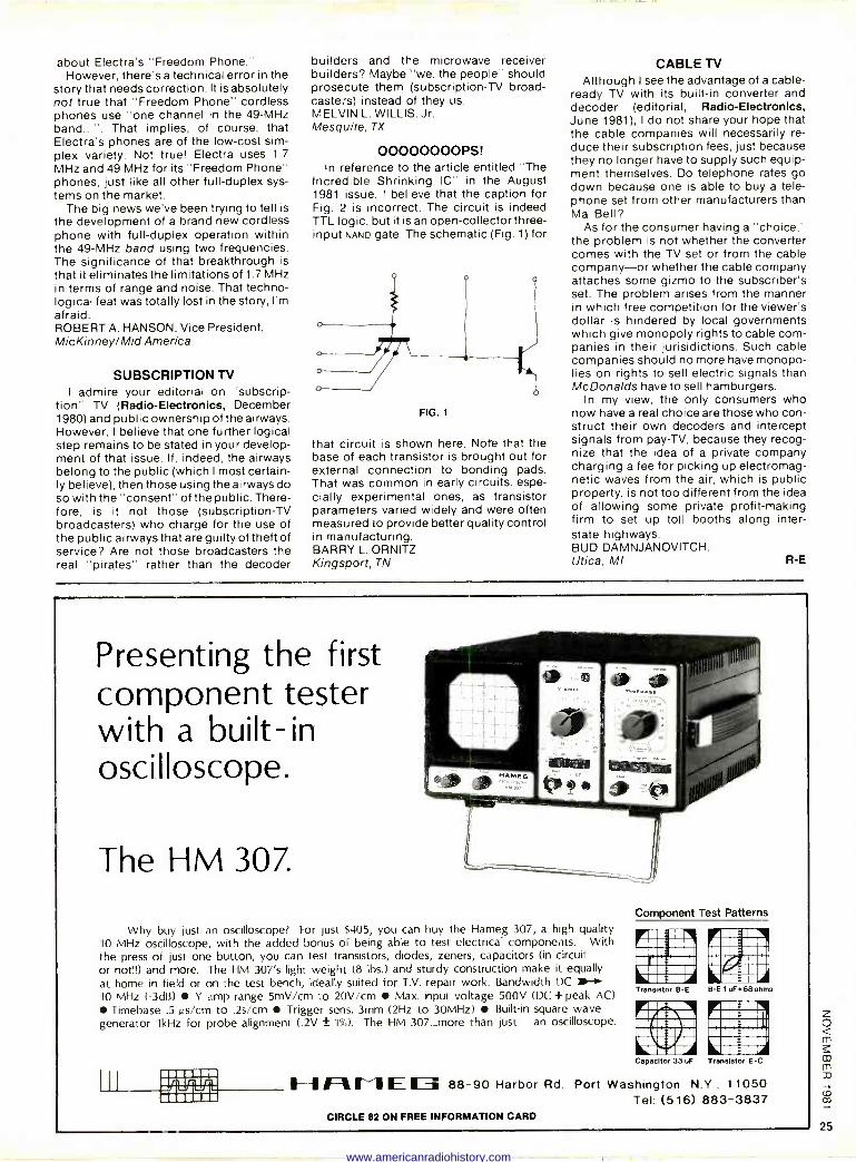
Presenting the first component tester with a built-in oscilloscope.
The HM 307.
Why buy just an oscilloscope? For just $405, you can buy the Hameg 307, a high quality 10 MHz oscilloscope, with the added bonus of being able to test electrical components. With the press of just one button, you can test transistors, diodes, zeners, capacitors (in circuit or not!!) and more. The HM 307's light weight (8 lbs.) and sturdy construction make it equally at home in field or on the test bench, ideally suited for T.V. repair work. Bandwidth DC 1,-1- 10 MHz (-3dB) Y amp range 5mV/cm to 20V/cm Max. input voltage 500V (DC+peak AC)
Timebase .5 µs/cm to .2s/cm Trigger sens. 3mm (2Hz to 30MHz) Built-in square wave generator 1kHz for probe alignment (.2V ± 1%). The HM 307...more than just an oscilloscope.
I J 1
r
Component Test Patterns
4.1i INK ARBIIIUU 1=U AI 1111111504111.11 ,B1.1,411ZZIP
p, Trandel« B -E B -E 1 uF+68 dms
Agal 1ufis11mL Iwwsui 1erri tU.....r 11f11
Capacitor 33 uF Transistor E -C
r
11-11 ß I l E 11 88-90 Harbor Rd. Port Washington N.Y , 1 1050 Tel. (516) 883-3837
CIRCLE 82 ON FREE INFORMATION CARD
www.americanradiohistory.com
EQUIPMENT REPORTS
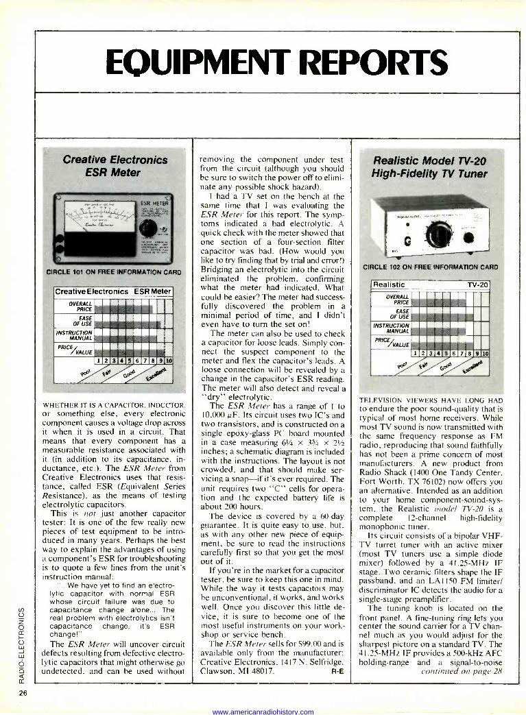
Creative Electronics ESR Meter
CIRCLE 101 ON FREE INFORMATION CARD
Creative Electronics ESR Meter
OVERALL PRICE
EASE OF USE
INSTRUCTION MANUAL
PRICE VALUE
1 2 3 4 5 6 7 8 9 10
WHETHER IT IS A CAPACITOR, INDUCTOR. or something else, every electronic component causes a voltage drop across it when it is used in a circuit. That means that every component has a measurable resistance associated with it (in addition to its capacitance, in- ductance, etc.). The ESR Meter from Creative Electronics uses that resis- tance, called ESR (Equivalent Series Resistance), as the means of testing electrolytic capacitors.
This is not just another capacitor tester: It is one of the few really new pieces of test equipment to be intro- duced in many years. Perhaps the best way to explain the advantages of using a component's ESR for troubleshooting is to quote a few lines from the unit's instruction manual:
"...We have yet to find an electro- lytic capacitor with normal ESR whose circuit failure was due to capacitance change alone... The real problem with electrolytics isn't capacitance change, it's ESR change!" The ESR Meter will uncover circuit
defects resulting from defective electro- lytic capacitors that might otherwise go undetected, and can be used without
removing the component under test from the circuit (although you should be sure to switch the power off to elimi- nate any possible shock hazard).
I had a TV set on the bench at the same time that I was evaluating the ESR Meter for this report. The symp- toms indicated a bad electrolytic. A quick check with the meter showed that one section of a four -section filter capacitor was bad. (How would you like to try finding that by trial and error!) Bridging an electrolytic into the circuit eliminated the problem, confirming what the meter had indicated. What could be easier? The meter had success- fully discovered the problem in a minimal period of time, and I didn't even have to turn the set on!
The meter can also be used to check a capacitor for loose leads. Simply con- nect the suspect component to the meter and flex the capacitor's leads. A loose connection will be revealed by a change in the capacitor's ESR reading. The meter will also detect and reveal a "dry" electrolytic.
The ESR Meter has a range of 1 to 10,000 µF. Its circuit uses two IC's and two transistors, and is constructed on a single epoxy -glass PC board mounted in a case measuring 61/4 x 33/4 x 21/2
inches; a schematic diagram is included with the instructions. The layout is not crowded, and that should make ser- vicing a snap-if it's ever required. The unit requires two "C" cells for opera- tion and the expected battery life is about 200 hours.
The device is covered by a 60 -day guarantee. It is quite easy to use, but, as with any other new piece of equip- ment, be sure to read the instructions carefully first so that you get the most out of it.
If you're in the market for a capacitor tester, be sure to keep this one in mind. While the way it tests capacitors may be unconventional, it works, and works well. Once you discover this little de- vice, it is sure to become one of the most useful instruments on your work- shop or service bench.
The ESR Meter sells for $99.00 and is available only from the manufacturer: Creative Electronics. 1417 N. Selfridge, Clawson. MI 48017. R -E
Realistic Model TV -20 High -Fidelity TV Tuner
CIRCLE 102 ON FREE INFORMATION CARD
Realistic TV -20
OVERALL PRICE
EASE OF USE
INSTRUCTION MANUAL
PRIG VALUE
1 2 3 4 5 6 7 8 910
I ELE\ ISION VIEWERS HAVE LONG HAD to endure the poor sound -quality that is typical of most home receivers. While most TV sound is now transmitted with the same frequency response as FM radio, reproducing that sound faithfully has not been a prime concern of most manufacturers. A new product from Radio Shack (1400 One Tandy Center, Fort Worth, TX 76102) now offers you an alternative. Intended as an addition to your home component -sound -sys- tem. the Realistic model TV -20 is a complete 12 -channel high-fidelity monophonic tuner.
Its circuit consists of a bipolar VHF - TV turret tuner with an active mixer (most TV tuners use a simple diode mixer) followed by a 41.25 -MHz IF stage. Two ceramic filters shape the IF passband, and an LA 1150 FM limiter/ discriminator IC detects the audio for a single -stage preamplifier.
The tuning knob is located on the front panel. A fine-tuning ring lets you center the sound carrier for a TV chan- nel much as you would adjust for the sharpest picture on a standard TV. The 41.25 -MHz IF provides a 500 -kHz AFC holding -range and a signal-to-noise
continued on page 28
www.americanradiohistory.com
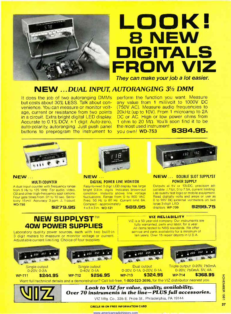
LOOK! 8 NEW
DIGITALS FROM VIZ
They can make your job a lot easier.
N EW ... DUAL INPUT, AUTORANGING 31/2 DMM It does the job of two autoranging DMMs but costs about 30% LESS. Talk about con- venience. You can measure or monitor volt- age, current or resistance from two points in a circuit. Extra bright digital LED display. Accurate to 0.1% DCV, ± 1 digit. Auto -zero, auto -polarity, autoranging. Just push panel buttons to preprogram the instrument to
perform the function you want. Measure any value from 1 millivolt to 1000V DC (750V AC). Measure audio frequencies to 20kHz (up to 10V). From 1 microamp to 2A DC or AC. High or low power ohms from 1 ohm to 20 M12. You'll soon find it to be the most used instrument you own! WD -753 $384.95.
NEW ... MULTI -COUNTER
A dual input counter with frequency range from 5 Hz to 125 MHz. For audio, video, CB and other high -frequency applications. Four gate times from .01 to 10 sec. Sensi- tivity 15 mV. Accuracy 3 ppm ± 1 count. WD -755 $279.95
NEW ... DIGITAL POWER LINE MONITOR
Easy -to -read 3 digit LED display has large bright 0.8 -in. digits. Indicates brown -out condition. Instantly shows line voltage fluctuations. Range from 0 to 500 VAC. Freq. 50 Hz to 60 Hz. Current limit 8A. Compact-approximately 4x5x3in. WD -121 $89.95
NEW ... DOUBLE SLOT SUPPLYST
POWER SUPPLY Outputs at 5V or 13VDC, precision ad- justable ±11/2V, 0 to 7.5A, current limiting. Lab quality test logic or mobile equipment. Read digitally volts and amps or use as 0 to 99V DC external voltmeters on two large 3 -digit LED displays. WP -709 $299.75
NEW SUPPLYST" 40W POWER SUPPLIES
Laboratory quality power sources, each with two built-in 3 digit meters to measure or monitor voltage or current. Adjustable current limiting. Choice of four supplies:
Single output 0-20V, 0-2A
Single output 0-40V, 0-1A
WP -711 $244.95 WP -712 $256.95
VIZ RELIABILITY VIZ is a 50 year -old company. Our instruments are
fully warranted, parts and labor, for a year. All items tested to NBS standards. We offer
service and parts availability for a minimum of ten years. Over 15 repair depots in U.S.A.
Dual output 0-20V, 0-1A. 0-20V, 0-1A.
WP -713 $324.95
Triple output 0-20V, 750mA. 0-20V, 750mA. 5V, 4A.
WP -714 $368.95 Want full technical details and a demonstration? Call toll -free, 1-800-523-3696, for the VIZ distributor nearest you.
Look to VIZ for value, quality, availability. Over 70 instruments in the line-PLUS full accessories.
VIZ Mfg. Co., 335 E. Price St., Philadelphia, PA 19144 MI CIRCLE 68 ON FREE INFORMATION CARD
www.americanradiohistory.com
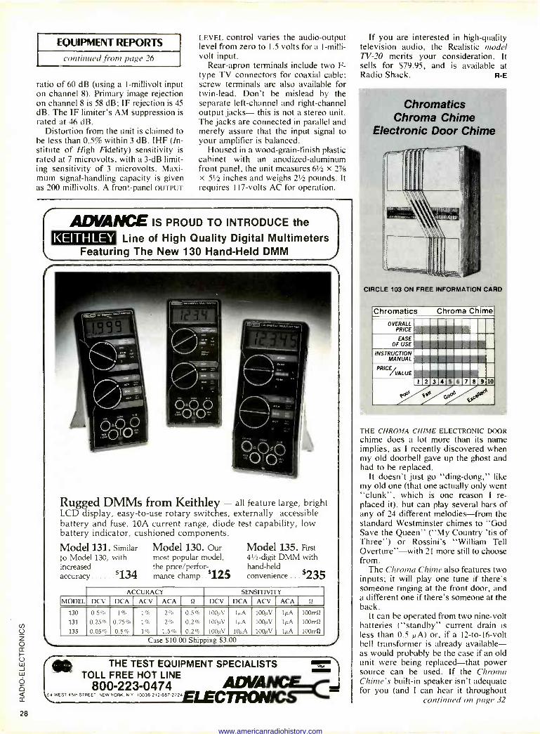
EQUIPMENT REPORTS
continued from page 26
ratio of 60 dB (using a (-millivolt input on channel 8). Primary image rejection on channel 8 is 58 dB; IF rejection is 45 dB. The IF limiter's AM suppression is rated at 46 dB.
Distortion from the unit is claimed to be less than 0.5% within 3 dB. IHF (In- stitute of High Fidelity) sensitivity is rated at 7 microvolts, with a 3 -dB limit- ing sensitivity of 3 microvolts. Maxi- mum signal -handling capacity is given as 200 millivolts. A front -panel OUTPUT
LEVEL control varies the audio -output level from zero to 1.5 volts for a I -milli- volt input.
Rear -apron terminals include two F - type TV connectors for coaxial cable; screw terminals are also available for twin -lead. Don't be mislead by the separate left -channel and right -channel output jacks- this is not a stereo unit. The jacks are connected in parallel and merely assure that the input signal to your amplifier is balanced.
Housed in a wood -grain -finish plastic cabinet with an anodized -aluminum front panel, the unit measures 6114 X 2V/a
x 511 inches and weighs 211 pounds. It requires 117 -volts AC for operation.
ADVANCE IS PROUD TO INTRODUCE the
KEITHLEY Line of High Quality Digital Multimeters Featuring The New 130 Hand -Held DMM
Rugged DMMs from Keithley - all feature large, bright LCD display, easy -to -use rotary switches, externally accessible battery and fuse, 1.0A current range, diode test capability, low battery indicator, cushioned components.
Model 131. Similar Model 130. Our to Model 130, with most popular model, increased the price/perfor- accuracy 134 mance champ .. 125
Model 135. First 41/2 -digit DMM with hand-held convenience . . $235
ACCURACY SENSITIVITY MODEL DCV DCA ACV ACA R DCV DCA ACV ACA f2
130 0.5% 1% 1% 2% 0.5% 100µV 1µA 100µV 1µA 100mO
131 0.25% 0.75% 1% 2% 0.2% 100µV 1µA 100µV 1µA 100mú
135 0.05% 0.5% 1% 1.5% 0.2% 100µV 10µA 100µV 1µA 100mí2
Case $10.00 Shipping $3.00
lip THE TEST EQUIPMENT SPECIALISTS TOLL FREE HOT LINE
800-223-0474 ADV 5 WEST O61ä STREET, NEW YORK. N Y 10036 212 687 2224 ELEcmoN
If you are interested in high -quality television audio, the Realistic model TV -20 merits your consideration. It sells for $79.95, and is available at Radio Shack. R -E
Chromatics Chroma Chime
Electronic Door Chime
CIRCLE 103 ON FREE INFORMATION CARD
Chromatics OVERALL
PRICE
Chroma Chime
EASE OF USE
INSTRUCTION MANUAL
....m .....®e .....nn 111....9",
1.©©©CIEWIEMII]m
PRIG VALUE
THE CHROMA CHIME ELECTRONIC DOOR chime does a lot more than its name implies, as I recently discovered when my old doorbell gave up the ghost and had to be replaced.
It doesn't just go "ding -dong," like my old one (that one actually only went "clunk", which is one reason I re- placed it), but can play several bars of any of 24 different melodies-from the standard Westminster chimes to "God Save the Queen" ("My Country 'tis of Three") or Rossini's "William Tell Overture"-with 21 more still to choose from.
The Chroma Chime also features two inputs; it will play one tune if there's someone ringing at the front door, and a different one if there's someone at the back.
It can be operated from two nine -volt batteries ("standby" current drain is less than 0.5 µA) or, if a l2 -to -16 -volt bell transformer is already available- as would probably be the case if an old unit were being replaced-that power source can be used. If the Chroma Chime's built-in speaker isn't adequate for you (and I can hear it throughout
continued on page 32
28
www.americanradiohistory.com
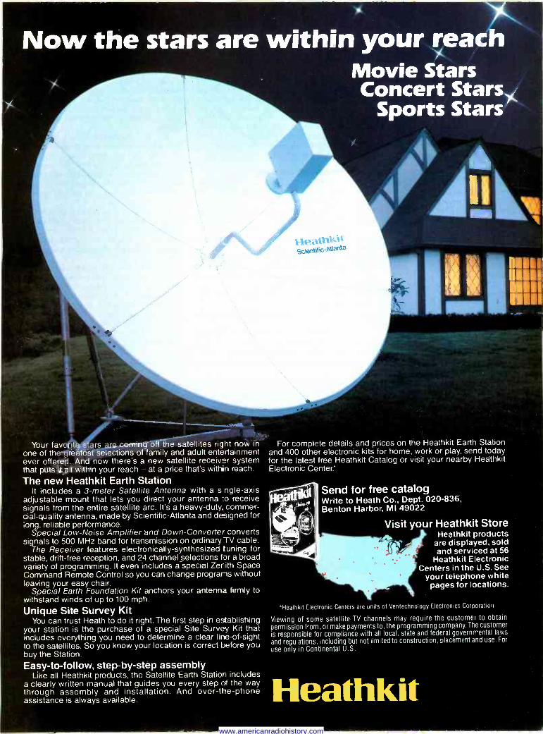
Now the stars are within your reach Movie Movie Stars Concert Stars
Sports Stars
_..---- Your favceiiStars are setning off the satellites right now in For complete details and prices on the Heathkit Earth Station
one of the neatest selections of family and adult entertainment ever offered. And now there's a new satellite receiver system that puts it all within your reach - at a price that's within reach.
The new Heathkit Earth Station It includes a 3 -meter Satellite Antenna with a s ngle-axis
adjustable mount that lets you direct your antenna :o receive signals from the entire satellite arc. It's a heavy-duty, commer- cial -quality antenna, made by Scientific-Atlanta and designed for long, reliable performance.
Special Low -Noise Amplifier end Down -Converter converts signals to 500 MHz band for transmission on ordinary TV cable.
The Receiver features electronically -synthesized tuning for stable, drift -free reception, and 24 channel selections for a broad variety of programming. It even includes a special Zerith Space Command Remote Control so you can change programs without leaving your easy chair.
Special Earth Foundation Kit anchors your antenna firmly to withstand winds of up to 100 mph.
Unique Site Survey Kit You can trust Heath to do it right. The first step in establishing
your station is the purchase of a special Site Survey Kit that includes everything you need to determine a clear line -of -sight to the satellites. So you know your location is correct before you buy the Station.
Easy -to -follow, step-by-step assembly Like all Heathkit products, the Satellite Earth Station includes
a clearly written manual that guides you every step of the way through assembly and installation. And over -the -phone assistance is always available.
and 400 other electronic kits for home, work or play, send today for the latest free Heathkit Catalog or visit your nearby Heathkit Electronic Center
Send for free catalog Write to Heath Co., Dept. 020-836, Benton Harbor, MI 49022
Visit your Heathkit Store Heathkit products
are displayed sold and serviced at 56
Heathkit Electronic Centers in the U.S. See
your telephone white pages for locations.
`Heathkit Electronic Centers are units of Ventechnology Electronics Corporation
Viewing of some satellite TV channels may require the customer to obtain permission from, or make payments to, the programming company. The customer is responsible for compliance with all local, state and federal governmental laws
and regulations, including but not limited to construction, placement and use. For
use only in Continental U.S.
Heathkit www.americanradiohistory.com
EQUIPMENT REPORTS
continued from page 28
my house), an external speaker is avail- able as an option.
How it works The heart of the Chroma Chime is a
Texas Instruments TMS 1000 micropro- cessor. That IC not only provides the logic needed to play the tune that is selected, but also carries all 24 tunes in its on -board ROM.
When a doorbell button is pressed, the microprocessor checks the melody - selector switches to see which tune is
required. Having determined that, it then looks up the selected tune in its ROM and generates the appropriate audio output.
That signal is then amplified and pro- cessed to remove some of its square - wave characteristics and make it sound more like a chime or other musical instrument.
The user can select the tempo of the melody (how fast it will be played) and, by means of the DECAY control, how quickly the tones die away. The tempo circuitry also enriches the sound by generating a tremelo effect.
The audio output can be made to sound like anything from the output of
a signal generator to a sharply -plucked violin string. I've set mine to approxi- mate the sound of a harpsichord.
The microprocesor automatically shuts off the device when the selection is ended, whether or not the doorbell button is still depressed. There is an ex- ception to this, though. Several pieces ("The Star Spangled Banner." for ex- ample) have an "extended-play" op- tion-if the button is still depressed, a
few more bars will be played. Then the microprocessor shuts the unit off, ex- tending battery life.
Design and assembly Although the Chroma Chime is avail-
able as an assembled unit. I chose to build the kit version.
The assembly manual is better written than average, and is well illustrated. The PC board is screened with the out- lines of the components, to make things still easier for the builder.
Although the IC used is manufactured by TI, the unit itself was designed, and the manual written, in England. Here are a few hints that may simplify mat- ters for those unfamiliar with life abroad:
First, English technology sometimes differs from our own. For example: a "skeleton pot" is a trimmer pot. Those pots are referred to as "RV I ," "RV2," etc. "RV" probably stands for "resis-
tor. variable." Also, transistor pinout is frequently
"CBE" or "ECB," while ours is usually "EBC." It's possible that any of several transistors may have been in- cluded in your kit (all the types are illustrated) and it's necessary to check the part numbers against the pinouts shown in the manual to make sure that you're installing the components cor- rectly.
(My kits contained several transis- tors whose numbers were identical, ex- cept for the last letter. Naturally, I
ignored that letter and installed every- thing backwards. Fortunately, no harm was done. The transistors were re- moved and reversed, and the unit func- tioned as promised.)
The switches used to select the tunes are a bit unusual. The switch contacts are part of the PC -board foil pattern, and are contacted by spring -loaded wipers. Although unorthodox, the sys- tem works well.
The case is white plastic with con- cealed. but easily accessible, adjust- ment and battery compartments, and will blend in with most decorating schemes. Installation instructions are detailed and easy to follow.
The Chroma Chime is a clever appli- cation of LSI technology and, whether you buy it "ready to go," or as a kit, is
continued on page 36
MAO solid state problems? 1400 RCA SK Series
+3,500 JEDEC* Devices
4,900 MRO Solutions
Pec
sa\ ePac
mce EC e pe RPce sa
For MRO/ industrial applications
Make replacements from your RCA Distributor's shelf with 3,500 RCA
JEDEC and RCA commercial types.
'Joint Electron Device Engineering Council
To fill your solid state replacement needs - for MRO/ indus- trial and consumer applications - see your RCA Distributor for copies of the 1981 RCA MRO Replacement Manual (1K6804) and the 1981 RCA SK Replacement Guide (SPG-202Z).
For a list of RCA Distributors, write to Sales Promotion Services, RCA Distributor and Special Products Division, 2000 Clements Bridge Road, De.tford, N.J. 08096.
For MRO/industrial and consumer applications 1,400 SK replacements for more than 170,000 domestic and foreign types.
SK Replacemen I Solid State
CIRCLE 33 ON FREE INFORMATION CARD
www.americanradiohistory.com
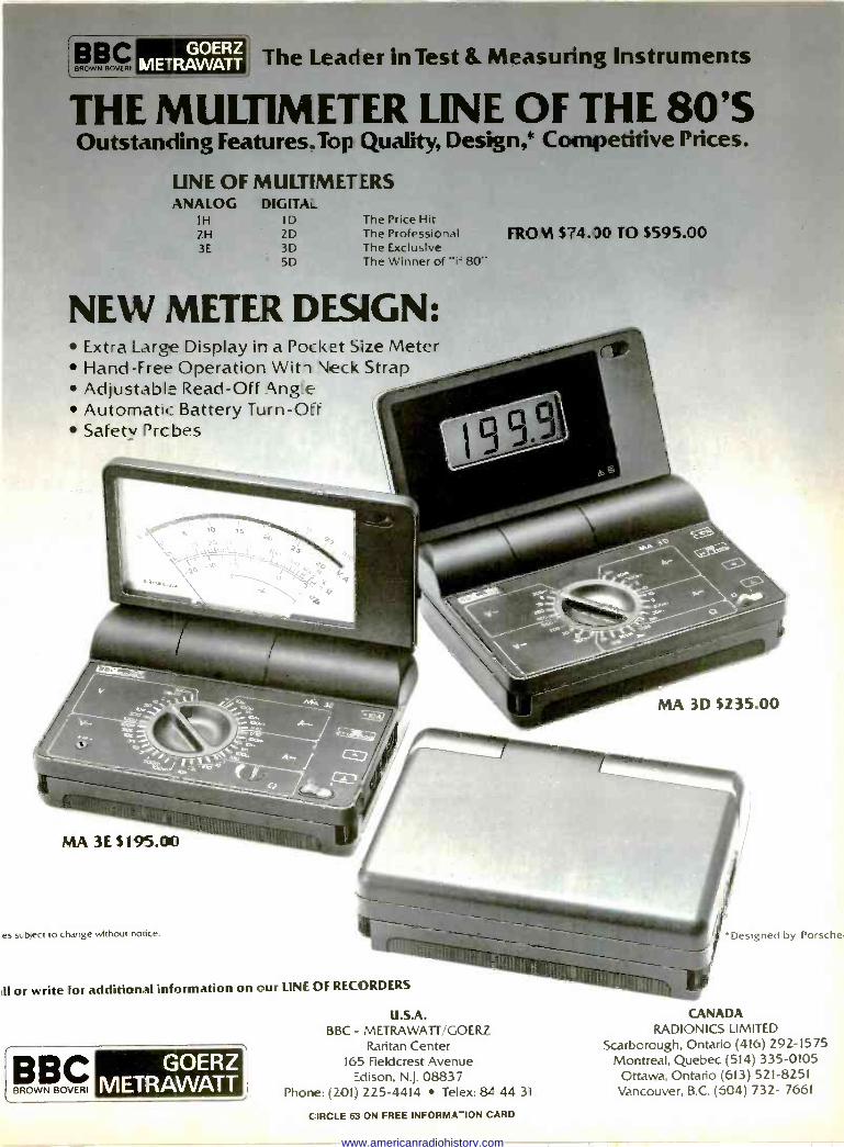
The Leader in Test & Measuring Instruments
THE MULTIMETER LINE OF THE 80'S Outstanding Features.Top Quality, Design,* Competitive Prices.
UNE OF MULTIMETERS ANALOG DIGITA
IH ID 2H 2D 3E 3D
5D
The Price Hit The Professional The Exclusive The Winner cf "i= 80"
NEW METER DESIGN: Extra Large Display ir a Pocket Size Meter Hand -Free Operation Witl Neck Strap Adjustable Read -Off i\ng e
Automatic_ Battery Turn -Orr Safety Drc bes
MA 3E $195.00
es subject to change without notice.
II or write for additional information on our LINIE OF RECORDERS
BBC BROWN BOVERI
FRO N $74.30 TO 5595.00
MA 3D $235.00
'Designed by Porsche
U.S.A. CANADA BBC - METRAWATT/GOERZ RADIONICS LIMITED
Raritan Center Scarborough, Ontario (416) 292-1575
GOERZ 165 Fieldcrest Avenue Montreal, Quebec (514) 335-0105
METRAWATT Edison, N.J. 08837 Phone: (201) 225-4414 Telex: 84 44 31
Ottawa, Ontario (613) 521-8251 Vancouver, B.C. (604) 732- 7661
CIRCLE 83 ON FREE INFORMATION CARD
www.americanradiohistory.com
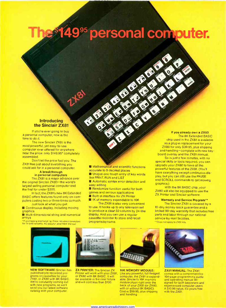
Introducing the Sinclair ZX81
If you're ever going to buy a personal computer, now is the time to do it.
The new Sinclair ZX81 is the most powerful, yet easy -to -use computer ever offered for anywhere near the price: only $149.95* completely assembled.
Don't let the price fool you. The ZX81 has just about everything you could ask for in a personal computer.
A breakthrough in personal computers
The ZX81 is a major advance over the oriiginal Sinclair ZX80-the world's largest selling personal computer and the first for under $200.
In fact, the ZX81's new 8K Extended BASIC offers features found only on com- puters costing two or three times as much.
Just look at what you get: Continuous display, including moving
graphics Multi -dimensional string and numerical
arrays Plus shipping and handling. Price includes connectors
for TV and cassette, AC adaptor, and FREE manual.
NEW SOFTWARE:Sinclair has published pre-recorded pro- grams on cassettes for your ZX81, or ZX80 with 8K BASIC. We're constantly coming out with new programs, so we'll send you our latest software catalog with your computer.
Mathematical and scientific functions accurate to 8 decimal places
Unique one -touch entry of key words like PRINT, RUN and LIST IS Automatic syntax error detection and easy editing
Randomize function useful for both games and serious applications
Built-in interface for ZX Printer 1K of memory expandable to 16K
The ZX81 is also very convenient to use. It hooks up to any television set to produce a clear 32 -column by 24 -line display. And you can use a regular cassette recorder to store and recall programs by name.
ZX PRINTER: The Sinclair ZX Printer will work with your ZX81, or ZX80 with 8K BASIC. It will be available in the near future and will cost less than $100.
If you already own a ZX80 The 8K Extended BASIC
chip used in the ZX81 is available as a plug-in replacement for your
ZX80 for only $39.95, plus shipping and handling-complete with new key-
board overlay and the ZX81 manual. So in just a few minutes, with no
special skills or tools required, you can upgrade your ZX80 to have all the powerful features of the ZX81. (You'll have everything except continuous dis- play, but you can still use the PAUSE and SCROLL commands to get moving graphics.)
With the 8K BASIC chip, your ZX80 will also be equipped to use the ZX Printer and Sinclair software.
Warranty and Service Program** The Sinclair ZX81 is covered by a
10 -day money -back guarantee and a limited 90 -day warranty that includes free parts and labor through our national service -by -mail facilities. Does not apply to ZX81 kits.
i m A .ó.s,íam ï,.iao4
16K MEMORY MODULE: Like any powerful, full fledged computer, the ZX81 is expand- able. Sinclair's 16K memory module plugs right onto the back of your ZX81 (or ZX80, with or without 8K BASIC). Cost is $99.95, plus shipping and handling.
ZX81 MANUAL: The ZX81 comes with a comprehensive 164 -page programming guide and operating manual de- signed for both beginners and experienced computer users. A $10.95 value, it's yours free with the ZX81.
www.americanradiohistory.com
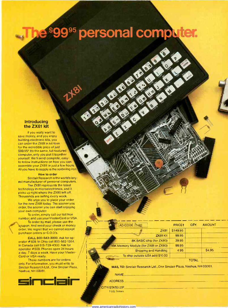
Introducing the ZX81 kit
If you really want to save money, and you enjoy building electronic kits, you can order the ZX81 in kit form for the incredible price of just $99.95' It's the same, full -featured computer, only you put it together yourself. We'll send complete, easy - to -follow instructions on how you can assemble your ZX81 in just a few hours All you have to supply is the soldering iron.
How to order Sinclair Research is the world's larg-
est manufacturer of personal computers. The ZX81 represents the latest
technology in microelectronics, and it
picks up right where the ZX80 left off. Thousands are selling every week.
We urge you to place your order for the new ZX81 today. The sooner you order, the sooner you can start enjoying your own computer.
To order, simply call our toll free number, and use your MasterCard or VISA.
To order by mail, please use the oupon. And send your check or money
order. We regret that we cannot accept purchase orders or C.O.D's.
CALL 800-543-3000. Ask for op- erator #509. In Ohio call 800-582-1364. In Canada call 513-729-4300. Ask for operator # 509. Phones open 24 hours a day, 7 days a week. Have your Master- Card or VISA ready.
These numbers are for orders only. For information, you must write to Sinclair Research Ltd., One Sinclair Plaza, Nashua, NH 03061.
1/
1j i
Sinclair
AD CODE 1 PRICEt QTY. AMOUNT
ZX81 $149.95 "!% ZX81 Kit 99.95
8K BASIC chip (for ZX80) 39.95
16K Memory Module (for ZX81 or ZX80) 99.95
Shipping and Handling
liilK 4.95 $4.95
To ship outside USA add $10.00
TOTAL
MAIL TO: Sinclair Research Ltd., One Sinclair Plaza, Nashua, NH 03061.
NAME
ADDRESS
CITY/STATE/ZIP t U.S. Dollars
www.americanradiohistory.com
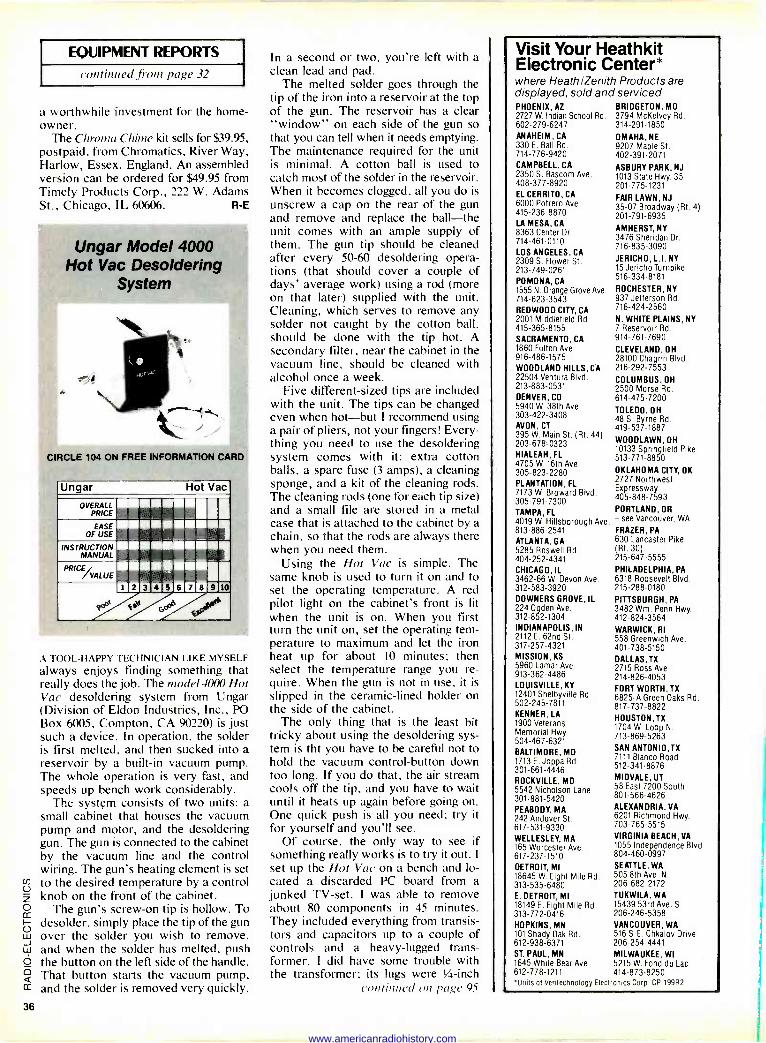
EQUIPMENT REPORTS
continued from page 32
a worthwhile investment for the home- owner.
The Chroma Chime kit sells for $39.95, postpaid, from Chromatics, River Way, Harlow, Essex, England. An assembled version can be ordered for $49.95 from Timely Products Corp., 222 W. Adams St., Chicago, IL 60606. R -E
Ungar Model 4000 Hot Vac Desoldering
System
CIRCLE 104 ON FREE INFORMATION CARD
Ungar Hot Vac
OVERALL PRICE
EASE OF USE
INSTRUCTION MANUAL
PRICE VALUE
1 2 3 4 3 6 7 8 9 10
io ,epò
A TOOL -HAPPY TECHNICIAN LIKE MYSELF always enjoys finding something that really does the job. The model 4000 Hot Vac desoldering system from Ungar (Division of Eldon Industries, Inc., PO Box 6005, Compton, CA 90220) is just such a device. In operation, the solder is first melted, and then sucked into a
reservoir by a built-in vacuum pump. The whole operation is very fast, and speeds up bench work considerably.
The system consists of two units: a
small cabinet that houses the vacuum pump and motor, and the desoldering gun. The gun is connected to the cabinet by the vacuum line and the control wiring. The gun's heating element is set to the desired temperature by a control
2 knob on the front of the cabinet. 0 The gun's screw -on tip is hollow. To cc
desolder, simply place the tip of the gun w over the solder you wish to remove, L9 and when the solder has melted, push 0 the button on the left side of the handle. 2 That button starts the vacuum pump, cc and the solder is removed very quickly.
In a second or two, you're left with a
clean lead and pad. The melted solder goes through the
tip of the iron into a reservoir at the top of the gun. The reservoir has a clear "window" on each side of the gun so that you can tell when it needs emptying. The maintenance required for the unit is minimal. A cotton ball is used to catch most of the solder in the reservoir. When it becomes clogged, all you do is
unscrew a cap on the rear of the gun and remove and replace the ball-the unit comes with an ample supply of them. The gun tip should be cleaned after every 50-60 desoldering opera- tions (that should cover a couple of days' average work) using a rod (more on that later) supplied with the unit. Cleaning, which serves to remove any solder not caught by the cotton ball, should be done with the tip hot. A secondary filter, near the cabinet in the vacuum line, should be cleaned with alcohol once a week.
Five different -sized tips are included with the unit. The tips can be changed even when hot-but I recommend using a pair of pliers, not your fingers! Every- thing you need to use the desoldering system comes with it: extra cotton balls, a spare fuse (3 amps), a cleaning sponge, and a kit of the cleaning rods. The cleaning rods (one for each tip size) and a small file are stored in a metal case that is attached to the cabinet by a chain, so that the rods are always there when you need them.
Using the Hot Vac is simple. The same knob is used to turn it on and to set the operating temperature. A red pilot light on the cabinet's front is lit when the unit is on. When you first turn the unit on, set the operating tem- perature to maximum and let the iron heat up for about 10 minutes; then select the temperature range you re- quire. When the gun is not in use, it is slipped in the ceramic -lined holder on the side of the cabinet.
The only thing that is the least bit tricky about using the desoldering sys- tem is tht you have to be careful not to hold the vacuum control -button down too long. If you do that, the air stream cools off the tip, and you have to wait until it heats up again before going on. One quick push is all you need; try it for yourself and you'll see.
Of course, the only way to see if something really works is to try it out. I set up the Hot Vac on a bench and lo- cated a discarded PC board from a
junked TV -set. I was able to remove about 80 components in 45 minutes. They included everything from transis- tors and capacitors up to a couple of controls and a heavy -lugged trans- former. I did have some trouble with the transformer; its lugs were t/ -inch
c ontinrmd on page 95
Visit Your Heathkit Electronic Center* where Heath/Zenith Products are displayed, sold and serviced. PHOENIX, AZ BRIDGETON, MO 2727 W. Indian School Rd. 3794 McKelvey Rd. 602-279-6247 314-291-1850 ANAHEIM, CA OMAHA, NE 330 E. Ball Rd. 9207 Maple St. 714-776-9420 402-391-2071 CAMPBELL, CA 2350 S. Bascom Ave. 408-377-8920 EL CERRITO, CA 6000 Potrero Ave. 415-236-8870 LA MESA, CA 8363 Center Dr. 714-461-0110
LOS ANGELES, CA 2309 S. Flower St. 213-749-0261
POMONA, CA 1555 N. Orange Grove Ave. ROCHESTER, NY 714-623-3543 937 Jefferson Rd.
REDWOOD CITY, CA 716-424-2560
2001 Middlefield Rd. N. WHITE PLAINS, NY 415-365-8155 7 Reservoir Rd.
SACRAMENTO, CA 914-761-7690 1860 Fulton Ave. CLEVELAND, OH 916-486-1575 28100 Chagrin Blvd. WOODLAND HILLS, CA 216-292-7553 22504 Ventura Blvd. COLUMBUS, OH 213-883-0531 2500 Morse Rd. DENVER, CO 614-475-7200 5940 W. 38th Ave. TOLEDO, OH 303-422-3408 48 S. Byrne Rd. AVON, CT 419-537-1887 395 W. Main St. (Rt. 44)
WOODLAWN, OH 203-678-0323 10133 Springfield Pike
HIAL W.
FL 513-771-8850 4705OKLAHOMA CITY, OK 305-823-2280
1ót Ave.
2727 Northwest PLANTATION, FL Expressway 7173 W. Broward Blvd. 405-848-7593 305-791-7300 TAMPA, FL PORTLAND, OR
4019 W. Hillsborough Ave. - see Vancouver, WA
813-886-2541 FRAZER, PA
ATLANTA, GA 630 Lancaster Pike
5285 Roswell Rd. (Rt. 30) 404-252-4341 215-647-5555
CHICAGO, IL PHILADELPHIA, PA
3462-66 W. Devon Ave. 6318 Roosevelt Blvd. 312-583-3920 215-288-0180 DOWNERS GROVE, IL 224 Ogden Ave. 312-852-1304 INDIANAPOLIS, IN 2112 E. 62nd St. 317-257-4321 MISSION, KS 5960 Lamar Ave. 913-362-4486 LOUISVILLE, KY 12401 Shelbyville Rd. 502-245-7811 KENNER, LA 1900 Veterans Memorial Hwy. 504-467-6321 BALTIMORE, MD 1713 E. Joppa Rd. 301-661-4446 ROCKVILLE, MD 5542 Nicholson Lane 301-881-5420 PEABODY, MA 242 Andover St. 617-531-9330 WELLESLEY, MA 165 Worcester Ave. 617-237-1510
DETROIT, MI 18645 W. Eight Mile Rd. 313-535-6480 E. DETROIT, MI 18149 E. Eight Mile Rd. 313-772-0416 HOPKINS, MN 101 Shady Oak Rd. 612-938-6371
ASBURY PARK, NJ 1013 State Hwy. 35 201-775-1231
FAIR LAWN, NJ 35-07 Broadway (Rt. 4) 201-791-6935
AMHERST, NY 3476 Sheridan Dr. 716-835-3090
JERICHO, L.I. NY 15 Jericho Turnpike 516-334-8181
PITTSBURGH, PA 3482 Wm Penn Hwy. 412-824-3564
WARWICK, RI 558 Greenwich Ave. 401-738-5150 DALLAS, TX 2715 Ross Ave. 214-826-4053
FORT WORTH, TX 6825-A Green Oaks Rd. 817-737-8822 HOUSTON, TX 1704 W. Loop N. 713-869-5263
SAN ANTONIO,TX 7111 Blanco Road 512-341-8876
MIDVALE, UT 58 East 7200 South 801-566-4626 ALEXANDRIA, VA 6201 Richmond Hwy. 703-765-5515
VIRGINIA BEACH, VA 1055 Independence Blvd. 804-460-0997 SEATTLE, WA 505 8th Ave. N. 206-682-2172
TUKWILA, WA 15439 53rd Ave. S. 206-246-5358 VANCOUVER, WA 516 S.E. Chkalov Drive 206-254-4441
ST. PAUL, MN MILWAUKEE, WI 1645 White Bear Ave. 5215 W. Fond du Lac 612-778-1211 414-873-8250 "Units of Veritechnology Electronics Corp. CP-199R2
36
www.americanradiohistory.com
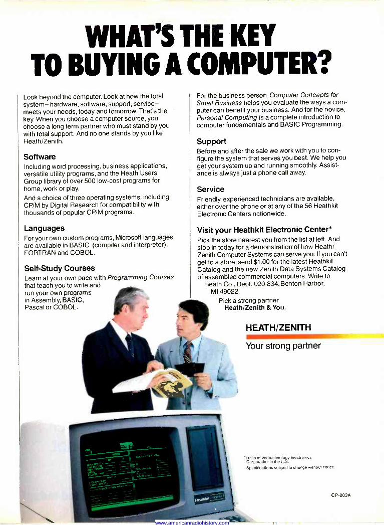
WHAT'S THE KEY TO BUYING A COMPUTER?
Look beyond the computer. Look at how the total system- hardware, software, support, service- meets your needs, today and tomorrow. That's the key. When you choose a computer source, you choose a long term partner who must stand by you with total support. And no one stands by you like Heath/Zenith.
Software Including word processing, business applications, versatile utility programs, and the Heath Users' Group library of over 500 low-cost programs for home, work or play.
And a choice of three operating systems, including CP/M by Digital Research for compatibility with thousands of popular CP/M programs.
Languages For your own custom programs, Microsoft languages are available in BASIC (compiler and interpreter), FORTRAN and COBOL.
Self -Study Courses Learn at your own pace with Programming Courses that teach you to write and run your own programs in Assembly, BASIC, Pascal or COBOL.
For the business person, Computer Concepts for Small Business helps you evaluate the ways a com- puter can benefit your business. And for the novice, Personal Computing is a complete introduction to computer fundamentals and BASIC Programming.
Support Before and after the sale we work with you to con- figure the system that serves you best. We help you get your system up and running smoothly. Assist- ance is always just a phone call away.
Service Friendly, experienced technicians are available, either over the phone or at any of the 56 Heathkit Electronic Centers nationwide.
Visit your Heathkit Electronic Center* Pick the store nearest you from the list at left. And stop in today for a demonstration of how Heath/ Zenith Computer Systems can serve you. If you can't get to a store, send $1.00 for the latest Heathkit Catalog and the new Zenith Data Systems Catalog of assembled commercial computers. Write to
Heath Co., Dept. 020-834, Benton Harbor, MI 49022.
Pick a strong partner. Heath/Zenith & You.
HEATH/ZENITH
Your strong partner
`Units of Veritechnology Electronics Corporation in the U.S.
Specifications subject to change without notice.
CP-203A
www.americanradiohistory.com

If you have put off learning more electronics for any of these reasons, act now!
I don't have the time.
High school was hard for me and electronics sounds like it may be hard to learn.
I can't afford any more education.
I have a family now.
I'm here. You're there. I've never learned that way before. I'm not sure it will work for me.
2 Read the opposite page and see how you can get started today! 38
www.americanradiohistory.com
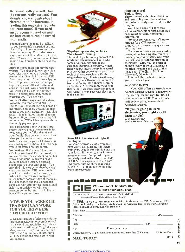
Be honest with yourself. Are the reasons really excuses? You already know enough about electronics to be interested in reading this magazine. So why not learn more? If you need encouragement, read on and see how excuses can be turned into results. You don't have the time. Be realistic. All you have in life is a period of time. Use it. Try to know more tomorrow than you do today. That's the proven way to success. CIE studies require just about 12 hours of your time a week, two hours a day. You probably do have the time. Electronics sounds like it may be hard to learn. You already know something about electronics or you wouldn't be reading this. Now, build on that. CIE Auto -Programmed ® Lessons help you learn. Topics are presented in simple, logical sequence. All text is clear and concise for quick, easy understanding. You learn step by step, at your own pace. No classes to attend. Nobody pressures you. You can learn. You can't afford any more education. Actually, you can't afford NOT to gain the skills that can put you ahead of the others. You know what inflation is doing to you now. Education-learning a skill-is an inflation -fighter that can be yours. If you are not able to pay full tuition now, CIE will lend you funds on a monthly payment plan. You have a family now. All the more reason why you have the responsibility to advance yourself. For the sake of your family. Do you want them to have what you had or have more than you had? The choice is yours. Electronics is a rewarding career choice. CIE can help you to get started on that career. You're there. We're here. How does CIE help you learn? First, we want you to succeed. You may study at home, but you are not alone. When you have a question about a lesson, a postage stamp gets you your answer fast. You may find this even better than having a classroom teacher. CIE understands people need to learn at their own pace. When CIE receives your completed lesson before noon any day of the week, it will be graded and mailed back the same day with appropriate instructional help. Your satisfaction with your progress comes by return mail. That's how CIE helps you learn.
NOW, IF YOU AGREE CIE TRAINING CAN WORK FOR YOU, HOW ELSE CAN CIE HELP YOU?
Cleveland Institute of Electronics is the largest independent home study school in the world that specializes exclusively in electronics. Although "big" does not always mean "best;' it is evidence that CIE is a strong, successful institution with the people and resources to help you succeed.
Step-by-step learning includes "hands-on " training. The kind of professional you want to be needs more than theory. That's why some of our courses include the Personal Training Laboratory, which helps you put lesson theory into actual practice. Other courses train you to use tools of the trade such as a 5MHz triggered -sweep, solid-state oscilloscope you build yourself-and use to practice troubleshooting. Or a Digital Learning Laboratory to let you apply the digital theory that's essential today for anyone who wants to keep pace with electronics in the eighties.
Your FCC License can impress employers. For some electronics jobs, you must have your FCC License. For others, employers usually consider it a mark in your favor. Either way, your License is government -certified proof of your knowledge and skills. More than half of CIE's courses prepare you to pass this exam. Surveys show that some 80% of CIE graduates who take the exam are successful.
Find out more! Today. Now. There's a card with this ad. Fill it in and return. If some other ambitious person has already removed it, use the coupon.
You'll get a copy of CIE's free school catalog, along with a complete package of personal home study information.
For your convenience, we'll try to arrange for a CIE representative to contact you to answer any questions you may have.
If you are serious about a rewarding career, about learning electronics or building on your present skills, your best bet is to go with the electronics specialists-CIE. Mail the card or coupon today or write CIE (please mention the name and date of this magazine), 1776 East 17th Street, Cleveland, Ohio 44114.
This could be the best decision you've made all year.
Associate Degree Now, CIE offers an Associate in
Applied Science Degree in Electronics Engineering Technology. In fact, all or most of every CIE Career Course is directly creditable towards the Associate Degree.
"If you're going to learn electronics, you might as well learn it right:' John Cunningham Senior Technical Director
ABBI
CIE Cleveland Institute of Electronics, Inc.
1776 East 17th Street, Cleveland, Ohio 44114 Accredited Member National Home Study Council
YES...I want to learn from the specialists in electronics-CIE. Send me my FREE CIE school catalog...including details about the Associate Degree program...plus my FREE package of home study information.
Print Name
Address Apt
City
State Zip
Age Phone (area code)
Check box for G.I. Bill bulletin on Educational Benefits: Veteran Active Duty
MAIL TODAY! RE -24
www.americanradiohistory.com
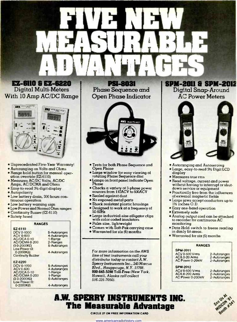
EZ -6110 6 EZ -62 Digital Multi -Meters
With 10 Amp AC/DC Range
Unprecedented Five -Year Warranty! Autoranging on Volts and Ohms Range hold button for manual oper- ation override (EZ -6110) Measures AC/DC Volts, AC/DC Amps, AC/DCMA and Ohms Easy -to -read 3' digit display Autopolarity Low battery drain, 300 hours con- tinuous operation Low battery warning sign Low Power and Normal Ohm ranges Continuity Biirzer (EZ -6110) Safety fused
RANGES
EZ -6110 DCV 0-1000 ACV 0-600 AC/DCA 0-10 AC/DCMA 0-200 f10 -2000K11 Low Power St: 0-2000Kí2
Continuity Buzzer
EZ -6220 DCV 0-1000 ACV 0-600 AC/DCA 0-10 AC/DCMA 0-200 S2 0-2000Kí2 Low Power SI: 0-2000KS2
5 -Autoranges 4 -Autoranges 1 -Range 2 -Ranges 5 -Autoranges
4 -Autoranges
5 -Autoranges 4 -Autoranges 1 -Range 1 -Range 5 -Autoranges
4 -Autoranges
Phase Sequence and Open Phase Indicator
Tests for both Phase Sequence and Open Phase Large window for easy viewing of rotating Phase Sequence disc Lamps on front panel indicate Open Phase Checks a variety of 3 -phase power sources from i lOACV to 600ACV Sealed against dust No exposed metal parts Shock resistant plastic housings Designed to work at a frequency of 50-60Hz Large industrial -size alligator clips with color coded insulators Palm -size, lightweight Comes with Soft -Pak carrying case Warranted for six (6) months
For more information on the AWS line of test instruments call your distributor today or contact A.W. Sperry Instruments Inc., 245 Marcus Blvd., Hauppcuge, N.Y. 11788. 800-645-5398 Toll -Free (New York, Hawaii, Alaska call collect 516-231-705W.
PM -2011 6 SPM-2012 Digital Snap -Around
AC Power Meters
Autoranging and Autozeroing Large, easy -to -read 31 Digit LCD display Measures true rms Read voltage, current and power without having to interrupt or shut- down service or equipment Practically free from the influences of external magnetic fields Large jaws accept conductors up to 1' inches O.D. Easy one -hand operation Extremely safe Analog output cord can be attached to recorder for continuous AC monitoring Data Hold switch to freeze reading in dimly lit areas. Warranted for six (6) months
RANGES
SP41-2011 ACV 0-600 Vrms ACA 0-20 Arms AC Power 0-20kW
SPM-2012 AC;/ 0-600 Vrms ACA 0-200 Arms AC Power 0-200kW
2 -Autoranges 2 -Autoranges 2 -Autoranges
2 -Autoranges 2 -Autoranges 2 -Autoranges
A.W. SPRRRY INSTRUMENTS INC. The Measurable Advantage
CIRCLE 27 ON FREE INFORMATION CARD
www.americanradiohistory.com
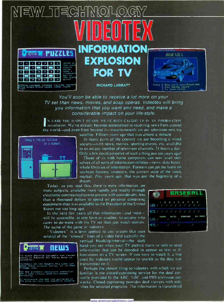
L J
PLIZZLEa IIII n TR E
F 11.1 N Mil H Mill A
1 R ESS Mi I Mil R NZ E
li Ik NESS
Which o
the u
liste beloc make cros, Out the e grid`
SS HARNESS IMI'RE HILAIRE TRE EA:!': INN N HANDS 1171 RI. TRAS"
fr
INFORMATION EXPLOSION
FOR TV RICHARD LARRATT
JAGUAR XJ12 L
Press 1 This car`s speeiricatioiLS 2 Your Carias repot
lo leave Fairfax.
You'll soon be able to receive a lot more on your TV set than news, movies, and soap operas. Videotex will bring
you information that you want and need, and make a
considerable impact on your life-style.
CASE YOU HADN'T HEARD. WE'VE BEEN CAUCH r UP IN AN INFOR\L\TION revolution. We've already become accustomed to receiving news from around
the world-and even from beyond it-instantaneously on our television sets via satellite. Fifteen years ago that was almost a miracle.
In many parts of the country we are becoming a wired society-with news, movies, sporting events. etc. available to us on any number of television channels. 24 hours a day. Only a few could conceive of such a thing just ten years ago!
Those of us with home computers can now avail our- selves of all sorts of information utilities-news, data bases. whole libraries of information. Farmers can get the latest on
soybean futures: investors, the current state of the stock market. Eire years ago. that was just the beginning of a
dream. Today. as you read this, there is more information, on
more subjects. available more rapidly and readily through electronic communications to anyone with considerably less
than a thousand dollars to spend on personal computing equipment than was available to the President of the United States not too long ago.
In the next few years all that information-and more- will be accessible. in one form or another, to anyone who cares to do more with his TV set than just watch movies. The name of the game is: videotex.
"Videotex" is a term applied to any system that uses
several of the "unused" lines of a video field (actually the vertical blanking-interval-the dark hand you see when your TV picture starts to roll) to send
information that can be decoded to appear as text or il- lustrations on a TV screen. If you were to watch it. a line used for videotex would appear to sparkle as the data was
transmitted on it. Perhaps the closest thing to videotex with which we are
familiar is the closed -captioning service for the deaf cur- rently provided by the ABC. NBC. and PBS television net- works. Closed captioning provides deaf viewers with sub- titles for selected programs. The information is transmitted
L ell MI
-- nEwS Ihº space shuttle Columbia has landed lately at Edwards Air Force base in a1itorni a.
hdown on the Rogers Dry Lake was .t three 'stout*. early. at 12:25p- ago time
t),e critical maneuvers essential a sate return ware performed spotty
Cestimated 100,000 had gathered at he sit. t. view the historic landing.
f
1111111111 Bfl5 Leg fl¿
I 2 3 4 5 6 T B 9
CUBS i/ / / / / / i/ METS / / / / / / i/ / /
RUNS HITS ERRORS ON BASE
CUBS / / / /
METS , i i
www.americanradiohistory.com
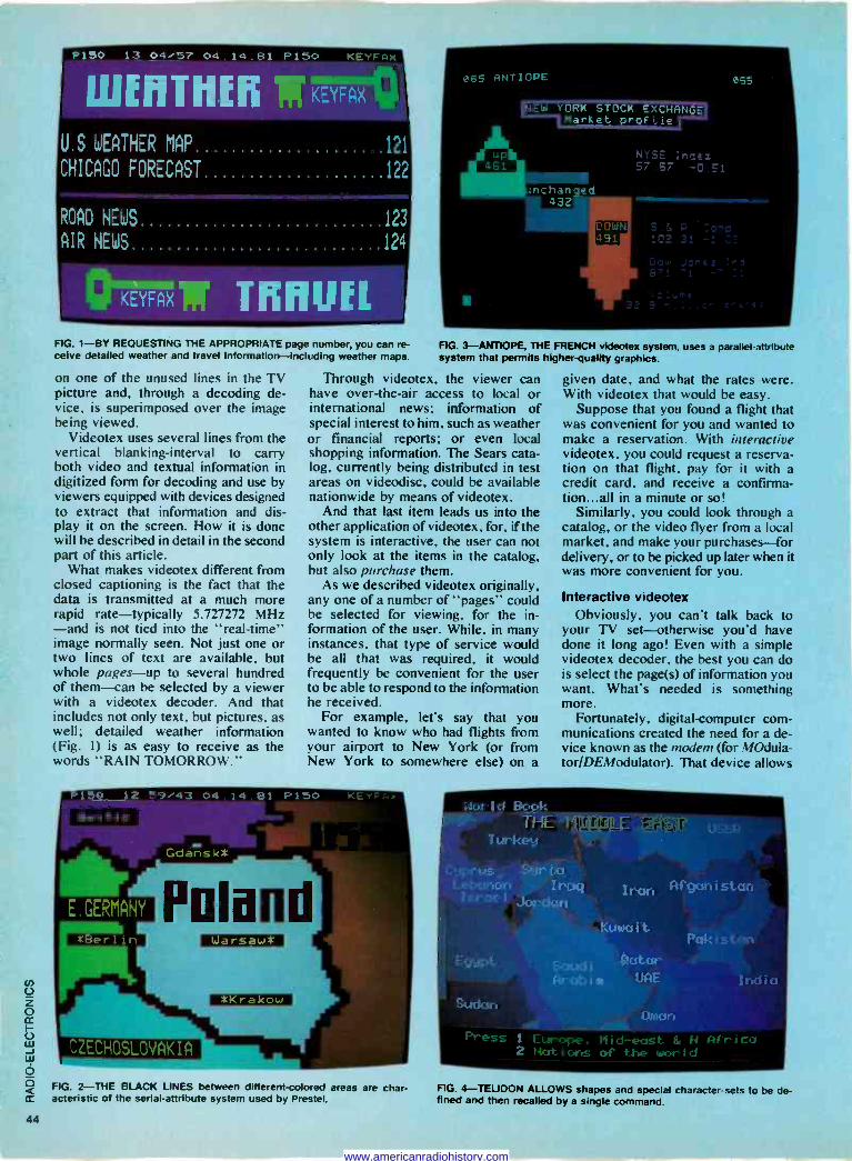
F'150 13 04,-57 04.14 81 P150 E
W[IITIIU111KEYFax
U . S WEATHER MAP
CHICAGO FORECAST
121
122
ROAD NEWS 123
AIR NEWS 124
>MR nrnuii FIG. 1-BY REQUESTING THE APPROPRIATE page number, you can re- FIG. 3-ANTIOPE, THE FRENCH videotex system, uses a parafie4attribute calve detailed weather and travel information --including weather maps. system that permits higher -quality graphics.
on one of the unused lines in the TV picture and, through a decoding de- vice, is superimposed over the image being viewed.
Videotex uses several lines from the vertical blanking -interval to carry both video and textual information in digitized form for decoding and use by viewers equipped with devices designed to extract that information and dis- play it on the screen. How it is done will be described in detail in the second part of this article.
What makes videotex different from closed captioning is the fact that the data is transmitted at a much more rapid rate-typically 5.727272 MHz -and is not tied into the "real-time" image normally seen. Not just one or two lines of text are available, but whole pages-up to several hundred of them-can be selected by a viewer with a videotex decoder. And that includes not only text, but pictures, as well; detailed weather information (Fig. I) is as easy to receive as the words "RAIN TOMORROW."
Through videotex, the viewer can have over -the -air access to local or international news; information of special interest to him, such as weather or financial reports; or even local shopping information. The Sears cata- log, currently being distributed in test areas on videodisc, could be available nationwide by means of videotex.
And that last item leads us into the other application of videotex, for, if the system is interactive, the user can not only look at the items in the catalog, but also purchase them.
As we described videotex originally, any one of a number of "pages" could be selected for viewing, for the in- formation of the user. While, in many instances, that type of service would be all that was required, it would frequently be convenient for the user to be able to respond to the information he received.
For example, let's say that you wanted to know who had flights from your airport to New York (or from New York to somewhere else) on a
FIG. 2-THE BLACK LINES between different -colored areas are char- acteristic of the serial -attribute system used by Prestel.
given date, and what the rates were. With videotex that would be easy.
Suppose that you found a flight that was convenient for you and wanted to make a reservation. With interactive videotex. you could request a reserva- tion on that flight, pay for it with a credit card, and receive a confirma- tion...all in a minute or so!
Similarly, you could look through a catalog, or the video flyer from a local market, and make your purchases-for delivery, or to be picked up later when it was more convenient for you.
Interactive videotex Obviously, you can't talk back to
your TV set-otherwise you'd have done it long ago! Even with a simple videotex decoder, the best you can do is select the page(s) of information you want. What's needed is something more.
Fortunately, digital -computer com- munications created the need for a de- vice known as the modem (for MOdula- tor/DEModulator). That device allows
Nor I d BoUt.. - y iHE I 1 NIL . LE -1:H° .
Turkey
Stlr' I a !-e tptsr;an Iraq aq I ran Af'gctn i sta; 1 s.i-oe i .tordun
Egypt
.Sudan
Kum it. Pak
i 4?crtcst-. krr'tapío UFtF
1 Europe. Nid -east & 2 Not i orrs of the wor l d
FIG. 4-TELIDON ALLOWS shapes and special character -sets to be de- fined and then recalled by a single command.
www.americanradiohistory.com
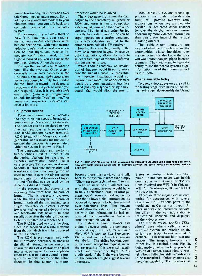
you to transmit digital information over telephone lines as audio tones. So, by adding a keyboard and modem to your videotex setup, you can talk back to a computer connected to a videotex system.
For example, if you find a flight to New York that meets your require- ments, you can dial a telephone num- ber connecting you with your nearest videotex center and request a reserva- tion on that flight...and receive im- mediate confirmation. And, if that flight is booked -up, you can make the next -best choice. All on the spot.
Perhaps that sounds a bit familiar to you-like the two-way Qube system currently in use over cable -TV in the Columbus, OH area. Qube does allow viewer response, but only to a limited degree-both as regards the degree of response and the subjects to which you can -respond. Also, it is available only over cable. Qube is pre-programmed to look for simple "yes" or "no," or numerical, responses. Videotex can offer a lot more.
Equipment needed To receive non -interactive videotex
the only thing that needs to be added to your existing TV receiver is a decoder. The decoder can be considered to have five main sections: a data -acquisition unit, RAM (Random Access Memory), ROM (Read Only Memory), a video generator, and a means for the user to control the decoder. A representative videotex system is shown in Fig. 5.
The data -acquisition unit performs two functions. First, it "tunes in" on the vertical -blanking lines carrying the videotex information-acting like a very selective TV receiver, as it were. Second, it takes that information and translates it from the analog format used to send it over the air (or cable) into a digital format (a series of logic - l's and 0's) that can be used by the decoder's digital circuitry.
In the process it also converts the incoming data from serial to parallel format. (That is necessary because, while the data is originally in parallel format-with all the bits making up a single character or picture element (pixel or peo arranged side -by -side in one block-the bits have to be sent serially, one after the other, if they are to be transmitted on a video line.)
The RAM is used to store the data, since it is received at a rate different from that at which it will be displayed on the TV screen.
The ROM is pre-programmed with the information necessary to translate the digital information containing the characteristics of a character or pixel into a video image. In more sophisti- cated units, it may also contain a pro- gram for overall control of the entire decoder. In that context, a micro-
processor would be involved. The video generator takes the data
output by the character/pixel-generator ROM and turns it into a composite - video signal, similar to that from a TV camera. The signal can either be fed directly to a video monitor, or can be superimposed on a carrier generated by a RF -modulator and fed to the antenna terminals of a TV receiver.
Finally, the controller, usually in the form of a numeric keypad in receive - only installations, allows the user to select which page of videotex informa- tion he wishes to see.
While it sounds complex, an installa- tion of that sort would fit easily into a case the size of a cable -TV translator.
A two-way installation would not require much more. The added element would be a communications interface -and possibly a typewriter -style key- board-that would allow the user to
l- - - - -1 I MODEM (FOR
INTERACTIVE
L_ VIDEOTEX) T_J
TO TELEPHONE
LINE
VIDEOTEX DATA FROM TV
RECEIVER
DATA AC OUISITION
UNIT
Most cable -TV systems whose ap- plications are under consideration today will provide two-way com- munications, when they are put into service. A dedicated cable channel (or over -the -air channel) can transmit enormously more videotex information than can a few lines of the vertical blanking -interval.
The cable -system operators are aware of what the future holds, and the communities whose franchises they are competing for also know that they will want more than just piped -in enter- tainment. They will want to have the ability to use their cable systems to get information out of their homes as well as into them.
What's available today To date, videotex systems are still in
the testing stage, with much of the test- ing having been done outside the United
FRAME MEMORY
(RAM)
CHARACTER GENERATOR (ROM/RAM)
CONTROLLER (ROM)
KEY PAD
VIDEO GENERATOR
TO VIDE'] D SPLAY
FiiG. 5-THIE MODEM shown at lett is required for interactive videotex using telephone lines tines. Tow -way cable service would use an interface between the user's keypad or keyboard and the cable line.
become more than a viewer and talk back to the system in more than simply "Show me page such -and -such" terms.
With an over -the -air videotex sys- tem, that communication would have to be via telephone. Suck. an arrange- ment would require a modem, the de- vice that allows digital information (as opposed to speech) to be transmitted over telephone lines. The modem would allow the videotex user to inter- act with the information he had re- quested from over -the -air transmis- sions through his decoder.
By dialing a phone number and giving his access code to a computer, he could say, in effect, "I see that flight 901 is open to San Francisco. Please book me one first class seat on that flight." The airline -booking com- puter would accept his request, make the reservation (if it were still avail- able), and charge the flight to his credit card. If the flight were booked up, the computer might suggest several alternates.
States. A number of tests have taken place, or are now under way in this country, as well. Among the TV sta- tions involved are WFLD in Chicago, WETA in Washington, DC, and KCET in Los Angeles.
There are three major systems com- peting for acceptance, with several others in use in various parts of the world such as Germany and Japan. All offer one-way or interactive service, but differ in the way information is transmitted, decoded, and displayed on the video screen.
The British Prestel (PRESs TELe- phone) uses what's called a serial attribute system (no relation to the serial -transmission format referred to earlier). It can transmit both text and images. The images, however, are rather low in resolution (see Fig. 2), being made up of rather large pixels. A version of Prestel, called Picture Pres- tel allows full -color still video -frames to be transmitted. (Other systems also have this capability. The drawback, as
www.americanradiohistory.com
we'll see later, is the length of time it takes to transmit the picture.)
Antiope, from France, uses a paral- lel -attribute system. It permits some- what more detailed images, without some of the limitations inherent in the Prestel system. An example of Antiope is shown in Fig. 3.
The third system. Telidon (from a
combination of Latin and Greek for "distant image"), was developed in Canada. and is more flexible than either of the others. It also uses a parallel -attribute system but, instead of relying on shapes stored in the de- coder's ROM, can download (trans- mit from the system's master memory to the memory of the user's decoder) specific shapes that can be used for the application at hand and called up by a single command. An example of Telidon's capabilities is shown in Fig. 4.
Detailed descriptions of the formats of each of those systems will be covered in the next part of this article.
In Britain and France (and in other countries related to them by culture or video standards) over 100,000 house- holds have been equipped for videotex. In addition. public videotex terminals have been tried on a limited basis.
Both Prestel and Antiope have been sampled in this country, but the gen- eral and specific results of the tests are yet to be fully evaluated.
The Canadian Telidon system is just starting to make its presence known here, although it has seen use in other parts of the world. Trials of Telidon are underway by organizations such as Time. Inc., the Times Mirror Cable Co., and AT&T. The first intends to make as many as 24 "magazines" available over the system. AT&T has petitioned the FCC to make the Telidon system the U.S. videotex standard.
Currently the EIA (Electronic In- dustries Association) is developing a set of standards which it hopes will be adopted for use in this country. The FCC is expected to start evaluating that proposal this year.
What's coming While it was probably conceived
with the general public in mind, most applications of videotex to date have been directed to the businessman, who, it was felt, could well afford its services.
As personal computers have proven, though (through the introduction and increasing use of the Source, MicroNet, and other, smaller, computer net- works), there are many individuals who want and need interactive infor- mation utilities.
The "magazine" format would seem to indicate the response of large organ- izations to the public's wishes. Also.
banks, whose managers previously felt that their computers might be "in- vaded" by personal computers, are beginning to open their doors to video- tex transactions, seeing the videotex system as a protective buffer between their systems and the users'.
Along those same lines, owners of personal computers will soon be able to use local videotex systems (in both the interactive mode and the creative mode-where data, and not just re- sponses, can be entered into the sys- tem) with a simple addition to their own systems. Norpak of Canada has an- nounced a plug-in board for the Apple // computer for Telidon. Even better, there should be a module available soon for Radio Shack's TRS-80 Color Computer, since it uses the same microprocessor (the 6809) as the ter- minal that was originally designed for the Telidon system. You may soon be able to walk into your local Radio Shack store and walk out with a plug-in videotex system for under $500!
As it proliferates, videotex will be the means by which you'll obtain the information you need, and transact your personal business-as well as, perhaps. earn your living-without leaving home. It's part of the informa- tion revolution.
Next month we'll discuss the tech- nology behind the various videotex systems. R -E
Whc.t's News Electricity from coal, without pollution
Dr. Richard Williams, Fellow of the technical staff of RCA Labs, Princeton, NJ, has patented a process that uses coal to produce electricity, without burning the coal, eliminating the air pollution that is normally caused by common coal -burning generators.
The conversion is not direct. The pro- cess starts with passing steam over hot coal, producing carbon monoxide and hydrogen. (This process is used to make the so-called "water gas" used in many cities.)
The carbon monoxide is then reacted with hot sodium hydroxide to form sodium formate that can then be used in a fuel cell to generate electricity. The remaining hydrogen is also usable in a fuel cell.
Originally conceived about 150 years ago, fuel cells-in which the oxidation of a gaseous fuel produces electricity in a continuous process-have been used to provide energy for spacecraft. Now, be- cause of the energy shortage, they may be able to produce electricity economi- cally for many earthbound applications.
Dr. Williams points out that a coal-fired steam plant can convert only about 30 percent of the coal's energy to electricity, while producing undersirable pollution. The fuel cell can convert as much as 50 percent of the coal's energy to electricity,
Dr. RICHARD WILLIAMS of RCA shows the steps in his method of using steam and coal to produce electricity efficiently.
without producing pollutants during the process.
RCA will grant non-exclusive licenses to use the Williams patent.
Cellular system for mobile two- way phone
The FCC has granted approval to "cellular" mobile radiotelephony. In cel- lular communication, a service area- such as a city- is divided into small areas, called "cells," each with its own low -
power transmitter. Thus, a taxi company or other service would not need to cover an entire city with just one station; in- stead, it would use several small ones. Each of those stations would be designed to cover its own "cell" efficiently while causing as little interference as possible in adjoining cells. As vehicles move from cell to cell, communications would be switched electronically from one trans- mitter to the next.
The cellular approach wilc allow many more telephone calls to be died at the same time than is possi with the present two-way phone s e. Highly successful tests of the c lar system have been carried out under preliminary FCC rules by Illnois Bell in Chicago and by Motorola in Washington, DC.
Radio common carriers are looking for- ward to the coming system `th a mixture of anticipation and concern. ys Bernard Kahn, of a large Chicago co unications service: "Cellular is so eff t that by the year 2000-at the leas will carry practically all forms of porta communi- cations. We've been waiting for this moment for more than 10 years."
Yet he expressed the fear of possible wire -line company domination that is worrying many independent common carriers. "Our greatest concern," he said, "is that the Bell System-directly or indi- rectly-might be handed a virtual monopoly on cellular systems. The FCC's own Common Carrier Bureau and the Justice Department have also gone on record with the same concern." R -E
www.americanradiohistory.com
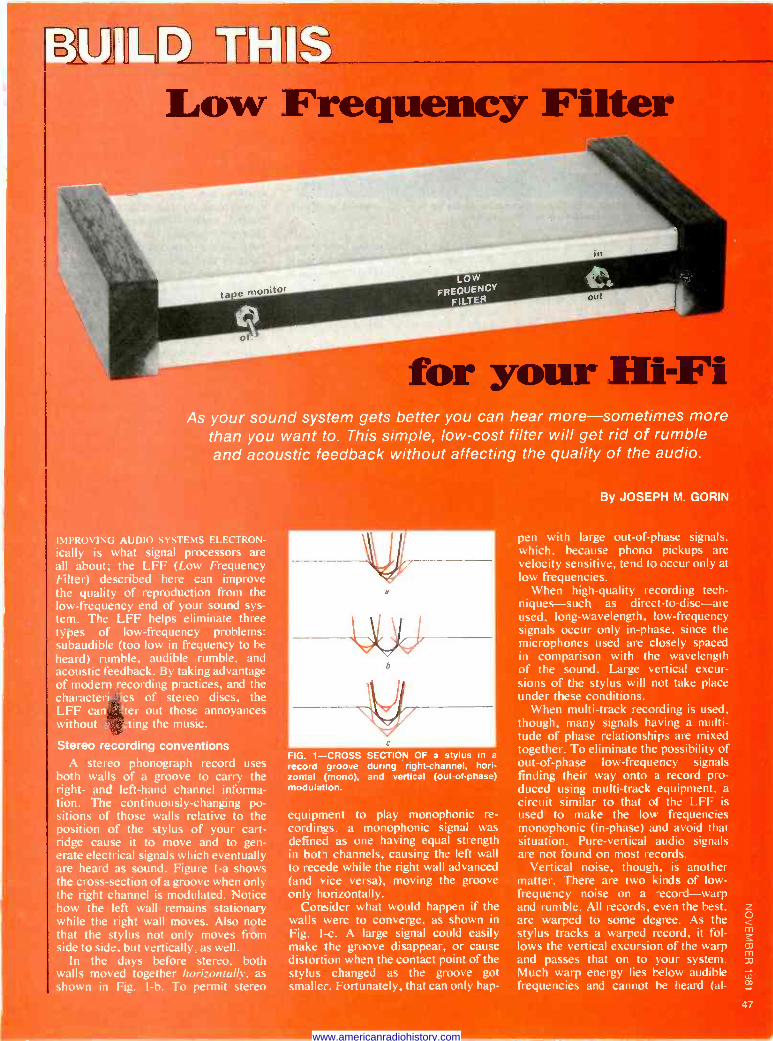
D vL L
D1 L J
Low Frequency Filter
tase moníto LOW
FREQUENCY FILTER
in
ea o
Hi-Fi As your sound system gets better you can hear more-sometimes more
than you want to. This simple, low-cost filter will get rid of rumble and acoustic feedback without affecting the quality of the audio.
PROVING AUDIO SYSTEMS ELECTRON -
is what signal processors are about; the LFF (Low Frequency
!ter) described here can improve quality of reproduction from the
-frequency end of your sound sys- . The LFF helps eliminate three
.es of low -frequency problems: baudible (too low in frequency to be ard) rumble, audible rumble, and oustic feedback. By taking advantage modern recording practices, and the racteri tics of stereo discs, the F can '!ter out those annoyances
thout a zting the music.
ereo recording conventions A stereo phonograph record uses th walls of a groove to carry the ht- and left-hand channel informa- n. The continuously -changing po - ions of those walls relative to the sition of the stylus of your cart- ge cause it to move and to gen- te electrical signals which eventually
heard as sound. Figure I -a shows e cross-section of a groove when only e right channel is modulated. Notice w the left wall remains stationary ile the right wall moves. Also note
at the stylus not only moves from e to side, but vertically, as well. In the days before stereo, both Its moved together horizontalk, as
own in Fig. l -b. To permit stereo
FIG. 1-CROSS SECTION OF a stylus in a record groove during right -channel, hori- zontal (mono), and vertical (out -of -phase) modulation.
equipment to play monophonic re- cordings, a monophonic signal was defined as one having equal strength in bota channels, causing the left wall to recede while the right wall advanced (and vice versa), moving the groove only horizontally.
Consider what would happen if the walls were to converge, as shown in Fig. 1-c. A large signal could easily make the groove disappear, or cause distortion when the contact point of the stylus changed as the groove got smalle-. Fortunately, that can only hap -
By JOSEPH M. GORIN
pen with large out -of -phase signals, which, because phono pickups are velocity sensitive, tend to occur only at low frequencies.
When high -quality recording tech- niques-such as direct-to-disc-are used, long -wavelength, low -frequency signals occur only in -phase, since the microphones used are closely spaced in comparison with the wavelength of the sound. Large vertical excur- sions of the stylus will not take place under these conditions.
When multi -track recording is used, though, many signals having a multi- tude of phase relationships are mixed together. To eliminate the possibility of out -of -phase low -frequency signals finding their way onto a record pro- duced using multi -track equipment. a circuit similar to that of the LFF is used to make the low frequencies monophonic (in -phase) and avoid that situation. Pure -vertical audio signals are not found on most records.
Vertical noise, though, is another matter. There are two kinds of low - frequency noise on a .ecord-warp and rumble. All records, even the best, are warped to some degree. As the stylus tracks a warped record, it fol- lows the vertical excursion of the warp and passes that on to your system. Much warp energy lies below audible frequencies and cannot be heard (al-
www.americanradiohistory.com
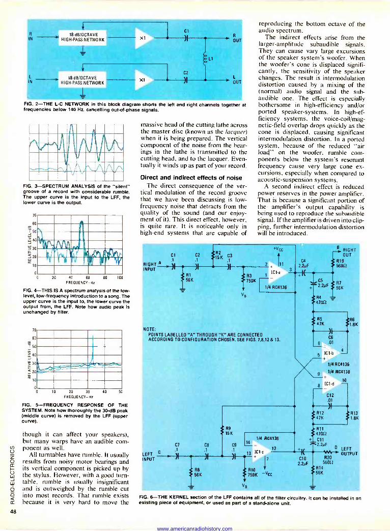
R
IN
L
IN
18 dB/OCTAVE HIGH-PASS NETWORK
1 X1
r 18 dB/OCTAVE
HIGH-PASS NETWORK
1 XI
Cl
02
R
OUT
OUT
FIG. 2-THE L -C NETWORK in this block diagram shorts the left and right channels together at frequencies below 140 Hz, cancelling out -of -phase signals.
Vivv, FIG. 3-SPECTRUM ANALYSIS of the "silent" groove of a record with considerable rumble. The upper curve is the input to the LFF, the lower curve is the output.
70
60
I 5° W
40
> 30
3 20
10
0
0 20 40 60 80
FREQUENCY -Hz 100
FIG. 4-THIS IS A spectrum analysis of the low- level, low -frequency introduction to a song. The upper curve is the input to, the lower curve the output from, the LFF. Note how audio peak is unchanged by filter.
70
60 i 50
40
30 17-
3 20
2 10
0 0 10 20 30
FREQUENCY -Hz
L_ r
40 50
FIG. 5-FREQUENCY RESPONSE OF THE SYSTEM. Note how thoroughly the 30 -dB peak (middle curve) is removed by the LFF (upper curve).
though it can affect your speakers), but many warps have an audible com- ponent as well.
All turntables have rumble. It usually results from noisy motor bearings and its vertical component is picked up by the stylus. However, with a good turn- table. rumble is usually insignificant and is outweighed by the rumble cut into most records. That rumble exists because it is very hard to move the
massive head of the cutting lathe across the master disc (known as the lacquer) when it is being prepared. The vertical component of the noise from the bear- ings in the lathe is transmitted to the cutting head, and to the lacquer. Even- tually it winds up as part of your record.
Direct and indirect effects of noise The direct consequence of the ver-
tical modulation of the record groove that we have been discussing is low - frequency noise that detracts from the quality of the sound (and our enjoy- ment of it). This direct effect, however, is quite rare. It is noticeable only in high -end systems that are capable of
reproducing the bottom octave of the audio spectrum.
The indirect effects arise from the larger -amplitude subaudible signals. They can cause vary large excursions of the speaker system's woofer. When the woofer's cone is displaced signifi- cantly, the sensitivity of the speaker changes. The result is intermodulation distortion caused by a mixing of the (normal) audio signal and the sub - audible one. The effect is especially bothersome in high -efficiency and/or ported speaker -systems. In high -ef- ficiency systems, the voice-coil/mag- netic-field overlap drops quickly as the cone is displaced, causing significant intermodulation distortion. In a ported system, because of the reduced "air load" on the woofer, rumble com- ponents below the system's resonant frequency cause very large cone ex- cursions, especially when compared to acoustic -suspension systems.
A second indirect effect is reduced power reserves in the power amplifier. That is because a significant portion of the amplifier's output capability is being used to reproduce the subaudible signal. If the amplifier is driven into clip- ping, further intermodulation distortion will be introduced.
Cl .1
RIGHT A. I INPUT ' 7f
R2 15 K ,3
i r
R1 R3 156K 750K
Vg
1/4 RC4136
NOTE: POINTS LABELLED "A" THROUGH "K" ARE CONNECTED ACCORDING TO CONFIGURATION CHOSEN. SEE FIGS. 7,8,12 & 13.
C7
.1
LEFT INPUT
R9
15K
C8 C9
.1
R8
56K
14 1/4 RC4136
12
13 ICI -c
7
R10 750K -VCC
Vg
C5
2.2µF
R4
47052
RIGHT OUT
R19 56052
R7
56K
R5 47K
R6 1.8K
C6
6 .01
8
1/4 RC4136
1/4 RC4136
ICI
C12
.01
10
R12 .*R13 47K >1.8K
R11 47052
C11
2.2µF O
CO 2.2µF 56052
R14 56K
1M R20
LEFT OUTPUT
FIG. 6-THE KERNEL section of the LFF contains all of the filter circuitry. It can be installed in an existing piece of equipment, or used as part of a stand-alone unit.
www.americanradiohistory.com
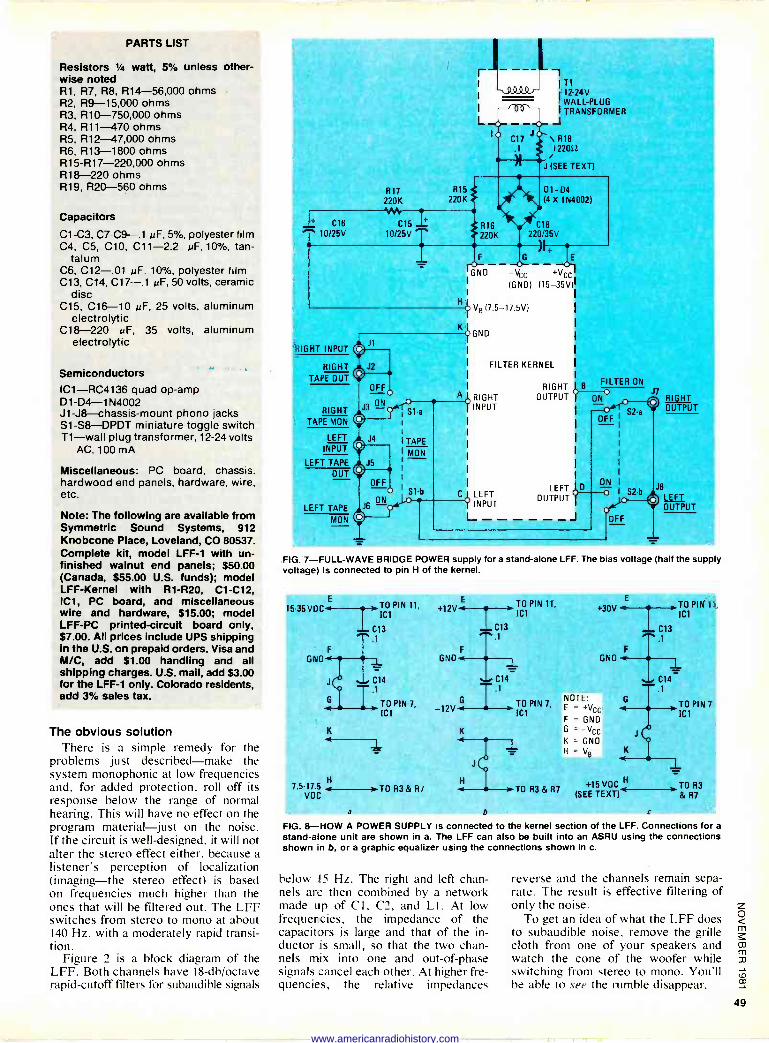
PARTS LIST
Resistors 1/4 watt, 5% unless other- wise noted R1, R7, R8, R14-56,000 ohms R2, R9-15,000 ohms R3, R1O-750,000 ohms R4, R11-470 ohms R5, R12-47,000 ohms R6, R13-1800 ohms R15 -R17-220,000 ohms R18-220 ohms R19, R20-560 ohms
Capacitors
C1 -C3, C7 -C9-.1 MF, 5%, polyester film C4, C5, C10, C11-2.2 pF, 10%, tan-
talum C6, C12-.01 pF. 10%, polyester film C13, C14, C17-.1 uF, 50 volts, ceramic
disc C15, C16-10 MF, 25 volts. aluminum
electrolytic C18-220 uF, 35 volts, aluminum
electrolytic
Semiconductors ICI-RC4136 quad op -amp D1 -D4-1 N4002 J1-J8-chassis-mount phono jacks S1-S8-DPDT miniature toggle switch T1-wall plug transformer, 12-24 volts
AC, 100 mA
Miscellaneous: PC board, chassis. hardwood end panels, hardware, wire. etc.
Note: The following are available from Symmetric Sound Systems, 912 Knobcone Place, Loveland, CO 80537. Complete kit, model LFF-1 with un- finished walnut end panels; $50.00 (Canada, $55.00 U.S. funds); model LFF-Kernel with R1 -R20, C1 -C12, IC1, PC board, and miscellaneous wire and hardware, $15.00; model LFF-PC printed -circuit board only, $7.00. All prices include UPS shipping in the U.S. on prepaid orders. Visa and M/C, add $1.00 handling and all shipping charges. U.S. mail, add $3.00 for the LFF-1 only. Colorado residents, add 3% sales tax.
The obvious solution There is a simple remedy for the
problems just described-make the system monophonic at low frequencies and, for added protection, roll off its response below the range of normal hearing. This will have no effect on the program material just on the noise. If the circuit is well -designed, it will not alter the stereo effect either, because a listener's perception of localization (imaging-the stereo effect) is based on frequencies much higher than the ones that will be filtered out. The LFF switches from stereo to mono at about 140 Hz. with a moderately rapid transi- tion.
Figure 2 is a block diagram of the LFF. Both channels have 18-db/octave rapid -cutoff filters for subaudible signals
220K 220K
C16 C15 10/25V 10/25V
RIGHT INPUT
RIGHT
TAPE OUT
RIGHT TAPE MON
LEFT
INPUT
LEFT TAPE
OUT
LEFT TAPE
MON
OFF
J3 (3-N
A
r
L
GND
T1 ( 12-24V
WALL -PLUG I TRANSFORMER
J \ R18 I220L2
J (SEE TEXT)
918 D1 -D4 (4 x 1N40021
220/35V
-VCC +VCC (GND) (15-35V)
VB (7.5-17.5V)
>GM]
FILTER KERNEL
RIGHT INPUT
LEFT )INPUT
RIGHT B FILTER ON
OUTPUT ON0
LEFT OUTPUT
RIGHT OUTPUT
J8
LEFT OUTPUT
FIG. 7-FULL-WAVE BRIDGE POWER supply for a stand-alone LFF. The bias voltage (half the supply voltage) is connected to pin H of the kernel.
E TO PIN 11, 15-35 VDC , I 1C1
C13 1
GND F
K a
7.5-17 5
VDC
C14
TO PIN 7,
IC1
TOR3&R7
E
+12V 4
F
GND 4
TO PIN 11,
ICI
IC13
G
-12V 4
K
C14 1
a h
TO PIN 7,
ICI
E
+30V
GND <
NOTE E _ +VCC
F = GNU G =-Vcc K = GNO H = V8
,,TO PIN 11
'Cl
.-. C13 .1
1 C14 .1
TO PIN 7
ICI
TO R3&R7 +15VOC TOR3
(SEE TEXT) & R7
c
FIG. 8-HOW A POWER SUPPLY is connected to the kernel section of the LFF. Connections for a
stand-alone unit are shown in a. The LFF can also be built into an ASRU using the connections shown on b, or a graphic equalizer using the connections shown in c.
below 15 Hz. The right and left chan- nels are then combined by a network made up of C I , C2, and L I . At low frequencies, the impedance of the capacitors is large and that of the in- ductor is small, so that the two chan- nels mix into one and out -of -phase signals cancel each other. At higher fre- quencies, the relative impedances
reverse and the channels remain sepa- rate. The result is effective filtering of only the noise.
To get an idea of what the LFF does to subaudible noise, remove the grille cloth from one of your speakers and watch the cone of the woofer while switching from stereo to mono. You'll be able to see the rumble disappear.
www.americanradiohistory.com
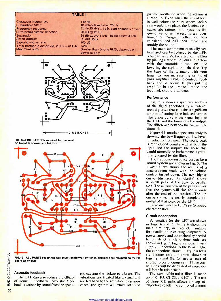
TABLE 1
Crossover frequency: Subaudible filter: Frequency response: Differential rumble rejection: Separation: Rated output: Signal-to-noise ratio: Total harmonic distortion, 20 Hz - 20 kHz: Maximum output:
140 Hz 18 dB/octave below 20 Hz 20Hz-20 kHz ±1 dB, both channels driven. 20 dB @20 Hz 25 dB above 1 kHz; 35 dB above 3 kHz .5 -volt RMS 100 dB .02% Greater than 5 -volts RMS: depends on power supply.
rhi -gcc°91
2 1/2 INCHES
FIG. 9-FOIL PATTERN required for the small PC board is shown here full size.
3 t
'1
-Jr
FIG.10-ALL PARTS except the wall -plug transformer, switches, and jacks are mounted on the PC board as shown.
Acoustic feedback The LFF can also reduce the effects
of acoustic feedback. Acoustic feed- back is caused by sound from the speak-
ers causing the pickup to vibrate. The vibrations are treated like a signal and are fed back to the amplifier. In serious cases, the system will "take off" and
go into oscillation when the volume is turned up. Even when the sound level is well below the point where oscilla- tion would take place, the feedback can cause aberrations in a system's fre- quency response that result in an "over- hang" or "ringing" effect on bass transients and dull their impact and muddy the sound.
The main component is usually ver- tical and can be reduced by the LFF. You can simulate the effect of the filter by placing a record on your turntable- with the turntable turned off-and lowering the stylus onto the disc. Tap the base of the turntable with your finger as you increase the setting of your amplifier's volume control. Feed- back should occur. If you put the amplifier in the "mono" mode, the feedback should disappear.
Performance Figure 3 shows a spectrum analysis
of the signal generated by a "silent" record groove that contains a significant amount of cutting -lathe -induced rumble. The upper curve is the signal input to the LFF and the lower one the output. The difference between the two is quite dramatic.
Figure 4 is another spectrum analysis showing the low -frequency, low-level, introduction to a song. The sound peak is reproduced equally well at both the input and the output; the noise that would normally be bothersome is great- ly attenuated by the filter.
The frequency -response curves for a sound system are shown in Fig. 5. The lowest curve shows the results of a measurement made with the volume control turned down. The next higher curve (displaced for clarity) shows a 30 -dB peak at the edge of oscilla- tion. The narrowness of the peak implies that the system will ring for seconds after the end of the transient. The top curve shows the nearly complete re- moval of that peak by the LFF.
Table one lists the LFF's performance characteristics.
Circuit description Schematics for the LFF are shown
in Figs. 6 and 7. Figure 6 shows the main circuitry, or "kernel," suitable for installation in existing equipment. A power supply and other circuitry needed to construct a stand-alone unit are shown in Fig. 7. Figure 8 shows power - supply connections to the kernel. Use the connections shown in Fig. 8-a for a stand-alone unit and those shown in Figs. 8-b and 8-c for use as part of another piece of equipment. Those con- nections will be discussed in more de- tail later in this article.
The subaudible-noise filter is made up of Rl -R3, CI -C3, and ICI -a. The use of three R -C pairs allows a steep 18- dB/octave rolloff; the controlled amount
www.americanradiohistory.com
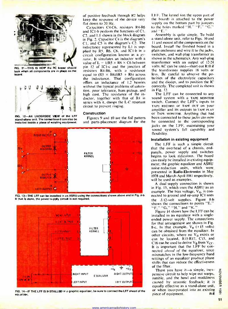
RG. T1-THIS IS HOW the FC bc-ac should look when all components aire do plane on the board
FIG. 12-AN UNDERSIDE VEW of the LFF stand-alone unit. The kernel board can also be instahled inside a piece of existing equipment.
OUT'UT RESISTER .
of positive feedback through R2 helps keep the response of the device very flat down to 20 Hz.
Capacitors C4 -C6, resistors R4 -R6 and ICI -b perform the functions of CI, C2, and LI shown in the block diagram in Fig. 2. Capacitor C4 is the diagram's CI , and C5 is the diagram's C2. The inductance represented by LI is sup- plied by R5, R6, C6, and ICI -b in a
circuit configuration known as a gy- rator. It simulates an inductor with a
value of L = 1/R5 X R6 x C6 between pin 12 of ICI -c and the junction of resistors R4 -R6, with a resistance equal to (R5 x R6)/(R5 + R6) across the inductance. That configuration offers an inductance of 1.2 henries without the typical problems of satura- tion, poor tolerance, hum pickup, and high cost. The resistance of the in- ductor, together with that of R4 in series with it, damps the L -C resonant circuit to prevent ringing.
Construction Figures 9 and IO are the foil pattern
and parts -placement diagram for the
FILTER KERNEL
I --- --- -- FlG. 13-1HE LFF can be installed in an ASRU using the connections shown above and in Fig. 8-b. It that is done, the powersupplg cinzuit is not required.
F
- k( rii N' iT A
H - )1 -PUT
TIbPUt
IT011FI1T
TAPE .F e 1
RIGHT INPUT
LEFT INPUT
FILTER KER'JEL
ElUALIZER
+v8 _ +Vcc
RIGHT OUTPUT
LEFT OUTPUT
FIG. 14-I. THE LFF IS INSTALLED in a graphic equalizer, be sure to connect the LFF ahead of the equalizer.
LFF. The kernel (on the upper part of the board) is attached to the power supply on the bottom part by jumpers to the holes marked "H," "F," "G." and "E."
Assembly is quite simple. To build a stand-alone unit, refer to Figs. IO and II and mount all the components on the board. Install the finished board in a
plain enclosure and wire it to the jacks, switches, and wall -plug transformer as shown in the schematics. Any wall -plug transformer with an output of 12-24 volts AC can be used-short out R I8 if the transformer supplies 18 volts or less. Be careful to observe the po- larities of the electrolytic capacitors and the diodes, and to position the IC correctly. The completed unit is shown in Fig. 12.
The LFF can be connected to any sound system with a TAPE MONITOR switch. Connect the LFF's inputs to TAPE RECORD or TAPE OUT on your amplifier and its outputs to TAPE PLAY or TAPE MONITOR. Anything that had been connected to these jacks can now be connected to the corresponding jacks on the LFF, maintaining your sound system's full capability and flexibility.
Installation in existing equipment The LFF is such a simple circuit
that the overhead of a chassis, end - panels, power supply and switches begins to look ridiculous. The board can easily be installed in existing equip- ment; the graphic equalizer and ASRU noise -reduction units, which were, presented in Radio -Electronics in May 1978 and March -April 1981 respectively, will be used as examples.
A dual -supply connection is shown in Fig. 13, which uses the ASRU as an example. The bias voltage, VB, is con- nected to ground and op -amp ICI uses
the ± 12 -volt supplies. Figure 8-b shows the connections to points "E," "F," "G," "H," and "K."
Figure 14 shows how the LFF can be
installed in an equalizer with a single - ended power supply. The connections for that arrangement are shown in Fig. 8-c. In that example, VB (+15 volts) can be obtained from the equalizer. In other circuits, where no VB exists or can be located. R 15-R17, C15, and C l6 can be used to derive VB from Vcc It is important that the LFF be con- nected ahead of the equalizer, since mismatches in the low -frequency band settings of an equalizer produce phase shifts that can reduce the effectiveness of the filter.
There you have it-a simple, inex- pensive circuit to help wipe out warps, rumble, and the howl and muddiness caused by acoustic feedback; it is equally effective as a stand-alone unit, or when incorporated into an existing piece of equipment. R -E
www.americanradiohistory.com
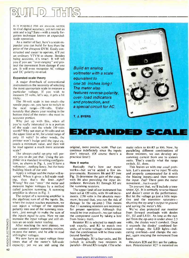
ELL L
J
IS IT POSSIBLE FOR AN ANALOG METER to rival digital accuracy, yet not cost an arm and a leg? Sure-with a nearly for- gotten technique known as expanded - scale operation.
As a matter of fact, here's a scale ex- pander you can build for less than the price of the cheapest DVM. Easily con- structed and easier to operate, it'll put an ordinary VTVM to shame. Besides being accurate, it's smart. It will tell you if you are "over -ranging" and pro- tect the movement from damage if you are. It will even recognize AC voltage and DC polarity -reversal.
Expanded -scale theory A major drawback of conventional
instruments is the necessity of selecting the most appropriate scale to measure a particular voltage. If you wish to measure 55 volts, let's say, it gets a bit tricky.
The 50 -volt scale is too small-the needle pegs-so, you have to switch to the next range -150 -volts. Unfor- tunately that places your reading in the bottom third of the meter-the most in- accurate portion.
Why put up with this, when all you're really interested in is a portion of the scale-not the whole 150 -volts worth? Why not start at 50 volts and set the upper limit at 60, for a total range of only 10 volts? In other words, the pointer won't budge until the input ex- ceeds a minimum value, and then will be read against a much more accurate scale?
The always -useful op -amp will per- mit you to do just that. Using the am- plifier in a standard inverting configura- tion, as shown in Fig. 1, you'll have a voltmeter... nothing fancy, but the basic building block of our unit.
Apply a voltage and the meter will re- spond. When it gives a full-scale read- ing, then that's the limit...right? Wrong! We can "zero" the meter and measure higher voltages by a method called junction summing. A summing amplifier is shown in Fig. 2.
The output of a summing amplifier is the algebraic sum of all the inputs. So, when the output reaches maximum, we can inject a voltage of the opposite polarity into one of the summing resis- tors...just enough to make the sum of the inputs equal to zero. Now we can increase the input voltage and still ob- tain an on -scale meter reading.
After reaching the next plateau, we can connect another summing resistor, re -zero the meter, and be able to read still -higher voltages.
We now have an input voltage three times that of the meter's full-scale capacity; yet we are still using the
Build an analog voltmeter with a scale equivalent to one 36 inches long ! The meter also features reverse -polarity, over- load indicators and protection, and a special circuit for AC.
T. J. BYERS
original, more precise, scale. That can continue indefinitely since the inputs don't interact. (Of course there's a practical limit!)
How it works Basically that's how our meter
works-but we've added a few im- provements. Resistors R6 and R7 (see Fig. 3) determine the gain of the stage, with R6 also providing the input im- pedance. Resistors R1 through RS are the summing resistors.
The upper limit of our instrument has been set at 120 volts, with 10 -volt incre- ments. (150 volts is the absolute maxi- mum; beyond that, you run the risk of damage to the op -amp.) This means that 11 summing resistors are necessary for proper operation. Although that would be true ordinarily, we can reduce the component count by taking a hint from binary math.
Resistor RI is selected to match one unit exactly, and R2 to match two units, of reverse voltage-which means that the combination will be three units (sound familiar?).
Accordingly, R3 is four units, and R4 (which is actually two resistors in parallel-R4 and R5) is eight. (The sche-
matic refers to R4 -R5 as R4). Now, by paralleling different combinations of those resistors, we can develop any summing current from one to sixteen units. That's exactly what the range switch, SI, does.
This leaves us with one small prob- lem. Let's assume we've input 70 volts and properly compensated for it with the biasing inputs-and then remove the input. Zap! There goes the meter movement... backwards !
To prevent that, we'll include a tran- sistor, Ql. It is normally reverse -biased and doesn't enter in the performance. But let the voltage go just a little nega- tive and the transistor saturates- shunting the op -amp's output to ground and saving the meter's life.
We've also protected our monitor from forward overloads with diodes DI, D2 and LEDI. As long as the out- put from the op -amp is under about 2.5 volts, the diodes won't conduct. Once it exceeds the diodes' combined for- ward voltage, the LED lights-indi- cating overload-and clamps the out- put, again rescuing the movement from harm.
Resistors R28 and RI I are for calibra- tion. Potentiometer R27 is mounted on
www.americanradiohistory.com
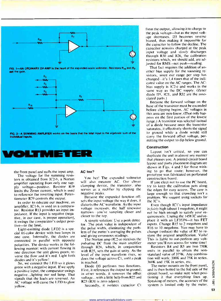
RIN
1N RF
FIG. 1-AN ORDINARY OP -AMP is the heart of the expanded -scale voltmeter. Resistors RIN and RF
set the gain.
Rs
Rs
.
Rs
RIN
RF
-4M
FIG. 2-A SUMMING AMPLIFIER works on the basis that the total input is the algebraic sum of the individual inputs.
TIME the front panel and nulls the input amp.
The voltage for the summing resis- tors is obtained from IC2-b, a Norton amplifier operating from only one sup- ply voltage-positive. Resistor R19 limits the Zener current, which is used to reference the inverting input. Poten- tiometer R29 controls the output.
In order to educate our machine, an amplifier, ICI -b, is used as a compara- tor. Resistor R13 provides an input im- pedance. If the input is negative (nega- tive, in our case, is proper operation), it swings the comparator's output posi- tive-to the limit.
Light -emitting diode LED2 is a spe- cial tri -color device with two lamps in
one case. Internally, the diodes are connected in parallel with opposite polarities. The device works in the fol- lowing manner: with current flowing in
one direction the unit glows green: re- verse the flow and it's red. Light both diodes and it's yellow!
So, we connect the LED so it glows green with a negative input. If we apply a positive input, the comparator swings negative...lighting our red lamp. That signals that the leads are reversed. An AC voltage will cause the LED to glow yellow.
AC too?
You bet! The expanded voltmeter will also measure AC. Our clever clamping device, the transistor, also serves as a rectifier by clipping the negative peaks.
Because the expanded function off- sets the input voltage the way it does, it
distorts the AC waveform. As the input voltage increases, the half sinewave narrows-you're sampling closer and closer to the top.
A simple solution: Use a peak detec- tor. The peak value is independent of the pulse width, eliminating the prob- lem of the meter's averaging the pulses and giving erroneous readings.
The Norton amp (IC2-a) receives the pulsating DC from the main amplifier through R24, which, in conjunction with R25, sets the gain at unity. As the level of the input waveform rises, so does the voltage across Cl, until a peak is reached.
Diode D3 performs two functions. First, it references the óutput to ground; in other words, it removes the offset voltage...with a little help from R22 and R23 (R31 is zero adjust).
Secondly, it isolates capacitor CI
from the output, allowing it to charge to the peak voltage-but as the input volt- age decreases, D3 becomes reverse biased, thus making it impossible for the capacitor to follow the decline. The capacitor remains charged at the peak input voltage and slowly discharges through R30 and R26, the calibration resistors which, we should add, are ad- justed for RMS-not peak-reading.
That fact requires the addition of an- other bias supply for the summing re- sistors, since our range per step has changed-it's 1.4 times that of the indi- cated value on the AC ranges. The AC - bias supply is IC2-c and works in the same way as the DC supply. (Zener diode D5, R2I, and R32 are the asso- ciated parts.)
Because the forward voltage on the base of the transistor must be exceeded before clipping begins, AC voltages in
this area are non-linear. (That only hap- pens on the first portion of the lowest range.) A transistor was selected instead of a diode because once the transistor saturates, it effectively shorts the signal to ground while a diode would still carry the forward offset voltage, per- mitting the output to dip below ground.
Construction Layout isn't critical, so you can
duplicate the unit in almost any manner that pleases you. A printed -circuit board layout and parts placement diagram are shown in Figs. 4 and 5 for those wish- ing to go that route; however, the prototype was fabricated on perforated construction board.
If you elect not to use the PC board, try to keep the calibration pots along the edges for easy access. The case is large enough so that crowding isn't a problem. We suggest using sockets for the [C's.
Even though ICI's input impedance is fairly high (about 1 megohm), it might not be high enough to satisfy your re- quirements. Unplug the 1458 IC and re- place it with an LF353N-it has FET inputs. Change R15 to 2 megohms and R I6 to 10 megohms. You may have to change (reduce) the value of R7 to re- store the original amplification. Voila! This is liable to out -perform any volt- meter you'll run across for some time!
Resistors R4 and R5 are two 750K units in parallel to obtain the non- standard value of 375K. Any combina- tion will work: 300K and 75K in series, 360K and 15K in series, etc.
The meter mounts on the front panel, and is then bolted to the foil side of the circuit board, so make sure when posi- tioning it that everything lines up. Speaking of meters, the accuracy of the system is limited only by the meter.
www.americanradiohistory.com
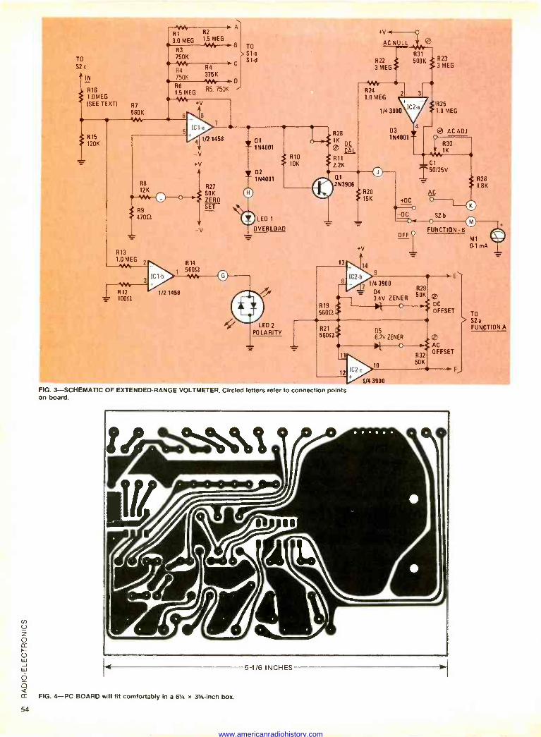
R1 R2 3.0 MEG 1.5 MEG
+v
TO
S2 -c
R16 1.0 MEG
(SEE TEXT) R7
560K 1µ
e R15 120K
WY R4
375K 750K
R6 R5. 750K -
1.5 MEG
VW
6
R13 1.0 MEG
W R12
er 10052
V
8
IC1-a
41
-V +V
R14 56052 :V
R3 TO
750K Sta Si -d
1/2 1458
R27 50K ZERO SET
11:1P14001
1
= 1 N4001
R10 10K
y 02 1N4001
J LED 1
OVERLOAD
/5r
% [ LED POLARITY
AC NULL
R31
R22 e 500K 3 MEG
Wt R24 1.0 MEG
1/4 3900
R28 o
® CA` R11
2.2K
O O1
2N3906 R
15K20
+V
D4 50K 3.4V ZENER
2
03 1N4001
+DC
3
R23 3 MEG
eR25 1.0 MEG
- AC ADJ
R30 1K
_ C1
I50/25V
_ R26 1.8K
AC
-O -DC S2 -b
OFF O FUNCTION - B
05 6.2V ZENER
O
R32 50K
DC
OFFSET
AC OFFSET
M1
0-1 mA
TO > S2 -a
FUNCTION A
FIG. 3 --SCHEMATIC OF EXTENDED -RANGE VOLTMETER. Circled letters refer to connection points on board.
FIG. 4-PC BOARD will fit comfortably in a 61/4 x 33/4 -inch box.
5 1/6 INCHES
www.americanradiohistory.com
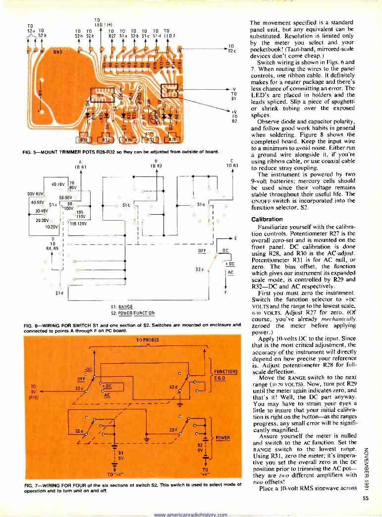
TO S2 -a TO
rATh S2 -b
TO
LED 1 (+1
TO TO TO TO TO TO TO TO 52 b S2 -b R27 Sl -a S2 -b S1 -c S1 -d LEO 2
FIG. 5-MOUNT TRIMMER POTS R28 -R32 so they can be adjusted from outside of board.
DV -60V
A B
TO Rl TO R2
60-70V70- 80V
80-90V 40-50V
S 1 a I 90-
3040V 1100V
100
20-30V o 110V
ççç
10-20V I
D
TO F R4, R5
J
S1 -d
S1 -b
-V TO 01
+V TO 02
C
TO R3
U U
0 0
S1c Cr1
o o bl
OFF
S2 -a
Si: RANGE
S2: POWER/FUNCTION
J
The movement specified is a standard panel unit, but any equivalent can be substituted. Resolution is limited only by the meter you select and your pocketbook! (Taut -band, mirrored -scale devices don't come cheap.)
Switch wiring is shown in Figs. 6 and 7. When routing the wires to the panel controls, use ribbon cable. It definitely makes for a neater package and there's less chance of committing an error. The LED's are placed in holders and the leads spliced. Slip a piece of spaghetti or shrink tubing over the exposed splices.
Observe diode and capacitor polarity, and follow good work habits in general when soldering. Figure 8 shows the completed board. Keep the input wire to a minimum to avoid noise. Either run a ground wire alongside it, if you're using ribbon cable, or use coaxial cable to reduce stray coupling.
The instrument is powered by two 9 -volt batteries; mercury cells should be used since their voltage remains stable throughout their useful life. The ON/OFF switch is incorporated into the function selector, S2.
o Calibration Familiarize yourself with the calibra-
tion controls. Potentiometer R27 is the overall zero -set and is mounted on the front panel. DC calibration is done using R28, and R30 is the AC -adjust. Potentiometer R31 is for AC null, or zero. The bias offset, the function which gives our instrument its expanded scale mode, is controlled by R29 and R32-DC and AC respectively.
First you must zero the instrument. Switch the function selector to +DC
VOLTS and the range to the lowest scale, 0 -IO VOLTS. Adjust R27 for zero. (Of course, you've already mechanically zeroed the meter before applying power.)
Apply 10 -volts DC to the input. Since that is the most critical adjustment, the accuracy of the instrument will directly depend on how precise your reference is. Adjust potentiometer R28 for full- scale deflection.
Move the RANGE switch to the next range (10-20 VOLTs). Now, turn pot R29 until the meter again indicates zero, and that's it! Well, the DC part anyway. You may have to strain your eyes a little to insure that your initial calibra- tion is right on the button-as the ranges progress. any small error will be signifi- cantly magnified.
Assure yourself the meter is nulled and switch to the AC function. Set the RANGE switch to the lowest range. Using R31, zero the meter; it's impera- tive you set the overall zero in the DC
position prior to trimming the AC pot- they are two different amplifiers with two offsets!
Place a 10 -volt RMS sinewave across
- DC
E
+ºC
r FIG. 6-WIRING FOR SWITCH Si and one section of S2. Switches are mounted on enclosure and
connected to points A through F on PC board.
TO PROBES
-DC o OFF
S2 -c 1 U+ DC
i' AC
i o i
S2 -e 70-0 -0 , z
- -
f
o
S2 -d
o
S2 -f /
O-1
o
82 9V
FUNCTIONS
Cao
FIG. 7-WIRING FOR FOUR of the six sections of switch S2. This switch is used to select mode of operation and to turn unit on and off.
www.americanradiohistory.com
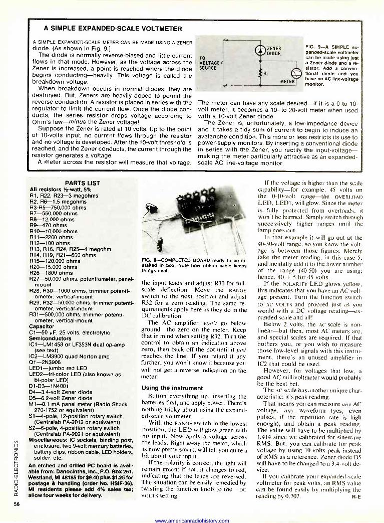
A SIMPLE EXPANDED -SCALE VOLTMETER
A SIMPLE EXPANDED -SCALE METER CAN BE MADE USING A ZENER diode. (As shown in Fig. 9.)
The diode is normally reverse -biased and little current flows in that mode. However, as the voltage across the Zener is increased, a point is reached where the diode begins conducting-heavily. This voltage is called the breakdown voltage.
When breakdown occurs in normal diodes, they are destroyed. But, Zeners are heavily doped to permit the reverse conduction. A resistor is placed in series with the regulator to limit the current flow. Once the diode con- ducts, the series resistor drops voltage according to Ohm's law-minus the Zener voltage!
Suppose the Zener is rated at 10 volts. Up to the point of 10 -volts input, no currE-nt flows through the resistor and no voltage is developed. After the 10 -volt threshold is reached, and the Zener conducts, the current through the resistor generates a voltage.
A meter across the resistor will measure that voltage.
ZENER DIODE,
TO VOLTAGE SOURCE
FIG. 9-A SIMPLE ex- panded -scale voltmeter can be made using just a Zener diode and a re- sistor. Add a conven- tional diode and you have an AC line -voltage monitor.
The meter can have any scale desired-if it is a 0 to 10 - volt meter, it becomes a 10- to 20 -volt meter when used with a 10 -volt Zener diode.
The Zener is, unfortunately, a low -impedance device and it takes a tidy sum of current to begin to induce an avalanche condition. This more or less restricts its use to power -supply monitors. By inserting a conventional diode in series with the Zener, you rectify the input -voltage -- making the meter particularly attractive as an expanded - scale AC line -voltage monitor.
PARTS LIST All resistors 1 -watt, 5% R1, R22, R23-3 megohms R2, R6-1.5 megohms R3 -R5-750,000 ohms R7-560,000 ohms R8-12,000 ohms R9-470 ohms R10-10,000 ohms R11-2200 ohms R12-100 ohms R13, R16, R24, R25-1 megohm R14, R19, R21-560 ohms R15-120,000 ohms R20-15,000 ohms R26-1800 ohms R27-50,000 ohms, potentiometer, panel -
mount R28, R30-1000 ohms, trimmer potenti-
ometer, vertical -mount R29, R32-50,000 ohms, trimmer potenti-
ometer, vertical -mount R31-500,000 ohms, trimmer potenti-
ometer, vertical -mount Capacitor C1-50 NF, 25 volts, electrolytic Semiconductors IC1-LM1458 or LF353N dual op -amp
(see text) IC2-LM3900 quad Norton amp Q1 -2N3906 LED1-jumbo red LED LED2-tri-color LED (also known as
bi -polar LED) Dl -D3 -1N4001 D4 -3.4 -volt Zener diode D5 -6.2 -volt Zener diode M1-0.1 mA panel meter (Radio Shack
270-1752 or equivalent) S1 -4 -pole, 12 -position rotary switch
(Centralab PA -2012 or equivalent) S2 -6 -pole, 4 -position rotary switch
(Centralab PA -2021 or equivalent) Miscellaneous: IC sockets, binding post,
enclosure, two 9 -volt mercury batteries, battery clips, ribbon cable, LED holders, solder, etc.
An etched and drilled PC board is avail- able from: Danocinths, Inc., P.O. Box 261, Westland, MI 48185 for $9.40 plus $1.25 for postage & handling (order No. HSIF-36). MI residents please add 4% sales tax; allow four weeks for delivery.
FIG. 8-COMPLETED BOARD ready to be in- stalled in box. Note how ribbon cable keeps things neat.
the input leads and adjust R30 for full- scale deflection. Move the RANGE switch to the next position and adjust R32 for a zero reading. The same re- quirements apply here as they do in the DC calibration.
The AC amplifier won't go below ground-the zero on the meter. Keep that in mind when setting R32. Turn the control to obtain an indication above zero, then back off the pot until it just reaches the line. 1f you retard it any further, you won't know it because you will not get a reverse indication on the meter!
Using the instrument Button everything up, inserting the
batteries first, and apply power. There's nothing tricky about using the expand- ed -scale voltmeter.
With the RANGE switch in the lowest position, the LED will glow green with no input. Now apply a voltage across the leads. Right away the meter, which is now pretty smart, will tell you quite a hit about your input.
If the polarity is correct, the light will remain green; if not, it changes to red, indicating that the leads are reversed. The situation can he easily remedied by twisting the function knob to the -DC VOLTS setting.
If the voltage is higher than the scale capability-for example, 45 volts on the 0 -10 -volt range-the OVERLOAD LED, LEDI, will glow. Since the meter is fully protected from overloads, it won't be harmed. Simply switch through successively higher ranges until the lamp goes out.
In that example it will go out at the 40 -50 -volt range, so you know the volt- age is between those figures. Merely take the meter reading, in this case 5, and mentally add it to the lower number of the range (40-50) you are using; hence, 40 + 5 for 45 volts.
If the POLARITY LED glows yellow, this indicates that you have an AC volt- age present. Turn the function switch to AC VOLTS and proceed just as you would with a DC voltage reading-ex- panded scale and all!
Below 2 volts, the AC scale is non- linear-but then, most AC meters are, and special scales are required. If that bothers you, or you wish to measure those low-level signals with this instru- ment, there's an unused amplifier in IC2 that could be used.
However, for voltages that low, a good AC millivoltmeter would probably be the best bet.
The AC scale has another unique char- acteristic: it's peak reading.
That means you can measure any AC voltage, any waveform (yes, even pulses, if the repetition rate is high enough), and obtain a peak reading. The value will have to be multiplied by 1.414 since we calibrated for sinewave RMS. But, you can calibrate for peak voltage by using 10 -volts peak instead of RMS as a reference. Zener diode D5 will have to be changed to a 3.4 -volt de- vice.
If you calibrate your expanded -scale voltmeter for peak volts, an RMS value can be found easily by multiplying the reading by 0.707. R -E
www.americanradiohistory.com
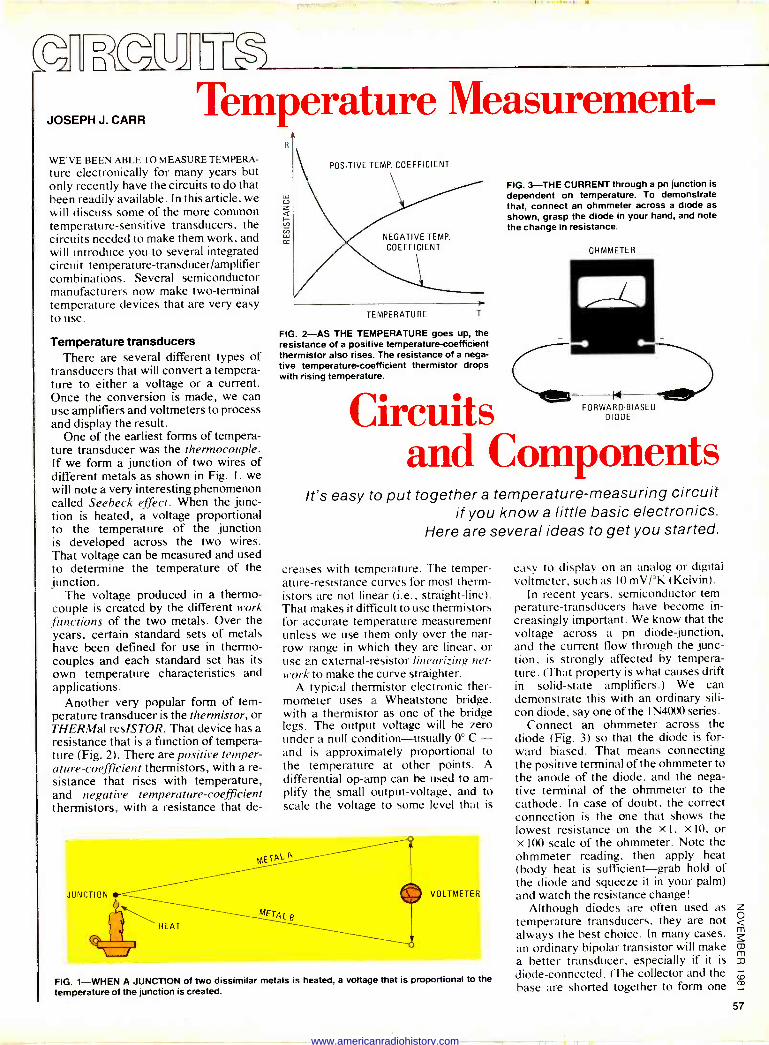
L J
JOSEPH J. CARR Temperature Measurement -
WE'VE BEEN ABLE TO MEASURE TEMPERA-
ture electronically for many years but only recently have the circuits to do that been readily available. In this article, we will discuss some of the more common temperature -sensitive transducers, the circuits needed to make them work, and will introduce you to several integrated circuit temperature-transducer/amplifier combinations. Several semiconductor manufacturers now make two -terminal temperature devices that are very easy to use.
Temperature transducers There are several different types of
transducers that will convert a tempera- ture to either a voltage or a current. Once the conversion is made, we can use amplifiers and voltmeters to process and display the result.
One of the earliest forms of tempera- ture transducer was the thermocouple. If we form a junction of two wires of different metals as shown in Fig. 1, we will note a very interesting phenomenon called Seebeck effect. When the junc- tion is heated, a voltage proportional to the temperature of the junction is developed across the two wires. That voltage can be measured and used to determine the temperature of the junction.
The voltage produced in a thermo- couple is created by the different work functions of the two metals. Over the years, certain standard sets of metals have been defined for use in thermo- couples and each standard set has its own temperature characteristics and applications.
Another very popular form of tem- perature transducer is the thermistor, or THERMal resISTOR. That device has a resistance that is a function of tempera- ture (Fig. 2). There are positive temper- ature -coefficient thermistors, with a re- sistance that rises with temperature, and negative temperature -coefficient thermistors, with a resistance that de -
LU
y
POSITIVE TEMP. COEFFICIENT
NEGATIVE TEMP.
COEFFICIENT
TEMPERATURE T
FIG. 2-AS THE TEMPERATURE goes up, the resistance of a positive temperature -coefficient thermistor also rises. The resistance of a nega- tive temperature -coefficient thermistor drops with rising temperature.
Circuits and Components
FIG. 3-THE CURRENT through a pn junction is dependent on temperature. To demonstrate that, connect an ohmmeter across a diode as
shown, grasp the diode in your hand, and note the change in resistance.
OHMMETER
FORWARD -BIASED DIODE
It's easy to put together a temperature -measuring circuit if you know a little basic electronics.
Here are several ideas to get you started.
creases with temperature. The temper- ature -resistance curves for most therm- istors are not linear (i.e., straight-line). That makes it difficult to use thermistors for accurate temperature measurement unless we use them only over the nar- row range in which they are linear, or use an external -resistor linearizing net- work to make the curve straighter.
A typical thermistor electronic ther- mometer uses a Wheatstone bridge, with a thermistor as one of the bridge legs. The output voltage will be zero under a null condition-usually 0° C - and is approximately proportional to the temperature at other points. A
differential op -amp can be used to am- plify the small output -voltage, and to scale the voltage to some level that is
VOLTMETER
FIG. 1-WHEN A JUNCTION of two dissimilar metals is heated, a voltage that is proportional to the
temperature of the junction is created.
easy to display on an analog or digital voltmeter, such as 10 mV/°K (Kelvin).
In recent years, semiconductor tem- perature -transducers have become in- creasingly important. We know that the voltage across a pn diode junction, and the current flow through the junc- tion, is strongly affected by tempera- ture. (That property is what causes drift in solid-state amplifiers.) We can demonstrate this with an ordinary sili- con diode, say one of the 1N4000 series.
Connect an ohmmeter across the diode (Fig. 3) so that the diode is for- ward biased. That means connecting the positive terminal of the ohmmeter to the anode of the diode, and the nega- tive terminal of the ohmmeter to the cathode. In case of doubt, the correct connection is the one that shows the lowest resistance on the X I. X 10, or X 100 scale of the ohmmeter. Note the ohmmeter reading, then apply heat (body heat is sufficient-grab hold of the diode and squeeze it in your palm) and watch the resistance change!
Although diodes are often used as temperature transducers, they are not always the best choice. In many cases, an ordinary bipolar transistor will make a better transducer, especially if it is
diode -connected. (The collector and the base are shorted together to form one
z o m
W m
Jo' co
57
www.americanradiohistory.com
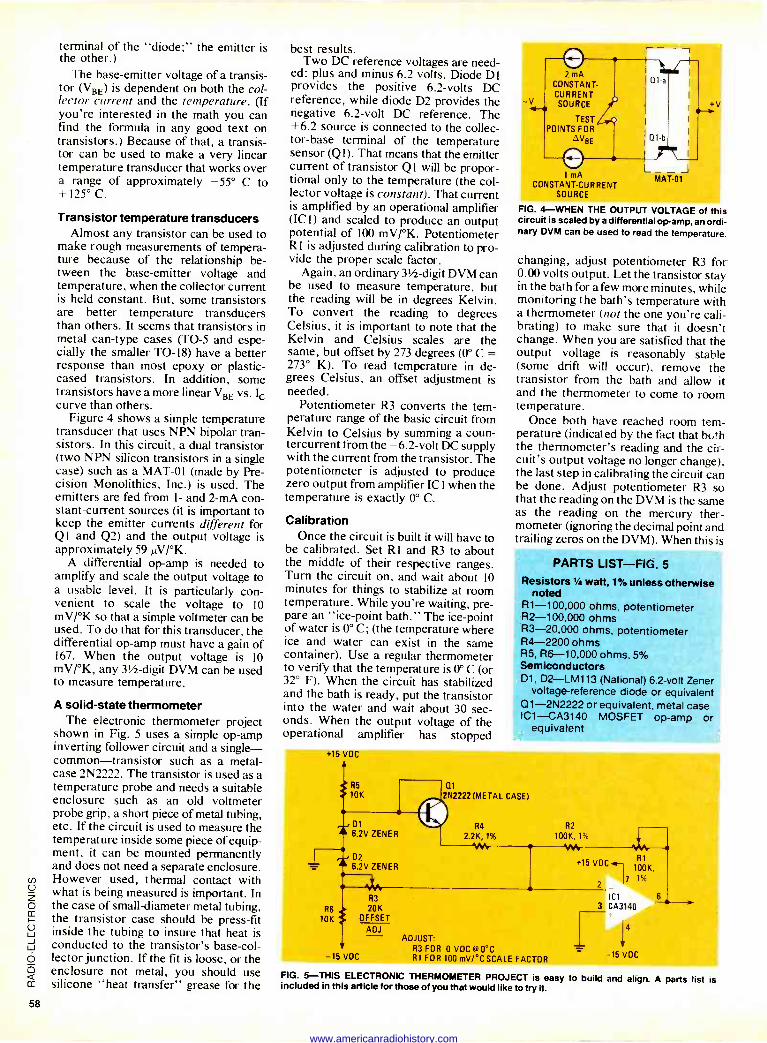
terminal of the "diode;" the emitter is the other.)
The base -emitter voltage of a transis- tor (VBE) is dependent on both the col- lector current and the temperature. (If you're interested in the math you can find the formula in any good text on transistors.) Because of that, a transis- tor can be used to make a very linear temperature transducer that works over a range of approximately -55° C to + 125° C.
Transistor temperature transducers Almost any transistor can be used to
make rough measurements of tempera- ture because of the relationship be- tween the base -emitter voltage and temperature, when the collector current is held constant. But, some transistors are better temperature transducers than others. It seems that transistors in metal can -type cases (TO -5 and espe- cially the smaller TO -18) have a better response than most epoxy or plastic - cased transistors. In addition, some transistors have a more linear VBE vs. lc curve than others.
Figure 4 shows a simple temperature transducer that uses NPN bipolar tran- sistors. In this circuit, a dual transistor (two NPN silicon transistors in a single case) such as a MAT -01 (made by Pre- cision Monolithics, Inc.) is used. The emitters are fed from 1- and 2 -mA con- stant -current sources (it is important to keep the emitter currents different for Q I and Q2) and the output voltage is approximately 59 µV/°K.
A differential op -amp is needed to amplify and scale the output voltage to a usable level. It is particularly con- venient to scale the voltage to 10 mV/°K so that a simple voltmeter can be used. To do that for this transducer, the differential op -amp must have a gain of 167. When the output voltage is 10 mV/°K, any 311 -digit DVM can be used to measure temperature.
A solid-state thermometer The electronic thermometer project
shown in Fig. 5 uses a simple op -amp inverting follower circuit and a single- common-transistor such as a metal - case 2N2222. The transistor is used as a temperature probe and needs a suitable enclosure such as an old voltmeter probe grip, a short piece of metal tubing, etc. If the circuit is used to measure the temperature inside some piece of equip- ment, it can be mounted permanently and does not need a separate enclosure. However used, thermal contact with what is being measured is important. In the case of small -diameter metal tubing, the transistor case should be press -fit inside the tubing to insure that heat is conducted to the transistor's base -col- lector junction. If the fit is loose, or the enclosure not metal, you should use silicone "heat transfer" grease for the
10K
-15 VDC
best results. Two DC reference voltages are need-
ed: plus and minus 6.2 volts. Diode D1 provides the positive 6.2 -volts DC reference, while diode D2 provides the negative 6.2 -volt DC reference. The +6.2 source is connected to the collec- tor -base terminal of the temperature sensor (Q1). That means that the emitter current of transistor Q1 will be propor- tional only to the temperature (the col- lector voltage is constant). That current is amplified by an operational amplifier (ICI) and scaled to produce an output potential of 100 mV/°K. Potentiometer RI is adjusted during calibration to pro- vide the proper scale factor.
Again, an ordinary 311 -digit DVM can be used to measure temperature, but the reading will be in degrees Kelvin. To convert the reading to degrees Celsius, it is important to note that the Kelvin and Celsius scales are the same, but offset by 273 degrees (0° C = 273° K). To read temperature in de- grees Celsius, an offset adjustment is needed.
Potentiometer R3 converts the tem- perature range of the basic circuit from Kelvin to Celsius by summing a coun- tercurrent trom the -6.2 -volt DC supply with the current from the transistor. The potentiometer is adjusted to produce zero output from amplifier IC I when the temperature is exactly 0° C.
Calibration Once the circuit is built it will have to
be calibrated. Set RI and R3 to about the middle of their respective ranges. Turn the circuit on, and wait about 10 minutes for things to stabilize at room temperature. While you're waiting, pre- pare an "ice -point bath." The ice -point of water is 0° C; (the temperature where ice and water can exist in the same container). Use a regular thermometer to verify that the temperature is 0° C (or 32° F). When the circuit has stabilized and the bath is ready, put the transistor into the water and wait about 30 sec- onds. When the output voltage of the operational amplifier has stopped
2 mA CONSTANT. CURRENT
-V SOURCE
TEST POINTS FOR
dVBE
1 mA CONSTANT -CURRENT
SOURCE
r-- -,
L__J MAT -01
+v
FIG. 4-WHEN THE OUTPUT VOLTAGE of this circuit is scaled by a differential op -amp, an ordi- nary DVM can be used to read the temperature.
changing, adjust potentiometer R3 for 0.00 volts output. Let the transistor stay in the bath fora few more minutes, while monitoring the bath's temperature with a thermometer (not the one you're cali- brating) to make sure that it doesn't change. When you are satisfied that the output voltage is reasonably stable (some drift will occur), remove the transistor from the bath and allow it and the thermometer to come to room temperature.
Once both have reached room tem- perature (indicated by the fact that bc,!h the thermometer's reading and the cir- cuit's output voltage no longer change), the last step in calibrating the circuit can be done. Adjust potentiometer R3 so that the reading on the DVM is the same as the reading on the mercury ther- mometer (ignoring the decimal point and trailing zeros on the DVM). When this is
PARTS LIST-FIG. 5
Resistors 1/4 watt, 1% unless otherwise noted
R1-100,000 ohms, potentiometer R2-100,000 ohms R3-20,000 ohms, potentiometer R4-2200 ohms R5, R6-10,000 ohms, 5% Semiconductors D1. D2-LM113 (National) 6.2 -volt Zener
voltage -reference diode or equivalent Q1 -2N2222 or equivalent, metal case IC1-CA3140 MOSFET op -amp or
equivalent
+15 VOC
R5 Q1
10K 2N2222 (METAL CASE)
R3
R6 20K OFFSET
ADJ
R4
2.2K, 1%
ADJUST: R3 FOR O VDC @0`C RI FOR 100 mV/ °C SCALE FACTOR
R2
100K, 1%
+15 VDC-4-1R1 100K,
2 7 1%
ICI 3 CA3140
+
-15 VOC
FIG. 5-THIS ELECTRONIC THERMOMETER PROJECT is easy to build and align. A parts list is included in this article for those of you that would like to try it.
www.americanradiohistory.com
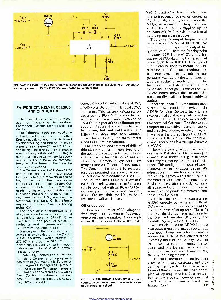
VREF1 +1.20 VDC
VREF2
-5.00 VDC
2N2907
7
11
Cl C2
1000pF 200pF
12
Vcc +5VDC
14
'Cl VF G-1
4 1
R1
10K
8
R2
100K
VEE
-5VDC
s 10 Hz/°K
FIG. 6-THE HEART of this temperature -to -frequency converter circuit is a Datel VFQ-1 current -to - frequency converter IC. The 2N2907 is used as the temperature probe.
FAHRENHEIT, KELVIN, CELSIUS AND CENTIGRADE
There are three scales in common use for measuring temperature: Fahrenheit, Celsius (centigrade) and Kelvin.
The Fahrenheit scale, now used only in the United States and a few other English-speaking countries, is based on the freezing and boiling points of water at sea level -32° and 212°, re- spectively. The zero -point on this scale was probably established by using a mixture of ice and salt-materials com- monly used to achieve low tempera- tures in laboratories at the time the scale was developed.
The Celsius scale, also known as the centigrade scale (it's not capitalized because, while the other three scales bear the names of their inventors- Gabriel Daniel Fahrenheit, Anders Cel- cius and Lord Kelvin-the term "centi- grade" refers to the fact that the scale is divided into a hundred divisions), is used outside the U.S., wherever the metric system is found. On it, the freez- ing point of water is 0° and the boiling point 100°.
The Kelvin scale is also known as the absolute scale because its zero point is absolute zero, (-273.16° C or -459.69° F), the point at which all molecular motion ceases and there is-literally-no temperature.
One degree in the Kelvin scale is the same size as one degree in the Celsius scale; therefore water freezes at 273.16° K and boils at 373.16° K. The Kelvin scale is used primarily in appli- cations such as solid-state physics and astronomy.
Incidentally, conversion from Fah- renheit to Celsius, and vice versa, is easier than you may think. To convert from degrees F to degrees C, just sub- tract 32 from the Fahrenheit tempera- ture and divide the result by 1.8. Going from Celsius to Fahrenheit is even easier-double the temperature, sub- tract 10%, and add 32.
done, a 0 -volts DC output will equal 0° C, a 3.00 -volts DC output will equal 30° C, and so on. This happens, of course, be- cause of the 100 mV/°C scaling factor. Alternately, a warm -water bath can be used for this part of the calibration pro- cedure. Prepare the warm -water bath by mixing hot and cold water, and follow the steps that were outlined above for calibrating the thermometer circuit at room temperature.
The precision, and amount of drift, of this electronic thermometer depend on the quality of components used. The re- sistors, except for possibly R5 and R6, should be 1% precision -types with a low temperature -coefficient of resistance. The Zener diodes should be tempera- ture -compensated reference types, such as National Semiconductor LM 113's. The op -amp should also be a low -drift type, although acceptable performance can be obtained with an RCA CA3140, especially if it is heat -linked. An ordi- nary TO -5 heatsink (the kind made of thin metal) will work nicely.
Other devices There are a number of IC voltage -to -
frequency (or current -to -frequency) converters on the market. An example of an IC that does both is the Datel
VFEF
5.00 VDC
1 mV1'K
FIG. 7-A TEMPERATURE -SENSITIVE current source, the AD590, is used to measure tempera- ture in this simple circuit.
VFQ-l. That IC is shown in a tempera- ture -to -frequency converter circuit in Fig. 6. In the circuit, we are using the VFQ-1 as a current -to -frequency con- verter; the current is supplied by the collector of a PNP transistor that is used as a temperature transducer.
This circuit's output frequency will have a scaling factor of 10 Hz/°K. We can, therefore, expect an output fre- quency of 2730 Hz at the freezing point of water (273° K, or 0° C), and a fre- quency of 3730 Hz at the boiling point of water (373° K or 100° C). This type of circuit can be used to record the tem- perature data from an experiment on magnetic tape, or to transmit the tem- perature via radio telemetry from an amateur rocket or model aircraft. Un- fortunately, the Datel IC is still a little expensive (although it is one of the low- est cost converters on the market) and is not generally available through hobbyist outlets.
Another special temperature -mea- surement semiconductor device is the AD590 (Analog Devices, Inc.) It is a two -terminal IC that is available at low cost in either a TO -18 case or a special two -terminal flat -pack. The device is a temperature -sensitive current source and is scaled to approximately 1µA/°K. If we pass the current from the AD590 through a 1000 -ohm resistor, the result (using Ohm's law) is a voltage change of 1 mV/°K.
There are several ways that we can use the AD590 device. One is simply to connect it as shown in Fig. 7, in series with approximatley 100 ohms of resis- tance. This configuration is called a one - temperature, or one -point, circuit. We adjust potentiometer R2 so that the out- put voltage agrees with a mercury ther- mometer at some specific temperature. Slight nonlinearities in the device, as in all semiconductor devices, will cause some error at points far removed from the calibration point.
Another method is to connect thé AD590 directly between a +5.00 -volt DC precision reference source and the inverting input of an op -amp. The scale factor of the thermometer can be set by the feedback resistor (RF) using the formula: Vo = (I µA/°K) (RF) (T).
We can also use the AD590 in a two trim -point circuit that uses an op -amp as described above. An offset current is summed with the AD590 current at the inverting input of the op -amp. We can then use two potentiometers, one for offset and one for gain, to adjust the circuit at two different temperatures, thereby reducing the error.
Electronic thermometer projects are easy to build and calibrate, and they can be put together by anyone who knows Ohm's law and the basic princi- ples of op -amp circuits. Just remem- ber to use precision components that don't drift with-you guessed it- temperature! R -E
www.americanradiohistory.com
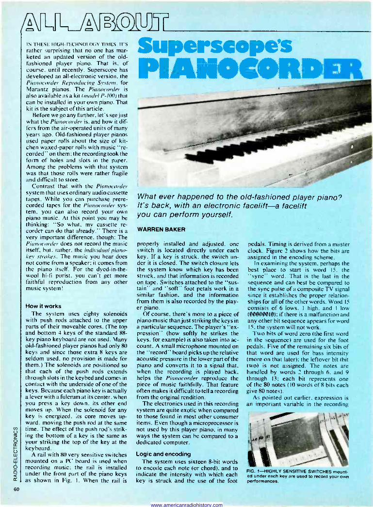
IN THESE. HIGH-TECHNOLOGY TIMES. ITS rather surprising that no one has mar- keted an updated version of the old- fashioned player piano. That is. of course, until recently. Superscope has developed an all -electronic version. the Pianocorder Reproducing System, for Marantz pianos. The Pianocorder is also available as a kit (model P-100) that can be installed in your own piano. That kit is the subject of this article.
Before we go any farther, let's see just what the Pianocorder is. and how it dif- fers from the air -operated units of many years ago. Old-fashioned player pianos used paper rolls about the size of kit- chen waxed -paper rolls with music "re- corded" on them: the recording took the form of holes and slots in the paper. Among the problems with that system was that those rolls were rather fragile and difficult to store.
Contrast that with the Pianocorder system that uses ordinary audio cassette tapes. While you can purchase prere- corded tapes for the Pianocorder sys- tem. you can also record your own piano music. At this point you may be thinking: "So what, my cassette re- corder can do that already." There is a very important difference, though: The Pianocorder does not record the music itself. but. rather, the individual piano - I ev strokes. The music you hear does not come from a speaker: it comes from the piano itself. For the dyed-in-the- wool hi-fi purist, you can't get more faithful reproduction from any other music system!
How it works The system uses eighty solenoids
with push rods attached to the upper parts of their moveable cores. (The top and bottom 4 keys of the standard 88 - key piano keyboard are not used. Many old-fashioned player pianos had only 80 keys and since those extra 8 keys are seldom used, no provision is made for them.) The solenoids are positioned so that each of the push rods extends through slots in the keybed and comes in contact with the underside of one of the keys. Because each piano key is actually a lever with a fulcrum at its center, when you press a key down, its other end moves up. When the solenoid for any key is energized, ;ts core moves up- ward. moving the push rod at the same time. The effect of the push rod's strik- ing the bottom of a key is the same as your striking the top of the key at the keyboard.
A rail with 80 very sensitive switches mounted on a PC board is used when recording music: the rail is installed under the front part of the piano keys as shown in Fig. I. When the rail is
uperscope's PIANOCORDEII
What ever happened to the old-fashioned player piano? It's back, with an electronic facelift-a facelift you can perform yourself.
WARREN BAKER
properly installed and adjusted, one switch is located directly under each key. If a key is struck, the switch un- der it is closed. The switch closure lets the system know which key has been struck, and that information is recorded on tape. Switches attached to the "sus- tain" and "soft" foot petals work in a similar fashion, and the information from them is also recorded by the play- er piano.
Of course. there's more to a piece of piano music than just striking the keys in a particular sequence. The player's "ex- pression" (how softly he strikes the keys. for example) is also taken into ac- count. A small microphone mounted on the "record" board picks up the relative acoustic pressure in the lower part of the piano and converts it to a signal that, when the recording is played back, helps the Pianocorder reproduce the piece of music faithfully. That feature often makes it difficult to tell a recording from the original rendition.
The electronics used in this recording system are quite exotic when compared to those found in most other consumer items. Even though a microprocessor is not used by this player piano, in many ways the system can be compared to a dedicated computer.
Logic and encoding The system uses sixteen 8 -bit words
to encode each note (or chord), and to indicate the intensity with which each key is struck and the use of the foot
pedals. Timing is derived from a master clock. Figure 2 shows how the bits are assigned in the encoding scheme.
In examining the system, perhaps the best place to start is word 15. the "sync" word. That is the last in the sequence and can best be compared to the sync pulse of a composite TV signal since it establishes the proper relation- ships for all of the other words. Word 15
consists of 6 lows. 1 high. and 1 low (000000191): if there is a malfunction and any other bit sequence appears for word 15. the system will not work.
Two bits of word zero (the first word in the sequence) are used for the foot pedals. Five of the remaining six bits of that word are used for bass intensity (more on that later): the leftover bit (bit two) is not assigned. The notes are handled by words 2 through 6. and 9 through 13: each bit represents one of the 80 notes (10 words of 8 bits each give 80 notes).
As pointed out earlier. expression is an important variable in the recording
FIG. 1-HIGHLY SENSITIVE SWITCHES mount- ed under each key are used to record your own performances.
60
www.americanradiohistory.com
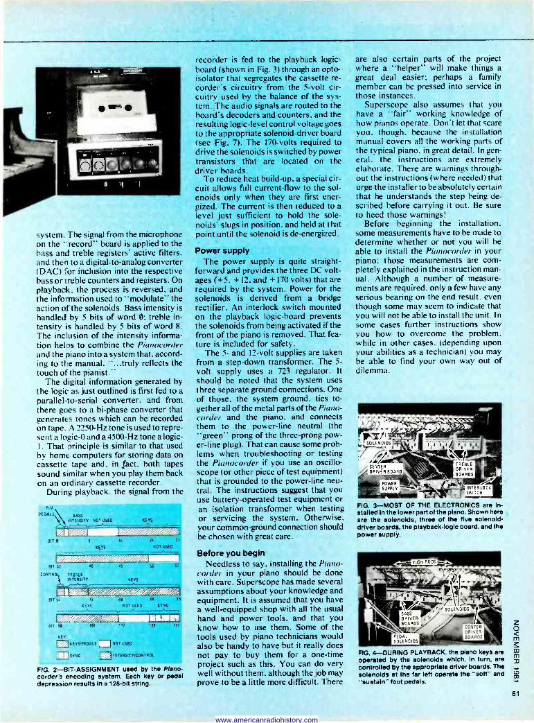
BIT 64 72 88 88
KEYS NOT USED SYNC
system. The signal from the microphone on the "record" board is applied to the bass and treble registers' active filters, and then to a digital -to -analog converter (DAC) for inclusion into the respective bass or treble counters and registers. On playback, the process is reversed, and the information used to "modulate" the action of the solenoids. Bass intensity is handled by 5 bits of word 0: treble in- tensity is handled by 5 bits of word 8. The inclusion of the intensity informa- tion helps to combine the Pianocorder and the piano into a system that, accord- ing to the manual, "...truly reflects the touch of the pianist."
The digital information generated by the logic as just outlined is first fed to a parallel -to -serial converter, and from there goes to a bi -phase converter that generates tones which can be recorded on tape. A 2250 -Hz tone is used to repre- sent a logic -0 and a 4500 -Hz tone a logic-
] . That principle is similar to that used by home computers for storing data on cassette tape and, in fact, both tapes sound similar when you play them back on an ordinary cassette recorder.
During playback. the signal from the
NU
PEDALS
` i BASS
INTENSITY NOT USES KEYS
BIT B 8 16 24 31
KEYS NOT USED
1
BIT 32
CONTROL TREBLE IIL TENSITY KEYS
56 63
FITT7T_..._ 95
B:T 96
KEY
104 112 120 127
A. EYS PEDALS I NOT USED
I SYNC
i 2 INTENSIf Y/CONTROL
FIG. 2-BIT-ASSIGNMENT used by the Plano- corder's ercoding system. Each key or pedal depression results in a 128 -bit string.
recorder is fed to the playback logic - board (shown in Fig. 3) through an opto - isolator that segregates the cassette re- corder's circuitry from the 5 -volt cir- cuitry used by the balance of the sys- tem. The audio signals are routed to the board's decoders and counters. and the resulting logic -level control voltage goes to the appropriate solenoid -driver board (see Fig. 7). The 170 -volts required to drive the solenoids is switched by power transistors that are located on the driver boards.
To reduce heat build-up. a special cir- cuit allows full current -flow to the sol- enoids only when they are first ener- gized. The current is then reduced to a level just sufficient to hold the sole- noids' slugs in position. and held at that point until the solenoid is de -energized.
Power supply The power supply is quite straight-
forward and provides the three DC volt- ages (+5. + 12. and + 170 volts) that are required by the system. Power for the solenoids is derived from a bridge rectifier. An interlock switch mounted on the playback logic -board prevents the solenoids from being activated if the front of the piano is removed. That fea- ture is included for safety.
The 5- and 12 -volt supplies are taken from a step-down transformer. The 5 -
volt supply uses a 723 regulator. It should be noted that the system uses three separate ground connections. One of those, the system ground. ties to- gether all of the metal parts of the Piano - corder and the piano, and connects them to the power -line neutral (the "green" prong of the three -prong pow- er -line plug). That can cause some prob- lems when troubleshooting or testing the Pkrnocorder if you use an oscillo- scope (or other piece of test equipment) that is grounded to the power -line neu- tral. The instructions suggest that you use battery -operated test equipment or an isolation transformer when testing or servicing the system. Otherwise. your common -ground connection should be chosen with great care.
Before you begin Needless to say, installing the Piano -
corder in your piano should be done with care. Superscope has made several assumptions about your knowledge and equipment. It is assumed that you have a well-equipped shop with all the usual hand and power tools, and that you know how to use them. Some of the tools used by piano technicians would also be handy to have but it really does not pay to buy them for a one-time project such as this. You can do very well without them. although the job may prove to be a little more difficult. There
are also certain parts of the project where a "helper" will make things a great deal easier; perhaps a family member can be pressed into service in those instances.
Superscope also assumes that you have a "fair" working knowledge of how pianos operate. Don't let that scare you. though. because the installation manual covers all the working parts of the typical piano. in great detail. In gen- eral. the instructions are extremely elaborate. There are warnings through- out the instructions (where needed) that urge the installer to be absolutely certain that he understands the step being de- scribed before carrying it out. Be sure to heed those warnings!
Before beginning the installation, some measurements have to be made to determine whether or not you will be able to install the Pianocorder in your piano: those measurements are com- pletely explained in the instruction man- ual. Although a number of measure- ments are required, only a few have any serious bearing on the end result. even though some may seem to indicate that you will not be able to install the unit. In some cases further instructions show you how to overcome the problem, while in other cases. (depending upon your abilities as a technician) you may be able to find your own way out of dilemma.
SOLENOIDS
/r /CENTER /" DRIVER -BOARD
FIG. 3-MOST OF THE ELECTRONICS are in- stalled in the lower part of the piano. Shown here are the solenoids, three of the five solenoid - driver boards, the playback -logic board. and the power supply.
FIG. 4-DURING PLAYBACK, the plano keys are operated by the solenoids which, in turn, are controlled by the appropriate driver boards. The solenoids at the far left operate the "soft" and "sustain" foot pedals.
61
www.americanradiohistory.com
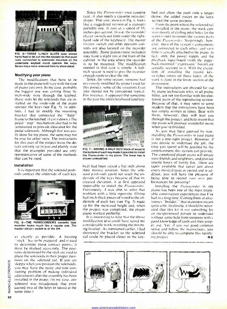
FIG. 5-THREE 1/2 -INCH SLOTS (one shown here) had to be cut into the keybed so that push rods connected to solenoids mounted on the underside keybed could operate the keys. Seven keys were removed here to show detail.
Modifying your piano The modifications that have to be
made to the piano will vary with the type of piano you own. In my case. probably the biggest one was cutting three 1/2 -
inch -wide slots through the keybed; those slots let the solenoids that are in- stalled on the underside of the piano operate the keys (see Fig. 5). In addi- tion. I had to modify the mounting bracket that connected the "harp" frame to the keybed. (I cut it down.) The pedal "trap" mechanism also had to be remounted to provide clearance for the pedal solenoids. Although that was eas- ily done for my piano. the same may not be true for other units. The instructions for this part of the project leave the de- tails entirely up to you and plainly state that the examples provided are only representative of some of the methods that can be used.
Installation It is important that the solenoid push -
rods contact the underside of each key
FIG. 6-THE PIANOCORDER'S cassette tape recorder looks much like a regular one. The master ON/OFF switch is at the left.
as cleanly as possible. A locating "stick" has to be prepared. and is used to determine those contact points; it must be marked accurately. The posi- tions determined by the stick are used to place the solenoids in their proper posi- tions on the solenoid rail. If you are sloppy when you position the solenoids. you may have the nasty and time-con- suming problem of making individual adjustments after the assembly has been installed in the piano. (In my case, one solenoid was misadjusted; that error caused two of the keys to sound at the same time.)
Since the Pianocorder uses cassette tape, it also needs a cassette recorder/ player. That unit, shown in Fig. 6, looks like a ruggedized version of a standard portable one. It runs at a speed of 33/4
inches -per -second. In use, the recorder/ player swivels out from under the right- hand side of the keyboard. The master ON/OFF switch and other operator con- trols are also located on the recorder assembly. Some pianos (mine included) may have a slight rim at the front of the cabinet, in the area where the recorder is to be mounted. The modification needed in that case is simple: A half - inch spacer is used to give the recorder enough room to clear the rim.
Since. for some reason. someone had previously modified the piano I used for this project. some of the situations I ran into should not be considered typical. For instance. it appeared that sometime in the past the entire keyboard (and key -
UNMODIFIED d KEY
FIG. 7-ADDING A HALF -INCH block of wood to the bottom of each key made it possible to install the Pianocorder in my piano. The lower key is shown unmodified.
bed) had been raised a full inch above their normal position. Since the sole- noid push -rods could not reach the un- derside of the keys because of that in- creased elevation, it at first appeared impossible to install the Pianocorder. Fortunately. I was able to solve that problem with a little ingenuity. Gluing half -inch -thick pieces of wood to the un- derside of each key (see Fig. 7) made up for the increased height and, when the project was completed, the player piano worked perfectly.
It is interesting to note that the above modification also could have saved me considerable work in cutting the mount- ing bracket. As mentioned earlier, I had shortened the bracket so the solenoid rail could be placed closer to the key -
bed and allow the push rods a longer throw; the added pieces on the keys served the same purpose.
From the point where the solenoid rail is installed in the piano, the work con- sists mostly of drilling pilot holes for the screws used to mount the various parts of the Pianocorder. Surprisingly, how- ever. most of the system's components are connected to each other, and very little is actually attached to the piano. In fact. only the power supply and the playback logic -board (with the piggy- back -mounted "expression" board) are actually secured to it. With the excep- tion of installing the record key - switches (more on those later). all the work is done in the lower section of the instrument.
The instructions are phrased for use by piano technicians who, in all proba- bility, are not too familiar with the elec- tronic parts of the reproducing system. Because of that, it may seem to some readers that the instructions have been too simply written at times. Bear with them, however; they will lead you through the project, and help insure that the piano will produce wonderful music when you're finished.
As you may have guessed by now, installing the Pianocorder in your piano is not a one-night project. However, if you decide to undertake the job, the time you spend will be justified by the entertainment this system can provide. The completed player piano will amaze your friends and neighbors, and provide untold hours of family fun. There are tapes available that cover just about every musical taste or period and in ad- dition, you will have the pleasure of being able to record your own per- formances for posterity!
Installing the Pianocorder in my piano has been one of the most enjoy- able construction experiences that I've had in a long time. Coming from an elec- tronics "builder." that statement means quite a bit. In closing, it should be reiter- ated that this kit is not something for an inexperienced person to undertake without some help from someone with a good knowledge of tools and their prop- er use. Yet, if you use good common sense and follow the instructions, you should be able to complete this satisfy- ing project. R -E
62
www.americanradiohistory.com
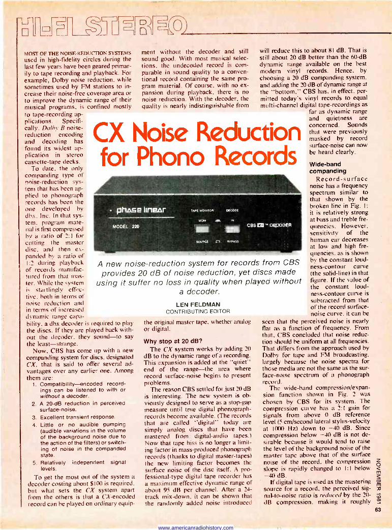
MOST OF THE NOISE -REDUCTION SYSTEMS
used in high-fidelity circles during the last few years have been geared primar- ily to tape recording and playback. For example, Dolby noise reduction, while sometimes used by FM stations to in- crease their noise -free coverage area or to improve the dynamic range of their
confined mostly musical programs, is to tape-recording ap- plications. Specifi- cally. Dolby B noise - reduction encoding and decoding has found its widest ap- plication in stereo cassette -tape decks.
To date, the only companding type of noise -reduction sys- tem that has been ap- plied to phonograph records has been the one developed by dbx. Inc. In that sys- tem. program mate- rial is first compressed by a ratio of 2:1 for cutting the master disc, and then ex- panded by a ratio of 1:2 during playback of records manufac- tured from that mas- ter. While the system is startlingly effec- tive. both in terms of noise reduction and in terms of increased dynamic range capa- bility, a dbx decoder is required to play the discs. If they are played back with- out the decoder, they sound-to say the least-strange.
Now, CBS has come up with a new companding system for discs, designated CX, that is said to offer several ad- vantages over any earlier one. Among them are:
1. Compatibility-encoded record- ings can be listened to with or without a decoder.
2. A 20 -dB reduction in perceived surface -noise.
3. Excellent transient response. 4. Little or no audible pumping
(audible variations in the volume of the background noise due to the action of the filters) or switch- ing of noise in the companded state.
5. Relatively levels.
To get the most out of the system a decoder costing about $100 is required. but what sets the CX system apart from the others is that a CX-encoded record can be played on ordinary equip-
ment without the decoder and still sound good. With most musical selec- tions. the undecoded record is com- parable in sound quality to a conven- tional record containing the same pro- gram material. Of course, with no ex- pansion during playback, there is no noise reduction. With the decoder, the quality is nearly indistinguishable from
will reduce this to about 81 dB. That is
still about 20 dB better than the 60 -dB dynamic range available on the best modern vinyl records. Hence, by choosing a 20 dB companding system, and adding the 20 dB of dynamic range at the "bottom," CBS has, in effect, per- mitted today's vinyl records to equal multi -channel digital tape -recordings as
far as dynamic range and quietness are concerned. Sounds that were previously masked by record surface -noise can now be heard clearly.
CX Noise Reduction for Phono Records
A new noise -reduction system for records from CBS provides 20 dB of noise reduction, yet discs made
using it suffer no loss in quality when played without a decoder.
LEN FELDMAN CONTRIBUTING EDITOR
independent signal
the original master tape, whether analog or digital.
Why stop at 20 dB? The CX system works by adding 20
dB to the dynamic range of a recording. This expansion is added at the "quiet" end of the range-the area where record surface -noise begins to present problems.
The reason CBS settled for just 20 dB is interesting. The new system is ob- viously designed to serve as a stop -gap measure until true digital phonograph - records become available. (The records that are called "digital" today are simply analog discs that have been mastered from digital -audio tapes.) Now that tape hiss is no longer a limit- ing factor in mass-produced phonograph records (thanks to digital master -tapes) the new limiting factor becomes the surface noise of the disc itself. A pro- fessional -type digital tape recorder has a maximum effective dynamic range of about 95 dB per channel. After a 24 - track mix -down, it can be shown that the randomly added noise introduced
Wide -band companding
Record -surface noise has a frequency spectrum similar to that shown by the broken line in Fig. l: it is relatively strong at bass and treble fre- quencies. However. sensitivity of the human ear decreases at low and high fre- quencies, as is shown by the constant loud- ness -contour curve (the solid -line) in that figure. If the value of the constant loud- ness -contour curve is subtracted from that of the record surface - noise curve, it can be
seen that the perceived noise is nearly flat as a function of frequency. From that, CBS concluded that noise reduc- tion should be uniform at all frequencies. That differs from the approach used by Dolby for tape and FM broadcasting, largely because the noise spectra for those media are not the same as the sur- face -noise spectrum of a phonograph record.
The wide -band compression/expan- sion function shown in Fig. 2 was chosen by CBS for its system. The compression curve has a 2:1 gain for signals from above 0 dB reference level (5 cm/second lateral stylus -velocity at 1000 Hz) down to -40 dB. Since compression below -40 dB is not de- sirable because it would tend to raise the level of the background noise of the master tape above that of the surface noise of the record, the compression slope is rapidly changed to I:I below -40 dB.
If digital tape is used as the mastering source for a record, the perceived sig- nal-to-noise ratio is reduced by the 20 - dB compression. making it roughly
www.americanradiohistory.com
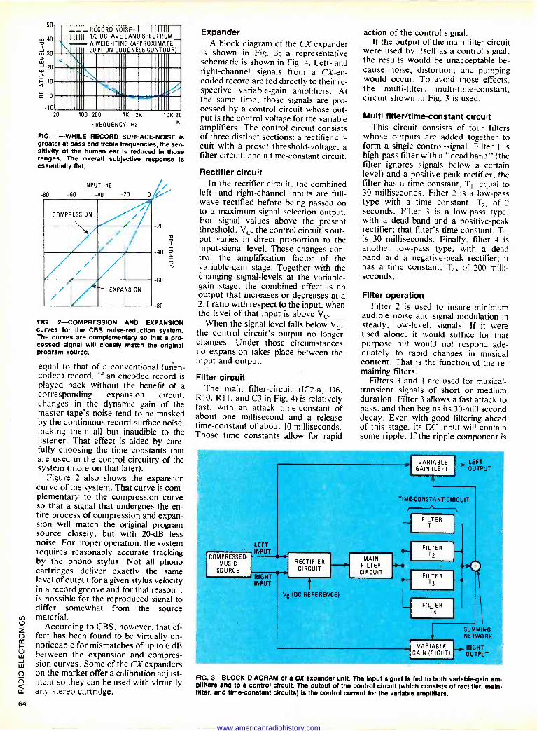
50
m 40
-10
__ RÉcóRò Nöi'sE- I I I I 11111
j 1/3 OCTAVE BAND SPECTRUM A WEIGHT NG (APPROXIMATE 30 PHON L UDNESS CONTOUR)
20 100 200 1K 2K
FREQUENCY -Hz
OK 20 K
FIG. 1-WHILE RECORD SURFACE -NOISE is greater at bass and treble frequencies, the sen- sitivity of the human ear is reduced in those ranges. The overall subjective response is essentially flat.
INPUT dB
-80 -60 -40 -20
COMPRESSION / / / / / / /
/ / / EXPANSION /
20
40
60
80
FIG. 2-COMPRESSION AND EXPANSION curves for the CBS noise -reduction system. The curves are complementary so that a pro- cessed signal will closely match the original program source.
equal to that of a conventional (mien - coded) record. If an encoded record is played back without the benefit of a corresponding expansion circuit. changes in the dynamic gain of the master tape's noise tend to be masked by the continuous record -surface noise. making them all but inaudible to the listener. That effect is aided by care- fully choosing the time constants that are used in the control circuitry of the system (more on that later).
Figure 2 also shows the expansion curve of the system. That curve is com- plementary to the compression curve so that a signal that undergoes the en- tire process of compression and expan- sion will match the original program source closely, but with 20 -dB less noise. For proper operation, the system requires reasonably accurate tracking by the phono stylus. Not all phono cartridges deliver exactly the same level of output for a given stylus velocity in a record groove and for that reason it is possible for the reproduced signal to differ somewhat from the source
o material.
2 According to CBS, however, that ef-
o feet has been found to be virtually un - cc
v noticeable for mismatches of up to 6 dB J between the expansion and compres-
sion curves. Some of the CX expanders o on the market offer a -calibration adjust -
D.
ment so they can be used with virtually any stereo cartridge.
Expander A block diagram of the CX expander
is shown in Fig. 3; a representative schematic is shown in Fig. 4. Left- and right -channel signals from a CX-en- coded record are fed directly to their re- spective variable -gain amplifiers. At the same time, those signals are pro- cessed by a control circuit whose out- put is the control voltage for the variable amplifiers. The control circuit consists of three distinct sections: a rectifier cir- cuit with a preset threshold -voltage, a filter circuit. and a time -constant circuit.
Rectifier circuit In the rectifier circuit, the combined
left- and right -channel inputs are full - wave rectified before being passed on to a maximum -signal selection output. For signal values above the present threshold, Vc, the control circuit's out- put varies in direct proportion to the input -signal level. These changes con- trol the amplification factor of the variable -gain stage. Together with the changing signal -levels at the variable - gain stage, the combined effect is an output that increases or decreases at a 2:1 ratio with respect to the input, when the level of that input is above Vc.
When the signal level falls below Vc. the control circuit's output no longer changes. Under those circumstances no expansion takes place between the input and output.
Filter circuit The main filter -circuit (IC2-a, D6.
RIO. RI l , and C3 in Fig. 4) is relatively fast, with an attack time -constant of about one millisecond and a release time -constant of about 10 milliseconds. Those time constants allow for rapid
action of the control signal. If the output of the main filter -circuit
were used by itself as a control signal, the results would be unacceptable be- cause noise, distortion, and pumping would occur. To avoid those effects, the multi -filter, multi -time -constant, circuit shown in Fig. 3 is used.
Multi filter/time-constant circuit This circuit consists of four filters
whose outputs are added together to form a single control -signal. Filter 1 is high-pass filter with a "dead band" (the filter ignores signals below a certain level) and a positive -peak rectifier; the filter has a time constant, T1, equal to 30 milliseconds. Filter 2 is a low-pass type with a time constant, T2, of 2 seconds. Filter 3 is a low-pass type, with a dead -band and a positive -peak rectifier; that filter's time constant, T3, is 30 milliseconds. Finally, filter 4 is another low-pass type, with a dead band and a negative -peak rectifier; it has a time constant, T4, of 200 milli- seconds.
Filter operation Filter 2 is used to insure minimum
audible noise and signal modulation in steady, low-level, signals. If it were used alone, it would suffice for that purpose but would not respond ade- quately to rapid changes in musical content. That is the function of the re- maining filters.
Filters 3 and I are used for musical - transient signals of short or medium duration. Filter 3 allows a fast attack to pass. and then begins its 30 -millisecond decay. Even with good filtering ahead of this stage, its DC input will contain some ripple. If the ripple component is
COMPRESSED MUSIC
SOURCE
LEFT INPUT
RIGHT INPUT
RECTIFIER CIRCUIT
Vc (DC REFERENCE)
MAIN FILTER CIRCUIT
VARIABLE LEFT GAIN (LEFT) OUTPUT
TIME -CONSTANT CIRCUIT
FILTER T) f
FILTER T2
FILTER T3
FILTER T4
SUMMING NETWORK
VARIABLE RIGHT GAIN (RIGHT) OUTPUT
FIG. 3-BLOCK DIAGRAM of a CX expander unit. The input signal Is fed to both variable -gain am- plifiers and to a control circuit. The output of the control circuit (which consists of rectifier, main - filter, and time -constant circuits) Is the control current for the variable amplifiers.
64
www.americanradiohistory.com
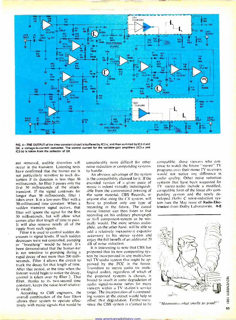
R39 836 tOK 10K
2
LEFT C6
INPUT 0.1
RIGHT INPUT
ier R 38 100K
IC4 a
1/2 LF353
R37 250K L5 CAL
R45 5.1K
1-'1M.
R6 470K
R20 10K
C1
3300pF
R43 5.1K
C2 L R32 3300pF
10K .T.
R33 1 10K a
+15V
8
IC45 1/2LF353
C7
01
5
4
11
R42 - 91K YW
15V
IC1d 1/4 LF347
-15V
834 + -15V
250K 810 CAL.
024 10K
AAA,
31
+15V I
103-a
1/ 2 LM13700
C11
203904
+15V.-- -15V R28 R49 1K
D1 1MEG J_ 10458 FEED THROUGH
BALANCE
41
+15V
R9 33K
IC2-a
li4 LF347
t2 1Ati R10 91K
02 203906
-I5V
13 D6
10458
Y>11L 14
5 7
51K í00K Lour
LEVEL
1
9
0
IC2 6
U 1 1/4 LF347
- C4
0.1
RIS
150K
68
12
- 7
K
+15V -_ I
- 18V LEFT - J OUTPUT
R23 C81+ R40 15K6.BµF 100K
-15V
1-1M. '- R16 150K
131
fl25 R50
IK 1MEG
+15V -YN---15V FEED -THROUGH
BALANCE
16
N458 3K2
1NF- R13 200 K
4"4R+ 14
20K 5 --'-~ IC1t O8 11 1/4 LF347 10458 + C5 -15V
+15V . 10µF
+15V
R18
03
203904
12 10
831 R26 5.1K 100K
7 10K
'Nee
R19 10K
- 1M 1C2-4
1/41F347
811 á1K
827 15K
04 203906
15 'We +15V
I R48 68K
I C9
J 6.8µF RIGHT OUTPUT
FIG. 4-THE OUTPUT of the time -constant circuit is buffered by IC2-c, and then summed by IC2-d and
04, a voltage -to -current converter. The control current for the variable -gain amplifiers (IC3-a and
IC3-b) is taken from the collector of 04.
not removed, audible distortion will occur in the transient. Listening tests have confirmed that the human ear is
not particularly sensitive to such dis- tortion if its duration is less than 30 milliseconds. So filter 3 passes only the first 30 milliseconds of the attack - transient. If the signal continues for longer than 30 milliseconds, filter I
takes over. It is a low-pass filter with a 30 -millisecond time constant. When a sudden transient signal occurs, that filter will ignore the signal for the first 30 milliseconds, but will allow what comes after that length of time to pass. It will also remove nearly all of the ripple from such signals.
Filter 4 is used to control sudden de- creases in signal levels. If such sudden decreases were not controlled, pumping or "breathing" would be heard. It's been demonstrated that the human ear is not sensitive to pumping during a rapid decay of not more than 200 milli-
seconds. Filter 4 allows the circuit to track the decay for that length of time. After that period, at the time when the listener would begin to notice the decay, control is taken over by filter 2. That filter, thanks to its two -second time constant, keeps the noise -level relative- ly steady.
According to CBS engineers, the overall combination of the four filters allows their system to operate effec- tively with music signals that would be
considerably more difficult for other noise reduction or companding systems to handle.
An obvious advantage of the system is the compatibility claimed for it. If the encoded version of a given piece of music is indeed virtually indistinguish- able from the conventional pressing of the same material, CBS Records, or anyone else using the CX system, will have to produce only one type of recording in the future. The casual music listener can then listen to that recording on his ordinary phonograph or hi-fi component -system as he nor- mally would. The more serious audio- phile, on the other hand, will be able to add a relatively inexpensive expander accessory to his stereo system and enjoy the full benefit of an additional 20 dB of noise reduction.
It is interesting to note that CBS has proposed that its new companding sys- tem be incorporated in any multi -chan- nel TV -audio system that might be ap- proved by the FCC in the future. Transition to stereo audio (or multi. - lingual audio), regardless of which of the proposed systems is chosen, is
bound to result in some degradation of audio signal-to-noise ratios for many viewers within a TV station's service range. The incorporation of a compand- ing system at the outset would help to offset that degradation. Furthermore, since the CBS system is claimed to be
compatible, those viewers who con- tinue to watch the future "stereo" TV programs over their mono TV receivers would not notice any difference in
audio quality. Other noise reduction systems that have been suggested for TV stereo -audio include a modified, compatible form of the linear db.y corn- panding system and the newly de- veloped Dolby C noise -reduction sys- tem (see the May issue of Radio -Elec- tronics) from Dolby Laboratories. R -E
7-717 +Ï
"Mmmmm-what smells so good?"
www.americanradiohistory.com
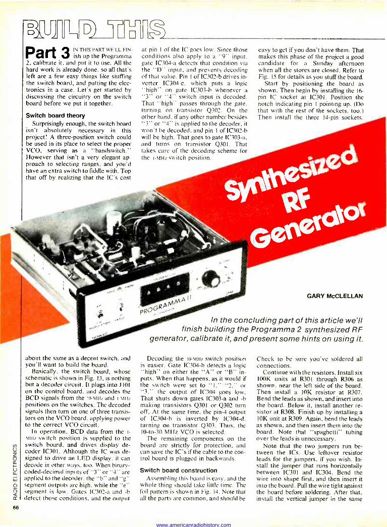
CZJ- -1 . Part 3 IN THIS wE'LL FI
ish up the PART
Programma N-
2. calibrate it, and put it to use. All the hard work is already done, so all that's left are a few easy things like stuffing the switch board, and putting the elec- tronics in a case. Let's get started by discussing the circuitry on the switch board before we put it together.
Switch board theory Surprisingly enough, the switch board
isn't absolutely necessary in this project! A three -position switch could be used in its place to select the proper VCO, serving as a "bandswitch." However that isn't a very elegant ap- proach to selecting ranges, and you'd have an extra switch to fiddle with. Top that off by realizing that the IC's cost
about the same as a decent switch, and you'll want to build the board.
Basically, the switch board, whose schematic is shown in Fig. 13, is nothing but a decoder circuit. It plugs into J101 on the control board, and decodes the BCD signals from the 10 -MHz and I -MHz positions on the switches. The decoded signals then turn on one of three transis- tors on the VCO board, applying power to the correct VCO circuit.
In operation, BCD data from the 1 -
mi -17 switch position is supplied to the switch board, and drives display de- coder IC301. Although the IC was de- signed to drive an LED display, it can decode in other ways, too. When binary- coded -decimal inputs of "3" or "4" are applied to the decoder, the "b" and "g" segment outputs are high, while the "e" segment is low. Gates IC302-a and -b detect those conditions, and the output
at pin I of the IC goes low. Since those conditions also apply to a "9" input. gate IC304-a detects that condition via the "D" input, and prevents decoding of that value. Pin I of IC302-b drives in- verter IC304-c, which puts a logic "high" on gate IC303-b whenever a "3" or "4" switch input is decoded. That "high" passes through the gate, turning on transistor Q302. On the other hand, if any other number besides "3" or "4" is applied to the decoder, it won't be decoded, and pin I of IC302-b will be high. That goes to gate IC303-a, and turns on transistor Q301. That takes care of the decoding scheme for the I -MHz switch position.
easy to get if you don't have them. That makes this phase of the project a good candidate for a Sunday afternoon when all the stores are closed. Refer to Fig. 15 for details as you stuff the board.
Start by positioning the board as shown. Then begin by installing the 16 - pin IC socket at IC301. Position the notch indicating pin I pointing up. (Do that with the rest of the sockets, too.) Then install the three 14 -pin sockets.
GARY McCLELLAN
In the concluding part of this article we'll finish building the Programma 2 synthesized RF
generator, calibrate it, and present some hints on using it.
Decoding the 10 -MHz switch position is easier. Gate IC304-b detects a logic "high" on either the "A" or "B" in- puts. When that happens, as it would if the switch were set to "I," "2." or "3." the output of IC304 goes low. That shuts down gates IC303-a and -b making transistors Q301 or Q302 turn off. At the same time, the pin -4 output of IC304-b is inverted by IC304-d, turning on transistor Q303. Thus, the 10 -to -30 MHz VCO is selected.
The remaining components on the board are strictly for protection, and can save the IC's if the cable to the con- trol board is plugged in backwards.
Switch board construction Assembling this board is easy. and the
whole thing should take little time. The foil pattern is shown in Fig. 14. Note that all the parts are common, and should be
Check to be sure you've soldered all connections.
Continue with the resistors. Install six 100K units at R301 through R306 as shown, near the left side of the board. Then install a 10K resistor at R307. Bend the leads as shown, and insert into the board. Below it, install another re- sistor at R308. Finish up by installing a 10K unit at R309. Again, bend the leads as shown, and then insert them into the board. Note that "spaghetti" tubing over the leads is unnecessary.
Note that the two jumpers run be- tween the ICs. Use leftover resistor leads for the jumpers, if you wish. In- stall the jumper that runs horizontally between IC301 and IC304. Bend the wire into shape first, and then insert it into the board. Pull the wire tight against the board before soldering. After that, install the vertical jumper in the same
66
www.americanradiohistory.com
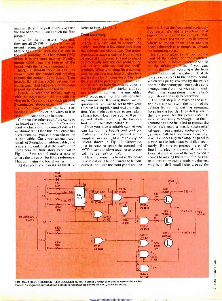
manner. Be sure to pull it tightly against the board so that it can't touch the first jumper.
Now for the transistors. No rat they are all 2N3904's, a t'they all mount facing In t direction. Mount Q301 first, with the flat side in t pointing up. Then mount Q302
it in the same manner. Finally, mount Q303 near the bottom of the board, with the flat side pointing up.
Install a 1N4148 diode at D301 as shown, with the banded end pointing toward the center of the board. Then install a 0.1 NF disc atC301 between the transistors. That takes care of the com- ponent installation on the board.
Finish up with the cables, starting with the input cable-the one with the plug on it. Cut about a six -i 8 -conductor ribb prepare the ends. Then a the 8 -pin DIP head .
: solder the wires to it in der. nd snap the cap in place. Connect the other end of the cable to
the board as shown in Fig. 15. (You may want to check out the connections with an ohmmeter.) Once the input cable has been installed, you can procede to the output cable.. Cut about an eight -inch length of 3 -conductor ribbon cable, and prepare the end. Install the wires in the holes near the transistors as shown in Fig. 16. You should make a note of where the wiresgo, for future reference. That completes the board wiring.
At this point you can install the IC's.
Refer to Fi s 16.
ly The time has come to install the
boards in a case and to connect the cables. But first, a few comments about the cabinet you should use. The proto- type used a leftover cabinet from a piece of medical equipment. It's not available commercially but you can probably do just as well with an `off the shelf' product. When you shop for a cabinet, look for one that is at least 3 inches by$ inches wide by 7 inches deep. That the size of the proto . _: net, and is just right to hol: .. rds. Also, it should + or shielding. If you
c cabinet, the unshielded ronics may interfere with sensitive
measurements. Knowing those two re- quirements, you are all set to visit your electronics supplier and make a selec- tion. You might even want to use a plain chassis box to keep costs down. If paint- ed and labelled carefully, the box can look better than most cabinets!
Once you have a suitable cabinet you can lay out the boards and controls. Probably the best arrangement is the simplest, so you might want to copy the layout shown in Fig. 17. Otherwise. just be sure to space the control and VCO boards as close together as practi- cal; the rest isn't critical.
Here are some tips to make the board layout easier. The only areas to be con- cerned about are the front panel and the
bottom. Since the front panel holds only five parts, it's not a problem. That leaves the bottom of the cabinet. Posi- tion all three boards on it to determine where to mount them; then use the boards themselves as templates to mark the mounting holes.
Be sure to allow extra room at t front of the cabinet for the swítc .
About three inche of clearance should be the m so, if you can.
c board near the front .ottom of the cabinet. That sl-
ows easier access to the control board, which was partly covered by the switch board in the prototype-not such a good arrangement from a service standpoint. With those suggestions, board place- ment should be easy to determine.
The next step is to machine the cabi- net. You can start with the bottom of the cabinet by drilling out the mounting holes for the boards. Then drill a hole in the rear panel for the power cable. It may be necessary to enlarge it so that a grommet can be installed to protect the cable. (We used a plastic strain -relief salvaged from a junked appliance.) You can now drill the front panel. Generally, it will be necessary to clamp the panel in a vise so the holes can be drilled accu- rately. Be sure to protect the panel's finish by placing a piece of cloth be- tween it and the jaws of the vise. When it comes to making the cutout for the FRE-
QUENCY SET switches, probably the best way is to drill small holes around the
10 CONTROL BOARD
1''s
10s
D301
1N4148
+9vE-----11--- R301 100K
A .*--NVN- 6 R302,100K 1
2
C 4 W,
R303,
D
R304 100K
R305 100K 1N
R306 100K
6
10304-b 1/4 4001
14
7
1C302-5 1/2 4012
-- IC304-c
1/4 4001
C 30 1 ,y 1
Q301
14 R307 2N3904I
1 10K
2 _ --._/ --
1C303 -a
1/4 4081
1C303 -d
1/4 4081
->5-10MHz
D302 -35MHz R308 203904
I
10K
NC
1C303 c
1/4 4081
---*-10-30MHJ
-0
TO VCO BOARD
RG. 13-A SEVEN -SEGMENT LED DECODER, IC301, is put to a rather unorthodox use on the switch board. Its segment output states determine which of the generator's V+CO's will be active.
www.americanradiohistory.com
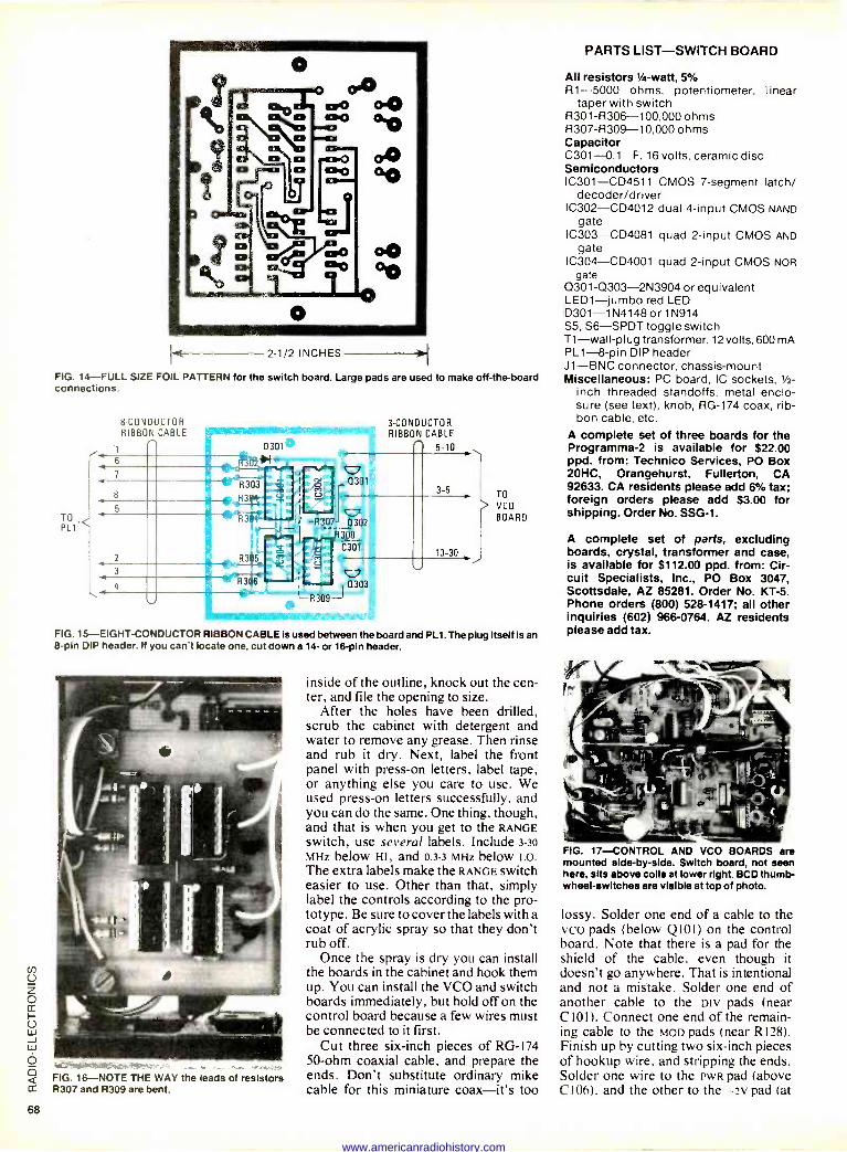
PARTS LIST-SWITCH BOARD o
00 0 I a p 0 o o 0.0
ce 00
o
o 0 o CPO d Oro
o
Ft 2 1/2 INCHES
FIG. 14-FULL SIZE FOIL PATTERN for the switch board. Large pads are used to make off -the -board connections.
8 -CONDUCTOR RIBBON CABLE
TO PL1
-R30 0302 R308
C301
3 -CONDUCTOR RIBBON CABLE
5-10
TO
VCO
BOARD
FIG. 15-EIGHT-CONDUCTOR RIBBON CABLE is used between the board and PL1. The plug itself is an 8 -pin DIP header. If you can't locate one, cut down a 14- or 16 -pin header.
FIG. 16-NOTE THE WAY the leads of resistors R307 and R309 are bent.
inside of the outline, knock out the cen- ter, and file the opening to size.
After the holes have been drilled, scrub the cabinet with detergent and water to remove any grease. Then rinse and rub it dry. Next, label the front panel with press -on letters, label tape, or anything else you care to use. We used press -on letters successfully, and you can do the same. One thing, though, and that is when you get to the RANGE switch, use several labels. Include 3-30
MHz below HI, and 0.3-3 MHz below LO. The extra labels make the RANGE switch easier to use. Other than that, simply label the controls according to the pro- totype. Be sure to cover the labels with a coat of acrylic spray so that they don't rub off.
Once the spray is dry you can install the boards in the cabinet and hook them up. You can install the VCO and switch boards immediately, but hold off on the control board because a few wires must be connected to it first.
Cut three six-inch pieces of RG -174 50 -ohm coaxial cable, and prepare the ends. Don't substitute ordinary mike cable for this miniature coax-it's too
All resistors 1/4 -watt, 5% R1-5000 ohms, potentiometer, linear
taper with switch R301 -R306-100,000 ohms R307 -R309-10,000 ohms Capacitor C301-0.1 F, 16 volts, ceramic disc Semiconductors IC301-CD4511 CMOS 7 -segment latch/
decoder/driver IC302-CD4012 dual 4 -input CMOS NAND
gate IC303-CD4081 quad 2 -input CMOS AND
gate IC304-CD4001 quad 2 -input CMOS NOR
gate 0301-0303-2N3904 or equivalent LED1-jumbo red LED D301 -1N4148 or 1N914 S5, S6-SPDT toggle switch T1-wall-plug transformer, 12 volts, 600 mA PL1-8-pin DIP header J1-BNC connector, chassis -mount Miscellaneous: PC board, IC sockets, 1/2 -
inch threaded standoffs, metal enclo- sure (see text), knob, RG -174 coax, rib- bon cable, etc.
A complete set of three boards for the Programma -2 is available for $22.00 ppd. from: Technico Services, PO Box 20HC, Orangehurst, Fullerton, CA 92633. CA residents please add 6% tax; foreign orders please add $3.00 for shipping. Order No. SSG -1.
A complete set of parts, excluding boards, crystal, transformer and case, is available for $112.00 ppd. from: Cir- cuit Specialists, Inc., PO Box 3047, Scottsdale, AZ 85281. Order No. KT -5. Phone orders (800) 528-1417; all other inquiries (602) 966-0764. AZ residents please add tax.
FIG. 17-CONTROL AND VCO BOARDS are mounted side -by -side. Switch board, not seen here, sits above coils at lower right. BCD thumb - wheel -switches are visible at top of photo.
lossy. Solder one end of a cable to the vco pads (below Q101) on the control board. Note that there is a pad for the shield of the cable, even though it doesn't go anywhere. That is intentional and not a mistake. Solder one end of another cable to the DIV pads (near C101). Connect one end of the remain- ing cable to the MoD pads (near R128). Finish up by cutting two six-inch pieces of hookup wire, and stripping the ends. Solder one wire to the PWR pad (above C106), and the other to the -3v pad (at
68
www.americanradiohistory.com
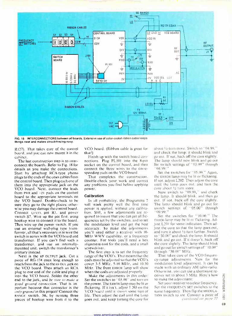
S6 RANGE H I t4r
FREQUENCY SET SWITCHES
RIBBON CABLES
Si S2 S3 S4
â ô COM
SWITCH BOARD
x ó
fl
RIBBON CABLES
J101
CONTROL BOARD
S1 S4
COM
PL 101
RANO.SW
MOO
PWR
-2V
117 VAC
LO o -
- CW SM O c
MODULATION
T1
RG 174 COAX
LO ONO HI VCO BOARD
VCO IN
DIV
2-
MOD
RF
OUT
PWR AC
2V VCO SEL LEV A R
LEVEL
12V, 600mA
D
R1
5K
S7 i
POWER 1 OFF
ON
FIG. 18-INTERCONNECTIONS between all boards. Extensive use of color -coded ribbon cable keeps things neat and makes circuit -tracing easy.
RI27). That takes care of the control board, and you can now mount it in the cabinet.
The last construction step is to inter- connect the boards. Refer to Fig. 18 for details as you make the connections. Start by attaching RCA -type phono plugs to the ends of the coax cables from the control board. Then plug each one of them into the appropriate jack on the VCO board. Next, connect the leads from PWR and -2v pads on the control board to the appropriate terminals on the VCO board. Double-check to be sure they go to the right places; other- wise you may damage the control board. Connect LEVEL pot RI, and power switch S7. Wire up the pot first, using hookup wire to connect it to the board. Then wire up the power switch. If you use an external wall -plug type trans- former, all that's necessary is to wire the switch in series with the VCO board and transformer. If you can't find such a transformer, and use an internally - mounted unit, switch the transformer's primary instead.
Next is the RF OUTPUT jack. Cut a piece of RG -174 coax long enough to reach from the jack to the RF OUT jack on the VCO board. Then attach an RCA plug to one end of the cable and plug it into the VCO board. Solder the other end to the jack, and be sure to make a good ground connection. That is im- portant because that connector is the only ground in this project! Connect the RANGE switch, S6, by running three pieces of hookup wire from it to the
VCO board. (Ribbon cable is great for that!) -
Finish up with the switch board con- nections. Plug PL 101 into the 8 -pin socket on the control board, and then connect the three wires to the corre- sponding pads on the VCO board.
That completes the construction. Double-check your work and correct any problems you find before applying power.
Calibration In all probability, the Programma 2
will work pretty well the first time power is applied, without any calibra- tion. Still, a few adjustments are re- quired to insure that you can get all fre- quencies set by the switches, and to set the modulation level and get the best accuracy. To make the adjustments you'll need either a receiver with 10 -
MHz WWV capability, or a frequency counter. For tools you'll need a hex alignment -tool for the coils, and a small screwdriver.
The first step is to set the frequency range of the VCO's. That means that the coils must be adjusted so that the VCO's cover 3-5 MHz, 5-10 MHz, and 10-30 MHz. The front ERROR lamp will show when the coils are adjusted properly.
Make the adjustments in this order: Set the switches to "03.00" and turn on the power. The ERROR lamp may be lit or flickering. If it isn't, adjust L203 on the VCO board until it shows some sign of life. Then adjust the coil until the lamp goes out, and keep turning the core for
about 1/2 -turn more. Switch to "04.99," and check the lamp; it should blink and go out. If not, back off the core slightly. The lamp should now blink and go out for switch settings of "03.00" through "04.99."
Set the switches for "05.00." Again, the ERROR lamp may be lit or flickering. If not, adjust L202. Then adjust the core until the lamp goes out, and turn the core about 1/2 turn more.
Now switch to "09.99," and check the lamp. It should blink, and then go out. If not, back off the core slightly. The lamp should blink and go out for switch settings of "05.00" through "09.99."
Set the switches for "10.00." The ERROR lamp may be lit or flickering. Ad- just L201 for some indication. Then ad- just the core so that the lamp goes out, and turn it about 1/2 -turn farther. Switch to "30.00" and check the lamp. It should blink and go out. If it doesn't, back off the core slightly. The lamp should blink and go out for switch settings of "10.00" through "30.00" MHz.
That takes care of the VCO frequen- cy -range adjustments. Now for the modulation -level adjustment. It can be made with an ordinary AM table -radio. Otherwise, you can use a shortwave re- ceiver set to about 3 MHz. Here's how to make the adjustment:
Set your receiver to a clear frequency. Set the FREQUENCY SET switches to the same frequency. Then flip the MODULA- TION switch to AM. Connect a piece of
continued On page 77
www.americanradiohistory.com
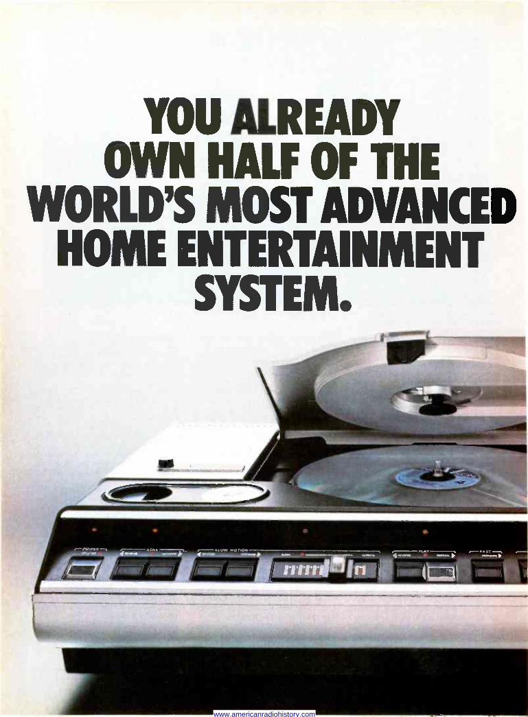
YOU ALREADY OWN HALF OF THE
WORLD'S MOST ADVANCED HOME ENTERTAINMENT
SYSTEM.
www.americanradiohistory.com
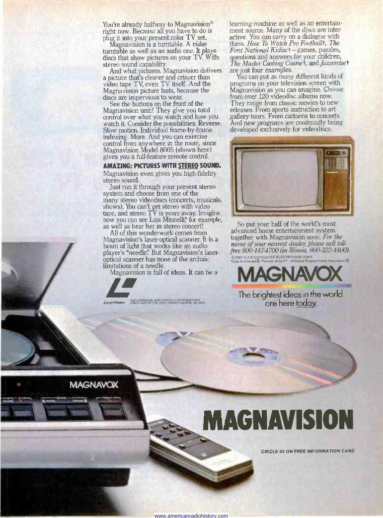
You're already halfway to Magnavision*' right now. Because all you have to do is plug it into your present color TV set.
Magnavision is a turntable. A video turntable as well as an audio one. It plays discs that show pictures on your TV. With stereo sound capability.
And what pictures. Magnavision delivers a picture that's clearer and crisper than video tape TV, even TV itself. And the Magnavision picture lasts, because the discs are impervious to wear.
See the buttons on the front of the Magnavision unit? They give you total control over what you watch and how you watch it. Consider the possibilities: Reverse. Slow motion. Individual frame -by -frame indexing. More. And you can exercise control from anywhere in the room, since Magnavision Model 8005 (shown here) gives you a full -feature remote control..
AMAZING: PICTURES WITH STEREO SOUK. Magnavision even gives you high-fidelity stereo sound.
Just run it through your present stereo system and choose from one of the many stereo videodiscs (concerts, musicals, shows). You can't get stereo with video tape, and stereo TV is years away. Imagine, now you can see Liza Minnelli ' for example, as well as hear her in stereo concert!
All of this wonderwork comes from Magnavision's laser -optical scanner. It is a beam of light that works like an audio player's "needle:' But Magnavision's laser - optical scanner has none of the archaic limitations of a needle.
Magnavision is full of ideas. It can be a L LASERVION MAI« CERTIFIES COMPA LaseVise.I OTHER LASER.O ICAL VIDEO PRODUCTS BEARINGYTHETMORE
learning machine as well as an entertain- ment source. Many of the discs are inter- active. You can carry on a dialogue with them. How To Watch Pro Footballt, The First National Kidisct-games, puzzles, questions and answers for your children, The Master Cooking Courset, and Jazzerciset are just four examples.
You can put as many diifferent kinds of programs on your television screen with Magnavision as you can imagine. Choose from over 120 videodisc albums now. They range from classic movies to new releases. From sports instruction to art gallery tours. From cartoons to concerts. And new programs are continually being developed exclusively for videodiscs.
_ ,. ®.. So put your half of the world's most
advanced home entertainment system together with Magnavision soon. For the name of your nearest dealer, please call toll - free 800-447-4700 (in Illinois 800-322-4400). © 1981 N.A.P CONSUMER ELECTRONICS CORP 'Liza In Concerte,. Pioneer Artists' tOptical Programming Associatron©
MAGNAVOX The brightest ideas n the world
are here today.
MAGNAVISION CIR .LE 83 ON FREE INFORMATION CARD
www.americanradiohistory.com
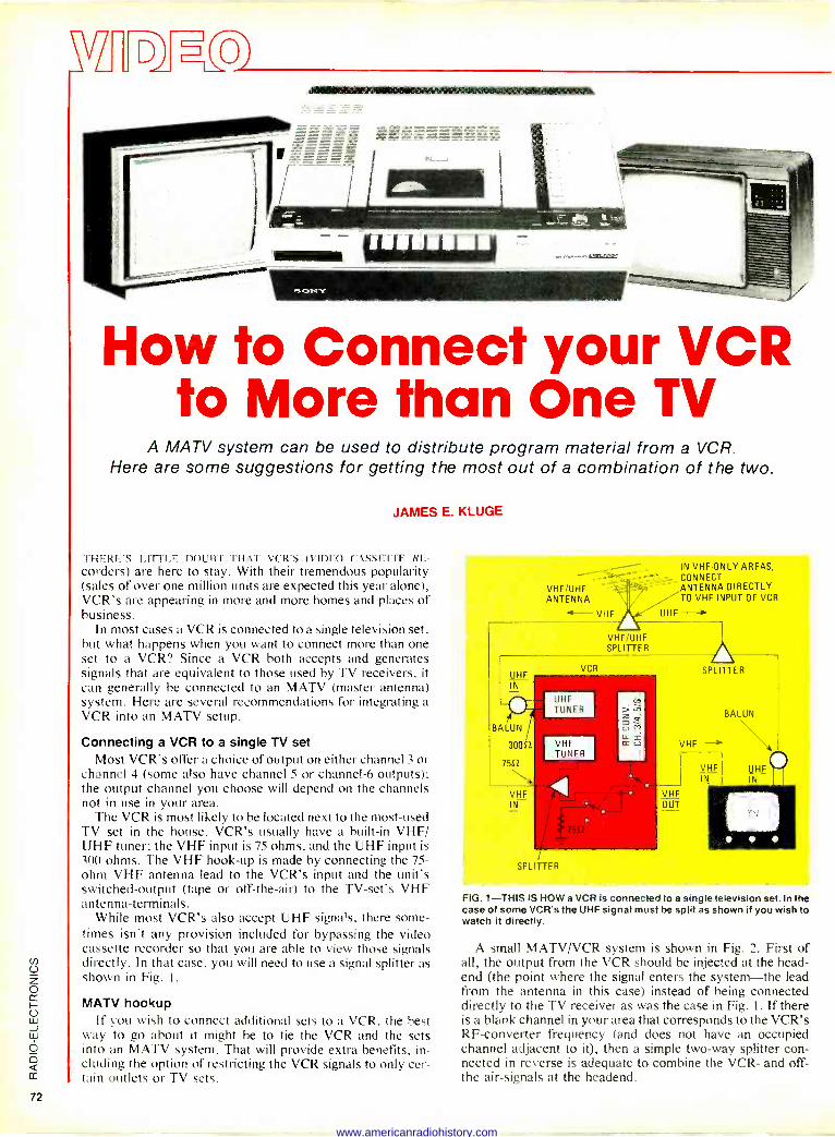
How to Connect your VCR to More than One TV
A MATV system can be used to distribute program material from a VCR. Here are some suggestions for getting the most out of a combination of the two.
JAMES E. KLUGE
rHERE'S LITTLE DOUBT THAT VCR'S (VIDEO CASSE"FTT. RE-
corders) are here to stay. With their tremendous popularity (sales of over one million units are expected this year alone), VCR's are appearing in more and more homes and places of business.
In most cases a VCR is connected to a single television set, but what happens when you want to connect more than one set to a VCR? Since a VCR both accepts and generates signals that are equivalent to those used by TV receivers, it
can generally be connected to an MATV (master antenna) system. Here are several recommendations for integrating a VCR into an MATV setup.
Connecting a VCR to a single TV set Most VCR's offer a choice of output on either channel 3 or
channel 4 (some also have channel -5 or channel -6 outputs); the output channel you choose will depend on the channels not in use in your area.
The VCR is most likely to be located next to the most -used TV set in the house. VCR's usually have a built-in VHF/ UHF tuner: the VHF input is 75 ohms, and the UHF input is 300 ohms. The VHF hook-up is made by connecting the 75 - ohm VHF antenna lead to the VCR's input and the unit's switched -output (tape or off -the -air) to the TV -set's VHF antenna -terminals.
While most VCR's also accept UHF signals, there some- times isn't any provision included for bypassing the video cassette recorder so that you are able to view those signals directly. In that case, you will need to use a signal splitter as shown in Fig. I.
MATV hookup If you wish to connect additional sets to a VCR, the best
way to go about it might be to tie the VCR and the sets into an MATV system. That will provide extra benefits, in- cluding the option of restricting the VCR signals to only cer- tain outlets or TV sets.
VHF/UHF ANTENNA eri '4- VHF A UHF -->
VHF/UHF SPLITTER
UHF IN
BALUN
30052
7552
VHF IN
VCR
UHF TUNER
VHF TUNER
SPLITTER
IN VHF -ONLY AREAS, CONNECT ANTENNA DIRECTLY TO VHF INPUT OF VCR
SPLITTER
VHF,
VHF OUT
VHF
BALUN
UHF IN
FIG. 1-THIS IS HOW a VCR Is connected to a single television set. In the case of some VCR's the UHF signal must be split as shown if you wish to watch it directly.
A small MATV/VCR system is shown in Fig. 2. First of all, the output from the VCR should be injected at the head - end (the point where the signal enters the system-the lead from the antenna in this case) instead of being connected directly to the TV receiver as was the case in Fig. 1. If there is a blank channel in your area that corresponds to the VCR's RF -converter frequency (and does not have an occupied channel adjacent to it), then a simple two-way splitter con- nected in reverse is adequate to combine the VCR- and off - the air -signals at the headend.
www.americanradiohistory.com
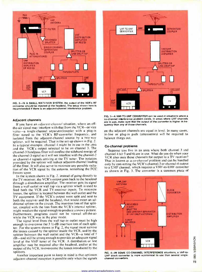
7552
VHF ANTENNA
FILTER
REVERSED SPLITTER
VHF DISTRIBUTION AMPLIFIER (IF REO'D)
SINGLE -CHANNEL SEPARATOR/
SPLITTER OR PLUG IN
COUPLER LINE-DRCPTAP
f
VHF DISTRIBUTION AMPLIFIER (IF REO'D)
VHF OUT
TAPS/OUTLETS
VHF 1(Y
VCR
SPLITTER
I
VHF IN
FIG. 2-IN A SMALL MATV/VCR SYSTEM, the output of the VCR's RF
converter should be injected at the headend. The setup shown here is recommended if there is an adjacent -channel interference problem.
Adjacent channels If you have an adjacent -channel situation, where an off -
the -air signal may interfere with that from the VCR-or vice versa-a single -channel separator/coupler with a plug-in filter tuned to the VCR's RF -converter frequency, and isolated from the adjacent -channel source by a two-way splitter, will be required. That is the set-up shown in Fig. 2.
In atypical example, channel 4 might be in use in the area and the VCR's output selected to be on channel 3. The channel -3 bandpass filter will confine the sideband energy of the channel -3 signal so it will not interfere with the channel -2
or channel -4 signals arriving at the TV tuner. The isolation provided by the splitter will reduce adjacent -channel loading of the filter. It will also serve to minimize any possible radia- tion of the VCR signal by the antenna, something the FCC frowns upon.
In the system shown in Fig. 2, instead of going directly to the TV receiver, the VCR's output goes back to the headend through a distribution amplifier. The receiver gets its signal from a wall outlet or wall tap via a splitter which is used to feed both the VCR and TV -receiver inputs. To minimize losses, the splitter is located between the wall outlet and the TV equipment. If the VCR's output were split and sent to both the receiver and the headend, that would mean an ad- ditional splitter in the circuit. The insertion loss of that split - ter, coupled with the loss from the VCR's internal splitter, might weaken the signal enough to produce a snowy picture. Furthermore, programs could not be viewed off -the -air while the VCR was in the play mode.
The signal level from the wall tap or outlet must be high enough to overcome the 3 t/ -dB insertion loss of each split - ter. For the system shown in Fig. 2, the signal must survive the losses caused by the splitter inside the VCR, and by the splitter between the wall outlet and the VCR-a total of 7
dB-and still be strong enough to provide an adequate signal level at the VHF tuner of the VCR. A distribution or line amplifier may be required after the headend, and/or at the output of the VCR, to overcome the losses introduced by the splitters.
Another important point to keep in mind is that optimum adjacent -channel reception is possible only when the signals
VHF OUT
mk
Hr TC UHF EONVLHrrr
VHF'UHF IN
UHF
VCR
IIZZ11113
SEPARATOR/' COUPLER
VHF/UHF DISTRIBUTION AMPLIFIER
SPLITTER OR
LINE DROP TAP
TAPS/OUTLETS
SPLITTER VHF/UHF IN
FIG. 3-A VHF -TO -UHF CONVERTER can be used in situations where a
co -channel Interference problem exists. In areas where UHF channels are in use, make Sure that the output of the converter is higher in fre- quency than any of those channels.
on the adjacent channels are equal in level. In many cases, in -line or plug-in pads (attenuators) will be required to balance things out.
Co -channel problems Suppose you live in an area where both channel 3 and
channel 4 (or 5 and 6) are in use. What do you do when your VCR also uses those channels for output to a TV receiver? That is known as a co -channel problem and can be handled only by converting the VCR's channel -3 or channel -4 output to a UHF channel, which requires a VHF -to -UHF converter as shown in Fig. 3. The converter is a common piece of
VHF. UHF ANTENNA
REVERSED 2 -WAY SPLIT -ER (LISE UHF/VFF SEPARATOR IF VHF ONLY ANTENNA)
4 -WAY SPLITTER
VCR N
BLOCK CONVERTER
DISTRIBUTION AMPLIFIER
FIG. 4-IN SOME CO -CHANNEL INTERFERENCE situations, a VHF -to - UHF block converter is more economical to use than several single - channel converters.
www.americanradiohistory.com
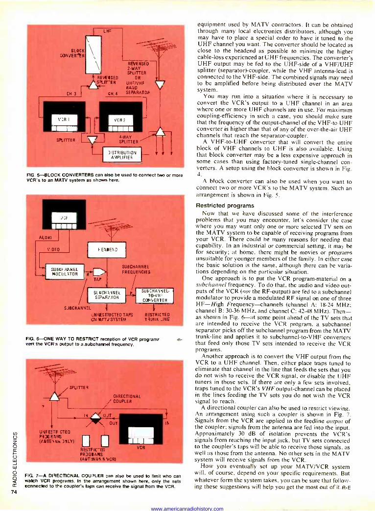
LO_Cgi
CONJER
L H=
bEiSED PLrr-ER I-
CH. 4
REVERSED 2 -WAY SPLITTER
OR
UH=/VHF BAND SEPARATOF
VCR 2
Lill 4 -WAY SPLITTER
J STRIBUTIUN AMPLIFIEF
FIG 5 EILOCK CONVERTERS cal also be used to conrect two or more VCR s to an MATV system as shown here.
/;F w. AL DIO
V CEO FE5IEND
SUBtFANHEL MO_LLaTOR J}
TAP
SUB(HANNEL FREQUENCIES
SLIC31aNNEL SPAFaTOR
SJBCHANN=L
_NRESTRICTED TAP; / SYSTEM
SUICHANJEL- TO-VH=
CONWRTER
RESTRICTED TRUNK _INE
FIG. 6-ONE WAY TO RESTRICT reception of VCR program. Bert the VCR's output to a subchannel frequency.
m-
t4
í SPLITTES
UVFES-F CTED Pi]CFarrs It UTE JNLY)
DIRECTIONAL f COUPLER
I OJT
N OUT
R6TF IC -EU PRJGIAMS YT3JNa$VCR)
I IR
FIG. 7-A DIRECTIONAL COUPLER :an also be used to limit who can watch VCR programs. In the arrangement shown here. only the sets connected to the coupler's taps cal receive the signal from the VCR.
equipment used by MATV contractors. It can be obtained through many local electronics distributors, although you may have to place a special order to have it tuned to the UHF channel you want. The converter should be located as close to the headend as possible to minimize the higher cable -loss experienced at UHF frequencies. The converter's UHF output may be fed to the UHF -side of a VHF/UHF splitter (separator) -coupler, while the VHF antenna -lead is connected to the VHF -side. The combined signals may need to be amplified before being distributed over the MATV system.
You may run into a situation where it is necessary to convert the VCR's output to a UHF channel in an area where one or more UHF channels are in use. For maximum coupling -efficiency in such a case, you should make sure that the frequency of the output -channel of the VHF -to -UHF converter is higher than that of any of the over -the -air UHF channels that reach the separator -coupler.
A VHF -to -UHF converter that will convert the entire block of VHF channels to UHF is also available. Using that block converter may be a less expensive approach in some cases than using factory -tuned single -channel con- verters. A setup using the block converter is shown in Fig. 4.
A block converter can also be used when you want to connect two or more VCR's to the MATV system. Such an arrangement is shown in Fig. 5.
Restricted programs Now that we have discussed some of the interference
problems that you may encounter, let's consider the case where you may want only one or more selected TV sets on the MATV system to be capable of receiving programs from your VCR. There could be many reasons for needing that capability. In an industrial or commercial setting, it may be for security; at home, there might be movies or programs unsuitable for younger members of the family. In either case the basic solution is the same, although there can be varia- tions depending on the particular situation.
One approach is to put the VCR program -material on a subchannel frequency. To do that, the audio and video out- puts of the VCR (not the RF -output) are fed to a subchannel modulator to provide a modulated RF signal on one of three HF-High Frequency-channels (channel A: 18-24 MHz; channel B: 30-36 MHz, and channel C: 42-48 MHz). Then- as shown in Fig. 6-at some point ahead of the TV sets that are intended to receive the VCR program, a subchannel separator picks off the subchannel program from the MATV trunk -line and applies it to subchannel-to-VHF converters that feed only those TV sets intended to receive the VCR programs.
Another approach is to convert the VHF output from the VCR to a UHF channel. Then, either place traps tuned to eliminate that channel in the line that feeds the sets that you do not wish to receive the VCR signal, or disable the UHF tuners in those sets. If there are only a few sets involved, traps tuned to the VCR's VHF output -channel can be placed in the lines feeding the TV sets you do not wish the VCR signal to reach.
A directional coupler can also be used to restrict viewing. An arrangement using such a coupler is shown in Fig. 7. Signals from the VCR are applied to the feedline output of the coupler; signals from the antenna are fed into the input. Approximately 30 dB of isolation prevents the VCR's signals from reaching the input jack, but TV sets connected to the coupler's taps will be able to receive those signals, as well as those from the antenna. No other sets in the MATV system will receive signals from the VCR.
How you eventually set up your MATV/VCR system will, of course, depend on your specific requirements. But whatever form the system takes, you can be sure that follow- ing these suggestions will help you get the most out of it. R -E
www.americanradiohistory.com
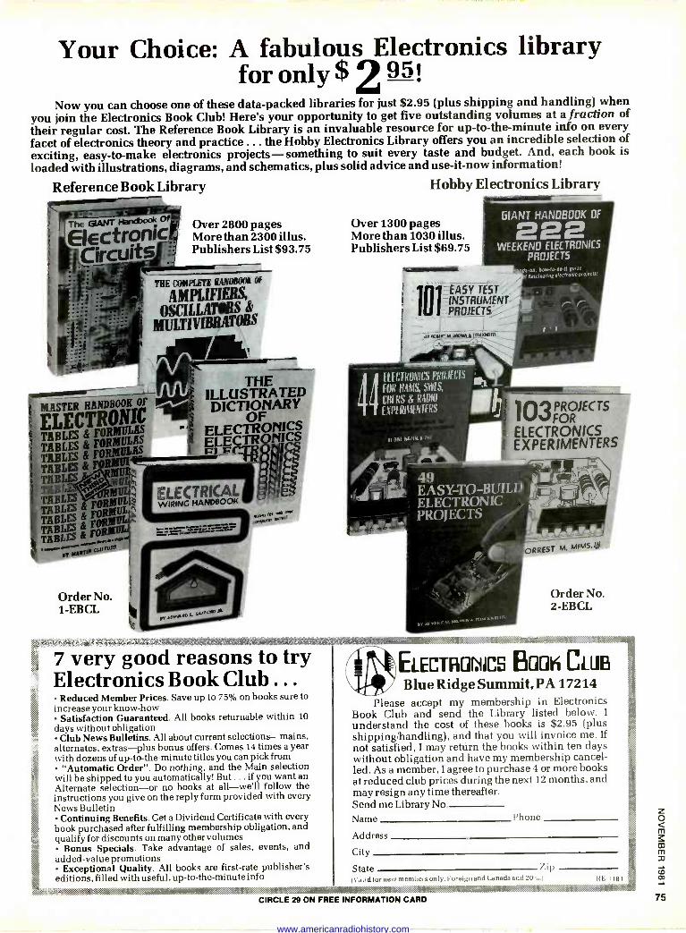
Your Choice: A fabulous Electronics library for only $ 2 95!
Now you can choose one of these data -packed libraries for just $2.95 (plus shipping and handling) when you join the Electronics Book Club! Here's your opportunity to get five outstanding volumes at a fraction of their regular cost. The Reference Book Library is an invaluable resource for up-to-the-minute info on every facet of electronics theory and practice ... the Hobby Electronics Library offers you an incredible selection of exciting, easy -to -make electronics projects-something to suit every taste and budget. And, each book is
loaded with illustrations, diagrams, and schematics, plus solid advice and use -it -now information!
Reference Book Library Hobby Electronics Library
;MASTER HANDBOOK OF
F OI
TA BLES & FORMULAS
fTABLES TA BLES& Fßffih TABLES & ÓLTABLES
&F T;BTABLES
FORMULAS
TABLES FRItROÜL"
TABLES &
....w BY
tcu'foR°
1
i$. ;áP,:ï',t:
Order No. 1-EBCL
Over 2800 pages More than 2300 illus. Publishers List $93.75
THE ILLUSTRATED DICTIONARY
ELECTRONICSOF ffriONI7
. ELECTRICr ,E WIRING HANDBOOK
.=r= :.=:ir
.,::1:e M:
Over 1300 pages More than 1030 illus. Publishers List $69.75
.41111111111111111111113111111
GIANT HANDBOOK OF 222 WEEKEND ELECTRONICS
PROJECTS ds-on, how -todo -if guide
f fascinatingelectronicprolecfs,
lU I INSTRUMENT
I. N ICIRO,11CS PRU,1[f,1S
FOR HAMS, SH`IS,
NI All A4141144141
49 EASY -TO -BUILD ,- ELECTRONIC PROJECTS
PROJECTS FOR
ELECTRONICS EXPERIMENTERS
_.. v,.. .. .
. ;.rt >;rc;x,>;r:i<:k:i' >a:::. _...:. >-<:....
ORREST M. MIMS.AI
Order No. 2-EBCL
7 very good reasons to try Electronics Book Club .. .
Reduced Member Prices. Save up to 75% on books sure to increase your know-how
Satisfaction Guaranteed. All books returnable within 10
days without obligation Club News Bulletins. All about current selections-mains,
alternates, extras-plus bonus offers. Comes 14 times a year with dozens of up-to-the-minute titles you can pick from
"Automatic Order". Do nothing, and the Main selection will be shipped to you automatically! But ... if you want an Alternate selection-or no books at all-we'll follow the instructions you give on the reply form provided with every News Bulletin
Continuing Benefits. Get a Dividend Certificate with every book purchased after fulfilling membership obligation, and qualify for discounts on many other volumes
Bonus Specials. Take advantage of sales, events, and added -value promotions
Exceptional Quality. All books are first-rate publisher's editions, filled with useful, up-to-the-minute info
ELECTRONICS BUUK CLUB Blue Ridge Summit, PA 17214
Please accept my membership in Electronics Book Club and send the Library listed below. I
understand the cost of these books is $2.95 (plus shipping/handling), and that you will invoice me. If not satisfied, I may return the books within ten days without obligation and have my membership cancel- led. As a member, I agree to purchase 4 or more books at reduced club prices during the next 12 months, and may resign any time thereafter. Send me Library No Name Phone
Address
City
State Y i 11
Valid for nes, members unly. Foreign and C,1nad., add 211H I R 1181
. . :$8b c4.,w ,#.:txers:t.;.>ï:«da:;tià,;rA
CIRCLE 29 ON FREE INFORMATION CARD
.... ... .... ..:.. ,.. . .y._.....,.,.,. +PY+r(ç .:i.
www.americanradiohistory.com
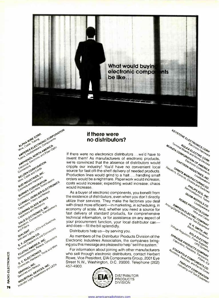
e
(
s
<
ne
PYPGPea`GGoPGPP
cPe"ePe,°J:µ:PGet,°:P
P e<eGaO\e
9°:QtóN0eO°°`a°
deeoQc
`pt
ppGOPQOS `<eea°d 0JGaQJ-:a
OP y°Ga `PePe:. P°sGS. Ga.Oeeá
x
GeaAePae GaQade°
oQS
GOP*GG
PS
POeeds`o<sGGPOO<S,
aeeo,s GaQa`°<Sadesga
O;¿
OSadSre
Ú
-(<`F
.eO<Gaa6Ga°G<O.aaGGoeeec>O<s
FJP0PGP
G°eeec\OòP>G"
6 e`c°aPJPas G EG,°°\saeade
Gre<Gaa4+e. ),a éa`Is G ,Gs
GPPyesaeaPJGe
esaed
6i\cn AP\,Ose<e
ag\9r \ed,°
Ó S
78
What would buyirt electronic comp. be like...
if there were no distributors?
If there were no electronics distributors ... we'd have to invent them! As manufacturers of electronic products, we're convinced that the absence of distributors would cripple our industry! You'd have no convenient local source for fast off -the -shelf delivery of needed products. Production lines would grind to a halt.... handling small orders would be a nightmare. Paperwork would increase; costs would increase; expediting would increase; chaos would increase.
As a buyer of electronic components, you benefit from the existence of distributors, even when you don't directly utilize their services. They make the factories you deal with direct more efficient-in marketing, in scheduling, in economy of scale. And, whether you need a source for fast delivery of standard products, for comprehensive technical information, or for assistance on any aspect of your procurement function, your local distributor can- and does-fill the bill splendidly.
Distributors help us-by serving you.
As members of the Distributor Products Division of the Electronic Industries Association, the companies bring- ing you this message are pleased to help "sell the system."
For information about joining with other manufacturers who sell through electronic distributors, contact Herbert Rowe, Vice President, EIA Components Group, 2001 Eye Street N.W., Washington, D.C. 20006. Telephone (202) 457-4900.
DISTRIBUTOR PRODUCTS DIVISION
www.americanradiohistory.com
RF GENERATOR continued front pu,,e 69
wire to the RI- OUTPUT jack, and advance the LEVEL control. Tune in the signal on your receiver carefully. Adjust the pot on the control board for a clean -sound- ing tone, then turn the pot until the tone sounds rough. Back off the adjustment so that the tone sounds clean again. That completes the modulation adjustment.
The last step is to adjust for the best frequency calibration. You can either use a counter for that, or station WWV at 10 MHz. Here's how to do it:
Put the MODULATION switch in the cw position, and the RANGE switch to HI.
Then set the FREQUENCY switches to "10.00." Connect a piece of wire to the RF OUTPUT jack for an antenna if you are using a receiver for calibration; other- wise, connect a frequency counter to the jack.
If you are using a receiver for calibra- tion, tune in WWV at 10 MHz. Advance the LEVEL control on the RF generator until you can just hear its carrier beating against WWV's 10 -MHz signal. Then adjust the trimmer on the control board for the lowest -pitched beat note. There may be a slight warble in the project's carrier; that is a normal characteristic of synthesized RF -generators, and some
care will be required to find zero beat. If you are using a counter, simply ad-
just the trimmer on the control board until you read 10.000 MHz.
Using the Programma 2
Using this RF generator is a snap be- cause there are so few controls. A few comments on the key controls, though, are in order.
Remember that the range of the FRE-
QUENCY SET switches is "03.00" to "30.00" (MHz). If you exceed those limits, the ERROR lamp will come onto remind you that the frequency is wrong.
The RANGE switch selects direct, or divided -by -10. output frequencies. Use the HI position for outputs of 3 to 30 MHz, and LO for 300 KHz to 3 MHz. Typically, the HI position will be used for RF -stage and mixer -alignment of re- ceivers, while the LO range will be used for IF alignment.
The ERROR lamp serves as a visual reminder that the output frequency is
not the same as that indicated by the FREQUENCY SET switches. In normal op- eration, it should blink once when the frequency is changed. If a value is selected outside the range of the FRE-
QUENCY SET switches, it will stay lit, alerting you to your mistake.
To use the Programma 2, simply se- lect the desired frequency and range.
Then adjust the LEVEL control as neces- sary. If you are working on a receiver, tune in the signal on the receiver first; then adjust the LEVEL control as required.
If you must work with low-level sig- nals, insert a 50 -ohm attenuator at the RF
OUTPUT jack and then set the attenuator for the desired output level. That may not always be necessary, as the RF out- put of this project with a 50 -ohm load ranges from 10 mV to 300 mV. R -E
FE -$911
A Holiday Thought
Reminding you that USO is there holidays...and every day for our young servicemen and women. USO: "A HOME AWAY FROM HOME" for 40 years.
Judd Hirsch
SuDDohl USO through rho UnI1eC Wey. OCFC. Or local USO Camp.ipn
i
I Ew.t,"' rm.," t7
BIM SPECIAL THIS MONTH
SALE PRICE GOOD UNTIL
12/30/81
Electronics Paperback Books illIBM Mali IMO MOB MBE IMZ
Quality Paperbacks at Affordable Prices'
HOUSENO` be Roed around
$4.50
Dyne
EECtFtONt acts that caa11. Regular price
UnusuallProlects in
25 different This month ONLY $4.00
NTFt0t. FOft ebe 4í4e s. including
Regular price $4.50
WOO r introductionction projects. Reg
Pümber °On This month ONLY $4.00
COUNTER DPcaR sU
DISPLAY pO
Features,
1iadPnélects using a variety
of
numeral d splays
Regular $4.50
This month ONLY $4.00
gust
to
reading the
who Want
activate
REMCOSIROt-PROJET
hls creations at a stance.
Regular price $4.75
This month ONLY $4.50
CIS generators., and
`ECtRONtC., ene a effects, sound gpner $4.50
E tar effects.,e all described. ass
To order from this ad: Check off the books you want. Total the prices Add in shipping. NY State residents add Sales Tax. Total it up, enclose
your check and mail. 28 Tested Transistor Projects $3.50 Single IC Projects $3.95 Digital IC Projects $4.95 Electronic Test Equipment Construction $4.50 1st Book of Hi Fi Loudspeaker Enclosures $3.25
50 Circuits Using Germanium Silicon and Zener Diodes $3.50 Practical Computer Experiments $4.75 50 CMOS IC Projects $3.50 Digital IC Equivalents and Pin Connections $7.50 Linear IC Equivalents and Pin Connections $7.50 Popular Electronic Circuits, Book 1 $4.95 Power Supply Projects $4.95 Popular Electronic Projects $3.50 Electronic Music and Creative Tape Recording $3.50
50 LED Circuit Book 1 $3.50 50 LED Circuits, Book 2 $3.50
U Electronic Games $4.50
ELECTRONIC TECHNOLOGY TODAY INC.
P.O. Box 83, Massapequa Park, NY 11762-0083
Price of Books
Sales Tax (NY State Residents only)
Shipping and Handling (60c 1 or 2 books. 25e each addl.)
TOTAL # OF BOOKS n Name
Address Guy
ones This month ONLY $4 00 City State Zip
mom sum mum mote ma am ma ma am um mom
TOTAL
www.americanradiohistory.com
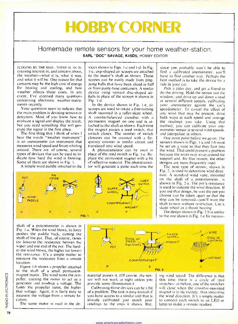
Homemade remote sensors for your home weather -station. EARL "DOC" SAVAGE, K4SDS, HOBBY EDITOR
JUDGING BY THE MAIL. THERE IS AN IN -
creasing interest in, and concern about, the weather-what it is, what it was, and what it will be. One reason for that concern may be the high cost of energy for heating and cooling, and how weather effects those costs. In any event, I've received many questions concerning electronic weather -instru- ments recently.
Your questions seem to indicate that the main problem is devising sensors or detectors. Most of you know how to evaluate a signal and display the result. but you need something that will gen- erate the signal in the first place.
The first thing that I think of when 1
hear the words "weather instrument" is an anemometer (an instrument that measures wind speed and force) whirling around. There are, of course, several types of devices that can be used to in- dicate how hard the wind is blowing. Some of them are shown in Fig. 1.
A simple wind paddle attached to the
vices shown in Figs. 1-c and I -d. In Fig. I -c, cup -shaped air scoops are attached to the motor's shaft as shown. Those scopes can be easily made from ping- pong balls that have been sliced in half or from panty -hose containers. A similar device using vertical disc -shaped air- foils in place of the scoops is shown in Fig. 1-d.
In the device shown in Fig. I -e, air scoops are used to rotate a free -turning shaft mounted in a roller-skate wheel. A counterbalanced crossbar with a permanent magnet on one end is at- tached to the shaft as shown. Each time the magnet passes a reed switch, that switch closes. The number of switch closures can be counted with a fre- quency counter or similar circuit and translated into wind speed.
A phototransistor can be used in place of the reed switch in Fig. I -e. Re- place the permanent magnet with a bit of reflective material. The phototransis- tor will generate a pulse each time the
POT
WIND PADDLE
a
PM MOTOR
6
FIG. t
SKATE WHEEL
COUNTERWEIGHT
MAGNET d e
REED 5W ITC H
shaft of a potentiometer is shown in Fig. I -a. When the wind blows, its force pushes the paddle back, turning the shaft of the pot. That, of course, raises (or lowers) the resistance betwen the wiper and one end of the pot. The hard- er the wind blows, the higher (or lower) the resistance. It's a simple matter to measure the resistance from a remote location.
Figure I -b shows a propeller attached to the shaft of a small permanent - magnet motor. The wind turns the pro- peller, causing the motor to act as a generator and produce a voltage. The faster the propeller turns, the higher that voltage. Again, it is fairly easy to measure the voltage from a remote lo- cation.
The same motor is used in the de -
since you probably won't be able to find a calibrated anemometer, you'll have to find another way. Perhaps the best method is to take the device for a ride in your car.
Pick a calm day, and get a friend to do the driving. Hold the sensor out the window, and drive up and down a road at several different speeds, calibrating your anemometer against the car's speedometer. To cancel the effect of any wind that may be present, drive both ways at each speed and average the readings you take. Using that method, you can calibrate your ane- mometer sensor at several wind speeds, and interpolate at others.
One more point before we go on. The sensors shown in Figs. 1-a and I -h must be set on a vane so that they face into the wind. That could present a problem because the wires may wrap around the support and, for that reason, the other designs are more frequently used.
The next type of sensor, shown in Fig. 2, is used to determine wind direc- tion. A standard wind vane, mounted on the shaft of a potentiometer, is shown in Fig. 2-a. The pot's resistance is used to indicate the wind direction. If you use that design, be sure the pot you choose can be taken apart so that the stop can be removed-you'll want the shaft to turn without restriction. Use a skate wheel as a thrust bearing.
The design shown in Fig. 2-b is similar to the one shown in Fig. I -e for measur-
a
POT
RI NC, OF REED SWITCHES
COUNTERWEIGHT
b FIG. 2
S KATE WHEEL
MAGNET
WIRE
RING OF CONTAcT3
Vi WEIGHT
material passes it. (Of course, the sen- sor will not work at night unless you provide some illumination.)
Calibrating those devices can be a bit of a problem. The task is easy enough if you have access to a similar unit that is already calibrated just match your readings to the ones it shows. But,
ing wind speed. The difference is that this time there is a circle of reed switches; as before, one of the switches will close when the crossbar -mounted magnet is in its vicinity, thus indicating the wind direction. It's a simple matter to connect each switch to an LED or lamp to make a remote readout.
www.americanradiohistory.com

You're on the spot. Any set you tell your customer about has a chance of failing sometime.
But though we're not saying we're perfect, we'd like you to recommend RCA. Because we're sure your customer will love its picture performance.
You can find the problem and repair it quickly if anything does go wrong. Because with RCA's unitized chassis, failures are easy to handle.
"You fix TV's...
what brand should
t!! RCA gives frequent
hands-on workshops, as well as lectures. So when failures do occur, you'll be ready.
RCA has more than 500 parts distributors nationwide. We have this large network because we don't want you to have to wait too long for parts.
We also keep your inventory expenses lower by using components instead of modules, in most circuits.
1 99 We know your
customers think you're responsible for everything
about their sets. Good and bad. And that's why we here
at RCA are doing everything possible to make sure that when you finish a service call, everybody's smiling. Your customer's happy with your recommendation. And you're still the expert.
RC,' RCA IS MAKING TELEVISION BETTER AND BETTER.
For your free subscription to RCA COM- MUNICATOR, our magazine of news and advice for service technicians, write RCA, Dept. 1-455, 600 North Sherman Drive, Indianapolis, IN 46201:
www.americanradiohistory.com
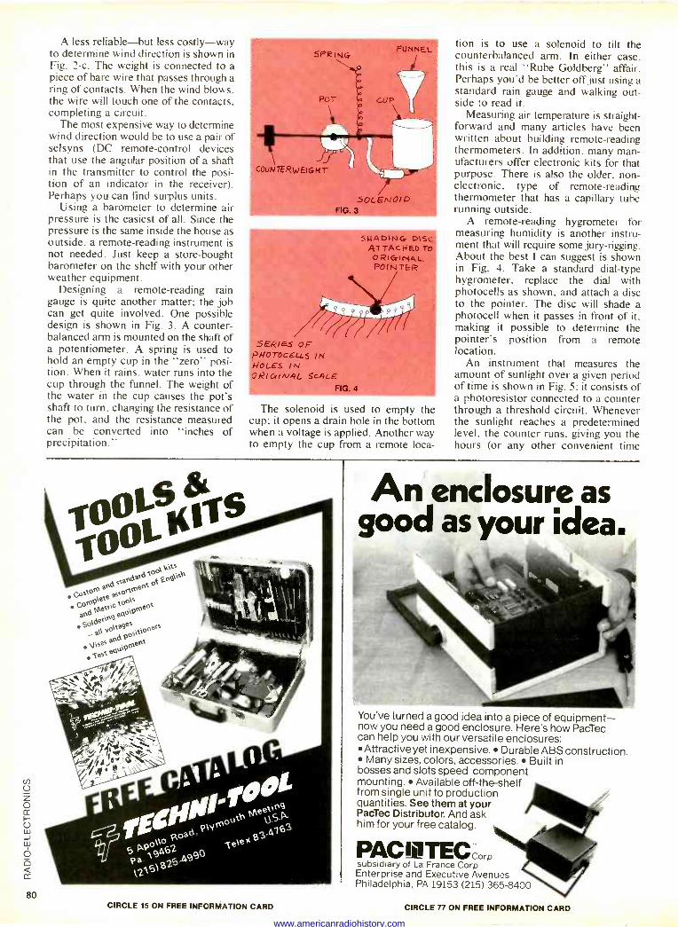
A less reliable-but less costly-way to determine wind direction is shown in Fig. 2-c. The weight is connected to a piece of bare wire that passes through a ring of contacts. When the wind blows, the wire will touch one of the contacts, completing a circuit.
The most expensive way to determine wind direction would be to use a pair of selsyns (DC remote -control devices that use the angular position of a shaft in the transmitter to control the posi- tion of an indicator in the receiver). Perhaps you can find surplus units.
Using a barometer to determine air pressure is the easiest of all. Since the pressure is the same inside the house as outside, a remote -reading instrument is not needed. Just keep a store-bought barometer on the shelf with your other weather equipment.
Designing a remote -reading rain gauge is quite another matter; the job can get quite involved. One possible design is shown in Fig. 3. A counter- balanced arm is mounted on the shaft of a potentiometer. A spring is used to hold an empty cup in the "zero" posi- tion. When it rains, water runs into the cup through the funnel. The weight of the water in the cup causes the pot's shaft to turn, chaRging the resistance of the pot, and the resistance measured can be converted into "inches of precipitation."
SNADING DISC' ATTAINED OR%GiN POINTE
5ER1ES Oh PNOTocEtLs IN 1-loLEs in" 0 IG/N44. Sc./34E
FIG. 4
The solenoid is used to empty the cup; it opens a drain hole in the bottom when a voltage is applied. Another way to empty the cup from a remote loca-
tion is to use a solenoid to tilt the counterbalanced arm. In either case, this is a real "Rube Goldberg" affair. Perhaps you'd be better off just using a standard rain gauge and walking out- side to read it.
Measuring air temperature is straight- forward and many articles have been written about building remote -reading thermometers. In addition, many man- ufacturers offer electronic kits for that purpose. There is also the older, non- electronic, type of remote -reading thermometer that has a capillary tube running outside.
A remote -reading hygrometer for measuring humidity is another instru- ment that will require some jury-rigging. About the best I can suggest is shown in Fig. 4. Take a standard dial -type hygrometer, replace the dial with photocells as shown, and attach a disc to the pointer. The disc will shade a photocell when it passes in front of it, making it possible to determine the pointer's position from a remote location.
An instrument that measures the amount of sunlight over a given period of time is shown in Fig. 5; it consists of a photoresistor connected to a counter through a threshold circuit. Whenever the sunlight reaches a predetermined level, the counter runs, giving you the hours (or any other convenient time
An enclosure as good as your idea.
You've turned a good idea into a piece of equipment- now you need a good enclosure. Here's how PacTec can help you with our versatile enclosures:
Attractiveyet inexpensive. Durable ABS construction. Many sizes, colors, accessories. Built in
bosses and slots speed component mounting. Available off -the -shelf from single unit to production quantities. See them at your PacTec Distributor. And ask him for your free catalog.
PACWTECcorp.
subsidiary of La France Corp. Enterprise and Executive Avenues Philadelphia, PA 19153 (215) 365-8400
CIRCLE 15 ON FREE INFORMATION CARD CIRCLE 77 ON FREE INFORMATION CARD
www.americanradiohistory.com
unit) of sunshine since the last time the counter was reset. For accurate mea- surements, be sure to keep the photo - resistor clean.
FIG. 5
That should keep you meterologists busy for a while. If you come up with any other ideas, or improvements on the ones presented here, let me know and I'll pass them along.
Electronic hobby kits The people at OK Machine and Tool
Corp. (3455 Conner St., Bronx, NY 10475) have come up with five low-cost electronics kits that I'm sure you will find quite interesting. You'll wind up with a useful device, and have an oppor- tunity to learn something about elec- tronics in the process.
The kits available are named: Quick Reaction (a game), Electronic Organ, Digital Roulette, Electronic Dice, and Morse Code Practice (an audio oscilla- tor); each one sells for less than $15.00, and comes complete with everything except batteries and tools. The plastic packages the kits come in double as cases for the projects. The instructions are detailed and clear, and even a first- time builder should have little trouble completing any of the kits.
Do you know a young person who you would like to nudge into elec- tronics? You won't find a better way than to present him (or her) with one or more of those kits. An assembled kit may be appropriate for a younger child. The roulette and dice devices can be used with other games, and seeing the internal parts is sure to arouse the child's curiosity. R -E
"Sometimes I wish you collected stamps, like other men."
Catalog Discover the newest in electronics for your home and business:
Computer hardware and software Precision test instruments Energy savers for car and home
Self -study programs in electronics Fine stereo components Color TV's and video accessories Amateur radio gear
...all in easy -to -build money -saving kits.
If coupon is missing, write Heath Co.,
Dept. 020-832 Benton Harbor,
MI 49022 In Canada, write
Heath Co., 1480 Dundas
Highway East, Mississauga, Ontario
L4X 2R7
Send today for the all -new, free Heathkit Catalog...with 104 pages describing nearly 400 exciting kits for your electronics hobby.
Please send my free Heathkit Catalog I am not currently receiving one. Send to: Heath Co., Dept.020-832
Benton Harbor, MI 49022
Name
Address
City State
CL -751 Zip J
CIRCLE 31 ON FREE INFORMATION CARD 81
www.americanradiohistory.com
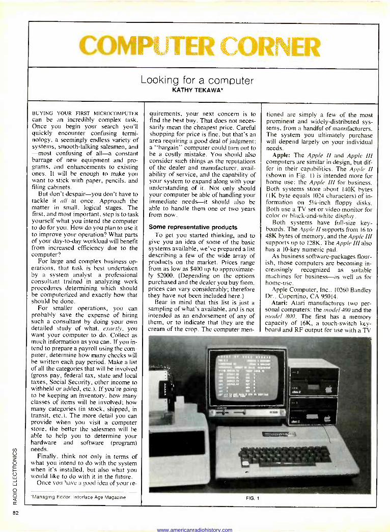
(...dflhMl..I iTIPI CORNER Looking for a computer
KATHY TEKAWA*
BUYING YOUR FIRST MICROCOMPUTER can be an incredibly complex task. Once you begin your search you'll quickly encounter confusing termi- nology, a seemingly endless variety of systems, smooth -talking salesmen, and -most confusing of all-a constant barrage of new equipment and pro- grams, and enhancements to existing ones. It will be enough to make you want to stick with paper, pencils, and filing cabinets.
But don't despair-you don't have to tackle it all at once. Approach the matter in small, logical stages. The first, and most important, step is to task yourself what you intend the computer to do for you. How do you plan to use it to improve your operation? What parts of your day-to-day workload will benefit from increased efficiency due to the computer?
For large and complex business op- erations, that task is best undertaken by a system analyst-a professional consultant trained in analyzing work procedures determining which should be computerized and exactly how that should be done.
For smaller operations, you can probably save the expense of hiring such a consultant by doing your own detailed study of what, exactly, you want your computer to do. Collect as much information as you can. If you in- tend to prepare a payroll using the com- puter, determine how many checks will be written each pay period. Make a list of all the categories that will be involved (gross pay, federal tax, state and local taxes, Social Security, other income to withheld or added, etc.). If you're going to be keeping an inventory, how many classes of items will be involved; how many categories (in stock, shipped, in transit, etc.). The more detail you can provide when you visit a computer store, the better the salesmen will be able to help you to determine your hardware and software (program) needs.
Finally, think not only in terms of what you intend to do with the system when it's installed, but also what you would like to do with it in the future.
Once you have a good idea of your re -
'Managing Editor. Interlace Age Magazine
quirements, your next concern is to find the best buy. That does not neces- sarily mean the cheapest price. Careful shopping for price is fine, but that's an area requiring a good deal of judgment: a "bargain" computer could turn out to be a costly mistake. You should also consider such things as the reputations of the dealer and manufacturer, avail- ability of service, and the capability of your system to expand along with your understanding of it. Not only should your computer be able of handling your immediate needs-it should also be able to handle them one or two years from now.
Some representative products To get you started thinking, and to
give you an idea of some of the basic systems available, we've prepared a list describing a few of the wide array of products on the market. Prices range from as low as $400 up to approximate- ly $2000. (Depending on the options purchased and the dealer you buy from, prices can vary considerably; therefore they have not been included here.)
Bear in mind that this list is just a sampling of what's available, and is not intended as an endorsement of any of them, or to indicate that they are the cream of the crop. The computer men -
FIG. 1
tioned are simply a few of the most prominent and widely -distributed sys- tems, from a handful of manufacturers. The system you ultimately purchase will depend largely on your individual needs.
Apple: The Apple II and Apple III computers are similar in design, but dif- fer in their capabilities. The Apple II (shown in Fig. 1) is intended more for home use: the Apple III for business. Both systems store about 140K bytes (1 K byte equals 1024 characters) of in- formation on 51/4 -inch floppy disks. Both use a TV set or video monitor for color or black -and -white display.
Both systems have full-size key- boards. The Apple II supports from 16 to 48K bytes of memory, and the Apple III supports up to 128K. The Apple III also has a 10 -key numeric pad.
As business software -packages flour- ish, those computers are becoming in- creasingly recognized as suitable machines for business-as well as for home -use.
Apple Computer, Inc., 10260 Bandley Dr., Cupertino, CA 95014.
Atari: Atari manufactures two per- sonal computers: the model 400 and the model 800. The first has a memory capacity of 16K, a touch -switch key- board and RF output for use with a TV
www.americanradiohistory.com
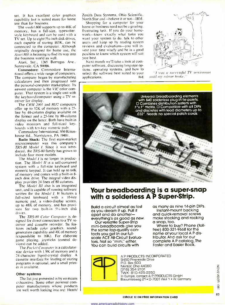
set. It has excellent color graphics capability but is suited more for home use than for business.
The model 800 supports up to 48K of memory, has a full-size, typewriter - style keyboard and can be used with a TV set. Up to eight 51/4 -inch disk drives, each capable of storing 163K, can be connected to the computer. Although originally designed for home use, the Atari 800 is beinning to find its way into the business world as well.
Atari, Inc., 1265 Borregas Ave., Sunnyvale, CA 94086.
Commodore: Commodore Interna- tional offers a wide range of computers. The company began by manufacturing calculators and then progressed into the personal -computer marketplace. Its newest computer is the VIC color com- puter. That system is a single unit with the keyboard/computer using a TV re- ceiver for display.
The CBM 2001 and 8032 computers offer up to 32K of memory with a 25 - line by 40 -column display available on the former and a 25 -line by 80 -column display on the latter. Both have built-in video monitors and full-sized key- boards with ten -key numeric pads.
Commodore International, 950 Ritten- house Rd., Norristown, PA 19401.
Radio Shack: The first mass -market microcomputer was this company's TRS-80 Model I. Since it was intro- duced, the TRS-80 family has grown to include four more models.
The Model I is no longer in produc- tion. The Model II is a self-contained system with a full-size keyboard and numeric keypad. It can hold up to 64K of memory and comes with a built-in 8 -
inch disk drive. The integral video dis- play provides 24 lines of 80 columns.
The Model III also is an integrated unit, and is capable of running software written for the Model I. It features a full-sized keyboard with a 10 -key numeric pad, a video -display screen, up to 48K of memory, and has provi- sion for two built-in 51/4 -inch disk drives.
The TRS-80 Color Computer is de- signed for direct connection to a TV re- ceiver and cassette recorder. Its fea- tures include color graphics, sound - generation capability and 4K of memory (expandable to 16K). For elaborate game playing, joysticks (control de- vices) can be added.
The Pocket Computer is a calculator - size device with I.9K of memory and a 24 -character liquid -crystal display. A
cassette interface for loading or storing programs is optional, and a small print- er is available.
Other systems The list just presented is by no means
exhaustive. Some other personal com- puter manufacturers whose products are well worth looking into are: Heath/
Zenith Data Systems, Ohio Scientific, North Star and-believe it or not-IBM.
Shopping for a computer for your home or business need not be a grueling, frustrating task. If you do your home- work-know exactly what tasks you want your system to do, talk to other users and keep up by reading system reviews and evaluations-you will in- vest your time wisely and be in a good position to know which system will suit you best.
Next month we'll take a look at com- puter software, discussing language op- tions, operating systems, and how to select the software best suited to your applications. R -E
"I was a successful TV serviceman until my mirror broke."
Universal breadboarding elements with 840 solderless plug-in tie points.
D Combines distribution system with .1"x.1" matrix. O Compatible with all DIPs and discretes with lead diameters up to .032". Needs no special patch cords.
Your breadboarding is a super -snap with a solderless A P Super -Strip.
Build a circuit almost as fast as you dream it up. Pull it apart and do another- everything's as good as new.
Our versatile Super -Strip mini -breadboards give you the same top-quality con- tacts you get in our full- scale ACE All -Circuit Evalua- tors. Not so "mini," either. You can build circuits with
as many as nine 14 -pin DIPs. Instant -mount backing
and quick -removal screws make stacking and racking a snap, too.
Where to buy? Phone (toll - free) 800-321-9668 for the name of your local A P dis- tributor. And ask for our complete A P catalog, The Faster and Easier Book.
A P PRODUCTS INCORPORATED 9450 Pineneedle Drive P.O. Box 603 Mentor, Ohio 44060 [216) 354-2101 TWX: 810-425-2250 In Europe, contact A P PRODUCTS GmbH Baeumlesweg 21 D-7031 Weil 1 W. Germany
CIRCLE 12 ON FREE INFORMATION CARD
www.americanradiohistory.com
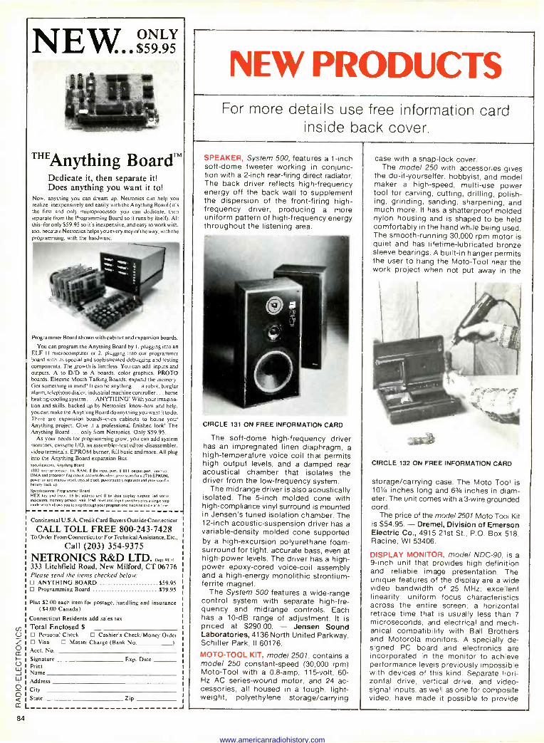
NE W... $59 95
"'Anything BoardTM Dedicate it, then separate it! Does anything you want it to!
Now, anything you can dream up. Netronics can help you realize -inexpensively and easily with the Anything Board (it's the first and only microprocessor you can dedicate, then separate from the Programming Board so it runs by itself). All this -for only $59.95 so it's inexpensive, and easy to work with, too, because Netronics helps you every step of the way, with the programming, with the hardware.
Programmer Board shown with cabinet and expansion boards.
You can program the Anything Board by I. plugging into an ELF I1 microcomputer or 2. plugging into our programmer board with its special and sophisticated debugging and testing components. The growth is limitless. You can add inputs and outputs, A to D/D to A boards, color graphics, PROTO boards, Electric Mouth Talking Boards, expand the memory. Got something in mind' It can be anything... a robot, burglar alarm, telephone dialer, industrial machine controller... home heating/cooling system ... ANYTHING! With your imagina- tion and skills, backed up by Netronics' know-how and help, you can make the Anything Board do anything you want it to do. There are expansion boards -even cabinets to house your Anything project. Give it a professional finished look! The Anything Board ... only from Netronics. Only $59.95.
As your needs for programming grow, you can add system monitors, cassette I/O, an assembler -text editor-disassembler, video terminals, EPROM burner, full basic and more. All plug into the Anything Board expansion Bus. Specification. Anything Board 1802 microprocessor, I K RAM, 8 Bit input pun. 8 BIT output port, interrupt. DMA and processor Bag inputs, address decoders, provisions fora 2716 EPROM. power cn and manual reset, crystal clock. power supply regulator and provision for battery beck up.
Specifications. Programmer Board HEX key pad input. 16 bit address and 8 bit data display outputs, led status indicators memory protect, wait, load, reset and input switches plus single step oxide which allows you to step through your program one machine cycle at a time.
Continental U. S.A. Credit Card Buyers Outside Connecticut
CALL TOLL FREE 800-243-7428 To Order From Connecticut or For Technical Assistance, Etc.,
Call (203) 354-9375 NETRONICS R&D LTD. nept. RED
333 Litchfield Road, New Milford, CT 06776 Please send the items checked below:
ANYTHING BOARD $59.95 D Programming Board $79.95
Plus $2.00 each item for postage, handling and insurance ($4.00 Canada)
Connecticut Residents add sales tax
to Total Enclosed $ U Personal Check 13Cashier's Check/Money Order Z Visa D Master Charge (Bank No.
Acct No. CC H Signature Exp. Date
Print J Name L1J Address
City State Zip
L
84
J
NEW PRODUCTS For more details use free information card
inside back cover.
SPEAKER, System 500, features a 1 -inch soft -dome tweeter working in conjunc- tion with a 2 -inch rear -firing direct radiator. The back driver reflects high -frequency energy off the back wall to supplement the dispersion of the front -firing high - frequency driver, producing a more uniform pattern of high -frequency energy throughout the listening area.
CIRCLE 131 ON FREE INFORMATION CARD
The soft -dome high -frequency driver has an impregnated linen diaphragm, a high -temperature voice coil that permits high output levels, and a damped rear acoustical chamber that isolates the driver from the low -frequency system.
The midrange driver is also acoustically isolated. The 5 -inch molded cone with high -compliance vinyl surround is mounted in Jensen's tuned isolation chamber. The 12 -inch acoustic -suspension driver has a variable -density molded cone supported by a high -excursion polyurethane foam - surround for tight, accurate bass, even at high -power levels. The driver has a high - power epoxy -cored voice -coil assembly and a high-energy monolithic strontium - ferrite magnet.
The System 500 features a wide -range control system with separate high -fre- quency and midrange controls. Each has a 10 -dB range of adjustment. It is priced at $290.00. - Jensen Sound Laboratories, 4136 North United Parkway, Schiller Park, II 60176.
MOTO -TOOL KIT, model 2501, contains a model 250 constant -speed (30,000 rpm) Moto -Tool with a 0.8 -amp, 115 -volt, 60 - Hz AC series -wound motor, and 24 ac- cessories, all housed in a tough, light- weight, polyethylene storage/carrying
case with a snap -lock cover. The model 250 with accessories gives
the do-it-yourselfer, hobbyist, and model maker a high-speed, multi -use power tool for carving, cutting, drilling, polish- ing, grinding, sanding, sharpening, and much more. It has a shatterproof molded nylon housing and is shaped to be held comfortably in the hand while being used. The smooth -running 30,000 rpm motor is quiet and has lifetime -lubricated bronze sleeve bearings. A built-in hanger permits the user to hang the Moto -Tool near the work project when not put away in the
CIRCLE 132 ON FREE INFORMATION CARD
storage/carrying case. The Moto Tool is 101/4 inches long and 63/4 inches in diam- eter. The unit comes with a 3 -wire grounded cord.
The price of the model 2501 Moto -Tool Kit is $54.95. - Dremel, Division of Emerson Electric Co., 4915 21st St., P.O. Box 518, Racine, WI 53406.
DISPLAY MONITOR, model NDC-90, is a 9 -inch unit that provides high definition and reliable image presentation. The unique features of the display are a wide video bandwidth of 25 MHz; excellent linearity; uniform focus characteristics across the entire screen; a horizontal retrace time that is usually less than 7 microseconds, and electrical and mech- anical compatibility with Ball Brothers and Motorola monitors. A specially de- signed PC board and electronics are incorporated in the monitor to achieve performance levels previously impossible with devices of this kind. Separate hori- zontal drive, vertical drive, and video - signal inputs. as well as one for composite video, have made it possible to provide
www.americanradiohistory.com
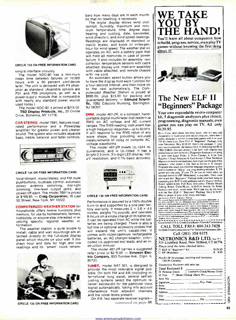
CIRCLE 133 ON FREE INFORMATION CARD
simple interface circuitry. The model NDC-90 has a minimum
mean time between failures of 10,000 hours with a 90 percent confidence level. The unit is delivered with P4 phos- phor as standard. (Available options are P31 and P39 phosphors, as well as a
power -supply module that is compatible with nearly any standard power source used today.)
The model NDC-90 is priced at $215.00. - TSD Display Products, Inc., 35 Orville Drive, Bohemia, NY 11716.
CAR STEREO, model T691, features road - rated performance and a Powerplay amplifier for greater power and cleaner sound. The system also includes separate bass, treble, balance, and fader controls:
CIRCLE 134 ON FREE INFORMATION CARD
local/distant, mono/stereo, and FM mute pushbuttons; loudness control; automatic power antenna switching; dial -light dimming; line -level output jacks, and power -off eject. The model T691 is priced at $169.95. - Craig Corporation, 16 East 52 Street, New York, NY 10022.
COMPUTERIZED WEATHER STATION for households offers twelve functions plus memory, for use by homeowners, farmers, hobbyists, or anyone else interested in re- ceiving specific regional weather in- formation.
The weather station is quite simple to install; cable and wall mountings are at- tached directly to the full-sized display panel which mounts on your wall. It dis- plays hour and date for high and low readings and its "smart" clock remem-
CIRCLE 135 ON FREE INFORMATION CARD
bers how many days are in each month, so that no resetting is necessary.
The digital display shows wind chill, rainfall, humidity, maximum and mini- mum temperature, time, degree days, heating and cooling, date, barometer, wind direction, and wind -speed readings. Readings are displayed in standard or metric scales, and knots or miles -per - hour for wind speed. The weather station operates on AC, with a battery pack that will hold all memories in case of power failure. It also includes for assembly: rain collector, temperature sensors with cable attached, display unit, mast -arm assembly with cable attached, and remote chassis with line cord.
An automatic select button allows you to have the display hold each function for a four -second interval, and then move on to the next automatically. The Com- puterized Weather Station is priced at $995.00, plus $15.00 for packing and guaranteed delivery. - Edmund Scienti- fic, 7082 Edscorp Building, Barrington, NJ 08007.
DMM, model 461-2R, is a compact, hand - portable digital multimeter that reads true RMS on AC voltage and AC current ranges. The RMS-reading instrument has a high frequency -response --up to 50 kHz. It will respond to the RMS value of any wave shape, thus providing accurate measurements of noisy or complex AC - voltage waveforms.
The model 461-2R meets UL -1244 re- quirements, and is UL -listed. It has a
bright 0.3 -inch, 31/2 -digit LED display. 100- 0V resolution, and 0.1% basic accuracy.
CIRCLE 136 ON FREE INFORMATION CARD
Performance is assured by a 100% double burn -in and supported by a one-year fac- tory warranty. It measures 2 x 5.6 x 4.6 inches, weighs 11/2 pounds, and operates 8 -hours on a single charge of its batteries. It can be operated from AC while the bat- teries are being charged. There is also a
full line of optional accessory probes that will expand the unit's capabilities. It
comes with nickel -cadmium rechargeable batteries, an AC charger/adaptor, color - coded UL -approved test leads, and an in-
struction manual. The model 461-2R carries a suggested
retail price of $216.00. - Simpson Elec- tric Company, 853 Dundee Ave., Elgin, IL
60120.
TUNER, model NAT 301, is designed to provide the most listenable signal pos- sible. On both FM and AM (including in- ternational long wave), several self-ad- justing systems select the optimum re- ceiver bandwidth for the particular input signal automatically, taking into account interference from adjacent channels and the noise levels present.
On AM, two separate receiver signals- continued can page 88
WE TAKE YOU BY THE HAND! You'll learn all about computers: how to build, program, service, even play TV games-without knowing the first thing about it!
The New ELF II "Beginners" Package Your own expandable micro -computer kit, 5 diagnostic analyzers plus circuit, programming, diagnostic manuals, even games you can play on TV. All only $139.95. Even if you don't know bits from bytes, now it's easy and
inexpensive to build your own micro -computer, learn how it works, program it, service it-even play games with it on your TV. It's here in the New ELF II "Beginners" Package, only from Netronics. Only $139.95. Here's the package: I. your own micro -computer, the famous ELF II (featuring the RCA 1802 CMOS microprocessor) in kit form with step-by-step instructions on how to build it. Diagnostic Analysers including 2. your own Logic Probe, 3. Pulse Catcher, 4. 8 bit Test
Registor, 5. Logic Analyzer, 6. Gate Arrays, 7. Non -Technical Manuals on how to use analyzers, how to get into the guts of the
computer, what makes it tick, how to service it. 8. Sample Programs that teach you machine language programming plus
how to correct or "debug" any programming mistakes. 9. TV games you can play. If your TV set has no video input, an
optional converter (RF Modulator), is available. Then, once
you've got this "Beginners" Package under your belt, keep on
expanding your ELF II with additions like the Typewriter Key Board, added RAM, Full Basic Interpreter, Electric Mouth Talking Board, Color/Music, A/D-D/A Boards for Robot Controls and much, much more. We'll take you by the hand
with the New ELF 11 "Beginners" Package. Only $139.95. Mail or phone in your order today and begin. Specifications: ELF 11 "Beginners" Package
The computer features an RCA CMOS 18028 bit microprocessor addressable to
64K bytes with DMA. interrupt, 18 Registers, ALU, 256 byte RAM expandable to
64K bytes. Professional -Hex keyboard. fully decoded sothere's no need to waste
memory with keyboard scanning circuits. buih-in power regulator. 5 slot plug-in expansion BUS (less connectors). stable crystal clock fortimiw purposesasd a
doubk-sided. dated through PC Board plus RCA 1861 video IC to display any
segment of memory on a video monitor or 1Y screen along with the logic and s uPPon
circuitry you need to learn every one niche RCA 18on upabilities. The diagnostic
analyeen aid in understanding and trouble shooting you ELF 11. as well sa other
computer and microprocessor products.
Continental U.S.A. Credit Card Buyers Outside Connecticut
CALL TOLL FREE 800-243-7428 To Order From Connecticut or For Technical Assistance, Etc.,
Call (203) 354-9375 NETRONICS R&D LTD. need RE11
333 Litchfield Road, New Milford, CT 06776 Please send the items checked below:
ELF II "Beginners" Kit $139.95 RF Modulator S 8.95
Plus $3.00 for postage, handling and insurance ($6.00 Canada)
Connecticut Residents add sales tax
Total Enclosed S Personal Check Cashier's Check/Money Order
Visa Master Charge (Bank No.
Acct. No.
Signature Exp. Date
Print Name
Address
City State Zip
L -1
85
www.americanradiohistory.com
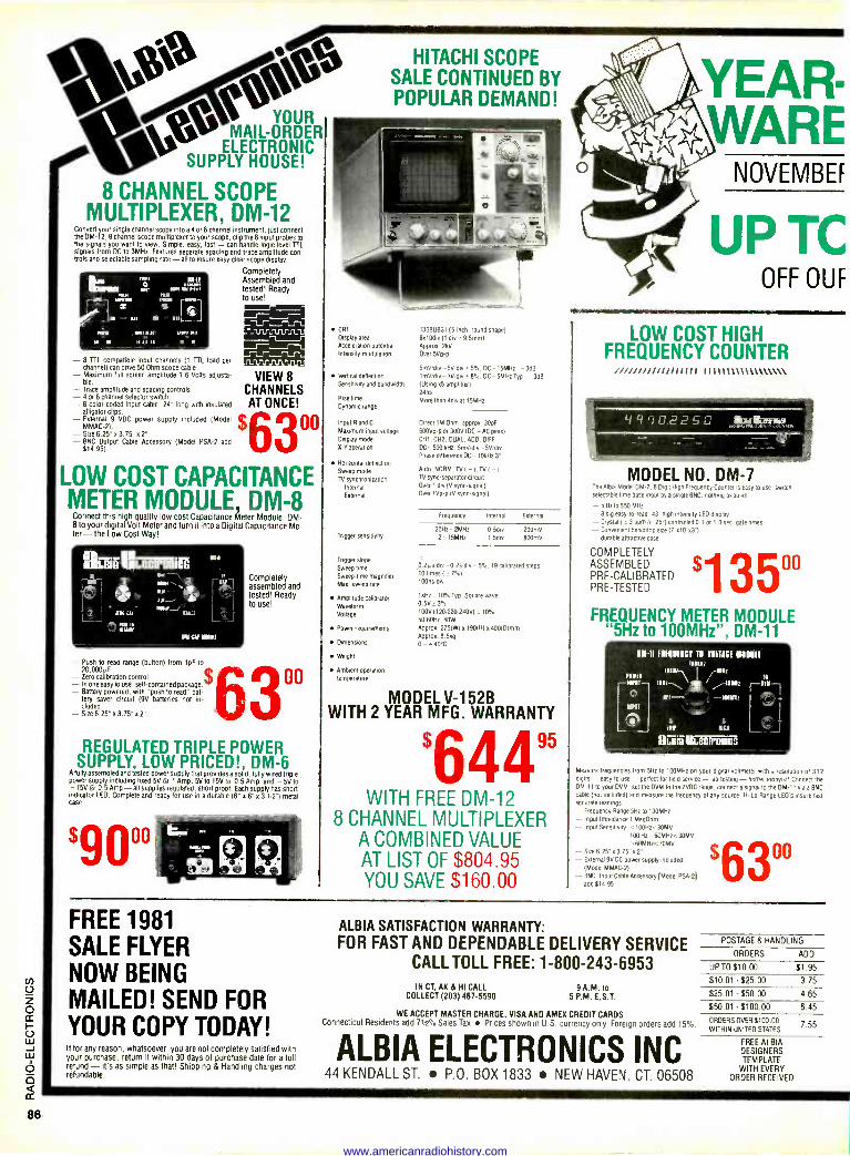
%,e,*to0 YOUR MAIL-ORDER
ELECTRONIC HOUSE! C
8 CHANNEL SCOPE MULTIPLEXER, DM -12
Convert your single channel scope into a 4 or 8 channel instrument. lust connect the DM -12, 8 channel scope multiplexer to your scope, clip the 8 input probes to the signals you want to view. Simple, easy, fast - can handle logic level TTL signals from DC to 3MHz. Features separate spacing and trace amplitude con- trols and selectable sampling rate - all to insure easy clear scope display.
- 6 TTL compatible input channels (1 TTL load per channel) can drive 50 Ohm scope cable. - Maximum full screen amplitude 1.6 Volts adjusta- VIEW 8 lira.
CHANNELS - Trace amplitude and spacing controls. - 4 or 8 channel selector switch - 8 color coded input cable. 24" long with insulated AT ONCE! alligator clips. - External 9 VDC power supply included (Model
$ MMAC-2). - Size 6.25" a 3.75" x 2". - BNC Output Cable Accessory (Model PSA-2 add 614.95).
Completely Assembled and tested! Ready to use!
00
LOW COST CAPACITANCE METER MODULE, DM -8
Connect this high quality low cost Capacitance FAeter Module. DM -
8 to your digital Volt Meter and turn it into a Digital Capacitance Me- ter- the Low Cost Way!
- Push to read range (button) from 1pF to 20,000p.F - Zero calibration control - In one easy to use, sell -contained package. - Battery powered. with "push to read" bat- tery saver circuit (9V batteries not in- cluded. - Size 6.25" e 3.75"e2".
Completely assembled and tested! Ready to use!
0
REGULATED TRIPLE POWER SUPPLY, LOW PRICED!, DM -6
A fully assembled and tested power supply that provides a solid, fully wired triple per supply including fixed 5V to 1 Amp, 5V to 15V Or 0.5 Amp, and - 5V to 5 Amp - all supplies regulated, short proof. Each supply has short
indicator LED. Complete and ready for use in a durable (8" a 6" x 3 r2") metal case.
$9000
HITACHI SCOPE SALE CONTINUED BY POPULAR DEMAND!
CRT
Display area
Acceleration potential
Intensity modulation
Vertical deflection Sensitivity and bandwidth
Rise time
Dynamic range
Input R and C
Maximum input voltage Display mode x.Voperation
Horizontal deflection Sweep mode
TV synchronization Internal
External
Trigger sensitivity
Trigger slope Sweep time
Sweep -lime magnifier Max sweep rate
Amplitude calibrator Waveform Voltage
Power requirements
Dimensions
Weight
Ambient operation temperature
130BUB31 (5 -inch, round snape) 651 Odiu (1 div =9 5mm) Approx 2kV
Over 5Vp-p
5mV div- 5V div r 5% DC-- 15MHz. - 306 1mV div - IV 6% DC 5MHz Typ -306 (Using x5 amplifier)
24ns
More than 4diu at 15MHz
Direct 1M Ohm approx 30p1
600Vp-p or 300V WC - AC peak)
CHI. CH2. DUAL ADD Off DC -500 kHz. 5mV dry 5V div Phase difference DC I DkHz 3
Auto. NORM TV (. ). TV I - I
TV sync -separator circuit Over 1 div (V sync-signah Over 1vp-p Iv sync -signal)
Frequency Internal External
20Hz 2MHz 0 5drv 200mV 2 - 15MHz t 5dw 800mV
0 2txs div- - 0 25'div - 5%. 19 calibrated steps 10 times ( n 7%)
100ns div
1 kHz _ IO% Typ. Square wave
05V_ 3%
100V (120'220.240V) . 10%
50.60Hz. 40W Approx 275(W) x 190(H) x 40010)mm Approx 8 5kg
o-- . 4o -C
MODEL V-1526 WITH 2 YEAR MFG. WARRANTY
$64495 WITH FREE DM -12
8 CHANNEL MULTIPLEXER A COMBINED VALUE AT LIST OF $804.95 YOU SAVE $160.00
P/1f1 -IIPar-,
h11er $ " J lit N1/1
LiLBpd úLt:cmEMÌCú
YEARS WARE
NOVEMBEf
UP TC OFF OUF
LOW COST HIGH FREQUENCY COUNTER
11 111111111\\\\\\\\\
MODEL NO. DM -7 The Alba Model DM -7 8 Digit High Frequency Counter is easy to use switch selectable time base input by a single 8NC. nothing to build'
- 5 Hz to 550 MHz - 8 big easy -to -read 43" nigh intensity LED display - Crystal I n 3 ppm ',i 25`1 controlled 0 1 or 1 0 sec gale times - Convenient benchtop size (7"510 x3") durable attache case
COMPLETELY ASSEMBLED PRE -CALIBRATED PRE -TESTED $1 35°° FREQUENCY METER MODULE
"5Hz to 100MHz", DM -11
sail FIEUEICt II MIüACE asisto 111691
I/lir IMet Illt IItIt M7 ill-- -111111111
Ikx VW-
ei
a
Measure frequencies from 5Hz to 100MHz on your digital voltmeter with a resolution of 312 digits - easy to use - penect for field service - lab testing - nome hobbyist' Connect the DM -11 to your DVM set the DOM to the 2VDC range connect a signal to the DM -II via a BNC cable (not included) and measure the frequency of any source Hi Lo Range LED s insure fast accurate readings - Frequency Range 5Hz to 100MHz - Input Impedance I MegOnm - Input Sensitiwry -. 100Hz.. 80MV
100 Hz - 60MHz< 30MV .60MHz. 70MV - Size 6 25' x 3 75- x 2" - External 9V DC power supply Included
(Model MMAC-21 - BNC Input Cable Accessory Model PSA-2)
add 014 95 $63°°
FREE 1981 SALE FLYER NOW BEING MAILED! SEND FOR YOUR COPY TODAY! If for any reason, whatsoever, you are not completely satisfied with your purchase, return it within 30 days of purchase date for a full refund - it's as simple as that! Shipping & Handling charges not refundable.
ALBIA SATISFACTION WARRANTY: FOR FAST AND DEPENDABLE DELIVERY SERVICE POSTAGE& HANDLING
CALL TOLL FREE: 1-800-243-6953 UPTOa 0D00s $1D95
IN CT, AK 6 HI CALL COLLECT (203) 467-5590
9 A.M. to 5 P.M. E.S.T.
WE ACCEPT MASTER CHARGE, VISA AND AMEX CREDIT CARDS Connecticut Residents add 712°ró Sales Tax Prices shown in U S currency only Foreign orders add 15°°
ALBIA ELECTRONICS INC 44 KENDALL ST. P.O. BOX 1833 NEW HAVEN, CT. 06508
$1001-$25.00 375
$25.01 - $50.00 4.65
$50 01 - $100.00 6 45
ORDERS OVER $100.00 WITHIN UNITED STATES
755
FREE ALBIA DESIGNERS TEMPLATE
WITH EVERY ORDER RECEIVED
www.americanradiohistory.com
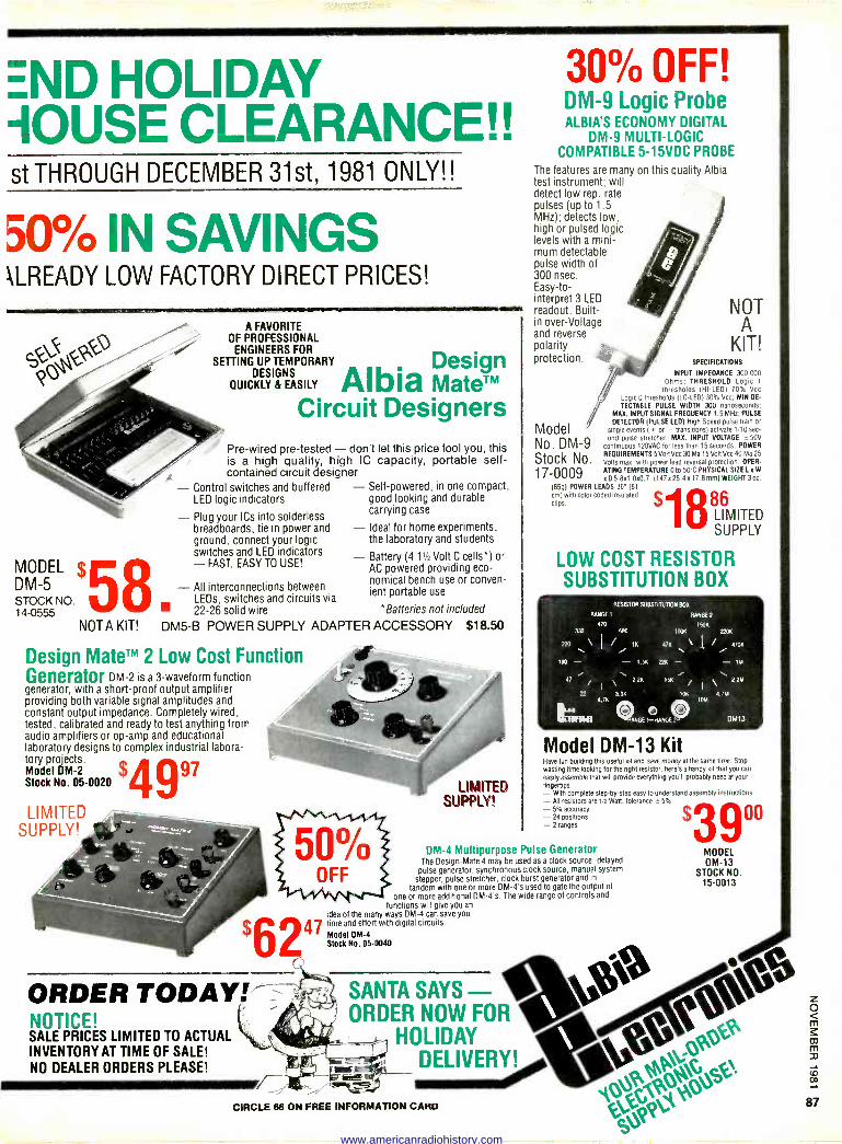
END HOLIDAY -IOUSE CLEARANCE!! st THROUGH DECEMBER 31st, 1981 ONLY!!
50% IN SAVINGS \LREADY LOW FACTORY DIRECT PRICES!
CJ QO I
MODEL $ DM -5 STOCK NO. 14-0555
NOTA KIT!
LED logic indicators - Plug your ICs into solderless breadboards, tie in power and ground, connect your logic switches and LED indicators - FAST, EASY TO USE!
- All interconnections between LEDs, switches and circuits via 22-26 solid wire
A FAVORITE OF PROFESSIONAL
ENGINEERS FOR
SETTING UP TEMPORARY Design DESIGNS
Albia MateTM QUICKLY & EASILY
Circuit Designers Pre -wired pre -tested - don't let this price fool you, this is a high quality, high IC capacity, portable self- contained circuit designer
Control switches and buffered - Self -powered, in one compact, good looking and durable carrying case - Ideal for home experiments, the laboratory and students - Battery (4 11/2 Volt C cells*) or AC powered providing eco- nomical bench use or conven- ient portable use
* Batteries not included
DM5-B POWER SUPPLY ADAPTER ACCESSORY
Design MateTM 2 Low Cost Function Generator DM -2 is a 3 -waveform function generator, with a short -proof output amplifier providing both variable signal amplitudes and constant output impedance. Completely wired, tested, calibrated and ready to test anything from audio amplifiers or op -amp and educational laboratory designs to complex industrial labora - tor el -2. Mock Stock No.o.
2 05-0020 $4997
LIMITED SUPPLY!
ORDER TODAY! NOTICE! SALE PRICES LIMITED TO ACTUAL INVENTORY AT TIME OF SALE! NO DEALER ORDERS PLEASE!
$18.50
LIMITED SUPPLY
30% OFF! DM -9 Logic Probe ALBIA'S ECONOMY DIGITAL
DM -9 MULTI -LOGIC COMPATIBLE 5-15VDC PROBE
The features are many on this quality Albia test instrument; will detect low rep. rate pulses (up to 1.5 MHz); detects low, high or pulsed logic levels with a mini- mum detectable pulse width of 300 nsec. Easy -to - interpret 3 LED readout. Built- in over -Voltage and reverse polarity protection.
Model No. DM -9 Stock No.
NOT A
KIT! SPECIFICATIONS
INPUT IMPEDANCE 300.000 Ohms. THRESHOLD Logic 1
thresholds (HI -LEO) 70% Vcc Logic 0 thresholds (LO -LEDI 30% Vcc, MIN DE-
TECTABLE PULSE WIDTH 300 nanoseconds MAX. INPUT SIGNAL FREQUENCY 1.5 MHz PULSE
DETECTOR (PULSE LED) High Speed pulse tram or
single events I - or - transitions( activate 1.10 sec- ond pulse stretcher MAX. INPUT VOLTAGE - 50V
continuous 120VAC for less than 15 seconds. POWER
REQUIREMENTS 5 Volt Vcc 30 Ma 15 Volt Vcc 40 Ma 25
Q Volts max. with power lead reversal protection. OPER-
ATIG 17 000 KD5 Bel
OZO.7"(14Ex 254 0 to
0x 178mml WEIGHT 3 Kozz
(05g) POWER LEADS 36" (61
cm) with color coded insulated flips. 86
LIMITED SUPPLY
LOW COST RESISTOR SUBSTITUTION BOX
RESISTOR SUBSTITUTION BOX
RANGE 1 RANGE
470 330 Oeo
220 \ I
K
100 - - 15K
41 y \ 22K
22 3.3K 4 7K
hr. Q6E1-1-wU1GE
150K 100K 220K
47K \ 22K \
15K
tdr
47dr
- 1M \ 2.2N
47M 101.4
DM13
Model DM -13 Kit Have fun building this useful lot and save money al the same time. Stop wasting time looking for the right resistor. here's a handy kit that you can
easily assemble that will provide everything you'll probably need at your fingertips. - With complete step-by-step easy to understand assembly instructions - All resistors are 12 Watt. tolerance o 5% - 5% accuracy - 24 positions - 2 ranges
DM -4 Multipurpose Pulse Generator The Design -Mate 4 may be used as a clock source. delayed
pulse generator, synchronous clock source. manual system stepper, pulse stretcher, clock burst generator and in
tandem with one or more DM -4's used to gate the Output of
one or more additional DM -4's. The wide range of controls and
functions will give you an idea of the many ways DM -4 can save you
47 time and effort with digital circuits.
I Model DM -4 Stock No. 05-0040
SANTA SAYS ORDER NOW FOR
HOLIDAY DELIVERY!
CIRCLE 66 ON FREE INFORMATION CARD
MODEL DM -13
STOCK NO. 15-0013
www.americanradiohistory.com
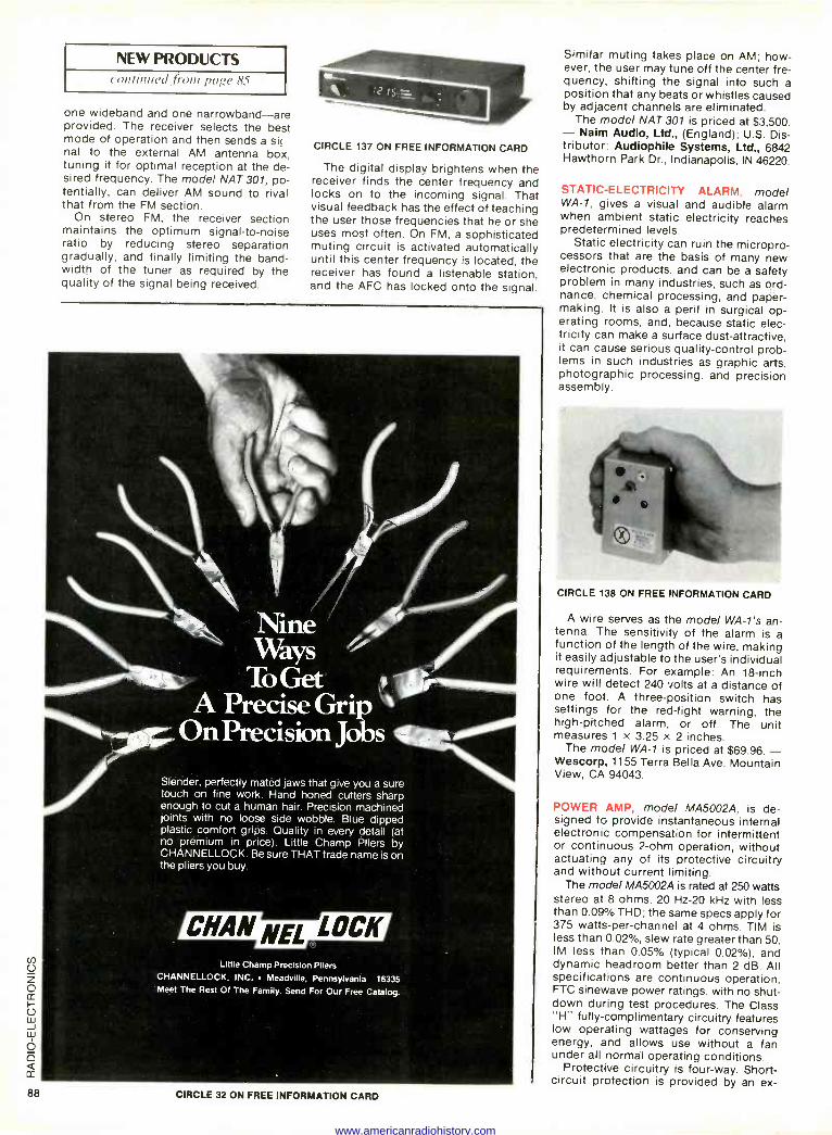
NEW PRODUCTS continued fronr pn,,e 85
one wideband and one narrowband-are provided. The receiver selects the best mode of operation and then sends a si( nal to the external AM antenna box, tuning it for optimal reception at the de- sired frequency. The model NAT 301, po- tentially, can deliver AM sound to rival that from the FM section.
On stereo FM, the receiver section maintains the optimum signal-to-noise ratio by reducing stereo separation gradually, and finally limiting the band- width of the tuner as required by the quality of the signal being received.
CIRCLE 137 ON FREE INFORMATION CARD
The digital display brightens when the receiver finds the center frequency and locks on to the incoming signal. That visual feedback has the effect of teaching the user those frequencies that he or she uses most often. On FM, a sophisticated muting circuit is activated automatically until this center frequency is located, the receiver has found a listenable station, and the AFC has locked onto the signal.
Slender, perfectly mated jaws that give you a sure touch on fine work. Hand honed cutters sharp enough to cut a human hair. Precision machined Joints with no loose side wobble. Blue dipped plastic comfort grips. Quality in every detail (at no premium in price). Little Champ Pliers by CHANNELLOCK. Be sure THAT trade name is on the pliers you buy.
CHAN NEL LOCK Little Champ Precision Pliers
CHANNELLOCK, INC. Meadville, Pennsylvania 16335 Meet The Rest O1 The Family. Send For Our Free Catalog.
Similar muting takes place on AM; how- ever, the user may tune off the center fre- quency, shifting the signal into such a position that any beats or whistles caused by adjacent channels are eliminated.
The model NAT 301 is priced at $3,500. - Naim Audio, Ltd., (England); U.S. Dis- tributor: Audiophile Systems, Ltd., 6842 Hawthorn Park Dr., Indianapolis, IN 46220.
STATIC -ELECTRICITY ALARM, model WA -1, gives a visual and audible alarm when ambient static electricity reaches predetermined levels.
Static electricity can ruin the micropro- cessors that are the basis of many new electronic products, and can be a safety problem in many industries, such as ord- nance, chemical processing, and paper - making. It is also a peril in surgical op- erating rooms, and, because static elec- tricity can make a surface dust -attractive, it can cause serious quality -control prob- lems in such industries as graphic arts, photographic processing, and precision assembly.
CIRCLE 138 ON FREE INFORMATION CARD
A wire serves as the model WA -1's an- tenna. The sensitivity of the alarm is a function of the length of the wire, making it easily adjustable to the user's individual requirements. For example: An 18 -inch wire will detect 240 volts at a distance of one foot. A three -position switch has settings for the red-light warning, the high-pitched alarm, or off. The unit measures 1 x 3.25 x 2 inches.
The model WA -1 is priced at $69.96. - Wescorp, 1155 Terra Bella Ave. Mountain View, CA 94043.
POWER AMP, model MA5002A, is de- signed to provide instantaneous internal electronic compensation for intermittent or continuous 2 -ohm operation, without actuating any of its protective circuitry and without current limiting.
The model MA5002A is rated at 250 watts stereo at 8 ohms. 20 Hz -20 kHz with less than 0.09% THD; the same specs apply for 375 watts -per -channel at 4 ohms. TIM is less than 0.02%, slew rate greater than 50, IM less than 0.05% (typical 0.02%), and dynamic headroom better than 2 dB. All specifications are continuous operation, FTC sinewave power ratings. with no shut- down during test procedures. The Class "H" fully -complimentary circuitry features low operating wattages for conserving energy, and allows use without a fan under all normal operating conditions.
Protective circuitry is four-way. Short- circuit protection is provided by an ex -
88 CIRCLE 32 ON FREE INFORMATION CARD
www.americanradiohistory.com
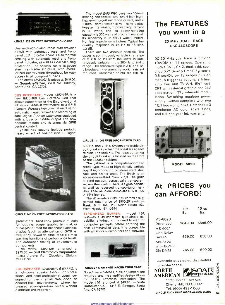
CIRCLE 139 ON FREE INFORMATION CARD
clusive-design dual-purpose auto -crowbar circuit with automatic reset and front - panel LED indicator. There is also thermal sensing with automatic reset and front - panel indicator, as well as external fusing protection. The chassis has a 16 -gauge steel mainframe structure, with modu- larized construction throughout for easy access to all component parts.
The model MA5002A is priced at $849.00. - Soundcraftsmen, 2200 So. Ritchey, Santa Ana, CA 92705.
BUS INTERFACE, model 4380-488, is a
new IEEE -488 bus interface unit that allows connection of the Bird directional RF Power Analyst wattmeters to a GPIB (General Purpose Instrumentation Bus) for automatic measurement and recording of data. Digital Thruline wattmeters equipped with a bus -compatible output can now become talkers and listeners via GPIB central control.
Typical applications include periodic measurement of one to nine RF -signal
CIRCLE 140 ON FREE INFORMATION CARD
parameters; hard -copy printout of data for logging; scope, graphic terminal, or curve -plotter feed for dependent variables display (such as attenuation or SWR vs. frequency, power vs. time, etc.); alarm or warning functions of performance levels, and automatic testing of equipment or components.
The model 4380-488 is priced at $975.00. - Bird Electronics Corporation, 30303 Aurora Rd., Cleveland (Solon), OH 44139.
LOUDSPEAKER. Wharfedale E-90 PRO, is
a high -power speaker system for profes- sional and semi-professional users, de- signed for use in small club, disco, or concert -hall environments where in- creased sound -pressure levels without distortion are important.
The model E-90 PRO uses two 10 -inch moving -coil bass drivers, two 4 -inch high - flux moving -coil midrange drivers, and a
1 -inch compression -drive horn -loaded tweeter. Its minimum power requirement is 30 watts, and its power -handling capacity is 300 watts of program material. Its sensitivity is 95 dB (1 watt/1 meter). Nominal impedance is 8 ohms. Typical fre- quency response is 45 Hz to 18 kHz, ±3 dB.
There are two contour controls. The upper is continuously variable in a range of 2 kHz to 20 kHz; the lower is con- tinuously variable in the 200 -Hz to 2 -kHz range. The crossover type is a 6- and 12-
dB/octave, 14 -element network, resistant mounted. Crossover points are 150 Hz,
CIRCLE 141 ON FREE INFORMATION CARD
800 Hz, and 7 kHz. System and treble cir- cuit breakers protect the speakers against misuse or accidents. The reset button for the circuit breaker is located on the front of the speaker cabinet.
The cabinet is a computer -optimized reflex type, made of high -density particle board incorporating crush -resistant steel rails and corner caps. The finish is an abrasion -resistant black vinyl. The grille is semi -opaque, acoustically transparent woven steel mesh. There is a grab handle, as well as recessed transportation han- dles. External dimensions are 451/4 x 153/4
x 163/4 inches. The Wharfedale E-90 PRO carries a sug-
gested retail price of $900.25 each. - Rank Hi Fi, Inc., 260 North Route 303, West Nyack, NY 10994.
TYPE -AHEAD BUFFER, model 150, features a 40 -character type -ahead ca- pability, eliminating the need to wait for computer prompts before entering the next command or data. It is compatible with all Apple II computers and software.
CIRCLE 142 ON FREE INFORMATION CARD
No software patches, cuts, or jumpers are required, and the simplified design allows for nearly effortless installation. The model 150 is priced at $49.95. - Vista Computer Co., 1317 E. Edinger, Santa Ana. CA 92705. R -E
The FEATURES you want in a
20 MHz DUAL TRACE OSCILLOSCOPE
DC -20 MHz dual trace @ 5mV to
10V/Div on 11 ranges. Operating modes Ch 1, Ch 2, dual, add, sub.,
chop, X -Y. Sweep Time 0.5 µ sec to
0.5 sec/Div on 19 ranges plus X5
mag. 5 trigger selections; 3 filters; auto free run; TV-V/H. 5%2" rect.
CRT with internal graticle and 2kV acceleration. TTL intensity modu- lation. Switching regulator power supply. Comes complete with two 10:1 hook -on probes. Detachable 3
conductor AC cord, spare fuses,
and full one year ltd. warranty.
MODEL 6020
At PRICES you can AFFORD!
MS -6020
1-9 Ea.
10up Ea.
Described $649.00 $585.00
MS -6021 with Delay Sweep 699.00 630.00
MS -6120 with Built-in 3Y2 DMM 765.00 690.00
Available at selected distributors or write/phone:
NORTH AMERICAN corporation
1 126 Cornell Avenue Cherry Hill, NJ 08002 Tel. (609) 488-1060
CIRCLE 72 ON FREE INFORMATION CARD 89
www.americanradiohistory.com
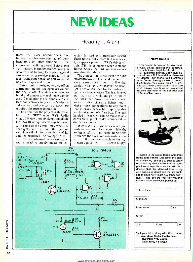
NEW IDEAS
Headlight Alarm
HAVE YOU EVER FOUND YOUR CAR battery dead because you had left your headlights on after shutting off the engine and walking away? Before long your battery is totally drained, and you have to start looking for a passing good samaritan or a service station. It is a frustrating experience, as you know if it has ever happened to you.
This circuit is designed to give off an alarm anytime that the lights are on but the engine off. The device is easy to build and almost any technique can be used. Installation is also simple and just two connections to your car's electri- cal system, and one to its chassis, are required for proper operation.
The circuit for the project is shown in Fig. 1. An SPDT relay, RYl (Radio Shack 275-003 or equivalent), and diode D2 (IN4004 or equivalent) supply power to the rest of the circuit only when the headlights are on and the ignition switch is off. A circuit made up of R7 and D1 regulates the voltage to ICI. The IC is configured as an oscillator, and is used to supply pulses to Ql.
which is used as a transistor switch. Each time a pulse from ICI reaches it, Q I supplies power to TR l's driver cir- cuit (TRI is a piezo-buzzer element, Radio Shack 273-064 or equivalent), sounding the alarm.
The connections to your car are fairly straightforward. The lead marked To +12v LIGHTS should go to a line that carries + 12 volts whenever the head- lights are on (the one for the dashboard lights is a good choice). The lead labeled TO +12V IGNITION should go to one of the lines that power the car's acces- sories (radio, cigarette lighter, etc.). Make those connections to any point that is easily accessible; typically that will be at your car's fuse box. The lead labeled TO GROUND can be made to any convenient point that's connected to the car's chassis.
Of course there are times when you wish to use your headlights while the engine is off. All that needs to be done to silence the alarm in those instances is to turn the ignition switch to the AC-
CESSORY position. --James Griggs
R8 4.7 K
TO +12V +t d*
R7 LIGHTS c3 L_ To 220 35V IOOIL
+12V IGNITIOW
TO CTRoUND Ca -
IN 400 4
RKI
c
ICI : CP4011
12
13 II
Dl t C2 5-12V T 220
ZENERT IroV
QI 2N2219A
14
2
Ici -4 RI
3.3 MEG
ICI -d NC
a
ICI -c
5 ICI -,b
R2 3.3 ME4
R3 3.9k
c1 o.
10
Nc
RED
TR1
BLUE
BLACK
R4 220 K
R(o I0K
RS 4701E
Q2 2N222ZA
NEW IDEAS
This column is devoted to new ideas, circuits, device applications, construc- tion techniques, helpful hints, etc.
All published entries, upon publica- tion, will earn $25. In addition, Panavise will donate their model 324 Electronic Work Center, having a value of $49.95. It combines their circuit -board holder, tray base mount, and solder station (see photo below). Selections will be made at the sole discretion of the editorial staff of Radio -Electronics.
I agree to the above terms, and grant Radio -Electronics Magazine the right to publish my idea and to subsequently republish my idea in collections or com- pilations of reprints of similar articles. I
declare that the attached idea is my own original material and that its publi- cation does not violate any other copy- right. I also declare that this material had not been previously published.
Title of Idea
Signature
Print Name Date
Street
City State ZIP
Mail your idea along with this coupon to: New Ideas Radio -Electronics,
200 Park Ave. South, New York, NY 10003
90
www.americanradiohistory.com
Hitachi V202 and V352 Dual Trace Oscilloscopes When you get exceptional capa- bility per dollar, that's superior cost -performance. And that's the 35 MHz Hitachi V-352 and the 20 MHz Hitachi V-202 dual trace oscilloscopes.
Proof? Just skim these fea- tures, then note the price. For starters, both scopes have a 2 - year limited warranty. And then there are features like square CRT's with internal graticules, vertical sensitivity
of 1 mV/division, and a wide dynamic range for vertical am- plifier of 8 divisions or more. Each scope features front panel X -Y operation, l0X sweep mag- nification, 3% vertical deflec- tion and sweep accuracy, and low vertical drift. For ease of operation, functionally related controls are grouped into 3 color -coded front panel blocks.
How do we build in all that capability at such low cost? Chalk it up to two decades of oscilloscope design experience and some of the most modern production methods around.
Hitachi V-352 and V-202 are CIRCLE 85 ON FREE INFORMATION CARD
stocked by your authorized industrial distributor and ready for fast delivery.
Ask for a demonstration and see more performance than you expected for less than you thought possible.
Hitachi... the measure of quality.
HITACHI Hitachi Denshi America, Ltd. 175 Crossways Park West Woodbury, NY 11797 (516) 921-7200
You'll recognize the name... appreciate the quality.
www.americanradiohistory.com
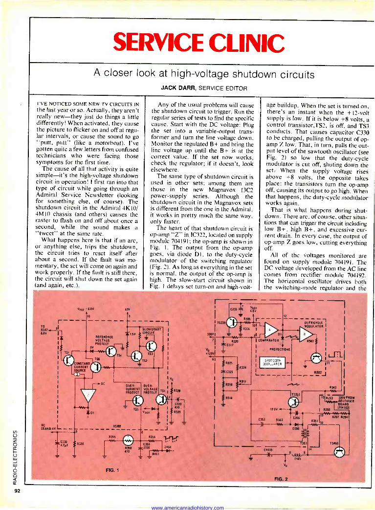
SERVICE CLINIC A closer look at high -voltage shutdown circuits
JACK DARR, SERVICE EDITOR
I'VE NOTICED SOME NEW TV CIRCUITS IN the last year or so. Actually, they aren't really new-they just do things a little differently! When activated, they cause the picture to flicker on and off at regu- lar intervals, or cause the sound to go "putt, putt" (like a motorboat). I've gotten quite a few letters from confused technicians who were facing those symptoms for the first time.
The cause of all that activity is quite simple-it's the high -voltage shutdown circuit in operation! I first ran into that type of circuit while going through an Admiral Service Newsletter (looking for something else, of course). The shutdown circuit in the Admiral 4K10/ 4M10 chassis (and others) causes the raster to flash on and off about once a second, while the sound makes a "tweet" at the same rate.
What happens here is that if an arc, or anything else, trips the shutdown, the circuit tries to reset itself after about a second. If the fault was mo- mentary, the set will come on again and work properly. If the fault is still there, the circuit will shut down the set again (and again, etc.).
Any of the usual problems will cause the shutdown circuit to trigger. Run the regular series of tests to find the specific cause. Start with the DC voltage: Plug the set into a variable -output trans- former and turn the line voltage down. Monitor the regulated B+ and bring the line voltage up until the B+ is at the correct value. If the set now works, check the regulator; if it doesn't, look elsewhere.
The same type of shutdown circuit is used in other sets; among them are those in the new Magnavox 13C2 power -supply series. Although the shutdown circuit in the Magnavox sets is different from the one in the Admiral, it works in pretty much the same way, only faster.
The heart of that shutdown circuit is op -amp "Z" in IC322, located on supply module 704191; the op -amp is shown in Fig. I. The output from the op -amp goes, via diode DI, to the duty -cycle modulator of the switching regulator (Fig. 2). As long as everything in the set is normal, the output of the op -amp is high. The slow -start circuit shown in Fig. I delays set turn -on and high -volt-
age buildup. When the set is turned on, there's an instant when the + 12 -volt supply is low. If it is below +8 volts, a control transistor,TS2, is off, and TS3 conducts. That causes capacitor C330 to be charged, pulling the output of op - amp Z low. That, in turn, pulls the out- put level of the sawtooth oscillator (see Fig. 2) so low that the duty -cycle modulator is cut off, shuting down the set. When the supply voltage rises above +8 volts, the opposite takes place; the transistors turn the op -amp off, causing its output to go high. When that happens, the duty -cycle modulator works again.
That is what happens during shut- down. There are, of course, other situa- tions that cah trigger the circuit including low B+, high B+, and excessive cur- rent drain. In every case, the output of op -amp Z goes low, cutting everything off.
All of the voltages monitored are found on supply module 704191. The DC voltage developed from the AC line comes from rectifier module 704192. The horizontal oscillator drives both the switching -mode regulator and the
TO
R317
6.8V
r 81
I
I
VREF = 6.8V.
1 10
12V
TS?
REFERENCE VOLTAGE PROTECT
8V
14
CONSTANT CURRENT SOURCE
OC
ST RC
ANO -8V
--'VVr-1, I01
C330 2 4.7vF S 8370
í7.5V
T
10322
R355 M
SLOW START CIRCUIT
TS3
TS2
OVER- OVER CURRENT VOLTAGE PROTECT PROTECT
6
FIG. 1
R358 470
VO
TS1 8328
I( C320 470
R329
1
J
R354 1,41....4- VM
C354 2700 0464
1 RAN - N R461
I C336
R335
TS336
300VI _
71
V 0 .1291
61
R320
C311
1R11325
C325
8316
318
8336
R324
R317
VREF 6.8V
r 10
81 r/ 1 COMPARATOR
PROTECTIONS
( L_
SAWTOOTH OSCILLATOR
DUTY -CYCLE, MODULATOR I
R342 # I
I
I
1C322J
8342
¡¡ YN-
''3 8293 3VFROM ' RECTIFIER
90AR0
12.6V s--+ MI
I 8298 1704192)
M MA V'A C353 9353
C356 R297 8294
R351118 -l .,H O a1J
1
- -o`J r1.
T351 TS463
54608 1<
+ 6 8
T465
V0
FIG. 2
TS353
www.americanradiohistory.com
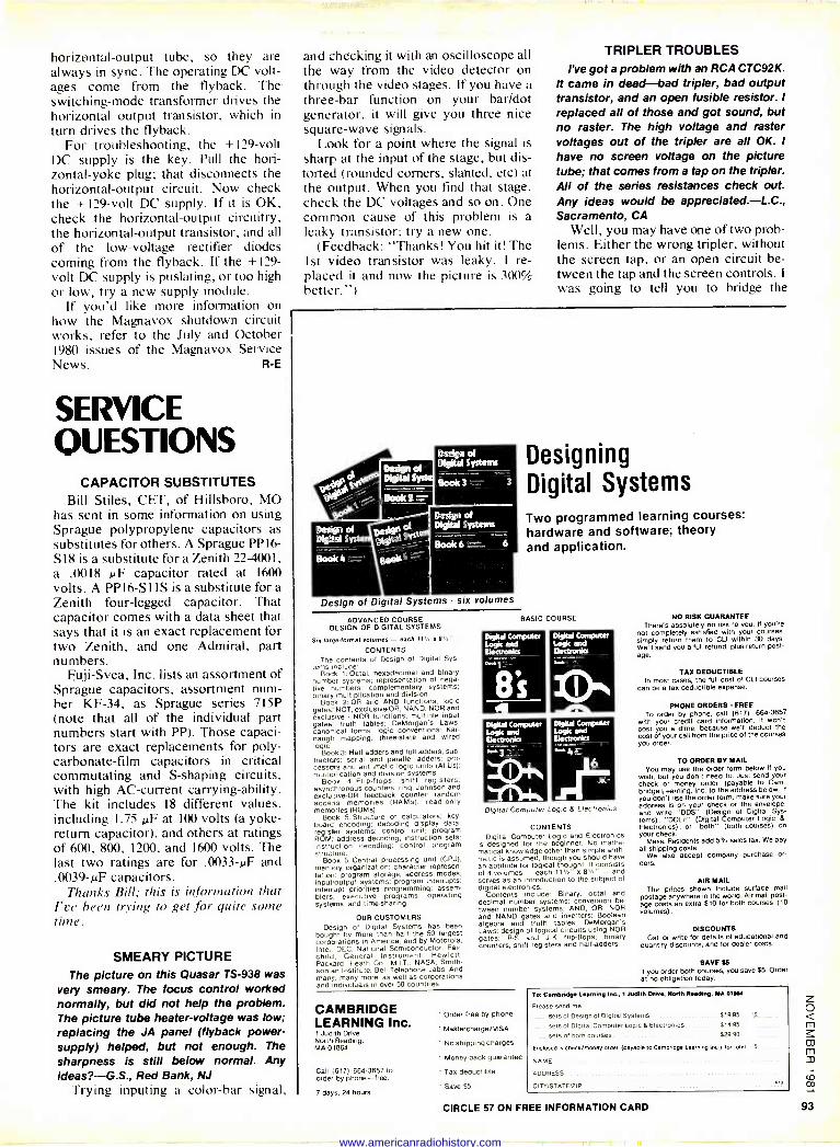
horizontal -output tube, so they are always in sync. The operating DC volt- ages come from the flyback. The switching -mode transformer drives the horizontal output transistor, which in turn drives the flyback.
For troubleshooting, the + 129 -volt DC supply is the key. Pull the hori- zontal -yoke plug; that disconnects the horizontal -output circuit. Now check the +129 -volt DC supply. If it is OK, check the horizontal -output circuitry, the horizontal -output transistor, and all of the low -voltage rectifier diodes coming from the flyback. If the + 129 -
volt DC supply is puslating, or too high or low, try a new supply module.
If you'd like more information on how the Magnavox shutdown circuit works, refer to the July and October 1980 issues of the Magnavox Service News. R -E
SERVICE QUESTIONS
CAPACITOR SUBSTITUTES Bill Stiles, CET, of Hillsboro, MO
has sent in some information on using Sprague polypropylene capacitors as substitutes for others. A Sprague PP I6 - S l8 is a substitute fora Zenith 22-4001, a .0018 µF capacitor rated at 1600 volts. A PP16-S1IS is a substitute for a Zenith four -legged capacitor. That capacitor comes with a data sheet that says that it is an exact replacement for two Zenith, and one Admiral, part numbers.
Fuji-Svea, Inc. lists an assortment of Sprague capacitors, assortment num- ber KF-34, as Sprague series 715P (note that all of the individual part numbers start with PP). Those capaci- tors are exact replacements for poly - carbonate -film capacitors in critical commutating and S -shaping circuits, with high AC -current carrying -ability. The kit includes 18 different values, including 1.75 µF at 100 volts (a yoke - return capacitor), and others at ratings of 600, 800, 1200, and 1600 volts. The last two ratings are for .0033-µF and .0039-µF capacitors.
Thanks Bill; this is information that I've been trying to get for quite some time.
SMEARY PICTURE The picture on this Quasar TS -938 was
very smeary. The focus control worked normally, but did not help the problem. The picture tube heater -voltage was low; replacing the JA panel (flyback power - supply) helped, but not enough. The
sharpness is still below normal. Any ideas?-G.S., Red Bank, NJ
Trying inputing a color -bar signal,
and checking it with an oscilloscope all the way from the video detector on through the video stages. If you have a three -bar function on your bar/dot generator, it will give you three nice square -wave signals.
Look for a point where the signal is sharp at the input of the stage, but dis- torted (rounded corners, slanted, etc) at the output. When you find that stage, check the DC voltages and so on. One common cause of this problem is a leaky transistor; try a new one.
(Feedback: "Thanks! You hit it! The 1st video transistor was leaky. I re- placed it and now the picture is 300% better.")
TRIPLER TROUBLES I've got a problem with an RCA CTC92K.
It came in dead-bad tripler, bad output transistor, and an open fusible resistor. I
replaced all of those and got sound, but no raster. The high voltage and raster voltages out of the tripler are all OK. I
have no screen voltage on the picture tube; that comes from a tap on the tripler. All of the series resistances check out. Any ideas would be appreciated.-L.C., Sacramento, CA
Well, you may have one of two prob- lems. Either the wrong tripler, without the screen tap, or an open circuit be- tween the tap and the screen controls. I
was going to tell you to bridge the
igital Systems tems
nook 3
Dedgn 01 Digital Systems
Pook6 :: 6
Design of Digital Systems - six volumes
ADVANCED COURSE DESIGN OF DIGITAL SYSTEMS
Six largtrformaf volumes - each 111/4 a a'. CONTENTS
The contents of Design of Digital Sys- tems include:
Bock 1: Octal, hexadecimal and binary number systems; representation of nega' live numbers; complementary systems; binary multiplication and division.
Book 2. OR and ANO functions; logic gates: NOT, exclusive -OR, NAND, NOR and exclusive - NOR functions; multiple input gates: truth tables; DeMorgan s Laws; canonical forms; logic conventions; Ear- naugh mapping; three -state and wired logic:
Book 3: Halt adders and full adders; sub - tractors; serial and parallel adders; pro- cessors and arithmetic logic units (ALUS); multiplication and division systems.
Book 4: Flip-flops. shift registers: asynchronous counters. ring, Johnson and exclusive -OR feedback counter; random access memories (RAMS); read-only memories IROMs).
Book 5: Structure of calculators; key - boars encoding; decoding display data; register systems; control unit; program ROM; address decoding, instruction sets; instruction decoding; control program structure.
Book 6: Central processing unit (CPU); memory organization; character represen- tation, program storage; address modes; inpuloutput systems; program interrupts; interrupt priorities programming; assem- blers, executive programs, operating systems, and time-sharing.
OUR CUSTOMERS Design of Digital Systems has been
bought by more than half the 50 largest corporations in America, and by Motorola, Intel. DEC, National Semiconductor. Fair- child, General Instrument, Hewlett- Packard. Heath Co., M.I.T.. NASA. Smith- sonian Institute, Bell Telephone Labs. And many, many more, as well as corporations and individuals in over 50 countries.
Designing
Digital Systems
Two programmed learning courses: hardware and software; theory and application.
BASIC COURSE
INeltel Logic L Itlamedö
tal Computer Logic & Electronics
CONTENTS Digital Computer Logic and Electronics
is designed for the beginner. No mathe- matical knowledge other than simple arith- metic is assumed. though you should have an aptitude for logical thought. It consists of 4 volumes - each 111/2" x 84." - and serves as an introduction to the subject of digital electronics.
Contents nclude; Binary, octal and decimal number systems; conversion be-
tween number systems; AND, OR, NOR and NAND gates and inverters; Boolean algebra and truth tables; DeMorgan's Laws; design of logical circuits using NOR gates; R -S and J -E flip-flops; binary counters, shift registers and halt -adders.
CAMBRIDGE LEARNING Inc.
41
t Jud th Drive North Reading. MA 01864
Call ;617) 664-3657 to order by phone-tree.
7 days, 24 hours
' Order free by phone
' Mastercharge/VISA
No shipping charges
' Money -back guarantee
Tax deductible
Save $5
NO RISK GUARANTEE There's absolutely no risk to you. If you're
not completely satisfied with your courses, simply return them to CLI within 30 days. We'll send you a full refund, plus return post- age.
TAX DEDUCTIBLE In most cases, the full cost of CLI courses
can be a tax deductible expense.
PHONE ORDERS FREE To order by phone, call (617) 684-3857
with your credit card information. It won't cost you a dime, because we'll deduct the cost of your call from the price of the courses you order.
TO ORDER BY MAS. You may use the order form below If you
wish, but you don't need to. Just send your check or money order (payable to Cam- bridge Learning Inc. to the address below. It
you don't use the order form. make sure your address Is on your check or the envelope, and write "DOS" (Design of Digital Sys- tems). "DCLE" (Digital Computer Logic &
Electronics), or "both" (both courses) on your check.
Mass. Residents add 5% sales tax. We pay all shipping costs.
We also accept company purchase or- ders.
AIR MAIL The prices shown include surface mail
postage anywhere in the world. Air mail post- age costs an extra $10 for both courses (10 volumes) .
DISCOUNTS Call or write for details of educational and
quantity discounts, and for dealer costs.
SAVE tb It you order both courses. you save $5. Order et no obligation today.
To: Cambridge Learning Inc., 1 Judith Drive, Berth Reeding, MA 01064
Please send me
sets of Design of Digital Systems .. $19.95 s
sets of Digital Computer Logic & Electronics $14.95
sets of both courses. $29.90
Encbsad Is Check/ money order (peyebit to Cambridge Learning Inc.) for total S
NAME
ADDRESS
CITY IS TATE/ZIP PIO
CIRCLE 57 ON FREE INFORMATION CARD
www.americanradiohistory.com
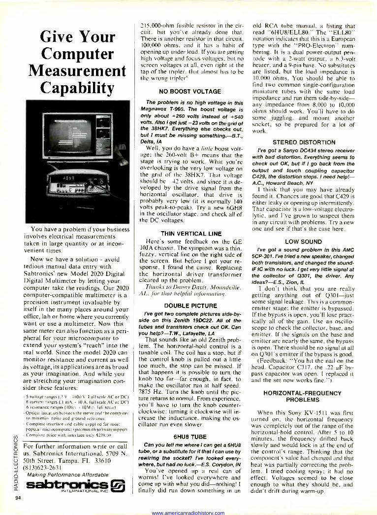
Give Your Computer
Measurement Capability
You have a problem if your business involves electrical measurements taken in large quantity or at incon- venient times.
Now we have a solution - avoid tedious manual data entry with Sabtronics' new Model 2020 Digital Digital Multimeter by letting your computer take the readings. Our 2020 computer -compatible multimeter is a precision instrument invaluable by itself in the many places around your office, lab or home where you currently want or use a multimeter. Now this same meter can also function as a peri- pheral for your microcomputer to extend your system's "reach" into the real world. Since the model 2020 can monitor resistance and current as well as voltage, its applications are as broad as your imagination. And while you are stretching your imagination con- sider these features: - 5 voltage ranges (. I V. - 1000 V. Full scale AC or DC)
6 current ranges (.1 mA. - 10 A. full scale AC or DC) 6 resistance ranges (l00n - 10M n full scale)
-Optical isolation between the meter and the computer to minimize noise and ground reference.
- Complete interface and cable supplied for most popular microcomputer systemswith software support.
- Complete price with interface only $239.00
For further information write or call us. Sabtronics International, 5709 N. 50th Street, Tampa, FL 33610 (813)623-2631
Making Performance Affordable
sabtronics INTERNATIONAL INC
1
215.000 -ohm fusible resistor in the cir- cuit. but you've already done that. There is another resistor in that circuit. 100,000 ohms, and it has a habit of opening up under load. If you are getting high voltage and focus voltages, but no screen voltages at all, even right at the tap of the tripler, that almost has to be the wrong tripler!
NO BOOST VOLTAGE
The problem is no high voltage in this Magnavox T-960. The boost voltage is only about +260 volts instead of +540 volts. Also I get just -23 volts on the grid of the 38HK7. Everything else checks out, but I must be missing something.-B.T., Delta, IA
Well, you do have a little boost volt- age; the 260 -volt B+ means that the stage is trying to work. What you're overlooking is the very low voltage on the grid of the 38HK7. That voltage should be -42 volts, and since it is de- veloped by the drive signal from the horizontal oscillator, that drive is probably very low (it is normally 140 volts peak -to -peak). Try a new 6GH8 in the oscillator stage, and check all of the DC voltages.
THIN VERTICAL LINE Here's some feedback on the GE
IOJA chassis. The symptom was a thin, fuzzy, vertical line on the right side of the screen. But before I got your re- sponse, I found the cause. Replacing the horizontal driver transformer cleared up the problem.
Thanks to Danny Davis, Moundville, AL, for that helpful information.
DOUBLE PICTURE I've got two complete pictures side -by -
side on this Zenith 19DC22. All of the tubes and transistors check out OK. Can you help?-T.W., Lafayette, LA
That sounds like an old Zenith prob- lem. The horizontal -hold control is a tunable coil. The coil has a stop, but if the control knob is pulled out a little too much, the stop can be missed. If that happens it is possible to turn the knob too far-far enough, in fact, to make the oscillator run at half speed, 7875 Hz. Turn the knob until the pic- ture returns to normal. From experience, you'll have to turn the knob counter- clockwise; turning it clockwise will in- crease the inductance, making the os- cillator run even slower.
6HU8 TUBE Can you tell me where I can get a 6HU8
tube, or a substitute for it that I can use by rewiring the socket? l've looked every- where, but had no luck.-E.S. Corydon, IN
You've opened up a real can of worms! I've looked everywhere and come up with what you did-nothing! I
finally did run down something in an
old RCA tube manual, a listing that read "6HU8/ELL80." The "ELL80" notation indicates that this is a European type with the "PRO -Electron" num- bering. It is a dual power -output pen- tode with a 2 -watt output. a 6.3 -volt heater, and a 9 -pin base. No substitutes are listed, but the load impedance is 10.000 ohms. You should be able to find two common single -configuration miniature tubes with the same load impedance and run them side-by-side- any impedance from 8,000 to 10,000 ohms should work. You'll have to do some juggling, and mount another socket, so be prepared for a lot of work.
STEREO DISTORTION l've got a Sanyo DC434 stereo receiver
with bad distortion. Everything seems to check out OK, but if I go back from the output and touch coupling capacitor C429, the distortion stops. I need help!- A.C., Howard Beach, NY
I think that you may have already found it. Chances are good that C429 is either leaky or opening up intermittently. That capacitor is a low -voltage electro- lytic, and I've grown to suspect them in any circuit with problems. Try a new one and see if that's the case here.
LOW SOUND l've got a sound problem in this AMC
5CP-301. I've tried a new speaker, changed both transistors, and changed the sound - IF IC with no luck. I get very little signal at the collector of 0301, the driver. Any ideas?-E.S., Zion, IL
I don't think that you are really getting anything out of Q301 just some signal leakage. This is a common - emitter stage; the emitter is bypassed. If the bypass is open, you'll lose pract- ically all of the gain. Use an oscillo- scope to check the collector, base, and emitter. If the signals on the base and emitter are nearly the same, the bypass is open. There should be no signal at all on Q301's emitter if the bypass is good.
(Feedback: "You hit the nail on the head. Capacitor C317, the .22 uF by- pass capacitor was open. I replaced it and the set now works fine.")
HORIZONTAL -FREQUENCY PROBLEMS
When this Sony KV -1511 was first turned on. the horizontal frequency was completely out of the range of the horizontal -hold control. After 5 to 10 minutes, the frequency drifted back slowly and would lock in at the end of the control's range. Thinking that the component's value had changed and that heat was partially correcting the prob- lem, I tried cooling spray; it had no effect. Voltages seemed to be close enough to what they should be, and didn't drift during warm-up.
94
www.americanradiohistory.com
In this set, the frequency is controlled by a DC voltage. The horizontal -hold control sets the DC -voltage level that biases the AFC. An oscilloscope showed horizontal pulses across that control. I traced the pulse back to the B+ line, and finally to C533. a 100 µt filter capacitor. Replacing the capaci- tor fixed the problem.
Thanks for this to Vic Spacek of Bloomfield, CT
VIDEOTAPE COLOR
I wrote you about a problem in a Sony videotape recorder. It would play back previously -recorded material in perfect color, but would not record in color. Although you said that you didn't know anything about that ma- chine, you did suggest a few things to try, including cleaning the record/play- back switch's contacts. After finding the thing (the switch on this unit works through a series of levers; the contacts themselves are on one of the circuit boards). I cleaned the contacts with a spray cleaner. The videotape recorder now works perfectly. I just thought that you'd like to know.
-Lloyd Host, Brigham City, UT
TWO HINTS Here are a couple of hints for your
files. The first deals with the vertical - output fuse in the Zenith 23FC45 that keeps failing. The only way to repair that problem is to replace the vertical - driver transistor (the one with the TO - 126 flat -pack case). The transistor seems prone to failure under load. The problem is intermittent, and heating or freezing does not reveal it.
The second hint involves the Zenith 25CC50 and similar chassis. The symptom is poor focus even if the focus voltage is normal. Even though the CRT will test out as good (at least on my testers) the CRT must be replaced anyway. That has shown up recently on 25VACxx and 23VAQ CRT's. R -E
EQUIPMENT REPORTS
r ontinued on pagre 36
wide and I could not get quite enough heat from the desoldering gun. Holding the tip of a second soldering iron to the other side of the lug melted the solder, and the Hot Vac did the rest.
The desoldering system is a well - made piece of equipment; I've used Ungar products for many years, and I've liked them. The instructions are very complete, and include a parts list, service information, and clear illustra- tions. The model 4000 Hot Vac is priced at $399.00. There is also the model 4000E for 220 -volt operation that sells for $555.55. R -E
The TSE-HARDSIDE 1982 Micro -Computer Buyer's Guide is now available! We've included such valuable information as print samples from each of the printers we carry, feature -by -feature comparisons of microcomputer systems in an easy -to -read table format, an informative article on Micros, and pages and pages of complete product descriptions. We're making this valuable reference available for only $2.95 (credited toward first purchase from TSE-HARDSIDE). Just clip the coupon (or send a note) with your check for $2.95 to the address below. THE TSE-HARDSIDE 1982 BUYER's GUIDE will soon arrive postpaid to your door.
Yes! Send me the TSE-HARDSIDE 1982 Micro -Computer Buyer's Guide.
I've enclosed $2.95 Name Address_ _
City State
Send to
RE
V`I DS'rx Dept. C. 14 South Street Milford. NH 03055
Please send only your FREE Price List
Zip Code J
CIRCLE 69 ON FREE INFORMATION CARD
*Ng
A Classroom In Your Mailbox
STUDY
Two -Way Radio THROUGH THE
REVISED
MT/ Home Study Course
Send coupon below for free course outline
No obligation - No salesman will call
Professional Training in a Unique Career Field
Providing Training to the Industry Since 1960
L study FM two - way
radio at home! I am interested in learning more about pro-
fessional FM two-way radio. Please send me frill details on the MTI training program.
Name Address City/State/Zip
MT/ C3L
Mobile Training Institute Boo 775, Camp Ni11, P4 17011-U.S.1.
a
Get A GNOME the original micro -synthesizer Every day more people discover that PAIA's GNOME is the most versatile, cost effective special effects device on the market today.
John Simonton's time -proven design provides two envelope generators, VCA, VCO and VCF in a low cost, easy to use package. Use alone with it's built in ribbon controller or modify to use with guitar, electronic piano, polytonic keyboards, etc.
The perfect introduction to electronic music and best of all, the Gnome is only $69.95 in easy to assemble kit form. Is it any wonder why we've sold thousands'?
r 1020 W. Wilshire Blvd. Oklahoma City. OK 73116
I Send GNOME MICRO- SYNTHESIZER Kit 1$69.95 plus $2.00 postage I
Send FREE CATALOGsik = name address city state _ zip
visa _,,,_ r .c _ card no. Dept. 11 R (405)843-9626
1020 W. Wilshire Blvd. Oklahoma City. OK 73116
95 CIRCLE 76 ON FREE INFORMATION CARD CIRCLE 22 ON FREE INFORMATION CARD
www.americanradiohistory.com
NEW LIT
For more details use free information card inside back cover.
REPLACEMENT BATTERY BROCHURE ucts. The latter include socket and ter- rated intrinsically safe. is an illustrated 8 -sheet foldout showing minal strips ("snap strips") and cable- Pocket pagers are available in VHF and and describing all the batteries presently strip connectors. Free upon request. UHF models. All are rated intrinsically offered by Gould. The clearly -printed, easy-to-read chart gives needed informa-
-Samtec, Inc., 810 Progress Blvd., PO Box 1147, New Albany, IN 47150.
safe. Repeaters, designed to extend busi- ness-radio signals over greater distances,
tion on volts/ampere hour capacity, Gould part numbers, maximum battery
CIRCLE 112 ON FREE INFORMATION CARD are available in both VHF and UHF models.
dimensions, battery description, and COLOR BROCHURE, Land Mobile Radios A complete line of accessories, includ- typical application. There is also a brief instruction on how to make the best use
and Accessories, is 12 pages, 81/2 x 11 inches, and describes a broad line two
ing antennas, power supplies, external loudspeakers, microphones, crystals,
of the brochure. Free upon request.-Avex of way business radios, tone devices, batteries, and chargers
Electronics Corp., 121 Coulter Avenue, Ardmore, PA 19003.
pagers, repeaters, and accessories in layman's language.
Rugged, slimly styled dash
support the two-way radio line. Free upon request.-Standard Communications
CIRCLE 111 ON FREE INFORMATION CARD mount mo
Corp., PO Box 92151, Los Angeles, CA bile radios are available with up to four channels in power ranges from 20 to 75
90009.
ELECTRONIC HARDWARE CATALOG, watts. The trunk -mount radios feature a CIRCLE 113 ON FREE INFORMATION CARD
two-color, 44 pages, 81/2 x 11 inches, two -channel, mini -control head and combines previous catalogs and includes transceiver capable of being mounted in RADIO -PRODUCTS CATALOG is 40 many newly -released products. It con- any convenient place in the vehicle -trunk, pages, 2 -color, 51/2 x 81/2 inches, and fea - tains complete specifications and order- under a seat. or under the dash. tures a new 5 -channel, 10 -watt VHF FM ing information on a full range of DIP, Handheld UHF radios have a transmit- transceiver; new COR and CWID modules transistor and IC sockets; adaptor plugs and covers; cable sockets, plugs and
ter output of 3.5 watts, and VHF models have a full 5 -watt capability. All models
for repeater builders, and new accessories, such as RF -tight enclosures for repeaters
jumpers, and the industry's most corn- have six -channel capacity and weigh less and power supplies. Also featured are the prehensive line of strip -connector prod- than two pounds. Several models are new T51 (VHF) and T451 (UHF) FM exciter
J KAJ2.
G>,`'. .c 7 sc e . %aatP^ k 1( c d^; Gst P^s c9 srP2
N
0^di^9^oc V ^i d lZi!Jp O
O. 7Q ,
G Od7 `o^o.
^occdr/ s OBciZs áh ó Pssoo7
Vole, h ̀P47.4...-?..+/s oP4^/d r cZsd t
' esio %j r`c s
e < "' 2 ,d 0^Pdd/
.9e,:90 (od,r,\a.) /9d3, O
ti , ° 9 a9 ? E `'s P 9,
AIL
CIRCLE 23 ON FREE INFORMATION CARD
SHEET METAL WORKERS
MULTI- PURPOSE
SHEAR PRESS BRAKE' SLIP ROLL
ALL FUNCTIONS ti OPERATE .
SIMULTANEOUSLY L.
THE COMPLETE R&D SHOP 24" wide 257 lbs. 20 ga. capacity mild steel or .050/.060" 1/2 hard aluminum punches, special dies, stand available as accessories
Special Purchase before Dec. 31, 1981 and receive a FREE SHEAR -NOTCH ER
SHEAR-NOTCHER NO DISTORTION NO BURRS
continuous shearing corner notching $5850 tab notching plus $4.00 nibbling shipping
alpSend for your FREE literature and SHEET METALWORKER BULLETIN
PACIFIC ONE CORPORATION 410 W. Pacific Coast Hwy. Suite K107
Newport Beach, CA 92663 (714) 645-5962
Put Professional Knowledge and a
COLLEGE DEGREE in your Electronics Career through
HOME STUDY
\.1
ÄL
Earn Your
DEGREE L No commuting to class. Study at your own pace, while continuing your present job. Learn from easy -to -understand les- sons, with help from your home -study instructors whenever you need it.
In the Grantham electronics program, you first earn your A.S.E.T. degree, and then your B.S.E.T. These degrees are ac- credited by the Accrediting Commission of the National Home Study Council.
Our free bulletin gives full details of the home -study program, the degrees awarded, and the requirements for each degree. Write for Bulletin R-81.
Grantham College of Engineering 2500 So. LaCienega Blvd.
Los Angeles, California 90034 CIRCLE 53 ON FREE INFORMATION CARD
www.americanradiohistory.com
modules. Many new ranges of transmitting and receiving converters have been added, as well as a series of receiving converters to extend the frequency coverage of scanners to new military, satellite, and commercial bands. The catalog also includes the full line of Cush - craft and Larsen VHF/UHF antennas. Free upon request. -Hamtronics, Inc., 65F Moul Rd., Hilton, NY 14468.
CIRCLE 114 ON FREE INFORMATION CARD
THERMISTOR BULLETIN, 5 -pages, 81/2 x 11 inches, is a 'technical data" bulletin which provides information relating to the testing of thermistors and includes material such as: RT testing; resistance measurement; temperature control; un- balanced thermocouple voltage -error; self -heating errors; determining bridge - supply voltage; accuracy of measure- ment, and other associated topics. Free upon request.-Fenwal Electronics, 63 Fountain Street, PO Box 585, Framing- ham, MA 01701.
CIRCLE 115 ON FREE INFORMATION CARD
DIGITAL INSTRUMENTATION CATALOG, is a 2 -color, 16 -page reference brochure, 81/2 X 11 inches, describing a broad range of digital instrumentation. Included are: 51/2 -digit and 41/2 -digit multimeters; 41/2 -
digit portable/bench DMM's; 31/2 -digit hand-held portable DMM's; DC voltage/ current standards; analog multiplexer; 488 interface; frequency counters; capa- citance meter, and thermometer. A com- plete range of options and accessories is
also included. Free upon request. -Data
Precision , Corporation, Electronics Avenue, Danvers, MA 01923.
CIRCLE 116 ON FREE INFORMATION CARD
THIS MONTH, 32 pages, 81/2 X 11 inches, is an illustrated catalog of electronics equipment. A recent issue features audio- visual materials, compressors, fans/ blowers, lenses, CCTV, magnets and acces- sories, motors and accessories, power sup- plies, pumps and compressors, relays, sole- noids, tools, TV/CCTV equipment, valves and gauges, video-tape, and innumerable other items. Free upon request.-Herbach & Rademan, Inc., 401 East Erie Avenue, Philadelphia, PA 19134.
CIRCLE 117 ON FREE INFORMATION CARD
TERMINAL BLOCK CATALOG, 32 pages, 81/2 x 11 inches, describes both lines of RDI back -barrier series and JB series open -barrier terminal blocks. Full and complete dimensional drawings, tabular matter, and engineering specifications are given.
All four rating/sizes RDI back -barrier series are described fully, including the miniature No. 3 series (5 amps) the No. 4
series (10 amps), the univeral No. 6 series (20 amps, 300 volts), and the heavy-duty No. 8 series (25 amps). All are available with vertical and right-angle PC pin termi- nals, solder -turret, wire -wrap, quick -con- nect, and surface mount. Standard screws are the wire -clamp type designed to elimi- nate the need for crimp -on terminals, etc.
The open -barrier JB series is available in 20 -amp, 300- and 600 -volt models. PC pins, surface mount, and insulated and
non -insulated feed -through solder -turret, quick -connect, and wire -wrap terminal styles are featured. Standard screws are the binder -head type with wire -clamp style offered as an option.
All RDI terminal blocks feature break - resistant thermoplastic barriers, wire - ready screws (screws are in the raised position), and standoffs for full flux clean- ing. Free upan request.-RDI/Reed De- vices Inc., 525 Randy Road, Carol Stream, IL 60187.
CIRCLE 118 ON FREE INFORMATION CARD
COLOR -CODE CHART, is single -sheet, 81/2 X 11 inches, in full color, on stiff coated paper. Designed to aid specifica- tion of fixed composition and metal film resistors, the chart includes all standard MIL and EIA resistance and tolerance values, with ordering information. Free upon request.-Stackpole Components Company, PO Box 14466, Raleigh, NC 27620.
CIRCLE 119 ON FREE INFORMATION CARD
ELECTRONICS CATALOG, 142 pages, 51
x 81/2 inches, is fully illustrated and lists a
wide variety of equipment, including test instruments, digital portable multimeters, tool kits, soldering stations, outlets and outlet strips, tubes, antennas, assorted components, TV accessories, kits, micro- phones, TV games, personal computers, auto accessories, and video connectors and cables. Free upon request.-Fordham Radio, 855 Conklin Street, Farmingdale, NY 11735. R -E
CIRCLE 120 ON FREE INFORMATION CARD
ORGAN AND
PIANO
KITS The most advanced - most versatile
electronic instruments in the indust- ry are now within most everyone's
reach .... because you build them yourself the easy and very exclusive
WERSI way. Best of all, you'll save
up to two-thirds the cost of a comm-
ercially built instrument.
With WERSI's unique "Building Block" system, you actually select
features you desire. Incorporate new
features as they're developed. No
need to trade organs again.
Send for free literature on this excit- ing concept today. (Please specify Piano or Organ) to:
Dept. M 21, P.O. Box 5318 Lancaster, PA 17601
ER HYBRID
AMPLIFIER MODULES
HY60
30 watts $29.95
15 Hz - 50 KHz THD 0.015% SIN ratio 100 db
* State-of-the-art performance " Built-in heatsinks * 5 simple connections * Encapsulated circuitry * No external parts required * Five-year warranty
Choose from five modules $25.95 HY30 (15 watts RMS)
HY60 (30 watts RMS) $29.95
HY120460 watts RMS) 59.95
HY200(120 watts RMS) HY400 (240 watts RMS)
79.95 99.95
FP480 "Bridges" 2 HY400s for 480 watts RMS 20.00
GLaDSTO ÍE Electronics 901 Fuhrmann Blvd., Phone Orders Buffalo, New York, 14203. (718) 849-0735
Name Address City Zip
Please send Amt.
Check ( ) MIO ( ) Visa ( ) M/C ( )
Number Exp. J
flame computer (omp114 MICIOp,oC.u0,, I,M. p.rlph.ril1 ¿ lernic011
APPLE II PLUS Dist( 130K DOS 3.3 48K $1215 00 w/controller $575.00 LANG SYS SOROC 10135 ....795.00 W/PASCAL 395 00 TI -99/4 399.00 Green Monitor 174 00 Epson MX -80 call us
Leedea 100 Mon 139 00 Color Monitor 10
call us
IDS 445G 1,440 00 8ll
us o Column Board 299500
.00 Haas
Texas Instruments Invest. Anal $ 42.00 TI -59 $175 00
Accessories Call us TI -55 Il 39 95
TI -58C 80.00 Speak & Spell 49 95
PC100C 155.00 TI Programmer 47 95
TI BAIT 39.00 MBA 49 4',
HEWLETT-PACKARD HP/125 Computer call us lire ,1' C Men' HP/37E $62.00 Module 26 00
HP -33C 75 00 H P-41 CV call us
HP -34C 119 00 HP -67 295.00 HP -38C 114 99 HP -97 570.00 HP -41C Prog 189 00 Quad Ram call us
HP -41C Printer 289 00 Application Pac call us
HP -41C CRD RDR 169 00
HP N.3 HE'tl5 and acsessory ,auns'sr Lac e,
SCM TYPEWRITER SPECIALS SCM 2200 $279.00 INTREPID $274.-00 SCM 2500 289.00 CLASSIC 12 159.00
All units shipped in original cartons with accessories according to manufacturer's specification. Send money orders, personal check 2 weeks to clear. In Illinois add 6%
sales tax. Add $6.95 minimum shipping 8 handling charges per unit. We ship UPS. Subject to availability. Written warranty for specific products can be obtained free upon request. Above prices are for mail order and prepaid only. Prices and specifications subject to change without notice. Send mail orders..
i?aóik ér Sac. 519 DAVIS EVANSTON ILL 60201 TEL 312-669-6144
97 CIRCLE 87 ON FREE INFORMATION CARD
www.americanradiohistory.com
For more details use free information card inside back cover.
THE HOME VIDEO HANDBOOK, Second how one's video equipment can be used None of the techniques and hints in the Edition, by Charles Bensinger. Video -Info to pay for itself, create new opportunities book are theoretical, however: They have Publications, PO box 1507, Santa Bar- for personal employment, or perform all been tested and proved effective on bara, CA 93102. 304pp.; 51/2 x 81/2 inches; community educational and information the service bench. softcover. $8.95. services. The introduction describes the many
This is much more than a second print- Photographs, drawings, and cartoons types of CB radios and their accessories. ing of the popular first edition; there are illustrate the easy -to -read text; there is a Then we get into basic troubleshooting 100 additional pages and 80 new photo- list of home -program sources, educa- techniques. Chapters 3 to 8 cover "De - graphs and graphics. The aim of this sec- ond edition, however, remains the same
tional sources, and popular video books, as well as an 11 -page glossary of tech-
veloping Signal Frequencies," "The Re- ceiver," "The Transmitter," "Power Sup -
as that of the first: It is designed to un- nical terms and a list of manufacturers' plies," "Antennas and Transmission scramble the confusing data and claims addresses. Lines," and "Single-Sideband Circuitry." surrounding home -video equipment and CIRCLE 121 ON FREE INFORMATION CARD The book is fully illustrated with photo - to provide clear and visual explanations graphs, diagrams, tables, and charts. of technical jargon and popular video sys- HOW TO REPAIR CB RADIOS, by Law- CIRCLE 122 ON FREE INFORMATION CARD tems.
There is a detailed treatment of popular home color cameras, videocassette re-
rence E. Schultz. Gregg/McGraw-Hill, 1221 Avenue of the Americas, New York, NY 10020. 184pp.; 52/4 x 8 inches; soft-
MICROCOMPUTERS FOR EXTERNAL CONTROL DEVICES, by James A. Gup-
corders, videodisc systems, large -screen cover. $9.95. ton, Jr. dilithium Press, P.O. Box 606, TV projectors, home -satellite TV receivers, and 1/2 -inch industrial -video systems.
This book is written from a service technician's point of view and uses a
Beaverton, OR 97075. 279pp., including appendices and index; 51/2 x 81/4 inches;
The reader is instructed not only in how hands-on approach. Theory is dealt with softcover. $13.95 to purchase the best equipment for his or only when the material is peculiar to CB This book deals with the ways in which her own needs, and how to obtain the radios and the reader needs it as a sup- a microcomputer can be used to control de - most satisfactory results from it, but also port to trouble -shooting techniques. vices in one's home, one's business, or
CREATE ANY RHYTHM p wd
DRUM PRD
DRUM SET
r -- Q inn ®®t®a OOOOOI- 1l e
ogrammable Drum Set's simple programming system allows even first time users to structure bass, tom, snare. wood -block and clave sounds into any rhythm in any time signature Versatile memory organization provides simultaneous storage of two separate rhythm patterns each with its own bridge rhythm. Bridges are activated from either the control panel touch plate or optional foot switch and are automatically synchronized to the main rhythm.
Improved memory circuitry lets the "save' mode hold rhythm patterns for over one year while battery lite for normal operation has been extended to several hundred hours.
In easy to assemble kit.
Ú r
( I Send #3750 'Drum Set Kit, $99.95 plus $3 shipping enclosed.
Q ( I Send Free Catalog.
Ú Name: e' No -i 11
Address: W J W
`4 e City: ate: Zip-_
O VISA: MC Card No.
cr LELLE-TRO$5SS.-EP=.1-R=0-0=-ILS-iRE okL .CITY. ON---71-fi-1
98 CIRCLE 80 ON FREE INFORMATION CARD
1 SWLs! Now copy: I RTTY, ASCII I 1 and Morse!
I 1
1
1
1
1 Why just copy voice transmis -
1 sions when you can easily decode radioteletype, ASCII computer language and Morse code with a Kantronics Mini-Readertm?
Easy, one -wire connection to any 1 receiver is all it takes to open up
many new frequencies to you and 1 get you copying all sorts of coded
1 transmissions, including ham con- versations, financial and news
1 reports , and weather information.
The Mini -Reader operates on I 12 VDC and copies Morse from 3 to : 80 WPM, radioteletype at 60, 67, 75 and 100 WPM Baudot, and ASCII at 110 and 300 (if sent as it is typed)
a WPM Baud. Price: $314.95, plus S2.00 shipping.
1 Write for more information.
1 t Kantronics 1 1202 E. 23rd Street (913) 842-7745 I
Lawrence, Kansas 66044 - - - - - - - - --RBI CIRCLE 79 ON FREE INFORMATION CARD
1
1
1
1
1
1
1
1
1
1
1
1
1
1
1
1
1
Saving gas in 1968 - Our original customers
saved $ then and are saving $$$$ today
Tiger 581
Redesigned CD ignition fits on late model cars with factory electronic ignitions or older cars with points. American or foreign.
*50,000 miles between tune-ups *Up to 15% savings on gas * Faster starts *Easy to install
K:t $49.95 Assembled $79.95
PREVENT AUTO THEFT This new undetectable system automatically arms itself, is keyless, and shuts down the electrical system 25 seconds after intruder starts car.
.a2117 _ $49.95 Some dealer and distributor territories are available
For information call collect 1.303.243.5200 Mastercard & Visa accepted or send check to
TStar Corporation Dept. R, 730 Independent Ave.
Grand Junction, CO 81501
CIRCLE 81 ON FREE INFORMATION CARD
www.americanradiohistory.com
elsewhere. Many manual functions that are frequently subject to human error can be accomplished faster, with greater accuracy, greater repeatability, and lower cost through a computer.
After an introduction to data acquisi- tion and conversion, and a discussion of the principles involved, the reader is in- troduced to remote control, micro- processors, and one -IC microcomputers, then shown how the microcomputer is
used as a programmable controller. The reader will learn about computer
systems for automating his or her home, microcomputer -controlled robots, and the use of robots in emergency situations, among other operations and processes. There are many photographs and dia- grams, glossaries, and review questions at the end of each chapter.
CIRCLE 123 ON FREE INFORMATION CARD
30 PROJECTS TO IMPROVE YOUR STEREO SYSTEM, by David B. Weems. Tab Books, Inc., Blue Ridge Summit, PA 17214. 240pp., including appendices and index; 5 x 81/4 inches; softcover. $7.95.
While almost any system can be im- proved, there are two areas where small changes can pay big dividends in better sound: at the antenna and at the speaker. That is why there are more antenna and speaker -related projects in this book than any other kinds. Some improvements, while real enough, are very expensive. The projects outlined here have all been chosen with one eye upon performance and one eye upon cost.
The 10 chapters deal with FM antennas,
antenna projects, an amplifier project, crossover networks, crossover -network projects, speaker -enclosure projects, speaker -improvement projects, more speaker -improvement projects, high -fre- quency improvement projects, and stereo -equipment cabinets. Each chapter is fully illustrated with photos, clear line illustrations, or both.
CIRCLE 124 ON FREE INFORMATION CARD
A CONSUMER'S GUIDE TO PERSONAL COMPUTING AND MICROCOMPUTERS, second edition, by Stephen Frei - berger and Paul Chew, Jr. Hayden Book Company, 50 Essex St., Rochelle Park, NJ 07662. 198pp.; 7 x 93/4 inches; soft- cover. $8.95.
The authors of this book assume that the reader has had no previous experience with, or knowledge of, either computers or microcomputers. Thus, the first sec- tion, chapters 1 through 5, introduces the reader to fundamental principles and definitions, with photos and charts.
Chapters 6 through 10 constitute a prod- uct guide, reviewing over 100 microcom- puter products from over 60 manufac- turers They include a selection -and - sou rces section to assist the reader in re- viewing, selecting and purchasing micro- computer products; summary charts of major microcomputer products, offering a quick rundown of specifications for a
given product, and comment sections covering the advantages and disad- vantages for each microcomputer prod- uct. as well as best -buy tips.
CIRCLE 125 ON FREE INFORMATION CARD
IMPROVE SHORTWAVE
RECEPTION FOR ONLY $23.95! E.O.C. ANTENNA & BOOSTER
Eliminates Costly Antenna Installation
No Extra Tuning Low Power Consumption No Grounding Required High Efficiency
ONE YEAR
GUARANTEE
ONLY $23.95 Postage Paid Two Week Delivery
Electronic Overseas Corp., Inc. 214 E. Franklin Avenue, Midland Park. N.J. 07432
name
address
city state zip
NJ residents add 5% sales tax.
CIRCLE 37 ON FREE INFORMATION CARD
N
Microcomputer -Controlled Autoranging DMM Model 2845
Computer stabilized accuracy to 0.1°ró Auto -perfection Selects range for maximum resolution Audible continuity indicator Built-in audible tone generator G-MOV overload protection Provides AC and DC voltage range protection to 1000 VDC or AC peak Shielded in RIF fields Accuracy maintained in RF fields
Long life, high reliability Four hermetically sealed reed relays perform range switching with virtually no contact wear. Microcomputer intelligence Designed around 4 -bit microcomputer. Analyzes stored data and range that provides greatest display resolution. Program memory capacity 1024 x 8 bits of ROM supported by 48 x 4 bits of data memory RAM
... in stock and available for immediate delivery. Dual Trace 5" 30 MHz Triggered Scope Model 1479A
\,
Sweep'Function Generator Model 3020
Semiconductor Transistor Tester Model 5208
Portable Digital Capacitance Meter Model 820
Buy any of these instruments and get a FREE Bonus Gift!
in N Y State call 15161 752-0050 855 Conklin St. Farmingdale, N.Y. 11735
Call for our prices TOLL FREE FORD (800)645-9518
- Master Charge V/S4' BankAmericard
VISA COD Money Order Check
COD's extra masiei charge 5
99
www.americanradiohistory.com
i x3+7x-4-p?1 It looks HARD with that x' term, but it's EASY to get x=.547928287. I Use your calculator right now to
learn METHOD OF R
INFINITE -LIMITS Set x'+7x=4=(x'+7)x and then x=41(x'+7).
Now make a first guess of x = V2 and use it on the right-hand side to calculate 4/(.5'+7)=.55... Let .55 be your second guess and get 4/(.55'+7) =.5477...for your third guess. Repeat this process
for greater and greater accuracy.
QUICK EASY GUARANTEED FUN, TOOI
INTRIGUED BY CALCULATORS? Then you can step up your math skills fast! Use my new method in guidebook form. It's called CALCULATOR CALCULUS and comes with this guarantee: If after 10 days you're not astounded at the problems you're solving on your own calculator, return the guidebook for an immediate refund.
But the point is - you won't want to send it back. For this is the easiest, fastest shortcut ever! The day you receive your copy in the mail you'll want to put it to work. It's that exciting and helpful.
My name is Dr. George McCarty. I teach math at the University of California. I wrote this guidebook to cut through the confusion. It does just that - with worked -out examples, simple exercises and practical problems - all designed to work with precision and magic on your calculator!
POWER METHODS. Need to evaluate functions, areas, volumes - solve equations - use curves, trig, polar coor- dinates - find limits for sequences and series? Ifs all here!
If you're in the biological, social or physical sciences, v,')111 be doing Bessel functions, carbon dating, Gomperti growth curves, half-life, future value, marginal costs. motion, cooling, probability, pressure - and plenty more even differential equations).
Important numerical techniques? Those algorithms are here, too: rational and Padé approximation, bracketing, con- tinued fractions, Euler's method, Heun's method, iteration functions, Newton's method, predictor -corrector, successive substitutions, Simpson 's method and synthetic division.
LOOK AT WHAT USERS SAY: Samuel C. McCluney, Jr., of Philadelphia writes: "CALCULATOR CALCULUS IS GREAT! For ten
years I have been trying to get the theory of calculus through my head, using home -study courses. It was not until I had your book that it became clear what the calculus was all about. Now I can go through the other books and see what they are trying to do. With your book and a calculator the whole idea becomes clear in a moment, and is a MOST REFRESHING EXPERIENCE. 1 program some of the iterative prob- lems you suggest and it always GIVES ME A THRILL to see it start out with a wild guess and then approach the limit and stop."
Professor John A. Ball of Harvard College (author of the book 'Algorithms for RPN Calculators') writes: "I wish I had had as good a calculus course."
Professor H. I. Freedman of the U. of Alberta, writing in Soc. Ind. Appl. Math Review, states: "There can be no question as to the usefulness of this book...lots of exercises...very clearly written and makes for easy reading."
C.B. of Santa Barbara says: "Your book has given me much instruction and pleasure. 1 do not hesitate to recommend it. 'CALCULATOR CALCULUS' is a book that inspires the reader to understand everything down to the last detail. You seem to have put your heart into the teaching."
I WANT YOU TO TRY THIS. Get my com- plete kit, with a TI -35 calculator, a 200 p. Student Math Book, AND the guidebook, ALL for $44.95 (for shipping to USA add $2, or $5 by AIR; Foreign $5, or $10 AIR), in Calif. add $2.70 tax.
If you already have a scientific calculator, you scan invest in 'CALCULATOR CALCULUS' for only IU.S. $19.95 (to USA or foreign: add $1 for shipping,
Ior $4 by AIR; in Calif. add $1.20 tax).
As pennywise Ben Franklin said, "An invest- ment in knowledge pays the best dividends." GET
'STARTED NOW - Tax deductible for profes- U) sionals. U I NO RISK WHATEVER! Send for it today. Be Z sure to give me your complete mailing address With O (your check or money order. If you want to charge it CC (Visa or MC), tell me your card no. and exp. date. (.3- (Prompt shipment
a ed - J w 'Thanrka you! EduCALC Publications, Dept. DO
Box 974, Laguna Beach, California 92652 In Calif. (also AK and HI), call 714-497-3600;
,elsewhere TOLL FREE 24 -hour Credit Card orders: 800-854.0561, Ext. 845; Dept. DO
OI
34 MORE TESTED, READY -TO-RUN GAME PROGRAMS IN BASIC, by Delton T. Horn. Tab Books, Inc., Blue Ridge Summit, PA 17214. 224pp., including appendices and index; 51/e x 83/8 inches; $7.95.
Computers are mainly for serious busi- ness, but they can be fun, too-and that is what this book is about. It presents a col- lection of games, gags, brain -teasers, and non -games, and even sneaks in some programs that educate while they enter- tain the user.
For a single player there are not only such familiar games as "Craps," "High/ Low", "Go Fish", and "Tic Tac Toe", but also new ones with such fascinating titles as "Hangman," "There's Gold in Them There Skyscrapers," and "What Comes Next?"
Two -player games include "To and Fro," "Passing Points," and "Money Mad. '
An entire chapter is devoted to the challenging and complex game called "Frustration." After the main game pro- gram, there is "Two Man Frustration," "Frustration vs. the Computer," and "The Computer vs. Itself."
Non -games, such as "Surprise Poem," and "Favorite Song," are dealt with in chapter 4, and the book closes (chapter 5) with entertaining helpful programs: "Bi- nary/Decimal," "Day of the Week," "Ohm's Law," and "Fahrenheit/Celsius." The appendix presents notes on pro- gramming in BASIC.
CIRCLE 126 ON FREE INFORMATION CARD
PASCAL PROGRAMS For Scientists and Engineers, by Alan R. Miller. SYBEX, 2344 Sixth Street, Berkeley CA 94710.374 pp., including appendices, bibliography, and index; 7 x 9 inches; softcover. $16.95.
This book has the twofold purpose of helping the reader to develop proficiency in using Pascal, and in building a library of programs that can be used to solve problems frequently encountered in science and engineering. The programs presented will prove valuable to practicing scientists and engineers but are also suitable for a junior- or senior -level course in numerical methods.
The reader must have a working knowl- edge of an applications language such as Pascal, FORTRAN, or BASIC. Experience with vector operations and with dif- ferential and integral calculus would be helpful.
There are 11 chapters, starting with "Evaluation of a Pascal Compiler." That is followed by "Mean and Standard Devi- ation," "Vector and Matrix Operations," "Simultaneous Solution of Linear Equa- tions," "Development of a Curve -Fitting Program," "Sorting," "General Least - Squares Curve Fitting," "Solution of Equations by Newton's Method," "Numerical Integration," "Nonlinear Curve - Fitting Equations, and a final chapter on "Advanced Applications." The appendices cover reserved words and functions and a summary of Pascal. The book is cleanly printed and clearly laid out. R -E
CIRCLE 127 ON FREE INFORMATION CARD
For
faster service
USE
ZIP
CODE
on
all
GET TO KNOW COMPUTERS
Introduce yourself to the world of computers. Speak their language, feel their sensors and get to know them inside and out. FutureTec 180® is a complete Z-80 base computer deve- loped by electronic educators and is all you need to get started in the fast-growing world of computers. This is a hands-on, user oriented computer now offered at the special introductory price of $225. Satisfaction guaranteed or return within ten days for full refund.
FutureTec 180 can open doors for you into a world of scien- tific data that is as far reaching as space itself. How do computers think? What is a memory device? What is address decoding to peripheral devices? Answers to these questions and many more are covered in our easy step-by-step home instruction manual.
Our FutureTec 180 computer includes a spacious mahogany case with built-in power supply and reserve capabilities for exter- nal application. Powerful Concept® software monitor system which allows machine language programming with BASIC ease and full on -board display section with tone indicator for audio- visual reinforcement makes learning easier. Automatic scrolling is included plus telephone -type keyboard for ease of operation. Execution cf your program can be stopped any time, memory address or registers can be changed and your program can be continued with single key stroke In fact 32 keyboard functions like data search, computing and tracing jump relatives and hardware testing facili- ties makes a truly user friendly operating system.
Experience a 180° turn in your career - send today for your FutureTec 180 computer.
FLmIKETEC18O Box 5784, Cleveland Ohio 44101 216-961.4041
$225
Assembled and Tested
100 CIRCLE 84 ON FREE INFORMATION CARD
www.americanradiohistory.com
Radio - Electronics.
00 9D2
CALL AND
RESERVE
YOUR SPACE""' $550 for a 6X frequency insertion.
:r ' Reaches 211,387 readers. KLM's SKY EYE I SATELLITE RE-
Fast reader service cycle. CEIVER NOW IN A KIT! The popular Short lead time for the placement of Sky Eye I delivers superb video and
ANALOG-DIGITAL TEST INSTRUMENT, ads. sound from single conversion/image We typeset and layout the ad at no additional charge.
Huntron Tracker Compar-A-Trace, fea- tures single or timed dual channel modes
rejection circuitry, features fully agile tuning, DC blocking, regulated LNA
for comparison testing of devices in or power supply. Kit is modularized with
Call 212-777-6400 to reserve space. out of circuit. Visual CRT indicates condi- factory -assembled and aligned micro -
Ask for Arline Fishman. Limited num- tion of devices under test with no power wave section. Kit price is $695 Includ-
ber of pages available. Mail materials applied. Simple to operate...cuts service ing discount certificates good for
to: mini -ADS, RADIO -ELECTRONICS, costs. Comprehensive 40 page manual. other KLM system components.
200 Park Ave. South, New York, NY Immediate availability at $965. Huntron KLM Electronics, Inc., P.O. Box 816,
10003. Instruments, 15123 Hwy 99 North, Lynn- wood, WA 98036.
CIRCLE 25 on FREE INFORMATION CARD
Morgan Hill, CA 95037 (408) 779-7363. Order toll free: 800-538-2140. CIRCLE 74 on FREE INFORMATION CARD
NEW
NEW'
'
Keep up with electronics. And what electronics is up to. Electronics is affecting the way we live and learn and work- from typewriters to TV to toys - cars to calculators to computers. It's a subject you should be familiar with.
;;.:;: : .;s.. 1
..,....._......>;:>
r..:. gr:ï<::: ... ..<.:.:...;.;:s
The TI Basic Electricity Series and the TI Understanding Series' books can help. These books, written for non -technical readers, offer an understanding of basic functions and concepts. Each book is illustrated and clearly written in a self -paced format with review questions to make learning easy.
Up -to -the Minute Books By The Texas Instruments Learning Center
',] LCB5471 Understanding Computer Science Covers architecture, hardware and programming to help you understand the computer, with emphasis on the software necessary to use computers.
280 pages $6.95 LCB5472 Understanding Optronics A study cE li ht and its use coupled with elec-
t/ tronxs. sources of light, detectors, couplers, displays, lasers. Learn how they're used in
circuits and systems. Material is presented in an easy to understand format.
272 pages $6.95 LCB4521Understanding Communications
Sysb3rns Covers electronic systems in the current era of transferring information.
288 pages $4.95 LCB3311 Understanding Digital Electronics The basics on the foundation of today's logic devices, circuits and systems.
265 pages $4.95 LCB4023 Understanding Microprocessors Understand what they do and what they can do. A must for everyone involved with electronics.
288 pages $4.95
:;a:; :: :. .;:
_.._.::;:;..._:::.....
I, I I 0- -I I=It
LCB3361 Understanding Solid State Elec- tronics. 3rd Edition. An individualized approach to electricity, semicon- ductors and microelectronics. Up to date.
270 pages $4.95
LCB3321 Understanding Calculator Math Basic information, formulas, facts and the mathe- matical tools you need to unlock the power of your hand-held calculator.
224 pages $4.95
LCW8161 Basic Electricity and DC Circuits. 2nd Edition. Basic terms, principles, concepts and math for beginning electricity students.
924 pages $19.95
LC 35922 Basic Electricity and DC Circuits Audio Course Seven hours of tape. Used with text (LCW8161) it couples sight and sound for easier understanding.
6 tapes $34.95
n LCW8168 Basic AC Circuits The theory and basic principles of alternating cur- rent. as well as how to apply it to modem circuits.
560 pages $19.95
Send orders to: Texas Instruments, P.O. Box 3640, M/S 84, Dallas, Texas 75285
Enclose check or money order with sales tax (except in AK, DE, NH, OR). Foreign orders must be in U.S. dollars including shipping charges.
Name
Address
aty Stabs Zip
TEXAS INSTRUMENTS INCORPORATED
Prices subject to change without notice. 51981 Texas Instruments Incorporated
RE11 80113
101
www.americanradiohistory.com
MARKET CENTER CLASSIFIED COMMERCIAL RATE (for firms or individuals offering commercial products or ser- vices). $1.65 per word prepaid (no charge for zip code) . . . MINIMUM 15 WORDS. 5% discount for 6 issues, 10% for 12 issues within one year, if prepaid. NON-COMMERCIAL RATE (for individuals who want to buy or sell a personal item) $1.00 per word prepaid . . . no minimum. ONLY FIRST WORD AND NAME set in bold caps. Additional bold face (not available as all caps) at 101E per word. All copy subject to publisher's approval. ADVERTISEMENTS USING P.O. BOX ADDRESS WILL NOT BE ACCEPTED UNTIL ADVERTISER SUPPLIES PUBLISHER WITH PER- MANENT ADDRESS AND PHONE NUMBER. Copy to -be in our hands on the 26th of the third month preceding the date of the issue (i.e., August issue closes May 26). When normal closing date falls on Saturday, Sunday, or a holiday, issue closes on preceding working day.
WANTED INTERESTED parties regarding construction of interstellar craft for future survival and space exploration; write KRONUS; P.O. Box 232-A, Glencoe, CA 95232
AUDIO-Visual Club International. Exchange vid- eo or audio cassettes of your collection or have conversation with members of similar interests. For men & women of all ages. Dues $16/yr. For more info write: AVCI, Dept. 0, 16 Sycamore St., Chelmsford, MA 01824
ADDRESSERS-mailers-homeworkers needed! 50 firms listed, rush 50 cents, addressed envelope. BONNIE NIEUWENDAAL, P.O. Box 23432, Tampa, FL 33623
BUSINESS OPPORTUNITIES WINNERS! Build on your technical skills to create a successful computer business. Free report tells how. SEABIRD PRESS, Box 461T, Lexington, MA 02173
MECHANICALLY inclined individuals desiring ownership of Small Electronics Manufacturing Business-without investment. Write: BUSINESS- ES, 92-R, Brighton 11th, Brooklyn, NY 11235
$700 per month earnings possible filling out income tax forms at home or tax office during tax season. We show you how. Simple, quickly learned. Details mailed free. No salesmen. Hurry. Big demand. FEDERATED TAX, 2015 Montrose, Chicago, IL 60618
PROJECTION TV ... Make $200.00+ per eve- ning assembling projectors . . . Easy . . . Re- sults equal to $2,500 projectors . . . Your total cost less than $15.00 . . . Plans, lens & dealer's information $14.00 Illustrated information free ... MACROCOMGCX, Washington Cross- ing, PA 18977. Credit card orders 24 hours. (215) 736-2880.
PHONE TOLL CALL METER SLASH telephone bills. "Gas pump" display shows dollars increasing every minute. Built-in calculator. $59, kit $49. Free information. BUZBY METER, 28D, George, Danbury, CT 06810
COMPUTERS FREE book catalog, getting started in computers; household, classroom, business, games pro- grams. ARCsoft, Box 132D, Woodsboro, MD 21798
SPEAKER crossover network response and phase program for TI 58 and 59 computers. Send $5.00 COLEMAN, 316 Elm Street, Vestal, NY 13850
OCTATRACE-Converts any oscilloscope to dis- play 8 channels. PC bd. & case $21.00. AB COM- PUTER PRODUCTS, P.O. Box 571, Jackson, NJ 08527
CB RADIO GET more CB channels and range! Frequency expanders, boosters, speech processors, how-to books, plans. Catalog $2. CB CITY, Box 31500RE, Phoenix, AZ 85046
SATELLITE TELEVISION SATELLITE super -mixer; DBM-4150A. Clean up your TRVO receiver) Near -theoretical perfor- mance; flat response, DC-1500IF, SMA connec- tors; $69.50-CK/MO/COD. RIGEL SYSTEMS, 2974R Scott Blvd., Santa Clara, CA 95050 (408) 727-4231
SATELLITE TVRO kit: contains entire system including LNA and 11 ft. fiberglass dish. 20% down, financing available nationwide. Complete kit for under $2,400.00. Easily assembled. For complete brochure and information package send $2.00 for postage and handling to: NATION- AL TELECOMMUNICATION SYSTEMS, Dept. RT, 1048 Mt. Gallant Rd., Rock Hill, SC 29730
SATELLITE television...Howard/Coleman boards to build your own receiver. For more information write: ROBERT COLEMAN, Rt. 3, Box 58 -ARE, Travelers Rest, SC 29690
SATELLITE TV antenna, 10 ft. fiberglass, com- plete, polar mount, $1950.00, electronics at cost also. TRI -STAR COMMUNICATIONS, Box 843, Erie, MI 48133 (419) 726-1095
-Satellite TV
Now!
ear
Receive 200 Channels Anywhere!
That's what the ads say. Is it true? Well, yes and no. You can receive 75 to 200 channels, but not just anywhere. Those ads are written to sell expensive equipment, which you might not even be able to use. Only a complex computer analysis of your location can tell for sure.
We offer an independent comput- er analysis of your location, anywhere in the world, covering more than 100 different satellites! Our computer will tell you which satellites you can receive, where to point your antenna, and how strong the signals are likely to be. Know for sure BEFORE you spend your money on equipment.
The cost? Only $19.95 postpaid. [Air Mail $2.00 extra]. We can save you hundreds - even thousands - of dollars. Send check, money order, or charge in on VISA or Master Card.
Satellite Computer Service Dept. RE, 1808 Pomona Drive Las Cruces, NM 88001 U.S.A.
Satellite TV FOR THE HOME Sick of Network TV? Our receiver lets you get over 75 channels of tele- vision directly from earth - orbiting cable TV satel- lites!: HBO, Showtime, su- per stations, sports and movies worldwide.
We don't just sell Information! We Manufacture Hardware!
From offshore oil rigs, data links to hotels and backyard instal- lations, we wrote the book. Constantly up- dated, our 94 Page
technical information book and catalog gives you all the facts. Inexpensive dishes, feeds, telem-
etry software, kits and more. Recom- mended reading by NASA, The Office
of Consumer Affairs and quality com- panies like Rockwell/Collins. Send $7.95 today!
CALL 24 -hi.. C.O.D. Hotline
(305) 339-7600
® SPACECOAST RESEARCH CORPORATION
P.O. Box 442-E. Altamonte Spgs, FL 32701
Enjoy Satellite TV Now
Better than Cable TV-Over 200 TV and radio services. Why waste money? Learn the whole story and build a video system the family can enjoy. No commercials, FREE movies, sports and Vegas shows-worldwide, crystal clear reception connects to any TV set. Big (8 x 11 in.) book loaded with details, photos, plans, kits- TELLS EVERYTHING! Satisfaction Guaranteed. Send $7.95 TODAY! Add $2.00 for 1st class (air mail) or call our 24 hour C.O D. rush order line (305) 862-5068.
GLOBAL ELECTRONICS, P.O. Box 219-E, Maitland, Florida 32751
SATELLITE TELEVISION EARTH STATION KIT LOW COST COMPLETE SYSTEM
Kit includes all electronic and mechanical parts needed to assemble a complete operating Earth Station. You provide the labor and hand tools.
Included in the kit are a I2loot fully steerable parabolic dish. low noise amplifier. antenna. rotator, receiver. modulator. necessary cables/connectors and complete assembly/ operating instructions. EVERYTHING - down to the last nut. bolt and screw is provided.
Illustrated Brochure with
Complete Details - S2.00
MICROTENNA ASSOCIATES 2335 South. 2300 West
Salt Lake City. Utah 84119
102 CIRCLE 62 ON FREE INFORMATION CARD
www.americanradiohistory.com
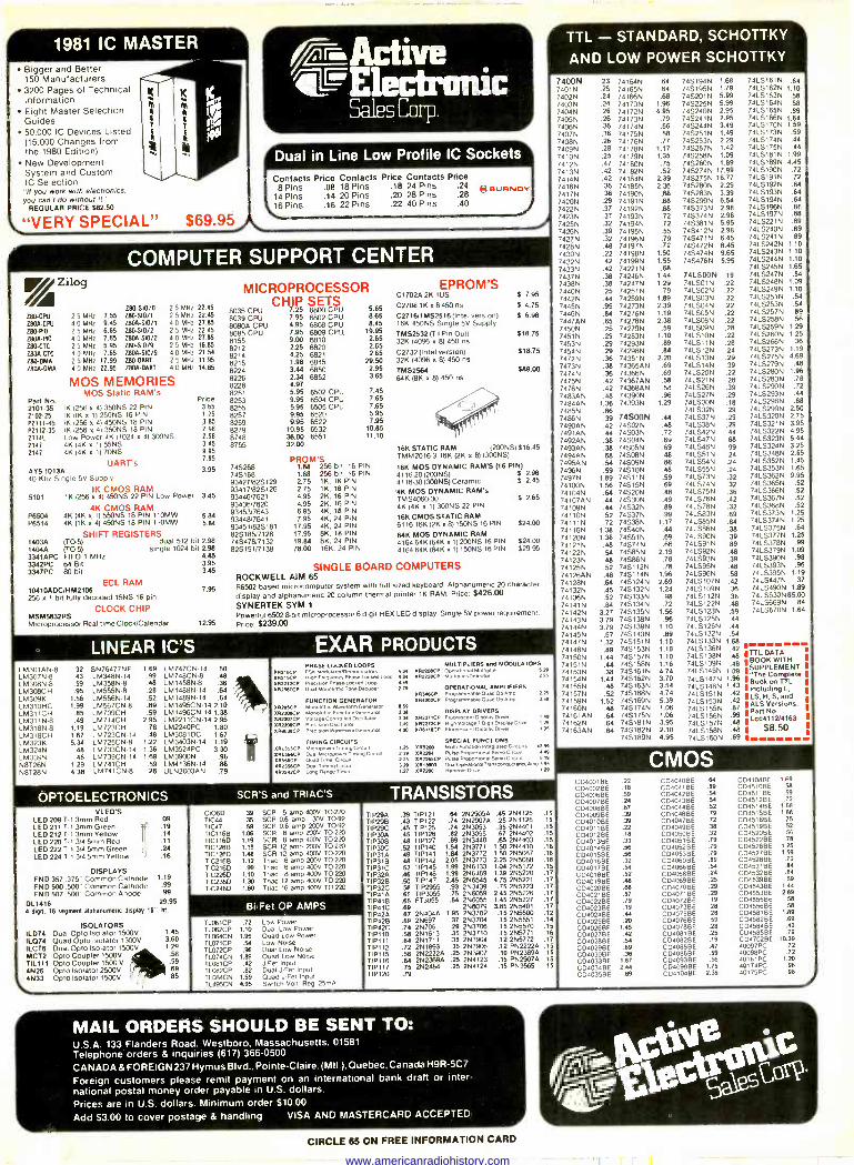
1981 IC MASTER Bigger and Better 150 Manufacturers 3200 Pages of Technical Information Eight Master Selection Guides 50,000 IC Devices Listed (15,000 Changes from the 1980 Edition). New Development System and Custom IC Selection
"Il you work with electronics, you can't do without it."
REGULAR PRICE $82.50
K
"VERY SPECIAL"
790 -CPU
L80Á -CPU
100 -RO 2900 -RO 290-CTC 7809-CTC Z90 -DMA 280A -DMA
Zilog
25 MHz 7.55 40 MHz 9.45 2 5 MHz 6.65 40 MHz 7.65 2 5 MHz 5.95 4 0 MHz 7.65 2 5 MHz 17.99 4 0 MHz 22.95
A.Active 4LE1ectrnnic
Sales Corp.
$69.95
Dual in Line Low Profile IC Sockets
Contacts Price Contacts Price Contacts Price 8 Pins .08 18 Pins .18 24 Pins .24
14 Pins .14 20 Pins .20 28 Pins .28 16 Pins .16 22 Pins .22 40 Pins .40
e BuwNOY
COMPUTER SUPPORT CENTER
Z80-$10/0 Z96SI0/1 ID0A-S10/1 790-5M/2 2909-SIO/2 Z80.510/9 MA -510/9 Z80 -DART ZBOA-DART
2 5 MHz 22.45 2.5 MHz 22.45 4.0 MHz 27.85 2 5 MHz 22.45 4.0 MHz 27.85 2.5 MHz 16.85 4.0 MHz 21.54 2.5 MHz 11.95 4.0 MHz 14.85
MOS MEMORIES MOS Static RAM's
Price Part No. 210135 IK (256 x 4) 350NS 22 PIN 3 65
2102-25 IK OK x 1) 25ONS 16 PIN 1 25
P2111.45 IK (256 x 4) 450NS 18 PIN 3.65 P2112-35 IK 256 x 41 350NS 18 PIN 298 21141 Low Power 4K (1024 x 4) 300NS 298 2147 4K (4K x 1) 55NS 3.45
7147 4K (4K x 1) 7ONS 9.95 795
UART's AYS-1013A 3.95 40 Khz Single 5V Supply
IK CMOS RAM 5101 1K (256 x 4) 450NS 22 PIN Low Power 3.45
4K CMOS RAM P8504 4K (4K x 1) 550NS 18 PIN 110MW P6514 4K (1K x 4) 450NS 18 PIN 110Mal
SHIFT REGISTERS 1403A 0-O-5) dual 512 bit 298 1404A (1051 single 1024 bit 2.98 3341APC FIFO 1 MHz 4.45 3342PC 64 Bit 3.95 3347PC 80 bit 3.45
ECL RAM 10410ADCMM2108 256 x 1 bit fully decoded 15NS 16 pin
CLOCK CHIP MSM5832RS Microprocessor Real-time Clock/Calendar
5.84 5.84
7.95
1295
MICROPROCESSOR CHIP SETS
8035 CPU 7.25 6800 CPU 7.95 6802 CPU 4.95 6808 CPU 7.95 6809 CPU 9.00 6810 2.25 6820 4.25 6821 1.98 6845 3.44 6850 2.34 6852 4.97 5.95 6502 CPU 9.95 6504 CPU 5.95 6505 CPU 9.95 6520 9.95 6522
10.95 6532 36.00 6551 32.00
8039 CPU 8080A CPU 8085 CPU 8155 8212 8214 8216 8224 8226 8228 8251 8253 8255 8257 8259 8279 8748 8755
5.85 8.85 8.45
19.95 2.65 2.65 2.65
29.50 2.95 3.65
7.45 7.65 7.65 5.95 7.95
10.85 11.10
PROM'S 74S288 1.66 256 bit, 16 PIN 74S188 1.88 256 b4, 16 PIN 934271825129 2.75 1K, 16 PIN 93417)825126 2.75 1K, 16 PIN 9344617621 4.95 2K, 16 PIN 93436/7620 4.95 2K. 16 PIN 93453/7643 6.95 4K, 18 PIN 93448/7641 7.95 4K. 24 PIN 93451)828181 17.95 4K, 24 PIN 82S185)7128 17.95 8K, 18 PIN 74547817132 19.84 8K, 24 PIN 825191/7138 78.00 16K, 24 PIN
EPROM'S C1702A 2K 1 US
C2706 1K x 8 450 ns
C271611 MS2516 (Intel version) 16K 450NS Single 5V Supply TMS2532 (T I Pin Out) 32K (4096 x 8) 450 ns
C2732 (Intel version) 32K (4096 x 8) 450 vs
TMS2584 64K (8K n 8) 450 ns
$ 7.95
$ 4.75
f 6.98
$18.75
$18.75
$89.00
16K STATIC RAM (200NS) $16.45 TMM20163 16K (2K x 8) (300NS)
18K MOS DYNAMIC RAM'S (16 PIN) 4116.20(200NS) $ 2.98 4116.30 (300NS) Ceramic S 2.45
4K MOS DYNAMIC RAM's TMS406030 S 2.65 4K (4K x 1) 300NS 22 PIN
16K CMOS STATIC RAM 611616K (2K x 8) 15ONS 16 PIN $24.00
84K MOS DYNAMIC RAM 416464K (64K x 1) 200NS 16 PIN $24.00 4164 64K (64K x 1) 15ON S 16 PIN $29.95
SINGLE BOARD COMPUTERS ROCKWELL AIM 65 86502 based microcomputer system with full sized keyboard. Alpsanumenc 20 character
display and alphanumeric 20 column thermal printer 1K RAM. Price $426.00
SYNERTEK SYM 1
Powerful 6502 8 -bit microprocessor 6 digit HEX LED display. Single 5V power requirement.
Price: $239.00
LINEAR IC'S EXAR PRODUCTS LM301AN-8 LM307N-8 LM308N-8 LM308CH LM309K
M310HC LM311CH LM311 N-8 LM318N.8 LM318CH LM323K LM324N LM339N N8T26N 0812861
.32
.43
.59
.95 1.56 1.99
.85
.49 1.19 1.67 5.34
.48
.48 1.29 4.38
SN76477NF LM348N14 LM358N-8 LM555N-8 LM556N14 LM567CN-8 LM709CH LM714CH LM723CH LM723CN-14 LM725CN.8 LM733CN-14 LM739CN.14 LM741CH LM741CN-8
1.69 LM747CN14 .50 .99 LM748CN-8 .48 .48 LM1458N-8 .36 .28 LM1488N-14 .64 .52 LM1489N-14 .64 .89 LM1495CN-14 2.10 .59 LM1496CN-14 1.38
2.95 LM2211CN14 2.95 .78 LM2240PC 1.80 .48 LM3081DC 1.67
1.22 LM3403N.14 1.19 1.36 LM3524PC 3.30 1.69 LM3900N .98
.59 LM4136N.14 .88
.28 ULN2003AN .79
PHASE-LOOtEO LOOPS 11210Cv FSK Momnare.memwenalcus AN
241216Cv Rrgh Freouency PhaseLocked loop 4 34
282212CP N asoLocxM Lode Mt
xR25º7CP 13, 210, trot Tone 02cpper 2.79
FUNCTION GENERATOR R205CP Klonol,c Wasetoren Generator 282208CP on Generator 282201CP diagetonlrÌI1 r 4tor
RF03CP Prec'slon Dacio
emn htor
GeM,sior
xRL55xP %AL556CP xR556CP xR2252CP xR2242CP
TIMING CIRCUITS ropowerM1mmpCn n
ON, ...Power mr,p cncrrd Oum Tuner Cm, Duel m^9 C. c Long Range 1- mer
MULTIPLIERS and MODULATORS 20 20äP ONeal denme Mwr,pl.er 2.20 2142211CP Mum eeerePerectw 2.25
OPERATIONAL AMPLIFIERS 08339CP Programmable., Op amp 2.25
284202CP Programmante Ouad Ov Amp J39
1]8 DISPLAY DRIVERS 3.N 2122271CP F uoeºceo D,Spay Dover 4º 1.39 282272CP H,gh Voltage 7Dpn D,apra" Dever 120 4.20 xWn6cP Fluorescent Respray Dreyer 1ºs
SPECIAL FUNCTIONS 125 ARS100 Multo F uns nonlnleg,ared Cucuels 4739
toxl239r se-Propon,onal serro Guai, 4.49
4187265C Puse Omporoonae seno tutu,, SIR 339 2813200 DuaUOperapmalrr,,o0lZcrarr¢Amp 195
r 27 118320 Mummer Dure 1.39
OPTOELECTRONICS SCR'S and TRIAC'S TRANSISTORS VLED'S
LED 209 T-1 3mm Red LED 211 T-1 3mm Green LED 212 T 3mm Yellow LED 220 7,1 3/4 5rnm Red LED 222 T.1 3(4 5mm Green LED 224 T.1 3(4 5mm Yellow
.09
.19
.14
.11
.24
.16
DISPLAYS FND 357 375' Common Cathode 1.19
FND 500 .500" Common Cathode .99 FND 507 500' Common Anode .99
OL1416 29.95 4 diel. 16 segment alphanumeric dIsplsy 16" M.
ISOLATORS 1L074 Dual Opto Isolator 1500V 1.45 1L074 Quad Opto Isolator 1500V 3.60 ILCT6 Dual Opto Isolator 1500V 1.29 MCT2 Opto Coupler 1500V .58 TIL111 Opto Coupler 1500 V
4N26 Opto Isolator 2500V 4N33 Opto Isolator 1500V
.59
.69 .85
C1060 TIC44 TIC47 1IC1168 TIC116D TIC1268 TIC126D TIC216B TIC216D TIC226D TIC236D 11C246D
.39 SCR 5 amp 400V TO -220
.35 SCR 0.6 amp 300 TO -92
.59 SCR 06 amp 200V 1092 1.06 SCR 8 amp 200V TO -220 1.19 SCR 8 amp 400V TO.220 1.18 SCR 12 amp 200V 10-220 1.48 SCR 12 amp 400V TO -220 1.12 Tnac 6 amp 2013V 70-220 99 Triac 6 amp 4130V TO -220
1.10 Triac 8 amp 400V 10220 1.30 Triac 12 only 400V 10220 1.80 Triac 16 amp 400V T0-220
Bi-Fet OP AMPS
TL061CP TL062CP TL064CN TL071CP TL072CP TL074CN TL081CP TL082CP TL0B4CN TL495CN
.72 Low Power 1.10 Dual Low Power 1.95 Quad Low Power
.54 Low Noise
.98 Dual Low Noise 1.89 Quad Low Noise
.42 J -Fer Inpul
.82 Dual J -FUI Inpul 1.59 Ouad J-Fet Input 4.95 Switch Voll Reg 25m4
TIP29A TIP29B TIP29C TIP3DA TIP3OB TIP30C TIP31A TIP31B TIP31C TIP32A TIP32B TIP32C TIP41A TIP41B TIP41C TIP42A TIP42B TIP42C TIP110 TIP111 TIP112 TIP115 TIP116 TIP117 TIP120
.39 TIP121
.43 TIP122
.45 TIP125
.45 TIP126 .48 TIP127 .52 TIP140 .49 TIP141 .48 TIP142 .52 TIPtdS 1.99 2N6133 .48 TIP146 1.99 2N6489 .50 TIP147 2.45 2N6545 .56 TIP2955 .93 2N3439
.g TIP3055 .75 2N6059 FT3055 .84 2N6055
2N6079 .87 2N404A 1.95 2N3702 .89 2N697 .37 2N3704 .74 2N706 .29 2N3706 .58 2N1613 .35 2N3710 .84 2N1711 .35 2N3904 .72 2N1893 .35 2N3906 .56 2N2222A .25 2N3907 . 2N2389.25 2N4123 .75 2N2484A .25 2N4124 .79
.84 2N2905Á
.74 2N2907A
.74 2N3053
.82 2N3055
.89 2N3440 1.54 2N3771 1.84 2N3772 2.05 2N3773
.45 2N4125
.25 2N4126
.35 2N4401
.87 2N4402 .85 2N4403
1.50 2N4410 1.50 2N5087 2.25 2N5088 1.04 2N5172 1.39 2N5220 4.75 2N5221
.75 2N5223 245 2N5226 1.45 2N5227 3.85 2N5401 .15 2N5500 .12 .15 2N5551 .14 .15 2N5570 .15 .15 2N5771 .16 .12 2N5772 .17 .12 PN2222A .15 .10 PN2389A .15 .15 PN2907A .15 .15 PN3565 .15
.15
.15
.15
.15
.15
.18
.16
.18
.15
.17 .17 .17 .17 .17 17
TTL - STANDARD, SCHOTTKY
AND LOW POWER SCHOTTKY
7400N .23 74164N .64 745194N 1.68 74LS161N .84 7401N .25 74165N .64 74S195N 1.79 74LS162N 1.10 7402N .24 74166N .68 74S201N 5.99 74LS163N .58 7403N .24 74170N 1.96 74822539 5.99 74LS164N .58
7404N .26 74172N 4.95 745240N 2.95 74LS165N .89 7405N .26 74173N .79 745241N 2.95 74LS166N 1.64 7406N .36 74174N .66 745244N 3.49 741_5170N 1.59 7407N .36 74175N .58 745251N 1.49 741.5173N .59
7408N .26 74176N .77 745253N 2.29 741_5174N .44
7409N .28 74178N 1.17 74S257N 1.42 7415175N .44
7410N .25 74179N 1.35 748258N 1.09 74L5181N 1.99
7412N .47 74180N .75 745260N 1.89 74LS189N 4.45
7413N .42 74182N .52 745274N 17.99 74L5190N .72
7414N .42 74184N 2.39 745275N 16.77 741_5191N .72
7416N .36 74185N 2.36 745280N 2.29 74LS192N .64
7417N .36 74190N .68 745283N 3.39 74LS193N .64
7420N .29 74191N .68 74S299N 6.54 74LS194N .64
7422N .37 74192N .68 745373N 2.98 74LS196N .86
7423N .37 74193N .72 745374N 2.98 74LS197N .88
7425N .32 74194N .72 745381N 5.95 741_5221N .89
7426N .39 74195N .55 745412N 2.98 74LS240N .89
7427N .32 74196N .79 74S471N 6.45 74LS241N .89
7428N .48 74197N .72 74S472N 8.45 74LS242N 1.10
7430N .22 74198N 1.50 74S474N 9.65 74LS243N 1.10
7432N .42 74199N 1.55 74S476N 5.95 74LS244N 1.10
7433N .42 74221N .68 74LS245N 1.65
7437N .38 74246N 1.44 74LSOON .19 74LS247N .84
7438N .38 74247N 1.29 74LSO1N .22 74LS248N 1.09
7440N .25 74251N .79 741502N .22 74LS249N 1.10
7442N .44 74259N 1.89 741503N .22 74LS251N .54
7445N .95 74273N 2.39 74LSO4N .22 74LS253N .54
7446N .84 74276N 1.19 74LS05N .22 74LS257N .89
7447AN .65 74278N 2.38 74LS06N .22 74LS258N .56
7450N .25 74279N .59 74LS09N .28 74LS259N 1.29
7451N .29 74283N 1.10 74LS1ON .22 74LS260N 1.25
7453N .29 74293N .89 74LS11N .28 74LS266N .36
7454N .29 74298N .84 74LS12N .24 74LS273N 1.19
7472N .36 74351N 2.20 74LS13N .29 74LS275N 4.89
7d73N .38 74365AN .69 74151439 .39 74LS279N .48
7474N .36 74366N .69 74LS20N .22 74LS280N 1.96
7475N .42 74367AN .58 74LS21N .28 74LS283N .78
7476N .42 74368AN .58 74LS26N .39 74LS290N .72
7483AN .48 74390N .96 74LS27N .29 74LS293N .44
7484AN 1.38 74393N 1.29 74LS30N .18 74LS298N .88
7485N .66 74LS32N .29 74LS299N 2.50
7486N .39 74SOON .44 74LS37N .29 74LS320N 2.75
7490AN .42 74S02N .48 74LS38N .29 74LS321N 3.95
7491AN .44 74S03N .72 74LS42N .44 74LS322N 4.95
7492AN .38 74SO4N .69 7 ,68 74LS323N 5.44
7493AN .38 74S05N .69 74LS48N .99 74LS324N 3.25 7494AN .68 74S08N .48 7 .24 74LS348N 2.65 7495AN .54 74S09N .86 74LS54N .24 74LS352N 1.45
7496N .59 74S1ON .48 74LS55N .24 74LS353N 1.65
7497N 1.89 74S11N .59 74LS73N .32 74LS362N 9.95 74100N 74104N
1.58 .64
74515N 74520N
.69
.48 7 .32 74LS75N4LS74N .36
74LS365N .52
74LS366N .52
74107AN .44 74S30N .49 74LS76N .42 74LS367N .52
74109N .44 74532N .89 74LS78N .32 74LS368N .52
74110N .52 74S37N .99 74LS83N .69 74LS373N 1.25
74111N .72 74S38N 1.17 74LS85N 84 74LS374N 1.25
74116N 1.38 74S40N .44 74LS86N .38 74LS375N .64
74120N 1.38 74$51N .69 74LS90N .39 74LS377N 1.25
74121N .48 74S74N .66 74LS91N .89 74LS378N .99
74122N .54 74S85N 2.19 74LS92N .48 74LS379N 1.09
74123N .48 74S86N .78 74LS93N .39 74LS39ON .98
74125N .52 74S112N .78 74LS95N .48 74LS393N .96
74126AN .48 74S114N 1.96 74LS96N .58 74LS395N 1.19
74128N .64 74S124N 2.69 74LS107N .42 74LS447N .37
74132N 74S132N 1.24 74LS109N .36 74LS490N 1.89
74136N .45
745133N .98 74LS112N .36 74LS630N 85.00
74141N .52 .84 74S134N .72 74LS122N .48 74LS669N .84
74142N 3.27 74S135N 1.56 74LS123N .59 74LS670N 1.64
74143N 3.79 74S138N .96 74LS125N .44
74144N 3.79 74S139N 1.10 74LS126N .44
74145N .67 74S140N .89 7415132N .54 74147N 1.32 745151M 1.10 74LS133N 1.68 74148N 74S153N 1.10 74LS136N .42 74150N
.89 1.44 745157N 1.10 74LS138N .UL 48 ITTLATA
D WIT H
74151N .44 745158N 1.16 741573939 .48 BOOKEMENT 74153N 74154N
.38 1.44
745161N 74S162N
4.74 3.70
74LS145N 7.09 .,The Codeplots 74LS147N 1.96 Seookon TTL
74155N .48 745163N 3.54 74LS148N 1.43 I lncludlrp L, 74157N .52 74S168N 4.74 74LS151N .42 ILS,H, Sand 74159N 1.52 74S169N 5.39 741515539 .42 ,ALS Versions. 74160N 741610N 74)62N
.48
.64
.64
745174N 74S175N 745181N
1.06 1.06 3.95
74LS155N .87 741515 .99 74LS157397N .48
Part No. Lcc411214163
74163AN .64 745182N 2.10 74LS158N .48 5 $8.50 74S189N 4.95 74LS160N .69 9
CMOS 00400113E CD4002BE CD4006BE CD40078E CD4008BE CD4009BE .39 CD40100E .39 CD40118E .22 CD40128E .18 CD4013BE .33 CD4014BE .56 C040158E .56 CD40168E .32 CD4017BE .54 CD4018BE .52 CD40198E .48 CD40208E .68 CD4021BE .57 C04022BE .79 CD4023BE .19 CD4024BE .44 CD40258E .20 CD4026BE 1.45 CD4027BE .42
CD4028BE .54 CD4029BE .69 CD4030BE .38 0040338E 1.67 CD4034BE 2.44 rD4035BE .69
.22
.18
.59
.24
.67
CD40408E CD4041BE CD4042BE CO40438E CD4044BE CD4046BE 0040470E CD4049BE CD4050BE CD4051BE CD40520E C04053BE 0040608E CD4066BE CD4068BE CD40690E 00407016E CD4071BE CD4072BE CD40738E C04075BE C04076BE CD4078BE CD4081BE CD4082BE CD40B5BE CD4086BE CD4093BE CD40990E CD4t04HF
.64 CD4108BE 1.69
.89 CD4510BE .58
.54 CD4511BE .59
.54 CO45128E .72
.52 CD45140E 1.88
.79 CD4515BE 1.68 .72 C134516BE .75 .38 CD45198E .52 .32 0045200E .56 .79 CD45228E .78 .79 CD4526BE 1.25 .79 0045276E 1.59 .89 CD4528BE .72 .54 CD4531BE .84 .24 CD4532BE _84
.2S CD4539BE 59
.29 CD45430E 164
.29 CD45538E 2.89
.19 CD4555BE .58
.28 CD4556BE .SB
.28 CC/458113E 1.89
.59 01345828E 69
.28 C04584BE 42
.25 C04585BE 79
.19 0047028E 10.39
.47 40097PC .72
.59 40098PC .72
.56 40161PC 1.20 1.75 40174PC .98 2.39 40175PC .98
MAIL ORDERS SHOULD BE SENT TO: U.S.A. 133 Flanders Road. Westboro. Massachusetts. 01581 Telephone orders & inquiries (617) 366-0500
CANADA & FOREIGN 237 Hymus Blvd.. Pointe -Claire. (Mt) ). Quebec. Canada H9R-5C7
Foreign customers please remit payment on an international bank draft or Inter- national postal money order payable in U S dollars. Prices are in U S dollars. Minimum order 510.00
Add 53.00 to cover postage & handling VISA AND MASTERCARD ACCEPTED.
Gree03r CIRCLE 65 ON FREE INFORMATION CARD
www.americanradiohistory.com
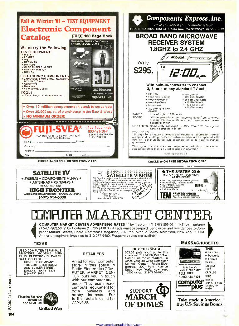
Fall 8t Winter '81 - TEST EQUIPMENT
Electronic Component Catalog FREE 160 Page Book
SEXING Mc COMPONENTS
We carry the Following: TEST EQUIPMENT
B&K LEADER VIZ BECKMAN HITACHI GLOBAL SPECIALTIES DATA PRECISION HICKOK
ELECTRONIC COMPONENTS JAPANESE 8, MOTOROLA Transistors IC's, FET, Diodes Capacitors Resistors Connectors. Cables
TOOLS Weller. Ungar. Xcellite. Vaco. etc.
AT WHOLESALE COST ""'
hur (Atmob rwo `ñwain w
Ol ...40r1118 Wilt
FIIp -SATA INC.
Over 10 million components in stock to serve you Over 20,000 sq. ft. of warehouse in the East & West NO MINIMUM ORDER!
FU, I-SVEO CALL TOLL421-2841 FREE
P.O. Box 40325 Cincinnati OH 45240 Local: 513-874-0220 Dept. Radlo-Electronlcs Telex: 182 392
Name Phone
Company
Address
City Slate Zip
CIRCLE 44 ON FREE INFORMATION CARD
I> Components Express, Inc. Have you kissed your computer lately'
1380 E Edinger. Unit CC Santa Ana. CA 92705(714) 558-3972
BROAD BAND MICROWAVE RECEIVER SYSTEM 1.8GHZ to 2.4 GHZ
only
$295.
With built -in -converter to channel 2, 3, or 4 of any standard TV set.
24" Dish Feed -Horn Receiver Mounting Bracket Mounting Clamp Instructions 3 Feet Coax Cable
with Connectors 300 Ohm to 75 Ohm Adapter
750 Ohm to 300 Ohm Adapter 60 Feet Coax Cable with Connectors
RANGE: Line of sight to 250 miles. SCOPE: Will receive within the frequency band from satelites,
primary microwave stations, and repeater microwave booster stations.
CONTENTS: Completely packaged in 19"x19"x4 1/2" corrugated carton complete with list.
WARRANTY: 180 days for all factory defects and electronic failures for normal useage and handling. Defective sub assemblies will be replaced with new or re -manufactured sub assembly on a 48 hour exchange guarantee. This system is not a kit and requires no additional devices or equipment other than a TV set to place in operation.
Dealer inquiries invited
CIRCLE 16 ON FREE INFORMATION CARD
SATELLITE TV SYSTEMS COMPONENTS LNA's
ANTENNAS RECEIVERS WE CAN HELP YOU!
HIGH FRONTIER 2230 E. Indian School Rd., Phoenix, AZ 85016
(602) 954-6008
CATCI I ITC 11l1CIr1Al1 SATELLITE VISION!
We have the highest spec 3 meter home earth station in the world today 41dß gain antenna Includes receiver, LNA 8 modulator, All professionally engineered for top quality, Completely warranteedi Immediate delivery. Complete details including satellite TV information, aiming service, specs, & dis- count schedule. Send 51.25 for postage & handling to:
TIGER TENNASr PO Box 561
Casselberry, Florida 32707
THE SYSTEM 20 MICROWAVE TV RECEPTION
AT ITS BEST!! RX-2300 Assembled Down Converter Power Supply / Antenna Switch 25" Parabolic Antenna ixM.ilS All Coaxial Cables + Full Year Warranty $5.00 shipping
TEM MICMwg7I CMFIRATIM
Avenue 22518 -97th Avenue North Corcoran, Minnesota 55374 /e.
COMPUTER MARKET CENTER COMPUTER MARKET CENTER ADVERTISING RATES 1" by 1 column (1 5/8") $55.00. 1 1/2" by 1 column (1 5/8") $82.50. 2" by 1 column (1 5/8") $110.00. All ads must be prepaid. Send order and remittances to Com- puter Market Center, Radio -Electronics Magazine, 200 Park Avenue South, New York, New York, 10003. Address telephone inquiries to 212-777-6400. Frequency rates are available.
TEXAS
USED COMPUTER TERMINALS, PRINTERS, MODEMS, SUR- PLUS ELECTRONIC PARTS. CATALOG $1.00
RONDURE COMPANY THE COMPUTER ROOM 2522 BUTLER STREET DALLAS, TEXAS 75235 (214) 630-4621
Thanks to you, It works.
for all of us.
United Way
RETAILERS
An ad for your computer store in this space in Radio -Electronics COM- PUTER MARKET CEN- TER puts you in touch with our computer audi- ence. They use micro- computer equipment for both business and hobby interests. For further details call 212- 777-6400.
BUY THIS SPACE $55.00 puts your ad in this space in front of 197,223 active Radio -Electronics readers. To place your ad write Computer Market Center, Radio -Elec- tronics, 200 Park Avenue South, New York, New York 10003 or call 212-777-6400.
SUPPORT
MARCH OF DIMES
MASSACHUSETTS THIS is only one of hundreds of unusual 7Saoa:e-T
r values .. .
Radio Shack's Get your
Model Ill 16K $859 FREE
TOLL FREE CATALOG
1-800-343-8124 today!
Dept. R
cann245A Great Rcad
usLittleton, MA
01460
Take stock in America. Buy U.S. Savings Bonds.;
www.americanradiohistory.com
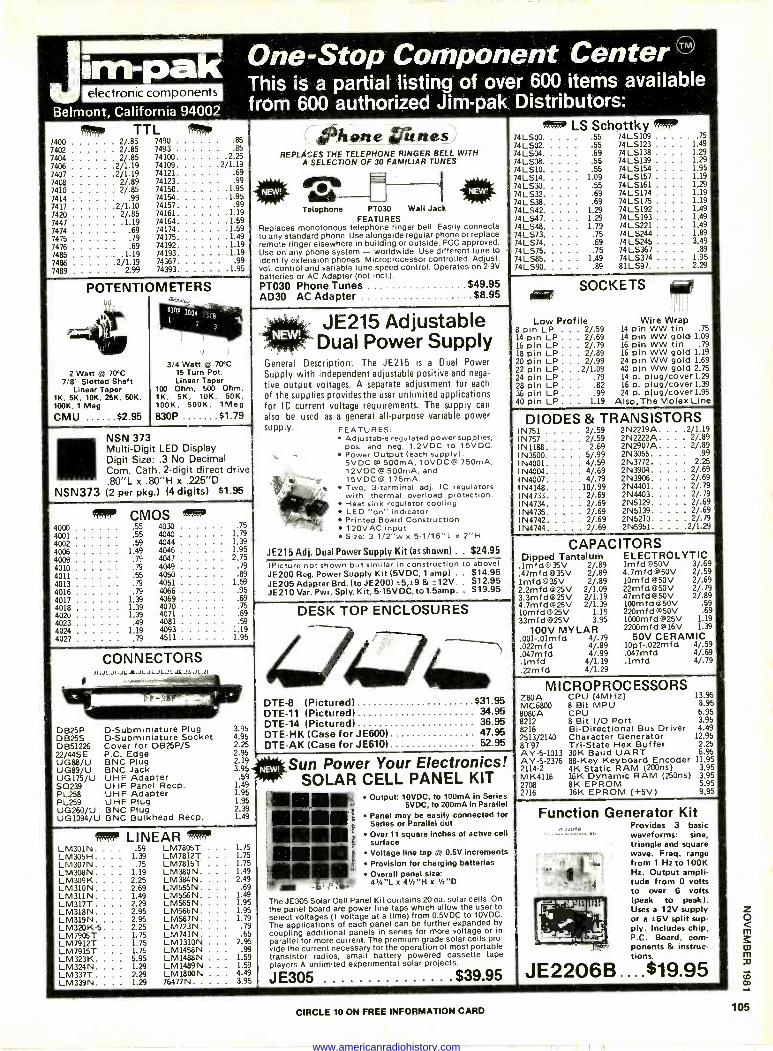
electronic components
Belmont California 94002
One -Stop Component Center TM
This is a partial listing of over 600 items available from 600 authorized Jim-pak Distributors:
me! 7400 7402 2/ 7404 2/ 7406 2/1 7407 2/1 7408
2/ 7410 89 85
7414 99 7417 2/1 10
7420 2/ 85 7447 1 19 7474 69 7475 79
7476 69 7485 1 19 7486 2/1 19
7489 2 99
TTL 2/ 85 7490
8.5 85 7493 85 74100 2 25 19 74109 2/1 19
19 74121 69
74123 99 74150 1 95 74154 1 95 74157 99 74161 1 19
74164 1 59 74174 1 59 74175 1 49 74192 1 19
74193 1 19 74367 99 74393 1 95
POTENTIOMETERS
2 Watt @ 70°C 7/8" Slotted Shaft
Linear Taper 1K, 5K, 10k, 25K, 50k, 100K, 1 Meg
CMU $2.95
3/4 Watt 0± 70°C 15 Turn Pot. Linear Taper
100 Ohm, 500 Ohm, 1K, 5K, 10K, 50K, 100K, 500K, Meg 830P $1.79
NSN 373 Multi -Digit LED Display Digit Size: .3 No Decimal Corn. Cath. 2 -digit direct drive .80"L x .80"H x .225"D
NSN373 (2 per pkg.) (4 digits) $1.95
"°°' CMOS 4000 55 4030 75
4001 55 4040 1 79
4002 59 4044 1 39
4006 149 4046 195 4009 79 4047 2 75
4010 79 4049 79
4011 55 4050 89
4013 79 4051 1 59
4016 79 4066 95
4017 1 39 4069 69 4018 1 39 4070 75 4020 1 39 4071 69 4023 49 4081 59
4024 1 19 4093 4027 79 4511
MIER
CONNECTORS
DB25P D -Subminiature Plug DB25S D -Subminiature Socket DB51226 Cover for DB25P/S 22/44SE P.C. Edge UG88/U BNC Plug UG89/U BNC Jack UG175/U UHF Adapter 50239 UHF Panel Recp. PL258 UHF Adapter PL259 UHF Plug UG260/U BNC Plug ÚG1094/U BNC Bulkhead Recp.
1 19 1 95
3.95 4.95 2.25 2.95
3.95 Sun Power Your Electronics! .59
PT030 FEATURES
Replaces monotonous telephone ringer bell. Easily connects to any standard phone. Use alongside regular phone or replace remote ringer elsewhere in building or outside. FCC approved. Use on any phone system - worldwide. Use different tune to identify extension phones. Microprocessor controlled. Adjust. vol. control and variable tune speed control. Operates on 2-9V batteries or AC Adapter (not incl.).
PT030 Phone Tunes $49.95 AD30 AC Adapter $8.95
JE215 Adjustable Dual Power Supply
General Description: The JE215 is a Dual Power
Supply with independent adjustable positive and nega-
tive output voltages. A separate adjustment for each
of the supplies provides the user unlimited applications for IC current voltage requirements. The supply can
also be used as a general all-purpose variable power
supply. FEATURES: Adjustable regulated power supplies, pos. and neg. 1.2VDC to 15VDC. Power Output leach supply), 5VDC @ 500mA, 10VDC @ 750mA, 12VDC@500mA, and 15VDC@ 175mA. Two, 3 -terminal adj. IC regulators with thermal overload protection. Heat sink regulator cooling LED "on" indicator Printed Board Construction 120VAC input Size: 3-1/2"w x 5-1/16"L x 2"H
JE215 Adj. Dual Power Supply Kit (as shown) .. $24.95
(Picture not shown but similar in construction to above) JE200 Reg. Power Supply Kit (5VDC, 1 amp) . . $14.95 JE205 Adapter Brd. (to JE200)±±5,±9 & ±12V.. $12.95 JE21 0 Var. Pwr. Sply. Kit, 5-15VDC, to 1.5amp. . $19.95
ego' LS Schottky Me' 74LS00 55 74 S109 75
74 LS02 55 741-5123 . . 1.49 74LSO4 69 74 LS138 . . 1.29 74LS08 55 74LS139 . . 1.29 74LS10 74LS154 . . 1.95 74LS14 74LS157 . . 1.19 74LS30 74LS161 . . 1.23 74LS32 74LS174 . . 1.19 74LS38 74LS175. . 1.19
74LS42 74LS192. . 1.49 74LS47 74LS193 . . 1.49 74LS48 74LS221 . . 1.49
74LS73 74LS244 . . 1.89
74LS74 74LS245 . . 3.49 74LS75 74L5367 . . .89 74LS85 74LS374 . . 1.95 74LS90 81LS97 2 29
55 1 09
55 69 69
1 29 1 29 1 79
75 69 75
1 49 89
SOCKETS
Low Profile 8 pin LP . . . 2/.59 14 pin LP . . . 2/.69 16 pin LP . . . 2/.79 18 pin LP . . . 2/.89 20 pin LP . . . 2/.99 22 pin LP . . .2/1.09 24 pin LP . . . .79 28 pin LP . . . .82 36 pin LP . . . .99 40 pin LP . . . 1.19
Wire Wrap 14 pin WW tin .75 14 pin WW gold 1.09 16 pin WW tin .79 16 pin WW gold 1.19 24 pin WW gold 1.69 40 pin WW gold 2.75 14 p. plug/cover 1.29 16 p. plug/cover 1.39 24 p. plug/cover 1.95
Atso,The Molex Line
DIODES & TRANSISTORS N751 2/ 59 2N2219A. . , .2/1.19 N757 2/ 59 2N2222A. . . . 2/.89 N1188 2 69 2N2907A. . . . 2/ 89
N3600 5/ 99 2N3055 99
N4001 4/ 59 2N3772 2 25
N4004 4/ 69 2N3904 2/ 69
N4007 4/ 79 2N3906 2/ 69
N4148 10/ 99 2N4401 2/ 79
N4733 2/ 69 2N4403 2/ 79
N4734 2/ 69 2N5129 2/ 69
N4735 2/ 69 2N5139 2/ 69
N4742 2/ 69 2N5210 2/ 79
N4744. . . . 2/.69 2N5951 2/1 29
DESK TOP ENCLOSURES
DTE-8 (Pictured) $31.95 DTE-11 (Pictured) 34-95 DTE-14 (Pictured) 36.95
47.95 DTE-AK (Case for JE610) 52.95 DTE-HK (Case for JE600)
'shone Dienes) REPLACES THE TELEPHONE RINGER BELL WITH
A SELECTION OF 30 FAMILIAR TUNES
V Telephone
{ Wall Jack
.47mfd@35V lmfd@35V 2.2mfd @25V 3.3mfd@25V 4 7mfd@25V
CAPACITORS Dipped Tantalum ELECTROLYTIC
2/.89 lmfd@50V 3/.69 2/.89 4.7mfd@50V 2/.59 2/.89 lOmfd@5OV 2/.69
2/1.09 22mfd@50V 2/.79 2/1.19 47mfd@SOV 2/.89 2/1.39 lOOmfd 550V .59
lOmfd@25V 1.19 220mfd@50V .69 33míd525V 3.95 1000mfd@25V 1.19
100V MYLAR 2200mfd@16V 1.39
.001-.01mfd 4/.79 50V CERAMIC
.022mfd 4/.89 'Opt -.022mfd 4/.59
.047mfd 4/.99 .047mfd 4/.69
.lmfd 4/1.19 .1mfd 4/.79 .22mfd 4/1.29
1.95 1.95 2.39 1.49
Mr LINEAR lee LM301N. . . . .59 LM7805T . . . 1.75 L M305H. . . . 1.39 LM7812T . . . 1.75 LM307N . . . . .75 LM7815T . . . 1.75 LM308N. . . . 1.19 LM380N. . . , 1.49 LM309K. . . . 2.25 LM384N. . . . 2.49 LM310N . . . . 2.69 LM555N . . . . .69 LM311N. . . . 1.49 LM556N. . . . 1.49 LM317T . . . . 2.29 LM565N . . . . 1.95 LM318N. . . . 2.95 LM566N. . . . 1.95 LM319N. . . . 2.95 LM567N. . . . 1.79 LM320K-5. . . 2.25 LM723N . . . . .79 LM7905T . . . 1.75 LM741N. . . . .65 LM7912T . . . 1.75 LM1310N . . . 2.95 LM7915T . . . 1.75 LM1458N . . . .99 LM323K. . . . 5.95 LM1488N . . . 1.59
LM324N. . . . 1.29 LM1489N . . . 1.59 LM337T . . . 2.29 LM1800N . . . 4.49 LM339N. . . . 1.29 76477N 3 95
SOLAR CELL PANEL KIT Output: 10VDC, to 100mA in Series
5VDC, to 200mA in Parallel Panel may be easily connected for Series or Parallel out Over 11 square Inches of active cell surface Voltage line tap rz 0.5V increments Provision for charging batteries Overall panel size: 41/2"L e 41"H x '/"D
The JE305 Solar Cell Panel Kit contains 20 ea. solar cells. On the panel board are power line taps which allow the user to select voltages (1 voltage at a time) from 0.5VDC to 10VDC. The applications of each panel can be further expanded by coupling additional panels in series for more voltage or in parallel for more current. The premium grade solar cells pro- vide the current necessary for the operation of most portable transistor radios, small battery powered cassette tape players & unlimited experimental solar projects.
J E305 $39.95
MICROPROCESSORS ZSOA CPU (4MHz) 13.95
MC6800 8 Bit MPU 8.95 8080A CPU 6.95 8212 8 Bit I/O Port 3.95 8216 Bi -Directional Bus Driver 4.49 2513/2140 Character Generator 12.95 8T97 Tri-State Hex Buffer 2.25 AV -5-1013 30K Baud UART 6.95 AY -5-2376 88 -Key Keyboard Encoder 11.95 2114-2 4K Static RAM (200ns) 3.95 MK4116 16k Dynamic RAM (250ns) 3.95 2708 8K EPROM 5.95 2716 16K EPROM (+5V) 9.95
Function Generator Kit Provides 3 basic waveforms: sine, triangle and square wave. Freq. range from 1 Hz to 100K Hz. Output ampli- tude from 0 volts to over 6 volts (peak to peak). Uses a 12V supply or a ±6V split sup- ply. Includes chip, P.C. Board, com- ponents & instruc- tions.
JE2206B . . . .$19.95
CIRCLE 10 ON FREE INFORMATION CARD 105
www.americanradiohistory.com
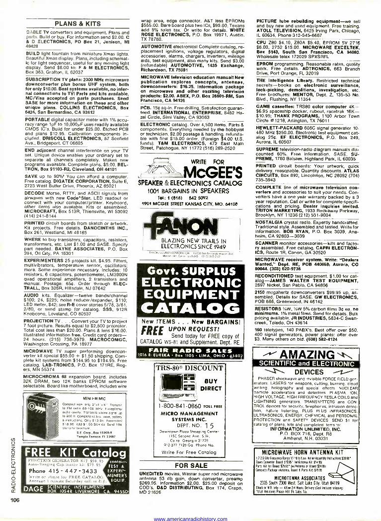
PLANS & KITS CABLE TV converters and equipment. Plans and parts. Build or buy. For Information send $2.00. C & D ELECTRONICS, PO Box 21, Jenison, MI 49428
BUILD light fountain from miniature Xmas lights. Beautiful Xmas display. Plans, including schemat- ic for light sequencer, useful for any moving light display. Send $8.00 to: F & M ELECTRONICS, Box 363, Grafton, IL 62037
SUBSCRIPTION TV plans: 2300 MHz microwave downconverter plus bonus UHF system, both for only $10.00. Best systems available, no inter- nal connections to TVI Parts and kits available, MC/Visa accepted on parts purchases. Send SASE for more information on these and other unique plans. COLLINS ELECTRONICS, Box 6424, San Bernardino, CA 92412
PORTABLE digital capacitor meter with 1% accu- racy range 1pF to 10,000µF uses readily available CMOS IC's. Build for under $25.00. Etched PCB and plans $12.95. Calibration components in- cluded. DRISCOLL ELECTRONICS, 57 Scofield Ave., Bridgeport, CT 06605
END adjacent channel interference on your TV set. Unique device enables your ordinary set to separate all channels completely. Makes new programs available. Complete plans, $5.00. REL- TRON, Box 91103-R2, Cleveland, OH 44101
SAVE up to 90%! You can afford a computer. Free catalog. DIGATEK CORPORATION, Suite E, 2723 West Butler Drive, Phoenix, AZ 85021
DECODE Morse, RTTY, and ASCII signals from airwaves with new Code°Star. LED readout or connect with your computer/printer. Keyboard, other items also available. Kits or assembled. MICROCRAFT, Box 513R, Thiensville, WI 53092 (414) 241-8144
PRINTED circuit boards from sketch or artwork. Kit projects. Free details. DANOCINTHS INC., Box 261, Westland, MI 48185
WHERE to buy transistors, capacitors, resistors, transformers, etc. List $1.00 and SASE. Specify part needed. BAYNE ASSOCIATES, P.O. Box 394, Oil City, PA 16301
EXPERIMENTERS 25 projects kit. $4.95. Filters, multivibrators, temperature sensor, oscillators; more. Some experience necessary. Includes: 10 resistors, 6 capacitors, potentiometer, LM3900N quad operational amplifiers, 2 transistors and manual. Postage: 654. Order through ELEC- TRALL, Box 326R, Hillsdale, NJ 07642
AUDIO kits. Equalizer-twelve bands/channel $100; 24, $225; noise reducer/expander, $110; LED meter, $42; see R -E cover stories 5/78, 3/81, 2/80, or send stamp for catalog. SSS, 912R Knobcone, Loveland, CO 80537
PROJECTION TV . . . Convert your TV to project 7 foot picture. Results equal to $2,500 projector. Total cost less than $20.00. Plans & lens $16.00. Illustrated information free. Credit card orders - 24 hours. (215) 736-3979. MACROCOMGC, Washington Crossing, PA 18977
MICROWAVE TV super performing downcon- verter kit special $55.00 + $1.50 shipping. Com- plete kit systems from $144.95 to $194.95. Free catalog. LAB-TRONICS, P.O. Box 171RE, Rog- ers, MN 55374
MICROCHROMA 68 expansion board. Includes 32K DRAM, two 12K banks EPROM software selectable. Board like motherboard, includes wire
MINI FM MIC :ompact size, only 2"x1 "x'/,". Transmit o FM radio 88-108 MHz. Exceptional lutlio quality. Transmits stable signal up 0 900 ft. Complete kit incl. case, battery I instructions. Only $13.95. Assembled 618.95. Add $1.55 S8H ea. Send 18e stamp for brochure.
S.E. Corp., Box 16969-R Temple Terrace, FI 33687
FREE KIT Catalog FUNCTION GENERATOR KIT $59.95 Auto -Ranging Cap -meter kit $79.95
Phone 415 - 447 -3433 Write or Phone for FREE CATALOG. Average 1 minute Saturday call is 21st.
DAGE
tonlolns TEST &
EXPERI - MENTER S
EQUIP
SCIENTIFIC INSTRUMENTS BOX 1054R LIVERMORE CA 94550
wrap area, edge connector. A&T less EPROMs $555.00. Bare board plus two ICs, $95.00. Texans add 5% sales tax. Or write for details. WHITE ROSE ELECTRONICS, P.O. Box 19571, Austin, TX 78760.
AUTOMOTIVE electronics! Complete catalog, re- placement Ignitions, voltage regulators, digital accessories, alarms, chargers, inverters, mileage aids, test equipment, also many kits. Send $3.00 (refundable) AUTOMOTIVE, 1435 Exchange, Richardson, TX 75081
MICROWAVE television education manual! New publication explores concepts, antennas, downconverters: $16.25. Information package on microwave and other exciting television products: $2.00. ABEX, P.O. Box 26601 -RM, San Francisco, CA 94126
PCB. 154 sq-In. Free drilling. Satisfaction guaran- teed. INTERNATIONAL ENTERPRISE, 6452 Ha- zel Circle, Simi Valley, CA 93063
ELECTRONIC catalog. Over 4,500 items. Parts & components. Everything needed by the hobbyist or technician. $2.00 postage & handling, refunda- ble with first $15.00 order. (Foreign $4.00 U.S. funds). T&M ELECTRONICS, 472 East Main Street, Patchogue, NY 11772 (516) 289-2520
WRITE FOR
MCGEE'S SPEAKER & ELECTRONICS CATALOG
1001 BARGAINS IN SPEAKERS Tel.: 1 (816) 842 50íY2
1901 MCGEE STREET KANSAS CITY, MO. 64108
BLAZING NEW TRAILS IN ELECTRONICS SINCE 1949
[ANON/COURIER CORPORATION 15300 San Fernondo µs1100 000 Mission Hills. Calrfornlo 91345 (213)365.2531
Govt. SURPLUS ELECTRONIC EQUIPMENT CATALOG New ITEMS ... New BARGAINS!
FREE UPON REQUEST! Send today for FREE copy of
CATALOG WS -81 and Supplement. Dept. RE
FAIR RADIO SALES 1016 E. EUREKA Box 1105 LIMA, OHIO 45802
TRS-80® DISCOUNT ® BUY DIRECT
1-800-841-0860 TOLL FREE
MICRO MANAGEMENT SYSTEMS INC.
DEPT. NO. 1 5 Downtown Plazo Shopping Center
115C Second Ave. S.W. Cairo, Georgia 31728
912.377.7120 Ga. Phone No.
Write For Free Catalog
FOR SALE UNEDITED movies, Westar super rod microwave antenna 53 db gain, down converter, preamp $269.95. Information $2.00. $25.00 deposit on COD's. D&D DISTRIBUTING, Box 174, Crapo, MD 21626
PICTURE tube rebuilding equipment-we sell and buy new and used equipment. Free training. ATOLL TELEVISION, 6425 Irving Park, Chicago, IL 60634, Phone 312-545-6667
CPU Z80 $4.10, Z80A $5.40, EPROM 5V 2716 $6.00, 2732 $15.00. MICROWARE EXCELTEK, Box 5143, South San Francisco, CA 94080. Wholesale telex 172029 SPXSRFL
EPROM programming. Reasonable rates, quality work. Free details. ADTRONICS, 663 Branch Drive, Port Orange, FL 32019
THE Intelligence Library. Restricted technical secrets-books on electronic surveillance, lock -picking, demolitions, investigation, etc. Free brochures: MENTOR, Dept. Z, 135-53 No. Blvd., Flushing, NY 11354
GAME cassettes: TRS80 color computer 4K- $6.95 spaceship docker, rubout, racetrak 16K- $10.95; THANX PROGRAMS, 1100 Arbor Town Circle # 1218, Arlington, TX 76011
HEWLETT-PACKARD 608C signal generator 10- 480 MHz $250.00. Electronic test equipment cat- alog 254. EF ELECTRONICS, P.O. Box 249, Aurora, IL 60507
SUPREME television -radio diagram manuals dis- counted 60%. Free information. SASE. SU- PREME, 1760 Balsam, Highland Park, IL 60035
PRINTED circuit boards: Your artwork, quick delivery, reasonable. Quantity discounts. ATLAS CIRCUITS, Box 892, Lincolnton, NC 28092 (704) 735-3943
COMPLETE line of microwave television con- verters and accessories to suit your needs. Con- verters have a one year warranty backed by a 3 year reputation. Call or write for complete specifi- cations and pricing. Dealer inquiries invited. TRITON MARKETING, 1933 Rockaway Parkway, Brooklyn, NY 11236 (212) 531-9004
NOSTALGIA crystal radio. Expertly handcrafted. Traditional style. Assembled and tested. Write for information. BOB RYAN, P.O. Box 3039, Ana- heim, CA 92803-3039 SCANNER monitor accessories-kits and facto- ry assembled. Free catalog. CAPRI ELECTRON- ICS, Route 1R, Canon, GA 30520
MICROWAVE receiver system. Write: "Dealers Wanted," Dept. RE, POB 440668, Aurora, CO 80044. (303) 620-9736
RECONDITIONED test equipment. $1.00 for cat- alog-JAMES WALTER TEST EQUIPMENT, 2697 Nickel, San Pablo, CA 94806
2150 megahertz downconverters $99.95 up, as- sembled. Details for SASE. GW ELECTRONICS, POB 688, Greenwood, IN 46142
RESISTORS 1/4W, 1/0W 5% carbon films 34 ea. no minimums. 1% metal films. Send for details. Bulk pricing available. JR INDUSTRIES, 5834-C Swan - creek, Toledo, OH 43614
160 teletypes, 140 PABX's. Best offer over $50. 400 signal generators, power plants: offer over $3. Many others on bid. (608) 582-4124
AMAZING SCIENTIFIC and ELECTRONIC
DEVICES PHASER shockwave and invisible FORCE FIELD gen-
erators. LASERS for weapons, cutting, burning, cloud writing, holography and special effects. NUCLEAR particle accelerators and detectors. PLASMA, ION, HIGH VOLTAGE, HIGH FREQUENCY TESLA COILS and LIGHTNING generators. TRANSMITTERS and CON- TROL devices for security, telephones, intrusion detec- tion, nature listening, PLUS PLUS INFRASONICS. ULTRASONICS, ENERGY, CHEMICAL and PERSONAL PROTECTION and SAFETY DEVICES. SEND $1 for catalog of plans, kits and completed items to:
INFORMATION UNLIMITED, INC. P.O. BOX 716, Dept. R8
Amherst, N.H. 03031
MICROWAVE HORN ANTENNA KIT 1.726 GHz Frequency Range 17á91b Gain Kit w/Assembly Instructions $39.95'
Down Converts Board 919.95' No/Antenna Kit $14951
Parts Kit for Board $2995' 1w/Antennas Bord 524.95)
Complete Package (Antenna, Board & Parts Kill 57995
MICROTENNA ASSOCIATES 2335 South 2300 West. Salt Lake City, Utah 84119
Check or MO only - Allow 2-4 Weeks Delivery (Cost includes shipping)
'Utah Residents Please Add 5% Sales Tan
www.americanradiohistory.com
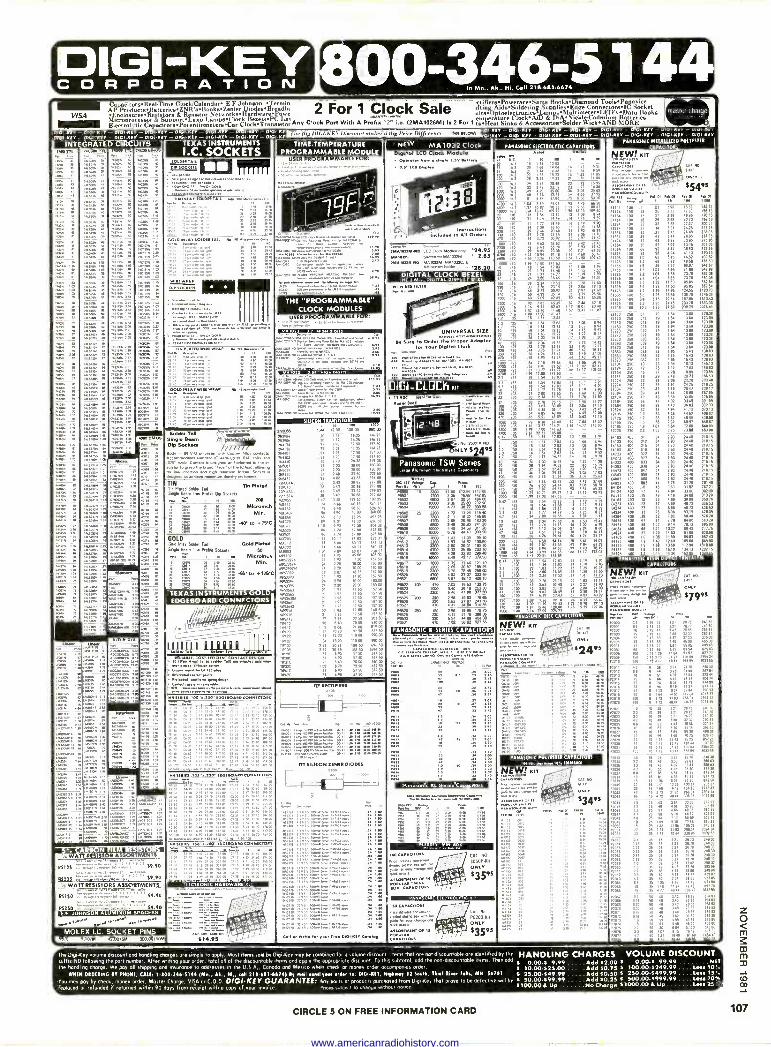
DIGI-KEY C O R P O R A TION leo 800-346-5144Cn11 218.681.6674
4 . .
CapaeitorseReal.Tinee Clock/Calendare E F.' Johssoo eTermmo "' - etifiersPoweracesSams BooksDiamond ToolsePanavece -or-
VISA g ProductsBs4t nesZNR seBoQlyseZeeper_DlocIeseB gad& 2 For 1 Clock Sale tftio&AidsSoldering SupolieseEdge ConnecepreIC Socket
EnclosureseRespelors & Resistor NetworksHardwate rowe 0...,..... tkiteDptioelleetrozicrisaings,AMMtmeterLD ...Dot...Books Ble, Microprocessor & SuPPOrtLUILO LamossClock BerelsPC La. Electrolytic CapacitorsPotestimetersCar ClockTransistor AYTE Clock P01, Elf1YA A PPEBN ..r. LA 12NIA102ANN M 2 F0,1 rzffen:mr,k7EA.ecessories;older 4E-fete:M. Meek"'
0101 KEY PIG, 1212.2
INTEGRATED
-01G1.Y - 1310,22-1 01,01 KEY
- 01. KEY
CIRCUITS
- OPGJ KW -12101K
- DIGI KEY - DIGI KEY - 01.1 411- 0100 Y -- DPW KEY - 0.1 KEY - INGI-KEY - 0/1111,222
KE 0/ re. 01 KEY
NEW' MA 1032 Clock
010/ /221, 131G, 222 2 0101, REY DOG/ - DIG,. V 0101-1(12- I - 0101 -KEY - O./
PANASONK ILECTROLY1IC CAPACITORS
8,121 010/...2 - INGO Eff1 - 0141 K2 Y
AFT" - OlGi-KEY - 010I -KEY - 0101 KEY
PANASONIC METALLIZED NN.YESTEE
PACITORS TIME TEMPERATURE
PROGRAMMABLE MODULE TEXAS INSTRUMENTS I.C. SOCKETS ymery,
74°
ALDO TT.
111
0
.".'"
NA.
MO
.46 it
NEW! KIT .....--... --..--. ,,,...
'kit... 'Me $549' res.:s.a.e.,'
DRAW PM IN WV 1.81 Of Po Of
'''''.. "47 99' ' ' ' ' "
o .
r
g to co c o< m., cm.,...,,.......,,..,,y ....,,,
1 2 : 3°418 ,,,.
141......». ''''..' ' "°""
61441
.'" r.. , ,. ,. , ,.
11 j liJ 1,2
USER
..,.....,.................,.....,...........
............. .---..-'-
. .
..y......,....... 8619,400.4.3
3..4.
..,,,,, ..
." --
PR,. ' AMMO . 1 i
. ,Pi L -0 -I! it 1 :=-,J. -.:-.-. . -:,-
1.,..2 r c. 04.
::499 .... ....,
-. 911.7.19.173V.Z.:::
R.
.ODoeDI .... : .
'
:1g ""oo
-'
. 7,........,,. is
.. ................ .... 7.7..2.= "' a"'
.
rio° 111 11 11 IN 'I°. 19; ii 332. Al. 43 SA 57.43 75 6.38
° ree .242.202241.712
2.- 9,, '
......
2929. 244 au
13 2.93 31 '5,2 1912 212 .2 ; 2 12 ;33 ;, iZ 12 22 2:2 21154 100 15 27 2 28 1116 17055 2114 100 16 29 2 49 20 73 10853
21224 100 .22 32 2.88 22 V AO 37
21274 100 27 34 291 2435 11115 21334 100 33 37 Ile 28.45 231.05 5440 1 41 3.. 28.85 73783
21474 100 47 43 3.61 10 85 27585
322 33
mg z .1' :" te 22 22 21125 100 12 68 6211 46_50 43160
7 6616/ 21156 100 1.5 88 737 061A 21113 100 18 I 01 11.14 A BOA 212.25 190 23 1 04 1.65 73.70 88104 11275 100 2.7 1.04 1.15 73.70 24308 21315 AO 3.3 1.35 1150 216.86 8212 54
21103 AA 3.4 1.35 11.30 05,15 862.54
21475 100 4 7 1.76 14.95 AC. 1120 /2
21565 100 5.6 1.05 1665 IA /0 114108 21845 100 6.8 133 1034 107.16 151613
21825 190 1.2 286 24,45 203 70 1133.30
AAA 100 10.0 3.23 Ern 270 72 2076 41
1;20 1 .i': 'ii kl..3 2, '',.ii
',ió : 2 VA .2 m .010 INLAY $01914 1,612 my ea 4.3.....» OAT
2 :2
22 :94
*c"': 11:11:. imps° s s
11' 13 III ell' 31
.9% ',,ii - '13 J1:13 1.11 A':.
mom. om.-
-.......------J-°,70=,...'.,7' .21:: . 20.20
DIGITAL CLOCK BEZEL THE 1.2A.J. DIGITAL DISPlAY 82222
..,.....,,.
/00- -
___.------
_.--,- UNIVERSAL SIZE -,"'1 244yous AAA u0.41024.42.
14 Ora.. Pee Proper Adopter " U". for Your OAK. Clock .... ,ser's-
:II .:4=41,.7273:=4;11.62.7gcri,41441.
'' .3:311: ''''''''''' ""'"' oo
Dal -CLOCK .,
00 510 ' 116
» ,,» . d. 80
AA
'AAA ...,,,.. 000 14.4*2941.242.234.,3,
111.1111.111A11113111
THE "PROGRAMMABLE" CLOCK MODULES
ape ... ., 114 se. ...
4200 116
4
rio ',g _ - - - - - 22103 250 211 .19 1.04 13.08 12101
22113 150 .012 .19 1.11 13 IN 1231. 22153 750 efs to . isee 123.09 22183 23.0 .0111 .19 1. 13.01 121398
250 022 19 IN AP 23.92
22273 250 017 19 1.84 13_88 123. 13333 no 033 19 LIN 1.3.24 123.011
12393 50 OH 19 1.84 13.84 12308 .473 250 .047 19 1.04 13.81 113.00
22563 250 .0511 .21 LA 1543 131.63 22823 254 .0111 .22 1.85 16.43 e'en 22623 230 082 22 1. 15 43 13483 22104 no to 23 1.94 18,13 14513 AIN 256 12 35 2 12 1713 111,32
4 25 .22 32 2.68 VA 200.48 22274 2. .27 34 2.01 24.25 21125 22334 250 33 37 3 10 26.0 131117
223114 2. .31 41 344 28.65 25785 22474 250 V 43 360 30.66 27512 22584 250 66 47 492 33.45 101.05
22624 250 .02 58 4.94 41.13 PO 13
22105 no 1.0 113 5.35 44.52 4111 87
22125 250 12 .88 5.82 48.50 AM 50
Ems 750 1.5 as 732 eo.e. see..
:2 3:: 2r.
USER PROGRAMMABLE FOR: , . . , -..,,,......,....,...,
00 Sc22223 , ,I , ,!E'LM1Mei=X,,,g.,
"'''''''' 1.1" 1113.073311" :1:9
.
9 2 9:212 1"1::ro,...32,
''''°"''''f"'"'"*"'""'""'" ''''''"'' '
zu=urr..2e-' ."-.2 , A
3.2.1.1:"'"C,Z.
MBZWII2Ele°991.11e. 20 1 n 1636 IA 25
223206." . . 20 I /9 10.25 me 25
7144174 . A 1.03 17 50 157 50
AAA 22 2.01 1125 164.15 . 1.93 17 50 157 50
.403 1 93 17 50 257 50
""'" " "" '" 212.7 24 120 70,00 18003
27 2 41 72 50 202 . ..,,,,,, H 4 86 43 A 304 88
1
r3
TIN PLATA AM 0.141, 444 2. .. ........
op . :2 22 ...
132 ,22
Ir , NI t
3 1:r. 91
2 :: : 8.2
1» A. 118»
... :: 29 9:2 92:
2192. PA
14.108 1412/1
NLY .
Panasome TSW
1803.
't, ,
'''''''i ' r .2.1
P6503 74 2 9,3.9 16030 en
. .... .._
. Hy 9.3......
y 2y,
9 A...." '1° ... 17:.
.24" Series
'72 °;i-1113 12 5400
36.72 330.
470
rj,
,thl. - - - - 2:2 Solee.T...... = .1
12 12 32 2 12 133 232 -ele 2- 2.15
9:9;9 29 92 2 999 22 233 24333 as 033 at . S3 24.40 210 A 24193 AA 039 . 2.13 24.40 211,5 24471 eon 047 34 293 24.40 211.15 24583 400 056 H 2.03 24.40 211 A 24603 400 .0141 34 2.03 24.40 21.15 24823 roe 082 .44 3.76 3116 Al 48
24104 4,310 10 45 303 3192 287.21
3321 ".: 13 2 22, MN 24114 400 14 .55 31 3496 350.72
224 AO 32 57 499 4,0 73 6453
;9 29 :9; 12 92 :119 :299 AM 400 A .82 7.02 51.41 51610 24474 . .47 7 A 64.40 58320
00 459 00 50
tr. u 1,1; 111: NI CI: 14111 sea le lee lei° 134.13 110315
_61225 co i 11.34 152 E
......0. 3400. 2,)M1910 DIN Bookete
soply - 94 V.0 porn MA Copper Alloy contacts AcconynoMe AAA. IC lea. up to 014" Pp. NW .'''...°c=?...- suletor A 92.13 the Ca -140, of Ae IC 139.1. allm 10 lox Irrem.n ... e...........3:21,
41.6.306 lo ASA. maynym elemPly on bow*.
'1 3.' 1 :....t 233 13 II 12 ''e -1: iisi 3:8 11 ill e.
...... - Ois A
. 1'1/ l 11:111
4
A
11 12 1111 :3 ,:
1 1' 11 lil If, '11 ''11_ _
TIN %Pealed Tin PAW Safe Tail .1184 Bunt Las Prone 06 Sockets r ...r.' I
MO
A151012 ,,,,,,,, % Ni e: 'F,33.1',7
9,424 p3,2,23 ea e .a "" 2012055 1 0 13. 12250
329 14 6 44 60 11
72 0 41 .50
r..1" , 4 80 40 00
00 6 IT 55 25
''''''° 09 .1 A 32
MA. 1 10 9 A AA 34
66 7 74 92 88
47
1, :1 1. P ,13: 193 -12 .. 290 10.03 16 1. Y3
ccral 13 .3 ,v3 e......h .'4 116 'Pe EE ".
40.54 .i..7MC
111 el.' 2 P11 1.. - 99
r2" e303 .191 ii in 1:22 ,91,1 22 322
neydo 1.0 578 AI 45 389_90 .1 1,5 iti
8cr
'ti GOLD Geld IN., SAM ME Gold Nerd
Sinele Been Eva Ref% Seykeu 00 se_ 4.7.1 1 to Miami...N.
cf ; iFE FEE Mk'
..1. LE :3 g '2 44. to ,12MC
3 ,r, ..
.521 86 7 NI 6188 703 1 13 10 12 91 82
96717 74 6.. 60 .3 WA. 74 e 24 60 13
skews '.:S 1g: coo. ,,,,,,, 3, 1 93 A .
zr.',::: P28516063
14 2 20 A 013
A I. MOO
A.,31:1 23 1 07 11175
71 1.93 1P 50
1053394 . 2 20 2003 s 14 7 » 20 Ca
21 t 93 17 50
.5 21 1 al A 50
.. 11 13 1/ 50
1
V 1 93 A 50
3 3: Y., i,iee' n,:56
AA 2
19117 1 12 10 08 91 00
;1 r, 1 0 10 73 4, 50
7::"I'',-
, »»o» 232 2068 16150 16.50
Eenw ,p, ne Tr, 1,,,t,r,.`:ettit
Wei .31C 1 01 8 70 72.. 711,12 MAC _
01 6 A 57 50
-
;
-
,
. -",
ier,,, ,g
01900 ,377 50
052 50 517 50
o E . e if, Ili Pests
¿co 2.13 . 2: 'A:
.216 '103190- '1'76 '134617 '121'10
:rt. i.rt irt 1-17.
00. 03
o cc ,...s. . ,c, r. r.,r .... .., co.',
el 13g '. ''-'' ne. '11'. 7 99.11 11 :1: IIS
1.1! .J''
PANASONIC RESIN
CAPACITORS
. "Zr. ?.... = ''''.:7
e '2 1
MI g grs Pe: 1
83010 220 1
DI ANT L
01 f3'11'
P ....31;4;11. '4i2 $7095 1 7
e'''. i. sw
i i/ i.1410 gi.; 2to
:SI Sit Ms ziVei'e 0 512 AIM W. 1012 55
Pili ° 'AC 1:9, iii di P24531
, erliemon
C 43
c° eco...PAP...,
,..... ,.....,
e
-
'''" --
J
1.622 100 470 3.02 16 63 138.76 21623 1000 3.40 36.16 263.30000 P8624 2200 2,46 41 811 A7.00 TEXAS INSTRUMENT
EDGEBOARD CONNECTORS
,
I I-
QUIP A iße a Ii,I)J
P.9 203 213 2 66 1963 18166
"4329 22 122 23 ',133 I:73 ,T:I1 ze Tat ilól It ett -- P6. 360 160 2 68 19 80 171.75
p.p." .n neL .,A ..-ol 470 7.02 5802 621 53
PANASONIC; DISC CAPACITORS
NEW! PM '. P. ecrio. 3.^.......
s. MI
......,,,,,.... /M«...eir,,: ...... .24es
'V....".".".:- ".22". ''.'...... """.. ....'
'A.., my. 13 423 34py or.j.....=..........1....................
Eennifseci EroSEI MI I110 - -
Eilik:sertjeiri=74°..keisary'etrway ..932.4,302622,245422,43,
I: Yr. '".
cs ssnewsos 4,32.832.4 eve
AMA
922 :;
12 PAU 23 non A 01075 my lee P1,370 150
2 ;3
reps oe
AIM 13 le
In» V 10
3333' 4,0 ;3
nos is 11
12 18
9203 33 t.
"", :8 ;3 . , 0 Ill
tinken*1 il 1,7543 11 18
2 998 .i 1T2
7,1 434 51. .522 25
88 110
'Sc 1405 12 04 1022 33
'13 7183 AM 04 21214 23
4 72 44 44 33686 1032 55
2 33; 22 322
. 41 210 44 14 10/ 3, 78 082 50 24 482 Er
1 2, 1510 120 44 153, 2,
23 233 322 eM 121 26 Pi- 242 s
42 3.50 /$43 284 0, 47 4o2 3343 300 8,
31 32 42 :tV; 41 li 2753 213 ,
" '9"5 12 37 ,,;'' 3 SI ',IS: :: 2.'.
4 72 4014 1490 .3255
'71"
y. 24.
.
1ST «CTN.» Ap
.1 1- 'Y.'
-411 1. ..... nos ii ii
!I: ' 1 Ili lÌ
.:i -
jo.,, o
1
24,11.0.23. 100 2.200 22,02110,42.4 CO.. 042
1 º
,-. , .., ... ......, AT SILICON 555154 MOPES
-222o
PANASONIC POLYESTER CAPACITORS
- i,:77:Atg'
CA . 7 , , . . -.MY"-
H :3
.. .:" -
''¡;L
; - n
... o.r......-n-....,....r....... 2:4". Ar11941 _29 V 'AA
131,2 99 1Z 3 LI 3: yy, y, y y , y yy mmialisiguazzoirs e e :; ILI 3: ::.'n
s.,0......., CAT..
'''"*""'."« 30608..2 a.......... ........,..... ....-. ,..,,. $3595 ...a -T.: - 'avii,i...ag
, .....
'>«21 "
5 Ho. _54 1.., ,334....1 A, 1..11
, yyy, ,,, 1:: 1:.::::
:312
:1: '-:: ' .00 :1: ',..:: » ,.. o, .
7- 92 39
re i::: '33 o ...._ .. ,.
7 :::,=::::-i re ::
'" o' '''°'°' .>'"'......`.0.....
15 25 1 40 1214 10538 042 3P
A 25 3.71 1183 280.04 7114 34
1 33 25 4 72 AO AI 336 95 2012 3,
iti 31 34 221 16 70 Ma 14
3 N IV, 2;3 3330! 56 013 35 30 31/
I 040 15 33 321 23, 9:0 1
12 99 2 999 9:89 920 99
:1 :: :, 1 ItI 1: in 55 EA IS 35 4 TT .4. 3.215 3032 5,-
9 62 '.', 2 2 254 5, 254 93
25493
' i'i ..'''.i mo :32 O. 50 45 117 10 2.,
, 0 50 55, AM 41%5 113 YS
3,, ;; N 2 3 3 3n , r to, It 1,20 ,, 1.r. P2,24 61 50 oil 40.44 33115 30375>
.6511111222.2 . 100 11141112y1,101011110Y, - --r- "''' '
Ill
....m.
vet ewe. 4Y. ',die 2- ,.., 'de,-
I v. viiMMT*Pieff Is RilitiAteiell 113125 .7.* 59.90
.
55222 5 co
WATT lit SISioRs A ssoRTAAENTS
115100 . '
RS250 iiiimprri--,:riNec.IT'I'l71,1-ZTe4;,,i
MIGIISITÄMI.M314231. 1.......... ..t.. -...=.7.2..r.-. ,101:`...°ia.%,, ...Area, Enron on .ief.-..-YTE..-
...fn. ete,2 .
.ssocrlowo or es 405.N.- 15.5 mr.r....
...0,,...., ,,.....-%.,,,.... MOLEX LC. SOCKET PINS
. . ,,,24 342 (10 SAS 00100614.95 The Degi Key donate discount and handling ch toes are simple to opoiy Most demo sold by 9 key may be costoned tor o volume discount Items mot ore not discountable are ,dentified by the HANDLING CHARGES VOLUME DISCOUNT suf I or -ND following the port number. After writing your orde,. total all of ,he discountable tems end apply the uppropmate discount To this subtotaf. add the non.chscountable irems Then odd 9.99 Add 52.00 $ 0.00.5 99.99 NOT the handling charge. We pay all sfopp/ng and Insurance to addresses in the USA.. Cana acid Mexico when check or money order accompanies order 5
WHIM ORDERING IT PRONE, CALL 1.100.346.5144 (M.., AL, NI., WI 210-611-H674) By nwil Noll yew NM, toi 121101,M. Nelnary 32 545118. INN River EMIL MN 56101 5 10.00-525.00 25,00-549.99
Add $0.75 Add $0.50
$ 100.00.5249.99 ....less 10% S 250.00-.499.99 ....Lem 15%
Yoo may Fsoy by check, money order, Master Charge. VISA or C.0 D. RIGI-KEY GUARANTEE: Any ports or producls purchased from Dogi-1(ey that prove to be defective will be 5 M100499.99 Add 90.25 Ti 500.00-S999.99 ...Leas 20%
replaced or refunded if returned within 90 do ys from receipt with o copy of your invoice fwes 63.1.901 113 CA,. M.A. n01.0 H00.00 a Up No cho," S1000.00 & Up Lets 25%
CIRCLE 5 ON FREE INFORMATION CARD
z o m
m 03
33
<7:;
OD
107
www.americanradiohistory.com
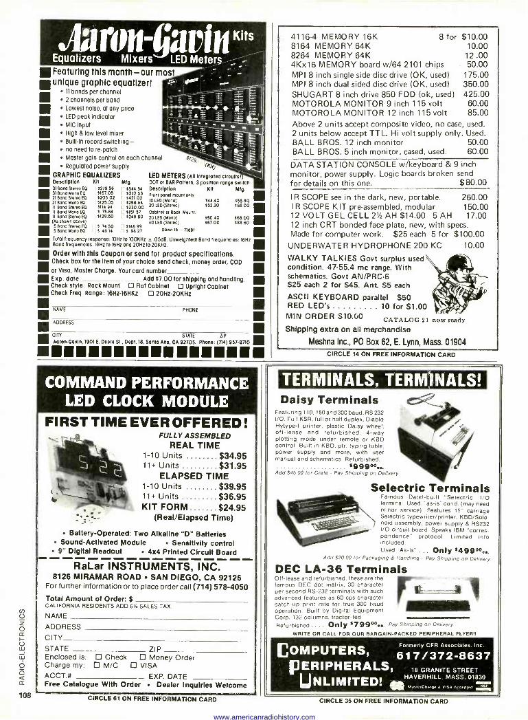
Featuring this month -our most
-.J-----.. -= L = , ' \i }--' _
channel s719 ~
Front panel mount only. 10 LED (Mono) 20 LED (Stereo)
Cabinet or Rock Mount. MIIl Bond Stereo EQ 20 LED (Mono) (As shown obove) 40 LED (Stereo)
5 Bond Stereo $ 49. $1489 5 Band Mono EDD
Down to - 71dB1 . 1 49.14 $ 98.
Total frequency response x)Hz to 100KHz ±.05áe. Unwelghtedl Band frequencies 16Hz Band frequencies. 16Hz to 16Hz and 20Hz to 20KHz.
Order with this Coupon or send for product specifications. Check box for the item of your choice send check, money order, COD
Mor Visa, Master Charge. Your card number . E xp. dote Add $7.00 for shipping and handling Check style : Rack Mount Flat Cabinet D Upright Cabinet Check Freq. Range: 16Hz-16HKz 2oHz-20KHz
CITY STATE ZIP Aaron -Gavin, 1901 E. Deere SI, Dept. 18, Santa Ana, CA 92705. Phone. (714) 957-8710 aaaaaaaaaaaamaaaaa
unique graphic equalizer! 11 bands per channel 2 channels per band Lowest noise, at any price LED peak indicator MIC input High & low level mixer Built-in record switching - no need to re -patch Master gain control on each Regulated power supply
GRAPHIC EQUALIZERS Description Kit Mfg. 31 Bona Stereo EQ 5279.56 1544.51 31 Band Mono FO $157.05 5322.53 21 Bond Stereo EO 1205 02 5421.02 21 Bond Mono EQ $125.05 $258.64 Ti Bond Stereo EO 1114.94 1230.00 11 Bond Mono EQ $ 75.84 5151 57
5129.50 $249.80
NAME
ADDRESS
orio
LED METERS (All Integrated circuits! DOT or BAR Pattern, 3 position range switch Description Kit Mfg.
$44 40 $55 80 552.20 $68 00 in $50.40 $68.00 IIII $67 00 $88 60
PHONE
COMMAND PERFORMANCE LED CLOCK MODULE
FIRST TIME EVER OFFERED ! FULLY ASSEMBLED
REAL TIME 1-10 Units $34.95 11+ Units $31.95
ELAPSED TIME 1-10 Units $39.95 11+ Units $36.95 KIT FORM $24.95
(Real/Elapsed Time)
Battery -Operated: Two Alkaline "D" Batteries Sound -Activated Module Sensitivity control
9" Digital Readout 4x4 Printed Circuit Board
RaLar INSTRUMENTS, INC. 8126 MIRAMAR ROAD SAN DIEGO, CA 92126
For further information or to place order call (714) 578-4050
Total Amount of Order $ CALIFORNIA RESIDENTS ADD 6% SALES TAX.
NAME
ADDRESS
CITY
STATE ZIP Enclosed is: Check Money Order Charge my: M/C VISA ACCT.# EXP. DATE Free Catalogue With Order Dealer Inquiries Welcome
4116-4 MEMORY 16K 8 for $10.00 8164 MEMORY 64K 10.00 8264 MEMORY 64K 12 .00 4Kx16 MEMORY board w/64 2101 chips 50.00 MPI 8 inch single side disc drive (OK, used) 175.00 MPI 8 inch dual sided disc drive (OK, used) 350.00 SHUGART 8 inch drive 850 FDD (ok, used) 425.00 MOTOROLA MONITOR 9 inch 115 volt 60.00 MOTOROLA MONITOR 12 inch 115 volt 85.00 Above 2 units accept composite video, no case, used. 2 units below accept TTL. Hi volt supply only. Used. BALL BROS. 12 inch monitor 50.00 BALL BROS. 5 inch monitor, cased, used. 60.00
DATA STATION CONSOLE w/keyboard & 9 inch monitor, power supply. Logic boards broken send for details on this one. $80.00
I R SCOPE see in the dark, new, portable. 260.00 IR SCOPE KIT pre -assembled, modular 150.00 12 VOLT GEL CELL 2h/ AH $14.00 5 AH 17.00 12 inch CRT bonded face plate, new, with specs. Made for computer work. $25 each 5 for $100.00 UNDERWATER HYDROPHONE 200 KC
WALKY TALKIES Govt surplus used condition. 47-55.4 me range. With schematics. Govt AN/PRC-6 S25 each 2 for $45. Ant. S5 each
ASCII KEYBOARD parallel $50 RED LED's 10 for $1.00 MIN ORDER S10.00 CATALOG 21 now ready
Shipping extra on all merchandise
Meshna Inc., PO Box 62, E. Lynn, Mass. 01904
10.00
CIRCLE 14 ON FREE INFORMATION CARD
TERMINALS, TERMINALS! Daisy Terminals
Featuring 110, 150 and 300 baud, RS 232 I/O. Full KSR, full or half duplex, Diablo Hytype-I printer, plastic Daisy wheel, off -lease and refurbished. 4 -way plotting mode under remote or KBD control. Built in KBD, ptr. typing table, power supply and more. with user manual and schematics. Refurbished.
11999o%.. Add $45.00 for Crate - Pay Shipping on Delivery
Selectric Terminals Famous Datel-built "Selectric" I/O terminal. Used, "as -is" cond. (may need minor service). Features 15" carriage Selectric typewriter/printer, KBD/Sole- noid assembly, power supply & RS232 I/O circuit board. Speaks IBM "corres- pondence" protocol. Limited info included. Used "As -Is" ... Only :49900.
Add 520.00 for Packaging & Handling - Pay Shipping on Delivery
DEC LA -36 Terminals Off -lease and refurbished, these are the famous DEC dot matrix, 30 character per second RS -232 terminals with such advanced features as 60 cps character catch-up print rate for true 300 baud operation. Built by Digital Equipment Corp. 132 columns. tractor -fed. Refurbished .... Only $%9977.. Pay Shipping on Delivery
WRITE OR CALL FOR OUR BARGAIN -PACKED PERIPHERAL FLYER!!
[COMPUTERS, Formerly CFR Associates. Inc.
617/372-8637 PERIPHERALS,
UNLIMITED! a HAVERHILL. MASS. 01830 M,iI.,Cnn, n.' d VISA A[ia pi,.,,
18 GRANITE STREET
CIRCLE 61 ON FREE INFORMATION CARD CIRCLE 35 ON FREE INFORMATION CARD
www.americanradiohistory.com
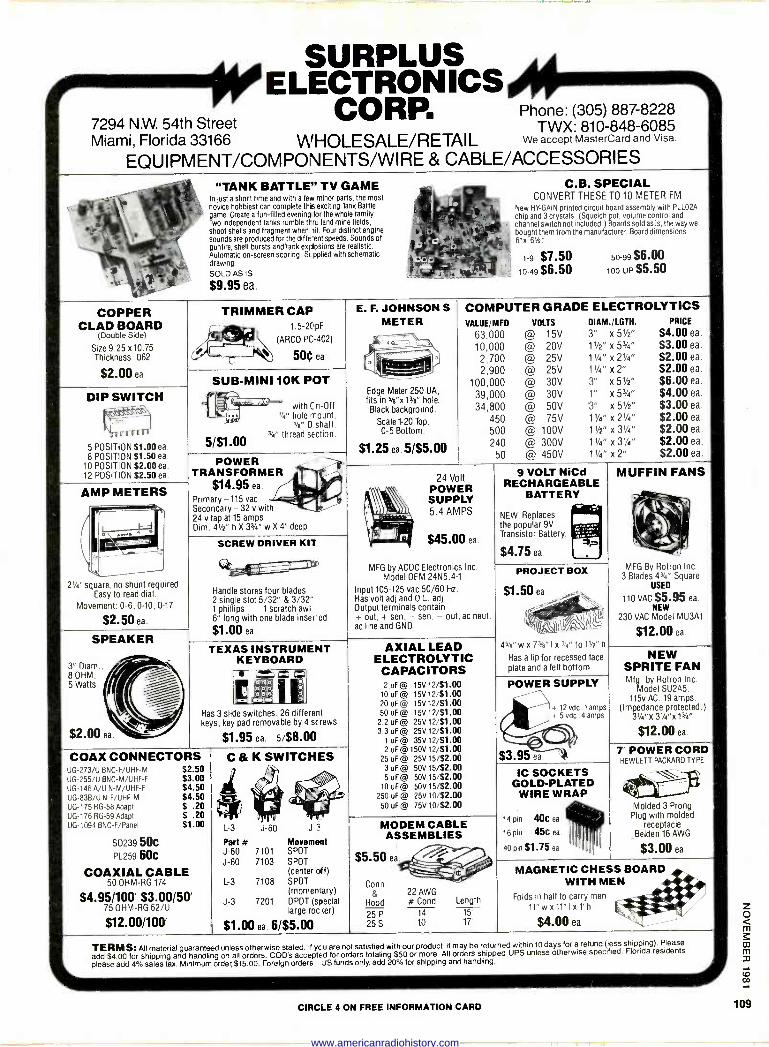
7294 N.W. 54th Street Miami, Florida 33166 WHOLESALE/RETAIL
EQUIPMENT/COMPONENTS/WIRE & CABLE/ACCESSORIES
COPPER CLAD BOARD
(Double Side)
Size 9.25 x10.75 Thickness .062
$2.00 ea.
SURPLUS ELECTRONICS
CORP. Phone: (305) 887-8228 TWX: 810-848-6085
We accept MasterCard and Visa.
"TANK BATTLE" TV GAME In just a short time and with a few minor parts, the most novice hobbiest can complete this exciting Tank Battle game. Create a fun -filled evening for the whole family. Two independent tanks rumble th -ru land mine fields, shoot shells and fragment when lit. Four distinct engine sounds are produced for the ditfe-est speeds. Sounds of gunfire, shell bursts and tank ex¡losions are realistic. Automatic on -screen scoring. SLpplied with schematic drawing.
SOLD AS IS
$9.95 ea.
C.B. SPECIAL CONVERT THESE TO 10 METER FM
New HY-GAIN printed circuit board assembly with PLLO2A
chip and 3 crystals. (Squelch pot, volume control and channel switch not included.) Boards soldas is, the way we bought them from the manufacturer. Board dimensions 6"x 61/27
1-9 $7.50 50-99 $6.00 10-49 $6.50 100 -UP $5.50
TRIMMER CAP 1.5-2[pF
(ARCO PC -402)
50e ea.
DIP SWITCH
5 POSITION $1.00 ea.
8 POSITION $1.50 ea. 10 POSITION $2.00 ea. 12 POSITION $2.50 ea.
SUB -MINI 10K POT
5/$1.00
with C n -Off 1/4" hole mount,
1h" D shaft, 1" thread section.
AMP METERS
2'/4' square, no shunt required. Easy to read dial.
Movement: 0-6, 0-10, 0-17
$2.50 ea.
SPEAKER
3" Diam. 8 OHM, 5 Watts.
$2.00 ea.
COAX CONNECTORS
POWER TRANSFORMER
$14.95 ea.
Primary -115 vac Secondary - 32 V with 24 v tap at 15 amps Dim. 41/2" h X 33/4" w X 4" deep
SCREW DRIVER KIT
Handle stores four blades 2 single slot 5/32" & 3/32" 1 phillips 1 scratch awl 6" long with one blade insered
$1.00 ea.
E. F. JOHNSON S
METER
Edge Meter 250 UA, fits in sex t3/4" hole. Black background.
Scale 1-20 Top, 0-5 Bottom.
$1.25 ea. 5/$5.00
COMPUTER GRADE ELECTROLYTICS VALUE/MFD VOLTS DIAM./LGTH.
63,000 @ 15V 3" x 5'/2"
10,000 @ 20V 11/2" x 51/4"
2,700 @ 25V 11/4" x 21/4"
2,900 @ 25V 11/4" x 2"
100,000 @ 30V 3" x 51/2"
39,000 @ 30V 1" x 52/4"
34,800 @ 50V 3" x 51/2"
450 @ 75V 11/4" x 21/4"
500 @ 100V 11/2" x 31/4"
240 @ 300V 11/4" x 31/4"
50 @ 450V 11/4" x 2"
24 Volt POWER SUPPLY 5.4 AMPS
$45.00 ea.
MFG by ACDC Electronics Inc. Model OEM 24N5.4-1
Input 105-125 vac 50/60 Hz. Has volt adj and 0.L. adj. Output terminals contain + out, + sen, - sen, - out, ac neuf, ac line and GND.
9 VOLT NiCd RECHARGEABLE
BATTERY
NEW. Replaces the popular 9V Transistor Battery.
$4.75 ea.
TEXAS INSTRUMENT KEYBOARD
on -
I I l gil,. alfaN4 ° lo ;oZm, Ìà,
Has 3 slide switches, 26 different keys, key pad removable by 4 screws
$1.95 ea. 5/$8.00
UG-273/U BNC-F/UHF-M UG-255/U BNC-M/UHF-F UG-146 A/U N-M/UHF-F UG-838/U N-F/UHF-M UG-175 RG -58 Adapt UG-176 RG -59 Adapt UG-1094 BNC-F/Panel
S0239 50C PL259 60C
COAXIAL CABLE 50 OHM -RG 174
$4.95/100' $3.00/50' 75 OHM -RG 62/U
$12.00/100'
$2.50 53.00 $4.50 $4.50 $ .20 $ .20 51.00
C K SWITCHES
4 L-3 J-60 J-3
Part # Movement J-60 7101 SPDT
J-60 7103 SPDT (center off)
L-3 7108 SPDT (momentary)
J-3 7201 DPDT (special large roger)
$1.00 ea. 6/$5.00
AXIAL LEAD ELECTROLYTIC CAPACITORS 2 uF @ 15V 12/$1.00
10 uF @ 15V12/$1 .00 20 uF @ 15V 12/51.00 50 uF @ 15V 12/$1.00
2.2 uF @ 25V 12/$1.00 3.3 uF @ 25V 12/$1.00
1 uF @ 35V 12/$1.00 2 uF @ 150V 12/51.00
25 uF @ 25V 15/52.00 3 uF @ 50V 15/$2.00 5 uF @ 50V 15/$2.00
10 uF @ 50V 15/$2.00 250 uF @ 25V 10/52.00
50 uF @ 75V 10/$2.00
PROJECT BOX
$1.50 ea
45e"wx73/4"Ix3/4"to11/2"h Has a lip for recessed face plate and a felt bottom
PRICE
$4.00 ea.
$3.00 ea.
$2.00 ea.
$2.00 ea.
$6.00 ea.
$4.00 ea.
$3.00 ea.
$2.00 ea.
$2.00 ea.
$2.00 ea. $2.00 ea.
MUFFIN FANS
MFG By Rotron Inc. 3 Blades 43/4" Square
USED
110 VAC $5.95 ea. NEW
230 VAC Model MU3A1
$12.00 ea.
POWER SUPPLY
+ 12 vdc .1 amps + 5 vdc .4 amps
$3.95 ea `é1
NEW SPRITE FAN Mfg. by Rotron Inc.
Model SU2A5. 115v AC. 19 amps.
(Impedance protected.) 31/4"x 31/4"x 13"
$12.00 ea
MODEM CABLE ASSEMBLIES
Conn
Hood
25 P
25 S
22 AWG # Cond
14 10
Length
15' 17'
IC SOCKETS GOLD-PLATED
WIRE WRAP
14 pin 4OC ea
16 pin 45C ea
40 pin $1.75 ea
7' POWER CORD HEWLETT PACKARD TYPE
Molded 3 Prong Plug with molded
receptacle Belden 16 AWG
$3.00 ea.
MAGNETIC CHESS BOARD WITH MEN
Folds in half to carry men
11"wx11"Ixt'h
$4.00 ea.
TERMS: All material guaranteed unless otherwise stated. If ycu are not satisfied with our product, It may be returned within 10 days fora refund (less shipping). Please
add $4.00 for shipping and handling on all orders. COD's accepted for orders totaling $50 or more. All orders shipped UPS unless otherwise specified. Florida residents
please add 4% sales tax. Minimum order, $15.00. Foreign orders- JS funds only, add 20% for shipping and handling.
CIRCLE 4 ON FREE INFORMATION CARD
z o m
m m
co
109
www.americanradiohistory.com
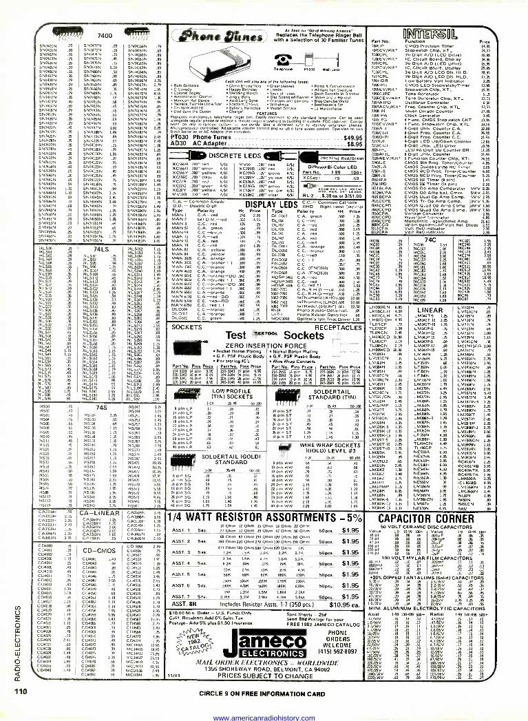
eiree 7400
SN7400N .20 SN7472N .29 SN74156N .79 SN7A01N .20 SN7473N .35 5N74157N. .69 SN7402N .8 SN7/7/N .35 SN74160N .89 SN749N .25 SN7475N .49 SN74161N .9 SN7408N .25 SN7476N .ä SN74162N .89 SN7105N .29 5N71AN 5.00 SN74163N .89 SN7406N .35 5N749N .50 SN74164N .9 SN7407N .35 SN7482N .99 SN7/165N .89 SN740BN .29 SN7483N .69 SN7119N 1.8 SN749N .29 SN7485N .89 SN74167N 2.79 SN7410N .25 SN7486N 35 SN74170N 1.95 SN7AIIN .29 SN7489N 1.75 SN74172N 4.95 SN7412N .35 SN7490N .49 SN71173N 1.39 SN7413N .40 SN7491N .59 SN74174N .99 SN7414N .69 SN7492N .15 SN74175N .89 SN7416N .29 SN7493N .45 SN74176N .79 SN74I7N .29 SN7494N .69 SN74177N .79 SN7420N .25 SN795N .69 SN74179N 1.49 SN7421N SN7496N .69 SN74180N .A SN7422N .5 SN7497N 3.00 SN74181N 2.25 SN7423N .29 5N71100N 1.49 SN74182N .79 SN7425N .29 SN74104N SN74184N 2.49 SN7426N .29 SN741%N sº 5N74I85N 2.49 SN7427N .25 SN74107N .35 SN74190N 1.E SN7428N .49 SN74109N .39 SN7419IN 1.8 SN7430N .25 5N7/116N 1.95 SN74192N .89 5N7432N .29 SN74121N .39 SN74193N .89 SN7437N .E SN74122N .55 SN74194N .89 SN7435N .40 SN74123N .59 SN7/19N .69 SN7439N .25 SN71I8N .49 SN74196N .89 SN7440N .20 SN71126N .49 SN74197N .89 5N7441N .89 SN74132N 75 SN741%N 1.49 SN7442N .59 SN1/136N .75 SN74199N 1.49 SN740N 1.10 SN741I1N .99 5N74221N 1.25 SN7444N 1.10 SN74142N 3.8 SN7481N .9 SN7445N .89 SN74143N 3.49 SN74276N 1.95 SN7416N .A SN741/4N 3.49 5N74279N .79 SN7447N .69 SN74145N .79 SN74283N 1.49 SN7448N .79 SN74147N 1.95 SN74284N 3.95 SN7150N .20 5N71148N 1.29 5N7429N 3.95 SN7451N .20 SN71150N 1.8 5N74365N .69 5N7453N .20 SN74I51N .69 5N7/39N .69 SN7451N .20 5N71152N .69 5N7/367N .69 SN7459A .25 SN7/153N .79 5N74368N .9 SN7460N .20 5N71154N. 1.8 SN74330N 1.19 SN7470N .A SN7/155N .79 SN74393N 1.9
iiLS01 .29 .29
74LS 7415192 71L5193
1.15 1.15
74L502 741503 .29 14L59
.75 .75
7415194 74L5195
1.15 1.15
7/L501 74 LS%
.35
.35 741595 741595
.99 1.15
7415197 7415221
1.19 1.19
741506 741509
.35 7115107 7415109
A5 .45
74L529 74L5241
1.9 1.9 741510
741511 74LS12
.Á
.ffi
74LS112 7415113
.45
.49 7415242 7415243 74L52/4
1.49 1.49 1.49 74L513
71LS1/ .59 .99
74L51II 74L5123
.89 1.8
74L5245 74L5247
2.95 1.19
741515 141520 É 7415125
74 L6126 .59 .9
74L5248 74 L524
1.19
1.19 7/L521 741522
.35
.35 7415132 74L5133
.99
.89 74L5251 74L5253
.99
7/L58 74L527
.35
.35 74L5138 .4936
8 74LS87 74LS258
.99
.89
74L528 74L531
.35
.35 74L5139 74L5151
.89
.89 74 L5260 71LS86
.69 .69 .69
741532 74L533
.35
.9 74L5153 7/L5151
.89 1.75
7415273 7415279
1.95
71L537 11L538
.45
.39 1415155 74L519
.9
.89 74L529 74L5290
.9
.89
71L59 741542
.35
.89 7415157 74LS158
.9
.89 74L5293 74L5298
.99
.99 1.25
741547 741548
.89 1.15
74L519 7415161
1.15 1.15
71L5352 74L5353
1.29 1.29
7/L5/9 141551
1.15 .25
7415162 7415163
1.15 1.15
74L539 7415366
.69
74L554 7/L59 .35 35
7/L5164 79LS19
1.15 1.15
74L5ä7 7415368
.69
.9 74L573 741574
.45
.45 74L519 7415169
1.19 1.19
71L5373 7415374
.69 1.95 1.95
741575 741576
.59
.45 7415170 7415173
1.95 .99
74L5375 7415386
.89
74LS78 741583
.49
.89 71L5174 IIL5175
.99 .99
74L5393 74L539
.69 2.49 2.49
74L5% 741586
1.8 .49
74L5181 74L5190
2.95 1.8
7415670 811595
2.49 1.%
741590 .69 7415191 1.8 81LS97 1.95
74500 74502
.45
.45 74S 74S243 745244
3.25 3.35
74503 .45 745124 3.95 74581 1.45 74501 .% 745133 .% 745253 1.45 74505 .55 745134 .69 74587 1.35 74508 .50 745135 1.19 745258 1.35 7459 .50 745135 1.75 745260 .79 74510 .45 745138 1.35 745280 2.95 74511 .45 745139 1.35 745287 3.8 71515 745140 .79 745288 2.75 74520 .45 745151 1.8 745373 349 74522 .45 745153 1.35 745374 3.49 74530 .45 745157 1.35 745387 2.% 74532 .55 745158 1.35 715471 10.95 74538 1.25 745160 2.% 745472 10.95 74540 745171 1.59 745473 10.% 74551 .45 745175 1.59 745174 12.95 74564 .50 14519 2.% 745475 12.95 74565 .50 745194 1.95 745570 5.95 74574 .75 745195 1.95 745571 5.95 74586 .79 7451% 1.95 745572 9.95 745112 .79 745240 2.95 745573 9,% 745113 .79 745241 2.95 745940 3.15 745114 .A 745242 3.25 745941 3.15
CA301oH CA3013H
.99
2.15 CA -LINEAR CA309N
CA30%N 3.75 3.95
CA3023H CA3035H CA3039H
3.25 2.49 1.35
CA3060N CA390H CA391N CA3082N
3.25 1.25 2.00 2.00
CA3130H CA319H CA3I9H
1.39 1.8 1.25
CA3046N CA3059N
1.30 3.25
CA393N CA309N
1.60 .85
CA3401N CA3500N
.59 3.50
C D4000 .39 CO 4098 2.49 C0/001 .39 CD-CMOS CD1506 .75 C04032 CD4006
.39 1.19 C04011 1.49
C04507 CD/508
.99 3.95
C 04007 .8 C 04012 .99 C01510 1.39 C04009 .49 CD4013 .89 C04511 1.29 C 04010 .49 C 01014 .89 C04512 1.49 C04011 .39 C D1016 1.79 C04514 3.95 C04012 .25 C D4047 2.50 CD/515 2.95 C D4013 .9 CD4018 1.35 C04516 1.49 C04074 1.39 C040f9 .49 CD4518 1.79 CD4015 1.19 C 04050 .69 C04519 .89 C04016 .59 C04%1 1.19 C04520 1.29 C04017 1.19 C04062 1.19 C04526 1.79 CO/o18 .99 C134053 1.19 C04528 1.79
Ú_
Z O
C 01019 C04020 C04021 CD4022 C04023
.49 1.19 1.39 1.19 .29
C 04056 C 04059 C 04060 C 04056 C 040118
2.95 9.% 1.49 .79
.39
C0458 C04543 C 04562 C0459 C04583
1.95 2.79
11.95 2.79 2.49
IY C04020 .A C04069 .45 C04584 .75 H C04025 .23 C 04070 .55 C04723 1.% U CD4026 2.95 C 04071 .49 C04724 1.95 W C04027 .69 C 04072 .19 MC1449 17.95
CDI021 .89 C 04073 .39 MC14410 18.95 LL C 0402 1.19 C 04075 .39 MC14411 15.95
C04030 .49 C 04076 1.39 MC14412 15.95 C04034 3.49 C D4078 .55 MC14419 7.95
I o 01035 \ CDI040 .99
1.49 C 04081 C 04082
.39
.39 MC14433 MC14538
15.95 2.49
Q Q
C134093 .99 MC14541 1.95
as Seen on 'Good Morning Amado." (Jetons ons Replaces the Telephone Ringer Bell with a Selection of 30 Familier Tunes
0701 ® 6.6 Telephone PT038 Wall Jack
Each Una will play any of the following lune.- Rule Brlllania Close Encounters Greensleevea Pomp 8 Circumstance 0 Canada Happy Birthday Lorelei William Tell Overture Colonel Bogey Wedding March Eyes of Texas Bach Toccata In 0 Minor Westminister Chimes Jingle Bells Star Spangled Banner Shave and a Haircut Mexican Het Dance Auld Lang Sync Oranges and Lemons Blue Danube Waltz Twinkle, Twinkle Little Star Soldiers Chorus WIlhelmus Beethoven's 5th Deutechlandlled Sailor's Hornpipe Mozart Sonata La Marseillaise God Save the Oueen Charge! FEATURES
Replaces monolonous telephone ringer bell. Easily connects to any standard telephone. Can be used Ionysido regular phone or replace a remote ringçeer Isewhere In building or outside- FCC approved. Can be a ed on e y telephone system - w rldwlde. Use
alter:, d111erenl tune to idenhry tansmn phones.
Microprocessor controlled. Adjustable volume control and variable tune speed control.xOperalea on Iwo 9 -volt batteries or AC Adapter mot includerli.
PT030 Phone Tunes $49.95 AD30 AC Adapter $8.95
-11» DISCRETE LEDS XC556R .200" , ed XC556G .200" green XC556V .200" yellow XC556C .200" clear XC22R .200" reo XC22G .200" green XC22Y .200" yellow MVIOB .170" ree
5/51 4/$1 4/$l 4/$1 5/$1 4/51
4/$1
MV9 XC29R XC209G XC209v XC526R X15260 XC526Y XC526C
.085" red 6/51
.18" red 5/51
.18" green 4/$1
.18" yellow 4/$1
.185" red 5/$1
.185" green 4/$1
.185" yellow 4/51 .185" crear 4/$1
.200(T11Á) Red/Green
Oiffuaed Bicolor LED Part No. 1-99 100. XC5491 .79 .69
RL -2 . .S.39 ea. or 3/51.00 C.A. - Common Anode D.D. - Double Digit Type Polarity MAN 1 C.A.-red MAN 2 5x7 D.M.-red MAN 3 C.C.-red MAN 52 C.A.---green MAN 54 C.C.-green MAN 71 C.A.-red MAN 72 C.A.-red MAN 74 C.C.-red MAN 82 C.A. yellow MAN 84 MAN 3620 MAN 3630 MAN 3640 MAN 4610 MAN 6610 MAN 6630 MAN 6640 MAN 6650 MAN 960 MAN 6710 MAN 6740 MAN 6750 DL0304 DL0307 D LG500
DISPLAY LEGS RHO -Common Right Hand Cathode
Ht Price Type Polarity Ht Prie. .270 2.95 OLG507 C.A.-green .500 1.8 .700 4.95 DL701 C.C.-red .300 1.8 .1E .25 DL707 C.A.-red .300 1.8 .300 .9 01128 C.C.-red .500 1.9 .310 .99 DL74I C.A.-red .600 1.8 .335 35 0L747 C.A.-red .600 1.9 .900 .75 DL750 C.C.red .600 1.49 .310 1.8 DLO847 C.A.-orange .800 1,49 .331 .49 OLO85) C.C.-orange .800 1.19 C.C.-yellow .30 .99 0L338 C.C.-red .110 .35 C.A.-orange .300 .49 FN039 C.C. ± I .357 .99 C.A.-orange 1 1 .300 .99 FN0357 C.C. .357 .75 C.C.-orange .300 .99 FND500 C.C. (FND503) .500 .99
C.A.-orange .400 .99 FND507 C.A. (FND510) .500 .99 C.A.-orange-DO .560 .99 HOSP-3401 C.A.-red .800 1.50 C.A.-Orange± 1 .59 .99 HDSP-3403 C.C.-red .800 1.50 C.C.-orange-DO .560 .99 HDSP-396 C.C. rad+1 ,9pp 1.50 C.C.-orange ± 1 .560 .99 5052-7751 C.A.,R.H.D.red .430 1.8 C.A.-orange .560 .99 5082-7160 C.C..R.H.D.red .430 1.8 C.A.-red-DO .59 .99 5082-7300 4x7 Nu mer Ic(RHD).6» 22.00 C.C.-red-DO .560 .9 5082-1302 4x7Numeric(LHD).600 22.00 C.C.-red 1 1 .560 .99 592-7340 4x7Hxd cl. (0-9/Aí).600 22.50 C.C.-orange .300 1.8 42425 Photo XslstorOpto-Isol. 69 C.A.-orange .300 1.8 LIT -1 Photo Xslntr Opto -!sol. .69 C.C.-green .500 1.25 MOC3010 Optically lsol.Trla.C/river 1.8
Pries 14.% 24.95 16.95 34.95 15.95 29.95
7116CPL 30, Digit A/D LCD Dis. HLD. 18.95 7117CPL 344 Dlglt A/D LED Dls. HLD. 11.95 72011DR Low Battery Volt Indicator 2.25 72%IPG CMOS LEO Stopwatch/Timer 12.95 7205EV/Kit Stopwatch Chip, XTL 19.95 1206CJPE Tone Generator 5.15 7206CEV/Kit Tone Generator Chip, XTL 12.95 7207AIPD Oscillator Controller 6.50 7207AEV/Kit Fret. Counter Chip, XTL 13.95 72061P1 Seven Decade Counter 17.95 7209IPA Clock Generator 3.95 72151PG 4 Func. CMOS Stopwatch CKT 13.95 7215EV/Kit 4 Func. Stopwatch Chip, XTL 19.95 7216A1J1 8 -Digli Univ. Counter C.A. 32.00 7216C1JI 6 -Digit Freq. Counter C.A. 26.95 72160IPI 8 -Digit Frag. Counter C.C. 21.95 72171JI 6-D1git LED Up/Down Counter 12.95 7218CIJI 8-12191t Unlo. LED Orb e 10.% 72241PL LCO 41,14 Digit Up Counter DRI 11.E 7226AIJL 8-01918 Unie. Counter 31.95 7226AEV/Kit 5 FunctIon Counter Chip, XTL 74.95 72401JE CMOS Bln Prog. Timer/Counter 4.95 72421JA CMOS DivideAy-256 RC Timer 2.05 725013E CMOS BCD Prog. Tuner/Counter 6.00 72601JE CMOS BCD Prog. Timer/Counter 6.8 7555IPA CMOS 555 Timer (8 pin) 1.45 75561PD CMOS 556 Timer (11 pin) 2.20 7611BCPA CMOS Op Amp Comparator SMV 2.8 7612BCPA CMOS Op Amp Ext. Cmvr. SMV 2.95 7621BCPA CMOS Dual Op Amp Comp. SMV 3.95 7631CCPE CMOS Tri Op Amp Comp. 1016V 5.35 7641CCPD CMOS Goad Op Amp Comp. 1051V 7.50 7642CCPD CMOS Goad Op Amp Comp. IOM V 7.50 7660CPA Voltage Converter 2.95 93BCCPD Waveform Generator 4.%
COPE Monolithic Logarithm c Amp 21.60 139CC0 SOPpm Band -GAP Volt Ref. Diode 2.50 8211CPA Volt Ref/Indicator 2.95 8212CPA Volt Ref/Indicator 2.95
74C00
71CW 74C9 74C10 74C14 7/C20 14C30 74C42 74C48 74C73 74C74 74C% 74C86 74C89 74C90 74C93
.33
.39
.39 39
.39 75
.39
1.95 .99
6.95 1.29 1.29
74C 74C95 74C107 71C151 71C151 74Ca7 71C160 7/C161 71C162 74C163 71C161 74C173 71C174 74C175 71C193 7/C193 71C1%
1.89 2.95 3.95 2.8 1.69 140 1.49 1.9 1.59 1.39 1.39 1.19 1.69 1.69 1.9
71C221 1.95 74C240 2.8 71C241 2.25 74C373 2.49 74C374 2.59 74C901 .69 740903 69 74C911 10.95 74C912 10.95 74C915 1.69 74C917 10.95 74C922 5.49 14C923 5.75 14C925 7.50 74C926 7.50
80C97 .79
SOCKETS RECEPTACLES
Test T[XTOOL Sockets ZERO INSERTION FORCE
Nickel Boron Plating Nickel Boron Plating G.F. PSF Plastic Body G.F. PSF Plastic Body -7- For testing IC's Wire Wrap Contacts L.
PartNo. Pins Price PartNo. Pins Price PartNo. Pins Pries Part No. Pins Price 214-3339-3339 14 pin 5.% 222-3343 8 pin 9.95 214-3592 14 pin 9.75 222-2596 2T pin 12.% 216.3340 16 pin 6.49 224-3344 24 pin 9.75 216-39.3 16 pin 9.95 224-397 24 pin 12.75 218-3341 18 pin 7.% 228-3346 28 pin 11.95 2163594 18 pin 10.95 228-35% 28 pin 13.% 220.3342 20 pin 8.95 240.3346 40 pin 12.95 220-3595 20 pin 11.95 2463599 9 pin 15.95
8 pin LP 14 pin LP 16 pin LP I8 pin LP 24 pin LP 22 pin LP 24 pin LP 28 pin LP 35 pin LP 40 pin LP
LOW PROFILE (TIN) SOCKETS
1-24 25-49 56100 .17 .16 .15 .20 .19 .10 22 .21 .20
.29 .28 .27
.34 .32 .30
.37 .35 .35
.38 .37 .35
.45 .44 .43
.60 .53 .58
.63 .62 .61
14 pin ST .27 16 pin ST .30 18 pin ST .35
24 pin ST .49 28 pin ST .99 35 pin ST 1.75 40pin ST 1.59
DERD STANDARD (TIN)
1-24 25.49 50.100
.25 .24
.27 .25
.32 .30
.45 .42
.90 .81 1.8 1.15 1.45 1.30
8 pin SG 14 pin SG 16 pin SG 18 pin SG 24 pin SG 28 pin SG ä pin SG 40 pin 5G
SOLDERTAIL(GOLD) STANDARD
1-24 25-49 50-100
.39 .35 .31 .49 .45 .41
.54 .49 .44
.59 .53 .48
.79 .75 .69 1.10 1.00 .90 1.65 1.40 1.26 1.75 1.59 1.45
20 22 24
8 35-
40
I ITf
8 pin WW 10 pin WW 14 pin WW 16 pin WW 18 pin WW
pin Wei pin WW pin WW pin WW pin WW Pin WW
WIRE WRAP SOCKETS (GOLD) LEVEL #3
1-24 8-49 56100 .59 .51 .49 69 63 .58 A 73 .67
.35 .77 .70
.99 .90 .81 1.19 1.9 .99 1.49 1.35 1.23 1.39 1.26 1.14 1.69 1.53 1.35 2.19 1.99 1.79 2.29 2.09 1.89
G Ud Pert No. Function 70461PI CMOS Precision Timar 7045EV/Kit Stopwatch Chip, XTL 7105CPL 3174 Digit A/D (LCD Drive) 7106EV/Kitt IC, Circuit Board, Display 7107CPL 344 01915 A/O (LED Drive) 7107EV/Kit IC, Circuit Board, 0110180
LH009CN 6.9 LMIOCLH 4.50 LMIICLH 4.75 LH0076OH 4.95 TL071CP .79 TL072CP 1.39 TL074CN 2.49 LH0082CD 35.90 TL082CP 1.19 TL044CN 2.19 LH0094CD 35.9 LM300H .99 LM301CN .35 LM39H 1.% LM39H 1.% LM39H .99 LM307CN .45 LM39CN 1.00 LM39H 1.% LM39K 1.25 LM310CN 1.75 LM311/CN .90 LM312H 2.49 LM317MP 1.16 LM317T 1.75 LM317K 3.% LM318CN 1.95 LM319N 1.% LM320Ká 1.35 LM320K-12 1.35 LM320K-15 1.35 LM320Tó 1.8 LM320T-12 1.25 LM320T-15 1.8 LM323K 5.95 LM324N .99 LM329OZ .65 LM331N 3.95 LM334Z 1.30 LM3352 1.40 LM3362 1.75 LM337T 1.% LM337MP 1.15 LM338K 6.% LM339N .99 LM310K6 1.35 LM310K-12 1.35 LM310K-15 1.35
LINEAR LM3/0Ti 1.8 LM340T-12 1.8 LM340T-15 1.25 LM341Pó .75 LM341R12 .75 LM3/1P-15 .75 LM3/2P3 .9 LM342P-12 .69 LM312P-15 .69 LM39N 1.8 LM3wK 5.75 LF35IN .60 LF353N 1.00 LF255N 1.10 LF39N 110 LM358N 1.00 LM359N 1.79 LM3AN 4.49 LM373N 3.8 LM317N 2.% LM39N 1.8 LM381N 1.95 LM362N 1.79 LM384N 1.% LM366N-3 1.29 LM367N 1.45 LM39N 1.35 LM392N .69 LF3%N 4.00 LM399H 5.00 TL94CN 4.49 TL96CP 1.75 NE5I0A 6.00 NE529A 4.95 NE531H 1.% NE535H 6.00 NF340H 6.00 NE541N 1.95 NE560A 1.30 NE556V .37 LM556N .99 NE564N 3.95 LM59N 1.8 LM566CN l.% LM567V 1.8 NE5AN A.%
LM79H LM79CN LM709N LM710N LM711N LM723N LM733N LM739N
.79 9
.29
.79 .79 .69
1.00 1.19
LM7/1CN .35 MC1711SCG 3.00 LM747N .79 LM748N .59 LM1014N 2.75 LM1310N 1.95 LM149CN .59 LM1488N 1.8 LM1189N 1.25 LM11%N 1.% LM1556V 1.75 LMI800N 2.95 LM1871N 5.9 LMI872N 5.9 LM1877N-9 3.8 LM199N 3.20 LMI96N 1.75 LM2002T 1.49 LM2677P 2.05 LM2878P 2.8 LM28%P-1 2.E LM319N 2.% LM3900N .69 LM399CN 1.8 LM3909N 1.15 LM3914N 3.95 LM3915N 3.95 LM3916N 3.95 RC1135N 1.25 s4C4151NB 3.95 RC4I94TK 6.95 RCII95TK 5.49 LM4600A 3.25 ICL80388 1.95 LM13040N 1.29 LM13600N 1.49
75138N 1.95 75/50N .89 75451CN .39 75492 .9
1/4 WATT RESISTOR ASSORTMENTS -5% 10 Ohm 12 Ohm 15 Ohm 18 Ohm 22 Ohm
ASST. 1 5e.. 27 Ohm 13 Ohm 39 Ohm 17 Ohm 56 Ohm 9 ohm 82 Ohm 100 Ohm 120 Ohm 150 Ohm
ASST. 2 5e.. 19 Ohm 220 Ohm 27 Ohm 330 Ohm 390 Ohm WO Ohm 560 Ohm 680 Ohm 820 Ohm 1K
ASST. 3 524. 1.2K 1.5K 1.8K 2.21, 2.7K
3.3K 3.9K 4.715
ASST. 4 5aa. 8.2K 10K 12K
ASST. 5 5e..
ASST. 6Se.. ABST.7 Sea.
ASST. BR
22K 27K 33K 56K 68K 82K
150K 180K 220K 390K I70K 560K
5.6K 6.8K 15K 18K
39K 47K 100K 120K
270K 330K 680K 820K
1M 1.2M 15M 1.8M 2.2M 2.7M 33M 3.9M 4.754 5.6M
Includes Resistor Assts. 1-71350 pcs.)
50pee. $1.95
sep.. $1.95
50 pas. $1.95
50pes. $1.95
50pos. $1.95
50prls. $1.95
50pes. $1.95 $10.95 ea.
$10.00 Min. Order - U.S. Fonds Only Calif. Residents Add 6% Sales Tao Postage -Add 5% plus $1.50 Insurance
J
Spec Sheets - 254 Send 866 Postage for your FREE 1982 JAMECO CATALOG
PHONE ORDERS
WELCOME (415) 592.8097
ameco ELECTRONICS
MAIL ORDER ELECTRONICS - WORLDWIDE 1355 SHOREWAY ROAD, BELMONT, CA 94002
11/81 PRICES SUBJECT TO CHANGE
72 of .0088 .06 .ÓS 47 pl 08 .06 .O5
100 p/ .08 .06 .9 4Áói .08 .006 06
.mlmr 100 VOLT MYLAR
.12 .10 .07 .0012mf .12 .10 .07 .097mí .12 .10 .07 ,Olmi .12 .10 .07
CAPACITOR CORNER 50 VOLT CERAMIC DISC CAPACITORS
Value 19 1099 100+ Value 14 169 100+ .0010F .9 .06 .9 .ppylPF
m ÁB .
022PF .9 .07 .9 .0/7YFFF .5-9
02 . 0 ILM CAPACITORS
.847mí .13
.17 .13 .Imf .27 .23 .17 .22mí .33 .27 .22
+20% DIPPED TANTALUMS (Solid) CAPACITORS .1/35V .39 .34 .29 1.5/39V .41 .37 .29 .15/35V .39 .34 .29 2.2/35V .51 .46 .34 22/35V .39 .34 .29 3.3/25V .53 .47 .37 .33/35V .39 .34 .29 4.7/25V .63 .9 .45 .47/35V .39 .14 .29 6.8/25V .79 .69 .55 68/35V .39 .34 .29 15/25V 1.39 1.25 .95
MINI. ALUMINUM ELECTROLYTIC CAPACITORS Axial 199 100-499 500+ Radial 149 100-499 500+ 17/50V .16 .14 .10 .47/25V .15 .13 .12 1.0/50V .19 .16 .12 .47/50V .16 .14 .13 3.3/50V .17 .15 .11 1.0/16V .15 .13 .12 4,7/25v .18 .15 .11 1.0/äV .16 .14 .13 10/äv .18 .15 .11 1.0/50V .17 .15 .14 10/50V .19 .16 .12 4.7/16V .15 .13 .12 22/25V .19 .16 .12 4.7/25V .16 .14 .13 22/50V .24 .20 .18 4.7 V .17 .15 .14 47/äV .E .21 .19 1016V .15 .13 .12 47/50V .29 .8 .23 10/25v .16 .14 .13 100/25 V .28 .24 22 10190 V .17 .15 .14 100/50V .41 .37 .34 47/50V .8 .21 .19 220/25V .39 .31 .33 190/16v .21 .17 .14 220/50v .49 .45 .41 100/25V .25 .23 .21 470/25V .54 .49 .6 100ß0V .37 .34 .39 2800/16V .A .69 .61 210/I5v .25 .21 19 2200/16V .89 .79 .69 /Á/25V .35 .31 .27
110 CIRCLE 9 ON FREE INFORMATION CARD
www.americanradiohistory.com
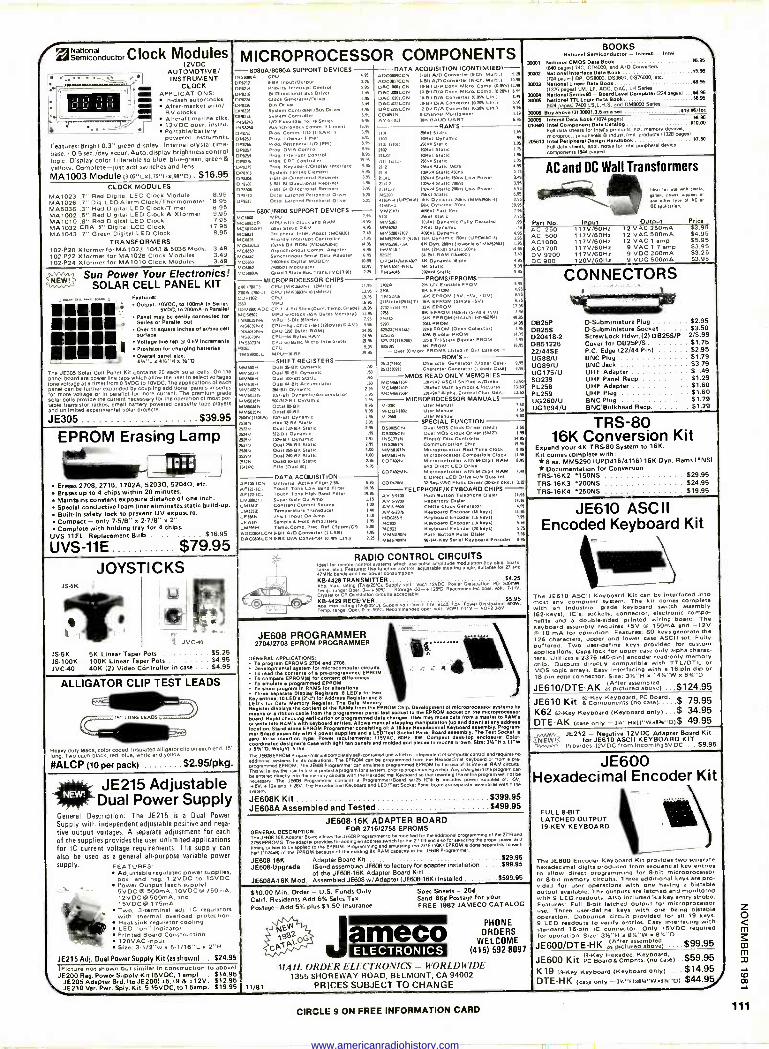
2Senonal mconductorClock Modules
12VDC AUTOMOTIVE/ INSTRUMENT ,... __. , . L
ram CLOCK MI Ian
APPLICATIONS: In -dash autoclocks I 1 1_I 1_I I_I I II IJ II r
/ aen After -market auto/ RV clocks Aircraft -marine al.. 12VDC oper. Instru. Po rteble/battery powered instrumnts.
Features:Bright 0.3" green display. Internal crystal time -
base. ± 0.5 sec -/day eccur.Auto.displey brightness control logic. Display color filterable to blue, blue-green, green &
yellow. Complete -just add switches and lens.
MA1003 Module (3.05"Lx1.75"Ho.98"DI . $16.95 CLOCK MODULES
MA1023 .7" Red Digital LED Clock Module 8.95 MA1026 .7" Dig. LED Alarm Clock/Thermometer 18.95 MA5036 .3" Red Digital LED Clock/Timer 6.95 MA1002 .5" Red Digital LED Clock & Xformer 9.95 MA1010 .8" Red Digital LED Clock 7.95 MA1032 CBA .5" Digital LCD Clock 17.95 MA1043 .7" Green Digital LED Clock 8.95
TRANSFORMERS 102-P20 Xformerfor MA1023, 1043 & 5036 Mods. 3.49 102-P22 )(former for MA1026 Clock Modules 3.49 102P24 )(former for MA1010 Clock Modules 3.49
MICROPROCESSOR COMPONENTS -8080A/8080A SUPPORT DEVICES DATA ACQUISITION (CONTINUED)- NSOA- CPU 11811 A/0 Converter 1&Ch, 51.1.15.25
pMIPo212 &Bit Input/Oulp. DP621 Prrocity mterr.pt Control O PP16 151.01rectIonel au, Orlver O 11321 Inr /Driver
Bus ver D1 Controller/Bus Orlver
Syflem System
Controller 1/0 Expander for 45eries Asynchronous Comm. element Pro& Comm SARTI
aI IT'mer O IPPII
P ros. DIKA Control Inter... Control
Pr. CRT Controller Pros rd/Display rolaeteee
4.1111 BiDirectounal ever &Olt ei.Obe<tmnn Ra ewer s -Bu 561.0trectmnel Reamer Octal Latched PIMP.. DIM, Octal Latched Peripnerar Driver
Sun Power Your Electronics! SOLAR CELL PANEL KIT
Features:
Output: 10VOC, lo 100mA In Series 590C. to 200mA In Parallel
Panel may be easily concealed for Serles or Parallel out
Over c1
square Iahe. or active cell
Voltaa line tap B 0.5V increments Provision for charging battenes Oesrall pan1 slw: 41A"L x 4V."H 5 'h"D
The 4E305 Solar Cell Panel Kit ccnlalns 20 each solar cells. On the panel board are power Ilne taps which allow the veer to select voltages lone l clang be furtheex a nded ouplingadditioenallidsilos Panels
each pa mdes for morevoltai In parallel for amore current. The premium grade solar celle provide the current necebeary for the operation of most por- table transistor radios, small battery powered 0330011e tape players and unlimited experimental solar prolecte.
JE305 $39.95
EPROM Erasing Lamp timaliow
Erases 2708, 2716, 1702A, 52030, 52040, etc. Erases up to 4 chips within 20 minutes. Maintains constant exposure distance of one inch. Special conductive foam liner eliminetesstatid build-up. Built-in safety lock to prevent UV exposure, Compact - only 7.5/8" o 2-7/8" x 2" Complete with holding tray for 4 chips.
UVS-11EL Replacement Bulb $16.95
UVS-11E $79.95
-6800/6800 SUPPORT DEVICES MC6600 MPU MCSamCPi
cR endRAM
MC581onP1 sSt.ocA 51C6/Q1 Perioneral Inter. C.1. PAC6112M
MC428 PRON. Interrupt Co r 5006910Ú 101+&mtROM 30-6)
65[66 Asynchronous Comm.a Adapter 50[6953 Synchronous Serial Data Adaptar MC6160 09E0bps DgitI MODEM MC6e62 3Motu iator M C61M A >State.N.Tn05.IMC.T.)
3:ri 595 '.16 .4
14 1.95$
9.95
u95 6.95 8.95
9.95 9.95
3.95
.535
96
525
1.95
1435 6. 7 1.95
14.95
6.95
6.96
10.95
12.95
3.. MICROPROCESSOR CHIPS
ZM (MC) CPU WK..) (2MHz1 11.. MA 17.11 CPU lM163114N4114MMZ) ILO COPIM2 CPU 1935
MPU 2650 58.95
IDAANOIAGIC CPU-4Bit Sikc (Corn. Temp. Grade) 19.15
15510 82 MPU w/[lacy (6516 Bytes Morn.. 11.95
51P1.1-1-111 Mlles( 7.95 115550161+ 51P1.1-1-111 iN5403Ná CPU -591. 011p RAM05bylasRAM) 4.95
INSM(ONá CPU DM Bate . RA N.% 15.INS71N CPU RAM 23.95
In CPU w/Basic Mlcra Intepreer 23.95
PMTS CPU 5.95
59900JL v[rl&en 0.55
SHIFT REGISTERS MMMOH Dua125-011 Dynamic N MMSH Dual 50811 Dynamic 611
MM501H Dual Melt Static .50
51MS1016 Dual WBIt Accumulator MM14025 350 -Bit Dynam5 2.95
5050110 I024.911 Dynamic/Accumulator 1.95
WSW. 500/612.11 Oynamlc 1.95
N M». Octal WWI 9.95
MM50365 Octal .011011 9.95
3511V(140.1 1v1a aS IHnee is 1.95
25111 ley.011 Static 3.95
2532V Duel112.01í Static 2.95
35NV 2525v 241V 2M5V 2M9v 23335 11411C
113-BII Dy 1011-511t DYnemm Dual 03Blt Sta. Dual Welt Stall< Due Hal. static
duonaif smut
Duel M/
DATA ACQUISITION
50
90
395 2.95 4.14 4.14 395 6.96
AFis0-1C5 U ter AOlio. Filer 3.5%
AF121.1CJ Touch Ton Low Bane Fln.r 254122.101 TCtisch
e 911 Barra Filter
L M303CH Sune GInOP Amp LM3$3 Constant current Source LM3n2 Temperature Trans.., LF3565 JFET Input Oa Amp LFAIN Sample a Hold Amollrle. LMAIH Temp.Com0.0.1r R.I.(.Sppm/C1 coC95o5LC5 4.611 0/0 converter 11 Lsel DACM95LCN aen D/A Converter (0.1. L../
5.95
1995 19.95
1.15
I.n 1.4 4.10
3.05
1.11
}.A
NDCMOºCCN OC44UCC5 aelt A/C/Converter 06.Ch. Multi.) 1496
025[50954.[5 10-011 D/A Conv. 50ík 0. Comp.10.051411116 025[15054.[1 10.04 D/A conv. Mm o. Coma. (o.4%1 00.96
AC10201.C5 10.e110/A Converter ISE. .10.1 349 OACI022LC5 10-8110/A Converter 13.20% Lln.l 5.96
25[42324.[5 12.8110/A Converter (0.204 Lin, 995
CCO.15 &Channel Mulllolexer 1.19
A35-1013 nK BAUD UART 6.95
RAM'S I 1.0 1, ...Stalls 1.4 1 101x1 Dynamic .95
2101 01011 256.5.11c 195
rt. 102+15et1c 1.75214.50
101x1 Seanc 1.95
3111/711/1 2569 static 3.95
2112 255. Static MOS 4.95
2114 101+4 Stetic 45005 335
NHL 1924x4 Stalls 45005 Low Power 149
2114-2 150+1 Stet c 300ne 195
21144..2 1024. Slatic 30005 Low Power 4.95
145200 HA 1 Static 6.. 4116Nw NAA. 16K0 ,c..116.5290Na1 2.. 41645a MK Dynamic glens 19.95
0521413 emsrl Fast Ms 9.95
5101 2959 Stall< 135 MM5261 101+1 Dynamic role. Acode. MM.. Mal 000005ík .w 505052113/2507 4496. °Teem, 4,95 515152305.2141161 16K Dynamic 15006 (UP0416Ca1 3.95
5052931a25 IK 0yn.2mns (lower w of 5M56.1l1 I. HM61169 1616 (2.9) Static 200ns 14.95
52525 M Bit RAM (16x4[) 3.49
ÚP2514/6161057 4 .ml<95-pin 4.95
TM5141195NL IK Sellc 9.95
TMS416 ROW. Static 9.95
PROMS/EPROMS I702A 216 UV Erasable PROM 5.95
TM 316 EPROM 195
52}16 6516 EPROM ISV, sv, Pvl 9.95
21161ntwes161TI 16K EPROM (Sinai* HV) ºe 1321ntel T1 let EPROM 17.95
2958 316 EPROM mono (s.a.5V) 7.4
2140 MK EPROM (Hitachi 1-1542764) 49.95
5209 2044 PROM 11.95
452501500) Q. PROM (Open Collector) 1. 15115 409681.1. PROM 1.95
5 13105. 411 32x5 Trl-Stets Siemer PROM 3.93
MPS all PROM Over n More PROMS Listed 111 Our Catalog-
1695
ROM'S 2513(2141 Character Generator Wooer C.le) 6.
Mß(1m11) Cnea<ter ...or (Lower Cale) 9.95
-NMOS READ ONLY MEMORIES Mc465n3P 125+9+1 ASCII ShIll. «meek 1330
MCM95744P 1.90 Math symbol & Pictures 13.50
MCM66150P 1..9x7 Alpha. Control Char. Caen. 15.14
MICROPROCESSOR MANUALS M.ZM User Manual 130
51-COP1602 UHr Manual 7.50
M.2B0 User Manual 5.00
SPECIAL FUNCTION O S003145 Dual MOS Clock Drlvar (W EI 2.50
0S1426C5 Duel DOS Clock Driver 155021 1.96
15517715.1 41015. DIK Convoke, N.% 5526515 Communlutmn ChM 19.95
1.151I675 Mlc ...100f Rut Time Clock 6.4511155 1101.013,0.00, compet. Clock 11195
COPS.. Microvontroller with 58.0e511 RAM 6.95
no Direct LED Dr. COPP.. 1.11..ontroller wt. 64.01u11 RAM 7.H
5 AreCt LED Dr. wile Buss Int. COPLN ve [ 411.1. drir l30ein OHL) 10
TELEPHONE/KEYBOARD CHIPS - AV.59100 Push Button Telephone MOM 1.96 AV -.2013 ry 01.10 1.95 Áy99500 CMOS Clock Generator 4.95
Ay -5213 Keyboard encoaer IN keys/ 11.95
WI666 keyboard Encoder A kwsl 7.95
100932 K.111011.1 Encoder In keTel 5.4 74L121 Keyboard En.. .I (. keys) 5.11
6.15153195N Push Button Pa158 0141111 7.95
MM574.N 95/114-Key..111 Keyboard Encoar 4.95
BOOKS \ Notional Semiconductor - Intone - Intel
300171 National CMOS CPU Book 65,96
1600 pages/ 740, 004000, end A/0 Convening 65 30002 National Interlace Dau Book
1700 parietal DP, DS8000. 05380, DS76000, etc. 65.96 30000 Nation./ Linear Data Book
11376 pages) CM, LF, ADC. DAC. LH Sens* 30004 National 30wú National TTTI. Logic Data Book
Level Cempuw OMfS'allsel NN.
1620 pages) 74012,LS,L,H,S end DM8000 Seras
30005 ecnlbov.l3130001.a.6nawt al9.96/let
30005 Intersll Dee Book 11074 pages/ 1696
010100 ratel Component Data Camp 410.00
Full data sheen for Inters products kd. memory devkea, mi roproc., peepharek b indus%. /m5. produce 1020 pageal
706810 Intel Peripheral Design Handbook 17.8 Full date sleets, app, note. for Inel PeriPheral devke colnponente 160417pæ1
AC and DC Wall Transformers
P!rt No. AC 250 AC 500 AC1000 AC1700 DV 9200 DC 900
Input 117V/60Hz 117V/60Hz 117V/60Hz 117V/60Hz 117V/60Hz 120V/60Hz
Ideal tor me mil dot6t. SPplet
any AC or
OC aoa r4tie..
Output 12 VAC 250mA 12 VAC 500mA 12 VAC t amp 9 VAC 1.7 amp 9 V DC 200mA 9 V OC 500mA
Price $3.95 $4.95 $5.95 $3.95 $3.25 $3.95
CONNECTORS
tiemmonmag 0825F DSubminiature Plug $2.95 DB25S D -Subminiature Socket $3.50 020418-2 Screw Lock Hdwr. (2) DB25S/P 2/S.99 DB51226 Cover for DB25P/S $1.75 22/44SE P.C. Edge 122/44 Pin) $2.95 ÚG88/U BNC Plug $1,79 ÚG89/U BNC Jack $3.79 ÚG175/U UHF Adapter $ .49 S0239 UHF Panal Rasp $1.29 P L258 UHF Adapter $1.60 PL259 UHF Plug $1.60 UG260/U BNC Plug $1.79 UG1094/U BNC Bulkhead Recp. $1.29
TRS-80 16K Conversion Kit
Expand your 4K TRS-80 System to 16K. Kit comes complete with: *8 ea. MM52901UPD416/4116116K Dyn. Rama CMS) * Documentation for Conversion
TRS-16K2 150N5 $29.95 TRS-16K3 200NS $24.95 TRS-16K4 250NS $19.95
JS3K
JS.5K JS100K JVC-40
JOYSTICKS
LI
/ LL
e I P 1 L J w
JVC-40
5K Linear Taper Pots $5.25 100K Linear Taper Pots $4.95 40K 12) Video Cóntroller in case .. $4.95
RADIO CONTROL CIRCUITS ldeel for 1.mote conta system whkh titre nuise empntua Regulatbn Noy can. boats l nka, e1a1 Features: Ilse l00011on 0011101, adlusleble steering angle. aullabe for 27 and
4 HZ bonde end low power consumplim
KE1-44211TRANSMITTER s'í25 bs. m riling RA025Cl. Supply volt: Vaal 12VDC. Power Dlaalpatlon. PD: 3wmW.
Temp. ries' Ope. 0- SOC - Obotepe 317-+ 125rG. Racomnwnad neat, to" 7.11V
5 -442 CR Osclllelon circuits ecap1.ON.
ne RECEIVER $000 R a025CI Sq«om oit- covtivVit1 DIÓI Z'1ëv. J i.mp. -ea. óó0r. sac. me ml
ALLIGATOR CLIP TEST LEADS
15 LONG LEADS
Heavy-duty leads. color coded. Insulated alligalot clip on each end. 15"
long Tug each black, red. blue. white and yellow.
#ALCP (10 per pack) $2.95/pkg.
JE215 Adjustable Dual Power Supply
General Description: The JE215 is a Dual Power
Supply with independent adjustable positive and nega-
tive output voltages. A separate adjustment for each
of the supplies provides the user unlimited applications for IC current voltage requirements. The supply can
also be used as a general all-purpose variable power supply. FEATURES:
Adjustable regulated power supplies. pos. and C to
g Power Output leach supply): 15V DC
5 V DC & 500mA, 10 V DC M 75005 A, 12VDC IQ 600mA, and 15VDCe 175mA. Two, 3 -terminal adi. IC regulators with thermal overload protection. Heat sink regulator cooling LED "on" Indicator Printed Board Construction 120VAC input Size: 3.1/2"w x 5-1/16"L x 2"H
1E215 Adj. Dual Power Supply Kit (es shown) . , $24.95 (Picture not shown but similar in construction to above) Jß200 Reg. Power Supply Kit (5VDC, 1 amp/ - $14.95
Jß205 Adapter Brd. Ito JE200) r5,n9 & f 12V. $12.95 JE210 Ver. Pwr. Sply. Kit, 5-15VDC, to l.5amp. $19.95
JE608 PROGRAMMER 2704/2708 EPROM PROGRAMMER
GENERAL APPLICATIONS:
411 To program EPROMS 3704 and 2708. Developmental eyeem tor microcomputer citrons
TO nad Ow content. of preprogrammed EPROM To compare EPROM(51 tor content dllfer.nces To emulate programmed EPROM To slop program in RAMS for altnNone Tom separate Display Registers: a LED'. Im Hex
Key entree, 10 LED'. IV -al lor Address Register end 8
LED's for Data Memory Rplete, The Data Memory Replete, dépiles the contant of the RAMS Iron Me EPROM Chlp. Demlopment of microprocessor systems by means el ribbon 01511 rom the programmer panel test socket to Me EPROM socket on IM microprocessor board Rapid checking verillction of programmed dell changes
x
se may a more¿taehorn
meets. w e1 10 RAM's or write
!
with o entries. Allows manual User
y end down) el ny
Program- mer
address loation Stand-alone EPROM Pregsrnme 1511rrqqf A l YHexadecimal Keyboard aseembl .
Borie assembly with 4po ule.and
LE , Sakti .a B a aswmb. The Teel Socket Is
force Ineenla type. Power rpqulrlmnts: taW. pct
desktop 's saw light tan remote and molded end pieces In mocha brown. Size:
34"Ha1"W
wllghr: nlor er iMJßáal EPROM Programmer oprtiecompletelyaOf beauneammu Hexadecimal Keyboard
yboar1anaroma re.
prou additional systems for is operations. The EPROM can n programmed ben the b of Ks int me w from
plogwmmed use The JE.m can ra lefe e programmed EPROM by hle lee a itsgse (nor RAM cien
enteredd theuserto tame oryairceowimforesystem.prioreprogramming echip.AMe it graprpremun ne entered decay Me memory circuits with the renne// Keyboard w Chet rewriting Pow. program 16+5 not
The JE26B Programmer comingProgaCEOlne Socket
IC'. induce power paie 5v
yse +i2vand +lev. ria Hexedecim1 crewra .rad LED/ren Parts eo.ra sn.apente esearialer within 111;
swum.
JE608K Kit $399.95 JE608A Assemlbled and Tested $499.95
JE608-16K ADAPTER BOARD GENERAL DESCRIPTION: FOR 271612758 EPROMS The JE(Iw1M( Adapter 9oord allows the JEew Programmer to be modified for the addiranel prprammoia of the ZI16 end
Z15a EPROMS. The adepte provide te adding In eddrae mach for ow 21 Nt end.. Ire electing the eo0r power and
putes to be apphed to the EPROM. Progrmmip are enueing tie 2715115K) EPROM is dort «tenter to each
hell 11024481 of the EPROM became of Ma existing SK RAM CilpecitY in te AO* Props
JE608'18K Adapter Board Kit $29.95
JE608-Upgrade (Send assembled JE608 to factory for adapter installation $99.95 of the JE608-18K Adapter Board Kit)
JE808A.16K Mod. Assembled JE608w/Adapter (JE608-16KI Installed $599.95
$10.00 Min. Order - U.S. Funds Only Calif. Residents Add 6% Sales Tax
Postage -Add 5% plWs $1.50 Insurance
11/81
J
Spec Sheets - 251 Send 86¢ Postage for your FREE 1982 JAMECO CATALOG
arreco ELECTRONICS
PHONE ORDERS
WELCOME (415) 592-8097
MAIL ORDER ELECTRONICS - WORLDWIDE 1355 SHOREWAY ROAD, BELMONT, CA 94002
PRICES SUBJECT TO CHANGE
JE610 ASCII Encoded Keyboard Kit
The JE610 ASCII Keyboard Kit can be Interfaced Into most any computer system. The kit corn.. complete with an industrial grade keyboard switch eWmbty (62 -keys), IC's, sockets, connector, electronic compo- nents and a double -sided printed wiring board. The keyboard aesembly require. +BV W 150mA and -12V M 10 mA for operation. Features: 90 keys generate the 128 characters, upper and lower caw ASCII set. Fully buffered. Two user -define keys provided for custom application& Caps lock for upper -case -only alpha charac- ters. Utilizes a 2376 140 -pin) encoder read-only memory chip. Outputs directly compatible with TTL/DTL or MOS logic arrays. Easy Interfacing with a 18 -pin dip or 18 -pin edge connector. Size: 315"H x 1414"W x 8%"1:1
JE610/DTE-AK ásAcicëureéábbol2) ,..$124.95
JE610 Kit scpmDonénf2(ocáe),r.°'..$ 79.95 K62 62 -Key Keyboard (Keyboard only). . $ 34.95 DTE-AK (case only - 300"Holt"WoB14"D)$ 49.95 A.a5e JE212 - Negative 12VDC Adapter Board Kit
Y1Mfaae^1`C for .1E610 ASCII KEYBOARD KIT provides -12v DC from incoming SVDC . $9.95
JE600 Hexadecimal Encoder Kit
FULL 8.81T LATCHED OUTPUT 19 -KEY KEYBOARD
The .E600 Encoder Keyboard Kit provide. two operate hexadecimal digits produced from sequentiel key entries to allow direct programming for 8 -bit microproceseor or 8 -bit memory circuits. Three additional keys are pro- vided for user operations with one having a bistable output meltable. The Outputs are latched and monitored with 9 LED readouts. Also included Ise key entry strobe. F natures: Full 8 -bit latched output for microprocessor
Three userdetine keys with one being blsteble operation. Debounce circuit provided for all 19 keys. 9 LED readouts to verify entries. Easy interfacing with standard 16 -pin IC connector. Only +SVDC required for operation. Size: 355"H x B%"W x 8%"1)
JE600/DTE-HK (After assembled as p+ctursd above) .. $99.95
19 -Key Hexadec. Keyboard, Jß600 Kit PCBoam4CmDnts,(nocase)..$59.95
K19 /9 -Kay Keyboard (Keyboard only).... $14.95 DTE-HK (case only - 327"HOR4"WxO8."D) $44.999
CIRCLE 9 ON FREE INFORMATION CARD 111
www.americanradiohistory.com
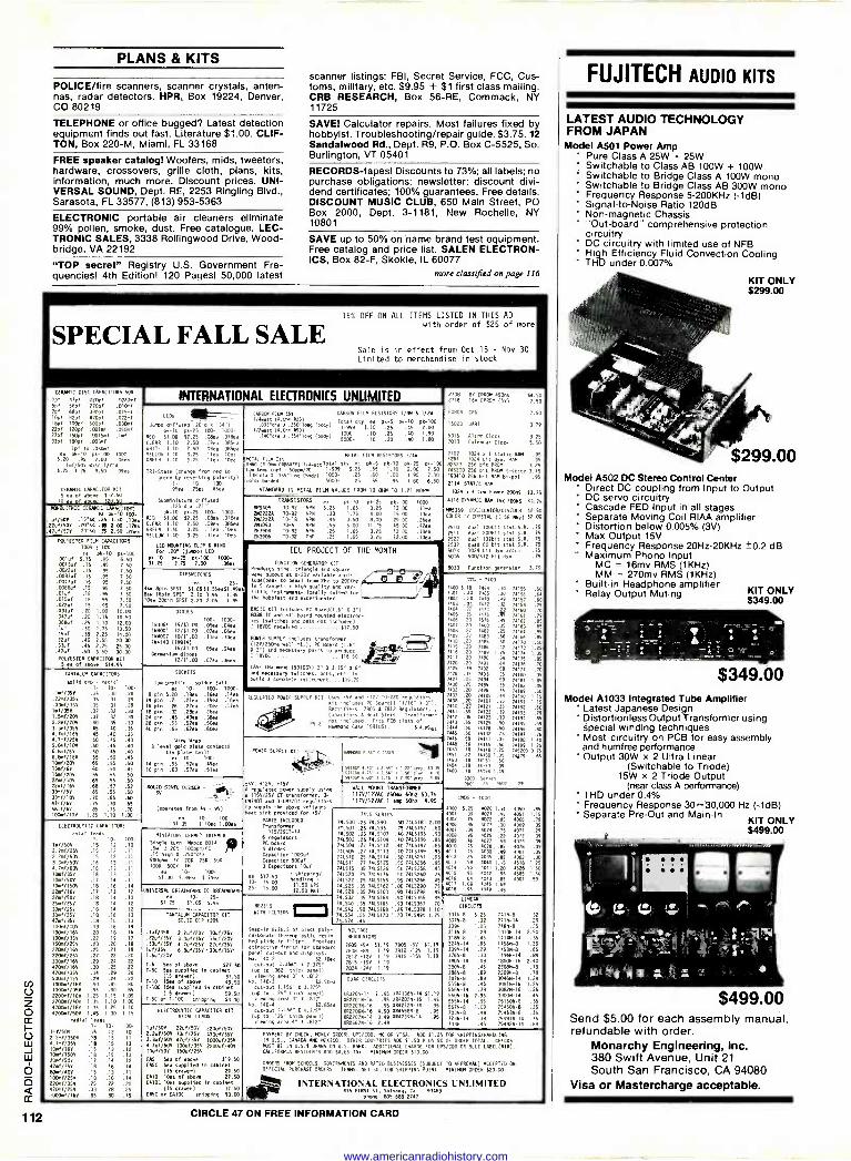
PLANS & KITS
POLICE/fire scanners, scanner crystals, anten- nas, radar detectors. HPR, Box 19224, Denver, CO 80219
TELEPHONE or office bugged? Latest detection equipment finds out fast. Literature $1.00. CLIF- TON, Box 220-M, Miami, FL 33168
FREE speaker catalog! Woofers, mids, tweeters, hardware, crossovers, grille cloth, plans, kits, information, much more. Discount prices. UNI- VERSAL SOUND, Dept. RE, 2253 Ringling Blvd., Sarasota, FL 33577, (813) 953-5363
ELECTRONIC portable air cleaners eliminate 99% pollen, smoke, dust. Free catalogue. LEC- TRONIC SALES, 3338 Rollingwood Drive, Wood- bridge, VA 22192
"TOP secret" Registry U.S. Government Fre- quencies! 4th Edition! 120 Pages! 50,000 latest
scanner listings: FBI, Secret Service, FCC, Cus- toms, military, etc. $9.95 + $1 first class mailing. CRB RESEARCH, Box 56 -RE, Commack, NY 11725
SAVE! Calculator repairs. Most failures fixed by hobbyist. Troubleshooting/repair guide. $3.75. 12 Sandalwood Rd., Dept. R9, P.O. Box C-5525, So. Burlington, VT 05401
RECORDS -tapes! Discounts to 73%; all labels; no purchase obligations; newsletter; discount divi- dend certificates; 100% guarantees. Free details. DISCOUNT MUSIC CLUB, 650 Main Street, PO Box 2000, Dept. 3-1181, New Rochelle, NY 10801
SAVE up to 50% on name brand test equipment. Free catalog and price list. SALEN ELECTRON- ICS, Box 82-F, Skokie, IL 60077
more classified on page 116
SPECIAL FALL SALE 15% OFF ON ALL ITEMS LISTED IN THIS AD
with order of $25 of more
Sale is in effect f om Oct 15 - Nov 30
Limited to merchandise in stock
CERAMIC DISC CAPACITORS 50v
Ipf 1rç1 220pí Mai*f 50f 560f 270pf .0179ní
7pf 680f 390pf .0150f 1001 82pf 470pf .022.f 18pí 100pf 600pí .030nf 220/ 120pf .001.
. 050.f
27pí 15O0í .0015af . 78f
33pí I80pf 0031f
Ipf to .050,7 a 0-10 pk-100 1000.
9.20 .95 7.00 .Oded
l.f/SOY disc 1/2"d $.25 1.25 9.50 .09ea TRI-St.te (change from red to
green by reversing polarity) 1- 10- 100-
0380,3C CAPACITOR AIT .957. .75ea .654,
5 ea Of above 912.50 1yy i .bave 570 50 Subminiature diffused
XONOLITXIC CERAIIC pk-10 pk-25 100- 1000- p3.90 200-
REO 97.00 02,.25 .081..07dea .lu/í/5e .20's9 .25 3.90 .17e. CLEAN 1.10 .0 .099. DE .22uf/505 .20'09 .IB 2.00 .20.1 fAFEO 1.40 3.25 .Ilea .l0ekaa .018//SOV 2.50 .1100 YELLa 1.40 3.26 .flee .l0ee
POLYESTER FILM CAPACITORS
1009 2 109
pk-10 pk-100 .001uf 9.15 .95 6.50 .0015uf .15 .95 7.50 .0022uf .15 .95 7.50 .00330 .15 .95 7.50 .0047uí .15 .95 7.50 .U060uf .15 .95 7.50 .010/ .15 .95 7.50 .015uf .1S .95 7.50 .022uf .15 .95 7.50 .033uf .20 1.00 10.00 .042101 .20 1.15 10.50 .068uf .25 1.30 12.00 Auf .30 1.75 13.50 .15uf .35 2.25 14.00 .22uf .40 2.55 20.00 .33uf .45 2.75 25.00 .470f .50 3.50 30.00
POLYESTER CAPACITOR 91T 5 ea of .8000 074.95
LEO MOUNTING CLIP 4 RING for .20" (lulo) LEO
00-10 p6-25 p6-100 1000- 11.25 2.75 7.00 .060.
INTERNATIONAL ELECTRONICS UNUMITED
LEDs ZZ J.Mo diffuses 20-4 ..34'1
pk-10 pt -25 100- 1000 -
RED 57.00 02.25 .oeea .07Bea
CLEAR 1.10 2.50 Agee .085ea MITE 1.10 2 50 09e 065e
SFIR.OI.tR25) CARSON FILM RESISTORS 1/4W 6 1/25
..95-e1 X 350.1.9 (body/ Total qty pk-5 pk-10 pk-100
1/2watl (R.am R50) 1-999 0.10 .25 .45 2.00
.116b1. .]54^lon9 /body) IOU0..10 .25 .40 1.90 5000- .20 .40 I.BO
YELLOW 1.40 1.40 3.2525 .flea
ADea lea .10ea METAL FILM !Is
METAL 7510 RESISTORS 1/30
IMO (4.0. C A40FY) 1/4w.tt100.1 952 nee pk-5 pk-10 pk-25 20-100
Low c00f . 50ppn/oc 1-999 0.25 .65 1.10 2.00 7.50 .
tame 15"ata 0 .055-IOng (body) 1000- .25 .60 1.00 1.90 7.00
Dolor banded 5000- .25 .55 .95 1.90 6.50
STANDARD 15 METAL FILM VALUES FROM 10 OM5 TO 1.27 MOIN
TRANSISTORS
IV5406 TO -92 NPN
21122220 T0-92 NPN
2022224 T0-18 NPN 293053 T0.5 NPN 203904 T0-92 NPN 201906 TO -92 NIP
ee
1.25
.30
.45
.55
.25
.25
pk-10 1.65
1.15
3.50 5.00 1.65 1.65
pk-25 3.25 4.00
8.00 11.75
3.25 3.25
pk-100
12.00 15,00 29.00 45.00
12.00 12.00
1000
.1171
.13ea
.208.
.12ea
.iá4
D12501701E5
0- 25- 4sw 8pin SPST 01.6581.55.51 49 Bs0 16pin SPST 2.10 1.95 1.85 1000 20010 SPSi 2.20 2.05 1.95
DI 100- 1000-
103064 15/81.00 A5ea .0477 184001 12/61.00 .07ea .06ea 104007 10/91.00 .77e..10fa 181148 (11.14)
15/41.00 .05,4 .08ea Gera.nide diodes
12/61.00 .07ea .06ea
TANTALUM CAPACITORS
solid am - radial
1- 10- 100- .1./350 .35 .30 .28 .221171/756 .35 .31 .29
33Nf/356 .35 .31 .29
i.//359 .37 .32 .30 1.5.f/203 .37 .32 .30
2.2.f/206 .40 .35 .33
3.3035V .45 .4 .35
4.7./166 .45 .40 .35 4.78f/259 .50 .45 .40 5.6./10Y .50 .45 .40 6.6./611 .50 .45 .10
6.8180/160 .55 .50 .45
lxf/205 .65 .55 .50 15./69 .60 .90 .4S 15./206 .65 .55 .50
22./100 .65 .55 .50
22./166 .68 .51 .52
33.7/6V .65 .55 .50
33m1/706 .70 .65 .60 47./65 .75 .70 .65
Senf/6Y .85 .75 .70 lOxf/10V 1.25 1.10 1.00
5000E TS
low profile - solder tail
ea 10- 100- 1000-
8 pin 5.20 .16., .16ea .16ea
14 pin .25 .2171 .1971 .16e4
16 pin .26 .22.. .20., .I7ea
18 pin .32 .28ea .26.,
24 pin .45 .40., .18ea
28 pin .55 .52ea .Sapa
40 pin .65 .627. .607.
Wire Wrap
3 level gold plate contacts
SI, plate tails
to 10- 100- 11 pin .55 .527. .499,
16 pin .60 .570. .51ea
IEU PROJECT OF THE, MONTH
100077ON GENERATOR KIT Prod ces sine, triangle and square
output at o-203 variable ugll-
Ind5(re49.8- peek)
high quality 212 to
20a,Nt1 sltlle instrument- Ideally suited for 1
the hobbles[ and experimenter. -
BASIC KIT includes PC 94.04/7.0" X 31 8038 IC and all board .bunted electron- ics (switches and pots not Included) ' lava 06961404 917.50
POWER SUPPLY Includes transformer (124/250me wall
)
Board and necessaryp rts0 produce
18000 916.50
CASE (14. n0 15970GY) 2" X 3 15" X 6" and necessary switches. pats, etc. to build a complete 175707eent 119.75
2108 L
, ,ROP 450,0 S4.50 2716 16YCeROH I501 7.50
00804 CPU 7.50
16020 UART 3.79
5316 Mane Clack 3,25 7010 Calendar Clock 5.50
2102 1024 a 1 static RAI .95 5261 1024 bit en. RAM .95 87523 256 Dit PROM 3.25 745200 256 bit PROM t -state 3.15 F93410 256 bit RAM 01-po1 .95
2114 STATIC RAM
1024 . 4 10. Power 200115 83.75
4116 Df9MIC RAN 166 TOMS 51.75
M6369 OSCILLATOR/DIVIDER 52.50 coil» TV CRYSTAL (3.58 Mat) 57.00
2510 dual 100bit st.t.5.0. .75
2511 deal 200515 stat.5.6..75 2522 dual 132615 stat.5.9..75
9013 1024 80 bit dyn :001 75
5016 500/512 bit dyn .75
8038 function generator 3.19
1218110 POWER SUPPLY KIT Uses 50 and 0123 00-220 regulator,
Kit includes PC Board(( 11/I6' I l"i Rectifiers, 7805 6 7812 Regulators.
0,2001t0rs 6 heat Sinks. Transforme
032 t included. f,ts PCB slots Of amro404 Case 1501000. s ..95 et.
ELECTROLYTIC CAPACITORS
£x1.7 leads 0- 100
I0/50V .15 .12 .10 2.2.//25V .15 .12 Al 2.2./508 .15 .12 .11
3.3mf/SOV .16 .13 .I1
A.10/63Y .16 .13 Al Ixf/35V .16 .13 Al 10.7/50V .17 .11 .11
1041!/1509 .18 .16 .14
22.1/169 .17 .13 .12
22.//SOV .18 .14 .13
25.f/259 .1B .14
30.f/25V .18 .14
303//256 .1B .16
470/359 .18 .16 100nf/10Y .19 .16 100.(/168 .20 .18 100.í/158 .22 .19
150.(/254 .23 .20
220.1/16Y .25 .21
220.f/25Y .27 .22
330.!/166 .29 .24
/700f/16Y 30 .25
470./354 .34 .29
500.f/15V .29 .24
000.4/160 90 .BS
0000/358 .95 .90 .85
200mf/160 1.25 1.15 1.05 200.3/4007 1.35 1.10 1.00
]0011/16Y 1,35 1.25 1.10 IOxf/508 1.45 1.30 1.1$
radial leads
1- 10- 100-
l.r/509 .IS .12 .10 2.28f/3501/ AB .15 Al 4.3.l758 .1B .15 .13 Ixf/1611 .15 .13 .12 lxf/160V .18 .IS .13
20m8/558 .17 .l4 .IS
41.í/3511 .18 .16 .11
804f/40V .15 .13 Al 100mf/2511 .18 .16 .14
22x1/359 .25 .22 .20 170ef/2511 .33 .28 .25 1000mf/161/ .85 .40 .75
.12
.12
.i3
.13
.14
.16
.17
.18
.19
.20
.22
.22
.26
.22
SO.Io SITTE BVZtm -
6V
(operates fron 49 - 9V)
0- 100-
91`]5 I.iOea 1.00ea
1119147I10 CERMET TRIMER
Sin91. turn M0000 0014 0 .5182201 100ppM00
fie
.15"h19h X .250"dia 500040 1K 209 256 506 1036 5005 IN
0- 100-
51 .00 1.89ea 9.19e.
1VER5Al 69040004110 IC BREADBOARD ee 0- 25-
87.25 81.05 0.95
SlPplr KIT
25V. 012V. 015V
A regulated p0ner supply using e 1154/290 CT transforwer, 3-
193401 and 3-0113201 regulators to supply the bo It Se Heat sink provided for 85V.
PARTS INCLUDED Transformer
115/29C1 -l8
gulat0rs L Doara
4 diodes Capacitor I000uf
Capacitor 500uí 3 Capacitors 104f
ea 017.50 shlp0in9/
10- 16.00 '371.90'1;
ndin
25- 15.00 82.50 995 82.50 men
0 PLASTIC CASES
4 ideé- i i:ü^ ér: Ll.ls
1501040 6.c0 1 . 2.00. grey e.a
WALL MOUNT TRANSFORMER 1119/124AC 2501. 6402 83.75 1170/12060 7 amp 60111 4.95
In - 7400
7100 1.19 1464 .30 11155 .50 7401 .20 7465 .30 74156 .64 7. .20 7470 .49 74157 .60 7403 .2 1 702 .32 14158 .15 7404 . 7414 21 11160 .10
1405 .25 7415 ,19 11161 .19 M. .20 7516 .19 74162 .85 7407 .20 1460 .35 74163 .85 7e01 .27 1082 .25 71164 .85 1409 .21 1483 .58 74166 .95 7410 ..20 7485 .50 7115 .29 7486 .12
11170 1.50
4171 1.25
74" .20 '499 I.)5 71175 1.05 .20 90 .59 71175 .85
7420 20 )191 .64 14176 .70 1425 .29 7492 .S9 11171 .10 1426 .25 7493 .35 74190 .35 1427 .25 1491 .59 11181 1.85 7430 .25 7195 .35 14189 .35 7412 .20 1416 .35 71199 .50 MI .20 74105 .48 70490 1.15
]4 r20 711W .5 711º1 1.15 .27 74121 .05 2092 .50
7441 .59 74122 .39 71193 .79 7442 .15 '4123 .5 74194 .05 ,443 .55 4125 .50 74195 .69 7444 .60 7026 .50 74196 .80 7415 .50 74132 .75 74191 .75 1446 .59 74141 .35 71199 4.10 7448 .59 14145 .50 74199 1.25
.1B 74118 1.25 145200 3.15 7451 .22 74190 1.35 74279 .65 7453 .18 74151 .50 7454 .18 74153 .35 1460
.
.18 14154 1.45
9ba0 ser,es
9601 .25 9602 .19
TANTALUM CAPACITOR KIT
SOLID 0IP 4209
, luf/5V 2.2uf/209 101f/256 .22uf/5V 3.301/354 ISuf/20Y 330//353 4.7uf/25V 220f/350
luf/353 6.Buf/359 ]luf/15Y I. Suf/203
0-5 54e of ,Dose $27.50 1-5C See supplied in cabinet
(IS drawer) 37.50 T-10 10.a of above 49.50 T -IOC 10ea supplied In cabinet
(15 drawer) 59.50 T -5C or T -10C shipping 03.00
ELECTROLYTIC CAPACITOR KIT
AXIAL 0E4E6
lof/SOY 2291/5011 2204//500 2.2uf/SOY l3o//259 470uf/3511 3.347f/501/ 4774//359 10004f/350 4.70f/506 100uf/51/ 22000/409 10,0/500 150uf/253
EPA Sea of 480ve 819.50 EASE Sea supplied 17 cablmet
(15 draer) 29.50 0410 10ea of above 27.50 34100 Ix. ',ppl184 In cabinet
(15 drawer) 37.50 0450 or EA70C shipping 03.00
1415 SERIES
7 1500 .25 110590 .90 1415181 2.00 7 1501 .25 740595 .75 7105192 .60
741.502 .25 7413107 .40 7413195 .90
1 1503 .25 7415109 .40 1115196 .85
'7 1504 .27'7415112 .40 7415191 .85
7 L505 .27 7413113 .40 7415199 .95
7 L510 .25 7415114 .50 7405251 .95
71511 .27 7415125 .50 7115256 .95
140515 .35 7415126 .50 7115258 .95
7 1520 .25 7415136 .50 1415260 .75 741522 .25 1415156 .95 1415266 .45 741526 .35 7415162 1.00 1415290 .75
741528 .35 7415163 .90 7415298 .85
141532 .357415164 .90'7415365 .85
BE2ELS 74L540 .35 7415165 .90 7115361 .70
WIM fILiERS E= 141542 .50 1115168 1.25 7405378 1.10 741554 .25 7415110 1.70 1415490 1.75 1 0574 .45
4009 .I6
4010 .15
4011 .45
4012 .25
4013 .59
4014 .95
4015 .5 4016 .61
011 1.08 4019 .95
TO6 - 4000
4000 9 25 4020 1.14 4001 .39 4021 .95
4002 .25 4022 .95 1006 .95 4023 .30 4007 .19 4014 .15 4008 .95 4025 .22
021 .59 4028, .85
030 .4º 4035 .95 1010 1.15 4041 1.20 4042 .95
043 .85 4016 d1.49 9 .45
M0 .45
1.15 4066 .79 4069 .39 1011 .29 4012 .l9 4070 .39 4078 .39 4081 .39 4082 .30 4518 1.25 4528 1.50 4585 1.50 4901 .59
Snap -In BEZELS of black Poly carbonate themoplastic rest .
Red slide -In f1lter. Provides
attractive finish for standard panel cut-out and displays.
No. 140-2 $2.10440
cut-out 1.156" X 2.115" (up to 062" 0911k panel) viewing area 3' X .812"
No 140-3 52.50ea cut-out 1.156 X 3.1/5"
(up to .1257 thick panel) vle4ing area 3" N .812"
No. 140-4 52. BSea cut-out 1.156 X 4.375"
(01yó.125 thick panel)
viewing area 1' X .812'
VOLTAGE
0EGULAT095
7805 050 51.19 7905 -56 91.19
7808 080 1.19 7912 -128 1.19
7812 0126 1.19 7915 -15V 1.19
7815 015V 1.19
7824 .24V 1.19
EXM CIRCUITS
093209-14 i .95 4041367-14 $1.
4422010-16 .95 0042020-16 1.
8922039-16 .95 242120-14 .
8022068-16 4.50 8045580-8 .
0922079-14 3.49 8041390-14 0»25679-16 2.49
LINEAR CIRC0775
3010-8 $.25 7410-8 .32
3070-8 .32 74111-14 .29
3090 1.05 74811-8 .25
3110-8 .29 13100-14 2.50 3180-8 1.45 44101-14 .35
3240-14 .95 145611-8 1.29
1390-14 .29 14588-8 .65 1769-8 .30 14961-14 .89
34007-14 1.09 10000-16 2.40 3800-8 .45 22000-8 .79
38611 8 89 22090-8 .79 3871-8 .89 30460-14 1.29 5550-8 .45 30810-16 1.25 5560-14 .79 30820-16 1.25
5600-16 2.95 39004-14 .45
5650-14 .95 751501-8 .35
5679-8 1.09 754500-8 .35
70311-8 .49 754531-8 .35
7236-14 .39 754911-14 .75
7330 .45 754920-14 .09
PAYMENT BY CHECK, MONEY ORDER, UPS/COD, MC OR VISA. A00 51.25 FOR SHIPPINS/HMoi1N6 IN U.S., CANADA ANO MEXICO. OTHER COUNTRIES A00 $1.50 PLUS 5 OF ORDER TOTAL. CHECKS MIST BE IN U.S.5 OMNN 0N U S. BANK. ADDITIONAL CRAOGE FOR UPS/COO OR BLUE 18001(610). CALIFORNIA RESIDENTS ADD SALES TAX. MINIMUM ORDER 510.00
ON0FR5 FRON SCHOOLS, GOVERNMENTS AND RATED BUSINESSES (SU83EC T0 APPROVAL) ACCEPTED 0N OFFICIAL PURCHASE ORDERS. TERMS: NET 30, FOB SHIPPING POINT. MIXINN ORDER 920.00.
INTERNATIONAL ELECTRONICS UNLIMITED 435 FIRST 51. Salran9. Ca. 91461
05000 805 688 2117
FUJITECH AUDIO KITS
LATEST AUDIO TECHNOLOGY FROM JAPAN Model A501 Power Amp
Pure Class A 25W + 25W ' Switchable to Class AB 100W + 100W ` Switchable to Bridge Class A 100W mono
Switchable to Bridge Class AB 300W mono Frequency Response 5-200KHz (-1dB) Signal -to -Noise Ratio 120dB Non-magnetic Chassis "Out -board" comprehensive protection circuitry DC circuitry with limited use of NFB High Efficiency Fluid Convection Cooling
' THD under 0.007%
Model A502 DC Stereo Control Center Direct DC coupling from Input to Output DC servo circuitry Cascade FED Input in all stages Separate Moving Coil RIAA amplifier Distortion below 0.005% (3V) Max Output 15V Frequency Response 20Hz-20KHz ±0.2 dB Maximum Phono Input
MC = 16mv RMS (1KHz) MM = 270mv RMS (1KHz)
Built-in Headphone amplifier Relay Output Muting KIT ONLY
$349.00
$349.00 Model A1033 Integrated Tube Amplifier
Latest Japanese Design Distortionless Output Transformer using special winding techniques Most circuitry on PCB for easy assembly and humfree performance
' Output 30W x 2 Ultra Linear (Switchable to Triode)
15W x 2 Triode Output (near class A performance)
THD under 0.4% ' Frequency Response 30'-30,000 Hz (-1dB)
Separate Pre -Out and Main -In KIT ONLY $499.00
$499.00 Send $5.00 for each assembly manual, refundable with order.
Monarchy Engineering, Inc. 380 Swift Avenue, Unit 21 South San Francisco, CA 94080
Visa or Mastercharge acceptable.
CIRCLE 47 ON FREE INFORMATION CARD
www.americanradiohistory.com
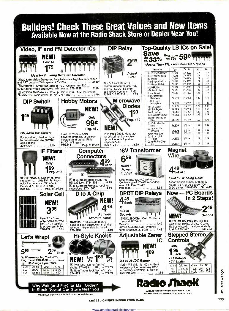
Builders! Check These Great Values and New Items Available Now at the Radio Shack Store or Dealer Near You!
Video, IF and FM Detector ICs
NEW! Low As
N © 179
[1]
Ideal for Building Receiver Circuits! 117 MC1330 Video Detector. Fully balanced, high linearity. Video and AFT outputs. With specs. 276-1757 2 49
e MC1350 IF Amplifier. Built-in AGC. Usable from DC to 60 MHz! For video and audio. With specs. 276-1758 2 19
© MC1358 FM Detector. IF amp (100 kHz to 5.5 MHz), limiter, FM detector, audio driver. 14 -pin. 276-1759 1 79
DIP Switch
149
Fits 8 -Pin DIP Socket Four -position, ideal for digi- tal projects and low -current applications. 275-1304 1 49
Hobby Motors
NEW!
Only
99¢ Pkg. of 2
Ideal for models, solar - powered projects, or as low - voltage generators. 11/2 to 6VDC. With gear. 273-219 Pkg. of 2/995
IF Filters NEW!
Only
199 UP kg. of 2
SFE10.7MA5-A. Quality ceramic filters for 10.7 MHz FM IFs. Input/ output impedance: 330 ohms. Bandwidth: 280 kHz (3 db). 272-1301 Pkg. of 2/1.99
Solar Cell
NEW! 395
New 2.5 x 5 cm polycrystalline -type cell. 0.42V typical. Max. current: 0.2A. 276-124 3 95
DIP Relay
299
Actual Size!
Fits DIP sockets or PC boards, measures only 3/8x 5/8x7/re"! 5VDC, 56 -ohm coil. SPDT contacts: 1A Cä
125VAC. 275-216 .... 2.99
Microwave Diodes
199
Pkg. of 2
NEW. H -P 5082-2835. Manufac- turer's prime! Low -noise Schottkys with 1 pf max. capacitance. 276-1124 1 99
Top -Quality LS ICs on Sale! Save Reg. Low 59¢ IT" 1tó 33% As 79¢
Faster Than TTL With Pin -Out & Specs
Description Type Cat. No. Reg. SALE
Quad 2 -Input NAND Gate 74LS00 276-1900 .79 .59
Quad 2 -Input NOR Gate 74LS02 276-1902 .79 .59
Hex Inverter 74LSO4 276-1904 .79 .59
Quad 2 -Input AND Gate 74LS08 276-1908 .79 .59
Quad 2 -Input OR Gate 74LS32 276-1915 .89 .69
Dual D Flip Flop 74LS74 276-1919 .79 59
4 -Bit Bi -stable Latch 74LS75 276-1920 .99 .79
Decade Counter 74LS90 276-1923 1.09 .89
Retag. Monostable
Multivibrator 74LS123 276-1926 1.49 1.19
1 of 8 Decoder/ Demultiplexer 74LS138 276-1939 1.19 .99
4 -Binary Counter 74LS161 276-1931 1.39 1.09
8 -Bit Shift Register 74LS164 276-1932 1.39 1.09
Quad D Flip Flop 74LS175 276-1934 1.19 .99
Up/Down Binary Counter 74LS193 276-1936 1.49 1.19
Octal Inverting Bus/Line Driver 74LS240 276-1940 1.99 1.49
Octal 3 -State Non -Inv.
Driver 74LS244 276-1941 1.99 1.49
Octal Non -Inv. Bus
Transceiver 74LS245 276-1942 2.99 1.99
Hex Butler (3 -State) 74LS367 276-1835 1.29 .99
Octal O Latch, Fall
Through 74L5373 276-1943 2.39 1.59
Octal D Flip Flop (Edge Trig) 74LS374 276-1944 2.39 1.59
Computer Connectors
499 Each
D -Submini Male.. Plugs into RS -232 jack. 276-1559 4 99 g D-Subminl Female. Ideal for extensions. 276-1565 4 99
D to A Chip NEW! 449
Put Your Micro to Work!
DAC801. Produces up to 20V peak -to -peak output with 8 -bit digi- tal input. 16 -pin, data included. 276-1791 4 49
18V Transformer 699 Build a Power Supply!
1
Steel frame. 120VAC primary. Center -tapped 18VAC secondary, rated 2A. 23/4x21/4x2.' 273-1515 6 99
DPDT DIP Relays 449
Each
Fit 16 -Pin Sockets 1 Urri 12VDC, 280 -Ohm Coil. Contacts: 1 amp at 120VAC. 275-213 4 49
5VDC, 50 -Ohm Coll. With fea- tures of above. 275-215 4 49
Magnet Wire
449 Sett of 3
Ideal for Winding Coils Assortment includes 40 ft. of 22 - gauge, 75 ft. of 26 -gauge, 200 ft. of 30 -gauge. 278-1345 .. Set 4.49
Now -PC Boards In 2 Steps!
249 Set of 4
Direct -Etch Dry Transfers. Just rub your circuit (strips, circles, IC pads, etc.) onto board ... and you're ready to etch! 276-1577 Set 2.49
Let's Wrap! Sietemimete-
595 --
Each
Wire -Wrapping Tool. 41/2" - long, metal. 276-1570 5 95
0 30 -Gauge Kynar Wire Color Cat. No. Color Cat. No.
Red 278-501 White 278-502 Blue 278-503 Yellow 278-504
Hi -Style Knobs
NEW! 28169 of 2 El Two-tone "top hat" for 1/4"
shafts. 274-423 ... Pkg. of 2/1.69 © Neat "metal -look' for 1/4" shafts. 274-424 Pkg. of 2/1.89
Adjustable Zener IC
NEW! 189
2.5 to 36VDC Range T1431. Will sink 1 to 100 mA. Use in voltage monitors, series regulators, over -voltage protectors. 8 -pin with data. 276-559 1 89
Stepped Stereo Controls
Only
199 Each
41 Detents '/!" Shafts Value Cat. No. Value Cat. No.
5k 271-1730 100k 271-1732 10k 271-1731 500k 271-1733
Why Wait (and Pay) for Mail Order? In Stock Now at Our Store Near You
Retail prices may vary at individual stores and dealers.
ftadio IhaeK A DIVISION OF TANDY CORPORATION
OVER 8000 LOCATIONS IN 33 COUNTRIES
CIRCLE 3 ON FREE INFORMATION CARD
www.americanradiohistory.com
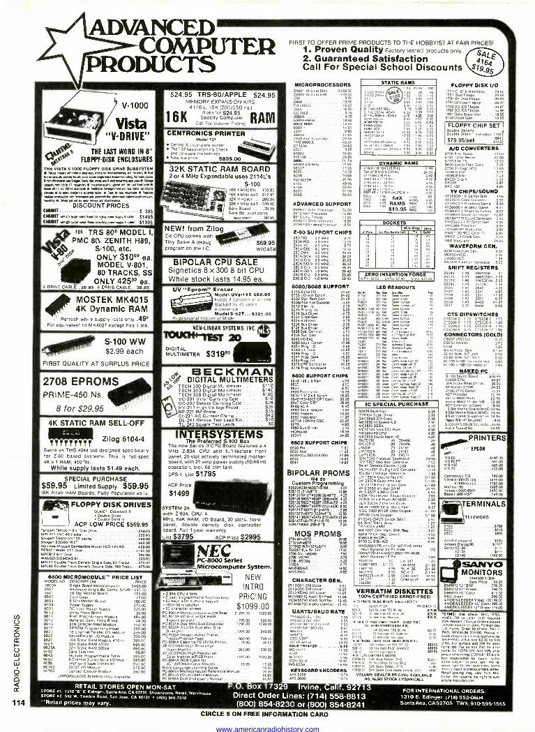
2 DRIVE CABLE
ADVANCED COMPUTER
PRODUCTS
V-1000
Vista ,i'
J "V -DRIVE"
^1t" 1 THE LAST WORD 19 8" %at FLOPPY -DISK ENCLOSURES
THe VISTA V-1000 FLOPPY DISK DRIVE SUBSYSTEM Drba desee new *Jewry wee [mementoao none BI
eznelekeeYWapv111e a*4$1ó11ám--rteke65eel». firth691á,m mISNpl5
Nee .weer See
meaty IiLI 03 540', lees Nee per eel Merle UK apr 6ebl e e ul we 05114 area /Mee eel O aro err mere ewes
pee p al re Ma Pew In, wee aleló Ore d re mere Nees near wem1e1eneaaea lereaw 5ad Wmeerreoeama mom VA W b w aaa mine are nwmrn
DISCOUNT PRICES CABINET S 395 CABINET em (a re as ea. (rare Pa. 550/ a eel $1495 GANNET mea m mew am ax. pram pew .asy a as $1995
FOR TRS 80° MODEL I, PMC 80. ZENITH H89,
S100, etc. ONLY 31000 ea. MODEL V801, 80 TRACKS, SS
ONLY 4250° ea. 35.95 4 DRIVE CABLE. 31,05
MOSTEK MK4015 4K Dynamic RAM
1I t Refresh while supply lasts only .49e Pin equivalent to MK4027 except has 1 ms.
S-100 WW $2.99 each
FIRST QUALITY AT SURPLUS PRICE
4K STATIC RAM SELL-OFF
11111.1. TTY
Zilog 6104.4 Same as TMS 4044 but designed specifically for Z-80 based systems. This is full -spec 4K x1 RAM, 450 Ns.
While su ly lasts $1.49 each.
SPECIAL PURCHASE $59.95 Limited Supply $59.95 16K Altair RAM Boards. Fully Populated as Is.
FLOPPY DISK DRIVES o Daletn<k 8
Double Sided Double Density
ACP LOW PRICE $589.95 random 71/11on- 5, Ste Drive 249.96 MIN 8519,, 40 tracks 2309$ Shugart 50400- v- 35 Necks 29500 Shugart 800/801R 8' 449.00 51 Shugart Compatible Model FDD-I 20 80 .429.00 PERSCI Model 2 7 Dual.. 119500 Mfg 852 5, Dual 34800 WANOO/SIEMENS 82 290.00 MPI 01 Double T90k penally Single Slde. 80 Track. 375.00 MPI 92 Double Tack Den41ly Double Side, 160 Track.. 075.00
0800 MICROMODULE PRICE UST MODEL NO. DESCRIPTION PRICE 960)0 Slagle Board Microcomputer 5495.00 9603 Advanced Sngle Bd. Comp 168091 595.00 9601 16 Slot Mother Board 17500 9602 Carlo Cape 7500 9603 8 Slot Mother Board 106300, 9604 Power Sul3ply 275.00 9605 DC Input Power Supply 325.00 961 Urrty Prolo Board 3900 9611 0,110 Pr9c/Memory Module 49500 9612 Buffered Uhxty Prolo Board 49.00
326 EPROM/RAM Module 250.00 9617 EPROM Programmed Head 250.00 9622 16 Channel Parallel I/O Module 295.00 9622 Serlal-Parallel I/O Module 325.00 9627 36K Stallc RAM Module 4700s 395.00 9623 321( Stated RAM 4501. 695.00 96230 326 Stated RAM 200n5 895,00 9632 Card Entende/ 6800 9640 Mulhpe Programmable Tamer 395.00 9655 BChannel Dupe l 1/0 Mod 395.00 9656 Intelligent Talle Conl/dler 550.00 96103 32/32 I/O Module 2]5.00 96702 Contact Closure Module 350.00
UNPOPULATED BOARDS (Also evadable(
$24.95 TRS-80/APPLE $24.95 MEMORY EXPANSION KITS.
4116's, 16K (200/250 os.)
16KB fyr omput
RAM 1 Specify Computer Call For Volume Pncing
CENTRONICS PRINTER Model 737
Genrcomcs complete printer and 737 hase
featuresg.
0 and compare the Iealure5 New low pote $835.00
32K STATIC RAM BOARD 2or4 MHz Expandable uses 2114L's
s-100 1664 MHZ Kit 159.95 16K 4 MHz AST 217.95 32K MHz Kg 289.95 32K 4 MHz A8T 339.00 Bare 50ar0 39.95 Bare Bd. Wall parts
less mem 99.95.
NEW! from Zilog Z-8 CPU comes with Tiny Basle & debug program on the I.C.
I '
$69.95 widata
BIPOLAR CPU SALE Signetics 8 x 300 8 bit CPU While stock lasts 14.95 ea.
UV "Eprom" r Model UVS-1 I E $09.96 Holds 4 Epl0111 s al a ?erneBacked
by 45 years expellent., ezpenenl-e Modal S -52T... $325.00
ProlesSlona! Indus(nal Model
NON-LINEAR SYSTEMS. INC.
TOUOf1IEyT 20 DIGITAL MULTIMETER $319°6
BECKMAN _ewer DIGITAL MULTIMETERS T. TECH 300 Digital Multimeter $110
TECH 310 Digital Multimeter 95140 TECH 330 Digital Multimeter 189
VC -201 Vinyl Carrying Case... 10 DC -202 Deluxe Carrying Case 24 HV -211 High Voltage Probe 35 RP -221 RP Probe 35 Ct-231 AC Current Clamp 2 DL -241 Delxue Test Lead Kit 10 TL -242 Square Test Leads S6
INTERSYSTEMS The Preferred S-100 Box
The new Series II CPU Board features a 4
MHz Z -80A CPU and full -feature front panel. 20 -slot actively terminated mother- board, with 25 amp power supply (50)60 Hz operation, Incl. 88 cfn, fan).
DPS-1, List $1795 ACP Price
$1499
SYSTEM 2A with Z -80A CPU 4 MHz, 64K RAM, I/O Board, 20 slofe, front panel, double density disk controller board. Full 1 -year warranty. List $3795 ACP Price $2995
NOPC -8000 Series Microcomputer System.
2900 CPU 4 MHz 5 user pr Minaoopp ble function keys 82 Key wflh numeric keypad 160.100 80 character
resolution cter screen
NEW
INTRO
PRICING
$1099.00 PC.8001 A Microcomputer 0132KRAM $1295 00 1099.00 PC8012A 110 Unit 0/326 RAM,
E.pp Lon stole 795.00 PC8031A Dual Mini.Dlsk Drive Unll 1295.00 PC -9032k Add -On Dual Men! -Disk
Drive Unit 109500 PC80230 Impact Mºtn. Printer,
Tractor/Friction Feed 86000 PC80940 Cable for PC -8023A Printer ....49.95 JB.1201M(A) High Resolution
Green Monitor 265.00 239.00 JC1202DH(Al He Resolution
Color Monitor w1RGB Input .. .. 1195.00 1049.00 PC -8091A RGB Cable for
JC 1 2 0 2 0 0101 Color Monitor 1995 17.95 Basic Language Learn log Guide 1995 PC8001 A Microcomputer Reference Manual 1995 PC.60120I/O Unit leer's Manual .. 1495 PC -80310 Dual Desk Users Manual 4444 1495
599.00 1098.00
94900
78900 4495
FIRST TO OFFER PRIME PRODUCTS TO THE HOBBYIST AT FAIR PRICES! 1. Proven Quality Factory tested products only.
2. Guaranteed Satisfaction Call For Special School Discounts
MICROPROCESSORS Z8001 rB dl to BMb. ..$189.00 28002 16 5,1 to 64K 149.00 280 995 Z80A 13.95 F-6138501
. .
.. 16 95 2650 .1695 CD 1802 975 80800... 4.75 s0B0A-4MHa. BALE 8085
2901 29010 29034-011 Supmelice TMS 99000 CP1600 6502 65020. 106100 6800 68008 20 MHz 6802P 4444
8035 8039 INS 80735 .
6755 8748 6809 8006
'495 495 9400
195 2995 09.95 3995
16.95 2995 11.75 19.95 1795 1a.95 i9.95 2495 4995 6995 3795 6995
ADVANCED SUPPORT ÁM9511 Anlh. Processor 17500 9512 0,1111 Processor 17500 9513 Un.9 Tlming 7995 AM9517 DMA Controller 18 95 AM., 9 Universal Inlerruol rß.95
zee SUPPORT CHIPS ZOOPlO 2.5 MHz 875 2500 -PIO 4.0 MHz 12.95 280LTC 25 MHz 875 ZBOALTC 40 MHz 12 95 Z80DMA 2.5 MHz 29.95 280A -DMA 40 MHz. 38.95 Z80.810/0 2.6 MHz... 35.96 2800.810/0 40 MHZ... .39.40 280.910/1 2.5 MHz. 3595 2800-910/1 4o MHz.. 39.40 280.910/2 25 MHz .... 38.95 260810/2 40 MHz... ...39.40
6000/0084 SUPPORT 6166/61661/o 24.96 8766 I/O with Epom . 04.95 8202 Dyn. Ram Cont. 34.95 8205/749 138 Decoder 3 95 8212 8 5,1 1/0.. 275 8214 Prodly Inl 5 20 8218 Bus Dover 2 75 8224 Clock Den 2 85
8220 But Driver 2 98 6120 Bui Dove, 295 8228
8ys 8y1. Com rot 5 50
6238 .50 8243 I/O ben 9.50 8250 Asyn. Comm 1595 8261 Prag //O. 0.95 82ó31n. T1 1295 8256 Prop. I/O 650 8257 Prop. DMA. 18.95 0259 Prot Int... 15.95 8275 CRT Controller 45.95 8279 Prop. Keyboard 15.95
6800 SUPPORT CHIPS 8810 128.8 Ram 4.75 6820 .8.58821
e 6828 Pri mny Inh 10.75 8834.1 512.8 Epom 1695 0045/H046505 CRT Com.. 2º.95 6847 Color CRT .29,95 0850 ACIA. 5400 0052 94mal Mager 5 95 68 Modem. 10 08 8862 0061810/ II 85 8871A 1 0MHz OSC.. 25.95
58BÓ But Dr,ver 2,19 00004es t 9.96 65047. 2496
0602 SUPPORT CHIPS 8520 PIA.. 4444...... 7.50 0522 Mull It. 95 0530-002.003.004.005 2196 0532 4444 19.58 8551 1996
BIPOLAR PROMS We do
Custom Programming 82823533015000/748188 425 829115(5129119 . .12.% 828123 1N74B288(3208IT8.. 4.25 829128/5003/748387(25804)0C 4.25 828129150230/48287175004118.4.25 62513015004/748570(512ä410C 600 828131 /74867 512x4118 0% 529137/748573 102454)75. 12 95 52514113024/7 71 512081181215 821314777484721
TS740971103125508)
....17 0 08
MOS PROMS 2764186X8115 ....... 80.95 20214(08118 1605 27162115;óV12608110 8.06 TM82710,a 5V. 12V 17.95 275800, 145065 7.50 2708 1450551. 5.75 2708 (0505.1 5.25 17020 5.75 00520300... 14.50 0052040 ....9.Bó
FLOPPY DISK I/O 1771-01 Er a M,mll0000 24.95 1781 Dual Floppy 29.95 1791-01 Dual Fee ...38.95 1791-02 Duel Floppy 4495 1793 D0, DS Floppy 44.95 1797 DD. DS Floppy 54.95 1691 Data Separator 18.95 2143 Clock Gen 18.95
FLOPPY CHIP SET Double Deneity Double Sided Include.: 1797
$79.95/set ? 911
A/D CONVERTERS 8700 8 DI &nary 13.50 8701 TONI Binary .2200 87038 d1 T5 13.50 9400 091 10 Fr. COne 7.25 87503.4 Dv BCD 1395 140606 8 Mt. 3.95 1,08.86ón 595 DACO00000180 to
995 080 100 995
TV CHIPS/SOUND 0030500-r 6 Games 81W 4.95 ÁY36515 Color Convener 2.95 Á138603., 0000,000 Game 8.95 ÁY388061 Wee( Game 950 *039ó07-I Shooting Gallery. 8.95 Áy39910 Sound Generator 12.95 SN76477 TISound Generator 395 MM5320/21 TV Synch Gen 9 95 1405369 Prescaler 3.95 101889 RF Mod01alor 3 95 MM57100 NSC Color 1V 695 0057104 Clock Gen 375 MOO Modulator. 2995
WAVEFORM GEN. 8038 Function Gen.. 4.50 MC4024VC0 295 LM566 VCO 1.95 052208 FunCton Generator 5 25
SHIFT REGISTERS 2504V 1.49 MM50011 50 2507V. 1 49 11450565. 2.95 25176 ....149 MM5060N 2.95 2524V I 49 25100. 1 95 2525 149 2847 495 2527 .149 3341 4.95 2526 1 49 3351 I7 95 2529 1.49 3357 695 2533 149 9403 24.95 3347 5.95 9408. 9.95
CTS DIPSWITCNES 076206.2 175 015200.7 1 75 CrS206-4 175 CTS206-8 1 95 CT8206-5 1 75 010206-0 1 95. CTS2056 1 75 005206.10 t 95
CONNECTORS (GOLD) 0525P 1002321. 3 25 08255 Female.. 3.75 Hood 25 Set w/Hood, Sale 57.50. 22/44 WM. S/T XIM .295 43786 W/W SR MOT 650 507100 SI 03 Connecta w/w 4.95 50/1o05í CO Connector s0 395
NAKED PC S-100 Sound Board.... ..534.95 8080A CPU . 30.95 32K Stelo RAM (21145 39.95 8K Eprom 127081. . 24.95 2708/2718 Epom 34.95 ACP Wowed. 2295 Vector 8800 Proto 22.20 Vector 8803 11 slot M8 29.95 ACP Extender w/Conn 1895 13 Slot MolSi,Soard S'OMCI 32.95
9 Slot MotherBoard IWMCI 2505 B 5101 MoIOer 1Eaendableb 34.95 Ro9Po PCB it Sxu84R11 39.95 Sr 00 (4Y589 lob Souna Bá.-34.95 Apple Sound Bd....... 24.95
PRINTERS -EPSON
0X80 9495.00 MX -80 FT 595.00 MX.100 885400 05.70 425.00
Centronics 739 799.00 Vita 8300/25 003 1495.00
0.300/45 cps 1795.00 Malibu 165
e5.55009501 !
995 CO Ana 50.1X5 Base II800 MST /49 00
ior\TERMINALS TELEVIDEO
912C
950c...: ._. .:.. 5799 5849 5995
AddS Vlewpolnt 5599 Ampex Dialog 80 3107'. Soroc10120 Son,
10135 18339 10100 1149.00
Sak N=ty MONITORS
CHARACTER OEN. S; e P50
9 rice 159.95
2513220115V1 Upper .........,9.60 - DM501212-B/W 239.00 2S13-005/SWLower .1496 VERBATIM DISKETTES DM801313'Color
DM5112 12. Green 4150000 M315V1 Lower. 14.95
MCM0B710 A50Il Shifted 12.95 100% CERTIFIED ERROR -FREE( NEC Green 149.00 MCM08740 Math Symbol 13.45 31 NUM. eel U stem t1.91141e1e P. AMOEK/LEEDE%Vldeo 100148.00 00080750 Alpha Control 13.45 AMDEK/LEEDEX 13. Color 399.00
TYPE DESCRIPTION Seclo10N Pa CE Sox 10 AMKEWLEEDEX 12' Green 179.00 DARTS/BAUD RATE ses D1 sd15ea1mea es NI :. 429.%
525.10 10 Mole TWO NS bpk etc 10-.% TERM,; Une check, 0-/C. NSA TRI 602915V, 1201 395 52516 16 TIM Nam Memo. 829.95 AMEX. CB, or COD. COD remoras
2596 deposit Charge Orders deaee enclude dab. Foreyn pay
532 25 U.S. Funds. Order by phone, mail l'
3225 TWX. MINIMUM 51000. Please 101
1775 lade magasine nsuenaphone no. SHIPPING USA add 52.00ley Ural
X16 2 ló For surface add 304 for dole 13995 tonal01 Ire. For all add 714 for 500,- cogs tonal Ide. FOREIGN Add 110%ehi.
pro and CODa SI.85 extra.
53350 Not resp00óóh. oneble foe typos Some
5350
tee to pna ssb We r. ,tek eght to en mammies. some
KEYBOARD ENCODERS mein,, sal DEA ER a.. N'' 3740 49éó 'y aewlem lowacleusrnetel ROerl prbiret maY very Iron Mail Áy5.337, 4.. 13.75 VOLUME DEALER PRICING DYI0 AD.. peee ma ÍM npnl to wD gY53800.... 4444. 4444 13.75 WE ALSO STOCK DYSANCALL woe manufacturer
Av5r01ñN181215-140 .51015M1863 1501 IM6402 1M6403 2350 USRT 671 B Aalroa 2
M 55081 Sdr See« SA 450 P 52 1141.875/478a
4.2 W01941 COM 5016 11458250
STATIC RAMS 1.24 2599
59 1
25 55
5 65 295 295 13.] y 70 90
5 855 495 4.95 425 695 7 So
995 995
095 lori 195 t 95
95 95 1 75
º BJS
2902 450 9t% 21.0225021 ', g1D 21131 21011
221 11iNt50nsJ14p451
21141.450m.(404u) 4044 250 ne 4044 4eMe.
EM2004 4.2 4.4.1091.4/41 440913431 1101 P2125/93425105ns1 6519 2147 LtwrPwe.4x61a1e 995 995 93415 .. 995 595
100
J 55 265
325 550 596 690 4.75 7 95
025 25 loes
eis 725 695 550
DYNAMIC RAMS 415/4116 086)10 Pin) Sel 018416'S 200 Na. 41158K(18 Pint 4050 40.1 115 Pm
2 Mr 404K. 1 216 Poi %
) 2Ñ x 1 ÌI6 Pin UPD 4rÁ
Z2 ,95 64k 1103
562 9500051 5220 RAMS5290 éss
$19.95 óó2
2.49 2095
5.49 95
º5 3
d. 95 95
495
95 50
SOCKETS
ne 1 Wire
bPn f leet( wnPD T in
Lee. Geld old
14
Is 9
32 36
45 59
16
10 20 24
39 59
62 84
20 29 69 99
24 38 95 120 26 36
43 58
110 1 25
149 1 69
40 60 1. 1. ZERO INSERTION FORCE
16 Pm 15.50 24 Po 5750 40 Pm 51025
LED READOUTS Nu4 e 0.M mss 11.70. w01ó Como DUO? 300 9r cram Am /x6357 357 Rra Corm Genk 1x050, 500 R5 Dam Gam ihn .C603i5110, 500 PM C COMO .505075,0. 500 0.o Corm Anme .0501 500 9a Comm Mme 14,1 .0530 Sw Dem Comm Gam .4650 500 Day Gem Gem «x0w 500 as Comm cea
x080710101ral,l 000. Corm A
55042700 .. 4
Sa 0y 00 4505,300 500 Ger
11550427131 .. Corm Mee T.5 ruse nr ̂
5141104 4.51002
4x3053 11.3064w51
4/3052 451053 053054 4x3051 4.82 0.3083 LOOM
Mw 5.1 270 Re We.
v
Oren
ñóRea 01.7
mma 9a
210 nee 444 Saner 300 64 Coen M909 Re on 000 Re, Crrm Mob lm 01 300 Ad Om. CA Ter10P 300 Rea Corm Came Rae 04
0 Geer Came Moor 991'
l 1N
Gee, Cam Mae TM OP
300 Gem O. Lm OP
300 Gan Ca1,, Gam 819 CP
w 0444 Com MMe Ade OP
300 414 Cam Moon 10- OP
w ve 0 e. Nan CA lm 0, 300 W. cox Rpm [P
IC SPECIAL PURCHASE 820096459 Ram 8.95 DP8304 Octal Driver 2.95 DAC88EX D/A Conv. 8.95 MC1650 Hl speed A/D 795 M00852 SSDA 3.49 MC10145 18.4 ECL Ram 450 MK3B50'F8 CPU 4.95 MK3853 Static Ham IIO 4.95 5575138 48 781408 49 MC10210 69 79006 .49 LA1339 .79 74157 .49 LM710CN .29 74101 .49 LM711CN .29 74074 .35 ICM 7045 Mammon StopWalcn 2395 ICM 7207 Oscillator Controller 750 Seen Decade Counter 7208 18.95 MC 4433P 3', 0511 4/0 Convener 13.95 ICL 8211 Voltage Reference 1 95 LM 1850N Ground Fault IC 3/100 LM 29005 Oued Amplaler 2/1.00 LM 29175 Freo to Vat Cony 2/1 99 AY -3-3550 4% Mot OMM 24 95 Al-6350740MHz CAM 995 0E144963 Moslel Smoke Detector 7.95 27908 32.8 Pry' OM 56001. 2 95 ULN 20034 7 channel Sorer 99 MCM 14505 84 5,t State Ram 6.95 MOC 1003 1414281 Opo Couper 3/1.00 SP2330p0 Couper _, ....... ,_ 311.00 IH 5045 CMOS Switch DBST Oó0 UA 3045 Trans. ATM, 1 25 TR1402A UART 196 MK 1007 Dyn. Mer. Shirt Reg 396 531811 Ch. Die. Circuit 460 808049 &t CPU 496 8700 CJ 8 Bit A/D., 9.96 M05280NPD 411/02 107/TMS 4080/
4Ke1 DSmam( 22 Pln RAM 1 75 8804NPD 414/4027/2880/MK 4038/
46x1 04 mlc 16 Pln 198 7520/25 50 LM 381 .. I 25 1488/14/9 21199 LM 455E 3/199 103230 4 95 RC 4135 2/199 MC1372 8 95 RC 4131 2/1.99 M0529ó-40/1 2 95 COM 5027 39.95 LM 317 1 25 COM 5037 4995 1031/0 1 25
6 95 410 17 TUCK 00414 556511Y -911194.N0
6 95 54" 61606111151[1.1.1 le
7.95 57701 Sal Seem 105 80 err 527,0 lO Noe et MS 400 Mt9
95 57716 16 Noe Nm Manas
95 N NACU Mai pal. ano 50(1154
55010 10 tee 008. 5000 000000
1.B5 ASO 16 6 We N.a Mae
1 95 1- Is4. een5161 eltUrr t 16.95 0050001 Sat 1.94 Celery 3140
15.96 P0800 32 32 Nao See Den9ry yap 1ue,zu 50. ^--
RETAIL STORES OPEN MON -SAT STORE el: 1310'Eí E. Edinger, Santa Ana. CA 92705 Showrooms. Relall. Warehouse STORE 92: 542 W. Trimble Road. San Jose. CA 95131 1408) 946-7010 "Retail prices may vary.
e Box 17329 Irvine, Calif. 92713 Direct Order Lines: (714) 558-8813 (800) 854-8230 or (800) 854-8241
CIRCLE 8 ON FREE INFORMATION CARD
FOR INTERNATIONAL ORDERS: 1310 E. Edinger (7141953-0604 Santa Ana. CA92705 TWX:910.595-1565
www.americanradiohistory.com
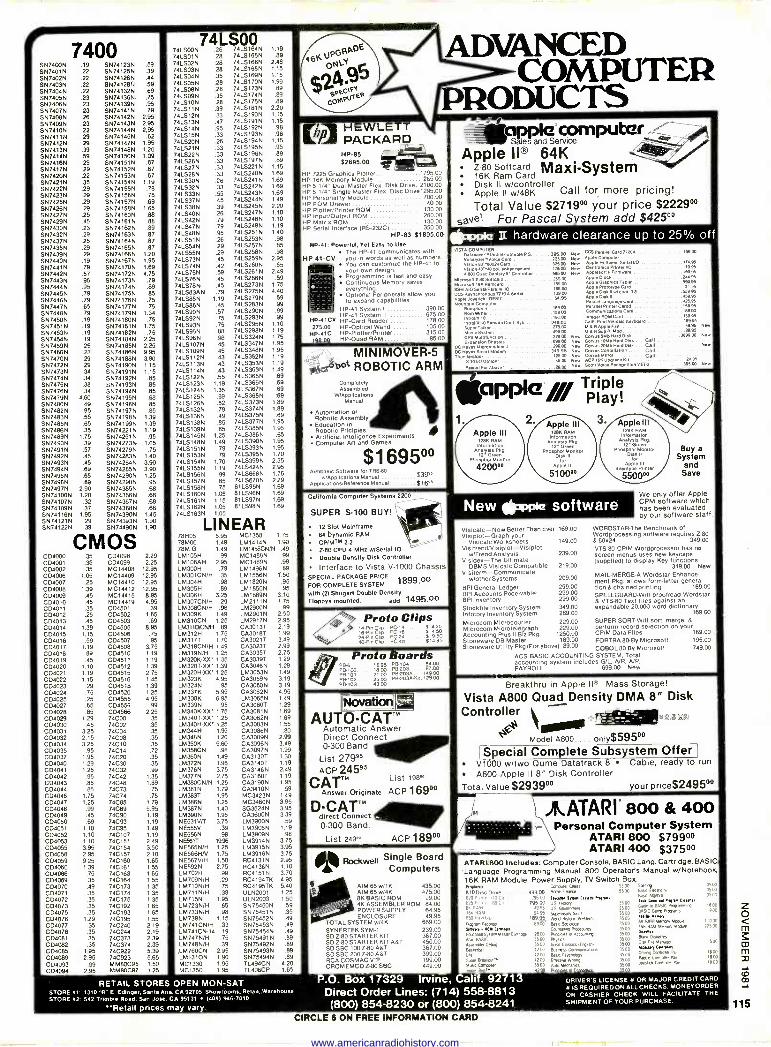
7400 SN7400N .19 S9741239 .59 S974019 .22 S9741259 .39 S974029 .22 SN74126N .44 S974039 .22 S974128/1 .59 597404N .22 S9741329 .69 S974059 .23 S9711369 .75 S974089 .23 09741399 .95 5974079 .23 S9741419 .79 SN7408N .26 SN7/142N 2.95 S974099 .23 S974/439 2.95 S974109 .22 SN74144N 2.95 S97411N .29 SN74145N .62 597412N .29 SN74147N 1.95 SN71139 .39 S9741489 1.20 SN741/9 .59 S9741509 1.09 SN7416N .29 S9741519 .67 597417N .29 S9741529 .67 S974209 .22 S9741539 .67 S974219 .35 S9741549 1.19 S974229 .29 SN74155N .78 S974239 .29 SN741569 .78 SN7125N .29 09741579 .69 S971289 .29 5974158N 1.65 SN7427N .25 S9741609 .88 5974299 .45 S9741619 .88 S974309 .23 s9741629 .89 SN7432N .29 SN741839 .87 S974379 .25 SN74164N .87 SN7438N .29 SN74185N .87 S974399 .29 SN74168N 1.20 SN7440N .19 S9741679 1.95 S971419 .79 SN74170N 1.89 S974429 .57 59741729 4.75 S974439 .95 09741739 .79 SN74449 .95 09741749 .89 SN7445N .79 S9741759 .85 S974469 .79 6974176N .75 S974479 .65 5974177N .75 SN7448N .79 6974179N 1.34 S974509 .19 0974180N .75 S974519 .19 09741819 1.75 5974539 .19 09741829 .75 5974549 .19 S9741849 2.25 S974599 .25 SN74185N 2.25 S974809 .23 S9741869 9.95 S974709 .29 S9741889 3.90 SN7472N .29 S9741909 1.15 SN7473N .34 5N741919 1.15 SN74749 .34 S9741929 .85 SN74759 .38 S9741939 .85 S974769 .34 S9741949 .85 S974799 4.80 59741959 .88 S974809 .49 SN74198N .85 0974829 .95 5974197N .85 S1474839 .55 SN74198N 1.39 5974859 .65 S9741999 1.39 S10718610 .35 S9742219 1.19 S974899 1.75 S9742519 .95 S974909 .39 S9742739 1.05 S974919 .57 S9742799 .75 0N74929 .45 097428314 1.40 SN749314 .45 S9742849 3.90 SN74949 .69 S9742859 3.90 S1474959 .65 09742909 1.25 S974989 .69 S9742989 .95 S974979 2.90 S9713859 .68 S9741009 1.20 S9743669 .68 S9741079 .32 S9743679 .68 59741099 .37 S9743689 .88 S9741169 1.95 59743909 1.45 S9741219 .29 S9743939 1.90 SN74122N 39 SN74490N 1.90
CMOS CD4000 .35 0134098 2.29 CD4001 .35 004099 2.25 CD4002 .35 MC14408 12.95 C04036 1.05 M C 14409 12.95 CD4007 .25 MC14410 12.95 CD/006 1.39 MC14412 12.95 CD4009 .45 MC14415 8.95 004010 .45 MC14419 4:95 C04011 .35 CD4501 .39 0134012 .25 CD4502 1.65 CD4013 .45 C04503 .69 CD4014 1.39 CD4505 8.95 C04015 1.15 CD4506 .75 C04016 .59 CD4507 .95 CD4017 1.19 CD4508 3.75 CD4018 .89 CD4510 1.19 C04019 .45 CD4511 1.19 CD4020 1.10 CD4512 1.39 004021 1.19 CD4515 2.75 CD4022 1.15 CD4516 1.45 CD4023 .29 C04518 1.39 C04024 .75 C04520 1.25 CD4025 .25 CD4555 4.95 CD4027 .65 CD4556 .99 CD4028 .85 C04566 2.25 CD4029 1.29 74000 .35 CD4030 .45 74CO2 .35 CD4031 3.25 74C04 .35 CD4032 2.15 74C08 .35 C04034 3.25 74C10 .35 C04035 .95 74C14 .72 C04037 1.95 74C20 .35 C134040 1.29 74C30 .35 CD4041 1.25 74C32 .99 C04012 .95 74C42 1.35 004043 .85 74048 1.89 CD4044 .85 74C73 .75 CD4046 1.75 74C74 .75 CD4047 1.25 74C85 1.79 004048 .99 74C89 5.95 CD4049 .45 74C90 1.19 CD4050 .69 74C93 1.19 CD4051 1.10 74C95 1.49 CD4052 1.10 74C107 1.19 CD4053 1.10 74C151 2.49 004055 3.95 74C154 3.50 C134056 2.95 740157 2.10 CD4059 9.25 74C160 1.65 004060 1.39 74C161 1.55 CD4066 .75 74C183 1.65 C04089 .35 74C164 1.55 C04070 .49 74C173 1.35 CD4071 .35 74C174 1.35 CD4072 .35 74C175 1.35 CD4073 .35 74C192 1.65 CD4075 .35 74C193 1.65 C04076 1.29 74C195 1.55 C04077 .35 74C240 2.19 CD4078 .35 740244 2.19 CD4081 .35 74C373 2.39 CD4082 .35 74C374 2.39 C04085 1.95 74C922 5.39 C04089 2.95 74C923 5.65 CD4093 .99 MM80C95 1.50 CD4-094 2.95 MMBOC97 1.25
74L500 741000N .26 74L51649 1.19
7415019 .28 74LS18510 .89
741502N .28 7410168N 2.48 74L0039 .28 7415188N 1.15
7415049 .35 7415169N 1.15
7415059 .28 7415170N 1.99
74LSO8N .28 74LS1739 .89
741509N .35 7415174N .89
741510N .28 74L51759 .89
741011N .39 74LS181N 2.20 7415129 .33 74LS190N 1.15 741013N .47 74LS191N 1.15
74LS149 .95 74LS192N .98
7410159 .33 74151939 .98
7415209 .26 74L5194N 1.15
741521N .33 7410195N .95
74LS22N .33 74LS196N .89
74152611 .33 74101979 .89
74LS279 .33 7410221N 1.15 7410289 .33 74L02409 1.69
741030N .26 74152419 1.69 74L5329 .33 7415242N 1.69 74L5339 .55 74152439 1.69 7415379 .45 74LS24414 1.49
7415389 .39 74152459 2.20 741040N 26 74L02479 1.10
74LS42N .79 741.5248N 1.10 7415479 .79 1415249N 1.19
7415489 .95 741525114 1.40
74L0519 .26 74LS253N .98
7415549 .29 74L52579 .85
74L5559 .29 74LS258N .98
74LS739 .45 74L5259N 2.95 7410749 .42 74L02609 .65
74157514 .59 74LS26114 2.49 74L5769 .45 7410266N .59
7415789 .45 74LS273N 1.75
74LS83AN .79 741S2759 4.40 741,5859 1.19 74102799 .59 7410869 .45 7415283N .99
7415909 .57 74L02909 .99 7415929 .75 14152939 .99 7415939 .75 7410295W 1.10 7415959 .88 74152989 1.19 7415969 .98 74LS324N 1.75 7410107N .45 74LS347N 1.95 74LS1099 .45 74153489 1.95 7410112W .43 74LS352N 1.19 7410113N .43 74L53539 1.19
74151149 .43 74103639 1.49
74101229 .55 7410365N .69
7410123N 1.19 74L03669 .69
7410124N 1.35 74153679 .69
74151259 .89 74153889 .69
7415126N .52 7415373N 1.89
74L51329 .79 74153749 1.89
7410138N .49 7415375N .69
7415138N .85 74103779 1.95
74101399 .85 7415385N 1.95 7410145N 1.25 7410386N .65
7410148W 1.49 74153909 1.95
74151519 .79 7415393N 1.95
7415153W .79 74103959 1.70
7415154N 1.70 7410399N 2.35 74L51559 1.19 7415424N 2.95 7410158N .99 74151388N 1.75
74151579 .85 74156709 2.29 7410158N .75 81LS95N 1.69 7415160N 1.05 611596N 1.69
74151619 1.15 8115979 1.69 74151829 1.05 811098N 1.69
74L51639 1.05
LINEAR 781105 5.95 MC1358 1.75 78M06 1.49 LM14149 1.90 78M.G. 1.49 LM1458CNIN .49 LM105H .99 MC14889 .99 LM108AH 2.95 MC14899 .99 LM300H .79 LM1496N .89 LM301CN/H .35 LM 15569 1.50 LM304H .98 LM18209 ,95 LM305H .89 LM18509 .95 LM306H 3.25 LM18899 3.10 LM307CN/H .29 LM21119 1.75 LM308CN/H .98 LM2900N .99 LM309K 1.49 1M2901N 2.50 LM310CN 1.25 LM29179 2.95 LM311DCN1H .89 CA30137 2.19 LM312H 1.75 CA30187 1.99 LM317T 1.70 CA3021T 3.49 LM318CN/H 1.49 CA3023T 2.99 LM3199/H 1.25 CA3035T 2.75 LM320K-XX 1.35 CA30397 1.29 LM320T-XX 1.39 CA30469 1.29 LM320H-XX' 1.25 LM30539 1.49 LM323K 4.95 CA3059N 3.19 LM324N .95 CA30809 3.19 LM337K 5.95 CA3062N 4.95 LM338K 6.95 LM30659 1.49 LM339N .95 CA3O80T 1.29 LM340K-XX' 1.75 CA3081 N 1.69 LM340T-0X' 1.25 CA30829 1.69 LM340H-XX 1.25 CA3083N 1.55 LM344H 1.95 CA3086N .80 LM3489 1.20 CA3089N 2.99 LM350K 5.80 CA3096N 3.49 LM358CN .98 CA30979 1.99 1M3609 1.49 CA3130T 1.30 LM372N 1.95 CA3140T 1.19 LM3769 3.75 CA31469 2.49 LM3779 2.75 CA3160T 1.19 LM380C9/9 1.25 CA31909 1.95 LM3819 1.79 CA3410N .59 LM383T 1.95 MC34239 1.49 1M3881,1 1.25 MC34609 3.95 LM387N 1.40 SG3524N 3.95 1M3909 1.95 CA36009 3.39 NE531V/T 3.75 LM39009 .59 NE555V .39 LM39059 1.19 9E5569 .98 LM39099 .98 NE5617 1995 1M39149 3.75 NE565N/H 1.25 1M39159 3.95 NE566HN 1.75 LM39169 3.75 9E5676/H 1.50 RC4131N 2.95 9E5929 2.75 RC41369 1.10 LM702H .99 RC4151N 3.70 LM7099/H .29 RC4194TK 4.95 LM710N/H .75 RC4195TK 5.40 LM711N/H .39 ULN2001 1.25 1M7159 1.95 ULN2003 1.50 LM7239/H .85 S9754509 .59 LM733N/H .98 5975451N .35 1M7399 1.15 SN75452N .49 LM711CN/H .33 S9754539 .49 1M741C10-14 .19 59754549 .49 LM7479/H .75 5975491N .89 LM748N/H .39 0975492N .89 ,1M76009 2.95 09754939 .89 LM13109 1.90 0975494N .89 MC1330 1.95 7L494C9 4.20 MC1350 1.95 TL496CP 1.85
ADVANCED COMPUTER
PRODUCTS (hl..l T7
P] PACKARD HP -85 $2695.00
HP 7225 Graphics Plotter 1795.00 HP 16K Memory Module 285.00 HP 5 1/4" Dual Master Flex. Disk Drive 2100.00 HP 5 1/4" Single Master Flex Disc Drive 1295.00 HP Personality Module 700.00 HP ROM Drawer 40.00 HP Plotter/Printer ROM 13000 HP Input/Output ROM 260.00 HP Matex ROM 13000 HP Serial Interface (RS -2320) 350.00
HP -83 $1895.00 HP -41: Powerful, Yet Easy to Use
The HP -41 communicates with HP 41 -CV you in words as well as numbers.
Il You can customize the HP -41 to your own design Programming 1s fast and easy. Continuous Memory saves everything. Optional Peripherals allow you to expand capabilities.
HP -41 System I 398.00 HP -41 System II 675.00
HP-41CV HP -Card Reader 178.00 275.00 HP -Optical Wand 10500
HP -41C HP-Plotter/Printer :115.00
198.00 HP -Oued RAM 85.00
MINIMOVER-5 bot ROBOTIC ARM
Completely Assembled
W/Appllcalions Manuel
Automation or Robotic Assembly Education in Robotic Priciples Artificial Intellgence Experiments Computer An and Games
$1695°° Annbesic Software for ORS 80
$39.wlApplictlona Manual Appllcaeonslnererence Manual... $1615
C zll/orma Computer Systems 2200
SUPER S-100 BUY!
12 Slot Mainframe 64 Dynamic RAM CP/MTM 2.2
Z-0 CPU 4 MHz w/Serial 10
Double Density Disk Controller
Interface to Vista v-1000 Chassis SPECIAL PACKAGE PRICE
1899 .00 FOR COMPLETE SYSTEM
with (2) Shugart Double Density Floppys mounted. add 1495.00
Proto Clips 14Pin C1,p PC -14 S 4.25
B-P,n Che PC -16. S 4.50 24 -Pm Ce PC -24. S 9.50 40-0e lisp PC -40. .51495
ro o Boar s PB -6 1895 P19.1 04 ..... 5400 P0100. 1500 P6-203 97.00 P&101 ... 21.00 P8403Ä .14900 P6-102. 2500 P&203A-Ki1.12900 P&103... 43.00
AUT -CATTM Automatic Answer Direct Connect
st0-3 20 Band
List 27995 ACP 24595
CATTM List 19800
Answer Originate ACP 169D0
D-CATTM direct Connect 0-300 Band.
List 249. ACP 18900
Single Board Computers
AIM 65w/1K 435.00 AIM 65 w/4K 475.00 8K BASIC ROM 99.00 4K ASSEMBLER ROM 84.00 POWER SUPPLY 64.95 ENCLOSURE 49.95
TOTALSYSTEM w/4K 669.00 SYNERTEK SYM-1 239.00 SDZ-80STARTER KIT 367.00 SD Z-80 STARTER KIT AST 450.00 SD SBC 100 Z-80 AST 367.00 SD SBC 200 Z-80 AST 399.00 RCA COSMAC VIP 199.00 CROMEMCO Z-80 SBC 449.00
-_ - c! A_ -_._-ter
Sa -le§ and Service
Apple II® 64K Alkie Z-80 Softcard Maxi -System 16K Ram Card Disk II w/controller Apple II w/48K Call for more pricing!
Total Value $27190° your price $2229°° Save! For Pascal S stem add $42500
c>r>n1e II hardware clearance up to 25% off
1epI Co
I.spNC GnIronies Rin,e
PI.CI«me
pl. DMFG,rts.lypeCar pla II wr cod
pension CrO
mete
Gree or Mc
New Ipppe software
Isicalc Workshe lrendNisiplot- irrentl Analysis dien -The Ultime BMS VisiCaiC C term-Commur
t Pkg. allows ft 8 chained print LLGUARD-Will rS-80 Text files
mom Microte punting Plus II aware DB Ma;
Special Complete Subsystem Offer
Dls rDrive 94sieC ''c
P.O. Box 17329 Irvine, Calif. 92713 Direct Order Lines: (714) 558-8813 (800) 854-8230 or (800) 854-8241
e1.1 ñs own Oane Pavan
RETAIL STORES OPEN MON -SAT STORE et 1310 -B" E. Edinger. Santa Ana, CA 82705 Showrooms. Revel. Warehouse STORE e2: 542 Trimble Road. San Jose. CA 95131 (484) 848.7010
'Retail prices may vary. CIRCLE 6 ON FREE INFORMATION CARD
DRIVER'S LICENSE s OR MAJOR CREDIT CARD e IS REQUIRED ON ALL CHECKS. MONEY ORDER OR CASHIER CHECK WILL FACILITATE THE SHIPMENT OF TOUR PURCHASE.
www.americanradiohistory.com
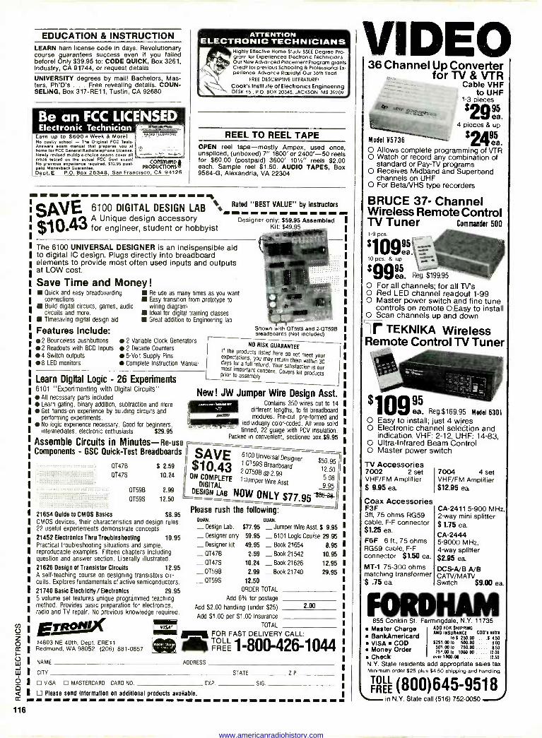
EDUCATION & INSTRUCTION LEARN ham license code in days. Revolutionary course guarantees success even if you failed before! Only $39.95 to: CODE QUICK, Box 3261, Industry, CA 91744, or request details
UNIVERSITY degrees by mail! Bachelors, Mas- ters, Ph'D's . . . Free revealing details. COUN- SELING, Box 317-RE11, Tustin, CA 92680
Be an FCC LICENSED Electronic Technician r -
Earn up to $600 a Week & Mor& No costly school - The Original FCC Tests. Answers seem manual that prepares you at home for FCC General Radiotelephone License. Newly revised multiple-choice exams cover all areas tested on the actual FCC Govt exam! commanD No previous experience required. S12.95 post-
VRODUCTInt) . paid. Moneyback Guarantee. I Dept. E P.O. Box 26348, San Francisco CA 94126
aapio TELex41or
ATTENTION ELECTRONIC TECHNICIANS
Highly Effective Home Study BSEE Degree Pro- gram for Experienced Electronic Technicians Our New Advanced Placement Program grants Credit for previous Schooling & Professional Ex- perience. Advance Rapidly! Our 36th Year!
FREE DESCRIPTIVE LITERATURE!
Cook's Institute of Electronics Engineering DESK 15 . P.O. BOX 20345, JACKSON, MS 39209
REEL TO REEL TAPE OPEN reel tape -mostly Ampex, used once, unspliced, (unboxed) 7" 1800' or 2400'-50 reels for $60.00 (postpaid) 3600' 10'/2' reels $2.00 each. Sample reel $1.50. AUDIO TAPES, Box 9584-G, Alexandria, VA 22304
II
SAVE 6100 DIGITAL DESIGN LAB ¡ Rated "BEST VALUE" by Instructors ----- ..... --- 1043 A Unique design accessory Designer only: $59.95 Assembled I
for engineer, student or hobbyist Kit: $49.95 1
The 6100 UNIVERSAL DESIGNER is an indispensible aid to digital IC design. Plugs directly into breadboard elements to provide most often used inputs and outputs at LOW cost.
Save Time and Money !
Quick and easy breadboarding connections Build digital circuits, games, audio circuits and more. Timesaving digital design aid
Features Include: 2 Bounceless pushbuttons 2 Readouts with BCD Inputs 4 Switch outputs 8 LED monitors
Re -use as many times as you want Easy transition from prototype to wiring diagram Ideal for digital training classes Great addition to Engineering lab
2 Variable Clock Generators 2 Decade Counters
5 -Volt Supply Pins
Complete Instruction Manual
Learn Digital Logic - 26 Experiments 6101 "Experimenting with Digital Circuits"
All necessary parts included Learn gating, binary addition, subtraction and more Get hands-on experience by building circuits and performing experiments. No logic experience necessary. Good for beginners, intermediates, electronic enthusiasts $29.95
Assemble Circuits in Minutes -Re -use Components - GSC Quick -Test Breadboards
OT47B $ 2.59
0T47S 10.24
0T59B 2.99
0T59S 12.50
21654 Guide to CMOS Basics $8.95 CMOS devices, their characteristics and design rules. 22 useful experiements demonstrate concepts.
21452 Electronics Thru Troubleshooting 10.95 Practical troubleshooting situations and simple, reproducable examples. Fifteen chapters including question and answer section. Liberally illustrated.
21626 Design of Translator Circuits 12.95 A self -teaching course on designing transistors cir- cuits. Explores fundamentals of active semiconductors.
21740 Basic Electricity/Electronics 29.95 5 volume set features unique programmed teaching method. Provides basic preparation for electronics, radio and TV repair. No previous knowledge required. E*' 14803 NE 40th, Dept. ERE11 Redmond, WA 98052 (206) 881-0857
Shown with 0159S and 2-07598 breadboards (Not included)
NO RISK GUARANTEE If the products listed here do not meet your expectations, you may return them within 30 days for a full refund. Your satisfaction is our most important concern. Covers kit products prior to assembly.
New! JW Jumper Wire Design Asst. Contains 350 wires cut to 14
different lengths, to fit breadboard modules. Pre-cut, pre -formed and
individually color -coded. All wire solid - tinned, 22 guage with PCV insulation.
Packed in convenient, sectioned box.$9.95
SAVE6100 Universal Designer $59.95 @i O- 1 OT59S Breadboard 2 07598 12.50 $ 1
ON COMPLETE 1 Jumper
®2 5.98
DIGITAL Wire Asst 9.95
DESIGN LAB NOW ONLY $77,95 s
Please rush the following: QUAK. - Design Lab. $77.95 - Designer only 59.95
DUAN.
Jumper Wire Asst. $ 9.95
_ 6101 Logic Course 29.95 - Designer kit 49.95 - Book 21654 8.95
_ 0T47B 2:59 _ Book 21542 10.95 - 0T47S 10.24 _ Book 21626 12.95
_ 0T59B 2.99 - Book 21740 29.95
_ 0T59S 12.50
ORDER TOTAL
Add 6% for postage
Add $2.00 handling (under $25) - 2.00
Add $1.00 per $1.00 insurance
TOTAL
FOR FAST DELIVERY CALL:
dig FREE 1-800-426-1044 NAME ADDRESS
CITY STATE ZIP
VISA MASTERCARD CARD NO EXP. SIG
Please send Information on additional products available. -- -------- f- ---- - MMMMMMMfflfflMMMMMMMMI
VIDEO 36 Channel Up Converter
for TV & VTR Cable VHF
to UHF 1-3 pieces
'29éá.
Model V5736
4 pieces 8. up
'24éá. O Allows complete programming of VTR O Watch or record any combination of
standard or Pay -TV programs O Receives Midband and Superband
channels on UHF O For Beta VHS type recorders
BRUCE 37- Channel Wireless Remote Control TV Tuner Commander 500 1-9 pcs.
'1o9ea.
10 pcs. & up
'99áa. Reg. $199.95
O For all channels; for all TV's O Red LED channel readout 1-99 O Master power switch and fine tune
controls on remote O Easy to install O Scan channels up and down
H; f TEKNIKA Wireless Remote Control TV Tuner
09e ea.` Reg.$169.95 Model 6301 O Easy to install; just 4 wires O Electronic channel selection and
indication. VHF: 2-12, UHF: 14-83, O Ultra -Infrared Beam Control O Master power switch
TV Accessories 7002 2 set 7004 4 set VHF/FM Amplifier VHF/FM Amplifier $ 9.95 ea $12.95 ea
Coax Accessories F3F 3ft, 75 ohms RG59 cable, F -F connector $1.25 ea.
F6F 6 ft, 75 ohms RG59 cable, F -F connector $1.50 ea.
MT -1 75-300 ohms matching transformer $ .75 ea
CA -2411 5-900 MHz, 2 -way mini splitter $1.75 ea CA -2444 5-9000 MHz, 4 -way splitter $2.95 ea DCS-A/B A/B CAN/MAN Switch $9.00 ea.
FORDHAM 855 Conklin St. Farmingdale, N.Y. 11735 Master Charge ADD FOR SHIPPING
AND INSURANCE COO'. sate. to $ 250.00 5 1.50
5251.00 to 500.00 6.00 501.00 to 750.00 5.50 751.00 10 1000.00 12.00
Check. over 1000.00 12.50
N.Y. State residents add appropriate sales tax Minimum order $25 plus $4.50 shipping and handling.
BankAmerlcard VISA COD Money Order
TRH (800)645-9518 in N.Y. State call (516) 752-0050
116
www.americanradiohistory.com
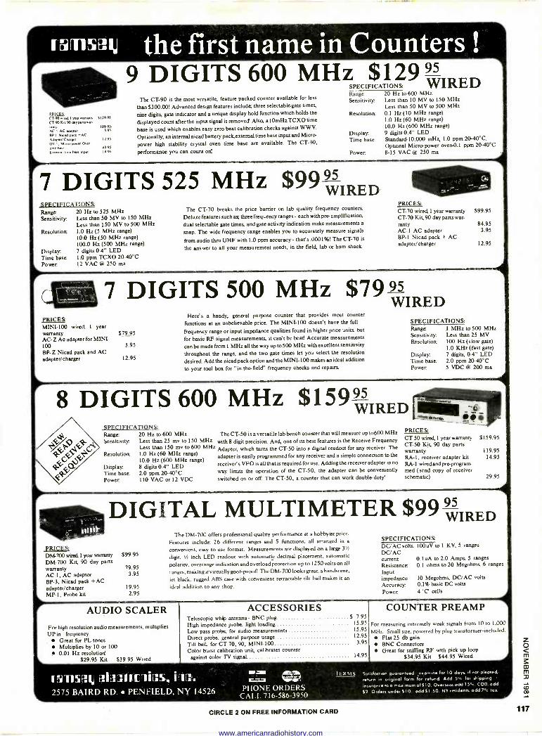
ramsaU the first name in Counters !
fRICEs CT -90 oued 1 year wamanry $129.95 CT 90 Kit 90 day passe., rants 109.95 RCA AC loger 195 SPI Mead pact +AC Adapter/Cherrer 12.95
OV- I. Micro power Oven me hue 49 95
Calmed ume bare input 14 95
9 DIGITS 600 MHz $'29 WIRED The CT -90 is the most versatile, feature packed counter available for less
than $300.00! Advanced design features include; three selectable gate times,
nine digits, gate indicator and a unique display hold function which holds the
displayed count after the input signal is removed Also, a IOmHz TCXO time
base is used which enables easy zero beat calibration checks against W W V.
Optionally; an internal nicad battery pack external time base input and Micro
power high stability crystal oven time base are available. The CT -90,
performance you can count on!
SPECIFICATIONS: Range: Sensitivity
Resolution:
Display Time base
Power.
20 Hz to 600 MHz Less than 10 MV to 150 MHz Less than 50 MV to 500 MHz 0.1 Hz(10 MHz range) 1.0 Hz (60 MHz range) 10.0 Hz (600 MHz range) 9 digits 0.4" LED Standard -10.000 mHz, 1.0 ppm 20-40°C. Optional Micro -power oven -0.l ppm 20-00°C 8-15 VAC @ 250 ma
7 DIGITS 525 MHz $99 WIRED SPECIFICATIONS: Range: Sensitivity
Resolution:
Display. Time base Power.
20 Hz to 525 MHz Less than 50 MV to 150 MHz Less than 150 MV to 500 MHz 1.0 Hz (5 MHz range) 10.0 Hz (50 MHz range) 100.0 Hz (500 MHz range) 7 digits 0.4" LED 1.0 ppm TCXO 20-40°C 12 VAC @ 250 ma
The CT -70 breaks the price barrier on lab quality frequency counters
Deluxe features such as; three frequency ranges - each with pro -amplification,
dual selectable gate times, and gate activity indication make measurements a
snap. The wide frequency range enables you to accurately measure signals
from audio thru UHF with 1.0 ppm accuracy- that's .0001%! The CT -70 is
the answer to all your measurement needs, in the field, lab or ham shack.
PRICES: CT -70 wired, 1 year warranty CT -70 Kit, 90 day parts war- ranty AC -1 AC adapter BP -1 Nicad pack + AC adapter/charger
$99.95
84.95 3.95
12.95
7 DIGITS 500 MHz $7995IRED
PRICES: MINI -100 wired, 1 year warranty AC -Z Ac adapter for MINI - 100 BP -Z Nicad pack and AC adapter/charger
Here's a handy, general purpose counter that provides most counter
functions at an unbelievable price. The MINI -100 doesn't have the full
$79.95 frequency range or input impedance qualities found in higher price units, but
for basic RF signal measurements, it can't be beat! Accurate measurements 3.95 can be made from 1 MHz all the way up to500 MHz with excellent sensitivity
12.95 throughout the range, and the two gate times let you select the resolution
desired. Add the nicad pack option and the MINI -100 makes an ideal addition
to your tool box for "in -the -field" frequency checks and repairs
SPECIFICATIONS: Range Sensitivity Resolution:
Display Time base Power.
1 MHz to 500 MHz Less than 25 MV 100 Hz (slow gate) 1.0 KHz (fast gate) 7 digits, 0.4" LED 2.0 ppm 20-40°C 5 VDC @ 200 ma
8 DIGITS 600 MHz $159 WIRED SPECIFICATIONS: Range: Sensitivity
Resolution:
Display Time base: Power.
20 Hz to 600 MHz Less than 25 mv to 150 MHz Less than 150 mv to 600 MHz 1.0 Hz (60 MHz range) 10.0 Hz (600 MHz range) 8 digits 0.4" LED 2.0 ppm 20-40°C 110 VAC or 12 VDC
The CT -50 is a versatile lab bench counter that will measure up to600 MHz
with 8 digit precision. And, one of its best features is the Receive Frequency
Adapter, which turns the CT -50 into a digital readout for any receiver. The
adapter is easily programmed for any receiver and a simple connection to the
receiver's VFO is all that is required for use. Adding the receiver adapter in no
way limits the operation of the CT -50, the adapter can be conveniently
switched on or off. The CT -50, a counter that can work double -duty!
CT -50 wired, 1 year warranty $159.95 CT -50 Kit, 90 day parts warranty 119.95 RA -I, receiver adapter kit 14.95 RA -1 wired and pre-program med (send copy of receiver schematic) 29.95
DIGITAL MULTIMETER $99 WIRED
PRICES; DM -700 wired, I year warranty
DM -700 Kit, 90 day parts warranty AC -1, AC adaptor BP -3, Nicad pack +AC adapter/charger MP -1, Probe kit
The DM -700 offers professional quality performance at a hobbyist price.
Features include; 26 different ranges and 5 functions, all arranged in a
convenient, easy to use format. Measurements are displayed on a large 31/2
$99.95 digit, 1/2 inch LED readout with automatic decimal placement, automatic
79.95 polarity, overrange indication and overload protection up to 1250 volts on all
3.95 ranges, making it virtually goof -proof The DM -700 looks great, a handsome,
jet black, rugged ABS case with convenient retractable tilt bail makes it an
19.95 ideal addition to any shop. 2.95
SPECIFICATIONS: DC/AC volts 100uV to I KV, 5 ranges DC/AC current 0.1 uA to 2.0 Amps, 5 ranges Resistance 0.1 ohms to 20 Megohms, 6 ranges
Input impedance 10 Megohms, DC/AC volts
Accuracy 0.1% basic DC volts
Power. 4 'C' cells
AUDIO SCALER
For high resolution audio measurements, multiplies UP in frequency.
Great for PL tones Multiplies by 10 or 100 0.01 Hz resolution!
$29.95 Kit $39.95 Wired
ACCESSORIES Telescopic whip antenna - BNC plug $ 7.95
15.95 15.95 12.95
3.95
High impedance probe, light loading Low pass probe, for audio measurements Direct probe, general purpose usage Tilt bail, for CT 70, 90, MINI -100 Color burst calibration unit, calibrates counter against color TV signal 14.95
I511Is31,j A1a.,Irr *AS. in. 2575 BAIRD RD. PENFIELD, NY 14526 PHONE ORDERS
CALL 716-586-3950
IfR\1S
COUNTER PREAMP
For measuring extremely weak signals from 10 to 1,000
MHz. Small size, powered by plug transformer -included. Flat 25 db gain BNC Connectors Great for sniffing RF with pick-up loop
$34.95 Kit $44.95 Wired
Satisfaction guaranteed - examine for 10 days if notpleased
return in original form for refund Add 5% for shipping
insurance ro a maximum of S 10. Overseas odd 1 5% COD, odd
$2 Orders under $10 add f 1 50 NT residents add 7% tax.
CIRCLE 2 ON FREE INFORMATION CARD
www.americanradiohistory.com
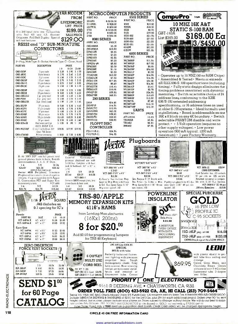
L
STAR MODEM FROM
LIVERMORE LIST PRICE
0 to 300 baud data rate. Compatible $199.00 with Bell 103 and 113. Answer/ SALE PRICE Originate. Full/Half Duplex. Special $129 .00 self test features. G i RS232 and "D" SUB -MINIATURE
CONNECTORS
P= Plug, Male Type -S= Socket, Female Type -C- Cover, Hood
PART NO.
CND-DE9P CND-DE9S
CND-DE9C CND-DA15P
CND-DAI5S
CND-DAI5C
CND-DB25P
CND-DB25S
CND-DB51212 CND-P25H
CND-DB51226
CND-DC37P CND-DC37S CND-DC37C
CND-DD5OP
CND-DD50S
CND -0050C CND -D20410
DESCRIPTION
9 pin male
9 pin female 9 pin cover 15 pin male
15 pin female 15 pin cover
25 pin male
25 pin female 1 pc. grey hood
2 pc. grey hood
2 pc. black hood
1-9
S 2.10
$ 2.70
E 1.50
S 2.75
$ 3.95
$ 1.50
$ 3.50
$ 4.60
S 1.60
$ 1.50
S 1.90
37 pin male $ 5.80
37 pin female $ 8.70 37 pin cover 5 1.80
50 pin male S 8.75
50 pin female $11.65
50 pin cover $ 2.00
Hardware set 2 pr. S 1.00
RS232, DB25P, EIA CND-RS2328F Class 1 cable 8 con. 81t. $19.95
Cent. 700 Series
Printer connector S 9.00 CND -5730360
PRICE 10-24
S 1.90
$ 2.40
$ 1.25
$ 2.45
$ 3.60
$ 1.30
5 3.25
$ 4.35
S 1.45
$ 1.25
$ 1.65
$ 5.10
S 7.70
S 1.55
Y 7.75
$10.25
$ 1.80
$ .80
25-99
$ 1.70
$ 2.10
$ 1.10
$ 2.15
$ 3.20
$ 1.10
$ 3.00
E 4.20
S 1.30
5 1.10
$ 1.45
$ 4.45
$ 6.70
$ 1.30
$ 6.70
$ 8.90
$1.60 $ .70
$17.95 $15.95
S 7.50 S6.00
MICROCOMPUTER PRODUCTS PART NO. PRICE 6502 SERIES 2016P3 PART NO. PRICE
2114N3L 6502 $12.95 5257N3L 6502A $18.95 2732 6520 58.95 2716 6522 $10.95 2708 6530-002 $21.95
8/5100.00 8/$28.00 8/$50.00
8'$120.00 8/$50.00 8/$32.00
8080 SERIES PART NO. PRICE
INS 8080A $5.50 INS 8085A DP8212N DP8214N DP8216N DP8224N DP8224-4N DP8226N DP8228N DP8238N INS8250N INS825IN INS8253N INS8255N iNS8257N 1NS8259N INS8275N INS8279N
$19.95 $2.95 $5.25 $2.95 $3.25 $9.95 $3.50 $5.55 $5.55
$15.00 $7.50
$17.95 $6.80
$16.45 $18.00 $59.95 $49.95
Z80 SERIES Z80A Z80APIO Z80ACTC Z8OADMA Z8OAS [00 Z80AS lb 1
Z80AS102
$14.95 $14.95 $13.95 $45.00 $59.95 $59.95 $59.95
FLOPPY DISC CONTROLLER
FDI771B-01 $24.95 FD1791B-01 $44.95
6530-003 $21.95 6530-004 $21.95 6530-005 $21.95 6532M $21.95 6551M $21.95
6800 SERIES PART NO. PRICE
MC6800P $11.95 MC6802P $17.95 MC6808P 59.95 MC6809P $34.95 MC6821P $5.95 MC6828P $14.95 MC6840P $14.95 MC6845P $31.00 MC6847P $14.95 MC6850P $5.41 MC6852P $5.79 MC6854P $24.95 MC6860P $10.89 MC6862P $12.00 MC6875L $7.40 MC66710P $12.50 MC66750P $12.50
UARTS PART NO PRICE
AY51013A TR1602B TR1863 IM6402
$5.95 $5.95 $6.95 $7.95
(mpUPrOr" from wee
10 MHZ 16K A&T STATIC S-100 RAM
List GBT-143A$349
00 $169 00 Ea
Operates up to 10 MHZ (90 ns RAM Chips) Assembled & Tested Meets or exceeds
all IEEE 696/S-100 specifications (including timing). Fully static design eliminates the timing problems associated with dynamic memories. Switch selectable choice of 24 address lines conforming to the IEEE 696/S-100 extended addressing specifications, or 16 address lines as used in older S-100 systems. Ideal for multi-user installations. Board is addressable as one 16K x 8 block on any 4K boundary. Switch selectable PHANTOM disable and write protect. + 5 Volt operation (requires no other supply voltages). Low power operation (900 mA typical, 1200 mA maximum). 1 year Factory Warranty.
S-100 "ANY DIP" has full power and ground planes back to back. Boards accommodates .3..4, .6, .9" Dips.
1-4 5-9 10-24 $24.67 $22.34 $20.02
APPLE PLUGBOARD Vector 4609 Peripheral Interface Plugboard for construction of custom circuits. Plug compatible with Apple II, Commodore PET and Super Kim microcomputers. VCT-4609
1-4 5-9 10-24 $20.74 $18.79 $16.84
/1 VCT-8800V
Universal Micmcumpuier: processor plugboard use with S-100 bus. Complete with heat sink & hardware. 53" a 10" x
1/16". 1-4
522.48
5-9 10-24
520.37 518.26
VCT-8801-1
Same as 8800V except plain, less power buses & heat sink.
1-4 5-9 10-24
515.67 $14.24 $12.82
VCT-3682 9.6" x 4.5" 513.63
VCT-3862-2 6.5" x 4.5" $11.04
Hi -Density Dual -In -Line Plug -
board far Wire Wrap with Power
& Grd. Bus Epoxy Glass 1/16" 44 pin con. spaced .156
Plugboards
VCT3677 9.6"x4.5"
VCT-3667 96" x 4.5" $13.33
VCT-3677-2 6.5" x 4.5" $ 10.68
Gen. Purpose D.I.P. Boards with Bus Pattern for Solder or Wire
Wrap. Epoxy Glass 1/16" 44 pin con. spaced 156
VCT-3662 6.5" x 4.5" 58.69
VCT-3662-2 9.6" n 4.5" $10.85
P pattern plugboards for IC's Ex-
port Glass 1/16" 44 pin con.
spaced 156
VCT 3690 2 $26 64
CARD EXTENDER Card Extender has 100 contacts 50 per side on .125 centers - Attached connector -is compati- ble with S-100 Bus Systems.
VCT-3690 6.5" 22/44 pin .156 ctrl. Extenders ... $15.66
1/16 j"- "" BOARD .042 diaholes on
0.1 spacing for IC's
Phenolic PART NO. SIZE
VCT-64P44-X 4.5" x 6.5" VCT-169P44-X 4.7" x 17"
Epoxy Glass
VCT-64P44 4.5" x 6.5" VCT-84P44 4.5" x 8.5"
VCT-169P44 4.5" x 17"
VCT-169P48 8.5" x 17"
PRICE 1-9 10-19
$1.56 $1.40
$3.69 $3.32
$1.83 $1.65 $2.25 $2.03
54.61 54.15
$9.00 $8.10
TRS-80/APPLE POWERLINE INSOLATOR
MEMORY EXPANSION KITS 4116's RAMS ei GOW3
ZERO INSERTION FORCE TEST SOCKETS
ZIP -1601P
ZIP-24DIP ZIP-400DIP
1-9
S 5.50
S 7.50
510.25
from Leading Manufacturers
(16Kx1 200ns)
8 for $20.°° Add $3.00 for programming Jumpers
for TRS-80 Keybaord
lbs.
t Price $59° Sale Price
$ 29.00
A MUST FOR EVERY OFFICE WITH DATA PROCESSING EQUIPMENT
SPECIAL PURCHASE
GOLD 16 PIN LOW PROFILE IC.
C-95 SOCKETS
If
ezre), '. i
1
TIG-16LP pkg. of 100 $16.00 TIG-16LP pkg. of 1000 $120.00
OEMS Stock up at this LOW PRICE
.a,,,,, ,
nt. Ì6 OUTLET MULTI USE
10-24 25-99 l' 'CORD REEL $5.35 $4.95 SH. WT. 5 LBS. 57.25 56.95 v $0F -CRI 22 ft. Cord 524.95 $9.85 $9.50 GOF-CR50 50 It Cord 549.95
1M -10A List $104.95 SPECIAL
$69.95 with tube Perfectly balanced fluores- cent lighting with precision magnifier lens. Tough thermoplastic shade. Easy lens removal. New wire clip design permits easy instal- lation and removal of flourescent tube. Comes
SEND $10° for 60 Page
CATALOG
j $69.95
LEDO with plastic shield to pro- tect tube from soiling and damage. Colorsi Gray, Black, and Chocolate Brown. Comes with one 22 watt T-9 Circline fluorescent tube, 3 diopter lens. 10 lbs.
PRIOR TY ONE ELECTRONICS 9161-R DEERING AVE. CHATSWORTH, CA 91311 M
ORDER TOLL FREE (800) 423-5922 CA, AK, HI CALL (213) 709-5464'9E0' Terms US.: VISA. MC, BAC, Check Money Order, U.S. Funds Only. CA residents add 6% Sales Tax. MINIMUM PREPAID ORDER $15.00. Include MINIMUM SHIPPING & HANDLING of $250 for the first 3 lbs., plus 25C for each additional pound. Orders over 50 lbs. sent freight collect. Just In case...please include your phone no. Prices subject to change without notice. We will do our best to main- tain prices Ihru October 1981 SOCKET and CONNECTOR prices based on GOLD. not exceeding 370000 per oz
Sales Prices Valid only if YOU mention publication and month. Credit Card orders will be charged appropriate freight.
CIRCLE 45 ON FREE INFORMATION CARD
www.americanradiohistory.com
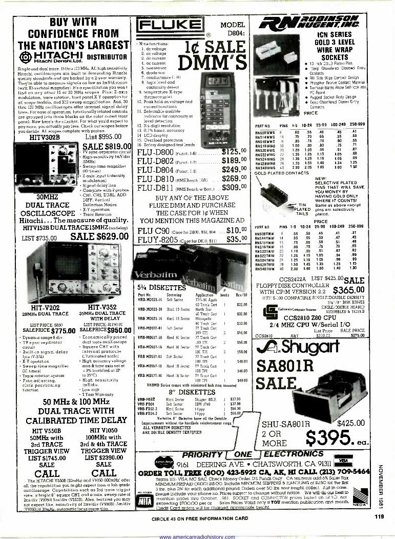
BUY WITH CONFIDENCE FROM
THE NATION'S LARGEST H ITACH I DISTRIBUTOR Hitachi Denshia td.
Single and dual trace, 15 thru 100 MHz. All high sensitivity Hitachi oscilloscopes are built to demanding Hitachi quality standards and are backed by a 2 -year warranty. They're able to measure signals as low as 1mV/division (with X5 vertical magnifier). It's a specification you won't find on any other 15 or 30 MHz scopes. Plus: Z-axis modulation, trace rotation, front panel X -Y operation for all scope models, and X10 sweep magnification. And, 30
thru 100 MHz oscilloscopes offer internal signal delay lines. For ease of operation, functionally related controls are grouped into three blocks on the color coded front panel. Now here's the clincher: For what you'd expect to pay more, you actually pay less. Check our scopes before you decide. All scopes complete with probes.
HITV302B List $995.00
Dynamic range 8 div. TV sync separator circuit Built-in signal delay line W-352) X -Y operation Sweep -time magnifier (10 times) Trace rotation system Fine adjusting, click -positioning function
SALE $819.00 TV sync -separator circuit High -sensitivity lmV/div (5MHz) Sweep -time magnifier (10 times)
+ 1 Z-axis input (intensity modulation) Signal delay line Complete with 2 probes
30MHZ CHI. CH2, DUAL, ADD. DIFF, Vertical
DUAL TRACE Deflection Modes -Y ope
OSCILLOSCOPE TX race R rationotation
Hitachi ... The measure of quality. HITV152B DUAL TRACE 15MHZ (no delay)
SALE $629.00 LIST $735.00
HIT -V202 20MHz DUAL TRACE
HIT -V352 35MHz DUAL TRACE
WITH DELAY LIST PRICE: $850 LIST PRICE: $1150.00
SALEPRICE $775.00 SALEPRICE$950.00 Economically priced dual trace oscilloscope Square CRT with internal graticule (illuminated scale) High -accuracy voltage axis & time axis set at
3% (certified at 1CP
to 35°C) High -sensitivity lmV/div. Low drift 2 Year Warranty
50 MHz & 100 MHz DUAL TRACE WITH
CALIBRATED TIME DELAY HIT V550B
50MHz with 3rd TRACE
TRIGGER VIEW LIST $1745.00
SALE
CALL The HITACHI V550B (50mHz) and V1050 (100mHz) offer
all the capabilities you might expect from a lab grade oscilloscope. Capabilities such as 3rd trace trigger view, a bright 6" square CRT, and a max. sweep rate of
2ns/div (V1050) 5ns/div (V550B). Also, features you may not expect like, sensitivity of lmv/div (V550B) .5m/div (V1050) (al 10mHz, automatic focus correction.
HIT V1050 100MHz with
3rd & 4th TRACE TRIGGER VIEW
LIST $2390.00 SALE
CALL
tALnnecla
M
FLUKE MODEL
Nine functions: 1. dc voltage 2. ac voltage 3. dc current 4. ac current 5. resistance 6. diode test 7. conductance (1-R) 8. logic level and
continuity detect 9. temperature (K -type
thermocouple) 10. Peak hold on voltage and
current functions 11. Selectable audible
indicator for continuity or level detection
12. 31 -digit resolution 13. 0.1% basic, accuracy 14. LCD display 15. Overload protection 16. Safety designed test leads
® D804:
1 t SALE DMM'S
FLU -D800 (Fund. l-6) 5,00
FLU -D802 (Funct. l-7) $189.00 FLU -D804 (Funct. l-9) $249.00
$269.00 FLU -D810 (MS Bench 10A)
FLU -D811 (RMS Bench w/Batt.) .. $309.00 BUY ANY OF THE ABOVE
FLUKE DMM AND PURCHASE THE CASE FOR 1¢ WHEN
YOU MENTION THIS MAGAZINE AD
FLU C90 (Case for D800, 802. 804 ... $10.00 FLUY-8205 (C se for D810,811) ... $35.00
5% DISKETTES Port No. Sectoring Application heads Box/10 VRB-MD525.01 Soft Sector TRS-80 Apple
40 Track Cert 1 $32.00 VRB-MD525-10 Hard 10 Sector North Star
90 Track Cert 1 $32.00 VRB-MD525-ll6 Hard 16 Sector Micropolis
40 Track Cert I $32.00 VRB-MD557-81 Soft Sector 77 Track Cert
100 TPI 2 S56.00
VRB-MD557-110 Hard 10 Sector 77 Track Cerf
100 TPI 2 $56.00 VRB-MD557-16 Hard 16 Sector 77 Track Cert
100 TPI 2 $56.00 VRB-MD557-81 Soft Sector 77 Track Cert
100 TPI 1 548.00 VRB-MD557-IQ Hard 10 Sector 77 Track Cerf
100 TPI I $48.00 VRB-M0577-16 Hard 16 Sector 77 Track Cut
100 TPI 1 $48.00
VRBMD Series comes with reinforced hub ring mounted
8" DISKETTES VRB-F032 Hard Sector Shugart 80111 1 S37.00 VRB-FD34 Soft Sector IBM 3740 1 $37.00 VRB-FD32-2 Hard Sector Flippy 1 $66.00 VRB-FD34-2 Soft Sector Flippy 1 $66.00
Verbatim 8" Diskettes have all the Datalife Improvements without the hardhole reinforcement rings. ALL VERBATIM DISKETTES
ARE DOUBLE DENSITY CERTIFIED
N íZOIl/NSON (/6ENT, /NC
ICN SERIES GOLD 3 LEVEL
WIRE WRAP SOCKETS
10 inch GOLD Plated Pins
Deep Chamfered Closewd Entry
Contacts
RN Side Wipe Contact Design
Phosphor Bronze Contact Material
Terminal Barbs Allow Self -lock into
PC Board
Rugged Socket Body Design
Deep Chamfered Closed Entry
Contacts
PRICE
PART NO. PINS 1-9 10-24
RNS08WW6 8
RNS14WW6 14
RNSI6WWG 16
RNS18WW6 18
RNS20WW6 20
RNS22WWG 22
RNS24WW6 24
RNS28WWG 28
RNS40WWG 40
.60
.75
.85
1.00 1.20 1.35 1.35 1.70 2.20
.55
.70
.75
.90 1.05 1.25 1.25 1.55 2.05
25-99 100-249 250-999
.49 .45 .41
.85 .50
.70 .55 .W .55
.80 .75 .71
.98 .91 .87
1.15 1.05 .99
1.15 1.05 .99
1.40 1.34 1.25 1.85 1.60 1.50
GOLD PLATED CONTACTS NEW! SELECTIVE PLATED PINS THAT WILL SAVE YOU MONEY BY HAVING GOLD ONLY WHERE IT COUNTS!
'
1- TIN Same as above except PLATED pins are selectively TAILS plated.
PRICE PART NO. PINS 1-9 10-24 25-99 100.249 250.999
RNSO8TWW 8 .55 .50 RNS14TWW 14 .65 .55
RNSI6TWW 16 .75 .65
RNS1BTWW 18 .90 .79
RNS2OTWW 20 1.10 .95 RNS22TW W 22 1.25 1.15
RN S24TW W 24 1.25 1.15
RNS28TWW 28 1.50 1.45
RNS4OTWW 40 2.00 1.80
.45 .41 .37
.53 .47 .45
.58 .51 .48
.75 .70 .65
.91 .87 .82
1.05 .94 .89
1.05 .96 .89
1.35 1.25 1.15
1.80 1.40 1.30
CCS2422A LIST $425.00 SALE FLOPPY
WITH CP/M VERSION 2I 211 $365.00 IEEE S-100 COMPATIBLE SINGLE/DOUBLE DENSITY
51/4"/8" DISK DRIVES
isCslitornaComputeeSSsrers SINGLE/DOUBLE HEADED
ASSEMBLED & TESTED
CCS2810 Z80 CPU 2/4 MHZ CPU W/Serial I/O
List Price SALE PRICE CCS2810 A&T $310.00 $275.00
.P3.Si1l.gQ SA801R SALE
SHU-SA801R $425.00
MORE $395. ea. 2 OR
PRIORITY ONE J ELECTRONICS [ i
9161 DEERING AVE. CHATSWORTH, CA 91311 me. ORDERSOLL SEE (800) 423-5922 CA. AK. HI CALL (213) 7095464
Terms: U.S.: VISA. MC, BAC. Check Money Order. U.S. Funds Only. CA residents add 6% Sales Tax.
MINIMUM PREPAID ORDER $15.00. Include MINIMUM SHIPPING & HANDLING of $2.50 for the first
3 lbs.. plus 25C for each additional pound Orders over 50 lbs. sent freight collect. - Just in case... please include your phone no. Prices suoiect to change without notice.. We will do our best to maintain prices triru October. 1981. SOCKET and CONNECTOR prices based on GOLD. not exceeding $700.00 per oz. Sales Prices Valid only if YOU mention publication and month. Credit Card orders will be charaed appropriate freight.
CIRCLE 45 ON FREE INFORMATION CARD
NEGA
z o m
m
co
119
www.americanradiohistory.com
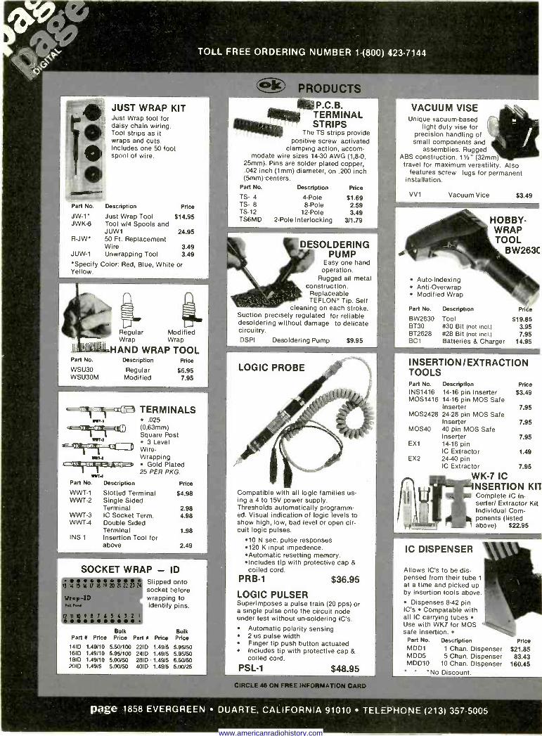
cra- Part No.
JW-1- JWK-6
R-JW
JUW-1
JUST WRAP KIT Just Wrap tool for daisy chain wiring. Tool strips as it wraps and cuts. Includes one 50 foot spool of wire.
Description Price
Just Wrap Tool Tool w/4 Spools and JUW1 50 Ft. Replacement Wire Unwrapping Tool
$14.95
Specify Color: Red, Blue, White or Yellow.
Part No.
WSU30 WSU30M
TO_L FREE ORDERING NUMBER 1-(800) 423-7144
Regular Modified Wrap Wrap
HAND WRAP TOOL Description Price
Regular $6.95 Modified 7.95
qrximirionaa TERMINALS .025
citairEgrce (0,63mm) Square Post Wa
3 Level Wire-
a*r4 Wrapping c=i Gold Plated
25 PER PKG. ..r. Part No. Description
WWT-1 WWT-2
WWT-3 WWT-4
INS 1
Slotted Terminal Single Sided Terminal IC Socket Term. Double Sided Terminal Insertion Tool for above
Price
$4.98
2.98 4.98
t98
2.49
SOCKET WRAP - ID Slipped onto socket before wrapping to identify pins.
Bulk Bulk Part N Price Price Part I Price Price
141 D 1.49110 5.501100 2210 1.4915 5.95150 161 D 1.49110 5.951100 2410 1.4915 5.95/50 1810 1.49/10 5.00150 281D 1.4915 8.50/50 201 D 1.4915 5.00150 4010 1.4915 5.00/25
alto P.C.B. TERMINAL STRIPS
The TS strips provide positive screw activated
clamping action, accom- modate wire sizes 14-30 AWG (1,8-0,
25mm). Pins are solder plated copper, .042 inch (1mm) diameter, on .200 inch (5mm) centers.
Part No. Description Price
TS- 4 TS- 8 TS -12 TS6MD
4 -Pole 61.69 8 -Pole 2.59
12 -Pole 3.49 2 -Pole Interlocking 311.79
DESOLDERING PUMP
Easy one hand operation.
Rugged all metal construction.
Replaceable TEFLON© Tip. Self
cleaning on each stroke. Suction precisely regulated for reliable desoldering without damage to delicate circuitry. DSPI Desoldering Pump $9.95
LOGIC PROBE
Compatible with all logic families us- ing a 4 to 15V power supply. Thresholds automatically programm- ed. Visual indication of logic levels to show high, low, bad level or open cir- cuit logic pulses.
10 N sec. pulse responses 120 K input impedence. Automatic resetting memory. Includes tip with protective cap & coiled cord.
PRB-1 $36.95
LOGIC PULSER Superimposes a pulse train (20 pps) or a single pulse onto the circuit node under test without un -soldering IC's.
Automatic polarity sensing 2 us pulse width Finger tip push button actuated Includes tip with protective cap & coiled cord.
PSL-1 $48.95
VACUUM VISE Unique vacuum -based
light duty vise for precision handling of small components and
assemblies. Rugged ABS construction. 11/2" (32mm)
travel for maximum versatility. Also features screw lugs for permanent
installation.
VV1 Vacuum Vice 63.49
HOBBY - WRAP TOOL
BW263C
Auto -Indexing Anti-Overwrap Modified Wrap
Part No. Description Price
BW2630 BT30 BT2628 BC1
Tool $19.85 #30 Bit (not incl.) 3.95 #28 Bit (not incl.) 7.95 Batteries & Charger 14.95
INSERTION/EXTRACTION TOOLS Part No. Description Price INS1416 14-16 pin Inserter 63.49 MOS1416 14-16 pin MOS Safe
Inserter 7.95 MOS2428 24-28 pin MOS Safe
Inserter 7.95 MOS40 40 pin MOS Safe
Inserter 7.95 EX1 14-16 pin
IC Extractor 1.49 EX2 24-40 pin
IC Extractor 7.95
WK -7 IC NSERTION KIl Complete IC In- serter/ Extractor Kit Individual Com- ponents (listed above) $22.95
IC DISPENSER
Allows IC's to be dis- pensed from their tube 1
at a time and picked up by insertion tools above.
Dispenses 8-42 pin IC's Compatable with all IC carrying tubes Use with WK7 for MOS safe insertion.
Part No. Description MDD1 1 Chan. Dispenser MDD5 5 Chan. Dispenser MDD10 10 Chan. Dispenser
*No Discount.
page 1858 EVERGREEN DUARTE, CALIFORNIA 91010 TELEPHONE (213) 3575005
Price
$21.85 83.43
160.45
www.americanradiohistory.com
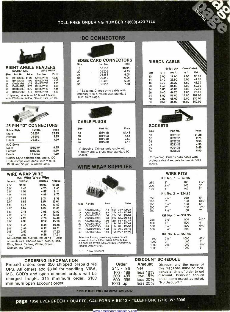
TO_L FREE ORDERING NUMBER 1-(800) L23.7144
RIGHT ANGLE HEADERS SOLDER TAIL WIRE WRAP
Size Part No. Price Part No. Price
10 IDH1OSRB $1.20 20 IDH2OSRB 1.90 26 IDH26SRB 2.75 34 IDH34SRB 3.75 40 IDH4OSRB 3.75 50 IDH5OSRB 4.75
.1" Spacing. Mounts on with IDS Socket below.
IDH1OWRB IDH2OWRB IDH26WRB IDH34WRB IDH4OWRB I DH50W RB
$2.60 4.15 5.35 6.25 7.35 9.20
PC Board & Mates Ejector Bars - 4/1.00.
25 PIN "D" CONNECTORS Solder Style Male Female Cover
IDC Style Male Female Cover
Part No.
DB25P DB25S DB25C
IDB25P IDB25S IDB25C
Price
$2.95 3.95 1.50
6.25 6.80 1.60
Solder Style solders onto cable, IDC Style crimps onto cable with vise. 9, 15, 37 and 50 pin available also.
WIRE WRAP WIRE #30 Wire Wrap Wire
Length 100/Bag 500/Bag lKJBag
2.5" 3.0" 3.5" 4.0" 4.5" 5.0" 5.5" 6.0" 6.5" 7.0" 7.5" 8.0"
$1.38 1.43 1.51 1.56
1.63 1.69 1.74 1.82
2.11 2.19 2.29 2.35
$3.94 $6.81 4.25 7.46 4.57 8.11 4.88 8.73
5.21 9.39 5.54 10.04 5.92 10.69 6.23 11.34
7.08 12.99 7.44 13.68 7.78 14.40 8.12 15.10
8.5" 2.40 8.46 15.80 9.0" 2.46 8.92 16.51 9.5" 2.53 9.15 17.22 10.0" 2.63 9.58 17.91 All lengths are overall, including 1" strip on each end. Choose from colors; Red, Blue, Black, Yellow, White, Green, Orange, and Violet.
EDGE CARD CONNECTORS Size Part No.
10 20 26 34 40 50
IDE1OB IDE2OB IDE26B IDE34B IDE4OB IDE5OB
$3.95 4.35 5.00 6.05 6.90 7.50
.1" Spacing. Crimps onto cable with ordinary vise & mates with standard .062" Card Edge.
1111 CABLE PLUGS
Part No.
IDP14B IDP16B IDP24B IDP40B
$1.45 1.65 2.50 4.15
.1" Spacing Crimps onto cable with ordinary vise & plugs into standard IC Socket.
Size Part Nc. Each Tube
08 ICNO83WBSG .44 14 ICN143VJBSG .53 16 ICN163WBSG .58 18 ICN183V/BSG .78 20 ICN203VJBSG 1.00 22 ICN224VJBSG 1.07 24 ICN246VJBSG 1.09 28 ICN286VJBSG 1.43 40 ICN406VJBSG 1.85
52x .39=920.28 30x 46=813.80 26x .50 =á13.O0 23x .68=31844 21x .85=817.85 19x .92=817.48 17x1.09=$15.98 15x1.23=818.45 10x1 60 =818.00
Selective Plat ng provides gold in contact where it coun:s. 3 -level wrap. Save by buy- ing sockets by the tube. All gold available at '/a¢Ipin extra charge.
' No Discount
ORDERING INFORMATION Prepaid orders over $50 shipped prepaid via UPS. All others add $3.00 for handling. VISA, MC, COD's and open account orders will be charged freight. $15 minimum order. $100 minimum open account order.
Order $15 - 99 100 - 199 200 - 499 500 - 999
1000 up
RIBBON CABLE
Solid Color Color Coded \ Size 10 ft. 100 ft. 10 ft. 100 ft.
10 2.90 17.00 4.00 30.00 14 3.40 23.80 5.00 42.00 16 3.70 27.20 5.60 48.00 20 4.40 34.00 7.00 60.00 24 5.00 40.80 8.00 72.00 26 5.40 44.20 8.60 78.00 34 6.80 57.80 11.00 102.00 40 7.80 68.00 13.00 120.00 50 9.50 85.00 16.00 150.00
SOCKETS Size Part No.
10 IDS10B 20 IDS20B 26 IDS26B 34 IDS34B 40 IDS4OB 50 IDS5OB
$1.88 2.75 3.50 4.50 5.40 6.50
.1" Spacing. Crimps onto cable with ordinary vise & mounts to header sold above.
WIRE KITS Kit No. 1 - $9.95
250 3" 100
200 3'/a" 100 100 4" 100
Kit No. 2 - $24.95 250 21/2" 250 500 3" 100 500 31/2" 100 500 4" 100 250 41/2" 100
Kit No. 3 - $34.95 250 21/2" 500 500 3" 500 500 3'/2" 500 500 4" 500
500 1000 1000 1000
Kit No. 4 - $59.95 2Y2" 1000 3" 1000 3'/2" 1000 4" 1000
DISCOUNT SCHEDULE Amount
NE1 less 10% less 15% less 20% less 25%
41/2"
5" 6"
Discount and the name of this magazine must be men- tioned at time of order to get discount. Discount applies on all items except as noted, "No Discount."
page 1858 EVERGREEN DUARTE, CALIFORNIA 91010 TELEPHONE (213) 357-5005
www.americanradiohistory.com
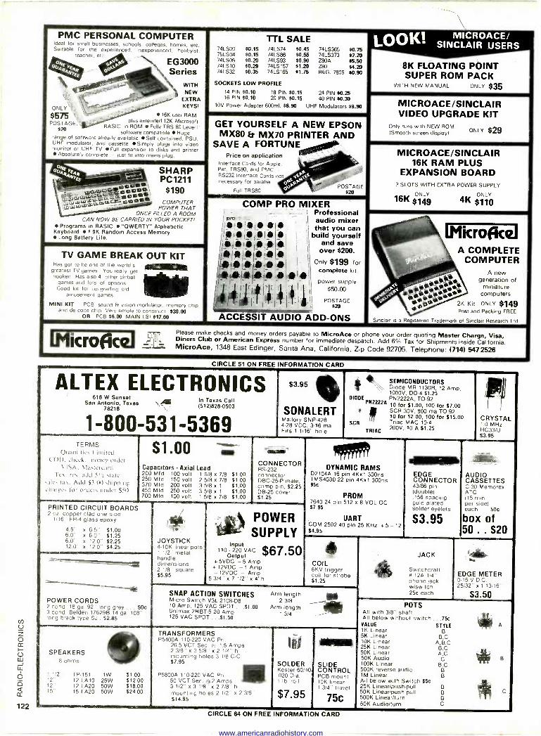
PMC PERSONAL COMPUTER Ideal for small businesses, schools, colleges, homes, etc. Suitable for the experienced, inexperienced, hobbyist,
teacher, etc
'It OÚNEY %VI's EG3000 4aq/4E Series
WITH NEW
TTL SALE 74LS00 $0.15 74LS74 $0.45 74LS365 $0.75 75LSt34 $0.15 74LS86 $0.55 74LS373 $2.20 74LS05 80.20 74LS93 $0.90 Z80A 95.50 74LS10 $0.29 74LS157 $1.20 Z80 $4.20 74LS32 80.35 74LS165 $1.75 REG. 7805 $0.90
SOCKETS LOW PROFILE
14 PIN $0.10 18 PIN $0.15 24 PIN 80.25
MICROACE OK! LO SINCLAIR USERS
8K FLOATING POINT SUPER ROM PACK
WITH NEW MANUAL ONLY $35 EXTRA
ONLY' KEYS!
`
16 PIN $0.10 20 PIN 80.15 40 PIN 80.30 10V Power Adapter 600m1, $6.90 UHF Modulators $9.90 MICROACE/SINCLAIR
VIDEO UPGRADE $575 _ 16K user RAM
POSTAGE 't plus extended 12K Microsoft BASIC in ROM Fully TRS-80 Level II
$20 software compatible Huge range.of software already available Self contained, PSU, UHF modulator, Simply
GET YOURSELF A NEW EPSON MX80 Fr MX70 PRINTER AND
KIT Onlyruns with NEW ROM ONLY (Smooth screen display)
and cassette plugs into video monitor or UHF TV Fun expansion to disks and printer
Absolutely complete -lust fit into mains plug.
SAVE A FORTUNE Price on application
`- MICROACE/SINCLAIR
0Ù4R .I44 - - + SHARP 4prFF-- PC1211 p10s`i .í:dííFr ai0.`
Interface Cards for Apple, ../ Pet, TRs80, and PMC -- Pe -
< RS232 Interface Cards not pet", necessary for parallel. pe eP a° pJP a' POSTAGE
a TRSflo ,' $20
16K RAM PLUS EXPANSION BOARD
°SLOTS WITH EXTRA POWER SUPPLY
ONLY ONLY u=--`"`1k® emu -, ®a+lo COMPUTER 'J"L ̀v POWER THAT COMP PRO MIXER 1
Professional
16K 5149 4K $110
ONCE FILLED A ROOM CAN NOW BE CARRIED IN YOUR POCKET!
- I
( audio mixer Programs in BASIC "OWERTY" Alphabetic
Keyboard 1.9K Random Access Memory Long Battery Life.
11111,» t I that you can i i i i i i build yourself
I _
Iri,Ilia lb 014bC 1 and save
_ icroectl TV GAME BREAK OUT KIT
Has got to be one of the world's ® greatest TV games You really et 9 hooked Has also 4 other pinball
games and lots of options. Good kit for up grading old
amusement games
MINI KIT PCB, sound &vision modulator, memory cop and de code chip. Very simple to construct. $30.00
OR PCB $6.00 MAIN LSI 817.00
t
/e i `ile
I11,1191i: I
i
t l j
i
x ' -^- ACCESSIT
t l;
AUDIO
$200.
only V $199 for ) complete kit.
owe! supply r 11 p pply
$50.00 (
1. POSTAGE n0
ADD-ONS
COMPLETE - ACOMPUTER
shy A new ereAa generation of
4, 1 1 e J94 i - r. t7- s computers
f . miniatter
.1 aNO{ 0. 2K Kit ONLY 8149 M. Post and Packing FREE
Sinclair is a Registered Trademark of Sinclair Research Ltd.
LfiucrojcqJPlease make checks and money orders payable to MicroAce or phone your order quoting Master Charge, Visa, t Dines Club or Amecan Express number for immediate despatch. Add 6°II Tax for Shipments(7 inside California. -''LLw: MicroAce, 1348 Eastri Edinger, Santa Ana, California, Zip Code 92705. Telephone: 14) 5472526
RMATION CARD
ALTEX ELECTRONICS 618 W Sunset In Texas Call San Antonio, Texas \ï4E 1512)828.0503 78216
1-800-531-5369
$3.95 s SONALERT
Mallory SNP -428 4-28 VDC, 3-16 ma Fits 1 1/16" hole
SEMICONDUCTORS Diode MR 1130R, 12 Amp, 1000V, DO -4 $1.25
DIODE PN2222A, TO -92 PN2222A
10 for $1.00, 100 for $7.00 ! SCR 30V, 800 ma TO -92 10 for 02.00, 100 for $15.00
SCR Triac MAC 10-4
TRIAC 200V, 10 A $1.25
le*
TERMS Quantities Limited
COI). cheek, tourney order VISA, Mastercard
Tex. res. add Sir slate sales tax. Add 53.00 shipping charges for orders under $50
S 1.00 .., Capacitors - Axial Lead 200 Mfd 100 volt 1 5/8 x 7/8 250 Mfd 150 volt 2 5/8 x 7/8 370 Mfd 200 volt 3 5/8 x 1
450 Mfd 250 volt 3 5/8 x 1
700 Mfd 100 volt 1 5/8 x 7/8
51.00 $1.00 51.00 $1.00 $1.00
CONNECTOR RS -232 connector, DBC-25-P male, crimp pin, $2.25 DB -25 cover $1.25
PRINTED CIRCUIT BOARDS 2 oz. copper clad one side
1/16" FR -4 glass epoxy
4.5" x 6.5" $1.00 6.0" e 6.0" $1.25 6.0" x 12.0" $2.25 12.0" x 12.0" $4.25
POWER CORDS 2 cond. 18 ga. 92" long grey ... 50c 3 cond. Belden 176298 14 ga. 108" long black type SJ . $2.85
JOYSTICK 4-10K linear pots
1 1/2" metal handle dimensions 2 118" square $5.95
POWER SUPPLY
Input $67.50 110 - 220 VAC Output
+5VDC -5 Amp + 12VDC - 1 Amp - 12VDC - Amp
5 3/4" x 7 1/2" x 4"h
Ire DYNAMIC RAMS
D2104A 16 pin 4Kx1 300ns TMS4030 22 pin 4Kx1 300ns 95c
PROM 7640 24 pin 512 e 8 VOL OC S7.95
UART COM 2502 40 pin 25 KHz + 5 - 12 $4.95
41111111111111110
EDGE CONNECTOR 43/86 pin (double)
156 spacing gold plated solder eyelets
$3.95
CRYSTAL 1.0 MHz HC33/U $3.95
AUDIO CASSETTES C-30 Memorex ATC (15 min. per side) each.. 504
box of 50 .. S20
COIL 6KV trigger coil for strobe $1.25
SNAP ACTION SWITCHES Micro Switch V3L-2108-D8 10 Amp, 125 VAC SPDT ...51.00 Unimax 2HBT-5 20 Amp 125 VAC SPDT ...$1.50
Arm length 2 3/8
Arm length 1 3/4
JACK
Switchcraft V 12A 1/4" phone lack w/switch 256 each
EDGE METER 0-15 V.D.C. 25/32" x 1 13/16
S3.50
SPEAKERS 8 Ohms
1 1/2" 12- 12 15"
TP -151 12 LA10 12 LA20 15 LA20
.1W 25W 50W 50W
$1.00 $12.00 $18.00 $24.00
TRANSFORMERS P5400A 110-220 VAC Pri.
26.5 VCT Sec. 6 1.5 Amps 2 3/8" x 3 5/8" x 2 1/4" h mounting holes 3 1/8 C -C $7.95
P5800A 110-220 VAC Pri. 50 VCT Sec it 2 Amps 3 1/2" x 3 118" x 2 7/8" h mounting holes 2 1/2" x 2 3/8' $14.95
SOLDER Kester 60/40 .020 Dia. 1 lb. roll
$7.95
Mom SLIDE CONTROL PCB mount 10K linear. 1 3/4 travel
75c
POTS All with 3/8- shaft All below without switch
VALUE 1K Linear 5K Linear 10K Linear 25K Linear 50K Linear 50K Audio 100K Linear 500K reverse audio 1M Linear All below with Switch $5c 25K Linear/push-pull 50K Linear/push-pull 500K Linear/turn 50K Audio/turn
75c
STYLE B
B,C A,B,C B,C A,C
C B,C
B B
B B B C
A
B
C
CIRCLE 64 ON FREE INFORMATION CARD
www.americanradiohistory.com
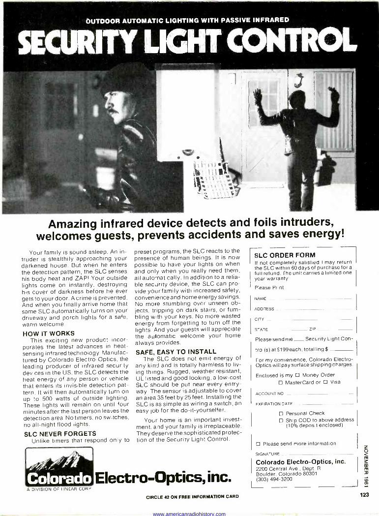
OUTDOOR AUTOMATIC LIGHTING WITH PASSIVE INFRARED
SECURITY LIGHT CONTROL
Amazing infrared device detects and foils intruders, welcomes guests, prevents accidents and saves energy!
Your family is sound asleep. An in- truder is stealthily approaching your darkened house. But when he enters the detection pattern, the SLC senses his body heat and ZAP! Your outside lights come on instantly, destroying his cover of darkness before he ever gets to your door. A crime is prevented. And when you finally arrive home that same SLC automatically turns on your driveway and porch lights for a safe, warm welcome.
HOW IT WORKS This exciting new product incor-
porates the latest advances in heat - sensing infrared technology. Manufac- tured by Colorado Electro -Optics, the leading producer of infrared security devices in the US, the SLC detects the heat energy of any person or vehicle that enters its invisible detection pat- tern. It will then automatically turn on up to 500 watts of outside lighting. These lights will remain on until four minutes after the last person leaves the detection area. No timers, no switches, no all-night flood lights.
SLC NEVER FORGETS Unlike timers that respond only to
Colorado
preset programs, the SLC reacts to the presence of human beings. It is now possible to have your lights on when and only when you really need them, all automatically. In addition to a relia- ble security device, the SLC can pro- vide your family with increased safety, convenience and home energy savings. No more stumbling over unseen ob- jects, tripping on dark stairs, or fum- bling with your keys. No more wasted energy from forgetting to turn off the lights. And your guests will appreciate the automatic welcome your home always provides.
SAFE, EASY TO INSTALL The SLC does not emit energy of
any kind and is totally harmless to liv- ing things. Rugged, weather resistant, UL listed and good looking, a low-cost SLC should be put near every entry- way. The sensor is adjustable to cover an area 35 feet by 25 feet. Installing the SLC is as simple as wiring a switch, an easy job for the do-it-yourselfer.
Your home is an important invest- ment, and your family is irreplaceable. They deserve the sophisticated protec- tion of the Security Light Control.
Electro -Optics, inc.
rISLC ORDER FORM f not completely satisfied I may return the SLC within 60 days of purchase for a
full refund. The unit carries a limited one year warranty.
Please Print
NAME -
ADDRESS
CITY
STATE ZIP
Please send me Security Light Con-
trol(s) at $199 each, totalling $
For my convenience, Colorado Electro - Optics will pay surface shipping charges.
Enclosed is my D Money Order MasterCard or D Visa
ACCOUNT NO
EXPIRATION DATE
Personal Check Ship COD to above address (10% deposit enclosed)
D Please send more information.
SIGNATURE
Colorado Electro -Optics, Inc. 2200 Central Ave., Dept. R
Boulder, Colorado 80301 (303)494-3200
A DIVISION OF LINEAR CORP.
CIRCLE 42 ON FREE INFORMATION CARD 123
www.americanradiohistory.com
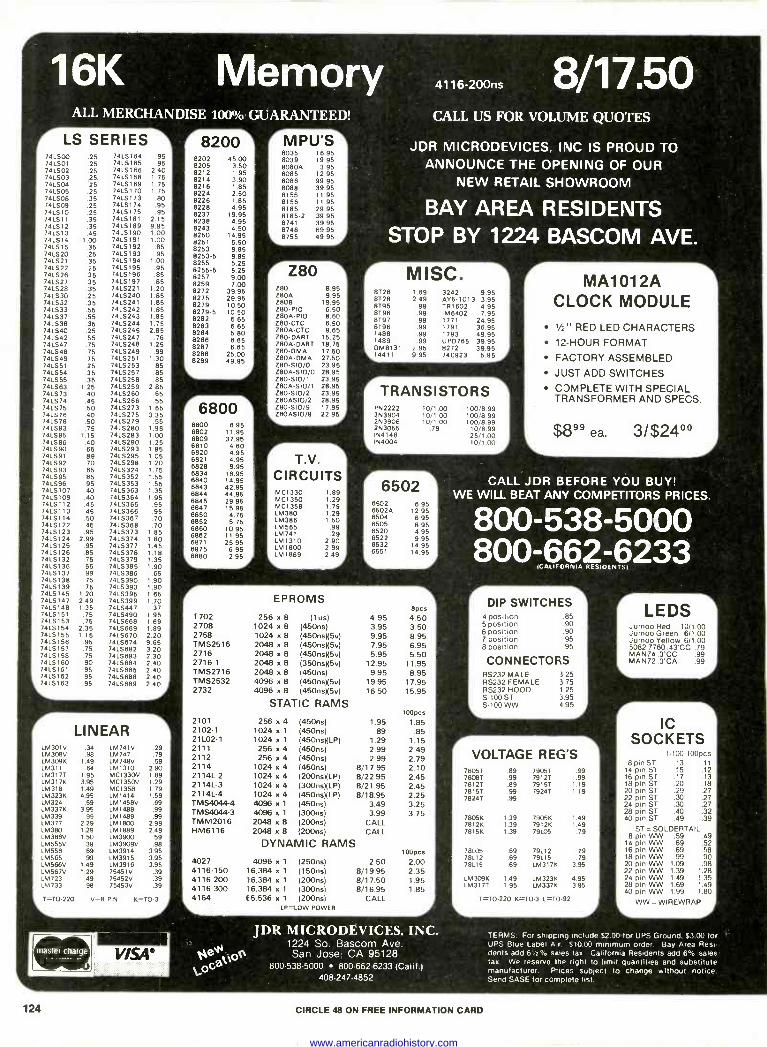
16K Memory .,,e,00 8/17.50 ALL MERCHANDISE 100% GUARANTEED! r LS SERIES
741S00 .25 741501 .25 741502 .25 741503 .25 741504 .25 741506 .25 741508 .35 741S09 .25 741510 .25 741511 .35 741512 .35 741.513 .46 741514 1.00 741515 .35 741520 .25 741S21 .35 741522 .25 741526 .35 74LS27 .35 74LS28 .35 741530 .25 741532 .35 74LS33 .55 74L537 .55 74LS38 .35 741540 .25 741542 .55 741S47 .75 741548 .75 741549 .75 741551 .25 741554 .35 741555 .35 741583 1.25 741573 .40 741574 .45 741575 .50 741576 .40 741S78 .50 741583 .75 741585 1.15 741586 .40 741590 .65 741591 .89 74LS92 .70 741593 .65 741595 .85 741596 .95 7415107 .40 7415109 .40 74LS112 .45 7415113 .45 7415114 .50 7415122 .45 7415123 .95 7415124 2.99 7415125 .95 7415126 .85 7415132 .75 7415136 .55 7415137 .99 7415138 .75 7415139 .75 7415145 1.20 7415147 2.49 7415148 1.35 7415151 .75 7415153 .75 7415154 2.35 7415155 1.15 74LS156 .95 74L5157 .75 74LS158 .75 7415160 .90 7415161 .95 741S162 .95 741.5163 .95
7415184 .95 741S165 .95 74151116 2.40 7415188 1.75 741S169 1.75 7415170 1.75 7415173 .80 7415174 .95 7415175 .95 7415181 2.15 7415189 9.95 74LS190 1.00 7415191 1.00 7415192 .85 7415193 .95 7415194 1.00 7415195 .95 7415196 .85 7415197 .85 741S221 1.20 7415240 1.85 7415241 1.85 7415242 1.85 7415243 1.85 7415244 1.75 7415245 2,85 7415247 .76 7415248 1.25 7415249 .99 7415251 1.30 7415253 .85 7415257 .85 7415258 .85 74LS259 2.85 7415260 .85 7415266 .55 7415273 1.65 7415275 3.35 741S279 .55 7415280 1.98 7415283 1.00 7415290 1.25 7415293 1.85 7415295 1.05 7415298 1.20 7415324 1.75 7415352 1.55 7415353 1.55 7415363 1.35 7415364 1.95 7415385 .95 7415368 .95 7415367 .70 7415388 .70 74LS373 1.85 741S374 1.80 74LS377 1.45 741S378 1.18 7415379 1.35 741S385 1.90 7415386 .85 7415390 1.90 7415393 1.90 7415395 1.85 74LS399 1.70 7415447 .37 7415490 1,95 7415868 1.89 7415669 1.89 7415870 2.20 7415674 9.85 7415882 3.20 7415683 2.30 74LS684 2.40 74LS685 2,40 7415688 2.40 7415889 2.40
r LINEAR LM301V .34 1M741V .29 LM308V .98 1M747 .79 LM309K 1.49 LM748V .59 LM311 .64 LM1310 2.90 1M3171 1,95 MC1330V 1.89 1M3171( 3.95 MC1350V 1.29 1M318 1,49 MC1358 1,79 LM323K 4,95 LM1414 1.59 LM324 .59 LM1458V .69 LM337K 3.95 LM1488 .99 1M339 .99 1M1489 .99 1M377 2.29 LM1800 2.99 LEA 380 1.29 1M1889 2.49 LM386V 1.50 LM3900 .59 LM555V 39 LM3909V .98 LM556 .69 LM3914 3.95 LM565 .99 LM3915 3.95 LEA 566V 1.49 1M3916 3.95 LM567V 1.29 75451V .39 LM723 .49 75452V .39 LM733 98 75453V .39
PIN
r 82001 8202 45.00 8205 3.50 8212 1.95 8214 3.90 8216 1.85 8224 2.50 8226 1.85 8228 4.95 8237 19.95 8238 4.95 8243 4,50 8250 14.95 8251 5.50 8253 9.85 8253-5 9.85 8255 5.25 8255-5 5.25 8257 9.00 8259 7.00 8272 39.95 8275 29.95 8279 10.50 8279-5 10.50 8282 8.65 8283 8.85 8284 5.80 8288 6.85 8287 8.85 8288 25.00 8289 49.95
_ I
r6800-1 8800 6802 6809 8810 6820 8821 6828 6834 6840 6843 8844 6845 6847 6850 6852 6860 6862 6871 6875
6.8880
6.95 11,95 37.95
4.60 4.95 4.95 9.95
18.95 14.95 42.95 44.95 29.95 15.95 4.75 5.75
10.95 11.95 25.95
6.95 2.95,
MPU'S 8035 16.95 8039 19.95 8080A 3.95 8085 12.95 8086 99.95 8088 39.95 8155 11.95 8156 11.95 8185 29.95 8185-2 39.95 8741 39.95 8748 89,95 8755 49.95
r Z80 1 Z80 8.95 Z80A 9.95 2808 19,95 Z80 -P10 6.50 Z80A-PI0 8.60 Z80-CTC 8.50 Z80A-CTC 8.65 Z80 -DART 15.25 Z804 -DART 18.75 Z80 -DMA 17.50 Z804 -DMA 27,50 Z80 -S10/0 23.95 280A -S10/0 28.95 Z80 -S10/1 23.95 Z80A-510/1 28.95 280-510/2 23.95 Z80A510/2 28.95 Z80 -S10/9 17.95
, ZB0A510/9 22.95 I
T.V.
CIRCUITS MC1330 MC1350 MC1358 1M380 LM 386 LM 585 LM 741 1M1310 LM 1800 L M 1889
I 89 1 29. 1.79 1,29 1.50
.99
.29 2.90 2.99 2.49
CALL US FOR VOLUME QUOTES
JDR MICRODEVICES, INC IS PROUD TO ANNOUNCE THE OPENING OF OUR
NEW RETAIL SHOWROOM
BAY AREA RESIDENTS STOP BY 1224 BASCOM AVE.
MISC. 8726 1.69 3242 9.95 8728 2.49 AY5-1013 3,95 8195 .99 TR1602 4.95 8796 .99 1M8402 7.95 8797 .99 1771 24.95 8796 .99 1791 38.95 1488 .99 1793 49.95 1489 .99 UPD765 39.95 DM8131 2.95 8272 39.95 14411 9.95 74C923 5.95
TRANSISTORS 1 PN2222 263904 2N3908 2N3055 IN4148 IN4004
10/1.00 10/1.00 10/1.00
.79
100/8.99 100/8.99 100/8.99 10/6.99 25/1.00 10/1.00
6502 6502 6502A 8504 8505 6520 6522 6532 6551
6,95 12.95
6.95 8.95 4.95 9,95
14.95 14.95
1702 2708 2758 TMS2516 2716 2716-1 TMS2716 TMS2532 2732
2101 2102-1 21102-1 2111 2112 2114 2114L-2 21141-3 2114L-4 TMS4044-4 TMS4044.3 TMM2016 HM6116
4027 4116-150
4116-200 116-300
EPROMS
256 x 8 (I us) 4.95 1024 x 8 (450ns) 3.95 1024 x 8 (45OnsX5v) 9.95 2048 a 8 (45OnsX5v) 7.95 2048 x 8 (46OnsX5v) 5.95 2048 x 8 (35OnsN5v) 12.95 2048 x 8 (450ns) 9.95 4096 a 8 (45Ons)(5v) 19.95 4096 x 8 (45OnsX5v) 16.50
STATIC RAMS
256 x 4 (450ns) 1.95 1024 x 1 (450ns) .89 1024 a 1 (45OnsXLP) 1.29 256 x 4 (450ns) 2.99 256 x 4 (450ns) 2.99
1024 x 4 (450ns) 8/17.95 1024 x 4 (200nsXLP) 8/22.95 1024 x 4 (300nsXLP) 8/21.95 1024 x 4 (45OnsXLP) 8/18.95 4096 x 1 (450ns) 3.49 4096 x 1 (300ns) 3.99 2048 a 8 (200ns) CALL 2048 a 8 (200ns) CALL
DYNAMIC RAMS 4096 x 1 (250ns) 2.50
16.384 x 1 (150ns) 8/19.95 16,384 x 1 (200ns) 8/17.50 16,384 x 1 (300ns) 8/16.95
4164 65.536 x 1 (200ns) CALL LP=LOW POWER
8pcs 4.50 3.50 8.95 6.95 5.50
11.95 8.95
17.95 15.95
100pcs
1.85 .85
1.15 2.49 2.79 2.10 2.45 2.45 2.25 3.25 3.75
100pcs
2.00 2.35 1.95 1.85
JDR MICRODEVICES. INC. 1224 So. Bascom Ave.
Óeá oA San Jose; CA 95128 G 800-538-5000 800-662-6233 (Calif.)
408-247-4852
r MA1012A CLOCK MODULE V, " RED LED CHARACTERS 12 -HOUR FORMAT
FACTORY ASSEMBLED
JUST ADD SWITCHES
CJMPLETE WITH SPECIAL TRANSFORMER AND SPECS.
$899 ea. 3/$24°°
CALL JDR BEFORE YOU BUY! WE WILL BEAT ANY COMPETITORS PRICES.
800-538-5000 800-662-6233
CALIFORNIA RESIDENTSI
DIP SWITCHES 4 position .85 5 position .90 6 position .90 7 position .95 8 position .95
CONNECTOFS RS232 MALE RS232 FEMALE RS232 HOOD S-100 ST 5-100 WW
3.25 3.75 1.25 3.95 4.95
r - VOLTAGE REG'S
78051 89 79051 .99 78087 .99 79121 .99 78121 .89 79151 1,19 78151 99 79241 1.19 78241 99
7805K 1.39 7905K 1.49 7812K 1.39 7912K 1.49 7815K 1.39 79106 .79
78105 .69 79112 .79 78112 .69 79115 .79 78115 .69 1M317K 3.95
LM309K 1.49 LM323K 4.95 LM317T 1.95 LM337K 3.95
T=T0-220 K=TO-3 L=10-92
L
LEDS Jumbo Red 10/1.00 Jumbo Green 6/1.00 Jumbo Yellow 6/1.00 5082-7760.43'CC 79 MAN74.3'CC .99 MAN72 .3'CA .99
r IC
SOCKETS 1100 100pcs
8 pin ST .13 .11 14 pin S1 .15 .12 16 pm ST .17 .13 18 pin ST .20 .18 20 pm ST .29 .27 22 pin ST .30 .27 24 pin ST .30 .27 28 pin ST .40 .32 40 pin ST .49 .39
ST = SOLDERTAIL 8 pin WW .59 .49
14 pin WW .69 .52 16 pin WW .69 .58 18 pin WW .99 .90 20 pin WW 1.09 .98 22 pin WW 1.39 1.28 24 pin WW 1.49 1.35 28 pin WW 1.69 1.49 40 pin WW 1.99 1.80
L_
WW =WIREWRAP
TERMS For shipping include $2.00.for UPS Ground. $3.00 for -
UPS Blue Label A r. $10.00 minimum order, Bay Area Resi- dents add 61/2% sales tax California Residents add 6% sales tax. We reserve the right to limit quantities and substitute manufacturer. Pices subject to change without notice. Send SASE for complete list.
124 CIRCLE 48 ON FREE INFORMATION CARD
www.americanradiohistory.com
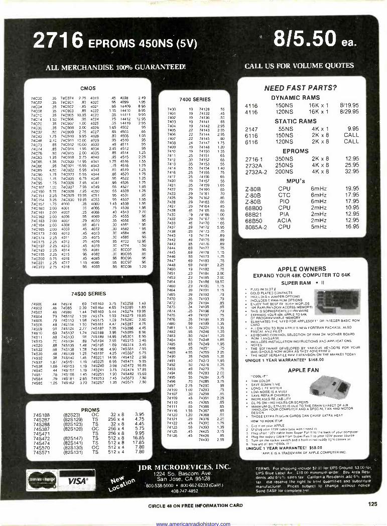
2716 EPROMS 450NS (5V)
ALL MERCHANDISE 100% GUARANTEED!
CMOS
74000 .35 74C374 2.75 4019 74002 .35 740901 .80 4020 74004 .35 740902 ',.85 4021 74008 .35 740903 .85 4022 74010 .35 740905 10.95 4023 74014 1.50 740906 .95 4024 74020 .35 740907 1.00 4025 74030 .35 740908 2.00 4026 74032 .50 740909 2.75 4027 74C42 1.75 740910 9.95 4028 74C48 2.10 740911 10.00 4029 74C73 .65 740912 10.00 4030 74074 .85 740914 1.95 4034 74076 .80 740915 2.00 4035 74083 1.95 740918 2.75 4040 74C85 1.95 740920 17.95 4041 74C86 .95 740921 15.95 4042 74089 4.50 74C922 5.95 4043 74090 1.75 740923 5.95 4044 74093 1.75 74C925 6.75 4046 74095 1.75 74C926 7.95 4047 740107 1.00 740927 7.95 4049 740150 5.75 740928 7.95 4050 740151 2.25 74C929 19.95 4051 740154 3.25 740930 19.95 4053 740157 1.75 4000 .35 4060 740160 2.00 4001 .35 4066 740161 200 4002 .25 4068 740162 2.00 4006 .95 4069 740163 2.00 4007 .29 4070 740164 2.00 4008 .95 4071 740165 2.00 4009 .45 4072 740173 2.00 4010 .45 4073 740174 2.25 4011 .35 4075 740175 2.25 4012 .25 4076 740192 2.25 4013 .45 4078 740193 2.25 4014 .95 4081 740195 2.25 4015 .95 4082 740200 5.75 4016 .45 4085 740221 2.25 4017 1.15 4086 740373 2.75 4018 .95 4093
74S00 SERIES
74500 .44 74S74 .89 74S163 74502 .48 74585 2.39 74S168 74503 .48 74586 1.44 74S169 74SO4 .79 74S112 1.59 74S174 74S05 .79 745113 1.98 74S175 74S08 .48 74S114 1.50 74S181 74S09 .98 74S124 2.77 74S182 74S10 .69 74S132 1.24 745188 74S11 .88 74S133 .98 74S189 74S15 .70 74S134 .69 74S194 74S20 .68 74S135 1.48 74S195 74S22 .98 74S138 1.08 745196 74S30 .48 74S139 1.25 74S197 74S32 .98 74S140 1.45 74S201 74S37 1.87 74S151 1.19 74S225 74S38 1.68 74S153 1.19 74S240 74S40 .44 74S157 1.19 74S241 74S51 .78 74S158 1.45 74S251 74564 .79 74S161 2.85 74S253 74565 1.25 746162 3.70 74S257
PROMS 74S188 (82S23) OC 74S287 (825129) TS 74S288 (825123) TS 74S387 (82S126) OC 745471 TS 74S472 (82S147) TS 74S474 (82S141) TS 74S570 (82S130) OC 74S571 (82S131) TS
.45 4098 2.49
.95 4099 1.95
.95 14409 8.95
7400 SERIES
1.15 14410 8.95 7400 .19 74128 .55
.35 14411 9.95 7401 .19 74132 .45
14412 12.95 7402 .19 74136 .50 .75 .35 14419 2.95 7403 .19 74141 .65
1.65 4502 .95 7404 .19 74142 2.95
4503 .65 7405 .22 74143 2.95 .65 .80 4508 1.95 7406 .22 74144 2.95
.95 4510 .95 7407 .22 74145 .60
.45 4511 .95 7408 .24 74147 1.75
2.95 4512 .95 7409 .19 74148 1.20
.85 4514 1.25 7410 .19 74150 1.35
.95 4515 2.25 7411 .25 74151 .65
1.25 4516 1.55 7412 .30 74152 .65
4518 1.25 7413 .35 74153 .55 .75 .85 4519 1.25 7414 .55 74154 1.40
4520 1.25 7416 .25 74155 .75 .85 .95 4522 1.25 7417 .25 74156 .65
4526 1.25 7420 .19 74157 .55 .95 .55 4527 1.95 7421 .35 74159 1.65
4528 1.25 7422 .29 74160 .85 .55 4531 .95 7423 .29 74161 .70 .95
.95 4532 1.95 7425 .29 74162 .85
1.45 4538 1.95 7426 .29 74163 .85
4539 1.95 7427 .29 74164 .85 .75
4543 2.70 7428 .45 74165 .85 .40 4555 .95 7430 .19 74166 1.00 .35 4556 .95 7432 .29 74167 1.95 .35 4581 1.95 7433 .45 74170 1.65 .30 4582 1.95 7437 .29 74172 5.95 .30
.30 4584 .95
.30 4585 .95
7438 7440
.29
.19 74173 74174
.75
.89
4702 12.95 7442 .49 74175 .89 .95 .30 4724 1.50 7443 .65 74176 .89
80007 .95 7444 .69 74177 .75 .30 .30 80095 .85 7445 .69 74178 1.15
.95 80096 .95 7446 .59 74179 1.75
80097 .95 7447 .69 74180 .75 .95 80098 1.20 7448 .69 74181 2.25 .95
7450 .19 74182 .75 7451 7453
.23
.23 74184 74185
2.00 2.00
7454 .23 74186 18.50 7460 .23 74190 1.15 7464 .39 74191 1.15 7465 .39 74192 .79 7470 .35 74193 .79
3.75 74S258 1.49 7472 .29 74194 .85 4.65 74S260 1.83 7473 .34 74195 .85 5.44 745274 19.95 7474 .35 74196 .79 1.09 74S275 19,95 7475 .49 74197 .75 1.09 74S280 2.90 7476 .35 74198 1.35 4.47 74S287 4.75 7480 .59 74199 1.35
2.95 74S288 4.45 7481 1.10 74221 1.35
3.95 745289 6.98 7482 .95 74246 1.35
14.95 74S301 6.95 7483 .50 74247 1.25
2.95 74S373 3.45 7484 .50 74248 1.85
1.89 74S374 3.45 7485 .65 74249 1.95
4.90 74S381 7.95 7488 .35 74251 .75
4.25 748387 5.75 7489 4.95 74259 2.25
14.95 74S412 2.98 7490 .35 74265 1.35
8.95 74S471 9.95 7491 .40 74273 1.95
3.98 74S472 16.85 7492 .50 74276 1.25
3.75 74S474 17.85 7493 .49 74279 .75
1.90 74S482 15.60 7494 .65 74283 2.00
7.45 745570 7.80 7495 .55 74284 3.75 1.39 745571 7.80 7496 .70 74285 3.75
7497 2.75 74290 .95 74100 1.00 74293 .75 74107 .30 74298 .85 74109 .45 74351 2.25 74110 .45 74365 .65 74111 .55 74386 .65 74116 1.55 74367 .65
32 x 8 3.95 74120 1.20 74368 .65
256 x 4 4.75 74121 .29 74376 2.20
32 x 8 4.45 74122 .45 74390 1.75
256 x 4 5.75 256 x 8 9.95 512 x 8 16.85
74123 74125 74126
.55
.45
.45
74393 74425 74426 74490
1.35 3.15
.85 2.55
512 x 8 17.85 512 x 4 7.80 512 x 4 7.80
JDR MICRODEVICES, INC. 1224 So. Bascom Ave.
Nell . A San Jose, CA 95128 O 800.538-5000 800-662-6233 (Calif.)
LD 408-247.4852
815.50 ea.
CALL US FOR VOLUME QUOTES
NEED FAST PARTS? DYNAMIC RAMS
4116 15ONS 16K x 1 8/19.95 4116 12ONS 16K x 1 8/29.95
STATIC RAMS 2147 55NS 4K x 1 9.95 6116 15ONS 2K x 8 CALL 6116 12ONS 2K x 8 CALL
EPROMS 2716-1 350NS 2K x 8 12.95 2732A 250NS 4K x 8 25.95 2732A-2 200NS 4K x 8 32.95
MPU's Z -80B CPU 6mHz 19.95 Z -80B CTC 6mHz 17.95 Z -80B PIO 6mHz 17.95 68B00 CPU 2mHz 10.95 68821 PIA 2mHz 12.95 68850 ACIA 2mHz 12.95 8085A-2 CPU 5mHz 16.95
APPLE OWNERS EXPAND YOUR 48K COMPUTER TO 64K
SUPER RAM Il
PLUG IN SLOT d GOLD PLATED CONTACTS INCLUDES 5 JUMPER OPTIONS INCLUDES 5 RAM-ROM OPTIONS ENJOY THE BEST OF BOTH WORLDS 18K RAM (RANDOM ACCESS MEMORY, THIS IS SOPHISTICATED FIRMWARE EXPANDS YOUR 48K APPLE TO 84K OFPROGRAMMABLEMEMORY ELIMINATES THE NEED FOR APPLESOFT OR INTEGER BASIC ROM
CARD ALLOW YOU TO RUN APPLE'S NEW FORTRAN PACKAGE, ALSO PASCAL AND PILOT KEYBOARD CONTROL SELECTION OF RAM OR MOTHER BOARD ROM LANGUAGE INCLUDES INSTALLATION INSTRUCTIONS AND APPLICATIONS NOTES THE SOFTWARE DEVELOPED BY VARIOUS VENDORS FOR YOUR
(64K) SHOULD NOW WORK AS THEY ADVERTISED THE MOST VERSATILE RAM EXPANSION ON THE MARKET TODAY
UNIQUE 1 YEAR WARRANTEE! $168.00
APPLE FAN "COOL -IT"
TAN COLOR SAVE DOWN TIME LONG LIFE MOTOR LOW NOISE IS A MUST SAVE REPAIR CHARGES INCREASES RELIABILITY CLIPS ON -NO HOLES OR SCREWS MINIMUM QUIETNESS IS DUE TO THE DRAW EFFECT OF AIR
THROUGH YOUR COMPUTER AND A SPECIAL FAN AND MOTOR DESIGN THOSE EXTRA PLUG-IN CARDS CAN CAUSE EXTRA HEAT
HOW TO HOOK IT UP
1. CIIp It on your APPLE 2 Unplug your 120V cable (you wori t need iII
3 Plug short 120V cable from Super Fan II to the back of your computer 4 Plug the supply cable from Super Fan II to your 120V power source
5. Turn on the rocker switch and a built-in red ready light comes on
6 You are all set "COOL IT" UNIQUE 1 YEAR WARRANTEE! $89.00
APPLE IS A TRADEMARK OF APPLE COMPUTER INC
TERMS. For shipping Include $2 00 for UPS Ground. S300lor. UPS Blue Label Air. $1000 mmlmum order. Bay Area Resi dents add 6'ße % sales tax California Residents add 6% sales
tax We reserve the right to limit quantities and substitute manufacturer. Prices subject to change wlthOut notice Send SASE for complete list
CIRCLE 48 ON FREE INFORMATION CARD 125
www.americanradiohistory.com
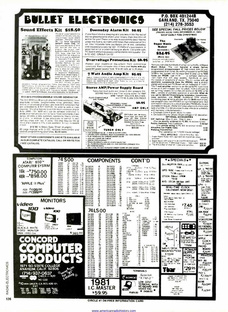
ULLE1 ILICImIcs Sound Effects Kit $18.50
If11}$iJi$itii3 9 :7ItI::Rtt:JtU! .e.., eees
r
V
Nt!
The SE -01 is a complete kit that contains all the parts to build a programmable sound effects generator Designed around the new Teem Inetn,maele SN75477 Sound ChM. the board provides banks of MINI DIP switches and pots to program the various com- binations of The SLF Oscillator, VCO. Noise, One Shot, and Envelope Controls. A Quad Op Amp IC is used to' implement an Adlusteble Pulse Genera- tor. Level Comparator and Multiplex Oscillator for even more versatility. The 3'/' x 5" PC Board features a prototype area to allow for user added circuitry. Easily programmed to duplicate Eaploslona, Phew Gum, Steam Trains, or almost an infinite number of other bound. The unit has a multiple of applications. The low price includes all parts,
assembly manual. programming charts. and detailed 76477 chip specifications. It runs on a 9V battery (not included). On board 100MW amp will drive a small speaker directly, or the unit can be connected to your stereo With incredible results, (Sneaker not included). 764771e Included. Available separately for $3.15 each.
AY3-8910 PROGRAMMABLE SOUND GENERATOR The AY3-8910 is a 40 pin LSI chip with three oscillators, three amp itude controls, programmable noise generator, three mixers, an envelope generator, and three D/A converters that are controlled by 8 BIT WORDS. No external pots or caps required. This chip hooked to an 8 bit microprocessor chip or Buss (8080, Z80, 6800 etc.) can be software controlled to produce almost any sound. It will play three note chords, make bangs, whistles. sirens, gunshots, explosions, bleats, whines, or gunts. In addition, it has provisions to control its own merrory chips with two IO ports. The chip requires +5V @ 75ma and a standard TTL clock oscillator. A truly incredible circuit.
$12.95 W/Basic Spec Sheet (4 pages) 60 page manual with S-100 interface instructions and several programming examples, $3.00 extra
MANY OTHER COMPONENTS AND KITS AVAILABLE IN OUR COMPLETE CATALOG. CALL OR WRITE FOR FREE CATALOG.
Doomsday Alarm Kit $9.95 If you have trouble sleeping and you would like the rest of the neighborhood to share your misery then this little kit will be for you! There is no way to accurately describe the unearthly howls, screams and tones that come out of this kit. Four separate tone oscillators are mixed, cancelled and stepped at a varying rate. 10 Watts of crazy sounds. A great fun kit or a practical burglar alarm. Complete with PC board and all necessary components less speaker. For 6-12 VDC. ORDER DA -02.
Overvoltage Protection Kit 86.95 Protect your expensive equipment from overvoltage conditions. Every computer should have one! Works with any fused DC power source from 10 to 20 volts up to 25 amps.
7 Watt Audio Amp Kit $5.95 SMALL. SINGLE HYBRID IC AND COMPONENTS FIT ON A 2" x 3" PC BOARD (INCLUDED) RUNS ON 12VDC. GREAT FOR ANY PROJECT THAT NEEDS AN INEXPENSIVE AMP. LESS THAN 3% TOD W 5 WATTS. COMPATIBLE WITH SE -01 SOUND KIT.
Stereo AMP/Power Supply Board Takes low level audio and drives 8 ohm speakers ON-
BOARD Rectifiers and Filter supply power for AMP AND TUNER, VOLUME, BALANCE,
and TONE SLIDE CONTROLS
"ere 4
'yar . AM -FM
STEREO TUNER
$12.95 RN1Ww12VDC
PLUG COMPATABLE with TUNER
REQUIRES I2VAC TRANSFORMER AT 400 MA
(not Included) AMP ONL
$6.95
FEATURES: AM, FM Stereo, Phono Input, Aux Input, AC Cord, 300 Ohm Antenna Input AM Loopelkk Antenna, Standard Turntable Plugs.
BUY 3 SETS 1eß (Tuner Amp combos) for
$50.00 TUNER ONLY
COD MINIMUM $20.00 ADD $2.50 FOR COD'. UPS DELIVERY ADDRESS MUST ACCOMPANY ALL COD ORDERS $1.00 HANDLING ON ORDERS UNDER $10.00 VISA, MC CARDS OR CHECK ADD 8% FOR SHIPPING TEXAS RESIDENTS ADD 5% STATE SALES TAX ALL FOREIGN ORDERS ADD 25% FOR SHIPPING (CANADA 15%) NO FOREIGN COD's CALL (214) 278-3553 TO PLACE CREDIT CARD OR COD ORDER
P.O. BOX 401244R GARLAND, TX. 75040
(214) 278-3553 SEE SPECIAL FALL PRICES BELOW
(PRICES GODD THRU DECEMBER 31, 1981)
SHOP EARLY FOR CHRISTMAS
The Super Music
Maker REVISION 2
$24.95 (Basic KIt)
Does not include speaker switches or 2708 ROM.
Doorbells Car Horne
Toys
Now you can play hundreds of songs using the Bullet Super Music Maker. The and features a single factory programmed micooprocessor IC that comes with 20 pre- programmed shor tunes. By adding the additional PROMS (2708's) the system can be expanded to play up to 1000 notes per PROM. Just think ... a compact electronic instrument that will play dozens, hundreds or even thousands of selections of music. The kit comes with all electronic components (less the PROM), and a drilled. plated and screered PC Board which measures 4" x The 7 watt amplifier section is on the same PC board and drives an 8 ohm speaker (not included), from a whisper to ear splitting volume. Since the unit works on 12 VDC or 12 VAC , vehicle or portable operation is possible. What do you get for $24.957 Everything but a speaker, transformer, case, switches, and PROM. Additional 2708 albums containing popular tunes are available for $9.95 each or you can program your own PROMS using information provided with the kit instructions. Lists of available PROM albums are available on request. (Note: Unit plays electronic music one note at a time, it is not possible to play chords or a melody with harmony simultaneously.) * Envelope control gives decay to notes. r On board inverter allows single voltage (+12) operation.
OPTIONAL ACCESSORIES DIP Switches (One 8 pos., One 5 pos.) 2.00/sal
(Can be directly soldered to PC Bd. to access tunes) Rotary Switches Two 5 position 2.50/set
(For remote wiring to PC Bd. to access tunes) Attractive Tan Plastic Ca a 8.50 W allplug Transformer 3.00
(For operation on 117VAC house voltage) FALL SPECIALS: (Good Thru Oec. '81)
1. Super Music Make' with case and two 5 -position rotary switches $32.00
2. per se 8 2K X 8 R OM h filled wit ovSu er 50Mu Seleicctwithions
on 3f adddi271 onel musicP ( 1500 notes) $32.00
3. The Whole Ball of Rax! 42 + case end switches. $39.95
COMPUTERS
ATARI' 800" COMPUTER SYSTEM
16k -=750.00 48k :898.00
1PPLE II Plus"
48k-$1199.00 64k -$1399.00
S00 74500 39 7a5138 74902 45 745140 74503 745158 74504 745174 74S05 745175 74510 745182 74515 745189 74520 745201 6 75 5N7412N 74522 745240 2 75 S074138 74530 745244 295 S417414N 74537 745251 2 75 S747416111 74550 745287 2 95 5N741751 74551 745288 2 % 5N7420N 74564 745299 575 S704258 74574 745470 9 25 SN7430N 74586 745471 9 50 5874372 745112 745473 950 SN7438N 745132 745474 950 S7,74407.
SN7442N SN7443N SN7445N SN 7451N 5N7454N SN7474N SN 74 75N
39 39 45 55 55 75 55 65 49 55 65 96
1B5 t 45
MONITORS video 100
12ench 12MN, BLACK & WHITE VIDEO MONITOR SMDE6 'LIED( IIcup
12101: -ANDEN' CREEN pina
DEO MONITOR Mr4a e.e.
$365.00
CONCOPURD
COMTER PRODUCTS 1971 SO. STATE COLLEGE ANAHEIM, CALIF. 92806 Se
(714) 937-0637 Aik CHECK - M/O ellelr NO COD
VGA
$10.MIN ORDER i CA RES ADD 6'.
s)9 FRT
499 pp $10- 99 54.0000
520000- 999 51L00
100 240 8.00 1000 -UP CALL
' foa,ao9 ;1
75 100
75 5147400N NI 135 5N7402N 22 135 S14740411 21
75 5M74069 22 4 25 SN7410N /e
20
COMPONENTS CONT'D SN 7482N SN7492N SN 7493N SN7495N SN 7490N SN74122N
22 SN74136N 29 SN7414/N 27 SN741S1N 29 SN74153N 17 SN741S4N 20 SN741SSN 17 SN74157N M SN7416011 24 SN74161N te SN74143N 45 SN7a184N 42 SN74165N 64 SN74174N 19 SN74175N 19 SN741a0N 27 SN74181 N
35 51174393N
74LS00 741500 28 7415158 7141.902 28 7415181 741503 28 7415182 741.504 28 74L5163 74L506 22 74L9164 741508 29 7415166 741.900 29 7415109 74LS10 20 74L5170 175 NL514 88 7415174 74L520 22 741.5175 741521 25 7415190 741526 40 7415191 1 25 741.527 27 74L5/96 741528 37 7415197 741.530 29 M L5221 741532 31 74 L5240 741536 31 74L5241 166 741542 0.7 7415243 741545 77 74 L5244 741.574 38 7415245 741575 SS 74 LS251 741588 45 74L5253 741590 50 74 L5257 741.593 55 74 L5250 741.505 80 7415200 741.5107 43 N 1S273 141.5113 45 74 15279 7415122 45 7415290 74L5123 88 74L5293 74LS125 as 74 L5365 74LS128 79 74L5367 741.5138 84 7415373 145 7415139 59 74 t.5374 145 74LS151 49 7415377 125 7415153 49 74 1.5669 1 55 14 L5157 66 74 L5670 1 as
ao es 49 So es 39 95 139
S6 125
75 Se 88 85
87 S6 as 79 75
115 las
ISS 156 245 125
1 :1 I.C. MASTER
$ 59.95
á ees
as S6
as as as
m 1 25 1 6
ea as
ras 1 55 45
1 25 as as 75
CSOF7OC
(PROMS 2716 6 .25ea e ler 5,75ea
5V 45085 rt.e 716 5,25eä a to. 4.50P.ì 2706
450415 4 1044 8 for 395.4
2732 1996 ea 4 rol 16%4a
411e 300ró 200.aß rol 1203 20OeS 235a. B le 15,00
21141 300415 295 ea 4 rol 2 75ea 20016 3 50.4 Ora 3 00.4
2111 450NS 1 soca 10 rol 2 00e.
CPUs Z BO Z 80ACTC Z 804 cpu Z 80 002 16 641 8085/. 2901A MC6800
MISC 2102
450NS 5038 NE555 ens 10134 1498 1489 8726 8728 8212 8216 134105CR 1T4lOTR1AC
ºé 7915 791e 7805 7806 7808 7812 MC1330A1P taC1350P MC135eP 14380 L 111565 1.14741 MC 1458P LAI 720
M386
ºs 10 50 10 so 12900 13 50
7 50 950
% 2 % 1103A 75
27 1/p0765 1785 4 25 pop, aHk w spe
1 t0 controller 1 q ULN2001 %
1 30 TM54400 40
130 MC4008P 75 75 1940026 55 7S as
o3624 as D3001 %
% B%5
D3002
as es as 65 85 IC SOCKETS 65 8 PIN l0/120 85 M 10/ 1 40
160 16 10/160 1 15 1e )0/1 90
1 50 20 10/2 80 1 20 22 10/2 80
96 24 10/2 80 25 28 10/3 RO 55 40 10/4 75 30
I 75
TERMINALS
Synertek "K TM 3"
9,! LOW COST l TERMINAL WITH
KEYBOARD AND a1 VIDEO 100 r
$68900 $499.00
s SPECIALS M
3,ovo MUFFIN FAN ..n cod'
5% UPD 7650- elope, Dw Centro..
11.95.,WO" 2732A 250Nsec EPSON
24.50 AY5 1013A- 30K Band UANT
.
REAL-TIME CLOCK CALENDAR (MSM 9332)
Nwens Mono Metal Gaia CMOs lc Irren Ten. Month One war Dar or MN Na 0nrrd , 13t1 Gala aua
I 9.1 Cedrino '019 bin Selec .
'inter signal 32 Meru xtal Control S. Pe. Sup
'Lo. Co.., D,swar,on
712
$745OO
SHOWN ,as
OR
SHELF/ DESK MOUNTED#5722
$75500 .sc. ti 'i! (4111e11 PE11, Mall i, toues nt, rom Neel
13111 r*IMI , Ne1111 71 rie H n i(el hl blet nMr
$745 e12Hn
XTAL $3.85
111-
.411/
MY.. THE MPO 117
wlm fuel.<E
o Power 2.w2e
17950
Tba r -..
Aeon E. penhewi ,t 161( Memo,' Add - On Includes Inorucl,005
S25 95
731580 169 Add -On ana Serti gibes i
D,p SwItcnes 325 %
GLOBAL .aqi Probes
LP -1: $40.00 Cut. wgMthro
raeíro WAN LP -3: e60.00'
gtlw.,dihlo órgi4cover ?o
LPK-1: Logic Robe
Ki1 cY,pNle ^o11,Wroe to Kim wiseF.idf 14Y,eec
41895
CARDS MICROSOFT
280 $295°° 16K RAM
$76000 viOee
VIDEOTERM no coke,.,
$295LU KEYBOARD ENHANCER
$120 CALIF COMPSYS
APPLE CLOCK $ 724w
PROTO BOARD $25co
PRINTERS EPSON
MX- 80
CE5IO01IICS
737-1
753-1 $29500
YSE II ne
8008 $64900
850 $74900
CIRCLE 41 ON FREE INFORMATION CARD
www.americanradiohistory.com
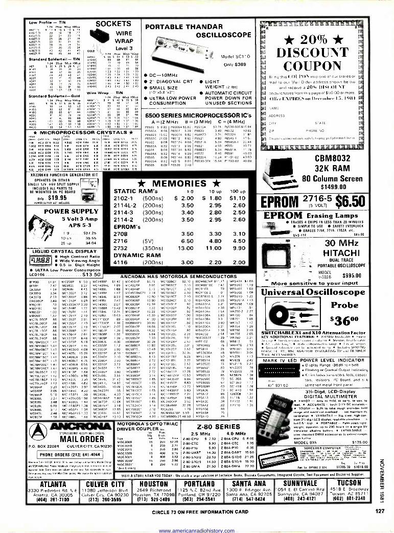
Low Profile - TIN 124 25up 604p 10040
4821 -TI 1 I7 $ 16 5 15 S. 11
0142T.T 4162T -T
20 22
19 21
18 20
17 19
418ZT-T 42021.T
29 33
28 32
27 31
26 30
42221.1 42421.1
36 37
35 36
34 35
33 34
42621.1 440,-T
43 46
42 45
41
44 40 43
Standard Soldertail- TIN 1.24 2546 504010040
491 4141
S 30 36
S 29 35
S 28 34
S 27 33
016T 0181
38 44
37 43
36 42
35 41
422T 72 71 70 69 4247 4281
52 78
51 77
50 76
49 75
4367 4407
83 108
82 107
81 106
80 105
Standard Soldertail-Gold 124 25up 5040 1O0up
09G $ 38 5 37 S 36 t 35 014G 416G
55 83
54 62
53 61
52 80
022G 81 80 79 78 424G 4.280
91 101
90 100
89 99
88 98
436G 1 41 140 139 138 440G 155 154 153 152
SOCKETS WIRE WRAP
401.11 Level Level 3
1.24 25,p Soup 100up ABWG S 55 S 54 5 53 $ 52 A,OWG 69 68 67 66
69 68 71 70 99 98 2, 120
016WG 418WG A20WG 022WG 024WG 028WG 036 WG A40WG
73 72 101 100 123 122 135 134 143 142 183 182 195 194 243 242
73 , 3] ,40
81 1 80 93 1 92 41 240
Wire Wrap - TIN 1-24 215up 404410044
4.8WT-TI S 41 S 40 S 39 S 38 014WT.T 59 58 57 56 016WT-1 63 62 61 60 018W1 -T 87 66 65 64 A20W1.T 91 90 89 88 022WT-T 99 98 97 96 024W1-1 I 09 108 107 106 428WT-1 139 138 137 136
16316216711 161 160 440WT.T ' 89 7 89 ' 81 1 86
PORTABLE THANDAR OSCILLOSCOPE
g
DC-10MHz 2" DIAGONAL CRT
SMALL SIZE (10".5.8"o2")
ULTRA LOW POWER CONSUMPTION
Model SC110
Only $369
LIGHT WEIGHT (2 IDS)
AUTOMATIC CIRCUIT POWER DOWN FOR UNUSED SECTIONS
* MICROPROCESSOR CRYSTALS * MHn c
C
Mia Il 6 I
Mnal 6 100 9011 CHA 51.N 41662 11011 MA 610016.00 8418 011511 1.76
1.132 9433 COIS 8.50 6.80 11618 MA 690 II.00 11C18 CYI/A 4.16
200 11033 MA 1.26 5.061 NCII 4650 600 11432 11018 CY116 4.15
24570 11011 CY30 1.26 6.711 8411 0064 600 11.6601 11C1 0118 4.16
1.2761 9033 CY11 1.00 6.00 0011 C111 /00 1.00 NCII 01224 6.26
3.571 11C31 0710 6.00 6144 8011 MC 8.00 21.11 0411 CY238 6.25
400 11010 MA 600 800 5011 41110 6.00 21.00 9011 C1274 1.16
4434 NCII CY4C 640 NCII CYI2A 32.00 NC11
2.04 132A /.16
455 MCII CY45 600 143ó118 8018 C7144 44 17: 10000 XCIB CYINA 1.16
XR2206KB FUNCTION GENERATOR KIT
OPERATES ON EITHER. - l SINGLE 12V í6V SPLIT SUPPLY
INCLUDES ALL PARTS TO BE MOUNTED ON PC BOARD 177j
iß(1 Only . $19.95 PO WfR SUPPLY NOT INCLUDED
POWER SUPPLY 5 Volt 3 Amp
APS 5-3 1-9 .... $37.25
10 up 35.55 25 up 34.04
LIQUID CRYSTAL DISPLAY
, - ee High Contrast Ratio Wide Viewing Angle 0.5 in. Digit Height
ULTRA Low Power Consumption LCD106 $13.50
6500 SERIES MICROPROCESSOR IC's A =(2 MHz) B =(3 MHz) C =(4 MHz)
P6502 $ 8.82 P65064 $8.82 P65204 53.74 P6530-005 515.84 P65020 9.66 P6507 8.09 P6820 P65028 15.02 P65070 8.82 P88820 P6502C 21.00 P6512 8.82 P6521 P6503 8.09 P65120 9.86 P65214 P65030 8.82 P6513 8.09 P6821 P6504 8.09 P65134 8.82 P68621 P65044 8.82 P6514 8.09 P6522 8.40 P6505 8.09 P65140 8.82 P65224. 11.24 P65050 8.82 P6515 8.09 P6530-004 15.84 P6506 809 P6520 3.40
3.40 3.74 4.90 5.34 4.90 5.34
P6532 P6532Á P6545.1 P65450-1 P6551 P6551Á P6591 P1791-02 P1793-02
10.82 11.87 17.51 22.44 10.71 11 76 40.00 40.00 40.00
* MEMORIES * STATIC RAM's 1-9 10 up loo up
2102-1 (500ns) $ 2.00 $ 1.80 $1.10 2114L-2 (200ns) 3.50 2.95 2.60 2114-3 (300ns) 3.40 2.80 2.50 2114-2 (200ns) 3.50 2.95 2.60 EPROM's 2708 3.50 3.30 2716 (5V) 6.50 4.80 2732 (350ns) 13.00 11.00 DYNAMIC RAM 4116 (200ns) 3.00 2.20 2.00
3.10 4.50 9.90
ANCRONA HAS [MOTOROLA SEMICONDUCTORS 13F890 $1.91 MC858P $1.50 MC1488P $1.47 MC4024P $5 15 MC7906CT $2.10 MCM6674P 511 17 MPSH34 $1 00
BFR91 2.42 MC862L 2.27 MC1489AL 1.89 MC4026P 3.05 MC7908CT 2.10 MCM6810C 7.47 MPSUO3 1.19
CA3054 1.54 MC9581 443 MC1489L 1.68 MC4044P 5.75 MC7912CT 2.10 MC8103 .79 MPSUO5 1.00
CA3059 3.34 MCI 302P 3.72 MC1489P 1.47 MC4558NCP1 3.18 MC7915CT 2.10 MC8106-2 1.01 MPSUO6 1.09
C03079 2.23 MC7309P 2.86 MC1494L 8.53 MC6800P 13.90 MC7918CT 2.10 MCR3918-8 7.74 MPSU10 1.23
oAC08CP 3.49 MC1310P 6.29 MC1495L 7.47 MC6808P 13.90 MC7924CT 2.10 MDA100A 205 MPSU51A 1.13
M80101 .73 MC133001P2.20 MC1496G 2.07 MC6809P 45.39 MC10101 P .92 MDA10/0 2.21 MPSU56 1.09
M80102 .88 MC1349P 1.72 MC1568R 13.42 MC6821P 7.33 MC10102P .92 MDA1020 2.38 MPU131 91
M80201 1.03 MC1350P 1.44 MC15941. 12.74 MC6840P 12.22 MC10104P .92 .44041040 2.54 MR250-2 2.27
M80501 1,57 MC1351P 2.10 MC15951. 10.63 MC6844P 45.39 MC10107P 1.00 MDA1060 2.83 MR750 .84
MC78L05CP .66 MC1352P 2.01 MC1710CP .89 MC6845P 41,20 MC10109P .92 MDA1080 3.31 MR751 1.06
MC78L08CP .66 MC1355P 2.10 MC1733CP 1.30 MC6846P1 39.90 MC10115P .92 MDA110A 3.80 MR752 1.12
MC78L12CP .66 MCI 357P 2.19 MC1776CP1 2.07 MC6847P 16.06 MC10116L 1.10 MDA2004 2.21 MR754 1.26 MC78L75CP .66 MC1358P 1.91 MC1807P 1.36 MC6350L 14.32 MC10116P .92 MD02014 2.38 MR756 2.10
MC78L18CP .66 MC1364P 201 MC1808P 1.36 MC6850P 6.84 MC10123L 2.39 M00202 2.54 MR758 2.65
MC78L24CP .66 MC1372P 6.48 MC1809P 1.36 MC6852P 7.33 MC10124L 3.01 M3E30557 1.29 MR760 321
MC78M05CT 1.47 MC1373P 5.19 MC3062L 4.00 MC6854P 32.26 MC10124P 2.52 MPF102 .66 MR812 51
MC78M06CT 1.47 MC1391P 1.44 MC3302P 1.12 MC6860P 12.92 MC10125L 3.01 MPN3402 .76 MRF476 2.93
MC78M08CT 1.47 MC1403UD 4.08 MC3303P 5.80 MC6875L 13.49 MC10125P 2.52 MPS918 1.28 MRF901 3.15
MC78M12CT 147 MC14051. 15.28 MC3325P 2.10 MC6881 P 8.91 MC10137L 32.36 MPS36384 .48 MRF911 3.04
MC78M15CT 1.47 MC140816 3.84 MC3340P 2.10 MC6882AL 6.13 MC10176P 6.26 MPS3704 .50 MV209 1.13
MC78M18CT 1.47 MC1408L7 4.75 MC3360P 3.50 MC6885P 2.72 MC10189L 3.27 MP56514 .68 MV839 2.42
MC78M2OCT 1.47 MC1408L8 6.55 MC3370P 3.72 MC6886P 2.72 MC10195L 2.52 MPS6520 .72 MV2115 2.21
MC78M24CT 1.47 MC1408P8 4.40 MC3403P 1.77 MC6887P 2.72 MC10216L 1.83 MP56521 .83 MV2205 .78
MC79L05CP 1.12 MC1413P 1.68 MC3405P 3.60 MC6888P 2.72 MC14411P 17.26 MPS6522 76 MV2209 78
MC79L12CP 1,12 MC1436CU 4.96 MC3408L 3.55 MC6889P 3.14 MC14412VP 15.53 MPS6523 85 NE592N 198 MC79L15CP 1.12 MC1437L 3.99 MC34161. 31.42 MC7805CT 1.65 MC14435VP 8.64 MP56566 .73 SC1368 .98
MC79L24CP 1.12 MC1439L 4.62 MC34171. 14.83 MC7808CT 1.65 MC14457P 6.60 MP58099 .57 SC1360 1.17
MC664P 3.20 MC1439P1 3.97 MC3420L 10.08 MC7812CK 3,14 MC14458P 13.73 MPS8599 .60 SC1418 1.76
MC680P 2.05 MC1445G 4.20 MC3423P1 1.66 MC7812CT 1.65 MC14490FP 5.60 iAPS006 .73 SC1410 1.98
MC684P 5.10 MC1455P1 .99 MC3438L 4.33 MC7815CK 3.14 MC14490VP 424 MPS012 .85 728000 1.91
MC830L 2.27 MC14550051.98 MC3448AP 5.80 MC7815CT 1.65 MC14495P 3.96 MPSA13 .65 TIL116 1.32
MC835L 2.46 MC1458CL 1.44 MC3470P 12.64 MC7818CT 1.65 MC34004P 3.52 MPSA20 .38 TIP102 191
MC839L 5.88 MC1458CP1 1.08 MC3476P1 3.18 MC7824CK 3.14 MC68488P 32.26 MPSA42 .82 TIP110 1 36
MC848L 3.17 MC1458P1 108 MC3480P 12.85 MC7902CT 2.10 MCA255 1.76 MP5456 .88 MC847L 2.46 MC1458P1S 1-33 MC3503L 18.62 MC7905CT 2.10 MCM68410P 5.59 MPSA64 75
MC857P 1.50 MC1488L 1.68 MC4016P 10.10 MC7906CK 4.20 MCM6666L25 46 50 MPSA70 44
ANCFICINA STORES 00 NOT ACCEPT MAIL 000E PS
MAIL ORDER P.O. BOX 22080 CULVER CITY, CA 90230
PHONE ORDERS (213) 641-4064
Mwmum Orde 510 00 Add 67 0010 cove panne and handing Mann Ciarpe
and VISA we6omed Please en4Nde vow 4he0e 4ed number nler9e4 wm0e, and
naden dale Some rmmº aie sober, lo pea sale Not usponsele ic, Inds
Stole dens nun vary Own Mel Orde poeto We reserve Ile 11301 lo suOETTIII
manuh4rme
MOTOROLA'S OPTO TRIAC DRIVER COUPLER ru,n
p Peak 9 Block
voma lts Price
15 250 82.20 8 250 2.71 5 250 2.86
15 400 3.15 8 400 3.52
15 2.50 396 8 260 522
Type
MOC3009 MOC3010 MOC3011 MOC3020 MOC3021 MOC3030- MOC3031- -24ru Crp4nn9
Z-80 SERIES 2.5 MHz
Z -80 -CPU S 7.10 Z-80-CTC 5.90 Z -80-P10 5.90 Z -80 -DART 14.30 Z -80-S10/0 20.10 Z-80-010/9 14.50 Z -60 -DMA 21.50
4.0 MHz 2 -800 -CPU $ 8.05 Z-80A-CTC 6.35 Z -80A -P10 6.35 Z -80A -DART 15.50 Z -80A -S10/0 21.25 Z-804-510/9 15.70 Z -80A -DMA 22.70
I mí111 tiá4Dt 410;tí
* 20% * DISCOUNT
COUPON Bring this (AM PO\ Into one of our stores or
mail to our Mail Order address shown below and receive a 20% I)IK(A)1 VI'
on purchases from this page of $50.00 or more.
Offer EXPIRES on l)eeetnbcr 15. 1981
NAME
ADDRESS
CITY
ZIP
STATE
PHONE NO
Coupons accepted only with lull name and address filled in 1!
CBM8032 32K RAM
m 80 Column Screen vonso $1499.00
EPROM 2751,6-5 $6.50
EPROM Erasing Lamps ERASES 4 CHIPS IN LESS THAN 20 MINUTES
SIMPLE TO USE SAFETY INTERLOCK
ERASES 2708. 2716. 17024, etc.
UVS-11E. 585.00
s
in 30 MHz HITACHI
DUAL TRACE
o - PORTABLE OSCILLOSCOPE
- MODEL _ V-3028 $995.00
More sensitive to your input
Universal Oscilloscope Probe
$3600
V
SWITCHABLE Xl and X10 Attenuation Factor KEY ADDITIONAL FEATURES: I1IIIMII, handuidih Heat* duly up Break rl 818 to "ndut nI Slender. llesihle cable
6h. able length I Wide a Ingerange EilS all 5'11310
Grand refer i hr 11 altip Ilk üide5 SPRUNG HOOK. I TIP. HNC1 ADAPTS OR INS( EATING TIP and TRIMMER 1(811 AC CESSIIHII.S
MARK IV LED POWER LEVEL INDICATOR Display Range -36d6 to+5dB Floating or Gradual Output Indicating Kit includes transistors, leds, capaci- tors. resistors, PC Board, and silk
KIT $31.50 screened metal front panel
31/2 -Digit, LCD-Display DIGITAL MULTIMETER
HANDY - easy to hold. to terry, to use, to eed. ACCURATE - basic 0.1% DC accuracy -
TOUGH - built to take rough everyday field usage and electrical overload . yet maintain no
calibration VERSATILE - big. char. high con- 1s13`/e-digit LCD display, readable anywhere full 0.51' PORTABLE - Palm -nixed. light - " weight operates up to 200 hours one single 9V transistor alkaline battery. EXPANDABLE - uses standard DMM accessories to extend ranges
van further
MODEL 935 .. $175 00
SORCERER COMPUTER *
RPM - 32xaRAMyr FEATUSRE d ? 0.1
r,on m s iw Bus w:m 4.áw4 uo FOp' Card conrr..
6149 Our Pone
Pan No 01E1002 2 321( 51395.00 51016.00
VISIT A STORE NEAR YOU TODAY We stock a large selection of Technical Books, Discrete Component , Integrated Circuits. Test Equipment and Elec runic Supplies
ATLANTA 3330 Piedmont Rd. N.E
Atlanta. GA 30305 1404) 261.7100
CULVER CITY 11080 Jefferson Blvd. Culver Clty, CA 90230
(213) 390-3595
HOUSTON 2649 Richmond
Houston, TX 77098 (713) 529-3489
PORTLAND 1125 N . 82nd Ave Portland, OR 97220
(503) 254-5541
SANTA ANA 1300 E. Edinger Ave. Santa Ana, CA 92705
(714) 547-8424
SUNNYVALE 1054 E. El Camino Real Sunnyvale, CA 94087
(408) 243-4121
TUCSON 4518 E Broadway Tucson. AZ 85711
(602) 881-2348
CIRCLE 73 ON FREE INFORMATION CARD
www.americanradiohistory.com
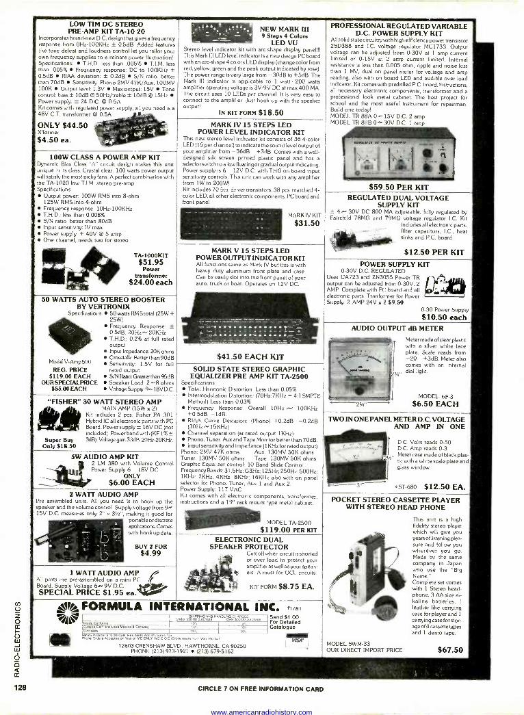
le FORMULA INTERNATIONAL INC. Send $1.00 For Detailed Catalogue
11/81
VISI
50 WATTS AUTO STEREO BOOSTER BY VERTRONIX
Specifications: 50 watts RMS total (25W+ 25W) Frequency Response: ± 0.5dB, 20Hz",20KHz T.H.D.: 0.2% at full rated output Input Impedance: 20K ohms Crosstalk: Better than 90dB Sensitivity: 1.5V for full
REG. PRICE rated output $119.00 EACH S/N Ratio: Greater than 95dB
OUR SPECIALPRICE Speaker Load: 2 ^-8 ohms $55.00 EACH Voltage Supply:918VD.C.
"FISHER" 30 WATT STEREO AMP le*MAIN AMP (15W x 2)
Kit includes 2 pcs. Fisher PA 301 Hybrid IC all electronic parts with PC Board. Power supply ± 16V DC (not included). Power band with (KF 1% ±
Super Buy 3dB). Voltage gain 33dB. 20Hz-20KHz. Only $18.50
5W AUDIO AMP KIT 2 LM 380 with Volume Control Power Supply 6 18V DC
ONLY $6.00 EACH
2 WATT AUDIO AMP Pre assembled units. All you need is to hook up the speaker and the volume control. Supply voltage from 15V D.C. measures only 2" x 31/2", making it good for
portable or discrete applications. Comes with hook up data
BUY 2 FOR $4.99
MARK V 15 STEPS LED POWER OUTPUT INDICATOR KIT All functions same as Mark IV but this is with heavy duty aluminum front plate and case. Can be easily slot into the front panel of your auto, truck or boat. Operates on 12V DC.
$41.50 EACH KIT
SOLID STATE STEREO GRAPHIC EQUALIZER PRE AMP KIT TA -2500
Specifications: Total Harmonic Distortion: Less than 0.05% Intermodulation Distortion: (70Hz:7KHz = 4:1 SMPfE Method) Less than 0.03% Frequency Response: Overall 10Hz N 100KHz +0.5dB, -1dB. RIAA Curve Deviation: (Phono) +0.2dB, -0.2dB (30Hz N 15KHz) Channel separation (at rated output 1KHz) Phono, Tuner. Aux and Tape Monitor better than 70dB. Input sensitivity and impedance (1KHz for rated output)
Phono: 2MV 47K ohms Aux: 130MV 50K ohms Tuner 130MV 50K ohms Tape: 130MV 50K ohms Graphic Equalizer control: 10 Band Slide Control Frequency Bands: 31.5Hz; G3Hz; 125Hz; 250Hz; 500Hz: 1KHz; 2KHz; 4KHz; 8KHz; 16KHz also with on panel selector for Phono, Tuner, Aux 1 and Aux 2. Power Supply: 117 VAC Kit comes with all electronic components, transformer. instructions and a 19" rack mount type metal cabinet.
MODEL TA -2500 $119.00 PER KIT
1 WATT AUDIO AMP 72 All parts are pre -assembled on a mini PC C Board. Supply Voltage 60.9V D.C.
SPECIAL PRICE $1.95 ea.
ELECTRONIC DUAL SPEAKER PROTECTOR
Cutt off when circuit is shorted or over load to protect your amplifieras well as your speak- ers. A must for OCL circuits.
KIT FORM $8.75 EA.
443 anva cGdom,a
rvde ceM {,roroese..co-a-c- d.l o.eraa
LOW TIM DC STEREO PRE -AMP KIT TA -10 20
Incorporates brand-new D.C. design that gives a frequency response from 0Hz-100KHz ± 0.5dB! Added features like tone defeat and loudness control let you tailor your own frequency supplies to eliminate power fluctuation! Specifications: T.H.D. less than .005% T.I.M. less than .005% Frequency response: DC to 100KHz ± 0.5dB RIM deviation: ± 0.2dB S/N ratio: better than 70dB Sensitivity: Phono 2MV 47K/Aux. 100MV 100K Output level: 1.3V Max output: 15V Tone control: bass ± 10dB @ 50Hz/treble ± 10dB @ 15Hz Power supply: ± 24 D.C. @ 0.5A Kit comes with regulated power supply, all you need is a
48V C.T. transformer @ 0.5A.
ONLY $44.50 X'former
$4.50 ea.
NEW MARK III 9 Steps 4 Colors
LED VU Stereo level indicator kit with arc -shape display panel!!! This Mark III LED level indicator is a new design PC board with an arc -shape 4 colors LED display (change colorfrom red, yellow, green and the peak output indicated by rose). The power range is very large from -30dB to +5dB. The Mark III indicator is applicable to 1 watt - 200 watts amplifier operating voltage is 3V -9V DC at max 400 MA. The circuit uses 10 LEDs per channel. It is very easy to connect to the amplifier. Just hook up with the speaker output!
IN KIT FORM $18.50
100W CLASS A POWER AMP KIT Dynamic Bias Class "A" circuit design makes this unit unique in its class. Crystal clear, 100 watts power output will satisfy the most picky fans. A perfect combination with the TA -1020 low T.I.M. stereo pre -amp. Specifications:
Output power: 100W RMS into 8 -ohm 125W RMS into 4 -ohm Frequency response: 10Hz-100KHz T.H.D.: less than 0.008% S/N ratio: better than 80dB Input sensitivity: IV max. Power supply: ± 40V @ 5 amp One channel, needs two for stereo
TA-1000KIT $51.95
Power transformer
$24.00 each
MARK IV 15 STEPS LED POWER LEVEL INDICATOR KIT
This new stereo level indicator kit consists of 36 4 -color LED (15 per channel) to indicate the sound level output of your amplifier from -36dB +3dB. Comes with a well - designed silk screen printed plastic panel and has a selector switch to allow floating or gradual output indicating. Power supply Is 6 12V D.C. with THG on board input sensitivity controls. This unit can work with any amplifier from 1W to 200W! Kit includes 70 fits. driver transistors, 38 pcs. matched 4 - color LED, all other electronic components, PC board and front panel.
MARK IV KIT
$31.50
Model V -Amp 500
led, e so " WPN HNDOeHeRow rcae t0'. is. 25%
s-. Ip.
20% M,nanum Order Ere 00/Ceel Res,dema Add 5. Salen Ta. Pooe Orders Acoe01,0 on 0, e o, Mc ONLY, No c o o,Sto,e Ibu,e r0.7 Mon ew Sal
12603 CRENSHAW BLVD., HAWTHORNE, CA 90250 PHONE: (213) 973-1921 (213) 679-5162
CIRCLE 7 ON FREE INFORMATION CARD
PROFESSIONAL REGULATED VARIABLE D.C. POWER SUPPLY KIT
All solid state circuitry with high efficiency power transistor 2SD388 and I.C. voltage regulator MC1733. Output voltage can be adjusted from 0.30V at 1 amp current limited or 0.15V at 2 amp current limited. Internal resistance is less than 0.005 ohm; ripple and noise less than 1 MV, dual on panel meter for voltage and amp reading, also with on board LED and audible over load indicator. Kit comes with predrilled P.C. board, instructions. all necessary electronic components, transformer and a professional look metal cabinet. The best project for school and the most useful instrument for repairman. Build one today! MODEL TR 88A 0 - 15V D.C. 2 amp MODEL TR 88B 0. 30V D.C. 1 amp
$59.50 PER KIT REGULATED DUAL VOLTAGE
SUPPLY KIT ± 4 30V DC 800 MA adjustable, fully regulated by Fairchild 78MG and 79MG voltage regulator I.C. Kit
includes all electronic parts, filter capacitors, I.C., heat sinks and P.C. board.
$12.50 PER KIT
POWER SUPPLY KIT 0-30V D.C. REGULATED
Uses UA723 and ZN3055 Power TR output can be adjusted from 0.30V, 2 AMP. Complete with PC board and all electronic parts. Tranformer for Power Supply. 2 AMP 24V x 2 $9.50
0-30 Power Supply
$10.50 each AUDIO OUTPUT dB METER
Meter made of clear plastic with a silver white face plate. Scale reads from -20 +3dB. Meter also comes with an internal
, dial light.
MODEL 6F-3
$6.50 EACH
TWO IN ONE PANEL METER D.C. VOLTAGE AND AMP IN ONE
D.C. Volts reads 0-50 D.C. Amp reads 0-3
, Meter case made of black plas- tic with a white scale plate and glass window.
#ST -680 $12.50 EA.
POCKET STEREO CASSETTE PLAYER WITH STEREO HEAD PHONE
This unit is a high fidelity stereo player which will give you years of listening plea- sure and follow you wherever you go. Made by the same company in Japan who use the "Big Name." Complete set comes with 1 Stereo head- phone, 3 AA size al- kaline batteries, I
leather like carrying case for player and 1
carrying case for stor- age of 4 cassette tapes and 1 demo tape.
MODEL SWM-33 OUR DIRECT IMPORT PRICE $67.50
www.americanradiohistory.com
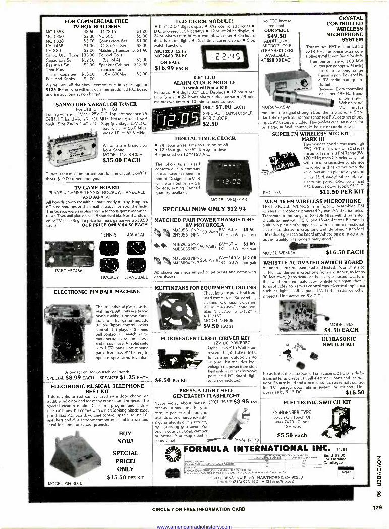
FOR COMMERCIAL FREE TV BOX BUILDERS
MC 1358 $2.50 LM 7815 $1.20 MC 1350 $2.00 NE 565 $2.00 MC 1330 $3.00 Connectors Set $1.00 1M 1458 $1.00 I.C. Socket Set $2.00 LM 380 $2.00 Matching Transformer $1.40 Sanyo UHF Tuner $35.00 Tolriod Coils Capacitors Set $12.50 (Set of 4) $3.00 Resistors Set $2.00 Speaker Cabinet $12.95 Trim Pots; Transformer
Trim Caps Set $13.50 18V 800MA $3.00 Pots and Knobs $2.00
We sell you all the above components in a package for $125.00 and you will receive a free predrilled P.C. board and instructions at no charge!
SANYO UHF VARACTOR TUNER For UHF CH 14 83
Tuning voltage +1V -+28V D.C. Input impedance 75 OHM. I.F. band width 7 ~16 MHz. Noise figure 11.5dB MAX. Size 2%" x 1'/s" a 3". Supply voltage 15V D.C.
Sound I.F. = 58.0 MHz. Video I.F. = 62.5 MHz.
/ =e44
I.--..
All units are brand new from Sanyo. MODEL 115 -B -405A
$35.00 EACH
Tuner is the most important part for the circuit. Don't let
those $19.00 tuners fool you!
TV GAME BOARD PLAYS 4 GAMES: TENNIS; HOCKEY; HANDBALL
AND JAI -ALAI. All boards complete with all parts ready to play. Requires 6C size batteries and a small speaker for sound effects. The boards were surplus from a famous game manufac- turer. They will play on all US standard black and white or color TV sets. (Regular price for these games were $39.50 each) OUR PRICE ONLY $6.50 EACH
PART e57456
TENNIS JAI -ALAI
HU('KiX HANDBALL
ELECTRONIC PIN BALL MACHINE
That sounds and plays like the real thing. All units are brand new but without the case. Func- tions of the game include double flipper control. kicker control, 1-4 players, 3 speed ball control, tilt switch, auto- matic score, extra bonus cave and many more. All solid state with LED panel, no moving parts. Requires 9V battery to operate, speaker not included.
A perfect gift for yourself or friends.
SPECIAL $8.99 EACH SPEAKER $1.25 EACH
ELECTRONIC MUSICAL TELEPHONE REST KIT
This telephone rest can be used as a door charm, an audible indicator and for many other sound projects. The special custom made I.C. is pre programmed with 4 musical tunes. Kit comes with a nice looking plastic case,
pre -drilled P.C. board, volume control, special sound I.C.
speakers and all electronic components and instructions. Ideal for home or school projects.
BUY
NOW!
SPECIAL PRICE! ONLY
$15.50 PFR RI
6.50 Per Kit
LCD CLOCK MODULE! 0.5" LCD 4 digits display X'tal controlled circuits
DC. powered (1.5V battery) 12 hr. or 24 hr. display 24 hr. alarm set 60 min. countdown timer On board dual back-up lights Dual time zone display Stop watch function.
NIC1200 (12 hr) MC2400 (24 hr)
ON SALE $16.99 EACH
0.5" LED ALARM CLOCK MODULE
Assembled! Not a Kit Features: 4 digits 0.5" LED Displays 12 hours real time format 24 hours alarm audio output 59 min. countdown timer 10 min. snooze control.
ONLY $7.00 EACH
SPECIAL TRANSFORMER FOR CLOCK
$2.50
No FCC license required.
OUR PRICE $49.50
ADDITIONAL MICROPHONE
(TRANSMITTER) AVAILABLE
AT $28.00 EACH
CRYSTAL CONTROLLED
WIRELESS MICROPHONE
SYSTEM Transmitter: FET mic for flat 30 ..018 KHz response extra con- trolled 49MHz AM Band for drift -
free performance. 100 MW output (range approx. %mile)
for reliable long range transmission. Powered by a 9V radio battery (in- cluded). Receiver. Extra controlled locks on 49MHz trans-
mitter signal. With on panel
MURA WMS-49 VU meter monitors the signal strength from the microphone. Stan- dard phone jack outlet connection to a P.A. or other phone input. 9V battery included. This professional set is ideal for on stage, in field, church, in house or outdoor use.
DIGITAL TIMER/CLOCK 24 Hour preset time to turn on or off 12 Hour green 0.5" display for time operated on 12^'16V A.C.
The whole timer is self contained in a compact plastic case (as seen in photo). Designed for VTR with push button switch for easy setting. Limited quantity available.
MODEL VEQ 0143
SPECIAL! NOW ONLY $12.94
SUPER FM WIRELESS MIC KIT - MARK III This new designed circuit uses high FEQ. FET transistors with 2 stages
pre amp. Transmits FM Range (88- 120 MHz) up to 2 blocks away and with the ultra sensitive condensor microphone that comes with the kit, allows you to pick up any sound within 15 ft. away! Kit includes all electronic parts, OSC coils, and P.C. Board. Power supply 9V D.C.
FMC -105 $11.50 PER KIT
MATCHED PAIR POWER TRANSISTORS BY MOTOROLA
MJ2955 PNP 150 WattsBV=60 V $3.50 4 4 2N3055 NPN I.C.=15 A per pair
MJE2955 PNP 90Watts BV=60 V
MJE3055 NPN I.C.=10 A $3.00
per pair
MJ15003 NPN 250 WattsBV=140 V $12.00 MJ15004 PNP 1.C.=20 A per pair
All above parts guaranteed to be prime and come with data sheets.
WEM -36 FM WIRELESS MICROPHONE TEET MODEL WEM -36 is a factory assembled FM wireless microphone powered by two AA size batteries. Transmits in the range of 88-108 MHz with 3 transistor circuits to meet with F.C.C. part 15 regulations. Element is
built In a plastic tube type case with an omni-directional electret condenser microphone unit. By using a standard FM radio, signal can be heard anywhere on a one -acre lot. Sound quality was judged "very good."
MODEL WEM -36 $16.50 EACH
MUFFIN FANS FOR EQUIPMENT COOLING These fans are pulled out from used computers. But carefully cleaned by ultrasonic cleaner. All in "like -new" condition. Size 4 11/16" x 1-1/2" x
4 11/16". MODEL MF505
$9.50 EACH
FLUORESCENT LIGHT DRIVER KIT 12V DC POWERED
Lights up 8x'15 Watt Fluo- rescent Light Tubes. Ideal for camper, outdoor, auto or boat. Kit includes high voltage coil, power transistor, heat sink, all other electronic parts and PC Board, light tube not included!
PRESS -A -LIGHT SELF GENERATED FLASHLIGHT
Never worry about battery, EXCLUSIVE!$3.95 ea. because it has none! Easy to carry in pocket and handy to use. Ideal for emergency light. It generates its own electricity by squeezing grip lever. Put one in your car, boat, camper or home. You may need it some time! Model F-179
WHISTLE ACTIVATED SWITCH BOARD All boards are pre -assembled and tested. Your whistle to its FET condenser microphone from a distance, as far as
30 feet away (sensitivity can be easily adjusted) will turn the switch on, then match your whistle to it again, then it
turns off. Ideal for remote control toys, electrical appliance such as lights, coffee pots, TV, Hi-Fi, radio or other projects. Unit works on 9V D.C.
MODEL 968
$4.50 EACH
ULTRASONIC SWITCH KIT
Kit includes the Ultra Sonic Transducers, 2 PC Boards for transmitter and receiver. All electronic parts and instruc- tions. Easy to build and a lot of uses such as remote control for TV, garage door, alarm system or counter. Unit operates by 9-12 DC. $15.50
ELECTRONIC SWITCH KIT
CONDENSER TYPE Touch On Touch Off
uses 7473 I.C. and 12V relay
$5.50 each
% FORMULA INTERNATIONAL INC. 11/81
onde, sóáó cnµsaeD CASD4rGeçe Send $1.00
All ,.e e/O tms se For Detailed OuvdC e cad en,, ded ate. a.-z dai ts% ton Catalogue
20, ® Minimum O,de, 510.00/tali) ResIdents Add 6't Sale. T a
mon O,de,s Accepted on Visa 0, MC ONLY. NO C.0.0/Store Nw,s t0 r MM dru Set
12603 CRENSHAW BLVD., HAWTHORNE, CA 90250 PHONE: (213) 973-1921 (213) 679-5162
aera
VISA
25,
CIRCLE 7 ON FREE INFORMATION CARD
www.americanradiohistory.com
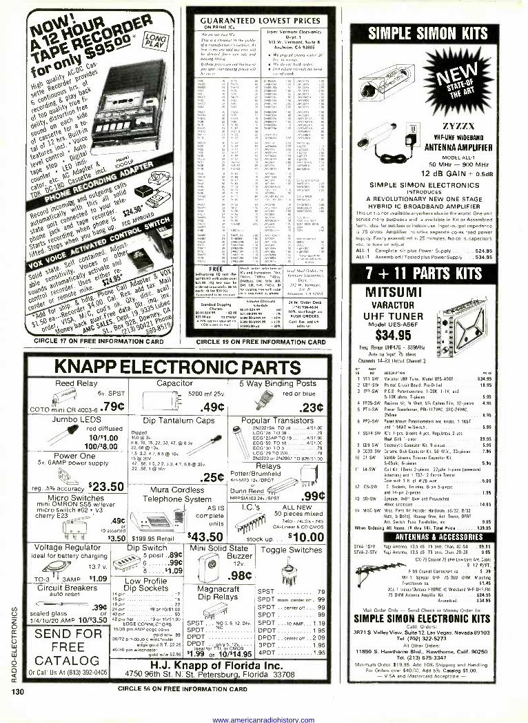
CIRCLE 17 ON FREE INFORMATION CARD
GUARANTEED LOWEST PRICES ON PRIME ICs
We do nor buy lCs.
This is u closeout ro the publie n/ a monufatrurer's surplus. As line items are sold saur they will be deleted from our ads and catalog listing.
lJ these prices are not the lowest u spot. our r slog prices will
hr hml r.
7171
7476
492
7,4692
7110
745.0
35
30 74111
74.137
7440 71161
Ir 1442
I' 450 74165
74.
745760
oo
74564 24 DAIMON
C112; g'1'4
09113200.4
36 091.21061 DAM
74673 211 047823019
06.811.6,4 00
FREE Sell woring IQ test [Re- tail $9.951 with order over 525.00. (IQ test may be ordered separately: $6.95 each: la lee SMOS) Guuanlesd ro M accrale
Standard Shipping Ch
w.01.s24.99 ss2.oa 52500 up no charge
Mt demur required en COO orders by mail
from: Vermont Electronics Dept. 3
312 W. Vermont, Suite B
Anaheim, CA 92805
We ship all orders within 14 hr, of receipt.
f We do not bark order. * Immediate !funds on item
orsI of -work
014661.934
01.160,0.4
glZggeldgN 00 00
BO
139483. 06.80332.4
1,11111.1 1.3.1.70470.1
677,3.071
,3091,
1.43171.1
6943209 529 10
66,3229 90
1.3y 1130 2.13 10
1.34331.1
.3.3763
1,555CM .1
.1656. 61.0031.717.
355
6 55
22
95
Much wider selectioncl ICs and tramisto,, rase, )alas, 7511aa, >aSm DMhaa, LM. MM, AH, DH. LH, NH. ]aC au. SI
I11 Pee ...order ,t requested by phone.
Volume Discount Schedule
50.0,-la4.99 net S2500s99.99 -S% 5100.00499.99 -10% 5500.065999.99 -1S% 31000.00up -20%
69130706
.417520.4
13.175.013.13
9,92501 115 9.9251.0" 75
.337003 1,4223 990225 1.11.11101661 106,5261319
6,9,92609
071001606
9007 90. 90.6
960,7
9,44106
350
rOg
Send Mail Orders to
Vermont E/ettronirs Dept. .1
.7/2 W. Vermoor. Ste. 9
Anahrtm. CA 92X05
24 hr. Order Desk C714) 9564834
10% surcharge on RUSH ORDERS.
caul Res add We.
sales la..
CIRCLE 19 ON FREE INFORMATION CARD
KNAPP ELECTRONIC PARTS Reed Relay Capacitor 5 Way Binding Posts
/'° red or blue
.23e 6v. SPST
(
I 1
5200 mf 25v.
COTO mini CR 4003-6 .79e .49e Jumbo LEDS
red diffused
100/$8.00
Dip Tantalum Caps Dipped 100 @ 3v. 6.8. 10, 15, 22, 33, 47, @ 6.3v. 22, 68 @ 10v.
Popular Transistors d/51.79
ECG128. TO 39 79 ECG123AP TO 18 4/$1.00 ECG753. TO 18 1/$I.00 ECGI30. TO 3 79 ECG129 TO 220 79 2N2222 or 2N2907 TO 926/$1 00 Power One
5v, 6AMP power supply
1.5, 3.3, 4.7, 6.8 @ 16v. 15 @ 20V. .47. .68, 1.5.2.2, 3.3, 4.7, 6.8 @ 35v. .22, .68.1 @ 50v. "sr
JAY
Relays Potter/Brumfield KH-587012v./DPOT
or Dunn Reed
I I
reg..5%accuracy $23.50 Mura Cordless Micro Switches
mini OMRON SS5 w/lever micro switch 462 + V3
Telephone System .
AS IS
MRRSIA10324v./SPST
I.C.rS ALL NEW 50 pieces mixed
7400 - 74LS's - 74S CA -Linear & CD CMOS
stock up... $10.00
cherry E23 complete 490 , . {
I O \ units o 10 a sorted p
$3.50 $199.95 Retai $43.50 Voltage Regulator
ideal for battery charging
13.7 v.
TO -3 f 13AMP $1.09
i
Dip Switch 5 posit ..894
8 9 6h`j/
Mini Solid ch State Buzzer
12v.
Toggle Switches
:J Low Profile e98C
Circuit Breakers auto reset
Dip Sockets 14 pin
17 16 pin 18
2d 1B ppinin 22
19 or 10/51.00 40 pin 50
42 pin pat 1s or to/stop
EDGE CONNECTORS 15/30 pin AMP edge conn.
golds-. .89 36/72 pin double winchester
edge gold ST. $2.25 40/80 pin winchester
gold w/w5295
Magnacraft Dip y Rela s
SPST ... NO 5, 6, 12. 24v
SPDT NC
DPDT DPDT
forTTY ó5'.ónó.... '
$1.99or 10/$14.95
SPST 79 SPDT mom. center off . 99 SPDT .. center ott... 99 SPDT 99 SPDT ...10 AMP... 1.19 DPDT 195 DPDT .. center off .. 2.09 3PDT 1 95 4PDT 1 95
O r 90
sealed glass or 1/4/1u/20 AMP 10/$3.50
SEND FOR FREE
CATALOG Or Call Us At (813) 392-0406
H.J. Knapp of Florida Inc. 4750 96th St. N. St. Petersburg, Florida 33708
OESCRIR10e
Varactor UHF Tuner. Model UES-A56F
Printed Circuit Board, Pre -Drilled
P.C.B. Potentiometers. I -20K, 1-1K. and
5-10K ohms. 7 -pieces
4 FR35-SW Resistor Kit, 'A Wan, 5% Carbon Film, 32 -pieces... 4.95
5 PT1-SW Power Transformer, PRI-11IVAC, SEC-24VAC,
250ma
8 PP2-SW Patel Mount Potentiometers and Knobs, 1-1KBT and I -SKAT w/Switch
7 SSI4-SW IC's 7-pca, Diodes 4-pcs, Regulators 2-pcs Heat Sink 1 -piece
B CE9-SW Electrolytic Capacitor Kit. 9 -pieces
9 CC33-SW Ceramic Disk Capacitor Kit 50 W.V., 33 -pieces.
10 CT -SW Varible Ceramic Trimmer Capacitor Kit.
5-65pld. 6 -pieces 5 95
Coil Kit, 18mhs 2 -pieces, .22µhs 1 -piece (*.wound inductors) and I T37-12 Ferrite Torrid Core with 3 It of 826 wire
12 ICS -SW I.C. Sockets, Tin inlay, 8 -pin 5 -pieces
and 14 -pin 2 -pieces
13 SR -SW Speaker, 4x6" Oval and Prepunchad
Wood Enclosure
14 MISC-SW Misc. Parts Kit Includes Hardware, (6/32, 8/32 Nuts, B Bolts). Hookup Wire. Ant. Terms, OPOT
Ant. Switch, Fuse, Fuseholder, etc
When Ordering Alll Items, (I thru 14), Total Price
SIMPLE SIMON KITS
I ' ZiZZX VHF -UHF WIDEBAND
ANTENNAAMPIJFIER MODEL ALL -1
50 MHz - 900 MHz
12 dB GAIN ± 0.5dB
SIMPLE SIMON ELECTRONICS INTRODUCES
A REVOLUTIONARY NEW ONE STAGE HYBRID IC BROADBAND AMPLIFIER
This unit is not available anywhere else in the world. One unit serves many purposes and is available in Kit or Assembled form. Ideal for outdoor or indoor use. Input-output impedance is 75 ohms. Amplifier includes separate co -ax feed power supply. Easily assembled in 25 minutes. No coils. capacitors etc. to tune or adjust. ALL -1 Complete Kit plus Power Supply $24.95 ALL -1 Assembled / Tested plus Power Supply $34.95
7 + 11 PARTS KITS
MITSUMI VARACTOR
UHF TUNER Model UES-A56F
$34.95 Frog.
Range UHF470 - 889MHz
Antenna Input 75 ohms
Channels 14-83 Output Channel 3
KIT PART
R0 Re
I V71 -SW
2 CB1-SW
3 TP7-SW
11 14 -SW
ICI
S34 95
1895
595
695
5 95
2995 5 95
7.95
5 00
1 95
14.95
9.95
139.95
ANTENNAS & ACCESSORIES SNA-1STV Yagi Antenna. 13.5 dB. 75 ohm, Chan. 42-54 $9.95 SNA-2-STV Yagi Antenna, 13.5 d8, 75 ohm, Chan. 20-28 .... 9.95
CX-75 Coaxial 75 ohm Low Loss Ant. Cable
rejig/P.' . . 9 .12 P/FT.
F-59 Coaxial Connectors ea ...., . $ .39
M7-1 Special UHF 75-300 OHM Matching
Transformer es $1.45 AIL -1 Indoor/Outdoor HYBRID IC Wideband VHF -UHF -FM 75 OHM Antenna Amplifier Kit $24.95
Assembled 934.95
Mall Order Cnly - Send Check or Money Order Too
SIMPLE SIMON ELECTRONIC KITS Call). Orders
3871 S. Valley View, Suite 12, Las Vegas. Nevada 89103 Tel: (702) 322-5273
All Other Orders: 11850 S. Hawthorne Blvd.. Hawthorne. Calif. 90250
Tel: (213) 675-3347 Minimum Order: $19.95. Add 10% Shipping and Handling.
For Orders over $40.00, Add 5%. Catalog $1.00. - VISA and Mastercard Acceptable - CIRCLE 56 ON FREE INFORMATION CARD
www.americanradiohistory.com
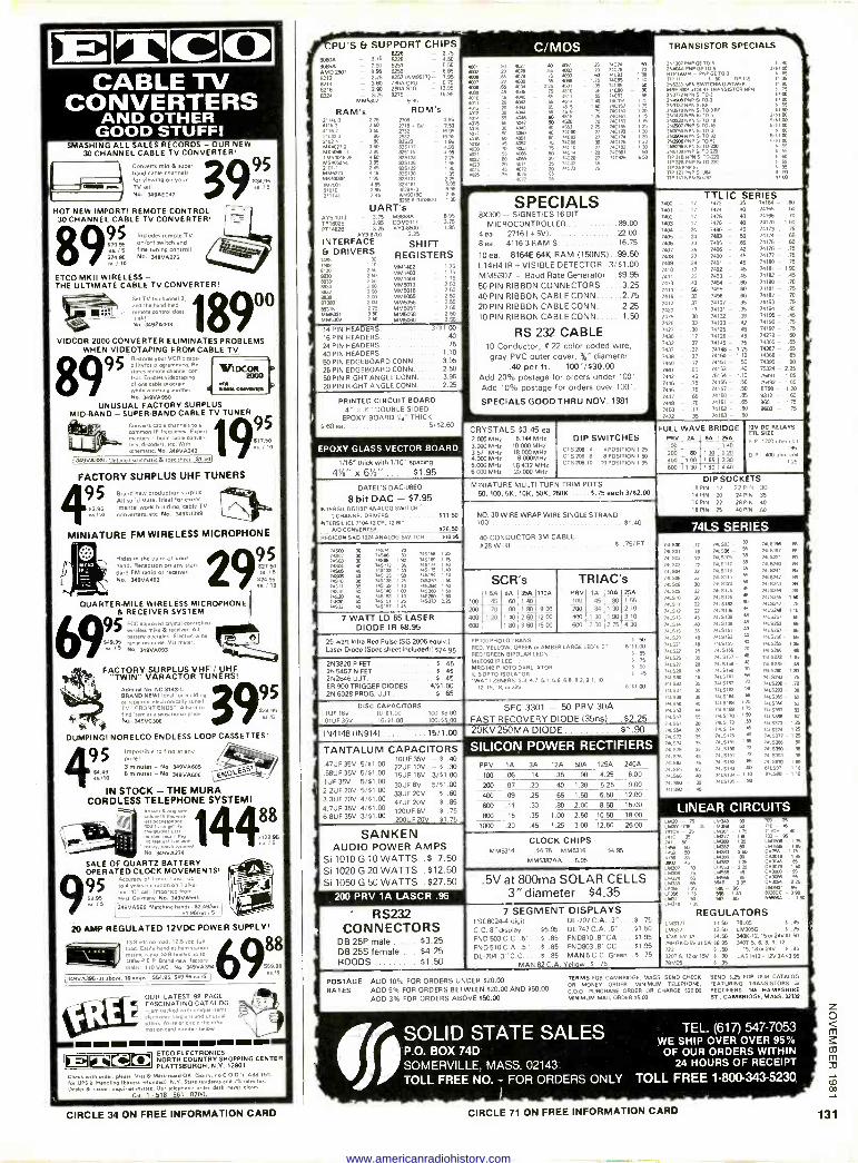
CPU'S Et SUPPORT CHIPS TRANSISTOR SPECIALS C 0 CABLE TV
CONVERTERS AND OTHER
GOOD STUFF! SMASHING ALL SALES RECORDS - OUR NEW
30 CHANNEL CABLE TV CONVERTER'
Converts mid & super band cable channels for viewing on your
aA TV sell No. 3490E047 3995
HOT NEW IMPORT! REMOTE CONTROL 30 CHANNEL CABLE TV CONVERTER!
891
Includes remote TV on/off switch and fine tuning control, No. 349140275
ETCO MKII WIRELESS - THE ULTIMATE CABLE TV CONVERTER,
I S' 111111
es1
8
Set TV to channe, -,
and the hend.heid N control doe,
it alll No. 34920998
VIDCOR 2000 CONVERTER ELIMINATES PROBLEMS WHEN VIDEOTAPING FROM CABLE TV
Rez.o.ez your VCR's cape
stores programmin
channel con vIDCOR roleEnables videotaping
r 200D
off one cable program OCR
ile wetch'irq another. u . Coewealall
No. 3491/4960
UNUSUAL FACTORY SURPLUS MID.BAND - SUPER -BAND CABLE TV TUNER
Converts cable channels to a
common IF frequency. E opera
- build cable conyc, decoders, etc. With
schematic. No. 349V0342
34 9140369, Deta462 schematic & spec sheet. Sí.501
FACTORY SURPLUS UHF TUNERS
95 Brand new production surplus. All solid state. Ideal for eopep
$3.99 mental work building, cable TV ea./l0 converters, etc. No. 349SU099
MINIATURE FM WIRELESS MICROPHONE
9 29,5 4 95
Hides In the palm Of your hand. Reception on any stan- dard FM radio or receiver. No. 349V0482
QUARTER -MILE WIRELESS MICROPHONE & RECEIVER SYSTEM
95 0CC approved crystal controneI Ahreless mike & receiver. All battery operated. ElecIret wide
$499lì range reeds., VU mater. ./5 No. 34900093
FACTORY SURPLUS VHF / UHF "TWIN" VARACTOR TUNERS!
s DUMPING! NORELCO ENDLESS LOOP CASSETTES!
95 mpos9mle to find at any Pfiq! 3 minuter - No 30900605
S4 49 6 minutes - No 349VÁ606
IN STOCK - THE MURA CORDLESS TELEPHONE SYSTEM!
400 It meat Re
No. 349V0274 1125.
SALE OF QUARTZ BATTERY. OPERATED CLOCK MOVEMENTS!
4yearof1mm , year up
to 4 years operation on 1 4144
line "C" cell. Imported from 58.96 'Nest Germany. No. 34900561 u;
16 349VA585 Matching hells 62,49/set. l
St95/tat l 5
20 AMP REGULATED 12VDC POWER SUPPLY'
95
Admiral No. NC 3143-1. BRAND NEW Ideal for buildn.n or repair neelENDS" en tun TV "FRONT ENDS' A hard n, lind item at a sensational once' N7. 349140308 .
4$$ 5129 96 ea 15
88 load e
mn
mad 125vdc stab,
run
d y toadies ham marine radm.558 shear, u,
400w P o Brand new facto. sealed 110 VAC No. 34900394 9569.88
u./5 '134900395.44 above, 10 amps -554.95. 449.95 ea./5. i
OUR LATEST 98 PAGE FASCINATING CATALOG
electpacked wnh unmde .rem,
r herga.n, and unusual offers w,.te or male me .25íg1
matron cam number below
Bl X881 8) M ETCO ELECTRONICS NORTH COUNTRY SHOPPING CENTER PLATTSBURGH, N.Y. 12901 I©©©
Check wnh order. pleo.e. V na 8 Mastercard OK. (Sorry. no C O D. 's. Add 155
for UPS e Handlee IExcate refunded/. N.Y. Sue reaidentt add 7%eelez tax.
Dealer 8 Export morrows 0 Our telephone70.0 never doses
1 . 518561 - 870081
,47UF35V 5/01.00 .68UF35V 5/01.00 1UF35V 5/81.00 2,2UF20V 5/01.00 3.3UF20V 4/91.00 4.7UF35V 4/51.00 6.8UF35V 3/01.00
8IÄ0A - 3.75 8226 8278
- 2.75
80135). AMID 2901
- 7.50 - 895
8251 8259
- 550 - 6.95
8212 8214
2.25 - 3.60 825710M9517) Z930 CPU
- 7.95 - 6.75
8216 - 2.90 Z800 S10 - 12.95
8224 M-
325 M55307
8275 9.95
- 16.95
RAM's Z4L 3 275
61 250 aí162 350 211021
ROM's 2708 1116 . 50 2732
2532
3Ä 7.50
16 95 .95
1,024 5407 3
- 80 3 50
92523 815112 - 4 ºs
5G996 I 75154045 75
295 150
azs115 825123
75405051 395 825126 nds
825130 MIM5270
4098P - 345
Ä 815131 047001 5101F
495 295
81161 383903 69'.
1,11AL -
2A5 925685198A1 -
29.
UART's AY5-1013 - 3.75 548568A - 8.95 TR1602B PT14828
- 3.95 - 3.25
COM917 - AY3-8502-1 - 3 75
195
INTERFACE SHIFT Et DRIVERS
t499 REGISTERS .489
1]0 1 m 250 MM1402
MM140 - 1 75
- t 75
8930 260
2 M MM1404 - 175
8834 2831 ro MM5013 - 50
HBO r838
2 DO
100 MM5016 MM5055
56 - 50
er81 95316
20 275
MM5056 MM5057
SU
- /I MM5321 M145369á0
950 MM5058 MM5060
- 5.1
- .50'
14 PIN HEADERS 3/01,00 16 PIN HEADERS 40 24 PIN HEADERS 75
40 PIN HEADERS 1.10
50 PIN EDGEBOARD CONN..... 3.95
26 PIN EDGEBOARD CONN 2 50
50 PIN RIGHT ANGLE CONN 3 95
20 PIN RIGHT ANGLE CONN... 2.25
PRINTED CIRCUIT BOARD 4" o 6" DOUBLE SIDED
EPDXY BOARD 'Ae" THICK 5.60 ea 5/02.60
EPDXY GLASS VECTOR BOARD
1116" thick with 1110" Spacing
41/,' x 672" $1.95
C/MOS 40,01 402
4001 4936 459 pio
:poi:
4077 - e0
46T8 . 55
109 - 75 4030 - 35 4034 - 2.15
401 - 20 )al1 401 N 74C9 yBt el 74C93 1 Ä a06 I ß 14C55 1.40
5m -
Ä 74C86 - .50 65 90 90
4 i tl iiC1v51 , ß 4515 I 50 740157 1 ß
sl: 457 C1
1
;'7r1
>4C14 li 1
5
4561 2 165 125 74c027 i4CaC173 130 74c0 27 74C174 t 30
76ó D
7:2192 1 30
/4C14 1. 7690, So
167 74C99 5 5e 7:cy 1.73 iz
SPECIALS 8X300 - SIGNETICS 16 BIT
MICROCONTROLLER 89.00 4 ea. 27161+5VI 22.00 8 ea. 4116-3 RAM'S 16.75
10 ea. 8164E 64K RAM (15ONS) 99.50 L14H4 IR + VISIBLE DETECTOR .331.00 MM5307 - Baud Rate Generator $9.95 50 PIN RIBBON CONNECTORS , ...3.25 40 PIN RIBBON CABLE CONN 2 75
20 PIN RIBBON CABLE CONN 2 25 10 PIN RIBBON CABLE CONN 1 50
RS 232 CABLE 10 Conductor, # 22 color coded wire, gray PVC outer cover, %" diameter
.40 per ft. - 100'/530.00 Add 20% postage for orders under 100'. Add 10% postage for orders over 100'.
SPECIALS GOODTHRU NOV. 1981 l CRYSTALS $3.45 ea 2000 MHz 6.144 MHz 3.000 MHz 10.000 MHz 3.57 MHz 18030MHe 4.000 MHz 8.000MHz 5.000 MHz 18.432 MHz 6.000 MHz 20.000MHz
DIP SWITCHES 01'5283 CTS206 9 CTS 206 10
40051TION 1.25 8 POSITION 1.50
10 POSITION I 95
251307 PNP GE 10,5 2aa40eA PAP GE TOS HEP 05014 GE 70,3 Hem t 50 TIP
44 2N6.233 -5P6 SNITCHING PONY. MAE8004a C9 RF TRANSISTOR NPN 2N3772 NPN S TO -3 2N480B PAP S. 709 2,3137NPN5.RF
2N143Ó NPN Si T0t5 RF
/NUM NPR S T0 18
2902 PNP 5,10 19
263056 NNPN
,
i0 3
753904 PN 5 092 2N39Ä PNP 8 T0 92 165296 NPR 5, T0 720 2N610e PNP 5 TO 220 rIP31eNPN5110220 NP 6 PAP s,10220
TIP 111 PNFS1.94 TIP 141 NPN S. L57
Ii
7400 7401 7902
7403 7404
7405 7406 7407 7408 7409 7410 7411 7413
7414 7416
7417 7420 7425 ]425 7427 7430
7432
7437
7438
7440
7441
7442 7445
7446
7447 7448
7050
7472
TTL IC SERIES 17 ] 13 35 74161 - S)
17 7474 40 74165 W 17 7475 40 74166 79 - 17 7476 40 74170 - 1.60
24 7480 45 74173. 05
24 7483 50 74174 - 65
33 7485 65 74175- 60
35 7496 42 74176 - 75
27 7490 45 14177 - 75
24 7491 45 74183 - 75
17 1492 45 74181 - 190 22 7493 45 74182 45
42 7494 02 74190 70
50 7495 60 74191 - 75
33 7496 02 74192- 70
37 74107 - 35 74193 79
17 74121 - 35 74194 - 65 30 74122 - 39 74195 - 45
33 74123 - 42 74196 - 75
30 74125 46 74197 75
17 74126 - 45 74279 - 69
27 74145 - 75 74365 - 65 27 74148 - 1.25 14367 - 65 27 74150 -
1.10 74388 65 17 74151 - 50 74390 90
.85 74153 - 40 75324 2.25 45 75154 - 1.10 75491 - 1.05
70 74155 - 50 75492 - 1.05
75 74157 - 50 8798 - 20
65 74160 - 85 9312 - 60
75 74161 - 65 9601 - 75
17 74152 - 60 9602 - 1S
35 74163 60
FULL WAVE BRIDGE PRV 2A 625 26A 100 1 40
200 80y 130 220 400 1.00 1 65 443 30
800 130 r, 90 40
12V DC RELAYS TTL SIZE
S P. 1202 ohm no
9r.
D . 409 ohm ca. 1 25.
DATEL'S DAC-06EO
8 bit DAC - $7.95 INTERSIL DGIIBP ANALOG SWITCH
2 CHANNEL DRIVERS INTERSIL ICL 7100120'1.12 BIT
ND CONVERTER
911.50
.426.50 REDICON SAD 1024 ANALOG SWITCH :10.96
1450 /4Se2 /450 770
7744 ó 7Slt )4515 1459
74532
30 7.74 7 30 74556 80 30 7418 190
)52m p5L 13;:2;2i ñ Ä /45139 1 0
p )45140 1 0 745163 1 10
W 145;5; i ñ
74515e ]45189 ]:51)4 74s75
.5ß7 715259 145260 74590 715373
I25 1 R 140 1 e
éó 140 1 50 1.50 29
7 WATT LD 65 LASER DIODE IR $8.95
MINIATURE MULTI -TURN TRIM POTS 50, 100, 5K. 10K, 56K, 250K 5 75 each 3/82.00
NO.30 WIRE WRAP WIRE SINGLE STRAND 100 $1 40
40 CONDUCTOR 3M CABLE. 428 WIRE 5 75 FT
100
SCR's 1 5A
45
400 500
70 1.20
5A02
80 1.40
1.80
35A 1-40
TRIAC's 110A PRV 1A 10A 25A
100 .45 .93 1.55
9.00 200 84 130 2.10
12. 00 400 1.30 1.90 3.10
15 CO 600 2.00 2.75 4.30
1.90 2.60 3.60
25 Wan Infra Red Pulse (SG 2006 equiv.) Laser Diode (Spec sheet included) $24.95
2N3820 P FET .. .. S .45 2N 5457 N FET $ 45 2N2646 UJT 8 .45 ER 900 TRIGGER DIODES.. 4/81.00 2N 6028 FROG. UJT S .65
FP 100 PHOTO TRANS RED, YELLOW. GREEN or AMBER LARGE LEO, 2
RED, GREEN BIPOLAR LED's MLE092 IR LED MRDI48 PHOTO OAK 0TOR IL 5OPTO 1501ATOP 1,9077 ZENERS- 3 3. 4.7. 5 1. 5 6, 6 8. 8 2, 9 1, 10.
12.15. 18, or 22V fi
SS
5
DISC CAPACITORS IUF 16V, , 10 41.00 100/58.00
.011.1F 31V 16351.00. 100795.00
1N414811N9141 15/1.00
SEC 3301 - 50 PRV 30A FAST RECOVERY DIODE )35ns) ..$2.25 20KV250MA DIODE S1.90
0 1 0 TT I TANTALUM CAPACITORS
1OUF35V -5,40 22UF 10V - 0 .30 15UF 16V 3/01.00 30UF6V 5/51.00 33UF20V 5 60
47UF20V 5 .85
120UF6V 5 ,75
2000F 20V S7.75
SANKEN AUDIO POWER AMPS
Si 1010 G 10 WATTS .$ 7,50 Si 1020 G 20 WATTS .$12,50 Si 1060 G 50 WATTS .$27.50
200 PRV 1A LASCR .95
PRV 1A 3A 12A 50A 125A 240A
100 .06 .14 .35 .90 4.25 6.00
200 .07 .20 .40 1.30 5.25 9.00
400 .09 .25 .65 1.50 6.50 12.W
600 .11 .30 .80 2.00 8.50 15.00
800 .15 .35 1.00 2.50 10.50 18.00
1000 .20 .45 1.25 3.00 12.50 26.W
DIP SOCKETS B PIN 17 227'', 30
14 MN 20 24 PIN 36 16 PIN 22 28 PIN 40 18 PIN 25 40 PIN 60
74L 741502
7. 501
501 74.50
1µ525 74150 74LS0
16.511 741512 r.511
51a
7.515 74559 74.511 7.522 7.59 1.51)
528 /.520 1.532 7.53) /4L536 741540 741541 7.547 741551 741564
66573 74L574 741575 741576 74.593 66586 7.586 7.590 74LSm
7.598 )415109 ]415112 7.6114
ís519 4íS125 7µS128 .1132
7415136 ]µ513a 1415139 1, 5151 -
1415155 1eí5155 7.5157 - 1.51.
7.5161 7435162 AIS.- 74LS1M
741510 1415110
5173 ).5114 415tß 7.5181 745S132 7.5191 ]415182
5193 74LSIM -110 7..195 90
66593 - '39 56 Ä 39
55
46
SU
48
44
m
.70
19 75
ISO
1% 72
usie 741557 e 415V1 741240
74.241 741S. et 74 0 52ret )4115244
)415245 7.520- 7.524e -tt 7.5151 7óS253 741597 -
74LS25: -
7.5289 7.52e6 7.5273 7.52ß-48 ].52a1 7.53. 7415290 -
74L593 7413396 i ).5387 7aí5)® 1.5373 - I
5214 74.377 7.5286 741590 -
7.5E2 )41567 86.7 8,1598 1
CLOCK CHIPS MM5314 44 75 MM5316 54 9S
MM5387AA... 5.95
.5V at 800ma SOLAR CELLS 3"diameter $4.35
RS232 CONNECTORS
DB 25P male $3.25 DB 25S female $4.25 HOODS $1 50
7 SEGMENT DISPLAYS FSC8024-4 digit C.C. 8" display $5.95 FND503C.C,.5" 5 .85
END 510 C.A. .5". -
-5 .85
DL-704.3"C.C.., 5 .85
MAN 82 C. A
POSTAGE ADD 10% FOR ORDERS UNDER 520.00
RATES ADD 5% FOR ORDERS BETWEEN $20.00 AND $50.00
ADD 3% FOR ORDERS ABOVE 850.00
DL -707 CA..3" DL747C.A..6" FN0810.8"CA F513803 .8" CC .. MAN 5 C.C. Green
Yellow .5 .75
.$ .75 91.50
.81.95
.01.95
.8 .75
LINEAR CIRCUITS 5M21I LM301.748 - 30 aGy -
741C 325
41 ®
tl8 4136
3vo 45 Ä7 30
i7M3º 5
a 65 15316 65 Lt. Iß t
Äso
L68 10
1511.18 LM.
L1 11m LM3:0 1ß LM3N L5.3M ®50 LM386 168390 1 25
LM553 2 25 555 45
Le.4566 85 56413 Ä 56B-,0 5561. 85
79 25
ÓCM
M- 95 608 - I 75
Cn7 1175 C0Ä,8 I SS C030e8 - 6 CAÄ9 - 1 50 CA3015 . 95 CA3666 96
LMÄB4 29 901 %
mÄCC5964
-9. 90
N5 , 50
REGULATORS LM3177 41.50 9L05 9.45 LM337 6250 LM305G 9.75 3235 51(3A 94.50 340612, 15or24091.50 7911G5C.55 al SA 46.95 34015, 6, 8. 9, 12.
723 1 .50 15,180r24V .9 .86
320T5,120115V 9 90 LAS14121203093.95 78M05 .6 .36
TERMS:008 CAMBRIDGE. MASS. SEND CHECK SEND 6.25 FOR OUR CATALOG
OR MONEY ORDER. MINIMUM TELEPHONE, FEATURING TRANSISTORS 8 C.O.D PURCHASE ORDER OR CHARGE 920.02 RECTIFIERS. 146 HAMPSHIRE MINIMUM MAIL ORDER 45.00. ST.. CAMBRIDGE. MASS. 02139
SOLID STATE SALES P.O. BOX 74D SOMERVILLE, MASS. 02143 TOLL FREE NO. - FOR ORDERS ONLY
I -
TEL. (617) 547-7053 WE SHIP OVER OVER 95%
OF OUR ORDERS WITHIN 24 HOURS OF RECEIPT
TOLL FREE 1.800.343.5230
CIRCLE 34 ON FREE INFORMATION CARD CIRCLE 71 ON FREE INFORMATION CARD
www.americanradiohistory.com
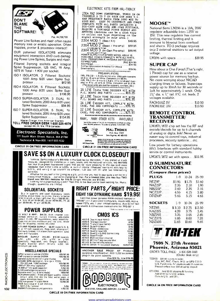
DON'T BLAME THE SOFTWARE!
ISO -3
Pat. #4,259,705
Power Line Spikes and Hash often cause memory loss or erratic operation. Often floppies, printer & processor interact! OUR patented ISOLATORS eliminate equipment interaction AND curb damag- ing Power Line Spikes, Surges and Hash. Filtered 3 -prong sockets and integral Spike Suppression. 125 VAC, 15 Amp, 1875 W Total - 1 KW per socket. ISO -1 ISOLATOR. 3 Filtered Sockets;
1000 Amp 8/20 usec Spike Sup- pressor $62.95
ISO -4 ISOLATOR. 6 Filtered Sockets; 1000 Amp 8/20 usec Spike Sup- pressor $106.95
ISO -3 SUPER -ISOLATOR. 3 DUAL fil- tered Sockets; 2000 Amp 8/20 usec Spike Suppressor $94.95
ISO -7 SUPER -ISOLATOR. 5 DUAL fil- tered Sockets; 2000 Amp 8/20 usec Spike Suppressor $154.95
Master Charge, Visa, American Express TOLL FREE ORDER DESK 1.800.225.4876
(except AK. HI, MA. PR & Canada(
Electronic Specialists, Inc. 171 South Main Street. Natick, MA 01760
Technical & Non -800: 1.617.655.1532
CIRCLE 20 ON FREE INFORMATION CARD
ELECTRONIC KITS FROM HAL-TRONIX
2304 MHZ DOWN CONVERTERS. TUNES IN ON CHANNELS 2 TO 7 ON YOUR OWN HOME T.V. HAS FREQUENCY RANGE FROM 2000 MHZ TO 2500 MHZ. EASY TO CONSTRUCT AND COMES COMPLETE WITH ALL PARTS INCLUDING A DIE-CAST ALUM CASE AND COAX FITTINGS, REQUIRE A VARIABLE POWER SUPPLY AND ANTENNA (Antenna can be a dish type or coffee can type depending on the signal strength in your area.) 2304 MOD 1 (Basic Kit) $49.95
Meer Da.. a fittings)
2304 MOD 2 (Basic / Pre -amp) $59.95 (Imead« o... a fining.)
2304 MOD 3 (Hi -Gain Pre -amp) $69.95 moo.... a Hemp.)
POWER SUPPLY FOR EITHER MODEL ABOVE IS AVAILABLE. COMES COMPLETE WITH ALL PARTS, CASE, TRANSFORMER, ANTENNA SWITCH AND CONNECTORS (Kit) $24.95 Assembled $34.95 Slotted Microwave Antenna For Above Downverters $39.95
PREAMPLIFIERS HAL PA -19-1.5 mhz to 150 mhz. 19db gain operates on 8 to 18 volts at 10ma. Complete unit $8.95. HAL PA -1.4-3 mhz to 1.4 ghz. 10 to 12 db gain oper- ates on 8 to 18 volts at 10ma. Complete unit $12.95.
(The above units are ideal for receivers, counters, etc.)
16 LINE TOUCH TONE DECODER KIT6WITH P.C. BOARD AND PARTS 99
p2 LINE TOUCH TONE DECODER K17WITH ,Cr BOARD AND PARTS $39,95
16 LINE ENCODER KIT, COMPLETE WITH CASE, PAD AND COMPONENTS ,,,,$39,95 12 LINE ENCODER KIT, COMPLETE y1Te{ CASE, PAD AND COMPONENTS ....$Z9.95
MANY, MANY OTHER KITS AVAILABLE Send 154 stomp or S.A.S.E. for Intormo,ion end flyer on other IIALTRONIX product. To ord., by phone. 1.313-246.1762.
:Mk
1.10.17 NANCEDc ``. oI.,APc *ERNE
HAL-TRONIX P.O. Sox 1101
Southgate, MI 48195
0000M 001010.00 VIII .E HO010 P0510 010CEr, SNIPPING ON rnm VrM *Commas EMA100I ARE REQUESTED.
ItKdaMAnoir, O =7, MLS THAN 30.00 MALE INCLUDE ADDITION. Al 1,.50 r0. RANDOM AND MAILING EMERGES
CIRCLE 21 ON FREE INFORMATION CARD
SAVE $$ ON A LUXURY CLOCK CLOSEOUT National Semiconductor's MA1003 is the Cadillac (or Mercedes, if you prefer) of clock
modules. Designed for Installation in cars, boats, and recreational vehicles, the MA1003 has four blue-green fluorescent digits that are far more pleasing to the eye (and more readable) than either LEDs or LCDs. A built-in crystal timebase maintains accuracy to 0.01%, and wiring It up couldn't be simpler; just add 12V DC and two time -setting switches.
Whether for yourself or for giving as a gift, until now you had to pay quite a lot for this classy clock module...but we're changing all that. For a limited time, you may buy TWO brand new MA1003 modules for $19.95 (single modules are $10.95).
Looking for a great -looking clock? Then this is the deal you've been waiting for. Hurry, though; quantities are limited.
SOLDERTAIL SOCKETS Buy in quantity and save! Everybody needs
sockets, and at these low prices, there's no better time to stock up than right now. 8 pin 100/55.95; 14, 16 & 18 pin 50/$4.95; 20 pin 40/54.95; 24, 28 pin 30/54.95; 40 pin 20/54.95.
POWER SUPPLIES 12 VOLT 8 AMP: $44.50. With crowbar over - voltage protection, current limiting, adjustable output 11-14V, RF suppression, easy assembly. Does not include enclosure and line cord. Allow $10 for shipping; excess refunded. 1/2 AMP POWER SUPPLY: $8.00 (specify 5, 6, 8, or 12 Volt operation). Regulated, short -proof, thermally limited, 1 A intermittent operation. Less case and hardware.
BIPOLAR SUPPLY #13 -XX: $15.00 (specify ±5V, ±6V, ±8V, ±9V, ±12V, or ±15V operation). Regulated, very simple assembly, virtually blow-out proof, delivers +250 mA minimum per side.
MISCELLANEOUS SPECIALS NPN transistor similar 2N3904 100/57.95 PNP transistor similar 2N3906 100/58.95 General purpose silicon signal diodes 50/52 GT5306 NPN darlington, min gain 17000,
25V 200 mA, To92 package 100/$8.95 1000 uF 35V axial capacitor 10/$2.00 10,000 uF 10V axial capacitor 5/$2.00 S-100 card edge connectors 10/529.50 Resistor asst. (cut & bent leads) 1000/55 RCA phono jacks - these are super quality, closed
circuit jacks that are the best we've seen in years. American made. 20/51.95
2102 low power 1K static RAM 10/59.90 4N26 opto -coupler 6 pin minidip,
MCT-2/IL-1 pinout 5/$2 SN76477 complex sound generator 1/$2.50
RIGHT PARTS/RIGHT PRICE: EIGHT 16K DYNAMIC RAMS $19.95!
I I Fast/ low power dynamic RAMS expand memory in
TRS-80- I / II / Ill and Color Computers, Heath H89, Apple, newer PETs, etc. 1 year limited warranty. Add $3 for two dip shunts & conversion instructions for TRS-80 I.
TOS -DO N a trademark M thee Tandy Co,eer.uon
CMOS ICS 4012-S Dual 4 input NAND 12/52 4020-S 14 stage counter 4/$2 4023-S Triple 3 input NAND 12/$2 4044-S Quad R -S latch 4/$2 4046-S Phase locked loop 2/52 4071-S Quad 2 input OR 12/52 4093-S Quad 2 in NAND Schmitt trig 4/52 4507-S Quad EX -OR 4/$2 4510-S BCD up/down counter 2/52 4511-S BCD to 7 seg decode/drvr 3/52 4512-S 8 channel data selector 4/52 5101-S CMOS 1K low power memory 10/$17.50
ANOTHER SALE PRICE! AP Products solerless breadboard kit. With 1,032 solderless plug-in tie point capacity.
Was $24.95, now $19.95
TERMS: Cal res add tax. Arrow 5% shipping; excess refunded Orders under 515 add S2 handling. VISA and Mastercard orders (S25 minimum) call 415) 542.0634, 24 hrs. Include street address for UPS. Prices subject to change without nonce, rm,ted quamlty on most Items
®5[3rjeU ELECTRONICS
BOX 2355, OAKLAND AIRPORT, CA 94614
MOOSE' National Semi LM3% is a 10A, 70W regulator adjustable from 1.25V to 15V. This new regulator has current limiting, thermal limiting and is immune to blowout from overload and shorts. TO -3 package requires only 2 external resistors to set output voltage.
LM396 with specs $19.95
SUPER CAP How about a One Farad (That's right, 1 Farad) cap for use as a reserve power source for memory backup. No more worrying about NICAD charging times or failures. Supercaps supply up to 10mA for 30 seconds or luA for approximately 1 week. Only 13/á' dia. x 3/4" tall. P C. mt. leads. 2 voltages available.
FAOH105Z 5V $10.50 FAOH110Z 10V $10.50
REMOTE CONTROL TRANSMITTER/ RECEIVER LM1871/1872 chip set has the RF and encode/decode for up to 6 channels of analog or digital link! Never an easier way to control toys, industrial processes, security systems... etc.
Low power for battery operations (6V). Interfaces with standard hobby servos or control instruments.
LM1871/1872 set with specs $15.95
D SUBMINIATURE CONNECTORS (Compare these prices!) PLUGS 1-9 10-24 25-99
NEZ9P $1.95 $1.75 $1.60 NAZ15P 2.35 2.10 1.90 NBZ25P 2.60 2.35 2.15 NCZ37P 4.55 4.15 3.80 DDZ5OP 5.65 5.15 4.65
SOCKETS 1-9 10-24 25-99
NEZ9S $ 3.10 $ 2.75 $ 2.50 NAZ15S 4.20 3.75 3.45 NBZ25S 3.35 3.05 2.85 NCZ37S 8.85 8.00 7.35 NDZ5OS 11.65 10.60 9.65
TRI -TEK 7808 N. 27th Avenue
Phoenix, Arizona 85021 ORDER TOLL FREE: 1-800-528-0183
(Order desk only) TERMS: $10.00 minimum order.
Visa, MC, BAC, Check, M.O. or UPS C.O.D. U.S. Funds only. AZ residents add 5% sales tax. Prepaid orders over $50 shipping prepaid.
OTHERS: Add $3.00 shipping & handling. Add $1.50 for C.O.D. orders. Outside U.S., add 20%.
CIRCLE 54 ON FREE INFORMATION CARD
CIRCLE 59 ON FREE INFORMATION CARD
www.americanradiohistory.com
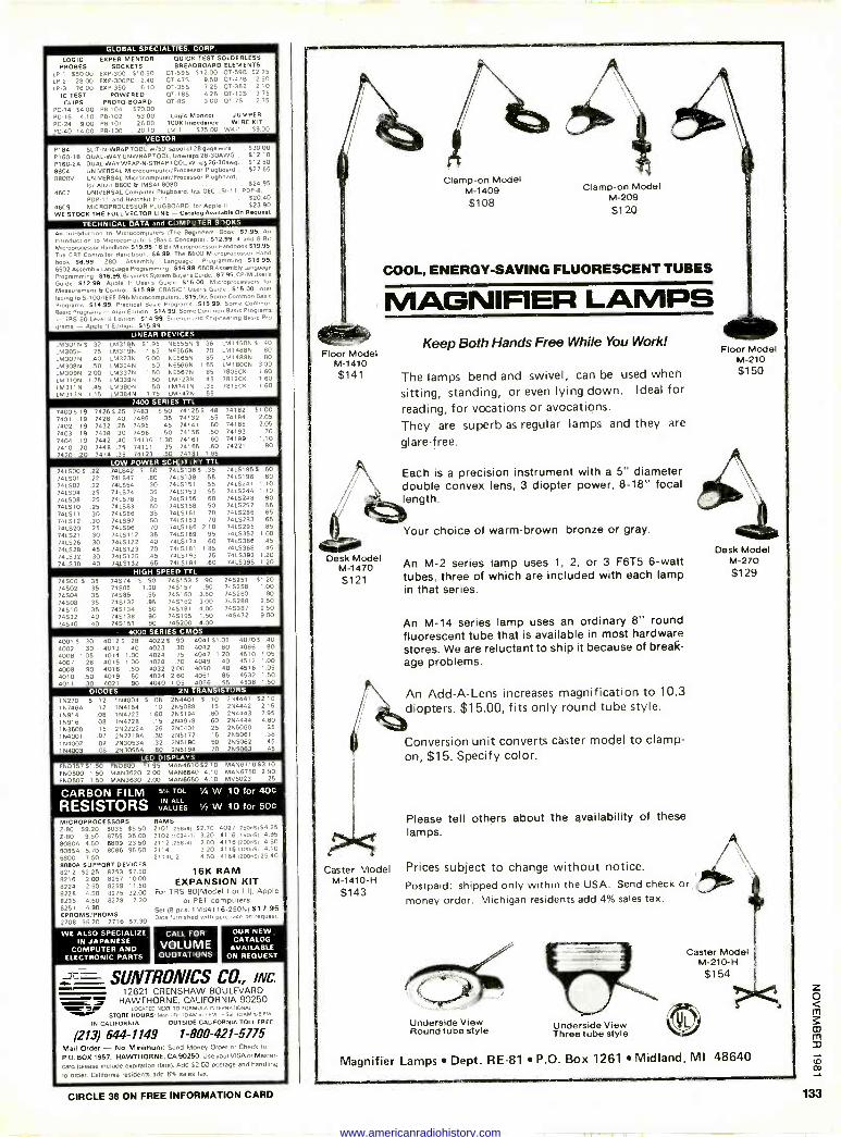
GLOBAL SPECIALTIES. CORP
LOGIC PROBES
LP -1 550.00 LP -2 28 00 LP -3 7600
IC TEST CLIPS
PC -14 $4.00 PC -16 410 PC -24 900 PC -40 1400
EXPERIMENTOS SOCKETS
EXP-300 $10.50 EXP-300PC 240 EXP-350 610
POWERED PROTO-SOARD P13-104 $70.00 P8-102 53.00 P8.101 2600 PB -100 20.10
QUICK TEST SOLDERLESS BREADBOARD ELEMENTS
QT -595 $1200 QT -598 $275 OT -47$ 9.50 OT -478 2.50 OT -355 7 25 OT -358 2 10 OT -18S 4.25 OT -12S 3 75
07-8S 3.00 QT -7S 2 75
Logic Monitor JUMPER 100K Impedance WIRE KIT LM -1 575.00 WK -1 59.00
VECTOR
P184 SLIT -N -WRAP TOOL. w/50' spool of 28 gage wire .. .530.00 P1130.1 El DUAL -WAY UNWRAP TOOL. Unwraps 26-30AWG $12.10 P160 -2A DUAL -WAY WRAP -N -STRAP TOOL. Wrap;26-30awg... 512.50 8804 UNIVERSAL Microcomputer/Processor Plugboard $27 65
8800V UNIVERSAL Mlcroconlputer/Processor Plugboard, for Altan 8800 6 IMSAI 8080 $24.95
4607 UNIVERSAL Computer Plugboard, tits DEC L51-11. PDP-8.
POP -I1 and Heathkll H-11 $2040 4609 MICROPROCESSOR PLUGBOARD. for Apple II 623.90 WE STOCK THE FULL VECTOR LINE - Catalog Available On Requeal
TECHNICAL DATA and COMPUTER BOOKS
An Introduction to Microcomputers (The Beginners Book .57.96, An
rnnoducuon to Mlcrocomouters BBasic Concepts, $12.99. 4 and 8 BIZ
Microprocessor Handbook $19.95. 16 B,1 Microprocessor Handbook 519.95, The CRT Controller Handboak..$6.99. The 6800 Microprocessor Hand
book.. 58.99. 280 Assembly Language Programming... 616.99. 6502 Assembly Language Programming...816.99. 6809 Assembly language Programming .516.99. Business System Buyer s Gurde...87.95. CP/M Users
Guide... 512.99, Apple II Users Guide .$15.00. M,cropr0cess0rs for
Measurement B Control.. 515.99. CBASIC - User's Goode.. $15.00. Inter
facing to 5-100/IEEE 696 Microcomputers... 516.00. Some Common Basic
Programs... $14.99. P10011001 Basic Programs... 515.99. Some Common
Basic Programs - Ala,, Edition ..514.99. Some Common Basic Programs - TR5-80 Level II Edilloli 514.99, Science and Engineering Basic Pro
grams - Apple II Eilinon 615.99 LINEAR DEVICES
LM301N5 32 LM318N LM305H 75 LM3196 LM307N 40 LM323K LM308N .50 LM324N LM309N 2.00 LM337N LM310N 1.75 LM339N LM311N 45 LM380N LM317N 1.15 1M3846
51 95 NE555N $ 36 1 65 NE556N 70 500 NE565N .85
50 NE566N 1.65 1.50 NE567N 85
50 LM723N 45 .50 LM741N .35
175 LM747N .55
LM1458N$ .40 LM1488N 80 LM1489N BO
LM1800N 3.00 7805CK 160 7812CK 1.60 7815CK 1.60
74005.19 7426325 483 S50 741255 48 74182 $1.00 7401 19 7428 .40 7486 35 74132 55 74184 205 7402 .19 7432 .25 7495 .45 74141 .80 74185 2.05 7403 19 7438 30 7496 .50 74156 .50 74193 70
7404 19 7442 40 74116 1.30 74161 60 74199 1.10
7410 .20 7448 75 74121 35 74165 60 74221 80
7 20 .20 7474 35 74123 .50 74181 1.65
LOW POWER SCHOTTKY TTL
74LS00 S
741301 741502 74L504 741508 741510 741511 741.312 74L520 741521 741526 741528 791332 741538
22 741542 $ .50 74L5136$ .35 22 741347 .80 74L5138 .55 22 741554 30 7415151 55 25 741574 .35 7415153 .55 25 741576 .35 7415158 .60 25 741583 .60 74L5158 .50 30 741586 35 7415161 .70 30 741592 .50 7413163 70 25 741398 .70 7415166 2 10
30 7415112 .35 7415169 95 30 7415122 40 74LS174 .60 45 7415123 70 7415181 1.85 30 7415125 45 74L5193 .75 40 741S132 65 7415194 60
74131955 60 7415196 .80 7415241 1.10 7415244 1.10 7415248 90 7415257 55 7415266 65 74LS283 65 7415295 85 74LS352 1 .00 7415366 45 7415368 45 7415393 1.20 7415395 1.20
HIGH SPEED TTL
74S00'$ .35 74502 .35 74504 35 74508 .35 74510 .35 74532 .40 ]4540 .40
74574 0 .50 74585 1.20 74S86 55 745132 95 745134 50 745138 90 745151 90
745153 5 .90 745157 90 745160 3.50 745162 3.00 745181 4,00 745195 1.50 745200 4.00
745251 51.20 745258 1.00 745260 90 745288 2.50 745387 2.50 745472 900
4000 SERIES CMOS 4001 5 .30 4002 30 4006 1 05 4007 28 4008 .90 4010 50 4011 .30
4012$ 28 4013 40 4014 100 4015 1.00 4016 50 4019 .50 4021 .90
4022 5 90 4023 30 4024 15 4028 70 4032 200 4034 2.60 4040 1.05
4041 $1.05 4042 80 4047 1.20 4049 40 4050 40 4051 85 4066 55
4070 $ .40 4086 90 4510 1 05 4512 1.00 4516 105 4532 1.50 4538 1.50
DIODES 2N TRANSISTORS 16270 S 12 154004 5 .08 2N4401 5 .10 167464 12 164154 10 2N5088 15
16914 08 1N4723 1.60 2N5194 60 16916 .08 164728 .15 254918 60 153600 15 2N2222A .26 2N5401 25 164001 07 262219A 30 2N5172 15
1N4002 07 2630534 .32 265190 .50 164003 .08 2630554 .80 265194 .70
264441 52 10 254442 215 2N4443 2 95 254444 4.60 255060 35 265061 .38 255062 .45 265063 45
LED DISPLAYS F5035751.50 FND800 51 95 MAN461052.10 MAN671003.10 F50500 1.50 MAN3620 2 00 MAN6640 4.10 MAN6750 2 90 FND507 1.50 MAN3630 2.00 MAN6650 410 MV5023 25
CARBON FILM 5 TOL / W 10 for 40c
RESISTORS VA ES v w 10 for 50C
MICROPROCESSORS Z-80 59.20 8035 55.50 Z-80 9.50 8755 35.00 80604 450 6809 23.50 8085A 5.70 8086 95 50 6800 7.50 5080A SUPPORT DEVICES 8212 42.25 )3253 $7.50 8216 2.00 8257 1000 8224 2.50 8259 11.50 8228 4.50 8275 32.00 8238 4.50 8279 7 20 8251 4 90 EPROM S/PROMS 2708 $6.20 2716. $7.30
RAMS 2101 1256+41 S2 70 4027125005184.25 2102 11024.1 3.20 4116 1150051 4.95 2112 1256.41 2.80 41161200n51 4.50 2114 3.20 4116 130005. 4.10 21141.2 4.50 4164 ,200n5125.40
16K RAM EXPANSION KIT
For TRS-80)MoVel I or III), Apple or PET computers
Set (8 pcs. TM54116-250N) $17.95 Data furnished with purchase on reflues,.
WE ALSO SPECIALIZE IN JAPANESE
COMPUTER AND ELECTRONIC PARTS
CALL FOR
VOLUME QUOTATIONS
OUR NEW CATALOG
AVAILABLE ON REQUEST
SUNTRONICS CO., INC. 12621 CRENSHAW BOULEVARD
HAWTHORNE, CALIFORNIA 90250 ear ILOCATED NEXT T0 FORMULA INTERNATIONAL, _1". STORE HOURS: Man 'Fri +0 AM lo PM. -Sal to AM mónkn
IN CALIFORNIA OUTSIDE CALIFORNIA TOLL FREE
1213) 644-1149 1-800421-5775 Mail Order - No Minimum: Send Money Order or Check
P.O. BOX 1957. HAWTHORNE. CA 90260. Use your VISA or Mas+.
card (please include explrallon date). Add $2.00 postage and ho,,,' 0
to Order. Califorma realdenls add 6% sales tax.
Floor Model M-1410 $141
llll Desk Model
M-1470 $121
Clamp -on Model M-1409 $108
Clamp -on Model M-209 $120
COOL, ENERGY -SAVING FLUORESCENT TUBES
MAGNIFIER LAMPS Keep Both Hands Free While You Work!
The lamps bend and swivel, can be used when
sitting, standing, or even lying down. Ideal for reading, for vocations or avocations.
They are superb as regular lamps and they are
glare -free.
Each is a precision instrument with a 5" diameter double convex lens, 3 diopter power, 8-18" focal
,,,A length.
Your choice of warm -brown bronze or gray.
Caster Model M -1410-H
$143
An M-2 series lamp uses 1, 2, or 3 F6T5 6 -watt tubes, three of which are included with each lamp in that series.
An M-14 series lamp uses an ordinary 8" round fluorescent tube that is available in most hardware stores. We are reluctant to ship it because of break- age problems.
An Add -A -Lens increases magnification to 10.3 diopters. $15.00, fits only round tube style.
Conversion unit converts caster model to clamp - on, $15. Specify color.
Please tell others about the availability of these lamps.
Floor Model M-210 $150
Desk Model M-270 $129
Prices subject to change without notice.
Postpaid; shipped only within the USA. Send check oriee money order. Michigan residents add 4% sales tax.
IÉ
Underside View Round tube style Underside View
Three tube style
Caster Model M -210-H $154
Magnifier Lamps Dept. RE -81 P.O. Box 1261 Midland, MI 48640
CIRCLE 38 ON FREE INFORMATION CARD 133
www.americanradiohistory.com
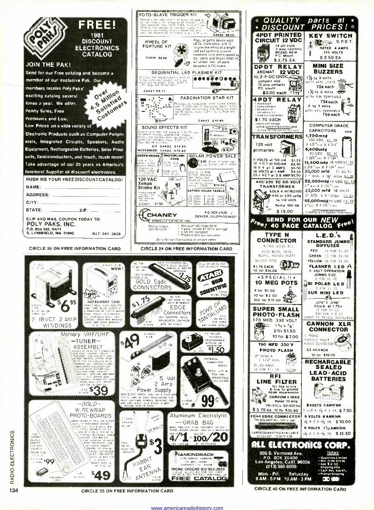
FREE! 1981
DISCOUNT ELECTRONICS
CATALOG
JOIN THE PAK! Send for our Free catalog and become a
member of our exclusive Pak. Our
members receive Poly Paks'
exciting catalog several
times a year. We of fer:
Penny Sales, Free
Premiums and Low,
Low Prices on a wide variety of
Electronic Products such as Computer Periph.
erais, Integrated Circuits, Speakers, Audio
Equipment, Rechargeable Batteries, Solar Prod-
ucts, Semiconductors, and much, much more!
Take advantage of our 25 years as America's
foremost Supplier of discount electronics.
RUSH ME YOUR FREEDISCOUNTCATALOG!
NAME.
ADDRESS'
CITY.
STATE: ZIP
CLIP AND MAIL COUPON TODAY TO: POLY PAKS, INC. P.O. Box 942, RA11 S. LYNMFIELD, MA. 01940 (617) 245- 3828
CIRCLE 36 ON FREE INFORMATION CARD
FOTO -SLAVE TRIGGER KIT -,4 PN THE IOST ENUI11VE CLA E TRI ER KIi `.
NET. NAIS SCRIED BY THIEHT°L ICAT. ' ' MUCnHSUPERIOR THAN LASCR TYPES, THIS NIL c
AN OPERATE ATE FROM N°IRECCT FLASH, KIT ALL P
°1.51-x CORD FOR CONNECTION TD suRORE.51809: I" C4450
WHEEL OF Popular game device uses - LEDs. transistors, and IC
FORTUNE KIT l, to give the effect of a bright Aa 1
0 Q' red ball spinning around *me numbers. Unit emits sound as
C3800 8095 "y!
ball spins and finally stops on
e.,v a number. Incl. all parts. faceplate 8 PC board.
SEQUENTIAL LED FLASHER KIT IC REDCIRCUITRY SEDUENTIALLY LICHAS OR 10 LEDS CON WITH AL
u0 PC BOARD. SIZE: 5.25" N
I.5"5 REpu1REs 9V BA
. ONNOI I
C4431 $0.78
e e II
I
,?. ; A ; .
e 13 ;G'.
e
FASCINATION STAR KIT PR°DUCE6 XPL NG STAR" VISUAL EFFECT. USES 25 LEDS"AND ICI CI ROUITRY. GREAT AT1EN-
TAON GETTER FORDISC ETC.WITH ALL PARTS AND PC BOARD. SIZE: 552 2"A 3.4". REQUIRES
9V BATTERY.
74132 810.98
SOUND EFFECTS KIT ""4Djo COMPACT NIT uSES THE POPULAR 1176477 CHIP 10 CREATE PNASOR, LOCOMOTIVE, SIREN` BOARD, ETC SOUNDS. WITH ALL PARTS,
F Smarr AND BATTER SIZE: 3.25" T1",C
REQUIRES 9V BAiiERY, y' 9 e KIT C4422 $12.55
ASSEMBLED C4423 815.56 ee GREEN NEONS
5AmEAs NEe Eí. RIGHTG REEN.
OPERATES oN 1El
FOR 74451
8 SCROD
PHOTOFLASH CAPS
C292e .75 35011.0 330V
C /1
72930 360V$1.2
£2930 310V5
SOLAR POWER SALE 2.55 LIANT 31' N1lO E E
C44VB. OUTPUT .4V A 4ó0n
BATTERY su LACE SPECIAL REPLACE - ,ENI PANELERIND 500
TorOO.01 C4396 *12.00
120 VAC
Strobe Klt 21
C23071R 87.50
LARGER SOLAR PANELS
6V 1250, $ 25.00 C4409 12V 125nÁ 1 49.00 04410lija 122 25005 8 85.00 C4411 I2V 500A. $150.00 C4449
P.O. BOX 27038 CHANEY DENVER, COLORADO 80227
electronics inc. Phone Orders Minimum AD Order $6.00 303-781.5750 Please Include 81.50 for postage
VISA MC accepted Phone orders are welcome
Send for our free catalog of unIgue items } r..r...
CIRCLE 24 ON FREE INFORMATION CARD
GREAt. 0
5v T
C> OR
12eAT
2-I8VCT 2 AMP WINDINGS
INSTRUMENT CASE BRAND NEW, HIGH SUALITO TWO-TONE BLUE CASES A A FRACTION OF THEIR wORTH FRONT PANEL IS PUNCHED,
WITH BUT REPLACES T 0
SCREWS BACK HAS BANANA JACKS AND CORD WINDER
5 % 7' X 12*
Memory VHF/UHF-9 -TUNER- ASSEM BLY ANTASTiC DEAL ON A COMPLETE NEW SONY MEMORY TUNER, FEATURES VHF AND UHF vAR- ACTOR TUNERS. DIGITAL SCAN- NING TUNING CIRCUITS WITH MEMORY, ALL CONTROLS AND
_..INDICATORSvED WITH C NLHEMATCS.
NSTRUCTIONS, OWNERS MANUAL VNF/UHF ANTENNA N,IF OUT BRAND SEA CURRENT PRODUCTION FROM MODEL Kv -1217 GREAT ADD-ON TO ANY TV,
X- 1000
LB $39
!NOT SHOWN/ JUBLE BOARDS
TO -S00 SOCKETS
BOARD S12E
5" 12 /2 La
x- o4s8
-GOLD- WI RE WRAP
PROTO -BOARDS uNBEL IEVABLE DEAL ON SUPER QUALITY WIREWRAP BOARDS OVER 100, 16 PIN GOLO Wei 13-LEVELI SOCKETS (UP TO
1201 MTD ON A PCB WITH HEAVILY BYPASSED POREF BUSSES, 260 WW I/O
PINS LEADING TO GOLD EDGE CONTACTS USE P
AS SUPER OTO - BOARD, OR CAN BE EASILY DISASSEM- BLED FOR PARTS EIHER W i5
0
STEAL. 15 ARD S
15- x 6-I/2-
$49
56 PIN
I TWO ROWS OF 251
156' CENTER C-2120,2 02
GOLD BIFURCATED CON- TACTS,GOLD SOLDER
TERMINALS. MED BY AMPHENOL
a
GOLD Egdé CONNECTORS
w SO PIN 1 1 ITpOLD ROWE WIRE W
OF RAP 251
1 OL
EDGE 1 Connectors .156' CENTERS, GOLD
20Z BIFURCATED CONTACTS
E -DIOS MFD BY CINCH_- 1
X-1900 9 Le
5 Volt 12 Amp
-i- Power Supply NEW ELPAC MODEL SOLV 60-S FEATURES ! 0.I % LINE B LOAD REGULATION, CUR- RENT LIMITING, REMOTE SENSING, 120/ 240 VAC INPUT OUR PRICE IS WAY ` BELOW DEALER COST' 4
r A HMO" 7" EARS ,'\1 ICI BÑEy ` EXTEND l'
TO 3"
III III YDP
00Á291Y
FULL SWIVEL MOUNTING BRACKET
CALL OR WRITE FOR OUR FANTASTIC PRICES
TV BALUM 75/3003.
TRANSFORMER W/ PUSH -ON CONNECTOR
ANTENNA CONNECTOR
BOXES
SODA UHF B
15.11. VHF CONNECTORS
D LEADS
X-1091 99 e oz
Aluminum Electrolytic, -GRAB BAG -
BAG
[NONE SMALLER THAN 1,000MFD NO VOL TAGES BELO5VDC BAG OF 4 WORTH $5
/1:!o/2o0 POUNDS
`DIAMONDBACK C[FC1NONICS COMPANY
O Sox 12095 SARASOTA. FL 33570
%7 1 L .I
PHONE ORDERS 813-953-2829 ACCUSE Ní EACH OH ADDITIONAL R
THE FIRST a 25 LB
FREE CATA
QUALITY parts at *
* DISCOUNT PRICES ! 4PDT PRINTED CIRCUIT 12 VDC
/ 14 pin style F - 3 amp contacts
BRAND NEW PC. Mount
$ 2.75 EA. 1,1,114
KEY SWITCH S.P.S.T.
RATED 4 AMPS 125 VOLTS
$ 3.50 EA.
DPDT RELAY AROMAT 12 VDC
HL 2 -P -DC 12VDC compact elm 10 amp contacts P.C. mount
$3.00 each
r¡Y te 11It
4PDT RELAY pe pin co
3 n contacts 24 volt 0.0. or 120 volt a.c. 0011
Used Out twly leaned
$1.70 EACH specify coil 0011.9* LARGE OUANTITiES AVAILABLE
SOCKETS FOR RELAY SOR eacn
I111
z
1
MINI SIZE BUZZERS
1h to 3 volts WITH WIRE LEADS
756 each 1A to 3 vOlts
WITH PIN TERMINALS
756 each 3 to 7 volts
WITH PIN TERMINALS 75e each
TRANSFORMERS le 120 Volt primaries
6 VOLTS at 150 mA $1.25 12 V. C.T. at 500 mA $2.50 16.5 V. at 3 AMPS $6.50 18 VOLTS at '1 AMP $4.50 25.2 VC T at 2.8 AMP $5.50
440/220 TO 110 VOLT TRANSFORMER
SOLA s HTIBZI00 440 or 220 volts
to 110 vats Rated 100 VA
$ 15.00
TYPE N CONNECTOR
KINGS 53526 B/U
FITS RG55, RG58, RG141, R0142; RG223
SOLDER TYPE
$1.75 EACH 10 for $16.00
i1_Ï 4/l
*SPECIAL !!* 10 MEG POTS
4 for $1.00 10 for $2.00 100 tot $15.00
SUPER SMALL PHOTO=FLASH 170 MFD 330 VOLT
1 1/4"1( 7/8 N
2 for $1.50 10 for $7,00
COMPUTER GRADE CAPACITORS NEW
1,700mfd 150 VDC $2.00 J
2 1/2 "Dow X 4 3140
6,400mfd 60 VDC $2_50
1 3/BMoln X 4 1)4
11,5OOmfd 18 VOC$1_50 1 3/800iÁ X 3 1/4N HIGH
20,000 mfd 25 VOLTS
2 11 DIA. X 21/2" HIGH $2.00 22,000mfd 15 VDC $2_50 20 con X 2 1/200A00
22,DfA. 000 X
mfd 48 VOLTS
2" 6" HIGH 13.09 52,000mfd15 VDC $3.00 2.0 IA X 4 1/2'41G1-1
CLAMPS TO FIT CAPACITORS SOe ea.
L.E. D: a STANDARD JUMBO
DIFFUSED RED 10 FOR $1.50
OREEN 10 FOR $2.00 YELLOW 10 FOR $2.00
FLASHER LED /n? 5 VOLT OPERATION
JUMBO SIZE 2 FOR $1.70
!.?B1 POLAR LED 2 FOR 51.70
SUB MINICNI LED
079"% 098" 20mA at 1.75v 10 FOR $1.00 200 FOR 518.00
QUANTITY PRICES AV/SII_AFL_
750 MFD 330 V PHOTO FLASH
211 HIGH X 1 1/4" DIA. . .
$1.25 EACH 10 FOR $11.00 0
R I LINE FILTER
for line to line A line to ground
note, suppression CORCOM a 10E8
Rated:10 amp 115/250 e 50.400 hz
$ 3.75 ea. 10 for $35.00 22/44 [DOE CONNECTOR
TIN SOLDERTAIL.i56"X .200"
LARGE QUANTITIES AVAILABLE $1.35 each 1010,512.50
CANNON XLR CONNECTOR
3 PRONG
CHA551$ MOUNT
AUDIO CONNECTOR
$2.00 EACH
10 for $19.00
RECHARGABLE SEALED
LEAD -ACID BATTERIES
OVOLTS 3AMP/HR 2 5/8 X 11/2 X 5 IN. S 7.50 e VOLTS 6AMP/HR y4X2X4s,IN. $10.00 6 VOLTS 71/2AMPAIR
415 X 2 X 414 IN. $ 12.50
ALL ELECTROAICS CORP. 905 S. Vermont Ave. TEAMS
P.O. BOX 20406 Los Angeles, Calif. 90006
(213) 380-8000
Mon. - Fri. Saturday 9 Aryl -5 PM 10AM3PM
Quantities Limits/ Min. Order $10.00 A00 $ 2.50 Shipping USA Calif. Ras. Add 6% Prompt Shipping ®;*
CIRCLE 55 ON FREE INFORMATION CARD CIRCLE 40 ON FREE INFORMATION CARD
www.americanradiohistory.com
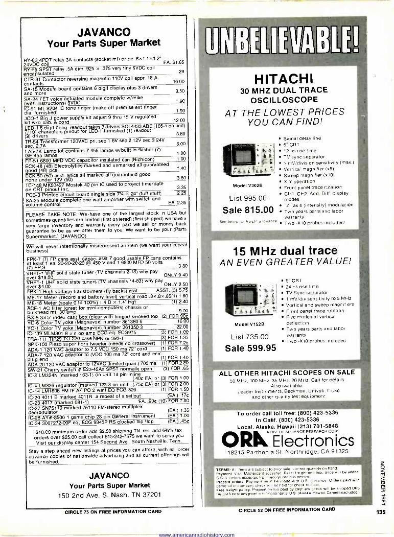
JAVANCO Your Parts Super Market
RY-83 4PDT relay 3A contacts (socket mt) or pc .6x 1.1 x 1.2" $1 65 24VDC coil
RY-55 SPST relay .5A dim .925 x .375 very tiny 6VDC coil .29 encapsulated
CTR-31 Contactor reversing magnetic 110V coil appr. 18 A 16.00 contacts
SA -15 Module board contains 6 digit display plus 3 drivers 3.50 and more
SA -24 FET voice actuated module complete w/mike 1 90 (with instructions) 9VDC
IC -91 ML 8204 IC tone ringer (make off premise ext ringer 1 90 dia. furnished)
JCO-1 Big J power supply kit adjust 9 thru 15 V regulated 12.00 kit w/o cab. & cord
LED -1 6 digit 7 seg; readout takes 3 drivers SCL4433 ABE (165-1 on unit) 7/10" characters pinout for LED -1 furnished (1) readout
3.80 (3) drivers TR -54 Transformer 120VAC pri. sec 1 6V sec 2 12V sec 3 24V
6.00 sec. 2.7A LA5-7K Lamp kit contains 7 455 lamps w/built in flasher (7)
1.00 GE 455 lamps FP -51 6800 MFD VDC capacitor insulated can (Nichicon) 1.00
ECK -48 148) Electrolytics marked and unmarked all guaranteed 1 40 good (48) pcs.
ECK -50 (50) asst. lytics all marked all guaranteed good 3.80 none under 12V (50)
1C-148 MK50427 Mostek 40 pin IC used to project time/date 3.35 on CRT pinout inc.
PCB -3 Printed circuit board single side 73/4 x 24" (tuff stuff) 2.25
SA -25 Module complete one watt amplifier with switch and 2 35 volume control
PLEASE TAKE NOTE: We:have one of the largest stock in USA but
sometimes quantities are limited (first ordered) (first shipped) we have a
very large inventory and warranty every part we sell or money back
guarantee to be as we offer them to you. We want to be your (Parts
Supermarket.) (JAVANCO)
We will never intentionally misrepresent an item (we want your repeat business)
FPK-7 (7)FP cans asst. capac. asst 7 good usable FP cans contains at least 1 ea. 20-20-20-20 l 450 V and 1 6800 MFD 50 volts (7) 3.80
VH $1 VHF solid state tuner (TV channels 2-13) why payov
0 ONLY 9.40
VHFT-1 UHF solid state tuners (TV channels 14-83) why pay ONLY 2.50 over $4.00
FBK-1 High voltage transformers (fly backs) asst ASST. (3) 5.75
ME -17 Meter (record and battery level) vertical read .8x.8x.85(1) 1.80
ME -18 Meter (scale 0 to 100%) 1.4 0 x 1.4" Hgt (1) 2.40
ACF-1 AC filter (great for mini -computers) chassis or bulkhead mt. 30 amp. 9.00
BX-5 3x5" index card box (clear with hinged smoked top (2) FOR 90e
Y5-6 Color TV yoke (Magnavox) number 361380-6 16.00
YO -1 Color TV yoke (Magnavox)_ number 361350-3 22.00
IC -139 MLM301 8 pin op amp ECG eq: ECG975 (3) FOR 1.00
TRA -111 TIP29 TO -220 case NPN or 393-1 (3) FOR 1.35
SPK-100 Piezo super horn tweeter (needs no crossover) (1) FOR 7.25
ADA -1 120 VAC adaptor to 7.5 VDC 150 ma 72" cord (1) FOR 1.40
ADA -7 120 VAC adaptor to (VDC 100 ma 72" cord and mini plug end (1) FOR 1.40
ADA -20 120 VAC adaptor to 12VAC (limited quan.) 700 ma (1) FOR 2.80
SW -21 Cherry switch # E23-45Ax SPST normally open (3) FOR .65
IC -3 LM324N (marked 163-1) on unit 14 pin inline (.400EA) or (3) FOR 1.00
IC -4 LM326 regulator (marked 123-3 on unit (.75¢ EA) or (3) FOR 2.00
IC -14 LM.1808 FM IF AF PO 2 watt EQ ECG 826 (1) FOR 1.50
1C-20 4011 B marked 4011B a repeat of a sellout WA.) .17¢
IC -23 4017 (marked 081-1) EA. .905 (10) FOR 7.00
IC -27 SN75110 marked 75110 FM -stereo multiplex 1.35 demodulator (EA.)
IC -28 AY# -8500 1 game chip 28 pin General Instrument (EA.) 1.00
IC -34 3007272-00F eq; ECG 9945P RS clocked flip flop (EA.) .455
$10.00 minimum order add $2.50 shipping TN. res. add 63'4% tax
orders over $25.00 call collect 615-242-7575 we want to serve you
Visit our display center 154 Second Ave.. South Nashville, Tenn.
Stay a step ahead new listings at prices you can afford, with ea. order
advance copies of nationwide advertising and all current offerings will
be furnished.
JAVANCO Your Parts Super Market
150 2nd Ave. S. Nash. TN 37201
CIRCLE 75 ON FREE INFORMATION CA
1
HITACHI 30 MHZ DUAL TRACE
OSCILLOSCOPE
AT THE LOWEST PRICES YOU CAN FIND!
Model V302B
Signal delay line 5" CRT
l 12 ns rise time TV sync separator 1 mV/division sensitivity (max.)
s, 7, Vertical magnifier (x5)
Sweep magnifier (x10)
X -Y operation Front panel trace rotation CH1, CH2. Add, Diff. display
List 995.00 modes "Z" axis (intensity) modulation
Sale 815.00 Two years parts and labor warranty
See below for freight allowance Two -X10 probes included!
}
15 MHz dual trace AN EVEN GREATER VALUE!
,. ° I
,t
,_
Model V152B
List 735.00
Sale 599.95
5" CRT 24 ns rise time TV Sync separator 1 mV/div sensitivity to 5 MHz
Vertical and sweep magnifiers Front panel trace rotation Five modes of vertical deflection Two years parts and labor warranty Two -X10 probes included
ALL OTHER HITACHI SCOPES ON SALE 50 MHz. 100 MHz, 35 MHz, 20 MHz. Call for details
Also available: Leader Instruments, Beckman, Univolt. Fluke,
and other quality test equipment.
1
To order call toll free: (800) 423-5336 In Calif. (800) 423-5336
Local, Alaska, Hawaii (213) 701-5848 A OF ALLIANCE RESEARCH CORP
ORk 18215 Parthenia St Northridge, CA 91325
TERMS: All items are subject to prior sale Limited quantity on hand
Payment Visa Mastercard accepted Exact freight and insurance will be added
C O D. orders accepted from recognized businesses Prepaid orders: Payment must be made with U s. currency Orders paid wife
l,ersonal or company check will be held for check to clear Free freight policy: Prepaid orders paid by cashiers check will be shipped UPS
freight free to any point in the continental US (Alaska. Hawaii. Canada excluded
CIRCLE 52 ON FREE INFORMATION CARD
z O
m
W m
Co
135
www.americanradiohistory.com
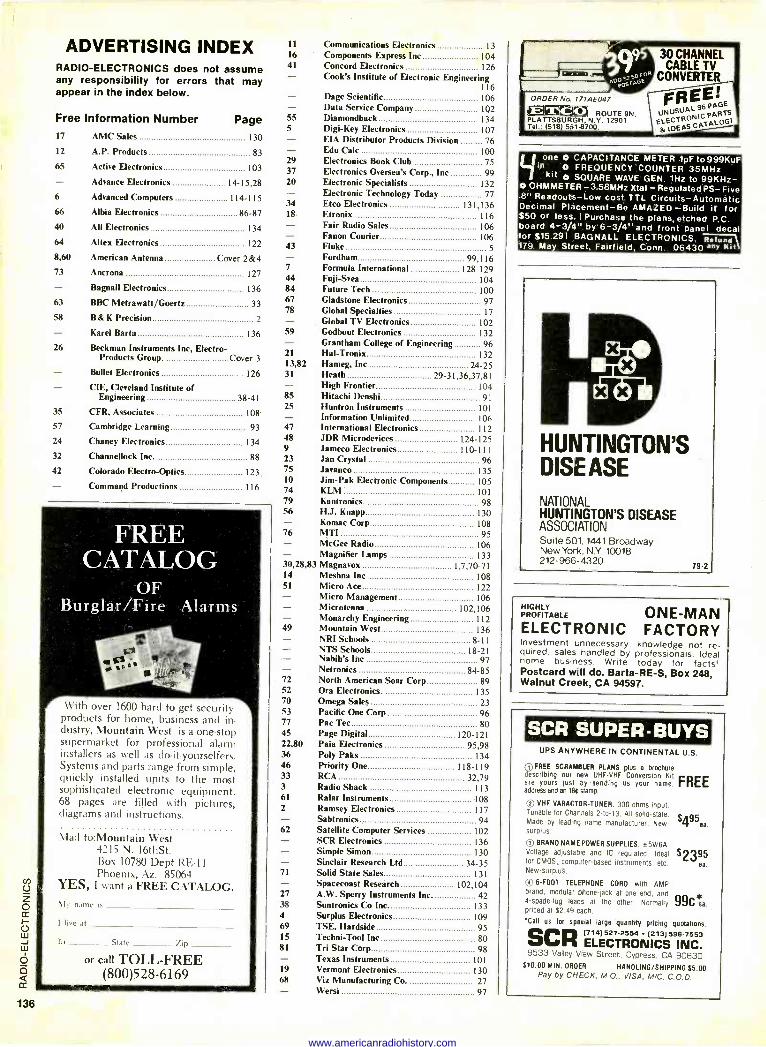
ADVERTISING INDEX RADIO -ELECTRONICS does not assume any responsibility for errors that may appear in the index below.
Free Information Number Page 17 AMC Sales 130
12 A.P. Products 83
65 Active Electronics 103 - Advance Electronics 14-15,28
6 Advanced Computers 114-115
66 Albia Electronics 86-87
40 All Electronics 134
64 Altex Electronics 122
8,60 American Antenna Cover 2&4 73 Ancrona 127
Bagnall Electronics 136
63 BBC Metrawatt/Goertz 33
58 B& K Precision 2
- Karel Barta 136
26 Beckman Instruments Inc, Electro - Products Group Cover 3 - Bullet Electronics 126 - CIE, Cleveland Institute of Engineering 38-41
35 CFR, Associates 108
57 Cambridge Learning 93
24 Chaney Electronics 134
32 Channellock Inc 88
42 Colorado Electro -Optics 123 - Command Productions 116
FREE CATALOG
OF Burglar/Fire Alarms
With over 1600 hard to get security products for home, business and in- dustry, Mountain West is a one -stop supermarket for professional alarm installers as well as do-it-yourselfers. Systems and parts range from simple, quickly installed units to the most sophisticated electronic equipment. 68 pages are filled with pictures, diagrams and instructions.
Mail to:Mountain West 4215 N. 16thSt. Box 10780 Dept RE -11 Phoenix, Az. 85064
YES, I want a FREE CATALOG. \Iv name is
I live at
In State lip
or call TOLL -FREE (800)528-6169
11
16
41
Cook's Institute of Electronic Engineering 116 - Dage Scientific 106
Data Service Company 102 55 Diamondback 134 5 Digi-Key Electronics 107 - EIA Distributor Products Division 76 - Edu Cale 100 29 Electronics Book Club 75 37 Electronics Oversea's Corp., Inc 99 20 Electronic Specialists 132
Electronic Technology Today 77 34 Etco Electronics 131,136 18 Etronix 116 - Fair Radio Sales 106 - Fanon Courier 106 43 Fluke 5 - Fordham 99,116 7 Formula International 128-129 44 Fuji-Svea 104 84 Future Tech 100 67 Gladstone Electronics 97 78 Global Specialties 17
Global TV Electronics 102 59 Godbout Electronics 132
Grantham College of Engineering 96 21 Hal-Tronix 132 13,82 Hameg, Inc 24-25 31 Heath 29-31,36,37,81 - High Frontier 104 85 Hitachi Denshi 91 25 Huntron Instruments 101
Information Unlimited 106 47 International Electronics 112 48 JDR Microdevices 9 Jameco Electronics 23 Jan Crystal 75 Javanco 10 Jim -Pak Electronic Components 74 KLM 79 Kantronics 56 H.J. Knapp - Komac Corp 76 MTI
McGee Radio
Communications Electronics 13 Components Express Inc 104 Concord Electronics 126
124-125 110-111
96 135 105 101
98 130 108 95
106
133 Magnifier Lamps 30,28,83 Magnavox 1,7,70-71 14 Meshna Inc 108 51 Micro Ace 122
Micro Management 106 Microtenna 102,106 - Monarchy Engineering 112
49 Mountain West 136 NRI Schools 8-11 NTS Schools 18-21 Nabih's Inc 97 - Netronics 84-85
72 North American Soar Corp 89 52 Ora Electronics 135 70 Omega Sales 23 53 Pacific One Corp 96 77 Pac Tec 80 45 Page Digital 120-121 22,80 Paia Electronics 95,98 36 Poly Paks 134 46 Priority One 118-119 33 RCA 32,79 3 Radio Shack 113 61 Ralar Instruments 108 2 Ramsey Electronics 117 - Sabtronics 94 62 Satellite Computer Services 102 - SCR Electronics 136 - Simple Simon 130 - Sinclair Research Ltd 34-35 71 Solid State Sales 131 - Spacecoast Research 102,104 27 A.W. Sperry Instruments Inc. 42 38 Suntronics Co Inc 133 4 Surplus Electronics 109 69 TSE. Hardside 95 15 Techni-Tool Inc 80 81 Tri Star Corp 98 - Texas Instruments 101 19 Vermont Electronics 130 68 Viz Manufacturing Co. 27 - Wersi 97
30 CHANNEL CABLE TV
CONVERTER
FREE! ROUTE 9N, U¡dUS"A-
PAGE
ELECTRONIC PARTS
PLATTSBURILMGH, N.V. 12901 Tel.: 1518) sel -8700. 8, IDEAS CATALOG
ORDER N. 171.4E047
Lione O CAPACITANCE METER .1pF to999KuF to O FREQUENCY COUNTER 35MHz kit O SQUARE WAVE GEN. 1Hz to 99KHz-
O OHMMETER -3.58MHz Xtat - Regulated PS- Five .8" Readouts -Low cost TTL Circuits -Automatic Decimal Placement -Be AMAZED -Build it for $50 or less. I Purchase the plans, etched P.C. board 4-3/4" by 6-3/4" and front panel decal for $15.291 BAGNALL ELECTRONICS, Refund 179 May Street, Fairfield, Conn. 06430 anv Kit
HUNTINGTON'S DISE ASE
NATIONAL HUNTINGTON'S DISEASE ASSOCIATION Suite 501, 1441 Broadway New York, N.Y. 10018 212-966-4320
79-2
HIGHLY PROFITABLE ONE-MAN ELECTRONIC FACTORY Investment unnecessary- knowledge not re- quired, sales handled by professionals. Ideal home business. Write today for facts, Postcard will do. Barta-RE-S, Box 248, Walnut Creek, CA 94597.
SCR SUPER -BUYS UPS ANYWHERE IN CONTINENTAL U.S.
gftt FREE SCRAMBLER PLANS plus a brochure describing our new UHF -VHF Conversion Kit
FREE are yours just by sending us your name, address and an 1St stamp.
Q VHF VARACTOR-TUNER. 300 ohms input. Tunable for Channels 2 -to -13. All solid-state. Made by leading name manufacturer. New- $495ea. surplus.
Qa BRAND NAME POWER SUPPLIES. ±5V/6A. Voltage adjustable and IC regulated. Ideal for CMOS. computer -based instruments, etc. New -surplus.
rQ 6 -FOOT TELEPHONE CORD with AMP brand, modular phone -jack at one end, and ,k 4 -spade -lug leads at the other. Normally 99C ea. priced at $2.49 each.
'Call us for special large quantity pricing quotations. SCR[714)527-2554 6-7553 ELECTRONICS 9INC.
9533 Valley View Street. Cypress, CA 90630 $10.00 MIN. ORDER HANDLING/SHIPPING $5.00
Pay by CHECK, M.O., VISA, M/C, C.O.D.
$2395 ea.
www.americanradiohistory.com
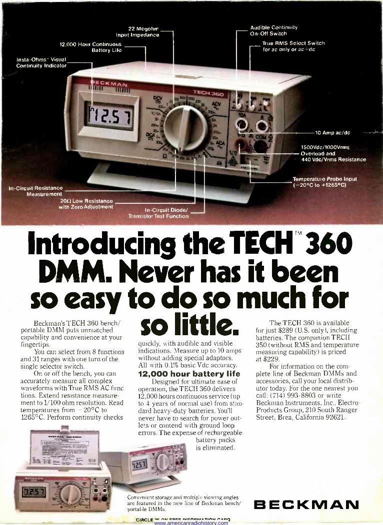
22 Megohn- Input Impedance
12,000 Hour Continuous Battery Life
Insta-Ohms Visual Continuity Indicator
-----"'---
In -Circuit Resistance Measurement
209 Low Resistance with Zero Adjustment
In -Circuit Diode/ Transisto Test Function
Audible Continuity On -Off Switch
True RMS Select Switch for ac only or ace dc
10 Amp ac/dc
1500Vdc/1000Vrms Overload and 440 Vdc/Vrms Resistance
Temperature Probe Input ( -20°C to +1265°C)
Introducing the TECH" 360 DMM. Never has it been
so easy to do so much for Beckman's TECH 360 bench/
portable DMM puts unmatched capability and convenience at your fingertips.
You can select from 8 functions and 31 ranges with one turn of the single selector switch.
On or off the bench, you can accurately measure all complex waveforms with True RMS AC func- tions. Extend resistance measure- ment to 1/100 ohm resolution. Read temperatures from -20°C to 1265°C. Perform continuity checks
A
so little. quickly, with audible and visible indications. Measure up to 10 amps without adding special adaptors. All with 0.1% basic Vdc accuracy. 12,000 hour battery life
Designed for ultimate ease of operation, the TECH 360 delivers 12,000 hours continuous service (up to 4 years of normal use) from stan- dard heavy-duty batteries. You'll never have to search for power out- lets or contend with ground loop en -ors. The expense of rechargeable
battery packs is eliminated.
Convenient storage and multiple viewing angles are featured in the new line of Beckman bench/ portable DMMs.
CIRCLE MOM FREE INFORMATION CARD
The TECH 360 is available for just $289 (U.S. only), including batteries. The companion TECH 350 (without RMS and temperature measuring capability) is priced at $229.
For information on the com- plete line of Beckman DMMs and accessories, call your local distrib- utor today. For the one nearest you call: (714) 993-8803 or write Beckman Instruments, Inc., Electro - Products Group, 210 South Ranger Street, Brea, California 92621.
BECKMAN www.americanradiohistory.com
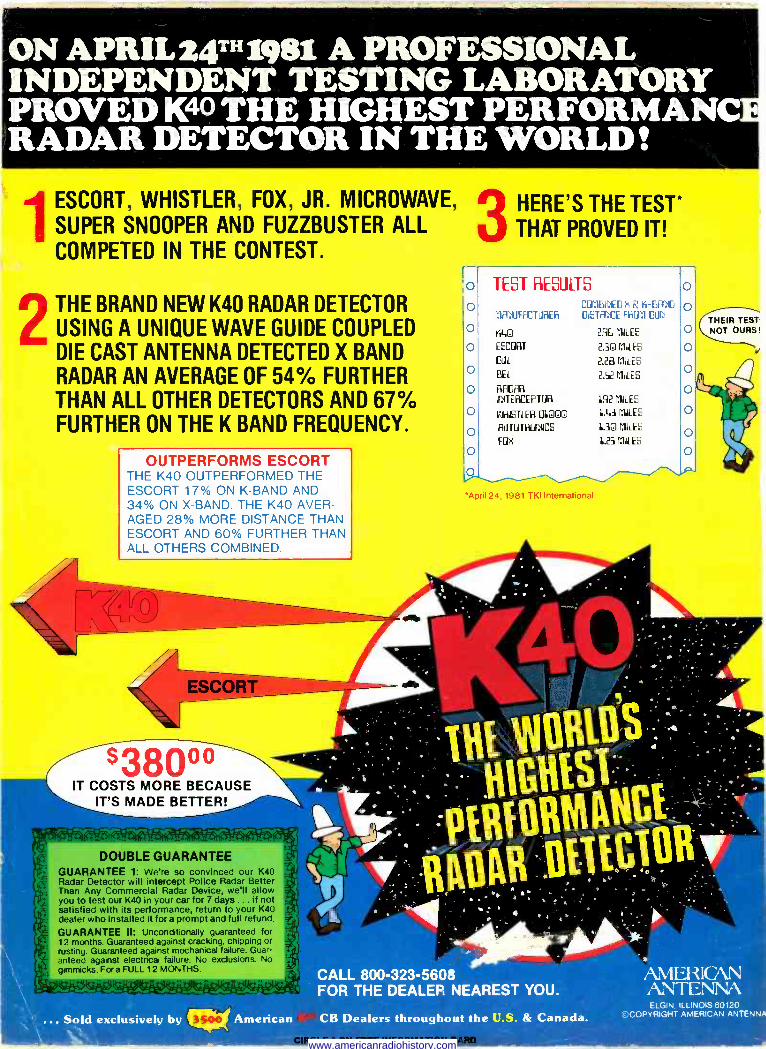
ON APRIL24THig8i A PROFESSIONAL INDEPENDENT TESTING LABORATORY PROVED K40 THE HIGHEST PERFORMANC RADAR DETECTOR IN THE WORLD!
1 ESCORT, WHISTLER, FOX, JR. MICROWAVE,
SUPER SNOOPER AND FUZZBUSTER ALL COMPETED IN THE CONTEST.
f:
i.
i.
THE BRAND NEW K40 RADAR DETECTOR
USING A UNIQUE WAVE GUIDE COUPLED DIE CAST ANTENNA DETECTED X BAND RADAR AN AVERAGE OF 54% FURTHER THAN ALL OTHER DETECTORS AND 67% FURTHER ON THE K BAND FREQUENCY.
OUTPERFORMS ESCORT THE K40 OUTPERFORMED THE ESCORT 17% ON K -BAND AND 34% ON X -BAND. THE K40 AVER- AGED 28% MORE DISTANCE THAN ESCORT AND 60% FURTHER THAN ALL OTHERS COMBINED.
S380oo IT COSTS MORE BECAUSE
IT'S MADE BETTER!
- --_-'V_T`-!! . . -. e y ,i.'?d,, .
-, DOUBLE GUARANTEE
GUARANTEE 1: We're so convinced our K40 Radar Detector will intercept Police Radar Better Than Any Commercial Radar Device, we'll allow you to test our K40 in your car for 7 days ... if not satisfied with its performance, return to your K40 dealer who installed it for a prompt and full refund.
GUARANTEE II: Unconditionally guaranteed for 12 months. Guaranteed against cracking, chipping or rusting Guaranteed against mechanical failure. Guar- anteed against electrical failure. No exclusions. No gimmicks. For a FULL 12 MONTHS.
di:. Sold exclusively by American
THEIR TEST NOT OURS!
HERE'S THE TEST* THAT PROVED IT!
o TEST RESULTS p CC7MBiryEo n R K BArfD
MAYUfACTiJRER GiSTAf:ICE fRM Dllr
o ra.o O ESCORT
G l1L
O BEL
O RADAR INTERCEPTOR
O FIFtETLER l UOQ
O AUTOTRONICS
fOK
'April 24, 1981 TKI International
2R6 MILES
2.313 MILES
2.28 MILES
2.52 MILES
L92 MILES
L.43 MILES
L.3G CULES
L.25 CULES
o o O
O
O
O
o
O
CALL 800-323-5608 AMERICAN FOR THE DEALER NEAREST YOU. ANTENNA
ELGIN. ILLINOIS 60120 ©COPYRIGHT AMERICAN ANTENN CB Dealers throughout the U.S. & Canada.
www.americanradiohistory.com
Related Documents