Wayland Engineering cc Lucky Star: St Helena Bay Technical Note: Marine Pipeline Stability & Hydraulic Assessment Doc No: WAYLAND/176130/TN/001 Revision: 0 Date: 29/11/2017 Page 1 of 16 St Helena Marine Outfall Project No. 176130 Technical Note Stability Design and Hydraulic Assessment of new Marine Pipeline Lucky Star Rev. No. Date Reason for Issue Prepared by Verified by Approved by 0 29/11/2017 Preliminary Design DP MlR DP

Welcome message from author
This document is posted to help you gain knowledge. Please leave a comment to let me know what you think about it! Share it to your friends and learn new things together.
Transcript

WaylandEngineeringcc
LuckyStar:StHelenaBay
TechnicalNote:MarinePipelineStability&HydraulicAssessment
DocNo:WAYLAND/176130/TN/001 Revision:0
Date:29/11/2017
Page1of16
StHelenaMarineOutfallProjectNo.176130
TechnicalNote
StabilityDesignandHydraulicAssessmentofnewMarinePipeline
LuckyStar
Rev.No. Date ReasonforIssue Preparedby Verifiedby Approvedby
0 29/11/2017 PreliminaryDesign DP MlR DP

WaylandEngineeringcc
LuckyStar:StHelenaBay
TechnicalNote:MarinePipelineStability&HydraulicAssessment
DocNo:WAYLAND/176130/TN/001 Revision:0
Date:29/11/2017
Page2of16
TableofContents
1 INTRODUCTION.......................................................................................................................3
2 EXTREMEWAVE&CURRENTCLIMATE.....................................................................................4
2.1 EXTREMEWAVES........................................................................................................................4
2.2 EXTREMECURRENTS....................................................................................................................7
3 PIPELINECONFIGURATION......................................................................................................8
4 PIPELINESTABILITYDESIGN...................................................................................................10
5 HYDRAULICASSESSMENT......................................................................................................11
6 REFERENCES..........................................................................................................................15
ANNEXUREA:GENERALLAYOUT–MARINEPIPELINE...................................................................16

WaylandEngineeringcc
LuckyStar:StHelenaBay
TechnicalNote:MarinePipelineStability&HydraulicAssessment
DocNo:WAYLAND/176130/TN/001 Revision:0
Date:29/11/2017
Page3of16
1 IntroductionOn 24May 2017 theWestern Capewas declared a provincial state of disaster as a result of the
magnitudeandseverityofdroughtaffectingtheprovince.Thedrasticmeasurewasinresponsetothe
currentdroughtcrisis,theworstsince1904.
OceanaGroupLimitedhastwolargecanningandfishmealprocessingfacilitiesontheWestCoast.The
operationsarehighlydependentonwaterforsteamgeneratingwhichisrequiredforpilchardsand
industrial fishprocessing.Thetwofacilitiesemployatotalof2000employeesfor its landandsea
basedoperations.LuckyStarOperationshasimplementedseveralinterventionstocomplywiththe
municipalities request for a 30% reduction in consumption. Engagements with the Saldanha Bay
Municipality and Berg River Municipality have led us to conclude that the municipal emergency
intervention plans will not be completed in time to avoid DAY ZERO (anticipated May 2018)
consequences.
Duetotheabove,OceanaGroupproposestoimplementthefollowing:
• Constructa seawaterdesalinationplantsatStHelena factory,ofwhich thebrine (effluent
stream from desalination plant) will be co-discharge with the existing effluent from the
factory.
• Installanewmarinepipelinefromtheexistingjettytoapproximately10mwaterdepthin
ordertodischargethecombinedeffluentstream
AnchorEnvironmentalhaspreviouslyconductedastudywhichmodelledthedispersionoftheeffluent
andassesstheenvironmentalimpactofadischargepointat10mwaterdepthWaylandEngineering
cchasbeenappointedbyOceanatodesigntheweightingrequirementsofthenewmarinepipeline
toensurestabilityandconductahydraulicassessmentofthenewpipeline.Wayland’smethodology
toconducttheabovecomprisedthefollowing:
1. Determinetheextremewaveandcurrentclimatebasedonexistinginformation;
2. Recommendthemost suitablemarinepipelinediameterandmaterial, taking intoaccount
existing infrastructure, hydraulic and operational performance of the system, installation
loadsandmethodology;
3. Determinerequiredpipelineweightingtoensurestability(permanentdesign);and
4. Desktophydraulicassessmentofnewpipeline.
Thistechnicalnotesummarisesthefindingsoftheabove.

WaylandEngineeringcc
LuckyStar:StHelenaBay
TechnicalNote:MarinePipelineStability&HydraulicAssessment
DocNo:WAYLAND/176130/TN/001 Revision:0
Date:29/11/2017
Page4of16
2 ExtremeWave&CurrentClimateEstimatesofextremewavesandcurrentsarerequiredforthecalculationofpipelinestabilityonthe
seabed. The scope of the present study excluded any numerical modelling or measurement
campaigns,thereforeexistingdatasourceshavebeenadopted.Duetothelimitationsofthestudy,
cautionhasbeentakentoerronthesideofconservatism.
2.1 Extremewaves
TheproposedpipelinewillbesituatedinthewaveshelteredembaymentofStHelenaBay.Thewave
climate for theBayhasbeenproducedusing thenumerical codeSWAN (SimulatingWAves in theNearshore)aspartofaCoastalVulnerabilityAssessmentforSouthAfrica(Theronetal.,2014).Sixteen
yearsoftheoffshorewaveclimatewererefractedintothenearshoreviaanestednumericalgridding
approach.Theoutputresolutiononthe7mcontour,indicatedinFigure1,was500m.Thereanalysed
wavemodelproduct,providedbytheNationalCentreforEnvironmentalPrediction(NCEP)wasused
forboththeoffshoreswellwaveandtheuniformwindfieldforcing.
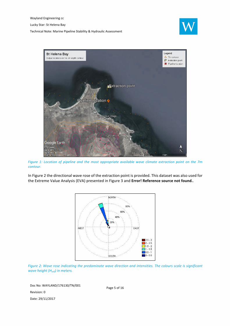
InFigure1theextractionpointutilisedforthepresentanalysisisindicated.Thispointwaschosenas
aconservativeestimateasitisslightlylessshelteredfromtheincomingwaveclimatethantheother
modeloutputlocationsincloserproximitytothepipeline.Thisconservativeapproachwasadopted
astheclosestmodeloutputlocationstothelocationofinterestareinfactmoreshelteredthanthe
locationofinterest.
WaylandEngineeringcc
LuckyStar:StHelenaBay
TechnicalNote:MarinePipelineStability&HydraulicAssessment
DocNo:WAYLAND/176130/TN/001 Revision:0
Date:29/11/2017
Page5of16
Figure 1: Location of pipeline and themost appropriate availablewave climate extraction point on the 7mcontour.
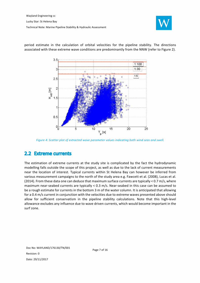
InFigure2thedirectionalwaveroseoftheextractionpointisprovided.Thisdatasetwasalsousedfor
theExtremeValueAnalysis(EVA)presentedinFigure3andError!Referencesourcenotfound..
Figure2:Waveroseindicatingthepredominatewavedirectionandintensities.Thecoloursscaleissignificantwaveheight(Hm0)inmeters.

WaylandEngineeringcc
LuckyStar:StHelenaBay
TechnicalNote:MarinePipelineStability&HydraulicAssessment
DocNo:WAYLAND/176130/TN/001 Revision:0
Date:29/11/2017
Page6of16
Figure3:ExtremeValueAnalysisfortheextractionpointwaveclimateindicatedinFigure1.Indicatedaretheextremesignificantwaveheight(Hm0)returnperiods.
Table1:ExtremeValueAnalysisfortheextractionpointwaveclimateindicatedinFigure1.Indicatedaretheextreme significantwave height (Hm0) return periods. The return periods are also provided as a function ofdirectionalsectors.
EXTREMESTORMRETURNPERIOD
DIRECTION Events Events/
Year
1:1 1:5 1:10 1:25 1:30 1:40 1:50 1:100
ALL 684 40.691 2.38 2.77 2.92 3.12 3.15 3.21 3.26 3.4
N 636 37.836 2.35 2.72 2.87 3.06 3.09 3.15 3.19 3.33
NE 14 0.833 1.15 1.72 1.97 2.31 2.38 2.48 2.57 2.82
NW 19 1.130 1.16 1.60 1.74 1.9 1.93 1.98 2.01 2.12
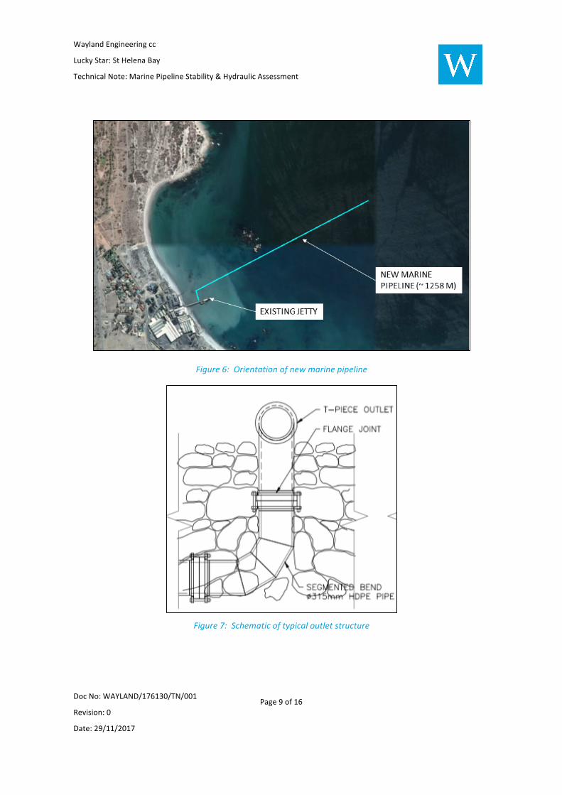
InFigure4ascatterplotoftheentirewaverecordofsignificantwaveheightsvspeakperiodsare
provided. The 1:100, 1:30 and 1:5-year significantwave heights are also indicated. In a thorough
analysis,theEVAofthewindseasandswellshouldbetreatedseparately,especiallybecauseboth
componentscontributedtotheextremewaveheightanalysispresentedabove.Aconservativerange
ofextremepeakperiodsarethussuggested.Largerperiodwaveswillproducehighernear-bottom
currentsactingonthepipeline.Itisthussuggestedthatavalueof18sbeusedasaconservativepeak
WaylandEngineeringcc
LuckyStar:StHelenaBay
TechnicalNote:MarinePipelineStability&HydraulicAssessment
DocNo:WAYLAND/176130/TN/001 Revision:0
Date:29/11/2017
Page7of16
period estimate in the calculation of orbital velocities for the pipeline stability. The directions
associatedwiththeseextremewaveconditionsarepredominantlyfromtheNNW(refertoFigure2).
Figure4:Scatterplotofextractedwaveparametervaluesindicatingbothwindseasandswell.
2.2 Extremecurrents
Theestimationofextremecurrentsat the study site is complicatedby the fact thehydrodynamic
modellingfallsoutsidethescopeofthisproject,aswellasduetothelackofcurrentmeasurements
near the locationof interest. Typical currentswithin StHelenaBay canhoweverbe inferred from
variousmeasurementcampaignstothenorthofthestudyareae.g.Fawcettetal.(2008),Lucasetal.
(2014).Fromthesedataonecandeducethatmaximumsurfacecurrentsaretypically<0.7m/s,where
maximumnear-seabedcurrentsaretypically<0.3m/s.Near-seabedinthiscasecanbeassumedto
bearoughestimateforcurrentsinthebottom3mofthewatercolumn.Itisanticipatedthatallowing
fora0.4m/scurrentinconjunctionwiththevelocitiesduetoextremewavespresentedaboveshould
allow for sufficient conservatism in the pipeline stability calculations. Note that this high-level
allowanceexcludesanyinfluenceduetowavedrivencurrents,whichwouldbecomeimportantinthe
surfzone.

WaylandEngineeringcc
LuckyStar:StHelenaBay
TechnicalNote:MarinePipelineStability&HydraulicAssessment
DocNo:WAYLAND/176130/TN/001 Revision:0
Date:29/11/2017
Page8of16
3 PipelineConfigurationPresentlytheeffluentfromthefactoryisdischargeviaapipelinewhichextendsfromasumponland
totheendofanexistingjetty.Thetotallengthoftheexistingpipeline(measuredfromthesumpto
theendofjetty)is135m.TheexistingpipelineconsistofuPVCwithaninternaldiameterof300mm.
AschematicoftheexistingpipelineisillustratedintheFigurebelow.
Figure5:Schematicofexistingoutfallpipeline
ItisproposedtoreplacetheexistingpipelinewithanewpipelineconsistingofanewuPVCpipeline
onshoreandanewoffshorepipelinewhichwillconsistofHDPEmaterialandapproximately1258m
inlengthmeasuredfromtheconnectionattheendofthejettytoapproximately10mwaterdepthas
illustratedinFigure6.Thetotallengthofthepipelineisanticipatedtobe1393mlong.
Themarinepipelinewillbelaiddirectlyontheseabed(fromtheconnectionattheexistingjetty)and
weighteddownbymeansofconcretecollars,spaced4mc/c.RefertoSection4ofthisdocumentfor
amoredetaileddescriptionoftheconcretecollars.
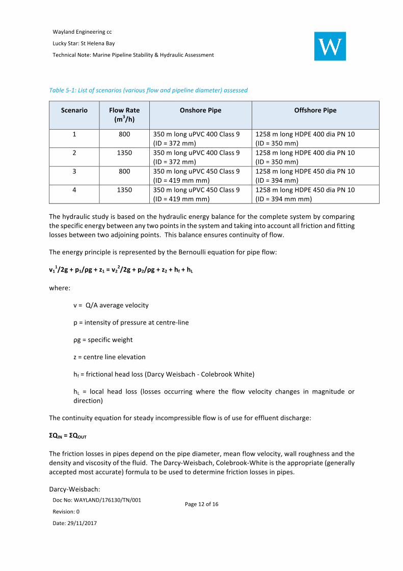
Anoutletstructure,consistingofaT-piecesection(2xports)willbeconnectedtotheoffshoreendof
themarinepipeline. Theportsaretobemanufacturedfroma315mmnominaldiameterteeand
each port will have an internal diameter of 276 mm. The tee will be orientated to discharge
horizontally.TheT-pieceoutletwillbeprotectedbyrockorgravelbagstopreventrotationdueto
localscourandminimizetheriskofvesselanchorscatchingtheoutletstructure.Aschematicofthe
T-pieceoutletstructureisillustratedinFigure7below.
WaylandEngineeringcc
LuckyStar:StHelenaBay
TechnicalNote:MarinePipelineStability&HydraulicAssessment
DocNo:WAYLAND/176130/TN/001 Revision:0
Date:29/11/2017
Page9of16
Figure6:Orientationofnewmarinepipeline
Figure7:Schematicoftypicaloutletstructure

WaylandEngineeringcc
LuckyStar:StHelenaBay
TechnicalNote:MarinePipelineStability&HydraulicAssessment
DocNo:WAYLAND/176130/TN/001 Revision:0
Date:29/11/2017
Page10of16
4 PipelineStabilityDesignOnbottomstabilityofthepipelineisensuredthroughtheadditionofconcreteweightcollarstothe
pipeline.TheweightofeachconcretecollarisdeterminebasedonguidelinespublishedbyDetNorsk
Veritas,DNVRP F109On-BottomDesign of Submarine Pipelines. The intentionof thedesign is toachieveabsolutestabilityandisbasedona2-dimensionalresolutionofforces.Belowisaschematic
oftheforcesactingonthepipeline.
Figure8:2-DimensionalStabilityAnalysisMethod.
Therequiredsubmergedweightisdeterminedbasedonthefollowingequation:
!" =$% +$( + )$(
) *"+
Where
Ws=Submergedweight
FH=HorizontalForce(consistingofbothdragandinertialcomponents)
FL=LiftForce
gsc=SafetyFactor
µ=CoulombFrictionFactorforpipeinsand(0.6)
Thehorizontalandliftforcesarecalculatedbasedonthehydrodynamicloadonthepipelineattributed
tobothwaveandcurrentloading.AiryWaveTheoryisusedtocalculatethewaterparticlevelocityat
the pipeline resting on the seabed. Due to the water depth and wave length, in this case the

WaylandEngineeringcc
LuckyStar:StHelenaBay
TechnicalNote:MarinePipelineStability&HydraulicAssessment
DocNo:WAYLAND/176130/TN/001 Revision:0
Date:29/11/2017
Page11of16
approximationfortransitionalwaveswasusedtocalculatethevelocity.Thecomponentofthewater
particle motions perpendicular to the pipeline were calculated and used to determine the
hydrodynamichorizontalandverticalforces.
Belowisanimageofatypicalconcreteweightcollar.
Figure9:TypicalConcreteWeightCollar.
Thecollarsaretobespacedat4mcentretocentre,andwillhaveanin-airweightof770kgtoachieve
anin-waterweightof106kg/maveragedoverthelengthofthepipeline.
Theconcretecollarsaretobeheldinpositionwithstainlesssteelboltsforcorrosionresistance.
5 HydraulicAssessmentThehydraulicperformanceofthesystemwasassessedforanumberofscenarios.Duetotheageand
highfrictionallossesthroughtheexisting300mdiameteruPVCpipelineitisrecommendedthatthis
shouldbereplacedaspartoftheprojectworks.
Thepipelinevelocityandfrictionlosseswereassessedbasedonanew400mmnominaldiameterand
comparedwitha450mmnominaldiameterpipeline.
Theconfigurationwhichwasassessed(i.e.pipelinelength,material,etc.)isdescribedinSection3of
thisdocument.
Thefollowingtabledetailsthescenariosassessed.
WaylandEngineeringcc
LuckyStar:StHelenaBay
TechnicalNote:MarinePipelineStability&HydraulicAssessment
DocNo:WAYLAND/176130/TN/001 Revision:0
Date:29/11/2017
Page12of16
Table5-1:Listofscenarios(variousflowandpipelinediameter)assessed
Scenario FlowRate(m3/h)
OnshorePipe OffshorePipe
1 800 350mlonguPVC400Class9
(ID=372mm)
1258mlongHDPE400diaPN10
(ID=350mm)
2 1350 350mlonguPVC400Class9
(ID=372mm)
1258mlongHDPE400diaPN10
(ID=350mm)
3 800 350mlonguPVC450Class9
(ID=419mmmm)
1258mlongHDPE450diaPN10
(ID=394mm)
4 1350 350mlonguPVC450Class9
(ID=419mmmm)
1258mlongHDPE450diaPN10
(ID=394mmmm)
Thehydraulicstudyisbasedonthehydraulicenergybalanceforthecompletesystembycomparing
thespecificenergybetweenanytwopointsinthesystemandtakingintoaccountallfrictionandfitting
lossesbetweentwoadjoiningpoints.Thisbalanceensurescontinuityofflow.
TheenergyprincipleisrepresentedbytheBernoulliequationforpipeflow:
v11/2g+p1/ρg+z1=v2
2/2g+p2/ρg+z2+hf+hL
where:
v=Q/Aaveragevelocity
p=intensityofpressureatcentre-line
ρg=specificweight
z=centrelineelevation
hf=frictionalheadloss(DarcyWeisbach-ColebrookWhite)
hL = local head loss (losses occurring where the flow velocity changes in magnitude or
direction)
Thecontinuityequationforsteadyincompressibleflowisofuseforeffluentdischarge:
ΣQIN=ΣQOUT
Thefrictionlossesinpipesdependonthepipediameter,meanflowvelocity,wallroughnessandthe
densityandviscosityofthefluid.TheDarcy-Weisbach,Colebrook-Whiteistheappropriate(generally
acceptedmostaccurate)formulatobeusedtodeterminefrictionlossesinpipes.
Darcy-Weisbach:

WaylandEngineeringcc
LuckyStar:StHelenaBay
TechnicalNote:MarinePipelineStability&HydraulicAssessment
DocNo:WAYLAND/176130/TN/001 Revision:0
Date:29/11/2017
Page13of16
hf=(λLv2)/(2gD)
where:
hf=headlossduetofriction
λ=frictionfactor
v=effluentvelocity
D=diameterofpipe
L=lengthofpipe
g=accelerationduetogravity
λiscalledthepipefrictionfactorandcanbedeterminedbyapplyingtheColebrook-Whiteformula:
Colebrook-Whiteformula:
λ=0.25{log10{ks/3.7D+2.51/(Reλ1/2)}]-2
where:
kS=roughnessheight(mm)
Re=Reynoldsnumber
Reynoldsnumber
Re=rvD/µ
where:
r =Fluiddensity(kg/m3)
v=Velocity(m/s)
D=Diameter(m)
µ=Viscosity(kg/m.s)
ThemainoutfallpipevelocityandfrictionlossesforallscenariosarelistedinTable5-2below:
WaylandEngineeringcc
LuckyStar:StHelenaBay
TechnicalNote:MarinePipelineStability&HydraulicAssessment
DocNo:WAYLAND/176130/TN/001 Revision:0
Date:29/11/2017
Page14of16
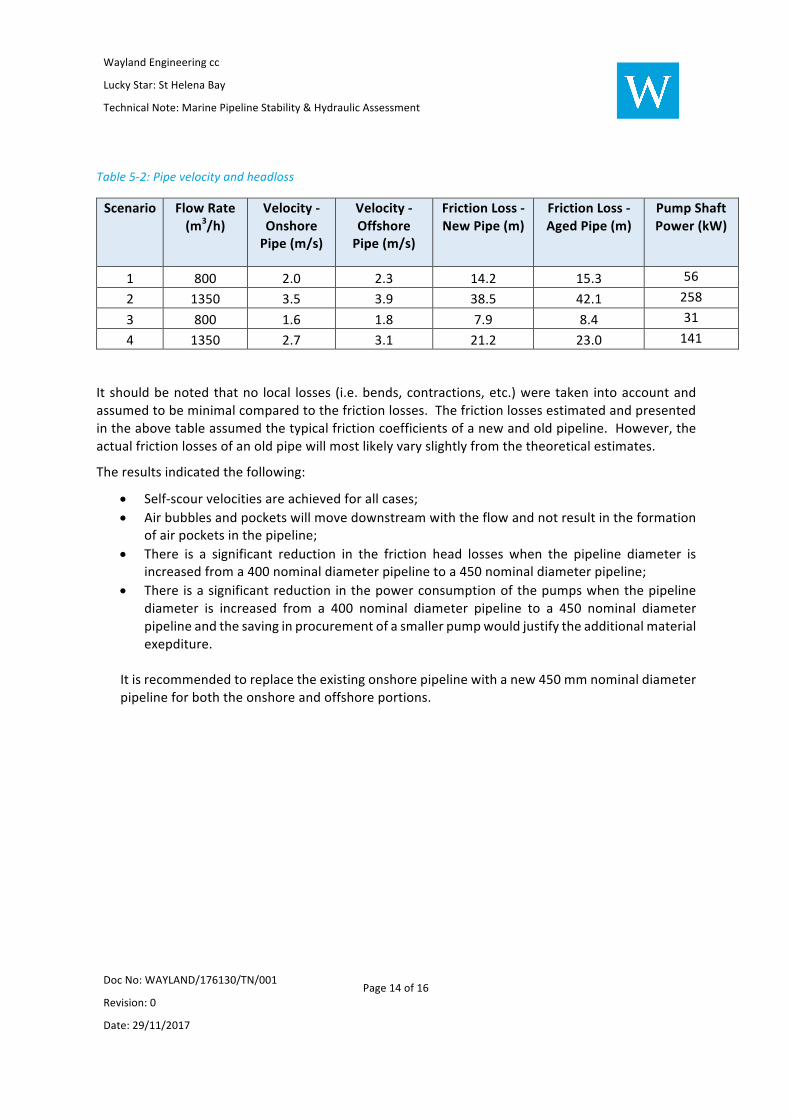
Table5-2:Pipevelocityandheadloss
Scenario FlowRate(m3/h)
Velocity-OnshorePipe(m/s)
Velocity-OffshorePipe(m/s)
FrictionLoss-NewPipe(m)
FrictionLoss-AgedPipe(m)
PumpShaftPower(kW)
1 800 2.0 2.3 14.2 15.3 56
2 1350 3.5 3.9 38.5 42.1 258
3 800 1.6 1.8 7.9 8.4 31
4 1350 2.7 3.1 21.2 23.0 141
It shouldbenotedthatno local losses (i.e.bends,contractions,etc.)weretaken intoaccountand
assumedtobeminimalcomparedtothefrictionlosses.Thefrictionlossesestimatedandpresented
intheabovetableassumedthetypicalfrictioncoefficientsofanewandoldpipeline.However,the
actualfrictionlossesofanoldpipewillmostlikelyvaryslightlyfromthetheoreticalestimates.
Theresultsindicatedthefollowing:
• Self-scourvelocitiesareachievedforallcases;
• Airbubblesandpocketswillmovedownstreamwiththeflowandnotresultintheformation
ofairpocketsinthepipeline;
• There is a significant reduction in the friction head losses when the pipeline diameter is
increasedfroma400nominaldiameterpipelinetoa450nominaldiameterpipeline;
• There isasignificantreductioninthepowerconsumptionofthepumpswhenthepipeline
diameter is increased from a 400 nominal diameter pipeline to a 450 nominal diameter
pipelineandthesavinginprocurementofasmallerpumpwouldjustifytheadditionalmaterial
exepditure.
Itisrecommendedtoreplacetheexistingonshorepipelinewithanew450mmnominaldiameter
pipelineforboththeonshoreandoffshoreportions.

WaylandEngineeringcc
LuckyStar:StHelenaBay
TechnicalNote:MarinePipelineStability&HydraulicAssessment
DocNo:WAYLAND/176130/TN/001 Revision:0
Date:29/11/2017
Page15of16
6 ReferencesDean,R.(1965).”Streamfunctionrepresentationofnonlinearoceanwaves.JournalofGeophysical
Research,70,4561-4572.
Fawcett,A.,Pitcher,G.,&Shillington,F.(2008).NearshorecurrentsonthesouthernNamaquashelf
oftheBenguelaupwellingsystem.ContinentalShelfResearch,1026-1039.
Lucas,A.,Pitcher,G.,Probyn,T.,&Kudela,R.(2014).Theinfluenceofdiurnalwindson
phytoplanktondynamicsinacoastalupwellingsystemoffsouthwesternAfrica.Deep-SeaResearchII,50-62.
Theron,A.K.,Rossouw,M.,Rautenbach,C.,Luck-Vogel,M.,&VanNiekerk,L.(2014).SouthAfricanCoastalVulnerabilityAssessment-CSIRContract:Phase2.Stellenbosch:CSIR/DEA.
DNVRPF109(2010)OnBottomStabilityDesignforSubmarinePipelines
HenryT.Falvey(1980)Air-WaterFlowinHydraulicStructures
USArmyCorpofEngineers(2006)CoastalEngineeringManual

WaylandEngineeringcc
LuckyStar:StHelenaBay
TechnicalNote:MarinePipelineStability&HydraulicAssessment
DocNo:WAYLAND/176130/TN/001 Revision:0
Date:29/11/2017
Page16of16
AnnexureA:GeneralLayout–MarinePipeline

NOTES :
1. CO-ORDINATE SYSTEM : UTM - Zone 332. CO-ORDINATE DATUM : WGS843. LEVEL DATUM : METERS CHART DATUM (mCD)
AREV.
1 : 5 000SCALE
A3SIZE
PROJECT :
GENERAL LAYOUT
DO NOT SCALE FROM DRAWING
DRAWING TITLE :
DRAWN : W. M
CHECKED:
DESIGNED :
APPROVED :
DATE :
D. Pitt
M. Le Roux
D. Pitt
2017-11-27
LUCKY STAR MARINE OUTFALL PIPELINE ROUTE
REV DATE DRN DES APP REVISIONS DESCRIPTION
REVISIONS
- - - - - -
Registration No. 2008/172141/23
2 Heath StreetNewlands7700Cape TownSouth Africa
Tel : +27 (0)83 648 8942
www.wayland.co.za
171121 PE 001- 01- -PROJECT DISCIPL. ELEMENT SHEET
DRAWING NUMBER
ConsultantClient
C COPYRIGHT RESERVED
2m
2m
3m
3m
2m
2m
4m
4m
6m
6m
7m
7m
8m
8m
9m
9m
2m
3m
3m
4m
4m
4m
4m
6m
7m
6m
6m
8m
7m
7m
4m
4m
4m
4m
4m
9m
9m
9m
9m
9m
5m
5m
10m
10m
5m
5m
Y 780 000
X 6 375 000
Y 780 500
X 6 375 000
Y 779 500
X 6 375 000
Y 779 000
X 6 375 000
Y 780 000
X 6 375 500
Y 780 500
X 6 375 500
Y 779 500
X 6 375 500
Y 779 000
X 6 375 500
Y 780 000
Y 780 500
X 6 376 000
X 6 376 000
Y 779 500
X 6 376 000
X 6 376 000
Y 779 000
uPVC CLASS 9, 135m LONG PIPELINE EXTENTS FROM SUMP ON LAND TO CONNECTION WITH MARINE PIPELINE
LUCKY STAR FISH FACTORY

NOTES :
1.
AREV.
1 : 5 000SCALE
A3SIZE
PROJECT :
TYPICAL WEIGHT COLLAR DETAIL
DO NOT SCALE FROM DRAWING
DRAWING TITLE :
DRAWN : W. M
CHECKED:
DESIGNED :
APPROVED :
DATE :
D. Pitt
M. Le Roux
D. Pitt
2017-11-27
LUCKY STAR MARINE OUTFALL PIPELINE ROUTE
REV DATE DRN DES APP REVISIONS DESCRIPTION
REVISIONS
- - - - - -
Registration No. 2008/172141/23
2 Heath StreetNewlands7700Cape TownSouth Africa
Tel : +27 (0)83 648 8942
www.wayland.co.za
171121 PE 001- 02- -PROJECT DISCIPL. ELEMENT SHEET
DRAWING NUMBER
ConsultantClient
C COPYRIGHT RESERVED
r=200mm PIPE
r=215mm
15mmTHK NEOPRENE LINER
WEIGHT COLLAR DETAIL
SCALE 1 : 10
Related Documents