S&T HEAT EXCHANGERS, Part I: Configuration, TEMA; Tube thk, Tubesheet and Flat Covers STUDY NOTES Instructor: Javier Tirenti [email protected] www.arvengconsulting.com

Welcome message from author
This document is posted to help you gain knowledge. Please leave a comment to let me know what you think about it! Share it to your friends and learn new things together.
Transcript

S&T HEAT EXCHANGERS, Part I:
Configuration, TEMA; Tube thk,
Tubesheet and Flat Covers
STUDY NOTES
Instructor: Javier Tirenti
www.arvengconsulting.com

Training
Projects
Connecting Dots
SHELL & TUBE HEAT EXCHANGERS, PART I – Instructor: Javier Tirenti Page 2
Table of contents
Introduction .................................................................................................... 4
1. Terminology ............................................................................................. 8
1.1) Fluids ................................................................................................ 8
1.2) Pressure ............................................................................................ 8
1.3) Temperature ...................................................................................... 9
1.4) External loads .................................................................................. 10
1.5) Other definitions ............................................................................. 11
2. Shell and tube heat exchangers .............................................................. 12
2.1) Parts of heat exchangers ................................................................. 13
2.2) Types of heat exchangers ................................................................ 15
2.3) Main components ............................................................................ 17
2.4) TEMA heat exchanger selection ....................................................... 20
3. Design codes .......................................................................................... 21
3.1) TEMA code (Tubular Exchangers Manufacturers Association) ........... 22
3.2) HEI Standard (Heat Exchange Institute) ............................................ 25
3.3) API 660–American Petroleum Institute ............................................. 27
3.4) ASME VIII Div.1 Code, UHX part ........................................................ 28
3.5) ASME VIII Div.1 Code, pressure parts ............................................... 29
3.6) Scope and precedence ..................................................................... 33
4. Material Selection ................................................................................... 35
4.1) Corrosion ........................................................................................ 36
4.2) Corrosion types ............................................................................... 37
4.3) Corrosion allowance ........................................................................ 40
4.4) Essential properties of materials ...................................................... 42
4.5) Technical-economical selection ........................................................ 46
4.6) Product forms .................................................................................. 47
4.7) Material designation ........................................................................ 48
4.8) Recommended good practices ......................................................... 50
5. Shell and tube heat exchangers arrangement ......................................... 54
5.1) Tube pattern ................................................................................... 54
5.2) Tube side number of passes ............................................................ 58
5.3) Shell side number of passes ............................................................ 59
6. Tube bundle design ................................................................................ 62

Training
Projects
Connecting Dots
SHELL & TUBE HEAT EXCHANGERS, PART I – Instructor: Javier Tirenti Page 3
6.1) Tubesheet ....................................................................................... 63
6.2) Tube bundle assembly ..................................................................... 69
6.3) Transverse baffles ........................................................................... 71
6.4) Longitudinal baffle .......................................................................... 74
6.5) Tubes .............................................................................................. 76
6.6) Tube – tubesheet joint ..................................................................... 78
6.7) Floating head .................................................................................. 82
6.8) Impingement plate .......................................................................... 85
6.9) Pulling devices ................................................................................. 87
7. Design of external elements ................................................................... 88
7.1) Main parts ....................................................................................... 88
7.2) Flat covers ....................................................................................... 94
8. Bibliography ........................................................................................... 97
Training
Projects
Connecting Dots
SHELL & TUBE HEAT EXCHANGERS, PART I – Instructor: Javier Tirenti Page 4
Introduction
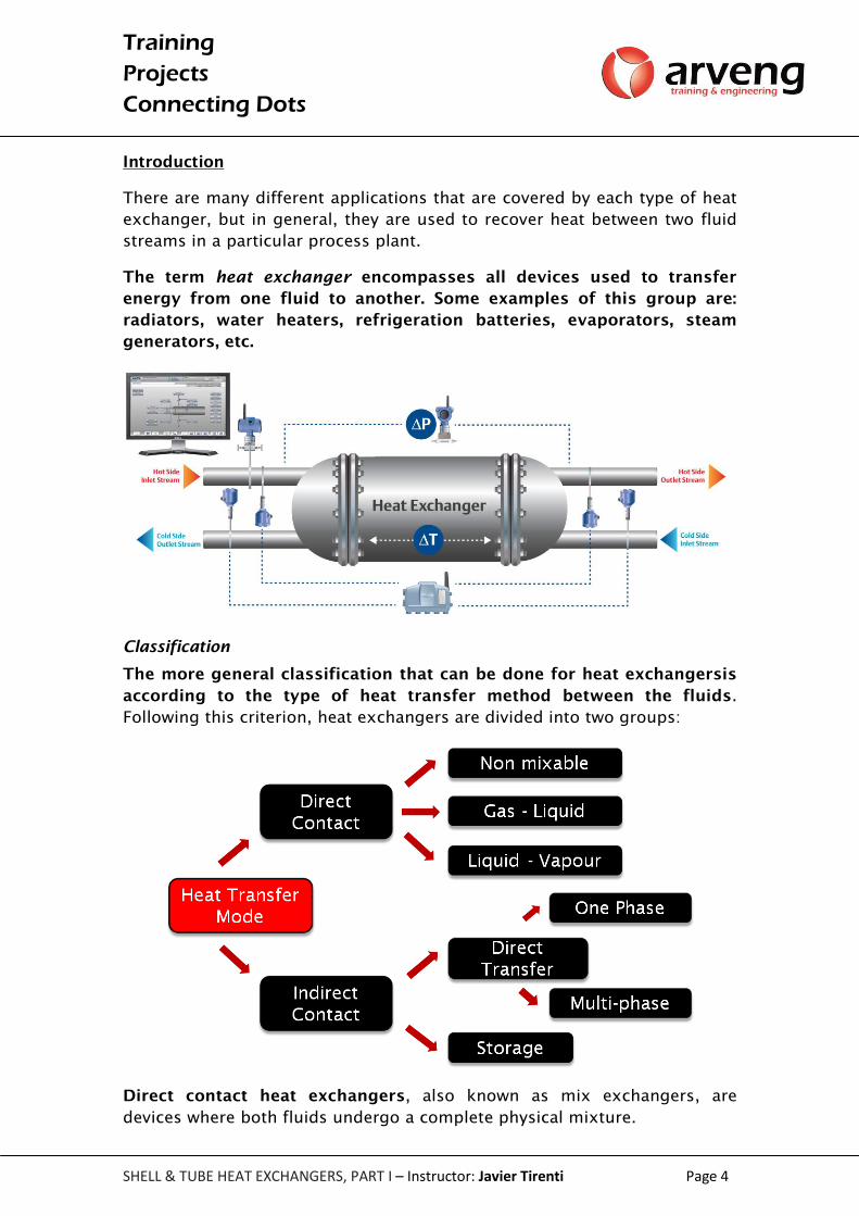
There are many different applications that are covered by each type of heat
exchanger, but in general, they are used to recover heat between two fluid
streams in a particular process plant.
The term heat exchanger encompasses all devices used to transfer
energy from one fluid to another. Some examples of this group are:
radiators, water heaters, refrigeration batteries, evaporators, steam
generators, etc.
Classification
The more general classification that can be done for heat exchangersis
according to the type of heat transfer method between the fluids.
Following this criterion, heat exchangers are divided into two groups:
Direct contact heat exchangers, also known as mix exchangers, are
devices where both fluids undergo a complete physical mixture.

Training
Projects
Connecting Dots
SHELL & TUBE HEAT EXCHANGERS, PART I – Instructor: Javier Tirenti Page 5
Among others, cooling towers and mix condensers belong to the direct
contact heat exchangers group.
On the other hand, devices in which heat transfer takes place through a
flat or cylindrical surface are called indirect contact exchangers. There
is a barrier that physically separates the two fluid flows, thus there being no
possibility of direct contact or contamination between such fluids, except in
case of damage of the separation barrier.
Examples of this type of heat exchanger areshell and tube exchangers,
double tube exchangers and plate heat exchangers.
On the other hand, according to their type of construction, exchangers are
classified as:
In multi-tubular or shell and tube heat exchangers, it is usual to combine
the above classification to anotherbased on the number of times each
particle of the fluidtravels the entire exchanger length, a process called a
“pass”.
In addition to their type of construction, tubular exchangers are often
classified based on the relative directionflow of both fluids. Thus, there
are parallel and cross flow heat exchangers, according to the direction of
the streams inside the exchanger.
Additionally, tubular exchangers having same direction and sense are
called co-current. When the flow circulates in opposite direction, the
heat exchanger is operating in counter counter.
Parallel flow heat exchangers mostly used in industrial plants are, among
others: plate and frame, double tube, shell and tube and hair pin.

Training
Projects
Connecting Dots
SHELL & TUBE HEAT EXCHANGERS, PART I – Instructor: Javier Tirenti Page 6
Training
Projects
Connecting Dots
SHELL & TUBE HEAT EXCHANGERS, PART I – Instructor: Javier Tirenti Page 7
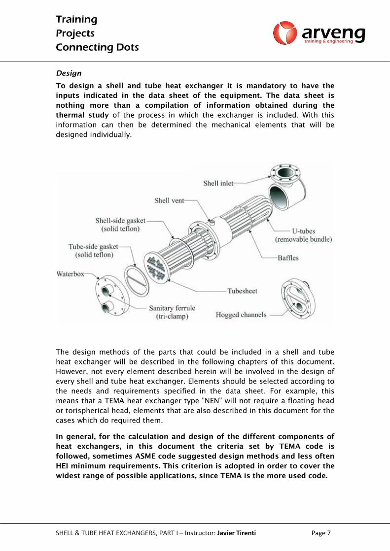
Design
To design a shell and tube heat exchanger it is mandatory to have the
inputs indicated in the data sheet of the equipment. The data sheet is
nothing more than a compilation of information obtained during the
thermal study of the process in which the exchanger is included. With this
information can then be determined the mechanical elements that will be
designed individually.
The design methods of the parts that could be included in a shell and tube
heat exchanger will be described in the following chapters of this document.
However, not every element described herein will be involved in the design of
every shell and tube heat exchanger. Elements should be selected according to
the needs and requirements specified in the data sheet. For example, this
means that a TEMA heat exchanger type "NEN" will not require a floating head
or torispherical head, elements that are also described in this document for the
cases which do required them.
In general, for the calculation and design of the different components of
heat exchangers, in this document the criteria set by TEMA code is
followed, sometimes ASME code suggested design methods and less often
HEI minimum requirements. This criterion is adopted in order to cover the
widest range of possible applications, since TEMA is the more used code.

Training
Projects
Connecting Dots
SHELL & TUBE HEAT EXCHANGERS, PART I – Instructor: Javier Tirenti Page 8
1. Terminology
1.1) Fluids
1.1.1) Tube side
The fluid flowing inside the tubes (that belong to the tube bundle) is
called the tube side of a shell and tube heat exchanger.
1.1.2) Shell side
On the contrary, the fluid flowing inside the shell is called the shell side
of a shell and tube heat exchanger.
1.2) Pressure
1.2.1) Internal Pressure
The difference between the operation (Po) and design pressure (Pd) is a
safety margin. This margin exists because sometimes it is difficult to establish
operation conditions with certainty. If we need to design but only have
operating pressure, a workaround could be as follows:
If Po > 300 psi →Pd = 1.1. Po.
If Po ≤ 300 psi → Pd = Po + 30 psi
Where Pd is the design pressure, and Po is the operating pressure.
When determining the design pressure (Pd), the hydrostatic head
(pressure of the fluid column) should be considered, especially in vertical
cylindrical vessels.
Training
Projects
Connecting Dots
SHELL & TUBE HEAT EXCHANGERS, PART I – Instructor: Javier Tirenti Page 9
1.2.2) External pressure
If under operating conditions the equipment gets depressurized or
operates under vacuum, at that moment the atmospheric pressure is
acting outside the pressure vessel.
At sea level, atmospheric pressure is 1 atm. According to the location (height
above sea level) at which the equipment is to be installed, we should see the
atmospheric pressure declining. To simplify the calculations, and always on the
safe side, usually 1 atm external pressure is taken without considering the
height above sea level.
Steam out or blanketing
When performing a steam out operation (used to clean the vessel) using high
or medium steam pressure, steam can condense due to a temperature change
and produce vacuum. Depending on the temperature of the steam used, it is
advisable to calculate the equipment under external pressure due to vacuum.
1.2.3) Maximum allowable working pressure (MAWP)
MAWP is the maximum continuous working pressure that the vessel could
operate, assuring that the equipment will not deform plastically.
Is MAWP the same as the design pressure? The answer is NO. Adopted
thicknesses usually exceed the required thickness by calculation. This excess
is what generates the pressure to jump up to the MAWP.
The MAWP is a consequence of over-thickness due to: commercial thicknesses,
margin of safety and manufacturing methods.
When dealing with shell and tube heat exchangers, it is important to
mention that many of the parts of this equipmentface the effect of pressure,
temperature or corrosion from both the tube side and the shell side. Since
design conditions may be different for the tube side and for the shell side,
the most critical condition should be always specified.
1.2.4) Test pressure (Pt)
The test pressure is commonly known as hydrostatic test pressure. This
test is carried out once the heat exchanger manufacturing process is
completed. This test consists in filling the equipment with water while it is
subjected to pressure as indicated by the ASME code (to be discussed
later).
1.3) Temperature
1.3.1) Minimum temperature
It is the minimum temperature at which membrane stress occurs due to an
environmental or process condition. The client or process department must
provide this information. If this information is not available and there are no

Training
Projects
Connecting Dots
SHELL & TUBE HEAT EXCHANGERS, PART I – Instructor: Javier Tirenti Page 10
process requirements, we look for the historical minimum temperature of the
site.
1.3.2) Minimum design metal temperature (MDMT)
MDMT is the minimum temperature that our material is able to resist
against a brittle fracture. It is a property of the material.
1.3.3) Operating temperature (To)
It is the shell and tube heat exchanger temperature, considering normal
operating conditions.
1.3.4) Design temperature (Td)
It is the temperature to be used in the design of the heat exchanger. Same as
with the design pressure, this value is defined by the thermal design. When only
the operating temperature is known, it could be estimated as follows:
For fluids operating above 0ºC, the design temperature should be the
greater of the following expressions:
o To x 1,1
o To + 15 º C
o 65º C
For fluids operating at a temperature of 0º C or lower, it should be
simultaneously specified the minimum and maximum expected
temperature, the latter being not less than 65º C for the shell side. This
consideration is made in order to consider the hot air flow during the
drying operation, after the hydrostatic test.
1.4) External loads
1.4.1) Wind, snow and earthquake
These external conditions are imposed according to the place of installation of
the equipment. Ideally, a detailed study of the legislation of the place shall be
carried out; misreading values represent a lot of man-hour rework.
To analyze combined actions is essential to review the requirements of the
client.
1.4.2) Cyclic loading
If a pressure vessel has a requirement of cyclical service, the equipment should
meet the requirements of fatigue analysis of Div.2. Does this mean that the
entire pressure vessel should be designed according to the Div.2? NO. The
vessel can be design according to Div.1, but must also meet the requirements
for fatigue analysis according Div.2.

Training
Projects
Connecting Dots
SHELL & TUBE HEAT EXCHANGERS, PART I – Instructor: Javier Tirenti Page 11
An alternative to the fatigue analysis according to the provisions of Part 5 Div.2
is FEA. This latter method is being used more and more nowadays.
1.5) Other definitions
1.5.1) Design stress (S)
It is the maximum stress value that a material, that forms part of a shell
and tube heat exchanger, can undergo in normal operation. Its value is
based on 25% of the final tensile strength of the material.
1.5.2) Joint efficiency (E)
Joint efficiency can be defined as the reliability that you can obtain from
welded joint. This coefficient can be values smaller than 1, and it can be
said that the joint efficiency is a way of reducing the allowable stress of
the material. Therefore, the joint efficiency depends on the level of non-
destructive examination (NDE) and the category and type of the weld we use
for joining two pieces of equipment.

Training
Projects
Connecting Dots
SHELL & TUBE HEAT EXCHANGERS, PART I – Instructor: Javier Tirenti Page 12
2. Shell and tube heat exchangers
A heat exchanger is a device in which two fluids, one through the tube
side and the other through the shell side, circulating at different
temperature conditions, exchange heat through the walls of the tubes,
without direct contact between them.
There are different types of shell and tube exchanger, one of the most used
classifications is shown below:
The most widely used shell and tube heat exchangers in industrial
processes are horizontal and pressurized circulation. Therefore, this type of
heat exchanger will be studied in later chapters.
Horizontal shell and tube heat exchangers can take several configurations.
Different alternatives, geometries and configurations are described in the
following chapters.
Training
Projects
Connecting Dots
SHELL & TUBE HEAT EXCHANGERS, PART I – Instructor: Javier Tirenti Page 13
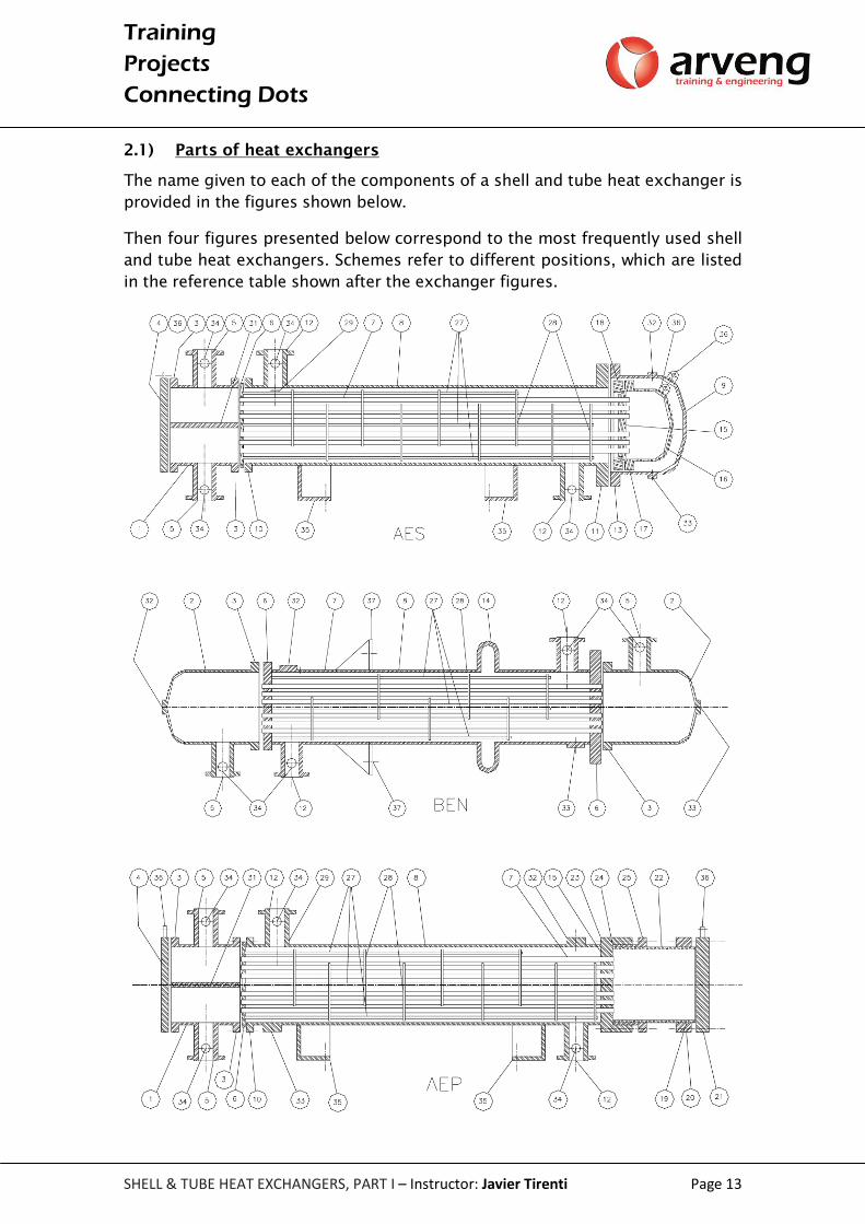
2.1) Parts of heat exchangers
The name given to each of the components of a shell and tube heat exchanger is
provided in the figures shown below.
Then four figures presented below correspond to the most frequently used shell
and tube heat exchangers. Schemes refer to different positions, which are listed
in the reference table shown after the exchanger figures.

Training
Projects
Connecting Dots
SHELL & TUBE HEAT EXCHANGERS, PART I – Instructor: Javier Tirenti Page 14
1. Stationary head with flat cover 20. Sliding flange
2. Stationary head with elliptical cover 21. Floating head flat cover
3. Flange of stationary head 22. Floating head shell
4. Flat cover of stationary head 23. Gasket box
5. Stationary head inlet nozzle 24. Gasket
6. Fixed tubesheet 25. Box counter flange
7. Tubes 26. Sealing ring
8. Shell 27. Tie rods and spacers
9. Shell head 28. Transverse baffles
10. Shell flange mating tubesheet 29. Impingement plate
11. Shell flange mating shell head 30. Longitudinal baffle
12. Shell inlet nozzle 31. Partition pass plate
13. Shell head flange 32. Shell flange mating shell head
14. Expansion joint 33. Shell head flange mating shell
15. Floating tubesheet 34. Instrumentation nozzle
16. Floating tubesheet head 35. Saddles or supports
17. Floating tubesheet flange 36. Lifting device
18. Floating tubesheet counter flange 37. Support brackets
19. Floating tubesheet backing ring

Training
Projects
Connecting Dots
SHELL & TUBE HEAT EXCHANGERS, PART I – Instructor: Javier Tirenti Page 15
2.2) Types of heat exchangers
2.2.1) Fixed tubesheet
This kind of exchanger features two fixed plates at both ends of the
tube bundle.
Advantages: its fabrication is the most economical of all types, minimizing
jacketed gaskets, thereby reducing potential leakage.
Disadvantages: the shell and outside of the tubes of the bundle cannot be
mechanically cleaned or physically inspected. For significant temperature
gradients, it presents structural problems, caused by differential
thermal expansion between the shell and the tube bundle
2.2.2) U tube
In this case, there is only one tubesheet anchoring all tubes that are U-
shaped. Thus, the fluid returns to the stationary head.
Advantages: this kind of exchanger can handle high pressure and
temperature fluids in the tube side. Another positive aspect is its ability to
freely absorb thermal expansions at low cost.
Disadvantages: it is difficult to mechanically clean the internal part of the
tubes. Moreover, the number of passes in the tube side is limited.

Training
Projects
Connecting Dots
SHELL & TUBE HEAT EXCHANGERS, PART I – Instructor: Javier Tirenti Page 16
2.2.3) Floating tubesheet
These exchangers are a mixture of the two presented above. Although
thetubes are not U-shaped, the fluid returns to the stationary head due to
the floating head that is design at the end of the tube bundle.
Advantages: this configuration is the best option for inspection,
maintenance and repair.It eliminates differential thermal expansion effects
between the tube bundle and the shell, as a result of the free movement of the
floating head.
Disadvantages: the manufacturing cost is the highest of all configurations.
Due to the numerous jacketed gaskets present, it is not the best option for
toxic or hazardous processes.

Training
Projects
Connecting Dots
SHELL & TUBE HEAT EXCHANGERS, PART I – Instructor: Javier Tirenti Page 17
2.3) Main components
2.3.1) Shell
The shell is a cylindrical body constructed from one or more pieces,
obtained from a rolled plate or a seamless tube, containing the tube
bundle. The fluid bathing the tubes and the tube bundle circulates inside
the shell. It is one of the most important parts of a shell and tube heat
exchanger, especially from the structural point of view.
2.3.2) Tube bundle
The tube bundle is a component formed mainly by tubes and baffles. This
bundle is located inside de shell, following the same alignment. The
function of the tubes is to transfer heat between the two present fluids. The
baffles support the tubes, create turbulence and direct the fluid flowing
outside the tubes.

Training
Projects
Connecting Dots
SHELL & TUBE HEAT EXCHANGERS, PART I – Instructor: Javier Tirenti Page 18
2.3.3) Tubesheet
The tube bundle ends in circular perforated plates called Tubesheets.
Their main purposes are to divide the flow between the shell side and
tube side flow and secondly to anchor all the tubes of the bundle.
Tubes cross the tubesheet from side to sideinside the drilled holes; these
tubes will be sealed against the tubesheet thru expansion or welding. The
aim is to join both elements permanently.
2.3.4) Tubes
The function of the tubes is to transfer heat between the two present
fluids Tubes are standard length, whose nominal diameter coincides with
the outer diameter, and it is normally specified using the Birmingham
Gauge system, known as BWG.

Training
Projects
Connecting Dots
SHELL & TUBE HEAT EXCHANGERS, PART I – Instructor: Javier Tirenti Page 19
2.3.5) Stationary head
From a structural point of view, the stationary head is similar to the shell. Its
function is to receive the tube side fluid, distribute it in the different
passes and collect it to send it outside the exchanger.
2.3.6) Floating head
The floating head is formed by the floating tubesheet, aspherical head
and a split backing ring the entire assembly bolted together. The
purpose is returning the fluid circulating inside the tubes to the
stationary head.The fabrication of floating heads is complex, requires
many hours of machining and strict quality controls. Nevertheless, leaks
can occur due to the large number of jacketed gaskets present.

Training
Projects
Connecting Dots
SHELL & TUBE HEAT EXCHANGERS, PART I – Instructor: Javier Tirenti Page 20
2.4) TEMA heat exchanger selection
Main parts of a shell and tube heat exchanger have been described
previously; the question is, what kind of shell and tube heat exchangers
are used for which applications and why?
The thermal designer is the person with the required ability to select, through
well-defined criteria, the type of exchanger that provides the greater benefits
to the process under study. Although the type of exchanger is defined in the
thermal design stage, the mechanical designer must review the design,
warning the thermal designer in case of clashes.
The thermal designer should work basedon good practices and
recommendations as shown below.
Training
Projects
Connecting Dots
SHELL & TUBE HEAT EXCHANGERS, PART I – Instructor: Javier Tirenti Page 97
8. Bibliography
This document has been compiled using different books and references. The
most important ones are:
-Boiler and Pressure Vessel Code: ASME II, part D
ASME VIII, Division 1
-Pressure Vessel Design Manual – DENNIS MOSS
-Standards of Tubular Exchanger Manufacturers Association (TEMA)
-Power Plant Heat Exchangers from Heat Exchange Institute (HEI)
-API Standard 660.
-Process Equipment Design Brownell, Lloyd. E. 1959
Related Documents