Welcome message from author
This document is posted to help you gain knowledge. Please leave a comment to let me know what you think about it! Share it to your friends and learn new things together.
Transcript


12/2006
Series: SSW-07
0899.5318 E/2
SOFT-STARTER
MANUAL

Summary of revisions
The information below describes the revisions in this manual.
Revision Description Chapter
1 First Edition -
2 General Revision -
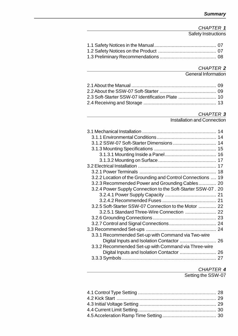
Summary
CHAPTER 1Safety Instructions
1.1 Safety Notices in the Manual.............................................. 071.2 Safety Notices on the Product ........................................... 071.3 Preliminary Recommendations .......................................... 08
CHAPTER 2General Information
2.1About the Manual ............................................................... 092.2 About the SSW-07 Soft-Starter .......................................... 092.3 Soft-Starter SSW-07 Identification Plate ............................ 102.4 Receiving and Storage ...................................................... 13
CHAPTER 3Installation and Connection
3.1 Mechanical Installation ....................................................... 143.1.1 Environmental Conditions ............................................ 143.1.2 SSW-07 Soft-Starter Dimensions ................................ 143.1.3 Mounting Specifications .............................................. 15
3.1.3.1 Mounting Inside a Panel...................................... 163.1.3.2 Mounting on Surface ........................................... 17
3.2 Electrical Installation .......................................................... 173.2.1 Power Terminals ......................................................... 183.2.2 Location of the Grounding and Control Connections .... 193.2.3 Recommended Power and Grounding Cables............. 203.2.4 Power Supply Connection to the Soft-Starter SSW-07 . 20
3.2.4.1 Power Supply Capacity ...................................... 213.2.4.2 Recommended Fuses ........................................ 21
3.2.5 Soft-Starter SSW-07 Connection to the Motor ............. 223.2.5.1 Standard Three-Wire Connection ....................... 22
3.2.6 Grounding Connections ............................................... 233.2.7 Control and Signal Connections................................... 24
3.3 Recommended Set-ups .................................................... 243.3.1 Recommended Set-up with Command via Two-wire
Digital Inputs and Isolation Contactor ........................... 263.3.2 Recommended Set-up with Command via Three-wire
Digital Inputs and Isolation Contactor ........................... 263.3.3 Symbols ...................................................................... 27
CHAPTER 4Setting the SSW-07
4.1 Control Type Setting .......................................................... 284.2 Kick Start .......................................................................... 294.3 Initial Voltage Setting ......................................................... 294.4 Current Limit Setting .......................................................... 304.5 Acceleration Ramp Time Setting........................................ 30

Summary
4.6 Deceleration Ramp Time Setting ....................................... 314.7 Motor Current Setting ........................................................ 324.8 Motor Electronic Overload Protection ................................ 334.9 Reset ................................................................................ 354.10 DI2 Digital Input Setting ................................................... 354.11 Digital Output Relay Operation ......................................... 364.12 Relay output RL1 Programming ....................................... 36
CHAPTER 5Programming Information and Suggestions
5.1 Applications and Programming.......................................... 385.1.1 Voltage Ramp Starting ................................................ 395.1.2 Current Limit Starting................................................... 40
5.2 Protection and Programming ............................................. 415.2.1 Suggestion on How to Program the Thermal Class ...... 415.2.2 Time Reduction from Cold to Hot Starting .................... 435.2.3 Service Factor ............................................................ 44
CHAPTER 6Solutions and Troubleshooting
6.1 Faults and Possible Causes .............................................. 466.2 Troubleshooting ................................................................. 496.3 Preventive Maintenance .................................................... 50
CHAPTER 7Options and Accessories
7.1 IP20 Kit ............................................................................. 51
CHAPTER 8Technical Characteristics
8.1 Rated Powers and Currents According to UL508 ............... 528.2 Rated Powers and Currents for Standard IP55,
IV Pole Weg Motor ............................................................ 528.3 Power Data ....................................................................... 538.4 Electronics and Programming Data ................................... 53

7
SAFETY INSTRUCTIONS
This Manual contains the necessary information for the correct use ofthe Soft-Starter SSW07.It was written to be used by qualified personnel with suitable trainingor technical qualifications to operate this type of equipment.
The following safety notices will be used in the text.
DANGER!Failure to observe the recommended procedures may lead to seriousor fatal injuries and considerable material damage.
ATTENTION!Failure to observe the recommended procedures in this notice maylead to material damage.
NOTE!Important information for the correct understanding and good functionof the product.
The following symbols may be attached to the product as a safetynotice.
High Voltages
Components are sensitive to electrostatic discharge. Do nottouch them.
Mandatory connection to ground protection (PE)
1.2 SAFETYNOTICES ONTHE PRODUCT
1.1 SAFETYNOTICES IN THEMANUAL
CHAPTER 1
CHAPTER 1 - SAFETY INSTRUCTIONS
8
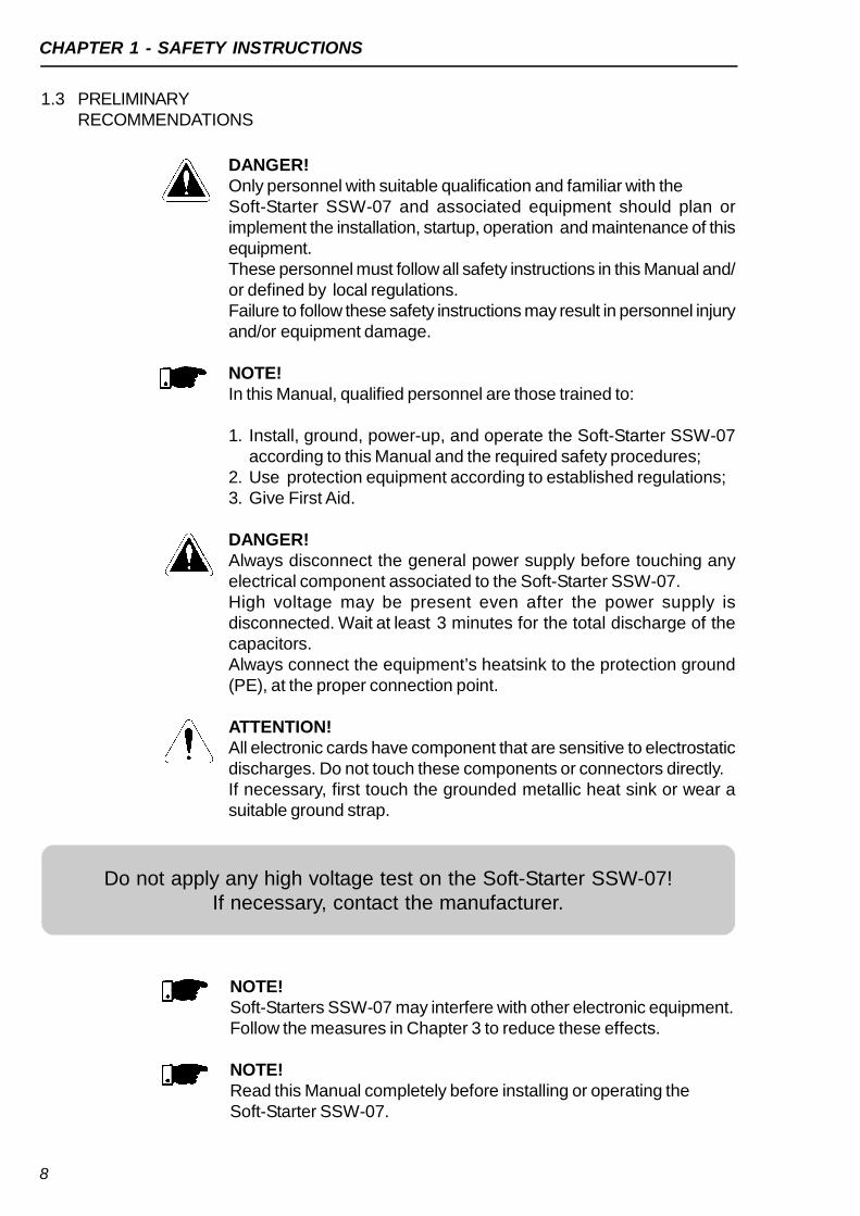
Do not apply any high voltage test on the Soft-Starter SSW-07!If necessary, contact the manufacturer.
DANGER!Only personnel with suitable qualification and familiar with theSoft-Starter SSW-07 and associated equipment should plan orimplement the installation, startup, operation and maintenance of thisequipment.These personnel must follow all safety instructions in this Manual and/or defined by local regulations.Failure to follow these safety instructions may result in personnel injuryand/or equipment damage.
NOTE!In this Manual, qualified personnel are those trained to:
1. Install, ground, power-up, and operate the Soft-Starter SSW-07according to this Manual and the required safety procedures;
2. Use protection equipment according to established regulations;3. Give First Aid.
DANGER!Always disconnect the general power supply before touching anyelectrical component associated to the Soft-Starter SSW-07.High voltage may be present even after the power supply isdisconnected. Wait at least 3 minutes for the total discharge of thecapacitors.Always connect the equipment’s heatsink to the protection ground(PE), at the proper connection point.
ATTENTION!All electronic cards have component that are sensitive to electrostaticdischarges. Do not touch these components or connectors directly.If necessary, first touch the grounded metallic heat sink or wear asuitable ground strap.
1.3 PRELIMINARYRECOMMENDATIONS
NOTE!Soft-Starters SSW-07 may interfere with other electronic equipment.Follow the measures in Chapter 3 to reduce these effects.
NOTE!Read this Manual completely before installing or operating theSoft-Starter SSW-07.
9
GENERAL INFORMATION
This manual presents the soft-starter installation, how to start it up, itsmain technical characteristics and how to identify and correct the mostcommon problems. The manuals listed next must be consulted in orderto get more information regarding the functions, accessories andworking conditions:
Programming Manual, with a detailed description of the parametersand its functions;
RS232 / RS485 Communication Manual.
These manuals are supplied in electronic format on the CD-ROM thataccompanies the soft-starter, or can be obtained at WEG’s web site:http://www.weg.net.
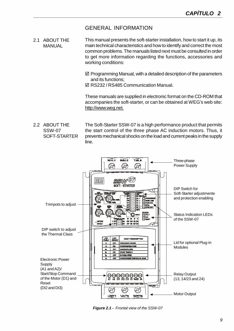
The Soft-Starter SSW-07 is a high performance product that permitsthe start control of the three phase AC induction motors. Thus, itprevents mechanical shocks on the load and current peaks in the supplyline.
2.1 ABOUT THEMANUAL
CAPÍTULO 2
2.2 ABOUT THESSW-07SOFT-STARTER
Figure 2.1 - Frontal view of the SSW-07
Three-phasePower Supply
DIP Switch forSoft-Starter adjustmenteand protection enabling
Status Indication LEDsof the SSW-07
Lid for optional Plug-inModules
Relay Output(13, 14/23 and 24)
Motor Output
Electronic PowerSupply(A1 and A2)/Start/Stop Commandof the Motor (D1) andReset(DI2 and DI3)
DIP switch to adjustthe Thermal Class
Trimpots to adjust

CHAPTER 2 - GENERAL INFORMATION
10
Figure 2.2 - Soft-Starter SSW-07 block diagram
2.3 SOFT-STARTER SSW-07 IDENTIFICATION PLATE
Figure 2.3 - Soft-Starter SSW-07 identification plate
SSW-07 Model
Input Data (Voltage,Number of Phases,
Current and Frequency)
Output Data (Voltage,Number of Phases,
Current and Frequency)
Control Power SupplyData (Voltage,
Frequency)
Serial Number
SoftwareVersion
ManufacturingDate
WEGStock Item
Number
HardwareRevision
Three-PhasePower Supply
ControlPower Supply
ProgrammableDigital Inputs
Programmable DigitalOutputs
Digital SignalProcessor
DSP
Three-Phase Motor PE
R S T A1 A2 Dl2 Dl3 13 14/23 24Dl1
3 x
2 x
RL1 RL2
U V W

CHAPTER 2 - GENERAL INFORMATION
11
Position of the Identification Plate on the Soft-Starter SSW-07:
Figure 2.4 – Detail of the Soft-Starter SSW-07 identification plate
X
FRONTAL VIEW X VIEW
CHAPTER 2 - GENERAL INFORMATION
12
HO
WT
OS
PE
CIF
YT
HE
SS
W-0
7M
OD
EL
:
NO
TE
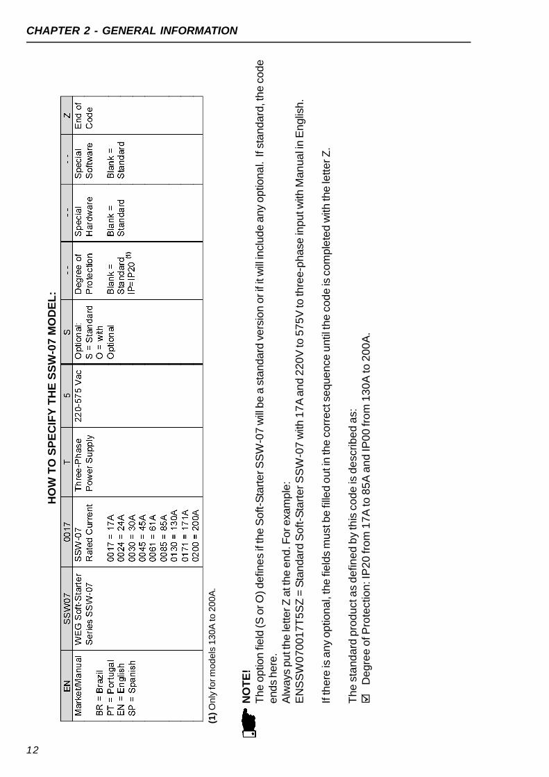
!T
he
optio
nfie
ld(S
orO
)defin
es
ifth
eS
oft-S
tart
erS
SW
-07
will
be
ast
andard
vers
ion
orif
itw
illin
clud
eany
optio
na
l.If
standard
,the
code
ends
here
.A
lways
pu
tthe
letterZ
att
he
en
d.F
orexa
mp
le:
EN
SS
W0
70
01
7T
5S
Z=
Sta
nda
rdS
oft-S
tart
erS
SW
-07
with
17
Aan
d2
20
Vto
57
5V
toth
ree-p
ha
sein
pu
twith
Man
ua
lin
En
glis
h.
Ifth
ere
isa
ny
optio
nal,
the
field
sm
ust
be
fille
do
uti
nth
ecorr
ect
seque
nce
until
the
cod
eis
com
ple
ted
with
the
letterZ
.
Th
esta
nd
ard
pro
du
cta
sd
efin
ed
by
this
co
de
isd
escrib
ed
as:
De
gre
eo
fP
rote
ctio
n:IP
20
fro
m1
7A
to8
5A
an
dIP
00
fro
m1
30
Ato
20
0A
.
(1)O
nly
form
odels
130A
to200A
.

CHAPTER 2 - GENERAL INFORMATION
13
The Soft-Starter SSW-07 is supplied in a cardboard box. On theoutside of the package there is an identification plate which is identicalto the one placed on the Soft-Starter SSW-07.To open the package:1- Put it on a table;2- Open the package;3- Take out the soft-starter.
Check if: The Identification plate of the Soft-Starter SSW-07 matches the
model purchased:
Damage has occurred during transport. If so, contact the carrierimmediately.
If the Soft-Starter SSW-07 is not installed immediately, store it inits package in a clean and dry place (temperature between-10ºC and 65º C), (14ºF and 149ºF).
2.4 RECEIVINGANDSTORAGE
Table 2.1 - Dimensions of the package in mm (in)
Figure 2.5 - Dimensions of the package
SSW-07Model
HeightH
mm(in)
WidthL
mm(in)
DepthP
mm(in)
Volume
cm3
(in3)
Weight
kg(lb)
SSW-070017SSW-070024SSW-070030
221(8.70)
180(7.09)
145(5.71)
5768(352.2)
1.65(3.64)
SSW-070045SSW-070061SSW-070085
260(10.24)
198(7.80)
245(9.65)
12613(770.8)
3.82(8.42)
SSW-070130SSW-070171SSW-070200
356(14.02)
273(10.75)
295(11.61)
28670(1750)
8.36(18.43)

14
INSTALLATION AND CONNECTION
This chapter describes the procedures for the electrical andmechanical installation of the Soft-Starter SSW-07. The guidelinesand suggestions must be followed for the correct operation of theSoft-Starter SSW-07.
The location of the Soft-Starters SSW-07 is an important factor toassure the correct operation and high product reliability.
Avoid: Direct exposure to sunlight, rain, high moisture and sea air ; Exposure to gases or explosive and corrosive liquids; Exposure to excessive vibration, dust or any metallic and/or oil
particles in the air.
Allowed Environmental Conditions: Surrounding air Temperature: 0ºC to 55ºC (32ºF to 131ºF) - nominal
conditions. Relative air humidity: 5% to 90%, with no-condensation. Maximum altitude: 1,000m (3,300ft) above sea level - nominal
conditions. From, 1,000m to 4,000m (3,300ft to 13,200ft) abovesea level – current reduction of 1% for each 100m (330ft) above1,000m (3,300ft).
Pollution degree: 2 (according to the UL508).Normally, only non conductive pollution. Condensation must notcause conduction in the particles in the air.
The external dimensions and mounting holes are shown in figure 3.1and table 3.1. below.
3.1 MECHANICALINSTALLATION
3.1.1 EnvironmentalConditions
CHAPTER 3
3.1.2 SSW-07Soft-StarterDimensions
Figure 3.1 - SSW-07 dimensions
A L P
C
DB H

CHAPTER 3 - INSTALLATION AND CONNECTION
15
Table 3.1 - Installation data with dimensions in mm (in)
To install the Soft-Starter SSW-07 leave at least the free spacessurrounding the Soft-Starter as in figure 3.2 below. The dimensionsof these free spaces are described in table 3.2.
3.1.3 MountingSpecifications
* IP20 with optional kit for size 3.
ModelSSW -07
HeightH
mm(in)
WidthL
mm(in)
DepthP
mm(in)
Amm(in)
Bmm(in)
Cmm(in)
Dmm(in)
Mountingscrew
Weightkg(lb)
Degreeof
Protection
SSW-070017SSW-070024SSW-070030
162(6.38)
95(3.74)
157(6.18)
85(3.35)
120(4.72)
5(0.20)
4(0.16)
M4(5/32”)
1.3(2.9)
IP20
SSW-070045SSW-070061SSW-070085
209(8.2)
141(5.57)
202(7.94)
132(5.2)
149(5.87)
4.7(0.19)
3.4(0.13)
M4
(5/32”)3.3
(7.28)IP20
SSW-070130SSW-070171SSW-070200
276(10.9)
218(8.6)
220(8.66)
207(8.15)
213(8.39)
6(0.24)
3.5(0.14)
M4
(3/16”)7.6
(16.8)IP00 *
Install the Soft-Starter SSW-07 in the vertical position according tothe following recommendations:
1) Install on a reasonably flat surface;2) Do not put heat sensitive components immediately above the
Soft-Starter SSW-07.
ATTENTION!If a Soft-Starter SSW-07 is installed on top of another use the minimumdistance A + B and diverge from the top Soft-Starter the hot air thatcomes from the one beneath it.
ATTENTION!Independent conduits or cable trays must be planned for physicseparation of signal, control and power cables. (Refer to item 3.2Electric installation).
Table 3.2 - Recommended free spaces
Model SSW-07A
mm(in)
Bmm(in)
Cmm(in)
SSW -070017SSW -070024SSW -070030
50(2)
50(2)
30(1.2)
SSW -070045SSW -070061SSW -070085
80(3.2)
80(3.2)
30(1.2)
SSW -070130SSW -070171SSW -070200
100(4)
100(4)
30(1.2)

CHAPTER 3 - INSTALLATION AND CONNECTION
16
For Soft-Starters SSW-07 installed in panels or closed metallic boxesexhaustion/cooling is required so the temperature does not exceedthe maximum allowed. See dissipated nominal power in table 3.3.
3.1.3.1 MountingInside a Panel
Table 3.3 - Dissipated power for ventilator panel dimensioning
ModelSSW-07
Dissipated Powerin the electronics
(W)
Average Powerdissipated10 starts/h
3 x in @ 30s(W)
Total Average Powerdissipated10 starts/h
3 x in @ 30s(W)
SSW-070017 12 15.3 27.3SSW-070024 12 21.6 33.6SSW-070030 12 27 39SSW-070045 12 41 53SSW-070061 12 55 67SSW-070085 12 77 89SSW-070130 12 117 129SSW-070171 12 154 166SSW-070200 12 180 192
Air FlowInlet
Air FlowOutlet
A
B
C
Figure 3.2 - Free spaces for ventilation

CHAPTER 3 - INSTALLATION AND CONNECTION
17
Figure 3.3 shows the installation of the Soft-Starter SSW-07 on thesurface of a mounting panel.
3.1.3.2 Mounting onSurface
Figure 3.3 - Installation procedures of the Soft-Starter SSW-07 on a surface
3.2 ELECTRICALINSTALLATION
DANGER!The Soft-Starter SSW-07 cannot be used as an emergency stopdevice.
DANGER!Be sure that the AC input power is disconnected before making anyterminal connection.
ATTENTION!The information below may be used as a guide to achieve a properinstallation. Follow also the applicable local standards for electricalinstallations.
CHAPTER 3 - INSTALLATION AND CONNECTION
18
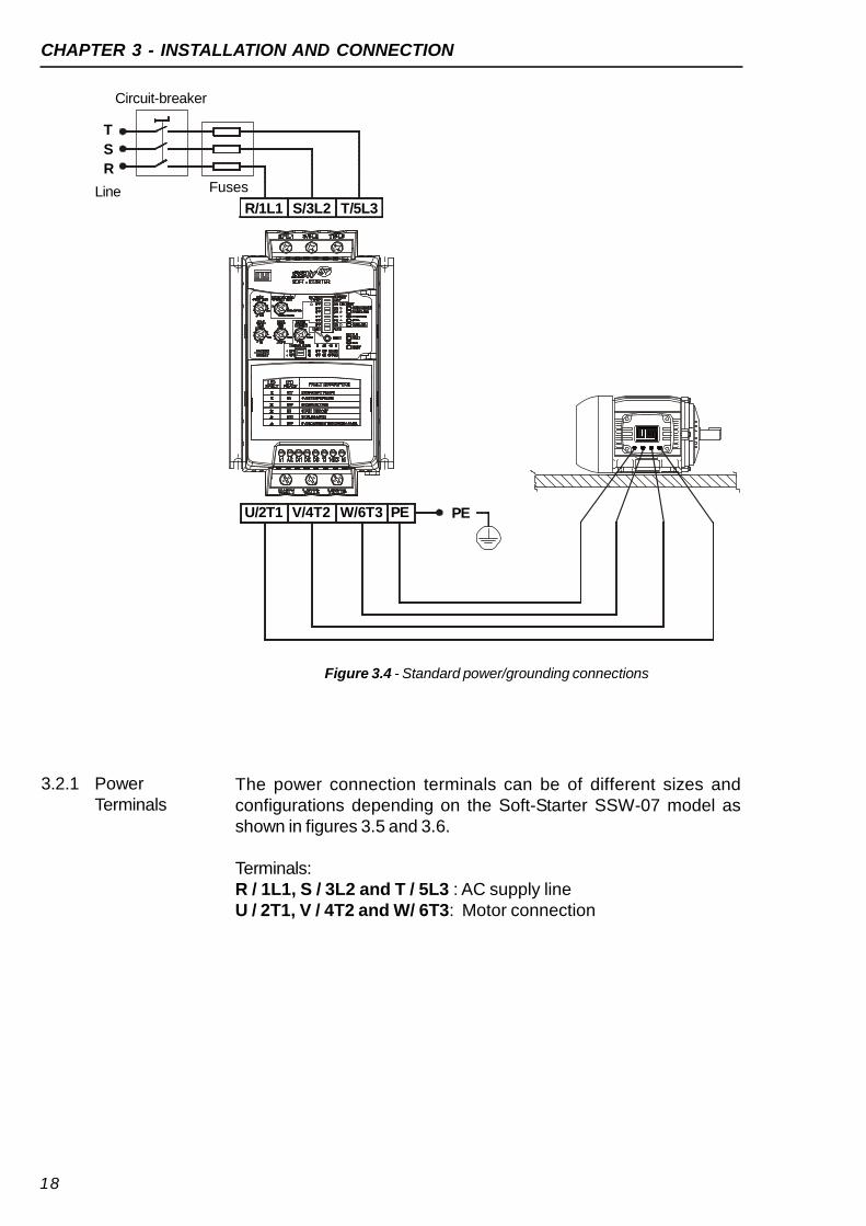
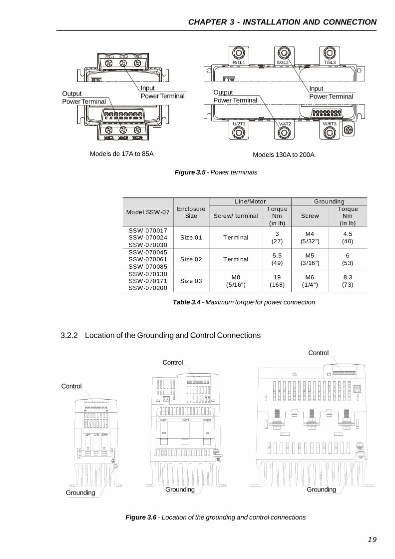
The power connection terminals can be of different sizes andconfigurations depending on the Soft-Starter SSW-07 model asshown in figures 3.5 and 3.6.
Terminals:R / 1L1, S / 3L2 and T / 5L3 : AC supply lineU / 2T1, V / 4T2 and W/ 6T3: Motor connection
3.2.1 PowerTerminals
Figure 3.4 - Standard power/grounding connections
Line
Circuit-breaker
Fuses
T
S
R
R/1L1 S/3L2 T/5L3
U/2T1 V/4T2 W/6T3 PE PE
CHAPTER 3 - INSTALLATION AND CONNECTION
19
Figure 3.5 - Power terminals
Table 3.4 - Maximum torque for power connection
Model SSW-07Enclosure
Size
Line/Motor Grounding
Screw/ terminalTorque
Nm(in lb)
ScrewTorque
Nm(in lb)
SSW-070017SSW-070024SSW-070030
Size 01 Terminal3
(27)M4
(5/32")4.5(40)
SSW-070045SSW-070061SSW-070085
Size 02 Terminal5.5(49)
M5(3/16")
6(53)
SSW-070130SSW-070171SSW-070200
Size 03M8
(5/16")19
(168)M6
(1/4")8.3(73)
3.2.2 Location of the Grounding and Control Connections
Figure 3.6 - Location of the grounding and control connections
Grounding
Control
Control
Control
Grounding Grounding
OutputPower Terminal
InputPower Terminal
OutputPower Terminal
InputPower Terminal
Models de 17A to 85A
R/1L1 S/3L2 T/5L3
R/1L1 S/3L2 T/5L3
U/2T1
Models 130A to 200A
V/4T2 W/6T3

CHAPTER 3 - INSTALLATION AND CONNECTION
20
The described specifications in table 3.5 are valid only for the followingconditions: Copper wires with PVC 70ºC (158ºF) insulation for ambient
temperature of 40ºC (104ºF), installed in perforated and notagglomerated conduits.
Naked or silver coated copper busbars with round edges with 1mmradius with ambient temperature of 40ºC (104ºF).
NOTE!For correct cable dimensioning, consider the installation conditionand the maximum permitted line voltage drop.
3.2.3 RecommendedPower andGroundingCables
DANGER!The AC input must be compatible with the voltage range of theSoft-Starter SSW-07.
DANGER!Provide a power supply disconnecting switch for the Soft-StarterSSW-07. This disconnecting switch must disconnect the AC inputvoltage to the Soft-Starter SSW-07 whenever necessary (for example:during maintenance services).If a disconnected switch or a contactor is inserted in the motor supplyline never operate these devices with the motor running or when theSoft-Starter SSW-07 is enabled.
3.2.4 Power SupplyConnection tothe Soft-StarterSSW-07
Table 3.5 - Minimum cable gauge specification
Model SSW-07SSW-07 Rated Current
(A)Power Cables
(mm2)
Grounding Cable(mm2)
SSW-070017 17 2.5 6
SSW-070024 24 4 6SSW-070030 30 6 6SSW-070045 45 10 6SSW-070061 61 16 10SSW-070085 85 25 10SSW-070130 130 50 16SSW-070171 171 70 25SSW-070200 200 95 35

CHAPTER 3 - INSTALLATION AND CONNECTION
21
ATTENTION!Over-voltage control in the line that supplies the Soft-Starter must bemade using over-voltage protections of 680Vac (phase to phaseconnection) and energy absorptioncapacity of 40 joules.
NOTE!Use the wire sizes and fuses recommended in tables 3.5, 3.6 and3.7. The connector tightening torque is indicated in table 3.4. Useonly copper wires 70°C, (158°F).
3.2.4.1 Power SupplyCapacity
Table 3.6 - Maximum current capacity of the power supply
The Soft-Starter SSW-07 is suitable to be used in a circuit capable ofsupplying not more than X (as per table 3.6) symmetrical rms amperes,Y maximum volts when protected by ultra-rapid fuses.
Model SSW-07Y = 220V-575V
X (kA)SSW-070017 5SSW-070024 5SSW-070030 5SSW-070045 5SSW-070061 5SSW-070085 10SSW-070130 10SSW-070171 10SSW-070200 10
The fuses used at the input should be ultra-rapid fuses with I²t lower orequal to 75% of the indicated SCR value (A²s). These fuses will protectthe SCR against short-circuit. Standard fuses can be used instead ofultra-rapid fuses. These will protect the installation against short-circuitbut will not protect the SCR.
3.2.4.2 RecommendedFuses
Model
SSW-07
SSW-070017
SSW-070024
SSW-070030
SSW-070045
SSW-070061
SSW-070085
SSW-070130
SSW-070171
SSW-070200
Rated
Current
(A)
50A(DIII)
80A (aR)
80A (aR)
100A (aR)
125A (aR)
200A (aR)
315A (aR)
450A (aR)
500A (aR)
I²t of the
SCR
(A²s)
720
4000
4000
8000
10500
51200
97000
168000
245000
Table 3.7 - Recommended fuses
CircuitryFuses
6A
(Type D)
CHAPTER 3 - INSTALLATION AND CONNECTION
22
DANGER!Power factor correction capacitors must never be installed at the outputof the Soft-Starter SSW-07. (U / 2T1, V / 4T2 and W / 6T3).
ATTENTION!To ensure that the protections based on the current reading and displayoperate correctly, for example the overload, the motor rated currentmust not be lower than 50% of the rated Soft-Starter SSW-07 current.
NOTE!Use the wire sizes and fuses recommended in tables 3.5, 3.6 and3.7. The connector tightening torque is indicated in table 3.4. Useonly copper wires.
NOTE!The Soft-Starter SSW-07 is provided with electronic protection againstmotor overload. This protection must be set according to the specificmotor. When several motors are connected to the same Soft-StarterSSW-07 use individual overload relays for each motor.
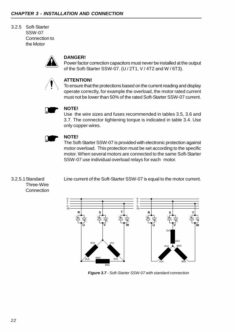
3.2.5 Soft-StarterSSW-07Connection tothe Motor
Figure 3.7 - Soft-Starter SSW-07 with standard connection
3.2.5.1StandardThree-WireConnection
Line current of the Soft-Starter SSW-07 is equal to the motor current.
1/U1
4/U2 2/V1
5/V26/W2
3/W1
2/V1
5/V2
1/U1
4/U2 6/W2
3/W1
RSTNPE
RSTNPE
T
WV
S
U
RT
WV
S
U
R

CHAPTER 3 - INSTALLATION AND CONNECTION
23
DANGER!The Soft-Starter must be grounded for safety purposes (PE).The ground connection must comply with the local regulations. Forgrounding use cables with cross sections as indicated in table 3.5.Make the ground connection to a grounding bar or to the generalgrounding point (resistance 10 ohms).
DANGER!The AC input for the Soft-Starter SSW-07 must have a groundconnection.
DANGER!Do not use the neutral conductor for grounding purpose. Usededicated ground contuctor.
ATTENTION!Do not share the ground wiring with other equipment that operatewith high current (for examples: high voltage motors, weldingmachines, etc.). When several Soft-Starters SSW-07 are used,observe figure 3.8.
3.2.6 GROUNDINGCONNECTIONS
EMI - Electronic InterferenceThe Soft-Starter SSW-07 is developed to be used in industrial systems(Class A) as per Norm EN60947-4-2.It’s necessary to have a distance of 0,25m (10in) between theSoft-Starter SSW-07 and the cables between the Soft-Starter SSW-07and the motor. Example: CLP wiring, temperature controllers,thermocouple cables, etc.
Figure 3.8 - Grounding connections for more than one Soft-Starter SSW-07
GROUNDING BAR
INTERNAL TO THE PANEL
GROUNDING BAR
INTERNAL TO THE PANEL

CHAPTER 3 - INSTALLATION AND CONNECTION
24
3.2.7 Control andSignalConnections
Terminal Description SpecificationsTorque Nm
(in lb)A1
Electronics SupplyVoltage: 110 a 240 Vac (-15% a +10%)Current: 140mA Max.
0.5(4.5)
A2Terminal Factory Default Specifications
DI1 Starts/Stops Motor 3 isolated digital inputsVoltage: 110 a 240 Vac (-15% a +10%)Current: 2 mA Max.
DI2 Fault resetDI3 Fault reset13 Relay 1 output - Operation Contact capacity:
Voltage: 250VacCurrent: 1A
14 / 23 Relay common point24 Relay 2 output - Full voltage
Table 3.8 - Description of the control connector pins
Figure 3.9 - Control terminals of the Soft-Starter SSW-07
Grounding of the Motor frameAlways ground the motor frame. Ground the motor in a panel wherethe Soft-Starter SSW-07 is installed. The Soft-Starter SSW-07 outputwiring to the motor must be installed separately from the input wiringas well as from the control and signal wiring.
The control connections (digital inputs and relay outputs) are madethrough the terminals (see figure 3.9).
Some recommended set-ups are shown here and they can becompletely or partly used.The main warning notes for all the recommended set-ups are shownbelow and are described in the schemes by their respective numbers.
NOTES!For the protection of the whole electrical installation it is necessaryto use fuses or circuit breakers. The use of ultra-rapid fuses isnot required for the operation of the Soft-Starter SSW-07 but theyare recommended for the complete SCR protection;
3.3 RECOMMENDEDSET-UPS
1

CHAPTER 3 - INSTALLATION AND CONNECTION
25
The transformer “T1” is optional and must be used when there isa difference between the line voltage and the electronic powervoltage;
To protect the motor from damage by possible short-circuits inthe power circuit of the Soft-Starter SSW-07 use an isolatingcontactor (K1) or circuit-breaker (Q1);
Start push-button.
Stop push-button.
Remember that when the command via two-wire digital input isused (the switch is normally open with retention) every time thepower supply is restored after any fault the motor will startimmediately if the switch remains closed;
In case of maintenance of the Soft-Starter SSW-07 or the motorit is necessary to remove the input fuses or disconnect the powersupply to ensure the complete equipment disconnection from thepower supply;
The emergency stop can be used by disconnecting the electronicspower supply.
Shunt trip for the Q1 power isolation circuit breaker.
ATTENTION!On the first energization, if a contactor or a circuit breaker withundervoltage release were not used for the power section isolation,apply power first to the control, adjust the trimpots necessary for theSSW-07 start-up, and only after this apply voltage to the power section;
2
3
4
5
6
7
8
9

CHAPTER 3 - INSTALLATION AND CONNECTION
26
3.3.1 RecommendedSet-up withCommand viaTwo-wire DigitalInputs andIsolationContactor
Figure 3.10 - Recommended set-up with commands via two-wire digital inputsand isolation contactor
3.3.2 RecommendedSet-up withCommand viaThree-wireDigital Inputsand IsolationContactor
* See note 3.3
NOTE!It’s necessary to program the digital input DI2 for the three-wirecommand function. See item 4.10.
NOTE!The RL1 shall be set to the “No fault” function. See item 4.12.
Figure 3.11 - Recommended set-up with commands via three-wire digital inputsand a circuit-breaker
* See note 3.3
24231413DI3
RL1 RL2
T1
PE
R
S
T
K1 K1
DI2DI1A2A1
M3~
R S T
U V W
R
S
T
PE
M3~
R S T
U V W
T1
Q1
24231413DI3
RL1 RL2
DI2DI1A2A1
Q1

CHAPTER 3 - INSTALLATION AND CONNECTION
27
3.3.3 Symbols
Electrical connection between
two signals
Connection terminals
Relay or contactor coil
Normally open contact (NO)
Indicator light
Circuit-breaker
(opens under load)
Resistor
Capacitor
Fuse
Thyristor/SCR
Three-phase motor
Emergency button
Transformer
N.O Contact (with retention)
Normally closed (NC)
push-button
Normally open (NO)
push-button
Circuit-breaker with
undervoltage release
M3~

28
CHAPTER 4
SETTING THE SSW-07
This chapter describes how to make the necessary settings for thecorrect functioning of the SSW-07.
4.1 CONTROLTYPE SETTING
Select the type of starting control that best adapts to the application.
Voltage Ramp Starting:This is the most commonly used method. Very easy to program andset.The SSW-07 Soft-Starter imposes the voltage applied to the motor.Generally applied to loads with a lower initial torque or a square torque.This kind of control can be used as an initial working test.
Current Limit Starting:The maximum current level is maintained during the start, being setaccording to the application necessities.Generally applied to loads with a higher initial torque or a constanttorque.This kind of control is used to adapt the start to the capacity limits ofthe supply network.
Figure 4.1 - Control type setting
Dip Switch Control TypeSetting

CHAPTER 4 - SETTING THE SSW-07
29
4.2 KICK START
Soft-Starter SSW-07 offers a kick start function for loads that presenta large initial resistance to movement.This function is enabled through the Kick Start dip switch. The durationof the voltage pulse is set through the trimpot Kick Start Time.The voltage pulse applied is of 80% Un during the programmed trimpotkick start time.
NOTE!Use this function only for specific applications and where necessary.
Set the initial voltage to a value that the motor starts to run as soon asthe start command is given to the SSW-07.
4.3 INITIALVOLTAGESETTING
The dotindicates thefactory defaultsetting
Initial VoltageSetting Trimpot
Figure 4.3 - Initial voltage setting
Kick Start EnablingDip Switch
Figure 4.2 - Kick start enabling
NOTE!The Initial Voltage trimpot has an initial voltage setting function onlywhen the kind of control is programmed to start with a voltage ramp.
CHAPTER 4 - SETTING THE SSW-07
30
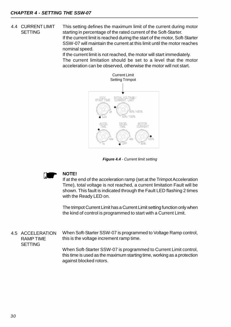
This setting defines the maximum limit of the current during motorstarting in percentage of the rated current of the Soft-Starter.If the current limit is reached during the start of the motor, Soft-StarterSSW-07 will maintain the current at this limit until the motor reachesnominal speed.If the current limit is not reached, the motor will start immediately.The current limitation should be set to a level that the motoracceleration can be observed, otherwise the motor will not start.
4.4 CURRENT LIMITSETTING
Current LimitSetting Trimpot
Figure 4.4 - Current limit setting
NOTE!If at the end of the acceleration ramp (set at the Trimpot AccelerationTime), total voltage is not reached, a current limitation Fault will beshown. This fault is indicated through the Fault LED flashing 2 timeswith the Ready LED on.
The trimpot Current Limit has a Current Limit setting function only whenthe kind of control is programmed to start with a Current Limit.
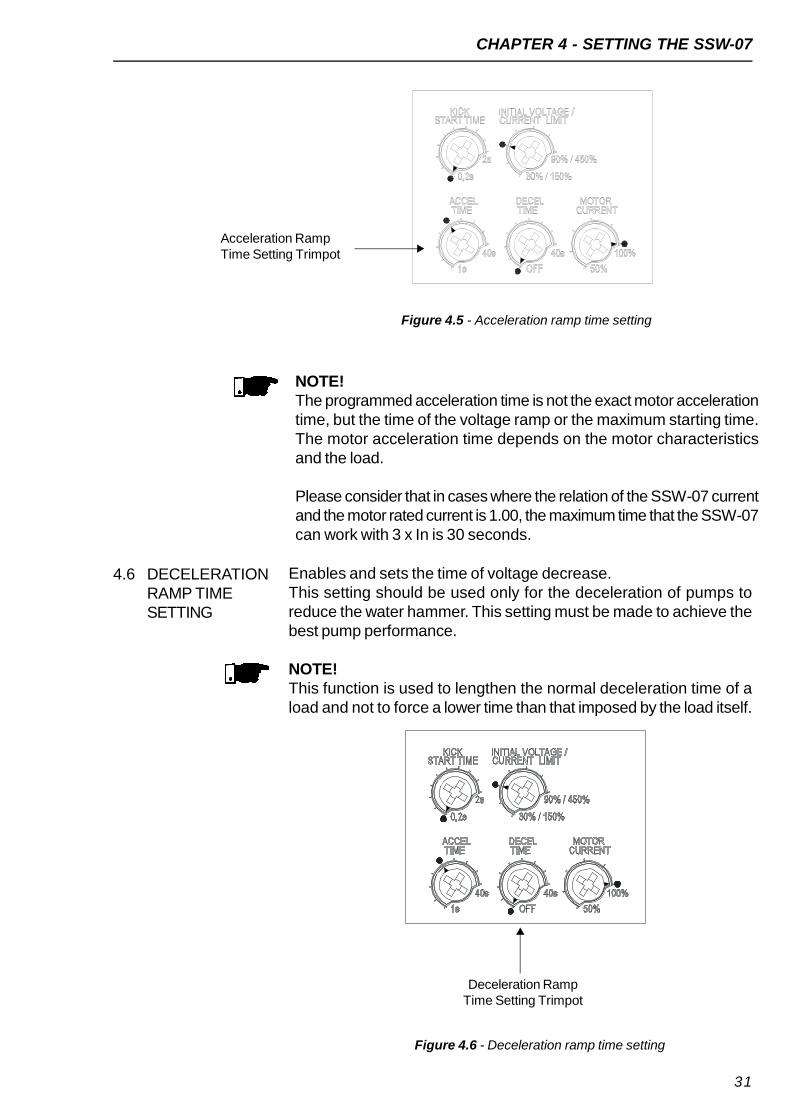
When Soft-Starter SSW-07 is programmed to Voltage Ramp control,this is the voltage increment ramp time.
When Soft-Starter SSW-07 is programmed to Current Limit control,this time is used as the maximum starting time, working as a protectionagainst blocked rotors.
4.5 ACCELERATIONRAMP TIMESETTING
CHAPTER 4 - SETTING THE SSW-07
31
4.6 DECELERATIONRAMP TIMESETTING
Enables and sets the time of voltage decrease.This setting should be used only for the deceleration of pumps toreduce the water hammer. This setting must be made to achieve thebest pump performance.
NOTE!This function is used to lengthen the normal deceleration time of aload and not to force a lower time than that imposed by the load itself.
Figure 4.6 - Deceleration ramp time setting
Deceleration RampTime Setting Trimpot
Figure 4.5 - Acceleration ramp time setting
Acceleration RampTime Setting Trimpot
NOTE!The programmed acceleration time is not the exact motor accelerationtime, but the time of the voltage ramp or the maximum starting time.The motor acceleration time depends on the motor characteristicsand the load.
Please consider that in cases where the relation of the SSW-07 currentand the motor rated current is 1.00, the maximum time that the SSW-07can work with 3 x In is 30 seconds.
CHAPTER 4 - SETTING THE SSW-07
32
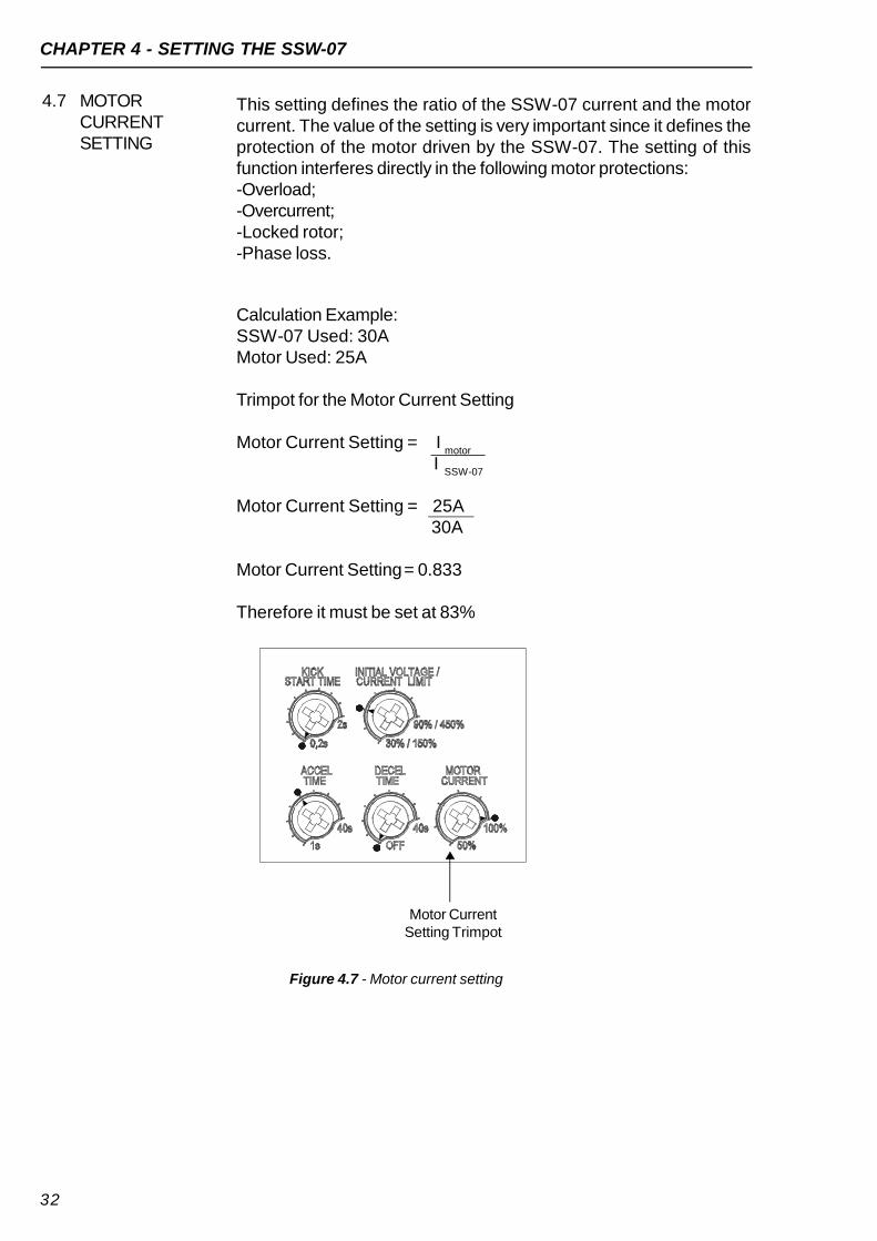
4.7 MOTORCURRENTSETTING
This setting defines the ratio of the SSW-07 current and the motorcurrent. The value of the setting is very important since it defines theprotection of the motor driven by the SSW-07. The setting of thisfunction interferes directly in the following motor protections:-Overload;-Overcurrent;-Locked rotor;-Phase loss.
Calculation Example:SSW-07 Used: 30AMotor Used: 25A
Trimpot for the Motor Current Setting
Motor Current Setting = Imotor
ISSW-07
Motor Current Setting = 25A30A
Motor Current Setting= 0.833
Therefore it must be set at 83%
Figure 4.7 - Motor current setting
Motor CurrentSetting Trimpot

CHAPTER 4 - SETTING THE SSW-07
33
4.8 MOTORELECTRONICOVERLOADPROTECTION
The motor electronic overload protection simulates the heating andcooling of the motor, also known as thermal image. This heatingsimulation uses as input data the True rms current. The curve with theworking time in motor overload is defined in figure 4.8.
Table 4.1 - Motor protection thermal class time in cold condition at F.S.=1
Table 4.2 - Motor protection thermal class time in cold condition at F.S.=1.15
30
101.2s
36.1s
18.3s
20
67.5s
24s
12.2s
10
33.7s
12s
6.1s
Motor
Current
3xIn
5xIn
7xIn
ClassClass Class
30
135.1s
47.7s
24.3s
20
90.1s
31.8s
16.2s
10
45.1s
15.9s
8.1s
Motor
Current
3xIn
5xIn
7xIn
ClassClass Class
Time t(s)
10000
1000
100
10
1
F.S.=1,15 1x 2x 3x 4x 5x 6x 7x 8x 9x 10x
Class 30Class 25Class 20Class 15Class 10
Class 5x In motorcurrentF.S.=1 1x 2x 3x 4x 5x 6x 7x 8x 9x
Figure 4.8 - Thermal classes of motor protection in cold condition

CHAPTER 4 - SETTING THE SSW-07
34
NOTES! When SSW-07 is without the electronic supply voltage (A1 andA2),
the thermal image is saved internally. When the supply (A1 andA2)is re-established, the thermal image value returns to the value priorto the electronic supply loss.
The RESET of the electronic overload protection can be set tomanual function (man). In this case the RESET must be made viadigital input 2 (DI2) or through the RESET key. If the RESET settingis set to automatic (auto), the fault condition will automatically bereset after the equipment cooling time;
Upon disabling the electronic overload protection, the thermal imageis reset at zero.
Figure 4.9 - motor protection thermal classes in hot condition at 100% ln
Table 4.3 - Motor protection thermal class time in hot condition
30
34.4s
12.6s
6.4s
20
23.6s
8.4s
4.2s
10
11.8s
4.2s
2.1s
Motor
Current
3xIn
5xIn
7xIn
ClassClass Class
Time t(s)
1000
100
10
1
1x 2x 3x 4x 5x 6x 7x 8x 9x F.S.=1
Class 30Class 25Class 20Class 15Class 10
Class 5
x In motorCurrent
0.1

CHAPTER 4 - SETTING THE SSW-07
35
Factor
1
0.87
0.74
0.61
0.48
0.35
Current in %
of motor ln
0% (cold condition)
20%
40%
60%
80%
100% (for the load)
Table 4.4 - Multiplication factor of the thermal class times in cold condition toobtain the thermal class times in hot condition
4.9 RESET A fault condition can be reset using the RESET key at the front of theSSW-07 or through a push-button (0.5 seconds) at DI3 (digital inputfor RESET).Another way to reset the SSW-07 is by switching On/Offthe electronic power supply (A1 and A2).
NOTE!The SSW-07 also allows for the possibility of automatic RESET byenabling this function through the Dip-Switch (auto):
Automatic RESET occurs after 15 minutes in the followingconditions:-Overcurrent;-Phase loss;-Blocked rotor;-Overcurrent before By-pass;-Frequency out of range;-Contact of the internal By-pass relay is open;-Power control supply undervoltage;-External fault.
For incorrect phase sequence there is no automatic RESET. For electronic overload of the motor there is a specific algorithm
for the automatic RESET time.
In the factory default, the DI2 digital input has its function programmedfor the reset of faults. DI2 can also be programmed to work as athree wire control.The three wire control allows the Soft-Starter to be commandedthrough two digital inputs, DI1 as an ON input and DI2 as an OFFinput. This allows for the direct placement of two push buttons. Seeitem 3.3.2.To change the DI2 digital input, follow the instructions below:
1. To enter in programming mode, maintain the reset key at the frontof the SSW-07 pressed for 5 seconds. Maintain the reset keypressed during programming;
4.10 DI2 DIGITALINPUTSETTING

CHAPTER 4 - SETTING THE SSW-07
36
2. When in programming mode, two LEDs will switch-on (overcurrentand phase loss), indicating that DI2 is programmed for fault Reset.When three LEDs switch-on (overcurrent, phase loss and phasesequence), it indicates that the DI2 is programmed for three wirecommands;
3. To change the programming to three wire commands, move theovercurrent dip-switch and return to the previous position. The threeLEDs will switch-on, indicating that DI2 is programmed for threewire commands;
4. To change the DI2 programming to fault Reset, move the kick startdip-switch and return to the previous position. Two LEDs will switch-on, indicating that the DI2 is programmed for fault Reset;
5. Programming is concluded when the reset key is released.
The relayof the Operation Function closes its N.O. contact (13-14/23)every time the SSW-07 receives the enable command. This contactis only opened at the end of the deceleration ramp (when it is setvia trimpot) or when the SSW-07 receives the disable command.
The relay of the Full Voltage Function closes the N.O. contacts(14/23-24) every time the SSW-07 applies 100% of the voltage tothe driven motor. This contact opens when the SSW-07 receivesthe disable command.
4.11 DIGITALOUTPUTRELAYOPERATION
(Motor Voltage)UN
Operation Function(13- 14/23)
Full Voltage Function(14/23-24)
Figure 4.10 - Digital output relay operation
100%
Relay on
t
t
t
In the factory default programming, the relay output RL1 has its functionprogrammed for “Operation”. RL1 (13/14) can be also be programmedfor the “No Fault” function. This function allows the installation of acircuit breaker with an undervoltage release at the SSW-07 input. Referto figure 3.3.2. In order to change the relay output RL1 programmingfollow these instructions:
1. For entering the programming mode keep the reset key, at theSSW-07 front cover, pressed during 5 seconds, keeping it alsopressed throughout the programming;
4.12 RELAY OUTPUTRL1PROGRAMMING

CHAPTER 4 - SETTING THE SSW-07
37
2. When in the programming mode two LED’s go on (Overcurrentand Phase Loss), indicating that DI2 is programmed for ErrorReset. If three LED’s go on (Overcurrent, Phase Loss and PhaseSequence), it indicates that DI2 is programmed for three-wirecommand. If the Overload LED goes on, then the RL1 function is“No Fault”, otherwise the function is “Operation”;
3. To modify the RL1 function change the Overload dip switch and putit back in the previous position. The Overload LED will indicate thenew programmed function:-Overload LED off: “Operation” function;-Overload LED on = “No Fault” function.
38
CHAPTER 5
5.1 APPLICATIONS ANDPROGRAMMING
PROGRAMMING INFORMATION ANDSUGGESTIONS
This chapter helps the user to set the types of starting controlsaccording to their applications.
ATTENTION!Tips and important notes for each type of starting control.
ATTENTION!To know the correct programming of the parameters, have your loaddata on hand and use the WEG (Soft-Starter) Dimensioning Softwareavailable at WEG’s home page (http://www.weg.net).If you are unable to use the software mentioned above, you can followsome practical concepts described in this chapter.
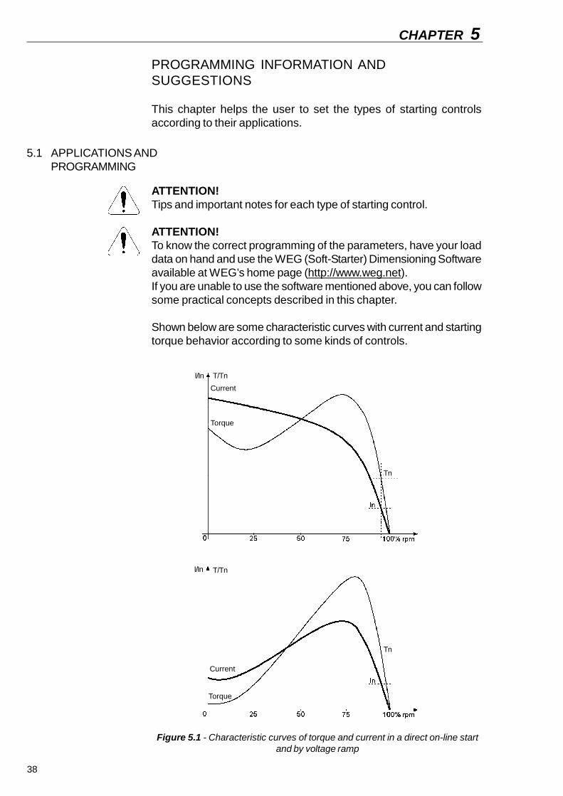
Shown below are some characteristic curves with current and startingtorque behavior according to some kinds of controls.
Figure 5.1 - Characteristic curves of torque and current in a direct on-line startand by voltage ramp
Current
Torque
Current
Torque
T/TnI/In
I/In
Tn
T/Tn
Tn

CHAPTER 5 - PROGRAMMING INFORMATION AND SUGGESTIONS
39
5.1.1 Voltage RampStarting
1) Set the value of the initial voltage to a low value;2) When a load is applied to the motor, set the initial voltage to a
value that makes the motor rotate smoothly from the instant it isstarted.
3) Set the acceleration time with the necessary start time, initially withshort times, 10 to 15 seconds, and afterwards try to find the beststarting condition for you load.
Figure 5.3 - Voltage ramp starting
NOTES! With long starting times, or when the motor is without a load, vibration
can occur during the start of the motor, therefore lower the startingtime;
If faults occur during the start, check all the connections from theSoft-Starter to the supply network, motor connections, supplynetwork voltage levels, fuses and circuit breakers.
The following items show characteristic curves with the starting torquebehavior according to some types of loads and their suggestedcontrols.
Figure 5.2 - Characteristic curves of torque and current in acurrent limitation start
Current
Torque
Start
DisableVoltage RampEnable
t(s)0
100%UnU(V)
T/Tn
Tn
I/In
CHAPTER 5 - PROGRAMMING INFORMATION AND SUGGESTIONS
40
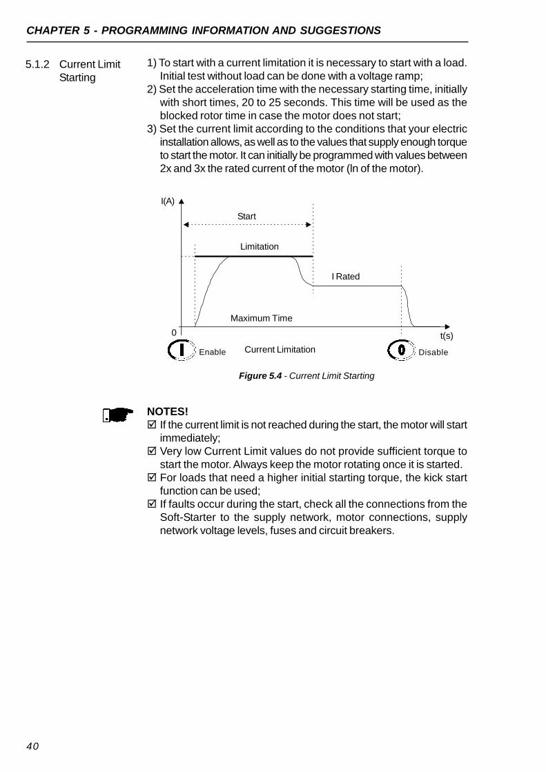
5.1.2 Current LimitStarting
1) To start with a current limitation it is necessary to start with a load.Initial test without load can be done with a voltage ramp;
2) Set the acceleration time with the necessary starting time, initiallywith short times, 20 to 25 seconds. This time will be used as theblocked rotor time in case the motor does not start;
3) Set the current limit according to the conditions that your electricinstallation allows, as well as to the values that supply enough torqueto start the motor. It can initially be programmed with values between2x and 3x the rated current of the motor (ln of the motor).
Figure 5.4 - Current Limit Starting
NOTES! If the current limit is not reached during the start, the motor will start
immediately; Very low Current Limit values do not provide sufficient torque to
start the motor. Always keep the motor rotating once it is started. For loads that need a higher initial starting torque, the kick start
function can be used; If faults occur during the start, check all the connections from the
Soft-Starter to the supply network, motor connections, supplynetwork voltage levels, fuses and circuit breakers.
I(A)
Start
Limitation
I Rated
Maximum Time
Current Limitation
0 t(s)
Enable Disable

CHAPTER 5 - PROGRAMMING INFORMATION AND SUGGESTIONS
41
1) Initially start at the standard thermal class, sometimes, but withoutthe motor overheating;
2) Determine the correct starting time. Find an average of the currentusing a multmeter with a current probe to measure it;A current average can be found for any type of starting control;
For example:Starting an 80Amotor using a voltage ramp. The current starts at 100Aand goes to 300A, returning afterwards to the rated value in 20seconds.(100A + 300A)/2 = 200A200A/80A = 2.5 x ln of the motorTherefore: 2.5 x ln @ 20 seconds.
5.2 PROTECTIONANDPROGRAMMING
5.2.1 Suggestion onhow to programthe thermal class
Figure 5.5 - Typical current curve during a voltage ramp start
3) Use this time to find the minimum class necessary to start the motorin cold condition. In the overload protection chapter it is possible tocheck the thermal class curves of the motor in cold condition.
Figure 5.6 - Checking the minimum class of curves in cold condition
2.5 x ln of the motor
t(s)
20s
0 xln
15
10
5
Cold
F.S.=1
MotorCurrent
P102Accel Time
Initial Voltage P101
U(V) Start100% Un
300A
t(s)20s
0
100A
Enable

CHAPTER 5 - PROGRAMMING INFORMATION AND SUGGESTIONS
42
Therefore the minimum class necessary to start the motor is Class10. Class 5 has an inferior time for this current.This class allows motor starting in cold condition.
4) To know which thermal class is necessary to start the motor in hotcondition, it is necessary to know up to what the motor can handle.For this, one needs to know the blocked rotor time that the motorcan withstand.
NOTE!To correctly program the Thermal Class that will protect your motor itis essential to have in hands the stall time of the motor. This informationis available in the motor manufacturer’s catalogue.
With the stall time it is possible to find the maximum thermal classthat will protect the motor to start in hot condition. In the overloadprotection chapter, it is possible to check the thermal class curves ofthe motor in hot condition.For example: 6.6 x ln @ 6s.
Figure 5.7 - Checking the maximum class of curves in hot condition
Therefore the maximum thermal class that will protect the motor isThermal Class 25, Class 30 has a higher time for this current.This class permits the start of the motor in hot condition, in other words,in any condition.
NOTE!Remember that this protection has as a standard the Three PhaseIP55 Standard WEG Motor, therefore if your motor is different, thendo not program the thermal class to its maximum, instead, program itnear its minimum thermal class to start.
6.6 x ln of the motor
t(s)
6s
0 xln
30
Hot
25
20

CHAPTER 5 - PROGRAMMING INFORMATION AND SUGGESTIONS
43
Example of how setting the thermal class:
Motor data:Power: 50HpVoltage: 380VRated Current (ln): 71AService Factor (S.F.): 1.00lp/ln: 6.6Stall time: 12s in hot conditionSpeed-1770rpm
Motor + load starting data:Starting by Voltage Ramp, starting current average:3 x the rated current of the motor during 25s (3 x ln @ 25s).
1) In the graph, figure 4.8 in cold condition, one can see the minimumThermal Class that will allow the start with a reduced voltage:For 3 x ln of the motor @25s, the next highest is adopted: Class 10.
2) In the graph, figure 4.9 in hot condition, one can see the maximumThermal Class that the motor can stand due to the stall time in hotcondition:For 6.6 x ln of the motor @ 12s, the next lowest is adopted. Class 30.
One now knows that Thermal Class 10 allows a start and ThermalClass 30 is the maximum limit. Thus, a Thermal Class between thetwo should be adopted, according to the quantity of starts per hourand the interval of time between stopping and re-starting the motor.
The closer to Class 10, the more protected the motor will be, the fewerthe starts per hour and the greater the interval of time must be betweenstopping and re-starting the motor.
The closer to Class 30, the closer it gets to the maximum limit of themotor, thus there can be more starts per hour and lower intervals oftime between stopping and re-starting the motor.
To determine the working times of the thermal classes in hot condition,when the motor is running at full voltage with a current lower that 100%of the ln of the motor, use the multiplication factor in table 4.4, accordingto the current percentage that the motor is operating.For example:A motor is running with 80% ln and is turned off.Immediately afterwards it is turned back on.The starting sequence is 3 x ln of the motor @ 25s.The Thermal Class selected is Class 10 with 33.7s @ 3 x ln of themotor.In the table, the setting factor to 80% ln of the motor is 0.48.
The final working time will be: 0.48 x 33.7s = 16.2s, in other words, thetime was reduced from 33.7s during a start in cold condition to 16.2sfor a start in hot condition. A new start will not be allowed before thethermal image of the motor decreases, in other words, cools down.
5.2.2 TimeReduction fromCold to HotStarting
CHAPTER 5 - PROGRAMMING INFORMATION AND SUGGESTIONS
44
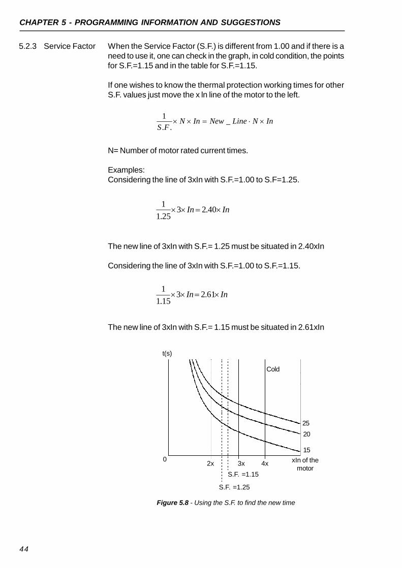
5.2.3 Service Factor When the Service Factor (S.F.) is different from 1.00 and if there is aneed to use it, one can check in the graph, in cold condition, the pointsfor S.F.=1.15 and in the table for S.F.=1.15.
If one wishes to know the thermal protection working times for otherS.F. values just move the x ln line of the motor to the left.
InNLineNewInNFS
_..
1
N= Number of motor rated current times.
Examples:Considering the line of 3xIn with S.F.=1.00 to S.F=1.25.
InIn 40.2325.1
1
The new line of 3xIn with S.F.= 1.25 must be situated in 2.40xIn
Considering the line of 3xIn with S.F.=1.00 to S.F.=1.15.
The new line of 3xIn with S.F.= 1.15 must be situated in 2.61xIn
Figure 5.8 - Using the S.F. to find the new time
2x
t(s)
0 xIn of themotor
Cold
25
20
15
3x 4x
S.F. =1.15
S.F. =1.25
InIn 61.2315.1
1
CHAPTER 5 - PROGRAMMING INFORMATION AND SUGGESTIONS
45
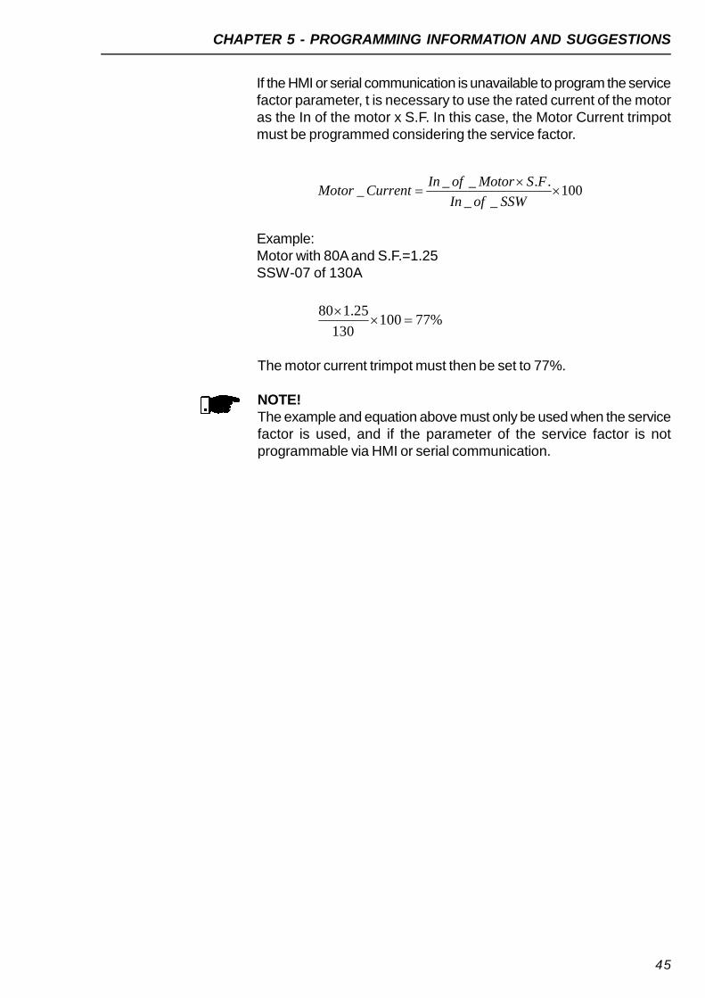
If the HMI or serial communication is unavailable to program the servicefactor parameter, t is necessary to use the rated current of the motoras the In of the motor x S.F. In this case, the Motor Current trimpotmust be programmed considering the service factor.
100__
..___
SSWofIn
FSMotorofInCurrentMotor
Example:Motor with 80A and S.F.=1.25SSW-07 of 130A
%77100130
25.180
The motor current trimpot must then be set to 77%.
NOTE!The example and equation above must only be used when the servicefactor is used, and if the parameter of the service factor is notprogrammable via HMI or serial communication.

46
6.1 FAULTS ANDPOSSIBLECAUSES
SOLUTION AND TROUBLESHOOTING
When a fault is detected, the Soft-Starter is disabled and the FaultCode is displayed by flashing LEDs. To restart the Soft-Starter after afault has occured it must be reset. In general, resetting can be doneas follows:
Disconnecting and reapplying the AC power (power-on reset); Pressing the “RESET” key in the SSW-07 front panel (RESET key); Automatically by the automatic RESET. Enable this function via Dip-
Switch (auto); Via digital input DI2 or DI3;
CHAPTER 6
Table 6.1 - Faults and possible causes
ProtectionDescriptionand FaultDisplay
Activation Description Probable Causes Reset
Phase loss orUndercurrent
E03
(LED PhaseLoss Flashing)
At starting: It occurs when thereis no voltage in the power supplyterminals (R/1L1, S/3L2 andT/5L3) or when the motor isdisconnected.At full voltage: It trips when thecurrent stays below theprogrammed value longer thanthe programmed time.Referring the motor nominalcurrent.When the parameters are setwith the factory default values,then this protection trips afterelapsing 1 second with phaseloss either at the input or at theoutput (motor). It trips when thecurrent circulating through theSSW-07 is less than 20% of thevalue adjusted at the MotorCurrent trimpot.
Percentage values programmed asmaximum acceptable limit.In hydraulic pump applications, it maybe running with no load.Phase loss in the three-phasenetwork.Short-circuit or thyristor or By-passfault.Motor not connected.Motor connection is incorrectLoose contact in the connections.Starting problems with the inputcontactor.Input fuses are blown.Undersized input transformer.Incorrect programming of the MotorCurrent Trimpot.Motor current consumption lower thanrequired for phase loss protection towork.
Power-onReset keyAuto-resetDIx
Overtemperature in
the powersection
E04
(LED Fault)flashesonce
(LED Ready)On
When the heatsink temperatureis superior to the limit.Also works when thetemperature sensor is notconnected.
Shaft load too high.Elevated number of successive starts.Internal temperature sensor notconnected.
Power-onReset keyAuto-resetDIx.

CHAPTER 6 - SOLUTION AND TROUBLESHOOTING
47
Table 6.1 (cont.) - Faults and possible causes
ProtectionDescription and
Fault DisplayActivation Description Probable Causes Reset
Electronic motoroverload
E05
(LED Overload)Flashing
When the times given by theprogrammed thermal classcurves exceed the limit.
Incorrect setting of the "Motor Current"trimpot (motor current set). The setvalue is too low for the motor beingused.Starting sequence greater thanallowed.Programmed thermal class too low.Time between stopping andrestarting lower than that permitted bythe motor power refrigeration time.Load on the motor shaft too high.Thermal protection value saved whenthe control is turned off and broughtback when turned back on.
Power-onReset keyAuto-resetDIx.
Excessive timewith current limitduring the start
E62
(LED Fault)flashes twice (LED
Ready)On
When the starting time islonger than the time set in theacceleration ramp trimpot.Active only with current limitstarting.
Programmed time for the accelerationramp inferior to what is needed.Value of the programmed currentlimitation too low.Motor locked, rotor blocked.
Power-onReset keyAuto-resetDIx.
Rotor blocked
E63
(LED Stall)Flashing
Activates before full voltage, ifthe current is greater thantwice the rated motor current.
Programmed acceleration ramp timelower than the actual accelerationtime.Motor shaft is lockedThe transformer that supplies themotor can be saturating and taking toomuch time to recover from the startingcurrent.
Power-onReset keyAuto-resetDIx.
Overcurrent
E66
(LED Overcurrent)Flashing
It is only monitored when theSSW-07 is at 100% of thevoltage. When the parametersare set with the factory defaultvalues this protection tripswhen the motor currentexceeds 3 times the valueadjusted in the trimpot (MotorCurrent) for a time longer than1 second.
Short-circuit between phases.Momentary motor overload.Motor shaft is locked, rotor blocked.
Power-onReset keyAuto-resetDIx.
Incorrect phasesequence
E67
(LED Phase Seq.)Flashing
When the sequence ofsynchronism signalsinterruptions does not followthe RST sequence.
Network phase sequence inverted atthe input.May have been changed in anotherplace of the supply network.
Power-onReset keyDIx.

CHAPTER 6 - SOLUTION AND TROUBLESHOOTING
48
Table 6.1 (cont.) - Faults and possible causes
OBSERVATIONS:In the case of E04 (over temperature), it is necessary to wait a littlebefore resetting, in order to cool down.In the case of E05 (motor overload), it is necessary to wait a littlebefore resetting, in order to cool down.
ProtectionDescriptionand FaultDisplay
Activation Description Probable Causes Reset
Undervoltage inthe control
supply
E70
(LED Fault)flashes twice(LED Ready)
Off
Activates when the controlsupply voltage is lower than 93Vac.
Electronics supply lower than theminimum value.Electronics power supply with loosecontact.Electronics power supply fuse blown.
Power-onReset keyAuto-resetDIx.
Internal By-pass relay
contact Open
E71
(Led Fault)flashes 3 times(LED Ready)
Off
When there is a fault with theinternal by-pass relay contactsat full voltage.
Loose contact in the starting cablesof the Internal By-pass relays.Defective By-pass relay contacts dueto an overload
Power-onReset keyAuto-resetDIx.
Overcurrentbefore the By-
pass
E72
(LED Fault)flashes 4 times(LED Ready)
off
Activates before the closing ofthe By-pass if the current isgreater than:37.5A for the SSW models up to30A;200A for the SSW models from45 to 85A;260A for the SSW model of130A;400A for the SSW models from171 and 200A.
The time programmed for theacceleration ramp is shorter than theactual acceleration time.Rated motor current higher than thecurrent that can be supported by theSoft-Starter.Motor shaft is locked, rotor blocked.
Power-onReset keyAuto-resetDIx.
Frequency outof tolerance
E75
(LED Fault)flashes 1 times(LED Ready)
Off
When the limit is higher or lowerthan the limits of 45 to 66Hz.
The line frequency is out of range.When the Soft-Starter + motor arebeing supplied by a generator that isnot supporting the full load regime orthe start of the motor.
Power-onReset keyAuto-resetDIx.

CHAPTER 6 - SOLUTION AND TROUBLESHOOTING
49
6.2 TROUBLESHOOTING
Table 6.2 - Solving the most frequent problems
NOTE!When contacting WEG for service or technical assistance, please havethe following data on hand:
Model of the Soft-Starter; Serial number, production date and hardware revision present in
the identification label of the product (see item 2.4); Installed software version (see item 2.2); Application and programming data.
For explanations, training or service, please contact WEGAutomaçãoService Department.
Problem Points to check Corrective actionWrong wiring Check all the power and command connections.
For example:The DIx digital inputs programmed as enabling orexternal fault must be connected to AC supply.
Wrong programming Check if the parameters are with the correct valuesfor the application
Motor does not run
Fault Check if the Soft-Starter is not blocked to a detectedfault condition
Motor does notreach rated speed
Motor stall Increase the current limit level with the control tolimit the current.
Motor rotationoscillates (fluctuates)
Loose connections Switch the Soft-Starter and the power supply off andtighten all the connections.Check all the internal connections of the Soft-Starterto make sure they are well connected.
Motor rotation:Too high or too low
Motor nameplate data Check if the motor used is in accordance to theapplication.
LEDs off Check the power supplyvoltage of the controlcard (A1 and A2)
Rated values must be inside the following limits:Umin. = 93.5VacUmax.= 264Vac
Vibration duringacceleration
Soft-Starter Settings Reduce the acceleration ramp time.Reduce the pedestal voltage setting.

CHAPTER 6 - SOLUTION AND TROUBLESHOOTING
50
6.3 PREVENTIVEMAINTENANCE
WARNING!Always disconnect the general power supply before touching anyelectric component associated to the Soft-Starter SSW-07.
Periodic inspections of Soft-Starters SSW-07 and installations arenecessary to avoid operating problems due to unfavorableenvironmental conditions like high temperature, humidity, dust,vibrations or due to the aging of the components.
Do not run any high voltage tests onthe Soft-Starter SSW-07!
If necessary, consult the manufacturer.
Table 6.3 - Periodic inspections after putting into use
OBS:(1) Every six months.(2) Twice a month.
Do not use megometers to test thyristors.
Component Abnormality Corrective ActionLoose screws
Terminals, ConnectorsLoose connectors
Tightening(1)
Dirty fans Cleaning(1)
Abnormal noiseFan always offAbnormal vibration
Substitute fanFans / Ventilation Systems
Dust in the air filters Cleaning or substitution(2)
Accumulated dust, oil, humidity, etc. Cleaning(1)
Power Module / Power ConnectionsScrews with loose connections Tightening(1)

51
CHAPTER 7
OPTIONS AND ACCESSORIES
This chapter describes the optional devices that can be used withSoft-Starter SSW-07. They are: ventilation kit and IP20 kit.
NOTE!Please, check the availability of the accessorie.
The IP-20 KIT is used to protect against touching the energized parts.7.1 IP20 KIT
382,50mm
Optional DescriptionWEG PartNumber
Plug-in Local Keypad 417114750
Remote Keypad Kit 417114751
1m SSW-07 - Remote HMI Connection Cable 0307.7827
2m SSW-07 - Remote HMI Connection Cable 0307.7828
3m SSW-07 - Remote HMI Connection Cable 0307.7829
5m SSW-07 - Remote HMI Connection Cable 0307.8113
7,5m SSW-07 - Remote HMI Connection Cable 0307.8114
10m SSW -07 - Remote HMI Connection Cable 0307.8115
Plug-in Kit for Profibus Communication 417114752
Plug-in Kit for DeviceNet Communication 417114753
Plug-in Kit for RS-232 Communication 417114754
3m RS-232 Connection Cable 0307.8320
10m RS-232 Connection Cable 0307.8321
Plug-in Kit for RS-485 Communication 417114755
Ventilation Kit for Size 2 (Currents from 45 to 85 A) 417114756
Ventilation Kit for Size 3 (Currents from 130 to 200 A) 417114757
IP20 Kit for Size 3 (Currents from 130 to 200 A) 417114758
Plug-in Kit for Motor PTC 417114759
Figure 7.1 - IP20 kit
Table 7.1 - Optional description

52
CHAPTER 8
TECHNICAL CHARACTERISTICS
This chapter describes the electric and mechanical technicalcharacteristics of the Soft-Starter SSW-07 line.
8.1 RATED POWERS AND CURRENTS ACCORDING TO UL508
NOTE!The maximum powers indicated in table 8.1 are based on 3 x ratedcurrent of Soft-Starter SSW-07 during 30s and 10 starts per hour(3xIn @ 30s).
SSW-07Ratedcurrent
SSW-07
Motor voltage220/230V
Motor voltage380/400V
Motor voltage440/460V
Motor voltage575VModel
SSW-07(A) (hp) (kW) (hp) (kW) (hp) (kW) (hp) (kW)
SSW-070017 17 5 3.7 7.5 5.5 10 7.5 15 11SSW-070024 24 7.5 5.5 10 7.5 15 11 20 15SSW-070030 30 10 7.5 15 11 20 15 25 18.5SSW-070045 45 15 11 25 18.5 30 22 40 30SSW-070061 61 20 15 30 22 40 30 50 37SSW-070085 85 30 22 50 37 60 45 75 55SSW-070130 130 50 37 75 55 100 75 125 90SSW-070171 171 60 45 100 75 125 90 150 110SSW-070200 200 75 55 100 75 150 110 200 150
Table 8.1 - Powers and currents according to UL508, temperature of 55°C, (131°F)
8.2 RATED POWERS AND CURRENTS FOR STANDARD IP55, IV POLE WEG MOTOR
SSW-07Ratedcurrent
SSW-07
Motor voltage220/230V
Motor voltage380/400V
Motor voltage440/460V
Motor voltage575VModel
SSW-07(A) (hp) (kW) (hp) (kW) (hp) (kW) (hp) (kW)
SSW-070017 17 6 4.5 10 7.5 12.5 9.2 15 11SSW-070024 24 7.5 5.5 15 11 15 11 20 15SSW-070030 30 10 7.5 20 15 20 15 30 22SSW-070045 45 15 11 30 22 30 22 40 30SSW-070061 61 20 15 40 30 50 37 60 45SSW-070085 85 30 22 60 40 60 45 75 55SSW-070130 130 50 37 75 56 100 75 125 90SSW-070171 171 60 45 125 90 125 90 175 132SSW-070200 200 75 55 125 90 150 110 200 150
Table 8.2 - Powers and currents for WEG motors, room temperature of 55°C, (131°F)

CHAPTER 8 - TECHNICAL CHARACTERISTICS
53
8.4 ELECTRONICSAND PROGRAMMING DATA
(110 to 240)Vac (-15% to +10%), or (94 to 264)Vac
(50 to 60)Hz (±10%), or (45 to 66)Hz
Max. 140mA
Voltage ramp;
Current limitation.
03 Isolated digital inputs;
Minimum upper level: 93Vac;
Maximum lower level: 10Vac;
Maximum voltage: 264Vac;
Input current: 1.1mA @ 220V;
Programmable functions.
02 relays with NO contacts, 240Vac, 1A, and programmable
functions.
Overcurrent;
Phase loss;
Inverted phase sequence;
Heatsink overtemperature;
Motor overload;
External fault;
Open By-pass contact;
Blocked rotor;
Frequency out of range;
Electronic supply undervoltage.
Control voltage
Connector X1A (1.2)
Frequency
Consumption
Method
Digitals
Relay
Protection
8.3 POWER DATA
Power Supply Power Voltage (R/1L1,S/3L2, T/5L3)
(220 to 575)Vac (-15% to +10%), or(187 to 632)Vac
Frequency (50 to 60)Hz (±10%), or (45 to 66)Hz
Capacity Maximum number of startsper hour (without ventilation)
10 (1 every 6 minutes; models from 17A to 30A)3 (1 every 20 minutes; models from 45A to 200A)
Maximum number of startsper hour with optionalventilation Kit
10 (1 every 6 minutes; models from 45A to 200A)
Start cycle 3 x In of the SSW-07 during 30 secondsThyristors (SCRs) Reverse voltage with 1600V maximum peakOvervoltage category III (UL508/EN61010)
Power Supply
Control
Inputs
Outputs
Safety
Related Documents