Service Training Self-study Programme 368 The 2.0l 125 kW TDI Engine with 4-valve technology Design and function

Welcome message from author
This document is posted to help you gain knowledge. Please leave a comment to let me know what you think about it! Share it to your friends and learn new things together.
Transcript
Protected by copyright. C
opying
for p
rivat
e or
com
mer
cial
pur
pose
s, in
par
t or i
n w
hole
, is
not p
erm
itted
unles
s authorise
d by Volkswagen AG. Volkswagen AG does not guarantee or accept any liability with respect to the correctness ofinform
ation in this document.Copyright by Volkswagen AG.
Service Training
Self-study Programme 368
The 2.0l 125 kW TDI Enginewith 4-valve technology
Design and function

Protected by copyright. C
opying
for p
rivat
e or
com
mer
cial
pur
pose
s, in
par
t or i
n w
hole
, is
not p
erm
itted
unles
s authorise
d by Volkswagen AG. Volkswagen AG does not guarantee or accept any liability with respect to the correctness ofinform
ation in this document.Copyright by Volkswagen AG.
2
Following the 2.0l 103 kW TDI engine with 4-valve technology, the 2.0l TDI engine with 125 kW is now being launched onto the market.
In this document, we will introduce you to the design and function of the 2.0l 125 kW TDI engine with 4-valve technology, whereby we will concentrate extensively on the differences versus the 103kW variant.
The 2.0l 125 kW TDI engine with 4-valve technology will initially be fitted in the Passat.
S368_009
The self-study programme shows the design and function of new developments.The contents will not be updated.
For current testing, adjustment and repair instructions, refer to the relevant service literature.
NEW ImportantNote
Information on the 2.0l 103 kW TDI engine with 4-valve technology can be found in self-study programme 316 "The 2.0l TDI Engine".

Protected by copyright. C
opying
for p
rivat
e or
com
mer
cial
pur
pose
s, in
par
t or i
n w
hole
, is
not p
erm
itted
unles
s authorise
d by Volkswagen AG. Volkswagen AG does not guarantee or accept any liability with respect to the correctness ofinform
ation in this document.Copyright by Volkswagen AG.
3
Introduction . . . . . . . . . . . . . . . . . . . . . . . . . . . . . . . . . . . . . . . . . . . . . . . . . . 4
Engine mechanics . . . . . . . . . . . . . . . . . . . . . . . . . . . . . . . . . . . . . . . . . . . . . . 6Crankshaft drive . . . . . . . . . . . . . . . . . . . . . . . . . . . . . . . . . . . . . . . . . . . . . . . . 6Toothed belt drive . . . . . . . . . . . . . . . . . . . . . . . . . . . . . . . . . . . . . . . . . . . . . . . 8Cylinder head . . . . . . . . . . . . . . . . . . . . . . . . . . . . . . . . . . . . . . . . . . . . . . . . . . .9Cylinder head gasket . . . . . . . . . . . . . . . . . . . . . . . . . . . . . . . . . . . . . . . . . . . 10Cylinder head cover . . . . . . . . . . . . . . . . . . . . . . . . . . . . . . . . . . . . . . . . . . . . 12Intake manifold . . . . . . . . . . . . . . . . . . . . . . . . . . . . . . . . . . . . . . . . . . . . . . . . 14Exhaust gas recirculation system . . . . . . . . . . . . . . . . . . . . . . . . . . . . . . . . . . 16Turbocharger with travel feedback. . . . . . . . . . . . . . . . . . . . . . . . . . . . . . . . . 21Diesel particulate filter . . . . . . . . . . . . . . . . . . . . . . . . . . . . . . . . . . . . . . . . . . 23
Engine management . . . . . . . . . . . . . . . . . . . . . . . . . . . . . . . . . . . . . . . . . . 24System overview . . . . . . . . . . . . . . . . . . . . . . . . . . . . . . . . . . . . . . . . . . . . . . . 24Sensors . . . . . . . . . . . . . . . . . . . . . . . . . . . . . . . . . . . . . . . . . . . . . . . . . . . . . . . 26Actuators . . . . . . . . . . . . . . . . . . . . . . . . . . . . . . . . . . . . . . . . . . . . . . . . . . . . . 32
Functional diagram . . . . . . . . . . . . . . . . . . . . . . . . . . . . . . . . . . . . . . . . . . . 40
Test yourself . . . . . . . . . . . . . . . . . . . . . . . . . . . . . . . . . . . . . . . . . . . . . . . . . 43
Contents
Protected by copyright. C
opying
for p
rivat
e or
com
mer
cial
pur
pose
s, in
par
t or i
n w
hole
, is
not p
erm
itted
unles
s authorise
d by Volkswagen AG. Volkswagen AG does not guarantee or accept any liability with respect to the correctness ofinform
ation in this document.Copyright by Volkswagen AG.
4
Introduction
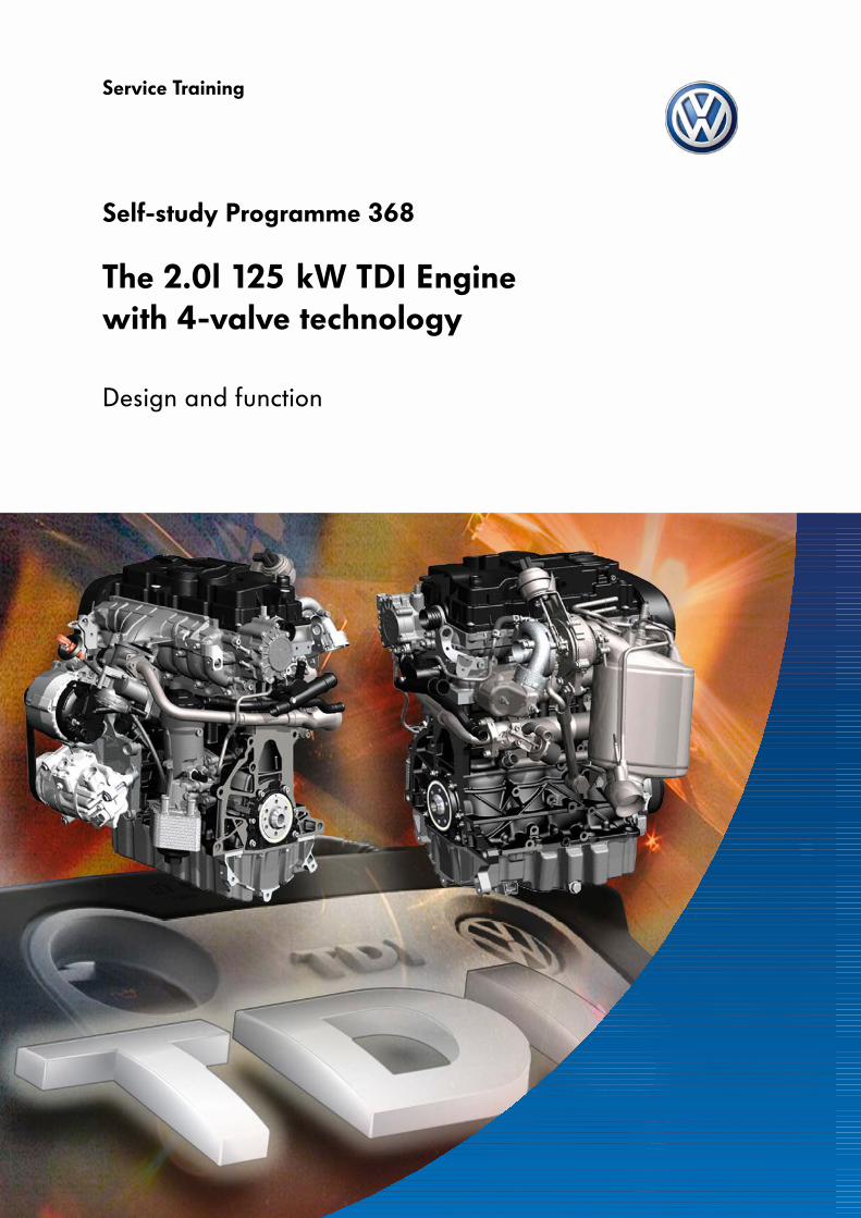
The 2.0l 125 kW TDI engine with 4-valve technology
The 2.0l 125 kW TDI engine is based on the 2.0l TDI engine with 103 kW. With its output, the 125 kW TDI engine is the market leader amongst 2-litre diesel engines. This increased output has been achieved by consistently re-developing the tried-and-tested technology whilst simultaneously reducing consumption and pollutant emissions.
S368_002

Protected by copyright. C
opying
for p
rivat
e or
com
mer
cial
pur
pose
s, in
par
t or i
n w
hole
, is
not p
erm
itted
unles
s authorise
d by Volkswagen AG. Volkswagen AG does not guarantee or accept any liability with respect to the correctness ofinform
ation in this document.Copyright by Volkswagen AG.
5
400
350
250
150
1000
S368_082
Torque and output diagram
55
450
300
200
100
65
75
95
105
115
125
135
45
50
Engine speed (rpm)
Torq
ue (N
m)
Out
put
(kW
)
Engine codes BMR, BMN
Type 4-cylinder in-line engine
Displacement 1968cm3
Bore 81mm
Stroke 95.5mm
Valves per cylinder 4
Compression ratio 18.5 : 1
Maximum output 125kW at 4200 rpm
Maximum torque 350 Nm at 1800 rpm to 2500 rpm
Engine management Simos PPD 1
Fuel Diesel, at least 51CN
Exhaust gas treatment Exhaust gas recirculation and diesel particulate filter
Emissions standard EU4
Technical data
2000 3000 4000 5000
Technical features
● New unit injector with piezo-electric valve and an injection pressure of up to 2200 bar
● Balancer shaft module *● Pistons without valve pockets● New ceramic glow plugs● CTC toothed belt sprocket on the crankshaft● Improved oil separation● Turbocharger with travel feedback● Maintenance-free diesel particulate filter
* In the Passat and with longitudinal mounting only
S368_001
500
35

Protected by copyright. C
opying
for p
rivat
e or
com
mer
cial
pur
pose
s, in
par
t or i
n w
hole
, is
not p
erm
itted
unles
s authorise
d by Volkswagen AG. Volkswagen AG does not guarantee or accept any liability with respect to the correctness ofinform
ation in this document.Copyright by Volkswagen AG.
6
Engine mechanics
Crankshaft drive
The crankshaft
Due to the increase in output to 125 kW, the crankshaft is exposed to higher stresses. A reinforced, forged crankshaft is therefore used.
Instead of the usual eight, the crankshaft only has four counterweights, as a result of which weight has been reduced. The new design of the crankshaft helps to reduce the maximum crankshaft bearing strain. Noise emissions, which may be caused by the engine's inherent movement and vibrations, have also been reduced.
The pistons
Thanks to the omission of the valve pockets on the top of the pistons, the chamber volume has been reduced and swirl generation in the cylinder has been improved. Swirl is the circular movement of flow around the vertical cylinder axis The swirl exerts a vital influence on the quality of the mixture.
Omission of the valve pockets has been achieved via the use of flatter valve heads on the valves and modified valve seats.
S368_073
S368_078
Counterweight
Crankshaft

Protected by copyright. C
opying
for p
rivat
e or
com
mer
cial
pur
pose
s, in
par
t or i
n w
hole
, is
not p
erm
itted
unles
s authorise
d by Volkswagen AG. Volkswagen AG does not guarantee or accept any liability with respect to the correctness ofinform
ation in this document.Copyright by Volkswagen AG.
7
The balancer shaft module
The 2.0l 125 kW TDI engine is only equipped with a balancer shaft module, which is housed in the oil pan beneath the crankshaft, in the Passat and when the engine is mounted longitudinally. The balancer shaft module is driven by the crankshaft via a gear drive. The duocentric oil pump is integrated into the balancer shaft module.
Design
The balancer shaft module is comprised of a grey cast iron housing, two contra-rotating balancer shafts, the gear drive with helical toothing and the integrated duocentric oil pump. The crankshaft's rotation is transmitted to the intermediate gear on the outer side of the housing. This drives balancer shaft I. From this balancer shaft, the movement is then transmitted, via a pair of gears within the housing, to balancer shaft II and the duocentric oil pump.
The gear drive is designed in such a way that the balancer shafts rotate at twice the speed of the crankshaft.
The gear drive's backlash is adjusted with the aid of the coating on the intermediate gear. This coating wears off during engine start-up and results in a defined backlash.
Crankshaft gear
Intermediate gear
Drive gearbalancer shaft I
Drive gearbalancer shaft II
Housing
Duocentric oil pump
S368_003
The intermediate gear must always be exchanged if the intermediate gear or the drive gear of balancer shaft I have been released.

Protected by copyright. C
opying
for p
rivat
e or
com
mer
cial
pur
pose
s, in
par
t or i
n w
hole
, is
not p
erm
itted
unles
s authorise
d by Volkswagen AG. Volkswagen AG does not guarantee or accept any liability with respect to the correctness ofinform
ation in this document.Copyright by Volkswagen AG.
8
Engine mechanics
Toothed belt drive
This drive is designed as a toothed belt drive. It includes the crankshaft's toothed belt sprocket, the two camshafts, the coolant pump, two guide rollers and a belt tensioner.
A CTC toothed belt sprocket is used as the drive gear for the CTC toothed belt sprocket. CTC is the abbreviation for Crankshaft Torsionals Cancellation. This name means that the camshaft's tensile forces and torsional vibrations are reduced.
During the combustion process, the narrow side of the toothed belt sprocket enables slight relaxation of the toothed belt drive. As a result of this, the tensile forces are reduced and the toothed belt drive's torsional vibrations are lessened. This has enabled the omission of a camshaft damper.
Camshaft sprockets
Guide roller
Coolant pumpdrive gear
Belt tensioner
Guide roller
Poly-V belt pulley
S368_012
Crankshafttoothed belt sprocket
(CTC toothed belt sprocket)
CTC toothed belt sprocket
d2>d1
S368_083
d2
d1

Protected by copyright. C
opying
for p
rivat
e or
com
mer
cial
pur
pose
s, in
par
t or i
n w
hole
, is
not p
erm
itted
unles
s authorise
d by Volkswagen AG. Volkswagen AG does not guarantee or accept any liability with respect to the correctness ofinform
ation in this document.Copyright by Volkswagen AG.
9
S368_059
Annular portSupply port
S368_005
The cylinder head cooling system
Water jacket
Cylinder head
The cylinder head is manufactured from an aluminium-silicone-copper alloy and has been adapted to the 125 kW output.
The cylinder head's water jacket has been completely re-engineered to improve thermal dissipation. Annular ports, which run around the injector orifice, are new. Via supply ports between the valves, the annular ports are supplied with coolant. As a result of this, the regions around the injectors and the exhaust ports, which are exposed to higher thermal strain due to the increase in output to 125kW, are relieved.
The layout of the valves, the unit injector and the glow plugs corresponds to that in the 103 kW TDI engine.
The valve seats in the cylinder head
To enable the valve pockets to be omitted, the valve seats are integrated deeper into the cylinder head than in a cylinder head for pistons with valve pockets. This, together with the flatter valve heads, has enabled the chamber volume to be reduced.
S368_080
Valve with conventional valve seat
Valve with deeper valve seat

Protected by copyright. C
opying
for p
rivat
e or
com
mer
cial
pur
pose
s, in
par
t or i
n w
hole
, is
not p
erm
itted
unles
s authorise
d by Volkswagen AG. Volkswagen AG does not guarantee or accept any liability with respect to the correctness ofinform
ation in this document.Copyright by Volkswagen AG.
10
Engine mechanics
Cylinder head gasket
A new cylinder head gasket reduces cylinder head and cylinder bore distortion. This improves combustion chamber sealing as a result. The gasket is structured in 5 layers and has two special features:
● Vertically profiled combustion chamber stoppers● Rear land support
The vertically profiled combustion chamber stopper
Combustion chamber stopper refers to the sealing edge of the cylinder bore. This is of different heights along the edge to the combustion chamber. Thanks to this special shape, distribution of the tightening forces at the combustion chambers is more even after tightening the cylinder head bolts. This reduces the sealing gap vibrations and cylinder bore distortions which occur.
The trigger for this improved cylinder head gasket is the different distances between the cylinder head bolts and the cylinder bores. This means that sections of the combustion chamber stopper lie close to a cylinder head bolt and are therefore exposed to high tightening forces. Other sections are located further away from a cylinder head bolt and are therefore exposed to lower tightening forces. These differences are compensated by a higher combustion chamber stopper in sections with low tightening forces and a flat combustion chamber stopper in sections with higher tightening forces.
S368_039
S368_036
Combustion chamber stopperRear land support
Rear land support
Schematic depiction
Plates withdifferent
profile heights
Combustion chamber
Support of high tightening forces
Different combustion chamber stopper heights
S368_034
Support of low tightening forces
Cylinder head gasket section
Tightening forces

Protected by copyright. C
opying
for p
rivat
e or
com
mer
cial
pur
pose
s, in
par
t or i
n w
hole
, is
not p
erm
itted
unles
s authorise
d by Volkswagen AG. Volkswagen AG does not guarantee or accept any liability with respect to the correctness ofinform
ation in this document.Copyright by Volkswagen AG.
11
The rear land support
The cylinder head gasket's rear land supports are each located in the area of the two outer cylinders. In these areas, they achieve more even distribution of the outer cylinder head bolt tightening forces. Deflection of the cylinder head and distortion of the outer cylinder bores are reduced as a result.
Due to the smaller cylinder head contact surface in the area of the two outer cylinders, the outer cylinder head bolts generate higher tightening forces. This leads to increased pressure on the cylinder head gasket and therefore deflection of the cylinder head. In turn, this deflection leads to distortion at the outer cylinder bores. The rear land support absorbs this increased pressure on the edge of the cylinder head gasket, with the result that the cylinder head deflects less. Thanks to this improvement, the distribution of tightening forces at the outer combustion chamber stoppers has also been optimised. In addition, all cylinder head movement is reduced during engine operation.
S368_040
Plates withidentical
profile heights
S368_035
Without rear land support
With rear land support
Tightening forces
Tightening forces
High edge pressure leads to deflection of the cylinder head
Edge pressure absorbed by the stable structure of the cylinder head gasket
Cylinder head gasket section
Rear land support
Cylinder head
S368_037
S368_038

Protected by copyright. C
opying
for p
rivat
e or
com
mer
cial
pur
pose
s, in
par
t or i
n w
hole
, is
not p
erm
itted
unles
s authorise
d by Volkswagen AG. Volkswagen AG does not guarantee or accept any liability with respect to the correctness ofinform
ation in this document.Copyright by Volkswagen AG.
12
Engine mechanics
Cylinder head cover
It is manufactured from plastic and contains the crankcase ventilation system's oil separation facility. The oil separation facility is firmly integrated into the cover and cannot be opened or removed.
The oil separation facility is sub-divided into four areas:
- The pressure control valve- Coarse separation- Fine separation- The damping volume
This staged structure of the oil separation facility has enabled oil entrainment from the crankcase ventilation system to be reduced.
Coarse separation
Pressure control valve
Fine separation
Damping volume
Oil drain
Oil drain
Intake manifold connectionInner view of cylinder head cover
S368_010Vacuumreservoir
The pressure control valve
The pressure control valve is located between the coarse and the fine separation facility, and limits the vacuum in the crankcase. An excessively high vacuum may damage the engine's seals.
The valve is comprised of a diaphragm and a pressure spring. If the vacuum in the intake port is low, the valve opens due to the pressure spring's force. If the vacuum in the intake port is high, the pressure control valve closes and thereby interrupts the flow between coarse and fine separation.
S368_084
Valve open
Valve closed
Diaphragm
Pressure spring
S368_090/092
From coarse separation
To fine separation
Diaphragm interrupts coarse and fine separation

Protected by copyright. C
opying
for p
rivat
e or
com
mer
cial
pur
pose
s, in
par
t or i
n w
hole
, is
not p
erm
itted
unles
s authorise
d by Volkswagen AG. Volkswagen AG does not guarantee or accept any liability with respect to the correctness ofinform
ation in this document.Copyright by Volkswagen AG.
13
The fine separation facility
Fine separation is carried out via a cyclonic oil separator with pressure control valve. Cyclonic oil separators are also called centrifugal force oil separators. Their functional principle is based on the fact that the oil/gas mixture is caused to rotate via a corresponding guide. Due to the centrifugal force, the oil droplets, which are heavier than the gas, are accelerated outwards. They are separated off on the wall of the cyclonic oil separator housing and drip into the cylinder head via a drain bore. The cyclonic oil separator can also be used to catch very fine oil droplets.
To avoid disturbing flow swirl on induction into the intake manifold, a damping volume is connected to the cyclonic oil separator. In this, the kinetic energy of the gas is reduced. A residual quantity of oil is also separated off in the damping volume.
S368_027
S368_029
Fine separation
Damping volume
Gas/oil mixture transition from coarse separation
Oil return
Cyclonic oil separator
The coarse separation facility
The coarse separation facility consists of an impact plate separator. The larger oil droplets, which have been carried along out of the crankcase with the flow of gas, are separated off on the impact plates and collect on the floor of the coarse separation facility. Small bores in the plastic housing enable the oil to drip into the cylinder head.
S368_011
S368_028
Coarse separation
Gas/oil mixture inlet Oil return
To fineseparation
Gas particles
Oil particles
Impact plate

Protected by copyright. C
opying
for p
rivat
e or
com
mer
cial
pur
pose
s, in
par
t or i
n w
hole
, is
not p
erm
itted
unles
s authorise
d by Volkswagen AG. Volkswagen AG does not guarantee or accept any liability with respect to the correctness ofinform
ation in this document.Copyright by Volkswagen AG.
14
Engine mechanics
Intake manifold
The 125 kW TDI engine is equipped with an intake manifold with swirl flaps. It has the same connection dimensions as the rigid intake manifold and is manufactured as a one-piece aluminium housing. Carbon monoxide (CO) and hydrocarbon (HC) emissions are significantly reduced by closing the swirl flaps.
Design
A steel selector shaft, which is actuated via a gearshift gate by a vacuum unit, is located inside the intake manifold. The vacuum unit is supplied with vacuum by an electric switching valve, the intake manifold flap valve N316. The vacuum which is required is generated by the tandem pump.
The special feature of the intake manifold is that each cylinder's intake port is sub-divided into a charge and a swirl port, but that the selector shaft only closes the charge port with a swirl flap. When the swirl flap is closed, intake takes place exclusively via the swirl port. This increases the flow speed in this port.
The swirl flaps can only assume the positions "open" or "closed". Without vacuum at the vacuum unit, the swirl flaps are set to the "open" position (emergency running position).
Main plenum
Vacuum unitGearshift gate
Charge port Swirl flap
Selector shaft
S368_006
Swirl port

Protected by copyright. C
opying
for p
rivat
e or
com
mer
cial
pur
pose
s, in
par
t or i
n w
hole
, is
not p
erm
itted
unles
s authorise
d by Volkswagen AG. Volkswagen AG does not guarantee or accept any liability with respect to the correctness ofinform
ation in this document.Copyright by Volkswagen AG.
15
Function
Due to the increased flow speed in the swirl port when the swirl flap is closed and the design and layout of the swirl port, the intake swirl in the cylinder is increased with low intake air throughput. When this desired effect occurs, the rotational movement of the inflowing gas intensifies. This rotation and the higher flow speed are required, particularly in the lower engine speed range and at lower engine torques, to guarantee better mixture formation. Lower consumption and pollutant emission are thereby achieved.
In the engine speed range between 950 and 2200 rpm, the swirl flaps are kept closed depending on the engine torque. The swirl flaps are always open when starting the engine and during deceleration mode.
At higher engine speeds and torques, the swirl flap is opened in order to achieve better volumetric efficiency. Intake air can now flow into the cylinder via both intake ports. The intake swirl required for mixture formation is achieved by means of the rapid gas exchange at high engine speeds.
The intake manifold flap valve N316 is controlled by the engine control unit via a performance map.
S368_069
Charge port(closed)
Swirl port
Intake valves
Exhaust valves
Combustion chamber
Intake air
Swirl flaps in "closed" position
Swirl flaps in "open" position
S368_070
Charge port (open)
Swirl port
Intake air

Protected by copyright. C
opying
for p
rivat
e or
com
mer
cial
pur
pose
s, in
par
t or i
n w
hole
, is
not p
erm
itted
unles
s authorise
d by Volkswagen AG. Volkswagen AG does not guarantee or accept any liability with respect to the correctness ofinform
ation in this document.Copyright by Volkswagen AG.
16
Engine mechanics
Exhaust gas recirculation system
The 125 kW TDI engine is equipped with a re-engineered exhaust gas recirculation system. The added diesel particulate filter, the new position of the turbocharger above the intake manifold and the increase in the engine's output made it necessary to adapt the exhaust gas recirculation system.
Design
The exhaust gas is taken off from the exhaust manifold on the engine's exhaust side, and is conducted to the exhaust gas cooler with switching valve. From there, the exhaust gas is conducted around the engine via a pipe and is introduced into the exhaust gas recirculation valve. The exhaust gas recirculation valve is located in the direction of flow downstream of the electrically actuated intake manifold flap.
Task
The objective of the exhaust gas recirculation system is to reduce nitrogen oxide emissions. Exhaust gas recirculation reduces nitrogen oxide emissions because:
- Less oxygen is available for combustion due to the recirculated exhaust gas,
- The combustion speed and therefore the increase in temperature are reduced by the exhaust gas which is introduced.
Legenda - Intake airb - Intake manifold flap
with intake manifold flap position senderand intake manifold flap motor V157
c - Exhaust gas recirculation valvewith exhaust gas recirculation potentiometer G212and exhaust gas recirculation valve N18
d - Intake manifold flap valve N316e - Engine control unit J623f - Exhaust gas supply lineg - Intake manifoldh - Coolant temperature sender G62i - Exhaust manifoldk - Exhaust gas coolerl - Exhaust gas recirculation cooler
change-over valve N345
S368_077
c
b
g
i
k
l
h
e
d
a
f

Protected by copyright. C
opying
for p
rivat
e or
com
mer
cial
pur
pose
s, in
par
t or i
n w
hole
, is
not p
erm
itted
unles
s authorise
d by Volkswagen AG. Volkswagen AG does not guarantee or accept any liability with respect to the correctness ofinform
ation in this document.Copyright by Volkswagen AG.
17
The exhaust gas cooler
Due to its higher output, the 125 kW TDI engine is equipped with a larger exhaust gas cooler than the 103 kW TDI engine. The exhaust gas cooler is bolted to the crankcase below the turbocharger.
Design
In contrast to the predecessor model, the new exhaust gas cooler is housed in a smooth, enveloping pipe. Internally, the enveloping pipe is split into two. The upper area contains thin cooling ducts for the exhaust gas, around which the coolant flows. The lower area contains an individual, thicker tube. As a bypass, this conducts the exhaust gas past the cooler and can be opened or closed by means of a flap.
The flap is actuated via a vacuum unit with gearshift gate. If no vacuum is present, the flap closes the bypass. The vacuum unit is supplied with vacuum via an electric switching valve (exhaust gas recirculation cooler change-over valve N345).
Cooling ducts
BypassCoolant inflow
Exhaust manifold
Coolant outflow
Gearshift gate
S368_041
Turbocharger
Exhaust gas coolerS368_013
Enveloping pipe
Protected by copyright. C
opying
for p
rivat
e or
com
mer
cial
pur
pose
s, in
par
t or i
n w
hole
, is
not p
erm
itted
unles
s authorise
d by Volkswagen AG. Volkswagen AG does not guarantee or accept any liability with respect to the correctness ofinform
ation in this document.Copyright by Volkswagen AG.
18
Engine mechanics
Function
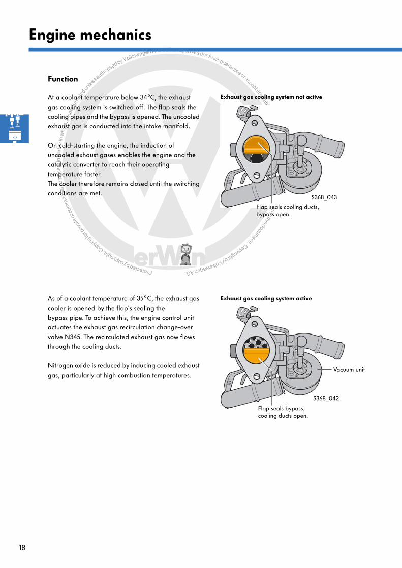
As of a coolant temperature of 35°C, the exhaust gas cooler is opened by the flap's sealing the bypass pipe. To achieve this, the engine control unit actuates the exhaust gas recirculation change-over valve N345. The recirculated exhaust gas now flows through the cooling ducts.
Nitrogen oxide is reduced by inducing cooled exhaust gas, particularly at high combustion temperatures.
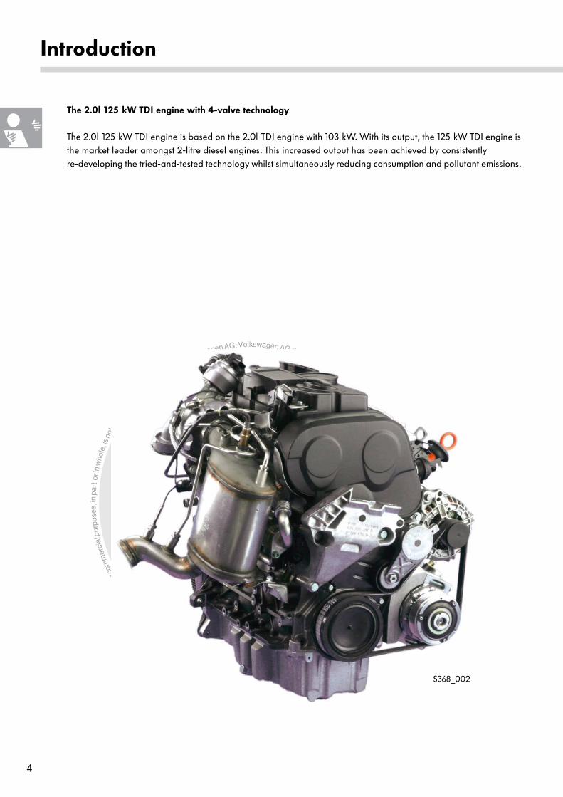
At a coolant temperature below 34°C, the exhaust gas cooling system is switched off. The flap seals the cooling pipes and the bypass is opened. The uncooled exhaust gas is conducted into the intake manifold.
On cold-starting the engine, the induction of uncooled exhaust gases enables the engine and the catalytic converter to reach their operating temperature faster. The cooler therefore remains closed until the switching conditions are met.
S368_042
S368_043
Exhaust gas cooling system active
Flap seals bypass, cooling ducts open.
Exhaust gas cooling system not active
Flap seals cooling ducts, bypass open.
Vacuum unit
Protected by copyright. C
opying
for p
rivat
e or
com
mer
cial
pur
pose
s, in
par
t or i
n w
hole
, is
not p
erm
itted
unles
s authorise
d by Volkswagen AG. Volkswagen AG does not guarantee or accept any liability with respect to the correctness ofinform
ation in this document.Copyright by Volkswagen AG.
19
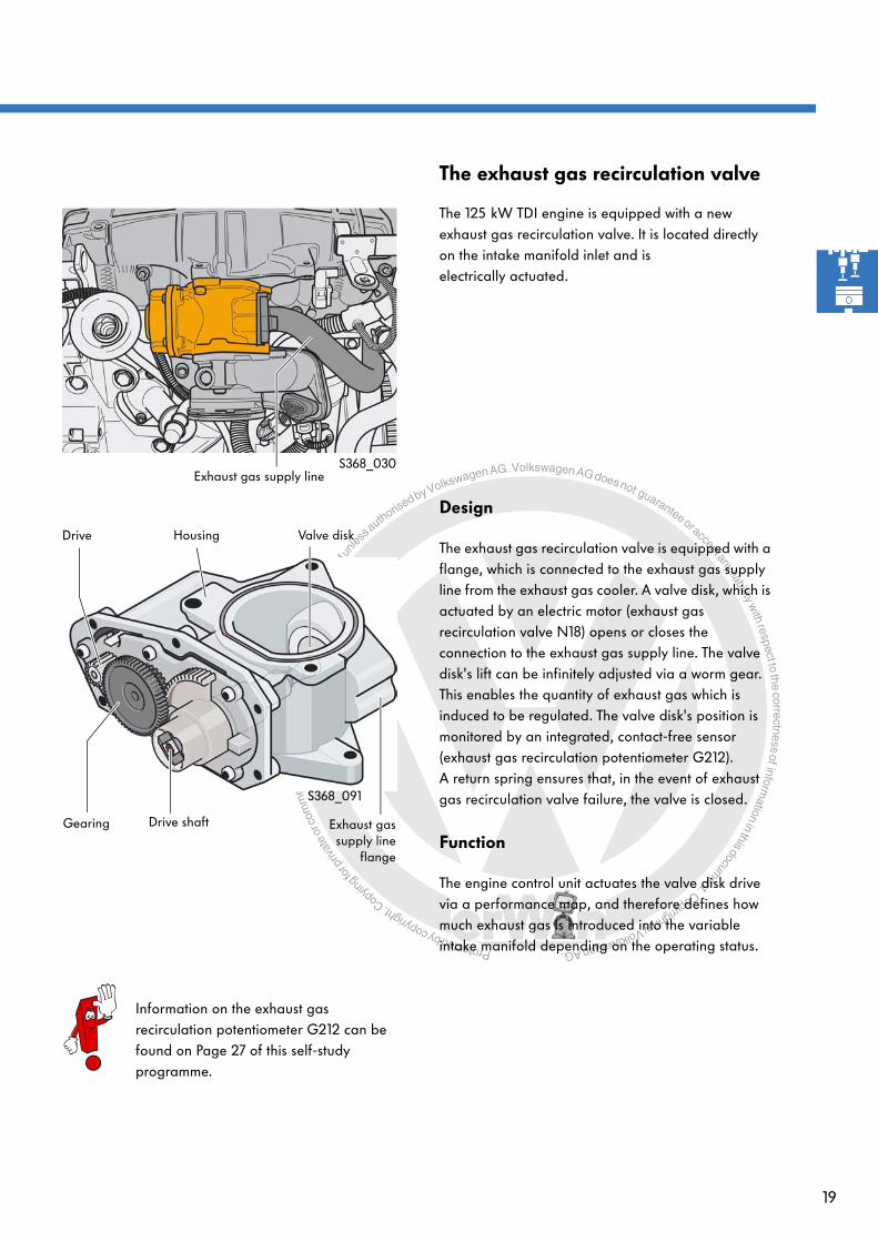
The exhaust gas recirculation valve
The 125 kW TDI engine is equipped with a new exhaust gas recirculation valve. It is located directly on the intake manifold inlet and is electrically actuated.
Design
The exhaust gas recirculation valve is equipped with a flange, which is connected to the exhaust gas supply line from the exhaust gas cooler. A valve disk, which is actuated by an electric motor (exhaust gas recirculation valve N18) opens or closes the connection to the exhaust gas supply line. The valve disk's lift can be infinitely adjusted via a worm gear. This enables the quantity of exhaust gas which is induced to be regulated. The valve disk's position is monitored by an integrated, contact-free sensor (exhaust gas recirculation potentiometer G212). A return spring ensures that, in the event of exhaust gas recirculation valve failure, the valve is closed.
Function
The engine control unit actuates the valve disk drive via a performance map, and therefore defines how much exhaust gas is introduced into the variable intake manifold depending on the operating status.
Information on the exhaust gas recirculation potentiometer G212 can be found on Page 27 of this self-study programme.
S368_030
Exhaust gassupply line
flange
Valve diskHousing
Drive shaftGearing
Drive
S368_091
Exhaust gas supply line

Protected by copyright. C
opying
for p
rivat
e or
com
mer
cial
pur
pose
s, in
par
t or i
n w
hole
, is
not p
erm
itted
unles
s authorise
d by Volkswagen AG. Volkswagen AG does not guarantee or accept any liability with respect to the correctness ofinform
ation in this document.Copyright by Volkswagen AG.
20
Engine mechanics
The intake manifold flap
The 125 kW TDI engine is equipped with an electrically actuated intake manifold flap. It is mounted in the direction of flow upstream of the exhaust gas recirculation valve. The intake manifold flap has the task of supporting the induction of exhaust gas into the intake port by building up a vacuum downstream of the control flap. Adjustment is infinite and can therefore be adapted to the relevant load and engine speed. When the engine is switched off, the regulating flap is closed to prevent juddering on switching off.
Design
The intake manifold flap is comprised of the housing, the regulating flap and the drive with an integrated, contact-free sensor for determining the position of the flap. The drive consists of an electric motor (intake manifold flap motor V157) with slightly inhibiting gearing. A return spring ensures that, when it is not supplied with current, the regulating flap is pulled to the "open" position (emergency running position). In this position, the flow of intake air is not impeded.
Function
The intake manifold flap motor is actuated directly by the engine control unit with a direct voltage. The integrated sensor (intake manifold flap position sender) reports the actual flap position to the engine control unit.
S368_031
The intake manifold flap position sender is integrated into the housing of the intake manifold flap motor V157. The sender is not therefore listed in "Guided Fault Finding".
Information on the intake manifold flap position sender can be found on Page 29 of this self-study programme.
Exhaust gas supply line
Flap shaft with return spring
Gearing
Drive
S368_085
Housing
Regulating flap

Protected by copyright. C
opying
for p
rivat
e or
com
mer
cial
pur
pose
s, in
par
t or i
n w
hole
, is
not p
erm
itted
unles
s authorise
d by Volkswagen AG. Volkswagen AG does not guarantee or accept any liability with respect to the correctness ofinform
ation in this document.Copyright by Volkswagen AG.
21
Turbocharger with travel feedback
Design
The 125 kW TDI engine is equipped with a re-engineered turbocharger. The turbocharger is integrated, together with the turbine housing, in the exhaust manifold. The compressor and turbine wheel have been flow-mechanically and thermodynamically optimised. This has enabled the achievement of faster charge pressure build-up, higher gas throughput with the same design size and better efficiency.
Due to the introduction of the near-engine mounted particulate filter, the turbocharger is now mounted above the exhaust manifold. It is supported on the crankcase via a tubular element.
Function
The function of the turbocharger's adjustment mechanism has not changed. The current position of the adjustment mechanism is reported to the engine control unit by the position sender for charge pressure positioner G581 (travel feedback).
S368_076
Adjustableguide vanes
Turbine wheel
Exhaust turbinehousing
Compressor
Adjustment mechanism
Further information on the turbocharger's adjustment mechanism can be found in self-study programme 190 "Adjustable Turbocharger".

Protected by copyright. C
opying
for p
rivat
e or
com
mer
cial
pur
pose
s, in
par
t or i
n w
hole
, is
not p
erm
itted
unles
s authorise
d by Volkswagen AG. Volkswagen AG does not guarantee or accept any liability with respect to the correctness ofinform
ation in this document.Copyright by Volkswagen AG.
22
Engine mechanics
Design
The design of the adjustment mechanism's connection to the turbocharger has been modified. Up to present, the adjustment mechanism has been joined to the turbine housing. In this turbocharger, the adjustment mechanism is held by a cage structure, the insert, which is bolted to the bearing housing. This has the advantage that the adjustment mechanism is decoupled from the turbine housing and that vibrations arising from the turbine therefore have less impact on the adjustment mechanism. The guide vane adjustment mechanism via an adjuster ring has not been modified.
Position sender for charge pressure positioner
The turbocharger is equipped with a position sender for charge pressure positioner G581. The sensor is integrated into the turbocharger's vacuum unit. Without contact, it records the travel of the diaphragm in the vacuum unit on actuation of the guide vanes. The position of the diaphragm is therefore a measure of the guide vane setting angle.
Bearing housing
Insert
Guide vanes with adjustment mechanism
Sensor housing with electrical connector
Sensor
Vacuum unit with diaphragm
Vacuum connection
Switching linkageS368_049
S368_066
Information on the position sender for charge pressure positioner G581 can be found on Page 26 of this self-study programme.

Protected by copyright. C
opying
for p
rivat
e or
com
mer
cial
pur
pose
s, in
par
t or i
n w
hole
, is
not p
erm
itted
unles
s authorise
d by Volkswagen AG. Volkswagen AG does not guarantee or accept any liability with respect to the correctness ofinform
ation in this document.Copyright by Volkswagen AG.
23
Diesel particulate filter
The diesel particulate filter is comprised, together with an oxidising catalytic converter, to form a single module. The module has been developed for all transversely mounted 3- and 4-cylinder engines. Due to its position close to the engine and the fact that the oxidising catalytic converter and the particulate filter are comprised together, the use of an additive is not necessary. As the diesel particulate filter reaches its operating temperature quickly, continuous, passive regeneration is possible.
In addition to passive regeneration, active regeneration of the particulate filter can also be induced. Active regeneration by the engine control unit is carried out when the particulate filter has become filled with soot particles, e.g. due to short journeys at partial load. In this case, the temperature required to carry passive regeneration out completely is not reached in the particulate filter.
Further information on the catalytically coated diesel particulate filter can be found in self-study programme 336 "The catalytic coated diesel particulate filter".
S368_007

Protected by copyright. C
opying
for p
rivat
e or
com
mer
cial
pur
pose
s, in
par
t or i
n w
hole
, is
not p
erm
itted
unles
s authorise
d by Volkswagen AG. Volkswagen AG does not guarantee or accept any liability with respect to the correctness ofinform
ation in this document.Copyright by Volkswagen AG.
24
Engine management
Overview of the system
Sensors
Engine speed sender G28
The overview of the system shows the 2.0l 125 kW TDI engine with 4-valve technology in the Passat.
Hall sender G40
Accelerator position sender G79Accelerator position sender 2 G185
Air mass meter G70
Coolant temperature sender G62
Radiator outlet coolanttemperature sender G83
Fuel temperature sender G81
Intake air temperature sender G42Charge air pressure sender G31
Position sender for charge pressure positioner G581
Brake light switch F
Lambda probe G39
Clutch position sender G476(for manual gearbox only)
Exhaust gas recirculation potentiometer G212
Exhaust gas temperature sender 1 G235Bank 1 exhaust gas temperature sender 2 G448
Exhaust gas pressure sensor 1 G450
Temperature sender after particulate filter G527
Engine control unit J623
CAN data bus
Diagnostic connection

Protected by copyright. C
opying
for p
rivat
e or
com
mer
cial
pur
pose
s, in
par
t or i
n w
hole
, is
not p
erm
itted
unles
s authorise
d by Volkswagen AG. Volkswagen AG does not guarantee or accept any liability with respect to the correctness ofinform
ation in this document.Copyright by Volkswagen AG.
25
Actuators
Automatic glow period control unit J179Glow plugs 1-4 Q10, Q11, Q12, Q13
Unit injector valve, cyl. No. 1-4 N240, N241, N242, N243
Exhaust gas recirculation valve N18
Charge pressure control solenoid valve N75
Exhaust gas recirculationcooler change-over valve N345
Intake manifold flap valve N316
Lambda probe heater Z19
Intake manifold flap motor V157
Fuel pump relay J17Fuel system pressurisation pump G6
Radiator fan control unit J293Radiator fan V7Radiator fan 2 V177
S368_072
Control unit in dash panel insert J285
Protected by copyright. C
opying
for p
rivat
e or
com
mer
cial
pur
pose
s, in
par
t or i
n w
hole
, is
not p
erm
itted
unles
s authorise
d by Volkswagen AG. Volkswagen AG does not guarantee or accept any liability with respect to the correctness ofinform
ation in this document.Copyright by Volkswagen AG.
26
Engine management
Sensors
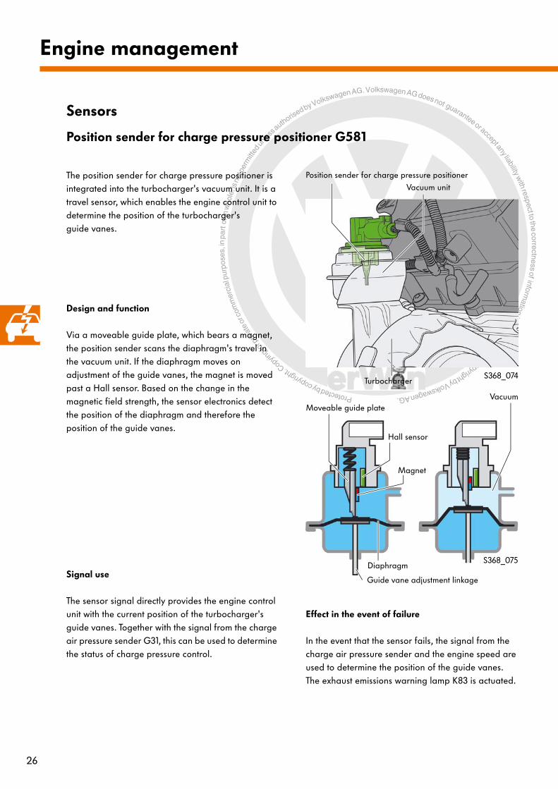
Position sender for charge pressure positioner G581
The position sender for charge pressure positioner is integrated into the turbocharger's vacuum unit. It is a travel sensor, which enables the engine control unit to determine the position of the turbocharger's guide vanes.
Signal use
The sensor signal directly provides the engine control unit with the current position of the turbocharger's guide vanes. Together with the signal from the charge air pressure sender G31, this can be used to determine the status of charge pressure control.
Effect in the event of failure
In the event that the sensor fails, the signal from the charge air pressure sender and the engine speed are used to determine the position of the guide vanes. The exhaust emissions warning lamp K83 is actuated.
Design and function
Via a moveable guide plate, which bears a magnet, the position sender scans the diaphragm's travel in the vacuum unit. If the diaphragm moves on adjustment of the guide vanes, the magnet is moved past a Hall sensor. Based on the change in the magnetic field strength, the sensor electronics detect the position of the diaphragm and therefore the position of the guide vanes.
S368_074
S368_075
Vacuum unit
Position sender for charge pressure positioner
Turbocharger
Hall sensor
Magnet
Moveable guide plate
Diaphragm
Guide vane adjustment linkage
Vacuum

Protected by copyright. C
opying
for p
rivat
e or
com
mer
cial
pur
pose
s, in
par
t or i
n w
hole
, is
not p
erm
itted
unles
s authorise
d by Volkswagen AG. Volkswagen AG does not guarantee or accept any liability with respect to the correctness ofinform
ation in this document.Copyright by Volkswagen AG.
27
S368_056
S368_017
S368_057
Hall sender
Permanent magnet
EGR valve cover
EGR valve housing
Drive
Valve diskdrive shaft
The exhaust gas recirculation potentiometer records the position of the valve disk in the EGR valve (exhaust gas recirculation valve). The valve disk's lift controls the inflow of recirculated exhaust gas into the intake manifold.
Design
The sender is integrated into the EGR valve's plastic cover. It is a Hall sender, which scans a permanent magnet on the drive shaft without coming into contact with it. Based on the change in field strength, it supplies a signal, from which the valve disk's opening lift can be calculated.
Signal use
The signal informs the engine control unit of the valve disk's current position. Amongst other purposes, this is required to regulate the quantity of recirculated exhaust gas and therefore the nitrogen oxide content in the exhaust gas.
Effect in the event of failure
In the event that the sensor fails, exhaust gas recirculation is switched off. The EGR valve's current supply is also deactivated, with the result that the valve disk is pulled to the "closed" position by a return spring.
Exhaust gas recirculation potentiometer G212

Protected by copyright. C
opying
for p
rivat
e or
com
mer
cial
pur
pose
s, in
par
t or i
n w
hole
, is
not p
erm
itted
unles
s authorise
d by Volkswagen AG. Volkswagen AG does not guarantee or accept any liability with respect to the correctness ofinform
ation in this document.Copyright by Volkswagen AG.
28
Engine management
Voltagecorresponds to travel
Sensor electronics
Hall IC
External,permanent magnet
Sensor signal
Travel
S368_089
Hall sensors for position detection
This type of sensor registers a voltage change within a voltage range. To measure a linear movement such as, e.g. in the position sender for charge pressure positioner G581, the magnet is separate from the Hall IC, with the result that the Hall IC passes by the magnet when it moves. The magnet's field strength changes along with its distance from the Hall IC. If the Hall IC moves towards the magnetic field, the Hall voltage increases; if it moves away from the magnet, the voltage decreases again. The sensor electronics can therefore conclude the travel which has been undertaken based on the change in Hall voltage.
Depending on the design of the Hall sensor and the permanent magnet, rotational angles can also be recorded and measured on the basis of the Hall principle. To achieve this, two Hall ICs are arranged in the sensor in such a way that they are at right angles to each other. Due to this position, the two Hall ICs supply opposing Hall voltages. These two voltages are used by the sensor electronics to calculate the adjustment angle of the rotational axis. In this example, the permanent magnet consists of two rod magnets, which are connected via two metal bridges so that the field curves between the two rod magnets run parallel.
Permanent magneton the rotational axis
Calculated rotational angle
Voltage, Hall IC 2
Voltage,Hall IC 1
Sensorelectronics
Rotational angle
S368_093
Design and function of Hall sensors
Hall sensors are used to measure rotational speed and detect positions. Both linear travel and rotational angles can be recorded by means of position detection.

Protected by copyright. C
opying
for p
rivat
e or
com
mer
cial
pur
pose
s, in
par
t or i
n w
hole
, is
not p
erm
itted
unles
s authorise
d by Volkswagen AG. Volkswagen AG does not guarantee or accept any liability with respect to the correctness ofinform
ation in this document.Copyright by Volkswagen AG.
29
Intake manifold flap position sender
The sensor element is integrated into the intake manifold flap drive (intake manifold flap motor V157). It records the current position of the intake manifold flap.
Design
The sender is located on a printed circuit board beneath the plastic cover of the intake manifold flap module. It is a magnetoresistive sensor, which scans a permanent magnet on the control flap axis without coming into contact with it.
Signal use
The signal informs the engine control unit of the intake manifold flap's current position. Amongst other purposes, the control unit requires this position to control exhaust gas recirculation and particulate filter regeneration.
Effect in the event of failure
In the event that the sensor fails, exhaust gas recirculation is switched off. The intake manifold flap drive's current supply is also deactivated, with the result that the regulating flap is pulled to the "open" position by the reset spring. A fault is entered in the fault memory under the relevant intake manifold flap motor V157.
S368_054
S368_018
S368_055
Magnetoresistive sensor element
Permanent magnet
Printed circuit board
Intake manifold flap housing

Protected by copyright. C
opying
for p
rivat
e or
com
mer
cial
pur
pose
s, in
par
t or i
n w
hole
, is
not p
erm
itted
unles
s authorise
d by Volkswagen AG. Volkswagen AG does not guarantee or accept any liability with respect to the correctness ofinform
ation in this document.Copyright by Volkswagen AG.
30
Engine management
Design and function of magnetoresistive sensors
Magnetoresistive sensors operate without making contact. They are used to measure rotational angles such as, e.g. the adjustment angle of the intake manifold flap. The special, internal design of these sensors enables them to measure a rotational angle from 0° to 180°.Further advantages include:
- Insensitivity to temperature-related magnetic field strength fluctuations,- Insensitivity to reference magnet ageing,- Insensitivity to mechanical tolerances.
Design
A magnetoresistive sensor is comprised of an electronic sensor element, which is coated with a ferromagnetic material, and a magnet as a reference magnet. The magnet is joined to the axis whose rotational angle is to be measured. When the axis rotates together with the rod magnet, the position of the magnet's field curves change versus the sensor element. As a result, the sensor element's resistance changes. The sensor electronics then use this value to calculate the absolute rotational angle of the axis versus the sensor.
The sensor element consists of two sub-sensors A and B, which are offset by 45° from one another. In turn, each sub-sensor consists of four resistance measuring bridges, each of which is rotated by 90° around a common centre point.
Axis with reference magnet
Field curves
Sensor element with ferromagnetic coating
Reference magnet rotational angle versus the sensor element
Sub-sensor A
Sub-sensor B
Resistance measuring bridges
S368_062
S368_061
S368_060

Protected by copyright. C
opying
for p
rivat
e or
com
mer
cial
pur
pose
s, in
par
t or i
n w
hole
, is
not p
erm
itted
unles
s authorise
d by Volkswagen AG. Volkswagen AG does not guarantee or accept any liability with respect to the correctness ofinform
ation in this document.Copyright by Volkswagen AG.
31
Function
If the axis is rotated versus a sub-sensor, this results in a sinusoidal change in this sub-sensor's resistance (R). Due to the shape of a sine curve, however, only a range from -45° to +45° can be determined as a clear angle by a sub-sensor. Example: Resistance R corresponds to a rotational angle of α = 22.5°.
There are two possible angles for a resistance value in the range between -90° and +90°. One sub-sensor alone cannot therefore supply a clear signal in this measuring range.Example: Resistance R corresponds to a rotational angle of α = 22.5° and 67.5°.
The use of two sub-sensors and their arrangement, offset by 45° from each other, result in two sine curves with a phase-shift of 45° as the measurement signal. By means of a calculation function, the sensor electronics can now calculate a clear angle between 0° and 180° from the two curves and pass this on to the assigned control unit.
Sub-sensor A
Output signal
A resistance value supplies a rotational angle
A resistance valve supplies two possible rotational angles
Phase-shifted sine curve
Sensor electronics
Clear angle
Output signal,sub-sensor A
Output signal, sub-sensor B
S368_063
S368_064
S368_065

Protected by copyright. C
opying
for p
rivat
e or
com
mer
cial
pur
pose
s, in
par
t or i
n w
hole
, is
not p
erm
itted
unles
s authorise
d by Volkswagen AG. Volkswagen AG does not guarantee or accept any liability with respect to the correctness ofinform
ation in this document.Copyright by Volkswagen AG.
32
Engine management
Actuators
Unit injector valve, cyl. No. 1-4 N240, N241, N242, N243
Detailed information can be found in self-study programme 352 "Unit Injectors with Piezo Valves".
S368_021
The unit injector valves are piezo-electric valves. They are components of the unit injector units and are connected directly to the engine control unit. The engine control unit uses the valves to control the unit injectors' individual injection phases.
The advantages of piezo-electric valves versus a unit injector with solenoid valve are:
- Lower noise emissions,- A wider range of injection pressures
(130-2200bar), - More flexible pilot, primary and secondary
injection design,- Higher efficiency,- Lower consumption,- Lower pollutant emissions and - Higher engine output.
Effects upon failure
If a unit injector valve fails, the corresponding cylinder's injection is deactivated. In the event of a slight deviation from the control limit, the unit injector valve continues to be actuated. In each case, an entry is made in the fault memory.

Protected by copyright. C
opying
for p
rivat
e or
com
mer
cial
pur
pose
s, in
par
t or i
n w
hole
, is
not p
erm
itted
unles
s authorise
d by Volkswagen AG. Volkswagen AG does not guarantee or accept any liability with respect to the correctness ofinform
ation in this document.Copyright by Volkswagen AG.
33
Charge pressure control solenoid valve N75
S368_052
This valve is installed in the engine compartment, in the vicinity of the turbocharger on the plenum chamber. It supplies the turbocharger's vacuum unit with the vacuum required to adjust the guide vanes.
Effect in the event of failure
When it is not supplied with current, the valve isolates the vacuum unit from the vacuum system. A spring in the vacuum unit moves the adjustment mechanism's linkage in such a way that the turbocharger's guide vanes are positioned to a sharp setting angle (emergency running position). Only a low charge pressure is available at a low engine speed and therefore a low exhaust gas pressure.
Legenda - Vacuum systemb - Engine control unit J623c - Intake aird - Charge air coolere - Charge pressure control solenoid valve N75f - Compressorg - Vacuum unit with position sender for
charge pressure positioner G581h - Exhaust turbine with guide vane adjustment
ba
dc
e f
g
h
S368_094

Protected by copyright. C
opying
for p
rivat
e or
com
mer
cial
pur
pose
s, in
par
t or i
n w
hole
, is
not p
erm
itted
unles
s authorise
d by Volkswagen AG. Volkswagen AG does not guarantee or accept any liability with respect to the correctness ofinform
ation in this document.Copyright by Volkswagen AG.
34
Engine management
S368_053
This is an electric motor, which actuates the exhaust gas recirculation valve disk, causing it to effect a lifting movement by means of gearing. To do this, it is actuated by the engine control unit with an analogue signal.
Effect in the event of failure
When it is not supplied with current, the valve is pulled into an emergency running position (closed) by a return spring. In this position, exhaust gas recirculation is switched off.
Exhaust gas recirculation valve N18
Legenda - Intake airb - Intake manifold flapc - Exhaust gas supply lined - Exhaust gas recirculation valve N18 with
exhaust gas recirculation potentiometer G212e - Engine control unit J623f - Exhaust gas cooler
e
a
c
d
f
b
S368_097

Protected by copyright. C
opying
for p
rivat
e or
com
mer
cial
pur
pose
s, in
par
t or i
n w
hole
, is
not p
erm
itted
unles
s authorise
d by Volkswagen AG. Volkswagen AG does not guarantee or accept any liability with respect to the correctness ofinform
ation in this document.Copyright by Volkswagen AG.
35
S368_051
d
a
e
c
f
b
g
i k
h
lm
S368_096
Exhaust gas recirculation cooler change-over valve N345
This valve is installed in the engine compartment next to the turbocharger. It supplies the exhaust gas cooler's vacuum unit with the vacuum required to switch the bypass flap.
Effect in the event of failure
When it is not supplied with current, the valve isolates the vacuum unit from the vacuum system. The exhaust gas cooler's bypass flap therefore remains closed, with the result that no exhaust gas is able to flow through the cooler.
Legenda - Intake airb - Intake manifold flapc - Exhaust gas recirculation valved - Engine control unit J623e - Cooled exhaust gasf - Coolant outletg - Exhaust gas coolerh - Hot exhaust gasi - Vacuum unitk - Coolant inletl - Exhaust gas recirculation cooler
change-over valve N345m - Vacuum system
Protected by copyright. C
opying
for p
rivat
e or
com
mer
cial
pur
pose
s, in
par
t or i
n w
hole
, is
not p
erm
itted
unles
s authorise
d by Volkswagen AG. Volkswagen AG does not guarantee or accept any liability with respect to the correctness ofinform
ation in this document.Copyright by Volkswagen AG.
36
S368_058
e
a
c
d
f
b
S368_098
Engine management
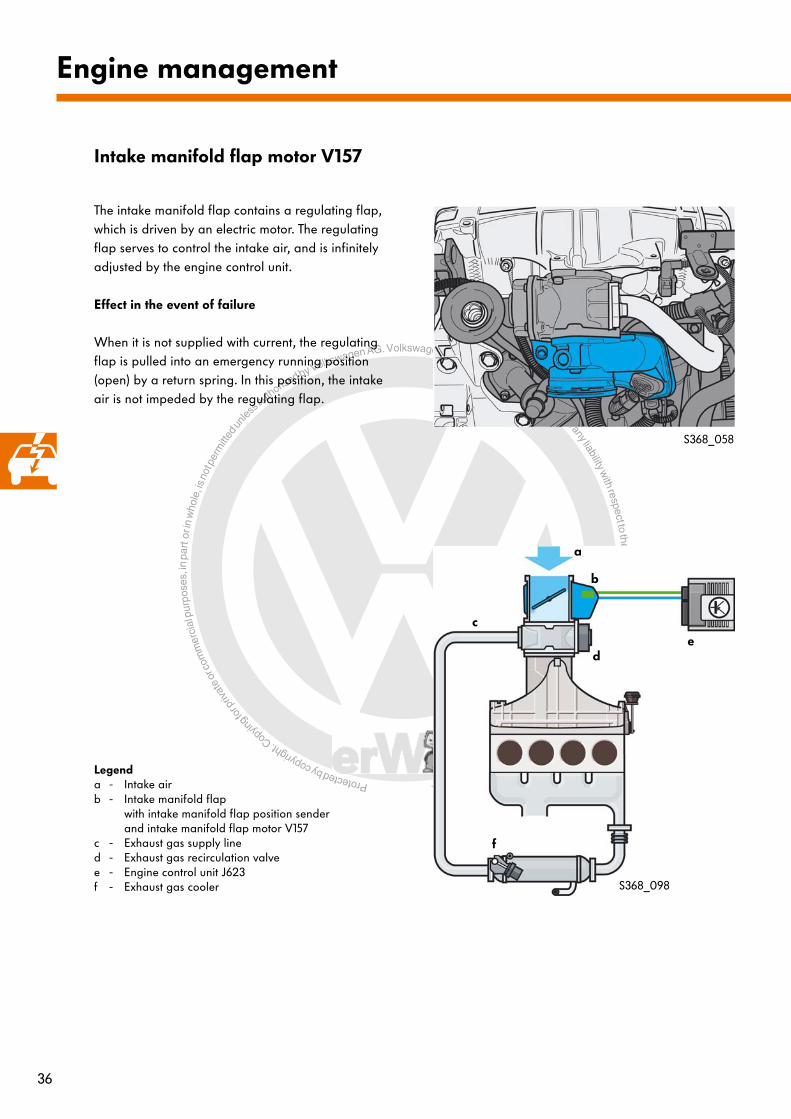
Intake manifold flap motor V157
The intake manifold flap contains a regulating flap, which is driven by an electric motor. The regulating flap serves to control the intake air, and is infinitely adjusted by the engine control unit.
Effect in the event of failure
When it is not supplied with current, the regulating flap is pulled into an emergency running position (open) by a return spring. In this position, the intake air is not impeded by the regulating flap.
Legenda - Intake airb - Intake manifold flap
with intake manifold flap position senderand intake manifold flap motor V157
c - Exhaust gas supply lined - Exhaust gas recirculation valvee - Engine control unit J623f - Exhaust gas cooler

Protected by copyright. C
opying
for p
rivat
e or
com
mer
cial
pur
pose
s, in
par
t or i
n w
hole
, is
not p
erm
itted
unles
s authorise
d by Volkswagen AG. Volkswagen AG does not guarantee or accept any liability with respect to the correctness ofinform
ation in this document.Copyright by Volkswagen AG.
37
Intake manifold flap valve N316
S368_050
d
a
c
b
e
f
h
g
S368_095
The intake manifold flap valve is a solenoid valve. It supplies the intake manifold's vacuum unit with the vacuum required to open and close the swirl flaps. The intake manifold flap valve is installed in the engine compartment above the alternator. It is actuated by the engine control unit depending on a performance map.
Effect in the event of failure
In the event of failure, it is no longer possible to close the swirl flaps in the intake manifold. The intake manifold's swirl flaps are set to the "open" position.
Legenda - Intake airb - Intake manifold flapc - Exhaust gas recirculation valved - Engine control unit J623e - Intake manifold flap valve N316f - Vacuum unitg - Variable intake manifold with selector shafth - Vacuum system

Protected by copyright. C
opying
for p
rivat
e or
com
mer
cial
pur
pose
s, in
par
t or i
n w
hole
, is
not p
erm
itted
unles
s authorise
d by Volkswagen AG. Volkswagen AG does not guarantee or accept any liability with respect to the correctness ofinform
ation in this document.Copyright by Volkswagen AG.
38
Engine management
Glow plugs 1 to 4 Q10, Q11, Q12, Q13
The new, ceramic glow plugs are a special feature of the glow plug system. They are subject to minimal ageing and therefore have a long service life. Further advantages include better cold-starting behaviour and improved exhaust emission values.
Design
The ceramic glow plugs are comprised of the plug body, the connecting pin and the heating element, which is manufactured from ceramic materials. The heating element consists of an insulating, protective ceramic casing and an inner, conductive ceramic heating element. The ceramic heating element replaces the regulating and heating coil in a metal glow plug.
Effect in the event of failure
If, when the glow plugs are connected, the automatic glow period control unit determines excessive current consumption or excessive resistance, the corresponding glow plugs are no longer actuated.
Make sure that ceramic glow plugs are only installed in engines designed to accommodate them. If you install ceramic glow plugs in an engine which is not designed for this purpose, difficulties will inevitably arise during cold-starting, as the engine control system cannot make use of the full potential offered by the ceramic glow plugs.
Note that the ceramic glow plugs for 2-valve and 4-valve TDI engines differ as regards their length and screw-in threads.
The ceramic glow plugs are sensitive to impact and bending. Further information can be found in the Workshop Manual.
Connecting pin
Plug body
Protective ceramic casing
Ceramic heating element
S368_020

Protected by copyright. C
opying
for p
rivat
e or
com
mer
cial
pur
pose
s, in
par
t or i
n w
hole
, is
not p
erm
itted
unles
s authorise
d by Volkswagen AG. Volkswagen AG does not guarantee or accept any liability with respect to the correctness ofinform
ation in this document.Copyright by Volkswagen AG.
39
Function
Glowing
The ceramic glow plugs are actuated sequentially by the engine control unit via the automatic glow period control unit J179 with the aid of a pulse width-modulated signal (PWM). The voltage at the individual glow plug is adjusted via the frequency of the PWM pulses in this case. For rapid starting at an exterior temperature of less than 14°C, the maximum voltage of 11.5V is applied. This guarantees that the glow plug is heated to over 1000°C within the shortest possible space of time (max. 2 seconds). This reduces the engine's glow period.
Post-start glowing
By continuously reducing the control frequency of the PWM signal, the voltage for post-start glowing is adjusted to the rated voltage of 7V. During post-start glowing, the ceramic glow plug reaches a temperature of approx. 1350°C. Post-start glowing is carried out for a maximum of 5 minutes after starting the engine, up to a coolant temperature of 20°C. The high glow temperature helps to reduce hydrocarbon emissions and combustion noise during the warm-up phase.
Intermediate glowing
To regenerate the particulate filter, the glow plugs are actuated by the engine control unit for intermediate glowing. Intermediate glowing improves the combustion conditions during the regeneration process. Due to their low ageing, intermediate glowing during particulate filter regeneration makes no special demands on the ceramic glow plugs.
For comparison purposes
In comparison with metal glow plugs, ceramic glow plugs have significantly higher glow temperatures with similar voltage requirements.
Metal glow plug Ceramic glow plug
Legend
S368_023-024
Voltage [V]Glow temperature [°C]
Protected by copyright. C
opying
for p
rivat
e or
com
mer
cial
pur
pose
s, in
par
t or i
n w
hole
, is
not p
erm
itted
unles
s authorise
d by Volkswagen AG. Volkswagen AG does not guarantee or accept any liability with respect to the correctness ofinform
ation in this document.Copyright by Volkswagen AG.
40
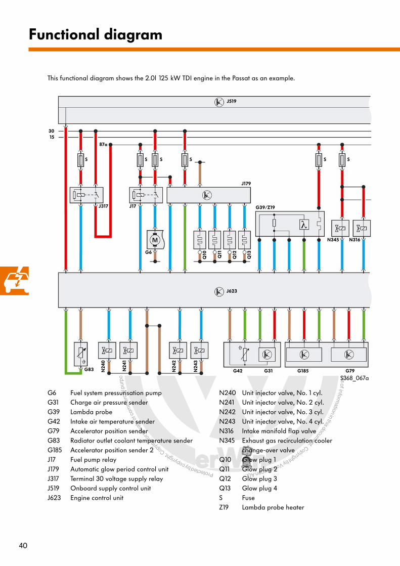
Functional diagram
This functional diagram shows the 2.0l 125 kW TDI engine in the Passat as an example.
G6 Fuel system pressurisation pumpG31 Charge air pressure senderG39 Lambda probeG42 Intake air temperature senderG79 Accelerator position senderG83 Radiator outlet coolant temperature senderG185 Accelerator position sender 2J17 Fuel pump relayJ179 Automatic glow period control unitJ317 Terminal 30 voltage supply relayJ519 Onboard supply control unitJ623 Engine control unit
N240 Unit injector valve, No. 1 cyl.N241 Unit injector valve, No. 2 cyl.N242 Unit injector valve, No. 3 cyl.N243 Unit injector valve, No. 4 cyl.N316 Intake manifold flap valveN345 Exhaust gas recirculation cooler
change-over valveQ10 Glow plug 1Q11 Glow plug 2Q12 Glow plug 3Q13 Glow plug 4S FuseZ19 Lambda probe heater
J519
J623
J317 J17
G6
J179
Q10
Q11
Q12
Q13
G39/Z19
N345 N316
G83 N24
0
N24
1
N24
2
N24
3
G42 G31 G185 G79
3015
87a
S S S S S S
S368_067a

Protected by copyright. C
opying
for p
rivat
e or
com
mer
cial
pur
pose
s, in
par
t or i
n w
hole
, is
not p
erm
itted
unles
s authorise
d by Volkswagen AG. Volkswagen AG does not guarantee or accept any liability with respect to the correctness ofinform
ation in this document.Copyright by Volkswagen AG.
41
F Brake light switchG28 Engine speed senderG40 Hall senderG62 Coolant temperature senderG81 Fuel temperature senderG235 Exhaust gas temperature sender 1G448 Bank 1 exhaust gas temperature senderG476 Clutch position sender
(vehicles with manual gearbox only)G527 Temperature sender after particulate filterJ293 Radiator fan control unitJ519 Onboard supply control unitJ623 Engine control unitN75 Charge pressure control solenoid valve
S Fuse
V7 Radiator fanV157 Intake manifold flap motorV177 Radiator fan 2
a Control unit for electromechanical parking brake J540
Colour code/legend
= positive= earth
J519
J623
S SSS
S
3015
87a
a
N75 V7 V177
J293
F G476
G235 G448
G527 G40 G28 G81 G62 V157 S368_067b
IN OUT

Protected by copyright. C
opying
for p
rivat
e or
com
mer
cial
pur
pose
s, in
par
t or i
n w
hole
, is
not p
erm
itted
unles
s authorise
d by Volkswagen AG. Volkswagen AG does not guarantee or accept any liability with respect to the correctness ofinform
ation in this document.Copyright by Volkswagen AG.
42
G70 Air mass meterG212 Exhaust gas recirculation potentiometerG450 Exhaust gas pressure sensor 1G581 Position sender for charge pressure positionerJ519 Onboard supply control unitJ623 Engine control unitJ533 Data bus diagnostic interfaceN18 Exhaust gas recirculation valveS Fuse Colour code/legend
J519
J623
S
3015
G450 G70
N18 G212 G581
J533
Diagnostic
connection
CAN drive data bus low
S368_067c
= positive= earth
IN OUT
CAN drive data bus high
Functional diagram

Protected by copyright. C
opying
for p
rivat
e or
com
mer
cial
pur
pose
s, in
par
t or i
n w
hole
, is
not p
erm
itted
unles
s authorise
d by Volkswagen AG. Volkswagen AG does not guarantee or accept any liability with respect to the correctness ofinform
ation in this document.Copyright by Volkswagen AG. 43
Test yourself
1. How is the balancer shaft module driven in the 2.0l 125 kW TDI engine?
a) The crankshaft drives the balancer shaft module via a chain drive.
b) The balancer shaft module is driven via a toothed belt drive.
c) The balancer shaft module is driven by the crankshaft.
3. How are the swirl flaps in the intake manifold switched?
a) With the aid of an electrically driven positioning motor
b) With the aid of a vacuum unit
c) With the aid of an electric switching valve
Which answers are correct?
One, several or all answers may be correct.
2. The exhaust gas recirculation valve ...
a) Has a valve disk which is actuated by an electric motor.
b) Is controlled by means of a vacuum.
c) Is equipped with a contact-free sensor for determining the valve disk position.
Answers
1. b), c); 2. a), c); 3. b), c); 4. c)
4. The balancer shaft's backlash is adjusted ...
a) With the aid of a dial gauge.
b) With the aid of a feeler gauge.
c) Via a special coating.
d) With the aid of a new, special tool.

Protected by copyright. C
opying
for p
rivat
e or
com
mer
cial
pur
pose
s, in
par
t or i
n w
hole
, is
not p
erm
itted
unles
s authorise
d by Volkswagen AG. Volkswagen AG does not guarantee or accept any liability with respect to the correctness ofinform
ation in this document.Copyright by Volkswagen AG.
© VOLKSWAGEN AG, WolfsburgAll rights and rights to make technical alterations reserved.000.2811.90.20 Technical status 10.2005
Volkswagen AGService Training VSQ-1Brieffach 1995D-38436 Wolfsburg
❀ This paper has been manufactured from pulp bleached without the use of chlorine.
368
Related Documents