SSME SEAL TEST PROGRAM: TEST RESULTS FOR SAWTOOTH PATTERN DAMPER SEAL--INTERIM PROGRESS REPORT NASA CONTRACT NAS8- 35824 Prepared by Dara W. Childs, Ph.D., P.E. Professor of Mechanical Engineering February 1986 TRC-Seal-1-86 III (NASA-CK-1788C1) SSME SEAL TEST PROGRAM TEST RESULTS FOE SAWTOOTH PATTEBN DAMPER SEAL Interim Proqress Report JTexas A6M Dniv. ) 101 p HC A06/MF A01 CSCL 11A G3/37 N86-2394D Unclas 16969 Turbomachinery Laboratories Mechanical Engineering Department stion, Tex.:

Welcome message from author
This document is posted to help you gain knowledge. Please leave a comment to let me know what you think about it! Share it to your friends and learn new things together.
Transcript
SSME SEAL TEST PROGRAM: TEST RESULTSFOR SAWTOOTH PATTERN DAMPER SEAL--INTERIM PROGRESS REPORT
NASA CONTRACT NAS8- 35824
Prepared by
Dara W. Childs, Ph.D., P.E.
Professor of Mechanical Engineering
February 1986
TRC-Seal-1-86
III(NASA-CK-1788C1) SSME SEAL TEST PROGRAMTEST RESULTS FOE SAWTOOTH PATTEBN DAMPERSEAL Interim Proqress Report JTexas A6MDniv. ) 101 p HC A06/MF A01 CSCL 11A
G3/37
N86-2394D
Unclas16969
Turbomachinery LaboratoriesMechanical Engineering Department
stion, Tex.:
SSME SEAL TEST PROGRAM:TEST RESULTS FOR SAWTOOTH-PATTERN DAMPER SEAL
INTERIM PROGRESS REPORT
NASA CONTRACT NAS8-358211
Prepared by
Dara W. Childs, Ph.D., P.E.
Professor of Mechanical Engineering
Turbomachinery LaboratoriesMechanical Engineering Department
Texas A&M UniversityCollege Station, Texas 77843
February 1986
TRC-Seal-1-86

TABLE OF CONTENTS
Page
ABSTRACT 1
LIST OF FIGURES 3
LIST OF TABLES 6
NOMENCLATURE 8
INTRODUCTION 10
TEST CONFIGURATIONS AND CAPABILITYTest Configurations 15Test and Data Capability 21
DYNAMIC TEST DATA 24
CONCLUSIONS: 52
REFERENCES 53
APPENDIX A. STATIC TEST RESULTS FOR SAWTOOTH PATTERN STATORS . . . 54
APPENDIX B. DYNAMIC TEST DATA FOR SAWTOOTH-PATTERN 77

ABSTRACT
Test results consisting of direct and transverse force coefficients are
presented for eleven, sawtooth-pattern, damper-seal configurations.
The designation "damper" seal refers to a seal which uses a
deliberately roughened stator and smooth rotor as suggested by von
Pragenau [1] to increase the net damping force developed by a seal.
The designation "sawtooth-pattern" refers to a stator roughness pattern
whose normal cross section to the axis of the seal resembles a saw
tooth with the teeth direction opposing fluid motion in the direction
of shaft rotation. The sawtooth pattern yields axial grooves in the
stator which are interrupted by spacer elements which act as flow
constrictions or "dams".
All seals tested use the same smooth rotor and have the same,
constant, minimum clearance. The stators which were tested examined
the consequences of changes in the following design parameters:
(a) axial-groove depth (tooth height),
(b) number of teeth,
(c) number of sawtooth sections,
(d) number of spacer elements (dams),
(e) dam width,
(f) Axially aligned sawtooth sections versus axially-staggered
sawtooth sections, and
(g) Groove geometry.
From a rotordynamics viewpoint, none of the sawtooth-pattern seals
performs as well as the best round-hole-pattern seal. The best
sawtooth-pattern stator yielded 18$ more net damping than a smooth seal
1
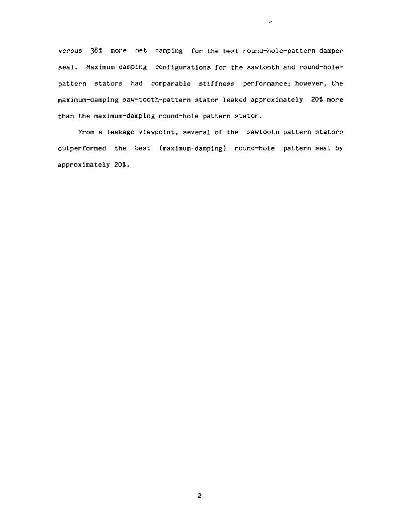
versus 38$ more net damping for the best round-hole-pattern damper
seal. Maximum damping configurations for the sawtooth and round-hole-
pattern stators had comparable stiffness performance; however, the
maximum-damping saw-tooth-pattern stator leaked approximately 20$ more
than the maximum-damping round-hole pattern stator.
From a leakage viewpoint, several of the sawtooth pattern stators
outperformed the best (maximum-damping) round-hole pattern seal by
approximately 20$.
LIST OF FIGURES
page
1. Round-hole pattern stator number, insert number one .... 13
2. Axially-grooved, sawtooth-pattern stator insert with end
seals 14
3. High-Reynolds-Number seal test section 16
4. Cross-section of sawtooth-pattern stator 17
5. Schematic for sawtooth-pattern stators 1 through 4 18
6. Schematic for sawtooth-pattern stators 5 through 7 19
7. Schematic for sawtooth-pattern stators 8 through 11 .... 20
8. Radial and tangential force coefficients for sawtooth
stator 1 25
9. Radial and tangential force coefficients for sawtooth
stator 2 26
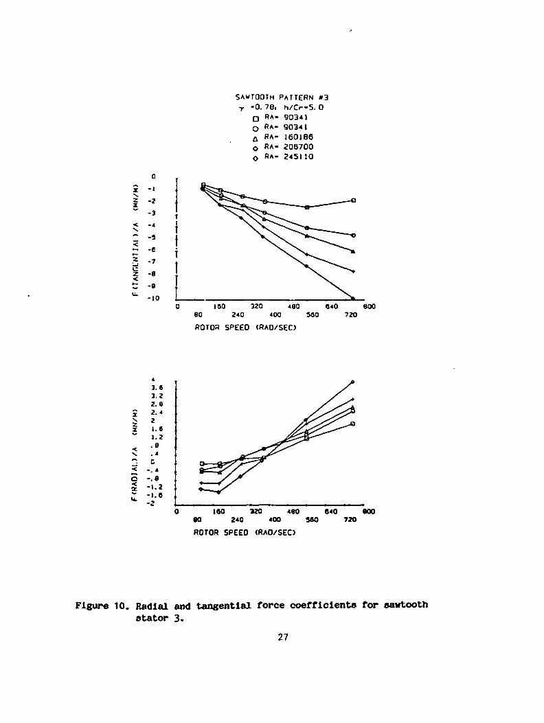
10. Radial and tangential force coefficients for sawtooth
stator 3 27
11. Radial and tangential force coefficients for sawtooth
stator 4 28
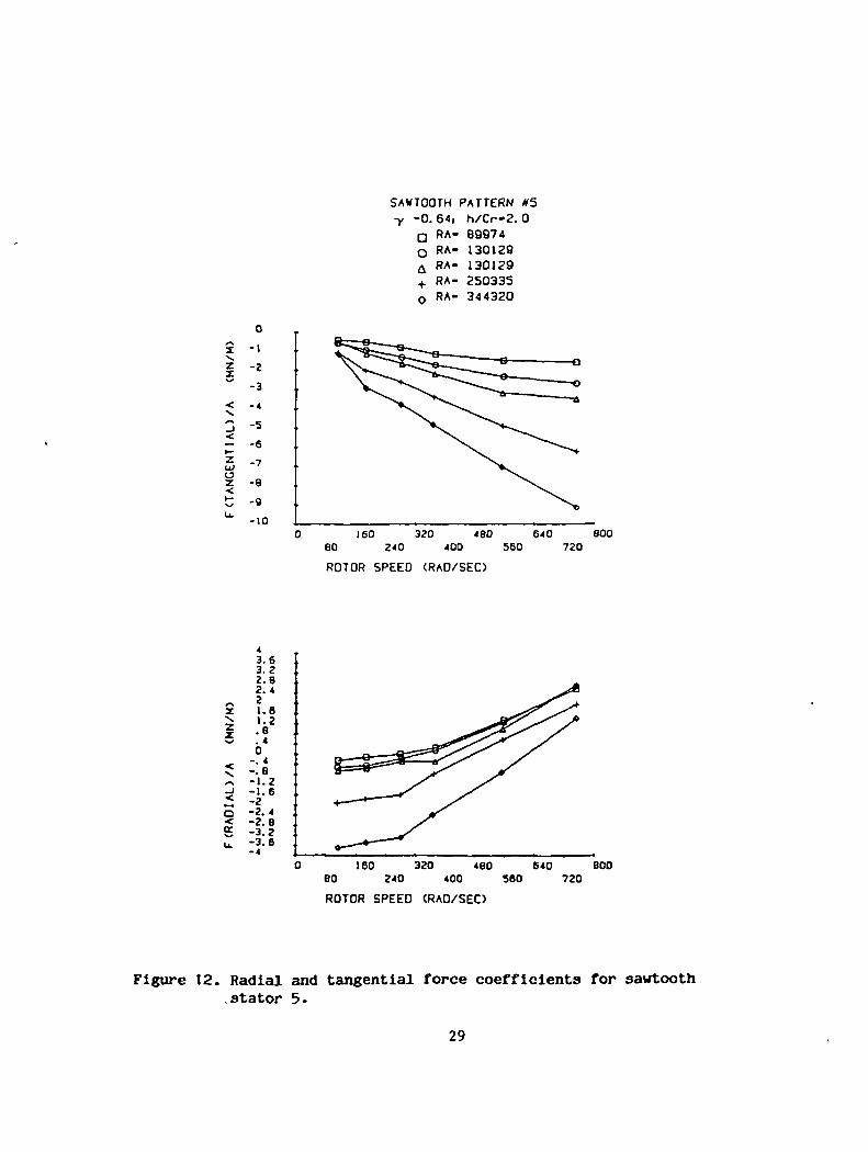
12. Radial and tangential force coefficients for sawtooth
stator 5 29
13. Radial and tangential force coefficients for sawtooth
stator 6 30
14. Radial and tangential force coefficients for sawtooth
stator 7 31
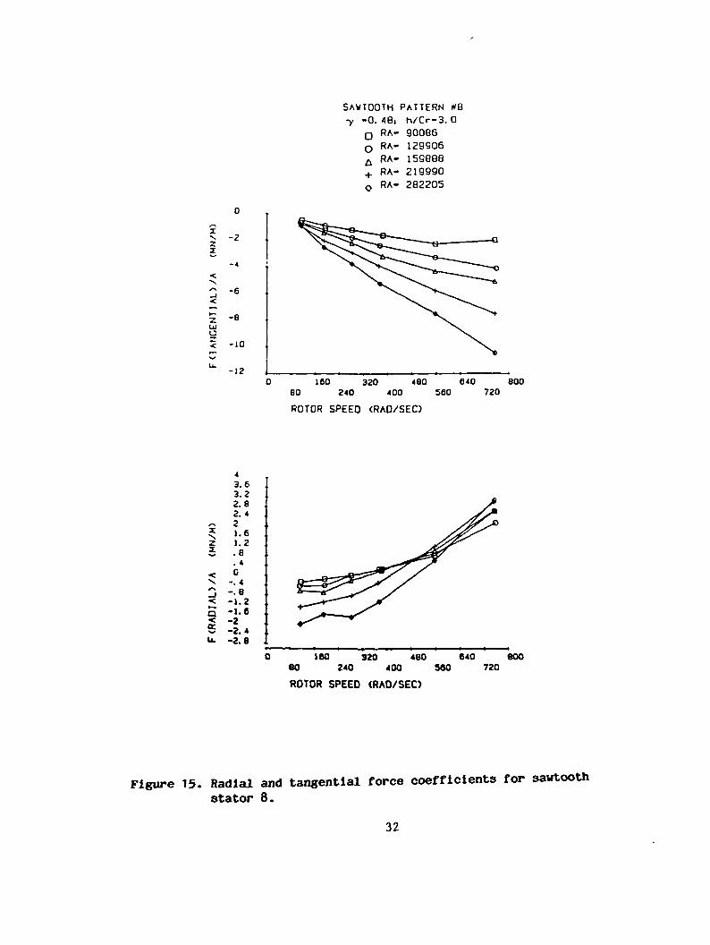
15. Radial and tangential force coefficients for sawtooth
stator 8 32

16. Radial and tangential force coefficient? for sawtooth
stator 9 33
17. Radial and tangential force coefficients for sawtooth
stator 10 34
18. Radial and tangential force coefficients for sawtooth
stator 11 35
19. Cef versus AP for sawtooth stators 1 through 4,
a smooth stator, and the optimum-damping round-hole-
pattern stator 40
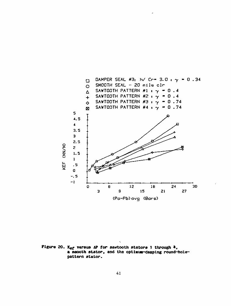
20. Kef versus AP for sawtooth stators 1 through 4,
a smooth stator, and the optimum-damping round-hole-
pattern stator 41
21. CL versus AP for sawtooth stators 1 through 4,
a smooth stator, and the optimum-damping round-hole-
pattern stator 42
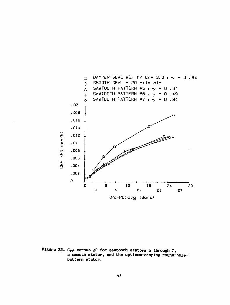
22. Cef versus AP for sawtooth stators 5 through 7,
a smooth stator, and the optimum-damping round-hole-
pattern stator. 43
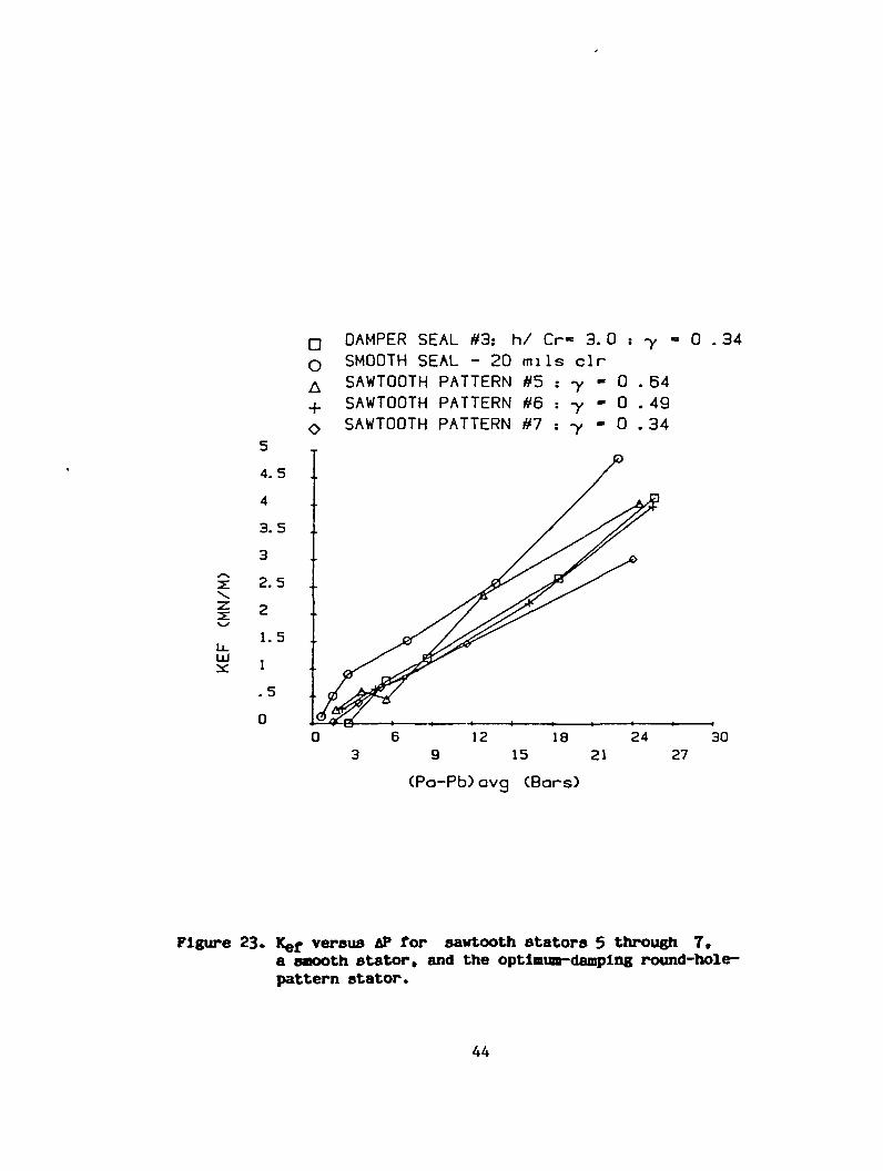
23. Kef versus AP for sawtooth stators 5 through 7,
a smooth stator, and the optimum-damping round-hole-
pattern stator 44
24. CL, versus AP for sawtooth stators 5 through 7,
a smooth stator, and the optimum-damping round-hole-
pattern stator 45
25. Cef versus AP for sawtooth stators 8 through 11,
a smooth stator, and the optimum-damping round-hole-
pattern stator 46

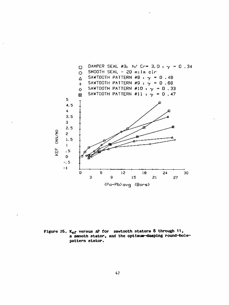
26. Kef versus AP for sawtooth stators 8 through 11,
a smooth stator, and the optimum-damping round-hole-
pattern stator 147
27. CL, versus AP for sawtooth stators 8 through 11,
a smooth stator, and the optimum-damping round-hole-
pattern stator H8

LIST OF TABLES
page
1. Dimension? of sawtooth-pattern stators 22
2(a). Measured values for Kef, Cef, and Mef for sawtooth
stators 1 through 4 37
2(b). Measured values for Kef, Cef, and Mef for sawtooth
stators 5 through 7 38
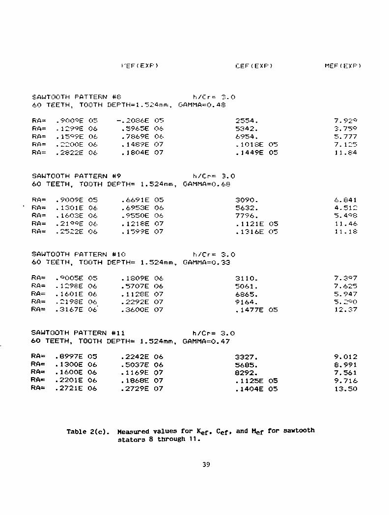
2(c). Measured values for Kef, Cef, and Mef for sawtooth
stators 8 through 11 39
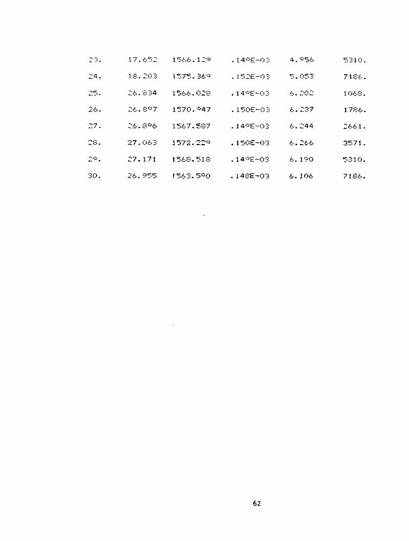
A.1 Test Data: Operating Conditions and Parameters for stator 1 . 55
A.2 Test Data: Operating Conditions and Parameters for stator 2 . 57
A.3 Test Data: Operating Conditions and Parameters for stator 3 . 59
A.14 Test Data: Operating Conditions and Parameters for stator 4 . 61
A.5 Test Data: Operating Conditions and Parameters for stator 5 . 63
A.6 Test Data: Operating Conditions and Parameters for stator 6 . 65
A.7 Test Data: Operating Conditions and Parameters for stator 7 . 67
A.8 Test Data: Operating Conditions and Parameters for stator 8 . 69
A.9 Test Data: Operating Conditions and Parameters for stator 9 . 71
A.10 Test Data: Operating Conditions and Parameters for stator 10. 73
A.11 Test Data: Operating Conditions and Parameters for stator 11. 75
B.I Test Data: Force Coefficients (average and standard deviations)
and average force magnitudes for stator 1 78
B.2 Test Data: Force Coefficients (average and standard deviations)
and average force magnitudes for stator 2 80

B.3 Test Data: Force Coefficients (average and standard deviations)
and average force magnitudes for stator 3 82
B.4 Test Data: Force Coefficients (average and standard deviations)
and average force magnitudes for stator 4 84
B.5 Test Data: Force Coefficients (average and standard deviations)
and average force magnitudes for stator 5 86
B.6 Test Data: Force Coefficients (average and standard deviations)
and average force magnitudes for stator 6 88
B.7 Test Data: Force Coefficients (average and standard deviations)
and average force magnitudes for stator 7 90
B.8 Test Data: Force Coefficients (average and standard deviations)
and average force magnitudes for stator 8 92
B.9 Test Data: Force Coefficients (average and standard deviations)
and average force magnitudes for stator 9 94
B.10 Test Data: Force Coefficients (average and standard deviations)
and average force magnitudes for stator 10 96
B.11 Test Data: Force Coefficients (average and standard deviations)
and average force magnitudes for stator 11 98
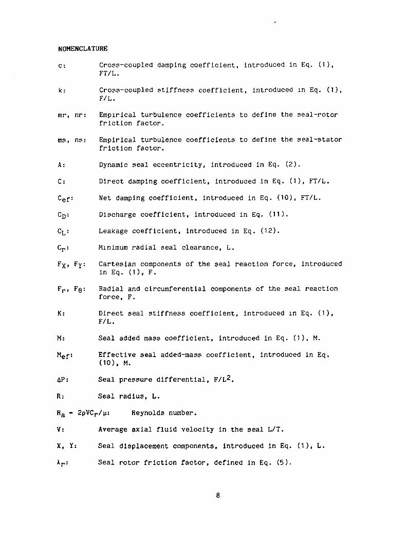
NOMENCLATURE
c: Cross-coupled damping coefficient, introduced in Eq. (1),FT/L.
k: Cross-coupled stiffness coefficient, introduced in Eq. (1),F/L.
mr, nr: Empirical turbulence coefficients to define the seal-rotorfriction factor.
ms, ns: Empirical turbulence coefficients to define the seal-statorfriction factor.
A: Dynamic seal eccentricity, introduced in Eq. (2).
C: Direct damping coefficient, introduced in Eq. (1), FT/L.
Cef: Net damping coefficient, introduced in Eq. (10), FT/L.
CD: Discharge coefficient, introduced in Eq. (11).
CL,: Leakage coefficient, introduced in Eq. (12).
Minimum radial seal clearance, L.
FX» FY: Cartesian components of the seal reaction force, introducedin Eq. (1 ), F.
Fr, FQ: Radial and circumferential components of the seal reactionforce, F.
K: Direct seal stiffness coefficient, introduced in Eq. (1),F/L.
M: Seal added mass coefficient, introduced in Eq. (1), M.
Mef: Effective seal added-mass coefficient, introduced in Eq.(10), M.
AP; Seal pressure differential, F/L2.
R: Seal radius, L.
Ra • 2pVCr/u: Reynolds number.
V: Average axial fluid velocity in the seal L/T.
X, Y: Seal displacement components, introduced in Eq. (1), L.
Xr: Seal rotor friction factor, defined in Eq. (5).

o •= X(L/Cr): Axial pressure-gradient coefficient,
p: Seal density. M/L3.
u>: Seal rotational and precessional velocity, T"1
p: Seal viscosity, FT/L2.
INTRODUCTION
The test and analysis results which are reported here were obtained
under NASA Contract NAS8-3582i4. The present work continues research
activity which began in January of 1980 under NASA Contract NAS8-33716.
Earlier contract reports C3~7] provide detailed information covering
the following points:
(a) test-section and facility description,
(b) test-objectives and procedures, and
(c) data acquisition, analysis and procedures.
Most of this information is not repeated here, and interested readers
are referred to earlier reports.
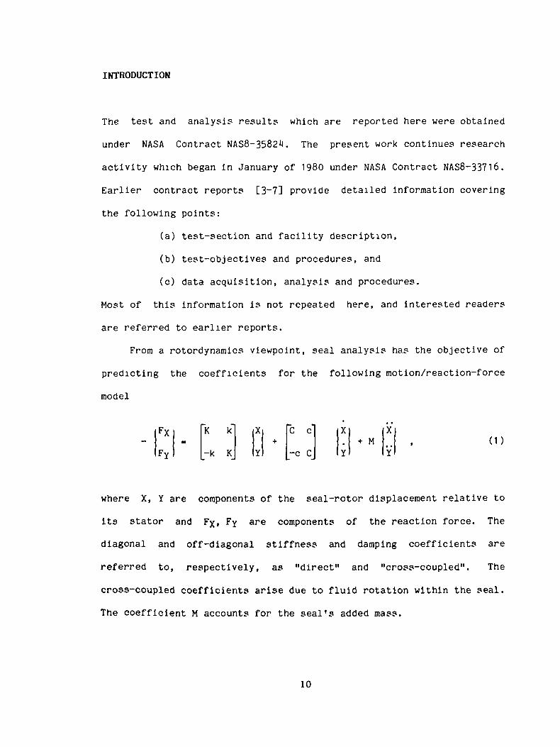
From a rotordynamics viewpoint, seal analysis has the objective of
predicting the coefficients for the following motion/reaction-force
model
(1)FXFY
=K k"
-k K
X
Y+
C c"
_-c C_
X.
Y+ M
* •
X
Y
where X, Y are components of the seal-rotor displacement relative to
its stator and FXI FY are components of the reaction force. The
diagonal and off-diagonal stiffness and damping coefficients are
referred to, respectively, as "direct" and "cross-coupled". The
cross-coupled coefficients arise due to fluid rotation within the seal.
The coefficient M accounts for the seal's added mass.
10

If a circular orbit of the form
X = A coswt, Y = A sinut (2)
is assumed, Eq. (1) yields the following definition of force
coefficients which are, respectively, parallel and perpendicular to the
rotating displacement vector
Fr/A = -K -coj + Mo)2
(3)Fe/A = k - Co>
Observe that the cross-coupled-stiffness coefficient k yields a
"driving" tangential contribution in the direction of rotation, while
the direct damping coefficient develops a drag force opposing the
tangential velocity.
A prior investigation [6] examined five new "damper seal"
configurations which were largely inspired by von Pragenau's work [1].
Von Pragenau's analysis predicts that a smooth-rotor/rough-stator
combination will yield a reduced asymptotic fluid tangential velocity
within the seal, which will, in turn, yield a reduction in the
cross-coupled stiffness coefficient. A reduced cross-coupled stiffness
coefficient reduces the destabilizing tangential driving force on the
rotor, yields an increased net damping force, and generally enhances
rotor stability and response. A subsequent and more comprehensive
analysis by Childs and Kim [2], yields the same sort of encouraging
predictions.
The results of [6] confirmed that damper seals could yield
11

increased net damping coefficients and showed particularly encouraging
results for the round-hole pattern configuration of figure 1. The
report [7] provided test data for twelve additional round-hole-pattern
seal configurations.
The results of [6] also included test results for the sawtooth-
pattern, axially-grooved seal of figure 2. The teeth in the sawtooth-
pattern cross section are directed against fluid rotation, with the
intuitive expectation that this arrangement reduces the average
circumferential fluid velocity and thereby reduces the cross-coupled-
stiffness-coefficient, k. Test results for this seal showed a
substantial increase in net damping as compared to a smooth seal;
however, the leakage performance was only slightly better than a smooth
seal and substantially worse than the hole pattern seal. The present
report provides test data for eleven, sawtooth-pattern seals which are
"inspired" by the original axially-grooved seal of figure 2, but have
additional intermediate separators between the sawtooth pattern
sections to improve leakage performance. The hope and expectation of
this test program was that a sawtooth-pattern seal could be developed
which retained or improved upon the damping performance suggested by
the test results for the stator of figure 2, while sharply improving
the leakage performance.
12

Olmcnilont In Mllllm«t«r»
O O O O OO O O O O
O O O O Oo o o o
279 Ola 10 0««p
97
s.»«Surface RovglMMi* Octal)
Figure 1. Round-hole pattern stator number insert number one.
13

'Jv////
-4.7
*////>b[-7.9
— 49.9—
10
|
12
1.0
i:
7.0
0Olm«n«loni In
109 T««th
Surfeet 0«toN
Figure 2. Axially-grooved, sawtooth-pattern statorinsert with end seals.

TEST CONFIGURATIONS, CAPABILITY. AND RESULTS
Test Configurations
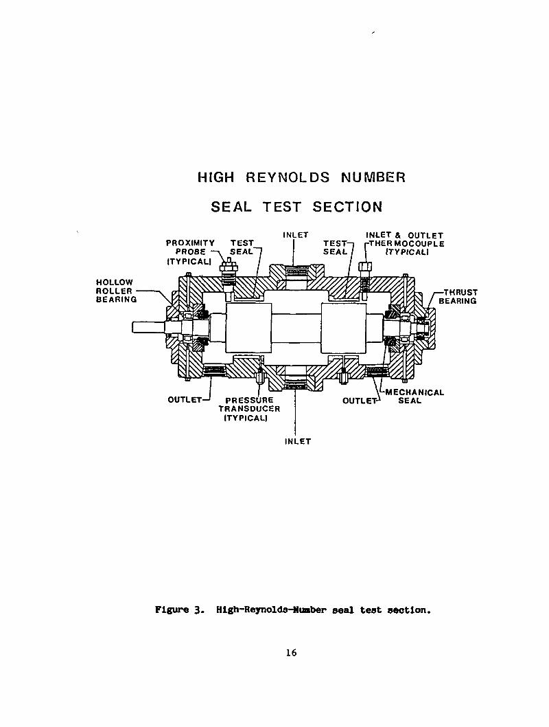
The seal test section Is illustrated in figure 3 and is designed to
accept candidate seal inserts. All seals tested use a smooth rotor and
have a constant minimum clearance, i.e., no taper. Figure H
illustrates the assembly procedure for the sawtooth-pattern seal. The
sawtooth-pattern sections are pressed into a stainless-steel housing
and separated by dams. A brass retaining ring at the seal entrance
holds the seal-ring/dam assembly together.
All stators tested had 1 inch ( 101.6 mm) internal diameters, were
2 inches (50 mm) long, and had .020 in (.508 mm) minimum radial
clearances.
Figure 5 illustrates the dimensions and arrangements for stators 1
through 4. Observe that the axial-grooves in the seal section are
aligned for seals 1 and 3 (straight), but are staggered for seals 2 and
i*. The groove-depth (tooth height) of 2.5 4 mm is characteristically
large for these four stators.
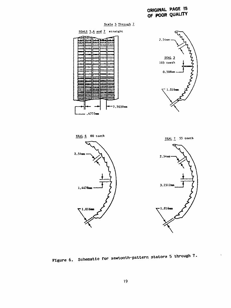
Figure 6 illustrates the dimensions for seals 5 through 7. By
comparison to figure 2, seal 5 has the same cross-section as the
original axial-grooved seal. The three, stator cross sections of
figure 6 differ only in the number of teeth or grooves. For these
stators, the groove-depth to minimum-clearance ratio, h/Cr, is two.
15
HOLLOWROLLERBEARING
HIGH REYNOLDS NUMBER
SEAL TEST SECTION
PROXIMITYPROBE
ITYPICALI
TESTINLET INLET & OUTLET
•THERMOCOUPLEITYPICALI
•THRUSTBEARING
PRESSURETRANSDUCER
(TYPICAL)
-MECHANICALOUTLET-1 SEAL
INLET
Figure 3. High-Reynolds-Nuaber seal test section.
16

SEAL ASSEMBLY
St«lnle«8SteelHousing
Sc«lRing*
V/A A7/77
V
Brass.RetatnlnRRing
Figure *l. Cross-section of sawtooth-pattern stator.
17

Sea In 1 Ttirnuch 4
2.54mm
SEALS 1 and 3 straight
3.81mm
DanSeal Ring
SEALS £ and staggered
Figure 5. Schematic for sawtooth-pattern stators 1 through
18
ORIGINAL PAGE ISOF POOR QUALfTY
Seals 5 Through
SEALS 5.6 and 7 straight
•7.7038B
2.54mm
SEAL .5
105 teeth
SEAL 6 80 teeth
2.54mm
SEAL 7 55 teeth
2.54ma
Figure 6. Schematic for sawtooth-pattern stators 5 through 7.
19

MJUS B TIIKOIICH I I
SEALS 9 AND 11 STACCERKD
0.4775m
3.335mm
60 TEETH
SEALS 8 AND 10 STAGGERED
1.9845BB-*- •*- 3.3172nn
1.524
Figure 7. Schematic for sawtooth-pattern stators 8 through 11
20

Figure 7 illustrates the dimensions of seals 9 through 11. The
h/Cr ratios for this group of seals is 3-0.
The parameter,
hole area
total area
was easily calculated for the round-hole pattern seals. For the
present seals, the area of a single "hole" is defined to be An - BXE.
Table 1 provides, the dimensions, and h/Cr and Y ratios for all of the
sawtooth-pattern stators.
Test and Data Capability
The rotor segments of the test seal are mounted eccentrically on the
rotor of figure 2 with the eccentricity A. Hence, rotor rotation
generates a synchronously precessing pressure field. Axially spaced,
strain-gauge, pressure transducers are provided to measure the
transient pressure field, and the transient pressure measurements are
recorded and integrated to define Fr/A, Fg/A, and |F|. In any test,
five to ten cycles of data, containing on the order of 2,000 data
points, are analyzed. Each data point yields a calculated value for
Fp/A, FQ/A and |F|, and average and standard-deviation values are
calculated for the test case. Observe from Eq. (3) that the test
apparatus yields only the net radial and tangential force coefficients
and can not be used to separately identify the seal coefficients.
The analysis of von Pragenau [1] and Childs and Kim [2] indicates
that the seal rotor and stator roughness are important in defining the
cross-coupled stiffness coefficient k and net-damping-force coefficient
21

2in
oo
inHo
HCO
oICO
w8<HCO
T
T05O
52HCO
COZ
toJ O«« X10 KHCO OC
toto
COto
I. O O O O O O O O O O Oo
U"* kf\ lO (A <\1 (\1 f\i no ro ro
CO CO CO cO OO cO <-O *\l u~* <\jr**— I"*** oo co oo oo i**™v c^— IA t**—
Gen e — — f- r—
t\j rg t~- t— r- r~ t—
O E
• = r - = r o o o o o — o— o
<\» oj o oCO CO OO CO — — IA IA
Eto E
OO <M IA zr IA lACO cO oo cO cO t1*™ *~ t*~ f*™1 -T ^T
6 O O O O O ^ - l A t - t — C O C OO E
VO vO lA IAO O f- f-
E3C E
ro oo PO on
vO ^O ^O -7 -^ —T -7— — — CO OO (\J f\J
E l A l A l A l A O O O l A l A l A l AE
o jo jcv j rv i — — — — — — —
t o c £ < i > M < i > 6 0 o o e o a > a > < i > < i >a.x
lA lA lA lA lA lA lAcOGOoOOO
< \ l f \ j r \ » f \ J O C O « A v O v D v O v £ >
22

Fg/A. For homogeneous roughness, estimate? for the relative roughness
parameters can be obtained from measured results for the axial pressure
gradient and leakage rate. The required data, consisting of the supply
and discharge pressures and pressure measurements at axial locations
throughout the seal, are sampled, averaged, and recorded immediately
before transient data are recorded. For homogeneous-roughness
stators, this data can be used as input data for predictions of seal
rotordynamic coefficients. However, no analytical model presently
exists for the inhomogeneous and discontinuous roughness pattern
presented by these sawtooth stators.
For a given seal configuration, a test matrix is carried out with
variations in the flowrate (axial Reynolds number) and shaft rotational
speed. The flowrate is varied from a minimum value, which Is
sufficient to yield adequate signal-to-noise ratios of the transient
pressure measurements, out to the maximum flow capability of the
circuit. Shaft rotation speed is incremented from approximately 1,000
rpm to 7,200 rpm. In a given test series, the axial Reynolds number is
held constant and the running speed incremented.
For a given test, the following two types of data are secured:
(a) steady-state "input" data consisting of the pressure
differential, average fluid density and viscosity, mass leakage
rate, and rotational speed, and
(b) "output" data consisting of Fr/A, F0/A, \F\ versus the axial
Reynolds number and shaft running speed.
The tables of Appendices B and C provide this type of data for each
test of each seal configuration.
23

DYNAMIC TEST RESULTS
Figure 8 through 18 illustrate measured result? for Fr/A and Fg/A
versus Ra and cj for the sawtooth-pattern seals. Each curve of these
figures corresponds to a fixed axial Reynolds number, Ra. Appendix B
contains the data presented in these figures.
The results of figures 8 through 18 generally follow the
predictions of Eq. (3). The radial force coefficients starts at a
negative valve for low running speeds and increases in an approximate
quadratic fashion as w increases. The tangential force coefficients is
an approximate linear function of 01.
An inspection of Eqs. (3) suggest that sufficient independent
equations could be obtained to calculate all the rotordynamic
coefficients by simply testing at three running speeds. However, the
fact that the coefficients depend on u> precludes this approach. While
K, C, and M are weak functions of u through their dependence on a, the
"cross-coupled" coefficients k and c are linear functions of tu. In
fact, if the fluid is prerotated prior to entering the seal such that
the inlet tangential velocity is UQO •= Rco/2, then theory predicts that
k = Cu)/2, c = Mco, and
Fp/A - -K, Fe/A = -Coo/2 (M)
The present test apparatus provides no intentional prerotation, and the
expected result is of the form
k - b-iCoj/2, b!<1
c - b2Mo>, b2<1 (5)
Fe/A • -Cef to • -C(1-b1/2)u)
Fr/A • -Kef + Mef u)2 • -K + M(1 -b2)u>
2 (6)

z
-J
I<
o-i-3
-3
-4
-5
-6
-7
-8
-9
-10
X
z
X
acr
32.72. 42. 11.81.51.2.9.6.30'.6.81.21.31.6Z. 12.42. /3
SAWTOOTH PATTERN #1y -0. 40i h/Cr-5. 0
a RA- 90134o RA- 129963A RA- 1602840 RA- 257800o RA- 326400
80160 320 480 640 800
240 400 560 720
ROTOR SPEED (RAD/SEC)
1BO 320 460 040 80080 240 400 380 720
ROTOR SPEED (RAO/SEC)
Figure 8. Radial and tangential force coefficients for sawtoothstator 1.
25

SAWTOOTH PATTERN *2
•y -0. 40, h/Cr-5. 0
D
oRA- 69929RA- 89929RA- 154735RA- 253100RA- 327338
X
i
zUl
<s.
Q
a
o-i-2
-3-4
-3
-6
-7
-e-e-10
43.63.22.82. 421.6
.'e
.4o-.4-.6-1.2-1.6-2-2.4-2.6-3.2-3.6-4
160 320 460 040 60080 240 400 560 720
ROTOR SPEED (RAO/SEC)
60160 320 460 640 800
240 400 SCO 720
ROTOR SPEED (RAO/SCO
Figure 9. Radial and tangential force coefficients for sawtoothstator 2.
26
0
z -I
I -2w -3
~ -0"• -io
zN
Z
oa:
4
3.63.22.82.4
21.61.2.8. 4
c-. 4
-. e-J.2-i.e
SAWTOOTH PATTERN #3-y -0. 78i h/Cr-5. 0
D RA- 90341O RA- 90341A RA- 1601860 RA- 206700O RA- 245110
801 00 320 480 840 800
240 400 SCO 720
ROTOR SPEED (RAO/SEC)
160 320 480 040 80000 240 400 SBO 720
ROTOR SPEED (RAO/SEC)
Figure 10. Radial and tangential force coefficients for sawtoothstator 3.
27

2Z.
_l
•z.UJo
z2
<oa
4.543.532.521.5I.50-.5-J-1.5-2
SAWTOOTH PATTERN *4•y -0. 74j h/Cr-5. 0
D RA- 90044
o RA- 129923A RA- 160136+ RA- 210021
RA- 262694
160eo
320 460 6402*0 400 560
600720
ROTOR SPEED (RAD/SEC)
160 320 480 840 BOO60 240 400 500 720
ROTOR SPEED (RAO/SEC)
Figure 11. Radial and tangential force coefficients for sawtoothstator 4.
28
Xx
Z
zUJO
0
-1-2
-3
-4
-5
-6
-7
-8
-9
-10
X
5ac.
43.63.22.82. 421.61.2.8. 40. 4.61.21.622.42.63.23.64
SAWTOOTH PATTERN <csy -0.64, h/Cr-2.0
Q RA- 89974
o RA- 130129
A RA- 130129+ RA- 250335
0 RA- 344320
0 160 320 480 640 80060 240 400 560 720
ROTOR SPEED (RAD/SEC)
160 320 480 640 80080 240 400 560 720
ROTOR SPEED (RAD/SEC)
Figure 12. Radial and tangential force coefficients for sawtooth.stator 5.
29

SAWTOOTH PATTERN #•y -0. 49, h/Cr-2. 0
oo
RA- 90125RA- 130062RA- 159877RA- 250101RA- 319763
zX2Z
ZLJO
2
QK
0
-I
-2
-3
-4
-*,
-6
-7
-e-9
-10
43.63.22.82.421.61.2.8. 40-. 4-.6-1.2-1.6-2-2.4-2.8-3.2-3.6-4
0 160 320 460 640 80080 240 400 560 720
ROTOR SPEED (RAO/SEC)
160 320 480 640 eoo80 240 400 seo 720
ROTOR SPEED (RAO/SEC)
Figure 13. Radial and tangential force coefficients for sawtoothstator 6.
30

z -2x
-4
-6
zUl0
aa:
-8
-10
-12
43 63.22 82. 421.61.2.6. 40
-. 4-.8-1.2-1.6-2-2.4-2.8-3.2-3.6-4
S A W T O O T H P A T T E R N t-y -0. 34, h/Cr-2.0
Q RA- 89898O "A- 129912A RA- 159929+ RA- 249908O RA- 362041
0 160 320 480 640 60080 240 400 560 720
ROTOR SPEED (RAO/SEC)
160 320 480 640 80080 240 400 S60 720
ROTOR SPEED (RAO/SEC)
Figure 1U. Radial and tangential force coefficients for sawtoothstator 7.
31
I•y2X
ZLUO
X
2
Q
a
-2
-4
-6
-e
-10
-12
43.63.22.82.421.61.2.8. 4C
-. 4-.8-1.2-1.6-2-2.4-2.8
SAWTOOTH PATTERN #£-y -0. 48, h/Cr-3. 0
Q RA- 90086o RA- 129906A RA- 159888+ RA- 219990rt RA- 282205
0 ICO 320 480 640 80080 240 400 560 720
ROTOR SPEED <RAO/SEC>
0 160 320 480 640 BOO80 240 400 900 720
ROTOR SPEED (RAD/SEC)
Figure 15. Radial and tangential force coefficients for sawtoothstator 8.
32

SAWTOOTH PATTERN *•y -0. 681 h/cr-3. 0
O RA- 900B9o RA- 130063A RA- 160274+ RA- 219859
RA- 252237
z
o
0
-1-3-3
-4
-5
-e-7
-e-s-10
0 100 320 460 040 BOO80 240 400 560 720
ROTOR SPEED (RAO/SEC)
zxz
0
cr
54.54
3.532.5ZI. 51.50
-.5-1-1.5-2
60100 320 460 640 600
240 400 SOO 720
ROTOR SPEED (RAD/SEC)
Figure 16. Radial and tangential force coefficients for sawtoothstator 9.
33

SAWTOOTH PATTERN #10•y -0. 33» h/Cr-3. 0
D RA- 90048RA- 129810RA- 180088RA- 218819RA- 318898
z
X«*\_J
zLJU
-2
-4
-8
-9
-10
-12
*~ "'oa
43.83.22.82.421.81.2.8. 40>. 4.81.21.622.42.83.23.64
80180 320 480 840 800
240 400 560 720
ROTOR SPEED (RAO/SEC)
160 320 480 640 80080 240 400 560 720
ROTOR SPEED (RAD/SEC)
Figure 17. Radial and tangential force coefficients for sawtoothstator 10.
34

•z.
•z.Ulo
7.
Z
-2
-6
-8
-10
-12
acru. -
SAWTOOTH PATTERN #•y -0. 47j h/Cr-3. 0
Q RA- 89973o RA- 130003A RA- 159973+ RA- 220132o RA- 272141
0 160 330 460 640 60080 240 400 560 720
ROTOR SPEED (RAO/SEC)
640 800240 400 580 720
ROTOR SPEED (RAD/SEC)
Figure 18. Radial and tangential force coefficients for sawtoothstator U.
35
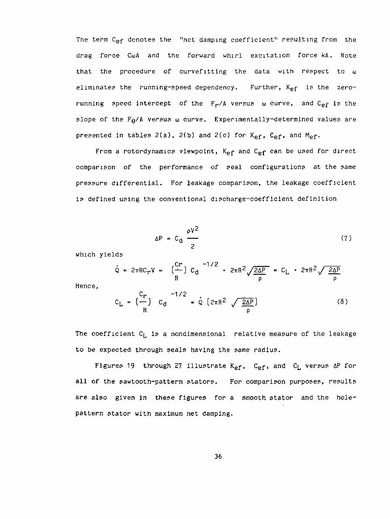
The term Cef denotes the "net damping coefficient" resulting from the
drag force Cu>A and the forward whirl excitation force kA. Note
that the procedure of curvefitting the data with respect to co
eliminates the running-speed dependency. Further, Kef is the zero-
running speed intercept of the Fr/A versus w curve, and Cef is the
slope of the F0/A versus oi curve. Experimentally-determined values are
presented in tables 2(a), 2(b) and 2(c) for Kef, Cef, and Mef.
From a rotordynamics viewpoint, Kef and Cef can be used for direct
comparison of the performance of seal configurations at the same
pressure differential. For leakage comparison, the leakage coefficient
is defined using the conventional discharge-coefficient definition
pV2
AP = Cd (7)2
which yields,Cr. -1/2
Q - 2irRCrV - (—) Cd • 2irR2v/2AP^ = CL • 2irR2
v/ 2APR p p
Hence,Cr -1/2
CL - ( —) Cd - Q (2TiR2 V/^2APJ (8)R p
The coefficient CL is a nondimensional relative measure of the leakage
to be expected through seals having the same radius.
Figures 19 through 27 illustrate Kef, Cef, and CL versus AP for
all of the sawtooth-pattern stators. For comparison purposes, results
are also given in these figures for a smooth stator and the hole-
pattern stator with maximum net damping.
36

KEF(EXP) MEP(EXP)
SAWTOOTH PATTERN #1 h/Cr= 5.O25 TEETH, TOOTH DEPTH= 2.540mm, GAMMA=O.4O
RA= .9013E 05RA= . 1300E 06RA= . 16O3E 06RA= .2578E 06RA= .3264E 06
.4126E O6
. 4918E 06
.60O2E O6
. 1971E 07
.3003E 07
SAWTOOTH PATTERN #225 TEETH, TOOTH
RA= .8993E 05RA= . 1300E O6RA= . 1598E 06RA= .253 IE 06RA= .3273E 06
DEPTH= 2.540mm,
. 1942E O6
.5279E 06
.8402E 06
.209QE 07
.3417E 07
SAWTOOTH PATTERN *325 TEETH, TOOTH
RA= .9O34E 05RA= . 1300E 06RA= . 1602E O6RA= .2067E O6RA= .245 IE 06
SAWTOOTH PATTERN25 TEETH, TOOTH
RA= .9004E 05RA= . 1299E O6RA= . 1601E 06RA= .2101E O6RA= .2620E 06
DEPTH= 2.54Omm,
.235 IE 06
.62O2E O6
.9123E O6
. 1669E 07
. 1942E O7
#4DEPTH= 2.540mm,
-.8431E 05.3121E 06.7688E 06. 1082E 07.2142E 07
2254.4021.4878.8255.. 1190E 05
h/Cr= 5.0GAMMA=O.40
2712.4362.5166.8746.. 1 286E 05
h/rr= 5.0GAMMA=0.74
2174.6327.8093.. 1061E 05. 13S7E 05
h/Cr= 5.0GAMMA=O.74
3352.5634.7151.9724.. 1116E 05
2.5424.5926.0085.4446.O92
4.9356.8865.9897. 1787.S25
3.O6O2. 1241.7652.0165.865
6. 1714.2653.6535.8652.483
Table 2(a). Measured values for Kef. Cef, and Mef for sawtoothstators 1 through H.
37

EF(EXP) MEF(EXP)
SAWTOOTH PATTERN *5 h/Cr = T.O105 TEETH, TOOTH DEPTH= l.O16mm, GAMMA=O.64
RA= . 89-57E 05RA= . 130 IE O6RA= . 1600E 06RA= . 2503E 06RA= .3443E 06
SAWTOOTH PATTERN80 TEETH, TOOTH
RA= .9O12E 05RA= . 130 IE 06RA= . 1599E O6RA= .25O1E 06RA= . 3198E O6
SAWTOOTH PATTERN55 TEETH, TOOTH
RA= . 8<>90E 05RA= . 1299E O6RA= . 1599E 06RA= .2499E O6RA= .3620E 06
. 2567E
. 58-54E
.4427E
. 2352E
. 4O25E
#6DEPTH= 1.
.27O3E
. 6323E
.8114E
. 2203E
.3-57 IE
#7DEPTH= 1.
. 3352E
. 38O9E
. 6550E
. 1460E
. 3O07E
06O606O707
0 1 6mm ,
06060607O7
O 1 6mm ,
05O6060707
1-580.O Tie=" ~s
4687.7 10.. 3 1C'7E 05
h/Cr= 2.OGAMMA=0. 49
2110.3592.4898.^24 1 .. 1 1 83E O5
h/Cr= 2.OGAMMA=O. 34
1 69 1 .3083.4179.8072.. 1203E O5
5.7266.1188.8404. 5 347.046
5.8306.8267.6319.c'255.7-56
6.8747.0416.81-510.231 1. 36
Table 2(b) Measured values forstators 5 through 7.
Cef. and Mef for sawtooth
38
^EF(EXP) CEF(EXP) MEF(EXP)
SAWTOOTH PATTERN 4*8 h/Cr = 3.060 TEETH, TOOTH DEPTH=1.524mrt,, GAMMA=0.48
RA= . 900*E 05RA= . 1299E 06RA= . 15 9E 06RA= . 2200E O6RA= . 2822E 06
SAWTOOTH PATTERN60 TEETH, TOOTH
RA= . 9009E O5RA= . 130 IE 06RA= . 1603E 06RA= . 21-^E 06RA= . 2522E 06
SAWTOOTH PATTERN60 TEETH, TOOTH
RA= . «005E 05RA= . 1298E O6RA= . 160 IE 06RA= .2198E 06RA= .3167E 06
-.2086E. 5965E. 7869E. 1489E. 1 804E
#9DEPTH= 1.
.6691E
. 6953E
.9550E
. 1218E
. 1599E
#10DEPTH= 1.
. 1809E
. 57O7E
. 1 1 28E
. 2292E
. 3600E
SAWTOOTH PATTERN 4*116O TEETH, TOOTH DEPTH= 1.
RA= .8997E 05RA= . 1300E 06RA= . 1600E 06RA«= .2201E 06RA= .272 IE O6
. 2242E
. 5037E
.1169E
. 1868E
. 2729E
O5O606O707
524rrifTi,
0506060707
524fTicn ,
06O6070707
524mm,
O60607O707
2554.5342.6954.. 1018E. 1449E
h/Cr= 3.0GAMMA=0.68
309O.5632.7796.. 1121E. 1316E
h/Cr= 3.0GAMMA=0.33
3110.5061.6865.9164.. 1477E
h/Cr= 3.0GAMMA=0.47
3327.5685.8292.. 1125E. 1404E
O505
05O5
O5
0505
7. 92C'3.7595.7777. 1251 1.84
6.8414.5125.4'--'S11. 4611.18
7.3*77. 6255.9475. 2*O12.37
9.0128.9917.5619.71613.50
Table 2(c). Measured values for Kef. Cef, andstators 8 through 1 1 .
for sawtooth
39

DOA
DAMPER SEAL #3: h/CCr- 3.0 •SMOOTH SEAL - 20 mils clrSAWTOOTH PATTERN #1SAWTOOTH PATTERN #2SAWTOOTH PATTERN 03SAWTOOTH PATTERN #4
- 0 .34
• -y
« y
i y
i y
- 0- 0
- 0- 0
o01W
u
.02
.018
.016
.014
.012
.01
.008
.006
.004
.002
0
447474
12 18 24 30IS 21 27
(Po-Pb)ovg (Bars)
Figure 19. Cef versus AP for sawtooth stators 1 through 4,a smooth stator, and the optinun-damping round-hole-pattern stator.
LL.LU
5
4.5
4
3.53
2.5
2
1.5
1
.5
0
-.5
-1
DOA
DAMPER SEAL #3j h/ Cr- 3. 0 iSMOOTH SEAL - 20 mils clrSAWTOOTH PATTERN #1 i -0SAWTOOTH PATTERN #2 tSAWTOOTH PATTERN #3 »SAWTOOTH PATTERN #4 «
- 0 . 34
yT
-0- 0- 0
447474
6 12 18 24 303 9 15 21 27
CPa-Pb> ovg (Bars)
Figure 20. Kef versus AP for sawtooth stators 1 through 4,a soooth stator, and the optlaur-damplng round-hole-pattern stator.
41

a
OA
DAMPER SEAL #3: h/Cr- 3. 0 i -y - 0 . 34SMOOTH SEAL - 20 mils clrSAWTOOTH PATTERN #1 : -y - 0 . 4SAWTOOTH PATTERN #2 : -y - 0 . 4SAWTOOTH PATTERN #3 i y - 0 . 74SAWTOOTH PATTERN #4 » - 0 . 74
oo0
*t—
UJI-H
U.U_UJ0uUJo
UJ_J
9
8. 1
7.2
6.3
5. 4
4.5 .
3.6 .
2.7
1.8
.9
0
-o
^^^
o ^ ^"
0 6 1 2 1 8 2 4 3 03 9 15 21 27
(Pa-Pb)avg (Bars)
Figure 21. CL versus AP for sawtooth stators 1 through 4,a smooth stator, and the optimuar-daoplng round-hole-pattern stator.
42
no
DAMPER SEAL #3: h/ Cr- 3. 0 « ySMOOTH SEAL - 20 mils clrSAWTOOTH PATTERN #5 t -y - 0 . 64SAWTOOTH PATTERN #6 : -y - 0SAWTOOTH PATTERN #7 : y - 0
- 0 . 34
4934
o01U)
u.LU
(Po-Pb)avg (Bars)
Figure 22. Cef versus AP for sawtooth stators 5 through 7,a smooth stator, and the optimum-damping round-hole-pattern stator.
u.UJ
noA
DAMPER SEAL #3: h/ Cr= 3.0 :SMOOTH SEAL - 20 mils clrSAWTOOTH PATTERN #5 : -y - 0SAWTOOTH PATTERN #6 : -y - 0SAWTOOTH PATTERN #7 : -v - 0
y 0 .34
644934
3 9
(Pa-Pb)avg (Bars)
Figure 23. Kef veroua AP for sawtooth atators 5 through 7*a eaooth etator, and the optimum-damping round-hole-pattern stator.
44

LEA
KA
GE
CO
EF
FIC
IEN
T
* 10
00
CcL
<9
8. 1
7.2
6.3
5.4
4.5 .
3.6 .
2.7 .
1.8 .
.9
0
3 DAMPER SEAL #3: h/Cr- 3. 0 . -y - 0 .3 SMOOTH SEAL - 20 mils clr^ SAWTOOTH PATTERN #5 : T - 0 . 64h SAWTOOTH PATTERN #6 » -y - 0 . 49> SAWTOOTH PATTERN #7 : -y - 0 . 34
n «-i O — O0-° o- u u
/
<V , r, - •- * 0A ^ "r, ----A— • • • A
I i 1 — I f
6 12 18 24 303 9 1 5 2 1 2 7
(Po-Pb)avg (Bars)
Figure 24. CL versus AP for sawtooth stators 5 through 7.a smooth etator, and the optiBuo-daoping round-hole-pattern stator.
45

o01
u.LUU
DOA+OIS
DAMPER SEAL #3: h/ Cr- 3. 0SMOOTH SEAL - 20 mils clrSAWTOOTH PATTERN #8 : T - 0SAWTOOTH PATTERN #9 : -y = 0SAWTOOTH PATTERN #10 : -y -SAWTOOTH PATTERN #11 i
T - 0 . 34
4868.33
0 . 47
(Pa-Pb)avg (Bars)
Figure 25. Cef versus AP for sawtooth stators 8 through 11,a aoooth otator, and the optlaum-daaping round-hole-pattern stator.
u.UJ
54.5
4
3.5
32.5
21.51.5
0-.5-1
DOA+OEl
DAMPER SEAL #3: h/ Cr= 3. 0 : -y =SMOOTH SEAL - 20 mils clrSAWTOOTH PATTERN #8 : y - 0 . 48SAWTOOTH PATTERN #9 : y - 0 . 68SAWTOOTH PATTERN #10 t y - 0 . 33SAWTOOTH PATTERN #11 : -y - 0 . 47
0 .34
12 18 24 3015 21 27
(Pa-Pb)avg (Bars)
Figure 26. Kef versus AP for sawtooth stators 8 through 11.a smooth etator, and the optlmun-daaplng round-hole-pattern stator.
47

aoA
DAMPER SEAL #3: h/Cr= 3. 0 : -y - 0 . 34SMOOTH SEAL - 20 mils clrSAWTOOTH PATTERN #8 : -y - 0 . 48SAWTOOTH PATTERN #9 : -y - 0 . 68SAWTOOTH PATTERN #10 : y - 0 . 33SAWTOOTH PATTERN #11 : y - 0 .47
ao0*— »
*i—zLU•— iU*— iU.LLLUOU
LU0
iC<LU_J
9 T
8. 1 .
7.2
6.3 .
5.4 .
4 e• O
3.6
2.7
1.8
.9
0
f-. .- Q O
.f"O
.- 6 0 0 O
8 'P 'flg --M —ft
6 12 18 24 303 9 1 5 2 1 2 7
(Pa-Pb)avg (Bars)
Figure 27. CL versus AP for sawtooth stators 8 through 11,a smooth stator, and the optimum-damping round-hole-pattern stator.
48

Test result? for stators 1 through H are presented in figures 19
through 21. Results for thee seals are grouped together, because they
have the same groove geometry and h/Cr - 5. From figure 19, the
damping performance of those seals is, at best, comparable to that of a
smooth seal and substantially inferior to the best damper seal. As
illustrated in figure 20, Kef for these seals is generally less than
comparable values for the damper seal and significantly less than
measured values for a smooth seal. Stators 1 and 2 have perceptibly
higher stiffness valves than stators 3 and 14, presumably because of
differences in Y for the two stator groups. Test results for hole-
pattern seals [7] showed a consistent drop in Kef as Y increases.
Figure 21 shows stators 1 through 4 to leak substantially less than a
smooth seal. Stators 1 and 2 leak worse than the damper seal; seals 3
and 4 leak less. The original vortex flowmeters used for leakage
measurements were replaced by turbine flowmeters between tests for
stators 3 and ^, because they yielded invalid data at higher Reynolds
numbers.
The results for sawtooth patterns 5 through 7 are grouped together
in figures 22 through 25, because these stators have the same groove
geometry, and all have h/Cr = 2. The sawtooth cross-section of stator
munber 5 coincides with the original axially-grooved seal of [6].
These seals differ only in the number of grooves used in the sawtooth
cross section with a consequent change in the hole-density parameter Y.
Figure 22 shows the damping performance of these stators to be
comparable to a smooth seal and substantially inferior to the best
hole-pattern damper seal. The stiffness results of figure 23 are
erratic but generally show stiffness values on a par with the damper

seal. The leakage result? of figure 25 show that all of these seals
leak worse than the hole-pattern damper seal but less than a smooth
seal.
The results for stators 8 through 11 are grouped together in
figures 25 through 27 because they have the same groove geometry and
all have h/Cr «• 3-0. The design for these seals was guided by results
for the hole-pattern seal which showed maximum damping to result for
h/Cr •= 3.0 and Y - 0.3 . Figure 25 shows that all of these stators
have better damping performance than a smooth seal and worse than the
hole-pattern damper seal. Figure 26 shows lower Kef values for stators
8, 9, and 11 than the damper seal, but higher or comparable values for
stator 10. Figure 27 shows superior leakage performance for stator 9
(Y=0.68), lesser but comparable performance for stators 11 (Y=0.147) and
8 (Y=0.'47), and the worst performance for stator 10 (Y°0.33). Stators
8 and 11 have about the same leakage performance as the hole-pattern
stator. All of the sawtooth-pattern stators have much better
performance than the smooth seal.
From an overall viewpoint the best leakage performance for a
sawtooth pattern seal is provided by stators #9 (Y-0.68, h/Cr=3) and #3
or #4 (Y-O.?^, h/Cr=5.0). The maximum effective damping performance is
turned in by seals #8 (Y-0.48, h/Cr-3), #10 (Y-0.33, h/Cr=3), and #11
(Y-O.JJ7, h/Cr-3); each of which provides a maximum at various AP values
in figure 21. The maximum Kef values are provided by seals #10
(Y-0.33, h/Cr-3) and #7 (Y-0.31*, h/Cr-2).
These results support the following general conclusions:
(a) Leakage performance is improved by increasing Y and h/Cr.
From table 1, the minimum-leakage stators used dams with thin
50

widths (0=0.4775 mm). A comparison of the results for stators 3
and 4 or 1 and 2 in figure 20 shows no particular advantage for
either straight or staggered assemblies.
(b) The clear superiority of the h/Cr = 3 ratio in maximizing
Cef is evident in the superior performances of stators 8, 10, and
11. The results do not seem to be particularly sensitive to Y.
(c) Stiffness is decreased by increasing h/Cr and Y.
From a rotordynamics viewpoint, stator number 10 has the best
combined attributes of maximizing Cef and Kef. Interestingly, the
parameters Y - 0.33 and h/Cr = 3 are almost exactly those obtained for
the hole-pattern seal with maximum damping (Y-0.3^, h/Cr=3). Note,
however, from figures 27 that stator number 10 leaks substantially
more than the hole-pattern damper seal.
51

CONCLUSIONS
The results of this test program support the following general
conclusions:
(a) A sawtooth-pattern damper seal can be developed which has
substantially better leakage and damping performance than a
corresponding smooth seal; however, the best sawtooth-pattern seal
tested in this program was substantially inferior to the best
round-hole-pattern seal developed earlier, in terms of both net-
damping coefficients and leakage.
(b) Leakage performance is improved by increasing Y and h/Cr. No
advantage is demonstrated by using staggered versus inline
assembly of sawtooth-pattern seal segments. Leakage performance
is better with thin dams, which increases Y.
(c) For the h/Cr ratios tested (2, 3, 5), h/Cr - 3 is clearly
superior.
(d) Stiffness is decreased by increasing h/Cr and Y.
(e) In terms of Y and h/Cr, the sawtooth pattern seal with the
best rotordynamic performance in terms of the ordered criteria (i)
maximum damping and (ii) maximum stiffness had h/Cr - 3, Y - 0.33.
These are almost the same nondimensional parameters which were
obtained for the maximum-damping round-hole-pattern seal (h/Cr-3,
52

REFERENCES
1. von Pragenau, G. L., "Damping Seals for Turbomachinery," NASATechnical Paper 1987, 1982.
2. Childs, D. W. and Kim, C-H., "Analysis and Testing of TurbulentAnnular Seals with Different, Directionally Homogeneous SurfaceRoughness Treatments for Rotor and Stator Elements," ASMS Trans.Journal of Trlbology Technology, July 1985t Vol. 107, pp. 296-306\
3- Childs, D. W., "SSME HPFTP Interstage Seals: Analysis andExperiments for Leakage and Reaction-Force Coefficients," ProgressReport, NAS 8-33716, Texas A&M University-Turbomachinery LaboratoriesReport, Seal-1-83, 15 February 1983.
H. Childs., D. W., "SSME HPFTP Interstage Seals: Analysis andExperiments for Leakage and Reaction-Force Coefficients," SupplementaryProgress Report, NASA Contract NAS8-33716, Texas A&MUniversity-Turbomachinery Laboratories Report Seal-2-83, 15 July 1983.
5. Childs, D. W., "SSME Seal Program: Leakage Tests forHelically-Grooved Seals," Progress Report NASA Contract NAS8-33716,Texas A&M University, Turbomachinery Laboratories Report, Seal-3-83,November 1983.
6. Childs, D. W., "SSME Interstage Seal Research" Progress ReportContract NAS8-33716, Texas A&M University, Turbomachinery LaboratoriesReport, Seal-1-84, January 1984.
7. Childs, D. W., "SSME Seal Test Program: Test Results for Hole-Pattern Damper Seals" Interim Progress Report Contract NAS8-3582^,Texas A&M University, Turbomachinery Laboratories Report,July 1985.
53

APPENDIX A.
STATIC TEST RESULTS FOR SAWTOOTH
PATTERN STATORS
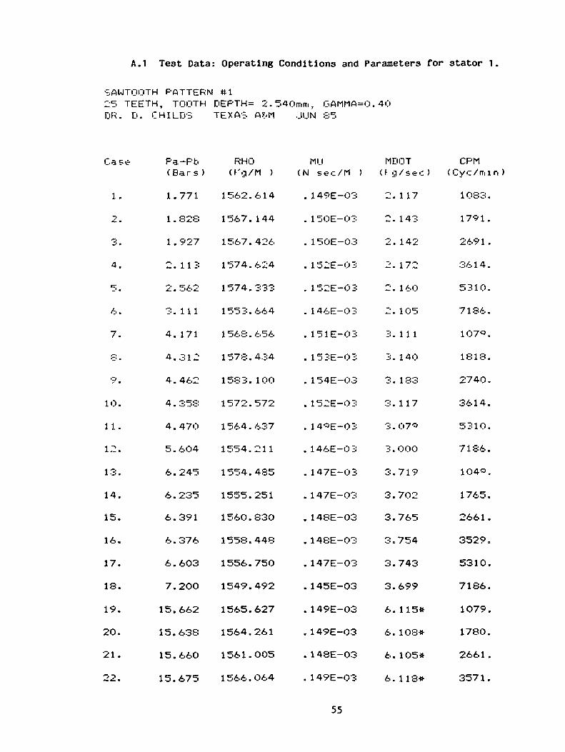
A.I Test Data: Operating Conditions and Parameters for stator 1,
SAWTOOTH PATTERN ttl25 TEETH, TOOTH DEPTH= 2.540mm, GAMMA=0.40DR. D. CHILDS TEXAS A?/M .JIJN 85
Case
1.
2.
3.
4.
5.
6.
7.
8.
9.
10.
11.
12.
13.
14.
15.
16.
17.
18.
19.
20.
21.
22.
Pa-Pb(Bars)
1.771
1 . 328
1 . 927
2. 113
2.562
3.111
4. 171
4.312
4.462
4.353
4.47O
5.6O4
6.245
6.235
6.391
6.376
6.603
7.200
15.662
15.638
15.660
15.675
RHOO'g/M )
1562.614
1567. 144
1567.426
1574.624
1574.333
1553.664
1568.656
1578.434
1583. 100
1572.572
1564.637
1554.211
1554.485
1555.251
1560.830
1558.448
1556.750
1549.492
1565.627
1564.261
1561.005
1566.O64
MIJ(N sec/M )
. 149E-03
. 1 50E-O3
. 150E-03
. 152E-03
. 152E-03
. 146E-03
. 151E-03
. 153E-03
. 154E-03
. 152E-03
. 14*E-03
. 146E-03
. 147E-03
. 1 47E-03
. 148E-03
. 1 48E-03
. 147E-03
. 145E-03
. 149E-03
. 149E-03
. 148E-03
. 1 49E-O3
MOOTU g/sec)
2. 117
2. 143
2. 142
2. 172
2. 160
2. 105
3. 11 1
3. 140
3. 183
3. 117
3.07"
3 . 000
3.719
3.702
3.765
3.754
3.743
3.699
6. 115*
6. 108*
6. 105*
6. 118*
CPM( Cyc/mi n )
1083.
1791.
2691.
3614.
5310.
7136.
1O7<5.
1818.
2740.
3614.
5310.
7186.
1O40.
1765.
2661.
3529.
5310.
7186.
1079.
1780.
2661.
3571.
55

23. 15.632 1568.528 . 150E-03 6.315* 5310.
24. 16.015 1550.847 . 145E-O 3 6.154* 7186.
25. 24.511 1533.-301 .142E-03 7.436 1020.
26. 24.606 153c'.6'-'4 . 142E-O3 7.429 1724.
27. 24.575 1541.781 .142E-03 7.4*2 2586.
28. 24.773 1545.763 .143E-03 7.482 3468.
2"r'. 24.048 1546.371 . 144E-03 7.459 5310.
30. 25.074 1555.547 .146E-O3 7.070 7186.
* ESTIMATED
56

A.2 Test Data: Operating Conditions and Parameters for stator 2
SAWTOOTH PATTERN #225 TEETH, TOOTH DEPTH= 2.540mm, O.AMMA=0. 40DR. D. CHILDS TEXAS A?/M
Case
1.
2.
3.
4.
5.
6.
7.
8.
*.
10.
11.
12.
13.
14.
15.
16.
17.
18.
19.
20.
21.
22.
Pa-Pb(Bars)
1 . 852
1 . 872
1.915
1 . *92
2.517
3.208
4 . 067
4.058
4. 136
4. 157
4 . 33*
5.571
5.852
6.O97
6. 169
3.944
6.284
7.281
15.301
15.295
15.292
15.327
RHO0 q/M )
1572.581
1568. 366
1 567 . 302
1564. 127
1560.O65
155*. 566
1570.826
1 56* . 9*6
1571. 408
1571. *66
155*. 46*
156O.343
155*. 464
1566.893
1564.223
1555.661
1556.726
1554.951
1563.062
1562.493
1559.358
1557.727
MU<N sec/M )
. 151E-03
. 150E-O3
. 150E-03
. 1 49E-03
. 148E-03
. 1 48E-O3
. 151E-03
. 151E-03
. 151E-03
. 151E-O3
. 148E-03
. 148E-03
. 148E-03
. 1 50E-03
. 149E-03
. 147E-O3
. 147E-03
. 147E-03
. 149E-03
. 148E-03
. 148E-03
. 147E-03
57
MOOT(Kg/sec)
2. 148
2. 141
2. 135
2. 132
2. 104
2. 123
3. 123
3 . 0*8
3. 109
3.111
3 . 048
3.059
3.749
3.785
3.773
3.017
3.721
3.711
• 6.039*
6.036*
6.030*
6.O34*
CPM( Cyc /mi n )
1083.
1796.
2685.
3561.
5333.
7186.
1083.
17*6.
2697.
35*3 .
5333.
7186.
1071.
1791.
2673.
3529.
5333.
7229.
1068.
178O.
2661.
3529.

2 5 .
24.
-~icr
26.
27.
28.
29.
30.
15.
15.
24.
24.
24.
24.
24.
24.
314
276
453
550
553
610
768
8 6
1555.
154'-'.
1 546 .
1554.
1554.
154S.
1 55 1 .
1548.
=>88
171
736
38'?
342
028
430
561
. 147E-O3
, 145E-03
. 144E-03
. 146E-O3
. 146E-03
. 144E-03
. 145E-03
. 144E-03
6.
6.
7.
7.
7.
7.
7.
7.
027*
OO7*
6 1 2
640
6O5
522
542
063
5333
7 1 86
1038
1749
2626
3458
5333
7186
* ESTIMATED
58

A.3 Test Data: Operating Conditions and Parameters for stator 3-
SAWTOOTH PATTERN #325 TEETH, TOOTH DEPTH= 2.540mm, G,AMhA=.74PR. D. CHILD'S TEXAS A?/M JIJL 85
Case
1.
2.
3.
4.
c-_' .
6.
7.
y .
•3.
10.
11.
12.
13.
14.
15.
16.
17.
18.
19.
20.
21.
22.
Pa-Pb(Bars)
3 . 302
3.272
3.347
3.534
3.8 2O
3.'r'05
7.21 '-•>
7 . 27*
7 . 365
7 -S --i •-•• ^_^_O
7 . 680
8. SO 3
10.618
10.665
10.088
10.427
10.659
1 1 . 234
18.378
18.389
18.395
18.385
RHO(Kq/M )
1571.601
1564.658
1563.036
1571.633
1571.^61
1548.476
1581.941
1581.071
1582.264
1570.718
1573.583
1559.061
1575.780
1577.425
1563.663
1565. 158
1564.231
1551.642
1564.530
1564.043
1571.861
1563.803
MU(N sec/M )
. 151E-03
. 149E-O3
. 149E-03
. 151E-03
. 151E-03
. 145E-03
. 154E-03
. 154E-03
. 154E-03
. 151E-03
. 152E-03
. 148E-03
. 152E-03
. 153E-03
. 1 49E-03
. 149E-03
. 149E-O3
. 146E-03
. 149E-03
. 149E-03
. 151E-03
. 149E-03
59
MOOTCfg/sec)
2. 168
2. 143
2. 135
2. 155
2. 161
2.084
3. 182
3. 162
3. 171
3. 128
3.11 6
3.047
3.861
3.880
3.768
3.788
3.782
3.710
5.044*
5.044*
5.056*
5.043*
CFM(Cyc/mi n )
1083.
1 786 .
267-5.
3604.
5333.
7186.
107C>.
1818.
«™« "7 «~i """i2/3 J.
3593.
5333.
7186.
1071 .
1802.
2673.
3571.
5333.
7186.
1064.
177O.
2691.
3550.

23.
-.4.
25.
26.
27.
23.
29.
30.
18.
IS.
26.
26.
27.
27.
27.
27.
353
3c/6
753
CK/ 3
012
080
24<>
062
1557.
1554.
1542.
1552.
1555.
1553.
1555.
1541.
1 -»er...O
4C'8
«5*>0
170
346
727
145
7S6
. 147E-03
. 146E-03
. 143E-03
. 145E-03
. 14&E-03
. 1 45E-03
. 146E-03
.142E-03
5.
CJ
6.
6.
6.
6.
6.
6.
02S*
n ~;o«
043*
08S*
Q'3'5#
101*
123*
075*
5333
7 ISA/ A '„* >ff
1031
174-5
o/. o^><co ;>»_
350'5
5310
7186
# ESTIMATED
60

A.1! Test Data: Operating Conditions and Parameters for stator i\.
SAWTOOTH PATTERN tt425 TEETH, TOOTH DEPTH= 2.54Omrri, GAMMA=.74DR. D. CHILDS TEXAS AS/M AUG 1985
Case
1.
—i-£. m
3.
4.
5.
6.
7.
•T' •
*.
10.
11.
12.
13.
14.
15.
16.
17.
18.
19.
20.
21.
22.
Pa-Pb(Bars)
2.647
2.752
2.810
2 . 352
3.053
3.614
6.21 3
6 . 276
6. 313
6.4-5-4
6.714
6.339
10.369
10.433
1O.067
10.275
10.093
10.240
16.940
17.247
17.250
17.710
RHOO'q/M )
155C'.595
1558.975
1561.488
1559.89C'
1563.428
1572.O61
156 .641
1566.237
1562.40I=>
1563.464
1566.c'80
1577. 190
1558.714
1559.318
1572.338
1570.426
1563.946
1571.519
1564.816
1568.887
1569.980
1575.003
MU(N sec/M )
. 148E-03
. 148E-O3
. 149E-03
. 148E-O3
. 14«E-03
. 151E-O3
. 151E-03
. 150E-O3
. 14*E-03
. 1 49E-O3
. 150E-O3
. 153E-03
. 148E-O3
. 148E-O3
. 151E-03
. 151E-03
. 149E-03
. 151E-O3
. 149E-03
. 150E-03
. 150E-03
. 152E-O3
61
MDOT(Kq/sec)
2. 125
2. 121
2. 1 14
2. 106
2. 124
2. 148
3. 105
3 . O97
3 . 049
3.088
3.035
3. 133
3.754
3.760
3.830
3.826
3.782
3.817
4.947
4.997
4.991
5.045
CPM(Cyc/mi n )
) 060 .
1775.
2673.
3550.
5333.
7186.
1071.
17^1.
2673.
3571.
5333.
7186.
1O75.
1775.
27O3.
3593.
5333.
7229.
1O68.
1791.
2691.
3604.
23. 17.652 1566. 121=> . 14C'E-O3 4.c'56 5310.
24. 18.203 1575. 36C' . 152E-03 5.053 7186.
25. 26.834 1566.028 . 14'-'E-O3 6.202 1068.
26. 26.8^7 1570.ir'47 . 150E-03 6.237 1786.
27. 26.806 1567.587 . 14'r'E-O3 6.244 2661.
28. 27.063 1572.22^ .150E-03 6.266 3571.
2'=>. 27.171 1568.518 . 14OE-O3 6.190 5310.
30. 26.955 1563.5^0 .148E-03 6.106 7186.
62

A.5 Test Data: Operating Conditions and Parameters for stator 5.
SAWTOOTH PATTERN 85105 TEETH, TOOTH DEPTH= 1.016mm, C-AMMA=0. 64DR. D. CHILDS TEXAS AS/M SEPT. 1935
Case
1.
•*-. •
3.
4.
5.
6.
7.
8.
*•
1O.
11.
12.
13.
14.
15.
16.
17.
IS.
19.
20.
21.
22.
Pa-Pb(Bars)
1.413
1.483
1.530
1.785
1 . 982
2. 2*5
3.360
3.401
3.478
3.642
4.161
4.044
5.213
5.280
5.451
5.215
6.002
6. 144
12.713
12.698
12.597
12.764
RHO(h'g/M )
1562.525
1563.524
1560.395
1563.322
1568.470
156O.477
1566. 388
1565. 177
1567.863
1567. 167
1571.505
1561.680
1569.004
1569.590
1572.859
1561.992
1576.996
1562.043
1561. 198
156O.O15
1558.494
1556.633
MU(N sec/M )
. 1 49E-03
. 149E-03
. 3 48E-03
. 149E-03
. 150E-03
. 148E-03
. 150E-03
. 150E-03
. 150E-03
. 150E-O3
. 151E-03
. 149E-03
. 151E-03
. 151E-03
. 152E-03
. 149E-03
. 153E-03
. 149E-03
. 148E-O3
. 148E-03
. 147E-03
. 147E-03
63
MOOT(Kg/sec)
2. 116
2. 118
2. 103
2. 140
2. 145
2 . 1 26
3.0*1
3.O88
3 . 082
3.O94
3. 124
3.O58
3.801
3.816
3.839
3.771
3.862
3.776
5.862
5.861
5.848
5.836
CPM( Cyc/mi n )
1O75.
1786.
2661.
3571.
5333.
7186.
1068.
1786.
2691.
3571.
5333.
7186.
1083.
1796.
2709.
3561.
5310.
7186.
1060.
1760.
2661.
3529.

23.
24.
25.
26.
27.
28.
29.
30.
13.
12.
24.
24.
24.
24.
24.
24.
267
8 1*
447
433
467
357
520
40'-"'
1565.
1546.
1 56C' .
157O.
1570.
1558.
1564.
1556.
484
424
OQg
538
264
141
331
987
. 14'r'E-03
. 144E-O3
. 150E-03
. 150E-03
. 1 50E-0 3
. 147E-O3
. 148E-03
. 146E-O3
5.
e=j
y .
y .
8.
8.
8.
8.
•r'12
720
107
110
103
087
103
023
5310
7 1 86
JOS 3
1 780
267
350*
52S6
7186
64
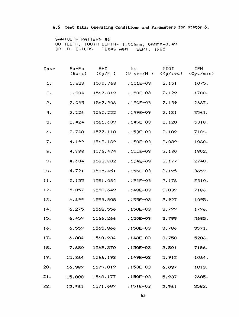
A.6 Test Data: Operating Conditions and Parameters for stator 6.
SAWTOOTH PATTERN #6SO TEETH, TOOTH DEPTH= 1.016mm, GAMMA=0.49DR. D. CHILDS TEXAS A?vM SEPT. 1985
Case
1.
2.
3.
4.
5.
6.
7.
8.
9.
10.
11.
12.
13.
14.
15.
16.
17.
IS.
19.
20.
21.
22.
Pa-Pb(Bars )
1 . 823
1 . 904
2.035
2.226
2.424
2.748
4. l^-s
4 . 388
4.604
4.721
5. 155
5.057
6.6C'<5
6.275
6.459
6.559
6.884
7.68O
15.864
16.389
15.808
15.981
RHO<Kg/M )
1570.768
1567. O19
1567.3O6
1562.222
1561.609
1577. 118
1568. IS*
1576.474
1582.8O2
1585.451
1581.084
1558.649
1584. SOS
1568.556
1566.266
1565.866
1560.934
1568.370
1566. 193
1579.019
1568. 177
1571.689
MU(N sec/M )
. 151E-O3
. 150E-O3
. 150E-03
. 149E-O3
. 1 49E-03
. 153E-O3
. 150E-03
. 152E-03
. 154E-03
. 155E-03
. 154E-03
. 148E-03
. 155E-O3
. 15OE-03
. 150E-03
. 150E-O3
. 148E-03
. 150E-03
. 149E-03
. 153E-03
. 150E-O3
. 151E-O3
65
MOOT(Kg /sec)
2. 151
2. 129
2. 139
2. 131
2. 128
2. 189
3.08
3. 130
3. 177
3. 195
3. 176
3.039
3.927
3.799
3.788
3.786
3.750
3.801
5.912
6.037
5.937
5.961
CPM( Cy c / m i n )
1075.
1780.
2667 .
3561.
5310.
7186.
1060.
1 802 .
2740.
365 .
5310.
7186.
10 5.
1796.
2685.
3571.
52S6.
7186.
1064.
1813.
2685.
3582.

23.
24.
~ierj- -' •
26.
2.7.
28.
20.
30.
1
1
•— ,
-2
6.
6.
5.
5.
5.
25.
25.
25.
3C'6
71S
387
380
376
491
591
2-54
1 57 3 .
1568.
1565.
1564.
1563.
1568.
1567.
1544.
QV1
• 68
117
744
568
974
884
496
. 151E-03
. 150E-O3
. 148E-03
. 148E-03
. 148E-03
. 149E-O3
. 149E-03
. 143E-03
5.
5.
7.
7.
7.
7.
7.
7.
•3Q4
'r'50
503
481
461
524
507
392
5286
7186
1075
1765
2661
3561
5286
7186
66
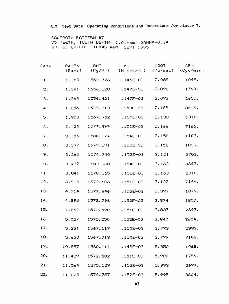
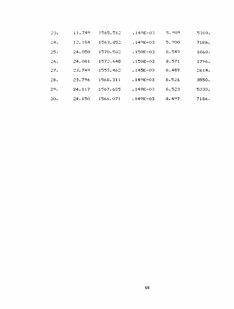
A.7 Test Data: Operating Conditions and Parameters for stator 7
SAWTOOTH PATTERN #755 TEETH, TOOTH DEPTH= 1.016mm, GAMMA=O.34DR. D. CHILD'S TEXAS A?/M SEPT 1985
Case Pa-Pb(Bars)
1.
2.
3.
4.
5.
6.
7.
8.
9.
10.
11.
12.
13.
14.
15.
16.
17.
18.
19.
20.
21.
22.
1.
1.
1.
1.
1.
-.
3.
3.
3.
3.
3.
3.
4.
4.
4.
5.
5.
5.
10.
11.
11.
11.
163
191
264
656
858
124
156
197
263
472
841
914
914
893
864
027
231
630
857
429
564
624
RHOO'g/M )
1552.
1556.
1556.
1577.
1567.
1577.
1580.
157*.
1574.
1582.
1 578 .
1572.
1579.
1578.
1572.
1575.
1567.
1567.
1560.
1572.
1575.
1574.
776
328
421
213
«52
490
274
89 1
740
988
365
686
846
396
490
250
119
713
114
582
129
787
MU(N sec/M )
. 146E-03
. 147E-O3
. 147E-03
. 153E-O3
. 150E-03
. 153E-03
. 154E-03
. 153E-03
. 152E-03
. 1 54E-03
. 153E-03
. 151E-03
. 153E-03
. 153E-O3
. 151E-03
. 152E-03
. 150E-03
. 150E-03
. 148E-03
. 151E-03
. 152E-O3
. 152E-03
67
MOOT(Kg/sec)
2.
2.
2.
-•
2.
J— m
3.
3.
3.
3.
O •
3.
3.
3.
3.
3.
3.
3.
5.
5.
5.
5.
089
O96
093
185
1 38
166
158
156
121
162
163
122
897
874
837
847
793
799
850
98O
993
995
CPM(Cyc/min )
1040.
1760.
2655.
3614.
5310.
7186.
1103.
1818.
2703.
3647.
5310.
7186.
107-5.
1807.
2697.
3604.
5333.
7186.
1068.
1786.
2697.
3604.
23. 11. 74<r' 1 565.512 .14'-'E-0 3 5. *<:>•=> 5 310.
24. 12.184 1563.852 . 14>r'E-O3 5.c'00 7186.
25. 24.O50 1570.502 .150E-03 8.549 1O60.
26. 24.081 1572.648 .150E-03 8.571 1796.
27. 23.74<=- 1553.462 .145E-03 8.487 2614.
28. 23.7'=>6 1568.311 . 14C'E-03 8.526 3550.
2*. 24.117 1567.635 .149E-03 8.523 5333.
30. 24.150 1566.071 . 149E-03 8.4>:>7 7186.
68
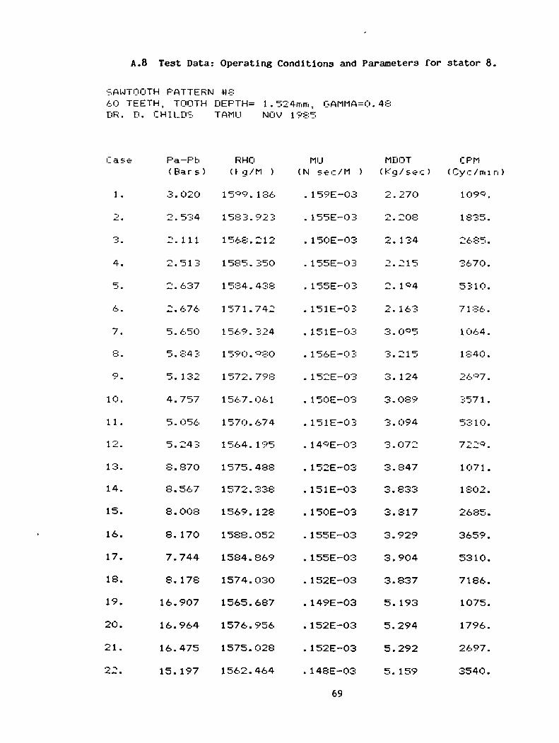
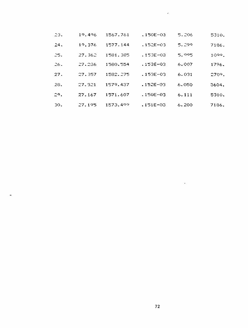
A.8 Test Data: Operating Conditions and Parameters for stator 8.
SAWTOOTH PATTERN #86O TEETH, TOOTH DEPTH= 1.524mm, GAMMA=0.48DR. D. CHILDS TAMU NOV 1985
Case
1.
2.
3.
4.
5.
6.
7.
8.
9.
10.
11.
12.
13.
14.
15.
16.
17.
18.
19.
20.
21.
22.
Pa-Pb(Bars)
3.020
2.534
2. Ill
2.513
2.637
2.676
5 . 650
5.843
5. 132
4.757
5.056
5.243
8.870
8.567
8.008
8. 170
7.744
8. 178
16.907
16.964
16.475
15. 197
RHOU q/M )
15*9. 186
1583.923
1568.212
1585. 350
1584.438
1571.742
1569. 324
159O.*8O
1572.798
1567.061
157O.674
1564. 195
1575.438
1572.338
1569. 128
1588.052
1584.869
1574.O30
1565.687
1576.956
1575.028
1562.464
ML)(N sec/M )
. 159E-03
. 155E-03
. 150E-03
. 155E-03
. 155E-03
. 151E-03
. 151E-03
. 156E-03
. 152E-03
. 150E-03
. 151E-03
. 14*E-03
. 152E-03
. 151E-03
. 150E-03
. 155E-03
. 155E-03
. 152E-03
. 149E-03
. 152E-03
. 152E-03
. 148E-03
69
MDOT(Kg /sec)
2.270
2.208
2. 134
2.215
2.1«4
2. 163
3 . 0*5
3.215
3. 124
3.089
3.094
3.O72
3.847
3.833
3.817
3.929
3.904
3.837
5. 193
5.294
5.292
5. 159
CPM( Cyc /mi n )
109*.
1835.
2685.
3670.
5310.
7186.
1064.
1840.
26*7 .
3571.
5310.
722*.
1071.
1802.
2685.
3659.
5310.
7186.
1075.
1796.
2697.
3540.

2 3 .
24.
jjfi •
26.
27.
28.
2*.
Or~i;•'-' .
14.
1 3.
26.
26.
26.
26.
26.
26.
4C'0
661
674
685
532
474
434
453
1 562 .
155C'.
1568.
1578.
1 572 .
1 57 1 .
1572.
1572.
672
015
874
748
455
205
SQ4
719
. 148E-03
. 147E-O3
. 14i:>E-O3
. 152E-O3
. 150E-O3
. 150E-O3
. 150E-03
. 150E-O3
5.
5.
6.
6.
6.
6.
6.
7.
131
123
512
598
634
723
855
O2 3
5 3 1 0
7186
107*
1807
2691
3582
5310,
7186,
70

A.9 Test Data: Operating Conditions and Parameters for stator 9.
SAWTOOTH PATTERN #*60 TEETH, TOOTH DEPTH= 1.524mm, GAMI*1A=0.63DR. D. CHILD'S TAMU NOV l'"'S5
Case
1.
-v
3.
4.
c-
6.
7.
8.
*.
10.
11.
12.
13.
14.
15.
16.
17.
18.
19.
20.
21.
22.
Pa-Pb(Bars)
3.457
3.470
3. 177
3.215
3.410
3 . 5SS
7.311
7 . 440
6.942
6.863
6.643
7. Oil
10.873
10.773
10.909
10.355
9.754
9.726
20. 453
21.021
20.341
19.875
RHO(Kq/M )
1577.0 9
1582.873
1572.945
1581.445
1575. O05
157<:>.434
1568.534
1583. 33O
1570. 156
1573.601
1574.706
1586.c'52
1572.766
1573.605
1584.866
1575.000
1574.462
1567.747
1567.058
1574.662
1570.219
1566.976
MU(N sec/M )
. 153E-03
. 154E-03
. 152E-03
. 154E-03
. 152E-03
. 153E-03
. 150E-03
. 154E-03
. 151E-03
. 152E-03
. 152E-03
. 155E-03
. 151E-03
. 151E-O3
. 154E-03
. 152E-03
. 152E-03
. 150E-O3
. 150E-03
. 151E-03
. 150E-03
. 149E-O3
71
MOOTU g/sec)
2. 177
2.207
2. 156
2. 197
2. 181
2. 173
3 . Oc'<:>
3. 166
3.092
3. 130
3. 133
3.201
3.844
3.847
3.912
3.851
3.839
3.813
5.204
5.282
5.232
5.207
CPM(Cyc/mi n )
1O75.
1813.
2697.
3636.
5286 .
7186.
1 064 .
1813.
2691.
3604.
5286.
7186.
1087.
1796.
2721.
3604.
5310.
7186.
1068.
1796.
2679.
3571.
jj o -
24.
25.
26.
27.
23.
20.
30.
10.
10.
27.
27.
27.
27.
27.
27.
406
376
362
236
357
321
167
195
1567.
1577.
1581.
15SO.
1532.
1579.
1571.
1573.
761
144
335
554
275
437
607
400
. 1
. 1
. 1
50E-03
5
5
. 15
. 1
. 1
5
5
2E-03
3E-03
3E-03
3E-03
2E-03
. 150E-03
. 151E-O3
5 .
5.
5.
6.
6.
6.
6.
6.
206
29O
005
007
031
050
111
200
5 3 1 0
7 1 86
1 0**
1796
27C>o
3604
5310
7186
72

A. 10 Test Data: Operating Conditions and Parameters for stator 10.
SAWTOOTH PATTERN60 TEETH, TOOTH DEPTH= 1.524(T,ir,, GAMMA=0.33DR. D. CHILDS TAMU DEC 1985
Case Pa-Pb(Bars )
1.
2.
O •
4.
5.
6.
7.
8.
«•
10.
11.
12.
13.
14.
15.
16.
17.
18.
19.
20.
21.
22.
1.
1.
1.
1.
2.
2.
4.
4.
— i
3.
4.
4.
6.
6.
6.
5.
6.
6.
12.
12.
12.
11.
795
586
602
621
204
711
146
OOO
700
803
319
84*
831
120
253
830
032
663
789
766
476
979
RHO(Kq/M )
1577.
1574.
1575.
1566.
1 578 .
1 580 .
1577.
1577.
1572.
1584.
1 58 1 .
1576.
1587.
1571.
1587.
1571.
1584.
1569.
1576.
1582.
1584.
1578.
146
867
862
832
751
O05
064
241
719
394
356
759
446
350
240
014
656
947
233
442
178
669
MU(N sec/M )
. 153E-03
. 152E-03
. 152E-03
. 150E-03
. 153E-03
. 153E-03
. 153E-03
. 153E-03
. 151E-03
. 1 55E-03
. 154E-03
. 153E-03
. 155E-03
. 151E-03
. 155E-03
. 151E-03
. 155E-03
. 151E-03
. 152E-03
. 154E-03
. 154E-03
. 153E-O3
73
MDOT( k q / s e c )
2.
2.
2.
2.
2.
•—i
3.
3.
3.
3.
3.
3.
3.
3.
3.
3.
3.
3.
5.
5.
5.
5.
187
175
168
138
175
187
141
136
111
173
161
14O
*42
826
929
829
914
828
288
348
367
317
CPM(Cyc/fTii n )
1079.
1 807 .
2721.
3571.
5333.
7186.
1 087 .
17*6.
2691.
3636.
5333.
7186.
1095.
1802.
2752.
3593.
5310.
7186.
1071.
1813.
2727.
3614.

23.
24.
25.
26.
27.
2;-!
29.
30.
11.
10.
25.
25.
25.
25.
25.
25.
135
682
42*
1*5
240
2*7
21*
163
1
1
1
1
570.
562.
575.
56*.
1577.
1576.
1574.
1575.
151
551
180
815
85*
074
225
861
. 1
. 1
. 1
. 1
. 1
. 1
. 1
. 1
51E-03 5.
4
5
8E-03
1E-03
50E-03
52E-03
51E-03
5
5
1E-03
1E-03
5.
7.
7.
7.
7.
7.
7.
238
1 66
446
424
530
566
656
808
5310
7186
] 0*5
1775
270*
3593 ,
531O
7186,
74

A.11 Test Data: Operating Conditions and Parameters for stator 11
SAWTOOTH PATTERN 81160 TEETH, TOOTH OEPTH= 1.524mm, GAMMA=0.47DR. D. CHILDS TAMU JAN 1C'S6
Cast
1.
2.
7»
4.
5.
6.
7.
8.
«.
10.
11.
12.
13.
14.
15.
16.
17.
18.
19.
20.
21.
22.
Pa-Pb(Bars)
2.451
2.521
2.26*
2.569
2.894
3. 137
5.082
5.778
5.587
5.074
5.448
6. 110
9. 321
9.383
9. 153
8.594
7.989
8.319
17.675
17.422
17.594
16.438
RHOO'g/M )
1563.701
1576.753
1571.782
1575.264
1562.3**
1555.878
1574.743
1570.615
1578.406
1572.226
1566.074
1568.835
1572.8Q3
1581.614
1581. 115
1575.563
1569.818
1557.770
1567.672
1568.097
1576.4*2
1562.883 .
MU(N sec/M )
.14*E-03
. 153E-03
. 151E-03
. 152E-03
. 149E-03
. 147E-03
. 152E-03
. 151E-03
. 153E-03
. 151E-03
. 150E-03
. 1 50E-03
. 151E-03
. 154E-03
. 1 53E-03
. 152E-03
. 151E-03
.147E-03
. 150E-03
. 150E-03
.152E-03
. 1 48E-03
75
MOOT(Ka/sec)
2. 128
2. 172
2. 147
2. 175
2. 124
2.002
3. 117
3. 117
3. 156
3. Ill
3.081
3.092
3.824
3.899
3.887
3,849
3.827
3.722
5.206
5.227
5.296
5. 184
CPM(Cyc/min )
1060.
1706.
2685.
3604.
5357.
7186.
1001.
1791.
2721.
35*3.
5333.
722*.
1083.
1807.
2721.
3604.
5333.
7186.
1071.
1770.
2709.
3561.

23.
24.
25.
26.
27.
28.
2i:>.
30.
15.
14.
26.
26.
26.
26.
26.
26.
64O
422
743
857
503
•332
!-i24
446
1566.
1557.
1567.
1574.
1571.
1575.
1574.
1573.
6 ---'3
345
444
755
* 6 9
040
372
030
. 14C>E-03
. 147E-03
. 14C'E-03
. 151E-03
. 150E-03
. 151E-03
. 151E-03
. 151E-03
5.
5.
6.
6.
6.
6.
6.
6.
1<5<5
134
337
364
423
487
545
747
5333
722Q
1O75
1796
2685
3582
5333
7186
76

APPENDIX B.
DYNAMIC TEST DATA
FOR SAWTOOTH-PATTERN
77
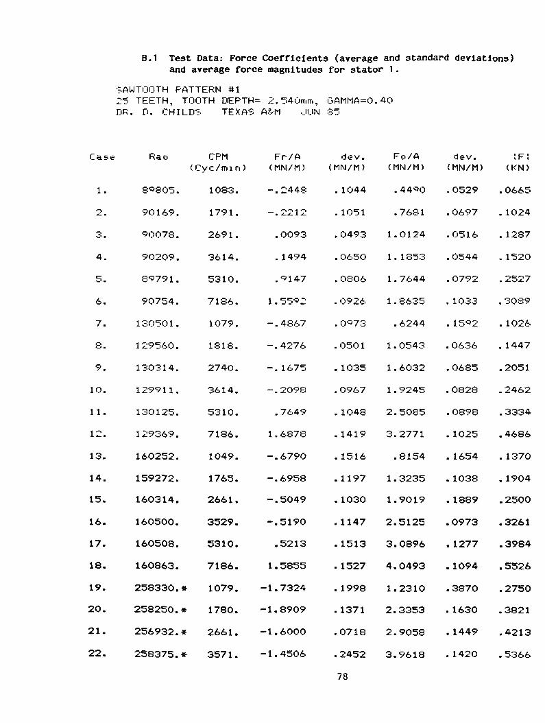
B.I Test Data: Force Coefficients (average and standard deviations)and average force magnitudes for stator 1.
SAWTOOTH PATTERN #125 TEETH, TOOTH DEPTH= 2.540mm, GAMMA=0.40DR. D. CHILDS TEXAS A?/M .JIJN 85
Case
1.
2.
3.
4.
5.
6.
7.
8.
9.
1O.
11.
12.
13.
14.
15.
16.
17.
18.
19.
20.
21.
22.
Rao
8"805.
90169.
90078.
9O209.
89791.
90754.
13O501.
129560.
130314.
1299H.
130125.
129369.
16O252.
159272.
160314.
160500.
160508.
160863.
258330. »
258250. »
256932.*
258375. »
CPM( Cyc/mi n )
1083.
1791.
2691.
3614.
5310.
7186.
1079.
1818.
2740.
3614.
5310.
7186.
1049.
1765.
2661.
3529.
5310.
7186.
1079.
1780.
2661.
3571.
Fr/A(MN/M)
-.2448
'-I'-i 1 •"»• A. . 1 4-
. 0093
. 1494
. 147
1 . 55 2
- . 4867
-.4276
-. 1675
-.2098
. 7649
1 . 6878
-.6790
-.6958
-.5049
-.5190
.5213
1 . 5855
-1.7324
-1.8909
-1.6000
-1.4506
dev.(MN/M)
. 1O44
. 1O51
.0493
. 0650
. 0806
. 0926
. 0 73
.0501
. 1035
.0967
. 1048
. 1419
. 1516
. 1197
.1030
.1147
. 1513
. 1527
. 1998
. 1371
.0718
.2452
78
Fc./A(MN/M)
. 4400
.7681
1.0124
1 . 1 853
1 . 7644
1 . 8635
. 6244
1.0543
1 . 6032
1.9245
2.5085
3.2771
.8154
1 . 3235
1.9019
2.5125
3.0896
4.0493
1.2310
2.3353
2.9058
3.9618
dev.(MN/M)
.0529
.0697
.0516
. 0544
.0792
. 1033
. 15«>2
.0636
. 0685
.0828
. 0898
. 1025
. 1654
. 1038
. 1889
.0973
. 1277
. 1094
.387O
. 1630
. 1449
. 1420
:F:(KN)
.0665
. 1024
. 1287
. 1520
.2527
. 3089
. 1026
. 1447
.2051
.2462
.3334
.4686
. 1370
. 1904
.2500
.3261
.3984
.5526
.2750
.3821
.4213
.5366
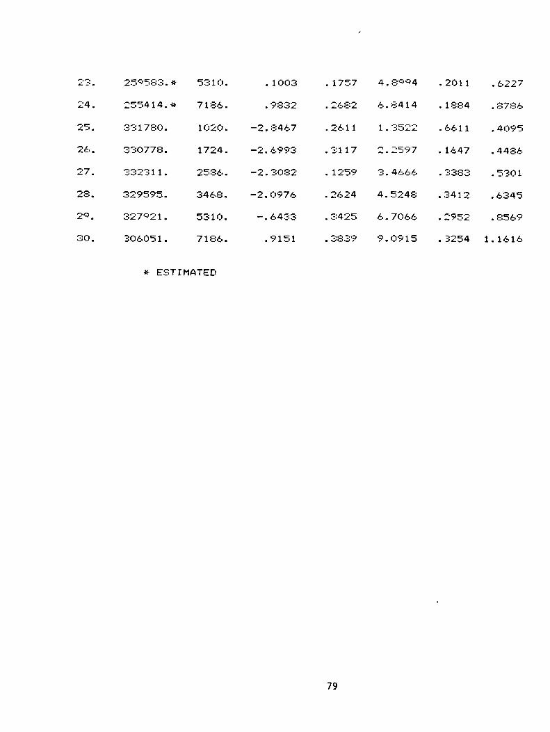
23 .
24.
25.
26.
27.
23.
2*.
30.
25*583.*
255414.*
331780.
330778.
3323 1 1 .
329595.
327*21.
3O6051.
5310.
7186.
1020.
1724.
2586.
3468.
5310.
7186.
. 1003
. 9832
-2.8467
-2.6993
-2.3082
-2.O976
-.6433
.9151
. 1757
. 2682
.2611
.3117
. 1259
. 2624
. 3425
. 3839
4 . 8**4
6.8414
1 . 3522
2.2597
3.4666
4.5248
6.7066
9.0915
.2011
. 1884
.6611
. 1647
- i -r. <-• ~-»m _' O O O
.3412
. 2952
. 3254
.6227
. 8786
. 4095
. 4486
.5301
.6345
.8569
1. 1616
ESTIMATED
79

B.2 Test Data: Force Coefficients (average and standard deviations)and average force magnitudes for stator 2.
SAWTOOTH PATTERN #225 TEETH, TOOTH DEPTH= 2.54mn-,, GAMMA=.40PR. D. CHILDS TEXAS A?/M ..IUN 85
Case
1.
•-%
^- *
3.
4.
5.
6.
7.
8.
*.
10.
11.
12.
13.
14.
15.
16.
17.
18.
19.
2O.
21.
22.
Rao
89548.
89*21.
8*800.
*0163.
896 1 7 .
*0531.
13050*.
129673.
12*815.
129854.
12**75.
130246.
160048.
159542.
159750.
129583.
159668.
159823.
255528.*
253785.*
254036.*
252762.*
CPM(Cyc/min )
1083.
1796.
2685.
3561.
5333.
7186.
1O83.
1796.
26*7.
3593.
5333.
7186.
1O71.
1791.
2673.
3529.
5333.
7229.
1068.
1780.
2661.
3529.
Fr/A(MN/M)
-.3414
-. 1281
- . 0373
- . O776
. 7436
1.7431
-. 6*36
-.6202
- . 3722
-.3611
.57*7
l.*833
-.8378
-1.0063
-.5890
-.4844
.3460
1.6864
-2. 1022
-2. 1409
-2.0339
-2.0064
dev.(MN/M)
. 08 1 3
. 0574
.0814
. 09 1 0
. 0*05
.2114
. 1 1*7
. 1 1 39
. 0390
.0572
. OS**
. 2625
. 1242
. 0566
. 1461
. 0498
. 1256
.2483
.2778
. 1589
. 1 270
. 0844
80
Fo/A(MN/M)
.4149
.8134
.*555
1 . 1 1 86
1 . 8686
2 . 1 500
. 5795
.9721
1 . 42*5
1.8167
2 . 3*9O
3.4890
.6518
1.2021
1.8011
1.9763
3.0979
4.0689
.9059
2. 1335
2.7720
4.0235
dev.(MN/M)
. 1 022
. 1 2O7
. 0776
. 1 0 30
.0700
. 1034
. 1380
. 0753
. 0675
. 0663
. 0767
. 1592
. 141*
. 1188
.0795
.0630
. 1281
. 1780
. . 5454
. 1265
. 1268
. 118*
;F:(KN)
. 0700
. 1048
. 1218
. 1428
.2557
-»er -i--». 3-3*-.*-.
. 1167
. 1469
. 1876
.2354
.3137
.5105
. 1366
. 1994
.2414
.2585
.3962
.5606
.3004
.3844
. 4370
.5711

23.
24.
25.
26.
27.
28.
2«.
3O.
252745.*
249583.*
334598.
331329.
329779.
330050.
328733.
309540.
5333 .
7186.
1038.
1749.
2626.
3458.
5333.
7186.
— .
•
—3.
-3.
-2.
-3.
-1.
4235
60 1 5
4510
3722
Q444
0300
4692
1576
. 1789
. 3O53
. 40C'9
.2139
.2103
.2133
. 3093
. 4329
cr_' .
6.
•
-•
_' •
4.
6.
9.
2734
6*45
8 1 65
2343
6 2 SO
925O
8117
4265
. 1588
. 2704
. 82 1 8
.3152
.2196
. 3122
. 3007
. 37 1 2
. 67 3O
. 8546
. 4645
.5145
.5*3*
. 7347
. 886O
1 . 1 988
* ESTIMATED
81

B.3 Test Data: Force Coefficients (average and standard deviations)and average force magnitudes for stator 3-
SAWTOOTH PATTERN #325 TEETH, TOOTH DEPTH= 2.540mm, GAMMA=0.74DR. D. CHILD'S TEXAS A?/M .JUL 85
Case
1.
-s
3.
4.
5.
6.
7.
8.
•=>.
10.
11.
12.
13.
14.
15.
16.
17.
18.
19.
20.
21.
22.
Rao
90463.
90533.
90457.
89915.
•=>0071.
90610.
130352.
129747.
129836.
130641.
129477.
13OO73.
16O170.
160523.
159670.
160051.
160025.
160680.
207509.
206466.
209855.
207494.
CPM(Cyc/mi n )
1083.
1786.
2679.
36O4 .
5333.
7186.
107 .
1818.
2733.
3593.
5333 .
7186.
1071.
1802.
2673.
3571.
5333.
7186.
* 1064.
* 1770.
* 2691.
* 3550.
Fr/A(MN/M)
-.0933
- . 0354
. 239C>
. 2854
1 . 2 1 34
l.c'311
-.2C'47
-. 1183
. 3341-'
.7144
1 . 3838
2.5423
-.3716
-.4130
.2860
.7262
1.5924
2.7514
-.9253
-.9426
.0717
.225O
dev.(MN/M)
. 1246
. 0682
. 0880
.0918
. 1200
.2163
. 1606
. 1007
. 1032
. 0893
. 1777
. 2939
. 1668
. 1504
. 1015
. 1384
. 1731
.2875
.2826
. 1349
. 1 74
.2657
82
Fc./A(MN/M)
. 5255
.9721
1 . 4888
1 . 9O43
2.3630
1.SO10
. 7045
1 . 3789
2.2448
2.8247
4.0861
4.6886
. 8452
1 . 6263
2.2265
3.3371
4.7144
5.9942
.9843
2. 1424
2.5979
4.0082
dev.(MN/M)
.0415
. 0464
. 1010
. 0856
.0 10
. 159-3
. 3 258
.0701
. 1 72 3
. 1040
. 1051
. 1826
. 1220
.0841
.2118
. 1404
. 1221
.2635
. 2380
. 1730
. 1364
.2089
IF:O N)
. 06 7
. 1238
. 1910
. 2449
. 3378
.3359
_ QQOQ
. 1762
. 2883
. 3702
. 5485
. 6784
. 1196
.2140
.2854
.4341
. 6326
.8383
. 1773
.2977
.3310
-511O
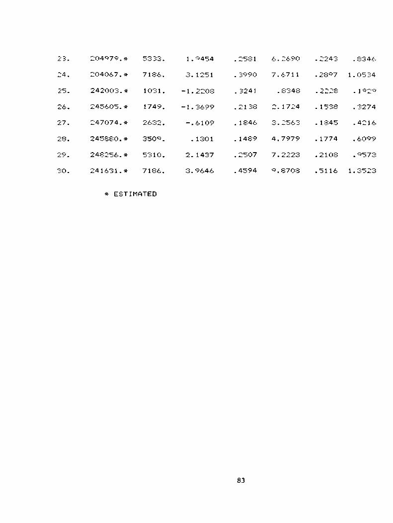
23.
24.
25.
26.
27.
28.
29.
30.
204*79.*
204067.*
242003.*
245605.*
247074.*
245880.*
248256.*
24 1 63 1 . *
5333.
7186.
1031.
1749.
2632 .
350*.
5310.
7186.
1 .
3.
-1.
-1.
-.
•
2.
3.
•-'454
1251
2208
3699
6109
13O1
1437
9646
.2581
. 3990
. 3241
.21 33
. 1846
. 1489
.2507
. 4594
6. 269O
7.6711
. 8348
2. 1724
3. 2563
4.7979
7.2223
•3.87O3
. 2243
. 28--' 7
. 2228
. 1 538
. 1845
. 1774
.21O8
.5116
.3346
1.0534
. lc'2>:>
. 3274
. 42 1 6
. 6099
. 0573
1 . 3523
* ESTIMATED
83

B.M Test Data: Force Coefficients (average and standard deviations)and average force magnitudes for stator *4.
SAWTOOTH PATTERN *425 TEETH, TOOTH DEPTH= 2.540mm, GAMMA=O.74DR. D. CHILDS TEXAS A?/M AUG 1*85
Case
1.
2.
3.
4.
5.
6.
7.
8.
9.
10.
11.
12.
13.
14.
15.
16.
17.
18.
19.
20.
21.
22.
Rao
9O618.
*O530.
89851.
89743.
89926.
8*59* .
12**37.
130381.
129253.
1 3O697 .
129751.
12*524.
160453.
160511.
159848.
160202.
160190.
159617.
209748.
21O384.
209743.
210152.
CPM( Cyc/mi n )
1060.
1775.
2673.
3550.
5333.
7186.
1071.
17*1.
2673.
3571.
5333.
7186.
1075.
1775.
2703.
3593.
5333.
7229.
1068.
1791.
2691.
3604.
Fr/A(MN/M)
- . 0568
. 0567
. 2928
. 4470
1 . 1 1 46
2.5*88
-. 1088
-.0573
. 32O9
. 7306
1 . 5260
2.8747
-.3616
-.3052
.2015
.8448
1 . 7033
3.2465
-.7225
-.4774
.0695
.8771
dev.(MN/M)
. 1O94
. 0407
. 0448
. 0568
.0981
. 1400
. 1326
. 1273
. 0939
.0678
.1185
. 1730
. 1863
. 0636
. 0930
.0903
. 1544
. 1990
. 1387
. 1364
. 1956
. 1201
84
Fn/A(MN/M)
.4415
. 8 1 68
1. 1848
1.5136
2.2336
2.5614
.6948
1. 1142
1.7020
2. 1936
3.4033
4.2220
.7194
1 . 3966
2.0047
2.7989
4.0309
5.3656
.6905
1 . 7642
2.4081
3.4811
dev.(MN/M)
. 0696
. 048O
. 0403
. 0576
.0701
.1112
. 0559
. 0588
.0741
. 0*48
. 1073
. 1574
. 1007
. 1028
.1104
.0743
. 1093
.2071
.3073
. 1474
.2199
. 1679
:F:(KN)
.0581
. 1041
. 1552
. 2006
.3173
. 463*
. 090*
. 1427
. 2204
. 2*38
. 4740
. 64* 1
. 1052
. 1817
.2561
.3714
.5560
.796*
. 1321
.2328
.3067
.4562
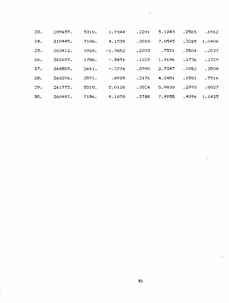
23.
24.
25.
26.
27.
28.
29.
30.
209659 .
21O445.
263412.
262697 .
264503.
263296.
261772.
260437.
5310.
7136.
1068.
1786.
2661.
3571.
5310.
7186.
1.
4.
-1.
" ~ •
-.
•
2.
4.
9344
1539
3852
8476
3776
8929
O120
1070
.22O1
.3010
. 2035
. 1329
. 0990
.2176
. 3024
.3788
5.
7.
•
1.
2.
4.
5.
7.
1243
0545
7521
9696
7347
2451
9830
9955
. 2565
. 3265
. 28O4
. 1736
. 1O82
. 1581
. 2993
. 4096
. 6962
1 . 04O8
. 20 37
. 2729
. 3508
.5516
. 8027
1. 1425
85
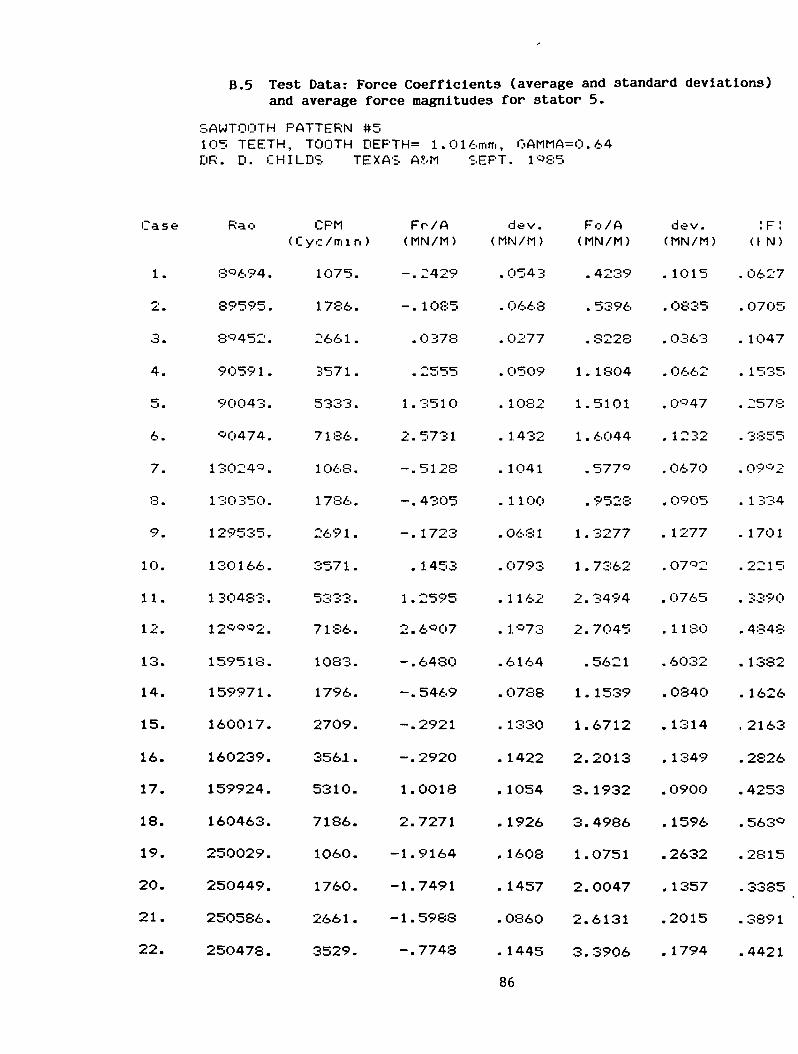
B.5 Test Data: Force Coefficients (average and standard deviations)and average force magnitudes for stator 5.
SAWTOOTH PATTERN #5105 TEETH, TOOTH DEPTH= 1.016mm, GAMMA=0.64DR. D. CHILDS TEXAS A?/M SEPT. 1^85
Case
1.
2.
3.
4.
5.
6.
7.
8.
9.
10.
11.
12.
13.
14.
15.
16.
17.
18.
19.
20.
21.
22.
Rao
8 694.
89595.
8'r'452.
9059 1 .
90043.
•30474.
13024*.
130350.
129535.
130166.
130483.
12*0*2.
159518.
159971.
160017.
160239.
159924.
160463.
250029.
250449.
250586.
250478.
CPM( Cyc/mi n )
1075.
1786.
2661.
3571.
5333.
7186.
1068.
1786.
269 1 .
357 1 .
5333.
7186.
1083.
1796.
2709.
3561.
5310.
7186.
1060.
1760.
2661.
3529.
Fr/A(MN/M)
-.2429
-. 1O85
.0378
.2555
1.351O
2.5731
-.5128
-.4305
-. 1723
. 1453
1 . 2595
2.6*07
-.6480
-.5469
-.2921
-.2920
1.0018
2.7271
-1.9164
-1.7491
-1.5988
-.7748
dev.(hN/M)
.0543
. 0668
. 0277
. 0509
. 1082
. 1 432
. 1041
. 1100
.0681
. O793
. 1 1 62
. 1*73
.6164
. 0788
. 1330
. 1422
. 1054
. 1926
. 1608
. 1457
.O860
. 1445
86
Fo/A(MN/M)
.4239
. 5396
. 8228
1. 1804
1.5101
1 . 6044
.577*
. 9528
1 . 3277
1 . 7362
2.3494
2.7045
.5621
1. 1539
1.6712
2.2013
3. 1932
3.4986
1.O751
2.0047
2.6131
3.3906
dev.(MN/M)
. 1015
. O835
. O363
. 0662
. 0*47
. 1232
. 0670
. 0905
. 1277
.07*2
. O765
. 1 1 80
. 6032
.0840
. 1314
. 1349
.0900
. 1596
.2632
. 1357
.2015
. 1794
!F!a N)
. 0627
. 0705
. 1O47
. 1535
. 2578
. 3855
. 09*2
. 1 334
. 1701
. 22 1 5
. 3390
. 4848
. 1382
. 1626
. 2163
.2826
.4253
.563*
.2815
.3385
.3891
.4421

23.
24.
25.
26.
27.
28.
29.
30.
24 919.
250552.
342151.
341964.
341768.
348323.
345254.
346465.
5310.
7186.
1083.
1780.
2679.
3509.
5286.
7186.
. 5785
1 . 9629
-3.6912
-3.4752
-3.2849
•'"i *~i «""» t~* *~i*L. m s-*OC'«— '
-.716O
1.415*
. 20O5
.2
. 3
.2
~>
373
356
534
143
. 2487
.3
. 3
336
•=•09
4.
6.
1.
— i
3.
4.
7.
9.
8939
2416
1616
9152
7743
8151
0402
1342
. 1 998
. 2082
. 42O6
. 1977
. 1441
. 1*25
.2415
. 3375
. 6265
.8315
. 4l7'52
. 5773
. 6 363
. 6833
. 8997
1. 1752
87

B.6 Test Data: Force Coefficients (average and standard deviations)and average force magnitudes for stator 6.
SAWTOOTH PATTERN #6SO TEETH, TOOTH DEPTH= 1.016mm, GAMMA=0.4*DR. D. CHILDS TEXAS A?/M SEPT. 1*85
Case
1.
2.
3.
4.
5.
6.
7.
8.
9.
10.
11.
12.
13.
14.
15.
16.
17.
18.
19.
20.
21.
22.
Rao
89904.
89559.
8994*.
9O408.
90398.
90536.
12*814.
12*670.
13O19S.
130323.
130529.
12*843.
16O478.
159645.
159797.
159824.
159728.
159795.
250011.
249754.
250207.
249704.
CPM( Cyc/mi n )
1075.
1780.
2667.
3561.
531O.
7186.
106O.
1802.
2740.
365*.
5310.
7186.
1095.
1796.
2685.
3571.
5286.
7186.
1064.
1813.
2685.
3582.
Fr/A(MN/M)
- . 2428
-. 1640
. 1 258
.2513
1 . 3542
2.6642
-. 600*
-.4*5*
-. 1752
. 10*7
1 . 2352
2.8381
-.8296
-.6893
-.4222
-. 1495
1.0656
2.8270
-2.O770
-2. 1234
-1.7311
-1.2256
dev.(MN/M)
. 0452
. 020 1
.0266
.0243
.0*28
. 1474
. 0554
. 0322
.0535
. 0298
. 2000
. 1 246
. 0870
.0360
.O582
.O800
. 1075
. 1435
. 1488
.0698
.0991
. 1176
88
Fo/A(MN/M)
. 3*22
.8101
1 . 05*9
1. 104*
1 . 5974
1 . S295
. 6237
1 . 1 285
1 . 5935
1 . 8638
2.5946
2.*4*5
. 80*4
1 . 4355
1 . 7799
2.4869
3.3844
3.9111
1. 1664
2.4083
3. 1476
3.9961
dev.(MN/M)
. 03 1 0
.0291
.0214
.0291
. 0732
.1115
. 0564
.03*3
. 0624
. 0286
. 1 085
. 1312
.0*01
. 0526
.0715
.0607
. 0949
. 1550
.2411
. 0723
. 1238
.0975
:F:<KN)
. 059O
. 1050
. 1356
. 143*
. 266 3
. 4 1 07
. 1 1 04
. 1566
. 2037
.2371
. 3661
.5201
. 1480
.2023
.2325
.3166
.45O9
.6132
.3045
. 4O79.
. 4564
. 53 1 0
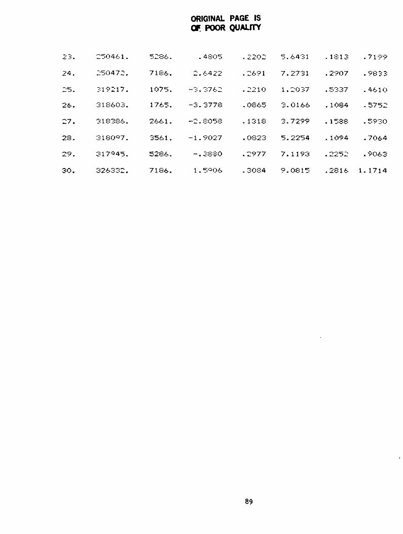
ORIGINAL PAGE ISOF POOR QUALITY
•*" ~* •
24.
25.
26.
27.
28.
29.
30.
250461.
250472.
319217.
3 1 8603 .
318386.
3180*7.
317*45.
326332.
5286.
7186.
1075.
1 765 .
2661.
3561.
5286.
7186.
. 4805
2.6422
-3.3762
-3.3778
-2 . 8058
-1.9027
-.3880
1 . 5*06
. 2202
.2691
.2210
. 0865
. 1318
. O823
.2977
. 3084
5.
7.
1.
• i
3.
5.
7.
9.
6431
2731
2037
0166
7299
2254
1193
0815
. 1813
. 2907
. 5337
. 1084
. 1 588
. 1094
. 2252
. 28 1 6
.7199
. 98 3 3
.4610
. 5752
. 593O
. 7064
. 9063
1. 1714
89

B.7 Test Data: Force Coefficients (average and standard deviations)and average force magnitudes for stator 7.
SAWTOOTH PATTERN #755 TEETH, TOOTH DEPTH= 1.016mm, GAMMA=0.34DR. D. CHILDS TEXAS A?/M SEPT 1*85
Case
1.
2.
3.
4.
5.
6.
7.
8.
*.
10.
11.
12.
13.
14.
15.
16.
17.
18.
19.
20.
21.
22.
Rao(
90146.
80900.
89730.
90333.
89795.
89490.
12*942.
129885.
1 29600 .
129474.
130412.
ISO 163.
16O491.
159935.
160023.
159689.
159637.
1598O2.
249864.
249995.
249438.
249675.
CPMCyc/mi n )
1O49.
1760.
2655.
3614.
5310.
7186.
1103.
1818.
27O3.
3647.
5310.
7186.
1079.
1807.
2697.
3604.
5333.
7186.
1068.
1786.
2697.
3604.
Fr/A(MN/M)
-. 1885
-.0180
. O386
.2395
1. 1*3*
2 . 58*2
-.5291
-. 2062
- . 1 603
. 1 373
1.0*33
2.7070
- . 6738
-.5266
-.2680
-.0182
1.0791
2.6591
-1.6280
-1.3198
-1. 1767
-.8644
dev.(MN/M)
.0331
.011*
. 0220
. 0285
.0513
. 0950
. 08 1 8
. 0278
. 0426
.0436
. 0746
. 1394
. 1 1 00
.0336
. 0457
.0493
. 1307
. 1383
.2281
.0658
.0881
. 1157
90
F.I./A(MN/M)
•
•
•
1.
1 .
1.
•
1.
1.
1.
— t4- m
*_ •
•
1.
1.
2.
2.
3.
1.
2.
2.
3.
4O38
527*
8061
0822
3 393
4332
7O82
0784
3887
8324
2487
6*7*
8992
2131
6512
3575
9079
5114
3813
1552
8528
8050
dev.(MN/M)
.0212
.0131
.0151
. 04 1 2
.0521
. 0942
. 0636
. 0426
. 0507
.0473
. 0886
. 1284
. 0845
.0356
.0439
. 0908
. 1099
. 1135
.2740
.O7O8
.0736
. 1453
:F:(KN)
. 0568
.0671
. 1025
. 14O3
. 2280
. 3761
.112*
. 1395
. 1776
. 2 334
. 3176
. 4857
. 1438
. 168O
.2125
. 2995
. 3942
.5596
.2748
.3211
.3921
.4957
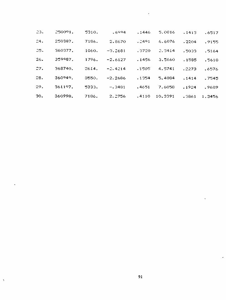
""• If-_ _• •
24.
25.
26.
27.
28.
29.
30.
250001.
250387 .
360377.
3590S7.
368740.
360040.
361107.
360998.
5310.
7 1 86 .
1060.
1796.
2614.
3550.
5333.
7186.
. £.Q04
2 . 867O
-3 . 268 1
-2.6127
-2.4214
-2.2686
-. 3481
2.2756
. 1 446
.2401
. 3720
. 1456
. 1 505
. 1 354
.4651
.4110
5.
6.
-t
O •
4.
5.
7.
10.
OS 1 6
6076
3414
5660
5741
4884
6058
3391
.1413
. 2204
. 50 33
. 1585
. 2273
. 1414
. 1924
.3861
.6517
.9155
. 5 1 64
. 56 1 8
. 6576
. 7545
. 9689
1 . 3456
91

B.8 Test Data: Force Coefficients (average and standard deviations)and average force magnitudes for stator 8.
SAWTOOTH PATTERN #860 TEETH, TOOTH DEPTH= 1.524mm, GAMMA=0.48DR. D. CHILDS TAMU NOV l'-'S5
Case
1.
?..
3.
4.
5.
6.
7.
8.
•-',
10.
11.
12.
13.
14.
15.
16.
17.
18.
19.
20.
21.
22.
Rao
9O421.
90240.
89601.
90342.
8C'617.
9O30O.
129835.
12*<:>13.
ISO 188.
13O034.
129444.
130024.
159844.
160109.
160300.
159739.
159515.
159826.
219832.
219848.
220500.
219671.
CPM(Cyc/min )
10*9.
1835.
2685.
3670.
5310.
7186.
1064.
1840.
2697.
3571.
531O.
7229.
1071.
1802.
2685.
3659.
5310.
7186.
1075.
1796.
2697.
3540.
Fr/A(MN/M)
- . 277O
-. 1495
. 02O6
.2531
. 8006
2.607O
-.4438
-.4145
-.0148
. 2459
. -3025
2. 1307
-.6408
-.6945
-.2018
. 1987
1.0132
2.6380
-1.3020
-1.0907
-.8263
-.3139
dev.(MN/M)
. OS 2 2
-O251
. 0265
. 06OO
. 0576
. 125O
. Q*4*
.0413
.03*1
. 0524
. 0776
. 530*
. 1023
.0322
.O502
. 0852
. 1077
.2436
. 1946
.0683
. 080O
. O668
92
Fo/A(MN/M)
.51*8
. 9470
1 . 2509
1.6433
2.28*2
2 . O36*
. 6878
1.2*21
1.8158
2.3934
3.3057
4. 1654
. 8040
1 . 4635
2.2265
3.2O30
4.3521
5. 1616
.9744
2.0583
2.9492
3.9239
dev.(MN/M)
. O477
. 0247
. 02 1 6
. 03 1 8
.0518
.121 8
. 064*
. 0847
.0343
.0711
. 1 06 1
.2ir'71
. 0855
. 0309
.0439
.0699
.0960
.2330
.2594
.0834
. 0857
. 1324
:F :(MM)
. O75S
. 1213
. 1589
.2113
. 3O8O
. 4204
. 1 050
. 1724
. 2307
. 3056
. 4 35 3
. •37
. 1316
. 2058
.2840
.4076
.5677
.7368
.2105
.2959
.3891
.500O
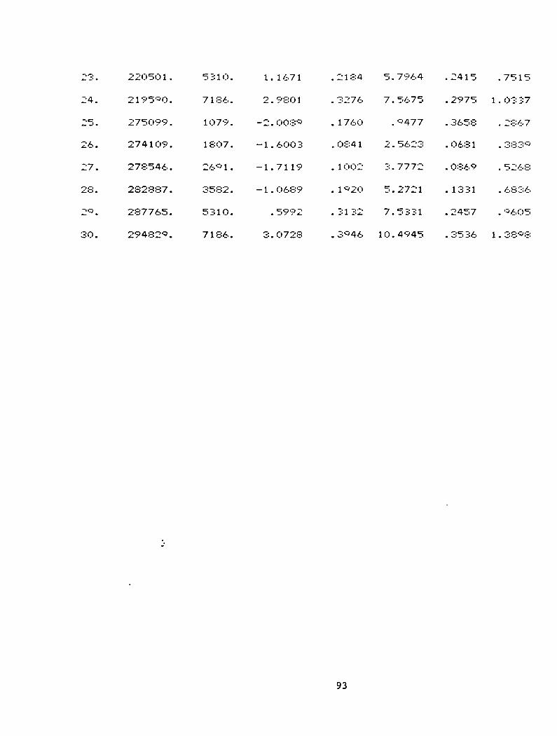
*_.!•.
24.
25.
26.
27.
28.
2*.
30.
220501.
2195*0.
275O99.
274109.
278546.
282887.
287765.
29482*.
531 0.
7186.
1079.
1807.
26*1.
3582.
531O.
7186.
1.
2.
-2.
-1.
~" 1 •
-1.
•
O •
1 67 1
980 1
008*
6003
7119
0689
5992
0728
.2184
. 3276
. 1760
.0841
. 1002
. 1 *2O
. 3132
. 3*46
5.
7.
•
2-
3-
5.
7.
10.
7964
5675
*477
5623
7772
2721
5331
4945
.2415
. 2975
. 3658
.O681
. 0369
. 1331
.2457
.3536
.7515
1.0337
. 2867
. 383*
. 5268
. 6836
. *6O5
1 . 38*8
93
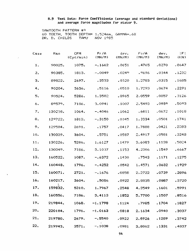
B.9 Test Data: Force Coefficients (average and standard deviations)and average force magnitudes for stator 9.
SAWTOOTH PATTERN tt^60 TEETH, TOOTH DEPTH= 1.524mm, GAMMA=.6SDR. D. CHILDS TAMU NOV l^'Sf.
Case
1.
2.
3.
4.
5.
6.
7.
8.
9.
10.
11.
12.
13.
14.
15.
16.
17.
18.
19.
20.
21.
22.
Rao
90025.
90385.
89822.
9O204.
90524.
8C>57'=>.
130238.
12«722.
129504.
130339.
130226.
130349.
160522.
160448.
160071.
160217.
159832.
160556.
219844.
220184.
219780.
219943.
CPM(Cyc/min)
1075.
1813.
2697.
3636.
5286.
7186.
1O64.
1813.
269 1 .
3604.
5286.
7186.
1087.
1796.
2721.
3604.
5310.
7186.
1068.
1796.
2679.
3571.
Fr /A(MN/M)
-. 1662
-.0049
. 3533
.5116
1 . 3502
3.0941
-.4046
-.3150
. 1757
. 575 1
1.6127
3. 1037
-.6372
-.4252
-. 1676
.5086
1 . 7967
3.4113
-1. 1798
-1.0163
-.5540
-. 1038
dev.(MN/M)
.0651
. 024«
.032O
.0510
. 0965
. 1007
. 1062
.O345
. 04 1 7
. 0587
. 1479
. 1153
. 1430
.0542
. 0858
.0922
.2548
. 1852
. 1124
.0818
.0922
.0981
94
Fo/A(MN/M)
. 4765
. '=>696
1 . 2783
1 . 7293
2.0559
2.5493
. 68 1 1
1 . 3334
1 . 7888
2.4917
3.6O83
4.2306
.7543
1.4571
2.2722
2.8835
4.3549
5.7700
.7985
2. 1634
2.8926
3.8062
dev.(MN/M)
. 0270
.0344
.0315
. 0674
. 0857
. 0980
. 0672
.0501
.0421
.0581
.1138
. 1549
. 1171
.0632
.0739
.0887
. 1601
. 1507
. 1704
.0940
. 1289
. 1331
(KN)
. 0647
1 ~I* I*-"1
. 1685
.2291
. 3126
. 50*3
. 1018
. 1741
.2283
.3248
. 5024
. 6667
. 1275
. 1929
.2896
.3720
.5991
.8516
. 1827
.3037
.3742
.4837
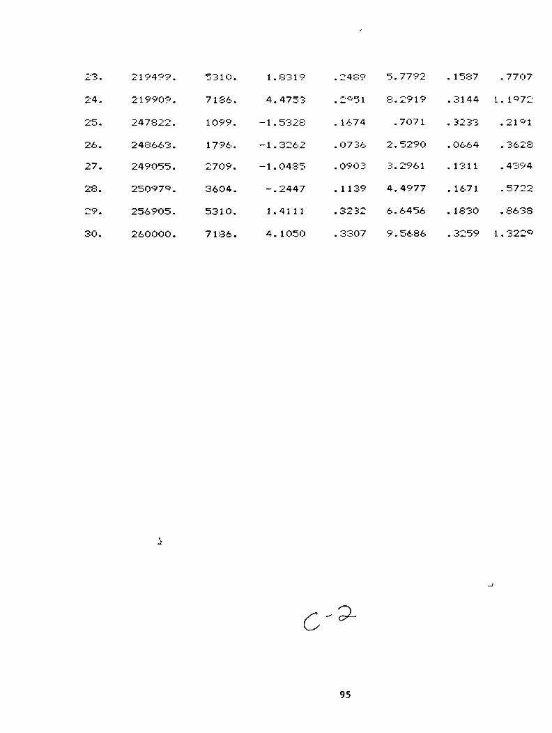
23.
24.
25.
26.
27.
28.
29.
30.
219499.
219909.
247822.
248663.
249O55.
25097*.
2569O5.
260000.
5310.
7136.
1099.
1796.
2709.
3604.
531O.
7186.
1.
4.
-1.
-1.
-1.
^ •
1.
4.
8319
4753
5328
3262
0485
2447
41 1 1
1050
. 2489
.2-51
. 1674
. O7 36
.0903
.1139
.3232
.3307
5.
8.
•
2.
3.
4.
6.
9.
7792
2919
7071
5290
296 1
4977
6456
5686
. 1587
.3144
. 32 33
. 0664
.1311
. 1671
. 1830
. 3259
. 7707
1. 1-72
.21-1
. 3628
. 4394
. 5722
.8638
1 . 322C)
c
95

B.10 Test Data: Force Coefficients (average and standard deviations)and average force magnitudes for stator 10.
SAWTOOTH PATTERN #106O TEETH, TOOTH DEPTH= 1.524mm, GAMMA=O.33DR. D. CHILD'S TAMU DEC 1*85
Case
1.
--%*- m
3.
4.
5.
6.
7.
8.
9.
10.
11.
12.
13.
14.
15.
16.
17.
18.
19.
20.
21.
22.
Rao
9O448.
*0287.
8*865.
90011.
89708.
89970.
1299*4.
129751.
129678.
129671.
12*844.
129959.
160282.
159893.
159895.
160100.
159957.
160393.
219714.
219872.
219994.
219907.
CPM( Cyc/mi n )
1O7*.
1807.
2721.
3571.
5333.
7186.
1087.
1796.
2691.
3636.
5333.
7186.
10*5.
1802.
2752.
3593.
5310.
7186.
1071.
1813.
2727.
3614.
Fr/A(MN/M)
-.2791
-.0825
. 0542
.3346
1.4122
3.0426
-.6483
-.4741
-.0844
. 0969
1. 1867
3.0463
-.9556
-.8728
-.4855
-.0225
.9793
2.6540
-1.8094
-1.7343
-1.3052
-.6576
dev.(MN/M)
.0630
. 0 1 94
.0330
.0272
. 0720
. 0846
. 0874
.0267
. O342
.0334
. 1297
. 131*
. 1365
. 0343
.0417
.0462
.0943
. 1726
. 1471
.0571
.0602
.O773
96
FC./A(MN/M)
.4582
.6835
1. 1516
1. 1974
1 . 7962
2.5029
.6443
1 . 0775
1 . 6338
1 . *79O
2.*258
3.9278
.7032
1 . 3094
2.0466
2.5504
3.6290
5.2192
.9763
2. 1338
2.6727
3.4937
dev.(MN/M)
. 0420
.0252
.0249
. 0243
. 0649
.0725
. 0879
. 0279
. 0630
.0304
. 1089
. 1 366
. 1782
.0314
.O787
.0426
. 1218
. 1837
.2811
.0614
.0700
.1142
IF;(KN)
.0688
.0875
. 1465
. 1579
.2903
. 5004
. 1171
. 14*5
. 2078
.2517
.4012
.6316
. 1532
. 1999
.2672
.324O
.4776
.7438
.2641
.3493
.3778
.4515

23.
24.
25.
26.
27. "
28.
29.
30.
219754.
219676.
311309.
313196.
313344.
315782.
320554.
326006.
531O.
7186.
1095.
1775.
2709.
3593.
5310.
7186.
. 9285
2.4451
-3.6021
-3.2822
-3.5872
-2. 1249
-.6450
2. 1677
.1199
. 2008
.2571
. 0964
. 1 887
. 1221
. 1 722
.5610
_l m
7.
•
•-.
3.
5.
7.
10.
1 6 1 5
04 1O
•-•'627
5697
5327
2804
5629
6522
. 1052
. 2 1 56
. 7483
. Oc'58
. 1640
. 19Q2
. 172*
. 4559
. 666 1
. 9469
. 48I-:7
. 5296
.63*7
.7231
. 9642
1 . 3826
97

B.11 Test Data: Force Coefficients (average and standard deviations)and average force magnitudes for stator 11.
SAWTOOTH PATTERN #1160 TEETH, TOOTH DEPTH= 1.524mm, GAMMA=0.47DR. D. CHILE'S TAMU .JAN 1*86
Case
1.
2..
3.
4.
5.
6.
7.
3.
9.
10.
11.
12.
13.
14.
15.
16.
17.
18.
19.
20.
21.
22.
Rao
*0088.
8*8*2.
89638.
90252.
00153.
8*817.
12*545.
1304*0.
1 30356 .
12*803.
12**41 .
12*888.
159641.
160328.
159081.
159853.
160505.
159530.
219676.
220351.
220126.
220514.
CPM( Cyc/mi n )
1060.
1 7-56 .
2685.
3604.
5 357 .
7186.
1O91.
17*1.
2721.
35*3.
53 3 3 .
7229.
1083.
1807.
2721.
3604.
5333.
7186.
1071.
1770.
27O9.
3561.
Fr/A(MN/M)
- . 3O57
-.2322
-.0261
. 1876
1 . 7287
3.4147
-.6800
-.632'-"'
-. 3023
- . 20 1 2
. 9** 1
2.*023
-1.0642
-1. 1218
-.7751
-.3050
.8702
2.5992
-1.7671
-1.9913
-1.8773
-1.2498
dev.(MN/M)
.0616
. 0323
.0401
. 05 1 6
. 1312
. O**7
. 0*O 3
.0352
. 0426
. 0565
. 0*47
. 5426
. 09*9
. 0473
. 0569
. 0688
. 1552
. 1678
. 1549
. 0929
.0942
. 1056
98
Fo/A(MN/M)
. 3893
.**63
1 . 349O
1 . 6780
1.9871
2.7566
. 64 36
1.2873
1 . 7264
2.44*5
3.6536
4.2152
. 7268
1 . 5500
2.0200
2.7808
4.4805
6.0616
.8458
1 . 9625
2.9265
3.5629
dOV.
(MN/M)
. O552
. 043*
.0533
.0701
. 1 1 60
. 1008
. 0*24
.0301
. O6*2
. 0446
. 0876
. 38 1 3
. 1419
. 0483
. 0764
. 0995
. 1045
.2064
.3135
.0955
.1121
-O759
IF:(KM)
. 0637
. 1300
. 1714
.2145
. 3350
.5575
. 1 2OO
. 1822
. 2227
. 3122
.4812
. 654*
. 1 65 1
.2431
.2749
. 3554
. 58OO
.8378
.2527
.3552
.4417
.4798
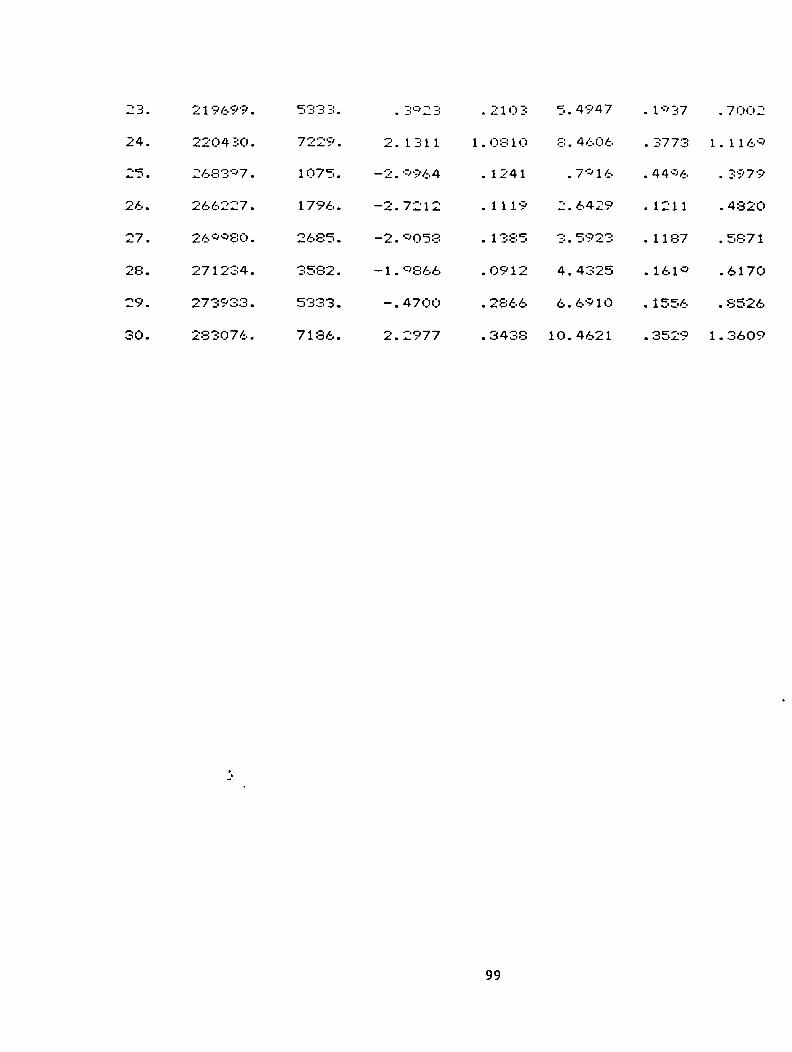
23.
24.
25.
26.
27.
28.
29.
30.
219699.
220430.
2683*7.
266227.
26 **80.
271234.
273933.
283076.
5333.
7229.
1075.
1796.
2685.
3582.
5333.
7186.
. 3*23
2 . 1311
-2.<r'964
-2.7212
-2.*058
-1.0866
-.470O
2.2977
.210 3
1.0810
.1241
.1119
. 1385
.0912
. 2866
. 3438
5. 4947
8. 4606
.7*16
2.6429
3 . 5923
4.4325
6.6*10
10.4621
. 1*37
. 3773
. 44*6
. 1211
.1187
. 161*
. 1556
. 3529
. 70O2
1.11 6*
. 3979
. 482O
. 587 1
.6170
. 8526
1 . 3609
99
Related Documents


