SSC-301 PROBABILISTIC STRUCTURAL ANALYSIS OF SHIP HULL LONGITUDINAL STRENGTH Thisdocument hasbeenapproved forpublic release endsalqits distribution isunlimited. SHIP STRUCTURE COMMITTEE 1981

Welcome message from author
This document is posted to help you gain knowledge. Please leave a comment to let me know what you think about it! Share it to your friends and learn new things together.
Transcript

SSC-301
PROBABILISTIC STRUCTURALANALYSIS OF SHIP HULL
LONGITUDINAL STRENGTH
Thisdocumenthasbeenapprovedforpublicreleaseendsalqits
distributionisunlimited.
SHIP STRUCTURE COMMITTEE
1981
SHIP STRUCTLTW COWWITTEE
l%. SHIP STRLVCUSE COI’LMITTEEis constit.ced co prosecute a researchp..gram co imPr.ve che hU1l .tr..t.re, of ship. ..d .ch= =.fne .C~U.tUres byan extension of knowledge pertaining to design, materials and methods ofCon,tr”ctio”.
R4DM H. H. BELL (Chaizwwd ,Nr.J. GROSSChicf, Office af !Yezdcmt
Marine Safety~P.*Y As.ist@ Administrator
Us. Coost Gluzld,“orConrreretal Development
,YuritinEAdministration
<Mr.P. ,v.PALER)40 MF. P. McDONALDDeputy Director, HulL Gmlq Chief, Branch of Offshore,Nava1 Sea SyaternsCornnmd Field @ezntimts
u.S. Geological Survey
Mr. W. N. RANNAN Mr. C. J. WRI!O?S!WI!Vice ?rwsident Engi*er OfploerAxetican Bmati of Ship@ng ,% lit~ Sealift Conrncmd
CUR T. L ROEW50W, CI.s. Coast Gumi (Secx?tm )
SKIP STICUCTURS.SUECONMIHEE
The SHIP STSUCTURS SUSCOIU-IITTEEacts for the Ship Structure Committeem technical matters by providio~ techr.ical.o.rdir,atioofor the determinationof goals and objectives of the program, and by evaluating and interpretingche resul,w in terms of structural desi~, construciton and qeration .
U.S. CUAST GUARU MILITARY SEALI~ CUMMANO
CAST R. L. BRO&7iCDR J. C CARDCUR J. A. SA?LC4L,JR.CDR V. M. SIMFSON, JR.
NAVAL SEA SYSTEMS COM!ANU
Mr. R. 6’.CmuMIS.J. B. OtBRISE&. k’.C. SANDBfXGWr. R. F. SWANNLCDR D. W. WRIDDLW
U.S. GEOLOGICAL SURPSY
Mr. G. ASSEw. T. w. CBASMANMr. A. B. STAVOVYMr. D. STEIN
~F.lCAN BUSEAU UF SNIPPING
Dr. D. LIUL@. I. L. STE.W
MAIuTIMS AUIIIN1STRATION
m. N. 0. SA.WSRDr. !/.M. M4CLEANW. F. SEIROLDMr. M. W. TOW
~. R. J. GIANG3RELLI INTSENATIUNAl SHIP STRUCTURES CONCRBSSA&. J. 8. LXEWRI
W. S. G. STIAN.ST3V- LiaisonNATIONAL KADSUY OF SCISNCES
SHIP SSSSASCR COWTTSE AMTRICAN IRON & STSEL INST1”WTE
Mr. A. D. SAFF - Liaisonh?. R. V. RUMKS - Liaison
Mr. R. E. ,STERNE- Liai,o”
S’YATEuNIVES.SITTUF NEW YUFW MARITIMS CULLEGETHS SOCIETY OF NAVAL ASCEITSCTS
& .WINS SNGINSESS Dr. !.’.R. PORTSR - Liaison
Mr. N. 0. :WWRR - Liaise” D S cUAST WARD ACADEMY
WLDING ksssmm cOuNcxL LC3R R. G. VORIWAN - Liaison
W. ,?.V. XGOPMAN - Liai$on U S NAVAL ACADEXY
3?. :;.-B. ,CX - Liaison

MemberAgencies:
UnitedStatesCoastGuardNavalSeaSystemsCommand
MilitarySealiftCommandMaritimeAdministration
UnitedStatesGeologicalSurveyAmeriwnBureauofSipping
*
AddressCorrespondenceto:
Secretary,ShipStructureCommitteeU.S.CoastGuardHeadquarters,(G-M/TP13)
structureWashington,D.C.20593
CommitteeAnInteragencyAdvisoryCommittee
Dedicatedto ImprovingtheStructureofShips
SR-1241March1981
Uncertaintiesareunavoidableinanyengineeringdesign.Limitationonthecontrolofmaterialproperties,milltolerancesinplateandextrudedshapethickness,time-dependenteffectssuchasdeteriorationduetocorrosion,cracking,wearandtearareonlysomeofthefactorsthatcontributetotheuncertaintiesassociatedwiththeactualstrengthofa ship’shull.Shipdesignersandnavalarchi-tectsusuallytreattheseitemsina qualitativesenseasveryfewattemptshavebeenmadetoquantifythem.
Basedonpreviousexperience,thequalitativeassessmentoftheuncertaintiesdoesnotlenditselftosystematicimprovementofdesignprocedures.Therefore,theShipStructureCommitteeinitiatedthisprojecttodevelopa computerprogramtoanalyzetheuncertaintiesassociatedwithshiphullstrength.Thedevelopmentoftheprogramanditscontentsarepresented.
&/”QRearAdmiral,U.S.CoastGuard
Chairman,ShipStructureCommittee
...
TechnicalReportDocumentationPage1. ReportNo. 2, GovernmentAccession~,>~ 3. Recipient’s CotologNo.
SSC-301——4. Title and Subt#tl= 5. ReportDate
t-
DECEMBER1980PROBABILISTICSTRUCTURAL-ANALYSISOFSHIPHULL 6. PctformingOrganizationCode
LONGITUDINALSTRENGTH\
7. Authorts)8. Pbr{ormingOrgonizotionReportND,
J.C.DaidolaandN.S.Basar9. PerformvrlgOrgonizottonNgmeand Address 10. WorkUn,t No. (TRAIS)
M.Rosenblatt& Son,Inc.350Broadway Il.Controctor GronfNQ.
NewYork,NY10013 D07-CG-61908-AIs.Type of Repo,tondPeriod Covered
.—12, SponsoringAgencyNamemid Addres~
U.S.CoastGuardOfficeof’MerchantMarineSafetyWashington,D.C.20593 1-
14. SponsoringAgencyCode
G-M115. SupplementaryNotes
SHIPSTRUCTURECOMMITTEEProjectSR-1241
16. Abs.rroct
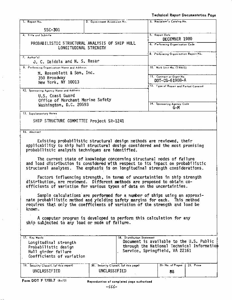
Existingprobabilisticstructuraldesignmethodsarereviewed,theirapplicabilitytoshiphullstructuraldesignconsideredandthemostpromisingprobabilisticanalysistechniquesareidentified.
Thecurrentstateofknowledgeconcerningstructuralmodesoffailureandloaddistributionisconsideredwithrespect”toitsimpactonprobabilisticstructuralanalyses.Theemphasisisonlongitudinalstrengthconsiderations.
Fact:rsinfluencingstrength,tntermsofuncertaintiesinshipstrengthdistribution,arerevfewed.Differentmethodsareproposedtoobtainco-efficientsofvariationforvarioustypesofdataontheuncertainties.
Samplecalculationsareperformedfora numberofshipsusinganapproxi-mateprobabilisticmethodandy~eldingsafetymarginsforeach.Thismethodrequiresthqtonlythecoefficientsofvariationofthestrengthandloadbeknown.
A computerprogramisdevelopedtoperformthiscalculationforanyshipsubjectedtoanyloadormodeoffailure.
17. Key Words 18. DistributionStatement
Longitudinalstrength “DocumentisavailabletotheU.S.PublicProbabilisticdesign through.theNationalTechnicalInformationHullgirderfailure , Service,Springfield,VA22161Coefficientsofvariation
I19. SecurityClassif. (oI this report) 29. SecurityClassil. (of this page) 21. No. of Pages 22. Price
UNCLASSIFIED UNCLASSIFIED 88L 1 1 I
FormDOTF 1700.7(8-72) Reproductionof cotnpl.etedpage❑uthorized● *.-%’LtL-

METt71CCONVERSIONFACTORS
ApproximateConversions10MetricMeasures ApproximateConversionsf
WhsaYouKnow MultiSymbol
nmcmmmkm
cm’~2
km’hO
9kgi
mlII
L~3
“c
Symbol WhenYOIIknow Muhiplyby Tofind SVmbal
lEUlEfJGTH millirrwlws 0.0
ceniimwwrs 0.4nwmls 3.3nwters 3.kitmmeters t3.6
inhVdmi
inches “2.5lee! 30yards 0.9mites 1.6
c.mtmmtcrscentimetersmeterskilametexs
<Illcmmlull
cmz~2~zkm2ha
ukgt
mlmtmtI11
;3ml
“c
ARAREAsquarec*nlineters 0.squaremeters 1.squarakikmcters 0.hect~es[10,0001112} 2.
inzddmi2
squntainches 6.5suuarmicfet 0.02s@mewards 0.9squaremites 2.6acres 0.4
z.quaracemnmciersSqumometerssqmronwcrssqmmkilmuet{:rsht+cI;),*S
MASS(MASS[weight]&‘y gmrm 0.kiIogrwrts 2.2mnnns(10+0kfl) 1.
Winces 20pumds 0.45S!WMItwta 0.9
(2000ibl
Omntskitoqranw40+1,%0s
VOLUME’ VOLteaapamsmbles~sftuidcNnc*acupspintsquamgallmlscubichotcubicyard~
515300,240.470.953.00.020,1s
nlilJi#itacsmiliililefs.mltli~ilerskite!sIiqerstilers.tiler2-c“b#cnwierscubicnelnrs
milliliters 0.0Iiwm 2,liters 1.liters 0.cubicmeters 35cubicrrmaers 1.
tspTb’pIIor!cptqtgal,,3Vda TEMPER
Cataius 9/5Wllp4tathlreadd
“F Fahrenheit 5/9Ialierlcmpwatum subtractino
321
Celsiuslcr@ratur*
‘F 32-40 0 40 80}’t’ , , ,
1 t I #-40 -20 0 20●C
.1u,t 2.54Iwlcl!vl.f,.“11!.2,*.=1COllwwblh,ns,WJInLno&M.3,11w!Kllh+srSLwNW M!ic.Putll.2ni4U,uwdWuwhtsa,.+M,-M8us,F’ncos2.25,SOCmdutIMO.Cl3.T0205.

TABLEOFCONTENTS
Section 1. INTRODUCTION. . . . . . . . . . . . . . . . . . . . . . . . . . . . . . . . . . . . . . . . . . . .
Secticn2. STATEMENTANDOBJECTIVES● . . . . . . . . . . . . . . . . . . . . . . . . . . . . . . .
fj~~t;~~ 3. PROBABILISTICAPPROACHTOSTRUCTURALDESIGN. . . . . . . . . . . . . .
3.1 General● ● ● .** . ● . ● ● ● . . . . . . . ● . ● . . . . . . “. . . . . . . . . . . . ● ●
3.2 Probabilistic Methods. . . . . . . . . . . . . . . . . . . . . . . . . . . . .
3.2.1 QuantitativeMeasureofPerformance......3.2.2 Classical Approach... ~.. . ~. . . . . . ..- ..-..,3.2.3 Safety Index Approach. . . . . . . . . . . . . . . . . . . .3.2.4 Strength Reductionand LoadMagnification
Factors3.3 Strength Statistics. ., . . . . . . . . . . . . . . . . . . . . . . . . . . . .
3.3*I General. . . ● . . . . . . . . . . . . . . . . . . . . ● . . . ., . . , .3.3.2 Strength Equation. . . . . . . . . . . . . . . . . . . . . . . .3.3.3 Strength Distribut ions. . . . . . . . . . . . . . . . . . .3.3.4 T?meDependentStrengths. . . . . . . . . . . . . . . . ..
3.4 LoadStatistics ● . . . . . . . . . . . . . . . . . . . . . . . . . . . . , .. . . . .
3.4.1 General. . . . . . . . . . . . . . . . . . . . . . . P, . . . , . . . r .3.4.2 Equationsand Distribut ions. . . . . . . . . . . . . .
Sect7cm4. MODESOFHULLFAILURE. . . . . . . . . . . . ,,. . . . . . . . . . . . . . . . . . . . . .
4.1 General. . . . . . . . . . . . . . . . . . . . . . . . . . . . . . . . . . . . . . . . . . .4.2 Modesof FailureoF the Hull Girder. . . . . . . . . . . . . . .4.3 Conclusion. . . . . . . ● . ● . . . . . . . . . . . . . . . . . . . . . . . . . . . . . .
Section 5. LOADINGS. . ● . . . . . . . . . . .“ . . . . . . . . . ● . . . . . . . . . . . . . . . . . . . . . . . .
sectian 6. PROBA!31LISTICSTRUCTURALANALYSISOFSHIPHULLLONGITUDINALSTRENGTH. . . . . . . - . . . . . . . . . . . . . . . . . “. . ● . . . , . .
General. ● . . . . . . . . . . . . . . ● . . . . . . . . . . . . . . . . . . . . . . . . . .::: i)evel~prnentof a probabilistic Structural
~n;l{sis Methodology. . . . . . ● . . .* .+. ● . “. . . . . . . c. . . r .. . Strength and LoadDistributions .F. +r..r.“
6.2.2 Strength equations. . . . . . . . . . . . . . . . . . . . . . .$.2.3 TimeDependentS:rength Analyses. . . . . . . . .
Page
1
2
3
34
4
27
G
86913
15
1516
Jtl
18lb20
21
23
23
24242526
-v-
TABLEOFCONTENTS(cont.)
Page
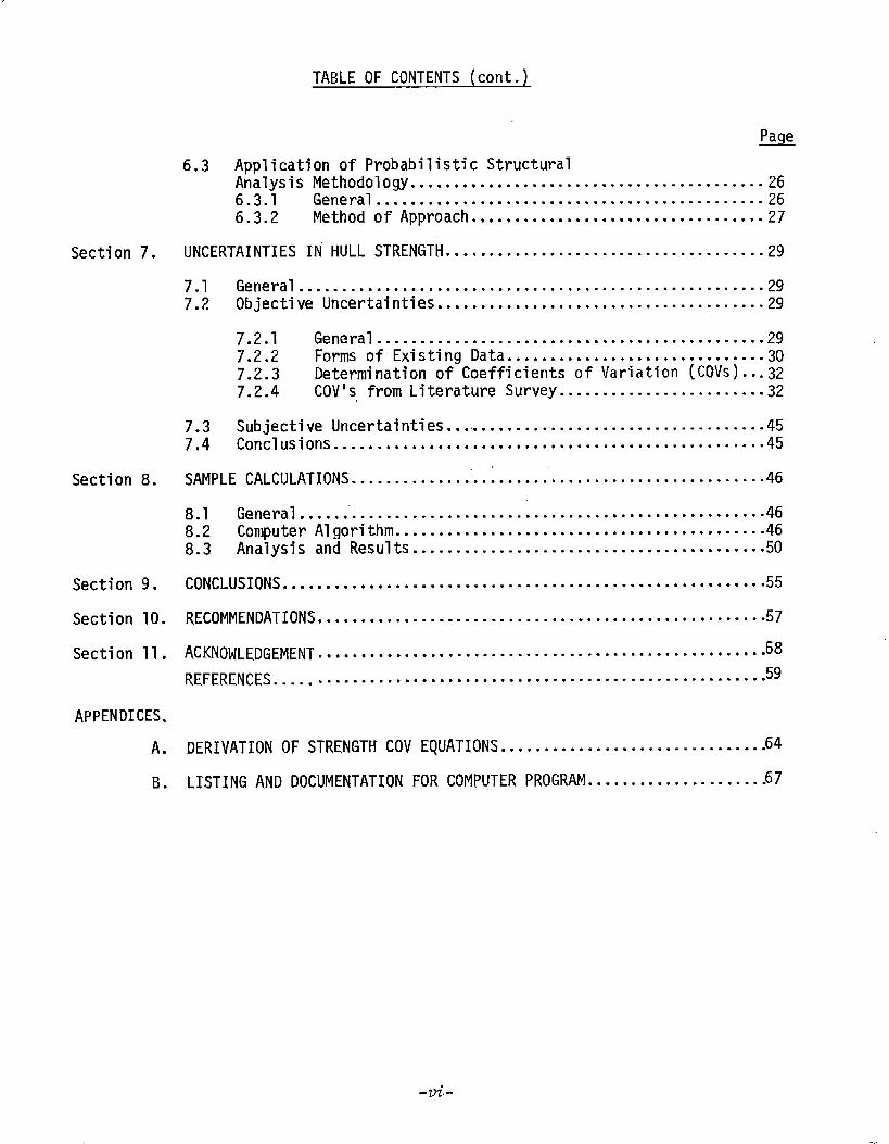
6.3 ApplicationofProbabilisticStructuralAnalysisMethodology....***..**....................*..*......266.3.1 General........● ........................**-----.....266.3.2 MethodofApproach..*.*.............................27
Section7. UNCERTAINTIESINHULLSTRENGTH●*● ...● ..● ● ● ● ........................29
7.1 General.....*................................................297.2 ObjectiveUncertainties........................●.............29
7.2.1 General.........*.*.................................297.2.2 FormsofExistingData● *.........................--.7.2.3 DeterminationofCoefficientsofVariation(COVS)....;7.2.4 COV’SfromLiteratureSurvey........................32
7.3 SubjectiveUncertainties.... .........................---......457.4 Conclusions....*.**.**..........*..● *........................45
Section8. SAMPLECALCULATIONS,’
.......● ● .*............● ●...................● ...46
8.1 General.................*..*..............● *.................8.2 ComputerAlgorithm.....● ● ..............-.-● .............-....%8.3 AnalysisandResults.............*...........................50
Section9. CONCLUSIONS.........***..............................-*............55
Section10. RECOMMENDATIONS● .....● ..●*.................● ● ● ...........● .● .......57
Section11. ACKNOWLEDGEMENT 68..● ●.........●*● ..............*●*● ...........● ● ● ● ...REFERENCES.....●........● ●...............● .● -............● .........59
APPENDICES.A. DERIVATIONOFSTRENGTHCOVEQUATIONS...............................64
B. LISTINGANDDOCUMENTATIONFORCOMPUTERPROGRAM.....................67
-vi-

LIST OFF,IGURES
NO.—.
1 Curw!ative Long.TerrnDistribution of AverageBendingMoments. . . . . . . . . . . . . . . . . . . . . . . . . . . . . . . . . . . . . . . . . . . . .
Probability of Failure versusSafety Index. . . . . . . . . .
COVfor Depthof Stiffener Web. . . . . . . . . . . . . . . . . . . . . .
COVfor Breadthof Stiffener Flange...............:.
COVfor Breadthand Lengthof Plate . . . . . . . . . . . . . . . . .
“ApproximateProbabilistic Method”Algorithm. . . . . . . .
ApproximateMidship Section for “UNIVERSEIRELAND”..
Reliability Analysis● ● . . . . . . . . . . . . ● . . . . .* . . . . . . . . . , ●
PAGE
22
28
34
35
36
48
52
54
-vii-

,, .. ,
LIST OFTABLES
NO. PAGE—.-
CarbonSteel Plates Data. . ● . . . . . . - - . . . . . . - . -. - , - , . . . .
As-Rolled Plate Data... . . . . . . . . . . . . . . . . . . . . . . . . . . . . . .
Data for Carbon-SteelWide-FlangeShapes. . . . . . . . . . . . .
Flange BreadthUncertainty. . . . . . . . . . . . . . . . . . . . . . . . . . .
COVof Depth. . . . . . . ..**.*. . . . . . . . . . . . . . . ....... -.*-””
COVof Beam..*.**. . . ...** . . . . . . . . . . . . . . ------- . ..-.”.
Uncertainty--Depth Of Ship.. . . . . . . . . . . . . . . . . . . . . . . . . .
Uncertaint-y--BeamofShip. . . . . . . . . . . . . . . . . . . . . . . . . . . .
Uncertainty--Thickness (Receipt Inspection). . . . . . . . . .
Uncertainty--Thickness (Undercut). . . . . . ..- -.- . . . . . . . .
Objective Uncertainties. . . . . . . . . . . . . . . . . . . . . . . . . . . . . .
Objective Uncertainties. . .. - . . . . . . . . .- - -s...”--- --”-”
Subjective Uncertainties. . . . . . . . . . . . . . . . . . . . . . . . . --’.
“Appt”oximateProbabilistic Method”. . . . . . . . . . . . . . . . . . .
~’UNIVERSEIRELAND”Characteristics . . . . . . . . . . . . . . . . . . .
“uNIVERSElRELAb!D”Structural Variables. . . . . . . . . . . . . .
I’IJNIVERSEIRELAND”Uncertainty COVES. . . . . . . . . . . . . . . . .
St,rengthCOVEquationTerms. . . .. ------- . . . . . . . . . . . . . .
33
33
33
37
38
39
40
41
41
42
43
43
44
47
51
53
53
53
-v{<i.
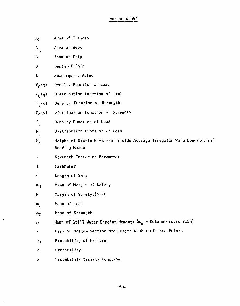
NOMENCLATUR&
Area of Flarlge~
Area of Webs
Beamof Ship
Depthof Ship
MeanSquareValue
Density ‘Functionof Lbad
Distribution Functionof Load
Density Functionof Strength
Distribution Functionof Strength
Density Function of Load
Distribution Functionof”Load
Height of Static Wavethat Yields Average Irregular WaveLongitudinalBenrJingMoment
Strength Factor or Parameter
Parameter
Lengthof S+ip
Meanof Margin of Safety
Margin of Safety,(S-Z)
Meanof Loacl
Heanof Strength
Meanof Still WaterBendingMoment;(mO-
Deckor BottomSection Modulus;orNumber
Probability of Failure
Probability
Probability Density Function
Deterministic SWBM)
of Data Points
-’ix-

Q
R
R=
s
c
SM
Fay
t
tc
tf
$1
“m1
v~
Vz
Vx
VXa
vXs.-‘%
z
6
*yn
‘ #yn
4zn
4 Zr,
s/z
Reliability
Rate of Corrosion
Failure GoverningStrength
NominalStrength Under Idealized and StandardTest Conditions
RequiredSection ModulusofShip Hull
Tensile Yield S,tres,sof Material
Thickness
(For CorrosionAllowafice) to (Original)
(Of Flange) b (Of Web)
(For Limiting Stress} Tn, ~JMeans of tn and t=.)
Tolerance
Coefficient of Variation (COV)of Strength, (w,)
Coefficient ~f Variation (COV)of Load,Fz/mz )
Coefficient of Variation of x
Coefficient of Variation of Objective Uncertainties of x
Coefficient of Variation ofSubject’
Meanof Variable x
Failure GoverningLoad
Coefficient of Variation
ve Uncertainties of x
Density Functionof the ExtremeWaveBendingMoment
Distribution Functionof the ExtremeWaveBendingMoment
Density Functionof ExtremeLoadCunposedof WaveBendingand StillWater Bending
Distribution Functionof the ExtremeLoadof WaveBendingand StillWater Bending
-x-

T
RandomVariable RepresentingConstituerit parts. of Strength
Central Safety Factor,(mS/mz)
Density Functionof LoadDistribution Function of Load
Time
Coefficient of Variation of Strength
Variance of Margin of Safety
AverageFailure Stress
Variance of Load
Variance of Strength
Variance of Still Water BendingMomentor ~enetal”variance
AverageFailure Stress of Hul.l,Material
Safety lndex,(mN/~M)
Correlakinn Coefficient
StandardTabulated NormalFunction.,.
Mm2il
InitialLateralDeflectio+fi-’of.Plating
-xi–

SECTION1.0
INTRODUCTION
The conventionalmethodsof performing longitudinal structure designsof ships makeuse of accumulatedexperience from previously built ships ofsimilar size and function. The accumulatedexperience is mostly expressedinthe form of semi-empirical formulascontained in classification society rulesand des’ignspecifications. The designs resulting from this approachare uncertainas to the degree of structural adequacythey afford even thoughthe ship designsbasedon these approacheshavegiven acceptable service, The uncertainty stemsfrom the assumptionsmaderegarding parametersaffecting the environmentandthe szt-rq-gthof the ship. Manyyears of design experiencehave shownthat byusing appropriate empirical marginsfor strength over expectedload, the unknownscan be accountedfor and ships with acceptable risk or probability of failure’Iev&ls designed.
With the advent of newship types, and the resultant lack of “accumulatedexperienceII on ve$se~sof similar size andfunction?it has becomea professionalresponsibility to look into amore,scientific, or rational, approachto longitudinal strength design of ship hulls, in this context, various invest-igators in the ship research communityhaveadoptedprobabilistic structural“anaiysisproceduresfrommechanicaland civil engineering. II-I the “probabilisticapproach” since the quantitative values of manyof the factors affecting thestrength ;f the structure and the magnitudeof the load are statisticallydetermined, the resulting measureof the adequacyof the design is aIso5tstistical in nature,
In the study presented in this report, various facets of probabilisticsti-ucti~ral design were investigated with emphasison applicability to ships,
Section 2.0 gives a statementconcerningthe detailed objectives of thestudy. in Ssction 3.0, probabilistic structural analysis IS reviewedfrom L:generalstandpoint and its applicability to ships is noted, Section 4,0 discusse~thepossible structural modesof failure of a ship that pertain to lofigitudinalstrcn~thq The present situation with information on ship loads as ~li~y relateto structural design is discussedin Section 5.0, and the probabilisticstructural analysis proceduresthat showpromisefor ship applications arepresented in Section 6.o. In Section 7.0, the invest~gations~analyses andcollected information performedandobta;ned as part of this study ‘n the areaof the uncertainties of hull strength with respect to the statistical descriptionof -thertrength are presented. Section 8.o gives samplecalculations fordifferent ships using a probabilistic structural analysis prccedureembodiedin a computerprogramincluded in the Appendix. Sections 9,0 and !0 Ogi’ve the conclusionsand recommendationsrespectively arrived at as a result ofthese ~tudie,~.
The references cited in the report are listed in Section 11.0
-1-

SECTION2.0
STATEMENTOFOBJECTIVES
The objectives of this studywere modified by the Ship Structure Com-mittee during the courseof the project to be commensuratewith what was found
to be available and possible within the rather small funding allocated.
The final objectives can be stated as follows:
o Surveythe existing literature on reliability analysis and proba-bilistic design methodsin structures. Commenton the applicabi-lity to ships.
o Developa method, or use an existing method,for the formulationof strength in terms of the meansandvariances of its uncertain-ties. Althougha mathematicaldistribution of strength is not re-quired, observations are to be madewith respect to the impactofusing only meansand variances.
o Relate the existing bend’in’gmcrnentdistributions calculated fromexisting data to the developedstrength distributions using an existingmethodfor structural reliability analysis. Useavailable statis-tical strength parametermeansand variances andmakeassumptionsfor any strength or load parametersfor which no statistical dataare available.
o Developa FO”RTRANIV computerproqramto perform the aboveproce-dure with the objective of determining the safety level of a givenship subjected to a given load.
n AppIy the developedmmputer?zedproceduri tc actual ships,
o On the basis of ob,tainedresults , suggestfurther research todevelop suitable longitudinal strength criteria for future designs.
-2-

SECTION3.0
PROBABILISTICAPPROACHTO STRUCTURALDESIGN—
3.1 General
The objectives tif this study include the analysis of uncertaintiesassociated with ship hull strength and the developmentof expressionsfQrstructural reliability. Suchanalyses require the adoptionof a probabilisticstructural design approachsince a purely deterministic approachcannot yieldthe desired information.
In the deterministic designof structures, the strength of the structureis always increasedabovethat whichwouldjust survive the greatest expectedluad by an empirical margin. The ratio of the latter to the former strengthis usually termedthe factor of safety. It accountsfor all the unknownsinthe load and strength and yields a structure that shouldhavean acceptableperformancebasedon past experiences.
The fundamentalaims of a probabilistic approachare to moreclearlyand rationally define the necessarymargin, or factor of safety, and obtain aquantitative measureof performancethrougha rational rather than empiricalanalysis. The measureof performanceis usually called the probability offailure or reliability. With suchaims, it is not necessarythat a probabi-listic analysis be exhaustive in that rationalization of evenonly one of theunknownsin the factor of safety will put it on a sounderfooting. In thisvein, ‘the-’ultimate result of improvedprobabilistic analysis procedures,asfar as designers are concerned,will probably be rational factors of safetybasedon desired quantitative levels of performance. The probabilisticanalysis itself neednot be executedby the designers, although this couldbe possible.
A completeprobabilistic structural analysis wouldproceedin thefollowing manner[9]*:
o Conductan analysis of failure modes.effects. and criticality.Identify-all significant failure rmdes-of the structure.List the causeof these failure modes.Identify all parameterscontributing to these causes.Determinethe criticality of all siginficant failure modesto the successof structures.List the n~st.ctiitical failure modesin order of priority.
‘- Formulatethe relationshi~ betweenthe critical ~aramete;sand -the failure-governing cri~eria involved.
.
0 Determine0 Determine0 Determinea Determin&o Calculate
the failure-governing load function.the failure-governing load distribution.the failure-governing strength function.the failure-governing skrengthdistribution,the probability of failure or reliability associatedwith
* Numbersin brackets iqdicate similarly numberedreferences in Section 11.0.
-3-

the failure-governingloadandstrengthdistributionfor eachcritical failure mode.
“ An upperboundcf.the total probability of failure or a lowerboundof the reliability will be the sum of the individualprobabilities of eachof the critical failure modesunder theassumptionthat these modesare mutually exclusive events.
Becauseof the difficulty associated with the determination ofthe fiji]ul-e-governingload and strength functions and di~tributions,a numberor probabilistic approachesor methodshaveevolved. Theydiffer fundamentallyin tile two primary aimsof any probabilistic analysis as mentionedabove:
0 Quantitative measureof performance0 Rational quantification of load and strength
Actually, not all the approachesare necessarily probabilistic inthe mathematicalsense in that for some, probability densities and distributionsare not needed,and the output is not a probability.
Thesemethodsmaybe groupedas follows:
“ Classical probabilistic approach0 Safety index approach0 Strength reduction and load magnification factors approach
The presentation in this section is divided into three groups. Thefirst groupdiscussesthe general approachused in obtaining the quantitativemeasureof performanceof a structure given the load and strength statistics.T!-Icnext groupseach deal with details of the strength and load formulationsrespectively, in a general sense. Morespecific mentionof these considerations,as applicable to ships, is given in Sections 5.0 thru 7.0,respectively for
the
aria’e~g
the
ship
ysesneer
longitudinal ”stre;gth, and for uncertainties in-the ;trength-nf-shull.
The literature contains abundantsourcesof probabilistic structuralMostof the work has beendone in the areas of civil and mechanical
ng but has morerecently spreadto naval architecture.
Probabilistic design conceptsfor structures were first proposedinin 1947 [1]. Since then, several investigators have presented~.sm
further considerations for applications in civil en~ineerinq. References[2]. .thru [6], mechanicalengineering, references [7] thru [9], and morerecentiy-
- .
in naval architecture, reference [10].
Within the frameworkof the present study, a brief review of thenumerousmethodsas cited wasperformedto identify the oneswhichwouldseemappropriate for future consideration in probabilistic structural analysesof ships from the standpoint of design.
3,Z Probabilistic Methods
3,2.1 Quantitative Measureof Performance——
As previously menticned, the existing probabilistic structuralanalysis methodsdiffer in the output measureof performanceof the structure
-4”
being consic!el-ed.
Thosemethodsthat are moreprobabilistic in the mathematical5?n5e, generally, are of the classical type. Their measureof performanceisin terms of a probability defining failure or reliability.
The other methodshaveevolved primarily due to the difficultiesassociated with executing a ‘fully probabilistic procedure. Their measureofperformanceis not a probability at all, instead, it is a numberindicatingeither a marginof safety or reduction and magnification factors for strengthand load, respectively. Thesenumbersdo not havea physical siqnificandelike probabil-ity of failure or reliability, but they can be comp~redother for previous successfuland unsuccessfuldesigns to obtain lim
3.Z.2 Classical Approach
The one commonpoint in all probabilistic structural ana
to eachting values.
vsis vro-cedur-esis the definition of the probability of failure and reliability. “1fthe failure-governing load is Z and the failure-governing strength S, then theprobability of failure, Pf, is qiven by all probabilities that the failure-~overning ~oadexceeds”the-fail~re-governi ng”strength:
(1)Pf = P (Z>s)
The probability df faithe reliabil ity, R, becomes:
R = I-Pf = P (S>Z)
ure is also called the unreliability, while
(2)
Equation (1) is presented in muchof the literature. for exam~lein [10], a~ directly applicable to ships in the following manner:
Pf = P [s<2] =P [~1] = P [Q<l] (3).= P [(S-Z)<O] = P [M<O]
The terms “Q” and “M”of Equation (3) are functions of two randomvariables:the stren~th, S, and the load, i?, and themselvesrandomvariables whoseprobability mustbe determinedby joint probability densi,tyand distributionfunctions. However,there seemsto be a universal a reementto qon~ider
ithe load and strength statistti@ly independentso t atthestatisticsaf ElandQ canb directly determinedfrom thosd~f S and Z. This assumptionappears to bereasonable for moststrength considerations as long as the effects on thestructure of being in an aqueousenvironmentwith wavesfor a long period ofti’mcare accountedfor in the strength. If ~ [z,) and@&}are the probabilitydensity and distribution functions of the load, respectively, and fs (s) and F* (s)those of strength, then it can be shownthat the density and distributionfunctions of Q are, [10]:
‘Q (d = ~~(j(z) f’s (qz) z dz (4)
FQ (q) ‘o~~(d FS (qz) dz (5)
“5-
and the prcbabil ity of failure becomes:
~+(dF~ (z)dzPf=e (6)
= ]-j~(Z) fs (Z) dz (7)
Equations (6) and (7) are rather simple and could easily beevaluated provided the derlsity arid distribution functions of load andstrength are known. This is where the crux of the matter lies and willbradiscussed later in Sections 3.3and 3.1}.The methodsthat makeuseof Equations (6)and(7)varySignifi=rrtlyincornp~exityandeffortrequired for execution.
Equation (7) can be evaluated for each modeof failure and,as nated previously, the sumof all probabilities of failure for all modeswill give an upper bound. To do better would require the joint probabilityde~sity function of strength in the various failure modeswhichwould beat’best very difficult to obtain. A lower boundorI the probability offailure can.be determinedby assumingthat the modesof failure are perfectlycorrelated.
3.2.3 Safety~—.
The difficulty in obtaining load and strength density and dis-tribution functions has led investigators to developapproacheswhich mini-in!ze the effort required. For instance, in,the area of ships, [13] containsan approximate semi-probabilistic design methodwhichwasmotivated, amongother things, by the lack of data on loads and strength and by the contro-versial status of formsof load and strength distributions. The methodrequires that orIly the meansand variances of the load and strength be known.
This “approximate”approachconsiders the margino5 safety II
of Equation (3) as a randomvariablewithmeanw andvarianceOH..‘f = P ~M<O]= P [~w<~] = P [WY] = FG (-7) (8)CM
By using the error distribution of M, [161, discussedin moredetail inSection 3.3, the meanand the variance of H can be written:
(9)
0H2 = ~z ~2S+i! (10}
where:riis, 0s= meanand variance, respectively of strength.
rn~: q = meanand variance of total load.
The following results are obtained by algebraic processes:
v z+vzz+’~%$ 1/2~j= 1+”~ s ), —.—-.-———l-+f52
(12)
(13]
(,1,)
Vkre: Y =
‘s =SH =
vz=91 =aN =
m =n2 --=
‘h
indexY is
~ ..8 ~
‘sski . —gN
safety index = m/uMM
central safety factor = m$/mZ
OScoefficient of variation (COV)of strength = —
‘srequired section modulusof the ship hull
COVof load = rjmZ
required section mod~lusof s-hiphull
average of failure stress of hull material
meanof the marginof safety
variance of the marginof safety
FromEquation (8),it can be seen that each vaiue of the safetyassociated with someprobabil ity of failure. However,Equation (8)
cannot be evaluated since the distribution function F is not known. Iferioug~information were a“~ailable to detsrrnineF~, th% Equations (6I and (7)fif the ciassical approachcould be useddirectly. FromEquations (11)through (14),itcanbeseenthattheinputsneededtoobtaina hulldesignstrengtharethestrengthandloadCOV’S,meanof the bendingmoment,andthe safety index Y= The am~untof computationis insignificant.
The safety index Y is a sinqle numberthat must.be obtainedon Yhe bas,isof manyteciinf:cal~~actdrs. l.t has previously”’bee~proposed[13]todeterminethisvaluefromexistingdesignstotakeintoaccountthevastaccumulatedexperience.Inaddition,if the probabilityof failure associated with past designs is socially acceptable, then thisaspect is also considered.
3.2.4 ~h Reductionand LoadIlagnification Factors
This method, discussedin [5,62,63], is similar to the approximateinethoddescribed above in that only meansand variances of the load andstrength are used to obtain relative and semi-probabilistic measuresof thestructure’s performance. In this case, the measuresof performanceare’thestrength reduction and load magnificatioti factors.
-7-
The strength reduction factor. f., and load magnification factor.
‘z’can be defined as follows: s
f.~ = minimumstrength = ‘S-K$ ‘Saverage strength . 1-KSVS; $< 1= (15)m~
where: K =%>= l%cto~$givi~thenumberofstandarddeviations betweenthe averageand theminimumstrengths and the maximumloads,respectively.
For a safe design, the minimumstrength mustexceedthe maximumload:
or equal
“mf > ms s- z ‘z (17)
The values of acceptable strength reductions factors and loadmagnification factors could be obtained from past designs in a similar-fashionto the safety index of the previous section.
In [5], this approachhas beenextendedto fatigue for both thecocstznt rangeand the randomloads.
Similarly to the safety index approach,to ex.ec~tethis methodare quite limited in extent and
3.3 Strength Statistics
the analyses requiredtiomplexi~y.
3.3.1General
It mustbe first stated that the strength of the hull girdermayor maynot vary with time dependingon the failure modebeing con-sidered. Time invariant strengths will include yielding and buckling.Time variant strengths will include fracture, fatigue, Snd reducedstrengthsdue to corrosion. ‘For ships, time variant strengths will ainclude randomloadingsof low or high cycles, and possiblyThis scenario shouldcover the mostsignificant nmdesof hu’which need to be addressed.
3.3.2 Strength Equation
The strength of a structure is principally
so normallythermal loadings.1 girder failure
described in twodifferent ways in the numerousprobabilistic structural design methodstobe found In the literature.
or:
s = f (E,, ~2, ----- En) (18)
S= k,k2k3----knS’ (19)
-8-
where: cl----en = Constituent parts of the strength whichare assumedto be randomvariables
s’ = Nominalstrength determinedunder idealizedand standard test conditions
‘i--- $ = Strength factors to convert the nominalstrength to actual strength. (Thesefactorsare assumedto be randomvariables)-
The Kfactors.account for physical variables suchas size, formingandmanu-factut-ing processes, surface finish, load, heat treatment, direct surfaceenvironment, temperature, timez corrosion~etc-
The approachgiven by Equation (18) has beenused in ships,but the actual examplesdevelopedhave beensuch that only the explicitfunctional strength constituents, F, have beenconsideredas randomvariables or uncertainties in the strength. As the probabilistic analysesbecomemorecomprehensiveand moreuncertainties becomeidentified, someof these maynot appearas constituents in the strength equation, andthe approachdepicted in Equation (19) mayhave to be adoptedin additionto that in Equation (18).
3.3.3 Strength Distributions
Equations (18) and (19) give qeneral expressionsfor thestrength, but since the strength is statistical in nature, the probability‘densityand distribution function mustbe specified to completely characterizeit and allow the probability of failure to be evaluated by Equations (6) and(7) .
The probabilistic structural analysis approachesfound inthe literature assumethat the strength distribution can be determinedinone of the following ways:
0 Actual componentstrength distribution determinedbyactual testing under the exact geometry,application,andoperationalenvironmentinwhich the componentshall function.
0 Componentstrength distribution synthesizedfrom theknowndistributions of the constituent parts andstrength factors as given in Equations (18) and (19).
o An assumptionmadeas to what type of distribution thestrength will follow, i.e. normal, lognormal,Weibull, etc.
0 An assumptionmadethat all that can be determinedofthe strength is its COV.
The first of the aboveapproachesis usedextensively inmachinedesign and someof the test equipmentrequired is described in [7].This approachwouldhardly seemrealistic for ships becauseof the largesize of the structure, the implication of using the whole ship as a dis-
-9-

cardable test component,and the large data samplerequired for conclusiveresu)ts. Whetheror not componentsof the ship structure could be tested;~ndresults extrapolated to the whole ship appearsquestionable. In thecase of weldedship grillages undercompressiveload [64]:
“Further experimental evaluation of grillage strength alsohas a key part to play but cannot be expected‘to provide direct statisticaldescriptions of grillage strength; large-scale tests of the type describedin the present paperare too expensiveto carry out in sufficient n(~rirbersand small-scale tests are statistically unrepresentative for the reasonsmentionedabove. It is suggestedthat the main role of further -grillage tests should,therefore~be to guide the developmentof improvedanalysis methodsand to checkthe accuracyof suchmethodsand designdata with provision of empirical corrections wherenecessary.”
The secondapproachrequires that the distributions ofthe constituent parts and strength factors be known. It may, for example,be necessarythat the distribution of the dimensionsof depth, beam,andthe area of flanges be known. Suchquantities are muchmoreamenableto scrutiny in ships than the overall testing of the hull girder. AS
discussed in Section 7.0,however,not muchdata presently exist for manyof the variables, and consequentlythe distributions themselvescannotbe identified. This wouldseemto be a promisingarea in the future,if an effortismadetocollectsuchdata.
If the distribution of the constituent parts arid functionsare known,there are various methodsfor synthesizing their distributionto obtain the overall strength distribution. Reference [7] gives eightmetimds:
“ The0 The0 The0 The0 The0 The0 The0 The
algebra of normalfunction methodchangeof variable methodmomentgenerating function methodFourier transform, convolution, and inversion methodMellin transform, convolutionand inversion methodcharacteristic function methodcumulativedistribution functionMonteCarlo method
The MonteCarlo methodwill always give results even forof non-identically distributed randomvariables although
method
complexfunctionsthe length and
complexity of the computationswill reportedly be quite extensive andpossibly unrealistic.
The third approachrequires that assumptionsbe madeconcerningthe distribution of the strength. Of course the samecould bedonewith the constituent parts and factors, and the secondmethodusedto construct the strength distribution. This approachseemsto beuniversal in Ihe literature for civil engineering and naval architecture.it is natural that these two disciplines wouldmakegreater use of thislast approachbecauseof the size and complexityof the structure analyzed.
-1o-

This approachrequires the adoption of a distribution (suchas tha normal, lognormal, Weibull, etc.) and the specification of necessaryparametersof the distribution to obtain numerical values from tabulatedJe[lsity and distribution functions. The necessaryparamete~sareat ieast thefirst and secondmomentsof the distribution, the meanand variance.
Most of the assumeddistributions in the literature onstructural analysis are the normaland the lognormaldistributions. Itwould seemnatural for investigators to makesuchassumptionssince expe-rimental measurementsin science and engineering seemto approximate,rather well, the normal law. However,the integrations of Equations (6)ancl(7)for theprobabilityof failureinvolve important constituentparts at thetail”e~dof the distributions which can vary greatly dependingon th~ assumeddistributions. In r ference [~]}it is stated that forthe probability of”failure P 4 10“5
%, the calculated probability is sen-
sitive to the assumeddistri ution and the results can only be usedrelatively. ‘3On the other handfor probabilities of failure Pf> 10 ,such problemswould not be too serious.
As reported in [15], the record of world ship catastrophes
-“4ind.cate a current probability of failure for ships in the order of10 so that these approximationsmaynot be a problemin the case ofships if the historical safety levels are consideredadequate.
If the strength is assumedto be normally distributedthe probabil ity density and distribution functions are:
j+) =T* exp -1/2(~:) (20)s
~ (s) ‘JsJ.@ As s“?!! (.) (21)-z
where: ‘s = mea~of strength S
‘s = standard deviation of strength S
Ys = standard tabulated normal function.
Consequently,under suchan assumption,theonly quantities that need to betieterminedare the meansand variances of the strength- Then, the pro-bability of failure given by Equations(6)and (7) can be evaluated(provided the load distribution is known). The latter statement is not
trivial since~in fact, the meansand variances of ships strength are noteasi ly determinable.,
Thefunction in terms ofof t}le C(]n$tituents:
s =
approach,in general,has beento expandthe strengthits constituents in a Taylor Series about the means
f(E,, E2,---- PEn)
-11-
) +&’’(Eif(r, rz, ----, q.~f
= - ‘Ti) (~~)~t”1 (22).
+ v2z-%i - ~i)2 ‘(-?!.) +.... + (Remainder)<“+ aEi2&;
in which tne derivatives are evaluatea at tne constituent means,K , v-- G
2,--and the remainder consists of the higher derivatives. 1
nIf it is assumedthat the higher derivatives are small
Cr zero and that th’e coefficients of variation of the constitlJents are‘small, inbe linear
the order of 15 per cent or less [16], then Equation (22) canzed and the following obtained:
!!?s~ f(~], z2,----zn)
~ (23)
Where & is the correlation coefficient between:. andEj.These assumptionsmaymot turn out to be correct for all shiDs f~r all
modesof failure. It is indicated in [14] that the inclusion of ~on-Iinearities in the strength distribution causesvarious changesonly inthe predictions of long-term probability of failure.
Further, makingthe assumptionthat the constituent partsare statistically independent, the corr&lation becomeszero and Equation (24)reduces to:
(25)
..Equations (23) and (25) have been used in ship studies to
date. The assumptionof~erc cmrelation inherent in Equation (25) maybe reasonable for manyof the constituent parts. For example, in thecase of thestrength defined by Equation (27), the beam(B ) should haveno effect an the depth (D) and similarly both D and B should have noeffect on.plate thicknesses tf and tw On the other hand, as an example,the strengths in different fa”ilure modesof the samepaqel maybe highlycGri-elatec! [(16].
IfEquation(25)iswritten,intermsof a coefficient ofvariation (COV):
m&”6:i*
Cov
(26)
g=$=COV’sof constituent parts4
-12-

Equations (23), (25) , and (26) then gi,ve the strength parame~erls~lean,variance,and CGVrespectively in’ terms of the meansand variances ofthe constituent parts, ( E ). Thesemust be determinedfrom data or byestimation as discussed in detail in Section 7.o. The definition ofthe strength is then completeand the probability of failurd can thenbe evaluated. The greatest amountof effort is neededin determiningthe strength COV,and is only a fraction of that required by the first~ViO approaches. Onewould,of course,havea lesser degreeof confidencein tha results.
The fourth approachrequires only that the COVor theman and variance of the strength be known. The procedureto obtainthese was just given above. Ttiesedatacanonlybeusedin the semi~probabilistic methodsoutlined in Sections 3.2.3 and 3.2.4. This approachreq~ires the least computationaleffort to obtain its results.
3.3.4 Time DependentStrengths
In general, whenevera critical failure modeinvolvesa t?mevariant strength suchas it does in the casesof fracture, fatigue,thermal effect , and corrosion, the variations with time mustbe accountedfor. If the strength can be treated as a function of time, the generalprobabilisticprocedurespresentedpreviouslycan be utilized.
Mechanical reliability for componentsexposedto fatigue isdiscussed in [81and [9]. The approachtherein is to use the form ofstrength given by Equation (19) whichwould take care of sometime-dependenteffects through the K coefficients; this is implied but not stated.
Fromthe standpoint of fatigue, the following problemsaredjrectly addrzssed in these references:
Q Fatigue undera fixed alternating load level, giventhe “cycles to failure” distribution of the component.
0 Fatigue for a specified life given the broad bandstrength and load distributions for that life.
“ Cumulative fatigue under sequential groupsof stresses,each group having a specific numberof cycles and thssamemaximumand meanalternating stress levels.
‘fh~ approachestG solving these problemsare identical to those previouslydiscussed herein in that all analyses are performedat a given time in thelife of the componentand at a constantloadlevel.
Reference [17] reports on studies conductedtoinvestigate time-varying structural probabilistic strengths in the jetengine field. The basis”of the general procedureproposedis a compu-tational sequenceto determitm probability of failure w tin-wconsistingof two phases: the first is a failure ~robability phaseand the seconda de~radation of strength phase. Thus, a probability of failure .calcu-laticn is made, followed by a strength degradationcalculation reflectingsomeoperation time. The sequencecan be repeated indefinitely. The
-13-

(27)
crux of the procedurerevolves around identifying a time-varying strengthdegradation scenarifi. Several types are proposedbut the analyses reportedin that paper were of a “preliminary” nature. It is noted that additionalwork was.in progress at that time.
During the courseof”the study presentedherein, a po-tential scenario for corrosion of ship hulls wasenvisioned. If themodeof failure under consideration is that of yielding during bendingof the hu?i girder as a “free-free” beam, it can easily be shownthatthe strength equation is:
s = f(D, tf, B, tw, ~Y)
= N5y E D(@+l/3twD) sY
where: N = deck or bottomsection modulus
= tensile strength‘YD = section depth
B = section beam
‘f = area of flanges
Aw w area of webs
‘f = Af/2B = equivalent thickness of one flange
t = Aw/2D=equivalent thickness of one webw
if corrosion is introduced, then Af, Aw, tf arid twbecomefunctions of time as the plating corrodes.
The plate thicknesses maythen be considereda function of time as follows:
where: t(r) = Plate thickness in time -
to = original thickness at T=O
R= = Rate of corrosion, also a random
The ~tren~t~, ~ou~~ then becomea function of time and
(28)
variable
the probability offa;lure c~uld be estimated at various times during the ship’s life usingthe probabil istic theory previously presented. Alternatively3 the originalstrength at time t=o ccil~dbe multiplied by a factor kc, reflecting equation(23), also a randomvariable, to accountfor a specific reduction in~trengti~ at a certain time in the vessel life.
Anotherapproachto considertheeffectofcorrosionwhi~!~ C50CSnot result in a time dependentstrength is to take the totalplate Lhicknessas the sumof the thickness required for limiting stresses,
-14-

t“, pl us
Which by
where:
a thickuess for corrosion allowance, t c [62]:
t =t”+tc (29)
Equation (26) yields:
7=22~: = (>)2 . ~: + (~) 6= (30)
n
6t = COV of the plate thickness due to production tolerancesn
6 = COV due to corrosionc
As pointed out in [62], the corrosion rate wil I vary from one group of
strength members to another and this has been addressed by others usinga Monte Carlo simulation technique [651 .
In [19], a method is presented for probabi 1 istic analysis
of fatigue-crack initiation at a butt-welded joint. The procedure is used
for analyzing both the longitudinal and transverse structural members of
a tanker subjected to random st i 11 water and wave loads. This reference
represents the only source found during the course of this study which
gives a probabilistic evaluation of ship structure fatigue. The strengthfunction given therein is based on Miners’ law and on the coefficients
of a logarithmic 1 inear approximation of the S-!1 curve, which are regarded
as random variables. A sensitivity analysis on these raridom variablesis also presented. The degradation of strength in time by factors other
then fatigue is not considered and it is noted that:
llbeca”~e of lack Of sufficient amount Of Statistic data
or quantitative information on unexpected defects in hull structure, this
study is limited to within a range of treating only a standard ship whichis built through sound workmanship of well qual ity-control led fab:-icat ion
and is put inlo service with satisfactory maintenance under normal ope-rating conditions. [t should, therefore, be clearly born in mind that
the results obtained by this analysis will provide information on
the rel iabi 1 ity of ship structures merely on the basis of design-oriented
point of view. ” [19].
The approach used in [5] , as previously discussed inSection 3.2.4., has been extended therein to constant stress range andrandom fatigue.
3.4 Load Statistics
3.4.1 Genera 1
As discussed in Section 2.0, the objectives of this study
do not include details concerning the load distribution. However, sincethe load is one of the two major considerations of any probabi I istic
structural design, it will be discussed here from the standpoint ofcharacteristics and mechanics that must be considered for appl i cation in
probabil istic structural design. The 1 iterature on loads does not
-15-
address this point extensively. A qualitative appraisal of the situation
with respect to loads applied to ships is included in Section 5.o of
this report.
The types of loads appl ied to the hul 1 girder consist
or the fr,l lowing [59] :
Calm water due to weight and buoyancy.Ship’s owrl wave train.
Thermal effects.
Quasi-static wave induced (row frequency) .
Oynamic (high frequency) : including slamming,
whipping, springing, and propelrer induced vibration.
Equations and Distributions
Equations (1) through (7) deal with expressions for
the probabil ity of failure, reliabil ity, and margin of safety. In these
expressions strength and load carry the same weight and require the same
type of expressions for their mathematical description. Hence, al 1 that
has been stated for the strength equations and distributions would apply
in most cases to the load distributions as well.
With respect to ships, th+ procedures of synthesizing
distributions of the constituent parts into that of the whole should beemphasized. The procedure for combining sti 11 water and wave bending
moments, springing, slamming, and thermal effects should be similar to
that presented in 3 .3.3 for strength distributions.
The analyses to be found in the 1 iterature on probabil is tic
;tructur.~1 design of ships have only considered sti 11 water and wave
Lending momerits directly. This is primarily due to lack of information
appl icable to other types of loads, as discussed further in Section 5.0.
I t should be pointed out here, however, that in any complete probabi 1 istic
ana Iys is, the total load must be considered.
(n the case of longitudinal strength, this total load wi 11
include the effects of local loadings, such as that due to water head,
since this wi 11 add a random load toward increasing the. overal 1 load and
hence, the stress.
With respect to specific distributions proposed in the
1 iterature, those found in [10] have been used in probabi 1 istic structural
analyses of ships presented therein; the wave bending moments and sti 11-
water bendi ng moments have been cons idered. The ampl itudes of the wave
bending moments are assumed to fol low a Rayleigh distribution in the shortterm, and an exponential probability law in the Iong. term. Using the
Weibull distribution, both the short-term and the long-term wave distri-bution and densi ty funct ions, respectively, are given as follows:
f, (x) = (l/k) . (x/k) L-l c--(x/k) x>O (3?)
JxfL(x) dx = \-e-(x/k) ‘>0(32)
FL (X) -
-T6-

i!.~ 2 for short term= 1 for long term
k = ‘&for short termk = A for long term
E = meansquare value of L taken over a short period of timea = expectedvalueofL takenovera longperiodof time
It should be pointed out that in [60] it is shownthat theexponential Tawunderestimatesthe data measuredonboardanOre/Sulk/Oil carrier. Therein, it is concludedthat mathematicalmodelsbasedon the normalor general Weibull distributions give excellent agree-ment with statistical data for the ship analyzed. Reference [61] showsIhat for two other ship%the Wibull distribution doesnot exactly fitthe data.
In Reference [12], “order statistics”areusedreobtaintheextremewavebendingmomentdensityanddistributionfunctionsusingequations (31) and (32)- These extreme functions become:
4(Y) = & (y/k) L”l-e - (y/k) ‘[l-e- (y/k) ‘]n-~ y>nYn
Q(YL p[yn<y] =Y,~
[1-e- (y/k)k] n y>()
(33)
(34)
where n is the numberof wave records considered.
The still-water bendingmomentisincorporatedfirstasciaterministicandthenasa normallydistributedrandomvariable. Thecombinedstill-water and wavebendingmomentprobability density anddistribution func~ions in the deterministic case are: . .
= 0, otherwise, ~ >Me
(36)
= O-otherwise, z >mo
where m is the deterministic bendingmoment.oThe prohabil itydensity and distribution functions in the
and s9dl -mzm(z)= -,— ~/@~-i,e-(@)J (m}k uafi o
.[~_ ~-whl m-l] j’:. ,-~~%”)’ d~v
where mand a are the meanand standard deviation of the stiil waterbendingmomentrespectively.
-17“

SECTION4.0
MODESOFHULLFAILURE
4.1 General
It is well knownthat the design of a ship’s hull girderfrom the standpoint of longitudinal strength is usually performedbyconsidering yield failure of the hull girder as a free-free beamin bending.The load is normally determinedby balancing the ship on an “extremewave”for both hoggingand saggingconditions and the resulting stressmust remainbelowan allowable level, Factors of safety basedorIexperience are contained in the loads and the allowable stresses. Ex-perience has showntha,t suchan approachlea s to probabilities ofcommercialship failures in the order of 10-9, .[15, 59], although.themodes ofthe failures are not all known.,
[n turning to probabilistic structural design, as pointedout in Section 3.0,and accu$Further,calculat
rememberthe only
ate distriall potentens.
all conventional facto’rs of safety mustbe stripped awayutions of load and strength mustbe determined.al modesof failure must be analyzed in separate
ast aspect mayappear subtle to some;but one musteld failure of the hull ’girder as a beami.s not
Thisthat the ypotential modeof failure of a ship hull qirder. ldith the
historical conventional factor of safety approach& this yield failurermde, other modesof failure mayalso be automatically taken care ofbut with smaller marginand,therefore,with less of an effective factorof safety. This,of course,is the major shortcoming of the conventionalfactor of safety approachand is rooted in its empiricism.
Consequently,in the probabilistic structural analysis, allthe potential modesof failure of the hull girder mustbe identified andanalyzed. The output mayagain be a factor of safety, but its determinationwould be on a morerational basis.
4.2 Modesof Failure of the.Hull Girder
Modesof failure of the hull girder from a longitudinal strengthstandpoint can be groupedinto the following:
0 Yield failure due toas a free-free beam
0 Compressioninstabilo Brittle fracture
9 Fatigue fracture
bendingof the ship considered
ty buck i,ng
0 Ult!mate plastic collapse
-18-

As previously stated, longitudinal strengthin hull girder designis usually basedonthe deterministic evaluation .of beambendingwith”factors ofsafety to prevent a yield failure. However,it is interesting to note thatvarious investigators have indicated this not to be the mostsignificantmodeof failure, [21] and [23].
In [2)],itisshownthat compressiveand tensile strengths ofeven poorly built ships are adequateto withstand the nmstsevere wavebendingmoments.Mith respect to brittle fracture, it is noted thatfractures cannot initiate becausethe quality of workmanshiptoday ishigh and the nominalstresses are usually low. However,if higher allowable~~re5~e5 in hull materials are used, then meansof arresting cracks willhave to be considered. The feeling is that the brittle-fracture problemcarI be eliminated by proper use of crack-arresting steels underanycircumstances. In the future, the problemmaybe restricted to fatiguecracks and howlarge they maybe allowed to get without leading tounstable fracture. Fracture-mechanicsinvestigations are proposedfor this analysis. A statementmadein (21] is of interest:
“SOmuchfor the brittle-fracture problem. It is quitepossible that within 10 or 20 years it has disappearedfrom shipbuilding.Then the level of permissible stresses will be to a large extentdeterminedby fatigue considerations. In fact it do(:sso already now-adays together with brittle fracture, ‘bucklingof bulkheadsand websof deep framesand bottomdamagedue to slamming. It seemsthatnot everyone is awareof this fact. There are even investigators,dedicating theit- time to wavebendingmoments,whoare not muchinterested in fatigue.”
In [22.], a methodis presentedfor the determination of theultimate plastic momentof the hull girder. It is stated that elasticstresses from the conventional approach:
“maybe influenced hy residual reactiori or thermal effectsto suchan uncertain extent that the stresses thus calculated are some-times regarded as havingonly comparativerather than absolute value-The ultimate strength of a ship is likely to be influenced by theseuncertainties to a muchsmaller extent, so that the calculated hullbendingmomentshouldgive a reli,able indication of thq true bendingstrength of the hull. It mustbe emphasizedagain, however,that thepossibility of prematurefailure by major hull fracture mustbe guardedagainst by proper designand construction details and control nf materialquality. If this is true, then overall hull girder failure can onlyoccur-throughyielding and buckling, in the wayassumedin this analysis.”
However,discussionsof the cited reference indicate thatbuckling has beeneliminated to a very great extent and brittle fractureis the principal hazard, [23],andthatlow-cyclefatigueleadingtolocalfailureandhasteningthecomplete“breakingitsback”beforethe ideal ultimate failure load is the primary probJem,[24].
It is proposedin [11] that the fracture modesof failurecan be avoided providing care is taken in material selection and inspec-tions are madeperiodically. In conclusion, it is in eff,ect stated thatonly adequatesafeguardagainst the occurenceof plastic collapse need
-19-

be provided. This ‘is.tantamount’to the considerations of compressioninstability whichare summarizedas strut-panel and tripping ofstiffeners locally as well as overall grillage buckling.
In [18], the importanceof analyzing various modesoffailures and damageto ship structuresispointedout. Resultsofa20-year-lifetimeprobabilityanalysisaregivenwithrespecttoyielding,localbuckling,totalcollapse,andfatiguetypefailures.Effectsoflocalwatarpressurearealsoincluded.The results, quoting fromthe afore-mentionedstudy~were that “The probabilif
Yof fatigue crack
initiation is comparatively high, whereasfor ductl e failures,probabilfollowedprobabil’
remember
ty of local collapse of bottomlongitudinal is fairly significant,by the yield failure of deckor bottomplating, and very lowty of total plastic collapse of the hull girder.”
As a further complication to the problem, one mustalsothat manyof the proposedmodes of failure have been inves-. .
tigated from a “stress at a point” view and due to primary hullstressesonly,However,the hull girder has the capability of redistributingstresses once it yields at a point. The total principal stress must,~herefore, be determined by the superpositionof primary, secondary,and tertiary stresses. Again these considerations are not importantin the ilsual empirical approachto longitudinal strength but are ofGreat concern in any precise structural analysis.
4.3 Conclusion
It is obvious from the foregoing that the modeof failurefor a ship hull girder is not specifically known. In fact, it seemsperfectlyplausiblethatthe modeof failure mayvary dependingonthe clesign as is generally experienced in structural design. Furthermore,the overall probability of failure requires that all probabilitiesof failure of individual modesof failure be knownandcombined,andthat the total stresses including any local stresses mustbe considered.
As opposedto this situation, in the examplesofprobabilistic structural design for machineparts, suchas the onein [8], the modeof failure and various stress componentsacting onthe parts are exactly known;and it is emphasizedthat ~his mustbethe case. Section 3.0 discussesthis subject in moredetail.
-20-

SECTION 5.0
LOADINGS
The present study is not concernedwith any investigationof loadingsonthehullgirderotherthantoobtain,froma review ofthe literature, data on loadings needed to perform an example calculation.Yet, this point must be addressed in principle, since it shares anequal portion with the strength of structures in the probabilisticstructural design theory. In other words, in order to performpro-babilistic structural analyses, all mustbe knownabout both the loadarid the strength.
It wasstated in Section 3.0thattheloadconsideredmustbethetotalloadactingonthestructuretocausetheparticularfailurein question. in relation to the longitudinal strength ofa ship hull girder, such loads would include still-water bendingmoments,wave-inducedbendingmoments,springing induced bendingmoments,slamminginducedbending moments of all types, transient deck loadsdue to weather, thermal effects, and bendingmomentsdue-to the shipsownwavetrain, Except for the waveloads, there is very littlein the literature concerningthe statistical data for these variousloadings.
From thewave loads, Referenceextreme values of theandassumingthat the
standpoint of analytically determining lifetime[12] presents a procedurefor determining thewavebendingmomentusing “order statistics”distribution of the maximumsis of the Weibull type.
Several investigators havepresentedstatistical ful i-scaledata measurementsof wavebendingmomentsfor actual vessels,[25],[26],[~~”f, ltered out
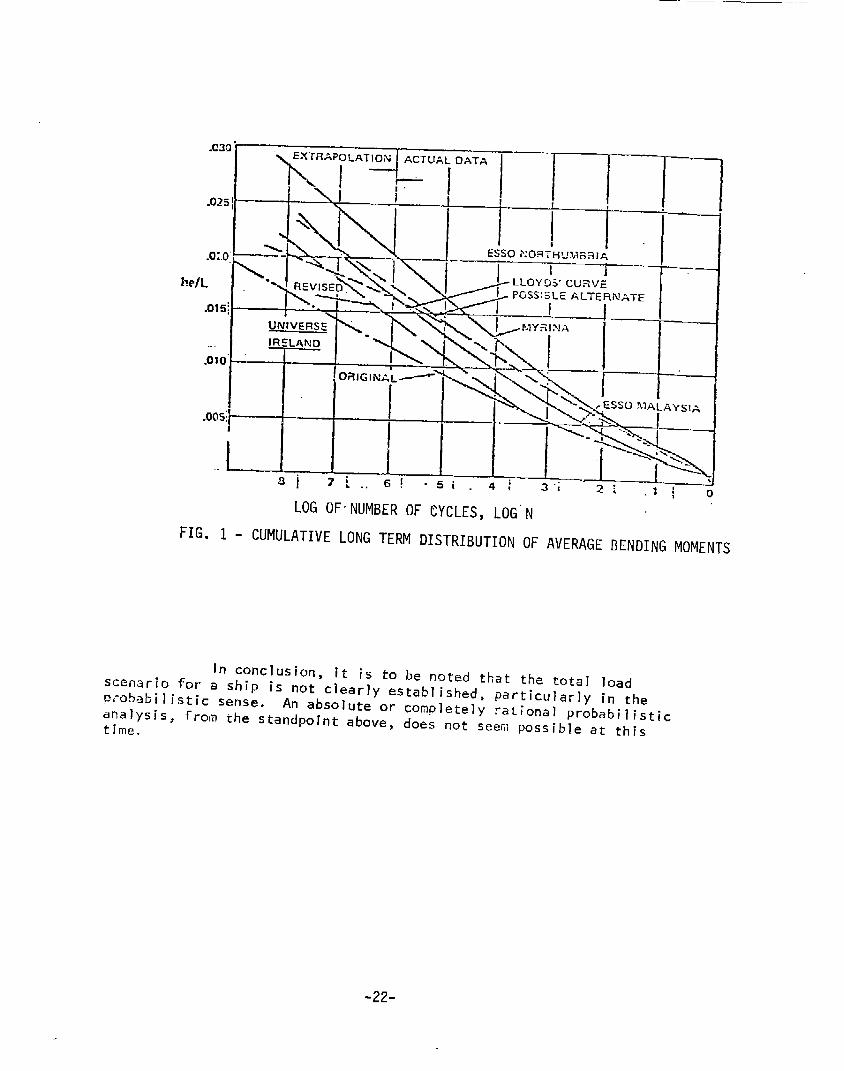
In the measurements presented, thee ffects of springing and whipping. . The results are curves of cumulative long-termdistribution of the averagebendingmomentsWhiCtIshow the probabilities,per cycle of load [27], of exceedingdifferent levels of these bendingnmmentsduring a ship’s lifetime. Figure 1 is an examplereproducedFrom[26].A methodfor converting these loads per cycle to a cumulativeprobability curve for the ship’s lifetime is indicated in [28].Followinqthis procedure, a form of long term distribution mustb: assumed.As discussed in Section 3.4, the different assumedIong-term-distributshapesfit the measureddata differently [10, 60, 61].
Th&redoesnot appear to”’beenoughdata nor any analyticamethod~in the literature for determining the statistical distributionof the other loads mentionedabove. The ship structural reliabilitystudies presented in [1o] assumedboth deterministic and normallydistributed still-water bendingmoments. Reference [29] discussesthecomputationsof waveslammingand springing bendingmomentsin the
on
context of a probabilistic structural a,nalysis, but it is painted out ’thatmuchverification mustbe madewith respect to slammingand springingbefore the procedurescan be used. [t is also noted that with regardto the structural probabilistic analysis, springing and slammingwerenot incorporated although they might easily be.
-21-
I AI--I-11
.015: i \UNIVERSE\
I.010”oalGIN&L~
l--F~sSollA~AysIA
.005: <
L-,.gj 7. ~ -, 6! .5i.4/
LOGOFNUMBEROFCYCLES,LOG”N
FIG. 1 - CUMULATIVELONGTERMDISTRIBUTIONOFAVERAGEBENDINGMOMENTS
In conclusion, it is to be noted that the total loadsceriario for a ship is not clearly established, particularly in theprobabilistic sense. An absolute or completely rational probabilisticanaly~i~, from the standpoint above, does not seem possible at thistime.
-22-

SECTION6.0
PROBABILISTICSTRUCTURALANALYSISOF
SHIPHULLLONGITUDINALSTRENGTH
6.1 General—“
All of the mostessential considerations for probabilistic structuraldesign, discussedin precedingsections, wouldapply to transverse andtorsional hull strength as well as longitudinal. Howevzr, transverse andtorsional hull strength are beyond the scope of this study (Section 2.0).
It is clear that there are significant problems concerning thedata, theory, and techniques that stand in the way of a completely rationalprobabilistic hull girder longitudinal strength analysis. This is to saythat the probabilities of failure from suchan analysis could only be usedin a relative sense; and even then the comparisoncf malesof failuremight be questionable due to possible better input to one modeof failureanalysis than the other.
Other investigators havediscussedthis point. It is stated in[18] that the relative assessmentof probabilities of failure maybe one oftha useful methodsof evaluation of ship structures. In Reference [13], oneof th~ motivations behind the approximateapproachpresentedtherein wasthat “probabilistic analysisofstructuralsafetyfor ships is difficult atthe present time becausethe available data are too limited to provide theexact formsof the probability distributions of the bendingmomentandth~ ship strength.” Reportedly, the samplesize required is of the orderof mllltimil lion pieces of recordsor data [30]. Twomorerecentpapers,[62]and[63], also discuss this point.
Oneother aspect of probabilistic designwhichhas received mentianbut not muchanalysis is the problemof determining the acceptable limitingvalue ~f the. probability of failure. It wasmentionedprevious-lythat thecur-rent level, basedon actual occurrences,wasdeterminedin a study [J5, 59J.
The two emergingproblems, i.e. the lack of available data andtechniquesto performan accurate probability of failure analysis and theabsenceof an acceptable limit to the probability of failure, point to aneed for the following three overall efforts:
0 Continueto develop techniquesan~ obtain data for bothload and strength for probabilistic analysis.
0 Performabsolute probability of failure analyses fordifferent ships, compareand update the results asbetter data and techniquesare developed.
0 Fromthe data presently available on ship failures of alltypes for all types of ships, performsemi-probabilisticanalyses to identify safety factors of current andpast ships.
The first of the abovestructural analysis methodology.
is neededfor the advancementof probabilistic
-23-

The secondis necessaryto obtain results using the latest col]~~teddata and the theoretical and testing methodsin a developinganalysisprocedure, and to comparethese results with what is known and with eachother. Ultimately, the results of sucha procedurecould be used, inconjunction with non-structural aspects, to obtain an acceptable limit forth~ probability of failure. This would lead to the determination of theresulting factors of safety tO be usedby designers.
The third and last effort is neededto reap immediatefruits fromthe probabilistic design approach. AS mentioned earlier, current ]ongjtUdina] ~strength proceduresonly consider ductile yielding of”the hull girder dueto an equivalent wave imposinga vertical bendingmoment. An extensiveanalysis of ships, particularly those that have failed in longitudinalstrength, considering all the modesof failure and using knownloads, canproducea better understandingof whichmodesof failure are most significant,what the factors of safety are for these modes,and possibly indicate trendswith respect to ship type, size, area of operation, etc.
It should be noted that the factor of safety discussed in conjunctionwith the secondeffort above is different from that discussedin the third.Factors of safety that comefroiman exact probabilistic analysis are to bebasedon the exact knowledgeof the load and strength. ‘This would be thecase with the seconditem but in the case of the third, uncertainty concerningthe load and strength would be tied into that sq.fety factor but it should involveless uncertainty than in current procedures. As morebecomesknownaboutthe strength and load, the results of the third item can of course be updated.
The proposedapproachesfor the abovethree areas of effort arepresented below in greater detail.
6.2 Developmentof a.ProbabilisticstructuralAnalysisMethodology
in Sections 3, 4 and 5, the areas were identified where moretheoretical studies need to be performedand data collected from full-scaleexperimental rne’asurernents,These.areas can further be divided into strengthand load distributions, str>h equations, and time-dependentanalyses.
6.2.1 Strength and LoadDistribut@
As discussed in Section 3.0, if the exact form, and themagnitudesof the strength and load distributions are known,it is simpleto determine the probability of failure. The problemis that for bothstrength and load, these distributions do not exist. The problemsfor loadare discussed in Section 5.0, and will not be elaborated uponhere since thisis not the specific area addressedby this project and is being addressedelsewhere [32].
‘In the case of the strength, the procedurehas been tosynthesize the distribution either by estimating only the coefficients of-variation of strength. variables, i.e. constituent parts whosedistributionsare not known,or by makingan assumptionas to what type of distribution thestrength follows. Higher level synthesesdiscussed ih Section 3-3.3 consistof the determination of strength statistics from the assumeddistribution of theccmstituent parts, .frornthe knowndistribution of constituent parts, or the
-24-

cletermil~ationof strength statistics from actual testing. The latter wouldgive the greatest accuracybut, as discussedpreviously, is very nearlyimpossible due to its extent.
6.2.2 Strength”Equations
A simple strength equation for ductile yielding due to bendingof the hull girder is given in Section 3.0, Equation (27). Thewhole structuraldescription rests with equations like these and the variabies they include,.since it is the statistics of these variables whichare Usedtc synthesize theoverall strencjth distribution. Suchan equation can be lacking in the simplifyingassumptionsassociated with its derivation or in the numberof variables itc.dritains. Equationscan have the samesimplifying assumptions,which contributeto subjective uncertainties as discussed in Section 7, but a difercnt number ofvariables, For instance consider the following:
S = f(N,sy) = Nsy (39)
,N= g(D,t .,, B, tw) (40)
s = f[g(a, tf? B, tw)~,sy]=@B+l/3t;,4@sy (4! )
where: N = deck or bottomsection modulusSy= tensile strengthD = section depthB = section beamAf= area of flangesI&e area of webstf= Af12B= equivalent thickness of one flangetw= Aw/22= equivalent thifkness of ot~eweb
-25-

Equation (39) only considers the section modulusand tensile strength and isbasedon the simplifying assumptionsof engineering beamtheory. TOsynthesize a distribution from these, one wouldneedthe statistics of thesection modulusand of the tensile strength. The former wouldbe nearlyimpossible10 obtain accurately since ships or structural modelswouldhave to be tested. By breaking the section modulusinto variables as inEquation (40), the strength also becomescomposedof morevariablesamenableto moredirect scrutiny as far as their statistics are concerned,Equation (41). This can naturally be extendedto muchmoresubtlevarisbles.
The objective of suchan approachis to define all the variableswhich can more easily be measuredand for which statistics can be determined.The methodsdiscussedin Section 3.3.3shouldthen enable one to synthesize,Gnaccurate strength.distrihutlon.
The exampleof Equation (41) is usually intended for elasticbendingof the hull girder as a beam. In the casesof fracture, fatigue,and ultimate strength, moreworkwill probably have to be doneto obtain anaccurate expressionfor hul1 strength for these modesof failure.
6.2.3 Time-DependentStrength Analyses
It wasdiscussedin Section 3.3.4thatthereisnotmuchavailableintheliteratureregardingtime-dependentstrengthsofships.Itis,therefore,suggestedthatresearchbeperformedto developan accuratepi-obability of failure procedurefor the analysis of time-variant shipstrengths, i.e. in the case of fatigue, corrosion, etc.
6.3 Application of Probabilistic Structural Analysis Methodology
6.3.1 General
In order to obtain an immediateand clear idea of ship longitu-dinal strength from the practical standpointsof modesof failure, safetymargins, and probability of failure, the probabilistic structural designapproachcan be usedmost fruitfully in a semi-probabilistic type of analysis.
The semi-probabilistic analysis approachwouldbe the easiestto apply and be consistent with the assumptionsthat Gouldbe necessary.Applyinga morerigorous and time-consumingtechniquewith an equal amountof additional assumptionsmaynot add insight or accuracy, and it mayevendetract from the efforts.
A potential basis for suchan approachhas beenpr$sented in[13].Itisimpliedtherethattheproceduremightactuallytieused instructural design. Fromthe standpoint of a designer, this seemshighlyunlikely in the near future since mostship longitudinal strengthdeterminationsare presently basedon classification society,rules, orspecifications which have beendevelopedthroughyears of experience,and in all likelihood they wouldnot be changeduntil a different approachthat offers advantagecould be established andwell proven.
-26-
However,in the interest of obtaining improvedanalysis methodsand insi~ht, it is important for researchers and designers to have abetter appreciation for the basic structural phenomenaassociated withhull girder longitudinal strength. As pointed out, the present procedureof designing for ductile yielding of the hull girder in vertical bendingmay be mythical in some cases; and only coincidentally, an adequatestrength for other modesof failure mayhave been accounted for.
6.3.2 IdethodofApproach
The “ApproximateProbabilistic Method”of Reference[13]doesi;otrequireassumptionsconcerningthetypesofdistributionfor loadand strength. This methodis a candidate for the semi-probabilisticprobability studies discussedfor the short term. The details of thisprocedureare presented in Section 3.2.3.
The procedurewaspresentedspecifically for vertical bendingof the hull girder as a beam. But it seemsplausible that the approachmight be extended, with somemodification, to other modesof failure.Far the specific purposesof obtaining better knowledgeon morerationalfactors of safety andon critical modesof failure, this procedureyieldsthe safety index as given by Equation (11) of Section 3.0. If thisinciexcan be evaluated for existing ships, including those that havefailed, for various modesof failure, then the safety factors of shiplongitudinal strength will be better understood. The results of limitedanalyses of this type are presented in [13]and[31]foroiltankersand[63]for naval designs. It is of interest to note that Figure 2,reproducedfrom [13], gives an indication of the probability of failurefo~ a given safety- ind~x whendifferent distributions are assumed.
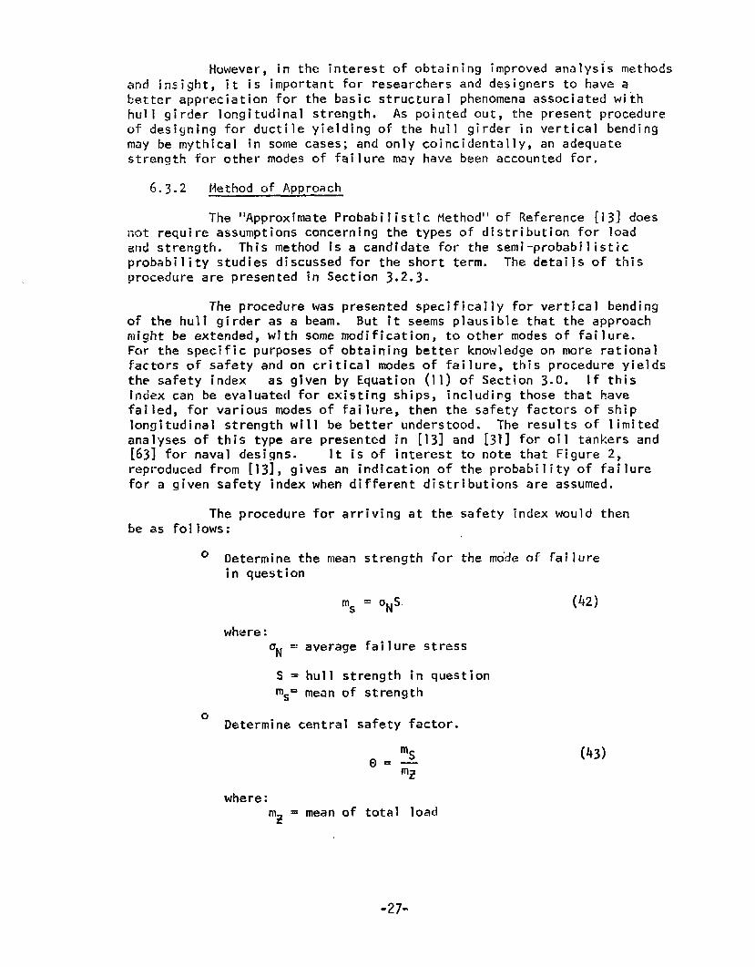
The procedurefor arriving at thebe as follows:
0 Determinethe meanstrength forin question
m5 = ONS
safety indexwould then
the mo”deof failure
(42)
whzre:‘N = average failure stress
S = hull strength in questionms=meanof strength
oDeterminecentral safety factor.
(43)
where:‘z = meanof total load
-27-

- 0.”13- 0.10
s- NORWLz-EXPOSEXTIAL+ eao?.w&
s - NQRK%La- ASY=TOTICEXTRELNS11
s- NOW%Lz-EX7RZHS(n=3)&NOWW
ASYKQTOTXCEXTPE~IhSYKPTOTICEX?REM211
‘,,
..L1 1 I I t1 2 3 4 s 6
SAFETYINDEXv
FIG.. 2 - PROBABILITYOFFAILUREVERSUSTHESAFETYINDEX
0 Ileterminesafetyindex.
where: v~ = Cov
‘z=Cov
The quantitiescalculations of the ship.
(44)
of strength
of load.
ONand S shouldbe obtainable from the designmZcan be determinedby measureddata, emp;rica]
procedures,or by an analytical approachsuchas the one in [!101. A correctionfor loads not consideredby theseapproachesand the COV’Sof loadand strength can be determinedfrom existing data. Anexampleof thisprocedurealong with a computerprogramare presented in Section 8.0.
The safety index Ywill be directly indicative of thesafety factor, and since it will be derived from statistics of boththe load and the strength, for various modesof failure, it will givemuchmore information than the singular approachof current designbasedon vertical bendingonly.
-28-
SECTION7.0
UNCERTAINTIESIN HULLSTRENGTH
7.1 General
As mentionedrepeatedly in the precedingsections, a suitableapproechto ship probabilistic structural analysis requires the determinationof strength variable meansand variances. The ratio of standard deviation tomeanis termedthe coefficient ofvariation or, COV.
The statistical nature of the variables has led to their beingtermed“uncertainties.”
Reference (3] classifies the uncertainties into two types:
o Objective - “Measurableor quantifiable, suchas observedstatistical variabilities and deductive,,probabilisttcinformation.”
o Subjective - “No factual information is available or theuncertainty is not amenableto quantitative descriptionand mustbe described and handledsubjectively on thebasis of judgementand intuition.”
Oncethe means and variances ofuncertainties have beenestablished, they can
%‘mv. = Cov of xwhere:
the objective and subjectivebe combined as follows: ‘
(45)
ll~o= C,OVof objective uncertainties of xVX5= COV of subjective uncertainties of x
7.2 Objective Uncertainties
7.2.1 General-—
The objective uncertainties of the hull longitudinalstrength are divided into three groups: mill practice, shipyard practice,and operational occurrences.
o Mill Practice
- Variation in physical properties of materials includingductile, fatigue and fracture characteristics.
- Variation in material thickness and shapedimensions.
o ShipyardPractice
- Variation5 in material scantlings.-“Variations in fabrication tolerances.- Variation in weldments.- Residual stresses.-initial Deflections
-29-

o Operational Occurrences
- Corrosion- Wear and Tear
With the goal of collecting data for these variousuncertainties, requestswere madeto steel mills-and the-literatuie wassurveyed. Fromthe steel mills, statistical data in the form of eitherd;~tributi~ns, meansand variances, raw data points, or tolerances for atleast the following quantities were requested:
o Tensile, Yield, and Ultimate Strengtho Young’sModulus,TangentModulus,and ShearModuluso Ductilityo CorrosionResistanceo Dimensionsof ManufacturedItems (Plate Thicknesses,Shape
Dimensions,etc.)o Poisson’sRatio
Elevenmajor steel pmdwcers in the U.S. were contacted.The responsesreceived [34] did not include any newdata, but instead madereference to [35] through [39]. Gen&rally speaking,the steel producersindicated that they do not collect the type of data requested. Manufacturingof steels is controlled within the limitations of References[37] and [39].
The literature survey disclosed a numberof pertinentreferences. that are of value. Thesereferences contain information onstrengths, fatigue, corrosion, dimensionalaccuracy, andwelding stresses.
makeuse of crrCOV’5, someofof several COVposs{ble t,o un
Since mostship-related probabilistic structural analysesy a few uncertainties and usually assumevalues for theirthe references cited were used to obtain moreaccurate estimatess. Although there is not an abundance of data, it may beover morenumericalvalues and do morecomprehensivean
s reported here. This work should, thereforejbe continued.amalysis than what
7.2.2
study fell into
o0n
Formsof Existing Data
The data for the uncertainties considered in thisthree categories:
Meansand VariancesData pointsTolerances
For eachof these a different approachwas usedto computethe respective COV.
In the first case the COVcan simply be computed bydividing the square root of the.varian.ce by the mean.,
directly computethewoulddirectly yield
Irl the secondcase, the data points can be used tomeanand variance of the uncertainty, whichof caursethe COV:
-30”

H~=+~%
n
;= : ;-.&~.,N-1
Cov = ;
wh~re: N = number of data pointsx =n n~ data pointp = mean of variable xa;= variance of variable x
III the third case, if it is assumedthat the uncertaintiesarise becauseof manyindividual variables, it can be shownby the “CentralLimit Theorem” that the uncertainties will be normally distributed. [t hasbeendeterminedfor someship-related uncertainties that the tolerance limitscjenerally encompass99.7%of the events [531. For a normally distributedrandomvariable, this correspondsto the following:
(46)
(47)
148)
p+ t~l p+t 1
I !7 -(x-v) 2Pr = ~(x)dx= ~exp[=l—]dx (49)p-tol ~- tol =0.997
~fi~r~: p (x) = probability density function and tol = tolerance limit.
By the changeof variable t = ~,equation (49) reducesto:+2;1
I(50)Pr= , & e~,.{-t2/~)dt = 0.997
.%
E~:uation(50) represents a zero mean,normally distributed processwith astandard deviation o~ 1.0. It is knownthat the .957 probability levelis containedwithin - 3 standard deviation. Therefore;
+tol_+3 (51).—. .0
~ .~ol (52)r
It is mentionedin [54] that tolerance limits are usually taken to be1.lt3u. Consequently,on the basis oftheforeqoing,themean,u,canbechosenfromthecontextandthestandarddeviationc~mputedbydividingthe tolerance by 3.
The uncertainties whichwere analyzedFn groupscorrespondingto the type of data that were avai
are 1isred belowable:
-31-

o Means and Standard Deviations
- Depthof stiffener web [53]- Breadthof stiffener flange [53]- Breadthand length of plate [53]- Yield strength [35]- Tensile strength [35]
Initial deflections in plates [67]o Data Points
- Depthof ship [40]- Beamof ship [40]- Flange breadth [401
, 0 Tolerances
- Depth of ship [40]- Beamof ship [40]- Thicknessof plate (receipt inspection) [40]- Thicknessof plate (undercut) [40]
7.2.3 ~termination of COV.s
The meansand standarddeviations from [35] are presentedi~ Tables 1 through 3 along with the computedCOVS.
II-I the case of the meansand variances available forflange breadth, webdepth, arid length of plate, it is assumedthat the varianceis not a function of the absolute size of the membersince lt is not presentedin t!lis manner. Consequently,the meanand the COVof a dimension“L” aregiven by:
!J = %1,
& =Cov=:
(53)
(54)
Figures 3 through5 give the data baseand expres’!onsfor the uncertainties.
The d~te-rminationsof COVSfrom data points for flangebreadth, ship depth, and ship beamare shownin Tables 4 through6. Notethat the results of Table 4 and .Figure4 agree well in that they bothshowCov around 1%for flarlge breadth. It shouldbe noted that the COVSforship beamand depth are extremely small. Reference [10] assumeda valueof zero which appears reasonable.
The determination of COVSfrom tolerances for shipdepth, ship beam,thickness of plate (receipt inspection), and the thicknessof plate (undercut) are given in Tables 7 throl~gh10.
7.2.4 COV~ FromLiterature Survey
Reference[II] presents someresults for objectiveuncertainties for materials , scantl ings, and manufacturingimperfections.Theseare shownin Table 11,
-32Y.

TABLEI - CARBONSTEELPLATES
TfH21LtSrMSGTtt.OffJctfilTenalteStrength,k.1UrAr+0 60-7G●XC). lo-m2I?Xct. 00*d overr
Wmbrat Tdots ;19 1,119 703 152Offlclal TmstAv.raga,psl 57:J:: 65,)?1 74,513 ah,WAwarag.DOff. r.nce.PSI +$06 ●I5 -367Standardvevlat~m,p-l 1,51? 2,1E%Corn
5,245 3,0s6.020 .0)1 .044 ,016
71[10POIW
OffJclil Y1.ldPol,nl.k,lUnderJO 30-40excl. 40-50.Ilcl. 50andovnr
tJAcrof Tasts 1,26s n!} 16SOfflcl.1r*ttAwr.g*,P*1 18,55 35,65! U,$ll 5s.61GA“eragaDliferrxm,ptr +?3z -lh2 -8,421 -:,:W;Sttnd,rdOaW1.tlcm,PSI 1,711cW
I,67J 3,251.095 .075 .or5 :072
TABLE11- AS-ROLLEDPLATETABLE111- CARBONSTEELWIDEFLANGESHAPES
IiAverageOlfference.PSIS1.ndardD.vl.tlo., psi
IICov
NumberorT.st! 1,170 .“ 150 oFflclalTcitAverage,patOf(lcls!TestWcragt,PST 16.015 “44,R 55,8)6 AVer.9eolffertnca,PITAverageDIlferance,p,! +)0? -196 -360 SI.ndardOev{.tlcm,PSI51.mdirdDevlnLlom,pql 1,020 z,la] 2,171 CovcOv .056 .049 .039...—
TENSIU SIRINGTH I YIELDPoINTIndcr651 65-7o 70LOver Under+0]40-45145-50[ 50.2over
T159 15662:jfl 6>,170
-1,1422,512 2,690
.04 .04f
FLMIGETESTS
IL4 i 1872,?26 37,608-3,357 +1613,632 2,649
.05 .07—~
UEOTESTS—.
311 I1042,19347,011-2,247 -4,11193,600 ]a~a].0a5 .060
160 362 167 111 ]]6 14562,67) 67,182 71,769 37,697 42:~f; 47,010*I ,966 +161 -2,133 +1,344 -6061,627 3,11] 4,257 2,314 z.an3m60J.042 .046 .059 .061 ,ofia .077
.-—.—89
52,497-5,845>,86].074
—— ..
52,5::-2,0154,o69.07?

FIGURE 3
~-ETERMINATIONOF COEFFICIENTOFVARIATION
FORTHEUNCERTAINTY
DEPTHOFSTIFFENERWEE
(Data from reference 53)
-1
.26’mm
ahk =1.98mm
(1)
! -;, I-fi-q-y,r ..—- fl..<.:X1I
-h:X:“-?5.0----——------——–— S.o1:.rwl .-3.0 3.0
~!.2U-2.?0— 5.z2
50
40
m
20
0d-J.-3-2
—
—o
—
1
—
—23
,s213i l.x-a-1.93
k
where:. ~web=: stiffener depth
-34-

where:
FIGURE 4
DETERMINATIOhlOFCOEFFICIENTOFVARIATION
FORTHEUNCERTAINTY
BREADTHOFSTIFFENERFLANGE
(Data from reference 53)
..
..
Is&= 2.18
0.51 + Lflange
(2)
breadth of stiffener flange‘flange=
-35-

FIGURE 5DETERMINATIONOFCOEFFICIENTOFVARIATION
FCJRTHEUNCERTAINTIESBREADTHAND
LENGTHOFPLATE
(Data from reference
- .
‘At = -0.33 mm(breadth of plate)
‘A& =-2.36 ~
= -0.95 nmn(,length of plate)‘AE
‘At = 2.69 mm
53)
fl:I.r!
&L m:=gA~ = 2.69FL ‘~q+fl -0.95 +~L
FL.~]ffj-r.?,> I FL
30 (It!:-s.05 —“ ~!2#
I K
Freauency Distribution —— 4.3920~ For&aJth of PJa~e ,
10 .1
where: $L .=iength “fPL Plate
I ‘1,-ti-7-6...4.~.2-.2-lo ] 2 3 4 5 6 ? R 9
[J:i
-1” -6.33 **2- .4.43
,Frequency Distributionm. n .Fo~L~~gth Of plate
10.“I-36-
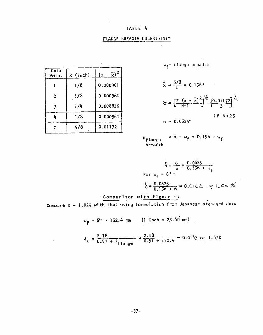
.—Data
l?~int
1
2
3
4—.-
E.——
—— .—
x (inch)
1/8
1;8
1/4
1/8
5/8.—
TABLE 4
FLANGEBREADTHUNCERTAINTY
(x- ;)2——.0.000961
0.000961
0.008836
0.000961
0.01172
flange breadth
5/8—-= 0.1561’4
if N<250.0625’1
‘flange=
breadth
*
x-l-l+f = o.156+wf
For Wf = 6“ :
Comparison with Figure 4:CompareA ~ 1.02% with that using formulation from Japanese standard data
‘f~ @t = 152.4 mm (1 inch = 25-46
= 2.180.51 + 152.4 =
mm}
0.0143or 1.43%
“37-
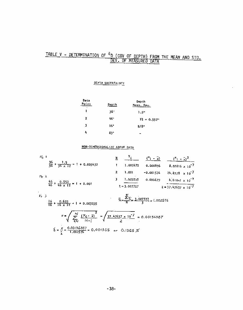
. ..T
TABLEV - DETERMINATIOriOF6D(COVOFDEPTH)FROMTHEMEANANDSTD.DEV.OFMEASUREDDATA
Data
DEPTHUNCERTAINTY—
DepthPaint
.%@ Hess’. I)ev.
1 36‘ 1.5”2 46’ 1%= 0.55211
3 16’ 5/8”4 83‘
NON-DIHENSIONALIZEABOVEDATA
P&1 N Yi— [xi
- a
S+* = 1 + 0.003472 I 1.003472 0.0008962 1.001 -0.001576
8.02816~ 10-724.8378x 10⁻⁷
p~. 23 1.G03255 o.ooG67y 4;610+I X 10-7
.—= 1 + 0.001~g+g;5;21=3.007727 z=~
r+ 3#L3.007727 ./,902576
$+ ~ * I + 0.003255
.=[~ ./+ ;.00,3,,8,
&=~=o;o:o;;;% 0.0D13G5O. 0.!365%x
-38-

TABLEVI- ‘B(COVOFBEAM)FROMTHEMEANANDSTDDEV.OFMEASUREDDATA
Data Point #1
55’+ 2!Iw- 55x 12
DataPoint #2
Data BeainPoint Beam He.asurecl llev.
,.— 55‘ +-=,,,? (2ships - measureddata)
2 95’ 0.1%or 1.14”
3 75‘ 1/2”
4 i4s’ -4”
NCIN-DIHEN510NA1.IZEA30’JED.4TA— ——--
DataPoint:3
~ 0.003 75’+ 0.5L 1 75‘ 75x 12= 1+ .000555
DataPoint1#1
1.1425+.—.= 145’ 41 1. 0.001 w --—-=1-95
0.00229955x 12 145x 12
~ xi (xi -~) (xi -11,2=6
1 1.001 0.001z481.5575x 10
0.6448X 10-62 1.000555 0.000803-6
0.9977013 -0.002051 4.2o66X 10-6
z-2.999256 z=6.4089X 10n
Exix =—= 2.999256= 0.999752N — 3
“=Fs”d”408~x‘f6=0-oO’7’0‘“~:’g;:;;;=o‘-’’”%“39-

TABLE 7
Data Tol .Point (Inch)
1 “ 1/4”
2 1/2”
3 0.1%
4 1/2%
5 3/8
6 1/2
,-. -.— .—— .- -
UN
(Fe~t)
0.00694
0.0139
0.012
0.0139
0.0104
0.0139
ERTAINTY- DEPTHOF SHIP
~
2C.O 0.000347
36.0 0.000386
36..0 I 0.000333
26.01
0.000535
50.0 I 0.000278
——
L-uvg.= 0:’2:
-40-
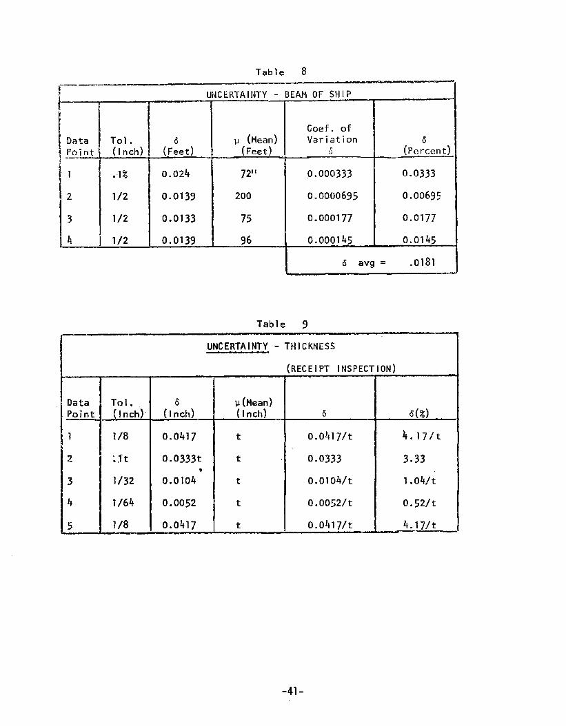
Table 8.— ——— .—s
UNCERTAINTY- BEAMOFSHIP
IT(~ee~, I :
Coef ofp (Mean) Variation
I ~o;nt (In;h) (F~et) 3 (Pe~cent)—..—$
111
i .1% 0.024 ~~1, 0.000333 0.0333
2 1/2 0.0139 200 0.0000695 0.0069s
3 1/2 0.0133 75 0.000177 0.0177
4 1/2 0.0139 96 0.000145— 0.0145II 6 Wg = .0181
Table 9.—,—
UNCERTAINTY- THICKNESS
(RECEIPTinspection)
~~ i“
Point..—1
2
3
4
5
+-1/8
I0.0417
;J”t Io.0333t
1/32 0.0104’
1/64 I 0.0052
]/8 I 0.0417
p (Mean)(Inch)
t
t
t
t
t
6
o.0417/t
0.0333
o.olo4/t
O.oowt
o.0417/t
d(%)4.17/t
3*33
1 .04/t
o.52/t
4.17/t.——
-41-

TABLE 10
UNCERTAINTY- THICKNESS.— —. ——.
—
DataPoint——
1
2
3
4
5
6
Tol ., (Inch)
1132
1/16
1/32
1/32
1!32
1/32
1/15
1/32
1/16.——
_ (I n~h)
0.0104
0.0625
0.0104
0.104
0.0104
0.0104
0.0625
0.0104
0.0625
v (Mean)(Inch)
t
t
t
t
t
t
t
“t
t——.———
(UNDERCUT)—.
6
o.loVt
o.0625/t
o.olo4/t
o.olo4/t
o.olo4/t
o-olo4/t
f).0625/t
o.olo4/t
o.0625/t———
-42-
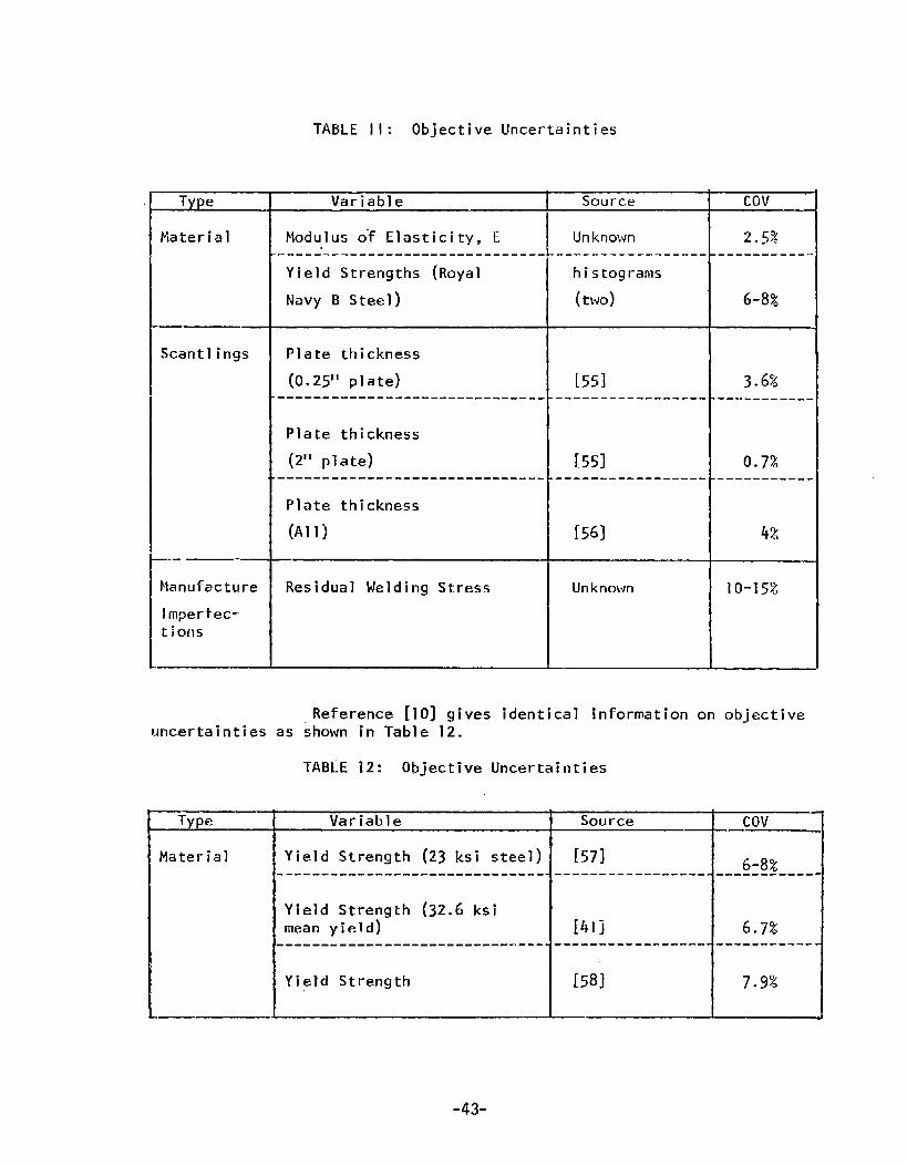
TABLE11: Objective Uncertainties
Tv~e
Material
Scantlings
—
Manufacture
lmperfec-tiarls
———
Variable
Moduluso-f Elasticity, E------------.-----------------Yield Strengths (Royal
NavyB Steel)
Plate thickness
(0.25” plate).-- - -- -- -. - - - - -- - _- ___--- _-- - .
Plate thickness(2” plate)
---- - - - - - - -- - -- - -- -- - - --- - - - - .
Plate thickness(All)
Residual WeldingStress
Source
Unknown. -+-- . -- - --------
histograms(two)
[551--------- ----- ---
[551. - -- - - . -- -- --- . - .
[56]
Unknown
Cov
2.5%---------- .
6-8%
3.6%. - -- ----- - .
0.72------- - - - .
4%
10-15%
Reference [10] gives identical information on objectiveuncertainties as ~hownin Table 12.
TABiE12: Objective Uncertainties
TVDe
Material
Variable
Yield Strength (23 ksi steel)- - - -- - --- -- - - - -- - ---- --- -- - - -
Yield Strength (32.6 ksimeanyield)-- - --- - - -- . -- -- -- - - - -- - - . - - - -
Yield Strength
Source
[571,----------- - -- - -
[41]!-- -- - - -- - - - - - - - -
[58]
Cov
6-8%.“-- - - - -- - -
6.7%.- - - -- -- - --
7.9%

Reference[67] gives information on initial lateral deflections inplating in the bottom of a universal bulk carrier and a tanker as shownin?ahle 12-A. It was shownby analysis of the histogramsby the X2 - criteriathat the initial defections obey a GaussianlaIw.
shiptypE— .—
UBC-.—-
Tanker. —— .
Dead Ia TyPeofweight ~ IStructure (m;)
25,000 I 2.0 I bottom 118
100,000 I’”’H
5UBJECT.—
‘T–-T–-”—r————
37.5 I 1.41810.136 I 0.0618
TABLE 13
VEUNCERTANTIES[II]-—.
k]dnOf Fai]ure——.—.-.,..— — —. .—.,,——...—.—--
“ensionyield . . . .** ● * . . . . . . . . .** . . . . .
‘late Buck’
Strut
Be-am
ing
Panel -
\. . . ...** .****.. . .
Column
;rlllage B“ucklinq. ..*..... .-..***= ● **-*
.“——.—
-—
Ship bending~
3
4
4
.—
,-.—
q‘~,
-F--<.-.
0.15—. -0.43
F4;—.
Grossf’ane]?:~— — .—.—.——0
* C.O.V. of subjective uncertainties in strength arising from ship bendingactions. (%)
-,.J-
●. . . C.o.v.ofStibjective Uncertainties in strength arising frolmgross pa~elactions. [%)
-44-

7.3 Subjective Uncertainties
The subjective uncertainties, quoting from [3], “includethe non~neasurable inaccuracies of engineering analyses, any non-measuredvariances of construction and fabrication, and the unavoidable and non-dc+terminable errors associated with the prediction of future conditions.”
In Reference [10], which contains ship longitudinalstrength analyses, for tensile yield ductile bending and inelasticcompression buckling, the COVof the subjective uncertainties was takenas 3%and 5% respectively. In the case of bending, the uncertainty wasattributed to:
II 1. The use of the simple beam theory which is based on Navierhypothesis. This hypothesisexcludes any shear lag orshear deformation effects.
2. The presence of small cutouts and openings in the deck.3- The residual stresses due to welding.h. The cracks, voids, and other flaws in the material.’!
For buckling, in addition to the above, the’uncertaintyin initial deflections of the plate was added. No mention of how thet.~,~certainties were specifically determined is made.
In Reference [11], subjective uncertainties are given forvariatis strengths, including ultimate tension, bending, and compressionfai~ure due to plate and grillage buckling. The discussion therein~~~e~ a nljmher of references from which data was obtained and the Ccvlsestimated. The results are presented-in Table 13.
7.4 Conclusions
Future efforts, in the long and short terms, shouldbe directed towards identifying and quantifying more uncertainties. Hostsubjective uncertainties are really “as-yet-unquantified” objectiveuncertainties. They possess the property of being Ineasllrable althoughdata may not exist or may be sparse and difficult to locate.
The data presented herein verifies thie assumption in theliterature that the variability in principal ship dimensions is small.The additional results for material yield strength also agree well withwhat has beer] presented before.
-45-

SECTI’OIJ8.0
SAMPLECALCULATIONS
8.1 General
[t was stated in Section 6.3.2 that the “ApproximateProbabilisticStructural Analysis Method”of Reference [13] can be used to obtain more in-sight into ship hull longitudinal strength throughdetermination of the safetyindex, Y“.
In this section, the methodis applied to the ten differentships in vertical hull bendingmodeof failure whichwere analyzed using themethodfound in Reference [3”1]. Table 14, reproduced fron this reference, givesthe input data and the safety index results.
TITis section presents a computeralgorithm whichembodiesthe subjectmethod. An equation for the strength COVfor ductile yield vertical bendingis developedin terms”o,f the COV’Sof the uncertainties. Results of the com-putations with the computeralgorithm are presentedfor nine ships using thedata from Table ]4. In the casdof Ship #10, the formula developedhereinfor the strength COVis utilized along with the ramainingdata of Table 14 toobtain the safety index.
8.2 Canputer Algorithm
The computeralgorithm represents the canputational sequenceof Equa-tions thru (44) of Section 6.3,2. Within this framework,all quantities inthe e~uations are input. However,in the case of the strength COV,theoptionexists of evaluating it from the strength COVequation and the input COV’SofTI-W.strel~gth unc~rtainties.
The algorithm is structured as shownin Figure 6. The main programconsists of Equations (42) thru (44) noted above. The subroutinesfoi- thestrength COV’Sare basedon individual derivation of the strength COVdeterminedby the techniquegiven by Equation (26) of Section 3.3..3 ~nd the strength equa-tion. Only the ductile yielding of the hull girder due to vertical bendingisconsideredhere. Equation (20) of Settion 3.3.3 is the strength equation forthis modeof failurq of the hull girder. If the areas of the flange and theweb, Af and Aw, at-e respectively expressedas functions of additional variables,the following equationswould result:
Af = 2[Btd+Mft5(tv,,+tf,)] (55)
Aw= 4[Dtw-I-Mw(kiti2+lf2)] “(56)
[DBtd+DMft~(~w,+gf, )+(2/3) D2tw (57)
+(2/3)DMwt@v,2+tf2) ISy
-46-

26
,.-.—= ..—-:SHII’
——.——
1
z
3
4
5
6
7
8
~
10—.—
NOTE-..— .;7
——.~,Bp
(ft)
F’
(ft:ton) ‘:—. —
594.00
656.20
700.65
719.10
754.70
775.00
800.00
206,000
328,500
396,500
357,500
519,500
610,000
613,500
1,000.00 1,474-,500’
I1,069.25 1,718,300
L,076.00 1,906,500
(f;-ton);’
34,500
42,500
51,500
48,850
60,500
61,000
65,500
113,250
118,400
131,400
Vz
0.1595
O.ldoo
0.1402
0.1444
0.1325
0.1229
Om~268
0.1105
0.1068“
0.1068
TABLE14: “APPROXIMATEPROBABILISTICMETHOD”(input and Results from Reference [31])
m = Meanof Still Water Bending MomentA = Average Value of LongTermWaveBendingMomentAssumed:m~= m+A
-47-
7 —
5.619
5.840
5.796
5.769
5.993
5.856
6.10:
6.152
6.279
6.314

—.
INPUTFor i=], . . . . ..s
Si, aNijm~i, ~Ei, 6i””””3-IN* Ai
J-——MAIN
J~ 2+Ai2‘i
m~i = uNiSi
rolJrPuTYi
-1HULLDUCTILEYIELDING
Is51 = fl(dll””””dlN)
HULLULTIMATE* ~
%2 = fz(dz]””””dzt~)
-1-HULLFATIGUE
d~~= f3(~31”-” ’d3N)
r —.— —-.4 .HULLBUCKLING
d~h= f4(~h~-”””d4N)
OTHERTIMEDEPENDENTSTRENGTHS
Figure 6: “ApproximateProbabilistic Method”Algorithm
-48-
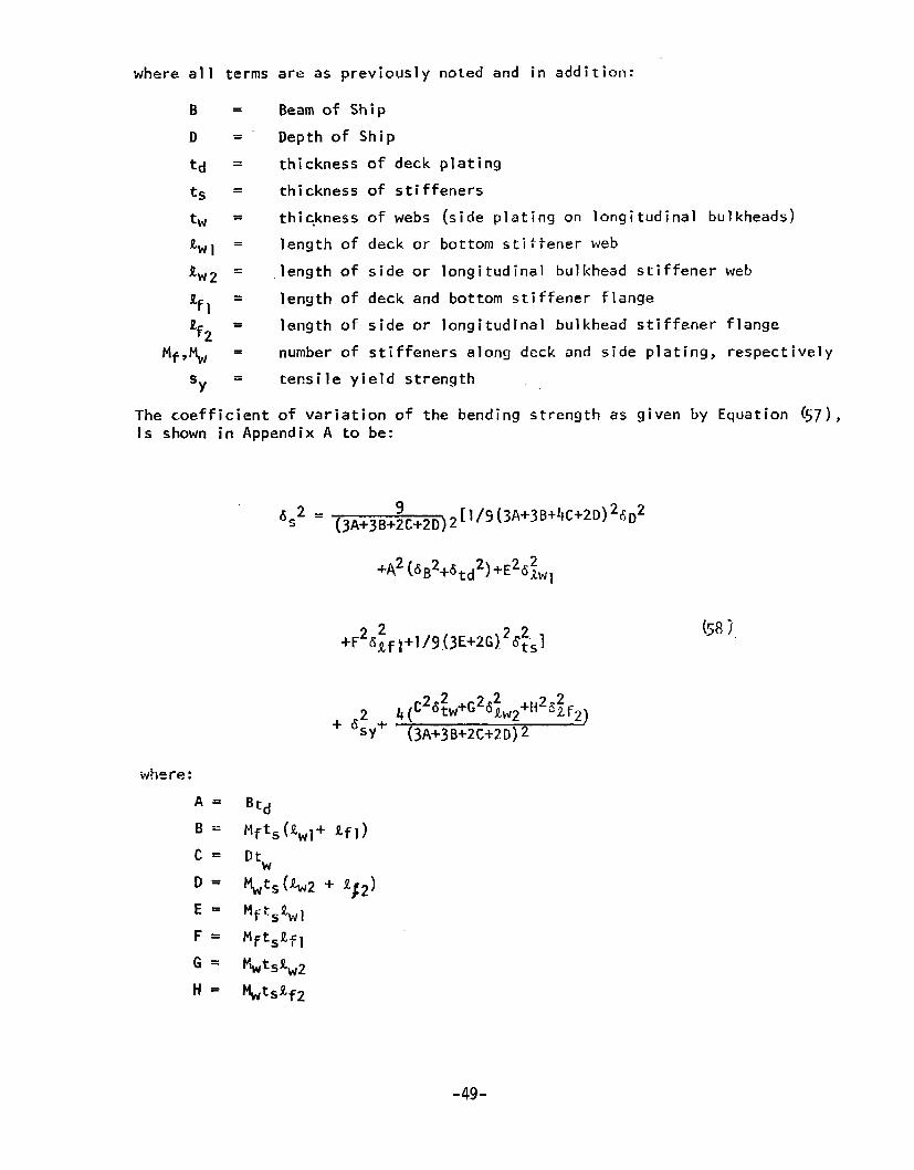
where al 1 terms are as previously noted and in addition:
B = Beamof ShipD .= Depthof Shipt~ = thickness of deck platingts = thickness of stiffeners
t~ = thickness of webs (side plating on longitudinal bulkheads)Lw, = length of deckor bottomstiffener webtw~ = length of side or longitudinal bulkheadstiffener web
~f1 = length of deck and bottomstiffener flangeaf2 = length of side or longitudinal bulkheadstiffener flange
Mf,~ = numberof stiffeners along deckand side plating, respectively
‘Y = tensile yield strength
The coefficient of variation of the bendingstrength as given by Equation (57),is shownin AppendixA to be:
6S2= (3A+3B+~C+2D)~[1/5 (3A+3B+4c+2D)2~D2
+~2(dB2+dtd2)+E26~w1
-49-
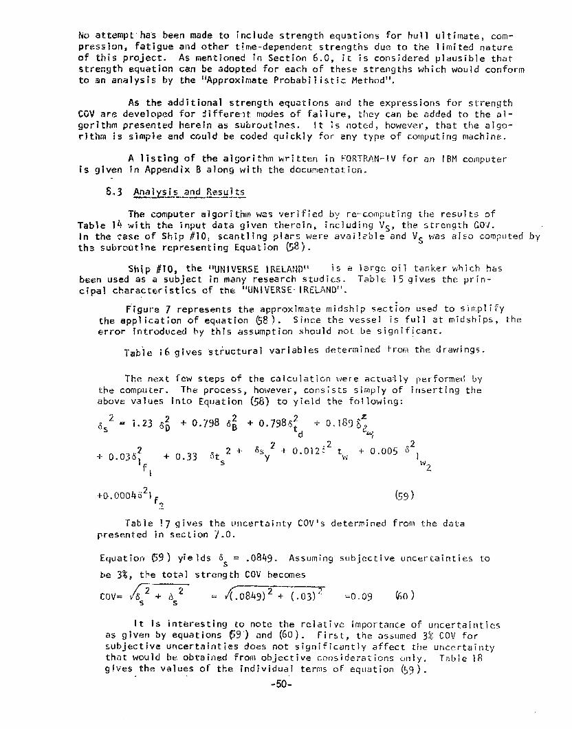
hicIattemptha”sbeen madetO include strength equations for hull ultimate, cclm-pression, fatigue and other time-dependentstrengths due to the limited natureof this project. As mentionedin Section 6.c, it is consideredplausible thatstre~gth equation can be adoptedfor eachof these stre~gths whichwouldconformto an analysis by the “Approximate Probabilistic Method”.
AS the additional strength equations and the expressionsfor strengthCGVare developedfor differe~t modesof faili~re, t!ley can be addedto the al-gcrithm presentedherein as suhrout!nes. It IS noted, however,that the alqc]-rithm 15
isgiven
5*3
Table 14
simple and could be codedquickly for any type of computingmachine.
A listingaf thealgorithmwrittenirrFORT’RAH-IVforan IBMcomputerin AppendixB along with the docu.ment.ati~rl.
Analysi~,~~l@ul IS
The computera“lgoriti-rmwasverified by re-ccmputirrgthe result~ ofwith the input data given therein, including Vc, thz strength GO’J.
In the case of Ship ~10, scan~ling plars were avai?=~le-andV~ wasalso computedbyth~ s.ubrairtinerepresenting Equation(58).
ship #lo, the IIU~jV~~s~ lREL/A.?~D”is a large oil tafiker which hasbserrusedas a subject in many research studi~s. Tabls 15gives the prirl-cipal ch.aracteristlcsofthe“UNIVERSElREL~ND”.
Figure7 representstheapproximatemidship5ect~orItisedtosimplifytheapplicationofeqdation(58).Since the vessel is full at midships, theerror- introducedby this assumptionshould not be significant.
Table i6 gives structural variables determinedfrom the drawings.
The next few steps of the calculatiGrr were actually performedbythe computer. The process, however, consists simply of inserting theabove values into Equation (58) to yield the following:
+0.0C04521F (59)9,-Table !7 gives the uncertainty COV’Sdeterminedfrom the data
presented in section 7.0.
Equation (59) yields 8S = .0849. Assumingsubjective uncertainties tohe 3%, tbe totaI strength COVbeccmes
n—”— ‘“-C(IV= i’&5 + Asz = ~084g)2 -r- (,o~)~ =0.09 &dl)
It is interesting to note the relative importance of u~lcertaintiesas given by equations 69’) and (6c)). First, the a~~umed3%Co\] forsubjective uncertainties does not significantly affect the urlcertaintythat would be obtained from objective csnsidei-ationsu,nly. Table 18gives the values of the individual terms OF eqUation {~~).
-50-
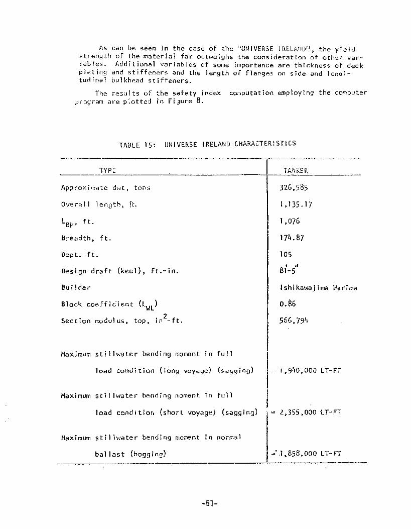
As can be seen in the case of the “UNIVERSElRELAflD”, theyieldstrength of the material far outweighs the consideration of other var-iatlles, Additional variables of some importance are thickness of deckpldting and :jtiffen~rS and the length of flanges on side and lonni-turlinal bulkhead stiffeners.
Tt;e resijl~s of the safety index computation employing the comptiterpr>gram are piotted in Fi~ure 8.
TABLE15: UNIVERSEIRELANDCHARACTERISTICS
TYP:——.— -——. .-—— —
Apgroxif::ate dwt, ton:+
Overall Iengkb, H.
~Bp, ft.
Breadth, ft.
Dept. ft.
Design draft (keel), ft.-in.
8uilder
i310ck coefficient (LWL)
Section rra~ulus, top, in2-ft.
Maximumstillwaterbending~iom~nt in
load cond”iticm (long voyage)
Fhximum stillwater bending moment in
full
(sagging)
full
load conclitior, (short voyagej [saggi~g)
Maximum stillwater bending moment in noi-fial
ballast (hogging).
—— .—
326,585
1,135.17
1,076
1?4.87
IshikawajirnaHarima
0.86
556,794
= l,~&0,00CI LT-FT
I= ,2,355,000“u-i-r
=“J,858,000 LT-FT.- ,-- --- —. .-
-51-
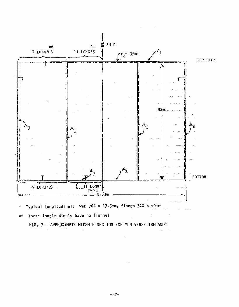
If.. >,:;!: GSHIPITLONG’LS 11 LONG’$ “I ‘1
~~i p=35mm
L
TOP DECK—.~––– II–-––– ‘ ----- 1– - –––––-r
1A\ 1,
II11“
II
*+
I!I
1“ It ‘- -..’J--’‘1 I r .. ..1i I .- .,.. I1“ I ..# 1 I
I “’ 32m... . . . I, I [
II .I “.
T?-LI L,+ I ~6
I ‘3 I ‘b Id5 IJ-
‘1. . I 1,1. I I ‘ “’- ““”[
L T .<[”,=? “1. 1 ~“,
1 - ----i --‘1 ““ 1“ 1 i.. ~’ ,’ : I.-1 I I t“ ““’tI “-; 4 I ....I A7i“ II ~~--- ‘i 130TTOM1~—
L.15-— ..11[o=
-+: ? ““53 “m --* Typical longitudinal: Web764 x 17.5mm, flame 328x !Opm . . ,..,.L A. . ,. Theselongitudinalhavenoflanges
FIG.7-APPROXIMATEMIDSHIPSE~TIONFOR“UNIVERSEIRELAND”
-52-

4Ia
x
P
mC-4
.
xa
●
“o.w
00 .u
a)c1,%
●
Iilx
w ““
* %rno
. m
II E..
II II~-a -“”
II II II 11II
-** ● ✎ ● u-l4
— — —--—— .
I
I
.0E
LnW0
Ii
.
,0
-———
-53-

J‘-—--”–-–-””-—–”--.-—-—-----––—–––-azm WI3 -I
000
“m”
“’-----
-54-

SECTION9.0
~O}lCLUSIONS
The conclusions reached in the courseof this study are summarizedbelowunder the major subheadings from which they were derived.
General Probabilistic Structural Analysis:
o t4echanical, Civil, and Ship probabilistic analyses of structurehave all utilized similar methods which differ in the assumptionsconcerningload and strength distributions.
o Strengths can be described from knowndistributions, synthesizedfrom known distributions of constituent parts, synthesized fromassumeddistribution of constituent parts, or synthesized in termsof meansand,variancesfrom those of the constituent parts. Thesccuracydecreasesfromtheformertothelatterapproaches.
o Sinceprobabilityoffailure,marginofsafety,andreliabilityinvolveintegrationunderthetailsofdistributioncurves= theshapesof
O Notmuchdependent
ModesofFai
th~ distribution maybe important.
s available in the literature c~ncerning timestrength”analyses in general.
ure:—.
o The most significant mode of failure of ship hulls from a lonqitudstrengthstandpointisnotknown.The probable modesinclude ductyield bendingof the hull as a free-free beam,ultimate plastic co’buckling, fatigue and fracture.
o Modes of failure may vary according to ship type, size, etc.
o Local stresses must be superimposed on primary stresses whenconsidering modes of failure i.e. principal stresses must beknown.
o The lack of knowledge of ship modes of failure for longitudinalstrength point to the need to obtain more insight into these typesof failures to be better able to establish guidelines for new a~dstructurallydifferentshipsofthefuture.
Loadings
o The total load scenario for a ship at sea is not clearly known interms of statistical distributions-
Structure Statistics:
na1lelapse
o Strength and uncertainty distributions for ships are not availableexcept for limited cases of the latter. Assumptions are made inanalyzing individual structures.
-55-

o Strength statistics in terms of means and variations have beengznerated for ships usincjan approximatemethod to obtain themean and variance from those of the u~certainties in the strength.
o Little has been done with strenqths other than static bendingstrength and plate buckling strength.
Strenqth Uncertainties:
o It is difficult to obtain data on strength uncertainties.
o Dimensional uncertain’appear negligible.
o “Strength variations inappear significant.
es in principal characteristics of ships
yield and tensile properties of steels
o It is difficult to estimate subjective uncertainties; not muchdata.are available.
o Uncertainty statistics can be obtained from tolerances in production.
,ShipAnalyses:.—
0
Most ship probabilistic structural analyses have been concernedwith vertical bending and yielding.
Due to the lack of statistics concerning ship stregths and loads,the development of an analysis approach which does not require adistribution shape appears warranted. This would, therefore,be askmi-probabilistic approach.
Analyses using an approachof thela~ter type could be used tocomparepastandpresentdesigns,modes of failure, etc, ,to obtainmore insight into ship longitudinal strength.
-56-

SECTION10.0
RECOMMENDATIONS
An overallrecorrunendationis that investigations should continuein the area of ship longitudinal strength so that any structurallydifferent ship of the future can be properly designed with confidence.Although the probabilistic structural analysis of ships will probablyhave to remain at a moreor less simplistic orsemi-probabilistic levelfor the near future due to lack of methodsand data, the efforts to im-prove the approachshouldnevertheless be undertakenif technology isto Forge ahead.
Somespecific recommendationsare presentedbelow for both theshort-and long-term goals:
LongTerm——
o Continueto develop techniques and obtain data forboth load and strength for probabilistic analysis.
0 Performclassical probability of failure analysesfor different ships; compare and update the resultsas better data and techniques are developed
Strength and LoadDistributions:
o Determineconclusively whether it would be practicalor not to determine strength distributions from smallscale structural models.
0 Obtain accurate coefficient of ‘var!ation estimatesfor strength variables.
0 Synthesize strength distributions using coefficientsof variationofstrengthvariablesand assumeddis-tributions of these variables.
0 Determinethe exact distributions of strength vari-ables and synthesize strength distributions by themethods,discussedearlier, to obtain a moreaccuratedistribution than otherwise-available with the assumeddistribution approach.
“ Determinetions are
Strength Equations:
whether or not specific tabulated distribu-accurate for ship strengths.
0 Developaccurate strength formulas for hull f~ilure inductile beambending, compressionbuckling, ultimate
-57-

strength failure, fracture and fatigue.
0 Incorporate into these formulasas manyuncertaintyvariables as possible.
Time-DependentAnalyses:
0 Developan accurate probability of failure procedureforthe analysis of time-variant ship strengths for the casesof fatigue, corrosion, etc.
Short Term
o Using acomp1ex’analyzehave fa’
probabilistic structural analysis methodofty consistent with required assumptions,past and current ships, including those thatled in longitudinal strength, for various modes
of failure. This methodshouldembodya semi-probabilisticapproach. Determinethe correspondingsafety factors.
0 Compareresults of the analyses to gain more insightinto ship longitudinal strength.
ACKNOWLEDGEMENT
The authors wish to acknowledgethe contributions of others in theperformanceof this study.
At M. Rosenblatt & Son, Inc. Messrs. RoyRuszkowskiand Walter Luand Ms. MeigeHsuhave been involved in the initial stages of work.
Mr. JohnDalzell of the DavidsonLaboratory (Stevens Institute ofTechnology)aided the effort as a consultant.
The reviews, commentsand the general guidanceprovided by membersof the ad-hoc Project Advisory Committeeare acknowledgedwith thanks.
Thanksare also due to Professor E.V. Lewis for the useful commentshe provided and to the steel producers (BethlehemSteel, Inland Steel,Ryerson& Son, United States Steel Corp.) whoprovided input on strengthuncertainties at the mill.
-58-

SECTION11.0i?EFERENCES——
(1) Freudenthal,A.M., “TheSafety of Structures”, Trans. ASCE,Vol. 112,1947.
(2) $hinozuka,M.,“ApplicationofScholastic?rocessestoFatigue,Creepand Catastrophic Fai]Llr~S”, ColumbiaUniversity, ls166.
(3) Ang, 14.. H-S, llExtend5d Reliabi~ iry ~~~is of Structural DesignUnderUncertainties”, ProceedingsSAE/AMA/ASME,Ninth Reliability and Main-tainability Conference,1970.
(4) Ang, A.,H-S, “Structural Risk Analysis and Reliability BasedDesign”,, Journal qf the Structural DivisionofASCE,Vol. 99,No.st.9,1973.
Ang, A. H-S, “A ComprehensiveBasis For Reliability Analysis and Design”,Reliability Approachin Structural Engineering, tlaruzenCo., Tokyo, Japan,1975.
Freucienthal, A. M., “Structural 5afety, Reliability and Risk Assessment”,GeorgeWashingtonUniversity, Tech. Report No. 20, 1974.
Kececioglu, D., McKinley, J.M. and Saroni, M.J., “A Probabilistic Methodof DesigningSpecified Reliabilities into MechanicalComponentwith TimeDependentStress and Strength Distribution”, NASAReport, University ofArizona, 1967.
Kececioglu, D., “Mechan
Kececioglu, D., “MechanP4P/76,1976.———Ma~sour,,1.. “Probabil
calReliability”, ProceedingsPLP?76,1976.
cal Failure Prevention Via Prediction”, Proceedings—.
stic Dl?siCnConcepts!n Ship Structu~al Safetyand Reliability”, Trans. SNAME,1972.
14ansour,A. and Faulkner, D., “OnApplying the Statistical ApproachtoExtremeSea Loadsand Ship Hull Strength”, RINA, 1972.
.Mansour,A., “Methodsof Computingthe Probability of Failure UnderEx;-treme Values of BendingMoment”,JSR, 1972.
Manscwr,A., “ApproximateProbabilistic Hethodof Calculating Ship Longi-tudinal Strength”,
Jensen, J. and Pedersen,P., “TheEffect of Non-Linearities of the,Probability bf Failure of Ship Structures”,DanishCenterfor AppliedMathematicsand MechanicsReport No. 122, August1977.
Dalzell, J. F.,informal Note on “Probability of Ship Failures”.
Chatfield, C.: “Statistic for Technology”;PenguinBooks, 1970.
!3ratt, M.J., Reethof, G. andWeber,G.W., “Modelfor TimeVarying andInterfering Stress-Strength Probability Density Distributions withConsideration for Failure Incidenceand Property Degradation”, sAE/ASME/AIAA,Aerospace-Reliability and Maintainability Conference,Washington,D.C., 1964.
.—.
-59-

(?8) Akita, et al. , “Desigri Procedlire :.,sei on Reliability Analysis ofShip Structure”, Naval Archi~.ect~re ~nd Ocean Engineering”, Volume 15,.——.—. ..—.—-- .. .--—1977, SNAJ.
(19)Nitta, A., ‘~Reliability Analysis on the Fatigue Strength of Ship Struc-tlJreSi”, I W D O C. tdO.XIII-797-76, Transactions of Nippon Kaiji Kyokai,No. 155 (1976).
—
(20) Lewis, E.V., “Prediction Long-Term Distributions of Wave Induced BendingMoment on Snip Hulls, SNAME, Lpring P!eeting, lg67.
(21) Nibbering, J.J.W.,“Permissible Stresses and Their Limitations”, 5sc-206,1970.
(22) Caldwell, J. B., “Ultimate Longitudinal Strength”, Trans. RINA, Vol. 107,1965.
(23) Comment to Reference (22) by J.M. Murry
(24) Comment to Reference (22) by E.V. Lewis
(25) Little, R. S., Lewis, E.V. and Bailey, F. C., “A Statistical Study of~Jave-induced Bending Moments on Large Oceangoing Tanker and BulkCarriers”, Trans. SNAME,,1971.
(2~} Lewis, E.V. and Zubaly, R.B., “Dynamic Loading Due to Wavesand ShipMotions”, SNAt4EShip Structure Symposium, 1975.
(27) Lew?s,E.V., “Ship Structural Design for Extrernt. Loads”, Schiffstechnik, 1976.
(28) Zuk.sly, R.B. and Lewis, E.V., “SupplementaryMemoon Ship Structural Designfcr Fxtreme Loads”. Webb Institute, 1977.
(29) Stiansen, S.G. and Mansour,A.E., “Ship Primary Strength Based on StatisticalData Analysis”, Trans SNAM~,1975.
(30)Cornell, C.A., “A First Order Reliability Theory for Structural Design”,StudyNumber3,Structural Reliability and Codified Design, University ofWaterloo, 1970.
(31)Mansour,A. andEvans, J.H., “Criteria For the Designof Primary ShipStructure”, MIT Report No. 73-23, 1973.
(32) Dalzell, J. F., Manler, N. M., and tisu, M.W., “Examination of Service andStress Date of Three Ships for Development of Hull Girder LoadCriteria”,SSC-287,1979.
(33)Moses,F. and Stahl, B., “Reliability Analysis Format for OffshoreStructures”, OTC Proceedings,1978,Vol.1,page29.—-
(34)PrivateCorrespondencebetweenBethlehemSteelCorporation,tniandSteelCorporation, Joseph T. Ryerson and Son, Inc., United States Steel Corpor-ation and M. Rosenblatt & Son, Inc.., 1977.
(35!‘Vrhe Variation of Product Analysis and Tensile Properties, Carbon SteelPlates and Side Flange Shapes”, American Iron and Steel Institute,September1974.
-60-
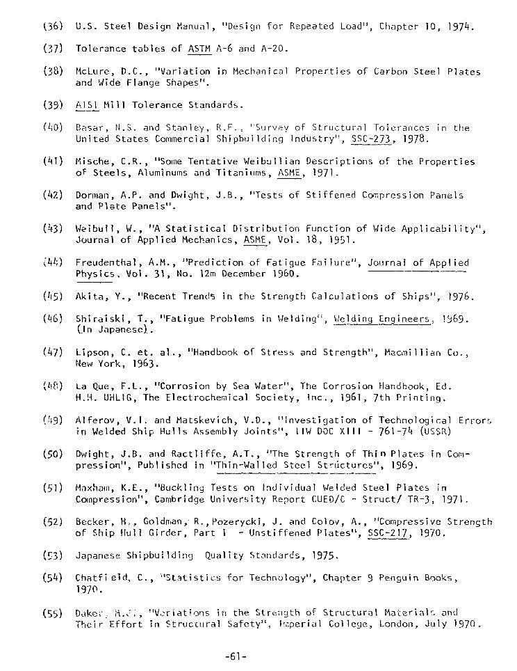
(36)
(37)
(38)
(39)(1,())
(41)
(42)
(43)
(~l;)
(45)(q~)
(47)
(1!8)
(!;cj)
(501
(51)
(52]
!53)
(54)
(55)
U.S. Steel Design Manual, “Design for Rzpeated Load”, Chapter 10, 1974.
Tolerance tables of ASTMA-6andA-20.
McLure, D.C., “Variation in Mechanical Properties of Carbon Steel Platesand Wide Flange Shapes”.
Al$l MillTolerance Standards.——
Easar, N.S. and Stanley, R.F., “Survey of Structural Tolerances in theUnited States Commercial Shipbuilding Industry”, SSC-273, 1978.
Mische, C.R., “Some TentatOF Steels, Aluminums and T
Dorman, A.P. and Dwight, Jand Plate Panels”.
ve Weibull ian Descriptions of the Propertiestaniums, ASME, 1971.
B., “Tests of Stiffened Compression
Weibull, W., “A Statistical Distribution Function of Wide ApplJournal of Applied Mechanics, ASME, Vol. 18,1951.
Freudenthal, A.M., “Prediction of Fatigue Failure”, Journal ofPhysics, Vol. 31, No. 12m December 1960. ——
Panels
cability”,
Appl iecl
Akita, Y., “Recent Trend% in the Strength Calculations of Ships”, 1976.
Shiraiski,T.,“FatigueProblemsinWelding”,Welding Engineers, 1969.(In Japanese). .
Lipson, C. et. al., “Handbook of Stress and Strength”, Mecmillian CO.,New York, 1963.
La@e, F.L., “Corrosion by Sea Water”, The Corrosion Handbook, Ed.H.!+. UHLIG, The Electrochemical Society, Inc., 1961,7th Printing.
Alferov, V.I. aad Matskevich, V.D., “investigation of Technological Errorsin Welded Ship Hulls Assembly Joints”, IIW DOCX111- 761-74(USSR)
Dwight, J.B. and RactIiffe, A.T., “The Strength of Thin Plates in Com-pression”, Published in “Thin-Walled Steel Strictures”, 1969._..—Flaxham, K.E., “Buckling Tests on Individual Welded Steel Plates inCompression”, Cambridge University Report CUED/C - Struct/ TR-3,1971.
Becker, H., Goldm,an,R., Pozerycki, J. and Colov, A., “Compressive Strenqthof $hi.~ tlu~l Girder, Part
Japanese Shipbuilding Qua’
Chatfield, C., “Statistics1970.
: Unstiffened Plates’’, ’SSC-2\7, 1970. -
ityStandards,1975.
for Technology”,
Daker, !4..., “Vt:riations in the Strength ofTF,eir Effort irl Struc~lJral Safety”, I:nperia’
-61-
Chapter 9 Pen~uin Books,
Structural Materialz andCollege, London, July 1970.

(36)
(37)
(38)
(39)
(40)
(41)
(42)
(43)
(44)
(45)
(46)
(47)
(48)
(f19)
(50)
(51)
(52)
(53)
(54)
(55)
U.S. Steel Design Manual, “Design for Repeated Load”, Chapter 10, 1974.
Tolerance Tables of ASTMA-6 and A-20.
Fujita, J., Yoshida, K., and Takezawa, M., “On the Strength of StructuresWith Imperfections”, Selected Papers from The Journal of the Society ofNaval Architects of Japan, Vol. 14, 1976.
AISI Mill Tolerance Standards.
Basar, N.S., and Stanley, R.F., “Survey of Structural Tolerances in theUnited States Commercial Shipbuilding Industry”, SSC-273, 1978.
Mische, C.R., “Some Tentative Weibull ian Descriptions of the Properties ofSteels, Aluminums and Titaniums, ASME, 1971.
Dorman, A.P. and Dwight, J.B., “Tests on Stiffened Compression Plates andPlate Panels”, Conference on Steel Box Girder Bridges, Institute of CivilEngineers, London, Feb. 1973.
Weibull, W., “A Statistical Distribution Function of Wide Applicability”,Journal of Applied Mechanics, ASME, Vol. 18, 1951.
Freudenthal, A.M., “Prediction of Fatigue Failure”, Journal of AppliedPhysics, Vol. 31,No.12m December 1960.
Akita, et al., “Design Procedure Based on Reliability Analysis of ShipStructures”, Naval Architecture and Ocean Engineering, Society of NavalArchitects of Japan, Volume 15, 1977.
Shiraiski, T., “Fatigue Problems in Welding”, Welding Engineers, 1969.(InJapanese).
Lipson, C., et al., “Handbook of Stress and Strength”, Macmillan Co., NewYork, 1963
La Que, F.L., “Corrosion by Sea Water”, The Corrosion Handbook, Ed. H. H.Uhlig, The Electrochemical Society, Inc. 196[, ~th Printing.
Alfreov, V.I. and Matskevich, V.D., “Investigation of Technological Errorsin Welded Ship Hulls Assembly Joints”, llW DOCX111 - 761-74(USSR).
Dwight, J.B. and Ractliffe, A.T., “The Strength of Thin Plates in Compres-sion”, Published in “Thin-Walled Steel Structures”, 1969.
Maxham, E.E., “Buckling Tests on Individual Welded Steel Plates in Compres-sion”, Cambridge University Report CUED/C - Struct/TR-3, 1971.
Becker, H., Goldman, R., Pozerycki,J. and CO1OV, A., “compressive Strengthof Ship Hull Girder, Part 1 - Unstiffened Plates”, SSC-217, 1970.
Japanese Shipbuilding Quality Standards, 1975
Chatfield, C., “Statistics for Technology”, Chapter 9, Penguin Books, 1970.
Daker, M.J.,“Variations in the Strength of Structural Materials and TheirEffort in Structural SafetyI’, imperial College, London, July 1970.
-62-

(56)
(5’7)
(58)
(59)
(60)
(61)
(62)
(631
(6~i)
[65)
(66)
(67)
Report of Committee 10 on “Design Philosophy and Procedure”, Proceedingsof the Third ISSC, Oslo, 1967..—_
International Ship Structures Congress, Report of Committee 10, 1970.
Belyaev, B.I., “Statistical Method of Determining Standard Stresses forSteel Structures”, National Research Council of Canada, TechnicalTranslation No. 1368(from Russian), 1969.
Lewis, E.V., et al, “Load Criteria for Ship Structural Design”, ShipStructure Committee, SSC-240,1973.I-e,,vis, E-\/., “Long-Term Applications af St. Denis/Pierson Techniqueto Ship Design”, SNAMESeakeepin g Symposium, 1973.
Private communication between Prof. E.V.Lewis and M. Rcsenblatt 6 Son,ltic., September 1978.
Stiansen, S.G., et. al, “Reliability Methods in Ship Structures”,R!NA, Spring Meeting, 1979.
raulkner, D. and Sadden, J.A., “Toward a Unified Approach to ShipStructural Safety”, RINA,1978.
Smith, C.S., “Compressive Strength of Welded Steel Ship Grillages”,RINA, 1975.
Parlee, E.L., Leyland, W.A. and McPherson, W.E., “Economic AnalysisofTank Coatings for Tankers in Clean Service”, J. Marine Technology,October 1965.
“Review Commentson Draft Final Report of sR-1241”, by Ang, A. H-S,October 23, 1978.
!vanov, L.D. and Pousev, S.G., IIStatistical Estimation Of ReductionCoefficient of Shipls Hu1l Plates with Initial Deflections”,The Naval Architect, July 1979.
-63-

APPENDIXA
DERIVATIONOFEXPRESSIONFORSTRENGTHCOVFORDUCTILEYIELDOFTHEHULLDVERTICALBENDING
Yielcl Strength= :(Af+ 1/3
D= section depth
B= section beam
Af= total area of
&= total area ofs.=yield stress
Aw) Sy (,1)
(betweenneutral axes of combined plate anbeams of- deck and bottom)
flanges (deck and bottcm)
webs (sides and Imgitudal bulkheads)
8Take into acc unt the following uncertainties in the abovestrength form
o DSB:asdescribed above
o td : thickness of deck plating
o t~t thickness of stiff&ner
o tw: thickness of webs(side plating or longitudal bulkhead
o IL: length of stiffener web
o If: length of stiffener flange
M = numberof stiffeners alongf, Mw deck and numberof stiffene
alongside plating respectively.
Af=[Bt~+Mft$ \lwl+ l@]02 (2)
AW=Q[Dtw+ Mw(lq+lf2)]c 4 (3)
INSERTINGINTO(1):
‘+ ]/3[Dtw+ ‘Wts (IW2+ lf2}l*4} Sy+{[( Btd + ~~+ts(lw, + lf,)]Z
S=lDBt~+ DMft~(I,wl+$)+ 2/3D2tw+ 2/3D~~t~(1w2+ lf2)lsj (41
FROMSECTION3.3.3:2
&~= En(?J , 2)2. d:i
i=l i ‘5(5)
-65-

.66.

let: A=Btd ‘= M$ts’w,
B= Mft~(lwl+ lf )1
F= Hft5&$,
c= Dtw G=Mwt~1W2
D=Mwt~(1w2+ 1+2) H= MWt31f2
—----+ 629 ]:.&\+ (3A+ 3;(+~c-1-2D‘(A+; +2/JC+2/3D w
E ):&z)2 2 +- (p,+ B + ~!3C+ 2/3D+ ‘r+B+ 2/3C+ 2/3D●~<‘%
2G ):#1 2H 21)# f2‘(3A+ 3B+2c +20‘~~A+3B+2c+2D ‘2
~2 9 .[1/9 (3A+ 3B+4C+2D)2fi2D ‘A2s ‘(3 A+3B+2C+2D)~. -
2 22 + 62+ D lsl 2 + F ~lf ~1/9(3E + 2G)2&:~ 3
1~(c262t + ~2621 + H2621~2)
w+
‘2
(3A+ 3B+2C+2D)2
‘f,
(18)
Equation(18)is the final expression for the strengthCOVasa functionOf
theCOV’Softheuncertainties.
-67-
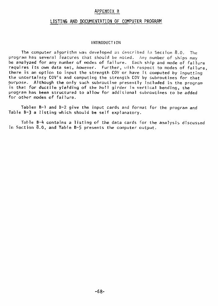
APPENDIXB
LISTINGANDDOCUMENTATIONOFCOMPUTERPROGRAM
INTRODUCTION
The computer algorithm was developed as described in Section 8.o. Theprograin has several features that should be noted. Any number of ships maybe analyzed for any number of modes of failure. Each ship and mode of failurerequires its own data set, however. Further, ~:ith respect to modes of failure,there is an option to input the strength COV or have it computed by inputtingthe uncertainty COV’S and computing the strength COV by ~ubroutines for thatpurpose. Although the only such subroutine pt-esently included in the programis that for ductile yielding of the hull girder in vertical bending, theprogram has been structured to allow for additional subroutines to be addedfor other modes of failure.
Tables B-l and B-2 give the input cards and format for the program andTable B-3 a listing which should be self explanatory.
‘f{)k,le B-4 contains a listing of the data cards for the analysi~ discussedin Section 8.0, and Table B-5 presents the computeroutput.
-68-

TABLEB-1: INPUTCARDSANDFORMAT
._—-CARD
I.—
2
.————3
.——4
.——
5
——— -.—6
7
8.——
9
.——
——‘ORHAT
13
13
4FI0.4
13
13
10F7.5
7FI0.4
-—7FI0.4
FIo.5
NUMBEROF CARDS
I
1 pership
——.1 pership
1
I
I
I
1
1
SYMBOL
NS
NMF
SD, DS,ZH.COWL
I FLAGO-InputstrengthCov2-computestrengthCov
NTS
see notes
Cov
NOTES
Numberof Ships
Number of modes of failure, each shipmust have this card repeated. Inputall data cards for edch ship beforerepeating.
SD = Actual Design MOO0S = Average Design StressZM= Mean of LoadCOVL = COV of Load
Flag to indicate whether strengthCOVwill be input or computed.
This card to be filled out only ifcard 4 is “2”. This directs cardgiven the direction of which mode offailure is being analyzed and henceone is needed for every mde offailure. The next card should comeafter card 6. Currentlyonly ver-tical bending is available in theprogram so that NTS= 1.
—.These cards to be filled out only ifcard 4 is “2”. The followingvariables in order, as defined inSection 8~6, are required:
6D, 6B, 6td, 61W:1,~lf, , 6ts, ~5y,6tw, 61W2,61f2, Depth, Beam,td! ts,Mf, IW1* lf2, twi %* lW?lf2s Sy, SUBCO(Subjective
Uncertainties COV)
This card to be filled out only ifcard 4 is “O”. In that case thestrer,gth COV is input and is given by-:
Cov= )&2+ A:6s = objective uncertainty COVAs = subjective uncertainty COV
-69-

—— —.

TABLEB-3: LISTINGOF COMPUTERPROGRAM
cM%IIER ALGORITH’4TOOETERMINESHIP HULLLoNGITu51NALSTREMTHSAFtTYc.ccc
cc

TABLEB-3:LISTINGOFCOMPUTERPROGRAM(cONT.)
LINCEQNTAI/4TYCOVfS
CCIMPUTESTREN5THCOV
flX*’AVElA5E DESIfJNFAILuI?ESTf~tiS5=itF20s41‘4,14) IRS1(lx,IMEAN OF STRENGTH= ‘oF20m4flM*15} 2M(1x,I!4EAN OF LOAD= 4,F2U041M,16) Cov(lX*ICGVOF STRENGTH= I,F1(Js4)P!917) coVL
-72-

cc SUgROUTINETOcwwv THE13UCTILEYIELDINGSTRENGTHcov F“o(tA SHIP Idc vFRTIcALgENolNG,FORMuLATJONACcOJ7DJNGTO THATGIVEN IN SR-241,c
SUBROUTINEVERTSlAtDEpTH~BEAMtTD$TS*14F*LWl*LFl*TWt’4W~LW2tLTztlx(w)RFAL MF)LWI$LFI$MW*LV12$LT2DIMENSIONA(10)A1=9FAM*T0q=t.IF*TS*lL#l+LFl)c.DEPTH*Twl’)x’.l!#*Tsit[Lw2+LT2)Es?~FttTs*LwlF=~~FitTs*LFlG8!Jw4tTs*LN2HX’4:**TS*LT2cOVl=(3cO*Al+300*9+4SO*C+2,0*D)**2*A(l)**2/9o0COV2=A1**2E(A12)**2+A(3) **2)CC)V3=E**2*A(41**2COV4=F**2*A(5)**2COV5=(300*E+200*5)**2*A(6)**2/9c0COV6=900/(300*Al+30u*P+2tO*C+20C*D)**2COV7=CCIV5*(COV1+COV2+COV3+COV4+COV5)COV9=A(7)**2cOV9=~t,0*(c**24Ald)**2+G**2*A (9)**2+H**2*A 11J)**2)COVl@*(30’l*Al+3.0*n+20(J*C+2tO*DI**2covll=cov9/covloXOV=SC::TICW7+COV8+C!)V11)?:TLJ:/tqEv!l
-73-
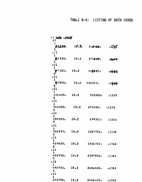
TABLEB-4:LISTINGOF DATACARDS
15.2
15*Z
15*2
15.2
15D2
15,2
15.2
15.2
15.2
15=2
15.2
15.2

TABLEB-5:COMPUTEROUTPUT
SH1!C NIJM~EQ = 1VC)DFOf FAILIII?ENIJ,MBEKR 1ACTIJALDESIGN M3DuLU5z 512(!oqO07YAV??A5EDTSIGNFAILURECITkES5= 1502000VEAP;~F 5THENCITH= 7713240*OU17vr4y of LOAD. 24!3500,0316COVnc ST?ENGTli* 0,1100C(WOF LOAD= 001595sAFETY11’J13EX= 5.7323
SHIP hJuYRE3= 2‘.OnF!lF FAILURENU,MBER= 1ACTUALDESIGN MODULUS= 81320sG154AVFRAGEDESIGNFAILURESTRESS= 15.2000v~A~lOF sTRENGTH= 1236064.0034ME4kIOF L3AD❑ 371000m3632C9V OF ST?ENGTH= O*11OOC(IV OF I.OA~ = 0.1400sAFETYINDEX= 5.9434
5H1p NUMRFR = 3‘.’!I’)E OF FAILURENUM~ER= 1lCT!JALDEsIGN MODULUSz 970Qll*o15t)AVZnA5FDESIGNFAILU:?EsTREsS= 15m2303‘~f;AvOF 5T7SNGTH= 1/+7/.405,0034‘~FA?JOF LOAD= “ 44!!000.3632C(IV 5F STPENGTH= O*11OOCT3VIIF LOAC= 0.14925AFETY.IXDEX= 5*9915
SHIP NUMRER= 4y.~~EOF FAILURENuMBER= 1ACTUALDESIGN VQDuLusa 87950.0153AVF?AGE9ESIGNFAILURESTRESS= 15.2303“’TAN3F jT17F~J5TH= 1335?40,0029“.’EA’d3F L(IA> = hrJf,350aL)53’jC~V OF 5T~ZNGTH= 0,1100Cgv oF LoAD= 0.144+
-75-

TABLEB-5:COMPUTEROUTPUT(CONT.)
sAFETYINDEX= 5.l?71D
S}+lD~(p.lq~~= 5vi)!)E OF FAILURENUMRER= 1ACTUALDESIGN MODULUS= 131600,0316AVERAGEDESIGNFAILURESTRESS= 15.2000MEANOF STRCNGTH= 2000320,0034V~4N OF LOAD= 5dOOOOi1264COVOF ST7ENGTH= O*11OOcOl/ oF LOAD= 0.1325$AFETY INDEX = 600939
slilP wut?~EIJ= 6‘.lWIEOF FAILuREWMnEi?= 1ACTUALf)ESIGIJ WODULUS= l~300000316hVFQAGEDESIGNFAILURESTRESS=“4EANOF STRENGTH=
15,20002173600-0058
671OOOSL267x O*11OO
0,1229509410
7..~Jo~~F FAILu~~ ~+IJM~E:~= 1ACTUALDESIGN ~0DuLu5z 1513000,0316AVERAGED~51GNFAILURESTRESS= 15,2COU,yEA5]OF STPENGTti❑ 2401600,a068.‘.!F.ANOF LOAD= 6791J03m1267CW OF 5T17ENGTH= 3,1100C’3VOF LOAC= o.126asAFETYINDEX= 6,1997
-----76-
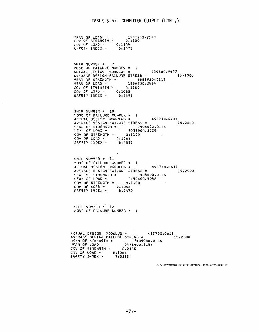
TABLEB-5: COMPUTEROUTPUT(CONT.)
ACTUALDESIGN ~oDuLiJ5= 439600,?53?AVE?AGED5SIGNFAIL1J7ESTRESS= 1502220.#FA\jOF sTRCNGTH= 6691920mal17Y?ANOF LaA5 = lB3b7D9.2534COV5F ST?ENGTH‘= 9.1100COVaF LSAD= (3-1069sAFETY“INDEX= 6,3591
= 1= 493750.0633STRESS= 1592300
75053COtO1362037900.2523
2bI!6400,505ti= 9*11OO
rl.lDsY5*737!)
AC”ilJALDESIGN ;4C)OULuss 49?75c*obj3hVE;lAGEDESIGNFAILURESTRESS~= 15.2000:,!EANOF sTRENGTH= 75059G0.0:.36.,!rA\j OF LaAD= 24H64L19w5G5YCnVO= qTl?EyGTH8 9.03/40C’)VOF LOALI= 00136HsAl=FTyIqfjEx = 7.3332
*u.S. QOVERMENTPRINTINGOFFICE:1981-0-72>969/1541
-77-

SHIP RESEARCH COMMITTEEMaritime Transportation Research Board
National Academy of Sciences - National Research Council
********
The Ship Research Committee has technical cognizance of the inter-agency Ship Structure Committee’s research program:
Mr. A. D. Haff, Chairman, Consultant, Annapolis, MDProf. A. H.-S. Ang, &:tviZ ,?hqrg.Dept., Univerisib!{Ojr l“ZZ-Lnois,Clzmpuiyz, ILMr. A. C. McC1 ure, .42an C. MCCZWO A.sso&ztes, Inc., Houston, TXDr. W. R. Porter, vice i’residentfor Academic Affairs, Sthzte[Iniv.of Neu Yorak
Mimitime cozZe<laMr. D. A. Sarno, ??cznaqc?r-?deckni(:s,AH!)(7OInc., P?LddZetow, 0[1Prof. H. E. Sheets, DiF. of Enfl-~nee.r7.n~7,AnnL?j,sis4;!’cefi,noZcxqy,Tnc.,
,f~toninggton,CTMr. J. E. Steele, Naval. Architect, Quakertmm, PAMr. R. W. Rumke, llxeeutive secre Lar~g, Ship .Pe.searchcam-itte,?
********
The Ship Design, Response, & Load Criteria Advisory Group preparedthe project prospectus, eval uated the proposals for this project, providedthe liaison technical guidance, and reviewed the project reports with theinvestigator:
Mr. J. E. Steele, Chairman, Naval Architect, Quakrtowz, $’.4Mr. J. W. Boyl ston, ?.fmzwgerjMcn+ze 0;~erKzt710m, El Paso fkzrine L’om[xzn!j,
********

SHIP STRUCTURE COMMITTEE PUBLICATIONS
SSC-287,
SSC-288,
SSC-289,
SSC-290 ,
SSC-291 ,
SSC-292,
SSC-293 ,
SSC-294 ,
SSC-295,
SSC-296,
SSC-297,
l%ese docwwnts are distributed by the Natiov&Z TechnicsZInformation Serwice, Springfield, VA 22314. These doc-uments have been announced in the Clearinghouse JournalU. S. Government Reeeareh & Development Reports (USGRDR)under the indicated AD nwnbers.
E=6ininationof Service and Stwss Data of Three Ships for Developmentof Hull Girder Load Criteria by J. F. Oalzell , N. M. Maniar, andM. W. Hsu. 1979. AD-AO7291O.
The Effects of Varying Ship Hull Proportions and HuZZ Materials on HullFlexibility Bending and Vibratory Stresses by P ‘t. Chang. 1979.AD-A075477 .
A Method for Economic Trade-Offs of Alternate Skip Structural Materia2sby C. R. Jordan , J. B. Montgomery, R. P. Krumpen, and D. J. Woodley.1979. AD-A075457,
Significance and Control of LcuneZ1~ Tearing of Steel Plate in theShipbuilding Industry by J Somme 11a. 1979. AD-A075473.
A Design Procedure for Minimizing Propeller-Induced Vibration in HullStructural Elements by O. H. Burnside, D. D. Kana, and F. E. Reed.1979. A13-Ao79443.
Report on Ship Vibration Symposium ‘78 - Sheraton Yatiom 1 Hotei?,Arlington, VA. by E. Scott Di 1lon. 1979. AD-A079291.
Underwater Nondestructive Te~ting of Ship Hull Welds by R. Youshawand C. Dyer. 1979. AD-A079445
Further Survey of Inservice Performance of Struct~a 1 Detai2s byC. R. Jordan and L. T. Knight. 1979. AD-A086019.
No&es truetive Inspection of Longitudirw1 Stiffener Butt Welds incommercial vessels by R. A. Youshaw. 1980. AO-A085352.
Revieu of Fillet Weld Strength Parameters for Shipbuilding byC-L Tsai, K. ltoga, A. P. Mall iris, W. C. McCabe, and K. Masubuchi.1980. AO-A085356.
Evaluation of Liquid Dynmnic Loads in Slack LNG Cargo Tanks byP. A. Cox, E. B. Bowles, and R. L. Bass. 1980.
SSC-298, I~oestiga~ion of steels for .lmp~ved FeZdability in Ship Construction -Phase I by R. W. Vanderbeck. 1980.
SSC-299, Ultimate Stre~th of a Ship’s Hull Girder in PZastic and Buckling Modesby A. E. Mansour and A. Thayamballi. 1980.
SS C- 300, .%nnnaq of Nondestructive Inspection Standards for Heavy SeetionCastings, Forgiv~s, and Wek!ments by R. A. Youshaw. 1980.
Related Documents


