SERVICE MANUAL FOREWORD This manual includes procedure for mainte- nance, adjustment, service operation and re- moval and installation of components. All information, illustrations and specifications contained in this manual are based on the latest product information available at the time of manual approval. The right is reserved to make changes at any time without notice. SECTION INDEX DRIVE LINE/AXLE BRAKES TRANSMISSION STEERING HVAC (HEATING, VENTILATION, AND AIR CONDITIONING) RESTRAINTS BODY AND ACCESSORIES 3 4 5 6 7 8 9 ENGINE SUSPENSION 1 2 FRONT MATTER GENERAL INFORMATION 0A 0B SSANGYONG- DAEWOO MOTOR CO., LTD. 1998 KORANDO MUSSO

Welcome message from author
This document is posted to help you gain knowledge. Please leave a comment to let me know what you think about it! Share it to your friends and learn new things together.
Transcript

8/18/2019 SsangYong Musso Service Manual 1998.pdf
http://slidepdf.com/reader/full/ssangyong-musso-service-manual-1998pdf 1/1459
SERVICEMANUAL
FOREWORD
This manual includes procedure for mainte-nance, adjustment, service operation and re-
moval and installation of components.
All information, illustrations and specificationscontained in this manual are based on the latestproduct information available at the time ofmanual approval.
The right is reserved to make changes at anytime without notice.
SECTION INDEX
DRIVE LINE/AXLE
BRAKES
TRANSMISSION
STEERING
HVAC(HEATING, VENTILATION,AND AIR CONDITIONING)
RESTRAINTS
BODY AND ACCESSORIES
3
4
5
6
7
8
9
ENGINE
SUSPENSION
1
2
FRONT MATTER
GENERAL INFORMATION
0A
0B
SSANGYONG- DAEWOOMOTOR CO., LTD. 1998
KORANDO
MUSSO

8/18/2019 SsangYong Musso Service Manual 1998.pdf
http://slidepdf.com/reader/full/ssangyong-musso-service-manual-1998pdf 2/1459
PERSONAL INJURY CAUTION
Appropriate service methods and proper repair procedure are essential for the safe, reliable operation of all motor vehicles, as well as for the personal safety of the person doing the repair. There are many variations in procedures, techniques, tools and parts for servicing vehicles, as well as in the skills of the people doing the work. This manual cannot possibly anticipate all such variations and provide advice or precautions for each. Anyone who deviates from the instructions provided in this manual must ensure their own safety and preserve the safety and integrity of the vehicle. The following list contains general precautions that should always be followed while working on a vehicle.• Safety stands are required whenever a procedure calls for
underbody work.• Do not smoke when you work on a vehicle.• To prevent serious burns, do not touch any hot metal parts.• Set the parking brake when you work on the vehicle.
• Turn the ignition switch OFF unless a procedure states otherwise.
• The engine may operate only in a well-ventilated area.• Avoid moving parts when the engine is running.• Safety glasses must be worn for eye protection.
8/18/2019 SsangYong Musso Service Manual 1998.pdf
http://slidepdf.com/reader/full/ssangyong-musso-service-manual-1998pdf 3/1459
TABLE OF CONTENTSSection 0A Front Matter
Section 0B General Information
Section 1 EngineSection 1A1 M162 General Engine InformationSection 1B1 M162 Engine MechanicalSection 1D1 M162 Engine CoolingSection 1E1 M162 Engine ElectricalSection 1F1 M162 Engine ControlsSection 1G1 M162 Engine Intake & ExhaustSection 1A2 M161 General Engine InformationSection 1B2 M161 Engine MechanicalSection 1D2 M161 Engine CoolingSection 1E2 M161 Engine ElectricalSection 1F2 M161 Engine ControlsSection 1G2 M161 Engine Intake & ExhaustSection 1A3 OM600 General Engine InformationSection 1B3 OM600 Engine MechanicalSection 1D3 OM600 Engine CoolingSection 1E3 OM600 Engine ElectricalSection 1F3 OM600 Engine ControlsSection 1G3 OM600 Engine Intake & Exhaust
Section 2 SuspensionSection 2A Suspension DiagnosisSection 2B Wheel AlignmentSection 2C Front SuspensionSection 2D Rear SuspensionSection 2E Tires and Wheels
Section 3 Drive Line / AxleSection 3A Front Drive AxleSection 3C Propeller ShaftSection 3D Rear Drive Axle
Section 4 BrakesSection 4A Hydraulic BrakesSection 4B Master CylinderSection 4C Power BoosterSection 4D Front Disc BrakesSection 4E Rear Disc BrakesSection 4F Antilock Brake System
Section 4G Parking Brakes
Section 5 TransmissionSection 5A Automatic TransmissionSection 5B Manual Transmission
Section 5C ClutchSection 5D1 Transfer Case (Part Time 4480)Section 5D2 Transfer Case (TOD)
Section 6 SteeringSection 6A Power Steering SystemSection 6E Steering Wheel and Column
Section 7 HVAC (Heating, Ventilation & AirConditioning)
Section 7B/C Manual Control/Semiauto Tempera-ture Control Heationg, Ventilation,and Air Conditioning System
Section 7D Full Automatic Temperature ControlHeationg, Ventilation, and Air Condi-tioning System
Section 8 RestraintsSection 8A Seat BeltsSection 8B Supplemental Restraint System
(SRS)
Section 9 Body and AccessoriesSection 9A Body Wiring SystemSection 9B Lighting SystemsSection 9D Wipers/Washer SystemsSection 9E Instrumentation/Driver InformationSection 9F AudioSection 9H SeatsSection 9L Glass and MirrorsSection 9N Front and Under Body
Section 9O Bumpers and FendersSection 9P DoorsSection 9Q RoofSection 9R Body Front EndSection 9T Remote Keless Entry and Anti-Theft
SystemSection 9U Control Units and SystemSection 9W Immobilizer System

8/18/2019 SsangYong Musso Service Manual 1998.pdf
http://slidepdf.com/reader/full/ssangyong-musso-service-manual-1998pdf 4/1459
SECTION 1A1 M162 GENERAL ENGINE INFORMATION
SECTION 1B1 M162 ENGINE MECHANICAL
SECTION 1D1 M162 ENGINE COOLING
SECTION 1E1 M162 ENGINE ELECTRICAL
SECTION 1F1 M162 ENGINE CONTROLS
SECTION 1G1 M162 ENGINE INTAKE & EXHAUST
SECTION 1A2 M161 GENERAL ENGINE INFORMATION
SECTION 1B2 M161 ENGINE MECHANICAL
SECTION 1D2 M161 ENGINE COOLINGSECTION 1E2 M161 ENGINE ELECTRICAL
SECTION 1F2 M161 ENGINE CONTROLS
SECTION 1G2 M161 ENGINE INTAKE & EXHAUST
SECTION 1A3 OM600 GENERAL ENGINE INFORMATION
SECTION 1B3 OM600 ENGINE MECHANICALSECTION 1D3 OM600 ENGINE COOLING
SECTION 1E3 OM600 ENGINE ELECTRICAL
SECTION 1F3 OM600 ENGINE CONTROLS
SECTION 1G3 OM600 ENGINE INTAKE & EXHAUST
ENGINE
CONTENTS

8/18/2019 SsangYong Musso Service Manual 1998.pdf
http://slidepdf.com/reader/full/ssangyong-musso-service-manual-1998pdf 5/1459
SUSPENSION
CONTENTS
SECTION 2A SUSPENSION DIAGNOSIS
SECTION 2B WHEEL ALIGNMENT
SECTION 2C FRONT SUSPENSION
SECTION 2D REAR SUSPENSION
SECTION 2E TIRES AND WHEELS

8/18/2019 SsangYong Musso Service Manual 1998.pdf
http://slidepdf.com/reader/full/ssangyong-musso-service-manual-1998pdf 6/1459
DRIVE LINE / AXLE
CONTENTS
SECTION 3A FRONT DRIVE AXLE
SECTION 3C PROPELLER SHAFT
SECTION 3D REAR DRIVE AXLE

8/18/2019 SsangYong Musso Service Manual 1998.pdf
http://slidepdf.com/reader/full/ssangyong-musso-service-manual-1998pdf 7/1459
BRAKE
CONTENTS
SECTION 4A HYDRAULIC BRAKES
SECTION 4B MASTER CYLINDER
SECTION 4C POWER BOOSTER
SECTION 4D FRONT DISC BRAKES
SECTION 4E REAR DISC BRAKES
SECTION 4F ANTILOCK BRAKE SYSTEM
SECTION 4G PARKING BRAKE

8/18/2019 SsangYong Musso Service Manual 1998.pdf
http://slidepdf.com/reader/full/ssangyong-musso-service-manual-1998pdf 8/1459
TRANSMISSION
CONTENTS
SECTION 5A AUTOMATIC TRANSMISSION
SECTION 5B MANUAL TRANSMISSION
SECTION 5C CLUTCH
SECTION 5D1 TRANSFER CASE (PART TIME 4408)
SECTION 5D2 TRANSFER CASE (TOD)

8/18/2019 SsangYong Musso Service Manual 1998.pdf
http://slidepdf.com/reader/full/ssangyong-musso-service-manual-1998pdf 9/1459

8/18/2019 SsangYong Musso Service Manual 1998.pdf
http://slidepdf.com/reader/full/ssangyong-musso-service-manual-1998pdf 10/1459
HVAC (HEATING, VENTILATION &
AIR CONDITIONING)CONTENTS
SECTION 7B/C MANUAL CONTROL/SEMIAUTOTEMPERATURE CONTROLHEATING, VENTILATION, AND
AIR CONDITIONING SYSTEMSECTION 7D FULL AUTOMATIC
TEMPERATURE CONTROLHEATING, VENTILATION, ANDAIR CONDITIONING SYSTEM

8/18/2019 SsangYong Musso Service Manual 1998.pdf
http://slidepdf.com/reader/full/ssangyong-musso-service-manual-1998pdf 11/1459
RESTRAINTS
CONTENTS
SECTION 8A SEAT BELTS
SECTION 8B SUPPLEMENTAL RESTRAINTSYSTEM (SRS)

8/18/2019 SsangYong Musso Service Manual 1998.pdf
http://slidepdf.com/reader/full/ssangyong-musso-service-manual-1998pdf 12/1459
BODY AND ACCESSORIES
CONTENTS
SECTION 9A BODY WIRING SYSTEMSECTION 9B LIGHTING SYSTEMSECTION 9C HORNS
SECTION 9D WIPERS/WASHER SYSTEMSECTION 9E INSTRUMENTATION/DRIVER INFORMATIONSECTION 9F AUDIO SYSTEMSECTION 9H SEATSSECTION 9L GLASS AND MIRRORSSECTION 9N FRAME AND UNDERBODYSECTION 9O BUMPERS AND FASCIAS
SECTION 9P DOORSSECTION 9Q ROOFSECTION 9R BODY FRONT ENDSECTION 9T REMOTE KEYLESS ENTRY AND ANTI-THEFT
SYSTEMSECTION 9U CONTROL UNITS AND SYSTEMSECTION 9W IMMOBILIZER SYSTEM

8/18/2019 SsangYong Musso Service Manual 1998.pdf
http://slidepdf.com/reader/full/ssangyong-musso-service-manual-1998pdf 13/1459
SECTION 0B
GENERAL INFORMATION
Specifications. . . . . . . . . . . . . . . . . . . . . . . . 0B-1Technical Data . . . . . . . . . . . . . . . . . . . . . . . . 0B-1Vehicle Dimensions and Weights . . . . . . . . . . 0B-5Standard Bolt Specifications . . . . . . . . . . . . . . 0B-6
Maintenance and Repair . . . . . . . . . . . . . . . 0B-7Maintenance and Lubrication . . . . . . . . . . . . . . 0B-7
Normal Vehicle Use . . . . . . . . . . . . . . . . . . . . . 0B-7
Explanation of Scheduled Maintenance Services . . . . . . . . . . . . . . . . . . . . . . . . . . . . 0B-7Scheduled Maintenance Charts (Gasoline Engine) . . . . . . . . . . . . . . . . . . . . . 0B-8Scheduled Maintenance Charts (Diesel Engine) . . . . . . . . . . . . . . . . . . . . . . 0B-10
Owner Inspections and Services . . . . . . . 0B-12
TABLE OF CONTENTS
While Operating the Vehicle . . . . . . . . . . . . . 0B-12At Each Fuel Fill . . . . . . . . . . . . . . . . . . . . . . 0B-12At Least Twice A Month . . . . . . . . . . . . . . . . 0B-12At Least Monthly . . . . . . . . . . . . . . . . . . . . . . 0B-12At Least Twice a Year . . . . . . . . . . . . . . . . . . 0B-12Each Time the Oil is Changed . . . . . . . . . . . 0B-13At Least Annually . . . . . . . . . . . . . . . . . . . . . 0B-13
Recommended Fluids and Lubricants . . . . . 0B-14General Description and System Operation . . . . . . . . . . . . . . . . . . . . . . . . 0B-15
General Repair Instructions . . . . . . . . . . . . . 0B-15Vehicle Identification Number System . . . . . . 0B-16Vehicle Lifting Procedures . . . . . . . . . . . . . . 0B-19
SPECIFICATIONSTECHNICAL DATATransaxle Performance
ApplicationMaximum Speed (Km/h)Minimum Turning Radius (m)
661LA1435.7
662NA1455.7
662LA1565.7
2.0L DOCH1685.7
2.3L DOCH1765.7
3.2L DOCH1905.7
ApplicationMaximum Speed (Km/h)Minimum Turning Radius (m)
Performance-Autumatic Transaxle (MB)
2.3L DOCH1715.7
3.2L DOCH1905.7
ApplicationMaximum Speed (Km/h)Minimum Turning Radius (m)
Performance-Autumatic Transaxle (BTRA)661LA
1435.7
662NA1385.7
662LA1565.7
2.3L DOCH1715.7
3.2L DOCH1885.7

8/18/2019 SsangYong Musso Service Manual 1998.pdf
http://slidepdf.com/reader/full/ssangyong-musso-service-manual-1998pdf 14/1459
0B-2 GENERAL INFORMATION
661LA4CylinderDIESEL
89
92.4229922:1
101/400021.5/2400
ApplicationEngine Type
Bore (mm)
Stroke (mm)Total Displacement (cc)Compression RatioMaximum Power (ps/rpm)Maximum Torque (kg.m/rpm)
Engine
662NA5CylinderDIESEL
89
92.4287422:1
95/400019.6/2400
662LA5CylinderDIESEL
89
92.4287422:1
120/400025.5/2400
2.0L DOCH4Cylinder
GASOLINE89.9
78.719989.6:1
135/550019.3/4000
2.3L DOCH4Cylinder
GASOLINE90.9
88.42295
10.4:1149/550022.4/4000
3.2L DOCH6Cylinder
GASOLINE89.9
84319910:1
222/550031.6/3750
661LATREMEC
T53.9692.3411.4571.0000.8513.7054.55
3.4
ApplicationIgnition Type
Ignition Timing (BOTH)Ignition SequenceSpark Plug Gap (mm)Spark Plug MakerSpark Plug Type
Ignition System
Clutch - Manual Type
2.0L DOHC
6° ± 2°1-3-4-2
0.8 ± 0.1
2.3L DOHC
6° ± 2°1-3-4-2
0.8 ± 0.1
2.0L DOHC
8° ± 2°1-5-3-6-2-4
0.8 ± 0.1
Distributorless Ignition
Bosch, Chapion, BeruF8DC4(BOSCH)
C11YCC(CHAMPION)14F8DU4(BERU)
661LA
2251509.2
662NA
2251509.2
662LA
2401509.2
2.0L DOHC
2251509.2
2.3L DOHC
2251509.2
3.2L DOHC
2401559.3
ApplicationTypeOutside Diameter (mm)Inside Diameter (mm)ThicknessFluid
Single Dry Diaphram
Common use :Brake Fluid
ApplicationMakerType or ModelGear Ratio : 1st
2nd3rd4th5thReverse
Final Drive RatioOil Capacity (L)
Manual Transmission
662NATREMEC
T53.9692.3411.4571.0000.8513.7054.55
3.4
662LATREMEC
T53.9692.3411.4571.0000.8513.7054.27
3.4
2.0L DOHCTREMEC
T53.9692.3411.4571.0000.8513.7054.55
3.4
2.3L DOHCTREMEC
T53.9692.3411.4571.0000.8513.7054.55
3.4
3.2L DOHCTREMEC
T53.9692.3411.4571.0000.8513.7053.73
3.4

8/18/2019 SsangYong Musso Service Manual 1998.pdf
http://slidepdf.com/reader/full/ssangyong-musso-service-manual-1998pdf 15/1459

8/18/2019 SsangYong Musso Service Manual 1998.pdf
http://slidepdf.com/reader/full/ssangyong-musso-service-manual-1998pdf 16/1459
0B-4 GENERAL INFORMATION
SpecificationsRACK & PINION
0 - 4 mm2°
30’±
30’0° ± 30’1L
ApplicationGear TypeWheel Alignment:
Front Toe-inFront CasterFront Camber
Oil Capacity
Steering System
ApplicationFront TypeRear Type
Suspension
SpecificationsDouble Wishbone
5 - Link
ApplicationFuel Pump TypeFuel Filter TypeFuel Capacity
SpecificationsElectric Motor Pump
Cartridge70 L
Fuel System
Lubricating TypeOil Pump TypeOil Filter TypeOil Capacity (L) (Including Oil Filter)
Lubricating System
661LA
8.0
662NA
9.0
662LA
9.5
2.0L DOHC
7.2
2.3L DOHC
7.5
3.2L DOHC
8.2
External Gear pumpCombination(Full & Part) Full Flow
Cooling TypeCoolant Capacity (L)
Radiator TypeWater Pump Type
Cooling System
661LA9.5-10
662NA10.5
662LA10.5-11
2.0L DOHC10.5
2.3L DOHC10.5
3.2L DOHC11.3
Forced CirculationCentrifugal
ApplicationBattery (MF)GeneratorStarter
Electric System
661LA
75A2.2kw
662NA
75A2.2kw
662LA
75A2.2kw
2.0L DOHC
115A1.2kw
2.3L DOHC
115A1.2kw
3.2L DOHC
115A1.7kw
12V - 90AH 12V - 75AH

8/18/2019 SsangYong Musso Service Manual 1998.pdf
http://slidepdf.com/reader/full/ssangyong-musso-service-manual-1998pdf 17/1459
GENERAL INFORMATION 0B-5
ApplicationOverall Length (mm)Overall Width (mm)
Overall Height (mm)Wheel Base (mm)Tread : Front (mm)
Rear (mm)
VEHICLE DIMENSIONS AND WEIGHTSVehicle Dimensions
ApplicationManual : Curb Weight (kg)
Gross Vehicle Weight (kg)
Automatic : Curb Weight (kg)Gross Vehicle Weight (kg)
Passenger Capacity
Vehicle Weights
Application46561864
1735263015101520
661LA18602520
19162520
5
662NA19682520
19892520
5
662LA18902520
20052520
5
2.0L DOHC19372520
--5
2.3L DOHC18502520
19422520
5
3.2L DOHC19302520
20252520
5

8/18/2019 SsangYong Musso Service Manual 1998.pdf
http://slidepdf.com/reader/full/ssangyong-musso-service-manual-1998pdf 18/1459
0B-6 GENERAL INFORMATION
STANDARD BOLTS SPECIFICATIONS
Bolt*
Torque (N · m / Ib-in)Standard Limit
4T 7T 9T 4T 7T 9TM3 ´ 0.5
M4 ´ 0.7
M5 ´ 0.8
M6 ´ 1.0
M8 ´ 1.25
M10 ´ 1.25
M10 ´ 1.5
M12 ´ 1.25
M12 ´ 1.75
M14 ´ 1.5
M16 ´ 1.5
M18 ´ 1.5
M20 ´ 1.5
M22 ´ 0.5
M24 ´ 1.5
M24 ´ 2.0
0.5 N ····· m
(4.5 lb-in)1.2 N ····· m(11 lb-in)2.4 N ····· m(22 lb-in)4.0 N ····· m(36 lb-in)8.6 N ····· m(77 lb-in)18.6 N ····· m
(14 lb-in)18.6 N ····· m(14 lb-in)34.3 N ····· m(25lb-in)
32.3 N ····· m(24 lb-in)54.0 N ····· m(40 lb-in)81.3 N ····· m(60 lb-in)
117.6 N ····· m(87 lb-in)
166.6N ····· m(123 lb-in)225.4N ····· m(167 lb-in)284.2 N ····· m(210 lb-in)274.4 N ····· m(203 lb-in)
0.9 N ····· m
(8 lb-in)2.0 N ····· m(18 lb-in)4.0 N ····· m(36 lb-in)6.7 N ····· m(60 lb-in)15.7 N ····· m(12 lb-in)32.3 N ····· m
(24 lb-in)30.4 N ····· m(22 lb-in)56.8 N ····· m(42 lb-in)53.9 N ····· m(40 lb-in)89.2 N ····· m(66 lb-in)
107.8 N ····· m(80 lb-in)
196.0 N ····· m(145 lb-in)274.4 N ····· m(203 lb-in)372.4 N ····· m(276 lb-in)480.2 N ····· m(355 lb-in)460.6 N ····· m(341 lb-in)
1.3 N ····· m
(12 lb-in)3.0 N ····· m(27 lb-in)5.6 N ····· m(50 lb-in)9.7 N ····· m(87 lb-in)22.5 N ····· m(17 lb-in)46.0 N ····· m
(34 lb-in)44.1 N ····· m(33 lb-in)82.3 N ····· m(61 lb-in)77.4 N ····· m(57 lb-in)
127.4 N ····· m(94 lb-in)
196.0 N ····· m(145 lb-in)284.2 N ····· m(210 lb-in)392.0 N ····· m(290 lb-in)529.2 N ····· m(392 lb-in)686.0 N ····· m(508 lb-in)666.4 N ····· m(493 lb-in)
0.7 N ····· m
(6.3 lb-in)1.6 N ····· m(14 lb-in)3.1 N ····· m(28 lb-in)5.4 N ····· m(49 lb-in)12.7 N ····· m(9 lb-in)
25.5 N ····· m
(19 lb-in)24.5 N ····· m(18 lb-in)45.0 N ····· m(33 lb-in)43.1 N ····· m(32 lb-in)71.6 N ····· m(53 lb-in)
107.8 N ····· m(80 lb-in)
156.8 N ····· m(116 lb-in)215.6 N ····· m(160 lb-in)294.0 N ····· m(218 lb-in)382.2 N ····· m(283 lb-in)372.4 N ····· m(276 lb-in)
1.2 N ····· m
(11 lb-in)2.6 N ····· m(23 lb-in)5.2 N ····· m(47 lb-in)9.0 N ····· m(81 lb-in)20.6 N ····· m
(15.2 lb-in)42.1 N ····· m
(31 lb-in)41.2 N ····· m(30 lb-in)75.5 N ····· m(56 lb-in)71.5 N ····· m(53 lb-in)
117.6 N ····· m(87 lb-in)
186.2 N ····· m(138 lb-in)264.6 N ····· m(196 lb-in)362.6 N ····· m(268 lb-in)490.0 N ····· m(362 lb-in)637.0 N ····· m(471 lb-in)617.4 N ····· m(457 lb-in)
17 N ····· m
(15 lb-in)4.0 N ····· m(36 lb-in)7.6 N ····· m(68 lb-in)12.7 N ····· m(114 lb-in)30.4 N ····· m(22 lb-in)60.8 N ····· m
(31 lb-in)58.8 N ····· m(44 lb-in)
107.8 N ····· m(80 lb-in)98.0 N ····· m(73 lb-in)
166.6 N ····· m(123 lb-in)264.6 N ····· m(196 lb-in)372.4 N ····· m(276 lb-in)519.4 N ····· m(384 lb-in)705.6 N ····· m(522 lb-in)921.2 N ····· m(682 lb-in)891.8 N ····· m(660 lb-in)
*Diameter ´ pitch in millimeters
8/18/2019 SsangYong Musso Service Manual 1998.pdf
http://slidepdf.com/reader/full/ssangyong-musso-service-manual-1998pdf 19/1459
GENERAL INFORMATION 0B-7
MAINTENANCE AND REPAIR
MAINTENANCE AND LUBRICATION
Fuel Filter Replacement
Replace the engine fuel filter every.Gasoline Engine : 60,000km (36,000 miles)Diesel Engine : 45,000km (24,000 miles)
Spark Plug ReplacementReplace spark plugs with same type.
Type : BOSCH : F8DC4BERU : 14F-8DU4Champion : C11YCC
Gap : 0.8 ± 0.1 mm
Spark Plug Wire ReplacementClean wires and inspect them for burns, cracks or otherdamage. Check the wire boot fit at the Distributor and atthe spark plugs. Replace the wires as needed.
Brake System ServiceCheck the disc brake pads or the drum brake linings.Check the pad and the lining thickness carefully.
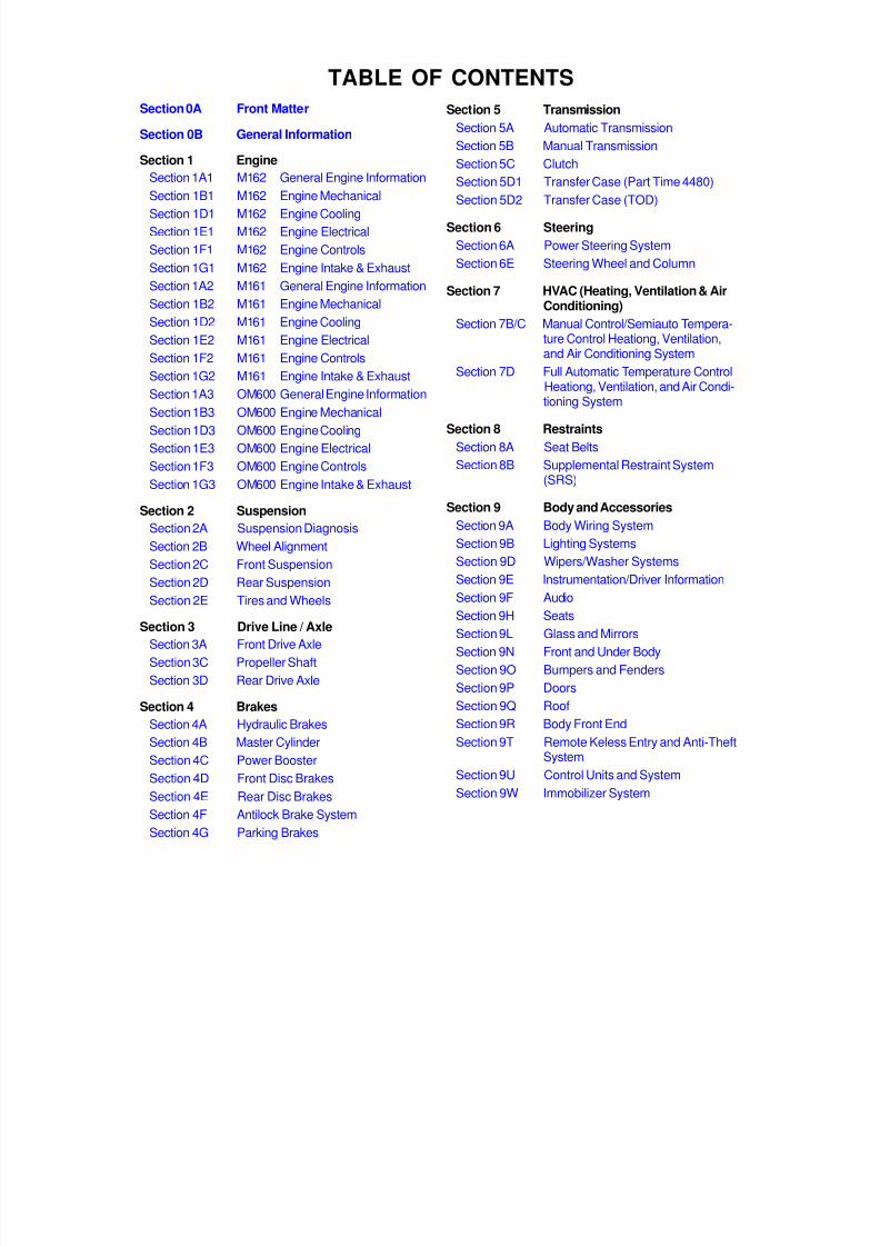
Tire and Wheel Inspection and RotationCheck the tires for abnormal wear or damage. Toequalize wear and obtain maximum tire life, rotate thetires. If irregular or premature wear exists, check the
wheel alignment and check for damaged wheels. Whilethe tires and wheels are removed, inspect the brakes.
NORMAL VEHICLE USEThe maintenance instructions contained in themaintenance schedule are based on the assumptionthat the vehicle will be used for the following reasons:
To carry passengers and cargo within the limitationof the tire inflation prassure. Refer to “Tire and Wheel”in section 2E.To be driven on reasonable road surfaces and withinlegal operating limits.
EXPLANATION OF SCHEDULED
MAINTENANCE SERVICESThe services listed in the maintenance schedule arefurther explained below. When the following maintenanceservices are performed, make sure all the parts arereplaced and all the necessary repairs are done beforedriving the vehicle. Always use the proper fluid andlubricants.
Engine Oil and Oil Filter ChangeAlways use above the API SH grade or recommendedengine oil.
Engine Oil ViscosityEngine oil viscosity (thickness) has an effect on fueleconomy and cold weather operation. Lower viscosityengine oils can provide better fuel economy and coldweather performance; however, higher temperatureweather conditions require higher viscosity engine oilsfor satisfactory lubrication. Using oils of any viscosityother than those viscosities recommended could resultin engine damage.
Cooling System ServiceDrain, flush and refill the system with new coolant. Referto “Recommended Fluids And Lubricants” in this section.
Air Cleaner Element ReplacementClean the air cleaner element every.
Gasoline Engine : 15,000km (10,000 miles)Diesel Engine : 10,000km (6,000 miles)
Replace the air cleaner element every .Gasoline Engine : 60,000km (36,000 miles)Diesel Engine : 30,000km (18,000 miles)
Replace the air cleaner more often under dustyconditions.
Tire Rotation (Left - Hand Drive Type)

8/18/2019 SsangYong Musso Service Manual 1998.pdf
http://slidepdf.com/reader/full/ssangyong-musso-service-manual-1998pdf 20/1459
0B-8 GENERAL INFORMATION
SCHEDULED MAINTENANCE CHARTS (GASOLINE ENGINE)
Engine
MonthsMAINTENANCEITEM
MAINTENANCE INTERVAL Kilometers or time in months, whichever comes first
1201059075604530151
9684726048362412-
x1,000 km
Chart Symbols:
I - Inspect these items and their related parts. If necessary, correct, clean, replenish, adjust or replace.R - Replace or change.(1) If vehicle is operated under severe condition : short distance driving, extensive idling or driving in dusty condition. Change
engine oil and the filter every 7,500 km or 6 months, whichever comes first.(2) More frequent maintenance is required if under dusty driving condition.(3) Refer to “Recommended fluids and lubricants”.
Drive beltEngine oil & filter (1) (3)Cooling system hose & connectionsEngine coolant (3)Fuel filter (2)Fuel line & connectionsAir cleaner (2)Ignition timingSpark plugsCharcoal canister & vapor lines
IIII-I
--
IRII-IIII-
IRII-IIIR-
IRII-IIIII
IRIRRIRIR-
IRII-I
II-
IRII-IIIRI
IRII-IIII-
IRIRRIRIR-

8/18/2019 SsangYong Musso Service Manual 1998.pdf
http://slidepdf.com/reader/full/ssangyong-musso-service-manual-1998pdf 21/1459
GENERAL INFORMATION 0B-9
Chassis and Body
MonthsMAINTENANCEITEM
MAINTENANCE INTERVAL Kilometers or time in months, whichever comes first
1201059075604530151
9684726048362412-
x1,000 km
Exhaust pipes & mountingsBrake/Clutch fluid (3)(4)
Parking brake/Brake pads F & R (5)Brake line & connections (including booster)Manual transmission oil (3)Clutch & brake pedal free playFront & Rear Differential Fluid (3)
IR
IIIII
--
-II-I
II
IIIII
IR
IIIII
II
II
RI
R
II
IIIII
IR
II
RI
R
II
IIIII
IR
IIIII
Automatic transmission fluid (MB W4A040) (6)Automatic transmission fluid (BTRA M74)Chassis & underbody bolts & nuts tight/secureTire condition & inflation pressureWheel alignment (7)Steering wheel & linkagePower steering fluid & lines* (3)Drive shaft bootsSeat belts, buckles & anchorsLubricate locks, hinges & bonnet latch
IIII
I
IIIII
II
III
IIIII
II
III
RIII
II
III
IIII
II
III
IIIII
II
III
RRIII
II
III
IIII
II
III
Transfer case fluid R II I
Inspect & ADJUST when abnormal condition is noted
I
III
II
III
Chart Symbols :I - Inspect these items and their related parts. If necessary, correct, clean, replenish, adjust or replace.R - Replace or change.
(3) Refer to “Recommended fluids and lubricants”.(4) Change the brake / clutch fluid every 15,000 km if the vehicle is mainly driven under severe conditions:
- Driving in hilly or mountainous terrain, or- Towing a trailer frequently
(5) More frequent maintenance is required if under severe condition : short distance driving, extensive idling, frequent low -speed operation in stop-and-go traffic or driving in dusty condition.
(6) Change automatic transaxle fluid and filter every 75,000 km if the vehicle is mainly driven under severe conditions.- In heavy city traffic where the outside temperature regularly reaches 32°C (90°F) or higher, or- In hilly or mountainous terrain, or- When doing frequent trailer towing, or- Uses such as found in taxi, police or delivery service.
(7) If necessary, rotate and balance wheels.

8/18/2019 SsangYong Musso Service Manual 1998.pdf
http://slidepdf.com/reader/full/ssangyong-musso-service-manual-1998pdf 22/1459
0B-10 GENERAL INFORMATION
SCHEDULED MAINTENANCE CHARTS (DIESEL ENGINE)
Engine
Months -MAINTENANCEITEM
MAINTENANCE INTERVAL Kilometers or time in months, whichever comes first
1009080706050403020101
6054484236302418126
x1,000 km
NOTE 1 : Injection Timing :Adjust as required :
- When excessive smoke is visible (black or white)- Poor performance/economy
Chart Symbols:I - Inspect these items and their related parts. If necessary, correct, clean, replenish, adjust or replace.R - Replace or change.
(1) If vehicle is operated under severe condition : short distance driving, extensive idling or driving in dusty condition, changeengine oil every 5,000km or 3 months, whichever comes first.
(2) More frequent maintenance is required if under dusty driving conditing.(3) Refer to “Recommended fluids and lubricants”.
Drive beltEngine oil & fillter (1) (3)Cooling system hose & connectionsEngine coolant (3)Fuel filter (2)Fuel line & connectionsGlow plugPre - fuel filterAir cleaner (2)Ignition timing (see NOTE 1)
IR
I
IR
I
III
IRII
IIIII
IRI
I
IRI
IRI
RIIIII
IRI
I
III
IRIR
IIIRI
IRI
I
III
IRI
IRIII
IRI
RI
IRI
IRII
IIIII
8/18/2019 SsangYong Musso Service Manual 1998.pdf
http://slidepdf.com/reader/full/ssangyong-musso-service-manual-1998pdf 23/1459
GENERAL INFORMATION 0B-11
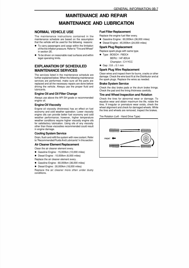
Chassis and Body
Months -MAINTENANCEITEM
MAINTENANCE INTERVAL Kilometers or time in months, whichever comes first
1009080706050403020101
6054484236302418126
x1,000 km
Exhaust pipes & mountingsBrake/clutch fluid (3) (4)
Parking brake/Brake pads (F & R) (5)Brake line & connections (including booster)Manual transmission fluid (3)Clutch & brake pedal free playF & R Differential fluid (3)
I
I
II
IIIII
II
IIIII
IR
IIIII
II
IIIII
II
IIRIR
IR
IIIII
II
IIIII
II
IIIII
IR
IIIII
II
II
RI
R
Automatic transmission fluid (BTRA M74) (6)Chassis & underbody bolts & nuts tight/secureTire condition & inflation pressureWheel alignment (7)Steering wheel & linkagePower steering fluid & lines* (3)Drive shaft bootsSeat belts, buckles & anchorsLubricate locks, hinges & bonnet latch
III
IIIII
III
IIIII
IIII
IIIII
III
IIIII
III
IIIII
III
IIIII
III
I
III
III
IIIII
III
IIIII
Transfer case fluid (3) R I R
I
I I
II
III
IIII
III
II
Inspect & ADJUST when abnormal condition is noted
I I I
Chart Symbols :I - Inspect these items and their related parts. If necessary, correct, clean, replenish, adjust or replace.R - Replace or change.
(3) Refer to “Recommended fluids and lubricants”.(4) Change the brake / clutch fluid more regularly if the vehicle is mainly driven under severe conditions :
- Driving in hilly or mountainous terrain, or- Towing a trailer frequently
(5) More frequent maintenance is required if under severe condition : short distance driving, extensive idling, frequent low -speed operation in stop-and-go traffic or driving in dusty condition.
(6) Change automatic transmission fluid every 70,000 km if the vehicle is mainly driven under severe conditions.- In heavy city traffic where the outside temperature regularly reaches 32°C (90°F) or higher, or
- In hilly or mountainous terrain, or- When doing frequent trailer towing, or- Uses such as found in taxi, police or delivery service.
(7) If necessary, rotate and balance wheels.

8/18/2019 SsangYong Musso Service Manual 1998.pdf
http://slidepdf.com/reader/full/ssangyong-musso-service-manual-1998pdf 24/1459
0B-12 GENERAL INFORMATION
OWNER INSPECTIONSAND SERVICES
WHILE OPERATING THE VEHICLE
Horn OperationBlow the horn occasionally to make sure it works. Checkall the button locations.
Brake System OperationBe alert for abnormal sounds, increased brake pedaltravel or repeated puling to one side when braking. Also,if the brake warning light goes on, or flashes, somethingmay be wrong with part of the brake system.
Exhaust System OperationBe alert to any changes in the sound of the system orthe smell of the fumes. These are signs that the systemmay be leaking or overheating. Have the systeminspected and repaired immediately.
Tires, Wheels and Alignment OperationBe alert to any vibration of the steering wheel or theseats at normal highway speeds. This may mean a wheelneeds to be balanced. Also, a pull right or left on astraight, level road may show the need for a tire pressureadjustment or a wheel alignment.
Steering System OperationBe alert to changes in the steering action. An inspection
is needed when the steering wheel is hard to turn orhas too much free play, or is unusual sounds are noticedwhen turning or parking.
Headlight AimTake note of the light pattern occasionally. Adjust theheadlights if the beams seem improperly aimed.
AT EACH FUEL FILLA fluid loss in any (except windshield washer) systemmay indicate a problem. Have the system inspected andrepaired immediately.
Engine Oil LevelCheck the oil level and add oil if necessary. The besttime to check the engine oil level is when the oil is warm.1. After stopping the engine, wait a few minutes for the
oil to drain back to the oil pan.2. Pull out the oil level indicator (dip stick).3. Wipe it clean, and push the oil level indicator back
down all the way.4. Pull out the oil level indicator and look at the oil level
on it.
5. Add oil, if needed, to keep the oil level above thelower mark. Avoid overfilling the engine, since thismay cause engine damage.
6. Push the indicator all the way back down into theengine after taking the reading.
If you check the oil level when the oil is cold, do not runthe engine first. The cold oil will not drain back to thepan fast enough to give a true oil level reading.Engine Coolant Level and ConditionCheck the coolant level in the coolant reservoir tankand add coolant if necessary. Inspect the coolant.Replace dirty or rusty coolant.
Windshield Washer Fluid LevelCheck the washer fluid level in the reservoir. Add fluid ifnecessary.
AT LEAST TWICE A MONTH
Tire And Wheel Inspection and PressureCheckCheck the tire for abnormal wear or damage. Also checkfor damaged wheels. Check the tire pressure when thetires are cold ( check the spare also, unless it is astowaway). Maintain the recommended pressures. Referto “Tire and Wheel” is in section 0B.
AT LEAST MONTHLYLight OperationCheck the operation of the license plate light, the
headlights (including the high beams), the parking lights,the fog lights, the taillight, the brake lights, the turnsignals, the backup lights and the hazard warning flasher.
Fluid Leak CheckPeriodically inspect the surface beneath the vehicle forwater, oil, fuel or other fluids, after the vehicle has beenparked for a while. Water dripping from the airconditioning system after use is normal. If you noticefuel leaks or fumes, find the cause and correct it at once.
AT LEAST TWICE A YEAR
Power Steering System Reservoir LevelCheck the power steering fluid level. Keep the powersteering fluid at the proper level. Refer to Section 6A,Power Steering System.
Brake Master Cylinder Reservoir LevelCheck the fluid and keep it at the proper level. A lowfluid level can indicate worn disc brake pads which mayneed to be serviced. Check the breather hole in thereservoir cover to be free from dirt and check for anopen passage.
8/18/2019 SsangYong Musso Service Manual 1998.pdf
http://slidepdf.com/reader/full/ssangyong-musso-service-manual-1998pdf 25/1459
GENERAL INFORMATION 0B-13
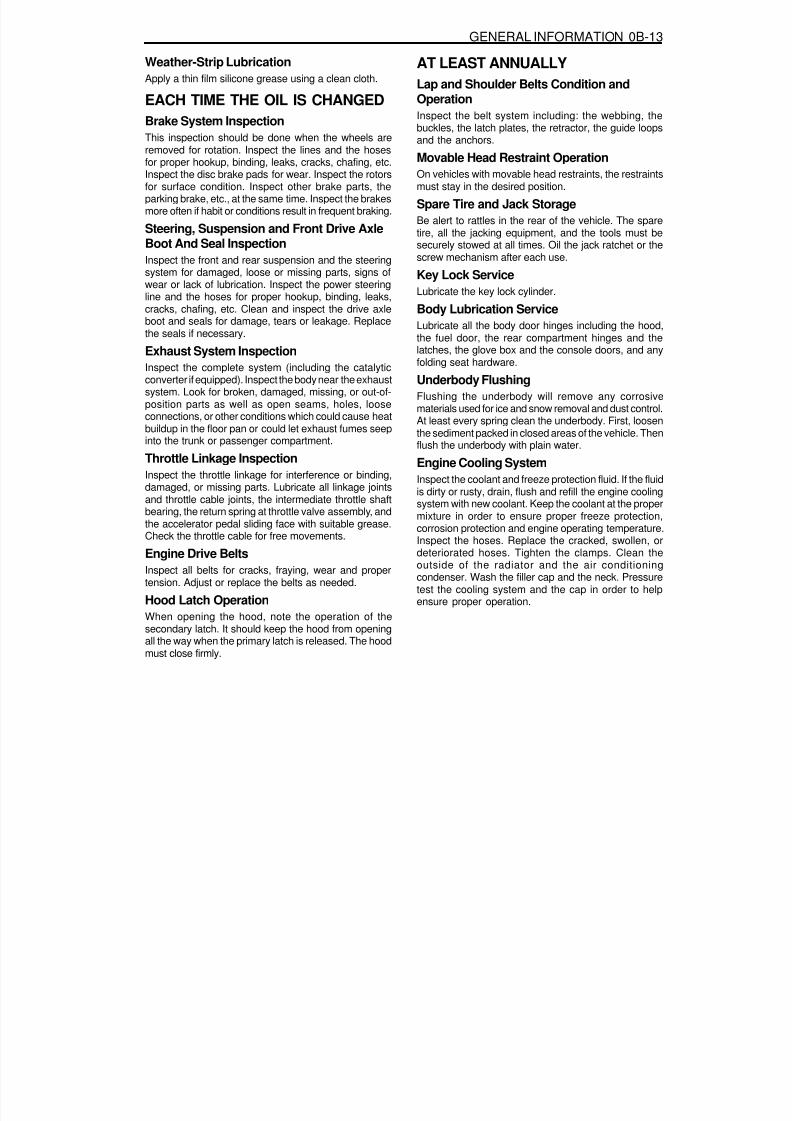
Weather-Strip LubricationApply a thin film silicone grease using a clean cloth.
EACH TIME THE OIL IS CHANGEDBrake System InspectionThis inspection should be done when the wheels are
removed for rotation. Inspect the lines and the hosesfor proper hookup, binding, leaks, cracks, chafing, etc.Inspect the disc brake pads for wear. Inspect the rotorsfor surface condition. Inspect other brake parts, theparking brake, etc., at the same time. Inspect the brakesmore often if habit or conditions result in frequent braking.
Steering, Suspension and Front Drive AxleBoot And Seal InspectionInspect the front and rear suspension and the steeringsystem for damaged, loose or missing parts, signs ofwear or lack of lubrication. Inspect the power steering
line and the hoses for proper hookup, binding, leaks,cracks, chafing, etc. Clean and inspect the drive axleboot and seals for damage, tears or leakage. Replacethe seals if necessary.
Exhaust System InspectionInspect the complete system (including the catalyticconverter if equipped). Inspect the body near the exhaustsystem. Look for broken, damaged, missing, or out-of-position parts as well as open seams, holes, looseconnections, or other conditions which could cause heatbuildup in the floor pan or could let exhaust fumes seepinto the trunk or passenger compartment.
Throttle Linkage InspectionInspect the throttle linkage for interference or binding,damaged, or missing parts. Lubricate all linkage jointsand throttle cable joints, the intermediate throttle shaftbearing, the return spring at throttle valve assembly, andthe accelerator pedal sliding face with suitable grease.Check the throttle cable for free movements.
Engine Drive BeltsInspect all belts for cracks, fraying, wear and propertension. Adjust or replace the belts as needed.
Hood Latch OperationWhen opening the hood, note the operation of thesecondary latch. It should keep the hood from openingall the way when the primary latch is released. The hoodmust close firmly.
AT LEAST ANNUALLYLap and Shoulder Belts Condition andOperationInspect the belt system including: the webbing, thebuckles, the latch plates, the retractor, the guide loopsand the anchors.
Movable Head Restraint OperationOn vehicles with movable head restraints, the restraintsmust stay in the desired position.
Spare Tire and Jack StorageBe alert to rattles in the rear of the vehicle. The sparetire, all the jacking equipment, and the tools must besecurely stowed at all times. Oil the jack ratchet or thescrew mechanism after each use.
Key Lock ServiceLubricate the key lock cylinder.
Body Lubrication ServiceLubricate all the body door hinges including the hood,the fuel door, the rear compartment hinges and thelatches, the glove box and the console doors, and anyfolding seat hardware.
Underbody FlushingFlushing the underbody will remove any corrosivematerials used for ice and snow removal and dust control.At least every spring clean the underbody. First, loosenthe sediment packed in closed areas of the vehicle. Thenflush the underbody with plain water.
Engine Cooling SystemInspect the coolant and freeze protection fluid. If the fluidis dirty or rusty, drain, flush and refill the engine coolingsystem with new coolant. Keep the coolant at the propermixture in order to ensure proper freeze protection,corrosion protection and engine operating temperature.Inspect the hoses. Replace the cracked, swollen, ordeteriorated hoses. Tighten the clamps. Clean theoutside of the radiator and the air conditioningcondenser. Wash the filler cap and the neck. Pressuretest the cooling system and the cap in order to help
ensure proper operation.
8/18/2019 SsangYong Musso Service Manual 1998.pdf
http://slidepdf.com/reader/full/ssangyong-musso-service-manual-1998pdf 26/1459
0B-14 GENERAL INFORMATION
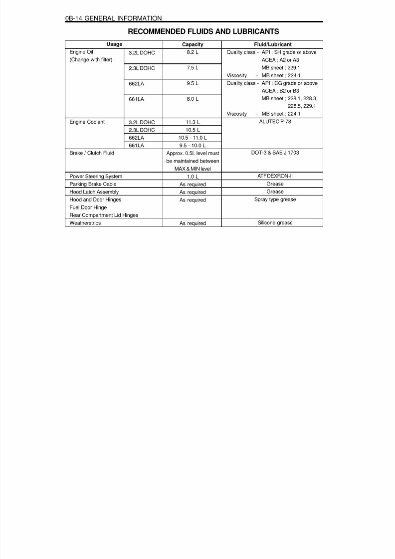
UsageEngine Oil(Change with filter)
Engine Coolant
Brake / Clutch Fluid
Power Steering SystemParking Brake CableHood Latch AssemblyHood and Door HingesFuel Door HingeRear Compartment Lid HingesWeatherstrips
RECOMMENDED FLUIDS AND LUBRICANTS
Capacity8.2 L
7.5 L
9.5 L
8.0 L
11.3 L10.5 L
10.5 - 11.0 L9.5 - 10.0 L
Approx. 0.5L level mustbe maintained between
MAX & MIN level1.0 L
As requiredAs requiredAs required
As required
Fluid/LubricantQuality class - API ; SH grade or above
ACEA ; A2 or A3MB sheet ; 229.1
Viscosity - MB sheet ; 224.1Quality class - API ; CG grade or above
ACEA ; B2 or B3MB sheet ; 228.1, 228.3,
228.5, 229.1Viscosity - MB sheet ; 224.1
ALUTEC P-78
DOT-3 & SAE J 1703
ATF DEXRON-IIGreaseGrease
Spray type grease
Silicone grease
3.2L DOHC
2.3L DOHC
662LA
661LA
3.2L DOHC2.3L DOHC662LA661LA

8/18/2019 SsangYong Musso Service Manual 1998.pdf
http://slidepdf.com/reader/full/ssangyong-musso-service-manual-1998pdf 27/1459
GENERAL INFORMATION 0B-15
GENERAL DESCRIPTIONAND SYSTEM OPERATION
GENERAL REPAIR INSTRUCTIONSIf a floor jack is used, the following precautions are
recommended.Park the vehicle on level ground, “block” the front orrear wheels, set the jack against the frame, raise thevehicle and support it with chassis stands and thenperform the service operation.Before performing the service operation, disconnectthe negative battery cable in order to reduce thechance of cable damaged and burning due to short-cir cuiting.Use a cover on the body, the seats and the floor toprotect them against damage and contamination.Handle brake fluid and antifreeze solution with careas they can cause paint damage.The use of proper tools, and the recommendedessential and available tools where specified, areimportant for efficient and reliable performance ofthe service repairs.
Use genuine DAEWOO parts.Discard used cotter pins, gaskets, O-rings, oil seals,lock washers and self-locking nuts. Prepare new onesfor installation. Normal function of these parts cannotbe maintained if these parts are reused.Keep the disassembled parts neatly in groups tofacilitate proper and smooth reassembly.Keep attaching bolts and nuts separated, as theyvary in hardness and design depending on theposition of the installation.Clean the parts before inspection or reassembly.Also clean the oil parts, etc. Use compressed air tomake certain they are free of restrictions.Lubricate rotating and sliding faces of parts with oilor grease before installation.When necessary, use a sealer on gaskets to preventleakage.Carefully observe all specifications for bolt and nut
torques.When service operation is completed, make a finalcheck to be sure service was done properly and theproblem was corrected.

8/18/2019 SsangYong Musso Service Manual 1998.pdf
http://slidepdf.com/reader/full/ssangyong-musso-service-manual-1998pdf 28/1459
0B-16 GENERAL INFORMATION
VEHICLE IDENTIFICATION NUMBER SYSTEM
K P T P 0 A 1 9 S W P 122357
12~17.Production Serial Number: 000001- 999999
11.Plant CodeP : PyongTaek Plant
10.Model YearM : 1991N :1992P :1993R :1994S :1995
T :1996V :1997W : 1998X : 1999Y : 2000
9. Check DigitConstant “S”
8. Engine Type3 : 2299cc, In-line 4Cylinder, Diesel (OM601)4 : 2874cc, In-line 5Cylinder, Diesel (OM602)8 : 1998cc, In-line 4Cylinder, Gasoline (E20)
6 : 2295cc, In-line 4Cylinder, Gasoline (E23)9 : 3199cc, In-line 6Cylinder, Gasoline (E32)A : 2299cc, In-line 4Cylinder, Diesel (OM601)B : 2874cc, In-line 5Cylinder, Diesel (OM602)C : 2299cc, In-line 4Cylinder, Diesel (SY662LA)D : 2874cc, In-line 5Cylinder, Diesel (SY662LA)
7. Restraint System0 : NO Seat Belt,1 : 3-Point Seat Belts, 2 : 2-Point Seat Belts
6. Trim LevelA : Standard, B : Deluxe, C : Super Deluxe
5. Body Type0 : 5-Door1 : 4-Door2 : 3-Door
4. Line ModelsP : Musso, LHD, R : Musso, RHD
3. Vehicle TypeT (Passengr Cars)
2. Name of Mamufacturer : P1. Nation : K

8/18/2019 SsangYong Musso Service Manual 1998.pdf
http://slidepdf.com/reader/full/ssangyong-musso-service-manual-1998pdf 29/1459
GENERAL INFORMATION 0B-17
Manufacturer’s Plate
Manufacturer’s Plate Location
1.Type Approval No. 2.Vehicle Identification Number.
Diesel Engine Gasoline Engine

8/18/2019 SsangYong Musso Service Manual 1998.pdf
http://slidepdf.com/reader/full/ssangyong-musso-service-manual-1998pdf 30/1459
0B-18 GENERAL INFORMATION
Engine Number Location
Diesel EngineThe engine number is stamped on the cylinder block infront of injection pump.
IL6 3200The engine number is stamped on the lower rear sideof the alternator.
Gasolind Engine Number
162 990 1 0 012345
Serial Number
0 : Manual T/M1 : Hydr - Auto Coupling2 : Automatic T/M
99 : 3.2L97 : 2.3L94 : 2.0L
0 : Common1 : Left - Hand Drive2 : Right - Hand Drive
ENGINE TYPE
0 : MUSSO
Diesel Engine Number
662 920 1 0 012345
Serial Number
0 : Manual T/M1 : Hydr - Auto Coupling2 : Automatic T/M
910 : Non-Intercooler Engine920 : Intercooler Engine
0 : Common1 : Left - Hand Drive2 : Right - Hand Drive
661 : 2299cc662 : 2874cc

8/18/2019 SsangYong Musso Service Manual 1998.pdf
http://slidepdf.com/reader/full/ssangyong-musso-service-manual-1998pdf 31/1459

8/18/2019 SsangYong Musso Service Manual 1998.pdf
http://slidepdf.com/reader/full/ssangyong-musso-service-manual-1998pdf 32/1459
SECTION 1
ENGINE
SECTION 1A1(M162 ENGINE)GENERAL ENGINE INFORMATION
Specifications. . . . . . . . . . . . . . . . . . . . . . . 1A1-1Engine Specifications . . . . . . . . . . . . . . . . . . 1A1-1
Component Locator . . . . . . . . . . . . . . . . . . 1A1-3Front View . . . . . . . . . . . . . . . . . . . . . . . . . . 1A1-3Side View . . . . . . . . . . . . . . . . . . . . . . . . . . . 1A1-4
Performance Curve . . . . . . . . . . . . . . . . . . 1A1-5E32 Engine . . . . . . . . . . . . . . . . . . . . . . . . . . 1A1-5
Special Tools . . . . . . . . . . . . . . . . . . . . . . . 1A1-6Special Tools Table . . . . . . . . . . . . . . . . . . . . 1A1-6
Diagnosis . . . . . . . . . . . . . . . . . . . . . . . . . . 1A1-7Oil Leak Diagnosis . . . . . . . . . . . . . . . . . . . . 1A1-7Engine Cranking at The
Front of Crankshaft . . . . . . . . . . . . . . . . . . 1A1-8Compression Pressure Test . . . . . . . . . . . . . 1A1-9Cylinder Pressure Leakage Test. . . . . . . . . 1A1-11
General Information . . . . . . . . . . . . . . . . . 1A1-13Cleanliness and Care . . . . . . . . . . . . . . . . . 1A1-13On-Engine Service . . . . . . . . . . . . . . . . . . . 1A1-13
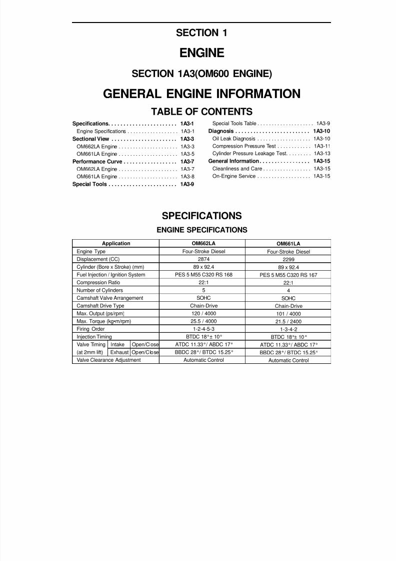
ApplicationEngine ModelDisplacement (CC)Cylinder (Bore x Stroke) (mm)Fuel Injection / Ignition SystemCompression RatioNumber of Cylinders
Camshaft Valve ArrangementCamshaft Drive TypeMax. Output (ps/rpm)Max. Torque (kg•m/rpm)Firing OrderIgnition TypeIgnition TimingValve Timing Intake Open/Close
Exhaust Open/CloseValve Clearance Adjustment
SPECIFICATIONSENGINE SPECIFICATIONS
E32 Engine
M162.9903199
89.9 x 84.0MSE 3.62S
10 : 16
DOHCChain-Driven
222 / 550031.6 / 37501-5-3-6-2-4
Distributorless Double IgnitionBTDC 8°± 2°
ATDC 11°/ ABDC 34°BBDC 31°/ BTDC 14°
Automatic Control
TABLE OF CONTENTS

8/18/2019 SsangYong Musso Service Manual 1998.pdf
http://slidepdf.com/reader/full/ssangyong-musso-service-manual-1998pdf 33/1459
1A1-2 GENERAL ENGINE INFORMATION
Application
Idle Speed (rpm)Fuel Injection Pressure (kg/cm²)Oil Capacity (liter)Lubrication TypeOil Filter TypeFuel
ENGINE SPECIFICATIONS (Cont'd)
E32 Engine700 ± 50
3 - 48.2
Forced by Gear PumpFull Flow with Paper Filter
Unleaded Gasoline
MSE 3.62S/3.53S (Motorsteuer Elektronik : German)MSE : Engine Control Electronic3.62S : 6 Cylinder Version3.53S : 4 Cylinder Version

8/18/2019 SsangYong Musso Service Manual 1998.pdf
http://slidepdf.com/reader/full/ssangyong-musso-service-manual-1998pdf 34/1459
GENERAL ENGINE INFORMATION 1A1-3
COMPONENT LOCATORFRONT VIEW
1 HFM Sensor2 Intake Air Duct3 Resonance Flap4 Cylinder Head Cover5 Exhaust Camshaft6 Intake Camshaft7 Cylinder Head8 Spark Plug Connector9 Valve Tappet
10 Injector11 Exhaust Valve
12 Intake Manifold13 Connecting Rod14 Exhaust Manifold15 Crankshaft16 Engine Mounting Bracket17 Starter18 Crankcase19 Oil Pump Sprocket20 Oil Strainer21 Oil Pan22 Drain Plug

8/18/2019 SsangYong Musso Service Manual 1998.pdf
http://slidepdf.com/reader/full/ssangyong-musso-service-manual-1998pdf 35/1459
1A1-4 GENERAL ENGINE INFORMATION
23 Camshaft Adjuster24 Cooling Fan and Viscous Clutch25 Piston26 Flywheel of Drive Plate
27 Oil Pump Drive Chain28 Oil Return Pipe29 Timing Chain30 Oil Pump
SIDE VIEW

8/18/2019 SsangYong Musso Service Manual 1998.pdf
http://slidepdf.com/reader/full/ssangyong-musso-service-manual-1998pdf 36/1459
GENERAL ENGINE INFORMATION 1A1-5
PERFORMANCE CURVEE32 ENGINE

8/18/2019 SsangYong Musso Service Manual 1998.pdf
http://slidepdf.com/reader/full/ssangyong-musso-service-manual-1998pdf 37/1459
1A1-6 GENERAL ENGINE INFORMATION
SPECIAL TOOLSSPECIAL TOOLS TABLE
000 589 10 99 01Torque Wrench
001 589 76 21 00Compression Pressure
Tester
119 589 01 09 00Spark Plug Wrench
001 589 65 09 00Socket

8/18/2019 SsangYong Musso Service Manual 1998.pdf
http://slidepdf.com/reader/full/ssangyong-musso-service-manual-1998pdf 38/1459
GENERAL ENGINE INFORMATION 1A1-7
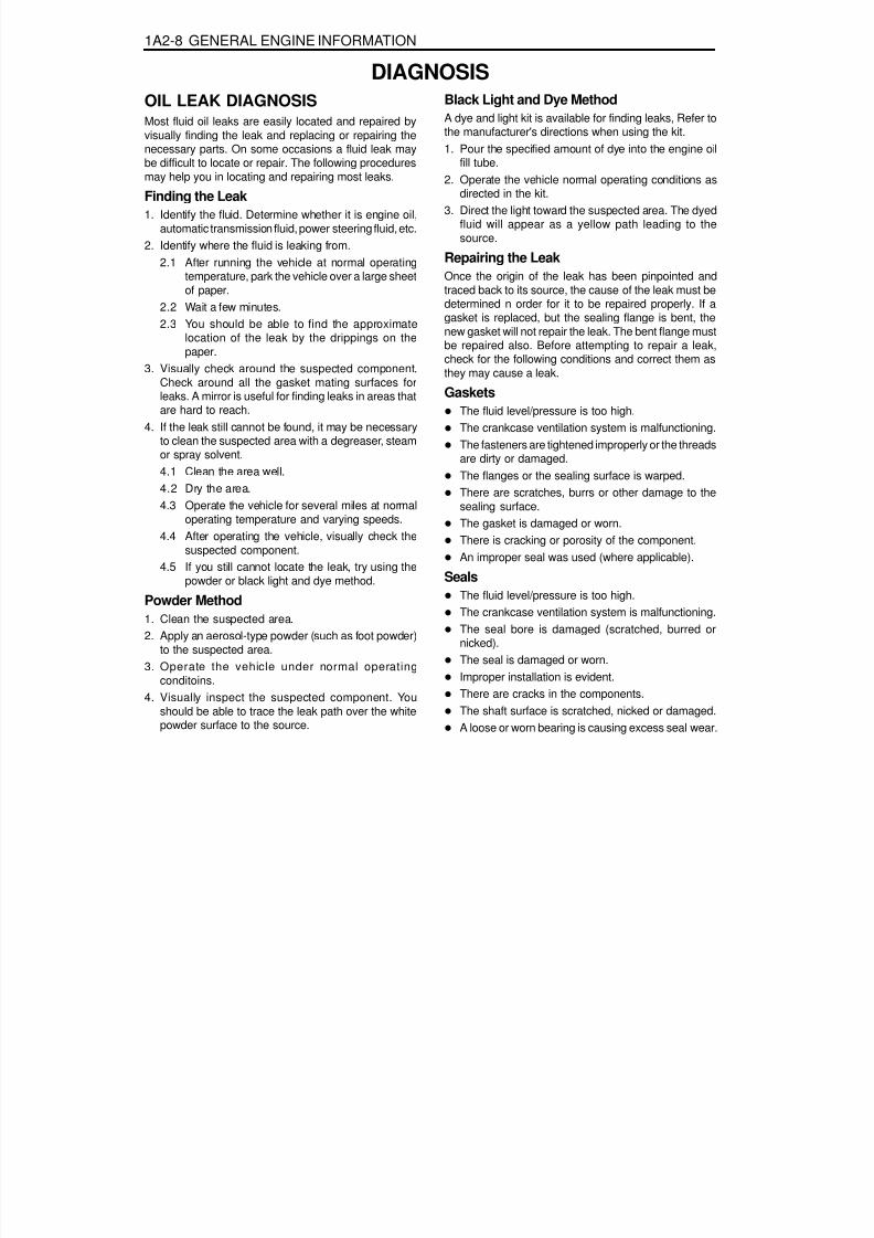
OIL LEAK DIAGNOSISMost fluid oil leaks are easily located and repaired byvisually finding the leak and replacing or repairing thenecessary parts. On some occasions a fluid leak may
be difficult to locate or repair. The following proceduresmay help you in locating and repairing most leaks.
Finding the Leak1. Identify the fluid. Determine whether it is engine oil,
automatic transmission fluid, power steering fluid, etc.2. Identify where the fluid is leaking from.
2.1 After running the vehicle at normal operatingtemperature, park the vehicle over a large sheetof paper.
2.2 Wait a few minutes.2.3 You should be able to find the approximate
location of the leak by the drippings on thepaper.
3. Visually check around the suspected component.Check around all the gasket mating surfaces forleaks. A mirror is useful for finding leaks in areas thatare hard to reach.
4. If the leak still cannot be found, it may be necessaryto clean the suspected area with a degreaser, steamor spray solvent.4.1 Clean the area well.4.2 Dry the area.4.3 Operate the vehicle for several miles at normal
operating temperature and varying speeds.4.4 After operating the vehicle, visually check the
suspected component.4.5 If you still cannot locate the leak, try using the
powder or black light and dye method.
Powder Method1. Clean the suspected area.2. Apply an aerosol-type powder (such as foot powder)
to the suspected area.
3. Operate the vehicle under normal operatingconditoins.
4. Visually inspect the suspected component. Youshould be able to trace the leak path over the whitepowder surface to the source.
Black Light and Dye MethodA dye and light kit is available for finding leaks, Refer tothe manufacturer's directions when using the kit.1. Pour the specified amount of dye into the engine oil
fill tube.
2. Operate the vehicle normal operating conditions asdirected in the kit.
3. Direct the light toward the suspected area. The dyedfluid will appear as a yellow path leading to thesource.
Repairing the LeakOnce the origin of the leak has been pinpointed andtraced back to its source, the cause of the leak must bedetermined n order for it to be repaired properly. If agasket is replaced, but the sealing flange is bent, thenew gasket will not repair the leak. The bent flange mustbe repaired also. Before attempting to repair a leak,check for the following conditions and correct them asthey may cause a leak.
Gaskets
The fluid level/pressure is too high.The crankcase ventilation system is malfunctioning.The fasteners are tightened improperly or the threadsare dirty or damaged.The flanges or the sealing surface is warped.There are scratches, burrs or other damage to thesealing surface.The gasket is damaged or worn.There is cracking or porosity of the component.An improper seal was used (where applicable).
SealsThe fluid level/pressure is too high.The crankcase ventilation system is malfunctioning.The seal bore is damaged (scratched, burred ornicked).The seal is damaged or worn.Improper installation is evident.There are cracks in the components.The shaft surface is scratched, nicked or damaged.A loose or worn bearing is causing excess seal wear.
DIAGNOSIS

8/18/2019 SsangYong Musso Service Manual 1998.pdf
http://slidepdf.com/reader/full/ssangyong-musso-service-manual-1998pdf 39/1459
1A1-8 GENERAL ENGINE INFORMATION
ENGINE CRANKING AT THE FRONT OF CRANKSHAFTPreceding Work : Removal of cooling fan
1 Vibration Damper Assembly2 Crankshaft Pulley
NoticeRemove the negative ground cable before proceeding the work.Rotate the pulley in normal engine rotating direction when cranking.
3 Bolt ................................................. 8.6 ± 0.9 Nm
Tools Required000 589 10 99 01 Torque wrench001 589 65 09 00 Socket

8/18/2019 SsangYong Musso Service Manual 1998.pdf
http://slidepdf.com/reader/full/ssangyong-musso-service-manual-1998pdf 40/1459
GENERAL ENGINE INFORMATION 1A1-9
COMPRESSION PRESSURE TEST
1 Compression Pressure Tester2 Diagram Sheet
3 Adaptor4 Sealing Cone
Tools Required001 589 76 21 00 Compression Pressure Tester119 589 01 09 00 Spark Plug Wrench
Standard Service Data
Compression RatioNormal Engine TemperatureNormal Compression Pressure
Permissible Pressure Difference Between IndividualCylinders
10 : 180°C
Min. 10 bar, Max. 14 barMin. 6 bar, Max. 10 bar
Max. 1.5 bar
GeneralFuel Optimization

8/18/2019 SsangYong Musso Service Manual 1998.pdf
http://slidepdf.com/reader/full/ssangyong-musso-service-manual-1998pdf 41/1459
1A1-10 GENERAL ENGINE INFORMATION
Measuring Procedure1. Warm the engine up to normal operating temperature.2. Remove the spark plugs.3. Place the diagram sheet to compression pressure
tester.4. Connect the adaptor to compression pressure tester
and install it into the spark plug hole.5. Crank the engine approx. eight revolutions by using
the start motor.6. Compare the measurements of compression
pressure tester with the specifications.7. Measure the compression pressure of the other
cylinders in the same way.8. If measured value is not within the specifications,
perform the cylinder pressure leakage test.
NoticeDischarge the combustion residues in the cylindersbefore testing the compression pressure.Apply the parking brake before cranking theengine.

8/18/2019 SsangYong Musso Service Manual 1998.pdf
http://slidepdf.com/reader/full/ssangyong-musso-service-manual-1998pdf 42/1459

8/18/2019 SsangYong Musso Service Manual 1998.pdf
http://slidepdf.com/reader/full/ssangyong-musso-service-manual-1998pdf 43/1459

8/18/2019 SsangYong Musso Service Manual 1998.pdf
http://slidepdf.com/reader/full/ssangyong-musso-service-manual-1998pdf 44/1459

8/18/2019 SsangYong Musso Service Manual 1998.pdf
http://slidepdf.com/reader/full/ssangyong-musso-service-manual-1998pdf 45/1459
SECTION 1
ENGINE
SECTION 1A2(M161 ENGINE)GENERAL ENGINE INFORMATION
TABLE OF CONTENTSSpecifications. . . . . . . . . . . . . . . . . . . . . . . 1A2-1
Engine Specifications . . . . . . . . . . . . . . . . . . 1A2-1Component Locator . . . . . . . . . . . . . . . . . . 1A2-3
Front View . . . . . . . . . . . . . . . . . . . . . . . . . . 1A2-3Side View . . . . . . . . . . . . . . . . . . . . . . . . . . . 1A2-4
Performance Curve . . . . . . . . . . . . . . . . . . 1A2-5E23 Engine . . . . . . . . . . . . . . . . . . . . . . . . . . 1A2-5E20 Engine . . . . . . . . . . . . . . . . . . . . . . . . . . 1A2-6
Special Tools . . . . . . . . . . . . . . . . . . . . . . . 1A2-7Special Tools Table . . . . . . . . . . . . . . . . . . . . 1A2-7
Diagnosis . . . . . . . . . . . . . . . . . . . . . . . . . . 1A2-8Oil Leak Diagnosis . . . . . . . . . . . . . . . . . . . . 1A2-8Engine Cranking At The
Front of Crankshaft . . . . . . . . . . . . . . . . . . 1A2-9
Compression Pressure Test . . . . . . . . . . . . 1A2-10Cylinder Pressure Leakage Test. . . . . . . . . 1A2-12
General Information . . . . . . . . . . . . . . . . . 1A2-14Cleanliness and Care . . . . . . . . . . . . . . . . . 1A2-14On-Engine Service . . . . . . . . . . . . . . . . . . . 1A2-14
E20 EngineM161.940
199889.9 x 78.7
¬
9.6:1¬
¬
¬
135 / 550019.3 / 4000
¬
¬
¬
ATDC 13.15°/ ABDC 13.57°BBDC 16.58°/ BTDC 17.05°
¬
ApplicationEngine ModelDisplacement (CC)Cylinder (Bore x Stroke) (mm)Fuel Injection / Ignition SystemCompression RatioNumber of CylindersCamshaft Valve ArrangementCamshaft Drive TypeMax. Output (ps/rpm)Max. Torque (kg•m/rpm)Firing OrderIgnition TypeIgnition TimingValve Timing Intake Open/Close
Exhaust Open/CloseValve Clearance Adjustment
SPECIFICATIONSENGINE SPECIFICATIONS
E23 EngineM161.970
229590.9 x 88.4MSE 3.53S
10.4:14
DOHCChain-Driven
149 / 550022.4 / 4000
1-3-4-2DistributorlessBTDC 6°± 2°
ATDC 19.25°/ ABDC 28.76°BBDC 20.62°/ BTDC 15.08°
Automatic Control

8/18/2019 SsangYong Musso Service Manual 1998.pdf
http://slidepdf.com/reader/full/ssangyong-musso-service-manual-1998pdf 46/1459
1A2-2 GENERAL ENGINE INFORMATION
E20 Engine¬
¬
¬
¬
¬
¬
Application
Idle Speed (rpm)Fuel Injection Pressure (kg/cm²)Oil Capacity (liter)Lubrication TypeOil Filter TypeFuel
ENGINE SPECIFICATIONS (Cont'd)
E23 Engine
750 ± 503.2 - 4.2
7.5Forced by Gear Pump
Full Flow with Paper FilterUnleaded Gasoline
MSE 3.62S/3.53S (Motorsteuer Elektronik : German)MSE : Engine Control Electronic3.62S : 6 cylinder version3.53S : 4 cylinder version

8/18/2019 SsangYong Musso Service Manual 1998.pdf
http://slidepdf.com/reader/full/ssangyong-musso-service-manual-1998pdf 47/1459
GENERAL ENGINE INFORMATION 1A2-3
COMPONENT LOCATORFRONT VIEW
1 HFM Sensor
2 Intake Air Duct3 Cylinder Head Cover4 Ignition Coil5 Spark Plug Connector6 Fuel Distributor7 Injector8 Exhaust Camshaft9 Intake Camshaft
10 Valve Tappet11 Intake Valve
12 Intake Manifold
13 Cylinder Head14 Exhaust Manifold15 Dipstick Guide Tube and Gauge16 Connecting Rod17 Crankshaft18 Engine Mounting Bracket19 Starter20 Crankcase21 Oil Pump Sprocket22 Oil Pan

8/18/2019 SsangYong Musso Service Manual 1998.pdf
http://slidepdf.com/reader/full/ssangyong-musso-service-manual-1998pdf 48/1459
1A2-4 GENERAL ENGINE INFORMATION
23 Camshaft Adjuster24 Oil Filler Cap25 Engine Hanger Bracket
26 Cooling Fan and Viscous Clutch27 Oil Filter28 Timing Chain
29 Oil Pump Drive Chain30 Oil Strainer31 Oil Pump
32 Ring Gear and Flywheel of Drive Plate33 Piston
SIDE VIEW

8/18/2019 SsangYong Musso Service Manual 1998.pdf
http://slidepdf.com/reader/full/ssangyong-musso-service-manual-1998pdf 49/1459
GENERAL ENGINE INFORMATION 1A2-5
PERFORMANCE CURVEE23 ENGINE

8/18/2019 SsangYong Musso Service Manual 1998.pdf
http://slidepdf.com/reader/full/ssangyong-musso-service-manual-1998pdf 50/1459
1A2-6 GENERAL ENGINE INFORMATION
E20 ENGINE

8/18/2019 SsangYong Musso Service Manual 1998.pdf
http://slidepdf.com/reader/full/ssangyong-musso-service-manual-1998pdf 51/1459
8/18/2019 SsangYong Musso Service Manual 1998.pdf
http://slidepdf.com/reader/full/ssangyong-musso-service-manual-1998pdf 52/1459
1A2-8 GENERAL ENGINE INFORMATION
OIL LEAK DIAGNOSISMost fluid oil leaks are easily located and repaired byvisually finding the leak and replacing or repairing thenecessary parts. On some occasions a fluid leak may
be difficult to locate or repair. The following proceduresmay help you in locating and repairing most leaks.
Finding the Leak1. Identify the fluid. Determine whether it is engine oil,
automatic transmission fluid, power steering fluid, etc.2. Identify where the fluid is leaking from.
2.1 After running the vehicle at normal operatingtemperature, park the vehicle over a large sheetof paper.
2.2 Wait a few minutes.2.3 You should be able to find the approximate
location of the leak by the drippings on thepaper.
3. Visually check around the suspected component.Check around all the gasket mating surfaces forleaks. A mirror is useful for finding leaks in areas thatare hard to reach.
4. If the leak still cannot be found, it may be necessaryto clean the suspected area with a degreaser, steamor spray solvent.4.1 Clean the area well.4.2 Dry the area.4.3 Operate the vehicle for several miles at normal
operating temperature and varying speeds.4.4 After operating the vehicle, visually check the
suspected component.4.5 If you still cannot locate the leak, try using the
powder or black light and dye method.
Powder Method1. Clean the suspected area.2. Apply an aerosol-type powder (such as foot powder)
to the suspected area.
3. Operate the vehicle under normal operatingconditoins.
4. Visually inspect the suspected component. Youshould be able to trace the leak path over the whitepowder surface to the source.
Black Light and Dye MethodA dye and light kit is available for finding leaks, Refer tothe manufacturer's directions when using the kit.1. Pour the specified amount of dye into the engine oil
fill tube.2. Operate the vehicle normal operating conditions as
directed in the kit.3. Direct the light toward the suspected area. The dyed
fluid will appear as a yellow path leading to thesource.
Repairing the LeakOnce the origin of the leak has been pinpointed andtraced back to its source, the cause of the leak must bedetermined n order for it to be repaired properly. If agasket is replaced, but the sealing flange is bent, the
new gasket will not repair the leak. The bent flange mustbe repaired also. Before attempting to repair a leak,check for the following conditions and correct them asthey may cause a leak.
GasketsThe fluid level/pressure is too high.The crankcase ventilation system is malfunctioning.The fasteners are tightened improperly or the threadsare dirty or damaged.The flanges or the sealing surface is warped.There are scratches, burrs or other damage to thesealing surface.The gasket is damaged or worn.There is cracking or porosity of the component.An improper seal was used (where applicable).
SealsThe fluid level/pressure is too high.The crankcase ventilation system is malfunctioning.The seal bore is damaged (scratched, burred ornicked).The seal is damaged or worn.Improper installation is evident.There are cracks in the components.The shaft surface is scratched, nicked or damaged.A loose or worn bearing is causing excess seal wear.
DIAGNOSIS

8/18/2019 SsangYong Musso Service Manual 1998.pdf
http://slidepdf.com/reader/full/ssangyong-musso-service-manual-1998pdf 53/1459
GENERAL ENGINE INFORMATION 1A2-9
ENGINE CRANKING AT THE FRONT OF CRANKSHAFTPreceding Work : Removal of cooling fan
1 Torque Wrench2 Socket3 Vibration Damper Ass'y
NoticeRemove the negative ground cable before proceeding the work.Rotate the pulley in normal engine rotating direction when cranking.
Tools Required000 589 10 99 01 Torque Wrench001 589 65 09 00 Socket
4 Center Bolt (M18 ́ 55, 1piece)..................................... 1st Step 200Nm + 20Nm
2nd Step 90°+ 10°

8/18/2019 SsangYong Musso Service Manual 1998.pdf
http://slidepdf.com/reader/full/ssangyong-musso-service-manual-1998pdf 54/1459
1A2-10 GENERAL ENGINE INFORMATION
COMPRESSION PRESSURE TEST
1 Compression Pressure Tester2 Diagram Sheet
3 Adaptor4 Sealing Cone
Tools Required001 589 76 21 00 Compression Pressure Tester119 589 01 09 00 Spark Plug Wrench
Standard Service DataCompression RatioNormal Engine TemperatureNormal Compression Pressure
Permissible Pressure Difference Between IndividualCylinders
10.4, 9.680°C
Min. 11 bar, Max. 15 barMin. 10.5 bar, Max. 14 bar
Max. 1.5 bar
E23 Engine(e = 10.4)E20 Engine(e = 9.6)

8/18/2019 SsangYong Musso Service Manual 1998.pdf
http://slidepdf.com/reader/full/ssangyong-musso-service-manual-1998pdf 55/1459

8/18/2019 SsangYong Musso Service Manual 1998.pdf
http://slidepdf.com/reader/full/ssangyong-musso-service-manual-1998pdf 56/1459
1A2-12 GENERAL ENGINE INFORMATION
CYLINDER PRESSURE LEAKAGE TEST
3 Engine Oil Filler Cap5 Vibration Damper
Permissible Pressure Leakage
6 Cylinder Pressure Leakage Tester withConnecting Hose
Universal Tool
At Whole EngineAt Valve and Cylinder Head GasketAt Piston and Piston Ring
Max. 25 %Max. 10 %Max. 20 %
Cylinder Number By Mark On Vibration Damper At TDC
TDC MarkCylinder Number
UT (BDC : 180°)
2, 3
OT (TDC)
1, 4
Cylinder Pressure Leakage Tester Bosch EF AW 210ASun, CLT 228

8/18/2019 SsangYong Musso Service Manual 1998.pdf
http://slidepdf.com/reader/full/ssangyong-musso-service-manual-1998pdf 57/1459

8/18/2019 SsangYong Musso Service Manual 1998.pdf
http://slidepdf.com/reader/full/ssangyong-musso-service-manual-1998pdf 58/1459
1A2-14 GENERAL ENGINE INFORMATION
GENERAL INFORMATIONCLEANLINESS AND CAREAn automobile engine is a combination of manymachined, honed, polished and lapped surfaces withtolerances that are measured in the ten-thousanths of
an inch. When any internal engine parts are serviced,care and cleanliness are important. A liberal coating ofenigne oil should be applied to friction areas duringassembly, to protect and lubricate the surfaces on initialoperation. Proper cleaning and protection of machinedsurfaces and friction areas is part of the repairprocedure. This is considered standard shop practiceeven if not specifically stated.Whenever valve train components are removed forservice, they should be kept in order. They should beinstalled in the same locations, and with the same matingsurfaces, as when they were removed.
Battery cables should be disconnected before any majorwork is performed on the engine. Failure to disconnectcables may result in damage to wire harness or otherelectrical parts.
ON-ENGINE SERVICECaution: Disconnect the negative battery cable be- fore removing or installing any electrical unit, or when a tool or equipment could easily come in con-
tact with exposed electrical terminals. Disconnect- ing this cable will help prevent personal injury and damage to the vehicle. The ignition must also be in LOCK unless otherwise noted.
Notice: Any time the air cleaner is removed, the intakeopening should be covered. This will protect againstaccidental entrance of foreign material, which couldfollow the intake passage into the cylinder and causeextensive damage when the engine is started.
8/18/2019 SsangYong Musso Service Manual 1998.pdf
http://slidepdf.com/reader/full/ssangyong-musso-service-manual-1998pdf 59/1459

8/18/2019 SsangYong Musso Service Manual 1998.pdf
http://slidepdf.com/reader/full/ssangyong-musso-service-manual-1998pdf 60/1459
1A3-2 GENERAL ENGINE INFORMATION
OM 662 LA
720 - 820135 - 1438.0 - 9.5
Forced by Gear PumpCombined Full-Flow and Partial Flow
FilterDiesel
Application
Idle Speed (rpm)Fuel Injection Pressure (bar)Oil Capacity (liter)Lubrication TypeOil Filter Type
Fuel
ENGINE SPECIFICATIONS (Cont'd)
OM661LA750 - 850135 - 1436.5 - 8.0
Forced by Gear PumpCombined Full-Flow and Partial Flow
FilterDiesel

8/18/2019 SsangYong Musso Service Manual 1998.pdf
http://slidepdf.com/reader/full/ssangyong-musso-service-manual-1998pdf 61/1459
GENERAL ENGINE INFORMATION 1A3-3
SECTIONAL VIEWOM662LA ENGINEFront View

8/18/2019 SsangYong Musso Service Manual 1998.pdf
http://slidepdf.com/reader/full/ssangyong-musso-service-manual-1998pdf 62/1459
1A3-4 GENERAL ENGINE INFORMATION
Side View

8/18/2019 SsangYong Musso Service Manual 1998.pdf
http://slidepdf.com/reader/full/ssangyong-musso-service-manual-1998pdf 63/1459
GENERAL ENGINE INFORMATION 1A3-5
OM661LA ENGINEFront View

8/18/2019 SsangYong Musso Service Manual 1998.pdf
http://slidepdf.com/reader/full/ssangyong-musso-service-manual-1998pdf 64/1459

8/18/2019 SsangYong Musso Service Manual 1998.pdf
http://slidepdf.com/reader/full/ssangyong-musso-service-manual-1998pdf 65/1459

8/18/2019 SsangYong Musso Service Manual 1998.pdf
http://slidepdf.com/reader/full/ssangyong-musso-service-manual-1998pdf 66/1459
1A3-8 GENERAL ENGINE INFORMATION
OM661LA ENGINE
rpm

8/18/2019 SsangYong Musso Service Manual 1998.pdf
http://slidepdf.com/reader/full/ssangyong-musso-service-manual-1998pdf 67/1459
GENERAL ENGINE INFORMATION 1A3-9
SPECIAL TOOLSSPECIAL TOOLS TABLE
000 589 10 99 01Torque Wrench
001 589 76 21 00Compression Pressure
Tester
001 589 73 21 00Hand Vacuum Pump
001 589 65 09 00Socket

8/18/2019 SsangYong Musso Service Manual 1998.pdf
http://slidepdf.com/reader/full/ssangyong-musso-service-manual-1998pdf 68/1459
1A3-10 GENERAL ENGINE INFORMATION
OIL LEAK DIAGNOSISMost fluid oil leaks are easily located and repaired byvisually finding the leak and replacing or repairing thenecessary parts. On some occasions a fluid leak may
be difficult to locate or repair. The followingprocedures may help you in locating and repairingmost leaks.
Finding the Leak1. Identify the fluid. Determine whether it is engine
oil, automatic transmission fluid, power steeringfluid, etc.
2. Identify where the fluid is leaking from.2.1 After running the vehicle at normal operating
temperature, park the vehicle over a largesheet of paper.
2.2 Wait a few minutes.2.3 You should be able to find the approximate
location of the leak by the drippings on thepaper.
3. Visually check around the suspected component.Check around all the gasket mating surfaces forleaks. A mirror is useful for finding leaks in areasthat are hard to reach.
4. If the leak still cannot be found, it may benecessary to clean the suspected area with adegreaser, steam or spray solvent.
4.1 Clean the area well.4.2 Dry the area.4.3 Operate the vehicle for several miles at
normal operating temperature and varyingspeeds.
4.4 After operating the vehicle, visually check thesuspected component.
4.5 If you still cannot locate the leak, try using thepowder or black light and dye method.
Powder Method1. Clean the suspected area.2. Apply an aerosol-type powder (such as foot
powder) to the suspected area.3. Operate the vehicle under normal operating
conditions.4. Visually inspect the suspected component. You
should be able to trace the leak path over the whitepowder surface to the source.
Black Light and Dye MethodA dye and light kit is available for finding leaks, Referto the manufacturer's directions when using the kit.
1. Pour the specified amount of dye into the engineoil fill tube.
2. Operate the vehicle normal operating conditionsas directed in the kit.
3. Direct the light toward the suspected area. Thedyed fluid will appear as a yellow path leading tothe source.
Repairing the LeakOnce the origin of the leak has been pinpointed andtraced back to its source, the cause of the leak mustbe determined n order for it to be repaired properly. Ifa gasket is replaced, but the sealing flange is bent,the new gasket will not repair the leak. The bent flangemust be repaired also. Before attempting to repair aleak, check for the following conditions and correctthem as they may cause a leak.
GasketsThe fluid level/pressure is too high.The crankcase ventilation system is malfunctioning.The fasteners are tightened improperly or thethreads are dirty or damaged.The flanges or the sealing surface is warped.There are scratches, burrs or other damage to thesealing surface.The gasket is damaged or worn.There is cracking or porosity of the component.An improper seal was used (where applicable).
SealsThe fluid level/pressure is too high.The crankcase ventilation system is malfunctioning.The seal bore is damaged (scratched, burred ornicked).The seal is damaged or worn.Improper installation is evident.There are cracks in the components.The shaft surface is scratched, nicked or damaged.A loose or worn bearing is causing excess sealwear.
DIAGNOSIS

8/18/2019 SsangYong Musso Service Manual 1998.pdf
http://slidepdf.com/reader/full/ssangyong-musso-service-manual-1998pdf 69/1459
GENERAL ENGINE INFORMATION 1A3-11
28barApprox.18bar
Max. 3bar
COMPRESSION PRESSURE TEST
1 Test Adapter2 Flexible Connector3 Compression Pressure Recorder
Tools Required000 589 65 09 00 Socket001 589 73 21 00 Hand Vacuum Pump
Service DataNormal Compression PressureMinimum Compression PressurePermissible Pressure Difference Between Individual Cylinders
Engine at normal operating temperature of 80°C

8/18/2019 SsangYong Musso Service Manual 1998.pdf
http://slidepdf.com/reader/full/ssangyong-musso-service-manual-1998pdf 70/1459
1A3-12 GENERAL ENGINE INFORMATION
Compression Pressure MeasurementNoticeEnsure that no gear is engaged and that the vehicle isprotected from rolling.
1. Run the engine to be the coolant temperature 80°C.2. Remove the fuel injection nozzle.
Socket Wrench Insert 001 589 65 09 00
3. Install the test adapter (1) and connect the flexibleconnector (2) to the compression pressure recorder.
Compression Pressure Recorder 001 589 76 21 00
4. Disconnect the vacuum line from the stop unit andconnect the hand vacuum pump to the stop unit.
5. Pump the hand vacuum pump and make the fuel injectionpump in stop position.
Operating Pressure Approx. 500bar
Hand Vacuum Pump 001 589 73 21 00
6. Using a starter motor, crank the engine 8 revolutions.7. Measure the remaining cylinder compression pressure
in the same manner and compare it with service data.
NoticeIf out of standard, do cylinder pressure leakage test.
8. Remove the compression pressure recorder.
9. Install the fuel injection nozzle.

8/18/2019 SsangYong Musso Service Manual 1998.pdf
http://slidepdf.com/reader/full/ssangyong-musso-service-manual-1998pdf 71/1459
8/18/2019 SsangYong Musso Service Manual 1998.pdf
http://slidepdf.com/reader/full/ssangyong-musso-service-manual-1998pdf 72/1459
1A3-14 GENERAL ENGINE INFORMATION
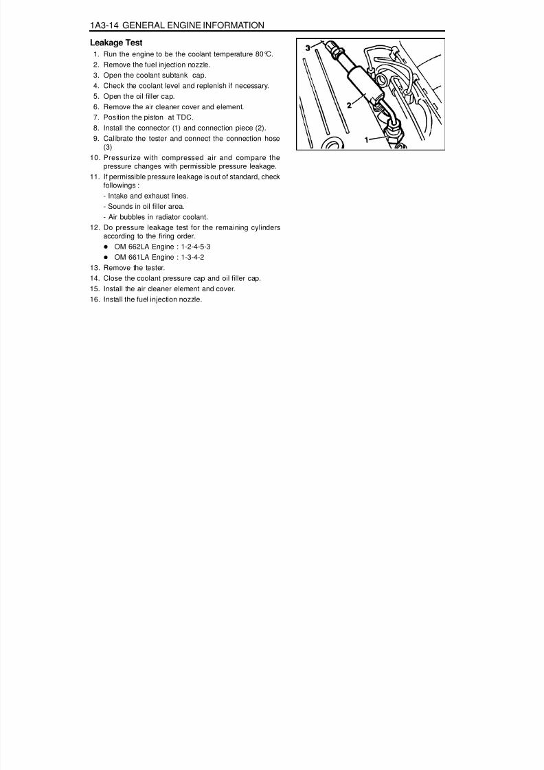
Leakage Test1. Run the engine to be the coolant temperature 80°C.2. Remove the fuel injection nozzle.3. Open the coolant subtank cap.4. Check the coolant level and replenish if necessary.5. Open the oil filler cap.6. Remove the air cleaner cover and element.7. Position the piston at TDC.8. Install the connector (1) and connection piece (2).9. Calibrate the tester and connect the connection hose
(3)10. Pressurize with compressed air and compare the
pressure changes with permissible pressure leakage.11. If permissible pressure leakage is out of standard, check
followings :- Intake and exhaust lines.
- Sounds in oil filler area.- Air bubbles in radiator coolant.
12. Do pressure leakage test for the remaining cylindersaccording to the firing order.
OM 662LA Engine : 1-2-4-5-3OM 661LA Engine : 1-3-4-2
13. Remove the tester.14. Close the coolant pressure cap and oil filler cap.15. Install the air cleaner element and cover.16. Install the fuel injection nozzle.

8/18/2019 SsangYong Musso Service Manual 1998.pdf
http://slidepdf.com/reader/full/ssangyong-musso-service-manual-1998pdf 73/1459

8/18/2019 SsangYong Musso Service Manual 1998.pdf
http://slidepdf.com/reader/full/ssangyong-musso-service-manual-1998pdf 74/1459
SECTION 1B1
M162 ENGINE MECHANICAL
CAUTION: Disconnect the negative battery cable before removing or installing any electrical unit or when a tool or equipment could easily come in contact with exposed electrical terminals. Disconnecting this cable will help prevent personal injury and damage to the vehicle. The ignition must also be in LOCK unless otherwise noted.
Specifications. . . . . . . . . . . . . . . . . . . . . . . 1B1-2Fastener Tightening Specifications . . . . . . . . 1B1-2
Special Tools . . . . . . . . . . . . . . . . . . . . . . . 1B1-4
Special Tools Table . . . . . . . . . . . . . . . . . . . . 1B1-4Maintenance and Repair . . . . . . . . . . . . . . 1B1-8On-Vehicle Service . . . . . . . . . . . . . . . . . . . . . 1B1-8
Engine Assembly . . . . . . . . . . . . . . . . . . . . . 1B1-8Crankcase Ventilation System . . . . . . . . . . 1B1-16Alternator . . . . . . . . . . . . . . . . . . . . . . . . . . 1B1-18Power Steering Pump and A/C Bracket . . . 1B1-19Hydraulic Engine Mounting Insulator . . . . . . 1B1-22Poly V-Belt . . . . . . . . . . . . . . . . . . . . . . . . . 1B1-25Tensioning Device . . . . . . . . . . . . . . . . . . . . 1B1-27
Poly V-Belt Inspection . . . . . . . . . . . . . . . . . 1B1-29Cylinder Head Cover . . . . . . . . . . . . . . . . . 1B1-31Cylinder Head Front Cover . . . . . . . . . . . . . 1B1-33Cylinder Head . . . . . . . . . . . . . . . . . . . . . . . 1B1-35Timing Gear Case Cover . . . . . . . . . . . . . . 1B1-38Crankshaft Sealing Rear Cover . . . . . . . . . 1B1-40Belt Pulley and Vibration Damper . . . . . . . . 1B1-42Crankshaft Front Radial Seal . . . . . . . . . . . 1B1-45Crankshaft Rear Radial Seal . . . . . . . . . . . 1B1-46Crankshaft . . . . . . . . . . . . . . . . . . . . . . . . . 1B1-47
Flywheel / Driven Plate . . . . . . . . . . . . . . . . 1B1-53Camshaft Adjuster . . . . . . . . . . . . . . . . . . . 1B1-55Camshaft Sprocket Bolt . . . . . . . . . . . . . . . 1B1-58Camshaft . . . . . . . . . . . . . . . . . . . . . . . . . . 1B1-59
TABLE OF CONTENTSCamshaft Timing Position . . . . . . . . . . . . . . 1B1-64Valve Spring . . . . . . . . . . . . . . . . . . . . . . . . 1B1-67Valve Stem Seal . . . . . . . . . . . . . . . . . . . . . 1B1-71
Chain Tensioner . . . . . . . . . . . . . . . . . . . . . 1B1-72Timing Chain . . . . . . . . . . . . . . . . . . . . . . . . 1B1-75Tensioning Rail . . . . . . . . . . . . . . . . . . . . . . 1B1-80Cylinder Head Guide Rail . . . . . . . . . . . . . . 1B1-81Crankcase Guide Rail. . . . . . . . . . . . . . . . . 1B1-82Crankshaft Sprocket . . . . . . . . . . . . . . . . . . 1B1-83Piston . . . . . . . . . . . . . . . . . . . . . . . . . . . . . 1B1-85Connecting Rod . . . . . . . . . . . . . . . . . . . . . 1B1-88Piston Ring . . . . . . . . . . . . . . . . . . . . . . . . . 1B1-90Engine Oil Specification . . . . . . . . . . . . . . . 1B1-92
Oil Pan . . . . . . . . . . . . . . . . . . . . . . . . . . . . 1B1-93Engine Oil and Oil Filter Element . . . . . . . . 1B1-95Oil Filter . . . . . . . . . . . . . . . . . . . . . . . . . . . 1B1-97Oil Pump . . . . . . . . . . . . . . . . . . . . . . . . . . . 1B1-99Oil Pressure Relief Valve . . . . . . . . . . . . . 1B1-101Oil Non-Return Valve . . . . . . . . . . . . . . . . 1B1-102Oil Dipstick Guide Tube . . . . . . . . . . . . . . 1B1-103
Unit Repair . . . . . . . . . . . . . . . . . . . . . . . 1B1-104Oil Gallery in Crankcase . . . . . . . . . . . . . . 1B1-104Oil Gallery in Cylinder Head . . . . . . . . . . . 1B1-106Core Plugs in Crankcase . . . . . . . . . . . . . 1B1-109Cylinder Bore . . . . . . . . . . . . . . . . . . . . . . 1B1-111Crankcase Mating Surface . . . . . . . . . . . . 1B1-113Cylinder Head Mating Surface . . . . . . . . . 1B1-115

8/18/2019 SsangYong Musso Service Manual 1998.pdf
http://slidepdf.com/reader/full/ssangyong-musso-service-manual-1998pdf 75/1459

8/18/2019 SsangYong Musso Service Manual 1998.pdf
http://slidepdf.com/reader/full/ssangyong-musso-service-manual-1998pdf 76/1459
M162 ENGINE MECHANICAL 1B1-3
N····· m20 / +90°
4072 - 88
20 / +90°25 - 35
22.5 - 27.522.5 - 27.522.5 - 27.522.5 - 27.5
3026 - 34
308 - 10
2525
22.5 - 27.529 - 35
22.5 - 27.59 - 11
509 - 11
15
ApplicationExhaust Camshaft Sproket BoltChain Tensioner Screw PlugChain Tensioner Assembly
Exhaust Camshaft Sprocket to CamshaftOil Pump Sprocket BoltTensioning Device BoltWater Pump PulleyUpper Intake Manifold BoltLower Intake Mainfold BoltFlange Bolt to Exhaust MainfoldExhaust Mainfold Nut to Stud BoltRivet Nut in Exhuast Mainfold HolePre-silencer Bolt
Oil Drain PlugOil Filter CoverOil Filter BoltOil Pump Drive Sprocket BoltOil Pump Mounting BoltOil Strainer Bracket BoltOil Pressure Relief Valve Screw PlugOil Dipstick Guide Tube BoltOil Gallery Screw Plug
FASTENER TIGHTENING SPECIFICATIONS (Cont’d)

8/18/2019 SsangYong Musso Service Manual 1998.pdf
http://slidepdf.com/reader/full/ssangyong-musso-service-manual-1998pdf 77/1459
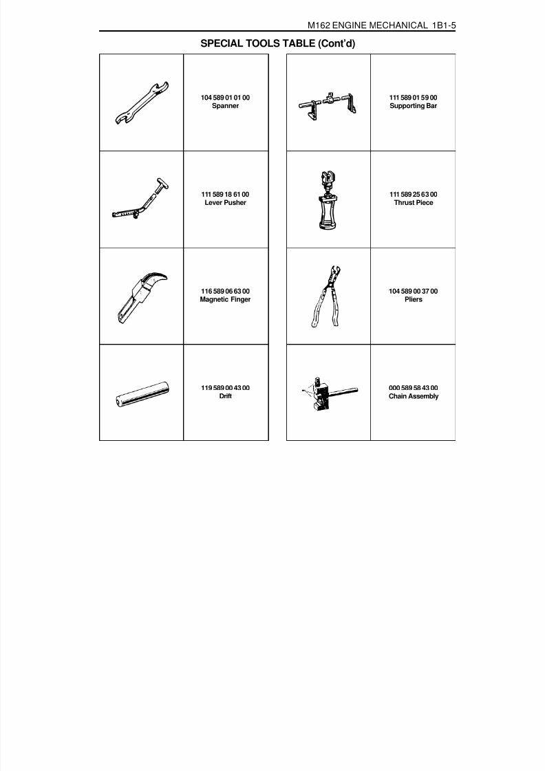
8/18/2019 SsangYong Musso Service Manual 1998.pdf
http://slidepdf.com/reader/full/ssangyong-musso-service-manual-1998pdf 78/1459

8/18/2019 SsangYong Musso Service Manual 1998.pdf
http://slidepdf.com/reader/full/ssangyong-musso-service-manual-1998pdf 79/1459
1B1-6 M162 ENGINE MECHANICAL
116 589 20 33 00Sliding Hammer
602 589 00 40 00Engine Lock
103 589 00 33 00Puller
SPECIAL TOOLS TABLE (Cont’d)
601 589 03 43 00Sleeve
001 589 65 09 00Socket Wrench Insert
001 589 74 21 00Torque Wrench
000 589 04 14 00Clamping Strap
000 589 88 33 00Puller
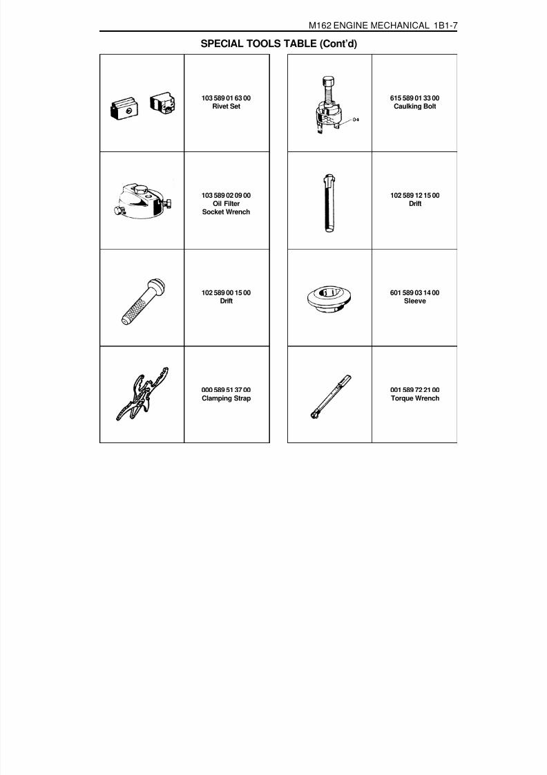
8/18/2019 SsangYong Musso Service Manual 1998.pdf
http://slidepdf.com/reader/full/ssangyong-musso-service-manual-1998pdf 80/1459
M162 ENGINE MECHANICAL 1B1-7
103 589 01 63 00Rivet Set
103 589 02 09 00Oil Filter
Socket Wrench
102 589 12 15 00Drift
SPECIAL TOOLS TABLE (Cont’d)
615 589 01 33 00Caulking Bolt
102 589 00 15 00Drift
000 589 51 37 00Clamping Strap
001 589 72 21 00Torque Wrench
601 589 03 14 00Sleeve

8/18/2019 SsangYong Musso Service Manual 1998.pdf
http://slidepdf.com/reader/full/ssangyong-musso-service-manual-1998pdf 81/1459
1B1-8 M162 ENGINE MECHANICAL
MAINTENANCE AND REPAIR
ON-VEHICLE SERVICEENGINE ASSEMBLY
Tools Required000 589 10 99 01 Torque Wrench000 589 40 37 00 Hose Clamp112 589 00 72 00 Oil Extractor

8/18/2019 SsangYong Musso Service Manual 1998.pdf
http://slidepdf.com/reader/full/ssangyong-musso-service-manual-1998pdf 82/1459
M162 ENGINE MECHANICAL 1B1-9
4. Disconnect the coupling of HFM sensor and remove the aircleaner cross pipe.
6. Loosen the radiator drain cock and drain the coolant.NoticeOpen the coolant reservoir cap.
5. Remove the air cleaner cover. Remove the mounting boltsand air cleaner housing and element assembly.
Removal & Installation Procedure1. Disconnect the negative terminal of battery.2. Remove the hood.3. Remove the under cover.
Installation Notice
Tightening Torque 28 - 47 Nm

8/18/2019 SsangYong Musso Service Manual 1998.pdf
http://slidepdf.com/reader/full/ssangyong-musso-service-manual-1998pdf 83/1459

8/18/2019 SsangYong Musso Service Manual 1998.pdf
http://slidepdf.com/reader/full/ssangyong-musso-service-manual-1998pdf 84/1459

8/18/2019 SsangYong Musso Service Manual 1998.pdf
http://slidepdf.com/reader/full/ssangyong-musso-service-manual-1998pdf 85/1459
1B1-12 M162 ENGINE MECHANICAL
19. Disconnect the engine ground wire.
15. Remove the automatic transmission dipstick guide tube.
16. Disconnect the wire of alternator.
17. Disconnect the wire of starter motor and remove the startermotor.
18. Disconnect the engine main harness ground.

8/18/2019 SsangYong Musso Service Manual 1998.pdf
http://slidepdf.com/reader/full/ssangyong-musso-service-manual-1998pdf 86/1459
M162 ENGINE MECHANICAL 1B1-13
20. Disconnect following sensors connector.HFM sensor.Coolant temperature sensor.2 knock sensors.Camshaft and crankshaft sensors.
21. After removing the ignition coil cover, disconnect the ignitioncoil connector.
22. Remove the harness cover and disconnect the 6 injectionvalve connectors. Disconnect the main harness
23. Separate the hose toward engine from canister purgesolenoid valve.
24. Remove the automatic transmission oil cooler line.
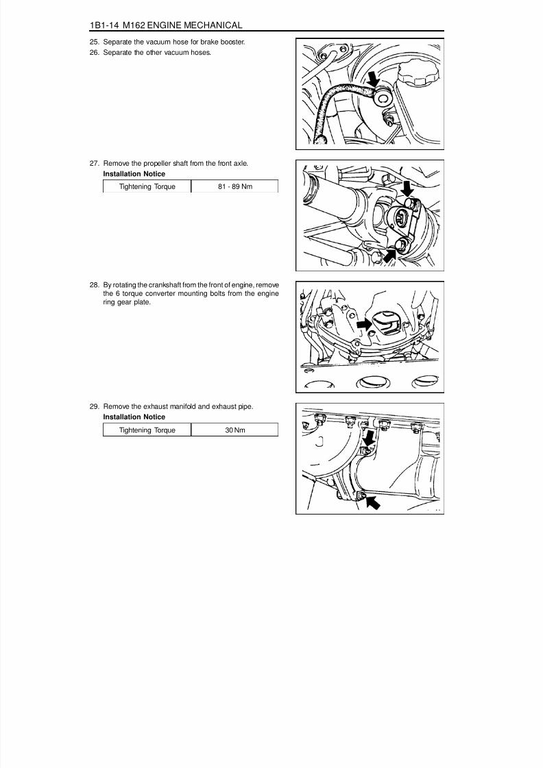
8/18/2019 SsangYong Musso Service Manual 1998.pdf
http://slidepdf.com/reader/full/ssangyong-musso-service-manual-1998pdf 87/1459
1B1-14 M162 ENGINE MECHANICAL
Tightening Torque 30 Nm
29. Remove the exhaust manifold and exhaust pipe.Installation Notice
25. Separate the vacuum hose for brake booster.26. Separate the other vacuum hoses.
27. Remove the propeller shaft from the front axle.Installation Notice
28. By rotating the crankshaft from the front of engine, removethe 6 torque converter mounting bolts from the enginering gear plate.
Tightening Torque 81 - 89 Nm

8/18/2019 SsangYong Musso Service Manual 1998.pdf
http://slidepdf.com/reader/full/ssangyong-musso-service-manual-1998pdf 88/1459

8/18/2019 SsangYong Musso Service Manual 1998.pdf
http://slidepdf.com/reader/full/ssangyong-musso-service-manual-1998pdf 89/1459
1B1-16 M162 ENGINE MECHANICAL
CRANKCASE VENTILATION SYSTEM
1 Crankcase2 Air Admission Port in Crankcase3 Oil Drain Port4 Filter5 Gasket6 A/C Bracket
7 Oil Drain Pipe8 Oil Pan9 Air Admission Line
10 Vent Line11 Restriction Hole (Diameter = 2 mm)12 Intake Manifold
13 Intake Air Duct (Cross Pipe)14 Cylinder Head Cover15 Oil Separator16 Oil Separator17 Air Admission and Vent Connection18 Air Admission and Vent Connection
19 Throttle Valve20 Vent LineA Fresh AirB Blowby Gas in Partial LoadC Blowby Gas in Full Load

8/18/2019 SsangYong Musso Service Manual 1998.pdf
http://slidepdf.com/reader/full/ssangyong-musso-service-manual-1998pdf 90/1459
M162 ENGINE MECHANICAL 1B1-17
Operation at Idling and Mid-LoadIt show that the throttle valve (19) is closed or very partiallyopened and the vacuum pressure in intake manifold is high.The blowby gas in the crankcase in partial load flows intothe intake manifold through the vent line (20) after passingthe air conditioner bracket (6) and the filter (4). The airreentered into the intake manifold will be dilluted on the flowthrough the restriction hole (11) in the vent line (10).The circulated engine oil is separated at the air conditionerbracket (6) and then returns into the oil pan through thedrain pipe (7).The vacuum pressure generated at the crankcase sucksfresh air from intake air line(13) through the air admissionand vent connection (17,18).The fresh air prevents engine oil from being contami-natedand the air admission and vent connection (17,18) isdesigned to control the rapid pressure changes in intakeair line (13).
Operation at Full-LoadThe throttle valve (19) is fully opened.All the blowby gases flow into the intake air duct (13) afterpassing through the oil separator (15,16) of the cylinderhead cover (14) when fully loaded. This dilluted air will besupplied to the combustion chamber through the intakemanifold (12).

8/18/2019 SsangYong Musso Service Manual 1998.pdf
http://slidepdf.com/reader/full/ssangyong-musso-service-manual-1998pdf 91/1459
1B1-18 M162 ENGINE MECHANICAL
ALTERNATOR
1 Nut (M8) ......................................... 22.5-27.5 Nm2 Bolt (M8 x 30, 3 pieces) ................. 22.5-27.5 Nm3 Bolt (M8 x 40, 1 piece) ................... 22.5-27.5 Nm
Removal & Installation Procedure1. Remove the drive belt.2. Remove the alternator.3. Unscrew the alternator carrier bolts and remove the carrier.
Installation Notice
4 Bolt (M8 x 70, 1 piece) ................... 22.5-27.5 Nm5 Bolt (M8 x 75, 1 piece) ................... 22.5-27.5 Nm
Tightening Torque 10 - 15 Nm
4. Installation should follow the removal procedure in thereverse order.

8/18/2019 SsangYong Musso Service Manual 1998.pdf
http://slidepdf.com/reader/full/ssangyong-musso-service-manual-1998pdf 92/1459
M162 ENGINE MECHANICAL 1B1-19
POWER STEERING PUMP AND A/C BRACKETPreceding Work : Removal of cooling fan and shroud
1 Vent Hose2 Bolt (M8 x 91, 2 pieces) ................. 22.5-27.5 Nm3 Power Steering Pump4 Bolt (M8 x 105, 4 pieces) ............... 22.5-27.5 Nm5 Washer6 A/C Compressor7 Bolt (M8 x 40, 3 pieces,
M8 x 95, 2 pieces).......................... 22.5-27.5 Nm
8 A/C Bracket9 Gasket ................................................... Replace
10 Bracket11 Bolt (M8 x 22, 2 pieces) ................. 22.5-27.5 Nm12 Tensioning Pulley13 Nut ................................................. 40.5-49.5 Nm

8/18/2019 SsangYong Musso Service Manual 1998.pdf
http://slidepdf.com/reader/full/ssangyong-musso-service-manual-1998pdf 93/1459
1B1-20 M162 ENGINE MECHANICAL
Removal & Installation Procedure1. Remove the belt pulley.
Installation Notice
2. Disconnect the hydraulic pipe of the power steering pumpand drain the oil.
3. Unscrew the bolts (arrows) and remove the steering pump.
Installation Notice
NoticePull the tensioning pulley clockwise as shown in the figure.
4. Remove the compressor after disconnecting the wiringconnector and refrigerant pipe of A/C compressor.NoticeDischarge all the refrigerant before removing the pipes.
Tightening Torque 40.5 - 49.5 Nm
Tightening Torque 22.5 - 27.5 Nm

8/18/2019 SsangYong Musso Service Manual 1998.pdf
http://slidepdf.com/reader/full/ssangyong-musso-service-manual-1998pdf 94/1459
M162 ENGINE MECHANICAL 1B1-21
5. Disconnect the vent hose from the A/C bracket.
6. Unscrew all the mounting bolts (arrows) and remove theA/C bracket and the gasket.
Installation Notice
7. Clean the sealing surface.8. Replace the gasket with new one.9. Installation should follow the removal procedure in the
reverse order.10. Check the oil leakage by operating the engine after
installation.
Tightening Torque 22.5 - 27.5 Nm

8/18/2019 SsangYong Musso Service Manual 1998.pdf
http://slidepdf.com/reader/full/ssangyong-musso-service-manual-1998pdf 95/1459
1B1-22 M162 ENGINE MECHANICAL
HYDRAULIC ENGINE MOUNTING INSULATORService Data

8/18/2019 SsangYong Musso Service Manual 1998.pdf
http://slidepdf.com/reader/full/ssangyong-musso-service-manual-1998pdf 96/1459
M162 ENGINE MECHANICAL 1B1-23
Sectional View
1 Rubber Body2 Brackek3 Core4 Lower Bolt5 Rubber Plunger6 Plunger Plate7 Rubber8 Plate
9 Lower Orifice10 Upper Orifice11 Diaphram12 Cover Plate13 Upper Bolt14 Flange Bolt15 Rivet16 Fluid

8/18/2019 SsangYong Musso Service Manual 1998.pdf
http://slidepdf.com/reader/full/ssangyong-musso-service-manual-1998pdf 97/1459
1B1-24 M162 ENGINE MECHANICAL
1 Upper Nut2 Hydraulic Installor ................. 62-93 Nm3 Lower Nut ............................. 28-47 Nm
Removal and Installation Procedure1. Unscrew the upper nut(1) on engine mounting and remove
the engine.
Installation Notice
3. Installation should follow the removal procedure in thereverse order.
Tightening Torque 62 - 93 Nm
2. Unscrew the lower nut(3) and remove the hydraulic enginemounting insulator.
Installation Notice
Tightening Torque 28 - 47 Nm
NoticeIf the insulator is spotted with oil, replace the hydraulicinsulator assembly.
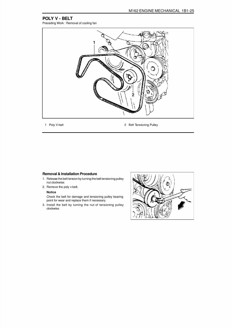
8/18/2019 SsangYong Musso Service Manual 1998.pdf
http://slidepdf.com/reader/full/ssangyong-musso-service-manual-1998pdf 98/1459
M162 ENGINE MECHANICAL 1B1-25
POLY V - BELTPreceding Work : Removal of cooling fan
1 Poly V-belt
Removal & Installation Procedure1. Release the belt tension by turning the belt tensioning pulley
nut clockwise.2. Remove the poly v-belt.
NoticeCheck the belt for damage and tensioning pulley bearingpoint for wear and replace them if necessary.
3. Install the belt by turning the nut of tensioning pulleyclockwise.
2 Belt Tensioning Pulley
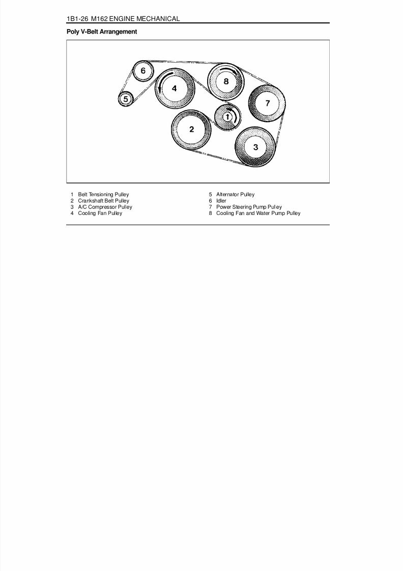
8/18/2019 SsangYong Musso Service Manual 1998.pdf
http://slidepdf.com/reader/full/ssangyong-musso-service-manual-1998pdf 99/1459
1B1-26 M162 ENGINE MECHANICAL
Poly V-Belt Arrangement
1 Belt Tensioning Pulley2 Crankshaft Belt Pulley3 A/C Compressor Pulley4 Cooling Fan Pulley
5 Alternator Pulley6 Idler7 Power Steering Pump Pulley8 Cooling Fan and Water Pump Pulley
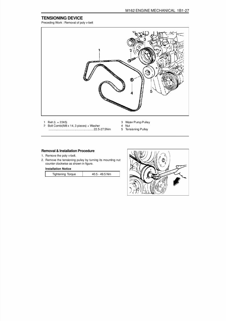
8/18/2019 SsangYong Musso Service Manual 1998.pdf
http://slidepdf.com/reader/full/ssangyong-musso-service-manual-1998pdf 100/1459
M162 ENGINE MECHANICAL 1B1-27
TENSIONING DEVICEPreceding Work : Removal of poly v-belt
1 Belt (L = 2245)2 Bolt Combi(M8 x 14, 3 pieces) + Washer
.......................................................22.5-27.5Nm
Removal & Installation Procedure1. Remove the poly v-belt.2. Remove the tensioning pulley by turning its mounting nut
counter clockwise as shown in figure.
Installation Notice
3 Water Pump Pulley4 Nut
5 Tensioning Pulley
Tightening Torque 40.5 - 49.5 Nm

8/18/2019 SsangYong Musso Service Manual 1998.pdf
http://slidepdf.com/reader/full/ssangyong-musso-service-manual-1998pdf 101/1459
1B1-28 M162 ENGINE MECHANICAL
4. Remove the mounting bolts(M8 x 30, 3 pieces) at the
tensioning device, and remove the tensioning device (arrow).Installation Notice
3. Remove the 3 bolts (2) and remove the water pump pulley(arrow).
Installation Notice
5. Installation should follow the removal procedure in thereverse order.
Tightening Torque 22.5 - 27.5 Nm
Tightening Torque 26 - 32 Nm

8/18/2019 SsangYong Musso Service Manual 1998.pdf
http://slidepdf.com/reader/full/ssangyong-musso-service-manual-1998pdf 102/1459
M162 ENGINE MECHANICAL 1B1-29
3. Pointed rib.4. Belt cord visible in the base of rib.
POLY V - BELT INSPECTIONMake marks on the belt with chalk.Rotate the engine and check the belt for damage.
NoticeIf one of the following types of damages is found, replacethe belt.
1. Rubber lumps in the base of rib.2. Dirt or grit ingrained.
5. Cord torn out at the side.6. Outer cords frayed.

8/18/2019 SsangYong Musso Service Manual 1998.pdf
http://slidepdf.com/reader/full/ssangyong-musso-service-manual-1998pdf 103/1459
1B1-30 M162 ENGINE MECHANICAL
7. Rib detached from the base of belt.
8. Splits across the rib.9. Sections of rib torn out.
10. Splits across several ribs.
11. Splits across the back of the belt.

8/18/2019 SsangYong Musso Service Manual 1998.pdf
http://slidepdf.com/reader/full/ssangyong-musso-service-manual-1998pdf 104/1459
M162 ENGINE MECHANICAL 1B1-31
CYLINDER HEAD COVER
1 Ignition Cable Dust Cover2 Bolt (M6 x 65, 8 pieces) ......................... 9-11 Nm3 Bolt (M6 x 50, 4 pieces) ......................... 9-11 Nm4 Spacer Sleeve5 Thrust Piece
Composition of The Cylinder Head Cover Bolts
A. M6 x 50, 4 Pieces - Bolts + WashersB. M6 x 65, 8 Pieces - Bolts + Washers
6 Cylinder Head Cover7 Gasket ................................................... Replace8 Spart Plug Hole Seal .............................. Replace9 Camshaft Seal ....................................... Replace

8/18/2019 SsangYong Musso Service Manual 1998.pdf
http://slidepdf.com/reader/full/ssangyong-musso-service-manual-1998pdf 105/1459
1B1-32 M162 ENGINE MECHANICAL
Removal & Installation Procedure1. Remove the intake air duct.
Installation Notice
2. Remove the ignition cable cover.
Installation Notice
3. Remove the spark plug connector and ignition cable.
4. Unscrew all the bolts (2,3) and remove the head cover andthe gasket.Installation Notice
NoticeUnscrew the seven (M6 x 60) bolts and remove the ignitioncable cover.
NoticeReplace the gasket with a new one if necessary.
5. Installation should follow the removal procedure in thereverse order.
6. Check for oil leaks by operating the engine.
Tightening Torque 8 - 9 Nm
Tightening Torque 9 - 10 Nm
Tightening Torque 9 - 10 Nm

8/18/2019 SsangYong Musso Service Manual 1998.pdf
http://slidepdf.com/reader/full/ssangyong-musso-service-manual-1998pdf 106/1459
M162 ENGINE MECHANICAL 1B1-33
CYLINDER HEAD FRONT COVERPreceding Work : Removal of cylinder head cover
Removal of coolant connection fitting
1 Camshaft Position Sensor2 Magnet Assembly3 Upper Guide Rail4 Bolt (M6 x 60, 3 pieces) ................. 22.5-27.5 Nm
5 Bolt (M8 x 80, 3 pieces) ................. 22.5-27.5 Nm6 Front Cover7 Rubber Gasket ...................................... Replace8 Bolt (M6 x 16, 3 pieces) ......................... 9-11 Nm
Removal & Installation Procedure1. Remove the magnet assembly.
Installation Notice
Tightening Torque 9 - 11 Nm

8/18/2019 SsangYong Musso Service Manual 1998.pdf
http://slidepdf.com/reader/full/ssangyong-musso-service-manual-1998pdf 107/1459
1B1-34 M162 ENGINE MECHANICAL
2. Remove the cylinder head front cover (6).
Installation Notice
4. Remove the gasket (arrow).
Installation NoticeReplace the gasket with new one and apply the sealant.
5. Installation should follow the removal procedure in the
reverse order.
Apply the sealant at the mating surface of the cylinder headand the front cover.
3. Remove the upper guide rail pin and the guide rail (3).Installation NoticeInstall it while the chain tensioner is loose.
Tightening Torque 22.5 - 27.5 Nm
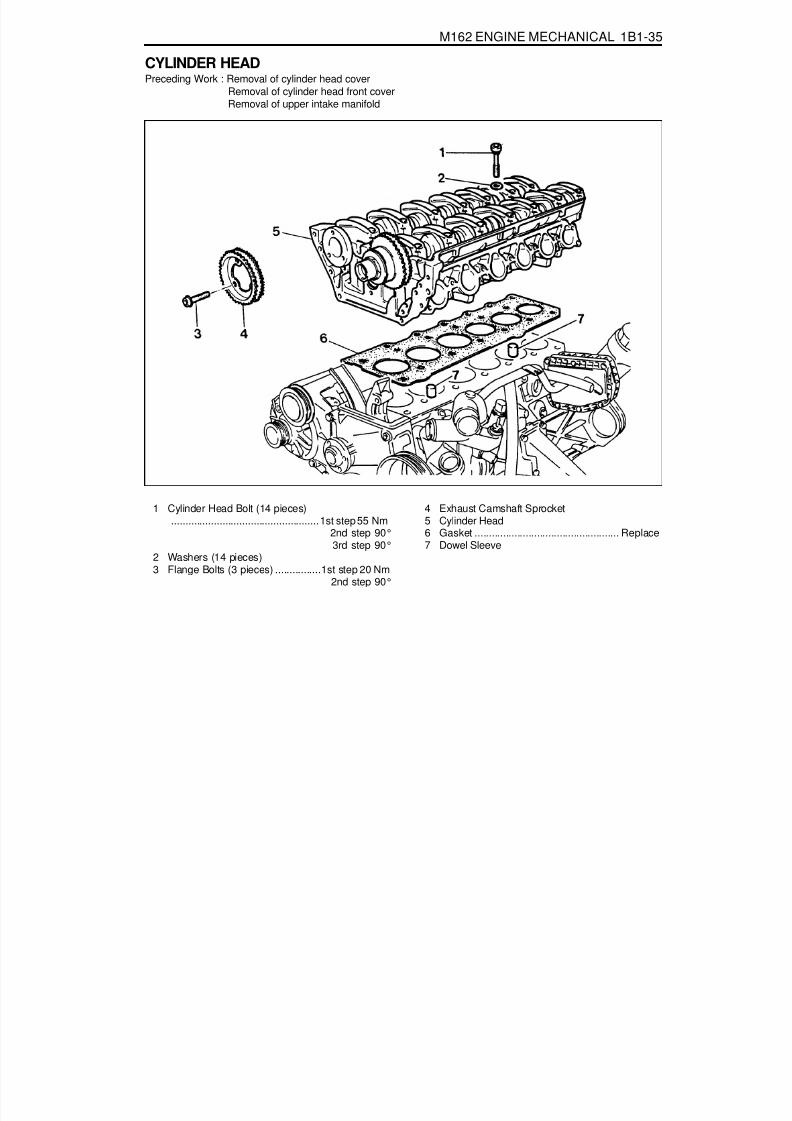
8/18/2019 SsangYong Musso Service Manual 1998.pdf
http://slidepdf.com/reader/full/ssangyong-musso-service-manual-1998pdf 108/1459
M162 ENGINE MECHANICAL 1B1-35
CYLINDER HEADPreceding Work : Removal of cylinder head cover
Removal of cylinder head front coverRemoval of upper intake manifold
1 Cylinder Head Bolt (14 pieces)....................................................1st step 55 Nm
2nd step 90°3rd step 90°
2 Washers (14 pieces)3 Flange Bolts (3 pieces) ................1st step 20 Nm
2nd step 90°
4 Exhaust Camshaft Sprocket5 Cylinder Head6 Gasket ................................................... Replace7 Dowel Sleeve

8/18/2019 SsangYong Musso Service Manual 1998.pdf
http://slidepdf.com/reader/full/ssangyong-musso-service-manual-1998pdf 109/1459

8/18/2019 SsangYong Musso Service Manual 1998.pdf
http://slidepdf.com/reader/full/ssangyong-musso-service-manual-1998pdf 110/1459
M162 ENGINE MECHANICAL 1B1-37
7. Remove the cylinder head bolts in numerical order.
Installation Notice
8. Check the length of the cylinder head bolt.
Installation Notice
Box Wrench Insert 000 589 01 10 00
Replace the bolt if the measured length exceed themax. length.Apply the oil to the thread surface of bolt.
9. Carefully remove the cylinder head and check the matingsurface.
10. Installation should follow the removal procedure in thereverse order.
6. Remove the guide rail fixing pin from the cylinder head usingthe sliding hammer (01) and the threaded pin (02).
Sliding Hammer 116 589 20 33 00Threaded Pin 116 589 02 34 00
Tightening Torque1st step 55 Nm2nd step 90°3rd step 90°
Length (L)New 160 ± 0.8 mm
Max. 162 ± 0.7 mm
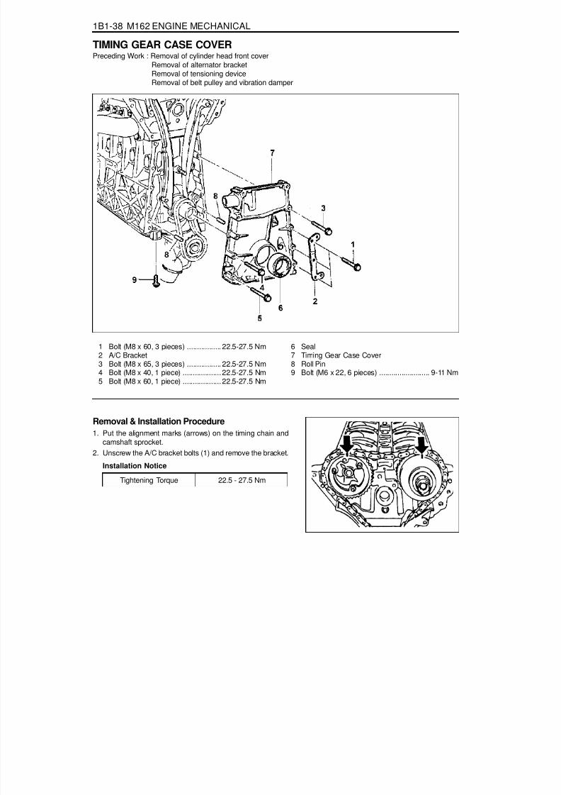
8/18/2019 SsangYong Musso Service Manual 1998.pdf
http://slidepdf.com/reader/full/ssangyong-musso-service-manual-1998pdf 111/1459
1B1-38 M162 ENGINE MECHANICAL
TIMING GEAR CASE COVERPreceding Work : Removal of cylinder head front cover
Removal of alternator bracketRemoval of tensioning deviceRemoval of belt pulley and vibration damper
1 Bolt (M8 x 60, 3 pieces) ................. 22.5-27.5 Nm2 A/C Bracket3 Bolt (M8 x 65, 3 pieces) ................. 22.5-27.5 Nm4 Bolt (M8 x 40, 1 piece) ................... 22.5-27.5 Nm5 Bolt (M8 x 60, 1 piece) ................... 22.5-27.5 Nm
6 Seal7 Timing Gear Case Cover8 Roll Pin9 Bolt (M6 x 22, 6 pieces) ......................... 9-11 Nm
Removal & Installation Procedure1. Put the alignment marks (arrows) on the timing chain and
camshaft sprocket.2. Unscrew the A/C bracket bolts (1) and remove the bracket.
Installation Notice
Tightening Torque 22.5 - 27.5 Nm

8/18/2019 SsangYong Musso Service Manual 1998.pdf
http://slidepdf.com/reader/full/ssangyong-musso-service-manual-1998pdf 112/1459
M162 ENGINE MECHANICAL 1B1-39
3. Remove the cooling fan and the viscous clutch. Unscrewthe three bolts from the cooling fan bracket and remove thebracket (arrows).
Installation Notice
4. Remove the timing gear case cover after unscrewing thebolts (3) and (4) from the timing gear case cover and thebolt (9) from the oil pan.
Notice
Be careful not to damage the oil pan gasket.Installation Notice
Apply the sealant after cleaning the timing gear casecover surface.Be careful not to stain the oil chamber of chain tensionerwith the sealant.
5. Installation should follow the removal procedure in thereverse order.6. Warm up the engine and check for oil leaks.
Tightening Torque 22.5 - 27.5 Nm
Tightening TorqueBolt (3,4) 22.5 - 27.5 Nm
Bolt (9) 9 - 11 Nm

8/18/2019 SsangYong Musso Service Manual 1998.pdf
http://slidepdf.com/reader/full/ssangyong-musso-service-manual-1998pdf 113/1459
1B1-40 M162 ENGINE MECHANICAL
CRANKSHAFT SEALING REAR COVERPreceding Work : Removal of the automatic transmission drive plate
1 Bolt (M6 x 20, 6 pieces) ......................... 9-11 Nm2 Radial Shaft Seal3 Rear Cover
4 Sleeve5 Bolt (M6 x 85, 2 pieces) ......................... 9-11 Nm6 Washer
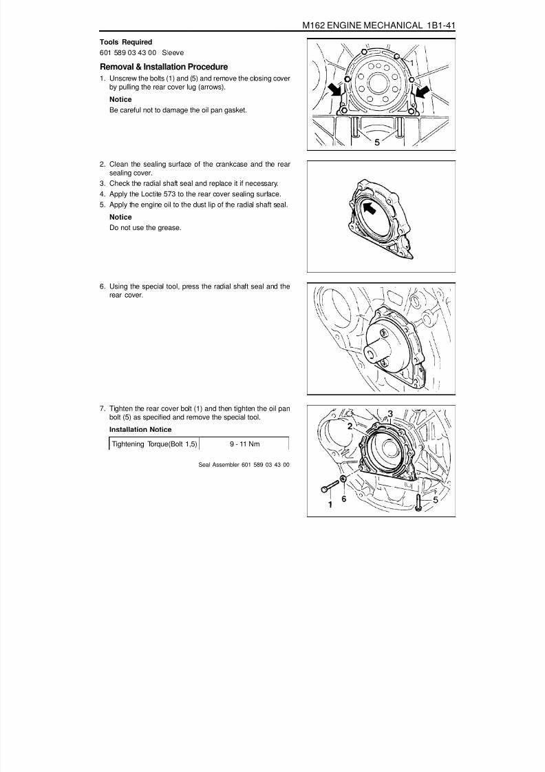
8/18/2019 SsangYong Musso Service Manual 1998.pdf
http://slidepdf.com/reader/full/ssangyong-musso-service-manual-1998pdf 114/1459
M162 ENGINE MECHANICAL 1B1-41
Tools Required601 589 03 43 00 Sleeve
Removal & Installation Procedure1. Unscrew the bolts (1) and (5) and remove the closing cover
by pulling the rear cover lug (arrows).
NoticeBe careful not to damage the oil pan gasket.
2. Clean the sealing surface of the crankcase and the rearsealing cover.
3. Check the radial shaft seal and replace it if necessary.4. Apply the Loctite 573 to the rear cover sealing surface.
5. Apply the engine oil to the dust lip of the radial shaft seal.NoticeDo not use the grease.
6. Using the special tool, press the radial shaft seal and therear cover.
7. Tighten the rear cover bolt (1) and then tighten the oil panbolt (5) as specified and remove the special tool.Installation Notice
Seal Assembler 601 589 03 43 00
Tightening Torque(Bolt 1,5) 9 - 11 Nm

8/18/2019 SsangYong Musso Service Manual 1998.pdf
http://slidepdf.com/reader/full/ssangyong-musso-service-manual-1998pdf 115/1459
1B1-42 M162 ENGINE MECHANICAL
1 Center Bolt (M18 x 50) ...... 1st step 200- 220 Nm2nd step 90°+10°
2 Vibration Damper Disk3 Bolt (M6 x 20, 6 pieces) ..................... 7.7-9.5 Nm
BELT PULLEY AND VIBRATION DAMPERPreceding Work : Removal of cooling fan and viscous clutch
Removal of fan shroudRemoval of drive belt
4 Vibration Damper Assembly5 Woodruff Key6 Bolt (M6 x 12, 4 pieces) ......................... 9-11 Nm7 Cooling Fan Pulley

8/18/2019 SsangYong Musso Service Manual 1998.pdf
http://slidepdf.com/reader/full/ssangyong-musso-service-manual-1998pdf 116/1459
M162 ENGINE MECHANICAL 1B1-43
Components
1 Center Bolt (M18 x 50)2 Center Bolt Washer3 Vibration Damper and Pulley Assembly4 Key5 Crankshaft Front Seal6 Timing Gear Case Cover7 Crankshaft Sprocket (Camshaft Driven)8 Crankshaft Sprocket (Oil pump Driven)9 Crankshaft
10 Oil Pan11 Oil Pan Gasket12 Oil Pan Mounting Bolt (M6 x 22)
Service Data Standard
Permissble Deviation of The Vibration Damper Radial RunoutAxial Runout
0.6 mm0.6 mm
Tools Required103 589 00 33 00 Puller001 589 65 09 00 Socket Wrench Insert602 589 00 40 00 Engine Lock
Removal & Installation Procedure1. Adjust the piston of number 1 cylinder to the TDC.
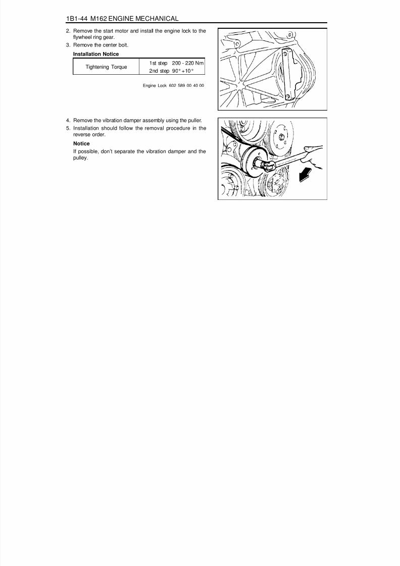
8/18/2019 SsangYong Musso Service Manual 1998.pdf
http://slidepdf.com/reader/full/ssangyong-musso-service-manual-1998pdf 117/1459
1B1-44 M162 ENGINE MECHANICAL
Engine Lock 602 589 00 40 00
2. Remove the start motor and install the engine lock to theflywheel ring gear.
3. Remove the center bolt.
Installation Notice
Tightening Torque1st step 200 - 220 Nm2nd step 90°+10°
4. Remove the vibration damper assembly using the puller.5. Installation should follow the removal procedure in the
reverse order.
Notice
If possible, don’t separate the vibration damper and thepulley.

8/18/2019 SsangYong Musso Service Manual 1998.pdf
http://slidepdf.com/reader/full/ssangyong-musso-service-manual-1998pdf 118/1459
M162 ENGINE MECHANICAL 1B1-45
CRANKSHAFT FRONT RADIAL SEALPreceding Work : Removal of belt pulley and vibration damper
1 Center Bolt (M18 x 50)................................ 1st step 200-220 Nm
2nd step 90°+10°2 Center Bolt Washer3 Sleeve (Special Tool)4 Crankshaft Front Seal5 Key
Tools Required601 589 03 14 00 Sleeve
Replacement Procedure1. Remove the radial seal with a screw driver.
NoticeUse a clean cloth not to damage the radial seal mountinghole and the crankshaft.
5. Remove the sleeve and install the belt pulley and thevibration damper.
6. Check for leaks while operating the engine.
2. Coat the radial sealing lip with engine oil.3. Using the sleeve, assemble the radial seal .4. Align the sleeve groove and the woodruff key and tighten
the center bolt until the center bolt and the damper diskstop in the movement.
Installation Notice
Tightening Torque1st step 200 - 220Nm2nd step 90°+ 10°

8/18/2019 SsangYong Musso Service Manual 1998.pdf
http://slidepdf.com/reader/full/ssangyong-musso-service-manual-1998pdf 119/1459
1B1-46 M162 ENGINE MECHANICAL
CRANKSHAFT REAR RADIAL SEALPreceding Work : Removal of flywheel or drive plate
1 Special Tool2 Special Tool
3 Crankshaft Rear Seal
Tools Required601 589 03 43 00 Sleeve
Replacement Proceudre1. Remove the radial seal with a screw driver.
Notice
Use a clean cloth not to damage the radial seal mountinghole and the crankshaft.
2. Install the special tool (2) to the crankshaft.3. Apply the engine oil on the special tool (2).
NoticeDo not use the grease.
4. Install the radial seal on the inner parts assembler.5. Press in the special tool (1) until the radial seal is stopped.6. Check for leaks while operating the engine.

8/18/2019 SsangYong Musso Service Manual 1998.pdf
http://slidepdf.com/reader/full/ssangyong-musso-service-manual-1998pdf 120/1459

8/18/2019 SsangYong Musso Service Manual 1998.pdf
http://slidepdf.com/reader/full/ssangyong-musso-service-manual-1998pdf 121/1459

8/18/2019 SsangYong Musso Service Manual 1998.pdf
http://slidepdf.com/reader/full/ssangyong-musso-service-manual-1998pdf 122/1459
M162 ENGINE MECHANICAL 1B1-49
Selection of Crankshaft Main Bearing1. Crankcase Side
There are seven punching marks on the mating surface tooil pan. This mark is correspondent to the bearingdistinguished by color. Select the relevant bearing accordingto the punching mark when repaired.
2. Crankshaft Bearing Cap SideSelect the crankshaft main bearing according to the markingletter on the crankshaft main journal when repaired.
Color Dot Marking
BlueYellowRed
WhiteViolet
Crankshaft Journal Diameter (mm)
57.960 - 57.96557.955 - 57.96057.950 - 57.95557.945 - 57.95057.940 - 57.945
Punching Mark
···
···
Bearing Color SelectedBlue
YellowRed
Marking LetterBYRWV
Bearing Color Selected
BlueYellowRed
WhiteViolet
Service DataUnit : mm
CrankshaftBearing Jour-nal Diameter
CrankshaftBearing
Diameter
CrankshaftJournal Widthat fit bearing
Connecting RodBearing Journal
Diameter
ConnectingRod Bearing
Jourmal WidthStandard size1st repair size2nd repair size3rd repair size4th repair size
57.950-57.96557.700-57.71557.450-57.46557.200-57.21556.950-56.965
58 24.50-24.533
-
47.94-47.9647.7547.5047.2547.00
27.958-28.042
-
Crankshaft Standardand Repair Size

8/18/2019 SsangYong Musso Service Manual 1998.pdf
http://slidepdf.com/reader/full/ssangyong-musso-service-manual-1998pdf 123/1459
1B1-50 M162 ENGINE MECHANICAL
Installation NoticeMake sure the crankshaft bearing cap properly seatedin place in the crankcase side. When perfectly installed,the projected part (arrow) locates in the left side (intakemanifold side).Assemble so that the projected part of the cap andcrankcase face the same direction.
Removal & Installation Procedure1. Unscrew the connecting rod bearing cap bolt and remove
the bearing cap.
Installation Notice
2. Unscrew the crankshaft bearing cap bolts and separate theupper and lower bearing shells and thrust washers.
Installation Notice
Remove the bearing cap from front (pulley side) to rear.Make sure that the upper and lower bearing shells donot change each other and coat with engine oil.The oil grooves (arrows) in the thrust washers must faceoutward and insert the thrust bearing into the bearingcap.There are five kinds of thrust washers by thickness. Selectthe proper washer when repaired.
3. Remove the crankshaft.4. Installation should follow the removal procedure in the
reverse order.5. After completion of the installation, check for the rotating
condition of the crankshaft.
Make sure that the upper and lower bearing shells donot change each other.Coat the bearing shell with engine oil.Install the bearing cap according to the consecutivenumber.
Part No. : 601 030 00 62 2.15 mmPart No. : 601 030 01 62 2.20 mmPart No. : 601 030 02 62 2.25 mmPart No. : 601 030 03 62 2.30 mmPart No. : 601 030 04 62 2.40 mm
Tightening Torque 40 Nm + 90°
Tightening Torque 55 Nm + 90°

8/18/2019 SsangYong Musso Service Manual 1998.pdf
http://slidepdf.com/reader/full/ssangyong-musso-service-manual-1998pdf 124/1459
M162 ENGINE MECHANICAL 1B1-51
Inspection1. If the length ‘L’ of the crankshaft bearing cap bolt exceeds
63.8mm, replace it.
2. Make sure the crankshaft bearing cap is properly seatedon the cylinder block (arrows).
3. Measure and record the inner diameter of the crankshaftbearing.
NoticeMeasure at 2 points (1, 2).Measure ‘A’,‘B’and ‘C’ as shown. If average value of ‘B’and ‘C’is less than value ‘A’, then the average value of‘B’ and ‘C’ is actual average value. If average value of‘B’ and ‘C’ is more than value ‘A’is actual average value.
4. Measure and record the diameter of the crankshaft bearing journal.Notice
Record the mean value when measured at 3 points (A,B, C).Measure the inner diameter of bearing and the diameterof journal and if it is out of the standard data, replacethe bearing shell.

8/18/2019 SsangYong Musso Service Manual 1998.pdf
http://slidepdf.com/reader/full/ssangyong-musso-service-manual-1998pdf 125/1459
1B1-52 M162 ENGINE MECHANICAL
Service Data Standard (Crankshaft Main Bearing Gap)
(Connecting Rod Bearing Gap)
ItemMain Bearing Journal
( NO. 1, 5, 7)
Main Bearing Journal( NO. 3, 4, 6)
Measuring Position
Radial
Axial
Radial
Axial
Gap (mm)Static condition :0.015 - 0.039
Dynamic condition: 0.031 - 0.051(Consider the expansion 0.011 - 0.016)
0.010 - 0.254Static condition :0.011 - 0.039
Dynamic condition: 0.031 - 0.051(Consider the expansion 0.015 - 0.022)
0.010 - 0.254
ItemConnecting Rod Bearing
Measuring PositionRadial
Gap (mm)0.030 - 0.050

8/18/2019 SsangYong Musso Service Manual 1998.pdf
http://slidepdf.com/reader/full/ssangyong-musso-service-manual-1998pdf 126/1459
M162 ENGINE MECHANICAL 1B1-53
FLYWHEEL / DRIVEN PLATEPreceding Work : Removal of manual or automatic transmission
1 Flywheel Mounting Bolt (M10 x 22, 8 pieces)............................................... 1st step 45+5 Nm
2nd step +90°+10°2 Plate
3 Driven Plate (A/T)4 Dowel Pin
Service Data Standard (Stretch Bolt)
Nominal Size
Stretch Side Diameter
Bolt LengthTightening Torque
M x 1.5
8.5 - 0.2 mm8.0 mm
21.8 - 22.2 mm
-
When NewMin. Diameter
When New
D
d
L1st step 50 Nm, 2nd step 90°

8/18/2019 SsangYong Musso Service Manual 1998.pdf
http://slidepdf.com/reader/full/ssangyong-musso-service-manual-1998pdf 127/1459
1B1-54 M162 ENGINE MECHANICAL
Removal & Installation Procedure1. Unscrew the stretch bolt.
Installation Notice
Sectional View
1 Oil Pan2 Cover3 Crankshaft Front Seal4 Flywheel MTG Bolt5 Crankshaft6 Dowel Pin7 Plate8 TGCC9 Bolt
10 Front Drive Plate11 Rear Drive Plate12 Rivet13 Segment14 Ring Gear
Replace the bolt when the stretch side diameter (d) ofthe flywheel mounting bolt is less than 8.0mm.For the stretch bolt tightening, keep the socket wrenchand Tommy-bar to be 90°and tighten as specified.
2. Remove the flywheel for manual transmission vehicles, orthe driven plate (3), and plate (2) for Auto. transmissionvehicle.
3. Installation should follow the removal procedure in thereverse order.
Tightening Torque1st step 45+5 Nm2nd step 90°+ 10°

8/18/2019 SsangYong Musso Service Manual 1998.pdf
http://slidepdf.com/reader/full/ssangyong-musso-service-manual-1998pdf 128/1459
M162 ENGINE MECHANICAL 1B1-55
CAMSHAFT ADJUSTER
1 Bolt (M6 x 16, 3 pieces) ........................ 9-11 Nm2 Electromagnetic Actuator (2 Pin Connector)3 Bolt ........................................................... 35 Nm4 Armature5 Roll Pin6 Nut (M20 x 1.5) .................................... 60-70 Nm7 Front Cover8 Seal9 Camshaft Position Sensor
10 Bolt (M6 x 16, 2 pieces) ......................... 9-11 Nm11 Seal12 Seal Cover
13 Camshaft Sprocket and Position Indicator (b)14 Adjuster piston15 Flange bolt (M7 x 13, 3 pieces)
.............................................. 1st step 18-22 Nm2nd step 90°± 5°
16 Flange Shaft17 Compression Spring18 Control Piston19 Circlip20 Oil Gallery21 Pin22 Intake Camshaft

8/18/2019 SsangYong Musso Service Manual 1998.pdf
http://slidepdf.com/reader/full/ssangyong-musso-service-manual-1998pdf 129/1459
1B1-56 M162 ENGINE MECHANICAL
Removal & Installation Procedure1. Turn the crankshaft to the direction of engine rotation and
position the no.1 cylinder piston at TDC which the camshaftis positioned at OT.
2. Remove the cylinder head front cover.3. Paint the alignment marks (arrows) on the intake and
exhaust camshaft sprocket and the timing chain.
4. Unscrew the bolt (3) from the armature (4) and remove thearmature.
Installation Notice
3 Bolt4 Amarture6 Nut (M20 x 1.5)
11 Seal Cover
5. Unscrew the nut (6) and remove the ring and seal cover(11).
Installation Notice
Tightening Torque 35 Nm
Tightening Torque 60 - 70 Nm
12 Camshaft Sprocket17 Control Piston21 Intake Camshaft
6. Unscrew the sprocket bolt from the exhaust camshaft andremove the sprocket.
Installation Notice
The sprocket bolt is designed to be used only once, soalways replace with new one.
Tightening Torque1st step 18 - 22 Nm2nd step 90°± 5°

8/18/2019 SsangYong Musso Service Manual 1998.pdf
http://slidepdf.com/reader/full/ssangyong-musso-service-manual-1998pdf 130/1459
M162 ENGINE MECHANICAL 1B1-57
7. Remove the camshaft sprocket (13) and adjust piston (14),and remove the flange shaft (16) from the intake camshaft(22) after removing the bolt (15).
Installation Notice
The sprocket bolt is designed to be used only once, soalways replace with new one.
8. Installation should follow the removal procedure in thereverse order.
9. Adjust the camshaft timing.
Tightening Torque1st step 18 - 22 Nm2nd step 90°± 5°

8/18/2019 SsangYong Musso Service Manual 1998.pdf
http://slidepdf.com/reader/full/ssangyong-musso-service-manual-1998pdf 131/1459
1B1-58 M162 ENGINE MECHANICAL
CAMSHAFT SPROCKET BOLTIntake Flange Shaft Bolt
NoticeThe sprocket bolts are designed to be used only once, soalways replace with new one.
Exhaust Camshaft Sprocket Bolt
NoticeThe sprocket bolts are designed to be used only once, soalways replace with new one.
C. M7 x 13 Collar Bolt Torx-T30e. 6.8 mm
16. Flange Shaft18. Control Piston22. Intake Camshaft
E. M7 x 13 Collar Bolt Torx-T30e. 6.8 mm
13a. Camshaft Sprocket22a. Exhaust Camshaft
Tightening Torque1st step 18 - 22 Nm2nd step 90°± 5°
Tightening Torque
1st step 18 - 22 Nm
2nd step 90°± 5°

8/18/2019 SsangYong Musso Service Manual 1998.pdf
http://slidepdf.com/reader/full/ssangyong-musso-service-manual-1998pdf 132/1459
M162 ENGINE MECHANICAL 1B1-59
CAMSHAFTPreceding Work : Removal of cylinder head cover, removal of coolant connection fitting
1 Chain Tensioner Assembly .................. 72-88 Nm2 Exhaust Camshaft Sprocket3 Upper Guide Rail4 Cylinder Head Front Cover
5 Intake Camshaft Sprocket6 Chain7 Wrench (Special Tool)

8/18/2019 SsangYong Musso Service Manual 1998.pdf
http://slidepdf.com/reader/full/ssangyong-musso-service-manual-1998pdf 133/1459
1B1-60 M162 ENGINE MECHANICAL
Tools Required000 589 01 10 00 Box Wrench Insert104 589 01 01 00 Spanner
Removal Procedure1. Turn the crankshaft and position the No. 1 cylinder piston
at BTDC 30°.2. Remove the alternator.3. Remove the chain tensioner.
4. Remove the cylinder head front cover and the upper guiderail.
6. Unscrew the exhaust camshaft sprocket bolt and removethe sprocket.
7. Separate the chain from the intake camshaft sprocket andput the chain not to be dropped into timing case.
5. Put the alignment marks (arrows) on the camshaft sprocket(2, 5) and the timing chain (6).

8/18/2019 SsangYong Musso Service Manual 1998.pdf
http://slidepdf.com/reader/full/ssangyong-musso-service-manual-1998pdf 134/1459
M162 ENGINE MECHANICAL 1B1-61
8. Unscrew the intake side bolts (8, 11, 13, 14) and the exhaustside bolts (1, 4, 6, 7).
9. Loosen the remaining bolts and unscrew the intake andexhaust side camshaft bearing cap bolts.
NoticeNumber the camshaft bearing cap bolts when removing
them, so that they don’t get mixed up.10. Remove the intake and exhaust camshafts.
Installation Procedure1. Turn the crankshaft and position the No. 1 cylinder piston
at BTDC 30°.
Notice
Turn the crankshaft in the direction of engine rotation.
3. Turn the camshaft using the wrench (special tool) so thatthe intake camshaft adjustment hole lines up with the cylinderhead upper side (3 o’clock direction at the intake, 9 o’clockdirection at the exhaust).
NoticeTurn the crankshaft and adjust it to OT so that No. 1 cylinder’spiston would be at TDC.
Install the bearing caps according to the numbers on thebearing caps.
Tightening Torque 22.5 - 27.5 Nm
2. Install the exhaust camshaft bearing caps (2, 3, 5) and theintake camshaft bearing caps (9, 10, 12). Tighten the boltswith specified torque and install the remaining bearing caps.
Notice

8/18/2019 SsangYong Musso Service Manual 1998.pdf
http://slidepdf.com/reader/full/ssangyong-musso-service-manual-1998pdf 135/1459
1B1-62 M162 ENGINE MECHANICAL
4. Turn the intake camshaft adjuster to the direction of camshaftrotation by hard until it stops and then install the chain.
NoticeMake sure that the camshaft sprocket and timing chainare aligned with marks.Intake camshaft adjuster should be in retarded position.
5. Install the chain on the exhaust sprocket and tighten thesprocket bolts.
Notice
7. Rotate the crankshaft 2 revolutions and check followings:- TDC of no. 1 cylinder : OT- Alignment between camshaft adjustment hole and
cylinder head surface.- Alignments between timing chain and sprocket marks.
NoticeTurn the crankshaft in the direction of engine rotation.Read just if not aligned.
6. Install the chain tensioner and tighten it as specified.
Notice
Make sure that the camshaft sprocket and timing chainare aligned with marks.Replace the sprocket bolt with new one.
Tightening Torque1st step 18 - 22 Nm
2nd step 90°± 5°
Tightening Torque (1) 40 Nm(2) 72 - 88 Nm

8/18/2019 SsangYong Musso Service Manual 1998.pdf
http://slidepdf.com/reader/full/ssangyong-musso-service-manual-1998pdf 136/1459
M162 ENGINE MECHANICAL 1B1-63
8. Install the upper guide rail and cylinder head front cover.9. Install the alternator.

8/18/2019 SsangYong Musso Service Manual 1998.pdf
http://slidepdf.com/reader/full/ssangyong-musso-service-manual-1998pdf 137/1459
1B1-64 M162 ENGINE MECHANICAL
CAMSHAFT TIMING POSITIONPreceding Work : Removal of cylinder head cover
Removal of cylinder head front cover
1 Chain Tensioner Assembly2 Exhaust Camshaft Sprocket3 Upper Guide Rail
4 Cylinder Head Front Cover5 Wrench (Special Tool)6 Adjustment Hole Fitting Pin ( f 4.0 mm)

8/18/2019 SsangYong Musso Service Manual 1998.pdf
http://slidepdf.com/reader/full/ssangyong-musso-service-manual-1998pdf 138/1459
M162 ENGINE MECHANICAL 1B1-65
Adjustment Procedure1. Position the No.1 cylinder to BTDC 30°.
2. Remove the chain tensioner.3. Remove the exhaust camshaft sprocket.4. Align the intake and exhaust camshaft flange hole with the
cylinder head upper surface.Intake Side : 3 o’clock directionExhaust Side : 9 o’clock direction
5. Secure the intake and exhaust camshaft.6. Position the piston of No.1 cylinder at TDC (OT) by turning
the crankshaft.7. Turn the camshaft adjuster of the intake camshaft to the
left as much as possible (cam adjuster ‘retarded’ position).8. Install the chain to the intake camshaft sprocket.
NoticeTiming chain must be placed on the guide rail in gear casecover.
Tools Required104 589 01 01 00 Spanner
Inspection1. Position the No.1 cylinder piston to TDC (OT) by turning
the crankshaft.
NoticeWhen the OT mark on vibration damper is aligned with timinggear case cover, the intake and exhaust cam of cylinderwill make the slope to the center and will face up. In thisway, the adjustment hole of the intake and exhaust camshaftwill match in line with the cylinder head upper end, at 3o’clock, and 9 o’clock direction each other.
2. Check the timing as below procedure;- Check if the camshaft adjustment hole is positioned to 3
o’clock direction at the intake side and to 9 o’clockdirection at the exhaust side, respectively and align withthe cylinder head mating surface.
- At this condition, check if the OT mark on vibrationdamper aligns with the marker on the timing gear case.

8/18/2019 SsangYong Musso Service Manual 1998.pdf
http://slidepdf.com/reader/full/ssangyong-musso-service-manual-1998pdf 139/1459
1B1-66 M162 ENGINE MECHANICAL
11. Check the camshaft timing.
The sprocket bolt is designed to be used only once, soreplace with new one.
10. Install the chain tensioner.
Installation Notice
Tightening Torque1st step 18 - 22 Nm2nd step 90°± 5°
9. Install the chain to the exhaust camshaft sprocket andinstall it to the camshaft.
Installation Notice (Sprocket Bolt)
TighteningTorque
Screw Plug 40 Nm
Tensioner Assembly 72 - 88 Nm

8/18/2019 SsangYong Musso Service Manual 1998.pdf
http://slidepdf.com/reader/full/ssangyong-musso-service-manual-1998pdf 140/1459
M162 ENGINE MECHANICAL 1B1-67
VALVE SPRINGPreceding Work : Removal of camshaft
Removal of spark plug
1 Valve Tappet Assembly2 Valve Cotter3 Upper Retainer4 Valve Spring .......... Check, Replace if necessary5 Valve Stem Seal6 Lower Retainer
7 Connecting Hose8 Thrust Piece9 Slide
10 Adjust Bolt11 Lever Pusher12 Supporting Bar

8/18/2019 SsangYong Musso Service Manual 1998.pdf
http://slidepdf.com/reader/full/ssangyong-musso-service-manual-1998pdf 141/1459
1B1-68 M162 ENGINE MECHANICAL
Tools Required111 589 01 59 00 Supporting Bar111 589 18 61 00 Lever Pusher111 589 25 63 00 Thrust Piece116 589 06 63 00 Magnetic Finger
Removal & Installation Procedure1. Place the supporting bar (12) and the slide (9) at the
camshaft bearing cap (Nos 1 & 7/8&14) and tighten themwith the bearing cap bolt.
Installation Notice
2. Turn the crankshaft to position the each cylinder piston at
TDC.
5. Install the engine lock to the ring gear to prevent thecrankshaft from rotating.
6. Blow up with compressed air.
NoticeRemove the valve spring only at TDC.Always rotate the crankshaft by holding the chain toprevent from timing chain damage and tangling, and forsmooth rotation.
3. Remove the valve tappet (1) using the magnetic finger.4. Install the leakage tester connecting hose to the spark plug
hole.
Supporting Bar 111 589 01 59 00
Tightening Torque 22.5 - 27.5 Nm
Mark on The Vibration DamperOT
120°240°
Cylinder1, 62, 53, 4

8/18/2019 SsangYong Musso Service Manual 1998.pdf
http://slidepdf.com/reader/full/ssangyong-musso-service-manual-1998pdf 142/1459
M162 ENGINE MECHANICAL 1B1-69
8. Install the lever pusher (11) and the thrust piece (8) to theslide (9).
13. Remove the valve cotter (2) using either the pincette (13)or magnetic finger.
Lever Pusher 111 589 18 61 00
Magnetic Finger 116 589 06 63 00
9. Mount the thrust piece (8) vertically to the valve springretainer (3).
10. Make the thrust piece (8) and the slide (9) perpendicularto each other.
11. Secure the slide (9) by turning the adjust bolt (10).12. Press the valve spring (4) by using the lever pusher (11).
14. Remove the upper retainer (3) and the valve spring (4).15. Remove the valve stem seal and replace if necessary.
NoticeCheck the valve stem seal and replace if necessary.
16. Remove the lower retainer (6).
NoticeCheck the retainer for damages and replace with a newone if necessary.
17. Installation should follow the removal procedure in thereverse order.

8/18/2019 SsangYong Musso Service Manual 1998.pdf
http://slidepdf.com/reader/full/ssangyong-musso-service-manual-1998pdf 143/1459
1B1-70 M162 ENGINE MECHANICAL
Test (Upper and Lower Valve Tappet and ValveCotter)
Upper Valve Spring Retainer
Lower Valve Spring Retainer
Valve Cotter
12.3(D)
(d) 8.5 Size (mm)
Thickness (mm) (a) 0.8 - 1.0
9.2 - 9.8(H)
(B) 9.0
Size (mm)

8/18/2019 SsangYong Musso Service Manual 1998.pdf
http://slidepdf.com/reader/full/ssangyong-musso-service-manual-1998pdf 144/1459
M162 ENGINE MECHANICAL 1B1-71
VALVE STEM SEALPreceding Work : Removal of valve spring
1 Drift (Special Tool)2 Valve Stem Seal3 Protective Sleeve
Drift 119 589 00 43 00
Pliers 104 589 00 37 00
Tools Required104 589 00 37 00 Pliers119 589 00 43 00 Drift
Replacement Procedure1. Remove the valve stem seal (2) using the pliers.
NoticeCheck the valve stem seal for damage and replace ifnecessary.
2. Coat the valve stem seal with oil and assemble it with theprotective sleeve.
3. Insert the valve stem seal by pressing it with the drift.

8/18/2019 SsangYong Musso Service Manual 1998.pdf
http://slidepdf.com/reader/full/ssangyong-musso-service-manual-1998pdf 145/1459

8/18/2019 SsangYong Musso Service Manual 1998.pdf
http://slidepdf.com/reader/full/ssangyong-musso-service-manual-1998pdf 146/1459
M162 ENGINE MECHANICAL 1B1-73
Installation Procedure1. Connect the thrust pin (6) and the snap ring (5) to the chain
tensioner housing (7).
NoticeWhen connecting the thrust pin, push in the thrust pin farenough so that it doesn’t protrude at the chain tensionerhousing.
4. Carefully unscrew the screw plug (1), and remove the seal(2).
NoticeFor the removal of screw plug, be careful that it can be
jumped out due to the force of compression spring.Remove the screw plug only when the seal and
compression spring are damaged.5. Carefully remove the filler pin (3), compression spring (4),
snap ring (5), and the thrust pin (6).
6. Remove the chain tensioner housing (7) and the seal (8).
3. Insert the compression spring (4) with the filler pin (3) intochain tensioner housing.
2. Install the chain tensioner housing (7), thrust pin (6), snapring (5), and the seal (8).
Installation Notice
Tightening Torque 35 - 40 Nm

8/18/2019 SsangYong Musso Service Manual 1998.pdf
http://slidepdf.com/reader/full/ssangyong-musso-service-manual-1998pdf 147/1459

8/18/2019 SsangYong Musso Service Manual 1998.pdf
http://slidepdf.com/reader/full/ssangyong-musso-service-manual-1998pdf 148/1459
M162 ENGINE MECHANICAL 1B1-75
TIMING CHAINPreceding Work : Removal of cylinder head cover
Removal of spark plug
1 Pin2 New Timing Chain3 Timing Chain (Used)
4 Wedge
5 Link6 Center Plate7 Outer Plate

8/18/2019 SsangYong Musso Service Manual 1998.pdf
http://slidepdf.com/reader/full/ssangyong-musso-service-manual-1998pdf 149/1459
1B1-76 M162 ENGINE MECHANICAL
Tools Required000 589 58 43 00 Chain Assembly103 589 01 63 00 Rivet Set001 589 72 21 00 Torque Wrench
Replacement Procedure1. Position the No.1 cylinder to TDC (OT).
4. Mount the wedges to both sides of the camshaft sprocketas shown in the figure.
2. Insert the f 4mm pin to the intake and exhaust camshaftflange not to rotate camshaft.
3. Remove the chain tensioner.
5. Cover the chain housing with a clean cloth, and grind offthe timing chain pin from the intake camshaft sprocket withthe grinder.

8/18/2019 SsangYong Musso Service Manual 1998.pdf
http://slidepdf.com/reader/full/ssangyong-musso-service-manual-1998pdf 150/1459

8/18/2019 SsangYong Musso Service Manual 1998.pdf
http://slidepdf.com/reader/full/ssangyong-musso-service-manual-1998pdf 151/1459
1B1-78 M162 ENGINE MECHANICAL
15. Replace the thrust piece (b) as shown in the figure.
13. Install the assembly tool above the link and tighten thespindle (c) until a block is felt.
14. Place the assembly tool.
12. Place the outer plate (7, thickness 1.2mm) inside the thrustpiece (b).
16. Install the assembly tool to the link pin and tighten thespindle (c).
Tightening Torque 30 Nm

8/18/2019 SsangYong Musso Service Manual 1998.pdf
http://slidepdf.com/reader/full/ssangyong-musso-service-manual-1998pdf 152/1459
M162 ENGINE MECHANICAL 1B1-79
17. Rivet the link pin.Check the condition and it again if necessary.
18. Install the chain tensioner.Installation Notice
19. Check the camshaft timing position.
Tightening
Torque
Screw Plug 40 Nm
Tensioner Assembly 72 - 88 Nm

8/18/2019 SsangYong Musso Service Manual 1998.pdf
http://slidepdf.com/reader/full/ssangyong-musso-service-manual-1998pdf 153/1459
1B1-80 M162 ENGINE MECHANICAL
TENSIONING RAILPreceding Work : Removal of timing gear case cover
1 Tensioning Rail2 Plastic Guide3 Tensioning Rail Pin4 Guide Rail
Removal & Installation Procedure1. Put the assembly mark at the camshaft sprocket and the
timing chain with the paint (arrow).2. Remove the exhaust camshaft sprocket.3. Remove the tensioning rail (1) from the tensioning rail pin
(3).
NoticeReplace the plastic guide (2) if it is damaged.For installation, exactly align the plastic guide (2) withthe tensioning rail (1).
4. Installation should follow the removal procedure in thereverse order.
5. Check the camshaft timing position.

8/18/2019 SsangYong Musso Service Manual 1998.pdf
http://slidepdf.com/reader/full/ssangyong-musso-service-manual-1998pdf 154/1459

8/18/2019 SsangYong Musso Service Manual 1998.pdf
http://slidepdf.com/reader/full/ssangyong-musso-service-manual-1998pdf 155/1459
1B1-82 M162 ENGINE MECHANICAL
CRANKCASE GUIDE RAILPreceding Work : Removal of timing gear case cover
1 Guide Rail2 Plastic Guide3 Guide Rail Pin4 Tensioning Rail
Removal & Installation Procedure1. Put the assembly mark at the camshaft sprocket and the
timing chain with the paint (arrow).2. Remove the exhaust camshaft sprocket.3. Remove the guide rail (1) from the guide rail pin (3).
NoticeReplace the plastic guide (2) if damaged.
Connect the plastic guide (2) and the guide rail (1) byaligning them accurately when installing.
4. Installation should follow the removal procedure in thereverse order.
5. Check the camshaft timing position.

8/18/2019 SsangYong Musso Service Manual 1998.pdf
http://slidepdf.com/reader/full/ssangyong-musso-service-manual-1998pdf 156/1459
M162 ENGINE MECHANICAL 1B1-83
CRANKSHAFT SPROCKETPreceding Work : Removal of oil pan
Removal of tensioning railRemoval of crank case guide rail
6 Bolt (M8 x 20, 1 piece) / Washer .......... 29-35 Nm7 Oil Pump Sprocket8 Oil Pump9 Oil Pump Roller Chain
10 Timing Chain
1 Oil Pump Chain Tensioner2 Oil Pump Chain Bushing3 Oil Pump Chain Spring4 Crankshaft Sprocket5 Key

8/18/2019 SsangYong Musso Service Manual 1998.pdf
http://slidepdf.com/reader/full/ssangyong-musso-service-manual-1998pdf 157/1459
1B1-84 M162 ENGINE MECHANICAL
Tools Required615 589 01 33 00 Puller
Removal & Installation Procedure1. Put the assembly mark at the crankshaft sprocket (4) and
the timing chain (10) with the paint (arrow).
Installation NoticeAlign the assembly marks on cranshaft sprocket and timingchain. Also, align the assembly marks on camshaft sprocketand timing chain when installing.
2. Unscrew the bolt (6) and remove the oil pump sprocket (7)from the oil pump.
Installation Notice
Puller (04) 615 589 01 33 00
3. Remove the oil pump roller chain (9).4. Remove the oil pump chain tensioner (1), oil pump chain
bushing (2), and the oil pump chain spring (3).5. Remove the crankshaft sprocket (4) using the puller (04,
special tool).
NoticeMake sure not to lose the crankshaft pulley key(5) whenremoving.Install the crankshaft sprocket(4) after warming it up.
6. Installation should follow the removal procedure in thereverse order.
Tightening Torque 29 - 35 Nm
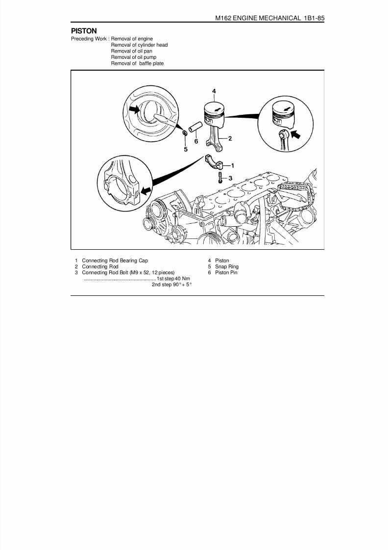
8/18/2019 SsangYong Musso Service Manual 1998.pdf
http://slidepdf.com/reader/full/ssangyong-musso-service-manual-1998pdf 158/1459
M162 ENGINE MECHANICAL 1B1-85
PISTONPreceding Work : Removal of engine
Removal of cylinder headRemoval of oil panRemoval of oil pumpRemoval of baffle plate
1 Connecting Rod Bearing Cap2 Connecting Rod3 Connecting Rod Bolt (M9 x 52, 12 pieces)
....................................................1st step 40 Nm2nd step 90°+ 5°
4 Piston5 Snap Ring6 Piston Pin

8/18/2019 SsangYong Musso Service Manual 1998.pdf
http://slidepdf.com/reader/full/ssangyong-musso-service-manual-1998pdf 159/1459

8/18/2019 SsangYong Musso Service Manual 1998.pdf
http://slidepdf.com/reader/full/ssangyong-musso-service-manual-1998pdf 160/1459
M162 ENGINE MECHANICAL 1B1-87
1. Check the piston ring gap and apply the engine oil to thepiston pin and the connecting rod bushing.
2. Connect the piston and the connecting rod by pressing inthe piston pin (6) and install the snap ring to the groove.
3. Clean the cylinder bore, connecting rod bearing journal,connecting rod bearing shell and the piston and coat themwith engine oil.
4. Install the piston ring using the tensioning strap(000 58904 14 00).
5. Install the piston so that the arrow on the piston head facesto the forward of the vehicle.
6. After aligning the connecting rod and the bearing cap mark(// or a number), tighten the bolts.
Installation Notice
Tightening Torque1st step 35 - 45 Nm2nd step 90°+ 5°
Apply the engine oil to the bearing cap upper and lowerbearing shells.7. Check if the crankshaft rotates without any trouble by rotating
it.

8/18/2019 SsangYong Musso Service Manual 1998.pdf
http://slidepdf.com/reader/full/ssangyong-musso-service-manual-1998pdf 161/1459

8/18/2019 SsangYong Musso Service Manual 1998.pdf
http://slidepdf.com/reader/full/ssangyong-musso-service-manual-1998pdf 162/1459
M162 ENGINE MECHANICAL 1B1-89
Inspection1. Measure the basic bore of the connecting rod bearing.
NoticeIf the basic bore exceeds the value of 51.614mm, replacethe bearing or check the connecting rod.
2. Check connecting rod bolts.
3. Check the assembly mark(indication//or number:arrow) ofthe connecting rods and the bearing cap when installing.
NoticeMake sure it doesn’t exceed over 4g with otherconnecting rods when replacing the connecting rods.Check if the connecting rod and the bearing cap areaccurately seated on the groove when replacing thebearing.
NoticeIf the length exceeds max. length, replace it.
Length When New (L)Max. Length (L)
Tightening Torque
51.7 - 52 mm52.9 mm
1st step 40 + 5 Nm2nd step 90°+10°

8/18/2019 SsangYong Musso Service Manual 1998.pdf
http://slidepdf.com/reader/full/ssangyong-musso-service-manual-1998pdf 163/1459

8/18/2019 SsangYong Musso Service Manual 1998.pdf
http://slidepdf.com/reader/full/ssangyong-musso-service-manual-1998pdf 164/1459
M162 ENGINE MECHANICAL 1B1-91
2. Remove the piston ring with a pliers.
3. For installation, position the piston ring to be the ‘TOP’ markon the piston ring upward and arrange the piston ring endsto be 120°apart.
4. Adjust the hook spring joint in the oil ring 180°away fromthe ring end.
Clamping Strap 000 589 51 37 00

8/18/2019 SsangYong Musso Service Manual 1998.pdf
http://slidepdf.com/reader/full/ssangyong-musso-service-manual-1998pdf 165/1459

8/18/2019 SsangYong Musso Service Manual 1998.pdf
http://slidepdf.com/reader/full/ssangyong-musso-service-manual-1998pdf 166/1459

8/18/2019 SsangYong Musso Service Manual 1998.pdf
http://slidepdf.com/reader/full/ssangyong-musso-service-manual-1998pdf 167/1459
1B1-94 M162 ENGINE MECHANICAL
Oil Circulation
1 Oil Pump2 Oil Gallery (to oil filter)3 Oil Filter4 Oil Pressure Switch5 Main Oil Gallery6 Cylinder Head Closing Cover
7 Oil Gallery (At Chain Tensioner)8 Oil Non-return Valve9 Chain Tensioner
10 Vent (Chain Tensioner)11 Front Closing Cover ( f 17 mm)12 Oil Gallery (Perpendicular to The Shaft)13 Ball ( f 6 mm)14 Oil Spray Nozzle (Timing Chain)15 Oil Gallery (At Cylinder Head)16 Ball ( f 15mm)17 Oil Restriction Inner ( f 4mm)18 Oil Supply (To Exhaust Camshaft)
19 Oil Supply (To Intake Camshaft)20 Oil Supply (To Exhaust Camshaft Bearing)21 Oil Supply (To Intake Camshaft Bearing)22 Oil Gallery (Oil Supply to Exhaust Valve Tappet)23 Oil Gallery (Oil Supply to Exhaust Valve Tappet)24 Camshaft Closing Cover
25 Ball ( f 8 mm)26 Screw Plug27 Camshaft Adjuster28 Front Closing Cover (Intake Camshaft)29 Front Treaded Bushing (Exhaust Camshaft)30 Valve tappet
a Oil Gallery (From Oil Pump to Oil Filter)b Main Oil Galleryc Oil Return Line (Oil Returns to the Oil Pan when
Replacing the Filter Element)

8/18/2019 SsangYong Musso Service Manual 1998.pdf
http://slidepdf.com/reader/full/ssangyong-musso-service-manual-1998pdf 168/1459
M162 ENGINE MECHANICAL 1B1-95
ENGINE OIL AND OIL FILTER ELEMENT
4. Remove the drain plug (arrow) and drain the engine oil.
NoticeLeave the oil filler cap open to ease the engine oil discharge.
5. Tighten the engine oil drain plug after cleaning it.
Installation Notice
Tools Required103 589 02 09 00 Oil Filter Socket Wrench
Replacement Procedure1. Install the socket wrench”7” (special tool : 103 589 02 09
00) on the oil filter cover (2).
NoticeMake the screw cover removable by tightening the bolt atthe side of the socket wrench (special tool).
2. Install the wrench to the upper bolt in the socket wrenchand remove the oil cover by turning it.
3. Remove the oil filter element.
NoticeWork with a cloth under the vehicle when removing the oilfilter element to not drain the oil.
Replace the seal washer with new one.6. Replace the O-ring(5) in the oil filter cover with new one.
NoticeApply the engine oil to the O-ring.
7. Insert new oil filter element into the oil filter housing.
Tightening Torque 25 Nm
8. Temporarily tighten the oil filter cover (2). Install the socketwrench “7” (special tool : 103 589 02 09 00), and thencompletely tighten it.
Installation Notice
2 Oil Filter Cover5 O-ring6 Oil Filter Element7 Special Tool (Socket Wrench)
Tightening Torque 25 Nm

8/18/2019 SsangYong Musso Service Manual 1998.pdf
http://slidepdf.com/reader/full/ssangyong-musso-service-manual-1998pdf 169/1459
1B1-96 M162 ENGINE MECHANICAL
3 Oil Filler Cap4 Dipstick Gauge
9. Fill up engine oil through the engine oil filler opening (3).10. Check for oil leaks at normal engine temperature after
starting the engine.11. Stop the engine and wait 5 minutes.
Check the oil level and fill up as specified if necessary.

8/18/2019 SsangYong Musso Service Manual 1998.pdf
http://slidepdf.com/reader/full/ssangyong-musso-service-manual-1998pdf 170/1459
M162 ENGINE MECHANICAL 1B1-97
OIL FILTERPreceding Work : Removal of starter motor
Removal of upper intake manifold
1 Coolant Line2 O-ring .................................................... Replace3 Clip4 Hose
5 Bolt ........................................................... 23 Nm6 Oil Filter7 Gasket ................................................... Replace
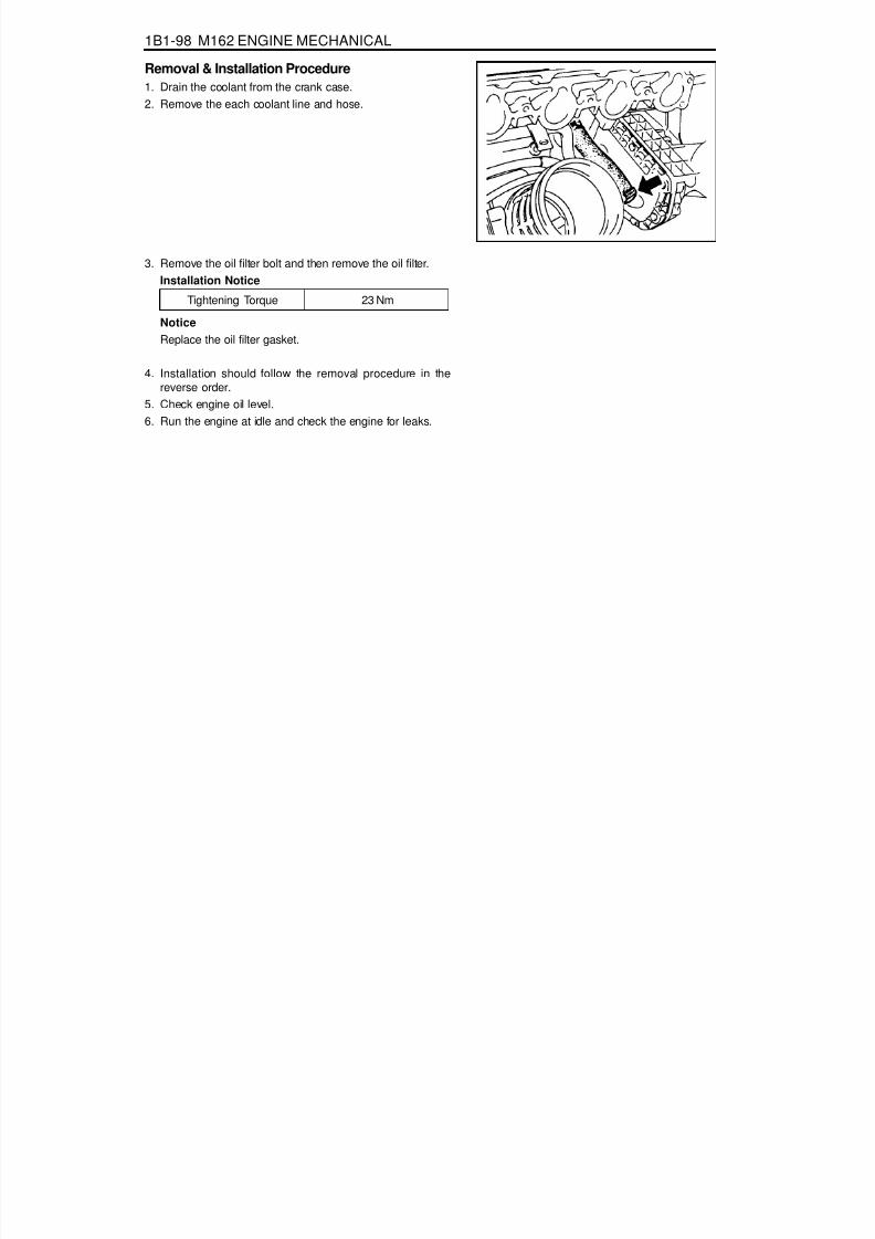
8/18/2019 SsangYong Musso Service Manual 1998.pdf
http://slidepdf.com/reader/full/ssangyong-musso-service-manual-1998pdf 171/1459
1B1-98 M162 ENGINE MECHANICAL
Tightening Torque 23 Nm
NoticeReplace the oil filter gasket.
4. Installation should follow the removal procedure in thereverse order.
5. Check engine oil level.6. Run the engine at idle and check the engine for leaks.
3. Remove the oil filter bolt and then remove the oil filter.Installation Notice
Removal & Installation Procedure1. Drain the coolant from the crank case.2. Remove the each coolant line and hose.

8/18/2019 SsangYong Musso Service Manual 1998.pdf
http://slidepdf.com/reader/full/ssangyong-musso-service-manual-1998pdf 172/1459
M162 ENGINE MECHANICAL 1B1-99
1 Bolt (M8 x 20, 1 piece) ......................... 29-35 Nm2 Sprocket (Oil Pump Drive)3 Bolt (M8 x 35, 3 pieces) ................. 22.5-27.5 Nm
OIL PUMPPreceding Work : Removal of oil pan
4 Spring Pin5 Oil Pump

8/18/2019 SsangYong Musso Service Manual 1998.pdf
http://slidepdf.com/reader/full/ssangyong-musso-service-manual-1998pdf 173/1459
1B1-100 M162 ENGINE MECHANICAL
Removal & Installation Procedure1. Remove the bolt (1) from the oil pump drive sprocket
(2) and separate the gear and the oil pump drive chain.
Installation Notice
4. Remove the oil pump and oil strainer assembly.5. Replace the strainer in oil pump if necessary.6. Installation should follow the removal procedure in the
reverse order.
Tighten the baffle plate and the oil pump with the two boltsin right side first, and then tighten the other bolt.
3. Unscrew the bolt (9) from the oil strainer bracket.
Installation Notice
2. Unscrew the oil pump mounting bolts (3).
Installation Notice
Tightening Torque 29 - 35 Nm
Tightening Torque 22.5 - 27.5 Nm
Tightening Torque 9 - 11 Nm

8/18/2019 SsangYong Musso Service Manual 1998.pdf
http://slidepdf.com/reader/full/ssangyong-musso-service-manual-1998pdf 174/1459
M162 ENGINE MECHANICAL 1B1-101
OIL PRESSURE RELIEF VALVEPreceding Work : Removal of oil pan
1 Screw Plug ................................................ 50 Nm2 Compression Spring
Removal & Installation Procedure1. Remove the screw plug (1).
Installation Notice
2. Remove the spring (2), guide pin (3) and the piston (4).3. Installation should follow the removal procedure in the
reverse order.
NoticeDon’t use the seal for the screw plug.
3 Guide Pin4 Piston
Tightening Torque 50 Nm

8/18/2019 SsangYong Musso Service Manual 1998.pdf
http://slidepdf.com/reader/full/ssangyong-musso-service-manual-1998pdf 175/1459
1B1-102 M162 ENGINE MECHANICAL
OIL NON-RETURN VALVEPreceding Work : Removal of timing gear case cover
1 Oil Non-return Valve
FunctionsThe non-return valve prevents the oil in the chain tensionerfrom drying up. In other words, it stops oil-returning in order toprevent the oil in the chain tensioner from getting dry. As aresult, the chain tensioner can be activated with oil in itself.
Replacement Procedure1. Remove the non-return valve using a pliers.
2. Insert new non-return valve with hand.

8/18/2019 SsangYong Musso Service Manual 1998.pdf
http://slidepdf.com/reader/full/ssangyong-musso-service-manual-1998pdf 176/1459
M162 ENGINE MECHANICAL 1B1-103
OIL DIPSTICK GUIDE TUBE
1 Oil Dipstick Level Gauge2 Oil Dipstick Guide Tube
Removal & Installation Procedure1. Pull out the oil dipstick level gauge (1).2. Remove the bolt (4) in the upper intake manifold and remove
the oil dipstick guide tube.
Installation Notice
3. Install new O-ring to the dipstick guide tube.
4. Installation should follow the removal procedure in thereverse order.5. Check for leaks by starting the engine.
3 O-ring4 Bolt (M6 x 12, 1 piece) ........................... 9-11 Nm
Tightening Torque 9 - 11 Nm

8/18/2019 SsangYong Musso Service Manual 1998.pdf
http://slidepdf.com/reader/full/ssangyong-musso-service-manual-1998pdf 177/1459
1B1-104 M162 ENGINE MECHANICAL
UNIT REPAIROIL GALLERY IN CRANKCASEPreceding Work : Removal of crankshaft, removal of oil spray nozzle
1 Plug2 Steel Ball
Cleaning Procedure1. Remove the plug (1) with a screwdriver.2. Using a round bar (3) and hammer, remove the steel ball
(2).3. Using the compressed air, blow into the oil galleries and
clean it off.
3 Round Bar ................................... f 11 x 750 mm

8/18/2019 SsangYong Musso Service Manual 1998.pdf
http://slidepdf.com/reader/full/ssangyong-musso-service-manual-1998pdf 178/1459
M162 ENGINE MECHANICAL 1B1-105
1 Plug ....................................................... Replace2 Main Oil Gallery
Tools Required102 589 12 15 00 Drift
Sealing Procedure1. Enlarge the end of main oil gallery (4) to be diameter of
16mm, depth of 15mm.2. Using an M16 x 1.5 thread (tap), make the thread at the
end of main oil gallery (4).3. Throughly clean the oil gallery with compressed air and
tighten the screw plug (M16 x 1.5) after applying sealingbond on it.
4. Apply Loctite 270 on new plug and tighten to the hole untilthe drift is stopped after inserting new plug into the drift.
3 Screw Plug

8/18/2019 SsangYong Musso Service Manual 1998.pdf
http://slidepdf.com/reader/full/ssangyong-musso-service-manual-1998pdf 179/1459
1B1-106 M162 ENGINE MECHANICAL
OIL GALLERY IN CYLINDER HEADPreceding Work : Removal of cylinder head
Removal of camshaftRemoval of tappet
1 Screw Plug ................................................ 15 Nm2 Seal
Cleaning Procedure1. Remove the screw plug (1) and the seal (2).
Installation Notice
Replace the seal with new one.
2. Clean the oil gallery using the compressed air.
3 Steel Ball ( f 8mm)
Tightening Torque 15 Nm

8/18/2019 SsangYong Musso Service Manual 1998.pdf
http://slidepdf.com/reader/full/ssangyong-musso-service-manual-1998pdf 180/1459
M162 ENGINE MECHANICAL 1B1-107
Sealing Procedure1. Remove the screw plug (1) and the seal.
Installation Notice
2. Remove the steel ball from the oil gallery (4), (5), (6) and(7) using the round bar (12, f 6 x 700 mm).
4. Enlarge the oil gallery at the rear of the cylinder head to bediameter 9mm, depth 8mm.
5. Tap in the steel ball (3) from the side to the oil gallery usingthe punch (13).
6. Pull out the steel ball (3) using the round bar (12).7. Enlarge the oil gallery to be diameter 9mm, depth 8mm.
Tightening Torque 15 Nm
3. Remove the plug (8) using the screw driver.

8/18/2019 SsangYong Musso Service Manual 1998.pdf
http://slidepdf.com/reader/full/ssangyong-musso-service-manual-1998pdf 181/1459

8/18/2019 SsangYong Musso Service Manual 1998.pdf
http://slidepdf.com/reader/full/ssangyong-musso-service-manual-1998pdf 182/1459
M162 ENGINE MECHANICAL 1B1-109
CORE PLUGS IN CRANKCASEPreceding Work : Draining of the coolant
1 Core Plug ............................................... Replace

8/18/2019 SsangYong Musso Service Manual 1998.pdf
http://slidepdf.com/reader/full/ssangyong-musso-service-manual-1998pdf 183/1459
1B1-110 M162 ENGINE MECHANICAL
Tools Required102 589 00 15 00 Drift
Replacement Procedure1. Remove the intake and exhaust manifolds.2. Pull back the core plug until the end of one side comes out
using the screw driver.
3. Pull out the plug carefully using a pliers.
5. Press in new plug using a drift.
NoticeWait for about 45minutes before filling the coolant so thatthe Loctite 240 hardens.
6. Warm up the engine and check the coolant for leaks.
4. Clean the sealing surface and apply Loctite 241.

8/18/2019 SsangYong Musso Service Manual 1998.pdf
http://slidepdf.com/reader/full/ssangyong-musso-service-manual-1998pdf 184/1459
M162 ENGINE MECHANICAL 1B1-111
Group Code Letter and Cylinder Bore Size
Repair Size
1) The group code letters are carved on the surface of the piston crown and in the mating surface of the crankcase.
CYLINDER BORE
Group Code Letter of Cylinder
AXB
X + 5X + 10
Piston Type to be Used
A or XA, X or B
X or BX + 5
X + 10
Cylinder Bore Size (mm)f 89.900 - f 90.906f 89.906 - f 89.912f 89.912 - f 89.918f 89.950 - f 89.968f 90.000 - f 90.018
TypeStandard Size f 89.9
1st Repair Size(Standard Size + 0.25)
2nd Repair Size(Standard Size + 0.5)
Group Code Letter 1)
AXBAXBAXB
Cylinder Bore Size (mm)f 89.900 - f 90.906f 89.906 - f 89.912f 89.912 - f 89.918f 90.150 - f 90.156f 89.156 - f 90.162f 90.162 - f 90.168f 90.400 - f 90.406f 90.406 - f 90.412f 90.412 - f 90.418

8/18/2019 SsangYong Musso Service Manual 1998.pdf
http://slidepdf.com/reader/full/ssangyong-musso-service-manual-1998pdf 185/1459
1B1-112 M162 ENGINE MECHANICAL
Service Data Standard
Measurement of Cylinder Bore1. Clean the cylinder wall.2. Using a internal diameter gauge, measure the bore size in
axial and transverse direction at three points (1,2,3).
1,2,3. Measuring PointsA. Axial DirectionB. Transverse Directiona. Location of the No.1 Piston Ring at TDCb. Location of the Piston BDCc. Location of the Oil Ring at BDC
Chamfer Angle
Wear Limit in Longitudinal and Transverse DirectionPermissible Deviation of Cylinder Out-of-round
Permissible Deviation of Rectangular Cylinder Height (Except Chamfered Area)
Basic Peak-to-valley Height After Final Honing and BrushingChamfer AngleHoning Angle
When newWear limit
0.1 mm0.007 mm0.05 mm0.05 mm
0.003 - 0.006 mm60°
50°± 10°

8/18/2019 SsangYong Musso Service Manual 1998.pdf
http://slidepdf.com/reader/full/ssangyong-musso-service-manual-1998pdf 186/1459
M162 ENGINE MECHANICAL 1B1-113
CRANKCASE MATING SURFACE
Service Data StandardHeight of The Crankcase “H” (When new)Minimum Height After MillingFlatness
Permissible Deviation of Parallelism of TheUpper to Lower Mating SurfacePeak-to-valley Height
Crankcase Upper Mating SurfaceCrankcase Lower Mating SurfaceAxial DirectionTransverse DirectionCrankcase Upper Mating SurfaceCrankcase Lower Mating Surface
282.25 - 282.35mm281.95mm
0.03mm0.04mm0.1mm
0.05mm0.005 - 0.020mm
0.025mm

8/18/2019 SsangYong Musso Service Manual 1998.pdf
http://slidepdf.com/reader/full/ssangyong-musso-service-manual-1998pdf 187/1459
1B1-114 M162 ENGINE MECHANICAL
Chamfering Procedure1. Chamfer angle : 60°
2. Polish the lower chamfered area evenly with a grinder afterfinishing the chamfering with a suitable tool (e.g., hand millingcutter).

8/18/2019 SsangYong Musso Service Manual 1998.pdf
http://slidepdf.com/reader/full/ssangyong-musso-service-manual-1998pdf 188/1459
M162 ENGINE MECHANICAL 1B1-115
CYLINDER HEAD MATING SURFACEPreceding Work : Removal of valves
Service Data Standard
NoticeDo not exceed 0.4mm for the milling of the mating surface of crankcase and cylinder head.
Overall Height of Cylinder HeadMinimum Height After MachiningFlatness
Distance ‘T’(Between Camshaft Bearingand Valve Stem)
Axial DirectionTransverse DirectionStandard Size
Repair Size
135.9 - 136.0 mm135.5 mm0.08 mm0.0 mm
24.21 - 24.75 mm22.21 - 22.75 mm23.96 - 24.51 mm21.96 - 22.51 mm
IntakeExhaustIntake
Exhaust

8/18/2019 SsangYong Musso Service Manual 1998.pdf
http://slidepdf.com/reader/full/ssangyong-musso-service-manual-1998pdf 189/1459
1B1-116 M162 ENGINE MECHANICAL
Measurement of Mating Surface1. Measure the height (H) of the cylinder head (refer to Service
data standard ).2. Check the mating surface of the cylinder head.3. Mill the sharp edge of the combustion chamber.4. Re-measure the height (H) of the cylinder head.
5. Seal the intake and exhaust valves.6. Measure the dimension (T) between the camshaft bearing
and the valve system (refer to Service data standard ).7. Mill the cylinder head valve seat (refer to Service data
standard ).
Universal Tool
Surface Grinding MachineSceledum, Type RTY
RoaroSchio/Italy
8/18/2019 SsangYong Musso Service Manual 1998.pdf
http://slidepdf.com/reader/full/ssangyong-musso-service-manual-1998pdf 190/1459
SECTION 1B2
M161 ENGINE MECHANICAL
CAUTION: Disconnect the negative battery cable before removing or installing any electrical unit or when a tool or equipment could easily come in contact with exposed electrical terminals. Disconnecting this cable will help prevent personal injury and damage to the vehicle. The ignition must also be in LOCK unless otherwise noted.
Specifications. . . . . . . . . . . . . . . . . . . . . . . 1B2-2Fastener Tightening Specifications . . . . . . . . 1B2-2
Special Tools . . . . . . . . . . . . . . . . . . . . . . . 1B2-4
Special Tools Table . . . . . . . . . . . . . . . . . . . . 1B2-4Maintenance and Repair . . . . . . . . . . . . . . 1B2-9On-Vehicle Service . . . . . . . . . . . . . . . . . . . . . 1B2-9
Engine Assembly . . . . . . . . . . . . . . . . . . . . . 1B2-9Crankcase Ventilation System . . . . . . . . . . 1B2-17Alternator . . . . . . . . . . . . . . . . . . . . . . . . . . 1B2-21Power Steering Pump and A/C Bracket . . . 1B2-22Hydraulic Engine Mounting Insulator . . . . . . 1B2-25Poly V-Belt . . . . . . . . . . . . . . . . . . . . . . . . . 1B2-28Tensioning Deivce . . . . . . . . . . . . . . . . . . . . 1B2-30
Tensioning Device Shock Absorber . . . . . . 1B2-31Poly V-Belt Inspection . . . . . . . . . . . . . . . . . 1B2-32Cylinder Head Cover . . . . . . . . . . . . . . . . . 1B2-35Cylinder Head Front Cover . . . . . . . . . . . . . 1B2-37Cylinder Head . . . . . . . . . . . . . . . . . . . . . . . 1B2-39Timing Gear Case Cover . . . . . . . . . . . . . . 1B2-44Crankshaft Sealing Rear Cover . . . . . . . . . 1B2-47Belt Pulley and Vibration Damper . . . . . . . . 1B2-49Crankshaft Front Radial Seal . . . . . . . . . . . 1B2-52Crankshaft Rear Radial Seal . . . . . . . . . . . 1B2-53
Crankshaft . . . . . . . . . . . . . . . . . . . . . . . . . 1B2-54Flywheel/Driven Plate . . . . . . . . . . . . . . . . . 1B2-60Camshaft Adjuster . . . . . . . . . . . . . . . . . . . 1B2-62
TABLE OF CONTENTSCamshaft Sprocket Bolt . . . . . . . . . . . . . . . 1B2-65Camshaft . . . . . . . . . . . . . . . . . . . . . . . . . . 1B2-66Camshaft Timing Position . . . . . . . . . . . . . . 1B2-69
Valve Spring . . . . . . . . . . . . . . . . . . . . . . . . 1B2-72Valve Stem Seal . . . . . . . . . . . . . . . . . . . . . 1B2-76Chain Tensioner . . . . . . . . . . . . . . . . . . . . . 1B2-77Timing Chain . . . . . . . . . . . . . . . . . . . . . . . . 1B2-80Tensioning Rail . . . . . . . . . . . . . . . . . . . . . . 1B2-85Cylinder Head Guide Rail . . . . . . . . . . . . . . 1B2-86Crankcase Guide Rail. . . . . . . . . . . . . . . . . 1B2-87Crankshaft Sprocket . . . . . . . . . . . . . . . . . . 1B2-88Piston . . . . . . . . . . . . . . . . . . . . . . . . . . . . . 1B2-90Connecting Rod . . . . . . . . . . . . . . . . . . . . . 1B2-93
Piston Ring . . . . . . . . . . . . . . . . . . . . . . . . . 1B2-95Oil Pan . . . . . . . . . . . . . . . . . . . . . . . . . . . . 1B2-97Engine Oil and Oil Filter Element . . . . . . . . 1B2-99Oil Pump . . . . . . . . . . . . . . . . . . . . . . . . . 1B2-101Oil Pressure Relief Valve . . . . . . . . . . . . . 1B2-103Oil Non-Return Valve . . . . . . . . . . . . . . . . 1B2-104Oil Dipstick Guide Tube . . . . . . . . . . . . . . 1B2-105
Unit Repair . . . . . . . . . . . . . . . . . . . . . . . 1B2-106Core Plugs in Crankcase . . . . . . . . . . . . . 1B2-106Cylinder Bore . . . . . . . . . . . . . . . . . . . . . . 1B2-108Crankcase Mating Surface . . . . . . . . . . . . 1B2-110Cylinder Head Mating Surface . . . . . . . . . 1B2-112

8/18/2019 SsangYong Musso Service Manual 1998.pdf
http://slidepdf.com/reader/full/ssangyong-musso-service-manual-1998pdf 191/1459
1B2-2 M161 ENGINE MECHANICAL
SPECIFICATIONSFASTENER TIGHTENING SPECIFICATIONS
N····· m35 - 40
10 - 155 - 10
21 - 2530
56 - 6650 - 60
22.5 - 27.541.5 - 49.522.5 - 27.522.5 - 27.5
9 - 119 - 119 - 119 - 11
22.5 - 27.510
+90°55
+90°+90°
22.5 - 27.522.5 - 27.5
9 - 109 - 10200+90°40
+90°45
+90°35
9 - 1120
+90°20
+90°20 / + 90°20 / + 90°
22.5 - 27.5
ApplicationPower Steering Hydraulic Lines
A/C High Pressure and Liquid HoseRadiator Support Menber BoltFuel Supply and Return Hose to Fuel DistributorExhaust Manifold and PipePropeller Shaft to TransmissionEngine Mounting NutAlternator Carrier BoltBelt Pulley BoltSteering Pump BoltA/C Bracket BoltIntake Air Duct BoltIgnition Cable Cover BoltCylinder Head Cover BoltCamshaft Adjuster BoltCylinder Head Front Cover BoltFlange Bolt in Exhaust Camshaft Sprocket
Cylinder Head Bolt
Cooling Fan Bracket BoltTiming Gear Case Cover Bolt M8
M6Crankshaft Rear Cover BoltVibration Damper Center Bolt
Connecting Rod Bearing Cap Bolt
Flywheel Stretch Bolt
Amarture Bolt in FlywheelRing and Seal Cover Nut in FlywheelSprocket Bolt to Exhaust Camshaft
Camshaft Adjuster Flange Bolt
Intake Flange Shaft BoltExhaust Camshaft Sprocket BoltCamshaft Bearing Cap Bolt

8/18/2019 SsangYong Musso Service Manual 1998.pdf
http://slidepdf.com/reader/full/ssangyong-musso-service-manual-1998pdf 192/1459
M161 ENGINE MECHANICAL 1B2-3
N····· m20 / + 90°
4072 - 88
20 / + 90°25 - 35
22.5 - 27.522.5 - 27.522.5 - 27.522.5 - 27.5
3026 - 34
308 - 10
2525
22.5 - 27.529 - 35
22.5 - 27.59 - 11
509 - 11
15
ApplicationExhaust Camshaft Sproket BoltChain Tensioner Screw PlugChain Tensioner Assembly
Exhaust Camshaft Sprocket to CamshaftOil Pump Sprocket BoltTensioning Device BoltWater Pump PulleyUpper Intake Manifold BoltLower Intake Mainfold BoltFlange Bolt to Exhaust MainfoldExhaust Mainfold Nut to Stud BoltRivet Nut in Exhuast Mainfold HolePre-Silencer Bolt
Oil Drain PlugOil Filter CoverOil Filter BoltOil Pump Drive Sprocket BoltOil Pump Mounting BoltOil Strainer Bracket BoltOil Pressure Relief Valve Screw PlugOil Dipstick Guide tube BoltOil Gallery Screw Plug
FASTENER TIGHTENING SPECIFICATIONS (Cont’d)

8/18/2019 SsangYong Musso Service Manual 1998.pdf
http://slidepdf.com/reader/full/ssangyong-musso-service-manual-1998pdf 193/1459
1B2-4 M161 ENGINE MECHANICAL
SPECIAL TOOLSSPECIAL TOOLS TABLE
000 589 10 99 01Torque Wrench
112 589 00 72 00Oil Extractor
000 589 72 21 00Torque Wrench
001 589 66 21 00Torque Wrench
000 589 01 10 00Box Wrench Insert
124 589 15 21 00Radiator CapTesting Unit
116 589 02 34 00Screw-Fixed Pin
000 589 40 37 00Hose Clamp

8/18/2019 SsangYong Musso Service Manual 1998.pdf
http://slidepdf.com/reader/full/ssangyong-musso-service-manual-1998pdf 194/1459
M161 ENGINE MECHANICAL 1B2-5
SPECIAL TOOLS TABLE (Cont’d)
104 589 01 01 00Spanner
111 589 18 61 00Lever Pusher
111 589 25 63 00Thrust Piece
111 589 01 59 00Supporting Bar
116 589 06 63 00Magnetic Finger
119 589 00 43 00Drift
000 589 58 43 00Chain Assembly
104 589 00 37 00Pliers

8/18/2019 SsangYong Musso Service Manual 1998.pdf
http://slidepdf.com/reader/full/ssangyong-musso-service-manual-1998pdf 195/1459

8/18/2019 SsangYong Musso Service Manual 1998.pdf
http://slidepdf.com/reader/full/ssangyong-musso-service-manual-1998pdf 196/1459
M161 ENGINE MECHANICAL 1B2-7
SPECIAL TOOLS TABLE (Cont’d)
103 589 01 63 00Rivet Set
103 589 02 09 00Oil Filter
Socket Wrench
102 589 12 15 00Drift
615 589 01 33 00Caulking Bolt
102 589 00 15 00Drift
000 589 51 37 00Clamping Strap
001 589 72 21 00Torque Wrench
601 589 03 14 00Sleeve

8/18/2019 SsangYong Musso Service Manual 1998.pdf
http://slidepdf.com/reader/full/ssangyong-musso-service-manual-1998pdf 197/1459
1B2-8 M161 ENGINE MECHANICAL
SPECIAL TOOLS TABLE (Cont’d)
617 589 00 10 00Wrench Socket
104 589 00 40 00Holder
111 589 03 15 00Insert Pin
116 589 01 34 00Threaded Bolt
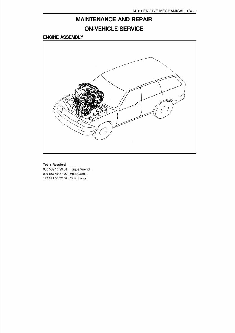
8/18/2019 SsangYong Musso Service Manual 1998.pdf
http://slidepdf.com/reader/full/ssangyong-musso-service-manual-1998pdf 198/1459
M161 ENGINE MECHANICAL 1B2-9
MAINTENANCE AND REPAIR
ON-VEHICLE SERVICEENGINE ASSEMBLY
Tools Required000 589 10 99 01 Torque Wrench000 589 40 37 00 Hose Clamp
112 589 00 72 00 Oil Extractor

8/18/2019 SsangYong Musso Service Manual 1998.pdf
http://slidepdf.com/reader/full/ssangyong-musso-service-manual-1998pdf 199/1459
1B2-10 M161 ENGINE MECHANICAL
4. Disconnect the coupling of HFM sensor and remove the aircleaner cross pipe.
6. Loosen the radiator drain cock and drain the coolant.NoticeOpen the coolant reservoir cap.
5. Remove the air cleaner cover. Remove the mounting boltsand air cleaner housing and element assembly.
Removal & Installation Procedure1. Disconnect the negative terminal of battery.2. Remove the hood.3. Remove the under cover.
Installation Notice
Tightening Torque 28 - 47 Nm

8/18/2019 SsangYong Musso Service Manual 1998.pdf
http://slidepdf.com/reader/full/ssangyong-musso-service-manual-1998pdf 200/1459
M161 ENGINE MECHANICAL 1B2-11
10. Remove the upper mounting bolts of radiator and thenremove the radiator.
7. Loosen the cylinder block drain plug and then drain thecoolant completely.Installation Notice
Tightening Torque 30 Nm
NoticeReplace the seal before installation of the drain plug.
8. Remove the cooling fan shroud.
9. Disconnect the each hose from radiator.

8/18/2019 SsangYong Musso Service Manual 1998.pdf
http://slidepdf.com/reader/full/ssangyong-musso-service-manual-1998pdf 201/1459

8/18/2019 SsangYong Musso Service Manual 1998.pdf
http://slidepdf.com/reader/full/ssangyong-musso-service-manual-1998pdf 202/1459
M161 ENGINE MECHANICAL 1B2-13
19. Disconnect the engine ground wire.
15. Remove the automatic transmission dipstick guide tube.
16. Disconnect the wire of alternator.
17. Disconnect the wire of starter motor and remove the startermotor.
18. Disconnect the engine main harness ground.

8/18/2019 SsangYong Musso Service Manual 1998.pdf
http://slidepdf.com/reader/full/ssangyong-musso-service-manual-1998pdf 203/1459
1B2-14 M161 ENGINE MECHANICAL
20. Disconnect following sensors connector.HFM sensor.Coolant temperature sensor.2 knock sensors.Camshaft and crankshaft sensors.
21. After removing the ignition coil cover, disconnect the ignitioncoil connector.
22. Remove the harness cover and disconnect the 6 injectionvalve connectors. Disconnect the main harness.
23. Separate the hose toward engine from canister purgesolenoid valve.
24. Remove the automatic transmission oil cooler line.

8/18/2019 SsangYong Musso Service Manual 1998.pdf
http://slidepdf.com/reader/full/ssangyong-musso-service-manual-1998pdf 204/1459
M161 ENGINE MECHANICAL 1B2-15
Tightening Torque 30 Nm
29. Remove the exhaust manifold and exhaust pipe.Installation Notice
25. Separate the vacuum hose for brake booster.26. Separate the other vacuum hoses.
27. Remove the propeller shaft from the front axle.Installation Notice
28. By rotating the crankshaft from the front of engine, removethe 6 torque converter mounting bolts from the enginering gear plate.
Tightening Torque 81 - 89 Nm

8/18/2019 SsangYong Musso Service Manual 1998.pdf
http://slidepdf.com/reader/full/ssangyong-musso-service-manual-1998pdf 205/1459
1B2-16 M161 ENGINE MECHANICAL
30. Remove the transmission mounting bolts and separatethe transmission from the engine.Installation Notice
Tightening Torque 65 Nm
31. Remove the bolts for engine mounting bracket.Installation Notice
Tightening Torque 50 - 75 Nm
32. Hook the chain to the bracket of engine and by using ahoist or crane, carefully separate the engine assemblyfrom the vehicle.
33. Installation should follow the removal procedure in thereverse order.

8/18/2019 SsangYong Musso Service Manual 1998.pdf
http://slidepdf.com/reader/full/ssangyong-musso-service-manual-1998pdf 206/1459

8/18/2019 SsangYong Musso Service Manual 1998.pdf
http://slidepdf.com/reader/full/ssangyong-musso-service-manual-1998pdf 207/1459
1B2-18 M161 ENGINE MECHANICAL
Operation at Idling and Mid-LoadThe throttle valve(6) is closed or very partially opened, andthe vacuum pressure in intake manifold is high.The blow-by gas and the fresh air that is additionally suppliedthrough the vent connection(D) in the crankcase in partialload gets supplied to the combustion chamber from the crankchamber(12) through the oil separation chamber(11), air-conditioner bracket(10), vent line(9), and restrictor(7)mounted to the cylinder head.The circulated engine oil returns to the oil pan through theoil return pipe(13) at the bottom of oil separationchamber(11).The fresh air gets supplied to the crank chamber(12) throughthe HFM sensor(1), intake air duct(4), vent line(5), oilseparation chamber(3), chain housing(17), and the timinggear case cover(15).The additional supply of the fresh air is needed to preventfrom forming the residues of the engine oil.

8/18/2019 SsangYong Musso Service Manual 1998.pdf
http://slidepdf.com/reader/full/ssangyong-musso-service-manual-1998pdf 208/1459
M161 ENGINE MECHANICAL 1B2-19
Operation When Full-Load at Partial Load
1 HFM Sensor2 Cylinder Head Cover3 Oil Spearation Chamber (Full-Load or Over
Mid-Load)4 Intake Air Duct (Cross Pipe)
5 Vent Line (Full-Load or Over Mid-Load)6 Throttle Valve7 Restrictor, Diameter 1.1mm (Mid-Load at Idling)8 Intake Manifold9 Vent Line (Mid-Load at Idling)
10 Air Conditioner Bracket
11 Oil Separation Chamber (Mid-Load at Idling)12 Crank Chamber13 Oil Return Pipe14 Oil Pan15 Timing Gear Case Cover
16 Crankcase17 Chain Housing
A Fresh AirC Blow-by GasD Vent Connection

8/18/2019 SsangYong Musso Service Manual 1998.pdf
http://slidepdf.com/reader/full/ssangyong-musso-service-manual-1998pdf 209/1459
1B2-20 M161 ENGINE MECHANICAL
Operation When Full-Load at Partial LoadThe throttle valve (6) is partially opened or fully opened.The air flows very rapidly through the vent line(5)sconnection(D) and the intake air duct when full-load at partialload.Consequently, most of the low-by gases are supplied to the
combustion chamber through the timing gear casecover(15), chain housing(17), oil separation chamber(3),vent line(5), throttle valve(6), and intake manifold(8).

8/18/2019 SsangYong Musso Service Manual 1998.pdf
http://slidepdf.com/reader/full/ssangyong-musso-service-manual-1998pdf 210/1459
M161 ENGINE MECHANICAL 1B2-21
ALTERNATOR
Removal & Installation Procedure1. Remove the drive belt.2. Remove the alternator.
3. Unscrew the alternator carrier bolts (1,2,3) and remove thecarrier (4).Installation Notice
Tightening Torque 22.5 - 27.5 Nm
NoticeApply 3Nm of torque when mounting the bolt (1); apply 25 ±2.5Nm of torque when mounting the bolts (2), and (3); andthen tighten the bolt (1) with 25 ± 2.5Nm of torque.
4. Installation should follow the removal procedure in thereverse order.
1 Bolt (M8 X 40, 3 pieces) ................. 22.5-27.5 Nm2 Bolt (M8 X 70, 2 pieces) ................. 22.5-27.5 Nm
3 Bolt (M8 X 85, 1 piece)...................22.5-27.5 Nm4 Alternator Bracket

8/18/2019 SsangYong Musso Service Manual 1998.pdf
http://slidepdf.com/reader/full/ssangyong-musso-service-manual-1998pdf 211/1459
1B2-22 M161 ENGINE MECHANICAL
POWER STEERING PUMP AND A/C BRACKETPreceding Work : Removal of cooling fan and shroud
Removal of drive belt
1 Nut ................................................. 35.2-28.8 Nm2 Washer3 Belt Pulley4 Bolt (M8 X 91, 2 pieces) ................. 22.5-27.5 Nm5 Power Steering Pump6 Bracket
7 Washer8 Bolt (M8 X 20, 2 pieces) ................. 22.5-27.5 Nm
9 Washer10 Bolt (M8 X 105,4 pieces) ................22.5-27.5 Nm11 A/C Compressor12 Bolt (M8 X 50, 5 pieces, M8 X 80,
5 pieces) ........................................ 22.5-27.5 Nm13 A/C Bracket
14 Vent Hose15 Bracket Gasket ...................................... Replace

8/18/2019 SsangYong Musso Service Manual 1998.pdf
http://slidepdf.com/reader/full/ssangyong-musso-service-manual-1998pdf 212/1459
M161 ENGINE MECHANICAL 1B2-23
Removal & Installation Procedure1. Remove the belt pulley after removal of poly v-belt.
Installation Notice
2. Disconnect the hydraulic pipe of the power steering pumpand drain the oil.
3. Unscrew the bolts (arrows) and remove the steering pump.
Installation Notice
NoticePull the tensioning pulley counterclockwise as shown in thefigure.
4. Remove the compressor after disconnecting the wiringconnector and refrigerant pipe of A/C compressor.NoticeDischarge all the refrigerant before removing the pipes.
Tightening Torque 40.5 - 49.5 Nm
Tightening Torque 22.5 - 27.5 Nm
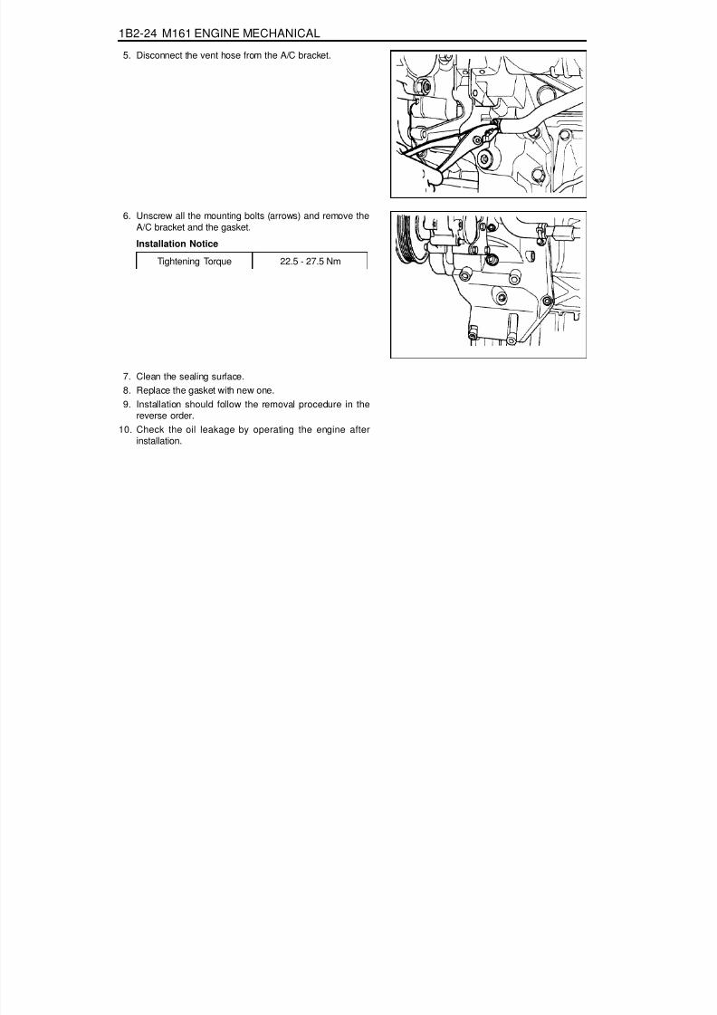
8/18/2019 SsangYong Musso Service Manual 1998.pdf
http://slidepdf.com/reader/full/ssangyong-musso-service-manual-1998pdf 213/1459
1B2-24 M161 ENGINE MECHANICAL
5. Disconnect the vent hose from the A/C bracket.
6. Unscrew all the mounting bolts (arrows) and remove theA/C bracket and the gasket.
Installation Notice
7. Clean the sealing surface.8. Replace the gasket with new one.9. Installation should follow the removal procedure in the
reverse order.10. Check the oil leakage by operating the engine after
installation.
Tightening Torque 22.5 - 27.5 Nm

8/18/2019 SsangYong Musso Service Manual 1998.pdf
http://slidepdf.com/reader/full/ssangyong-musso-service-manual-1998pdf 214/1459
M161 ENGINE MECHANICAL 1B2-25
HYDRAULIC ENGINE MOUNTING INSULATORService Data

8/18/2019 SsangYong Musso Service Manual 1998.pdf
http://slidepdf.com/reader/full/ssangyong-musso-service-manual-1998pdf 215/1459
1B2-26 M161 ENGINE MECHANICAL
Sectional View
1 Rubber Body2 Brackek3 Core4 Lower Bolt5 Rubber Plunger6 Plunger Plate7 Rubber8 Plate
9 Lower Orifice10 Upper Orifice11 Diaphram12 Cover Plate13 Upper Bolt14 Flange Bolt15 Rivet16 Fluid

8/18/2019 SsangYong Musso Service Manual 1998.pdf
http://slidepdf.com/reader/full/ssangyong-musso-service-manual-1998pdf 216/1459
M161 ENGINE MECHANICAL 1B2-27
1 Upper Nut2 Hydraulic Installer .................62~93 Nm3 Lower Nut.............................28~47 Nm
Removal and Installation Procedure1. Unscrew the upper nut(1) on engine mounting and remove
the engine.
Installation Notice
3. Installation should follow the removal procedure in thereverse order.
Tightening Torque 62 - 93 Nm
2. Unscrew the lower nut(3) and remove the hydraulic enginemounting insulator.
Installation Notice
Tightening Torque 28 - 47 Nm
NoticeIf the insulator is spotted with oil, replace the hydraulicinsulator assembly.

8/18/2019 SsangYong Musso Service Manual 1998.pdf
http://slidepdf.com/reader/full/ssangyong-musso-service-manual-1998pdf 217/1459
1B2-28 M161 ENGINE MECHANICAL
POLY V-BELTPreceding Work : Removal of cooling fan
1 Poly V-belt (2,155 mm)2 Belt Tensioning Pulley
Removal & Installation Procedure1. Release the belt tension by turning the stud on the cap with
12 sided wrench or spanner counterclockwise.2. Remove the poly v-belt.
NoticeCheck the belt for damage and tensioning pulley bearingpoint for wear and replace them if necessary.
3. Install the belt after prying the tensioning pulley.
3 Belt Tensioner

8/18/2019 SsangYong Musso Service Manual 1998.pdf
http://slidepdf.com/reader/full/ssangyong-musso-service-manual-1998pdf 218/1459
M161 ENGINE MECHANICAL 1B2-29
Poly V-belt Arrangement
1 Belt Tensioning Pulley2 Crankshaft Belt Pulley3 A/C Compressor Pulley
5 Alternator Pulley7 Power Steering Pump Pulley8 Water Pump Pulley

8/18/2019 SsangYong Musso Service Manual 1998.pdf
http://slidepdf.com/reader/full/ssangyong-musso-service-manual-1998pdf 219/1459
1B2-30 M161 ENGINE MECHANICAL
TENSIONING DEVICEPreceding Work : Removal of tensioning device shock absorber
1 Bolt (M8 x 75, 2 pieces) +Washer .......................................... 22.5-27.5 Nm
2 Bolt (M8 x 25, 1 pieces) +Washer .......................................... 22.5-27.5 Nm
Removal & Installation Procedure1. Turn the stud bolt to counterclockwise.2. Insert the pin (111 589 01 15 00) into the hole in tensioning
arm.3. Unscrew the bolts (1, 2) and remove the tensioning device.
Installation Notice
4. Installation should follow the removal procedure in thereverse order.
3 Tensioning Device4 Stud bolt
5 Tensioning Arm
Tightening Torque 22.5 - 27.5 Nm

8/18/2019 SsangYong Musso Service Manual 1998.pdf
http://slidepdf.com/reader/full/ssangyong-musso-service-manual-1998pdf 220/1459
M161 ENGINE MECHANICAL 1B2-31
TENSIONING DEVICE SHOCK ABSORBER
1 End Cover2 Nut ................................................. 40.5-49.5 Nm3 Tensioning Pulley
4 Bolt (M8 X 25) + Washer ................22.5-27.5 Nm
Removal & Installation Procedure1. Remove the end cover (1).2. Remove the nut (2) and remove the tensioning pulley (3).
Installation Notice
5 Tensioning Device6 Bolt (M8 X 35) + Washer ................22.5-27.5 Nm7 Shock Absorber
Tightening Torque 40.5 - 49.5 Nm3. Unscrew the bolts (4,6) and remove the shock absorber
(7).Installation Notice
Tightening Torque 22.5-27.5 Nm

8/18/2019 SsangYong Musso Service Manual 1998.pdf
http://slidepdf.com/reader/full/ssangyong-musso-service-manual-1998pdf 221/1459
1B2-32 M161 ENGINE MECHANICAL
3. Pointed rib.4. Belt cord visible in the base of rib.
POLY V-BELT INSPECTIONMake marks on the belt with chalk.
Rotate the engine and check the belt for damage.
NoticeIf one of the following types of damages is found, replacethe belt.
1. Rubber lumps in the base of rib.2. Dirt or grit ingrained.
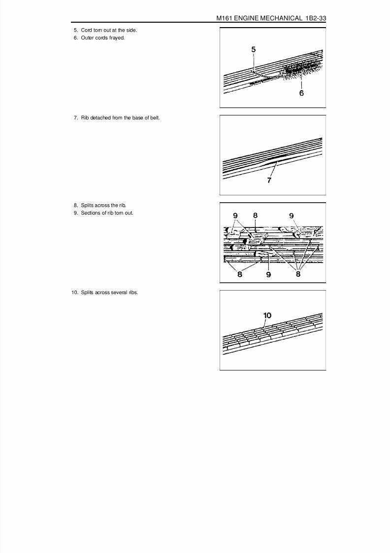
8/18/2019 SsangYong Musso Service Manual 1998.pdf
http://slidepdf.com/reader/full/ssangyong-musso-service-manual-1998pdf 222/1459
M161 ENGINE MECHANICAL 1B2-33
5. Cord torn out at the side.6. Outer cords frayed.
7. Rib detached from the base of belt.
8. Splits across the rib.9. Sections of rib torn out.
10. Splits across several ribs.
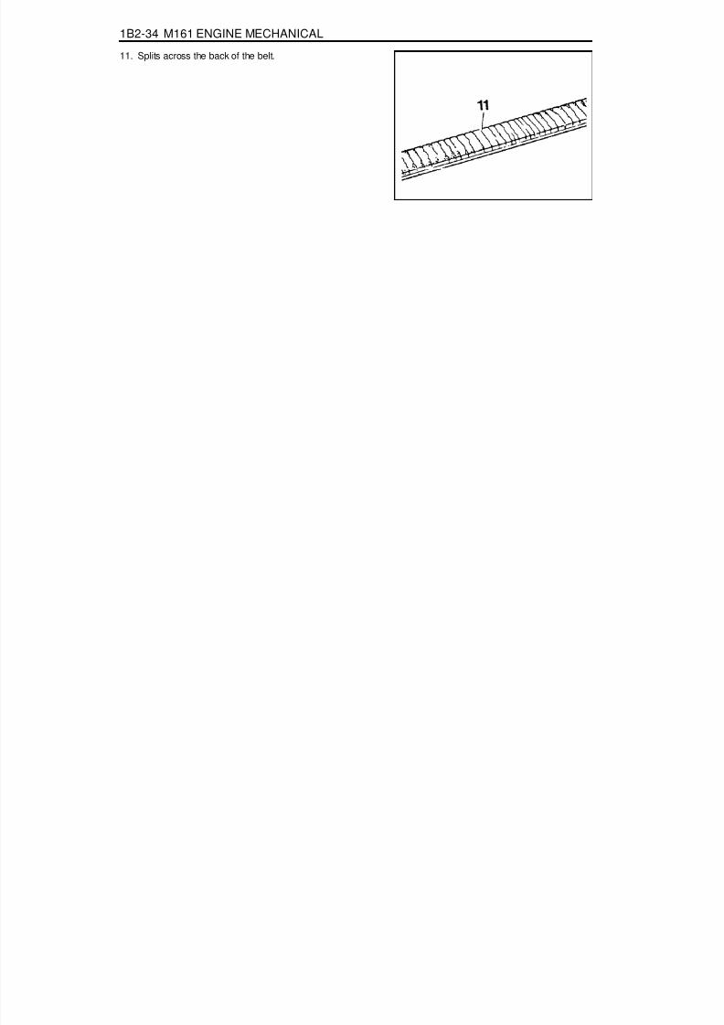
8/18/2019 SsangYong Musso Service Manual 1998.pdf
http://slidepdf.com/reader/full/ssangyong-musso-service-manual-1998pdf 223/1459
1B2-34 M161 ENGINE MECHANICAL
11. Splits across the back of the belt.
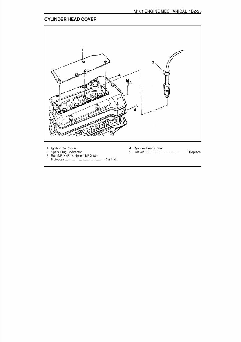
8/18/2019 SsangYong Musso Service Manual 1998.pdf
http://slidepdf.com/reader/full/ssangyong-musso-service-manual-1998pdf 224/1459
M161 ENGINE MECHANICAL 1B2-35
CYLINDER HEAD COVER
1 Ignition Coil Cover2 Spark Plug Connector3 Bolt (M6 X 45 : 4 pieces, M6 X 60 :
6 pieces) ............................................. 10 ± 1 Nm
4 Cylinder Head Cover5 Gasket ................................................... Replace

8/18/2019 SsangYong Musso Service Manual 1998.pdf
http://slidepdf.com/reader/full/ssangyong-musso-service-manual-1998pdf 225/1459
1B2-36 M161 ENGINE MECHANICAL
Removal & Installation Procedure1. Remove the intake air duct.
Installation Notice
2. Remove the ignition coil cover.
Installation Notice
3. Remove the spark plug connector and ignition cable.
NoticeRelease 3 screws from the ignition cover and remove thecover for M161 Engine coil.
Tightening Torque 9 - 11 Nm
Tightening Torque 9 - 10 Nm

8/18/2019 SsangYong Musso Service Manual 1998.pdf
http://slidepdf.com/reader/full/ssangyong-musso-service-manual-1998pdf 226/1459
M161 ENGINE MECHANICAL 1B2-37
CYLINDER HEAD FRONT COVERPreceding Work : Removal of cylinder head cover
Removal of thermostat housing assemblyRemoval of engine hanger bracket
Removal & Installation Procedure1. Disconnect the camshaft adjuster connector and remove
the camshaft adjuster (E23 engine only).Installation Notice
Tightening Torque 9 - 11 Nm
1 Bolt (M6 X 16, 3 pieces) ......................... 9-11 Nm2 Camshaft Adjuster3 Bolt (M8 X 35, 2 pieces) ................. 22.5-27.5 Nm4 Bolt (M6 X 22, 6 pieces) ......................... 9-11 Nm5 Front Cover (E23 : M161.973)
6 Front Cover (E20 : M161.943)7 Sleeve8 O-ring .................................................... Replace9 Thermostat Housing

8/18/2019 SsangYong Musso Service Manual 1998.pdf
http://slidepdf.com/reader/full/ssangyong-musso-service-manual-1998pdf 227/1459

8/18/2019 SsangYong Musso Service Manual 1998.pdf
http://slidepdf.com/reader/full/ssangyong-musso-service-manual-1998pdf 228/1459
M161 ENGINE MECHANICAL 1B2-39
CYLINDER HEADPreceding Work : Removal of cylinder head cover
Removal of cylinder head front coverRemoval of intake manifoldRemoval of cylinder head lower line (intake manifold side)
1 Cylinder Head Bolt (M12 X 100, 10 pieces)....................................................1st step 55 Nm
2nd step 90° rotation added3rd step 90° rotation added
3 Bolt (M8 X 35, 4 pieces) ................. 22.5-27.5 Nm
4 Camshaft Bearing cap ................... 22.5-27.5 Nm5 Cylinder Head6 Gasket ................................................... Replace7 Dowel Sleeve ............................................... Note

8/18/2019 SsangYong Musso Service Manual 1998.pdf
http://slidepdf.com/reader/full/ssangyong-musso-service-manual-1998pdf 229/1459
1B2-40 M161 ENGINE MECHANICAL
Tools Required617 589 00 10 00 Wrench Socket116 589 20 33 00 Sliding Hammer116 589 01 34 00 Threaded Bolt001 589 66 21 00 Torque Wrence104 589 00 40 00 Holder
Removal & Installation Procedure1. Rotate the crankshaft so that the piston of number 1 cylinder
is at ATDC 20.
2. Put the pin into the camshaft bearing cap (number 1, 6).
Pin 111 589 03 15 00
3. Put the alignment marks (arrows) on the timing chain andcamshaft sprocket.
4. Remove the chain tensioner.Installation Notice
Tightening Torque 72 - 88 Nm
Tightening Torque1st step 18 - 22 Nm2nd step 85° - 95°
5. Remove the exhaust camshaft sprocket.Installation Notice
NoticeThe flange bolt is designed to be used only once, so alwaysreplace with new one.

8/18/2019 SsangYong Musso Service Manual 1998.pdf
http://slidepdf.com/reader/full/ssangyong-musso-service-manual-1998pdf 230/1459
M161 ENGINE MECHANICAL 1B2-41
6. Remove the in take camshaft sprocket (E20 engine).7. Remove the camshaft adjuster (E23, M161.970 engine).
Installation Notice (Flange Bolt)
1 Flange Shaft2 Flange Bolt3 Campression Spring4 Adjust Piston5 Camshaft Sprocket6 Seal Cover7 Nut
Tightening Torque1st step 18 - 22 Nm2nd step 85°- 95°
NoticeThe flange bolt is designed to be used only once, so alwaysreplace with new one.
8. Remove the guide rail pin using the sliding hammer (02)and the threaded pin (03).NoticeApply the sealant on guide rail pin when installation.
9. Unscrew the bolts (A).Installation Notice
Tightening Torque 22.5 - 27.5 Nm
Bolt (A) : (M8 X 35, 4 pieces)
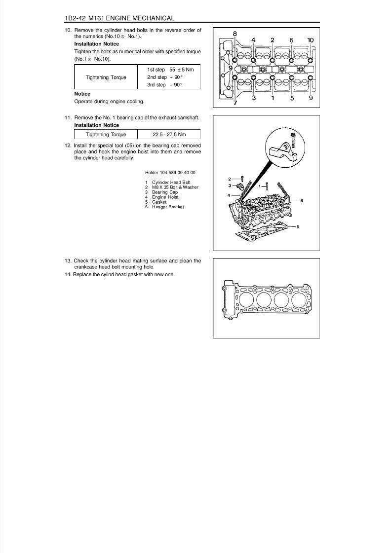
8/18/2019 SsangYong Musso Service Manual 1998.pdf
http://slidepdf.com/reader/full/ssangyong-musso-service-manual-1998pdf 231/1459
1B2-42 M161 ENGINE MECHANICAL
10. Remove the cylinder head bolts in the reverse order ofthe numerics (No.10 ® No.1).Installation NoticeTighten the bolts as numerical order with specified torque(No.1 ® No.10).
Holder 104 589 00 40 00
1 Cylinder Head Bolt2 M8 X 35 Bolt & Washer3 Bearing Cap4 Engine Hoist5 Gasket6 Hanger Bracket
Tightening Torque1st step 55 ± 5 Nm2nd step + 90°3rd step + 90°
11. Remove the No. 1 bearing cap of the exhaust camshaft.Installation Notice
Tightening Torque 22.5 - 27.5 Nm
12. Install the special tool (05) on the bearing cap removedplace and hook the engine hoist into them and removethe cylinder head carefully.
13. Check the cylinder head mating surface and clean thecrankcase head bolt mounting hole.
14. Replace the cylind head gasket with new one.
NoticeOperate during engine cooling.
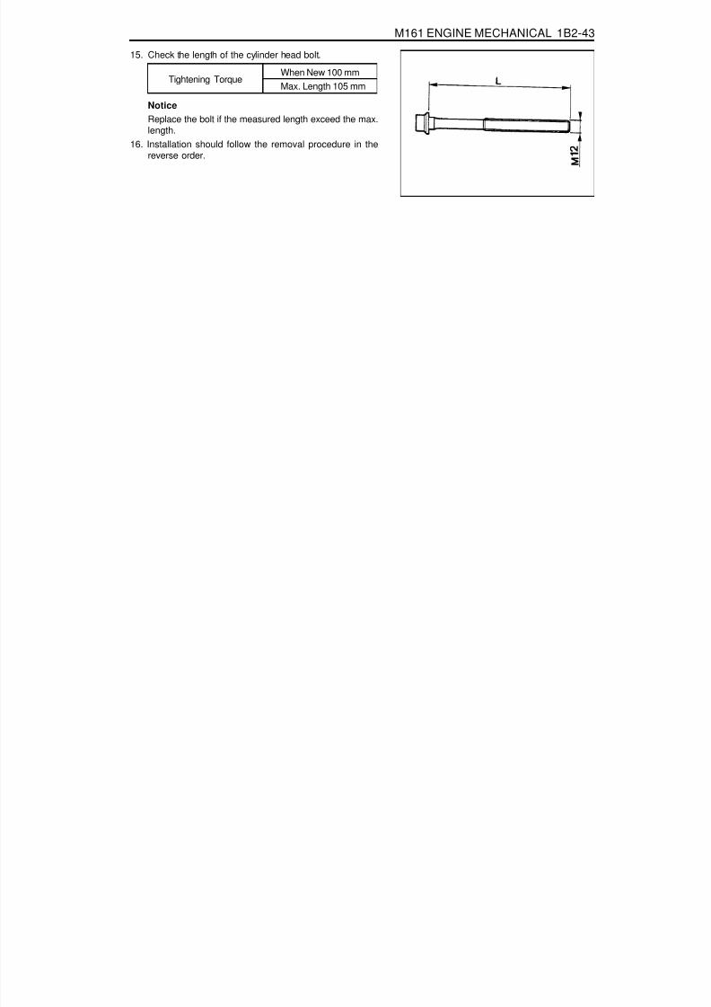
8/18/2019 SsangYong Musso Service Manual 1998.pdf
http://slidepdf.com/reader/full/ssangyong-musso-service-manual-1998pdf 232/1459

8/18/2019 SsangYong Musso Service Manual 1998.pdf
http://slidepdf.com/reader/full/ssangyong-musso-service-manual-1998pdf 233/1459
1B2-44 M161 ENGINE MECHANICAL
TIMING GEAR CASE COVERPreceding Work : Removal of viscous clutch
Removal of cylinder head front coverRemoval of tensioning deviceRemoval of water pumpRemoval of oil filter elementRemoval of oil panRemoval of alternator bracker
1 Bolt (M8 X 60, 3 pieces) ................. 22.5-27.5 Nm2 Bolt (M8 X 75, 1 piece)...................22.5-27.5 Nm3 Seal
4 Timing gear case cover5 O-ring6 Sleeve

8/18/2019 SsangYong Musso Service Manual 1998.pdf
http://slidepdf.com/reader/full/ssangyong-musso-service-manual-1998pdf 234/1459
M161 ENGINE MECHANICAL 1B2-45
Tools Required001 589 72 21 00 Torque Wrench116 589 20 33 00 Sliding Hammer116 589 01 34 00 Threaded Bolt
Removal & Installation Procedure1. Remove the power steering belt pulley and A/C compressor
bracket.2. Remove the oil line from power steering pump.3. Rotate the crankshaft so that the piston of number, cylinder
is at ATDC20°
Sliding Hammer 116 589 20 33 00Threaded Pin 116 589 02 34 00
4. Put the alignment marks (arrows) on the timing chain andcamshaft sprocket.
5. Remove the chain tensioner.Installation Notice
Tightening Torque 78 - 88 Nm6. Remove the intake and exhaust camshaft sprocket
(remove the camshaft adjuster assembly in E23 engine).Installation Notice
Tightening Torque1st step 18 - 22 Nm2nd step 85° - 95°
NoticeThe flange bolt is designed to be used only once, so alwaysreplace with new one.
7. Remove the guide rail pin using the sliding hammer (02)and the threaded pin (03).NoticeApply the sealant on guide rail pin when installation.

8/18/2019 SsangYong Musso Service Manual 1998.pdf
http://slidepdf.com/reader/full/ssangyong-musso-service-manual-1998pdf 235/1459
1B2-46 M161 ENGINE MECHANICAL
8. Unscrew the bolts (A).Installation Notice
Tightening Torque 22.5 - 27.5 Nm
9. Remove the belt pulley and vibration damper.Installation Notice (Center Bolt)
Tightening Torque1st step 180 - 220 Nm2nd step 80°- 100°
10. Unscrew the bolts (1, 2) on timing gear case cover andremove the timing gear case cover.Installation Notice
Tightening Torque 22.5 - 27.5 Nm
NoticeBe careful not to damage the cylinder head gasket.
11. Remove the radial shaft sealNoticeInstallation note replace the seal with new one.
12. Clean the timing gear case cover and crankcase sealingsurface.
13. Replace the O-ring with new one and apply the sealant on
the sealing surface.NoticeBe careful not to stain the oil chamber of chain tensionerwith the sealant.
14. Installation should follow the removal precedure in thereverse order.
15. Warm up the engine and check for oil leaks.

8/18/2019 SsangYong Musso Service Manual 1998.pdf
http://slidepdf.com/reader/full/ssangyong-musso-service-manual-1998pdf 236/1459
M161 ENGINE MECHANICAL 1B2-47
CRANKSHAFT SEALING REAR COVERPreceding Work : Removal of the automatic transmission drive plate or flywheel
1 Bolt (M6 x 20, 6 pieces) ......................... 9-11 Nm2 Radial Shaft Seal3 Rear Cover
4 Sleeve5 Bolt (M6 x 85, 2 pieces) ......................... 9-11 Nm6 Washer

8/18/2019 SsangYong Musso Service Manual 1998.pdf
http://slidepdf.com/reader/full/ssangyong-musso-service-manual-1998pdf 237/1459
1B2-48 M161 ENGINE MECHANICAL
Tools Required601 589 03 43 00 Sleeve
Removal & Installation Procedure1. Unscrew the bolts (1) and (5) and remove the closing cover
by pulling the rear cover lug (arrows).
NoticeBe careful not to damage the oil pan gasket.
2. Clean the sealing surface of the crankcase and the rearsealing cover.
3. Check the radial shaft seal and replace it if necessary.4. Apply the Loctite 573 to the rear cover sealing surface.
5. Apply the engine oil to the dust lip of the radial shaft seal.NoticeDo not use the grease.
6. Using the special tool, press the radial shaft seal and therear cover.
7. Tighten the rear cover bolt (1) and then tighten the oil panbolt (5) as specified and remove the special tool.Installation Notice
Seal Assembler 601 589 03 43 00
Tightening Torque(Bolt 1,5) 9 - 11 Nm

8/18/2019 SsangYong Musso Service Manual 1998.pdf
http://slidepdf.com/reader/full/ssangyong-musso-service-manual-1998pdf 238/1459
M161 ENGINE MECHANICAL 1B2-49
BELT PULLEY AND VIBRATION DAMPERPreceding Work : Removal of cooling fan and viscous clutch
Removal of fan shroudRemoval of drive belt
1 Center Bolt(M18 X 55) ....................... 1st step 200-220 Nm
2nd step 90° + 10° rotation added2 Vibration Damper Disk
5 Vibration Damper Assembly6 Key

8/18/2019 SsangYong Musso Service Manual 1998.pdf
http://slidepdf.com/reader/full/ssangyong-musso-service-manual-1998pdf 239/1459
1B2-50 M161 ENGINE MECHANICAL
Components
Service Data Standard
Permissble Deviation of The Vibration DamperRadial RunoutAxial Runout
0.6 mm0.6 mm
Tools Required103 589 00 33 00 Puller001 589 65 09 00 Socket Wrench Insert001 589 74 21 00 Puller000 589 88 33 00 Torque Wrench602 589 00 40 00 Engine Lock
Removal & Installation Procedure1. Adjust the piston of number 1 cylinder to the TDC.
1 Center Bolt (M18 x 50)2 Center Bolt Washer3 Vibration Damper and Pulley Assembly4 Key
5 Crankshaft Front Seal6 Timing Gear Case Cover7 Crankshaft Sprocket (Camshaft Driven)8 Crankshaft Sprocket (Oil pump Driven)9 Crankshaft
10 Oil Pan11 Oil Pan Gasket12 Oil Pan Mounting Bolt (M6 x 22)

8/18/2019 SsangYong Musso Service Manual 1998.pdf
http://slidepdf.com/reader/full/ssangyong-musso-service-manual-1998pdf 240/1459
M161 ENGINE MECHANICAL 1B2-51
Engine Lock 602 589 00 40 00
2. Remove the start motor and install the engine lock to theflywheel ring gear.
3. Remove the center bolt.
Installation Notice
4. Remove the vibration damper assembly using the puller.5. Installation should follow the removal procedure in the
reverse order.
Notice
If possible, don’t separate the vibration damper and thepulley.
Tightening Torque 1st step 180 - 220 Nm2nd step + 90°

8/18/2019 SsangYong Musso Service Manual 1998.pdf
http://slidepdf.com/reader/full/ssangyong-musso-service-manual-1998pdf 241/1459
1B2-52 M161 ENGINE MECHANICAL
CRANKSHAFT FRONT RADIAL SEALPreceding Work : Removal of belt pulley and vibration damper
1 Center Bolt (M18 x 50)............................... 1st step 200-220 Nm
2nd step 90° +10°2 Center Bolt Washer3 Sleeve (Special Tool)4 Crankshaft Front Seal5 Key
Tools Required601 589 03 14 00 Sleeve
Replacement Procedure1. Remove the radial seal with a screw driver.
NoticeUse a clean cloth not to damage the radial seal mountinghole and the crankshaft.
5. Remove the sleeve and install the belt pulley and thevibration damper.
6. Check for leaks while operating the engine.
2. Coat the radial sealing lip with engine oil.3. Using the sleeve, assemble the radial seal .4. Align the sleeve groove and the woodruff key and tighten
the center bolt until the center bolt and the damper diskstop in the movement.
Installation Notice
Tightening Torque1st step 200 - 220Nm2nd step 90° + 10°

8/18/2019 SsangYong Musso Service Manual 1998.pdf
http://slidepdf.com/reader/full/ssangyong-musso-service-manual-1998pdf 242/1459
M161 ENGINE MECHANICAL 1B2-53
CRANKSHAFT REAR RADIAL SEALPreceding Work : Removal of flywheel or drive plate
1 Special Tool2 Special Tool
3 Crankshaft Rear Seal
Tools Required601 589 03 43 00 Sleeve
Replacement Proceudre1. Remove the radial seal with a screw driver.
Notice
Use a clean cloth not to damage the radial seal mountinghole and the crankshaft.
2. Install the special tool (2) to the crankshaft.3. Apply the engine oil on the special tool (2).
NoticeDo not use the grease.
4. Install the radial seal on the inner parts assembler.5. Press in the special tool (1) until the radial seal is stopped.6. Check for leaks while operating the engine.

8/18/2019 SsangYong Musso Service Manual 1998.pdf
http://slidepdf.com/reader/full/ssangyong-musso-service-manual-1998pdf 243/1459
1B2-54 M161 ENGINE MECHANICAL
CRANKSHAFTPreceding Work : Removal of engine
Removal of cylinder headRemoval of timing gear case coverRemoval of crankcase sealing rear coverRemoval of oil panRemoval of baffle plateRemoval of oil pump
1 Bearing Cap Bolt(M8 X 55-10 pieces) ............ 1st step 50-60 Nm
2nd step 90°+5° rotation added2 Bearing Cap3 Upper Main Bearing4 Lower Main Bearing5 Upper Thrust Bearing6 Lower Thrust Bearing8 Crank Shaft

8/18/2019 SsangYong Musso Service Manual 1998.pdf
http://slidepdf.com/reader/full/ssangyong-musso-service-manual-1998pdf 244/1459
M161 ENGINE MECHANICAL 1B2-55
Arrangement of the Thrust Bearing and the Main Bearing
1 - 8 Weight Balance/Color Marking Point j1 - j5 Journal Main Bearing #1 - #5
Color Dot Marking
The color dot marking are put on the 1 , 2 , 4 , 6, 8 , and it indicates the diameter of crankshaft journalby color as below.
A Crankcase SideB Bearing Cap Side (Oil Pan Side)
1 Upper Main Bearing2 Upper Thrust Bearing3 Crankshaft4 Lower Main Bearing5 Lower Thrust Bearing

8/18/2019 SsangYong Musso Service Manual 1998.pdf
http://slidepdf.com/reader/full/ssangyong-musso-service-manual-1998pdf 245/1459
1B2-56 M161 ENGINE MECHANICAL
Selection of Crankshaft Main Bearing1. Crankcase Side
There are seven punching marks on the mating surfaceto oil pan. This mark is correspondent to the bearingdistinguished by color. Select the relevant bearingaccording to the punching mark when repaired.
2. Crankshaft Bearing Cap SideSelect the crankshaft main bearing according to themarking letter on the crankshaft main journal whenrepaired.
Color Dot Marking
BlueYellowRed
WhiteViolet
Crankshaft Journal Diameter (mm)
57.960 - 57.96557.955 - 57.96057.950 - 57.95557.945 - 57.95057.940 - 57.945
Punching Mark
···
···
Bearing Color SelectedBlue
YellowRed
Marking LetterBYRWV
Bearing Color SelectedBlue
YellowRed
WhiteViolet
Service DataUnit : mm
CrankshaftBearing Jour-nal Diameter
CrankshaftBearing
Diameter
CrankshaftJournal Widthat fit bearing
Connecting RodBearing Journal
Diameter
ConnectingRod Bearing
Jourmal WidthStandard size1st repair size2nd repair size3rd repair size4th repair size
57.950-57.96557.700-57.71557.450-57.46557.200-57.21556.950-56.965
58 24.50-24.533 47.94-47.9647.7547.5047.2547.00
27.958-28.042
Crankshaft Standardand Repair Size
-- -

8/18/2019 SsangYong Musso Service Manual 1998.pdf
http://slidepdf.com/reader/full/ssangyong-musso-service-manual-1998pdf 246/1459
M161 ENGINE MECHANICAL 1B2-57
Installation NoticeMake sure the crankshaft bearing cap properly seatedin place in the crankcase side. When perfectlyinstalled, the projected part (arrow) locates in the leftside (intake manifold side).Assemble so that the projected part of the cap andcrankcase face the same direction.
Removal & Installation Procedure1. Unscrew the connecting rod bearing cap bolt and remove
the bearing cap.
Installation Notice
2. Unscrew the crankshaft bearing cap bolts and separatethe upper and lower bearing shells and thrust washers.
Installation Notice
Remove the bearing cap from front (pulley side) torear.Make sure that the upper and lower bearing shells donot change each other and coat with engine oil.The oil grooves (arrows) in the thrust washers mustface outward and insert the thrust bearing into thebearing cap.There are five kinds of thrust washers by thickness.Select the proper washer when repaired.
3. Remove the crankshaft.
4. Installation should follow the removal procedure in thereverse order.5. After completion of the installation, check for the rotating
condition of the crankshaft.
Make sure that the upper and lower bearing shells donot change each other.Coat the bearing shell with engine oil.Install the bearing cap according to the consecutivenumber.
Part No. : 601 030 00 62 2.15 mmPart No. : 601 030 01 62 2.20 mmPart No. : 601 030 02 62 2.25 mmPart No. : 601 030 03 62 2.30 mmPart No. : 601 030 04 62 2.40 mm
Tightening Torque 40 Nm + 90°
Tightening Torque 55 Nm + 90°

8/18/2019 SsangYong Musso Service Manual 1998.pdf
http://slidepdf.com/reader/full/ssangyong-musso-service-manual-1998pdf 247/1459
1B2-58 M161 ENGINE MECHANICAL
Inspection1. If the length ‘L’ of the crankshaft bearing cap bolt exceeds
63.8mm, replace it.
2. Make sure the crankshaft bearing cap is properly seatedon the cylinder block (arrows).
3. Measure and record the inner diameter of the crankshaftbearing.
NoticeMeasure at 2 points (1, 2).Measure ‘A’,‘B’and ‘C’ as shown. If average value of‘B’ and ‘C’is less than value ‘A’, then the average valueof ‘B’ and ‘C’ is actual average value. If average valueof ‘B’ and ‘C’ is more than value ‘A’is actual averagevalue.
4. Measure and record the diameter of the crankshaftbearing journal.Notice
Record the mean value when measured at 3 points(A, B, C).Measure the inner diameter of bearing and thediameter of journal and if it is out of the standard data,replace the bearing shell.

8/18/2019 SsangYong Musso Service Manual 1998.pdf
http://slidepdf.com/reader/full/ssangyong-musso-service-manual-1998pdf 248/1459
M161 ENGINE MECHANICAL 1B2-59
Service Data Standard (Crankshaft Main Bearing Gap)
(Connecting Rod Bearing Gap)
ItemMain Bearing Journal
( NO. 1, 5, 7)
Measuring Position
Radial
Axial
Gap (mm)Static condition :0.015-0.039
Dynamic condition: 0.031-0.051(Consider the expansion 0.011-0.016)
0.010 - 0.254
ItemConnecting Rod Bearing
Measuring PositionRadial
Gap (mm)0.020 - 0.065

8/18/2019 SsangYong Musso Service Manual 1998.pdf
http://slidepdf.com/reader/full/ssangyong-musso-service-manual-1998pdf 249/1459
1B2-60 M161 ENGINE MECHANICAL
FLYWHEEL/DRIVEN PLATEPreceding Work : Removal of manual or automatic transmission
1 Flywheel Mounting Bolt(M10 x 22, 8 pieces) ................ 1st Step 45 Nm
2nd Step 90°+10°2 Plate
3 Driven Plate (A/T)4 Dowel Pin5 Flywheel (M/T)
Service Data Standard (Stretch Bolt)
Nominal SizeStretch Side Diameter
Bolt LengthTightening Torque
M x 1.58.5 - 0.2 mm
8.0 mm21.8 - 22.2 mm
-When New
Min. DiameterWhen New
Dd
L1st step 50 Nm, 2nd step 90°

8/18/2019 SsangYong Musso Service Manual 1998.pdf
http://slidepdf.com/reader/full/ssangyong-musso-service-manual-1998pdf 250/1459
M161 ENGINE MECHANICAL 1B2-61
Removal & Installation Procedure1. Unscrew the stretch bolt.
Installation Notice
Sectional View
1 Oil Pan2 Cover3 Radial Seal4 Bolt5 Crankshaft6 Dowel Pin7 Washer (Thickness : 3.5 mm)8 Washer9 Bolt
10 Front Drive Plate11 Rear Drive Plate12 Rivet13 Segment14 Ring Gear
Replace the bolt when the stretch side diameter (d) ofthe flywheel mounting bolt is less than 8.0mm.For the stretch bolt tightening, keep the socket wrenchand Tommy-bar to be 90° and tighten as specified.
2. Remove the flywheel for manual transmission vehicles,or the driven plate (3), and plate (2) for Auto. transmissionvehicle.
3. Installation should follow the removal procedure in thereverse order.
Tightening Torque1st step 45 Nm2nd step 90°+5°

8/18/2019 SsangYong Musso Service Manual 1998.pdf
http://slidepdf.com/reader/full/ssangyong-musso-service-manual-1998pdf 251/1459
1B2-62 M161 ENGINE MECHANICAL
CAMSHAFT ADJUSTER
1 Bolt (M6 X 16, 3 pieces) ......................... 9-11 Nm2 Cylinder Head Front Cover3 Bolt ........................................................... 35 Nm4 Armature5 Roll Pin6 Nut (M20 X 1.5) .................................... 60-70 Nm7 Seal Cover8 Camshaft Sprocket9 Adjust Piston
10 Conical Spring
11 Flange Bolt(M7 X 13, 3 pieces) ................. 1st Step 20±2 Nm
2nd Step 90°± 5°Rotation Added12 Flange Shaft13 Compression Spring14 Control Piston15 Circlip16 Oil Gallery17 Straight Pin18 Intake CamshaftY49 Magnetic Actuator (2-pin connector)

8/18/2019 SsangYong Musso Service Manual 1998.pdf
http://slidepdf.com/reader/full/ssangyong-musso-service-manual-1998pdf 252/1459
M161 ENGINE MECHANICAL 1B2-63
Removal & Installation Procedure1. Turn the crankshaft and position the n0.1 cylinder piston at
ATDC 20°.NoticeTurn the crankshaft in the direction of engine rotation.
2. Remove the cylinder head front cover.
3. Put the alignment marks (arrows) on the camshaft sprocketand the timing chain.
4. Insert the insert pin into the no.1 and no.6 bearing cap holeon camshaft to secure intake and exhaust camshaft.
5. Remove the chain tensioner.
6. Unscrew the exhaust sprocket bolt and remove the exhaustcamshaft sprocket.Installation Notice
Tightening Torque1st step 20 Nm2nd step 90°
NoticeThe flange bolt is designed to be used only once, so alwaysreplace with new one.

8/18/2019 SsangYong Musso Service Manual 1998.pdf
http://slidepdf.com/reader/full/ssangyong-musso-service-manual-1998pdf 253/1459
1B2-64 M161 ENGINE MECHANICAL
7. Unscrew the bolt (3) from the armature (4) and removethe roll pin, and remove the armature.Installation Notice
Tightening Torque 35 Nm
8. Unscrew the nut (6) and remove the seal cover (7).Installation Notice
Tightening Torque 60 - 70 Nm
NoticePut the locking slot of nut toward armarture.
9. Take off the timing chain from intake camshaft sprocket.
10. Remove the cover (7), adjuster piston (9) and conicalspring (10) from intake camshaft sprocket.
11. Unscrew the bolt (11) and remove the flange shaft.Installation Notice
Tightening Torque 1st step 20 Nm2nd step + 95°
NoticeThe flange bolt is designed to be used only once, so alwaysreplace with new one.
12. Installation should follow the removal procedure in thereverse order.
13. Check and adjust the camshaft timing.

8/18/2019 SsangYong Musso Service Manual 1998.pdf
http://slidepdf.com/reader/full/ssangyong-musso-service-manual-1998pdf 254/1459
M161 ENGINE MECHANICAL 1B2-65
CAMSHAFT SPROCKET BOLTIntake Flange Shaft Bolt
NoticeThe sprocket bolts are designed to be used only once, soalways replace with new one.
Exhaust Camshaft Sprocket Bolt
NoticeThe sprocket bolts are designed to be used only once, soalways replace with new one.
C. M7 x 13 Collar Bolt Torx-T30e. 6.8 mm
16. Flange Shaft18. Control Piston22. Intake Camshaft
E. M7 x 13 Collar Bolt Torx-T30e. 6.8 mm
13a. Camshaft Sprocket22a. Exhaust Camshaft
Tightening Torque1st step 20 Nm2nd step + 90°
Tightening Torque
1st step 20 Nm
2nd step + 90°

8/18/2019 SsangYong Musso Service Manual 1998.pdf
http://slidepdf.com/reader/full/ssangyong-musso-service-manual-1998pdf 255/1459
1B2-66 M161 ENGINE MECHANICAL
CAMSHAFTPreceding Work : Removal of cylinder head cover
Removal of camshaft adjust actuator and cylinder head front cover
1 Bolt (M7 X 13, 3 pieces) ......... 1st Step 18-22 Nm2nd Step 90°+ 5° Rotation Added
2 Exhaust Camshaft Sprocket3 Timing Chain
4a Intake Camshaft Spocket (E20)
4b Camshaft Adjuster and Camshaft Sprocket (E23)5 Bearing Cap Bolt (20 pieces) ......... 22.5-27.5 Nm6 Camshaft Bearing Cap7 Wrench (Special Tool)

8/18/2019 SsangYong Musso Service Manual 1998.pdf
http://slidepdf.com/reader/full/ssangyong-musso-service-manual-1998pdf 256/1459
M161 ENGINE MECHANICAL 1B2-67
Tools Required000 589 01 10 00 Box Wrench Insert104 589 01 01 00 Spanner
Removal & Installation Procedure1. Turn the crankshaft and position the no.1 cylinder piston at
ATDC20°.
2. Put the alignment marks (arrows) on the camshaft sprocketand the timing chain.
3. Remove the chain tensioner.Installation Notice
Tightening Torque 40 Nm72 - 88 Nm
Screw PlugTensioner Assembly
4. Remove the exhoust camshaft sprocket.Installation Notice
Tightening Torque 1st step 35 - 45 Nm2nd step 85° - 95°
NoticeThe sprocket bolt is designed to be used only once, soalways replace with new one.
5. Take off the timing chain from intake camshaft sprocket,and secute it not to fall down into the timing gear case.
6. Using the wrench (7), turn the camshaft until there is noresistence in camshaft bearing area.

8/18/2019 SsangYong Musso Service Manual 1998.pdf
http://slidepdf.com/reader/full/ssangyong-musso-service-manual-1998pdf 257/1459
1B2-68 M161 ENGINE MECHANICAL
7. Remove the bearing cap, and remove the intake and theexhaust camshaft.Installation Notice
Tightening Torque 22.5 - 27.5 Nm
NoticeCheck the numbers on the bearing cap not to be mikedup.
8. Apply the engine oil on the valve tappet and camshaftbearing.
9. Installation should follow the removal procedure in thereverse order.Notice
Base circle of cam should cantact with the valve tappet.Install the camshaft bearing caps according to thenumbers on the cylinder head cast and bearing cap.
10. Check the camshaft timing position.

8/18/2019 SsangYong Musso Service Manual 1998.pdf
http://slidepdf.com/reader/full/ssangyong-musso-service-manual-1998pdf 258/1459
M161 ENGINE MECHANICAL 1-1B-69
CAMSHAFT TIMING POSITIONPreceding Work : Removal of cylinder head cover
Removal of cylinder head front cover
1 Insert Pin ( f 6.5mm, Special Tool)2 Intake Camshaft Sprocket3 Camshaft Bearing Cap4 Timing Chain
5 Exhaust Camshaft Sprocket6 Bolt (M7 X 13, 3 pieces) ......... 1st step 20 ± 2 Nm
2nd step 90°± 5°rotation added7 Strate Pin

8/18/2019 SsangYong Musso Service Manual 1998.pdf
http://slidepdf.com/reader/full/ssangyong-musso-service-manual-1998pdf 259/1459
1B2-70 M161 ENGINE MECHANICAL
Tools Required104 589 01 01 00 Spanner111 589 03 15 00 Insert Pin
Inspection Procedure1. Position the NO.1 cylinder piston to ATDC 20°by turning
the crankshaftNoticeWhen the ATDC 20°mark on vibration damper is alignedwith timing gear case cover, the intake and exhaust cam ofcylinder will make the slope to the center and will face up.In this way, the insert hole in NO.1 and NO.4 camshaftbearing cap will match in line with the flange hole forcamshaft sprocket.
2. Check the timing as below procedure;- Check if the insert pin (111 589 03 15 00) can be inserted
into the NO.1 and NO.4 bearing cap hole.
- At this condition, check if the ATDC 20°mark on vibrationdamper aligns with the marker on the timing gear case.

8/18/2019 SsangYong Musso Service Manual 1998.pdf
http://slidepdf.com/reader/full/ssangyong-musso-service-manual-1998pdf 260/1459
M161 ENGINE MECHANICAL 1B2-71
Adjustment Procedure1. Position the NO.1 cylinder to ATDC 20°.2. Remove the chain tensioner.3. Remove the exhaust camshaft sprocket.4. Adjust the timing position with inserting the insert pin
(f 6.5mm, 111 589 03 15 00) into the NO.1 and NO.4
camshaft bearing cap hole and flange hole while rotatingthe camshaft by using wrench (104 589 01 01 00).
5. Install the chain to the intake camshaft sprocket.6. Install the chain to the exhaust camshaft sprocket and
tighten the bolt.Installation Notice
Tightening Torque1st step 20 Nm2nd step + 90°
The sprocket bolt is designed to be used only once, soreplace with new one.
7. Install the chain tensioner.Installation Notice
Screw plug
Tensioner assembly
40 Nm
80 ± 8 Nm
TighteningTorque
8. Check the camshaft timing.

8/18/2019 SsangYong Musso Service Manual 1998.pdf
http://slidepdf.com/reader/full/ssangyong-musso-service-manual-1998pdf 261/1459
1B2-72 M161 ENGINE MECHANICAL
VALVE SPRINGPreceding Work : Removal of camshaft
Removal of spark plug
1 Valve Tappet Assembly2 Valve Cotter3 Upper Retainer4 Valve Spring .......... Check, Replace if necessary5 Valve Stem Seal6 Lower Retainer
7 Connecting Hose8 Thrust Piece9 Slide
10 Adjust Bolt11 Lever Pusher12 Supporting Bar

8/18/2019 SsangYong Musso Service Manual 1998.pdf
http://slidepdf.com/reader/full/ssangyong-musso-service-manual-1998pdf 262/1459
M161 ENGINE MECHANICAL 1B2-73
Tools Required111 589 01 59 00 Supporting Bar111 589 18 61 00 Lever Pusher111 589 25 63 00 Thrust Piece116 589 06 63 00 Magnetic Finger
Removal & Installation Procedure1. Place the supporting bar (12) and the slide (9) at the
camshaft bearing cap (Nos 1 & 7/8&14) and tighten themwith the bearing cap bolt.
Installation Notice
2. Turn the crankshaft to position the each cylinder piston at
TDC.
5. Install the engine lock to the ring gear to prevent thecrankshaft from rotating.
6. Blow up with compressed air.
NoticeRemove the valve spring only at TDC.Always rotate the crankshaft by holding the chain toprevent from timing chain damage and tangling, and forsmooth rotation.
3. Remove the valve tappet (1) using the magnetic finger.
4. Install the leakage tester connecting hose to the spark plughole.
Supporting Bar 111 589 01 59 00
Tightening Torque 22.5 - 27.5 Nm
Mark on The Vibration DamperOTUT
Cylinder1, 42, 3

8/18/2019 SsangYong Musso Service Manual 1998.pdf
http://slidepdf.com/reader/full/ssangyong-musso-service-manual-1998pdf 263/1459
1B2-74 M161 ENGINE MECHANICAL
8. Install the lever pusher (11) and the thrust piece (8) to theslide (9).
13. Remove the valve cotter (2) using either the pincette (13)or magnetic finger.
Lever Pusher 111 589 18 61 00
Magnetic Finger 116 589 06 63 00
9. Mount the thrust piece (8) vertically to the valve springretainer (3).
10. Make the thrust piece (8) and the slide (9) perpendicularto each other.
11. Secure the slide (9) by turning the adjust bolt (10).12. Press the valve spring (4) by using the lever pusher (11).
14. Remove the upper retainer (3) and the valve spring (4).15. Remove the valve stem seal and replace if necessary.
NoticeCheck the valve stem seal and replace if necessary.
16. Remove the lower retainer (6).
NoticeCheck the retainer for damages and replace with a newone if necessary.
17. Installation should follow the removal procedure in thereverse order.

8/18/2019 SsangYong Musso Service Manual 1998.pdf
http://slidepdf.com/reader/full/ssangyong-musso-service-manual-1998pdf 264/1459
M161 ENGINE MECHANICAL 1B2-75
Test (Upper and Lower Valve Tappet and ValveCotter)
Upper Valve Spring Retainer
Lower Valve Spring Retainer
Valve Cotter
12.3(D)
(d) 8.5 Size (mm)
Thickness (mm) (a) 0.8 - 1.0
9.2 - 9.8(H)
(B) 9.0
Size (mm)

8/18/2019 SsangYong Musso Service Manual 1998.pdf
http://slidepdf.com/reader/full/ssangyong-musso-service-manual-1998pdf 265/1459
1B2-76 M161 ENGINE MECHANICAL
VALVE STEM SEALPreceding Work : Removal of valve spring
1 Drift (Special Tool)2 Valve Stem Seal3 Protective Sleeve
Drift 119 589 00 43 00
Pliers 104 589 00 37 00
Tools Required104 589 00 37 00 Pliers119 589 00 43 00 Drift
Replacement Procedure1. Remove the valve stem seal (2) using the pliers.
NoticeCheck the valve stem seal for damage and replace ifnecessary.
2. Coat the valve stem seal with oil and assemble it with theprotective sleeve.
3. Insert the valve stem seal by pressing it with the drift.

8/18/2019 SsangYong Musso Service Manual 1998.pdf
http://slidepdf.com/reader/full/ssangyong-musso-service-manual-1998pdf 266/1459
M161 ENGINE MECHANICAL 1B2-77
CHAIN TENSIONER
1 Screw Plug ................................................ 40 Nm2 Seal3 Filler Pin4 Compression Spring
5 Snap Ring6 Thrust Pin7 Chain Tensioner Housing ..................... 72-88 Nm8 Seal
Removal Procedure1. Position the number 1 cylinder to ATDC 20°.
NoticeRemove the oil filler cap at adjustment position, and checkwhether the intake camshaft cam’s lobe (arrow) stays in theupper side.
2. Cover the alternator with a clean cloth.3. Release the tension by unscrewing the screw plug once.
NoticeIn case that the tension is reduced by unscrewing the screwplug, reinstall after completely removing the chain tensioner.If the chain tensioner is tightened again without completelyreducing its tension, then the snap ring doesn’t return tothe original position and the tension gets excedded.

8/18/2019 SsangYong Musso Service Manual 1998.pdf
http://slidepdf.com/reader/full/ssangyong-musso-service-manual-1998pdf 267/1459

8/18/2019 SsangYong Musso Service Manual 1998.pdf
http://slidepdf.com/reader/full/ssangyong-musso-service-manual-1998pdf 268/1459
M161 ENGINE MECHANICAL 1B2-79
4. Lightly apply the grease to the seal (2) and install the screwplug (1).
Installation Notice
Sectional View
1 Screw Plug2 Ball (Nonreturn Valve)3 Compression Spring4 Ball Guide5 Seal (Aluminum)6 Filler Pin7 Compression Spring8 Snap Ring9 Thrust Pin
10 Ball (Nonreturn Valve)11 Compression Spring12 Thrust Piece
13 Chain Tensioner Housing14 Seal15 Timing Gear Case Cover16 Cylinder Head17 Bolt / Washer18 Tensioning Rail19 Cylinder Head Gasket20 Timing Chain21 Tensioning Rail Base (Sliding Surface)
A Oil Supply HoleB Chain Tensioner Oil Storage Hole
5. Check for leaks by operating the engine.
Tightening Torque 40 Nm

8/18/2019 SsangYong Musso Service Manual 1998.pdf
http://slidepdf.com/reader/full/ssangyong-musso-service-manual-1998pdf 269/1459
1B2-80 M161 ENGINE MECHANICAL
TIMING CHAINPreceding Work : Removal of cylinder head cover
Removal of spark plug
1 Pin2 New Timing Chain3 Timing Chain (Used)4 Wedge
5 Link6 Center Plate7 Outer Plate

8/18/2019 SsangYong Musso Service Manual 1998.pdf
http://slidepdf.com/reader/full/ssangyong-musso-service-manual-1998pdf 270/1459

8/18/2019 SsangYong Musso Service Manual 1998.pdf
http://slidepdf.com/reader/full/ssangyong-musso-service-manual-1998pdf 271/1459
1B2-82 M161 ENGINE MECHANICAL
7. Connect the new timing chain (2) to the used timing chain(3) with the link (5), center plate (6, thickness 1.6mm),and the outer plate (7).
8. Rotate the crankshaft in the direction if engine revolutionby pressing the new timing chain against the exhaustcamshaft sprocket to prevent it to be tangled.NoticeBe sure to remove the wedge before cranking the engine.
9. Take out the used timing chain out from the chain housing.10. Connect both separators of the new timing chain with the
link (5) and the center plate (6).
6. Remove the outer plate (7) with the screw driver andremove the link (5).
11. Install the jaw (a) and the thrust piece (b) to the assemblytool as shown in the figures.

8/18/2019 SsangYong Musso Service Manual 1998.pdf
http://slidepdf.com/reader/full/ssangyong-musso-service-manual-1998pdf 272/1459
M161 ENGINE MECHANICAL 1B2-83
15. Replace the thrust piece (b) as shown in the figure.
13. Install the assembly tool above the link and tighten thespindle (c) until a block is felt.
14. Place the assembly tool.
12. Place the outer plate (7, thickness 1.2mm) inside the thrustpiece (b).
16. Install the assembly tool to the link pin and tighten thespindle (c).
Tightening Torque 30 Nm

8/18/2019 SsangYong Musso Service Manual 1998.pdf
http://slidepdf.com/reader/full/ssangyong-musso-service-manual-1998pdf 273/1459
1B2-84 M161 ENGINE MECHANICAL
17. Rivet the link pin.Check the condition and it again if necessary.
18. Install the chain tensioner.Installation Notice
19. Check the camshaft timing position.
Tightening TorqueScrew Plug 40 Nm
Tensioner Assembly 72 - 88 Nm

8/18/2019 SsangYong Musso Service Manual 1998.pdf
http://slidepdf.com/reader/full/ssangyong-musso-service-manual-1998pdf 274/1459
M161 ENGINE MECHANICAL 1B2-85
TENSIONING RAILPreceding Work : Removal of cylinder head
Removal & Installation Procedure1. Remove the timing gear case cover (3).
NoticeBe careful not to damage the gasket.
2. Remove the sliding rail (1) from the sliding rail pin (2).Notice
Replace the plastic guide (2) if it is damaged.For installation, exactly align the plastic guide (2) withthe sliding rail (1).
3. Installation should follow the removal procedure in thereverse order.
1 Sliding Rail Pin2 Sliding Rail
3 Timing Gear Case Cover

8/18/2019 SsangYong Musso Service Manual 1998.pdf
http://slidepdf.com/reader/full/ssangyong-musso-service-manual-1998pdf 275/1459
1B2-86 M161 ENGINE MECHANICAL
CYLINDER HEAD GUIDE RAILPreceding Work : Removal of cylinder head cover
1 Bolt (M6 X 45, 2 pieces) .................. 9-11 Nm2 Guide Rail
Removal & Installation Procedure1. Position the number 1 cylinder to ATDC20°guide rail.
2. Install the pin (special tool : 111 589 03 15 00) into the no.1and no.6 bearing cap hole.3. Remove the chain tensioner.
Installation Notice
Tightening TorqueScrew Plug 40 Nm
Tensioner Assembly 72 - 88 Nm
4. Unscrew the bolt (1) and remove the guide rail.Installation Notice
Tightening Torque 9 - 11 Nm
5. Installation should follow the removal procedure in thereverse order.
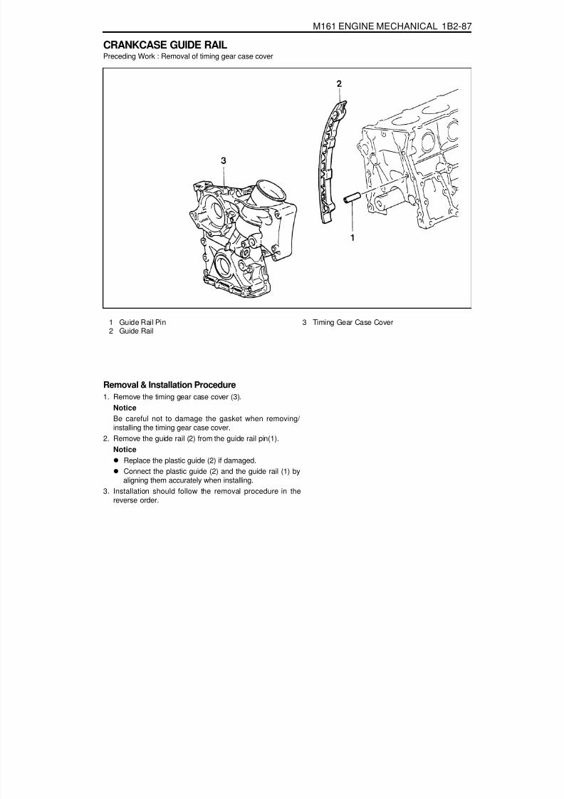
8/18/2019 SsangYong Musso Service Manual 1998.pdf
http://slidepdf.com/reader/full/ssangyong-musso-service-manual-1998pdf 276/1459
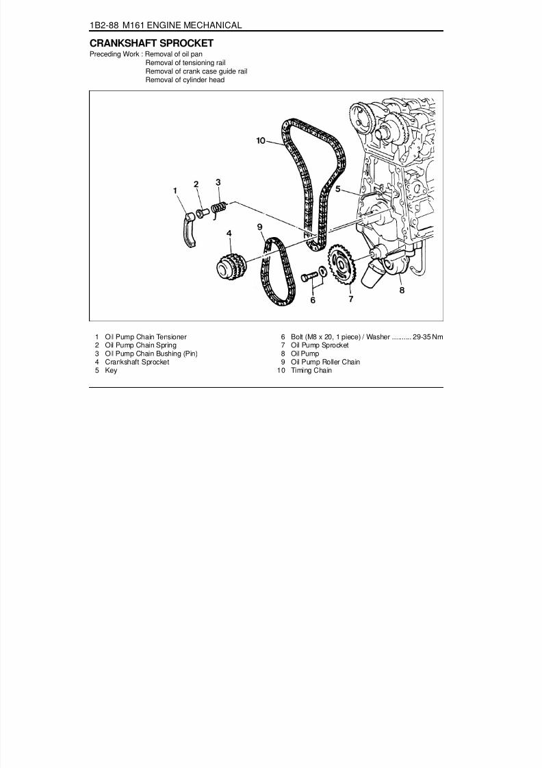
8/18/2019 SsangYong Musso Service Manual 1998.pdf
http://slidepdf.com/reader/full/ssangyong-musso-service-manual-1998pdf 277/1459

8/18/2019 SsangYong Musso Service Manual 1998.pdf
http://slidepdf.com/reader/full/ssangyong-musso-service-manual-1998pdf 278/1459
M161 ENGINE MECHANICAL 1B2-89
Tools Required615 589 01 33 00 Caulking Bolt
Removal & Installation Procedure1. Put the assembly mark at the crankshaft sprocket (4) and
the timing chain (10) with the paint (arrow).
Installation NoticeAlign the assembly marks on cranshaft sprocket and timingchain. Also, align the assembly marks on camshaft sprocketand timing chain when installing.
2. Unscrew the bolt (6) and remove the oil pump sprocket (7)from the oil pump.
Installation Notice
Caulking (04) 615 589 01 33 00
3. Remove the oil pump roller chain (9).4. Remove the oil pump chain tensioner (1), oil pump chain
bushing (3), and the oil pump chain spring (2).5. Remove the crankshaft sprocket (4) using the puller (04,
special tool).
NoticeMake sure not to lose the crankshaft pulley key (5) whenremoving.Install the crankshaft sprocket (4) after warming it up.
6. Installation should follow the removal procedure in thereverse order.
Tightening Torque 29 - 35 Nm

8/18/2019 SsangYong Musso Service Manual 1998.pdf
http://slidepdf.com/reader/full/ssangyong-musso-service-manual-1998pdf 279/1459
1B2-90 M161 ENGINE MECHANICAL
PISTONPreceding Work : Removal of engine
Removal of cylinder headRemoval of oil panRemoval of oil pumpRemoval of baffle plate
1 Connecting Rod Bearing Cap2 Connecting Rod3 Connecting Rod Bolt
(M9 x 52, 8 pieces) ......................1st step 40 Nm2nd step 90°+5°
4 Piston5 Snap Ring6 Piston Pin

8/18/2019 SsangYong Musso Service Manual 1998.pdf
http://slidepdf.com/reader/full/ssangyong-musso-service-manual-1998pdf 280/1459
M161 ENGINE MECHANICAL 1B2-91
Tools Required001 589 72 21 00 Torqued Wrench000 589 04 14 00 Clamping Strap
Removal Procedure1. Unscrew the connecting rod bolt (3) and remove the cap.2. Remove the connecting rod and the piston upward.
NoticeMake sure that the bearing cap and shell are not changedeach other.
3. Remove the snap ring (5) and pull out the piston pin (6).
NoticeRemove the snap ring using a clean cloth as shown in theright picture so that the piston, piston ring, and the snapring don’t get damaged.
Installation Procedure

8/18/2019 SsangYong Musso Service Manual 1998.pdf
http://slidepdf.com/reader/full/ssangyong-musso-service-manual-1998pdf 281/1459
1B2-92 M161 ENGINE MECHANICAL
1. Check the piston ring gap and apply the engine oil to thepiston pin and the connecting rod bushing.
2. Connect the piston and the connecting rod by pressing inthe piston pin (6) and install the snap ring to the groove.
3. Clean the cylinder bore, connecting rod bearing journal,connecting rod bearing shell and the piston and coat themwith engine oil.
4. Install the piston ring using the tensioning strap(000 58904 14 00).
5. Install the piston so that the arrow on the piston head facesto the forward of the vehicle.
6. After aligning the connecting rod and the bearing cap mark(// or a number), tighten the bolts.
Installation Notice
Tightening Torque1st step 35 - 45 Nm2nd step 90°+5°
Apply the engine oil to the bearing cap upper and lowerbearing shells.7. Check if the crankshaft rotates without any trouble by rotating
it.

8/18/2019 SsangYong Musso Service Manual 1998.pdf
http://slidepdf.com/reader/full/ssangyong-musso-service-manual-1998pdf 282/1459
M161 ENGINE MECHANICAL 1B2-93
CONNECTING RODPreceding Work : Removal of piston
1 Connecting Rod Bushing2 Oil Gallery3 Balance Weight4 Connecting Rod Bolt
(M9 x 52, 8 pieces) ............1st step 40 Nm2nd step 90°5 Fit Sleeve6 Upper Connecting Rod Bearing7 Lower Connecting Rod Bearing8 BearingShell Lug9 Marking [Indication(//) or Numbers]
Service Data Standard
Distance (L) from The Connecting Rod Bearing to Bushing Bore Center
Width of The Connecting Rod (B) at Bearing BoreWidth of The Connecting Rod (b) at Bushing BoreBasic Bore at The Bearing Shell (D1)Basic Bore at The Bushing (d1)Bushing Inner Diameter (d)Clearance Between The Piston Pin and The BushingPeak-to-valley Height of Connecting Rod Bushing on InsidePermissible Wwist of Connecting Rod Bearing Bore to
Connecting Rod Bushing BorePermissible Deviation of Axial Paralleism of Connecting RodBearing Bore to Connecting Rod Bushing BorePermissible Deviation of Axial Paralleism of Connecting Rod Bearing Bore fromConcentricityPermissible Difference of Each Connecting Rod in Weight
E20 : 154 mmE23 : 149 ± 0.05 mm21.940 - 22.000 mm21.940 - 22.000 mm51.600 - 51.614 mm24.500 - 24.571 mm22.007 - 22.013 mm
0.007 - 0.018 mm0.005 mm
0.1/100 mm
0.045/100 mm
0.01 mm
0.4 g

8/18/2019 SsangYong Musso Service Manual 1998.pdf
http://slidepdf.com/reader/full/ssangyong-musso-service-manual-1998pdf 283/1459
1B2-94 M161 ENGINE MECHANICAL
Inspection1. Measure the basic bore of the connecting rod bearing.
NoticeIf the basic bore exceeds the value of 51.614mm, replacethe bearing or check the connecting rod.
2. Check connecting rod bolts.
3. Check the assembly mark(indication//or number:arrow) ofthe connecting rods and the bearing cap when installing.
NoticeMake sure it doesn’t exceed over 4g with otherconnecting rods when replacing the connecting rods.Check if the connecting rod and the bearing cap areaccurately seated on the groove when replacing thebearing.
NoticeIf the length exceeds max. length, replace it.
Length When New (L)Max. Length (L)
Tightening Torque
51.7 - 52 mm52.9 mm
1st step 40 + 5 Nm2nd step 90°+10°
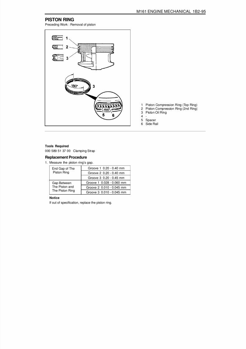
8/18/2019 SsangYong Musso Service Manual 1998.pdf
http://slidepdf.com/reader/full/ssangyong-musso-service-manual-1998pdf 284/1459
M161 ENGINE MECHANICAL 1B2-95
PISTON RINGPreceding Work : Removal of piston
1 Piston Compression Ring (Top Ring)2 Piston Compression Ring (2nd Ring)3 Piston Oil Ring4 -5 Spacer6 Side Rail
NoticeIf out of specification, replace the piston ring.
Tools Required000 589 51 37 00 Clamping Strap
Replacement Procedure1. Measure the piston ring’s gap.
Gap Between
The Piston andThe Piston Ring
Groove 1 0.20 - 0.40 mmGroove 2 0.20 - 0.40 mmGroove 3 0.20 - 0.45 mm
Groove 1 0.028 - 0.060 mm
Groove 2 0.010 - 0.045 mmGroove 3 0.010 - 0.045 mm
End Gap of The Piston Ring

8/18/2019 SsangYong Musso Service Manual 1998.pdf
http://slidepdf.com/reader/full/ssangyong-musso-service-manual-1998pdf 285/1459
1B2-96 M161 ENGINE MECHANICAL
2. Remove the piston ring with a pliers.
3. For installation, position the piston ring to be the ‘TOP’mark on the piston ring upward and arrange the piston ringends to be 120°apart.
4. Adjust the hook spring joint in the oil ring 180°away fromthe ring end.
Clamping Strap 000 589 51 37 00

8/18/2019 SsangYong Musso Service Manual 1998.pdf
http://slidepdf.com/reader/full/ssangyong-musso-service-manual-1998pdf 286/1459
M161 ENGINE MECHANICAL 1B2-97
OIL PAN
1 Bolt2 Bolt3 Bolt
4 Bolt
1. Remove the drain plug and drain the oil completely.2. Unscrew the bolts and remove the oil pan and gasket.
NoticeArrange the bolts according to each size.
3. Clean the inside of oil pan and sealing surface, then applythe sealant.
4. Replace the gasket with new one.5. Install the oil pan with gasket, and tighten each bolt in
specified torque.6. Check for oil leaks while running the engine.
M8 X 40, 4 piecesM6 X 35, 1 piecesM6 X 100, 2 pieceM6 X 85, 3 piecesM6 X 20, 20 pieces
5 Bolt6 Oil Pan7 Gasket

8/18/2019 SsangYong Musso Service Manual 1998.pdf
http://slidepdf.com/reader/full/ssangyong-musso-service-manual-1998pdf 287/1459
1B2-98 M161 ENGINE MECHANICAL
Oil Circulation
1 Oil Strainer2 Oil Pump3 Oil Pan4 Oil Non-Return Valve5 Oil Filter6 Oil Filter Bypass Valve7 Main Oil Gallery8 Closing Ball ( f 15mm)9 Crankshaft
10 Connecting Rod Bearing11 Crankshaft Bearing12 Connecting Rod13 Piston14 Oil Spray (Piston Crown Area)15 Non-Return Valve (Crankcase)
16 Oil Supply (To Chain Tensioner)17 Camshaft18 Cam Bearing19 Valve20 Oil Gallery (Supply Oil to Intake Tappet)21 Oil Gallery (Supply Oil to Exhaust Tappet)22 Ball ( f 8mm)23 Camshaft Plug24 Seal25 Screw Plug26 Oil Return Gallery (Cylinder Head and
Crankcase)27 Oil Return Gallery (Crankcase)28 End Cover ( f 20mm)29 Oil Return Pipe

8/18/2019 SsangYong Musso Service Manual 1998.pdf
http://slidepdf.com/reader/full/ssangyong-musso-service-manual-1998pdf 288/1459
M161 ENGINE MECHANICAL 1B2-99
ENGINE OIL AND OIL FILTER ELEMENT
1 Oil Filter Cover.......................................... 25 Nm2 O-ring .................................................... Replace3 Oil Filter Element
4 Oil Drain Plug5 Oil Filter Bypass Valve6 Oil Filter Cap

8/18/2019 SsangYong Musso Service Manual 1998.pdf
http://slidepdf.com/reader/full/ssangyong-musso-service-manual-1998pdf 289/1459

8/18/2019 SsangYong Musso Service Manual 1998.pdf
http://slidepdf.com/reader/full/ssangyong-musso-service-manual-1998pdf 290/1459
M161 ENGINE MECHANICAL 1B2-101
OIL PUMPPreceding Work : Removal of oil pan
1 Bolt (M8 X 35, 3 piece)...................22.5-27.5 Nm2 Oil Pump3 Oil Strainer Assembly4 Bolt (M6 X 12, 2 pieces) ......................... 9-11 Nm
(In E23 Engine, These Bolts areCombined with Baffle Plate)
5 Bolt (M8 X 20, 1 pieces) ....................... 29-35 Nm
6 Washer7 Sprocket (Oil Pump Drive)8 Chain (Oil Pump Drive)9 Plate-Baffle
10 Bolt (M6 X 12, 6 piece) ........................... 9-11 Nm(E23 Engine Only : Baffle Plate Mounting Bolt)

8/18/2019 SsangYong Musso Service Manual 1998.pdf
http://slidepdf.com/reader/full/ssangyong-musso-service-manual-1998pdf 291/1459
1B2-102 M161 ENGINE MECHANICAL
Removal & Installation Procedure1. Unscrew the bolt (6) from the oil pump drive sprocket and
separate the oil pump drive chain.Installation Notice
Tightening TorqueBolt (4) 9 - 11 Nm
Bolt (5) 9 - 11 Nm
Tightening Torque 29 - 35 Nm
2. Unscrew the bolts (4,5) and remove the oil strainer assembly(3).Installation Notice
Insert the steel gasket into the oil pump and bolt (4) mountingsurface.
3. Unscrew the six bolts (11) and remove the haffle plate.Installation Notice
Tightening Torque 9 - 11 Nm
4. Unscrew the three bolt (1) and remove the oil pump.Installation Notice
Tightening Torque 22.5 - 27.5 Nm

8/18/2019 SsangYong Musso Service Manual 1998.pdf
http://slidepdf.com/reader/full/ssangyong-musso-service-manual-1998pdf 292/1459
M161 ENGINE MECHANICAL 1B2-103
OIL PRESSURE RELIEF VALVEPreceding Work : Removal of oil pan
1 Screw Plug ................................................ 50 Nm2 Compression Spring
Removal & Installation Procedure1. Remove the screw plug (1).
Installation Notice
2. Remove the spring (2), guide pin (3) and the piston (4).3. Installation should follow the removal procedure in the
reverse order.
NoticeDon’t use the seal for the screw plug.
3 Guide Pin4 Piston
Tightening Torque 50 Nm

8/18/2019 SsangYong Musso Service Manual 1998.pdf
http://slidepdf.com/reader/full/ssangyong-musso-service-manual-1998pdf 293/1459
1B2-104 M161 ENGINE MECHANICAL
OIL NON-RETURN VALVEPreceding Work : Removal of timing gear case cover
1 Oil Non-Return Valve
FunctionsThe non-return valve prevents the oil in the chain tensionerfrom drying up. In other words, it stops oil-returning in order toprevent the oil in the chain tensioner from getting dry. As aresult, the chain tensioner can be activated with oil in itself.
Replacement Procedure1. Remove the non-return valve using a pliers.
2. Insert new non-return valve with hand.

8/18/2019 SsangYong Musso Service Manual 1998.pdf
http://slidepdf.com/reader/full/ssangyong-musso-service-manual-1998pdf 294/1459
M161 ENGINE MECHANICAL 1B2-105
OIL DIPSTICK GUIDE TUBE
1 Oil Dipstick Level Gauge
2 Oil Dipstick Guide Tube3 O-ring
Removal & Installation Procedure1. Pull out the oil dipstick level gauge (1).2. Unscrew the bolt (4) and remove the oil dipstick guide
tube (2).Installation Notice
4 Bolt (M6 X 16, 1 piece) ........................... 9-11 Nm
5 Clamp
Tightening Torque 9 - 11 NmIt is very hard to remove the oil dipstick guide tube withoutspecial tool. If it is not necessary, do not remove the guidetube.
3. Installation should follow the removal procedure in thereverse order.
4. Check for leaks by starting the engine.

8/18/2019 SsangYong Musso Service Manual 1998.pdf
http://slidepdf.com/reader/full/ssangyong-musso-service-manual-1998pdf 295/1459
1B2-106 M161 ENGINE MECHANICAL
UNIT REPAIRCORE PLUGS IN CRANKCASEPreceding Work : Draining of the coolant
1 Core Plug............................................... Replace

8/18/2019 SsangYong Musso Service Manual 1998.pdf
http://slidepdf.com/reader/full/ssangyong-musso-service-manual-1998pdf 296/1459
M161 ENGINE MECHANICAL 1B2-107
Tools Required102 589 00 15 00 Drift
Replacement Procedure1. Remove the intake and exhaust manifolds.2. Pull back the core plug until the end of one side comes out
using the screw driver.
3. Pull out the plug carefully using a pliers.
5. Press in new plug using a drift.
NoticeWait for about 45minutes before filling the coolant so thatthe Loctite 241 hardens.
6. Warm up the engine and check the coolant for leaks.
4. Clean the sealing surface and apply Loctite 241.

8/18/2019 SsangYong Musso Service Manual 1998.pdf
http://slidepdf.com/reader/full/ssangyong-musso-service-manual-1998pdf 297/1459
1B2-108 M161 ENGINE MECHANICAL
Group Code Letter and Cylinder Bore Size
CYLINDER BORE
Group Code Letter of Cylinder
AXB
X + 5X + 10
AXB
X + 5X + 10
Piston Type to be Used
A or XA, X or B
X or BX + 5
X + 10A or X
A, X or BX or BX + 5
X + 10
Cylinder Bore Size (mm)f 90.906 - f 90.912f 90.906 - f 90.912f 90.912 - f 90.918f 90.950 - f 90.968f 91.000 - f 91.018f 89.900 - f 90.906f 89.906 - f 89.912f 89.912 - f 89.918f 89.950 - f 89.968f 90.000 - f 90.018
Engine
E23
E20
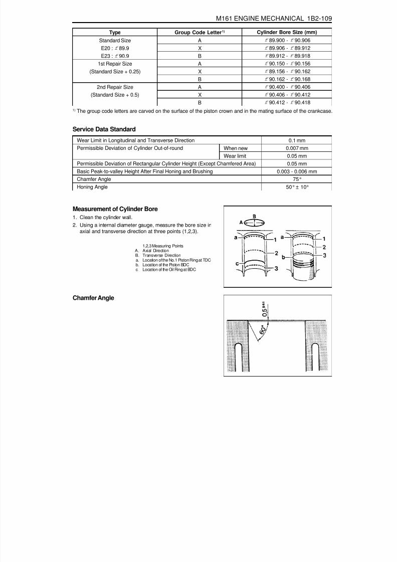
8/18/2019 SsangYong Musso Service Manual 1998.pdf
http://slidepdf.com/reader/full/ssangyong-musso-service-manual-1998pdf 298/1459
M161 ENGINE MECHANICAL 1B2-109
Service Data Standard
Measurement of Cylinder Bore1. Clean the cylinder wall.
2. Using a internal diameter gauge, measure the bore size inaxial and transverse direction at three points (1,2,3).
1,2,3 Measuring PointsA. Axial DirectionB. Transverse Directiona. Location of the No.1 Piston Ring at TDCb. Location of the Piston BDCc. Location of the Oil Ring at BDC
Chamfer Angle
Wear Limit in Longitudinal and Transverse DirectionPermissible Deviation of Cylinder Out-of-round
Permissible Deviation of Rectangular Cylinder Height (Except Chamfered Area)Basic Peak-to-valley Height After Final Honing and BrushingChamfer AngleHoning Angle
When newWear limit
0.1 mm0.007 mm0.05 mm0.05 mm
0.003 - 0.006 mm75°
50°± 10°
1) The group code letters are carved on the surface of the piston crown and in the mating surface of the crankcase.
TypeStandard SizeE20 : f 89.9E23 : f 90.9
1st Repair Size(Standard Size + 0.25)
2nd Repair Size(Standard Size + 0.5)
Group Code Letter 1)
AXBAXBAXB
Cylinder Bore Size (mm)f 89.900 - f 90.906f 89.906 - f 89.912f 89.912 - f 89.918f 90.150 - f 90.156f 89.156 - f 90.162f 90.162 - f 90.168f 90.400 - f 90.406f 90.406 - f 90.412f 90.412 - f 90.418

8/18/2019 SsangYong Musso Service Manual 1998.pdf
http://slidepdf.com/reader/full/ssangyong-musso-service-manual-1998pdf 299/1459
1B2-110 M161 ENGINE MECHANICAL
CRANKCASE MATING SURFACE
Service Data StandardHeight of the Crankcase “H” (When New)Minimum Height After MillingFlatness
Permissible Deviation of Parallelism of theUpper to Lower Mating SurfacePeak-to-valley Height
Crankcase Upper Mating SurfaceCrankcase Lower Mating SurfaceAxial DirectionTransverse DirectionCrankcase Upper Mating SurfaceCrankcase Lower Mating Surface
289.35 - 289.45mm289.05mm
0.03mm0.04mm0.1mm
0.05mm0.012 - 0.009mm0.025 - 0.020mm

8/18/2019 SsangYong Musso Service Manual 1998.pdf
http://slidepdf.com/reader/full/ssangyong-musso-service-manual-1998pdf 300/1459
M161 ENGINE MECHANICAL 1B2-111
Chamfering Procedure1. Chamfer angle : 75°
2. Polish the lower chamfered area evenly with a grinder afterfinishing the chamfering with a suitable tool (e.g., hand millingcutter).

8/18/2019 SsangYong Musso Service Manual 1998.pdf
http://slidepdf.com/reader/full/ssangyong-musso-service-manual-1998pdf 301/1459
1B2-112 M161 ENGINE MECHANICAL
CYLINDER HEAD MATING SURFACEPreceding Work : Removal of valves
Service Data Standard
NoticeDo not exceed 0.4mm for the milling of the mating surface of crankcase and cylinder head.
Overall Height of Cylinder HeadMinimum Height After MachiningFlatness
Distance ‘T’(Between Camshaft Bearingand Valve Stem)
Axial DirectionTransverse DirectionStandard Size
Repair Size
135.9 - 136.0 mm135.5 mm0.08 mm0.0 mm
24.21 - 24.75 mm22.21 - 22.75 mm23.96 - 24.51 mm21.96 - 22.51 mm
IntakeExhaustIntakeExhaust

8/18/2019 SsangYong Musso Service Manual 1998.pdf
http://slidepdf.com/reader/full/ssangyong-musso-service-manual-1998pdf 302/1459

8/18/2019 SsangYong Musso Service Manual 1998.pdf
http://slidepdf.com/reader/full/ssangyong-musso-service-manual-1998pdf 303/1459
SECTION 1B3
OM600 ENGINE MECHANICAL
CAUTION: Disconnect the negative battery cable before removing or installing any electrical unit or when a tool or equipment could easily come in contact with exposed electrical terminals. Disconnecting this cable will help prevent personal injury and damage to the vehicle. The ignition must also be in LOCK unless otherwise noted.
Specifications. . . . . . . . . . . . . . . . . . . . . . . 1B3-2Fastener Tightening Specifications . . . . . . . . 1B3-2
Special Tools . . . . . . . . . . . . . . . . . . . . . . . 1B3-4Special Tools Table . . . . . . . . . . . . . . . . . . . . 1B3-4
Maintenance and Repair . . . . . . . . . . . . . 1B3-12On-Vehicle Service . . . . . . . . . . . . . . . . . . . . 1B3-12
Engine Assembly . . . . . . . . . . . . . . . . . . . . 1B3-12Poly V-Belt . . . . . . . . . . . . . . . . . . . . . . . . . 1B3-21Tensioning Device . . . . . . . . . . . . . . . . . . . . 1B3-23Poly V-Belt Alignment & Inspection . . . . . . . 1B3-26Prechamber . . . . . . . . . . . . . . . . . . . . . . . . 1B3-29Milling of Prechamber Sealing Surface . . . . 1B3-32TDC (TDC Sensor Bracket) Setting . . . . . . 1B3-35Cylinder Head . . . . . . . . . . . . . . . . . . . . . . . 1B3-37
Timing Case Cover . . . . . . . . . . . . . . . . . . . 1B3-63Crankshaft End Cover . . . . . . . . . . . . . . . . 1B3-71Vibration Damper and Hub . . . . . . . . . . . . . 1B3-74Crankshaft Front Radial Seal . . . . . . . . . . . 1B3-80Crankshaft Ball Bearing . . . . . . . . . . . . . . . 1B3-82Crankshaft . . . . . . . . . . . . . . . . . . . . . . . . . 1B3-83Flywheel . . . . . . . . . . . . . . . . . . . . . . . . . . . 1B3-93Machining of Flywheel . . . . . . . . . . . . . . . . 1B3-97Flywheel Ring Gear . . . . . . . . . . . . . . . . . . 1B3-98Hydraulic Valve Clearance Compensation
Element Check . . . . . . . . . . . . . . . . . . . . 1B3-101Valve Tappets . . . . . . . . . . . . . . . . . . . . . . 1B3-103Valve Spring Check . . . . . . . . . . . . . . . . . 1B3-105Valve Springs (Cylinder Head Removed) . 1B3-106
TABLE OF CONTENTSValve Springs (Cylinder Head Installed) . . 1B3-109Valve Stem Seals . . . . . . . . . . . . . . . . . . . 1B3-112Check and Replacement of
Valve Guides . . . . . . . . . . . . . . . . . . . . . 1B3-116
Valve Seat Rings . . . . . . . . . . . . . . . . . . . 1B3-122Check and Machining of Valves . . . . . . . . 1B3-127Machining of Valve Seat . . . . . . . . . . . . . . 1B3-132Camshaft Timing Test . . . . . . . . . . . . . . . . 1B3-137Camshaft . . . . . . . . . . . . . . . . . . . . . . . . . 1B3-139Chain Tensioner . . . . . . . . . . . . . . . . . . . . 1B3-145Timing Chain . . . . . . . . . . . . . . . . . . . . . . . 1B3-147Tensioning Rail . . . . . . . . . . . . . . . . . . . . . 1B3-151Cylinder Head Guide Rail . . . . . . . . . . . . . 1B3-152Timing Case Cover Guide Rail . . . . . . . . . 1B3-156
Crankshaft Sprocket . . . . . . . . . . . . . . . . . 1B3-158Piston . . . . . . . . . . . . . . . . . . . . . . . . . . . . 1B3-163Oil Filter . . . . . . . . . . . . . . . . . . . . . . . . . . 1B3-169Oil Pan . . . . . . . . . . . . . . . . . . . . . . . . . . . 1B3-171Oil Spray Nozzle . . . . . . . . . . . . . . . . . . . . 1B3-174Oil Pump . . . . . . . . . . . . . . . . . . . . . . . . . . 1B3-175
Unit Repair . . . . . . . . . . . . . . . . . . . . . . . 1B3-177Cylinder Head Pressure Leakage Test . . . 1B3-177Facing Cylinder Head Mating Surface. . . . 1B3-178Replacement of Crankcase Core Plug . . . 1B3-180Facing Crankcase Contacting Surface . . . 1B3-182Oil Gallery Steel Ball . . . . . . . . . . . . . . . . . 1B3-183Cylinder Bore Measurement . . . . . . . . . . . 1B3-187

8/18/2019 SsangYong Musso Service Manual 1998.pdf
http://slidepdf.com/reader/full/ssangyong-musso-service-manual-1998pdf 304/1459
1B3-2 OM600 ENGINE MECHANICAL
SPECIFICATIONSFASTENER TIGHTENING SPECIFICATIONS
N····· m
28 - 4730
3 - 78 - 18
20 - 3430
70 - 8081 - 8450 - 75
N····· m1023
200 / 90°10
55 / 90°45 / 90°25 / 90°
25
N····· m35 / 90°
N····· m45 / 90°
Application
Skid Plate BoltDrain Plug BoltCoolong Fan Shroud BoltControl Linkage NutClutch Linkage Cylinder NutExhaust Manifold BoltPropeller Shaft Bolt & Nut (Axle)Propeller Shaft Bolt & Nut (T/C)Engine Mounting Nut
Application
Cooling Fan Belt Pulley BoltSocket BoltTighten The BoltEnd Cover BoltCrankshaft Bearing Cap BoltBall BearingCamshaft Sprocket Bolt
Oil Pump Sprocket Bolt
ApplicationConnecting Rod Bolt
Application12-Sided Stretch Bolt
Engine Assembly
Crankshaft Assembly
Piston
Flywheel
Cylinder HeadApplication
Prechamber Threaded RingCylinder Head Cover BoltFuel Injsction Pipe NutSocket BoltFuel Filter Pipe BoltIdle Pulley BoltDamper Bolt
N····· m130101825252321

8/18/2019 SsangYong Musso Service Manual 1998.pdf
http://slidepdf.com/reader/full/ssangyong-musso-service-manual-1998pdf 305/1459
OM600 ENGINE MECHANICAL 1B3-3
N····· m
12
2525
25 / 90°
N····· m10102332
4238023
Application
Stud Bolt
Exhaust Manifold NotCamShaft Bearing Cap Bolt12-Sided Bolt (M11)
ApplicationOil Pan Bolt-Socket BoltOil Pan Bolt- M6Oil Pan Bolt- M23Belt Pulley Bolt
Guide Pulley BoltGuide Pulley Bracket NutChain TensionerTesioning Lever Bolt
Cylinder HeadApplication
Camshaft Bearing Cap BoltCamshaft Sprocket BoltExhaust Pipe Bolt& NutChain TensionerInjection NozzleIntake Manifold NotInjection Nozzle Pipe NotOil Dipstick Tube BoltScrew Plug M18 x 15
N····· m
2525 / 90°
25804025181050
Cam Support & Shaft
Timing Cover

8/18/2019 SsangYong Musso Service Manual 1998.pdf
http://slidepdf.com/reader/full/ssangyong-musso-service-manual-1998pdf 306/1459
1B3-4 OM600 ENGINE MECHANICAL
SPECIAL TOOLSSPECIAL TOOLS TABLE
603 589 00 09 00Serration Wrench
657 589 03 63 00Sliding Hammer
000 589 77 03 00Box Wrench Insert
601 589 00 66 00Counter Sink
667 589 00 23 00Height Gauge
602 589 00 40 00Engine Lock
116 589 20 33 00Sliding Hammer
603 589 00 40 00Counter Holder
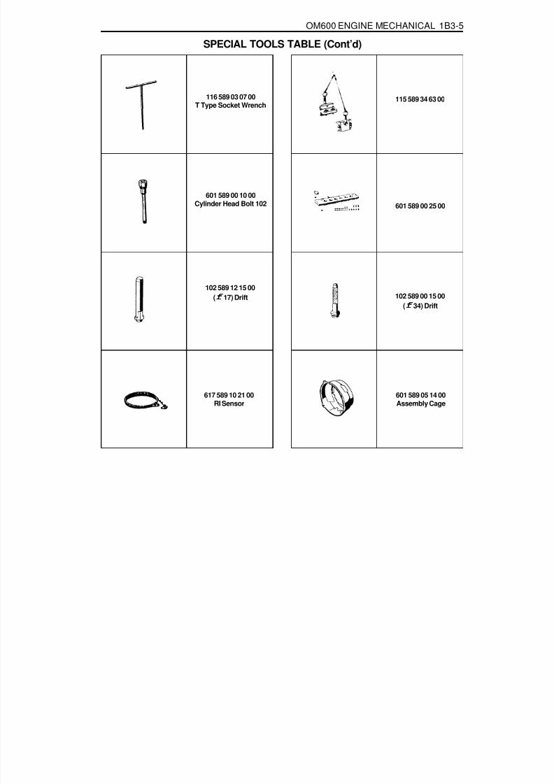
8/18/2019 SsangYong Musso Service Manual 1998.pdf
http://slidepdf.com/reader/full/ssangyong-musso-service-manual-1998pdf 307/1459
OM600 ENGINE MECHANICAL 1B3-5
116 589 03 07 00
T Type Socket Wrench
601 589 00 25 00
SPECIAL TOOLS TABLE (Cont’d)
115 589 34 63 00
601 589 00 10 00Cylinder Head Bolt 102
102 589 12 15 00(f f f f f 17) Drift 102 589 00 15 00
(f f f f f 34) Drift
617 589 10 21 00RI Sensor
601 589 05 14 00Assembly Cage

8/18/2019 SsangYong Musso Service Manual 1998.pdf
http://slidepdf.com/reader/full/ssangyong-musso-service-manual-1998pdf 308/1459

8/18/2019 SsangYong Musso Service Manual 1998.pdf
http://slidepdf.com/reader/full/ssangyong-musso-service-manual-1998pdf 309/1459
OM600 ENGINE MECHANICAL 1B3-7
363 589 02 21 00Dial Gauge Holder
000 589 33 33 00Counter Support
000 589 04 14 00Tensioning Strap
SPECIAL TOOLS TABLE (Cont’d)
116 589 07 15 00Drift
000 589 25 33 00Internal Extractor
102 589 05 33 00Puller
601 589 01 59 00Assembling Board
102 589 03 40 00Magnetic Bar
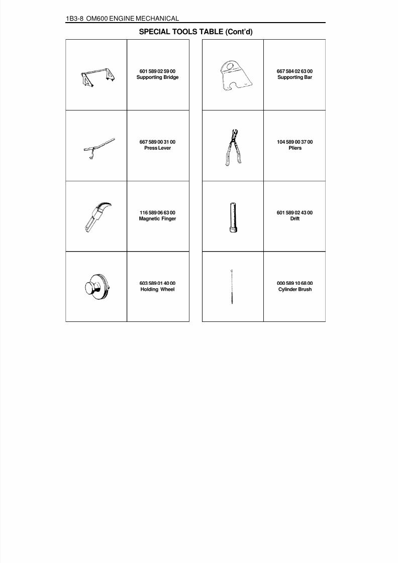
8/18/2019 SsangYong Musso Service Manual 1998.pdf
http://slidepdf.com/reader/full/ssangyong-musso-service-manual-1998pdf 310/1459
1B3-8 OM600 ENGINE MECHANICAL
601 589 02 59 00Supporting Bridge
667 589 00 31 00Press Lever
104 589 00 37 00Pliers
SPECIAL TOOLS TABLE (Cont’d)
667 584 02 63 00Supporting Bar
116 589 06 63 00Magnetic Finger
603 589 01 40 00Holding Wheel
000 589 10 68 00Cylinder Brush
601 589 02 43 00Drift

8/18/2019 SsangYong Musso Service Manual 1998.pdf
http://slidepdf.com/reader/full/ssangyong-musso-service-manual-1998pdf 311/1459
OM600 ENGINE MECHANICAL 1B3-9
601 589 02 23 00Go/No Go Gauge
105 589 03 15 00Drift (for Intake)
601 589 06 15 00Drift (for Exhaust)
SPECIAL TOOLS TABLE (Cont’d)
601 589 05 15 00Drift (for Intake)
103 589 02 15 00Drift (for Exhaust)
346 589 00 63 00Super Cooling Box
000 589 21 53 00Reamer (for Intake)
000 589 10 53 00Reamer (for Exhaust)

8/18/2019 SsangYong Musso Service Manual 1998.pdf
http://slidepdf.com/reader/full/ssangyong-musso-service-manual-1998pdf 312/1459

8/18/2019 SsangYong Musso Service Manual 1998.pdf
http://slidepdf.com/reader/full/ssangyong-musso-service-manual-1998pdf 313/1459
OM600 ENGINE MECHANICAL 1B3-11
000 589 14 21 00Tester
001 589 65 09 00Serration Wrench
116 589 02 34 00Thread Bolt
SPECIAL TOOLS TABLE (Cont’d)
000 589 00 68 00Cleaning Set
601 589 05 21 00Looking Screw
617 589 08 21 00Position Sensor
667 589 04 63 00Retaining Plate
601 589 00 08 00Flange

8/18/2019 SsangYong Musso Service Manual 1998.pdf
http://slidepdf.com/reader/full/ssangyong-musso-service-manual-1998pdf 314/1459
1B3-12 OM600 ENGINE MECHANICAL
MAINTENANCE AND REPAIR
ON-VEHICLE SERVICEENGINE ASSEMBLY

8/18/2019 SsangYong Musso Service Manual 1998.pdf
http://slidepdf.com/reader/full/ssangyong-musso-service-manual-1998pdf 315/1459
OM600 ENGINE MECHANICAL 1B3-13
4. Remove the radiator drain cock and drain the coolant.NoticeOpen the coolant reservoir tank cap.
3. Remove the skid plate.
Installation Notice
Tightening Torque 28 - 47 Nm
5. Remove the drain plug (1) and seal (2) from the cylinderblock and drain the coolant completely.
6. After draining, replace the seal and reinstall the drain plug.
Installation Notice
7. Disconnect the lower coolant hose from the radiator.
Tightening Torque 30 Nm
Removal & Installation Procedure1. Disconnect the negative terminal of battery.2. Remove the hood.

8/18/2019 SsangYong Musso Service Manual 1998.pdf
http://slidepdf.com/reader/full/ssangyong-musso-service-manual-1998pdf 316/1459
1B3-14 OM600 ENGINE MECHANICAL
9. Loosen the bolt and remove the coolant pipe and coolingfan shroud.
10. Remove the hoses (air intake to intercooler, intercooler tointake duct).
8. Disconnect the upper coolant hose from the radiator.
Tightening Torque 3 -7 Nm
11. Remove the pipes connected to intercooler.

8/18/2019 SsangYong Musso Service Manual 1998.pdf
http://slidepdf.com/reader/full/ssangyong-musso-service-manual-1998pdf 317/1459
OM600 ENGINE MECHANICAL 1B3-15
15. Remove the air-conditioner lines from the compressor.
NoticeEvacuate the refrigerant before removal.
12. Remove the hose(air cleaner to turbocharger) with blowby hose.
13. Disconnect the air cleaner intake hose and remove the aircleaner cover and element.
14. Disconnect the coolant hose from the water inlet.

8/18/2019 SsangYong Musso Service Manual 1998.pdf
http://slidepdf.com/reader/full/ssangyong-musso-service-manual-1998pdf 318/1459
1B3-16 OM600 ENGINE MECHANICAL
16. Remove the power steering pump lines.
NoticeCompletely drain the fluid.
17. Disconnect the fuel feed line with prefilter from the feedpump on injection pump.
18. Vehicle with automatic transmission.Remove the hydraulic lines (19, 20) from oil cooler (2).
19. Disconnect the engine harness.20. Disconnect the preheating time relay cable.

8/18/2019 SsangYong Musso Service Manual 1998.pdf
http://slidepdf.com/reader/full/ssangyong-musso-service-manual-1998pdf 319/1459
OM600 ENGINE MECHANICAL 1B3-17
26. Disconnect the starter motor wires and remove the startermotor.
21. Remove the fuel lines from the fuel filter and cover thefilter with plug.
22. Disconnect the brake booster hose from vacuum pump.23. Disconnect the other vacuum lines.
24. Disconnect the ground cable.25. Disconnect the alternator wires.

8/18/2019 SsangYong Musso Service Manual 1998.pdf
http://slidepdf.com/reader/full/ssangyong-musso-service-manual-1998pdf 320/1459
1B3-18 OM600 ENGINE MECHANICAL
27. Disconnect the preheating time relay sensor plug.
28. Disconnect the coolant temperature sensor plug.
29. Disconnect the accelerator cable from the control linkage.
Installation Notice
Tightening Torque 8 - 18 Nm
30. Loosen the connection of control pressure cable (an arrow)used in auto transmission.

8/18/2019 SsangYong Musso Service Manual 1998.pdf
http://slidepdf.com/reader/full/ssangyong-musso-service-manual-1998pdf 321/1459
OM600 ENGINE MECHANICAL 1B3-19
33. Disconnect the exhaust pipe flange from the exhaustmanifold.
Installation Notice
35. Remove the shift control cable.36. Remove the transmission.
Tightening TorqueAxle 70 ~ 80 Nm
T/C 81 ~ 89 Nm
Tightening Torque 20 - 34 Nm
31. Separate the exhaust pipe flange from the turbo charger.
Installation Notice
32. Loosen the installing bolt of clutch release cylinder andremove the clutch release cylinder.
Installation Notice
Tightening Torque 30 Nm
Tightening Torque 30 Nm
34. Remove the propeller shaft from the transmission.
Installation Notice

8/18/2019 SsangYong Musso Service Manual 1998.pdf
http://slidepdf.com/reader/full/ssangyong-musso-service-manual-1998pdf 322/1459
1B3-20 OM600 ENGINE MECHANICAL
37. Loosen the engine mounting bracket nut.
Installation Notice
38. Remove the engine assembly from the vehicle by using ahoist or crane.
39. Installation should follow the removal procedure in thereverse order.
Tightening Torque 50 - 75 Nm

8/18/2019 SsangYong Musso Service Manual 1998.pdf
http://slidepdf.com/reader/full/ssangyong-musso-service-manual-1998pdf 323/1459
OM600 ENGINE MECHANICAL 1B3-21
POLY V-BELT
1 Nut ............................................................. 23Nm2 Tensioning Lever
3 Bolt
4 Spring5 Tensioning Lever
6 Poly V-Belt

8/18/2019 SsangYong Musso Service Manual 1998.pdf
http://slidepdf.com/reader/full/ssangyong-musso-service-manual-1998pdf 324/1459
1B3-22 OM600 ENGINE MECHANICAL
With Air Conditioner
Removal & Installation Procedure1. Remove the nut.2. Push the tensioning lever in direction of arrow with a rod
(F12 ´ 180mm) and pull out the bolt to the rear.
3. Push back the tensioning lever (arrow direction) to releasethe spring tension and remove the belt.
4. Install the poly V-belt beginning at the tensioning pulley (7).
7 Tensioning Pulley8 Crankshaft9 Alternator
10 Coolant Pump11 Guide Pulley12 Power Steering Pump13 Aircon. Compressor
Lengthe of Belt
Length (L)Without Air Conditioner
2,100 mm
2,040 mm

8/18/2019 SsangYong Musso Service Manual 1998.pdf
http://slidepdf.com/reader/full/ssangyong-musso-service-manual-1998pdf 325/1459
OM600 ENGINE MECHANICAL 1B3-23
TENSIONING DEVICEPreceding Work : Removal of cooling fan
1 Bolt ............................................................ 21Nm2 Damper3 Nut ............................................................. 21Nm4 Tensioning Lever5 Guide Rail Pin6 Bolt7 Poly V-Belt8 Belt Pulley9 Bolt ............................................................ 10Nm
10 Tensioning Pulley11 Socket Bolt ................................................ 29Nm12 Closing Cover13 Washer14 Tensioning Lever15 Fit Bolt ..................................................... 100Nm16 Closing Cover17 Spring18 Bolt ............................................................ 20Nm
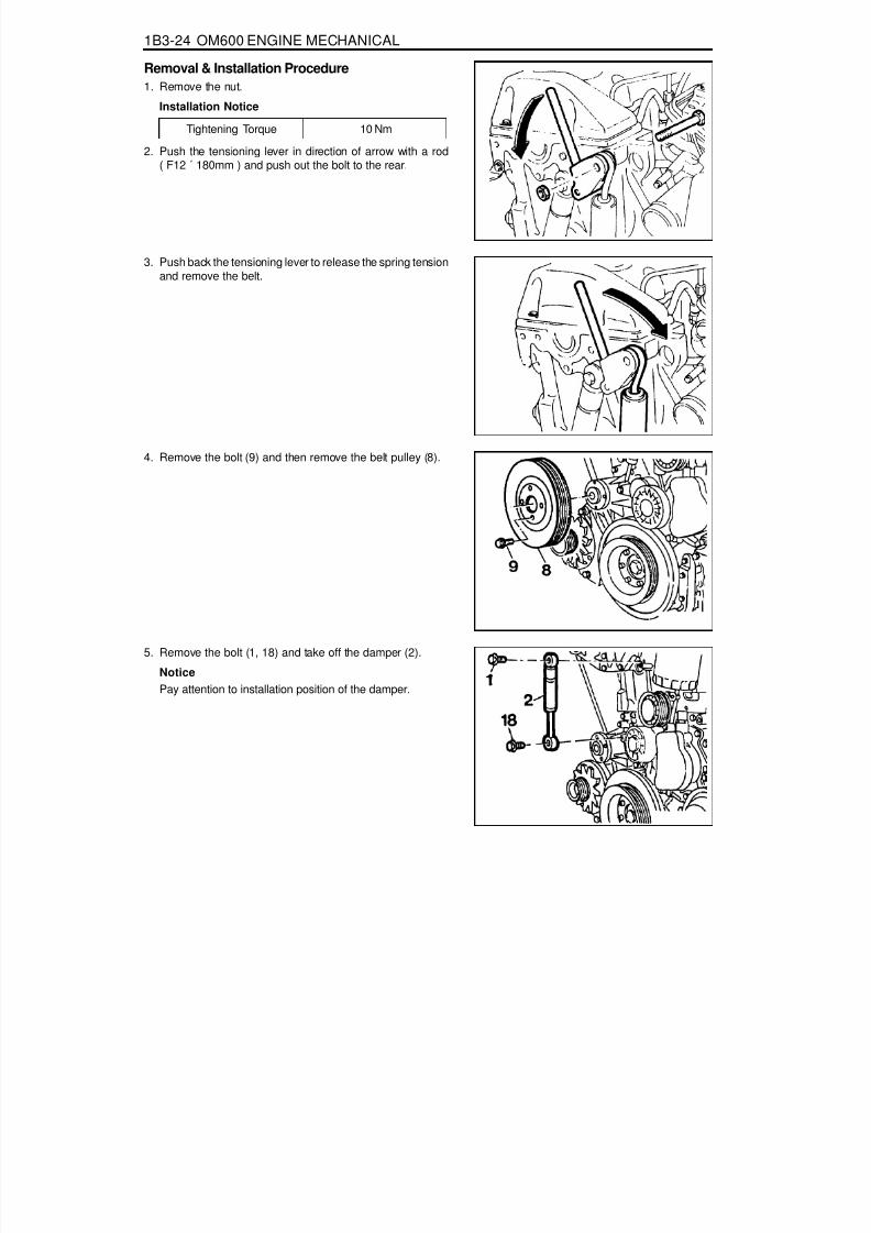
8/18/2019 SsangYong Musso Service Manual 1998.pdf
http://slidepdf.com/reader/full/ssangyong-musso-service-manual-1998pdf 326/1459
1B3-24 OM600 ENGINE MECHANICAL
Removal & Installation Procedure1. Remove the nut.
Installation Notice
Tightening Torque 10 Nm
2. Push the tensioning lever in direction of arrow with a rod
( F12 ´ 180mm ) and push out the bolt to the rear.
3. Push back the tensioning lever to release the spring tensionand remove the belt.
4. Remove the bolt (9) and then remove the belt pulley (8).
5. Remove the bolt (1, 18) and take off the damper (2).
NoticePay attention to installation position of the damper.

8/18/2019 SsangYong Musso Service Manual 1998.pdf
http://slidepdf.com/reader/full/ssangyong-musso-service-manual-1998pdf 327/1459
OM600 ENGINE MECHANICAL 1B3-25
6. Pull off the tensioning lever (4) from guide rail pin.7. Remove the spring (17).
Installation NoticeInsert spring (17) with color coding (blue/violet) facing up.
8. Pry off the closing cover (12) and remove the socket bolt(11) and then remove the tensioning pulley (10).
Installation Notice
Tightening Torque 29 Nm
9. Pry off the closing cover (16) and remove the fit bolt (15).10. Remove the tensioning lever (14) and washer (13).11. Clean thread in the timing case cover and fit bolt.
Installation NoticeApply Loctite on thread of fit bolt.
Tightening Torque 100 Nm
12. Installation should follow the removal procedure in thereverse order.

8/18/2019 SsangYong Musso Service Manual 1998.pdf
http://slidepdf.com/reader/full/ssangyong-musso-service-manual-1998pdf 328/1459
1B3-26 OM600 ENGINE MECHANICAL
POLY V-BELT ALIGNMENT & INSPECTION
Without Air Conditioner
With Air Conditioner

8/18/2019 SsangYong Musso Service Manual 1998.pdf
http://slidepdf.com/reader/full/ssangyong-musso-service-manual-1998pdf 329/1459
OM600 ENGINE MECHANICAL 1B3-27
Inspection ProcedureMark poly V-belt at a clearly visible point with chalk.Rotate the engine and check the belt.
NoticeIf one of the following types of damage is found, replacethe belt.
1. Rubber lumps in the base of rips.2. Dirt or grit ingrained.
5. Cord torn out at the side.6. Outer cords frayed.
3. Pointed rips.4. Belt cord visible in the base of rips.

8/18/2019 SsangYong Musso Service Manual 1998.pdf
http://slidepdf.com/reader/full/ssangyong-musso-service-manual-1998pdf 330/1459
1B3-28 OM600 ENGINE MECHANICAL
7. Belt detached from the base of rip.
8. Splits across the rips.9. Sections of rip torn out.
10. Splits across several rips.
11. Splits across the back.

8/18/2019 SsangYong Musso Service Manual 1998.pdf
http://slidepdf.com/reader/full/ssangyong-musso-service-manual-1998pdf 331/1459

8/18/2019 SsangYong Musso Service Manual 1998.pdf
http://slidepdf.com/reader/full/ssangyong-musso-service-manual-1998pdf 332/1459
1B3-30 OM600 ENGINE MECHANICAL
Tools Required
2. Install the sliding hammer into the prechamber.
Sliding Hammer 667 589 03 63 00
Removal & Installation Procedure1. Using the serration wrench (4), remove the threaded ring
(1).
Serration Wrench 603 589 00 09 00
3. Remove the perchamber (2).
Notice
After removing the prechamber, cover over the bores withclean rag.
603 589 00 09 00 Serration Wrench667 589 03 63 00 Sliding Hammer
4. Inspect the prechamber.
NoticeIf the prechamber seats in the cylinder head are leaking orif the prechambers are replaced, the sealing surfaces inthe cylinder head must be remachined.

8/18/2019 SsangYong Musso Service Manual 1998.pdf
http://slidepdf.com/reader/full/ssangyong-musso-service-manual-1998pdf 333/1459
OM600 ENGINE MECHANICAL 1B3-31
Assembly ProcedureNoticeIn case the prechambers are reused, inspect theprechambers thoroughly, if the ball pin by heat and fire isbroken, it can not be used.
1. Clean the sealing surface of the prechamber.2. Insert the prechamber into the cylinder head at the same
time aligning the cam on the collar of the prechambers withthe slots in the cylinder head.
NoticeIf the spacer rings are fitted to the prechambers, the spacerrings should be replaced with rings of the same thickness.
Thickness of Spacer Ring 0.3, 0.6, 1.0 mm
3. Coat the threaded ring with oil and assemble the ring byusing the serration wrench.
Tightening Torque 130 Nm
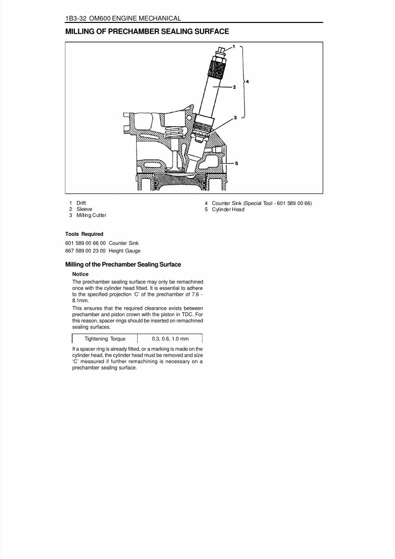
8/18/2019 SsangYong Musso Service Manual 1998.pdf
http://slidepdf.com/reader/full/ssangyong-musso-service-manual-1998pdf 334/1459
1B3-32 OM600 ENGINE MECHANICAL
MILLING OF PRECHAMBER SEALING SURFACE
1 Drift2 Sleeve3 Milling Cutter
4 Counter Sink (Special Tool - 601 589 00 66)5 Cylinder Head
Tightening Torque 0.3, 0.6, 1.0 mm
Milling of the Prechamber Sealing SurfaceNoticeThe prechamber sealing surface may only be remachinedonce with the cylinder head fitted. It is essential to adhereto the specified projection ‘C’ of the prechamber of 7.6 -
8.1mm.This ensures that the required clearance exists betweenprechamber and piston crown with the piston in TDC. Forthis reason, spacer rings should be inserted on remachinedsealing surfaces.
If a spacer ring is already fitted, or a marking is made on thecylinder head, the cylinder head must be removed and size‘C’ measured if further remachining is necessary on aprechamber sealing surface.
Tools Required
601 589 00 66 00 Counter Sink667 589 00 23 00 Height Gauge

8/18/2019 SsangYong Musso Service Manual 1998.pdf
http://slidepdf.com/reader/full/ssangyong-musso-service-manual-1998pdf 335/1459
OM600 ENGINE MECHANICAL 1B3-33
6. Measure the ‘X’ by using a vernier caliper.
7. Mount the turning tool onto the countersink tool and rotateto the right approx. 5 revolutions by applying slight pressure.
1. Remove the injection nozzle.2. Remove the prechamber.3. Cover the prechamber bore to avoid any chips dropping
into the combustion chamber.4. Remove the protective sleeve from the countersink and
rotate the countersink into the prechamber bore to bemachined as far as the stop.
Counter Sink 601 589 00 66 00
5. Maintain size ‘X’ from the top edge of mandrel to the topedge of the sleeve with the gauge.
Height Gauge 667 589 00 23 00

8/18/2019 SsangYong Musso Service Manual 1998.pdf
http://slidepdf.com/reader/full/ssangyong-musso-service-manual-1998pdf 336/1459
1B3-34 OM600 ENGINE MECHANICAL
8. Remeasure size ‘X’ and compare it with the firstmeasurement and determine the thickness of spacer ring.
Size before machining 25.7 mm
Size after machining 25.5 mm
Ex
The spacer ring should be selected so that it is at least
0.1mm and not more than 0.3mm thicker than themeasured on the sealing surface. In this example, thenecessary thickness of spacer ring should be within0.3 ~ 0.5mm and the thickness of spacer ring to beinstalled is 0.3mm.
9. Remove the countersink tool and clean the chips.
NoticeIf the sealing surface is not completely flat, remachine thesealing surface.
10. emove rag from the prechamber bore and crank the enginewith starter motor to threw out any chips which may have
got into the combustion chamber.11. Insert the proper spacer ring into the prechamber sealing
surface.12. Punch a mark on the cylinder head above the prechamber
sealing surface which has been machined.13. Install the prechambers.
NoticeIf the cylinder head is removed, the projection ‘C’ ismeasured in place of size ‘X’ and the appropriate size ofspacer ring selected.
Normal Projection (c) 7.6 - 8.1mm
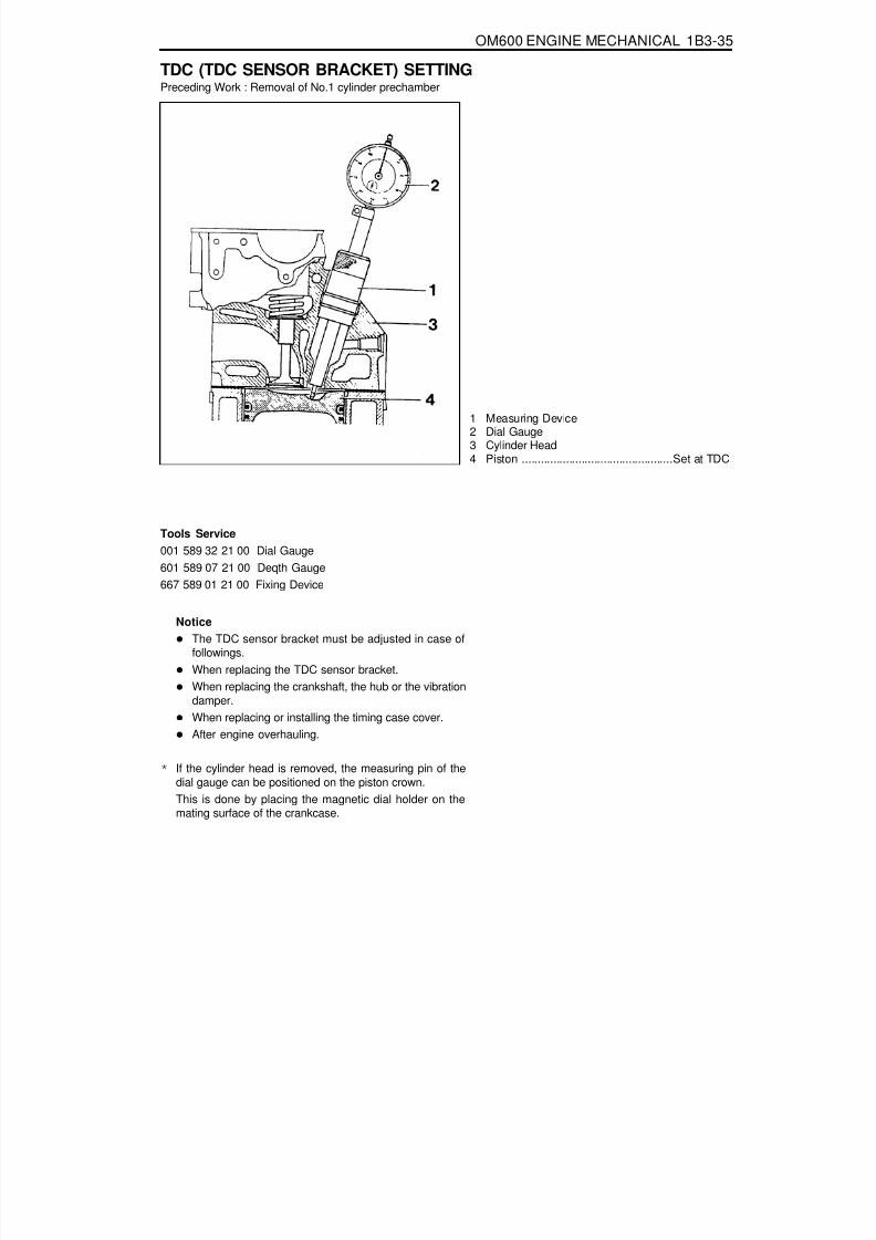
8/18/2019 SsangYong Musso Service Manual 1998.pdf
http://slidepdf.com/reader/full/ssangyong-musso-service-manual-1998pdf 337/1459

8/18/2019 SsangYong Musso Service Manual 1998.pdf
http://slidepdf.com/reader/full/ssangyong-musso-service-manual-1998pdf 338/1459
1B3-36 OM600 ENGINE MECHANICAL
Setting (with cylinder head installed)1. Remove the prechamber of No. 1 cylinder.2. Position the piston of No.1 cylinder at BTDC 10.
3. Install the measuring device into the prechamber bore andposition the dial gauge with a preload of 5mm.
Dial Gauge 001 589 53 21 00Depth Gauge 601 589 07 21 00
4. Slowly rotate the crankshaft in the direction of engine rotationuntil the large pointer on the dial gauge stops (TDC position).
NoticeThe position of TDC is when the large pointer on the dialgauge is stopped before moving back.
5. remove the reinstall the measuring device and position thedial gauge scale at ‘0’.
6. Slowly rotate the crankshaft in the direction of engine rotationuntil the dial gauge has moved back (counterclockwise) by3.65mm.
7. Insert fixing device into the sensor bracket.
NoticeThe pin on the vibration damper must engage into the slotof the fixing device.
Fixing Device 667 589 01 21 00
8. If the pin does not engage, adjust the setting of the sensorbracket by removing and tightening of the sensor bracketbolts.
Tightening Torque 10 Nm
NoticeThe timing mark on the damper must be positioned at ATDC20.

8/18/2019 SsangYong Musso Service Manual 1998.pdf
http://slidepdf.com/reader/full/ssangyong-musso-service-manual-1998pdf 339/1459
OM600 ENGINE MECHANICAL 1B3-37
CYLINDER HEAD
1 Fuel Injection Pipe ..................................... 18Nm2 Cylinder Head3 Gasket ................................................... Replace4 Bolt ............................................................ 25Nm5 Washer6 Clamp7 Heater Feed Pipe8 Bolt9 Washer
10 Bolt11 Nozzle Washer ....................................... Replace12 Fuel Injection Nozzle ............................ 35-40 Nm13 Hexagon Socket Bolt ................................. 25 Nm14 Washer15 Bolt ........................................................... 25 Nm16 Cylinder Head Bolt .............................. See Table17 Cylinder Head Cover18 Bolt ........................................................... 10 Nm19 Gasket20 Camshaft
21 Camshaft Drive Sprocket ....................... Replace22 Washer23 Bolt(12-Sided).................................. 25Nm + 90°24 Sliding Rail25 Sliding Rail Pin26 Sliding Rail Pin27 Chain Tensioner ....................................... 80 Nm28 Gasket ................................................... Replace29 Cooling Fan .............................................. Check
30 Hexagon Socket Bolt ................................. 45 Nm31 Tensioning Lever32 Bolt ........................................................... 25 Nm33 Bolt34 Nut ............................................................ 23 Nm35 Fuel Filter36 Turbo Charger37 Intake Duct38 Gasket ................................................... Replace39 Intake Manifold

8/18/2019 SsangYong Musso Service Manual 1998.pdf
http://slidepdf.com/reader/full/ssangyong-musso-service-manual-1998pdf 340/1459
1B3-38 OM600 ENGINE MECHANICAL
000 589 77 03 00 Box Wrench Insert001 589 65 09 00 Socket Wrench Insert102 589 03 40 00 Magnetic Bar116 589 02 34 00 Threaded Pin116 589 03 07 00 T Type Socket Wrench116 589 20 33 00 Sliding Hammer
601 589 00 10 00 Cylinder Head Bolt Wrench602 589 00 40 00 Engine Lock603 589 00 40 00 Counter Holder
Tools Required
Cylinder Bolts (12-sided socket head)(Engine cold)
M8 Cylinder Head Bolts
Tightening Torque
stage1stage2stage3
10 Nm35 Nm180°
25 Nm
Tightening Sequence for Cylinder Head BoltsOM 662LA Engine
OM 661LA Engine
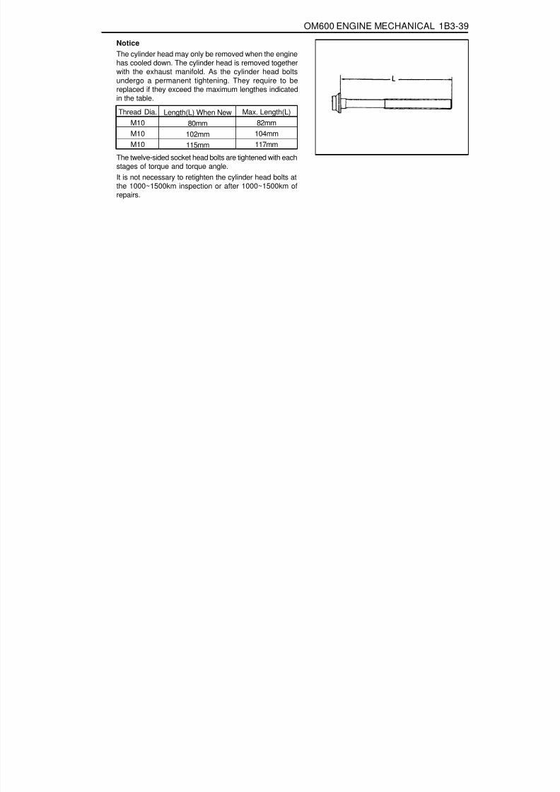
8/18/2019 SsangYong Musso Service Manual 1998.pdf
http://slidepdf.com/reader/full/ssangyong-musso-service-manual-1998pdf 341/1459
OM600 ENGINE MECHANICAL 1B3-39
Length(L) When New80mm
102mm115mm
Thread Dia.M10M10M10
Max. Length(L)82mm
104mm117mm
The twelve-sided socket head bolts are tightened with eachstages of torque and torque angle.It is not necessary to retighten the cylinder head bolts atthe 1000~1500km inspection or after 1000~1500km ofrepairs.
NoticeThe cylinder head may only be removed when the enginehas cooled down. The cylinder head is removed togetherwith the exhaust manifold. As the cylinder head boltsundergo a permanent tightening. They require to bereplaced if they exceed the maximum lengthes indicatedin the table.

8/18/2019 SsangYong Musso Service Manual 1998.pdf
http://slidepdf.com/reader/full/ssangyong-musso-service-manual-1998pdf 342/1459
1B3-40 OM600 ENGINE MECHANICAL
Disassembly Procedure1. Completely drain the coolant from the radiator and cylinder
block.2. Remove the cooling fan shroud.3. Hold the fan with counter holder and remove the bolt and
then remove the cooling fan.
NoticeKeep the fan in vertical position.
Counter Holder 603 589 00 40 00
5. Remove the nut.6. Remove the nut on the tensioning lever and insert the
rod(F12 ́ 180mm). By pushing the rod to the arrow direction,pull back the bolt.
7. Push the tensioning lever to the opposite direction to releasethe spring tension and remove the poly V-belt.
4. Remove the bracket oil dipstick tube.

8/18/2019 SsangYong Musso Service Manual 1998.pdf
http://slidepdf.com/reader/full/ssangyong-musso-service-manual-1998pdf 343/1459
OM600 ENGINE MECHANICAL 1B3-41
8. Remove the air cleaner cover and element and thenremove the air cleaner housing.
9. Remove the oil return hose and plug.
NoticeCover them to prevent chips from coming into.
10. Unscrew the EGR pipe mounting bolts onto the exhaustmanifold.
11. Remove the duct bracket from the cylinder head.
12. Unscrew the intake duct mounting bolts onto the intakemanifold.
13. Separate the connecting rod from the control lever.

8/18/2019 SsangYong Musso Service Manual 1998.pdf
http://slidepdf.com/reader/full/ssangyong-musso-service-manual-1998pdf 344/1459
1B3-42 OM600 ENGINE MECHANICAL
14. Pull out the accelerator control linkage.
15. Remove the fuel injection line(1) from the fuel injectionnozzle(12).
Box Wrench Inset 000 589 77 03 00
16. Remove the fuel injection line from the fuel injection pump.
Box Wrench Insert 000 589 77 03 00
17. Remove the bracket mounting bolts and then remove thefuel injection line(1).

8/18/2019 SsangYong Musso Service Manual 1998.pdf
http://slidepdf.com/reader/full/ssangyong-musso-service-manual-1998pdf 345/1459
OM600 ENGINE MECHANICAL 1B3-43
18. Disconnect the booster hose connected to intake manifold.
19. Remove the intake manifold and gasket.
20. Remove the cylinder head cover and gasket with the blow-by gas hose.
21. Disconnect the glow plug cables.

8/18/2019 SsangYong Musso Service Manual 1998.pdf
http://slidepdf.com/reader/full/ssangyong-musso-service-manual-1998pdf 346/1459
1B3-44 OM600 ENGINE MECHANICAL
22. Remove the cable channel.
23. Disconnect the cables from the glow plug sensor andcoolant temperature sensor.
24. Remove the heater pipe bracket from the oil filter.
25. Pry off the clamp and push the heater feed pipe forwardand then pull out the pipe.

8/18/2019 SsangYong Musso Service Manual 1998.pdf
http://slidepdf.com/reader/full/ssangyong-musso-service-manual-1998pdf 347/1459
OM600 ENGINE MECHANICAL 1B3-45
26. Disconnect the fuel lines from the fuel filter.
27. Disconnect the fuel lines from the injection pump.
28. Remove the fuel filter(35).
29. Remove the fuel injection nozzle(12) and nozzlewasher(11).
Socket Wrench Insert 001 589 65 09 00

8/18/2019 SsangYong Musso Service Manual 1998.pdf
http://slidepdf.com/reader/full/ssangyong-musso-service-manual-1998pdf 348/1459
1B3-46 OM600 ENGINE MECHANICAL
30. Rotate the crankshaft and set the no.1 cylinder at TDC.
NoticeDo not rotate the crankshaft to the opposite direction ofengine revolution.
31. Place alignment marks on the camshaft gear and timingchain.
32. Ensure that the camshaft and the bearing cap markingare aligned.
33. Remove the starter motor and install the engine lock ontothe flywheel ring gear.
Engine Lock 602 589 00 40 00

8/18/2019 SsangYong Musso Service Manual 1998.pdf
http://slidepdf.com/reader/full/ssangyong-musso-service-manual-1998pdf 349/1459
OM600 ENGINE MECHANICAL 1B3-47
34. Remove the turbocharger.
35. Remove the exhaust manifold and gasket.
36. Remove the chain tensioner and seal.
37. Remove the bolt and separate the drive sprocket(21).
NoticeDuring removal, be careful not to drop the sprocket andchain into the timing case.Carefully pull off the chain and then pull out the sprocket.

8/18/2019 SsangYong Musso Service Manual 1998.pdf
http://slidepdf.com/reader/full/ssangyong-musso-service-manual-1998pdf 350/1459

8/18/2019 SsangYong Musso Service Manual 1998.pdf
http://slidepdf.com/reader/full/ssangyong-musso-service-manual-1998pdf 351/1459
OM600 ENGINE MECHANICAL 1B3-49
41. Remove the bolt(32).
42. Separate the spring and pull out the tensioning lever(31).
43. Pry off the closing cover. Remove the bolt and then removethe idle pulley.
44. Using the sliding hammer(36) and the threaded pin(37),pull out the sliding rail pins(25, 26) and remove the slidingrail(24).
Sliding Hammer 116 589 20 33 00Threaded Pin 116 589 02 34 00

8/18/2019 SsangYong Musso Service Manual 1998.pdf
http://slidepdf.com/reader/full/ssangyong-musso-service-manual-1998pdf 352/1459
1B3-50 OM600 ENGINE MECHANICAL
OM 662LA
46. Disconnect the vacuum pipe from thermo valve.
47. Remove the socket bolts(13) of the chain box.
T Type Socket Wrench 116 589 03 07 00Magnetic Bar 102 589 03 40 00
48. Remove the cylinder head bolts in numerical se-quence.
Cylinder Head Bolt Wrench 601 589 00 10 00
45. Remove the vacuum line from the vacuum pump.

8/18/2019 SsangYong Musso Service Manual 1998.pdf
http://slidepdf.com/reader/full/ssangyong-musso-service-manual-1998pdf 353/1459
OM600 ENGINE MECHANICAL 1B3-51
49. Remove the cylinder head(2) and gasket(3).
OM 661LA

8/18/2019 SsangYong Musso Service Manual 1998.pdf
http://slidepdf.com/reader/full/ssangyong-musso-service-manual-1998pdf 354/1459
1B3-52 OM600 ENGINE MECHANICAL
Length(L)
Assembly Procedure1. Replace the cylinder head gasket.
2. Install the cylinder head onto the crankcase.
NoticeAlign the cylinder head holes with the guide pins.
3. Measure the length(L) of cylinder head bolts.NoticeIf the max. length is exceeded, replace the bolts.
Thread Dia. Max. Limit(L)
M10M10M10
80mm102mm115mm
82mm104mm117mm
when new
4. Coat the head contact surface of bolts and thread with oiland insert them as shown.
- Cylinder head bolts arrangementBore
1 ........................................... M10 × 802 ........................................... M10 × 1023 ........................................... M10 × 1154 ........................................... M 8 × 505 ........................................... M 8 × 80
OM662LA

8/18/2019 SsangYong Musso Service Manual 1998.pdf
http://slidepdf.com/reader/full/ssangyong-musso-service-manual-1998pdf 355/1459
OM600 ENGINE MECHANICAL 1B3-53
5. Tighten the cylinder head bolts to specified torque andtorque angle.
OM 662LAOM 661LA
6. Install the socket bolts in the chain box.
Tightening Torque 25 Nm
Stage 1
Stage 2
Torque angle
Wait for
Torque angle
15 Nm
35 Nm
90°
10 minutes
90°
7. Connect the vacuum pipe to the thermo valve.

8/18/2019 SsangYong Musso Service Manual 1998.pdf
http://slidepdf.com/reader/full/ssangyong-musso-service-manual-1998pdf 356/1459
1B3-54 OM600 ENGINE MECHANICAL
8. Connect the vacuum lines to the vacuum pump.
9. Install the fuel filter and connect the pipe.
Tightening Torque 25 Nm
NoticeBe careful not to be confused the connections and hoses.
10. Connect the fuel pipe to the injection pump.
11. Install the sliding rail(24) and insert the sliding rail pins(25,26).NoticeApply sealing compound on the each collar of the slidingrail pins.
Sliding Hammer 116 589 20 33 00Threaded Pin 116 589 02 34 00

8/18/2019 SsangYong Musso Service Manual 1998.pdf
http://slidepdf.com/reader/full/ssangyong-musso-service-manual-1998pdf 357/1459
OM600 ENGINE MECHANICAL 1B3-55
12. Install the idle pulley and fit the closing cover.
Tightening Torque 25 Nm
13. Insert the tensioning lever(31) and install the spring.
14. Install the damper.
Tightening Torque 23 Nm
NoticeInsert the tensioning lever bolts onto the mounting hole.
15. Insert the locking washer.16. Inspect the valve tappet and check that the tappet moves
smoothly.

8/18/2019 SsangYong Musso Service Manual 1998.pdf
http://slidepdf.com/reader/full/ssangyong-musso-service-manual-1998pdf 358/1459
1B3-56 OM600 ENGINE MECHANICAL
17. Coat the camshaft with oil and install the camshaft on thecylinder head to be TDC mark(arrow) upward.
18. Measure the axial end play of the camshaft.
End Play 0.06 - 0.21mm
Notice
If out of standard, adjust it with the proper thickness oflocking washer.
19. Install the bearing caps on the camshaft according to thenumber on the caps.
20. Tighten the bearing cap bolts according to the numericalsequence.
Tightening Torque 25 Nm
NoticeTighten the No. 1 bolts(light arrow) first and then tightenthe No. 2 bolts(dark arrow) stage by stage.
OM662LA
OM661LA

8/18/2019 SsangYong Musso Service Manual 1998.pdf
http://slidepdf.com/reader/full/ssangyong-musso-service-manual-1998pdf 359/1459
OM600 ENGINE MECHANICAL 1B3-57
21. Position the camshaft on marking and install the camshaftsprocket.
NoticeAlign the alignment marks on the chain and sprocket.
23. Install the camshaft sprocket bolt.
22. Check the TDC position of the crankshaft.
Tightening Torque 25 Nm + 90°

8/18/2019 SsangYong Musso Service Manual 1998.pdf
http://slidepdf.com/reader/full/ssangyong-musso-service-manual-1998pdf 360/1459
1B3-58 OM600 ENGINE MECHANICAL
24. Install the exhaust manifold and gasket.
25. Install the turbocharger.
26. Install the exhaust pipe onto the turbocharger.
Tightening Torque 25 Nm
NoticeMeasure the max. length ‘L’ and replace the bolt if it exceeds53.6mm.

8/18/2019 SsangYong Musso Service Manual 1998.pdf
http://slidepdf.com/reader/full/ssangyong-musso-service-manual-1998pdf 361/1459
OM600 ENGINE MECHANICAL 1B3-59
27. Replace the seal and then install the chain tensioner.
Tightening Torque 80 Nm
28. Remove the engine lock.
29. Insert the nozzle washer into the hole to face round partdownward.
30. Install the fuel injection nozzle.
Tightening Torque 40 Nm
31. Connect the fuel hose.32. Install the cable channel and connect the cables to glow
plugs.

8/18/2019 SsangYong Musso Service Manual 1998.pdf
http://slidepdf.com/reader/full/ssangyong-musso-service-manual-1998pdf 362/1459
1B3-60 OM600 ENGINE MECHANICAL
35. Connect the wires to the coolant temperature sensor andthe glow plug sensor.
36. Replace the intake manifold gasket.
37. Install the intake manifold.
Tightening Torque 25 Nm
33. Replace the gasket and install the cylinder head cover.
Tightening Torque 10 Nm
34. Install the blow-by hose.

8/18/2019 SsangYong Musso Service Manual 1998.pdf
http://slidepdf.com/reader/full/ssangyong-musso-service-manual-1998pdf 363/1459
OM600 ENGINE MECHANICAL 1B3-61
38. Replace the O-ring of heater feed pipe and install it to thecylinder head.NoticeFor installation, clean the hole.
39. Install the bracket of heater feed pipe to the oil filter.
40. Install the fuel pipe and the accelerator control linkage.41. Connect the fuel lines to the injection nozzles and to the
injection pump.Box Wrench Insert 000 589 77 03 00
Tightening Torque 18 Nm

8/18/2019 SsangYong Musso Service Manual 1998.pdf
http://slidepdf.com/reader/full/ssangyong-musso-service-manual-1998pdf 364/1459
1B3-62 OM600 ENGINE MECHANICAL
43. By inserting a rod into the tensioning lever upper hole andpulling the rod, install the bolt and then tighten the nut.
44. Install the oil dipstick tube bracket.
Tightening Torque 10 Nm
45. Hold the cooling fan with the counter holder and tightenthe bolt.
42. Install the poly V-belt.
NoticeBe careful not to contaminate the belt.
Tightening Torque 23 Nm

8/18/2019 SsangYong Musso Service Manual 1998.pdf
http://slidepdf.com/reader/full/ssangyong-musso-service-manual-1998pdf 365/1459
OM600 ENGINE MECHANICAL 1B3-63
TIMING CASE COVERPreceding Work : Removal of the cooling fan
Rmoval of the V-belt tensioning deviceRemoval of the vibration damper and hubRemoval of the alternator
1 Bolt ............................................................ 10Nm2 Cylinder Head Cover3 Gasket ................................................... Replace4 Socket Bolt ................................................ 25Nm5 Fuel Filter6 Square Nut7 Oil Pan8 Socket Bolt ................................................ 10Nm9 Bolt .................................................... M6 : 10Nm
M8 : 23Nm10 Power Steering Pump11 Bolt12 Belt Pulley
13 Bolt ............................................................ 32Nm14 Timing Case Cover15 Bolt ............................................................ 23Nm16 Alternator Bracket17 Bolt ............................................................ 45Nm18 Bolt ............................................................ 25Nm19 Bolt ............................................................ 10Nm20 Closing Cover21 Socket Bolt ................................................ 23Nm22 Guide Pulley23 Bolt .............................................................. 9Nm24 Guide Pulley Bracket25 Nut ............................................................. 23Nm

8/18/2019 SsangYong Musso Service Manual 1998.pdf
http://slidepdf.com/reader/full/ssangyong-musso-service-manual-1998pdf 366/1459
1B3-64 OM600 ENGINE MECHANICAL
8. Remove the guide pulley bracket (24).
Tools Required116 589 03 07 00 Socket Wrench
Removal Procedure1. Remove the fan clutch and cooling fan belt pulley.2. Drain the engine oil completely.
3. Remove the oil dipstick tube bracket bolts.4. Remove the crankshaft pulley.5. Loosen the bolt (1) and then remove the cylinder head cover
(2) and gasket.
6. Remove the vacuum pump.
7. Detach the closing cover (20). Remove the bolts(21) andthen remove the guide pulley (22).

8/18/2019 SsangYong Musso Service Manual 1998.pdf
http://slidepdf.com/reader/full/ssangyong-musso-service-manual-1998pdf 367/1459
OM600 ENGINE MECHANICAL 1B3-65
11. Remove the alternator bracket (16).
9. Disconnect the pipes of power steering pump and removethe belt pulley.
NoticeBe careful not to lose the key.
10. Remove the nut and pull out the bolt and then remove thepower steering pump.
12. Remove the fuel filter.

8/18/2019 SsangYong Musso Service Manual 1998.pdf
http://slidepdf.com/reader/full/ssangyong-musso-service-manual-1998pdf 368/1459
1B3-66 OM600 ENGINE MECHANICAL
18. Remove the timing case cover (19) bolts and then removethe timing case cover (14).NoticeBe careful not to damage the cylinder head gasket or oilpan gasket.
13. Remove the camshaft.14. Remove the socket bolts(4) in the chain box.
Socket Wrench 115 589 03 07 00
15. Remove the injection pump.
NoticeSee the ‘Removal of fuel injection pump’.
16. Remove the oil pan bolts (8, 9) in the area of the timingcase cover (14).
17. Slightly loosen the remaining oil pan bolts.

8/18/2019 SsangYong Musso Service Manual 1998.pdf
http://slidepdf.com/reader/full/ssangyong-musso-service-manual-1998pdf 369/1459
OM600 ENGINE MECHANICAL 1B3-67
Installation Procedure1. Thoroughly clean the sealing surface and apply sealant.
2. Install the timing case cover.
NoticeBolts arrangement1.M6 x 602.M6 x 703.M6 x 40
3. Tighten the socket bolts in the chain box.
Tightening Torque 10 Nm
Tightening Torque 23 Nm
4. Tighten the oil pan bolts.
Tightening Torque10 Nm10 Nm23 Nm
Socket boltM6 boltM8 bolt

8/18/2019 SsangYong Musso Service Manual 1998.pdf
http://slidepdf.com/reader/full/ssangyong-musso-service-manual-1998pdf 370/1459
1B3-68 OM600 ENGINE MECHANICAL
Tightening Torque25 Nm
5. Install the flange, vibration damper and crankshaft beltpulley.
NoticeReplace front radial seal if necessary.
6. Install the alternator bracket.
25 Nm
Front
Side
7. Install the alternator
Tightening Torque
Upper - 25 Nm
Low - 25 Nm
8. Install the cylinder head cover.
Tightening Torque 10 Nm
9. Tighten the injection pump mounting bolts.
Tightening Torque 23 Nm

8/18/2019 SsangYong Musso Service Manual 1998.pdf
http://slidepdf.com/reader/full/ssangyong-musso-service-manual-1998pdf 371/1459
OM600 ENGINE MECHANICAL 1B3-69
10. Install the fuel filter.
11. Install the vacuum pump.
12. Install the power steering pump.
13. Install the power steering pump pulley.
Tightening Torque 25 Nm
Tightening Torque 10 Nm
Tightening Torque 23 Nm
Tightening Torque 32 Nm
14. Install the guide pulley bracket.
Tightening Torque 9 Nm

8/18/2019 SsangYong Musso Service Manual 1998.pdf
http://slidepdf.com/reader/full/ssangyong-musso-service-manual-1998pdf 372/1459
1B3-70 OM600 ENGINE MECHANICAL
15. Install the guide pulley (22) and fit the closing cover (20).
16. Replace the gasket (3) and install the cylinder head cover(2).
17. Install the cooling fan belt pulley and fan clutch.18. Install the belt tensioning device and then install the belt.19. Install the cooling fan.20. Fill the engine oil and check oil leaks by running the engine.
Tightening Torque 23 Nm
Tightening Torque 10 Nm

8/18/2019 SsangYong Musso Service Manual 1998.pdf
http://slidepdf.com/reader/full/ssangyong-musso-service-manual-1998pdf 373/1459
OM600 ENGINE MECHANICAL 1B3-71
CRANKSHAFT END COVERPreceding Work : Removal of flywheel and driven plate.
1 Crankshaft Flange2 End Cover.............................. Clean, Loctite 5733 Bolt ......................................... 10Nm, Loctite 573
4 Radial Seal ............................................ Replace5 Dowel Sleeve6 Bolt ......................................... 10Nm, Loctite 573

8/18/2019 SsangYong Musso Service Manual 1998.pdf
http://slidepdf.com/reader/full/ssangyong-musso-service-manual-1998pdf 374/1459
1B3-72 OM600 ENGINE MECHANICAL
Tools Required601 589 03 43 00 Oil Seal Assmbler
Removal Procedure1. Remove the bolts (3, 6) from end cover, By pulling out the
lugs (arrow), remove the cover.
NoticeBe careful not to damage the oil pan gasket.
2. Remove the radial seal (4) with care not to damage thesealing surface.
Installation Procedure1. Thoroughly clean the sealing surface of end cover and apply
Loctite 573.2. Clean the groove of radial seal.3. Apply Loctite 573 on the bolts and install the end cover.
Tightening Torque 10 Nm
NoticeBe careful not to damage the oil pan gasket.
4. Install the inner oil seal assembler to the crankshaft flange.
Oil Seal Assembler 601 589 03 43 00

8/18/2019 SsangYong Musso Service Manual 1998.pdf
http://slidepdf.com/reader/full/ssangyong-musso-service-manual-1998pdf 375/1459
OM600 ENGINE MECHANICAL 1B3-73
NoticeThe sealing lip of the repair radial seal is offset to the insideby 3mm to ensure that it does not run in any groove whichthe standard radial seal may have left on the crankshaftflange.
7. Install the outer oil seal assembler on he seal and bytightening the bolts, press the radial seal into the end coveras far as the stop.
NoticeThe seal must be positioned exactly at right angles in theend cover to ensure that it provides a proper seal.
Oil Seal Assembler 601 589 03 43 00
A Standard Radial SealB Repair Radial Seal
5. Coat a little oil on the sealing lip of new radial seal andcontacting surface.
NoticeDon’t use grease.
6. Insert the new radial seal (4) onto the oil seal assembler(7).

8/18/2019 SsangYong Musso Service Manual 1998.pdf
http://slidepdf.com/reader/full/ssangyong-musso-service-manual-1998pdf 376/1459
1B3-74 OM600 ENGINE MECHANICAL
VIBRATION DAMPER AND HUBPreceding Work : Removal of the cooling fan
Removal of poly V-belt
1 Bolt ............................................................ 10Nm2 Cooling Fan Belt Pulley3 Socket Bolt ................................................ 23Nm4 Crankshaft Belt Pulley5 Vibration Damper
6 Bolt ................................................ 200Nm + 90°7 Washer8 Straight Pin9 Hub
10 Oil Pan

8/18/2019 SsangYong Musso Service Manual 1998.pdf
http://slidepdf.com/reader/full/ssangyong-musso-service-manual-1998pdf 377/1459
OM600 ENGINE MECHANICAL 1B3-75
Sectional View
3 Socket Bolt4 Crankshaft Belt Pulley5 Vibration Damper6 Bolt7 Washer8 Straight Pin
NoticeThe mounting position of vibration damper is fixed by straightpin (8).
Tools Required
602 589 00 40 00 Engine Lock103 589 00 30 00 Puller
9 Hub11 Radial Seal12 Timing Gear Case Cover13 Key14 Crankshaft Sprocket16 Crankshaft

8/18/2019 SsangYong Musso Service Manual 1998.pdf
http://slidepdf.com/reader/full/ssangyong-musso-service-manual-1998pdf 378/1459
1B3-76 OM600 ENGINE MECHANICAL
Removal Procedure1. Remove the starter motor and install the engine lock into
the wheel ring gear.
Engine Lock 602 589 00 40 00
2. Remove the poly V-belt.3. Remove the cooling fan.
NoticeKeep the fan in vertical position.
4. Remove the cooling fan belt pulley (2).5. Place alignment marks (arrow) on the vibration damper (5)
and crankshaft belt pulley (4).
6. Remove the timing sensor bracket.
NoticeRemove if necessary.

8/18/2019 SsangYong Musso Service Manual 1998.pdf
http://slidepdf.com/reader/full/ssangyong-musso-service-manual-1998pdf 379/1459
OM600 ENGINE MECHANICAL 1B3-77
7. Remove the socket bolts (3) and then remove the beltpulley (4) and vibration damper (5).
8. Remove the washer and bolt.
9. Remove the hub by using a puller.
Puller 103 589 00 33 0010. Replace the radial seal.

8/18/2019 SsangYong Musso Service Manual 1998.pdf
http://slidepdf.com/reader/full/ssangyong-musso-service-manual-1998pdf 380/1459
1B3-78 OM600 ENGINE MECHANICAL
Installation Procedure1. Install the hub.
NoticeExactly align the woodruff key and the groove of hub (arrow).
2. Install the washer (7) and tighten the bolt (6).
Washer (new) : 1 EA 200 Nm + 90°
3. Install the vibration damper.
Notice
Exactly align and insert onto the straight pin.
4. Install the belt pulley.
Tightening Torque 25 Nm
NoticeAlign the alignment marks.

8/18/2019 SsangYong Musso Service Manual 1998.pdf
http://slidepdf.com/reader/full/ssangyong-musso-service-manual-1998pdf 381/1459
OM600 ENGINE MECHANICAL 1B3-79
5. Install the timing sensor bracket.
NoticeSee the ‘TDC setting’.
6. Install the cooling fan pulley.
Tightening Torque 10 Nm
7. Install the cooling fan.8. Install the fan belt.
9. Remove the engine lock.

8/18/2019 SsangYong Musso Service Manual 1998.pdf
http://slidepdf.com/reader/full/ssangyong-musso-service-manual-1998pdf 382/1459
1B3-80 OM600 ENGINE MECHANICAL
CRANKSHAFT FRONT RADIAL SEAL
1 Radial Seal2 Timing Case Cover
Tools Required601 589 03 14 00 Sleeve
3 Woodruff Key
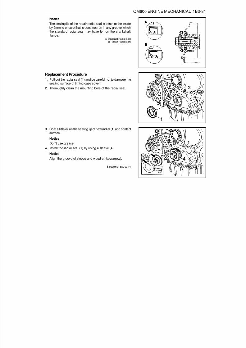
8/18/2019 SsangYong Musso Service Manual 1998.pdf
http://slidepdf.com/reader/full/ssangyong-musso-service-manual-1998pdf 383/1459
OM600 ENGINE MECHANICAL 1B3-81
NoticeThe sealing lip of the repair radial seal is offset to the insideby 2mm to ensure that is does not run in any groove whichthe standard radial seal may have left on the crankshaftflange.
A Standard Radial SealB Repair Radial Seal
Replacement Procedure1. Pull out the radial seal (1) and be careful not to damage the
sealing surface of timing case cover.2. Thoroughly clean the mounting bore of the radial seal.
3. Coat a little oil on the sealing lip of new radial (1) and contactsurface.
NoticeDon’t use grease.
4. Install the radial seal (1) by using a sleeve (4).
NoticeAlign the groove of sleeve and woodruff key(arrow).
Sleeve 601 589 03 14

8/18/2019 SsangYong Musso Service Manual 1998.pdf
http://slidepdf.com/reader/full/ssangyong-musso-service-manual-1998pdf 384/1459
1B3-82 OM600 ENGINE MECHANICAL
CRANKSHAFT BALL BEARING
1 Spacer2 Cover ......................................... Replace
NoticeManual transmission only.
Tools Required000 589 33 33 00 Counter Support000 589 25 33 00 Internal Extractor
Removal & Installation Procedure1. Remove the manual transmission.2. Using a puller, pull out the locking ring and ball bearing
together.
Counter Support 000 589 33 33 00Internal Extractor 000 589 25 33 00
3. Apply Loctite 241 on the new ball bearing and then insertthe ball bearing to be stopped at the spacer ring by using aproper mandrel.
3 Ball Bearing4 Bolt .......................................45Nm + 90°

8/18/2019 SsangYong Musso Service Manual 1998.pdf
http://slidepdf.com/reader/full/ssangyong-musso-service-manual-1998pdf 385/1459
OM600 ENGINE MECHANICAL 1B3-83
CRANKSHAFTPreceding Work : Removal of the end cover
Removal of the pistonRemoval of the crankshaft sprocket
3 Crankshaft Main Bearing Shells (Upper)4 Trust Bearings (Upper)5 Crankshaft6 Crankshaft Main Bearing Shells (Lower)
7 Thrust Bearings (Lower)8 Crankshaft Bearing Cap9 Crankshaft Bearing Cap (Fit Bearing)
10 12-sided Stretch Bolts .......................55Nm + 90°
Tools Required001 589 53 21 00 Dial Gauge363 589 02 21 00 Dial Gauge Holder366 589 00 21 05 Extension

8/18/2019 SsangYong Musso Service Manual 1998.pdf
http://slidepdf.com/reader/full/ssangyong-musso-service-manual-1998pdf 386/1459
1B3-84 OM600 ENGINE MECHANICAL
3 Crankshaft Main Bearing Shells (Upper)4 Thrust Bearings (Upper)5 Crankshaft6 Crankshaft Main Bearing Shells (Lower)7 Thrust Bearings (Lower)
A Radial BearingsB Radial and Axial Bearings (Thrust Bearing)
NoticeThe gaps between the bearing shell and bore andbetween the bearing shell and journal are differenteach other. Refer to service data.
Thrust Washer and Bearing ArrangementOM662LA Engine

8/18/2019 SsangYong Musso Service Manual 1998.pdf
http://slidepdf.com/reader/full/ssangyong-musso-service-manual-1998pdf 387/1459
OM600 ENGINE MECHANICAL 1B3-85
3 Crankshaft Main Bearing Shells (Upper)4 Thrust Bearings (Upper)5 Crankshaft6 Crankshaft Main Bearing Shells (Lower)7 Thrust Bearings (Lower)
A Radial BearingsB Radial and Axial Bearings (Thrust Bearing)
NoticeThe gaps between the bearing shell and bore andbetween the bearing shell and journal are differenteach other. Refer to service data.
OM661LA Engine

8/18/2019 SsangYong Musso Service Manual 1998.pdf
http://slidepdf.com/reader/full/ssangyong-musso-service-manual-1998pdf 388/1459
1B3-86 OM600 ENGINE MECHANICAL
24.500 - 24.53324.600 - 24.63324.700 - 24.73324.900 - 24.93325.000 - 25.033
NewLimitNewLimit
Radial clearances
Axial clearances
Crankshaft bearingjournal diameter
Crankshaft Standard and Repair Sizes
Standard size 50.950 - 57.965
journal width24.500 - 24.53324.600 - 24.63324.700 - 24.73324.900 - 24.93325.000 - 25.033
-
Thrust bearingjournal diameter
47.950 - 47.965
Thrust bearing
47.700 - 47.71547.450 - 47.65047.200 - 47.21546.950 - 46.965
57.500 - 57.71557.450 - 57.46557.200 - 57.21556.950 - 56.965
Repair size 1Repair size 2Repair size 3Repair size 4
Bearing Clearances
Thrust bearing Crankshaft bearing0.026 - 0.068
Max. 0.080--
0.027 - 0.051Max. 0.070
0.100 - 0.254Max. 0.300
Matching Fit Bearing Journal Width to Thrust Bearings
Fit bearing journal width Thrust bearings thickness2.152.202.252.352.40
NoticeMeasure crankshaft axial clearance and adjust with proper thrust Bearing.The same thickness of washer must be installed on both sides of the fit bearing.
mm
mm
mm

8/18/2019 SsangYong Musso Service Manual 1998.pdf
http://slidepdf.com/reader/full/ssangyong-musso-service-manual-1998pdf 389/1459
OM600 ENGINE MECHANICAL 1B3-87
bearing shell
Matching Crankshaft Bearing Shells to Basic Bearing Bore in Crankshaft
Matching Crankshaft Bearing Shells to Basic Bearing Journal of Crankshaft
Marking of basic bearing bore in lower Color code of relevant crankshaftparting surface1 punch mark or blue
2 punch marks or yellow3 punch marks or red
bearing shellBlue or white-blueYellow or white-yellowRed or white-red
Marking of bearing journals on crank webs Color code of relevant crankshaft
Blue or white-blueYellow or white-blueRed or white-blue
Blue or white-blueYellow or white-yellow
Red or white-red

8/18/2019 SsangYong Musso Service Manual 1998.pdf
http://slidepdf.com/reader/full/ssangyong-musso-service-manual-1998pdf 390/1459
1B3-88 OM600 ENGINE MECHANICAL
Removal & Installation Procedure1. Remove the bearing cab bolt.2. Remove the bearing caps (8).
NoticeThe crankshaft bearing caps are marked with stampednumbers. Remove the bearing cap from the vibrationdamper side.
3. Remove the crankshaft bearing caps (9) and lower thrustbearings (7).
4. Remove the lower thrust bearings (6) from the bearing cap(9).
5. Remove the crankshaft (5).
6. Remove the upper thrust bearings(4).7. Remove the upper bearing shells (3) from crankcase.
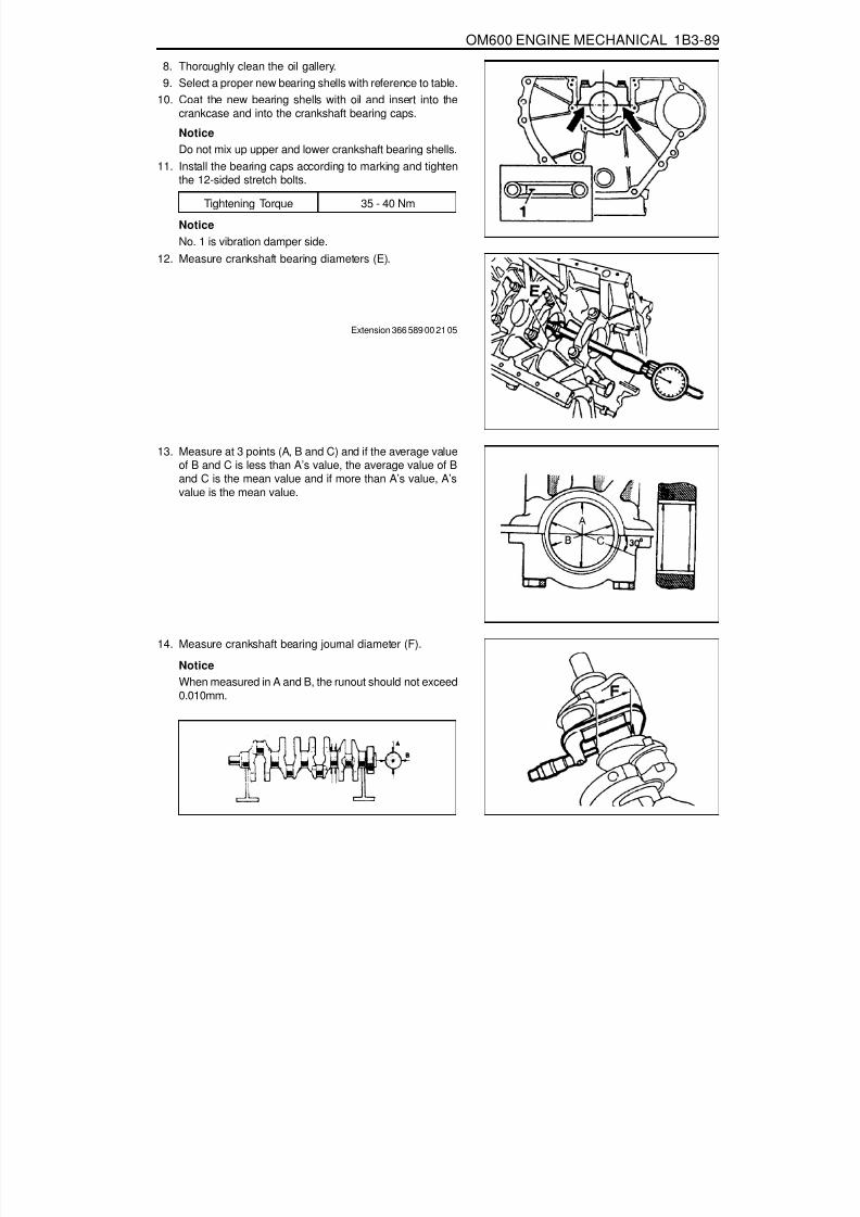
8/18/2019 SsangYong Musso Service Manual 1998.pdf
http://slidepdf.com/reader/full/ssangyong-musso-service-manual-1998pdf 391/1459
OM600 ENGINE MECHANICAL 1B3-89
14. Measure crankshaft bearing journal diameter (F).
NoticeWhen measured in A and B, the runout should not exceed0.010mm.
8. Thoroughly clean the oil gallery.9. Select a proper new bearing shells with reference to table.
10. Coat the new bearing shells with oil and insert into thecrankcase and into the crankshaft bearing caps.
NoticeDo not mix up upper and lower crankshaft bearing shells.
11. Install the bearing caps according to marking and tightenthe 12-sided stretch bolts.
Tightening Torque 35 - 40 Nm
NoticeNo. 1 is vibration damper side.
12. Measure crankshaft bearing diameters (E).
Extension 366 589 00 21 05
13. Measure at 3 points (A, B and C) and if the average valueof B and C is less than A’s value, the average value of Band C is the mean value and if more than A’s value, A’s
value is the mean value.

8/18/2019 SsangYong Musso Service Manual 1998.pdf
http://slidepdf.com/reader/full/ssangyong-musso-service-manual-1998pdf 392/1459

8/18/2019 SsangYong Musso Service Manual 1998.pdf
http://slidepdf.com/reader/full/ssangyong-musso-service-manual-1998pdf 393/1459
OM600 ENGINE MECHANICAL 1B3-91
NoticeIf the max. length of bolts(L) exceed 63.8mm, replace them.
19. Coat the new crankshaft with engine oil and place it on thecrankcase.
20. Install the crankshaft bearing caps according to markingand tighten the bolts.
Tightening Torque 55 Nm + 90°
NoticeInstall from No. 1 cap.
22. Rotate the crankshaft with hand and check whether itrotates smoothly.
23. Measure crankshaft bearing axial clearance.
Clearance 0.100 - 0.245mm
NoticeIf the clearance is out of standard, adjust the axial clearanceof crankshaft bearing by replacing the thrust washers.
Dial Gauge 001 589 53 21 00Dial Gauge Holder 363 589 02 21 00
NoticeThe same thickness of thrust washers should be installedon both sides of the thrust bearing.

8/18/2019 SsangYong Musso Service Manual 1998.pdf
http://slidepdf.com/reader/full/ssangyong-musso-service-manual-1998pdf 394/1459
1B3-92 OM600 ENGINE MECHANICAL
28. Remove the connecting rod bearing cap.29. Install the piston.30. Rotate the crankshaft by hand and check whether it rotates
smoothly.31. If the bearings are damaged,
- replace the oil presser relief valve.- clean the oil pump and oil filter housing carefully andreplace the hose if necessary.
NoticeAfter assembling the engine, check the camshaft timing,adjust the start of fuel injection and check the TDC sensorbracket setting.
32. Fill oil and run the engine and then check the oil pressureand oil level.
NoticeInstall the original oil filter element and then change theengine oil and oil filter element after 1,000 - 1,500km.
27. Measure the radial clearance (L) of the connecting rodbearing.Example) Measured value ‘J’ = 47.700mm
Measured value ‘K’ = 47.653mm
Clearance ‘L’ = 0.047mm
Radial Clearance ‘L’ 0.026 - 0.068mm
NoticeIf the clearance is out of standard, adjust the radialclearance of connecting rod bearing by replacing theconnecting rod bearing shells.
26. Measure connecting rod bearing journal diameter (K).
NoticeRefer to measurement of the crankshaft bearing journaldiameter.
24. Insert the new connecting rod bearing shells into theconnecting rod and connecting rod bearing cap and tightenthe 12-sided stretch bolts (11).
25. Measure inner diameter of connecting rod bearing.
Tightening Torque 40 Nm + 90°

8/18/2019 SsangYong Musso Service Manual 1998.pdf
http://slidepdf.com/reader/full/ssangyong-musso-service-manual-1998pdf 395/1459
OM600 ENGINE MECHANICAL 1B3-93
FLYWHEELPreceding Work : Removal of the transmission
Removal of the clutch
1 Oil Pan2 Straight Pin3 Flywheel
4 12-Sided Stretch Bolt ............Check, 45Nm + 90°5 Drive Plate (Automatic Transmission)6 Flywheel (Automatic Transmission)

8/18/2019 SsangYong Musso Service Manual 1998.pdf
http://slidepdf.com/reader/full/ssangyong-musso-service-manual-1998pdf 396/1459
1B3-94 OM600 ENGINE MECHANICAL
Manual transmission flywheel
Automatic transmission flywheel
OM661LAOM662LA

8/18/2019 SsangYong Musso Service Manual 1998.pdf
http://slidepdf.com/reader/full/ssangyong-musso-service-manual-1998pdf 397/1459
OM600 ENGINE MECHANICAL 1B3-95
3. Remove the flywheel (3), if equipped with manualtransmission.Installation NoticeCorrectly align the position of dowel pin (2).
Tools Required602 589 00 40 00 Engine Lock
Removal & Installation Procedure1. Install the engine lock.
Engine Lock 602 589 02 40 00
2. Remove the 12-sided stretch bolts (4).
Installation Notice
Tightening Torque 45 Nm + 90°
NoticeIf the length ‘L’ of bolts exceeds 22.5mm, replace the bolts.

8/18/2019 SsangYong Musso Service Manual 1998.pdf
http://slidepdf.com/reader/full/ssangyong-musso-service-manual-1998pdf 398/1459
1B3-96 OM600 ENGINE MECHANICAL
4. Remove the flywheel (6) and driven plate (5), if equippedwith automatic transmission.
Installation NoticeCorrectly align the position of dowel pin (2).
5. Installation should follow the removal procedure in thereverse order.

8/18/2019 SsangYong Musso Service Manual 1998.pdf
http://slidepdf.com/reader/full/ssangyong-musso-service-manual-1998pdf 399/1459
OM600 ENGINE MECHANICAL 1B3-97
MACHINING OF FLYWHEEL
1 Flywheel
Machining of FlywheelNoticeFlywheels which have scorch marks, scoring or cracks inthe clutch surface should be machined by grinding orprecision-turning. If the scores or cracks are severe thanpermissible specifications, replace the flywheel.
When machining the clutch surface ‘A’, the mountingsurface (B) for the clutch pressure plate should also bemachined in accordance with ‘A’ to keep the distance ‘a’.Do not machine under ‘b’ value.When machining, fix the flywheel exactly not to exceed thestandard runout.
OM662LAOM662LA
Max. axial runout
Distance ‘a’
New
Repair up to
19.3 - 19.5 mm
16.6 mm
15.6 mm
0.05 mm
Distance ‘b’

8/18/2019 SsangYong Musso Service Manual 1998.pdf
http://slidepdf.com/reader/full/ssangyong-musso-service-manual-1998pdf 400/1459
1B3-98 OM600 ENGINE MECHANICAL
FLYWHEEL RING GEARPreceding Work : Removal of flywheel
1 Ring Gear2 Flywheel
3 Centering Collar Diameter
Tools Required001 589 53 21 00 Dial Gauge363 589 02 21 00 Dial Gauge Holder

8/18/2019 SsangYong Musso Service Manual 1998.pdf
http://slidepdf.com/reader/full/ssangyong-musso-service-manual-1998pdf 401/1459
OM600 ENGINE MECHANICAL 1B3-99
Diameter ‘a’ 275 + 0.5mm
Replacement Procedure1. Drill a hole into the ring gear (1) (arrow) and snap
with a chisel.2. Thoroughly clean the collar surfaces of ring gear.
3. Measure diameter (a) of centering collar.
NoticeIf out of standard, replace the flywheel.
4. Heat up the new ring gear up to 220°C by using aheating device.
NoticeUse temperature measuring chalk.
5. Install the new ring gear (1) onto the flywheel by using adrift.

8/18/2019 SsangYong Musso Service Manual 1998.pdf
http://slidepdf.com/reader/full/ssangyong-musso-service-manual-1998pdf 402/1459

8/18/2019 SsangYong Musso Service Manual 1998.pdf
http://slidepdf.com/reader/full/ssangyong-musso-service-manual-1998pdf 403/1459
OM600 ENGINE MECHANICAL 1B3-101
HYDRAULIC VALVE CLEARANCE COMPENSATION ELEMENT CHECK
1 Cylinder Head Cover2 Bolt ............................................................ 10Nm3 Gasket ................................................... Replace
4 Valve Tappet5 Cylinder Head

8/18/2019 SsangYong Musso Service Manual 1998.pdf
http://slidepdf.com/reader/full/ssangyong-musso-service-manual-1998pdf 404/1459
1B3-102 OM600 ENGINE MECHANICAL
CheckingNoticeThe noise which continues short time during short travel(frequent starting of the engine) or engine starting after along time storage is normal operating conditions. So, it doesnot need to be repaired. Determine the malfunctions in valve
clearance compensation device with noise through followingtests. If defective, replace as respectively.1. Run the engine at more than 3000rpm for approx. 4 minutes.2. Stop the engine. After 5minutes, check the engine oil level
and adjust if necessary.3. Remove the cylinder head cover.4. Check the valve tappets at TDC position of each cylinders.5. Using a drift, lightly press the valve tappet and measure
clearance between the cam and valve tappet.
NoticeIf the clearance exceeds 0.4mm, replace the valve tappet.
6. If a valve tappet moves down too far in comparison to theothers, replace the valve tappet.
7. Rotate the engine and check the remaining valve tappets.
NoticeUnnecessary rotation of the engine will damage the valvetappets.Do not rotate the engine by using the camshaft sprocketbolt or to the opposite direction of the engine rotation.

8/18/2019 SsangYong Musso Service Manual 1998.pdf
http://slidepdf.com/reader/full/ssangyong-musso-service-manual-1998pdf 405/1459
OM600 ENGINE MECHANICAL 1B3-103
VALVE TAPPETSPreceding Work : Removal of camshaft
1 Valve Tappet2 Cylinder Head3 Oil Gallery
4 Seal ....................................................... Replace5 Screw Plug
Tools Required102 589 03 40 00 Magnetic Bar

8/18/2019 SsangYong Musso Service Manual 1998.pdf
http://slidepdf.com/reader/full/ssangyong-musso-service-manual-1998pdf 406/1459
1B3-104 OM600 ENGINE MECHANICAL
Replacement Procedure1. Pull out the valve tappet (1).
Magnetic Bar 102 589 03 40 00
2. Remove the plug (5) and blow compressed air into the oilgallery (3). At this time, check that the outlet bores(arrow)at the seat of the valve tappet are clear.
3. Replace the seal (4) and tighten the plug (5).4. Insert the new valve tappet.
NoticeCoat the valve tappet with oil.

8/18/2019 SsangYong Musso Service Manual 1998.pdf
http://slidepdf.com/reader/full/ssangyong-musso-service-manual-1998pdf 407/1459
OM600 ENGINE MECHANICAL 1B3-105
VALVE SPRINGS CHECKPreceding Work : Removal of valve spring
1 Valve Spring
Service Data
Outer diameter
33.1mm
Wire diameter
4.20mm
Free length
50.0mm
At preloaded
Length Tension (new)
680 - 740N27mm
Limit
612N
2 Spring Scale
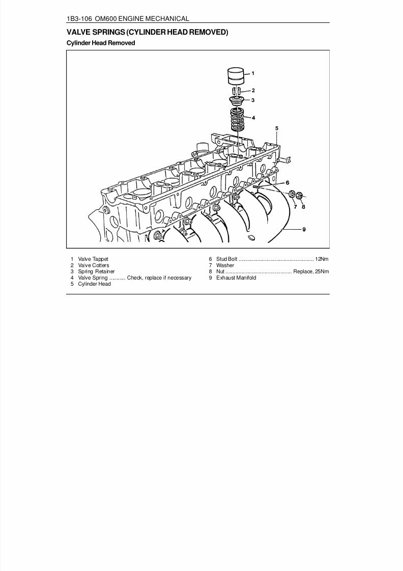
8/18/2019 SsangYong Musso Service Manual 1998.pdf
http://slidepdf.com/reader/full/ssangyong-musso-service-manual-1998pdf 408/1459
1B3-106 OM600 ENGINE MECHANICAL
VALVE SPRINGS (CYLINDER HEAD REMOVED)Cylinder Head Removed
1 Valve Tappet2 Valve Cotters3 Spring Retainer4 Valve Spring ........... Check, replace if necessary5 Cylinder Head
6 Stud Bolt .................................................... 12Nm7 Washer8 Nut .............................................. Replace, 25Nm9 Exhaust Manifold

8/18/2019 SsangYong Musso Service Manual 1998.pdf
http://slidepdf.com/reader/full/ssangyong-musso-service-manual-1998pdf 409/1459
OM600 ENGINE MECHANICAL 1B3-107
Removal & Installation Procedure1. Remove the nuts (8) uniformly and then remove the washer
(7), exhaust manifold (9) and gasket.
Installation NoticeCheck the stud bolt (6) for damage and replace if necessary.
Tighten Torque 12 Nm
Tighten Torque 25 Nm
Tools Required102 589 03 40 00 Magnetic Bar116 589 06 63 00 Magnetic Finger601 589 01 59 00 Assembling Board601 589 02 59 00 Supporting Bridge667 589 00 31 00 Press Lever
Replace the gasket and tighten the nuts (8).
2. Install the assembling board (11) to the cylinder head with 4cylinder head blots (10).
Assembling Board 601 589 01 59 00
3. Pull out the valve tappet (1) with magnetic bar (12).
Notice
Place the valve tappets upside down (open end upward).
Magnetic Bar 102 589 03 40 00
4. Install the supporting bridge (13) on the cylinder head (5).
Supporting Bridge 601 589 02 59 00

8/18/2019 SsangYong Musso Service Manual 1998.pdf
http://slidepdf.com/reader/full/ssangyong-musso-service-manual-1998pdf 410/1459
1B3-108 OM600 ENGINE MECHANICAL
5. Using the press lever (14), press the spring retainerdownward and remove the valve cotters (2) with magneticfinger (15).
NoticeBe careful not to damage guide bore of the valve tappet.
Press Lever 667 589 00 31 00Magnetic Finger 116 589 06 63 00
6. Remove the spring retainer (3) and spring (4).
Installation NoticeInstall the valve spring with the color coding (arrow) facingdown.
7. Check the valve spring and replace if necessary.8. Installation should follow the removal procedure in the
reverse order.

8/18/2019 SsangYong Musso Service Manual 1998.pdf
http://slidepdf.com/reader/full/ssangyong-musso-service-manual-1998pdf 411/1459
OM600 ENGINE MECHANICAL 1B3-109
VALVE SPRINGS (CYLINDER HEAD INSTALLED)Preceding Work : Removal of camshaft
1 Valve Tappet2 Valve Cotters3 Spring Retainer
4 Valve Spring .......... Check, replace if necessary5 Timing Chain6 Cylinder Head
NoticeRemove the valve springs only when the piston is at TDC.
Tools Required102 589 03 40 00 Magnetic Bar116 589 06 63 00 Magnetic Finger603 589 01 40 00 Holding Wheel667 589 00 31 00 Press Lever667 589 02 63 00 Supporting Bar

8/18/2019 SsangYong Musso Service Manual 1998.pdf
http://slidepdf.com/reader/full/ssangyong-musso-service-manual-1998pdf 412/1459
1B3-110 OM600 ENGINE MECHANICAL
5. Using the press lever (9), press the spring retainer(3)downward and remove the valve cotters (2) with magneticfinger (10).
NoticeBe careful not to damage guide bore of the valve tappet.
Press Lever 667 589 00 31 00Magnetic Finger 116 589 06 63 00
Removal & Installation Procedure1. Remove the valve tappet (1) with magentic lifter.
NoticePlace the valve tappets upside down (open end upward)
Magentic Liter 102 589 03 40 00
2. Install the holding wheel (7) into the timing chain of camshaftsprocket piston.
Holding Wheel 603 589 01 40 00
3. Position the piston of relevant cylinder at TDC.
4. Install the supporting bar (8).
Supporting Bar 667 589 02 63 00

8/18/2019 SsangYong Musso Service Manual 1998.pdf
http://slidepdf.com/reader/full/ssangyong-musso-service-manual-1998pdf 413/1459
OM600 ENGINE MECHANICAL 1B3-111
6. Remove the spring retainer(3) and spring (4).7. Check the valve spring and replace if necessary.8. Insert valve spring (4) with the color coding (arrow) facing
down and insert valve spring Retainer(3).
9. By press the spring retainer(3) with press lever (90), installthe valve cotters with magnetic finger (10).
Press Lever 667 589 00 31 00Magnetic Finger 116 589 06 63 00
10. Remove the supporting bar.11. Remove the holding wheel (7) from the timing chain (5).
Holding Wheel 603 589 01 40 00
13. Coat the valve tappet with oil and install it.
Magnetic Bar 102 589 03 40 00

8/18/2019 SsangYong Musso Service Manual 1998.pdf
http://slidepdf.com/reader/full/ssangyong-musso-service-manual-1998pdf 414/1459
1B3-112 OM600 ENGINE MECHANICAL
VALVE STEM SEALSPreceding Work : Removal of camshaft.
1 Valve Tappet2 Valve Cotters3 Spring Retainer
4 Valve Spring ........... Check, replace if necessary5 Valve Stem Seal6 Valve
NoticeRemove the valve stem seals when the piston is positioned at TDC.

8/18/2019 SsangYong Musso Service Manual 1998.pdf
http://slidepdf.com/reader/full/ssangyong-musso-service-manual-1998pdf 415/1459
OM600 ENGINE MECHANICAL 1B3-113
Tools Required667 589 00 31 00 Press Lever104 589 00 37 00 Pliers102 589 03 40 00 Magnetic Lifter603 589 01 40 00 Holding Wheel601 589 02 43 00 Drift
116 589 06 63 00 Magnetic Finger667 589 02 63 00 Supporting Bar
A : Intake valve stem seal B : Exhaust valve stem seal
Chamfer
Inner diameter ‘d’
Color
Wire ring
Intake valve stem seal
Offset
7.3mm
Brown
Black
Exhaust valve stem seal
All round
8.2mm
Green
Yellow

8/18/2019 SsangYong Musso Service Manual 1998.pdf
http://slidepdf.com/reader/full/ssangyong-musso-service-manual-1998pdf 416/1459
1B3-114 OM600 ENGINE MECHANICAL
Replacement Procedure1. Remove the valve tappet (1) with magnetic lifter.
NoticePlace the valve tappets upside down (open end upward).
Magnetic Lifter 102 589 03 40 00
2. Install the holding wheel (7) into the timing chain (11).
Holding Wheel 603 589 01 40 00
3. Position the piston of relevant cylinder at TDC.
4. Install the supporting bar (8).
Supporting Bar 667 589 02 63 00
5. Using press lever (9), press the spring retainer(3) downwardand remove the valve collets with magnetic finger (10).
Press Lever 667 589 00 31 00Magnetic Finger 116 589 06 63 00

8/18/2019 SsangYong Musso Service Manual 1998.pdf
http://slidepdf.com/reader/full/ssangyong-musso-service-manual-1998pdf 417/1459
OM600 ENGINE MECHANICAL 1B3-115
6. Remove the spring retainer(3) and valve spring (4).
7. Remove the valve stem seal (5).
Pliers 104 589 00 37 00
8. Insert the cap (12) onto the valve (6) and install the newvalve stem seal (5) and then remover the cap.
Drift 601 589 02 43 00
9. By pressing the spring seat with press lever (9), install thevalve cotters(2) with magnetic finger (10).NoticeBe careful not to damage guide bore of the valve tappet.
Press Lever 667 589 00 31 00Magnetic Finger 116 589 06 63 00

8/18/2019 SsangYong Musso Service Manual 1998.pdf
http://slidepdf.com/reader/full/ssangyong-musso-service-manual-1998pdf 418/1459
1B3-116 OM600 ENGINE MECHANICAL
8.000 - 8.0309.000
- 9.050
39.5Intake
Exhaust
0.029 - 0.0510.029
- 0.051
RedWhiteRed
White
Diameter ‘a’
Service Data
Item Basic Bore
Repair size 1Repair size 2Repair size 1Repair size 2
Outer Diameter ‘D’
14.25114.440 - 14.45114.240 - 14.25114.440 - 14.451
Color Code
14.200 - 14.21114.400 - 14.41114.200 - 14.21114.400 - 14.411
Overlap‘D’ - ‘a’
Valve GuideInner Diameter ‘A’
37.7
Length ‘L’
CHECK AND REPLACEMENT OF VALVE GUIDESPreceding Work : Removal of cylinder head
Removal of valve springRemoval of valve
1 Cylinder Head2 Valve Guide
3 Valve Seat Ringa Basic Bore Diameter

8/18/2019 SsangYong Musso Service Manual 1998.pdf
http://slidepdf.com/reader/full/ssangyong-musso-service-manual-1998pdf 419/1459
OM600 ENGINE MECHANICAL 1B3-117
Tools Required000 589 10 53 00 Reamer (for Exhaust)000 589 10 68 00 Cylinder Brush000 589 21 53 00 Reamer (for Intake)102 589 00 23 00 GO / NO GO Gauge (for Intake)103 589 02 15 00 Drift (for Exhaust)103 589 03 15 00 Drift (for Intake)
117 589 03 25 00 GO / NO GO Gauge (for Exhaust)346 589 00 63 00 Super Cooling Box601 589 02 23 00 GO/NO GO Gauge601 589 05 15 00 Drift (for Intake)
NoticeMeasure center (arrow) of the valve guide and if the innerdiameter ‘A’ exceeds standard value, replace the guide.
601 589 06 15 00 Drift (for Exhaust)
Matching Valve Seat - Broaching Tools - Guide Sleeves
Valve Seat
IntakeExhaustIntake
Exhaust
Broaching Tool No.
115 589 00 53 00(14.2mm)115 589 01 53 00
(14.4mm)
Guide Sleeve Tool No.
102 589 00 63 00102 589 08 63 00
Guide Sleeve Side
BBAB
601 589 15 63 00
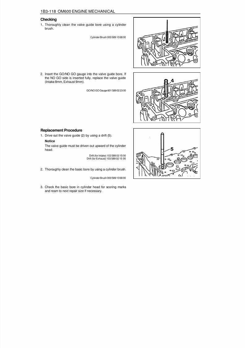
8/18/2019 SsangYong Musso Service Manual 1998.pdf
http://slidepdf.com/reader/full/ssangyong-musso-service-manual-1998pdf 420/1459
1B3-118 OM600 ENGINE MECHANICAL
2. Thoroughly clean the basic bore by using a cylinder brush.
Cylinder Brush 000 589 10 68 00
3. Check the basic bore in cylinder head for scoring marksand ream to next repair size if necessary.
2. Insert the GO/NO GO gauge into the valve guide bore. Ifthe NO GO side is inserted fully, replace the valve guide(Intake 8mm, Exhaust 9mm).
GO/NO GO Gauge 601 589 02 23 00
Replacement Procedure1. Drive out the valve guide (2) by using a drift (5).
NoticeThe valve guide must be driven out upward of the cylinderhead.
Drift (for Intake) 103 589 03 15 00Drift (for Exhaust) 103 589 02 15 00
Checking1. Thoroughly clean the valve guide bore using a cylinder
brush.
Cylinder Brush 000 589 10 68 00

8/18/2019 SsangYong Musso Service Manual 1998.pdf
http://slidepdf.com/reader/full/ssangyong-musso-service-manual-1998pdf 421/1459
OM600 ENGINE MECHANICAL 1B3-119
4. Reaming basic bore in cylinder head (repair size).- Thoroughly remove carbon deposits in cylinder head.
NoticeParticularly remove the insides of the valve seat rings.
- Remove the elevation (arrow) of intake valve seat rings.
- Select correct broaching tool and guide sleeve (refer tothe table).
NoticeBefore broaching work, the broaching tool must be cleared
of swarf with a stiff plastic brush.
- Lubricate the basic bore, guide sleeve and broaching toolwith petroleum.
- Push broaching tool (6) in broaching direction (arrow) intothe guide sleeve (7) far enough so that the first cut of thebroaching tool is positioned in the basic bore when guidesleeve is fitted onto the valve seat ring (3).
6. Broaching tool7. Guide sleeve
See the ‘standard data’
- Center the guide sleeve (7) in the valve seat ring (3) byturning.
- Knock through the broaching tool (6) with a plastic hammer(approx. 25g). and aluminum drift.

8/18/2019 SsangYong Musso Service Manual 1998.pdf
http://slidepdf.com/reader/full/ssangyong-musso-service-manual-1998pdf 422/1459

8/18/2019 SsangYong Musso Service Manual 1998.pdf
http://slidepdf.com/reader/full/ssangyong-musso-service-manual-1998pdf 423/1459

8/18/2019 SsangYong Musso Service Manual 1998.pdf
http://slidepdf.com/reader/full/ssangyong-musso-service-manual-1998pdf 424/1459
1B3-122 OM600 ENGINE MECHANICAL
VALVE SEAT RINGSPreceding Work : Removal of valve
Checking of valve guide, replace if necessaryRemoval of prechamber
1 Cylinder Head2 Valve Seat Ring3 Valve GuideA Height (Cylinder Head Upper / Lower Surface)B Height (cylinder Head Cover Surface - Seat of
Valve Seat Ring)
D Valve Seat Ring Outer DiameterD1 Valve Seat Ring Inner DiameterD2 Basic Bore DiameterH Height of Valve Seat Ring
Service Data
ItemD2D
D1H
Overlap U=D-D2BA
Intake40.000 - 40.016mm40.084 - 40.100mm33.400 - 33.600mm
6.955 - 7.045mm0.068 - 0.100mm
133.4mm142.5mm
Exhaust
37.000 - 37.016mm37.084 - 37.100mm30.400 - 30.600mm
6.955 - 7.045mm0.068 - 0.100mm
133.4mm142.5mm

8/18/2019 SsangYong Musso Service Manual 1998.pdf
http://slidepdf.com/reader/full/ssangyong-musso-service-manual-1998pdf 425/1459
OM600 ENGINE MECHANICAL 1B3-123
Cylinder Head Clamping Device
Valve Seat Turning Tool
Ring Seat Turning Tool
Pneumatic Removal / Installation Device(Drift : 8mm, 9mm, 14mm)
Tensioning Head
Cutting Tool for Recessing Grooves
Test Set for Valves
Internal Dial Gauge (Range : 25 - 60mm)
External Micrometer (Range : 25 - 60mm)
Electrically Heated Water Tank
Commercial Tools
HungerD-8000 München 70Type Ventilknecht K2000Order No. 221 00 100HungerD-8000 München 70Type VDS 1AOrder No. 236 03 308HungerD-8000 München 70Type RDS 1Order No. 219 00 100HungerD-8000 München 70
Type PVM 1HungerD-8000 München 70Order No. 250 15 250HungerD-8000 München 70Order No. 217 93 601HungerD-8000 München 70Order No. 216 69 210
MahrD-7300 EsslingenOrder No. 844MahrD-7300 EsslingenOrder No. 40 SOtto DürrD-7123 Sachsenherm - Ochsenbach

8/18/2019 SsangYong Musso Service Manual 1998.pdf
http://slidepdf.com/reader/full/ssangyong-musso-service-manual-1998pdf 426/1459
1B3-124 OM600 ENGINE MECHANICAL
1. Measure dimension ‘A’.
Removal Procedure
Limit 142.5mm
2. Clamp the cylinder head with clamping device.
3. Cut groove into the valve seat ring so that dimension ‘C’ isapprox. 2mm and dimension ‘E’ is approx. 6mm.
4. Remove the cylinder head from the clamping device andplace it onto wooden blocks.
5. Remove the valve guide (3).
Drift (Intake) 8mmDrift (Exhaust) 9mm
6. Insert the tensioning head (4) and extracted wedges(arrow)by turning the bolt (5).NoticeCarefully tighten the bolt (5) otherwise the valve seat ring inthe cylinder head will be excessively tensioned.
7. Lock the bolt (5) with nut (6).

8/18/2019 SsangYong Musso Service Manual 1998.pdf
http://slidepdf.com/reader/full/ssangyong-musso-service-manual-1998pdf 427/1459
OM600 ENGINE MECHANICAL 1B3-125
8. Turn over the cylinder head.9. Remove the tensioning head (4) and valve seat ring (2)
with drift (14mm) and removal tool.10. Clean the basic bore of valve seat ring.
11. Measure the basic bore diameter (D2) and outer diameter(D) of the new valve seat ring (standard size).
12. Calculate the overlap value ‘U’ (D - D2).
Overlap Value ‘U’ 0.068 - 0.100mm
Example) Measured value D = 37.100mmMeasured value D2 = 37.010mm
Overlap value ‘U’ = 0.090mmIf overlap value ‘U’ is out of standard, machinethe basic bore for the valve seat ring.
13. Clamp the cylinder head with clamping device.14. Machining basic bore for valve seat ring (repair size).
NoticeMaintain minimum value of ‘B’.- Machine the basic bore.
LimitIntake
ExhaustMax. D2
Min. B
40.516mm37.516mm133.4mm
- Measure machined basic bore and outer diameter ‘D’of valve seat ring (repair size).
- Measure the overlap ‘U’
Overlap ‘U’ (D - D2) 0.068 - 0.100 mm
Example) Measured value D = 37.600 mmMeasured value D2 = 37.480 mmOverlap U = 0.120 mmThe basic diameter D2 must be machined by0.020mm in order to get the required overlapvalue.
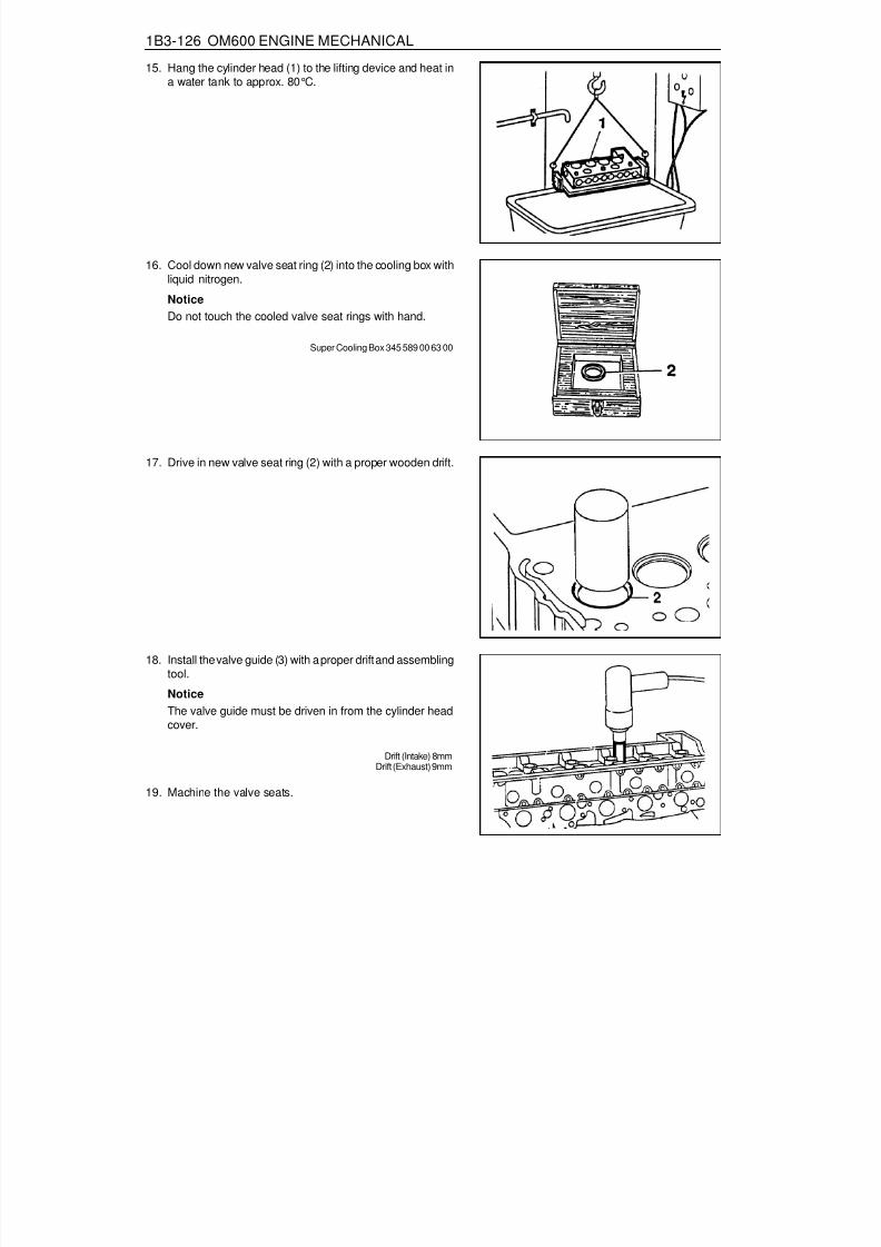
8/18/2019 SsangYong Musso Service Manual 1998.pdf
http://slidepdf.com/reader/full/ssangyong-musso-service-manual-1998pdf 428/1459
1B3-126 OM600 ENGINE MECHANICAL
17. Drive in new valve seat ring (2) with a proper wooden drift.
18. Install the valve guide (3) with a proper drift and assemblingtool.NoticeThe valve guide must be driven in from the cylinder headcover.
Drift (Intake) 8mmDrift (Exhaust) 9mm
19. Machine the valve seats.
15. Hang the cylinder head (1) to the lifting device and heat ina water tank to approx. 80°C.
16. Cool down new valve seat ring (2) into the cooling box withliquid nitrogen.
NoticeDo not touch the cooled valve seat rings with hand.
Super Cooling Box 345 589 00 63 00

8/18/2019 SsangYong Musso Service Manual 1998.pdf
http://slidepdf.com/reader/full/ssangyong-musso-service-manual-1998pdf 429/1459
OM600 ENGINE MECHANICAL 1B3-127
CHECK AND MACHINING OF VALVESPreceding Works : Removal of cylinder head
Removal of the vale springRemoval of the valve
I Valve LengthW Camshaft Cam Basic DiameterX Distance (Camshaft Basic Bore - Valve Stem)
Y Half Camshaft Basic Bore DiameterZ Distance (Cylinder Head Cover Parting Surface -
Valve Stem)

8/18/2019 SsangYong Musso Service Manual 1998.pdf
http://slidepdf.com/reader/full/ssangyong-musso-service-manual-1998pdf 430/1459
1B3-128 OM600 ENGINE MECHANICAL
Intake Valve Exhaust Valve
Item
Valve Disc Diameter ‘d’
Valve Disc Height ‘h’Setting Angle “ a ” or Machining the ValveValve Stem Diameter ‘d1’Valve Length ‘I’
Intake Valve
37.90 - 38.10 mm
1.7 mm45°
7.955 - 7.970 mm106.20 - 106.60 mm
105.30 - 105.700.03 mm
Exhaust Valve
34.90 - 35.10 mm
1.7 mm45°
9.945 - 8.960 mm106.20 - 106.60 mm105.30 - 105.70 mm
0.03 mm
StandardRepair
Max. Permis Sible Runout at Valve Stem and Valve Seat
W = 38.0 ± 0.2mm
Matching Valves
Camshaft Cam Basic Dia.
Size (x)
Size (x)
Size (x)
19.5 - 20.3mm
20.4 - 21.4mm
21.4 - 21.97mm
W = 36.6 ± 0.2mmCamshaft Cam Basic Dia.
19.5 - 20.1mm
20.2 - 21.2mm
21.2 - 21.97mm
Valve to be Used
Use machined valve,if needed
new repair valveI = 105.5 ± 0.2mm
Reuse valveUse standard size
valveI = 106.4 ± 0.2mm

8/18/2019 SsangYong Musso Service Manual 1998.pdf
http://slidepdf.com/reader/full/ssangyong-musso-service-manual-1998pdf 431/1459
OM600 ENGINE MECHANICAL 1B3-129
Tools Required001 589 32 21 00 Dial Gauge
Checking and Machining1. Clean the valves and do visual check.
Valves with wobbled valve disc, with worn or scored valvestem should be replaced.
2. Measure valve disc height ‘h’.
Service dataIntake
Exhaust
1.7 ± 0.15 mm
1.7 ± 0.15 mm
3. Machine the valve.
NoticePay attention to setting angle ‘ a ’.
Commercial ToolValve corn grinding machine
4. Measure radial runout between valve stem and valve seat.
Limit Max. 0.03mm
Dial Gauge 001 589 32 21 00

8/18/2019 SsangYong Musso Service Manual 1998.pdf
http://slidepdf.com/reader/full/ssangyong-musso-service-manual-1998pdf 432/1459
1B3-130 OM600 ENGINE MECHANICAL
10. Measure distance ‘z’ (cylinder head cover parting surface- valve stem).
5. Clean the vales, valve seats and valve guides.6. Coat the valve stem with oil and insert it into valve guide.
7. Insert the valves (1) into the valve guides according tomarking.
8. Measure amount by which the valve arrears ‘a’.
Arrears ‘a’ 0.1 - 0.7 mm
NoticeIf out of standard, replace the valve seat ring.
9. Measure camshaft cam basic diameter (w).
Diameter ‘w’38 ± 0.2 mm
or 37.6 ± 0.2 mm

8/18/2019 SsangYong Musso Service Manual 1998.pdf
http://slidepdf.com/reader/full/ssangyong-musso-service-manual-1998pdf 433/1459
OM600 ENGINE MECHANICAL 1B3-131
11. The distance ‘x’ (camshaft basic bore - valve stem).‘x’ = ‘z’ - ‘y’.Determine the valve to use according to this measurement(See ‘matching valves’)
Example) Measured value ‘w’ = 38.2 mm
Measured value ‘z’ = 36.5 mmValue ‘y’ = 15.5 mm
‘x’ = 36.5 - 15.5 = 21.0mmIn this case according to ‘Matching valves’ table, theinstalled valve may be used.

8/18/2019 SsangYong Musso Service Manual 1998.pdf
http://slidepdf.com/reader/full/ssangyong-musso-service-manual-1998pdf 434/1459
1B3-132 OM600 ENGINE MECHANICAL
MACHINING OF VALVE SEATPreceding Work : Removal of prechamber
Removal and inspection of valve, replace if necessaryInspection of valve guide, replace if necessary
1 Valve2 Valve Seat Ring3 Cylinder Head4 Valve Guide
a Valve Seat Angleb Valve Seat Free Angle

8/18/2019 SsangYong Musso Service Manual 1998.pdf
http://slidepdf.com/reader/full/ssangyong-musso-service-manual-1998pdf 435/1459
OM600 ENGINE MECHANICAL 1B3-133
Service Data
ItemValve Arrears ‘a’Valve Seat Width ‘b’Valve Seat Angle ‘ a ’
Valve Seat Free Angle ‘ b ’Permissible Radial RunoutValve Length ‘I’
Intake
0.1 - 0.7 mm1.2 - 1.7 mm
45°
65°0.03 mm
106.20 - 106.60 mm105.30 - 105.70 mm
Exhaust
0.1 - 0.7 mm1.5 - 2.0 mm
45°
65°0.03 mm
106.20 - 106.60 mm105.30 - 105.70 mm
StandardRepair
w = 38.0 ± 0.2 mm
Matching Valves
Camshaft cam basic dia.
Size (x)
Size (x)
Size (x)
19.5 - 20.3mm
20.4 - 21.4mm
21.4 - 21.97mm
w = 37.6 ± 0.2 mmCamshaft cam basic dia.
19.5 - 20.1mm
20.2 - 21.2mm
21.2 - 21.97mm
Valve to be used
Use machined valve,
if neededuse pair valve
1 = 105.5 ± 0.2mmReuse valve
Use standard sizevalve
I = 106.4 ± 0.2mm
Commercial Tools
HungerD-8000 München 70Type Ventilknecht K2000Order No. 221 00 100HungerD-8000 München 70Type VDS 1AOrder No. 236 03 308Hunger
D-8000 München 70Order No. 217 93 601
Cylinder Head Clamping Devie
Valve Seat Turning Tool
Test Sat for Valves

8/18/2019 SsangYong Musso Service Manual 1998.pdf
http://slidepdf.com/reader/full/ssangyong-musso-service-manual-1998pdf 436/1459
1B3-134 OM600 ENGINE MECHANICAL
Machining ProcedureValve machining is required :- When the valve is leaking.- When replacing the valve.- When replacing the valve guide.- When replacing the valve seat or valve seat ring.
1. Machine the valve seat (a=45°).
2. Measure valve seat width ‘b’.
Valve seatwidth ‘b’
1.2 - 1.7 mm
1.5 - 2.0 mm
Intake
Exhaust
3. If the specification is exceeded, the valve seat width has tobe corrected at the lower free angle of ‘ b ’=65°.
4. Measure radial runout.
Runout Max. 0.03mm

8/18/2019 SsangYong Musso Service Manual 1998.pdf
http://slidepdf.com/reader/full/ssangyong-musso-service-manual-1998pdf 437/1459
OM600 ENGINE MECHANICAL 1B3-135
38 ± 0.2mm
or 37.6 ± 0.2mm
5. Insert the valve (1) into the valve guide according to markingand measure amount by which the valve arrears ‘a’.
Arrears ‘a’ 0.1 - 0.7mm
6. Measure camshaft cam basic circle diameter (w).
Diameter ‘w’
7. Measure distance ‘z’ (cylinder head cover parting surface- valve stem).

8/18/2019 SsangYong Musso Service Manual 1998.pdf
http://slidepdf.com/reader/full/ssangyong-musso-service-manual-1998pdf 438/1459
1B3-136 OM600 ENGINE MECHANICAL
I Length of Valvew Camshaft Cam Basic Circle Diameterx Distance (Camshaft basic bore - valve stem)
y Half Camshaft Basic Bore Diameterz Distance (Cylinder head cover parting surface - .
valve stem)
8. Measure ‘x’ (Camshaft basic bore - valve stem).‘x’ = ‘z’ - ‘y’
9. Determine the valve to be used.(See ‘Matching valves’)Example) Measured value ‘w’ = 38.2 mm
Measured value ‘z’ = 36.5 mmValue ‘y’ = 15.5 mm‘x’ = 36.5 - 15.5 = 21.0 mm
In the case of a camshaft cam basic circle diameter‘w’ = 38.2mm and a distance ‘x’ = 21.0mm, the installedvalve may be used.

8/18/2019 SsangYong Musso Service Manual 1998.pdf
http://slidepdf.com/reader/full/ssangyong-musso-service-manual-1998pdf 439/1459
OM600 ENGINE MECHANICAL 1B3-137
CAMSHAFT TIMING TESTPreceding Work : Removal of glow plug
1 Cylinder Head Cover2 Bolt ............................................................ 10Nm3 Gasket ................................................... Replace
4 Valve Tappet5 Cylinder Head
Timing
Condition of camshaft
NewAfter approx. 20,000km
Intake valveOpen
ATDC 11.33°ATDC 12°
Close
ABDC 17°ABDC 18°
Exhaust valveOpen
BBDC 28°BBDC 27°
Close
BTDC 15.25°BTDC 14°
At 2mm of valve lifting stroke.

8/18/2019 SsangYong Musso Service Manual 1998.pdf
http://slidepdf.com/reader/full/ssangyong-musso-service-manual-1998pdf 440/1459
1B3-138 OM600 ENGINE MECHANICAL
6. Check the timing.
NewAfter approx. 20,000km
ATDC 11.33°ATDC 12°
NoticeIf timing is out standard, the camshaft should be checkedfor wear and the timing chain for stretch. If a difference ofmore than 4°exists, the timing chain should be replaced.
7. Replace the gasket and install the cylinder head cover.
Tightening Torque 10 Nm
Measurement Procedure1. Remove the cylinder head cover.2. Rotate the engine in the direction of engine rotation until
the intake valve of NO. 1 cylinder is completely closed. Thecam lobe faces up (arrow).
NoticeDo not rotate the engine at the bolt of the crankshaftsprocket. Do not rotate the engine in the opposite directionof engine rotation. If do, this will cause serious measuringerrors.
3. Install the dial gauge holder and dial gauge (7) with theextension (8) to the cylinder head and position the tracerpin (9) onto the valve tappet (intake valve of cylinder NO.1)with a preload of min. 3mm.
NoticeThe tracer pin should be positioned exactly vertical.
Dial gauge Holder 363 589 02 21 00Dial Gauge 001 589 53 21 00Extension 366 589 00 21 05
4. Set the dial gauge to ‘0’.5. Rotate the engine further in direction of rotation until the
dial gauge has moved back by 2mm (valve lift) to 1mm.
Tools Required001 589 53 21 00 Dial Gauge363 589 02 21 00 Dial Gauge Holder366 589 00 21 05 Extension

8/18/2019 SsangYong Musso Service Manual 1998.pdf
http://slidepdf.com/reader/full/ssangyong-musso-service-manual-1998pdf 441/1459
OM600 ENGINE MECHANICAL 1B3-139
CAMSHAFTPreceding Work : Removal of cylinder head cover
1 Bolt ............................................................ 25Nm2 Washer3 Camshaft Bearing Cap4 Camshaft5 Dowel Pin6 Locking Washer7 Timing Chain
8 Cylinder Head9 Oil Pan
10 Camshaft Sprocket11 Washer12 12-Sided Bolt (M11) ............. Check, 25Nm + 90°13 Gasket ................................................... Replace14 Chain Tensioner ........................................ 80Nm

8/18/2019 SsangYong Musso Service Manual 1998.pdf
http://slidepdf.com/reader/full/ssangyong-musso-service-manual-1998pdf 442/1459
1B3-140 OM600 ENGINE MECHANICAL
3. Remove the starter motor and install the engine lock.
Engine Lock 602 589 00 40 00
Tools Required602 589 00 40 00 Engine Lock
Removal Procedure1. Rotate the crankshaft and position the piston of no.1 cylinder
at TDC.
NoticeDo not rotate the crankshaft in the opposite direction ofengine rotation.
In this position, the markings of the camshaft/camshaftbearing cap (arrow) must be aligned.
2. Place alignment marks on the camshaft sprocket and timingchain.

8/18/2019 SsangYong Musso Service Manual 1998.pdf
http://slidepdf.com/reader/full/ssangyong-musso-service-manual-1998pdf 443/1459
OM600 ENGINE MECHANICAL 1B3-141
4. Remove the bolt and then remove the camshaft sprocket.
NoticeDuring removal, be careful not to drop the sprocket withchain. Remove the chain carefully and then pull out thesprocket.
5. Remove the chain tensioner.
6. Remove the camshaft bearing cap bolts according to theremoval order.
NoticeRemove the camshaft bearing cap bolts of 1(dark arrow)first and then remove the bolts of 2 (light arrow) onerevolution in stages until the counter-pressure is released.In order to avoid damaging the camshaft, it is essential toadhere to the removal order for the camshaft bearing caps.
OM 662LA
OM 661LA

8/18/2019 SsangYong Musso Service Manual 1998.pdf
http://slidepdf.com/reader/full/ssangyong-musso-service-manual-1998pdf 444/1459
1B3-142 OM600 ENGINE MECHANICAL
4. Install the camshaft bearing caps according to markings(1,2, 3 etc.).
7. Remove the camshaft bearing cap.8. Pull off the camshaft.
NoticeBe careful not to miss front locking washer.
9. Pull out the locking washer.
NoticeCheck the condition of locking washer and replace ifnecessary.
Installation Procedure1. Insert the locking washer.
2. Check the valve tappet and ensure that tappet movessmoothly.3. Coat the camshaft with oil and install the camshaft onto the
cylinder head so that the TDC marking (arrow) is positionedupward vertically.

8/18/2019 SsangYong Musso Service Manual 1998.pdf
http://slidepdf.com/reader/full/ssangyong-musso-service-manual-1998pdf 445/1459
OM600 ENGINE MECHANICAL 1B3-143
5. Tighten the camshaft bearing cap bolts acccording toinstallation order.
6. Install the camshaft sprocket to be aligned the markings ofthe camshaft / camshaft bearing cap (arrow).
NoticeAlign the alignment marks on the timing chain and sprocket.
Tightening Torque 25 Nm
NoticeTighten the No. 1 bolts (light arrow) by one revolution instages first and then tighten the No.2 bolts (dark arrow).
OM 661LA
OM 662LA
7. Tighten the camshaft sprocket bolt.
Tightening Torque 25Nm + 90°

8/18/2019 SsangYong Musso Service Manual 1998.pdf
http://slidepdf.com/reader/full/ssangyong-musso-service-manual-1998pdf 446/1459
1B3-144 OM600 ENGINE MECHANICAL
10. Check the TDC marking of OT on the crankshaft.
8. Install the chain tensioner.
Tightening Torque 80 Nm
NoticeReplace the seal.Before installation, by pumping in the oil approx. 10 times,fill the oil.
9. Remove the engine lock.
NoticeIf max. length ‘L’ of the 12-sided bolt exceeds 53.6mm,replace it.
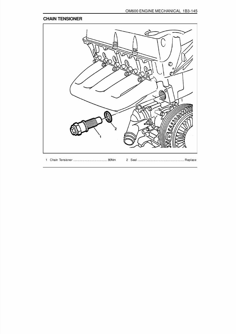
8/18/2019 SsangYong Musso Service Manual 1998.pdf
http://slidepdf.com/reader/full/ssangyong-musso-service-manual-1998pdf 447/1459
OM600 ENGINE MECHANICAL 1B3-145
CHAIN TENSIONER
1 Chain Tensioner ........................................ 80Nm 2 Seal ....................................................... Replace

8/18/2019 SsangYong Musso Service Manual 1998.pdf
http://slidepdf.com/reader/full/ssangyong-musso-service-manual-1998pdf 448/1459
1B3-146 OM600 ENGINE MECHANICAL
NoticeAlways install the chain tensioner to be filled with oil.
Place the chain tensioner in engine oil up to over the collar on the hexagon head with the thrust pin facing up.Slowly push down the thrust pin as far as the stop 7~10 times with the aid of a press or a column drill
Faulty chain tensioners should be replaced completely.
3 Screw Plug4 Aluminum Gasket5 Ball6 Ball Guide7 Compression Spring8 Compression Spring9 Housing
10 Thrust Pin
11 Valve Disc12 O-Ring13 Snap Ring14 Compression Spring15 Filler
A Feed Bore from Cylinder Head
B To Oil Pan

8/18/2019 SsangYong Musso Service Manual 1998.pdf
http://slidepdf.com/reader/full/ssangyong-musso-service-manual-1998pdf 449/1459
OM600 ENGINE MECHANICAL 1B3-147
TIMING CHAINPreceding Work : Removal of glow plug
Removal of chain tensioner Removal of cooling fan Removal of cylinder head cover
1 Chain Link2 Timing Chain3 Camshaft Sprocket4 Outer Plate

8/18/2019 SsangYong Musso Service Manual 1998.pdf
http://slidepdf.com/reader/full/ssangyong-musso-service-manual-1998pdf 450/1459
1B3-148 OM600 ENGINE MECHANICAL
5. By rotating the crankshaft in the of engine rotation, pull outthe old timing chain with installing the new timing chain.
6. Remove the old timing chain and hold the ends of the newtiming chain to camshaft sprocket (3) with wire (arrow).
Tools Required000 589 58 43 00 Chain Assembling Device
Replacement Procedure1. Cover over the chain box with cleaning rag and grind off
both chain pins (arrow) at a chain link (1) of the timing chain.
2. Remove the outer plate (4) and chain link (1).
NoticeEnsure that the ends of the timing chain do not drop intothe chain box.
3. Loosen the chain tension with approx. 4 turns.4. Connect the new timing chain (arrow) with chain link (1) to
the old timing chain (2).

8/18/2019 SsangYong Musso Service Manual 1998.pdf
http://slidepdf.com/reader/full/ssangyong-musso-service-manual-1998pdf 451/1459
OM600 ENGINE MECHANICAL 1B3-149
7. Insert the new chain link (1) to connect the chain.
8. Insert the new outer plate (4) into the fitting tool (8) andthen the outer plate will be held by a magnet.
Chain Assembling Device 000 589 58 43 00
9. Place the fitting tool (8) onto the chain link and press theouter plate on as far as the stop.
10. Switch over the die (9) of the fitting tool (8).

8/18/2019 SsangYong Musso Service Manual 1998.pdf
http://slidepdf.com/reader/full/ssangyong-musso-service-manual-1998pdf 452/1459
1B3-150 OM600 ENGINE MECHANICAL
In this position, the marking on camshaft / camshaft bearingcap (arrow) must also be aligned. If the markings are notaligned, the timing chain must be re-set and the injectionpump timing has to be set.
14. Position the no.1 cylinder at TDC.
11. Place the fitting tool (8) onto the chain link and rivet thechain pins one by one.
12. Check the riveting of chain pins and re-rivet if necessary.13. Remove the wire.
Tightening Torque 35 - 40 Nm

8/18/2019 SsangYong Musso Service Manual 1998.pdf
http://slidepdf.com/reader/full/ssangyong-musso-service-manual-1998pdf 453/1459
OM600 ENGINE MECHANICAL 1B3-151
TENSIONING RAILPreceding Work : Removal of cylinder head
Removal of timing case cover
1 Tensioning Rail 2 Bearing Pin
NoticeThe plastic coating of the tensioning rail can not be replaced.

8/18/2019 SsangYong Musso Service Manual 1998.pdf
http://slidepdf.com/reader/full/ssangyong-musso-service-manual-1998pdf 454/1459
1B3-152 OM600 ENGINE MECHANICAL
CYLINDER HEAD GUIDE RAILPreceding Work : Removal of the cooling fan
Removal of poly V-beltRemoval of chain tensioner
1 Cylinder Head Cover2 Bolt ............................................................ 10Nm3 Gasket ................................................... Replace4 Camshaft Sprocket5 Washer6 12-Sided Bolt (M11) ............ Inspect, 25Nm + 90°7 Tensioning Lever8 Bolt ............................................................ 23Nm
9 Bearing Pin ........................... Sealing Compound10 Guide Rail11 Bearing Pin12 Guide Pulley13 Socket Bolt ................................................ 23Nm14 Closing Cover15 Spring16 Timing Chain

8/18/2019 SsangYong Musso Service Manual 1998.pdf
http://slidepdf.com/reader/full/ssangyong-musso-service-manual-1998pdf 455/1459
OM600 ENGINE MECHANICAL 1B3-153
Tools Required115 589 02 34 00 Sliding Hammer116 589 20 33 00 Threaded Pin
Removal Procedure1. Removal the cylinder head cover.2. Pull off the tensioning lever (7) and remove from the spring
(15).
3. Pry off the closing cover (14) and remove the bolt (13) andthen remove the guide pulley (12).
4. Place alignment marks (arrow) on the timing chain (16) andcamshaft sprocket (4).
5. Remove the camshaft sprocket.

8/18/2019 SsangYong Musso Service Manual 1998.pdf
http://slidepdf.com/reader/full/ssangyong-musso-service-manual-1998pdf 456/1459
1B3-154 OM600 ENGINE MECHANICAL
4. Position the no. 1 cylinder at the TDC of OT.
6. Pull out the bearing pins (9, 11) with sliding hammer andremove the guide rail 10.
Sliding Hammer 116 589 20 33 00Threaded Pin 116 589 02 34 00
Installation Procedure1. Apply collar of both bearing pins with sealing compound.2. Position the guide rail and insert the bearing pins.3. Install the camshaft sprocket.
Tightening Torque 10 Nm
NoticeIf the max. length ‘L’ of the 12-sided bolt exceeds 53.6mm,replace it.

8/18/2019 SsangYong Musso Service Manual 1998.pdf
http://slidepdf.com/reader/full/ssangyong-musso-service-manual-1998pdf 457/1459
OM600 ENGINE MECHANICAL 1B3-155
In this position, the marking on the camshaft / camshaftbearing cap (arrow) must also be aligned.
5. Install the guide pulley (12).
Tightening Torque 23 Nm
6. Attach the tensioning lever (7) to the spring (15) and install.7. Replace the gasket and install the cylinder head cover.
Tightening Torque 10 Nm
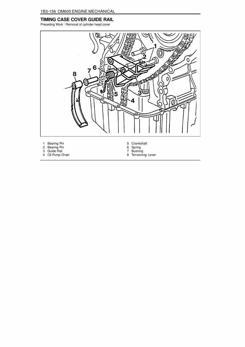
8/18/2019 SsangYong Musso Service Manual 1998.pdf
http://slidepdf.com/reader/full/ssangyong-musso-service-manual-1998pdf 458/1459
1B3-156 OM600 ENGINE MECHANICAL
TIMING CASE COVER GUIDE RAILPreceding Work : Removal of cylinder head cover
1 Bearing Pin2 Bearing Pin3 Guide Rail4 Oil Pump Chain
5 Crankshaft6 Spring7 Bushing8 Tensioning Lever

8/18/2019 SsangYong Musso Service Manual 1998.pdf
http://slidepdf.com/reader/full/ssangyong-musso-service-manual-1998pdf 459/1459
OM600 ENGINE MECHANICAL 1B3-157
Removal Procedure1. Pull out the tensioning lever (8) together with the spring (6)
and guide rail (3) far enough until the tensioning lever hasmoved passed the oil pump chain (4) and is resting againstthe crankshaft (5)
2. Pull the tensioning lever (8) off the bearing pin (2) andcarefully remove the spring (6). Remove the tensioning lever(8) together with the spring (6) and bushing (7).
3. Remove the guide rail (3).
Installation Procedure1. Install the guide rail (3). Attach the spring (6) to the guide
rail and to the tensioning lever (8).
NoticeEnsure that the spring is correctly located in the guide rail(arrow).
2. Push the guide rail, spring, bushing and tensioning levertogether onto the bearing pin (1, 2).

8/18/2019 SsangYong Musso Service Manual 1998.pdf
http://slidepdf.com/reader/full/ssangyong-musso-service-manual-1998pdf 460/1459
1B3-158 OM600 ENGINE MECHANICAL
CRANKSHAFT SPROCKETPreceding Work : Removal of oil pan
Removal of timing case cover
1 12-Sided Stretch Bolt (M11) .. Check, 25Nm + 90°2 Washer3 Camshaft Sprocket4 Timing Chain5 Bearing Pin6 Bearing Pin7 Oil Pump8 Oil Pump Sprocket9 Oil Pump Chain
10 Washer
11 Bolt ............................................................ 25Nm12 Crankshaft Sprocket13 Crankshaft15 Key16 Guide Rail17 Spring18 Bushing19 Tensioning Lever

8/18/2019 SsangYong Musso Service Manual 1998.pdf
http://slidepdf.com/reader/full/ssangyong-musso-service-manual-1998pdf 461/1459
OM600 ENGINE MECHANICAL 1B3-159
Special Tools116 589 07 15 00 Drift102 589 05 33 00 Puller
Removal Procedure1. Pull out the tensioning lever (19) together with the spring
(17) and guide rail (16) far enough until the tensioning leverhas passed the oil pump chain (9) and is resting againstthe crankshaft (13).
2. Pull out tensioning lever (19), spring (17) and bushing (18)from the bearing pin (6).
3. Pull out the guide rail (16).
4. Remove the bolt(11) and then remove the washer (10), oilpump chin (9) and sprocket (8).

8/18/2019 SsangYong Musso Service Manual 1998.pdf
http://slidepdf.com/reader/full/ssangyong-musso-service-manual-1998pdf 462/1459
1B3-160 OM600 ENGINE MECHANICAL
10. Remove the crankshaft sprocket (12) by using a puller(20).
Puller 102 589 05 33 00
5. Place alignment marks (arrow) on the timing chain (4) andcrankshaft sprocket (12).
6. Remove the woodruff key(15).
7. Place alignment marks (arrow) on the timing chain (4) andcamshaft sprocket (3).
8. Remove the chain tensioner.9. Remove the bolt (1) and then remove the washer (2) and
camshaft sprocket (3).

8/18/2019 SsangYong Musso Service Manual 1998.pdf
http://slidepdf.com/reader/full/ssangyong-musso-service-manual-1998pdf 463/1459
OM600 ENGINE MECHANICAL 1B3-161
Installation Procedure1. Put the same alignment mark on the new crankshaft
sprocket as in the old sprocket.
NoticeCheck the timing chain, camshaft sprocket, injection pumptiming sprocket, oil pump chain and oil pump sprocket for
wear and replace if necessary.
2. Install the new crankshaft sprocket (12) by using a drift (21).
NoticeAlign the groove of sprocket and woodruff key (arrow)exactly.
Drift 116 589 07 15 00
3. Fit the timing chain (4) on the crankshaft sprocket (12).
Notice
Align the alignment marks (arrow) on the chain and sprocket.
4. Install the camshaft sprocket (3).
Tightening Torque 25 Nm + 90°
NoticePay attention on the alignment marks and dowel pin (arrow).

8/18/2019 SsangYong Musso Service Manual 1998.pdf
http://slidepdf.com/reader/full/ssangyong-musso-service-manual-1998pdf 464/1459
1B3-162 OM600 ENGINE MECHANICAL
NoticeIf the max. length ‘L’ of the stretch bolt exceeds 53.6mm,replace it.
5. Fit the oil pump chain (9) on the crankshaft sprocket (12)and insert the oil pump sprocket (8) into the oil pump chainand then install it on the oil pump.
Notice
The curved side of the oil pump sprocket should face theoil pump.6. Insert the woodruff key (15).
7. Install the guide rail (16). Attach the spring (17) to guide railand to tensioning lever together onto the bearing pins (5,6).
NoticeEnsure that the spring is correctly located in the guide rail(arrow).
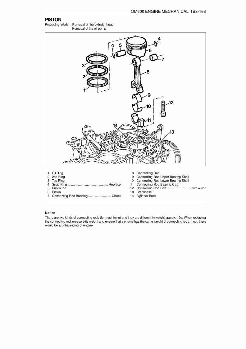
8/18/2019 SsangYong Musso Service Manual 1998.pdf
http://slidepdf.com/reader/full/ssangyong-musso-service-manual-1998pdf 465/1459
OM600 ENGINE MECHANICAL 1B3-163
PISTONPreceding Work : Removal of the cylinder head
Removal of the oil pump
1 Oil Ring2 2nd Ring3 Top Ring4 Snap Ring .............................................. Replace5 Piston Pin6 Piston7 Connecting Rod Bushing .......................... Check
8 Connecting Rod9 Connecting Rod Upper Bearing Shell
10 Connecting Rod Lower Bearing Shell11 Connecting Rod Bearing Cap12 Connecting Rod Bolt ......................... 35Nm + 90°13 Crankcase14 Cylinder Bore
NoticeThere are two kinds of connecting rods (for machining) and they are different in weight approx. 15g. When replacingthe connecting rod, measure its weight and ensure that a engine has the same weight of connecting rods. If not, therewould be a unbalancing of engine.

8/18/2019 SsangYong Musso Service Manual 1998.pdf
http://slidepdf.com/reader/full/ssangyong-musso-service-manual-1998pdf 466/1459
1B3-164 OM600 ENGINE MECHANICAL
Service Data
Piston clearancePiston crown protrusion in TDC positionConnecting rod bushing diameter
Max. 0.12 mm0.735 - 0.965 mm
26.012 - 26.018 mm
Connecting Rod Bolt Dimensions
ThreadStretch shaft(C) diameter (new)Minimum stretch shaft diameter (C)Length(L)(new)
Tools Required000 589 04 14 00 Tensioning Strap001 589 53 21 00 Dial Gauge363 589 02 21 00 Dial Gauge Holder
M9 x 17.4 -0.1 mm7.1 mm
52 -0.3 mm

8/18/2019 SsangYong Musso Service Manual 1998.pdf
http://slidepdf.com/reader/full/ssangyong-musso-service-manual-1998pdf 467/1459
OM600 ENGINE MECHANICAL 1B3-165
Removal Procedure1. Remove combustion residues from the cylinder bores.2. Remove the connecting rod bolts (12) and then remove
the connecting rod bearing caps(11).
3. Remove the connecting rod bearing shells (9, 10).
NoticeBe careful not mix the bearing caps and shells each other.
4. Remove the piston (6) and connecting rod (8).
5. Remove the snap ring (4) and pull out the piston pin (5).6. Separate the piston and connecting rod.

8/18/2019 SsangYong Musso Service Manual 1998.pdf
http://slidepdf.com/reader/full/ssangyong-musso-service-manual-1998pdf 468/1459
1B3-166 OM600 ENGINE MECHANICAL
Installation Procedure1. Fit the piston onto the connecting rod so that the arrow
(15) and the locking slot (16) are facing in direction of thevehicle.
2. Coat the piston pin (15) with engine oil and insert it by hand.
NoticeDo not heat up the piston.
3. Install the new snap ring (4) into the grooves (arrow).4. Check the piston rings (1, 2, 3) and replace them if
necessary.
5. Install and arrange the piston rings to be evenly 120°fromeach ends gap.

8/18/2019 SsangYong Musso Service Manual 1998.pdf
http://slidepdf.com/reader/full/ssangyong-musso-service-manual-1998pdf 469/1459
OM600 ENGINE MECHANICAL 1B3-167
6. Coat the cylinder bore, connecting rod bearing journal,connecting rod bearing shell and piston with oil.
7. Compress the piston rings with a tensioning strap (7).
Tensioning Strap 000 589 04 14 00
8. Insert the piston assembly into the cylinder with a woodenstick (18).
NoticeThe arrow on the piston crown must point toward the front
of vehicle.
9. Insert the connecting rod bearing shells (9, 10).
Notice
Be careful of the difference in upper and lower bearingshells and not to be changed.10. Position the connecting rod bearings caps.
NoticePosition so that the retaining lugs are on the same side ofthe connecting rod bearing(arrow).
11. Measure stretch shaft diameter (C) of the connecting rodbolts.
Limit ‘C’ 7.1mm

8/18/2019 SsangYong Musso Service Manual 1998.pdf
http://slidepdf.com/reader/full/ssangyong-musso-service-manual-1998pdf 470/1459
1B3-168 OM600 ENGINE MECHANICAL
12. Coat the bolts (12) with oil and then tighten the bolts.
Tightening Torque 40Nm + 90°
13. Rotate the crankshaft and check axial clearance betweenthe connecting rod and crankshaft.
14. Measure clearance between the piston crown and cylinder
Standard Max. 0.12mm
15. Position the piston at TDC and measure the distancebetween the piston crown and the crankcase surface.
NoticeMeasure at points marked.
Dial Gauge 001 589 00 53 21Dial Gauge Holder 363 589 02 21 00
Standard Max. 0.965 mm

8/18/2019 SsangYong Musso Service Manual 1998.pdf
http://slidepdf.com/reader/full/ssangyong-musso-service-manual-1998pdf 471/1459
OM600 ENGINE MECHANICAL 1B3-169
OIL FILTER
1 Nut ............................................................ 25 Nm2 Oil Filter .....................................................Cover3 O-Ring ................................................... Replace4 Oil Filter ............... Element Replace If necessary
5 Oil Filter Housing
6 Bolt (M8) .................................................... 10Nm7 Oil Pressure Switch8 Gasket9 Bolt ........................................................... 25 Nm

8/18/2019 SsangYong Musso Service Manual 1998.pdf
http://slidepdf.com/reader/full/ssangyong-musso-service-manual-1998pdf 472/1459
1B3-170 OM600 ENGINE MECHANICAL
Removal & Installation Procedure1. Remove the oil filter cover and then drain the oil.
2. Remove the oil pressure switch line.
3. Remove the oil filter housing.4. Clean the sealing surface.5. Installation should follow the removal procedure in the
reverse order.

8/18/2019 SsangYong Musso Service Manual 1998.pdf
http://slidepdf.com/reader/full/ssangyong-musso-service-manual-1998pdf 473/1459
OM600 ENGINE MECHANICAL 1B3-171
OIL PAN
1 Gasket ................................................... Replace2 Upper Oil Pan3 Combination Bolt ...................................... 10 Nm4 Combination Bolt ...................................... 10 Nm5 Gasket ................................................... Replace
6 Lower Oil Pan7 Combination Bolt ...................................... 25 Nm8 Drain Plug ................................................. 25 Nm9 Washer Seal .......................................... Replace
10 Oil Pan
*Remove and install as numerical sequence.
Notice
Replace the washer seal with new one.
OM662LA OM661LA

8/18/2019 SsangYong Musso Service Manual 1998.pdf
http://slidepdf.com/reader/full/ssangyong-musso-service-manual-1998pdf 474/1459
1B3-172 OM600 ENGINE MECHANICAL
Oil Circulation
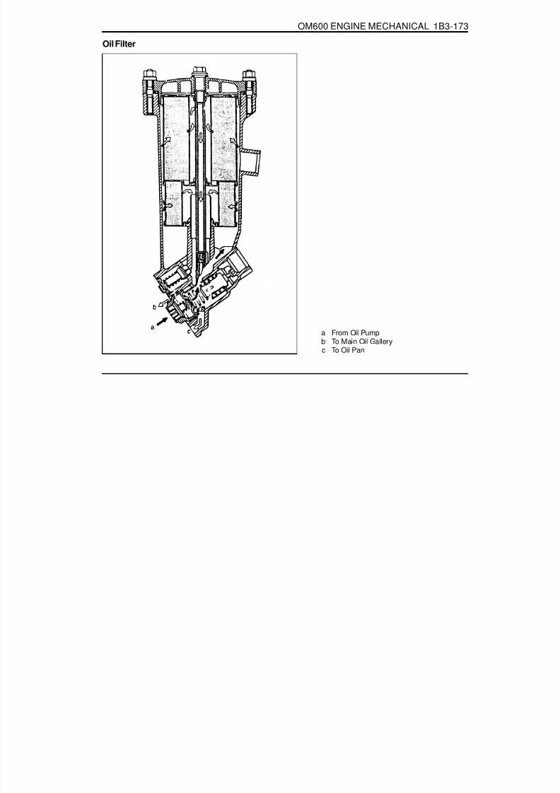
8/18/2019 SsangYong Musso Service Manual 1998.pdf
http://slidepdf.com/reader/full/ssangyong-musso-service-manual-1998pdf 475/1459
OM600 ENGINE MECHANICAL 1B3-173
Oil Filter
a From Oil Pumpb To Main Oil Galleryc To Oil Pan

8/18/2019 SsangYong Musso Service Manual 1998.pdf
http://slidepdf.com/reader/full/ssangyong-musso-service-manual-1998pdf 476/1459
1B3-174 OM600 ENGINE MECHANICAL
OIL SPRAY NOZZLE
1 Fitting Sleeve2 Oil Spray Nozzle
Disassembly Procedure1. Remove oil pan or crankshaft.2. Loose the bolt and then remove the nozzle.
3 Combination Bolt ..................................... 10 NmA Oil Duct

8/18/2019 SsangYong Musso Service Manual 1998.pdf
http://slidepdf.com/reader/full/ssangyong-musso-service-manual-1998pdf 477/1459
OM600 ENGINE MECHANICAL 1B3-175
OIL PUMP
1 Oil Pump2 Piston3 Pressure Spring4 Guide Pin
5 Screw Plug ................................................ 50 Nm6 Combination Bolt ...................................... 25 Nm7 Oil Strainer8 Bracket
Disassembly Procedure1. Remove the oil pan.2. Unscrew the mounting bolt of spracket.

8/18/2019 SsangYong Musso Service Manual 1998.pdf
http://slidepdf.com/reader/full/ssangyong-musso-service-manual-1998pdf 478/1459
1B3-176 OM600 ENGINE MECHANICAL
Tightening Torque 10 Nm
3. Unscrew the oil strainer bracket bolt.
4. Remove the oil pump.
5. Unscrew the screw plug and remove the relief valve.6. Installation should follow the removal procedure in the
reverse order.

8/18/2019 SsangYong Musso Service Manual 1998.pdf
http://slidepdf.com/reader/full/ssangyong-musso-service-manual-1998pdf 479/1459
OM600 ENGINE MECHANICAL 1B3-177
CYLINDER HEAD PRESSURE LEAKAGE TESTPreceding Work : Removal of the cylinder head
Removal of the exhaust manifold Removal of the valve
1 Feed Pipe2 Bolt3 Return Connection4 Gasket ................................................................ Replace5 Coolant Gallery ................................................... Sealing6 Pressure Measuring Plate .................................. Completely tight to the cylinder head7 Cylinder Head .....................................................
Immerse with pressure measuring plate into warm water of approx. 60°C and pressurize with compressedairof 2 bar.
Notice
If air bubbles are seen, replace the cylinderhead.
Tools Required
115 589 34 63 00 Pressure Measuring Plate601 589 00 25 00 Suspension Device
UNIT REPAIR
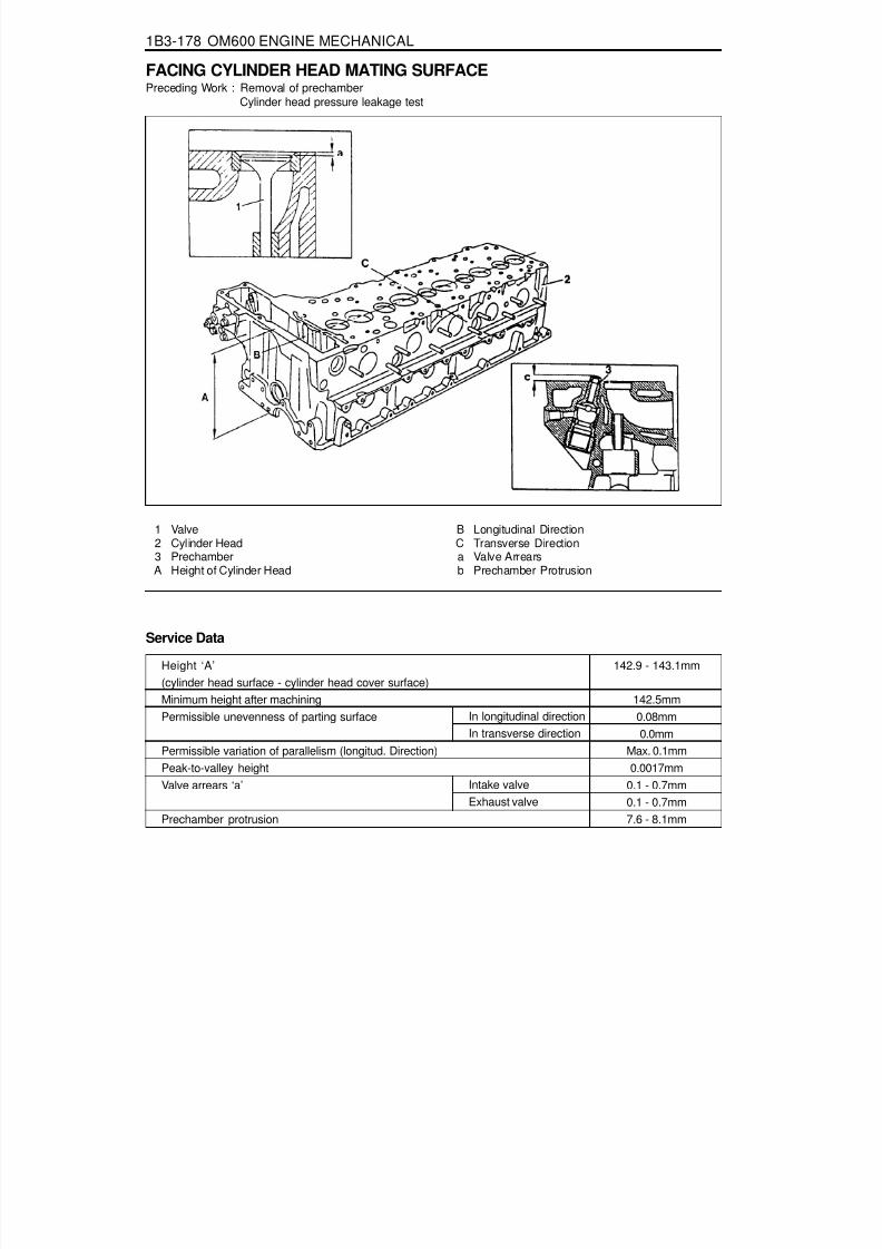
8/18/2019 SsangYong Musso Service Manual 1998.pdf
http://slidepdf.com/reader/full/ssangyong-musso-service-manual-1998pdf 480/1459
1B3-178 OM600 ENGINE MECHANICAL
Height ‘A’(cylinder head surface - cylinder head cover surface)Minimum height after machiningPermissible unevenness of parting surface
Permissible variation of parallelism (longitud. Direction)Peak-to-valley heightValve arrears ‘a’
Prechamber protrusion
Service Data
In longitudinal directionIn transverse direction
Intake valveExhaust valve
142.9 - 143.1mm
142.5mm0.08mm0.0mm
Max. 0.1mm0.0017mm
0.1 - 0.7mm0.1 - 0.7mm7.6 - 8.1mm
FACING CYLINDER HEAD MATING SURFACEPreceding Work : Removal of prechamber
Cylinder head pressure leakage test
1 Valve2 Cylinder Head3 PrechamberA Height of Cylinder Head
B Longitudinal DirectionC Transverse Directiona Valve Arrearsb Prechamber Protrusion

8/18/2019 SsangYong Musso Service Manual 1998.pdf
http://slidepdf.com/reader/full/ssangyong-musso-service-manual-1998pdf 481/1459
OM600 ENGINE MECHANICAL 1B3-179
Measurement Procedure1. Measure height ‘A’.
Limit 142.5 mm
NoticeIf the height is less than 142.5mm, replace the cylinder head.
2. Insert the valve (1) and measure valve arrears ‘a’.
Valve Arrears ‘a’ 0.1 - 0.7 mm
NoticeIf out of standard, machine the valve seat.
3. Install the prechamber and measure protrusion ‘C’.
Protrusion ‘C’ 7.6 - 8.1mm
4. Assemble the engine and check the valve timing.

8/18/2019 SsangYong Musso Service Manual 1998.pdf
http://slidepdf.com/reader/full/ssangyong-musso-service-manual-1998pdf 482/1459
1B3-180 OM600 ENGINE MECHANICAL
REPLACEMENT OF CRANKCASE CORE PLUG
Left Right
Core plug....................................................... f 34mmOM661LA - 2EAOM662LA - 3EA
Core plug....................................................... f 34mmOM661LA - 2EAOM662LA - 3EA
Core plug....................................................... f 17mmOM661LA - 1EAOM662LA - 1EA
Core plug....................................................... f 34mmOM661LA - 1EAOM662LA - 1EA
Left Right

8/18/2019 SsangYong Musso Service Manual 1998.pdf
http://slidepdf.com/reader/full/ssangyong-musso-service-manual-1998pdf 483/1459
OM600 ENGINE MECHANICAL 1B3-181
Tools Required
102 589 00 15 00 Drift102 589 12 15 00 Drift
Replacement Procedure1. Completely drain the coolant.2. Remove any parts which impede access.
(Example : transmission, injection pump)3. Place the screwdriver to the deepdrawn edge of the core
plug and pull forward and then rotate 90°.
4. Pull out the core plug with pliers.
5. Thoroughly clean the sealing surface and apply Loctite 241.6. Install the new core plug by using a drift.
Drift 102 589 00 15 00 (F34)Drift 102 589 12 15 00 (F17)
7. Install the removed parts and fill the coolant.
NoticeThe adhesive must be allowed to harden for about 45minutes before filling of coolant.
8. Warm up the engine and check the coolant for leaks.

8/18/2019 SsangYong Musso Service Manual 1998.pdf
http://slidepdf.com/reader/full/ssangyong-musso-service-manual-1998pdf 484/1459
1B3-182 OM600 ENGINE MECHANICAL
Service Data
Height ‘Y’Permissible unevenness of contacting surface
Permissible roughness upper contacting surfacePermissible variation of parallelism of crankcase uppersurface to lower surface in longitudinal directionPiston protrusion at TDC to crankcase upper surface
In longitudinal direction (B)In transverse direction (C)
Min. 299.62 mm0.06 mm0.06 mm
0.0006 - 0.0016 mm0.05 mm
0.965 mm0.735 mm
Max.Min.
FACING CRANKCASE CONTACTING SURFACE
1 Crankcase2 Crankcase Contacting Surface
Y Height (crankcase upper surface - crankcaselower surface)
B Longitudinal DirectionC Transverse DirectionH Chamfer Heightb Chamfer Angle

8/18/2019 SsangYong Musso Service Manual 1998.pdf
http://slidepdf.com/reader/full/ssangyong-musso-service-manual-1998pdf 485/1459
OM600 ENGINE MECHANICAL 1B3-183
OIL GALLERY STEEL BALLPreceding Work : Removal of cooling fan
Removal of the coolant pump housing Removal of the flywheel and driven plate
1 Steel Ball ................................................. f 15mm 2 Screw Plug ...............................Loctite 241,50Nm
NoticeThe screw plug (2) has to be installed as a repair solution if the steel ball (1) is leaking.

8/18/2019 SsangYong Musso Service Manual 1998.pdf
http://slidepdf.com/reader/full/ssangyong-musso-service-manual-1998pdf 486/1459
1B3-184 OM600 ENGINE MECHANICAL
3 Steel Ball ................................................. f 17mm4 Seal
5 Screw Plug ................................................. 50Nm
NoticeThe seal (4) and screw plug (5) have to be installed as a repair solution if the steel ball (3) is leaking.
Tools Required
601 589 08 15 00 Drift

8/18/2019 SsangYong Musso Service Manual 1998.pdf
http://slidepdf.com/reader/full/ssangyong-musso-service-manual-1998pdf 487/1459
OM600 ENGINE MECHANICAL 1B3-185
Removal & Installation Procedure1. Remove the timing case cover.2. By inserting a round bar (6) approx. 0.7m from the back to
the front side through the oil gallery, knock out the steelballs (1,3).
Notice
Be careful not to damage the bores of the steel balls.
6 Shop-made tool
3. Thoroughly clean the bores of steel balls.4. Place the steel ball (3) onto the drift (7) with a little grease
and position to the bore and then tap until the drift stops.
Drift 601 589 08 15 00
5. Place the steel ball (1) onto the drift (7) with a little greaseand position to the bore and then tap until the drift stops.
Drift 601 589 08 1500
6. Warm up the engine and check the oil for leaks.

8/18/2019 SsangYong Musso Service Manual 1998.pdf
http://slidepdf.com/reader/full/ssangyong-musso-service-manual-1998pdf 488/1459
1B3-186 OM600 ENGINE MECHANICAL
Installation of Screw PlugNoticeIf steel ball leaks again, install the screw plug.
1. Remove the steel ball.2. Tap thread into the bores of the oil gallery.
NoticeFront bore : M18 ´ 1.5, depth 10mmRear bore : M16 ´ 1.5, depth 14mm
3. Thoroughly clean the oil gallery.4. Tighten the front plug (5) with seal (4).
5. Apply Loctite 241 and then tighten the rear plug (2).
Tightening Torque 50 Nm
Tightening Torque 50 Nm

8/18/2019 SsangYong Musso Service Manual 1998.pdf
http://slidepdf.com/reader/full/ssangyong-musso-service-manual-1998pdf 489/1459
OM600 ENGINE MECHANICAL 1B3-187
Standard size
Wear limit in direction of travel and in transverse direction
Permissible deviation of cylinder shapeHoning angle
CYLINDER BORE MEASUREMENT
a Longitudinal Directionb Transverse Directionc, d, e. Measuring Point
1 Crankcase Contacting Surface2 TDC of 1st Piston Ring
4 BDC of Ring
Service Data
Code letter ‘A’Code letter ‘X’Code letter ‘B’
When newWear limit
89.000 - 89.006mm89.006 - 89.012mm89.012 - 89.018mm
Max. 0.20mm0.01mm0.05mm
50°± 10°

8/18/2019 SsangYong Musso Service Manual 1998.pdf
http://slidepdf.com/reader/full/ssangyong-musso-service-manual-1998pdf 490/1459

8/18/2019 SsangYong Musso Service Manual 1998.pdf
http://slidepdf.com/reader/full/ssangyong-musso-service-manual-1998pdf 491/1459
1D1-2 M162 ENGINE COOLING
FASTENER TIGHTENING SPECIFICATIONS
N····· m30
22.5 - 27.5
9 - 119 - 119 - 11
40.5 - 49.53 - 73 - 7
Application
Coolant Drain PlugEngine Hanger Bracket and Coolant OutletPort BoltThermostat Cover Bracket BoltOil Cooler Pipe Line BoltCooling Fan BoltViscous Clutch BoltAutomatic Transmission Oil Cooling Hose BoltCooling Fan Shroud Bolt

8/18/2019 SsangYong Musso Service Manual 1998.pdf
http://slidepdf.com/reader/full/ssangyong-musso-service-manual-1998pdf 492/1459
M162 ENGINE COOLING 1D1-3
SPECIAL TOOLSSPECIAL TOOLS TABLE
124 589 15 21 00Tester
603 589 00 40Counter Holder

8/18/2019 SsangYong Musso Service Manual 1998.pdf
http://slidepdf.com/reader/full/ssangyong-musso-service-manual-1998pdf 493/1459
1D1-4 M162 ENGINE COOLING
DIAGNOSIS
3. Connect the special tool to the reservoir filler cap and apply1.4 bar of pressure.
SYSTEM LEAKAGE TESTTools Required124 589 15 21 00 Tester
Test Procedure1. Loosen the cap a little and release pressure and remove
the cap.NoticeFor the risk of scalding, cap must not be opened unless thecoolant temperature is below 90°C.
2. Fill coolant up to upper edge (arrow) of reservoir.
Tester 124 589 15 21 00
4. If the pressure on the tester drops, check leakage at the allcoolant hoses and pipes and each connections. Replaceor retighten if necessary.

8/18/2019 SsangYong Musso Service Manual 1998.pdf
http://slidepdf.com/reader/full/ssangyong-musso-service-manual-1998pdf 494/1459
M162 ENGINE COOLING 1D1-5
MAINTENANCE AND REPAIR
ON-VEHICLE SERVICE
COOLANT DRAIN AND FILL UP
Draning & Filling up Procedure1. Loosen the cap a little and release pressure and remove
the cap.NoticeFor the risk of scalding, the cap must not be opened unlessthe coolant temperature is below 90 oC.
2. Loosen the radiator lower drain cock and drain the coolant.NoticeCollect coolant by using a proper container.
3. Drain the coolant from the crankcase by inserting a hose(dia. 14mm) onto the drain bolt on the side of crankcase(exhaust manifold) and by loosening the plug.Notice
Just loosen the drain plug to drain the coolant and donot remove the plug completely.Collect coolant by using proper container.
4. After complete draining of the coolant, remove the hose
connector to drain plug and reinstall the drain plug.Installation Notice
5. Tighten the radiator lower drain cock.
Tightening Torque 30 Nm
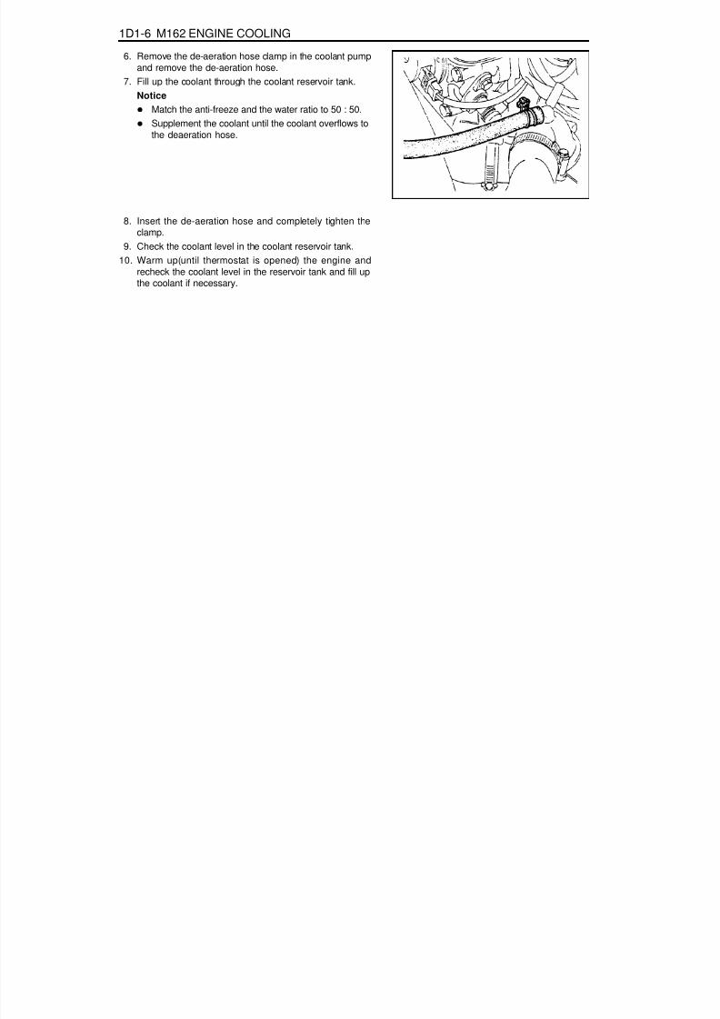
8/18/2019 SsangYong Musso Service Manual 1998.pdf
http://slidepdf.com/reader/full/ssangyong-musso-service-manual-1998pdf 495/1459
1D1-6 M162 ENGINE COOLING
6. Remove the de-aeration hose clamp in the coolant pumpand remove the de-aeration hose.
7. Fill up the coolant through the coolant reservoir tank.Notice
Match the anti-freeze and the water ratio to 50 : 50.Supplement the coolant until the coolant overflows to
the deaeration hose.
8. Insert the de-aeration hose and completely tighten theclamp.
9. Check the coolant level in the coolant reservoir tank.10. Warm up(until thermostat is opened) the engine and
recheck the coolant level in the reservoir tank and fill upthe coolant if necessary.

8/18/2019 SsangYong Musso Service Manual 1998.pdf
http://slidepdf.com/reader/full/ssangyong-musso-service-manual-1998pdf 496/1459
M162 ENGINE COOLING 1D1-7
COOLANT CONNECTION FITTINGPreceding Work : Removal of cooling fan shroud
1 Bolt (M8 X 100, 2 pieces) ............... 22.5-27.5 Nm2 Engine Hanger Bracket3 Coolant Outlet Port
Removal & Installation Procedure1. Drain coolant from the radiator.2. Remove the hose mounting clamp (5) and disconnect the
coolant hose (6).3. Remove the two bolts (1), the engine hanger bracket (2)
and coolant outlet port (3).Installation Notice
4 O-ring5 Hose Mounting Clamp6 Hose
Replace the O-ring with new one.
4. Installation should follow the removal procedure in thereverse order.
5. Fill up the coolant as specified.6. Check the leaks in the cooling system.
Tightening Torque 22.5 - 27.5 Nm

8/18/2019 SsangYong Musso Service Manual 1998.pdf
http://slidepdf.com/reader/full/ssangyong-musso-service-manual-1998pdf 497/1459
1D1-8 M162 ENGINE COOLING
WATER PUMPPreceding Work : Removal of V-belt
Removal of air admission housing
1 Air Admission Housing2 Oil Cooler Pipe Line3 Seal ....................................................... Replace
4 Bolt ........................................................9-11 Nm5 Coolant Hose6 Coolant Hose7 Outlet Coolant Hose
8 Coolant Hose9 Inlet Coolant Hose
10 Coolant Pump
11 Bolt ........................................................... 21 Nm12 Dowel Sleeve13 Seal ....................................................... Replace

8/18/2019 SsangYong Musso Service Manual 1998.pdf
http://slidepdf.com/reader/full/ssangyong-musso-service-manual-1998pdf 498/1459
M162 ENGINE COOLING 1D1-9
Removal & Installation Procedure1. Drain the coolant.2. Disconnect the coolant pump wire connector.3. Loosen the hose clip and dsconnect all hoses from the
coolant pump4. Remove the coolant line bolts (4) and then remove the
coolant line (2).Installation Notice
NoticeReplace the seal (3).
5. Remove the mounting bolts (11) and carefully pull outcoolant pump (10).Installation Notice
Tightening Torque 9 - 11 Nm
NoticeReplace the seal (13).
Tightening Torque 21 Nm
6. Installation should follow the removal procedure in thereverse order.
7. Fill up coolant.8. Do coolaing system leakage test

8/18/2019 SsangYong Musso Service Manual 1998.pdf
http://slidepdf.com/reader/full/ssangyong-musso-service-manual-1998pdf 499/1459
1D1-10 M162 ENGINE COOLING
THERMOSTAT
Removal & Installation Procedure1. Drain the coolant from the radiator.2. Loosen the hose mounting clamp (6) and remove the heater
hose (7).3. Unscrew the three bolts (5) and remove the thermostat cover
bracket, thermostat cover and the thermostat in order.Installation Notice
1 Thermostat Cover2 Thermostat3 O-ring4 Thermostat Cover Bracket
5 Bolt (M6 X 25, 3 pieces) ......................... 9-11 Nm6 Hose Mounting Clamp7 Heater Hose
Do not separate the thermostat cover and thermostat.
4. Replace the O-ring if necessary.5. Check the leakage in the cooling system.
Tightening Torque 9 - 11 Nm

8/18/2019 SsangYong Musso Service Manual 1998.pdf
http://slidepdf.com/reader/full/ssangyong-musso-service-manual-1998pdf 500/1459
M162 ENGINE COOLING 1D1-11
OIL COOLER PIPE LINEPreceding Work : Removal of upper intake manifold
Tightening Torque 9 - 11 Nm
1 Upper Intake Manifold2 Bolt (M6 X 35, 1 piece) ........................... 9-11 Nm3 Bolt (M6 X 16, 2 pieces) ......................... 9-11 Nm
4 Oil Cooler Pipe Line5 O-ring .................................................... Replace
Removal & Installation Procedure1. Drain the coolant.2. Unscrew the bolts (2, 3) and remove the oil cooler pipe line (4).
Replace the O-ring with new one.
Installation Notice3. Installation should follow the removal procedure in the
reverse order.4. Fill up the coolant as specified.5. Check the leaks in the cooling system.

8/18/2019 SsangYong Musso Service Manual 1998.pdf
http://slidepdf.com/reader/full/ssangyong-musso-service-manual-1998pdf 501/1459
1D1-12 M162 ENGINE COOLING
COOLING FAN AND VISCOUS CLUTCHPreceding Work : Removal of cooling fan shroud
1 Cooling Fan Pulley2 Viscous Clutch3 Cooling Fan
4 Bolt (M6 X 12, 4 pieces) ......................... 9-11 Nm5 Bolt (M10 X 45, 1 piece) ................. 40.5-49.5 Nm

8/18/2019 SsangYong Musso Service Manual 1998.pdf
http://slidepdf.com/reader/full/ssangyong-musso-service-manual-1998pdf 502/1459
M162 ENGINE COOLING 1D1-13
Tools Required603 589 00 40 00 Counter Holder
Removal & Installation Procedure1. Hold the cooling fan pulley using the counter holder (special
tool : 603 589 00 40 00) and remove the cooling fan afterunscrewing the four bolts (4).Installation Notice
2. Remove the bolt (5) from the viscous clutch and removethe viscous clutch from the cooling fan pulley.Installation Notice
Tightening Torque 9 - 11 Nm
Tightening Torque 40.5 - 49.5 Nm
3. Installation should follow the removal procedure in thereverse order.

8/18/2019 SsangYong Musso Service Manual 1998.pdf
http://slidepdf.com/reader/full/ssangyong-musso-service-manual-1998pdf 503/1459
1D1-14 M162 ENGINE COOLING
COOLING FAN SHROUD
Removal & Installation Procedure1. Pull out the 2 clips (1) from the fan shroud assembly.2. Remove the lower fan shroud (2).
NoticeFor installation, exactly align the lower fan shroud pin into
the hole of the fan shroud assembly (4) and insert theclips.3. Remove the bolts (3) and then remove the cooling fan
shroud assembly (4).
1 Clip2 Lower Fan Shroud3 Bolt
Installation Notice4. Installation should follow the removal procedure in the
reverse order.
Tightening Torque 7 Nm
4 Fan Shroud Assembly5 Radiator

8/18/2019 SsangYong Musso Service Manual 1998.pdf
http://slidepdf.com/reader/full/ssangyong-musso-service-manual-1998pdf 504/1459
M162 ENGINE COOLING 1D1-15
RADIATORPreceding Work : Removal of cooling fan shroud
1 Radiator Inlet Coolant Hose2 Radiator Outlet Coolant Hose3 Make Up Coolant Hose4 Automatic Transmission Oil Cooling Hose5 Automatic Transmission Oil Cooling Line
6 Bolt7 Insulator8 Stopper9 Bolt ............................................................. 7 Nm
10 Radiator

8/18/2019 SsangYong Musso Service Manual 1998.pdf
http://slidepdf.com/reader/full/ssangyong-musso-service-manual-1998pdf 505/1459
1D1-16 M162 ENGINE COOLING
Removal & Installation Procedure1. Drain coolant from the radiator.2. Remove the coolant thermo connector from the radiator.3. Remove the each coolant hoses.
Tightening Torque 14 Nm
4. Remove the automatic transmission oil cooling hose.
Installation Notice
5. Remove the automatic transmission oil cooling line boltsand then remove the oil cooling line.
6. Remove the radiator upper mounting bolts and thenremove the bracket and insulator.
7. Remove the radiator.8. Check the radiator pin for crack, damage, leakage and
bending and replace if necessary.9. Installation should follow the removal procedure in the
reverse order.10. Do cooling system leakage test.

8/18/2019 SsangYong Musso Service Manual 1998.pdf
http://slidepdf.com/reader/full/ssangyong-musso-service-manual-1998pdf 506/1459
Circulation TypeRadiationCapability
SECTION 1D2
M161 ENGINE COOLING
Specifications. . . . . . . . . . . . . . . . . . . . . . . 1D2-1General Specifications . . . . . . . . . . . . . . . . . 1D2-1Fastener Tightening Specifications . . . . . . . . 1D2-2
Special Tools . . . . . . . . . . . . . . . . . . . . . . . 1D2-3Special Tools Table . . . . . . . . . . . . . . . . . . . . 1D2-3
Diagnosis . . . . . . . . . . . . . . . . . . . . . . . . . . 1D2-4System Leakage Test . . . . . . . . . . . . . . . . . . 1D2-4
Maintenance and Repair . . . . . . . . . . . . . . 1D2-5On-Vehicle Service . . . . . . . . . . . . . . . . . . . . . 1D2-5
Coolant Drain and Fill Up . . . . . . . . . . . . . . . 1D2-5Cooling Fan and Viscous Clutch. . . . . . . . . . 1D2-7Coolant Pump . . . . . . . . . . . . . . . . . . . . . . . . 1D2-9Thermostat . . . . . . . . . . . . . . . . . . . . . . . . . 1D2-11Thermostat Housing Assembly . . . . . . . . . . 1D2-12Removal and Installation of Cooling
Fan Shroud . . . . . . . . . . . . . . . . . . . . . . . 1D2-14Removal and Installation of Radiator . . . . . 1D2-15
SPECIFICATIONSGENERAL SPECIFICATIONS
CAUTION: Disconnect the negative battery cable before removing or installing any electrical unit or when a tool or equipment could easily come in contact with exposed electrical terminals. Disconnecting this cable will help prevent personal injury and damage to the vehicle. The ignition must also be in LOCK unless otherwise noted.
TABLE OF CONTENTS
Description
Water Cooling Forced CirculationDown Flow
61,500 kcal/h58,000 kcal/h
680 x 415 x 25 mm680 x 415 x 28 mm
f 460, 9 BladesALUTEC-P78, Dragon Power Coolant A
50 : 5010.5 L3.4 L
1.4 bar
Application
Cooling TypeRadiator
Dimension(Width ´ Height ´ Thickeness)
Cooling FanAnti-Freeze AgentMixing Ratio of Anti-Freeze Agen with Water (Anti-Freeze Agent : Water)Coolant CapacityReservoir CapacityCap Operating Pressure (Reservoir Tank Pressure Cap)

8/18/2019 SsangYong Musso Service Manual 1998.pdf
http://slidepdf.com/reader/full/ssangyong-musso-service-manual-1998pdf 507/1459

8/18/2019 SsangYong Musso Service Manual 1998.pdf
http://slidepdf.com/reader/full/ssangyong-musso-service-manual-1998pdf 508/1459
M161 ENGINE COOLING 1D2-3
SPECIAL TOOLSSPECIAL TOOLS TABLE
124 589 15 21 00Tester
603 589 00 40Counter Holder
111 589 02 01 00Open End Wrench
111 589 00 40 00Open End Wrench

8/18/2019 SsangYong Musso Service Manual 1998.pdf
http://slidepdf.com/reader/full/ssangyong-musso-service-manual-1998pdf 509/1459
1D2-4 M161 ENGINE COOLING
DIAGNOSIS
3. Connect the special tool to the reservoir filler cap and apply1.4 bar of pressure.
SYSTEM LEAKAGE TESTTools Required124 589 15 21 00 Tester
Test Procedure1. Loosen the cap a little and release pressure and remove
the cap.NoticeFor the risk of scalding, cap must not be opened unless thecoolant temperature is below 90°C.
2. Fill coolant up to upper edge (arrow) of reservoir.
Tester 124 589 15 21 00
4. If the pressure on the tester drops, check leakage at the allcoolant hoses and pipes and each connections. Replaceor retighten if necessary.

8/18/2019 SsangYong Musso Service Manual 1998.pdf
http://slidepdf.com/reader/full/ssangyong-musso-service-manual-1998pdf 510/1459
M161 ENGINE COOLING 1D2-5
MAINTENANCE AND REPAIR
ON-VEHICLE SERVICECOOLANT DRAIN AND FILL UP
Draning & Filling up Procedure1. Loosen the cap a little and release pressure and remove
the cap.NoticeFor the risk of scalding, the cap must not be opened unlessthe coolant temperature is below 90oC.
2. Loosen the radiator lower drain cock and drain the coolant.NoticeCollect coolant by using a proper container.
3. Drain the coolant from the crankcase by inserting a hose(dia. 14mm) onto the drain bolt on the side of crankcase(exhaust manifold) and by loosening the plug.Notice
Just loosen the drain plug to drain the coolant and donot remove the plug completely.Collect coolant by using proper container.

8/18/2019 SsangYong Musso Service Manual 1998.pdf
http://slidepdf.com/reader/full/ssangyong-musso-service-manual-1998pdf 511/1459
1D2-6 M161 ENGINE COOLING
4. After complete draining of the coolant, remove the hoseconnector to drain plug and reinstall the drain plug.Installation Notice
5. Tighten the radiator lower drain cock.
6. Remove the de-aeration hose clamp in the coolant pumpand remove the de-aeration hose.
7. Fill up the coolant through the coolant reservoir tank.Notice
Match the anti-freeze and the water ratio to 50 : 50.Supplement the coolant until the coolant overflows tothe deaeration hose.
Tightening Torque 30 Nm
8. Insert the de-aeration hose and completely tighten theclamp.
9. Check the coolant level in the coolant reservoir tank.10. Warm up(until thermostat is opened) the engine and
recheck the coolant level in the reservoir tank and fill upthe coolant if necessary.

8/18/2019 SsangYong Musso Service Manual 1998.pdf
http://slidepdf.com/reader/full/ssangyong-musso-service-manual-1998pdf 512/1459
M161 ENGINE COOLING 1D2-7
COOLING FAN AND VISCOUS CLUTCH
1 Bolt (M6 X 14, 3 piece) ........................... 9-11 Nm
2 Cooling Fan
3 Viscous Clutch
4 Union Nut (Left Threaded Screw)... 40.5-49.5 Nm

8/18/2019 SsangYong Musso Service Manual 1998.pdf
http://slidepdf.com/reader/full/ssangyong-musso-service-manual-1998pdf 513/1459
1D2-8 M161 ENGINE COOLING
Tools Required111 589 02 01 00 Open End Wrench111 589 00 40 00 Open End Wrench
Removal & Installation Procedure1. Install the holder (special tool : 111 589 00 40 00) to the bolt
at the pulley as shown in the right figure to hold the pulley.2. Remove the viscous clutch using an open end wrench
(special tool : 111 589 02 01 00).Installation Notice
NoticeThe union nut is left threaded screw.
3. Remove the 3 bolts (1) from the viscous clutch and removethe cooling fan and the viscous clutch.Installation Notice
Tightening Torque 40.5 - 49.5 Nm
Tightening Torque 9 - 11 Nm
NoticeYou may change the procedure (2) and (3) if necessary.
4. Installation should follow the removal procedure in thereverse order.

8/18/2019 SsangYong Musso Service Manual 1998.pdf
http://slidepdf.com/reader/full/ssangyong-musso-service-manual-1998pdf 514/1459
M161 ENGINE COOLING 1D2-9
COOLANT PUMPPreceding Work : Removal of viscous clutch
1 Bolt (M6 X 45, 1 piece) ........................... 9-11 Nm
2 Bolt (M6 X 95, 1 piece) ........................... 9-11 Nm3 Bolt (M6 X 25, 4 piece) ........................... 9-11 Nm4 Bolt (M8 X 85, 2 piece)...................20.5-20.5 Nm5 Coolant Pump Housing6 Bolt (M6 X 16, 4 piece) ........................... 9-11 Nm
7 Coolant Pump Pulley
8 Coolant Inlet Hose9 Heater Hose10 Coolant Bypass Hose11 Gasket

8/18/2019 SsangYong Musso Service Manual 1998.pdf
http://slidepdf.com/reader/full/ssangyong-musso-service-manual-1998pdf 515/1459
1D2-10 M161 ENGINE COOLING
Tools Required124 589 15 21 00 Tester
Removal & Installation Procedure1. Drain the coolant.2. Disconnect the coolant hoses (8, 9, 10).3. Tak off the drive belt.4. Unscrew the four bolts (6) from coolant pump pulley and
remove the pulley (7).Installation Notice
Tightening Torque 9 - 11 Nm
22.5 - 27.5 Nm
(1, 2, 3)
(4)
NoticeHold the pulley with special tool (603 589 00 40 00) whileremoving the pulley.
Tightening Torque 9 - 11 Nm
5. Unscrew the bolts (1, 2, 3, 4) from coolant pump housing(5) and remove the coolant pump.Installation Notice
6. Clean the sealing surface.7. Replace the gasket with new one.
NoticeApply the sealant when the sealing surface of coolant pumphousing and coolant mounting area is clean.
8. Installation should follow the removal procedure in thereverse order.
9. Check for leaks by starting the engine.

8/18/2019 SsangYong Musso Service Manual 1998.pdf
http://slidepdf.com/reader/full/ssangyong-musso-service-manual-1998pdf 516/1459
M161 ENGINE COOLING 1D2-11
THERMOSTAT
Removal & Installation Procedure1. Drain the coolant from the radiator.2. Loosen the hose mounting clip and remove the coolant hose
(3, 4).3. Unscrew the three bolts (1) and remove the thermostat cover
assembly from thermostat housing.Installation Notice
Do not separate the thermostat cover and thermostat.4. Replace the O-ring if necessary.5. Check the leakage in the cooling system.
Tightening Torque 9 - 11 Nm
1 Bolt (M6 X 25, 3 pieces) ........................ 9 -11 Nm2 Thermostat Cover3 De-aeration Hose
4 Coolant Outlet Hose5 Thermostat6 O-ring

8/18/2019 SsangYong Musso Service Manual 1998.pdf
http://slidepdf.com/reader/full/ssangyong-musso-service-manual-1998pdf 517/1459
1D2-12 M161 ENGINE COOLING
THERMOSTAT HOUSING ASSEMBLYPreceding Work : Removal of viscous clutch
1a Bolt (M6 X 95, 2 pieces) ......................... 9-11 Nm1b Bolt (M8 X 75, 2 pieces) ................. 22.5-27.5 Nm1c Bolt (M8 X 35, 1 piece)...................22.5-27.5 Nm
2 Thermostat Housing Assembly3 O-ring
4 De-aeration Hose5 Coolant Outlet Hose6 Coolant Bypass Hose7 Tensioning Device Shock Absorber8 Engine Hanger Brocket

8/18/2019 SsangYong Musso Service Manual 1998.pdf
http://slidepdf.com/reader/full/ssangyong-musso-service-manual-1998pdf 518/1459
M161 ENGINE COOLING 1D2-13
Removal & Installation Procedure1. Drain the coolant.2. Remove the de-aeration hose (4), coolant outlet hose (5)
and coolant bypass hose (6).3. Disconnect the coolant temperature sensor connector.4. Unscrew the bolt (1c) and pry off the tensioning device shock
absorber (7).Installation Notice
6. Replace the O-ring with new one.7. Installation should follow the removal procedure in thereverse order.
8. Check for leaks in cooling system.
5. Unscrow the bolts (1a, 1b) and remove the enginehanger bracket and thermostat housing.Installation Notice
Tightening Torque9 - 11 Nm
22.5 - 27.5 Nm
(1a)
(1b)
Tightening Torque 22.5 - 27.5 Nm

8/18/2019 SsangYong Musso Service Manual 1998.pdf
http://slidepdf.com/reader/full/ssangyong-musso-service-manual-1998pdf 519/1459
1D2-14 M161 ENGINE COOLING
REMOVAL AND INSTALLATION OF COOLING FAN SHROUD
Removal & Installation Procedure1. Unscrew two bolts from cooling fan shroud and remove
the shrud.
Installation Notice
1 Fan Suroud Assembly
Tightening Torque 3 - 7 Nm
2 Bolt (M6 X 16, 2 pieces) ........................... 3-7 Nm
2. Installation should follow the removal procedure in thereverse order.

8/18/2019 SsangYong Musso Service Manual 1998.pdf
http://slidepdf.com/reader/full/ssangyong-musso-service-manual-1998pdf 520/1459
M161 ENGINE COOLING 1D2-15
REMOVAL AND INSTALLATION OF RADIATORPreceding Work : Removal of cooling fan shroud
1 Inlet Hose2 Hose (to Engine)3 Hose (to 3-way Connector)4 Make-up Hose (to Coolant Reservoir)5 3-way Connector6 Automatic Transmission Oil Cooling Hose (A/T
Equippend Vehicle)
7 Bolt (M6 X 20, 4 pieces) ........................... 3-7 Nm8 Insulator9 Radiator Bracket
10 Radiator

8/18/2019 SsangYong Musso Service Manual 1998.pdf
http://slidepdf.com/reader/full/ssangyong-musso-service-manual-1998pdf 521/1459
1D2-16 M161 ENGINE COOLING
Removal & Installation Procedure1. Drain coolant from the radiator.2. Remove the coolant thermo connector from the radiator.3. Remove the each coolant hoses.
Tightening Torque 14 Nm
4. Remove the automatic transmission oil cooling hose.
Installation Notice
5. Unscrew the bolts from radiator bracket and remove thebracket and insulator.Installation Notice
Tightening Torque 3 - 7 Nm
6. Remove the radiator upper mounting bolts and thenremove the bracket and insulator.
7. Remove the radiator.8. Check the radiator pin for crack, damage, leakage and
bending and replace if necessary.
9. Installation should follow the removal procedure in the
reverse order.10. Berform the cooling system leakage test.

8/18/2019 SsangYong Musso Service Manual 1998.pdf
http://slidepdf.com/reader/full/ssangyong-musso-service-manual-1998pdf 522/1459
SECTION 1D3
OM600 ENGINE COOLING
Specifications. . . . . . . . . . . . . . . . . . . . . . . 1D3-1General Specifications . . . . . . . . . . . . . . . . . 1D3-1Fastener Tightening Specifications . . . . . . . . 1D3-1
Diagnosis . . . . . . . . . . . . . . . . . . . . . . . . . . 1D3-2
Cooling Circulation . . . . . . . . . . . . . . . . . . . . 1D3-2Thermostat Operation . . . . . . . . . . . . . . . . . 1D3-3Cooling System Leakage Test . . . . . . . . . . . 1D3-4
Maintenance and Repair . . . . . . . . . . . . . . 1D3-5
On-Vehicle Service . . . . . . . . . . . . . . . . . . . . 1D3-5Drain and Filling of Coolant . . . . . . . . . . . . . 1D3-5Coolant Pump . . . . . . . . . . . . . . . . . . . . . . . . 1D3-6Coolant Pump Housing . . . . . . . . . . . . . . . . . 1D3-8Cooling Fan Clutch . . . . . . . . . . . . . . . . . . . 1D3-10Radiator . . . . . . . . . . . . . . . . . . . . . . . . . . . 1D3-12Cooling Sub-System . . . . . . . . . . . . . . . . . . 1D3-14Thermostat . . . . . . . . . . . . . . . . . . . . . . . . . 1D3-16
TABLE OF CONTENTS
Caution: Disconnect the negative battery cable before removing or installing any electrical unit or when a tool or equipment could easily come in contact with exposed electrical terminals. Disconnecting this cable will help prevent personal injury and damage to the vehicle. The ignition must also be in LOCK unless otherwise noted.
ApplicationCoolantMixing Ratio (Water : anticorrosion)Capacity
Description
ALUTEC P- 7850 : 50
10.5L - 11L9.5L - 10L
SPECIFICATIONSGENERAL SPECIFICATIONS
ApplicationCoolant Pump BoltBelt Pulley BoltCoolant Pump Housing Return Pipe BoltThermostat BoltCooling Fan Clutch Socket Bolt (Center)Cooling Fan Clutch Socket Bolt (Side)Radiator BoltCoolant Sub-tank Bolt
N····· m101010104510
3 - 73 - 7
FASTENER TIGHTENING SPECIFICATIONS
662LA661LA

8/18/2019 SsangYong Musso Service Manual 1998.pdf
http://slidepdf.com/reader/full/ssangyong-musso-service-manual-1998pdf 523/1459
1D3-2 OM600 ENGINE COOLING
COOLING CIRCULATION
A ThermostatB RadiatorD From HeaterE Hose
G Deaeration LineH Reservoir
DIAGNOSIS

8/18/2019 SsangYong Musso Service Manual 1998.pdf
http://slidepdf.com/reader/full/ssangyong-musso-service-manual-1998pdf 524/1459
OM600 ENGINE COOLING 1D3-3
THERMOSTAT OPERATIONOperation1. At warming up
Valve closes until temperature of coolant reaches to 85°C.
B. From RadiatorC. From CrankcaseD. To Crankcase
2. At partial opening.Valve opens partially as temperature of coolant is maintainedbetween 85-100°C.
3. At full opening.Valve opens full as temperature of coolant is more then100°C.

8/18/2019 SsangYong Musso Service Manual 1998.pdf
http://slidepdf.com/reader/full/ssangyong-musso-service-manual-1998pdf 525/1459
1D3-4 OM600 ENGINE COOLING
COOLING SYSTEM LEAKAGE TESTTools Required
124 589 15 21 00 Tester
Test
1. Loosen the pressure cap by 1 notch and remove the capafter.
NoticeDo not remove radiator cap when coolant is above 90°C.
2. Add the coolant to the arrow mark of coolant reservoir.
3. Connect the special tool to the injector of reservoir and apply1.4bar pressure.
Tester 124 589 15 21 00
4. If the pressure on the tester drops, check the hose, pipe
and leakage and, replace or retighten.

8/18/2019 SsangYong Musso Service Manual 1998.pdf
http://slidepdf.com/reader/full/ssangyong-musso-service-manual-1998pdf 526/1459
OM600 ENGINE COOLING 1D3-5
DRAIN AND FILLING OF COOLANTPreceding Work : Removal of skid plate
Drain / Filling1. Loosen the pressure cap of reservoir by 1 notch and remove
pressure and then loosen the cap.
NoticeDo not remove radiator cap when coolant is above 90°C.
2. Open the drain plug and drain the coolant.
NoticeCollect the coolant by using the proper bottle.
3. Remove the drain plug(1) and seal(2) of cylinder block anddrain the coolant.
4. Replace the seal to new one and tighten the drain plug
Installation Notice
Tightening Torque 30 Nm
5. Tighten the drain plug of the lower radiator.6. Fill the coolant through coolant reservoir-tank.
NoticeA proportion of 50% by volume of water / anticorrosionmust be ensured
7. After engine is running at idle speed, check the level ofcoolant. If necessary, add enough specified coolant.
MAINTENANCE AND REPAIR
ON-VEHICLE SERVICE

8/18/2019 SsangYong Musso Service Manual 1998.pdf
http://slidepdf.com/reader/full/ssangyong-musso-service-manual-1998pdf 527/1459
1D3-6 OM600 ENGINE COOLING
COOLANT PUMPPreceding Work : Removal of cooling fan
Removal of V-belt
1 Tensioning Lever2 Gasket ................................................... Replace3 Bolt ........................................................... 10 Nm
4 Belt Pulley5 Bolt ........................................................... 10 Nm6 Coolant Pump

8/18/2019 SsangYong Musso Service Manual 1998.pdf
http://slidepdf.com/reader/full/ssangyong-musso-service-manual-1998pdf 528/1459
OM600 ENGINE COOLING 1D3-7
Removal & Installation Procedure1. Loose the bolts(5) and remove the pulley (4).
Installation Notice
Tightening Torque 10 Nm
2. Loose the bolts (3).
Installation Notice
Tightening Torque 10 Nm
3. Pull the tensioning lever(1) to the arrow direction.4. Remove the coolant pump(6).
NoticeClean gasket residues on the sealing surface of coolantpump and replace the gasket.
5. Installation should follow the removal procedure in thereverse order.
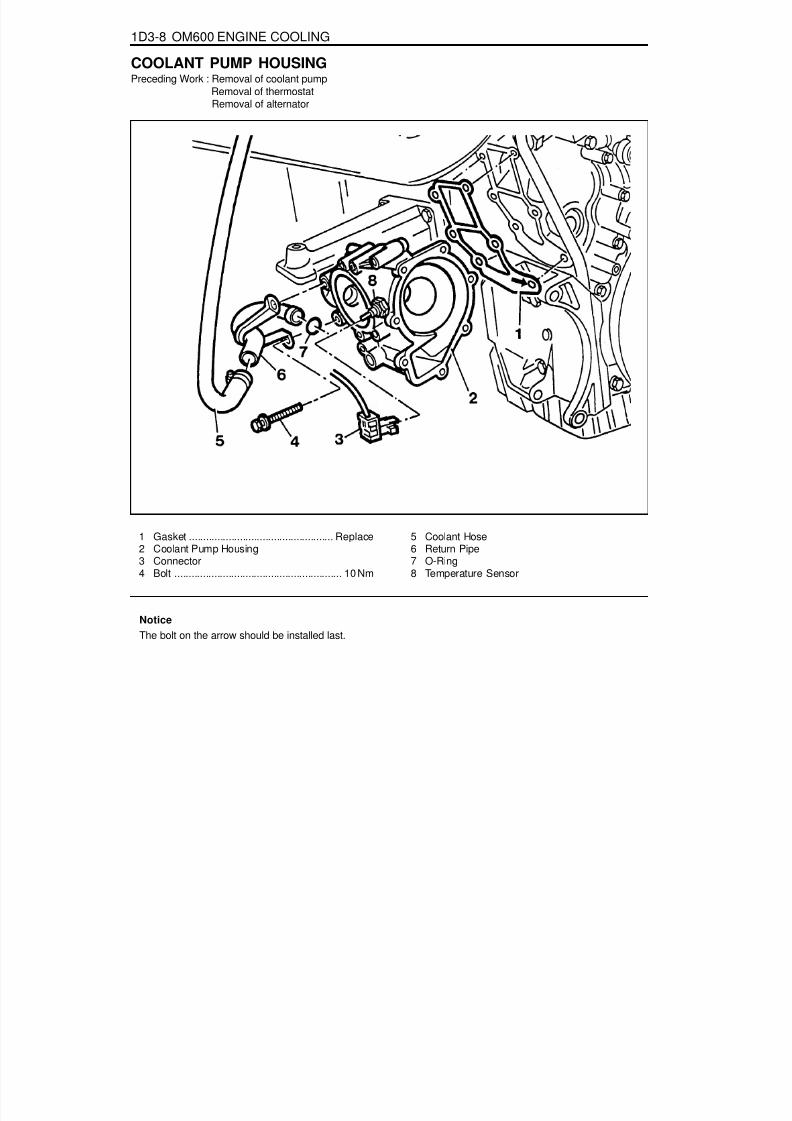
8/18/2019 SsangYong Musso Service Manual 1998.pdf
http://slidepdf.com/reader/full/ssangyong-musso-service-manual-1998pdf 529/1459
1D3-8 OM600 ENGINE COOLING
COOLANT PUMP HOUSINGPreceding Work : Removal of coolant pump
Removal of thermostat Removal of alternator
1 Gasket ................................................... Replace2 Coolant Pump Housing3 Connector4 Bolt ........................................................... 10 Nm
5 Coolant Hose6 Return Pipe7 O-Ring8 Temperature Sensor
NoticeThe bolt on the arrow should be installed last.

8/18/2019 SsangYong Musso Service Manual 1998.pdf
http://slidepdf.com/reader/full/ssangyong-musso-service-manual-1998pdf 530/1459
OM600 ENGINE COOLING 1D3-9
Removal & Installation Procedure1. Disconnect the connector(3).2. Separate the coolant hose (5) and return pipe(6).
3. Remove the bolts(4) evenly.
Installation Notice
Tightening Torque 10 Nm
NoticeClean gasket residues on the sealing surface of coolantpump and replace the gasket.
4. Remove the coolant pump housing(2).5. Installation should follow the removal procedure in the
reverse order.

8/18/2019 SsangYong Musso Service Manual 1998.pdf
http://slidepdf.com/reader/full/ssangyong-musso-service-manual-1998pdf 531/1459
1D3-10 OM600 ENGINE COOLING
COOLING FAN CLUTCH
1 Belt Pulley2 Cooling Fan Clutch3 Cooling Fan
4 Socket Bolt................................................ 45 Nm5 Socket Bolt................................................ 10 Nm
Tools Required603 589 00 40 00 Counter Holder

8/18/2019 SsangYong Musso Service Manual 1998.pdf
http://slidepdf.com/reader/full/ssangyong-musso-service-manual-1998pdf 532/1459
OM600 ENGINE COOLING 1D3-11
Removal & Installation Procedure1. Hold the bolt pulley with counter holder and remove the
bolt(4).
Counter Holder 603 589 00 40 00
Installation NoticeTightening Torque 45 Nm
2. Remove the socket bolt(5) and then remove the coolingfan(3) and fan clutch(2).
NoticeKeep the fan clutch vertically.
Installation Notice
Tightening Torque 10 Nm
3. Installation should follow the removal procedure in thereverse order.

8/18/2019 SsangYong Musso Service Manual 1998.pdf
http://slidepdf.com/reader/full/ssangyong-musso-service-manual-1998pdf 533/1459
1D3-12 OM600 ENGINE COOLING
RADIATORPreceding : Removal of cooling fan shroud
1 Radiator Inlet Hose ...............OM662LA : 220mm............................................. OM661LA : 321mm
2 Radiator outlet Hose3 Radiator Deaeration Tube & Hose4 Clamp
5 Spring Clamp6 Bolt .......................................................... 3-7 Nm7 Radiator8 Spring Clamp9 Bolt ........................................................... 3-7Nm

8/18/2019 SsangYong Musso Service Manual 1998.pdf
http://slidepdf.com/reader/full/ssangyong-musso-service-manual-1998pdf 534/1459
OM600 ENGINE COOLING 1D3-13
Removal & Installation Procedure1. Drain coolant from the radiator.2. Remove the coolant thermoswich connector from radiator.3. Remove the each coolant hose.
4. Remove the auto T/M oil cooling hose and cooling line.
Installation Notice
5. Loosen the radiator upper mounting bolt and remove themounting stopper and insulator.
6. Remove the radiator.7. Check the radiator pin for crack, leakage and bending and
replace it if necessany.8. Installation should follow the removal procedure in the
reverse order.
Tightening Torque Hose : 29 - 40Nm

8/18/2019 SsangYong Musso Service Manual 1998.pdf
http://slidepdf.com/reader/full/ssangyong-musso-service-manual-1998pdf 535/1459
1D3-14 OM600 ENGINE COOLING
COOLING SUB-SYSTEM
1 Radiator2 Cooling Fan Shroud3 Bolt .......................................................... 3-7Nm4 Cooling Fan Shroud5 Radiator Deaieration Hose
7 Mounting Bracket8 Make-up Cooling Hose9 Bolt ........................................................... 3-7Nm
10 Cooling Reservoir-tank Cap11 Cooling Reservoir-tank

8/18/2019 SsangYong Musso Service Manual 1998.pdf
http://slidepdf.com/reader/full/ssangyong-musso-service-manual-1998pdf 536/1459
OM600 ENGINE COOLING 1D3-15
Removal & Installation ProcedureCooling Fan Shroud1. Remove the radiator deaeration hose and tube.
Installation Notice
Tightening Torque 3 - 7 Nm
Tightening torque 3-7Nm2. Check the shroud.3. Installation should follow the removal procedure in the
reverse order.
Coolant Sub-Tank1. Drain the coolant from radiator.2. Remove the each hose.
3. Loosen the mounting bolt of sub-tank and remove thecoolant sub-tank.
Installation Notice
4. Installation should follow the removal procedure in thereverse order.
Tightening Torque 3 - 7 Nm

8/18/2019 SsangYong Musso Service Manual 1998.pdf
http://slidepdf.com/reader/full/ssangyong-musso-service-manual-1998pdf 537/1459
1D3-16 OM600 ENGINE COOLING
THERMOSTAT
1 Thermostat2 Seal ....................................................... Replace3 Thermostat Housing Cover
4 Coolant Hose5 Bolt ............................................................ 10Nm

8/18/2019 SsangYong Musso Service Manual 1998.pdf
http://slidepdf.com/reader/full/ssangyong-musso-service-manual-1998pdf 538/1459
OM600 ENGINE COOLING 1D3-17
Removal & Installation Procedure1. Drain the coolant completely.2. Disconnect the coolant hose(4) from the thermostat housing
cover(3).
3. Remove the bolts(5) and then remove the thermostat(1)and housing cover(3)
Installation NoticeAlign the groove on thermostat and the housing cover
rib(arrow).Tightening Torque 10 Nm
NoticeReplace the seal(2).
4. Installation should follow the removal procedure in thereverse order.

8/18/2019 SsangYong Musso Service Manual 1998.pdf
http://slidepdf.com/reader/full/ssangyong-musso-service-manual-1998pdf 539/1459
SECTION 1E1
M162 ENGINE ELECTRICAL
Specifications . . . . . . . . . . . . . . . . . . . . . . . 1E1-1Alternator Specifications . . . . . . . . . . . . . . . . 1E1-1Starting Motor Specifications . . . . . . . . . . . . 1E1-2Battery Specifications . . . . . . . . . . . . . . . . . . 1E1-2Fastener Tightening Specifications . . . . . . . . 1E1-2
Special Tools . . . . . . . . . . . . . . . . . . . . . . . 1E1-3Special Tools Table . . . . . . . . . . . . . . . . . . . . 1E1-3
Maintenance and Repair . . . . . . . . . . . . . . 1E1-4
On-Vehicle Service . . . . . . . . . . . . . . . . . . . . . 1E1-4Alternator . . . . . . . . . . . . . . . . . . . . . . . . . . . 1E1-4Starting Motor . . . . . . . . . . . . . . . . . . . . . . . . 1E1-5Battery . . . . . . . . . . . . . . . . . . . . . . . . . . . . . 1E1-6Spark Plug . . . . . . . . . . . . . . . . . . . . . . . . . . 1E1-7Ignition Cable . . . . . . . . . . . . . . . . . . . . . . . . 1E1-9
Unit Repair . . . . . . . . . . . . . . . . . . . . . . . . 1E1-12Battery . . . . . . . . . . . . . . . . . . . . . . . . . . . . 1E1-12
SPECIFICATIONSALTERNATOR SPECIFICATIONS
CAUTION: Disconnect the negative battery cable before removing or installing any electrical unit or when a tool or equipment could easily come in contact with exposed electrical terminals. Disconnecting this cable will help prevent personal injury and damage to the vehicle. The ignition must also be in LOCK unless otherwise noted.
TABLE OF CONTENTS
Application
Output VoltageCurrentResistance Between Rotor Core and Slip Ring
Description
12 - 14 V115 A
¥ W

8/18/2019 SsangYong Musso Service Manual 1998.pdf
http://slidepdf.com/reader/full/ssangyong-musso-service-manual-1998pdf 540/1459
1E1-2 M162 ENGINE ELECTRICAL
N· m
14 - 184 - 5
45 - 5012 - 15
6 - 735 - 4812 - 1812 - 18
12 - 189 - 119 - 11
25 - 30
STARTING MOTOR SPECIFICATIONS
ApplicationVoltageOutput Power
Description12 V
1.7 KW
BATTERY SPECIFICATIONS
FASTENER TIGHTENING SPECIFICATIONS
Application
CapacitySpecific GravityMax. Tolerance Between Cells
Description75 AH³ 1.24³ 0.04
ApplicationAlternator Terminal B+NutAlternator Terminal D+NutAlternator Combinction BoltBattery Cable Nut on Starting MotorElectric Wire Nut on Starting MotorStarting Motor Mounting NutBattery Mounting Bracket NutBattery Negative Cable
Battery Positive CableIgnition Cable Cover BoltIgnition Cable BoltSpark plug

8/18/2019 SsangYong Musso Service Manual 1998.pdf
http://slidepdf.com/reader/full/ssangyong-musso-service-manual-1998pdf 541/1459
M162 ENGINE ELECTRICAL 1E1-3
SPECIAL TOOLSSPECIAL TOOLS TABLE
120 589 02 09 00Spark Plug Wrench

8/18/2019 SsangYong Musso Service Manual 1998.pdf
http://slidepdf.com/reader/full/ssangyong-musso-service-manual-1998pdf 542/1459
1E1-4 M162 ENGINE ELECTRICAL
MAINTENANCE AND REPAIR
ON-VEHICLE SERVICEALTERNATORPreceding Work : Removal of the drivebelt
Removal & Installation Procedure1. Disconnect the negative battery terminal.2. Unscrew the nut and disconnect the terminal (1).
Installation Notice
1 Terminal (B+)
2 Terminal (D+)
3 Combination Bolt4 Alternator
3. Unscrew the nut and disconnect the terminal (2).
Installation Notice
Tightening Torque 14 - 18 Nm
4. Unscrew the combination bolt (3).
Installation Notice
Tightening Torque 4 - 5 Nm
5. Remove the alternator.6. Installation should follow the removal procedure in the
reverse order.
Tightening Torque 42 - 50 Nm

8/18/2019 SsangYong Musso Service Manual 1998.pdf
http://slidepdf.com/reader/full/ssangyong-musso-service-manual-1998pdf 543/1459
M162 ENGINE ELECTRICAL 1E1-5
3 Fixing Bolt4 Starting Motor
4. Unscrew the mounting bolts (3) of starting motor.
Installation Notice
5. Remove the starting motor.6. Installation should follow the removal procedure in the
reverse order.
Tightening Torque 35 - 48 Nm
STARTING MOTORRemoval & Installation Procedure1. Disconnect the ground cable.2. Unscrew the nut and disconnect the battery cable(1).
Installation Notice
1 Battery Cable2 Engine Electric Wire
3. Unscrew the nut and disconnect the engine electric wire(2).
Installation Notice
Tightening Torque 12 - 15 Nm
Tightening Torque 6 - 7 Nm

8/18/2019 SsangYong Musso Service Manual 1998.pdf
http://slidepdf.com/reader/full/ssangyong-musso-service-manual-1998pdf 544/1459
1E1-6 M162 ENGINE ELECTRICAL
BATTERY
1 Cable Terminal (-)
2 Cable Terminal Cap (-)3 Cable Terminal Cap (+)4 Nut5 Fuseblink Box6 Terminal (+)
7 Battery holddown Bracket
8 Battery Clamp Bolt9 Battery10 Sub Tray11 Battery Tray
Removal & Installation ProcedureNotice
Disconnect the battery negative cable first.Insert the clamp bolt (8) into the battery tray hole (11)from inside when installing.

8/18/2019 SsangYong Musso Service Manual 1998.pdf
http://slidepdf.com/reader/full/ssangyong-musso-service-manual-1998pdf 545/1459
M162 ENGINE ELECTRICAL 1E1-7
1 Ignition Coil Cable Cover2 Bolt (M6 X 60, 7 pieces) ......................... 9-11 Nm3 Spark Plug
SPARK PLUGPreceding Work : Removal of intake air duct
T1/1 Ignition Coil : Cylinder 2 and 5T1/2 Ignition Coil : Cylinder 3 and 4T1/3 Ignition Coil : Cylinder 1 and 6
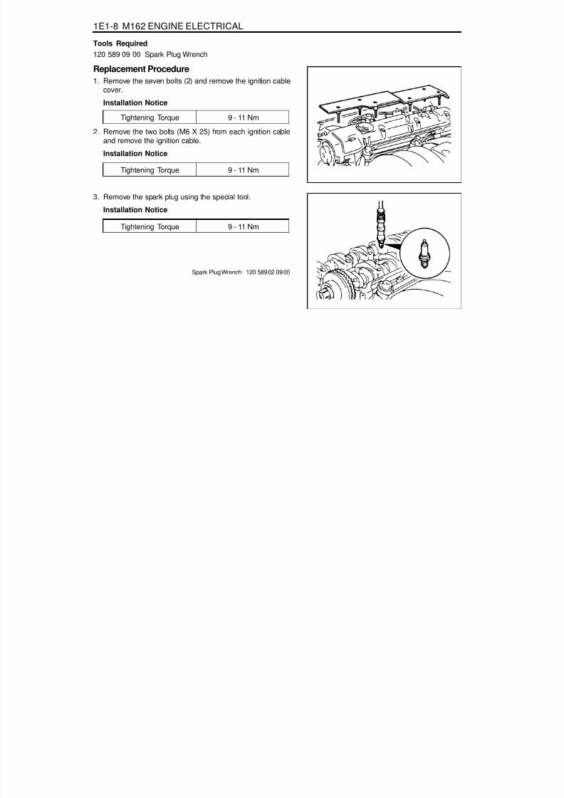
8/18/2019 SsangYong Musso Service Manual 1998.pdf
http://slidepdf.com/reader/full/ssangyong-musso-service-manual-1998pdf 546/1459
1E1-8 M162 ENGINE ELECTRICAL
Tools Required120 589 09 00 Spark Plug Wrench
Replacement Procedure1. Remove the seven bolts (2) and remove the ignition cable
cover.
Installation Notice
Tightening Torque 9 - 11 Nm
Tightening Torque 9 - 11 Nm
Tightening Torque 9 - 11 Nm
2. Remove the two bolts (M6 X 25) from each ignition cableand remove the ignition cable.
Installation Notice
3. Remove the spark plug using the special tool.
Installation Notice
Spark Plug Wrench 120 589 02 09 00

8/18/2019 SsangYong Musso Service Manual 1998.pdf
http://slidepdf.com/reader/full/ssangyong-musso-service-manual-1998pdf 547/1459
M162 ENGINE ELECTRICAL 1E1-9
IGNITION CABLEPreceding Work : Removal of intake air duct
1 Control Cable Connection2 Ignition Cable3 Spark Plug Connector4 Coupling Plug
5a, 5b Secondary Voltage ConnectionE Iron Core
L1 Secondary Ignition CoilL2 Primary Ignition Coil

8/18/2019 SsangYong Musso Service Manual 1998.pdf
http://slidepdf.com/reader/full/ssangyong-musso-service-manual-1998pdf 548/1459
1E1-10 M162 ENGINE ELECTRICAL
Functions1. Firing order : 1-5-3-6-2-42. The ignition cables are located on the cylinder head cover.
Each ignition coil provides the high voltage to two sparkplugs simultaneously.- T1/1 : cylinder 2 and 5
- T1/2 : cylinder 3 and 4- T1/3 : cylinder 1 and 6
Removal & Installation Procedure1. Disconnect the negative battery cable (1).2. Remove the ignition cable connector from the ignition cable.
3. Disconnect the secondary spark plug connectors from theeach spark plugs and remove the ignition cable.
Installation Notice
3. The secondary output voltage (5a) is supplied to the No.2cylinder spark plug through the spark plug connector. Thesecondary output voltage (5b) is supplied to the No.5 cylinderspark plug through the ignition cable. The guide pin (W)acts as a ground while the ignition cable is operated.
Make sure that the ignition cables are correctly routed.Exactly install the ignition cable guide pin into the vehicleto be grounded.
4. Installation should follow the removal procedure in thereverse order.
Tightening Torque 9 - 11 Nm

8/18/2019 SsangYong Musso Service Manual 1998.pdf
http://slidepdf.com/reader/full/ssangyong-musso-service-manual-1998pdf 549/1459
M162 ENGINE ELECTRICAL 1E1-11
Circuit Diagram
Inspection & Maintenance Procedure (for MSE)1. While the ignition switch is in 'OFF' position, remove the
wiring connectors (1 and 15) from ignition coil and measurethe primary resistance between terminal No.1 and No.15.
2. During engine cranking, measure primary voltage (T1/1)between ECU terminal No. 71 and No. 69.
NoticeIf out of specified value, replace the ignition coil.
Specified Value 0.9 - 1.6 W (20°C)
Specified Value 200 - 350 V
Notice
Measure remaining cables.- T1/2 : No. 72 and 69.- T1/3 : No. 70 and 69.If out of specified value, check ignition cable and ECU.
3. Using a multi-tester, measure the secondary coil resistancebetween 5a and 5b.
Specified Value 6 - 8.5 k W

8/18/2019 SsangYong Musso Service Manual 1998.pdf
http://slidepdf.com/reader/full/ssangyong-musso-service-manual-1998pdf 550/1459
1E1-12 M162 ENGINE ELECTRICAL
UNIT REPAIRBATTERY
InspectionNotice
When charging the battery, do not leave the inflammableobjects around it.When checking the electrolyte of battery, put onan eye protector and gloves.
1. Inspect the surface of the battery and replace if any defectswere found on it.
2. Check if the specific gravity of the electrolyte is within thespecified value.
NoticeReplace the battery if the maximum tolerance of theelectrolyte between cells is out of the specified value.Measure the specific gravity in the approx. 20°Cof ambient temperature.
3. Replenish the electrolyte if necessary.
Battery capacity(Ah)Battery specific gravityMax. tolerance between cells
85³ 1.24³ 0.04

8/18/2019 SsangYong Musso Service Manual 1998.pdf
http://slidepdf.com/reader/full/ssangyong-musso-service-manual-1998pdf 551/1459
SECTION 1E2
M161 ENGINE ELECTRICAL
Specifications . . . . . . . . . . . . . . . . . . . . . . . 1E2-1Alternator Specifications . . . . . . . . . . . . . . . . 1E2-1Starting Motor Specifications . . . . . . . . . . . . 1E2-2Battery Specifications . . . . . . . . . . . . . . . . . . 1E2-2Fastener Tightening Specifications . . . . . . . . 1E2-2
Special Tools . . . . . . . . . . . . . . . . . . . . . . . 1E2-3Special Tools Table . . . . . . . . . . . . . . . . . . . . 1E2-3
Maintenance and Repair . . . . . . . . . . . . . . 1E2-4
On-Vehicle Service . . . . . . . . . . . . . . . . . . . . . 1E2-4Alternator . . . . . . . . . . . . . . . . . . . . . . . . . . . 1E2-4Starting Motor . . . . . . . . . . . . . . . . . . . . . . . . 1E2-5Battery . . . . . . . . . . . . . . . . . . . . . . . . . . . . . 1E2-6Spark Plug . . . . . . . . . . . . . . . . . . . . . . . . . . 1E2-7Ignition Cable . . . . . . . . . . . . . . . . . . . . . . . . 1E2-9
Unit Repair . . . . . . . . . . . . . . . . . . . . . . . . 1E2-12Battery . . . . . . . . . . . . . . . . . . . . . . . . . . . . 1E2-12
CAUTION: Disconnect the negative battery cable before removing or installing any electrical unit or when a tool or equipment could easily come in contact with exposed electrical terminals. Disconnecting this cable will help prevent personal injury and damage to the vehicle. The ignition must also be in LOCK unless otherwise noted.
TABLE OF CONTENTS
SPECIFICATIONSALTERNATOR SPECIFICATIONS
Application
Output VoltageCurrentResistance Between Rotor Core and Slip Ring
Description
12 - 14 V115 A
¥ W

8/18/2019 SsangYong Musso Service Manual 1998.pdf
http://slidepdf.com/reader/full/ssangyong-musso-service-manual-1998pdf 552/1459
1E2-2 M161 ENGINE ELECTRICAL
N· m
14 - 184 - 5
45 - 5012 - 15
6 - 735 - 4812 - 1812 - 18
12 - 189 - 119 - 11
25 - 30
STARTING MOTOR SPECIFICATIONS
ApplicationVoltageOutput Power
Description12 V
1.2 KW
BATTERY SPECIFICATIONS
FASTENER TIGHTENING SPECIFICATIONS
Application
CapacitySpecific GravityMax. Tolerance Between Cells
Description90 Ah³ 1.24³ 0.04
ApplicationAlternator Terminal B+NutAlternator Terminal D+NutAlternator Combinction BoltBattery Cable Nut on Starting MotorElectric Wire Nut on Starting MotorStarting Motor Mounting NutBattery Mounting Bracket NutBattery Negative Cable
Battery Positive CableIgnition Cable Cover BoltIgnition Cable BoltSpark plug

8/18/2019 SsangYong Musso Service Manual 1998.pdf
http://slidepdf.com/reader/full/ssangyong-musso-service-manual-1998pdf 553/1459
M161 ENGINE ELECTRICAL 1E2-3
SPECIAL TOOLSSPECIAL TOOLS TABLE
120 589 02 09 00Spark Plug Wrench

8/18/2019 SsangYong Musso Service Manual 1998.pdf
http://slidepdf.com/reader/full/ssangyong-musso-service-manual-1998pdf 554/1459
1E2-4 M161 ENGINE ELECTRICAL
MAINTENANCE AND REPAIR
ON-VEHICLE SERVICEALTERNATORPreceding Work : Removal of the drivebelt
Removal & Installation Procedure1. Disconnect the negative battery terminal.2. Unscrew the nut and disconnect the terminal (1).
Installation Notice
1 Terminal (B+)
2 Terminal (D+)
3 Combination Bolt4 Alternator
3. Unscrew the nut and disconnect the terminal (2).
Installation Notice
Tightening Torque 14 - 18 Nm
4. Unscrew the combination bolt (3).
Installation Notice
Tightening Torque 4 - 5 Nm
5. Remove the alternator.6. Installation should follow the removal procedure in the
reverse order.
Tightening Torque 42 - 50 Nm

8/18/2019 SsangYong Musso Service Manual 1998.pdf
http://slidepdf.com/reader/full/ssangyong-musso-service-manual-1998pdf 555/1459
M161 ENGINE ELECTRICAL 1E2-5
3 Fixing Bolt4 Starting Motor
4. Unscrew the mounting bolts (3) of starting motor.
Installation Notice
5. Remove the starting motor.6. Installation should follow the removal procedure in the
reverse order.
Tightening Torque 35 - 48 Nm
STARTING MOTORRemoval & Installation Procedure1. Disconnect the ground cable.2. Unscrew the nut and disconnect the battery cable(1).
Installation Notice
1 Battery Cable2 Engine Electric Wire
3. Unscrew the nut and disconnect the engine electric wire(2).
Installation Notice
Tightening Torque 12 - 15 Nm
Tightening Torque 6 - 7 Nm

8/18/2019 SsangYong Musso Service Manual 1998.pdf
http://slidepdf.com/reader/full/ssangyong-musso-service-manual-1998pdf 556/1459
1E2-6 M161 ENGINE ELECTRICAL
BATTERY
1 Cable Terminal (-)
2 Cable Terminal Cap (-)3 Cable Terminal Cap (+)4 Nut5 Fuseblink Box6 Terminal (+)
7 Battery holddown Bracket
8 Battery Clamp Bolt9 Battery10 Sub Tray11 Battery Tray
Removal & Installation ProcedureNotice
Disconnect the battery negative cable first.Insert the clamp bolt (8) into the battery tray hole (11)from inside when installing.

8/18/2019 SsangYong Musso Service Manual 1998.pdf
http://slidepdf.com/reader/full/ssangyong-musso-service-manual-1998pdf 557/1459
M161 ENGINE ELECTRICAL 1E2-7
SPARK PLUGPreceding Work : Removal of intake air duct
Tools Required119 589 01 09 00 Spark Plug Wrence
1 Screw (3 pieces) .................................. 9 - 11 Nm2 Adaptor (3 pieces)3 Ignition Coil Cable Cover4 Spark Plug Connector5 Ignition Coil Connector
6 Bolts (M6 X 25, 4 pieces) ..................... 9 - 11 Nm7 Ignition Coil (T1/1)8 Coupling Plug9 Spark Plug ......................................... 25 - 30 Nm
10 Ignition Coil (T1/2)

8/18/2019 SsangYong Musso Service Manual 1998.pdf
http://slidepdf.com/reader/full/ssangyong-musso-service-manual-1998pdf 558/1459
1E2-8 M161 ENGINE ELECTRICAL
Tightening Torque 9 - 11Nm
Replacement Procedure1. Unscrew the three screws(1) and remove the ignition coil
cable cover
Installation Notice
Tightening Torque
Clearance
25 - 30 Nm
0.8 + 0.1 mm
2. Disconnect the cable from ignition coil and spark plug.
4. Using the special tool, remove the spark plug .
Installation Notice
Spark Plug Wrench 119 589 01 09 00
NoticeTighten the spark plug with specified torque.Install the ignition coil to number 2 and 4 cylinder, andconnect the cable to number 1, 4 and 2, 3 cylinder- T1/1 : cylinder 1 and 4- T1/2 : cylinder 2 and 3
3. Unscrew two bolts(M6 X 25) from each ignition coil andremove the ignition coil(arrow) .
Installation Notice
Tightening Torque 9 - 11Nm
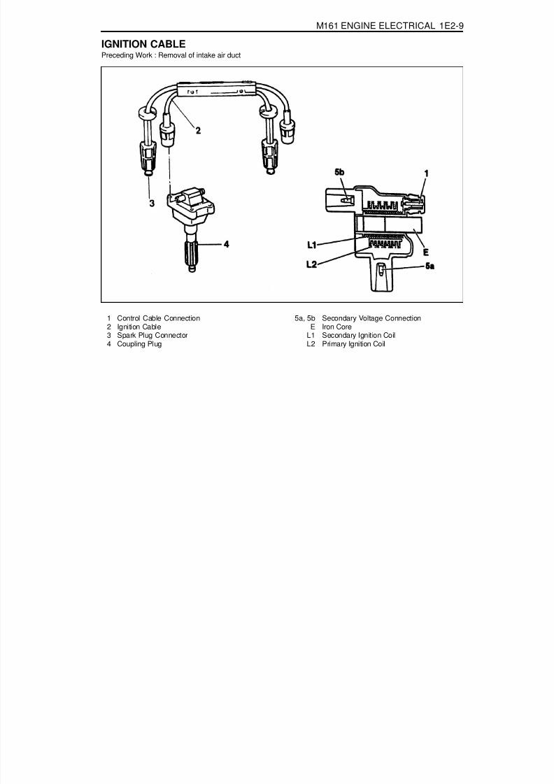
8/18/2019 SsangYong Musso Service Manual 1998.pdf
http://slidepdf.com/reader/full/ssangyong-musso-service-manual-1998pdf 559/1459
M161 ENGINE ELECTRICAL 1E2-9
IGNITION CABLEPreceding Work : Removal of intake air duct
1 Control Cable Connection2 Ignition Cable3 Spark Plug Connector4 Coupling Plug
5a, 5b Secondary Voltage ConnectionE Iron Core
L1 Secondary Ignition CoilL2 Primary Ignition Coil

8/18/2019 SsangYong Musso Service Manual 1998.pdf
http://slidepdf.com/reader/full/ssangyong-musso-service-manual-1998pdf 560/1459
1E2-10 M161 ENGINE ELECTRICAL
Ignition Cable and Cable Lay-out1. Firing Order : 1-3-4-22. T1/1 : Connect the cylinder 1 + 4
3. T1/2 : Connect the cylinder 2 + 3
Removal & Installation Procedure1. Disconnect the battery negative cable.2. Unscrew the 3 screws and remove the ignition cable duct
cover.
Installation Notice
3. Seperate the cable from the ignition cable and the sparkplug.
4. Remove the 2 bolts from each ignition cable and removethe ignition cables.
Installation Notice
Install the ignition cable to the cylinder 2 and 4 and connectthe cable from 1 to 4, and from 2 to 3.
- T1/1 : Cylinder 1 and 4- T1/2 : Cylinder 2 and 3
5. Installation should follow the removal procedure in thereverse order.
Tightening Torque 9 - 11 Nm
Tightening Torque 9 - 11 Nm
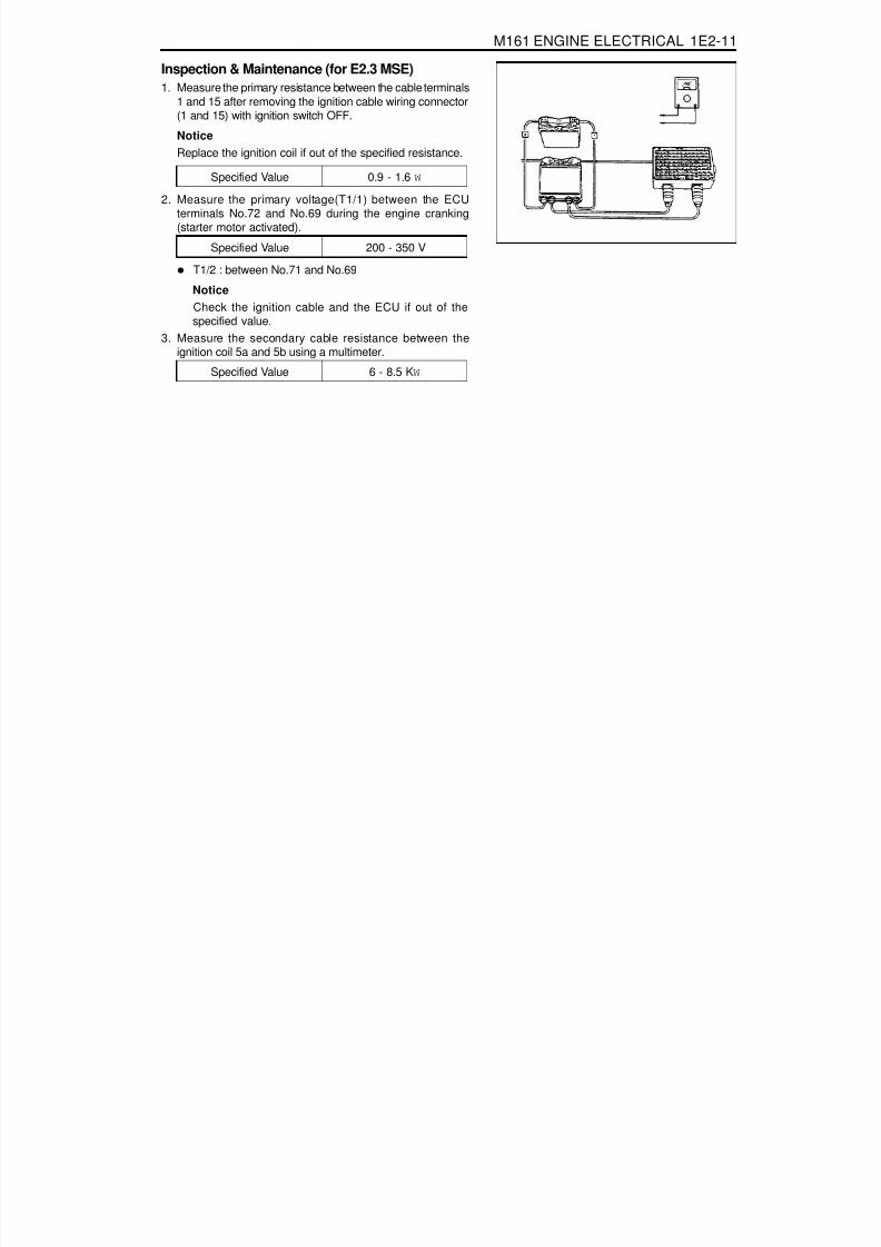
8/18/2019 SsangYong Musso Service Manual 1998.pdf
http://slidepdf.com/reader/full/ssangyong-musso-service-manual-1998pdf 561/1459
M161 ENGINE ELECTRICAL 1E2-11
Inspection & Maintenance (for E2.3 MSE)1. Measure the primary resistance between the cable terminals
1 and 15 after removing the ignition cable wiring connector(1 and 15) with ignition switch OFF.
NoticeReplace the ignition coil if out of the specified resistance.
T1/2 : between No.71 and No.69
NoticeCheck the ignition cable and the ECU if out of thespecified value.
3. Measure the secondary cable resistance between theignition coil 5a and 5b using a multimeter.
2. Measure the primary voltage(T1/1) between the ECUterminals No.72 and No.69 during the engine cranking(starter motor activated).
Specified Value 6 - 8.5 K W
Specified Value 0.9 - 1.6 W
Specified Value 200 - 350 V

8/18/2019 SsangYong Musso Service Manual 1998.pdf
http://slidepdf.com/reader/full/ssangyong-musso-service-manual-1998pdf 562/1459
1E2-12 M161 ENGINE ELECTRICAL
UNIT REPAIRBATTERY
InspectionNotice
When charging the battery, do not leave the inflammableobjects around it.When checking the electrolyte of battery, put onan eye protector and gloves.
1. Inspect the surface of the battery and replace if any defectswere found on it.
2. Check if the specific gravity of the electrolyte is within thespecified value.
NoticeReplace the battery if the maximum tolerance of theelectrolyte between cells is out of the specified value.Measure the specific gravity in the approx. 20°Cof ambient temperature.
3. Replenish the electrolyte if necessary.
Battery Capacity(Ah)Battery Specific GravityMax. Tolerance between Cells
75³ 1.24³ 0.04

8/18/2019 SsangYong Musso Service Manual 1998.pdf
http://slidepdf.com/reader/full/ssangyong-musso-service-manual-1998pdf 563/1459
SECTION 1E3
OM600 ENGINE ELECTRICAL
Specifications . . . . . . . . . . . . . . . . . . . . . . . 1E3-1General Specifications . . . . . . . . . . . . . . . . . 1E3-1
Maintenance and Repair . . . . . . . . . . . . . . 1E3-2On-Vehicle Service . . . . . . . . . . . . . . . . . . . . . 1E3-2
TABLE OF CONTENTS
Caution: Disconnect the negative battery cable before removing or installing any electrical unit or when a tool or equipment could easily come in contact with exposed electrical terminals. Disconnecting this cable will help prevent personal injury and damage to the vehicle. The ignition must also be in LOCK unless otherwise noted.
ApplicationAlternatorStarterGlow Plug
Description12V - 75A
12V - 2.2kW11.5V
SPECIFICATIONSGENERAL SPECIFICATIONS
Glow Plug . . . . . . . . . . . . . . . . . . . . . . . . . . . 1E3-2Alternator . . . . . . . . . . . . . . . . . . . . . . . . . . . 1E3-6Starter Motor . . . . . . . . . . . . . . . . . . . . . . . . . 1E3-8

8/18/2019 SsangYong Musso Service Manual 1998.pdf
http://slidepdf.com/reader/full/ssangyong-musso-service-manual-1998pdf 564/1459
1E3-2 OM600 ENGINE ELECTRICAL
Preheating SystemGeneral informationThe preheating system consists of control, coolant temperaturesensor and glow plugs.
Control relay - preheating time.Coolant temperature sensor.Glow plug.
GLOW PLUG
1 Wiring Harness2 Nut .............................................................. 4 Nm
3 Wire Terminal4 Glow Plug
MAINTENANCE AND REPAIR
ON-VEHICLE SERVICE

8/18/2019 SsangYong Musso Service Manual 1998.pdf
http://slidepdf.com/reader/full/ssangyong-musso-service-manual-1998pdf 565/1459
OM600 ENGINE ELECTRICAL 1E3-3
1. Preheating time - control relay.Control relay functions as followings :
Switching of preheating current.Indication of preheating finish.Control of preheating sequence.Indication of fault.
2. Coolant temperature sensor.Coolant temperature sensor senses coolant’s temperatureand signals it to the preheating relay continuously.
3. Glow plugThe glow plug parts are housing with M12 ´ 1.25 threadand heating pin in housing. It is connected in a parallel circuitwith the specified voltage of 11.5V.The heating element has a heating coil and a control coiland they are connected in series.
1. Control Coil2. Heater Coil
4. Current and temperature of glow plugCurrent of glow plugWhile the preheating system operates, current of about30A flows in each glow plug and temperature of heatingcoil rises very fast.Due to the rise of temperature, the resistance of controlcoil increases therefore the current is controlled toabout 8~15A and that protects the glow plug from over-heating.
Temperature of glow plugThe temperature of the glow plug reaches up to 900°Cafter about 9 seconds and up to 1,050°C after 30seconds.

8/18/2019 SsangYong Musso Service Manual 1998.pdf
http://slidepdf.com/reader/full/ssangyong-musso-service-manual-1998pdf 566/1459
1E3-4 OM600 ENGINE ELECTRICAL
Preheating System Operation1. Preheating before start.
Preheating time is different by coolant temperature and it ison until the glow indicator light goes off.
2. Preheating after start.Preheating continues for max. 60 seconds to rise incharacteristic of warming-up on engine after starting too.
3. Monitoring on glow plug.Glow plugs are monitored by low current by the microprocessor in control relay respectively while running theengine.If glow indicator comes on after starting for about one minute,it indicates on or several plugs are faulty.
Possible Cause
- One or several glow are faulty
Problem
Glow indicator does not come on in preheatingtime and comes on after starting the engine.
Glow indicator does not come on whilepreheating and after starting engine.
Glow indicator does not come on and engine’sstarting is difficult or does not start at all.
Glow indicator comes on after starting forabout one minute.
1
2
3
4
- Faulty glow indicator- Faulty circuit of glow indicator- Faulty control relay
- Circuits short in one or several glow plugs- Faulty preheating circuits- Faulty control relay
- One or several glow plugs are faulty

8/18/2019 SsangYong Musso Service Manual 1998.pdf
http://slidepdf.com/reader/full/ssangyong-musso-service-manual-1998pdf 567/1459
OM600 ENGINE ELECTRICAL 1E3-5
Removal & Installation Procedure1. Disconnect the negative terminal of battery.2. Remove the nut (2).
3. Remove the glow plug (4).4. Install the glow plug (4).
5. Tighten the nut (2).
Tightening Torque 20 Nm
Tightening Torque 4 Nm

8/18/2019 SsangYong Musso Service Manual 1998.pdf
http://slidepdf.com/reader/full/ssangyong-musso-service-manual-1998pdf 568/1459
1E3-6 OM600 ENGINE ELECTRICAL
ALTERNATORPreceding Work : Removal of poly V-belt
1 Cooling Fan2 Bolt ............................................................ 45Nm3 Bolt ............................................................ 45Nm
4 Alternator5 Plug Connection

8/18/2019 SsangYong Musso Service Manual 1998.pdf
http://slidepdf.com/reader/full/ssangyong-musso-service-manual-1998pdf 569/1459
OM600 ENGINE ELECTRICAL 1E3-7
Removal & Installation Procedure1. Disconnect the negative terminal of the battery.2. Disconnect the plug connection (5).
3. OM 662 EngineAlign the groove of cooling fan with bolt (2) (arrow).
4. Remove the bolts (2, 3) and take out the alternator.
5. Installation should follow the removal procedure in thereverse order.
Tightening Torque 45 Nm

8/18/2019 SsangYong Musso Service Manual 1998.pdf
http://slidepdf.com/reader/full/ssangyong-musso-service-manual-1998pdf 570/1459
1E3-8 OM600 ENGINE ELECTRICAL
STARTER MOTOR
1 Starter Motor2 Washer
3 Nut ............................................................. 15Nm4 Bolt ............................................................ 48Nm
Removal & Installation Procedure1. Disconnect the battery terminals.2. Disconnect the starter motor cable harnesses.3. Remove the bolts and then remove the starter motor.4. Installation should follow the removal procedure in the
reverse order.

8/18/2019 SsangYong Musso Service Manual 1998.pdf
http://slidepdf.com/reader/full/ssangyong-musso-service-manual-1998pdf 571/1459
SECTION 1F1
M162 ENGINE CONTROLS
TABLE OF CONTENTS
CAUTION: Disconnect the negative battery cable before removing or installing any electrical unit or when a tool or equipment could easily come in contact with exposed electrical terminals. Disconnecting this cable will help prevent personal injury and damage to the vehicle. The ignition must also be in LOCK unless otherwise noted.
Specifications . . . . . . . . . . . . . . . . . . . . . . . 1F1-2Fastener Tightening Specifications . . . . . . . . 1F1-2
Special Tools . . . . . . . . . . . . . . . . . . . . . . . 1F1-3Special Tools Table . . . . . . . . . . . . . . . . . . . . 1F1-3
Schematic and Routing Diagrams . . . . . . . 1F1-4E32 ECU (HFM) . . . . . . . . . . . . . . . . . . . . . . 1F1-4E32 ECU (MSE) . . . . . . . . . . . . . . . . . . . . . . 1F1-5
Diagnosis . . . . . . . . . . . . . . . . . . . . . . . . . . 1F1-6Self Diagnosis Socket Pin Numbers and
Descriptions . . . . . . . . . . . . . . . . . . . . . . . . 1F1-6Self Diagnosis Failure Code . . . . . . . . . . . . . 1F1-7Test Box Connection . . . . . . . . . . . . . . . . . . 1F1-10Fuel Injection System Test (MSE3.62). . . . . 1F1-11
Ignition System Test . . . . . . . . . . . . . . . . . . 1F1-21Idling Control and Electronic Pedal
System Test . . . . . . . . . . . . . . . . . . . . . . . 1F1-26Air Conditioner Control System Test . . . . . . 1F1-28Fuel Pressure and Internal Leakage Test . . 1F1-29Fuel Pump Test . . . . . . . . . . . . . . . . . . . . . . 1F1-31
Injector Test . . . . . . . . . . . . . . . . . . . . . . . . 1F1-33Maintenance and Repair . . . . . . . . . . . . . 1F1-35On-Vehicle Service . . . . . . . . . . . . . . . . . . . . 1F1-35
ECU . . . . . . . . . . . . . . . . . . . . . . . . . . . . . . 1F1-35Fuel Pressure Regulator . . . . . . . . . . . . . . 1F1-46Fuel Distributor . . . . . . . . . . . . . . . . . . . . . . 1F1-50Injector . . . . . . . . . . . . . . . . . . . . . . . . . . . . 1F1-54Fuel Filter . . . . . . . . . . . . . . . . . . . . . . . . . . 1F1-57Fuel Pump . . . . . . . . . . . . . . . . . . . . . . . . . 1F1-58Purge Switchover Valve . . . . . . . . . . . . . . . 1F1-62Vacuum System . . . . . . . . . . . . . . . . . . . . . 1F1-64Crankshaft Position Sensor . . . . . . . . . . . . 1F1-65Camshaft Position Sensor . . . . . . . . . . . . . 1F1-67
Hot Film Air Mass (HFM) Sensor . . . . . . . . . 1F1-69Oxygen Sensor . . . . . . . . . . . . . . . . . . . . . . 1F1-72Knock Sensor . . . . . . . . . . . . . . . . . . . . . . . 1F1-74Coolant Temperature Sensor . . . . . . . . . . . 1F1-75Accelerator Pedal Module . . . . . . . . . . . . . . 1F1-78

8/18/2019 SsangYong Musso Service Manual 1998.pdf
http://slidepdf.com/reader/full/ssangyong-musso-service-manual-1998pdf 572/1459
1F1-2 M162 ENGINE CONTROLS
SPECIFICATIONSFASTENER TIGHTENING SPECIFICATIONS
ApplicationFuel Return and Supply Line
Fuel Distributor Assembly BoltPressure Test ConnectorFuel Inlet and Outlet LineFuel Filter Mounting Bracket BoltCrankshaft Position Sensor BoltCamkshaft Position Sensor BoltKnock Sensor Mounting BoltCoolant Temperature Bolt
N· m25 - 30
22.5 - 27.521.6 - 26.4
25 - 304 - 8
9 - 119 - 11
22.5 - 27.518 - 22

8/18/2019 SsangYong Musso Service Manual 1998.pdf
http://slidepdf.com/reader/full/ssangyong-musso-service-manual-1998pdf 573/1459
M162 ENGINE CONTROLS 1F1-3
SPECIAL TOOLSSPECIAL TOOLS TABLE
129 589 00 21 00Test Box
119 589 04 63 00Pressure Hose
106 589 00 21 00Pressure Tester
210 589 08 63 00ECU Test Cable
210201Adaptor line

8/18/2019 SsangYong Musso Service Manual 1998.pdf
http://slidepdf.com/reader/full/ssangyong-musso-service-manual-1998pdf 574/1459
1F1-4 M162 ENGINE CONTROLS
E 3 2 E C U ( H F M )
SCHEMATIC AND ROUTING DIAGRAMS

8/18/2019 SsangYong Musso Service Manual 1998.pdf
http://slidepdf.com/reader/full/ssangyong-musso-service-manual-1998pdf 575/1459
M162 ENGINE CONTROLS 1F1-5
E 3 2 E C U ( M S E )

8/18/2019 SsangYong Musso Service Manual 1998.pdf
http://slidepdf.com/reader/full/ssangyong-musso-service-manual-1998pdf 576/1459
1F1-6 M162 ENGINE CONTROLS
DIAGNOSISSELF DIAGNOSIS SOCKET PIN NUMBERS AND DESCRIPTIONS
1 Ground2 Ignition 13 Battery Power Supply (Fuse NO.17)4 REKES :PIN 65 Engine Speed Signal :MSE PIN 606 TCCU(Part-time)7 STICS(PIN 26)
8 -9 -10 Air Bag(PIN 20)
11 Remote Engine Start Unit(PIN 10)12 -13 Brake System
(ABS 5.3:PIN 11, ABS/ABD 5.3:PIN 46)14 MSE 3.62S/3.53S(ECU Data Output:PIN 58)15 TOD(PIN 20)16 Immobilizer
17 -18 TCU(PIN 23)19 -20 K-LINE(ECS:PIN 23)

8/18/2019 SsangYong Musso Service Manual 1998.pdf
http://slidepdf.com/reader/full/ssangyong-musso-service-manual-1998pdf 577/1459
M162 ENGINE CONTROLS 1F1-7
41
44
45
56
57
58
59
60
62
64
65
66
67
71
72
73
7475
76
77
78
79
80
81
82
83
86
87
89
00
01
02
03
04
05
08
09
10
11
17
18
19
20
21
23
24
25
26
27
29
30
31
34
35
40
Failurecode Description
Coolant temperature sensor open
Coolant temperature sensor short
Coolant temperature sensor signal failure
Intake temperature sensor open
Intake temperature sensor short
Intake temperature sensor signal failure
Low battery voltage
HFM sensor signal failure
HFM sensor signal failure(Low)
HFM sensor signal failure(High)
Crankshaft position sensor signal failure
(no engine revolution signal)
Crankshaft position sensor signal failure
(rpm > max. value)
No.1 cylinder recognition failure
Crankshaft position sensor signal failure
(gab recognition failure)Transmission coding failure
CAN communication failure : ASR
-
Transponder signal failure
CAN communication failure : TCU(A/T only)
CAN communication failure : TOD(E32 only)
-
-
CAN communication failure :
communication initialization failure
Fuel pump relay short(PWR)
Fuel pump relay open/short(GND)
Purge valve short
Fa ilurecode Description
Purge valve open/short
Condenser fan(HI) relay short(PWR)
Condenser fan(HI) relay short(GND)
No.1 knock sensor signal failure
No.2 knock sensor signal failure
No.1 cylinder synchronization failure
-
-
Cluster S/W defectave
No ignition voltage output(No.1 ignition coil)
No ignition voltage output(No.2 ignition coil)
No ignition voltage output(No.3 ignition coil)
Crankshaft position sensor adaptation failure
Start signal recognition failure
No.1 injector short(PWR)
No.1 injector open/short(GND)
No.2 injector short(PWR)No.2 injector open/short(GND)
No.3 injector short(PWR)
No.3 injector open/short(GND)
No.4 injector short(PWR)
No.4 injector open/short(GND)
High oxygen sensor voltage
Low oxygen sensor amplifying voltage
Oxygen sensor operating failure
Not excessive lean indication in oxygen
sensor(during coasting)
Oxygen sensor heater short(PWR)
Oxygen sensor heater open/short(GND)
Low oxygen sensor voltage
SELF DIAGNOSIS FAILURE CODE

8/18/2019 SsangYong Musso Service Manual 1998.pdf
http://slidepdf.com/reader/full/ssangyong-musso-service-manual-1998pdf 578/1459
1F1-8 M162 ENGINE CONTROLS
Cruise control acceleration failure
Cruise control deceleration failure
ECU failure(RAM)
ECU failure(EPROM)
Servo motor control output inter-ruption
memory failure
Servo motor open/short
Unprogramed ECU with Immobilizer
Uncoded ECU
ECU failure(NVRAM checksum failure)
ECU failure(coding ID checksum failure)
ECU failure(coding checksum failure)
ECU failure(programing checkusm failure)
ABD input signal short(power)
ABD input signal short(GND)
Low pedal valve sensor SP1 voltage
High pedal valve sensor SP1 voltage
Low pedal valve sensor SP2 voltage
High pedal valve sensor SP2 voltage
Different pedal valve sensor signal(1,2)
Pedal valve sensor 1,2 failure
HFM sensor, and throttle position sensor
failure
ECU failure(incompatible CPU)
ECU failure(CPUs communication failure)
ECU failure(CPU(2) configuration failure)ECU failure(CPU(2) fault)
ECU failure(CPU run time failure between
CPUs)
No.5 injector short(PWR)
93
96
97
98
99
100
101
102
103
104
105
108
109
110
116
117
119
120
121
122
123
125
126
127129
130
131
132
Short learning control failure
Lambda control failure (rich stop)
Lambda control failure (lean stop)
Lambda idle adaptation failure(above rich
threshold)
Lambda idle adaptation failure(below lean
threshold)
learning control failure(rich, low load)
learning control failure(lean, low load)
learning control failure(rich, high load)
learning control failure(lean, high load)
Low throttle position sensor(IP1) voltage
High throttle position sensor(IP1) voltage
Low throttle position sensor(IP2) voltage
High throttle position sensor(IP2) voltage
Throttle actuator learning data fault
Throttle actuator learning control failure
Exceed fuel-cut safety time
Throttle valve return spring failure
Cruise control interruption memory failure
Throttle actuator failure
Pedal module position sensor signal failure
Different HFM signal with throttle potentiometer
Both throttle potentiometer(IP1&IP2) failure
IPS1 with IPS2
High permanent throttle signalMessage counter failure ® cruise control ’OFF’
Vehicle speed signal failure
Vehicle speed signal failure
Cruise control lever failure
133
134
136
137
139
140
141
142
143
144
145
146
150
151
160
161
162
163
164
167
185
186
187
188189
190
192
Failurecode Description
Failurecode Description

8/18/2019 SsangYong Musso Service Manual 1998.pdf
http://slidepdf.com/reader/full/ssangyong-musso-service-manual-1998pdf 579/1459
M162 ENGINE CONTROLS 1F1-9
234
235
236
237
238
239
240
241
242
243
No.5 injector open/short(GND)
No.6 injector short(PWR)
No.6 injector open/short(GND)
Variable intake air valve short(PWR)
Variable intake air valve open/short(GND)
Cam actuator short(PWR)
Cam actuator open/short(GND)
A/C compressor relay short(PWR)
A/C compressor relay open/short(GND)
Over acceleration limit
Over acceleration limit(CPU2)
193
194
195
198
199
226
227
228
229
232
233
Failurecode
DescriptionFailure
code Description
Control lever dual operation(CPU2)
Control lever safety terminal failure(CPU2)
Unusual pedal position variation(CPU2)
Unusal throttle position variation(CPU2)
Unusal throttle control data(CPU2)
Unusal pedal position sensor(CPU2)
Throttle potentiometer fault(CPU2)
Unusual CPU communication(CPU2)
Unusual CPU configuration(CPU2)
AD converter failure(CPU2)

8/18/2019 SsangYong Musso Service Manual 1998.pdf
http://slidepdf.com/reader/full/ssangyong-musso-service-manual-1998pdf 580/1459
1F1-10 M162 ENGINE CONTROLS
TEST BOX CONNECTION
1 ECU2 Test Coupling(No.1 - 60)3 Test Coupling(No.61 - 120)4 Multi-tester
01 Test Box02 ECU Test Cable
Tools Required
129 589 00 21 00 Test Box210 589 08 63 00 ECU Test Cable

8/18/2019 SsangYong Musso Service Manual 1998.pdf
http://slidepdf.com/reader/full/ssangyong-musso-service-manual-1998pdf 581/1459
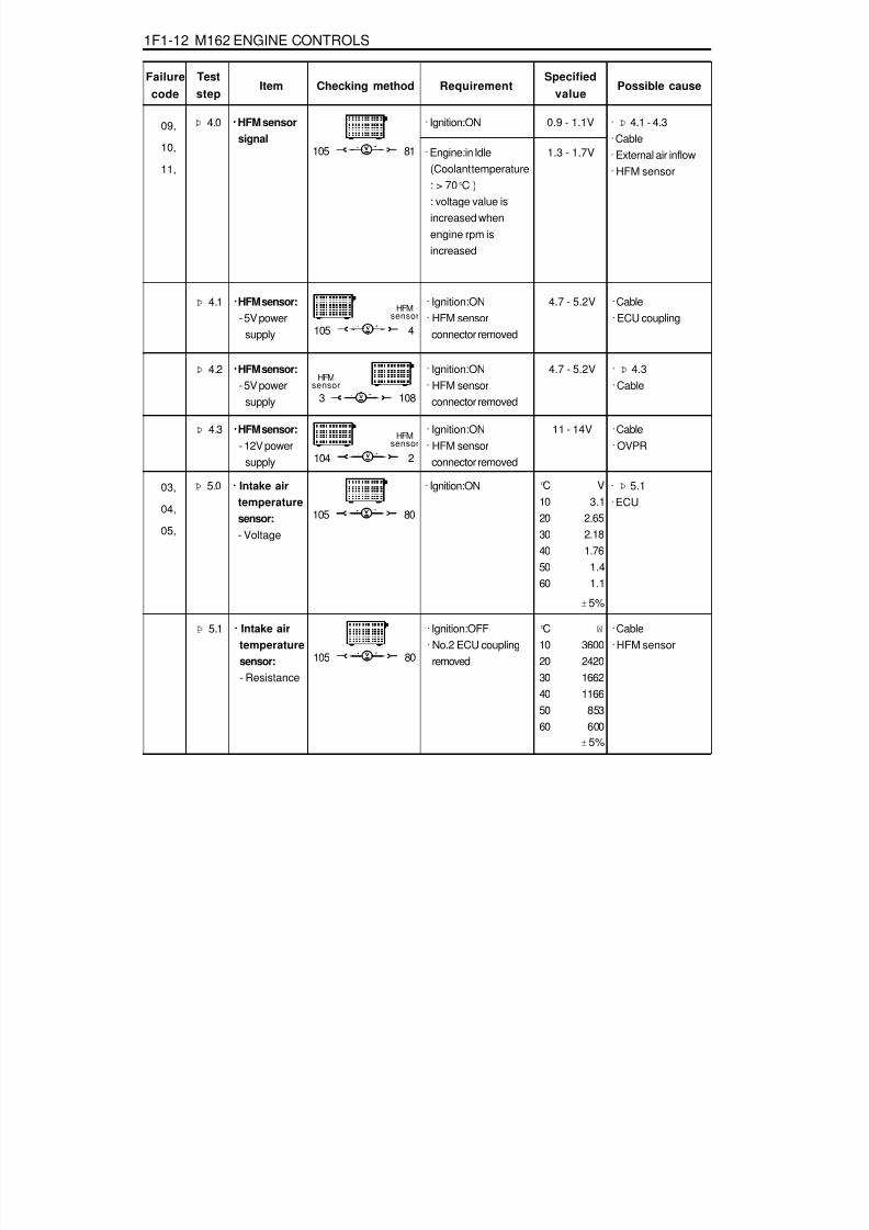
8/18/2019 SsangYong Musso Service Manual 1998.pdf
http://slidepdf.com/reader/full/ssangyong-musso-service-manual-1998pdf 582/1459
1F1-12 M162 ENGINE CONTROLS
Failurecode
Item
09,
10,
11,
Checking methodTeststep
RequirementSpecified
valuePossible cause
Þ 4.0 ····· HFM sensorsignal
105 81
· Ignition:ON 0.9 - 1.1V · Þ 4.1 - 4.3· Cable· External air inflow· HFM sensor
· Engine:in Idle
(Coolant temperature: > 70 °C ): voltage value isincreased whenengine rpm isincreased
1.3 - 1.7V
Þ 4.1
105 4
· Ignition:ON· HFM sensor
connector removed
4.7 - 5.2V · Cable· ECU coupling
····· HFM sensor:- 5V power
supply
HFMsensor
Þ 4.2
3 108
· Ignition:ON· HFM sensor
connector removed
4.7 - 5.2V · Þ 4.3· Cable
····· HFM sensor:- 5V power
supply
HFMsensor
Þ 4.3
104 2
· Ignition:ON· HFM sensor
connector removed
11 - 14V · Cable· OVPR
····· HFM sensor:- 12V power
supply
HFMsensor
03,
04,
05,
Þ 5.0 ····· Intake airtemperaturesensor:- Voltage
105 80
· Ignition:ON · Þ 5.1· ECU
± 5%
Þ 5.1 · Ignition:OFF· No.2 ECU coupling
removed105 80
· Cable· HFM sensor
····· Intake airtemperature
sensor:- Resistance
°C10
2030405060
± 5%
W
3600
242016621166
853600
°C102030405060
V3.1
2.652.181.76
1.41.1

8/18/2019 SsangYong Musso Service Manual 1998.pdf
http://slidepdf.com/reader/full/ssangyong-musso-service-manual-1998pdf 583/1459
M162 ENGINE CONTROLS 1F1-13
Failure
codeItem Checking method
Teststep
RequirementSpecified
value Possible cause
Þ 6.1 · Ignition:ON 0.1 - 0.3A · Cable· Fuel pump relay· ECU
····· Fuel pumprelay:
- Currentconsumption
00,
01,
02,
06,
Þ 7.0 ····· Coolanttemperaturesensor:- Voltage
79 78
· Ignition:ON °C V20 3.5780 1.22
100 0.78
· Þ 7.1· ECU
±5%
Þ 6.0 · Ignition:ON(Fuel pump relay will
operate for 1 - 2seconds when theignition switch isturned to "ON" afterstopping the engine)
· Engine:cranking
33 11
· Cable· Fuel pump relay
····· Fuel pumprelay:- Operation
34, 11 - 14V(approx.1-
2sec.)
11 - 14V(Cranking ordriving)
5 33
Þ 7.1 · Ignition:OFF(Remove the No.2
coupling from ECU)79 78
· Þ 7.2· Cable
····· Coolanttemperaturesensor:- Resistance
& cable
°C W
20 250080 322
100 185
±5%
Þ 7.2 ····· Coolanttemperaturesensor:
- Resistance
Coolant temperaturesensor:
1 4
· Remove theconnector fromcoolant temperature
sensor and measurethe resistancebetween No.1 andNo.2 pin withmultimeter.
· Þ refer tospecifiedresistance
value of 7.1
· Coolanttemperaturesensor
34,
35,

8/18/2019 SsangYong Musso Service Manual 1998.pdf
http://slidepdf.com/reader/full/ssangyong-musso-service-manual-1998pdf 584/1459
1F1-14 M162 ENGINE CONTROLS
Failure
codeItem Checking method
Test
step RequirementSpecified
valuePossible cause
Þ 9.0 · Keep the engine runabove 2 minutes inover 80 °C of coolanttemperature.
6.0 - 7.0 V
· ECU· Cable· Oxygen sensor
····· Oxygensensor:- Signal
80,
81,
82,
83,
89,
5 60
Þ 8.0 · Engine:in cranking oridle
5 60
· Cable· ECU
····· ECU:- RPM signal
output
32,
33,
refer to figure2
Þ 10.0 · Keep the engine runabove 2 minutes inover 80 °C of coolanttemperature.
····· Oxygensensor:- Heating
functionoperated
Þ 11.0 ····· No.1cylinderinjector:- Operating &
injectiontime
· When the coolanttemperature isapprox. 20 °C:- Engine:in cranking 8.0 ms
· Cable· ECU· No.1 Injector· Coolant
temperature sensor· Oxygen sensor· Intake air
temperature sensor
- Voltage · Engine:in crankingor idle(above 5V in idling)
16 17
5 9
9 11
· Ignition:ON
11 - 14 V · ECU· Cable· Oxygen sensor
- Currentconsumption
0.2 - 2.0 A
72,
73, 63 11
· When the coolanttemperature isapprox. 80 °C:- Engine:at idling
speed- Engine:at sharp
acceleration(fullthrottle)
(refer to figure 3 and4)
approx.2.7 - 5.0ms
approx.14ms
There will be avoltage
fluctuation inthe range of- 0.2 -1.0V
85,
86,
87,

8/18/2019 SsangYong Musso Service Manual 1998.pdf
http://slidepdf.com/reader/full/ssangyong-musso-service-manual-1998pdf 585/1459

8/18/2019 SsangYong Musso Service Manual 1998.pdf
http://slidepdf.com/reader/full/ssangyong-musso-service-manual-1998pdf 586/1459
1F1-16 M162 ENGINE CONTROLS
Failure
codeItem Checking method
Teststep
RequirementSpecified
valuePossible cause
· Ignition:OFF(injectortemperature is 20 °C)
14 - 17 W- Internalresistance(No.3
injector)
66 11
Þ 14.0 ····· No.4cylinderinjector:- Operating &
injectiontime
· When the coolanttemperature isapprox. 20 °C:- Engine:in cranking 8.0 ms
· Cable· ECU· No.4 Injector· Coolant
temperature sensor· Oxygen sensor· Intake air
temperature sensor
78,
79, 62 11
· When the coolanttemperature isapprox. 80 °C- Engine:at idling
speed- Engine:at sharp
acceleration(fullthrottle)
(refer to figure 3 and4)
approx.
2.7 - 5.0msapprox.14ms
· Ignition:OFF(injectortemperature is 20 °C)
14 - 17 W- Internalresistance(No.4
injector)
62 11
192,
193,
Þ 15.0 ····· No.5cylinderinjector:- Operating &
injectiontime
· When the coolanttemperature isapprox. 20 °C:- Engine:in cranking
8.0 ms · Cable· ECU· No.5 Injector· Coolant
temperature sensor· Oxygen sensor· Intake air
temperature sensor
65 11
· When the coolanttemperature isapprox. 80 °C:- Engine:at idling
speed- Engine:at sharp
acceleration(fullthrottle)
(refer to figure 3 and4)
approx.
2.7 - 5.0msapprox.14ms

8/18/2019 SsangYong Musso Service Manual 1998.pdf
http://slidepdf.com/reader/full/ssangyong-musso-service-manual-1998pdf 587/1459
M162 ENGINE CONTROLS 1F1-17
Failurecode
Item Checking methodTest
stepRequirement
Specified
valuePossible cause
Þ 17.0 ····· Variableintake airvalve(resonanceflap switchvalve)- Operating
· Engine:in cranking/ below 3500rpm
· ECU· Cable· Variable intake air
valve
< 1V
· Ignition:ON 0.4 - 0.6A- Currentconsumption
198,199,
· Ignition:OFF(injectortemperature is 20 °C)
14 - 17 W- Internalresistance(No.5 injector) 65 11
Þ 16.0 ····· No.6cylinderinjector:- Operating &
injectiontime
· When the coolanttemperature isapprox. 20 °C:- Engine:in cranking 8.0 ms
· Cable· ECU· No.6 Injector· Coolant
temperature sensor· Oxygen sensor· Intake air
temperature sensor
194,
195,64 11
· When the coolanttemperature isapprox. 80 °C:- Engine:at idling
speed- Engine:at sharp
acceleration(fullthrottle)
(refer to figure 3 and4)
approx.2.7 - 5.0ms
approx.
14ms
· Ignition:OFF(injectortemperature is 20 °C)
14 - 17 W- Internalresistance(No.6 injector) 64 11
97 11
69 97
· Engine:rpm > above3500rpm
11 - 15V
····· Camshaft
actuator:Currentconsumption
1 2
Camshaft actuator 1 - 1.5 A · ECU
· Þ 18.1· Þ 19.0
Þ 18.0226,
227,
· Engine : in idling
- Coolant temperature: above 70 °C
- Engine rpm :increase up to 2000rpm

8/18/2019 SsangYong Musso Service Manual 1998.pdf
http://slidepdf.com/reader/full/ssangyong-musso-service-manual-1998pdf 588/1459
1F1-18 M162 ENGINE CONTROLS
Failure
codeItem
Þ 18.1
Checking methodTest
step RequirementSpecified
valuePossible cause
73 2
8 - 12 W····· Camshaftactuator:Solenoidresistance
Þ 21.0 ····· Purgecontrolvalve:- Vacuum
control
· Engine:in idling/ normal operatingtemperature
· Vacuum line· Purge control valve
· Cable· Camshaft actuator
Diagnosissocket
Þ 19.0
73 69
Engine isunstable or
stopped
····· Camshaftactuator:MechanicalActuation
· Mechanical failure ofcamshaft actuator
Þ 20.0 · Engine:in idling
34 11
The purgecontrol valveshould be
operated afterapprox.
1minute.(refer to figure
5)
····· Purgecontrolvalve:- Operating
226,227,
· ECU· Cable· Purge control valve
· Ignition:ON 0.3 - 0.5 A- Currentconsumption
10 34
Creatingabove 50mbar
of vacuumafter approx.
1 minute
Þ 22.0 · Ignition:OFF
38 37
· Data bus· Þ 22.1· Þ 22.2
55 - 65 W····· CAN databus
· Ignition:OFF
· Engine:in idling- connect the bridge
to the test box forapprox. 10 seconds
40,41,54,
Connect the vacuumgauge between thecontrol valve andcanister
22,23,24,26,27,29,30,31,59,60,

8/18/2019 SsangYong Musso Service Manual 1998.pdf
http://slidepdf.com/reader/full/ssangyong-musso-service-manual-1998pdf 589/1459
M162 ENGINE CONTROLS 1F1-19
Failurecode
Item
Þ 22.1
Checking methodTeststep
RequirementSpecified
valuePossible cause
38 37
115 - 125 W····· CAN moduleresistance inABS, ABD,ASR controlunit
· Cable· ABS, ABD, ASR
control unit
· Ignition:OFF- disconnect the
coupling "No.1" fromECU.
Þ 22.2
38 37
115 - 125 W····· CAN moduleresistance inECU controlunit
· ECU· Ignition:OFF- disconnect the
coupling "No.1" fromECU.
Þ23.0
5 58
11 - 14 V·····
Diagnosiscableoperating
· ECU· Cable
· Ignition:ON
22,23,24,26,27,29,30,31,59,60,

8/18/2019 SsangYong Musso Service Manual 1998.pdf
http://slidepdf.com/reader/full/ssangyong-musso-service-manual-1998pdf 590/1459
1F1-20 M162 ENGINE CONTROLS
Reference Figures
Figure2. RPM Sgnal Output Figure 3. Injection Valve Wave(at idle speed)
Figure 4. Injection Valve Wave(at sharpacceleration)
Figure 5. Purge Control Valve Operationg Wave

8/18/2019 SsangYong Musso Service Manual 1998.pdf
http://slidepdf.com/reader/full/ssangyong-musso-service-manual-1998pdf 591/1459
M162 ENGINE CONTROLS 1F1-21
Failurecode
Item Checking methodTeststep
RequirementSpecified
valuePossible cause
10 12
11 - 14V····· ECU:powersupply- terminal
30(TM.30)
Þ 2.2 ····· Powersupply:- terminal
87(TM.87)
· Ignition:ON · Power supply cable· OVPR
IGNITION SYSTEM TEST
08, · Þ 1.1· Þ 1.2
Þ 1.1 · Ignition:ON
10 2
11 - 14V····· Groundcable:- Battery
ground
· Ground cable· Ground condition
(figure 1)Diagnosissocket
69 2
Diagnosissocket
Þ 1.2 · Ignition:ON
1 12
11 - 14V····· Powersupply:- terminal
30(TM.30)
· Power supply cable· Fuse No.8
Diagnosissocket
Þ 2.0 · Ignition:ON
5 11
11 -14V····· ECU:powersupply- terminal
87(TM.87)
08, · Þ 2.1· Þ 2.2
Þ 2.1 · Ignition:ON 11 - 14V····· Groundcable- Electronic
ground
· Ground cable
5 2
Diagnosissocket
1 11
Diagnosissocket
· Ignition:OFF
11 - 14V
< 1V
Þ 3.0 · Ignition:ON
69
11 - 14 V····· Ignitioncoil(T1/1)- No.2,5
Cylinder
64, · Cable· Ignition coil(T1/1)· Fuse No.17
· Engine:in cranking > 10 V
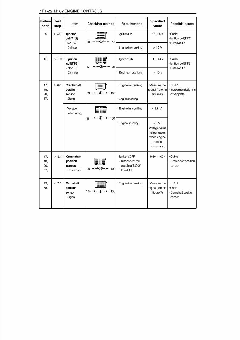
8/18/2019 SsangYong Musso Service Manual 1998.pdf
http://slidepdf.com/reader/full/ssangyong-musso-service-manual-1998pdf 592/1459
1F1-22 M162 ENGINE CONTROLS
Failurecode
Item Checking methodTeststep
RequirementSpecified
valuePossible cause
Þ 6.1 ····· Crankshaftpositionsensor:- Resistance
· Ignition:OFF- Disconnect the
coupling "NO.2"from ECU
· Cable· Crankshaft position
sensor
Þ 6.0 · Engine:in cranking
99 100
Measure thesignal (refer to
figure 6)
····· Crankshaftpositionsensor:- Signal
17,18,20,67,
· Þ 6.1· Increament failure in
driven plate
> 5 V -99 100
99 100
1050 - 1400 W
Þ 7.0 · Engine:in cranking
104 106
· Þ 7.1· Cable· Camshaft position
sensor
Measure thesignal(refer to
figure 7)
····· Camshaftpositionsensor:- Signal
Þ 4.0 · Ignition:ON
69 72
11 -14 V····· Ignitioncoil(T1/2)- No.3,4
Cylinder
65, · Cable· Ignition coil(T1/2)· Fuse No.17
· Engine:in cranking > 10 V
· Engine:in idling
- Voltage(alternating)
· Engine:in cranking
· Engine: in idling
> 2.5 V -
19,58,
Þ 5.0 · Ignition:ON
69 70
11 -14 V····· Ignitioncoil(T1/3)- No.1,6
Cylinder
66, · Cable· Ignition coil(T1/3)· Fuse No.17
· Engine:in cranking > 10 V
17,18,20,67,
Voltage valueis increased
when enginerpm is
increased

8/18/2019 SsangYong Musso Service Manual 1998.pdf
http://slidepdf.com/reader/full/ssangyong-musso-service-manual-1998pdf 593/1459
M162 ENGINE CONTROLS 1F1-23
Failure
codeItem Checking method
Teststep
RequirementSpecified
valuePossible cause
106 11
The value willbe changed in
1.2 - 1.7 V
- Voltage(alternating)
0.9 - 1.6 W
71 11
71 72
· Engine:in cranking
Þ 7.1· Ignition:ON
- Remove theconnector from theCamshaft positionsensor betweenNo.1 terminal andNo.3 terminal.
1 3
11 -14 V····· Camshaftpositionsensor(E23 only)- Power
supply
· Cable· OVPR
····· Ignitioncoil(T1/1)
- primary coilvoltage(No.2 and 5
cylinder)
· Engine:in cranking(starter operating)
- Measuring range:400 V
- Time range: 100 %(using engine tester)
· Ignition:OFF
200 - 350 V
Camshaft positionsensor
64, Þ 8.0 · Þ 8.1
Þ 8.1 ····· Connectingresistance ofignition coilbetween T1/1 and T1/2
· Cable· Ignition coil T1/1· Ignition coil T1/2
72 11
····· Ignitioncoil(T1/2)- primary coil
voltage(No.3 and 4
cylinder)
· Engine:in cranking(starter operating)- Measuring range:
400 V- Time range: 100 %(using engine tester)
200 - 350 V65, Þ 9.0 · Þ 9.1
0.9 - 1.6 W
72 71
· Ignition:OFFÞ 9.1 ····· Connecting
resistance ofignition coilbetween T1/2 and T1/1
· Cable· Ignition coil T1/1
· Ignition coil T1/2
Theresistance ofignition coil at
20 °C isapproached
0.6W
Theresistance ofignition coil at
20 °C isapproached
0.6W

8/18/2019 SsangYong Musso Service Manual 1998.pdf
http://slidepdf.com/reader/full/ssangyong-musso-service-manual-1998pdf 594/1459

8/18/2019 SsangYong Musso Service Manual 1998.pdf
http://slidepdf.com/reader/full/ssangyong-musso-service-manual-1998pdf 595/1459
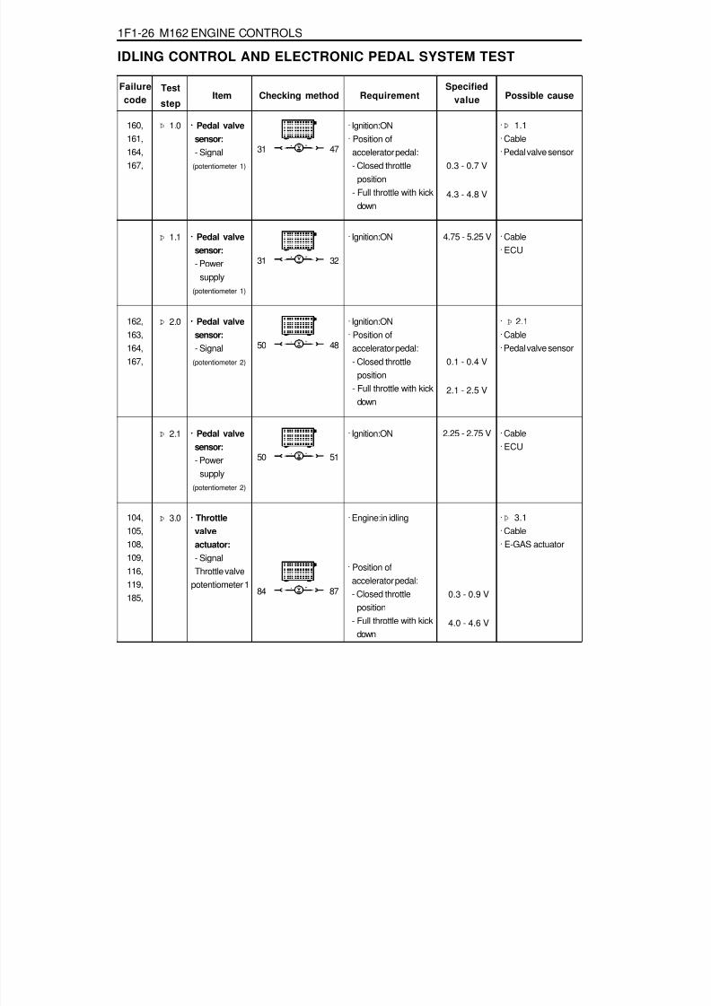
8/18/2019 SsangYong Musso Service Manual 1998.pdf
http://slidepdf.com/reader/full/ssangyong-musso-service-manual-1998pdf 596/1459
1F1-26 M162 ENGINE CONTROLS
IDLING CONTROL AND ELECTRONIC PEDAL SYSTEM TEST
Þ 2.1 · Ignition:ON
50 51
2.25 - 2.75 V····· Pedal valvesensor:- Power
supply (potentiometer 2)
· Cable· ECU
Failurecode Item
Þ 1.0
Checking method
· Ignition:ON· Position of
accelerator pedal:- Closed throttle
position- Full throttle with kick
down
Test
stepRequirement
Specifiedvalue Possible cause
31 47
0.3 - 0.7 V
····· Pedal valvesensor:- Signal
(potentiometer 1)
160,161,164,167,
4.3 - 4.8 V
· Þ 1.1· Cable· Pedal valve sensor
Þ 1.1 · Ignition:ON
31 32
4.75 - 5.25 V····· Pedal valvesensor:- Power
supply (potentiometer 1)
· Cable· ECU
Þ 2.0 · Ignition:ON· Position of
accelerator pedal:- Closed throttle
position- Full throttle with kick
down
50 48
0.1 - 0.4 V
····· Pedal valvesensor:- Signal
(potentiometer 2)
162,163,164,167,
2.1 - 2.5 V
· Þ 2.1· Cable· Pedal valve sensor
Þ 3.0 · Engine:in idling
84 87 0.3 - 0.9 V
····· Throttlevalve
actuator:- SignalThrottle valve
potentiometer 1
104,105,
108,109,116,119,185,
4.0 - 4.6 V
· Þ 3.1· Cable· E-GAS actuator
· Position ofaccelerator pedal:- Closed throttle
position- Full throttle with kick
down

8/18/2019 SsangYong Musso Service Manual 1998.pdf
http://slidepdf.com/reader/full/ssangyong-musso-service-manual-1998pdf 597/1459
M162 ENGINE CONTROLS 1F1-27
Failurecode Item Checking method
Teststep Requirement
Specifiedvalue
Possible cause
Þ 3.1 · Ignition:ON
84 112
4.75 - 5.25 V····· Throttlevalveactuator:- Power
supply(5V)
· Cable· ECU
Þ 4.0 · Ignition:ON
68 67
0.8 - 2.3 VThe value willbe changed in
1.0 - 2.5V.
····· Throttlevalveactuator:- Signal
Throttle valveactuatormotor voltagesupply
104,105,108,109,116,119,185,
· ECU· Cable· E-GAS actuator
· Engine:in idling- Coolant
temperature: >70 °C
84 85 4.0 - 4.6 V
Throttle valve potentiometer 2
0.3 - 0.9 V
· Position ofaccelerator pedal:- Closed throttle
position- Full throttle with
kick down
Throttle valvepotentiometer1+2
· Ignition:OFF < 10 W
Throttle valveactuatormotorresistance
68 67

8/18/2019 SsangYong Musso Service Manual 1998.pdf
http://slidepdf.com/reader/full/ssangyong-musso-service-manual-1998pdf 598/1459
1F1-28 M162 ENGINE CONTROLS
AIR CONDITIONER CONTROL SYSTEM TEST
Þ 2.0 · Engine:In idling· Air conditioner
switch : ON/OFFAir conditionerswitch : OFFAir conditionerswitch : ONCoolant temperature:above 105 °C
10 35
11 - 14 V
11 - 14 V
< 1 V
····· Condenserfan(HI)control:
· Condenser fanrelay
· Fan motor· ECU
Failurecode
Item
Þ 1.0
Checking method
· Engine:In idling· Air conditioner
switch : ON/OFFAir conditionerswitch : OFFAir conditionerswitch : ON
Teststep
RequirementSpecified
value Possible cause
10 44
< 1 V
····· Airconditionersignal:- Input signal
(input signalfrom thermoamplifier)
44,45,
11 - 14 V
· Þ 5.1· Cable· Thermo amp· Auto amp· Dual pressure
switch· Air conditioner
control panel
Þ 1.1 · Engine:In idling· Air conditioner
switch : ON/OFFAir conditionerswitch : OFFAir conditionerswitch:ON
10 27
< 1 V
····· Airconditionercompressor:- Output
signal
11 - 14 V
· Thermo amp· Auto amp· Dual pressure
switch· Air conditioner
control panel· ECU

8/18/2019 SsangYong Musso Service Manual 1998.pdf
http://slidepdf.com/reader/full/ssangyong-musso-service-manual-1998pdf 599/1459
M162 ENGINE CONTROLS 1F1-29
FUEL PRESSURE AND INTERNAL LEAKAGE TEST
01 Pressure Tester02 Pressure Hose03 Measuring Beaker
Preparation
Connection of the Equipment1. Turn the ignition switch to "OFF" position.2. Remove the air cleaner cross pipe.3. Remove the cap on fuel pressure test plug and connect the
pressure hose and pressure tester.4. Prepare the beaker for measuring the amount of fuel.
Tools Required103 589 00 21 00 Pressure Tester119 589 04 63 00 Pressure Hose

8/18/2019 SsangYong Musso Service Manual 1998.pdf
http://slidepdf.com/reader/full/ssangyong-musso-service-manual-1998pdf 600/1459
1F1-30 M162 ENGINE CONTROLS
Failurecode
Item Checking methodTeststep
RequirementSpecified
valuePossible cause
3.2 - 3.6 bar····· Fuelpressure:inidling speed- When the
vacuum isapplied
· Engine:in idling- Close the valve
screw on pressuretester
Þ 1.0 Connect the fuelpressure test plug tothe pressure tester
(refer to the flgure onprevious page).
· Þ Fuel pump test· Fuel pressure
regulator
3.7 - 4.2 bar····· Fuelpressure:inidling speed- When the
vacuum isnot applied
· Engine:in idling- Close the valve
screw on pressuretester
Þ 2.0 Connect the fuelpressure test plug tothe pressure tester
(refer to the flgure onprevious page).
· Fuel pressureregulator
> 3.0 bar····· Fuel systeminternalleakage:
· Engine:stopÞ 3.0 Connect the fuelpressure test plug tothe pressure tester
(refer to the flgure onprevious page).
· The pressure dropsrapidly:non-returnvalve in fuel pump
> 2.5 bar· After 30 minutes fromengine stop
· The pressure dropsslowly:- Injector test- Fuel pressure
regulator- O-ring

8/18/2019 SsangYong Musso Service Manual 1998.pdf
http://slidepdf.com/reader/full/ssangyong-musso-service-manual-1998pdf 601/1459
M162 ENGINE CONTROLS 1F1-31
FUEL PUMP TESTPreparation
1 ECU2 Test Coupling(No.1-60)3 Test Coupling(No.61-120)4 Stop Watch5 Measuring Beaker
Connection of the Equipment1. Turn the ignition switch to "OFF" position.2. Connect the test box to the ECU.
03 Test Box04 ECU Test Cable
Tools Required103 589 00 21 00 Pressure Tester210 589 00 99 00 Adaptor Line129 589 00 21 00 Test Box210 589 08 63 00 Ecu Test Cable

8/18/2019 SsangYong Musso Service Manual 1998.pdf
http://slidepdf.com/reader/full/ssangyong-musso-service-manual-1998pdf 602/1459
1F1-32 M162 ENGINE CONTROLS
Failurecode
Item Checking methodTeststep Requirement
Specifiedvalue
Possible cause
1 liter of fuelsupply formax. 35seconds
····· Fuel pump:- Fuel supply
ratio
· Ignition:ON- Disconnect the fuel
return pipe andconnect the host tobeaker to collect thesupplied fuel
Þ 1.0 · Þ 2.0· Check the fuel line
5 - 9 A····· Fuel pump:- Current
consumption
· Ignition:ON- Remove the fuel
relay from the fuseand relay box inluggagecompartment andconnect theamperemeterbetween No.1 andNo.3 in relaybox(fuel pump relayremoved position)for measuringcurrent consumption
Þ 2.0 · Fuel pump
5 33
Multi tester(DC current)
3 1

8/18/2019 SsangYong Musso Service Manual 1998.pdf
http://slidepdf.com/reader/full/ssangyong-musso-service-manual-1998pdf 603/1459
M162 ENGINE CONTROLS 1F1-33
Connection of the Equipment1. Connect the test box to the ECU as shown in the figure.2. Remove the 2-pin coupling from injector.3. Remove the fuel distributor and injector with a unit. At this
time, do not remove the supply and return line.4. Connect the shop made cable to the injector with a firing
order.5. Collect the fuel from injector.
INJECTOR TEST
1 ECU2 Test Coupling(No.1-60)3 Test Coupling(No.61-120)4 Measuring Beaker5 Shop Made Cable
Preparation
03 Test Box04 ECU Test Cable
Tools Required129 589 00 21 00 Test Box210 589 08 63 00 Ecu Test Cable

8/18/2019 SsangYong Musso Service Manual 1998.pdf
http://slidepdf.com/reader/full/ssangyong-musso-service-manual-1998pdf 604/1459
1F1-34 M162 ENGINE CONTROLS
Figure 9. Shop Made Cable Figure 10. Fuel Injector Normal Spary Pattern
Failurecode
Item Checking methodTest
stepRequirement
Specifiedvalue
Possible cause
There shouldbe no leaks
and laterdrops fromthe injector
····· Injector:- Leakage test
· Ignition:ON- Remove the fuel
distributor and fuelinjector with a unit.
Þ 1.0
The spraypattern of theinjector mostshow in the
figure 10.
· Ignition:ON- Connect the shop
made cable to theinjector
- Collect the sprayingfuel with a beaker
- Connect the shopmade cable toNo.21(+) and No.3
(-) terminal in testbox
Þ 2.0 · Injector
5 33
····· Injector:- Function test
and spraypatterncheck
5 33

8/18/2019 SsangYong Musso Service Manual 1998.pdf
http://slidepdf.com/reader/full/ssangyong-musso-service-manual-1998pdf 605/1459
M162 ENGINE CONTROLS 1F1-35
MAINTENANCE AND REPAIR
ON-VEHICLE SERVICEECU
Appearance
1 Cover2 Plate3 Connector4 Flat Pin
Vehicle Side : No. 1 - 12Engine Side : No. 61 - 72
5 PinVehicle Side : No. 13 - 60Engine Side : No. 73 - 120
A Vehicle Side Connector : BlackB Engine Side Connector : Gray

8/18/2019 SsangYong Musso Service Manual 1998.pdf
http://slidepdf.com/reader/full/ssangyong-musso-service-manual-1998pdf 606/1459
1F1-36 M162 ENGINE CONTROLS
LocationEngine ECU is located at the inside of cowl side trim in rightbottom of instrument panel of passenger side.
Removal & Installation Procedure1. Turn the ignition switch to "OFF" position.2. Disconnect the battery negative cable3. Remove the cowl side trim form passenger side.4. Unscrew four securing nuts for ECU from mounting bracket.
Installation Notice
5. Pulling out the ECU from bracket.6. Disconnect the vehicle side coupling(B).7. Installation should follow the removal procedure in the
reverse order.
Tightening Torque 9 - 11 Nm

8/18/2019 SsangYong Musso Service Manual 1998.pdf
http://slidepdf.com/reader/full/ssangyong-musso-service-manual-1998pdf 607/1459
M162 ENGINE CONTROLS 1F1-37
Pin No. AbbreciationDescription
123
456789
1011121314151617181920
-TM.50
-
-GND---
LSH1TM.31TM.87TM.30
WFS I/OWFS O
-GNDLS1
---
-Starter motor TM.50-
-Electronic ground---Lambda probe 1 heatingPower ground TM.31V-BATTERY TM.87V-BATTERY TM.30Immobilizer crypto readImmobilizer crypto write-Lambda probe 1 groundLambda probe 1 signal---
ECU Pin Numbers and Descriptions
Vehicle Connector

8/18/2019 SsangYong Musso Service Manual 1998.pdf
http://slidepdf.com/reader/full/ssangyong-musso-service-manual-1998pdf 608/1459
1F1-38 M162 ENGINE CONTROLS
Pin No. AbbreciationDecription
212223242526272829303132333435363738394041424344
45464748495051525354
555657585960
BRS-----
KLIKU---
GNDSP1+5V
KPTEVML
-CAN LCAN H
----
KPIKLIMA
KLIMA-
SP1SSP2SBLSGND
SP2+2.5VS+BWAS-B
KSK-
AUSDIAGV-SIG
TN-SIG
Brake switch-----Air conditioning clutch relay---Pedal potentiometer 1 groundPedal potentiometer 1 supplyFuel pump relayTank purge valveEngine fan (H1)-CAN-LowCAN-High----Clutch switchAir conditioning
Electronic traction signal-Pedal potentiometer 1 signalPedal potentiometer 2 signalBrake light switchPedal potentiometer 2 groundPedal potentiometer 2 supplyCruise accelerate/SetCruise resumeCruise decelerate/Set
Cruise safety contact switch-Cruise off switchDiagnostics (k-line)Vehicle speed signalEngine speed signal

8/18/2019 SsangYong Musso Service Manual 1998.pdf
http://slidepdf.com/reader/full/ssangyong-musso-service-manual-1998pdf 609/1459
M162 ENGINE CONTROLS 1F1-39
Engine Connector
Pin No. AbbreciationDecription
61626364
65666768697071727374
757677787980
EV5EV6EV1EV4
EV2EV3M+M-
TM.31ZSC16ZSA25ZSB34NWS
-
---
MTGND
LT
Injector-cylinder 2Injector-cylinder 4Injector-cylinder 1Injector-cylinder 6
Injector-cylinder 5Injector-cylinder 3E-GAS motor plusE-GAS motor minusPower ground TM.31Ignition coil cylinder 1+6Ignition coil cylinder 2+5Ignition coil cylinder 3+4Camshaft control-
---Engine coolant temperatureTemperature groundIntake air temperature
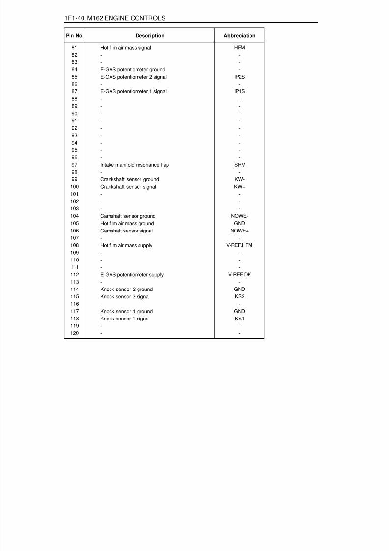
8/18/2019 SsangYong Musso Service Manual 1998.pdf
http://slidepdf.com/reader/full/ssangyong-musso-service-manual-1998pdf 610/1459
1F1-40 M162 ENGINE CONTROLS
Pin No. AbbreciationDescription
81828384858687888990919293949596979899
100101102103104
105106107108109110111112113114
115116117118119120
HFM---
IP2S-
IP1S---------
SRV-
KW-KW+
---
NOWE-
GNDNOWE+
-V-REF.HFM
---
V-REF.DK-
GND
KS2-
GNDKS1
--
Hot film air mass signal--E-GAS potentiometer groundE-GAS potentiometer 2 signal-E-GAS potentiometer 1 signal---------Intake manifold resonance flap-Crankshaft sensor groundCrankshaft sensor signal---Camshaft sensor ground
Hot film air mass groundCamshaft sensor signal-Hot film air mass supply---E-GAS potentiometer supply-Knock sensor 2 ground
Knock sensor 2 signal-Knock sensor 1 groundKnock sensor 1 signal--

8/18/2019 SsangYong Musso Service Manual 1998.pdf
http://slidepdf.com/reader/full/ssangyong-musso-service-manual-1998pdf 611/1459
M162 ENGINE CONTROLS 1F1-41
Application
Pin No. Description
-
Starter motor TM.50
-
-
Electronic ground
-
-
-
Lambda probe 1 heating
Power ground TM.31
V-BATTERY TM.87
V-BATTERY TM.30
Immobilizer crypto read
Immobilizer crypto write
-
Lambda probe 1 ground
Lambda probe 1 signal-
-
-
Brake switch
-
-
-
-
-
Air conditioning clutch relay
-
-
-
1
2
3
4
5
6
7
8
9
10
11
12
13
14
15
16
1718
19
20
21
22
23
24
25
26
27
28
29
30
-
TM.50
-
-
GND
-
-
-
LSH1
TM.31
TM.87
TM.30
WFS I/O
WFS O
-
GND
LS1-
-
-
BRS
-
-
-
-
-
KLIKU
-
-
-
-
-
-
-
-
-
-
-
-
-
-
-
-
-
-
-
-
-
-
-
-
-
-
-
-
-
-
-
-
-
-
-
-
-
-
-
: Standard, : Option
RemarksAbbreviationE32 ENG,
5speed M/T
E32 ENG,4speed A/T
(BTRA)

8/18/2019 SsangYong Musso Service Manual 1998.pdf
http://slidepdf.com/reader/full/ssangyong-musso-service-manual-1998pdf 612/1459
1F1-42 M162 ENGINE CONTROLS
Pin No. Description
Pedal potentiometer 1 ground
Pedal potentiometer 1 supply
Fuel pump relay
Tank purge valve
Engine fan
-
CAN-Low
CAN-High
-
-
-
-
Clutch switch
Air conditioning
Electronic traction signal(ABD)
-
Pedal potentiometer 1 signal
Pedal potentiometer 2 signal
Brake light switch
Pedal potentiometer 2 ground
Pedal potentiometer 2 supply
Cruise accelerate/Set
Cruise resume
Cruise decelerate/Set
Cruise safety contact switch
-Cruise off switch
Diagnostics(K-line)
Vehicle speed signal
Engine speed signal
31
32
33
34
35
36
37
38
39
40
41
42
43
44
45
46
47
48
49
50
51
52
53
54
55
5657
58
59
60
GND
SP1+5V
KP
TEV
ML
-
CAN L
CAN H
-
-
-
-
KPL
KLIMA
ETS
-
SP1S
SP2S
BLS
GND
SP2+2.5V
S+B
WA
S-B
KSK
-AUS
DIAG
V-SIG
TN-SIG
-
-
-
-
-
-
-
-
-
-
-
-
-
-
RemarksAbbreviationE32 ENG,
5speed M/T
E32 ENG,4speed A/T
(BTRA)

8/18/2019 SsangYong Musso Service Manual 1998.pdf
http://slidepdf.com/reader/full/ssangyong-musso-service-manual-1998pdf 613/1459
M162 ENGINE CONTROLS 1F1-43
Pin No.
61
62
63
64
65
66
67
68
69
70
71
72
73
74
75
76
77
78
79
80
81
82
83
84
85
8687
88
89
90
Description
Injector-cylinder 2
Injector-cylinder 4
Injector-cylinder 1
Injector-cylinder 6
Injector-cylinder 5
Injector-cylinder 3
E-GAS motor plus
E-GAS motor minus
Power ground TM.31
Ignition coil cylinder 1+6
Ignition coil cylinder 2+5
Ignition coil cylinder 3+4
Camshaft control
-
-
-
-
Engine coolant temperature
Temperature ground
Intake air temperature
Hot film air mass signal
-
-
E-GAS potentiometer ground
E-GAS potentiometer 2 signal
-E-GAS potentiometer 1 signal
-
-
-
EV5
EV6
EV1
EV4
EV2
EV3
M+
M-
TM.31
ZSC16
ZSA25
ZSB34
NWS
-
-
-
-
MT
GND
LT
HFM
-
-
GND
IP2S
-IP1S
-
-
-
-
-
-
-
-
-
-
-
-
-
-
-
-
-
-
-
-
-
-
-
RemarksAbbreviationE32 ENG,
5speed M/T
E32 ENG,4speed A/T
(BTRA)

8/18/2019 SsangYong Musso Service Manual 1998.pdf
http://slidepdf.com/reader/full/ssangyong-musso-service-manual-1998pdf 614/1459
1F1-44 M162 ENGINE CONTROLS
Pin No. Description
-
-
-
-
-
-
Intake manifold resonance flap
-
Crankshaft sensor ground
Crankshaft sensor signal
-
-
-
Camshaft sensor ground
Hot film air mass ground
Camshaft sensor signal
-
Hot film air mass supply
-
-
-
E-GAS potentiometer supply
-
Knock sensor 2 ground
Knock sensor 2 signal
-Knock sensor 1 ground
Knock sensor 1 signal
-
-
91
92
93
94
95
96
97
98
99
100
101
102
103
104
105
106
107
108
109
110
111
112
113
114
115
116117
118
119
120
-
-
-
-
-
-
SRV
-
KW-
KW+
-
-
-
NOWE-
GND
NOWE+
-
V-REF.HFM
-
-
-
V-REF.DK
-
GND
KS2
-GND
KS1
-
-
-
-
-
-
-
-
-
-
-
-
-
-
-
-
-
-
-
-
-
-
-
-
-
-
-
-
-
-
-
-
-
-
-
-
-
-
RemarksAbbreviationE32 ENG,
5speed M/T
E32 ENG,4speed A/T
(BTRA)

8/18/2019 SsangYong Musso Service Manual 1998.pdf
http://slidepdf.com/reader/full/ssangyong-musso-service-manual-1998pdf 615/1459
M162 ENGINE CONTROLS 1F1-45
Removal & Installation Procedurewhen removing the ECU only
1. Turn the ignition switch to "OFF" position.2. Disconnect the negative battery cable.3. Disconnect the couplings from ECU.4. Unscrew the left and right bolt (3) on bolt (1) and auxiliarly
bracket and remove the auxiliarly bracket from the bracketassembly (2).
Installation Notice
5. Unscrew the four bolts (5) and disconnect the ECU (6) fromthe bracket assenbly.
Installation Notice
6. Installation should follow the removal procedure in thereverse order.
Tightening Torque6 - 8 Nm
5 - 7 Nm
(1)
(3)
Tightening Torque 5 - 7 Nm
8. Unscrew the bolts (5) and disconnect the ECU (6) from thebracket assenbly.
Installation Notice
When Removing the ECU with ABS or ABS/ASR Unit1. Turn the ignition switch to "OFF" position.2. Disconnect the negative battery cable.3. Disconnect the couplings from ECU.4. Disconnect the coupling from ABS or ABS/ASR unit.5. Unscrew the bolt (1) and the left and right flange nuts.
6. Remove the ECU with ABS or ABS/ASR unit assembly.7. Unscrew the left and right bolt (3) on the auxiliary bracket
and remove the auxiliary bracket from the bracket assembly.
Installation Notice
Tightening Torque 6 - 8 Nm
Tightening Torque 5 - 7 Nm
Tightening Torque 5 - 7 Nm
9. Installation should follow the removal procedure in thereverse order.

8/18/2019 SsangYong Musso Service Manual 1998.pdf
http://slidepdf.com/reader/full/ssangyong-musso-service-manual-1998pdf 616/1459
1F1-46 M162 ENGINE CONTROLS
1 Vacuum Hose
2 Circlip3 Fuel Pressure Regulator
FUEL PRESSURE REGULATOR
4 O-ring ..................................................... replace
5 O-ring ..................................................... replace

8/18/2019 SsangYong Musso Service Manual 1998.pdf
http://slidepdf.com/reader/full/ssangyong-musso-service-manual-1998pdf 617/1459
M162 ENGINE CONTROLS 1F1-47
3. Disconnect the vacuum hose.4. Disconnect the circlip and remove the fuel pressure
regulator.5. Apply the oil to O-ring lightly and then replace it.6. Installation should follow the removal procedure in the
reverse order.7. Check for fuel pressure and internal leaks by operating the
engine.
2. Discharge the pressure in fuel supply system by pressingthe service valve.
Removal & Installation Procedure1. Remove the fuel pressure test connector.

8/18/2019 SsangYong Musso Service Manual 1998.pdf
http://slidepdf.com/reader/full/ssangyong-musso-service-manual-1998pdf 618/1459
1F1-48 M162 ENGINE CONTROLS
A. Valves ClosedB. Valves Opened
The pressure difference between the fuel pressure and theintake manifold is about 3.8 bars during the full load.
<Operating at Idle and partial load>The spring chamber(9) is connected to the intake manifoldwith the vacuum hose at the intake pipe connection(7). Thenegative pressure generated in the intake manifold activatesthe diaphragm, and thus the fuel pressure gets reduced to therate of the operating extent of the diaphragm by the intakemanifold's negative pressure.Consequently, the fuel pressure in the fuel distributor changesby the intake manifold's negative pressure, and the injector'sfuel pressure gets reduced independently to the throttle valve'sposition. Thus, the fuel injection volume can only be determinedaccording to the injector's injecting duration.
2. Fuel return line3. Valve5. Diaphragm6. Compression Spring8. Fuel Chamber9. Spring Chamber
1. Fuel Pressure Regulator2. Intake Manifold3. Fuel Return(to fuel tank)4. Fuel Supply(form fuel pump)5. Fuel Pressure(approx. 3.8 bars)6. Intake Manifold Negative Pressure(0 bar)
Function of the Fuel Pressure RegulatorThe fuel pressure regulator maintains the fuel pressure in thefuel line with the pressure of 3.2 bars to 3.8 bars according tothe intake manifold pressure. This operating pressure cannotbe changed, and the fuel injection volume will be onlydetermined by the injection time. Over supplied fuel returns tothe fuel tank through the return line.<Operating at full load>There is no negative pressure applied to the spring chamber(9)during the full load, and it is separated from the fuel chamber(8)by the diaphragm(5).When the fuel pressure goes up, the diaphragm forces thecompression spring(6) in the direction of compression . At thismoment, the valve(3) sticks to the diaphragm by the fuelpressure, and the fuel return line(2) opens. The fuel oversupplied returns to the fuel tank through the return line.

8/18/2019 SsangYong Musso Service Manual 1998.pdf
http://slidepdf.com/reader/full/ssangyong-musso-service-manual-1998pdf 619/1459
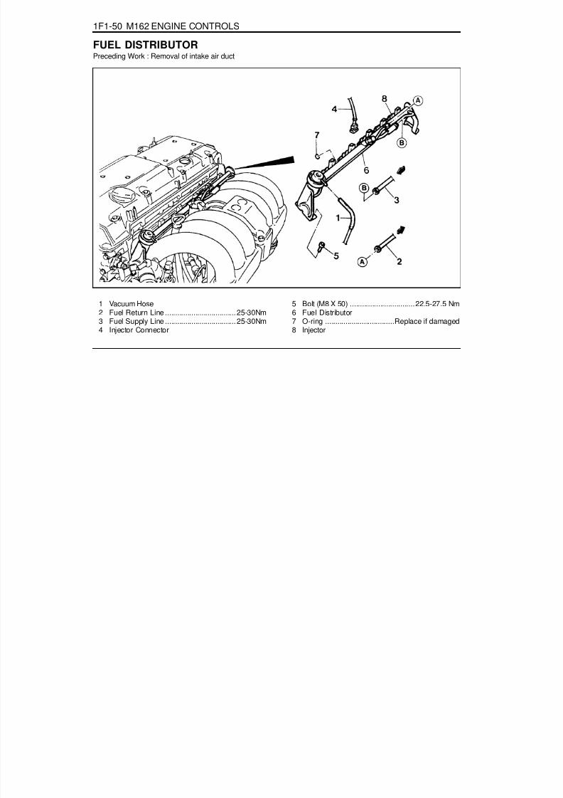
8/18/2019 SsangYong Musso Service Manual 1998.pdf
http://slidepdf.com/reader/full/ssangyong-musso-service-manual-1998pdf 620/1459
1F1-50 M162 ENGINE CONTROLS
1 Vacuum Hose2 Fuel Return Line ................................... 25-30Nm
3 Fuel Supply Line ................................... 25-30Nm4 Injector Connector
FUEL DISTRIBUTORPreceding Work : Removal of intake air duct
5 Bolt (M8 X 50) ................................22.5-27.5 Nm6 Fuel Distributor
7 O-ring ..................................Replace if damaged8 Injector

8/18/2019 SsangYong Musso Service Manual 1998.pdf
http://slidepdf.com/reader/full/ssangyong-musso-service-manual-1998pdf 621/1459
M162 ENGINE CONTROLS 1F1-51
Removal & Installation Procedure1. Discharge the fuel pressure from the fuel pressure test
connector.2. Disconnect the battery ground cable.3. Disconnect the vacuum hose from the fuel pressure
regulator.
4. Remove the cable guide.
5. Remove the fuel return and supply line.
NoticeFor removal, cover around parts with cloths not to bestained by fuel.In case of checking the injector only, do not remove thefuel return and supply line.
Installation Notice
6. Remove the six injector connectors.7. Remove the two left and two right bolts and one center bolt
of the fuel distributor assembly from the intake manifold.
Installation Notice
Tightening Torque 25 - 30 Nm
Tightening Torque 22.5 - 27.5 Nm

8/18/2019 SsangYong Musso Service Manual 1998.pdf
http://slidepdf.com/reader/full/ssangyong-musso-service-manual-1998pdf 622/1459
1F1-52 M162 ENGINE CONTROLS
8. Remove the injectors and the fuel distributor carefully.9. Installation should follow the removal procedure in the
reverse order.10. Check for fuel pressure and internal leakage by operating
the engine.
Fuel Pressure Test1. Turn the ignition switch to "OFF" position.2. Remove the fuel pressure test connector.
Vacuum Hose Connected (bar) 3.2 - 3.6
Vacuum Hose Disconnected (bar) 3.7 - 4.2
5. Replace the pressure regulator diaphragm if out of thespecification.
3. Connect the fuel pressure gauge to the fuel pressure testconnector.
4. Test the fuel pressure at idling by operating the engine.

8/18/2019 SsangYong Musso Service Manual 1998.pdf
http://slidepdf.com/reader/full/ssangyong-musso-service-manual-1998pdf 623/1459
M162 ENGINE CONTROLS 1F1-53
3. If there is no change in fuel pressure and maintain thefollowing pressure over 30 minutes, it is normal.
Internal Leakage Test1. Connect the fuel pressure gauge to the fuel pressure test
connector.2. Stop the engine for approx. 30 minutes and then check the
fuel pressure changes.
Fuel pressuredrops slowly
· Fuel leakage at theinjector
• Faulty fuel pressureregulator'sdiaphragm and O-ring.
Fuel pressuredrops rapidly
• Faulty check valvein the fuel pump.
Possible CausePressure Change
Fuel Pressure(bar) 2.5
Discharging the pressure in fuel system1. Remove the fuel pressure test connector.
Installation Notice
2. Remove the fuel pressure in fuel system by pressing theservice valve with a clean, pointy tool.NoticePlace a cloth so that the fuel doesn't stain around.
Tightening Torque 22.5 - 27.5 Nm

8/18/2019 SsangYong Musso Service Manual 1998.pdf
http://slidepdf.com/reader/full/ssangyong-musso-service-manual-1998pdf 624/1459
1F1-54 M162 ENGINE CONTROLS
INJECTORPreceding Work : Removal of fuel distributor
1 O-ring .................................... rplace, if damaged2 Injector Bracket3 Injector
4 O-ring .................................. replace, if damaged5 Fuel Distributor

8/18/2019 SsangYong Musso Service Manual 1998.pdf
http://slidepdf.com/reader/full/ssangyong-musso-service-manual-1998pdf 625/1459
M162 ENGINE CONTROLS 1F1-55
Removal & Installation Procedure1. Remove the O-ring.
Check for damage and replace it if necessary.2. Remove the injector bracket from the injector.
Installation NoticeExactly seat the anti-twist lock into the square groove ininjector.
3. Separate the injector from the fuel distributor.
Inspection & MaintenanceInspection of the Injector operation and spray pattern1. Connect the contact box to the ECU.2. Connect the shop made test plug to the injector and place
it into the tank.3. Position the ignition switch to ON.4. Connect the pin 63(+) and 69(-) of the contact box with a
test cable.
5. Check the injector spray pattern.
NoticeReplace the injector if the injector spray pattern is abnormalor the fuel doesn't inject.
Injector Resistance Inspection1. Remove the injector connector.2. Measure the injector coil resistance using a resistance
tester.
NoticeReplace the injector if the measured values is out of thespecified values. Check the connector and wire connectionbetween the ECU and the injector if the measured valuesare normal.
Specified Value 14 - 17 W

8/18/2019 SsangYong Musso Service Manual 1998.pdf
http://slidepdf.com/reader/full/ssangyong-musso-service-manual-1998pdf 626/1459
1F1-56 M162 ENGINE CONTROLS
The Injector Spray Pattern Check1. Connect the test box (129 589 00 21 00) to the ECU.2. Disconnect the connector from connector.3. Disconnect the fuel distributor and injector with a unit from
engine without removing the fuel supply and return line.
NoticePrepare the beaker for taking the poping fuel.
4. Connect either end of shop made cable to the injector.5. Connect the other end of shop made cable to the No.21
(+:63)and No.3(-:69) terminal of the test box.6. Turn the ignition switch to "ON" position.7. Check the injector for normal spray pattern as shown in the
figure. Check injector for leaks or later drops.
NoticeRefer to fuel injector test of engine diagnosis in this sectionfor detailed information.

8/18/2019 SsangYong Musso Service Manual 1998.pdf
http://slidepdf.com/reader/full/ssangyong-musso-service-manual-1998pdf 627/1459
M162 ENGINE CONTROLS 1F1-57
FUEL FILTER
1 Fuel Filter2 Outlet
Removal & Installation Procedure1. Open the fuel tank cap and remove the fuel tank pressure.2. Remove the fuel at (2) and in (3).
Installation Notice
NoticePlace the fuel pump pad. There may be a corrosion due tothe contact between the fuel filter and the bracket.
4. Check for leaks by operating the engine.
NoticeInstallation should follow the removal procedure in thereverse order.
3. Remove the mounting bracket bolt (4) and remove the fuelfilter (1).
Installation Notice
3 Inlet
Tightening Torque 25 - 30 Nm
Tightening Torque 4 - 8 Nm

8/18/2019 SsangYong Musso Service Manual 1998.pdf
http://slidepdf.com/reader/full/ssangyong-musso-service-manual-1998pdf 628/1459
1F1-58 M162 ENGINE CONTROLS
FUEL PUMP
Requirements for Fuel Pump
Item Specified Value Item Specified Value
System Pressure 3.8 bar Minimum Delivery at 8V 30 Litre/Hr
Maximum Pressure 8.5 bar (12 V)
Minimum Amountof Fuel Supply
114 Liter/Hr (12 V, 3.8 bar, -30 ~ +70°C)
Minimum Pressure 5.0 bar (12 V) Maximum Allowable Current 7.5 A
Nominal Voltage 12 V Ambient Temperature -30 ~ +70°C
1 Reservoir Tank2 Fuel Sensor (float/arm)3 Resistance4 Wiring Connector5 Fuel Supply Pipe7 Float
10 Flange and Harness Assembly11 Fuel Pump12 Spring13 Thermister Housing14 Thermister15 Resistor Card and Wiper16 Float Arm
Operating Voltage 8 V
Maximum Amountof Fuel Supply
165 Liter/Hr (12V, 3.8 bar,-30 ~ +70°C)

8/18/2019 SsangYong Musso Service Manual 1998.pdf
http://slidepdf.com/reader/full/ssangyong-musso-service-manual-1998pdf 629/1459
M162 ENGINE CONTROLS 1F1-59
1234
1 Fuel Pump Connector Wiring2 Fuel Return Pipe3 Fuel Supply Pipe4 Bolts
5 Fuel Return Pipe6 Fuel Supply Pipe7 Float8 Ground Stud (Sender "-")
COLORPump "+"
Thermister "+"Ground
Sender Unit "+"
USEHarness Location & ConnectorABCD
2.0 BR0.5 W2.0 B
0.5 RY
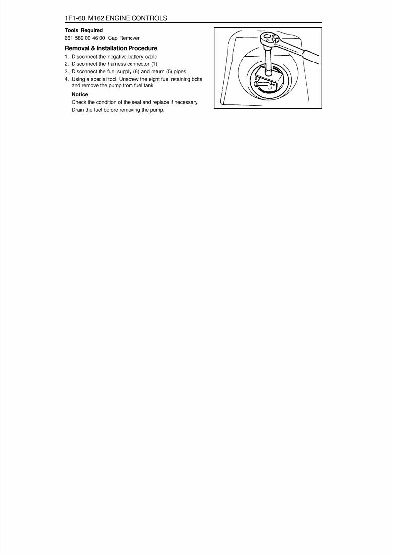
8/18/2019 SsangYong Musso Service Manual 1998.pdf
http://slidepdf.com/reader/full/ssangyong-musso-service-manual-1998pdf 630/1459
1F1-60 M162 ENGINE CONTROLS
Tools Required661 589 00 46 00 Cap Remover
Removal & Installation Procedure1. Disconnect the negative battery cable.2. Disconnect the harness connector (1).3. Disconnect the fuel supply (6) and return (5) pipes.4. Using a special tool, Unscrew the eight fuel retaining bolts
and remove the pump from fuel tank.
NoticeCheck the condition of the seal and replace if necessary.Drain the fuel before removing the pump.

8/18/2019 SsangYong Musso Service Manual 1998.pdf
http://slidepdf.com/reader/full/ssangyong-musso-service-manual-1998pdf 631/1459
M162 ENGINE CONTROLS 1F1-61
NoticeReplace the fuel pump relay if the measured value is over9A.
NoticeCheck the fuel filter and fuel line when the fuel delivery isnot within specified value.
Measure the Current Consumption of Fuel Pump1. Remove the fuel pump relay from fuse and relay box in
trunk, and turn the ignition switch to "ON" position.2. Using a multi-tester, measure the current consumption by
connecting the terminal No.1 and No.3 of pump.
Measure the Fuel Delivery From the Fuel Pump1. Disconnect the return pipe from fuel distributor and insert
the appropriate hose into it.2. Place the hose end into the beaker with the minimum capacity
of 1Liter.3. Turn the ignition switch to "ON" position.
4. Connect the terminal No.33 and No.5 of ECU with a servicewire.
5. Measure the fuel delivery from the fuel pump.
1Liter/max.35sec.Specifed Value
5 - 9ASpecifed Value

8/18/2019 SsangYong Musso Service Manual 1998.pdf
http://slidepdf.com/reader/full/ssangyong-musso-service-manual-1998pdf 632/1459
1F1-62 M162 ENGINE CONTROLS
PURGE SWITCHOVER VALVE
1 Purge Switchover Valve2 Line to Engine3 Line to Canister4 Canister
FunctionsThe fuel vaporization control system is installed to inhibit thefuel vaporized gas from discharging into the atmosphere. Thefuel vaporized gas that is accumulated in the canister abstractsthrough the purge switchover valve purification during theengine combustion (except the decreasing mode) and coolanttemperature of over 80 °C. For this reason, the ECU transactsthe engine speed, air inflow quantity, coolant temperature, andintake temperature.The purge switchover valve is activated by the ECU frequencyaccording with the engine rotating speed to adjust thepurification rate. The purification rate is determined by thecontinuous valve opening interval.The purge switchover valve is activated by the ECU for thefollowing conditions :
Coolant temperature of over 80 °CEngine speed of over 1000rpm2 Minutes after startingWhen the fuel cut-off mode is not activated

8/18/2019 SsangYong Musso Service Manual 1998.pdf
http://slidepdf.com/reader/full/ssangyong-musso-service-manual-1998pdf 633/1459
M162 ENGINE CONTROLS 1F1-63
4. Remove the line to canister and measure the pressure withthe vacuum pressure gauge.
Test1. Maintain the normal temperature and idling state by
operating the engine.2. Connect the ECU terminal No.11 and No.34 and check for
normal operation through the output waves using thescanner.
NoticeTest during purge control switchover valve operation afterthe minimum of 1 minute after the engine turned on.
3. Connect the ECU terminal No.34 and No.10 and check forcurrent consumption during the ignition switch ON.
Purge switchover valve output waveSpecified Value 0.3 - 0.5
Specified Value
> 50mbar
(after approx. 1min.) purge switchover valve
operates at this time
NoticeTest while at normal temperature and at idling state byoperating the engine.

8/18/2019 SsangYong Musso Service Manual 1998.pdf
http://slidepdf.com/reader/full/ssangyong-musso-service-manual-1998pdf 634/1459
1F1-64 M162 ENGINE CONTROLS
VACUUM SYSTEM
1 Purge Control Valve2 Molded Hose3 Insulator4 Fuel Tube5 Molded Hose6 Idle Regulator7 Resonance Flap8 Intake Manifold9 Fuel Pressure Regulator
10 Vacuum Line Rubber Hose11 Vacuum Tube(Gray, 270mm)12 Molded Hose13 Rubber Cap18 Rubber Hose19 Vacuum Tube(Brown or Black, 770mm)20 Rubber Hose
A To Canicter

8/18/2019 SsangYong Musso Service Manual 1998.pdf
http://slidepdf.com/reader/full/ssangyong-musso-service-manual-1998pdf 635/1459
M162 ENGINE CONTROLS 1F1-65
1 Crankshaft Position Sensor2 Bolt (M6 X 14) ........................................ 9 -11Nm
CRANKSHAFT POSITION SENSOR
Removal & Installation Procedure
1. Disconnect the wiring connector at the crankshaft positionsensor.2. Unscrew the bolt and remove the crankshaft position sensor
unit.
Installation Notice
3. Installation should follow the removal procedure in thereverse order.
3 Segment4 Flywheel
Tightening Torque 9 -11Nm

8/18/2019 SsangYong Musso Service Manual 1998.pdf
http://slidepdf.com/reader/full/ssangyong-musso-service-manual-1998pdf 636/1459
1F1-66 M162 ENGINE CONTROLS
Crankshaft Position Sensor ResistanceInspection1. Disconnect the coupling "E" of ECU while the ignition switch
is in "OFF" position.2. Measure the resistance between the coupling terminal pin
No.99 and No.100 using a multimeter.
NoticeMeasure the insulator resistance of the crankshaft positionsensor if out of the specified value.
Crankshaft Position Sensor Output WaveInspection1. Connect the test box to the ECU.2. Measure the output wave between the ECU terminals No.99
and No.100 using the scanner or the oscilloscope whileengine cranking (starter motor activated).
NoticeCheck the segment or crankshaft position sensor and airgap if cannot get the output wave as shown in the figure.
Specified Value 1050 - 1400 W
Specified Value > 20k W
Crankshaft Position Sensor Insulator ResistanceInspection1. Disconnect the engine coupling from ECU while the ignition
switch is in "OFF" position.2. Measure the resistance between the coupling terminal pin
No.100 and No.69.
NoticeMeasure the check and ground terminal of the crankshaftposition sensor if out of the specified value.

8/18/2019 SsangYong Musso Service Manual 1998.pdf
http://slidepdf.com/reader/full/ssangyong-musso-service-manual-1998pdf 637/1459
M162 ENGINE CONTROLS 1F1-67
CAMSHAFT POSITION SENSOR
1 Bolt (M6 X 14) ......................................... 9-11Nm2 Camshaft Position Sensor
Removal & Installation Procedure1. Disconnect the wiring connector from the camshaft position
sensor.2. Unscrew the bolt (2) and remove the camshaft position
sensor.
Installation Notice
3 Shim5 O-ring
Tightening Torque 9 - 11 Nm
3. Check the clearance and replace the shim if necessary.4. Check the O-ring for damage and replace it if necessary.5. Installation should follow the removal procedure in the
reverse order.

8/18/2019 SsangYong Musso Service Manual 1998.pdf
http://slidepdf.com/reader/full/ssangyong-musso-service-manual-1998pdf 638/1459
1F1-68 M162 ENGINE CONTROLS
Camshaft Position Sensor Power SupplyInspection1. Turn the ignition switch to 'ON' position.2. Disconnect the camshaft position sensor connector.3. Measure the voltage between the No.1 and No.3 pin of
camshaft position sensor while the ignition switch is in "ON"position.
NoticeIf the measured value is not within the specified value, checkthe cable.
NoticeThe signal voltage will be changed in the range of 1.2 -1.7V.
Camshaft Position Sensor Output WaveInspection1. Connect the test box to the ECU.2. Measure the output wave between the ECU terminal No.104
and No.106 using the scanner or the oscilloscope while theengine speed is at idle.
NoticeReplace the camshaft position sensor if cannot get theoutput wave as shown in the figure.
Specified Value 11 - 14 V
Specified Value 1.2 - 1.7 V
Camshaft Position Sensor Signal VoltageInspection1. Connect the test box to the ECU.2. Measure the voltage between the ECU terminal No.11 and
No.106 while the engine speed is at idle.

8/18/2019 SsangYong Musso Service Manual 1998.pdf
http://slidepdf.com/reader/full/ssangyong-musso-service-manual-1998pdf 639/1459
M162 ENGINE CONTROLS 1F1-69
HOT FILM AIR MASS (HFM) SENSOR
1 Housing2 Protector Net3 Electronic Housing
Removal & Installation Procedure1. Turn the HFM sensor coupling in the direction shown in the
figure in the right so that it gets separated from the contactsurface.
NoticeMake sure the HFM sensor coupling connects completely
with the contact surface Installation.2. Remove the clip with a screw driver.3. Pry off two tensioning clamps.4. Remove the HFM sensor.5. Installation should follow the removal procedure in the
reverse order.
4 Connector5 Hot film Sensor6 Measuring Port

8/18/2019 SsangYong Musso Service Manual 1998.pdf
http://slidepdf.com/reader/full/ssangyong-musso-service-manual-1998pdf 640/1459
1F1-70 M162 ENGINE CONTROLS
Circuit Diagram
1 Housing2 Electronic Housing3 Connector
RH : Heat Resistance
RT : Temperature ResistanceRS : Sensor Resistance

8/18/2019 SsangYong Musso Service Manual 1998.pdf
http://slidepdf.com/reader/full/ssangyong-musso-service-manual-1998pdf 641/1459
M162 ENGINE CONTROLS 1F1-71
If the measured value is not within the specified value, thepossible cause may be in cable or HFM sensor in itself.Perform the 5V power supply inspection procedures.
HFM Sensor 5V Power Supply Inspection1. Measure the voltage between the HFM sensor No.108 (+) and
No.105(-) after removing the HFM sensor connector.
HFM Sensor Input Voltage Inspection1. Measure the HFM sensor signal voltage between the ECU
terminal No.103 and No.104.
Specified Value (coolant temperature is over 70°C)
If the measured value is not within the specified value, thepossible cause may be in cable or ECU coupling.
Iginition"ON” 0.9 - 1.1 V
Engine at Idle 1.3 - 1.7 V
Specified Value 4.7 - 5.2 V
2. Measure the voltage between the HFM sensor winingconnector terminal No.3 pin(-) and No.4 after removing theHFM sensor connector.
Specified Value
If the measured value is not within the specified value, thepossible cause may be in cable or over voltage protectionrelay.Perfrom the 12V power supple inspection procedures.
Specified Value 4.7 - 5.2 V
HFM Sensor 12V Power Supply Inspection1. Measure the voltage between the HFM sensor wiring
connector 1G No.2 pin(+) and No.104 after removing theHFM sensor connector.
If the measured value is not within the specified value, thepossible cause may be in cable or over voltage protectionrelay.
Specified Value 11 - 14 V

8/18/2019 SsangYong Musso Service Manual 1998.pdf
http://slidepdf.com/reader/full/ssangyong-musso-service-manual-1998pdf 642/1459
1F1-72 M162 ENGINE CONTROLS
OXYGEN SENSOR
1 Electricity Wire2 Oxygen Sensor Housing3 Sensor Ceramic4 Electrode (Internal)5 Electrode (External)6 Heating Coil7 Open Space8 Protector Tube
FunctionsThe oxygen sensor optimizes the combustion (Air-Fuel Ratio14.7:1) and resets the Air-fuel ratio in the ECU after sensing
the amount of oxygen from the exhaust gases to diminish theexhaust gases.- Rich(<1) above approx. 450mV- Lean(>1) below approx. 450mV
Locatoin of SensorOxygen sensor is located on the front exhaust pipe.

8/18/2019 SsangYong Musso Service Manual 1998.pdf
http://slidepdf.com/reader/full/ssangyong-musso-service-manual-1998pdf 643/1459
M162 ENGINE CONTROLS 1F1-73
Oxygen Sensor Signal Voltage Inspection1. Measure the oxygen sensor signal voltage between the ECU
terminal No.11 and No.9. Maintain the engine speed ia atidle while the coolant temperature is over 80°C.
If the measured value is not within the specified value, thepossible cause may be in cable, oxygen sensor or ECU.
Oxygen Sensor Heating Voltage Inspection1. Measure the oxygen sensor heating voltage between the
ECU terminal No.11 and No.9. Maintain the engine speed iaat idle while the coolant temperature is over 80°C.
If the measured value is not within the specified value, thepossible cause may be in cable, oxygen sensor or ECU.
Oxygen Sensor Heating Current ConsumptionInspection1. Measure the oxygen sensor heating current consumption
between the ECU terminal No.9 and No.5 while the ignitionswitch is in "ON" position.
If the measured value is not within the specified value, thepossible cause may be in cable, oxygen sensor or ECU.
Specified Value 0.2 - 2.0 A
Specified Value -0.2 - 1.0 V
Specified Value 11 - 14
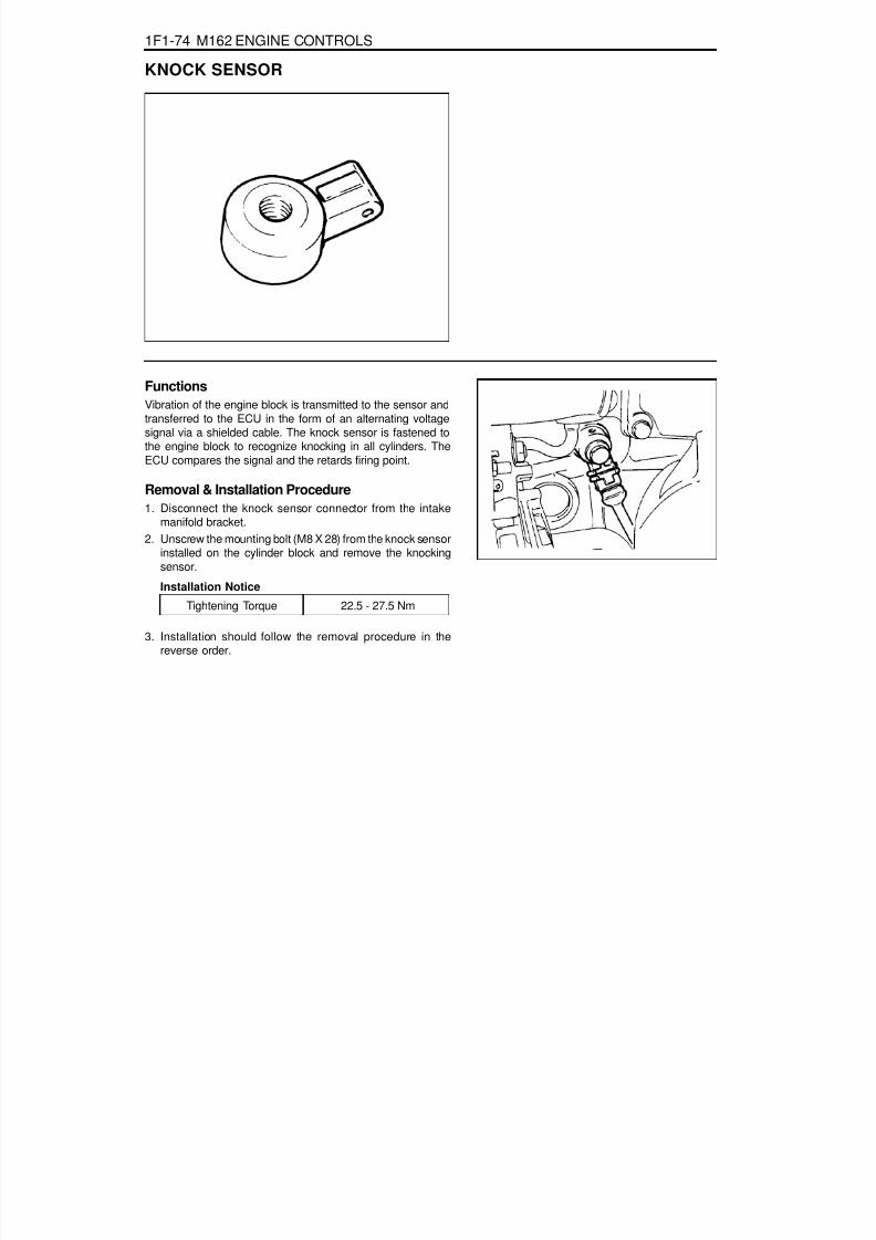
8/18/2019 SsangYong Musso Service Manual 1998.pdf
http://slidepdf.com/reader/full/ssangyong-musso-service-manual-1998pdf 644/1459
1F1-74 M162 ENGINE CONTROLS
KNOCK SENSOR
FunctionsVibration of the engine block is transmitted to the sensor andtransferred to the ECU in the form of an alternating voltagesignal via a shielded cable. The knock sensor is fastened tothe engine block to recognize knocking in all cylinders. TheECU compares the signal and the retards firing point.
Removal & Installation Procedure1. Disconnect the knock sensor connector from the intake
manifold bracket.2. Unscrew the mounting bolt (M8 X 28) from the knock sensor
installed on the cylinder block and remove the knockingsensor.
Installation Notice
3. Installation should follow the removal procedure in thereverse order.
Tightening Torque 22.5 - 27.5 Nm

8/18/2019 SsangYong Musso Service Manual 1998.pdf
http://slidepdf.com/reader/full/ssangyong-musso-service-manual-1998pdf 645/1459
M162 ENGINE CONTROLS 1F1-75
COOLANT TEMPERATURE SENSOR
1 Artificial Resin Housing2 Metal Housing3 NTC (negative temperature coefficient) Resistor
Removal & Installation Procedure1. Remove the pressure by opening the pressure cap in the
coolant subtank.2. Disconnect the connector and remove the coolant
temperature sensor.
Installation Notice
Replace the seals with new one.
3. Installation should follow the removal procedure in thereverse order.4. Check for leaks at each connections after starting the engine.
4 Connector5 Coolant Temperature Sensor
Tightening Torque 18 - 22 Nm

8/18/2019 SsangYong Musso Service Manual 1998.pdf
http://slidepdf.com/reader/full/ssangyong-musso-service-manual-1998pdf 646/1459
1F1-76 M162 ENGINE CONTROLS
2. Measure the resistance between the coolant temperaturesensor terminal No.1 and No.4 with the coolant temperaturesensor disconnected.
Inspection1. Measure the coolant sensor input voltage between the ECU
terminal No.79 and No.78 while the ignition switch in "ON"position.
NoticeReplace wiring and coolant temperature sensor if out ofspecified value.
allowable error : ±5%
allowable error : ±5%
Voltage (V)
3.57
1.22
0.78
Temperature (°C)
20
30
40
Resistance (W)
2,500
322
185
Temperature (°C)
20
30
40

8/18/2019 SsangYong Musso Service Manual 1998.pdf
http://slidepdf.com/reader/full/ssangyong-musso-service-manual-1998pdf 647/1459
M162 ENGINE CONTROLS 1F1-77
Service Data
Resistance characteristic curve according to the coolanttemperature
Temperature(°C) Resistance(W) Voltage(V) Temperature(°C) Resistance(W) Voltage(V)
-40 48,550 4.8991 60 594 1.8632
-30 27,000 4.8214 70 434 1.5132
-20 15,670 4.7001 80 322 1.2179
-10 9,450 4.5215 90 243 0.9775
0 5,890 4.4273 100 185 0.7806
10 3,790 3.9562 110 143 0.6255
20 2,500 3.5714 120 111.6 0.5020
30 1,692 3.1426 130 88.0 0.4044
40 1,170 2.6959 140 71.2 0.3323
50 826 2.2618 - - -

8/18/2019 SsangYong Musso Service Manual 1998.pdf
http://slidepdf.com/reader/full/ssangyong-musso-service-manual-1998pdf 648/1459
1F1-78 M162 ENGINE CONTROLS
ACCELERATOR PEDAL MODULE
1 Accelerator pedal
2 Accelerator pedal Sensor3 Bolts (2 Pieces) ....................................... 4-8 Nm
Removal and Installation Procedure1. Disconnect the 6-pin connector(arrow).2. Unscrew the 2 bolts (3) / 1 nut (6) and remove the pedal
and sensor assembly.
Installatoin Notice
Tightining Torque 4 - 8 Nm
2. Installation should follow the removal procedure in thereverse order.
4 6-Pin Connector
5 Kick down Switch6 Nut (1 piece) ............................................ 4-8 Nm

8/18/2019 SsangYong Musso Service Manual 1998.pdf
http://slidepdf.com/reader/full/ssangyong-musso-service-manual-1998pdf 649/1459
M162 ENGINE CONTROLS 1F1-79
Accelerator Pedal Sensor Connector (Sensor Side)Potentiometer 1.
Pin no. 3 :RedPin no. 1 :YellowPin no. 5 :Brown
Potentiometer 2.Pin no. 6 :VioletPin no. 4 :GreenPin no. 2 :White
Accelerator Pedal Sensor Connector (Vehicle Side)Potentiometer 1.
Pin no. 3 :Red-BlackPin no. 1 :Blue-Green
Pin no. 5 :Yellow-Green
Potentiometer 2.Pin no. 6 :GreenPin no. 4 :Blue-RedPin no. 2 :LightGreen
FunctionPotentiometer 1, Power Supply(+)
Potentiometer 1, Signal
Potentiometer 2, Ground
Potentiometer 2, Power Supply(+)
Pin no. 3
Pin no. 1
Pin no. 5
Pin no. 6
Pin no. 4
Pin no. 2
Potentiometer 2, Signal
Potentiometer 2, Ground
Circuit Diagram
Potentiometer 1.Potentiometer 2.

8/18/2019 SsangYong Musso Service Manual 1998.pdf
http://slidepdf.com/reader/full/ssangyong-musso-service-manual-1998pdf 650/1459
SECTION 1F2
M161 ENGINE CONTROLS
TABLE OF CONTENTS
CAUTION: Disconnect the negative battery cable before removing or installing any electrical unit or when a tool or equipment could easily come in contact with exposed electrical terminals. Disconnecting this cable will help prevent personal injury and damage to the vehicle. The ignition must also be in LOCK unless otherwise noted.
Specifications . . . . . . . . . . . . . . . . . . . . . . . 1F2-2Fastener Tightening Specifications . . . . . . . . 1F2-2
Special Tools . . . . . . . . . . . . . . . . . . . . . . . 1F2-3Special Tools Table . . . . . . . . . . . . . . . . . . . . 1F2-3
Schematic and Routing Diagrams . . . . . . . 1F2-4E23 ECU (MSE) . . . . . . . . . . . . . . . . . . . . . . 1F2-4E23 ECU (HFM) . . . . . . . . . . . . . . . . . . . . . . 1F2-5
Diagnosis . . . . . . . . . . . . . . . . . . . . . . . . . . 1F2-6Self Diagnosis Socket Pin Numbers and
Descriptions . . . . . . . . . . . . . . . . . . . . . . . . 1F2-6Self Diagnosis Failure Code (for E23 ENG) . 1F2-7Test Box Connection . . . . . . . . . . . . . . . . . . 1F2-10Fuel Injection System Test . . . . . . . . . . . . . 1F2-11
Ignition System Test . . . . . . . . . . . . . . . . . . 1F2-20Idling Control and Electronic Pedal
System Test . . . . . . . . . . . . . . . . . . . . . . . 1F2-25Air Conditioner Control System Test . . . . . . 1F2-27Fuel Pressure and Internal Leakage Test . . 1F2-28Fuel Pump Test . . . . . . . . . . . . . . . . . . . . . . 1F2-30
Injector Test . . . . . . . . . . . . . . . . . . . . . . . . 1F2-32Maintenance and Repair . . . . . . . . . . . . . 1F2-34On-Vehicle Service . . . . . . . . . . . . . . . . . . . . 1F2-34
ECU . . . . . . . . . . . . . . . . . . . . . . . . . . . . . . 1F2-34Fuel Pressure Regulator . . . . . . . . . . . . . . 1F2-45Fuel Distributor . . . . . . . . . . . . . . . . . . . . . . 1F2-49Injector . . . . . . . . . . . . . . . . . . . . . . . . . . . . 1F2-54Fuel Filter . . . . . . . . . . . . . . . . . . . . . . . . . . 1F2-57Fuel Pump . . . . . . . . . . . . . . . . . . . . . . . . . 1F2-58Purge Switchover Valve . . . . . . . . . . . . . . . 1F2-62Vacuum System . . . . . . . . . . . . . . . . . . . . . 1F2-64Crankshaft Position Sensor . . . . . . . . . . . . 1F2-66Camshaft Position Sensor . . . . . . . . . . . . . 1F2-68
Hot Film Air Mass (HFM) Sensor . . . . . . . . . 1F2-70Oxygen Sensor . . . . . . . . . . . . . . . . . . . . . . 1F2-73Knock Sensor . . . . . . . . . . . . . . . . . . . . . . . 1F2-75Coolant Temperature Sensor . . . . . . . . . . . 1F2-76Accelerator Pedal Module . . . . . . . . . . . . . . 1F2-79

8/18/2019 SsangYong Musso Service Manual 1998.pdf
http://slidepdf.com/reader/full/ssangyong-musso-service-manual-1998pdf 651/1459

8/18/2019 SsangYong Musso Service Manual 1998.pdf
http://slidepdf.com/reader/full/ssangyong-musso-service-manual-1998pdf 652/1459
M161 ENGINE CONTROLS 1F2-3
SPECIAL TOOLSSPECIAL TOOLS TABLE
129 589 00 21 00Test Box
119 589 04 63 00Pressure Hose
106 589 00 21 00Pressure Tester
210 589 08 63 00ECU Test Cable
210201Adaptor Line

8/18/2019 SsangYong Musso Service Manual 1998.pdf
http://slidepdf.com/reader/full/ssangyong-musso-service-manual-1998pdf 653/1459
1F2-4 M161 ENGINE CONTROLS
SCHEMATIC AND ROUTING DIAGRAMS
E 2 3 E C U ( M S E )

8/18/2019 SsangYong Musso Service Manual 1998.pdf
http://slidepdf.com/reader/full/ssangyong-musso-service-manual-1998pdf 654/1459
M161 ENGINE CONTROLS 1F2-5
E 2 3 E C U ( H F M )

8/18/2019 SsangYong Musso Service Manual 1998.pdf
http://slidepdf.com/reader/full/ssangyong-musso-service-manual-1998pdf 655/1459
1F2-6 M161 ENGINE CONTROLS
DIAGNOSISSELF DIAGNOSIS SOCKET PIN NUMBERS AND DESCRIPTIONS
1 Ground2 Ignition 13 Battery Power Supply (Fuse NO.17)4 REKES :PIN 65 Engine Speed Signal :MSE PIN 606 TCCU(Part-time)7 STICS(PIN 26)
8 -9 -10 Air Bag(PIN 20)11 Remote Engine Start Unit(PIN 10)
12 -13 Brake System
(ABS 5.3:PIN 11, ABS/ABD 5.3:PIN 46)14 MSE 3.62S/3.53S(ECU Data Output:PIN 58)15 TOD(PIN 20)16 Immobilizer17 -
18 TCU(PIN 23)19 -20 K-LINE(ECS:PIN 23)

8/18/2019 SsangYong Musso Service Manual 1998.pdf
http://slidepdf.com/reader/full/ssangyong-musso-service-manual-1998pdf 656/1459
M161 ENGINE CONTROLS 1F2-7
No ignition voltage output(NO.1 ignition coil;
1, 4cylinder)
No ignition voltage output(NO.2 ignition coil;
2, 3cylinder)
Cranshaft position sensor adaption failure
Start signal recognition failure
No.1 injector short(PWR)
No.1 injector open/short(GND)
No.2 injector short(PWR)
No.2 injector open/short(GND)
No.3 injector short(PWR)
No.3 injector open/short(GND)
No.4 injector short(PWR)
No.4 injector open/short(GND)
High oxygen sensor voltage
Low oxygen sensor amplifying voltage
Oxygen sensor operating failureNot excessive lean indication in oxygen
sensor(during coasting)
Oxygen sensor heater short(power)
Oxygen sensor heater open/short(GND)
Low oxygen sensor voltage
Short learning control failure
Lambda control failure (rich stop)
Lambda control failure (lean stop)
Lambda idle adaptation failure(above rich
threshold)
Lambda idle adaptation failure(below lean
threshold)
learning control failure(rich, low load)
Coolant temperature sensor open
Coolant temperature sensor short
Coolant temperature sensor signal failure
Intake temperature sensor open
Intake temperature sensor short
Intake temperature sensor signal failure
Low battery voltage
HFM sensor signal failure
HFM sensor signal failure (Low)
HFM sensor signal failure (High)
Crankshaft position sensor signal failure
(no engine revolution signal)
Crankshaft position sensor signal failure
(rpm > max. value)
No.1 cylinder recognition failure
Crankshaft position sensor signal failure
(gab recognition failure)Transmission coding failure
Transponder signal communication failure
CAN communication failure : TCU(A/T only)
CAN communication failure :
communication initialization failure
Fuel pump relay short(PWR)
Fuel pump relay open/short(GND)
Purge valve short
Purge valve open/short
Condenser fan(HI) relay short(PWR)
Condenser fan(HI) relay short(GND)
No.1 knock sensor signal failure
No.1 cylinder synchronization failure
00
01
02
03
04
05
08
09
10
11
17
18
19
20
21
25
26
31
34
35
40
41
44
45
56
58
Failurecode Description
Fa ilurecode Description
64
65
67
71
72
73
74
75
76
77
78
79
80
81
8283
86
87
89
93
96
97
98
99
100
SELF DIAGNOSIS FAILURE CODE (FOR E23 ENG)

8/18/2019 SsangYong Musso Service Manual 1998.pdf
http://slidepdf.com/reader/full/ssangyong-musso-service-manual-1998pdf 657/1459
1F2-8 M161 ENGINE CONTROLS
Servo motor open/short
Unprogramed ECU with Immobilizer
Uncoded ECU
ECU failure(NVRAM checksum failure)
ECU failure(coding ID checksum failure)
ECU failure(coding checksum failure)
ECU failure(programing checkusm failure)
ABD input signal short(power)
ABD input signal short(GND)
Low pedal valve sensor SP1 voltage
High pedal valve sensor SP1 voltage
Low pedal valve sensor SP2 voltage
High pedal valve sensor SP2 voltage
Different pedal valve sensor signal(1,2) SP1
with SP2
Pedal valve sensor 1,2 failure
HFM sensor, and throttle position sensor failure
ECU failure(incompatible CPU)
ECU failure(CPUs communication failure)
ECU failure(CPU(2) configuration failure)
ECU failure(CPU(2) fault)
ECU failure(CPU run time failure between
CPUs)
-
-
--
-
-
Cam actuator short(PWR)
101
102
103
104
105
108
109
110
116
117
119
120
121
122
123
125
126
127
129
130
131
132
133
134136
137
139
140
141
142
143
144
145
146
150
151
160
161
162
163
164
167
185
186
187
188
189
190
192
193
194195
198
199
226
learning control failure(lean, low load)
learning control failure(rich, high load)
learning control failure(lean, high load)
Low throttle position sensor(IP1) voltage
High throttle position sensor(IP1) voltage
Low throttle position sensor(IP2) voltage
High throttle position sensor(IP2) voltage
Throttle actuator learning data fault
Throttle actuator learning control failure
Exceed fuel-cut safety time
Throttle valve return spring failure
Cruise control interruption memory failure
Throttle actuator failure
Pedal module position sensor signal failure
Defferent HFM signal with throttle potentiom-
eter
Both throttle potentiomenter(IP1 & IP2)
failure
Different IPS1 with IPS2
High permanent throttle signal deviation
Message counter fault ® cruise control “OFF”
Vehicle speed signal failure
Vehicle speed signal failure
Cruise control lever failure
Cruise control acceleration failure
Cruise control deceleration failureECU failure(RAM)
ECU failure(EPROM)
Servo motor control output inter-ruption
memory failure
Failurecode Description
Failurecode Description

8/18/2019 SsangYong Musso Service Manual 1998.pdf
http://slidepdf.com/reader/full/ssangyong-musso-service-manual-1998pdf 658/1459
M161 ENGINE CONTROLS 1F2-9
227
228
229
232
233
234
235
236
237
238
239
240
241
Cam actuator open/short(GND)
A/C compressor relay short(PWR)
A/C compressor relay open/short(GND)
Decel limit defected by CPU2
Accel limit defected by CPU2
Cruise control lever double input(CPU2)
Cruise control lever safety terminal
failure(CPU2)
Unusual pedal position variation(CPU2)
Unusual throttle position variation(CPU2)
Unusual throttle control data(CPU2)
Unusual pedal position sensor(CPU2)
Throttle potentiometer fault(CPU2)
Unusual CPU communication(CPU2)
242
243
244
245
246
247
248
249
250
251
Unusual CPU configuration(CPU2)
AD converter failure(CPU2)
Pedal position sensor setpoint fault berween
CPU1 and CPU2
Position setpoint fault berween CPU1 and
CPU2
-
Idle controller setpoint fault berween CPU1
and CPU2
AD converter overflow degected by CPU2
ROM fault degected by CPU2
RAM fault degected by CPU2
Cycle monitor fault degected by CPU2
Failurecode
DescriptionFailure
code Description

8/18/2019 SsangYong Musso Service Manual 1998.pdf
http://slidepdf.com/reader/full/ssangyong-musso-service-manual-1998pdf 659/1459
1F2-10 M161 ENGINE CONTROLS
TEST BOX CONNECTION
1 ECU2 Test Coupling(No.1 - 60)3 Test Coupling(No.61 - 120)4 Multi-tester
01 Test Box02 ECU Test Cable
Tools Required129 589 00 21 00 Test Box210 589 08 63 00 ECU Test Cable
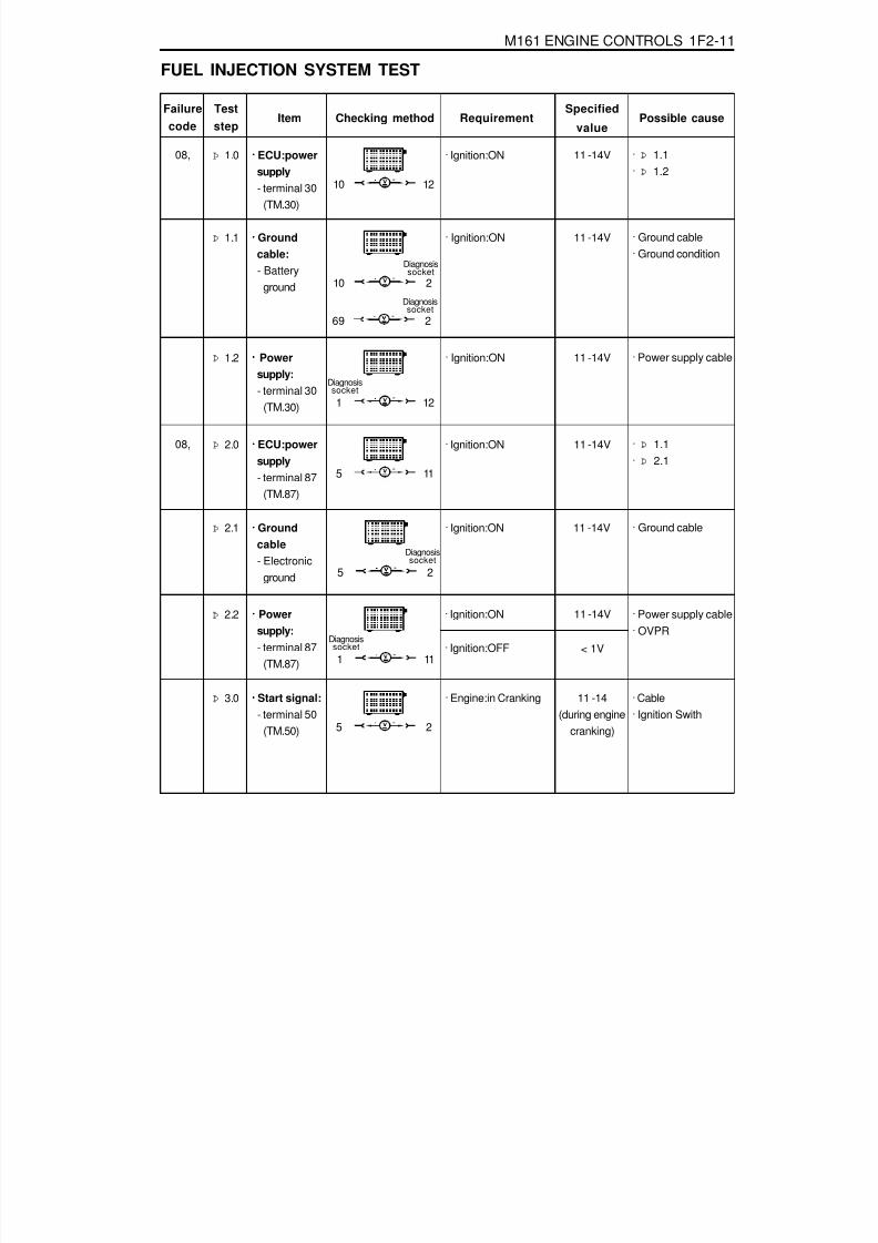
8/18/2019 SsangYong Musso Service Manual 1998.pdf
http://slidepdf.com/reader/full/ssangyong-musso-service-manual-1998pdf 660/1459
M161 ENGINE CONTROLS 1F2-11
FUEL INJECTION SYSTEM TEST
Failurecode
Item
Þ 1.0
Checking method
· Ignition:ON
Teststep
RequirementSpecified
valuePossible cause
10 12
11 -14V····· ECU:powersupply- terminal 30
(TM.30)
Þ 2.2 ····· Powersupply:- terminal 87
(TM.87)
· Ignition:ON · Power supply cable· OVPR
08, · Þ 1.1· Þ 1.2
Þ 1.1 · Ignition:ON
10 2
11 -14V····· Groundcable:- Battery
ground
· Ground cable· Ground condition
Diagnosissocket
69 2
Diagnosissocket
Þ 1.2 · Ignition:ON
1 12
11 -14V····· Powersupply:- terminal 30
(TM.30)
· Power supply cable
Diagnosissocket
Þ 2.0 · Ignition:ON
5 11
11 -14V····· ECU:powersupply- terminal 87
(TM.87)
08, · Þ 1.1· Þ 2.1
Þ 2.1 · Ignition:ON 11 -14V····· Groundcable- Electronic
ground
· Ground cable
5 2
Diagnosissocket
1 11
Diagnosissocket · Ignition:OFF
11 -14V
< 1V
Þ 3.0 · Engine:in Cranking
5 2
· Cable· Ignition Swith
11 -14(during engine
cranking)
····· Start signal:- terminal 50
(TM.50)

8/18/2019 SsangYong Musso Service Manual 1998.pdf
http://slidepdf.com/reader/full/ssangyong-musso-service-manual-1998pdf 661/1459
1F2-12 M161 ENGINE CONTROLS
Failurecode
Item
09,
10,
11,
Checking methodTeststep
RequirementSpecified
valuePossible cause
Þ 4.0 ····· HFM sensorsignal
105 81
· Ignition:ON 0.9 - 1.1V · Þ 4.1 - 4.3· Cable· External air inflow· HFM sensor
· Engine:in Idle
(Coolant temperature: > 70 °C )
1.3 - 1.7V
Þ 4.1
105 4
· Ignition:ON· HFM sensor
connector removed
4.7 - 5.2V · Cable· ECU coupling
····· HFM sensor:- 5V power
supply
HFMsensor
Þ 4.2
3 108
· Ignition:ON· HFM sensor
connector removed
4.7 - 5.2V · Þ 4.3· Cable
····· HFM sensor:- 5V power
supply
HFMsensor
Þ 4.3
104 2
· Ignition:ON· HFM sensor
connector removed
11 - 14V · Cable· OVPR
····· HFM sensor:- 12V power
supply
HFMsensor
03,
04,
05,
Þ 5.0 ····· Intake airtemperaturesensor:- Voltage
105 80
· Ignition:ON · Þ 5.1· ECU
Þ 5.1 · Ignition:OFF· No.2 ECU coupling
removed105 80
· Cable· HFM sensor
····· Intake airtemperature
sensor:- Resistance
: voltage valueis increasedwhen engine
rpm isincreased
± 5%
°C10
2030405060
± 5%
W
3600
242016621166
853600
°C102030405060
V3.1
2.652.181.76
1.41.1

8/18/2019 SsangYong Musso Service Manual 1998.pdf
http://slidepdf.com/reader/full/ssangyong-musso-service-manual-1998pdf 662/1459
M161 ENGINE CONTROLS 1F2-13
Failure
codeItem Checking method
Teststep
RequirementSpecified
value Possible cause
Þ 6.1 · Ignition:ON 0.1 - 0.3A · Cable· Fuel pump relay·
ECU
····· Fuel pumprelay:
- Currentconsumption
00,
01,
02,
06,
Þ 7.0 ····· Coolanttemperaturesensor:- Voltage
79 78
· Ignition:ON °C V20 3.5780 1.22
100 0.78
· Þ 7.1· ECU
± 5%
Þ 6.0 · Ignition:ON(Fuel pump relay will
operate for 1 - 2seconds when theignition switch isturned to "ON" afterstopping theengine)
· Engine:cranking
33 11
· Cable· Fuel pump relay· ECU
····· Fuel pumprelay:- Operation
34,
35,
11 - 14V(approx.1-
2sec.)
11 - 14V(Cranking or
driving)
5 33
Þ 7.1 · Ignition:OFF(Remove the No.2
coupling from ECU)79 78
· Þ 7.2· cable
····· Coolanttemperaturesensor:- Resistance
& cable
°C W
20 250080 322
100 185
± 5%
Þ 7.2 ····· Coolanttemperaturesensor:
- Resistance
Coolant temperaturesensor:
1 4
· Remove theconnector fromcoolant temperature
sensor and measurethe resistancebetween No.1 andNo.2 pin withmultimeter.
· Þ refer tospecifiedresistance
value of 7.1.
· Coolanttemperaturesensor

8/18/2019 SsangYong Musso Service Manual 1998.pdf
http://slidepdf.com/reader/full/ssangyong-musso-service-manual-1998pdf 663/1459
1F2-14 M161 ENGINE CONTROLS
Failure
codeItem Checking method
Test
step RequirementSpecified
valuePossible cause
Þ 9.0 · Keep the engine runabove 2 minutes inover 80 °C of coolanttemperature
6.0 - 7.0 V
· ECU· Cable· Oxygen sensor
····· Oxygensensor:- Signal
80,
81,
82,
83,
89,
5 60
Þ 8.0 · Engine:in crankingor idle
5 60
· Cable· ECU
····· ECU:- RPM signal
output
32,
33,
refer to figure2
Þ 10.0 · Keep the engine runabove 2 minutes inover 80 °C of coolanttemperature.
····· Oxygensensor:- Heating
functionoperated
Þ 11.0 ····· No.1cylinderinjector:- Operating &
injectiontime
· When the coolanttemperature isapprox. 20 °C:- Engine:in cranking 8.0 ms
· Cable· ECU· No.1 Injector· Coolant
temperature sensor· Oxygen sensor· Intake air
temperature sensor
- Voltage · Engine:in crankingor idle(above 5V in idling)
16 17
5 9
9 11
· Ignition:ON
11 - 14 V · ECU· Cable· Oxygen sensor
- Currentconsumption
0.2 - 2.0 A
72,
73, 63 11
· When the coolanttemperature isapprox. 80 °C:- Engine:at idling
speed- Engine:at sharp
acceleration(fullthrottle)
(refer to figure 3and 4)
approx.2.7 - 5.0ms
approx.14ms
There will be avoltage
fluctuation inthe range of- 0.2 -1.0V.
85,86,87,

8/18/2019 SsangYong Musso Service Manual 1998.pdf
http://slidepdf.com/reader/full/ssangyong-musso-service-manual-1998pdf 664/1459
M161 ENGINE CONTROLS 1F2-15
Failurecode Item Checking method
Teststep
RequirementSpecified
valuePossible cause
· Ignition:OFF (injectortemperature is 20 °C)
14 - 17 W- Internalresistance(No.1
injector)
63 11
Þ 12.0 ····· No.2cylinderinjector:- Operating &
injectiontime
· When the coolanttemperature isapprox. 20 °C:- Engine:in cranking 8.0 ms
· Cable· ECU· No.2 Injector· Coolant
temperaturesensor
· Oxygen sensor· Intake air
temperaturesensor
74,
75, 64 11
· When the coolanttemperature isapprox. 80 °C:- Engine:at idling
speed- Engine:at sharp
acceleration (fullthrottle)
(refer to figure 3 and4)
approx.
2.7 - 5.0msapprox.14ms
· Ignition:OFF (injectortemperature is 20 °C)
14 - 17 W- Internalresistance(No.2
injector)
64 11
Þ 13.0 ····· No.3cylinderinjector:- Operating &
injectiontime
· When the coolanttemperature isapprox. 20 °C:- Engine:in cranking 8.0 ms
· Cable· ECU· No.3 Injector· Coolant
temperature sensor· Oxygen sensor· Intake air
temperature sensor
76,
77, 65 11
· When the coolanttemperature isapprox. 80 °C:- Engine:at idling
speed- Engine:at sharp
acceleration(fullthrottle)
(refer to figure 3and 4)
approx.
2.7 - 5.0msapprox.14ms

8/18/2019 SsangYong Musso Service Manual 1998.pdf
http://slidepdf.com/reader/full/ssangyong-musso-service-manual-1998pdf 665/1459
1F2-16 M161 ENGINE CONTROLS
Failurecode Item Checking method
Teststep Requirement
Specifiedvalue Possible cause
· Ignition:OFF (injectortemperature is 20 °C)
14 - 17 W- Internalresistance(No.3
injector)
65 11
Þ 14.0 ····· No.4 cylinderinjector:- Operating &
injection time
· When the coolanttemperature isapprox.20 °C:- Engine:in cranking 8.0 ms
· Cable· ECU· No.4 Injector· Coolant
temperature sensor· Oxygen sensor· Intake air
temperature sensor
78,
79, 66 11
· When the coolanttemperature isapprox.80 °C:- Engine:at idling
speed- Engine:at sharp
acceleration(fullthrottle)
(refer to figure 3and 4)
approx.
2.7 - 5.0msapprox.14ms
· Ignition:OFF(injector temperature
is 20 °C)
14 - 17 W- Internalresistance(No.4
injector)
66 11
226,
227,
Þ 15.0 ····· Camshaftactuator:Currentconsumption
1 2Camshaft actuator 1 - 1.5 A · ECU
· Þ 15.1· Þ 16.0
· Engine : using a testcable(102 589 63 00)in idling, measure thecurrent consumptionwith below condition- Coolant temperature
: above 70 °C- Engine rpm :
increase up to 2000rpm

8/18/2019 SsangYong Musso Service Manual 1998.pdf
http://slidepdf.com/reader/full/ssangyong-musso-service-manual-1998pdf 666/1459
M161 ENGINE CONTROLS 1F2-17
Failurecode Item
Þ 15.1
Checking methodTeststep Requirement
Specifiedvalue Possible cause
73 2
8 - 12 W····· Camshaftactuator:Solenoidresistance(E23 only)
Þ 18.0 ····· Purgecontrolvalve:- Vacuum
control
· Engine:in idling/ normal operatingtemperature
· Power supply cable· OVPR
· Cable· Camshaft actuator
Diagnosissocket
Þ 16.0
73 69
Engine isunstable or
stopped.
····· Camshaftactuator:Mechanicalactuation(E23 only)
· Mechanical failureof camshaftactuator
Þ 17.0 · Engine:in idling
34 11
The purgecontrol valveshould be
operated afterapprox.
1minute.(refer to figure
5)
····· Purgecontrolvalve:- Operating
226,227,
· ECU· Cable· Purge control valve
· Ignition:ON 0.2 - 0.4 A- Currentconsumption
10 34
Creating above50mbar of
vacuum afterapprox.
1 minute
Þ 19.0 · Ignition:OFF
38 37
· Data bus· Þ 19.1· Þ 19.2
55 - 65 W····· CAN databus
· Ignition:OFF
· Engine:in idling
40,41,54,
40,41,54,
Connect the vacuumgauge between thecontrol valve andcanister
22,23,24,26,27,29,30,31,59,60,

8/18/2019 SsangYong Musso Service Manual 1998.pdf
http://slidepdf.com/reader/full/ssangyong-musso-service-manual-1998pdf 667/1459
1F2-18 M161 ENGINE CONTROLS
Failurecode
Item
Þ 19.1
Checking methodTeststep
RequirementSpecified
valuePossible cause
38 37
115 - 125 W····· CAN moduleresistance inABS, ABD,ASR controlunit
· Cable· ABS, ABD, ASR
control unit
· Ignition:OFF- disconnect the
coupling"No.1" from ECU
Þ 19.2
38 37
115 - 125 W····· CAN moduleresistance inECU controlunit
· ECU· Ignition:OFF- disconnect the
coupling"No.1" from ECU
Þ 20.0
5 58
11 - 14 V····· Diagnosiscableoperating
· ECU· Cable
· Ignition:ON

8/18/2019 SsangYong Musso Service Manual 1998.pdf
http://slidepdf.com/reader/full/ssangyong-musso-service-manual-1998pdf 668/1459
M161 ENGINE CONTROLS 1F2-19
Reference Figures
Figure1. RPM Sgnal Output Figure 2. Injection Valve Wave(at idle speed)
Figure 3. Injection Valve Wave(at sharpacceleration)
Figure 4. Purge Control Valve Operationg Wave

8/18/2019 SsangYong Musso Service Manual 1998.pdf
http://slidepdf.com/reader/full/ssangyong-musso-service-manual-1998pdf 669/1459
1F2-20 M161 ENGINE CONTROLS
Failurecode
Item
Þ 1.0
Checking method
· Ignition:ON
Teststep
RequirementSpecified
valuePossible cause
10 12
11 - 14V····· ECU:powersupply- terminal 30
(TM.30)
Þ 2.2 ····· Powersupply:- terminal 87
(TM.87)
· Ignition:ON · Power supply cable· OVPR
IGNITION SYSTEM TEST
08, · Þ 1.1· Þ 1.2
Þ 1.1 · Ignition:ON
10 2
11 - 14V····· Groundcable:- Battery
ground
· Ground cable· Ground condition
(figure 1)Diagnosissocket
69 2
Diagnosissocket
Þ 1.2 · Ignition:ON
1 12
11 - 14V····· Powersupply:- terminal 30
(TM.30)
· Power supply cable
Diagnosissocket
Þ 2.0 · Ignition:ON
5 11
11 -14V····· ECU:powersupply- terminal 87
(TM.87)
08, · Þ 2.1· Þ 2.2
Þ 2.1 · Ignition:ON 11 - 14V····· Groundcable- Electronic
ground
· Ground cable
5 2
Diagnosissocket
1 11
Diagnosissocket
· Ignition:OFF
11 - 14V
< 1V
Þ 3.0 · Ignition:ON
69 72
11 - 14 V····· Ignitioncoil(T1/1)- No.1,4Cylinder
64, · Cable· Ignition coil(T1/1)· Fuse No.17
· Engine:in cranking > 10 V
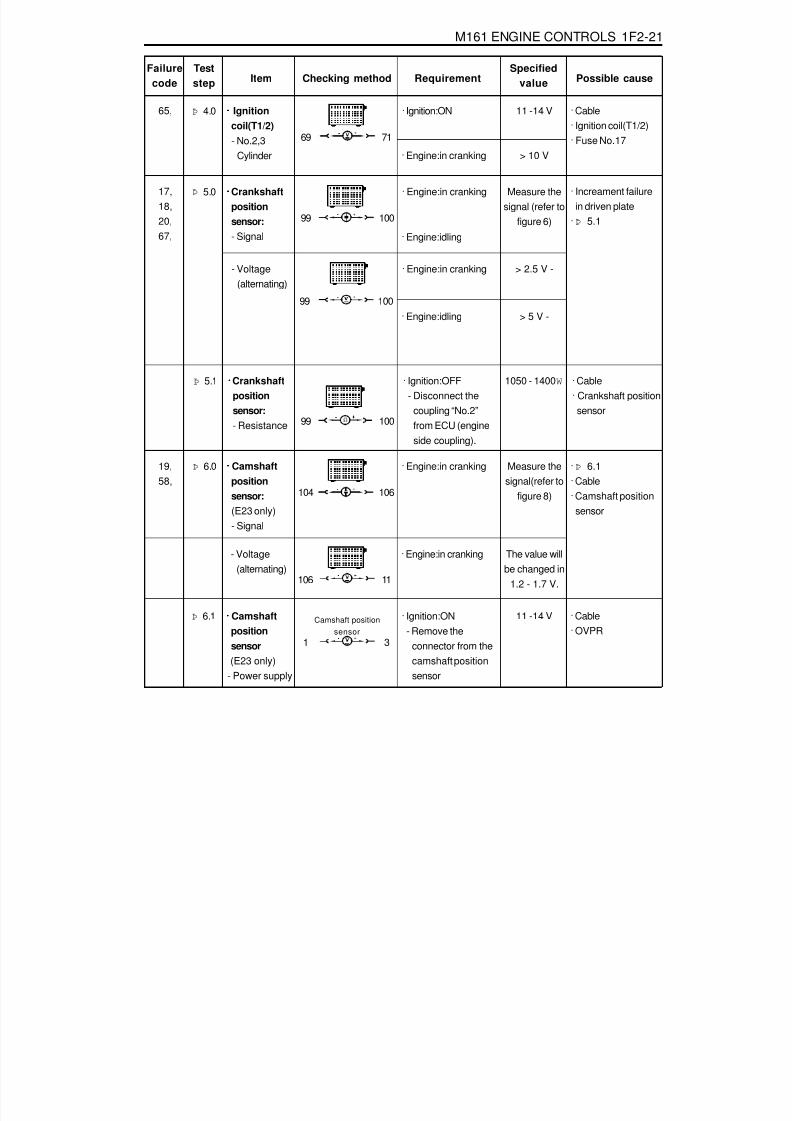
8/18/2019 SsangYong Musso Service Manual 1998.pdf
http://slidepdf.com/reader/full/ssangyong-musso-service-manual-1998pdf 670/1459
M161 ENGINE CONTROLS 1F2-21
Failurecode Item Checking method
Teststep Requirement
Specifiedvalue Possible cause
Þ 5.1 ····· Crankshaftpositionsensor:- Resistance
· Ignition:OFF- Disconnect the
coupling “No.2”from ECU (engineside coupling).
· Cable· Crankshaft position
sensor
Þ 5.0 · Engine:in cranking
99 100
Measure thesignal (refer to
figure 6)
····· Crankshaftpositionsensor:- Signal
17,18,20,67,
· Increament failurein driven plate
· Þ 5.1
> 5 V -99 100
99 100
1050 - 1400 W
Þ 6.0 · Engine:in cranking
104 106
· Þ 6.1· Cable· Camshaft position
sensor
Measure thesignal(refer to
figure 8)
····· Camshaftpositionsensor:(E23 only)- Signal
Þ 4.0 · Ignition:ON
69 71
11 -14 V····· Ignitioncoil(T1/2)- No.2,3
Cylinder
65, · Cable· Ignition coil(T1/2)· Fuse No.17
· Engine:in cranking > 10 V
· Engine:idling
- Voltage(alternating)
· Engine:in cranking
· Engine:idling
> 2.5 V -
19,58,
106 11
The value willbe changed in
1.2 - 1.7 V.
- Voltage(alternating)
· Engine:in cranking
Þ 6.1 · Ignition:ON- Remove the
connector from thecamshaft positionsensor
1 3
11 -14 V····· Camshaftpositionsensor
(E23 only) - Power supply
· Cable· OVPR
Camshaft positionsensor

8/18/2019 SsangYong Musso Service Manual 1998.pdf
http://slidepdf.com/reader/full/ssangyong-musso-service-manual-1998pdf 671/1459
1F2-22 M161 ENGINE CONTROLS
Failurecode Item Checking method
Teststep Requirement
Specifiedvalue
Possible cause
0.9 - 1.6 W
72 11
72 71
····· Ignitioncoil(T1/1)- Primary coil
voltage(No.1 , 4cylinder)
· Engine:in cranking(starter operating)- Measuring range:
400 V- Time range: 100 %(using engine tester)
· Ignition:OFF
200 - 350 V64, Þ 7.0 · Þ 7.1
Þ 7.1 ····· Connectionignition coilbetween T1/1 and T1/2
· Cable· Ignition coil T1/1· Ignition coil T1/2
71 11
····· Ignitioncoil(T1/2)- Primary coil
voltage(No.2 , 3
cylinder)
· Engine:in cranking(starter operating)- Measuring range:
400 V- Time range: 100 %(using engine tester)
200 - 350 V65, Þ 8.0 · Þ 8.1
0.9 - 1.6 W
71 72
· Ignition:OFFÞ 8.1 ····· Connection
ignition coilbetween T1/1 and T1/2
· Cable
· Ignition coil T1/1· Ignition coil T1/2
Theresistance ofignition coil at
20 °C isapproached
0.6W.
Theresistance ofignition coil at
20 °C isapproached
0.6W.
8 - 20 KV····· Ignition coil(T1/1, T1/2)- Secondary
ignitionvoltage
· Engine:in cranking- Select the ignition
coil in order of T1/1,T1/2
- Measuring range :20KV
- Time range : 100%
Þ 9.064,65,
Engine tester· Þ 9.1· Ignition plug· ECU· High tension cable

8/18/2019 SsangYong Musso Service Manual 1998.pdf
http://slidepdf.com/reader/full/ssangyong-musso-service-manual-1998pdf 672/1459
M161 ENGINE CONTROLS 1F2-23
Failurecode Item Checking method
Teststep Requirement
Specifiedvalue Possible cause
> 10 M W
117 118
· Ignition:OFF- Disconnect the
coupling "No.2" from ECU.
Þ 10.1 ····· Knocksensor- Resistance
· Connectingcondition
· Cable· ECU
6 - 8.5 K W····· Ignition coil(T1/1, T1/2)- Secondary
coilresistance
· Remove the hightension cable of
T1/1, T1/2
Þ 9.1 Ignition coil(T1/1, T1/2)
· Ignition coil T1/1· Ignition coil T1/2
TM.4a TM.4b
56,
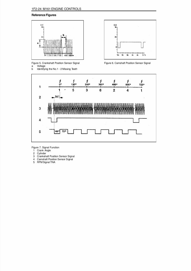
8/18/2019 SsangYong Musso Service Manual 1998.pdf
http://slidepdf.com/reader/full/ssangyong-musso-service-manual-1998pdf 673/1459
1F2-24 M161 ENGINE CONTROLS
Reference Figures
Figure 5. Crankshaft Position Sensor Signala Voltageb Identifying the No.1 - 2 Missing Teeth
Figure 6. Camshaft Position Sensor Signal
Figure 7. Signal Function1 Crank Angle2 Cylinder3 Crankshaft Position Sensor Signal4 Camshaft Position Sensor Signal5 RPM Signal TNA

8/18/2019 SsangYong Musso Service Manual 1998.pdf
http://slidepdf.com/reader/full/ssangyong-musso-service-manual-1998pdf 674/1459
M161 ENGINE CONTROLS 1F2-25
IDLING CONTROL AND ELECTRONIC PEDAL SYSTEM TEST
Þ 2.1 · Ignition:ON
50 51
2.25 - 2.75 V····· Pedal valvesensor:- Power
supply (potentiometer 2)
· Cable· ECU
Failurecode Item
Þ 1.0
Checking method
· Ignition:ON· Position of
accelerator pedal:- Closed throttle
position- Full throttle with
kick down
Test
stepRequirement
Specifiedvalue Possible cause
31 47
0.2 - 0.5 V
····· Pedal valvesensor:- Signal
(potentiometer 1)
160,161,164,167,
4.3 - 4.8 V
· Þ 1.1· Cable· Pedal valve sensor
Þ 1.1 · Ignition:ON
31 32
4.75 - 5.25 V····· Pedal valvesensor:- Power
supply (potentiometer 1)
· Cable· ECU
Þ 2.0 · Ignition:ON· Position of
accelerator pedal:- Closed throttle
position- Full throttle with
kick down
50 48
0.1 - 0.4 V
····· Pedal valvesensor:- Signal
(potentiometer 2)
162,163,164,167,
2.1 - 2.5 V
· Þ 2.1· Cable· Pedal valve sensor
Þ 3.0 · Engine:in idling
84 87 0.3 - 0.9 V
····· Throttlevalve
actuator:- SignalThrottle valve
potentiometer1
104,105,
108,109,116,119,185,
4.0 - 4.6 V
· Þ 3.1· Cable· E-GAS actuator
· Position ofaccelerator pedal:- Closed throttle
position- Full throttle with
kick down

8/18/2019 SsangYong Musso Service Manual 1998.pdf
http://slidepdf.com/reader/full/ssangyong-musso-service-manual-1998pdf 675/1459
1F2-26 M161 ENGINE CONTROLS
Failurecode Item Checking method
Teststep Requirement
Specifiedvalue
Possible cause
Þ 3.1 · Ignition:ON
84 112
4.75 - 5.25 V····· Throttlevalveactuator:- Power
supply
· Cable· ECU
Þ 4.0 · Ignition:ON
68 67
0.8 - 2.3 VThe value willbe changed in
1.0 - 2.5V.
····· Throttlevalveactuator:- Signal
Throttle valveactuatormotorvoltagesupply
104,105,108,109,116,119,185,
· ECU· Cable· E-GAS actuator
· Engine:in idling- Coolant
temperature: > 70 °C
84 85 4.0 - 4.6 V
Throttle valvepotentiometer2
0.3 - 0.9 V
· Position ofaccelerator pedal:- Closed throttle
position- Full throttle with
kick down
Throttlevalvepotentiometer1+2
· Ignition:OFF < 10 W
Throttle valveactuatormotorresistance
68 67
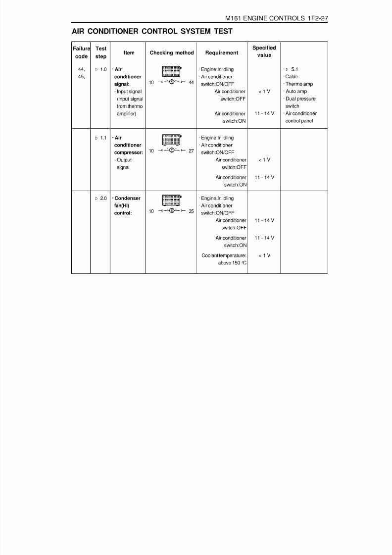
8/18/2019 SsangYong Musso Service Manual 1998.pdf
http://slidepdf.com/reader/full/ssangyong-musso-service-manual-1998pdf 676/1459
M161 ENGINE CONTROLS 1F2-27
AIR CONDITIONER CONTROL SYSTEM TEST
Þ 2.0 · Engine:In idling· Air conditioner
switch:ON/OFFAir conditioner
switch:OFF
Air conditionerswitch:ON
Coolant temperature:above 150 °C
10 35
11 - 14 V
11 - 14 V
< 1 V
····· Condenserfan(HI)control:
Failurecode
Item
Þ 1.0
Checking method
· Engine:In idling· Air conditioner
switch:ON/OFFAir conditioner
switch:OFF
Air conditionerswitch:ON
Teststep
RequirementSpecified
value
10 44
< 1 V
····· Airconditionersignal:- Input signal
(input signalfrom thermoamplifier)
44,45,
11 - 14 V
· Þ 5.1· Cable· Thermo amp· Auto amp· Dual pressure
switch· Air conditioner
control panel
Þ 1.1 · Engine:In idling· Air conditioner
switch:ON/OFFAir conditioner
switch:OFF
Air conditionerswitch:ON
10 27
< 1 V
····· Airconditionercompressor:- Output
signal
11 - 14 V

8/18/2019 SsangYong Musso Service Manual 1998.pdf
http://slidepdf.com/reader/full/ssangyong-musso-service-manual-1998pdf 677/1459
1F2-28 M161 ENGINE CONTROLS
FUEL PRESSURE AND INTERNAL LEAKAGE TEST
01 Pressure Tester02 Pressure Hose03 Measuring Beaker
Preparation
Connection of the Equipment1. Turn the ignition switch to "OFF" position.2. Remove the air cleaner cross pipe.3. Remove the cap on fuel pressure test plug and connect the
pressure hose and pressure tester.4. Prepare the beaker for measuring the amount of fuel.
Tools Required103 589 00 21 00 Pressure Tester119 589 04 63 00 Pressure Hose
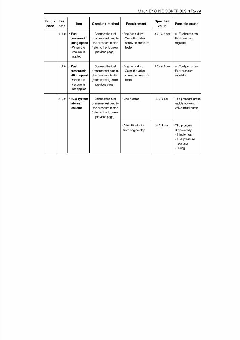
8/18/2019 SsangYong Musso Service Manual 1998.pdf
http://slidepdf.com/reader/full/ssangyong-musso-service-manual-1998pdf 678/1459
M161 ENGINE CONTROLS 1F2-29
Failurecode
Item Checking methodTeststep
RequirementSpecified
valuePossible cause
3.2 - 3.6 bar····· Fuelpressure:inidling speed- When the
vacuum isapplied
· Engine:in idling- Colse the valve
screw on pressuretester
Þ 1.0 Connect the fuelpressure test plug tothe pressure tester
(refer to the flgure onprevious page).
· Þ Fuel pump test· Fuel pressure
regulator
3.7 - 4.2 bar····· Fuelpressure:inidling speed- When the
vacuum isnot applied
· Engine:in idling- Colse the valve
screw on pressuretester
Þ 2.0 Connect the fuelpressure test plug tothe pressure tester
(refer to the flgure onprevious page).
· Þ Fuel pump test· Fuel pressure
regulator
> 3.0 bar····· Fuel systeminternalleakage:
· Engine:stopÞ 3.0 Connect the fuelpressure test plug tothe pressure tester
(refer to the flgure onprevious page).
· The pressure dropsrapidly:non-returnvalve in fuel pump
> 2.5 bar· After 30 minutesfrom engine stop
· The pressuredrops slowly:- Injector test- Fuel pressure
regulator- O-ring

8/18/2019 SsangYong Musso Service Manual 1998.pdf
http://slidepdf.com/reader/full/ssangyong-musso-service-manual-1998pdf 679/1459
1F2-30 M161 ENGINE CONTROLS
FUEL PUMP TESTPreparation
1 ECU2 Test Coupling(No.1-60)3 Test Coupling(No.61-120)4 Stop Watch5 Measuring Beaker
Connection of the Equipment1. Turn the ignition switch to "OFF" position.2. Connect the test box to the ECU.
03 Test Box04 ECU Test Cable
Tools Required103 589 00 21 00 Pressure Tester210 589 00 99 00 Adaptor Line129 589 00 21 00 Test Box210 589 08 63 00 Ecu Test Cable
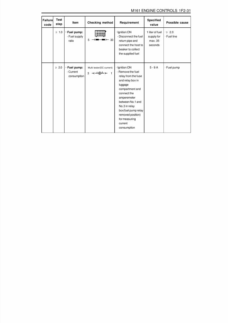
8/18/2019 SsangYong Musso Service Manual 1998.pdf
http://slidepdf.com/reader/full/ssangyong-musso-service-manual-1998pdf 680/1459
M161 ENGINE CONTROLS 1F2-31
Failurecode
Item Checking methodTeststep Requirement
Specifiedvalue
Possible cause
1 liter of fuelsupply formax. 35seconds
····· Fuel pump:- Fuel supply
ratio
· Ignition:ON- Disconnect the fuel
return pipe andconnect the host tobeaker to collectthe supplied fuel
Þ 1.0 · Þ 2.0· Fuel line
5 - 9 A····· Fuel pump:- Current
consumption
· Ignition:ON - Remove the fuel
relay from the fuseand relay box inluggagecompartment andconnect theamperemeterbetween No.1 andNo.3 in relaybox(fuel pump relayremoved position)for measuringcurrentconsumption
Þ 2.0 · Fuel pump
5 33
Multi tester(DC current)
3 1

8/18/2019 SsangYong Musso Service Manual 1998.pdf
http://slidepdf.com/reader/full/ssangyong-musso-service-manual-1998pdf 681/1459
1F2-32 M161 ENGINE CONTROLS
INJECTOR TEST
1 ECU2 Test Coupling(No.1-60)3 Test Coupling(No.61-120)4 Measuring Beaker5 Shop Made Cable
Preparation
03 Test Box04 ECU Test Cable
Connection of the Equipment1. Connect the test box to the ECU as shown in the figure.2. Remove the 2-pin coupling from injector.3. Remove the fuel distributor and injector with a unit. At this
time, do not remove the supply and return line.4. Connect the shop made cable to the injector with a firing
order.5. Collect the fuel from injector.
Tools Required129 589 00 21 00 Test Box210 589 08 63 00 ECU Test Cable

8/18/2019 SsangYong Musso Service Manual 1998.pdf
http://slidepdf.com/reader/full/ssangyong-musso-service-manual-1998pdf 682/1459
M161 ENGINE CONTROLS 1F2-33
Figure 8. Shop Made Cable Figure 9. Fuel Injector Normal Spary Pattern
Failurecode
Item Checking methodTest
stepRequirement
Specifiedvalue
Possible cause
There shouldbe no leaks
and laterdrops fromthe injector
····· Injector:- Leakage
test
· Ignition:ON- Remove the fuel
distributor and fuelinjector with a unit.
Þ 1.0 · Þ 2.0· Injector
The spraypattern of theinjector mostshow in the
figure 10
· Ignition:ON- Connect the shop
made cable to theinjector.
- Collect thespraying fuel with abeaker
- Connect the shopmade cable toNo.11(+) and No.5
(-) terminal in testbox.
Þ 2.0 · Injector
5 33
····· Injector:- Function
test andspraypatterncheck
5 33

8/18/2019 SsangYong Musso Service Manual 1998.pdf
http://slidepdf.com/reader/full/ssangyong-musso-service-manual-1998pdf 683/1459
1F2-34 M161 ENGINE CONTROLS
MAINTENANCE AND REPAIR
ON-VEHICLE SERVICEECU
Appearance
1 Cover2 Plate3 Connector4 Flat pin
Vehicle side : number 1 - 12Engine side : number 61 - 72
5 PinVehicle side : number 13 - 60Engine side : number 73 - 120
A Vehicle Connector : BlackB Engine Connector : Gray

8/18/2019 SsangYong Musso Service Manual 1998.pdf
http://slidepdf.com/reader/full/ssangyong-musso-service-manual-1998pdf 684/1459
M161 ENGINE CONTROLS 1F2-35
LocationEngine ECU is located at the inside of cowl side trim in rightbottom of instrument panel of passenger side.
Removal & Installation Procedure1. Turn the ignition switch to "OFF" position.2. Disconnect the battery negative cable3. Remove the cowl side trim form passenger side.4. Unscrew four securing nuts for ECU from mounting bracket.
Installation Notice
5. Pulling out the ECU from bracket.6. Disconnect the vehicle side coupling(B).7. Installation should follow the removal procedure in the
reverse order.
Tightening Torque 9 - 11 Nm
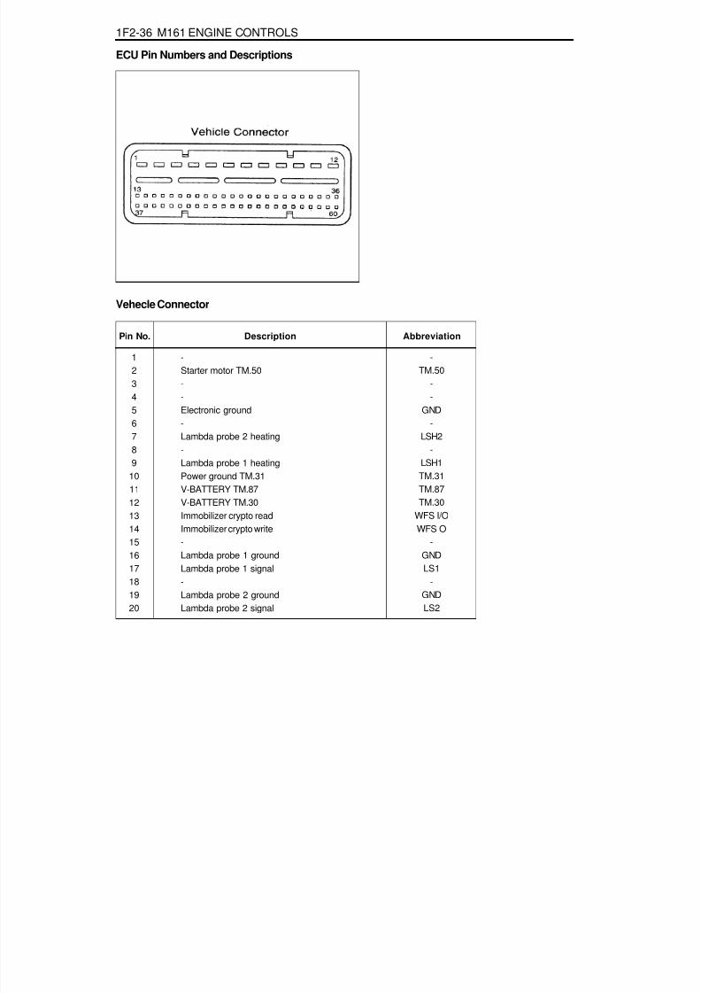
8/18/2019 SsangYong Musso Service Manual 1998.pdf
http://slidepdf.com/reader/full/ssangyong-musso-service-manual-1998pdf 685/1459
1F2-36 M161 ENGINE CONTROLS
Pin No. AbbreviationDescription
123
456789
1011121314151617181920
-TM.50
-
-GND-
LSH2-
LSH1TM.31TM.87TM.30
WFS I/OWFS O
-GNDLS1
-GNDLS2
-Starter motor TM.50-
-Electronic ground-Lambda probe 2 heating-Lambda probe 1 heatingPower ground TM.31V-BATTERY TM.87V-BATTERY TM.30Immobilizer crypto readImmobilizer crypto write-Lambda probe 1 groundLambda probe 1 signal-Lambda probe 2 groundLambda probe 2 signal
ECU Pin Numbers and Descriptions
Vehecle Connector

8/18/2019 SsangYong Musso Service Manual 1998.pdf
http://slidepdf.com/reader/full/ssangyong-musso-service-manual-1998pdf 686/1459
M161 ENGINE CONTROLS 1F2-37
Pin No. AbbreviationDescription
212223242526272829303132333435363738394041424344
45464748495051525354
555657585960
BRS-----
KLIKU---
GNDSP1+5V
KPTEVML
-CAN LCAN H
----
KPIKLIMA
ETS-
SP1SSP2SBLSGND
SP2+2.5VS+BWAS-B
KSK-
AUSDIAGV-SIG
TN-SIG
Brake switch-----Air conditioning clutch relay---Pedal potentiometer 1 groundPedal potentiometer 1 supplyFuel pump relayTank purge valveEngine fan(High)-CAN-LowCAN-High-----Air conditioning
Electronic traction signal-Pedal potentiometer 1 signalPedal potentiometer 2 signalBrake light switchPedal potentiometer 2 groundPedal potentiometer 2 supplyCruise accelerate/SetCruise resumeCruise decelerate/Set
Cruise safety contact switch-Cruise off switchDiagnostics(K-Line)Vehicle speed signalEngine speed signal

8/18/2019 SsangYong Musso Service Manual 1998.pdf
http://slidepdf.com/reader/full/ssangyong-musso-service-manual-1998pdf 687/1459
1F2-38 M161 ENGINE CONTROLS
Engine Connector
Pin No. AbbreviationDescription
61626364
65666768697071727374
757677787980
--
EV1EV4
EV2EV3M+M-
TM.31-
ZSB23ZSA14NWSEGR
-SLP
-MT
GNDLT
--Injector-cylinder 1Injector-cylinder 2
Injector-cylinder 3Injector-cylinder 4E-GAS motor plusE-GAS motor minusPower ground TM.31-Ignition coil cylinder 2+3Ignition coil cylinder 1+4Camshaft controlEGR (Exhaust Gas Recirculation)
-Second air pump relay-Engine coolant temperatureIntake air temperature groundIntake air temperature

8/18/2019 SsangYong Musso Service Manual 1998.pdf
http://slidepdf.com/reader/full/ssangyong-musso-service-manual-1998pdf 688/1459
M161 ENGINE CONTROLS 1F2-39
Pin No. AbbreviationDescription
81828384858687888990919293949596979899
100101102103104
105106107108109110111112113114
115116117118119120
HFM-
V-REF.PS-
IP2S-
IP1S-----------
KW-KW+
-PSAUG
GNDNOWE-
GNDNOWE+
-V-REF.HFM
---
V-REF.DK--
--
GNDKS1
--
Hot film air mass signal-Pressure sensor supplyE-GAS potentiometer groundE-GAS potentiometer 2 signal-E-GAS potentiometer 1 signal-----------Crankshaft sensor groundCrankshaft sensor signal-Intake manifold pressure signalIntake manifold pressure groundCamshaft sensor ground
Hot film air mass groundCamshaft sensor signal-Hot film air mass supply---E-GAS potentiometer supply--
--Knock sensor 1 groundKnock sensor 1 signal--

8/18/2019 SsangYong Musso Service Manual 1998.pdf
http://slidepdf.com/reader/full/ssangyong-musso-service-manual-1998pdf 689/1459
1F2-40 M161 ENGINE CONTROLS
Application
Pin No. AbbreviationDescription
-
Starter motor TM.50
-
-
Electronic ground
-
Lambda probe 2 heating
-
Lambda probe 1 heating
Power ground TM.31
V-BATTERY TM.87
V-BATTERY TM.30
Immobilizer crypto read
Immobilizer crypto write
-
Lambda probe 1 ground
Lambda probe 1 signal-
-
-
Brake switch
-
-
-
-
-
Air conditioning clutch relay
-
-
-
1
2
3
4
5
6
7
8
9
10
11
12
13
14
15
16
1718
19
20
21
22
23
24
25
26
27
28
29
30
-
TM.50
-
-
GND
-
LSH2
-
LSH1
TM.31
TM.87
TM.30
WFS I/O
WFS O
-
GND
LS1-
-
-
BRS
-
-
-
-
-
KLIKU
-
-
-
-
-
-
-
-
-
-
-
-
-
-
-
-
-
-
-
-
-
-
-
-
-
-
-
-
-
-
-
-
-
-
-
-
-
-
-
: Standard, : Option
E23 ENG,4speed A/T
E23 ENG,5speed A/T

8/18/2019 SsangYong Musso Service Manual 1998.pdf
http://slidepdf.com/reader/full/ssangyong-musso-service-manual-1998pdf 690/1459
M161 ENGINE CONTROLS 1F2-41
Pin No. AbbreviationDescription
Pedal potentiometer 1 ground
Pedal potentiometer 1 supply
Fuel pump relay
Tank purge valve
Engine fan
-
CAN-Low
CAN-High
-
-
-
-
-
Air conditioning
Electronic traction signal(ABD option only)
-
Pedal potentiometer 1 signal
Pedal potentiometer 2 signal
Brake light switch(Cruisel option only)
Pedal potentiometer 2 ground
Pedal potentiometer 2 supply
Cruise accelerate/Set(Cruisel option only)
Cruise resume(Cruisel option only)
Cruise decelerate/Set(Cruisel option only)
Cruise safety contact switch(Cruisel option only)
-Cruise off switch(Cruisel option only)
Diagnostics(K-Line)
Vehicle speed signal
Engine speed signal
31
32
33
34
35
36
37
38
39
40
41
42
43
44
45
46
47
48
49
50
51
52
53
54
55
5657
58
59
60
GND
SP1+5V
KP
TEV
ML
-
CAN L
CAN H
-
-
-
-
-
KLIMA
ETS
-
SP1S
SP2S
BLS
GND
SP2+2.5V
S+B
WA
S-B
KSK
-AUS
DIAG
V-SIG
TN-SIG
-
-
-
-
-
-
-
-
-
-
-
-
-
-
-
-
E23 ENG,4speed A/T
E23 ENG,5speed A/T

8/18/2019 SsangYong Musso Service Manual 1998.pdf
http://slidepdf.com/reader/full/ssangyong-musso-service-manual-1998pdf 691/1459
1F2-42 M161 ENGINE CONTROLS
Pin No.
61
62
63
64
65
66
67
68
69
70
71
72
73
74
75
76
77
78
79
80
81
82
83
84
85
8687
88
89
90
AbbreviationDescription
-
-
Injector-cylinder 1
Injector-cylinder 2
Injector-cylinder 3
Injector-cylinder 4
E-GAS motor plus
E-GAS motor minus
Power ground TM.31
-
Ignition coil cylinder 2+3
Ignition coil cylinder 1+4
Camshaft control
-
Second air pump relay
-
Engine coolant temperature
Temperature ground
Intake air temperature
Hot film air mass signal
-
-
E-GAS potentiometer ground
E-GAS potentiometer 2 signal
-
E-GAS potentiometer 1 signal-
-
-
-
-
EV1
EV4
EV2
EV3
M+
M-
TM.31
-
ZSB23
ZSA14
NWS
-
-
SLP
-
MT
GND
LT
HFM
-
-
-
IP2S
-IP1S
-
-
-
-
-
-
-
-
-
-
-
-
-
-
-
-
-
-
-
-
-
-
-
-
-
-
-
E23 ENG,4speed A/T
E23 ENG,5speed A/T

8/18/2019 SsangYong Musso Service Manual 1998.pdf
http://slidepdf.com/reader/full/ssangyong-musso-service-manual-1998pdf 692/1459
M161 ENGINE CONTROLS 1F2-43
Pin No. AbbreiationDescription
-
-
-
-
-
-
-
-
Crankshaft sensor ground
Crankshaft sensor signal
-
-
-
Camshaft sensor ground
Hot film air mass ground
Camshaft sensor signal
-
Hot film air mass supply
-
-
-
E-GAS potentiometer supply
-
-
-
-Knock sensor 1 ground
Knock sensor 1 signal
-
-
91
92
93
94
95
96
97
98
99
100
101
102
103
104
105
106
107
108
109
110
111
112
113
114
115
116117
118
119
120
-
-
-
-
-
-
-
-
KW-
KW+
-
-
-
NOWE-
GND
NOWE+
-
V-REF.HFM
-
-
-
V-REF.DK
-
-
-
-GND
KS1
-
-
-
-
-
-
-
-
-
-
-
-
-
-
-
-
-
-
-
-
-
-
-
-
-
-
-
-
-
-
-
-
-
-
-
-
-
-
-
-
-
-
-
-
E23 ENG,4speed A/T
E23 ENG,5speed A/T
-
-
-
-
-
-
-
-
-
-
-
-
-
-
-
-
-
-
-
-
-
E23 ENG,4speed A/T

8/18/2019 SsangYong Musso Service Manual 1998.pdf
http://slidepdf.com/reader/full/ssangyong-musso-service-manual-1998pdf 693/1459
1F2-44 M161 ENGINE CONTROLS
Removal & Installation Procedure····· When removing the ECU only1. Turn the ignition switch to "OFF" position.2. Disconnect the negative battery cable.3. Disconnect the couplings from ECU.4. Unscrew the left and right bolt (3) on bolt (1) and auxiliarly
bracket and remove the auxiliarly bracket from the bracketassembly (2).
Installation Notice
5. Unscrew the four bolts (5) and disconnect the ECU (6) fromthe bracket assenbly.
Installation Notice
6. Installation should follow the removal procedure in thereverse order.
Tightening Torque6 - 8 Nm
5 - 7 Nm
(1)
(3)
Tightening Torque 5 - 7 Nm
8. Unscrew the bolts (5) and disconnect the ECU (6) from thebracket assenbly.
Installation Notice
····· When Removing the ECU with ABS or ABS/ASR Unit1. Turn the ignition switch to "OFF" position.2. Disconnect the negative battery cable.3. Disconnect the couplings from ECU.4. Disconnect the coupling from ABS or ABS/ASR unit.5. Unscrew the bolt (1) and the left and right flange nuts.
6. Remove the ECU with ABS or ABS/ASR unit assembly.7. Unscrew the left and right bolt (3) on the auxiliary bracket
and remove the auxiliary bracket from the bracket assembly.
Installation Notice
Tightening Torque 6 - 8 Nm
Tightening Torque 5 - 7 Nm
Tightening Torque 5 - 7 Nm
9. Installation should follow the removal procedure in thereverse order.

8/18/2019 SsangYong Musso Service Manual 1998.pdf
http://slidepdf.com/reader/full/ssangyong-musso-service-manual-1998pdf 694/1459
M161 ENGINE CONTROLS 1F2-45
1 Vacuum Hose
2 Circlip3 Fuel Pressure Regulator
FUEL PRESSURE REGULATOR
4 O-ring ..................................................... replace
5 O-ring ..................................................... replace

8/18/2019 SsangYong Musso Service Manual 1998.pdf
http://slidepdf.com/reader/full/ssangyong-musso-service-manual-1998pdf 695/1459
1F2-46 M161 ENGINE CONTROLS
3. Disconnect the vacuum hose.4. Disconnect the circlip and remove the fuel pressure
regulator.5. Apply the oil to O-ring lightly and then replace it.6. Installation should follow the removal procedure in the
reverse order.7. Check for fuel pressure and internal leaks by operating the
engine.
2. Discharge the pressure in fuel supply system by pressingthe service valve.
Removal & Installation Procedure1. Remove the fuel pressure test connector.

8/18/2019 SsangYong Musso Service Manual 1998.pdf
http://slidepdf.com/reader/full/ssangyong-musso-service-manual-1998pdf 696/1459
M161 ENGINE CONTROLS 1F2-47
A. Valves ClosedB. Valves Opened
The pressure difference between the fuel pressure and theintake manifold is about 3.8 bars during the full load.
<Operating at Idle and partial load>The spring chamber(9) is connected to the intake manifoldwith the vacuum hose at the intake pipe connection(7). Thenegative pressure generated in the intake manifold activatesthe diaphragm, and thus the fuel pressure gets reduced to therate of the operating extent of the diaphragm by the intakemanifold's negative pressure.Consequently, the fuel pressure in the fuel distributor changesby the intake manifold's negative pressure, and the injector'sfuel pressure gets reduced independently to the throttle valve'sposition. Thus, the fuel injection volume can only be determinedaccording to the injector's injecting duration.
2. Fuel return line3. Valve5. Diaphragm6. Compression Spring8. Fuel chamber9. Spring Chamber
1. Fuel pressure Regulator2. Intake Manifold3. Fuel return(to fuel tank)4. Fuel supply(form fuel pump)5. Fuel pressure(approx. 3.8 bars)6. Intake Manifold Negative Pressure(0 bar)
Function of the Fuel Pressure RegulatorThe fuel pressure regulator maintains the fuel pressure in thefuel line with the pressure of 3.2 bars to 3.8 bars according tothe intake manifold pressure. This operating pressure cannotbe changed, and the fuel injection volume will be onlydetermined by the injection time. Over supplied fuel returns tothe fuel tank through the return line.<Operating at full load>There is no negative pressure applied to the spring chamber(9)during the full load, and it is separated from the fuel chamber(8)by the diaphragm(5).When the fuel pressure goes up, the diaphragm forces thecompression spring(6) in the direction of compression . At thismoment, the valve(3) sticks to the diaphragm by the fuelpressure, and the fuel return line(2) opens. The fuel oversupplied returns to the fuel tank through the return line.

8/18/2019 SsangYong Musso Service Manual 1998.pdf
http://slidepdf.com/reader/full/ssangyong-musso-service-manual-1998pdf 697/1459
1F2-48 M161 ENGINE CONTROLS
The pressure difference between the fuel pressure andthe intake manifold is approx. 3.2 bars during idling.
<Fuel Pressure Diagram>
1. Fuel pressure Regulator
2. Intake Manifold3. Fuel Return(to fuel tank)4. Fuel Supply(from fuel pump)7. Fuel Pressure(approx. 3.2 bars)8. Intake Manifold Negative Pressure(0.6 bars)
A. Fuel pressureB. Intake Manifold Negative PressureLL. IdlingTL. Partial loadVL. Full load

8/18/2019 SsangYong Musso Service Manual 1998.pdf
http://slidepdf.com/reader/full/ssangyong-musso-service-manual-1998pdf 698/1459
M161 ENGINE CONTROLS 1F2-49
FUEL DISTRIBUTORPreceding Work : Removal of intake air duct
1 Fuel Distributor2 Circlip
3 Fuel Pressure Regulator4 O-ring5 Fuel Pressure Test Connector6 Seal Ring7 Vacuum Hose8 Combination Bolt (M8 X 120) ......... 22.5-27.5 Nm
9 Fuel Return Line10 Seal Ring
11 Hollow Bolt ..................................... 22.5-27.5 Nm12 Clamp13 Bolt (M8 X 22) ........................................ 9-11 Nm14 Injector Bracket15 Injector16 O-ring
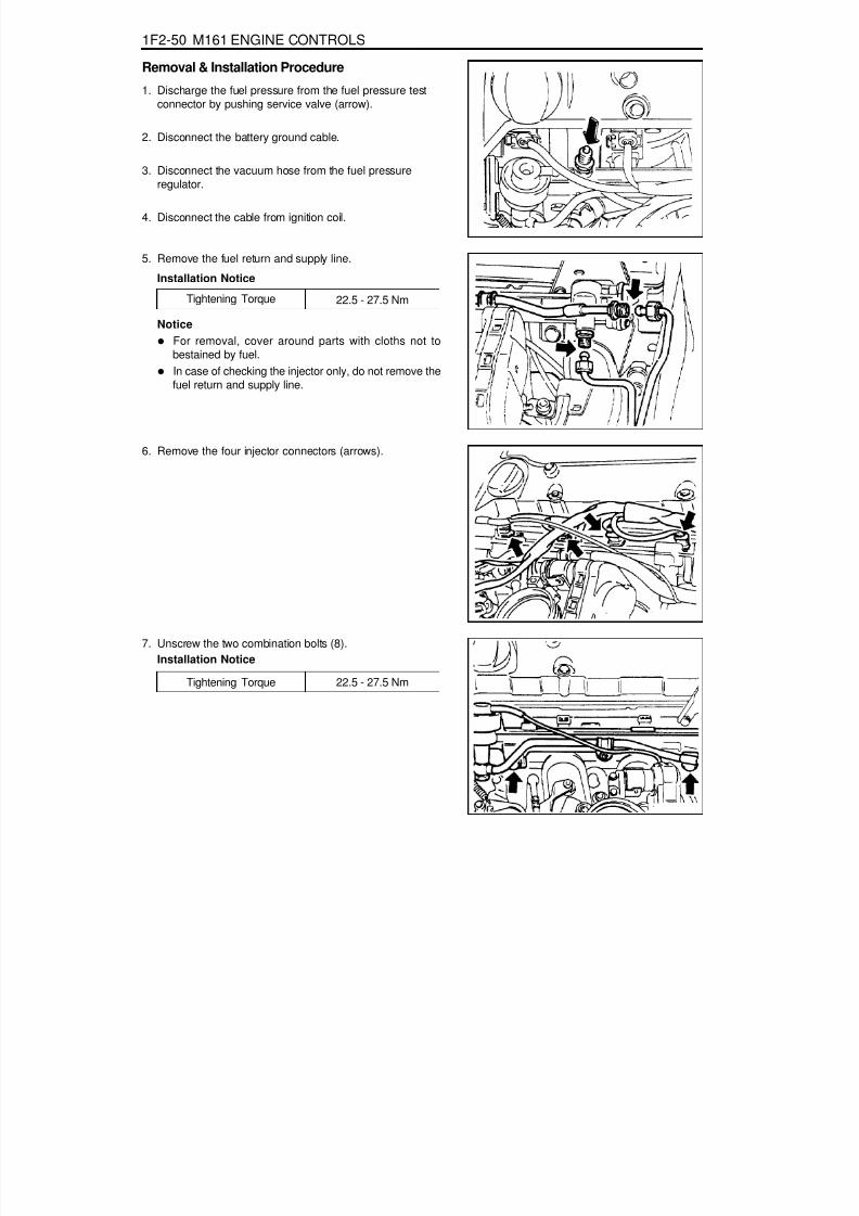
8/18/2019 SsangYong Musso Service Manual 1998.pdf
http://slidepdf.com/reader/full/ssangyong-musso-service-manual-1998pdf 699/1459
1F2-50 M161 ENGINE CONTROLS
Tightening Torque 22.5 - 27.5 Nm
Tightening Torque 22.5 - 27.5 Nm
Removal & Installation Procedure
1. Discharge the fuel pressure from the fuel pressure testconnector by pushing service valve (arrow).
2. Disconnect the battery ground cable.
3. Disconnect the vacuum hose from the fuel pressureregulator.
4. Disconnect the cable from ignition coil.
5. Remove the fuel return and supply line.
Installation Notice
NoticeFor removal, cover around parts with cloths not tobestained by fuel.In case of checking the injector only, do not remove thefuel return and supply line.
6. Remove the four injector connectors (arrows).
7. Unscrew the two combination bolts (8).Installation Notice

8/18/2019 SsangYong Musso Service Manual 1998.pdf
http://slidepdf.com/reader/full/ssangyong-musso-service-manual-1998pdf 700/1459
M161 ENGINE CONTROLS 1F2-51
9. Installation should follow the removal procedure in thereverse order.
10. Check for fuel pressure and internal leakage by operatingthe engine.
8. Pull out the injector from intake manifold and remove thefuel distributor.NoticeReplace the injector O-ring with new one.
Ignition Coil & Cable
Ignition coil T1/1 No.1 cylinder + No.4 cylinderInition coil T1/2 No.1 cylinder + No.4 cylinder

8/18/2019 SsangYong Musso Service Manual 1998.pdf
http://slidepdf.com/reader/full/ssangyong-musso-service-manual-1998pdf 701/1459
1F2-52 M161 ENGINE CONTROLS
Fuel Pressure Test1. Turn the ignition switch to "OFF" position.2. Remove the fuel pressure test connector.
Vacuum Hose Connected (bar) 3.2-3.6
Vacuum Hose Disconnected (bar) 3.7-4.2
5. Replace the pressure regulator diaphragm if out of thespecification.
3. Connect the fuel pressure gauge to the fuel pressure testconnector.
4. Test the fuel pressure at idling by operating the engine.

8/18/2019 SsangYong Musso Service Manual 1998.pdf
http://slidepdf.com/reader/full/ssangyong-musso-service-manual-1998pdf 702/1459
M161 ENGINE CONTROLS 1F2-53
3. If there is no change in fuel pressure and maintain thefollowing pressure over 30 minutes, it is normal.
Internal Leakage Test1. Connect the fuel pressure gauge to the fuel pressure test
connector.2. Stop the engine for approx. 30 minutes and then check the
fuel pressure changes.
Fuel pressuredrops slowly
· Fuel leakage at theinjector
• Faulty fuel pressureregulator'sdiaphragm and O-ring.
Fuel pressuredrops rapidly
• Faulty check valvein the fuel pump.
Possible CausePressure Change
Fuel Pressure(bar) 2.5
Discharging the pressure in fuel system1. Remove the fuel pressure test connector.
Installation Notice
2. Remove the fuel pressure in fuel system by pressing theservice valve with a clean, pointy tool.NoticePlace a cloth so that the fuel doesn't stain around.
Tightening Torque 22.5 - 27.5 Nm

8/18/2019 SsangYong Musso Service Manual 1998.pdf
http://slidepdf.com/reader/full/ssangyong-musso-service-manual-1998pdf 703/1459
1F2-54 M161 ENGINE CONTROLS
INJECTORPreceding Work : Removal of fuel distributor
1 O-ring .................................Replace, if damaged2 Injector Bracket3 Injector
4 O-ring .................................Replace, if damaged5 Fuel Distributor

8/18/2019 SsangYong Musso Service Manual 1998.pdf
http://slidepdf.com/reader/full/ssangyong-musso-service-manual-1998pdf 704/1459
M161 ENGINE CONTROLS 1F2-55
Removal & Installation Procedure1. Remove the O-ring.
Check for damage and replace it if necessary.2. Remove the injector bracket from the injector.
Installation NoticeExactly seat the anti-twist lock into the square groove ininjector.
3. Separate the injector from the fuel distributor.
Inspection & MaintenanceInspection of the Injector operation and spray pattern1. Connect the contact box to the ECU.2. Connect the shop made test plug to the injector and place
it into the tank.3. Position the ignition switch to ON.4. Connect the pin 63(+) and 69(-) of the contact box with a
test cable.
5. Check the injector spray pattern.
NoticeReplace the injector if the injector spray pattern is abnormalor the fuel doesn't inject.
Injector Resistance Inspection1. Remove the injector connector.2. Measure the injector coil resistance using a resistance
tester.
NoticeReplace the injector if the measured values is out of thespecified values. Check the connector and wire connectionbetween the ECU and the injector if the measured valuesare normal.
Specified Value 14 - 17 W
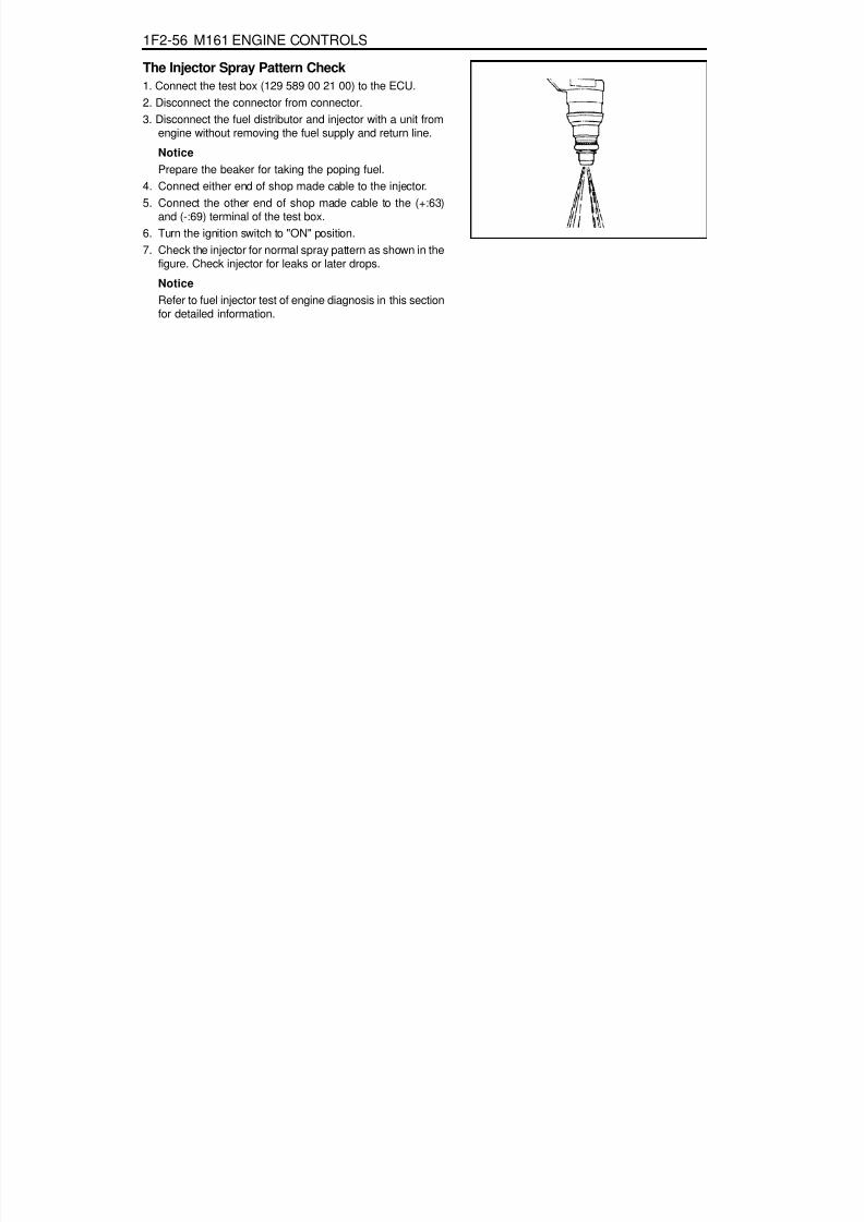
8/18/2019 SsangYong Musso Service Manual 1998.pdf
http://slidepdf.com/reader/full/ssangyong-musso-service-manual-1998pdf 705/1459
1F2-56 M161 ENGINE CONTROLS
The Injector Spray Pattern Check1. Connect the test box (129 589 00 21 00) to the ECU.2. Disconnect the connector from connector.3. Disconnect the fuel distributor and injector with a unit from
engine without removing the fuel supply and return line.
NoticePrepare the beaker for taking the poping fuel.
4. Connect either end of shop made cable to the injector.5. Connect the other end of shop made cable to the (+:63)
and (-:69) terminal of the test box.6. Turn the ignition switch to "ON" position.7. Check the injector for normal spray pattern as shown in the
figure. Check injector for leaks or later drops.
NoticeRefer to fuel injector test of engine diagnosis in this sectionfor detailed information.

8/18/2019 SsangYong Musso Service Manual 1998.pdf
http://slidepdf.com/reader/full/ssangyong-musso-service-manual-1998pdf 706/1459
M161 ENGINE CONTROLS 1F2-57
FUEL FILTER
1 Fuel Filter2 Outlet
Removal & Installation Procedure1. Open the fuel tank cap and remove the fuel tank pressure.2. Remove the fuel out (2) and in (3).
Installation Notice
NoticePlace the fuel pump pad. There may be a corrosion due tothe contact between the fuel filter and the bracket.
4. Check for leaks by operating the engine.
NoticeInstallation should follow the removal procedure in thereverse order.
3. Remove the mounting bracket bolt (4) and remove the fuelfilter (1).
Installation Notice
3 Inlet
Tightening Torque 25 - 30 Nm
Tightening Torque 4 - 8 Nm

8/18/2019 SsangYong Musso Service Manual 1998.pdf
http://slidepdf.com/reader/full/ssangyong-musso-service-manual-1998pdf 707/1459
1F2-58 M161 ENGINE CONTROLS
FUEL PUMP
Requirements for Fuel Pump
Item Specified Value Item Specified Value
System pressure 3.8 bar Minimum delivery at 8V 30 Litre/Hr
Maximum pressure 8.5 bar (12 V)
Minimum amountof fuel supply
114 Liter/Hr (12 V, 3.8 bar, -30 ~ +70°C)
Minimum pressure 5.0 bar (12 V) Maximum allowable current 7.5 A
Nominal voltage 12 V Ambient temperature -30 ~ +70°C
1 Reservoir Tank2 Fuel Sensor (float/arm)3 Resistance4 Wiring Connector5 Fuel Supply Pipe7 Float
10 Flange and Harness Assembly11 Fuel Pump12 Spring13 Thermister Housing14 Thermister15 Resistor Card and Wiper16 Float Arm
Operating voltage 8 V
Maximum amountof fuel supply
165 Liter/Hr (12V, 3.8 bar,-30 ~ +70°C)

8/18/2019 SsangYong Musso Service Manual 1998.pdf
http://slidepdf.com/reader/full/ssangyong-musso-service-manual-1998pdf 708/1459
M161 ENGINE CONTROLS 1F2-59
1234
1 Fuel Pump Connector Wiring2 Fuel Return Pipe3 Fuel Supply Pipe4 Bolts
5 Fuel Return Pipe6 Fuel Supply Pipe7 Float8 Ground Stud (Sender "-")
COLORPump "+"
Thermister "+"Ground
Sender Unit "+"
USEHarness Location & ConnectorABCD
2.0 BR0.5 W2.0 B
0.5 RY

8/18/2019 SsangYong Musso Service Manual 1998.pdf
http://slidepdf.com/reader/full/ssangyong-musso-service-manual-1998pdf 709/1459
1F2-60 M161 ENGINE CONTROLS
Tools Required661 589 00 46 00 Cap Remover
Removal & Installation Procedure1. Disconnect the negative battery cable.2. Disconnect the harness connector (1).3. Disconnect the fuel supply (6) and return (5) pipes.4. Using a special tool, Unscrew the eight fuel retaining bolts
and remove the pump from fuel tank.
NoticeCheck the condition of the seal and replace if necessary.Drain the fuel before removing the pump.

8/18/2019 SsangYong Musso Service Manual 1998.pdf
http://slidepdf.com/reader/full/ssangyong-musso-service-manual-1998pdf 710/1459
M161 ENGINE CONTROLS 1F2-61
NoticeReplace the fuel pump relay if the measured value is over9A.
NoticeCheck the fuel filter and fuel line when the fuel delivery isnot within specified value.
Measure the Current Consumption of Fuel Pump1. Remove the fuel pump relay from fuse and relay box in
trunk, and turn the ignition switch to "ON" position.2. Using a multi-tester, measure the current consumption by
connecting the terminal No.1 and No.3 of pump.
Measure the Fuel Delivery From the Fuel Pump1. Disconnect the return pipe from fuel distributor and insert
the appropriate hose into it.2. Place the hose end into the beaker with the minimum capacity
of 1Liter.3. Turn the ignition switch to "ON" position.
4. Connect the terminal No.33 and No.5 of ECU with a servicewire.
5. Measure the fuel delivery from the fuel pump.
1Liter/max.35sec.Specifed Value
5 - 9ASpecifed Value

8/18/2019 SsangYong Musso Service Manual 1998.pdf
http://slidepdf.com/reader/full/ssangyong-musso-service-manual-1998pdf 711/1459
1F2-62 M161 ENGINE CONTROLS
PURGE SWITCHOVER VALVE
1 Purge Control valve2 Line to engine3 Line to canister4 Canister
FunctionsThe fuel vaporization control system is installed to inhibit thefuel vaporized gas from discharging into the atmosphere. Thefuel vaporized gas that is accumulated in the canister abstractsthrough the purge switchover valve purification during theengine combustion (except the decreasing mode) and coolanttemperature of over 80 °C. For this reason, the ECU transactsthe engine speed, air inflow quantity, coolant temperature, andintake temperature.The purge switchover valve is activated by the ECU frequencyaccording with the engine rotating speed to adjust thepurification rate. The purification rate is determined by thecontinuous valve opening interval.The purge switchover valve is activated by the ECU for thefollowing conditions :
Coolant temperature of over 80 °CEngine speed of over 1000rpm2 Minutes after startingWhen the fuel cut-off mode is not activated

8/18/2019 SsangYong Musso Service Manual 1998.pdf
http://slidepdf.com/reader/full/ssangyong-musso-service-manual-1998pdf 712/1459
M161 ENGINE CONTROLS 1F2-63
4. Remove the line to canister and measure the pressure withthe vacuum pressure gauge.
Test1. Maintain the normal temperature and idling state by
operating the engine.2. Connect the ECU terminal No.11 and No.34 and check for
normal operation through the output waves using thescanner.
NoticeTest during purge control switchover valve operation afterthe minimum of 1 minute after the engine turned on.
3. Connect the ECU terminal No.34 and No.10 and check forcurrent consumption during the ignition switch ON.
Purge switchover valve output waveSpecified Value 0.3 - 0.5
Specified Value
> 50mbar
(after approx. 1min.) purge switchover valve
operates at this time
NoticeTest while at normal temperature and at idling state byoperating the engine.

8/18/2019 SsangYong Musso Service Manual 1998.pdf
http://slidepdf.com/reader/full/ssangyong-musso-service-manual-1998pdf 713/1459
1F2-64 M161 ENGINE CONTROLS
1 Purge Switchover Valve2 Molded Hose3 Fuel Tube (270 mm)4 Clamp5 Molded Hose6 Intake Manifold7 Throttle Body
VACUUM SYSTEMManual Transmission
8 Fuel Pressure Regulator9 Vacuum Line Rubber Hose (40 mm)10 Vacuum Tube (Gray, 540 mm)11 Rubber Cap12 Molded Hose13 Vacuum Tube (Brown)14 Connector

8/18/2019 SsangYong Musso Service Manual 1998.pdf
http://slidepdf.com/reader/full/ssangyong-musso-service-manual-1998pdf 714/1459
M161 ENGINE CONTROLS 1F2-65
15 Manual Transmission16 Distributor
Automatic Transmission
A. To CanisterB. To Auto Locking Hub

8/18/2019 SsangYong Musso Service Manual 1998.pdf
http://slidepdf.com/reader/full/ssangyong-musso-service-manual-1998pdf 715/1459
1F2-66 M161 ENGINE CONTROLS
1 Crankshaft Position Sensor (connector)2 Bolt (M6 X 14) ........................................ 9-11 Nm
CRANKSHAFT POSITION SENSOR
Removal & Installation Procedure1. Disconnect the wiring connector at the crankshaft position
sensor.2. Unscrew the bolt (2) and remove the crankshaft position
sensor unit (3).
Installation Notice
3. Installation should follow the removal procedure in thereverse order.
3 Sensor Unit
Tightening Torque 9 - 11 Nm

8/18/2019 SsangYong Musso Service Manual 1998.pdf
http://slidepdf.com/reader/full/ssangyong-musso-service-manual-1998pdf 716/1459
M161 ENGINE CONTROLS 1F2-67
Crankshaft Position Sensor ResistanceInspection1. Disconnect the coupling "E" of ECU while the ignition switch
is in "OFF" position.2. Measure the resistance between the coupling terminal pin
No.99 and No.100 using a multimeter.
NoticeMeasure the insulator resistance of the crankshaft positionsensor if out of the specified value.
Crankshaft Position Sensor Output WaveInspection1. Connect the test box to the ECU.2. Measure the output wave between the ECU terminals No.99
and No.100 using the scanner or the oscilloscope whileengine cranking (starter motor activated).
NoticeCheck the segment or crankshaft position sensor and airgap if cannot get the output wave as shown in the figure.
Specified Value 1050 - 1400 W
Specified Value > 20k W
Crankshaft Position Sensor Insulator ResistanceInspection1. Disconnect the engine coupling from ECU while the ignition
switch is in "OFF" position.2. Measure the resistance between the coupling terminal pin
No.100 and No.69.
NoticeMeasure the check and ground terminal of the crankshaftposition sensor if out of the specified value.

8/18/2019 SsangYong Musso Service Manual 1998.pdf
http://slidepdf.com/reader/full/ssangyong-musso-service-manual-1998pdf 717/1459
1F2-68 M161 ENGINE CONTROLS
CAMSHAFT POSITION SENSOR
1 Bolt (M6 X 14) ......................................... 9-11Nm2 Camshaft Position Sensor
Removal & Installation Procedure1. Disconnect the wiring connector from the camshaft position
sensor.2. Unscrew the bolt (2) and remove the camshaft position
sensor.
Installation Notice
3 Shim5 O-ring
Tightening Torque 9 - 11 Nm
3. Check the clearance and replace the shim if necessary.4. Check the O-ring for damage and replace it if necessary.5. Installation should follow the removal procedure in the
reverse order.

8/18/2019 SsangYong Musso Service Manual 1998.pdf
http://slidepdf.com/reader/full/ssangyong-musso-service-manual-1998pdf 718/1459
M161 ENGINE CONTROLS 1F2-69
Camshaft Position Sensor Power SupplyInspection1. Turn the ignition switch to 'ON' position.2. Disconnect the camshaft position sensor connector.3. Measure the voltage between the No.1 and No.3 pin of
camshaft position sensor while the ignition switch is in "ON"position.
NoticeIf the measured value is not within the specified value, checkthe cable.
NoticeThe signal voltage will be changed in the range of 1.2~1.7V.
Camshaft Position Sensor Output WaveInspection1. Connect the test box to the ECU.2. Measure the output wave between the ECU terminal No.104
and No.106 using the scanner or the oscilloscope while theengine speed is at idle.
NoticeReplace the camshaft position sensor if cannot get theoutput wave as shown in the figure.
Specified Value 11 - 14 V
Specified Value 1.2 - 1.7 V
Camshaft Position Sensor Signal VoltageInspection1. Connect the test box to the ECU.2. Measure the voltage between the ECU terminal No.11 and
No.106 while the engine speed is at idle.

8/18/2019 SsangYong Musso Service Manual 1998.pdf
http://slidepdf.com/reader/full/ssangyong-musso-service-manual-1998pdf 719/1459
1F2-70 M161 ENGINE CONTROLS
HOT FILM AIR MASS (HFM) SENSOR
1 Housing2 Protector Net3 Electronic Housing
Removal & Installation Procedure1. Turn the HFM sensor coupling in the direction shown in the
figure in the right so that it gets separated from the contactsurface.
NoticeMake sure the HFM sensor coupling connects completely
with the contact surface Installation.2. Remove the clip with a screw driver.3. Pry off two tensioning clamps.4. Remove the HFM sensor.5. Installation should follow the removal procedure in the
reverse order.
4 Connector5 Hot film Sensor6 Measuring Port

8/18/2019 SsangYong Musso Service Manual 1998.pdf
http://slidepdf.com/reader/full/ssangyong-musso-service-manual-1998pdf 720/1459
M161 ENGINE CONTROLS 1F2-71
Circuit Diagram
1 Housing2 Electronic Housing3 Connector
RH : Heat Resistance
RT : Temperature ResistanceRS : Sensor Resistance

8/18/2019 SsangYong Musso Service Manual 1998.pdf
http://slidepdf.com/reader/full/ssangyong-musso-service-manual-1998pdf 721/1459
1F2-72 M161 ENGINE CONTROLS
If the measured value is not within the specified value, thepossible cause may be in cable or HFM sensor in itself.Perform the 5V power supply inspection procedures.
HFM Sensor 5V Power Supply Inspection1. Measure the voltage between the HFM sensor No.108(+) and
No.105(-) after removing the HFM sensor connector.
HFM Sensor Input Voltage Inspection1. Measure the HFM sensor signal voltage between the ECU
terminal No.81 and No.105.
Specified Value (coolant temperature is over 70°C)
If the measured value is not within the specified value, thepossible cause may be in cable or ECU coupling.
Iginition"ON” 0.9 - 1.1 V
Engine at idle 1.3 - 1.7 V
Specified Value 4.7 - 5.2 V
2. Measure the voltage between the HFM sensor winingconnector terminal No.3 pin and No.102(+) after removingthe HFM sensor connector.
Specified Value
If the measured value is not within the specified value, thepossible cause may be in cable or over voltage protectionrelay.Perfrom the 12V power supple inspection procedures.
Specified Value 4.7 - 5.2 V
HFM Sensor 12V Power Supply Inspection1. Measure the voltage between the HFM sensor wining
connector 1G No.2 pin(+) and No.3 after removing the HFMsensor connector.
If the measured value is not within the specified value, thepossible cause may be in cable or over voltage protectionrelay.
Specified Value 11 - 14 V

8/18/2019 SsangYong Musso Service Manual 1998.pdf
http://slidepdf.com/reader/full/ssangyong-musso-service-manual-1998pdf 722/1459
M161 ENGINE CONTROLS 1F2-73
OXYGEN SENSOR
1 Electricity Wire2 Oxygen Sensor Housing3 Sensor Ceramic4 Electrode (Internal)5 Electrode (External)6 Heating Coil7 Open Space8 Protector Tube
FunctionsThe oxygen sensor optimizes the combustion (Air-Fuel Ratio14.7:1) and resets the Air-fuel ratio in the ECU after sensing
the amount of oxygen from the exhaust gases to diminish theexhaust gases.- Rich(<1) above approx. 450mV- Lean(>1) below approx. 450mV
Locatoin of SensorOxygen sensor is located on the front exhaust pipe.

8/18/2019 SsangYong Musso Service Manual 1998.pdf
http://slidepdf.com/reader/full/ssangyong-musso-service-manual-1998pdf 723/1459
1F2-74 M161 ENGINE CONTROLS
Oxygen Sensor Signal Voltage Inspection1. Measure the oxygen sensor signal voltage between the ECU
terminal No.11 and No.9. Maintain the engine speed ia atidle while the coolant temperature is over 80°C.
If the measured value is not within the specified value, thepossible cause may be in cable, oxygen sensor or ECU.
Oxygen Sensor Heating Voltage Inspection1. Measure the oxygen sensor heating voltage between the
ECU terminal No.11 and No.9. Maintain the engine speed iaat idle while the coolant temperature is over 80°C.
If the measured value is not within the specified value, thepossible cause may be in cable, oxygen sensor or ECU.
Oxygen Sensor Heating Current ConsumptionInspection1. Measure the oxygen sensor heating current consumption
between the ECU terminal No.9 and sensor heating(+) linewhile the ignition switch is in "ON" position.
If the measured value is not within the specified value, thepossible cause may be in cable, oxygen sensor or ECU.
Specified Value 0.2 - 2.0 A
Specified Value -0.2 - 1.0 V
Specified Value 11 - 14

8/18/2019 SsangYong Musso Service Manual 1998.pdf
http://slidepdf.com/reader/full/ssangyong-musso-service-manual-1998pdf 724/1459
M161 ENGINE CONTROLS 1F2-75
KNOCK SENSOR
FunctionsVibration of the engine block is transmitted to the sensor andtransferred to the ECU in the form of an alternating voltagesignal via a shielded cable. The knock sensor is fastened tothe engine block to recognize knocking in all cylinders. TheECU compares the signal and the retards firing point.
Removal & Installation Procedure1. Disconnect the knock sensor connector from the intake
manifold bracket.2. Unscrew the mounting bolt (M8 X 28) from the knock sensor
installed on the cylinder block and remove the knockingsensor.
Installation Notice
3. Installation should follow the removal procedure in thereverse order.
Tightening Torque 22.5 - 27.5 Nm

8/18/2019 SsangYong Musso Service Manual 1998.pdf
http://slidepdf.com/reader/full/ssangyong-musso-service-manual-1998pdf 725/1459
1F2-76 M161 ENGINE CONTROLS
COOLANT TEMPERATURE SENSOR
1 Artificial Resin Housing2 Metal Housing3 NTC (negative temperature coefficient) Resistor
Removal & Installation Procedure1. Remove the pressure by opening the pressure cap in the
coolant subtank.2. Disconnect the connector and remove the coolant
temperature sensor.
Installation Notice
Replace the seals with new one.
3. Installation should follow the removal procedure in thereverse order.4. Check for leaks at each connections after starting the engine.
4 Connector5 Coolant Temperature Sensor
Tightening Torque 18 - 22 Nm

8/18/2019 SsangYong Musso Service Manual 1998.pdf
http://slidepdf.com/reader/full/ssangyong-musso-service-manual-1998pdf 726/1459
M161 ENGINE CONTROLS 1F2-77
2. Measure the resistance between the coolant temperaturesensor terminal No.1 and No.4 with the coolant temperaturesensor disconnected.
Inspection1. Measure the coolant sensor input voltage between the ECU
terminal No.79 and No.78 while the ignition switch in "ON"position.
NoticeReplace wiring and coolant temperature sensor if out ofspecified value.
allowable error : ±5%
allowable error : ± 5%
Voltage (V)3.57
1.220.78
Temperature (°C)20
3040
Resistance ( W)2,500322185
Temperature (°C)203040

8/18/2019 SsangYong Musso Service Manual 1998.pdf
http://slidepdf.com/reader/full/ssangyong-musso-service-manual-1998pdf 727/1459
1F2-78 M161 ENGINE CONTROLS
Service Data
Resistance characteristic curve according to the coolanttemperature
Temperature( °C) Resistance(W) Voltage(V) Temperature( °C) Resistance(W) Voltage(V)
-40 48,550 4.8991 60 594 1.8632
-30 27,000 4.8214 70 434 1.5132
-20 15,670 4.7001 80 322 1.2179
-10 9,450 4.5215 90 243 0.9775
0 5,890 4.4273 100 185 0.7806
10 3,790 3.9562 110 143 0.6255
20 2,500 3.5714 120 111.6 0.5020
30 1,692 3.1426 130 88.0 0.4044
40 1,170 2.6959 140 71.2 0.3323
50 826 2.2618 - - -

8/18/2019 SsangYong Musso Service Manual 1998.pdf
http://slidepdf.com/reader/full/ssangyong-musso-service-manual-1998pdf 728/1459
M161 ENGINE CONTROLS 1F2-79
ACCELERATOR PEDAL MODULE
1 Accelerator pedal
2 Accelerator pedal Sensor3 Bolts (2 Pieces) ....................................... 4-8 Nm
Removal and Installation Procedure1. Disconnect the 6-pin connector(arrow).2. Unscrew the 2 bolts (3) / 1 nut (6) and remove the pedal
and sensor assembly.
Installatoin Notice
Tightining Torque 4 - 8 Nm
2. Installation should follow the removal procedure in thereverse order.
4 6-Pin Connector
5 Kick down Switch6 Nut (1 piece) ............................................ 4-8 Nm

8/18/2019 SsangYong Musso Service Manual 1998.pdf
http://slidepdf.com/reader/full/ssangyong-musso-service-manual-1998pdf 729/1459
1F2-80 M161 ENGINE CONTROLS
Accelerator Pedal Sensor Connector (Sensor Side)Potentiometer 1.
Pin no. 3 :RedPin no. 1 :YellowPin no. 5 :Brown
Potentiometer 2.Pin no. 6 :VioletPin no. 4 :GreenPin no. 2 :White
Accelerator Pedal Sensor Connector (Vehicle Side)Potentiometer 1.
Pin no. 3 :Red-BlackPin no. 1 :Blue-GreenPin no. 5 :Yellow-Green
Potentiometer 2.Pin no. 6 :GreenPin no. 4 :Blue-RedPin no. 2 :LightGreen
Circuit Diagram
Potentiometer 1.Potentiometer 2.
Function
Potentiometer 1, Power Supply(+)Potentiometer 1, Signal
Potentiometer 2, Ground
Potentiometer 2, Power Supply(+)
Pin no. 3Pin no. 1
Pin no. 5
Pin no. 6
Pin no. 4
Pin no. 2
Potentiometer 2, Signal
Potentiometer 2, Ground

8/18/2019 SsangYong Musso Service Manual 1998.pdf
http://slidepdf.com/reader/full/ssangyong-musso-service-manual-1998pdf 730/1459
SECTION 1F3
OM600 ENGINE CONTROLS
Specifications . . . . . . . . . . . . . . . . . . . . . . . 1F3-1Fastener Tightening Specifications . . . . . . . . 1F3-1
Maintenance and Repair . . . . . . . . . . . . . . 1F3-2
On-Vehicle Service . . . . . . . . . . . . . . . . . . . . 1F3-2Fuel System . . . . . . . . . . . . . . . . . . . . . . . . . 1F3-2Fuel Injection Pump Coding . . . . . . . . . . . . . 1F3-3Fuel Tank . . . . . . . . . . . . . . . . . . . . . . . . . . . 1F3-4Vacuum Control System Test . . . . . . . . . . . . 1F3-5Vacuum Pump(Sectional View) . . . . . . . . . . 1F3-10Vacuum Pump Test . . . . . . . . . . . . . . . . . . . 1F3-11Vacuum Pump . . . . . . . . . . . . . . . . . . . . . . 1F3-13Vacuum Unit Replacement . . . . . . . . . . . . . 1F3-15
Idle Speed Adjustment . . . . . . . . . . . . . . . . 1F3-16Fuel Pump Test . . . . . . . . . . . . . . . . . . . . . . 1F3-18Fuel Pump . . . . . . . . . . . . . . . . . . . . . . . . . 1F3-21Injection Nozzle Test . . . . . . . . . . . . . . . . . . 1F3-22Injection Nozzles . . . . . . . . . . . . . . . . . . . . . 1F3-25Injection Nozzle Repair . . . . . . . . . . . . . . . . 1F3-27Removal and Installation of
Injection Timing Device . . . . . . . . . . . . . . 1F3-30Injection Timing Device . . . . . . . . . . . . . . . . 1F3-35Start of Delivery Test
(Position Sensor, RIV Method) . . . . . . . . . 1F3-37Fuel Injection Pump . . . . . . . . . . . . . . . . . . 1F3-46
TABLE OF CONTENTS
Caution: Disconnect the negative battery cable before removing or installing any electrical unit or when a tool or equipment could easily come in contact with exposed electrical terminals. Disconnecting this cable will help prevent personal injury and damage to the vehicle. The ignition must also be in LOCK unless otherwise noted.
SPECIFICATIONSFASTENER TIGHTENING SPECIFICATIONS
Application
Fuel Tank Mounting NutFuel Pump Pressure LineFuel Injection NozzleFuel Injection PipeNozzle Tensioning NutScrew PlugLeft-Hand Thread Bolt
N·m
28 - 4713
35 - 4018803046
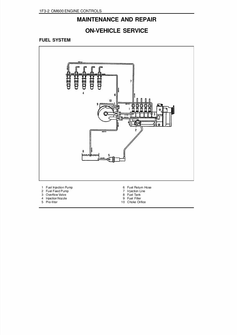
8/18/2019 SsangYong Musso Service Manual 1998.pdf
http://slidepdf.com/reader/full/ssangyong-musso-service-manual-1998pdf 731/1459
1F3-2 OM600 ENGINE CONTROLS
FUEL SYSTEM
1 Fuel Injection Pump2 Fuel Feed Pump3 Overflow Valve4 Injection Nozzle5 Pre-filter
6 Fuel Return Hose7 Injection Line8 Fuel Tank9 Fuel Filter
10 Choke Orifice
MAINTENANCE AND REPAIR
ON-VEHICLE SERVICE
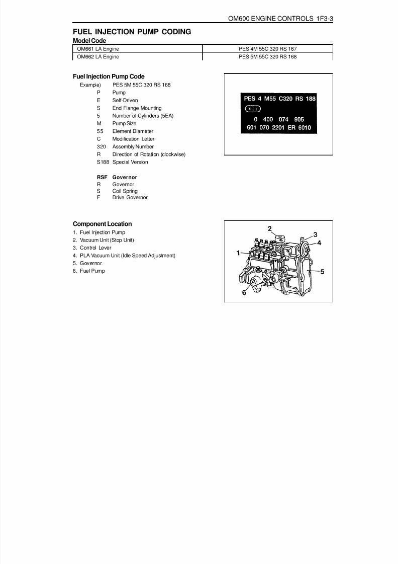
8/18/2019 SsangYong Musso Service Manual 1998.pdf
http://slidepdf.com/reader/full/ssangyong-musso-service-manual-1998pdf 732/1459
OM600 ENGINE CONTROLS 1F3-3
FUEL INJECTION PUMP CODINGModel Code
PES 4M 55C 320 RS 167PES 5M 55C 320 RS 168
Fuel Injection Pump CodeExample) PES 5M 55C 320 RS 168
P PumpE Self-DrivenS End Flange Mounting5 Number of Cylinders (5EA)M Pump Size55 Element DiameterC Modification Letter320 Assembly NumberR Direction of Rotation (clockwise)S188 Special Version
RSF GovernorR GovernorS Coil SpringF Drive Governor
Component Location1. Fuel Injection Pump2. Vacuum Unit (Stop Unit)3. Control Lever4. PLA Vacuum Unit (Idle Speed Adjustment)5. Governor6. Fuel Pump
OM661 LA EngineOM662 LA Engine

8/18/2019 SsangYong Musso Service Manual 1998.pdf
http://slidepdf.com/reader/full/ssangyong-musso-service-manual-1998pdf 733/1459
1F3-4 OM600 ENGINE CONTROLS
FUEL TANK
1 Fuel Tank2 The Sender of Fuel Tank3 2-way Check Valve4 Pre Filter5 Front Fuel Filler Neck6 Rear Fuel Filler Neck7 Fuel Supply Tube
8 Fuel Return Tube9 Filter Hose10 Fuel Tank Hose11 Fuel Filler Cap12 Clip13 Clip

8/18/2019 SsangYong Musso Service Manual 1998.pdf
http://slidepdf.com/reader/full/ssangyong-musso-service-manual-1998pdf 734/1459
OM600 ENGINE CONTROLS 1F3-5
VACUUM CONTROL SYSTEM TEST
2 Engine Cut-Off Valve (Ignition Key Switch)3 Auto-locking Hub Solenoid Valve4 Engine Stop Valve Unit5 PLA Vacuum Unit (Idle Speed Adjustment)6 Engine7 Vacuum Pump
8 30° Thermovalve9 Fuel Injection Pump
10 Filter with Restriction11 Check Valve12 Modulating Pressure Line (Automatic T/M)
Test Data
Idle Speed IncreasePermissible Pressure Drop of System
At least 100 rpm at approx. 500mbr400 - 500mbar approx. 1 min.

8/18/2019 SsangYong Musso Service Manual 1998.pdf
http://slidepdf.com/reader/full/ssangyong-musso-service-manual-1998pdf 735/1459
1F3-6 OM600 ENGINE CONTROLS
Temperature measuring instrument with test probeWB24
Digital tester
Tools Required001 589 73 21 00 Vacuum Pump201 589 13 21 00 Vacuum Tester667 589 00 21 00 TDC pulse generator
Commercial Tools
e.g. Bosch MOT 001.03Sun DIT 9000
e.g. Ahlborn, Therm 2263-2Eichenfeldstrabe 1 - 3
D-8150 Holzkirchen
Tester Connection
11 TDC Pulse Sender Unit12 Digital Tester
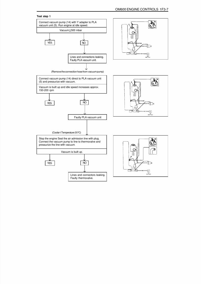
8/18/2019 SsangYong Musso Service Manual 1998.pdf
http://slidepdf.com/reader/full/ssangyong-musso-service-manual-1998pdf 736/1459
OM600 ENGINE CONTROLS 1F3-7
Vacuum 500 mbar
Lines and connections leaking.Faulty PLA vacuum unit.
Test step 1
Connect vacuum pump (14) with Y adapter to PLAvacuum unit (5). Run engine at idle speed.
YES NO
(Remove the connection hose from vacuum pump)
Connect vacuum pump (14) direct to PLA vacuum unit(5) and pressurize with vacuum.
Vacuum is built up and idle speed increases approx.150-200 rpm
YES NO
Faulty PLA vacuum unit
(Coolant Temperature 30°C)
Stop the engine Seal the air admission line with plug.Connect the vacuum pump to line to thermovalve andpressurize the line with vacuum.
Vacuum is built up.
YES NO
Lines and connectors leaking.Faulty thermovalve.
=>

8/18/2019 SsangYong Musso Service Manual 1998.pdf
http://slidepdf.com/reader/full/ssangyong-musso-service-manual-1998pdf 737/1459
1F3-8 OM600 ENGINE CONTROLS
Detach line downstream of air admission filter (13).
Vacuum drops.
Faulty thermovalve
Fit the line onto air admission filter. Built up vacuum withvacuum pump. Detach the plug from air admission line.
Vacuum drops.
Faulty filter with restriction.
Go to test step 2.
YES NO
YES NO

8/18/2019 SsangYong Musso Service Manual 1998.pdf
http://slidepdf.com/reader/full/ssangyong-musso-service-manual-1998pdf 738/1459
OM600 ENGINE CONTROLS 1F3-9
Test step 2
Connect vacuum pump (14) with Y adapter to PLAvacuum unit (5). Run the engine at idle speed.
Vacuum drops to ‘0’ at approx. 30°C of the thermovalve.
Faulty thermovalve.Defective filter with restriction.
Stop the engine. Detach the filter with restriction.
Filter with restriction is clear.
Defective filter with restriction.
YES NO
YES NO

8/18/2019 SsangYong Musso Service Manual 1998.pdf
http://slidepdf.com/reader/full/ssangyong-musso-service-manual-1998pdf 739/1459
1F3-10 OM600 ENGINE CONTROLS
VACUUM PUMP (SECTIONAL VIEW)
2 Suction Valve4 Piston5 Pressure Valve6 Safety Valve7 O-Ring8 Pump Housing9 Pump Cover
12 Lever14 Outer Return Spring15 Inner Spring Retainer
16 Roller Cam17 Piston Rod21 Inner Return Spring23 Upper Spring Retainer28 Piston Ring30 Seal Ring31 Oil Return Valve32 RestrictorSB To Brake BoosterSK To Vacuum Lines

8/18/2019 SsangYong Musso Service Manual 1998.pdf
http://slidepdf.com/reader/full/ssangyong-musso-service-manual-1998pdf 740/1459
OM600 ENGINE CONTROLS 1F3-11
VACUUM PUMP TEST
1 Fuel Filter2 Vacuum Line
3 Ancillaries Connection4 Vacuum Tester
Tools Required201 589 13 21 00 Vacuum Tester

8/18/2019 SsangYong Musso Service Manual 1998.pdf
http://slidepdf.com/reader/full/ssangyong-musso-service-manual-1998pdf 741/1459
1F3-12 OM600 ENGINE CONTROLS
Test Procedure1. Remove the fuel filter (1) and keep the filter not to be
damaged from running engine.
2. Remove the vacuum line (2) from ancillaries connection (3).3. Connect the vacuum tester (4) to the ancillaries connection
(3).
Vacuum Tester 201 589 13 21 00
4 Run the engine at idle and check vacuum pressure after 30sec.
NoticeIf out of standard, replace the vacuum pump.
5. Remove the vacuum tester.6. Connect the vacuum line to the ancillaries connection.7. Install the fuel filter.
Standard > 70 mbar

8/18/2019 SsangYong Musso Service Manual 1998.pdf
http://slidepdf.com/reader/full/ssangyong-musso-service-manual-1998pdf 742/1459
OM600 ENGINE CONTROLS 1F3-13
VACUUM PUMPPreceding Work : Remove the poly V-belt
1 Bolt ............................................................ 10Nm2 Vacuum Pump3 Vacuum Line (Ancillaries)
4 Vacuum Line (Brake Booster)5 Gasket ................................................... Replace

8/18/2019 SsangYong Musso Service Manual 1998.pdf
http://slidepdf.com/reader/full/ssangyong-musso-service-manual-1998pdf 743/1459
1F3-14 OM600 ENGINE CONTROLS
Removal & Installation Procedure1. Remove the vacuum line (3, 4).
2. Remove the bolts (1) evenly.
NoticeIf necessary, rotate the engine until the pressure on thetappet of the vacuum pump is released.
3. Remove the vacuum pump (2).
4. Install the vacuum pump (2).
Tightening Torque 10 Nm
NoticeClean the gasket residues of sealing surface of vacuumpump and replace the gasket(5).
5. Connect the vacuum line (3, 4).

8/18/2019 SsangYong Musso Service Manual 1998.pdf
http://slidepdf.com/reader/full/ssangyong-musso-service-manual-1998pdf 744/1459
OM600 ENGINE CONTROLS 1F3-15
VACUUM UNIT REPLACEMENT
1 Bracket2 Bolt3 Vacuum Unit4 Vacuum Line5 Seal .............................................. Replace

8/18/2019 SsangYong Musso Service Manual 1998.pdf
http://slidepdf.com/reader/full/ssangyong-musso-service-manual-1998pdf 745/1459
1F3-16 OM600 ENGINE CONTROLS
Idle Speed750 - 850 rpm720 - 820 rpm
EngineOM661LA EngineOM662LA Engine
Tools Required667 589 00 21 00 TDC Pulse Generato
Commercial Tool
IDLE SPEED ADJUSTMENTService Data
e.g. Bosch, MOT 001.03Sun, DIT 9000
Digital Tester
Adjustment Procedure1. Connect the digital tester (1) and TDC pulse sender unit
(11).2. Run the engine and warm up the coolant to 60~80°C.
TDC pulse generator 667 589 02 21 00
3. Disconnect the vacuum hose (4) from the PLA unit to checkidle speed with tester.
4. Check idle speed with tester.
NoticeTo adjust idle speed, loosen the locking nut (6) of PLA unit.
OM 661LA Engine 750 - 850rpm
OM 662LA Engine 720 - 820rpm

8/18/2019 SsangYong Musso Service Manual 1998.pdf
http://slidepdf.com/reader/full/ssangyong-musso-service-manual-1998pdf 746/1459
OM600 ENGINE CONTROLS 1F3-17
6. After adjustment, tighten the locking nut and place theposition marking with different color of paint.
NoticeIf there are no changes in idle speed with PLA unit
adjustment, perform the service at a BOSCH Service Center.7. Connect the vacuum pump to the PLA vacuum unit and
build up vacuum approx. 500mbar. If engine rpm increasesby approx. 100rpm, It is normal.
Vacuum Pump 001 589 73 21 00
8. Connect the vacuum line (4).9. Switch on all ancillaries and check the idle speed.
5. Ensure not to damage the idle spring in the governor andadjust idle speed by turning the PLA unit (5) slowly.
NoticeDo not rotate the PLA unit over ½ turn from the positionmarking. If do, idle spring in the governor will be severelydamaged.
Clockwise
Counterclockwise
RPM Decrease
RPM Increase

8/18/2019 SsangYong Musso Service Manual 1998.pdf
http://slidepdf.com/reader/full/ssangyong-musso-service-manual-1998pdf 747/1459

8/18/2019 SsangYong Musso Service Manual 1998.pdf
http://slidepdf.com/reader/full/ssangyong-musso-service-manual-1998pdf 748/1459
OM600 ENGINE CONTROLS 1F3-19
Fuel Pressure Test

8/18/2019 SsangYong Musso Service Manual 1998.pdf
http://slidepdf.com/reader/full/ssangyong-musso-service-manual-1998pdf 749/1459
1F3-20 OM600 ENGINE CONTROLS
Tools Required617 589 04 21 00 Tester
1. Disconnect the fuel line (2) from the fuel filter.2. Remove the banjo bolt (4) from the fuel injection pump and
remove the seals (3) and fuel line (2).
3. Connect the tester (5).
4. Start the engine and read off the fuel pressure on tester(5).
Notice
If out of standard, replace the fuel feed pump.
Tester 617 589 04 21 00
5. Stop the engine.
At Idle Speed
At Full load
> 0.3bar
> 0.5bar
6. Remove the tester.7. Replace the seal and connect the fuel line (2).

8/18/2019 SsangYong Musso Service Manual 1998.pdf
http://slidepdf.com/reader/full/ssangyong-musso-service-manual-1998pdf 750/1459
OM600 ENGINE CONTROLS 1F3-21
FUEL PUMP
1 Fuel Injection Pump2 Pressure Line ............................................ 13Nm3 Suction Line
4 Hose Clip ............................................... Replace
5 Gasket ................................................... Replace6 Spring Lock Washer7 Hexagon Nuts
8 Fuel Pump

8/18/2019 SsangYong Musso Service Manual 1998.pdf
http://slidepdf.com/reader/full/ssangyong-musso-service-manual-1998pdf 751/1459
1F3-22 OM600 ENGINE CONTROLS
INJECTION NOZZLE TESTPreceding Work : Removal of fuel injection nozzle
1. Fuel Injection Nozzle ............. New : 115 - 125barUsed : min. 100bar
A Closed Spray = goodB Stringy Spray = poor
2 Tester3 Valve

8/18/2019 SsangYong Musso Service Manual 1998.pdf
http://slidepdf.com/reader/full/ssangyong-musso-service-manual-1998pdf 752/1459
OM600 ENGINE CONTROLS 1F3-23
Tools Required000 589 14 27 00 Tester
NoticeWhen testing the injection nozzle, do not place your hand intothe spray of a nozzle. The spray will penetrate deep into theskin and destroy the tissue.
1. Connect the fuel injection nozzle to the tester (2).
Tester 000 589 14 27 00
2. Close the valve (3) and pump 5 times strongly.3. Chatter test :
Slowly operate the hand lever at tester (approx. 1 strokeper second). The nozzle must spray with a gentle chattering.
4. Spray pattern test :Operate the hand lever at tester rapidly (approx. 2~3 strokesper second).
GoodThe spray pattern shows closed and well atomized.
PoorThe spray pattern shows split, too wide and stringy.(Repair the fuel injection nozzle)

8/18/2019 SsangYong Musso Service Manual 1998.pdf
http://slidepdf.com/reader/full/ssangyong-musso-service-manual-1998pdf 753/1459
1F3-24 OM600 ENGINE CONTROLS
5. Opening pressure test :Open the valve (3) and slowly operate the hand lever attester (approx. 1 stroke / second) and measure openingpressure.
NoticeIf out of standard, repair the injection nozzle.
New Nozzle
Used Nozzle
Difference Between Nozzles
115 - 125bar
Min. 100bar
Max. 5bar
6. Leak testSlowly operate the hand lever at the tester until get apressure of approx. 90bar. Maintain this pressure for morethan20 seconds and within this period no drop of fuel shouldbuild up at the nozzle tip.

8/18/2019 SsangYong Musso Service Manual 1998.pdf
http://slidepdf.com/reader/full/ssangyong-musso-service-manual-1998pdf 754/1459
OM600 ENGINE CONTROLS 1F3-25
INJECTION NOZZLES
1 Fuel Injection Nozzle ............................. 35-40Nm2 Fuel Return Hose3 Plug4 Nozzle Washer ....................................... Replace5 Fuel Injection Pipe ..................................... 18Nm
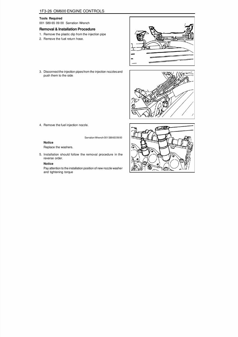
8/18/2019 SsangYong Musso Service Manual 1998.pdf
http://slidepdf.com/reader/full/ssangyong-musso-service-manual-1998pdf 755/1459
1F3-26 OM600 ENGINE CONTROLS
Tools Required001 589 65 09 00 Serration Wrench
Removal & Installation Procedure1. Remove the plastic clip from the injection pipe2. Remove the fuel return hose.
3. Disconnect the injection pipes from the injection nozzles andpush them to the side.
4. Remove the fuel injection nozzle.
Serration Wrench 001 589 65 09 00
NoticeReplace the washers.
5. Installation should follow the removal procedure in thereverse order.
NoticePay attention to the installation position of new nozzle washerand tightening torque
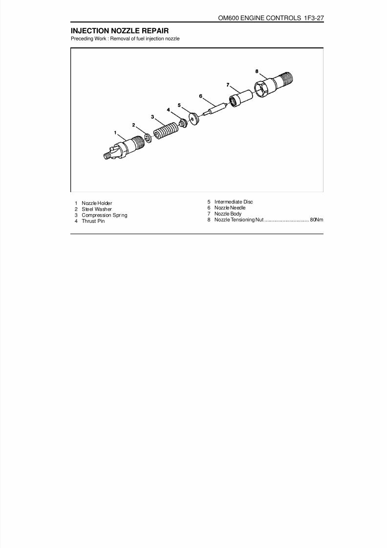
8/18/2019 SsangYong Musso Service Manual 1998.pdf
http://slidepdf.com/reader/full/ssangyong-musso-service-manual-1998pdf 756/1459
OM600 ENGINE CONTROLS 1F3-27
INJECTION NOZZLE REPAIRPreceding Work : Removal of fuel injection nozzle
1 Nozzle Holder2 Steel Washer3 Compression Spring
4 Thrust Pin
5 Intermediate Disc6 Nozzle Needle7 Nozzle Body
8 Nozzle Tensioning Nut ................................ 80Nm

8/18/2019 SsangYong Musso Service Manual 1998.pdf
http://slidepdf.com/reader/full/ssangyong-musso-service-manual-1998pdf 757/1459
1F3-28 OM600 ENGINE CONTROLS
Tools Required001 589 65 09 00 Socket Wrench Insert000 589 00 68 00 Cleaning Set
Repair Procedure1. Clamp the nozzle holder (1) in a vice and remove the nozzle
tensioning nut (8).
NoticeUse protective jaws for clamping.
2. Disassemble the fuel injection nozzle.
Socket Wrench Insert 001 589 65 09 00
3. Clean the nozzle needle (6) and nozzle body (7) with anabradant.
4. Clean the nozzle seat with cleaning cutter.
Cleaning Set 000 589 00 68 00
5. Immerse nozzle needle (6) and nozzle body (7) in filtereddiesel fuel. When the nozzle body is held vertical, the weightof the nozzle needle must cause it to slide down toward the
nozzle needle seat.
6. Assemble the injection nozzle so that the tip of the thrust(4) pin is facing toward the nozzle holder.
Tightening Torque 80 Nm
NoticeNozzle needle (6) and nozzle body (7) should always bereplaced as a pair.

8/18/2019 SsangYong Musso Service Manual 1998.pdf
http://slidepdf.com/reader/full/ssangyong-musso-service-manual-1998pdf 758/1459

8/18/2019 SsangYong Musso Service Manual 1998.pdf
http://slidepdf.com/reader/full/ssangyong-musso-service-manual-1998pdf 759/1459
1F3-30 OM600 ENGINE CONTROLS
REMOVAL AND INSTALLATION OF INJECTION TIMING DEVICEPreceding Work : Removal of vacuum pump
1 Cylinder Head Cover2 Bolt ............................................................ 10Nm3 Gasket ................................................... Replace4 Fuel Injection Pump5 Seal ....................................................... Replace
6 Screw Plug ................................................. 30Nm7 Oil Pan8 Locking Pin9 Injection Timing Device
10 Washer11 Bolt (Left-Hand Thread) ............................. 46Nm12 Camshaft Sprocket13 Washer14 12-Sided Stretch Bolt ............Check, 25Nm + 90°
15 Timing Chain16 Seal17 Chain Tensioner ......................................... 80Nm

8/18/2019 SsangYong Musso Service Manual 1998.pdf
http://slidepdf.com/reader/full/ssangyong-musso-service-manual-1998pdf 760/1459
OM600 ENGINE CONTROLS 1F3-31
Tools Required601 589 00 08 00 Flange601 589 05 21 00 Locking Screw116 589 20 33 00 Sliding Hammer116 589 02 34 00 Threaded Bolt667 589 04 63 00 Retaining Plate
Removal & Installation Procedure1. Remove the bolts (2) and then remove the cylinder head
cover (1) and gasket (3).
Installation Notice
Tightening Torque 10 Nm
NoticeReplace the gasket.Rotate the engine 1 revolution by hand and check TDCmarking of the crankshaft and camshaft.
2. Loosen the camshaft sprocket bolt (14).
Notice
Do not remove the bolt.Installation Notice
NoticeIf max. length of bolt exceeds 53.6mm, replace it.
Tightening Torque 25Nm + 90°
3. Loosen the bolt (11) (left-hand thread).
NoticeDo not remove the bolt.

8/18/2019 SsangYong Musso Service Manual 1998.pdf
http://slidepdf.com/reader/full/ssangyong-musso-service-manual-1998pdf 761/1459
1F3-32 OM600 ENGINE CONTROLS
5. Remove the plug (6) and seal (5) from the fuel injectionpump and collect oil in a suitable vessel.
Installation Notice
NoticeReplace the seal.
Tightening Torque 30 Nm
6. Install the locking screw (18) into the injection pump.
Notice
Before tightening the bolts for the injection timing deviceand the camshaft sprocket, always remove the locking screwfrom the injection pump and reinstall the plug.
Locking Screw 601 589 05 21 00
7. Place alignment marks (arrow) on the timing chain (12) andcamshaft sprocket (15).
4. Position the no.1 cylinder at ATDC 15°.
NoticeDo not rotate the engine with camshaft sprocket bolt oropposite direction of the engine rotation.

8/18/2019 SsangYong Musso Service Manual 1998.pdf
http://slidepdf.com/reader/full/ssangyong-musso-service-manual-1998pdf 762/1459
OM600 ENGINE CONTROLS 1F3-33
9. Pull out the 12-sided stretch bolt (14) and washer andremove the camshaft sprocket (12).
Tightening Torque 46 Nm
11. Using special tool (24, 25), remove the locking pin (8).
Sliding Hammer 116 589 20 33 00Threaded Bolt 116 589 02 34 00
8. Remove the chain tensioner (17).
Installation Notice
Tightening Torque 80 Nm
NoticeReplace the seal (16).
10. Pull out the bolt (11) and washer (10).
Notice
Be careful that the bolt is left-hand thread.Installation Notice

8/18/2019 SsangYong Musso Service Manual 1998.pdf
http://slidepdf.com/reader/full/ssangyong-musso-service-manual-1998pdf 763/1459
1F3-34 OM600 ENGINE CONTROLS
12. Push back the timing chain with retaining plate (26) andremove the injection timing device (9).
Retaining Plate 667 589 04 63 00
13. Installation should follow the removal procedure in the
reverse order.14. After assembling the engine, check start of delivery and
adjust if necessary.

8/18/2019 SsangYong Musso Service Manual 1998.pdf
http://slidepdf.com/reader/full/ssangyong-musso-service-manual-1998pdf 764/1459
OM600 ENGINE CONTROLS 1F3-35
INJECTION TIMING DEVICEPreceding Work : Removal of injection timing device
1 Cam Sprocket ........................................... Check2 Bushing .................................................... Check3 Governor Weights
4 Segment Flange and Drive Hub5 Compression Springs

8/18/2019 SsangYong Musso Service Manual 1998.pdf
http://slidepdf.com/reader/full/ssangyong-musso-service-manual-1998pdf 765/1459
1F3-36 OM600 ENGINE CONTROLS
Disassembly & Assembly1. Remove the governor weights (3).
2. Pull out the compression springs (5) and cam sprocket (1)from the segment flange (4).
3. Knock out the bushing with a proper drift.4. Installation should follow the removal procedure in the
reverse order.

8/18/2019 SsangYong Musso Service Manual 1998.pdf
http://slidepdf.com/reader/full/ssangyong-musso-service-manual-1998pdf 766/1459
OM600 ENGINE CONTROLS 1F3-37
START OF DELIVERY TEST (POSITION SENSOR, RIV METHOD)
1 Position Sensor2 Battery3 Fuel Injection Pump
4 Seal ....................................................... Replace5 Screw Plug ................................................. 30Nm
Service DataStart of Delivery (RIV) ATDC 14°- 16°

8/18/2019 SsangYong Musso Service Manual 1998.pdf
http://slidepdf.com/reader/full/ssangyong-musso-service-manual-1998pdf 767/1459
1F3-38 OM600 ENGINE CONTROLS
Tools Required617 589 08 21 00 Position Sensor
Test Procedure1. Remove the screw plug (5) and seal (4) and collect oil in a
suitable vessel.
2. Install the position sensor (1) into the governor housing ofthe injection pump to be the guide pin of the position sensorfacing up.
3. Connect the battery terminal of position sensor (1) to positiveterminal (+) of battery.
Position Sensor 617 589 08 21 00
4. Rotate the crankshaft by hand (in direction of engine rotation)until the lamp ‘B’ lights up. Rotate the crankshaft carefullyfurther until both lamps ‘A and B’ come on. In this position,
check the Rl value on the crankshaft vibration damper.
NoticeIf only lamp ‘A’ lights up, repeat the test and if out ofspecification, adjust start of delivery.
Specification ATDC 14°- 16°

8/18/2019 SsangYong Musso Service Manual 1998.pdf
http://slidepdf.com/reader/full/ssangyong-musso-service-manual-1998pdf 768/1459
OM600 ENGINE CONTROLS 1F3-39
Digital Tester, RIV Method(Connection Diagram for Testers Without Adapter)
1 Fuel Injection Pump2 Rl Sensor3 Digital Tester
4 TDC Pulse Sender Unit5 Battery

8/18/2019 SsangYong Musso Service Manual 1998.pdf
http://slidepdf.com/reader/full/ssangyong-musso-service-manual-1998pdf 769/1459
1F3-40 OM600 ENGINE CONTROLS
Start of Delivery (RIV)Idle Speed
(Connection Diagram for Testers With Adapter)
1 Fuel Injection Pump2 Rl Sensor3 Digital Tester
4 TDC Pulse Sender Unit5 Battery6 Rl Pulse Generator
Service DataATDC 14°- 16°
OM661LA : 720 - 820 rpm, OM662LA : 750 - 850 rpm

8/18/2019 SsangYong Musso Service Manual 1998.pdf
http://slidepdf.com/reader/full/ssangyong-musso-service-manual-1998pdf 770/1459
OM600 ENGINE CONTROLS 1F3-41
With Pulse Generator
Tools Required617 589 09 21 00 Rl Sensor617 589 10 21 00 Timing Tester667 589 00 21 00 TDC Pulse Generator
Commercial Tools
ItemDigital Tester
Without Pulse Generator
ToolsBosch, MOT 001.03
Hartmann & Braun, EOMT3Bosch, ETD 019.00
Sun, DIT 9000ALV, Diesel - Tester 875
Test Procedure
1. Remove the screw plug (7) and seal (8) collect oil in a suitablevessel.
2. Install the Rl sensor into the governor housing of injectionpump (1).
Rl Sensor 617 589 10 21 00
3. Connect the digital tester and TDC pulse sender unitaccording to connection diagram.
4. Run the engine at idle speed and check the Rl value on thedigital tester
NoticeIf out of standard, adjust the start of delivery.
5. Stop the engine.6. Remove the Rl sensor, digital tester and TDC pulse sender
unit.7. Replace the seal and tighten the plug.8. Check engine oil level and adjust if necessary.
Rl value ATDC 14°- 16°
Tightening Torque 30 Nm

8/18/2019 SsangYong Musso Service Manual 1998.pdf
http://slidepdf.com/reader/full/ssangyong-musso-service-manual-1998pdf 771/1459
1F3-42 OM600 ENGINE CONTROLS
After TestingPreceding Work : Start of delivery test
Position Sensor (RIV method)
1 Adjusting Screw2 Bolt ............................................................ 23Nm3 Fuel Injection Pump
4 Bolt ............................................................ 23Nm5 Scale .......... Rl start of delivery = 14°- 16°ATDC

8/18/2019 SsangYong Musso Service Manual 1998.pdf
http://slidepdf.com/reader/full/ssangyong-musso-service-manual-1998pdf 772/1459
OM600 ENGINE CONTROLS 1F3-43
Tools Required617 589 08 21 00 Position Sensor
Adjustment Procedure1. Position the No. 1 cylinder at ATDC 15°
NoticeDo not rotate the engine in opposite direction of enginerotation.
2. Remove the bolt (2) at the supporting bracket.
3. Remove the bolt (4).
4. Turn the adjusting screw (1) until both lamps ‘A’ + ‘B’ onthe position sensor light up.
NoticeIf the adjustment range is not adequate, remove the injectionpump and reinstall.
Position Sensor 617 589 08 21 00
5. After adjusting, retighten all the bolt to the specified torque.
To the rightTo the left
Start of delivery retardedStart of delivery advanced

8/18/2019 SsangYong Musso Service Manual 1998.pdf
http://slidepdf.com/reader/full/ssangyong-musso-service-manual-1998pdf 773/1459

8/18/2019 SsangYong Musso Service Manual 1998.pdf
http://slidepdf.com/reader/full/ssangyong-musso-service-manual-1998pdf 774/1459
OM600 ENGINE CONTROLS 1F3-45
Adjustment Procedure1. Remove the bolt (3) at the supporting bracket.
2. remove the bolts (1) at the timing case cover.
3. Run the engine at idle speed.4. Turn the adjusting screw (2) until the specification (15°± 1°
ATDC) is indicated on the digital tester.
To the RightTo the Left
Start of Delivery RetardedStart of Delivery Advanced
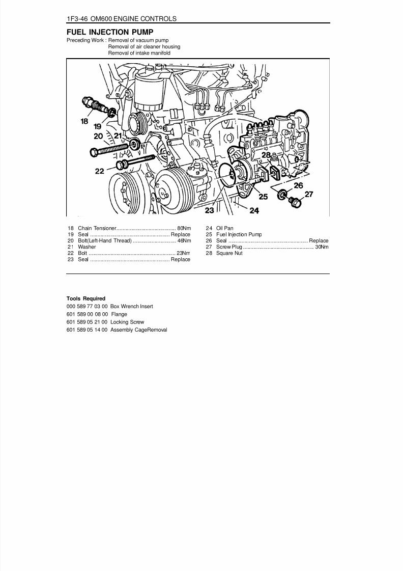
8/18/2019 SsangYong Musso Service Manual 1998.pdf
http://slidepdf.com/reader/full/ssangyong-musso-service-manual-1998pdf 775/1459
1F3-46 OM600 ENGINE CONTROLS
Tools Required
000 589 77 03 00 Box Wrench Insert601 589 00 08 00 Flange601 589 05 21 00 Locking Screw601 589 05 14 00 Assembly CageRemoval
FUEL INJECTION PUMPPreceding Work : Removal of vacuum pump
Removal of air cleaner housingRemoval of intake manifold
18 Chain Tensioner......................................... 80Nm19 Seal ....................................................... Replace20 Bolt(Left-Hand Thread) .............................. 46Nm21 Washer22 Bolt ............................................................ 23Nm23 Seal ....................................................... Replace
24 Oil Pan25 Fuel Injection Pump26 Seal ....................................................... Replace27 Screw Plug ................................................. 30Nm28 Square Nut

8/18/2019 SsangYong Musso Service Manual 1998.pdf
http://slidepdf.com/reader/full/ssangyong-musso-service-manual-1998pdf 776/1459
OM600 ENGINE CONTROLS 1F3-47
2. Remove the connecting rod (9).3. Disconnect the vacuum lines (13, 14).4. Remove the accelerator control damper (10).
(Manual transmission vehicle)
5. Remove the suction line (16) and pressure line (4).6. Remove the banjo bolt (1) and then remove the seal (2)
and fuel line (3).7. Remove the plastic clip (8) on the injection line.
Removal Procedure1. Position then no.1 cylinder at 15°ATDC.
NoticeDo not rotate the engine in opposition direction of enginerotation.
8. Disconnect the injection lines (15) from the injection pump(25).
9. Remove the banjo bolt (1) and then remove the seal (7)and return line (5).

8/18/2019 SsangYong Musso Service Manual 1998.pdf
http://slidepdf.com/reader/full/ssangyong-musso-service-manual-1998pdf 777/1459
1F3-48 OM600 ENGINE CONTROLS
10. Install the assembly cage (29) and remove the bolt (20)and pull off the washer (21).
NoticeBe careful that the bolt (20) is left hand thread.
Assembly Cage 601 589 05 14 00
11. Remove the chain tensioner (18) and seal (19).
12. Remove the bolt (12) and pull off the washer (11).
13. Remove the bolt (22) and pull off the square nut (28).14. Pull out the fuel injection pump (25) and seal (23).

8/18/2019 SsangYong Musso Service Manual 1998.pdf
http://slidepdf.com/reader/full/ssangyong-musso-service-manual-1998pdf 778/1459
OM600 ENGINE CONTROLS 1F3-49
Installation Procedure1. Remove the screw plug (27) and seal (26) and collect oil in
a vessel.
2. Insert flange (31) onto the injection pump camshaft andturn until the cam of the governor is visible in the hole.
Flange 601 589 00 08 00
3. Tighten the locking screw.
Locking Screw 601 589 05 21 00
4. Ensure that the No.1 cylinder is positioned at ATDC 15°.

8/18/2019 SsangYong Musso Service Manual 1998.pdf
http://slidepdf.com/reader/full/ssangyong-musso-service-manual-1998pdf 779/1459

8/18/2019 SsangYong Musso Service Manual 1998.pdf
http://slidepdf.com/reader/full/ssangyong-musso-service-manual-1998pdf 780/1459
OM600 ENGINE CONTROLS 1F3-51
12. Connect the vacuum line (13, 14).13. Connect the connecting rod (9).14. Connect the accelerator control damper (10).
(Manual transmission vehicle)
15. Install the chain tensioner.16. Install the vacuum pump.17. Check the start of delivery.18. Adjust the idle speed.
11. Assemble the plastic clip (8).

8/18/2019 SsangYong Musso Service Manual 1998.pdf
http://slidepdf.com/reader/full/ssangyong-musso-service-manual-1998pdf 781/1459

8/18/2019 SsangYong Musso Service Manual 1998.pdf
http://slidepdf.com/reader/full/ssangyong-musso-service-manual-1998pdf 782/1459
1G1-2 M162 ENGINE INTAKE & EXHAUST
MAINTENANCE AND REPAIR
ON-VEHICLE SERVICEAIR CLEANER
1 Air - Cleaner Assembly
2 Air - Cleaner Shield Upper Cover3 Blot
4 Blot
5 Air Intake Shield

8/18/2019 SsangYong Musso Service Manual 1998.pdf
http://slidepdf.com/reader/full/ssangyong-musso-service-manual-1998pdf 783/1459
M162 ENGINE INTAKE & EXHAUST 1G1-3
Removal & Installation Procedure1. Release the clamp securing HFM sensor and air cleaner.2. Disengage the air cleaner assembly and HFM sensor
assembly.3. Unserew the mounting bolt(6) from the bracket.
Installation Notice
Tightening Torque 22.5 - 27.5 Nm
4. Release the clamp from air cleaner assembly housing andremove the cover.
5. Remove the air cleaner assembly.6. Remove the air cleaner housing from insulator.
NoticeMake sure the air cleaner to be seated in insulator.
7. Disengage the air duct hose and air cleaner housing andremove the housing.
8. Remove the air duct hose.9. Unscrew the two bolts(7) from air inlet duct.Installation Notice
10. Remove the air inlet duct.11. Installation should follow the removal procedure in the
reverse order.
Tightening Torque 8 - 9 Nm

8/18/2019 SsangYong Musso Service Manual 1998.pdf
http://slidepdf.com/reader/full/ssangyong-musso-service-manual-1998pdf 784/1459
1G1-4 M162 ENGINE INTAKE & EXHAUST
INTAKE AIR DUCT
1 Clamp2 Sleeve3 Nut4 Clamp5 Intake Air Duct
3. Remove the clamp (4).4. Remove the intake air duct (5) carefully.
Installation NoticeExactly seat the pin of intake air duct onto the crankcaseventilation rubber mount.
5. Installation should follow the removal procedure in thereverse order.
Removal & Installation Procedure1. Remove the clamp (1) and disconnect the HFM sensor.
2. Remove the nut (3) (arrow).

8/18/2019 SsangYong Musso Service Manual 1998.pdf
http://slidepdf.com/reader/full/ssangyong-musso-service-manual-1998pdf 785/1459
M162 ENGINE INTAKE & EXHAUST 1G1-5
INTAKE MANIFOLDPreceding Work : Removal of fuel distributor and injection valve
1 Bolt (M6 X 40, 4 pieces) ......................... 9-11 Nm
2 Softcap3 Resonance Flap4 Gasket ................................................... Replace5 Upper Intake Manifold6 Bolt (M8 x 50, 9 pieces) ................. 22.5-27.5 Nm7 Gasket ................................................... Replace8 Blow-by Hose9 Blow-by Hose
10 Clamp11 Blow-by Nipple12 Inlet Air Housing
13 Bolt (M6 x 40, 4 pieces) ......................... 9-11 Nm
14 Throttle Body - Electric15 Gasket ................................................... Replace16 Lower Intake Manifold .........................................17 Bolt (M8 x 40, 4 pieces) ................. 22.5-27.5 Nm18 Nipple .................................................... Replace19 Seal Ring20 Connection House21 Clamp22 Noise Damper Assembly23 Tapping Screw

8/18/2019 SsangYong Musso Service Manual 1998.pdf
http://slidepdf.com/reader/full/ssangyong-musso-service-manual-1998pdf 786/1459
1G1-6 M162 ENGINE INTAKE & EXHAUST
Removal & Installation ProcedureUpper Intake Manifold
1. Disconnect the vacuum hose (8,9).2. Loosen the clip (22).3. Remove the upper intake manifold (5) after unscrewing the
bolt (6).
Installation Notice
NoticeCheck the gasket and replace it if necessary.
4. Installation should follow the removal procedure in thereverse order.
Lower Intake ManifoldPreceding work : removal of upper intake manifold
1. Remove the hose of brake booster vacuum line and idlespeed connector.
2. Disconnect the hot water inlet pipe from the bottom of lowerintake manifold.
3. Unscrew the bolt (17) and remove the lower intake manifold(16).
Installation Notice
4. Start the engine and check for leaks at each connectionpart.
Tightening Torque 22.5 - 27.5 Nm
Tightening Torque 22.5 - 27.5 Nm

8/18/2019 SsangYong Musso Service Manual 1998.pdf
http://slidepdf.com/reader/full/ssangyong-musso-service-manual-1998pdf 787/1459

8/18/2019 SsangYong Musso Service Manual 1998.pdf
http://slidepdf.com/reader/full/ssangyong-musso-service-manual-1998pdf 788/1459
1G1-8 M162 ENGINE INTAKE & EXHAUST
Function DescriptionA pneumatically actuated resonance flap (5) is located on theintake manifold, and will be opened and closed by load, whichoperates resonance flap according to engine and controlledby ECU and rpm.
1. Resonance flap closed (at idle/partial load : less than3,800/rpm)The switch valve (7) will be adjusted by ECU and resonancefalp will be colosed. By increasing air flow passage throughdividing intaking air flow toward both air collection housing(8). This leads to a signficant increase in the torque in thelower speed range.
2. Resonance flap open (at full load : over 3,800/rpm)The switch valve (7) will not be adjusted by ECU andresonance falp (5) will be open. The colllected air in the aircollection housing (8) will not be divided and intaking airpassage will be shorten.

8/18/2019 SsangYong Musso Service Manual 1998.pdf
http://slidepdf.com/reader/full/ssangyong-musso-service-manual-1998pdf 789/1459
M162 ENGINE INTAKE & EXHAUST 1G1-9
EXHAUST MANIFOLDPreceding Work : Removal of air cleaner
1 Nut ....................................................... 36-44 Nm2 Gasket ................................................... Replace
3 Exhaust Manifold

8/18/2019 SsangYong Musso Service Manual 1998.pdf
http://slidepdf.com/reader/full/ssangyong-musso-service-manual-1998pdf 790/1459

8/18/2019 SsangYong Musso Service Manual 1998.pdf
http://slidepdf.com/reader/full/ssangyong-musso-service-manual-1998pdf 791/1459
M162 ENGINE INTAKE & EXHAUST 1G1-11
Removal and Installation of Exhaust Line
1 Exhaust Manifold2 Rivet Nut3 Bolt ........................................................... 30 Nm4 Front Pipe5 Oxygen Sensor6 Bolt ...................................................... 28-47 Nm7 Rubber Pad8 Catalytic Converter9 Gasket ................................................... Replace
10 Nut11 Gasket ................................................... Replace12 Rubber Pad13 Nut ....................................................... 28-47 Nm14 Center Muffler15 Rubber Pad16 Tail Muffler17 Gasket ................................................... Replace18 Nut ....................................................... 28-47 Nm

8/18/2019 SsangYong Musso Service Manual 1998.pdf
http://slidepdf.com/reader/full/ssangyong-musso-service-manual-1998pdf 792/1459
SECTION 1G2
M161 ENGINE INTAKE & EXHAUST
TABLE OF CONTENTS
SPECIFICATIONSFASTENER TIGHTENING SPECIFICATIONS
N m
9 - 1122.5 - 27.522.5 - 27.59.5 - 12.5
15 - 2828 - 47
Application
Air Cleaner Housing Cover NutIntake Manifold Bolt (M8 x 20)Intake Manifold Bolt (M8)Exhaust Mainfold Stud BoltExhaust Pipe Nut (Engine)Exhaust Pipe Bolt
Specifications. . . . . . . . . . . . . . . . . . . . . . . 1G2-1Fastener Tightening Specifications . . . . . . . . 1G2-1
Maintenance and Repair . . . . . . . . . . . . . . 1G2-2On-Vehicle Service . . . . . . . . . . . . . . . . . . . . . 1G2-2
Air Cleaner . . . . . . . . . . . . . . . . . . . . . . . . . . 1G2-2
Air Intake Shield . . . . . . . . . . . . . . . . . . . . . . 1G2-4Intake Air Duct . . . . . . . . . . . . . . . . . . . . . . . 1G2-5Intake Manifold . . . . . . . . . . . . . . . . . . . . . . . 1G2-7Exhaust Manifold . . . . . . . . . . . . . . . . . . . . . 1G2-9
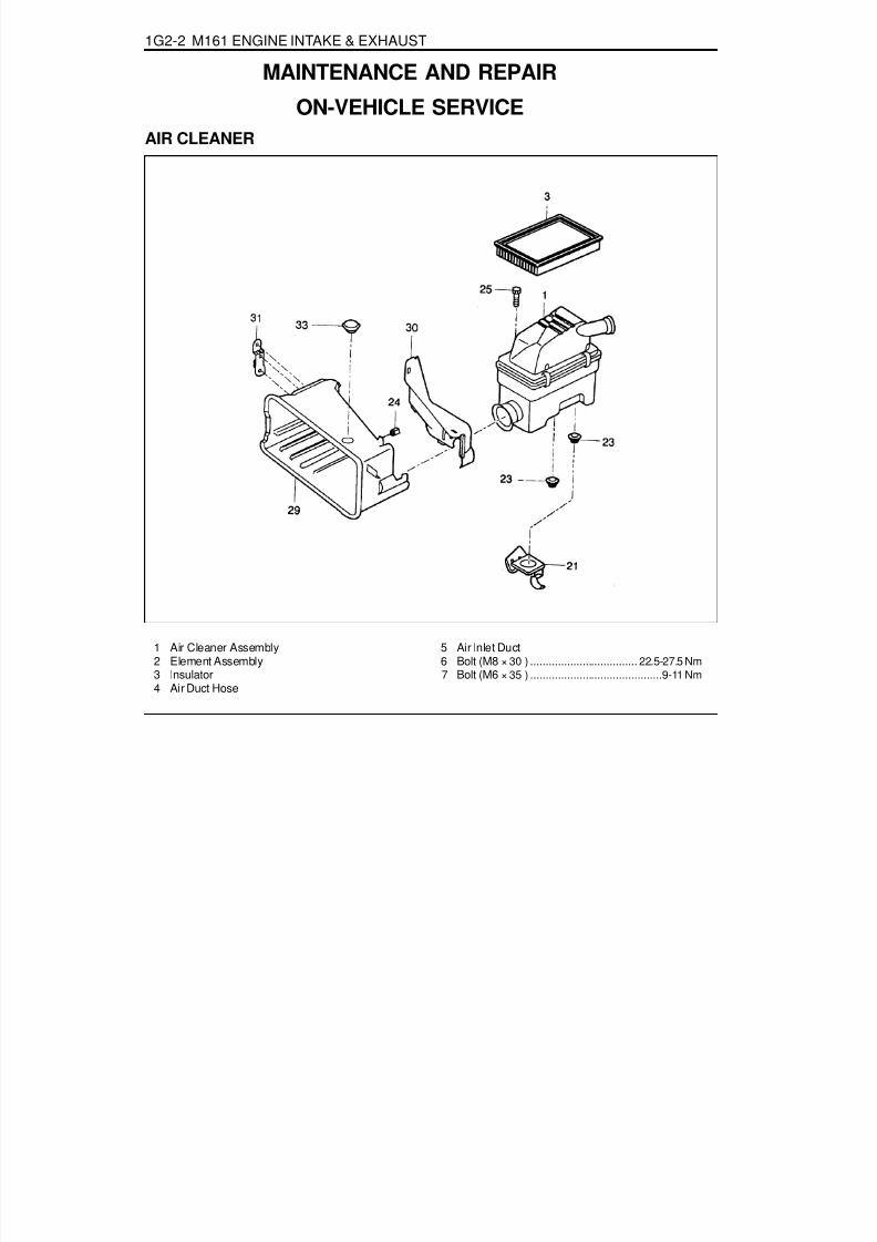
8/18/2019 SsangYong Musso Service Manual 1998.pdf
http://slidepdf.com/reader/full/ssangyong-musso-service-manual-1998pdf 793/1459

8/18/2019 SsangYong Musso Service Manual 1998.pdf
http://slidepdf.com/reader/full/ssangyong-musso-service-manual-1998pdf 794/1459
M161 ENGINE INTAKE & EXHAUST 1G2-3
Removal & Installation Procedure1. Release the clamp securing HFM sensor and air cleaner.2. Disengage the air cleaner assembly and HFM sensor
assembly.3. Unserew the mounting bolt(6) from the bracket.
Installation Notice
Tightening Torque 22.5 - 27.5 Nm
4. Release the clamp from air cleaner assembly housing andremove the cover.
5. Remove the air cleaner assembly.6. Remove the air cleaner housing from insulator.
NoticeMake sure the air cleaner to be seated in insulator.
7. Disengage the air duct hose and air cleaner housing andremove the housing.
8. Remove the air duct hose.9. Unscrew the two bolts(7) from air inlet duct.Installation Notice
10. Remove the air inlet duct.11. Installation should follow the removal procedure in the
reverse order.
Tightening Torque 8 - 9 Nm

8/18/2019 SsangYong Musso Service Manual 1998.pdf
http://slidepdf.com/reader/full/ssangyong-musso-service-manual-1998pdf 795/1459
1G2-4 M161 ENGINE INTAKE & EXHAUST
AIR INTAKE SHIELDPreceding Work : Removal of air cleaner
Removal & Installation Procedure1. Remove the upper cover (3) from the air intake shield (5)
upper mounting pin.2. Remove the bolts (4 and 6).3. Remove the air intake shield (5).4. Installation should follow the removal procedure in the
reverse order.
1 Air Cleaner2 Gasket3 Air Intake Shield Upper Cover4 Bolt
5 Air Intake Shield6 Bolt7 Bracket

8/18/2019 SsangYong Musso Service Manual 1998.pdf
http://slidepdf.com/reader/full/ssangyong-musso-service-manual-1998pdf 796/1459
M161 ENGINE INTAKE & EXHAUST 1G2-5
INTAKE AIR DUCT
1 Clamp2 Sleeve
3 HFM Sensor4 Intake Air Duct5 Blow-by Hose7 Clamp(2 pieces)8 Intake Air Duct Mounting
Bracket
Removal & Installation Procedure1. Release the clamp (1) and intake air duct.
2. Remove the Blow-by hose (5) (arrow).

8/18/2019 SsangYong Musso Service Manual 1998.pdf
http://slidepdf.com/reader/full/ssangyong-musso-service-manual-1998pdf 797/1459
1G2-6 M161 ENGINE INTAKE & EXHAUST
3. Release the clamp (7) and remove the intake air duct.NoticeCompletely fit the intake air duct with the mounting bracket(8).

8/18/2019 SsangYong Musso Service Manual 1998.pdf
http://slidepdf.com/reader/full/ssangyong-musso-service-manual-1998pdf 798/1459
M161 ENGINE INTAKE & EXHAUST 1G2-7
INTAKE MANIFOLDPreceding Work : Removal of intake air duce
Removal of fuel distributor and injector
1 Bolt (M6 X 40, 6 pieces) ................. 22.5-27.5 Nm2 Intake Manifold3 Gasket (2 pieces) .................................. Replace4 Bolt (M8 X 40, 3 pieces) ................. 22.5-27.5 Nm
5 Idle Regulator6 Intermediate Flange7 Bolt (M6 X 35, 4 pieces) ......................... 9-11 Nm8 Connection Piece With Seal Ring ........ 36-44 Nm

8/18/2019 SsangYong Musso Service Manual 1998.pdf
http://slidepdf.com/reader/full/ssangyong-musso-service-manual-1998pdf 799/1459
1G2-8 M161 ENGINE INTAKE & EXHAUST
Removal & Installation Procedure1. Disconnect the battery ground cable.2. Remove idle speed control plug connector (arrow).
3. Disconnect the brake booster vacuum line and othervacuum lines.
4. Disconnector the rod from bearing bracket assembly andremove the connection piece (8).Installation Notice
Tightening Torque 36 - 44 Nm
5. Unscrew the three bolts (4) and remove the idle regulatorand intermediate flange (6).Installation Notice
Tightening Torque 22.5 - 27.5 Nm
6. Unscrew the two bolts (M8 X 16) and remove the supportassembly (arrow).Installation Notice
7. Unscrew the intake manifold assembly mounting bolts (1)and remove the intake manifold and gasket.Installation Notice
NoticeReplace the gasket with new one.
8. Installation should follow the removal procedure in thereverse order.
9. Start the engine and check for leaks in each connection.
Tightening Torque 22.5 - 27.5 Nm
Tightening Torque 22.5 - 27.5 Nm

8/18/2019 SsangYong Musso Service Manual 1998.pdf
http://slidepdf.com/reader/full/ssangyong-musso-service-manual-1998pdf 800/1459
M161 ENGINE INTAKE & EXHAUST 1G2-9
EXHAUST MANIFOLD
1 Oxygen Sensor .............................. 49.5-60.5 Nm2 Bolt (4 pieces) ........................................ 9-11 Nm3 Upper Cover4 Nut (11 pieces)...............................31.5-38.5 Nm
5 Exhaust Manifold6 Flange Bolt & Exhaust Pipe
Mounting Nut ............................................ 30 Nm7 Gasket ................................................... Replace
Removal & Installation Procedure1. Remove the oxygen sensor if necessary.
Installation Notice
Tightening Torque 49.5 - 60.5 Nm
2. Unscrew the bolt (2) and remove the exhaust manifold uppercover (3).
3. Unscrew the flange bolt (6) of front exhaust pipe andseparate the front exhaust pipe.Installation Notice
Tightening Torque 30 Nm
NoticeCheck the exhaust pipe mounting nut, and replace it withnew one if necessary.

8/18/2019 SsangYong Musso Service Manual 1998.pdf
http://slidepdf.com/reader/full/ssangyong-musso-service-manual-1998pdf 801/1459

8/18/2019 SsangYong Musso Service Manual 1998.pdf
http://slidepdf.com/reader/full/ssangyong-musso-service-manual-1998pdf 802/1459

8/18/2019 SsangYong Musso Service Manual 1998.pdf
http://slidepdf.com/reader/full/ssangyong-musso-service-manual-1998pdf 803/1459
SECTION 1G3
OM600 ENGINE INTAKE & EXHAUST
Specifications. . . . . . . . . . . . . . . . . . . . . . . 1G3-1Fastener Tightening Specifications . . . . . . . . 1G3-1
Schematic and Routing Diagrams . . . . . . . 1G3-2EGR Circuit. . . . . . . . . . . . . . . . . . . . . . . . . . 1G3-2
Maintenance and Repair . . . . . . . . . . . . . . 1G3-3On-Vehicle Service . . . . . . . . . . . . . . . . . . . . 1G3-3
TABLE OF CONTENTS
Caution: Disconnect the negative battery cable before removing or installing any electrical unit or when a tool or equipment could easily come in contact with exposed electrical terminals. Disconnecting this cable will help prevent personal injury and damage to the vehicle. The ignition must also be in LOCK unless otherwise noted.
SPECIFICATIONSFASTENER TIGHTENING SPECIFICATIONS
Application
Air Cleaner Housing Cover NutIntake Manifold Bolt (M8 x 20)Intake Manifold Bolt (M8)Exhaust Mainfold Stud BoltExhaust Pipe Nut (Engine)
Exhaust Pipe Bolt
N····· m
9 - 1122.5 - 27.522.5 - 27.59.5 - 12.5
15 - 28
28 - 47
Air Cleaner and Inlet Duct & Hose . . . . . . . . 1G3-3Intake and Exhaust Manifold . . . . . . . . . . . . . 1G3-5
Turbocharger . . . . . . . . . . . . . . . . . . . . . . . 1G3-8Charge Air System Diagram . . . . . . . . . . . . . 1G3-8Intercooler . . . . . . . . . . . . . . . . . . . . . . . . . . 1G3-9Turbocharger Assembly . . . . . . . . . . . . . . . 1G3-11

8/18/2019 SsangYong Musso Service Manual 1998.pdf
http://slidepdf.com/reader/full/ssangyong-musso-service-manual-1998pdf 804/1459

8/18/2019 SsangYong Musso Service Manual 1998.pdf
http://slidepdf.com/reader/full/ssangyong-musso-service-manual-1998pdf 805/1459
OM600 ENGINE INTAKE & EXHAUST 1G3-3
AIR CLEANER AND INLET DUCT & HOSE
MAINTENANCE AND REPAIR
ON-VEHICLE SERVICE
1 Air Intake Shield Assembly 2 Air Cleaner Assembly 3 Mounting Bracket 4 Air Cleaner Element ........... Clean : 20,000km
Replace : 60,000km
5 Bolt ......................................................... 9-11Nm6 House7 Clamp8 Engine Cover Assembly (Turbo)9 Mounting Bracket

8/18/2019 SsangYong Musso Service Manual 1998.pdf
http://slidepdf.com/reader/full/ssangyong-musso-service-manual-1998pdf 806/1459
1G3-4 OM600 ENGINE INTAKE & EXHAUST
Removal & Installation Procedure1. Loosen the air duct hose clamp and then remove the air
cleaner and air duct hose.
2. Disconnect the air cleaner housing cover clamp and removethe cover and element.
Tightening Torque 9 - 11 Nm
3. Loosen the nut (4EA) and remove the air cleaner housingfrom the intake manifold.
NoticeDo not fold the rubber.
Operating IntervalClean
Replace
every 20,000km
every 60,000km
4. Loosen the clamp and remove the air duct hose.5. Loosen the mounting nut and bolt.6. Remove the air inlet duct and hose.7. Installation should follow the removal procedure in the
reverse order.

8/18/2019 SsangYong Musso Service Manual 1998.pdf
http://slidepdf.com/reader/full/ssangyong-musso-service-manual-1998pdf 807/1459
OM600 ENGINE INTAKE & EXHAUST 1G3-5
INTAKE AND EXHAUST MANIFOLD
1 Nut ................................................. 22.5-27.5 Nm2 Washer3 Support Assembly Bar
4 Nut ................................................. 22.5-27.5 Nm5 Exhaust Manifold Assembly6 Exhaust Gasket
7 Stud Bolt .......................................... 9.9-12.1 Nm8 Bolt (M8) ........................................22.5-27.5 Nm9 Intake Duct
10 Intake Duct Gasket11 Intake Manifold12 Intake Gasket

8/18/2019 SsangYong Musso Service Manual 1998.pdf
http://slidepdf.com/reader/full/ssangyong-musso-service-manual-1998pdf 808/1459
1G3-6 OM600 ENGINE INTAKE & EXHAUST
Exhaust Line
1 Heat Protector Assembly2 Heat Protector Floor3 Exhaust Front Pipe Assembly4 Ring5 Exhaust Rear Pipe Assembly
6 Muffler7 Mounting8 Heat Protector Front Floor9 Tail Exhaust Pipe Assembly

8/18/2019 SsangYong Musso Service Manual 1998.pdf
http://slidepdf.com/reader/full/ssangyong-musso-service-manual-1998pdf 809/1459
OM600 ENGINE INTAKE & EXHAUST 1G3-7
Removal & Installation Procedure1. Remove the bolt from the exhaust manifold and then remove
the front exhaust pipe.Installation Notice
Tightening Torque 15 - 18 Nm
NoticeWhen tightening the nut(3), maintain the clearance betweenexhaust manifold(1) and front exhaust pipe.
2. Remove the nut from the front of center muffler and thenremove the front exhaust pipe.
Installation Notice
3. Remove the nut from the rear of center muffler and thenremove the tail muffler.
Installation Notice
4. Remove the muffler mounting hanger from the rubber padand remove the center muffler and tail muffler.NoticeCheck the gasket, if necessary, replace the new one.
5. Installation should follow the removal procedure in thereverse order.
Tightening Torque 28 - 47 Nm
Tightening Torque 28 - 47 Nm

8/18/2019 SsangYong Musso Service Manual 1998.pdf
http://slidepdf.com/reader/full/ssangyong-musso-service-manual-1998pdf 810/1459
1G3-8 OM600 ENGINE INTAKE & EXHAUST
1 Turbocharger Oil Inlet2 Turbine Wheel3 Waste Gate4 Oil Outlet5 Compressor Wheel
6 Air Inlet7 Exhaust Gas Outlet8 Compressed Air Flow9 Intercooler
10 Cylinder
TURBOCHARGERCHARGE AIR SYSTEM DIAGRAM
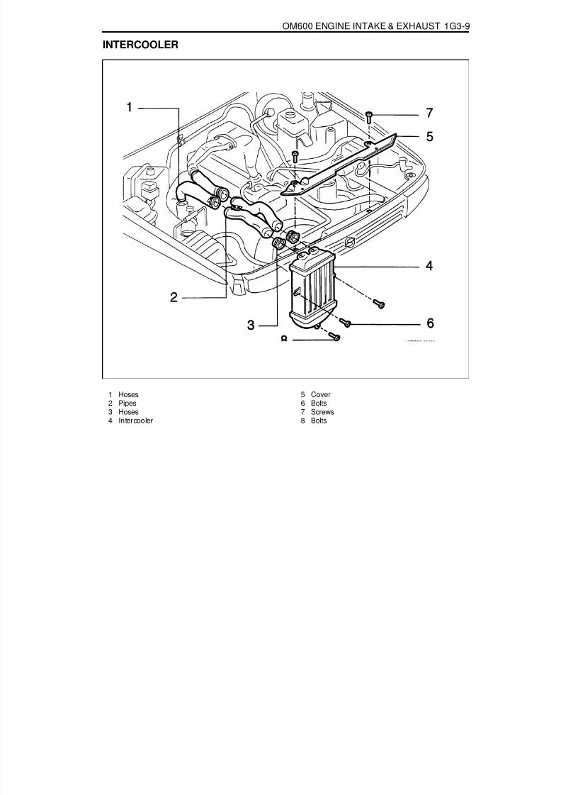
8/18/2019 SsangYong Musso Service Manual 1998.pdf
http://slidepdf.com/reader/full/ssangyong-musso-service-manual-1998pdf 811/1459
OM600 ENGINE INTAKE & EXHAUST 1G3-9
INTERCOOLER
1 Hoses2 Pipes3 Hoses4 Intercooler
5 Cover6 Bolts7 Screws8 Bolts
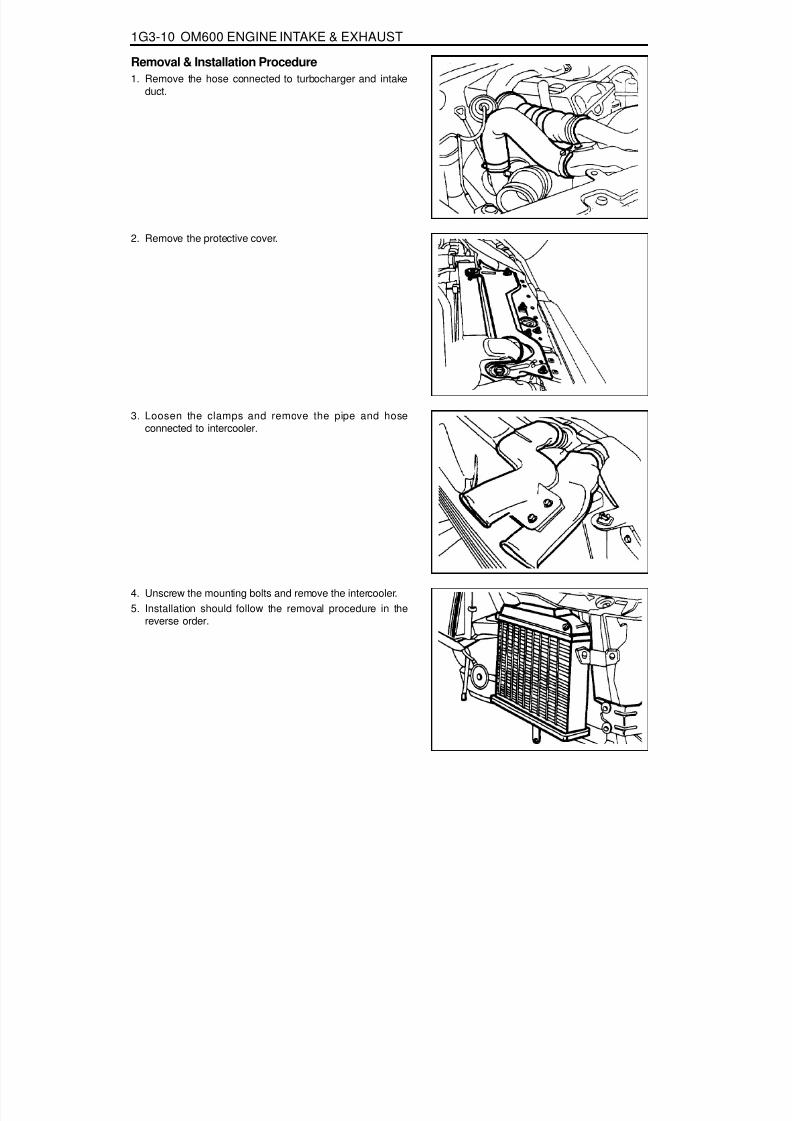
8/18/2019 SsangYong Musso Service Manual 1998.pdf
http://slidepdf.com/reader/full/ssangyong-musso-service-manual-1998pdf 812/1459
1G3-10 OM600 ENGINE INTAKE & EXHAUST
Removal & Installation Procedure1. Remove the hose connected to turbocharger and intake
duct.
2. Remove the protective cover.
3. Loosen the clamps and remove the pipe and hoseconnected to intercooler.
4. Unscrew the mounting bolts and remove the intercooler.5. Installation should follow the removal procedure in the
reverse order.
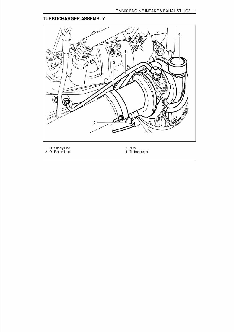
8/18/2019 SsangYong Musso Service Manual 1998.pdf
http://slidepdf.com/reader/full/ssangyong-musso-service-manual-1998pdf 813/1459
OM600 ENGINE INTAKE & EXHAUST 1G3-11
TURBOCHARGER ASSEMBLY
1 Oil Supply Line2 Oil Return Line
3 Nuts4 Turbocharger

8/18/2019 SsangYong Musso Service Manual 1998.pdf
http://slidepdf.com/reader/full/ssangyong-musso-service-manual-1998pdf 814/1459
1G3-12 OM600 ENGINE INTAKE & EXHAUST
Removal & Installation Procedure1. Remove the 2 hoses connected to intercooler.
2. Remove the hose(air cleaner to turbocharger) with blow byhose.
3. Disconnect the oil supply pipe.4. Remove the oil return pipe.5. Remove the support assembly.
6. Remove the 3 nuts(arrows).

8/18/2019 SsangYong Musso Service Manual 1998.pdf
http://slidepdf.com/reader/full/ssangyong-musso-service-manual-1998pdf 815/1459
OM600 ENGINE INTAKE & EXHAUST 1G3-13
7. Remove the turbocharger disconnecting the exhaust pipefrom the turbocharger.
8. Installation should follow the removal procedure in thereverse order.

8/18/2019 SsangYong Musso Service Manual 1998.pdf
http://slidepdf.com/reader/full/ssangyong-musso-service-manual-1998pdf 816/1459
SECTION 2A
SUSPENSION DIAGNOSIS
TABLE OF CONTENTSSpecifications. . . . . . . . . . . . . . . . . . . . . . . . 2A-1General Specifications . . . . . . . . . . . . . . . . . . 2A-1
Diagnosis . . . . . . . . . . . . . . . . . . . . . . . . . . . 2A-3General Diagnosis . . . . . . . . . . . . . . . . . . . . . 2A-3
Input & Output Devices and DampingForce Control Logic . . . . . . . . . . . . . . . . . 2A-5Input & Output Devices . . . . . . . . . . . . . . . . . . 2A-5System Layout . . . . . . . . . . . . . . . . . . . . . . . . 2A-5
Damping Force Control Logic . . . . . . . . . . . . . 2A-6Normal Control . . . . . . . . . . . . . . . . . . . . . . . . 2A-6Self-Diagnosis . . . . . . . . . . . . . . . . . . . . . . . . 2A-7Actuator Inspection . . . . . . . . . . . . . . . . . . . . . 2A-8
Schematic and Routing Diagrams . . . . . . . . 2A-9ECS Circuit . . . . . . . . . . . . . . . . . . . . . . . . . . . 2A-9
Self Diagnosis Test . . . . . . . . . . . . . . . . . . 2A-12Diagnosis Test . . . . . . . . . . . . . . . . . . . . . . . 2A-12
SPECIFICATIONSGENERAL SPECIFICATIONS
188
Application Front
3-stage Variable Damping Force Control Type
Rear
ECS Control Type
344 - 350ShockAbsorber 517 - 523Max. Length (mm)245 ± 3Compressed Length (mm)
102Stroke (mm)
331 ± 3

8/18/2019 SsangYong Musso Service Manual 1998.pdf
http://slidepdf.com/reader/full/ssangyong-musso-service-manual-1998pdf 817/1459
2A-2 SUSPENSION DIAGNOSIS
Application Description
4.75 - 5.25Power Voltage (V)
Axle VerticalAccelerationSensor(Wheel GSensor)
Less than 10Consuming Current (mA)
Less than 2.0Output Current (mA)
Operating Characteristics
TypeDampingForceSwitchingActuator
3-stage Rotary Step Motor TypeVoltage Rating (V) DC12
Current Rating (A) Less than 2.5
Current Time (mS) 95 - 105
4.75 - 5.25Power Voltage (V)
BodyVertical andLateral
AccelerationSensor
Less than 10Consuming Current (mA)
Less than 2.0Output Current (mA)
Operating Characteristics
Output Voltage
0.75
2.5
4.25
-1.5g 1g 3.5g
Acceleration
(Vertical Acceleration Sensor)Output Voltage
0.75
2.5
4.25
-1g 0g 1g
Acceleration
(Lateral Acceleration Sensor)
Output Voltage
0.75
2.5
4.25
-9g 1g 11g
Acceleration
GENERAL SPECIFICATIONS (Cont'd)

8/18/2019 SsangYong Musso Service Manual 1998.pdf
http://slidepdf.com/reader/full/ssangyong-musso-service-manual-1998pdf 818/1459
SUSPENSION DIAGNOSIS 2A-3
DIAGNOSISGENERAL DIAGNOSIS
ChecksLoosened MountingsDamaged or Worn wheel BearingDamaged Shock AbsorberDamaged Tire
ActionRetightening
ReplaceReplaceReplace
Abnormal Noises
ChecksBroken Stabilizer BarFaulty Shock Absorber
ActionReplaceReplace
Vehicle Rolling
ChecksOver Inflated Tire
Faulty Shock AbsorberLoosened wheel NutBent or Broken Coil SpringDamaged TireWorn Bushing
ActionPressure Adjustment
ReplaceTighten as SpecifiedReplaceReplaceReplace
Poor Riding
Problems in the steering, the suspension, the tires, andthe wheels involve several systems. Consider all systemswhen you diagnose a complaint. Some problems, suchas abnormal or excessive tire wear and scuffed tires,may by the result of hard driving. Always road test the
vehicle first. If possible, do this road test with thecustomer.Proceed with the following preliminary checks. Correctany substandard conditions.
ChecksIncorrect Wheel AlignmentExcessive Resistance of Lower Arm Ball JointInsufficient Tire PressureFaulty Power Steering
ActionRepair
ReplaceAdjust
Repair or Replace
Hard Steering
ChecksDeformed Arm AssemblyWorn BushingBent or Broken Coil SpringDifference Between L/H & R/H Heights
ActionReplaceReplaceReplaceAdjust
Vehicle Pulls to Right or Left

8/18/2019 SsangYong Musso Service Manual 1998.pdf
http://slidepdf.com/reader/full/ssangyong-musso-service-manual-1998pdf 819/1459
2A-4 SUSPENSION DIAGNOSIS
ChecksWorn or Broken Coil Spring
ChecksIncorrect Front wheel AlignmentWorn or Loosened Lower Arm Bushing
ActionReplace
Repair or Replace
Steering Instability
ActionReplace
Vehicle Bottoming

8/18/2019 SsangYong Musso Service Manual 1998.pdf
http://slidepdf.com/reader/full/ssangyong-musso-service-manual-1998pdf 820/1459
SUSPENSION DIAGNOSIS 2A-5
INPUT & OUTPUT DEVICES AND DAMPING FORCECONTROL LOGIC
INPUT & OUTPUT DEVICESDamping force of shock absorber will rotate shock absorber control rod in 3 modes by driving actuator on the upper
shock absorber when signaled from ECS.Rotary valve in the shock absorber will control hydraulic flow according to rotation of control rod to adjust dampingforce of shock absorber in SOFT « MEDIUM« HARD.
SYSTEM LAYOUT
1 ECS (ECU)2 Body Vertical Acceleration Sensor (Vertical
Sensor)3 Body Lateral Acceleration Sensor (Lateral
Sensor)
Speed Sensor
Axle Vertical Acceleration Sensor(Wheel G Sensor)
Stop Lamp Switch
Body Vertical Acceleration Sensor(Vertical Sensor)
ECS Switch
Indicator Lamp
Actuator
Shock Absorber
Self-Diagnosis Connector
Damping Force AdjustmentECS
(ECU)
Body Lateral Acceleration Sensor(Lateral Sensor)
4 ECS Mode Switch5 Stop Lamp Switch6 Axle Vertical Acceleration Sensor (Wheel G
Sensor)7 Mode Actuator

8/18/2019 SsangYong Musso Service Manual 1998.pdf
http://slidepdf.com/reader/full/ssangyong-musso-service-manual-1998pdf 821/1459
2A-6 SUSPENSION DIAGNOSIS
DAMPING FORCE CONTROL LOGICControl Logic that applies on damping force variable suspension is comprised of road sensing driving comfort controllogic to increase driving comfort and vehicle speed sensing control logic, anti-roll control logic and anti-dive controllogic to secure control safety.
LogicSensor
Road Sensing Driving Comfort Control Logic
Speed VerticalSensor (2.5g)
LateralSensor (1g)
AxleAccelerationSensor (10g)
Brake
Anti-bounce Control Logic
Anti-roll Control Logic
Anti-dive Control Logic
Vehicle Speed Sensing Control Logic
NORMAL CONTROL
Initial StageWhen ignition switch is "ON", system initialization will be performed for approx. 3 seconds. During this time, warninglamp will stay ON and damping force will be switched to Hard status. After 3 seconds, warning lamp will turn off andnormal control status will be restored.
Normal Damping Force Control EstablishmentDamping force will have Soft ® Medium ® Hard status in AUTO mode and Medium ® Hard status in SPORT mode.When double control items are satisfied at the same time it will be Hard ® Medium ® Soft in order.
Normal Damping Force Control Release
Control mode release will be "Hard ® Medium ® Soft"or "Medium ® Soft". In case that returned from Hard status toMedium status during control, it will be done after elapse of setting times. Returning from Medium status to Soft statuswill be done immediately without delay.

8/18/2019 SsangYong Musso Service Manual 1998.pdf
http://slidepdf.com/reader/full/ssangyong-musso-service-manual-1998pdf 822/1459
SUSPENSION DIAGNOSIS 2A-7
SELF-DIAGNOSISECS-ECU indicates ECS circuit defectives to the driver by flickering ECS indicator lamp in the meter cluster 0.5second of interval if there are defectives.
Code
Body vertical
accelerationsensor
Defects
When sensor output
voltage is less than0.5-4.5V, more than
4.5V.
Judging Conditions
01
0.9 - 1.1sec.
Set Time
Sensor Voltage
³ 2.0 ± 0.1V³ 3.0 ± 0.1V
Release Conditions
0.9 - 1.1sec.
Set Time
Body lateralacceleration
sensor
When sensor outputvoltage is less than
0.55±0.15V, more than4.45±0.1V.
020.9 - 1.1sec.
Sensor Voltage³ 2.0 ± 0.1V³ 3.0 ± 0.1V
0.9 - 1.1sec.
Stop anti-
bounce ridecontrol
Remedy
Stop anti-rollcontrol
Axle verticalacceleration
sensor (wheel Gsensor)
When sensor output
voltage is less than0.5-4.5V, more than4.5V.
030.9 - 1.1sec.
Sensor Voltage³ 2.0 ± 0.1V³ 3.0 ± 0.1V 0.9 - 1.1sec.
Stop ride
control
Front actuatorCheck step motor
power supply detectingcircuit for open and
short. check for relative
connectors.
04 0.4 - 0.6sec. IGN+ SW.OFF ® ON
Stop controlafter returning
to the previ-ous mode
Rear actuator When defective detect-ing circuit has detected
defectives duringoutput OFF.
05 0.4 - 0.6sec. IGN+ SW.OFF ® ON
Stop controlafter returningto the previous
mode
ECU When ECU does notwork normally.
06 0.4 - 0.6sec. ResetStop control
1. Turn the ignition switch ON and if ECS system is normal, ECS indicator lamp will turn on for 3 seconds and then gooff. However if defective, ECS indicator lamp will flicker in the interval of 0.5 second continuously.
2. Identify fault code with Scanner.

8/18/2019 SsangYong Musso Service Manual 1998.pdf
http://slidepdf.com/reader/full/ssangyong-musso-service-manual-1998pdf 823/1459
2A-8 SUSPENSION DIAGNOSIS
-
ACTUATOR INSPECTIONOutput position of the actuator should be changed as below when battery voltage is applied between actuatorconnector terminals.
Connectorterminal Battery Voltage Position of The Actuator Output Remark
1 (White)-
2 (Black) OPEN3 (Red) +
1 (White) +
2 (Black) -
3 (Red) OPEN1 (White) OPEN2 (Black) +
3 (Red)
SOFT Mode
MEDIUM Mode
HARD Mode

8/18/2019 SsangYong Musso Service Manual 1998.pdf
http://slidepdf.com/reader/full/ssangyong-musso-service-manual-1998pdf 824/1459
SUSPENSION DIAGNOSIS 2A-9
E C S C I R C U I T
SCHEMATIC AND ROUTING DIAGRAMS

8/18/2019 SsangYong Musso Service Manual 1998.pdf
http://slidepdf.com/reader/full/ssangyong-musso-service-manual-1998pdf 825/1459
2A-10 SUSPENSION DIAGNOSIS

8/18/2019 SsangYong Musso Service Manual 1998.pdf
http://slidepdf.com/reader/full/ssangyong-musso-service-manual-1998pdf 826/1459
SUSPENSION DIAGNOSIS 2A-11
Connector Pin Number and Circuits
2
15
3
16
4
17
5
18
6
19
7
20
8
21
9
22
10
23
11
24
12
25
13
26
Ignition
Actuator R-MEDIUM
Actuator R-SOFT
Actuator F-HEADSelect Switch
Speed Sensor
Wheel G Sensor
Wheel G Sensor Ground
-
Vertical G Sensor
Sensor +5V
Chassis Ground
Indicator Lamp
NO. Circuit NO. Circuit
1 14
2 15
3 16
4 17
5 18
6 19
7 20
8 21
9 22
10 23
11 24
12 25
13 26
Chassis Ground
Actuator R-HEAD
Actuator F-MEDIUM
Actuator F-SOFTBrake Switch
-
Lateral G Sensor
Lateral G Sensor Ground
Vertical G Sensor Ground
Diagnosis K Line
Diagnosis L Line
-
-

8/18/2019 SsangYong Musso Service Manual 1998.pdf
http://slidepdf.com/reader/full/ssangyong-musso-service-manual-1998pdf 827/1459
2A-12 SUSPENSION DIAGNOSIS
SELF DIAGNOSIS TESTDIAGNOSIS TESTSpecial Tool Requirements : Scanner
1. Position the ignition switch to 'OFF'.2. Connect Scanner harness connector to the engine
compartment diagnosis socket.3. Turn the ignition switch to 'ON' position.4. Select "Electronic control vehicle diagnosis" from function
selection display and press "Enter".5. Select "Musso ('98 model year)" from vehicle model selection
display and press 'Enter'.6. Select "Electronic suspension system (ECS)" from control
system selection display and press 'Enter'.7. Select "Self-diagnosis" from diagnosis item selection display.
NoticeCheck sensor value output display, if necessary.
8. Determine the fault code and check defective component.
NoticeRefer to self-diagnosis list.

8/18/2019 SsangYong Musso Service Manual 1998.pdf
http://slidepdf.com/reader/full/ssangyong-musso-service-manual-1998pdf 828/1459
SUSPENSION DIAGNOSIS 2A-13
Self - Diagnosis List
FaultCode Defects Service Hint
01 Vertical Acceleration Sensor
02 Lateral Acceleration Sensor
03 Wheel Acceleration Sensor
04
05 Rear Step Motor
06 ECU
Front Step Motor
1. Check sensor supply voltageCondition - IGN ONStandard value - voltage between pin 11 and 8 of ECU :
4.5 - 5.0V2. Check sensor output voltageCondition - IGN ONStandard value - voltage between pin 20 and 11 of ECU: 0.5 - 4.5V
3. Check the sensor.4. Check circuit for open.5. Check connection of other connectors.
1. Check sensor supply voltageCondition - IGN ONStandard value - voltage between pin 11 and 8 of ECU :4.5 - 5.0V
2. Check sensor output voltageCondition - IGN ONStandard value - voltage between pin 10 and 11 of ECU: 0.5 - 4.5V
3. Check the sensor.4. Check circuit for open.5. Check connection of other connectors.
1. Check step motor supply voltage.2. Check circuit for open.3. Check connection of other connectors.
1. Check step motor supply voltage.2. Check circuit for open.3. Check connection of other connectors.
1. Check connectors of ECU.2. Replace the ECU.
1. Check sensor supply voltageCondition - IGN ONStandard value - voltage between pin 11, 8 and pin7,11 of ECU : 4.5 - 5.0V
2. Check sensor output voltage3. Check the sensor.4. Check circuit for open.5. Check connection of other connectors.

8/18/2019 SsangYong Musso Service Manual 1998.pdf
http://slidepdf.com/reader/full/ssangyong-musso-service-manual-1998pdf 829/1459
SECTION 2B
WHEEL ALIGNMENT
TABLE OF CONTENTS
SPECIFICATIONSWHEEL ALIGNMENT SPECIFICATIONS
ApplicationCamberCasterToe-in
King Pin Inclination
Description
0° ± 30'2°30' ± 30'0 - 4 mm12 °30'
Specifications. . . . . . . . . . . . . . . . . . . . . . . . 2B-1Wheel Alignment Specifications . . . . . . . . . . . 2B-1
Diagnosis . . . . . . . . . . . . . . . . . . . . . . . . . . . 2B-2Tire Diagnosis . . . . . . . . . . . . . . . . . . . . . . . . . 2B-2Radial Tire Lead/Pull . . . . . . . . . . . . . . . . . . . 2B-3Vibration Diagnosis . . . . . . . . . . . . . . . . . . . . . 2B-5
Maintenance and Repair . . . . . . . . . . . . . . . 2B-6On-Vehicle Service . . . . . . . . . . . . . . . . . . . . . . 2B-6
Wheel Alignment. . . . . . . . . . . . . . . . . . . . . . . 2B-6General Description and System
Operation . . . . . . . . . . . . . . . . . . . . . . . . . 2B-9Four Wheel Alignment . . . . . . . . . . . . . . . . . . 2B-9Toe . . . . . . . . . . . . . . . . . . . . . . . . . . . . . . . . . 2B-9Caster . . . . . . . . . . . . . . . . . . . . . . . . . . . . . . . 2B-9Camber. . . . . . . . . . . . . . . . . . . . . . . . . . . . . . 2B-9

8/18/2019 SsangYong Musso Service Manual 1998.pdf
http://slidepdf.com/reader/full/ssangyong-musso-service-manual-1998pdf 830/1459
2B-2 WHEEL ALIGNMENT
DIAGNOSISTIRE DIAGNOSISIrregular and Premature WearIrregular and premature tire wear has many causes.Some of them are incorrect inflation pressures, lack ofregular rotation, poor driving habits, or improper wheelalignment.Rotate the tires if :
The front tire wear is different from the rear.The left and right front tire wear is unequal.The left and right rear tire wear is unequal, Checkwheel alignment if :The left and right front tire wear is unequal.The wear is uneven across the tread of either fronttire.
The front tire treads are scuffed with “feather” edgeson the side of the tread ribs or blocks.
Tread Wear IndicatorsThe original equipment tires have built-in tread wearindicators to show when the tires need replacement.These indicators appear as bands when the tire treaddepth becomes shallow. Tire replacement isrecommended when the indicators appear in three ormore grooves at six locations.
Radial Tire WaddleWaddle is side-to-side movement at the front or rear ofthe vehicle. It is caused by the steel belt not being straightwithin the tire, or by excessive lateral runout of the tireor wheel.The vehicle must be road tested to determine which endof the vehicle has the faulty tire. The rear end of thevehicle will shake from side to side or “waddle” if thewaddle tire is on the rear of the vehicle. From the driver’sseat, it feels as though someone is pushing on the sideof the vehicle. If the faulty tire is on the front of the vehicle,the waddle is more visual. The front sheet meld appears
to be moving back and forth, and the drivers seat feelslike the pivot point in the vehicle.Waddle can be diagnosed using the method ofsubstituting known good tire and wheel assemblies onthe problem vehicle1. Road test the vehicle to determine if the waddle is
coming from the front or the rear of the vehicle.2. Install good tires and wheels from a similar vehicle in
place of those on the offending end of the problemvehicle. If the source of the waddle is not obvious,change the rear tires.

8/18/2019 SsangYong Musso Service Manual 1998.pdf
http://slidepdf.com/reader/full/ssangyong-musso-service-manual-1998pdf 831/1459
WHEEL ALIGNMENT 2B-3
3. Road test the vehicle. If there is improvement, installthe original tires to find the offending tire. If there isno a straight improvement, install good tires in placeof all four offending tires.
4. Install original tires one at a time to find the offendingtire.
RADIAL TIRE LEAD/PULLLead/pull is the deviation of the vehicle from a straightpath on a level road with no pressure on the steeringwheel. Lead is usually caused by:
Incorrect alignment.Uneven brake adjustment.Tire construction.
The way in which a tire is built can produce lead/pull inthe vehicle.011-center belts on radial tires can causethe tire to develop a side force while the vehicle rollsstraight down the road. If one side of the tire has even alittle larger diameter than the diameter of the other side,the tire will tend to roll to one side. Unequal diameterswill cause the tire to develop a side force which canproduce vehicle lead/pull.The radial lead/pull diagnosis chart should be used todetermine whether the problem originates from analignment problem or from the tires. Part of the leaddiagnosis procedure calls for tire rotation that is differentfrom the proper tire rotation pattern. If a medium- to high-mileage tire is moved to the other side of the vehicle, besure to check for ride roughness. Rear tires will not causelead/pull.

8/18/2019 SsangYong Musso Service Manual 1998.pdf
http://slidepdf.com/reader/full/ssangyong-musso-service-manual-1998pdf 832/1459
2B-4 WHEEL ALIGNMENT
1. Perform wheel alignment preliminary inspection.2. Check the brakes for dragging.3. Road test the vehicle.Does the vehicle lead/pull?1. Cross switch the front tire and wheel assemblies.2. Road test the vehicle.Does the vehicle lead/pull?1. Check the front wheel alignment.Is the alignment within specifications?1. Compare the front camber and front caster tospecifications.Are they within specifications?1. Check the vehicle frame.Is the frame bent?1. Straighten the frame.
Is the repair complete?1. The probable cause is the tires.2. Switch the left front tire and wheel assembly withthe left rear tire and wheel assembly.3. Road test the vehicle.Does the vehicle still lead/pull?1. Switch the left front tire and wheel assembly withthe left rear tire and wheel assembly and replace theleft front tire.Does the repair complete?1. Switch the right front tire and wheel assembly withthe right rear tire and wheel assembly.2. Road test the vehicle.Does the vehicle still lead/pull?1. Switch the right front tire and wheel assembly withthe right rear tire and wheel assembly and replacethe right front tire.Is the repair complete?
Action
Radial Tire Lead/Pull Diagnosis Chart
Step
1
Values(s)
-
Yes
Go to Step 2
Go to Step 3
Go to Step 4
Go to Step 7
Go to Step 6
Go to Step 3
Go to Step 9
System OK
Go to Step 1
System OK
No
System OK
System OK
Adjustalignment
Go to Step 5
Go to Step 1
-
Go to Step 8
Go to Step 1
Go to Step 10
Go to Step 1
2
3
4
5
6
7
8
9
10
-
-
-
-
-
-
-
-
-

8/18/2019 SsangYong Musso Service Manual 1998.pdf
http://slidepdf.com/reader/full/ssangyong-musso-service-manual-1998pdf 833/1459
WHEEL ALIGNMENT 2B-5
VIBRATION DIAGNOSISWheel imbalance causes most highway speed vibrationproblems. A vibration can remain after dynamicbalancing because:
A tire is out of round.A rim is out of round.
A tire stiffness variation exists.Measuring tire and wheel free runout will uncover onlypart of the problem, All three causes, known as loadedradial runout, must be checked using method ofsubstituting known good tire and wheel assemblies onthe problem vehicle.
Preliminary ChecksPrior to performing any work, always road test the carand perform a careful visual inspection for:
Obvious tire and wheel runout.Obvious drive axle runout.
Improper tire inflation.Incorrect trim height.Bent or damaged wheels.Debris build-up on the tire or the wheel.Irregular or excessive tire wear.Improper tire bead seating on the rim,Imperfections in the tires, including: treaddeformations, separations, or bulges from impactdamage. Slight sidewall indentations are normal andwill not affect ride quality.
Tire BalancingBalance is the easiest procedure to perform and shouldbe done first if the vibration occurs at high speeds. Doan off-vehicle, two-plane dynamic balance first to correctany imbalance in the tire and wheel assembly.An on-vehicle finish balance will correct any brake drum,rotor, or wheel cover imbalance, If balancing does notcorrect the high-speed vibration, or if the vibration occursat low speeds, runout is the probable cause.

8/18/2019 SsangYong Musso Service Manual 1998.pdf
http://slidepdf.com/reader/full/ssangyong-musso-service-manual-1998pdf 834/1459
2B-6 WHEEL ALIGNMENT
MAINTENANCE AND REPAIR
ON VEHICLE SERVICEWHEEL ALIGNMENT
Vehicle Height1. Check the tire for proper inflation.2. Measure ‘A’ from the center of the lower arm rear mounting
bolt end to the ground.
3. Measure ‘B’ from the center of the steering knuckle shaft tothe ground.
4. If the difference between ‘A’ and ‘B’ is not within specification,adjust vehicle height using torsion bar height control bolt.
‘B’ - ‘A’
NoticeBefore wheel alignment, adjust vehicle height first.
31 - 36mm
Toe-in1. Measure toe-in.
Specification 0 - 4mm
2. If toe-in is not within specification, loosen the tie rod nutsand adjust it by turning the tie rod.

8/18/2019 SsangYong Musso Service Manual 1998.pdf
http://slidepdf.com/reader/full/ssangyong-musso-service-manual-1998pdf 835/1459
WHEEL ALIGNMENT 2B-7
Camber1. Remove the free wheel hub.2. Measure camber with a wheel alignment equipment.
3. If camber measurements are not within specification, adjustit by increasing or decreasing the number of adjusting shims(1) inserted between the upper arm shaft and cross bracket.
Camber Change
NoticeDifference between the left and right should be adjustedwithin 30’.
Specification 0°±30’
Caster1. Remove the free wheel hub.
2. Measure caster with a wheel alignment equipment and aturning radius gauge.
Specification 2° 30’ ± 30’
Adjusting Shims1.6 Iarge3.2 large
Increasing 1 ea+ 19’+ 38’
Decreasing 1 ea- 19’- 38’

8/18/2019 SsangYong Musso Service Manual 1998.pdf
http://slidepdf.com/reader/full/ssangyong-musso-service-manual-1998pdf 836/1459
2B-8 WHEEL ALIGNMENT
Increasing 1ea- 11’- 43’
3. If caster measurements are not within specification, adjustit by increasing 1ea (rear) or decreasing 1ea (front).
Caster Change
NoticeDifference between the left and right should be adjustedwithin 30’.
0.4 small1.6 small
Decreasing 1ea+ 11’+ 43’
FRONTAdjusting Shims
Increasing 1ea+ 11’+ 43’
0.4 small1.6 small
Decreasing 1ea- 11’- 43’
REARAdjusting Shims

8/18/2019 SsangYong Musso Service Manual 1998.pdf
http://slidepdf.com/reader/full/ssangyong-musso-service-manual-1998pdf 837/1459
WHEEL ALIGNMENT 2B-9
GENERAL DESCRIPTION AND SYSTEM OPERATIONFOUR WHEEL ALIGNMENT CASTER
Caster is the tilting 91 the uppermost point of the steeringaxis either forward or backward from the vertical whenviewed from the side of the vehicle. A backward tilt is
positive, and a forward tilt is negative. Caster influencesdirectional control of the steering but does not affecttire wear. Weak springs or overloading a vehicle will affectcaster. One wheel with more positive caster will pulltoward the center of the car. This condition will causethe car to move or lean toward the side with the leastamount of positive caster. Caster is measured in degrees.
CAMBERCamber is the tilting of the top of the tire from the verticalwhen viewed from the front of the vehicle. When thetires tilt outward, the camber is positive. When the tirestilt inward, the camber is negative. The camber angle ismeasured in degrees from the vertical. Camberinfluences both directional control and tire wear.If the vehicle has too much positive camber, the outsideshoulder of the tire will wear. If the vehicle has too muchnegative camber, the inside shoulder of the tire will wear.
The first responsibility of engineering is to design safesteering and suspension systems. Each componentmust be strong enough to withstand and absorb extreme
punishment. Both the steering system and the front andthe rear suspension must function geometrically withthebody mass.The steering and the suspension systems require thatthe front wheels self-return and that the tire rolling effortand the road friction be held to a negligible force in orderto allow the customer to direct the vehicle with the leasteffort and the most comfort.A complete wheel alignment check should includemeasurements of the rear toe and camber.Four-wheel alignment assures that all four wheels willbe running in precisely the same direction.When the vehicle is geometrically aligned, fuel economyand tire life are at their peak, and steering andperformance are maximized.
TOEToe-in is the turning in of the tires, while toe-out is theturning out of the tires from the geometric centerline orthrust line. The toe ensures parallel rolling of the wheels.The toe serves to offset the small deflections of the wheelsupport system which occur when the vehicle is rollingforward. The specified toe angle is the setting whichachieves 0 degrees of toe when the vehicle is moving.Incorrect toe-in or toe-out will cause tire wear andreduced fuel economy. As the individual steering andsuspension components wear from vehicle mileage,additional toe will be needed to compensate for the wear.Always correct the toe dimension last.

8/18/2019 SsangYong Musso Service Manual 1998.pdf
http://slidepdf.com/reader/full/ssangyong-musso-service-manual-1998pdf 838/1459
SECTION 2C
FRONT SUSPENSION
TABLE OF CONTENTS
SPECIFICATIONSGENERAL SPECIFICATIONS
Type
Spring TypeTorsion Bar
Shock AbsorberStabilizer Type
Double Wishbone
Torsion Bar Spring1,040 mm24.5 mm
Cylindrical Reciprocation TypeTorsion Bar Spring
Specifications. . . . . . . . . . . . . . . . . . . . . . . . 2C-1General Specifications . . . . . . . . . . . . . . . . . . 2C-1Fastener Tightening Specifications . . . . . . . . . 2C-2
Component Locator . . . . . . . . . . . . . . . . . . . 2C-3Front Suspension . . . . . . . . . . . . . . . . . . . . . . 2C-3
Maintenance and Repair . . . . . . . . . . . . . . . 2C-4On-Vehicle Service . . . . . . . . . . . . . . . . . . . . . 2C-4
Front Stabilizer Bar . . . . . . . . . . . . . . . . . . . . . 2C-4
Application Description
Torsion Bar . . . . . . . . . . . . . . . . . . . . . . . . . . . 2C-6Front Lower and Upper Arm . . . . . . . . . . . . . . 2C-8Front Shock Absorber . . . . . . . . . . . . . . . . . 2C-10Axle Vertical Acceleration Sensor
(Wheel G Sensor) . . . . . . . . . . . . . . . . . . . 2C-12Vertical and Lateral Sensor . . . . . . . . . . . . . . 2C-13ECS (ECU) . . . . . . . . . . . . . . . . . . . . . . . . . . 2C-14
LengthOuter Diameter( f )

8/18/2019 SsangYong Musso Service Manual 1998.pdf
http://slidepdf.com/reader/full/ssangyong-musso-service-manual-1998pdf 839/1459
2C-2 FRONT SUSPENSION
Application
Torque Arm BoltN m
40 - 6060 - 80
FASTENER TIGHTENING SPECIFICATIONSStabilizer Bar
Application
Stabilizer Bar Retaining NutStabilizer Bar Link NutLower Arm Nut
N m30 - 4560 - 8016 - 22
Torsion Bar
Lower and Upper ArmApplication
Upper Arm NutUpper Arm End Castle Nut
Lower Arm NutLower Arm End Castle Nut
N m120 - 14080 - 150
150 - 180120 - 180
Steering Knuckle and Drive ShaftApplication
Brake Caliper Hose BoltBrake Caliper Mounting BoltTie Rod Retaining NutUpper Arm Retaining NutLower Arm Retaining Nut
N m25 - 35
85 - 10535 - 45
80 - 150120 - 180
M10M12

8/18/2019 SsangYong Musso Service Manual 1998.pdf
http://slidepdf.com/reader/full/ssangyong-musso-service-manual-1998pdf 840/1459
FRONT SUSPENSION 2C-3
COMPONENT LOCATORFRONT SUSPENSION
1 Shock Absorber2 Upper Arm3 Steering Knuckle4 Lower Arm
5 Stabilizer Bar Link6 Stabilizer Bar7 Suspension Bumper

8/18/2019 SsangYong Musso Service Manual 1998.pdf
http://slidepdf.com/reader/full/ssangyong-musso-service-manual-1998pdf 841/1459
2C-4 FRONT SUSPENSION
MAINTENANCE AND REPAIR
ON-VEHICLE SERVICEFRONT STABILIZER BAR
1 Front Stabilizer Bar2 Bolt ...................................................... 30-45 Nm3 Fixing Cap4 Bushing5 Nut ....................................................... 60-80 Nm6 Stabilizer Bar Link Assembly7 Outer Washer
8 Bushing9 Center Washer
10 Lower Arm11 Bushing12 Outer Washer13 Nut ....................................................... 16-22 Nm

8/18/2019 SsangYong Musso Service Manual 1998.pdf
http://slidepdf.com/reader/full/ssangyong-musso-service-manual-1998pdf 842/1459
FRONT SUSPENSION 2C-5
Removal & Installation Procedure1. Remove the connecting nuts (1) from stabilizer bar link.
Installation Notice
2. Remove the connecting nuts (2) of the stabilizer bar andlink and then remove the link.
Installation Notice
3. Remove the stabilizer bar fixing cap bolts (arrow) andremove the stabilizer bar.
Tightening Torque 60 - 80 Nm
4. Installation should follow the removal precedure in thereverse order.
NoticeThe distance between the end of the nut and the end of thelink should be in 10-13 mm at the connection of the stabilizerbar link and lower arm.
Tightening Torque 30 - 45 Nm
Tightening Torque 16 - 22 Nm

8/18/2019 SsangYong Musso Service Manual 1998.pdf
http://slidepdf.com/reader/full/ssangyong-musso-service-manual-1998pdf 843/1459
2C-6 FRONT SUSPENSION
TORSION BAR
1 Nut2 Torque Arm3 Washer4 Bolt ............................................ M10 : 40-60 Nm
M12 : 60-80 Nm5 Torsion Bar End Seat6 Dust Cover
7 Torsion Bar8 Dust Cover9 Height Control Arm Assembly
10 Height Control Bolt End Piece
11 Height Control Bolt12 Height Control Seat

8/18/2019 SsangYong Musso Service Manual 1998.pdf
http://slidepdf.com/reader/full/ssangyong-musso-service-manual-1998pdf 844/1459
FRONT SUSPENSION 2C-7
Removal & Installation Procedure1. Remove the fixing nuts and bolts of the shock absorber
and lower arm connection.
Installation Notice
2. Remove the connecting nuts of the stabilizer bar link to thelower arm.
Installation Notice
3. Turn the height control bolt until the distance between theend of the height control bolt end piece and the bolt endbecomes 0-5 mm.
Installation NoticeInstall the torsion bar spring and adjust the distance betweenthe end of the height control bolt and piece end the boltend to be 50-55 mm. Adjust the vehicle height.
Tightening Torque 60 - 80 Nm
Tightening Torque 16 - 22 Nm
4. Remove the torque arm fixing nuts and bolts and thenwithdraw the torsion bar spring.Installation Notice
M10
M12Tightening Torque
40 - 60 Nm
60 - 80 Nm
5. Installation should follow the removal precedure in thereverse order.
6. Check and adjust the wheel alignment.

8/18/2019 SsangYong Musso Service Manual 1998.pdf
http://slidepdf.com/reader/full/ssangyong-musso-service-manual-1998pdf 845/1459
2C-8 FRONT SUSPENSION
FRONT LOWER AND UPPER ARM
1 Nut ................................................... 120-140 Nm2 Fulcrum Pin and Upper Arm Assembly3 Camber/Caster Adjusting Shim4 Bolt5 Bolt6 Washer7 Upper Arm End8 Nut ....................................................... 16-22 Nm9 Castle Nut .......................................... 80-150 Nm
10 Cotter Pin............................................... Replace11 Nut ................................................... 150-180 Nm12 Washer13 Bolt14 Lower Arm Assembly and Lower Arm End15 Bolt16 Washer17 Nut ....................................................... 60-80 Nm
Preceding Work : Removal of the torsion bar spring Removal of the steering knuckle and drive shaft
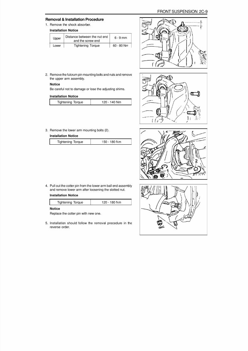
8/18/2019 SsangYong Musso Service Manual 1998.pdf
http://slidepdf.com/reader/full/ssangyong-musso-service-manual-1998pdf 846/1459
FRONT SUSPENSION 2C-9
Removal & Installation Procedure1. Remove the shock absorber.
Installation Notice
2. Remove the fulcrum pin mounting bolts and nuts and removethe upper arm assembly.
NoticeBe careful not to damage or lose the adjusting shims.
Upper
Lower
Distance between the nut endand the screw end
Tightening Torque
6 - 9 mm
60 - 80 Nm
3. Remove the lower arm mounting bolts (2).
Installation Notice
Tightening Torque 120 - 140 Nm
4. Pull out the cotter pin from the lower arm ball end assemblyand remove lower arm after loosening the slotted nut.Installation Notice
Tightening Torque 150 - 180 Nm
NoticeReplace the cotter pin with new one.
5. Installation should follow the removal precedure in thereverse order.
Tightening Torque 120 - 180 Nm
Installation Notice
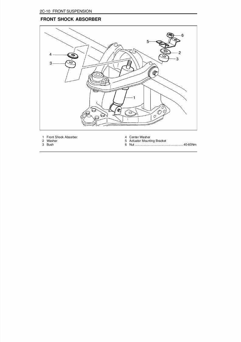
8/18/2019 SsangYong Musso Service Manual 1998.pdf
http://slidepdf.com/reader/full/ssangyong-musso-service-manual-1998pdf 847/1459
2C-10 FRONT SUSPENSION
FRONT SHOCK ABSORBER
1 Front Shock Absorber2 Washer3 Bush
4 Center Washer5 Actuator Mounting Bracket6 Nut ........................................................40-60Nm
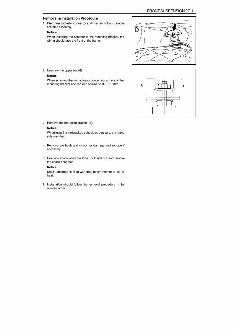
8/18/2019 SsangYong Musso Service Manual 1998.pdf
http://slidepdf.com/reader/full/ssangyong-musso-service-manual-1998pdf 848/1459
FRONT SUSPENSION 2C-11
Removal & Installation Procedure1. Disconnect actuator connector and unscrew bolt and remove
actuator assembly.
NoticeWhen installing the actuator to the mounting bracket, thewiring should face the front of the frame.
2. Unscrew the upper nut (6).
NoticeWhen screwing the nut, actuator contacting surface of themounting bracket and rod end should be 0.5 - 1.5mm.
3. Remove the mounting bracket (5).
Notice
When installing the bracket, it should be vertical to the frameside member.
4. Remove the bush and check for damage and replace ifnecessary.
5. Unscrew shock absorber lower bolt and nut and removethe shock absorber.
NoticeShock absorber is filled with gas, never attempt to cut orheat.
6. Installation should follow the removal procedure in thereverse order.

8/18/2019 SsangYong Musso Service Manual 1998.pdf
http://slidepdf.com/reader/full/ssangyong-musso-service-manual-1998pdf 849/1459
2C-12 FRONT SUSPENSION
1 Axle Vertical Acceleration Sensor (wheel Gsensor)
Removal & Installation Procedure1. Disconnect extension wiring connector (2) from the axle
vertical acceleration sensor.
NoticeInstallation of wiring connector should be as shown in theright drawing.
2. Unscrew bolts (3) and remove the axle vertical accelerationsensor (1).
NoticeWhen installing the sensor to the bracket, the sensor wiringshould be upward.
3. Installation should follow the removal procedure in thereverse order.
1 Actuator Connector2 Axle Vertical Acceleration Sensor Connector3 Front Hose Mounting Bracket4 Frame Side Member
AXLE VERTICAL ACCELERATION SENSOR (WHEEL G SENSOR)
2 Extension Wiring3 Bolt (M6) ............................................. 20 - 30Nm

8/18/2019 SsangYong Musso Service Manual 1998.pdf
http://slidepdf.com/reader/full/ssangyong-musso-service-manual-1998pdf 850/1459
FRONT SUSPENSION 2C-13
VERTICAL AND LATERAL SENSORRemoval & Installation Procedure1. Disconnect vertical sensor and lateral sensor connectors.
NoticeWhen connecting the connectors, connector connection of
the lateral sensor (2) should be in the right and connectorconnection of the vertical sensor (1) should face downward.
2. Unscrew bolts and remove vertical sensor and lateral sensor.
Installation Notice
1 Body Vertical Acceleration Sensor(Vertical Sensor)2 Body Lateral Acceleration Sensor (Lateral Sensor)
3. Installation should follow the removal procedure in thereverse order.
Tightening Torque 20 - 30 Nm

8/18/2019 SsangYong Musso Service Manual 1998.pdf
http://slidepdf.com/reader/full/ssangyong-musso-service-manual-1998pdf 851/1459
2C-14 FRONT SUSPENSION
ECS (ECU)
1 Electronically Controlled Suspension (ECU)2 Connector3 Bolts (2 pieces)
Removal & Installation Procedure1. Disconnect each connectors from the console box and
remove the console box.2. Disconnect ECU connector.3. Unscrew 10mm x 2 bolts and remove ECS (ECU).4. Installation should follow the removal procedure in the
reverse order.
4 Parking Brake Lever5 Over Voltage Protection Relay

8/18/2019 SsangYong Musso Service Manual 1998.pdf
http://slidepdf.com/reader/full/ssangyong-musso-service-manual-1998pdf 852/1459
TypeSpring TypeCoil Spring
Shock AbsorberStabilizer Type
Description5-link
Coil Spring13.8 mm
126.8 mm384.5 mm
f 139.6 mm2.58 kg
Cylindrical Reciprocation TypeTorsion Bar Type
SECTION 2D
REAR SUSPENSION
TABLE OF CONTENTS
SPECIFICATIONSGENERAL SPECIFICATIONS
Wire Diameter (mm)Diameter (mm)Free Heigth (mm)Outer Diameter (mm)Spring Constant (kg · m)
Application
Specifications. . . . . . . . . . . . . . . . . . . . . . . . 2D-1General Specifications . . . . . . . . . . . . . . . . . . 2D-1Fastener Tightening Specifications . . . . . . . . . 2D-1
Diagnosis . . . . . . . . . . . . . . . . . . . . . . . . . . . 2D-2Noise (During Straight Driving) . . . . . . . . . . . . 2D-2Oil Leakage . . . . . . . . . . . . . . . . . . . . . . . . . . 2D-2Noise (During Turning) . . . . . . . . . . . . . . . . . . 2D-2
Heating . . . . . . . . . . . . . . . . . . . . . . . . . . . . . . 2D-3Component Locator . . . . . . . . . . . . . . . . . . . 2D-4Maintenance and Repair . . . . . . . . . . . . . . . 2D-5On-Vehicle Service . . . . . . . . . . . . . . . . . . . . . 2D-5
Rear Suspension(5-Link) . . . . . . . . . . . . . . . . 2D-5Rear Shock Absorber . . . . . . . . . . . . . . . . . . . 2D-9
FASTENER TIGHTENING SPECIFICATIONS
ApplicationUpper NutStabilizer Bar BoltLateral Rod NutShock Absorber Mounting Nut Upper Arm Fixing Nut
N m16 - 2230 - 45
150 - 18050 - 65
150 - 180

8/18/2019 SsangYong Musso Service Manual 1998.pdf
http://slidepdf.com/reader/full/ssangyong-musso-service-manual-1998pdf 853/1459
2D-2 REAR SUSPENSION
DIAGNOSISNOISE (DURING STRAIGHT DRIVING)
CheckLack of Oil
Low Viscosity of OilInsufficient OilExcessive Backlash of Ring GearWorn or Damaged Tooth of Ring and Pinion GearWorn or Damaged Drive Pinion BearingWorn Spline of Side Bearing and Side GearBent Axle HousingBent Differential CaseWorn Pinion ShaftIncorrect Drive Pinion Preload
Incorrect Contact of Ring Gear and Pinion
ActionReplenish
ReplaceReplaceAdjust
ReplaceReplaceReplaceReplaceReplaceReplaceAdjust
Retightening
NOISE (DURING TURNING)Check
Worn or Damaged Tooth of Pinion or Side GearWorn Pinion ShaftExcessive Backlash of Pinion Gear and Side GearExcessive End-play of Rear Axle ShaftIncorrect Contact of Side Gear and Differential Case
Axle Housing CrackBent or Poor Installation of Drive Pinion Oil SealDamaged or Torn Drive Pinion Oil SealLoosened Bearing CollarWorn or Damaged Universal JointWorn of Damaged Axle Shaft Bearing
ActionReplaceReplaceReplaceAdjust
Replace
ReplaceReplaceReplaceReplaceReplaceReplace
OIL LEAKAGE
CheckExcessive OilFaulty Seal of Carrier Contact SurfaceAxle Housing CrackWorn or Damaged Oil Seal
ActionAdjustRepair
ReplaceReplace

8/18/2019 SsangYong Musso Service Manual 1998.pdf
http://slidepdf.com/reader/full/ssangyong-musso-service-manual-1998pdf 854/1459
REAR SUSPENSION 2D-3
HEATING
Check
Lack of OilInsufficient Backlash of GearsExcessive Preload of Bearing
Action
ReplenishAdjustAdjust
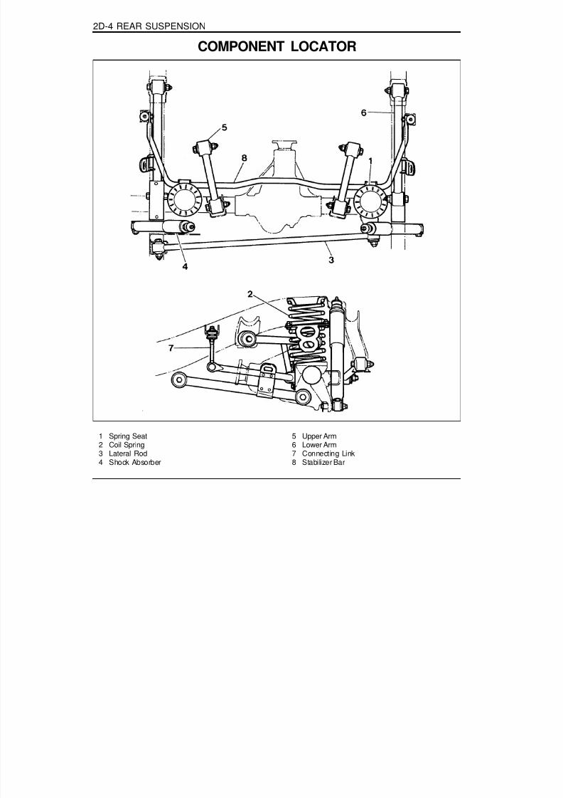
8/18/2019 SsangYong Musso Service Manual 1998.pdf
http://slidepdf.com/reader/full/ssangyong-musso-service-manual-1998pdf 855/1459
2D-4 REAR SUSPENSION
1 Spring Seat2 Coil Spring3 Lateral Rod4 Shock Absorber
5 Upper Arm6 Lower Arm7 Connecting Link8 Stabilizer Bar
COMPONENT LOCATOR

8/18/2019 SsangYong Musso Service Manual 1998.pdf
http://slidepdf.com/reader/full/ssangyong-musso-service-manual-1998pdf 856/1459
REAR SUSPENSION 2D-5
MAINTENANCE AND REPAIR
ON-VEHICLE SERIVCEREAR SUSPENSION (5 - LINK)
1 Spring Seat2 Coil Spring3 Lateral Rod4 Shock Absorber
5 Upper Arm6 Lower Arm7 Connecting Link8 Stabilizer Bar

8/18/2019 SsangYong Musso Service Manual 1998.pdf
http://slidepdf.com/reader/full/ssangyong-musso-service-manual-1998pdf 857/1459
2D-6 REAR SUSPENSION
Removal & Installation ProcedureStabilizer bar
1. Remove the upper nut of the connecting link.
Installation Notice
2. Remove the stabilizer bar cap fixing bolts (arrow) andremove the stabilizer bar.
Installation Notice
Tightening Torque 16 - 22 Nm
Distance Between the Nut
end and the Screw end10 - 13 mm
Tightening Torque 30 - 45 Nm
Lateral Rod1. Remove the lateral rod fixing nut from the frame.
NoticeCompletely press the coil springs.
Installation Notice
2. Remove the lateral rod fixing nut from the rear axle andremove the lateral rod.Installation Notice
Tightening Torque 150 - 180 Nm
Tightening Torque 150 - 180 Nm

8/18/2019 SsangYong Musso Service Manual 1998.pdf
http://slidepdf.com/reader/full/ssangyong-musso-service-manual-1998pdf 858/1459
REAR SUSPENSION 2D-7
Shock Absorber.1. Remove the lower mounting nut.
Installation Notice
2. Remove the upper mounting nut and remove the shockabsorber.
Installation Notice
Tightening Torque 50 - 65 Nm
Upper Arm1. Remove the upper arm fixing nut from the frame.
Installation Notice
2. Remove the upper arm fixing nut from the rear axle andremove the upper arm.
Installation Notice
Tightening Torque 150 - 180 Nm
Tightening Torque 150 - 180 Nm
Lower arm1. Remove the parking brake cable bracket.
Tightening Torque 30 - 45 Nm
Distance between the nutend and the screw end
6 - 9 mm

8/18/2019 SsangYong Musso Service Manual 1998.pdf
http://slidepdf.com/reader/full/ssangyong-musso-service-manual-1998pdf 859/1459
2D-8 REAR SUSPENSION
2. Remove the lower arm fixing nut from the frame.
Installation Notice
3. Remove the lower arm fixing nut from the rear axle andremove the lower arm.
Installation NoticeTightening Torque 150 - 180 Nm
Tightening Torque 150 - 180 Nm

8/18/2019 SsangYong Musso Service Manual 1998.pdf
http://slidepdf.com/reader/full/ssangyong-musso-service-manual-1998pdf 860/1459
REAR SUSPENSION 2D-9
REAR SHOCK ABSORBER
1 Rear Shock Absorber2 Washer3 Bush
4 Center Washer5 Actuator Mounting Bracket6 Nut (M12 x 1.25) ................................. 40 - 60Nm

8/18/2019 SsangYong Musso Service Manual 1998.pdf
http://slidepdf.com/reader/full/ssangyong-musso-service-manual-1998pdf 861/1459
2D-10 REAR SUSPENSION
Removal & Installation Procedure1. Disconnect actuator connector and unscrew bolt and remove
actuator assembly.
NoticeWhen installing the actuator to the mounting bracket,the wiring should face outward of the frame.
Actuator wiring should be fixed 40 - 50mm away fromthe wiring ends when fixing it with the frame open clip.
2. Unscrew the upper nut (6).
NoticeWhen screwing the nut, actuator contacting surface of themounting bracket and rod end should be 0.5 - 1.5mm.
3. Remove the mounting bracket (5).
NoticeWhen installing the bracket, it should be parallel to the frameside member.
4. Remove the bush and check for damage and replace ifnecessary.
5. Unscrew shock absorber lower bolt and nut and removethe shock absorber.
Notice
Shock absorber is filled with gas, never attempt to cut orheat.
6. Installation should follow the removal procedure in thereverse order.

8/18/2019 SsangYong Musso Service Manual 1998.pdf
http://slidepdf.com/reader/full/ssangyong-musso-service-manual-1998pdf 862/1459
DescriptionAlumimun7JJ X 15
Radial Tire
P215 / 75R 15 - 30psiP235 / 75R 15 - 30psiP255 / 70R 15 - 30psi
ApplicationWheel
SECTION 2E
TIRES AND WHEELS
TABLE OF CONTENTS
SPECIFICATIONSGENERAL SPECIFICATIONS
FASTENER TIGHTENING SPECIFICATIONS
ApplicationWheel Bolt
N m80 - 120
110 - 130
Specifications . . . . . . . . . . . . . . . . . . . . . . . . 2E-1General Specifications . . . . . . . . . . . . . . . . . . 2E-1Fastener Tightening Specifications . . . . . . . . . 2E-1
Diagnosis . . . . . . . . . . . . . . . . . . . . . . . . . . . 2E-2Wear Pattern Diagnosis . . . . . . . . . . . . . . . . . 2E-2
Identification. . . . . . . . . . . . . . . . . . . . . . . . . 2E-3Radial Tire . . . . . . . . . . . . . . . . . . . . . . . . . . . 2E-3
Wheel Disc . . . . . . . . . . . . . . . . . . . . . . . . . . . 2E-3Component Locator . . . . . . . . . . . . . . . . . . . 2E-4
Wheel and Tire . . . . . . . . . . . . . . . . . . . . . . . . 2E-4Maintenance and Repair . . . . . . . . . . . . . . . 2E-5On-Vehicle Service . . . . . . . . . . . . . . . . . . . . . 2E-5
Wheels and Tires . . . . . . . . . . . . . . . . . . . . . . 2E-5
MaterialSize
Tire Type
Size and Tire Pressure
SteelAlumimum

8/18/2019 SsangYong Musso Service Manual 1998.pdf
http://slidepdf.com/reader/full/ssangyong-musso-service-manual-1998pdf 863/1459

8/18/2019 SsangYong Musso Service Manual 1998.pdf
http://slidepdf.com/reader/full/ssangyong-musso-service-manual-1998pdf 864/1459
TIRES AND WHEELS 2E-3
IDENTIFICATIONRADIAL TIRE
WHEEL DISC
7 J x 16 ET 39
Wheel Offset (mm)(Distance from rim center to wheelnave contacting surface)
Rim Diameter (inch)
Identification for One-piece Well-base Rim
Code Letter for Height and Profile of Rim Flange
Rim Width (Inch)
ET : Distance from Rim Center to Wheel have ContactingSurface (mm)
a : Rim Width (Inch)d : Rim Diameter (Inch)
Four Season Mud & Snow
P 215/75 R 15 94 H M+S
Speed Rating (max. 210km/h)Load Range (below 670kg)
Rim Diameter (inch)
Radial TireAspect Ratio = (Section Height ¸ SectionWidth) x 100
Section Width (mm)
Passenger Car
215/6 5 R 16 93 V
Speed Rating (max. 240km/h)
Load Range (below 650kg)Rim Diameter (inch)
Radial TireAspect Ratio = (Section Height ¸ SectionWidth) x 100
Section Width(mm)
Summer Tire

8/18/2019 SsangYong Musso Service Manual 1998.pdf
http://slidepdf.com/reader/full/ssangyong-musso-service-manual-1998pdf 865/1459
2E-4 TIRES AND WHEELS
COMPONENT LOCATORWHEEL AND TIRE
1 Wheel Bolts ................. Steel Wheel : 80-120 Nm.......................... Aluminium Wheel : 110-130 Nm
2 Steel Wheel3 Aluminium Wheel
4 Tire5 Steel Wheel Weight Balance6 Hub Cap

8/18/2019 SsangYong Musso Service Manual 1998.pdf
http://slidepdf.com/reader/full/ssangyong-musso-service-manual-1998pdf 866/1459
TIRES AND WHEELS 2E-5
MAINTENANCE AND REPAIR
ON-VEHICLE SERVICEWHEELS AND TIRES
Removal & Installation Procedure1. Inspection of tireCheck tread area for tread surface, crack, damage by nailin or stones. Replace or repair if necessary.
Replace the tire if tread-wear indicator of the treadgrooves appears where marked ' ' .
The wear limit of snow tire is the same as normal tire(1.6mm) and indicator location is marked ' ¯ '.
Limit 1.6mm
Standard 2.66mm
Standard 2.03mm
2. Wear limit.
3. Runout measurement.Excessive runout of tires and wheels can cause theabnormal wear of tire. Using a dial indicator, measurewheel and tire runout.Measure radial runout at the rim flange and center ofthe tire tread area.
Measure lateral runout at the tire bead area of the wheeland tire sidewall.
NoticeIf runout is excessive, replace the tire or wheel.

8/18/2019 SsangYong Musso Service Manual 1998.pdf
http://slidepdf.com/reader/full/ssangyong-musso-service-manual-1998pdf 867/1459
2E-6 TIRES AND WHEELS
4. Tire pressure inspection.Tire pressure.
Check tread contact with road.
NoticeIf underinflated, tire may come away from the wheelduring rapid steering.
An overinflated tire will cause a hard riding and unevenwear.
Front & Rear(P235/75R15)
2.1kg/cm (30PSI)2
5. Wheel balance.Balance weights should be on each side. When the wheelis out of balance or a tire has been repaired, be sure tobalance the wheel again.
If total weight is over 150g, readjust the balance byreinstalling the tire on the wheel.Balance weight should not protrude from the wheel rimover 3mm.For aluminum wheel, use aluminum wheel balance weightonly.

8/18/2019 SsangYong Musso Service Manual 1998.pdf
http://slidepdf.com/reader/full/ssangyong-musso-service-manual-1998pdf 868/1459
TIRES AND WHEELS 2E-7
To correct unbalance, install equal weights 180°oppositeeach other, one on the inside of the wheel and one onthe outside, at the point of unbalance.Balance Weight
6. Cautions for installation and removal.Clean the mounting surfaces of hub and wheel.Do not apply grease or oil on the nuts and bolts (It willcause looseness and poor tightening).
Using a jack, lift up the tire about 3cm from the ground.Tighten nuts in a criss-cross pattern 2-3 times.
10g
0.4oz
20g
0.7oz
30g
1.10oz
40g
1.40oz
50g
1.80oz
60g
2.1oz
Steel : 80 - 120Nm
Aluminium : 110 - 130NmTighten Torque

8/18/2019 SsangYong Musso Service Manual 1998.pdf
http://slidepdf.com/reader/full/ssangyong-musso-service-manual-1998pdf 869/1459

8/18/2019 SsangYong Musso Service Manual 1998.pdf
http://slidepdf.com/reader/full/ssangyong-musso-service-manual-1998pdf 870/1459
3A-2 FRONT DRIVE AXLE
FASTENER TIGHTENING SPECIFICATIONSSteering Knuckle and Drive Shaft
ApplicationDrive Shaft to Front Axle Inner ShaftWheel Speed Sensor
Drive Shaft Cover BoltLocking Hub Washer ScrewHub Flange BoltHub Nut
N m
25 - 3585 - 105
50 - 602 - 4
70 - 9015

8/18/2019 SsangYong Musso Service Manual 1998.pdf
http://slidepdf.com/reader/full/ssangyong-musso-service-manual-1998pdf 871/1459
FRONT DRIVE AXLE 3A-3
1 Drive Shaft2 Axle Housing Mounting Bolt3 Axle Housing4 Cross Member
COMPONENT LOCATORFRONT AXLE
5 Brake Disc6 Hub-Wheel7 Locking Hub

8/18/2019 SsangYong Musso Service Manual 1998.pdf
http://slidepdf.com/reader/full/ssangyong-musso-service-manual-1998pdf 872/1459
3A-4 FRONT DRIVE AXLE
AUTO-LOCKING HUB
1 Cap2 Filter3 Vacuum Diaphragm4 Diaphragm Retainer5 Piston6 Bolt (M10)7 Lock Washer8 O-ring9 Retaining Ring
10 Clutch Ring
11 Body12 Return Spring
13 Bearing14 O-ring15 Retaining Ring16 Inner Drive Gear17 Oil Seal18 Oil Seal Race19 Axle Retaining Ring

8/18/2019 SsangYong Musso Service Manual 1998.pdf
http://slidepdf.com/reader/full/ssangyong-musso-service-manual-1998pdf 873/1459
FRONT DRIVE AXLE 3A-5
VACUUM CIRCUIT
1 Engine2 Vacuum Pump3 3-way Connector4 T-connector5 Check Valve
6 Auto locking Hub Solenoid Valve7 T-connector Hose8 Hub Hose (left)9 Hub Hose (right)

8/18/2019 SsangYong Musso Service Manual 1998.pdf
http://slidepdf.com/reader/full/ssangyong-musso-service-manual-1998pdf 874/1459
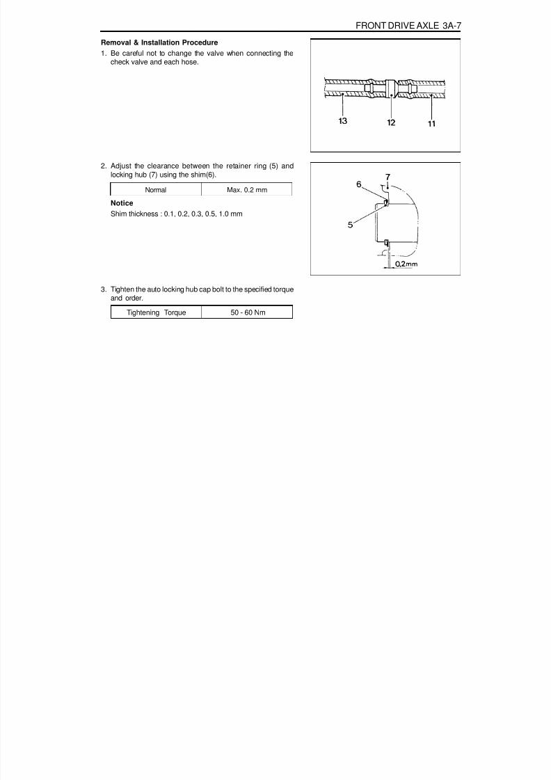
8/18/2019 SsangYong Musso Service Manual 1998.pdf
http://slidepdf.com/reader/full/ssangyong-musso-service-manual-1998pdf 875/1459
FRONT DRIVE AXLE 3A-7
Removal & Installation Procedure1. Be careful not to change the valve when connecting the
check valve and each hose.
2. Adjust the clearance between the retainer ring (5) andlocking hub (7) using the shim(6).
NoticeShim thickness : 0.1, 0.2, 0.3, 0.5, 1.0 mm
Normal Max. 0.2 mm
3. Tighten the auto locking hub cap bolt to the specified torqueand order.
Tightening Torque 50 - 60 Nm

8/18/2019 SsangYong Musso Service Manual 1998.pdf
http://slidepdf.com/reader/full/ssangyong-musso-service-manual-1998pdf 876/1459
3A-8 FRONT DRIVE AXLE
STEERING KNUCKLE AND DRIVE SHAFT
1 Front Axle Inner Shaft2 Front Axle Drive Shaft
3 Spring Washer
4 Bolt ...................................................... 45-60 Nm5 Steering Knuckle

8/18/2019 SsangYong Musso Service Manual 1998.pdf
http://slidepdf.com/reader/full/ssangyong-musso-service-manual-1998pdf 877/1459
FRONT DRIVE AXLE 3A-9
Removal & Installation Procedure1. Remove the tire.
Installation Notice
Steel Wheel
Aluminum WheelTightening Torque
80 - 120 Nm
110 - 130 Nm
2. Remove the autolocking hub vacuum hose.
3. With ABSRemove the wheel speed sensor from the steering knuckle.
Installation Notice
4. Remove the mounting bolts and pull off the caliper assembly.
Installation Notice
Tightening Torque 6 - 8 Nm
Hose Bolt
Mounting BoltTightening Torque
25 - 35 Nm
85 - 105 Nm
NoticeBe careful not to damage the brake hose.

8/18/2019 SsangYong Musso Service Manual 1998.pdf
http://slidepdf.com/reader/full/ssangyong-musso-service-manual-1998pdf 878/1459
3A-10 FRONT DRIVE AXLE
5. With part time transfer case.5-1. Remove the cover mounting bolts and pull off the cover.
Installation Notice
5-2. Remove the snap ring of the drive shaft and pull off thehub body.
NoticeFor assembly, adjust the clearance between the snap ring
and hub not to exceed 0.2 mm (Shim thickness : 0.1, 0.2,0.3, 0.5, 1.0 mm).
Tightening Torque 50 - 60 Nm
6. With full time transfer case6-1. Detach the hub cap with screw driver and remove the
snap ring on drive shaft.
Installation Notice
Tightening Torque 2 - 4 Nm
5-3. Remove the screws and pull off the locking hub washer.
Installation Notice
NoticeFor assembly, adjust the clearance between the snap ringand hub not to exceed 0.2 mm (Shim thickness : 0.1, 0.2,0.3, 0.5, 1.0 mm).
Tightening Torque 15 Nm

8/18/2019 SsangYong Musso Service Manual 1998.pdf
http://slidepdf.com/reader/full/ssangyong-musso-service-manual-1998pdf 879/1459
FRONT DRIVE AXLE 3A-11
8. Remove the hub and disk assembly.
9. Remove the disk brake dust shield.
Installation Notice
Tightening Torque 4 - 6 Nm
6-2. Unscrew the bolts and remove hub flange.
Installation Notice
Tightening Torque 70 - 90 Nm
Before installation, apply loctite on the mating surface.
7. Remove the hub nut with special tool.
Tightening Torque 15 Nm

8/18/2019 SsangYong Musso Service Manual 1998.pdf
http://slidepdf.com/reader/full/ssangyong-musso-service-manual-1998pdf 880/1459
3A-12 FRONT DRIVE AXLE
10. Remove the cotter pin and slotted nut and then removethe steering knuckle arm and tie-rod.
Installation Notice
Replace the cotter pin with new one.
Tightening Torque 35 - 45 Nm
11. Remove the cotter pin and nut from the steering knucklearm and upper arm ball joint connection.
Installation Notice
Tightening Torque 80 - 150 Nm
Replace the cotter pin with new one.
12. Remove the cotter pin and nut from the steering knucklearm and lower and lower arm boll joint connection.
13. Carefully remove the knuckle arm.
Installation Notice
Tightening Torque 120 - 180 Nm

8/18/2019 SsangYong Musso Service Manual 1998.pdf
http://slidepdf.com/reader/full/ssangyong-musso-service-manual-1998pdf 881/1459
FRONT DRIVE AXLE 3A-13
14. Remove the drive shaft mounting bolts and remove thedrive shaft.
Installation Notice
Tightening Torque 45 - 60 Nm
15. Installation should follow the removal precedure in thereverse order.
Observe the tighening torque and sequence.

8/18/2019 SsangYong Musso Service Manual 1998.pdf
http://slidepdf.com/reader/full/ssangyong-musso-service-manual-1998pdf 882/1459
3A-14 FRONT DRIVE AXLE
1 Axle Mounting Bracket2 Breather Hose3 Bolt (Rear)4 Nut ..................................................... 95-142 Nm5 Cross Member6 Bolt (Front)7 Bushing8 Spacer
FRONT AXLE
9 Bushing10 Nut ..................................................... 95-142 Nm11 Front Axle Assembly12 Nut ....................................................... 70-80 Nm13 Bolt14 Inner Axle Shaft (LH)15 Inner Axle Shaft (RH)
Preceding Work : Removal of the front axle drive shaft Removla of the steering gear box

8/18/2019 SsangYong Musso Service Manual 1998.pdf
http://slidepdf.com/reader/full/ssangyong-musso-service-manual-1998pdf 883/1459

8/18/2019 SsangYong Musso Service Manual 1998.pdf
http://slidepdf.com/reader/full/ssangyong-musso-service-manual-1998pdf 884/1459

8/18/2019 SsangYong Musso Service Manual 1998.pdf
http://slidepdf.com/reader/full/ssangyong-musso-service-manual-1998pdf 885/1459
FRONT DRIVE AXLE 3A-17
1 Front Axle Housing Mounting Bracket2 Inner Shaft (Left)3 Bolt ...................................................... 55-65 Nm4 Oil Seal .................................................. Replace
Apply Grease to the Sealing Rib5 Snap Ring6 Bearing
7 Snap Ring8 Oil Drain Plug....................................... 28-41 Nm9 Front Axle Housing
10 Breather Nipple11 Inner Shaft (Right)12 Pinion Lock Nut ................................ 240-310 Nm13 Washer14 Companion Flange15 Oil Seal .................................................. Replace
Apply Grease to the Sealing Rib16 Bearing17 Shim18 Bearing Baffle19 Shim
20 Bearing21 Oil Slinger22 Drive Pinion23 Oil Filler Plug ....................................... 28-41 Nm24 Bolt ...................................................... 39-46 Nm25 Axle Housing Cover..............Apply Liquid Gasket
to the Contact Surface
26 Ring Gear27 Bearing28 Shim29 Shaft Lock Pin30 Differential Case31 Bolt ...................................................... 75-90 Nm32 Bolt ...................................................... 48-69 Nm33 Washer34 Bearing Cap35 Thrust Washer36 Side Gear37 Differential Shaft38 Differential Pinion39 Thrust Washer

8/18/2019 SsangYong Musso Service Manual 1998.pdf
http://slidepdf.com/reader/full/ssangyong-musso-service-manual-1998pdf 886/1459
3A-18 FRONT DRIVE AXLE
Disassembly Procedure1. Remove the drain plug and drain the oil. Reinstall the drain
plug.Installation Notice
Tightening Torque 28 - 41 Nm
2. Unscrew the axle housing and housing mounting bracketbolts and remove the bracket and inner shaft assembly.
3. Remove the bearing fixing snap ring of the inner shaft andpull out the bearing. Separate the inner shaft and themounting bracket.
4. Remove the axle housing cover.NoticeClean the cover and housing contact surfaces.

8/18/2019 SsangYong Musso Service Manual 1998.pdf
http://slidepdf.com/reader/full/ssangyong-musso-service-manual-1998pdf 887/1459
FRONT DRIVE AXLE 3A-19
5. Unscrew the bearing cap bolts and remove the bearing caps.Pull out the differential carrier assembly.NoticePlace alignment marks on the bearing cap not to changethe caps before removal. When pulling out the differentialcarrier assembly, be careful not to damage the axle housing.
6. Disassemble the parts of the differential carrier assembly.
7. Remove the drive pinion lock nut. Disassemble the parts ofthe drive pinion.
Assembly Procedure1. Clean the all parts and check the followings :
Check the ring gear and drive pinion for wear anddamage. If damaged, replace it as a set.Check the bearing for sticks, wear, noise and turningresistance.Check the side gear, pinion, pinion shaft and thrustwasher for wear and damage.Check the differential carrier for crack and wear (bearingcontact surface). Check the gear case for crack.

8/18/2019 SsangYong Musso Service Manual 1998.pdf
http://slidepdf.com/reader/full/ssangyong-musso-service-manual-1998pdf 888/1459
3A-20 FRONT DRIVE AXLE
2. Assemble the parts of the drive pinion.
3. Assemble the parts of the differential carrier.
4. Measure backlash of the side gear and pinion.
5. Install the differential carrier assembly into the axle housing.
NoticeBe careful not to change the caps. Be sure to keep theoriginal position of the caps.
Tightening Torque of theLock Nut
240 - 310 Nm
Tightening Torque of theRing Gear Bolts 75 - 90 Nm
Standard 0 - 0.05 mm
Tightening Torque of theBearing Cap Bolts 48 - 69 Nm

8/18/2019 SsangYong Musso Service Manual 1998.pdf
http://slidepdf.com/reader/full/ssangyong-musso-service-manual-1998pdf 889/1459
FRONT DRIVE AXLE 3A-21
6. Measure backlash of the drive pinion and ring gear.
7. Install the axle housing cover.
8. Assemble the parts of the front axle shaft and housingmounting bracket.NoticeApply grease to the oil seal rib.
9. Align the axle shaft and differential carrier spline and insertthe axle shaft. Assemble the axle housing mounting bracketto the axle housing.
Specified Value 0.13 - 0.20 mm
Tightening Torque 39 - 46 Nm
Tightening Torque 55 - 65 Nm

8/18/2019 SsangYong Musso Service Manual 1998.pdf
http://slidepdf.com/reader/full/ssangyong-musso-service-manual-1998pdf 890/1459
3A-22 FRONT DRIVE AXLE
Inspection of Ring Gear Tooth Contact PatternNormal ContactApply gear-marking compound (prussian blue / red lead) onthe ring gear teeth. Rotate the ring gear and check the toothcontact pattern.
Abnormal Contact
Tooth Contact pattern Possible Cause Remedy
1. Heel Contact
2. Toe Contact
3. Face Contact
4. Flank Contact
Insufficient backlash (little)Tooth can be damagedor broken under heavyload
Excessive backlash (much)Drive pinion shaft is apartfrom the ring gearNoise can be occurred
Insufficient backlash (much)Gear contacts on the low
flankGear can be damaged orwornNoise can be occurred
Adjust backlash(Decrease backlash)Select proper shim(s) to move thedrive pinion toward the ring gear(toward toe)
Adjust backlash(Increase backlash)Select proper shim(s) to move thedrive pinion against the ring gear(toward heel)
Adjust backlash(Increase pinion shim)Move the drive pinion toward the ringgear (toward center of ring gear)
Adjust backlash(Decrease pinion shim)Move the ring gear toward the drivepinion (toward ring gear center line)
Excessive backlash (little)Noise can be occurred

8/18/2019 SsangYong Musso Service Manual 1998.pdf
http://slidepdf.com/reader/full/ssangyong-musso-service-manual-1998pdf 891/1459
Diesel
Gasoline(M161)
Gasoline(M162)
Diesel
Gasoline
ApplicationJoint Type
Number of SpiderFront
FrontRearFrontRear
Front (Full-Time)Front (Part-Time)RearFrontRear
SECTION 3C
PROPELLER SHAFT
TABLE OF CONTENTSSpecifications. . . . . . . . . . . . . . . . . . . . . . . . 3C-1
General Specifications . . . . . . . . . . . . . . . . . . 3C-1Component Locator . . . . . . . . . . . . . . . . . . . 3C-2
M/T & A/T (Part-time T/C) . . . . . . . . . . . . . . . . 3C-2
Maintenance and Repair . . . . . . . . . . . . . . . 3C-3On-Vehicle Service . . . . . . . . . . . . . . . . . . . . . 3C-3
Propeller Shaft . . . . . . . . . . . . . . . . . . . . . . . . 3C-3
SPECIFICATIONSGENERAL SPECIFICATIONS
DescriptionSingle or Single & Double Cardan
Single CardanConstant Velocity(CV) & Double Carden
Single Cardan
322
CV Joint : 1, Double Spiders : 12
Diesel
Gasoline
Shaft Dimensions(L´ O.D ´ I.D)When CompressedFully
FrontRearFrontRear
Front
Rear
---M/T & MB A/TBTRA A/T (2p-Type)
TONGILKSC-
576 ´ f 59.5 ´ f 63.5973 ´ f 63.5 ´ f 659.5583.5 ´ f 44.7 ´ f 50.8973 ´ f 63.5 ´ f 459.5380.8 ´ f 63.5 ´ f 59.5
591.5 ´ f 63.5 ´ f 59.5601.6 ´ f 50.8 ´ f 44.7579.6 ´ f 50.8 ´ f 44.7776.8 ´ f 63.5 ´ f 59.5

8/18/2019 SsangYong Musso Service Manual 1998.pdf
http://slidepdf.com/reader/full/ssangyong-musso-service-manual-1998pdf 892/1459
3C-2 PROPELLER SHAFT
1 Flange Yoke2 Cross and Bearing Assembly (with Snap Ring)3 Cross and Bearing Assembly (with Snap Ring)4 Slip Yoke Assembly5 Grease Nipple6 Dust Cap7 Oil Seal8 Split Washer9 Slip Tube Shaft
10 Tube
NoticeOnly the length of shaft is different and the components of front/rear shaft are the same.(The deadener is inserted to the inside of tube of rear shaft, both ends)
COMPONENT LOCATORM/T & A/T (PART-TIME T/C)
1. Gasolin : E32- Fromt Propeller Shaft
2. Diesel/Gasolin : E23,20- Fromt Propeller Shaft: A/T + Full - Time T/C
3. Gasolin- Rear Propeller Shaft
Diesel- Fromt & Rear Propeller Shaft: M/T & A/T + FPart - Time T/C
11 Tube Yoke12 Flange Yoke13 Diesel : Cross and Bearing Assembly (with Snap Ring)
Gasoline : CV Joint (DOJ)14 Diesel : Double Cardan
Gasoline : Stub Shaft15 Tube16 Cross and Bearing Assembly (with Snap Ring)17 Center Couping Yoke18 Boots Band

8/18/2019 SsangYong Musso Service Manual 1998.pdf
http://slidepdf.com/reader/full/ssangyong-musso-service-manual-1998pdf 893/1459
PROPELLER SHAFT 3C-3
1 Front Axle2 Bolt ...................................................... 70-80 Nm3 Front Propeller Shaft (661LA/662LA)4 Front Propeller Shaft (E32)5 Bolt ...................................................... 81-89 Nm6 Transfer Case
MAINTENANCE AND REPAIR
ON-VEHICLE SERVICEPROPELLER SHAFT
7 Bolt ...................................................... 81-89 Nm8 Rear Propeller Shaft9 Bolt ...................................................... 70-80 Nm
10 Rear Axle11 Front Propeller Shaft (E20/E23)

8/18/2019 SsangYong Musso Service Manual 1998.pdf
http://slidepdf.com/reader/full/ssangyong-musso-service-manual-1998pdf 894/1459
3C-4 PROPELLER SHAFT
Removal Procedure1. Place alignment marks and remove the propeller shaft.
2. Place alignment marks before removing the spider.
3. Using a snap ring pliers, remove the snap ring.
Gasoline
Diesel

8/18/2019 SsangYong Musso Service Manual 1998.pdf
http://slidepdf.com/reader/full/ssangyong-musso-service-manual-1998pdf 895/1459
PROPELLER SHAFT 3C-5
5. If difficult to remove, clamp the yoke side in a vise and tapoff the needle bearing, using a proper tool.
6. Disassemble the universal joint parts.As axles move up and down, universal joints allow driveangles to change without binding propeller shaft.
1 Grease Nipple2 Flange Yoke3 Spider
4 Seal5 Needle Roller Bearing6 Snap Ring
4. Slightly tapping the yoke shoulder using a brass hammer,remove the bearing. Remove the remaining bearings in thesame way.

8/18/2019 SsangYong Musso Service Manual 1998.pdf
http://slidepdf.com/reader/full/ssangyong-musso-service-manual-1998pdf 896/1459
3C-6 PROPELLER SHAFT
3. Clearance between the spider and bearing.
4. Propeller shaft runoutUsing a dial indicator, measure propeller shaft runout byturning the shaft. If runout exceeds limit, replace thepropeller shaft or correct it using a press.
Standard
0.03 - 0.098 mm
Limit
0.25 mm
Inspection Procedure1. Visual check.
Check the disassembled parts for wear or crack.Replace them if necessary.
2. Spider outer diameter (mm).
Standard16.668
Limit16.647
Limit 0.4 mm

8/18/2019 SsangYong Musso Service Manual 1998.pdf
http://slidepdf.com/reader/full/ssangyong-musso-service-manual-1998pdf 897/1459
PROPELLER SHAFT 3C-7
Installation ProcedureClean the disassembled parts and replace them if damaged.
1. Align the alignment marks of the yoke and assemble thespider, bearing and snap ring.
2. Apply grease to the inner of the bearing cap of the needleroller bearing and assemble the needle roller.
Grease EP #2
6. Possible cause of vibration.Drift away of balance weights.Excessive runout of the propeller shaft.Using normal bolts.
Excessive wear of the universal joint.Sticks in sleeve joint.Drive angle changes in universal joints or cross causesvibration and can be detected around 60~100 km/h.
5. Universal joint starting torque.
Starting Torque 3 - 8 kg cm

8/18/2019 SsangYong Musso Service Manual 1998.pdf
http://slidepdf.com/reader/full/ssangyong-musso-service-manual-1998pdf 898/1459
3C-8 PROPELLER SHAFT
3. Install the bearing cap to the yoke and insert the spider.Install the opposite side cap by tapping with a plastichammer. Adjust clearance of the spider pin to be within 0.1mm and install the snap ring.
4. Align the alignment marks and install the front and rearpropeller shaft. Tighten the nuts to the specified torque.
Gasoline
Diesel

8/18/2019 SsangYong Musso Service Manual 1998.pdf
http://slidepdf.com/reader/full/ssangyong-musso-service-manual-1998pdf 899/1459
SECTION 3D
REAR DRIVE AXLE
TABLE OF CONTENTSSpecifications. . . . . . . . . . . . . . . . . . . . . . . . 3D-1
General Specifications . . . . . . . . . . . . . . . . . . 3D-1Fastener Tightening Specifications . . . . . . . . . 3D-2
Diagnosis . . . . . . . . . . . . . . . . . . . . . . . . . . . 3D-3Noise (During Straight Driving) . . . . . . . . . . . . 3D-3Oil Leakage . . . . . . . . . . . . . . . . . . . . . . . . . . 3D-3Noise (During Turning) . . . . . . . . . . . . . . . . . . 3D-3Heating . . . . . . . . . . . . . . . . . . . . . . . . . . . . . . 3D-3Vibration . . . . . . . . . . . . . . . . . . . . . . . . . . . . . 3D-4
Noise . . . . . . . . . . . . . . . . . . . . . . . . . . . . . . . 3D-4Component Locator . . . . . . . . . . . . . . . . . . . 3D-5Maintenance and Repair . . . . . . . . . . . . . . . 3D-6On-Vehicle Service . . . . . . . . . . . . . . . . . . . . . 3D-6
Axle Shaft . . . . . . . . . . . . . . . . . . . . . . . . . . . . 3D-6Axle . . . . . . . . . . . . . . . . . . . . . . . . . . . . . . . . . 3D-9
Unit Repair . . . . . . . . . . . . . . . . . . . . . . . . . 3D-11Axle Housing . . . . . . . . . . . . . . . . . . . . . . . . . 3D-11LSD (Limited Slip Diffrential) . . . . . . . . . . . . . 3D-16
SPECIFICATIONSGENERAL SPECIFICATIONS
Axle Shaft TypeAxle Housing TypeDifferential
Reduction Ratio
TypeGearM/TM/TA/T (MB)M/TA/T (BTRA)M/T
A/T (BTRA)
Description
Semi - floatingSalibury (Build-up)Conventional Type
Hypoid Gear4.554.553.734.555.384.27
4.89
Application
661NA662NA
661LA
662LA

8/18/2019 SsangYong Musso Service Manual 1998.pdf
http://slidepdf.com/reader/full/ssangyong-musso-service-manual-1998pdf 900/1459
3D-2 REAR DRIVE AXLE
FASTENER TIGHTENING SPECIFICATIONS
ApplicationInner Bracket Mounting NutPropeller Shaft to Rear Axle Input ShaftLower Arm Mounting NutLower Shock Absorber to Axle HousingUpper Arm Mounting NutStabilizer Bar Mounting BoltLateral Rod Mounting NutDrive Pinion Lock NutOil Drain PlugRing Gear Mounting BoltOil Filler Plug
N····· m50 - 6570 - 80
150 - 18050 - 65
150 - 18030 - 45
150 - 180240 - 310
28 - 4275 - 9028 - 42
4.554.554.55
4.275.863.733.734.891.9 L
SEA 80W/90, API GL - 5
M/TA/T (MB)M/T
A/T (MB)A/T (BTRA)M/TA/T (MB)A/T (BTRA)
Oil CapacityOil Specification
Application Description
GENERAL SPECIFICATIONS(CONT'D)
E20
E23
E32
Reduction Ratio

8/18/2019 SsangYong Musso Service Manual 1998.pdf
http://slidepdf.com/reader/full/ssangyong-musso-service-manual-1998pdf 901/1459
REAR DRIVE AXLE 3D-3
ChecksWorn or Damaged Tooth of Pinion or Side GearWorn Pinion ShaftExcessive Backlash of Pinion Gear and Side GearExcessive End-play of Rear Axle ShaftIncorrect Contact of Side Gear and Differential CaseAxle Housing CrackBent or Poor Installation of Drive Pinion Oil SealDamaged or Torn Drive Pinion Oil SealLoosened Bearing CollarWorn or Damaged Universal JointWorn or Damaged Axle Shaft Bearing
ChecksExcessive OilFaulty Seal of Carrier Contact SurfaceAxle Housing CrackWorn or Damaged Oil Seal
ChecksLack of OilLow Viscosity of OilInsufficient OilExcessive Backlash of Ring GearWorn or Damaged Tooth of Ring and Pinion GearWorn or Damaged Drive Pinion BearingBent Axle HousingBent Differential CaseWorn Pinion ShaftIncorrect Drive Pinion PreloadIncorrect Contact of Ring Gear and Pinion
DIAGNOSISNOISE (DURING STRAIGHT DRIVING)
ActionReplenishReplaceReplaceAdjust
ReplaceReplaceReplaceReplaceReplaceAdjust
Retightening
OIL LEAKAGE
ActionAdjustRepair
ReplaceReplace
NOISE (DURING TURNING)
ActionReplaceReplaceReplaceAdjust
ReplaceReplaceReplaceReplaceReplaceReplaceReplace
HEATINGChecks
Lack of OilInsufficient Backlash of GearsExcessive Preload of Bearing
ActionReplenish
AdjustAdjust

8/18/2019 SsangYong Musso Service Manual 1998.pdf
http://slidepdf.com/reader/full/ssangyong-musso-service-manual-1998pdf 902/1459
3D-4 REAR DRIVE AXLE
VIBRATIONChecks
Faulty Connection of Sliding JointBent Propeller ShaftSymmetry of Universal Joint Snap Ring
Loosened Yoke Bolts
ActionAdjust
ReplaceAdjust
Tighten
NOISEChecks
Worn or Damaged Universal Joint BearingFallen Off Universal Joint Snap RingLoosened Yoke ConnectionWorn Sliding Joint SplineInsufficient Grease
ActionReplace
Adjust or ReplaceTightenReplace
Apply as Necessary

8/18/2019 SsangYong Musso Service Manual 1998.pdf
http://slidepdf.com/reader/full/ssangyong-musso-service-manual-1998pdf 903/1459
REAR DRIVE AXLE 3D-5
1 Spring Seat2 Coil Spring3 Lateral Rod4 Shock Absorber
5 Upper Arm6 Lower Arm7 Connecting Link8 Stabilizer Bar
COMPONENT LOCATOR

8/18/2019 SsangYong Musso Service Manual 1998.pdf
http://slidepdf.com/reader/full/ssangyong-musso-service-manual-1998pdf 904/1459
3D-6 REAR DRIVE AXLE
MAINTENANCE AND REPAIR
ON-VEHICLE SERVICEAXLE SHAFT
1 Brake Disc2 Dust Plug3 Rear Axle Shaft4 Nut ....................................................... 50-65 Nm5 Washer6 Parking Brake Cable
7 Parking Brake Lining and Back Plate Assembly8 Caliper Assembly9 Gasket
10 Bolt .................................................... 85-100 Nm11 Rear Axle Housing

8/18/2019 SsangYong Musso Service Manual 1998.pdf
http://slidepdf.com/reader/full/ssangyong-musso-service-manual-1998pdf 905/1459
REAR DRIVE AXLE 3D-7
Removal & Installation Procedure1. Remove the tire.
Installation Notice
2. Release the parking brake.
Steel Wheel
Aluminum WheelTightening Torque
3. Remove the bolts and the brake caliper.
Installation NoticeBe careful not to damage the brake hose.
Tightening Torque 85 - 100 Nm
4. Remove the brake disc.
Notice
To remove the disc, install the bolts (M8 x 1.25) into theservice hole and uniformly tighten the bolts.
5. Disconnect the parking brake cable.
80 - 120 Nm
110 - 130 Nm

8/18/2019 SsangYong Musso Service Manual 1998.pdf
http://slidepdf.com/reader/full/ssangyong-musso-service-manual-1998pdf 906/1459
3D-8 REAR DRIVE AXLE
Tightening Torque 50 - 65 Nm
6. Remove the plug from the axle shaft flange and remove theinner shaft mounting nuts.
Installation Notice
7. Remove the axle shaft, parking brake lining and back plateassembly.
8. Installation should follow the removal precedure in thereverse order.

8/18/2019 SsangYong Musso Service Manual 1998.pdf
http://slidepdf.com/reader/full/ssangyong-musso-service-manual-1998pdf 907/1459
REAR DRIVE AXLE 3D-9
AXLERemoval & Installation Procedure1. Lift up the vehicle and support the frame safely.2. Remove the axle shaft.
Tightening Torque 150 - 180 Nm
3. Remove the propeller shaft from the rear axle input shaft.
Installation Notice
NoticePlace alignment marks before removal.
Tightening Torque 81 - 89 Nm
4. Disconnect the parking brake cable and brake hose.
5. Remove the lower arm mounting nuts and remove the lowerarm from the axle housing.Installation Notice

8/18/2019 SsangYong Musso Service Manual 1998.pdf
http://slidepdf.com/reader/full/ssangyong-musso-service-manual-1998pdf 908/1459
3D-10 REAR DRIVE AXLE
6. Separate the lower shock absorber from the axle housing.
Installation Notice
7. Remove the upper arm mounting nuts and remove theupper arm form the axle housing.
Installation Notice
Tightening Torque 50 - 65 Nm
8. Remove the stabilizer bar.
Installation Notice
Tightening Torque 150 - 180 Nm
9. Remove the lateral rod mounting nuts and remove thelateral rod from the axle housing.Installation Notice
Tightening Torque 30 - 45 Nm
10. Lowering the axle housing slowly, remove the coil springsand spring seats.
11. Installation should follow the removal precedure in thereverse order.
Tightening Torque 150 - 180 Nm

8/18/2019 SsangYong Musso Service Manual 1998.pdf
http://slidepdf.com/reader/full/ssangyong-musso-service-manual-1998pdf 909/1459
REAR DRIVE AXLE 3D-11
UNIT REPAIRAXLE HOUSINGPreceding Work : Removal of the axle shaft
Removal of the axle housing
1 Drive Pinion Lock Nut ...................... 240-310 Nm2 Washer3 Companion Flange4 Pinion Oil Seal5 Bearing Slinger6 Bearing7 Shim8 Shim9 Bearing Cup
10 Breather Nipple11 Rear Axle Housing12 Oil Drain Plug ....................................... 28-42 Nm13 Shim14 Bearing15 Drive Pinion16 Bearing Cap
17 Bolt .................................................... 87-124 Nm18 Bearing19 Shim20 Ring Gear21 Shaft Lock Pin22 Differential Case23 Ring Gear Mounting Bolt...................... 75-90 Nm24 Thrust Washer25 Differential Pinion26 Thrust Washer27 Side Gear28 Differential Shaft29 Housing Cover30 Bolt ...................................................... 38-46 Nm31 Oil Filler Plug ....................................... 28-42 Nm

8/18/2019 SsangYong Musso Service Manual 1998.pdf
http://slidepdf.com/reader/full/ssangyong-musso-service-manual-1998pdf 910/1459
3D-12 REAR DRIVE AXLE
Disassembly Procedure1. Remove the drain plug and drain the oil. Reinstall the drain
plug.
2. Remove the axle housing cover.
NoticeClean the cover and housing contact surface.
3. Remove the bearing cap bolts and remove the bearing caps.Pull out the differential carrier assembly.
NoticePlace alignment marks on the bearing cap not to changethe caps before removal. When pulling out the differentialcarrier assembly, be careful not to damage the axle housing.
4. Disassemble the parts of the differential carrier assembly.
Tightening Torque 28 - 42Nm

8/18/2019 SsangYong Musso Service Manual 1998.pdf
http://slidepdf.com/reader/full/ssangyong-musso-service-manual-1998pdf 911/1459
REAR DRIVE AXLE 3D-13
5. Remove the drive pinion lock nut. Disassemble the parts ofthe drive pinion.
Assembly Procedure1. Clean the all parts and check the followings.
Check the ring gear and drive pinion for wear or damage.If damaged, replace it as set.
Check the bearing for sticks, wear, noise or turningresistance.Check the side gear, pinion, pinion shaft and thrustwasher for wear or damage.Check the differential carrier for crack or wear (bearingcontact surface). Check the gear case for crack.
2. Assemble the parts of the drive pinion.
3. Assemble the parts of the differential carrier.
Tightening Torque of ThePinion Lock Nut 240 - 310 Nm
Tightening Torque of TheRing Gear Bolts
75 - 90 Nm

8/18/2019 SsangYong Musso Service Manual 1998.pdf
http://slidepdf.com/reader/full/ssangyong-musso-service-manual-1998pdf 912/1459
3D-14 REAR DRIVE AXLE
4. Measure backlash of the side gear and pinion gear.
Specified Value 0 - 0.05 mm
5. Install the differential carrier assembly into the axle housing.
Tightening Torque of TheBearing Cap Bolts
48 - 69 Nm
NoticeBe careful no to change the caps. Be sure to keep the originalposition of the caps.
6. Measure backlash of the drive pinion and ring gear.
7. Install the axle housing cover.
Specified Value 0.13 - 0.20 mm
Tightening Torque 39 - 46 Nm

8/18/2019 SsangYong Musso Service Manual 1998.pdf
http://slidepdf.com/reader/full/ssangyong-musso-service-manual-1998pdf 913/1459
REAR DRIVE AXLE 3D-15
Inspection of Ring Gear Tooth Contact PatternNormal ContactApply gear-marking compound (prussian blue / red lead) onthe ring gear teeth. Rotate the ring gear and check the toothcontact pattern.
Abnormal Contact
Tooth Contact pattern Possible Cause Remedy
1. Heel Contact
2. Toe Contact
3. Face Contact
4. Flank Contact
Insufficient backlash (little)Tooth can be damagedor broken under heavyload
Excessive backlash (much)Drive pinion shaft is apartfrom the ring gearNoise can be occurred
Insufficient backlash (much)Gear contacts on the low
flankGear can be damaged orwornNoise can be occurred
Adjust backlash(Decrease backlash)Select proper shim(s) to move thedrive pinion toward the ring gear(toward toe)
Adjust backlash(Increase backlash)Select proper shim(s) to move thedrive pinion against the ring gear(toward heel)
Adjust backlash(Increase pinion shim)Move the drive pinion toward the ringgear (toward center of ring gear)
Adjust backlash(Decrease pinion shim)Move the ring gear toward the drivepinion (toward ring gear center line)
Excessive backlash (little)Noise can be occurred

8/18/2019 SsangYong Musso Service Manual 1998.pdf
http://slidepdf.com/reader/full/ssangyong-musso-service-manual-1998pdf 914/1459
3D-16 REAR DRIVE AXLE
LSD (LIMITED SLIP DIFFERENTIAL)
1 Limited Slip Differential Assembly2 Shaft, Hub (left)3 Shim4 Thrust Washer5 Face Cam (left)6 Cam Whillom7 Thrust Bearing8 Radial Bearing
9 Shaft, Hub (right)10 Thrust Washer11 Face Cam (right)12 Cage13 Thrust Bearing14 Plate Spring15 Radial Bearing16 Oil Catcher

8/18/2019 SsangYong Musso Service Manual 1998.pdf
http://slidepdf.com/reader/full/ssangyong-musso-service-manual-1998pdf 915/1459
REAR DRIVE AXLE 3D-17
InspectionRemove the LSD assembly and check the pre-load torque.If necessary, replace LSD assembly.
Procedure1. Fix the right shaft of LSD to the special tool (A).2. Install the special tool (B) to the left shaft and rotate
counterclockwise and check the pre-load torque.
Normal Torque 3.6 - 9.0kgm
NoticeIf necessary, replace LSD assembly.

8/18/2019 SsangYong Musso Service Manual 1998.pdf
http://slidepdf.com/reader/full/ssangyong-musso-service-manual-1998pdf 916/1459
SECTION 4A
HYDRAULIC BRAKES
Specifications. . . . . . . . . . . . . . . . . . . . . . . . 4A-1General Specifications . . . . . . . . . . . . . . . . . . 4A-1
Diagnosis . . . . . . . . . . . . . . . . . . . . . . . . . . . 4A-2Noise or Vehicle Vibration When Applied Brake . . . . . . . . . . . . . . . . . . . . . . . . . . . . . . 4A-2
Pulls to One Side When Braking. . . . . . . . . . . 4A-2Poor Braking. . . . . . . . . . . . . . . . . . . . . . . . . . 4A-2Increasing Pedal Stroke (Pedal Goes to Floor) or Brake Dragging . . . . . . . . . . . . . . . 4A-3Poor Braking of Parking Brake . . . . . . . . . . . . 4A-3
TABLE OF CONTENTSComponent Locator . . . . . . . . . . . . . . . . . . . 4A-4
ABS . . . . . . . . . . . . . . . . . . . . . . . . . . . . . . . . 4A-4ABS / ABD . . . . . . . . . . . . . . . . . . . . . . . . . . . 4A-5Non-ABS / ABD . . . . . . . . . . . . . . . . . . . . . . . . 4A-6
Maintenance and Repair . . . . . . . . . . . . . . . 4A-7
On-Vehicle Service . . . . . . . . . . . . . . . . . . . . . 4A-7Bleeding the Brakes . . . . . . . . . . . . . . . . . . . . 4A-7Brake Pedal . . . . . . . . . . . . . . . . . . . . . . . . . . 4A-9LCRV (Load Conscious Reducing Valve) . . . 4A-12
Caution: Disconnect the negative battery cable before removing or installing any electrical unit or when a
tool or equipment could easily come in contact with exposed electrical terminals. Disconnecting this cable will help prevent personal injury and damage to the vehicle. The ignition must also be in LOCK unless otherwise noted.
TypePedal Ratio
Pedal StrokePedal Freeplay
TypeInner Diameter
TypeRatioType
I.D. of Caliper CylinderThickness of Brake PadThickness of Disc Plate
TypeI.D. of Caliper Cylinder
Thickness of Brake PadThickness of Disc Plate
TypeOperation
Specification
PBR Brake
4.3 : 1132 mm
f 23.81 mm
5.0 : 1
f 60.4 mm
¬f 40.5 mm
9.5 mm¬
Suspended
1 - 4 mmTandem Type with Lever Sensor
Vacuum Booster Type
Ventilated Disc
10 mm24 mm
Rear Wheel Internal Expansion TypeMechanical
SAE J1703, DOT3
SPECIFICATIONSGENERAL SPECIFICATIONS
Brake Pedal
Master Cylinder
Brake Booster
Front Brake
Rear Brake
Parking Brake
Brake Fluid
MANDO Brake
4.3 : 1138 mm
f 25.4 mm
5.6 : 1
f 60 mm
Solid Discf 38.2 mm10.0 mm10.4 mm
Application

8/18/2019 SsangYong Musso Service Manual 1998.pdf
http://slidepdf.com/reader/full/ssangyong-musso-service-manual-1998pdf 917/1459
4A-2 HYDRAULIC BRAKES
CheckDirty or Lack of FluidAir in Brake SystemFaulty Brake BoosterPoor Contact of Pad or LiningOil or Grease on PadFaulty Auto Adjuster
Over Heated Rotor Due to Dragging Pad or LiningClogging Brake LineFaulty Proportioning Valve
CheckIncorrect Tire Pressure Between Left and RightPoor Contact of Pad or LiningOil or Grease is Applied to Pad or LiningBent or Uneven Wear of DrumIncorrectly Mounted Wheel CylinderFaulty Auto Adjuster
ActionRepair
RetightenReplaceReplaceRepairRepair
LubricateRetighten
CheckIncorrectly Mounted Back Plate or Caliper
Loosened Bolt of Back Plate or CaliperCrack or Uneven Wear of Brake Drum or DiscPad or Lining Sticking to Contact SurfaceExcessive Clearance Between Caliper and PadUneven Contact of PadLack of LubricationLoosened Suspension
DIGNOSISNOISE OR VEHICLE VIBRATION WHEN APPLIED BRAKE
PULLS TO ONE SIDE WHEN BRAKINGActionAdjustRepair
ReplaceReplaceRepair
Replace
ActionReplenish or Replace(Check eventual leakage)
BleedingReplaceRepair
ReplaceReplace
RepairRepair
Repair
POOR BRAKING
( If low cut-in : Adjust )( If Leakage : Replace )

8/18/2019 SsangYong Musso Service Manual 1998.pdf
http://slidepdf.com/reader/full/ssangyong-musso-service-manual-1998pdf 918/1459
HYDRAULIC BRAKES 4A-3
CheckAir in Brake systemFluid LeakingExcessive Clearance Between Push Rod and M/cylinderParking Brake is not Fully ReleasedIncorrect Adjustment of Parking BrakeWeak Return Spring of Brake PedalIncorrect Pedal FreeplayBroken Rear Drum Brake Shoe Return SpringLack of LubricationDamaged Master Cylinder Check Valve or Piston Return Spring
ActionBleedingRepairAdjustRepairAdjust
ReplaceRepair
ReplacelubricateReplace
INCREASING PEDAL STROKE (PEDAL GOES TO FLOOR)
OR BRAKE DRAGGING
CheckInsufficient Clearance Between Push Rod and Master CylinderWorn Brake LiningOil or Grease on LiningBinding Parking Brake CableFaulty Auto AdjusterExcessive Lever Stroke
ActionAdjust
ReplaceReplaceReplaceReplace
Adjust or Check Cable
POOR BRAKING OF PARKING BRAKE

8/18/2019 SsangYong Musso Service Manual 1998.pdf
http://slidepdf.com/reader/full/ssangyong-musso-service-manual-1998pdf 919/1459
4A-4 HYDRAULIC BRAKES
COMPONENT LOCATORABS
1 Actuation Assembly (Booster+TMC)2 ABS Control Unit3 Master Cylinder 2nd Tube (Secondary)4 Master Cylinder 1st Tube (Primary)5 Front Tube (LH)6 Front Tube (RH)
7 Brake Hose8 Rear Tube9 Bolt ...................................................... 25-35 Nm
10 2-way Connector11 3-way Connector

8/18/2019 SsangYong Musso Service Manual 1998.pdf
http://slidepdf.com/reader/full/ssangyong-musso-service-manual-1998pdf 920/1459
HYDRAULIC BRAKES 4A-5
ABS / ABD
1 Actuation Assembly (Booster+TMC)2 Master Cylinder 1st Tube (Primary)3 Master Cylinder 2nd Tube (Secondary)4 Hydraulic Modulator5 Front Tube (LH)
6 Front Tube (RH)7 Rear Tube (RH)8 Rear Tube (LH)9 2-way Connector

8/18/2019 SsangYong Musso Service Manual 1998.pdf
http://slidepdf.com/reader/full/ssangyong-musso-service-manual-1998pdf 921/1459
4A-6 HYDRAULIC BRAKES
NON-ABS/ABD
1 Actuation Assembly (Booster+TMC)2 3-way Connector3 Front Tube (LH)4 Front Tube (RH)
5 2-way Connector6 Rear Tube7 3-way Connector8 LCRV

8/18/2019 SsangYong Musso Service Manual 1998.pdf
http://slidepdf.com/reader/full/ssangyong-musso-service-manual-1998pdf 922/1459
HYDRAULIC BRAKES 4A-7
MAINTENANCE AND REPAIR
ON-VEHICLE SERVICEBLEEDING THE BRAKES
For Master Cylinder Replacement1. Add oil after master cylinder replacement.2. Run the engine and depress the brake pedal several times
to build pressure and then keep the pedal fully depressed.3. Loosen the screws of primary and secondary pipe at the
master cylinder outlets to bleed air.4. Repeat above step No.3 several times until there are no
more air bubbles.5. Bleed air in the system at the hydraulic unit outlet pipe and
wheel if pressure building is not enough by depressing thepedal only after above air bleeding.
For Caliper and Brake Hose Replacement1. Check the oil level from the oil reservoir and refill if necessary.2. Run the engine and depress the pedal several times to
build pressure and then keep the pedal fully depressed.3. Connect a vinyl tube to the caliper breather and prepare a
container to coentain brake oil.4. Loosen the breather screw until there are no more bubbles.
5. Bleed air in the system at four (4) wheels in order as shownin right figure if pressure building is not enough by depressingthe pedal after above air bleeding.
Tightening Torque
9 - 14 Nm
Item
Front Bleeder Screw
Rear Bleeder ScrewNotice
Do not reuse the bled brake fluid.Always bleed the air after replacing brake fluid ormaster cylinder, caliper, brake hose and pipe.Always operate in normal order.

8/18/2019 SsangYong Musso Service Manual 1998.pdf
http://slidepdf.com/reader/full/ssangyong-musso-service-manual-1998pdf 923/1459

8/18/2019 SsangYong Musso Service Manual 1998.pdf
http://slidepdf.com/reader/full/ssangyong-musso-service-manual-1998pdf 924/1459
HYDRAULIC BRAKES 4A-9
BRAKE PEDAL
1 Clevis Pin2 Brake Pedal3 Stop Lamp Switch4 Pad5 Nut ....................................................... 21-35 Nm6 Yoke Pin7 Fulcrum Pin
8 Return Spring9 Pedal Mounting Bracket
10 Washer11 Nut ....................................................... 16-32 Nm12 Bolt ........................................................8-18 Nm13 Stopper Bolt .............................................. Adjust14 Rubber Pad ........................................... Replace

8/18/2019 SsangYong Musso Service Manual 1998.pdf
http://slidepdf.com/reader/full/ssangyong-musso-service-manual-1998pdf 925/1459
4A-10 HYDRAULIC BRAKES
Removal & Installation Procedure1. Remove the stop lamp switch connector.
2. Remove the clevis pin and disconnect the brake boosterpush rod.
NoticeInstall in the upper hole (1), in case of Mando brake and
in the below hole (2), incase of PBR brake.Install the snap pin fully in the hole of clevis pin.Apply the grease around the hole of clevis pin.
3. Loosen the nut (4EA) and bolt (2EA) and remove the brakepedal.
4. Installation should follow the removal procedure in reverseorder.
Tightening Torque 8 - 18 Nm
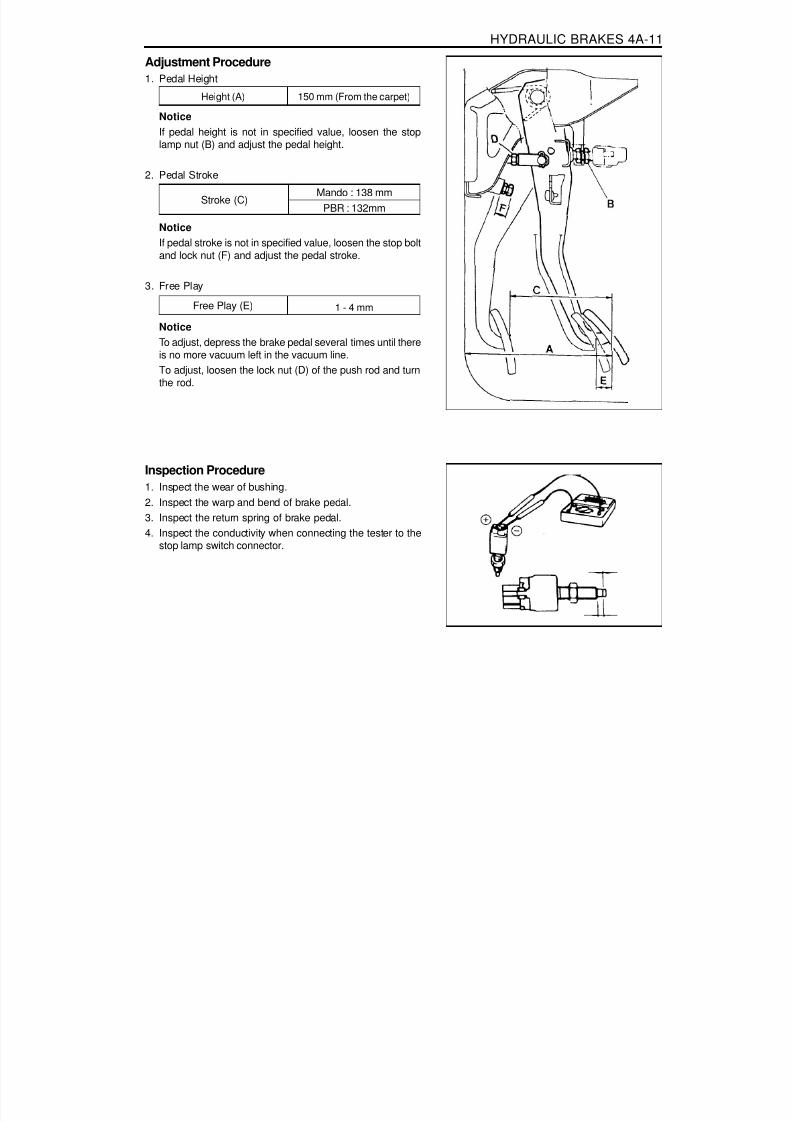
8/18/2019 SsangYong Musso Service Manual 1998.pdf
http://slidepdf.com/reader/full/ssangyong-musso-service-manual-1998pdf 926/1459
HYDRAULIC BRAKES 4A-11
Adjustment Procedure1. Pedal Height
NoticeIf pedal height is not in specified value, loosen the stoplamp nut (B) and adjust the pedal height.
2. Pedal Stroke
Height (A) 150 mm (From the carpet)
NoticeIf pedal stroke is not in specified value, loosen the stop boltand lock nut (F) and adjust the pedal stroke.
3. Free Play
Stroke (C)Mando : 138 mm
PBR : 132mm
NoticeTo adjust, depress the brake pedal several times until thereis no more vacuum left in the vacuum line.To adjust, loosen the lock nut (D) of the push rod and turnthe rod.
Free Play (E) 1 - 4 mm
Inspection Procedure1. Inspect the wear of bushing.2. Inspect the warp and bend of brake pedal.3. Inspect the return spring of brake pedal.4. Inspect the conductivity when connecting the tester to the
stop lamp switch connector.

8/18/2019 SsangYong Musso Service Manual 1998.pdf
http://slidepdf.com/reader/full/ssangyong-musso-service-manual-1998pdf 927/1459
4A-12 HYDRAULIC BRAKES
LCRV (LOAD CONSCIOUS REDUCING VALVE)
1 Brake Tube (from the master cylinder)2 Brake Tube (from the rear brake)3 LCRV Bracket4 Bolt ........................................................... 12 Nm
5 LCRV Assembly6 Connecting Link7 Spring Washer8 Nut ....................................................... 14-18 Nm

8/18/2019 SsangYong Musso Service Manual 1998.pdf
http://slidepdf.com/reader/full/ssangyong-musso-service-manual-1998pdf 928/1459
HYDRAULIC BRAKES 4A-13
ConstructionLCRV consists of sensing part and hydraulic control part.1. Sensing Part
It detects the changes of vehicle height caused by vehicleload. It consists of load sensing spring and control leverwhich change according to vehicle load.
2. Hydraulic Control PartIt consists of valve stem devices which controls hydraulicpressure according to load detected by sensing part.
Trouble ShootingPoor Braking
Possible CauseAir in Brake SystemPoor Adjustment of Sensor SpringDamaged Sensor SpringFluid Leaking from LCRV
RemedyBleeding
AdjustReplaceReplace
Possible CausePoor Adjustment of Sensor SpringInternal Fluid Leaking of LCRV
RemedyAdjust
Replace
Abnormal Locking

8/18/2019 SsangYong Musso Service Manual 1998.pdf
http://slidepdf.com/reader/full/ssangyong-musso-service-manual-1998pdf 929/1459
4A-14 HYDRAULIC BRAKES
LCRV SETTING METHOD
1. LCRV setting should be performed with unladen vehiclecondition.
2. Install the connecting rod (a) to the No.1 hole.
Tightening Torque 14 - 18 Nm
3. Adjust the clearance “X” to be 0 mm and tighten the bolt (c)using the lock nut (b).
Tightening Torque 14 - 18 Nm
4. Remove the connecting rod (a) from the No.1 hole andreinstall it to the No. 2 hole.
5. Place alignment marks between the lock nut (b) andadjusting screw (c) after the valve setting.

8/18/2019 SsangYong Musso Service Manual 1998.pdf
http://slidepdf.com/reader/full/ssangyong-musso-service-manual-1998pdf 930/1459
SECTION 4B
MASTER CYLINDER
Specifications. . . . . . . . . . . . . . . . . . . . . . . . 4B-1Fastener Tightening Specifications . . . . . . . . . 4B-1
Maintenance and Repair . . . . . . . . . . . . . . . 4B-2
TABLE OF CONTENTS
SPECIFICATIONSFASTENER TIGHTENING SPECIFICATIONS
ApplicationMaster Cylinder NutBooster Nut
N····· m
14 - 228 - 18
On-Vehicle Service . . . . . . . . . . . . . . . . . . . . . 4B-2Booster & Brake Master Cylinder . . . . . . . . . . 4B-2

8/18/2019 SsangYong Musso Service Manual 1998.pdf
http://slidepdf.com/reader/full/ssangyong-musso-service-manual-1998pdf 931/1459
4B-2 MASTER CYLINDER
1 Nut ....................................................... 14-22 Nm2 Washer3 Master Cylinder Assembly4 Oil Level Sensor5 Check Valve6 Booster7 Clevis Pin8 Snap Pin
9 Seal10 Spacer11 Nut ......................................................... 8-18 Nm12 Front Tube (LH)13 Front Tube (RH)14 Rear Tube15 1st Tube (Primary)16 2nd Tube (Secondary)
MANDO
PBR
MAINTENANCE AND REPAIR
ON-VEHICLE SERVICEBOOSTER AND BRAKE MASTER CYLINDER

8/18/2019 SsangYong Musso Service Manual 1998.pdf
http://slidepdf.com/reader/full/ssangyong-musso-service-manual-1998pdf 932/1459
MASTER CYLINDER 4B-3
Removal & Installation Procedure1. Remove the oil level sensor connector.2. Remove the tube from the master cylinder.
Installation Notice
NoticeBe careful not to drop the oil when removing the tube.If the oil is dropped, promptly sweep up.
3. Remove the booster vacuum hose.
NoticeConnect fully to the end of vacuum hose when installing.
4. Loosen the nut of master cylinder.
Installation Notice
5. Remove the clevis pin and disconnect the pedal and brakebooster push rod.Notice
Install in the upper hole when PBR brake.Connect the snap pin in the hole of clevis pin fully.Apply the grease around the hole of clevis pin.
Tightening Torque 14 - 22 Nm
Tightening Torque 15 - 19 Nm

8/18/2019 SsangYong Musso Service Manual 1998.pdf
http://slidepdf.com/reader/full/ssangyong-musso-service-manual-1998pdf 933/1459
4B-4 MASTER CYLINDER
6. Loosen the nut of booster and remove the booster from thedash panel.
Installation Notice
Tightening Torque 8 - 18 Nm
7. Installation should follow the removal procedure in the
reverse order.8. Add the fluid and bleed.9. If necessary, adjust the pedal height, pedal stroke and free
play.

8/18/2019 SsangYong Musso Service Manual 1998.pdf
http://slidepdf.com/reader/full/ssangyong-musso-service-manual-1998pdf 934/1459
SECTION 4C
POWER BOOSTER
Specifications. . . . . . . . . . . . . . . . . . . . . . . . 4C-1General Specifications . . . . . . . . . . . . . . . . . . 4C-1
Maintenance and Repair . . . . . . . . . . . . . . . 4C-2
TABLE OF CONTENTS
SPECIFICATIONS
GENERAL SPECIFICATIONSApplication
TypeRatio
N····· mVacuum Assisted
5.6 : 1
On-Vehicle Service . . . . . . . . . . . . . . . . . . . . . 4C-2Booster & Brake Master Cylinder . . . . . . . . . . 4C-2Pedal Stroke Inspection . . . . . . . . . . . . . . . . . 4C-5

8/18/2019 SsangYong Musso Service Manual 1998.pdf
http://slidepdf.com/reader/full/ssangyong-musso-service-manual-1998pdf 935/1459
4C-2 POWER BOOSTER
1 Nut ....................................................... 14-22 Nm2 Washer3 Master Cylinder Assembly4 Oil Level Sensor5 Check Valve6 Booster7 Clevis Pin8 Snap Pin
MAINTENANCE AND REPAIR
ON-VEHICLE SERVICEBOOSTER AND BRAKE MASTER CYLINDER
9 Seal10 Spacer11 Nut ......................................................... 8-18 Nm12 Front Tube (LH)13 Front Tube (RH)14 Rear Tube15 1st Tube (Primary)16 2nd Tube (Secondary)
MANDO
PBR

8/18/2019 SsangYong Musso Service Manual 1998.pdf
http://slidepdf.com/reader/full/ssangyong-musso-service-manual-1998pdf 936/1459
POWER BOOSTER 4C-3
Removal & Installation Procedure1. Remove the oil level sensor connector.2. Remove the tube from the master cylinder.
Installation Notice
NoticeBe careful not to drop the oil when removing the tube.If the oil is dropped, promptly sweep up.
3. Remove the booster vacuum hose.
NoticeConnect fully to the end of vacuum hose when installing.
4. Loosen the nut of master cylinder.
Installation Notice
5. Remove the clevis pin and disconnect the pedal and brakebooster push rod.Notice
Install in the upper hole when PBR brake.Connect the snap pin in the hole of clevis pin fully.Apply the grease around the hole of clevis pin.
Tightening Torque 14 - 22 Nm
Tightening Torque 15 - 19 Nm

8/18/2019 SsangYong Musso Service Manual 1998.pdf
http://slidepdf.com/reader/full/ssangyong-musso-service-manual-1998pdf 937/1459
4C-4 POWER BOOSTER
6. Loosen the nut of booster and remove the booster from thedash panel.
Installation Notice
Tightening Torque 8 - 18 Nm
7. Installation should follow the removal procedure in the
reverse order.8. Add the fluid and bleed.9. If necessary, adjust the pedal height, pedal stroke and free
play.

8/18/2019 SsangYong Musso Service Manual 1998.pdf
http://slidepdf.com/reader/full/ssangyong-musso-service-manual-1998pdf 938/1459
POWER BOOSTER 4C-5
PEDAL STROKE INSPECTION1. Start the engine and stop it after one or two minutes.
Depress the brake pedal several times.If the pedal goes down furthest the first time, but graduallyrises after the second or third time, brake booster is normal.If there is no change in pedal stroke, the brake booster is
abnormal.
2. Depress the brake pedal several times with engine stopped,and depress the brake pedal and start the engine. If thepedal goes down slightly, the booster is normal.
3. Depress the brake pedal with engine running, and stop itwith the pedal depressed. If there is no change in pedalheight during 30 sec., the booster is normal.

8/18/2019 SsangYong Musso Service Manual 1998.pdf
http://slidepdf.com/reader/full/ssangyong-musso-service-manual-1998pdf 939/1459

8/18/2019 SsangYong Musso Service Manual 1998.pdf
http://slidepdf.com/reader/full/ssangyong-musso-service-manual-1998pdf 940/1459
4D-2 FRONT DISC BRAKES
1 Eye-Hose Bolt ...................................... 25-35 Nm2 Gasket ................................................... Replace3 Brake Hose4 Brake Caliper5 Bolt ........................................................... 20 Nm6 Washer
MAINTENANCE AND REPAIR
ON-VEHICLE SERVICEFRONT DISC BRAKEPreceding Work : Removal of wheels and tires
7 Front Disc Assembly8 Brake Pad9 Brake Hose and Nut ............................. 25-35 Nm
10 Gasket ................................................... Replace11 Washer12 Bolt .................................................... 85-105 Nm

8/18/2019 SsangYong Musso Service Manual 1998.pdf
http://slidepdf.com/reader/full/ssangyong-musso-service-manual-1998pdf 941/1459
FRONT DISC BRAKES 4D-3
Removal & Installation Procedure1. MANDO Brake
Tightening Torque 25 - 35 Nm
2. PBR BrakeRemove the eye-hose bolt and disconnect the hose.
Installation Notice
Tightening Torque 15 - 18 Nm
3. Remove the wheel speed sensor (for ABS vehicies).Installation Notice
Tightening Torque 6 - 8 Nm
4. Remove the mounting bolts and then caliper assembly.
Installation Notice
Tightening Torque 85 - 105 Nm
Remove the hose mounting nut and disconnect the hose.Installation Notice

8/18/2019 SsangYong Musso Service Manual 1998.pdf
http://slidepdf.com/reader/full/ssangyong-musso-service-manual-1998pdf 942/1459
4D-4 FRONT DISC BRAKES
5. Pull out the brake pads. Replace pads if necessary.NoticeAlways change the all pads on one wheel at a time.
6. Installation should follow the removal procedure in thereverse order.
7. Bleed the air from the system.

8/18/2019 SsangYong Musso Service Manual 1998.pdf
http://slidepdf.com/reader/full/ssangyong-musso-service-manual-1998pdf 943/1459
FRONT DISC BRAKES 4D-5
4. Measure rotor disc thickness.
UNIT REPAIRFRONT DISC BRAKEInspection Procedure1. Clean all components and visually check the followings.
Check the cylinder and piston for wear, rust or damage.Check the caliper body and guide pin for wear, damageor crank.Check the pads for uneven wear or oiliness.Check the boots for damage or tear.
2. Measure caliper housing inner diameter.
ItemWith PBR
With MANDO
Wear Limitf 61.4 mmf 61.0 mm
Standard
10 mm
Wear Limit
2.0 mm
Standardf 60.4 mmf 60.0 mm
3. Measure pad thickness.
NoticeAlways change the all pads on one wheel at a time.
5. Check the rotor disc for score or runout.
Standard
24 mm
Wear Limit
22 mm

8/18/2019 SsangYong Musso Service Manual 1998.pdf
http://slidepdf.com/reader/full/ssangyong-musso-service-manual-1998pdf 944/1459
SECTION 4E
REAR DISC BRAKES
TABLE OF CONTENTSSpecifications . . . . . . . . . . . . . . . . . . . . . . . . 4E-1Fastener Tightening Specifications . . . . . . . . . 4E-1
Maintenance and Repair . . . . . . . . . . . . . . . 4E-2On-Vehicle Service . . . . . . . . . . . . . . . . . . . . . 4E-2
SPECIFICATIONSFASTENER TIGHTENING SPECIFICATIONS
ApplicationCaliper Mounting BoltBrake HoseCaliper Bolt
N····· m85 - 10515 - 18
20
Rear Disc Brake . . . . . . . . . . . . . . . . . . . . . . . 4E-2Unit Repair . . . . . . . . . . . . . . . . . . . . . . . . . . . 4E-4
Rear Disc Brake . . . . . . . . . . . . . . . . . . . . . . . 4E-4

8/18/2019 SsangYong Musso Service Manual 1998.pdf
http://slidepdf.com/reader/full/ssangyong-musso-service-manual-1998pdf 945/1459
4E-2 REAR DISC BRAKES
1 Rear Brake Disc Assembly2 Brake Pad3 Brake Caliper4 Gasket ................................................... Replace5 Bolt ........................................................... 20 Nm6 Gasket ................................................... Replace
MAINTENANCE AND REPAIR
ON-VEHICLE SERVICEREAR DISC BRAKEPreceding Work : Removal of wheels and tires
7 Brake Hose8 Gasket ................................................... Replace9 Eye-hose Bolt ...................................... 15-18 Nm
10 Washer11 Bolt .................................................... 85-105 Nm

8/18/2019 SsangYong Musso Service Manual 1998.pdf
http://slidepdf.com/reader/full/ssangyong-musso-service-manual-1998pdf 946/1459
REAR DISC BRAKES 4E-3
Tightening Torque 15 - 18 Nm
Tightening Torque 85 - 105 Nm
Removal & Installation Procedure1. Remove the eye-hose bolt and disconnect the hose.
Installation Notice
2. Unscrew the mounting bolts and remove the brake caliperassembly.
Installation Notice
3. Pull out the brake pads. Replace pads if necessary.
Notice
Always change the all pads on one wheel at a time.
4. Installation should follow the removal precedure in thereverse order.
5. Bleed the air from the system.

8/18/2019 SsangYong Musso Service Manual 1998.pdf
http://slidepdf.com/reader/full/ssangyong-musso-service-manual-1998pdf 947/1459
4E-4 REAR DISC BRAKES
Standard10.4 mm
Wear Limit
9.3 mm
UNIT REPAIRREAR DISC BRAKEInspection Procedure1. Clean all components and visually check the followings.
Check the cylinder and piston for wear, rust or damage.Check the caliper body and guide pin for wear, damageor crank.Check the pads for uneven wear or oiliness.Check the boots for damage or tear.
Standardf 40.5 mmf 38.2 mm
Wear Limitf 41.5 mmf 39.2 mm
2. Measure caliper housing inner diameter.
3. Measure pad thickness.
Standard
9.5 mm
Wear Limit
2.0 mmNoticeAlways change the all pads on one wheel at a time.
4. Measure rotor disc thickness.
5. Check the rotor disc for score or runout.
Item
With PBRWith MANDO

8/18/2019 SsangYong Musso Service Manual 1998.pdf
http://slidepdf.com/reader/full/ssangyong-musso-service-manual-1998pdf 948/1459
FrontRearFrontRear
SECTION 4F
ANTILOCK BRAKE SYSTEM
TABLE OF CONTENTS
Caution: Disconnect the negative battery cable before removing or installing any electrical unit or when a
tool or equipment could easily come in contact with exposed electrical terminals. Disconnecting this cable will help prevent personal injury and damage to the vehicle. The ignition must also be in LOCK unless otherwise noted.
SPECIFICATIONSGENERAL SPECIFICATIONS
ApplicationModel
ECU Number of PinsOperating TemperatureMotor Operating CurrentSolenoid Coil Resistance
External ResistanceAir Gap
Number of teeth
Description
ABS 5.331
-40 ~ +120 °CBelow MAX 40A
1.28K W - 1.92K W
0.35 - 1.60 mm0.15 - 1.20 mm
5252
ABS/ABD 5.383
-40 ~ +85 °CBelow MAX 45A
8.04 - 9.04 W except AV,HSV 4.04 - 4.54 W
1.28K W - 1.92K W
0.35 - 1.60 mm0.15 - 1.20 mm
5252
Hydraulic System
Wheel Speed SensorImpulse Ring
Specifications. . . . . . . . . . . . . . . . . . . . . . . . 4F-1General Specifications . . . . . . . . . . . . . . . . . . 4F-1
Schematic and Routing Diagrams . . . . . . . . 4F-2ABS 5.0 . . . . . . . . . . . . . . . . . . . . . . . . . . . . . 4F-2ABS/ABD 5.0 . . . . . . . . . . . . . . . . . . . . . . . . . 4F-3ABS 5.3 . . . . . . . . . . . . . . . . . . . . . . . . . . . . . 4F-4ABS/ABD 5.3 . . . . . . . . . . . . . . . . . . . . . . . . . 4F-5
Component Locator . . . . . . . . . . . . . . . . . . . 4F-6ABS, ABS/ABD . . . . . . . . . . . . . . . . . . . . . . . . 4F-6
ABD System Description . . . . . . . . . . . . . . . 4F-7
Self Diagnosis . . . . . . . . . . . . . . . . . . . . . . . 4F-9ABS, ABS/ABD 5.3 . . . . . . . . . . . . . . . . . . . . . 4F-9ABS, ABS/ABD 5.0 . . . . . . . . . . . . . . . . . . . . 4F-11Defect Codes . . . . . . . . . . . . . . . . . . . . . . . . 4F-13
Maintenance and Repair . . . . . . . . . . . . . . 4F-19On-Vehicle Service . . . . . . . . . . . . . . . . . . . . 4F-19
Wheel Speed Sensor . . . . . . . . . . . . . . . . . . 4F-19Hydraulic Circuit . . . . . . . . . . . . . . . . . . . . 4F-21
ABS 5.3 . . . . . . . . . . . . . . . . . . . . . . . . . . . . 4F-21ABS/ABD 5.3 . . . . . . . . . . . . . . . . . . . . . . . . 4F-24
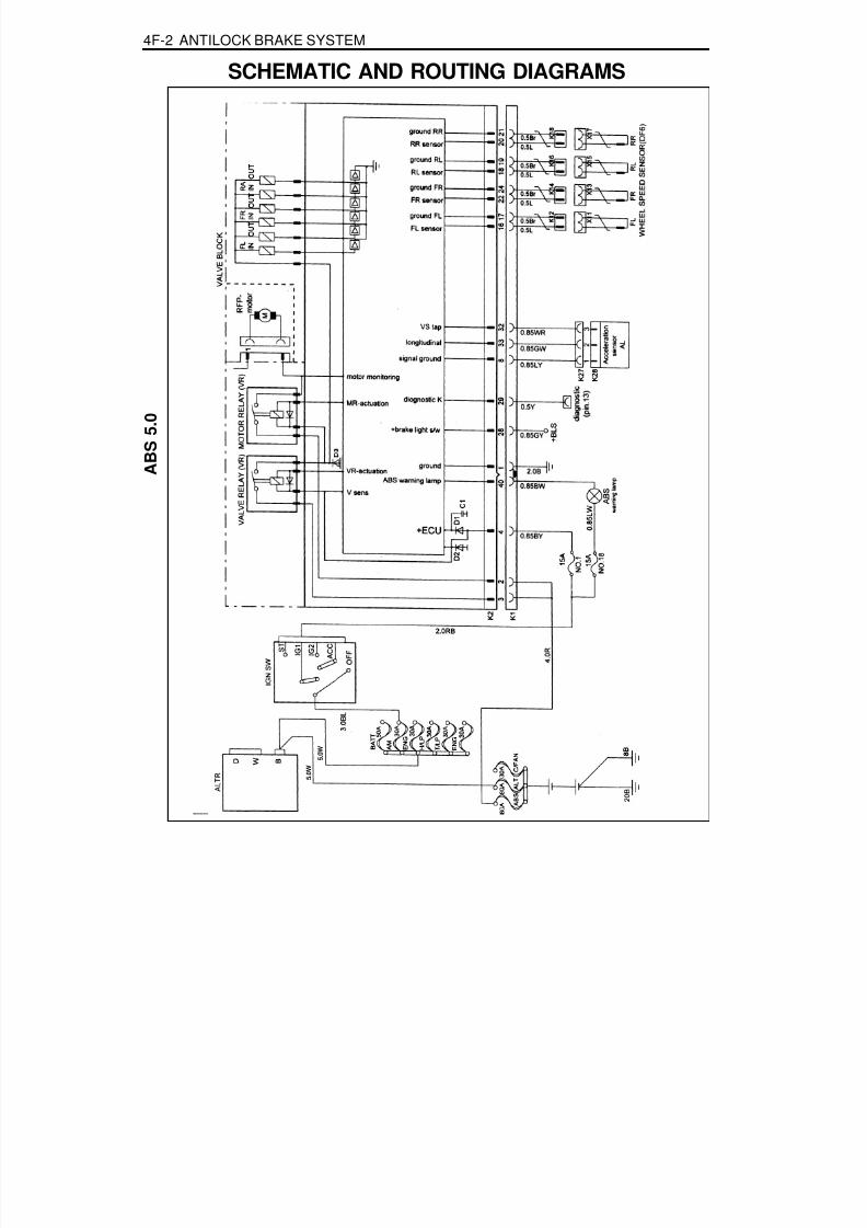
8/18/2019 SsangYong Musso Service Manual 1998.pdf
http://slidepdf.com/reader/full/ssangyong-musso-service-manual-1998pdf 949/1459
4F-2 ANTILOCK BRAKE SYSTEM
A B S 5 . 0
SCHEMATIC AND ROUTING DIAGRAMS
5 . 0 W
5 . 0 W
3 0 A 3 0 A
E N G

8/18/2019 SsangYong Musso Service Manual 1998.pdf
http://slidepdf.com/reader/full/ssangyong-musso-service-manual-1998pdf 950/1459
ANTILOCK BRAKE SYSTEM 4F-3
A B S / A B D 5 . 0
A B D A C T I V E
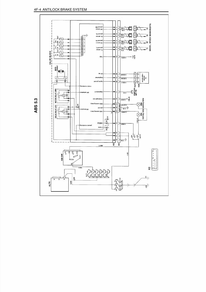
8/18/2019 SsangYong Musso Service Manual 1998.pdf
http://slidepdf.com/reader/full/ssangyong-musso-service-manual-1998pdf 951/1459
4F-4 ANTILOCK BRAKE SYSTEM
A B S 5 . 3
5 . 0 W
5 . 0 W
3 0 A
3 0 A
N O
. 2 1
K 2

8/18/2019 SsangYong Musso Service Manual 1998.pdf
http://slidepdf.com/reader/full/ssangyong-musso-service-manual-1998pdf 952/1459
ANTILOCK BRAKE SYSTEM 4F-5
A B S / A B D 5 . 3
5 . 0 W
5 . 0 W

8/18/2019 SsangYong Musso Service Manual 1998.pdf
http://slidepdf.com/reader/full/ssangyong-musso-service-manual-1998pdf 953/1459

8/18/2019 SsangYong Musso Service Manual 1998.pdf
http://slidepdf.com/reader/full/ssangyong-musso-service-manual-1998pdf 954/1459
ANTILOCK BRAKE SYSTEM 4F-7
ABD SYSTEM DESCRIPTIONGeneral:
The Automatic Brake Differential Lock (ABD) is a traction system by means of brake intervention only, available ina low speed range (< 60kph).It workes on m-split roads with sidewise different friction coefficients.
The spinning driven wheel is braked and the drive torque can be transferred to the wheel on the high- m side.During ABD active, the ABD information lamp is blinking.The temperature of the brakes is calculated by a mathematical model and ABD is switched passive if the calculatedtemperature is greater than a threshold value(500 °C).ABD is permitted again, when the calculated temperature is less than 350 °C.
Control Algorithm:The input signals for the control algorithm are the filteredwheel speed signals from the ABS speed processing.
With the speed difference of the driven wheels, the controldeviation is calculated.If the control deviation exceeds a certain threshold value,the wheel with the greater slip is braked actively.The threshold value depends on the vehicle speed:It is reduced with increasing vehicle speed down to a constantvalue.
Pressure Modulation:Depending on the control deviation and the wheel acceleration of the spinning wheel, pressure increase, hold anddecrease are made.The pressure modulation is done with the conventional control with the valves. ASV, USV, EV and AV accordingthe the following table:
Speed Range:ABD is available in the speed range £ 60 kph.Above 60 kph vehicle speed, ABD is passive.It is possible to initiate ABD operation up to a vehicle speed of 55kph.
IncreaseOpenOpenOpenASV
DecreaseHold
ClosedClosedClosed
ClosedClosedOpen
OpenClosedClosed
USV
EV
AV
Speed difference driven wheels [kph]
18
6
12 60
ABD operation
Vehiclespeed[kph]
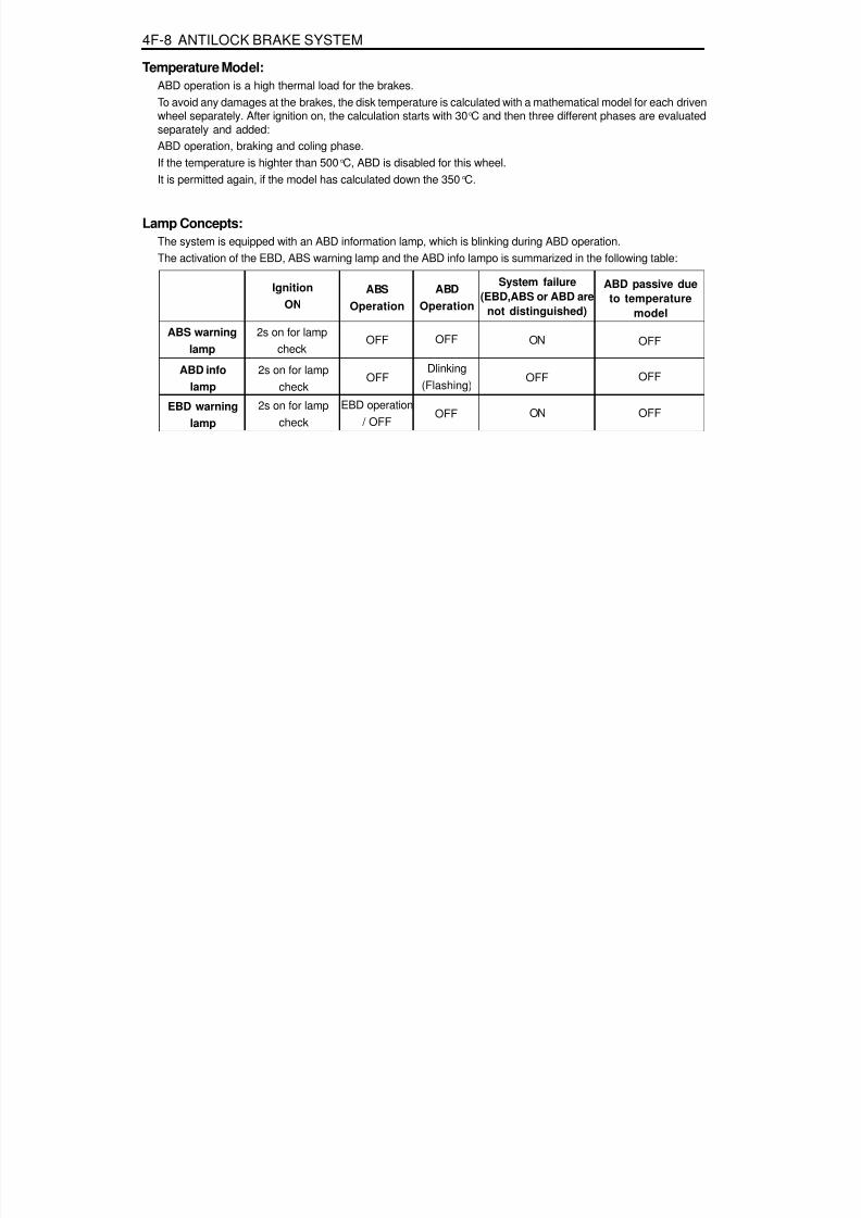
8/18/2019 SsangYong Musso Service Manual 1998.pdf
http://slidepdf.com/reader/full/ssangyong-musso-service-manual-1998pdf 955/1459
4F-8 ANTILOCK BRAKE SYSTEM
Temperature Model:ABD operation is a high thermal load for the brakes.To avoid any damages at the brakes, the disk temperature is calculated with a mathematical model for each drivenwheel separately. After ignition on, the calculation starts with 30 °C and then three different phases are evaluatedseparately and added:ABD operation, braking and coling phase.
If the temperature is highter than 500 °C, ABD is disabled for this wheel.It is permitted again, if the model has calculated down the 350 °C.
Lamp Concepts:The system is equipped with an ABD information lamp, which is blinking during ABD operation.The activation of the EBD, ABS warning lamp and the ABD info lampo is summarized in the following table:
IgnitionON
ABSOperation
ABDOperation
System failure(EBD,ABS or ABD are
not distinguished)
ABD passive dueto temperature
model
ABS warninglamp
ABD infolamp
EBD warninglamp
2s on for lampcheck
2s on for lampcheck
2s on for lampcheck
OFF
EBD operation / OFF
OFF
OFF
Dlinking(Flashing)
OFF
ON
OFF
ON
OFF
OFF
OFF

8/18/2019 SsangYong Musso Service Manual 1998.pdf
http://slidepdf.com/reader/full/ssangyong-musso-service-manual-1998pdf 956/1459
ANTILOCK BRAKE SYSTEM 4F-9
SELF DIAGNOSISABS, ABS/ABD 5.3Initialization1. Turn the ignition switch to "ON" position.
2. Using a service connector, ground the No.13 terminal ofdiagnosis socket and No.1 ground terminal for 3 - 4 seconds.NoticeIf it is over 5 seconds, initialization will not be performed.
3. After completing the initialization, ABS warning lamp will beturned on until the ignition switch is turned to "OFF" position.
Output of Fault Code1. Normal : 1 pulse (normal code 01)
2. Abnormal : 1 pulse (fault code)Notice
If appeared initial fault code and above 2 differnt faultcode, perform again initialization.Fault code will be output the numbers of fault code witha interval of 1 second.(turn on : 0.75 sec., turn off : 0.25sec.)
Fault Code EliminationAfter repairing the defect parts, eliminate the fault from ECU.1. Ground the diagnosis No.13 terminal to No.1 ground terminal
for over 5 seconds.2. Turn the igniotion switch to "OFF" position.
NoticeIf not eliminate the fault code, the code will be maintained.Check and find the other defect parts with performingthe imitialization again, if the fault code will be output,repair the defect parts completely.

8/18/2019 SsangYong Musso Service Manual 1998.pdf
http://slidepdf.com/reader/full/ssangyong-musso-service-manual-1998pdf 957/1459
4F-10 ANTILOCK BRAKE SYSTEM
Diagnosis the Flash Code
[Ex]Time Differences of Normal Code 01 : TW1<T<Te<TW2Time Differences of Fault Code 15 : TW1<T<Te<TW2
Time Characteristics1. Initialization
Tba < 5.0 sec.Tba 1.8 - 2.2 sec.
2. Output of Fault CodeTW1 = 1.8 - 2.2 sec.
TW2 = 1.8 - 2.2 sec.T = 0.75 sec., Te ³ 0.25 sec.
3. Elimination of Fault CodeTb1 = 5.0 sec.

8/18/2019 SsangYong Musso Service Manual 1998.pdf
http://slidepdf.com/reader/full/ssangyong-musso-service-manual-1998pdf 958/1459
ANTILOCK BRAKE SYSTEM 4F-11
ABS, ABS/ABD 5.0Initializing1. Set the ignition switch n “ON” position.2. Connect the No.1 terminal (Ground) and the No.13 (ABS)
from diagnosis socket located in E/G room by use of serviceconnector for 3 - 4 seconds and initialize the flash code.
NoticeBe careful not to connect over 5 seconds.
3. ABS indicator warning light continuously comes on until theignition switch is “OFF”.
Dignosis Table1. When the system is normal
One pulse (normal code 01) indicates.2. When the system is abnormal
One pulse (defect code) indicates.NoticeRepeat the initializing procedure when checking thedefect code Defect code is indicated once for 1 sec (lighton : 0.75 sec, light off : 0.25 sec).
Removal the Defect Code1. Repair the defect code and remove the memorized defect
code in the ECU.2. Connect the No. 13 terminal (ABS) from diagnosis socket
and No. 1 terminal (ground) for over 5 seconds.3. Set the ignition switch in the “OFF” position.
NoticeDefect code will be memorized in ECU unless the defectcode is not removed.Repeat the initializing procedure and check the otherdefects.
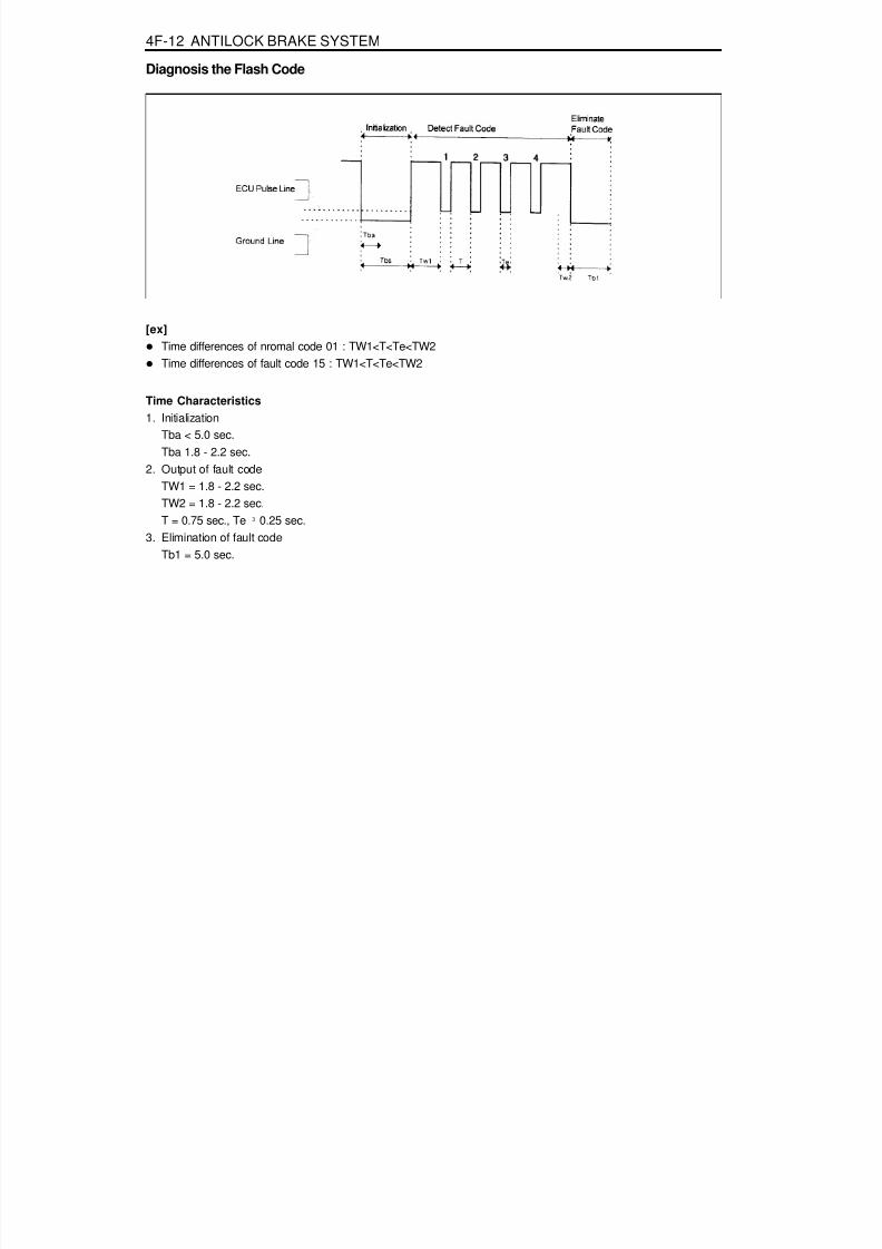
8/18/2019 SsangYong Musso Service Manual 1998.pdf
http://slidepdf.com/reader/full/ssangyong-musso-service-manual-1998pdf 959/1459
4F-12 ANTILOCK BRAKE SYSTEM
Diagnosis the Flash Code
[ex]Time differences of nromal code 01 : TW1<T<Te<TW2Time differences of fault code 15 : TW1<T<Te<TW2
Time Characteristics1. Initialization
Tba < 5.0 sec.Tba 1.8 - 2.2 sec.
2. Output of fault codeTW1 = 1.8 - 2.2 sec.
TW2 = 1.8 - 2.2 sec.T = 0.75 sec., Te ³ 0.25 sec.
3. Elimination of fault codeTb1 = 5.0 sec.

8/18/2019 SsangYong Musso Service Manual 1998.pdf
http://slidepdf.com/reader/full/ssangyong-musso-service-manual-1998pdf 960/1459
ANTILOCK BRAKE SYSTEM 4F-13
DEFECT CODES
Description -
Replace the ECUCheck resistance of the wheel speed sensor :1.280K W - 1.920K W
Check wire for ground and open.Replace the sensor.Check resistance of the wheel speed sensor :1.280K W - 1.920K W
Check wire for ground and open.Replace the sensor.Check resistance of the wheel speed sensor :1.280K W - 1.920K W
Check wire for ground and open.Replace the sensor.Check resistance of the wheel speed sensor :1.280K W - 1.920K W
Check wire for ground and open.Replace the sensor.Check wire for ground and open.Check connection of the wheel speed sensor connec-tor and ECU side connector.Measure air gap between wheel teeth and wheel speed
sensor and check installation of wheel tooth.(Standard air gap : 0.35 - 1.60 mm)Check output voltage of the sensor by rotating thewheel 1/2 - 1 revolution per second and shaking sen-sor wire.- When measured by multi - meter (AC) :
output voltage > 70 mV- When measured in oscilloscope :
output voltage ³ 120 mV/P-PReplace the sensor.
Check wire for ground and open.Check connection of the wheel speed sensor. con-nector and ECU side connector.Measure the air gap between wheel teeth and wheelspeed sensor and check installation of wheel tooth.(Standard air gap : 0.35 - 1.60 mm)Check output voltage of the sensor by rotating thewheel 1/2 - 1 revolution per second and shaking sen-sor wire.
Defect Code010203
04
05
06
07
08
ApplicationNormalDefective ECUFront/left Wheel SpeedSensor (Wire)
Front/right Wheel SpeedSensor (Wire)
Rear/left Wheel SpeedSensor (Wire)
Rear/right Wheel SpeedSensor (Wire)
Front/left Wheel SpeedSensor (Signal)
Front/right Wheel SpeedSensor (Signal)

8/18/2019 SsangYong Musso Service Manual 1998.pdf
http://slidepdf.com/reader/full/ssangyong-musso-service-manual-1998pdf 961/1459
4F-14 ANTILOCK BRAKE SYSTEM
Description- When measured by multi - meter (AC) :
output voltage > 70 mV- When measured in oscilloscope :
output voltage ³ 120 mV/P-PReplace the sensor.Check wire for ground and open.Check connection of the wheel speed sensor con-nector and ECU side connector.(Standard air gap : 0.15 - 1.20 mm)Check output voltage of the sensor by rotating thewheel 1/2 - 1 revolution per second and shaking sen-sor wire.- When measured by multi - meter (AC) :
output voltage > 70 mV- When measured in oscilloscope :
output voltage ³ 120 mV/P-PReplace the sensor.Check wire for ground and open.Check connection of the wheel speed sensor con-nector and ECU side connector.Measure air gap between wheel teeth and wheelspeed sensor and check installation of wheel tooth.(Standard air gap : 0.15 - 1.20 mm)Check output voltage of the sensor by rotating the
wheel 1/2 - 1 revolution per second and shaking sen-sor wire.- When measured by multi - meter (AC) :
output voltage > 70 mV- When measured in oscilloscope :
output voltage ³ 120 mV/P-PReplace the sensor.Check number of teeth on the wheel rotor and itscondition.- Number of teeth : 52
Check valve relay voltage.Check connection of connector and terminals in theECU and hydraulic modulator.Check ground.Check terminals for open or short.(When connector is removed)Replace the hydraulic modulator.
Defect Code
09
10
11
12
Application
Rear/left Wheel SpeedSensor (Signal)
Rear/right Wheel SpeedSensor (Signal)
Wheel Rotor
Valve Relay

8/18/2019 SsangYong Musso Service Manual 1998.pdf
http://slidepdf.com/reader/full/ssangyong-musso-service-manual-1998pdf 962/1459
ANTILOCK BRAKE SYSTEM 4F-15
DescriptionCheck each valve by using SCANNER's solenoid valveoverriding function.Check connection of connector and terminals in theECU hydraulic modulator.Check each valve by using SCANNER's solenoid valveoverriding function.Check connection of connector and terminals in theECU hydraulic modulator.Check terminals for open or short.(When connector is removed)Replace the hydraulic modulator.Check each valve by using SCANNER's solenoid valveoverriding function.Check connection of connector and terminals in the
ECU hydraulic modulator.Check terminals for open or short.(When connector is removed)Replace the hydraulic modulator.Check each valve by using SCANNER's solenoid valveoverriding function.Check connection of connector and terminals in theECU hydraulic modulator.Check terminals for open or short.(When connector is removed)
Replace the hydraulic modulator.Check each valve by using SCANNER's solenoid valveoverriding function.Check connection of connector and terminals in theECU hydraulic modulator.Check terminals for open or short.(When connector is removed)Replace the hydraulic modulator.Check each valve by using SCANNER's solenoid valveoverriding function.
Check connection of connector and terminals in theECU hydraulic modulator.Check terminals for open or short.(When connector is removed)Replace the hydraulic modulator.Check each valve by using SCANNER's solenoid valveoverriding function.Check connection of connector and terminals in theECU hydraulic modulator.Check terminals for open or short.
ApplicationFront / left INLET Valve
Front / left OUTLET Valve
Front / right INLET Valve
Front / right OUTLET Valve
Rear / left INLET Valve (ABD)
Rear / left OUTLET Valve
Rear / Right INLET Valve
Defect Code13
14
15
16
17
18
19

8/18/2019 SsangYong Musso Service Manual 1998.pdf
http://slidepdf.com/reader/full/ssangyong-musso-service-manual-1998pdf 963/1459
4F-16 ANTILOCK BRAKE SYSTEM
DescriptionCheck terminals for open or short.(When connector is removed)Replace the hydraulic modulator.Check each valve by using SCANNER's solenoid valveoverriding function.Check connection of connector and terminals in theECU hydraulic modulator.Check terminals for open or short.(When connector is removed)Replace the hydraulic modulatorCheck solenoid internal resistance of the prime(ASV)valve and pilot valve(USV) : 8.04 - 9.04 W
Check each valve by using SCANNER's solenoid valveoverriding function.Check connection of connector and terminals in theECU and hydraulic modulator.Check terminals for open or short.(When connector is removed)Replace the hydraulic modulatorCheck solenoid internal resistance of the prime(ASV)valve and pilot valve(USV) : 8.04 - 9.04 W
Check each valve by using SCANNER's solenoid valveoverriding function.Check connection of connector and terminals in the
ECU and hydraulic modulator.Check terminals for open or short.(When connector is removed)Replace the hydraulic modulatorCheck each valve by using SCANNER's pump motoroverriding function.Check resistance between pump motor ground ter-minal and battery negative terminal : total resistanceshould be less than 15 m W
Check body ground location.
Check relay supply voltage : IGN on : 11 - 14 VRelay coil internal resistance : 70 - 80 W
Replace the hydraulic modulatorCheck by using SCANNER's stop lamp switch diag-nosing function from sensor value output function.Check connection of ECU connector side stop lampswitch terminal.Check resistance of the stop lamp, switch.- Each end resistance value of the switch
Application
Rear / Right OUTLET Valve
Function and Response of TheValve
Function and Response of TheValve
Motor Relay / Circulation Pump
Stop Lamp Switch
Defect Code
20
21
22
24
27

8/18/2019 SsangYong Musso Service Manual 1998.pdf
http://slidepdf.com/reader/full/ssangyong-musso-service-manual-1998pdf 964/1459
ANTILOCK BRAKE SYSTEM 4F-17
Application
Power Voltage
Residual TemperatureMeasurement (ABD only)Acceleration Sensor Signal (wire)
Defect Code
28
29
42
Descriptionwhen switch knob (planger) is pressed by 3mm : ¥
- Each ends resistance value of the switch whenswitch knob(plunger) is not pressed :less than 200 m W
When brake is applied :ECU (ABS:No.14, ABD:No.48) terminal 11 - 14 Vor VBattery.When brake is released :ECU (ABS:No.14, ABD:No.48) terminal 0 VCheck battery voltage.Resistance between ECU (ABD:No.28 & 29,ABS:No.19) pins and battery negative terminal :less than 20 m W
Resistance between ECU No.1 (ABS:NO.15) pin and
ignition terminal : less than 60 m WCheck that normal voltage is applied to ECU(ABD:No.1, ABS:No.15) pin when ignition switch isturned to "ON" or "OFF".Check ABS fuses of 15A and 80A.Replace the ECU.Check wire (ECU No.50) for open or loose contact.
Check connection between connectors.Check relevant wires for open or short.
(When connector is removed)Check voltage between ECU side ground (ABD:No.1,ABS:No.15 pin) and acceleration sensor side ground(ABD:No.1, ABS:No.15 pin / ECU side ABD:No.39,ABS:No.30 pin)(When connector is installed and power is applied)- Voltage : less than 0.25 VCheck voltage among related terminals.(When connector is installed and power is applied)- Voltage between ECU (ABD:No.43, ABS:No.28 pin
and ABD:No.39, ABS:No.30 pin): 4.75 - 5.25 V
- Signal voltage between ECU (ABD:No.51,ABS:No.10) pin and (ABD:No.39, ABS:No.30) pin: 1.95 V - 3.45 V(Measure it by laying acceleration sensor horizon-tally and without external force)

8/18/2019 SsangYong Musso Service Manual 1998.pdf
http://slidepdf.com/reader/full/ssangyong-musso-service-manual-1998pdf 965/1459
4F-18 ANTILOCK BRAKE SYSTEM
ApplicationDefect Code DescriptionCheck connection between connectors.Check relevant wires for open or short.(When connector is removed)Check and replace the acceleration sensor.Replace the ECU.Check voltage between ECU side ground (ABD:No.1,ABS:No.15 pin) and acceleration sensor side ground(ABD:No.1, ABS:No.15 pin / ECU side ABD:No.39,ABS:No.30 pin)(When connector is installed and power is applied)- Voltage : less than 0.25 VCheck voltage among related terminals.(When connector is installed and power is applied)- Voltage between ECU (ABD:No.51, ABS:No.10
pin and ABD:No39, ABS:No.30) pin: 4.75 - 5.25 V- Signal voltage between ECU (ABD:No.51,
ABS:No.10 pin and ABD:No39, ABS:No.30) pin: 1.95 V - 3.45 V(Measure it by laying acceleration sensor horizontally and without external force)
43 Acceleration Sensor Signal (Signal)

8/18/2019 SsangYong Musso Service Manual 1998.pdf
http://slidepdf.com/reader/full/ssangyong-musso-service-manual-1998pdf 966/1459
ANTILOCK BRAKE SYSTEM 4F-19
MAINTENANCE AND REPAIR
ON-VEHICLE SERVICEWHEEL SPEED SENSOR
1 Bolt2 Front Wheel Speed Sensor3 Knuckle
4 Bolt5 Rear Wheel Speed Sensor6 Rear Axle

8/18/2019 SsangYong Musso Service Manual 1998.pdf
http://slidepdf.com/reader/full/ssangyong-musso-service-manual-1998pdf 967/1459
4F-20 ANTILOCK BRAKE SYSTEM
Removal & Installation ProcedureABS Hydraulic Unit1. Release the ABS wiring connector locking lever in arrow
direction and remove the connector.
NoticeDo not force the connector when releasing in arrowdirection.For installation of the connetor, align and fi rmly seatthe connector of the hydraulic unit and wiring connectorwhile keeping the locking lever upward and then push itdown.
2. Remove the hydraulic lines of the hydraulic unit.During removal, be careful not to drip brake fuid on thebody.
Installation Notice
3. Unscrew hydraulic unit mounting nuts (2EA) and removethe unit from the bracket.
Installation Notice
Tightening Torque 9 - 12 Nm
Removal of the ABS / ABD UnitLocation : Under the front passenger's seat.1. Remove the wiring connector of the ABS/ABD(or
ABS:attached type) ECU.2. Remove the ground wire.3. Unscrew the mounting bolts and remove the ECU.4. Installation should follow the removal precedure in reverse
order.
Tightening Torque 12 - 16 Nm
NoticeWhen carrying a new unit, never recline it over 30°.

8/18/2019 SsangYong Musso Service Manual 1998.pdf
http://slidepdf.com/reader/full/ssangyong-musso-service-manual-1998pdf 968/1459
ANTILOCK BRAKE SYSTEM 4F-21
HYDRAULIC CIRCUITABS 5.3Pressure Increased
1 Master Cylinder2 Hydraulic Unit3 Damping Chamber4 Return Pump5 Return Pump Motor
6 Accumulator Chamber7 Inlet Valve for Each Wheel8 Outlet Valve for Each Wheel9 Front Wheel
10 Rear Wheel
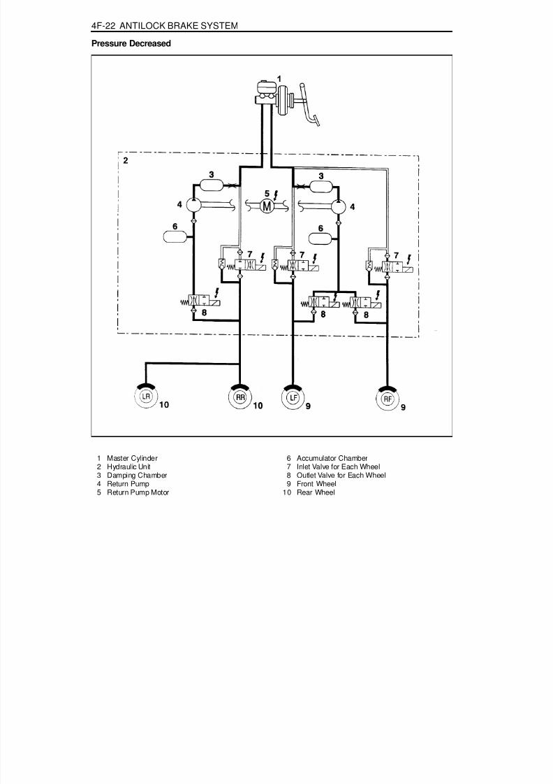
8/18/2019 SsangYong Musso Service Manual 1998.pdf
http://slidepdf.com/reader/full/ssangyong-musso-service-manual-1998pdf 969/1459
4F-22 ANTILOCK BRAKE SYSTEM
Pressure Decreased
1 Master Cylinder2 Hydraulic Unit3 Damping Chamber4 Return Pump5 Return Pump Motor
6 Accumulator Chamber7 Inlet Valve for Each Wheel8 Outlet Valve for Each Wheel9 Front Wheel
10 Rear Wheel

8/18/2019 SsangYong Musso Service Manual 1998.pdf
http://slidepdf.com/reader/full/ssangyong-musso-service-manual-1998pdf 970/1459
ANTILOCK BRAKE SYSTEM 4F-23
Pressure Maintained
1 Master Cylinder2 Hydraulic Unit3 Damping Chamber4 Return Pump5 Return Pump Motor
6 Accumulator Chamber7 Inlet Valve for Each Wheel8 Outlet Valve for Each Wheel9 Front Wheel
10 Rear Wheel

8/18/2019 SsangYong Musso Service Manual 1998.pdf
http://slidepdf.com/reader/full/ssangyong-musso-service-manual-1998pdf 971/1459
4F-24 ANTILOCK BRAKE SYSTEM
ABS/ABD 5.3Pressure Increased
1 Master Cylinder2 Hydraulic Unit3 Damping Chamber4 Return Pump5 Return Pump Motor6 Accumulator Chamber
7 Inlet Valve for Each Wheel8 Outlet Valve for Each Wheel9 Wheel
10 Prime Valve (ASV)11 Pilot Valve (USV)12 Check Valve13 ISD (Integrated Suction Damper)

8/18/2019 SsangYong Musso Service Manual 1998.pdf
http://slidepdf.com/reader/full/ssangyong-musso-service-manual-1998pdf 972/1459
ANTILOCK BRAKE SYSTEM 4F-25
Pressure Decreased
1 Master Cylinder2 Hydraulic Unit3 Damping Chamber4 Return Pump5 Return Pump Motor6 Accumulator Chamber
7 Inlet Valve for Each Wheel8 Outlet Valve for Each Wheel9 Wheel
10 Prime Valve (ASV)11 Pilot Valve (USV)12 Check Valve13 ISD (Integrated Suction Damper)

8/18/2019 SsangYong Musso Service Manual 1998.pdf
http://slidepdf.com/reader/full/ssangyong-musso-service-manual-1998pdf 973/1459
4F-26 ANTILOCK BRAKE SYSTEM
Pressure Maintained (Hold)
1 Master Cylinder2 Hydraulic Unit3 Damping Chamber4 Return Pump5 Return Pump Motor6 Accumulator Chamber
7 Inlet Valve for Each Wheel8 Outlet Valve for Each Wheel9 Wheel
10 Prime Valve (ASV)11 Pilot Valve (USV)12 Check Valve13 ISD (Integrated Suction Damper)

8/18/2019 SsangYong Musso Service Manual 1998.pdf
http://slidepdf.com/reader/full/ssangyong-musso-service-manual-1998pdf 974/1459
SECTION 4G
PARKING BRAKE
Specifications. . . . . . . . . . . . . . . . . . . . . . . . 4G-1General Specifications . . . . . . . . . . . . . . . . . . 4G-1
Fastener Tightening Specifications . . . . . . . . . 4G-1Component Locator . . . . . . . . . . . . . . . . . . . 4G-2
TABLE OF CONTENTSParking Brake . . . . . . . . . . . . . . . . . . . . . . . . . 4G-2
Maintenance and Repair . . . . . . . . . . . . . . . 4G-3
On-Vehicle Service . . . . . . . . . . . . . . . . . . . . . 4G-3Parking Brake . . . . . . . . . . . . . . . . . . . . . . . . . 4G-3
Caution: Disconnect the negative battery cable before removing or installing any electrical unit or when a tool or equipment could easily come in contact with exposed electrical terminals. Disconnecting this cable will help prevent personal injury and damage to the vehicle. The ignition must also be in LOCK unless otherwise noted.
SPECIFICATIONSGENERAL SPECIFICATIONS
ApplicationParking Brake Lever BoltCable Mounting Bracket Bolt
N····· m8 - 188 - 18
FASTENER TIGHTENING SPECIFICATIONS
ApplicationTypeOperating Type
DescriptionMechanically Operated Rear Wheel Expansion
Manual

8/18/2019 SsangYong Musso Service Manual 1998.pdf
http://slidepdf.com/reader/full/ssangyong-musso-service-manual-1998pdf 975/1459
4G-2 PARKING BRAKE
COMPONENT LOCATORPARKING BRAKE
1 Parking Brake Lever2 Praking Brake Lamp Switch3 Bolt4 Bolt ........................................................8-18 Nm5 Front Parking Brake Cable6 Equalizer
7 Nut8 Bolt ........................................................8-18 Nm9 Rear Parking Brake Cable
10 Brake Drum (if Equipped with Rear Drum Brake)11 Brake Disc (if Equipped with Rear Disc Brake)
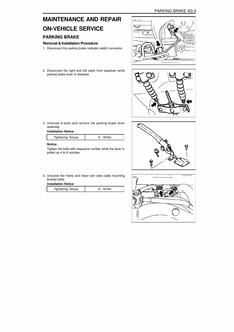
8/18/2019 SsangYong Musso Service Manual 1998.pdf
http://slidepdf.com/reader/full/ssangyong-musso-service-manual-1998pdf 976/1459
PARKING BRAKE 4G-3
MAINTENANCE AND REPAIR
ON-VEHICLE SERVICEPARKING BRAKE
Removal & Installation Procedure1. Disconnect the parking brake indicator switch connector.
2. Disconnect the right and left cable from equalizer whileparking brake lever is released.
3. Unscrew 8 bolts and remove the parking brake leverassembly.Installation Notice
NoticeTighten the bolts with sequence number while the lever ispulled up 4 to 6 notches.
Tightening Torque 8 - 18 Nm
4. Unscrew the frame and lower arm side cable mountingbracket bolts.Installation Notice
Tightening Torque 8 - 18 Nm
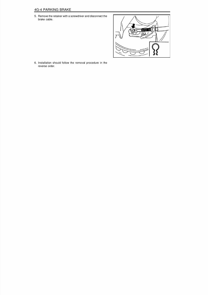
8/18/2019 SsangYong Musso Service Manual 1998.pdf
http://slidepdf.com/reader/full/ssangyong-musso-service-manual-1998pdf 977/1459
4G-4 PARKING BRAKE
5. Remove the retainer with a screwdriver and disconnect thebrake cable.
6. Installation should follow the removal procedure in thereverse order.

8/18/2019 SsangYong Musso Service Manual 1998.pdf
http://slidepdf.com/reader/full/ssangyong-musso-service-manual-1998pdf 978/1459
SECTION 5A
AUTOMATIC TRANSMISSION
TABLE OF CONTENTSSpecifications. . . . . . . . . . . . . . . . . . . . . . . . 5A-2
Model Part Numbers and Applications . . . . . . 5A-2Model Specifications . . . . . . . . . . . . . . . . . . . . 5A-2Clutch Pack Details . . . . . . . . . . . . . . . . . . . . . 5A-3
Special Tools . . . . . . . . . . . . . . . . . . . . . . . . 5A-4Special Tools Table . . . . . . . . . . . . . . . . . . . . . 5A-4
Schematic and Routing Diagrams . . . . . . . . 5A-5TCU Circuit (Diesel) . . . . . . . . . . . . . . . . . . . . 5A-5TCU Circuit (Gasoline) . . . . . . . . . . . . . . . . . . 5A-6
Shift Pattern Diagram . . . . . . . . . . . . . . . . . 5A-7661LA Normal Mode . . . . . . . . . . . . . . . . . . . . 5A-7661LA Power Mode . . . . . . . . . . . . . . . . . . . . 5A-8662LA Normal Mode . . . . . . . . . . . . . . . . . . . . 5A-9662LA Power Mode . . . . . . . . . . . . . . . . . . . 5A-10662LA Low Mode . . . . . . . . . . . . . . . . . . . . . 5A-11E32 Power Mode . . . . . . . . . . . . . . . . . . . . . 5A-12E32 Normal Mode . . . . . . . . . . . . . . . . . . . . . 5A-13E32 Low Mode . . . . . . . . . . . . . . . . . . . . . . . 5A-14E23 Power Mode . . . . . . . . . . . . . . . . . . . . . 5A-15E23 Normal Mode . . . . . . . . . . . . . . . . . . . . . 5A-16E23 Low Mode . . . . . . . . . . . . . . . . . . . . . . . 5A-17
Introduction . . . . . . . . . . . . . . . . . . . . . . . . 5A-18Operator Interfaces . . . . . . . . . . . . . . . . . . 5A-20
Gear Select Lever Operation . . . . . . . . . . . . 5A-20Driving Mode Selector . . . . . . . . . . . . . . . . . 5A-21
Control Systems . . . . . . . . . . . . . . . . . . . . . 5A-22General . . . . . . . . . . . . . . . . . . . . . . . . . . . . 5A-22Electronic Control System. . . . . . . . . . . . . . . 5A-22Hydraulic Control System . . . . . . . . . . . . . . . 5A-31
Power Train System . . . . . . . . . . . . . . . . . . 5A-42Torque Converter . . . . . . . . . . . . . . . . . . . . . 5A-43Clutch Packs. . . . . . . . . . . . . . . . . . . . . . . . . 5A-44
Bands . . . . . . . . . . . . . . . . . . . . . . . . . . . . . . 5A-45One Way Clutches . . . . . . . . . . . . . . . . . . . . 5A-45Planetary Gear Set . . . . . . . . . . . . . . . . . . . . 5A-45Parking Mechanism . . . . . . . . . . . . . . . . . . . 5A-46
Power Flows . . . . . . . . . . . . . . . . . . . . . . . . 5A-47Introduction . . . . . . . . . . . . . . . . . . . . . . . . . . 5A-47Power Flow - Park and Neutral . . . . . . . . . . . 5A-48Power Flow - Reverse. . . . . . . . . . . . . . . . . . 5A-49Power Flow - Manual 1 . . . . . . . . . . . . . . . . . 5A-50Power Flow - Drive 1 . . . . . . . . . . . . . . . . . . . 5A-51Power Flow - Drive 2 and Manual 2 . . . . . . . 5A-52Power Flow - Drive 3 and Manual 3 . . . . . . . 5A-54Power Flow - Drive 3 Lock Up and Manual 3 Lock Up . . . . . . . . . . . . . . . . 5A-56Power Flow - Drive 4 (Overdrive) . . . . . . . . . 5A-57Power Flow - Drive 4 Lock Up . . . . . . . . . . . . 5A-59
Diagnosis . . . . . . . . . . . . . . . . . . . . . . . . . . 5A-60Diagnostic System . . . . . . . . . . . . . . . . . . . . 5A-60Mechanical Tests . . . . . . . . . . . . . . . . . . . . . 5A-69
Self Diagnosis Test . . . . . . . . . . . . . . . . . . 5A-75Adjustments . . . . . . . . . . . . . . . . . . . . . . . . 5A-79
Hydraulic System . . . . . . . . . . . . . . . . . . . . . 5A-79Transmission Fluid Test Procedure . . . . . . . . 5A-79Electronic Adjustments . . . . . . . . . . . . . . . . . 5A-80
Maintenance and Repair . . . . . . . . . . . . . . 5A-82On-Vehicle Service . . . . . . . . . . . . . . . . . . . . 5A-82
Removal and Installation of Transmission . . . 5A-82Unit Repair . . . . . . . . . . . . . . . . . . . . . . . . . 5A-85
Rebuild Warnings . . . . . . . . . . . . . . . . . . . . . 5A-85Disassembly Procedure . . . . . . . . . . . . . . . . 5A-85Assembly Procedure . . . . . . . . . . . . . . . . . . . 5A-94Front and Rear Band Adjustment . . . . . . . . 5A-128
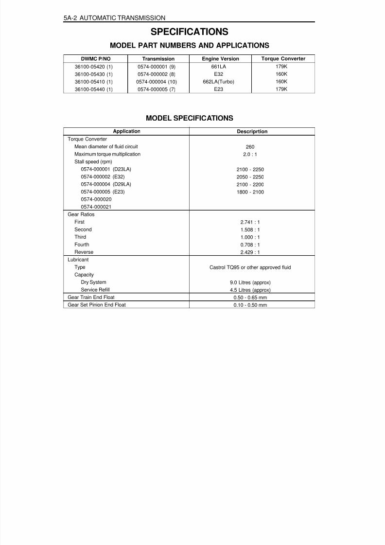
8/18/2019 SsangYong Musso Service Manual 1998.pdf
http://slidepdf.com/reader/full/ssangyong-musso-service-manual-1998pdf 979/1459
5A-2 AUTOMATIC TRANSMISSION
SPECIFICATIONSMODEL PART NUMBERS AND APPLICATIONS
Transmission
0574-000001 (9)
0574-000002 (8)0574-000004 (10)0574-000005 (7)
Torque Converter179K
160K160K179K
Engine Version661LA
E32662LA(Turbo)
E23
MODEL SPECIFICATIONS
ApplicationTorque Converter
Mean diameter of fluid circuitMaximum torque multiplicationStall speed (rpm)
0574-000001 (D23LA)0574-000002 (E32)0574-000004 (D29LA)0574-000005 (E23)0574-0000200574-000021
Gear Ratios
FirstSecondThirdFourthReverse
LubricantTypeCapacity
Dry SystemService Refill
Gear Train End FloatGear Set Pinion End Float
Descriprtion
2602.0 : 1
2100 - 22502050 - 22502100 - 22001800 - 2100
2.741 : 11.508 : 11.000 : 10.708 : 12.429 : 1
Castrol TQ95 or other approved fluid
9.0 Litres (approx)4.5 Litres (approx)
0.50 - 0.65 mm0.10 - 0.50 mm
DWMC P/NO
36100-05420 (1)
36100-05430 (1)36100-05410 (1)36100-05440 (1)

8/18/2019 SsangYong Musso Service Manual 1998.pdf
http://slidepdf.com/reader/full/ssangyong-musso-service-manual-1998pdf 980/1459
AUTOMATIC TRANSMISSION 5A-3
CLUTCH PACK DETAILS
C1Composition
SteelC2
CompositionSteel
C3CompositionSteel
C4CompositionSteel
0574-000002
5
5(2)
54(2)
44(2)
34(1)
0574-000001, 0574-000004,0574-000005
4
6(2)
45(2)
35(2)
34(1)
Note : Numbers in brackets indicate number of selective thickness steel plates required to achieve specifed clutch pack clearance
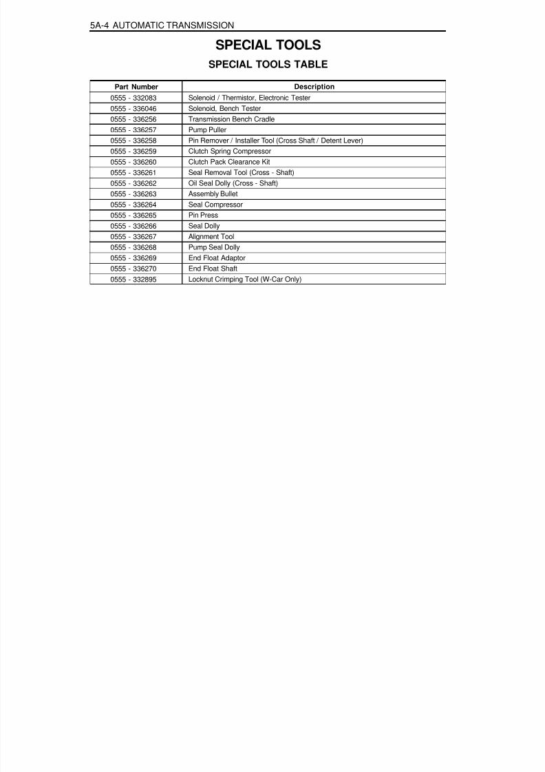
8/18/2019 SsangYong Musso Service Manual 1998.pdf
http://slidepdf.com/reader/full/ssangyong-musso-service-manual-1998pdf 981/1459

8/18/2019 SsangYong Musso Service Manual 1998.pdf
http://slidepdf.com/reader/full/ssangyong-musso-service-manual-1998pdf 982/1459
AUTOMATIC TRANSMISSION 5A-5
SCHEMATIC AND ROUTING DIAGRAMS
T C U C I R C U I T ( 4 W D - D
I E S E L )

8/18/2019 SsangYong Musso Service Manual 1998.pdf
http://slidepdf.com/reader/full/ssangyong-musso-service-manual-1998pdf 983/1459
5A-6 AUTOMATIC TRANSMISSION
T C U C I R C U I T ( 4 W D - G
A S O L I N E )
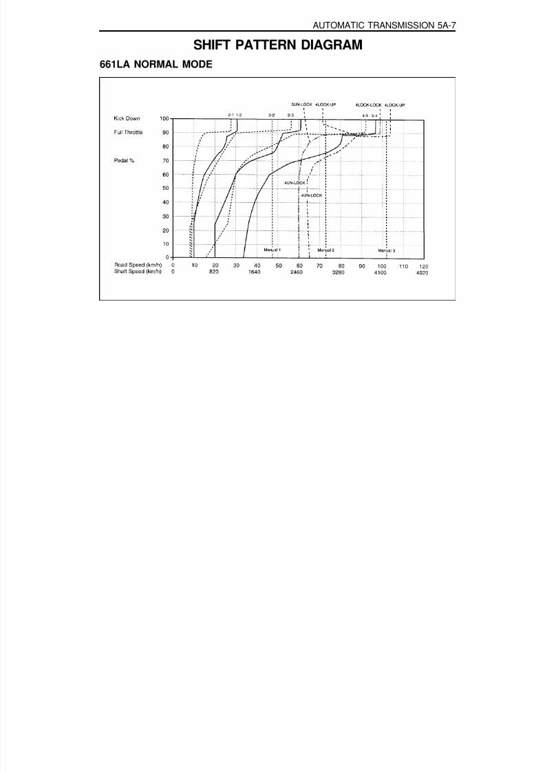
8/18/2019 SsangYong Musso Service Manual 1998.pdf
http://slidepdf.com/reader/full/ssangyong-musso-service-manual-1998pdf 984/1459
AUTOMATIC TRANSMISSION 5A-7
SHIFT PATTERN DIAGRAM661LA NORMAL MODE

8/18/2019 SsangYong Musso Service Manual 1998.pdf
http://slidepdf.com/reader/full/ssangyong-musso-service-manual-1998pdf 985/1459
5A-8 AUTOMATIC TRANSMISSION
661LA POWER MODE

8/18/2019 SsangYong Musso Service Manual 1998.pdf
http://slidepdf.com/reader/full/ssangyong-musso-service-manual-1998pdf 986/1459
AUTOMATIC TRANSMISSION 5A-9
662LA NORMAL MODE

8/18/2019 SsangYong Musso Service Manual 1998.pdf
http://slidepdf.com/reader/full/ssangyong-musso-service-manual-1998pdf 987/1459
5A-10 AUTOMATIC TRANSMISSION
662LA POWER MODE

8/18/2019 SsangYong Musso Service Manual 1998.pdf
http://slidepdf.com/reader/full/ssangyong-musso-service-manual-1998pdf 988/1459
AUTOMATIC TRANSMISSION 5A-11
662LA LOW MODE

8/18/2019 SsangYong Musso Service Manual 1998.pdf
http://slidepdf.com/reader/full/ssangyong-musso-service-manual-1998pdf 989/1459
5A-12 AUTOMATIC TRANSMISSION
E32 POWER MODE

8/18/2019 SsangYong Musso Service Manual 1998.pdf
http://slidepdf.com/reader/full/ssangyong-musso-service-manual-1998pdf 990/1459
AUTOMATIC TRANSMISSION 5A-13
E32 NORMAL MODE

8/18/2019 SsangYong Musso Service Manual 1998.pdf
http://slidepdf.com/reader/full/ssangyong-musso-service-manual-1998pdf 991/1459
5A-14 AUTOMATIC TRANSMISSION
E32 LOW MODE

8/18/2019 SsangYong Musso Service Manual 1998.pdf
http://slidepdf.com/reader/full/ssangyong-musso-service-manual-1998pdf 992/1459
AUTOMATIC TRANSMISSION 5A-15
E23 POWER MODE
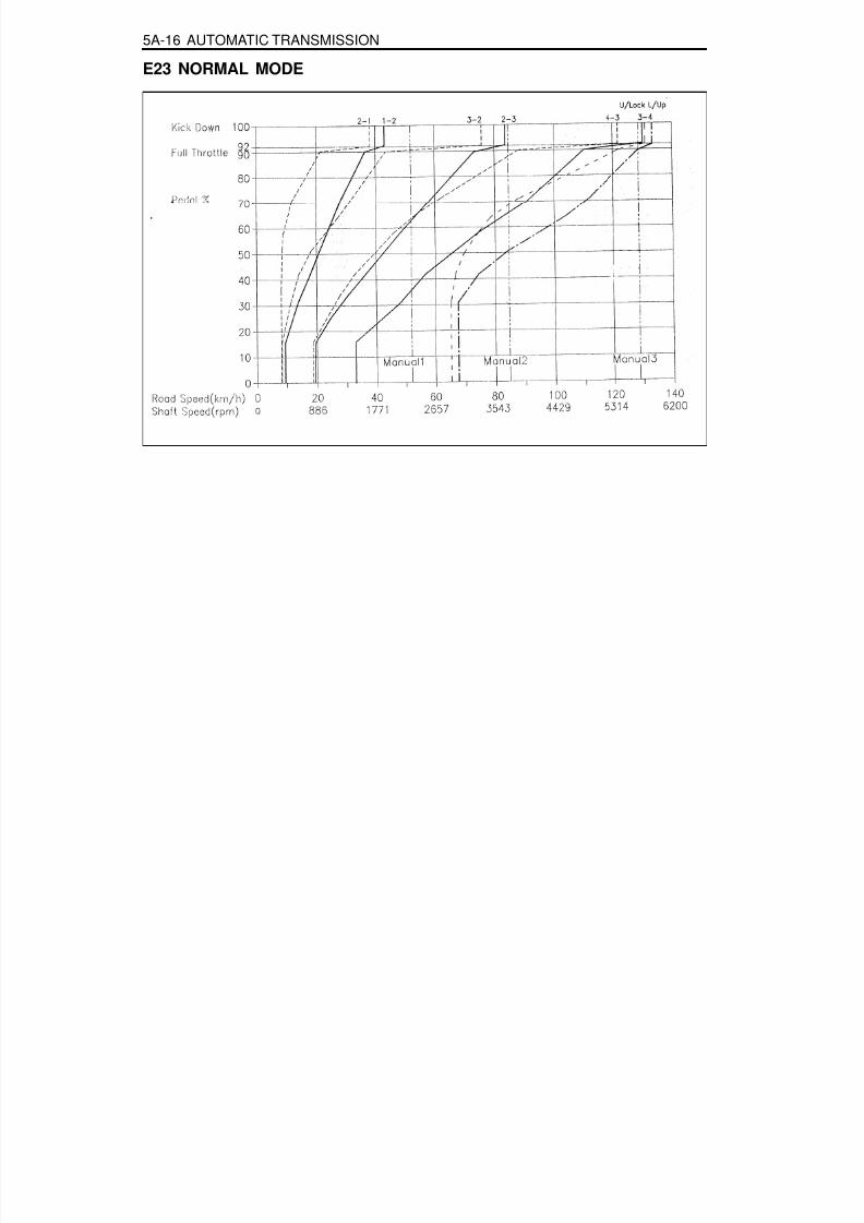
8/18/2019 SsangYong Musso Service Manual 1998.pdf
http://slidepdf.com/reader/full/ssangyong-musso-service-manual-1998pdf 993/1459
5A-16 AUTOMATIC TRANSMISSION
E23 NORMAL MODE

8/18/2019 SsangYong Musso Service Manual 1998.pdf
http://slidepdf.com/reader/full/ssangyong-musso-service-manual-1998pdf 994/1459
AUTOMATIC TRANSMISSION 5A-17
E23 LOW MODE

8/18/2019 SsangYong Musso Service Manual 1998.pdf
http://slidepdf.com/reader/full/ssangyong-musso-service-manual-1998pdf 995/1459
5A-18 AUTOMATIC TRANSMISSION
INTRODUCTIONThe BTR Automotive Model 74 Four Speed Automatic Transmission is an electronically controlled overdrive fourspeed unit with a lock-up torque converter. The lock-up torque converter results in lower engine speeds at cruise andeliminates unnecessary slippage. These features benefit the customer through improved fuel economy and noisereduction. Refer to table 1.1 for details of power, torque and configuration.Of primary significance is the transmission control unit (TCU) which is a microprocessor based control system. TheTCU utilizes throttle position, rate of throttle opening, engine speed, transmission output speed, transmission sumptemperature, gear selector position and mode selector inputs, and in some applications a ‘kickdown’ switch to controlall shift feel and shift schedule aspects.The TCU drives a single proportional solenoid multiplexed to three regulator valves to control all shift feel aspects.The output pressure of this solenoid is controlled as a function of transmission sump temperature to maintain consistentshift feel throughout the operating range.Shift scheduling is highly flexible, and several independent schedules are programmed depending on the vehicle.Typically the ‘NORMAL’ schedule is used to maximise fuel economy and driveability, and a ‘POWER’ schedule is usedto maximise performance. ‘WINTER’ schedule is used to facilitate starting at second gear.Figure 1.1 details the differences between conventional and electronic transmission control systems.
Max Torque (Nm)320
Configuration
260 mm Torque ConverterWide Ratio Gear SetSplined Output for Transfer Case
Min Torque (Nm)
160
Model
M74 4WDTransmission
Table 1.1 - M74 Torque, Power and Configuration
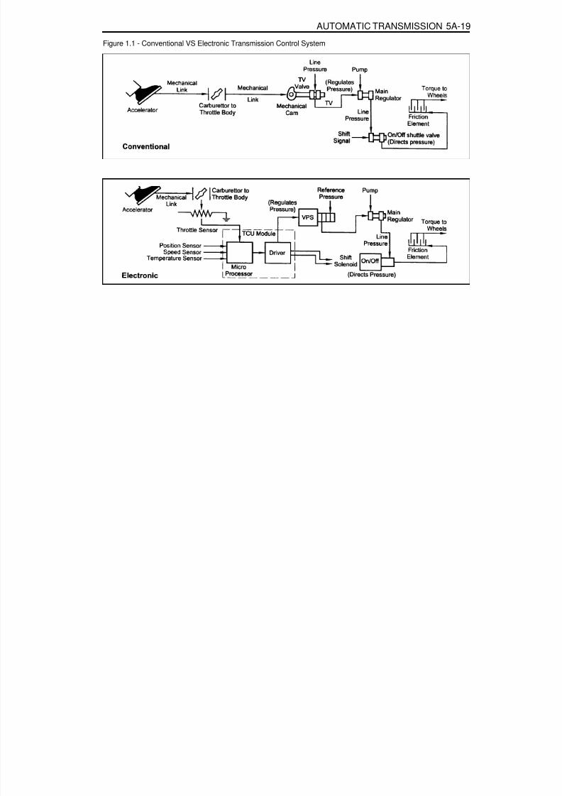
8/18/2019 SsangYong Musso Service Manual 1998.pdf
http://slidepdf.com/reader/full/ssangyong-musso-service-manual-1998pdf 996/1459
AUTOMATIC TRANSMISSION 5A-19
Figure 1.1 - Conventional VS Electronic Transmission Control System

8/18/2019 SsangYong Musso Service Manual 1998.pdf
http://slidepdf.com/reader/full/ssangyong-musso-service-manual-1998pdf 997/1459

8/18/2019 SsangYong Musso Service Manual 1998.pdf
http://slidepdf.com/reader/full/ssangyong-musso-service-manual-1998pdf 998/1459
AUTOMATIC TRANSMISSION 5A-21
Downshift Type
RANGE ‘1’ (MANUAL ‘1’):
RANGE ‘2’ (MANUAL ‘2’):
RANGE ‘3’ (MANUAL ‘3’):
RANGE ‘D’ (DRIVE):
RANGE ‘N’ (NEUTRAL):
RANGE ‘R’ (REVERSE):
RANGE ‘P’ (PARK):
Inhibited AboveFirst gear operation only with inhibited engagement as a function of vehiclespeed. Engine braking is applied with reduced throttle.First and second gear operation with inhibited engagement of second gear, asa function of vehicle speed. Engine braking is applied with reduced throttle.First, second and third gear operation with an inhibited third gear engagementat high vehicle speed. Refer to the vehicle owner’s manual.Engine braking is applied with reduced throttle.First, second, third and fourth gear operation. First to second (1-2), first to third(1-3), second to third (2-3), second to fourth (2-4), third to fourth (3-4), fourthto third (4-3), fourth to second (4-2), third to second (3-2), third to first (3-1)and second to first (2-1), shifts are all available as a function of vehicle speed,throttle position and the time rate of change of the throttle position (forceddownshift). Lockup clutch may be enabled in 3rd and 4th gears depending on
vehicle type. Refer to the owner’s manual.Rear band applied only, with inhibited engagement as a function of vehiclespeed, engine speed and throttle position. The inhibitor switch allows the en-gine to start.Reverse gear operation, with inhibitor engagement as a function of vehiclespeed, engine speed and throttle position. The inhibitor switch enables reverselamp operation.Rear band applied only, with inhibited engagement as a function of vehiclespeed, engine speed and throttle position. The transmission output shaft islocked. The inhibitor switch allows the engine to start.
Table 2.1 - Gear Selections
DRIVING MODE SELECTORThe driving mode selector consists of a mode selection switch and indicator light. The driving mode selector islocated on the centre console. See figure 2,1.The schedules available to be selected vary with vehicle types. Typically the driver should have the option to selectbetween ‘NORMAL’ , ‘POWER’ or ‘WINTER’ modes.
When ‘NORMAL’ mode is selected upshifts will occur to maximise fuel economy and the indicator lights remainextinguished. When ‘POWER’ mode is selected upshifts will occur to give maximum performance and the ‘POWER’mode indicator light is switched on. When ‘WINTER’ mode is selected, starting at second gear is facilitated, the‘WINTER’ mode indicator light is switched on and the ‘POWER’ mode indicator light is switched off.Refer to the vehicle owner’s manual for specific modes for each vehicle type.

8/18/2019 SsangYong Musso Service Manual 1998.pdf
http://slidepdf.com/reader/full/ssangyong-musso-service-manual-1998pdf 999/1459
5A-22 AUTOMATIC TRANSMISSION
CONTROL SYSTEMSGENERALThere are two control systems associated with the transmission. The electronic control system monitors vehicleparameters and adjusts the transmission performance. The hydraulic control system implements the electronic controlsystem commands.
ELECTRONIC CONTROL SYSTEMThe electronic control system is comprised of sensors, a TCU and seven solenoids. The TCU reads the inputs, andunder software control activates the outputs according to values stored in read only memory (ROM).The TCU controls the hydraulic control system. This control is via the hydraulic valve body, which contains sevenelectro-magnetic solenoids. Six of the seven solenoids are used to control the line pressure, operate the shift valvesand the torque converter lock-up clutch, and to turn on and off the two regulator valves (The two regulator valvescontrol the shift feel.).The seventh solenoid is the proportional or variable pressure solenoid (VPS) which works with the two regulatorvalves to control shift feel.Figure 3.1 details a typical TCU control system schematic.The individual component locations, operation and specifications which make up the electronic control subsystemare covered in this section.
Figure 3.1 - Typical TCU Control System Schematic

8/18/2019 SsangYong Musso Service Manual 1998.pdf
http://slidepdf.com/reader/full/ssangyong-musso-service-manual-1998pdf 1000/1459
AUTOMATIC TRANSMISSION 5A-23
Temperature ( °°°°°C)
-20020100135 (Overheat Mode Threshold)
Maximum17,2876,6162,72319685
Minimum13,6385,1772,27817775
Resistance (Ohms)
Table 3.1 - Temperature / Resistance Characteristics
Figure 3.2 - Temperature / Resistance Characteristics

8/18/2019 SsangYong Musso Service Manual 1998.pdf
http://slidepdf.com/reader/full/ssangyong-musso-service-manual-1998pdf 1001/1459
5A-24 AUTOMATIC TRANSMISSION
Transmission Control Unit(TCU)The TCU is an in-vehicle micro-processor based transmission management system. It is usually mounted in thevehicle cabin, under the instrument panel, under the seat, behind the side kick panels or under the floor in thefootwell on the passenger side. Different control units are supplied for different vehicle applications.
The TCU contains:Processing logic circuits which include a central microcontroller and a back-up memory system.
Input circuits.Output circuits which control external devices such as the variable pressure solenoid (VPS), on/off solenoiddrivers, a diagnostics output and the driving mode indicator light.
The various items which make up the TCU are discussed below.
Processing Logic
Shift schedule and calibration information is stored in an erasable programmable read only memory (EEPROM).Throttle input calibration constants and the diagnostics information are stored in electrically erasable programmableread only memory (EEPROM) that retains the memory even when power to the TCU is disconnected.In operation the software continuously monitors the input values and uses these, via the shift schedule, to determine
the required gear state, At the same time it monitors, via the solenoid outputs, the current gear state. Whenever theinput conditions change such that the required gear state is different to the current gear state, the TCU initiates agear shift to bring the two states back into line.Once the TCU has determined the type of gear shift required the software accesses the shift logic, estimates theengine torque output, adjusts the variable pressure solenoid ramp pressure then executes the shift.The TCU continuously monitors every input and output circuit for short or open circuits and operating range. Whena failure or abnormal operation is detected the TCU records the condition code in the diagnostics memory andimplements a limp mode, The actual limp mode used depends upon the failure detected with the object to maintainmaximum driveability without damaging the transmission. In general input failures are handled by providing a defaultvalue. Output failures, which are capable of damaging the transmission, result in full limp mode giving only third orfourth gear and reverse. For further details of limp modes and memory retention refer to the Diagnostic Section.The TCU is designed to operate at ambient temperatures between -40 and 85°C . It is also protected againstelectrical noise and voltage spikes, however all the usual precautions should be observed, for example when arcwelding or jump starting.
TCU InputsTo function correctly, the TCU requires engine speed, road speed, transmission sump temperature, throttle positionand gear position inputs to determine the variable pressure solenoid current ramp and on/off solenoid states. Thisensures the correct gear selection and shift feel for all driving conditions.The inputs required by the TCU are as follows:
Engine SpeedThe engine speed signal is derived from the tachometer signal line, a dedicated sensor or a Controlled AreaNetwork (CAN).
Road Speed
4WD (Diesel) - The shaft speed signal is derived from the speedo sensor located on the transfer case. This signalis transmitted directly to the TCU.4WD (Gasoline) - The speedo sensor sends the shaft speed signal to the engine control module (ECM). Theinformation is then transferred to the TCU via the CAN.
Transmission Sump TemperatureThe transmission sump temperature sensor is a thermistor located in the solenoid wiring loom within the transmission.This sensor is a typical NTC resistor with low temperatures producing a high resistance and high temperatures

8/18/2019 SsangYong Musso Service Manual 1998.pdf
http://slidepdf.com/reader/full/ssangyong-musso-service-manual-1998pdf 1002/1459
AUTOMATIC TRANSMISSION 5A-25
producing a low resistance.Temperature/Resistance characteristics and location within the solenoid wiring loom are given in tables 3-1 and 3-2, and figures 3.2 and 3.3.If the transmission sump temperature exceeds 135°C, the TCU will impose converter lock-up at lower vehiclespeeds and in some vehicles flashes the mode indicator lamp. This results in maximum oil flow through theexternal oil cooler and eliminates slippage in the torque converter. Both these actions combine to reduce the oiltemperature in the transmission.
Connects ToSolenoid 1Solenoid 2Solenoid 3Solenoid 4Solenoid 5Solenoid 6
Solenoid 7Solenoid 5
Temp SensorTemp Sensor
Wire ColorRedBlue
YellowOrangeGreenViolet
BrownGreenWhiteWhite
Pin No.123456
789
10
Table 3.2 - Pin No. Codes for Temperature Sensor Location In Solenoid Loom
Figure 3.3 - Temperature Sensor Location in Solenoid Loom

8/18/2019 SsangYong Musso Service Manual 1998.pdf
http://slidepdf.com/reader/full/ssangyong-musso-service-manual-1998pdf 1003/1459
5A-26 AUTOMATIC TRANSMISSION
I n h i b i t o rSwitch
Throttle Position SensorThe throttle position sensor(TPS) is a resistance potentiometermounted on the throttle body of the engine.It transmits a signal to the TCU proportional to the throttle plateopening.The potentiometer is connected to the TCU by three wires:
5 volts positive supply, earth and variable wiper voltage.Throttle voltage adjustments are as follows:
Closed throttle voltage is 0.2V to 1.0V.Wide open throttle voltage is 3V -4.7V.
These measurements are taken between pins 29 and 27 ofthe TCU.Maintaining good shift feel through the transmission life spanis dependant on having an accurate measure ofthe engine throttle position. To achieve this the TCUcontinuously monitors the maximum and minimum throttlepotentiometer voltages and, if a change occurs, stores the newvoltage values.However these limits will be lost and will require relearningshould a new TCU be installed, or the throttle calibration datais cleared by the execution of a particular sequence, This lastinstance depends on the installation, and reference should bemade to the Diagnostics Section of this manual. The relearningwill happen automatically
NoticeAbove figure of T.P.S. is for the diesel enginewhich is installed on the injection pump.
Gear Position SensorThe gear position sensor is incorporated in the inhibitor switchmounted on the side of the transmission case.(Refer to figure 3.5.) The gear position sensor is a multi-functionswitch providing three functions:
Inhibit starting of the vehicle when the shift lever is in aposition other than Park or NeutralIlluminate the reversing lamps when Reverse isselected indicate to the TCU which lever position hasbeen selected by way of a varying resistance (Refer totable 3.3.)
Figure 3.5 - Inhibitor Switch

8/18/2019 SsangYong Musso Service Manual 1998.pdf
http://slidepdf.com/reader/full/ssangyong-musso-service-manual-1998pdf 1004/1459

8/18/2019 SsangYong Musso Service Manual 1998.pdf
http://slidepdf.com/reader/full/ssangyong-musso-service-manual-1998pdf 1005/1459
5A-28 AUTOMATIC TRANSMISSION
Table 3.4 - Solenoid States and Functions
Table 3.5 - Solenoid Logic for Static Gear States
Solenoids 1 and 2
Solenoids 3 and 4
Solenoid 5
Solenoid 6
Solenoid 7
S1 and S2 are normally open On/off solenoids that set the selected gear.These solenoids determine static gear position by operating the shift valves.Refer to table 3.5. Note that S1 and S2 solenoids also send signal pres-sure to allow or prohibit rear band engagement.
S3 and S4 are normally open On/off solenoids that combine to controlshift quality and sequencing. S3 switches the clutch regulator valve off oron. S4 switches the front band regulator valve off or on.S5 is a variable force solenoid that ramps the pressure during gearchanges. This solenoid provides the signal pressure to the clutch andband regulator, thereby controlling the shift pressures.S6 is a normally open On/off solenoid that sets the high/low level of linepressure, Solenoid off gives high pressure.S7 is a normally open On/off solenoid that controls the application of theconverter clutch. Solenoid on activates the clutch.
S2ONON
OFF
OFFOFFOFFOFF
S1ON
OFFOFFON
OFFOFFOFF
Gear1st2nd3rd4th
ReverseNeutral
Park

8/18/2019 SsangYong Musso Service Manual 1998.pdf
http://slidepdf.com/reader/full/ssangyong-musso-service-manual-1998pdf 1006/1459
AUTOMATIC TRANSMISSION 5A-29
Table 3.6- Solenoid Operation During Gearshifts
To Initiate ShiftS1 OFFS4 ONS1 OFF
S2 OFFS3 ONS4 ONS2 OFFS3 ONS4 ONS2 OFFS3 ONS4 ONS1 ON
S4 ONS4 ON
S3 ON
S3 ONS4 ON
S2 ON
S4 ON
S3 ONS4 ON
S4 ON
S7 ON
To Complete Shift
S4 OFF
S3 OFF
S4 OFF
S3 OFFS4 OFF
S3 OFFS4 OFF
S4 OFF
S1 OFFS4 OFFS1 OFFS2 ONS3 OFFS2 ONS3 OFFS4 OFFS4 OFF
S1 ONS2 ONS3 OFFS4 OFFS1 ONS4 OFF
S7 OFF
Typical S5 Current Ramp750mA to 600mA
850mA to 750mA
850mA to 750mA
700mA to 500mA
750mA to 600mA
750mA to 900mA
750mA to 950mA
600mA to 1000mA
600mA to 450mA @ 20 kph.
550mA to 400mA @ 60 kph.800mA to 650mA @ 100 kph.
700mA to 950mA
800mA to 950mA
700mA to 400mA600mA to 100mA
Shift
1-2
1-3
1-4
2-3
3-4
4-3
4-2
4-1
3-2
3-1
2-1
Conv. ClutchONOFF

8/18/2019 SsangYong Musso Service Manual 1998.pdf
http://slidepdf.com/reader/full/ssangyong-musso-service-manual-1998pdf 1007/1459
5A-30 AUTOMATIC TRANSMISSION
Solenoid Valve Symbols (On/off Solenoids)The solenoid symbol shown adjacent to each solenoid on thehydraulic system schematics indicates the state of the oil flowthrough the solenoid valve with the power On or 0ff. Refer tofigure 3.6 for the On/off operational details of NO solenoidvalves.
Normally Open (NO) Solenoid
POWER ONLine 500 port is closed. The output port is open to exhaust atthe solenoid valve.
POWER OFF
The exhaust port is closed. The output port is open to line 500, Figure 3.6- Normally Open (NO) Symbols
Variable Pressure Solenoid Multiplexing SystemFriction element shifting pressures are controlled by the variable pressure solenoid (VPS).
Line pressure is completely independent of shift pressure and is a function of throttle position, gear state and enginespeed.S5 is a proportional or variable pressure solenoid that provides the signal pressure to the clutch and band regulatorvalves thereby controlling shift pressures.VPS pressure is multiplexed to the clutch regulator valve, the band regulator valve and the converter clutch regulatorvalve during automatic gearshifts.A variable pressure solenoid produces a hydraulic pressure inversely proportional to the current applied. During agearshift the TCU applies a progressively increasing or decreasing (ramped) current to the solenoid. Current appliedwill vary between a minimum of 200 mA and a maximum of 1000 mA, Increasing current decreases output (55)pressure. Decreasing current increases output (55) pressure.Line 500 pressure, (approximately 440 to 560 kPa), is the reference pressure for the VPS, and the VPS outputpressure is always below line 500 pressure.When the VPS is at standby, that is no gearshift is taking place, the VPS current is set to 200 mA giving maximumoutput pressure.Under steady state conditions the band and clutch regulator valve solenoids are switched off. This applies full Line500 pressure to the plunger and because Line 500 pressure is always greater than S5 pressure it squeezes the S5oil out between the regulator valve and the plunger. The friction elements are then fed oil pressure equal to Line 500multiplied by the amplification ratio.When a shift is initiated the required On/off solenoid is switched on cutting the supply of Line 500 to the plunger.At the same time the VPS pressure is reduced to the ramp start value and assumes control of the regulator valve bypushing the plunger away from the valve. The VPS then carries out the required pressure ramp and the timed shift iscompleted by switching Off the On/off solenoid and returning the VPS to the standby pressure.This system enables either the band or clutch or both to be electrically controlled for each gearshift.
Mode Indicator LightDepending on the application, the mode indicator light may be used to indicate the mode that has been selected orif an overheat condition exists. The mode indicator light is usually located on the instrument cluster.
Communication SystemsCANThe controller area network (CAN) connects various control modules by using a twisted pair of wires, to sharecommon information. This results in a reduction of sensors and wiring. Typical applications include using the enginecontroller to obtain the actual engine speed and throttle position, and adding these to the network. The ABS controller(if fitted) can be used to obtain the road speed signal. This information is then available to the TCU without anyadditional sensors.

8/18/2019 SsangYong Musso Service Manual 1998.pdf
http://slidepdf.com/reader/full/ssangyong-musso-service-manual-1998pdf 1008/1459
AUTOMATIC TRANSMISSION 5A-31
K-LineThe K-line is typically used for obtaining diagnostic information from the TCU. A computer with a special interface isconnected to the TCU and all current faults, stored faults, runtime parameters are then available. The stored faultcodes can also be cleared.The K-line can be used for vehicle coding at the manufacturer’s plant or in the workshop. This allows for one TCUdesign to be used over different vehicle models. The particular code is sent to the microprocessor via the K line andthis results in the software selecting the correct shift and VPS ramp parameters.
HYDRAULIC CONTROL SYSTEMThe hydraulic controls are located in the valve body, pump body and main case.
The valve body contains the following:Manual valve,Three shift valves,Sequence valve,solenoid supply pressure regulator valve,
line pressure control valve,clutch apply regulator valve,band apply regulator valve,S1 to S6, andReverse lockout valve.The pump body contains the following:Primary regulator valve for line pressure,converter clutch regulator valve,converter clutch control valve,S7,and
C1 bias valve.The main case contains the following:
B1R exhaust valveThe hydraulic control system schematic is shown at figure 3.7.
All upshifts are accomplished by simultaneously switching on a shift valve(s), switching VPS pressure to the bandand/or clutch regulator valve, and then sending the VPS a ramped current. The shift is completed by switching theregulators off and at the same time causing the VPS to reach maximum . pressure. All downshifts are accomplishedby switching VPS pressure to the band and/or clutch regulator valve and sending a ramped current to the VPS. Theshift is completed by simultaneously switching the regulators off, switching the shift valves and at the same timecausing the VPS to return to stand-by pressure.The primary regulator valve is located in the pump cover and supplies four line pressures; high and low for forwardgears, and high and low for reverse. This pressure has no effect on shift quality and merely provides static clutchcapacity during steady state operation. Low pressure can be obtained by activating an On/off solenoid with high linepressure being the default mode.Torque converter lock-up is initiated by toggling the converter clutch control valve with an On/off solenoid. The actualapply and release of the clutch is regulated by the VPS via the converter clutch regulator valve. As an additionalsafety feature, the lock-up is hydraulically disabled in first and second gear by the bias valve which only supplies oilto the lock-up solenoid when C1 is applied in third and fourth gears. This prevents the vehicle from being renderedimmobile in the unlikely event of S7 becoming stuck.
The solenoid supply valve provides reference pressure for all the solenoids.

8/18/2019 SsangYong Musso Service Manual 1998.pdf
http://slidepdf.com/reader/full/ssangyong-musso-service-manual-1998pdf 1009/1459
5A-32 AUTOMATIC TRANSMISSION
Figure 3.7 - Hydraulic Control Circuit

8/18/2019 SsangYong Musso Service Manual 1998.pdf
http://slidepdf.com/reader/full/ssangyong-musso-service-manual-1998pdf 1010/1459
AUTOMATIC TRANSMISSION 5A-33
Figure 3.8 - Valve Body
Figure 3.9 - Pump Cover
Valve BodyFigure 3.8 depicts the valve body as a unit as viewed from thetransmission sump. Figure 3.9 depicts the pump cover.

8/18/2019 SsangYong Musso Service Manual 1998.pdf
http://slidepdf.com/reader/full/ssangyong-musso-service-manual-1998pdf 1011/1459
5A-34 AUTOMATIC TRANSMISSION
Figure 3.10 - Manual Valve
1-2 Shift ValveThe 1-2 shift valve (refer to figure 3.11) is a two position valve that must be switched to the (2,3,4) position in order toget any forward gear other than first gear. It is used for all 1-2 and 2-1 gearshifts.The switching of this valve is achieved by using S1 and/or S2.During a 1-2 gearshift drive oil from the manual valve passes through to the second gear circuit. During a 2-1
gearshift the band apply feed oil is allowed to exhaust via the 1-2 shift valve.The 1-2 shift valve works in conjunction with the 3-4 shift valve (described below) to disengage the C4 clutch in firstgear, and engage C4 in second gear. When Manual 1 is selected the C4 clutch and rear band (B2) are engaged.
Figure 3.11 - 1-2 Shift Valve
Manual ValveThe manual valve (refer to figure 3.10) is connected to the vehicle selector mechanism and controls the flow of oil tothe forward and reverse circuits. The manual valve function is identical in all forward gear positions except that in theManual 1 position an additional supply of oil is directed to the 1-2 shift valve for application of the rear band and theC4 overrun clutch.

8/18/2019 SsangYong Musso Service Manual 1998.pdf
http://slidepdf.com/reader/full/ssangyong-musso-service-manual-1998pdf 1012/1459

8/18/2019 SsangYong Musso Service Manual 1998.pdf
http://slidepdf.com/reader/full/ssangyong-musso-service-manual-1998pdf 1013/1459
5A-36 AUTOMATIC TRANSMISSION
4-3 Sequence ValveThe 4-3 sequence valve (refer figure 3.14) is a two position spring loaded valve. It switches during 3-4 and 4-3gearshifts although it performs no function during the 3-4 shift.During the 4-3 shift the 4-3 sequence valve delays the connection of the clutch apply feed circuit (CAF) to the BIRcircuit until the BIR circuit has been fully pressurised by using the third gear circuit. This prevents objectionableengine flare on completion of the 4-3 gearshift.
Figure 3.14 - 4-3 Sequence Valve
Figure 3.15 - Solenoid Supply Pressure Regulator Valve and Line Pressure Control Valve
Solenoid Supply Pressure Regulator ValveThe solenoid supply valve (refer figure 3.15) supplies a constant pressure to all solenoids (51 to 57). Line pressureis used as the feed oil to this regulator and the output is termed line 500.
Line Pressure Boost Valve
Line pressure is controlled by 56, which acts as the line pressure boost valve (refer figure 3.15). When 56 pressureis applied to the end of the PRV it is opposed by spring force and causes LOW line pressure for light throttleapplication and cruising.Heavy throttle application causes the normally open 56 to open (switch Off) thus closing line 500 and opening 56 toexhaust. Removal of 56 pressure from the PRV results in HIGH line pressure.

8/18/2019 SsangYong Musso Service Manual 1998.pdf
http://slidepdf.com/reader/full/ssangyong-musso-service-manual-1998pdf 1014/1459
AUTOMATIC TRANSMISSION 5A-37
Figure 3.16 - Clutch Apply Regulator Valve
Clutch Apply Regulator ValveThe clutch apply regulator valve (refer figure 3.16) is a fixed ratio valve. This valve provides a regulated pressure tothe C1 clutch and controls the rate of change of state of the clutch to give the desired shift quality.This ratio is 2.25 : 1.Third gear oil supplied to the valve is regulated to provide an output pressure (CAF) of 2.25 times the S5 signalpressure when S3 is On. When S3 is Off the output pressure is 2.25 times the line 500 pressure.
Band Apply regulator ValveThe band apply regulator valve (refer figure 3.17) is a fixed ratio valve. It provides a regulated pressure to the frontservo, and controls the rate of change of state of the front band (B1) to give the desired shift quality.
This ratio is 1.4 : 1.Second gear oil supplied to the valve is regulated to provide an output pressure (BAF) of 1.4 times the S5 signalpressure when S4 is On. When S4 is Off the output pressure is 1.4 times the line 500 pressure.
Figure 3.17 - Band Apply Regulator Valve

8/18/2019 SsangYong Musso Service Manual 1998.pdf
http://slidepdf.com/reader/full/ssangyong-musso-service-manual-1998pdf 1015/1459
5A-38 AUTOMATIC TRANSMISSION
Reverse Lockout ValveThe reverse lockout valve (refer figure 3.18) is a two position valve contained in the upper valve body. This valveuses 51-52 pressure as a signal pressure and controls the application of the rear band (B2).While the manual valve is in D,3,2, or 1 positions, drive oil is applied to the spring end of the valve, overriding anysignal pressures and holding the valve in the lockout position. This prevents the application of B2 in any of theforward driving gears.
When the manual valve is in P, R or N positions, drive oil is exhausted and the reverse lockout valve may be toggledby S1-S2 pressure.
B2 is applied in P, R, and N provided that the following conditions are satisfied:
1. In P or N, roadspeed 3 km/h.2. In R, road speed 10 km/h.3. Engine speed 1400 rpm.4. For diesel vehicles, throttle 25%.5. For gasoline vehicles, throttle 12%.
Under these conditions, the TCU switches solenoids S1 and S2 to Off. The reverse lockout valve toggles under theinfluence of the S1-S2 pressure, to connect the line pressure to the B2 feed. Oil is fed to both the inner and outerapply areas of the rear servo piston, applying B2.If any of the above conditions are not satisfied, the TCU switches solenoids S1 and S2 to On. S1- S2 pressure isexhausted and the valve is held in the lockout position by the spring. In this position, engagement of B2 is prohibited.This feature protects the transmission from abuse by preventing the undesirable application of B2 at high speed, andby providing a reverse lockout function.Note that if the transmission is in failure mode, the rear band will be applied at all times in P, R and N.
Figure 3.18 - Reverse Lockout Valve
<
<
<
<
<

8/18/2019 SsangYong Musso Service Manual 1998.pdf
http://slidepdf.com/reader/full/ssangyong-musso-service-manual-1998pdf 1016/1459
AUTOMATIC TRANSMISSION 5A-39
Primary Regulator ValveThe primary regulator valve (PRV) (refer to figure 3.19) regulates the transmission line pressure (or pump outputpressure). This valve gives either high or low line pressure depending on whether S6 is switched Off or On, When S6is switched On,S6 pressure is applied to the PRV moving it against spring pressure and opening the line pressurecircuit to the pump suction port resulting in reduced line pressure. Low line pressure is used during light throttleapplications and cruising. Heavy throttle will cause S6 to switch Off and thereby cause high line pressure.This stepped line pressure control has no detrimental effect on shift feel because all shifting pressures are controlledby separate band and clutch regulator valves, and the output of S5.When reverse gear is selected, both the low and high line pressure values are boosted to guard against slippage.This is achieved by applying reverse oil line pressure to the PRV to assist the spring load. The other end of the valvecontains ports for line pressure feedback and 56 pressure.The PRV also regulates the supply of oil to the converter via the converter feed port. The cascade effect of the PRVensures the first priority of the valve is to maintain line pressure at very low engine speeds. When the engine speedincreases and the pump supplies an excess of oil the PRV moves to uncover the converter feed port thereby pressurisingthe converter. If there is an excess of oil for the transmission’s needs then the PRV moves further to allow oil to returnto the suction port.
Figure 3.19 - Primary Regulator Valve

8/18/2019 SsangYong Musso Service Manual 1998.pdf
http://slidepdf.com/reader/full/ssangyong-musso-service-manual-1998pdf 1017/1459
5A-40 AUTOMATIC TRANSMISSION
Converter Clutch Regulator ValveThe converter clutch regulator valve (refer figure 3.20) regulatesthe pressure of the oil which applies the converter clutch. Inputoil from the line 500 circuit is regulated within the valve, withthe output pressure being variable according to the signalpressure from the S5 circuit. Converter clutch apply and releaseapplication is smoothed by electronically varying the S5 circuitpressure.
Converter Clutch Control ValveThe converter clutch control valve (refer figure 3.21) is a two position valve which applies or releases the converterclutch.The switching of this valve is governed by the signal pressure from S7.When the valve is in the off or released position, converter feed oil from the PRV is directed to the release side of theconverter clutch. After flowing through the converter, oil returns to the converter clutch control valve and is thendirected to the oil cooler.When the valve is in the on or applied position, regulated oil from the converter clutch regulator valve is directed tothe apply side of the converter clutch. This oil remains within the converter because the converter clutch piston issealed against the flat friction surface of the converter cover. To provide oil flow to the cooler the converter clutchcontrol valve directs converter feed oil from the PRV directly to the cooler circuit.
Figure 3.21- Converter Clutch Control Valve
Figure 3.20 - Converter Clutch Regulator Valve

8/18/2019 SsangYong Musso Service Manual 1998.pdf
http://slidepdf.com/reader/full/ssangyong-musso-service-manual-1998pdf 1018/1459
AUTOMATIC TRANSMISSION 5A-41
C1 Bias ValveThe C1 bias valve (refer figure 3.22) ensures that the converter lock-up clutch is only applied in third and fourthgears. It uses C1 clutch oil pressure as the switching signal since C1 is only applied in third and fourth gears.Line to 500 oil is routed through the C1 bias valve to S7. The C1 bias valve therefore acts as a safety feature toensure drivability in the event of S7 failure.
Figure 3.22- C1 Bias Valve
B1R Exhaust ValveThe B1R exhaust valve (refer figure 3.23) is a two positionspring loaded valve located in the transmission case directlyadjacent to the front servo. It permits the servo release oil tobe rapidly exhausted into the transmission case during
application of the front band (B1). This prevents the need toforce the oil back from the front servo through the valve bodyand through the 3-4 shift valve. The spring positions the valveto prevent oil entering the release area of the servo until theB1R circuit oil pressure reaches approximately 100 kPa.
Figure 3.23 - B1R Exhaust Valve

8/18/2019 SsangYong Musso Service Manual 1998.pdf
http://slidepdf.com/reader/full/ssangyong-musso-service-manual-1998pdf 1019/1459
5A-42 AUTOMATIC TRANSMISSION
POWER TRAIN SYSTEMThe Power Train System consists of:
A torque converter with single face lock-up clutchFour multi-plate clutch assembliesTwo brake bands
Two one-way clutchesPlanetary gearsetParking mechanism
A conventional six pinion Ravigneaux compound planetary gearset is used with overdrive (fourth gear) being obtainedby driving the carrier.The cross-sectional arrangement is very modular in nature. Four main sub-assemblies are installed within the caseto complete the build. These sub-assemblies are:
Gearset-sprag-centre supportC1 -C2-C3-C4 clutch sub-assemblyPump assembly
Valve body assemblyOne, or a combination of selective washers are used between the input shaft flange and the number 4 bearing tocontrol the transmission end float. This arrangement allows for extensive subassembly testing and simplistic finalassembly during production.A general description of the operation of the Power Train System is detailed below. Refer to table 4.1 and figure 4.1.First gear is engaged by applying the C2 clutch and locking the 1-2 One Way Clutch (1-2 OWC). The 1-2 shift isaccomplished by applying the B1 band and overrunning the 1-2 OWC. The 2-3 shift is accomplished by applying theC1 clutch and releasing the B1 band. The 3-4 shift is accomplished by re-applying the B1 band and overrunning the3-4 OWC. Reverse gear is engaged by applying the C3 clutch and the B2 band.The C4 clutch is applied in the Manual 1,2 and 3 ranges to provide engine braking. In addition, the C4 clutch is alsoapplied in the Drive range for second and third gears to eliminate objectionable freewheel coasting. The B2 band isalso applied in the Manual 1 range to accomplish the low-overrun shift.Both the front and rear servos are dual area designs to allow accurate friction element matching without the need forsecondary regulator valves. All the friction elements have been designed to provide low shift energies and high staticcapacities when used with the new low static co-efficient transmission fluids. Non-asbestos friction materials are usedthroughout.
Gear
FirstSecondThirdFourth
ReverseManual 1
GearRatio
2.7411.5081.0000.7082.4282.741
C1
XX
C2
XXXX
X
C3
X
C4
XX
B1
XX
X
B2
XX
1-2
OWC
X
3-4OWC
XXX
LUCLUTCH
X*X
ELEMENTS ENGAGED
* For Certain Vehicle Applications, Refer to the Owner's Manual.
Table 4.1 - Engaged Elements vs Gear Ratios

8/18/2019 SsangYong Musso Service Manual 1998.pdf
http://slidepdf.com/reader/full/ssangyong-musso-service-manual-1998pdf 1020/1459
AUTOMATIC TRANSMISSION 5A-43
Figure 4.1 - Power Flow Diagram
TORQUE CONVERTERThe torque converter (refer figure 4.2) consists of a turbine,stator pump, impeller and a lock-up damper and pistonassembly. As in conventional torque converters, the impeller isattached to the converter cover, the turbine is splined to theinput shaft and the stator is mounted on the pump housing viaa one way clutch (sprag).The addition of the damper and piston assembly enables thetorque converter to ‘lock-up’ under favourable conditions. Lock-up is only permitted to occur in third and fourth gears underspecified throttle and road speed conditions.Lock-up is achieved by applying hydraulic pressure to thedamper and piston assembly which couples the turbine to theconverter cover, locking-up the converter and eliminatingunwanted slippage. Whenever lock-up occurs, improved fuelconsumption is achieved. Torsional damper springs are
provided in the damper and piston assembly to absorb anyengine torque fluctuations during lock-up. Figure 4.2 - Torque Converter Cross Section
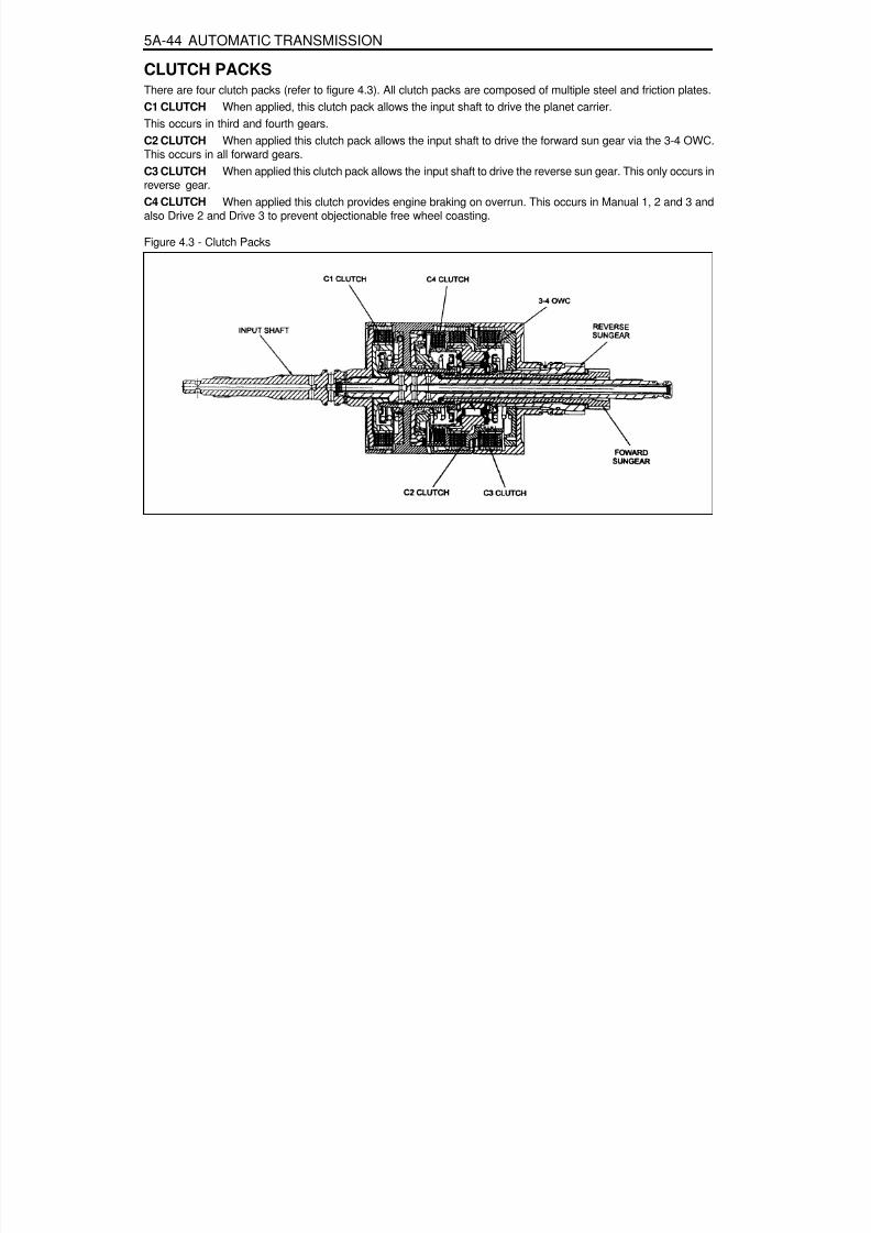
8/18/2019 SsangYong Musso Service Manual 1998.pdf
http://slidepdf.com/reader/full/ssangyong-musso-service-manual-1998pdf 1021/1459
5A-44 AUTOMATIC TRANSMISSION
CLUTCH PACKSThere are four clutch packs (refer to figure 4.3). All clutch packs are composed of multiple steel and friction plates.C1 CLUTCH When applied, this clutch pack allows the input shaft to drive the planet carrier.This occurs in third and fourth gears.C2 CLUTCH When applied this clutch pack allows the input shaft to drive the forward sun gear via the 3-4 OWC.This occurs in all forward gears.C3 CLUTCH When applied this clutch pack allows the input shaft to drive the reverse sun gear. This only occurs inreverse gear.C4 CLUTCH When applied this clutch provides engine braking on overrun. This occurs in Manual 1, 2 and 3 andalso Drive 2 and Drive 3 to prevent objectionable free wheel coasting.
Figure 4.3 - Clutch Packs

8/18/2019 SsangYong Musso Service Manual 1998.pdf
http://slidepdf.com/reader/full/ssangyong-musso-service-manual-1998pdf 1022/1459
AUTOMATIC TRANSMISSION 5A-45
BANDSThe transmission utilises two bands, the B1 band (sometimes known as the 24 band), and the B2 band (sometimesknown as the low-reverse band). Refer to figure 4.4.The B1 band is a flexible band which is engaged by the front servo piston. B1 is activated in second and fourth gear.When activated B1 prevents the reverse sun gear from rotating by holding the C3 clutch assembly stationary. Insecond gear only the outer area of the apply piston is utilised. In fourth gear both areas are utilised for greater
clamping force.The B2 band is a solid band which is engaged by the rear servo piston. B2 is activated in Park,Reverse, Neutral and Manual 1. When activated B2 prevents the planet carrier assembly from rotating. In Manual 1only the inner area of the apply piston is utilised. In Park, Reverse and Neutral, both areas are utilised for greaterclamping force.
Figure 4.4- Bands
ONE WAY CLUTCHESThe transmission uses two OWCs, the 1-2 OWC and the 34 OWC. (Note that a third OWC is located in the torqueconverter, also known as a sprag.)The 1-2 OWC is located between the planetary carrier assembly and the centre support. This allows the carrier to
rotate around the centre support in one direction only. The one way clutch is engaged only in Drive 1.The 3-4 OWC is located between the C4 and the C2 clutch assemblies. This allows the C2 clutch to drive the forwardsun gear in first, second and third gears but unlocks in fourth gear and during overrun.
PLANETARY GEAR SETThe planetary gear set used in the transmission is a conventional six pinion Ravigneaux compound gear set.

8/18/2019 SsangYong Musso Service Manual 1998.pdf
http://slidepdf.com/reader/full/ssangyong-musso-service-manual-1998pdf 1023/1459
5A-46 AUTOMATIC TRANSMISSION
PARKING MECHANISMWhen Park is selected the manual lever extends the park rod rearwards to engage the parking pawl (refer to (figure4.5). The pawl will engage the external teeth on the ring gear thus locking the output shaft to the transmission case.When Park is not selected a return spring holds the parking pawl clear of the output shaft, preventing accidentalengagement of Park.
Figure 4.5 - Park Rod and Cross Shaft

8/18/2019 SsangYong Musso Service Manual 1998.pdf
http://slidepdf.com/reader/full/ssangyong-musso-service-manual-1998pdf 1024/1459
AUTOMATIC TRANSMISSION 5A-47
POWER FLOWSINTRODUCTIONThe power flows for the various transmission selections are listed below:
Power Flow - Neutral and ParkPower Flow - ReversePower Flow - Manual 1Power Flow - Drive 1Power Flow - Drive 2Power Flow - Drive 3Power Flow - Drive 3 Lock UpPower Flow - Drive 4 (Overdrive)Power Flow - Drive4 Lock Up
Each power flow is described in the following sections.Table 5.1 details the engaged elements versus the gear selected for all transmission selections.
Gear State
Park and NeutralReverseManual 1Drive 1Drive 2 and Manual 2
Drive 3 and Manual 3Drive 3 Lock Up andManual 3 Lock UpDrive 4 OverdriveDrive 4 Lock Up
C1
-----
XX
XX
C2
--XXX
XX
XX
C3
-X---
-
---
C4
--X-X
XX
--
B1
----X
--
--
B2
XXX--
--
--
1-2OWC
---X-
--
--
3-4OWC
--XXX
XX
--
LUCLUTCH
-----
-X
-X
ELEMENTS ENGAGED
Figure 5.1 - Engaged Elements vs Gear Selected
Planetary Gear Set

8/18/2019 SsangYong Musso Service Manual 1998.pdf
http://slidepdf.com/reader/full/ssangyong-musso-service-manual-1998pdf 1025/1459
5A-48 AUTOMATIC TRANSMISSION
POWER FLOW - PARK AND NEUTRALIn Park and Neutral, there is no drive to the planetary gear set. The rear band is applied to eliminate ‘clunk’ onengagement of the reverse gear, and to improve the low range engagement for 4WD applications. No other clutchesor bands are applied.
In Park the transmission is mechanically locked by engaging a case mounted pawl with teeth on the output shaft ringgear.
ControlTo maintain this arrangement in the steady state solenoids and valves are activated as follows:
Solenoids S1 and S2 are switched off.Line (pump) pressure is applied to the primary regulator valve (PRV) and to the solenoid supply valve.The converter, oil cooler, and lubrication circuits are charged from the primary regulator valve.The line 500 circuit is charged by the solenoid supply valve.The S5 circuit is charged by the variable pressure solenoid (S5).Line pressure is prevented from entering the drive circuit by the manual valve.The B1 circuit and all clutch circuits are open to exhaust.
Refer to figure 5.1 and table 5.2.
Table 5.2 - Engaged Elements - Park arid Neutral
Gear State
Park and Neutral
C1
-
C2
-
C3
-
C4
-
B1
-
B2
X
1-2OWC
-
3-4
OWC-
LU
CLUTCH-
ELEMENTS ENGAGED

8/18/2019 SsangYong Musso Service Manual 1998.pdf
http://slidepdf.com/reader/full/ssangyong-musso-service-manual-1998pdf 1026/1459
AUTOMATIC TRANSMISSION 5A-49
POWER FLOW - REVERSEIn Reverse, transmission drive is via the input shaft and the forward clutch cylinder to the hub of the C3 clutch. Theelements of the transmission function as follows :
The C3 clutch is engaged and drives the reverse sun gear in a clock-wise direction.The B2 band is engaged and holds the planetary gear carrier stationary causing the long pinion to rotate anti-clockwise about its axis on the pinion shaft.
The long pinion drives the internal ring fear in the same direction.The internal ring being splined to the output shaft drives it in an anti-clockwise or reverse direction.
ControlTo maintain this arrangement in the steady statesolenoids and valves are activated as follows:
Solenoids S1 and S2 are switched off.Line pressure is directed through the reverse lockout valve to both the inner and outer apply areas of the rearservo piston for B2 band application.Line pressure feeds the reverse oil circuit via the manual valve.Reverse oil is routed from the manual valve to the C3 clutch.Reverse oil is also applied to the spring end of the primary regulator valve to assist the spring and to boost theline pressure value.All other clutch and band apply circuits are open to exhaust.
Refer to figure 5.2 and table 5.3
Table 5.3 - Engaged Elements - Reverse
Gear State
Reverse
C1
-
C2
-
C3
X
C4
-
B1
-
B2
X
1-2
OWC-
3-4OWC
-
LUCLUTCH
-
ELEMENTS ENGAGED

8/18/2019 SsangYong Musso Service Manual 1998.pdf
http://slidepdf.com/reader/full/ssangyong-musso-service-manual-1998pdf 1027/1459
5A-50 AUTOMATIC TRANSMISSION
POWER FLOW - MANUAL 1In Manual 1, transmission drive is via the input shaftto the forward clutch cylinder. The elements of thetransmission function as follows :
The C2 clutch is engaged to drive the forward sun gear, via the 3-4 OWC.The B2 band is engaged to hold the planetary gear carrier stationary.The forward sun gear drives the short pinion anti-clockwise.The short pinion drives the long pinion clockwise.The long pinion rotating about its axis drives the internal ring gear and the output shaft in a clockwise orforward direction.The C4 clutch provides engine braking through the 3-4 OWC on overrun.
ControlTo maintain this arrangement in the steady state solenoids and valves are activated as follows:
Solenoids S1 and S2 are switched ON.The 1-2,2-3, and 34 shift valves are held in their first gear positions by line 500 pressure.
Drive (line pressure) oil from the manual valve engages the C2 clutch.Lo-1st (line pressure) oil is routed through the 1-2 shift valve to the C4 clutch, and to the inner apply area ofthe rear servo piston for B2 band application.
Refer to figure 5.3 and table 5.4.
Table 5.4 - Engaged Elements - Manual 1
Gear State
Manual 1
C1
-
C2
X
C3
-
C4
X
B1
-
B2
X
1-2OWC
-
3-4
OWCX
LU
CLUTCH-
ELEMENTS ENGAGED

8/18/2019 SsangYong Musso Service Manual 1998.pdf
http://slidepdf.com/reader/full/ssangyong-musso-service-manual-1998pdf 1028/1459
AUTOMATIC TRANSMISSION 5A-51
POWER FLOW - DRIVE 1In Drive 1, transmission drive is via the input shaft to the forward clutch cylinder. The elements of the transmissionfunction as follows :
The C2 clutch is engaged to drive the forward sun gear.The forward sun gear drives the short pinion anti-clockwise.The short pinion drives the long pinion clockwise.The 1-2 OWC prevents the planetary gear carrier from rotating under reaction force and the long pinionrotates on its axis driving the internal ring gear and output shaft in a clockwise or forward direction.There is no engine braking on overrun.
ControlTo maintain this arrangement in the steady state solenoids and valves are activated as follows:
Solenoids S1 and S2 are switched On.The 1-2, 2-3, and 3-4 shift valves are held in their first gear positions by line 500 pressure.Drive (line pressure) oil from the manual valve engages the C2 clutch.
Refer to figure 5.4 and table 5.5
Table 5.5 - Engaged Elements - Drive 1
Gear State
Drive 1
C1
-
C2
X
C3
-
C4
-
B1
-
B2
-
1-2
OWCX
3-4OWC
X
LUCLUTCH
-
ELEMENTS ENGAGED
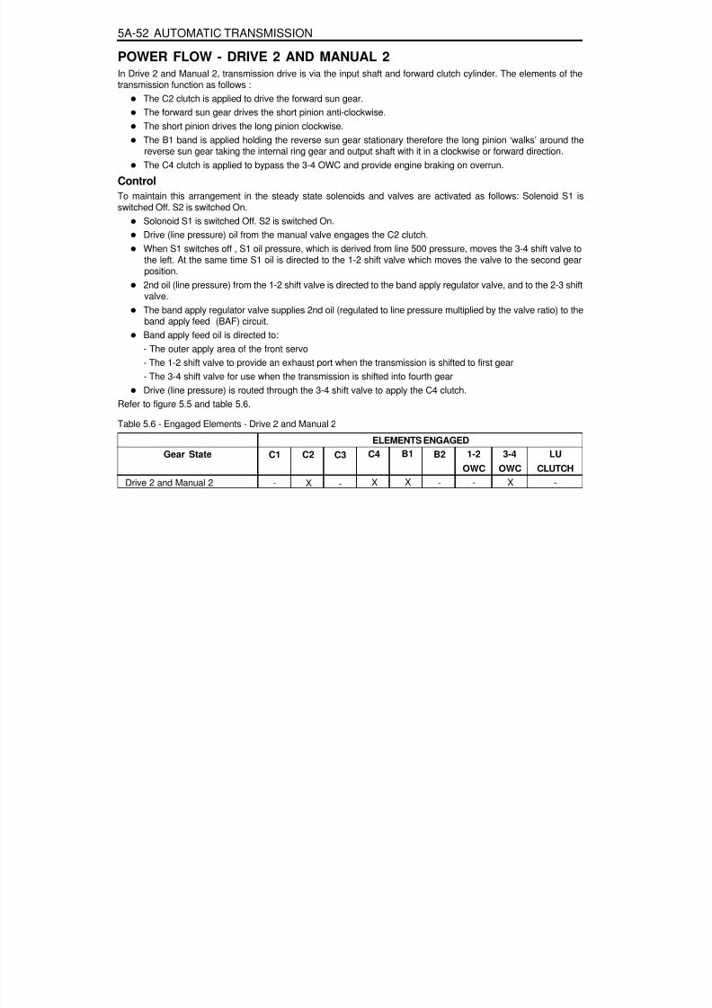
8/18/2019 SsangYong Musso Service Manual 1998.pdf
http://slidepdf.com/reader/full/ssangyong-musso-service-manual-1998pdf 1029/1459
5A-52 AUTOMATIC TRANSMISSION
POWER FLOW - DRIVE 2 AND MANUAL 2In Drive 2 and Manual 2, transmission drive is via the input shaft and forward clutch cylinder. The elements of thetransmission function as follows :
The C2 clutch is applied to drive the forward sun gear.The forward sun gear drives the short pinion anti-clockwise.The short pinion drives the long pinion clockwise.The B1 band is applied holding the reverse sun gear stationary therefore the long pinion ‘walks’ around thereverse sun gear taking the internal ring gear and output shaft with it in a clockwise or forward direction.The C4 clutch is applied to bypass the 3-4 OWC and provide engine braking on overrun.
ControlTo maintain this arrangement in the steady state solenoids and valves are activated as follows: Solenoid S1 isswitched Off. S2 is switched On.
Solonoid S1 is switched Off. S2 is switched On.Drive (line pressure) oil from the manual valve engages the C2 clutch.When S1 switches off , S1 oil pressure, which is derived from line 500 pressure, moves the 3-4 shift valve tothe left. At the same time S1 oil is directed to the 1-2 shift valve which moves the valve to the second gear
position.2nd oil (line pressure) from the 1-2 shift valve is directed to the band apply regulator valve, and to the 2-3 shiftvalve.The band apply regulator valve supplies 2nd oil (regulated to line pressure multiplied by the valve ratio) to theband apply feed (BAF) circuit.Band apply feed oil is directed to:- The outer apply area of the front servo- The 1-2 shift valve to provide an exhaust port when the transmission is shifted to first gear- The 3-4 shift valve for use when the transmission is shifted into fourth gearDrive (line pressure) is routed through the 3-4 shift valve to apply the C4 clutch.
Refer to figure 5.5 and table 5.6.Table 5.6 - Engaged Elements - Drive 2 and Manual 2
Gear State
Drive 2 and Manual 2
C1
-
C2
X
C3
-
C4
X
B1
X
B2
-
1-2OWC
-
3-4OWC
X
LUCLUTCH
-
ELEMENTS ENGAGED

8/18/2019 SsangYong Musso Service Manual 1998.pdf
http://slidepdf.com/reader/full/ssangyong-musso-service-manual-1998pdf 1030/1459
AUTOMATIC TRANSMISSION 5A-53

8/18/2019 SsangYong Musso Service Manual 1998.pdf
http://slidepdf.com/reader/full/ssangyong-musso-service-manual-1998pdf 1031/1459
5A-54 AUTOMATIC TRANSMISSION
POWER FLOW - DRIVE 3 AND MANUAL 3In Drive 3 and Manual 3, transmission drive is via the input shaft to the forward clutch cylinder. The elements of thetransmission function as follows :
The C2 clutch is engaged to drive the forward sun gear.The C1 clutch is engaged to drive the planet carrier.The forward sun gear and the planet carrier are driven clockwise at the same speed therefore there is norelative motion between the sun gear and the pinions.The ring gear and output shaft are driven in a clockwise or forward direction at input shaft speed.The C4 clutch is applied to bypass the 3-4 OWC and provide engine braking on overrun.
ControlTo maintain this arrangement in the steady state solenoids and valves are activated as follows:
Solenoid S1 is switched Off. S2 is switched Off.With S1 and S2 switched Off, the 2-3 and 3-4 shift valves are held in the third gear position by line 500pressure.The 1-2 shift valve is held in the third gear position by S1-S2 oil pressure.2nd oil (line pressure) from the 1-2 shift valve is directed to the band apply regulator valve. and to the 2-3 shiftvalve.The band apply regulator valve supplies 2nd oil (regulated to line pressure multiplied by the valve ratio) to theband apply feed (BAF) circuit.Band apply feed oil is directed to:- The outer apply area of the front servo- The 1-2 shift valve to provide an exhaust port when the transmission is shifted to first gear- The 3-4 shift valve for use when the transmission is shifted into fourth gear2nd oil at the 2-3 shift valve is directed to the 3rd oil circuit.3rd oil from the 2-3 shift valve is directed to the clutch apply regulator valve, and to the 4-3 Sequence Valve.The clutch apply regulator valve supplies oil (regulated to line 500 pressure multiplied by the valve ratio) to the
clutch apply feed (CAF) circuit.The CAF oil is directed to:- The C1 clutch- The C1 bias valve- The 4-3 sequence valveAt the 4-3 sequence valve the CAF oil becomes band 1 release feed (B1R-F) oil, and is directed through the3-4 shift valve to the spring end of the 4-3 sequence valve, and to the release side of the front servo piston tohold band 1 off.Drive (line pressure) is routed through the 3-4 shift valve to apply the C4 clutch.
Refer to figure 5.6 and table 5.7.
Table 5.7 - Engaged Elements - Drive 3 and Manual 3
Gear State
Drive 3 and Manual 3
C1
X
C2
X
C3
-
C4
X
B1
-
B2
-
1-2
OWC-
3-4OWC
X
LUCLUTCH
-
ELEMENTS ENGAGED

8/18/2019 SsangYong Musso Service Manual 1998.pdf
http://slidepdf.com/reader/full/ssangyong-musso-service-manual-1998pdf 1032/1459
AUTOMATIC TRANSMISSION 5A-55

8/18/2019 SsangYong Musso Service Manual 1998.pdf
http://slidepdf.com/reader/full/ssangyong-musso-service-manual-1998pdf 1033/1459
5A-56 AUTOMATIC TRANSMISSION
POWER FLOW - DRIVE 3 LOCK UP AND MANUAL 3 LOCK UPIn Drive 3 Lock Up and Manual 3 Lock Up, transmission drive is the same as for Drive 3 but with the application of theconverter lock up clutch to provide positive no-slip converter drive.
ControlControl for Drive 3 Lock Up and Manual 3 Lock Up is the same as for Drive 3 with the addition of the converter clutchcircuit activated by solenoid S7.
When S7 is switched On, S7 feed oil to the converter clutch control valve is switched off and allowed to exhaustthrough the S7 solenoid. This allows the valve to move to the clutch engage position.Regulated apply feed oil, derived from line 500 oil at the converter clutch regulator valve, is directed by theconverter clutch control valve to the engage side of the converter clutch.Converter clutch release oil is exhausted at the converter clutch control valve.Converter feed oil is re-routed by the converter clutch control valve directly to the oil cooler and lubricationcircuit.
Refer to figure 5.7and table 5.8.
Table 5.8 - Engaged Elements - Drive 3 Lock Up and Manual 3 Lock Up
Gear State
Drive 3 Lock Up and Manual 3Lock Up
C1
X
C2
X
C3
-
C4
X
B1
-
B2
-
1-2
OWC-
3-4OWC
X
LUCLUTCH
X
ELEMENTS ENGAGED
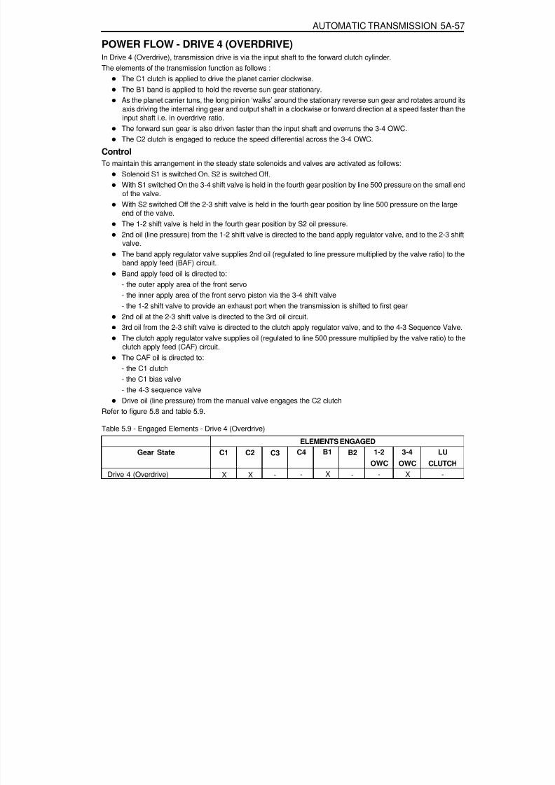
8/18/2019 SsangYong Musso Service Manual 1998.pdf
http://slidepdf.com/reader/full/ssangyong-musso-service-manual-1998pdf 1034/1459
AUTOMATIC TRANSMISSION 5A-57
POWER FLOW - DRIVE 4 (OVERDRIVE)In Drive 4 (Overdrive), transmission drive is via the input shaft to the forward clutch cylinder.The elements of the transmission function as follows :
The C1 clutch is applied to drive the planet carrier clockwise.The B1 band is applied to hold the reverse sun gear stationary.As the planet carrier tuns, the long pinion ‘walks’ around the stationary reverse sun gear and rotates around itsaxis driving the internal ring gear and output shaft in a clockwise or forward direction at a speed faster than theinput shaft i.e. in overdrive ratio.The forward sun gear is also driven faster than the input shaft and overruns the 3-4 OWC.The C2 clutch is engaged to reduce the speed differential across the 3-4 OWC.
ControlTo maintain this arrangement in the steady state solenoids and valves are activated as follows:
Solenoid S1 is switched On. S2 is switched Off.With S1 switched On the 3-4 shift valve is held in the fourth gear position by line 500 pressure on the small endof the valve.With S2 switched Off the 2-3 shift valve is held in the fourth gear position by line 500 pressure on the largeend of the valve.The 1-2 shift valve is held in the fourth gear position by S2 oil pressure.2nd oil (line pressure) from the 1-2 shift valve is directed to the band apply regulator valve, and to the 2-3 shiftvalve.The band apply regulator valve supplies 2nd oil (regulated to line pressure multiplied by the valve ratio) to theband apply feed (BAF) circuit.Band apply feed oil is directed to:- the outer apply area of the front servo- the inner apply area of the front servo piston via the 3-4 shift valve- the 1-2 shift valve to provide an exhaust port when the transmission is shifted to first gear
2nd oil at the 2-3 shift valve is directed to the 3rd oil circuit.3rd oil from the 2-3 shift valve is directed to the clutch apply regulator valve, and to the 4-3 Sequence Valve.The clutch apply regulator valve supplies oil (regulated to line 500 pressure multiplied by the valve ratio) to theclutch apply feed (CAF) circuit.The CAF oil is directed to:- the C1 clutch- the C1 bias valve- the 4-3 sequence valveDrive oil (line pressure) from the manual valve engages the C2 clutch
Refer to figure 5.8 and table 5.9.
Table 5.9 - Engaged Elements - Drive 4 (Overdrive)
Gear State
Drive 4 (Overdrive)
C1
X
C2
X
C3
-
C4
-
B1
X
B2
-
1-2OWC
-
3-4
OWCX
LU
CLUTCH-
ELEMENTS ENGAGED

8/18/2019 SsangYong Musso Service Manual 1998.pdf
http://slidepdf.com/reader/full/ssangyong-musso-service-manual-1998pdf 1035/1459
5A-58 AUTOMATIC TRANSMISSION

8/18/2019 SsangYong Musso Service Manual 1998.pdf
http://slidepdf.com/reader/full/ssangyong-musso-service-manual-1998pdf 1036/1459
AUTOMATIC TRANSMISSION 5A-59
POWER FLOW - DRIVE 4 LOCK UPIn Drive 4 Lock Up, transmission drive is the same as for Drive 4 but with the application of the converter lock up clutchto provide positive no-slip converter drive.
ControlControl for Drive 4 Lock Up is the same as for Drive 4 with the addition of the converter clutch circuit activated bysolenoid S7.
When S7 is switched On, S7 feed oil to the converter clutch control valve is switched off and allowed to exhaustthrough the S7 solenoid. This allows the valve to move to the clutch engage position.Regulated apply feed oil, delved from Line 500 oil at the converter clutch regulator valve, is directed by theconverter clutch control valve to the engage side of the converter clutch.Converter clutch release oil is exhausted at the converter clutch control valve.Converter feed oil is re-routed by the converter clutch control valve directly to the oil cooler and lubricationcircuit.
Refer to figure 5.9 arid table 5.10.
Table 5.10 - Engaged Elements - Drive 4 Lock Up
Gear State
Drive 4 Lock Up
C1
X
C2
X
C3
-
C4
-
B1
X
B2
-
1-2OWC
-
3-4OWC
-
LUCLUTCH
X
ELEMENTS ENGAGED

8/18/2019 SsangYong Musso Service Manual 1998.pdf
http://slidepdf.com/reader/full/ssangyong-musso-service-manual-1998pdf 1037/1459
5A-60 AUTOMATIC TRANSMISSION
DIAGNOSISDIAGNOSTIC SYSTEMRecommended Test Equipment and ProcedureThe test equipment is designed to be used with the control modules in all vehicles. The components used in thetransmission application are:
Multi Function Tester, andAppropriate vehicle for testing.
Multi Function Tester (MFT)The MFT is programmed with the special vehicle diagnostic software that allows selection of the unit under test.The program allows the proper communication to the Transmission Control Unit (TCU).It then requests information from the user via a menu system to select the required set up.Examples are viewing codes, clearing error codes, and real-time operation. Set up and operation instructions aredetailed in the user manual.This equipment can be used by trained personnel such as technicians and mechanics to diagnose electronic andwiring problems relating to the vehicle transmission. Information that is available includes engine and road (shaft)speed, transmission oil temperature, throttle position, solenoid/gear status and gear lever position. Current andstored faults detected by the electronics are also available.
TCU Pin DescriptionThe TCU pin descriptions are listed in table 6.1.1.The wiring loom pins are shown in figure 6.1.1
PinNo.
1
23
4
5
6
78
Identification
Common Ground
Do not useMode Indicator Lamp -‘Winter ’Gear Position ‘Park’Lamp
Gear Position ‘Reverse’LampGear Position ‘Neutral’LampDo not useEngine Speed InputSensor (-Ve)
Type
GND
-OP
OP
OP
OP
-IP
Description
Main power ground (or the module. Connectsdirectly to the battery negative terminal.
Indicates ‘WINTER’ mode shift schedule is se-lected.Drives the jewel in the instrument cluster to in-dicate ‘PARK’ gear lever position.
Drives the jewel in the instrument cluster to in-dicate ‘REVERSE’ gear lever position.Drives the jewel in the instrument cluster to in-dicate ‘NEUTRAL’ gear lever position.
Flywheel/Ring gear pulses to indicate enginespeed.
4WD(Diesel)
O
O
4WD(Gas)
O
OO
Table 6.1.1 - TCU Pin Description

8/18/2019 SsangYong Musso Service Manual 1998.pdf
http://slidepdf.com/reader/full/ssangyong-musso-service-manual-1998pdf 1038/1459
AUTOMATIC TRANSMISSION 5A-61
PinNo. 9
10
1112
13
14
15
1617
18
19
20
21222324
25
26
27
28
29
30
Identification
Mode Indicator Lamp -‘Power ’Throttle Position SensorOutput as Pulse WidthModulation for TODAir Conditioner Input SignalKickdown Switch
Mode Switch
Transfer Case Input(High) -4WD Lamp High
Ignition Switch
Do not useGear Position ‘1’ Lamp/ Gear Position Code 1*Gear Position ‘2’ Lamp/ Gear Position Code 2*Gear Position ‘3’ Lamp/ Gear Position Code 3*Gear Position ‘Drive’
Lamp/ Gear Position Code 4*CAN (-ve)CAN (+ve)K-line Communication LinkEngine Speed InputSensor (+ve)Road Speed Pulses
Shaft Speed SensorSignalThrottle Position Sensor -GroundThrottle Position Sensor -ReferenceThrottle Position Sensor -Input Signal
Transfer(or Case Input(Low) - 4WD Lamp Low
Type
OP
OP
-IP
IP
IP
IP
-OP
OP
OP
OP
I/OI/OI/OIP
OP
IP
GND
REF
IP
IP
Description
Indicates ‘POWER’ mode shift schedule is se-lected.Provides an analogue signal of the throttle po-sition for the Torque on Demand (TOD) Con-trol Module.InputSwitch to indicate when a kickdown is requiredat high throttle position.Switch to select ‘NORMAL’, ‘POWER’ or ‘WIN-TER’ shift schedule.Voltage varies from OV to 12V.Switch to indicate 4WD’HIGH RANGE’ is se-lected.
Ignition power is used as the main power sourceto drive the unit and the solenoids.
Drives jewel in the instrument cluster to indi-categear leverposition’1'. Drives jewel in the instru-ment cluster to indicategear lever position’2'. Drives jewel in the instru-ment cluster to indicate gear lever position’3'.Drives jewel in the instrument cluster to indi-
cate‘DRIVE’. gear lever position.CAN low side bus communication (CANL).CAN high side bus communication (CANH).Diagnostic information and vehicle coding.Flywheel/Ring gear pulses to indicate enginespeed.Road speed signals derived from shaft speedsensors.This sensor transmit shaft speed signal to theTCU.Throttle position sensor ground.
This is the 5V reference voltage supply gener-ated by the unit for the throttle position sensor.This sensor is a resistance potentiometer indi-cating throttle position.Voltage varies 0V to 5V.Switch to indicate 4WD’LOW RANGE’ is se-lected.
4WD(Diesel)
O
O
OO
4WD(Gas)
O
O
O
O
O
O
O
O

8/18/2019 SsangYong Musso Service Manual 1998.pdf
http://slidepdf.com/reader/full/ssangyong-musso-service-manual-1998pdf 1039/1459
5A-62 AUTOMATIC TRANSMISSION
Identification
Gear Lever Position
Transmission OilTemperature
Solenoid 4
Solenoid 1
Do not useSolenoid 5Return (-ve)
Gear Lever Position -GroundTransmission OilTemperature - GroundSolenoid 6
Solenoid 2
Solenoid 3
Solenoid 7
Do not useSolenoid 5 (+ve)
Type
IP
IP
OP
OP
-IP
GND
GND
OP
OP
OP
OP
-OP
Description
This switch has discreet values indicating thepositions selected by the gear shift lever(PRNDL). Voltage varies 0V to 5V.Resistive sensor indicates transmission tem-perature .High R = low tempLow R = high tempVoltage varies 0V to 5V.On/Off solenoid normally open, combines withother On/off solenoid 3 for shift quality and se-quencing.On/off solenoid normally open, combines withother On/off solenoid to set the selected gear.
This ensures the earth path for the VPS andthe current in this line is monitored to give feed-back control of the VPS.PRNDL switch ground.
Ground reference for temperature sensor in-put.On/Off solenoid normally open, sets low/highline pressure.
On/off solenoid normally open, combines withother On/off solenoid to set the selected gear.On/off solenoid normally open, combines withOn/off solenoid 4 for shift quality and sequenc-ing.On/off solenoid normally open, locks up thetorque converter to Increase cruising efficiency.
This is the variable force solenoid which rampsthe pressure during gear changes and solenoidswitching, to enhance transmission shift quality.
4WD(Diesel)
O
O
4WD(Gas)
O
O
PinNo.31
32
33
34
3536
37
38
39
40
41
42
4344
= circuit connected O = circuit not connected * = unique OP = Output IP = Input I/O = Input/outputGND = GroundREF = Reference
Notice :

8/18/2019 SsangYong Musso Service Manual 1998.pdf
http://slidepdf.com/reader/full/ssangyong-musso-service-manual-1998pdf 1040/1459
AUTOMATIC TRANSMISSION 5A-63
Ten Pin Plug Pin Numbers
Figure 6.1.1 - Wiring Loom Pins

8/18/2019 SsangYong Musso Service Manual 1998.pdf
http://slidepdf.com/reader/full/ssangyong-musso-service-manual-1998pdf 1041/1459
5A-64 AUTOMATIC TRANSMISSION
Default Transmission Operating ModesThe TCU relies on accurate information from its inputs and complete control of its outputs to effectively control thetransmission. To ensure that it has both valid inputs and functioning outputs, the TCU carries out both hardware andsoftware fault detection routines. The TCU will respond to any faults detected by adopting the operating modes whichare detailed below.The following symptoms of faults are the most obvious results of each fault under ‘normal’ conditions.
There is always the possibility that a fault may not be detected. If undetected fault conditions are present, theoperation of the transmission is difficult to predict.
1 Throttle FaultAll shifts will occur as if a nominal throttle (approx. 44%) were applied for shift scheduling.All shifts will be firm as full throttle and hence high engine torque is assumed.The torque converter will be unlocked at all times.All downshifts initiated by the shift lever will occur as though they were ‘automatic’ shifts. That is the enginebraking effect will not occur until near the end of the shift.Line pressure will always stay high (solenoid 6 OFF) to cope with assumed high throttle/torque.
If a fault is undetected, the percent throttle is most likely to be interpreted as higher than actual, resulting in late
upshifts, early downshifts, firm shifting and a harsh 3-1 shift when stopping.2 Throttle Not Learnt FaultThe transmission operates from default throttle calibration values which results in the evaluation of the throttle beinghigher (more open) than it is. There(ore at zero throttle settings, the transmission may calculate that sufficient throttleopening is present to justify high line pressure and switch solenoid 6 to OFF.
Other symptoms are:a. late upshifts andb. lock-up maintained at zero throttle when the vehicle speed is sufficiently high.
3 Engine Speed FaultAll shifts will be firm because an engine speed corresponding to peak engine torques is assumed.
If a fault is undetected, the engine speed is likely to be interpreted as stalled resulting in soft shifting possibly with anend of shift bump.
4 Vehicle Speed Sensor FaultAll shifts will be controlled by the shift lever with skip downshifts disabled and downshifts only allowed if theengine speed is low. Fourth gear will be inhibited.The torque converter will be unlocked at all times.
If a fault is undetected, the vehicle is likely to be interpreted as being stationary resulting in first gear operation at alltimes. Note that speedometer transducer faults are likely to cause the vehicle’s speedometer to become inoperative.
5 Gear Lever Fault (Inhibitor/PRNDL Switch)
The gear lever is assumed to be in the Drive position.The transmission is limited to 2nd,3rd, and R gears only.The rear band will apply at all times when the lever is shifted to P, R or N. (B2 inhibition and reverse lockoutprotection is disabled.)The torque converter will be unlocked at all times.Manually (gear lever) initiated downshifts will not be available.
If a fault is undetected, the gear lever position is likely to be interpreted as being higher than actual. Where Park is thehighest position and Manual 1 is the lowest, the result being the availability of higher gears than selected by the gearlever.

8/18/2019 SsangYong Musso Service Manual 1998.pdf
http://slidepdf.com/reader/full/ssangyong-musso-service-manual-1998pdf 1042/1459
AUTOMATIC TRANSMISSION 5A-65
If the gear lever is incorrectly adjusted, the transmission may shift gears on bumpy road surfaces.
6 Transmission Oil Temperature Sensing FaultAll shifts will be firm until the transmission has warmed up, because a high transmission oil temperature is
assumed.If a fault is undetected, the temperature is likely to be evaluated as being lower than actual, resulting in softer shiftswith ‘end bump’ (very firm feel at the end of the shift).
7 Mode Setting FaultAll shifts will occur as if the mode is set to ‘NORMAL’.The mode indicator will always be off indicating that ‘NORMAL’ mode is selected.The mode indicator will not respond to changes in switch setting.
If a fault is undetected, the mode as indicated by the mode indicator is not likely to respond to the mode switch.
8 Battery Voltage Sensing Fault
If the battery voltage is low then shifts to first gear are inhibited.9 the battery voltage is high (>16.5V) then thetransmission goes into limp home (LHM) mode.If a fault is undetected, the transmission is likely to incorrectly evaluate an ON/OFF solenoid fault resulting in limp
home mode (LHM) operation.9 ON/OFF Solenoid Fault (Solenoids 1,2,3 and 4)
The transmission adopts its limp home mode (LHM) operation, described above. However, if solenoid 1 is faulty thenthe fourth gear LHM strategy will be adopted independent of vehicle speed.If a fault is undetected, the operation of the transmission is dependent on which solenoid is actually faulty. Thecharacteristics for different solenoid fault conditions are listed in table 6.1.2.
10 ON/OFF Solenoid Fault (Solenoids 6,7)If solenoid 6 is found faulty it is always disabled resulting in high line pressure being applied continuously.If solenoid 7 is found faulty it is disabled resulting in the transmission being locked always.The transmission does not go into LHM.
11 Variable Pressure Solenoid FaultThe transmission adopts its LHM operation.If a fault is undetected, the transmission shift feel is likely to be poor for all shifts.
12 Software Fault
The transmission adopts the third gear LHM strategy of operation, independent of vehicle speed. The operation ofthe TCU under this condition is difficult to predict. Its operation may be erratic.If a fault is undetected, the operation of the TCU is likely to be erratic.
13 Power Supply Fault
The transmission adopts the third gear LHM strategy of operation, independent of vehicle speed. If there is anintermittent power supply connection, the TCU will power-up in fourth gear and then shift to the appropriate gear tosatisfy the conditions present. The power supply is not monitored for fault evaluation.All faults except for solenoid faults can be recovered without having to turn the TCU off and back on. However, ingeneral the recovery requires that no faults are present for a period of time (approx. 3 or 30 seconds). Recovery froma fault will not clear the fault from the keep alive memory
14 Transmission Sump Temperature Exceeding 135°CThe converter lockup clutch will be applied at lower speeds, causing a shudder through the vehicle.The mode indicator will flash in some vehicles.
These faults can be due to the transmission oil overheating or due to an incorrect signal received from the temperaturesensor.

8/18/2019 SsangYong Musso Service Manual 1998.pdf
http://slidepdf.com/reader/full/ssangyong-musso-service-manual-1998pdf 1043/1459
5A-66 AUTOMATIC TRANSMISSION
Diagnostic Trouble MessagesThe diagnostic trouble messages generated by the TCU and their possible causes are listed in table 6.1.3.
Table 6.1.2 - Transmission Operations for On/Off Solenoid FaultsTransmission Operation
First gear instead of second and fourth gear instead of third.This results in a 1 ® 4 shift as the vehicle accelerates from rest.Second gear instead of first and third gear instead of fourth.This results in second gear starts.Fourth gear instead of first and third gear instead of second.This results in fourth gear starts.Second gear instead of third and first gear instead of fourth.This results in a 1 ® 2 then 2 ® 1 (overrun) downshift as the vehicleaccelerates from rest.The following shifts become poor:1® 3, 1 ® 4, 2 ® 1 2 ® 3, 2 ® 4, 4 ® 2, 4 ® 1.The following shifts become poor:3® 4, 4 ® 3, 3 ® 2.There may be slippage in the gears during torque converter locking.The following shifts become poor:1® 2, 1 ® 3, 1 ® 4, 2 ® 3, 2 ® 4, 3 ® 1, 3 ® 2 (All Including Manual), 3 ® 4,4® 1,4 ® 3.The following shifts become poor:2® 4, 3 ® 2.
There may be slippage in the gears during torque converter locking.Line pressure always high.Line pressure always low thus resulting in risk of slippage in gears.Torque converter always unlocked.Torque converter always locked in 3rd and 4th gears, causing thevehicle to shudder at lower speeds,
ConditionAlways ON
Always OFF
Always OFF
Always ON
Always OFF
Always ON
Always OFF
Always ON
Always OFFAlways ONAlways OFFAlways ON
Solenoid1
2
3
4
6
7

8/18/2019 SsangYong Musso Service Manual 1998.pdf
http://slidepdf.com/reader/full/ssangyong-musso-service-manual-1998pdf 1044/1459
AUTOMATIC TRANSMISSION 5A-67
Table 6.1.3 - Diagnostic Trouble Messages
Description / Cause
There have been no faults recorded since the TCU was last cleared. Ifthe fault history has never been cleared, then there have been nofaults recorded since the TCU was originally powered up.There is an internal fault within the TCU.
The voltage measured by the TCU corresponding to the battery sup-ply voltage has been outside the range of the maximum operatingvoltage of 16.5 volts.The minimum operating voltage depends on the transmission tem-perature but is typically between 8-9 V for a warm transmission.The voltage measured by the TCU from the throttle potentiometer hasbeen outside acceptable levels.This would typically indicate a loose connection in the wiring to, or
within, the throttle sensor which has caused the signal at the TCU toread 0V or 5V.The voltage measured by the TCU across the temperature Input ter-minals has been outside acceptable levels.This would typically be caused by a loose connection or short to groundin the wiring to, or within, the temperature sensor which has causedthe signal at the TCU to read 0V or 5V.The voltage measured by the TCU across the shift lever input termi-nals has been outside acceptable levels for a significant length oftime. This would typically be caused by a loose connection or short to
ground in the wiring to, or within, the inhibitor switch which has causedthe signal at the TCU to read 0V or 5V.The signal from the ignition, of ignition pulses, has either been non-existent or has been unreliable.There are two reasons this fault could occur. The first is due to a lackof ignition pulses when other TCU inputs would indicate that the en-gine is running, that is the gear lever is in a driving position, the throttleis applied and vehicle speed increasing.The second cause of this (aunt is the frequency of the pulses of theignition pulse input to the TCU indicate an unachievable engine speed.The pulses from the shaft speed sensor have either been non-exis-tent or have been unreliable.There are three reasons this fault could occur. The first is due to asudden loss of speedometer pulses at a time when they were fre quent,thus indicating an unachievable degree of deceleration of the driveline. The second cause of this fault is that the frequency of the pulseson the shaft speed sensor input to the TCU indicate an unachievablepropeller shaft speed. The third is the presence of a high engine speedin a driving gear with no speedometer pulses.
Condition
Test Pass
Transmission ControlModule FaultBattery Voltage InputFault
Throttle Input Fault
Temperature Input Fault
Shift Lever PositionInput Fault(Inhibitor/PRNDL Switch)
Engine Speed SensorFault
Shaft Speed SensorFault(Speedo Sensor)
Solenoid1
2
3
4
5
6
7
8

8/18/2019 SsangYong Musso Service Manual 1998.pdf
http://slidepdf.com/reader/full/ssangyong-musso-service-manual-1998pdf 1045/1459
5A-68 AUTOMATIC TRANSMISSION
Description / Cause
The signal from the mode switch is unreliable.This fault is caused by too many changes in the mode input signalover a period of time. Typical causes would be an intermittent connection in the switch or wiring or an intermittent short to ground in thewiring.The data link between the TCU and the engine management moduleis found to be unreliable because the checksum, or the data received,did not match the correct checksum.This could be caused by an open circuit, short circuit to ground or aloose connection in the link wire itself.Each solenoid in turn is switched off if it was energised, or switched onif it was not energised by a very small 100 ms pulse. This pulse is tooshort for the solenoid to react so transmission operation is not affected.
The solenoid feedback voltage is measured before the 100 ms pulseand again during the pulse. If the difference is outside the acceptablelimits the relevant fault messages are set.Typical causes would be an open circuit in the wiring to or within thesolenoid, or a short circuit to ground in the wiring to, from or within thesolenoid in question.If several of these fault codes are presents check the wiring orconnectors that are common to the selected solenoids, especially theearth connections.The state of the solenoid feedback voltage is outside acceptable
limits but the faulty solenoid could not be isolated.The current to solenoid 5 was outside acceptable limits.This fault results from a mismatch between the current set point forsolenoid 5 and the current measured by the feedback within the TCU.Typical causes would be an open circuit or short circuit to ground inthe wiring to, from or within the solenoid. It is also possible that therehas been a fault in the solenoid output circuit. If this is the casehowever, the fault should be continually present.The closed throttle position has not been learnt. This faultmay be caused by the transmission not having reached normal
operating temperature or the engine idle speed being incorrect.The TCU will learn the closed throttle position automaticallywhen the transmission is brought to normal operatingtemperature and the engine is allowed to idle in Drive with the‘base idle’ correctly set and the air conditioner (if fitted)switched off.
ConditionMode Switch Input Fault(Power/Economy Mode)
Data Output Link Fault
On/off Solenoid Fault(Solenoid 1,2,3,4,6,7)
Solenoid 5 Fault(Variable PressureSolenoid)
Throttle Not Learnt
Solenoid9
10
11
12
13

8/18/2019 SsangYong Musso Service Manual 1998.pdf
http://slidepdf.com/reader/full/ssangyong-musso-service-manual-1998pdf 1046/1459
AUTOMATIC TRANSMISSION 5A-69
MECHANICAL TESTSIn Vehicle Transmission ChecksCarry out the following tests before removing the transmission.
See Checking Transmission Fluid Level, Section 7.2.1.Check that the transmission oil is not burnt (colour and smell are correct).
Ensure that the transmission is not in limp home mode (LHM).Check that the battery terminals and the earth connections are not corroded or loose.Check the engine stall speed is within the handbook value.Check that the cooler flow is not restricted.Check that all electrical plug connections are tight.Carry out a road test to confirm the symptoms, if necessary.Inspect the oil, ensure that there are no metal or other contaminants in the oil pan.
Diagnosing Oil LeaksDetermine the source of oil leaks by firstly cleaning down the affected area, then driving the vehicle.Inspect the seals to confirm the source of the leak.
To determine the source of a rear servo oil leak, raise the vehicle on a hoist, then carry out a reverse stall.To determine the source of a front servo leak, raise the vehicle on a hoist, then run the vehicle in second gear.
Troubleshooting ChartsThe troubleshooting charts are set out as follows:
Table 6.2.1 Drive Faults,Table 6.2.2 Faulty Shift Patterns.Table 6.2.3 Shift Quality Faults.Table 6.2.4 After Teardown Faults.
Table 6.2.1 - Drive Faults
ActionCheck the fluid level. Top up as necessary.Inspect and clean C1/C2 feed.Reinstall/renew the ‘z’ link.Remove, clean and re-install the PRV.Inspect and replace as necessary.
Inspect and replace as necessary.
Inspect and replace as necessary.
Check servo adjustment or replace rear bandas necessary.Check for failure in C3, C3 hub or C1/C2 cylin-der. Repair as necessary.Inspect and clean PRV.
Inspect and replace pump gears as necessary.Inspect and repair as necessary.
Possible CauseInsufficient auto transmission fluid.Blocked feed in C1/C2 cylinder.‘Z’ link displaced.Primal regulator valve (PRV) jammed open.Overdrive shaft or input shaft seal ringsfailed.3-4 or 1-2 one way clutch (OWC) installedbackwards or failed.C2 piston broken or cracked.
Rear band or servo faulty.
Failure in C3, C3 hub or C1/C2 cylinder.
Jammed primary regulator valve (PRV).
Damaged/broken pump gears.Dislodged output shaft snap ring.
SymptomNo Drive in D
No Drive inReverseNo engine brakingin Manual 1Engine braking inManual 1 is OKNo drive in Driveand Reverse

8/18/2019 SsangYong Musso Service Manual 1998.pdf
http://slidepdf.com/reader/full/ssangyong-musso-service-manual-1998pdf 1047/1459
5A-70 AUTOMATIC TRANSMISSION
Action
Inspect S1. Repair or replace as necessary.Check for 12 Volts applied to S1 at all times orfor wiring fault.Inspect S1. Repair or replace as necessary.Check for 12 Volts applied to S1 at all times orfor wiring fault.Inspect S2. Repair or replace as necessary.Check for open circuit or wiring fault.Inspect S2. Repair or replace as necessary.Check for open circuit or wiring fault.
Inspect and adjust as necessary.Inspect and repair as necessary.Inspect and replace or refit as necessary.
Inspect ‘O’ ring. Refit or replace as necessary.Inspect the 2-3 shift valve. Repair or replaceas necessary.Inspect C1 clutch. Repair or replace as neces-sary.Inspect ball. Refit or replace as necessary.Inspect C4. Repair C4 or replace C4 wave plateas necessary.Inspect rear band adjustment. Adjust as nec-essary.
Inspect ball- Refit or replace as necessary.Inspect’0’ring. Refit or replace as necessary.Inspect C4 and C4 wave plate. Repair or re-place as necessary.Inspect inhibitor switch.Repair or replace as necessary.Inspect the 1-2 shift valve.Repair or replace as necessaryInspect inhibitor switch.Repair or replace as necessary.Inspect the 2-3 shift valve.Repair or replace as necessary.
Possible Cause
S1 always OFF.
S1 always ON.
S2 always OFF.
S2 always ON.
B1 failed.Loose band adjustment.Front servo piston or seal failed.S1/S2 ball misplaced,
Smaller’0’ring on front servo piston failedor missing.2-3 shift valve jammed.C1 clutch failed or slipping in 3rd and 4th.(Gives 1st in 3rd and 2nd in 4th.)Over-run clutch (OC)/low ball misplaced.C4 failed or C4 wave plate broken.
Rear band slipping when hot.
Reverse/Low-1st ball misplaced.Rear servo inner ‘O’ ring missing.C4 failed or C4 wave plate broken.
Inhibitor switch faulty.
1-2 shift valve jammed.
Inhibitor switch fault, 1-2 only.
2-3 shift valve jammed.
Symptom
2-3 shift only(no 4th or 1st)
1-4 shift only1-3-4 (Delayed1-2shift)4-3 shift only
1-2-Neutral(1st over run)1-3 shift only
1-3-4 only
1-2-1 only
No manual 4-3,3-2or 2-1
No manual 1st
1st gear only or2nd,3rd, and 4thonly
1st and 2nd onlyor 1st, 3rd and 4th
only
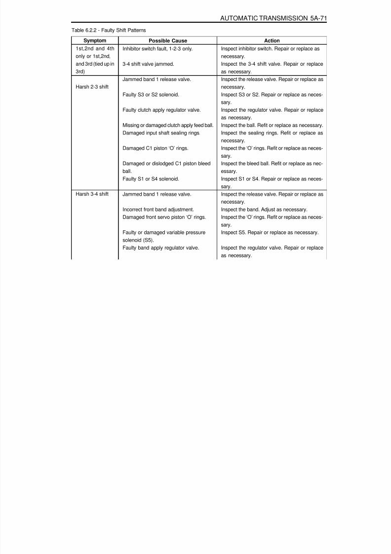
8/18/2019 SsangYong Musso Service Manual 1998.pdf
http://slidepdf.com/reader/full/ssangyong-musso-service-manual-1998pdf 1048/1459
AUTOMATIC TRANSMISSION 5A-71
Table 6.2.2 - Faulty Shift Patterns
ActionInspect inhibitor switch. Repair or replace asnecessary.Inspect the 3-4 shift valve. Repair or replaceas necessary.Inspect the release valve. Repair or replace asnecessary.Inspect S3 or S2. Repair or replace as neces-sary.Inspect the regulator valve. Repair or replaceas necessary.Inspect the ball. Refit or replace as necessary.Inspect the sealing rings. Refit or replace asnecessary.
Inspect the ‘O’ rings. Refit or replace as neces-sary.Inspect the bleed ball. Refit or replace as nec-essary.Inspect S1 or S4. Repair or replace as neces-sary.Inspect the release valve. Repair or replace asnecessary.Inspect the band. Adjust as necessary.Inspect the ‘O’ rings. Refit or replace as neces-
sary.Inspect S5. Repair or replace as necessary.
Inspect the regulator valve. Repair or replaceas necessary.
Possible CauseInhibitor switch fault, 1-2-3 only.
3-4 shift valve jammed.
Jammed band 1 release valve.
Faulty S3 or S2 solenoid.
Faulty clutch apply regulator valve.
Missing or damaged clutch apply feed ball.Damaged input shaft sealing rings.
Damaged C1 piston ‘O’ rings.
Damaged or dislodged C1 piston bleedball.Faulty S1 or S4 solenoid.
Jammed band 1 release valve.
Incorrect front band adjustment.Damaged front servo piston ‘O’ rings.
Faulty or damaged variable pressuresolenoid (S5).Faulty band apply regulator valve.
Symptom1st,2nd and 4thonly or 1st,2nd,and 3rd (tied up in3rd)
Harsh 2-3 shift
Harsh 3-4 shift
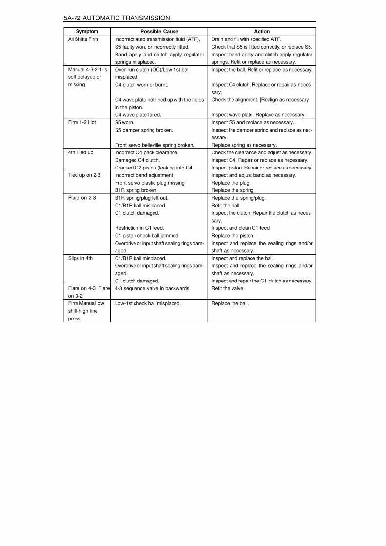
8/18/2019 SsangYong Musso Service Manual 1998.pdf
http://slidepdf.com/reader/full/ssangyong-musso-service-manual-1998pdf 1049/1459
5A-72 AUTOMATIC TRANSMISSION
Action
Drain and fill with specified ATF.Check that S5 is fitted correctly, or replace S5.Inspect band apply and clutch apply regulatorsprings. Refit or replace as necessary.Inspect the ball. Refit or replace as necessary.
Inspect C4 clutch. Replace or repair as neces-sary.Check the alignment. ]Realign as necessary.
Inspect wave plate. Replace as necessary.Inspect S5 and replace as necessary.Inspect the damper spring and replace as nec-essary.
Replace spring as necessary.Check the clearance and adjust as necessary.Inspect C4. Repair or replace as necessary.Inspect piston. Repair or replace as necessary.Inspect and adjust band as necessary.Replace the plug.Replace the spring.Replace the spring/plug.Refit the ball.Inspect the clutch. Repair the clutch as neces-
sary.Inspect and clean C1 feed.Replace the piston.Inspect and replace the sealing rings and/orshaft as necessary.Inspect and replace the ball.Inspect and replace the sealing rings and/orshaft as necessary.Inspect and repair the C1 clutch as necessary.Refit the valve.
Replace the ball.
Possible Cause
Incorrect auto transmission fluid (ATF).S5 faulty won, or incorrectly fitted.Band apply and clutch apply regulatorsprings misplaced.Over-run clutch (OC)/Low-1st ballmisplaced.C4 clutch worn or burnt.
C4 wave plate not lined up with the holesin the piston.C4 wave plate failed.S5 worn.S5 damper spring broken.
Front servo belleville spring broken.Incorrect C4 pack clearance.Damaged C4 clutch.Cracked C2 piston (leaking into C4).Incorrect band adjustmentFront servo plastic plug missingB1R spring broken.B1R spring/plug left out.C1/B1R ball misplaced.C1 clutch damaged.
Restriction in C1 feed.C1 piston check ball jammed.Overdrive or input shaft sealing rings dam-aged.C1/B1R ball misplaced.Overdrive or input shaft sealing rings dam-aged.C1 clutch damaged.4-3 sequence valve in backwards.
Low-1st check ball misplaced.
Symptom
All Shifts Firm
Manual 4-3-2-1 issoft delayed ormissing
Firm 1-2 Hot
4th Tied up
Tied up on 2-3
Flare on 2-3
Slips in 4th
Flare on 4-3, Flare
on 3-2Firm Manual lowshift-high linepress.

8/18/2019 SsangYong Musso Service Manual 1998.pdf
http://slidepdf.com/reader/full/ssangyong-musso-service-manual-1998pdf 1050/1459
AUTOMATIC TRANSMISSION 5A-73
Table 6.2.3 - Shift Quality Faults
ActionCheck the resistance. Replace the inhibitorswitch as necessary.Inspect and replace the sensor as necessary.Inspect and adjust the band as necessary.Inspect and replace the’0’rings as necessary.Inspect, repair or replace S5 as necessary.
Inspect, repair or replace S1 or S4 as neces-sary.Inspect, repair or replace the BAR as neces-sary.Inspect and repair as necessary.Inspect and clean CCCV.
Inspect, repair or replace as necessary.
Possible CauseFaulty inhibitor switch.
Faulty throttle position sensor.Incorrect front band adjustment.Damaged front servo piston’0’rings.Faulty or damaged variable pressure so-lenoid (S5).Faulty S1 or S4 solenoid.
Faulty band apply regulator valve (BAR).
Misassembled front servo return spring.Jammed converter clutch control valve
(CCCV).Faulty solenoid 7.
SymptomHarsh 1-2 shift
stalls when Drive
or Reverseselected Shudderon Rolldown

8/18/2019 SsangYong Musso Service Manual 1998.pdf
http://slidepdf.com/reader/full/ssangyong-musso-service-manual-1998pdf 1051/1459
5A-74 AUTOMATIC TRANSMISSION
ActionInspect, repair C2 and adjust the linkage as neces-sary.
Repair C2. Inspect, repair or replace S6 as neces-sary.
Repair C2. Inspect, replace the sealing rings and/ or shaft as necessary.
Repair C2. Inspect, repair or replace the C2 pistonas necessary.
Inspect C4 and repair as necessary.Inspect and adjust the C4 pack clearance as nec-
essary.Repair C4. Inspect and replace the wave plate as
necessary.Repair C4. Inspect and realign the wave plate as
necessary.
Repair C4. Inspect and realign the sealing ringsand/or shaft as necessary.
Repair C4. Inspect and refit the OWC as neces-sary.
Repair C4. Inspect and replace the C2 piston asnecessary.
Repair C4. Inspect and refit the ball as necessary.Inspect and repair B1 and replace the spring as
necessary.Replace sealing ring.
Repair B1. Refit the ball as necessary.Inspect and repair C1 and replace the spring.
Repair C1. Inspect and replace the sealing tongsand/or shaft as necessary.
Repair C1. Inspect and replace the C1 piston asnecessary.
Repair C1. Inspect and refit the capsule as neces-sary.
Repair C1. Inspect and refit the valve as neces-sary.Repair C1. Inspect and replace the ball as neces-
sary.Inspect and adjust the band as necessary.
Inspect and refit the ball as necessary.Inspect and replace the ‘O’ ring as necessary.
Inspect and refit the valve as necessary.Inspect and replace the ‘O’ ring as necessary.
Inspect and refit the valve as necessary.
Possible CauseT-bar linkage out of adjustment.
56 foiled - stuck low.
Overdrive/output shaft sealing rings damaged.
C2 piston cracked.
Incorrect C4 pack clearance.
C4 wave plate broken.
C4 wave plate not lined up properly.
Overdrive or output shaft sealing rings dam-aged.
3-4 one way clutch (OWC) in backwards.
C2 piston cracked.
Over-run clutch (OC)/low-1st ball misplaced.B1R spring broken.
Input shaft sealing ring cut.
C1/B1R ball misplaced.B1R spring left out.
Overdrive or input shaft sealing rings damaged.
C1 piston cracked.
Ball capsule jammed.
4-3 sequence valve in backwards.
Clutch apply feed (CAF)/B1R ball left out.
Rear band incorrectly adjusted or damaged.
Reverse-low/first ball misplaced.Input shaft ‘O’ ring missing or damaged.
Converter clutch regulator valve in backwards.Input shaft ‘O’ ring missing or damaged.
C1 bias valve in backwards.
SymptomC2 burnt
C4 burnt
B1 burnt
C1 burnt
Slips in reverse -no manual 1stFirm converterlock or unlockNo lock up at lightthrottle
Table 6.2.4 - After Teardown Faults
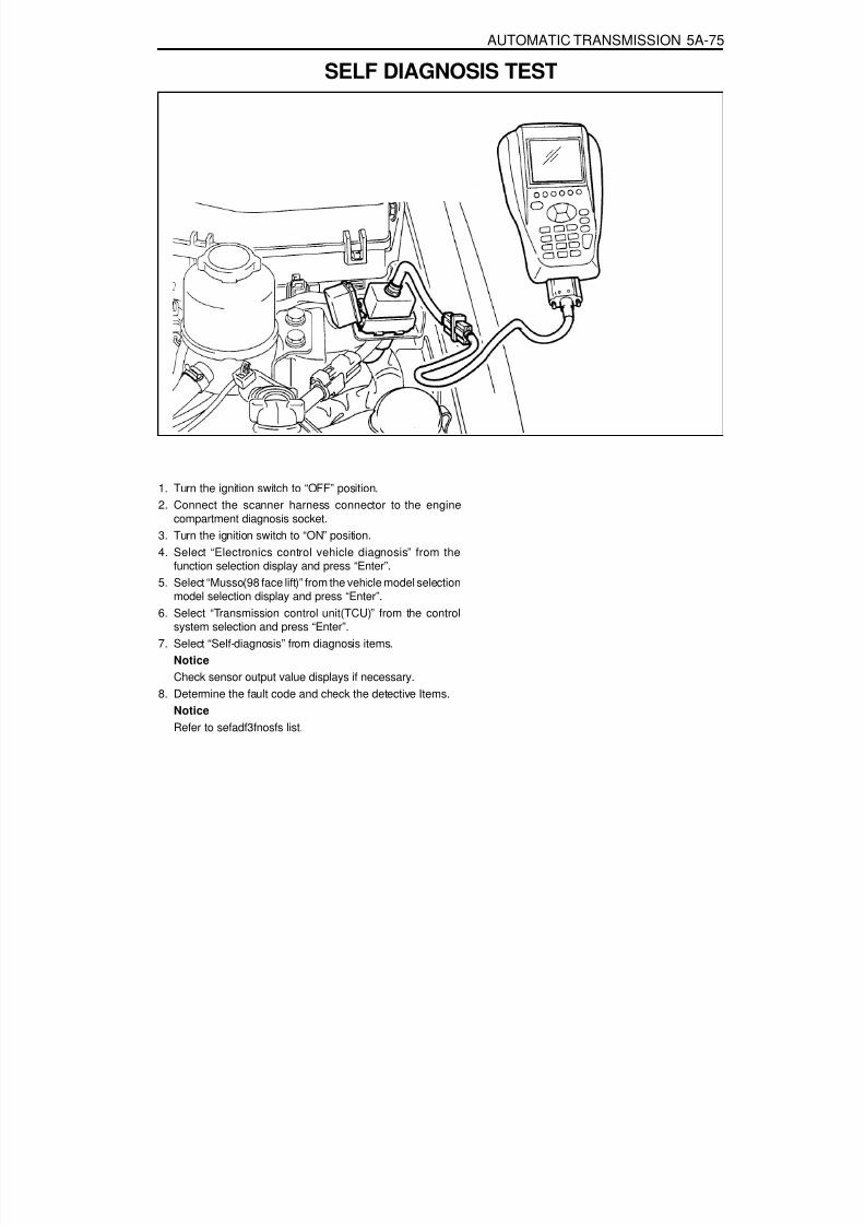
8/18/2019 SsangYong Musso Service Manual 1998.pdf
http://slidepdf.com/reader/full/ssangyong-musso-service-manual-1998pdf 1052/1459
AUTOMATIC TRANSMISSION 5A-75
SELF DIAGNOSIS TEST
1. Turn the ignition switch to “OFF” position.2. Connect the scanner harness connector to the engine
compartment diagnosis socket.3. Turn the ignition switch to “ON” position.4. Select “Electronics control vehicle diagnosis” from the
function selection display and press “Enter”.5. Select “Musso(98 face lift)” from the vehicle model selection
model selection display and press “Enter”.6. Select “Transmission control unit(TCU)” from the control
system selection and press “Enter”.7. Select “Self-diagnosis” from diagnosis items.
NoticeCheck sensor output value displays if necessary.
8. Determine the fault code and check the detective Items.NoticeRefer to sefadf3fnosfs list.

8/18/2019 SsangYong Musso Service Manual 1998.pdf
http://slidepdf.com/reader/full/ssangyong-musso-service-manual-1998pdf 1053/1459
5A-76 AUTOMATIC TRANSMISSION
Action
Check cable for open / short.Check connection of other connectors.Check voltage between terminal 27 and 29 of TCU,- Standard value : 0.2 - 4.7VCheck TPS.Check cable for open / short.Check connection of other connectors.Check engine speed sensor.Check resistance between terminal 8 and 24 of TCU (when theconnector is disconnected).- Standard value : 1 .9 - 0.2 k W
Check cable for open / short.Check connection of other connectors.Check vehicle speed sensor.Check cable for open / short.Check connection of other connectors.Check engine speed sensor.Check inhibitor switch resistance between terminal 34 and 37 ofTCU(when the connector is disconnected).- Standard value : 1st gear - 4 - 4.4 k W
2nd gear - 4,8 - 2.2 k W
3rd gear - 3 - 3.4 k W
D gear - 4.5 - 4.g k WN gear - 6.8 - 7.2 k W
R gear - 10.8 -11.2 k W
P gear - 18.6 - 19 k W
Check voltage between terminal 31 and 37 of TCU.- Standard value : 0-5V(P,R,N,D,L)Check cable for open / short.Check connection of other connectors.Check mode switch.Check condition between terminal 1 and 13 of TCU.
Winter mode :12V, Normal mode : Open status, Power mode : 0VCheck cable for open / short.Check connection of other connectors.Check voltage between terminal 32 and 38 of TCU.- Standard value : 0-5VCheck oil temperature sensor.Check cable for open / short.Check connection of other connectors.Check battery condition.Check alternator.
Possible CauseThrottle position sensor
Engine RPM
Vehicle speed
Shift lever
W, E, P mode switch
T/M oil temperature
Battery voltage
Symptom
P1702
P1703
P1704
P4705
P1706
P1707
P1708
Self-diagnosis List

8/18/2019 SsangYong Musso Service Manual 1998.pdf
http://slidepdf.com/reader/full/ssangyong-musso-service-manual-1998pdf 1054/1459
AUTOMATIC TRANSMISSION 5A-77
Action
Check cable for open / short.Check connection of other connectors.Check voltage between terminal 4 and 11 of TCU.- Standard value : when the A/C compressor is ON : 12V
when the A/C compressor is OFF : 0VCheck cable for open / short,Check connection of other connectors.Check voltage between terminal 1 and 12 of TCU.- Standard value : when the kick down switch is ON : 12V
when the kick down switch is OFF : 0V
Fully depress accelerator pedal for 5 seconds(ignition key is ON).
Release accelerator pedal.Depress brake pedal and start the engine in ‘P’ position.Depress brake pedal and idle the engine for 5 seconds in ‘D’position.Shift into ‘D’ position and determine fault code for throttle initial-ization.Complete the initialization.Check cable for open / short.Check connection of other connectors.Check resistance between terminal 1 and 34 of TCU(when the
connector is disconnected).- Standard value : 26 - 30 W
Check solenoid.Check cable for open / short.Check connection of other connectors,Check resistance between terminal 1 and 40 of TCU (when theconnector is disconnected).- Standard value : 26 - 30 W
Check solenoid.Check cable for open / short.
Check connection of other connectors.Check resistance between terminal 1 and 41 of TCU (when theconnector is disconnected).- Standard value : 26 - 30 W
Check solenoid.Check cable for open / short.Check connection of other connectors.Check resistance between terminal 1 and 33 of TCU (when theconnector is disconnected),- Standard value : 26 - 30 W
Possible Cause
Air conditioner switch
Kick down switch
PedalVehicle IDVPS offset
Throttle position sensor
initialization
Solenoid 1
Solenoid 2
Solenoid 3
Solenoid 4
Symptom
P1710
P1712
P1713P1714P1715P1716
P1733
P1734
P1735
P1736

8/18/2019 SsangYong Musso Service Manual 1998.pdf
http://slidepdf.com/reader/full/ssangyong-musso-service-manual-1998pdf 1055/1459
5A-78 AUTOMATIC TRANSMISSION
Action
Check solenoid.Check cable for open / short.Check connection of other connectors.Check resistance between terminal 36 and 44 of TCU (when theconnector is disconnected).- Standard value : 3.6 - 4.2 W
Check solenoid.Check cable for open / short.Check connection of other connectors.Check resistance between terminal 1 and 39 of TCU (when theconnector is disconnected).- Standard value : 26 - 30 W
Check solenoid.Check cable for open / short.
Check connection of other connectors.Check resistance between terminal 1 and 42 of TCU (when theconnector is disconnected).- Standard value : 26 - 30 W
Check solenoid.Check cable for short.Check connection of other connectors,Check solenoid.Check cable for short.Check connection of other connectors.
Check solenoid.Check cable for short.Check connection of other connectors.Check solenoid.Check cable for short.Check connection of other connectors.Check solenoid.Check cable for short.Check connection of other connectors.Check solenoid.
Check cable for short.Check connection of other connectors,Check solenoid.Check cable for short.Check connection of other connectors.Check solenoid.
Possible Cause
Solenoid 5
Solenoid 6
Solenoid 7
Short of solenoid 1
Short of solenoid 2
Short of solenoid 3
Short of solenoid 4
Short of solenoid 5
Short of solenoid 6
Short of solenoid 7
Symptom
P1737
P1738
P1739
P1741
P1742
P1743
P1744
P1745
P1746
P1747

8/18/2019 SsangYong Musso Service Manual 1998.pdf
http://slidepdf.com/reader/full/ssangyong-musso-service-manual-1998pdf 1056/1459
AUTOMATIC TRANSMISSION 5A-79
ADJUSTMENTSHYDRAULIC SYSTEMThe procedures detailed below should be followed in the event that the self test procedure detailed in section 6, or adefect symptom, indicates that there is a fault in the hydraulic system.When making adjustments to the transmission, select the appropriate procedures from the following preliminarychecks.
Conduct a transmission fluid test procedure, refer to section 7.2.Check the manual linkage adjustment (refer to the vehicle workshop manual).Check engine idle speed (refer to Section 7.3).Conduct a stall test (it is outside the scope of this publication to detail this procedure)conduct a road test (it is outside the scope of this publication to detail this procedure).
TRANSMISSION FLUID TEST PROCEDUREChecking Transmission Fluid LevelThis procedure is to be used when checking a concern with the fluid level in a vehicle. A low fluid level will result ingearshift loss or delay if driven when the vehicle is cold.The vehicle is first checked for transmission diagnostic messages (refer to section 6). If the vehicle has a speedo faultit is possible for the oil level to be low.The vehicle is to be test driven to determine if there is an abnormal delay when selecting drive or reverse, or loss ofdrive. One symptom of low oil level is a momentary loss of drive when driving the vehicle around a comer. Also whenthe transmission fluid level is low, a loss of drive may occur when the transmission oil temperature is low.If there is no loss of drive when the vehicle is driven warm and a speedo fault is registered, then fluid should be addedto the transmission.
Checking, Adding Fluid and FillingWhen adding or changing transmission oil use only Castrol TQ 95 automatic transmission fluid (ATF) or other approvedfluids. The use of incorrect oil will cause the performance and durability of the transmission to be severely degraded.Do not underfill the transmission. Incorrect tilling may cause damage to the transmission. The fluid level settingprocedure is detailed below.NoticeWhen a transmission is at operating temperature hot transmission fluid may come out of the case if the fill plug isremoved. 9 the transmission is at operating temperature allow two hours for cooling prior to removing the plug.
1. If the vehicle is at operating temperature allow the vehicle to cool down for two, but no greater than four hoursbefore adding transmission fluid (this will allow the transmission to be within the correct temperaturerange).While hot the ATF level is higher and removing the plug may result in oil being expelled from the filler hole. Thiswill result in the level being low.
2. The transmission selector is to be in Park.Switch the engine off.
3. Raise the vehicle on a hoist (or leave over a service pit).4. Clean all dirt from around the service fill plug prior to removing the plug. Remove the oil service fill plug.
Clean the fill plug and check that there is no damage to the ‘O’ ring.Install the filler pump into the filler hole.
5. Lower the vehicle with the filler pump still connected and partially fill the transmission.Start the vehicle in Park with the Parking brake and foot brake applied with the engine idling, cycle the transmissiongear selector through all positions, adding ATF until gear application is felt.
8/18/2019 SsangYong Musso Service Manual 1998.pdf
http://slidepdf.com/reader/full/ssangyong-musso-service-manual-1998pdf 1057/1459
5A-80 AUTOMATIC TRANSMISSION
6. Switch off the engine and raise the vehicle on the hoist, if applicable, ensuring that the vehicle is level.7. Three minutes after the engine has stopped, but no longer than one hour, remove the filler pump, The correct
level is reached when ATF is aligned with the bottom of the filler hole. If the correct level is not reached, then adda small quantity of ATF to the correct level.
8. Replace the transmission filler plug and clean all remnants of ATF on the transmission and vehicle.9. Tighten the transmission filler plug to specification.
Checking, Adding Fluid and Filling - Drained or Dry TransmissionTo set the correct fluid level proceed as follows.
1. Set the transmission selector to Park and switch the engine off.2. Raise the vehicle on a hoist (or leave over a service pit).3. Clean all dirt from around the service fill plug prior to removing the plug, Remove the oil service fill plug. Clean the
fill plug and check that there is no damage to the ‘O’ ring. Install the filler pump into the filler hole.4. Lower the vehicle with the filler pump still connected and partially fill the transmission. This typically requires
approximately :a. If the transmission torque converter is empty:
9.0 litres - 4WD
9.0 litres - RWDb. If the transmission torque converter is full:
4.5 litres - 4WD4.5 litres - RWD
5. Start the vehicle in Park with the Parking brake and foot brake applied with the engine idling, cycle the transmissiongear selector through all positions, adding ATF until gear application is felt.
6. Then add an additional 0.5 litres of ATF.7. Switch off the engine and raise the vehicle on the hoist. Remove the filler pump and replace the filler plug. The
plug shall be tightened to specification.8. The vehicle is then to be driven between 3.5 and 4.5 kilometers at light throttle so that the engine does not
exceed 2500 rpm. This should result in the transmission temperature being in the range 50 to 60°C.9. With the engine idling, cycle the transmission selector through all gear positions with the brake applied.10. Stop the engine. Raise the vehicle on the hoist, if applicable ensuring the vehicle is level.11. Three minutes after the engine has stopped, but no longer than one hour, remove the filler plug. The correct
level is reached when ATF is aligned with the bottom of the filler hole. If the correct level is not reached, then adda small quantity of ATP to the correct level.
12. Replace the transmission filler plug and clean all remnants of ATF on the transmission and vehicle. Tighten thetransmission Filler plug to specification.
ELECTRONIC ADJUSTMENTS
Idle Speed AdjustmentCarry out the adjustments to the idle speed as detailed in the workshop manual.
Throttle Position CalibrationShould the throttle position data stored in the TCU be lost or be out of specification, as indicated by a diagnostictrouble message, it may be re-established by the following procedure.
Check that the hot engine idle speed is within specification.Allow the engine to idle in ‘Drive’ for 60 seconds with the air conditioner (if fitted) turned off. The closed throttlereference point in the TCU has now been set.
Switch the engine off but leave the ignition on. Hold the accelerator pedal on the floor for 60 seconds. The wide openthrottle reference point in the TCU has now been set.

8/18/2019 SsangYong Musso Service Manual 1998.pdf
http://slidepdf.com/reader/full/ssangyong-musso-service-manual-1998pdf 1058/1459
AUTOMATIC TRANSMISSION 5A-81
Throttle ClearingThe leant throttle clearing routine uses the mode switch and gear lever. Carry out the following steps to complete theautomated throttle clearing procedure:1. Switch ignition ‘ON’ with handbrake applied and engine ‘OFF’.2. Select ‘M1’ and ‘WINTER’ mode.3. Move the T-bar to ‘M2’ and then select ‘NORMAL’ or ‘POWER’ mode.
4. Move the T-bar to ‘M3’ and then select ‘WINTER’ mode.
Vehicle CodingThe vehicle coding is integrated as part of the diagnostic software. The coding applies to the following vehiclemodels:
1. 4WD Gasoline E32.2. 4WD Gasoline 5233. 4WD Gasoline 520.4. 4WD Diesel D29NA.5. 4WD Diesel D29LA.
6. 4WD Diesel D23LA.7. RWD E20.8. RWD E23.

8/18/2019 SsangYong Musso Service Manual 1998.pdf
http://slidepdf.com/reader/full/ssangyong-musso-service-manual-1998pdf 1059/1459
5A-82 AUTOMATIC TRANSMISSION
MAINTENANCE AND REPAIR
ON-VEHICLE SERVICE
Tightening Torque 70 - 80 Nm
5. Remove the rear propeller shaft .Installation Notice
REMOVAL & INSTALLATION OF
TRANSMISSION1. Disconnect the negative battery cable.2. Disconnect the connectors from transfer case.3. Disconnect the speedometer connector from transfer
case.4. Disconnect the inhibitor and Sear position sensor
connector.
6. Unscrew the eight bolts and two nuts, and remove thecross member.

8/18/2019 SsangYong Musso Service Manual 1998.pdf
http://slidepdf.com/reader/full/ssangyong-musso-service-manual-1998pdf 1060/1459
AUTOMATIC TRANSMISSION 5A-83
Tightening Torque 70 - 80 Nm
11. Remove the two pipes for oil cooler.Installation Notice
Tightening Torque 24.5 - 34.3 Nm
12. Remove the service hall cover on torque converter.13. Put the alignment mark for installation, and unscrew the
six mounting bolts for torque converter from drive platethrough the service hole (arrow) by rotating the engineand remove the torque converter.Installation Notice
Tightening Torque 42 Nm
7. Remove the rear propeller shaft.Installation Notice
8. Unscrew the five bolts and remove the transfer case.9. Disconnect the 10-Pins Plug connector from transmission.
10. Separate the locking clip on shift lever and remove theshift rod.NoticeRemoval and installation performed when the shiftprocedure should be lever is in “D” range.
Screw the six bolts mounting the torque converter throughthe service hole by using a mirror and rotating the engine.
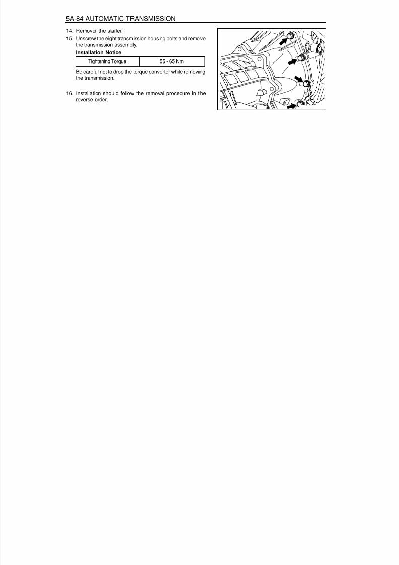
8/18/2019 SsangYong Musso Service Manual 1998.pdf
http://slidepdf.com/reader/full/ssangyong-musso-service-manual-1998pdf 1061/1459
5A-84 AUTOMATIC TRANSMISSION
Tightening Torque 55 - 65 Nm
14. Remover the starter.15. Unscrew the eight transmission housing bolts and remove
the transmission assembly.Installation Notice
Be careful not to drop the torque converter while removingthe transmission.
16. Installation should follow the removal procedure in thereverse order.

8/18/2019 SsangYong Musso Service Manual 1998.pdf
http://slidepdf.com/reader/full/ssangyong-musso-service-manual-1998pdf 1062/1459
AUTOMATIC TRANSMISSION 5A-85
UNIT REPAIRREBUILD WARNINGSPrior to rebuilding a transmission system, the following warningsare to be noted.
Ensure that, before replacing a transmission the coolerlines are flushed out to remove any debris. This can bedone by applying compressed air to the rear cooler lineforcing oil and any contaminants out of the front coolerline.The cooler flow should be checked after the transmissionhas been fitted. With the front cooler line connectedand the rear line run into a suitable container, measurethe flow over 15 seconds with the vehicle idling in park.The flow rate should exceed 1 liter in 15 seconds.Be wary of any situation where water enters thetransmission. This may result in fluid foaming and leaking
through the breather.Ensure that both earth straps (one at the batted terminaland one on the vehicle body) are connected in thevehicle before connecting the positive side of thebattery.Follow the throttle position calibration procedure insection 7 of this manual if the powertrain control moduletransmission control unit (PCM/TCU) is swapped.
DISASSEMBLY PROCEDURETransmissionNoticeRemove the inhibitor switch before washing the transmissionin solvent or hot wash.It is assumed that the transmission fluid has been drainedwhen the transmission was removed from thevehicle and that the ‘special tools’ quoted are available.The transmission is dismantled in a modular fashion, and thedetails of disassembly for each module are given under theappropriate subject. Refer to table 9.10 in section 9.6 for details
of all special tools required when performing disassemblyprocedures.Technicians overhauling these transmissions will also requirea selection of good quality Torx bit sockets, in particularnumbers 30, 40 and 50, and an 8 mm,10 mm and 12 mmdouble hex socket.
To disassemble the transmission, proceed as follows:1. Remove the converter and the converter housing.2. Mount the transmission on the bench cradle
No.0555-331895.3. Remove the sump and the sump seal.

8/18/2019 SsangYong Musso Service Manual 1998.pdf
http://slidepdf.com/reader/full/ssangyong-musso-service-manual-1998pdf 1063/1459
5A-86 AUTOMATIC TRANSMISSION
9. Remove the pump to case bolts using a multi-hex 8 mmspanner.
10. Using the pump puller No. 0555-332941, remove the pump.
11. Remove the input shaft, forward clutch cylinder, and theoverdrive shaft as an assembly, withdrawing them throughthe front of the case.
12. Remove the C3 clutch cylinder and sun gears.13. Remove the fronts band struts. Remove the front band.14. Remove the two centre support retaining bolts using a
T50 Torx bit.
15. Remove the centre support retaining circlip.NoticeDo not hammer the output shaft to remove the centresupport as this will cause permanent damage to the thrustbearing surfaces.
16. Remove the centre support, 1-2 one way clutch, planetarygear set and output shaft as an assembly.
17. Remove the parking rod cam plate. (T40 Torx bit).18. Remove the rear band struts and remove the band.
4. Detach each end of the filter retaining clip from the valvebody and remove the filter.
5. Detach the wires from each solenoid and lay the wiring toone side.
6. Remove the valve body securing screws and remove thevalve body from the case.
7. Remove the front servo cover circlip.Remove the cover and piston.NoticeThe plastic servo block is retained by the piston returnspring only.
8. Where fitted, remove the flange yoke, and then removethe extension housing (RWD model).Remove the adaptor housing (4WD model).

8/18/2019 SsangYong Musso Service Manual 1998.pdf
http://slidepdf.com/reader/full/ssangyong-musso-service-manual-1998pdf 1064/1459
AUTOMATIC TRANSMISSION 5A-87
Transmission CaseTo teardown the transmission case, proceed as follows:1. Remove the pin from the cross shaft inhibitor switch side
(4WD models) using tool No.0555-332942.
2. Remove the inhibitor switch from the case.Remove the cross shaft seals with special tool No.0555-331893.
3. Remove the circlip from the cross-shaft. Pull the shaft torelease the drive pin from the selector quadrant.
4. Using tool No. 0555-331897, press the pin from the cross-shaft and withdraw the shaft from the case. Retrieve thespring and pin
5. Remove the manual valve lever and the park rod.6. Remove the 10 pin plug from the wiring loom bracket
adjacent to the inhibitor switch(RWD models),7. Depress the tangs and withdraw the 10 pin connector from
the case. Remove the loom assembly.

8/18/2019 SsangYong Musso Service Manual 1998.pdf
http://slidepdf.com/reader/full/ssangyong-musso-service-manual-1998pdf 1065/1459
5A-88 AUTOMATIC TRANSMISSION
8. Detach the No.7 solenoid wire from the front of the case.
9. Remove the parking pawl pivot pin and the pawl and springfrom the case.
10. Remove the shaft and the rear servo lever.11. Remove the rear servo cover and piston assembly.
12. Remove the B1R circlip, valve and spring.13. Remove both band adjustment shims.14. Inspect the output shaft bushing in the case and replace if
necessary.15. Inspect cooler line fittings and replace as necessary.16. Inspect the case for damage.
17. To remove the park rod lever: Remove the circlip from theinner end of the pivot shaft and tap the outer end of theshaft until it moves free from the case, then using a wide
shallow tapered drift as a wedge, drive the pin out fromthe inside of the case and remove the lever and spring.NoticeDo not remove the park rod lever unless absolutelynecessary.

8/18/2019 SsangYong Musso Service Manual 1998.pdf
http://slidepdf.com/reader/full/ssangyong-musso-service-manual-1998pdf 1066/1459
AUTOMATIC TRANSMISSION 5A-89
Forward Clutch CylinderTo remove the forward clutch cylinder, refer to figure 8.4,
proceed as follows.1. Place the assembly in a horizontal position.2. Remove the thrust bearing and adjustment shims from the
input shaft.3. Remove the circlip from the front of the clutch cylinder and
remove the input shaft.4. Remove the overdrive shaft and the C1 clutch hub assembly
from the clutch cylinder.5. Remove the C1 clutch plates from the cylinder.6. Remove the circlip retaining the C3 clutch hub in the rear of
the clutch cylinder and remove the hub.7. Remove the C2/C4 clutch hub assembly and remove the
thrust bearing from the C4 hub.8. Remove the C2 clutch plates.9. Invert the clutch cylinder and remove the C4 clutch sleeve,
clutch plates and the two wave washers. The 3-4 one wayclutch is located between the C2 and C4 clutch hubs, andthe hubs may be separated by rotating one hub clockwiseand withdrawing it from the other.
Figure 8.4 - Forward Clutch Cylinder Assembly

8/18/2019 SsangYong Musso Service Manual 1998.pdf
http://slidepdf.com/reader/full/ssangyong-musso-service-manual-1998pdf 1067/1459
5A-90 AUTOMATIC TRANSMISSION
10. Remove the thrust block from the C4 clutch cylinder hub.NoticeMake sure that the spring keeper is not caught in the circlipgroove, and that all the spring pressure is released, beforeremoving the tool.
11. Mount the clutch cylinder on tool No.0555-331899 withthe C2/C4 end uppermost and compress the piston returnspring. Remove the spring retaining circlip. Release thetool and remove the circlip, keeper and spring.
12. Invert the clutch cylinder on the compressor tool andremove the C1 clutch piston return spring in a similarmanner.
13. To remove the clutch pistons from the clutch cylinder, applyair pressure to the apply ports in the bore of the cylinder.
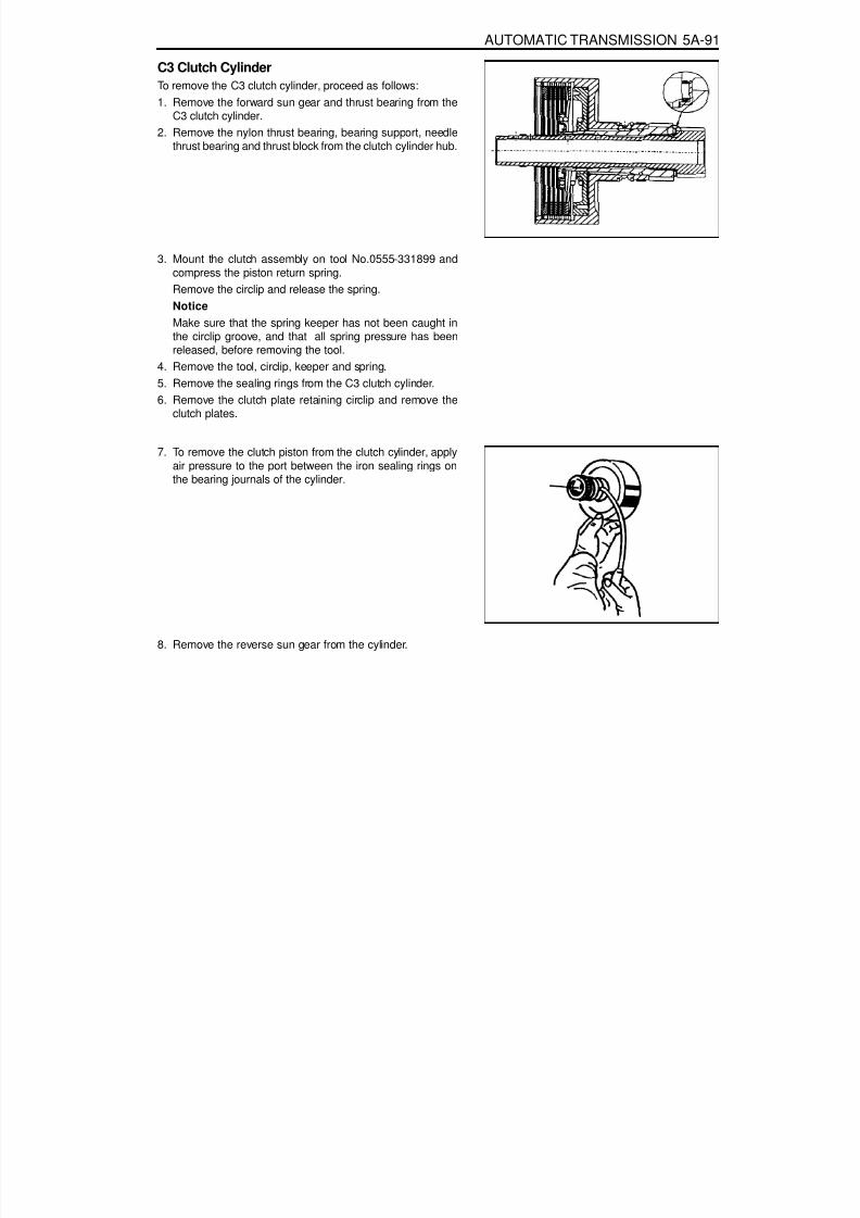
8/18/2019 SsangYong Musso Service Manual 1998.pdf
http://slidepdf.com/reader/full/ssangyong-musso-service-manual-1998pdf 1068/1459
AUTOMATIC TRANSMISSION 5A-91
C3 Clutch CylinderTo remove the C3 clutch cylinder, proceed as follows:1. Remove the forward sun gear and thrust bearing from the
C3 clutch cylinder.2. Remove the nylon thrust bearing, bearing support, needle
thrust bearing and thrust block from the clutch cylinder hub.
3. Mount the clutch assembly on tool No.0555-331899 andcompress the piston return spring.Remove the circlip and release the spring.Notice
Make sure that the spring keeper has not been caught inthe circlip groove, and that all spring pressure has beenreleased, before removing the tool.
4. Remove the tool, circlip, keeper and spring.5. Remove the sealing rings from the C3 clutch cylinder.6. Remove the clutch plate retaining circlip and remove the
clutch plates.
7. To remove the clutch piston from the clutch cylinder, applyair pressure to the port between the iron sealing rings onthe bearing journals of the cylinder.
8. Remove the reverse sun gear from the cylinder.

8/18/2019 SsangYong Musso Service Manual 1998.pdf
http://slidepdf.com/reader/full/ssangyong-musso-service-manual-1998pdf 1069/1459
5A-92 AUTOMATIC TRANSMISSION
Planet Carrier and Centre SupportTo remove the planet carrier and centre support, proceed asfollows.
1. Separate the planet carrier and centre support from theoutput shaft. Remove the thrust bearings from the outputshaft and the planet carrier.
2. Separate the centre support from the planet carrier byrotating it anti-clockwise.3. Lift the one way clutch from the planet carrier.4. Remove the circlip retaining the one way clutch outer race
in the planet carrier and remove the race.5. Remove the one way clutch retainer from the planet carrier.
Pump
Note that the following valves are housed in the pump cover:Solenoid 7C1 bias valveConverter clutch control valveConverter clutch regulator valvePrimary regulator valve
To remove the pump, proceed as follows.1. Remove the wiring loom retainer plate and remove
solenoid 7 with a T30 Torx bit.2. Remove the five washer head bolts from the cover plate
using a multi-point 8 mm socket.3. Remove the five Torx head screws from the cover plate
(Torx bit No. 30). Note that the odd screw holds the pumpbody to the pump body cover.NoticeDo not strike the converter support tube to loosen thepump body.
4. Separate the pump body from the pump cover.5. Lift the cover plate from the cover.6. Remove the two ball check valves and one spring from
the pump cover.
NoticeSome of the valves and plugs are preloaded by springsand may unexpectedly fall out of the cover when the pinsare removed.
7. Depress the plug inward and remove the retaining pin foreach of the four valves.
8. Remove the four valves, plugs and springs.9. Remove the pump gears from the pump body.
10. Remove the lip seal from the front of the pump body.

8/18/2019 SsangYong Musso Service Manual 1998.pdf
http://slidepdf.com/reader/full/ssangyong-musso-service-manual-1998pdf 1070/1459
AUTOMATIC TRANSMISSION 5A-93
Valve BodyTo disassemble the valve body, proceed as follows.
1. Remove the detent spring and retainer plate using a T40 Torx bit.NoticeBe aware that the manual valve will fall out of the valve body.
2. Take note of the angular relationship of the solenoid terminalsto the valve body, then slide the manual valve out of the lowervalve body.
3. Remove the solenoid and valve assembly as follows:solenoid 1solenoid 2solenoid 3solenoid 4solenoid 5solenoid 6
4. Place the valve body assembly on the bench with the upper
body uppermost.5. Remove the 24 clamping screws with a No. 30 Ton bit. Separatethe upper and lower valve bodies by lifting the upper body andthe separator plate together.
6. Upper body over and place it on the bench with the separatorplate uppermost.
7. Lift the separator plate and gaskets from the upper valve body.8. Remove the five nylon check balls exposed in the valve body.9. Remove the retainer plate, plug, spring and reverse lockout
valve.10. Remove the two filters (and the large nylon check ball) from the
lower valve body.NoticeOnce the pins are removed, the plates are loose in the valvebody and will drop out when the valve body is turned over.
11. Remove the keeper plates and pins from the 1-2,2-3,3-4, BARand CAR valves. The pins can be removed with a magnet.
12. Remove the 1-2,2-3 and 3-4 shift valves.NoticeThe plug is preloaded by the spring and may unexpectedly fallout of the valve body.
13. Depress the 4-3 sequence valve plug and remove the keeperplate.
14. Remove the plug, valve and spring.15. Depress the solenoid 5 valve. Remove the keeper pin and
remove the valve and spring.NoticeThe valve is preloaded by the spring and may unexpectedly fallout of the valve body.
16. Depress the line pressure release valve, remove the keeperpin, disc (if fitted), spring and valve.
17. Drive out the roll pin and remove the spring and ball check valveadjacent to the BAR valve.

8/18/2019 SsangYong Musso Service Manual 1998.pdf
http://slidepdf.com/reader/full/ssangyong-musso-service-manual-1998pdf 1071/1459
5A-94 AUTOMATIC TRANSMISSION
ASSEMBLY PROCEDUREThe transmission is assembled in modular fashion and detailsof assembly for each module are given under the appropriatesubject. Refer to table 8.1 (at the end of Section 8.3) for thetorque specifications to be applied, and to table 9.10 in section9.6 for details of all special tools required, when performingassembly procedures. Technicians overhauling thesetransmissions will also require a selection of good quality Torxbit sockets, in particular numbers 30,40 and 50, and an 8 mm,10mm and 12 mm double hex socket.
TransmissionNotice1. Ensure that the B1R circlip is fitted to the case. (If this is not
fitted, the valve will peen its way into and through theseparator plate.)
2. Ensure that the ‘E’ clip is fitted to the cross shaft.3. Ensure that all aspects of the parking mechanism are
working.To assemble the transmission, proceed as follows:1. Turn the transmission case upside down on the bench and
mount it to the transmission cradle No.0555-331895.2. Install all fittings, plugs and the breather, applying a sealant
where applicable, Tighten the fittings to specifications.Ensure that the breather is clear, and check that the lubefitting in the rear of the case is fitted and clear of obstruction.
3. Assemble the B1R valve and spring, and secure with theirclip. Refer to Ensure that the circlip is completely seatedin its groove.
4. Install the rear servo lever and pivot pin.Notice
The lever must pivot freely on its pin.

8/18/2019 SsangYong Musso Service Manual 1998.pdf
http://slidepdf.com/reader/full/ssangyong-musso-service-manual-1998pdf 1072/1459
AUTOMATIC TRANSMISSION 5A-95
NoticeCare must be taken when applying sealant to ensure that it isnot applied between the pin and the lever.5. Assemble the park rod lever, complete with the return spring
and pivot pin, applying a small amount of sealant to theouter end of the pivot pin.NoticeThat the lever must pivot freely on its pin and the springmust return the park rod lever to its correct location.
6. Secure the pivot pin with the circlip.NoticeThe pawl must pivot freely on its pin.
7. Install the parking pawl pivot pin and spring.
8. Connect the park rod to the manual valve detent lever.Ensure the spring and cam collar is firmly installed on therod.

8/18/2019 SsangYong Musso Service Manual 1998.pdf
http://slidepdf.com/reader/full/ssangyong-musso-service-manual-1998pdf 1073/1459
5A-96 AUTOMATIC TRANSMISSION
9. Check that the cam collar slides freely on the rod.10. Insert the cross shaft into the case, from the side opposite
to the inhibitor switch, then install the anti-rattle spring onthe shaft.
11. Position the manual valve detent lever, aligning it with thecross-shaft bore in the case.
12. Push the shaft through the detent lever until it starts in thedetent lever side of the case.
13. Install the detent lever drive pin in the shaft using tool No.0555-331897 with the adaptor over the pin.
14. Press the pin into the shaft until the tool bottoms.15. Remove the tool and fit the spring retaining circlip to the
shaft.
16. Install the new cross shaft seals using tool No. 0555-331894.
17. Install the inhibitor switch on the case. Torque the screwsas per specifications. Press the pin into the shaft until thetool bottoms (4WD models) using tool No.0555-332942.
18. Thoroughly check the terminal wiring loom for conditionand continuity.
19. Position the loom and locate the solenoid 7 contact andterminal in the pump mounting flange at the front of thecase. The solenoid 7 wire is routed under the park rod
and cross shaft in the case.
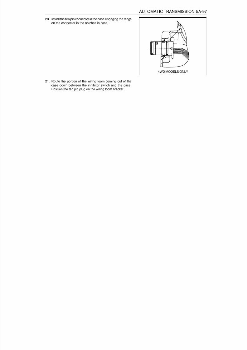
8/18/2019 SsangYong Musso Service Manual 1998.pdf
http://slidepdf.com/reader/full/ssangyong-musso-service-manual-1998pdf 1074/1459
AUTOMATIC TRANSMISSION 5A-97
20. Install the ten pin connector in the case engaging the tangson the connector in the notches in case.
4WD MODELS ONLY
21. Route the portion of the wiring loom coming out of thecase down between the inhibitor switch and the case.Position the ten pin plug on the wiring loom bracket .
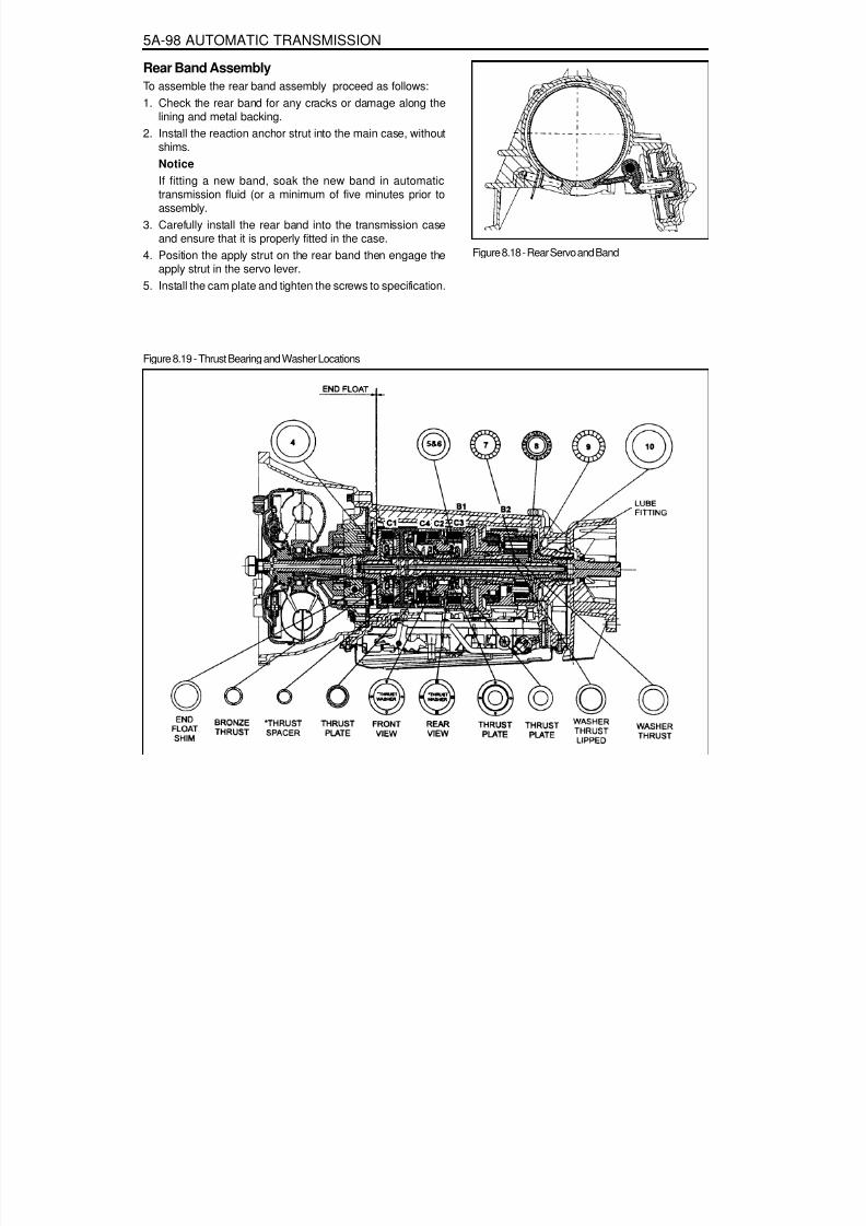
8/18/2019 SsangYong Musso Service Manual 1998.pdf
http://slidepdf.com/reader/full/ssangyong-musso-service-manual-1998pdf 1075/1459
5A-98 AUTOMATIC TRANSMISSION
Rear Band AssemblyTo assemble the rear band assembly proceed as follows:1. Check the rear band for any cracks or damage along the
lining and metal backing.2. Install the reaction anchor strut into the main case, without
shims.
NoticeIf fitting a new band, soak the new band in automatictransmission fluid (or a minimum of five minutes prior toassembly.
3. Carefully install the rear band into the transmission caseand ensure that it is properly fitted in the case.
4. Position the apply strut on the rear band then engage theapply strut in the servo lever.
5. Install the cam plate and tighten the screws to specification.
Figure 8.19 - Thrust Bearing and Washer Locations
Figure 8.18 - Rear Servo and Band
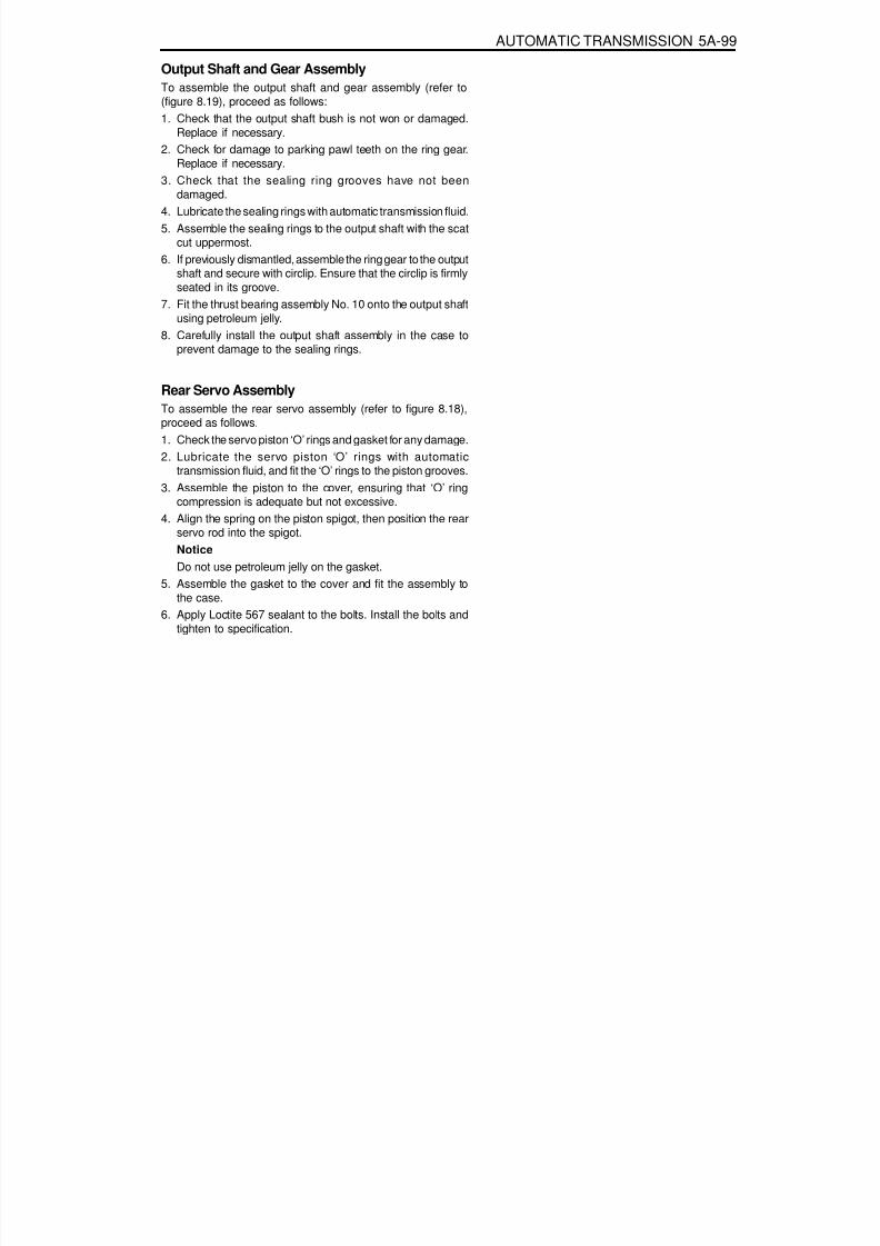
8/18/2019 SsangYong Musso Service Manual 1998.pdf
http://slidepdf.com/reader/full/ssangyong-musso-service-manual-1998pdf 1076/1459
AUTOMATIC TRANSMISSION 5A-99
Output Shaft and Gear AssemblyTo assemble the output shaft and gear assembly (refer to(figure 8.19), proceed as follows:1. Check that the output shaft bush is not won or damaged.
Replace if necessary.2. Check for damage to parking pawl teeth on the ring gear.
Replace if necessary.3. Check that the sealing ring grooves have not been
damaged.4. Lubricate the sealing rings with automatic transmission fluid.5. Assemble the sealing rings to the output shaft with the scat
cut uppermost.6. If previously dismantled, assemble the ring gear to the output
shaft and secure with circlip. Ensure that the circlip is firmlyseated in its groove.
7. Fit the thrust bearing assembly No. 10 onto the output shaftusing petroleum jelly.
8. Carefully install the output shaft assembly in the case toprevent damage to the sealing rings.
Rear Servo AssemblyTo assemble the rear servo assembly (refer to figure 8.18),proceed as follows.1. Check the servo piston ‘O’ rings and gasket for any damage.2. Lubricate the servo piston ‘O’ rings with automatic
transmission fluid, and fit the ‘O’ rings to the piston grooves.3. Assemble the piston to the cover, ensuring that ‘O’ ring
compression is adequate but not excessive.4. Align the spring on the piston spigot, then position the rear
servo rod into the spigot.NoticeDo not use petroleum jelly on the gasket.
5. Assemble the gasket to the cover and fit the assembly tothe case.
6. Apply Loctite 567 sealant to the bolts. Install the bolts andtighten to specification.
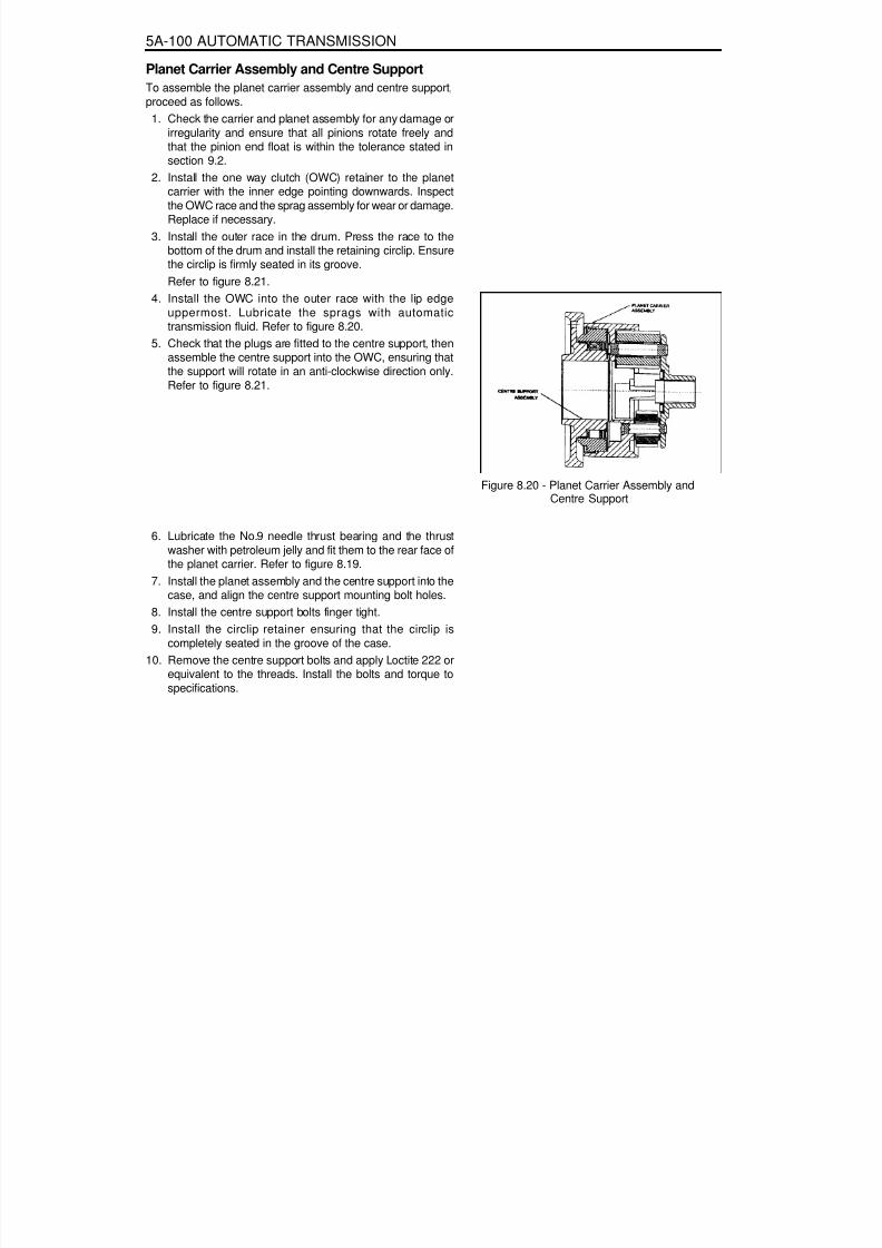
8/18/2019 SsangYong Musso Service Manual 1998.pdf
http://slidepdf.com/reader/full/ssangyong-musso-service-manual-1998pdf 1077/1459
5A-100 AUTOMATIC TRANSMISSION
Planet Carrier Assembly and Centre SupportTo assemble the planet carrier assembly and centre support,proceed as follows.
1. Check the carrier and planet assembly for any damage orirregularity and ensure that all pinions rotate freely andthat the pinion end float is within the tolerance stated insection 9.2.
2. Install the one way clutch (OWC) retainer to the planetcarrier with the inner edge pointing downwards. Inspectthe OWC race and the sprag assembly for wear or damage.Replace if necessary.
3. Install the outer race in the drum. Press the race to thebottom of the drum and install the retaining circlip. Ensurethe circlip is firmly seated in its groove.Refer to figure 8.21.
4. Install the OWC into the outer race with the lip edgeuppermost. Lubricate the sprags with automatictransmission fluid. Refer to figure 8.20.
5. Check that the plugs are fitted to the centre support, thenassemble the centre support into the OWC, ensuring thatthe support will rotate in an anti-clockwise direction only.Refer to figure 8.21.
Figure 8.20 - Planet Carrier Assembly and
Centre Support
6. Lubricate the No.9 needle thrust bearing and the thrustwasher with petroleum jelly and fit them to the rear face ofthe planet carrier. Refer to figure 8.19.
7. Install the planet assembly and the centre support into thecase, and align the centre support mounting bolt holes.
8. Install the centre support bolts finger tight.9. Install the circlip retainer ensuring that the circlip is
completely seated in the groove of the case.10. Remove the centre support bolts and apply Loctite 222 or
equivalent to the threads. Install the bolts and torque tospecifications.

8/18/2019 SsangYong Musso Service Manual 1998.pdf
http://slidepdf.com/reader/full/ssangyong-musso-service-manual-1998pdf 1078/1459
AUTOMATIC TRANSMISSION 5A-101
Extension Housing AssemblyTo assemble the extension housing assembly, proceed asfollows.1. Check the condition of the extension housing roller bearing.
Replace if necessary (RWD models). Install the new bearingfrom rear of extension housing. Press on the branded faceof bearing only.
2. Install a new seal to the extension housing or adaptorhousing. Refer to figure 8.21.NoticeDo not use petroleum jelly to hold the gasket in position.
3. Position a new gasket onto the extension housing or adaptorhousing.NoticeSee section 8.3.17 for the procedure to assemble the outputflange assembly - RWD models.
4. Install the extension housing (RWD) or adaptor housing
(4WD) and torque the bolts to specification.
Front Servo AssemblyNOTICEEnsure that the front servo snap ring is installed correctly.Orient the circlip with the gap at the bottom, near the pan rail.Refer to figure 8.22.To assemble the front servo assembly (refer to figure 8.22),proceed as follows.1. Lubricate the cover ‘O’ ring with automatic transmission fluid
and fit to the cover.2. Lubricate the piston ‘O’ rings with automatic transmission
fluid and fit to the piston.3. Assemble the piston, push rod, spring, belleville washer,
seat and retaining ring.4. Fit the piston push rod assembly into the front servo cover.5. Install the front servo block and spring into the case.6. Install the front servo assembly into the case.7. Compress the servo cover and fit the servo cover retaining
circlip, aligning the gap with the pan rail, and ensuring thatit is completely seated in its groove.
Figure 8.21 - Extension Housing
Figure 8.22 - Front Servo and Band

8/18/2019 SsangYong Musso Service Manual 1998.pdf
http://slidepdf.com/reader/full/ssangyong-musso-service-manual-1998pdf 1079/1459
5A-102 AUTOMATIC TRANSMISSION
Front Band AssemblyTo assemble the front band assembly, proceed as follows.
1. Install the reaction anchor strut to the case.2. Check the band for ally cracks or damage along its lining
and metal backing.3. Position the strut retainers on the band (refer to figure
8.23).NOTICEIf fitting a new band, soak the band in automatictransmission fluid for a minimum of 5 minutes prior toassembly.
4. Install the front band into the transmission case, ensuringthat it is properly seated in place.
5. Position the reaction strut in its retaining clip and engageit with the band and anchor strut.Position the apply strut in its retaining clip and engage itwith the band and the servo piston rod.
C2/C4 Clutch AssemblyNotice
1. Check pistons for cracks.2. Do not mix the clutch piston return springs.3. Ensure that the snap rings are fitted correctly.
To assemble the C2/C4 clutch assembly (refer to figure 8.24),proceed as follows.
1. Check the feed orifices in the cylinder bore are clear ofobstructions.
2. Check the C2 piston bleed orifices are clear of obstructions.3. Lubricate the ‘O’ rings with automatic transmission fluid.
Notice‘O’ rings must not be twisted in the grooves.
4. Fit the small ‘O’ ring onto the inner groove, and the large‘O’ ring onto the outer groove of the piston.
5. Check the C4 piston bleed orifices are clear of obstructions.6. Lubricate the ‘O’ rings with automatic transmission fluid.7. Fit the small ‘O’ rings onto the inner groove and the large
‘O’ rings onto the outer groove of the piston.8. Position the clutch cylinder with the C2/C4 cavity facing
upwards.9. Fit the C4 piston into the C2 piston with the bleed orifices
in alignment.10. Install the C2/C4 piston assembly into the cylinder, with the
piston bleed orifices aligned with the holes on the outsideof the cylinder, until the outer diameter of the C2 pistonenters the inner diameter of the cylinder.
Figure 8.23 - Front Band Strut Installation
Figure 8.24 - Typical C2/C4 Clutch Assembly

8/18/2019 SsangYong Musso Service Manual 1998.pdf
http://slidepdf.com/reader/full/ssangyong-musso-service-manual-1998pdf 1080/1459
AUTOMATIC TRANSMISSION 5A-103
11. Assemble the piston return spring to the piston, and fit thespring retainer over the spring.NoticeThe wire diameter of this spring is 4.3 mm.
12. Using special tool No. 0555-331899, compress the springsufficiently to enable the installation of the retaining circlipensuring that the circlip is firmly seated in its groove, thenremove the tool.
13. Check the C1 piston check valves are not damaged andare free to move, and that the cylinder feed orifices areclear of obstructions.
14. Lubricate the’0’rings with automatic transmission fluid andfit them to their respective grooves.Notice‘O’ rings must not be twisted in the grooves.
15. Position the cylinder with the C1 cavity upwards. Install thepiston into the cylinder until the outer diameter of the piston
enters the inner diameter of the cylinder.16. Install the spring and spring retainer onto the piston.NoticeThe wire diameter of this spring is 5.26 mm.
17. Using special tool No. 0555-331899, compress the springsufficiently to enable the installation of the retaining circlipensuring that the circlip is firmly seated in its groove, thenremove the tool.
18. Install the C2 wave washer into the cylinder with the crestof one wave covering one of the bleed orifices in the C2piston.
19. Measure and record the thickness of the flange of the C2sleeve. Refer to figure 8.25.
20. Install the C4 clutch plates and wave washer into the C2actuating sleeve, with the rounded edge of the steel platesdown, in the following sequence:
Steel plate (selective)Friction discSteel plateFriction discSteel plateFriction discSteel plateWave washer

8/18/2019 SsangYong Musso Service Manual 1998.pdf
http://slidepdf.com/reader/full/ssangyong-musso-service-manual-1998pdf 1081/1459
5A-104 AUTOMATIC TRANSMISSION
Figure 8.25 - C4 Clutch Pack Clearance

8/18/2019 SsangYong Musso Service Manual 1998.pdf
http://slidepdf.com/reader/full/ssangyong-musso-service-manual-1998pdf 1082/1459
AUTOMATIC TRANSMISSION 5A-105
21. Holding the cylinder horizontal, install the sleeve and clutchplate assembly into the cylinder, with the crest of one waveof the washer In line with one of the holes in the outside ofthe cylinder, until the sleeve contacts the C2 wave washer.
22. Check the C4 clutch pack clearance using special tool No.0555-331900. Refer to figure 8.25.NoticeWith the C2 wave spring compressed, and the clutch Packsupporting a 2 k9 weight, the dimension from the undersideof the C2 pressure plate to the selective steel is to bebetween 1.4- 1.8 mm. If the clutch is to be gauged fromthe top of the pressure plate, then the dimension is to bethe actual thickness of the pressure plate plus 1.4-1.8 mm.
23. Use selective plates to achieve the correct specification. Ifnew friction plates are being fitted, remove the clutch packand soak the friction plates in ATF for a minimum of 5minutes prior to reassembly.Notice
The clutch pack clearance must be taken before theelements are soaked in Automatic Transmission Fluid(ATF).
24. Reassemble the sleeve and clutch pack into the cylinder.Observe the alignment of the wave washer to the hole inthe cylinder.
25. Install the C2 clutch plates in the cylinder in the followingsequence:
Friction discSteel plateFriction discSteel plateSteel plate - 0574-000001, 0574-000003,0574-000004, 0574-000005, 0574-000020,0574-000021, or friction disc -0574-000002Steel plate (selective)Friction discSteel plate (selective)Friction disc

8/18/2019 SsangYong Musso Service Manual 1998.pdf
http://slidepdf.com/reader/full/ssangyong-musso-service-manual-1998pdf 1083/1459
5A-106 AUTOMATIC TRANSMISSION
29. Align the tangs and fit the nylon thrust washer onto theC4 hub. Refer to figure 8.27.
30. Align and fit the C4 hub to the C2 clutch and the OWCassembly.
31. Check the rotation of the C2 hub. While holding theC4 hub, the C2 hub should rotate in the clockwisedirection and lockup in the anti-clockwise direction whenviewed from the C2 hub. Refer to figure 8.27.
Figure 8.27 - C2 - Hub Rotation
32. Apply petroleum jelly to the No. 5 thrust bearing and fit
it to the C4 hub. Refer to figure 8.19.33. Remove the C2 clutch plates from the clutch cylinder.34. Fit the thrust plate over the cylinder inner hub. Refer
to figures 8.24 and 8.19.35. Engage the C2/C4 clutch hub assembly in the C4 clutch
plates.36. Install the C2 clutch plates.37. Install the C3 hub and secure it with the circlip, ensuring
that the circlip is firmly seated in its groove.Refer to figure 8.32.
Figure 8.26 - Typical C2 Clutch Pack Clearance
26. Check the clutch pack clearance using only the weightfrom tool No.0555-331900. Refer to figure 8.26.NoticeWith the clutch pack supporting a 2 kg weight, thedimension from the C3 clutch hub locating step to thefriction plate is to be between 0.80-1.05 mm.
27. Use selective plates to achieve the correct specification.If new friction plates are being fitted, remove the clutchpack and soak the friction plates in ATF for a minimumof 5 minutes prior to reassembly.NoticeThe clutch pack clearance must be taken before theelements are soaked in ATF.
28. Lubricate and fit the 3-4 OWC and end caps to the C2hub.
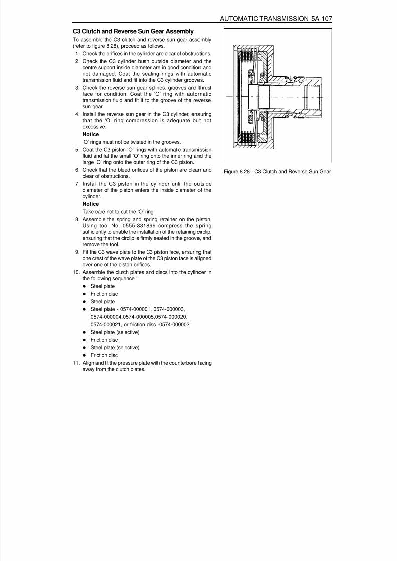
8/18/2019 SsangYong Musso Service Manual 1998.pdf
http://slidepdf.com/reader/full/ssangyong-musso-service-manual-1998pdf 1084/1459
AUTOMATIC TRANSMISSION 5A-107
C3 Clutch and Reverse Sun Gear AssemblyTo assemble the C3 clutch and reverse sun gear assembly(refer to figure 8.28), proceed as follows.
1. Check the orifices in the cylinder are clear of obstructions.2. Check the C3 cylinder bush outside diameter and the
centre support inside diameter are in good condition and
not damaged. Coat the sealing rings with automatictransmission fluid and fit into the C3 cylinder grooves.3. Check the reverse sun gear splines, grooves and thrust
face for condition. Coat the ‘O’ ring with automatictransmission fluid and fit it to the groove of the reversesun gear.
4. Install the reverse sun gear in the C3 cylinder, ensuringthat the ‘O’ ring compression is adequate but notexcessive.Notice‘O’ rings must not be twisted in the grooves.
5. Coat the C3 piston ‘O’ rings with automatic transmissionfluid and fat the small ‘O’ ring onto the inner ring and thelarge ‘O’ ring onto the outer ring of the C3 piston.
6. Check that the bleed orifices of the piston are clean andclear of obstructions.
7. Install the C3 piston in the cylinder until the outsidediameter of the piston enters the inside diameter of thecylinder.NoticeTake care not to cut the ‘O’ ring.
8. Assemble the spring and spring retainer on the piston.
Using tool No. 0555-331899 compress the springsufficiently to enable the installation of the retaining circlip,ensuring that the circlip is firmly seated in the groove, andremove the tool.
9. Fit the C3 wave plate to the C3 piston face, ensuring thatone crest of the wave plate of the C3 piston face is alignedover one of the piston orifices.
10. Assemble the clutch plates and discs into the cylinder inthe following sequence :
Steel plateFriction disc
Steel plateSteel plate - 0574-000001, 0574-000003,0574-000004,0574-000005,0574-000020,0574-000021, or friction disc -0574-000002Steel plate (selective)Friction discSteel plate (selective)Friction disc
11. Align and fit the pressure plate with the counterbore facingaway from the clutch plates.
Figure 8.28 - C3 Clutch and Reverse Sun Gear

8/18/2019 SsangYong Musso Service Manual 1998.pdf
http://slidepdf.com/reader/full/ssangyong-musso-service-manual-1998pdf 1085/1459
5A-108 AUTOMATIC TRANSMISSION
12. Install the circlip.13. Check the C3 clutch clearance (refer to figure 8.29) using
special tool No.0555-331900 in the following manner(weight only).a. Place the weight on the pressure plate and measure
the distance from the end of the cylinder to the top ofthe pressure plate.
b. Record this figure.c. Remove the weight.d. Lift the pressure plate up against the circlip and
measure the distance from the end ofthe cylinder to the top of the pressure plate.
e. Record this figure.f. Subtract the second reading from the first reading to
obtain the clutch pack clearance.NoticeWith the clutch pack supporting a weight of 2 kg, the
clearance between the snap ring and the top of thepressure plate is to be between 1.20-1.45 mm.
14. If new friction plates are being fitted, remove the clutchpack and soak the friction elements in automatictransmission fluid for a minimum of five minutes prior toreassembly.NoticeThe clutch pack clearance must be taken before theelements are soaked in automatic transmission fluid.
Figure 8.29 - Typical C3 Clutch Assembly Clearance

8/18/2019 SsangYong Musso Service Manual 1998.pdf
http://slidepdf.com/reader/full/ssangyong-musso-service-manual-1998pdf 1086/1459
AUTOMATIC TRANSMISSION 5A-109
Forward Sun Gear and C3 Clutch Pack Assembly
To assemble the forward sun gear and C3 clutch pack assembly(Refer to figure 8.30), proceed as follows:
1. Fit the No. 7 needle thrust bearing assembly over the forwardsun gear, ensuring that the thrust washer is between thebearing and the sun gear.
2. Lubricate the thrust plate with petroleum jelly and fit thethrust plate onto the reverse sun gear.Refer to figure 8.33.
3. Align and fit the C3 clutch assembly over the forward sungear.
4. Lubricate the No. 6 needle thrust bearing with petroleum jelly and fit it to the thrust plate. Ensure the lugs on theoutside diameter of the bearing fit in the thrust plate
counterbore.Refer to figure 8.19.
5. Align and fit the plastic thrust washer to the thrust plate withpetroleum jelly.Refer to to figures 8.19.
6. Install the assembly over the forward sun gear shaft againstthe No.6 thrust bearing.Refer to figure 8.19.
7. Place the assembly to one side.
Figure 8.30 - Typical forward Sun Gear add C3 Clutch Assembly

8/18/2019 SsangYong Musso Service Manual 1998.pdf
http://slidepdf.com/reader/full/ssangyong-musso-service-manual-1998pdf 1087/1459
5A-110 AUTOMATIC TRANSMISSION
C1 Clutch Overdrive Shaft and Input ShaftAssemblyNotice1. Ensure that the snap rings are fitted correctly.2. Check pistons for cracks, especially the C1 piston.3. Do not mix clutch piston return springs.4. If the C1/C2 clutch packs separate from the C3 clutch pack,
make sure the No. 6 bearing doesn’t drop out of the bearingretainer.
To assemble the C1 clutch overdrive shaft and input shaftassembly, proceed as follows:1. Check the overdrive shaft grooves for any defect.2. Coat the sealing rings, large and small, with petroleum jelly
and fit them to the overdrive shaft. The sealing rings maybe held in place with a small amount of petroleum jelly.
3. Assemble the clutch plate and disc into the cylinder in thefollowing sequence:
steel platefriction discsteel platefriction discsteel platesteel plate - 0574-GOOGOl, 0574-000003,0574-000004, 0574-000005, 0574-000020,0574-000021, or friction disc -0574-000002steel plate (selective)friction discsteel plate (selective)friction disc
4. Check the clutch pack clearance using special tool No.0555-331900. Refer to figure 8.31.Use selective plates to achieve the correct specification.NoticeThe clutch pack supporting a 2 kg weight, the dimensionfrom the input shaft locating stop to the friction disc mustbe 0.70-0.90 mm.
5. If new friction plates are being fitted, remove the clutch pack
and soak the friction elements in automatic transmissionfluid for a minimum of five minutes prior to assembly.NoticeThe clutch pack clearance must be taken beforeelements are soaked in automatic transmission fluid.
6. Check the fit of the C1 clutch hub on the overdrive shaft. Ifit is loose, the hub and shaft assembly must be replaced.
Figure 8.31 - Typical C1 Clutch Assembly Clearance

8/18/2019 SsangYong Musso Service Manual 1998.pdf
http://slidepdf.com/reader/full/ssangyong-musso-service-manual-1998pdf 1088/1459
AUTOMATIC TRANSMISSION 5A-111
7. Coat the small nylon thrust spacer with petroleum jelly andinstall it over the overdrive shaft. Refer to figure 8.19.
8. Carefully fit the overdrive shaft into the C1 cylinder so asnot to damage the sealing ring.
9. Fit the small bronze C1 hub thrust washer in place withpetroleum jelly. Refer to figure 8.19.
10. Check the input shaft for any defect. Fit the input shaftinto the cylinder and secure it with the circlip, ensuringthat the circlip is completely seated in the groove.
11. Coat the sealing rings with petroleum jelly and fit onto theinput shaft.
12. Assemble the C1/C2/C4 clutch assembly to the C3 clutchand sun gear assembly. Refer to figures 8.32 and 8.33.
13. Install this assembly in the transmission case.
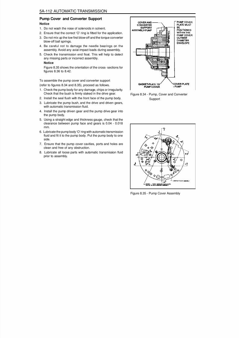
8/18/2019 SsangYong Musso Service Manual 1998.pdf
http://slidepdf.com/reader/full/ssangyong-musso-service-manual-1998pdf 1089/1459
5A-112 AUTOMATIC TRANSMISSION
Pump Cover and Converter SupportNotice1. Do not wash the nose of solenoids in solvent.2. Ensure that the correct ‘O’ ring is fitted for the application.3. Do not mix up the low first blow-off and the torque converter
blow-off ball springs.
4. Be careful not to damage the needle bearings on theassembly. Avoid any axial impact loads during assembly.
5. Check the transmission end float. This will help to detectany missing parts or incorrect assembly.NoticeFigure 8.35 shows the orientation of the cross- sections forfigures 8.36 to 8.42.
To assemble the pump cover and converter support(refer to figures 8.34 and 8.35), proceed as follows.
1. Check the pump body for any damage, chips or irregularity.Check that the bush is firmly staked in the drive gear.2. Install the seal flush with the front face of the pump body.3. Lubricate the pump bush, and the drive and driven gears,
with automatic transmission fluid.4. Install the pump driven gear and the pump drive gear into
the pump body.5. Using a straight edge and thickness gauge, check that the
clearance between pump face and gears is 0.04 - 0.018mm.
6. Lubricate the pump body ‘O’ ring with automatic transmission
fluid and fit it to the pump body. Put the pump body to oneside.7. Ensure that the pump cover cavities, ports and holes are
clean and free of any obstruction.8. Lubricate all loose parts with automatic transmission fluid
prior to assembly.
Figure 8.34 - Pump, Cover and Converter Support
Figure 8.35 - Pump Cover Assembly

8/18/2019 SsangYong Musso Service Manual 1998.pdf
http://slidepdf.com/reader/full/ssangyong-musso-service-manual-1998pdf 1090/1459
AUTOMATIC TRANSMISSION 5A-113
9. Assemble the primary regulator valve and plunger (referto figure 8.36) to the pump cover, ensuring that theregulator valve slides freely, then fit the regulator valveplug and ‘O’ ring.
10. Install the retaining pin.
11. Install the converter clutch regulator valve (refer to figure8.37), plug, and ‘O’ ring.
Figure 8.36 - Primary Regulator Valve
Figure 8.37 - Converter Clutch Regulator Valve

8/18/2019 SsangYong Musso Service Manual 1998.pdf
http://slidepdf.com/reader/full/ssangyong-musso-service-manual-1998pdf 1091/1459
5A-114 AUTOMATIC TRANSMISSION
13. Install the converter clutch control valve (refer to figure8.38), spring, plug, and ‘O’ ring.
14. Install the retaining pin. Refer to figure 8.39.
Figure 8.39 - Valve Retaining Plugs and Pins
Figure 8.38 - Converter Clutch Control Valve
12. Install the retaining pin. Refer to figure 8.39.

8/18/2019 SsangYong Musso Service Manual 1998.pdf
http://slidepdf.com/reader/full/ssangyong-musso-service-manual-1998pdf 1092/1459
AUTOMATIC TRANSMISSION 5A-115
15. Install the C1 bias valve spring, valve, plug and ‘O’ ring.Refer to figure 8.40.
16. Install the retaining pin. Refer to figure 8.39.
17. Install the converter release check ball and spring and thefeed ball. Refer to figures 8.41, 8.42 and 8.43.
Figure 8.40 - C1 Bias Valve
Figure 8.41 - Converter Relief Ball and Spring
Figure 8.42 - Peed Ball
Figure 8.42 - Feed Ball

8/18/2019 SsangYong Musso Service Manual 1998.pdf
http://slidepdf.com/reader/full/ssangyong-musso-service-manual-1998pdf 1093/1459
5A-116 AUTOMATIC TRANSMISSION
18. Install the gasket on the pump cover.19. Install the cover plate, solenoid 7 with the retainer and the
solenoid wiring retainer to the pump cover, ensuring thatthe periphery of the cover plate is flush with the peripheryof the pump cover. Refer to figure 8.34.Tighten the screws to specification in the order (1-5), shownin figure 8.44.
24. Install the pump and cover assembly over the input shaftbeing careful not to damage the sealing rings. Tighten thepump cover to case bolts to specification. Refer to figure8.45.
20. Tighten the solenoid 7 screw. Refer to figure 8.39.NoticeCheck that neither the wiring nor the connector protrudesexcessively, in order that at assembly neither the wiringand the connector contacts or rubs on the input shaft orthe C1/C2 clutch cylinder.
21. Assemble the pump to the pump cover.Tighten all bolts and the crescent screw finger tight,ensuring that the pump is flush against the pump cover.Tighten the bolts and the screw to specification in the order(A - F), shown in figure 8.44.
22. Install the pump to transmission case gasket onto the case.23. Fit the ‘O’ ring to the pump cover outer diameter.
Figure 8.44 - Pump Bolt Tightening Sequence
Figure 8.45 - Tightening Sequence Pump to Case

8/18/2019 SsangYong Musso Service Manual 1998.pdf
http://slidepdf.com/reader/full/ssangyong-musso-service-manual-1998pdf 1094/1459

8/18/2019 SsangYong Musso Service Manual 1998.pdf
http://slidepdf.com/reader/full/ssangyong-musso-service-manual-1998pdf 1095/1459
5A-118 AUTOMATIC TRANSMISSION
Valve BodiesNotice
1. Do not wash the nose of solenoids in solvent.2. Be aware of ball positions in the upper valve body.3. Be aware of 1-2 and 3-4 shift valve positions, they can be
swapped.
4. Check the 4-3 sequence valve and spring orientation.5. Check that the 12 mm ball is in the lower body.6. Do not mix up the low first blow-off and the torque converter
blow-off ball springs.7. Check the line pressure relief valve for swarf, and be aware
of replacing the shims.8. The orifices in the valve body are for stability and safeguard;
do not drill them any larger.9. When servicing the transmission, ensure that the solenoid
5 damper spring is not broken.10. Locate the detent spring central to the detent lever.
To assemble the valve bodies, proceed as follows.1. Wash the upper and lower valve bodies (refer to figures
8.47 and 8.48) thoroughly with cleansing solvent and blowdry.
2. Check the valve body cavities, ports and holes for damageor obstructions.
3. Install the detent lever locating pin.4. Thoroughly wash all loose components.5. Check that all valves slide freely in their location.
Figure 8.47 - Lower Valve Body
Figure8.48 - Upper Valve Body Showing CheckBall Locations

8/18/2019 SsangYong Musso Service Manual 1998.pdf
http://slidepdf.com/reader/full/ssangyong-musso-service-manual-1998pdf 1096/1459
AUTOMATIC TRANSMISSION 5A-119
6. Install the lo-1st spring, ball check valve and roll pin. Referto figure 8.49.
7. Install the solenoid 5 damper guide spring, piston andretaining pin. Refer to figure 8.49.
Figure 8.49 - Solenoid 5 and Damper, Lo-1st Check Valve Assemblies
Figure 8.50 - 1-2 Shift Valve
8. Install the 1-2 shift valve, plug and retaining pin. Refer tofigure 8.50.

8/18/2019 SsangYong Musso Service Manual 1998.pdf
http://slidepdf.com/reader/full/ssangyong-musso-service-manual-1998pdf 1097/1459
5A-120 AUTOMATIC TRANSMISSION
9. Install the 3-4 shift valve and retaining pin. Refer to figure8.51.
Figure 8.51 - 3-4 Shift Valve
10. Install the 2-3 shift valve and retaining pin. Refer to figure8.52.
Figure 8.52 - Solenoid 2 and 2-3 Shift Valve
11. Install the 4-3 sequence valve, spring, plug and retainingplate. Refer to figure 8.53.
Figure 8.53 - 4-3 Sequence Valve
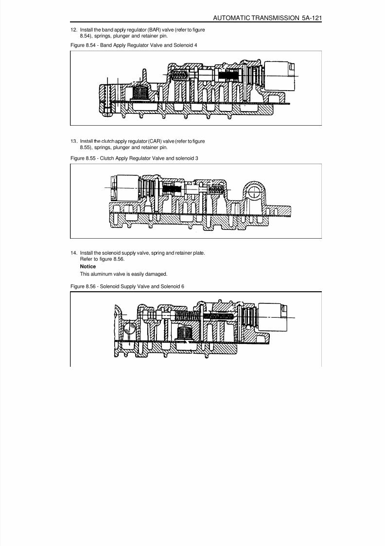
8/18/2019 SsangYong Musso Service Manual 1998.pdf
http://slidepdf.com/reader/full/ssangyong-musso-service-manual-1998pdf 1098/1459
AUTOMATIC TRANSMISSION 5A-121
12. Install the band apply regulator (BAR) valve (refer to figure8.54), springs, plunger and retainer pin.
Figure 8.54 - Band Apply Regulator Valve and Solenoid 4
13. Install the clutch apply regulator (CAR) valve (refer to figure
8.55), springs, plunger and retainer pin.
Figure 8.55 - Clutch Apply Regulator Valve and solenoid 3
14. Install the solenoid supply valve, spring and retainer plate.Refer to figure 8.56.NoticeThis aluminum valve is easily damaged.
Figure 8.56 - Solenoid Supply Valve and Solenoid 6

8/18/2019 SsangYong Musso Service Manual 1998.pdf
http://slidepdf.com/reader/full/ssangyong-musso-service-manual-1998pdf 1099/1459
5A-122 AUTOMATIC TRANSMISSION
15. Install solenoid 6 plunger, spring and retaining pin.16. Position the third feed ball (large nylon) in the valve body
and install the solenoid 5 filter and the solenoid 6 filter.Refer to figures 8.5 and 8.56.
17. Check the separator plate for burrs and damage. Repairor replace the separator plate as necessary.
18. Check the upper and lower valve body gaskets fordamage. Replace the gaskets as necessary.
19. Install the lower valve body gasket on the lower valve body.20. Install the reverse lockout valve, spring, plug and retainer
plate. Ensure that the valve is correctly oriented. Refer tofigure 8.57.
Figure 8.57 - Reverse Lockout Valve
21. Position the five nylon ball checks in the upper valve body.Refer to figure 8.48.
22. Fit the upper valve body gasket. Install the separator plateover the upper valve body.

8/18/2019 SsangYong Musso Service Manual 1998.pdf
http://slidepdf.com/reader/full/ssangyong-musso-service-manual-1998pdf 1100/1459
AUTOMATIC TRANSMISSION 5A-123
23. Holding the separator plate to the upper valve body toprevent the check balls from falling out, install the uppervalve body on the lower valve body. Install all screws fingertight then tighten the screws to specification in theprescribed sequence. Refer to figure 8.58.
24. Install solenoids 1,2,3,4 and 6. Ensure the solenoid is firmly
secured by the retainer and that the screw is tightened tospecification.25. Install solenoid 5. Ensure that the solenoid is pushed firmly
into the valve body by the retainer.NoticeThe wiring loom ground wire eyelet terminal is securedbeneath the solenoid retainer.
26. Install the line pressure relief valve, tapered end first, (referto figure 8.59), and the spring and disc. Secure with theretaining pin.
Figure 8.58 - Tightening Sequence Upper to Lower Valve Body
Figure 8.59 - Line Pressure Relief Valve

8/18/2019 SsangYong Musso Service Manual 1998.pdf
http://slidepdf.com/reader/full/ssangyong-musso-service-manual-1998pdf 1101/1459
5A-124 AUTOMATIC TRANSMISSION
27. Install the line pressure plug and tighten to specification.Refer to figure 8.62.
28. Install the detent spring assembly (spring, support plateand screw), ensuring that the screw is tightened tospecification. Check the spring for wear or damage.
29. Install the manual shift valve. Refer to figure 8.60.NoticeBe aware that the manual valve will fall out of the valvebody.
Figure 8.62 - Wiring Installation
Figure 8.60 - Manual Shift Valve

8/18/2019 SsangYong Musso Service Manual 1998.pdf
http://slidepdf.com/reader/full/ssangyong-musso-service-manual-1998pdf 1102/1459
AUTOMATIC TRANSMISSION 5A-125
30. Align the valve body assembly on the transmission caseand install the manual valve lever to manual valve link. Fitthe long end of the link to the manual valve first. Install thesecuring bolts and tighten to specification in the specifiedsequence. Refer to figure 8.61.
31. Check the alignment of the detent roller and the manuallever quadrant.
32. Connect the solenoid wiring as detailed below:Solenoid 1 - redSolenoid 2 - bIueSolenoid 3 - yellowSolenoid 4 - orangeSolenoid 5 - greenSolenoid 6 - violet (Refer to figure 8.62.)
NoticeAll hardware must be correctly installed and torqued tospecification.
Figure 8.61 - Tightening Sequence Valve Body to Case

8/18/2019 SsangYong Musso Service Manual 1998.pdf
http://slidepdf.com/reader/full/ssangyong-musso-service-manual-1998pdf 1103/1459

8/18/2019 SsangYong Musso Service Manual 1998.pdf
http://slidepdf.com/reader/full/ssangyong-musso-service-manual-1998pdf 1104/1459
AUTOMATIC TRANSMISSION 5A-127
Torque Converter and Housing AssemblyTo assemble the torque converter and housing assembly,proceed as follows.1. Locate the torque converter housing on the transmission
main case.2. Install and tighten the securing bolts to specification.
NoticeAll the hardware must be correctly installed and torqued tospecification.
3. Fit the converter ensuring that the tangs are engaged inthe pump gear. Ensure that the tangs do not contact thepump seal.
Figure 8.1 - Torque Specifications
Torque Specifications
Torque converter housing to case
Extension housing to caseRear servo coverPan to caseInhibitor switch to caseCooler connectorsTransmission filler plugOutput flange lock nut (RWD models)Centre support to caseCam plate to case (parking pawl)Valve body to caseUpper valve body to lower valve bodyON/OFF solenoid retainersVariable pressure solenoid retainerLine pressure plugDetent springPump cover to casePump cover plate to pump coverPump to pump adaptorPump cover plate to crescentAdaptor to case
N m
54 - 68
54 - 6825 - 35
4 - 62.3 - 3.430 - 3530 - 35
100 - 11020 - 2716 - 228 - 13
11 - 168 - 128 - 124 - 7
20 - 2224 - 3413 - 1624 - 2713 - 16
25 - 35

8/18/2019 SsangYong Musso Service Manual 1998.pdf
http://slidepdf.com/reader/full/ssangyong-musso-service-manual-1998pdf 1105/1459
5A-128 AUTOMATIC TRANSMISSION
FRONT AND REAR BAND ADJUSTMENTFront Band Setting ProcedureTo set the front band, proceed as follows.1. Measure the projection of the front servo push rod from the transmission case. Refer to figure 8.66, dimension A.
a. Apply air at 650/700 kPa to the front servo apply area (B1 outer). (Refer to figure 8.67.)
b. Measure the travel of the push rod and subtract 3 mm to find the shim size required.c. Release the air.
NoticeA minimum of one shim is required at all times - minimum shim size is 1 mm. The thicknesses of available shimsare listed in table 8.2.
2. Fit the selected shim(s) to the shank of the anchor strut as follows:a. Inspect the shim(s) for damage, wear or corrosion. Replace as necessary.b. The shim(s) are to be installed between the case abutment face and the anchor strut flange. Refer to figure
8.66.c. The shim(s) are to be fitted by hand and under no circumstances to be hammered or forced.d. Shim(s) are to be pressed on by hand until an audible click is heard. The click indicates that the shim is clipped
home correctly.3. Re-check that the push rod travel is 3 mm ± 0.25 mm.
Figure 8.66 - Front Band Settings
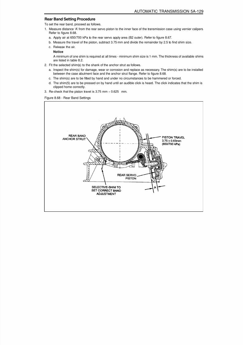
8/18/2019 SsangYong Musso Service Manual 1998.pdf
http://slidepdf.com/reader/full/ssangyong-musso-service-manual-1998pdf 1106/1459
AUTOMATIC TRANSMISSION 5A-129
Figure 8.68 - Rear Band Settings
Rear Band Setting ProcedureTo set the rear band, proceed as follows.1. Measure distance ‘A’ from the rear servo piston to the inner face of the transmission case using vernier calipers.
Refer to figure 8.68.a. Apply air at 650/700 kPa to the rear servo apply area (B2 outer). Refer to figure 8.67.b. Measure the travel of the piston, subtract 3.75 mm and divide the remainder by 2.5 to find shim size.
c. Release the air.NoticeA minimum of one shim is required at all times - minimum shim size is 1 mm. The thickness of available shimsare listed in table 8.2.
2. Fit the selected shim(s) to the shank of the anchor strut as follows.a. Inspect the shim(s) for damage, wear or corrosion and replace as necessary. The shim(s) are to be installed
between the case abutment face and the anchor strut flange. Refer to figure 8.68.c. The shim(s) are to be fitted by hand and under no circumstances to be hammered or forced.d. The shim(5) are to be pressed on by hand until an audible click is heard. The click indicates that the shim is
clipped home correctly.
3. Re-check that the piston travel is 3.75 mm ± 0.625 mm.

8/18/2019 SsangYong Musso Service Manual 1998.pdf
http://slidepdf.com/reader/full/ssangyong-musso-service-manual-1998pdf 1107/1459
5A-130 AUTOMATIC TRANSMISSION
Table 8.2 - Thickness of Available Shims
Thickness0.95/1.051.15/1.251.44/1.56
1.73/1.87
Part Number0574-0370170574-0370180574-037019
0574-037020
Thickness
1.93/2.072.12/2.282.42/2.58
2.61/2.79
Part Number0574-0370210574-0370220574-037023
0574-037024
Figure 8.68 - Thickness of Available Shims

8/18/2019 SsangYong Musso Service Manual 1998.pdf
http://slidepdf.com/reader/full/ssangyong-musso-service-manual-1998pdf 1108/1459
ModelTypeGear Ratio
Oil
Weight (Dry)
SECTION 5B
MANUAL TRANSMISSION
TABLE OF CONTENTSSpecifications. . . . . . . . . . . . . . . . . . . . . . . . 5B-1
General Specifications . . . . . . . . . . . . . . . . . . 5B-1Fastener Tightening Specifications . . . . . . . . . 5B-2
External View . . . . . . . . . . . . . . . . . . . . . . . . 5B-3Gear Train . . . . . . . . . . . . . . . . . . . . . . . . . . 5B-3Power Flow . . . . . . . . . . . . . . . . . . . . . . . . . 5B-4Diagnosis . . . . . . . . . . . . . . . . . . . . . . . . . . . 5B-5
Will not Shift (Control Lever Moves) . . . . . . . . 5B-5Hard Shift or Control Lever Will not Move IntoGear . . . . . . . . . . . . . . . . . . . . . . . . . . . . . . . . 5B-5Gears Crash When Shifting . . . . . . . . . . . . . . 5B-5Transmission Jumps Out . . . . . . . . . . . . . . . . . 5B-6Transmission Locked in One Gear . . . . . . . . . 5B-6Transmission Noise . . . . . . . . . . . . . . . . . . . . . 5B-6Transmission Leakage . . . . . . . . . . . . . . . . . . 5B-7
Diagnosis Table . . . . . . . . . . . . . . . . . . . . . . . 5B-8Component Locator . . . . . . . . . . . . . . . . . . . 5B-9Maintenance and Repair . . . . . . . . . . . . . . 5B-11On-Vehicle Service . . . . . . . . . . . . . . . . . . . . 5B-11
Shift Control Cable . . . . . . . . . . . . . . . . . . . . 5B-11Transmission . . . . . . . . . . . . . . . . . . . . . . . . 5B-14
Unit Repair . . . . . . . . . . . . . . . . . . . . . . . . . 5B-17Major Unit . . . . . . . . . . . . . . . . . . . . . . . . . . . 5B-17Main Shaft . . . . . . . . . . . . . . . . . . . . . . . . . . 5B-27Input Shaft . . . . . . . . . . . . . . . . . . . . . . . . . . 5B-32Counter Shaft . . . . . . . . . . . . . . . . . . . . . . . . 5B-34Extension Housing . . . . . . . . . . . . . . . . . . . . 5B-35Shift Cover . . . . . . . . . . . . . . . . . . . . . . . . . . 5B-36Inspection of Components . . . . . . . . . . . . . . 5B-40Pre-Installation Checks . . . . . . . . . . . . . . . . . 5B-45
SPECIFICATIONSGENERAL SPECIFICATIONS
Application DescriptionT5WC
Floor Change3.97 : 12.34 : 11.46 : 11.00 : 10.85 :13.71 : 1
ATF DEXRON II / III3.4 L
Check : Every 15,000km, Replace : Every 50,000km33kg
1st2nd3rd4th5th
ReverseSpecification
Capacity(litre)Change Interval
NoticeAdd LUBRIZOL (280cc) in oil after overhauling.

8/18/2019 SsangYong Musso Service Manual 1998.pdf
http://slidepdf.com/reader/full/ssangyong-musso-service-manual-1998pdf 1109/1459
5B-2 MANUAL TRANSMISSION
FASTENER TIGHTENING SPECIFICATIONS
ApplicationTransmission
Oil Filler PlugTransmission Mounting Bolt (Housing)
Oil Drain PlugFront Propeller Shaft (T/C)Rear Propeller Shaft (T/C)Cross Member Bolt (Center)Cross Member Bolt (Side)
Control CableShift Lever Bolt
N m
2577 - 87
2581 - 8970 - 9021 - 3562 - 93
20 - 30
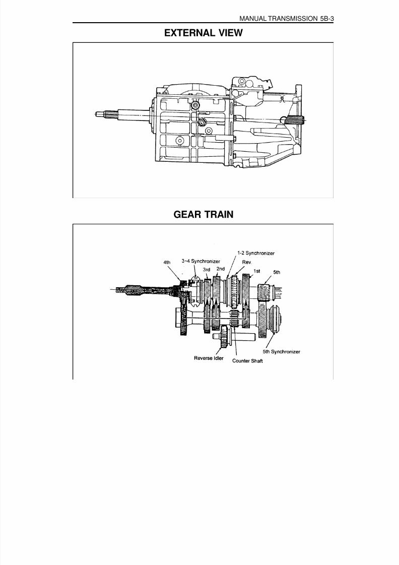
8/18/2019 SsangYong Musso Service Manual 1998.pdf
http://slidepdf.com/reader/full/ssangyong-musso-service-manual-1998pdf 1110/1459
MANUAL TRANSMISSION 5B-3
EXTERNAL VIEW
GEAR TRAIN

8/18/2019 SsangYong Musso Service Manual 1998.pdf
http://slidepdf.com/reader/full/ssangyong-musso-service-manual-1998pdf 1111/1459
5B-4 MANUAL TRANSMISSION
POWER FLOW

8/18/2019 SsangYong Musso Service Manual 1998.pdf
http://slidepdf.com/reader/full/ssangyong-musso-service-manual-1998pdf 1112/1459
MANUAL TRANSMISSION 5B-5
CheckClutch not releasing.Improper or low transmission oil.
Shift or shift rail binding.
Binding of sliding synchronizers or gears.
If reverse only, faulty backup switch.Worn or damaged flywheel pilot bushing.
CheckControl lever assembly broken or damaged.
Damaged offset lever, shift fork, selector place orselector arm.
DIAGNOSISWILL NOT SHIFT(CONTROL LEVER MOVES)
ActionReplace control lever and housing assembly.Remove extension, adapter or case cover.Check or replace damaged parts.
HARD SHIFT OR CONTROL LEVER WILL NOT MOVE INTO GEAR
ActionAdjust or replace clutch.Add or replace with specified oil.
Remove extension, adapter or case cover.Check or replace damaged parts.
Remove extension, adapter or case cover.Check synchronizers and gears and replacedamaged parts.
Check or replace backup switch.Replace pilot bushing.
GEARS CRASH WHEN SHIFTINGCheck
Engine idle speed too high.Damaged or faulty clutch.Pilot bearing between input shaft and output shaft binding.Damaged synchronizer.Bell housing misaligned.Damaged gear(s).Worn or damaged flywheel pilot bushing.
ActionAdjust idle speed to specified speed.Adjust or replace clutch.Replace or check roller bearings.Check or replace synchronizer parts.Align bell housing and bore.Check or replace gear(s).Replace pilot bushing.
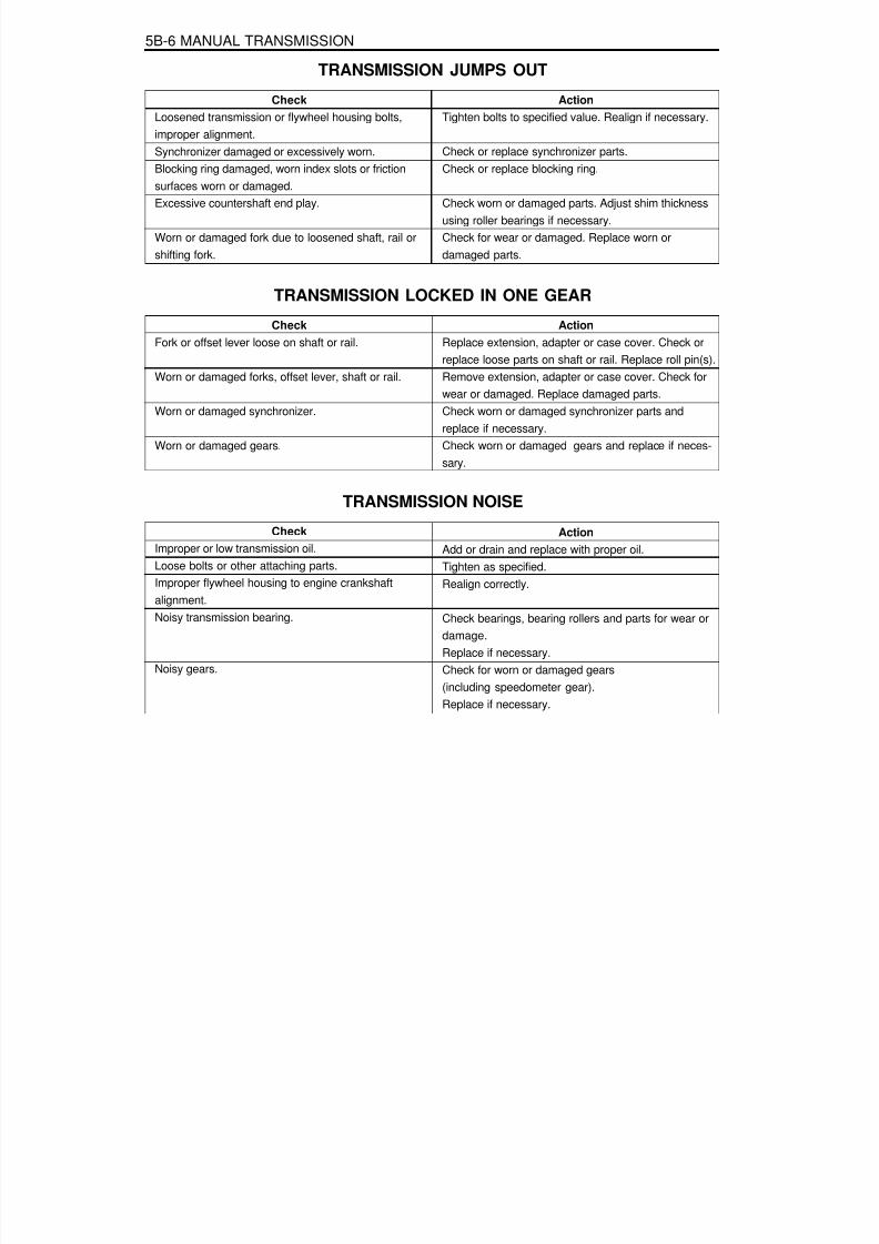
8/18/2019 SsangYong Musso Service Manual 1998.pdf
http://slidepdf.com/reader/full/ssangyong-musso-service-manual-1998pdf 1113/1459
5B-6 MANUAL TRANSMISSION
CheckLoosened transmission or flywheel housing bolts,improper alignment.Synchronizer damaged or excessively worn.
Blocking ring damaged, worn index slots or frictionsurfaces worn or damaged.Excessive countershaft end play.
Worn or damaged fork due to loosened shaft, rail orshifting fork.
TRANSMISSION JUMPS OUT
ActionTighten bolts to specified value. Realign if necessary.
Check or replace synchronizer parts.
Check or replace blocking ring.
Check worn or damaged parts. Adjust shim thicknessusing roller bearings if necessary.Check for wear or damaged. Replace worn ordamaged parts.
CheckFork or offset lever loose on shaft or rail.
Worn or damaged forks, offset lever, shaft or rail.
Worn or damaged synchronizer.
Worn or damaged gears.
TRANSMISSION LOCKED IN ONE GEAR
ActionReplace extension, adapter or case cover. Check orreplace loose parts on shaft or rail. Replace roll pin(s).Remove extension, adapter or case cover. Check forwear or damaged. Replace damaged parts.Check worn or damaged synchronizer parts andreplace if necessary.Check worn or damaged gears and replace if neces-sary.
CheckImproper or low transmission oil.Loose bolts or other attaching parts.Improper flywheel housing to engine crankshaftalignment.Noisy transmission bearing.
Noisy gears.
TRANSMISSION NOISEAction
Add or drain and replace with proper oil.Tighten as specified.Realign correctly.
Check bearings, bearing rollers and parts for wear ordamage.Replace if necessary.
Check for worn or damaged gears(including speedometer gear).Replace if necessary.

8/18/2019 SsangYong Musso Service Manual 1998.pdf
http://slidepdf.com/reader/full/ssangyong-musso-service-manual-1998pdf 1114/1459
MANUAL TRANSMISSION 5B-7
TRANSMISSION LEAKAGE
CheckLeakage from transmission.Vent or breather clogged.Too much oil.
Loose bolts at sealing faces.Improperly applied sealant.
Worn or damaged oil seal.
ActionClean all exposed surfaces, then check for leaks.Clean or replace vent or breather.Check oil level.
Tighten as specified.Clean leaking surfaces.Reapply sealant.Replace oil seal.

8/18/2019 SsangYong Musso Service Manual 1998.pdf
http://slidepdf.com/reader/full/ssangyong-musso-service-manual-1998pdf 1115/1459

8/18/2019 SsangYong Musso Service Manual 1998.pdf
http://slidepdf.com/reader/full/ssangyong-musso-service-manual-1998pdf 1116/1459
MANUAL TRANSMISSION 5B-9
COMPONENT LOCATOR

8/18/2019 SsangYong Musso Service Manual 1998.pdf
http://slidepdf.com/reader/full/ssangyong-musso-service-manual-1998pdf 1117/1459
5B-10 MANUAL TRANSMISSION
1 Filler/Drain Plug2 Shift Mechanism Cover3 Shift Shaft Lever4 Outer Select Lever5 Inner Select Lever6 Offset Control Lever7 Bias Spring
8 Bolt9 Pin10 Washer11 Bolt12 Bolt13 Extension and Plate Assembly14 O-Ring & Steel Ring15 Oiling Funnel16 Bolt17 Alignment Bolt18 Pin19 Shift Shaft20 3/4 Shift Fork21 1/2 Shift Fork22 Insert23 Selector Arm Assembly24 Interlock Plate Assembly25 Selector Plate26 O-ring27 Plug28 Case Cover29 Retaining Ring30 Pivot Pin31 Back-up Switch32 5/Reverse Shift Lever
33 Snap Ring34 5th Synchronizer Retainer35 5th Synchronizer Assembly36 Synchronizer Spring37 Synchronizer Assembly
38 Insert39 Synchronizer Hub40 Roll Pin41 5th Shift Fork42 Insert43 Shift Rail Assembly44 Blocking Ring
45 5th Speed Drive Gear46 Snap Ring47 Speed Gear48 Speed Gear Clip49 Bolt50 Input Bearing Retainer51 Oil Seal52 Shim53 Bearing Cup54 Bearing Cone55 Input Shaft56 Roller Bearing57 Spacer58 Thrust Bearing59 Thrust Bearing Race60 5th Speed Driven Gear61 Bearing Cup62 Bearing Cone63 1st Speed Gear64 Bearing Sleeve Assembly65 A. Bearing65 B. Bearing65 C. Spacer66 Sleeve67 Blocking Ring Assembly
68 3/4 synchronizer Assembly69 Synchronizer Spring70 Synchronizer Sleeve71 Insert72 Synchronizer Sleeve
73 3rd Speed Gear74 Needle Bearing75 Spacer76 Snap Ring77 Thrust Washer78 2nd Speed Gear79 2nd Speed Gear Bearing
80 Spacer81 Output Shaft Assembly82 Retaining Ring83 Thrust Washer84 Inner Cone85 Outer Cone Race86 1/2 Blocking Ring87 Spring Gear88 Reverse Sliding Gear89 Insert Gear90 Pin91 Shaft and Hub Assembly92 Spring93 Pin Fork and Reverse Roller
Assembly94 Bolt95 Rear Bearing Retainer96 Shim97 Roll Pin98 Reverse Idler Shaft99 Reverse Idler Gear Assembly
100 O-ring101 Bearing Cup102 Bearing Cup Assembly103 O-ring
104 Bearing Cup105 Bearing Cone106 Counter Shaft Gear107 Transmission Case Assembly

8/18/2019 SsangYong Musso Service Manual 1998.pdf
http://slidepdf.com/reader/full/ssangyong-musso-service-manual-1998pdf 1118/1459
MANUAL TRANSMISSION 5B-11
MAINTENANCE AND REPAIR
ON-VEHICLE SERVICESHIFT CONTROL CABLE
1 Shift Lever Assembly2 Bolt ...................................................... 20-30 Nm3 Select Cable4 Shift Cable5 Snap Pin6 Snap Pin7 Transmission8 Shift Cable
9 Select Cable10 Clip11 Clip12 Snap Pin13 Snap Pin14 Protector15 Washer

8/18/2019 SsangYong Musso Service Manual 1998.pdf
http://slidepdf.com/reader/full/ssangyong-musso-service-manual-1998pdf 1119/1459
5B-12 MANUAL TRANSMISSION
Removal & Installation Procedure1. Position the shift lever in neutral and remove the knob.
2. Remove the screw from the console box side and removethe shift lever cover.
3. Disconnect the cables by removing the snap pins from thecontrol cable connections to the select lever and shift lever.
4. Remove the shift lever an cable mounting snap pin and
washer of the select lever.

8/18/2019 SsangYong Musso Service Manual 1998.pdf
http://slidepdf.com/reader/full/ssangyong-musso-service-manual-1998pdf 1120/1459
MANUAL TRANSMISSION 5B-13
5. Pull out the clip from the bracket and remove the shift cableand select cable.
6. Installation is reverse order of the removal.
Inspection Procedure1. The shift lever should be positioned in neutral.2. Apply liquid gasket on the cable contact surface.3. Keep 130 mm between the center of the cable end-eye
and floor.
NoticeIf necessary, adjust the adjust nut.
Standard 130 mm

8/18/2019 SsangYong Musso Service Manual 1998.pdf
http://slidepdf.com/reader/full/ssangyong-musso-service-manual-1998pdf 1121/1459
5B-14 MANUAL TRANSMISSION
TRANSMISSIONPreceding Work : Removal of the shift control cable
1 Clutch Housing2 Oil Filler Plug ............................................ 25 Nm3 Transmission Assembly4 Back-up Switch5 Washer6 Bolt ...................................................... 77-87 Nm7 Oil Drain Plug ............................................ 25 Nm8 Bolt ...................................................... 81-89 Nm9 Washer
10 Front Propeller Shaft11 Transfer Case Assembly
12 Speedometer Cable13 Rear Propeller Shaft14 Washer15 Bolt ...................................................... 70-80 Nm16 Cross Member17 Washer18 Bolt ...................................................... 21-35 Nm19 Washer20 Bolt ...................................................... 62-93 Nm21 Breather Hose

8/18/2019 SsangYong Musso Service Manual 1998.pdf
http://slidepdf.com/reader/full/ssangyong-musso-service-manual-1998pdf 1122/1459
MANUAL TRANSMISSION 5B-15
Removal & Installation Procedure1. Disconnect the negative terminal from the battery.2. Lift up the vehicle and fix it safely.3. Remove the drain plug from the transmission housing and
drain the oil. Reinstall the drain plug.Installation Notice
Tightening Torque 25 Nm
4. Disconnect the back-up switch connector.
5. Remove the breather hose.
6. Remove the speedometer connector and other wiringharnesses and connectors.

8/18/2019 SsangYong Musso Service Manual 1998.pdf
http://slidepdf.com/reader/full/ssangyong-musso-service-manual-1998pdf 1123/1459
5B-16 MANUAL TRANSMISSION
7. Remove the front and rear propeller shafts from thetransfercase.Installation Notice
Tightening Torque81 - 89 Nm70 - 90 Nm
FrontRear
8. Support the transmission on an suitable jack.Unscrew the center mounting nuts and each sidesmounting bolts and remove the cross member.Installation Notice
9. Remove the transmission mounting bolts.Installation Notice
Tightening Torque (1)Tightening Torque (2)
21 - 35 Nm62 - 93 Nm
10. Move the transmission jack backward careful anddisengage the transmission input shaft from the engine.Remove the transmission.
11. Installation should follow the removal procedure in thereverse order.
Tightening Torque 77 - 87 Nm

8/18/2019 SsangYong Musso Service Manual 1998.pdf
http://slidepdf.com/reader/full/ssangyong-musso-service-manual-1998pdf 1124/1459
MANUAL TRANSMISSION 5B-17
UNIT REPAIRMAJOR UNITPreceding Work : Removal of the transmission
Removal of the transfer case
Disassembly Procedure1. Install the removed transmission into a fixture.2. Remove the drain plug and drain the oil. Using a 13 mm
wrench, remove the clamp bolt and position the offset leverin the 3-4 position of neutral.NoticeRemoval of the offset lever in a position other than 3-4 ofneutral will be difficult.
3. Using a pin punch and a hammer, remove the roll pin toremove the shift lever from the offset lever.
4. Using a 15 mm wrench, remove the 8 bolts from the extension
housing.
5. Separate the extension housing from the case and shiftcover.Separate the offset lever from the shift.NoticeDo not remove the offset lever while the extension housingis still assembled to the case.
6. Remove the offset lever from the extension housing withthe detent ball and spring.
7. Remove the roll pin from either the offset lever or extensionhousing.

8/18/2019 SsangYong Musso Service Manual 1998.pdf
http://slidepdf.com/reader/full/ssangyong-musso-service-manual-1998pdf 1125/1459
5B-18 MANUAL TRANSMISSION
8. Remove the counter shaft thrust race and bearing.
9. Carefully remove the oiling funnel from the end of thecounter shaft.
10. Using a 10 mm wrench, remove the 10 bolts from the shiftcover.NoticeFor assembly, note the location of the two bolts.
11. Lift up the shift cover after sliding it toward the drain plugabout 3 cm. At this time remove sealer bond.
12. Using a needle nose pliers, remove the 5-R lever clip.

8/18/2019 SsangYong Musso Service Manual 1998.pdf
http://slidepdf.com/reader/full/ssangyong-musso-service-manual-1998pdf 1126/1459
MANUAL TRANSMISSION 5B-19
13. Using a 21 mm wrench or a T-50 bit, remove the 5-R leverpivot bolt.NoticeApply sealer bond to this bolt during assembly.
14. Using a 22 mm wrench, remove the back-up lamp switchfrom the 5-R lever side.NoticeApply sealer to the threads.
15. Pull out the 5-R lever out of the transmission.
16. Using a snap ring pliers, remove the 5th synchronizer snapring from the end of the counter shaft.
17. Remove the 5th synchronizer assembly with its fork andrail assembly from the counter shaft.

8/18/2019 SsangYong Musso Service Manual 1998.pdf
http://slidepdf.com/reader/full/ssangyong-musso-service-manual-1998pdf 1127/1459
5B-20 MANUAL TRANSMISSION
18. Remove the slip yoke snap ring from the main shaft.
19. Remove the 5th speed drive gear snap ring from the mainshaft.
20. Make alignment marks on the case and input bearingretainer and remove the 4 input shaft bearing retainer bolts,using a 13 mm wrench.
NoticeApply sealer on these bolts during assembly.Remove the input bearing retainer with the bearing outerrace and shim.
21. Remove the input shaft from the case by rotating it untilthe flat surface appears.
22. Remove the following parts from the input shaft.4th speed gear blocking ring.Main shaft thrust race and bearing.Main shaft pilot bearing rollers (15 rollers).
NoticeBe careful not to dissipate the pilot bearing rollers.

8/18/2019 SsangYong Musso Service Manual 1998.pdf
http://slidepdf.com/reader/full/ssangyong-musso-service-manual-1998pdf 1128/1459
MANUAL TRANSMISSION 5B-21
23. Remove the main shaft in 2 steps.To remove the rear bearing outer race, push the mainshaft rearward.
Tilt and lift the main shaft from the case.
24. Remove the reverse fork and spring from the case.
25. Remove the counter shaft as follows:Using a punch and hammer, pry up the lock tabs.Using a 13 mm wrench or T-40 bit, remove the 4 bolts.Remove the retainer and shim from the case.Push the counter shaft rearward to remove the rearbearing outer race.

8/18/2019 SsangYong Musso Service Manual 1998.pdf
http://slidepdf.com/reader/full/ssangyong-musso-service-manual-1998pdf 1129/1459
5B-22 MANUAL TRANSMISSION
26. Using a pin punch and a hammer, remove the roll pin fixedon the reverse idler shaft.
27. By pushing the reverse idler shaft rearward and out of thecase, remove the reverse idler gear and O-ring.
28. Using a puller, remove the rear bearing assembly from thecounter shaft.
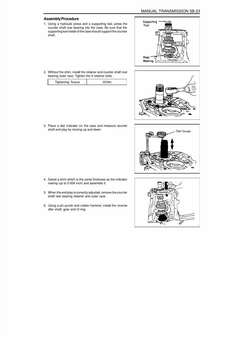
8/18/2019 SsangYong Musso Service Manual 1998.pdf
http://slidepdf.com/reader/full/ssangyong-musso-service-manual-1998pdf 1130/1459
MANUAL TRANSMISSION 5B-23
Assembly Procedure1. Using a hydraulic press and a supporting tool, press the
counter shaft rear bearing into the case. Be sure that thesupporting tool inside of the case should support the countershaft.
2. Without the shim, install the retainer and counter shaft rearbearing outer race. Tighten the 4 retainer bolts.
3. Place a dial indicator on the case and measure countershaft end play by moving up and down.
4. Select a shim which is the same thickness as the indicatorrearing (up to 0.004 inch) and assemble it.
5. When the end play is correctly adjusted, remove the countershaft rear bearing retainer and outer race.
6. Using a pin punch and rubber hammer, install the reverseidler shaft, gear and O-ring.
Tightening Torque 20 Nm

8/18/2019 SsangYong Musso Service Manual 1998.pdf
http://slidepdf.com/reader/full/ssangyong-musso-service-manual-1998pdf 1131/1459
5B-24 MANUAL TRANSMISSION
7. Install the counter shaft rear bearing outer race, shim andretainer.
Tightening Torque 39 - 52 Nm
Using a punch and hammer, bend the lock tabs on theretainer.
8. Install the following parts :Install the main shaft into case.Install the main shaft rear bearing outer race into therear of the case.
Install the 4th speed blocking ring onto the front of themain shaft.Install the input shaft onto the front of the main shaft.Install the input bearing retainer without shim onto thefront of the case.Using a torque wrench, tighten the 4 bolts.
9. Install the 5th speed drive gear and blocking ring on thecounter shaft.
10. Install the 5th synchronizer and rail/fork.
11. Install the 5th synchronizer snap ring and oiling funnel.
12. Align the slots of the lever with the rollers of the reversefork and 5th shift rail. Apply sealer on the 5-R lever pivotbolt and install it into the case.
Tightening Torque 28 Nm
13. Using a needle nose pliers, install the 5-R lever clip.

8/18/2019 SsangYong Musso Service Manual 1998.pdf
http://slidepdf.com/reader/full/ssangyong-musso-service-manual-1998pdf 1132/1459
MANUAL TRANSMISSION 5B-25
14. Using a needle nose pliers, install the reverse fork springto its pin inside the case. Check the operation of the 5-Rshift mechanism at this time.
15. Using a snap ring piers, install the slip yoke snap ring ontothe end of the main shaft.
16. Make sure that the 1-2 and 3-4 synchronizer sleeves and5-R shift lever are in neutral position.
17. Align the holes the case and cover with alignment-typebolts. Tighten the 10 bolts.
18. Apply ‘RTV’ sealant on the sealing surface of the extensionhousing.
19. Apply grease on the detent/guide plate in the extensionhousing. Install the detent ball in the 3-4 position.
20. Place the detent spring and offset lever in the extensionhousing and push the extension against the case and shiftcover.

8/18/2019 SsangYong Musso Service Manual 1998.pdf
http://slidepdf.com/reader/full/ssangyong-musso-service-manual-1998pdf 1133/1459
5B-26 MANUAL TRANSMISSION
21. Completely compress the detent spring.
22. To install the extension housing to the case, apply sealerto the top two bolts and tighten them and tighten the 6bolts.
23. Apply sealer to the back-up lamp switch and drain plugand tighten them.
24. Using a hammer, install the offset lever-to-shift roll pin.
25. Turn the transmission case reversely and place a dialindicator on the extension housing. Move the input andmain shift up and down and measure end play. Select ashim which is the same thickness as the measurement (±0.001 inch). After shim installation, the end play should be
‘0’.
26. Remove the input bearing retainer and do the following :Install the adjusting shim behind the input bearing outerrace in the retainer and if 2 shims are used, install thethinner one in first.Install the retainer to the case and tighten the bolts.If end play is not ‘0’change the shim again.Apply RTV sealant to the sealing surface of the retainer.Apply sealer to the 4 retainer bolts and tighten them.
27. Remove the fill plug.
28. Remove the transmission from the holding fixture and installit to the vehicle.
29. Clean the sealing surface of the shift control lever.
30. Install the control cables to the shift lever.

8/18/2019 SsangYong Musso Service Manual 1998.pdf
http://slidepdf.com/reader/full/ssangyong-musso-service-manual-1998pdf 1134/1459
MANUAL TRANSMISSION 5B-27
MAIN SHAFTDisassembly Procedure1. For correct reassemble, place an alignment mark on the 3-
4 Synchronizer hub and sleeve.
2. Using a hydraulic press and puller plate, remove the 3-4Synchronizer assembly and the 3rd speed gear.
3. Remove the 3rd speed gear bearing and spacer.
4. Using a snap ring pliers, remove the 2nd speed gear snapring.
5. Remove the 2nd speed gear thrust washer.
6. Remove the 2nd speed gear, bearing and spacer.

8/18/2019 SsangYong Musso Service Manual 1998.pdf
http://slidepdf.com/reader/full/ssangyong-musso-service-manual-1998pdf 1135/1459
5B-28 MANUAL TRANSMISSION
7. Using a screwdriver, remove the spiral retaining ring.
8. Remove the thrust washer and three-piece 2nd speedblocking ring assembly.
9. For correct reassembly, place an alignment mark on the1-2 synchronizer hub and sleeve.
10. Remove the 1-2 synchronizer sleeve from the hub withfollowing parts :
The anti-rattle ball and spring.The three keys.One of the 3 springs.
11. Using a hydraulic press and puller plate, remove the 5thspeed driven gear from the main shaft.

8/18/2019 SsangYong Musso Service Manual 1998.pdf
http://slidepdf.com/reader/full/ssangyong-musso-service-manual-1998pdf 1136/1459
MANUAL TRANSMISSION 5B-29
12. Remove the main shaft rear bearing assembly from theshaft.
13. Remove the 1st speed gear and bearing.
14. Remove the inner race.
15. Remove the tree-piece 1st speed blocking ring assemblyand remaining synchronizer spring.
16. Check and clean all removed parts and replace ifnecessary.

8/18/2019 SsangYong Musso Service Manual 1998.pdf
http://slidepdf.com/reader/full/ssangyong-musso-service-manual-1998pdf 1137/1459
5B-30 MANUAL TRANSMISSION
Assembly Procedure1. When assemble the synchronizer, make sure that the hubs
and sleeves are matched and the 3 keys are installedproperly. Also align blocking rings with keys duringinstallation.Notice
Before assembly, coat all parts with lubricant. In case of thepaper-lined blocking rings, soak them in Dexron II / III beforeinstallation.
2. Assemble the following parts :1st speed blocking ring.Alignment pin and 1st speed gear bearing race.1st speed gear and its bearing.
3. Install the rear bearing assembly to the main shaft.
4. Using a hydraulic press and installer, press the 5th drivengear onto the main shaft. While the main shaft is still on thepress bed, install the 5th driven gear snap ring. If the snap
ring does not fit completely, continue pressing the 5th drivengear.
5. Install the following parts :2nd speed blocking ring assembly.Thrust washer for the blocking ring inner cone.Spiral retaining ring (Use special tools).2nd speed gear spacer, bearing and gear.2nd gear thrust washer and snap ring.3rd speed gear spacer, bearing and gear.3rd speed blocking ring.

8/18/2019 SsangYong Musso Service Manual 1998.pdf
http://slidepdf.com/reader/full/ssangyong-musso-service-manual-1998pdf 1138/1459
MANUAL TRANSMISSION 5B-31
6. Using a hydraulic press and installer, install the 3-4synchronizer hub onto the main shaft.NoticeAlign the blocking ring with the synchronizer keys whileinstalling the hub.

8/18/2019 SsangYong Musso Service Manual 1998.pdf
http://slidepdf.com/reader/full/ssangyong-musso-service-manual-1998pdf 1139/1459
5B-32 MANUAL TRANSMISSION
INPUT SHAFTDisassembly Procedure1. Remove the following parts from the input shaft :
Main shaft thrust race and bearing.Main shaft pilot bearing rollers (15 rollers).
2. Using a hydraulic press and puller plate, remove the inputshaft bearing assembly from the shaft.
3. Remove the input bearing.
4. Remove the input shaft seal.
5. Check and clean all removed parts and replace if necessary.

8/18/2019 SsangYong Musso Service Manual 1998.pdf
http://slidepdf.com/reader/full/ssangyong-musso-service-manual-1998pdf 1140/1459
MANUAL TRANSMISSION 5B-33
Assembly Procedure1. Using a hydraulic press and installer, press the input shaft
bearing onto the input shaft.
2. Apply grease to the thrust bearing inner roller (15 rollers)and install the main shaft thrust bearing and its race in the
rear of the input shaft.
3. Using a rubber hammer and installer, install the input bearingretainer and input shaft seal after applying grease.
4. Install the bearing outer race to the retainer without endplay adjusting shim.

8/18/2019 SsangYong Musso Service Manual 1998.pdf
http://slidepdf.com/reader/full/ssangyong-musso-service-manual-1998pdf 1141/1459
5B-34 MANUAL TRANSMISSION
COUNTER SHAFTDisassembly Procedure1. Using a hydraulic press and special tool, remove the front
bearing assembly from the counter shaft.
2. Check and clean all removed parts and replace if necessary.
Assembly Procedure1. Using a hydraulic press and installer, press the front bearing
assembly onto the counter shaft.
2. Install is as follows :Install a new O-ring on the counter shaft outer race andlubricate it.Using a installer, lightly tap the race into its bore until theO-ring is compressed.Install the race to be fully seated on the inside of thecase.

8/18/2019 SsangYong Musso Service Manual 1998.pdf
http://slidepdf.com/reader/full/ssangyong-musso-service-manual-1998pdf 1142/1459
MANUAL TRANSMISSION 5B-35
EXTENSION HOUSINGDisassembly Procedure1. Remove the vent from the extension housing.
2. Remove the O-ring and steel ring from the rear of theextension housing.
3. Check and clean all removed parts and replace if necessary.
Assembly Procedure1. Install the O-ring and steel ring to the rear of the extension
housing.2. Install the vent to the extension housing.

8/18/2019 SsangYong Musso Service Manual 1998.pdf
http://slidepdf.com/reader/full/ssangyong-musso-service-manual-1998pdf 1143/1459
5B-36 MANUAL TRANSMISSION
SHIFT COVERDisassembly Procedure1. Using a hammer and a pin punch (3/16) remove the selector
arm roll pin.
2. Before removal, note the correct position of the interlockplate and selector arm and remove the shift shaft.
3. Check and clean all removed parts and replace if necessary.
Assembly Procedure1. If the shaft cup plug was removed, apply plug outer surface
with sealer and install it into the cover.
2. Install the fork pads and selector plates onto the 1-2 and 3-4 shift forks.
3. Assemble the sift cover parts as follows :Push the shift shaft into the cover until the front of the shaftis at the inside of the cover.

8/18/2019 SsangYong Musso Service Manual 1998.pdf
http://slidepdf.com/reader/full/ssangyong-musso-service-manual-1998pdf 1144/1459
MANUAL TRANSMISSION 5B-37
Install the 1-2 shift fork and its selector plate.
Push the shift shaft through the 1-2 shift fork.
Place the selector arm and interlock plate in the coverNote the position of the interlock plate and selector arm.
Push the shift shaft through the 3-4 shift fork.

8/18/2019 SsangYong Musso Service Manual 1998.pdf
http://slidepdf.com/reader/full/ssangyong-musso-service-manual-1998pdf 1145/1459
5B-38 MANUAL TRANSMISSION
Install the 3-4 shift fork and its selector plate.
Push the shift shaft through the 3-4 shift fork.
Install the roll pin that fixes the selector arm to the shiftshaft.
4. Check the shift cover parts for proper assembly as follows :Insert a pin punch (3/16) into the offset lever hole ofthe shift shaft.Place the shift cover to the flat ground and rotate theshift shaft so that the punch is vertical.

8/18/2019 SsangYong Musso Service Manual 1998.pdf
http://slidepdf.com/reader/full/ssangyong-musso-service-manual-1998pdf 1146/1459
MANUAL TRANSMISSION 5B-39
Selector arm should be aligned with the 3/4 shift forkselector plate.
5. Lubricate and install the O-ring on the rear of the shift cover.

8/18/2019 SsangYong Musso Service Manual 1998.pdf
http://slidepdf.com/reader/full/ssangyong-musso-service-manual-1998pdf 1147/1459
5B-40 MANUAL TRANSMISSION
INSPECTION OF COMPONENTSInspection Procedure1. Clean all parts with solvent and dry them with compressed
air. Check the following parts for cracks and damagedsealing surfaces.
CaseExtension housingShift CoverInput bearing retainerCounter shaft rear bearing retainer
2. Check the parts which support bearings and shafts forexcessive wear and replace them if necessary.
3. Check the bearing surfaces of the following parts ;Input shaftMain shaft and its gearsCounter shaft and 5th drive gear
4. Check the reverse idler shaft and its gears.NoticeReplace excessive wear parts and do not file on thehardened surface and precision ground.

8/18/2019 SsangYong Musso Service Manual 1998.pdf
http://slidepdf.com/reader/full/ssangyong-musso-service-manual-1998pdf 1148/1459
MANUAL TRANSMISSION 5B-41
5. Check the shift mechanism parts as follows :Wear of the shift shaft.Wear of the detent/guide plate and offset lever.
Check worn edges on the following parts :- Selector arm.- Interlock plate.- Selector plates for the 1-2 and 3-4 shift forks.
- 5-R shift lever and the rollers on the reverse fork andthe 5th shift rail/fork.
Check worn mating surfaces on the following parts :- 1-2 shift fork, pads and synchronizer sleeve.- 3-4 shift fork, pads and synchronizer sleeve.- 5th shift rail/fork pads and synchronizer sleeve.- Reverse fork and reverse idler gear sleeve.

8/18/2019 SsangYong Musso Service Manual 1998.pdf
http://slidepdf.com/reader/full/ssangyong-musso-service-manual-1998pdf 1149/1459
5B-42 MANUAL TRANSMISSION
6. Check the following Bearing for excessive war:Crankshaft pilot bushing for the front of the input shaft.Clutch release bearing.Input shaft bearing.Main shaft pilot bearing rollers.Main shaft thrust Bearing and its surfaces.
Speed gear roller bearing on the main shaft.Main shaft rear bearing.Counter shaft front and rear bearings.
7. Check the gear tooth surfaces of all gear sets.
8. Check the reverse gear set surfaces. Check the surfacesof gear teeth for excessive wear, pitting, scoring and spallingand replace if necessary.

8/18/2019 SsangYong Musso Service Manual 1998.pdf
http://slidepdf.com/reader/full/ssangyong-musso-service-manual-1998pdf 1150/1459
MANUAL TRANSMISSION 5B-43
9. Take apart the three synchronizer assemblies and check :The 1-2 synchronizer.
The 5th blocking ring.
10. Check the fit between the hub and sleeve of eachsynchronizer
Excessively tight or loose hub-to-sleeve fit.Wear of the cone clutch surfaces of brass blockingrings and gears.
11. Measure the clearance between the blocking ring and thespeed gear
New 1-2 blocking ring : 0.87-1.4mmNew 3-4 blocking ring : 0.88-1.5mm
NoticeExcessive wear of the blocking ring or the speed gear conesurface will cause shift block-out gear clash.

8/18/2019 SsangYong Musso Service Manual 1998.pdf
http://slidepdf.com/reader/full/ssangyong-musso-service-manual-1998pdf 1151/1459
5B-44 MANUAL TRANSMISSION
12. Check for gear clash on the synchronizer sleeve teeth orthe clutch teeth on the speed gear.
13. Check the synchronizer sleeve and gear clutch tooth forhop-out.

8/18/2019 SsangYong Musso Service Manual 1998.pdf
http://slidepdf.com/reader/full/ssangyong-musso-service-manual-1998pdf 1152/1459
MANUAL TRANSMISSION 5B-45
PRE-INSTALLATION CHECKSChecking Procedure1. Separate the clutch release fork from the pivot and remove
the pivot from the clutch housing.
2. Check the pivot. Fork and release bearing.
3. Check the pressure plate spring.NoticeInspect each parts and replace the excessively worn parts.
4. Check the clutch housing alignment as follows :Place the magnetic base on the pressure plate spring.
Check the housing bore alignment.- Place the dial indicator on the bore.- By rotating the crankshaft one revolution, record the
dial indicator reading.

8/18/2019 SsangYong Musso Service Manual 1998.pdf
http://slidepdf.com/reader/full/ssangyong-musso-service-manual-1998pdf 1153/1459

8/18/2019 SsangYong Musso Service Manual 1998.pdf
http://slidepdf.com/reader/full/ssangyong-musso-service-manual-1998pdf 1154/1459
TypeClutch Pedal
Clutch Disc
Clutch Master Cylinder
Clutch Release Cylinder
Clutch Fluid
DescriptionHydraulic
Suspended158 mm
5 - 10 mmSingle Dry Diaphragm
9.85 - 10.2 mm9.2 mm
19.8 mmf 15.87 mm
14.0 mmf 17.46 mm
SAE J1703 / DOT3
SECTION 5C
CLUTCH
TABLE OF CONTENTSSpecifications. . . . . . . . . . . . . . . . . . . . . . . . 5C-1
General Specifications . . . . . . . . . . . . . . . . . . 5C-1Fastener Tightening Specifications . . . . . . . . . 5C-2
Special Tools . . . . . . . . . . . . . . . . . . . . . . . . 5C-3Special Tools Table . . . . . . . . . . . . . . . . . . . . . 5C-3
Diagnosis . . . . . . . . . . . . . . . . . . . . . . . . . . . 5C-4Clutch Slips . . . . . . . . . . . . . . . . . . . . . . . . . . . 5C-4Poor Disengagement . . . . . . . . . . . . . . . . . . . 5C-4Hard to Shift or Will not Shift . . . . . . . . . . . . . . 5C-4Clutch Chatters When Starting . . . . . . . . . . . . 5C-4Difficult Pedal Operation . . . . . . . . . . . . . . . . . 5C-5
SPECIFICATIONSGENERAL SPECIFICATIONS
Caution: Disconnect the negative battery cable before removing or installing any electrical unit or when a
tool or equipment could easily come in contact with exposed electrical terminals. Disconnecting this cable will help prevent personal injury and damage to the vehicle. The ignition must also be in LOCK unless otherwise noted.
Application
TypeMax. Pedal StrokePedal Free Play
TypeThickness of Disc
StrokeInner DiameterStrokeInner Diameter
FreeWith Load
Clutch Noisy . . . . . . . . . . . . . . . . . . . . . . . . . . 5C-5Component Locator . . . . . . . . . . . . . . . . . . . 5C-6
Clutch Assembly . . . . . . . . . . . . . . . . . . . . . . . 5C-6Pedal and Master Cylinder . . . . . . . . . . . . . . . 5C-7
Maintenance and Repair . . . . . . . . . . . . . . . 5C-8On-Vehicle Service . . . . . . . . . . . . . . . . . . . . . 5C-8
Bleeding of Clutch System . . . . . . . . . . . . . . . 5C-8Clutch Disc . . . . . . . . . . . . . . . . . . . . . . . . . . . 5C-9Master Cylinder . . . . . . . . . . . . . . . . . . . . . . 5C-13Clutch Pedal . . . . . . . . . . . . . . . . . . . . . . . . . 5C-15Clutch Oil Chamber . . . . . . . . . . . . . . . . . . . 5C-17

8/18/2019 SsangYong Musso Service Manual 1998.pdf
http://slidepdf.com/reader/full/ssangyong-musso-service-manual-1998pdf 1155/1459

8/18/2019 SsangYong Musso Service Manual 1998.pdf
http://slidepdf.com/reader/full/ssangyong-musso-service-manual-1998pdf 1156/1459
CLUTCH 5C-3
SPECIAL TOOLSSPECIAL TOOLS TABLE
602 589 00 40 00Engine Lock
661 589 00 15 00Centering Pin

8/18/2019 SsangYong Musso Service Manual 1998.pdf
http://slidepdf.com/reader/full/ssangyong-musso-service-manual-1998pdf 1157/1459
5C-4 CLUTCH
ChecksOily Facing
Hard or Faulty FacingBurnt Torsion SpringFaulty Pressure PlateBent Clutch Diaphragm SpringHard or Bent FlywheelEngine Mounts Loose or Burnt Lever
Action
Adjust Pedal FreeplayRepair Release Cylinder
Repair or ReplaceRepair as Necessary
Replace
Checks
Excessive Clutch Pedal Free playFaulty Clutch Release CylinderWorn Disc, Excessive Run-out, Damaged LiningDirty or Burred Splines on Input Shaft or Clutch DiscDamaged Clutch Pressure Plate
ChecksVibration or Excessive Run-out of DiscRust or Wear of Disc SplineOily FacingDamaged Diaphragm SpringExcessive Clutch Pedal Free play
DIAGNOSISCLUTCH SLIPS
ChecksExcessive Wear of Facing
Hard or Oily FacingDamaged Pressure Plate or FlywheelDamaged or Burnt Diaphragm SpringClutch Pedal Free play InsufficientFaulty Operation of Clutch PedalWorn or Damaged Clutch Disc
ActionReplace
Repair or ReplaceReplaceReplaceAdjust
Repair or ReplaceReplace
POOR DISENGAGEMENT
ActionReplace
Repair or ReplaceRepair or Replace
ReplaceAdjust
HARD TO SHIFT OR WILL NOT SHIFT
CLUTCH CHATTERS WHEN STARTING
ActionRepair or Replace
ReplaceReplaceReplaceReplace
Repair or ReplaceTighten or Replace

8/18/2019 SsangYong Musso Service Manual 1998.pdf
http://slidepdf.com/reader/full/ssangyong-musso-service-manual-1998pdf 1158/1459
CLUTCH 5C-5
ChecksPoor Lubrication on Clutch CablePoor Lubrication on Pedal ShaftPoor Lubrication on Clutch Pedal
Not Using the Clutch
After DisengagementWhen Disengaging
DIFFICULT PEDAL OPERATION
ActionLubricate or ReplaceLubricate or Replace
Repair
CLUTCH NOISYChecks Action
AdjustReplaceReplaceReplaceRepair
Replace
Insufficient Clutch Pedal Free playExcessive Wear of FacingWorn or Damaged Release BearingPoor Lubrication Contact Surface of BearingFaulty Installation of Clutch Assembly or BearingDamaged Pilot BushingClutch Pedal is Partially Depressed
and Vehicle Speed is Reduced

8/18/2019 SsangYong Musso Service Manual 1998.pdf
http://slidepdf.com/reader/full/ssangyong-musso-service-manual-1998pdf 1159/1459
5C-6 CLUTCH
COMPONENT LOCATORCLUTCH ASSEMBLY
1 Clutch Disc2 Clutch Cover3 Clutch Housing4 Release Bearing5 Release Fork Pivot6 Release Cylinder7 Release Fork Boot
8 Bolt9 Release Fork
10 Bolt11 Spring Lock Washer12 Transmission Input Spline13 Release Bearing Contacting Surface14 Contacting Point of Release Fork and Pivot
Notice
Apply the long-term grease (DBL 6811.00) to No.12,13 and 14.

8/18/2019 SsangYong Musso Service Manual 1998.pdf
http://slidepdf.com/reader/full/ssangyong-musso-service-manual-1998pdf 1160/1459
CLUTCH 5C-7
PEDAL AND MASTER CYLINDER
1 Clutch Pedal2 Clutch Master Cylinder3 Clutch Tube4 Clutch Oil Chamber
5 Clutch Tube6 Clutch Hose7 Clutch Release Cylinder

8/18/2019 SsangYong Musso Service Manual 1998.pdf
http://slidepdf.com/reader/full/ssangyong-musso-service-manual-1998pdf 1161/1459
5C-8 CLUTCH
MAINTENANCE AND REPAIR
ON-VEHICLE SERVICEBLEEDING OF CLUTCH SYSTEM
Bleeding procedureNoticeKeep the fluid level over ‘MAX’ in reservoir duringbleeding operation.Do not let fluid contact a painted surface.
1. Remove the air bolt cap of the release cylinder.Connect a vinyl tube to the bolt.
2. Insert the other end of the tube in a vacant container.3. Slowly depress the clutch pedal several times.4. With clutch pedal fully depressed, open the air bolt and
release air rind fluid in the fluid line,5. Repeat this procedure until there are no more air bubbles
in the fluid flows.

8/18/2019 SsangYong Musso Service Manual 1998.pdf
http://slidepdf.com/reader/full/ssangyong-musso-service-manual-1998pdf 1162/1459
CLUTCH 5C-9
CLUTCH DISCPreceding Work : Removal of the transmission
1 Clutch Disc2 Clutch Cover Assembly3 Release Bearing4 Clutch Housing
Tools602 589 00 40 00 Engine Lock661 589 00 15 00 Centering Pin
5 Washer6 Bolt ........................................................... 23 Nm7 Washer8 Bolt ........................................................... 44 Nm

8/18/2019 SsangYong Musso Service Manual 1998.pdf
http://slidepdf.com/reader/full/ssangyong-musso-service-manual-1998pdf 1163/1459
5C-10 CLUTCH
Removal & Installation Procedure1. Remove the starter motor. Install the special tool to the
flywheel through the starter motor mounting holes.
Tightening Torque 47 Nm
Engine Lock 602 589 00 40 00
2. Unscren the release cylinder mounting bolts and removethe release cylinder.Installation Notice
3. Unscrew the clutch housing bolts and remove the clutchhousing, release fork and release bearing.Installation Notice
4. Insert the centering pin into the clutch spline.Loosen the clutch cover bolts 1/2 turn in crisscross sequenceuntil the spring tension is released.NoticeDo not remove the bolts at a time, or clutchcover can bedamaged or deformed.
Centering Pin 661 589 00 15 00
Tightening Torque 30 - 40 Nm

8/18/2019 SsangYong Musso Service Manual 1998.pdf
http://slidepdf.com/reader/full/ssangyong-musso-service-manual-1998pdf 1164/1459
CLUTCH 5C-11
5. Unscrew the bolts and remove the clutch cover, pressureplate and clutch disc.NoticeBe careful not to drop the pressure plate and clutch disc.Installation Notice
Tightening Torque 21 - 27 Nm
6. Installation should follow the removal procedure in thereverse order.Notice
Before installation, clean oil and grease on theflywheel surface.Do not clean the clutch disc and release bearing insolvent.

8/18/2019 SsangYong Musso Service Manual 1998.pdf
http://slidepdf.com/reader/full/ssangyong-musso-service-manual-1998pdf 1165/1459
5C-12 CLUTCH
Inspection Procedure1. Clutch Cover
Check the diaphragm spring tip for wear and heightunevenness.
Check the pressure plate surface for wear, crack anddiscoloration.Check the strap plate rivet for looseness and replacethe clutch cover if loosened.
Unevenness Limit 0.8 mm
2. Clutch DiscCheck the facing for rivet looseness, excessive runout,sticks, oil and grease.Measure the rivet head depth.
If out limit, replace the disc.
3. Clutch Release BearingThe release bearing is permanently lubricated andrequires no cleaning.Check the bearing for sticks, damage, abnormal noise,turning drag and wear.
4. Release ForkIf there is abnormal wear in contact point with bearing,replace the release fork.
Wear Limit 0.3 mm

8/18/2019 SsangYong Musso Service Manual 1998.pdf
http://slidepdf.com/reader/full/ssangyong-musso-service-manual-1998pdf 1166/1459
CLUTCH 5C-13
MASTER CYLINDER
1 Snap Pin2 Clevis Pin3 Clevis4 Lock Nut5 Flange Nut ........................................... 30-40 Nm6 Push Rod7 Cylinder Body8 Oil Pipe ................................................ 15-18 Nm
9 Clamp10 Reservoir11 Spring12 Piston Assembly13 Boot14 Plate15 Snap Ring
NoticeDo not disassemble the No.12.

8/18/2019 SsangYong Musso Service Manual 1998.pdf
http://slidepdf.com/reader/full/ssangyong-musso-service-manual-1998pdf 1167/1459
5C-14 CLUTCH
Removal & Installation Procedure1. Draw out the fluid.2. Pull out the snap pin and clevis pin from the clutch pedal
connection.3. Remove the clutch tube.
Installation Notice
Tightening Torque 15 - 18 Nm
NoticeBe careful not the fluid contact a painted surface.
4. Remove the master cylinder mounting nuts and pull off themaster cylinder.Installation Notice
Tightening Torque 8 - 18 Nm
5. Check the clutch pedal operation.
6. Bleed the clutch system.

8/18/2019 SsangYong Musso Service Manual 1998.pdf
http://slidepdf.com/reader/full/ssangyong-musso-service-manual-1998pdf 1168/1459
CLUTCH 5C-15
CLUTCH PEDAL
1 Snap Pin ................................................ Replace2 Clevis Pin ...................................... Apply Grease3 Master Cylinder Push Rod4 Gasket5 Nut ....................................................... 16-22 Nm6 Spring washer7 Bolt ........................................................8-18 Nm8 Fulcrum Pin
9 Turn Over Spring .......................... Apply Grease10 Bushing ......................... Replace, Apply Grease11 Full Stroke Stopper Contact Pad12 Clutch Pedal13 Pedal Pad14 Pedal Mounting Bracket15 Stopper Bolt .......................................... 21-25Nm16 Clutch Interlock Switch
NoticeAssembly should follow the disassembly procedure in the reverse order.Grease specification : Long - term grease (T/Mn DBL6611.00)

8/18/2019 SsangYong Musso Service Manual 1998.pdf
http://slidepdf.com/reader/full/ssangyong-musso-service-manual-1998pdf 1169/1459
5C-16 CLUTCH
Inspection Procedure1. Pedal Stroke (A).
NoticeTo adjust the pedal stroke, loosen the lock nut (H) of the
interlock switch (G) and turn the two lock auto until the strokeis correct.
Max. Stroke 158 mm
2. Pedal Height (B).
NoticeTo adjust the pedal height, loosen the lock nut (C) of thestopper bolt(D) and turn the stopper bolt until the height iscorrect.
Height (From the Floor Carpet) 147 - 187 mm
3. Pedal Free Play (E).
NoticeTo adjust the pedal free play, loosen the lock nut (F) of themaster cylinder and turn the push rod until the free play iscorrect.
4. Check the fulcrum pin and the bushing for wear, the pedal
for bending and the spring for damage.
Free Play 5 - 10 Nm

8/18/2019 SsangYong Musso Service Manual 1998.pdf
http://slidepdf.com/reader/full/ssangyong-musso-service-manual-1998pdf 1170/1459
CLUTCH 5C-17
CLUTCH OIL CHAMBER
1 Clutch Master Cylinder2 Hydraulic Tube3 Bolt
4 Clutch Oil Chamber5 Hydraulic Tube6 Clutch Release Cylinder
NoticeInstallation should follow the removal procedure in the reverse order.When installing, perform the bleeding procedures from chamber cylinder and release cylinder.

8/18/2019 SsangYong Musso Service Manual 1998.pdf
http://slidepdf.com/reader/full/ssangyong-musso-service-manual-1998pdf 1171/1459
ModelTypeGear Ratio
Oil
ManufacturerWeight
Part-Time 4408 (E)E.S.O.F. Type
1 : 12.48 : 1
ATF S-3, S-4 or DEXRON II, III1.2 L
Check : Every 15,000 km
Replace : Every 50,000 kmBorg Warner
30 kg
SECTION 5D1
TRANSFER CASE (PART TIME 4408)
TABLE OF CONTENTS
SPECIFICATIONS
GENERAL SPECIFICATIONS
Caution: Disconnect the negative battery cable before removing or installing any electrical unit or when a
tool or equipment could easily come in contact with exposed electrical terminals. Disconnecting this cable will help prevent personal injury and damage to the vehicle. The ignition must also be in LOCK unless otherwise noted.
Specifications. . . . . . . . . . . . . . . . . . . . . . . 5D1-1General Specifications . . . . . . . . . . . . . . . . . 5D1-1
Schematic and Routing Diagram. . . . . . . . 5D1-2Part Time Transfer Case - 4408 . . . . . . . . . . 5D1-2
Diagnosis . . . . . . . . . . . . . . . . . . . . . . . . . . 5D1-3Self-Diagnosis . . . . . . . . . . . . . . . . . . . . . . 5D1-4
System Description . . . . . . . . . . . . . . . . . . . . 5D1-4Self-Diagnosis Test . . . . . . . . . . . . . . . . . . . . 5D1-8
Diagnostic Diagram . . . . . . . . . . . . . . . . . . . 5D1-9Maintenance and Repair . . . . . . . . . . . . . 5D1-10On-Vehicle Service . . . . . . . . . . . . . . . . . . . 5D1-10
Maintenance of Transfer Case Lubricant . . 5D1-10Transfer Case . . . . . . . . . . . . . . . . . . . . . . . 5D1-11
Unit Repair . . . . . . . . . . . . . . . . . . . . . . . . 5D1-14Transfer Case . . . . . . . . . . . . . . . . . . . . . . . 5D1-14Transfer Case Control Unit (TCCU) . . . . . . 5D1-36
HighLowSpecificationCapacityLubrication
Application Description

8/18/2019 SsangYong Musso Service Manual 1998.pdf
http://slidepdf.com/reader/full/ssangyong-musso-service-manual-1998pdf 1172/1459
5D1-2 TRANSFER CASE (PART TIME 4408)
SCHEMATIC AND ROUTING DIAGRAM
P A R T T I M E T R A N S F E R C A S E -
4 4 0 8

8/18/2019 SsangYong Musso Service Manual 1998.pdf
http://slidepdf.com/reader/full/ssangyong-musso-service-manual-1998pdf 1173/1459
TRANSFER CASE (PART TIME 4408) 5D1-3
Cannot Front Wheel Drive when Shifted 4H,4L
DIAGNOSISElectric Shift Problems
ActionOverhaul and check, replace if necessary.
Overhaul and check for wear and damage.Replace if necessary.Check sliding parts, replace if necessary.
ChecksFaulty or Damaged TCCU, Speed Sensor, Motor, Clutchor Internal WiringsDamaged or Worn Shift Cam, Hub, Fork and Rail Shift
Binding Shift Fork, Hub Collar or Gear
ChecksBroken Drive Chain
ActionCheck sliding parts, replace if necessary.
Noise in 4WD Operation
ChecksImproper or low oilLoosened bolts or mounted partsNoisy T/C bearing
Noisy gears
ActionDrain and replace with specified oil.Retighten as specified.Disassemble bearings and parts and check for wear ordamage. Replace if necessary.Check for wear and damage including speedometergear, replace if necessary.
Noise in 4H or 4L
ChecksWorn or Damaged Sprockets or Drive Chain
Incorrect Tire Pressure
ActionDisassemble and check for wear and damage, replaceif necessary.Adjust tire pressure.
Transfer Case Oil LeakageAction
Replace the case.Clean case and parts and check for leakage.Remove breather hose and clean, replace if necessary.Use specified oil and adjust oil level.RetightenUse specified sealant and retighten.Replace
ChecksCracked Transfer CaseLeakage from Other PartsBreather CloggingImproper or too much OilLoosened Sealing BoltsImproperly Applied SealantWorn or Damaged Oil Seal

8/18/2019 SsangYong Musso Service Manual 1998.pdf
http://slidepdf.com/reader/full/ssangyong-musso-service-manual-1998pdf 1174/1459
5D1-4 TRANSFER CASE (PART TIME 4408)
SELF-DIAGNOSISSYSTEM DESCRIPTION1. TCCU detects transfer case system malfunctions and
indicates malfunctioning part(s) through flashing 4H,4Lindicator lights.
Using a service connector, connect it to the diagnosis boxin the engine room and read the flashing of the ‘4WDCHECK’ indicator light.The flashing indicator light will show you defective code(s).
2. Identify 7 defective codes after reading the flashing indicatorlight.
TCCUShift motorMagnetic synchronizer clutchSpeed sensorHub solenoidSelector switchMotor position sensor
3. Transfer case system is malfunctioning when:4H ,4L indicator lights are remain on after 0.6 secondwhen turning the ignition switch ‘ON’4H,4L indicator lights are continuously come on duringdriving.
4. If only 1 part is malfunctioning, ‘4WD CHECK’ indicator lightwill display defective code 3 times continuously.
5. If more then 2 part is malfunctioning, the first malfunctioning
part will be displayed 3 times and following malfunctioningparts will be displayed .
6. To read defective code, connect the service connector andturn the ignition switch 'ON'.
7. After repairing, eliminate the defective code stored in theTCCU.NoticeBefore replacing the malfunction parts with defective code,check the wires and connectors for proper condition.

8/18/2019 SsangYong Musso Service Manual 1998.pdf
http://slidepdf.com/reader/full/ssangyong-musso-service-manual-1998pdf 1175/1459
TRANSFER CASE (PART TIME 4408) 5D1-5
Defective Code Reading1. Position the ignition switch to ‘OFF’2. Using a service connector, connect the No.2 pin ( lgnition )
and No.6 pin (TCCU) of the diagnosis socket in the engineroom.
3. Position the ignition switch to 'ON'.4. Read the flashing ‘4WD CHECK’ indicator light and identify
the malfunctioning part.
How to Eliminate the Falut Code1. Position the ignition switch to ‘OFF’2. Using a service connector, connect the No.2 pin (GND) and
No.6 pin (TCCU) of the diagnosis socket in the engine room.3. Position the ignition switch to ‘ON’ over 5 seconds.4. Do defective code reading and make sure that all defective
codes are eliminated.

8/18/2019 SsangYong Musso Service Manual 1998.pdf
http://slidepdf.com/reader/full/ssangyong-musso-service-manual-1998pdf 1176/1459
5D1-6 TRANSFER CASE (PART TIME 4408)
Diagnostic TableConnect a service connector. If turn the ignition switch ‘ON’‘4WD CHECK’ indicator light will come on for 0.6 second andturn off for 3 seconds and then display a defective code 3times continuously.
No. Defective Code Malfunctioning Part
1
2
3
4
5
TCCU
Shift Motor
Synchronizer Clutch
Speed Sensor
Hub Solenoid
4WDCHECKLight
ON
OFF
Defective Code
4WD
CHECKLight
ON
OFF
Defective Code
4WDCHECKLight
ON
OFF
Defective Code
4WDCHECKLight
ON
OFF
Defective Code
4WDCHECKLight
ON
OFF
Defective Code

8/18/2019 SsangYong Musso Service Manual 1998.pdf
http://slidepdf.com/reader/full/ssangyong-musso-service-manual-1998pdf 1177/1459
TRANSFER CASE (PART TIME 4408) 5D1-7
No. Defective Code Malfunctioning Part
6
7
Selector Switch
Motor Positon Sensor
4WDCHECKLight
ON
OFF
Defective Code
4WDCHECKLight
ON
OFF
Defective Code

8/18/2019 SsangYong Musso Service Manual 1998.pdf
http://slidepdf.com/reader/full/ssangyong-musso-service-manual-1998pdf 1178/1459
5D1-8 TRANSFER CASE (PART TIME 4408)
SELF-DIAGNOSIS TEST
Test Procedure1. Connect the scanner harness connector to the engine
compartment diagnosis socket.2. Turn the ignition switch to "ON" position.
3. Select "Electronic control vehicle diagnosis" from the functionselection display and press "Enter".4. Select "Musso" from vehicle model selection display and
press "Enter".5. Select "TCCU" from control system selection display and
press "Enter".6. Select "TCCU Part Time" from TCCU diagnosis selection
display.
NoticeCheck sensor valve output display if necessary.
7. Select "Self-diagnosis" from diagnosis items selection display.8. Turn the ignition switch to "OFF" position and press
"ENTER". Turn the ignition swtich to "ON" position againand press "ENTER".
9. Determine fault code and check the defective component.
NoticeRefer to self-diagnosis list.

8/18/2019 SsangYong Musso Service Manual 1998.pdf
http://slidepdf.com/reader/full/ssangyong-musso-service-manual-1998pdf 1179/1459
TRANSFER CASE (PART TIME 4408) 5D1-9
DIAGNOSTIC DIAGRAM

8/18/2019 SsangYong Musso Service Manual 1998.pdf
http://slidepdf.com/reader/full/ssangyong-musso-service-manual-1998pdf 1180/1459
5D1-10 TRANSFER CASE (PART TIME 4408)
MAINTENANCE AND REPAIR
ON-VEHICLE SERVICEMAINTENANCE OF TRANSFER CASE
LUBRICANTOil Level CheckClean the oil level plug and surrounding area.Remove the oil level plug and check whether oil is dripout or not.
Tighten the oil level plug.
Oil Change
Clean the oil level plug and surrounding areaPlace a suitable container under the transfer case.Remove the oil and tighten the drain plug.Fill the oil through the oil level plug until oil begins todrip out.Tighten the oil level plug.
Cautions for oil level check and plugs tighteningDo not use an impact wrench to remove or tighten theoil level plug or drain plug since this will damage the
threads in the transfer case.
Tightening Torque 20 - 30 Nm

8/18/2019 SsangYong Musso Service Manual 1998.pdf
http://slidepdf.com/reader/full/ssangyong-musso-service-manual-1998pdf 1181/1459
TRANSFER CASE (PART TIME 4408) 5D1-11
TRANSFER CASE
1 Rear Companion Flange2 Cover3 Front Companion Flange4 Breather Plug5 Case6 Input Shaft7 Mounting Bolt ..................................... 38-52 Nm
8 Transmission Adapter9 Bolt ..................................................... 81-59 Nm
10 Washer11 Front Propeller Shaft12 Bolt ..................................................... 81-89 Nm13 Washer14 Rear Propeller Shaft

8/18/2019 SsangYong Musso Service Manual 1998.pdf
http://slidepdf.com/reader/full/ssangyong-musso-service-manual-1998pdf 1182/1459
5D1-12 TRANSFER CASE (PART TIME 4408)
Removal & Installation Procedure1. Disconnect the negative terminal from the battery.2. Lift up the vehicle and fix it safely.3. Remove the drain plug and drain the oil.
Reinstall the drain plug.* If planar damper is installed, unscrew 4 bolts and remove
the planar damper.Installation Notice
Tightening Torque 19 - 30 Nm
4. Remove the breather hose.
5. Disconnect the speedometer cable connector and othercable connectors and wiring harnesses.
6. Support the transfer case with jack and remove the frontand rear propeller shafts from the transfer case.Installation Notice
FrontRear
81 - 89 Nm70 - 80 Nm
Tightening Torque

8/18/2019 SsangYong Musso Service Manual 1998.pdf
http://slidepdf.com/reader/full/ssangyong-musso-service-manual-1998pdf 1183/1459
TRANSFER CASE (PART TIME 4408) 5D1-13
7. Remove the center mounting nuts and end sides mountingbolts of the cross member and then remove the crossmember.Installation Notice
Tightening Torque(1)
Tightening Torque(2)
21 - 35 Nm
62 - 93 Nm
8. Remove the transfer case by removing the bolts attachingthe transfer case to the transmission.Installation Notice
NoticeApply long-term grease to the inner spline of the transfercase input shaft.
9. Installation should follow the removal procedure in thereverse order.
Tightening Torque 38 - 51 Nm

8/18/2019 SsangYong Musso Service Manual 1998.pdf
http://slidepdf.com/reader/full/ssangyong-musso-service-manual-1998pdf 1184/1459
5D1-14 TRANSFER CASE (PART TIME 4408)
UNIT REPAIRTRANSFER CASEPreceding Work : Removal of the transfer case

8/18/2019 SsangYong Musso Service Manual 1998.pdf
http://slidepdf.com/reader/full/ssangyong-musso-service-manual-1998pdf 1185/1459
TRANSFER CASE (PART TIME 4408) 5D1-15
1 Nut2 Spring Washer3 Oil Seal4 Companion Flange5 Snap Ring6 Torsional Damper7 Pipe Plug
8 Bolt9 Bolt10 Speed Sensor and Harness
Bracket11 Speed Sensor Assembly12 Speed Sensor13 O-Ring14 Locking Clip15 Connector16 Motor Assembly17 Oil Seal18 Bearing19 Bolt20 Tag21 Decal22 Wiring Harness Clip23 Bolt24 Cover Assembly25 Nut26 Snap Ring27 Bearing28 Needle Bearing29 Cover30 Clutch Coil Assembly31 Speed Gear
32 Oil Seal33 Return Spring34 Magnet35 Clutch Housing
36 Lock-up Assembly37 Snap Ring38 Lock-up Hub39 Sleeve Return Spring40 Lock-up Collar41 Rail Shaft42 Lock-up Fork
43 Snap ring44 Spacer45 Driven Sprocket46 Driven Sprocket47 Drive Chain48 Shaft and Pump Assembly49 Screw50 Pump Housing51 Pump Gear Set52 Pump Cover53 Spring Pin54 Hose Clamp55 Hose Coupling56 Oil Strainer57 Output Shaft58 Reduction Hub59 Shift Fork Assembly60 Shift Fork Facing61 Pin, Roller and Retainer62 Pin63 Cam Roller64 Retainer65 Reduction Shift Fork66 Nut67 Plane Washer
68 Oil Seal70 Companion Flange71 Spacer72 Front Output Assembly
73 Breather Hose74 Bolt75 Front Adapter Assembly76 Snap Ring77 Oil Seal78 Spiral Pin79 Front Adapter
80 Snap Ring81 Bearing82 Input Shaft Assembly83 Sleeve Assembly84 Needle Bearing85 Input Shaft86 Thrust Washer87 Retaining Ring88 Thrust Plate89 Sun Gear90 Gear Carrier Assembly91 Planet Carrier92 Pinion Shaft93 Thrust Washer94 Pinion Gear95 Needle Roller Bearing96 Pinion Needle Spacer97 Electric Shift Cam98 Torsion Spring99 Spacer
100 Shift Shaft101 Case Assembly102 Oil Seal103 Snap Ring104 Bearing
105 Dowel Pin106 Ring Gear107 Case
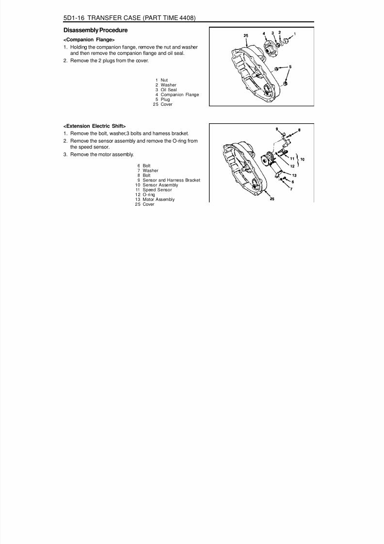
8/18/2019 SsangYong Musso Service Manual 1998.pdf
http://slidepdf.com/reader/full/ssangyong-musso-service-manual-1998pdf 1186/1459
5D1-16 TRANSFER CASE (PART TIME 4408)
Disassembly Procedure<Companion Flange>1. Holding the companion flange, remove the nut and washer
and then remove the companion flange and oil seal.2. Remove the 2 plugs from the cover.
1 Nut2 Washer3 Oil Seal4 Companion Flange5 Plug
25 Cover
6 Bolt7 Washer8 Bolt9 Sensor and Harness Bracket
10 Sensor Assembly11 Speed Sensor12 O-ring13 Motor Assembly25 Cover
<Extension Electric Shift>1. Remove the bolt, washer,3 bolts and harness bracket.2. Remove the sensor assembly and remove the O-ring from
the speed sensor.3. Remove the motor assembly.

8/18/2019 SsangYong Musso Service Manual 1998.pdf
http://slidepdf.com/reader/full/ssangyong-musso-service-manual-1998pdf 1187/1459
TRANSFER CASE (PART TIME 4408) 5D1-17
1. Remove the 9 bolts, wiring harness clip andidentification tag.
NoticeIdentification tag has information required for orderingreplacement parts, so be careful not to lose it.
2. Using a ‘-‘ driver, pry and disconnect the sealantbond of the cover and required case.
3. Remove the oil seal, bearing, 3 nuts and clutch coilassembly of the electric shift unit.
<Cover Assembly>
14 Bolt15 Wiring Clip16 Identification Tag17 Cover Assembly18 Oil Seal19 Bearing20 Nut21 Clutch Coil Assembly22 Snap Ring23 Ball Bearing
4. Remove the snap ring and pull out the ball bearingfrom the cover to remove the speed gear.
5. Pull out the needle bearing from the cover.6. Pull out the oil seal from the slot in cover.7. Remove the magnet form the slot in case.8. Remove the return spring from the rail shaft.9. Be careful not to damage the metal surface when
removing the sealant of the cover and case.
24 Needle Bearing25 Cover26 Magnet27 Speed Gear28 Oil Seal29 Return Spring38 Rail Shaft55 Output Shaft111 Transfer Case

8/18/2019 SsangYong Musso Service Manual 1998.pdf
http://slidepdf.com/reader/full/ssangyong-musso-service-manual-1998pdf 1188/1459
5D1-18 TRANSFER CASE (PART TIME 4408)
<Lock-up Shift Parts>1. Remove the retaining ring and clutch housing from the shift
collar hub.2. Remove the shift collar hub from the output shaft.3. Separate the 2WD - 4WD lock-up assembly and lock-up
fork from the output shaft and remove the rail shaft.
4. To remove the 2WD - 4WD lock-up assembly, separate thereturn spring, lock-up hub and snap ring from the lock-upcollar.
30 Retaining Ring31 Clutch Housing32 Shift Collar Housing33 2WD/4WD Lock-up Assembly34 Snap Ring35 Lock-up Hub36 Return Spring37 Lock-up Collar38 Rail Shaft39 Lock-up Fork55 Output Shaft
40 Snap Ring41 Spacer42 Drive Sprocket
43 Driven Sprocket44 Drive Chain55 Output Shaft(Rear)71 Output Shaft(Front)
<Drive Chains>1. Remove the snap ring and spacer from the output shaft.2. Remove the drive chain, driven sprocket and drive sprocket
from the output shaft.3. Separate the chain and sprocket when removing the
assembly.
<Pump Parts>1. Remove the 4 bolts and retainer and separate the output
shaft and rear pump cover.2. Loosen the hose clamp and remove the hose coupling from
the pump housing.3. Remove the hose clamp, hose coupling and strainer.4. Remove 2 pump pins and spring from the output shaft.5. Separate the front pump and remove the output shaft.
45 Shaft and Pump Assembly46 Bolt47 Pump Retainer48 Rear Pump Cover49 Hose Clamp50 Hose Coupling51 Pump Housing52 Pump Pin53 Spring54 Front Pump Cover55 Output Shaft56 Strainer

8/18/2019 SsangYong Musso Service Manual 1998.pdf
http://slidepdf.com/reader/full/ssangyong-musso-service-manual-1998pdf 1189/1459
TRANSFER CASE (PART TIME 4408) 5D1-19
<Front Output Assembly>1. Holding the companion flange, remove the nut and washer
and then remove the companion flange and oil seal.2. Remove the output shaft.
65 Nut66 Washer67 Oil Seal70 Companion Flange71 Output Shaft (front)
111 Case
57 Reduction Hub58 Shift Fork Facing59 Reduction Shift Fork Assembly60 Roller Pin and Retainer Assembly61 Retainer62 Pin63 Roller Cam64 Reduction Shift Fork
<Reduction Shift Parts>1. Remove the reduction hub and reduction shift fork assembly
from the case.2. Remove the 2 shill fork facings from the shift fork assembly.3. To remove the roller cam and pin, cut elf the plastic retainer
when disassembling the fork assembly.

8/18/2019 SsangYong Musso Service Manual 1998.pdf
http://slidepdf.com/reader/full/ssangyong-musso-service-manual-1998pdf 1190/1459
5D1-20 TRANSFER CASE (PART TIME 4408)
<Adapter, Input Shaft and Carrier Gear>
72 Breather73 Bolt74 Adapter Assembly75 Snap Ring76 Oil Seal77 Spiral Pin78 Front Adapter79 Retaining Ring80 Bearing81 Input Shaft Assembly
1. Remove the breather.2. After removing 6 bolts, remove the front adopter by
separating the adapter sealer bond from the caseusing a screw driver.Notice
Be careful not to damage the contacting surface ofthe case and adapter.3. Remove the adapter assembly, input shaft assembly
and carrier gear assembly.4. Remove the snap ring and oil seal from the front
adapter.
5. After removing snap ring, pull out the bearing andthrust washer from the input shaft assembly andseparate the input shaft assembly from the carriergear assembly.
6. Remove the needle bearing and sleeve bearing fromthe input shaft assembly.
7. Remove the retaining ring, thrust plate rind sun gearfrom the planet carrier assembly.NoticeDo not disassemble the planet carrier assembly.
82 Sleeve Bearing83 Needle Bearing84 Input Shaft85 Thrust Bearing86 Carrier Gear Assembly87 Retaining Ring88 Thrust Plate89 Sun Gear90 Planet Carrier Assembly
111 Case

8/18/2019 SsangYong Musso Service Manual 1998.pdf
http://slidepdf.com/reader/full/ssangyong-musso-service-manual-1998pdf 1191/1459
TRANSFER CASE (PART TIME 4408) 5D1-21
<Electric Shifts Cam Parts>1. Remove the electric shift cam parts from the case assembly.2. Separate the electric shift cam from the shift shaft.3. Holding the shift shaft in a vise, remove the torsion spring
and spacer from the shift shaft using a screw driver.
100 Electric Shift Cam101 Torsion Spr ing102 Spacer103 Shift Shaft111 Case
105 Transfer Case Assembly106 Oil Seal107 Retaining Ring
108 Ball Bearing119 Pin110 Ring Gear111 Case
<Case Assembly>1. Remove the oil seal.2. Remove the retaining ring and bearing.3. Remove the pin from the transfer case.
NoticeBe careful not to damage the pin.
4. Using a press, remove the ring gear from the case.

8/18/2019 SsangYong Musso Service Manual 1998.pdf
http://slidepdf.com/reader/full/ssangyong-musso-service-manual-1998pdf 1192/1459
5D1-22 TRANSFER CASE (PART TIME 4408)
Cleaning ProcedureNoticeBefore cleaning, check the magnet for thepresence of metal particles which indicate internalchipping of the transfer case.1. Using cleaning solvent, clean the residual oil and dirt
deposits.NoticeDuring cleaning, be careful not to damage the metalsurfaces.
2. After cleaning, dry the parts with low pressure (Max. 20 psi)compressed air.
3. Lubricate the ball bearings and needle bearings with transfercase oil after cleaning.NoticeProtect the lubricated bearings from dust.
Inspection Procedure1. Visually check the all removed parts.
NoticeAlways replace the hose coupling, O-ring and oil seal withnew parts.
2. Inspection TermsBurr : Local rise of material forming protruding sharpedgeChip : An area from which a small fragment has beenbroken off or cutCrack : Surface break of line nature indicating partial orcomplete separation of material.Excessive wear : Heavy or obvious wear beyondexpectations considering conditions of operation.Indentation : Displacement of material caused by localizedheavy contact.Galling : Breakdown of metal surface due to excessivefriction between parts. Particles of the softer materialare torn loose and welded to the harder material.Nick : Local break or notch, usually displacement of
material rather than loss.Scoring : Tear or break in metal surface from contactunder abnormal pressure.Step wear : Heavy wear that produces a step that canbe seen or felt between adjacent contact and noncontactsurfaces.Uneven wear : Condition of localized, unevenly distributedwear Includes hollows, shiny spots, uneven polish andother visual indications.

8/18/2019 SsangYong Musso Service Manual 1998.pdf
http://slidepdf.com/reader/full/ssangyong-musso-service-manual-1998pdf 1193/1459
TRANSFER CASE (PART TIME 4408) 5D1-23
3. Specific InspectionReferring to normal gear tooth face, specifically inspectthe uneven wear and chips of gear tooth.Replace or repair if necessary.
4. Inspection of Contact Patterns
Description Normal Abnormal
Normal Wear
End Face Wear
Traveling Face Wear
Upper Face Wear
Lower Face Wear

8/18/2019 SsangYong Musso Service Manual 1998.pdf
http://slidepdf.com/reader/full/ssangyong-musso-service-manual-1998pdf 1194/1459
5D1-24 TRANSFER CASE (PART TIME 4408)
Description Repair Description Repair
Corner chipat drive face
Edge chipat drive face
Corner chipat coast face
Side edge chipat drive face
Chip withincontact pattern
Chip completelythrough tooth
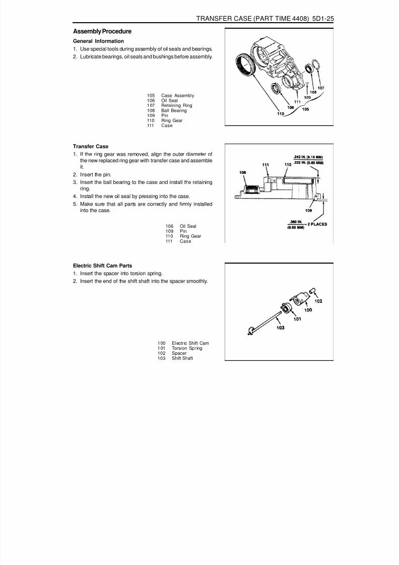
8/18/2019 SsangYong Musso Service Manual 1998.pdf
http://slidepdf.com/reader/full/ssangyong-musso-service-manual-1998pdf 1195/1459
TRANSFER CASE (PART TIME 4408) 5D1-25
Electric Shift Cam Parts1. Insert the spacer into torsion spring.2. Insert the end of the shift shaft into the spacer smoothly.
100 Electric Shift Cam101 Torsion Spr ing102 Spacer103 Shift Shaft
Assembly ProcedureGeneral Information1. Use special tools during assembly of oil seals and bearings.2. Lubricate bearings, oil seals and bushings before assembly.
105 Case Assembly106 Oil Seal107 Retaining Ring108 Ball Bearing109 Pin110 Ring Gear111 Case
106 Oil Seal109 Pin110 Ring Gear111 Case
Transfer Case1. If the ring gear was removed, align the outer diameter of
the new replaced ring gear with transfer case and assembleit.
2. Insert the pin.3. Insert the ball bearing to the case and install the retaining
ring.4. Install the new oil seal by pressing into the case.5. Make sure that all parts are correctly and firmly installed
into the case.
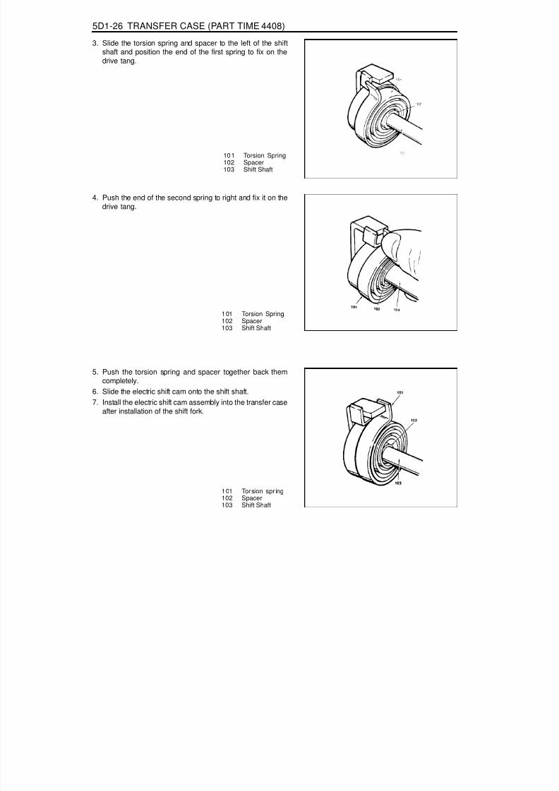
8/18/2019 SsangYong Musso Service Manual 1998.pdf
http://slidepdf.com/reader/full/ssangyong-musso-service-manual-1998pdf 1196/1459
5D1-26 TRANSFER CASE (PART TIME 4408)
101 Torsion Spring102 Spacer103 Shift Shaft
3. Slide the torsion spring and spacer to the left of the shiftshaft and position the end of the first spring to fix on thedrive tang.
4. Push the end of the second spring to right and fix it on thedrive tang.
101 Torsion Spring102 Spacer103 Shift Shaft
5. Push the torsion spring and spacer together back themcompletely.
6. Slide the electric shift cam onto the shift shaft.7. Install the electric shift cam assembly into the transfer case
after installation of the shift fork.
101 Torsion spr ing102 Spacer103 Shift Shaft

8/18/2019 SsangYong Musso Service Manual 1998.pdf
http://slidepdf.com/reader/full/ssangyong-musso-service-manual-1998pdf 1197/1459
TRANSFER CASE (PART TIME 4408) 5D1-27
Adapter, Input Shaft and Carrier
72 Breather73 Bolt74 Adapter Assembly75 Snap Ring76 Oil Seal77 Spiral Pin78 Front Adapter79 Retaining Ring80 Bearing81 Input Shaft Assembly
1. Place the planet carrier assembly on work bench to be theretaining ring mounting groove upward.
2. Install the sun gear with the hub end up into the planetcarrier assembly and rotate the sun gear to make sure thatgears are fully engaged.
3. Align the tabs and install the thrust plate into the planetcarrier assembly.4. Install the retaining ring to the planet carrier assembly.5. Press the needle bearing into the input shaft and press the
new sleeve bearing into the input shaft assembly.
82 Sleeve Bearing83 Needle Bearing84 Input Shaft85 Thrust Washer86 Carrier Gear Assembly87 Retaining Ring88 Thrust Plate89 Sun Gear90 Planet Carrier Assembly
111 Case

8/18/2019 SsangYong Musso Service Manual 1998.pdf
http://slidepdf.com/reader/full/ssangyong-musso-service-manual-1998pdf 1198/1459
5D1-28 TRANSFER CASE (PART TIME 4408)
6. Install the planet carrier assembly onto the input shaftand install the thrust washer. Press the bearing overinput shaft.
7. After pressing the bearing, install the retaining ring.8. Press the pin into the front adapter.9. Slowly press the oil seal into the front adapter.
10. Install the front adapter assembly.NoticeAfter installation, make sure that snap ring is correctlyinstalled into the groove.
11. Position the input shaft assembly over front cover andengage into the bearing groove by expanding the ends ofsnap ring.
12. Apply 1.6mm bead of sealant on the mounting face forthe transfer case and tighten the 6 bolts.
13. Install the breather.
75 Snap Ring76 Oil Seal77 Spiral Pin78 Front Adapter
82 Sleeve Bearing83 Needle Bearing
84 Input Shaft
Item6 Bolts
Breather
Tightening Torque28 - 48 Nm8 - 20 Nm

8/18/2019 SsangYong Musso Service Manual 1998.pdf
http://slidepdf.com/reader/full/ssangyong-musso-service-manual-1998pdf 1199/1459
TRANSFER CASE (PART TIME 4408) 5D1-29
Front Output Shaft1. Position the output shaft in transfer case and install the
companion flange assembly, oil seal, washer and nut.2. Holding the companion flange, tighten the nut.
65 Nut66 Washer67 Oil Seal70 Companion Flange71 Output Shaft (Front)
111 Case
55 Output Shaft57 Reduction Hub58 Shift Fork Facing59 Reduction Shift Fork Assembly60 Roller, Pin and Retainer Assembly61 Retainer62 Pin63 Roller Cam64 Reduction Shift Fork
Reduction Shift Parts1. Install the new pin, roller and retainer into the reduction
shift fork.
2. Press the pin, roller and retainer into the reduction spilt forkbore completely.NoticeMake sure that the cam roller turns freely.
3. Install the 2 fork facing on the reduction shift fork assembly.
4. Install the reduction shift fork onto the previously installedreduction hub in the transfer case.
5. Install the output shaft spline into the reduction hub andengage the output shaft end with input shaft bearing.NoticeFor installation of the output shaft, assemblethe oil pump temporarily.

8/18/2019 SsangYong Musso Service Manual 1998.pdf
http://slidepdf.com/reader/full/ssangyong-musso-service-manual-1998pdf 1200/1459
5D1-30 TRANSFER CASE (PART TIME 4408)
Oil Pump1. Install the pump front cover to be the ‘TOP’ mark down and
turn the cover to be the ‘TOP’ mark up when installed invehicle.
2. Install the 2 pump pins and spring to the output shaft.
NoticeFlat surface of the pins must point out and align the centerline of pins and spring.
3. Connect the hose coupling to the strainer coupling andinstall the strainer foot into the transfer case slot.NoticeThe hose coupling must face the pump assembly.
4. Install the pump housing to be the 'REAR' mark up and seatthe 2 pump pins inside of the pump housing by movingpump pins inward and compressing the spring.
5. Tighten the hose to pump housing by hose clamp.
6. Position the pump rear cover to be the ‘TOP REAR’ markup and located at the top of transfer case when installed invehicle. Position the pump retainer on the cover so that tabon the retainer is in notch in the transfer case. Apply Loctiteto the bolts and tighten the bolts with turning the outputshaft by hand to make the pump pins move freely.
45 Shaft and Pump Assembly46 Bolt47 Pump Retainer48 Rear Pump Cover49 Hose Clamp50 Hose Coupling54 Pump Housing52 Pump Pin53 Spring54 Front Pump Cover55 Output Shaft56 Strainer
40 Snap Ring41 Spacer42 Drive Sprocket43 Driven Sprocket44 Drive Chain55 Output Shaft (Rear)71 Output Shaft (Front)
Drive Chain1. Position the drive sprocket to the rear output shaft end and
driven sprocket to the front output shaft end.
2. Install the drive chain onto the sprocket.
3. Holding each sprocket to be the drive chain tight and parallelwith transfer case, install the drive chain assembly to theoutput shafts.
4. Rotate the driven sprocket slightly to engage splines onthe front output shaft.
5. Install the spacer to the front output shaft and insert thesnap ring into the shaft groove over spacer.
Tightening Torque 4 - 8.5 Nm

8/18/2019 SsangYong Musso Service Manual 1998.pdf
http://slidepdf.com/reader/full/ssangyong-musso-service-manual-1998pdf 1201/1459
TRANSFER CASE (PART TIME 4408) 5D1-31
Lockup Shift1. Install the lockup hub and return spring to the lockup collar
and insert the snap ring.2. Install the rail shaft through reduction shift fork assembly
previously installed and into the blind hole in case.3. Engage the lockup fork into the 2WD/4WD groove and
check operation.4. Install the shift collar hub to the output shaft spline.5. Install the previously assembled electric shift cam and
assemble the clutch housing as follows.Rotate the shift cam assembly to right so that the end ofthe torsion spring contacts with reduction shift fork side.Holding the rail shaft, lift up the fork assembly slightly.Adjust electric shift cam assembly so that the roller onreduction shift fork assembly is in groove in shift camand button on lockup fork is on cam end.Install the clutch housing over shift collar hub and insert
the retaining ring into the clutch collar hub groove. 30 Retaining Ring31 Clutch Housing32 Shift Collar Housing33 2WD/4WD
Lockup Assembly34 Snap Ring
38 Rail Shaft39 Lockup Fork
59 Reduction Shift Fork Assembly100 Electric Shift Cam101 Torsion Spr ing
35 Lockup Hub36 Return Spring37 Lockup Collar38 Rail Shaft39 Lockup Fork55 Output Shaft

8/18/2019 SsangYong Musso Service Manual 1998.pdf
http://slidepdf.com/reader/full/ssangyong-musso-service-manual-1998pdf 1202/1459
5D1-32 TRANSFER CASE (PART TIME 4408)
Cover1. Position the cover to be the open end up on the work table.2. Position the end of needle bearing to be identification mark
up and press into the cover until upper end of bearing is40.47 - 40.97mm below cover face that contacts with transfercase.
3. Press the ball bearing into the cover and install the snapring .
4. Install remaining parts as follows.Install the 4 O-rings on the stud bolts of the clutch coilassembly.Install the clutch coil assembly inside the cover andtighten 3 nuts.
18 Oil Seal19 Bushing20 Nut21 Clutch Coil Assembly22 Snap Ring23 Ball Bearing24 Needle Bearing25 Cover
Tightening Torque 8 - 11 Nm
Install the bearing and motor bearing into the cover.

8/18/2019 SsangYong Musso Service Manual 1998.pdf
http://slidepdf.com/reader/full/ssangyong-musso-service-manual-1998pdf 1203/1459
TRANSFER CASE (PART TIME 4408) 5D1-33
4. Install the cover onto the transfer case as follows :Align the cover bores with transfer case pins.Align the cover bearings with output shafts.Align the cover blind hole with rail shaft and make surethat return spring is not cocked.
29 Return Spring38 Rail Shaft55 Output Shaft71 Front Output Shaft
103 Shift Shaft109 Dowel Pin
Cover Assembly
14 Bolt15 Wiring Clip16 Identification Tag17 Cover Assembly26 Magnet27 Speed Gear28 Oil Seal29 Return Spring38 Rail Shaft
111 Case
1. Install the return spring over rail shaft in the transfer case.2. Insert the magnet into the transfer case slot.3. Apply 1.6mm bead of Loctite RTV 598 to the transfer case
mounting surface.Notice
For installation of cover, align the transfer case with covernot to use excessive force.
13 Motor Assembly14 Bolt15 Wiring Clip16 Identification Tag
5. Tighten 9 bolts positioning identification tag and wiring clip.
6. Install the speed gear over output shaft spline in the coverassembly.
7. Press the new oil seal into the cover assembly.
Tightening Torque 28 - 48 Nm

8/18/2019 SsangYong Musso Service Manual 1998.pdf
http://slidepdf.com/reader/full/ssangyong-musso-service-manual-1998pdf 1204/1459
5D1-34 TRANSFER CASE (PART TIME 4408)
External Electric Shift1. Align the motor with shift shaft and position the motor
assembly onto the cover.2. Install the motor to the shift shaft and contact cover androtate
the motor clockwise direction to check correctengagement.
6 Bolt7 Washer8 Bolt9 Sensor and Harness Bracket
10 Sensor Assembly14 Speed Sensor12 O-ring13 Motor Assembly25 Cover
13 Motor Assembly103 Shift Shaft
3. Insert the 0-ring on the speed sensor speed sensor
assembly to the cover.4. Install the bracket to the motor assembly and tighten 3bolts.
Tightening Torque 8 -11 Nm

8/18/2019 SsangYong Musso Service Manual 1998.pdf
http://slidepdf.com/reader/full/ssangyong-musso-service-manual-1998pdf 1205/1459
TRANSFER CASE (PART TIME 4408) 5D1-35
Companion Flange1. Install the 2 plugs to the cover.2. Install the companion flange, oil seal and washer.3. Holding the companion flange, tighten the nut.
1 Nut2 Washer3 Oil Seal4 Companion Flange5 Plug
25 Cover
NoticeApply Loctite 262 to nut before installation.
Tightening Torque 346 - 380 Nm

8/18/2019 SsangYong Musso Service Manual 1998.pdf
http://slidepdf.com/reader/full/ssangyong-musso-service-manual-1998pdf 1206/1459
5D1-36 TRANSFER CASE (PART TIME 4408)
TRANSFER CASE CONTROL UNIT(TCCU)System DescriptionTCCU is located under the front left handed seat and permitsthe vehicle to shift from two-wheel drive to four-wheel drive(and back shift) according to driver’s switch operation duringdriving (For the shifting between 4WD HIGH and 4WD LOW,stop the vehicle).
1. Shifting from 2H to 4HPosition the transfer case switch from '2H' to '4H'.Shifting is possible during driving.'4WD Hl' indicator light will turn on.
2. Shifting from 4H to 2HPosition the transfer case switch from '4H' to '2H'.Shifting is possible during driving.'4WD Hl' indicator light will turn off.
3. Shifting between 4H and 4LShifting is possible when the vehicle is almost stopped(below approx. 2 km/h), so it would be better stop thevehicle.In case of manual transmission equipped vehicle, applyclutch pedal.In case of auto transmission equipped vehicle, put the
lever position into 'N'.Position the transfer case switch '4H' to '4L' or '4L' to'4H'.According to the shifted position, indicator light will turnon.
NoticeIf there are malfunctions during shifting,'4H' or '4L' indicatorlight will blink.
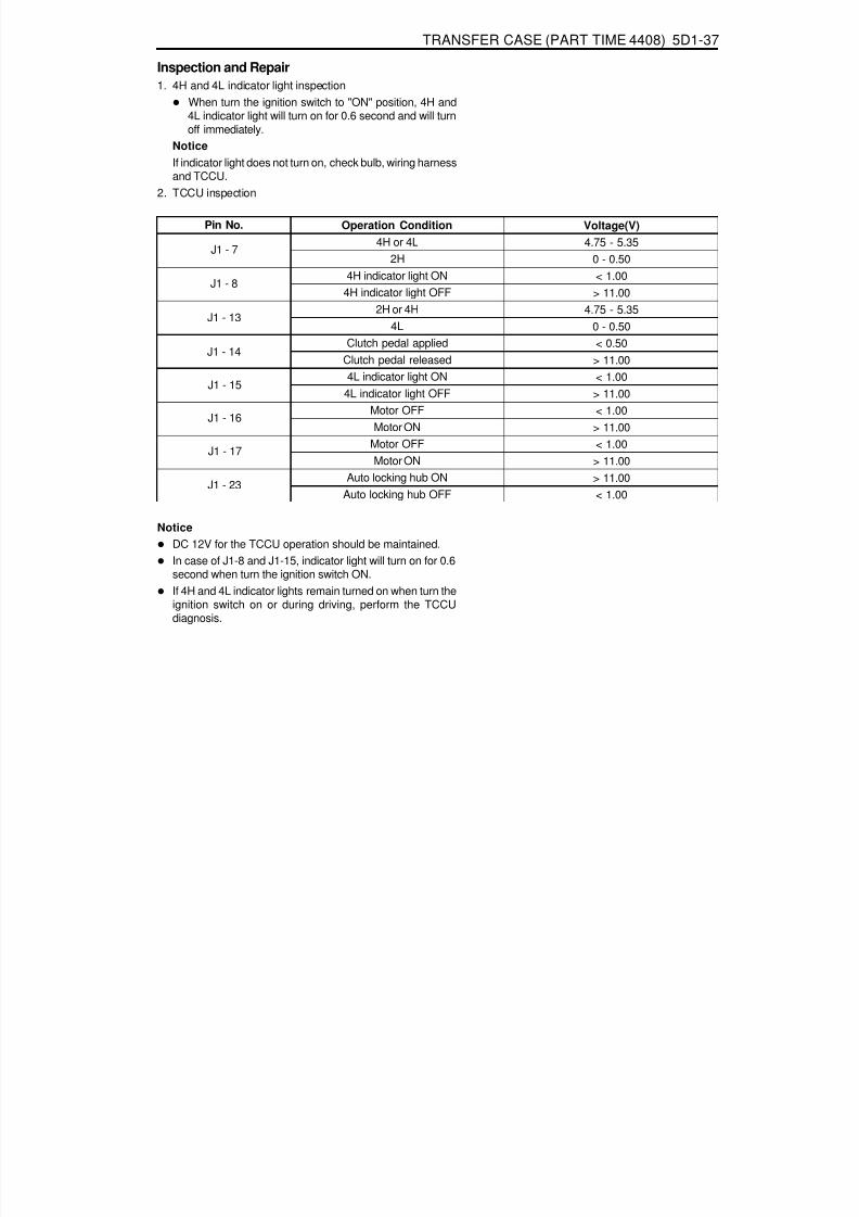
8/18/2019 SsangYong Musso Service Manual 1998.pdf
http://slidepdf.com/reader/full/ssangyong-musso-service-manual-1998pdf 1207/1459
TRANSFER CASE (PART TIME 4408) 5D1-37
Inspection and Repair1. 4H and 4L indicator light inspection
When turn the ignition switch to "ON" position, 4H and4L indicator light will turn on for 0.6 second and will turnoff immediately.
Notice
If indicator light does not turn on, check bulb, wiring harnessand TCCU.
2. TCCU inspection
Pin No. Operation Condition4H or 4L
2H4H indicator light ON
4H indicator light OFF2H or 4H
4LClutch pedal applied
Clutch pedal released4L indicator light ON
4L indicator light OFFMotor OFFMotor ON
Motor OFFMotor ON
Auto locking hub ON
Auto locking hub OFF
Voltage(V)4.75 - 5.35
0 - 0.50< 1.00
> 11.004.75 - 5.35
0 - 0.50< 0.50
> 11.00< 1.00
> 11.00< 1.00
> 11.00< 1.00
> 11.00> 11.00
< 1.00
J1 - 7
J1 - 8
J1 - 13
J1 - 14
J1 - 15
J1 - 16
J1 - 17
J1 - 23
NoticeDC 12V for the TCCU operation should be maintained.In case of J1-8 and J1-15, indicator light will turn on for 0.6second when turn the ignition switch ON.If 4H and 4L indicator lights remain turned on when turn theignition switch on or during driving, perform the TCCUdiagnosis.

8/18/2019 SsangYong Musso Service Manual 1998.pdf
http://slidepdf.com/reader/full/ssangyong-musso-service-manual-1998pdf 1208/1459
SECTION 5D2
TRANSFER CASE (TOD)
Specifications. . . . . . . . . . . . . . . . . . . . . . . 5D2-1General Specifications . . . . . . . . . . . . . . . . . 5D2-1
Schematic and Routing Diagrams . . . . . . . 5D2-2TOD . . . . . . . . . . . . . . . . . . . . . . . . . . . . . . . 5D2-2T.C.C.U . . . . . . . . . . . . . . . . . . . . . . . . . . . . . 5D2-3
Function Description . . . . . . . . . . . . . . . . . 5D2-4TOD Control Unit . . . . . . . . . . . . . . . . . . . 5D2-12Control Unit Diagram . . . . . . . . . . . . . . . . 5D2-14
TOD Control Unit . . . . . . . . . . . . . . . . . . . . 5D2-14Diagnosis . . . . . . . . . . . . . . . . . . . . . . . . . 5D2-15
Diagnostic Tests . . . . . . . . . . . . . . . . . . . . . 5D2-15Diagnostic Trouble Codes (DTC's) . . . . . . . 5D2-17
TABLE OF CONTENTS
SPECIFICATIONSGENERAL SPECIFICATIONS
ModelLength (mm)Weight (kg)Shift ModeGear Ratio
Oil
Max. Torque
HighLowSpecificationCapacityInterval
TOD(Torque On Demand) Transfer Case (4423E)343.036.6
4H and 4L1 : 1
2.48 : 1
ATF S-3, S-4 or Dexron II, III 1.4 L
Inspect Every 15,000km, Replace Every 50,000km550 lb · ft ( 76kg · m)
.=.
.=.
Application Description
Coding . . . . . . . . . . . . . . . . . . . . . . . . . . . . 5D2-18Eliminate the Memorized Fault Code . . . . . 5D2-20Diagnosis . . . . . . . . . . . . . . . . . . . . . . . . . . 5D2-21
Maintenance and Repair . . . . . . . . . . . . . 5D2-33On-Vehicle Service . . . . . . . . . . . . . . . . . . . 5D2-33
TOD Control Unit . . . . . . . . . . . . . . . . . . . . 5D2-33Transfer Case (TOD) . . . . . . . . . . . . . . . . . 5D2-34
Speed Sensor in Front and RearPropeller Shaft . . . . . . . . . . . . . . . . . . . . . 5D2-38
Replacement of Oil . . . . . . . . . . . . . . . . . . . 5D2-40Unit Repair . . . . . . . . . . . . . . . . . . . . . . . . 5D2-41
Transfer Case . . . . . . . . . . . . . . . . . . . . . . . 5D2-41

8/18/2019 SsangYong Musso Service Manual 1998.pdf
http://slidepdf.com/reader/full/ssangyong-musso-service-manual-1998pdf 1209/1459
5D2-2 TRANSFER CASE (TOD)
SCHEMATIC AND ROUTING DIAGRAMS
T O D

8/18/2019 SsangYong Musso Service Manual 1998.pdf
http://slidepdf.com/reader/full/ssangyong-musso-service-manual-1998pdf 1210/1459
TRANSFER CASE (TOD) 5D2-3
T . C
. C . U

8/18/2019 SsangYong Musso Service Manual 1998.pdf
http://slidepdf.com/reader/full/ssangyong-musso-service-manual-1998pdf 1211/1459
5D2-4 TRANSFER CASE (TOD)
FUNCTION DESCRIPTIONTOD System Select Mode (4H and 4L)4H is the mode when drive normally of which gear ratio is 1:1 and 4L mode distributes power to front and rearwheels 50:50 of which gear ratio is 2.48:1.
TOD System Function (select 4H mode)TOD system controls clutch mechanism to comply with rotation in front and rear propeller shaft and if its differenceexceeds the permissible range, corresponding power is distributed into front wheel through EMC (Electro-MagneticClutch).Hall effect sensor signals speed on front and rear propeller shafts going through with TOD control unit.Transfercase clutch coil is activated by variable current on exceeding difference of speed in front and rear propellershafts.
Function of 4L ModeWhen select 4L mode, EMC is locked to apply maximum torque into front and rear propeller shafts. Shift motorrotates also 4L position by rotation of cam thus propeller shaft torque changes from 1:1 to 2.48:1 by planetarygear set.
Shift MotorIt locates backside transfer case, which drives rotary helical cam.When mode select switch changes to 4L, shift fork is on position for 2.48:1 by rotation of helical cam.
Transfer CaseTOD transfer case distributes power into front and rear axle by operation of 4H/4L switch and shift motor.Shifting 4H to 4L, is performed towards reducing HI-LO collar by means for connection HI-LO shift fork withoutput shaft in order to join with planetary gear. Torque transmits input shaft then sun gear rotating front planetarygear. Front planetary gear join with output shaft and drives LO position.

8/18/2019 SsangYong Musso Service Manual 1998.pdf
http://slidepdf.com/reader/full/ssangyong-musso-service-manual-1998pdf 1212/1459

8/18/2019 SsangYong Musso Service Manual 1998.pdf
http://slidepdf.com/reader/full/ssangyong-musso-service-manual-1998pdf 1213/1459
5D2-6 TRANSFER CASE (TOD)
Input/Output diagramTOD control unit and main wiring harness is linked by 30 pinconnector. Each pin joins with switche and actuator whosedetails refer to the below diagram.
Battery Power
Ignition ON/OFF
Position Encoder 1
Position Encoder 2
Position Encoder 3
Position Encoder 4
4H / 4L Switch Signal
A/T “N” Position Signal
Speed / TPS Supply
Front Speed Sensor Input
Rear Speed Sensor Input
ABS Operation Signal
Brake Switch Signal
4
5
27
10
28
30
9
24
16
11
29
25
26
19
CAN H
CAN L
Shift Motor output port(LO-HI)
Shift Motor output port
(HI-LO)
EMC
'4L' Indicator
Position Return
'4WD CHECK' IND
TPS/speed Sensor Ground(Speed / TPS Return)
2
1
3
21
6
7
13
15
14
K-Line20
22
23
17
18

8/18/2019 SsangYong Musso Service Manual 1998.pdf
http://slidepdf.com/reader/full/ssangyong-musso-service-manual-1998pdf 1214/1459
TRANSFER CASE (TOD) 5D2-7
1. K-LINE : Communication line for coding and diagnosis with SCANNER.
Classification of Pin No.
Classification Pin No. Pin Name Description
Power Supply17,18 Ground TOD control unit ground
4,19 Battery TOD control unit battery supply : (Fuse No 13,20A)
5 Ignition Ignition ON / OFF27 Position 1 Position encoder 1 : check of shift motor position
10 Position 2 Position encoder 2 : check of shift motor position
28 Position 3 Position encoder 3 : check of shift motor position
30 Position 4 Position encoder 4 : check of shift motor position
9 4H/4L Switch Transfer case mode input
24 Auto T/M Neutral Check of neutral gear position in Auto T/M
16 Speed 5V supply (TPS / speed sensor)
11 Front Speed Front speed sensor signal input
Signal Input
29 Rear Speed Rear speed sensor signal input
25 ABS Operation ABS ON / OFF
6 Position Return Position encoder ground
13 Speed / TPS Return Ground for speed sensor / TPS
22 CAN-L CAN bus low line
23 CAN-H CAN bus high line
2,15 Motor LO-HI Motor output port- LO to HI : join with battery- HI to LO (or motor brake) : join with ground
1,14 Motor HI-LO Motor output port- HI to LO : join with battery- LO to HI (or motor brake) : join with ground
3 EMC TOD output
Signal Output
21 4L Illumination Illuminates “4L” indicator
7 Diagnosis Display 4WD check lamp illuminator- Upon defect ; Ground circuit
20 K-LINE1) Diagnosis

8/18/2019 SsangYong Musso Service Manual 1998.pdf
http://slidepdf.com/reader/full/ssangyong-musso-service-manual-1998pdf 1215/1459

8/18/2019 SsangYong Musso Service Manual 1998.pdf
http://slidepdf.com/reader/full/ssangyong-musso-service-manual-1998pdf 1216/1459
TRANSFER CASE (TOD) 5D2-9
4H/4L Switch Input4H4H4H4H
4H4H4H4H4H4L
4L4L4L4L4L4L
4L4L
Position Sensor Interpretation1. When the module powers up, it will read the position sensor
and the 4H/4L switch input and respond to the possiblecodes as follows
2. A command to shift will only be acted upon if the TCCU isreading a valid code at the time the command to shift ismade.
3. After a shift has started, the TCCU will power the shift motoruntil the code for the requested position is read. If an invalidcode is read, the TCCU will go into a default mode.
4. During a shift attempt, the shift motor will be energized for amaximum of 5 seconds.
Motor PositionLeft Stop
Left of HighHigh
Right of High
Zone 1NeutralZone 2
LowRight StopLeft Stop
Left of HighHigh
Right of HighZone 1NeutralZone 2
LowRight Stop
ActionNo action required. 4L bulb off.No action required. 4L bulb off.No action required. 4L bulb off.Blink 4L bulb. After the shift conditions are met, attempt a shiftto 4H under conditions of below 87 rpm in front and rearpropshaft and “Neutral” position. After succesfully shifting into4H, stop blinking 4L bulb.Same as aboveSame as aboveSame as aboveSame as aboveSame as aboveBlink 4L bulb. After the shift conditions are met, attempt a shiftto 4L. After succesfully shifting into 4L, stop blinking 4L bulb.Same as aboveSame as aboveSame as aboveSame as aboveSame as aboveSame as above
No action required. 4L bulb on.No action required. 4L bulb on.

8/18/2019 SsangYong Musso Service Manual 1998.pdf
http://slidepdf.com/reader/full/ssangyong-musso-service-manual-1998pdf 1217/1459

8/18/2019 SsangYong Musso Service Manual 1998.pdf
http://slidepdf.com/reader/full/ssangyong-musso-service-manual-1998pdf 1218/1459
TRANSFER CASE (TOD) 5D2-11
4. Electric Shift Default ModeIf the motor fails to reach its destination, the TCCU will attempt the following (in order):a. The TCCU will wait 3 seconds then attempt the shift again.b. If the second attempt to reach the destination fails the TCCU will wait 3 seconds then attempt to rotate the
motor back to the original position. If successful, all future shifts will be inhibited until the Ignition is cycled.c. If the attempt to return to the original position fails, the TCCU will wait 3 seconds then attempt to rotate the
motor to the original position again. If the second attempt to return to the original position is successful, the“4WD CHECK” lamp will be illuminated, and all future shifts will be inhibited until the Ignition is cycled.d. If the second attempt to return to the original position fails the motor will be turned off, the “4WD CHECK” lamp
will be illuminated, and all future shifts will be inhibited until the Ignition is cycled.
TOD TM System OperationThe TOD TM System is responsible for distributing torque between the front and rear axles. The TCCU monitors thepropshaft speeds, operating range (High/Low), and ABS activity and then applies a calculated amount of torque tothe front axle by Pulse Width Modulating the current applied to the EMC.1. Touch-off Torque
The minimum EMC Duty Cycle is based on the vehicle speed and throttle positionThe TCCU receives the TPS signal from the following sources:On vehicles equipped with CAN, the TCCU receives the TPS signal from the CAN bus.
2. When Slip DetectionThe TCCU continuously monitors the front and rear propshaft speeds to detect wheel slip.
3. Wheel Slip ControlWhen wheel slip is detected the TCCU controls the EMC duty cycle as necessary until the wheel slip is reducedbelow the allowable limit. The EMC Duty Cycle will then be reduced to the Touch-Off value.
4. Brake/ABS StrategyWhen the ABS System is active, the EMC Duty Cycle is set to a fixed duty cycle (30%) to aid in braking withoutcounteracting the ABS System.
5. 4L StrategyWhen the system is operating in 4L, the TCCU continues TOD TM (operation provided that the propshaft speed isbelow 175 rpm (5220 pulses/minute)). When the speed increases above 175 rpm, the EMC Duty Cycle is set tothe maximum value (88%) which applies the maximum available torque to the front axle.

8/18/2019 SsangYong Musso Service Manual 1998.pdf
http://slidepdf.com/reader/full/ssangyong-musso-service-manual-1998pdf 1219/1459

8/18/2019 SsangYong Musso Service Manual 1998.pdf
http://slidepdf.com/reader/full/ssangyong-musso-service-manual-1998pdf 1220/1459
TRANSFER CASE (TOD) 5D2-13
Speed Sensor/Clutch Coil and Motor ConnectorSpeed senso /clutch coil and shift motor connector locate upperbackside transfer case (upper part of shift motor).- Shift motor connector : Black- Speed sensor and clutch coil connector : White
Shift Mtor Connector Speed Sensor/Clutch Coil Connector
Rear View for ConnectorPinABCDEFG
FunctionPosition 4Motor (Counter-Clockwise)Position 3Position 2Position 1Position RetumMotor (Clockwise)
PinHIJKLMN
FunctionClutch Coil (EMC)Front Speed ReturnFront SpeedFront Speed Sensor SupplyRear Speed Sensor SupplyRear SpeedRear Speed Return
Rear View for Connector

8/18/2019 SsangYong Musso Service Manual 1998.pdf
http://slidepdf.com/reader/full/ssangyong-musso-service-manual-1998pdf 1221/1459
5D2-14 TRANSFER CASE (TOD)
Motor HI-LO(clockwise)
Motor LO-HI(counterclockwise)
PIN 13
CONTROL UNIT DIAGRAM
T O D C O N T R O L U N I T
14

8/18/2019 SsangYong Musso Service Manual 1998.pdf
http://slidepdf.com/reader/full/ssangyong-musso-service-manual-1998pdf 1222/1459
TRANSFER CASE (TOD) 5D2-15
DIAGNOSISWhile the TCCU is active it periodically monitors its inputs and outputs. If a fault is detected the “4WD CHECK” lampis illuminated and a fault code is stored in the TCCU memory.
When requested, fault codes are downloaded to a diagnostic connector (K-line) serial communications using SCAN-100.
DIAGNOSTIC TESTS1.TCCU Internal Function
When the Ignition is turned on the TCCU tests its ROM and RAM. If there is a fault, the TCCU immediately resetsitself and re-tests the ROM and RAM. If the fault persists the TCCU continues to reset and re-test until the fault iscorrected or the ignition is turned off. All TCCU functions are inhibited until the fault is corrected. The “4WDCHECK” lamp is not illuminated if there is a ROM or RAM fault.
If the ROM/RAM passes the EEPROM memory is tested. If there is a fault the “4WD CHECK” lamp is illuminatedand the TCCU continues to operate using the default calibration data stored in ROM. Fault codes are not storedwhen there is an EEPROM fault.
An EEPROM fault can only be cleared by cycling ignition off-on.
2.Shift Motor Assembly TestIf the TCCU detects a shift motor or position encoder fault continuously for one second the ‘4WD CHECK” lamp isturned on and the appropriate fault code is stored in memory.a. A shift motor fault when the motor is off is defined as follows:
Motor H-L shorted to GroundMotor L-H shorted to GroundMotor open circuit
b. A shift motor fault when the motor is energized is defined as follows:Motor H-L shorted to GroundMotor L-H shorted to GroundMotor H-L shorted to Motor L-HMotor open circuit
c. A position encoder fault is defined as follows:
Any position code which does not correspond to the valid 9 codes.A short to ground on any of the encoder lines.
d. If no shifts are in progress when a failure occurs the TCCU will not respond to any shift commands.
e. If a shift command has been received, but not acted upon when a failure occurs the TCCU will cancel thecommand and not respond to any subsequent shift commands.
f. If a shift command is in progress when an invalid position code is confirmed it will be halted and the TCCU will
turn the motor toward the high position. Afterwards the TCCU will not respond to any shift commands.

8/18/2019 SsangYong Musso Service Manual 1998.pdf
http://slidepdf.com/reader/full/ssangyong-musso-service-manual-1998pdf 1223/1459
5D2-16 TRANSFER CASE (TOD)
g. If the shift motor/position encoder assembly failure (other than a motor failure which occurs when the motor isenergized) recovers continuously for one second the TCCU will function normally. The “4WD CHECK” lamp isturned off but the fault code will remain in memory.
h. A motor failure (i.e. open or short circuit) which occurs when the motor is energized can only be cleared bycycling the ignition off-on.
3. Front Speed Sensor TestIf a Front Speed Sensor fault is detected continuously for 0.5 second the “4WD CHECK” lamp is illuminated. TheTCCU then responds as follows:a. If the system is in High Range the TCCU uses the Rear Speed Sensor to determine the EMC Touch Off level
and wheel slip control is suspended.b. If the system is in Low Range, the EMC Duty Cycle is set to maximum (independent of vehicle speed) until the
system is shifted out of 4L.c. All Electric Shift activity is halted until the Ignition is cycled. If a shift is in progress it will be completed.
If the Front Speed Sensor recovers continuously for O.5 second the TCCU will function normally. The “4WDCHECK” lamp is turned off but the fault code will remain in memory.
4. Rear Speed Sensor TestIf a Rear Speed Sensor fault is detected continuously for 0.5 second the “4WD CHECK” lamp is illuminated. TheTCCU then responds as follows:a. If the system is in High Range the TCCU uses the Front Speed Sensor to determine the EMC Touch Off level
and wheel slip control is suspended.b. If the system is in Low Range, the EMC Duty Cycle is set to maximum (independent of vehicle speed) until the
system is shifted out of 4L.c. All Electric Shift activity is halted until the Ignition is cycled. If a shift is in progress it will be completed.
If the Rear Speed Sensor recovers continuously for 0.5 second the TCCU will function normally. The “4WDCHECK” lamp is turned off but the fault code will remain in memory.
5. Both Speed Sensor FaultyIf both the Front and Rear Speed Sensors are faulty continuously for 0.5 seconds the “4WD CHECK” lamp isilluminated. The TCCU then responds as follows:a. If the system is in High Range the TCCU sets the EMC Touch Off level based on a vehicle speed of 0 and wheel
slip control is suspended.b. If the system is in Low Range, the EMC Duty Cycle is set to maximum until the system is shifted out of 4L.c. All Electric Shift activity is halted until the Ignition is cycled. If a shift is in progress it will be completed.
If both Speed Sensors recover continuously for 0.5 second the TCCU will function normally. The “4WD CHECK”lamp is turned off but the fault code will remain in memory.
6. EMC TestThe EMC is tested for open circuit or short circuit to ground. If a fault is detected continuously for 0.8 second the“4WD CHECK” lamp is turned on and all TOD TM activity is halted.
If the EMC recovers continuously for 0.8 second the TCCU will function normally. The “4WD CHECK” lamp isturned off but the fault code will remain in memory.

8/18/2019 SsangYong Musso Service Manual 1998.pdf
http://slidepdf.com/reader/full/ssangyong-musso-service-manual-1998pdf 1224/1459
TRANSFER CASE (TOD) 5D2-17
ClassificationTCCU
EMC
Speed Sensor
Shift Motor
Position Encoder
DIAGNOSTIC TROUBLE CODES(DTC’S)1. Diagnostic Trouble Code Retention
The first time a fault is detected a DTC is stored in the TCCU’sNon-Volatile memory. This DTC will remain in memory untilthe TCCU is instructed to erase DTC’s by SCAN-100. DTC’swill not be erased by disconnecting power to the TCCU.
2. Diagnostic Trouble Code Assignments
Code1714171517161721172217311732173317341735173617411742174317501751175217531754
DescriptionEEPROM Checksum Fault
TPS Loss of SignalTPS Out of Range
EMC Open / Short to BatteryEMC Short to ground
Front Speed Sensor Voltage LowFront Speed Sensor Voltage HighRear Speed Sensor Voltage LowRear Speed Sensor Voltage High
Speed Sensor Reference Voltage LowSpeed Sensor Reference Voltage High
Motor Open / Shorted to BatteryMotor Output Shorted to Ground
Shift System TimeoutGeneral Position Encoder Fault (Invalid Code)
Position 1 Shorted to GroundPosition 2 Shorted to GroundPosition 3 Shorted to GroundPosition 4 Shorted to Ground

8/18/2019 SsangYong Musso Service Manual 1998.pdf
http://slidepdf.com/reader/full/ssangyong-musso-service-manual-1998pdf 1225/1459
5D2-18 TRANSFER CASE (TOD)
CODINGCoding ToolSCANNER
Connection of Coding ToolConstruct SCANNER into diagnosis connector (20 pins) near fuse box in engine room as below figure.
1 Diagnosis Connector 2 SCANNER
Notice
Coding ; An input activity of data for the properperformance by matching specification, devices andsystem with control unit.

8/18/2019 SsangYong Musso Service Manual 1998.pdf
http://slidepdf.com/reader/full/ssangyong-musso-service-manual-1998pdf 1226/1459
TRANSFER CASE (TOD) 5D2-19
ClassificationEngine Type
Transmission/Vehicle Type
Axle Ratio
Tire Size
Coding Required1. Replacement of TOD control unit.2. Adjustment by input error.3. Change of tire specification.
ItemsGasoline Engine (E32)
661 Diesel Engine661LA Diesel Turbo Engine
662 Diesel Engine662LA Diesel Turbo Engine
Manual TransmissionAutomatic Transmission
MUSSO
KORANDO3.734.554.895.385.86P215P235P255P275
Coding Method1. Check and record engine type, axle ratio and tire size.2. Ignition “OFF”.3. Connect SCANNER with diagnosis connector in engine
room.4. Ignition “ON”.5. Read the current memorized specification in TOD control
unit.6. Compare memorized specification with the checked record.
If not matched, perform a coding.7. Read again memorized coding specification in TOD control
unit for confirmation of coding.8. Check coding specification whether it matches with vehicle
or not. If not, perform a coding again.
Coding items

8/18/2019 SsangYong Musso Service Manual 1998.pdf
http://slidepdf.com/reader/full/ssangyong-musso-service-manual-1998pdf 1227/1459
5D2-20 TRANSFER CASE (TOD)
ELIMINATE THE MEMORIZED FAULTCODEWhen diagnose by SCANNER, it is required that you makeadequate service on defects against all fault codes. And thenyou should delete the memorized fault codes in TOD controlunit using SCANNER as follows;
1. Connect SCANNER with diagnosis connector.2. Select “trouble code clear” in SCANNER.3. In “trouble code clear” screen, press “enter” key to erase
the fault code.4. Confirm deletion of fault code and, if not, repeat 2.-3.
process.

8/18/2019 SsangYong Musso Service Manual 1998.pdf
http://slidepdf.com/reader/full/ssangyong-musso-service-manual-1998pdf 1228/1459
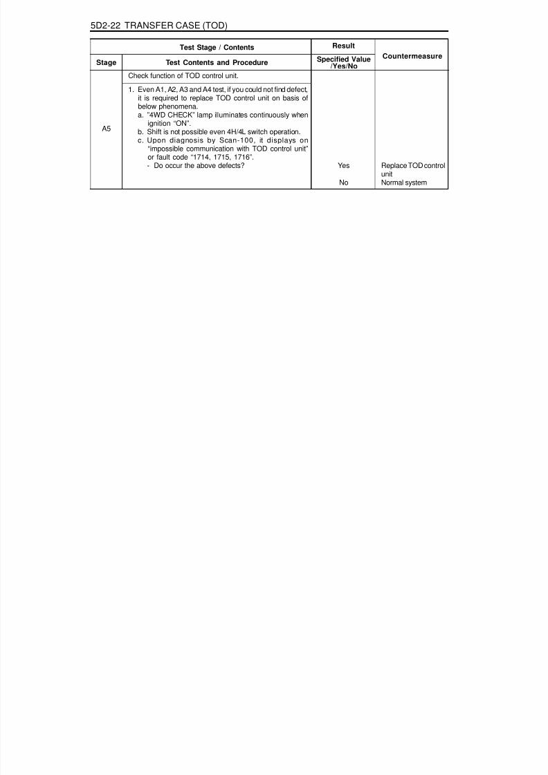
8/18/2019 SsangYong Musso Service Manual 1998.pdf
http://slidepdf.com/reader/full/ssangyong-musso-service-manual-1998pdf 1229/1459
5D2-22 TRANSFER CASE (TOD)
Check function of TOD control unit.
1. Even A1, A2, A3 and A4 test, if you could not find defect,it is required to replace TOD control unit on basis ofbelow phenomena.a. ”4WD CHECK” lamp illuminates continuously when
ignition “ON”.b. Shift is not possible even 4H/4L switch operation.c. Upon diagnosis by Scan-100, it displays on
“impossible communication with TOD control unit”or fault code “1714, 1715, 1716”.- Do occur the above defects? Yes
No
Replace TOD controlunitNormal system
A5
Test Stage / Contents Result
Stage Test Contents and Procedure Specified Value/Yes/No
Countermeasure

8/18/2019 SsangYong Musso Service Manual 1998.pdf
http://slidepdf.com/reader/full/ssangyong-musso-service-manual-1998pdf 1230/1459
TRANSFER CASE (TOD) 5D2-23
Error of signal in engine throttle position ; faultcode 1715, 1716
Phenomenon1. Upon diagnosis by SCAN-100, it display on 1715,
1716 codes.Cause
1. Bad communication line between E/G ECU and CAN.2. Defect of TOD control unit.3. Defect of E/G ECU.
Check connection status of connector through CANcommunication line.
1. Check connection of connector.- Does connector connect correctly between TOD
control unit and E/G ECU?2. In case of bad connection, connect correctly then
perform the follows ;a. Delete the memorized fault code using SCANNER.b. Ignition “OFF”.c. Ignition “ON”.d. Diagnose by SCANNER.
- Does it display fault codes “1715” or “1716”.
YesNo
B1
YesNo
Check connection status of CAN communication line towardsE/G ECU.
1. Ignition “OFF”.2. Disconnect 30 pin connector towards TOD control unit.3. Measure resistance between pin No.22 and 23 in wiring
connector using multi-tester.- Specified value- Measured value is within specified range?
B2115-125 W
YesNo
Check connection status of CAN communication line towardsTOD control unit.
1. Ignition “OFF”.2. Disconnect coupling of E/G ECU (gray, 1-60 pin).3. Measure resistance between pin No.37 and 38 in
coupling using multi-tester.- Specified value- Measured value is within specified range?
B3115-125 W
YesNo
Test Stage / Contents Result
Stage Test Contents and Procedure Specified Value/Yes/No
Countermeasure
Perform B2 stagePerform B1-2 stage
Perform B2 stageNormal system
Perform B3 STAGEPerform B4 stage,check and replace E/ G ECU
Perform B5 STAGEReplace TOD controlunit

8/18/2019 SsangYong Musso Service Manual 1998.pdf
http://slidepdf.com/reader/full/ssangyong-musso-service-manual-1998pdf 1231/1459
5D2-24 TRANSFER CASE (TOD)
Yes
No
B4
B5 YesNo
B6 4.75-5.25VdcYesNo
B7
0.3-0.9Vdc4.6-4.9Vdc
YesNo
4.6-4.9Vdc0.3-0.9Vdc
Yes
No
Test Stage / Contents Result
Stage Test Contents and Procedure Specified Value/Yes/No
Countermeasure
Check CAN communication line by diagnosis of E/G ECU.
1. Diagnose E/G ECU with SCANNER.2. Does it display on fault code “27” ?
Check power supply and signal output on throttle valveposition sensor (potentiometer) 1,2.
1. Diagnose E/G ECU with SCANNER.- Fault codes : 104, 105, 108, 109, 119, 185Does it display on above code ?
Check power supply (5V) of throttle valve position sensor.1. Ignition “ON”2. Measure voltage between pin 112(+) and 84(-) keeping
coupling connection status using multi - tester.- Specified value- Measured value is within specified range ?
Check output signal from throttle position sensor 1 and 2.
1. Keep E/G idle status.2. Measure output voltage between pin 87 (+) and 84 (-)keeping E/G ECU coupling connection status using multi-tester. (potentiometer 1)- Specified value min. acc. Pedal
max. acc. Pedal- Measured value is within specified range ?
3. Measure output voltage between pin 85 (+) and 84 (-)keeping E/G ECU coupling connection status using multi-tester. (potentiometer 2)- Specified value min. acc. Pedal
max. acc. Pedal- Measured value is within specified range ? Replace TOD control
unitReplace throttle bodyactuator or checkcable
Perform B1, B2, B3stagesPerform B5 stage
Perform B6 stageReplace TOD controlunit or perform A1-A5 stages
Perform B7 stageReplace E/G ECU orperform B1-2 stageafter checking cable.
Perform B7-3 stageReplace throttle bodyactuator or checkcable.

8/18/2019 SsangYong Musso Service Manual 1998.pdf
http://slidepdf.com/reader/full/ssangyong-musso-service-manual-1998pdf 1232/1459
TRANSFER CASE (TOD) 5D2-25
Error in electro - magnetic clutch : fault code“1721”, “1722”
Phenomenon1. Upon diagnosis by SCAN-100, it displays on fault
codes “1721,1722”.Cause
1. Defect in electro - magnetic clutch2. Defect in connector or wiring
- Open or short from EMC to the supply : 1721- Short EMC to ground : 1722
YesNo
C1
YesNo
YesNo
11-15VdcYesNo
C2
YesNo
Test Stage / Contents Result
Stage Test Contents and Procedure Specified Value/Yes/No
Countermeasure
Check relevant connector connection status.
1. Check relevant connector connection status with TOD
control unit.- Does it connect correctly ?
2. Check connection status of speed sensor and clutchcoil connector (7 pin) in transfer case.- Does it connect correctly ?
3. In case of bad connection, connect it correctly thenperform the follows :a. Delete the memorized fault code in control unit with
Scan - 100.b. Ignition “OFF”.c. Ignition “ON”.d. Diagnose by SCAN-100
- Does it display on fault codes “1721,1722” ?
Check supply voltage into electro-magnetic clutch.
1. Ignition “ON”2. Measure voltage between pin 4/19(+) and 17/18(-) in
TOD control unit connector.- Specified value- Measured value is within specified range ?
3. If the specified value would not be measured, performthe follows :a. Check battery voltage (charging condition)b. Check open circuit on No.13 fuse (20A)c. Check relevant wires.
- Is the above 3a, 3b, 3c normal ?
Perform C1-2 stagePerform C1-3 stage
Perform C2 stageNormal system
Perform C2 stagePerform C1-3 stage
Perform C3 stagePerform C2-3 stage
Perform C3 stageCharging/ Replace batteryReplace fuseRepair wires

8/18/2019 SsangYong Musso Service Manual 1998.pdf
http://slidepdf.com/reader/full/ssangyong-musso-service-manual-1998pdf 1233/1459
5D2-26 TRANSFER CASE (TOD)
0Vdc11 - 15Vdc
Yes
No
2.5 WYesNo
C3
Test Stage / Contents Result
Stage Test Contents and Procedure Specified Value/Yes/No
Countermeasure
Check resistance of electro-magnetic clutch.
1. Disconnect 30 pin connector from TOD control unit.2. Measure resistance between pin 3 and 7 in wiring
connector using multi-tester.- Specified value- Measured value is within specified range? Perform C4 stage
0W : short¥ W : open
C4
Check operational voltage of elector-magnetic clutch.
1. Ignition "ON"2. Measure voltge between pin 3(+) and 17(-)in TOD
control unit connector.- Specified value 4WD high
4WD low- Measure value is within specified range ? Replace TOD
control unitReplace wire

8/18/2019 SsangYong Musso Service Manual 1998.pdf
http://slidepdf.com/reader/full/ssangyong-musso-service-manual-1998pdf 1234/1459
TRANSFER CASE (TOD) 5D2-27
Defect in speed sensor : fault code 1731, 1732,1733, 1734, 1735,1736
Phenomenon1. Upon diagnosis by SCANNER, it displays on fault code
1731, 1732, 1733, 1734, 1735 and 1736.2. “4WD CHECK” lamp illuminates continuously when
ignition “ON”.Cause1. Defect of speed sensor (front, rear).2. Defect of power supply.
4.75-5.25VdcYesNo
D1
YesNo
D2
YesYes
YesNo
D3
Test Stage / Contents Result
Stage Test Contents and Procedure Specified Value/Yes/No
Countermeasure
Check power supply of speed sensor.
1. Ignition “ON” or driving mode2. Measure supply voltage between pin 16 (+) and 13 (-) in
TOD control unit connector using digital multi-tester.- Specified value- Measured value is within specified range ?
Check connection status of connector.
1. Check connection status of speed sensor/clutch coilconnector and TOD control unit connector.- Does it connect correctly ?
2. In case of bad connection, connect it correctly thenperform the follows:a. Delete the memorized fault code in control unit by
SCANNER.b. Ignition “OFF”.c. Ignition “ON”.d. Diagnose by SCANNER.
- It does not display fault code.- It displays one or more fault code among 1731 to
1736.
Check output wave of front and rear speed sensor.
1. Upon driving mode.2. Check output wave of each speed sensor by SCANNER.3. Is it normal on output wave ?
Perform D3 stagePerform D2 stage
Perform D3 stagePerform D2-2 stage
Normal systemPerform D3 stage
Perform D4 stageReplace speedsensor thenperform D2-2 stage

8/18/2019 SsangYong Musso Service Manual 1998.pdf
http://slidepdf.com/reader/full/ssangyong-musso-service-manual-1998pdf 1235/1459
5D2-28 TRANSFER CASE (TOD)
Yes
No
D4
Test Stage / Contents Result
Stage Test Contents and Procedure Specified Value/Yes/No
Countermeasure
Check output voltage of front and rear speed sensor.
1. Upon driving mode2. Measure output voltage of front and rear speed sensor
by multi-tester. Check voltage whether it varies withinspecified range.- Specified value
• Front speed sensor: Pin 11(+), 13(-) in TOD control unit connector
• Rear speed sensor: Pin 29(+), 13(-) in TOD control unit connector- Measure value is within specified range ? Check function of
control unit.It necessary,replace then deletefault codes and re-
diagnose .Perform D5 stage
YesNo
D5
Check short/open in cable.
1. Ignition"OFF"2. Disconnect TOD control unit connector3. Make a test for open circuit between pin 11 and 13, 16
and 13, 29 and 13 in wiring connector by multi-tester.- Is there a resistance of " ¥ " ?
4. Make a test for short between pin 11 and ground 13and ground, 29 and ground by multi-tester.- Is there a resistance of " ¥ W " ?
Repair wire PerformD5-4 stge
YesNo
Wiring short, repairPerform D3 stage,then delete faultcodes withrediagnosis

8/18/2019 SsangYong Musso Service Manual 1998.pdf
http://slidepdf.com/reader/full/ssangyong-musso-service-manual-1998pdf 1236/1459
TRANSFER CASE (TOD) 5D2-29
Shift motor malfunction : Fault code ® 1741,1742, 1743
Phenomenon1. When change the 4H/4L switch from 4H to 4L, ‘4L’
indicator lamp turn off after blinking for a time and then‘4WD CHECK’ indicator lamp turn on.
2. Fault codes display by diagnosis of SCAN-100 : 1741,1742, 1743
3. The shifting operation is not occurred when 4H / 4L switch,is operating.
CauseDefect in shift motor, improper voltage provided, incorrectconnection in connector, short of wiring.
11-14 V(Battery voltage)
YesNo
E1
11-14 V(Battery voltage)
YesNo
YesNo
E2
YesNo
Test Stage / Contents Result
Stage Test Contents and Procedure Specified Value/Yes/No
Countermeasure
Check the input voltage of shift motor.1. Turn the ignition switch to “ON” position.2. Measure the Hi/Low voltage of motor which is located
between No.1/No.14 and No.2/No.15 connector of TODcontrol unit with digital Multi-tester or which is locatedbetween No.G connector and body after detaching T/Cmotor connector.- The specified value (When operates 4H/4L switch)
- Measured value is within specified range ?3. Measure the Hi/Low voltage of motor which is located
between No.2/No.5 and No.1/No.14 connector or which
is located No.B connector and body after detaching T/Cmotor connector- The specified value (When operates 4H/4L switch)
- Measured value is within specified range ?
Check the fault condition of the relevant connector.
1. Check the installation condition of TOD control unit 30pinconnector and T/C shift motor connector.
- Is it installed properly ?
2. If the connector installation is improper, install properlyand then perform follows :a. Delete the fault code of control unit by scan scopeb. Turn off the ignition switchc. Turn on the ignition switchd. Re-diagnosis of system
It displays one or more fault code among 1741 to 1743.
Perform E1-3 stagePerform E2 stage
Perform E4 stagePerform E2 stage
Perform E3 stagePerform E2-2 stage
Perform E3 stageNormal system

8/18/2019 SsangYong Musso Service Manual 1998.pdf
http://slidepdf.com/reader/full/ssangyong-musso-service-manual-1998pdf 1237/1459
5D2-30 TRANSFER CASE (TOD)
Yes
No
Yes
No
YesNo
E3
Yes
No
E4
Yes
No
E5
Test Stage / Contents Result
Stage Test Contents and Procedure Specified Value/Yes/No
Countermeasure
Check the wiring of shift motor whether it is shorted or not.
1. Turn off the ignition switch.2. Detach the 30pin connector from TOD control unit
3. Perform short test between the wiring connector No.1/ No.14 and No.2/No.5.- Is there resistance of 0 W ?
4. Perform the short test between No.1/No.14 Connectorand body, No2/No.15 connector and body.- Is there resistance of 0 W ?
5. Execute E1 stage to check whether wiring is shortedbetween Hi-Low motor and LOW-HI motor.- Is the provided voltage proper ?
Check the resistance of shift motor
1. Turn off the ignition switch.2. Measure the resistance between No.1/No.14 and No.2/
No.15 connector after detaching 30pin connector of TODcontrol unit Or, check the resistance between No.G andNo.B after detaching motor connector of T/C side.- Specified value- Measured value is within specified range ?
Execute the test after detaching shift motor, when the faultis not solved after executing E1~E4 stage.
1. Detach the motor connector from T/C.2. Remove the shift motor.3. Connect motor connector with the removed shift motor.4. Operate the 4H/4L switch.
- Does motor rotate ?
Hi-Low motor andLo-Hi wiring areshorted each other.Repair or replace.Perform E3-4 stage.
Related wiring isshorted with ground.Repair or replace.
Perform E3-5 stage.
Perform E4 stage.Wiring is shorted.Repair or replace.
The defective T/C orperform E5 stage.Replace the shiftmotor.
Check and fix due tothe defective T/Cass’y.Replace the motoror delete fault codeand rediagnosissystem.

8/18/2019 SsangYong Musso Service Manual 1998.pdf
http://slidepdf.com/reader/full/ssangyong-musso-service-manual-1998pdf 1238/1459
TRANSFER CASE (TOD) 5D2-31
Position incoder and position 1,2,3,4 malfunction:Fault code®1750,1751,1752,1753, 1754
PhenomenonThe ‘4WD check’ lamp can not go out when the ignitionswitch positioned to ‘ON’.The fault code display 1750, 1751, 1752, 1753, 1754 by
diagnosis of SCAN-100.CauseThe portion of position incoder malfunction, each wiring isshorted with ground.
YesNo
F1
YesNo
Yes
NoF2
Test Stage / Contents Result
Stage Test Contents and Procedure Specified Value/Yes/No
Countermeasure
Check the installation condition of connector.
1. Check the installation condition between 30 pin connectorof TOD control unit and motor connector of T/C portion.- Is it installed properly ?
2. If the connector installation is improper, install properlyand then execute follow procedure.a. Delete the all fault code from memory by scan scope.b. Turn off ignition switch.c.Turn on ignition switch.d. Rediagnosis the system.
- Does the fault codes display one or more among 1750 ~ 1754.
Check the each wiring whether it is shorted or not.
1. Turn off the ignition switch2. Detach the 30 pin connector of TOD control unit.3. Perform short test each connector, No.27 (Position 1),
No.10 (Position 2), No.28 (Position 3),No.30 (Position4), No.6 with body.- Is there resistance of 0 W?
Perform F2 stagePerform F1-2 stage
Perform F2 stageNormal system
Repair or replacedue to wiring short1. Replace the
motor Ass’y duethe defectiveposition incoderportion.
2. And then, performF1-2 stage.
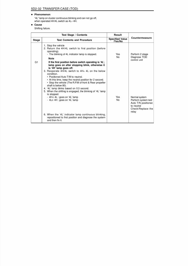
8/18/2019 SsangYong Musso Service Manual 1998.pdf
http://slidepdf.com/reader/full/ssangyong-musso-service-manual-1998pdf 1239/1459
5D2-32 TRANSFER CASE (TOD)
Phenomenon“4L” lamp on cluster continuous blinking and can not go off,when operated 4H/4L switch as 4L« 4H.CauseShifting failure.
1. Stop the vehicle2. Return the 4H/4L switch to first position (before
operating).- The blinking of 4L indicator lamp is stopped.
NoteIf the first position before switch operating is ‘4L’,lamp goes on after stopping blink, otherwise itis ‘4H’ lamp goes off.
3. Reoperate 4H/4L switch to 4H « 4L on the belowcondition.• Positioned Auto T/M to neutral.• At this time, keep the neutral position for 2 second.• Stop the vehicle (The R.P.M of front & Rear propellershaft is below 80).
4. ‘4L’ lamp blinks based on 0.3 second.5. When the shifting is engaged, the blinking of ‘4L’ lamp
is stopped.- 4H® 4L : goes on ‘4L’ lamp- 4L® 4H : goes on ‘4L’ lamp
6. When the ‘4L’ indicator lamp continuous blinking,repositioned to first position and diagnose the systemand then fix it.
YesNo
G1
YesNo
Test Stage / Contents ResultStage Test Contents and Procedure Specified Value
/Yes/NoCountermeasure
Perform 2 stageDiagnose TODcontrol unit
Normal systemPerform system testAuto T/N positionedto neutralCheck/Replace therelay

8/18/2019 SsangYong Musso Service Manual 1998.pdf
http://slidepdf.com/reader/full/ssangyong-musso-service-manual-1998pdf 1240/1459
TRANSFER CASE (TOD) 5D2-33
9 - 16 Vdc6 - 16 Vdc
2 mA1 A7 A
20 A
Removal & Installation Procedure1. Turn the ignition switch to "OFF" position.
2. Remove 30 pin connector from TOD control unit.
3. Unscrew 2 bolts (1).Installation Notice
1 Bolt (M6 x 16, 2pieces) ................ 9-11 Nm2 TOD control unit
MAINTENANCE AND REPAIR
ON-VEHICLE SERVICETOD CONTROL UNIT
TOD Electric CharacteristicsVoltage
Parasitic Current(Under max. operation Voltage)Max. Operation Current(Under max. operation Voltage)
Normal Operation RangeCAN communication Operation Range
Ignition “OFF”Ignition “ON”Motor “OFF”Motor “ON”
4. Installation should follow the removal procedure in thereverse order.NoticeWhen replace TOD control unit, it is required to make acoding correspondent with vehicle specification.
Tightening Torque 9 - 11 Nm

8/18/2019 SsangYong Musso Service Manual 1998.pdf
http://slidepdf.com/reader/full/ssangyong-musso-service-manual-1998pdf 1241/1459
5D2-34 TRANSFER CASE (TOD)
TRANSFER CASE (TOD)
1 Transmission2 TOD Transfer Case3 Extension Housing4 Bolt ....................................................... 35-60Nm
5 Front Propeller Shaft6 Bolt ....................................................... 81-89Nm7 Rear Propeller Shaft8 Bolt ....................................................... 81-89Nm

8/18/2019 SsangYong Musso Service Manual 1998.pdf
http://slidepdf.com/reader/full/ssangyong-musso-service-manual-1998pdf 1242/1459

8/18/2019 SsangYong Musso Service Manual 1998.pdf
http://slidepdf.com/reader/full/ssangyong-musso-service-manual-1998pdf 1243/1459
5D2-36 TRANSFER CASE (TOD)
11. Unscrew 4 units of M12 bolts from case flange thendisconnect front propeller shaft from transfer case.Installation Notice
Tightening Torque 81 - 89 Nm
12. Unscrew 4 units of M12 bolts from case flange thendisconnect rear propeller shaft from transfer case.Installation Notice
13. Unscrew 5 units of mounting bolt (M12) from extensionhousing in transmission.Installation Notice
Tightening Torque 81 - 89 Nm
Tightening Torque 35 - 60 Nm
NoticeMake sure the connecting surface is clean.Applying long-life grease spline inside transfer case inputshaft.
14. Installation should follow the removal procedure in thereverse order.
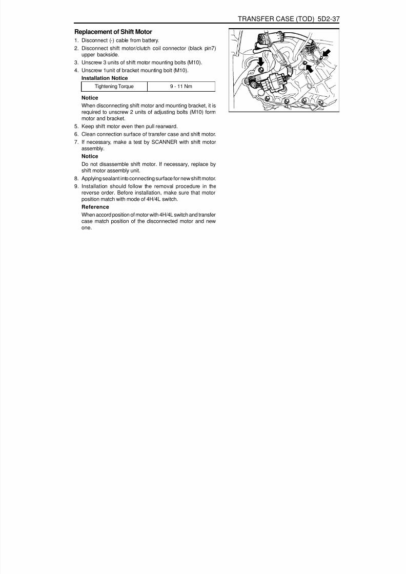
8/18/2019 SsangYong Musso Service Manual 1998.pdf
http://slidepdf.com/reader/full/ssangyong-musso-service-manual-1998pdf 1244/1459
TRANSFER CASE (TOD) 5D2-37
Replacement of Shift Motor1. Disconnect (-) cable from battery.2. Disconnect shift motor/clutch coil connector (black pin7)
upper backside.3. Unscrew 3 units of shift motor mounting bolts (M10).4. Unscrew 1unit of bracket mounting bolt (M10).
Installation NoticeTightening Torque 9 - 11 Nm
NoticeWhen disconnecting shift motor and mounting bracket, it isrequired to unscrew 2 units of adjusting bolts (M10) formmotor and bracket.
5. Keep shift motor even then pull rearward.6. Clean connection surface of transfer case and shift motor.7. If necessary, make a test by SCANNER with shift motor
assembly.
NoticeDo not disassemble shift motor. If necessary, replace byshift motor assembly unit.
8. Applying sealant into connecting surface for new shift motor.9. Installation should follow the removal procedure in the
reverse order. Before installation, make sure that motorposition match with mode of 4H/4L switch.ReferenceWhen accord position of motor with 4H/4L switch and transfercase match position of the disconnected motor and newone.

8/18/2019 SsangYong Musso Service Manual 1998.pdf
http://slidepdf.com/reader/full/ssangyong-musso-service-manual-1998pdf 1245/1459
5D2-38 TRANSFER CASE (TOD)
SPEED SENSOR IN FRONT ANDREAR PROPELLER SHAFTReplacement Procedure1. Disconnect (-) cable from battery.2. Detach shift motor assembly.
3. Disconnect front and rear speed sensor connector (white 3pin) upper backside transfer case.
4. Disconnect speed sensor connect from locking sleeve bypushing.
5. Disconnect wire stick cap from the detached connector.
6. Unscrew rear speed sensor mounting bolt (M10) from upperside of rear case flange.
7. Detach sensor from transfer case by lifting up using tool.NoticeWhen disconnect sensor, make sure on adequate pressuredue to sensitiveness with shock.
8. Disconnect taping from both protection tube ends that wrap3 wires of speed sensor and 1 wire of clutch coil.
9. Disconnect tube.

8/18/2019 SsangYong Musso Service Manual 1998.pdf
http://slidepdf.com/reader/full/ssangyong-musso-service-manual-1998pdf 1246/1459
TRANSFER CASE (TOD) 5D2-39
10. Disconnect pin and wire from speed sensor connector bypulling sticking long-nose plier into “L” pin in connector.
11. On the same way, disconnect pin and wire “M” and “N”from connector.NoticeDo not touch the wires related with EMC.
12. Prepare new speed sensor.13. Connect 3 pins with wires of speed sensor to coincide with
each connection position.14. Using long-nose plier, connect tightly by pulling pins.
15. Apply rubber cap into connector using long-nose plier notto detach.16. Connect protection tube with wire.17. Tape both ends of tube.18. Putting rear speed sensor into hole, connect exactly
pushing both ends.19. Screw 1 unit of bolt (M10).
Installation Notice
Tightening Torque 9 - 11 Nm
20. Connect speed sensor connector, then locking sleeve.
ReferenceFront propeller shaft should be premised by removal ofshift motor.After disconnecting shift motor, procedure of replacementon sensor assembly of accords with one of rear speedsensor.

8/18/2019 SsangYong Musso Service Manual 1998.pdf
http://slidepdf.com/reader/full/ssangyong-musso-service-manual-1998pdf 1247/1459
5D2-40 TRANSFER CASE (TOD)
REPLACEMENT OF OILOil Specification
Specified Oil Level
Specification StandardCapacityService
A.T.F S-3, S-4 or Dexron II, III1.4 Litre
Inspection every 15,000km, Replacement every 50,000km
Oil Replacement1. Lift on vehicle then make sure on safety.2. Prepare a vessel to drain transfer case oil.3. Release filler plug.
4. Drain oil completely.5. Wash drain plug and than tighten.
Installation Notice
Tightening Torque 19 - 30 Nm
6. Replenish standardized oil by specified level through fillerplug hole.
7. Tighten filler plug after washing.Installation Notice
8. Check oil leakage.
Tightening Torque 19 - 30 Nm
..

8/18/2019 SsangYong Musso Service Manual 1998.pdf
http://slidepdf.com/reader/full/ssangyong-musso-service-manual-1998pdf 1248/1459
TRANSFER CASE (TOD) 5D2-41
UNIT REPAIRTRANSFER CASE
Transfer Case, Diassembled View

8/18/2019 SsangYong Musso Service Manual 1998.pdf
http://slidepdf.com/reader/full/ssangyong-musso-service-manual-1998pdf 1249/1459
5D2-42 TRANSFER CASE (TOD)
1 Bearing2 Bushing3 Carrier Assembly4 Sun Gear5 Thrust Plate6 Input Shaft7 Output Shaft Thrust Washer
8 Bearing9 Retaining Ring10 Snap Ring11 High-low Collar12 Rear Output Shaft13 Oil Strainer14 Coupling Hose15 Hose Clamp16 Pump Assembly17 Thrust Washer18 Sprocket, Drive (24T)19 Clutch Pack Assembly20 Insulator Washer21 Armature22 Snap Ring23 Wave Washer24 Apply Cam25 Ball26 Cam and Coil Assembly27 Nut, Metric28 Output Shaft Yoke Washer29 Oil Seal30 Case Flange31 Bolt32 Upper Speed Sensor (Rear)
33 Nut34 Washer37 Bolt38 Tag, Identification39 Thrust Bearing40 Clutch Coil Assembly41 Fork, Reduction Shift
42 Shift Rail43 Shaft, Shift44 Spacer45 Torsion Spring46 Shift Cam47 Transfer Case Shift Motor48 Bolt
49 J-clip50 Connector Retainer51 Bolt52 Support Stud53 Lower Speed Sensor (Front)54 Plug55 Identification Decal56 Cover57 Tone Wheel, Lower58 Chain, Drive59 Sprocket, Driven (24T)61 Magnet62 Case63 Case Flange and Output Shaft64 Barb, Breather68 Spiral Pin69 Oil Seal70 Pin, Dowel71 Ring Gear72 Retaining Ring73 Snap Ring74 Bearing75 Snap Ring76 Bearing77 Speedometer Drive Gear
78 Facing, Shift Fork79 Upper Tone Wheel80 Oil Seal81 Bearing Sleeve82 Bearing

8/18/2019 SsangYong Musso Service Manual 1998.pdf
http://slidepdf.com/reader/full/ssangyong-musso-service-manual-1998pdf 1250/1459
TRANSFER CASE (TOD) 5D2-43
Disassembly Procedure1. Disconnect transfer case from vehicle2. Using a 30mm thin-wall socket, first remove the rear output
nut, output shaft yoke washer, oil seal then the case flange.Installation Notice
27 Nut28 Washer30 Case Flange
Tightening Torque 137 - 196 Nm
3. Disconnect shift motor/clutch coil connector and speedsensor connector from upper bracket of transfer case.NoticeWhen disconnect connector, pull forwards graspingconnector housing.
4. Remove outer tube on speed sensor connector.5. Remove wire supporting cape back side of speed sensor
connector.6. Disconnect pin of clutch coil wire (yellow) from speed sensor
connector (white 7 pin) using long-nose plier.7. Remove shift motor.
NoticeWhen remove shift motor, pay attention to the location oftriangular slot and shaft in transfer case inside motor.
8. Disconnect front and rear speed sensor.

8/18/2019 SsangYong Musso Service Manual 1998.pdf
http://slidepdf.com/reader/full/ssangyong-musso-service-manual-1998pdf 1251/1459
5D2-44 TRANSFER CASE (TOD)
9. Remove the bolts that retain the front case to therear case. Make sure that the front case is facingdownward so that the rear cover is facing upwards.Pry on the bosses and separate the front case fromthe rear case. Remove all traces of gasket sealantfrom the mating surfaces of the front case and rearcase.
10. If the speedometer drive gear is to be replaced, firstremove the flange seal by prying and pulling thecurved-up lip of the flange seal. Do not damage thebearing, bearing cage or case. Remove and discardthe flange seal. Remove the speedometer drive gearand upper tone wheel.
69 Yoke to Flange Seal75 Snap Ring76 Bearing77 Speedometer Drive Gear79 Upper Tone Wheel
40 Clutch Coil40a Clutch Coil Retaining Bolts40b Wire
11. If the rear output shaft bearing requires replacing, removethe internal snap ring that retains the bearing in the bore.From the outside of the case, drive out the bearing.
12. Remove the three nuts and washers retaining the clutchcoil assembly to the rear case. Pull the assembly, alongwith the O-ring and wire, from the case.
13. Remove bearing assembly from output shaft.Remove the clutch housing from the output shaft.Remove the balls and apply cam and wave washer fromthe output shaft.Remove snap ring from output shaft. Remove clutch packassembly from output shaft.
25 Ball26 Cam and Coil Assembly

8/18/2019 SsangYong Musso Service Manual 1998.pdf
http://slidepdf.com/reader/full/ssangyong-musso-service-manual-1998pdf 1252/1459
TRANSFER CASE (TOD) 5D2-45
19 Clutch Pack Assembly22 Snap Ring23 Wave Washer24 Apply Cam
14. Remove the chain, driven sprocket and drive sprocketas an assembly.
15. Remove thrust washer from output shaft.16. Remove the magnet from the slot in the front of the case
bottom. Remove the output shaft and oil pump as anassembly.NoticeIf there is removal resistance, do not pound or use forceto disassemble the pump.
17. If required, to remove the pump from the output shaft,rotate the pump to align.
18. Pull out the shift rail.18 Drive Sprocket58 Drive Chain59 Driven Sprocket
12 Rear Output Shaft16 Oil Pump61 Magnet
19. Remove the helical cam from the front case. If required,remove the helical cam, torsion spring and sleeve fromthe shaft.
20. Remove the high-low range shift fork and collar as anassembly.
21. Expand the tangs of the large snap ring in the case. Withthe input shaft against a bench, push the case down andslide the main drive gear bearing retainer off the bearing.Lift the input shaft and front planet from the case.
22. If required, remove the oil seal from the case by prying
and pulling on the curved-up lip of the oil seal. Do notdamage the bearing, bearing cage or case.

8/18/2019 SsangYong Musso Service Manual 1998.pdf
http://slidepdf.com/reader/full/ssangyong-musso-service-manual-1998pdf 1253/1459
5D2-46 TRANSFER CASE (TOD)
23. Remove the internal snap ring from the planetary carrierand separate the front planet from the input shaft.
24. Remove the external snap ring from the input shaft. Placethe input shaft in a vise and remove the bearing. Removethe thrust washer, thrust plate and the sun gear off theinput shaft.
25. Inspect the bushing and needle bearing in the end of theinput shaft for wear or damage.NoticeUnder normal use, the needle bearing and bushing shouldnot require replacement. If replacement is required, thebushing and needle bearing must be replaced as a set.
26. If replacement of the needle bearing and bushing isrequired, press the bearing and bushing is required, pressthe bearing and bushing out as follows:a. Position the input shaft on Axle Bearing/Seal plate,and
using Pinion Bearing Cone Replacer as a spacer.
b. Insert Input Shaft Bearing Remover into the input shaftso it is resting on top of the bearing cage.
c. Tighten the actuator pin until it stops, then press thebearing and bushing out together.
6 Input Shaft8 Bearig01 Pinion Bearing Cone Remover02 Compress the Dowel
27. If required, remove the front yoke to flange seal by pryingand pulling on the curved-up lip of the yoke to flange seal.Do not damage the bearing, bearing cage or case.
28. If required, remove the internal snap ring retaining thefront output shaft ball bearing and remove the bearing.

8/18/2019 SsangYong Musso Service Manual 1998.pdf
http://slidepdf.com/reader/full/ssangyong-musso-service-manual-1998pdf 1254/1459
TRANSFER CASE (TOD) 5D2-47
Assembly ProcedureAssemblyBefore assembly, lubricate all parts with Automatic TransmissionFluid or equivalent.1. If removed, drive the bearing into the front output case bore.
Drive the bearing in staight, making sure it is not cocked in
the bore. Install the internal snap ring that retains the bearingto the front case.2. If removed, install the front yoke to flange seal in the front
case bore.3. If removed, install the yoke to flange seal into the mounting
adapter bore.
4 Sun Gear5 Thrust Plate6 Input Shaft7 Thrust Washer8 Bearing9 External Snap Ring
10 Internal Snap Ring
4. If the input shaft needle bearing and bushing were removed,install a new bearing and bushing as detailed in the followingsteps:Press a new needle bearing, then a new bushing in theinput shaft as follows:a. Position the input shaft on Axle Bearing/Seal Plate or
equivalent, and Pinion Bearing Cone Replacer as aspacer.
b. Press a new needle bearing into the end of the inputshaft until it seats in the input shaft.
c. Press in a new bushing.
5. The recessed face of the sun gear and the snap ring grooveon the bearing outer race should be toward the rear of thetransfer case. The stepped face of the thrust washer should
face toward the bearing.Slide the sun gear, thrust plate and thrust washer intoposition on the input shaft. Press the bearing over the inputshaft. Install the external snap ring to the input shaft.

8/18/2019 SsangYong Musso Service Manual 1998.pdf
http://slidepdf.com/reader/full/ssangyong-musso-service-manual-1998pdf 1255/1459
5D2-48 TRANSFER CASE (TOD)
6. Install the front planet to the sun gear and input shaft.Install the internal snap ring to the planetary carrier.
7. Place the tanged snap ring in the case. Expand snap ringwith snap ring pliers and install planetary carrier assembly.Check installation by holding the case and carefully tappingthe face of the input shaft against a wooden block to makesure the snap ring is installed.
8. Remove all traces of gasket sealant from the front caseand mounting adapter mating surfaces. Install a bead ofgasket sealant on the surface of the front case.
9. Install the high-low shift fork and high-low collar as anassembly into the front planet.NoticeMake sure that the nylon wear pads are installed on theshift fork and snapped securely into place.
12 Rear Output Shaft13 Oil Strainer14 Coupling Hose15 Hose Clamp16 Pump Body
10. If new pump is used, align the flat of the output shaft andthe flat of the pump. Slide the pump onto the output shaft.
Do not disassemble oil pump. It is serviced only as anassembly. Check the pump to make sure the pumprotates freely.Do not remove the plastic insert from the bore of thenew pump. Discard it after it slides out during pumpinstallation to the rear output shaft.While turning the output shaft, prime the pump throughthe oil filter pickup tube or housing inlet hole with cleanAutomatic Transmission Fluid or equivalent.
11. Inspect the outside surfaces and bore of the oil pump. Ifthere is no discoloration in the pump housing, gear or cover,and the pump bore and the lube holes of the output shaftshow evidence of oil, the pump is working.

8/18/2019 SsangYong Musso Service Manual 1998.pdf
http://slidepdf.com/reader/full/ssangyong-musso-service-manual-1998pdf 1256/1459
TRANSFER CASE (TOD) 5D2-49
12. Install the output shaft and oil pump in the input shaft.Make sure that the internal splines of the ouput shaftengage the internal splines of the high-low shift collar. Makesure that the oil pump retainer arm and oil filter leg are inthe groove and slot of the front case.
13. Install the magnet in the slot in the front case just abovethe oil filter leg.
14. Install the front output shaft in the front case.15. Install the thrust washer on the rear output shaft. Install
the chain, drive sprocket and driven sprocket as anassembly over the output shaft.Notice
The driven sprocket (on the front output shaft) mustbe installed with the marking REAR facing toward therear case, if so marked.Drive sprocket has a bushing pressed into it.
16. Install tone wheel onto the front output shaft. Make surethe spline on the tone wheel engages the spline on thefront output shaft.
17. Install clutch pack assembly onto the rear output shaft.Make sure the spline of the clutch pack engages to thespline of the sprocket.
18. Install snap ring onto the rear output shaft. Start the snap
ring over the spline and use the wave spring to seat thesnap ring in the snap ring groove. If the snap ring will notinstall, the thrust washer inside the clutch pack may notbe seated properly.
12 Rear Output Shaft16 Oil Pump
61 Magnet
12 Rear Output Shaft13 Oil Strainer16 Oil Pump16a Pump Retainer

8/18/2019 SsangYong Musso Service Manual 1998.pdf
http://slidepdf.com/reader/full/ssangyong-musso-service-manual-1998pdf 1257/1459
5D2-50 TRANSFER CASE (TOD)
19. Install wave spring, insulator washer and armature. (Threeoffset slots must align with housing to be installed)NoticeThree slots on the thrust washer must be aligned with thethree tabs on the clutch pack housing.
20. Install apply cam onto the rear output shaft, install threeballs into the apply cam, install cam and coil housingassembly onto rear output shaft. Install thrust bearingassembly onto output shaft.
21. If removed, drive the front output shaft ball bearing intothe rear cover bore with Front Shaft Needle BearingReplacer and Driver Handle.
22. If removed, install the rear output bearing in the rear casebore. Drive the bearing into the rear case bore with OutputShaft Bearing Replacer and Driver Handle. Make sure thatthe bearing is not cocked in the bore. Install the internalsnap ring that retains the bearing to the rear case.
23. Install the clutch coil from inside the rear case until thewire and studs extend through the cover. Install the washersand nuts and tighten.
CAUTIONDo not kink or trap the wire while seating the clutch coil tothe case.
24. Slide the spring spacer on the camshaft and position itbeneath the drive tang. Place the torsion spring on thecamshaft. Position the first spring tang to the left of thecamshaft drive tang(View A). Wind the second spring tangclockwise past the drive tang(View B). Push the torsionspring and sleeve in as far as it will go (View C). This willseat the second spring tang on the right side of the drive
tang. Install the helical cam and slide the drive tang betweenthe torsion spring tangs as far as it will go.

8/18/2019 SsangYong Musso Service Manual 1998.pdf
http://slidepdf.com/reader/full/ssangyong-musso-service-manual-1998pdf 1258/1459
TRANSFER CASE (TOD) 5D2-51
25. Install the pin on the tang end of the helical cam into thehole in the front case. Position the torsion spring tangs sothat they are pointing toward the top side of the transfercase and just touching the high-low shift fork.CAUTIONDo not bend the helical cam during installation to the frontcase because of possible damage to the pin at the tangend of the motor shaft.
26. Install the shift rail through the high-low shift fork and makesure that the reverse gear shift rail is seated in the frontcase bore.
27. Install upper and lower speed sensors into the cover. Feedthe coil wire through the upper speed sensor wire shield.
28. Install upper tone wheel, speedometer gear and rear outputseal. Use Output Shaft Seal Replacer and Driver orequivalent to install seal.
29. Coat the mating surface of the front case with a bead ofBlack Non-Acid Cure Silicone Rubber or equivalent.
30. The following procedure must be followed prior to installingthe rear case onto the front case half:
a. Align the output shaft with the rear case output shaft bore.b. Align the helical cam with the rear case motor bore.
If difficulty is encountered with seating the rear case, tapthe rear output shaft with a sharp blow using a rubbermallet in a direction away from the triangular shaft whilepushing down on the rear case.
Tightening Torque 25 - 37 Nm
31. Install the bolts retaining the case halves and tighten.

8/18/2019 SsangYong Musso Service Manual 1998.pdf
http://slidepdf.com/reader/full/ssangyong-musso-service-manual-1998pdf 1259/1459
5D2-52 TRANSFER CASE (TOD)
32. Install shift shaft oil seal if it is not installed.33. Using pliers equipped with soft jaws, rotate the triangular
shaft so it is aligned with the triangular slot in the transfercase shift motor. If triangular shaft will not rotate, rotatethe rear output shaft.
34. Slightly loosen the two nuts that attach the slotted supportbracket to the end of the motor house.
35. Apply Black Non-Acid Cure Silicone Rubber or equivalentto motor housing base and install on transfer case.
36. Install the transfer case shift motor and three bolts alongwith speed sensor wire harness bracket and tighten.NoticeThe wire harness must be routed as shown to provideclearance and to prevent the wire harness from groundingthe damper.
37. Holding the slotted support bracket tight against the motorhousing end, secure the bracket to the transfer case,tightening the bolt with lockwasher to 8-11 Nm (72-96 lb-in).
38. Retighten the two nuts that attach the slotted supportbracket to the end of the motor.
39. Install the clutch coil wire terminal and sensor wires.

8/18/2019 SsangYong Musso Service Manual 1998.pdf
http://slidepdf.com/reader/full/ssangyong-musso-service-manual-1998pdf 1260/1459
TRANSFER CASE (TOD) 5D2-53
40. Install the rear case flange on the output shaft. Install therubber seal, output shaft yoke washer and nut. Tightenthe nut.
Tightening Torque 137 - 196 Nm
41. Install the drainplug and tighten.
42. Fill the transfer case with 1.4 liters of AutomaticTransmission Fluid or equivalent.NoticeFluid level should be just below the filler plug hole.
Tightening Torque 19 - 30 Nm
Tightening Torque 19 - 30 Nm
43. Install the fill pulg and tighten.
44. Install the transfer case as outlined in removal andInstallation, transfer case in the section.NoticeMake sure proper drain and fill plugs are installed if caseis replaced.

8/18/2019 SsangYong Musso Service Manual 1998.pdf
http://slidepdf.com/reader/full/ssangyong-musso-service-manual-1998pdf 1261/1459
ApplicationSteering Wheel
Steering Gear Box
Oil Pump
Steering Column
Minmum Turning RadiusOil
SECTION 6A
POWER STEERING SYSTEM
TABLE OF CONTENTSSpecifications. . . . . . . . . . . . . . . . . . . . . . . . 6A-1
General Specifications . . . . . . . . . . . . . . . . . . 6A-1Fastener Tightening Specifications . . . . . . . . . 6A-1
Diagnosis . . . . . . . . . . . . . . . . . . . . . . . . . . . 6A-2Hard Steering . . . . . . . . . . . . . . . . . . . . . . . . . 6A-2Steering Pulls to One Side . . . . . . . . . . . . . . . 6A-2Excessive Wheel Play . . . . . . . . . . . . . . . . . . . 6A-2Poor Return of Steering Wheel. . . . . . . . . . . . 6A-2Steering Wheel Shimmy . . . . . . . . . . . . . . . . . 6A-3
SPECIFICATIONSGENERAL SPECIFICATIONS
Abnormal Noise From Steering System . . . . . 6A-3Component Locator . . . . . . . . . . . . . . . . . . . 6A-4
Steering System . . . . . . . . . . . . . . . . . . . . . . . 6A-4Maintenance and Repair . . . . . . . . . . . . . . . 6A-5On-Vehicle Service . . . . . . . . . . . . . . . . . . . . . 6A-5
Inspection . . . . . . . . . . . . . . . . . . . . . . . . . . . . 6A-5Oil Pump Pressure Check. . . . . . . . . . . . . . . . 6A-6Bleeding of Power Steering System . . . . . . . . 6A-6Steering Gear Box . . . . . . . . . . . . . . . . . . . . . 6A-7
Number of SpokeOuter DiameterType
Gear RatioInner Steering AngleOuter Steering AngleTypeMaximum PressureUpper Tilting AngleLower Tilting Angle
TypeCapacityChange Interval
Description4
396 mmRack and Pinion
¥
33°37'31°50'Vane
75-82 kg/cm 2
4.646°6.969°5.25m
ATF DEXRON II1 L
Every 24,000 km
FASTENER TIGHTENING SPECIFICATIONS
ApplicationSteering Shaft BoltPressure Hose BoltReturn Pipe NutSlotted NutSteering Gearbox Bolt
N m30 - 4012 - 1812 - 1835 - 4535 - 45

8/18/2019 SsangYong Musso Service Manual 1998.pdf
http://slidepdf.com/reader/full/ssangyong-musso-service-manual-1998pdf 1262/1459
6A-2 POWER STEERING SYSTEM
Checks
Damaged or Binding Steering Ball JointImproper Preload of Steering PinionDamaged Wheel or TireFaulty Suspension System
ChecksWorn Steering GearWorn or Damaged Steering Ball JointLoosened Steering Gearbox Bolts
ChecksDamaged Steering LinkageDamaged Wheel and TireFaulty Brake SystemFaulty Suspension System
ChecksLack of LubricationAbnormal Wear or Binding of Steering Ball JointDamaged or Faulty Steering GearImproper Preload of Steering PinionFaulty Steering Shaft JointSteering Fluid LeaksLack of Fluid or Air-in SystemFaulty Steering Oil PumpDamaged or Loosened Pump Drive BeltClogging Oil LineDamaged Wheel or Tire
Faulty Suspension System
DIAGNOSISHARD STEERING
ActionLubricateReplace
Replace gear assemblyAdjust
ReplaceRepair or replace
Replenish or bleedReplace
Adjust or replaceRepair or replaceRepair or replace
Repair or replace
STEERING PULLS TO ONE SIDEActionRepair
Repair or replaceRepair or replaceRepair or replace
EXCESSIVE WHEEL PLAYAction
Replace gear assemblyReplace
Retighten
POOR RETURN OF STEERING WHEEL
Action
ReplaceReplace gear assemblyRepair or replaceRepair or replace

8/18/2019 SsangYong Musso Service Manual 1998.pdf
http://slidepdf.com/reader/full/ssangyong-musso-service-manual-1998pdf 1263/1459
POWER STEERING SYSTEM 6A-3
ChecksLoosened Steering Gearbox Mounting BoltFaulty Steering GearSteering Column Linterference
Loosened Steering LinkageDamaged or Loosened Oil Pump Drive BeltLoosened Oil Pump BracketLoosened Oil Pump Mounting BoltAir-in SystemFaulty Oil Pump
ChecksDamaged Steering LinkageLoosened Steering Gearbox Mounting BoltDamaged or Binding Steering Ball Joint
Worn or Damaged Front Wheel BearingDamaged Wheel or TireFaulty Suspension System
STEERING WHEEL SHIMMYAction
ReplaceRetightenReplace
ReplaceRepair or replaceRepair or replace
ABNORMAL NOISE FROM STEERING SYSTEMAction
RetightenReplace gear assembly
Replace
RetightenAdjust or replace
RetightenRetighten
BleedReplace

8/18/2019 SsangYong Musso Service Manual 1998.pdf
http://slidepdf.com/reader/full/ssangyong-musso-service-manual-1998pdf 1264/1459
6A-4 POWER STEERING SYSTEM
1 Steering Wheel2 Steering Column Shaft3 Steering Gear Box4 End Ass'y - Tie Rod
COMPONENT LOCATORSTEERING SYSTEM
5 Lower Shaft6 Oil Reservoir7 Oil Pump8 Steering Knuckle

8/18/2019 SsangYong Musso Service Manual 1998.pdf
http://slidepdf.com/reader/full/ssangyong-musso-service-manual-1998pdf 1265/1459
POWER STEERING SYSTEM 6A-5
MAINTENANCE AND REPAIRON-VEHICLE SERVICEINSPECTIONSteering Wheel Freeplay Inspection Procedure1. Start the engine and set the wheels in straight ahead position.2. Slightly move the steering wheel to the left and right and
measure steering wheel free play when the front wheel isstart to move.
NoticeIf exceeds specification, the steering column shaftconnections and steering linkage .clearance. Replace orrepair if necessary.
Steering Angle Inspection Procedure1. Place the front wheel on a measuring tool.2. Rotate steering wheel all the way right and left and measure
steering angle
NoticeIf out of standard, check or adjust toe-in.
Standard33°37'
31°50'
Inner
Outer
Steering Effort Inspection Procedure1 Place a vehicle on the paved flat ground with front wheels
in a straight ahead position.2 Start the engine and run it at 1,000rpm.3 Using a scale, measure the steering effort in both directions.
NoticeThe difference in steering effort of left and right should bewithin 0.6 kg.
Standard Max. 3.0kg
Standard Max. 30mm

8/18/2019 SsangYong Musso Service Manual 1998.pdf
http://slidepdf.com/reader/full/ssangyong-musso-service-manual-1998pdf 1266/1459
6A-6 POWER STEERING SYSTEM
OIL PUMP PRESSURE CHECKOil Pump Pressure Check1. Disconnect the pressure hose from the oil pump connect a
pressure gauge between the oil pump and pressure hose2. Bleed the system . Start the engine and turn the steering
wheel form lock several times until oil temperature is up to50°C
3. Run the engine at 1,000 rpm.4. Close the pressure gauge valve and check oil pressure.
NoticeDo not keep the valve closed for more than 10 seconds.
5. Remove the pressure gauge and connect the pressurehose.
6. Do bleeding procedure.
BLEEDING OF POWER STEERINGSYSTEMBleeding of Power Steering System1. Disconnect the fuel line. Using a starter motor, crank the
engine and turn the steering wheel from lock to lock 5 or 6times.
NoticeDo bleeding with engine cranking. If bleed with idling, there
can be a air contact with oil.
2. Connect the fuel feed line and start the engine at idle speed.3. Turn the steering wheel from lock to lock until there is no
more air in oil reservoir.4. Connect the oil level is within specification.5. By turning the steering wheel left to right, check the oil level
change.
NoticeIf oil is not changes more than 5mm, do bleeding again.If oil level rises suddenly when stopped engine, again.
Relief Pressure 75 - 82 kg/cm 2

8/18/2019 SsangYong Musso Service Manual 1998.pdf
http://slidepdf.com/reader/full/ssangyong-musso-service-manual-1998pdf 1267/1459
POWER STEERING SYSTEM 6A-7
STEERING GEAR BOX
1 Bolt ....................................................... 30-40Nm2 Spring Washer3 Lower Shaft4 Pressure Hose ...................................... 12-18Nm5 Return Pipe .......................................... 12-18Nm6 Cotter Pin
7 Slotted Nut ............................................35-45Nm8 Nut9 Spring Washer
10 Bolt .......................................................35-45Nm11 Washer12 Steering Gearbox Assembly

8/18/2019 SsangYong Musso Service Manual 1998.pdf
http://slidepdf.com/reader/full/ssangyong-musso-service-manual-1998pdf 1268/1459
6A-8 POWER STEERING SYSTEM
Tightening Torque 35 - 45 Nm
Removal & Installation Procedure1. Remove the cotter pin and nut and separate the steering
gear box tie rod from the steering knuckle arm using thepuller.
Installation Notice
2. Remove the bolt and separate the lower sha from thesteering gear box.
Installation Notice
Tightening Torque 30 - 40 Nm
3. Remove the oil pipe from the steering gear box and drainthe oil.
Installation Notice
4. Remove the clamp bolts and remove the steering gear boxassembly.Installation Notice
Tightening Torque 12 - 18 Nm
NoticeBe careful not to damage the rubber(1).When installing tighten the bolt (3) with the rubber(2)being inserted to the hole of clamp.
5. Bleed the air from system.6. Check the toe-in.
Tightening Torque 70 - 90 Nm
Tighten the bolt toward threadless side of lower shaftcoupling.

8/18/2019 SsangYong Musso Service Manual 1998.pdf
http://slidepdf.com/reader/full/ssangyong-musso-service-manual-1998pdf 1269/1459
POWER STEERING SYSTEM 6A-9
Inspection Procedure1. Check the distance of tie rod and toe-in data and, if
necessary, adjust as below.2. Adjustment
Unscrew the adjuster nut (1) and adjust the distance byturning the rod (2) counterclockwise.
Distance of Tie Rod 152mm
Toe-in 0 - 4 mm
Tightening Torque 65 - 80Nm
Check the toe-in date (A~B)
If the ton-in is normal, tighten the adjuster nut (1) to thespecified toque with tie rod (2) being fixed.
Tightening

8/18/2019 SsangYong Musso Service Manual 1998.pdf
http://slidepdf.com/reader/full/ssangyong-musso-service-manual-1998pdf 1270/1459
SECTION 6E
STEERING WHEEL AND COLUMN
TABLE OF CONTENTS
Specification . . . . . . . . . . . . . . . . . . . . . . . . 6E-1Fastener Tightening Specifications . . . . . . . . . 6E-1
Maintenance and Repair . . . . . . . . . . . . . . . 6E-2
SPECIFICATIONSFASTENER TIGHTENING SPECIFICATIONS
ApplicationSteering Wheel Mounting NutSteering Lower Shaft BoltSteering Column Shaft BoltSteering Column Mounting Bolt
N m50 - 8030 - 409 - 14
15 - 20
On-Vehicle Service . . . . . . . . . . . . . . . . . . . . . . 6E-2Steering Column . . . . . . . . . . . . . . . . . . . . . . . 6E-2

8/18/2019 SsangYong Musso Service Manual 1998.pdf
http://slidepdf.com/reader/full/ssangyong-musso-service-manual-1998pdf 1271/1459
6E-2 STEERING WHEEL AND COLUMN
MAINTENANCE AND REPAIR
ON-VEHICLE SERVICESTEERING COLUMN
1 Horn Pad2 Nut ....................................................... 50-80 Nm3 Washer4 Steering Wheel5 Combination Switch Assembly6 Combination Switch Lower Cover7 Combination Switch Upper Cover8 Bolt9 Bolt
10 Bolt11 Crash Pad Panel12 Bolt ...................................................... 30-40 Nm13 Spring Washer14 Steering Column Shaft15 Bolt ........................................................9-14 Nm16 Bolt ...................................................... 13-40 Nm17 Column & Shaft Assembly

8/18/2019 SsangYong Musso Service Manual 1998.pdf
http://slidepdf.com/reader/full/ssangyong-musso-service-manual-1998pdf 1272/1459

8/18/2019 SsangYong Musso Service Manual 1998.pdf
http://slidepdf.com/reader/full/ssangyong-musso-service-manual-1998pdf 1273/1459
6E-4 STEERING WHEEL AND COLUMN
6. Disconnect each connectors.7. Remove the vacuum hose from the ignition switch(Diesel
only) .
9. Remove the lower shaft by removing the bolt of the steeringcolumn shaft.
Installation Notice
Tightening Torque 9 - 14 Nm
8. Remove the combination switch assembly.
10. Remove the dash panel mounting bolts.
Installation Notice
Tightening Torque 30 - 40 Nm

8/18/2019 SsangYong Musso Service Manual 1998.pdf
http://slidepdf.com/reader/full/ssangyong-musso-service-manual-1998pdf 1274/1459
STEERING WHEEL AND COLUMN 6E-5
Tightening Torque 30 - 40 Nm
11. Remove the steering column upper mounting bolt and pullout steering column assembly.
Installation Notice
12. Installation is reverse order of the removal.

8/18/2019 SsangYong Musso Service Manual 1998.pdf
http://slidepdf.com/reader/full/ssangyong-musso-service-manual-1998pdf 1275/1459
SECTION 7B/C
MANUAL CONTROL /SEMIAUTO TEMPERATURE CONTROL
HEATING, VENTILATION AND AIRCONDITIONING SYSTEM
Caution: Disconnect the negative battery cable before removing or installing any electrical unit or when a tool or equipment could easily come in contact with exposed electrical terminals. Disconnecting this cable will help prevent personal injury and damage to the vehicle. The ignition must also be in LOCK unless otherwise noted.
Specifications. . . . . . . . . . . . . . . . . . . . . . 7B/C-2Cooling Capacity . . . . . . . . . . . . . . . . . . . . 7B/C-2Compressor . . . . . . . . . . . . . . . . . . . . . . . . 7B/C-2Condenser . . . . . . . . . . . . . . . . . . . . . . . . . 7B/C-2Receiver Drier . . . . . . . . . . . . . . . . . . . . . . 7B/C-2Dual Pressure Switch . . . . . . . . . . . . . . . . . 7B/C-2
Evaporator . . . . . . . . . . . . . . . . . . . . . . . . . 7B/C-3Heater Unit . . . . . . . . . . . . . . . . . . . . . . . . . 7B/C-3Fastener Tightening Specifications . . . . . . . 7B/C-3
Diagnosis . . . . . . . . . . . . . . . . . . . . . . . . . 7B/C-4Defectives in Fan Motor Circuit . . . . . . . . . . 7B/C-5Defectives in Compressor Circuit . . . . . . . . 7B/C-5
TABLE OF CONTENTSComponent Locator . . . . . . . . . . . . . . . . . 7B/C-6
Ventilation . . . . . . . . . . . . . . . . . . . . . . . . . . 7B/C-6Air Conditioner System . . . . . . . . . . . . . . 7B/C-8
Diesel Engine . . . . . . . . . . . . . . . . . . . . . . . 7B/C-8Gasoline Engine . . . . . . . . . . . . . . . . . . . . . 7B/C-9
Maintenance and Repair . . . . . . . . . . . . 7B/C-10Refrigerant Charging . . . . . . . . . . . . . . . . 7B/C-10Condenser . . . . . . . . . . . . . . . . . . . . . . . . 7B/C-14Receiver Drier . . . . . . . . . . . . . . . . . . . . . 7B/C-18Compressor . . . . . . . . . . . . . . . . . . . . . . . 7B/C-21Heater and Air Conditioner Control Box . . 7B/C-25

8/18/2019 SsangYong Musso Service Manual 1998.pdf
http://slidepdf.com/reader/full/ssangyong-musso-service-manual-1998pdf 1276/1459
7B/C-2 MANUAL & SEMIAUTO-HVAC
ApplicationTypeCapacityCondenser Fan Motor Output
Description
Parallel type (Multi Flow Condenser)11,000 kcal/h
160W
CONDENSER
ApplicationDesiccantTypeCapacity
DescriptionXH - 9 (30g)
Aluminum type240cc
RECEIVER DRIER
ApplicationHighLow
DescriptionOFF: 27±2kgf / cm 2, DIFF : 6±2kgf / cm 2
OFF : 1.8±0.2kgf / cm 2, ON 1.9±0.3kgf/ cm 2
DUAL PRESSURE SWITCH
SPECIFICATIONSCOOLING CAPACITY
Application
Type
Max. CapacityMax. Blowing CapacityRefrigerantRefrigerant Amount
Description
Air mix type
4,500kcal/h7.Om 3 /min
R134a650 - 75Og
ApplicationModel
TypeOutputOilMagnetic Clutch Output
Description
FK- ll
Vane rotary type140.5cc/rev
ZXL 200PG (PAG oil)45W
COMPRESSOR
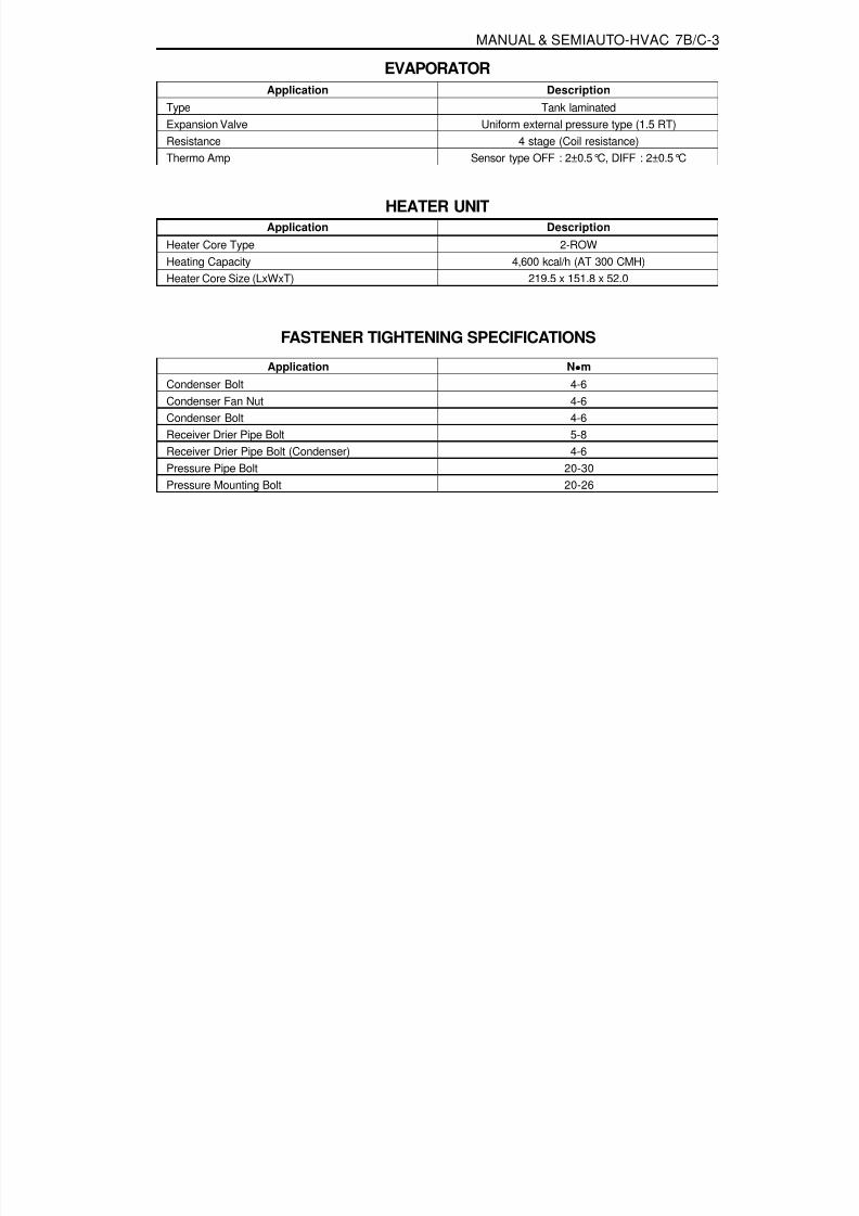
8/18/2019 SsangYong Musso Service Manual 1998.pdf
http://slidepdf.com/reader/full/ssangyong-musso-service-manual-1998pdf 1277/1459
MANUAL & SEMIAUTO-HVAC 7B/C-3
ApplicationTypeExpansion ValveResistance
Thermo Amp
Description
Tank laminatedUniform external pressure type (1.5 RT)
4 stage (Coil resistance)
Sensor type OFF : 2±0.5°C, DIFF : 2±0.5°C
EVAPORATOR
Application
Heater Core TypeHeating CapacityHeater Core Size (LxWxT)
Description
2-ROW4,600 kcal/h (AT 300 CMH)
219.5 x 151.8 x 52.0
HEATER UNIT
Application
Condenser BoltCondenser Fan NutCondenser BoltReceiver Drier Pipe BoltReceiver Drier Pipe Bolt (Condenser)Pressure Pipe Bolt
Pressure Mounting Bolt
N m
4-64-64-65-84-6
20-30
20-26
FASTENER TIGHTENING SPECIFICATIONS

8/18/2019 SsangYong Musso Service Manual 1998.pdf
http://slidepdf.com/reader/full/ssangyong-musso-service-manual-1998pdf 1278/1459
7B/C-4 MANUAL & SEMIAUTO-HVAC
DIAGNOSIS
m

8/18/2019 SsangYong Musso Service Manual 1998.pdf
http://slidepdf.com/reader/full/ssangyong-musso-service-manual-1998pdf 1279/1459

8/18/2019 SsangYong Musso Service Manual 1998.pdf
http://slidepdf.com/reader/full/ssangyong-musso-service-manual-1998pdf 1280/1459
7B/C-6 MANUAL & SEMIAUTO-HVAC
COMPONENT LOCATORVENTILATION

8/18/2019 SsangYong Musso Service Manual 1998.pdf
http://slidepdf.com/reader/full/ssangyong-musso-service-manual-1998pdf 1281/1459
MANUAL & SEMIAUTO-HVAC 7B/C-7
Switch
Door
VENT DoorFOOT DoorDEF Door
INTAKE DoorAIR MIX Door
Air Flow
Mode SwitchVENT
ACD
Recirculation Switch Temperature
Control Lever
[MANUAL]
[SEMI AUTO]----
B/L
BBD
FOOT
CAD
D/F
CBB
DEF
CCA
REC FRE
-- A B C
INDI.
On
-
-
-
A
INDI.
Off
-
-
-
B

8/18/2019 SsangYong Musso Service Manual 1998.pdf
http://slidepdf.com/reader/full/ssangyong-musso-service-manual-1998pdf 1282/1459
7B/C-8 MANUAL & SEMIAUTO-HVAC
AIR CONDITIONER SYSTEMDIESEL ENGINE
1 Compressor2 High Pressure Hose3 Condenser Fan4 Condenser5 Liquid Pipe (A)6 Receiver Drier7 Liquid (B)8 Evaporator Assembly9 Low Pressure Hose
10 Water Inlet Hose11 Water Outlet Hose12 Control Assembly13 Heater Unit Amplifier14 Mix Actuator Assembly15 Blower Unit16 Heater Unit17 Mode Actuator Assembly

8/18/2019 SsangYong Musso Service Manual 1998.pdf
http://slidepdf.com/reader/full/ssangyong-musso-service-manual-1998pdf 1283/1459
MANUAL & SEMIAUTO-HVAC 7B/C-9
GASOLINE ENGINE
1 Compressor2 High Pressure Hose3 Condenser4 Main Condenser Fan5 Sub Condenser Fan6 Condenser Fan Resistor7 Liquid Pipe(A)8 Receiver Dryer9 Liquid Pipe(B)
10 Grommet
11 Evaporator Assembly12 Control Assembly13 Heater Unit Amp14 Mix Actuator15 Blower Unit16 Heater Unit17 Mode Actuator Assembly18 Water Inlet Hose19 Water Outlet Hose

8/18/2019 SsangYong Musso Service Manual 1998.pdf
http://slidepdf.com/reader/full/ssangyong-musso-service-manual-1998pdf 1284/1459
7B/C-10 MANUAL & SEMIAUTO-HVAC
REFRIGERANT CHARGINGInstallation of Manifold Gauge1. Close both high/low pressure hand valve of gauge before
installation of gauge to the charging valve.
2. Connect the low pressure hose of the gauge to the lowpressure charging valve and the high pressure hose of thegauge to high pressure charging valve. Tighten the hosenuts by hand.
Discharging of Refrigerant1. Connect the manifold gauge to the charging valve.2. Place the free end of center hose in a shop towel.3. Slowly open the high pressure hand valve and discharge
refrigerant.
NoticeIf refrigerant is allowed to escape too fast, compressor oilwill be drawn out of the system.
MAINTENANCE AND REPAIR

8/18/2019 SsangYong Musso Service Manual 1998.pdf
http://slidepdf.com/reader/full/ssangyong-musso-service-manual-1998pdf 1285/1459
MANUAL & SEMIAUTO-HVAC 7B/C-11
Evacuating Refrigeration System1. Connect the manifold gauge to the charging valves.2. Connect the center hose of the gauge to the vacuum pump.3. Run the vacuum pump and open both high and low pressure
hand valves.4. Run the vacuum pump 15-20 minutes.5. Check that both high and low pressure gauge reading is
more than (-) 750mmHg of vacuum and close both valves.
Check for Refrigerant Leaks1. Connect the center hose of the gauge to the refrigerant
tank.2. Open the high pressure valve of the gauge to charge with
refrigerant gas.3. Charge until the low pressure gauge reads 1.0kg/cm and
close the valve.4. Using a gas leak detector, check the system for leaks.5. If a leak is found, replace a O-ring or repair the faulty
connection
2
6. Stop the vacuum pump and wait about 5 minutes.7. After 5 minutes, check that low pressure gauge reading is
changed or not.8. If low pressure gauge reading is changed, check the system
for leaks and repair as necessary and repeat steps from‘1’ to ‘7’.
9. If there are no changes in low pressure gauge reading,disconnect the vacuum pump.
4. After the high pressure gauge reading drops below 3.5kg/ cm2 , slowly open the low pressure valve.
5. When both high and low pressure gauges reading drops to0 kg/cm, discharging is completed.

8/18/2019 SsangYong Musso Service Manual 1998.pdf
http://slidepdf.com/reader/full/ssangyong-musso-service-manual-1998pdf 1286/1459
7B/C-12 MANUAL & SEMIAUTO-HVAC
Charging Refrigerant1. Connect the manifold gauge to the charging valve and
evacuate the system.2. Connect the center hose of the gauge to the refrigerant
tank.3. Open the high pressure valve and charge the system with
350g of refrigerant.4. Close the high pressure valve and start the engine and run
the compressor.
NoticeNever open the high pressure valve when the compressoris running. Refrigerant gas will be charged reverse.
5. Slowly open the low pressure valve and charge the systemwith refrigerant.
Standard 650 - 750 g
6. Close the low pressure valve after charging.
NoticeChecking the pressure through the sight glass is impossibleby applying & R-134a.
7. Stop the engine and disconnect the manifold gauge fromthe system.
Operation Check1. Place a dry bulb thermometer to the front duct.
2. Place a psychrometer close to the inlet of the cooling unit (under the glove box).3. Run the engine at 1,500 rpm.4. Set the blower switch at ‘HI’ and A/C switch ‘ON”.5. Set the temperature control lever at ‘COOL’.6. Set the air flow control at ‘REC’.7. Check that air conditioning system is stabilized.
Temperature of Air Inlet
High Pressure Gauge Reading
25 - 35°C
13.2 - 18.5kg/cm 2

8/18/2019 SsangYong Musso Service Manual 1998.pdf
http://slidepdf.com/reader/full/ssangyong-musso-service-manual-1998pdf 1287/1459
MANUAL & SEMIAUTO-HVAC 7B/C-13
Replacement of Refrigerant Connection (O-ringType)1. When connecting a O-ring type, apply compressor oil to
portions shown in illustration. Be careful not to apply oil tothreaded portion.
Notice
Use specified compressor oil.
2. O-rings must be closely attached to inflated portion of pipeand always replace used O-rings.
3. After inserting the pipe to the union, tighten the nut by handas much as possible and tighten the nut to specified torque.
4. When connecting liquid pipe(B) and low pressure hose(A)to evaporate pipe, apply compressor oil to the O-ring.
5. When tightening, set the center of pipe and tighten fully.6. Tighten the nut by specified wrench.
Installation Notice
Tightening Torque Inlet Side to 12 - 15Nm
Low Pressure Hose (A) 30 - 35 Nm

8/18/2019 SsangYong Musso Service Manual 1998.pdf
http://slidepdf.com/reader/full/ssangyong-musso-service-manual-1998pdf 1288/1459
7B/C-14 MANUAL & SEMIAUTO-HVAC
CONDENSERPreceding Work : Removal of the radiator
1 Bolt2 Condenser Fan
3 Bolt4 Condenser
Diesel Engine

8/18/2019 SsangYong Musso Service Manual 1998.pdf
http://slidepdf.com/reader/full/ssangyong-musso-service-manual-1998pdf 1289/1459
MANUAL & SEMIAUTO-HVAC 7B/C-15
Removal & Installation Procedure1. Disconnect the inlet and outlet pipes of condenser.
NoticeBefore disconnection, evacuate the refrigerant from thesystem.
2. Remove the mounting bolts (4 EA) and condenser assembly.3. Installation should follow the removal procedure in the
reverse order.
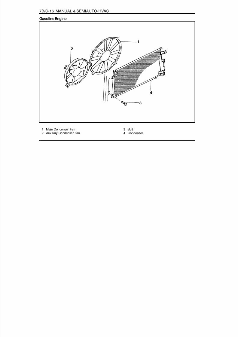
8/18/2019 SsangYong Musso Service Manual 1998.pdf
http://slidepdf.com/reader/full/ssangyong-musso-service-manual-1998pdf 1290/1459
7B/C-16 MANUAL & SEMIAUTO-HVAC
1 Main Condenser Fan2 Auxiliary Condenser Fan
3 Bolt4 Condenser
Gasoline Engine

8/18/2019 SsangYong Musso Service Manual 1998.pdf
http://slidepdf.com/reader/full/ssangyong-musso-service-manual-1998pdf 1291/1459
MANUAL & SEMIAUTO-HVAC 7B/C-17
Removal & Installation Procedure1. Disconnect the inlet and outlet pipes of condenser.
NoticeBefore disconnection, evacuate the refrigerant from thesystem.
2. Remove the mounting bolts (4bolts) and condenserassembly.
3. Remove the main condenser fan from condenser.
4. Installation should follow the removal procedure in thereverse order.

8/18/2019 SsangYong Musso Service Manual 1998.pdf
http://slidepdf.com/reader/full/ssangyong-musso-service-manual-1998pdf 1292/1459
7B/C-18 MANUAL & SEMIAUTO-HVAC
RECEIVER DRIERDiesel Engine
1 Condenser2 Receiver Drier3 Bolt ......................................................... 4-6 Nm
4 Bolt .......................................................... 5-8 Nm5 Bracket
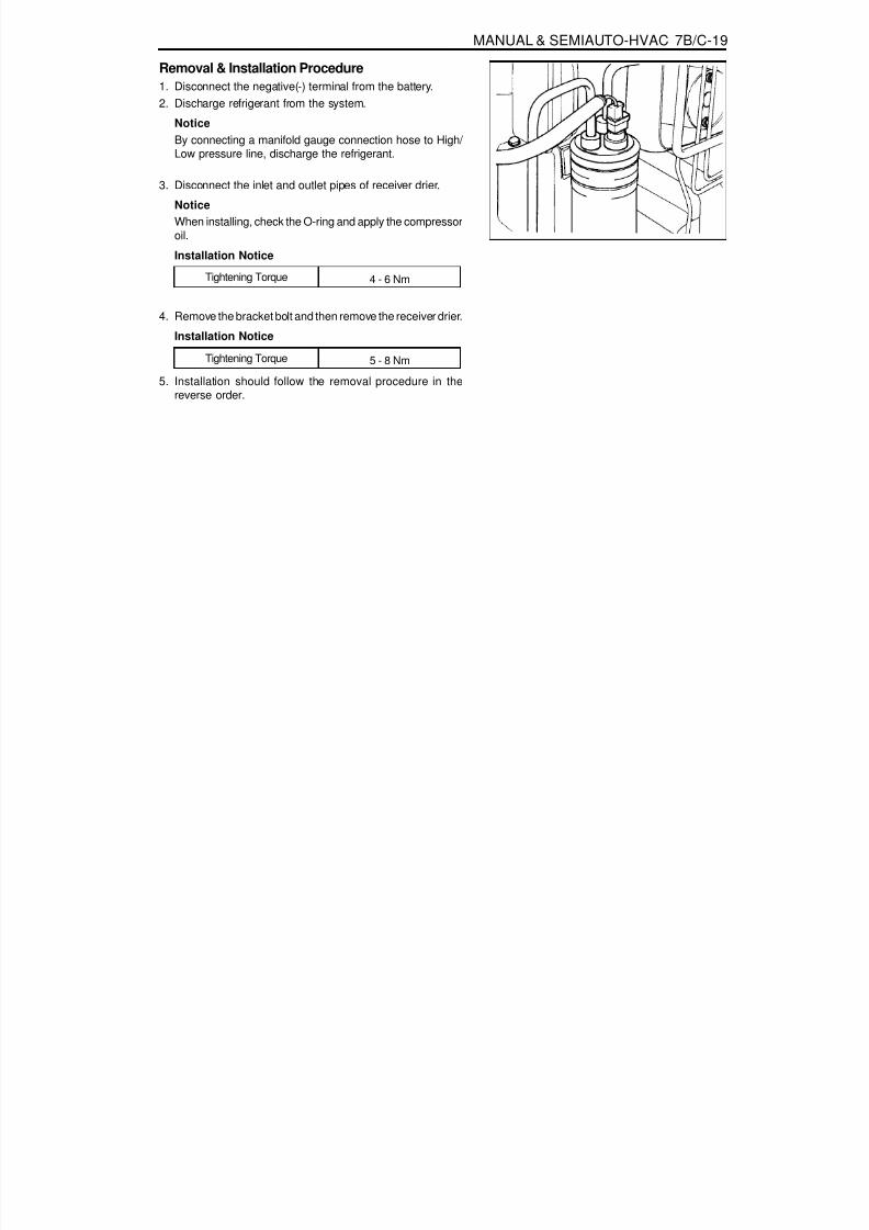
8/18/2019 SsangYong Musso Service Manual 1998.pdf
http://slidepdf.com/reader/full/ssangyong-musso-service-manual-1998pdf 1293/1459
MANUAL & SEMIAUTO-HVAC 7B/C-19
Removal & Installation Procedure1. Disconnect the negative(-) terminal from the battery.2. Discharge refrigerant from the system.
NoticeBy connecting a manifold gauge connection hose to High/ Low pressure line, discharge the refrigerant.
3. Disconnect the inlet and outlet pipes of receiver drier.
NoticeWhen installing, check the O-ring and apply the compressoroil.
Installation Notice
4. Remove the bracket bolt and then remove the receiver drier.
Installation Notice
Tightening Torque 4 - 6 Nm
5. Installation should follow the removal procedure in thereverse order.
Tightening Torque 5 - 8 Nm

8/18/2019 SsangYong Musso Service Manual 1998.pdf
http://slidepdf.com/reader/full/ssangyong-musso-service-manual-1998pdf 1294/1459
7B/C-20 MANUAL & SEMIAUTO-HVAC
1 Condenser2 Receiver Drier
3 Bracket
Removal & Installation Procedure1. Disconnect the dual pressure switch connector from the
receiver drier.2. Discharge refrigerant from the system.
3. Remove the high pressure pipe from the inlet / outlet ofreceiver drier.
4. Remove the bracket bolts and remove the receiver drier.5. Installation should follow the removal procedure in the
reverse order.
Gasoline Engine

8/18/2019 SsangYong Musso Service Manual 1998.pdf
http://slidepdf.com/reader/full/ssangyong-musso-service-manual-1998pdf 1295/1459

8/18/2019 SsangYong Musso Service Manual 1998.pdf
http://slidepdf.com/reader/full/ssangyong-musso-service-manual-1998pdf 1296/1459
7B/C-22 MANUAL & SEMIAUTO-HVAC
Removal & Installation Procedure1. Disconnect the negative(-) terminal from the battery.2. Discharge refrigerant from the system.
NoticeBy connecting a manifold gauge connection hose to High/ Low pressure line, discharge the refrigerant.
3. Disconnect the high / low pressure pipe and wire connectors.
Installation Notice
NoticeBefore tightening, apply the compressor oil to O-ring.
Tightening Torque 20 - 30 Nm
4. Remove the mounting bolt from the compressor bracketand remove compressor assembly.
NoticePlace the removed compressor in vertical position.
Installation Notice
5. Installation should follow the removal procedure in thereverse order.
Tightening Torque 21 - 26 Nm

8/18/2019 SsangYong Musso Service Manual 1998.pdf
http://slidepdf.com/reader/full/ssangyong-musso-service-manual-1998pdf 1297/1459
MANUAL & SEMIAUTO-HVAC 7B/C-23
Gasoline Engine
1 Low Pressure Pipe2 High Pressure Pipe
3 Compressor Bracket4 Compressor
Removal & Installation Procedure1. Disconnect the negative(-) terminal from the battery.
2. Discharge refrigerant from the system.NoticeBy connecting a manifold gauge connection hose to High/ Low pressure line, discharge the refrigerant.
3. Disconnect the high / low pressure pipe and wire connectors.

8/18/2019 SsangYong Musso Service Manual 1998.pdf
http://slidepdf.com/reader/full/ssangyong-musso-service-manual-1998pdf 1298/1459
7B/C-24 MANUAL & SEMIAUTO-HVAC
4. Remove the mounting bolt from the compressor bracketand remove compressor assembly.
NoticePlace the removed compressor in vertical position.
5. Installation should follow the removal procedure in thereverse order.

8/18/2019 SsangYong Musso Service Manual 1998.pdf
http://slidepdf.com/reader/full/ssangyong-musso-service-manual-1998pdf 1299/1459
MANUAL & SEMIAUTO-HVAC 7B/C-25
HEATER AND AIR CONDITIONER CONTROL BOX
1 Blower Switch2 Recirculation Switch3 Mode Switch
4 A/C Switch5 Temperature Control Lever6 In-vehicle Sensor
MANUAL
SATC

8/18/2019 SsangYong Musso Service Manual 1998.pdf
http://slidepdf.com/reader/full/ssangyong-musso-service-manual-1998pdf 1300/1459
7B/C-26 MANUAL & SEMIAUTO-HVAC
Removal & Installation Procedure1. Remove the switch panel.
NoticeBe careful not to damage the switch panel.
2. Remove the fixing screws (4 screws) of the control box.
3. Disconnect the wire connectors and remove the control box.4. Installation should follow the removal procedure in the
reverse order.

8/18/2019 SsangYong Musso Service Manual 1998.pdf
http://slidepdf.com/reader/full/ssangyong-musso-service-manual-1998pdf 1301/1459
SECTION 8A
SEAT BELTS
Specifications. . . . . . . . . . . . . . . . . . . . . . . . 8A-1Fastener Tightening Specifications . . . . . . . . . 8A-1
Component Locator . . . . . . . . . . . . . . . . . . . 8A-2Front Seat Belt . . . . . . . . . . . . . . . . . . . . . . . . 8A-2Rear Seat Belt . . . . . . . . . . . . . . . . . . . . . . . . 8A-3
TABLE OF CONTENTS
Caution: Disconnect the negative battery cable before removing or installing any electrical unit or when a tool or equipment could easily come in contact with exposed electrical terminals. Disconnecting this cable will help prevent personal injury and damage to the vehicle. The ignition must also be in LOCK unless otherwise noted.
General Description and System Operation . . . . . . . . . . . . . . . . . . . . . . . . . 8A-4
Driver Seat Belt Warning . . . . . . . . . . . . . . . . 8A-4Operation and Functional Checks . . . . . . . . . 8A-4
SPECIFICATIONSFASTENER TIGHTENING SPECIFICATIONS
ApplicationAnchor Bolt
N m35 - 55

8/18/2019 SsangYong Musso Service Manual 1998.pdf
http://slidepdf.com/reader/full/ssangyong-musso-service-manual-1998pdf 1302/1459
8A-2 SEAT BELT
COMPONENT LOCATORFRONT SEAT BELT
1 Seat Belt Assembly (3-Point)2 Buckle Assembly3 Seat Belt Dust Cover4 Seat Belt Webbing Guide
5 Seat Belt Reel Assembly6 Anchor Bolt .......................................... 35-55 Nm7 Anchor Bolt .......................................... 35-55 Nm8 Anchor Bolt .......................................... 35-55 Nm

8/18/2019 SsangYong Musso Service Manual 1998.pdf
http://slidepdf.com/reader/full/ssangyong-musso-service-manual-1998pdf 1303/1459

8/18/2019 SsangYong Musso Service Manual 1998.pdf
http://slidepdf.com/reader/full/ssangyong-musso-service-manual-1998pdf 1304/1459
8A-4 SEAT BELT
GENERAL DESCRIPTIONAND SYSTEM OPERATION
DRIVER SEAT BELT WARNINGThe driver's safety belt incorporates a safety belt reminder
light in the instment cluster remind the driver if the safety beltis not fastened when the ignition is turnd ON.
OPERATION AND FUNCTIONALCHECKSCaution :
Keep sharp objects and potentially damaging objectsaway from the seat belts.Avoid bending or damaging any portion of the buckleor the latch plate.
Do not bleach or dye the belt webbing. Use only mildsoap and water in order to clean the belts.When installing the seat belt anchor bolts and thescrews, start the bolts and screws by hand in orderto prevent crossthreading.Do not attempt any repairs on the retractormechsemblies with new assemblies.Replace any belts that are cut r damaged in any way.
1. Inspect all saet belt anchor bolts and the screw in order toverify that they are secure.
2. Inspect the seat belt buckle. The buckle must lock andunlock easily.
3. After inserting the latch into the buckle, tug sharply on thebelt. The buckle must remain locked.
4. Fully extend the shoulder belt portion to make sure thatthere is no twisting or tears in the belt.
5. Let the shoulder belt retract fully. The belt should retracteasily.
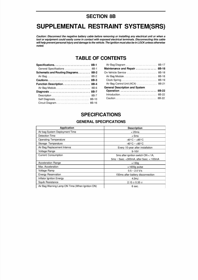
8/18/2019 SsangYong Musso Service Manual 1998.pdf
http://slidepdf.com/reader/full/ssangyong-musso-service-manual-1998pdf 1305/1459
SECTION 8B
SUPPLEMENTAL RESTRAINT SYSTEM(SRS)
Specifications. . . . . . . . . . . . . . . . . . . . . . . . 8B-1General Specifications . . . . . . . . . . . . . . . . . . 8B-1
Schematic and Routing Diagrams . . . . . . . . 8B-2Air Bag . . . . . . . . . . . . . . . . . . . . . . . . . . . . . . 8B-2
Cautions . . . . . . . . . . . . . . . . . . . . . . . . . . . . 8B-3Function Description . . . . . . . . . . . . . . . . . . 8B-4
Air Bag Module . . . . . . . . . . . . . . . . . . . . . . . . 8B-6Diagnosis . . . . . . . . . . . . . . . . . . . . . . . . . . . 8B-7
Description . . . . . . . . . . . . . . . . . . . . . . . . . . . 8B-7Self Diagnosis. . . . . . . . . . . . . . . . . . . . . . . . 8B-10Circuit Diagram . . . . . . . . . . . . . . . . . . . . . . . 8B-16
TABLE OF CONTENTS
Caution: Disconnect the negative battery cable before removing or installing any electrical unit or when a tool or equipment could easily come in contact with exposed electrical terminals. Disconnecting this cable will help prevent personal injury and damage to the vehicle. The ignition must also be in LOCK unless otherwise noted.
SPECIFICATIONSGENERAL SPECIFICATIONS
Application
Air bag System Deployment TimeDetection TimeOperating TemperatureStorage TemperatureAir Bag Replacement Interval
Voltage RangeCurrent Consumption
Acceleration RangeMax. AccelerationVoltage RampEnergy ReservationInflator Ignition EnergySquib ResistanceAir Bag Warning Lamp ON Time (When Ignition ON)
Description< 20ms< 5ms
-40°C ~ +85°C-40°C ~ +90°C
Every 10-year after installation
9-16V5ms after ignition switch ON < 1A,
5ms ~ 5sec. <300mA, after 5sec. < 100mA+/-50g
+/-600g pulse0.5 ~ 2.0 V/s
150ms after battery disconnection4.3mJ
2.15 ± 0.35 W
6 sec.
Air Bag Diagram . . . . . . . . . . . . . . . . . . . . . . 8B-17Maintenance and Repair . . . . . . . . . . . . . . 8B-18On-Vehicle Service . . . . . . . . . . . . . . . . . . . . . 8B-18
Air Bag Module . . . . . . . . . . . . . . . . . . . . . . . 8B-18Clock Spring . . . . . . . . . . . . . . . . . . . . . . . . . 8B-19Air Bag Control Unit (AC4) . . . . . . . . . . . . . . 8B-21
General Description and SystemOperation . . . . . . . . . . . . . . . . . . . . . . . . 8B-22Introduction . . . . . . . . . . . . . . . . . . . . . . . . . . 8B-22Caution . . . . . . . . . . . . . . . . . . . . . . . . . . . . . 8B-22

8/18/2019 SsangYong Musso Service Manual 1998.pdf
http://slidepdf.com/reader/full/ssangyong-musso-service-manual-1998pdf 1306/1459
8B-2 SUPPLEMENTAL RESTRAINT SYSTEM(SRS)
SCHEMATIC AND ROUTING DIAGRAMS
A I R B A G

8/18/2019 SsangYong Musso Service Manual 1998.pdf
http://slidepdf.com/reader/full/ssangyong-musso-service-manual-1998pdf 1307/1459
SUPPLEMENTAL RESTRAINT SYSTEM(SRS) 8B-3
CAUTIONSFailure to follow the correct service procedure can cause air bag damage or personal injury due to unexpected airbag deployment. Before service (removal and installation of part, check for replacement), please be weal noticed offollowing items for your correct service.1. For service, turn the ignition switch to ‘LOCK’ position and wait for 30 seconds after disconnecting the negative
battery cable.2. If the vehicle collapsed, remove the air bag ECU first to reserve the crash records.3, Never use other vehicles’ air bag components and replace with specified new part.4. Never disassemble or repair the air bag module, air bag unit and wiring harness to re-use.5. Replace the air bag module and air bag unit with new if it dropped, cracked or damaged.6. Only qualified technicians in service shop should check or repair the air bag,7. Before service, should be well noticed of warning labels on the vehicle.
A. Sun Visor Side
[Warning]Pull down the sun visor and see SRS air bagwarning lamp on the head lining.
B. Head Lining
[Warning]1 . This vehicle is equipped with air bag. Air bag is
supplemental device for the seatbelt. Fastenyour seatbelt.
2. This air bag should be replaced by authorizedsupplier within replacement intervals.
3. When the ignition key is turned to ON position,SRS warning lamp will turn on for 6 sec. and gooff. In this case, the system is normal.For the following cases, see service manual.- SRS warning lamp does not turn on.- SRS warning lamp does not go off.- SRS warning lamp continues to blink.
C. Steering Wheel Body Inner
[Warning]Before removing the steering wheel, read service
manual first. Set the front wheels straight forwardand align the center position marks of SRS clockspring. Improper removal or installation of thesteering wheel can damage the SRS components.
D. Engine Compartment
[Warning]This vehicle is equipped with air bag. Beforechecking the engine compartment, read servicemanual first. Faultuy check and service can causeSRS air bag deployment and system defects thatcan be led to severe damage.
E. Battery Cable
[Warning]Before disconnecting the battery power, read
service manual first.
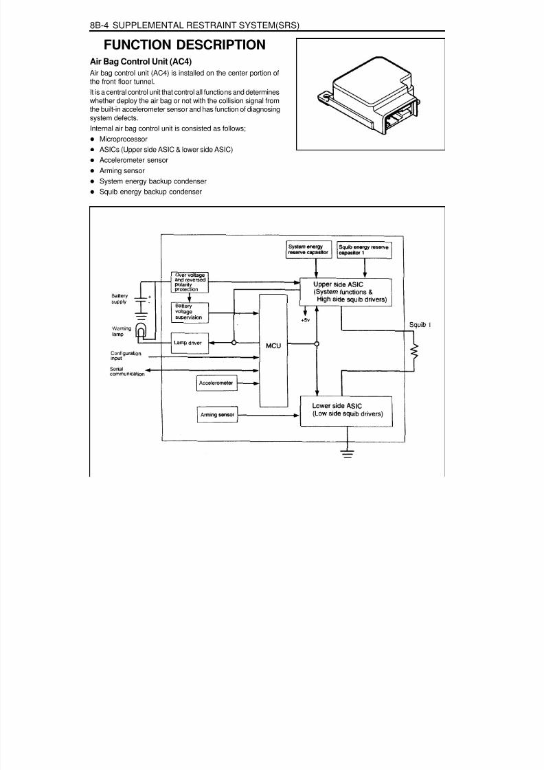
8/18/2019 SsangYong Musso Service Manual 1998.pdf
http://slidepdf.com/reader/full/ssangyong-musso-service-manual-1998pdf 1308/1459
8B-4 SUPPLEMENTAL RESTRAINT SYSTEM(SRS)
FUNCTION DESCRIPTIONAir Bag Control Unit (AC4)Air bag control unit (AC4) is installed on the center portion ofthe front floor tunnel.It is a central control unit that control all functions and determines
whether deploy the air bag or not with the collision signal fromthe built-in accelerometer sensor and has function of diagnosingsystem defects.Internal air bag control unit is consisted as follows;
MicroprocessorASICs (Upper side ASIC & lower side ASIC)Accelerometer sensorArming sensorSystem energy backup condenserSquib energy backup condenser

8/18/2019 SsangYong Musso Service Manual 1998.pdf
http://slidepdf.com/reader/full/ssangyong-musso-service-manual-1998pdf 1309/1459
SUPPLEMENTAL RESTRAINT SYSTEM(SRS) 8B-5
Input & Output FunctionElectronic air bag control and diagnosis module is connectedby full 30-pin connectors.Input : groundOutput : 1 squib line, warning lampInput/output : communication, diagnosis
16 Shorting Bar17 Shorting Bar18 Shorting Bar19 Shorting Bar20 Diagnosis
21 Shorting Bar22 Shorting Bar23 No Pin24 No Pin25 Shorting Bar26 Shorting Bar27 N/A28 Shorting Bar29 Shorting Bar30 N/A
1 Lamp2 Ground3 N/A4 N/A5 Ignition
6 N/A7 N/A8 CONF9 N/A
10 N/A11 N/A12 N/A13 Squib Line 1(upper)14 Squib Line 1(lower)15 N/A
IGN
GND
Warning lamp
RxD/TxD
Inflator line 1
+
-
5
2
1
20
13
14
Air bag lamp
Communication/ diagnosis
Air bagcontrolunit
Ground connection or open
Connector Pins
15
30
1
16

8/18/2019 SsangYong Musso Service Manual 1998.pdf
http://slidepdf.com/reader/full/ssangyong-musso-service-manual-1998pdf 1310/1459
8B-6 SUPPLEMENTAL RESTRAINT SYSTEM(SRS)
AIR BAG MODULEAir bag module is installed in the pad of steering wheel center and inflator is consisted of igniter, explosives, gasgenerating material and bag. When crashed, the air bag control unit sends current to the air bag module throughsquib line and this current ignites as ignition energy (6mJ) momentarily igniting explosives and bag will be inflatedby nitrogen gas protecting driver at the same and then deflates.
1 Air bag Module2 Module Housing3 Bag4 Module Bracket
5 Retainer Ring6 Inflator7 Horn Switch8 Backing Plate

8/18/2019 SsangYong Musso Service Manual 1998.pdf
http://slidepdf.com/reader/full/ssangyong-musso-service-manual-1998pdf 1311/1459
SUPPLEMENTAL RESTRAINT SYSTEM(SRS) 8B-7
DIAGNOSISDESCRIPTIONAir bag control unit continuously controls system function as follows during ignition ON or driving.- Recognition of collision- Internal diagnosis- External diagnosisIf recognize or detect defects, warning lamp will turn on. If there is danger of improper deployment, the system willenter overall shutdown status and the air bag will not inflate.Air bag control unit will store detected internal and external defects in the EEPROM.
System ControlBattery Voltage CheckBattery voltage will be monitored continuously. If voltage is out of normal operating range, all system diagnosis willstop and warning lamp turn on.
Battery Voltage (V)< 8.79 - 16> 16.3
FunctionSystem diagnosis stops and warning lamp turns on
Normal operation rangeSystem diagnosis stops and warning lamp turns on
Squib DiagnosisIt checks not only high (4.50.5) or low (1.40.5) resistance but also short resistance (1- 10k) status between thebattery and ground to indicate defects in squib line by blinking warning lamp. Air bag control unit (AC4) can measuresquib resistance.
Warning Lamp Turning On
Air bag control unit detects system defects during ignition ON or driving and displays following 2 warning lamps.- Warning lamp ON: internal defects of the air bag control unit- Warning lamp blinking: higher resistance than standard in the squib line or short at the battery or ground,
Safety Function CheckIt checks defects during operation of the arming sensor If the sensor is shorted for more than 2 seconds, the modulewill enter overall shutdown mode.
Temperature SensorFunction of the temperature sensor will be monitored continuously. If there is fault due to defective sensor or short,the lamp will turn on and program will take calibration temperature (25) of collision conditions.
Power SupplyAirbag control unit operates in 9-16v and the characteristic of the system has backup condenser to supply the powerfor max.150ms if there is power defect during collision.
8/18/2019 SsangYong Musso Service Manual 1998.pdf
http://slidepdf.com/reader/full/ssangyong-musso-service-manual-1998pdf 1312/1459
8B-8 SUPPLEMENTAL RESTRAINT SYSTEM(SRS)
Energy Reserve SystemEnergy reserve system is consisted of condensor and energy switch and will check following items continuouslyduring system operation.- High voltage- Low voltage- Low rating capacity
- Function of the energy reserve switchIf there is fault in the energy reserve system, warning lamp will turn on. And defects are found by continuouschecking of the condenser voltage, the system will enter overall shutdown status for safety reason.
Shutdown SwitchThere is 1 energy shutdown switch in the system and it will be checked during start-up. And it also checks thatcondenser is discharging properly. If shutdown switch is short, it will be detected during condensor voltage test.If squib line fault is obvious, the warning lamp will turn on and the module will enter overall shutdown status.
Accelerometer CheckAccelerometer function will be checked during start-up. During operation, accelerometer off-set signal will be checked,If there is fault, module will enter overall shutdown status.
ASIC OverheatModule monitors upper side ASIC overheats continuously. If overheated, the module will enter overall shutdownstatus.
Microprocessor FaultModule checks EEPROM, ROM checksum and RAM during start-up. EEPROM tests checksum operation.If RAM or ROM checksum is defective, module will not allow start-up continuously but will be re-set,If EEPROM is defective, warning lamp will turn on and the module will enter overall shutdown status.
During operation, RAM will continuously verify the proper operation of temporary memory program data usage. Ifthere is fault, the module will enter overall shutdown status and the warning lamp will turn on.
Watchdog TestWatchdog function will be tested in start-up. If there is fault during the test, warning lamp will turn on and the modulewill enter overall shutdown status.

8/18/2019 SsangYong Musso Service Manual 1998.pdf
http://slidepdf.com/reader/full/ssangyong-musso-service-manual-1998pdf 1313/1459
SUPPLEMENTAL RESTRAINT SYSTEM(SRS) 8B-9
DiagnosisAir bag control unit diagnoses each function in the intervals of 250ms - 20 sec. during start-up or driving to preventunwanted air bag deployment. If there is defect, it turns on or blinks warning lamp to indicate defects in the air bagsystem to the driver. And fatal defect is found, air bag control unit enters overall or partial shutdown status and faultcode will be stored.
Air bag control unit diagnoses following items.
- Ignition TR- Acceleration- Microprocessor, RAM and ROM- Watchdog- Shutdown Switch
Diagnosis Condition Diagnosis Items
Start-up (ignition ON)
During Driving
Lamp Blinking ModeThere are 2 kinds of blinking mode1. When system internal fault is found, the lamp will stay on.2. The lamp will blink according to external fault and there are 2 blinking codes.Blinking code 1 (Squib resistance fault in the driver’s air bag squib line)Blinking code 2 (Squib short on plus and minus in the air bag squib line)Lamp blinking code is as follows. The last blinking will be within 0.5 sec. and 1 cycle of blinking will be repeated every5 seconds.
Blinking Code 1
(Sec.) 0 0.5 1 1.5 2 2.5 3 3.5 4 4.5
Blinking Code 3
(Sec.) 0 0.5 1 1.5 2 2.5 3 3.5 4 4.5
- Squib resistance- Squib line short to battery and ground- Energy reserve system
- Lamp output- Battery voltage- ASIC communication- Arming sensor- ASIC overheating- RAM and W/D- EEPROM

8/18/2019 SsangYong Musso Service Manual 1998.pdf
http://slidepdf.com/reader/full/ssangyong-musso-service-manual-1998pdf 1314/1459
8B-10 SUPPLEMENTAL RESTRAINT SYSTEM(SRS)
1. Position the ignition switch to ‘OFF’.2. Connect the harness connector of scanner to the diagnosis
socket in engine compartment.3. Turn the ignition switch to ‘ON’ position.4. Select “Electronic control vehicle diagnosis” from function
selection display and press ‘Enter’.5. Select “Musso (’98 model year)” from vehicle model
selection display and press ‘Enter’.6. Select “Electronic air bag” from control system selection
display and press ‘Enter’.7. Select “Self-diagnosis” from diagnosis item selection display.
NoticeCheck sensor value of output display, if necessary.
8. Determine the fault code and trace defective component.
NoticeRefer to self-diagnosis list.
SELF DIAGNOSIS

8/18/2019 SsangYong Musso Service Manual 1998.pdf
http://slidepdf.com/reader/full/ssangyong-musso-service-manual-1998pdf 1315/1459
SUPPLEMENTAL RESTRAINT SYSTEM(SRS) 8B-11
Self-Diagnosis List
FaultCode Defects Service Hint
01 Driver ’s squib (+) side No. 1 Short of (+) side No. 1 in the driver’s squib circuit.Check connection of connector.Check the ECU.
Appli-cation
02 Driver ’s squib (+) side No. 2 Short of (+) side No. 2 in the driver’s squib circuit.Check connection of connector.Check the ECU.
X
03 Driver ’s squib (+) side No. 3 Short of (+) side No. 3 in the driver’s squib circuit.Check connection of connector.Check the ECU.
X
04 Driver ’s squib (+) side No. 4 X
05 Driver’s squib ground (-) side No. 1 Short of ground side No. 1 in the driver’s squibcircuit.Check and replace the ECU.
06 Driver’s squib ground (-) side No. 2 Short of ground side No. 2 in the driver’s squibcircuit.Check and replace the ECU.
X
07 Driver’s squib ground (-) side No. 3 Short of ground side No. 3 in the driver’s squibcircuit.Check and replace the ECU.
X
08 Driver’s squib ground (-) side No. 4 Short of ground side No. 4 in the driver’s squib
circuit.Check and replace the ECU.
X
09 Energy shutdown switch No. 1 Air bag control unit internal defects.Check and replace the ECU.
10 Energy shutdown switch No. 2 Air bag control unit internal defects.Check and replace the ECU.
X
11 Energy shutdown switch No. 3 Air bag control unit internal defects.Check and replace the ECU.
X
12 Energy shutdown switch No. 4 Air bag control unit internal defects.Check and replace the ECU.
X
13 Ignition switch wire No. 1 Air bag control unit internal defects.Check and replace the ECU.
14 Ignition switch wire No. 2 Air bag control unit internal defects.Check and replace the ECU.
X
15 Ignition switch wire No. 3 Air bag control unit internal defects.Check and replace the ECU.
X
16 Ignition switch wire No. 4 XAir bag control unit internal defects.Check and replace the ECU.

8/18/2019 SsangYong Musso Service Manual 1998.pdf
http://slidepdf.com/reader/full/ssangyong-musso-service-manual-1998pdf 1316/1459
8B-12 SUPPLEMENTAL RESTRAINT SYSTEM(SRS)
FaultCode
Defects Service Hint Appli-cation
17 Squib No. 1 resistance
18 Squib No. 2 resistance X
19 Squib No. 3 resistance X
20 Squib No. 4 resistance X
21 Squib No. 1 resistance
22 Squib No. 2 resistance X
Driver’s squib resistance is higher than standard(4.5±0.5W).Check related circuits for open/short.Check connection of connector.Check the ECU.Replace the squib wire.Plus side short : 7k, ground side short : 6kW.
Driver’s squib resistance is higher than standard(4.5±0.5W).Check related circuits for open/short.Check connection of connector.Check the ECU.Replace the squib wire.Plus side short : 7k, ground side short : 6kW.
Driver’s squib resistance is higher than standard(4.5±0.5W).Check related circuits for open/short.Check connection of connector.Check the ECU.Replace the squib wire.Plus side short : 7k, ground side short : 6kW.
Driver’s squib resistance is higher than standard(4.5±0.5W).Check related circuits for open/short.Check connection of connector.Check the ECU.Replace the squib wire.Plus side short : 7k, ground side short : 6kW.
Driver’s squib resistance is lower than standard(1.4±0.3W).Check related circuits for open/short.Check connection of connector.Check the ECU.Replace the squib wire.Plus side short : 7k, ground side short : 6kW.
Driver’s squib resistance is lower than standard(1.4±0.3W).Check related circuits for open/short.Check connection of connector.Check the ECU.Replace the squib wire.Plus side short : 7k, ground side short : 6kW.
23 Squib No. 3 resistance XDriver’s squib resistance is lower than standard(1.4±0.3W).Check related circuits for open/short.Check connection of connector.Check the ECU.Replace the squib wire.Plus side short : 7k, ground side short : 6kW.

8/18/2019 SsangYong Musso Service Manual 1998.pdf
http://slidepdf.com/reader/full/ssangyong-musso-service-manual-1998pdf 1317/1459
SUPPLEMENTAL RESTRAINT SYSTEM(SRS) 8B-13
FaultCode Defects Service Hint Appli-
cation
24 Squib No. 4 resistance X
25 Energy reserve No. 1 voltage
26 Energy reserve No. 2 voltage X
27 Energy reserve No. 3 voltage X
28 Energy reserve No. 4 voltage X
29 Energy reserve No. 5 voltage
30 Energy reserve No. 6 voltage
31 Energy reserve No. 1 current offcapacity
32 Energy reserve No. 2 current offcapacity
X
33 Energy reserve No. 3 current offcapacity
X
34 Energy reserve No. 4 current offcapacity
X
35 Energy reserve No. 5 current offcapacity
36 Condensor voltage
37 Collision times checksum
Driver’s squib resistance is lower than standard(1.4±0.3W).Check related circuits for open/short.Check connection of connector.Check the ECU.Replace the squib wire.Plus side short : 7k, ground side short : 6kW.
Air bag control unit internal defects.Check and replace the ECU.
Air bag control unit internal defects.Check and replace the ECU.
Air bag control unit internal defects.Check and replace the ECU.
Air bag control unit internal defects.Check and replace the ECU.
Air bag control unit internal defects.Check and replace the ECU.
Air bag control unit internal defects.Check and replace the ECU.
Air bag control unit internal defects.Check and replace the ECU.
Air bag control unit internal defects.Check and replace the ECU.
Air bag control unit internal defects.Check and replace the ECU.
Air bag control unit internal defects.Check and replace the ECU.
Air bag control unit internal defects.Check and replace the ECU.
Air bag control unit internal defects.Check and replace the ECU.
Air bag control unit internal defects.Check and replace the ECU.
41 Major USA Air bag control unit internal defects.Check and replace the ECU.
38 Driver ’s acceleration sensor
39 Driver’s acceleration sensor off-set
40 Arming sensor
Air bag control unit internal defects.Check and replace the ECU.
Air bag control unit internal defects.Check and replace the ECU.
Air bag control unit internal defects.Check and replace the ECU.

8/18/2019 SsangYong Musso Service Manual 1998.pdf
http://slidepdf.com/reader/full/ssangyong-musso-service-manual-1998pdf 1318/1459
8B-14 SUPPLEMENTAL RESTRAINT SYSTEM(SRS)
FaultCode Defects Service Hint Appli-
cation42 Over heat
43 SENS
44 Standard band gap
45 Temperature sensor
46 Warning lamp
47 Battery voltage
49 Fault code list
50 USA communication
51 LSA communication
52 No EEPROM program
53 EEPROM checksum
54 EEPROM map
55 External watchdog 1
Air bag control unit internal defects.Check and replace the ECU.
Air bag control unit internal defects.Check and replace the ECU.
Air bag control unit internal defects.Check and replace the ECU.
Air bag control unit internal defects.Check and replace the ECU.
Open/short in the warning lamp circuit.Check related circuits for open/short.Check connection of connector.Check the ECU.
Power wire voltage is out of standard voltage (9- 16V).
Check the battery for voltage and charging.Check related circuits for open/short.Check connection of connector.Check the ECU.
Air bag control unit internal defects.Check the ECU.
Air bag control unit internal defects.Check and replace the ECU.
Air bag control unit internal defects.Check and replace the ECU.
Air bag control unit internal defects.Check and replace the ECU.
Air bag control unit internal defects.Check and replace the ECU.
Air bag control unit internal defects.Check and replace the ECU.
Air bag control unit internal defects.Check and replace the ECU.
56 Arming sensor-no close
57 RAM check
58 System
Air bag control unit internal defects.Check and replace the ECU.
Air bag control unit internal defects.Check and replace the ECU.
Air bag control unit internal defects.Check and replace the ECU.
59 External watchdog 2
60 Pulse
Air bag control unit internal defects.Check and replace the ECU.
Air bag control unit internal defects.Check and replace the ECU.

8/18/2019 SsangYong Musso Service Manual 1998.pdf
http://slidepdf.com/reader/full/ssangyong-musso-service-manual-1998pdf 1319/1459
SUPPLEMENTAL RESTRAINT SYSTEM(SRS) 8B-15
FaultCode Defects Service Hint
Appli-cation
127 Collision signal
128 Collision number
Air bag control unit internal defects.Check and replace the ECU.
Air bag control unit internal defects.Check and replace the ECU.

8/18/2019 SsangYong Musso Service Manual 1998.pdf
http://slidepdf.com/reader/full/ssangyong-musso-service-manual-1998pdf 1320/1459
8B-16 SUPPLEMENTAL RESTRAINT SYSTEM(SRS)
CIRCUIT DIAGRAM

8/18/2019 SsangYong Musso Service Manual 1998.pdf
http://slidepdf.com/reader/full/ssangyong-musso-service-manual-1998pdf 1321/1459
SUPPLEMENTAL RESTRAINT SYSTEM(SRS) 8B-17
AIR BAG DIAGRAM

8/18/2019 SsangYong Musso Service Manual 1998.pdf
http://slidepdf.com/reader/full/ssangyong-musso-service-manual-1998pdf 1322/1459
8B-18 SUPPLEMENTAL RESTRAINT SYSTEM(SRS)
MAINTENANCE AND REPAIR
ON-VEHICLE SERVICEAIR BAG MODULE
Removal & Installation Procedure1. Remove the steering wheel rid (LH,RH) with a screwdriver.
Installation NoticeEach position mark (LH,RH) is stamped on the inner surfaceof the rids.
Tightening Torque 7 - 11 Nm
3. Disconnect the connectors and remove the air bag module.4. Installation should follow the removal procedure in the
reverse order.
2. Unscrew the bolts from both sides.
Installation Notice

8/18/2019 SsangYong Musso Service Manual 1998.pdf
http://slidepdf.com/reader/full/ssangyong-musso-service-manual-1998pdf 1323/1459
SUPPLEMENTAL RESTRAINT SYSTEM(SRS) 8B-19
Air BagHorn (Relay)
Remote Control (Electronic Circuit)
CLOCK SPRING
General SpecificationVoltageRating Operating VoltageCurrent Rating
Air Bag Circuit ResistanceIsolating ResistanceRotating Range
DC 12V DC 6 - 18V
10 - 30mA(6A,0.1second)200 - 220mA
15mA0.16 - 0.38 W(-40°C - 85°C)
5MW
2.7 - 3.1 Rotation from neutralPosition to Both Sides
NoticeClock spring can not be repaired.Do not disassemble or modify.To adjust to the center position, rotate clockwise until it
stops and then rotate it counterclockwise 2.3 ± 0.2revolutions and align marks. If not, airbag system cannot work normally and driver can be injured seriously.

8/18/2019 SsangYong Musso Service Manual 1998.pdf
http://slidepdf.com/reader/full/ssangyong-musso-service-manual-1998pdf 1324/1459
8B-20 SUPPLEMENTAL RESTRAINT SYSTEM(SRS)
Removal & Installation Procedurepreceding work : removal of steering wheel
1. Turn the ignition switch to “OFF” position and disconnectthe battery negative cable. Start the procedure after waitingover 3oseconds.
2. Unscrew 3 screws from lower cover on steering column shaft
and remove the lower cover.
3. Unscrew 4 screws from clock spring and remove the clockspring
Installation NoticeDon’t try to repair and modify the clock spring.When aligning the neutral position, turn to clockwise until itstops, and turn to counter clockwise until the marks arealigned

8/18/2019 SsangYong Musso Service Manual 1998.pdf
http://slidepdf.com/reader/full/ssangyong-musso-service-manual-1998pdf 1325/1459
SUPPLEMENTAL RESTRAINT SYSTEM(SRS) 8B-21
AIR BAG CONTROL UNIT(AC4)Removal & Installation ProcedureAC4 is installed on the center portion of the front floor tunnel.Built-in accelerometer sensor detects collision and determinesaction or non-action and ignition time.
NoticeDo not disassemble the AC4 to repair. If defective, replace it.AC4 should not be shocked or vibrated by dropping on theground or bumping.Replace the AC4 with new after air bag inflation.1. Disconnect the negative battery cable and wait for 30
seconds before starting service.
NoticeThough battery cable is disconnected, air bag control unitwill maintain backup power for 150ms and air bag can beinflated, so wait for min.30 seconds.
2. Remove the console box and center fascia panel assembly.3. Remove the heater control switch and audio assembly.4. Remove the lower side panel of the driver’s portion and
glove box.5. Remove the lower main panel.6. Release the lock lever of the AC4 connector and disconnect
the connector.7. Unscrew 3 nuts and remove the AC4.
NoticeFor installation, horizontal position should be secured for
the better changes of collision pulse between the vehiclebody and air bag control unit.8. Installation should follow the removal procedure in the
reverse order.
Inspection Procedure1. Check AC4 case and welt bolts for crack or deformation.2. Check connector, lock lever and terminal for deformation.
NoticeReplace the AC4 with new if dust, deformation or corrosionfound.

8/18/2019 SsangYong Musso Service Manual 1998.pdf
http://slidepdf.com/reader/full/ssangyong-musso-service-manual-1998pdf 1326/1459
8B-22 SUPPLEMENTAL RESTRAINT SYSTEM(SRS)
GENERAL DESCRIPTIONAND SYSTEM OPERATION
INTRODUCTIONSRS (Supplemental Restraint System) air bag protects driver
and passenger by inflating air bag under collision and seatbelt pre - tensioner is a supplemental equipment for seat beltreducing shocks from the collision by pulling passenger’s bodyagainst seat back at the same time of air bag inflation.Air bag unit has diagnosis functions and indicates systemmalfunctions to the driver by turning on the air bag warninglamp.
CAUTIONPerform the service procedures for the air bag system asordered, if not, the air bag can be operated suddenly and itcould result in damage of air bag or injury. Before service(removal, installation, checking and replacement of parts),observe the following instructions and service correctly.1. To service, turn the ignition switch to ‘LOCK’ position and
disconnect the negative battery cable and continue theprocedures after approx. 30 seconds.
2. If the vehicle is damaged due to accident, remove the airbag ECU first to get the accident records.
3. Never use the other vehicle’s air bag parts and replacewith genuine part, if required.
4. Do not disassemble or repair the air bag module, air bag
unit and wiring harness to reuse.5. Replace the air bag unit or air bag module if dropped,
cracked or damaged.

8/18/2019 SsangYong Musso Service Manual 1998.pdf
http://slidepdf.com/reader/full/ssangyong-musso-service-manual-1998pdf 1327/1459
SECTION 9A
BODY WIRING SYSTEM
Schematic and Routing Diagrams . . . . . . . . 9A-2Power Distribution . . . . . . . . . . . . . . . . . . . . . . 9A-2Starting & Charging (Gasoline HFM) . . . . . . . 9A-3Starting & Charging (Diesel) . . . . . . . . . . . . . . 9A-4
Fuse Box and Relay . . . . . . . . . . . . . . . . . . . 9A-5Location of Connectors by Wiring Harness . . . . . . . . . . . . . . . . . . . . . 9A-7
Main . . . . . . . . . . . . . . . . . . . . . . . . . . . . . . . . 9A-7Engine Room . . . . . . . . . . . . . . . . . . . . . . . . 9A-11Floor . . . . . . . . . . . . . . . . . . . . . . . . . . . . . . . 9A-13Roof . . . . . . . . . . . . . . . . . . . . . . . . . . . . . . . 9A-14Driver's Door . . . . . . . . . . . . . . . . . . . . . . . . . 9A-15Passenger's Door . . . . . . . . . . . . . . . . . . . . . 9A-15
TABLE OF CONTENTS
Caution: Disconnect the negative battery cable before removing or installing any electrical unit or when a tool or equipment could easily come in contact with exposed electrical terminals. Disconnecting this cable will help prevent personal injury and damage to the vehicle. The ignition must also be in LOCK unless otherwise noted.
Rear Left Door . . . . . . . . . . . . . . . . . . . . . . . 9A-16Rear Right Door . . . . . . . . . . . . . . . . . . . . . . 9A-16Tail Gate . . . . . . . . . . . . . . . . . . . . . . . . . . . . 9A-17Semi Automatic Air Conditioner . . . . . . . . . . 9A-18Full automatic Air Conditioner . . . . . . . . . . . . 9A-19Gasoline Engine (MSE) . . . . . . . . . . . . . . . . 9A-20Gasoline Engine (HFM) . . . . . . . . . . . . . . . . 9A-21Diesel Engine . . . . . . . . . . . . . . . . . . . . . . . . 9A-22Manual Transmission . . . . . . . . . . . . . . . . . . 9A-23Automatic Transmission (BENZ) . . . . . . . . . . 9A-24Automatic Transmission (BTRA) . . . . . . . . . . 9A-25Driver's Seat . . . . . . . . . . . . . . . . . . . . . . . . . 9A-26

8/18/2019 SsangYong Musso Service Manual 1998.pdf
http://slidepdf.com/reader/full/ssangyong-musso-service-manual-1998pdf 1328/1459
9A-2 BODY WIRING SYSTEM
SCHEMATIC AND ROUTING DIAGRAMS
P O W E R
D I S T R I B U T I O N

8/18/2019 SsangYong Musso Service Manual 1998.pdf
http://slidepdf.com/reader/full/ssangyong-musso-service-manual-1998pdf 1329/1459
STARTING & CHARGING (GASOLINE HFM)

8/18/2019 SsangYong Musso Service Manual 1998.pdf
http://slidepdf.com/reader/full/ssangyong-musso-service-manual-1998pdf 1330/1459
STARTING & CHARGING (DIESEL)

8/18/2019 SsangYong Musso Service Manual 1998.pdf
http://slidepdf.com/reader/full/ssangyong-musso-service-manual-1998pdf 1331/1459
BODY WIRING SYSTEM 9A-5
FUSE BOX AND RELAY
1 Interior Relay Box2 Interior Fuse Box
3 Engine Compartment Fuse and Relay Box

8/18/2019 SsangYong Musso Service Manual 1998.pdf
http://slidepdf.com/reader/full/ssangyong-musso-service-manual-1998pdf 1332/1459
9A-6 BODY WIRING SYSTEM
Engine Room Fuse (EF) and Relay Box
1 Fuse (15A) : ABS, ABD2 Fuse (20A) : Sun Roof3 Fuse (10A) : Air Bag4 Fuse (15A) : Audio, Clock, Out Side Mirror5 Fuse (30A) : Cigarette lighter, Power Socket6 Fuse (30A) : Heater
7 Fuse (15A) : Door Lock8 Fuse (30A) : Rear Heated9 Fuse (10A) : Audio, Buzzer, Chime, Clock
10 Fuse (30A) : Power Window11 Fuse (10A) : Immobilizer12 Fuse (20A) : T/C13 Fuse (15A) : Interior Lamp14 Fuse (15A) : Hazard Lamp15 Fuse (15A) : Stop Lamp16 Fuse (15A) : Turn signal Lamp, Head Lamp17 Fuse (10A) : Back up Lamp18 Fuse (15A) : Cluster, STICS19 Fuse (15A) : A/T, Diagnosis20 Fuse (15A) : Over Voltage Protection Relay
(Gasolin Only)21 Fuse (15A) : Seat Heater22 Fuse (15A) : ECS23 Fuse (15A) : Front Wiper & Washer24 Fuse (10A) : Rear Wiper & Washer, A/C25 Relay : Front Wiper
26 Relay : ABS Warning Lamp27 Relay : Flasher Unit28 Relay : Fuel Pump (Gasoline Only)29 Relay : Shift Lock (A/T)30 Relay : Clutch Interlock & Neutral31 Relay : Sun Roof
32 Relay : A/T ‘B’ Interlock (MB A/T)33 Relay : Power Window34 Relay : Rear Fog Lamp35 Relay : ECS36 Relay : Compressor (Diesel E/G)
Condenser Fan (Gasoline E/G)37 Relay : Condenser Fan38 Relay : Air Conditioner39 Fuse (10A) : Tail Lamp40 Fuse (15A) : Head Lamp(LH)41 Fuse (15A) : Head Lamp(RH)42 Fuse (15A) : Front Fog Lamp43 Fuse (10A) : Horn44 Fuse (10A) : Compressor45 Relay : Resistor with Diode (Gasoline E/G)46 Relay : Front fog Lamp47 Relay : Condenser Fan48 Relay : Tail Lamp49 Relay : Horn

8/18/2019 SsangYong Musso Service Manual 1998.pdf
http://slidepdf.com/reader/full/ssangyong-musso-service-manual-1998pdf 1333/1459
BODY WIRING SYSTEM 9A-7
LOCATION OF CONNECTORS BY WIRING HARNESSMAIN

8/18/2019 SsangYong Musso Service Manual 1998.pdf
http://slidepdf.com/reader/full/ssangyong-musso-service-manual-1998pdf 1334/1459
9A-8 BODY WIRING SYSTEM
1 Fuse Box2 Door Lock Relay3 Relay Box
3.1 Front Wiper Relay3.2 ABS Warning Lamp Relay .................................... ABD 5.03.3 Flasher Unit3.4 Fuel Pump Relay ................................................. Gasoline E/G
3.5 Shift Lock Relay ................................................... Automatic Transmission3.6 Clutch Interlock & Neutral Relay ........................... Manual Transmission or Automatic Transmission3.7 Sun Roof Relay3.8 Automatic Transmission ‘B’ Switch Interlock ....... Automatic Transmission3.9 Power Window Relay
3.10 Rear Fog Lamp Relay.......................................... Rear Fog Lamp3.11 ECS Relay
4 Defogger Relay5 Ground 16 Roof Wiring Connector7 Diode 18 Front Door Wiring Connector9 Front Door Wiring Connector
10 Front Door Wiring Connector11 Front Door Wiring Connector12 Kick Down Relay .................................................. Automatic Transmission13 Floor Wiring Connector14 Floor Wiring Connector15 Floor Wiring Connector16 ABD Floor Wiring Connector ................................ ABD 5.017 ECS Floor Wiring Connector18 Rear Iper & Washer Switch19 Clutch Switch ........................................................ Manual Transmission
19-1 Clutch Switch........................................................ E32 Gasoline E/G with Manual Transmission20 Stop Lamp Switch
21 Outside Mirror Switch22 Ignition Switch23 Multi Function Switch24 Multi Function Switch25 Black Out Switch .................................................. Black Out Lamp26 Black out switch ................................................... Black Out Lamp27 Joint Connector (Tail)28 Joint Connector (Ignition)29 Cluster30 Cluster ................................................................. Automatic Transmission31 Cluster32 Cluster
33 4WD Switch .......................................................... Except TOD33-1 4WD Switch .......................................................... TOD34 Hazard Switch35 Ground 236 Pedal Module ....................................................... Gasoline E/G with MSE ECU37 Audio Switch38 Immobilizer ........................................................... Crypto Type, Gasoline E/G with MSE ECU or Diesel E/G39 Ignition Switch40 Multi Function Switch41 STICS42 STICS43 REKES ................................................................. Remote Keyless

8/18/2019 SsangYong Musso Service Manual 1998.pdf
http://slidepdf.com/reader/full/ssangyong-musso-service-manual-1998pdf 1335/1459
BODY WIRING SYSTEM 9A-9
44 Joint Connector.................................................... Ground45 Door Unlock Switch46 Front Fog Lamp Switch47 Rear Defogger Switch48 ECS Switch49 Rear Fog Lamp Switch ........................................ Rear Fog Lamp50 Digital Clock
51 Thermo Amplifier52 Glove Box Lamp Switch53 Air Conditioner Wiring Connetor54 Glove Box Lamp55 Ground 656 Ground 6 ............................................................. Gasoline E/G57 Ground 7 ............................................................. Gasoline E/G58 Wheel Speed Sensor (FR) .................................. ABS 5.0 or ABD 5.059 O 2 Sensor ............................................................ E32 Gasoline E/G60 Engine Main Wiring Connector ............................ Gasoline E/G with MSE ECU61 HFM ..................................................................... Gasoline E/G with HFM ECU
61-1 MSE ..................................................................... Gasoline E/G with MSE ECU62 Front Door Wiring Connector (Passenger Side)63 Front door Wiring Connector (Passenger Side)64 Joint Connector (B+)65 Audio66 Audio67 Air Bag Wiring Connector68 Chime Bell69 Buzzer70 Kick Down Switch ................................................. Automatic Transmission71 Diode 2 ................................................................ Manual Transmission72 Ground 373 Ground 474 Front Cigarette Lighter
75 Diode 3 ................................................................ Automatic Transmission, MB76 S/E Mode Selector Switch .................................... Automatic Transmission
76-1 Mode Switch ........................................................ Automatic Transmission77 “B” Position Switch .............................................. Automatic Transmission78 “P” Position Switch .............................................. Automatic Transmission79 Shift Lock Solenoid Valve..................................... Automatic Transmission80 TCCU81 Ground 5 ............................................................. Gasoline E/G
81-1 Ground 7 ............................................................. Diesel E/G82 Seat Extension Wiring Connector83 Transmission Extension Wiring Connector ........... E23 & E32 Gasoline E/G with Manual Transmission
83-1 Transmission Extension Wiring Connector ........... Diesel E/G with MB A/T
84 Transmission Extension Wiring Connector ........... Gasoline E/G with Manual Transmission84-1 Transmission Extension Wiring Connector ........... Diesel E/G with Manual Transmission or BTRE A/T85 Transmission Extension Wiring Connector ........... E23 & E32 Gasoline E/G with A/T
85-1 Transmission Extension Wiring Connector ........... Diesel E/G with BTRE A/T86 Transfer Case Motor87 Transfer Case Motor88 Vehicle Speed Sensor89 Fuel Gauge90 Acceleration Sensor............................................. ABS 5.091 Seat Belt Switch (Passenger)92 Seat Heater Switch93 Head Lamp Leveling Device Switch ..................... Leveling Device

8/18/2019 SsangYong Musso Service Manual 1998.pdf
http://slidepdf.com/reader/full/ssangyong-musso-service-manual-1998pdf 1336/1459
9A-10 BODY WIRING SYSTEM
94 Seat Belt Switch (Driver)95 Seat Belt Switch (Dirver)96 Parking Brake Switch97 Rear Cigarette Lighter98 OVPR ................................................................. Gasoline E/G99 LH Side Repeater ............................................... Rear Fog Lamp
100 Engine Wiring Connector
101 Engine Joint Connector102 Engine Joint Connector ...................................... Gasoline E/G103 ECS Engine Wiring Connector ........................... Diesel E/G & Gasoline E/G with HFM ECU104 ABD Engine Wiring Connector ........................... ABD 5.0105 ABD Engine Wiring Connector ........................... ABD 5.0
105-1 ABS Engine Wiring Connector............................ ABS 5.0106 Canister Purge Solenoid Valve ........................... Gasoline E/G with MSE ECU
106-1 Canister Purge Solenoid Valve ........................... E20 & E23 Gasoline E/G with FHM ECU107 Econo/Standard Solenoid Valve ......................... Gasoline E/G with Automatic Transmission108 CO Potentio Meter .............................................. Gasoline E/G with HFM ECU & CO Potentio Meter109 Front Wiper Motor110 O 2 Sensor........................................................... E20 or E23 Gasoline E/G111 RH Side Repeater112 Engine Wiring Connector113 Vertical Sensor114 Lateral Sensor115 Diagnosis116 Joint Box ............................................................. Gasoline E/G (E32)117 Canister Purge Solenoid Valve ........................... E32 Gasoline E/G with HFM ECU118 Led Antenna ...................................................... Rolling code type Immobilizer119 E-key Connector ................................................ Gasoline E/G with Rolling Code Type Immobilizer120 Receiver Unit ...................................................... Gasoline E/G with Rolling Code Type Immobilizer121 Receiver Unit ...................................................... Gasoline E/G with Rolling Code Type Immobilizer122 Receiver Antenna .............................................. Gasoline E/G with Rolling Code Type Immobilizer123 Receiver Connector ........................................... Gasoline E/G with Rolling Code Type Immobilizer
124 ICU Connector .................................................... Gasoline E/G with Rolling Code Type Immobilizer125 ICU ..................................................................... Gasoline E/G with TOD (MSE ECU 3.2 Engine Only)126 CAN Line ............................................................ Gasoline E/G with TOD (MSE ECU 3.2 Engine Only)127 TOD ................................................................... Gasoline E/G with TOD (MSE ECU 3.2 Engine Only)128 TOD ................................................................... Gasoline E/G with TOD (MSE ECU 3.2 Engine Only)129 Transfer Case Speed Sensor ............................. Gasoline E/G with TOD (MSE ECU 3.2 Engine Only)130 Engine Main Wiring Connector ........................... Gasoline E/G with MSE ECU131 Remote Engine Start .......................................... Diesel E/G with A/T & Black Out Lamp132 Remote Engine Start .......................................... Diesel E/G with A/T & Black Out Lamp133 TCU.................................................................... Diesel E/G with BTRE A/T134 TCU.................................................................... Diesel E/G with BTRE A/T135 Ground 5 ............................................................ Diesel E/G
136 Start Protection Relay......................................... Diesel E/G with Rolling Code Type Immobilizer137 EGR control unit ................................................. Diesel E/G138 ICU 1 .................................................................. Diesel E/G with Rolling Code Type Immobilizer139 ICU 2 .................................................................. Diesel E/G with Rolling Code Type Immobilizer140 Injection Pump Valve Extension .......................... Diesel E/G with Rolling Code Type Immobilizer141 Injection Pump Valve Extension .......................... Diesel E/G with Rolling Code Type Immobilizer142 EGR Solenoid .................................................... Diesel E/G143 ICU led................................................................ Diesel E/G with Rolling Code Type Immobilizer144 Immobilizer Solenoid Valve.................................. Diesel E/G with Crypto Type Immobilizer147 Immobilizer Unit ................................................... Diesel E/G with Crypto Type Immobilizer

8/18/2019 SsangYong Musso Service Manual 1998.pdf
http://slidepdf.com/reader/full/ssangyong-musso-service-manual-1998pdf 1337/1459
BODY WIRING SYSTEM 9A-11
ENGINE ROOM
1 Engine Room Relay Box1.1 Main Wiring Connector1.2 Main Wiring Connector1.3 Main Wiring Connector ........................................ Gasoline E/G1.4 Joint1.5 Compressor, Condenser Fan Relay..................... Diesel E/G1.6 Condenser Fan Relay 21.7 Air Conditioner Relay1.8 Resistor with Diode .............................................. Gasoline E/G1.9 Front Fog Lamp Relay
1.10 Condenser Fan Relay 11.11 Tail Lamp Relay1.12 Horn Relay
2 Octane Selector ................................................... Gasoline E/G with HFM3 Preheating Unit .................................................... Diesel E/G
4 Preheating Timer Unit .......................................... Diesel E/G5 ECS Main Wiring Connector ................................ ECS6 Brake Leveling Fluid Sensor7 ABD Main Wiring Connector ................................ ABD 5.0
7-1 ABS Main Wiring Connector ................................ ABD 5.08 ABD main Wiring Connector ................................ ABD 5.09 Engine Temperature Sensor ................................ Diesel E/G
10 ABS 5.0 ECU ....................................................... ABS 5.010-1 ABD 5.0 Modulator............................................... ABD 5.0
11 Front Washer Motor ............................................. Diesel E/G12 Head Lamp Relay13 Compressor ......................................................... Air Conditioner14 Wheel Speed Sensor ........................................... ABS 5.0 or ABD 5.0

8/18/2019 SsangYong Musso Service Manual 1998.pdf
http://slidepdf.com/reader/full/ssangyong-musso-service-manual-1998pdf 1338/1459
9A-12 BODY WIRING SYSTEM
15 LH Damper........................................................... ECS16 Ground 117 Ground 218 Locking Hub Solenoid19 Condenser Fan Relay ......................................... Gasoline E/G20 LH Position Lamp21 LH Head Lamp
22 LH Head Lamp Leveling Device ........................... Leveling Device23 Thermo Switch 2 .................................................. Gasoline E/G with HFM24 Thermo Switch 3 .................................................. Gasoline E/G with HFM & Air Conditioner25 LH Front Fog Lamp26 LH Horn ............................................................... Black Out Driving Lamp (Domestic)27 Condenser Fan Motor ......................................... Diesel E/G28 Black Out Driving Lamp ....................................... Black Out Driving Lamp (Domestic)29 LH Horn ............................................................... Leveling Device30 LH Condenser Fan Motor .................................... Gasoline E/G with Air Conditioner31 Thermo Switch 1 .................................................. Diesel E/G or Gasoline E/G with HFM32 Resistor ............................................................... Gasoline E/G with Air Conditioner33 Thermo Switch 4 .................................................. Gasoline E/G with HFM & Air Conditioner34 Ambient Censor ................................................... Air Conditioner35 RH Condenser Fan Motor .................................... Gasoline E/G36 RH Horn37 RH Front Fog Lamp38 RH Position Lamp39 RH Head Lamlp40 RH Head Lamp Leveling Device .......................... Leveling Device41 Wheeling Sensor ................................................. ECS42 Wheel Speed Sensor (FR) .................................. ABS 5.0, 5.3 or ABD 5.0, 5.343 RH Damper .......................................................... ECS44 Alternator Extension Connector ........................... Gasoline E/G45 Alternator ............................................................. Gasoline E/G46 Alternator Extension Joint box .............................. Diesel E/G
47 Alternator Extension Connector ........................... Diesel E/G48 Ground 349 Fusible Link Box................................................... Gasoline E/G
49-1 Fusible Link Box................................................... Diesel E/G50 Receiver Dryer ..................................................... Gasoline E/G with Air Conditioner
50-1 Receiver Dryer..................................................... Diesel E/G with Air Conditioner51 Hood Switch ......................................................... Diesel E/G with Black Out Driving Lamp52 Front Washer Motor ............................................. Gasoline E/G53 Main Wiring Connector

8/18/2019 SsangYong Musso Service Manual 1998.pdf
http://slidepdf.com/reader/full/ssangyong-musso-service-manual-1998pdf 1339/1459
BODY WIRING SYSTEM 9A-13
FLOOR
1 ECS Main Wiring Connector ........................ ECS2 Main Wiring Connector3 Main Wiring Connector
4 Main Wiring Connector5 ABD Main Wiring Connector ........................ ABD6 LH Front Door Switch7 LH Tension Reducer8 Ground 19 LH Rear Door Wiring Connector
10 Wheel Speed Sensor (RL) .................. ABD, ABS11 Damper (RL) ................................................ ECS12 LH Rear Door Switch13 LH Rear Speaker14 Ground 215 Power Socket
16 Power Antenna17 Diode18 LH Rear Combination Lamp19 Tail Gate Wiring Connector20 Tail Gate Wiring Connector
21 Tail Gate Wiring Connector22 Rear Heated23 Luggage Lamp
24 ABD ECU ..................................................... ABD25 Ground 4 ..................................................... ABD26 ECS ............................................................. ECS27 Wheel Speed Sensor (RR) ................. ABD, ABS28 Damper (RR) ............................................... ECS29 RH Rear Door Switch30 RH Rear Speaker31 Ground 332 RH Rear Combination Lamp33 Trailer Connector34 Rear Washer Motor35 RH Tension Reducer
36 RH Front Door Switch37 RH Rear Door Wiring Connector38 RH Front Door Wiring Connector39 Wheel Speed Sensor (RR) ................. ABD, ABS40 Acceleration Sensor..................................... ABD

8/18/2019 SsangYong Musso Service Manual 1998.pdf
http://slidepdf.com/reader/full/ssangyong-musso-service-manual-1998pdf 1340/1459
9A-14 BODY WIRING SYSTEM
ROOF
1 Main Wiring Connector2 Room Lamp3 Inside Mirror
4 Sun Roof Motor5 Map Lamp

8/18/2019 SsangYong Musso Service Manual 1998.pdf
http://slidepdf.com/reader/full/ssangyong-musso-service-manual-1998pdf 1341/1459
BODY WIRING SYSTEM 9A-15
DRIVER'S DOOR
1 Main Wiring Connector2 Main Wiring Connector3 Main Wiring Connector4 Main Wiring Connector5 Speaker
6 Door Lock Actuator7 Outside Mirror Motor8 Tweeter Speaker Wiring Connector9 Power Window Motor
10 Power Window Switch11 Door Courtesy Lamp
PASSENGER'S DOOR
1 Main Wiring Connector2 Main Wiring Connector3 Floor Wiring Connector4 Speaker5 Door Lock Actuator6 Outside Mirror Motor7 Tweeter Speaker Wiring Connector8 Power Window Motor9 Power Window Switch
10 Door Courtesy Lamp

8/18/2019 SsangYong Musso Service Manual 1998.pdf
http://slidepdf.com/reader/full/ssangyong-musso-service-manual-1998pdf 1342/1459
9A-16 BODY WIRING SYSTEM
REAR LEFT DOOR
REAR RIGHT DOOR
1 Floor Wiring Connector2 Door Lock Actuator3 Power Window Motor4 Power Window Switch
1 Floor Wiring Connector2 Door Lock Actuator3 Power Window Motor4 Power Window Switch

8/18/2019 SsangYong Musso Service Manual 1998.pdf
http://slidepdf.com/reader/full/ssangyong-musso-service-manual-1998pdf 1343/1459
BODY WIRING SYSTEM 9A-17
TAIL GATE
1 Floor Wiring Connector2 Floor Wiring Connector3 Floor Wiring Connector4 LH Rear Combination Lamp5 LH Rear Fog Lamp6 Joint Connector (Ground)7 Rear Wiper Motor8 LH License Lamp
9 Tail Gate Switch10 Door Lock Actuator11 High Mounted Stop Lamp12 RH License Lamp13 RH Rear Combination Lamp14 RH Rear Fog Lamp15 Rear Heated

8/18/2019 SsangYong Musso Service Manual 1998.pdf
http://slidepdf.com/reader/full/ssangyong-musso-service-manual-1998pdf 1344/1459
9A-18 BODY WIRING SYSTEM
SEMI AUTOMATIC AIR CONDITIONER
1 Main Connector2 Air Conditioner Relay 23 LO Relay
4 ML Relay5 MH Relay6 HI Relay7 Intake Actuator8 Blower Motor9 Resistor
10 Diode11 Amplifier12 Amplifier
13 Temp Actuator14 Blower Relay15 Water Temperature Sensor
16 Air Conditioner Switch17 Fan Switch (Auto)18 PTC19 Control20 Mode Switch21 In Car Sensor22 Sun Sensor23 Mode Actuator

8/18/2019 SsangYong Musso Service Manual 1998.pdf
http://slidepdf.com/reader/full/ssangyong-musso-service-manual-1998pdf 1345/1459
BODY WIRING SYSTEM 9A-19
FULL AUTOMATIC AIR CONDITIONER
1 Main Connector2 Intake Actuator3 Blower Relay
4 HI Relay5 Power TR6 Water Temperature Sensor7 Temp Actuator
8 Blower Relay9 Control (A)
10 Control (B)
11 Sun Sensor12 Mode Actuator13 In Car Sensor

8/18/2019 SsangYong Musso Service Manual 1998.pdf
http://slidepdf.com/reader/full/ssangyong-musso-service-manual-1998pdf 1346/1459
9A-20 BODY WIRING SYSTEM
GASOLINE ENGINE (MSE)
1 ECU Main Wiring Connector2 ECU Main Wiring Connector3 Crankshaft Position Sensor4 Oil Pressure Switch5 Knock Sensor 26 Hot-Film Air Mass Sensor7 Injector 68 Injector 59 Injector 4
10 Injector 311 Injector 212 Injector 113 Camshaft Adjustment Magnet
14 Ignition Coil 315 Ignition Coil 216 Ignition Coil 117 Temperature Sensor (Gauge)18 Double Sensor19 Camshaft Position Sensor20 Knock Sensor 121 Throttle Regulating Unit22 Resonance Flap23 Main Wiring Connector24 ECU25 ECU Engine Wiring Connector26 ECU Engine Wiring Connector
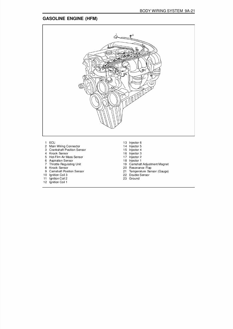
8/18/2019 SsangYong Musso Service Manual 1998.pdf
http://slidepdf.com/reader/full/ssangyong-musso-service-manual-1998pdf 1347/1459
BODY WIRING SYSTEM 9A-21
GASOLINE ENGINE (HFM)
1 ECU2 Main Wiring Connector3 Crankshaft Position Sensor4 Knock Sensor5 Hot-Film Air Mass Sensor6 Aspiration Sensor7 Throttle Regulating Unit8 Knock Sensor9 Camshaft Position Sensor
10 Ignition Coil 311 Ignition Coil 212 Ignition Coil 1
13 Injector 614 Injector 515 Injector 416 Injector 317 Injector 218 Injector 119 Camshaft Adjustment Magnet20 Resonance Flap21 Temperature Sensor (Gauge)22 Double Sensor23 Ground

8/18/2019 SsangYong Musso Service Manual 1998.pdf
http://slidepdf.com/reader/full/ssangyong-musso-service-manual-1998pdf 1348/1459
9A-22 BODY WIRING SYSTEM
DIESEL ENGINE
1 Preheating Unit2 Main Wiring Connector3 Glow Plug 14 Glow Plug 2
5 Glow Plug 36 Glow Plug 47 Glow Plug 58 Water Temperature Sensor (Gauge)
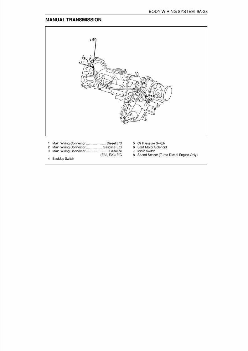
8/18/2019 SsangYong Musso Service Manual 1998.pdf
http://slidepdf.com/reader/full/ssangyong-musso-service-manual-1998pdf 1349/1459
BODY WIRING SYSTEM 9A-23
MANUAL TRANSMISSION
1 Main Wiring Connector ...................... Diesel E/G2 Main Wiring Connector .................. Gasoline E/G3 Main Wiring Connector ......................... Gasoline
(E32, E23) E/G4 Back Up Switch
5 Oil Pressure Switch6 Start Motor Solenoid7 Micro Switch8 Speed Sensor (Turbo Diesel Engine Only)
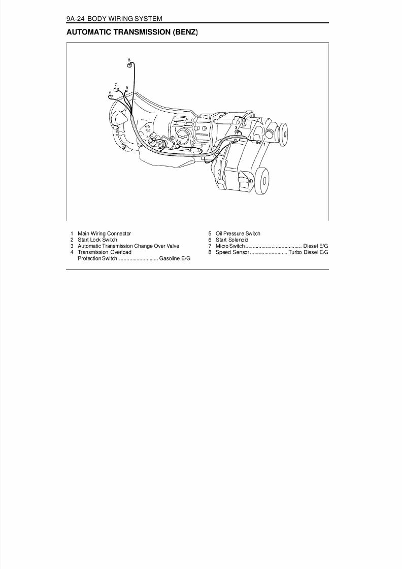
8/18/2019 SsangYong Musso Service Manual 1998.pdf
http://slidepdf.com/reader/full/ssangyong-musso-service-manual-1998pdf 1350/1459
9A-24 BODY WIRING SYSTEM
AUTOMATIC TRANSMISSION (BENZ)
1 Main Wiring Connector2 Start Lock Switch3 Automatic Transmission Change Over Valve4 Transmission Overload
Protection Switch ........................... Gasoline E/G
5 Oil Pressure Switch6 Start Solenoid7 Micro Switch ....................................... Diesel E/G8 Speed Sensor .......................... Turbo Diesel E/G

8/18/2019 SsangYong Musso Service Manual 1998.pdf
http://slidepdf.com/reader/full/ssangyong-musso-service-manual-1998pdf 1351/1459
BODY WIRING SYSTEM 9A-25
AUTOMATIC TRANSMISSION (BTRA)
1 Main Wiring Connector2 Main Wiring Connector3 Transmission4 Transmission Lever5 Oil Pressure Switch ............................ Diesel E/G
6 Start Motor Solenoid7 Throttle Position Sensor .................... Diesel E/G8 Speed Sensor .......................... Turbo Diesel E/G9 Inhibitor Switch

8/18/2019 SsangYong Musso Service Manual 1998.pdf
http://slidepdf.com/reader/full/ssangyong-musso-service-manual-1998pdf 1352/1459
9A-26 BODY WIRING SYSTEM
DRIVER'S SEAT
1 Main Wiring Connector2 Tilt Motor3 Heater Control Unit4 Height Motor
5 Slide Motor6 Back Seat Wiring Connector7 Seat Heater8 Driver Seat Switch

8/18/2019 SsangYong Musso Service Manual 1998.pdf
http://slidepdf.com/reader/full/ssangyong-musso-service-manual-1998pdf 1353/1459
Low (Philips H4)
Tail LampBrake Lamp
High Mounted Stop LampReverse Lamp
Fog Lamp*Turn Signal Lamp
Position Lamp
Front LampRear Lamp
Luggage LampDoor Courtesy Lamp
SECTION 9B
LIGHTING SYSTEM
Caution: Disconnect the negative battery cable before removing or installing any electrical unit or when a tool or equipment could easily come in contact with exposed electrical terminals. Disconnecting this cable will help prevent personal injury and damage to the vehicle. The ignition must also be in LOCK unless otherwise noted.
TABLE OF CONTENTS
SPECIFICATIONSBULB USAGE CHART
Head Lamp
Rear
Front
Interior
Application
Specifications. . . . . . . . . . . . . . . . . . . . . . . . 9B-1Bulb Usage Chart . . . . . . . . . . . . . . . . . . . . . . 9B-1
Schematic and Routing Diagrams . . . . . . . . 9B-2Tail Lamp & B/O Lamp . . . . . . . . . . . . . . . . . . 9B-2Head Lamp . . . . . . . . . . . . . . . . . . . . . . . . . . . 9B-3Head Lamp Leveling Device . . . . . . . . . . . . . . 9B-4Turn Signal Lamp and Hazard Lamp . . . . . . . . 9B-5
Back-Up Lamp and Stop Lamp . . . . . . . . . . . . 9B-6Front and Rear Fog Lamp . . . . . . . . . . . . . . . 9B-7Room Lamp . . . . . . . . . . . . . . . . . . . . . . . . . . 9B-8
Maintenance and Repair . . . . . . . . . . . . . . . 9B-9On-Vehicle Service . . . . . . . . . . . . . . . . . . . . . 9B-9
Front and Rear Lamps . . . . . . . . . . . . . . . . . . 9B-9
Hi(Philips H1)
HiLow
Watt/Quantity
55W / 255W / 255W / 25W / 4
21W / 421W / 121W / 255W / 221W / 25W / 2
8W / 210W / 18W / 15W / 4

8/18/2019 SsangYong Musso Service Manual 1998.pdf
http://slidepdf.com/reader/full/ssangyong-musso-service-manual-1998pdf 1354/1459
9B-2 LIGHTING SYSTEM
T A I L L A M P & B / O L A M P
SCHEMATIC AND ROUTING DIAGRAMS
1 5
( N O
. 1 5 )
O V P R

8/18/2019 SsangYong Musso Service Manual 1998.pdf
http://slidepdf.com/reader/full/ssangyong-musso-service-manual-1998pdf 1355/1459
LIGHTING SYSTEM 9B-3
H E A D L A M P

8/18/2019 SsangYong Musso Service Manual 1998.pdf
http://slidepdf.com/reader/full/ssangyong-musso-service-manual-1998pdf 1356/1459
HEAD LAMP LEVELING DEVICE

8/18/2019 SsangYong Musso Service Manual 1998.pdf
http://slidepdf.com/reader/full/ssangyong-musso-service-manual-1998pdf 1357/1459
TURN SIGNAL LAMP AND HAZARD LAMP
3 . 0 B G

8/18/2019 SsangYong Musso Service Manual 1998.pdf
http://slidepdf.com/reader/full/ssangyong-musso-service-manual-1998pdf 1358/1459
BACK-UP LAMP AND STOP LAMP

8/18/2019 SsangYong Musso Service Manual 1998.pdf
http://slidepdf.com/reader/full/ssangyong-musso-service-manual-1998pdf 1359/1459
FRONT AND REAR FOG LAMP

8/18/2019 SsangYong Musso Service Manual 1998.pdf
http://slidepdf.com/reader/full/ssangyong-musso-service-manual-1998pdf 1360/1459
9B-8 LIGHTING SYSTEM
R O O M L A M P

8/18/2019 SsangYong Musso Service Manual 1998.pdf
http://slidepdf.com/reader/full/ssangyong-musso-service-manual-1998pdf 1361/1459
LIGHTING SYSTEM 9B-9
FRONT AND REAR LAMPS
1 Low-beam Head Lamp2 High-beam Head Lamp3 Turn Signal Lamp4 Position Lamp
5 Back-up Lamp6 Tail / Stop Lamp7 Turn Signal Lamp8 Tail / Stop Lamp
MAINTENANCE AND REPAIR
ON-VEHICLE SERVICE

8/18/2019 SsangYong Musso Service Manual 1998.pdf
http://slidepdf.com/reader/full/ssangyong-musso-service-manual-1998pdf 1362/1459
9B-10 LIGHTING SYSTEM
Head Lamp FocusingWhen using the beam setting device1. The head lamp focus should be adjusted by using a proper
beam setting device.2. Adjust the head lamp focus by using Up/Down, Left/Right
adjusting screws.
When using the screen1. Put the vehicle on the leveling surface.2. One person is needed to seat on the driver's seat without
other loads(CVW) and check the tire pressure if it is in thespecification.
3. The distance between the headlamp and the screen is 25m.4. Draw the vertical line (crossing the center of each headlamp)
on the screen.5. Start the engine.6. Check if the cut-off line of the headlamp on the screen is in
the specification.1) Left/right direction
- The degree of the cross point at the cut-off line of theheadlamp and the vertical line should be 15.
2) Up/down direction- The distance between the cut-off line of the headlamp
and the horizontal line should be 25cm.
7. Adjust the focus if the cut-off line of the headlamp is out ofthe specification by using up/down, left/right adjustingscrews.A : Up/down direction adjusting screwB : Left/right direction adjusting secrw

8/18/2019 SsangYong Musso Service Manual 1998.pdf
http://slidepdf.com/reader/full/ssangyong-musso-service-manual-1998pdf 1363/1459

8/18/2019 SsangYong Musso Service Manual 1998.pdf
http://slidepdf.com/reader/full/ssangyong-musso-service-manual-1998pdf 1364/1459
9B-12 LIGHTING SYSTEM
Tail/stop and turn signal lamp
Tail/stop Lamp and backup lamp
Rear Combination LampRemoval & Installation Procedure1. Open the tailgate and remove the inner cover of the rear
combination lamp.2. Unscrew 4(8mm) nuts of tail/stop lamp and turn signal lamp
assembly.
3. Unscrew 6(8mm) nuts of tail/stop lamp and back-uplamp assembly.
4. Disconnect each connectors and remove the rearcombination lamp. Replace with specified bulb, ifnecessary.NoticeRefer to lamp specification.

8/18/2019 SsangYong Musso Service Manual 1998.pdf
http://slidepdf.com/reader/full/ssangyong-musso-service-manual-1998pdf 1365/1459
SECTION 9C
HORNS
Caution: Disconnect the negative battery cable before removing or installing any electrical unit or when a tool or equipment could easily come in contact with exposed electrical terminals. Disconnecting this cable will help prevent personal injury and damage to the vehicle. The ignition must also be in LOCK unless otherwise noted.
TABLE OF CONTENTSSchematic and Routing Diagrams . . . . . . . . 9C-2 Horn . . . . . . . . . . . . . . . . . . . . . . . . . . . . . . . . 9C-2

8/18/2019 SsangYong Musso Service Manual 1998.pdf
http://slidepdf.com/reader/full/ssangyong-musso-service-manual-1998pdf 1366/1459
9C-2 HORN
H O R N
SCHEMATIC AND ROUTING DIAGRAMS

8/18/2019 SsangYong Musso Service Manual 1998.pdf
http://slidepdf.com/reader/full/ssangyong-musso-service-manual-1998pdf 1367/1459
SECTION 9D
WIPERS/WASHER SYSTEM
Caution: Disconnect the negative battery cable before removing or installing any electrical unit or when a tool or equipment could easily come in contact with exposed electrical terminals. Disconnecting this cable will help prevent personal injury and damage to the vehicle. The ignition must also be in LOCK unless otherwise noted.
TABLE OF CONTENTSSchematic and Routing Diagrams . . . . . . . . 9D-2
Rear Wiper and Washer . . . . . . . . . . . . . . . . . 9D-2Maintenance and Repair . . . . . . . . . . . . . . . 9D-3
On-Vehicle Service . . . . . . . . . . . . . . . . . . . . . . 9D-3Front Wiper and Washer . . . . . . . . . . . . . . . . 9D-3Rear Wiper and Washer . . . . . . . . . . . . . . . . . 9D-5

8/18/2019 SsangYong Musso Service Manual 1998.pdf
http://slidepdf.com/reader/full/ssangyong-musso-service-manual-1998pdf 1368/1459
9D-2 WIPERS/WASHER SYSTEM
SCHEMATIC AND ROUTING DIAGRAMS
R E A R W I P E R A N D W A S H E R

8/18/2019 SsangYong Musso Service Manual 1998.pdf
http://slidepdf.com/reader/full/ssangyong-musso-service-manual-1998pdf 1369/1459
WIPERS/WASHER SYATEM 9D-3
FRONT WIPER AND WASHER
1 Windshield Linkage2 Wiper Arm3 Wiper Blade (Left)4 Wiper Blade (Right)5 Washer Nozzle6 Reservoir Tank Guide7 Reservoir Tank
8 Washer Hose9 Cap
10 Washer Motor11 Hose Connector (Y- type)12 Washer Hose (Left)13 Nozzle Pipe14 Washer Hose
MAINTENANCE AND REPAIR
ON VEHICLE SERVICE

8/18/2019 SsangYong Musso Service Manual 1998.pdf
http://slidepdf.com/reader/full/ssangyong-musso-service-manual-1998pdf 1370/1459
9D-4 WIPERS/WASHER SYSTEM
Removal & Installation Procedure1. Remove the wiper arm and blade.2. Remove the linkage connected to the wiper motor.3. Disconnect the connector from the wiper motor.4. Unscrew the locking bolts from wiper motor.5. Installation is reverse order of removal
Connector Appearance and Connecting CircuitConnector Terminal
HP
BL
HI(high speed)Intermittent
GroundLow(low speed)

8/18/2019 SsangYong Musso Service Manual 1998.pdf
http://slidepdf.com/reader/full/ssangyong-musso-service-manual-1998pdf 1371/1459
WIPERS/WASHER SYSTEM 9D-5
REAR WIPER AND WASHER
1 Wiper Arm2 Wiper Cap3 Wiper Blade4 Washer Nozzle5 Reservoir Tank
6 Wiper Hose7 Cap8 Washer Motor9 Wiper Hose Socket
10 Outer Joint
NoticeRemoval and installation is as shown in upper drawings.

8/18/2019 SsangYong Musso Service Manual 1998.pdf
http://slidepdf.com/reader/full/ssangyong-musso-service-manual-1998pdf 1372/1459
9D-6 WIPERS/WASHER SYSTEM
Removal & Installation Procedure1. Remove the spare tire.2. Unscrew the locking nut and remove the wiper.
3. Unscrew the locking nut of wiper motor.
4. Remove the tailgate trim panel.5. Dieconnect the connector from the wiper motor.
6. Unscrew four screws(arrows) and remove the wiper motor.

8/18/2019 SsangYong Musso Service Manual 1998.pdf
http://slidepdf.com/reader/full/ssangyong-musso-service-manual-1998pdf 1373/1459
WIPERS/WASHER SYSTEM 9D-7
Connector Appearance and Connecting CircuitConnector Terminal
B+E
WP
Battery Power SourceGround
From Switch
Diagram for Connecting Circuit

8/18/2019 SsangYong Musso Service Manual 1998.pdf
http://slidepdf.com/reader/full/ssangyong-musso-service-manual-1998pdf 1374/1459
SECTION 9E
INSTRUMENTATION/DRIVER INFORMATION
Caution: Disconnect the negative battery cable before removing or installing any electrical unit or when a tool or equipment could easily come in contact with exposed electrical terminals. Disconnecting this cable will help prevent personal injury and damage to the vehicle. The ignition must also be in LOCK unless otherwise noted.
TABLE OF CONTENTSSchematic and Routing Diagrams . . . . . . . . 9E-2
Cluster . . . . . . . . . . . . . . . . . . . . . . . . . . . . . . 9E-2Component Locator . . . . . . . . . . . . . . . . . . . 9E-3
Combination Meter . . . . . . . . . . . . . . . . . . . . . 9E-3
Maintenance and Repair . . . . . . . . . . . . . . . 9E-4On-Vehicle Service . . . . . . . . . . . . . . . . . . . . . . 9E-4
Combination Meter . . . . . . . . . . . . . . . . . . . . . 9E-4

8/18/2019 SsangYong Musso Service Manual 1998.pdf
http://slidepdf.com/reader/full/ssangyong-musso-service-manual-1998pdf 1375/1459
9E-2 INSTRUMENTATION/DRIVER INFORMATION
C L U S T E R
SCHEMATIC AND ROUTING DIAGRAMS

8/18/2019 SsangYong Musso Service Manual 1998.pdf
http://slidepdf.com/reader/full/ssangyong-musso-service-manual-1998pdf 1376/1459
INSTRUMENTATION/DRIVER INFORMATION 9E-3
COMBINATION METER
COMPONENT LOCATOR
1. Speedometer2. Odometer3. Trip odometer4. Tachometer5. Coolant temperature gauge6. Fuel gauge7. Low fuel level warning light8. Turn signal indicator (left)9. Turn signal indicator (right)
10. Outside rearview mirror & tailgate heating switch11. Reset button12. Auto shift indicator*13. Door open warning light14. TCS indicator (equipped with ABD)*21. ABS warning light*
22. EBD warning light*23. ECS / SPORT warning light*24. 4 - wheel warning light*25. 4 - wheel high indicator26. 4 - wheel low indicator27. WINTER indicator28. POWER indicator29. High beam indicator15. Alternator warning light16. Engine oil pressure warning light17. Brake system warning light18. Glow indicator light (For Diesel engine)19. Airbag warning light*20. Seat belt reminder

8/18/2019 SsangYong Musso Service Manual 1998.pdf
http://slidepdf.com/reader/full/ssangyong-musso-service-manual-1998pdf 1377/1459
9E-4 INSTRUMENTATION/DRIVER INFORMATION
COMBINATION METER
Diesel1. Speedometer (km/h)
2. TachometerRevolution
Tolerance
1000
+137-63
2000 3000
+261-39
4000
+298-2
5000
-+199-51
Gasolin1 Windshield Linkage
Speed
Tolerance
40
+3+0
60 80
+5+0
100
+5+0
140
+5.5+0.5
160
+5.5+0.5
180
-+4+0
120
+5.5+0.5
Speed
Tolerance
20+4+0
40 60+4+0
80+5+0
120+5.5+0
140+5.5+0.5
160
+5.5+0.5
+3+0
100+5+0
Speed
Tolerance
180+6+1
200 240-+6
+1
-
MAINTENANCE AND REPAIR
ON VEHICLE SERVICE

8/18/2019 SsangYong Musso Service Manual 1998.pdf
http://slidepdf.com/reader/full/ssangyong-musso-service-manual-1998pdf 1378/1459
INSTRUMENTATION/DRIVER INFORMATION 9E-5
3. Fuel Gauge
Resistance
Tolerance
E
97
2.5'
1/2
(32.5)
±5°
F
6
±2.5
Temperature
50 °C
86 °C
105.5 °C
120 °C
Resistance( W)
156.9 W
44.5 W
27.3 W
19.4 W
4. Temperature Gauge(Temperature Sensor)
Speed
Tolerance
1000
±100
2000 3000
±150
4000
±150
6000
±180
7000
±210
8000
-±125
5000
±150
2. Tachometer

8/18/2019 SsangYong Musso Service Manual 1998.pdf
http://slidepdf.com/reader/full/ssangyong-musso-service-manual-1998pdf 1379/1459
SECTION 9F
AUDIO SYSTEM
Caution: Disconnect the negative battery cable before removing or installing any electrical unit or when a tool or equipment could easily come in contact with exposed electrical terminals. Disconnecting this cable will help prevent personal injury and damage to the vehicle. The ignition must also be in LOCK unless otherwise noted.
TABLE OF CONTENTSSchematic and Routing Diagrams . . . . . . . . 9F-2
Audio . . . . . . . . . . . . . . . . . . . . . . . . . . . . . . . 9F-2Diagnosis . . . . . . . . . . . . . . . . . . . . . . . . . . . 9F-3
General Diagnosis . . . . . . . . . . . . . . . . . . . . . 9F-3

8/18/2019 SsangYong Musso Service Manual 1998.pdf
http://slidepdf.com/reader/full/ssangyong-musso-service-manual-1998pdf 1380/1459
9F-2 AUDIO SYSTEM
A U D I O
SCHEMATIC AND ROUTING DIAGRAMS
0 . 3 G B
R H E O ( E X P )
L Y
N O
. 1 3

8/18/2019 SsangYong Musso Service Manual 1998.pdf
http://slidepdf.com/reader/full/ssangyong-musso-service-manual-1998pdf 1381/1459
AUDIO SYSTEM 9F-3
DIAGNOSISGENERAL DIAGNOSIS
No sounds

8/18/2019 SsangYong Musso Service Manual 1998.pdf
http://slidepdf.com/reader/full/ssangyong-musso-service-manual-1998pdf 1382/1459
SECTION 9H
SEATS
Caution: Disconnect the negative battery cable before removing or installing any electrical unit or when a tool or equipment could easily come in contact with exposed electrical terminals. Disconnecting this cable will help prevent personal injury and damage to the vehicle. The ignition must also be in LOCK unless otherwise noted.
TABLE OF CONTENTSSpecifications. . . . . . . . . . . . . . . . . . . . . . . . 9H-1
General Specifications . . . . . . . . . . . . . . . . . . 9H-1Diagnosis . . . . . . . . . . . . . . . . . . . . . . . . . . . 9H-2
Schematic and Routing Diagrams . . . . . . . . 9H-3Power Seat . . . . . . . . . . . . . . . . . . . . . . . . . . . 9H-3Seat Warmer. . . . . . . . . . . . . . . . . . . . . . . . . . 9H-4
Seat Belt & Tension Reducer Circuit . . . . . . . . 9H-5Component Locator . . . . . . . . . . . . . . . . . . . 9H-6
Front Seat & Rear Seat . . . . . . . . . . . . . . . . . 9H-6
Maintenance and Repair . . . . . . . . . . . . . . . 9H-7On-Vehicle Service . . . . . . . . . . . . . . . . . . . . . 9H-7
SPECIFICATIONSGENERAL SPECIFICATIONS
SlideTiltHeightTilt and Height(up)SlideSlideTilt and HeightLoad RatingOperating Temperature RangeSwitch Operating Force
Application DeseriptionDC11 - 15V
-30°C - 80°C20 ± 7mm/sec
10.6 ± 5mm/sec7 ± 2mm/sec
Tilt:35 ± 2mm, Height:35 ± 2mmForward:230mmLess Then 7ALess Then 7A
DC12V 1A-30°C - 80°C0.3 - 0.7Kgf
Operating VoltageOperating Temperature RangeSeat Operating Speed(at 13.5V)
Seat Operating Distance
Operating Current(at 13.5V)
Seat Heater Switch

8/18/2019 SsangYong Musso Service Manual 1998.pdf
http://slidepdf.com/reader/full/ssangyong-musso-service-manual-1998pdf 1383/1459
9H-2 SEATS
DIAGNOSISWhen the power seat does not work :

8/18/2019 SsangYong Musso Service Manual 1998.pdf
http://slidepdf.com/reader/full/ssangyong-musso-service-manual-1998pdf 1384/1459

8/18/2019 SsangYong Musso Service Manual 1998.pdf
http://slidepdf.com/reader/full/ssangyong-musso-service-manual-1998pdf 1385/1459
9H-4 SEATS
S E A T W A R M E R
0 . 5 G W

8/18/2019 SsangYong Musso Service Manual 1998.pdf
http://slidepdf.com/reader/full/ssangyong-musso-service-manual-1998pdf 1386/1459
SEAT BELT & TENSION REDUCER

8/18/2019 SsangYong Musso Service Manual 1998.pdf
http://slidepdf.com/reader/full/ssangyong-musso-service-manual-1998pdf 1387/1459

8/18/2019 SsangYong Musso Service Manual 1998.pdf
http://slidepdf.com/reader/full/ssangyong-musso-service-manual-1998pdf 1388/1459
SEATS 9H-7
MAINTENANCE AND REPAIR
ON-VEHICLE SERVICE
1 Slide Adjusting Motor2 Height Adjusting Motor3 Tilt Adjusting Motor4 Recline Adjusting Motor
5 Driver's Power Seat Recline Switch6 Driver's Power Seat Switch(Slide, Height, Tilt)7 Seat Heater Control Unit8 Seat Heater Switch

8/18/2019 SsangYong Musso Service Manual 1998.pdf
http://slidepdf.com/reader/full/ssangyong-musso-service-manual-1998pdf 1389/1459
9H-8 SEATS
Power Seat Connector and Connection CircuitDriver's Power Seat Switch
Size and Color1.25LB1.25Br1.25Y
1.25BR1.25B
1.25BW1.25LB1.25LY1.25G
1.25BY
Connection CircuitTilt (UP)
Tilt (DOWN)Slide (RR)
Slide (FRT)Ground
Battery (+)Recline (RR)
Recline (FRT)Height (UP)
Height (DOWN)
No.12567
1011121314

8/18/2019 SsangYong Musso Service Manual 1998.pdf
http://slidepdf.com/reader/full/ssangyong-musso-service-manual-1998pdf 1390/1459
SEATS 9H-9
Seat Heater Connector and Connection CircuitSeat heater switch connector
Circuit
Connection Circuit
8/18/2019 SsangYong Musso Service Manual 1998.pdf
http://slidepdf.com/reader/full/ssangyong-musso-service-manual-1998pdf 1391/1459
SECTION 9L
GLASS AND MIRRORS
Caution: Disconnect the negative battery cable before removing or installing any electrical unit or when a tool or equipment could easily come in contact with exposed electrical terminals. Disconnecting this cable will help prevent personal injury and damage to the vehicle. The ignition must also be in LOCK unless otherwise noted.
TABLE OF CONTENTSSchematic and Routing Diagrams . . . . . . . . 9L-2
Outside Mirror . . . . . . . . . . . . . . . . . . . . . . . . . 9L-2
Auto Dimming Room Mirror . . . . . . . . . . . . . . . 9L-3Maintenance and Repair . . . . . . . . . . . . . . . 9L-4
On-Vehicle Service . . . . . . . . . . . . . . . . . . . . . . 9L-4Front & Side Glass . . . . . . . . . . . . . . . . . . . . . 9L-4
Tailgate Glass . . . . . . . . . . . . . . . . . . . . . . . . . 9L-9Auto Dimming Room Mirror . . . . . . . . . . . . . . 9L-12

8/18/2019 SsangYong Musso Service Manual 1998.pdf
http://slidepdf.com/reader/full/ssangyong-musso-service-manual-1998pdf 1392/1459
9L-2 GLASS AND MIRRORS
O U T S
I D E M I R R O R
SCHEMATIC AND ROUTING DIAGRAMS

8/18/2019 SsangYong Musso Service Manual 1998.pdf
http://slidepdf.com/reader/full/ssangyong-musso-service-manual-1998pdf 1393/1459
AUTO DIMMING ROOM MIRROR

8/18/2019 SsangYong Musso Service Manual 1998.pdf
http://slidepdf.com/reader/full/ssangyong-musso-service-manual-1998pdf 1394/1459
9L-4 GLASS AND MIRRORS
MAINTENANCE AND REPAIR
ON-VEHICLE SERVICEFRONT & SIDE GLASS

8/18/2019 SsangYong Musso Service Manual 1998.pdf
http://slidepdf.com/reader/full/ssangyong-musso-service-manual-1998pdf 1395/1459
GLASS AND MIRRORS 9L-5
Installation of Windshield1. Cleaning of windshield mounting flange.
Do not reuse a gauze over 20 times.Saturate the gauze in solvent (lsoprophyl alcohol).Keep the cleaned surface to be cleaned.Apply body primer to the cleaned and dry body flange.If body flange is oiled or contaminated, primer can notbe applied.Duration : 3 minutes - 8 hours (reapply after 8 hours).If primer is applied to the body, clean off immediatelywith solvent (ethyl alcohol and ethyl acetate, 50 : 50 involume).Do not apply primers which is over its duration.Be careful not to contaminate other parts.
2. Installation of windshield spacer.Insert the spacer completely.After inserting, there should be no clearance on the body.- To the direction of the side spacer.- To the direction of the lower spacer.
3. Cleaning of windshield glass.Clean the windshield glass keeping 15mm from the edgeof glass.Do not reuse a gauze over 20 times.
Saturate the gauze in solvent (lsoprophyl alcohol).Do not touch the cleaned glass surface.Apply glass primer to the cleaned and dry glass.If glass is oiled or contaminated, primer can not beapplied.

8/18/2019 SsangYong Musso Service Manual 1998.pdf
http://slidepdf.com/reader/full/ssangyong-musso-service-manual-1998pdf 1396/1459
9L-6 GLASS AND MIRRORS
4. Installation of glass dam rubber.Using a double - faced adhesive tape, install the damrubber keeping 10mm from the edge of glass. If intervalsare irregular, primers and sealants can be appliedunevenly.If need to remove the improper dam rubber, do notremain the double - faced adhesive tape on the glass.Improperly installed tape causes the inferior appearanceand weakening of adhesive strength of sealant.
5. Apply glass primer to the outer area of the dam rubber.Notice
Do not apply body primer to the glass.Do not touch the primer applied surface. If you touch,
this may cause water leakage after installation of thewindshield.Keep water or dust away from the primer applied surface.
6. Apply sealant to windshield glass.Uneven application of sealant may cause water leakageafter installation of the glass.Do not touch the glass moldings and dam rubber whileapplying sealant.Turn over the glass and apply sealant.
7. Using suction holders, install the windshield within 5minutesafter application of sealant.

8/18/2019 SsangYong Musso Service Manual 1998.pdf
http://slidepdf.com/reader/full/ssangyong-musso-service-manual-1998pdf 1397/1459

8/18/2019 SsangYong Musso Service Manual 1998.pdf
http://slidepdf.com/reader/full/ssangyong-musso-service-manual-1998pdf 1398/1459
9L-8 GLASS AND MIRRORS
Tightening Torque 7.7 Nm
4. Before installation, ensure that the stay bolt washer isinserted.
5. Using suction holders, install the side glass within 5minutesafter application of sealant.

8/18/2019 SsangYong Musso Service Manual 1998.pdf
http://slidepdf.com/reader/full/ssangyong-musso-service-manual-1998pdf 1399/1459
GLASS AND MIRRORS 9L-9
TAILGATE GLASS
1 Wiper Arm and Blade Assembly2 Heating Lines
3 Tailgate Trim4 Tailgate Glass
NoticeRemoval and installation is as shown in upper drawings.

8/18/2019 SsangYong Musso Service Manual 1998.pdf
http://slidepdf.com/reader/full/ssangyong-musso-service-manual-1998pdf 1400/1459
9L-10 GLASS AND MIRRORS
Installation of Tailgate Glass1. Clean the tailgate flange.
Do not reuse a gauze over 20 times.Saturate the gauze in solvent (Isoprophyl alcohol).Keep the cleaned surface to be cleaned.Apply body primer to the cleaned and dry flange.- If flange is oiled or contaminated, primer can not be
applied.
2. Apply primer after cleaning of tailgate flange.Keep primers in a refrigerator(-2 °C - +5 °C).Use sufficiently mixed primer in a mixer over 10 minutes.Apply primer within 2 hours after opening.
Do not apply primers which is over its druation.Apply evenly to the flange.Duration : 3 minutes - 8 hours (reapply after 8 hours).If primer is applied to the body, clean off immediatelywith solvent.Be careful not to contaminate other parts.
3. Clean the tailgate galss.Clean the glass keeping 15mm from the edge of glass.Do not reuse a gauze over 20 times.Saturate the gauze in solvent(Isoprophyl alcohol).Do not touch the cleaned galss surface.Apply glass primer to the cleaned and dry glass surface.If glass is oiled or contaminated, primer can not beapplied.
4. Apply primer to the tailgate glass.Use sufficiently mixed primer in a mixer over 10 minutes.Be careful not to contaminate other parts due to overapplication.Duration : 1 minute - 24 hours(reapply after 24 hours).Never use the primer containing deposits or floatingmaterials.Do not use primers which is over its duration.Do not reuse a gauze over 20 times.Apply evenly to glass.

8/18/2019 SsangYong Musso Service Manual 1998.pdf
http://slidepdf.com/reader/full/ssangyong-musso-service-manual-1998pdf 1401/1459
GLASS AND MIRRORS 9L-11
5. Apply sealant to the glass.Turn over the glass and apply sealant.Uneven application of sealant may cause water leakageafter installation of glass.Do not touch the glass moldings and dam rubber whileapplying sealant.
6. Using suction holders, install the tailgate glass within5minutes after application of sealant.
Fix the glass with adhesive tape.Apply sealant additionally between the quarter outerpanel and tailgate glass moldings.

8/18/2019 SsangYong Musso Service Manual 1998.pdf
http://slidepdf.com/reader/full/ssangyong-musso-service-manual-1998pdf 1402/1459
9L-12 GLASS AND MIRRORS
1 Auto Dimming Room Mirror Assembly2 Sensor (Front)3 Sensor (Rear)
AUTO DIMMING ROOM MIRRORLayout
4 Switch5 Cover6 Lamp

8/18/2019 SsangYong Musso Service Manual 1998.pdf
http://slidepdf.com/reader/full/ssangyong-musso-service-manual-1998pdf 1403/1459
GLASS AND MIRRORS 9L-13
Check & ServiceIf reflection ratio is not adjusted automatically during nightdriving when AUTO switch is pressed, check each connectorsfor proper connection and power flow to the auto dimming roommirror using multi tester.
1. Yellow (Connected to back-up lamp)2. Blue (Ground)3. White (Power)
Voltage RatingOperating Current
Over Current
DV 12V1 A3 A
FunctionWhen ignition switch is turned ON, green lamp on auto dimmingmirror will turn in and glare reflection ratio will be automaticallyadjusted. By positioning AUTO switch to ON, 2Sensors willautomatically adjust refection ratio after sensing rear andsurrounding brightness to reduce driver’s eye fatigue duringdriving though tunnel or in night.When OFF switch is pressed, the lamp goes out and it will beoperated as a normal rear view mirror and shift lever ispositioned in reverse, the auto dimming function will beautomatically OFF.
Specifications

8/18/2019 SsangYong Musso Service Manual 1998.pdf
http://slidepdf.com/reader/full/ssangyong-musso-service-manual-1998pdf 1404/1459
9L-14 GLASS AND MIRRORS
Removal & Installation Procedure1. Removal the room mirror cover (arrow).
2. Disconnect 3-pin connector.3. Removal the mirror assembly.4. Installation should follow the removal procedure in the
reverse order.

8/18/2019 SsangYong Musso Service Manual 1998.pdf
http://slidepdf.com/reader/full/ssangyong-musso-service-manual-1998pdf 1405/1459
SECTION 9N
FRAME AND UNDERBODY
TABLE OF CONTENTSDimension . . . . . . . . . . . . . . . . . . . . . . . . . . 9N-2Frame . . . . . . . . . . . . . . . . . . . . . . . . . . . . . . . 9N-2
Component Locator . . . . . . . . . . . . . . . . . . . 9N-3
Body Mountings . . . . . . . . . . . . . . . . . . . . . . . 9N-3Body Mounting-Sectional View . . . . . . . . . . . . 9N-4Skid Plate . . . . . . . . . . . . . . . . . . . . . . . . . . . . 9N-5
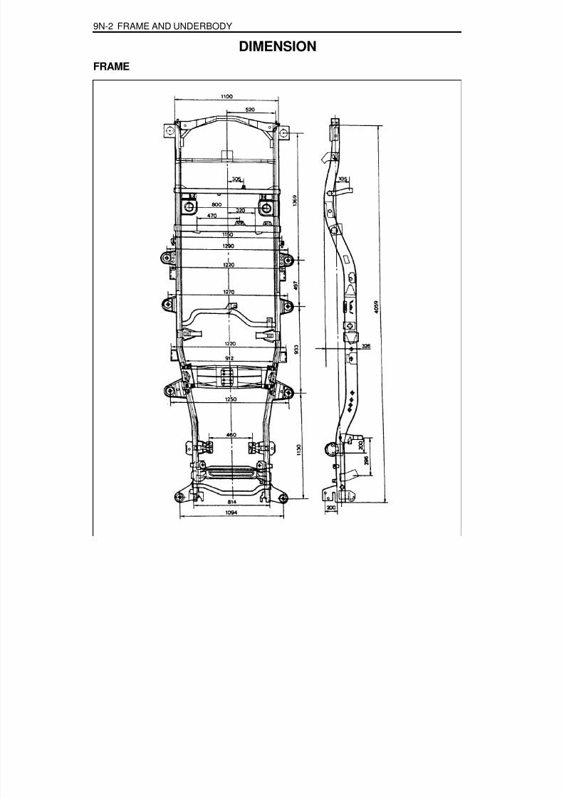
8/18/2019 SsangYong Musso Service Manual 1998.pdf
http://slidepdf.com/reader/full/ssangyong-musso-service-manual-1998pdf 1406/1459
9N-2 FRAME AND UNDERBODY
DIMENSIONFRAME
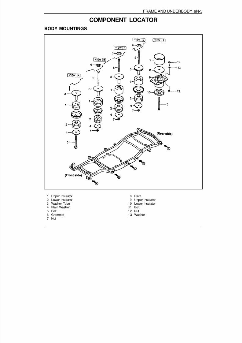
8/18/2019 SsangYong Musso Service Manual 1998.pdf
http://slidepdf.com/reader/full/ssangyong-musso-service-manual-1998pdf 1407/1459
FRAME AND UNDERBODY 9N-3
COMPONENT LOCATORBODY MOUNTINGS
1 Upper Insulator2 Lower Insulator3 Washer Tube4 Plain Washer5 Bolt6 Grommet7 Nut
8 Plate9 Upper Insulator
10 Lower Insulator11 Bolt12 Nut13 Washer
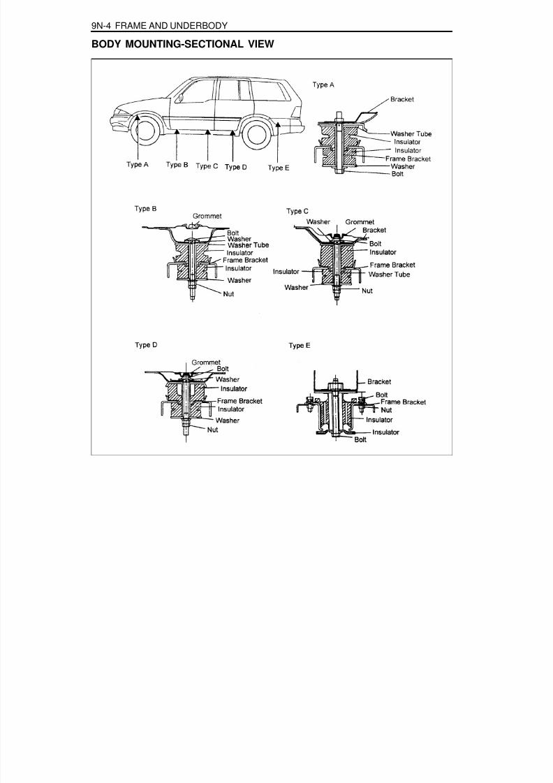
8/18/2019 SsangYong Musso Service Manual 1998.pdf
http://slidepdf.com/reader/full/ssangyong-musso-service-manual-1998pdf 1408/1459
9N-4 FRAME AND UNDERBODY
BODY MOUNTING-SECTIONAL VIEW

8/18/2019 SsangYong Musso Service Manual 1998.pdf
http://slidepdf.com/reader/full/ssangyong-musso-service-manual-1998pdf 1409/1459
FRAME AND UNDERBODY 9N-5
1 Mounting Bolt ....................................... 28-47 Nm
SKID PLATE.
2 Skid Plate
Removal & Installation Procedure1. Remove 6 mounting bolts and carefully remove the skid
plate.
Installation Notice
2. Installation should follow the removal procedure in thereverse order.
Tightening Torque 28 - 47 Nm

8/18/2019 SsangYong Musso Service Manual 1998.pdf
http://slidepdf.com/reader/full/ssangyong-musso-service-manual-1998pdf 1410/1459
SECTION 9O
BUMPERS AND FASCIAS
TABLE OF CONTENTSMaintenance and Repair . . . . . . . . . . . . . . . 9O-2On-Vehicle Service . . . . . . . . . . . . . . . . . . . . . . 9O-2
Front Bumper . . . . . . . . . . . . . . . . . . . . . . . . . 9O-2Rear Bumper . . . . . . . . . . . . . . . . . . . . . . . . . 9O-4

8/18/2019 SsangYong Musso Service Manual 1998.pdf
http://slidepdf.com/reader/full/ssangyong-musso-service-manual-1998pdf 1411/1459
9O-2 BUMPERS AND FASCIAS
MAINTENANCE AND REPAIR
ON-VEHICLE SERVICEFRONT BUMPER
NoticeRemoval and installation is as shown in upper drawings.
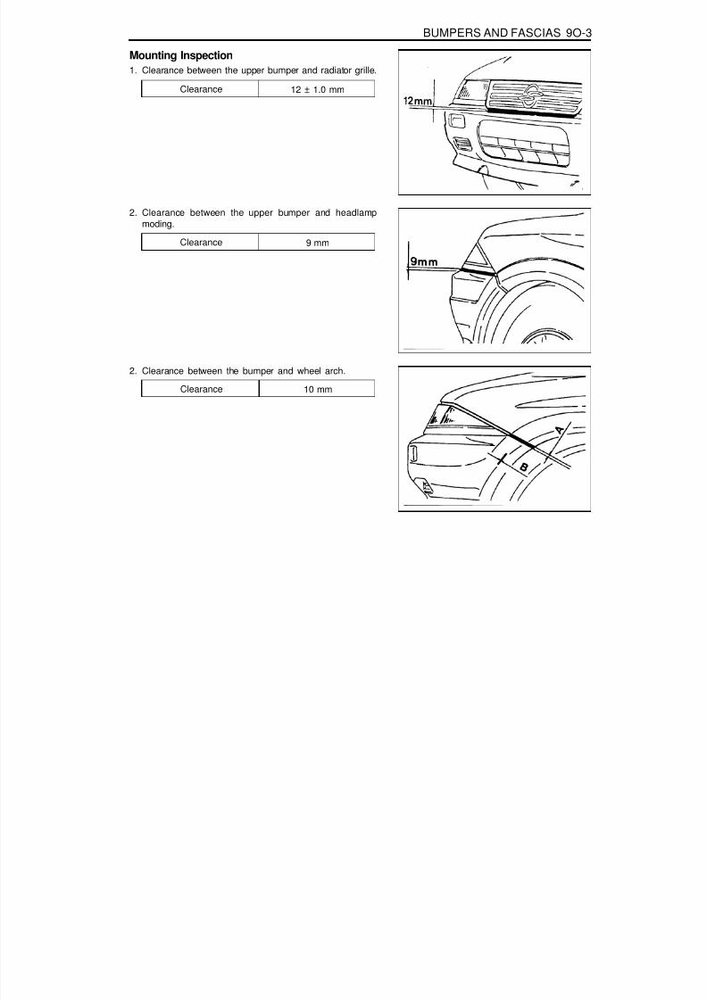
8/18/2019 SsangYong Musso Service Manual 1998.pdf
http://slidepdf.com/reader/full/ssangyong-musso-service-manual-1998pdf 1412/1459
BUMPERS AND FASCIAS 9O-3
Mounting Inspection1. Clearance between the upper bumper and radiator grille.
2. Clearance between the upper bumper and headlampmoding.
Clearance 12 ± 1.0 mm
Clearance 9 mm
2. Clearance between the bumper and wheel arch.
Clearance 10 mm

8/18/2019 SsangYong Musso Service Manual 1998.pdf
http://slidepdf.com/reader/full/ssangyong-musso-service-manual-1998pdf 1413/1459
9O-4 BUMPERS AND FASCIAS
REAR BUMPER
NoticeRemoval and installation is as shown in upper drawings.

8/18/2019 SsangYong Musso Service Manual 1998.pdf
http://slidepdf.com/reader/full/ssangyong-musso-service-manual-1998pdf 1414/1459
BUMPERS AND FASCIAS 9O-5
Mounting Inspection1. Clearance between the upper bumper facia and tailgate.
2. Clearance between the rear bumper facia and rear bumpermolding.
Clearance 12 ± 1.0 mm
Clearance 11.0 mm
3. Clearance between the quarter outer panel and rearbumper facia.
Clearance 10.0 mm

8/18/2019 SsangYong Musso Service Manual 1998.pdf
http://slidepdf.com/reader/full/ssangyong-musso-service-manual-1998pdf 1415/1459
SECTION 9P
DOORS
Caution: Disconnect the negative battery cable before removing or installing any electrical unit or when a tool or equipment could easily come in contact with exposed electrical terminals. Disconnecting this cable will help prevent personal injury and damage to the vehicle. The ignition must also be in LOCK unless otherwise noted.
TABLE OF CONTENTSSchematic and Routing Diagrams . . . . . . . . 9P-2
Power Window . . . . . . . . . . . . . . . . . . . . . . . . 9P-2Maintenance and Repair . . . . . . . . . . . . . . . 9P-3
On-Vehicle Service . . . . . . . . . . . . . . . . . . . . . . 9P-3
Front Door . . . . . . . . . . . . . . . . . . . . . . . . . . . 9P-3Rear Door . . . . . . . . . . . . . . . . . . . . . . . . . . . . 9P-4Tail Gate . . . . . . . . . . . . . . . . . . . . . . . . . . . . . 9P-5

8/18/2019 SsangYong Musso Service Manual 1998.pdf
http://slidepdf.com/reader/full/ssangyong-musso-service-manual-1998pdf 1416/1459
9P-2 DOORS
SCHEMATIC AND ROUTING DIAGRAMS
P O W E R W I N D O W
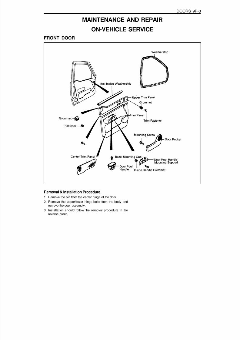
8/18/2019 SsangYong Musso Service Manual 1998.pdf
http://slidepdf.com/reader/full/ssangyong-musso-service-manual-1998pdf 1417/1459
DOORS 9P-3
MAINTENANCE AND REPAIR
ON-VEHICLE SERVICEFRONT DOOR
Removal & Installation Procedure1. Remove the pin from the center hinge of the door.2. Remove the upper/lower hinge bolts from the body and
remove the door assembly.3. Installation should follow the removal procedure in the
reverse order.

8/18/2019 SsangYong Musso Service Manual 1998.pdf
http://slidepdf.com/reader/full/ssangyong-musso-service-manual-1998pdf 1418/1459
9P-4 DOORS
REAR DOOR
Removal & Installation Procedure1. Remove the pin from the center hinge of the door.2. Remove the upper/lower hinge bolts from the body and
remove the door assembly.3. Installation should follow the removal procedure in the
reverse order.

8/18/2019 SsangYong Musso Service Manual 1998.pdf
http://slidepdf.com/reader/full/ssangyong-musso-service-manual-1998pdf 1419/1459
DOORS 9P-5
TAIL GATE
Removal & Installation Procedure1. Remove the shock absorber mounting bolts.
2. Disconnect the tailgate wiring harness.
3. Remove the tailgate by removing the tailgate bracket bolts.4. Installation should follow the removal procedure in the
reverse order.

8/18/2019 SsangYong Musso Service Manual 1998.pdf
http://slidepdf.com/reader/full/ssangyong-musso-service-manual-1998pdf 1420/1459

8/18/2019 SsangYong Musso Service Manual 1998.pdf
http://slidepdf.com/reader/full/ssangyong-musso-service-manual-1998pdf 1421/1459
SECTION 9Q
ROOF
TABLE OF CONTENTSSchematic and Routing Diagrams . . . . . . . . 9Q-2
Sun Roof . . . . . . . . . . . . . . . . . . . . . . . . . . . . 9Q-2Maintenance and Repair . . . . . . . . . . . . . . . 9Q-3
On-Vehicle Service . . . . . . . . . . . . . . . . . . . . . . 9Q-3Sun Roof . . . . . . . . . . . . . . . . . . . . . . . . . . . . 9Q-3

8/18/2019 SsangYong Musso Service Manual 1998.pdf
http://slidepdf.com/reader/full/ssangyong-musso-service-manual-1998pdf 1422/1459
9Q-2 ROOF
S U N R O O F
SCHEMATIC AND ROUTING DIAGRAMS

8/18/2019 SsangYong Musso Service Manual 1998.pdf
http://slidepdf.com/reader/full/ssangyong-musso-service-manual-1998pdf 1423/1459
ROOF 9Q-3
MAINTENANCE AND REPAIR
ON-VEHICLE SERVICESUN ROOF
1 Inner Sliding Sun Roof Assembly2 Sun Roof Body Mounting Bracket3 Drain Hose Rear Grommet4 Sun Roof Motor Spanner5 Mounting Clip
6 Mounting Bracket7 Mounting Bracket Assembly8 Sun Roof Mounting Bracket
11 Sun Roof Module Assembly

8/18/2019 SsangYong Musso Service Manual 1998.pdf
http://slidepdf.com/reader/full/ssangyong-musso-service-manual-1998pdf 1424/1459
9Q-4 ROOF
Removal & Installation Procedure1. Disconnect the connector and remove the sun roof module
assembly.
2. Disconnect the front and rear drain hose.
3. Unscrew the sun roof mounting bracket bolts(arrows) andremove the inner sliding and sun roof assembly

8/18/2019 SsangYong Musso Service Manual 1998.pdf
http://slidepdf.com/reader/full/ssangyong-musso-service-manual-1998pdf 1425/1459
SECTION 9R
BODY FRONT END
TABLE OF CONTENTSMaintenance and Repair . . . . . . . . . . . . . . . 9R-2On-Vehicle Service . . . . . . . . . . . . . . . . . . . . . . 9R-2
Hood . . . . . . . . . . . . . . . . . . . . . . . . . . . . . . . . 9R-2Fender . . . . . . . . . . . . . . . . . . . . . . . . . . . . . . 9R-5

8/18/2019 SsangYong Musso Service Manual 1998.pdf
http://slidepdf.com/reader/full/ssangyong-musso-service-manual-1998pdf 1426/1459
9R-2 BODY FRONT END
MAINTENANCE AND REPAIR
ON-VEHICLE SERVICEHOOD
1 Hood2 Sping
3 Hood Hinge Assembly4 Bolt

8/18/2019 SsangYong Musso Service Manual 1998.pdf
http://slidepdf.com/reader/full/ssangyong-musso-service-manual-1998pdf 1427/1459
BODY FRONT END 9R-3
Removal & Installation Procedure1. Remove the hood striker assembly.
NoticeWhen installing, tighten the bolt after setting the holebetween wratch and hood striker assembly.
Installation Notice
Tightening Toque 8 - 11 Nm
2. Remove the hood Mounting bolt and hood lifter assembly.
Installation Notice
3. Remove the hood lock, hood relese from the clip.4. Remove the cable holder screw.5. Pull the cable nut toward driver side.6. Installation should follow the removal procedure in the
reverse order.
Tightening Toque 14 - 26 Nm
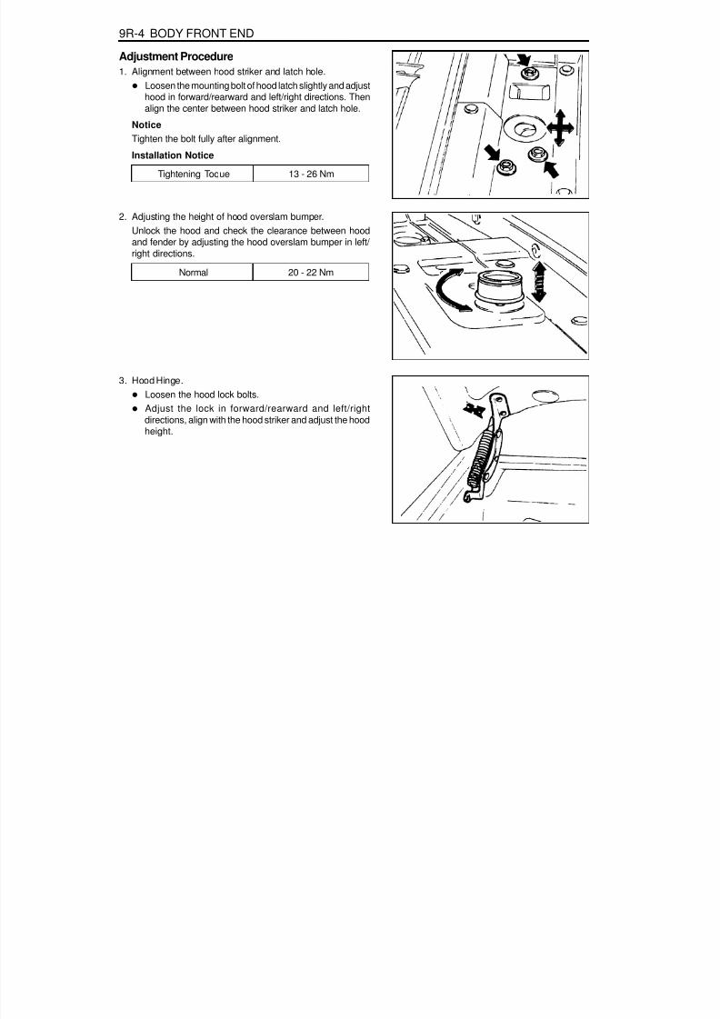
8/18/2019 SsangYong Musso Service Manual 1998.pdf
http://slidepdf.com/reader/full/ssangyong-musso-service-manual-1998pdf 1428/1459
9R-4 BODY FRONT END
Adjustment Procedure1. Alignment between hood striker and latch hole.
Loosen the mounting bolt of hood latch slightly and adjusthood in forward/rearward and left/right directions. Thenalign the center between hood striker and latch hole.
Notice
Tighten the bolt fully after alignment.Installation Notice
Tightening Toque 13 - 26 Nm
2. Adjusting the height of hood overslam bumper.Unlock the hood and check the clearance between hoodand fender by adjusting the hood overslam bumper in left/ right directions.
Normal 20 - 22 Nm
3. Hood Hinge.Loosen the hood lock bolts.
Adjust the lock in forward/rearward and left/rightdirections, align with the hood striker and adjust the hoodheight.

8/18/2019 SsangYong Musso Service Manual 1998.pdf
http://slidepdf.com/reader/full/ssangyong-musso-service-manual-1998pdf 1429/1459
BODY FRONT END 9R-5
FENDER
Removal Procedure1. Remove the screws.
2. Remove the mudguard and wheel guard.
3. Disconnect the front lamps connectors.4. Remove the front lamps.

8/18/2019 SsangYong Musso Service Manual 1998.pdf
http://slidepdf.com/reader/full/ssangyong-musso-service-manual-1998pdf 1430/1459
9R-6 BODY FRONT END
5. Remove the fender mounting bolts.
NoticeBe careful not to damage the paintwork.
Installation Procedure1. Installation should follow the removal procedure in the
reverse order.
Notice
Apply a tape sealer to the fender and body panel to preventrust in fender mounting bolts area.
Tightening Torque 7 - 9 Nm
8/18/2019 SsangYong Musso Service Manual 1998.pdf
http://slidepdf.com/reader/full/ssangyong-musso-service-manual-1998pdf 1431/1459
SECTION 9T
REMOTE KEYLESS ENTRY ANDANTI-THEFT SYSTEM
Caution: Disconnect the negative battery cable before removing or installing any electrical unit or when a tool or equipment could easily come in contact with exposed electrical terminals. Disconnecting this cable will help prevent personal injury and damage to the vehicle. The ignition must also be in LOCK unless otherwise noted.
TABLE OF CONTENTSSpecifications. . . . . . . . . . . . . . . . . . . . . . . . 9T-1
REKES Specifications . . . . . . . . . . . . . . . . . . . 9T-1
Schematic and Routing Diagrams . . . . . . . . 9T-2REKES . . . . . . . . . . . . . . . . . . . . . . . . . . . . . . 9T-2
Diagnosis . . . . . . . . . . . . . . . . . . . . . . . . . . . 9T-3
SPECIFICATIONSREKES SPECIFICATIONS
Diagnosis Test . . . . . . . . . . . . . . . . . . . . . . . . 9T-3Maintenance and Repair . . . . . . . . . . . . . . . 9T-5
On-Vehicle Service . . . . . . . . . . . . . . . . . . . . . . 9T-5REKES . . . . . . . . . . . . . . . . . . . . . . . . . . . . . . 9T-5
Transmitter
Description
DC 3V-10 °C - 60 °C
Changeable Coin Type LITHIUM Battery(CR2032)
Above 2 years (10 times/day)
ApplicationRated VoltageRated Range of Operating TemperatureModel
Durability
Description
DC 12VDC 8V - 16V
-30 °C - +80 °CAbove 5M W
Maximum 3mA
ApplicationRated VoltageRated Range of Operating VoltageRated Range of Operating TemperatureInsulating ResistanceArm Current
Receiver

8/18/2019 SsangYong Musso Service Manual 1998.pdf
http://slidepdf.com/reader/full/ssangyong-musso-service-manual-1998pdf 1432/1459
9T-2 REMOTE KEYLESS ENTRY AND ANTI-THEFT SYSTEM
R E K E S
SCHEMATIC AND ROUTING DIAGRAMS

8/18/2019 SsangYong Musso Service Manual 1998.pdf
http://slidepdf.com/reader/full/ssangyong-musso-service-manual-1998pdf 1433/1459
REMOTE KEYLESS ENTRY AND ANTI-THEFT SYSTEM 9T-3
DIAGNOSIS TESTIntroductionUsing the service connector, possible defects in power section,input·output section of internal STICS unit can be detected andeach normal status and defect mode can be checked.
Diagnosis Method1. Use buzzer for diagnosis check status output.2. Following function outputs should not act when diagnosis
switch is ON (STICS in the diagnosis socket box:connectionof No. 7 and ground No.1).- Tail lamp ON warning (buzzer output stop, door lock/
unlock output stop)- Seat belt warning (chime bell output stop)- Key reminder warning (chime bell output stop, door lock/
unlock output stop)
- Central door lock (door lock/unlock output stop)3. Functions in No. 2 should be restored when diagnosis switch
is OFF.4. Checked output should be made once while the diagnosis
switch is ON.5. When inputs are made by operating each different switches
more than 2 continuously, make output according to inputorder (buzzer ON) and turn off the buzzer for 1 second andthan make other remaining outputs for input switch.
DIAGNOSIS
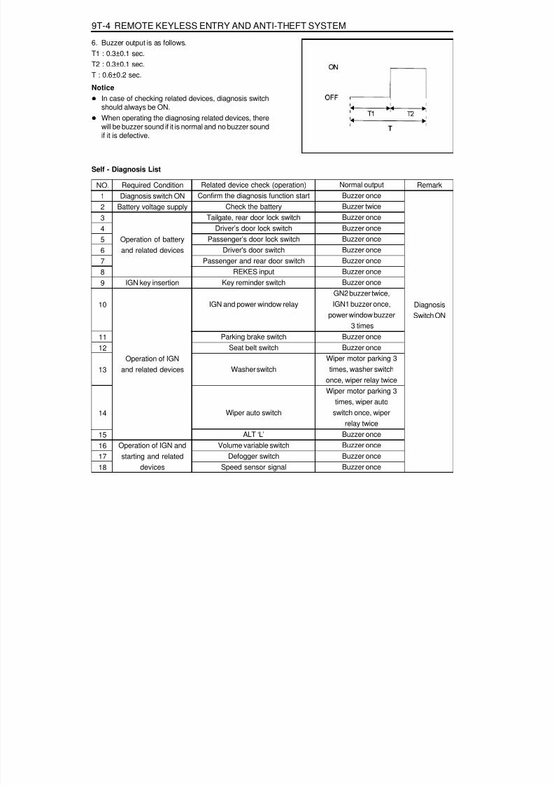
8/18/2019 SsangYong Musso Service Manual 1998.pdf
http://slidepdf.com/reader/full/ssangyong-musso-service-manual-1998pdf 1434/1459
9T-4 REMOTE KEYLESS ENTRY AND ANTI-THEFT SYSTEM
6. Buzzer output is as follows.T1 : 0.3±0.1 sec.T2 : 0.3±0.1 sec.T : 0.6±0.2 sec.
NoticeIn case of checking related devices, diagnosis switchshould always be ON.When operating the diagnosing related devices, therewill be buzzer sound if it is normal and no buzzer soundif it is defective.
Self - Diagnosis List
NO.123456789
10
1112
13
14
15161718
Required ConditionDiagnosis switch ON
Battery voltage supply
Operation of batteryand related devices
IGN key insertion
Operation of IGNand related devices
Operation of IGN andstarting and related
devices
Related device check (operation)Confirm the diagnosis function start
Check the batteryTailgate, rear door lock switch
Driver’s door lock switchPassenger’s door lock switch
Driver's door switchPassenger and rear door switch
REKES inputKey reminder switch
IGN and power window relay
Parking brake switchSeat belt switch
Washer switch
Wiper auto switch
ALT ‘L’Volume variable switch
Defogger switchSpeed sensor signal
Normal outputBuzzer onceBuzzer twiceBuzzer onceBuzzer onceBuzzer onceBuzzer onceBuzzer onceBuzzer onceBuzzer once
GN2 buzzer twice,IGN1 buzzer once,
power window buzzer 3 times
Buzzer onceBuzzer once
Wiper motor parking 3times, washer switch
once, wiper relay twiceWiper motor parking 3
times, wiper autoswitch once, wiper
relay twiceBuzzer onceBuzzer onceBuzzer onceBuzzer once
Remark
Diagnosis
Switch ON

8/18/2019 SsangYong Musso Service Manual 1998.pdf
http://slidepdf.com/reader/full/ssangyong-musso-service-manual-1998pdf 1435/1459
REMOTE KEYLESS ENTRY AND ANTI-THEFT SYSTEM 9T-5
MAINTENANCE AND REPAIR
ON-VEHICLE SERVICEREKES
1 REKES Receiver2 Antenna
3 Bolt4 Wiring Connector (6P)

8/18/2019 SsangYong Musso Service Manual 1998.pdf
http://slidepdf.com/reader/full/ssangyong-musso-service-manual-1998pdf 1436/1459
9T-6 REMOTE KEYLESS ENTRY AND ANTI-THEFT SYSTEM
Input MemoryWhen the REKES transmitter is lost
1. Connect the battery terminal No.3 and REKES terminal No.4which are on the diagnosis socket in engine room with servicelead wire.
2. Push the lock or unlock button on the REKES transmitter.3. Input Memory and close all doors.4. Check the operation of door locking system by pushing the
lock or unlock button on the REKES transmitter.
When the transmitter is faulty1. Replace the REKES transmitter with a new one and connect
the wiring connector.2. Set the input switch of the REKES receiver onto the No.1 or
No.2 position and push the lock or unlock button on theREKES transmitter.
3. Set the input switch of the REKES receiver onto the centralposition and close all doors.
4. Check the operation of door locking system by pushing thelock or unlock button on the REKES transmitter.
1 REKES Transmitter
2 Input Switch of the REKES Receive3 REKES Switch
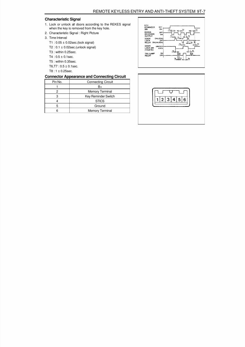
8/18/2019 SsangYong Musso Service Manual 1998.pdf
http://slidepdf.com/reader/full/ssangyong-musso-service-manual-1998pdf 1437/1459
REMOTE KEYLESS ENTRY AND ANTI-THEFT SYSTEM 9T-7
Characteristic Signal1. Lock or unlock all doors according to the REKES signal
when the key is removed from the key hole.2. Characteristic Signal : Right Picture3. Time Interval
T1 : 0.05 ± 0.02sec.(lock signal)
T2 : 0.1 ± 0.02sec.(unlock signal)T3 : within 0.25sec.T4 : 0.5 ± 0.1sec.T5 : within 0.35sec.T6,T7 : 0.5 ± 0.1sec.T8 : 1 ± 0.25sec.
Connector Appearance and Connecting CircuitPin No.
123456
Connecting CircuitB+
Memory TerminalKey Reminder Switch
STICSGround
Memory Terminal
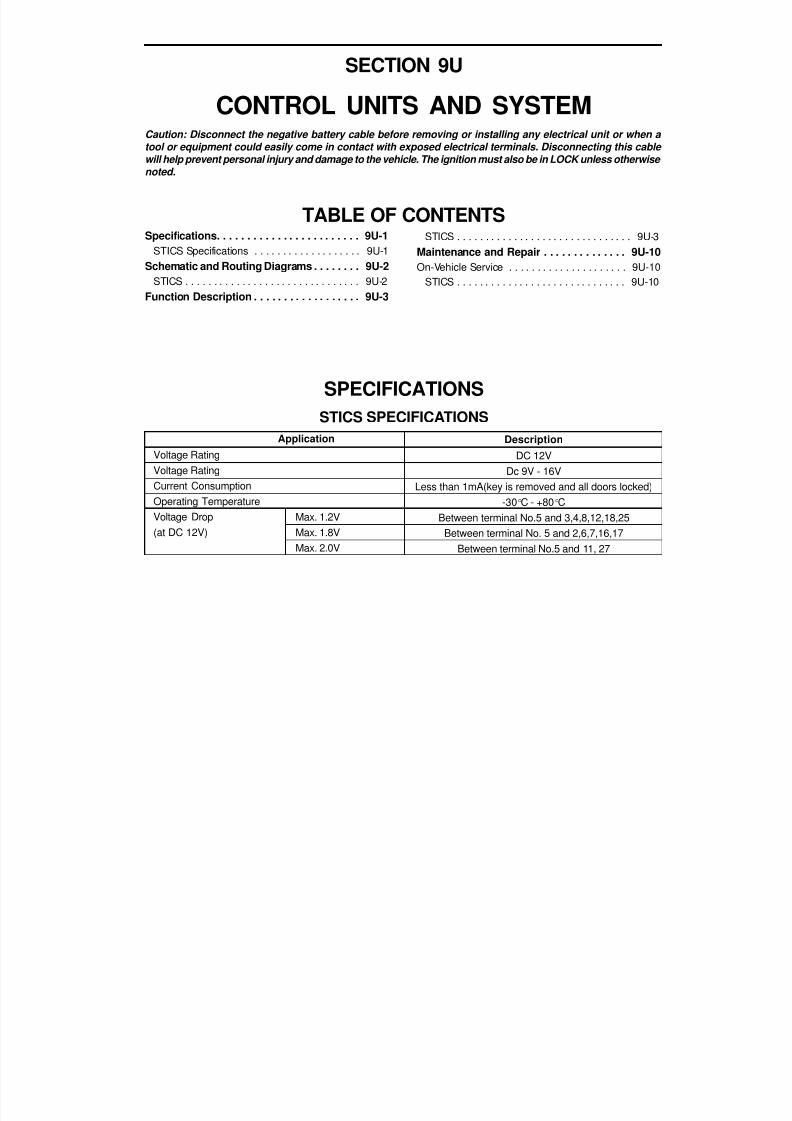
8/18/2019 SsangYong Musso Service Manual 1998.pdf
http://slidepdf.com/reader/full/ssangyong-musso-service-manual-1998pdf 1438/1459
SECTION 9U
CONTROL UNITS AND SYSTEMCaution: Disconnect the negative battery cable before removing or installing any electrical unit or when a
tool or equipment could easily come in contact with exposed electrical terminals. Disconnecting this cable will help prevent personal injury and damage to the vehicle. The ignition must also be in LOCK unless otherwise noted.
TABLE OF CONTENTSSpecifications. . . . . . . . . . . . . . . . . . . . . . . . 9U-1
STICS Specifications . . . . . . . . . . . . . . . . . . . 9U-1Schematic and Routing Diagrams . . . . . . . . 9U-2
STICS . . . . . . . . . . . . . . . . . . . . . . . . . . . . . . . 9U-2
Function Description . . . . . . . . . . . . . . . . . . 9U-3
SPECIFICATIONSSTICS SPECIFICATIONS
Description
DC 12VDc 9V - 16V
Less than 1mA(key is removed and all doors locked)-30 °C - +80 °C
Between terminal No.5 and 3,4,8,12,18,25Between terminal No. 5 and 2,6,7,16,17
Between terminal No.5 and 11, 27
Application
Voltage RatingVoltage RatingCurrent ConsumptionOperating TemperatureVoltage Drop(at DC 12V)
Max. 1.2VMax. 1.8VMax. 2.0V
STICS . . . . . . . . . . . . . . . . . . . . . . . . . . . . . . . 9U-3Maintenance and Repair . . . . . . . . . . . . . . 9U-10On-Vehicle Service . . . . . . . . . . . . . . . . . . . . . 9U-10
STICS . . . . . . . . . . . . . . . . . . . . . . . . . . . . . . 9U-10

8/18/2019 SsangYong Musso Service Manual 1998.pdf
http://slidepdf.com/reader/full/ssangyong-musso-service-manual-1998pdf 1439/1459
9U-2 CONTROL UNITS AND SYSTEM
S T I C S
SCHEMATIC AND ROUTING DIAGRAMS
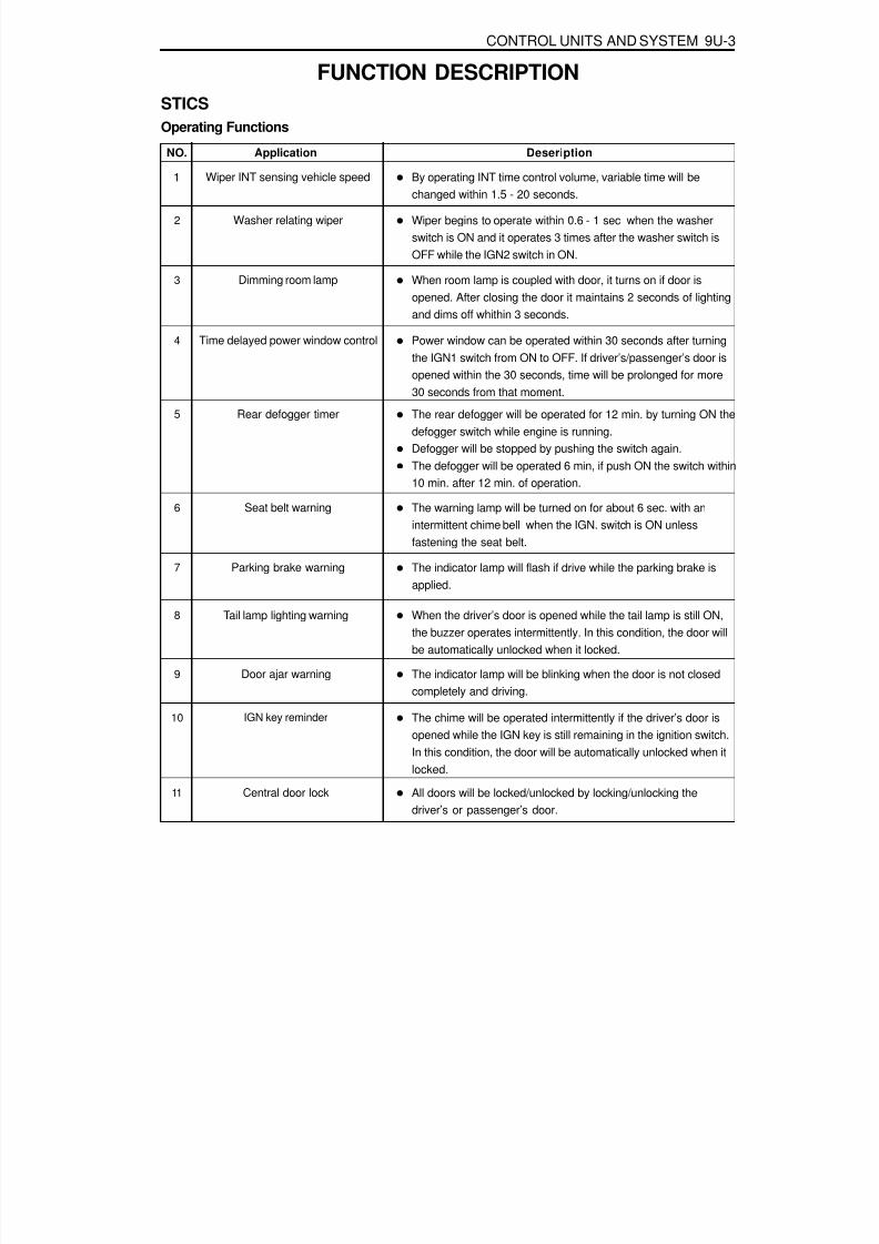
8/18/2019 SsangYong Musso Service Manual 1998.pdf
http://slidepdf.com/reader/full/ssangyong-musso-service-manual-1998pdf 1440/1459
CONTROL UNITS AND SYSTEM 9U-3
FUNCTION DESCRIPTIONSTICSOperating Functions
NO. Application Deseription
1 Wiper INT sensing vehicle speed By operating INT time control volume, variable time will bechanged within 1.5 - 20 seconds.
2 Washer relating wiper Wiper begins to operate within 0.6 - 1 sec when the washerswitch is ON and it operates 3 times after the washer switch isOFF while the IGN2 switch in ON.
3 Dimming room lamp When room lamp is coupled with door, it turns on if door isopened. After closing the door it maintains 2 seconds of lightingand dims off whithin 3 seconds.
4 Time delayed power window control Power window can be operated within 30 seconds after turningthe IGN1 switch from ON to OFF. If driver’s/passenger’s door isopened within the 30 seconds, time will be prolonged for more30 seconds from that moment.
5 Rear defogger timer The rear defogger will be operated for 12 min. by turning ON thedefogger switch while engine is running.Defogger will be stopped by pushing the switch again.The defogger will be operated 6 min, if push ON the switch within10 min. after 12 min. of operation.
6 Seat belt warning The warning lamp will be turned on for about 6 sec. with anintermittent chime bell when the IGN. switch is ON unlessfastening the seat belt.
7 Parking brake warning The indicator lamp will flash if drive while the parking brake isapplied.
8 Tail lamp lighting warning When the driver’s door is opened while the tail lamp is still ON,the buzzer operates intermittently. In this condition, the door willbe automatically unlocked when it locked.
9 Door ajar warning The indicator lamp will be blinking when the door is not closedcompletely and driving.
10 IGN key reminder The chime will be operated intermittently if the driver’s door isopened while the IGN key is still remaining in the ignition switch.In this condition, the door will be automatically unlocked when itlocked.
11 Central door lock All doors will be locked/unlocked by locking/unlocking thedriver’s or passenger’s door.

8/18/2019 SsangYong Musso Service Manual 1998.pdf
http://slidepdf.com/reader/full/ssangyong-musso-service-manual-1998pdf 1441/1459
9U-4 CONTROL UNITS AND SYSTEM
NO. Application Deseription
13 Ignition key hole illumination Coupled with door switch, ignition key hole illumination lamp will
turn on when the driver’s door is opened and will dim off after 10sec. after closing the door.
14 Auto door lock All doors will be locked automatically if the vehicle speedreaches 50km/h though the doors are in unlock.
15 Auto door unlock All doors will be automatically unlocked if the vehicle crasheswhile driving (over 15km/h).
16 Input checking function Self diagnostic function for each sensor switches and loads forthe system.
12 Coupled with REKES Being coupled with REKES (remote keyless entry system), alldoors will be locked/unlocked according to signals of transmitterwhen the ignition key is not inserted.

8/18/2019 SsangYong Musso Service Manual 1998.pdf
http://slidepdf.com/reader/full/ssangyong-musso-service-manual-1998pdf 1442/1459
CONTROL UNITS AND SYSTEM 9U-5
Operating Characteristics1. Wiper INT sensing vehicle speed
T1 : within 0.5 sec.T2 : Wiper motor 1 revolution timeT3 : 1.5±0.2 sec. - 20±2 sec.
2. Washer relating wiperT1 : 0.6 - 1.0 sec.T2 : motor 3 revolution (including motor revolution time)
3. Dimming room lampT1 : 2±0.3 sec.T2 : 3±0.5 sec
4. Time delayed power window controlT : 30±2 sec

8/18/2019 SsangYong Musso Service Manual 1998.pdf
http://slidepdf.com/reader/full/ssangyong-musso-service-manual-1998pdf 1443/1459
9U-6 CONTROL UNITS AND SYSTEM
5. Rear defogger timerT1 : 12±2 min.T2 : within 10±1 min.T3 : 6±1 min.
6. Seat belt warning timerT1 : 6±1 sec.T2 : 0.3±0.1 sec.T3 : 0.6±0.1 sec.
7. Parking brake warningT1 : 0.3±0.1 sec.T2 : 0.3±0.1 sec.V1 : 3km/h - 5km/h
8. Tail lamp lighting warningWhen the driver’s door is opened after removing the IGNkey while the tail lamp switch is still ON, the buzzer shouldbe operated.T1 : 0.3±0.1 sec.T2 : 0.3±0.1 sec.
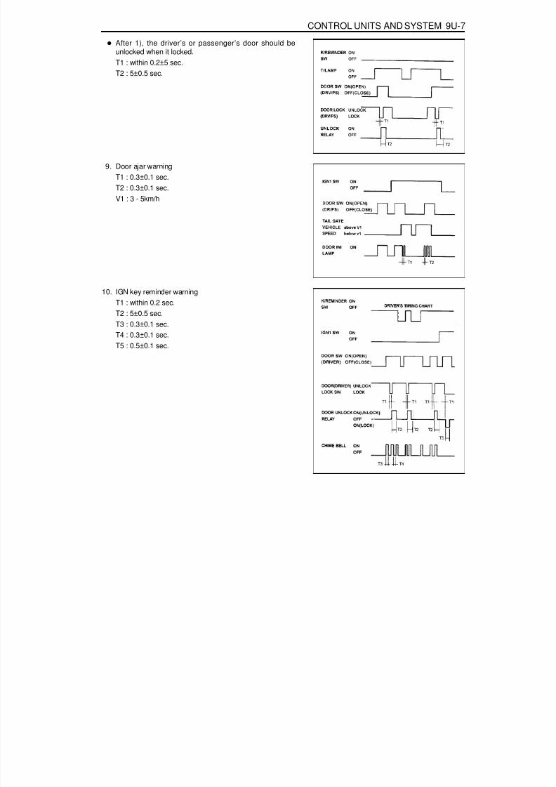
8/18/2019 SsangYong Musso Service Manual 1998.pdf
http://slidepdf.com/reader/full/ssangyong-musso-service-manual-1998pdf 1444/1459
CONTROL UNITS AND SYSTEM 9U-7
After 1), the driver’s or passenger’s door should beunlocked when it locked.T1 : within 0.2±5 sec.T2 : 5±0.5 sec.
9. Door ajar warningT1 : 0.3±0.1 sec.T2 : 0.3±0.1 sec.V1 : 3 - 5km/h
10. IGN key reminder warningT1 : within 0.2 sec.T2 : 5±0.5 sec.T3 : 0.3±0.1 sec.T4 : 0.3±0.1 sec.T5 : 0.5±0.1 sec.

8/18/2019 SsangYong Musso Service Manual 1998.pdf
http://slidepdf.com/reader/full/ssangyong-musso-service-manual-1998pdf 1445/1459
9U-8 CONTROL UNITS AND SYSTEM
11. Central door lockT1 : within 0.2 sec.T2 : 0.5±0.1
12. Coupled with REKES modeT1 : 0.05±0.02 sec. (lock signal)T2 : 0.1±0.02 sec. (unlock signal)T3 : within 0.2±5 sec.
T4 : 0.5±0.1 sec.T5 : within 0.3 sec.T6, T7 : 0.5±0.1 sec.T8 : 1±0.25 sec.
13. Ignition key hole illumination

8/18/2019 SsangYong Musso Service Manual 1998.pdf
http://slidepdf.com/reader/full/ssangyong-musso-service-manual-1998pdf 1446/1459
CONTROL UNITS AND SYSTEM 9U-9
14. Auto door lockV1 : 50±5km/hT1 : 0.5±0.1 sec.
15. Auto door unlockT1 : 0.5±0.1 sec.V1 : 15km/h

8/18/2019 SsangYong Musso Service Manual 1998.pdf
http://slidepdf.com/reader/full/ssangyong-musso-service-manual-1998pdf 1447/1459
9U-10 CONTROL UNITS AND SYSTEM
MAINTENANCE AND REPAIR
ON-VEHICLE SERVICESTICSSTICS, electonic control warning device, controls 16 functions and contains the self diagnostic function detecting anymalfunctions in the sensors and load.
Removal & Installation Procedure
1. Disconnector the battery negative cable.2. Unscrew 4screw from center console box.3. Remove the center console box and disconnect 3 STICS
connectors.4. Unscrew 3 fastening bolts and remove the STICS unit.5. Installation should follow the removal procedure in the
reverse order.
1 STICS Unit2 STICS Connector
3 STICS Unit Fastening Bolt4 Parking Brake Lever

8/18/2019 SsangYong Musso Service Manual 1998.pdf
http://slidepdf.com/reader/full/ssangyong-musso-service-manual-1998pdf 1448/1459
SECTION 9W
IMMOBILIZER SYSTEM
Function Description . . . . . . . . . . . . . . . . . . 9W-2System Description . . . . . . . . . . . . . . . . . . . . . 9W-3
Diagnosis . . . . . . . . . . . . . . . . . . . . . . . . . . . 9W-8Gasoline Engine . . . . . . . . . . . . . . . . . . . . . . . 9W-8Diesel Engine . . . . . . . . . . . . . . . . . . . . . . . . 9W-10
Schematic and Routing Diagrams . . . . . . . 9W-12
TABLE OF CONTENTS
Caution: Disconnect the negative battery cable before removing or installing any electrical unit or when a tool or equipment could easily come in contact with exposed electrical terminals. Disconnecting this cable will help prevent personal injury and damage to the vehicle. The ignition must also be in LOCK unless otherwise noted.
Gasoline Engine (HFM) Immobilizer . . . . . . . 9W-12Diesel Engine Immobilizer . . . . . . . . . . . . . . . 9W-13
Diesel Engine Immobilizer (Crypto Type). . . . 9W-14Maintenance and Repair . . . . . . . . . . . . . . 9W-15On-Vehicle Service . . . . . . . . . . . . . . . . . . . . . 9W-15
Immobilizer Antenna . . . . . . . . . . . . . . . . . . . 9W-15

8/18/2019 SsangYong Musso Service Manual 1998.pdf
http://slidepdf.com/reader/full/ssangyong-musso-service-manual-1998pdf 1449/1459
9W-2 IMMOBILIZER SYSTEM
NoticeIf vehicle is equipped with immobilizer system and the enginecranks normally but not start, check immobilizer system firstrather than ignition and other electrical systems because itcan be disabled fuel supply of injectors by ECU due todefective immobilizer system.Programming of the immobilizer system will be performedby authorized personnel only. If following defective codesfor immobilizer system appear during diagnosis of vehiclewith SCANNER, ask immobilizer programming to authorizedpersonnel and actual programming should be performedby authorized personnel only.
Display of defectives relevant to immobilizer system :SCANNER
1. No communication with transponder2. No immobilizer programming
The transponder in the key can be damaged by shocks ofdropping or hitting other objectives, so handle it with care.Each supplied key has programming of code on its own.Accordingly if ECU needs to be replaced, replace thetransponder in the key.The vehicle equipped with immobilizer system will never bestarted with remote ignition device, so do not attempt toinstall it.The immobilizer system will never be removed from thevehicle. So never attempt to remove it to install a remoteignition device or others.If engine does not start during service, use every key tostart the engine and then check immobilizer system finally.
FUNCTION DESCRIPTIONImmobilizer is a device disabling vehicle ignition unless a speific key is used and designed to help prevent vehicletheft.Immobilizer is comprised of two devices, a key with encoded transponder and engine control unit(ECU) with the sameencoding of the transponder. When a key is inserted into the key hole to start vehicle and turned to ‘ON’, the ECUreads and decodes the transponder code and, if the same, starts the engine, it is called immobilizer. It meansimmobilizer system disables starting by stopping fuel supply if the code in the transponder does not match the codestored in ECU each other.
Cases that requires immobilizerprogramming
1. Replacement ECUIn this case, replace the every transponderof the key at once.
2. Replacement of the transponder3. Additional key for lost 1 or 2 keys1) Clear all codes for current keys from the
ECU2) When using current key : clear code of
the transponder and re-program it3) Additional (purchased) key : perform
programming4. When lost all keys1) Clear all memorized key codes from the
ECU2) Replace the key and key set3) Immobilizer programming
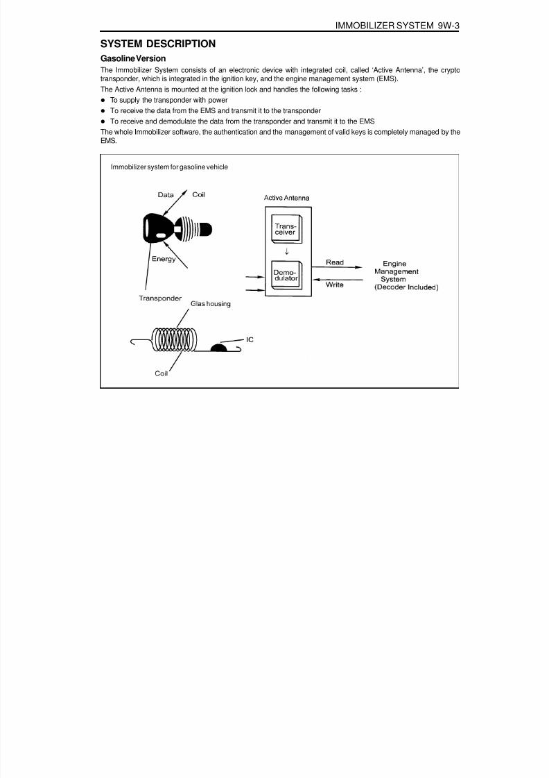
8/18/2019 SsangYong Musso Service Manual 1998.pdf
http://slidepdf.com/reader/full/ssangyong-musso-service-manual-1998pdf 1450/1459
IMMOBILIZER SYSTEM 9W-3
SYSTEM DESCRIPTIONGasoline VersionThe Immobilizer System consists of an electronic device with integrated coil, called ‘Active Antenna’, the cryptotransponder, which is integrated in the ignition key, and the engine management system (EMS).The Active Antenna is mounted at the ignition lock and handles the following tasks :
To supply the transponder with powerTo receive the data from the EMS and transmit it to the transponderTo receive and demodulate the data from the transponder and transmit it to the EMS
The whole Immobilizer software, the authentication and the management of valid keys is completely managed by theEMS.
Immobilizer system for gasoline vehicle

8/18/2019 SsangYong Musso Service Manual 1998.pdf
http://slidepdf.com/reader/full/ssangyong-musso-service-manual-1998pdf 1451/1459
9W-4 IMM OBILIZER SYSTEM
Active Antenna
Connector
1 2 3 41 : IGN (red) 2 : Ground (brown)3 : Data in (yellow) 4 : Data Out (green)
NoticePin arrangement and spec. of connector is same for gasoline and diesel vehicles.
Wire circuit diagram
34
Ant. 1413
E/GECU
IGN Ground
13 : Crypto read14 : Crypto write
·

8/18/2019 SsangYong Musso Service Manual 1998.pdf
http://slidepdf.com/reader/full/ssangyong-musso-service-manual-1998pdf 1452/1459
IMMOBILIZER SYSTEM 9W-5
Diesel VersionThe Immobilizer System consists of an electronic device with integrated coil, called ‘Active Antenna’, the cryptotransponder, which is integrated in the ignition key, and the Immobilizer-Control-Unit (ICU).The Active Antenna is mounted at the ignition lock and handles the following tasks :
to supply the transponder with powerto receive the data from the ICU and transmit it to the transponder
to receive and demodulate the data from the transponder and transmit it to the ICUThe whole Immobilizer software, the authentication and the management of valid keys and controlling the fuel valveis managed completely by the ICU.
Connector- Immobilizer unit - Solenoid valve
168
157
146
135
124
113
102
91
1 2 3
1 : Data out 3 : Data in 6 : Ground
7 : Data line 8 : K-Line 9 : IGN
1 : IGN (Brown)2 : Code (Green)
3 : Ground (Black)
Wire circuit diagram
Antenna3421
Immo.unit
7
8
Solenoidvalve
2
1
13
6 9 3
IGN
K-line (Diagnosis)
Solenoid Fuel Valve
Immobilizer System for Diesel Vehicles

8/18/2019 SsangYong Musso Service Manual 1998.pdf
http://slidepdf.com/reader/full/ssangyong-musso-service-manual-1998pdf 1453/1459
9W-6 IMMOBILIZER SYSTEM

8/18/2019 SsangYong Musso Service Manual 1998.pdf
http://slidepdf.com/reader/full/ssangyong-musso-service-manual-1998pdf 1454/1459
IMMOBILIZER SYSTEM 9W-7
System IntegrationThe med 98.2 immobilizer is an anti-theft protection device allowing the start of the engine only if a specific authorizationis obtained during the start up phase. The med 98.2 will allow (prohibit) the start of the engine by driving ON (OFF) aninternal solenoid valve.The med 98.2 is a single unit integrating the following subsystem :
a valve that allows (valve open) or blocks (valve closed) the fuel flow through the engine fuel system
a microprocessor control system to control and activate the valve during the start up of the engine, in order toallow the start up only when a specific permission is given
the med 98.2 task is, therefore, to prevent the non authorized start up of the engine.The functional unit includes also a basic set of electronic components whose function is to reduce its dependence onthe microprocessor control system: a part from a short temporarily period, during the start up phase, the electronicsallows the control system to excite and open the valve, but it doesn’t allow to close it.The valve can be shut off only after the KL 15 has been deactivated.The structure allows to obtain the highest degree of safe-operation (functionality fail-start): a failure in themicroprocessor unit cannot cause the shut-off of the valve. The main consequence of this type of failure is to preventthe next engine start up.As a result of the above considerations, the med 98.2 immobilizer can realize its anti-theft functionality only in conjunction
with a control device: the ICU.The ICU, when requested, sends a coded message to med 98.2 according to a settled communication protocol. Themed 98.2 will allow the start of the engine based upon this message.In addition to the basic anti-theft functionality, the 98.2 immobilizer provides a number of diagnostic services when itis connected to an external test instrument (SCAN-100). Those connections are depicted in the following integrationdiagram (Fig. 1), where the dashed line indicates a temporary link for diagnostic purposes, and the shaded area themed 98.2 system’s physical boundaries:
Fig. 1 - System Integration
Explanation of symbols:med 98.2 ImmobilizerICU Immobilizer Control UnitTESTER Device that can be connected for diagnostic purposesK-LINE Serial line for communication with ICUKL15 Ignition key (Power supply for med 98.2)GND Ground

8/18/2019 SsangYong Musso Service Manual 1998.pdf
http://slidepdf.com/reader/full/ssangyong-musso-service-manual-1998pdf 1455/1459
9W-8 IMMOBILIZER SYSTEM
Defects Possible cause Remedy
No communication withtransponder
1. Defective wiring harness- Power supply/Open/short of ground- Open/short of signal terminal or
mis-conneting(between ECUterminal No. 13 and 14)
1. Connect/replace the wire correctly.
2.1 Replace the transponder2.2 Immobilizer programming
2. Damaged transponder
3. Replace the antenna3. Defective antenna
4.1 Replace the ECU4.2 Replace all transponder of the keys4.3 Immobilizer programming
4. Defective ECU
No immobilizerprogramming(Components andwiring harnesses arenormal but codes inECU and transpondersare not registerednormally)
1. Replace the transponders and ECUwith new; Immobilizer programming is not
performed
1. Perform immobilizer programming
2. Replace transponders only(new); Immobilizer programming is not
performed
2. Perform immobilizer programming
3. Replace ECU only(new) 3.1 Replace the transponders with new3.2 Perform immobilizer programming
4. Replace the transponder only; Programmed for other ECU
4.1 Replace the transponders with new4.2 Perform immobilizer programming
5. Re-programming is not performedafter clearing transponder code storedin ECU that normally used system
5. Immobilizer programming
Notice1. Application of ex-programmed transponder into other ECUs.
; In this case, it can not be removed for the settled “lock bit” in transponder even though you perform immobilizerproblem normally. Moreover it is impossible to start engine, so replace the transponder with new and performimmobilizer programming.
DIAGNOSISGASOLINE ENGINECause and Remedy for Defective When Diagnosed by Scanner

8/18/2019 SsangYong Musso Service Manual 1998.pdf
http://slidepdf.com/reader/full/ssangyong-musso-service-manual-1998pdf 1456/1459
IMMOBILIZER SYSTEM 9W-9
Check and Remedy when Engine Does not Start
Starter operates normally?
Yes No
Check fuses (No. 8 and 27)Check ECU and antenna power
ECU terminal- No. 12 (Power)- No. 11 (Ignition)- No.5/10 (Ground)
Check battery voltageCheck battery wiring
Check signal wires between ECUand antenna- Immobilizer No.3 wire (0.5BY) =
ECU No. 14 pin (0.75BW): Writing immobilizer code number
- Immobilizer No.4 wire (0.5Y) =ECU No.13 pin (0.75Y): Reading immobilizer cod number
Check starter wiresCheck TCU wires (only for 5-speed automatic transmission)Check starter and TCU
ECU No.2 pin : check normalsignal of the starter 1)
- Engine cranking voltage : 8-15V
Check engine speed sensor wiresand replace
Replace immobilizer antenna
Replace transponder and ECU
Notice 1)
MSE ECU equipped vehicle is designed tomake fuel injection when the engine speedfor initial cranking is over 450rpm if thereare no start switch inputs in ECU No. 2 pin.
If transponder and ECU are replaced,perform programming.

8/18/2019 SsangYong Musso Service Manual 1998.pdf
http://slidepdf.com/reader/full/ssangyong-musso-service-manual-1998pdf 1457/1459
9W-10 IMMOBILIZER SYSTEM
1. Connect/replace the wire correctly
2. Replace the transponder
3.1 Replace the valve3.2 Turn Ign sw on3.3 Turn Ign sw OFF & ON
Defects Possible cause Remedy
No communication withtransponder
1. Defective wiring harness- Power supply/Open/short of ground- Open/short of signal terminal or
mis-conneting(between ICUterminal No. 13 and 14)
1. Connect/replace the wire correctly.
2.1 Replace the transponder2.2 Immobilizer programming
2. Damaged transponder
3. Replace the antenna3. Defective antenna4.1 Replace the ICU4.2 Replace all transponder of the keys4.3 Immobilizer programming
4. Defective ICU
No immobilizerprogramming(Components andwiring harnesses arenormal but codes inICU and transpondersare not registerednormally)
1. Replace the transponders and ICUwith new; Immobilizer programming is not
performed
1. Perform immobilizer programming
2. Replace transponders only(new); Immobilizer programming is not
performed
2. Perform immobilizer programming
3. Replace ICU only(new) 3.1 Replace the transponders with new3.2 Perform immobilizer programming
4. Replace the transponder only
; Programmed for other ICU
4.1 Replace the transponders with new
4.2 Perform immobilizer programming5. Re-programming is not performedafter clearing transponder code storedin ICU that normally used system
5. Immobilizer programming
Notice1. Application of ex-programmed transponder into other ICUs.
; In this case, it can not be removed for the settled “lock bit” in transponder even though you perform immobilizerproblem normally. Moreover it is impossible to start engine, so replace the transponder with new and performimmobilizer programming.
DIESEL ENGINECause and Remedy for Defective When Diagnosed by Scanner
No communication withvalve
1. Defective wiring harness- Power supply/Open/short of ground- Open/short of signal terminal or
mis-conneting(between ICUterminal No. 13 and 14)
2. Defective ICU
3. Defective valve

8/18/2019 SsangYong Musso Service Manual 1998.pdf
http://slidepdf.com/reader/full/ssangyong-musso-service-manual-1998pdf 1458/1459
IMMOBILIZER SYSTEM 9W-11
Check and Remedy when Engine Does not Start
Starter operates normally?
Yes No
Check fuses (No. 19)Check ECU and antenna powerand solenoid valve
ECU terminal- No. 9 (Ignition)- No. 6 (Ground)
Check battery voltageCheck battery wiring
Check signal wires between ICUand antenna
- Immobilizer No.3 wire (0.5Y) =ICU No. 1 pin (0.75BW): Writing immobilizer code number
- Immobilizer No.4 wire (0.5G) =ECU No.3 pin (0.75Y): Reading immobilizer cod number
Check starter wiresCheck TCU wires (only for 5-
speed automatic transmission)Check starter and TCU
ECU No.2 pin : check normalsignal of the starter 1)
- Engine cranking voltage : 8-15V
Check engine speed sensor wiresand replace
Replace immobilizer antenna
Notice 2)
New valve is possible coded either with anew ICU or an already used ICU. But oldcoded valve is only possible coded with anew ICU.
If transponder and ICU are replaced,perform programming.
Replace transponder and ICU Replace the valve
1. Turn Ign sw ON2. Turn Ign sw OFF & ON(To learn the valve correctly it is necessaryto switch on Ignition twice for at least 5seconds.)
2)

8/18/2019 SsangYong Musso Service Manual 1998.pdf
http://slidepdf.com/reader/full/ssangyong-musso-service-manual-1998pdf 1459/1459
9W-12 IMMOBILIZER SYSTEM
SCHEMATIC AND ROUTING DIAGRAMS
M O B I L I Z E R
Related Documents