SS7 • ITU-T Common Channel Signalling System No. 7 (CCSS7, CCS7, CCS, CCS#7, C7, SS7 … ) • At present the dominant inter-exchange signalling system in digital networks (PSTN, ISDN, PLMN) • SS7 is in effect a robust, high-performance packet switched network, intended for secure transmission of signalling messages • ITU-T Q.700-series Recommendations

Welcome message from author
This document is posted to help you gain knowledge. Please leave a comment to let me know what you think about it! Share it to your friends and learn new things together.
Transcript
SS7
• ITU-T Common Channel Signalling System No. 7(CCSS7, CCS7, CCS, CCS#7, C7, SS7 … )
• At present the dominant inter-exchange signallingsystem in digital networks (PSTN, ISDN, PLMN)
• SS7 is in effect a robust, high-performance packetswitched network, intended for secure transmissionof signalling messages
• ITU-T Q.700-series Recommendations

Channel-associated signalling (CAS)
Old form of signalling (has mostly been replaced by SS7)Signalling occurs in-band on voice channels
Before a circuit switched connection exists, end-to-endsignalling between originating and terminating localexchanges (or to/from databases) is not possible
Exchange Exchange Exchange
circuit switched connection
signalling possible signalling not possible
Common channel signalling (CCS)
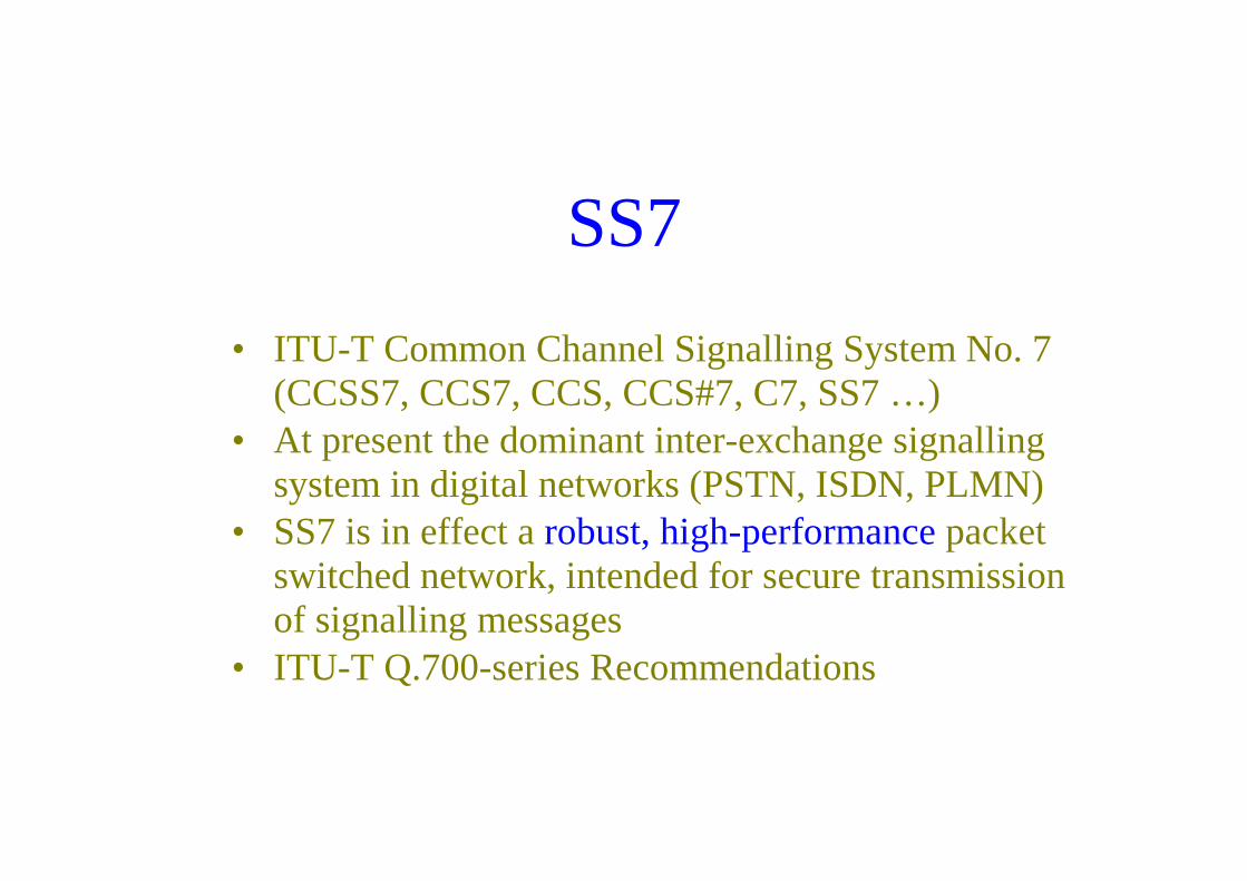
Modern form of signalling (SS7 is based on this method)Signalling occurs out-of-band on dedicated channels
Uses a separate packet-switched signalling network which isnot related to circuit switched connectionsEnd-to-end signalling between originating and terminatinglocal exchanges (or to/from databases) is possible anytime
Exchange Exchange Exchange
signalling possible anywhere anytime
Common channel signalling (CCS)
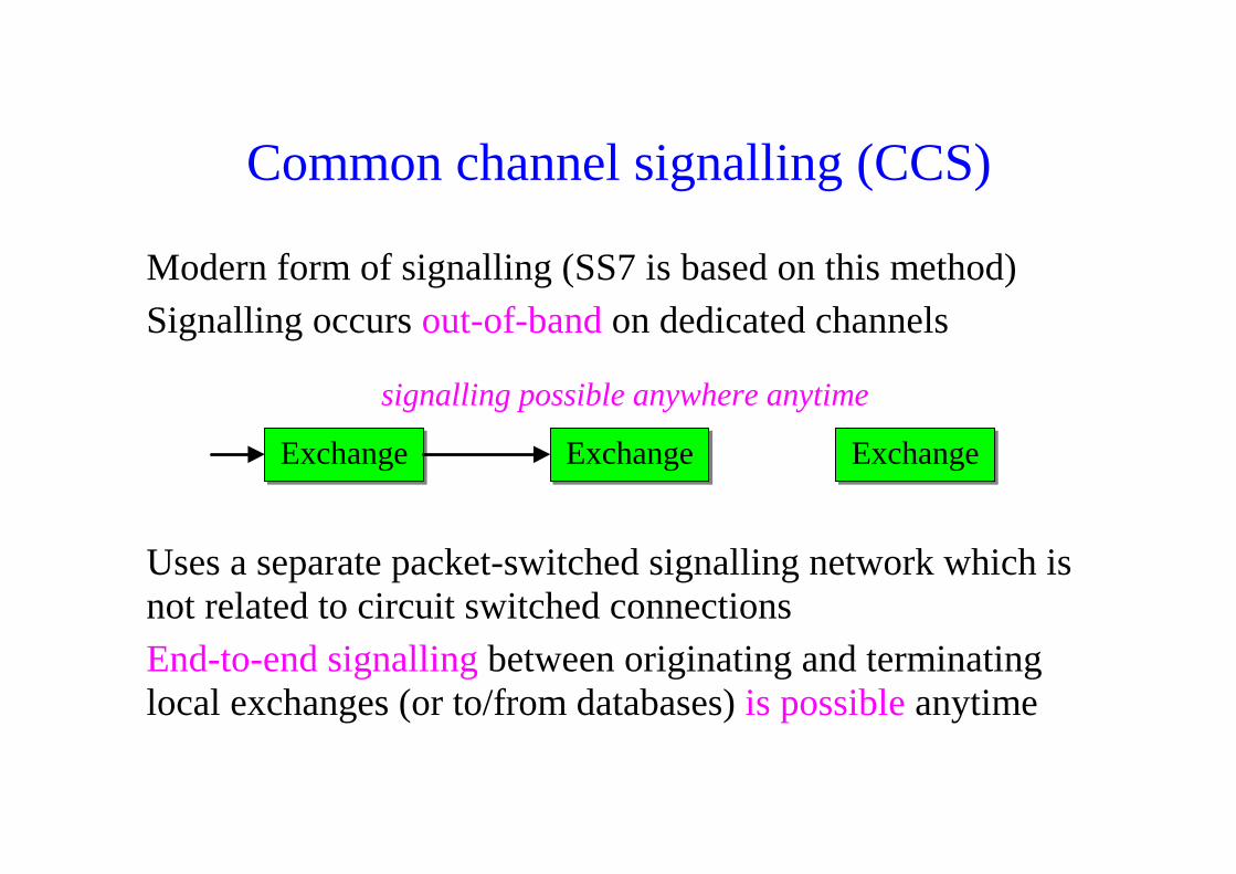
Faster call setup times - compared to in-band signalling usingmulti-frequency (MF) signalling tonesMore efficient use of voice circuitsSupport for Intelligent Network (IN) services which requiresignalling to network elements (e.g., database systems)without the use of circuit switched connectionsSupport for ISDN-type supplementary services which requireend-to-end signalling between terminals (or local exchanges)Improved control over fraudulent network usage
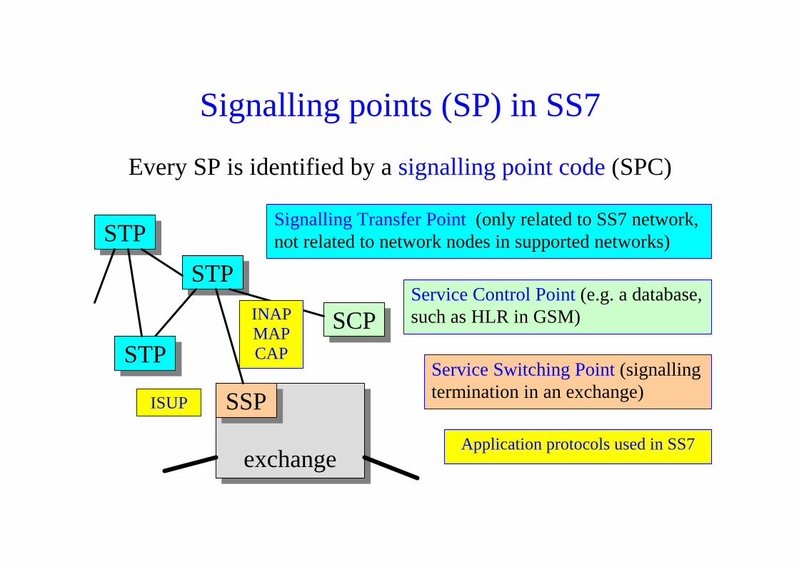
Signalling points (SP) in SS7
Every SP is identified by a signalling point code (SPC)
exchange
STP
SCP
SSP
STP
Service Control Point (e.g. a database,such as HLR in GSM)
Signalling Transfer Point (only related to SS7 network,not related to network nodes in supported networks)
Service Switching Point (signallingtermination in an exchange)
STP
INAPMAPCAP
ISUP
Application protocols used in SS7
Significance of SSP and SCP
During the processing of a circuit switched call, an SSP(Service Switching Point) in an exchange may be triggered toretrieve various switching related information (numberanalysis, time, location, security, charging...) from an SCP
Thus, the SCP (Service Control Point) provides informationnecessary for advanced call-processing capabilities
The usage of SSP and SCP depends on which IN (IntelligentNetwork) features a network operator has implemented (andwhich IN features the user has subscribed to).

Protocol layers (”levels”) of SS7
MTP - Message Transfer Part SCCP - Signalling Connection Control Part UP - User Part AP - Application Part
CAP INAPMAP ISUP
TCAP
SCCP
TUP
MTP level 3
MTP level 2 (HDLC-type protocol)
MTP level 1 (64 kbit/s PCM time slot)
routing

Application protocols in SS7TUP (Telephone User Part) – is being replaced by ISUP
ISUP (ISDN User Part) – for all signalling related tomanagement of circuit switched connections
MAP (Mobile User Part) – for transactions betweenexchanges (MSC, GMSC) and databases(HLR, EIR, AuC...) in mobile networks
INAP (Intelligent Network Application Part)– for IN applications in fixed networks
CAP (CAMEL Application Part) – for extendedIN functionality in mobile networks
CAMEL =CustomisedApplicationsfor MobilenetworksEnhancedLogic
MTP functions
MTP level 1 (signalling data link level):Physical transmission in a 64 kbit/s PCM time slot.
MTP level 2 (signalling link level):HDLC-type frame-based protocol for flow control, errorcontrol (using ARQ), and signalling network supervisionand maintenance functions.
MTP level 3 (signalling network level):Used for routing in the signalling network (OPC ó DPC)between SPs with level 4 users (see SIO at level 2).

MTP level 2 frame formats
MSU (Message Signal Unit)
LSSU (Link Status Signal Unit)
FISU (Fill-In Signal Unit)
F CK SIF SIO LI Control F
F CK SF LI Control F
F CK LI Control F
Network: National network(s) International network
User part: TUP ISUP SCCP Network management
Level 3 signalling message

MTP level 2 frames
MSU (Message Signal Unit):• Contains signalling messages (User Part ? ó SIO)• The received frame is MSU if LI > 2 (number of octets)
LSSU (Link Status Signal Unit):• Contains signalling messages for link supervision• The received frame is LSSU if LI = 1 or 2
FISU (Fill-In Signal Unit):• Can also be used to monitor quality of signalling link• The received frame is FISU if LI = 0
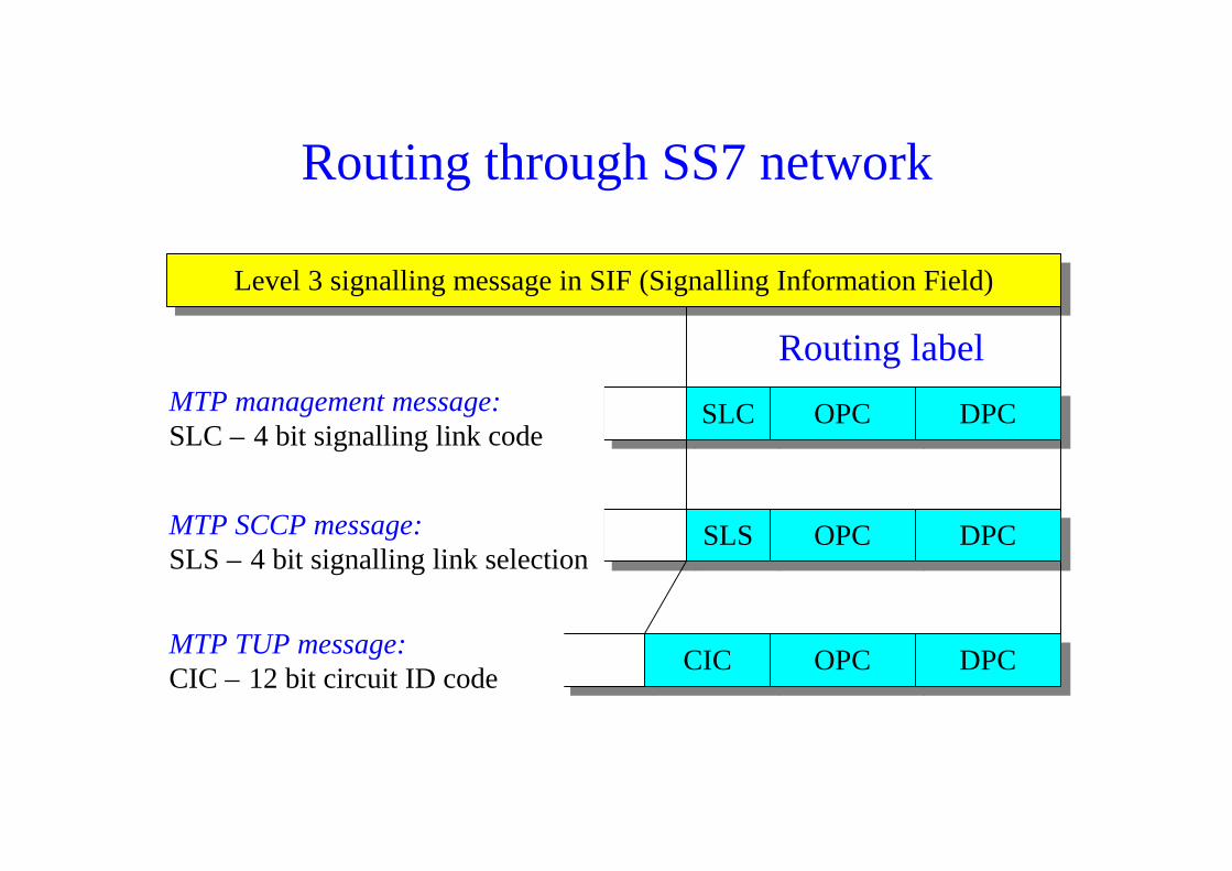
Routing through SS7 network
Routing label
Level 3 signalling message in SIF (Signalling Information Field)
SLC OPC DPCMTP management message:SLC – 4 bit signalling link code
CIC OPC DPCMTP TUP message:CIC – 12 bit circuit ID code
SLS OPC DPCMTP SCCP message:SLS – 4 bit signalling link selection

Routing through SS7 network
Routing label
Point codes for routing purposes
CIC
Level 3 signalling message in SIF (Signalling Information Field)
SLS OPC DPCMTP ISUP message:SLS – 4 bitCIC – 12 bit
Max 256 + 1 octets
OpP MaVP MaFP MTC
MTC – Message Type Code (name of ISUP message)MaFP – Mandatory Fixed Part (no LI, no parameter names required)MaVP – Mandatory Variable Part (LI, no parameter names required)OpP – Optional Part (LI and parameter names required)
ITU-T structureANSI => different

Difference between SLS and CIC
SLS defines the signalling link used for transfer of signallinginformation.
CIC defines the circuit (used for a certain circuit switchedconnection) with which the ISUP message is associated.
exchange
SSPSTP
exchange
SSP
circuit
signalling link
Role of DPC and OPC in SS7
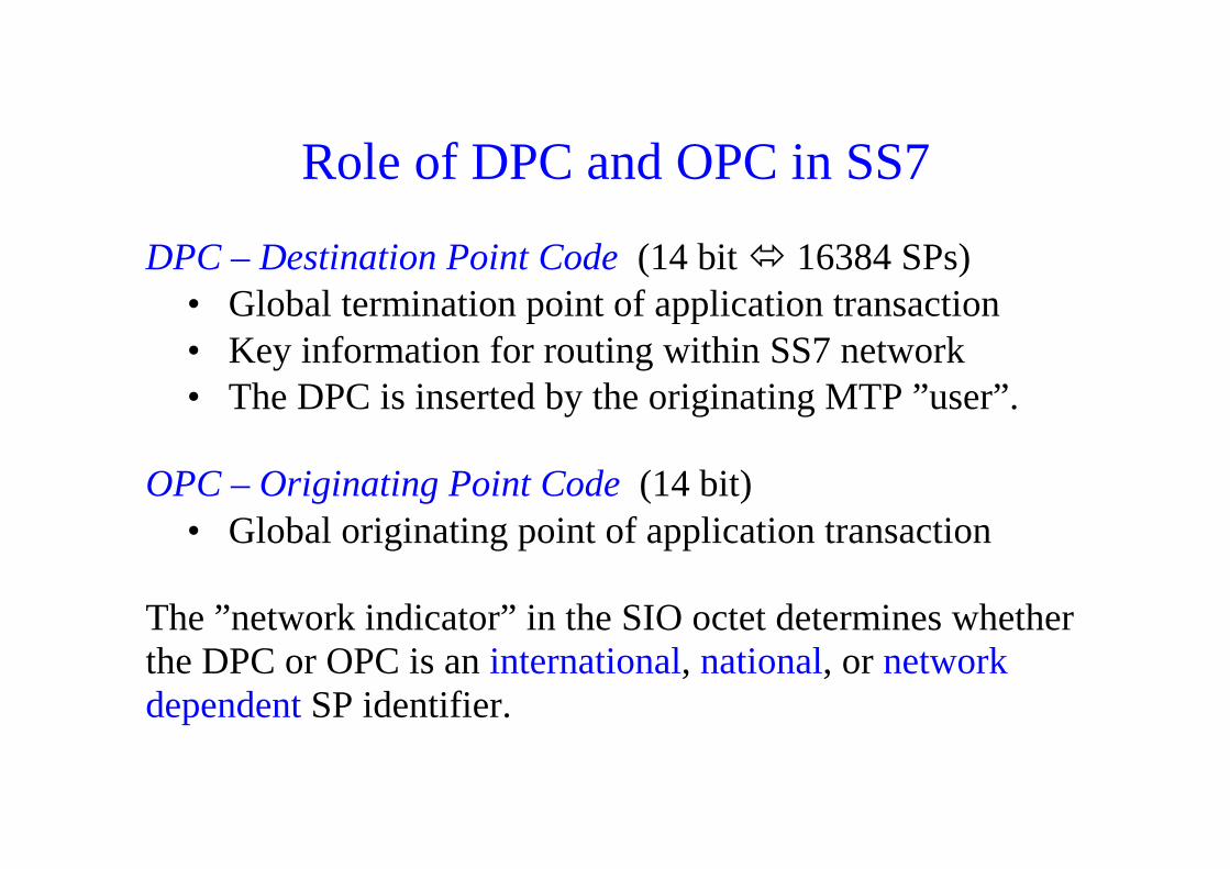
DPC – Destination Point Code (14 bit ó 16384 SPs)• Global termination point of application transaction• Key information for routing within SS7 network• The DPC is inserted by the originating MTP ”user”.
OPC – Originating Point Code (14 bit)• Global originating point of application transaction
The ”network indicator” in the SIO octet determines whetherthe DPC or OPC is an international, national, or networkdependent SP identifier.

Same signalling point codes can be reusedat different network levels
international
national
network operator
SP = 277
SP = 277
SP = 277

Signalling network functions
MTPuser
Signallinglink
Messagedistribution
Messagediscrimination
Messagerouting
Signalling message handling
Signalling network management
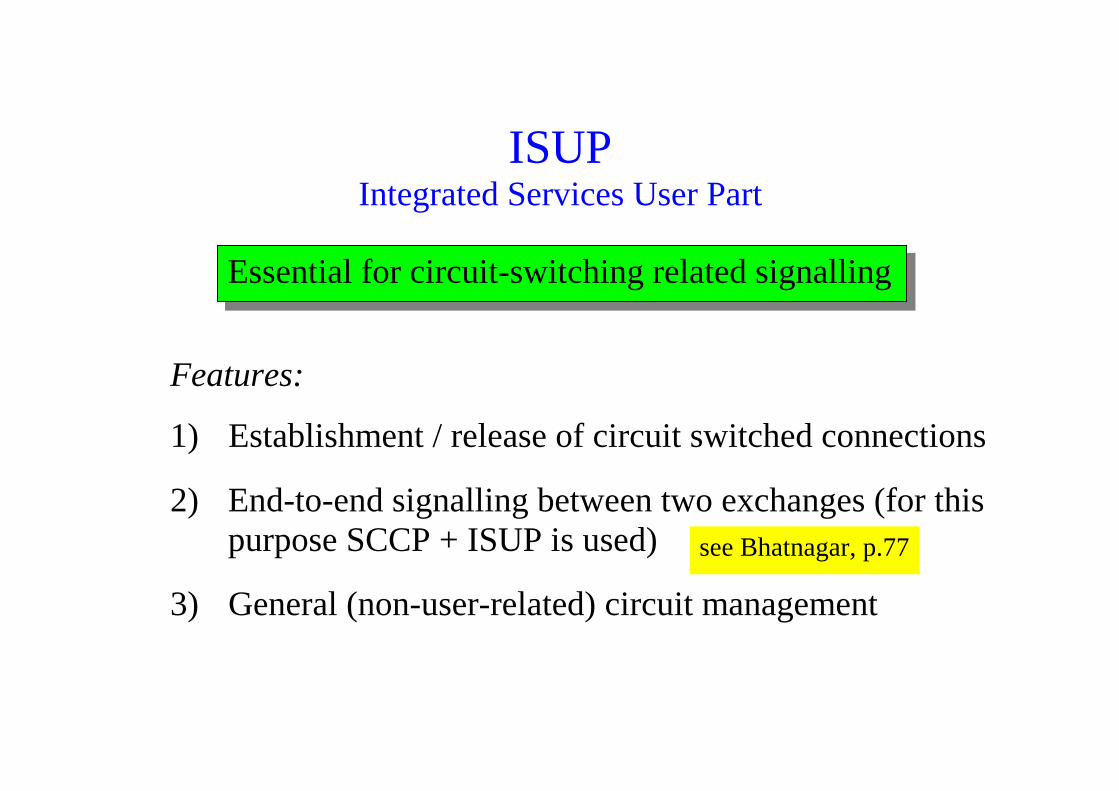
ISUPIntegrated Services User Part
Features:
1) Establishment / release of circuit switched connections
2) End-to-end signalling between two exchanges (for thispurpose SCCP + ISUP is used)
3) General (non-user-related) circuit management
Essential for circuit-switching related signalling
see Bhatnagar, p.77
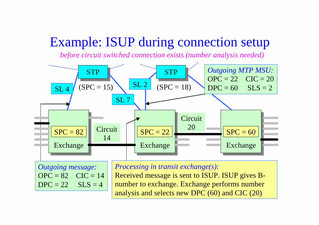
Example: ISUP during connection setup
Exchange ExchangeExchange
SPC = 82
(SPC = 18)(SPC = 15)
STP STP
Circuit14
Outgoing message:OPC = 82 CIC = 14DPC = 22 SLS = 4
SL 4
Processing in transit exchange(s):Received message is sent to ISUP. ISUP gives B-number to exchange. Exchange performs numberanalysis and selects new DPC (60) and CIC (20)
Outgoing MTP MSU:OPC = 22 CIC = 20DPC = 60 SLS = 2
SPC = 22 SPC = 60
Circuit20
SL 2
SL 7
before circuit switched connection exists (number analysis needed)
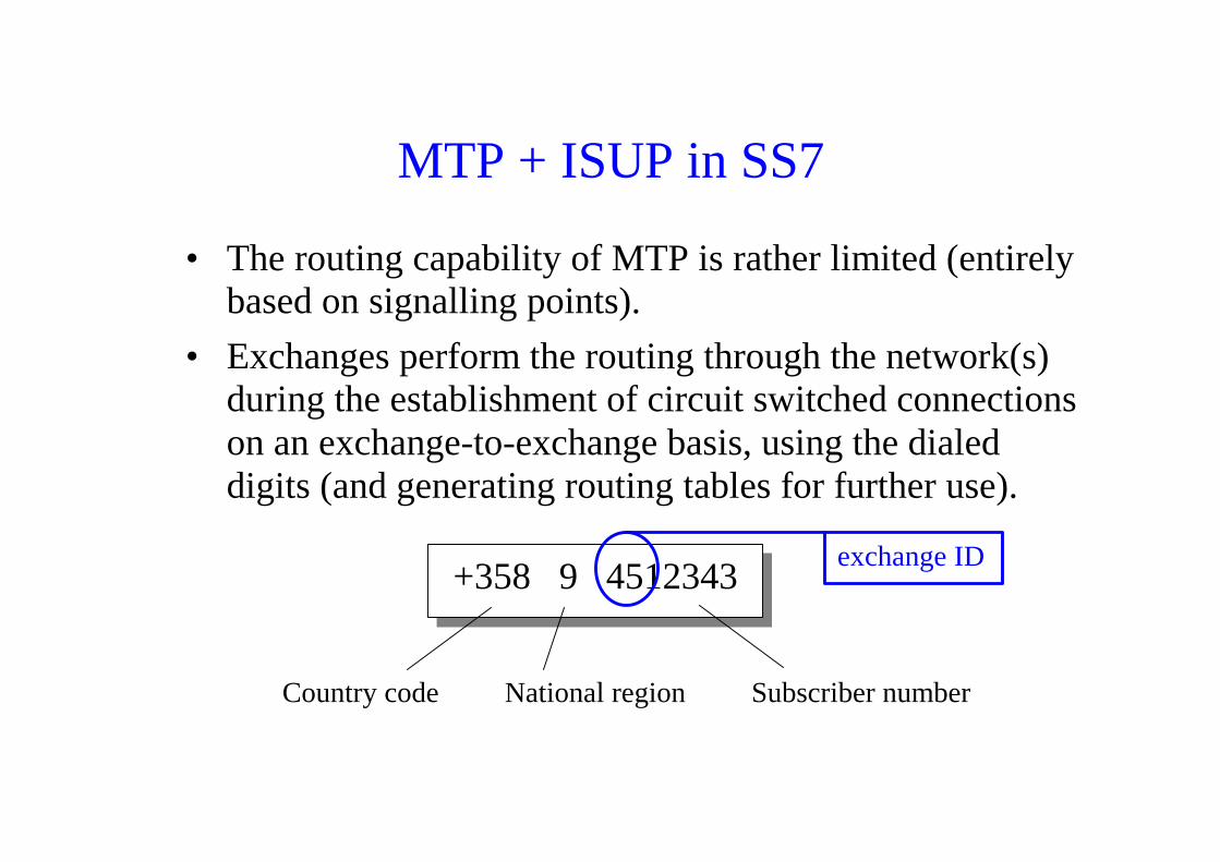
MTP + ISUP in SS7
• The routing capability of MTP is rather limited (entirelybased on signalling points).
• Exchanges perform the routing through the network(s)during the establishment of circuit switched connectionson an exchange-to-exchange basis, using the dialeddigits (and generating routing tables for further use).
+358 9 4512343
Country code National region Subscriber number
exchange ID

Example: ISUP for link-by-link signalling
Exchange ExchangeExchange
SPC = 82
(SPC = 18)(SPC = 15)
STP STP
Circuit14
Outgoing message:OPC = 82 CIC = 14DPC = 22 SLS = 4
SL 4
Processing in transit exchange(s):Using its routing table and incoming routing labelinformation, exchange inserts DPC (60) and CIC(20) into outgoing routing label
Outgoing MTP MSU:OPC = 22 CIC = 20DPC = 60 SLS = 2
SPC = 22 SPC = 60
Circuit20
SL 2
SL 7
when circuit switched connection already exists (no number analysis...)
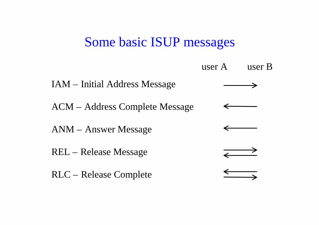
Some basic ISUP messages
user A user B
IAM – Initial Address Message
ACM – Address Complete Message
ANM – Answer Message
REL – Release Message
RLC – Release Complete

Setup of a ”call” using ISUPExchange A Exchange BTransit exchangeUser A User B
SetupIAM
IAMSetup
Alert
Connect
ACM
ANM
ACM
ANM
Alert
Connect
Charging of call starts here
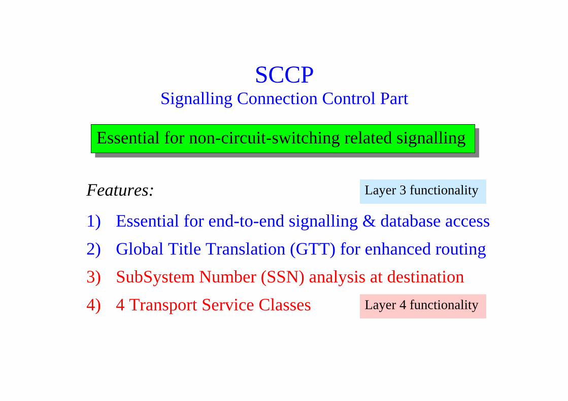
SCCPSignalling Connection Control Part
Features:
1) Essential for end-to-end signalling & database access
2) Global Title Translation (GTT) for enhanced routing
3) SubSystem Number (SSN) analysis at destination
4) 4 Transport Service Classes
Essential for non-circuit-switching related signalling
Layer 3 functionality
Layer 4 functionality
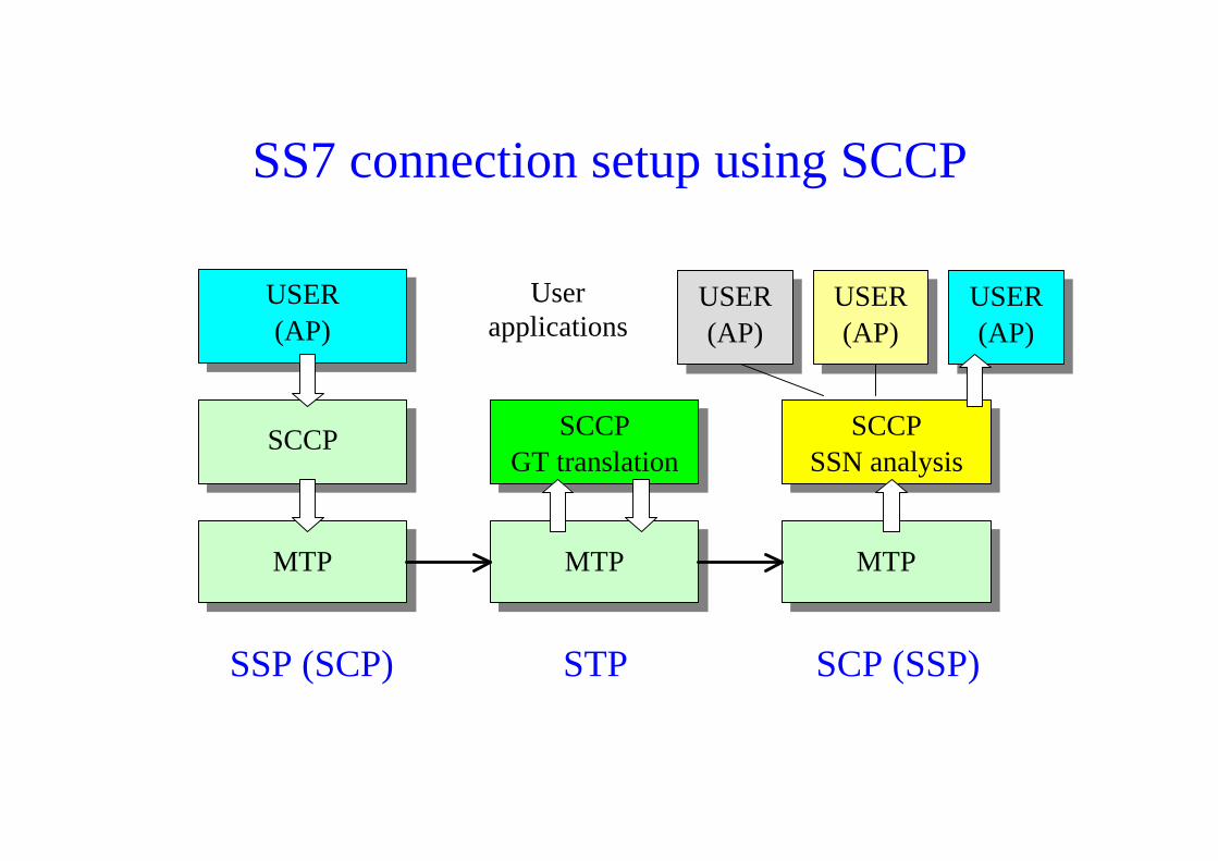
SS7 connection setup using SCCP
MTP
USER(AP)
SCCP
MTP
SCCPGT translation
MTP
USER(AP)
SCCPSSN analysis
USER(AP)
USER(AP)
Userapplications
SSP (SCP) STP SCP (SSP)
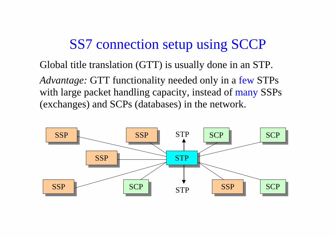
SS7 connection setup using SCCPGlobal title translation (GTT) is usually done in an STP.Advantage: GTT functionality needed only in a few STPswith large packet handling capacity, instead of many SSPs(exchanges) and SCPs (databases) in the network.
STPSSP
SCP
SCPSCP
SCPSSP
SSPSSP
SSP
STP
STP
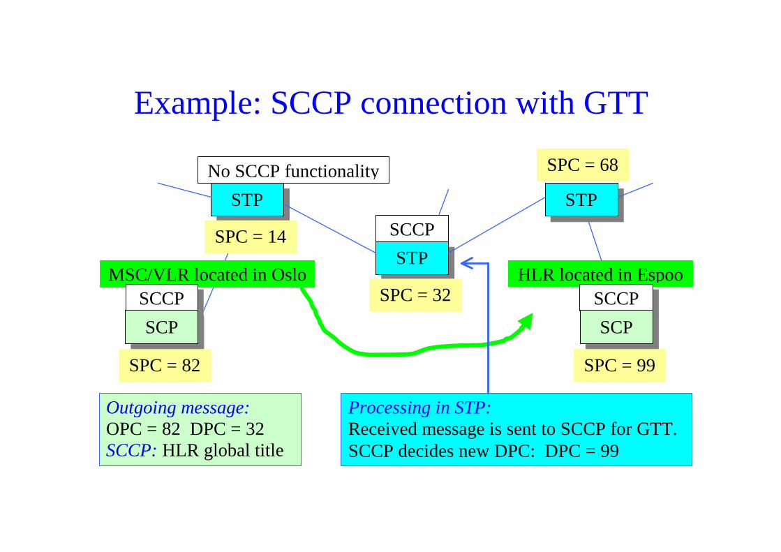
Example: SCCP connection with GTT
HLR located in EspooSCCP
MSC/VLR located in OsloSCCP
STP STP
SCP SCP
STP
SPC = 82 SPC = 99
SPC = 14
SPC = 32
SPC = 68No SCCP functionality
SCCP
Outgoing message:OPC = 82 DPC = 32SCCP: HLR global title
Processing in STP:Received message is sent to SCCP for GTT.SCCP decides new DPC: DPC = 99

MTP + SCCP
• SCCP ó can handle ”global” routing in those caseswhere the terminating point DPC is not known
• GT (Global Title) translation in intermediate STPnode(s) with SCCP functionality
• SSN (SubSystem Number) for distribution to thecorrect user (application part) ó SAP in OSI
In summary, routing capability of MTP + SCCP is muchbetter than that of MTP alone
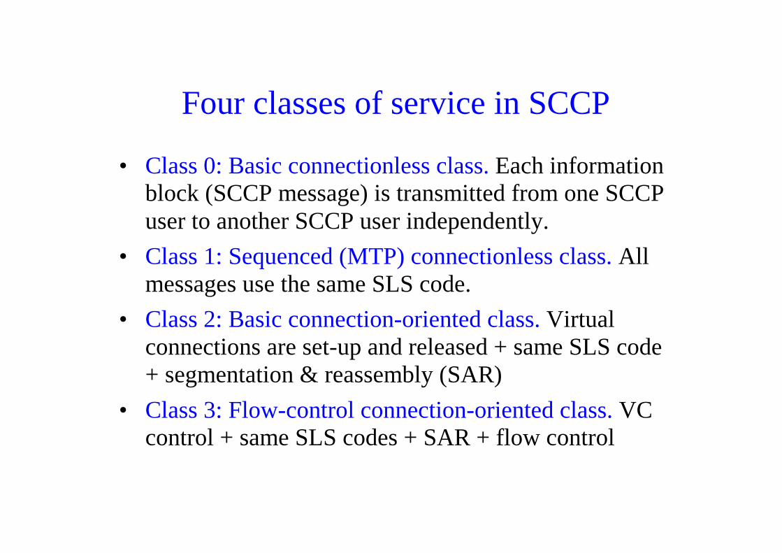
Four classes of service in SCCP
• Class 0: Basic connectionless class. Each informationblock (SCCP message) is transmitted from one SCCPuser to another SCCP user independently.
• Class 1: Sequenced (MTP) connectionless class. Allmessages use the same SLS code.
• Class 2: Basic connection-oriented class. Virtualconnections are set-up and released + same SLS code+ segmentation & reassembly (SAR)
• Class 3: Flow-control connection-oriented class. VCcontrol + same SLS codes + SAR + flow control
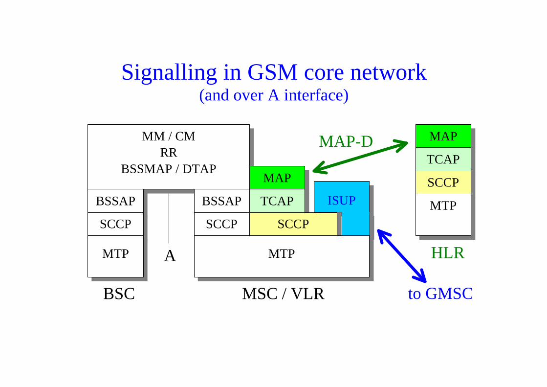
Signalling in GSM core network(and over A interface)
MAP
TCAP
MM / CMRR
BSSMAP / DTAPMAP
ISUPBSSAP TCAPBSSAP
SCCP
MTP
SCCP
MTP
BSC MSC / VLR to GMSC
HLR
MAP-D
SCCP SCCP
MTPA
GSM /UMTS core network interfaces (1)(UMTS: Circuit switched domain of core network)
MAP-B: Between MSC and its associated VLR.The interface is ”internal” and message transfer does not involve thesignalling network. This interface is not standardised by ETSI or3GPP.
MAP-C: Between Gateway MSC (GMSC) and HLR.This interface is required for the establishment of mobile terminatedcalls. Through this interface the GMSC enquires the current userlocation from the HLR, and the HLR provides the MSC with a MobileSubscriber Roaming Number (MSRN) necessary for setting up thecircuit switched connection from the GMSC to the serving MSC (seecase study 2 in GSM slides).
GSM /UMTS core network interfaces (2)
MAP-D: Between VLR and HLR.This interface is involved both in CM (Connection Management) andMM (Mobility Management) applications.
CM: Through this interface the HLR asks the VLR to assign and returna roaming number (MSRN) which is used for the establishment of amobile terminated call (see case study 2 in GSM slides).
MM: This interface may also be used during a Location Updatebetween VLRs when the VLRs update the HLR (in other words theVLRs inform the HLR about changes in user location), or when theHLR deletes information in “old” VLR (see case study 1 in GSMslides).
GSM /UMTS core network interfaces (3)
MAP-E: Between MSCs in a PLMN.This interface is used during inter-MSC handover operations. (Note: inaddition, the E interface involves ISUP)
MAP-F: Between MSC and EIR.This interface carries information for MS identity checking.
MAP-G: Between two VLRs.For instance, in case of an inter-VLR Location Update the “new” VLRmay request the “old” VLR to provide relevant user information (seecase study 1 in GSM slides).

GPRS /UMTS core network interfaces(UMTS: Packet switched domain of core network)
Gc: Between GGSN and HLR.Similar to MAP-C interface (see above).
Gf: Between SGSN and EIR.Similar to MAP-F interface (see above).
Gn: Between SGSN and GGSN.
Gr: Between SGSN and HLR.
Gs: Between SGSN and MSC/VLR.This interface is required when the user location information cannot bestored at the SGSN.
Further information on SS7Tutorials:Modarressi, Skoog: ”SS7: a tutorial”, IEEE Comm. Magazine, July 1990Laitinen, Rantala: ”Integration of IN services into GSM”, IEEE Comm.
Magazine, June 1995Jabbari: ”CCSS7 for ISDN and IN”, Proc. IEEE, Feb. 1991
Books:Bhatnagar: Engineering networks for synchronization, CCS7, and ISDN,
IEEE Press, 1997Van Bosse: Signaling in telecommunication networks, Wiley, 1998
Web tutorial:www.iec.org/online/tutorials/ss7
Related Documents