Data Sheet SS/269CS_3 ABB 2600T Series Engineered solutions for all applications ■ Base accuracy : ±0.04% ■ Span limits – 0.05 to 2000kPa, 0.2inH2O to 290psi differential pressure – 0.6 to 41MPa, 87 to 5945psia absolute pressure ■ One transmitter replaces three separate transmitters, saving initial purchase cost ■ Reduced process penetrations save money and reduce chances of leaks ■ Fewer transmitters, less wiring, and fewer shut-off valves reduce installation costs ■ Greater reliability due to fewer devices and less wiring ■ Flexible configuration facilities – provided by PC configuration platform ■ Multiple protocol availability – provides integration with HART ® , PROFIBUS PA, FOUNDATION Fieldbus and Modbus platforms offering interchangeability and transmitter upgrade capabilities ■ Full compliance with PED category III Field IT 2600T Series Pressure Transmitters Model 269CS Multivariable for mass flow selectable maximum working pressure up to 41MPa, 5945psi

Welcome message from author
This document is posted to help you gain knowledge. Please leave a comment to let me know what you think about it! Share it to your friends and learn new things together.
Transcript

Data SheetSS/269CS_3
ABB 2600T SeriesEngineered solutions
for all applications
Base accuracy : ±0.04%
Span limits– 0.05 to 2000kPa, 0.2inH2O to 290psi differential
pressure– 0.6 to 41MPa, 87 to 5945psia absolute pressure
One transmitter replaces three separatetransmitters, saving initial purchase cost
Reduced process penetrations save money andreduce chances of leaks
Fewer transmitters, less wiring, and fewershut-off valves reduce installation costs
Greater reliability due to fewer devices and lesswiring
Flexible configuration facilities– provided by PC configuration platform
Multiple protocol availability– provides integration with HART®, PROFIBUS PA,
FOUNDATION Fieldbus and Modbus platformsoffering interchangeability and transmitter upgradecapabilities
Full compliance with PED category III
FieldIT
2600T Series Pressure Transmitters
Model 269CS Multivariablefor mass flow
selectable maximum working pressureup to 41MPa, 5945psi
2600T Pressure TransmittersModel 269CS SS/269CS_3
2
Discharge coefficient
It is defined as the true flowrate divided by the theoretical flowrate andcorrects the theoretical equation for the influence of velocity profile(Reynolds number), the assumption of no energy loss between taps,and pressure tap location. It is dependent on the primary flow element,the β ratio and the Reynolds number. Reynolds number is in turndependent on the viscosilty, density and velocity of the fluid as well asthe pipe diameter per the following equation:
v = velocity
D= inside pipe diameter
ρ = fluid density
υ = fluid viscosity
Dynamical compensation for discharge coefficient provides highaccuracy for orifice, Venturi and nozzles.
Functional Specifications
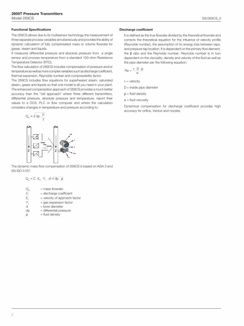
The 269CS allows due to its multisensor technology the measurement ofthree separate process variables simultaneously and provides the ability ofdynamic calculation of fully compensated mass or volume flowrate forgases, steam and liquids.It measures differential pressure and absolute pressure from a singlesensor and process temperature from a standard 100-ohm ResistanceTemperature Detector (RTD).The flow calculation of 269CS includes compensation of pressure and/ortemperature as well as more complex variables such as discharge coefficient,thermal expansion, Reynolds number and compressibility factor.The 269CS includes flow equations for superheated steam, saturatedsteam, gases and liquids so that one model is all you need in your plant.The enhanced compensation approach of 269CS provides a much betteraccuracy than the “old approach” where three different transmitters,differential pressure, absolute pressure and temperature, report theirvalues to a DCS, PLC or flow computer and where the calculationconsiders changes in temperature and pressure according to:
The dynamic mass flow compensation of 269CS is based on AGA 3 andEN ISO 5167:
Qm = mass flowrateC = discharge coefficientEv = velocity of approach factorY1 = gas expansion factord = bore diameterdp = differential pressureρ = fluid density
Qm ≈ C . EV . Y1
. d2 √ dp . ρ
Qm ≈ √ dp .p
T
Re = v . D . ρυ
2600T Pressure TransmittersModel 269CS SS/269CS_3
3
Y1 = 1 – (0.41 + 0.35β4 )dp
p . κ
Ev =1
√1 – β4
Gas expansion factor
It corrects for density differences between pressure taps due toexpansion of compressible fluids. It does not apply for liquids which areessentially non-compressible.
The gas expansion factor is dependent on the Beta ratio, the Isentropicexponent, the differential pressure and the static pressure of the fluidper the following equation.
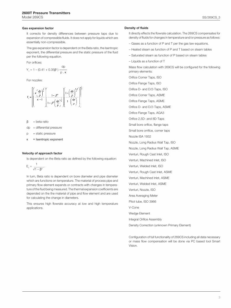
For orifices:
For nozzles:
β = beta ratio
dp = differential pressure
p = static pressure
κ = Isentropic exponent
Velocity of approach factor
Is dependent on the Beta ratio as defined by the following equation:
In turn, Beta ratio is dependent on bore diameter and pipe diameterwhich are functions on temperature. The material of process pipe andprimary flow element expands or contracts with changes in tempera-ture of the fluid being measured. The thermal expansion coefficients aredepended on the the material of pipe and flow element and are usedfor calculating the change in diameters.
This ensures high flowrate accuracy at low and high temperatureapplications.
Density of fluids
It directly effects the flowrate calculation. The 269CS compensates fordensity of fluids for changes in temperature and/or pressure as follows:
– Gases as a function of P and T per the gas law equations.
– Heated steam as function of P and T based on steam tables
– Saturated steam as function of P based on steam tables
– Liquids as a function of T
Mass flow calculation with 269CS will be configured for the followingprimary elements:
Orifice Corner Taps, ISO
Orifice Flange Taps, ISO
Orifice D- and D/2-Taps, ISO
Orifice Corner Taps, ASME
Orifice Flange Taps, ASME
Orifice D- and D/2-Taps, ASME
Orifice Flange Taps, AGA3
Orifice 2,5D- and 8D-Taps
Small bore orifice, flange taps
Small bore orrifice, corner taps
Nozzle ISA 1932
Nozzle, Long Radius Wall Tap, ISO
Nozzle, Long Radius Wall Tap, ASME
Venturi, Rough Cast Inlet, ISO
Venturi, Machined Inlet, ISO
Venturi, Welded Inlet, ISO
Venturi, Rough Cast Inlet, ASME
Venturi, Machined Inlet, ASME
Venturi, Welded Inlet, ASME
Venturi, Nozzle, ISO
Area Averaging Meter
Pitot tube, ISO 3966
V-Cone
Wedge Element
Integral Orifice Assembly
Density Correction (unknown Primary Element)
Configuration of full functionality of 269CS including all data necessaryor mass flow compensation will be done via PC based tool SmartVision.
2600T Pressure TransmittersModel 269CS SS/269CS_3
4
- absolute pressure sensors
Span limits
Maximum span = URL
IT IS RECOMMENDED TO SELECT THE TRANSMITTER SENSORCODE PROVIDING THE TURNDOWN VALUE AS LOWEST ASPOSSIBLE TO OPTIMIZE PERFORMANCE CHARACTERISTICS.
Zero suppression and elevation
No suppression or elevation but zero based range as long as
– calibrated span ≥ minimum span
Process temperature range
–50°C to +650°C (–58°F to 1200°F) by external four-wire RTD
DampingAdjustable time constant : 0 to 60s.This is in addition to sensor response time
Turn on time
Operation within specification in less than 2.5s with minimumdamping.
Insulation resistance
> 100MΩ at 1000VDC (terminals to earth)
Functional Specifications
Range and span limits
- differential pressure sensors
Operative limits
Temperature limits °C (°F) :
Ambient (is the operating temperature)
Silicone oil filling: -40°C and +85°C (-40°F and +185°F)
Inert filling: -20°C and +85°C (-4°F and +185°F)
Lower ambient limit for Viton and PTFE gaskets: –20°C (–4°F)
Note : For Hazardous Atmosphere applications see the temperaturerange specified on the certificate/approval relevant to theaimed type of protection
Process
Lower limit
– refer to lower ambient limits
Upper limit
– Silicone oil: 121°C (250°F)for working pressure above 10kPa abs, 100mbar abs, 1.45psia(1)
– Inert fluid: 121°C (250°F) (2)for working pressure above atmospheric pressure
(1) 85°C (185°F) for application below 10kPa abs, 100mbar abs,1.45psia down to 3.5 kPa abs, 35mbar abs, 0.5psia
(2) 85°C (185°F) for application below atmospheric pressure downto 40kPa abs, 400mbar abs, 5.8psia.
Storage
Lower limit: –50°C (–58°F); –40°C (–40°F) for LCD indicators
Upper limit: +85°C (+185°F)
Pressure limits
Overpressure limits (without damage to the transmitter)
Lower limit
– 0.5kPa abs, 5mbar abs, 0.07psia for silicone oil
– 40kPa abs, 400mbar abs, 5.8psia for inert fluid
Upper limit
– 0.6MPa, 6bar, 87psi for differential pressure sensor code A
– 2MPa, 20bar, 290psi or 10MPa, 100bar, 1450psi or41MPa, 410bar, 5945psi for differential pressure sensor codes C,F, L, N according to selected code variant.
Static pressure
Transmitters for differential pressure model 269CS operates withinspecifications between the following limits
Lower limit
– 3.5kPa abs, 35mbar abs, 0.5psia for silicone oil
– 40kPa abs, 400mbar abs, 5.8psia for inert fluid
Upper limit
– 0.6MPa, 6bar, 87psi for differential pressure sensor code A
– 2MPa, 20bar, 290psi or 10MPa, 100bar, 1450psi or41MPa, 410bar, 5945psi for differential pressure sensor codes C,F, L, N according to selected code variant.
Proof pressure
The transmitter can be exposed without leaking to line pressure of up1.5 times the nominal pressure simultaneously on both sides.
rosneSedoC
egnaRreppU)LRU(timiL
egnaRrewoL)LRL(timiL
muminiMnapS
1aPk006
rab6isp78
sba0aPk6
rab60.0isp78.0
2aPk0002
rab02isp092
sba0aPk02rab2.0isp9.2
3aPk00001
rab001isp0541
sba0aPk001
rab1isp5.41
4aPk00014
rab014isp5495
sba0aPk014
rab1.4isp5.95
rosneSedoC
egnaRreppU)LRU(timiL
egnaRrewoL)LRL(timiL
muminiMnapS
AaPk1
rabm01Hni4 2O
0aPk50.0rabm5.0
Hni2.0 2O
CaPk6
rabm06Hni42 2O
0aPk2.0rabm2
Hni8.0 2O
FaPk04
rabm004Hni061 2O
0aPk4.0rabm4
Hni6.1 2O
LaPk052
rabm0052Hni0001 2O
0aPk5.2rabm52
Hni01 2O
NaPk0002
rab02isp092
0aPk02rab2.0isp9.2

2600T Pressure TransmittersModel 269CS SS/269CS_3
5
Environmental limits
Electromagnetic compatibility (EMC)
Definition Class 3
Radio suppression Limit class B(according to EN 550011)
Fulfills NAMUR recommendation
Low voltage directive
Comply with 73/23/EEC
Pressure equipment directive (PED)
Instruments with maximum working pressure 41MPa, 410bar,5945psi comply with 97/23/EEC Category III module H.
Humidity
Relative humidity: up to 100% annual average
Condensing, icing: admissible
Vibration resistance
Accelerations up to 2g at frequency up to 1000Hz(according to IEC 60068–2–26)
Shock resistance (according to IEC 60068–2–27)
Acceleration: 50g
Duration: 11ms
Wet and dust-laden atmospheres
The transmitter is dust and sand tight and protected against immersioneffects as defined by IEC EN60529 (1989) to IP 67 (IP 68 on request)or by NEMA to 4X or by JIS to C0920.
– Transmitters of the type of protection "Intrinsically safe EEx ia"according to the directions 94 / 9 / EC (ATEX)Transmitter with 4 to 20mA output signal and HART communicationMarking (DIN EN 50 014): II 1/2 GD T50°C EEx ia IIC T6 or resp.
II 1/2 GD T95°C EEx ia IIC T4Supply and signal circuit type of protection Intrinsic SafetyEEx ib IIB/IIC resp. EEx ia IIB/IICfor connection to supply units with maximum values:II 1/2 GD T50°C EEx ia resp. ib IIC T6 resp.II 1/2 GD T95°C EEx ia resp. ib IIC T4for Temperature class T4 resp. T95°C:Ui = 30VIi = 200mAPi = 0.8W for T4 with Ta = (–40 to +85)°C / (–40 to +185)°FPi = 1.0W for T4 with Ta = (–40 to +70)°C / (–40 to +158)°Ffor Temperature class T6 resp. T50°C:Pi = 0.7W for T6 with Ta = (–40 to +40)°C / (–40 to +104)°Feffective internal capacitance, Ci ≤ 10nFeffective internal inductance, negligible.Fieldbus transmitters (PROFIBUS PA / FOUNDATION Fieldbus)Marking (DIN EN 50 014): II 1/2 GD T50°C EEx ia IIC T6 or resp.
II 1/2 GD T95°C EEx ia IIC T4Supply and signal circuit type of protection Intrinsic SafetyEEx ib IIB/IIC resp. EEx ia IIB/IICfor connection to FISCO supply units with rectangular ortrapezoidal characteristics with maximum values:II 1/2 G EEx ia respectively ib IIC T4/T6 Ui = 17.5V
Ii = 360mAPi = 2.52W
II 1/2 G EEx ia respectively ib IIB T4/T6 Ui = 17.5VIi = 380mAPi = 5.32W
resp. for connection to supply unit or barrier with linearcharacteristics with maximum values:II 1/2 G EEx ia respectively ib IIC T4/T6 Ui = 24V
li = 250mAPi = 1.2W
effective internal inductance Li ≤ 10 µH,effective internal capacitance Ci ≈ 0Maximum permissible ambient temperatures depending on thetemperature class:T4: –40°C to +85°C (–40°F to +185°F)T5, T6: –40°C to +40°C (–40°F to +104°F)
– Transmitters of the type of protection "flameproof enclosure EEx d"according to the directions 94 /9 / EC (ATEX)Transmitter with 4 to 20mA output signal and HART communicationand Fieldbus transmitters (PROFIBUS PA / FOUNDATION Fieldbus)Marking (DIN EN 50 014): II 1/2 G EEx d IIC T6Ambient temperature range: –40°C to +75°C (–40°F to +167°F)
– Transmitters of category 3 for the application in "Zone 2"Transmitter with 4 to 20mA output signal and HART communicationaccording to the directions 94 / 9 / EC (ATEX)Marking (DIN EN 50 014): II 3 GD T50°C EEx nL IIC T6 or resp.
II 3 GD T95°C EEx nL IIC T4Operating conditions:Supply and signal circuit (terminals signal +/-): U ≤ 45V
I ≤ 22.5mAconnector for external passive temperature sensorsupply and signal circuit: U ≤ 10.5V
I ≤ 1.5mAP ≥ 4mW
Ambient temperature range:Temperature class T4 Ta=–40°C to +85°C (–40°F to +185°F)Temperature class T5, T6 Ta=–40°C to +40°C (–40°F to +104°F)
– Factory Mutual (FM)Transmitter with 4 to 20mA output signal and HART communicationIntrinsically safe: Class I; Division 1; Groups A, B, C, D;
Class I; Zone 0; Group IIC; AEx ia IICDegree of protection : NEMA Type 4X (indoor or outdoor)
Permissible ambient temperature depending on temperature class
Fieldbus transmitters (PROFIBUS PA/FOUNDATION Fieldbus)Intrinsically Safe : Class I, II and III; Division 1; Groups A, B,
C, D, E, F, G;Class I; Zone 0, AEx ia Group IIC T6; T4Non-incendive Class I, II and III, Division2; Groups A, B, C, D, F, G
Transmitter with 4 to 20mA output signal and HART communicationand Fieldbus transmitters (PROFIBUS PA/FOUNDATION Fieldbus)Explosion-Proof: Class I; Division 1; Groups A, B, C, D;
Class II/III, Division 1; Groups E, F, GDegree of protection : NEMA Type 4X (indoor or outdoor)
– Canadian Standard (CSA)Transmitter with 4 to 20mA output signal and HART communicationand Fieldbus transmitters (PROFIBUS PA/FOUNDATION Fieldbus)Explosion-Proof: Class I; Division 1; Groups B, C, D
Class II; Division 1; Groups E, F, GClass III
Degree of protection : NEMA Type 4X (indoor or outdoor)
U xam Hµ01=iL,Fn5.01=iC,V03=
erutarepmeTtneibmAerutarepmeT
ssalcI xam iP
)F°581+ot04–(C°58+ot04– 4T Am002 W8.0)F°921+ot04–(C°07+ot04– 4T Am002 W1)F°401+ot04–(C°04+ot04– 5T Am52 W57.0)F°401+ot04–(C°04+ot04– 6T Am52 W5.0

2600T Pressure TransmittersModel 269CS SS/269CS_3
6
Electrical Characteristics and Options
HART digital communication and 4 to 20mA output
Power Supply
The transmitter operates from 10.5 to 45VDC with no load and isprotected against reverse polarity connection (additional load allowsoperations over 45VDC).
Minimum power supply is 14VDC with backlit indicator.
For EEx ia and other intrinsically safe approval power supply mustnot exceed 30VDC.
Ripple
Maximum permissible voltage ripple of power supply during thecommunication:
7Vpp at f = 50 to 100Hz
1Vpp at f = 100 to 200Hz
0.2Vpp at f = 200 to 300Hz
Load limitations
4 to 20mA and HART total loop resistance :
A minimum of 250Ω is required for HART communication.
R(kΩ) =Supply voltage – min. operating voltage (VDC)–––––––––––––––––––––––––––––––––––––––
22.5
Optional indicators
Integral display
2-line, 6-character 19-segment alphanumeric display with additionalbar chart display, optionally with back illumination. User-specificdisplay:
percentage of the output current or
output current in mA or
free process variable
Diagnostic message, alarms, measuring range infringements andchanges in the configuration are also displayed.
Output signal
Two–wire 4 to 20mA, related to mass flow calculation, compensatingall pressure (p) and temperature (T) effects completely.
HART® communication provides digital process variable (%, mA orengineering units) superimposed on 4 to 20mA signal, with protocolbased on Bell 202 FSK standard.
Output function
Mass flow calculation performed as per formula:
Qm = mass flowrateC = discharge coefficientEv = velocity of approach factorY1 = gas expansion factord = bore diameterdp = differential pressureρ = fluid density
Output current limits (to NAMUR standard)
Overload condition
- Lower limit: 3.8mA (configurable down to 3.5mA)
- Upper limit: 20.5mA (configurable up to 22.5mA)
Alarm current
Min. alarm current: configurable from 3.5mA to 4mA,standard setting: 3.6mA
Max. alarm current: configurable from 20mA to 22.5mA,standard setting: 21mA
Standard setting: max. alarm current
Qm ≈ C . EV . Y1
. d2 √ dp . ρ

2600T Pressure TransmittersModel 269CS SS/269CS_3
7
PROFIBUS PA outputPower supply
The transmitter operates from 10.2 to 32VDC with no polarity.
For EEx ia approval power supply must not exceed 17.5VDC.Intrinsic safety installation according to FISCO model.
Current consumptionoperating (quiescent): 11.7mA
fault current limiting: 17.3mA max.
Output signal
Physical layer in compliance to IEC 1158–2/EN 61158–2 withtransmission to Manchester II modulation, at 31.25kbit/sec.
Output interface
PROFIBUS PA communication according to Profibus DP50170 Part 2/DIN 19245 part 1–3 compliant to Profiles 3.0 Class A & B for pressuretransmitter.
Output update time
40ms
Function blocks
3 analog input, 2 transducer, 1 physical
Integral display
2-line, 6-character 19-segment alphanumeric display with additionalbar chart display, optionally with back illumination. User-specificdisplay:
percentage of the output or
OUT (analog input function block)
Diagnostic message, alarms, measuring range infringements andchanges in the configuration are aslo displayed.
Transmitter failure mode
Permanent self-diagnostic; possible errors indicated in diagnosticparameters and in the status of process values.
FOUNDATION Fieldbus output
Power supply
The transmitter operates from 10.2 to 32VDC polarity independent.
For EEx ia approval power supply must not exceed 24VDC (entitycertification) or 17.5VDC (FISCO certification), according to FF–816.
Current consumption
operating (quiescent): 11.7mA
fault current limiting: 17.3mA max.
Output signal
Physical layer in compliance to IEC 1158–2/EN 61158–2 withtransmission to Manchester II modulation, at 31.25kbit/sec.
Function blocks/execution period
3 standard Analog Input blocks/250ms max (each)
Additional blocks
Transducer block, 1 standard Resource block,
1 custom Pressure with calibration block
Number of link objects10
Number of VCRs
16
Output interface
FOUNDATION fieldbus digital communication protocol to standard H1,compliant to specification V. 1.5; FF registration in progress.
Integral display
2-line, 6-character 19-segment alphanumeric display with additionalbar chart display, optionally with back illumination. User-specificdisplay:
percentage of the output or
OUT (analog input function block)
Diagnostic message, alarms, measuring range infringements andchanges in the configuration are aslo displayed.
Transmitter failure mode
Permanent self-diagnostic; possible errors indicated in diagnosticparameters and in the status of process values.

2600T Pressure TransmittersModel 269CS SS/269CS_3
8
Performance specificationsStated at reference condition to IEC 60770 ambient temperature of 20°C(68°F), relative humidity of 65%, atmospheric pressure of 1013hPa(1013mbar), mounting position with vertical diaphragm and zero basedrange for transmitter with isolating diaphragms in Hastelloy and siliconeoil fill and HART digital trim values equal to 4–20mA span end points.
Unless otherwise specified, errors are quoted as % of span.
Some performance data are affected by the actual turndown (TD) as ratiobetween Upper Range Limit (URL) and calibrated span.
IT IS RECOMMENDED TO SELECT THE TRANSMITTER SENSOR CODEPROVIDING THE TURNDOWN VALUE AS LOWEST AS POSSIBLE TOOPTIMIZE PERFORMANCE CHARACTERISTICS.
Dynamic performance (according to IEC 61298–1 definition)
Standard configuration for instruments with turndown up to 30:1.
Dead time: 30ms
Time constant (63.2% of total step change):
– sensors F to N: 150ms
– sensor C: 400ms
– sensor A: 1000ms
Accuracy rating% of calibrated span, including combined effects of terminal basedlinearity, hysteresis and repeatability.
For fieldbus versions SPAN refer to analog input function blockoutscale range
For differential pressure sensor– ±0.04% for TD from 1:1 to 10:1
– ±(0.04 + 0.005 x – 0.05)% for TD greater than 10:1
For absolute pressure sensor– 0.1% URL of absolute pressure sensor
Operating influences
Ambient temperature (for turndown up to 15:1)
per 20K (36°F) change between the limits of–20°C to +65°C (–4 to +150°F)
for differential pressure sensor
– ±(0.03% URL + 0.05% span)
per 20K (36°F) change between the limits of –40°C to +80°C(–40°F to +176°F)
for absolute pressure sensor
– ±(0.08% URL + 0.08% span)
limited to ±(0.1% URL + 0.1% span) per the complete temperaturerange of 120K (216°F)
Static pressure (zero errors can be calibrated out at line pressure)
Supply voltage
Within voltage/load specified limits the total effect is less than0.001% of URL per volt.
Load
Within load/voltage specified limits the total effect is negligible.
Radio frequency interference
Total effect : less than 0.05% of span from 20 to 1000MHz and forfield strengths up to 10V/m when tested with unshielded conduit,with or without meter.
Common mode interference
No effect from 250Vrms @ 50Hz, or 50VDC
Mounting position
Rotations in plane of diaphragm have negligible effect. A tilt fromvertical causes a zero shifts of sin α x 0.35kPa (3.5 mbar, 1.4inH2O)of URL which can be corrected with the zero adjustment. No spaneffect.
Stability
±0.10% of URL over a thirty-six-month period
Vibration effect
±0.10% of URL (according to IEC 61298–3)
URLSpan
egnargnirusaeM ArosneS N,L,F,CsrosneS
orezno
:rab2otpuLRU%50.0
:rab001otpuLRU%50.0
:rab2>rab/LRU%50.0
:rab001>rab001/LRU%50.0
napsno
:rab2otpunaps%50.0
:rab001otpunaps%50.0
:rab2>rab/naps%50.0
:rab001>rab001/naps%50.0

2600T Pressure TransmittersModel 269CS SS/269CS_3
9
Physical Specification(Refer to ordering information sheets for variant availability related tospecific model or versions code)
Materials
Process isolating diaphragms (*)
AISI 316 L ss; Hastelloy C276™; Monel 400™; Tantalum;
Process flanges, adapters, plugs and drain/vent valves (*)
AISI 316 L ss; Hastelloy C276™; Monel 400™, Kynar (PVDF)
Sensor fill fluid
Silicone oil; inert fill (Carbon Fluoride).
Mounting bracket (**)
AISI 316 L ss.
Gaskets (*)
Viton™; Perbunan (NBR); EPDM;
PTFE (for sensors C, F, L, N) or FEP coated Viton™ (for sensor A)
Sensor housing
AISI 316 L ss.
Bolts and nuts
Stainless steel bolts and nuts Class A4–70 per ISO 3506, incompliance with NACE MR0175 Class II.
Electronic housing and covers
Barrel version
– Low-copper content aluminium alloy with baked epoxy finish;
– AISI 316 L ss.
DIN version
– Low-copper content aluminium alloy with baked epoxy finish.
Covers O-ring
Viton™.
Local zero and span adjustments
Glass filled polycarbonate plastic (removable).
Tagging
AISI 316ss or plastic data plate attached to the electronics housing.
CalibrationStandard: at maximum span, zero based range, ambient temperatureand pressure;
Optional: at specified range and ambient conditions.
Optional extras
Mounting brackets
For vertical and horizontal 50mm. (2in) pipes or wall mounting.
Integral display
plug-in rotatable LCD indicator.
Supplemental customer tag
AISI 316 ss tag fastened to the transmitter with stainless steel wire forcustomer's tag data up to a maximum of 30 characters and spaces.
Cleaning procedure for oxygen service
Hydrogen preparation
Test Certificates (test, design, calibration, material traceability)
Tag and manual language
Communication connectors
Process connectionson flanges: 1/4in NPT on process axis selectable with 7/16in–20 UNFfixing threads or DIN 19213 connection with M10 fixing threads forworking pressure up to 16MPa, 160bar , 2320psi or M12 fixing threadsfor greater working pressure up to 41MPa, 410bar, 6000psi
on adapters: 1/2in NPT on process axis
centre distance: 54mm (2.13in ) on flange;51,54 or 57mm (2.01, 2.13 or 2.24in) as per adapters fittings.
Electrical connectionsTwo 1/2 NPT or M20x1.5 threaded conduit entries, direct onhousing.
Special communication connector (on request)
– HART : straight or angle Harting HAN connector and one plug.
– FOUNDATION Fieldbus and PROFIBUS PA: M12x1 or 7/8.
Terminal block
HART version: four terminals for signal/external meter plus fourterminals for RTD connection wiring up to 2.5mm2 (14AWG) and fourconnection points for test and communication purposes.
Fieldbus versions: two terminals for signal (bus connection) plus fourterminals for RTD connection wiring up to 2.5mm2 (14AWG).
Grounding
Internal and external 4mm2 (12AWG) ground termination points areprovided.
Mounting positionTransmitter can be mounted in any position.Electronics housing may be rotated to any position. A positive stopprevents over travel.
Mass (without options)3.5kg approx (8lb); add 1.5kg (3.4lb) for AISI housing.Add 650g (1.5lb) for packing.
PackingCarton 23 x 25 x 27cm approx (9 x 10 x 11in).
2600T Pressure TransmittersModel 269CS SS/269CS_3
10
ConfigurationTransmitter with HART communication and 4 to 20 mA
Standard configuration
Transmitters are factory calibrated to customer's specified range.Calibrated range and tag number are stamped on the type plate. Ifcalibration range and tag data are not specified, the transmitter will besupplied configured as follows:
4 mA Zero20 mA Upper Range Limit (URL)Output LinearDamping 0.125sTransmitter failure mode 21mA
Any or all the above configurable parameters, including Lower range–valueand Upper range-value which must be the same unit of measure, can beeasily changed by a PC running the configuration software Smart Visionwith DTM for 2600T.The transmitter database is customized with specified flange type andmaterial, o–ring and filling liquid.
Transmitter with PROFIBUS PA communicationTransmitters are factory calibrated to customer's specified range.Calibrated range and tag number are stamped on the type plate. Ifcalibration range and tag data are not specified, the transmitter will besupplied configured as follows:
Measure Profile PressureEngineering Unit mbar/barOutput scale 0% Lower Range Limit (LRL)Output scale 100% Upper Range Limit (URL)Output LinearHi-Hi Limit Upper Range Limit (URL)Hi Limit Upper Range Limit (URL)Low Limit Lower Range Limit (LRL)Low-Low Limit Lower Range Limit (LRL)Limits hysteresis 0.5% of output scalePV filter 0.125s.Address 126
Any or all the above configurable parameters, including Lower range–valueand Upper range-value which must be the same unit of measure, can beeasily changed by a PC running the configuration software Smart Visionwith DTM for 2600T.The transmitter database is customized with specified flange type andmaterial, o–ring and filling liquid.
™ Hastelloy is a Cabot Corporation trademark
™ Monel is an International Nickel Co. trademark
™ Viton is a Dupont de Nemour trademark
(*) Wetted parts of the transmitter.
(**) U-bolt material: AISI 400 ss; screws material: AISI 316 ss.
Transmitter with FOUNDATION FieldbuscommunicationTransmitters are factory calibrated to customer's specified range.Calibrated range and tag number are stamped on the type plate. Ifcalibration range and tag data are not specified, the transmitter will besupplied configured as follows:
Measure Profile PressureEngineering Unit mbar/barOutput scale 0% Lower Range Limit (LRL)Output scale 100% Upper Range Limit (URL)Output LinearHi-Hi Limit Upper Range Limit (URL)Hi Limit : Upper Range Limit (URL)Low Limit Lower Range Limit (LRL)Low-Low Limit Lower Range Limit (LRL)Limits hysteresis 0.5% of output scalePV filter 0.125sAddress Not necessary
Any or all the above configurable parameters, including lower range valueand upper range value which must be the same unit of measure, can bechanged by any FOUNDATION Fieldbus compatible configurator.The transmitter database is customized with specified flange type andmaterial, o–ring and filling liquid.
2600T Pressure TransmittersModel 269CS SS/269CS_3
11
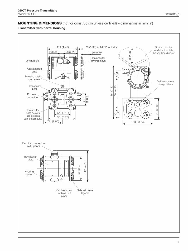
MOUNTING DIMENSIONS (not for construction unless certified) – dimensions in mm (in)Transmitter with barrel housing
54 (2.13)
96 (3.78)
41
.3(1
.63
)
9 (0.35) 58 (2.28)
114 (4.49) 23 (0.91)
20 (0.79)
71 (2.80)
10
8
(4.2
5)
30
(1.1
8)
61
(2
.40
)
18
6
(7.3
2)
26
(1.0
2)
90 (3.54)
70
(2.7
6)
11
7
(4.6
1)
83
(3
.27
)
Terminal side
Additional tagplate
Housing rotationstop screw
Transducerplate
Processconnection
Threads forfixing screws(see process
connection data)
Space must beavailable to rotate
the key-board cover
Drain/vent valve(side position)
Electrical connection(with gland)
Identificationplate
Housingcover
Captive screwfor keys unit
cover
Plate with keyslegend
with LCD indicator
Clearance forcover removal
2600T Pressure TransmittersModel 269CS SS/269CS_3
12
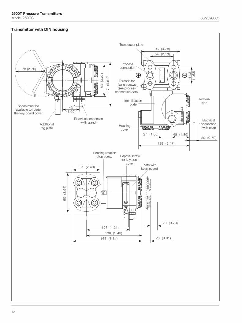
Transmitter with DIN housing
43(1.69)
11
7
(4.6
17
70 (2.76)
83
(3
.27
)
61 (2.40)
90
(3
.54
)
107 (4.21)
138 (5.43)
168 (6.61) 23 (0.91)
20 (0.79)
54 (2.13)
96 (3.78)
139 (5.47)
41
.3(1
.63
)
48 (1.89)27 (1.06)20 (0.79)
Space must beavailable to rotate
the key-board cover
Identificationplate
Housingcover
Threads forfixing screws(see process
connection data)
Processconnection
Additionaltag plate
Electrical connection(with gland)
Terminalside
Electricalconnection(with plug)
Housing rotationstop screw
Plate withkeys legend
Captive screwfor keys unit
cover
Transducer plate
2600T Pressure TransmittersModel 269CS SS/269CS_3
13
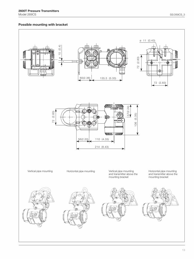
Possible mounting with bracket
Vertical pipe mounting Horizontal pipe mounting Vertical pipe mountingand transmitter above themounting bracket
Horizontal pipe mountingand transmitter above themounting bracket
ø
10
(0
.4)
60(2.36) 135.5 (5.33)
72 (2.83)
72
(2
.83
)
ø 11 (0.43)
214 (8.43)
56(2.20)
72
(2
.83
)
13
6
(5.3
5)
57
(2.2
4)
110 (4.33)

2600T Pressure TransmittersModel 269CS SS/269CS_3
14
Electrical connectionsStandard Terminal block
Harting HAN connector
+
21
RTD connection
Test socketsfor 4...20mA
Earthing/potentialequalizing terminal
Output signal/power supply
Harting pin identification(view onto socket)
14 12
1113
Cable entry
2600T Pressure TransmittersModel 269CS SS/269CS_3
15
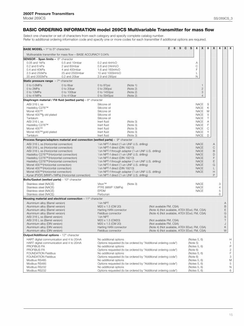
BASIC ORDERING INFORMATION model 269CS Multivariable Transmitter for mass flowSelect one character or set of characters from each category and specify complete catalog number.Refer to additional ordering information code and specify one or more codes for each transmitter if additional options are required.
LEDOMESAB 1– ts 5ot ht sretcarahc 2 6 9 C S X X X X X X X
%40.0YCARUCCAESAB–wolfssamrofrettimsnartelbairavitluM
–stimilnapS-ROSNES 6 ht retcarahcaPk1dna50.0aPk6dna2.0aPk04dna4.0
aPk052dna5.2aPk0002dna02
rabm01dna5.0rabm06dna2
rabm004dna4rabm0052dna52
rab02dna2.0
Hni4dna2.0 2OHni42dna8.0 2OHni061dna6.1 2OHni0001dna01 2Oisp092dna9.2
ACFLN
egnarerusserpcitatS 7– ht retcarahc
aPM6.0ot0aPM2ot0
aPM01ot0aPM14ot0
rab6ot0rab02ot0
rab001ot0rab014ot0
isp78ot0isp092ot0
isp0541ot0isp5495ot0
)1etoN()2etoN()2etoN()2etoN(
1234
)strapdettew(diulflliF/lairetammgarhpaiD 8– ht retcarahc
ssL613ISIA™672CyolletsaH
™004lenoMdetalpdlog™004lenoM
mulatnaTssL613ISIA
™672CyolletsaH™004lenoM
detalpdlog™004lenoMmulatnaT
lioenociliSlioenociliSlioenociliSlioenociliSlioenociliS
diulftrenIdiulftrenIdiulftrenIdiulftrenIdiulftrenI
)3etoN()3etoN()3etoN()3etoN()3etoN(
ECANECANECANECANECANECANECANECANECANECAN
SKMVTAFCYD
)strapdettew(noitcennocdnalairetamsretpada/segnalfssecorP – 9 ht retcarahc
)noitcennoclatnoziroH(ssL613ISIA)noitcennoclatnoziroH(ssL613ISIA)noitcennoclatnoziroH(ssL613ISIA
1/4 (tceridf-TPNni 7/ 61 )gnillird.S.UFNUni1/4 )31291NID(tceridf-TPNni1/2 (retpadahguorhtf-TPNni 7/ 61 )gnillird.S.UFNUni
ECANECANECANECANECANECANECANECANECAN
ACB
)noitcennoclatnoziroH(™672CyolletsaH)noitcennoclatnoziroH(™672CyolletsaH)noitcennoclatnoziroH(™672CyolletsaH
1/4 (tceridf-TPNni 7/ 61 )gnillird.S.UFNUni1/4 )31291NID(tceridf-TPNni1/2 (retpadahguorhtf-TPNni 7/ 61 )gnillird.S.UFNUni
DFE
)noitcennoclatnoziroH(™004lenoM)noitcennoclatnoziroH(™004lenoM)noitcennoclatnoziroH(™004lenoM
)noitcennoclatnoziroH()aPM1=PWM()FDVP(ranyK
1/4 (tceridf-TPNni 7/ 61 )gnillird.S.UFNUni1/4 )31291NID(tceridf-TPNni1/2 (retpadahguorhtf-TPNni 7/ 61 )gnillird.S.UFNUni1/4 (tceridf-TPNni 7/ 61 )gnillird.S.UFNUni
GLHP
)strapdettew(teksaG/stloB 01– ht retcarahc
)ECAN(leetssselniatS)ECAN(leetssselniatS)ECAN(leetssselniatS)ECAN(leetssselniatS
™notiV)aPM01PWM(EFTP
MDPEnanubreP
)3etoN( ECANECANECAN
3456
noitcennoclacirtcelednalairetamgnisuoH 11– ht retcarahc
)noisrevlerraB(yollamuinimulA)noisrevlerraB(yollamuinimulA)noisrevlerraB(yollamuinimulA)noisrevlerraB(yollamuinimulA
)noisrevlerraB(ssL613ISIA)noisrevlerraB(ssL613ISIA)noisrevNID(yollamuinimulA)noisrevNID(yollamuinimulA)noisrevNID(yollamuinimulA
1/2 TPNni)02MC(5.1x02M
rotcennocNAHgnitraHrotcennocsubdleiF
1/2 TPNni)02MC(5.1x02M)02MC(5.1x02M
rotcennocNAHgnitraHrotcennocsubdleiF
)ASC,MFelbaliavatoN()ASC,MF,dxEEXETA,elbaliavatoN()4etoN()ASC,MF,dxEEXETA,elbaliavatoN()4etoN(
)ASC,MFelbaliavatoN()ASC,MFelbaliavatoN(
)ASC,MF,dxEEXETA,elbaliavatoN()4etoN()ASC,MF,dxEEXETA,elbaliavatoN()4etoN(
ABEGSTJKW
snoitpolanoitiddA/tuptuO 21– ht retcarahc
Am02ot4dnanoitacinummoclatigidTRAHAm02ot4dnanoitacinummoclatigidTRAH
snoitpolanoitiddaoN)"edocgniredrolanoitiddA"ybderedroebot(detseuqersnoitpO
)6,5setoN()5etoN(
)6,5setoN()6etoN(
)6,5setoN()6etoN(
)6,5setoN()6,5setoN()6,5setoN()6,5setoN(
H1
APSUBIFORPAPSUBIFORP
snoitpolanoitiddaoN)"edocgniredrolanoitiddA"ybderedroebot(detseuqersnoitpO
snoitpolanoitiddaoN)"edocgniredrolanoitiddA"ybderedroebot(detseuqersnoitpO
snoitpolanoitiddaoN)"edocgniredrolanoitiddA"ybderedroebot(detseuqersnoitpO
snoitpolanoitiddaoN)"edocgniredrolanoitiddA"ybderedroebot(detseuqersnoitpO
P2
subdleiFNOITADNUOFsubdleiFNOITADNUOF
584SRsubdoM584SRsubdoM232SRsubdoM232SRsubdoM
F3M5N6

2600T Pressure TransmittersModel 269CS SS/269CS_3
16
ADDITIONAL ORDERING INFORMATION for model 269CSAdd one or more 2-digit code(s) after the basic ordering information to select all required options
XX XX XX XX XX XX XX XX XX XX XX
)strapdettew()noitisopdnalairetam(evlavtnev/niarDssL613ISIAssL613ISIAssL613ISIA
™672CyolletsaH™672CyolletsaH™672CyolletsaH
™004lenoM™004lenoM™004lenoM
sixassecorpnopotedisegnalfno
mottobedisegnalfnosixassecorpno
potedisegnalfnomottobedisegnalfno
sixassecorpnopotedisegnalfno
mottobedisegnalfno
)7etoN()7etoN()7etoN()8etoN()8etoN()8etoN()9etoN()9etoN()9etoN(
ECANECANECANECANECANECANECANECANECAN
1V2V3V4V5V6V7V8V9V
noitacifitreclacirtcelEaixEEytefaScisnirtnI–DG2/1yrogetaCIIpuorGXETA
dxEEfoorpemalF–G2/1yrogetaCIIpuorGXETAecnailpmocngisedLnxEE"N"noitcetorpfoepyT–DG3yrogetaCIIpuorGXETA
efaSyllacisnirtnI–)MF(lautuMyrotcaF)leballeetssselniatsdnanoitcennoclacirtceleTPNni2/1htiwylno(foorPnoisolpxE–)MF(lautuMyrotcaF
efaSyllacisnirtnI–noitaicossAdradnatSnaidanaCfoorPnoisolpxE–noitaicossAdradnatSnaidanaC
1E2E3EAEBEDEEE
DCLlargetnIyalpsidlargetniDCLlatigiD
yalpsidlargetniDCLlatigidtilkcaB1L2L
)lairetamdnaepahs(tekcarbgnitnuoMgnitnuomepiproFgnitnuomllawroF
ssL613ISIAssL613ISIA
2B4B
launamgnitarepOnamreG 1M
egaugnalgat&slebaL)W,K,JedocgnisuoHcinortcelENIDhtiwelbaliavaton(leetssselniatsninamreG
)foorPnoisolpxE-lautuMyrotcaFrofelbatiuston(citsalphsilgnEdnanamreG1TAT
etalpgatlanoitiddAleetssselniatsnI 1I
erudecorpnoitaraperP)F°041/C°06=xamT;isp0471/rab021/aPM21=xamP–)lliftrenihtiwelbaliavaylno(gninaelcecivresnegyxO
noitaraperpecivresnegordyH1P2P
setacifitreC
noitarbilacfoB.1.3–40201NEetacifitrecnoitcepsnI01452NIDotgnidroccaegatsssenilnaelcehtfoB.1.3–40201NEetacifitrecnoitcepsnI
eludomrosnesehtfotsetegakaelmuilehfoB.1.3–40201NEetacifitrecnoitcepsnItseterusserpehtfoB.1.3–40201NEetacifitrecnoitcepsnI
ngisedtnemurtsnifo1.2–40201NEredroehthtiwecnailpmocfoetacifitreC
1C3C4C5C6C
ytilibaecartlairetaM
strapdettewssecorpfo1.2–40201NEredroehthtiwecnailpmocfoetacifitreCstrapdettewssecorpfoB.1.3–40201NEetacifitrecnoitcepsnI
strapdettewssecorpdnagniraeberusserpehtfo2.2-40201NEtropertseT
1H3H4H
rotcennoC
8/7subdleiF1x21MsubdleiF
yrtnethgiarts–NAHgnitraHyrtneelgna–NAHgnitraH
)01,6setoN()01,6setoN()01,5setoN()11,5setoN(
1U2U3U4U

2600T Pressure TransmittersModel 269CS SS/269CS_3
17
Note 1: Not available with sensor code C, F, L, N
Note 2: Not available with sensor code A
Note 3: Suitable for oxygen service
Note 4: Select type in additional ordering code
Note 5: Not available with Electronic Housing code G and W
Note 6: Not available with Electronic Housing code E and K
Note 7: Not available with Process flanges/adapters code D, E, F, G, H, L, P
Note 8: Not available with Process flanges/adapters code A, B, C, G, H, L, P
Note 9: Not available with Process flanges/adapters code A, B, C, D, E, F, P
Note 10: Not available with Electronic housing code T, S, A, B, J
Note 11: Not available with Electronic housing code T, S, A, B, J, K.
™ Hastelloy is a Cabot Corporation trademark
™ Monel is an International Nickel Co. trademark
™ Viton is a Dupont de Nemour trademark
Standard delivery items (can be differently specified by additional ordering code)– Adapters supplied loose
– Plug on axis (no drain/vent valves)
– General purpose (no electrical certification)
– No meter/display, no mounting bracket
– English manual and labels (stainless steel nameplate for Barrel housing code A, B, E, G, S, T; plastic nameplate for DIN housing code J, K, W)
– Configuration with kPa and deg. C units
– No test, inspection or material traceability certificates
THE SELECTION OF SUITABLE WETTED PARTS AND FILLING FLUID FOR COMPATIBILITY WITH THE PROCESS MEDIA IS A CUSTOMER'SRESPONSIBILITY, IF NOT OTHERWISE NOTIFIED BEFORE MANUFACTURING.

2600T Pressure TransmittersModel 269CS SS/269CS_3
18

2600T Pressure TransmittersModel 269CS SS/269CS_3
19

2600T Pressure TransmittersModel 269CS SS/269CS_3
ABB LtdHoward Road, St. NeotsCambridgeshire, PE19 3EUUKTel: +44(0)1480 475321Fax: +44(0)1480 217948
ABB Inc.125 E. County Line RoadWarminster, PA 18974USATel: +1 215 674 6000Fax: +1 215 674 7183
SS
/269
CS
_3
ABB has Sales & Customer Supportexpertise in over 100 countries worldwide
www.abb.com
The Company’s policy is one of continuous productimprovement and the right is reserved to modify the
information contained herein without notice.
Printed in Italy (05.03)
© ABB 2002
ABB Automation Products GmbHSchillerstrasse 72D-32425 MindenGermanyTel: +49 (0) 571 830 1691Fax: +49 (0) 571 830 1368
ABB SACE spaBusiness Unit InstrumentationVia Statale 11322016 Lenno (CO) ItalyTel: +39 0344 58111Fax: +39 0344 56278
Related Documents