INSTRUCTION MANUAL Read and understand all of the instructions and safety information in this manual before operating this product. MAN-004 Rev G 02/2019 © 2019 MAC Medical, Inc. SS Series Surgical Scrub Sinks Installation - Operation - Maintenance - Cleaning OSHPD Pre-Approved SS32 Model SS64 Model SS96 Model C

Welcome message from author
This document is posted to help you gain knowledge. Please leave a comment to let me know what you think about it! Share it to your friends and learn new things together.
Transcript

INSTRUCTION MANUAL
Read and understand all of the instructions and safety information in this manual before operating this product.
MAN-004 Rev G 02/2019© 2019 MAC Medical, Inc.
SS Series Surgical Scrub SinksInstallation - Operation - Maintenance - Cleaning
OSHPDPre-Approved
SS32 Model
SS64 Model
SS96 Model
C

Instruction Manual
MAN-004 2 www.macmedical.com
KEEP THIS MANUAL
DESCRIPTION OF PRODUCTThis manual covers manual knee operated and Infrared self-activated Surgical Scrub Sink models -• SS32 - single basin• SS64 - double basin• SS96 - triple basin
PURPOSE OF THIS MANUALThis user manual details the installation, operation maintenance and cleaning of the MAC Medical Surgical ScrubSinks.Thismanualalsocontainsgeneralspecifications,warningsandcautions.
Table of Contents
Warnings and Cautions Icon Key 3GeneralSpecifications 4InLineFlowSwitchTimerController(S0130-01)-Specifications,SwitchRatingandWiringDiagram 5
Switch Timer Controller Maintenance 5SinkDimensions-SS32,SS64,SS96Models 6Installation 7Installing and Operating the Soap Spout 8RecommendedMountingSpecifications-SS32-SingleBasin 9RecommendedMountingSpecifications-SS64-DoubleBasin 10RecommendedMountingSpecifications-SS96-TripleBasin 11ConnectDrainPipetoDrainandPlumbingtoWaterLines 12
Plumbing Install Instructions 12Preventative Maintenance 13Troubleshooting 13
ReplacementPartsforManualKneeOperatedandInfraredSelf-ActivatedSinkPlumbing 14PlumbingAccess(ManualKneeOperatedSinksOnly) 15Infrared Controls (for Infrared Self-Activated Sinks only) 15
Installation 15Operation 15
Instructions for Cleaning Stainless Steel Surgical Scrub Sinks 16Optional IR Timer Assembly 17
Installing Optional Electronic Sink Timer Display 17TimerOperationDisplayandProgramming 18
Timer Battery Replacement 19In-lineWallCarrierMountAssembly-SingleBasinSinks(part#S0001) 20In-lineWallCarrierMountAssembly-DualBasinSinks(Part#S0002) 21In-lineWallCarrierMountAssembly-TripleBasinSinks(Part#S0003) 22Limited Lifetime Warranty 23

Instruction Manual
MAN-004 3 www.macmedical.com
Warnings and Cautions Icon KeyThe following is a list identifying the various warning and caution icons used in this manual.
Icon Type Icon DescriptionWarnings (Red triangle with an exclamation point) indicate the potential for
minor to severe injuries up to and including death to personnel.
Cautions (Yellow triangle with an exclamation point) indicate the potential minor injury to personnel and damage to equipment.
Note: The exclamation point will not be visible where only equipment damage is present.
Burn Hazard Warnings (Yellow triangle with radiating lines) indicate a potential burn injury to personnel.
Electrical Warnings
(Yellow triangle with a lightning bolt) indicate a possible shock hazard is present.
Severe shock hazards shall be a lightning bolt in a red triangle.
Warnings and Cautions When Installing or Operating This ProductPriortoinstallationoroperation,theusermustreadthesewarningsandcautions.The following is a list of the safety precautions that must be observed when operating this equipment.
WARNING-INJURY HAZARD - REPAIRS AND ADJUSTMENTS should be only attempted by experienced service agents fully acquainted with thisequipment.Theuseofinexperienced,unqualifiedpersonstoservicetheequipment,ortheinstallationofunauthorized parts, could cause serious personal injury, or result in costly damage. Always unplug power cord from power source prior to attempting any repairs or servicing.
WARNING - Burn HazardDONOTCHANGEtemperaturesettingsonthermostaticmixingvalve,unlessyouareatrainedmechanic.ANYREPAIRormodificationofmixingvalvemayaffectthehightemperaturesetting.Theinstallermustcheckoperating temperature before sink is back in operation.
CAUTION-POSSIBLE EQUIPMENT DAMAGE -When cleaning the sink - See complete Cleaning Instructions in this manual.
NOTE: This product is to be used strictly for the purpose it was designed for. If this product is used in a manner notspecifiedbyMACMedical,theprotectionprovidedbytheequipmentmaybeimpaired.MACMedicaldisclaims all liability for the consequences of this product being used for purposes other than its intended design.Productmodificationormisusecanbedangerous.MACMedicaldisclaimsallliabilityfortheconsequencesofproductalterationsormodifications,aswellasfortheconsequenceswhichmightresultfrom the combination of this product with other products, whether supplied by MAC Medical or by or by other manufacturers,unlesssuchacombinationhasbeenspecificallyendorsedbyMACMedical.

Instruction Manual
MAN-004 4 www.macmedical.com
General Specifications
1. Material:a. Sink basin and sink top: 14 gauge, 300 series stainless steelb. Sink skirt: 18 gauge, 300 series stainless steel.
2. Plumbing Material a. 1/2” copper or brass pipeb. Sink is furnished with in-line check valves on supply lines.
3. Utility requirements:a. Cold water - 20 to 50 psig 70º F maxb. Hotwater-20to50psig120ºFto140ºFc. Waterlinesshouldbeflushedcleanbeforewaterconnectionsaremade.d. It shall be the customers responsibility:
• toensurebyuseofpressureregulatorsorothermeans,thatmaximumspecifiedpressuresarenotexceeded.
• to ensure that water supplies are properly protected for internal cross connection control in accordance with local building and plumbing requirements.
• to eliminate water hammer conditions should they occur in the service piping.4. Power requirements (for sinks with optional infrared sensor operations)
a. 120Volt,60Hz,singlephase,3.0ampGFICprotectedelectricaloutlet(byothers)b. 220VAC,60Hz,singlephase1.5ampc. to be installed per local building codes.
5. Sink Weighta. Single basin - 130 lbsb. Doublebasin-230lbsc. Triple basin - 320 lbs
6. Sink Certificationsa. ULandcULcertifiedb. CaliforniaOSHPDpre-approvedwhenmountedonastructurallysoundwall.
7. Mixing Valve Specificationsa. Connections-1/2”NPTInletsand1/2”NPTTopOutletb. Capacity(withoutcheckstops)-5.25gpm[19.9L/min-at45psidifferential(310kPa)withhotwater
supply between 140° - 180° F (60° - 82° C) and 50/50 mix}] - (±0.25 gpm [0.95 L/min])c. MaximumHotWatersupplyTemperature-190°F(88°C)d. MinimumHotwatersupplytemperature(notapplicabletolowtemperaturehotwatervalves-5°F(2.8°
C) above set pointe. TemperatureRanges-ASSE1016TypeT:65-115°F(18-46°C);ASSE1016TypeT/P:90-110°F(32-43°C)f. MaximumOperatingPressure-125psig(862kPa)g. MaximumStaticPressure-125psig(862kPa)h. Compliant-ASSE1016-T-Pi. Certifiied-CSAB125

Instruction Manual
MAN-004 5 www.macmedical.com
Service Compatible liquids
Wetted materials Housing:brass;Piston:polysulfone;Spring:316SS;O-Ring:Fluoroelastomer,Other:Epoxy.
Temperature Limits -20 to 225°F (-29 to 107°C).PressureLimits 1000 psig (68.9 bar).Accuracy ±10% of set point.
Repeatability ±1%.Switch Type* SPDT,20VAElectricalRating .17A@120VAC,.08A@240VAC,.13A@120VDC,[email protected] 18AWG,24"(60.96cm),Polymericleadwires.ProcessConnection 1/4"femaleNPT.Mounting Orientation Any position. Set points shown are based on vertical, inlet down position.Required Filtration 50 microns or better.Weight 0.66 lb (301 g).Agency Approval CE
InLine Flow Switch Timer Controller (S0130-01) - Specifications, Switch Rating and Wiring DiagramNOTE:Thisfeature(Fig.1)isavailableonlyonInfraredActivatedScrubSinks.Thisisanexplosion-proofbrassflowswitch,actuationsetpoint0.50GPM(1.89LPM),andcalibratedforwateratstandardconditions.Itisusedforaccuratedetectionofexcessiveorinsufficientflowrates.
*Switch RatingsMax Resistive Load
Switch Timer Controller Maintenance
Accumulation of foreign debris should periodically be removed from these switches. Occasional “wipe-down” cleaning when excessive contamination is present is all that is normally required.
To Clean: Remove unit from system and disassemble as shown below. Clean all parts, reassemble and reinstall unit.
Note:50micronfiltrationisrecommended.
This unit was calibrated in a vertical position, with lead wires up. Install unit in piping system, using standard pipefittingprocedures.Besuretokeepthreadsealingcompoundoutofunit.Makesurethatflowisinproperdirection - marked “IN” and “OUT” on housing. See wiring diagrams for electrical connections.
CAUTION: See “Switch Ratings” before connecting power.
CAUTION: Flowsettingsforthisswitchisnormallycalibratedusingwater@+70°Fonincreasingflow.Water-calibrated units are not recommended for air/gas applications.
VA Volts Amps AC AmpsDC
200-30 .4 .3120 .17 .13240 .08 .06
A
C
B
Pin Connections forUnits with MS Receptacle
Typical Wiring Diagram
Piston
InletFitting
Housing
Spring
O-Ring
Fig. 1: In-line Flow Timer Controller

Instruction Manual
MAN-004 6 www.macmedical.com
Sink Dimensions - SS32, SS64, SS96 Models
Fig. 2: SS32 - single basin
Fig. 3:SS64-DualBasin
Fig. 4:SS96-TripleBasin
Instruction Manual
MAN-004 7 www.macmedical.com
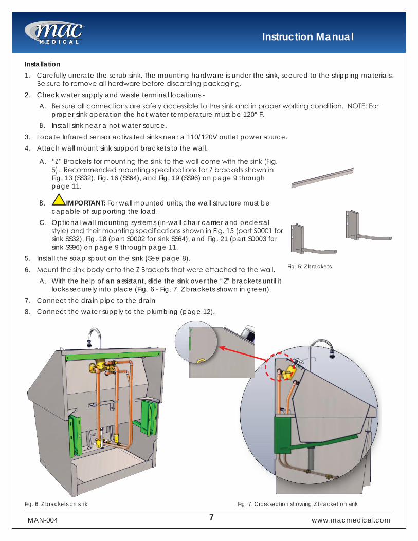
Installation1. Carefully uncrate the scrub sink. The mounting hardware is under the sink, secured to the shipping materials.
Besuretoremoveallhardwarebeforediscardingpackaging.2. Check water supply and waste terminal locations -
A. Besureallconnectionsaresafelyaccessibletothesinkandinproperworkingcondition.NOTE:Forproper sink operation the hot water temperature must be 120° F.
B. Install sink near a hot water source.3. Locate Infrared sensor activated sinks near a 110/120V outlet power source.4. Attach wall mount sink support brackets to the wall.
A. “Z”Bracketsformountingthesinktothewallcomewiththesink(Fig.5).RecommendedmountingspecificationsforZbracketsshowninFig. 13 (SS32), Fig. 16 (SS64), and Fig. 19 (SS96) on page 9 through page 11.
B. IMPORTANT: For wall mounted units, the wall structure must be capable of supporting the load.
C. Optional wall mounting systems (in-wall chair carrier and pedestal style)andtheirmountingspecificationsshowninFig.15(partS0001forsink SS32), Fig. 18 (part S0002 for sink SS64), and Fig. 21 (part S0003 for sink SS96) on page 9 through page 11.
5. Install the soap spout on the sink (See page 8).6. MountthesinkbodyontotheZBracketsthatwereattachedtothewall.
A. With the help of an assistant, slide the sink over the “Z” brackets until it locks securely into place (Fig. 6 - Fig. 7, Z brackets shown in green).
7. Connect the drain pipe to the drain8. Connect the water supply to the plumbing (page 12).
Fig. 5: Z brackets
Fig. 6: Z brackets on sink Fig. 7: Cross section showing Z bracket on sink
Instruction Manual
MAN-004 8 www.macmedical.com
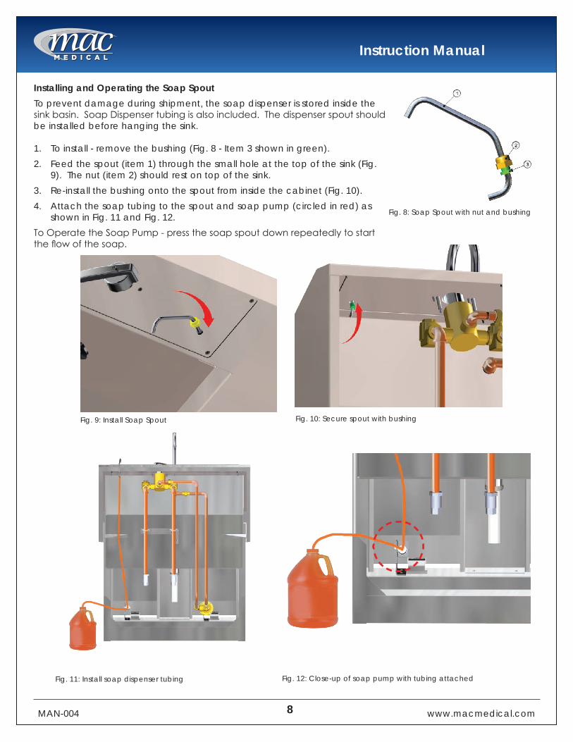
Installing and Operating the Soap SpoutTo prevent damage during shipment, the soap dispenser is stored inside the sinkbasin.SoapDispensertubingisalsoincluded.Thedispenserspoutshouldbe installed before hanging the sink.
1. To install - remove the bushing (Fig. 8 - Item 3 shown in green). 2. Feed the spout (item 1) through the small hole at the top of the sink (Fig.
9). The nut (item 2) should rest on top of the sink. 3. Re-install the bushing onto the spout from inside the cabinet (Fig. 10). 4. Attach the soap tubing to the spout and soap pump (circled in red) as
shown in Fig. 11 and Fig. 12. ToOperatetheSoapPump-pressthesoapspoutdownrepeatedlytostarttheflowofthesoap.
Fig. 8: Soap Spout with nut and bushing
Fig. 9: Install Soap Spout Fig. 10: Secure spout with bushing
Fig. 11: Install soap dispenser tubing Fig. 12: Close-up of soap pump with tubing attached

Instruction Manual
MAN-004 9 www.macmedical.com
Recommended Mounting Specifications - SS32 - Single Basin
For the assembly drawing of In-line wall carrier mount (S0001), see page 20.
Fig. 13: Z bracket mounting locations - SS32
Fig. 14: In-line wall carrier mount - S0001
Fig. 15: In-line wall carrier mounting locations - SS32
Instruction Manual
MAN-004 10 www.macmedical.com
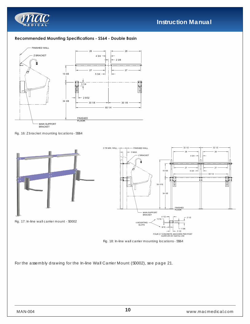
Recommended Mounting Specifications - SS64 - Double Basin
For the assembly drawing for the In-line Wall Carrier Mount (S0002), see page 21.
Fig. 16: Z bracket mounting locations - SS64
Fig. 17: In-line wall carrier mount - S0002
Fig. 18: In-line wall carrier mounting locations - SS64
Instruction Manual
MAN-004 11 www.macmedical.com
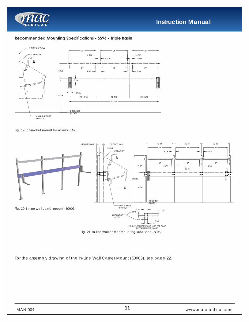
Recommended Mounting Specifications - SS96 - Triple Basin
For the assembly drawing of the In-Line Wall Carrier Mount (S0003), see page 22.
Fig. 19: Z bracket mount locations - SS96
Fig. 20: In-line wall carrier mount - S0003
Fig. 21: In-line wall carrier mounting locations - SS96

Instruction Manual
MAN-004 12 www.macmedical.com
Connect Drain Pipe to Drain and Plumbing to Water Lines
Localbuildingorplumbingcodesmayrequiremodificationstotheinformationprovided.Youarerequired to consult the local building and plumbing codes prior to installation. If the information provided here is not consistent with local building or plumbing codes, the local codes should be followed. This product must be installed by a licensed contractor in accordance with local codes and ordinances.
FAILURETOCOMPLYWITHPROPERINSTALLATIONANDMAINTENANCEINSTRUCTIONSCOULDCONTRIBUTETOVALVEFAILURE.Thishotwatermastertemperingvalvecannotbeusedfortemperingwatertemperatureatfixtures.Severebodily injury (i.e., scalding or chilling) and/or death may result depending upon system water pressure changes and/orsupplywatertemperaturechanges.ASSEstandard1016,1069or1070listeddevicesshouldbeusedatfixturestopreventpossibleinjury.This hot water tempering valve is designed to be installed at or near the boiler or water heater. They are not designedtocompensateforsystempressurefluctuationsandshouldnotbeusedwhereASSEstandard1016,1069 or 1070 devices are required. These valves should never be used to provide “anti-scald” or “anti-chill” service.The components of the system must be of materials with a construction capable of withstanding the high limit output temperatures of the water heating source.
Need for Periodic Inspection and Yearly Maintenance:Periodicinspectionandyearlymaintenancebyalicensed contractor is required. Corrosive water conditions, temperatures over 200°F, unauthorized adjustments or repair could render the valve ineffective for service intended. Regular checking and cleaning of the valve’s internal components and check stops helps assure maximum life and proper product function. Frequency of cleaning and inspection depends upon local water conditions.
Plumbing Install InstructionsPlumbingInstallationshouldbeinaccordancewithacceptedplumbingpractices.Installationandfieldadjustment are the responsibility of the installer.1. Flush all pipes thoroughly before installation.2. Connect sink drain pipe to drain connection.3. Close both hot and cold water shutoff valves upstream of the tempering valve.4. Bleedpressurefromthesystem.5. Routecoppertubingorpipingtofitvalvedimensions.6. Remove tailpieces from the valve and make sure union nuts are over the tubing/piping before connecting
to the tailpiece.A. Note: If soldering, remove unions and gaskets from valve body prior to soldering to prevent damage to
valve from excessive heat.7. Flushpipingagain,installvalveusingfiltergasketonhotandcoldwaterinletsandfibergasketonmixed
water outlet.8. Turn on the cold and hot water. If any leaks are observed, tighten connections as necessary to stop leaks
before proceeding.9. After the plumbing installation is complete, the water pressure can be adjust to avoid excess splash. The
pressurecanbecontrolledbyadjustingtheflowwiththeflowcontrolvalve.Seeitem#4oftheplumbingdiagram for the manual knee operated plumbing on page 14.

Instruction Manual
MAN-004 13 www.macmedical.com
Preventative MaintenanceEvery 6 months - 1. Check and adjust the temperature setting.Every 12 months - 1. Shut off water supply2. Open up checkstops.3. Clean strainers and check for free movement of checkstop poppet.4. Replace seals if cracked, cut, or worn.5. Re-assemble.6. Adjust stem to desired temperature.
Troubleshooting1. Iftheflowofwaterislessthandesired--
A. Valves upstream from supply not fully openB. Low supply pressuresC. Accumulationoflimedepositisinhotwaterpipes,restrictingtheflowofwaterD. Checkstops not fully openE. Clogged strainer screens in the checkstopsF. Clogged cartridge
2. Flow of water is completely cut off --A. Valves upstream from supply completely closedB. Failure of cold water supply pressure (mixing value is designed to shut off on a cold water supply
failure).C. Checkstops completely closed.
3. Flow is untempered hot or cold water--A. Accumulationoftimedepositsinhotwaterpipes,restrictingtheflowofhotwater.B. Thermostaticactuatorfailure;replacewithnewthermostaticactuatorC. Hotandcoldwatersuppliesareconnectedtothewrongports
4. Maximumtemperaturespecifiedforthemixingvalvecannotbeobtained--A. Accumulationoflimedepositsinhotwaterpipesrestritingtheflowofhotwater.B. Hotwatersupplytemperatureistoolow
5. Variable discharge temperature occurs--A. ExtremepressurevariationsinsupplylinesB. valve operating below minimum capacity requirements.

Instruction Manual
MAN-004 14 www.macmedical.com
8
Replacement Parts for Manual Knee Operated and Infrared Self-Activated Sink PlumbingBothplumbingconfigurationsshownbelowindicatewhichpartsarereplaceable.Seetablebelowforreplacement part numbers.
Item # Description Knee Operated Part # Infrared Activated Part #1 Spout for both knee operated or infrared activated plumbing SS0132-012 Thermostatic Mixing Valve for both knee operated or infrared activated plumbing S00093 MixingValveHandle for both knee operated or infrared activated plumbing S00104 1/2”BalanceFlowControlValve S0024 Solenoid Valve (for Infrared) S00135 Knee Operated Water Valve S0029 Infrared Sensor S00126 Inline Flow Switch Timer for infrared activated plumbing S0130-017 Checkstop Strainer (L/R) for both knee operated or infrared activated plumbing S00118 Swivel Aerator for both knee operated or infrared activated plumbing S00329 Soap Spout for both knee operated or infrared activated plumbing S004110 SoapPumpKit for both knee operated or infrared activated plumbing S002811 Check Valve for both knee operated or infrared activated plumbing S013112 SinkDividers(notshown) for dual and triple basin sinks S0034
Fig. 22: Manual knee operated sink plumbing Fig. 23:InfraredSelf-ActivatedSinkPlumbing

Instruction Manual
MAN-004 15 www.macmedical.com
Plumbing Access ( Manual Knee Operated Sinks Only)1. Open the knee panel door by depressing the latch at the bottom of the panel door (Fig. 24).2. Swing the door fully open to access the hinges (Fig. 25).3. Pushthehingepinsinwardtoreleasethedoorfromthehinges(Fig.26).
Infrared Controls (for Infrared Self-Activated Sinks only)Installation The sinks are supplied with a 24V power transformer(s) that connects to a standard duplex outlet (110/120V outlet required). Single basin sinks have one sensor, dual basin sinks have two sensors (one for each basin) and triple basin sinks have three sensors (one for each basin).1. Plugthetransformer(s)intotheoutlet.2. AredLEDwillflashinthesensorwindow(Fig.29-circledinred).
A. Important:Donotinterruptthesensorbeamuntilthelightturns off.
Operation The sensors are pre-set and equipped with a logic board. The sensors determines the range during initialization period (The time after initial power until the light turns off is approximately 5 minutes). The range is approximately 12-14” in front of the sensor and is 25 degrees at peak.Duringtheinitializationperiod,thesensorsallowforfixedobjectsthatmay be within the sensors’ range. The sensors are equipped with a 2 second on/off delay, and no-time-out feature. This prevents the sink from turning on when walking past at a normal pace and no-time-out allows for an uninterrupted scrub.
4. To re-attach the door, push in the hinge pins andfitthetopcornersofthekneepaneldoor onto the left and right hinge leaves (Fig. 27-circledinred).Whenthedoorisrefitted,release the hinge pins to secure the door to the sink.
5. The knee panel door should rotate freely on its hinges. Rotate the door back down on its bottom latch to close it (Fig. 28).
Fig. 24:Pushdownkneepaneldoorlatch Fig. 25:Doorinfullyopenedposition
Fig. 26:Pushhingesinward
Fig. 27: Left - right hinge leaves
Fig. 28:Doorshouldrotatefreelyonhinges
Fig. 29: Location of infrared sensor

Instruction Manual
MAN-004 16 www.macmedical.com
Instructions for Cleaning Stainless Steel Surgical Scrub SinksStainless steel sinks must be cleaned on a regular basis to prevent any unnecessary damage to the stainless steel surfaces.When cleaning Ssainless steel sinks, make sure to use the proper approved cleaning agents and cleaning materials.
CAUTIONDO NOT USE these Cleaning Materials
CAUTIONDO NOT USE these Cleaning Agents
AbrasivePads HardWater(waterwithapHreadingabove7.0).Scrapers HydrochloricAcidSteel Wool Steam or high pressure waterWireBrushes BleachoranycompoundscontainingchlorineorSoldium
hypochlorate, or ammonium chloride salts.
Approved cleaning materials and agents• Soft, clean lint-free cloth• Non-abrasive cleaning pads• Soft bristle brush• Mild detergents• SodiumBicarbonate(bakingsoda)• Distilledwater(pHrating7)aloneorwithamilddetergent• White vinegar (in a spray bottle) • Isopropyl Alcohol• Hospital-gradenon-bleachdisinfectants• Cleaners approved for use on stainless steel
Cleaning Stainless Steel Surfaces1. Using a damp, lint-free cloth and approved cleaner, wipe down the entire exterior surface of the stainless
steel sinks. Using a damp, lint-free cloth with distilled water and a mild detergent, wipe down the entire exterior surface of the stainless steel sinks.
2. Let cleaned sinks air dry.
Cleaning Decals or Printed Labels• Use only distilled water and a mild detergent applied with a clean, dry lint-free cloth to clean decals or
printed labels.• Cleaning agents can remove or smear any printing from decals and print labels.• Cleaning agents can damage plastic materials used in manufacturing covers for electronic items such as
infrared sensor face.
Instruction Manual
MAN-004 17 www.macmedical.com
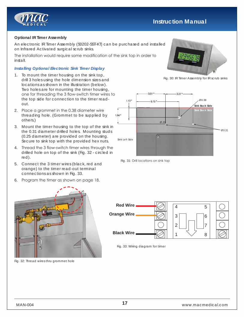
Optional IR Timer AssemblyAn electronic IR Timer Assembly (S0202-SST-KT) can be purchased and installed on Infrared Activated surgical scrub sinks.Theinstallationwouldrequiresomemodificationofthesinktopinordertoinstall.
Installing Optional Electronic Sink Timer Display1. To mount the timer housing on the sink top,
drill 3 holes using the hole dimension sizes and locations as shown in the illustration (below). Two holes are for mounting the timer housing, oneforthreadingthe3flow-switchtimerwirestothe top side for connection to the timer read-out.
2. Placeagrommetinthe0.38diameterwirethreading hole. (Grommet to be supplied by others.)
3. Mount the timer housing to the top of the sink in the 0.31 diameter drilled holes. Mounting studs (0.25 diameter) are provided on the housing. Secure to sink top with the provided hex nuts.
4. Threadthe3flow-switchtimerwiresthroughthedrilled hole on top of the sink (Fig. 32 - circled in red).
5. Connect the 3 timer wires (black, red and orange) to the timer read-out terminal connections as shown in Fig. 33.
6. Programthetimerasshownonpage18.
Fig. 30: IR Timer Assembly for IR scrub sinks
Ø0.31
Ø.31
Ø0.38
Sink Back SideSink Back Side
Sink Left Side
Red Wire 5
6
7
8
4
3
2
1
Orange Wire
Black Wire
Fig. 31:Drilllocationsonsinktop
Fig. 32: Thread wires thru grommet hole
Fig. 33: Wiring diagram for timer
Instruction Manual
MAN-004 18 www.macmedical.com
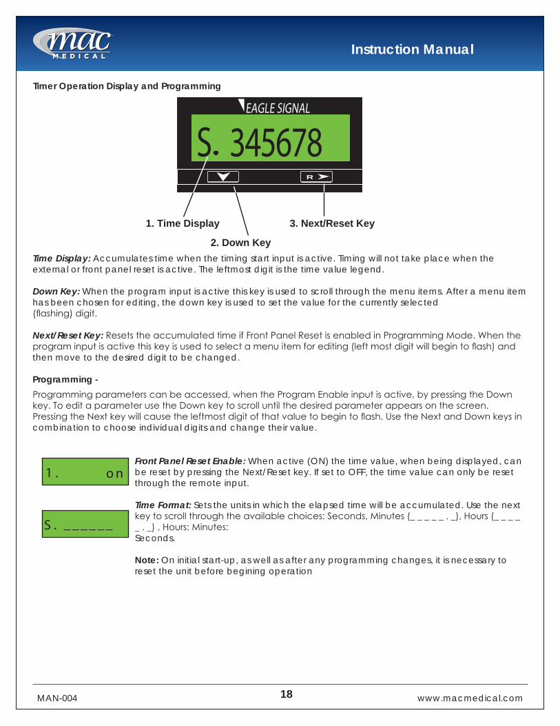
Timer Operation Display and Programming
Time Display: Accumulates time when the timing start input is active. Timing will not take place when the external or front panel reset is active. The leftmost digit is the time value legend.
Down Key: When the program input is active this key is used to scroll through the menu items. After a menu item has been chosen for editing, the down key is used to set the value for the currently selected(flashing)digit.
Next/Reset Key: ResetstheaccumulatedtimeifFrontPanelResetisenabledinProgrammingMode.Whentheprograminputisactivethiskeyisusedtoselectamenuitemforediting(leftmostdigitwillbegintoflash)andthen move to the desired digit to be changed.
Programming - Programmingparameterscanbeaccessed,whentheProgramEnableinputisactive,bypressingtheDownkey.ToeditaparameterusetheDownkeytoscrolluntilthedesiredparameterappearsonthescreen.PressingtheNextkeywillcausetheleftmostdigitofthatvaluetobegintoflash.UsetheNextandDownkeysincombination to choose individual digits and change their value.
Front Panel Reset Enable: When active (ON) the time value, when being displayed, can be reset by pressing the Next/Reset key. If set to OFF, the time value can only be reset through the remote input.
Time Format: Sets the units in which the elapsed time will be accumulated. Use the next keytoscrollthroughtheavailablechoices:Seconds,Minutes(_____._),Hours(_____._),Hours:Minutes:Seconds.
Note: On initial start-up, as well as after any programming changes, it is necessary to reset the unit before begining operation
VEEDER-ROOT
R
1. Time Display 3. Next/Reset Key
345678S
2. Down Key
EAGLE SIGNAL
on
______S .
1 .
Instruction Manual
MAN-004 19 www.macmedical.com
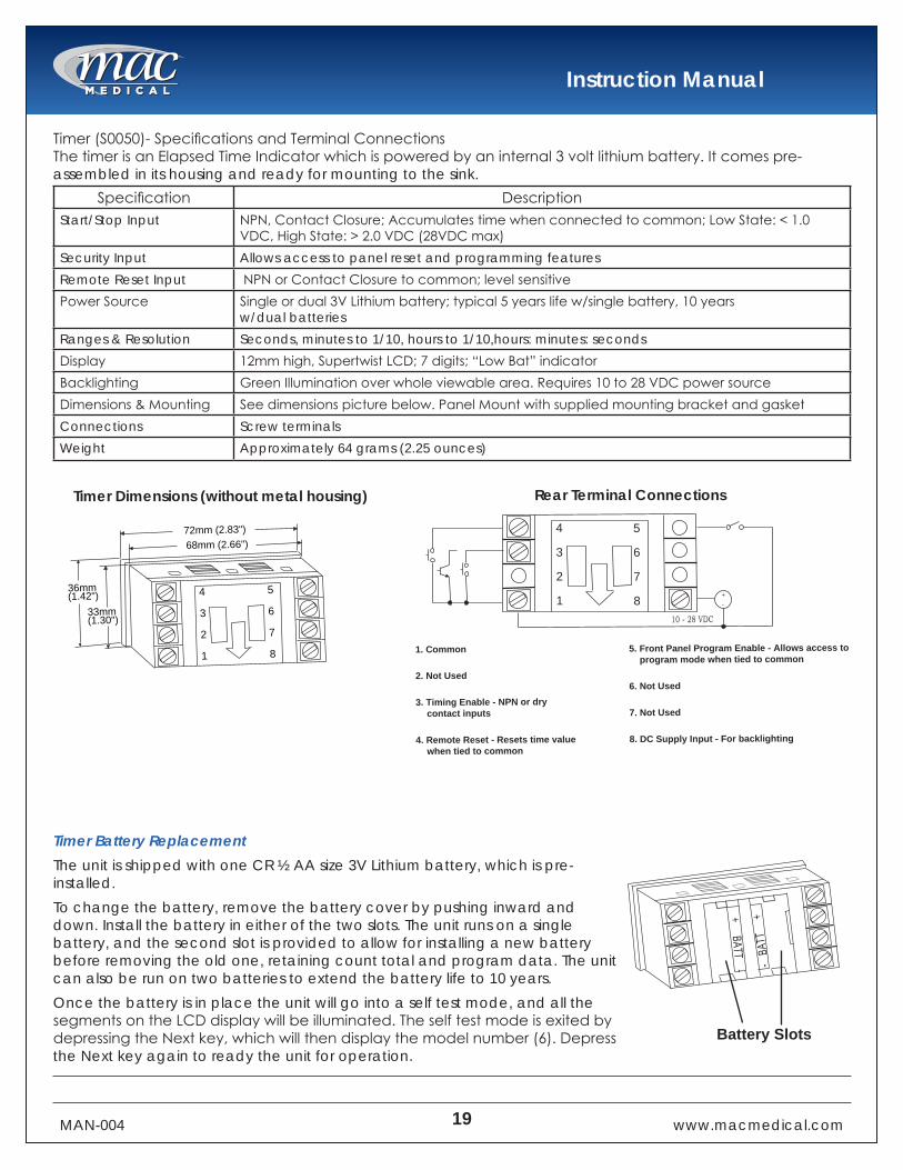
Timer(S0050)-SpecificationsandTerminalConnectionsThetimerisanElapsedTimeIndicatorwhichispoweredbyaninternal3voltlithiumbattery.Itcomespre-assembled in its housing and ready for mounting to the sink.
Specification DescriptionStart/Stop Input NPN,ContactClosure;Accumulatestimewhenconnectedtocommon;LowState:<1.0
VDC,HighState:>2.0VDC(28VDCmax)Security Input Allows access to panel reset and programming featuresRemote Reset Input NPNorContactClosuretocommon;levelsensitivePowerSource Singleordual3VLithiumbattery;typical5yearslifew/singlebattery,10years
w/dual batteriesRanges & Resolution Seconds, minutes to 1/10, hours to 1/10,hours: minutes: secondsDisplay 12mmhigh,SupertwistLCD;7digits;“LowBat”indicatorBacklighting GreenIlluminationoverwholeviewablearea.Requires10to28VDCpowersourceDimensions&Mounting Seedimensionspicturebelow.PanelMountwithsuppliedmountingbracketandgasketConnections Screw terminalsWeight Approximately 64 grams (2.25 ounces)
Rear Terminal Connections
Timer Battery Replacement The unit is shipped with one CR ½ AA size 3V Lithium battery, which is pre-installed. To change the battery, remove the battery cover by pushing inward and down. Install the battery in either of the two slots. The unit runs on a single battery, and the second slot is provided to allow for installing a new battery before removing the old one, retaining count total and program data. The unit can also be run on two batteries to extend the battery life to 10 years. Once the battery is in place the unit will go into a self test mode, and all the segmentsontheLCDdisplaywillbeilluminated.TheselftestmodeisexitedbydepressingtheNextkey,whichwillthendisplaythemodelnumber(6).Depressthe Next key again to ready the unit for operation.
Timer Dimensions (without metal housing)
5
6
7
8
4
3
2
1
72mm (2.83")68mm (2.66")
33mm(1.30")
36mm(1.42")
5. Front Panel Program Enable - Allows access toprogram mode when tied to common
6. Not Used
7. Not Used
8. DC Supply Input - For backlighting
1. Common
2. Not Used
3. Timing Enable - NPN or drycontact inputs
4. Remote Reset - Resets time valuewhen tied to common
5
6
7
8
4
3
2
1 +-
10 - 28 VDC
-
+ TTAB
+ BATT -
Battery Slots

Instruction Manual
MAN-004 20 www.macmedical.com
In-line Wall Carrier Mount Assembly - Single Basin Sinks ( part #S0001)This drawing shows how the in-line wall carrier for single basin scrub sinks is assembled.NOTE: To ensure stability, MAC Medical recommends that the In-line Wall Carrier Mount Assembly be tied into the existing wall support structure. All applicable local and state building codes should be adhered to when mounting this unit.
3/8 U BOLTSHDW0003-01
QTY (6)
3/8 FLAT WASHERHDW0001-01
QTY (12)3/8 HEX NUTHDW0002-01
QTY (12)
1/4 HEX NUTHDW0002-02
QTY (33)
1/4 ALL THREAD RODHDW0004-01
QTY (11)
BOTTOM CARRIER PLATESMS0052-01
QTY (1)
TOP CARRIER PLATESMS0051-01
QTY (1)
SINK SUPPORT SMS0050QTY (2)

Instruction Manual
MAN-004 21 www.macmedical.com
In-line Wall Carrier Mount Assembly - Dual Basin Sinks (Part #S0002)This drawing shows how the in-line wall carrier for dual basin scrub sinks is assembled.NOTE: To ensure stability, MAC Medical recommends that the In-line Wall Carrier Mount Assembly be tied into the existing wall support structure. All applicable local and state building codes should be adhered to when mounting this unit.
SINK POSTSMS0050QTY (3)
TOP CARRIER PLATESMS0051-02
QTY (2)
BOTTOM CARRIER PLATESMS0052-02
QTY (1)
1/4 ALL THREAD RODHDW0004-01
QTY (12)
1/4 HEX NUTHDW0002-02
QTY (36)
3/8 HEX NUTHDW0002-01
QTY (18)
3/8 FLAT WASHERHDW0001-01
QTY (18)
3/8 U BOLTSHDW0003-01
QTY (9)

Instruction Manual
MAN-004 22 www.macmedical.com
In-line Wall Carrier Mount Assembly - Triple Basin Sinks (Part #S0003)This drawing shows how the in-line wall carrier for triple basin scrub sinks is assembled.NOTE: To ensure stability, MAC Medical recommends that the In-line Wall Carrier Mount Assembly be tied into the existing wall support structure. All applicable local and state building codes should be adhered to when mounting this unit.
SINK POST SMS0050QTY (4)
TOP CARRIER PLATESMS0051-03
QTY (1)
BOTTOM CARRIER PLATESMS0052-03
QTY (1)
1/4 ALL THREAD RODHDW0004-01
QTY (14)
1/4 HEX NUTHDW0002-02
QTY (42)
3/8 HEX NUTHDW0002-01
QTY (24)
3/8 FLAT WASHERHDW0001-01
QTY (24)
3/8 U BOLTSHDW0003-01
QTY (12)
Corporate Office325 West Main Street Belleville, IL 62220
Phone: 618-476-3550 • Toll Free: 877-828-9975 • www.macmedical.com
MAC Medical, Inc.Printed in USAPublication No. MAN-004 Rev GFebruary 2019 Information regarding this product is subject to change without prior notice.
Customer needs are our first priority.
Manufacturing Plant 820 South Mulberry Street Millstadt, IL 62260
To place an order, contact our customer service department at 618-476-3550 or 877-828-9975 or by email at [email protected]
Limited Lifetime Warranty
MACMedicalwarrantstotheoriginalpurchaserthatitsProprietaryProductswillbefreefromdefects in workmanship or materials under normal use and service for the life of the product, so long as owned by the original purchaser, according to the limitations set forth below.DefectiveproductsshallberepairedorreplacedatMACMedical’soptionatnocosttotheoriginal purchaser provided:
1. The customer must obtain a written return authorization supplied by MAC Medical’s customer service department. The product must be returned, properly packaged, with a copyoftheoriginalsalesreceiptandcopyoftheRMAauthorization.Pleasecall(877)828-9975 or (618) 476-3550 to receive a return authorization.
2. The customer must pre-pay freight charges to and from MAC Medical and must ship merchandise properly packaged, in a way the product will not be damaged during transit to the factory. MAC Medical does not warranty any freight damage to or from the factory. It is the customer’s responsibility to inspect the product for packaging damage before signing theBOL.
This warranty does not apply to products, which have been subject to abuse, misuse, accident, modification,alteration,tampering,negligence,lackofroutinemaintenanceormisapplication;or products that have been repaired by other than MAC Medical or its authorized representatives.This warranty does not apply to glass, fabrics, vinyl, seat coverings, cushions, padding or their stitching, gluing or installation. Component parts not manufactured by MAC Medical, such as casters, caster inserts, any components made from rubber or plastic, circuit boards, fan heaters, plumbing parts, electrical switches and other components are also excluded. For these component parts, MAC Medical will pass on the original manufacturer’s warranty to MACMedicalequipmentoriginalpurchasers.Pleaseconsultfactoryforquestionsregardingthe warranties of these component parts. This warranty does not apply to custom fabricated products. Consult factory.
UNLESSEXPRESSLYSETFORTHINTHISWARRANTY,THEREARENOOTHERWARRANTIES,WHETHEREXPRESSORIMPLIED,OFFITNESSAND/ORMERCHANTABILITYORANYOTHERWARRANTYIMPLIEDBYCUSTOM,USAGEORCOURSEOFDEALING.
Liability of MAC Medical under this warranty is limited to the repair and / or replacement of any products.MACMedicalspecificallyexcludesanddisclaimsanyresponsibilityforanyincidentalor consequential damages claimed to have arisen from any defect in workmanship or materials. No representative has any authority to change or enlarge the above warranty or MAC Medical liability. This document supersedes all previous warranty provisions.
Related Documents