version 4.3 (1/13/12) visit www.stonestrong.com to check current version 1 The conv ent ional (non LRFD) calculat ion methodol ogy generally adheres to the AASHTO Standard Specifications for Highway Bridges (17th Edition, 2002). Additional methods and practices follow the FHWA Mechinically Stabilized Earth Walls and Reinforced Slopes Design and Construction Guidelines, NHI-00-043. Specifi c methods, procedures, equati ons , and nomenclat ure can be foun d in the Grav ity Wall Design Methodology and Example Gravity Calculations in the Engineering Manual and available on the Stone Strong web site www.StoneStrong.com. 2 The end user is responsible for all highl ighted input v alues and changes to unhighlight ed progr am defaul t values. Properties for soil and other materials should be obtained through testing or from recommendations by an experienced geotechnical engineer with knowledge of local materials and practices. 3 The bac kfill height defaults to the total wall height, as suming t hat the wall is backfill ed to the top of any Cap units or Dual Face unit s. The backfill height may be overwri tten where the Cap or Dual Face units are allowed to project abov e grade. The total wall hei ght and backfill height are measured from the top of the base pad, neglecting embedment. The exposed height is the total backfill height less the embedment depth. Note that passive resistance at the toe is neglected per customary engineering practice for modular wall systems. See the Wall Height Terminology sketch located below. 4 The lat eral load above the wall will evaluate live loads such as wind loads on a fence, lateral forces on a hand-rail, or barrier loads on an above grade Dual Face secti on. This live load is not included in seismic calculation s (if used). The height abov e the top of the wall is defined as the height abov e the blocks, not above the backfill height (where the backfill height is set at less than the wall height for a Cap or Dual Face projection above g rade). See the Wall Height Terminology sketch located below. 5 The soil par amet ers defaul t to unif orm condit ions. The foundation soils are set to mat ch changes in the retained soils, but can be overwritte n for non-un iform soils. For a sound rock foundation, enter "rock" or "ledge" (without quotations) instead of a fr iction angle for the f oundation soil. USER NOTES Stone Strong LLC is the owner of this computer file and retains all common law, statutory, and other reserved rights including the copyr ight. Limited licen se is granted to copy , print, or use this spreadshe et as an aid in performing design calculati ons for Stone Strong retai ning walls. Thiele Geotec h, Inc. and Stone Strong LLC make no warranties, either expressed or implied, of merchantability or fitness for any particular purpose, and accept no responsibility for the accuracy, suitability, or completeness of information contained herein. Licensee acknowledges that this computer file is the proprietary property of Stone Strong LLC. Licensee certifies that he/she will maintain this computer file as a confidential trade secret and will not copy or distribute the file to any person or entity that is not acting under his/her direct supervision and control. This calcul at ion spreadsheet is provided for general information purposes only. Anyone making use of this spreadsheet and rela ted informat ion does so at thei r own ri sk and assumes al l li abil it y for such use. Site sp ecifi c desi gn should be performed by a licens ed Prof essional Engineer who is familia r wi th the actual site conditions, materials, and local practices. © S T O N E S T R O N G L L C

Welcome message from author
This document is posted to help you gain knowledge. Please leave a comment to let me know what you think about it! Share it to your friends and learn new things together.
Transcript
7/27/2019 SS Gravity Calculations 4.3
http://slidepdf.com/reader/full/ss-gravity-calculations-43 1/11
version 4.3 (1/13/12)
visit www.stonestrong.com to check current version
1 The conventional (non LRFD) calculation methodology generally adheres to the AASHTO Standard
Specifications for Highway Bridges (17th Edition, 2002). Additional methods and practices follow the FHWA
Mechinically Stabilized Earth Walls and Reinforced Slopes Design and Construction Guidelines, NHI-00-043.
Specific methods, procedures, equations, and nomenclature can be found in the Gravity Wall DesignMethodology and Example Gravity Calculations in the Engineering Manual and available on the Stone
Strong web site www.StoneStrong.com.
2 The end user is responsible for all highlighted input values and changes to unhighlighted program default
values. Properties for soil and other materials should be obtained through testing or from recommendations
by an experienced geotechnical engineer with knowledge of local materials and practices.
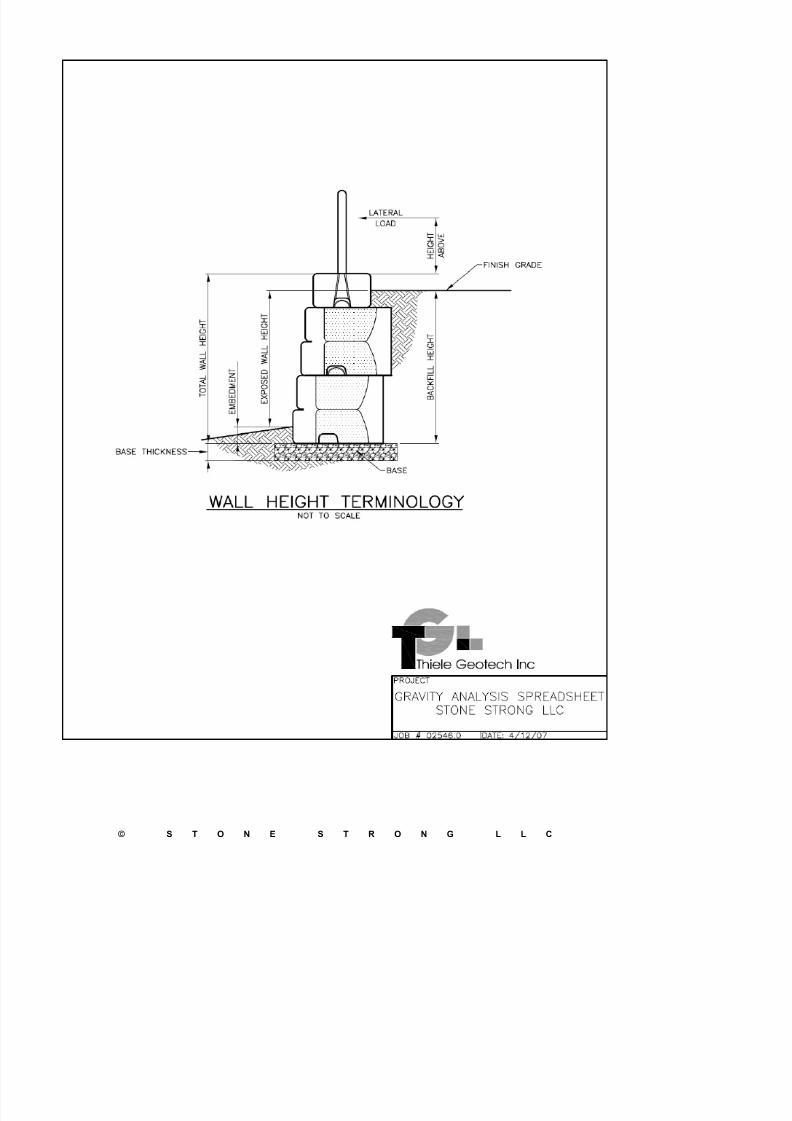
3 The backfill height defaults to the total wall height, assuming that the wall is backfilled to the top of any Capunits or Dual Face units. The backfill height may be overwritten where the Cap or Dual Face units are
allowed to project above grade. The total wall height and backfill height are measured from the top of the
base pad, neglecting embedment. The exposed height is the total backfill height less the embedment depth.
Note that passive resistance at the toe is neglected per customary engineering practice for modular wall
systems. See the Wall Height Terminology sketch located below.
4 The lateral load above the wall will evaluate live loads such as wind loads on a fence, lateral forces on a
hand-rail, or barrier loads on an above grade Dual Face section. This live load is not included in seismiccalculations (if used). The height above the top of the wall is defined as the height above the blocks, not
above the backfill height (where the backfill height is set at less than the wall height for a Cap or Dual Face
j ti b d ) S th W ll H i ht T i l k t h l t d b l
USER NOTES
Stone Strong LLC is the owner of this computer file and retains all common law, statutory, and other reservedrights including the copyright. Limited license is granted to copy, print, or use this spreadsheet as an aid in
performing design calculations for Stone Strong retaining walls. Thiele Geotech, Inc. and Stone Strong LLC
make no warranties, either expressed or implied, of merchantability or fitness for any particular purpose, and
accept no responsibility for the accuracy, suitability, or completeness of information contained herein.
Licensee acknowledges that this computer file is the proprietary property of Stone Strong LLC. Licensee certifies
that he/she will maintain this computer file as a confidential trade secret and will not copy or distribute the file to
any person or entity that is not acting under his/her direct supervision and control.
This calculation spreadsheet is provided for general information purposes only. Anyone making use of
this spreadsheet and related information does so at their own risk and assumes all liability for such use.
Site specific design should be performed by a licensed Professional Engineer who is familiar with the
actual site conditions, materials, and local practices.
7/27/2019 SS Gravity Calculations 4.3
http://slidepdf.com/reader/full/ss-gravity-calculations-43 2/11
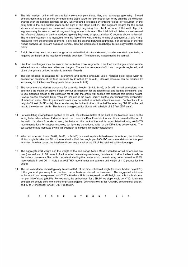
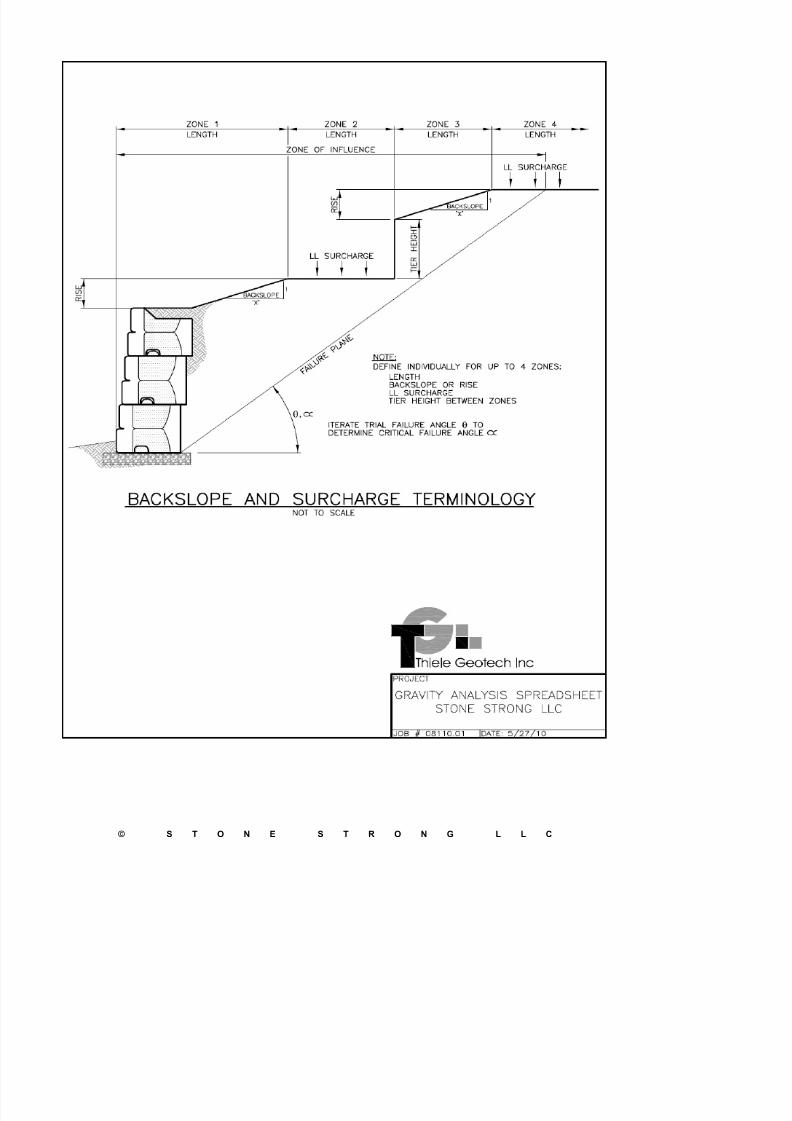
6 The trial wedge routine will automatically solve complex slope, tier, and surcharge geometry. Sloped
embankments may be defined by entering the slope value (run per foot of rise) or by entering the elevation
change over the defined segment length. Entry method is toggled by entering "slope" or "elevation" in the
entry field in the non-printed space to the right of the slope section. The segment lengths for the zoned
slopes and surcharges are measured successively beginning from the front face of the wall. Up to 4segments may be entered, and all segment lengths are horizontal. The total defined distance must exceed
the influence distance of the trial wedges, typically beginning at approximatley 30 degrees above horizontal.
The length of segment 1 is measured from the face of the wall, and the lengths of segments 2, 3, and 4 are
measured from the previous segment. Tiers may be entered between segments. For purposes of the trial
wedge analysis, all tiers are assumed vertical. See the Backslope & Surcharge Terminology sketch located
below.
7 A rigid boundary, such as a rock ledge or an embedded structural element, may be modeled by entering a
negative tier height at the location of the rigid boundary. The boundary is assumed to be vertical.
8 Live load surcharges may be entered for individual zone segments. Live load surcharges would include
vehicle loads and other intermittent surcharges. The vertical component of LL surcharges is neglected, and
LL surcharges are omitted in seismic analysis (if used).
9 The conventional calculations for overturning and contact pressure use a reduced block base width to
account for rounding of the face (reduced by 2 inches by default). Contact pressure can be reduced by
increasing the thickness of the granular base (see note #14).
10 The recommended design procedure for extended blocks (24-62, 24-86, or 24-ME) or tail extensions is to
determine the maximum gravity height without an extension for the specific soil and loading conditions, and
to use extended blocks or tail extension for at least the entire wall section that exceeds this limiting height.
Several precast extended block types are included in the Block Library, but the user should verify availabiltity
of extended units. Cast in place extensions may be added to individual block courses. For blocks with a
height of 3 feet (24SF units), the extender may be limited to the bottom half by selecting "1/2 H" in the cell
next to the extension width. This feature is neglected for blocks with a height of 1.5 feet (6SF units).
11 For calculating driving forces applied to the wall, the effective batter of the back of the blocks is taken as the
facing batter when a Mass Extender is not used, even if a Dual Face block or cap block is used at the top of
the wall. If a Mass Extender is used, the batter on the back of the wall is recalculated following AASHTO
recommendations for stepped modules, but ignoring the reduced width of the DF unit as conservative. The
soil wedge that is mobilized by the tail extension is included in stability calculations.
12 When an extended block (24-62, 24-86, or 24-ME) or a cast in place tail extension is included, the interfacefriction angle is taken as 3/4 of the retained soil friction angle per AASHTO recommendations for stepped
modules. In other cases, the interface friction angle is taken as 1/2 of the retained soil friction angle.
7/27/2019 SS Gravity Calculations 4.3
http://slidepdf.com/reader/full/ss-gravity-calculations-43 3/11
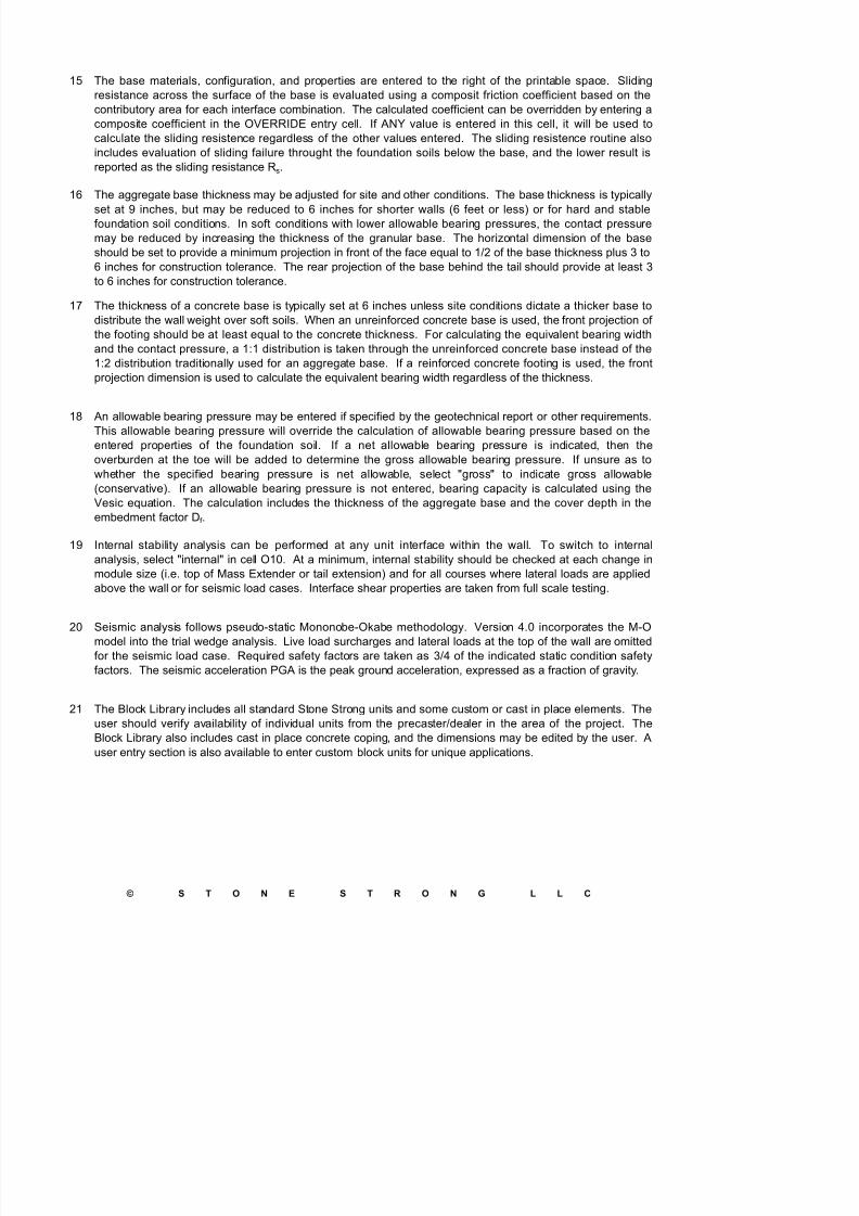
15 The base materials, configuration, and properties are entered to the right of the printable space. Sliding
resistance across the surface of the base is evaluated using a composit friction coefficient based on the
contributory area for each interface combination. The calculated coefficient can be overridden by entering a
composite coefficient in the OVERRIDE entry cell. If ANY value is entered in this cell, it will be used tocalculate the sliding resistence regardless of the other values entered. The sliding resistence routine also
includes evaluation of sliding failure throught the foundation soils below the base, and the lower result is
reported as the sliding resistance Rs.
16 The aggregate base thickness may be adjusted for site and other conditions. The base thickness is typically
set at 9 inches, but may be reduced to 6 inches for shorter walls (6 feet or less) or for hard and stable
foundation soil conditions. In soft conditions with lower allowable bearing pressures, the contact pressure
may be reduced by increasing the thickness of the granular base. The horizontal dimension of the base
should be set to provide a minimum projection in front of the face equal to 1/2 of the base thickness plus 3 to6 inches for construction tolerance. The rear projection of the base behind the tail should provide at least 3
to 6 inches for construction tolerance.
17 The thickness of a concrete base is typically set at 6 inches unless site conditions dictate a thicker base to
distribute the wall weight over soft soils. When an unreinforced concrete base is used, the front projection of
the footing should be at least equal to the concrete thickness. For calculating the equivalent bearing width
and the contact pressure, a 1:1 distribution is taken through the unreinforced concrete base instead of the
1:2 distribution traditionally used for an aggregate base. If a reinforced concrete footing is used, the front
projection dimension is used to calculate the equivalent bearing width regardless of the thickness.
18 An allowable bearing pressure may be entered if specified by the geotechnical report or other requirements.
This allowable bearing pressure will override the calculation of allowable bearing pressure based on the
entered properties of the foundation soil. If a net allowable bearing pressure is indicated, then the
overburden at the toe will be added to determine the gross allowable bearing pressure. If unsure as to
whether the specified bearing pressure is net allowable, select "gross" to indicate gross allowable
(conservative). If an allowable bearing pressure is not entered, bearing capacity is calculated using the
Vesic equation. The calculation includes the thickness of the aggregate base and the cover depth in theembedment factor Df .
19 Internal stability analysis can be performed at any unit interface within the wall. To switch to internal
analysis, select "internal" in cell O10. At a minimum, internal stability should be checked at each change in
module size (i.e. top of Mass Extender or tail extension) and for all courses where lateral loads are applied
above the wall or for seismic load cases. Interface shear properties are taken from full scale testing.
20 Seismic analysis follows pseudo-static Mononobe-Okabe methodology. Version 4.0 incorporates the M-Omodel into the trial wedge analysis. Live load surcharges and lateral loads at the top of the wall are omitted
for the seismic load case. Required safety factors are taken as 3/4 of the indicated static condition safety
7/27/2019 SS Gravity Calculations 4.3
http://slidepdf.com/reader/full/ss-gravity-calculations-43 4/11
22 The LRFD version follows the AASHTO LRFD Bridge Design Specification (5th Edition, 2010). Load and
Resistance Factor Design methodology applies separate factors to address the variability of the applied
loads, materials, and design components that provide support. The factored loads must be less than the
factored resistance to satisfy the design requirements. Specific methods, procedures, equations, and
nomenclature can be found in the LRFD Design Methodology and LRFD Example Calculations in theEngineering Manual and available on the Stone Strong web site www.StoneStrong.com.
23 A table of load and resistance factors used in the LRFD spreadsheet is included on page 2 of the program
output. These are based upon tables 3.4.1-1 and 3.4.1-2 in the AASHTO LRFD specification. Calculations
are provided for relevent load cases - Strength I (a & b variations), Strength II, Strength IV, Extreme Event I
(seismic), Extreme Event II (collision), and Service I. For this type of Precast Modular Block (PMB) system,
load cases Strength I and Extreme Event I (seismic) will typically control design. Results are summarized
for load case Strength I (relevent behaviors from a or b cases) and Extreme Event I (seismic, if applicable).Detailed calculations for all of the load cases are presented in tabular form below the summary. If these
additional calculations indicate stabiltiy problems, a flag occurs in the Results summary.
24 Lateral loads at the top of the wall are assumed to be guardrail or barrier collision loads in the LRFD analysis
(treated as live loads in conventional analysis). Collision loads are treated in Extreme Event II load case. If
the lateral load is a different type of loading, this may be investigated by editing the load factor CT and load
case designation. Note that the last 2 load case headings and the CT load factor designation are not
protected and can be edited by the user, as can all of the individual load factor values.
7/27/2019 SS Gravity Calculations 4.3
http://slidepdf.com/reader/full/ss-gravity-calculations-43 5/11
7/27/2019 SS Gravity Calculations 4.3
http://slidepdf.com/reader/full/ss-gravity-calculations-43 6/11
7/27/2019 SS Gravity Calculations 4.3
http://slidepdf.com/reader/full/ss-gravity-calculations-43 7/11
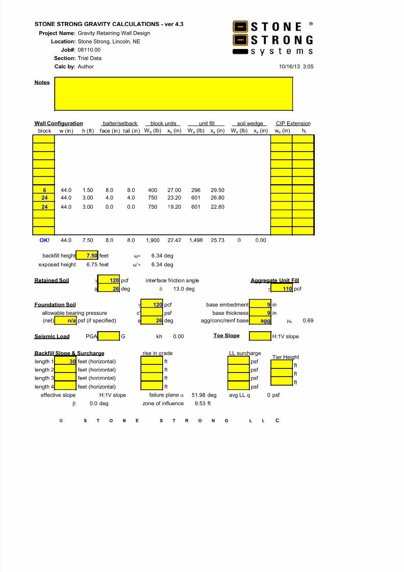
STONE STRONG GRAVITY CALCULATIONS - ver 4.3
Project Name: Gravity Retaining Wall Design
Location: Stone Strong, Lincoln, NE
Job#: 08110.00
Section: Trial DataCalc by: Author 10/16/13 3:05
Notes
Wall Configuration batter/setback block units unit fill soil wedge CIP Extension
block w (in) h (ft) face (in) tail (in) Wb (lb) xb (in) Wa (lb) xa (in) Ws (lb) xs (in) we (in) ht
6 44.0 1.50 8.0 8.0 400 27.00 296 29.50
24 44.0 3.00 4.0 4.0 750 23.20 601 26.80
24 44.0 3.00 0.0 0.0 750 19.20 601 22.80
OK! 44.0 7.50 8.0 8.0 1,900 22.42 1,498 25.73 0 0.00
backfill height 7.50 feet ω= 6.34 deg
exposed height 6.75 feet ω'= 6.34 deg
Retained Soil g 120 pcf interface friction angle Aggregate Unit Fill
f 26 deg d 13.0 deg g 110 pcf
Foundation Soil g 120 pcf base embedment 9 in
7/27/2019 SS Gravity Calculations 4.3
http://slidepdf.com/reader/full/ss-gravity-calculations-43 8/11
STONE STRONG GRAVITY CALCULATIONS - ver 4.3
Project Name: Gravity Retaining Wall Design
Location: Stone Strong, Lincoln, NE
Job#: 08110.00
Section: Trial DataCalc by: Author 10/16/13 3:05
Page 2 of 2
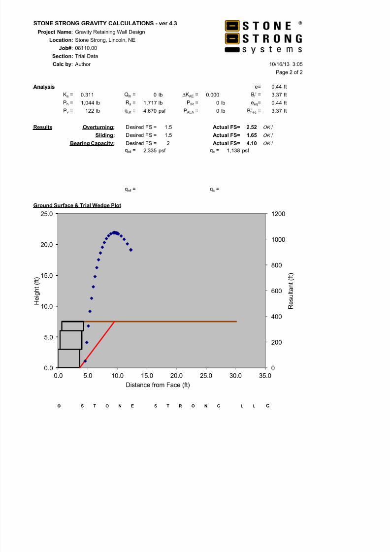
Analysis e= 0.44 ft
Ka = 0.311 Qlh = 0 lb DK AE = 0.000 Bf ' = 3.37 ft
Ph = 1,044 lb Rs = 1,717 lb PIR = 0 lb eeq= 0.44 ft
Pv = 122 lb qult = 4,670 psf P AEh = 0 lb Bf 'eq = 3.37 ft
Results Overturning: Desired FS = 1.5 Actual FS= 2.52 OK !
Sliding: Desired FS = 1.5 Actual FS= 1.65 OK !
Bearing Capacity: Desired FS = 2 Actual FS= 4.10 OK !
qall = 2,335 psf qc = 1,138 psf
qall = qc =
Ground Surface & Trial Wedge Plot
600
800
1000
1200
15.0
20.0
25.0
s u l t a n t ( f t )
e i g h t (
f t )

7/27/2019 SS Gravity Calculations 4.3
http://slidepdf.com/reader/full/ss-gravity-calculations-43 9/11
STONE STRONG GRAVITY CALCULATIONS - ver 4.3
Project Name: Gravity Retaining Wall Design
Location: Stone Strong, Lincoln, NE
Job#: 08110.00
Section: Trial DataCalc by: Author 10/16/13 3:05
Notes
Wall Configuration batter/setback block units unit fill soil wedge CIP Extension
block w (in) h (ft) face (in) tail (in) Wb (lb) xb (in) Wa (lb) xa (in) Ws (lb) xs (in) we (in) ht
6 44.0 1.50 8.0 8.0 400 29.00 296 31.50
24 44.0 3.00 4.0 4.0 750 25.20 601 28.80
24 44.0 3.00 0.0 0.0 750 21.20 601 24.80
OK! 44.0 7.50 8.0 8.0 1,900 24.42 1,498 27.73 0 0.00
backfill height 7.50 feet ω= 6.34 deg
exposed height 6.50 feet ω'= 6.34 deg
Retained Soil g 125 pcf interface friction angle Aggregate Unit Fill
f 30 deg d 15.0 deg g 110 pcf
Foundation Soil g 125 pcf base embedment 12 in
7/27/2019 SS Gravity Calculations 4.3
http://slidepdf.com/reader/full/ss-gravity-calculations-43 10/11
STONE STRONG GRAVITY CALCULATIONS - ver 4.3
Project Name: Gravity Retaining Wall Design
Location: Stone Strong, Lincoln, NE
Job#: 08110.00
Section: Trial DataCalc by: Author 10/16/13 3:05
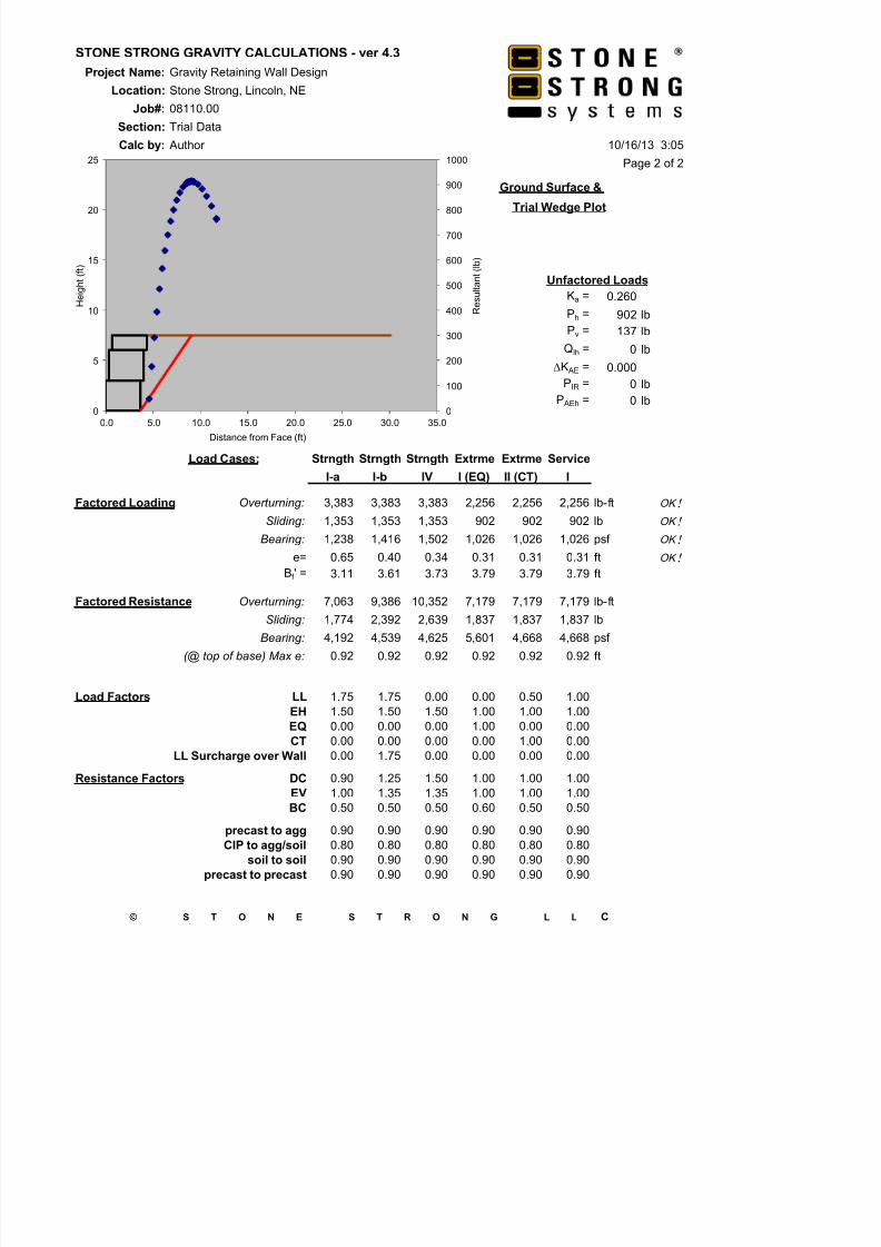
Page 2 of 2
Ground Surface &
Trial Wedge Plot
Unfactored Loads
Ka = 0.260
Ph = 902 lb
Pv = 137 lb
Qlh = 0 lb
DK AE = 0.000
PIR = 0 lbP AEh = 0 lb
Load Cases: Strngth Strngth Strngth Extrme Extrme Service
I-a I-b IV I (EQ) II (CT) I
Factored Loading Overturning: 3,383 3,383 3,383 2,256 2,256 2,256 lb-ft OK !
Sliding: 1,353 1,353 1,353 902 902 902 lb OK !
Bearing: 1,238 1,416 1,502 1,026 1,026 1,026 psf OK !
e= 0.65 0.40 0.34 0.31 0.31 0.31 ft OK !
Bf ' = 3.11 3.61 3.73 3.79 3.79 3.79 ft
Factored Resistance Overturning: 7,063 9,386 10,352 7,179 7,179 7,179 lb-ft
Sliding: 1,774 2,392 2,639 1,837 1,837 1,837 lb
Bearing: 4,192 4,539 4,625 5,601 4,668 4,668 psf (@ top of base) Max e: 0.92 0.92 0.92 0.92 0.92 0.92 ft
0
100
200
300
400
500
600
700
800
900
1000
0
5
10
15
20
25
0.0 5.0 10.0 15.0 20.0 25.0 30.0 35.0
R e s u l t a n t ( l b )
H e i g h t ( f t )
Distance from Face (ft)
7/27/2019 SS Gravity Calculations 4.3
http://slidepdf.com/reader/full/ss-gravity-calculations-43 11/11
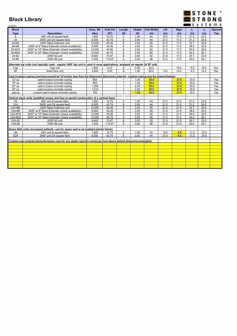
Block Librar 2/1/2011
Block Conc. Wt. Void Vol Length Height Unit Width Lift Align xc xv Special
Type Description (lbs) (ft3) (ft) (ft) (in) (in) (in) (in) (in) Top
6 6SF unit (6 square feet) 1,600 10.75 4 1.50 44 19.0 17.0 21.0 23.5
24 24SF unit (24 square feet) 6,000 43.74 8 3.00 44 21.0 17.0 21.2 24.8
24-ME 24SF Mass Extender unit 10,000 45.45 8 3.00 56 21.0 17.0 32.7 25.8
24-M6 24SF w/ 6" Mass Extender (check availability) 8,000 44.35 8 3.00 50 21.0 17.0 38.5 25.3
24-M18 24SF w/ 18" Mass Extender (check availability) 12,000 45.56 8 3.00 62 21.0 17.0 50.0 26.5
24-M24 24SF w/ 24" Mass Extender (check availability) 14,000 46.16 8 3.00 68 21.0 17.0 44.2 26.1
24-62 24SF-62 unit 6,600 75.87 8 3.00 62 21.0 17.0 29.1 33.0
24-86 24SF-86 unit 7,400 115.07 8 3.00 86 21.0 17.0 40.0 45.1
Alternate top units (not typically used - regular 24SF top unit is used in most applications, analyzed as regular 24 SF unit)
Cap Cap unit 1,600 0.00 8 0.58 32.0 16.0 16.0 16.0 Yes
DF Dual Face unit 3,500 0.00 8 1.50 28.0 14.0 14.0 14.0 14.0 Yes
Cast-in-place coping (overhang would be 19 inches less than the Alignment dimension entered - custom coping may be entered below)
12" cp cast-in-place concrete coping 604 1 1.00 50.0 27.0 25.0 Yes
18" cp cast-in-place concrete coping 906 1 1.50 50.0 27.0 25.0 Yes
24" cp cast-in-place concrete coping 1,208 1 2.00 50.0 27.0 25.0 Yes
30" cp cast-in-place concrete coping 1,510 1 2.50 50.0 27.0 25.0 Yes
coping custom cast-in-place concrete coping 755 1 1.25 50.0 27.0 25.0 Yes
Vertical stack units (modified recess and face to permit construction of a vertical face)
V6 6SF unit (6 square feet) 1,600 10.75 4 1.50 44 21.0 21.0 21.0 23.5
V24 24SF unit (24 square feet) 6,000 43.74 8 3.00 44 21.0 21.0 21.2 24.8V24-ME 24SF Mass Extender unit 10,000 45.45 8 3.00 56 21.0 21.0 32.7 25.8
V24-M6 24SF w/ 6" Mass Extender (check availability) 8,000 44.35 8 3.00 50 21.0 21.0 38.5 25.3
V24-M18 24SF w/ 18" Mass Extender (check availability) 12,000 45.56 8 3.00 62 21.0 21.0 50.0 26.5
V24-M24 24SF w/ 24" Mass Extender (check availability) 14,000 46.16 8 3.00 68 21.0 21.0 44.2 26.1
V24-62 24SF-62 unit 6,600 75.87 8 3.00 62 21.0 21.0 29.1 33.0
V24-86 24SF-86 unit 7,400 115.07 8 3.00 86 21.0 21.0 40.0 45.1
Green Wall units (increased setback - use for green wall or as isolated planter block)
G6 6SF unit (6 square feet) 1,600 10.75 4 1.50 44 19.0 -4.5 21.0 23.5
G24 24SF unit (24 square feet) 6,000 43.74 8 3.00 44 21.0 -4.5 21.2 24.8
Custom user entered elements below (use for any dealer specific variances from above default dimensions/weights)
Related Documents