SRX320 Services Gateway Hardware Guide Published 2022-05-04

Welcome message from author
This document is posted to help you gain knowledge. Please leave a comment to let me know what you think about it! Share it to your friends and learn new things together.
Transcript
SRX320 Services Gateway HardwareGuide
Published
2022-05-04

Juniper Networks, Inc.1133 Innovation WaySunnyvale, California 94089USA408-745-2000www.juniper.net
Juniper Networks, the Juniper Networks logo, Juniper, and Junos are registered trademarks of Juniper Networks, Inc.in the United States and other countries. All other trademarks, service marks, registered marks, or registered servicemarks are the property of their respective owners.
Juniper Networks assumes no responsibility for any inaccuracies in this document. Juniper Networks reserves the rightto change, modify, transfer, or otherwise revise this publication without notice.
SRX320 Services Gateway Hardware GuideCopyright © 2022 Juniper Networks, Inc. All rights reserved.
The information in this document is current as of the date on the title page.
YEAR 2000 NOTICE
Juniper Networks hardware and software products are Year 2000 compliant. Junos OS has no known time-relatedlimitations through the year 2038. However, the NTP application is known to have some difficulty in the year 2036.
END USER LICENSE AGREEMENT
The Juniper Networks product that is the subject of this technical documentation consists of (or is intended for usewith) Juniper Networks software. Use of such software is subject to the terms and conditions of the End User LicenseAgreement ("EULA") posted at https://support.juniper.net/support/eula/. By downloading, installing or using suchsoftware, you agree to the terms and conditions of that EULA.
ii

Table of Contents
About This Guide | vii
1 Overview
SRX320 Services Gateway Overview | 2
SRX320 Services Gateway Description | 2
SRX320 Services Gateway Field Replaceable Units Overview | 3
Benefits of the SRX320 Services Gateway | 3
SRX320 Chassis | 4
SRX320 Services Gateway Chassis Overview | 4
SRX320 Services Gateway Front Panel | 4
SRX320 Services Gateway Back Panel | 10
SRX320 Services Gateway Interface Modules Overview | 11
SRX320 Cooling System | 12
SRX320 Power System | 13
Understanding the SRX320 Services Gateway Power Supply | 13
SRX320 Services Gateway Power Specifications and Requirements | 14
Power Cord Specifications for SRX320 | 15
2 Site Planning, Preparation, and Specifications
SRX320 Site Preparation Checklist | 18
SRX320 Site Guidelines and Requirements | 20
SRX320 Services Gateway General Site Guidelines | 21
SRX320 Services Gateway Environmental Specifications | 21
SRX320 Services Gateway Electrical Wiring Guidelines | 22
SRX320 Services Gateway Grounding Specifications | 24
SRX320 Services Gateway Physical Specifications | 25
iii

SRX320 Services Gateway Clearance Requirements for Airflow and Hardware Maintenance | 26
Rack Requirements | 26
Cabinet Requirements | 27
SRX320 Transceiver Specifications and Pinouts | 28
SRX320 Transceiver Support | 28
RJ-45 Connector Pinouts for the SRX320 Services Gateway Ethernet Port | 28
RJ-45 Connector Pinouts for the SRX320 Services Gateway Console Port | 29
Mini-USB Connector Pinouts for the SRX320 Services Gateway Console Port | 30
3 Initial Installation and Configuration
SRX320 Installation Overview | 33
SRX320 Services Gateway Installation Overview | 33
SRX320 Services Gateway Autoinstallation Overview | 34
Unpacking and Mounting the SRX320 | 35
Unpacking the SRX320 Services Gateway | 35
Verifying Parts Received with the SRX320 Services Gateway | 36
Installing the SRX320 Services Gateway on a Desk | 37
Installing the SRX320 Services Gateway on a Wall | 37
Installing the SRX320 Services Gateway in a Rack | 40
Connecting the SRX320 to Power | 46
Required Tools and Parts for Grounding the SRX320 Services Gateway | 46
Connecting the SRX320 Services Gateway Grounding Cable | 46
Connecting the SRX320 Services Gateway to the Power Supply | 48
Powering On the SRX320 Services Gateway | 49
Powering Off the SRX320 Services Gateway | 49
Connecting the SRX320 Services Gateway to a Management Console | 50
SRX320 Services Gateway Factory-Default Settings | 51
iv

Configuring Junos OS on the SRX320 | 56
Initial Configuration Using the CLI | 57
Connect to the Serial Console Port | 57
Connect to the Mini-USB Console Port | 58
Configure the SRX320 Using the CLI | 59
Configure the SRX320 Using J-Web | 63
Perform Initial Configuration Using J-Web | 63
Manage the SRX320 Using J-Web | 64
Configure the Device Using ZTP with Juniper Networks Network Service Controller | 64
4 Maintaining Components
Maintaining the SRX320 Components | 67
Required Tools and Parts for Maintaining the SRX320 Services Gateway HardwareComponents | 67
Routine Maintenance Procedures for the SRX320 Services Gateway | 67
Maintaining the SRX320 Services Gateway Cooling System Components | 68
Maintaining the SRX320 Services Gateway Power Supply | 68
Replacing Mini-Physical Interface Modules in the SRX320 Services Gateway | 69
5 Troubleshooting Hardware
Troubleshooting the SRX320 | 71
Troubleshooting Resources for the SRX320 Services Gateway Overview | 71
Troubleshooting Chassis and Interface Alarm Messages on the SRX320 Services Gateway | 71
Troubleshooting the Power System on the SRX320 Services Gateway | 73
Using the RESET CONFIG Button | 74
Changing the RESET CONFIG Button Behavior | 75
6 Contacting Customer Support and Returning the Chassis or Components
Returning the SRX320 Chassis or Components | 77
Contacting Customer Support | 77
Returning a SRX320 Services Gateway Component to Juniper Networks | 78
v

Locating the SRX320 Services Gateway Chassis Serial Number and Agency Labels | 78
Locating the SRX320 Services Gateway Mini-Physical Interface Module Serial Number Label | 79
Listing the SRX320 Services Gateway Component Details with the CLI | 79
Required Tools and Parts for Packing the SRX320 Services Gateway | 79
Packing the SRX320 Services Gateway for Shipment | 80
Packing SRX320 Services Gateway Components for Shipment | 81
7 Safety and Compliance Information
Definitions of Safety Warning Levels | 83
General Safety Guidelines and Warnings | 84
Restricted Access Warning | 86
Qualified Personnel Warning | 87
Prevention of Electrostatic Discharge Damage | 88
Fire Safety Requirements | 89
Laser and LED Safety Guidelines and Warnings | 91
Radiation from Open Port Apertures Warning | 94
Maintenance and Operational Safety Guidelines and Warnings | 95
Action to Take After an Electrical Accident | 100
General Electrical Safety Guidelines and Warnings | 101
SRX320 Services Gateway Agency Approvals | 102
SRX320 Services Gateway Acoustic Noise Compliance Statements | 104
SRX320 Services Gateway EMC Requirements | 104
vi

About This Guide
Use this guide to install hardware and perform initial software configuration, routine maintenance, andtroubleshooting for the SRX320 Services Gateway. After completing the installation and basicconfiguration procedures covered in this guide, refer to the Junos OS documentation for informationabout further software configuration.
RELATED DOCUMENTATION
SRX320 Services Gateway Quick Start
SRX300 Series and SRX550 High Memory Gateway Interface Modules Reference
Wi-Fi Mini-PIM Installation Guide
LTE Mini-PIM and Antenna Installation Guide
Transceivers Supported on SRX320 Services Gateways
vii

1CHAPTER
Overview
SRX320 Services Gateway Overview | 2
SRX320 Chassis | 4
SRX320 Cooling System | 12
SRX320 Power System | 13

SRX320 Services Gateway Overview
IN THIS SECTION
SRX320 Services Gateway Description | 2
SRX320 Services Gateway Field Replaceable Units Overview | 3
Benefits of the SRX320 Services Gateway | 3
SRX320 Services Gateway Description
The SRX320 Services Gateway consolidates security, routing, switching, and WAN interfaces for smalldistributed enterprises. With advanced threat mitigation capabilities, the services gateway providescost-effective and secure connectivity across distributed enterprises.
With a desktop form-factor chassis, the SRX320 Services Gateway has six 1 G Ethernet ports, two 1 GSFP ports, 4 GB of DRAM memory, 8 GB of flash memory, and two Mini-Physical Interface Module(Mini-PIM) slots.
The SRX320 Services Gateway is available with or without Power over Ethernet (PoE) capability. In thePoE model. the six Ethernet ports are PoE capable.
The SRX320 Services Gateway runs the Junos operating system (Junos OS) and supports the followingfeatures:
• Firewall support with key features such as IPsec and VPN
• Intrusion Detection and Prevention (IDP)
• High availability
• QoS
• MPLS
You can manage the SRX320 Services Gateway by using the same interfaces that you use for managingother devices that run Junos OS—the CLI, the J-Web graphical interface, and Junos Space.
2

SRX320 Services Gateway Field Replaceable Units Overview
Field-replaceable units (FRUs) are components that you can replace at your site. The Mini-PhysicalInterface Module (MPIM) is the only FRU on the SRX320 Services Gateway.
The Mini-PIMs are not hot-swappable. You must power off the services gateway before removing orinstalling Mini-PIMs.
SEE ALSO
Replacing Mini-Physical Interface Modules in the SRX320 Services Gateway | 69
Benefits of the SRX320 Services Gateway
• High performance—The SRX320 supports up to 1-Gbps firewall and 300-Mbps IPsec VPN, and issuited for small distributed enterprise branch office deployments.
• Simplified deployment with minimal manual intervention—The Zero Touch Provisioning (ZTP) featureenables you to provision and configure the SRX300 line automatically, thereby reducing operationalcomplexity and simplifying the provisioning of new sites.
• Multiple WAN connectivity options—The SRX320 supports multiple options such as Ethernet, serial,T1/E1, VDSL2, and 3G/4G LTE wireless for WAN or Internet connectivity to link sites.
• Threat protection—The SRX300 line supports IPsec VPN, Media Access Control Security (MACsec),Juniper Sky Advanced Threat Prevention, and Trusted Platform Module (TPM) to protect againstpotential vulnerabilities.
RELATED DOCUMENTATION
SRX320 Installation Overview | 33
3

SRX320 Chassis
IN THIS SECTION
SRX320 Services Gateway Chassis Overview | 4
SRX320 Services Gateway Front Panel | 4
SRX320 Services Gateway Back Panel | 10
SRX320 Services Gateway Interface Modules Overview | 11
SRX320 Services Gateway Chassis Overview
The SRX320 Services Gateway chassis measures 1.73 in. high, 11.81 in. wide, and 7.52 in. deep. ThePoE model weighs 3.4 lb. and the non-PoE model weighs 3.28 lb.
CAUTION: Before removing or installing components of a functioning services gateway,attach an electrostatic discharge (ESD) strap to an ESD point and place the other end ofthe strap around your bare wrist. Failure to use an ESD strap could result in damage tothe device.
The services gateway must be connected to earth ground during normal operation. The protectiveearthing terminal on the rear of the chassis is provided to connect the services gateway to ground.
SRX320 Services Gateway Front Panel
IN THIS SECTION
Network Port LEDs | 9
4

Figure 1 on page 5 shows the front panel of the SRX320 Services Gateway.
Figure 1: SRX320 Services Gateway Front Panel
Table 1 on page 5 provides details about the front panel components.
Table 1: SRX320 Services Gateway Front Panel Components
Number Component Description
1 Reset Config button Returns the services gateway to the rescueconfiguration or the factory-default configuration.
5
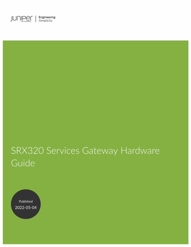
Table 1: SRX320 Services Gateway Front Panel Components (Continued)
Number Component Description
2,6 Console port • Serial—Connects a laptop to the services gatewayfor CLI management. The port uses an RJ-45 serialconnection and supports the RS-232 (EIA-232)standard.
• USB—Connects a laptop to the services gatewayfor CLI management through a USB interface. Theport accepts a Mini-B type USB cable plug. A USBcable with Mini-B and Type A USB plugs is suppliedwith the services gateway.
To use the mini-USB console port, you mustdownload a USB driver to the management devicefrom the Downloads page at https://www.juniper.net/support/downloads/?p=junos-srx#sw.
To download the driver for Windows OS, select 6.5from the Version drop-down list.
To download the driver for Mac OS, select 4.10from the Version drop-down list.
3 Mini-PIM slots Two slots for Mini-PIMs. Mini-PIMs can be used toprovide LAN and WAN functionality along withconnectivity to various media types.
4 1-GbE small form-factor pluggable(SFP) ports
Two 1-GbE MACsec-capable ports for network traffic.
6

Table 1: SRX320 Services Gateway Front Panel Components (Continued)
Number Component Description
5 1-GbE RJ-45 ports Six LAN ports (0/0 to 0/5)
The ports have the following characteristics:
• Operate in full-duplex and half-duplex modes
• Support autonegotiation
The ports can be used to:
• Function as front-end network ports
• Provide LAN and WAN connectivity to hubs,switches, local servers, and workstations
• Forward incoming data packets to the servicesgateway
• Receive outgoing data packets from the servicesgateway
7 USB port The services gateway has one USB port that accepts aUSB storage device.
8 LEDs Indicate component and system status at a glance.
9 Power button Use the Power button to power on or power off theservices gateway.
7

Figure 2 on page 8 shows the LEDs on the front panel.
Figure 2: SRX320 Services Gateway Front Panel LEDs
Table 2 on page 8 lists the front panel LEDs.
Table 2: SRX320 Services Gateway Front Panel LEDs
Component Description
ALARM • Solid amber (noncritical alarm)
• Solid red (critical alarm)
• Off (no alarms)
STAT • Solid green (operating normally)
• Solid red (error detected)
PWR • Solid green (receiving power)
• Solid red (power failure)
• Off (no power)
8

Table 2: SRX320 Services Gateway Front Panel LEDs (Continued)
Component Description
HA • Solid green (all HA links are available)
• Solid amber (some HA links are unavailable)
• Solid red (HA links are not functional)
• Off (HA is disabled)
mPIM0 and mPIM1 • Solid green (Mini-PIM is functioning normally)
• Solid red (Mini-PIM hardware failure)
• Off (Mini-PIM is not present or Mini-PIM is notdetected by the device)
Network Port LEDs
The SFP and Ethernet ports have two status LEDs, LINK and ACT, located above the port.
Table 3: Network Port LEDs
LED Description
LINK (LED on the left) • Solid green—There is link activity.
• Off—There is no link established.
ACT (LED on the right) • Blinking green—There is activity on the 1 G link.
• Off—There is no link activity.
9

SRX320 Services Gateway Back Panel
Figure 3 on page 10 shows the back panel of the SRX320 Services Gateway and Table 4 on page 10lists the components on the back panel.
Figure 3: SRX320 Services Gateway Back Panel
Table 4: SRX320 Services Gateway Back Panel Components
Number Component Description
1 Lock Provides the capability to lock andsecure the device at theinstallation site.
2 Fans Keeps all the services gatewaycomponents within the acceptabletemperature range.
3 Cable tie holder Secures the DC power cordconnection to the adapter.
4 Power supply input (DC powerinput)
Connects the services gateway tothe external power supply.
10

Table 4: SRX320 Services Gateway Back Panel Components (Continued)
Number Component Description
5 Grounding point Connects the services gatewaychassis to earth ground (optional).
NOTE: We recommendconnecting the services gatewayto ground if required.
SRX320 Services Gateway Interface Modules Overview
Mini-Physical Interface Modules (Mini-PIMs) are field-replaceable network interface cards (NICs)supported on the SRX300 line of services gateways. You can easily insert or remove Mini-PIMs from thefront slots of the services gateway chassis. The Mini-PIMs provide physical connections to a LAN or aWAN. The Mini-PIMs receive incoming packets from the network and transmit outgoing packets to thenetwork. During this process, they perform framing and line-speed signaling for the medium type.
CAUTION: The Mini-PIMs are not hot-swappable. You must power off the servicesgateway before removing or installing Mini-PIMs.
The following Mini-PIMs are supported on the SRX320 Services Gateway:
• 1-Port Serial Mini-Physical Interface Module (SRX-MP-1SERIAL-R)
• 1-Port T1/E1 Mini-Physical Interface Module (SRX-MP-1T1E1-R)
• 1-Port VDSL2 (Annex A) Mini-Physical Interface Module (SRX-MP-1VDSL2-R)
• LTE Mini-Physical Interface Module (SRX-MP-LTE-AE and SRX-MP-LTE-AA)
• Wi-Fi Mini-Physical Interface Module (SRX-MP-WLAN-US, SRX-MP-WLAN-IL, and SRX-MP-WLAN-WW)
For more information on the Mini-PIMs, see the SRX300 Series and SRX550 High Memory GatewayInterface Modules Reference.
11

RELATED DOCUMENTATION
SRX320 Installation Overview | 33
SRX320 Cooling System
The cooling system for the SRX320 Services Gateway includes two fixed fans. The fans draw air throughvents on the front of the chassis and exhaust the air through the back of the chassis. The airflowproduced by the fans keeps device components within the acceptable temperature range.
Figure 4 on page 12 shows the airflow through the chassis.
Figure 4: Airflow Through the SRX320 Services Gateway Chassis
RELATED DOCUMENTATION
SRX320 Services Gateway Clearance Requirements for Airflow and Hardware Maintenance | 26
12

SRX320 Power System
IN THIS SECTION
Understanding the SRX320 Services Gateway Power Supply | 13
SRX320 Services Gateway Power Specifications and Requirements | 14
Power Cord Specifications for SRX320 | 15
Understanding the SRX320 Services Gateway Power Supply
The power supply for the SRX320 Services Gateway is external. You must use the following powersupply adapters provided by Juniper Networks to provide power to the services gateway.
• 75 W, 12 V power supply adapter for non-PoE models
Figure 5: 75 W, 12 V Power Supply Adapter
• 280 W, 54 V power supply adapter for PoE models
Figure 6: 280 W, 54 V Power Supply Adapter
13

Each PoE port delivers a maximum power of 30 W. Because of line loss, the powered deviceconnected to a PoE port can use only 25.5 W of power. Line loss is influenced by cable length,quality, and other factors and is typically less than 16 percent of the maximum power.
SRX320 Services Gateway Power Specifications and Requirements
Table 5 on page 14 lists the power specifications for the SRX320 Services Gateway power supplyadapter.
Table 5: Power Specifications for the SRX320 Services Gateway Power Supply Adapter
Power Supply Adapter Requirement Specifications
Non-PoE model PoE model
AC input 100 to 240 VAC 100 to 240 VAC
AC input line frequency 50 to 60 Hz 50 to 60 Hz
AC system current rating 1.3 A maximum 3.25 A maximum
Maximum AC inrush current 11 A at 220 V/50 Hz (with twoMini-PIMs installed)
15 A at 220 V/50 Hz (with twoMini-PIMs installed)
WARNING: The AC power cord for the services gateway is intended for use with onlythe power supply adapter provided with the device.
SEE ALSO
SRX320 Services Gateway Electrical Wiring Guidelines | 22
14

Power Cord Specifications for SRX320
A detachable power cord is supplied with the device. The coupler is type C13 as described byInternational Electrotechnical Commission (IEC) standard 60320. The plug end of the power cord fitsinto the power source outlet that is standard for your geographical location.
NOTE: In North America, AC power cords must not exceed 4.5 meters (approximately 14.75 feet)in length, to comply with National Electrical Code (NEC) Sections 400-8 (NFPA 75, 5-2.2) and210-52 and Canadian Electrical Code (CEC) Section 4-010(3). The cords supplied with the deviceare in compliance.
Table 6 on page 15 lists the AC power cord specifications for the countries and regions listed in thetable.
Table 6: AC Power Cord Specifications
Country/Region Electrical Specifications Plug Standards Juniper Model Number
Australia 250 VAC, 10 A, 50 Hz AS/NZZS 3112 TypeSAA/3
CBL-JX-PWR-AU
China 250 VAC, 10 A, 50 Hz GB 1002-1996 TypePRC/3
CBL-JX-PWR-CH
Europe (except Italy,Switzerland, and UnitedKingdom)
250 VAC, 10 A, 50 Hz CEE (7) VII Type VIIG CBL-JX-PWR-EU
India 250 VAC, 10 A, 50 Hz IS 1293 Type IND/3 CBL-EX-PWR-C13-IN
Italy 250 VAC, 10 A, 50 Hz CEI 23-16 Type I/3G CBL-JX-PWR-IT
Japan 125 VAC, 12 A, 50 Hz or60 Hz
SS-00259 Type VCTF CBL-JX-PWR-JP
Korea 250 VAC, 10 A, 50 Hz or60 Hz
CEE (7) VII Type VIIGK CBL-JX-PWR-KR
15

Table 6: AC Power Cord Specifications (Continued)
Country/Region Electrical Specifications Plug Standards Juniper Model Number
Switzerland 250 VAC, 10 A, 50 Hz SEV 6534-2 Type 12G CBL-EX-PWR-C13-SZ
United Kingdom 250 VAC, 10 A, 50 Hz BS 1363/A Type BS89/13 CBL-JX-PWR-UK
United States 125 VAC, 13 A, 60 Hz NEMA 5-15 Type N5-15 CBL-JX-PWR-US
Figure 7 on page 16 illustrates the plug on the power cord for some of the countries or regions listed inTable 6 on page 15.
Figure 7: AC Plug Types
16
2CHAPTER
Site Planning, Preparation, andSpecifications
SRX320 Site Preparation Checklist | 18
SRX320 Site Guidelines and Requirements | 20
SRX320 Transceiver Specifications and Pinouts | 28

SRX320 Site Preparation Checklist
Table 7 on page 18 provides a checklist of tasks you need to perform when preparing a site forinstalling the SRX320 Services Gateway.
Table 7: Site Preparation Checklist for SRX320 Services Gateway Installation
Item or Task Additional Information
Environment
Verify that environmental factorssuch as temperature and humiditydo not exceed device tolerances.
"SRX320 Services Gateway Environmental Specifications" on page 21
Power
• Measure the distance betweenthe external power sources andthe device installation site.
• Locate sites for connection ofsystem grounding.
• Calculate the powerconsumption andrequirements.
"SRX320 Services Gateway Electrical Wiring Guidelines" on page 22
"SRX320 Services Gateway Power Specifications and Requirements" onpage 14
Rack Requirements
Verify that your rack meets theminimum requirements.
"SRX320 Site Guidelines and Requirements" on page 20
Rack Installation
18
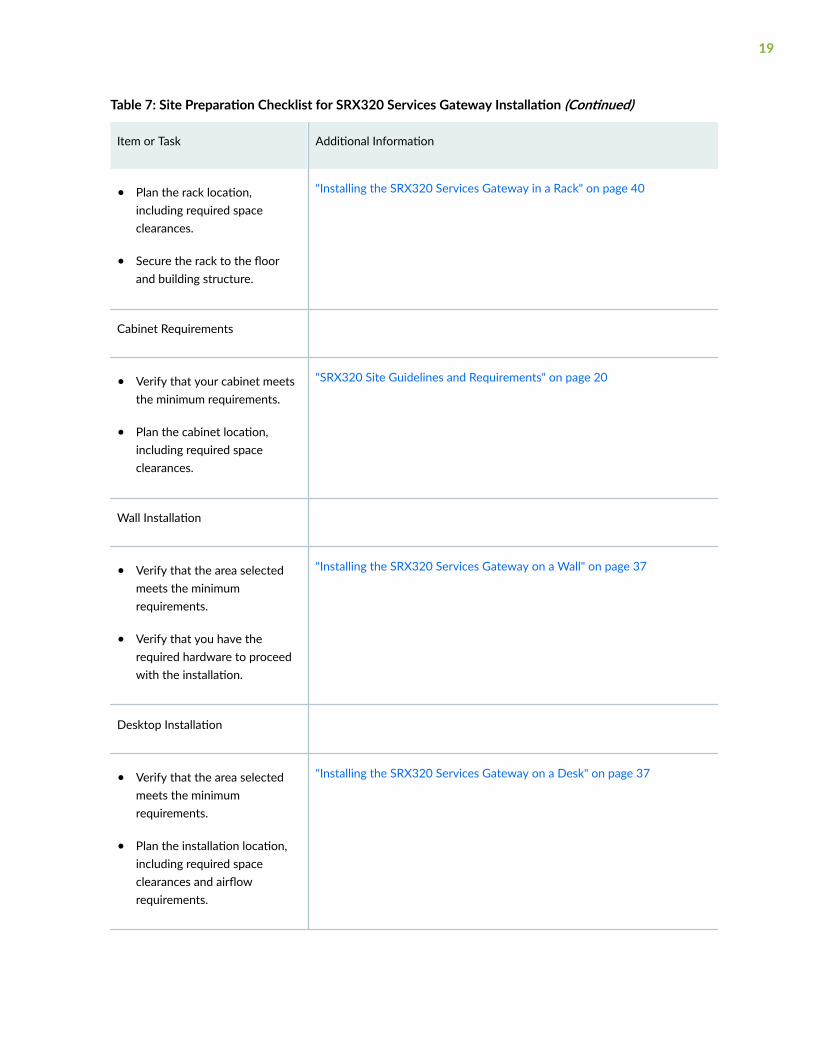
Table 7: Site Preparation Checklist for SRX320 Services Gateway Installation (Continued)
Item or Task Additional Information
• Plan the rack location,including required spaceclearances.
• Secure the rack to the floorand building structure.
"Installing the SRX320 Services Gateway in a Rack" on page 40
Cabinet Requirements
• Verify that your cabinet meetsthe minimum requirements.
• Plan the cabinet location,including required spaceclearances.
"SRX320 Site Guidelines and Requirements" on page 20
Wall Installation
• Verify that the area selectedmeets the minimumrequirements.
• Verify that you have therequired hardware to proceedwith the installation.
"Installing the SRX320 Services Gateway on a Wall" on page 37
Desktop Installation
• Verify that the area selectedmeets the minimumrequirements.
• Plan the installation location,including required spaceclearances and airflowrequirements.
"Installing the SRX320 Services Gateway on a Desk" on page 37
19

Table 7: Site Preparation Checklist for SRX320 Services Gateway Installation (Continued)
Item or Task Additional Information
Cables
• Acquire cables and connectors.
• Review the maximum distanceallowed for each cable. Choosethe length of cable based onthe distance between thehardware components beingconnected.
• Plan the cable routing andmanagement.
RELATED DOCUMENTATION
SRX320 Services Gateway General Site Guidelines | 21
SRX320 Site Guidelines and Requirements
IN THIS SECTION
SRX320 Services Gateway General Site Guidelines | 21
SRX320 Services Gateway Environmental Specifications | 21
SRX320 Services Gateway Electrical Wiring Guidelines | 22
SRX320 Services Gateway Grounding Specifications | 24
SRX320 Services Gateway Physical Specifications | 25
SRX320 Services Gateway Clearance Requirements for Airflow and Hardware Maintenance | 26
Rack Requirements | 26
20

Cabinet Requirements | 27
SRX320 Services Gateway General Site Guidelines
The following precautions help you plan an acceptable operating environment for your SRX320 ServicesGateway and avoid environmentally caused equipment failures:
• For the cooling system to function properly, the airflow around the chassis must be unrestricted.Allow sufficient clearance between the front and back of the chassis and adjacent equipment. Ensurethat there is adequate circulation in the installation location.
• Follow the ESD procedures to avoid damaging equipment. Static discharge can cause components tofail completely or intermittently over time. For more information, see Prevention of ElectrostaticDischarge Damage.
• Ensure that a blank Mini-PIM panel is installed in the empty slot to prevent any interruption orreduction in the flow of air across internal components.
SRX320 Services Gateway Environmental Specifications
Table 8 on page 21 provides the required environmental conditions for normal SRX320 ServicesGateway operations.
Table 8: Environmental Specifications for the SRX320 Services Gateway
Description Value
Altitude No performance degradation up to 10,000 ft (3048m)
Relative humidity 5% to 95%, noncondensing
21
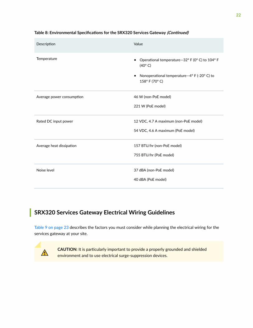
Table 8: Environmental Specifications for the SRX320 Services Gateway (Continued)
Description Value
Temperature • Operational temperature—32° F (0° C) to 104° F(40° C)
• Nonoperational temperature—4° F (-20° C) to158° F (70° C)
Average power consumption 46 W (non-PoE model)
221 W (PoE model)
Rated DC input power 12 VDC, 4.7 A maximum (non-PoE model)
54 VDC, 4.6 A maximum (PoE model)
Average heat dissipation 157 BTU/hr (non-PoE model)
755 BTU/hr (PoE model)
Noise level 37 dBA (non-PoE model)
40 dBA (PoE model)
SRX320 Services Gateway Electrical Wiring Guidelines
Table 9 on page 23 describes the factors you must consider while planning the electrical wiring for theservices gateway at your site.
CAUTION: It is particularly important to provide a properly grounded and shieldedenvironment and to use electrical surge-suppression devices.
22

Table 9: Site Electrical Wiring Guidelines for the SRX320 Services Gateway
Site Wiring Factor Guideline
Signaling Limitations To ensure that signaling functions optimally:
• Install wires correctly.
Improperly installed wires can emit radio interference.
• Do not exceed the recommended distances or pass wires betweenbuildings.
The potential for damage from lightning strikes increases if wires exceedrecommended distances or if wires pass between buildings.
• Shield all conductors.
The electromagnetic pulse (EMP) caused by lightning can damageunshielded conductors and destroy electronic devices.
Radio Frequency Interference(RFI)
To reduce or eliminate the emission of RFI from your site wiring:
• Use twisted-pair cable with a good distribution of grounding conductors.
• Use a high-quality twisted-pair cable with one ground conductor for eachdata signal when applicable, if you must exceed the recommendeddistances.
Electromagnetic Compatibility(EMC)
Provide a properly grounded and shielded environment and use electricalsurge-suppression devices.
Strong sources of electromagnetic interference (EMI) can cause the followingdamage:
• Destroy the signal drivers and receivers in the device
• Conduct power surges over the lines into the equipment, resulting in anelectrical hazard
NOTE: If your site is susceptible to problems with EMC, particularly fromlightning or radio transmitters, you may want to seek expert advice.
23
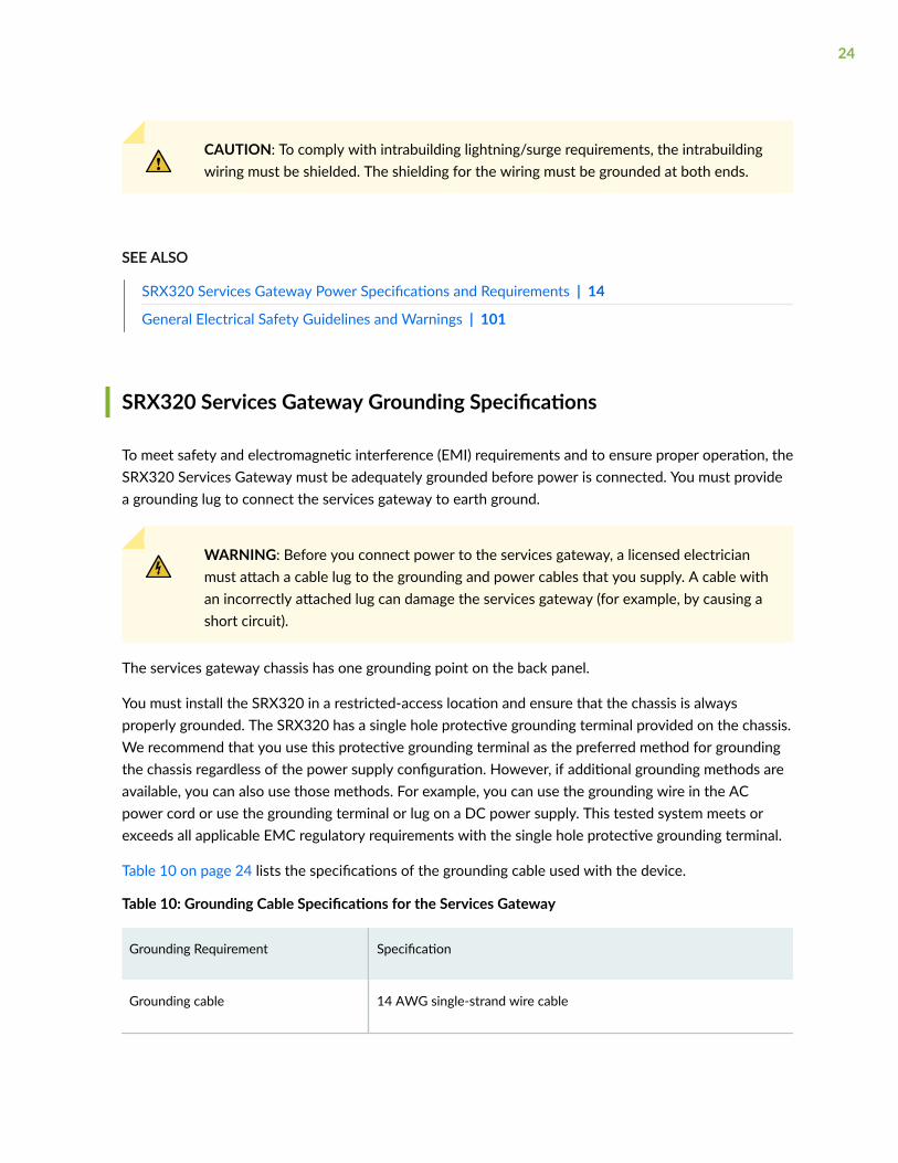
CAUTION: To comply with intrabuilding lightning/surge requirements, the intrabuildingwiring must be shielded. The shielding for the wiring must be grounded at both ends.
SEE ALSO
SRX320 Services Gateway Power Specifications and Requirements | 14
General Electrical Safety Guidelines and Warnings | 101
SRX320 Services Gateway Grounding Specifications
To meet safety and electromagnetic interference (EMI) requirements and to ensure proper operation, theSRX320 Services Gateway must be adequately grounded before power is connected. You must providea grounding lug to connect the services gateway to earth ground.
WARNING: Before you connect power to the services gateway, a licensed electricianmust attach a cable lug to the grounding and power cables that you supply. A cable withan incorrectly attached lug can damage the services gateway (for example, by causing ashort circuit).
The services gateway chassis has one grounding point on the back panel.
You must install the SRX320 in a restricted-access location and ensure that the chassis is alwaysproperly grounded. The SRX320 has a single hole protective grounding terminal provided on the chassis.We recommend that you use this protective grounding terminal as the preferred method for groundingthe chassis regardless of the power supply configuration. However, if additional grounding methods areavailable, you can also use those methods. For example, you can use the grounding wire in the ACpower cord or use the grounding terminal or lug on a DC power supply. This tested system meets orexceeds all applicable EMC regulatory requirements with the single hole protective grounding terminal.
Table 10 on page 24 lists the specifications of the grounding cable used with the device.
Table 10: Grounding Cable Specifications for the Services Gateway
Grounding Requirement Specification
Grounding cable 14 AWG single-strand wire cable
24

Table 10: Grounding Cable Specifications for the Services Gateway (Continued)
Grounding Requirement Specification
Amperage of grounding cable Up to 4 A
Grounding lug Ring-type, vinyl-insulated TV14-6R lug or equivalent
SEE ALSO
Connecting the SRX320 Services Gateway Grounding Cable | 46
SRX320 Services Gateway Physical Specifications
Table 11 on page 25 lists the physical specifications for the services gateway.
Table 11: Physical Specifications for the SRX320 Services Gateway
Physical Specification of Chassis SRX320 SRX320-PoE
Depth 7.52 in. 7.52 in.
Width 11.81 in. 11.81 in.
Height 1.73 in. 1.73 in.
Weight 3.28 lb 3.4 lb
25
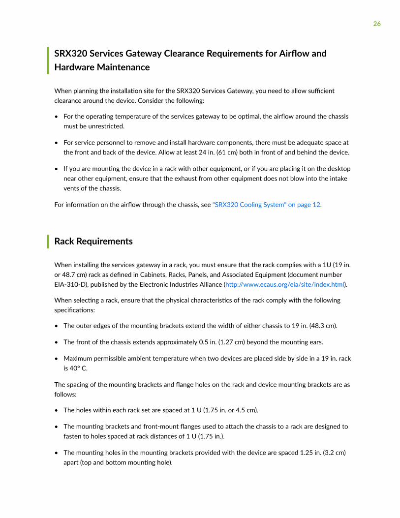
SRX320 Services Gateway Clearance Requirements for Airflow andHardware Maintenance
When planning the installation site for the SRX320 Services Gateway, you need to allow sufficientclearance around the device. Consider the following:
• For the operating temperature of the services gateway to be optimal, the airflow around the chassismust be unrestricted.
• For service personnel to remove and install hardware components, there must be adequate space atthe front and back of the device. Allow at least 24 in. (61 cm) both in front of and behind the device.
• If you are mounting the device in a rack with other equipment, or if you are placing it on the desktopnear other equipment, ensure that the exhaust from other equipment does not blow into the intakevents of the chassis.
For information on the airflow through the chassis, see "SRX320 Cooling System" on page 12.
Rack Requirements
When installing the services gateway in a rack, you must ensure that the rack complies with a 1U (19 in.or 48.7 cm) rack as defined in Cabinets, Racks, Panels, and Associated Equipment (document numberEIA-310-D), published by the Electronic Industries Alliance (http://www.ecaus.org/eia/site/index.html).
When selecting a rack, ensure that the physical characteristics of the rack comply with the followingspecifications:
• The outer edges of the mounting brackets extend the width of either chassis to 19 in. (48.3 cm).
• The front of the chassis extends approximately 0.5 in. (1.27 cm) beyond the mounting ears.
• Maximum permissible ambient temperature when two devices are placed side by side in a 19 in. rackis 40° C.
The spacing of the mounting brackets and flange holes on the rack and device mounting brackets are asfollows:
• The holes within each rack set are spaced at 1 U (1.75 in. or 4.5 cm).
• The mounting brackets and front-mount flanges used to attach the chassis to a rack are designed tofasten to holes spaced at rack distances of 1 U (1.75 in.).
• The mounting holes in the mounting brackets provided with the device are spaced 1.25 in. (3.2 cm)apart (top and bottom mounting hole).
26
Always secure the rack in which you are installing the services gateway to the structure of the building.If your geographical area is subject to earthquakes, bolt the rack to the floor. For maximum stability, alsosecure the rack to ceiling brackets.
Cabinet Requirements
You can install the services gateway in a 19 in. (48.7 cm) cabinet as defined in Cabinets, Racks, Panels,and Associated Equipment (document number EIA-310-D) published by the Electronic IndustriesAlliance (http://www.ecaus.org/eia/site/index.html). You must mount the services gateway horizontallyin the cabinet using appropriate rack adapters.
When selecting a cabinet, ensure that it meets the following specifications:
• The cabinet is at least 1U (3.50 in. or 8.89 cm) and can accommodate the services gateway.
• The outer edges of the mounting brackets extend the width of either chassis to 19 in. (48.7 cm), andthe front of the chassis extends approximately 0.5 in. (1.27 cm) beyond the mounting brackets.
• The minimum total clearance inside the cabinet is 30.7 in. (78 cm) between the inside of the frontdoor and the inside of the rear door.
NOTE: A cabinet larger than the minimum required provides better airflow and reduces thechance of overheating.
When you mount the services gateway in a cabinet, you must ensure that ventilation through thecabinet is sufficient to prevent overheating. Consider the following when planning for chassis cooling:
• Ensure that the cool air supply you provide through the cabinet can adequately dissipate the thermaloutput of the services gateway.
• Install the services gateway as close as possible to the front of the cabinet so that the cablemanagement system clears the inside of the front door. Installing the chassis close to the front of thecabinet maximizes the clearance in the rear of the cabinet for critical airflow.
• Route and dress all cables to minimize the blockage of airflow to and from the chassis.
RELATED DOCUMENTATION
SRX320 Installation Overview | 33
27

SRX320 Transceiver Specifications and Pinouts
IN THIS SECTION
SRX320 Transceiver Support | 28
RJ-45 Connector Pinouts for the SRX320 Services Gateway Ethernet Port | 28
RJ-45 Connector Pinouts for the SRX320 Services Gateway Console Port | 29
Mini-USB Connector Pinouts for the SRX320 Services Gateway Console Port | 30
SRX320 Transceiver Support
You can find information about the pluggable transceivers supported on your Juniper Networks deviceby using the Hardware Compatibility Tool. In addition to transceiver and connector type, the optical andcable characteristics—where applicable—are documented for each transceiver. The HardwareCompatibility Tool enables you to search by product, displaying all the transceivers supported on thatdevice, or category, by interface speed or type. The list of supported transceivers for the SRX320 islocated at https://apps.juniper.net/hct/product/#prd=SRX320.
RJ-45 Connector Pinouts for the SRX320 Services Gateway EthernetPort
Table 12 on page 28 describes the RJ-45 connector pinouts for the Ethernet port.
Table 12: RJ-45 Connector Pinouts for the SRX320 Services Gateway Ethernet Port
Pin Signal
1 BI_DA+
2 BI_DA
28

Table 12: RJ-45 Connector Pinouts for the SRX320 Services Gateway Ethernet Port (Continued)
Pin Signal
3 BI_DB+
4 BI_DC+
5 BI_DC
6 BI_DB
7 BI_DD+
8 BI_DD
RJ-45 Connector Pinouts for the SRX320 Services Gateway Console Port
Table 13 on page 29 describes the RJ-45 connector pinouts for the console port.
Table 13: RJ-45 Connector Pinouts for the SRX320 Services Gateway Console Port
Pin Signal Description
1 RTS Request to Send
2 DTR Data Terminal Ready
3 TXD Transmit Data
4 Ground Signal Ground
5 Ground Signal Ground
29
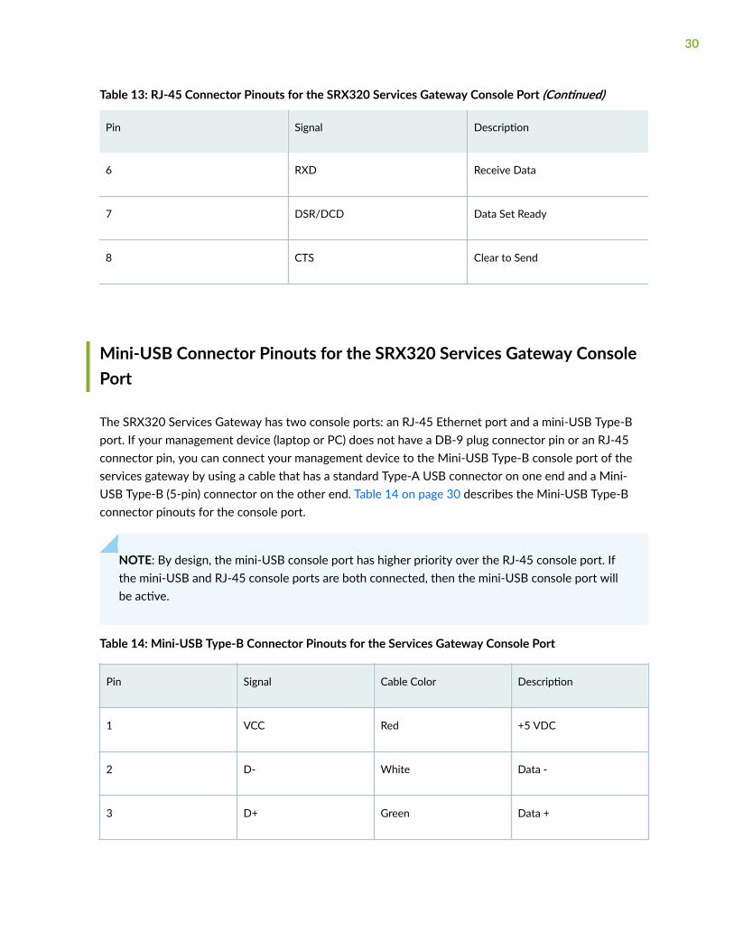
Table 13: RJ-45 Connector Pinouts for the SRX320 Services Gateway Console Port (Continued)
Pin Signal Description
6 RXD Receive Data
7 DSR/DCD Data Set Ready
8 CTS Clear to Send
Mini-USB Connector Pinouts for the SRX320 Services Gateway ConsolePort
The SRX320 Services Gateway has two console ports: an RJ-45 Ethernet port and a mini-USB Type-Bport. If your management device (laptop or PC) does not have a DB-9 plug connector pin or an RJ-45connector pin, you can connect your management device to the Mini-USB Type-B console port of theservices gateway by using a cable that has a standard Type-A USB connector on one end and a Mini-USB Type-B (5-pin) connector on the other end. Table 14 on page 30 describes the Mini-USB Type-Bconnector pinouts for the console port.
NOTE: By design, the mini-USB console port has higher priority over the RJ-45 console port. Ifthe mini-USB and RJ-45 console ports are both connected, then the mini-USB console port willbe active.
Table 14: Mini-USB Type-B Connector Pinouts for the Services Gateway Console Port
Pin Signal Cable Color Description
1 VCC Red +5 VDC
2 D- White Data -
3 D+ Green Data +
30

Table 14: Mini-USB Type-B Connector Pinouts for the Services Gateway Console Port (Continued)
Pin Signal Cable Color Description
X N/C Could be not connected(N/C), connected toground (GND), or used asan attached devicepresence indicator
4 GND Black Ground
31
3CHAPTER
Initial Installation and Configuration
SRX320 Installation Overview | 33
Unpacking and Mounting the SRX320 | 35
Connecting the SRX320 to Power | 46
Connecting the SRX320 Services Gateway to a Management Console | 50
SRX320 Services Gateway Factory-Default Settings | 51
Configuring Junos OS on the SRX320 | 56

SRX320 Installation Overview
IN THIS SECTION
SRX320 Services Gateway Installation Overview | 33
SRX320 Services Gateway Autoinstallation Overview | 34
SRX320 Services Gateway Installation Overview
After you have prepared the site for installation and unpacked the SRX320 Services Gateway, you areready to install the device. It is important to proceed through the installation process in the followingorder:
1. Review the safety guidelines explained in General Safety Guidelines and Warnings.
2. Prepare your site for the installation of the services gateway as described in "SRX320 SitePreparation Checklist" on page 18.
3. Install the services gateway. See:
• "Installing the SRX320 Services Gateway in a Rack" on page 40
• "Installing the SRX320 Services Gateway on a Desk" on page 37
• "Installing the SRX320 Services Gateway on a Wall" on page 37
4. Connect cables to external devices.
5. Connect the grounding cable as described in "Connecting the SRX320 Services Gateway GroundingCable" on page 46.
6. Power on the services gateway as described in "Powering On the SRX320 Services Gateway" onpage 49.
33

SRX320 Services Gateway Autoinstallation Overview
The autoinstallation process begins any time a services gateway is powered on and cannot locate a validconfiguration file in the internal flash. Typically, a configuration file is unavailable when a servicesgateway is powered on for the first time or if the configuration file is deleted from the internal flash. Theautoinstallation feature enables you to deploy multiple services gateways from a central location in thenetwork.
If you are setting up many devices, autoinstallation can help automate the configuration process byloading configuration files onto new or existing devices automatically over the network. You can useeither the J-Web interface or the CLI to configure a device for autoinstallation.
For the autoinstallation process to work, you must store one or more host-specific or defaultconfiguration files on a configuration server in the network and have a service available—typicallyDynamic Host Configuration Protocol (DHCP)—to assign an IP address to the services gateway.
Autoinstallation takes place automatically when you connect an Ethernet port on a new servicesgateway to the network and power on the device. To simplify the process, you can explicitly enableautoinstallation on a device and specify a configuration server, an autoinstallation interface, and aprotocol for IP address acquisition.
NOTE: If the USB autoinstallation feature is enabled (the default configuration), removal of a USBstorage device immediately after insertion is not supported.
After you insert a USB storage device, Junos OS scans the device to check whether it containsthe USB autoinstallation file. This process might take up to 50 seconds to complete dependingon the quality of the USB storage device and the number and size of the files in the device.Removing the USB storage device while this process is running might cause the services gatewayto reboot, the USB port to stop working, and data loss on the USB. We recommend that afterinserting a USB storage device, you wait for at least 60 seconds before removing it.
By issuing the set system autoinstallation usb disable command (which disables the USBautoinstallation feature) before you insert the USB device, you can reduce the waiting intervalbetween insertion and removal of a USB storage device from 60 seconds to 20 seconds.
For more information about configuring autoinstallation, see the following topics:
• Installation and Upgrade Guide for Security Devices
• Monitoring and Troubleshooting Guide
34

Unpacking and Mounting the SRX320
IN THIS SECTION
Unpacking the SRX320 Services Gateway | 35
Verifying Parts Received with the SRX320 Services Gateway | 36
Installing the SRX320 Services Gateway on a Desk | 37
Installing the SRX320 Services Gateway on a Wall | 37
Installing the SRX320 Services Gateway in a Rack | 40
Unpacking the SRX320 Services Gateway
The SRX320 Services Gateway is shipped in a cardboard carton and secured with foam packing material.The carton also contains an accessory box and quick-start instructions.
To unpack the SRX320 Services Gateway:
1. Move the cardboard carton to a staging area as close to the installation site as possible, where youhave enough room to remove the components from the chassis.
2. Position the cardboard carton with the arrows pointing up.
3. Carefully open the top of the cardboard carton.
4. Remove the foam covering the top of the services gateway.
5. Remove the accessory box.
6. Verify the parts received against the lists in "Verifying Parts Received with the SRX320 ServicesGateway" on page 36.
7. Store the brackets and bolts inside the accessory box.
8. Save the shipping carton and packing materials in case you need to move or ship the servicesgateway at a later time.
35

Verifying Parts Received with the SRX320 Services Gateway
The SRX320 Services Gateway shipment package contains a packing list. Check the parts in theshipment against the items on the packing list. The packing list specifies the part numbers and carries abrief description of each part in your order.
If any part is missing, contact a customer service representative.
A fully configured services gateway contains the chassis with installed components, listed in Table 15 onpage 36, and an accessory box, which contains the parts listed in Table 16 on page 37.
NOTE: The parts shipped with your services gateway can vary depending on the configurationyou ordered. To know the part numbers for ordering the separately orderable mounting kits, seethe SRX300 Line of Services Gateways for the Branch Platform Datasheet.
Table 15: Parts List for a Fully Configured SRX320 Services Gateway
Component Quantity
SRX320 services gateway 1
CAT5E cable 1
DB9-to-RJ45 adapter 1
USB console cable with Type-A and Mini-B USB plugs 1
Documentation Roadmap and Product Warranty 1
Power supply adapter and power cord
• 75 W, 12 V power supply adapter for non-PoE models
• 280 W, 54 V power supply adapter for PoE models
1
36

Table 16: Accessory/Upgrade Parts List for the SRX320 Services Gateway
Part Quantity
End User License Agreement 1
RoHS Card 1
Installing the SRX320 Services Gateway on a Desk
You can mount an SRX320 Services Gateway on a desk or any other level surface horizontally orvertically. The four rubber feet attached to the chassis provide stability. Before mounting an SRX320Services Gateway on a desk or other level surface:
• Verify that the installation site meets the requirements described in "SRX320 Site PreparationChecklist" on page 18.
• Place the desk in its permanent location, allowing adequate clearance for airflow and maintenance,and secure it to the building structure.
The horizontal position is the standard installation position. To install the device in a horizontal position:
1. Make sure that the rubber feet are attached to the chassis.
2. Place the device on a desk with the Juniper Networks logo, which is embossed on the top cover,facing up.
NOTE: For information on installing Mini-Physical Interface Modules (Mini-PIMs), see SRX300Series and SRX550 High Memory Services Gateway Interface Modules Reference.
Installing the SRX320 Services Gateway on a Wall
You can mount an SRX320 Services Gateway on a wall. The four rubber feet attached to the chassisprovide stability. Before mounting the SRX320 Services Gateway on a wall:
• Verify that the installation site meets the requirements described in "SRX320 Site PreparationChecklist" on page 18.
37

• Verify that you have the following parts available in your wall-mounting kit:
• Wall-mounting brackets
• Screws
NOTE: The wall-mounting kit is not shipped with the device and must be ordered separately.
To install the device on a wall:
1. Place the device on a flat, level surface with the Juniper Networks logo, which is embossed on thetop cover, facing up. Ensure that the rubber feet are attached to the bottom of the chassis.
2. Position a mounting bracket on each side of the chassis as shown in Figure 8 on page 38.
Figure 8: Attaching Wall-Mount Brackets
3. Use a number-2 Phillips screwdriver to install the screws that secure the mounting brackets to thechassis.
4. If you are using wall anchors to support the chassis, install two pairs of anchors on the wall with themounting brackets attached.
5. Have one person grasp the sides of the device, lift it, and position it on the wall.
38
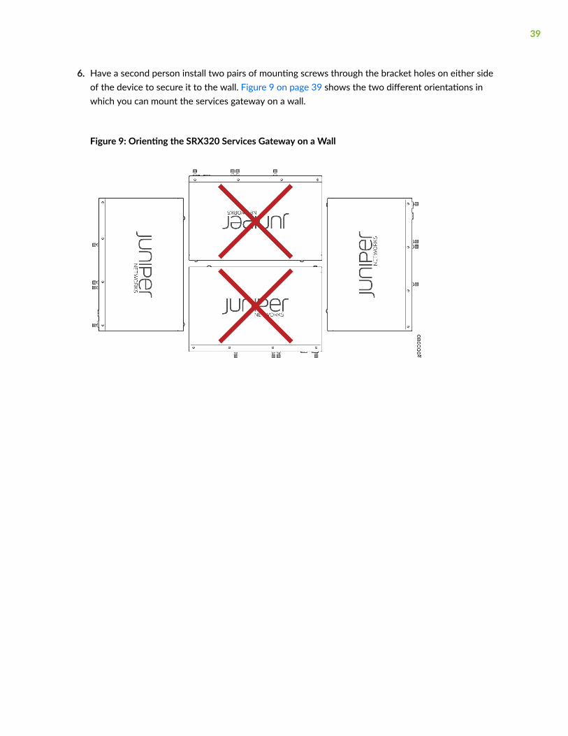
6. Have a second person install two pairs of mounting screws through the bracket holes on either sideof the device to secure it to the wall. Figure 9 on page 39 shows the two different orientations inwhich you can mount the services gateway on a wall.
Figure 9: Orienting the SRX320 Services Gateway on a Wall
39
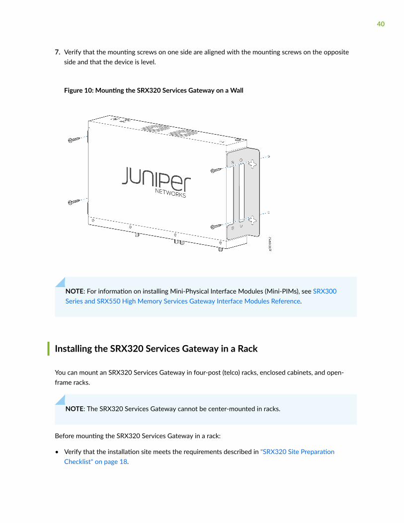
7. Verify that the mounting screws on one side are aligned with the mounting screws on the oppositeside and that the device is level.
Figure 10: Mounting the SRX320 Services Gateway on a Wall
NOTE: For information on installing Mini-Physical Interface Modules (Mini-PIMs), see SRX300Series and SRX550 High Memory Services Gateway Interface Modules Reference.
Installing the SRX320 Services Gateway in a Rack
You can mount an SRX320 Services Gateway in four-post (telco) racks, enclosed cabinets, and open-frame racks.
NOTE: The SRX320 Services Gateway cannot be center-mounted in racks.
Before mounting the SRX320 Services Gateway in a rack:
• Verify that the installation site meets the requirements described in "SRX320 Site PreparationChecklist" on page 18.
40

• Verify that the racks or cabinets meet the specific requirements described in SRX320 ServicesGateway Rack-Mounting Requirements and Warnings.
• Place the rack or cabinet in its permanent location, allowing adequate clearance for airflow andmaintenance, and secure it to the building structure. For more information, see "SRX320 ServicesGateway Clearance Requirements for Airflow and Hardware Maintenance" on page 26.
• Verify that you have the following parts available in your rack-mounting kit:
• Rack-mount tray
• Screws
NOTE: The rack-mounting kit is not shipped with the device and must be ordered separately.
NOTE: If you are installing multiple devices in one rack, install the lowest one first and proceedupward in the rack. Ensure that the rubber feet from the base of the chassis are removed for rackinstallation.
To install the device in a rack:
41

1. Position a mounting bracket on each side of the chassis as shown in Figure 11 on page 42 andFigure 12 on page 42.
Figure 11: Positioning the Mounting Brackets (75 W Power Supply Adapter)
Figure 12: Positioning the Mounting Brackets (280 W Power Supply Adapter)
2. Use a number-2 Phillips screwdriver to install the screws that secure the mounting brackets andpower supply adapter tray to the chassis as shown in Figure 13 on page 42.
Figure 13: Securing the Mounting Brackets
3. Place the power supply adapter in the tray as shown in Figure 14 on page 43.
42
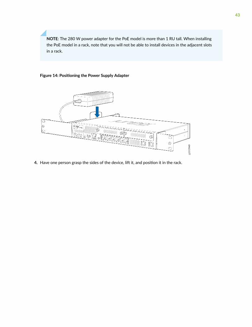
NOTE: The 280 W power adapter for the PoE model is more than 1 RU tall. When installingthe PoE model in a rack, note that you will not be able to install devices in the adjacent slotsin a rack.
Figure 14: Positioning the Power Supply Adapter
4. Have one person grasp the sides of the device, lift it, and position it in the rack.
43

5. Align the bottom hole in each mounting bracket with a hole in each rack rail as shown in Figure 15 onpage 44 and Figure 16 on page 45, making sure the chassis is level.
Figure 15: Positioning the SRX320 Services Gateway (PoE Model with 280 W Power SupplyAdapter) in a Rack
44
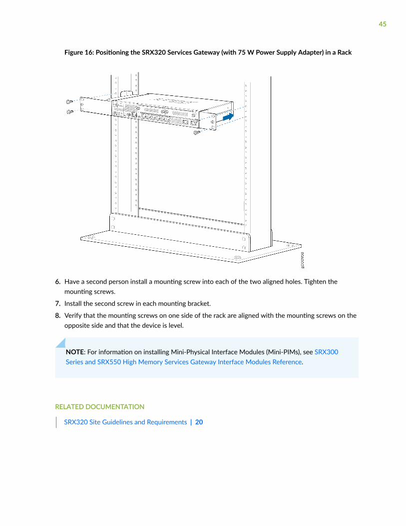
Figure 16: Positioning the SRX320 Services Gateway (with 75 W Power Supply Adapter) in a Rack
6. Have a second person install a mounting screw into each of the two aligned holes. Tighten themounting screws.
7. Install the second screw in each mounting bracket.
8. Verify that the mounting screws on one side of the rack are aligned with the mounting screws on theopposite side and that the device is level.
NOTE: For information on installing Mini-Physical Interface Modules (Mini-PIMs), see SRX300Series and SRX550 High Memory Services Gateway Interface Modules Reference.
RELATED DOCUMENTATION
SRX320 Site Guidelines and Requirements | 20
45

Connecting the SRX320 to Power
IN THIS SECTION
Required Tools and Parts for Grounding the SRX320 Services Gateway | 46
Connecting the SRX320 Services Gateway Grounding Cable | 46
Connecting the SRX320 Services Gateway to the Power Supply | 48
Powering On the SRX320 Services Gateway | 49
Powering Off the SRX320 Services Gateway | 49
Required Tools and Parts for Grounding the SRX320 Services Gateway
To ground and to provide power to the services gateway, you need the following tools:
• Phillips (+) screwdrivers, numbers 1 and 2
• Electrostatic discharge (ESD) grounding wrist strap
• Wire cutters
Connecting the SRX320 Services Gateway Grounding Cable
You ground the services gateway by connecting a grounding cable to earth ground and then attaching itto the chassis grounding point located on the back panel of the device using one M4 grounding screw.You must install the SRX320 in a restricted-access location and ensure that the chassis is alwaysproperly grounded. The SRX320 has a single-hole protective grounding terminal provided on the chassis.See Figure 17 on page 47. We recommend that you use this protective grounding terminal as thepreferred method for grounding the chassis regardless of the power supply configuration. However, ifadditional grounding methods are available, you can also use those methods. For example, you can usethe grounding wire in the AC power cord or use the grounding terminal or lug on a DC power supply.This tested system meets or exceeds all applicable EMC regulatory requirements with the single-holeprotective grounding terminal.
You must provide the following items:
46

• M4 grounding screw
• Grounding cables
• Cable lugs (for example, Panduit LCC6-10A-L)
CAUTION: Before you connect power to the services gateway, a licensed electricianmust attach a cable lug to the grounding and power cables that you supply. A cable withan incorrectly attached lug can damage the services gateway (for example, by causing ashort circuit).
To ground the device:
1. Attach an electrostatic discharge (ESD) grounding strap to your bare wrist, and connect the strap tothe ESD point on the chassis. For more details, see Prevention of Electrostatic Discharge Damage.
2. Ensure that all grounding surfaces are clean and brought to a bright finish before groundingconnections are made.
3. Connect the grounding cable to a proper earth ground.
4. Place the grounding cable lug over the grounding point (sized for M4 grounding screws) on the rearof the chassis.
5. Secure the grounding cable lug to the grounding point, first with the washer, then with the screw.Apply between 6 in.-lb (0.67 Nm) and 8 in.-lb (0.9 Nm) of torque to the screw.
6. Dress the grounding cable and verify that it does not touch or block access to the services gatewaycomponents and that it does not drape where people could trip on it.
Figure 17: Connecting the SRX320 Services Gateway Grounding Cable
47
NOTE: The device should be permanently connected to ground during operation.
SEE ALSO
SRX320 Services Gateway Grounding Specifications | 24
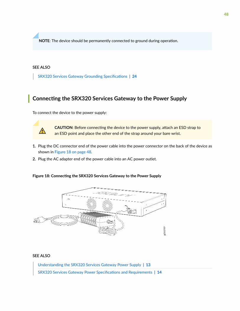
Connecting the SRX320 Services Gateway to the Power Supply
To connect the device to the power supply:
CAUTION: Before connecting the device to the power supply, attach an ESD strap toan ESD point and place the other end of the strap around your bare wrist.
1. Plug the DC connector end of the power cable into the power connector on the back of the device asshown in Figure 18 on page 48.
2. Plug the AC adapter end of the power cable into an AC power outlet.
Figure 18: Connecting the SRX320 Services Gateway to the Power Supply
SEE ALSO
Understanding the SRX320 Services Gateway Power Supply | 13
SRX320 Services Gateway Power Specifications and Requirements | 14
48
Powering On the SRX320 Services Gateway
To power on the services gateway:
1. Ensure that you have connected the power supply to the device.
2. Insert the plug of the power supply adapter into an AC power source receptacle.
3. Turn on the power to the AC power receptacle.
The device starts automatically as the power supply completes its startup sequence. The PWR LEDlights during startup and remains on when the device is operating normally.
NOTE: After the power supply is turned on, it can take up to 60 seconds for status indicators—such as the STAT and PWR LEDs—to show that the power supply is functioning normally. Ignoreerror indicators that appear during the first 60 seconds.
NOTE: When the system is completely powered off and you turn on the power supply, thedevice starts as the power supply completes its startup sequence. If the device finishes startingand you need to power off the system again, first issue the CLI request system power-off command.
Powering Off the SRX320 Services Gateway
You can power off the services gateway in one of the following ways:
• Graceful shutdown—Press and immediately release the Power button. The device begins gracefullyshutting down the operating system and then powers itself off.
CAUTION: Use the graceful shutdown method to power off or reboot the servicesgateway.
• Forced shutdown—Press the Power button and hold it for ten seconds. The device immediatelypowers itself off without shutting down the operating system.
49
CAUTION: Use the forced shutdown method as a last resort to recover the servicesgateway if the services gateway operating system is not responding to the gracefulshutdown method.
WARNING: Do not press the Power button while the device is shutting down.
CAUTION: Forced shutdown can result in data loss and corruption of the file system.
NOTE: To remove power completely from the device, unplug the power cord or switch off theAC power source.
After powering off a power supply, wait at least 10 seconds before turning it back on. Afterpowering on a power supply, wait at least 10 seconds before turning it off.
The power button on the services gateway is a standby power switch, which will not turn off theinput power to the services gateway.
TIP: When you are powering off the device, the CLI displays the following message: Turning thesystem power off. You can now safely remove the power cable to completely power off the device.
NOTE: You can use the request system reboot CLI command to schedule a reboot.
Connecting the SRX320 Services Gateway to aManagement Console
Use the CONSOLE port on the services gateway to connect to a management console.
To connect the SRX320 Services Gateway to a management console, use an RJ-45 cable:
50

1. Attach an electrostatic discharge (ESD) grounding strap to your bare wrist, and connect the strap toone of the ESD points on the chassis.
2. Plug the RJ-45 end of the cable into the CONSOLE port on the SRX320 Services Gateway as shownin Figure 19 on page 51.
Figure 19: Connecting the SRX320 Services Gateway to a Management Console
3. Connect the other end of the Ethernet cable to the supplied DB-9 adapter, which then connects tothe serial port on the management device (serial port settings: 9600-N-1).
NOTE: Alternately, you can use the USB cable to connect to the mini-USB console port onthe services gateway. To use the mini-USB console port, you must download a USB driver tothe management device from the Downloads page. To download the driver for Windows OS,select 6.5 from the Version drop-down list. To download the driver for Mac OS, select 4.10from the Version drop-down list.
SRX320 Services Gateway Factory-Default Settings
IN THIS SECTION
How to Load and View Factory-Default Settings | 53
51
Plug and Play for Cloud-Based Provisioning | 54
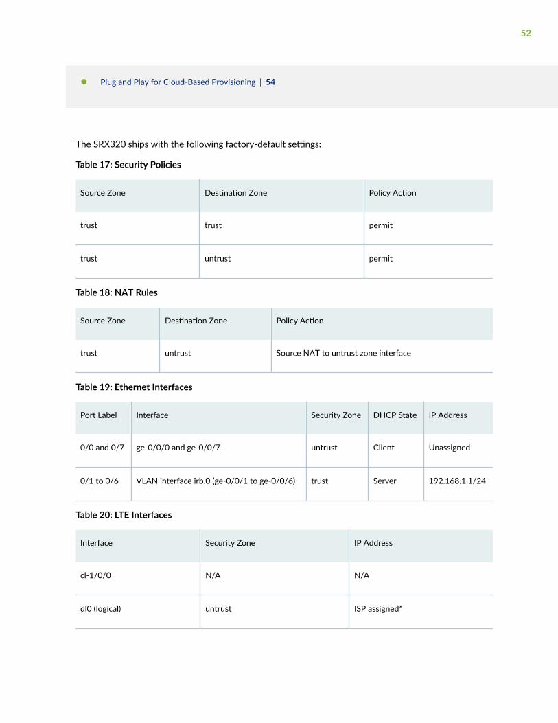
The SRX320 ships with the following factory-default settings:
Table 17: Security Policies
Source Zone Destination Zone Policy Action
trust trust permit
trust untrust permit
Table 18: NAT Rules
Source Zone Destination Zone Policy Action
trust untrust Source NAT to untrust zone interface
Table 19: Ethernet Interfaces
Port Label Interface Security Zone DHCP State IP Address
0/0 and 0/7 ge-0/0/0 and ge-0/0/7 untrust Client Unassigned
0/1 to 0/6 VLAN interface irb.0 (ge-0/0/1 to ge-0/0/6) trust Server 192.168.1.1/24
Table 20: LTE Interfaces
Interface Security Zone IP Address
cl-1/0/0 N/A N/A
dl0 (logical) untrust ISP assigned*
52

Table 20: LTE Interfaces (Continued)
Interface Security Zone IP Address
*Only if the LTE Mini-PIM is present
The SRX320 ships with the following services and protocols enabled by default:
Table 21: Services, Protocols, and Startup Mode
Services Protocols Device Startup Mode
SSH
HTTPS
NETCONF over SSH
RSTP (all interfaces) Switching
To provide secure traffic, a basic set of screens are configured on the untrust zone. In addition, thedefault security policy blocks traffic that originates from any untrust zone interface from passing to thetrust zone.
How to Load and View Factory-Default Settings
Your device ships with a set of factory-default configuration files. To view the factory-default settings onyour device:
1. Log in as the root user and provide your credentials.
2. View the full list of default configuration files for various hardware platforms:
user@host> file list /etc/config
3. To display the contents of a specific default configuration file:
user@host> file show /etc/config/<config file name>
53

When you commit changes to the configuration, a new configuration file is created, which becomes theactive configuration. You can always load a fresh factory-default configuration with the load factory-default configuration mode command to revert to the factory-default configuration. The Junos softwareselects the correct default configuration for the hardware platform when you issue the load factory-default configuration command.
You use the show configuration operational mode command, or simply the show command when inconfiguration mode, to view the settings.
NOTE: You can also load a factory default configuration using the front panel RESET CONFIGbutton. See "Using the RESET CONFIG Button on the SRX320 Services Gateway" on page 74.
Plug and Play for Cloud-Based Provisioning
This section shows you how to leverage the SRX320 factory defaults for Plug and Play Internetconnectivity. You use this connectivity to remotely manage and configure the SRX320, either manuallyor through a cloud-based provisioning service.
Follow these steps to quickly get your SRX320 on the Internet to access cloud-based provisioningservices such as Juniper Mist Cloud or Contrail Service Orchestration (CSO). The Plug and Playconnectivity of the SRX320 with a factory default configuration is shown below.
54

1. Connect the WAN network to port 0/0 (ge-0/0/0). In the default configuration the ge-0/0/0 is yourWAN interface. In the default configuration this interface is placed in the untrust zone and isconfigured as a DHCP client. These settings allow the SRX to receive an IP address and default routefrom the service provider.
2. Configure your LAN clients (PCs, notebooks, APs, etc.) for DHCP address assignment. Attach thesedevices to any of the LAN ports from 0/1 through 0/6 (ge-0/0/1 through ge-0/0/6). That's it, you'redone!
In the default configuration the LAN ports are configured in a trust VLAN with an associated IRBinterface. DHCP services are provided to the trust VLAN through that IRB interface, which is alsoplaced into the trust zone. The result is that all LAN ports share a common IP subnet with full Layer 2(untagged) connectivity through the SRX. At Layer 3, the IRB interface associates the LAN with a192.168.1.0/24 subnet, with the 192.168.1.1 address reserved for itself.
The LAN devices are assigned an IP address and default gateway from the 192.168.1.0/24 subnetthrough DHCP.
3. Verify that the SRX320 is providing Internet connectivity. Open a browser on a device attached to aLAN port and point it to http://www.juniper.net. If the page doesn’t load, check the Internetconnection.
To isolate any faults, try these steps:
• Power cycle the WAN modem. Verify the modem is correctly connecting to the service provider.
• Ping an Internet destination from the SRX320 using the CLI to test internet connectivity. Makesure the destination is allowed to reply to pings, and try using both a name and IP address toisolate DNS from connectivity issues.
• Generate a ping from a LAN device to the 192.168.1.1 address assigned to the IRB interface onthe SRX. A successful reply validates DHCP and Layer 2 connectivity between the LAN devicesand the SRX.
• Use the show dhcp server binding command to check the LAN side DHCP server addressassignments.
At this point, both the SRX320 and the LAN devices have Internet access. The default policy permitsall traffic from the trust to untrust zone. The default policy also perform SNAT on traffic leaving theWAN. By default all response traffic is allowed back from the untrust to the trust zone. Traffic thatoriginates in the untrust (WAN) zone is blocked from the trust zone. HTTPS, TFTP, and DHCP trafficis allowed to originate from the untrust zone and be sent to the local host.
You are able to access the SRX using J-Web to perform initial configuration both locally and remotely.For local access, use a machine attached to a LAN port and point your browser to https://191.168.1.1. To access remotely, over the WAN interface, you need to know the IP address assignedto the SRX by the WAN provider. See The J-Web Setup Wizard for details on performing initial setup
55
using J-Web setup wizard. You can always access the SRX320 locally using the console port toperform additional configuration. Refer to SRX320 Day One+ for details on using the CLI for initialconfiguration.
NOTE: In the default configuration a password is not needed to access the SRX320 using J-Web, either locally or remotely. You should either adopt the SRX into a cloud provisioningservice, or manually configure a root password (using J-Web or the Junos CLI), as soon aspossible after attaching your SRX to the Internet.
Configuring Junos OS on the SRX320
IN THIS SECTION
Initial Configuration Using the CLI | 57
Configure the SRX320 Using J-Web | 63
Configure the Device Using ZTP with Juniper Networks Network Service Controller | 64
The SRX320 Services Gateway is shipped with the Juniper Networks Junos operating system (Junos OS)preinstalled and is ready to be configured when the SRX320 is powered on. You can perform the initialsoftware configuration of the SRX320 by using one of the following methods:
• Command-line interface (CLI)
• Zero touch provisioning (ZTP) with a cloud-based provisioning service
• J-Web GUI
Before you configure your new SRX320, we recommend that you understand the factory-defaultconfiguration. In many cases you are able to leverage the factory defaults to simplify your configurationtasks. In other cases, you might find it easier to start with a blank configuration when you find that thedefaults don't align with your planned usage. See "SRX320 Services Gateway Factory-Default Settings"on page 51 for details on the factory-default configuration.
56

Initial Configuration Using the CLI
IN THIS SECTION
Connect to the Serial Console Port | 57
Connect to the Mini-USB Console Port | 58
Configure the SRX320 Using the CLI | 59
You can use either the serial or the mini-USB console port on the device.
Connect to the Serial Console Port
To connect to the serial console port:
1. Plug one end of the Ethernet cable into the RJ-45 to DB-9 serial port adapter supplied with yourSRX320.
2. Plug the RJ-45 to DB-9 serial port adapter into the serial port on the management device.
3. Connect the other end of the Ethernet cable to the serial console port on the SRX320.
Figure 20: Connect to the Console Port on the SRX320
4. Start your asynchronous terminal emulation application (such as Microsoft Windows HyperTerminal)and select the appropriate COM port to use (for example, COM1).
5. Configure the serial port settings with the following values:
57

• Baud rate—9600
• Parity—N
• Data bits—8
• Stop bits—1
• Flow control—none
Connect to the Mini-USB Console Port
To connect to the mini-USB console port:
1. Download the USB driver to the management device from the Downloads page. To download thedriver for Windows OS, select 6.5 from the Version drop-down list. To download the driver formacOS, select 4.10 from the Version drop-down list.
2. Install the USB console driver software:
NOTE: Install the USB console driver software before attempting to establish a physicalconnection between the SRX320 and the management device, otherwise the connection willfail.
a. Copy and extract the .zip file to your local folder.
b. Double-click the .exe file. The installer screen appears.
c. Click Install.
d. Click Continue Anyway on the next screen to complete the installation.
If you chose to stop the installation at any time during the process, then all or part of the softwarewill fail to install. In such a case, we recommend that you uninstall the USB console driver andthen reinstall it.
e. Click OK when the installation is complete.
3. Plug the large end of the USB cable supplied with the SRX320 into a USB port on the managementdevice.
4. Connect the other end of the USB cable to the mini-USB console port on the SRX320.
5. Start your asynchronous terminal emulation application (such as Microsoft Windows HyperTerminal)and select the new COM port installed by the USB console driver software. In most cases, this is thehighest-numbered COM port in the selection menu.
You can locate the COM port under Ports (COM & LPT) in Windows Device Manager after the driveris installed and initialized. This might take several seconds.
58

6. Configure the port settings with the following values:
• Bits per second—9600
• Parity—None
• Data bits—8
• Stop bits—1
• Flow control—None
7. If you have not already done so, power on the SRX320 by pressing the Power button on the frontpanel. Verify that the PWR LED on the front panel turns green.
The terminal emulation screen on your management device displays the startup sequence. When theSRX320 has finished starting up, a login prompt appears.
Configure the SRX320 Using the CLI
This section assumes you are performing initial configuration of a new SRX320 running a factory defaultconfiguration. We show you how to leverage the defaults to quickly get the SRX320 on the internet andable to be managed locally or remotely. See "SRX320 Services Gateway Factory-Default Settings" onpage 51 for details on the SRX320 factory defaults.
For this section, however, we assume the service provider does not support DHCP address assignmenton the WAN interface. This allows us to show you how to configure an interface and static route usingthe Junos CLI.
To perform initial configuration on the SRX320 using the CLI:
1. Login as the root user and start the CLI. No password is needed when running the factory default.
login: rootroot@% cliroot>
NOTE: You can view the current configuration, whether factory-default or not, by using theshow configuration operational mode command.
59

2. Enter configuration mode.
root> configure[edit]root#
3. Remove the ZTP configuration and set the root user authentication.
The ZTP configuration is not needed when performing the initial configuration using the CLI.Removing the ZTP configuration stops the periodic log messages that report the ZTP status on theconsole.
Set the root authentication password using a cleartext value. You cannot commit the change thatdeactivates ZTP unless you also set the root password.
[edit]root# delete chassis auto-image-upgraderoot# delete system phone-home root# set system root-authentication plain-text-passwordNew password: password Retype new password: password
4. Commit the configuration to activate the changes that removed ZTP and configured the rootpassword.
[edit]root# commit
5. Configure the management interface. Given the factory default settings, we recommend using thege-0/0/0 interface for remote management of the SRX320 over the WAN network. You can alsolocally manage the SRX320 using one of the LAN ports (ge-0/0/1 through ge-0/0/6).
If the WAN service provider supports DHCP IP address assignment you skip this step and let thefactory default settings work for you. In this example, the Internet provider requires a static IPaddress configuration. You must remove the default DHCP client setting in order to configure the IPaddress manually.
[edit]root# delete interfaces ge-0/0/0 unit 0 family inet dhcproot# set interfaces ge-0/0/0 unit 0 family inet address ip_address/mask
6. If the WAN service provider supports DHCP assignment of a default route you skip this step and letthe factory default settings work for you. In this example, the Internet provider does not support
60

DHCP. Therefore, you configure a static default route to provide the management interface. Thisroute is used to reach remote destinations, such as a cloud provisioning service or the remotemanagement station.
[edit]root# set routing-options static route 0.0.0.0/0 next-hop wan_gateway_ip_address
7. Enable the SSH protocol for remote access. By default, the root user cannot login remotely. Youalso enable root login over SSH in this step.
[edit]root# set system services ssh root-login allow
8. Enable SSH host support for the ge-0/0/0 interface. Recall that in the default configuration thege-0/0/0 interface is in the untrust zone, and that the untrust zone does not support host boundSSH.
[edit]root# set security zones security-zone untrust interfaces ge-0/0/0.0 host-inbound-traffic system-services ssh
9. Configure the hostname.
[edit]root# set system host-name hostname
10. (Optional) Configure domain name resolution, the time zone, and an NTP-based clock source.
[edit]root# set system name-server server_iproot# set system ntp boot-server server_iproot# set system ntp boot-server server_iproot# set system time-zone time-zone
11. That's it! The initial configuration is complete. Commit the configuration to activate the changes onthe SRX320.
[edit]root# commit
61

The resulting connectivity is shown below.
A few things to keep in mind about your new SRX320 branch network:
• You access the SRX CLI or J-Web user interface locally using the 192.168.1.1 address. To accessthe SRX remotely, specify the IP address assigned by the WAN provider. Simply issue a showinterfaces ge-0/0/0 terse CLI command to confirm the address in use by the WAN interface.
• Devices attached to the LAN ports are configured to use DHCP. They receive their networkconfiguration from the SRX. These devices obtain an IP address from the 192.168.1.0/24 addresspool and use the SRX as their default gateway.
• All LAN ports are in the same subnet with Layer 2 connectivity. All traffic is permitted between alltrust zone interfaces.
• All traffic originating in the trust zone is permitted in the untrust zone. Matching response trafficis allowed back from the untrust to the trust zone. Traffic that originates from the untrust zone isblocked from the trust zone.
•The SRX performs source NAT (S-NAT) using the WAN interface’s IP for traffic sent to the WANthat originated from the trust zone.
•Traffic associated with specific system services (HTTPS, DHCP, TFTP, and SSH) is permitted fromthe untrust zone to the local host. All local host services and protocols are allowed for traffic thatoriginates from the trust zone.
62

Configure the SRX320 Using J-Web
IN THIS SECTION
Perform Initial Configuration Using J-Web | 63
Manage the SRX320 Using J-Web | 64
Perform Initial Configuration Using J-Web
The J-Web user interface supports a setup wizard, which you can use to perform the initial configurationof the device.
1. Connect one end of the Ethernet cable to any of the network ports numbered 0/1 through 0/6 onthe device.
NOTE: The ge-0/0/0 and ge-0/0/7 interfaces (ports 0/0 and 0/7) are WAN interfaces. Don'tuse these ports for the initial configuration procedure.
2. Connect the other end of the Ethernet cable to the management device.
Figure 21: Connect the SRX320 to a Management Device
The SRX320 functions as a DHCP server and automatically assigns an IP address to the laptop.
63

3. Ensure that the management device acquires an IP address on the 192.168.1.0/24 network from thedevice.
If an IP address is not assigned to the management device, manually configure an IP address in the192.168.1.0/24 network.
NOTE: Don't assign the 192.168.1.1 IP address to the management device, as this IP addressis assigned to the SRX320.
4. Open a browser and enter https://192.168.1.1 as the target URL. The J-Web screen appears. Forinformation on accessing the J-Web interface, see Access the J-Web Interface. For information onusing J-Web to perform initial configuration, see The J-Web Setup Wizard.
Manage the SRX320 Using J-Web
After initial device configuration is complete you can use J-Web to perform ongoing configuration,management, and health monitoring of your SRX320 device.
For more information, see the SRX J-Web documentation for your release at https://www.juniper.net/documentation/product/us/en/j-web-srx-series.
Configure the Device Using ZTP with Juniper Networks Network ServiceController
NOTE: You can configure using ZTP for Junos OS Release 19.2 and earlier releases.
You can use ZTP to complete the initial configuration of the SRX320 in your network automatically, withminimum intervention.
Network Service Controller is a component of the Juniper Networks Contrail Service Orchestrationplatform that simplifies and automates the design and implementation of custom network services thatuse an open framework.
For more information, refer to the Network Service Controller section in the datasheet at http://www.juniper.net/assets/us/en/local/pdf/datasheets/1000559-en.pdf.
To configure the device automatically using ZTP:
64
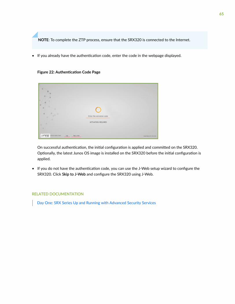
NOTE: To complete the ZTP process, ensure that the SRX320 is connected to the Internet.
• If you already have the authentication code, enter the code in the webpage displayed.
Figure 22: Authentication Code Page
On successful authentication, the initial configuration is applied and committed on the SRX320.Optionally, the latest Junos OS image is installed on the SRX320 before the initial configuration isapplied.
• If you do not have the authentication code, you can use the J-Web setup wizard to configure theSRX320. Click Skip to J-Web and configure the SRX320 using J-Web.
RELATED DOCUMENTATION
Day One: SRX Series Up and Running with Advanced Security Services
65

4CHAPTER
Maintaining Components
Maintaining the SRX320 Components | 67

Maintaining the SRX320 Components
IN THIS SECTION
Required Tools and Parts for Maintaining the SRX320 Services Gateway Hardware Components | 67
Routine Maintenance Procedures for the SRX320 Services Gateway | 67
Maintaining the SRX320 Services Gateway Cooling System Components | 68
Maintaining the SRX320 Services Gateway Power Supply | 68
Replacing Mini-Physical Interface Modules in the SRX320 Services Gateway | 69
Required Tools and Parts for Maintaining the SRX320 Services GatewayHardware Components
The following tools and parts are required to maintain the hardware components of the servicesgateway:
• Electrostatic bag or antistatic mat
• Electrostatic discharge (ESD) grounding wrist strap
• Flat-blade screw-blade screwdriver, approximately 1/8 in. (3 mm)
• Phillips (+) screwdrivers, numbers 1 and 2
Routine Maintenance Procedures for the SRX320 Services Gateway
For optimum performance of the services gateway, perform the following preventive maintenanceprocedures regularly:
• Inspect the installation site for moisture, loose wires or cables, and excessive dust.
• Make sure that airflow is unobstructed around the device and into the air intake vents.
• Check the status LEDs on the front panel of the services gateway and on the Mini-Physical InterfaceModule (Mini-PIM) that you are using.
67

Maintaining the SRX320 Services Gateway Cooling System Components
The services gateway cooling system works to maintain an optimal temperature for the device. If the fancontroller fails, the device temperature will exceed the maximum working temperature, and the devicewill fail. Ensure that you maintain the recommended clearances behind the device to enable the coolingsystem to function optimally.
SEE ALSO
SRX320 Cooling System | 12
Maintaining the SRX320 Services Gateway Power Supply
To maintain the power supply on the services gateway:
• Make sure that the power and grounding cables are arranged so that they do not obstruct access toother device components.
• Routinely check the PWR LED on the front panel. If this LED is solid green, the power supplies arefunctioning normally.
• Periodically inspect the site to ensure that the grounding and power cables connected to the servicesgateway are securely in place and that there is no moisture accumulating near the services gateway.
CAUTION: We recommend using a surge protector for the power connection.
SEE ALSO
SRX320 Power System | 13
68

Replacing Mini-Physical Interface Modules in the SRX320 ServicesGateway
The Mini-PIMs available on the SRX320 Services Gateway are not hot-swappable. You need to poweroff the device before removing or installing Mini-PIMs. For information on replacing Mini-PIMs, seeSRX300 Series and SRX550 High Memory Services Gateway Interface Modules Reference.
SEE ALSO
SRX320 Services Gateway Interface Modules Overview | 11
69
5CHAPTER
Troubleshooting Hardware
Troubleshooting the SRX320 | 71

Troubleshooting the SRX320
IN THIS SECTION
Troubleshooting Resources for the SRX320 Services Gateway Overview | 71
Troubleshooting Chassis and Interface Alarm Messages on the SRX320 Services Gateway | 71
Troubleshooting the Power System on the SRX320 Services Gateway | 73
Using the RESET CONFIG Button | 74
Changing the RESET CONFIG Button Behavior | 75
Troubleshooting Resources for the SRX320 Services Gateway Overview
To troubleshoot a services gateway, you use the Junos OS command-line interface (CLI) and LEDs on thecomponents:
• LEDs—When the services gateway detects an alarm condition, the alarm LED on the interfaces glowsred or yellow.
• CLI—The CLI is the primary tool for controlling and troubleshooting hardware, Junos OS, andnetwork connectivity. Use the CLI to display more information about alarms. CLI commands displayinformation about network connectivity derived from the ping and traceroute utilities. Forinformation about using the CLI to troubleshoot Junos OS, see the appropriate Junos OSconfiguration guide.
• JTAC—If you need assistance during troubleshooting, you can contact the Juniper NetworksTechnical Assistance Center (JTAC) by using the Web or by telephone. If you encounter softwareproblems, or problems with hardware components not discussed here, contact JTAC.
Troubleshooting Chassis and Interface Alarm Messages on the SRX320Services Gateway
When the services gateway detects an alarm condition, the alarm LED on the front panel turns red oramber as appropriate. To view a more detailed description of the alarm cause, issue the show chassisalarms CLI command.
71

Table 22 on page 72 describes alarms that can occur for an SRX320 Services Gateway chassiscomponent.
Table 22: SRX320 Services Gateway Chassis Alarm Conditions and Corrective Actions
Component Alarm Conditions Action AlarmSeverity
Boot media The services gatewayboots from an alternateboot device.
• If the internal flash memory fails at startup, theservices gateway automatically boots itself fromthe alternative boot device (USB storagedevice).
NOTE: If you configured your services gatewayto boot from an alternative boot device, ignorethis alarm condition.
• Reformat the internal flash memory and install abootable image. (See the Installation andUpgrade Guide for Security Devices andNetwork Monitoring and Troubleshooting Guidefor Security Devices)
• If you did not configure the services gateway toboot from an alternative boot device, contactJTAC.
Amber(minor)
Hardwarecomponents onthe servicesgateway
The services gatewaychassis temperature orchassis is too warm
Check the room temperature. See "SRX320Services Gateway Environmental Specifications" onpage 21.
Amber(minor)
The services gatewaytemperature is too high,either because of aninternal overheatingcondition or because themaximum recommendedroom temperature hasbeen exceeded.
The services gateway shuts down automatically in4 minutes.
Red(major)
72

Table 22: SRX320 Services Gateway Chassis Alarm Conditions and Corrective Actions (Continued)
Component Alarm Conditions Action AlarmSeverity
Mini-PIM A Mini-PIM has failed. • Contact the Juniper Networks TechnicalAssistance Center (JTAC).
• If you must replace the failed Mini-PIM, seeSRX300 Series and SRX550 High MemoryServices Gateway Interface Modules Referencefor information about replacing the Mini-PIMs.
Red(major)
Troubleshooting the Power System on the SRX320 Services Gateway
The LEDs on the services gateway enable you to determine the performance and operation. The PWRLED, located on the front panel of the services gateway, indicates the different settings with respect tothe power system.
Table 23 on page 73 describes different PWR LED status settings and their corrective actions.
Table 23: SRX320 Services Gateway Power LED Status
LED Status Meaning Possible Cause and Corrective Action
Green Device is receiving power. Normal indication. No action is required.
Amber Indicates that the powerbutton has been pressed andquickly released.
Normal indication. No action is required.
73
Table 23: SRX320 Services Gateway Power LED Status (Continued)
LED Status Meaning Possible Cause and Corrective Action
Off Indicates that the device is notreceiving power.
• Verify that the AC power cord from thepower source to the device is notdamaged. If the insulation is cracked orbroken, immediately replace the cord orcable.
• Ensure that the socket you plug in is inworking condition.
• Ensure the device has an AC input voltagebetween 100 and 240 VAC.
• If you cannot determine the cause of theproblem or need additional assistance,contact JTAC.
Using the RESET CONFIG Button
If a configuration fails or denies management access to the services gateway, you can use the RESETCONFIG button to restore the device to the factory-default configuration or a rescue configuration. Forexample, if someone inadvertently commits a configuration that denies management access to a servicesgateway, you can delete the invalid configuration and replace it with a rescue configuration by pressingthe RESET CONFIG button.
NOTE: The RESET CONFIG button is recessed to prevent it from being pressed accidentally.
The rescue configuration is a previously committed, valid configuration. You must have previously setthe rescue configuration through the J-Web interface or the CLI. To press the RESET CONFIG button,insert a small probe (such as a straightened paper clip) into the pinhole on the front panel.
• By default, pressing and quickly releasing the RESET CONFIG button loads and commits the rescueconfiguration through the J-Web interface or the CLI. The Status LED is solid amber during this time.
• By default, pressing and holding the RESET CONFIG button for 15 seconds or more—until the StatusLED is solid amber — deletes all configurations on the device, including the backup configurationsand rescue configuration, and loads and commits the factory configuration.
74

NOTE: Resetting the configuration does not trigger a reboot automatically. Thus, configurationchanges that require a reboot, such as Ethernet switching configurations, do not take effect afteryou reset the configuration. As a result, connectivity to the device might be lost. For theconfiguration to take effect, power off and power on the device after resetting the configuration.
Changing the RESET CONFIG Button Behavior
You can change the default operation of the RESET CONFIG button by limiting how the button resetsthe services gateway:
• To prevent the RESET CONFIG button from setting the device to the factory-default configurationand deleting all other configurations:
admin@host# set chassis config-button no-clear
You can still press and quickly release the button to reset it to the rescue configuration.
• To prevent the RESET CONFIG button from setting the device to the rescue configuration:
admin@host# set chassis config-button no-rescue
You can still press and hold the button for 15 seconds or more to reset the gateway to the factory-default configuration.
• To disable the button and prevent the device from resetting to either the factory-default or rescueconfiguration:
admin@host# set chassis config-button no-clear no-rescue
The no-clear option prevents the RESET CONFIG button from deleting all configurations on the servicesgateway. The no-rescue option prevents the RESET CONFIG button from loading the rescueconfiguration.
To return the function of the RESET CONFIG button to its default behavior, remove the config-buttonstatement from the device configuration.
75

6CHAPTER
Contacting Customer Support andReturning the Chassis or Components
Returning the SRX320 Chassis or Components | 77

Returning the SRX320 Chassis or Components
IN THIS SECTION
Contacting Customer Support | 77
Returning a SRX320 Services Gateway Component to Juniper Networks | 78
Locating the SRX320 Services Gateway Chassis Serial Number and Agency Labels | 78
Locating the SRX320 Services Gateway Mini-Physical Interface Module Serial Number Label | 79
Listing the SRX320 Services Gateway Component Details with the CLI | 79
Required Tools and Parts for Packing the SRX320 Services Gateway | 79
Packing the SRX320 Services Gateway for Shipment | 80
Packing SRX320 Services Gateway Components for Shipment | 81
Contacting Customer Support
Once you have located the serial numbers of the device or component, you can return the device orcomponent for repair or replacement. For this, you need to contact Juniper Networks TechnicalAssistance Center (JTAC).
You can contact JTAC 24 hours a day, 7 days a week, using any of the following methods:
• On the Web: Using the Service Request Manager link at https://support.juniper.net/support/
• By telephone:
• From the US and Canada: 1-888-314-JTAC
• From all other locations: 1-408-745-9500
NOTE: If contacting JTAC by telephone, enter your 12-digit service request numberfollowed by the pound (#) key if this is an existing case, or press the star (*) key to berouted to the next available support engineer.
When requesting support from JTAC by telephone, be prepared to provide the following information:
• Your existing service request number, if you have one
77

• Details of the failure or problem
• Type of activity being performed on the services gateway when the problem occurred
• Configuration data displayed by one or more show commands
• Your name, organization name, telephone number, fax number, and shipping address
The support representative validates your request and issues a Return Materials Authorization (RMA)number for return of the device or component.
Returning a SRX320 Services Gateway Component to Juniper Networks
To return an SRX320 Services Gateway or component to Juniper Networks for repair or replacement:
1. Determine the part number and serial number of the services gateway or component.
2. Obtain a Return Materials Authorization (RMA) number from JTAC.
NOTE: Do not return the services gateway or any component to Juniper Networks unless youhave first obtained an RMA number. Juniper Networks reserves the right to refuse shipmentsthat do not have an RMA. Refused shipments are returned to the customer via collect freight.
3. Pack the SRX320 Services Gateway or component for shipping.
For more information about return and repair policies, see the customer support webpage at https://www.juniper.net/support/guidelines.html.
For product problems or technical support issues, open a support case using the Case Manager link athttps://www.juniper.net/support/ or call 1-888-314-JTAC (within the United States) or 1-408-745-9500(outside the United States).
Locating the SRX320 Services Gateway Chassis Serial Number andAgency Labels
The chassis serial number is located on the side of the chassis.
78

Locating the SRX320 Services Gateway Mini-Physical Interface ModuleSerial Number Label
Mini-PIMs are field-replaceable on the SRX320 Services Gateway. Each Mini-PIM has a unique serialnumber. The serial number label is located on the right side of the Mini-PIM, when the Mini-PIM ishorizontally oriented (as it would be when installed on the device). The exact location might be slightlydifferent on different Mini-PIMs, depending on the placement of components on the Mini-PIM.
Listing the SRX320 Services Gateway Component Details with the CLI
Before contacting Juniper Networks to request an RMA, you must find the serial number on the SRX320Services Gateway or component.
To list all of the SRX320 Services Gateway components and their serial numbers, enter the followingcommand:
user@host> show chassis hardwareHardware inventory:Item Version Part number Serial number DescriptionChassis CX3315AN0019 SRX320-POERouting Engine REV 02 650-065041 CX3315AN0019 RE-SRX320-POEFPC 0 FPC PIC 0 6xGE,2xGE SFP Base PICPower Supply 0
NOTE: In the show chassis hardware command, the Mini-PIM slot number is reported as an FPCnumber, and the Mini-PIM number (always 0) is reported as the PIC number.
Most components also have a serial number ID label attached to the component body.
Required Tools and Parts for Packing the SRX320 Services Gateway
To remove the components from the SRX320 Services Gateway or to remove the services gateway froma rack, you need the following tools and parts:
79
• Electrostatic bag or antistatic mat for each component
• Electrostatic discharge (ESD) grounding wrist strap
• Flat-blade screwdriver, approximately 1/4 in. (6 mm)
• Phillips (+) screwdrivers, numbers 1 and 2
Packing the SRX320 Services Gateway for Shipment
To pack the SRX320 Services Gateway for shipment:
1. Retrieve the shipping carton and packing materials in which the services gateway was originallyshipped. If you do not have these materials, contact your Juniper Networks representative aboutapproved packaging materials.
2. Attach an electrostatic discharge (ESD) grounding strap to your bare wrist and connect the strap tothe ESD point on the chassis or to an outside ESD point if the device is disconnected from earthground. For more information about ESD, see Prevention of Electrostatic Discharge Damage.
3. On the console or other management device connected to the services gateway, enter CLIoperational mode and issue the following command to shut down the services gateway software:
user@host> request system halt
Wait until a message appears on the console confirming that the operating system has halted.
4. Shut down power to the services gateway by pressing the Power button on the front of theservices gateway.
5. Disconnect power from the services gateway.
6. Remove the cables that connect to all external devices.
7. If the device is installed on a wall or rack, have one person support the weight of the device whileanother person unscrews and removes the mounting screws.
8. Place the services gateway in the shipping carton.
9. Cover the services gateway with an ESD bag, and place the packing foam on top of and around thedevice.
10. Replace the accessory box on top of the packing foam.
11. Securely tape the box closed.
12. Write the Return Materials Authorization (RMA) number on the exterior of the box to ensureproper tracking.
80

Packing SRX320 Services Gateway Components for Shipment
Follow these guidelines for packing and shipping individual components of the services gateway:
• When you return a component, make sure that it is adequately protected with packing materials andpacked so that the pieces are prevented from moving around inside the carton.
• Use the original shipping materials if they are available.
• Place the individual component in an electrostatic bag.
• Write the Return Materials Authorization (RMA) number on the exterior of the box to ensure propertracking.
CAUTION: Do not stack any of the services gateway components during packing.
81

7CHAPTER
Safety and Compliance Information
Definitions of Safety Warning Levels | 83
General Safety Guidelines and Warnings | 84
Restricted Access Warning | 86
Qualified Personnel Warning | 87
Prevention of Electrostatic Discharge Damage | 88
Fire Safety Requirements | 89
Laser and LED Safety Guidelines and Warnings | 91
Radiation from Open Port Apertures Warning | 94
Maintenance and Operational Safety Guidelines and Warnings | 95
Action to Take After an Electrical Accident | 100
General Electrical Safety Guidelines and Warnings | 101
SRX320 Services Gateway Agency Approvals | 102
SRX320 Services Gateway Acoustic Noise Compliance Statements | 104
SRX320 Services Gateway EMC Requirements | 104
Definitions of Safety Warning Levels
The documentation uses the following levels of safety warnings (there are two Warning formats):
NOTE: You might find this information helpful in a particular situation, or you might overlook thisimportant information if it was not highlighted in a Note.
CAUTION: You need to observe the specified guidelines to prevent minor injury ordiscomfort to you or severe damage to the device.
Attention Veillez à respecter les consignes indiquées pour éviter toute incommodité oublessure légère, voire des dégâts graves pour l’appareil.
LASER WARNING: This symbol alerts you to the risk of personal injury from a laser.
Avertissement Ce symbole signale un risque de blessure provoquée par rayon laser.
WARNING: This symbol means danger. You are in a situation that could cause bodilyinjury. Before you work on any equipment, be aware of the hazards involved withelectrical circuitry and be familiar with standard practices for preventing accidents.
Waarschuwing Dit waarschuwingssymbool betekent gevaar. U verkeert in een situatiedie lichamelijk letsel kan veroorzaken. Voordat u aan enige apparatuur gaat werken,dient u zich bewust te zijn van de bij elektrische schakelingen betrokken risico's en dientu op de hoogte te zijn van standaard maatregelen om ongelukken te voorkomen.
Varoitus Tämä varoitusmerkki merkitsee vaaraa. Olet tilanteessa, joka voi johtaaruumiinvammaan. Ennen kuin työskentelet minkään laitteiston parissa, ota selvääsähkökytkentöihin liittyvistä vaaroista ja tavanomaisista onnettomuuksienehkäisykeinoista.
Avertissement Ce symbole d'avertissement indique un danger. Vous vous trouvez dansune situation pouvant causer des blessures ou des dommages corporels. Avant detravailler sur un équipement, soyez conscient des dangers posés par les circuitsélectriques et familiarisez-vous avec les procédures couramment utilisées pour éviterles accidents.
Warnung Dieses Warnsymbol bedeutet Gefahr. Sie befinden sich in einer Situation, diezu einer Körperverletzung führen könnte. Bevor Sie mit der Arbeit an irgendeinem
83

Gerät beginnen, seien Sie sich der mit elektrischen Stromkreisen verbundenen Gefahrenund der Standardpraktiken zur Vermeidung von Unfällen bewußt.
Avvertenza Questo simbolo di avvertenza indica un pericolo. La situazione potrebbecausare infortuni alle persone. Prima di lavorare su qualsiasi apparecchiatura, occorreconoscere i pericoli relativi ai circuiti elettrici ed essere al corrente delle pratichestandard per la prevenzione di incidenti.
Advarsel Dette varselsymbolet betyr fare. Du befinner deg i en situasjon som kan føretil personskade. Før du utfører arbeid på utstyr, må du vare oppmerksom på defaremomentene som elektriske kretser innebærer, samt gjøre deg kjent med vanligpraksis når det gjelder å unngå ulykker.
Aviso Este símbolo de aviso indica perigo. Encontra-se numa situação que lhe poderácausar danos físicos. Antes de começar a trabalhar com qualquer equipamento,familiarize-se com os perigos relacionados com circuitos eléctricos, e com quaisquerpráticas comuns que possam prevenir possíveis acidentes.
¡Atención! Este símbolo de aviso significa peligro. Existe riesgo para su integridad física.Antes de manipular cualquier equipo, considerar los riesgos que entraña la corrienteeléctrica y familiarizarse con los procedimientos estándar de prevención de accidentes.
Varning! Denna varningssymbol signalerar fara. Du befinner dig i en situation som kanleda till personskada. Innan du utför arbete på någon utrustning måste du varamedveten om farorna med elkretsar och känna till vanligt förfarande för att förebyggaskador.
General Safety Guidelines and Warnings
The following guidelines help ensure your safety and protect the device from damage. The list ofguidelines might not address all potentially hazardous situations in your working environment, so bealert and exercise good judgment at all times.
• Perform only the procedures explicitly described in the hardware documentation for this device.Make sure that only authorized service personnel perform other system services.
• Keep the area around the device clear and free from dust before, during, and after installation.
• Keep tools away from areas where people could trip over them while walking.
• Do not wear loose clothing or jewelry, such as rings, bracelets, or chains, which could become caughtin the device.
84

• Wear safety glasses if you are working under any conditions that could be hazardous to your eyes.
• Do not perform any actions that create a potential hazard to people or make the equipment unsafe.
• Never attempt to lift an object that is too heavy for one person to handle.
• Never install or manipulate wiring during electrical storms.
• Never install electrical jacks in wet locations unless the jacks are specifically designed for wetenvironments.
• Operate the device only when it is properly grounded.
• Follow the instructions in this guide to properly ground the device to earth.
• Replace fuses only with fuses of the same type and rating.
• Do not open or remove chassis covers or sheet-metal parts unless instructions are provided in thehardware documentation for this device. Such an action could cause severe electrical shock.
• Do not push or force any objects through any opening in the chassis frame. Such an action couldresult in electrical shock or fire.
• Avoid spilling liquid onto the chassis or onto any device component. Such an action could causeelectrical shock or damage the device.
• Avoid touching uninsulated electrical wires or terminals that have not been disconnected from theirpower source. Such an action could cause electrical shock.
• Some parts of the chassis, including AC and DC power supply surfaces, power supply unit handles,SFB card handles, and fan tray handles might become hot. The following label provides the warningof the hot surfaces on the chassis:
• Always ensure that all modules, power supplies, and cover panels are fully inserted and that theinstallation screws are fully tightened.
85

Restricted Access Warning
WARNING: This unit is intended for installation in restricted access areas. A restrictedaccess area is an area to which access can be gained only by service personnel throughthe use of a special tool, lock and key, or other means of security, and which iscontrolled by the authority responsible for the location.
Waarschuwing Dit toestel is bedoeld voor installatie op plaatsen met beperkte toegang.Een plaats met beperkte toegang is een plaats waar toegang slechts doorservicepersoneel verkregen kan worden door middel van een speciaal instrument, eenslot en sleutel, of een ander veiligheidsmiddel, en welke beheerd wordt door deoverheidsinstantie die verantwoordelijk is voor de locatie.
Varoitus Tämä laite on tarkoitettu asennettavaksi paikkaan, johon pääsy on rajoitettua.Paikka, johon pääsy on rajoitettua, tarkoittaa paikkaa, johon vain huoltohenkilöstöpääsee jonkin erikoistyökalun, lukkoon sopivan avaimen tai jonkin muun turvalaitteenavulla ja joka on paikasta vastuussa olevien toimivaltaisten henkilöiden valvoma.
Avertissement Cet appareil est à installer dans des zones d'accès réservé. Ces dernièressont des zones auxquelles seul le personnel de service peut accéder en utilisant un outilspécial, un mécanisme de verrouillage et une clé, ou tout autre moyen de sécurité.L'accès aux zones de sécurité est sous le contrôle de l'autorité responsable del'emplacement.
Warnung Diese Einheit ist zur Installation in Bereichen mit beschränktem Zutrittvorgesehen. Ein Bereich mit beschränktem Zutritt ist ein Bereich, zu dem nurWartungspersonal mit einem Spezialwerkzeugs, Schloß und Schlüssel oder andererSicherheitsvorkehrungen Zugang hat, und der von dem für die Anlage zuständigenGremium kontrolliert wird.
Avvertenza Questa unità deve essere installata in un'area ad accesso limitato. Un'areaad accesso limitato è un'area accessibile solo a personale di assistenza tramiteun'attrezzo speciale, lucchetto, o altri dispositivi di sicurezza, ed è controllatadall'autorità responsabile della zona.
Advarsel Denne enheten er laget for installasjon i områder med begrenset adgang. Etområde med begrenset adgang gir kun adgang til servicepersonale som bruker etspesielt verktøy, lås og nøkkel, eller en annen sikkerhetsanordning, og det kontrolleresav den autoriteten som er ansvarlig for området.
Aviso Esta unidade foi concebida para instalação em áreas de acesso restrito. Uma áreade acesso restrito é uma área à qual apenas tem acesso o pessoal de serviço autorizado,
86

que possua uma ferramenta, chave e fechadura especial, ou qualquer outra forma desegurança. Esta área é controlada pela autoridade responsável pelo local.
¡Atención! Esta unidad ha sido diseñada para instalarse en áreas de acceso restringido.Área de acceso restringido significa un área a la que solamente tiene acceso el personalde servicio mediante la utilización de una herramienta especial, cerradura con llave, oalgún otro medio de seguridad, y que está bajo el control de la autoridad responsabledel local.
Varning! Denna enhet är avsedd för installation i områden med begränsat tillträde. Ettområde med begränsat tillträde får endast tillträdas av servicepersonal med ett specielltverktyg, lås och nyckel, eller annan säkerhetsanordning, och kontrolleras av denauktoritet som ansvarar för området.
Qualified Personnel Warning
WARNING: Only trained and qualified personnel should install or replace the device.
Waarschuwing Installatie en reparaties mogen uitsluitend door getraind en bevoegdpersoneel uitgevoerd worden.
Varoitus Ainoastaan koulutettu ja pätevä henkilökunta saa asentaa tai vaihtaa tämänlaitteen.
Avertissement Tout installation ou remplacement de l'appareil doit être réalisé par dupersonnel qualifié et compétent.
Warnung Gerät nur von geschultem, qualifiziertem Personal installieren oderauswechseln lassen.
Avvertenza Solo personale addestrato e qualificato deve essere autorizzato ad installareo sostituire questo apparecchio.
Advarsel Kun kvalifisert personell med riktig opplæring bør montere eller bytte ut detteutstyret.
Aviso Este equipamento deverá ser instalado ou substituído apenas por pessoaldevidamente treinado e qualificado.
87

¡Atención! Estos equipos deben ser instalados y reemplazados exclusivamente porpersonal técnico adecuadamente preparado y capacitado.
Varning! Denna utrustning ska endast installeras och bytas ut av utbildad ochkvalificerad personal.
Prevention of Electrostatic Discharge Damage
Device components that are shipped in antistatic bags are sensitive to damage from static electricity.Some components can be impaired by voltages as low as 30 V. You can easily generate potentiallydamaging static voltages whenever you handle plastic or foam packing material or if you movecomponents across plastic or carpets. Observe the following guidelines to minimize the potential forelectrostatic discharge (ESD) damage, which can cause intermittent or complete component failures:
• Always use an ESD wrist strap when you are handling components that are subject to ESD damage,and make sure that it is in direct contact with your skin.
If a grounding strap is not available, hold the component in its antistatic bag (see Figure 23 on page89) in one hand and touch the exposed, bare metal of the device with the other hand immediatelybefore inserting the component into the device.
WARNING: For safety, periodically check the resistance value of the ESD groundingstrap. The measurement must be in the range 1 through 10 Mohms.
Avertissement Par mesure de sécurité, vérifiez régulièrement la résistance du braceletantistatique. Cette valeur doit être comprise entre 1 et 10 mégohms (Mohms).
• When handling any component that is subject to ESD damage and that is removed from the device,make sure the equipment end of your ESD wrist strap is attached to the ESD point on the chassis.
If no grounding strap is available, touch the exposed, bare metal of the device to ground yourselfbefore handling the component.
• Avoid contact between the component that is subject to ESD damage and your clothing. ESDvoltages emitted from clothing can damage components.
88

• When removing or installing a component that is subject to ESD damage, always place it component-side up on an antistatic surface, in an antistatic card rack, or in an antistatic bag (see Figure 23 onpage 89). If you are returning a component, place it in an antistatic bag before packing it.
Figure 23: Placing a Component into an Antistatic Bag
CAUTION: ANSI/TIA/EIA-568 cables such as Category 5e and Category 6 can getelectrostatically charged. To dissipate this charge, always ground the cables to a suitableand safe earth ground before connecting them to the system.
Attention Les câbles ANSI/TIA/EIA-568, par exemple Cat 5e et Cat 6, peuventemmagasiner des charges électrostatiques. Pour évacuer ces charges, reliez toujours lescâbles à une prise de terre adaptée avant de les raccorder au système.
Fire Safety Requirements
IN THIS SECTION
Fire Suppression | 90
89

Fire Suppression Equipment | 90
In the event of a fire emergency, the safety of people is the primary concern. You should establishprocedures for protecting people in the event of a fire emergency, provide safety training, and properlyprovision fire-control equipment and fire extinguishers.
In addition, you should establish procedures to protect your equipment in the event of a fire emergency.Juniper Networks products should be installed in an environment suitable for electronic equipment. Werecommend that fire suppression equipment be available in the event of a fire in the vicinity of theequipment and that all local fire, safety, and electrical codes and ordinances be observed when youinstall and operate your equipment.
Fire Suppression
In the event of an electrical hazard or an electrical fire, you should first turn power off to the equipmentat the source. Then use a Type C fire extinguisher, which uses noncorrosive fire retardants, to extinguishthe fire.
Fire Suppression Equipment
Type C fire extinguishers, which use noncorrosive fire retardants such as carbon dioxide and Halotron™,are most effective for suppressing electrical fires. Type C fire extinguishers displace oxygen from thepoint of combustion to eliminate the fire. For extinguishing fire on or around equipment that draws airfrom the environment for cooling, you should use this type of inert oxygen displacement extinguisherinstead of an extinguisher that leaves residues on equipment.
Do not use multipurpose Type ABC chemical fire extinguishers (dry chemical fire extinguishers). Theprimary ingredient in these fire extinguishers is monoammonium phosphate, which is very sticky anddifficult to clean. In addition, in the presence of minute amounts of moisture, monoammoniumphosphate can become highly corrosive and corrodes most metals.
Any equipment in a room in which a chemical fire extinguisher has been discharged is subject topremature failure and unreliable operation. The equipment is considered to be irreparably damaged.
90

NOTE: To keep warranties effective, do not use a dry chemical fire extinguisher to control a fireat or near a Juniper Networks device. If a dry chemical fire extinguisher is used, the unit is nolonger eligible for coverage under a service agreement.
We recommend that you dispose of any irreparably damaged equipment in an environmentallyresponsible manner.
Laser and LED Safety Guidelines and Warnings
IN THIS SECTION
General Laser Safety Guidelines | 91
Class 1 Laser Product Warning | 92
Class 1 LED Product Warning | 92
Laser Beam Warning | 93
Juniper Networks devices are equipped with laser transmitters, which are considered a Class 1 LaserProduct by the U.S. Food and Drug Administration and are evaluated as a Class 1 Laser Product per EN60825-1 requirements.
Observe the following guidelines and warnings:
General Laser Safety Guidelines
When working around ports that support optical transceivers, observe the following safety guidelines toprevent eye injury:
• Do not look into unterminated ports or at fibers that connect to unknown sources.
• Do not examine unterminated optical ports with optical instruments.
• Avoid direct exposure to the beam.
91

LASER WARNING: Unterminated optical connectors can emit invisible laser radiation. Thelens in the human eye focuses all the laser power on the retina, so focusing the eyedirectly on a laser source—even a low-power laser—could permanently damage the eye.
Avertissement Les connecteurs à fibre optique sans terminaison peuvent émettre unrayonnement laser invisible. Le cristallin de l’œil humain faisant converger toute lapuissance du laser sur la rétine, toute focalisation directe de l’œil sur une source laser, —même de faible puissance—, peut entraîner des lésions oculaires irréversibles.
Class 1 Laser Product Warning
LASER WARNING: Class 1 laser product.
Waarschuwing Klasse-1 laser produkt.
Varoitus Luokan 1 lasertuote.
Avertissement Produit laser de classe I.
Warnung Laserprodukt der Klasse 1.
Avvertenza Prodotto laser di Classe 1.
Advarsel Laserprodukt av klasse 1.
Aviso Produto laser de classe 1.
¡Atención! Producto láser Clase I.
Varning! Laserprodukt av klass 1.
Class 1 LED Product Warning
LASER WARNING: Class 1 LED product.
Waarschuwing Klasse 1 LED-product.
Varoitus Luokan 1 valodiodituote.
92

Avertissement Alarme de produit LED Class I.
Warnung Class 1 LED-Produktwarnung.
Avvertenza Avvertenza prodotto LED di Classe 1.
Advarsel LED-produkt i klasse 1.
Aviso Produto de classe 1 com LED.
¡Atención! Aviso sobre producto LED de Clase 1.
Varning! Lysdiodprodukt av klass 1.
Laser Beam Warning
LASER WARNING: Do not stare into the laser beam or view it directly with opticalinstruments.
Waarschuwing Niet in de straal staren of hem rechtstreeks bekijken met optischeinstrumenten.
Varoitus Älä katso säteeseen äläkä tarkastele sitä suoraan optisen laitteen avulla.
Avertissement Ne pas fixer le faisceau des yeux, ni l'observer directement à l'aided'instruments optiques.
Warnung Nicht direkt in den Strahl blicken und ihn nicht direkt mit optischen Gerätenprüfen.
Avvertenza Non fissare il raggio con gli occhi né usare strumenti ottici per osservarlodirettamente.
Advarsel Stirr eller se ikke direkte p strlen med optiske instrumenter.
Aviso Não olhe fixamente para o raio, nem olhe para ele directamente com instrumentosópticos.
¡Atención! No mirar fijamente el haz ni observarlo directamente con instrumentos ópticos.
Varning! Rikta inte blicken in mot strålen och titta inte direkt på den genom optiskainstrument.
93

Radiation from Open Port Apertures Warning
LASER WARNING: Because invisible radiation might be emitted from the aperture of theport when no fiber cable is connected, avoid exposure to radiation and do not stare intoopen apertures.
Waarschuwing Aangezien onzichtbare straling vanuit de opening van de poort kan komenals er geen fiberkabel aangesloten is, dient blootstelling aan straling en het kijken in openopeningen vermeden te worden.
Varoitus Koska portin aukosta voi emittoitua näkymätöntä säteilyä, kun kuitukaapelia ei olekytkettynä, vältä säteilylle altistumista äläkä katso avoimiin aukkoihin.
Avertissement Des radiations invisibles à l'il nu pouvant traverser l'ouverture du portlorsqu'aucun câble en fibre optique n'y est connecté, il est recommandé de ne pas regarderfixement l'intérieur de ces ouvertures.
Warnung Aus der Port-Öffnung können unsichtbare Strahlen emittieren, wenn keinGlasfaserkabel angeschlossen ist. Vermeiden Sie es, sich den Strahlungen auszusetzen, undstarren Sie nicht in die Öffnungen!
Avvertenza Quando i cavi in fibra non sono inseriti, radiazioni invisibili possono essereemesse attraverso l'apertura della porta. Evitate di esporvi alle radiazioni e non guardatedirettamente nelle aperture.
Advarsel Unngå utsettelse for stråling, og stirr ikke inn i åpninger som er åpne, fordi usynligstråling kan emiteres fra portens åpning når det ikke er tilkoblet en fiberkabel.
Aviso Dada a possibilidade de emissão de radiação invisível através do orifício da via deacesso, quando esta não tiver nenhum cabo de fibra conectado, deverá evitar an EXposiçãoà radiação e não deverá olhar fixamente para orifícios que se encontrarem a descoberto.
¡Atención! Debido a que la apertura del puerto puede emitir radiación invisible cuando noexiste un cable de fibra conectado, evite mirar directamente a las aperturas para noexponerse a la radiación.
Varning! Osynlig strålning kan avges från en portöppning utan ansluten fiberkabel och dubör därför undvika att bli utsatt för strålning genom att inte stirra in i oskyddade öppningar.
94

Maintenance and Operational Safety Guidelines andWarnings
IN THIS SECTION
Battery Handling Warning | 95
Jewelry Removal Warning | 96
Lightning Activity Warning | 98
Operating Temperature Warning | 98
Product Disposal Warning | 100
While performing the maintenance activities for devices, observe the following guidelines and warnings:
Battery Handling Warning
WARNING: Replacing a battery incorrectly might result in an explosion. Replace abattery only with the same or equivalent type recommended by the manufacturer.Dispose of used batteries according to the manufacturer's instructions.
Waarschuwing Er is ontploffingsgevaar als de batterij verkeerd vervangen wordt.Vervang de batterij slechts met hetzelfde of een equivalent type dat door de fabrikantaanbevolen is. Gebruikte batterijen dienen overeenkomstig fabrieksvoorschriftenweggeworpen te worden.
Varoitus Räjähdyksen vaara, jos akku on vaihdettu väärään akkuun. Käytä vaihtamiseenainoastaan saman- tai vastaavantyyppistä akkua, joka on valmistajan suosittelema.Hävitä käytetyt akut valmistajan ohjeiden mukaan.
Avertissement Danger d'explosion si la pile n'est pas remplacée correctement. Ne laremplacer que par une pile de type semblable ou équivalent, recommandée par lefabricant. Jeter les piles usagées conformément aux instructions du fabricant.
95

Warnung Bei Einsetzen einer falschen Batterie besteht Explosionsgefahr. Ersetzen Siedie Batterie nur durch den gleichen oder vom Hersteller empfohlenen Batterietyp.Entsorgen Sie die benutzten Batterien nach den Anweisungen des Herstellers.
Advarsel Det kan være fare for eksplosjon hvis batteriet skiftes på feil måte. Skift kunmed samme eller tilsvarende type som er anbefalt av produsenten. Kasser bruktebatterier i henhold til produsentens instruksjoner.
Avvertenza Pericolo di esplosione se la batteria non è installata correttamente.Sostituire solo con una di tipo uguale o equivalente, consigliata dal produttore. Eliminarele batterie usate secondo le istruzioni del produttore.
Aviso Existe perigo de explosão se a bateria for substituída incorrectamente. Substituaa bateria por uma bateria igual ou de um tipo equivalente recomendado pelo fabricante.Destrua as baterias usadas conforme as instruções do fabricante.
¡Atención! Existe peligro de explosión si la batería se reemplaza de manera incorrecta.Reemplazar la baterían EXclusivamente con el mismo tipo o el equivalenterecomendado por el fabricante. Desechar las baterías gastadas según las instruccionesdel fabricante.
Varning! Explosionsfara vid felaktigt batteribyte. Ersätt endast batteriet med sammabatterityp som rekommenderas av tillverkaren eller motsvarande. Följ tillverkarensanvisningar vid kassering av använda batterier.
Jewelry Removal Warning
WARNING: Before working on equipment that is connected to power lines, removejewelry, including rings, necklaces, and watches. Metal objects heat up when connectedto power and ground and can cause serious burns or can be welded to the terminals.
Waarschuwing Alvorens aan apparatuur te werken die met elektrische leidingen isverbonden, sieraden (inclusief ringen, kettingen en horloges) verwijderen. Metalenvoorwerpen worden warm wanneer ze met stroom en aarde zijn verbonden, en kunnenernstige brandwonden veroorzaken of het metalen voorwerp aan de aansluitklemmenlassen.
Varoitus Ennen kuin työskentelet voimavirtajohtoihin kytkettyjen laitteiden parissa, otapois kaikki korut (sormukset, kaulakorut ja kellot mukaan lukien). Metalliesineet
96

kuumenevat, kun ne ovat yhteydessä sähkövirran ja maan kanssa, ja ne voivat aiheuttaavakavia palovammoja tai hitsata metalliesineet kiinni liitäntänapoihin.
Avertissement Avant d'accéder à cet équipement connecté aux lignes électriques, ôtertout bijou (anneaux, colliers et montres compris). Lorsqu'ils sont branchés àl'alimentation et reliés à la terre, les objets métalliques chauffent, ce qui peut provoquerdes blessures graves ou souder l'objet métallique aux bornes.
Warnung Vor der Arbeit an Geräten, die an das Netz angeschlossen sind, jeglichenSchmuck (einschließlich Ringe, Ketten und Uhren) abnehmen. Metallgegenständeerhitzen sich, wenn sie an das Netz und die Erde angeschlossen werden, und könnenschwere Verbrennungen verursachen oder an die Anschlußklemmen angeschweißtwerden.
Avvertenza Prima di intervenire su apparecchiature collegate alle linee di alimentazione,togliersi qualsiasi monile (inclusi anelli, collane, braccialetti ed orologi). Gli oggettimetallici si riscaldano quando sono collegati tra punti di alimentazione e massa: possonocausare ustioni gravi oppure il metallo può saldarsi ai terminali.
Advarsel Fjern alle smykker (inkludert ringer, halskjeder og klokker) før du skal arbeidepå utstyr som er koblet til kraftledninger. Metallgjenstander som er koblet tilkraftledninger og jord blir svært varme og kan forårsake alvorlige brannskader ellersmelte fast til polene.
Aviso Antes de trabalhar em equipamento que esteja ligado a linhas de corrente, retiretodas as jóias que estiver a usar (incluindo anéis, fios e relógios). Os objectos metálicosaquecerão em contacto com a corrente e em contacto com a ligação à terra, podendocausar queimaduras graves ou ficarem soldados aos terminais.
¡Atención! Antes de operar sobre equipos conectados a líneas de alimentación, quitarselas joyas (incluidos anillos, collares y relojes). Los objetos de metal se calientan cuandose conectan a la alimentación y a tierra, lo que puede ocasionar quemaduras graves oque los objetos metálicos queden soldados a los bornes.
Varning! Tag av alla smycken (inklusive ringar, halsband och armbandsur) innan duarbetar på utrustning som är kopplad till kraftledningar. Metallobjekt hettas upp när dekopplas ihop med ström och jord och kan förorsaka allvarliga brännskador; metallobjektkan också sammansvetsas med kontakterna.
97

Lightning Activity Warning
WARNING: Do not work on the system or connect or disconnect cables during periodsof lightning activity.
Waarschuwing Tijdens onweer dat gepaard gaat met bliksem, dient u niet aan hetsysteem te werken of kabels aan te sluiten of te ontkoppelen.
Varoitus Älä työskentele järjestelmän parissa äläkä yhdistä tai irrota kaapeleitaukkosilmalla.
Avertissement Ne pas travailler sur le système ni brancher ou débrancher les câblespendant un orage.
Warnung Arbeiten Sie nicht am System und schließen Sie keine Kabel an bzw. trennenSie keine ab, wenn es gewittert.
Avvertenza Non lavorare sul sistema o collegare oppure scollegare i cavi durante untemporale con fulmini.
Advarsel Utfør aldri arbeid på systemet, eller koble kabler til eller fra systemet når dettordner eller lyner.
Aviso Não trabalhe no sistema ou ligue e desligue cabos durante períodos de mautempo (trovoada).
¡Atención! No operar el sistema ni conectar o desconectar cables durante el transcursode descargas eléctricas en la atmósfera.
Varning! Vid åska skall du aldrig utföra arbete på systemet eller ansluta eller koppla losskablar.
Operating Temperature Warning
WARNING: To prevent the device from overheating, do not operate it in an area thatexceeds the maximum recommended ambient temperature. To prevent airflowrestriction, allow at least 6 in. (15.2 cm) of clearance around the ventilation openings.
Waarschuwing Om te voorkomen dat welke switch van de Juniper Networks router danook oververhit raakt, dient u deze niet te bedienen op een plaats waar de maximaleaanbevolen omgevingstemperatuur van 40° C wordt overschreden. Om te voorkomen
98

dat de luchtstroom wordt beperkt, dient er minstens 15,2 cm speling rond de ventilatie-openingen te zijn.
Varoitus Ettei Juniper Networks switch-sarjan reititin ylikuumentuisi, sitä ei saa käyttäätilassa, jonka lämpötila ylittää korkeimman suositellun ympäristölämpötilan 40° C. Etteiilmanvaihto estyisi, tuuletusaukkojen ympärille on jätettävä ainakin 15,2 cm tilaa.
Avertissement Pour éviter toute surchauffe des routeurs de la gamme JuniperNetworks switch, ne l'utilisez pas dans une zone où la température ambiante estsupérieure à 40° C. Pour permettre un flot d'air constant, dégagez un espace d'au moins15,2 cm autour des ouvertures de ventilations.
Warnung Um einen Router der switch vor Überhitzung zu schützen, darf dieser nicht ineiner Gegend betrieben werden, in der die Umgebungstemperatur das empfohleneMaximum von 40° C überschreitet. Um Lüftungsverschluß zu verhindern, achten Siedarauf, daß mindestens 15,2 cm lichter Raum um die Lüftungsöffnungen herum freibleibt.
Avvertenza Per evitare il surriscaldamento dei switch, non adoperateli in un locale cheecceda la temperatura ambientale massima di 40° C. Per evitare che la circolazionedell'aria sia impedita, lasciate uno spazio di almeno 15.2 cm di fronte alle aperture delleventole.
Advarsel Unngå overoppheting av eventuelle rutere i Juniper Networks switch Disseskal ikke brukes på steder der den anbefalte maksimale omgivelsestemperaturenoverstiger 40° C (104° F). Sørg for at klaringen rundt lufteåpningene er minst 15,2 cm(6 tommer) for å forhindre nedsatt luftsirkulasjon.
Aviso Para evitar o sobreaquecimento do encaminhador Juniper Networks switch, nãoutilize este equipamento numa área que exceda a temperatura máxima recomendada de40° C. Para evitar a restrição à circulação de ar, deixe pelo menos um espaço de 15,2 cmà volta das aberturas de ventilação.
¡Atención! Para impedir que un encaminador de la serie Juniper Networks switch serecaliente, no lo haga funcionar en un área en la que se supere la temperatura ambientemáxima recomendada de 40° C. Para impedir la restricción de la entrada de aire, deje unespacio mínimo de 15,2 cm alrededor de las aperturas para ventilación.
Varning! Förhindra att en Juniper Networks switch överhettas genom att inte användaden i ett område där den maximalt rekommenderade omgivningstemperaturen på 40° Cöverskrids. Förhindra att luftcirkulationen inskränks genom att se till att det finns frittutrymme på minst 15,2 cm omkring ventilationsöppningarna.
99
Product Disposal Warning
WARNING: Disposal of this device must be handled according to all national laws andregulations.
Waarschuwing Dit produkt dient volgens alle landelijke wetten en voorschriften teworden afgedankt.
Varoitus Tämän tuotteen lopullisesta hävittämisestä tulee huolehtia kaikkiavaltakunnallisia lakeja ja säännöksiä noudattaen.
Avertissement La mise au rebut définitive de ce produit doit être effectuéeconformément à toutes les lois et réglementations en vigueur.
Warnung Dieses Produkt muß den geltenden Gesetzen und Vorschriften entsprechendentsorgt werden.
Avvertenza L'eliminazione finale di questo prodotto deve essere eseguita osservando lenormative italiane vigenti in materia
Advarsel Endelig disponering av dette produktet må skje i henhold til nasjonale lover ogforskrifter.
Aviso A descartagem final deste produto deverá ser efectuada de acordo com osregulamentos e a legislação nacional.
¡Atención! El desecho final de este producto debe realizarse según todas las leyes yregulaciones nacionales
Varning! Slutlig kassering av denna produkt bör skötas i enlighet med landets alla lagaroch föreskrifter.
Action to Take After an Electrical Accident
If an electrical accident results in an injury, take the following actions in this order:
1. Use caution. Be aware of potentially hazardous conditions that could cause further injury.
2. Disconnect power from the device.
3. If possible, send another person to get medical aid. Otherwise, assess the condition of the victim,then call for help.
100

General Electrical Safety Guidelines and Warnings
• Install the services gateway in compliance with the following local, national, or international electricalcodes:
• United States—National Fire Protection Association (NFPA 70), United States National ElectricalCode
• Canada—Canadian Electrical Code, Part 1, CSA C22.1
• Other countries—International Electromechanical Commission (IEC) 60364, Part 1 through Part 7
• Evaluated to the TN power system
• Locate the emergency power-off switch for the room in which you are working so that if an electricalaccident occurs, you can quickly turn off the power.
• Do not work alone if potentially hazardous conditions exist anywhere in your workspace.
• Never assume that power is disconnected from a circuit. Always check the circuit before starting towork.
• Carefully look for possible hazards in your work area, such as moist floors, ungrounded powerextension cords, and missing safety grounds.
• Operate the services gateway within marked electrical ratings and product usage instructions.
• For the services gateway and peripheral equipment to function safely and correctly, use the cablesand connectors specified for the attached peripheral equipment, and make certain they are in goodcondition.
RELATED DOCUMENTATION
Action to Take After an Electrical Accident
101

SRX320 Services Gateway Agency Approvals
IN THIS SECTION
Compliance Statement for Argentina | 103
The services gateway complies with the following standards:
• Safety
• CAN/CSA-C22.2 No.60950-1 (2007) Information Technology Equipment
• UL 60950-1 (2nd Ed.) Information Technology Equipment
• EN 60950-1 (2006+ A11:2010) Information Technology Equipment - Safety
• IEC 60950-1 (2005 +A1:2009) Information Technology Equipment - Safety (All countrydeviations): CB Scheme report
• EN 60825-1 (2007) Safety of Laser Products - Part 1: Equipment classification and requirements
• EMC
• EN 300 386 V1.6.1 Telecom Network Equipment - EMC requirements
• EN 55032:2012 + EN55032:2012/AC:2013 Electromagnetic compatibility of multimediaequipment - Emission requirements
• CISPR 32:2012
• EN 55022:2010/AC:2011 European Radiated Emissions
• CISPR 22 edition 6.0 : 2008-09
• EN 55024: 2010 Information Technology Equipment Immunity Characteristics
• CISPR 24 edition 2b :2010 COREC 2011 IT Equipment Immunity Characteristics
• EMI
• FCC 47CFR , Part 15 Class A (2012) USA Radiated Emissions
• ICES-003 Issue 5, August 2012 Canada Radiated Emissions
102

• VCCI-V-3/2013.04 and V-4/2012.04 Japanese Radiated Emissions
• BSMI CNS 13438 and NCC C6357 Taiwan Radiated Emissions
• Immunity
• EN-61000-3-2 Power Line Harmonics
• EN-61000-3-3 Voltage Fluctuations and Flicker
• EN-61000-4-2 Electrostatic Discharge
• EN-61000-4-3 Radiated Immunity
• EN-61000-4-4 (2004) Electrical Fast Transients
• EN-61000-4-5 (2006) Surge
• EN-61000-4-6 (2007) Low Frequency Common Immunity
• EN-61000-4-11 (2004) Voltage Dips and Sags
• EN 55024 +A1+A2 (1998) Information Technology Equipment Immunity Characteristics
• Environmental
• Reduction of Hazardous Substances (ROHS) 6
• Telco
• Common Language Equipment Identifier (CLEI) code
Compliance Statement for Argentina
EQUIPO DE USO IDÓNEO.
RELATED DOCUMENTATION
SRX320 Services Gateway Acoustic Noise Compliance Statements | 104
SRX320 Services Gateway EMC Requirements | 104
103

SRX320 Services Gateway Acoustic NoiseCompliance Statements
The maximum emitted sound pressure level is 70 dB(A) or less per EN ISO 7779.
German Translation:
Maschinenlärminformations-Verordnung - 3. GPSGV, der höchste Schalldruckpegel beträgt 70 dB(A)oder weniger gemäss EN ISO 7779.
RELATED DOCUMENTATION
SRX320 Services Gateway Agency Approvals | 102
SRX320 Services Gateway EMC Requirements | 104
SRX320 Services Gateway EMC Requirements
IN THIS SECTION
Canada | 104
European Community | 105
Israel | 105
Japan | 105
United States | 106
Canada
This Class A digital apparatus complies with Canadian ICES-003.
104

Cet appareil numérique de la classe A est conforme à la norme NMB-003 du Canada.
European Community
This is a Class A product. In a domestic environment this product may cause radio interference in whichcase the user may be required to take adequate measures.
Israel
The preceding translates as follows:
This product is Class A. In residential environments, the product may cause radio interference, and insuch a situation, the user may be required to take adequate measures.
Japan
The preceding translates as follows:
This is a Class A product. In a domestic environment this product may cause radio interference in whichcase the user may be required to take adequate measures.
VCCI-A
105

United States
The services gateway has been tested and found to comply with the limits for a Class A digital device ofthe FCC Rules. These limits are designed to provide reasonable protection against harmful interferencewhen the equipment is operated in a commercial environment. This equipment generates, uses, and canradiate radio frequency energy and, if not installed and used in accordance with the instruction manual,may cause harmful interference to radio communications. Operation of this equipment in a residentialarea is likely to cause harmful interference in which case the user will be required to correct theinterference at his own expense.
RELATED DOCUMENTATION
SRX320 Services Gateway Agency Approvals | 102
SRX320 Services Gateway Acoustic Noise Compliance Statements | 104
106
Related Documents