SRM-3006 Selective Radiation Meter SRM-3006 Selective Radiation Meter Safety Test Solutions

Welcome message from author
This document is posted to help you gain knowledge. Please leave a comment to let me know what you think about it! Share it to your friends and learn new things together.
Transcript

SRM-3006Selective Radiation Meter
SRM
-300
6 Se
lect
ive
Radi
atio
n M
eter
Safety Test Solutions
2
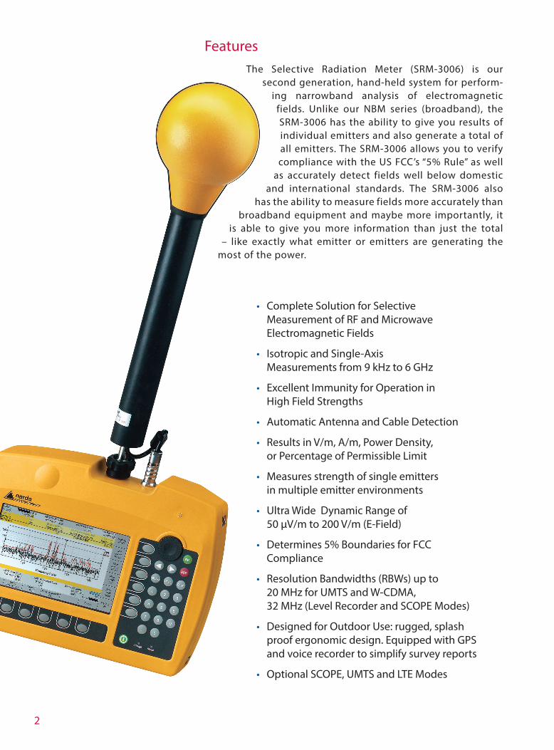
FeaturesThe Selective Radiation Meter (SRM-3006) is our
second generation, hand-held system for perform-ing narrowband analysis of electromagnetic
fields. Unlike our NBM series (broadband), the SRM-3006 has the ability to give you results of individual emitters and also generate a total of all emitters. The SRM-3006 allows you to verify compliance with the US FCC’s “5% Rule” as well
as accurately detect fields well below domestic and international standards. The SRM-3006 also
has the ability to measure fields more accurately than broadband equipment and maybe more importantly, it
is able to give you more information than just the total – like exactly what emitter or emitters are generating the
most of the power.
• Complete Solution for Selective Measurement of RF and Microwave Electromagnetic Fields
• Isotropic and Single-Axis Measurements from 9 kHz to 6 GHz
• Excellent Immunity for Operation in High Field Strengths
• Automatic Antenna and Cable Detection
• Results in V/m, A/m, Power Density, or Percentage of Permissible Limit
• Measures strength of single emitters in multiple emitter environments
• Ultra Wide Dynamic Range of 50 µV/m to 200 V/m (E-Field)
• Determines 5% Boundaries for FCC Compliance
• Resolution Bandwidths (RBWs) up to 20 MHz for UMTS and W-CDMA, 32 MHz (Level Recorder and SCOPE Modes)
• Designed for Outdoor Use: rugged, splash proof ergonomic design. Equipped with GPS and voice recorder to simplify survey reports
• Optional SCOPE, UMTS and LTE Modes
3
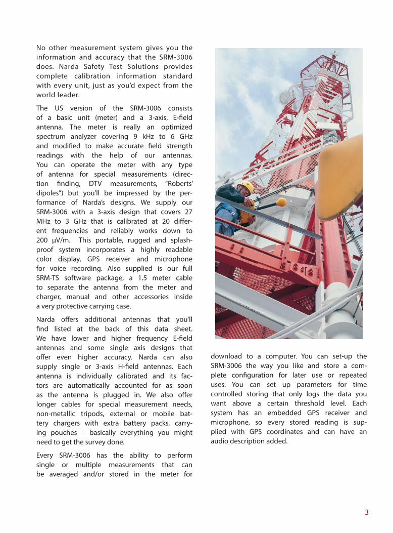
No other measurement system gives you the information and accuracy that the SRM-3006 does. Narda Safety Test Solutions provides complete calibration information standard with every unit, just as you’d expect from the world leader.
The US version of the SRM-3006 consists of a basic unit (meter) and a 3-axis, E-field antenna. The meter is really an optimized spectrum analyzer covering 9 kHz to 6 GHz and modified to make accurate field strength readings with the help of our antennas. You can operate the meter with any type of antenna for special measurements (direc-tion finding, DTV measurements, “Roberts’ dipoles”) but you’ll be impressed by the per-formance of Narda’s designs. We supply our SRM-3006 with a 3-axis design that covers 27 MHz to 3 GHz that is calibrated at 20 differ-ent frequencies and reliably works down to 200 µV/m. This portable, rugged and splash-proof system incorporates a highly readable color display, GPS receiver and microphone for voice recording. Also supplied is our full SRM-TS software package, a 1.5 meter cable to separate the antenna from the meter and charger, manual and other accessories inside a very protective carrying case.
Narda offers additional antennas that you’ll find listed at the back of this data sheet. We have lower and higher frequency E-field antennas and some single axis designs that offer even higher accuracy. Narda can also supply single or 3-axis H-field antennas. Each antenna is individually calibrated and its fac-tors are automatically accounted for as soon as the antenna is plugged in. We also offer longer cables for special measurement needs, non-metallic tripods, external or mobile bat-tery chargers with extra battery packs, carry-ing pouches – basically everything you might need to get the survey done.
Every SRM-3006 has the ability to perform single or multiple measurements that can be averaged and/or stored in the meter for
download to a computer. You can set-up the SRM-3006 the way you like and store a com-plete configuration for later use or repeated uses. You can set up parameters for time controlled storing that only logs the data you want above a certain threshold level. Each system has an embedded GPS receiver and microphone, so every stored reading is sup-plied with GPS coordinates and can have an audio description added.
4
ApplicationsThe SRM-3006 has some special capabilities when it comes to RF safety measurements. In addition we have added some other opera-tional modes (UMTS P-CPICH) for common engineering measurements. But if you simply want to perform safety measurements – the SRM-3006 makes it simple.
Safety Evaluation Mode
Have you ever made a broadband measure-ment and wish you really knew what all the emissions all around you were really adding? The Safety Evaluation Mode is a very popular method to make a reading that simply sepa-rates emitters the way you would like them displayed. We include multiple sample tables in the meter we deliver to you that you can use as is, or modify for your own geographi-cal area or interest. It’s easy to make your own tables that quickly and cleanly show the total level of individual emitters or bands. You can display the results in common field strength or equivalent power density, or the easily under-stood “% of standard” units shown below. You can easily modify these tables and identify each frequency band or emitter by the name that you choose. You can add or remove enti-ties as you see fit, thereby customizing the dis-play for your area or need. We even offer two different displays, a common tabular listing as well as a bar graph listing, making evaluation of data quick and accurate.
This is a very powerful way to display multiple emitter data in a way that even non-technical persons understand and technical persons can appreciate.
Spectrum Analysis Mode
Spectrum Analysis Mode makes finding “hidden” or “intermittent” emitters easy. Perhaps you didn’t expect a certain frequency to be used in your area, but in this mode that emitter can be quickly and easily identified by the frequency and level it’s operating at. This gives you the real story of what is hap-pening right now – when and where you are performing the measurement. The SRM-3006 allows easy settings of frequencies and reso-lution bandwidths with a powerful “marker” function that lets you see each significant signal, set a marker on it and zoom to it in a rapid manner. When it comes time to save a spectrum view the SRM saves the entire data-set rather than just a picture. With the sup-plied SRM-TS software you are able to even post-process information thereby enhancing detected data for your survey reports.
When using the SRM-3006 to “direction find” or search out “cable leakage” the Spectrum Analysis Mode with our overall system design makes it a simple, portable task. First is the SRM’s capability to add antennas into its memory. You can easily import calibration data of your existing antennas and/or cables and have the SRM account for them in its display.
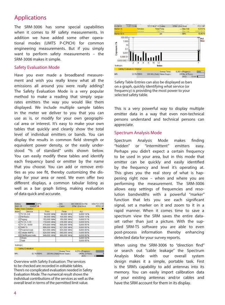
Overview with Safety Evaluation: The services to be checked are recorded in editable tables. There’s no complicated evaluation needed in Safety Evaluation Mode. The numerical result shows the individual contributions of the services as well as the overall level in terms of the permitted limit value.
Safety Table Entries can also be displayed as bars on a graph, quickly identifying what service (or frequency) is providing the most power to your selected safety table.

5
Spatial Averaging
FCC license holders will find the built-in spatial averaging feature very powerful. Broadcasters can employ the 1.5m cable along with optional antenna holders and a non-metallic tripod to make accurate and repeatable measurements at their transmitter sites. GPS logs exactly where the measurement was taken and the narrowband performance means you just survey your emissions. Cellular operators can also use the fast time averaging for a quick vertical spatial average sweep, again logging just your emission out and beyond the “5%” distance.
Level Recorder Mode
Level Recorder Mode allows you to particu-larly watch one signal or band over a long time period. The display is optimized to give you four results, Maximum Peak, Actual Peak (present reading), Maximum RMS and RMS. RMS Actual is an average over a time that you choose from 0.48 seconds to 30 minutes. This makes long term monitoring of an emitter easy and supplies all the data you might need to fully evaluate its contribution to the overall site levels.
Time Controlled Storing
The SRM can store measurements under timer control by specifying the start date, start time, measurement duration, and other parameters.
Classic Spectrum Analysis: Result evaluation using markers and delta markers. For example, the integration function can be used to deter-mine the channel power level. Special feature: Service Identification by means of pre-recorded service values.
Options
UMTS P-CPICH Demodulation
This option is useful for cellular phone com-panies and their consultants. The SRM-3006 automatically identifies every site and sector that it received a UMTS scrambling code from. The SRM-3006 can then measure the field strength (or power density) of the associated pilot channel (P-CPICH) at the same time. The SRM-3006 also shows the sum of all P-CPICH levels as an overall value (Total). The Analog measured value for the frequency channel is also shown for comparison. You can also set a factor that the SRM can use to extrapolate the field strength that would result if all channels were fully loaded. Therefore, instead of guess-ing what the UMTS signal is (at measurement time) and how it relates to the maximum pos-sible signal strength that the site could gener-ate, now you can measure and estimate with confidence.
Safety Evaluation in the UMTS Range: The individual channels with their channel numbers are shown next to each other in the bar graph display, just like a textbook. The “T” bar on the extreme right shows the total power density. The “O” bar shows the contributions from the frequency gaps (others) between the services
Scope Mode
The Scope Mode incorporates a high speed oscilloscope that displays pulse modulated signals down to a resolution of 31.25 ns. This allows high speed characterization of WiMax signals along with any other pulsed signal below 6 GHz. This mode allows the communi-cations engineer and technician an extended and powerful capability in a system that they needed already.

6
Long Term Evolution (LTE) / 4G
LTE, also generally but less correctly known as 4G (4th generation wireless), can be utilized in the frequency ranges 700 MHz, 900 MHz, 1.8 GHz, 2.1 GHz and 2.6 GHz.
As with UMTS, LTE uses individual cells, which are differentiated by their cell numbers (cell ID, 0 to 503). Each cell can also use one, two or four antennas (multiple input – multiple output, MIMO).
LTE uses a special method of modulation called orthogonal frequency domain modu-lation access (OFDMA). This distributes the information across many sub-carriers spaced at intervals of 15 kHz, each of which is modu-lated by QPSK, 16 QAM or 64 QAM. Frequency division duplex (FDD) is generally used to separate the uplink and downlink directions (from the subscriber to the base station and vice versa), although time division duplex (TDD) is also possible.
The LTE option equips users for all the crucial measurement tasks on LTE systems with FDD. The SRM 3006:
• supports all LTE channel bandwidths from 1.4 MHz to 20 MHz
• automatically determines the cell ID and number of antennas used
• measures the average power values of the PSS and SSS
• measures the average power values of the Reference Signal, separately for each antenna, or as average power of all antennas used, or as maximum power of all antennas used
• offers automatic extrapolation using factors up to 10,000
All the usual SRM 3006 result types are avail-able (see list, right), which users can select indi-vidually. Combined with the cell-specific power values, this gives up to 54 columns of results.
Display of cell-specific power values:
PSS Primary sync signal; average power
SSS Secondary sync signal; average power
RS Avg Reference signal; average power of all antennas used
RS Sum Reference signal; sum power of all antennas used
RS Max Reference signal; maximum power of all antennas used
RS 0, RS 1, RS 2, RS 3 Reference signal; average power of the individual antennas
Result types available:
• Actual, Act
• Maximum, Max
• Maximum Average, MxA
• Average, Avg
• Minimum Average, MnA
• Minimum, Min
Result of an LTE measurement with four cell-specific power values. The SRM 3006 shows the individual values obtained by demodulation and their total in the bottom line (Total) as well as the analog measured values (Analog) – similar to the UMTS option.
7
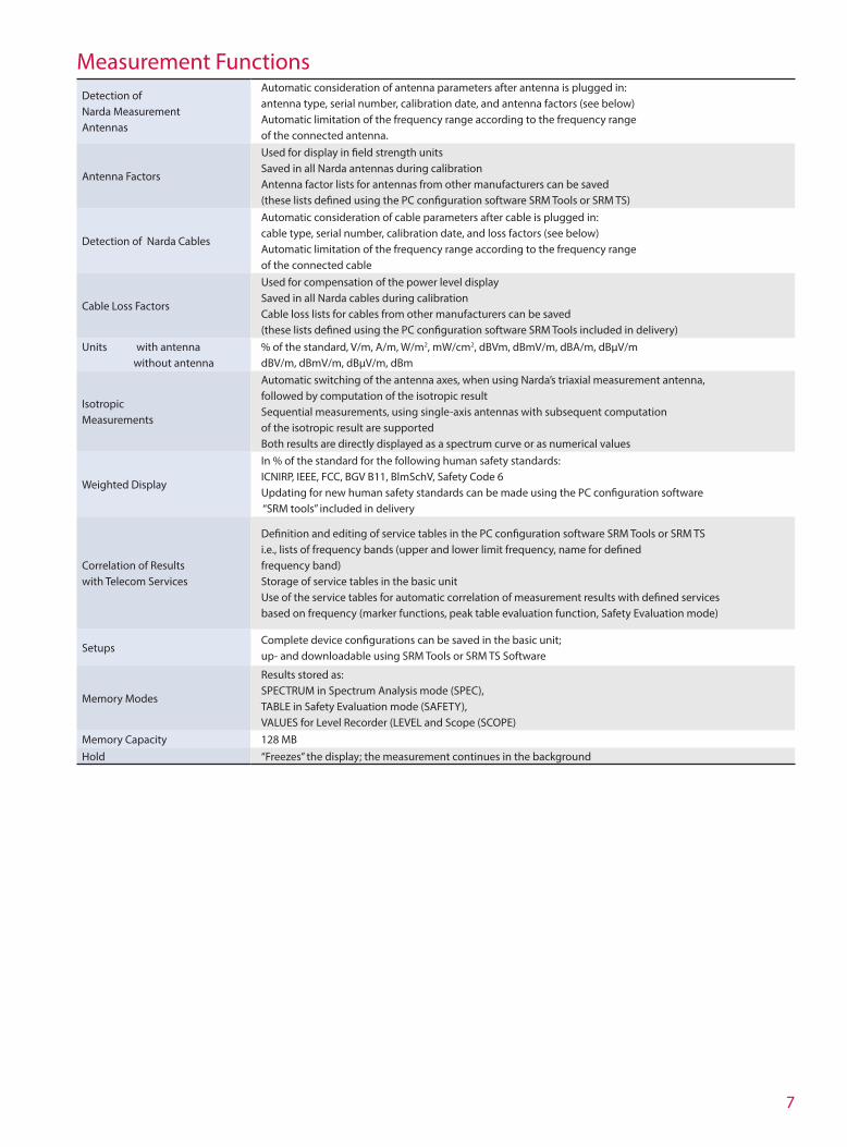
Detection of Narda Measurement Antennas
Automatic consideration of antenna parameters after antenna is plugged in: antenna type, serial number, calibration date, and antenna factors (see below)Automatic limitation of the frequency range according to the frequency range of the connected antenna.
Antenna Factors
Used for display in field strength unitsSaved in all Narda antennas during calibrationAntenna factor lists for antennas from other manufacturers can be saved (these lists defined using the PC configuration software SRM Tools or SRM TS)
Detection of Narda Cables
Automatic consideration of cable parameters after cable is plugged in: cable type, serial number, calibration date, and loss factors (see below)Automatic limitation of the frequency range according to the frequency range of the connected cable
Cable Loss Factors
Used for compensation of the power level displaySaved in all Narda cables during calibrationCable loss lists for cables from other manufacturers can be saved (these lists defined using the PC configuration software SRM Tools included in delivery)
Units with antenna without antenna
% of the standard, V/m, A/m, W/m2, mW/cm2, dBVm, dBmV/m, dBA/m, dBµV/mdBV/m, dBmV/m, dBµV/m, dBm
Isotropic Measurements
Automatic switching of the antenna axes, when using Narda’s triaxial measurement antenna, followed by computation of the isotropic resultSequential measurements, using single-axis antennas with subsequent computation of the isotropic result are supportedBoth results are directly displayed as a spectrum curve or as numerical values
Weighted Display
In % of the standard for the following human safety standards: ICNIRP, IEEE, FCC, BGV B11, BlmSchV, Safety Code 6Updating for new human safety standards can be made using the PC configuration software “SRM tools” included in delivery
Correlation of Results with Telecom Services
Definition and editing of service tables in the PC configuration software SRM Tools or SRM TS i.e., lists of frequency bands (upper and lower limit frequency, name for defined frequency band)Storage of service tables in the basic unitUse of the service tables for automatic correlation of measurement results with defined services based on frequency (marker functions, peak table evaluation function, Safety Evaluation mode)
SetupsComplete device configurations can be saved in the basic unit; up- and downloadable using SRM Tools or SRM TS Software
Memory Modes
Results stored as: SPECTRUM in Spectrum Analysis mode (SPEC), TABLE in Safety Evaluation mode (SAFETY), VALUES for Level Recorder (LEVEL and Scope (SCOPE)
Memory Capacity 128 MBHold “Freezes” the display; the measurement continues in the background
Measurement Functions

8
SpecificationsBASIC UNIT SRM-3006
Frequency Range 9 kHz to 6 GHz
ModesSpectrum Analysis Level RecorderSafety Evaluation SCOPEUMTS P-CPICH Demodulation (option)
RF FEATURES
Freq
uenc
y
Resolution Bandwidths (RBW) See specifications for each mode
Phase Noise (SSB)10 kHz carrier spacing < -70 dBc (1 Hz)300 kHz carrier spacing < -100 dBc (1 Hz)
Reference FrequencyInitial Deviation < 1.0 ppmAging < 5.0 ppm over 15 yearsThermal Drift < 1.5 ppm (within specified operating temperature range)
Am
plitu
de
Measurement Range Setting (MR) -30 dBm to +20 dBm (in steps of 1 dB)
Display Range 1 dB above the measurement range
Maximum RF Power Level +27 dBm
Maximum DC Voltage 50 V
Intrinsic Noise
<MR -100 dB for RBW = 1 kHz and f ≤ 30 MHz <MR -96 dB for RBW = 1 kHz and f ≤ 2 GHz <MR -95 dB for RBW = 1 kHz and f ≤ 4 GHz <MR -90 dB for RBW = 1 kHz and f ≤ 6 GHz
RF Attenuation 0 to 50 dB in steps of 1 dB (coupled with measurement range)
2nd Order Intermodulation Products≤ -40 dBc for two signals of level 6 dB below MR and a spectral line spacing of more than 1 MHz
3rd Order Intermodulation Products≤ -60 dBc for two signals of level 6 dB below MR and a spectral line spacing of more than 1 MHz
Extended Level Measurement Uncertainty
< 1.1 dB for the entire frequency band (within the temperature range from 15°C to 30°C)< ±1.2 dB SA and SE Modes only
Spurious Responses (input-related) < - 60 dBc or MR - 60 dB (whichever is worse)
Spurious Responses (residual)< -90 dBm or MR -60 dB (whichever is worse) Except the following frequency range: 294 to 306 MHz, where the value is < -85 dBm or MR -55 dB (whichever is worse)
RF In
put Type N Connector, 50 Ω
Return Loss>12 dB for 1 kHz RBW, f ≤ 4.5 GHz and MR ≥ -28 dBm >10 dB for 1 kHz RBW, f > 4.5 GHz and MR ≥ -28 dBm
9
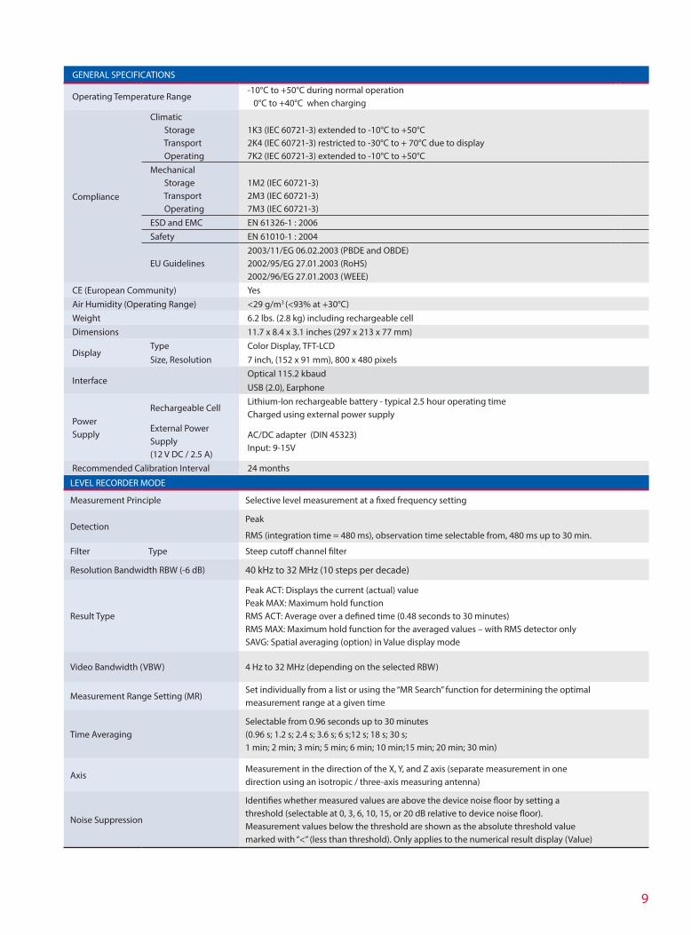
GENERAL SPECIFICATIONS
Operating Temperature Range-10°C to +50°C during normal operation 0°C to +40°C when charging
Compliance
Climatic Storage Transport Operating
1K3 (IEC 60721-3) extended to -10°C to +50°C2K4 (IEC 60721-3) restricted to -30°C to + 70°C due to display7K2 (IEC 60721-3) extended to -10°C to +50°C
Mechanical Storage Transport Operating
1M2 (IEC 60721-3)2M3 (IEC 60721-3)7M3 (IEC 60721-3)
ESD and EMC EN 61326-1 : 2006Safety EN 61010-1 : 2004
EU Guidelines2003/11/EG 06.02.2003 (PBDE and OBDE) 2002/95/EG 27.01.2003 (RoHS) 2002/96/EG 27.01.2003 (WEEE)
CE (European Community) YesAir Humidity (Operating Range) <29 g/m3 (<93% at +30°C)Weight 6.2 lbs. (2.8 kg) including rechargeable cellDimensions 11.7 x 8.4 x 3.1 inches (297 x 213 x 77 mm)
DisplayType Color Display, TFT-LCDSize, Resolution 7 inch, (152 x 91 mm), 800 x 480 pixels
InterfaceOptical 115.2 kbaudUSB (2.0), Earphone
Power Supply
Rechargeable CellLithium-Ion rechargeable battery - typical 2.5 hour operating time Charged using external power supply
External Power Supply (12 V DC / 2.5 A)
AC/DC adapter (DIN 45323) Input: 9-15V
Recommended Calibration Interval 24 months
LEVEL RECORDER MODE
Measurement Principle Selective level measurement at a fixed frequency setting
DetectionPeak
RMS (integration time = 480 ms), observation time selectable from, 480 ms up to 30 min.
Filter Type Steep cutoff channel filter
Resolution Bandwidth RBW (-6 dB) 40 kHz to 32 MHz (10 steps per decade)
Result Type
Peak ACT: Displays the current (actual) valuePeak MAX: Maximum hold functionRMS ACT: Average over a defined time (0.48 seconds to 30 minutes) RMS MAX: Maximum hold function for the averaged values – with RMS detector onlySAVG: Spatial averaging (option) in Value display mode
Video Bandwidth (VBW) 4 Hz to 32 MHz (depending on the selected RBW)
Measurement Range Setting (MR)Set individually from a list or using the “MR Search” function for determining the optimal measurement range at a given time
Time AveragingSelectable from 0.96 seconds up to 30 minutes (0.96 s; 1.2 s; 2.4 s; 3.6 s; 6 s;12 s; 18 s; 30 s; 1 min; 2 min; 3 min; 5 min; 6 min; 10 min;15 min; 20 min; 30 min)
AxisMeasurement in the direction of the X, Y, and Z axis (separate measurement in one direction using an isotropic / three-axis measuring antenna)
Noise Suppression
Identifies whether measured values are above the device noise floor by setting a threshold (selectable at 0, 3, 6, 10, 15, or 20 dB relative to device noise floor).Measurement values below the threshold are shown as the absolute threshold value marked with “<” (less than threshold). Only applies to the numerical result display (Value)
10
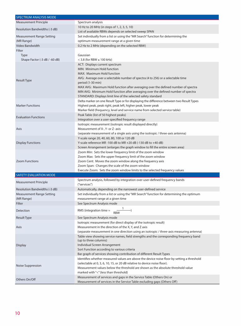
SPECTRUM ANALYSIS MODEMeasurement Principle Spectrum analysis
Resolution Bandwidths (-3 dB)10 Hz to 20 MHz (in steps of 1, 2, 3, 5, 10) List of available RBWs depends on selected sweep SPAN
Measurement Range Setting (MR Range)
Set individually from a list or using the “MR Search” function for determining the optimum measurement range at a given time
Video Bandwidth 0.2 Hz to 2 MHz (depending on the selected RBW)Filter Type Shape Factor (-3 dB / -60 dB)
Gaussian < 3.8 (for RBW ≤ 100 kHz)
Result Type
ACT: Displays current spectrum MIN: Minimum Hold function MAX: Maximum Hold function AVG: Average over a selectable number of spectra (4 to 256) or a selectable time period (1-30 min) MAX AVG: Maximum Hold function after averaging over the defined number of spectra MIN AVG: Minimum Hold function after averaging over the defined number of spectra STANDARD: Displays limit line of the selected safety standard
Marker FunctionsDelta marker on one Result Type or for displaying the difference between two Result Types Highest peak, peak right, peak left, higher peak, lower peak Marker field (frequency, level and service name from selected service table)
Evaluation FunctionsPeak Table (list of 50 highest peaks)Integration over a user-specified frequency range
AxisIsotropic measurement (isotropic result displayed directly) Measurement of X-, Y- or Z- axis (separate measurement of a single axis using the isotropic / three-axis antenna)
Display FunctionsY-scale range 20, 40, 60, 80, 100 or 120 dB Y-scale reference MR -100 dB to MR +20 dB (-130 dB to +40 dB) Screen Arrangement (enlarges the graph window to fill the entire screen area)
Zoom Functions
Zoom Min: Sets the lower frequency limit of the zoom window Zoom Max: Sets the upper frequency limit of the zoom window Zoom Cent: Moves the zoom window along the frequency axis Zoom Span: Changes the scale of the zoom window Execute Zoom: Sets the zoom window limits to the selected frequency values
SAFETY EVALUATION MODE
Measurement PrincipleSpectrum analysis, followed by integration over user-defined frequency bands (“services”)
Resolution Bandwidths (-3 dB) Automatically, depending on the narrowest user-defined serviceMeasurement Range Setting (MR Range)
Set individually from a list or using the “MR Search” function for determining the optimum measurement range at a given time
Filter See Spectrum Analysis mode
Detection RMS (integration time ≈ 1
) RBW
Result Type See Spectrum Analysis mode
AxisIsotropic measurement (for direct display of the isotropic result) Measurement in the direction of the X, Y, and Z axis (separate measurement in one direction using an isotropic / three-axis measuring antenna)
Display
Table view showing service names, field strengths and the corresponding frequency band (up to three columns) Individual Screen Arrangement Sort Function according to various criteria Bar graph of services showing contribution of different Result Types
Noise Suppression
Identifies whether measured values are above the device noise floor by setting a threshold (selectable at 0, 3, 6, 10, 15, or 20 dB relative to device noise floor). Measurement values below the threshold are shown as the absolute threshold value marked with “<” (less than threshold)
Others On/OffMeasurement of services and gaps in the Service Table (Others On) or Measurement of services in the Service Table excluding gaps (Others Off )
11
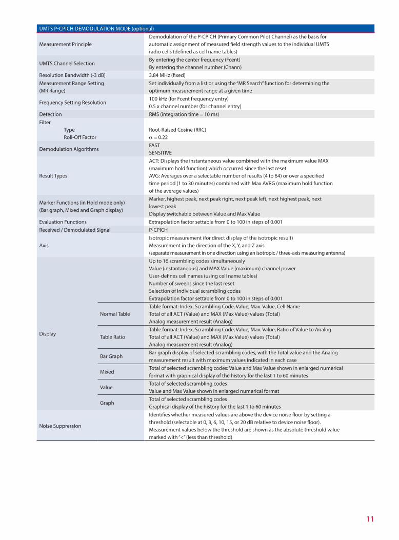
UMTS P-CPICH DEMODULATION MODE (optional)
Measurement PrincipleDemodulation of the P-CPICH (Primary Common Pilot Channel) as the basis for automatic assignment of measured field strength values to the individual UMTS radio cells (defined as cell name tables)
UMTS Channel SelectionBy entering the center frequency (Fcent) By entering the channel number (Chann)
Resolution Bandwidth (-3 dB) 3.84 MHz (fixed)Measurement Range Setting (MR Range)
Set individually from a list or using the “MR Search” function for determining the optimum measurement range at a given time
Frequency Setting Resolution100 kHz (for Fcent frequency entry) 0.5 x channel number (for channel entry)
Detection RMS (integration time = 10 ms)Filter Type Roll-Off Factor
Root-Raised Cosine (RRC)α = 0.22
Demodulation AlgorithmsFASTSENSITIVE
Result Types
ACT: Displays the instantaneous value combined with the maximum value MAX (maximum hold function) which occurred since the last resetAVG: Averages over a selectable number of results (4 to 64) or over a specified time period (1 to 30 minutes) combined with Max AVRG (maximum hold function of the average values)
Marker Functions (in Hold mode only) (Bar graph, Mixed and Graph display)
Marker, highest peak, next peak right, next peak left, next highest peak, next lowest peakDisplay switchable between Value and Max Value
Evaluation Functions Extrapolation factor settable from 0 to 100 in steps of 0.001Received / Demodulated Signal P-CPICH
AxisIsotropic measurement (for direct display of the isotropic result) Measurement in the direction of the X, Y, and Z axis (separate measurement in one direction using an isotropic / three-axis measuring antenna)
Display
Up to 16 scrambling codes simultaneouslyValue (instantaneous) and MAX Value (maximum) channel powerUser-defines cell names (using cell name tables)Number of sweeps since the last resetSelection of individual scrambling codesExtrapolation factor settable from 0 to 100 in steps of 0.001
Normal TableTable format: Index, Scrambling Code, Value, Max. Value, Cell NameTotal of all ACT (Value) and MAX (Max Value) values (Total)Analog measurement result (Analog)
Table RatioTable format: Index, Scrambling Code, Value, Max. Value, Ratio of Value to AnalogTotal of all ACT (Value) and MAX (Max Value) values (Total)Analog measurement result (Analog)
Bar GraphBar graph display of selected scrambling codes, with the Total value and the Analog measurement result with maximum values indicated in each case
MixedTotal of selected scrambling codes: Value and Max Value shown in enlarged numerical format with graphical display of the history for the last 1 to 60 minutes
ValueTotal of selected scrambling codes Value and Max Value shown in enlarged numerical format
GraphTotal of selected scrambling codes Graphical display of the history for the last 1 to 60 minutes
Noise Suppression
Identifies whether measured values are above the device noise floor by setting a threshold (selectable at 0, 3, 6, 10, 15, or 20 dB relative to device noise floor).Measurement values below the threshold are shown as the absolute threshold value marked with “<” (less than threshold)
SAFETY EVALUATION MODE
Measurement PrincipleSpectrum analysis, followed by integration over user-defined frequency bands (“services”)
Resolution Bandwidths (-3 dB) Automatically, depending on the narrowest user-defined serviceMeasurement Range Setting (MR Range)
Set individually from a list or using the “MR Search” function for determining the optimum measurement range at a given time
Filter See Spectrum Analysis mode
Detection RMS (integration time ≈ 1
) RBW
Result Type See Spectrum Analysis mode
AxisIsotropic measurement (for direct display of the isotropic result) Measurement in the direction of the X, Y, and Z axis (separate measurement in one direction using an isotropic / three-axis measuring antenna)
Display
Table view showing service names, field strengths and the corresponding frequency band (up to three columns) Individual Screen Arrangement Sort Function according to various criteria Bar graph of services showing contribution of different Result Types
Noise Suppression
Identifies whether measured values are above the device noise floor by setting a threshold (selectable at 0, 3, 6, 10, 15, or 20 dB relative to device noise floor). Measurement values below the threshold are shown as the absolute threshold value marked with “<” (less than threshold)
Others On/OffMeasurement of services and gaps in the Service Table (Others On) or Measurement of services in the Service Table excluding gaps (Others Off )
12
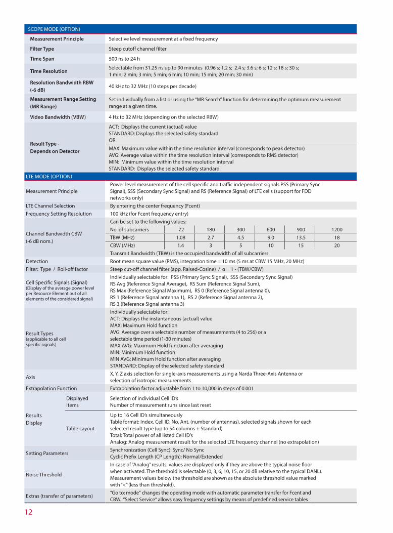
SCOPE MODE (OPTION)
Measurement Principle Selective level measurement at a fixed frequency
Filter Type Steep cutoff channel filter
Time Span 500 ns to 24 h
Time ResolutionSelectable from 31.25 ns up to 90 minutes (0.96 s; 1.2 s; 2.4 s; 3.6 s; 6 s; 12 s; 18 s; 30 s; 1 min; 2 min; 3 min; 5 min; 6 min; 10 min; 15 min; 20 min; 30 min)
Resolution Bandwidth RBW (-6 dB)
40 kHz to 32 MHz (10 steps per decade)
Measurement Range Setting (MR Range)
Set individually from a list or using the “MR Search” function for determining the optimum measurement range at a given time.
Video Bandwidth (VBW) 4 Hz to 32 MHz (depending on the selected RBW)
Result Type - Depends on Detector
ACT: Displays the current (actual) value STANDARD: Displays the selected safety standard OR
MAX: Maximum value within the time resolution interval (corresponds to peak detector) AVG: Average value within the time resolution interval (corresponds to RMS detector) MIN: Minimum value within the time resolution interval STANDARD: Displays the selected safety standard
LTE MODE (OPTION)
Measurement PrinciplePower level measurement of the cell specific and traffic independent signals PSS (Primary Sync Signal), SSS (Secondary Sync Signal) and RS (Reference Signal) of LTE cells (support for FDD networks only)
LTE Channel Selection By entering the center frequency (Fcent) Frequency Setting Resolution 100 kHz (for Fcent frequency entry)
Channel Bandwidth CBW (-6 dB nom.)
Can be set to the following values: No. of subcarriers 72 180 300 600 900 1200TBW (MHz) 1.08 2.7 4.5 9.0 13.5 18CBW (MHz) 1.4 3 5 10 15 20Transmit Bandwidth (TBW) is the occupied bandwidth of all subcarriers
Detection Root mean square value (RMS), integration time = 10 ms (5 ms at CBW 15 MHz, 20 MHz)Filter: Type / Roll-off factor Steep cut-off channel filter (app. Raised-Cosine) / α = 1 - (TBW/CBW)
Cell Specific Signals (Signal) (Display of the average power level per Resource Element out of all elements of the considered signal)
Individually selectable for: PSS (Primary Sync Signal), SSS (Secondary Sync Signal) RS Avg (Reference Signal Average), RS Sum (Reference Signal Sum), RS Max (Reference Signal Maximum), RS 0 (Reference Signal antenna 0), RS 1 (Reference Signal antenna 1), RS 2 (Reference Signal antenna 2), RS 3 (Reference Signal antenna 3)
Result Types (applicable to all cell specific signals)
Individually selectable for: ACT: Displays the instantaneous (actual) value MAX: Maximum Hold function AVG: Average over a selectable number of measurements (4 to 256) or a selectable time period (1-30 minutes) MAX AVG: Maximum Hold function after averaging MIN: Minimum Hold function MIN AVG: Minimum Hold function after averaging STANDARD: Display of the selected safety standard
AxisX, Y, Z axis selection for single-axis measurements using a Narda Three-Axis Antenna or selection of isotropic measurements
Extrapolation Function Extrapolation factor adjustable from 1 to 10,000 in steps of 0.001
Results Display
Displayed Items
Selection of individual Cell ID’sNumber of measurement runs since last reset
Table Layout
Up to 16 Cell ID’s simultaneouslyTable format: Index, Cell ID, No. Ant. (number of antennas), selected signals shown for each selected result type (up to 54 columns + Standard)Total: Total power of all listed Cell ID’sAnalog: Analog measurement result for the selected LTE frequency channel (no extrapolation)
Setting ParametersSynchronization (Cell Sync): Sync/ No Sync Cyclic Prefix Length (CP Length): Normal/Extended
Noise Threshold
In case of “Analog” results: values are displayed only if they are above the typical noise floor when activated. The threshold is selectable (0, 3, 6, 10, 15, or 20 dB relative to the typical DANL). Measurement values below the threshold are shown as the absolute threshold value marked with “<” (less than threshold).
Extras (transfer of parameters)“Go to: mode“ changes the operating mode with automatic parameter transfer for Fcent and CBW. “Select Service“ allows easy frequency settings by means of predefined service tables
13
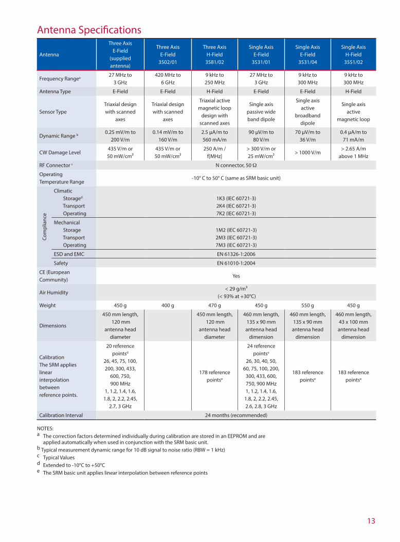
Antenna Specifications
Antenna
Three Axis E-Field
(supplied antenna)
Three Axis E-Field
3502/01
Three Axis H-Field
3581/02
Single Axis E-Field
3531/01
Single Axis E-Field
3531/04
Single Axis H-Field
3551/02
Frequency Rangea27 MHz to
3 GHz420 MHz to
6 GHz9 kHz to 250 MHz
27 MHz to 3 GHz
9 kHz to 300 MHz
9 kHz to 300 MHz
Antenna Type E-Field E-Field H-Field E-Field E-Field H-Field
Sensor TypeTriaxial design with scanned
axes
Triaxial design with scanned
axes
Triaxial active magnetic loop
design with scanned axes
Single axis passive wide band dipole
Single axis active
broadband dipole
Single axis active
magnetic loop
Dynamic Range b0.25 mV/m to
200 V/m0.14 mV/m to
160 V/m2.5 µA/m to 560 mA/m
90 µV/m to 80 V/m
70 µV/m to 36 V/m
0.4 µA/m to 71 mA/m
CW Damage Level 435 V/m or 50 mW/cm²
435 V/m or 50 mW/cm²
250 A/m / f[MHz]
> 300 V/m or 25 mW/cm²
> 1000 V/m> 2.65 A/m
above 1 MHz
RF Connector c N connector, 50 Ω
Operating Temperature Range
-10° C to 50° C (same as SRM basic unit)
Com
plia
nce
Climatic Storaged
Transport Operating
1K3 (IEC 60721-3)2K4 (IEC 60721-3)7K2 (IEC 60721-3)
Mechanical Storage Transport Operating
1M2 (IEC 60721-3)2M3 (IEC 60721-3)7M3 (IEC 60721-3)
ESD and EMC EN 61326-1:2006
Safety EN 61010-1:2004
CE (European Community)
Yes
Air Humidity< 29 g/m³
(< 93% at +30°C)
Weight 450 g 400 g 470 g 450 g 550 g 450 g
Dimensions
450 mm length, 120 mm
antenna head diameter
450 mm length, 120 mm
antenna head diameter
460 mm length, 135 x 90 mm
antenna head dimension
460 mm length, 135 x 90 mm
antenna head dimension
460 mm length, 43 x 100 mm
antenna head dimension
CalibrationThe SRM applies linear interpolation between reference points.
20 reference pointsd
26, 45, 75, 100, 200, 300, 433,
600, 750, 900 MHz
1, 1.2, 1.4, 1.6, 1.8, 2, 2.2, 2.45,
2.7, 3 GHz
178 reference pointse
24 reference pointse
26, 30, 40, 50, 60, 75, 100, 200,
300, 433, 600, 750, 900 MHz1, 1.2, 1.4, 1.6,
1.8, 2, 2.2, 2.45, 2.6, 2.8, 3 GHz
183 reference pointse
183 reference pointse
Calibration Interval 24 months (recommended)
NOTES:a The correction factors determined individually during calibration are stored in an EEPROM and are applied automatically when used in conjunction with the SRM basic unit. b Typical measurement dynamic range for 10 dB signal to noise ratio (RBW = 1 kHz)c Typical Valuesd Extended to -10°C to +50°Ce The SRM basic unit applies linear interpolation between reference points

14
Antenna Uncertaintya
THREE AXIS E-FIELD ANTENNA (supplied antenna)
Intrinsic Noise Display in conjunction with the SRM basic unit (separate measurement of a single axis) a, b
25 µV/m at 900 MHz with 1 kHz resolution bandwidth (RBW)40 µV/m at 2.1 GHz with 1 kHz resolution bandwidth (RBW)
Intrinsic Noise Display in conjunction with the SRM basic unit (for isotropic result) a
40 µV/m at 900 MHz with 1 kHz resolution bandwidth (RBW) 70 µV/m at 2.1 GHz with 1 kHz resolution bandwidth (RBW)
Measurement Range Limit (for single CW signal) 300 V/m, 1000 V/m for f ≤110 MHz
Max. Measurement Range (in conjunction with the SRM basic unit) a
200 V/m (without restrictions for total span of 27 MHz to 3 GHz)
Damage / Overload Level ≥ 1000 V/m
Extended Measurement Uncertainty b (in conjunction with SRM basic unit and 1.5 m RF cable)
Frequency Range
Single Axis Measurement with Isotropic
Antenna
Isotropic Measurement
27-85 MHz +2.4 / 3.3 dB +3.2 / -4.7 dB
86-900 MHz +2.4 / -3.4 dB +2.5 / -3.6 dB
900-1400 MHz +2.3 / -3.1 dB +2.5 / -3.4 dB
1400-1600 MHz +2.3 / -3.1 dB +2.6 / -3.8 dB
1600-1800 MHz +1.8 / -2.3 dB +2.2 / -3.0 dB
1800-2200 MHz +1.8 / -2.3 dB +2.4 / -3.3 dB
2200-2700 MHz +1.9 / -2.4 dB +2.7 / -3.8 dB
2700-3000 MHz +1.9 / -2.4 dB +3.3 / -5.3 dB
Calibration Uncertainty < 1.5 dB
THREE AXIS E-FIELD ANTENNA 3502/01
Intrinsic Noise Display in conjunction with the SRM basic unit (separate measurement of a single axis) a, b
33 µV/m at 900 MHz with 1 kHz resolution bandwidth (RBW)25 µV/m at 2.1 GHz with 1 kHz resolution bandwidth (RBW)
Intrinsic Noise Display in conjunction with the SRM basic unit (for isotropic result) a
60 µV/m at 900 MHz with 1 kHz resolution bandwidth (RBW) 43 µV/m at 2.1 GHz with 1 kHz resolution bandwidth (RBW)
Measurement Range Limit (for single CW signal) 200 V/m
Max. Measurement Range (in conjunction with the SRM basic unit) a
160 V/m (without restrictions for total span of 420 MHz to 6 GHz)
Extended Measurement Uncertainty b (in conjunction with SRM basic unit and 1.5 m RF cable)
Frequency Range
Single Axis Measurement with Isotropic
Antenna
Isotropic Measurement
420-750 MHz +2.1 / -2.9 dB +2.6 / -3.8 dB
> 750-1600 MHz +2.0 / -2.7 dB +2.2 / -2.9 dB
> 1600-2000 MHz +1.7 / -2.2 dB +1.9 / -2.4 dB
> 2000-4000 MHz +1.7 / -2.2 dB +2.0 / -2.6 dB
> 4000-4500 MHz +1.8 / -2.3 dB +2.2 / -3.0 dB
> 4500-5000 MHz +1.9 / -2.5 dB +2.5 / -3.5 dB
> 5000-6000 MHz +1.9 / -2.5 dB +2.9 / -4.3 dB
Calibration Uncertainty < 1.5 dB
THREE AXIS H-FIELD ANTENNA 3581/02
Intrinsic Noise Display in conjunction with the SRM basic unit (separate measurement of a single axis) a
0.3 µA/m with 1 kHz resolution bandwidth (RBW)
Intrinsic Noise Display in conjunction with the SRM basic unit (for isotropic result) a
0.8 µA/m with 1 kHz resolution bandwidth (RBW)
Extended Measurement Uncertainty a, b
Frequency Range
Single Axis Measurement with Isotropic
Antenna
Isotropic Measurement
0.3-30 MHz 2.1 dB 2.4 dB
30-60 MHz 2.2 dB 2.5 dB
60-250 MHz 2.3 dB 3.2 dB
Calibration Uncertainty < 1.5 dB

15
SINGLE AXIS E-FIELD ANTENNA 3531/01
Intrinsic Noise Display in conjunction with the SRM basic unit a, c
30 µV/m from 100 MHz to 2.1 GHz with 1 kHz resolution bandwidth (RBW)
Measurement Range Limit (for single CW signal) a 160 V/m
Extended Measurement Uncertainty a, b (in conjunction with SRM basic unit and 1.5m RF cable)
Frequency Range Single Axis Measurement
27-300 MHz 2.1 dB
300-433 MHz 2.4 dB
433-1600 MHz 2.2 dB
1600-3000 MHz 1.9 dB
Calibration Uncertainty < 1.5 dB
SINGLE AXIS E-FIELD ANTENNA 3531/04
Intrinsic Noise Display in conjunction with the SRM basic unit a
20 µV/m in the range from 100 MHz to 300 MHz with 1 kHz resolution bandwidth (RBW)
Measurement Range Limit (for single CW signal) a 50 V/m
Extended Measurement Uncertainty a, b (in conjunction with SRM basic unit and 1.5 m RF cable)
Frequency Range Single Axis Measurement
0.1-300 MHz 2.0 dB
Calibration Uncertainty < 1.2 dB
SINGLE AXIS H-FIELD ANTENNA 3551/02Intrinsic Noise Display in conjunction with the SRM basic unit a
0.12 µA/m for each frequency > 10 MHz with 1 kHz resolution bandwidth (RBW)
Measurement Range Limit (for single CW signal) a 100 mA/m
Extended Measurement Uncertainty a, b (in conjunction with SRM basic unit and 1.5 m RF cable)
Frequency Range Single Axis Measurement
0.1-300 MHz 2.0 dB
Calibration Uncertainty < 1.2 dB NOTES: a Typical Values b Typical value k=2 (k=extrapolation or correction factor for determining the assessment value); +15°C to +30°C c Intrinsic noise increases by 0.5 dB per 100 MHz above 2 GHz

16 STS-SRM-022013
USA 435 Moreland Road Hauppauge, NY 11788, USA Phone: +1 631 231-1700 Fax: +1 631 231-1711 E-Mail: [email protected] www.narda-sts.us
Germany Sandwiesenstrasse 7 72793 Pfullingen, Germany Phone: +49 (0) 7121-97 32-777 Fax: +49 (0) 7121-97 32-790 E-Mail: [email protected] www.narda-sts.de
Italy Via Leonardo da Vinci, 21/23 20090 Segrate (MI) ITALY Phone: +39 02 26952421 Fax: +39 02 26952406 E-Mail: [email protected] www.narda-sts.it
Safety Test Solutions
Ordering InformationSRM-3006 Order Number
Set comprising: Selective Radiation Meter SRM3006, basic unit, calibrated Triaxial antenna, E-field, 27 MHz to 3 GHz, calibrated 1.5 meter SRM RF cable, 9 kHz to 6 GHz, 50 Ω Carrying strap for SRM-3006 (basic unit) Operating manual Power supply 12.0 VDC, 100 – 240 VAC, universal AC line connector SRM-3006TS - Configuration, Evaluation and Remote Control Software USB 2.0 Cable - Master/Slave, 3 m DB9 / DB9 Cable for serial interface, 3 m Transport Hard Case
3006/127/USA
OPTIONS
UMTS P-CPICH Demodulation 3701/04
SCOPE 3701/05
LTE (for LTE FDD networks) 3701/06
OPTIONAL ANTENNAS
Three-axis E Field Antenna, 420 MHz to 6 GHz 3502/01
Three-axis H Field Antenna, 9 kHz to 250 MHz 3581/02
Single-axis E-Field Antenna, 27 MHz to 3 GHz 3531/01
Single-axis E-Field Antenna, 9 kHz to 300 MHz 3531/04
Single-axis H-Field Antenna, 9 kHz to 300 MHz 3551/02
OPTIONAL ACCESSORIES
5 meter SRM RF cable, 9 kHz to 6 GHz, 50 Ω 3602/02
Antenna holder for single axis and triaxial antennas 3501/90.01
Antenna holder for triaxial antennas (horizontal/vertical) 3501/90.02
Additional battery pack, rechargeable, 7.4 V / 4 A/h 3001/90.15
External charger set for SRM battery pack 3001/90.07
Tripod, non conductive, 1.65 m, with carrying bag 2244/90.31
Softcase with wheels 3001/90.05
O/E converter, RP-02/USB 2260/90.07
Cable, Fiber Optic Duplex, RP-02, 2m 2260/91.02
Cable, Fiber Optic Duplex, RP-02, 20 m 2260/91.03
Related Documents