Square-wave thin-film voltammetry: influence of uncompensated resistance and charge transfer kinetics Valentin Mir ceski a, * , Rubin Gulaboski b , Fritz Scholz b a Institute of Chemistry, Faculty of Natural Sciences and Mathematics, ‘‘Sv. Kiril i Metodij’’ University, P.O. Box 162, 1000 Skopje, Macedonia b Institut f€ ur Chemie und Biochemie, Ernst-Moritz-Arndt-Universit€ at Greifswald, Soldmannstraße 23, D-17489 Greifswald, Germany Received 22 July 2003; received in revised form 12 November 2003; accepted 13 November 2003 Abstract An electrode reaction occurring in a thin-film having a low electrical conductivity was considered under conditions of square- wave voltammetry (SWV). The ohmic polarization of the system owing to the low conductivity of the film is represented by the complex resistance parameter defined as q ¼ R X ðn 2 F 2 =RT ÞSc Ox ffiffiffiffiffiffi Df p , where R X is the resistance of the film, S is the electrode surface area, f is the SW frequency and the other symbols have their usual meanings. The influence of the thickness of the film is given by the thickness parameter K ¼ L ffiffiffiffiffiffiffiffiffi f =D p , where L is the thickness of the layer, and D is the diffusion coefficient. For a thin film (K 6 0:949) the dimensionless net-peak current of a reversible electrode reaction depends parabolically on the resistance parameter, exhibiting a well-developed maximum. A detailed study of this phenomenon revealed that it resembles the charge transfer kinetics effect as well as the property known as a ‘‘quasireversible maximum’’ that is typical for an adsorption complicated electrode re- action. The theoretically predicted properties of the SW response are illustrated by experiments with iodine, decamethylferrocene, and azobenzene at the three-phase electrode system. This methodology [Electrochem. Commun. 2 (2000) 112] consists of a single droplet of an organic water immiscible solvent containing an electroactive probe that is attached to the surface of a graphite electrode and immersed in an aqueous electrolyte solution. A good agreement between theory and experiment indicates that the SW voltammetric response of the three-phase electrode system exhibits properties of an electrode reaction occurring under limiting diffusion conditions. Ó 2003 Elsevier B.V. All rights reserved. Keywords: Thin-film electrode; Three-phase electrode; Square-wave voltammetry 1. Introduction The importance of the charge transfer across the li- quid j liquid (L j L) interface for living systems is well recognized and intensively studied over the last several decades [1,2]. Besides the standard experimental ar- rangement for studying the ion transfer at the interface of immiscible electrolyte solutions (ITIES) based on a four electrode configuration [3–7], in recent years a few attempts have been made to utilize a three electrode arrangement to assess both the ion and the electron transfer processes across the L j L interface. Anson and co-workers [8–13] used a solid graphite electrode, the surface of which is completely covered with a thin film of an organic liquid containing an electroactive probe and immersed in an aqueous electrolyte (see Scheme 1). The electron transfer at the carbon j organic liquid in- terface is accompanied by either ion or both ion and electron transfer across the organic liquid j aqueous so- lution interface. The method possesses a number of advantages and it is particularly useful for studying the electron transfer across the L j L interface utilizing a simple experimental arrangement [10]. However, this methodology is sensitive to the conductivity of the or- ganic film, which can be provided by partition of the electrolyte, initially present only in the aqueous phase, or alternatively by adding an organic electrolyte to the organic phase. When the conductivity is provided by partition between the aqueous electrolyte and the film, * Corresponding author. Tel.: +389-2-3117055; fax: +389-2-3226865. E-mail address: [email protected] (V. Mir ceski). 0022-0728/$ - see front matter Ó 2003 Elsevier B.V. All rights reserved. doi:10.1016/j.jelechem.2003.11.046 Journal of Electroanalytical Chemistry 566 (2004) 351–360 www.elsevier.com/locate/jelechem Journal of Electroanalytical Chemistry

Welcome message from author
This document is posted to help you gain knowledge. Please leave a comment to let me know what you think about it! Share it to your friends and learn new things together.
Transcript
Journal ofElectroanalytical
Chemistry
Journal of Electroanalytical Chemistry 566 (2004) 351–360
www.elsevier.com/locate/jelechem
Square-wave thin-film voltammetry: influence ofuncompensated resistance and charge transfer kinetics
Valentin Mir�ceski a,*, Rubin Gulaboski b, Fritz Scholz b
a Institute of Chemistry, Faculty of Natural Sciences and Mathematics, ‘‘Sv. Kiril i Metodij’’ University, P.O. Box 162, 1000 Skopje, Macedoniab Institut f€ur Chemie und Biochemie, Ernst-Moritz-Arndt-Universit€at Greifswald, Soldmannstraße 23, D-17489 Greifswald, Germany
Received 22 July 2003; received in revised form 12 November 2003; accepted 13 November 2003
Abstract
An electrode reaction occurring in a thin-film having a low electrical conductivity was considered under conditions of square-
wave voltammetry (SWV). The ohmic polarization of the system owing to the low conductivity of the film is represented by the
complex resistance parameter defined as q ¼ RXðn2F 2=RT ÞSc�Ox
ffiffiffiffiffiffiffiDf
p, where RX is the resistance of the film, S is the electrode surface
area, f is the SW frequency and the other symbols have their usual meanings. The influence of the thickness of the film is given by
the thickness parameter K ¼ Lffiffiffiffiffiffiffiffiffif =D
p, where L is the thickness of the layer, and D is the diffusion coefficient. For a thin film
(K6 0:949) the dimensionless net-peak current of a reversible electrode reaction depends parabolically on the resistance parameter,
exhibiting a well-developed maximum. A detailed study of this phenomenon revealed that it resembles the charge transfer kinetics
effect as well as the property known as a ‘‘quasireversible maximum’’ that is typical for an adsorption complicated electrode re-
action. The theoretically predicted properties of the SW response are illustrated by experiments with iodine, decamethylferrocene,
and azobenzene at the three-phase electrode system. This methodology [Electrochem. Commun. 2 (2000) 112] consists of a single
droplet of an organic water immiscible solvent containing an electroactive probe that is attached to the surface of a graphite
electrode and immersed in an aqueous electrolyte solution. A good agreement between theory and experiment indicates that the SW
voltammetric response of the three-phase electrode system exhibits properties of an electrode reaction occurring under limiting
diffusion conditions.
� 2003 Elsevier B.V. All rights reserved.
Keywords: Thin-film electrode; Three-phase electrode; Square-wave voltammetry
1. Introduction
The importance of the charge transfer across the li-
quid j liquid (L jL) interface for living systems is wellrecognized and intensively studied over the last several
decades [1,2]. Besides the standard experimental ar-
rangement for studying the ion transfer at the interface
of immiscible electrolyte solutions (ITIES) based on a
four electrode configuration [3–7], in recent years a few
attempts have been made to utilize a three electrode
arrangement to assess both the ion and the electron
transfer processes across the L jL interface. Anson andco-workers [8–13] used a solid graphite electrode, the
* Corresponding author. Tel.: +389-2-3117055; fax: +389-2-3226865.
E-mail address: [email protected] (V. Mir�ceski).
0022-0728/$ - see front matter � 2003 Elsevier B.V. All rights reserved.
doi:10.1016/j.jelechem.2003.11.046
surface of which is completely covered with a thin film
of an organic liquid containing an electroactive probe
and immersed in an aqueous electrolyte (see Scheme 1).
The electron transfer at the carbon j organic liquid in-terface is accompanied by either ion or both ion and
electron transfer across the organic liquid j aqueous so-
lution interface. The method possesses a number of
advantages and it is particularly useful for studying the
electron transfer across the L jL interface utilizing a
simple experimental arrangement [10]. However, this
methodology is sensitive to the conductivity of the or-
ganic film, which can be provided by partition of theelectrolyte, initially present only in the aqueous phase,
or alternatively by adding an organic electrolyte to the
organic phase. When the conductivity is provided by
partition between the aqueous electrolyte and the film,
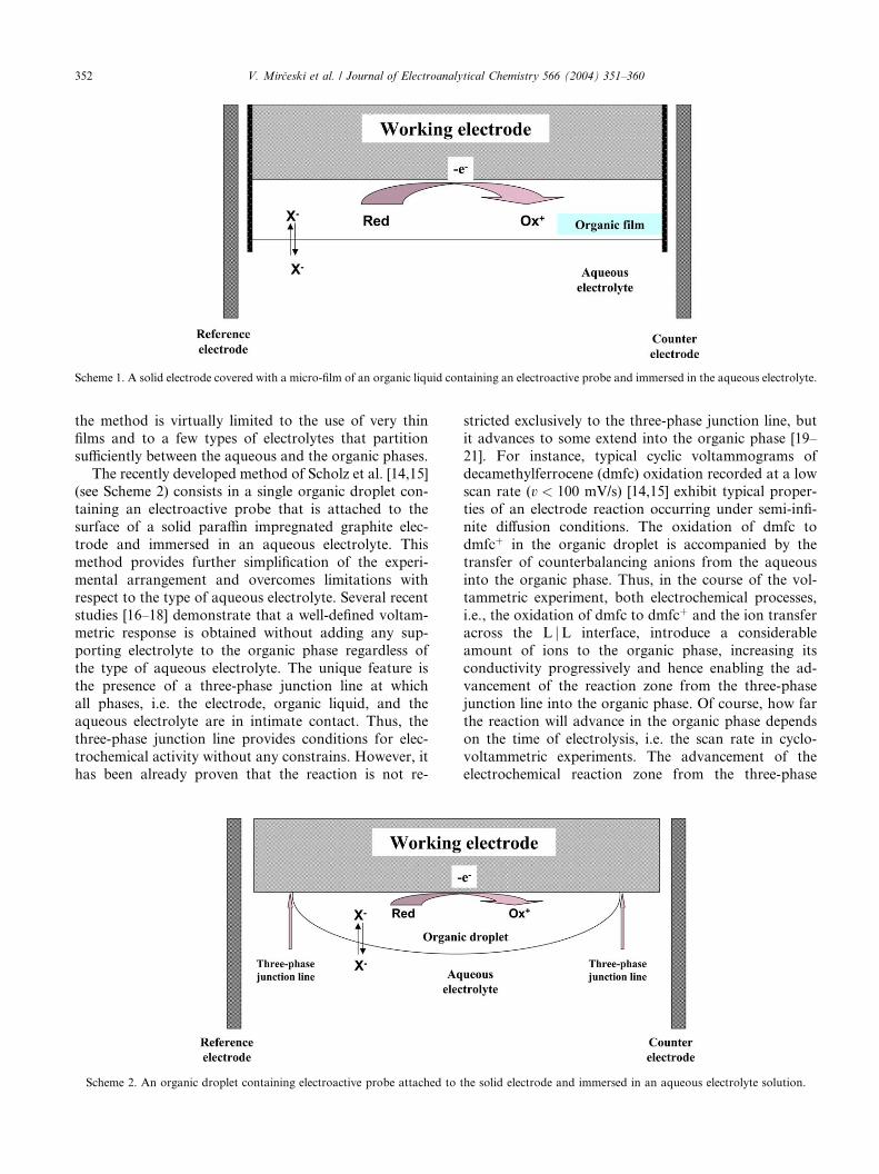
Scheme 1. A solid electrode covered with a micro-film of an organic liquid containing an electroactive probe and immersed in the aqueous electrolyte.
352 V. Mir�ceski et al. / Journal of Electroanalytical Chemistry 566 (2004) 351–360
the method is virtually limited to the use of very thin
films and to a few types of electrolytes that partition
sufficiently between the aqueous and the organic phases.
The recently developed method of Scholz et al. [14,15](see Scheme 2) consists in a single organic droplet con-
taining an electroactive probe that is attached to the
surface of a solid paraffin impregnated graphite elec-
trode and immersed in an aqueous electrolyte. This
method provides further simplification of the experi-
mental arrangement and overcomes limitations with
respect to the type of aqueous electrolyte. Several recent
studies [16–18] demonstrate that a well-defined voltam-metric response is obtained without adding any sup-
porting electrolyte to the organic phase regardless of
the type of aqueous electrolyte. The unique feature is
the presence of a three-phase junction line at which
all phases, i.e. the electrode, organic liquid, and the
aqueous electrolyte are in intimate contact. Thus, the
three-phase junction line provides conditions for elec-
trochemical activity without any constrains. However, ithas been already proven that the reaction is not re-
Scheme 2. An organic droplet containing electroactive probe attached to
stricted exclusively to the three-phase junction line, but
it advances to some extend into the organic phase [19–
21]. For instance, typical cyclic voltammograms of
decamethylferrocene (dmfc) oxidation recorded at a lowscan rate (v < 100 mV/s) [14,15] exhibit typical proper-
ties of an electrode reaction occurring under semi-infi-
nite diffusion conditions. The oxidation of dmfc to
dmfcþ in the organic droplet is accompanied by the
transfer of counterbalancing anions from the aqueous
into the organic phase. Thus, in the course of the vol-
tammetric experiment, both electrochemical processes,
i.e., the oxidation of dmfc to dmfcþ and the ion transferacross the L jL interface, introduce a considerable
amount of ions to the organic phase, increasing its
conductivity progressively and hence enabling the ad-
vancement of the reaction zone from the three-phase
junction line into the organic phase. Of course, how far
the reaction will advance in the organic phase depends
on the time of electrolysis, i.e. the scan rate in cyclo-
voltammetric experiments. The advancement of theelectrochemical reaction zone from the three-phase
the solid electrode and immersed in an aqueous electrolyte solution.
V. Mir�ceski et al. / Journal of Electroanalytical Chemistry 566 (2004) 351–360 353
boundary line towards the middle of the organic droplet
has already been proven by probing the reaction zone by
means of a micro-electrode [22].
However, using a fast voltammetric technique such
as square-wave voltammetry (SWV), it can be assumedthat the reaction is restricted to a ‘‘thin film’’ adjacent
to the three-phase junction line. Strictly speaking, this
is not a film but a prism lying on a rectangular base.
However, for the sake of simplicity, a film can be taken
as a model. The time of electrolysis is short to enable
considerable advancement of the reaction zone and
activation of the organic droplet. The true thickness of
the electrically conductive film, in which the reactioncan proceed, depends mainly on the partition of the
aqueous electrolyte between the aqueous and the or-
ganic phases.
Several authors attempted to provide a theoretical
basis for the electrode mechanism at the droplet elec-
trode [19–21,23–25]. In the first paper regarding the
modelling of this experiment, Myland and Oldham [23]
have assumed that the reaction occurs exclusively alongthe three-phase junction line, which was described geo-
metrically as a micro-hemitoroid. Later on, they have
developed a more complex theoretical model consider-
ing a thin film of an organic solvent that is free of a
supporting electrolyte and sandwiched between the
electrode and the aqueous phase [24]. In the theoretical
work of Lovric and Scholz [19], the organic droplet was
approximated as a conic film, whereas the distributionof electrochemically created ions in the organic phase
has been modelled considering a thin film of a constant
thickness [25]. Furthermore, Aoki et al. [20,21] have
modelled the experiment on the basis of a macroband
electrode. It is finally worth noting that Nakatani and
Sekine [26,27] investigated also the mass transport of
electroactive species at an oil jwater interface caused by
an electrode reaction. Their electrochemical systemconsisted of a single micro-oil droplet attached at a
micro-electrode in the water phase, but the electrode was
not in contact with the electrolyte. The mass transport
was modelled as a series combination of the elec-
trode j oil interface and the oil jwater interface. The
model is a modification of the Anson film electrode
configuration from the viewpoint of mass transport.
Therefore, consistent with the previous authors[19,24,20,27], both the film electrode of Anson and,
under certain conditions, the droplet electrode of Scholz
can be treated theoretically as a thin-film electrode with
a low conductivity of the film, i.e., under conditions of
uncompensated resistance. With this motivation, in the
present study we analyze theoretically the effect of the
uncompensated resistance on the voltammetric response
of a simple electrode reaction occurring in a limitingdiffusion space. Square-wave voltammetry is used as a
working technique. Further the influence of the charge
transfer kinetics is also analyzed, keeping in mind the
possible similarities between these two phenomena. The
theoretical results are compared with experimental re-
sults obtained with a single droplet attached to the
surface of a graphite electrode, using the reduction of
iodine [28], oxidation of dmfc [14,15], and reductionof azobenzene, all dissolved in nitrobenzene, as model
reactions.
2. Experimental
All the chemicals used were of analytical purity. 0.1
mol/l solutions of decamethylferrocene (ACR€OS, Ger-many) and iodine (Merck, Germany), as well as a 0.01
mol/l solution of azobenzene (Sigma–Aldrich, Ger-
many) were prepared by dissolution of the compounds
in water saturated nitrobenzene (NB). A droplet of these
solutions with a volume of 1 ll was attached to the
working paraffin impregnated graphite electrode (PIGE)
and immersed into the aqueous electrolyte solutions
(saturated with nitrobenzene). Square-wave voltammo-grams were recorded using the commercial electro-
chemical measuring system lAUTOLAB (Eco-Chemie,
Utrecht, Netherlands). An Ag jAgCl (saturated NaCl
solution; E ¼ 0:200 V vs. SHE) was the reference, while
the Pt wire served as an auxiliary electrode. The proce-
dure for preparing the working electrode, i.e. the par-
affin impregnated graphite electrode, is described
elsewhere [29]. Typical instrumental parameters (if notspecified otherwise) were: SW frequency f ¼ 10 Hz, SW
amplitude Esw ¼ 50 mV, and scan increment dE ¼ 0:5mV. At least three measurements were made for each
point presented in Figs. 5–9 and the average values of
the peak currents are presented. For all experiments,
Millipore Q water was used. All experiments were per-
formed at room temperature.
3. Mathematical model
The electrode reaction of two chemically stable spe-
cies, occurring in a thin film with a thickness L, is in-
vestigated
Oxþ ne� ¢Red: ðIÞ
For simplicity, the diffusion coefficients of both Ox and
Red are assumed to be equal. Furthermore, some effects
that under certain conditions could influence the overall
electrochemical process at both film and droplet elec-trodes, such as ion transfer kinetics, membrane poten-
tial, Marangoni effects, are not considered in the further
mathematical treatment. The following model repre-
sents mathematically the electrode reaction:
ocOx
ot¼ D
o2cOx
ox2; ð1Þ
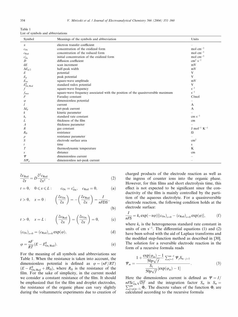
Table 1
List of symbols and abbreviations
Symbol Meanings of the symbols and abbreviation Units
a electron transfer coefficient –
cOx concentration of the oxidized form mol cm�3
cRed concentration of the reduced form mol cm�3
c�Ox initial concentration of the oxidized form mol cm�3
D diffusion coefficient cm2 s�1
dE scan increment mV
DEp=2 half-peak width mV
E potential V
Ep peak potential V
Esw square-wave amplitude mV
E;Ox=Red standard redox potential V
f square-wave frequency s�1
fmax square-wave frequency associated with the position of the quasireversible maximum s�1
F Faraday constant C/mol
u dimensionless potential –
I current A
DIp net-peak current A
k kinetic parameter –
ks standard rate constant cm s�1
L thickness of the film cm
K thickness parameter –
R gas constant J mol�1 K�1
RX resistance Xq resistance parameter –
S electrode surface area cm2
t time s
T thermodynamic temperature K
x distance cm
W dimensionless current –
DWp dimensionless net-peak current –
354 V. Mir�ceski et al. / Journal of Electroanalytical Chemistry 566 (2004) 351–360
ocRed
ot¼ D
o2cRed
ox2; ð2Þ
t ¼ 0; 06 x6 L : cOx ¼ c�Ox; cRed ¼ 0; ðaÞ
t > 0; x ¼ 0 :ocOx
ox
� �¼ � ocRed
ox
� �¼ I
nFDS;
ðbÞ
t > 0; x ¼ L :ocRed
ox
� �¼ ocOx
ox
� �¼ 0; ðcÞ
ðcOxÞx¼0 ¼ ðcRedÞx¼0 expðuÞ; ðdÞ
u ¼ nFRT
ðE � E;Ox=RedÞ: ðeÞ
For the meaning of all symbols and abbreviations seeTable 1. When the resistance is taken into account, the
dimensionless potential is defined as u ¼ ðnF =RT ÞðE � E;
Ox=Red þ IRXÞ, where RX is the resistance of the
film. For the sake of simplicity, in the current model
we consider a constant resistance of the film. It should
be emphasized that for the film and droplet electrodes,
the resistance of the organic phase can vary slightly
during the voltammetric experiments due to creation of
charged products of the electrode reaction as well as
the ingress of counter ions into the organic phase.
However, for thin films and short electrolysis time, this
effect is not expected to be significant since the con-
ductivity of the film is mainly controlled by the parti-
tion of the aqueous electrolyte. For a quasireversible
electrode reaction, the following condition holds at the
electrode surface:
InFS
¼ ks expð�auÞ½ðcOxÞx¼0 � ðcRedÞx¼0 expðuÞ�; ðfÞ
where ks is the heterogeneous standard rate constant in
units of cm s�1. The differential equations (1) and (2)have been solved with the aid of Laplace transforms and
the modified step-function method as described in [30].
The solution for a reversible electrode reaction in the
form of a recursive formula reads
Wm ¼1þ expðumÞ � 1
50pffiffiffif
p Pm�1
j¼1 WjSm�jþ1
S150p
ffiffiffif
p ½expðumÞ � 1�: ð3Þ
Here the dimensionless current is defined as W ¼ I=nFSc�Ox
ffiffiffiffiffiffiffiDf
pand the integration factor Sm is Sm ¼Ppm
i¼pðm�1Þ Ui. The discrete values of the function Ui are
calculated according to the recursive formula
V. Mir�ceski et al. / Journal of Electroanalytical Chemistry 566 (2004) 351–360 355
Ui ¼
1ffiffiffiffiffiffiffiffipid 0
p þexp
�a2
4id 0
� �ffiffiffiffiffiffiffiffipid 0
p �Xi�1
j¼1
UiMi�jþ1
Mi � 1; ð4Þ
where Mi ¼ erfcða=2ffiffiffiffiffiffiffiffiffiffiffiffiffiffiffiffiffiffiðiþ 1Þd 0
pÞ � erfcða=2
ffiffiffiffiffiffiid 0
pÞ and
a ¼ 2ðL=ffiffiffiffiD
pÞ. In deriving the above formula the main
time increment was defined as d ¼ 1=50f and the sub-
time increment d 0 ¼ d=p where p is the number of sub-intervals, and f is the SW frequency. In this work the
number of subintervals is set to p ¼ 5.
4. Theoretical results
4.1. Reversible electrode reaction
The properties of the SW voltammetric response of a
reversible electrode reaction occurring in a limiting dif-
fusion space in the absence of uncompensated resistance
are mainly controlled by the thickness parameter
K ¼ Lffiffiffiffiffiffiffiffiffif =D
p, where L is the thickness of the layer, f is
the SW frequency and D is the diffusion coefficient. The
dimensionless net-peak current (DWp) depends sigmoi-
dally on the logarithm of K (data not shown). Within theinterval �0:26 logðKÞ6 0:1 the net-peak current in-
creases linearly with K. For logðKÞ < �0:5 the diffusion
has no effect on the response, and the behavior of the
system is similar to a surface confined electrode reaction
[31], whereas for logðKÞ > 0:2, the thickness of the layer
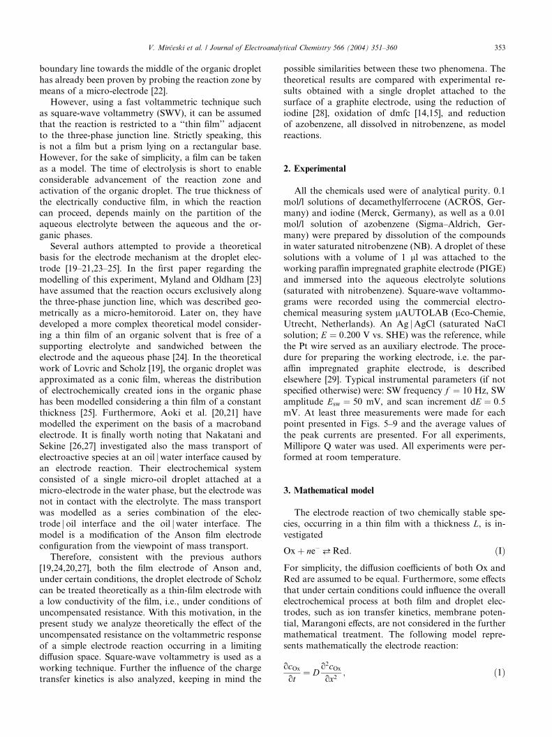
Fig. 1. Dimensionless SW voltammetric response of a reversible elec-
trode reaction occurring in a film with a thickness parameter
K ¼ 0:632. The signal parameters were: SW amplitude nEsw ¼ 50 mV
and the scan increment dE ¼ 10 mV. Wf ; Wb; Wnet are symbols for
forward, backward and net components of the SW voltammetric re-
sponse, respectively.
is bigger than the diffusion layer and the reaction occurs
under conditions of semi-infinite planar diffusion.
A typical voltammetric response of a film with a
thickness parameter K ¼ 0:632 is shown in Fig. 1.
Typical for the film voltammetry is the bell-shape ofboth the forward and backward components of the SW
response. On the contrary, for a semi-infinite diffusion
controlled reaction, these components have the shape
of a wave. Furthermore, the peak potentials as well as
peak currents of both the forward and backward
components are virtually identical. The relationship
between the real net-peak current and the SW fre-
quency depends on the thickness of the film. ForL > 10 lm and D ¼ 1� 10�5 cm2 s�1, the real net-peak
current depends linearly on the square-root of the
frequency, over the frequency interval from 10 to 1000
Hz, whereas for L < 2 lm the dependence deviates
from linearity. For thin films the peak current ratio of
the forward and backward components is sensitive to
the frequency. For instance, it varies from 1.19 to 1.45
over the frequency interval 106 f =Hz6 1000, which isvalid for L < 10 lm and D ¼ 1� 10�5 cm2 s�1. It is
important to emphasize that the frequency has no in-
fluence upon the peak potential of all components of
the response and their values are identical with the
formal potential of the redox system.
In the case of an uncompensated resistance, besides
the thickness parameter, the reaction is controlled by the
dimensionless resistance parameter q ¼ RXðn2F 2=RT ÞSc�Ox
ffiffiffiffiffiffiffiDf
p, where RX is the resistance of the film. The
overall voltammetric behaviour of the system changes
with the resistance parameter. The influence of the re-
sistance parameter upon the response depends on the
thickness of the layer. Generally, the thicker the film, the
smaller the effect of the resistance parameter. The min-
imal values of the resistance parameter exhibiting an
influence on the response are listed in Table 2 for dif-ferent thicknesses of the film. For K < 0:949, all com-
ponents of the response are appreciably sensitive to the
resistance parameter. In Fig. 2 are shown the SW re-
sponses of the film with a thickness parameter K ¼ 0:632
Table 2
Minimal values of the resistance parameter qmin that affect the SW
voltammetric response of a reversible electrode reaction for different
thicknesses of the film
L (lm) qmin
1 0.1
2 0.03
5 0.04
10 2
50 3
500 4
The conditions of the simulations were: diffusion coefficient
D ¼ 1� 10�5 cm2 s�1, SW frequency f ¼ 100 Hz, SW amplitude
nEsw ¼ 50 mV, and scan increment dE ¼ 10 mV.
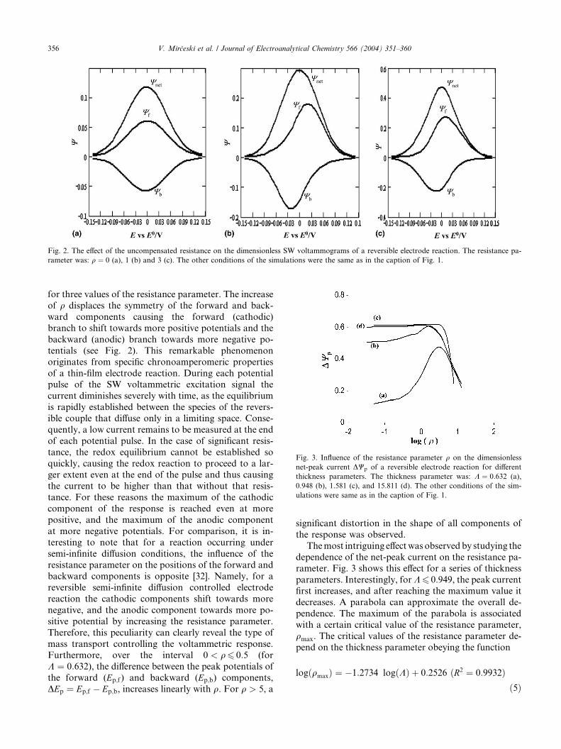
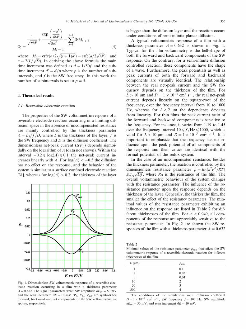
Fig. 3. Influence of the resistance parameter q on the dimensionless
net-peak current DWp of a reversible electrode reaction for different
thickness parameters. The thickness parameter was: K ¼ 0:632 (a),
0.948 (b), 1.581 (c), and 15.811 (d). The other conditions of the sim-
ulations were same as in the caption of Fig. 1.
Fig. 2. The effect of the uncompensated resistance on the dimensionless SW voltammograms of a reversible electrode reaction. The resistance pa-
rameter was: q ¼ 0 (a), 1 (b) and 3 (c). The other conditions of the simulations were the same as in the caption of Fig. 1.
356 V. Mir�ceski et al. / Journal of Electroanalytical Chemistry 566 (2004) 351–360
for three values of the resistance parameter. The increase
of q displaces the symmetry of the forward and back-
ward components causing the forward (cathodic)
branch to shift towards more positive potentials and the
backward (anodic) branch towards more negative po-
tentials (see Fig. 2). This remarkable phenomenon
originates from specific chronoamperomeric properties
of a thin-film electrode reaction. During each potentialpulse of the SW voltammetric excitation signal the
current diminishes severely with time, as the equilibrium
is rapidly established between the species of the revers-
ible couple that diffuse only in a limiting space. Conse-
quently, a low current remains to be measured at the end
of each potential pulse. In the case of significant resis-
tance, the redox equilibrium cannot be established so
quickly, causing the redox reaction to proceed to a lar-ger extent even at the end of the pulse and thus causing
the current to be higher than that without that resis-
tance. For these reasons the maximum of the cathodic
component of the response is reached even at more
positive, and the maximum of the anodic component
at more negative potentials. For comparison, it is in-
teresting to note that for a reaction occurring under
semi-infinite diffusion conditions, the influence of theresistance parameter on the positions of the forward and
backward components is opposite [32]. Namely, for a
reversible semi-infinite diffusion controlled electrode
reaction the cathodic components shift towards more
negative, and the anodic component towards more po-
sitive potential by increasing the resistance parameter.
Therefore, this peculiarity can clearly reveal the type of
mass transport controlling the voltammetric response.Furthermore, over the interval 0 < q6 0:5 (for
K ¼ 0:632), the difference between the peak potentials of
the forward (Ep;f ) and backward (Ep;b) components,
DEp ¼ Ep;f � Ep;b, increases linearly with q. For q > 5, a
significant distortion in the shape of all components of
the response was observed.
Themost intriguing effectwas observed by studying the
dependence of the net-peak current on the resistance pa-
rameter. Fig. 3 shows this effect for a series of thickness
parameters. Interestingly, forK6 0:949, the peak currentfirst increases, and after reaching the maximum value it
decreases. A parabola can approximate the overall de-
pendence. The maximum of the parabola is associated
with a certain critical value of the resistance parameter,
qmax. The critical values of the resistance parameter de-
pend on the thickness parameter obeying the function
logðqmaxÞ ¼ �1:2734 logðKÞ þ 0:2526 ðR2 ¼ 0:9932Þð5Þ
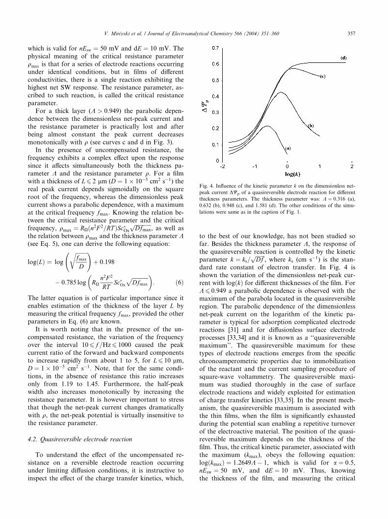
Fig. 4. Influence of the kinetic parameter k on the dimensionless net-
peak current DWp of a quasireversible electrode reaction for different
thickness parameters. The thickness parameter was: K ¼ 0:316 (a),
0.632 (b), 0.948 (c), and 1.581 (d). The other conditions of the simu-
lations were same as in the caption of Fig. 1.
V. Mir�ceski et al. / Journal of Electroanalytical Chemistry 566 (2004) 351–360 357
which is valid for nEsw ¼ 50 mV and dE ¼ 10 mV. The
physical meaning of the critical resistance parameter
qmax is that for a series of electrode reactions occurring
under identical conditions, but in films of different
conductivities, there is a single reaction exhibiting thehighest net SW response. The resistance parameter, as-
cribed to such reaction, is called the critical resistance
parameter.
For a thick layer (K > 0:949) the parabolic depen-
dence between the dimensionless net-peak current and
the resistance parameter is practically lost and after
being almost constant the peak current decreases
monotonically with q (see curves c and d in Fig. 3).In the presence of uncompensated resistance, the
frequency exhibits a complex effect upon the response
since it affects simultaneously both the thickness pa-
rameter K and the resistance parameter q. For a film
with a thickness of L6 2 lm (D ¼ 1� 10�5 cm2 s�1) the
real peak current depends sigmoidally on the square
root of the frequency, whereas the dimensionless peak
current shows a parabolic dependence, with a maximumat the critical frequency fmax. Knowing the relation be-
tween the critical resistance parameter and the critical
frequency, qmax ¼ RXðn2F 2=RT ÞSc�Ox
ffiffiffiffiffiffiffiffiffiffiffiffiDfmax
p, as well as
the relation between qmax and the thickness parameter K(see Eq. 5), one can derive the following equation:
logðLÞ ¼ log
ffiffiffiffiffiffiffiffifmax
D
r !þ 0:198
� 0:785 log RXn2F 2
RTSc�Ox
ffiffiffiffiffiffiffiffiffiffiffiffiDfmax
p� �: ð6Þ
The latter equation is of particular importance since it
enables estimation of the thickness of the layer L by
measuring the critical frequency fmax, provided the other
parameters in Eq. (6) are known.
It is worth noting that in the presence of the un-
compensated resistance, the variation of the frequencyover the interval 106 f =Hz6 1000 caused the peak
current ratio of the forward and backward components
to increase rapidly from about 1 to 5, for L6 10 lm,
D ¼ 1� 10�5 cm2 s�1. Note, that for the same condi-
tions, in the absence of resistance this ratio increases
only from 1.19 to 1.45. Furthermore, the half-peak
width also increases monotonically by increasing the
resistance parameter. It is however important to stressthat though the net-peak current changes dramatically
with q, the net-peak potential is virtually insensitive to
the resistance parameter.
4.2. Quasireversible electrode reaction
To understand the effect of the uncompensated re-
sistance on a reversible electrode reaction occurringunder limiting diffusion conditions, it is instructive to
inspect the effect of the charge transfer kinetics, which,
to the best of our knowledge, has not been studied sofar. Besides the thickness parameter K, the response of
the quasireversible reaction is controlled by the kinetic
parameter k ¼ ks=ffiffiffiffiffiffiffiDf
p, where ks (cm s�1) is the stan-
dard rate constant of electron transfer. In Fig. 4 is
shown the variation of the dimensionless net-peak cur-
rent with logðkÞ for different thicknesses of the film. For
K6 0:949 a parabolic dependence is observed with the
maximum of the parabola located in the quasireversibleregion. The parabolic dependence of the dimensionless
net-peak current on the logarithm of the kinetic pa-
rameter is typical for adsorption complicated electrode
reactions [31] and for diffusionless surface electrode
processes [33,34] and it is known as a ‘‘quasireversible
maximum’’. The quasireversible maximum for these
types of electrode reactions emerges from the specific
chronoamperometric properties due to immobilizationof the reactant and the current sampling procedure of
square-wave voltammetry. The quasireversible maxi-
mum was studied thoroughly in the case of surface
electrode reactions and widely exploited for estimation
of charge transfer kinetics [33,35]. In the present mech-
anism, the quasireversible maximum is associated with
the thin films, when the film is significantly exhausted
during the potential scan enabling a repetitive turnoverof the electroactive material. The position of the quasi-
reversible maximum depends on the thickness of the
film. Thus, the critical kinetic parameter, associated with
the maximum (kmax), obeys the following equation:
logðkmaxÞ ¼ 1:2649K� 1, which is valid for a ¼ 0:5,nEsw ¼ 50 mV, and dE ¼ 10 mV. Thus, knowing
the thickness of the film, and measuring the critical
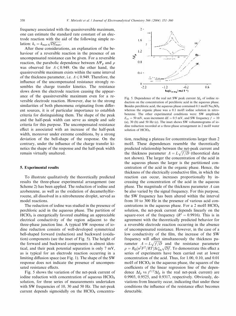
Fig. 5. Dependence of the real net SW peak current DIp of iodine re-
duction on the concentration of perchloric acid in the aqueous phase.
Besides perchloric acid, the aqueous phase contained 0.1 mol/l Na2SO4
whereas the organic phase was a 0.1 mol/l iodine solution in nitro-
benzene. The other experimental conditions were: SW amplitude
Esw ¼ 50 mV, scan increment dE ¼ 0:5 mV, and SW frequency f ¼ 10
(a), 30 (b) and 50 Hz (c). The inset shows SW voltammograms of io-
dine reduction recorded at a three-phase arrangement in 2 mol/l water
solution of HClO4.
358 V. Mir�ceski et al. / Journal of Electroanalytical Chemistry 566 (2004) 351–360
frequency associated with the quasireversible maximum,
one can estimate the standard rate constant of an elec-
trode reaction with the aid of the following simple re-
lation: ks ¼ kmax
ffiffiffiffiffiffiffiffiffiffiffiffiDfmax
p.
After these considerations, an explanation of the be-haviour of a reversible reaction in the presence of an
uncompensated resistance can be given. For a reversible
reaction, the parabolic dependence between DWp and qwas observed for K6 0:949. On the other hand, the
quasireversible maximum exists within the same interval
of the thickness parameter, i.e. K6 0:949. Therefore, theinfluence of the uncompensated resistance strongly re-
sembles the charge transfer kinetics. The resistanceslows down the electrode reaction causing the appear-
ance of the quasireversible maximum even for a re-
versible electrode reaction. However, due to the strong
similarities of both phenomena originating from differ-
ent sources, it is of particular importance to establish
criteria for distinguishing them. The shape of the peak
and the half-peak width can serve as simple and safe
criteria for this purpose. The uncompensated resistanceeffect is associated with an increase of the half-peak
width, moreover under extreme conditions, by a strong
deviation of the bell-shape of the response. On the
contrary, under the influence of the charge transfer ki-
netics the shape of the response and the half-peak width
remain virtually unaltered.
5. Experimental results
To illustrate qualitatively the theoretically predicted
results the three-phase experimental arrangement (seeScheme 2) has been applied. The reduction of iodine and
azobenzene, as well as the oxidation of decamethylfer-
rocene, all dissolved in a nitrobenzene droplet, served as
model reactions.
The reduction of iodine was studied in the presence of
perchloric acid in the aqueous phase. The partition of
HClO4 is energetically favored enabling an appreciable
electrical conductivity of the region adjacent to thethree-phase junction line. A typical SW response of io-
dine reduction consists of well-developed symmetrical
bell-shaped forward (reduction) and backward (oxida-
tion) components (see the inset of Fig. 5). The height of
the forward and backward components is almost iden-
tical, and their peak potential separation is only 7 mV,
as is typical for an electrode reaction occurring in a
limiting diffusion space (see Fig. 1). The shape of the SWresponse does not indicate the presence of uncompen-
sated resistance effects.
Fig. 5 shows the variation of the net-peak current of
iodine reduction with concentration of aqueous HClO4
solution, for three series of measurements undertaken
with SW frequencies of 10, 30 and 50 Hz. The net-peak
current depends sigmoidally on the HClO4 concentra-
tion, reaching a plateau for concentrations larger than 2
mol/l. These dependences resemble the theoretically
predicted relationship between the net-peak current and
the thickness parameter K ¼ Lffiffiffiffiffiffiffiffiffif =D
p(theoretical data
not shown). The larger the concentration of the acid inthe aqueous phases the larger is the partitioned con-
centration of the acid in the organic phase. Hence, the
thickness of the electrically conductive film, in which the
reaction can occur, increases proportionally by in-
creasing the concentration of the acid in the aqueous
phase. The magnitude of the thickness parameter K can
be also varied by the signal frequency. For this purpose,
the SW frequency has been altered within the intervalfrom 10 to 300 Hz in the presence of various acid con-
centrations in the aqueous phase. For a 2 mol/l HClO4
solution, the net-peak current depends linearly on the
square-root of the frequency (R2 ¼ 0:9916). This is in
agreement with the theoretically predicted behavior for
a reversible electrode reaction occurring in the absence
of uncompensated resistance. However, in the case of a
low conductivity of the film, the increase of the SWfrequency will affect simultaneously the thickness pa-
rameter K ¼ Lffiffiffiffiffiffiffiffiffif =D
pand the resistance parameter
q ¼ RXðn2F 2=RT ÞSc�Ox
ffiffiffiffiffiffiffiDf
p. To demonstrate this effect a
series of experiments have been carried out at lower
concentration of the acid. Thus, for 1.00, 0.10, and 0.01
mol/l of HClO4 in the aqueous phase, the squares of the
coefficients of the linear regression line of the depen-
dence DIp vs f 1=2DIp is the real net-peak current) are0.9903, 0.9525, and 0.9317, respectively. Obviously, de-
viations from linearity occur, indicating that under these
conditions the influence of the resistance effect becomes
detectable.
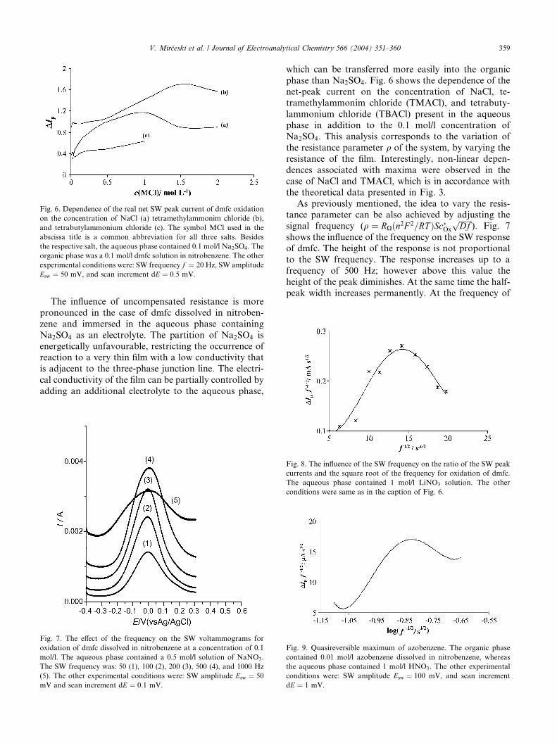
Fig. 6. Dependence of the real net SW peak current of dmfc oxidation
on the concentration of NaCl (a) tetramethylammonim chloride (b),
and tetrabutylammonium chloride (c). The symbol MCl used in the
abscissa title is a common abbreviation for all three salts. Besides
the respective salt, the aqueous phase contained 0.1 mol/l Na2SO4. The
organic phase was a 0.1 mol/l dmfc solution in nitrobenzene. The other
experimental conditions were: SW frequency f ¼ 20 Hz, SW amplitude
Esw ¼ 50 mV, and scan increment dE ¼ 0:5 mV.
V. Mir�ceski et al. / Journal of Electroanalytical Chemistry 566 (2004) 351–360 359
The influence of uncompensated resistance is more
pronounced in the case of dmfc dissolved in nitroben-
zene and immersed in the aqueous phase containing
Na2SO4 as an electrolyte. The partition of Na2SO4 isenergetically unfavourable, restricting the occurrence of
reaction to a very thin film with a low conductivity that
is adjacent to the three-phase junction line. The electri-
cal conductivity of the film can be partially controlled by
adding an additional electrolyte to the aqueous phase,
Fig. 7. The effect of the frequency on the SW voltammograms for
oxidation of dmfc dissolved in nitrobenzene at a concentration of 0.1
mol/l. The aqueous phase contained a 0.5 mol/l solution of NaNO3.
The SW frequency was: 50 (1), 100 (2), 200 (3), 500 (4), and 1000 Hz
(5). The other experimental conditions were: SW amplitude Esw ¼ 50
mV and scan increment dE ¼ 0:1 mV.
which can be transferred more easily into the organic
phase than Na2SO4. Fig. 6 shows the dependence of the
net-peak current on the concentration of NaCl, te-
tramethylammonim chloride (TMACl), and tetrabuty-
lammonium chloride (TBACl) present in the aqueousphase in addition to the 0.1 mol/l concentration of
Na2SO4. This analysis corresponds to the variation of
the resistance parameter q of the system, by varying the
resistance of the film. Interestingly, non-linear depen-
dences associated with maxima were observed in the
case of NaCl and TMACl, which is in accordance with
the theoretical data presented in Fig. 3.
As previously mentioned, the idea to vary the resis-tance parameter can be also achieved by adjusting the
signal frequency (q ¼ RXðn2F 2=RT ÞSc�Ox
ffiffiffiffiffiffiffiDf
p). Fig. 7
shows the influence of the frequency on the SW response
of dmfc. The height of the response is not proportional
to the SW frequency. The response increases up to a
frequency of 500 Hz; however above this value the
height of the peak diminishes. At the same time the half-
peak width increases permanently. At the frequency of
Fig. 8. The influence of the SW frequency on the ratio of the SW peak
currents and the square root of the frequency for oxidation of dmfc.
The aqueous phase contained 1 mol/l LiNO3 solution. The other
conditions were same as in the caption of Fig. 6.
ig. 9. Quasireversible maximum of azobenzene. The organic phase
ontained 0.01 mol/l azobenzene dissolved in nitrobenzene, whereas
he aqueous phase contained 1 mol/l HNO3. The other experimental
onditions were: SW amplitude Esw ¼ 100 mV, and scan increment
F
c
t
c
dE ¼ 1 mV.
360 V. Mir�ceski et al. / Journal of Electroanalytical Chemistry 566 (2004) 351–360
1000 Hz the response deviates strongly from the bell
shape (see curve 5 in Fig. 7). In contrast to the behavior
of the peak height and half-peak width, the peak po-
tential remained unchanged and insensitive to the in-
fluence of the resistance of the system. All these featuresof the response fit well with the theoretically predicted
behavior in the presence of uncompensated resistance.
Moreover, Fig. 8 shows the dependence of the ratio
DIpf�1=2 on f 1=2 for the oxidation of dmfc. Note that the
ratio DIpf�1=2 corresponds to the dimensionless net-
peak current and the f 1=2 to the resistance parameter q.The dependence DIpf�1=2 vs f 1=2 is associated with a
well-developed maximum. The data presented in bothFigs. 6 and 8 confirm the theoretically predicted para-
bolic dependence of the net-peak current on the resis-
tance parameter for a reversible electrode reaction in
thin-film voltammetry (see Fig. 3).
Finally, the reduction of azobenzene in a nitroben-
zene droplet was studied as a model for a quasireversible
electrode reaction occurring under limiting diffusion
conditions. The reaction was studied in the presence of 1mol/l aqueous HNO3 solution, since the two-electron
reduction of azobenzene is accompanied by the addition
of two protons to form hydrazobenzene. Fig. 9 shows
the relationship between the ratio DIpf�1=2 and the
logarithm of the inverse square-root of the frequency.
Again, a parabolic dependence was observed. It is,
however, important to note that the half-peak width did
not vary by increasing the frequency, which is oppositeto the behavior of the system under the influence of an
uncompensated resistance, as demonstrated in the case
of dmfc. Therefore, the parabolic relationship depicted
in Fig. 9 originates mainly from kinetic effects, pre-
senting the quasireversible maximum of azobenzene
electrode reaction occurring in a thin-film. To the best of
our knowledge it is the first experimental demonstra-
tion of the quasireversible maximum in SW thin-filmvoltammetry.
Acknowledgements
V.M. thanks A.V. Humboldt-Stiftung for providing a
Return Research Fellowship; R.G. thanks Deutscher
Akademische Austauschdienst (DAAD) for provision ofa Ph.D. scholarship, and F.S. acknowledges support by
Deutsche Forschungemeinschaft (DFG) and Fonds der
Chemischen Industrie (FCI).
References
[1] H.H. Girault, D.J. Schiffrin, in: A.J. Bard (Ed.), Electroanalytical
Chemistry, vol. 15, Marcel Dekker, New York, 1989.
[2] T. Osakai, K. Ebina, in: A.G. Volkov (Ed.), Liquid Interfaces in
Chemical, Biological, and Pharmaceutical Applications, Marcel
Dekker, New York, 2001, pp. 23–49.
[3] S. Wilke, H. Wang, J. Electroanal. Chem. 475 (1999) 9.
[4] S. Wilke, T. Zerihun, J. Electroanal. Chem. 515 (2002) 52.
[5] S. Wilke, T. Zerihun, Electrochim. Acta 44 (1998) 15.
[6] S. Wilke, H. Wang, H.H. Girault, J. Electroanal. Chem. 436
(1997) 53.
[7] F. Reymond, G. Lagger, P.-A. Carrupt, H.H. Girault, J.
Electroanal. Chem. 451 (1998) 59.
[8] C. Shi, C. Anson, Anal. Chem. 70 (1998) 3114.
[9] C. Shi, C. Anson, J. Phys. Chem. B. 102 (1998) 9850.
[10] C. Shi, F.C. Anson, J. Phys. Chem. B 103 (1999) 6283.
[11] T.D. Chung, F.C. Anson, Anal. Chem. 73 (2001) 337.
[12] C. Shi, C. Anson, J. Phys. Chem. B 105 (2001) 1047.
[13] C. Shi, C. Anson, J. Phys. Chem. B 105 (2001) 8963.
[14] F. Scholz, �S. Komorsky-Lovri�c, M. Lovri�c, Electrochem. Com-
mun. 2 (2000) 112.
[15] �S. Komorsky-Lovri�c, M. Lovri�c, F. Scholz, J. Electroanal. Chem.
508 (2001) 129.
[16] �S. Komorsky-Lovri�c, K. Riedl, R. Gulaboski, V. Mir�ceski, F.
Scholz, Langmuir 18 (2002) 8000;�S. Komorsky-Lovri�c, K. Riedl, R. Gulaboski, V. Mir�ceski, F.
Scholz, Langmuir 19 (2003) 3090.
[17] R. Gulaboski, V. Mir�ceski, F. Scholz, Electrochem. Commun. 4
(2002) 277.
[18] R. Gulaboski, K. Riedl, F. Scholz, Phys. Chem. Chem. Phys. 5
(2003) 1284.
[19] M. Lovri�c, F. Scholz, J. Electroanal. Chem. 540 (2003) 89.
[20] P. Tasakorn, J. Chen, K. Aoki, J. Electroanal. Chem. 533 (2002)
119.
[21] K. Aoki, P. Tasakorn, J. Chen, J. Electroanal. Chem. 542 (2003) 51.
[22] M. Donten, Z. Stojek, F. Scholz, Electrochem. Commun. 4 (2002)
324.
[23] J.C. Myland, K.B. Oldham, Electrochem. Commun. 2 (2000) 541.
[24] J.C. Myland, K.B. Oldham, J. Electroanal. Chem. 530 (2002) 1.
[25] M. Lovri�c, �S. Komorsky-Lovri�c, Electrochem. Commun. 5 (2003)
637.
[26] K. Nakatani, T. Sekine, J. Colloid Interface Sci. 225 (2000) 251.
[27] K. Nakatani, T. Sekine, Langmuir 16 (2000) 9256.
[28] V. Mir�ceski, F. Scholz, J. Electroanal. Chem. 522 (2002) 189.
[29] F. Scholz, B. Meyer, in: A.J. Bard, I. Rubinstein (Eds.),
Electroanalytical Chemistry. A Series of Advances., vol. 20,
Marcel Dekker, New York, 1998, p. 1.
[30] V. Mir�ceski, J. Electroanal. Chem. 545 (2003) 29.
[31] M. Lovri�c, in: F. Scholz (Ed.), Electroanalytical Methods, Guide
to Experiments and Applications, Springer, Berlin, Heidelberg,
2002, p. 111.
[32] V. Mir�ceski, M. Lovri�c, J. Electroanal. Chem. 497 (2001) 114.
[33] �S. Komorsky-Lovri�c, M. Lovri�c, Anal. Chim. Acta 305 (1995) 248.
[34] V. Mir�ceski, M. Lovri�c, Electroanalysis 9 (1997) 1283.
[35] V. Mir�ceski, M. Lovri�c, B. Jordanoski, Electroanalysis 11 (1999)
660.
Related Documents