ModuL6 3“VRV #5 le 4A, A Bl 6, 2nd Wes 4/12, First VILLA” No HAN HP 4 th F 2n 58, Coles R lock – 10th t Street, K Thiruvan G Floor, Aru V o: 14/15,L.NDING O Fire Spr @ PRES C HP INDIA LOOR, PR AR Plan A Dend Floor, A Road, Fras PM CO h Floor SP Perungudi MEP Camaraj Na miyur, ChGENERAL unachalam EXEVRV ENGIN D.G Street OVER DO rinkler Sy TIGE PAL CLIENT SALES PV RESTIGE PA CHITECT signtec So Above Sony ser Town, B ONSULTA Infocity, N i Chennai 6 ONSULTA gar, Thiruv ennai, Tam L CONTRA Road, Sal CUTED B NEERS IND t, Little Mo OCUMEN ystem LLADIUM VT LTD ALLADIUM T olutions y Centre, Bangalore ANT No 40, MGR 600096. ANT vanmyur, R mil Nadu 60 ACTOR ligramam, BY DIA LLP. unt, Saida NT M M. 560 005. R Salai Kan Ranganath 00041. Chennai – pet. Chenn ndanchava ha Puram, – 600093. nai 6000 01 adi, 15.

Welcome message from author
This document is posted to help you gain knowledge. Please leave a comment to let me know what you think about it! Share it to your friends and learn new things together.
Transcript

Modul
L6
34
“VRV
#5
le 4A, A Bl
6, 2nd Wes
4/12, First
VILLA” No
HAN
HP
4th F
2n58, Coles R
lock – 10thP
t Street, KThiruvan
G
Floor, Aru
Vo: 14/15,L.D
NDING OFire Spr
@ PRESC
HP INDIA LOOR, PR
AR
Plan A Desnd Floor, ARoad, Fras
PM CO
h Floor SP Perungudi
MEP CO
amaraj Namiyur, Che
GENERAL
unachalam
EXEC
VRV ENGIND.G Street
OVER DOrinkler Sy
TIGE PAL
CLIENT
SALES PVRESTIGE PA
CHITECT
signtec SoAbove Sonyser Town, B
ONSULTA
Infocity, Ni Chennai 6
ONSULTA
gar, Thiruvennai, Tam
L CONTRA
Road, Sal
CUTED B
NEERS INDt, Little Mo
OCUMENystem
LLADIUM
VT LTD ALLADIUM
T
olutions y Centre,Bangalore
ANT
No 40, MGR600096.
ANT
vanmyur, R
mil Nadu 60
ACTOR
ligramam,
BY
DIA LLP. unt, Saida
NT
M
M.
560 005.
R Salai Kan
Ranganath00041.
Chennai –
pet. Chenn
ndanchava
ha Puram,
– 600093.
nai 6000 01
adi,
15.
Handover Documents
S.No Description YES NO Remarks 1 Virtual Completion Certificate □ □ 2 No Dues Certificate □ □ 3 Warranty Certificate □ □
4 Warranty Certificate given by OEM/ Supplier
□ □
5 Design Concept/ Scope of Work □ □ 6 Testing & Commissioning Reports □ □ 7 Technical Data Sheets / Brochures □ □ 8 Operation Manuals □ □ 9 Do s / Don'ts □ □ 10 Maintenance Schedule □ □ 11 Call Escalation Chart □ □ 12 OEM / Suppliers Contact Details □ □ 13 Recommended Spares List □ □ 14 Recommended Tools for Maintenance □ □ 15 Inventory List/ Asset List □ □ 16 Attic Stock / Balance Material □ □
17 As Built Drawings Hard Copy and Soft Copy
□ □
18 WO/ PO Copy □ □ 19 Accepted Snag List □ □ 20 Practical Completion Certificate □ □ 21 Training Attendance □ □ 22 Extra Plastic Folders for Drawings / CD □ □
ACME Interiors Pvt. Ltd. CBRE
VRV Engineers India LLP. CLIENT
S.No
Table Of Contents
1. Virtual Completion Certificate
2. No Dues Certificate
3. Warranty Certificate
4. Warranty Certificate given by OEM/ Supplier
5. Design Concept / Scope of Work
6. Testing & Commissioning Reports
7. Technical Data Sheets / Brochures
8. Operation Manuals
9. Do s / Don'ts
10. Maintenance Schedule
11. Call Escalation Chart
12. OEM / Suppliers Contact Details
13. Recommended Spares List
14. Recommended Tools for Maintenance
15. Inventory List/ Asset List
16. Attic Stock / Balance Material
17. As Built Drawings Hard Copy and Soft Copy
18. WO/ PO Copy
19. Accepted Snag List
20. Practical Completion Certificate
21. Training Attendance
22. Extra Plastic Folders for Drawings / CD
VIRTUAL COMPLETION CERTIFICATE

“VRV VILLA” No: 14/15, LDG Street, Little Mount, Saidapet, Chennai-600015 Land Line – 044 – 2235 1856 |www.vrvgroup.in
Tamil Nadu | Pondicherry | Kerala | Andhra Pradesh | Karnataka
COMPLETION CERTIFICATE
Project Name: SPRINKLER- HP ` Date: P.O. REFERENCE:
M/S VRVENGINEERS INDIA LLP was awarded the work of Supply, Installation and Commissioning of Fire Sprinkler System for HP sales office at Prestige Palladium. The said work has been carried out at site according to the work orders. Entire design has been checked by us and conforms to the design intent As built drawing and technical documents are appended for submission and final payment should be released as per condition of contract/purchase order/ work order. Now the entire Sprinkler system is under defects liability period of one year they identified. The project is now handed over to the client for their benefit of use. VRV Engineers India LLP. CBRE
ACME Interiors Pvt. Ltd. CLIENT

NO DUES CERTIFICATE

NA

WARRANTY CERTIFICATE
“VRV VILLA” No: 14/15, LDG Street, Little Mount, Saidapet, Chennai-600015
Land Line – 044 – 2235 1856 |www.vrvgroup.in Tamil Nadu | Pondicherry | Kerala | Andhra Pradesh | Karnataka
WARRANTY CERTIFICATE FOR SPRINKLER SYSTEM
We refer to the supply and installation of Fire Sprinkler System, VRV ENGINEERS INDIA LLP warrants its system to be free from defects in material and workmanship for a period of one (1) year from the date of handing over. The comprehensive warranty of one year from date of handover is from ____________ to ____________. The Warranty Is Valid If:
1. Service/repair and shifting of the supplied materials is carried out only by us.
The Above Said Warranty Does Not Cover The Following:
1. Deterioration or failure of equipment & controls, pipes due to corrosive atmosphere.
During the warranty period, our service team will render 4 quarterly Maintenance checks, attend to all breakdown calls or performance related complaints promptly and diligently. Wish you 100% safety, Thanking you,
For VRV ENGINEERS INDIA LLP
J.PURUSHOTHAMAN GENERAL MANAGER

WARRANTY CERTIFICATE GIVEN BY OEM / SUPPLIER

DESIGN CONCEPT / SCOPE OF WORK
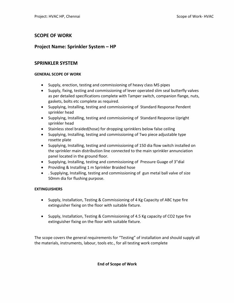
Project: HVAC HP, Chennai Scope of Work‐ HVAC
SCOPE OF WORK
Project Name: Sprinkler System – HP
SPRINKLER SYSTEM GENERAL SCOPE OF WORK
• Supply, erection, testing and commissioning of heavy class MS pipes • Supply, fixing, testing and commissioning of lever operated slim seal butterfly valves
as per detailed specifications complete with Tamper switch, companion flange, nuts, gaskets, bolts etc complete as required.
• Supplying, Installing, testing and commissioning of Standard Response Pendent sprinkler head
• Supplying, Installing, testing and commissioning of Standard Response Upright sprinkler head
• Stainless steel braided(hose) for dropping sprinklers below false ceiling • Supplying, Installing, testing and commissioning of Two piece adjustable type
rosette plate • Supplying, Installing, testing and commissioning of 150 dia flow switch installed on
the sprinkler main distribution line connected to the main sprinkler annunciation panel located in the ground floor.
• Supplying, Installing, testing and commissioning of Pressure Guage of 3"dial • Providing & Installing 1 m Sprinkler Braided hose • . Supplying, Installing, testing and commissioning of gun metal ball valve of size
50mm dia for flushing purpose. EXTINGUISHERS
• Supply, Installation, Testing & Commissioning of 4 Kg Capacity of ABC type fire extinguisher fixing on the floor with suitable fixture.
• Supply, Installation, Testing & Commissioning of 4.5 Kg capacity of CO2 type fire
extinguisher fixing on the floor with suitable fixture. The scope covers the general requirements for “Testing” of installation and should supply all the materials, instruments, labour, tools etc., for all testing work complete
End of Scope of Work
TESTING & COMMISSIONING REPORT
Test Report Sprinkler‐HP, Prestige Palladium. VRV ENGINEERS LLP
TESTING & COMMISSIONING REPORT
Project Name: Fire Sprinkler System‐ HP Date: P.O. REFERENCE: General VRV Engineers LLP served the testing & commissioning for this project for HP‐ Prestige Palladium. VRV carried out the installation, testing & commissioning of the Sprinkler System. This report summarizes the commissioning activities for completion of the T&C of the Sprinkler System. The testing & commissioning process included the following.
• Piping cleaning. • Sprinkler orientation and inspections. • Equipment and system verification checks. • Assistance in functional performance testing to verify testing and balancing
pressure and performance. • Provide qualified personnel to assist in commissioning tests, including seasonal
testing. • Complete and endorse functional performance test checklists to assure
equipment and systems are fully operational and ready for functional performance testing.
• Provide equipment, materials, and labor necessary to correct deficiencies found during commissioning process to fulfill contract and warranty requirements.
. Commissioning Check lists & Test Sheets are generated.

Checklist for Sprinkler Commissioning
Prepared by
VRV ENGINEERS INDIA LLP
S.No Description Status
1 Piping complete. Checked
2 Piping leak test complete Checked
3 Piping connected properly. Checked
4 Sprinklers are installed as required Checked
5 Piping flushed and cleaned Checked
6 Valves installed as required Checked
7 Verify open/closed status of valves Checked
8 Verify valves operation Checked
9 Flexible braided hoses are installed as specified Checked
10 Hydrostatic test complete. Checked
11 Water drain installed as specified Checked
12 Required pressure in psi at each reference point. Checked
13 Pipe size. Checked
14 Pipe lengths, center‐to center, of fittings Checked
15 Type, size and configuration of sprinkler piping Checked
16 Location of control valve and water flow switch Checked

TECHNICAL DATA SHEETS / BROUCHRES
OPERATION MANUALS
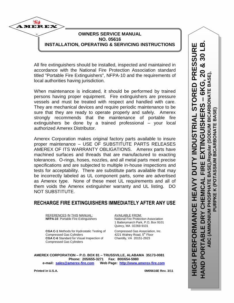
OWNERS SERVICE MANUAL NO. 05616
INSTALLATION, OPERATING & SERVICING INSTRUCTIONS
All fire extinguishers should be installed, inspected and maintained in accordance with the National Fire Protection Association standard titled "Portable Fire Extinguishers", NFPA-10 and the requirements of local authorities having jurisdiction. When maintenance is indicated, it should be performed by trained persons having proper equipment. Fire extinguishers are pressure vessels and must be treated with respect and handled with care. They are mechanical devices and require periodic maintenance to be sure that they are ready to operate properly and safely. Amerex strongly recommends that the maintenance of portable fire extinguishers be done by a trained professional – your local authorized Amerex Distributor. Amerex Corporation makes original factory parts available to insure proper maintenance – USE OF SUBSTITUTE PARTS RELEASES AMEREX OF ITS WARRANTY OBLIGATIONS. Amerex parts have machined surfaces and threads that are manufactured to exacting tolerances. O-rings, hoses, nozzles, and all metal parts meet precise specifications and are subjected to multiple in-house inspections and tests for acceptability. There are substitute parts available that may be incorrectly labeled as UL component parts, some are advertised as Amerex type. None of these meet UL requirements and all of them voids the Amerex extinguisher warranty and UL listing. DO NOT SUBSTITUTE.
RECHARGE FIRE EXTINGUISHERS IMMEDIATELY AFTER ANY USE
REFERENCES IN THIS MANUAL: AVAILABLE FROM: NFPA-10 Portable Fire Extinguishers National Fire Protection Association 1 Batterymarch Park, P.O, Box 9101 Quincy, MA 02269-9101
CGA C-1 Methods for Hydrostatic Testing of Compressed Gas Association, Inc. Compressed Gas Cylinders 4221 Walney Road, 5
th Floor
CGA C-6 Standard for Visual Inspection of Chantilly, VA 20151-2923
Compressed Gas Cylinders
AMEREX CORPORATION – P.O. BOX 81 – TRUSSVILLE, ALABAMA 35173-0081 Phone: 205/655-3271 Fax: 800/654-5980
e-mail: [email protected] Web Page: http://www.amerex-fire.com
Printed in U.S.A. 0M05616E Rev. 3/11
HIG
H P
ER
FO
RM
AN
CE
HE
AV
Y D
UT
Y I
ND
US
TR
IAL
ST
OR
ED
PR
ES
SU
RE
HA
ND
PO
RT
AB
LE
DR
Y C
HE
MIC
AL
FIR
E E
XT
ING
UIS
HE
RS
– 6
KG
, 20 &
30 L
B.
AB
C (
AM
MO
NIU
M P
HO
SP
HA
TE
BA
SE
),R
eg
ula
r (S
OD
IUM
BIC
AR
BO
NA
TE
BA
SE
),
PU
RP
KE
K (
PO
TA
SS
IUM
BIC
AR
BO
NA
TE
BA
SE
)
3
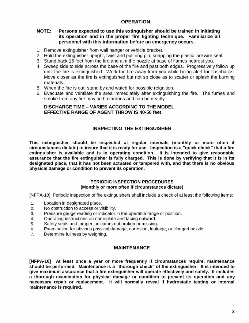
OPERATION
NOTE: Persons expected to use this extinguisher should be trained in initiating its operation and in the proper fire fighting technique. Familiarize all personnel with this information before an emergency occurs.
1. Remove extinguisher from wall hanger or vehicle bracket. 2. Hold the extinguisher upright, twist and pull ring pin, snapping the plastic lockwire seal. 3. Stand back 15 feet from the fire and aim the nozzle at base of flames nearest you. 4. Sweep side to side across the base of the fire and past both edges. Progressively follow up
until the fire is extinguished. Work the fire away from you while being alert for flashbacks. Move closer as the fire is extinguished but not so close as to scatter or splash the burning materials.
5. When the fire is out, stand by and watch for possible reignition. 6. Evacuate and ventilate the area immediately after extinguishing the fire. The fumes and
smoke from any fire may be hazardous and can be deadly.
DISCHARGE TIME – VARIES ACCORDING TO THE MODEL EFFECTIVE RANGE OF AGENT THROW IS 40-50 feet
INSPECTING THE EXTINGUISHER
PERIODIC INSPECTION PROCEDURES (Monthly or more often if circumstances dictate)
[NFPA-10] Periodic inspection of fire extinguishers shall include a check of at least the following items:
1. Location in designated place. 2. No obstruction to access or visibility. 3. Pressure gauge reading or indicator in the operable range or position. 4. Operating instructions on nameplate and facing outward. 5. Safety seals and tamper indicators not broken or missing. 6. Examination for obvious physical damage, corrosion, leakage, or clogged nozzle. 7. Determine fullness by weighing.
MAINTENANCE
[NFPA-10] At least once a year or more frequently if circumstances require, maintenance should be performed. Maintenance is a "thorough check" of the extinguisher. It is intended to give maximum assurance that a fire extinguisher will operate effectively and safely. It includes a thorough examination for physical damage or condition to prevent its operation and any necessary repair or replacement. It will normally reveal if hydrostatic testing or internal maintenance is required.
This extinguisher should be inspected at regular intervals (monthly or more often if circumstances dictate) to insure that it is ready for use. Inspection is a "quick check" that a fire extinguisher is available and is in operating condition. It is intended to give reasonable assurance that the fire extinguisher is fully charged. This is done by verifying that it is in its designated place, that it has not been actuated or tampered with, and that there is no obvious physical damage or condition to prevent its operation.
7
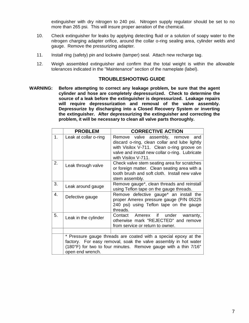
extinguisher with dry nitrogen to 240 psi. Nitrogen supply regulator should be set to no more than 265 psi. This will insure proper aeration of the chemical.
10. Check extinguisher for leaks by applying detecting fluid or a solution of soapy water to the nitrogen charging adapter orifice, around the collar o-ring sealing area, cylinder welds and gauge. Remove the pressurizing adapter.
11. Install ring (safety) pin and lockwire (tamper) seal. Attach new recharge tag.
12. Weigh assembled extinguisher and confirm that the total weight is within the allowable tolerances indicated in the "Maintenance" section of the nameplate (label).
TROUBLESHOOTING GUIDE
WARNING: Before attempting to correct any leakage problem, be sure that the agent cylinder and hose are completely depressurized. Check to determine the source of a leak before the extinguisher is depressurized. Leakage repairs will require depressurization and removal of the valve assembly. Depressurize by discharging into a Closed Recovery System or inverting the extinguisher. After depressurizing the extinguisher and correcting the problem, it will be necessary to clean all valve parts thoroughly.
PROBLEM CORRECTIVE ACTION 1. Leak at collar o-ring Remove valve assembly, remove and
discard o-ring, clean collar and lube lightly with Visilox V-711. Clean o-ring groove on valve and install new collar o-ring. Lubricate with Visilox V-711.
2. Leak through valve
Check valve stem seating area for scratches or foreign matter. Clean seating area with a tooth brush and soft cloth. Install new valve stem assembly.
3. Leak around gauge
Remove gauge*, clean threads and reinstall using Teflon tape on the gauge threads.
4. Defective gauge
Remove defective gauge* an install the proper Amerex pressure gauge (P/N 05225 240 psi) using Teflon tape on the gauge threads.
5. Leak in the cylinder
Contact Amerex if under warranty, otherwise mark "REJECTED" and remove from service or return to owner.
* Pressure gauge threads are coated with a special epoxy at the factory. For easy removal, soak the valve assembly in hot water (180°F) for two to four minutes. Remove gauge with a thin 7/16" open end wrench.
8
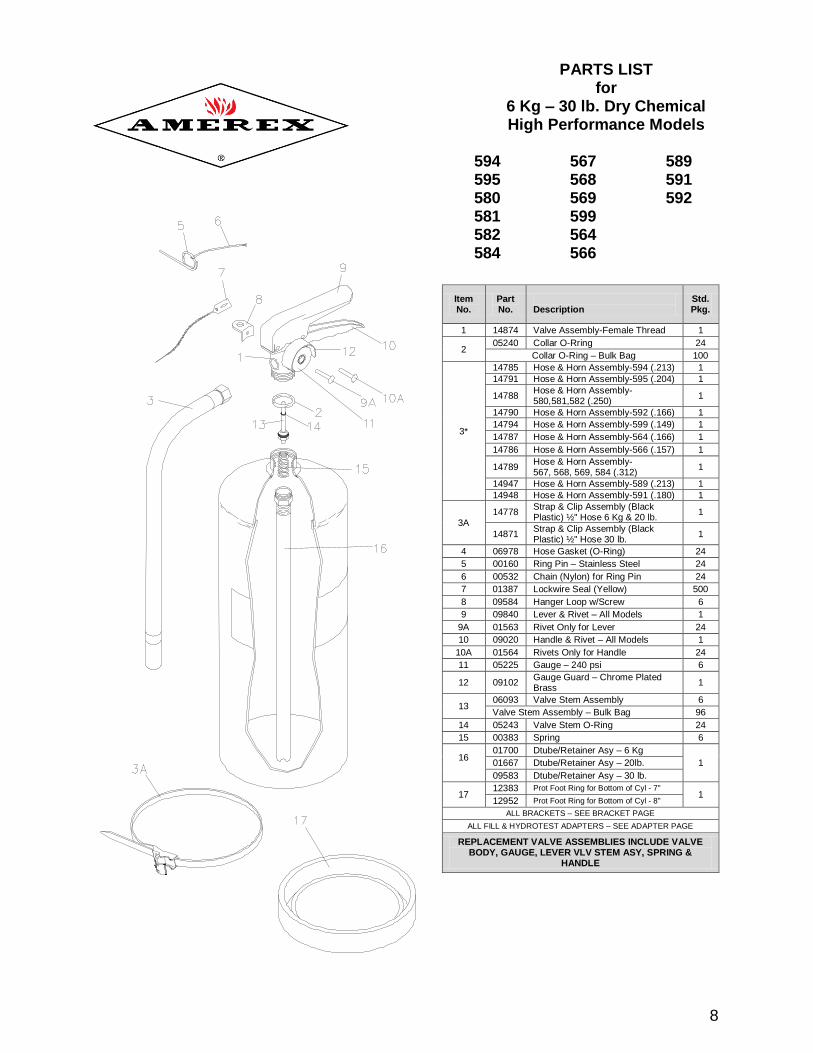
Item No.
Part No.
Description
Std. Pkg.
1 14874 Valve Assembly-Female Thread 1
2 05240 Collar O-Rring 24
Collar O-Ring – Bulk Bag 100
3*
14785 Hose & Horn Assembly-594 (.213) 1
14791 Hose & Horn Assembly-595 (.204) 1
14788 Hose & Horn Assembly-580,581,582 (.250)
1
14790 Hose & Horn Assembly-592 (.166) 1
14794 Hose & Horn Assembly-599 (.149) 1
14787 Hose & Horn Assembly-564 (.166) 1
14786 Hose & Horn Assembly-566 (.157) 1
14789 Hose & Horn Assembly- 567, 568, 569, 584 (.312)
1
14947 Hose & Horn Assembly-589 (.213) 1
14948 Hose & Horn Assembly-591 (.180) 1
3A 14778
Strap & Clip Assembly (Black Plastic) ½" Hose 6 Kg & 20 lb.
1
14871 Strap & Clip Assembly (Black Plastic) ½" Hose 30 lb.
1
4 06978 Hose Gasket (O-Ring) 24
5 00160 Ring Pin – Stainless Steel 24
6 00532 Chain (Nylon) for Ring Pin 24
7 01387 Lockwire Seal (Yellow) 500
8 09584 Hanger Loop w/Screw 6
9 09840 Lever & Rivet – All Models 1
9A 01563 Rivet Only for Lever 24
10 09020 Handle & Rivet – All Models 1
10A 01564 Rivets Only for Handle 24
11 05225 Gauge – 240 psi 6
12 09102 Gauge Guard – Chrome Plated Brass
1
13 06093 Valve Stem Assembly 6
Valve Stem Assembly – Bulk Bag 96
14 05243 Valve Stem O-Ring 24
15 00383 Spring 6
16
01700 Dtube/Retainer Asy – 6 Kg
1 01667 Dtube/Retainer Asy – 20lb.
09583 Dtube/Retainer Asy – 30 lb.
17 12383 Prot Foot Ring for Bottom of Cyl - 7"
1 12952 Prot Foot Ring for Bottom of Cyl - 8"
ALL BRACKETS – SEE BRACKET PAGE
ALL FILL & HYDROTEST ADAPTERS – SEE ADAPTER PAGE
REPLACEMENT VALVE ASSEMBLIES INCLUDE VALVE BODY, GAUGE, LEVER VLV STEM ASY, SPRING &
HANDLE
PARTS LIST for
6 Kg – 30 lb. Dry Chemical High Performance Models
594 567 589 595 568 591 580 569 592 581 599 582 564 584 566

Manual #8704200 - REV G6/10
Sprinkler Monitoring& Releasing Systems
Training Manual
10 11
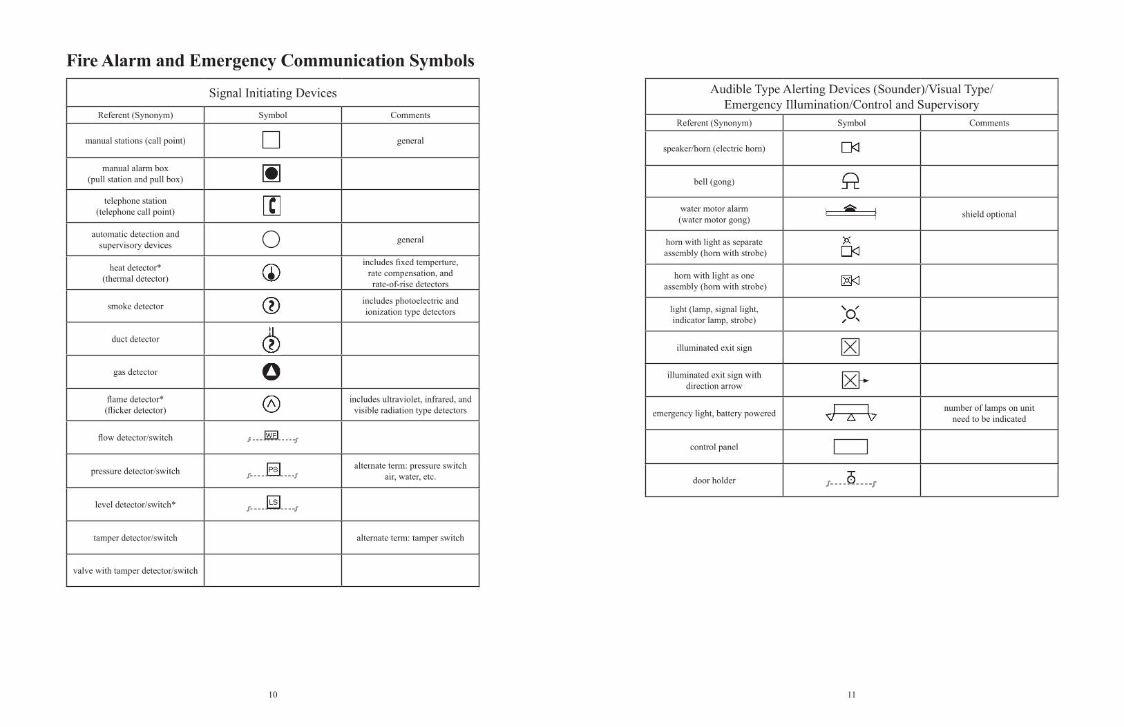
Fire Alarm and Emergency Communication Symbols
Signal Initiating DevicesReferent (Synonym) Symbol Comments
manual stations (call point) general
manual alarm box (pull station and pull box)
telephone station (telephone call point)
automatic detection and supervisory devices general
heat detector* (thermal detector)
includes fixed temperture, rate compensation, and rate-of-rise detectors
smoke detector includes photoelectric and ionization type detectors
duct detector
gas detector
flame detector* (flicker detector)
includes ultraviolet, infrared, and visible radiation type detectors
flow detector/switch
pressure detector/switch alternate term: pressure switchair, water, etc.
level detector/switch*
tamper detector/switch alternate term: tamper switch
valve with tamper detector/switch
Audible Type Alerting Devices (Sounder)/Visual Type/Emergency Illumination/Control and Supervisory
Referent (Synonym) Symbol Comments
speaker/horn (electric horn)
bell (gong)
water motor alarm (water motor gong) shield optional
horn with light as separate assembly (horn with strobe)
horn with light as one assembly (horn with strobe)
light (lamp, signal light,indicator lamp, strobe)
illuminated exit sign
illuminated exit sign withdirection arrow
emergency light, battery powered number of lamps on unit need to be indicated
control panel
door holder
12 13
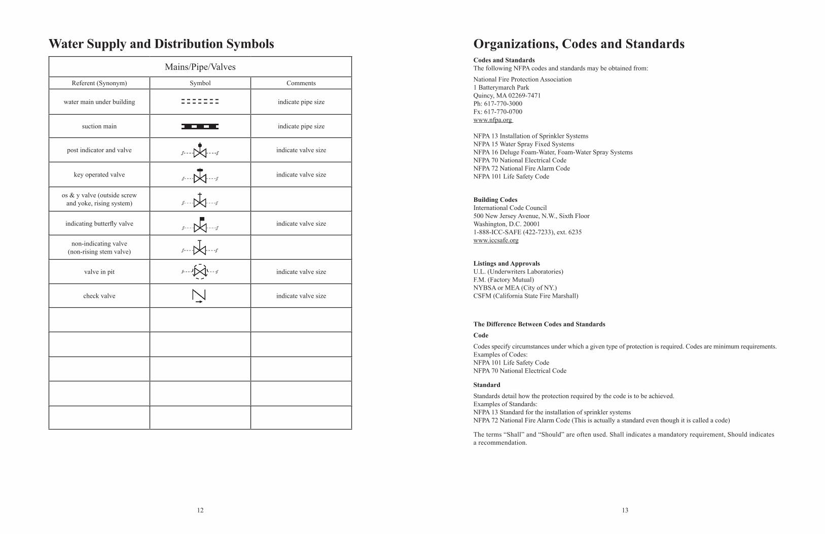
Water Supply and Distribution SymbolsMains/Pipe/Valves
Referent (Synonym) Symbol Comments
water main under building indicate pipe size
suction main indicate pipe size
post indicator and valve indicate valve size
key operated valve indicate valve size
os & y valve (outside screwand yoke, rising system)
indicating butterfly valve indicate valve size
non-indicating valve (non-rising stem valve)
valve in pit indicate valve size
check valve indicate valve size
Organizations, Codes and StandardsCodes and StandardsThe following NFPA codes and standards may be obtained from:
National Fire Protection Association1 Batterymarch ParkQuincy, MA 02269-7471Ph: 617-770-3000Fx: 617-770-0700www.nfpa.org
NFPA 13 Installation of Sprinkler SystemsNFPA 15 Water Spray Fixed SystemsNFPA 16 Deluge Foam-Water, Foam-Water Spray SystemsNFPA 70 National Electrical CodeNFPA 72 National Fire Alarm CodeNFPA 101 Life Safety Code
Building CodesInternational Code Council 500 New Jersey Avenue, N.W., Sixth FloorWashington, D.C. 200011-888-ICC-SAFE (422-7233), ext. 6235www.iccsafe.org
Listings and ApprovalsU.L. (Underwriters Laboratories)F.M. (Factory Mutual)NYBSA or MEA (City of NY.)CSFM (California State Fire Marshall)
The Difference Between Codes and StandardsCodeCodes specify circumstances under which a given type of protection is required. Codes are minimum requirements.Examples of Codes:NFPA 101 Life Safety CodeNFPA 70 National Electrical Code
StandardStandards detail how the protection required by the code is to be achieved.Examples of Standards:NFPA 13 Standard for the installation of sprinkler systemsNFPA 72 National Fire Alarm Code (This is actually a standard even though it is called a code)
The terms “Shall” and “Should” are often used. Shall indicates a mandatory requirement, Should indicates a recommendation.
14 15
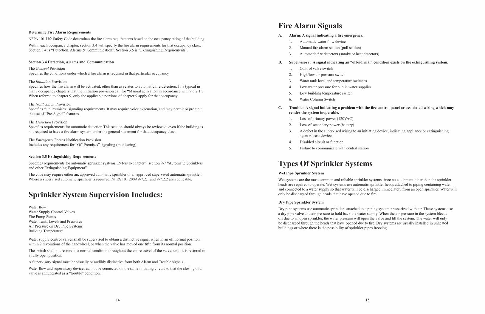
Determine Fire Alarm RequirementsNFPA 101 Life Safety Code determines the fire alarm requirements based on the occupancy rating of the building.
Within each occupancy chapter, section 3.4 will specify the fire alarm requirements for that occupancy class. Section 3.4 is “Detection, Alarms & Communication”. Section 3.5 is “Extinguishing Requirements”.
Section 3.4 Detection, Alarms and CommunicationThe General ProvisionSpecifies the conditions under which a fire alarm is required in that particular occupancy.
The Initiation ProvisionSpecifies how the fire alarm will be activated, other than as relates to automatic fire detection. It is typical in many occupancy chapters that the Initiation provision call for “Manual activation in accordance with 9.6.2.1”. When referred to chapter 9, only the applicable portions of chapter 9 apply for that occupancy.
The Notification ProvisionSpecifies “On Premises” signaling requirements. It may require voice evacuation, and may permit or prohibit the use of “Pre-Signal” features.
The Detection ProvisionSpecifies requirements for automatic detection.This section should always be reviewed, even if the building is not required to have a fire alarm system under the general statement for that occupancy class.
The Emergency Forces Notification ProvisionIncludes any requirement for “Off Premises” signaling (monitoring).
Section 3.5 Extinguishing RequirementsSpecifies requirements for automatic sprinkler systems. Refers to chapter 9 section 9-7 “Automatic Sprinklers and other Extinguishing Equipment”
The code may require either an, approved automatic sprinkler or an approved supervised automatic sprinkler. Where a supervised automatic sprinkler is required, NFPA 101 2009 9-7.2.1 and 9-7.2.2 are applicable.
Sprinkler System Supervision Includes:Water flowWater Supply Control ValvesFire Pump StatusWater Tank, Levels and PressuresAir Pressure on Dry Pipe SystemsBuilding Temperature
Water supply control valves shall be supervised to obtain a distinctive signal when in an off normal position, within 2 revolutions of the handwheel, or when the valve has moved one fifth from its normal position.
The switch shall not restore to a normal condition throughout the entire travel of the valve, until it is restored to a fully open position.
A Supervisory signal must be visually or audibly distinctive from both Alarm and Trouble signals.
Water flow and supervisory devices cannot be connected on the same initiating circuit so that the closing of a valve is annunciated as a “trouble” condition.
Fire Alarm SignalsA. Alarm: A signal indicating a fire emergency. 1. Automatic water flow device 2. Manual fire alarm station (pull station) 3. Automatic fire detectors (smoke or heat detectors)
B. Supervisory: A signal indicating an “off-normal” condition exists on the extinguishing system. 1. Control valve switch 2. High/low air pressure switch 3. Water tank level and temperature switches 4. Low water pressure for public water supplies 5. Low building temperature switch 6. Water Column Switch
C. Trouble: A signal indicating a problem with the fire control panel or associated wiring which may render the system inoperable.
1. Loss of primary power (120VAC) 2. Loss of secondary power (battery) 3. A defect in the supervised wiring to an initiating device, indicating appliance or extinguishing
agent release device. 4. Disabled circuit or function 5. Failure to communicate with central station
Types Of Sprinkler SystemsWet Pipe Sprinkler SystemWet systems are the most common and reliable sprinkler systems since no equipment other than the sprinkler heads are required to operate. Wet systems use automatic sprinkler heads attached to piping containing water and connected to a water supply so that water will be discharged immediately from an open sprinkler. Water will only be discharged through heads that have opened due to fire.
Dry Pipe Sprinkler SystemDry pipe systems use automatic sprinklers attached to a piping system pressurized with air. These systems use a dry pipe valve and air pressure to hold back the water supply. When the air pressure in the system bleeds off due to an open sprinkler, the water pressure will open the valve and fill the system. The water will only be discharged through the heads that have opened due to fire. Dry systems are usually installed in unheated buildings or where there is the possibility of sprinkler pipes freezing.
34 35
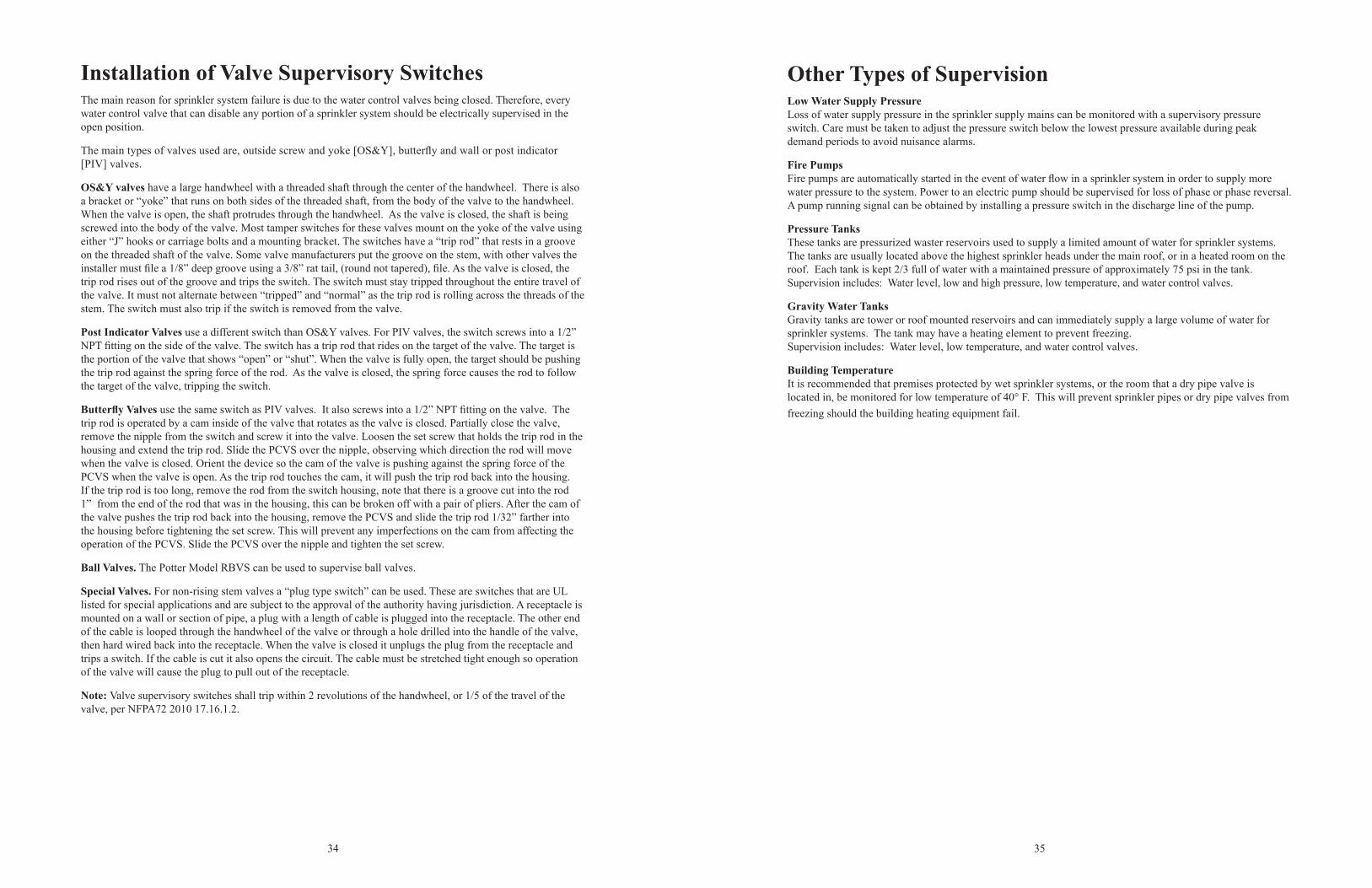
Installation of Valve Supervisory SwitchesThe main reason for sprinkler system failure is due to the water control valves being closed. Therefore, every water control valve that can disable any portion of a sprinkler system should be electrically supervised in the open position.
The main types of valves used are, outside screw and yoke [OS&Y], butterfly and wall or post indicator [PIV] valves.
OS&Y valves have a large handwheel with a threaded shaft through the center of the handwheel. There is also a bracket or “yoke” that runs on both sides of the threaded shaft, from the body of the valve to the handwheel. When the valve is open, the shaft protrudes through the handwheel. As the valve is closed, the shaft is being screwed into the body of the valve. Most tamper switches for these valves mount on the yoke of the valve using either “J” hooks or carriage bolts and a mounting bracket. The switches have a “trip rod” that rests in a groove on the threaded shaft of the valve. Some valve manufacturers put the groove on the stem, with other valves the installer must file a 1/8” deep groove using a 3/8” rat tail, (round not tapered), file. As the valve is closed, the trip rod rises out of the groove and trips the switch. The switch must stay tripped throughout the entire travel of the valve. It must not alternate between “tripped” and “normal” as the trip rod is rolling across the threads of the stem. The switch must also trip if the switch is removed from the valve.
Post Indicator Valves use a different switch than OS&Y valves. For PIV valves, the switch screws into a 1/2” NPT fitting on the side of the valve. The switch has a trip rod that rides on the target of the valve. The target is the portion of the valve that shows “open” or “shut”. When the valve is fully open, the target should be pushing the trip rod against the spring force of the rod. As the valve is closed, the spring force causes the rod to follow the target of the valve, tripping the switch.
Butterfly Valves use the same switch as PIV valves. It also screws into a 1/2” NPT fitting on the valve. The trip rod is operated by a cam inside of the valve that rotates as the valve is closed. Partially close the valve, remove the nipple from the switch and screw it into the valve. Loosen the set screw that holds the trip rod in the housing and extend the trip rod. Slide the PCVS over the nipple, observing which direction the rod will move when the valve is closed. Orient the device so the cam of the valve is pushing against the spring force of the PCVS when the valve is open. As the trip rod touches the cam, it will push the trip rod back into the housing. If the trip rod is too long, remove the rod from the switch housing, note that there is a groove cut into the rod 1” from the end of the rod that was in the housing, this can be broken off with a pair of pliers. After the cam of the valve pushes the trip rod back into the housing, remove the PCVS and slide the trip rod 1/32” farther into the housing before tightening the set screw. This will prevent any imperfections on the cam from affecting the operation of the PCVS. Slide the PCVS over the nipple and tighten the set screw.
Ball Valves. The Potter Model RBVS can be used to supervise ball valves.
Special Valves. For non-rising stem valves a “plug type switch” can be used. These are switches that are UL listed for special applications and are subject to the approval of the authority having jurisdiction. A receptacle is mounted on a wall or section of pipe, a plug with a length of cable is plugged into the receptacle. The other end of the cable is looped through the handwheel of the valve or through a hole drilled into the handle of the valve, then hard wired back into the receptacle. When the valve is closed it unplugs the plug from the receptacle and trips a switch. If the cable is cut it also opens the circuit. The cable must be stretched tight enough so operation of the valve will cause the plug to pull out of the receptacle.
Note: Valve supervisory switches shall trip within 2 revolutions of the handwheel, or 1/5 of the travel of the valve, per NFPA72 2010 17.16.1.2.
Other Types of SupervisionLow Water Supply PressureLoss of water supply pressure in the sprinkler supply mains can be monitored with a supervisory pressure switch. Care must be taken to adjust the pressure switch below the lowest pressure available during peak demand periods to avoid nuisance alarms.
Fire PumpsFire pumps are automatically started in the event of water flow in a sprinkler system in order to supply more water pressure to the system. Power to an electric pump should be supervised for loss of phase or phase reversal. A pump running signal can be obtained by installing a pressure switch in the discharge line of the pump.
Pressure TanksThese tanks are pressurized waster reservoirs used to supply a limited amount of water for sprinkler systems. The tanks are usually located above the highest sprinkler heads under the main roof, or in a heated room on the roof. Each tank is kept 2/3 full of water with a maintained pressure of approximately 75 psi in the tank.Supervision includes: Water level, low and high pressure, low temperature, and water control valves.
Gravity Water TanksGravity tanks are tower or roof mounted reservoirs and can immediately supply a large volume of water for sprinkler systems. The tank may have a heating element to prevent freezing.Supervision includes: Water level, low temperature, and water control valves.
Building TemperatureIt is recommended that premises protected by wet sprinkler systems, or the room that a dry pipe valve is located in, be monitored for low temperature of 40° F. This will prevent sprinkler pipes or dry pipe valves from freezing should the building heating equipment fail.
36 37
Test ProceduresWaterflow Switches - Wet Pipe SystemsVane TypeThere should be a valve downstream of the flow switch, preferably at the far end of the system, but it may be immediately after the flow switch. The valve should be marked Inspectors Test Valve per NFPA13 2010 6.7.4.1. The valve should also have a reduced orifice equal to the smallest sprinkler on the system per NFPA13 2010 8.17.4.2.1. The output of the valve should be piped to a spot where it will not cause any water damage.
Open the valve and allow the water to flow, after the retard time expires, the switch will trip. If the device does not operate check to make sure 10 gpm is flowing out of the test valve. If possible, place a 5 gallon bucket under the output of the valve. If the bucket can be filled in 30 seconds then the valve is flowing 10 gpm.
If a hose needs to be connected to the test valve to prevent water damage, the hose should be 5/8” ID, and as short as possible to reduce friction loss.
If the device still does not trip it may be installed too close to a valve or change in direction of pipe which is causing turbulence or back pressure in the water, or paddle may have been trimmed. Never trim the paddle.
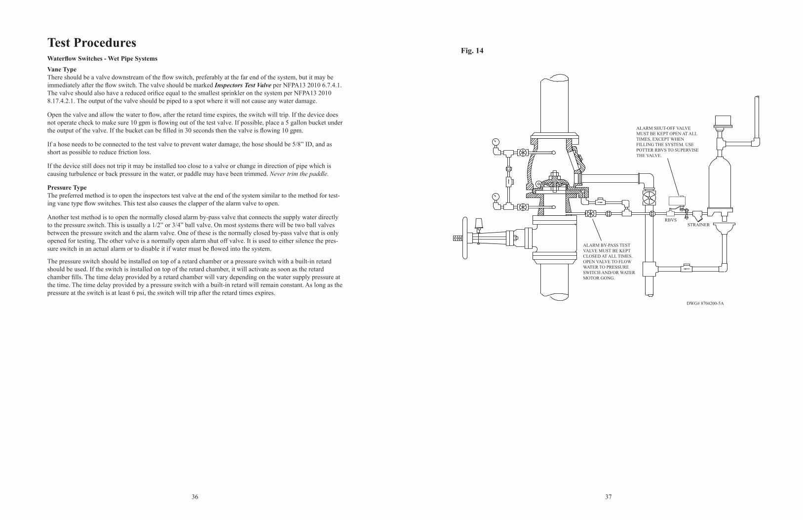
Pressure TypeThe preferred method is to open the inspectors test valve at the end of the system similar to the method for test-ing vane type flow switches. This test also causes the clapper of the alarm valve to open.
Another test method is to open the normally closed alarm by-pass valve that connects the supply water directly to the pressure switch. This is usually a 1/2” or 3/4” ball valve. On most systems there will be two ball valves between the pressure switch and the alarm valve. One of these is the normally closed by-pass valve that is only opened for testing. The other valve is a normally open alarm shut off valve. It is used to either silence the pres-sure switch in an actual alarm or to disable it if water must be flowed into the system.
The pressure switch should be installed on top of a retard chamber or a pressure switch with a built-in retard should be used. If the switch is installed on top of the retard chamber, it will activate as soon as the retard chamber fills. The time delay provided by a retard chamber will vary depending on the water supply pressure at the time. The time delay provided by a pressure switch with a built-in retard will remain constant. As long as the pressure at the switch is at least 6 psi, the switch will trip after the retard times expires.
Fig. 14
ALARM BY-PASS TEST VALVE MUST BE KEPT CLOSED AT ALL TIMES. OPEN VALVE TO FLOW WATER TO PRESSURE SWITCH AND/OR WATER MOTOR GONG.
ALARM SHUT-OFF VALVE MUST BE KEPT OPEN AT ALL TIMES, EXCEPT WHEN FILLING THE SYSTEM. USE POTTER RBVS TO SUPERVISE THE VALVE.
RBVSSTRAINER
DWG# 8704200-5A
48 49
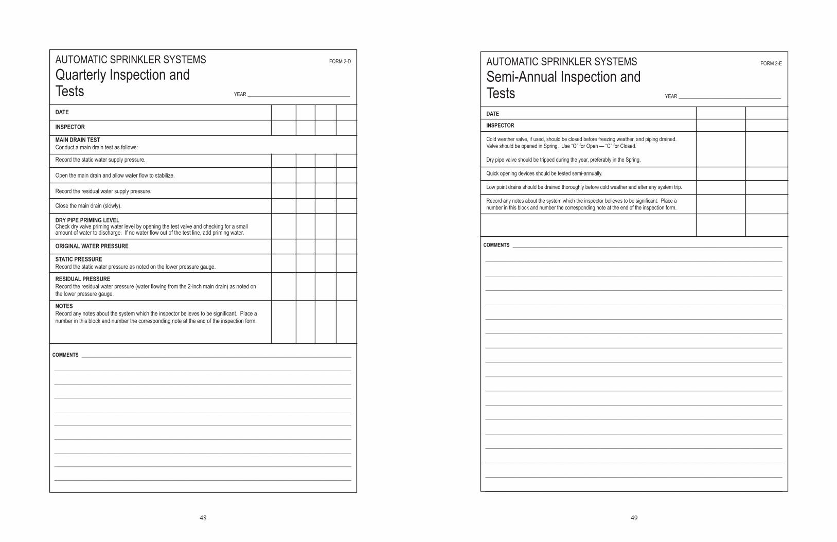
DATE
INSPECTOR
MAIN DRAIN TESTConduct a main drain test as follows:
Record the static water supply pressure.
Open the main drain and allow water flow to stabilize.
Record the residual water supply pressure.
Close the main drain (slowly).
DRY PIPE PRIMING LEVELCheck dry valve priming water level by opening the test valve and checking for a small amount of water to discharge. If no water flow out of the test line, add priming water.
ORIGINAL WATER PRESSURE
STATIC PRESSURERecord the static water pressure as noted on the lower pressure gauge.
RESIDUAL PRESSURERecord the residual water pressure (water flowing from the 2-inch main drain) as noted on the lower pressure gauge.
NOTESRecord any notes about the system which the inspector believes to be significant. Place a number in this block and number the corresponding note at the end of the inspection form.
AUTOMATIC SPRINKLER SYSTEMS FORM 2-D
Quarterly Inspection and Tests YEAR _________________________________________
COMMENTS ____________________________________________________________________________________________________________
_______________________________________________________________________________________________________________________
_______________________________________________________________________________________________________________________
_______________________________________________________________________________________________________________________
_______________________________________________________________________________________________________________________
_______________________________________________________________________________________________________________________
_______________________________________________________________________________________________________________________
_______________________________________________________________________________________________________________________
_______________________________________________________________________________________________________________________
_______________________________________________________________________________________________________________________
DATE
INSPECTOR
Cold weather valve, if used, should be closed before freezing weather, and piping drained. Valve should be opened in Spring. Use “O” for Open — “C” for Closed.
Dry pipe valve should be tripped during the year, preferably in the Spring.
Quick opening devices should be tested semi-annually.
Low point drains should be drained thoroughly before cold weather and after any system trip.
Record any notes about the system which the inspector believes to be significant. Place a number in this block and number the corresponding note at the end of the inspection form.
AUTOMATIC SPRINKLER SYSTEMS FORM 2-E
Semi-Annual Inspection andTests YEAR _________________________________________
COMMENTS ____________________________________________________________________________________________________________
_______________________________________________________________________________________________________________________
_______________________________________________________________________________________________________________________
_______________________________________________________________________________________________________________________
_______________________________________________________________________________________________________________________
_______________________________________________________________________________________________________________________
_______________________________________________________________________________________________________________________
_______________________________________________________________________________________________________________________
_______________________________________________________________________________________________________________________
_______________________________________________________________________________________________________________________
_______________________________________________________________________________________________________________________
_______________________________________________________________________________________________________________________
_______________________________________________________________________________________________________________________
_______________________________________________________________________________________________________________________
_______________________________________________________________________________________________________________________
_______________________________________________________________________________________________________________________
_______________________________________________________________________________________________________________________
_______________________________________________________________________________________________________________________
104 105
GROUND SCREW
YELLOW "WATER" LED
GREEN "POWER" LED
PROBE
TERMINAL BLOCK
DWG. #1158-3
PAGE 3 OF 3PRINTED IN USA
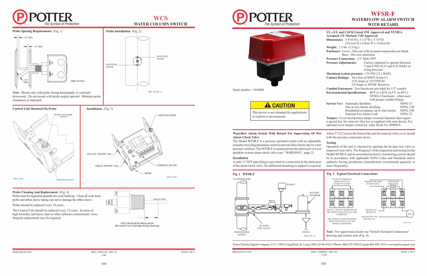
Control Unit Mounted On Probe
Probe Spacing Requirements (Fig. 1)
Note: Mount only with probe facing horizontally or vertically downward. Do not mount with probe angled upward. Maintain probe clearances as indicated.
Installation (Fig. 3)
Probe Cleaning And Replacement (Fig. 4) Probe must be inspected annually for scale build-up. Clean all scale from probe and teflon sleeve taking care not to damage the teflon sleeve.
Probe should be replaced every 10 years.
The Control Unit should be replaced every 15 years. In areas of high humidity and heavy dust or other airborne contaminants, more frequent replacement may be required.
DWG. #1158-1
1/4" MIN.
1/4" MIN.
1/4"MIN.
TEFLON SLEEVE INSULATOR(Be careful not to damage during cleaning)
DWG #1108-8
DWG. #1158-2 MOUNTING SCREWS
PROBE LOCK WASHER AND NUT
MOUNTING SCREW
MOUNTING SCREW
MFG. #5401158 - REV D5/08
WCSWATER COLUMN SWITCH
Probe Installation (Fig. 2)
WFSR-FWATERFLOW ALARM SWITCH
WITH RETARD
MFG. #5400987 - REV W12/08
PAGE 1 OF 2PRINTED IN USA
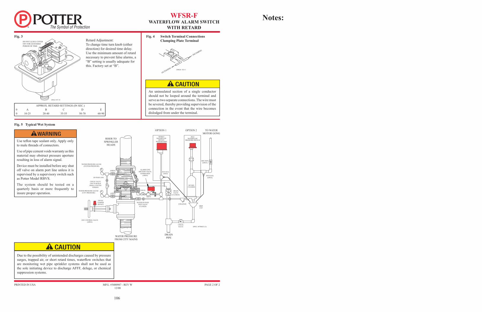
Waterflow Alarm Switch With Retard For Supervision Of Wet Alarm Check Valve The Model WFSR-F is a pressure operated switch with an adjustable, instantly recycling pneumatic retard to prevent false alarms due to water pressure variation. The WFSR-F is connected into the alarm port of a wet sprinkler system alarm check valve (see " WARNING", page 2).
InstallationA male ½" NPT pipe fitting is provided for connection to the alarm port of the alarm check valve. No additional mounting or support is required.
UL, cUL and CSFM Listed, FM Approved and NYMEA Accepted, CE Marked, VdS ApprovedDimensions: 5 9/16"H x 3 1/2"W x 5 7/8"D (14,1cm H x 8,9cm W x 14,9cm D)Weight: 1.5 lbs. (3,3 kg.)Enclosure: Cover - Die-cast with textured red powdercoat finish Base - Die-cast aluminumPressure Connection: 1/2" Male NPTPressure Adjustments: Factory adjusted to operate between
5 and 8 PSI (0.35 and 0,55 BAR) on rising pressure
Maximum system pressure: 175 PSI (12,1 BAR)Contact Ratings: Two Sets of SPDT (Form C) 15.0 Amps at 125/250VAC 2.0 Amps at 30VDC ResistiveConduit Entrances: Two knockouts provided for 1/2" conduitEnvironmental Specifications: 40°F to 120°F (4,5°C to 49°C) NEMA 4 Enclosure - when used
with proper conduit fittingsService Use: Automatic Sprinkler NFPA-13 One or two family dwelling NFPA-13D Residential occupancy up to four stories NFPA-13R National Fire Alarm Code NFPA-72Tamper: Cover incorporates tamper resistant fasteners that require a special key for removal. One key is supplied with each device. For optional cover tamper switch kit, order Stock No. 0090018.
Potter Electric Signal Company, LLC • 2081 Craig Road, St. Louis, MO, 63146-4161 • Phone: 800-325-3936/Canada 888-882-1833 • www.pottersignal.com
Fig. 2 Typical Electrical Connections
Note: For supervised circuits see “Switch Terminal Connections” drawing and caution note (Fig. 4).
2 SETS OF NORMALLY OPEN CONTACTS
CLOSE ON ALARM
THE N.C. AND N.O. MARKINGS ON THE SWITCH ARE FOR AN ALARM
CONDITION.
THE CONTACTS ARE REVERSED WHEN THE DEVICE IS IN THE
NORMAL CONDITION.
WATERFLOW ZONE ON FIRE PANEL
EOLR FROM FIRE PANEL
POSITIVE DC OR HOT AC
NEGATIVE DC OR NEUTRAL AC
DWG# 761-2
BELL
COM NO NC
COM NO NC
COM NO NC
COM NO NC
EOLR
Stock number - 1010080
This device is not intended for applications in explosive environments.
Fig. 1 WFSR-FTO SPRINKLERS
FROM WATER SUPPLY
BY-PASS TEST VALVE
RBVS
WFSR-F
TO DRAIN
RETARD CHAMBER
DWG# 987-1A
Allow 5" (12,7cm) to the front of the unit for removal of the cover. Install with the pressure connection down.
TestingOperation of the unit is checked by opening the by-pass test valve or inspector's test valve. The frequency of the inspection and testing for the Model WFSR-F and its associated protective monitoring system should be in accordance with applicable NFPA Codes and Standards and/or authority having jurisdiction (manufacturer recommends quarterly or more frequently).
106
WFSR-FWATERFLOW ALARM SWITCH
WITH RETARD
MFG. #5400987 - REV W12/08
PAGE 2 OF 2PRINTED IN USA
Switch Terminal Connections Clamping Plate Terminal
Fig. 4Fig. 3Retard Adjustment:To change time turn knob (either direction) for desired time delay. Use the minimum amount of retard necessary to prevent false alarms, a “B” setting is usually adequate for this. Factory set at “B”.
APPROX. RETARD SETTINGS (IN SEC.)0 A B C D E0 10-25 20-40 35-55 50-70 60-90
OUTGOING
INCOMING
DWG# 923-3
Fig. 5 Typical Wet System
DO NOT LEAVE COVER OFF FOR EXTENDED PERIOD OF TIME
DWG# 987-30
An uninsulated section of a single conductor should not be looped around the terminal and serve as two separate connections. The wire must be severed, thereby providing supervision of the connection in the event that the wire becomes dislodged from under the terminal.
Use teflon tape sealant only. Apply only to male threads of connectors.
Use of pipe cement voids warranty as this material may obstruct pressure aperture resulting in loss of alarm signal.
Device must be installed before any shut off valve on alarm port line unless it is supervised by a supervisory switch such as Potter Model RBVS.
The system should be tested on a quarterly basis or more frequently to insure proper operation.
Due to the possibility of unintended discharges caused by pressure surges, trapped air, or short retard times, waterflow switches that are monitoring wet pipe sprinkler systems shall not be used as the sole initiating device to discharge AFFF, deluge, or chemical suppression systems.
ALARM CHECK VALVE
RISER TOSPRINKLER
HEADS
OPTION 1 OPTION 2
WFSR-FWATERFLOW
DEVICEWITH RETARD
PS10WATERFLOW
PRESSURE SWITCH
TO WATERMOTOR GONG
SHUTOFF(OPEN)
PETCOCK(OPEN)
ALARM LINESHUTOFF VALVE,
SUPERVISED(OPEN)
WATER PRESSURE GAUGE(SYSTEM PRESSURE)
(OPEN)
CHECK VALVEUSE TO BUILD
SMALL EXCESSSURGES
BY-PASS LINE
WATER PRESSURE GAUGE(CITY PRESSURE) (OPEN)
CHECK
RBVS
DRAINVALVE
(CLOSED)
WATER BY-PASSTEST VALVE
(CLOSED)
OSYSUTAMPERDEVICE
OSY CONTROL VALVE(OPEN)
RETARDCHAMBER
PETCOCK(OPEN)
DRIPCUP
CHECKVALVE
STRAINER
DWG. #8700023-2A
DRAINPIPEWATER PRESSURE
FROM CITY MAINS
Notes:

DO’S & DONT’S
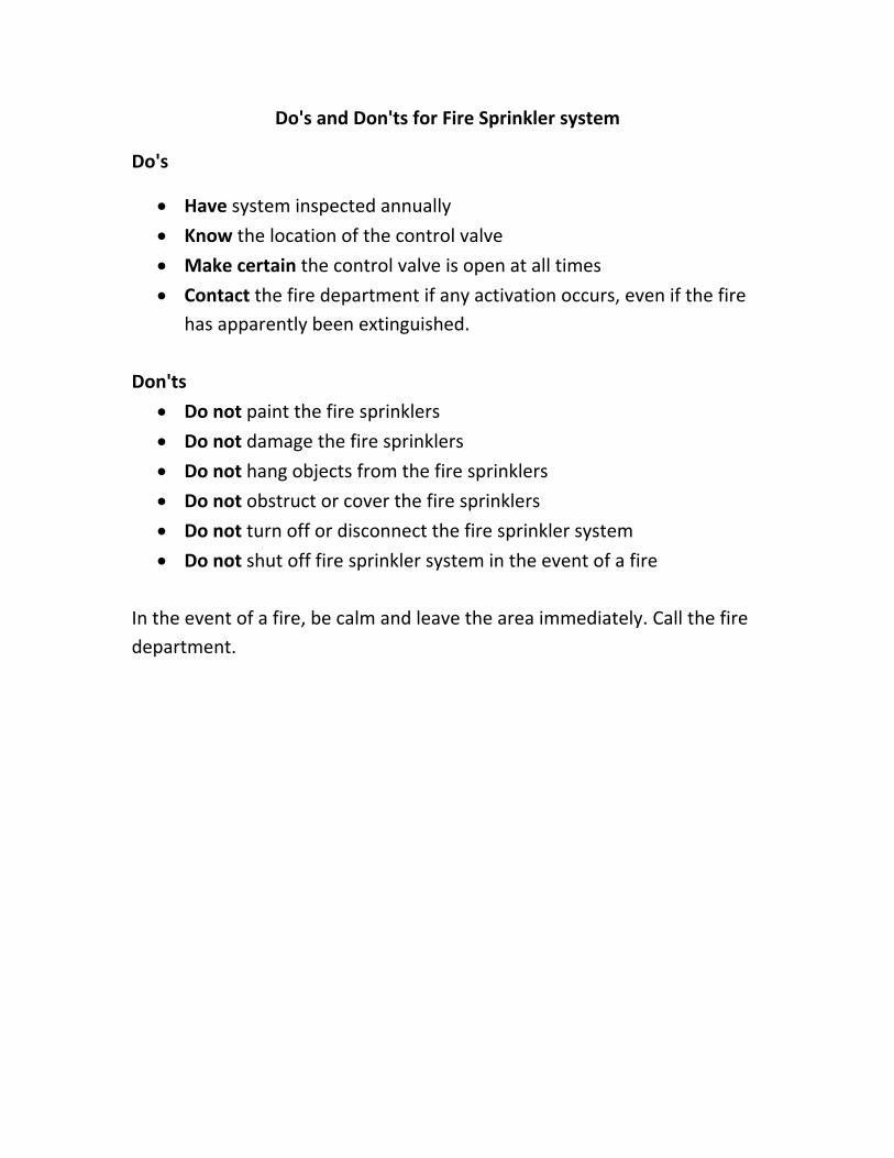
Do's and Don'ts for Fire Sprinkler system
Do's
• Have system inspected annually
• Know the location of the control valve
• Make certain the control valve is open at all times
• Contact the fire department if any activation occurs, even if the fire has apparently been extinguished.
Don'ts
• Do not paint the fire sprinklers
• Do not damage the fire sprinklers
• Do not hang objects from the fire sprinklers
• Do not obstruct or cover the fire sprinklers
• Do not turn off or disconnect the fire sprinkler system
• Do not shut off fire sprinkler system in the event of a fire
In the event of a fire, be calm and leave the area immediately. Call the fire department.
MAINTENANCE SCHEDULE
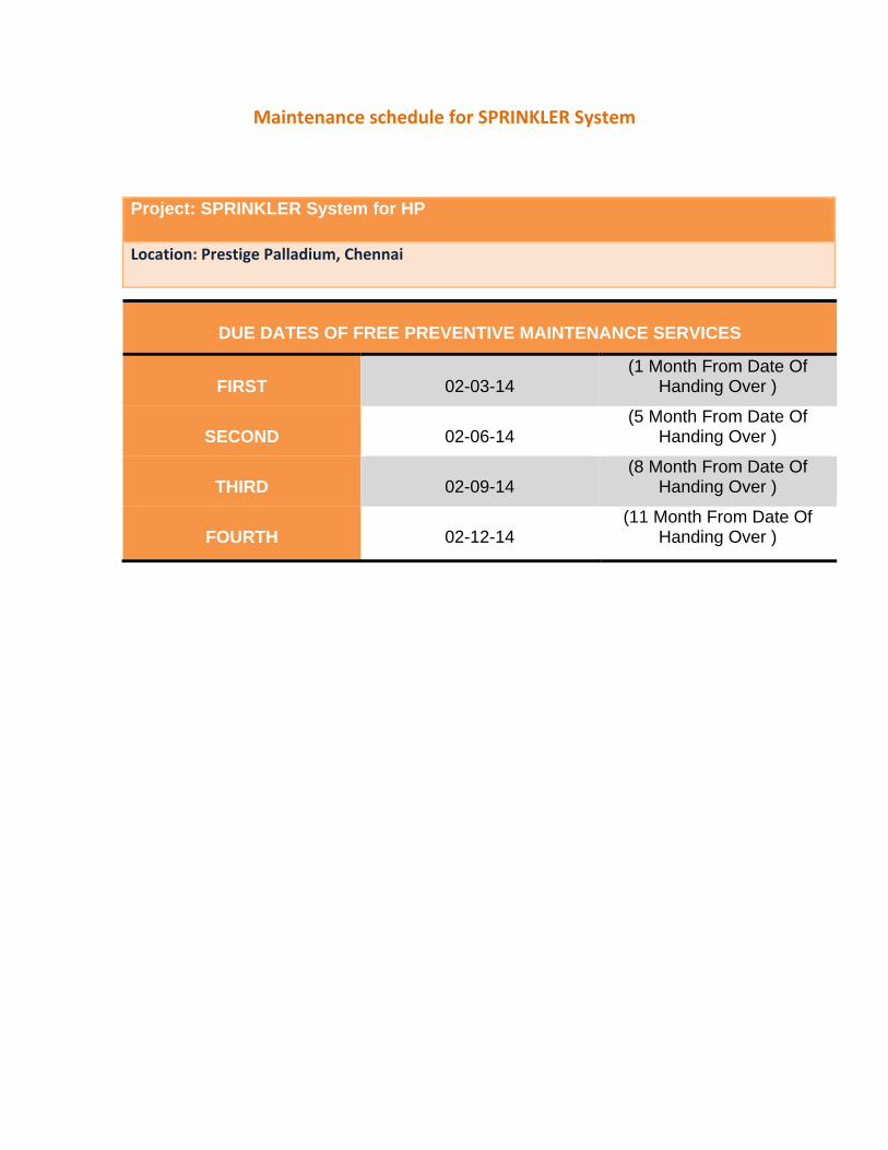
Maintenance schedule for SPRINKLER System
Project: SPRINKLER System for HP
Location: Prestige Palladium, Chennai
DUE DATES OF FREE PREVENTIVE MAINTENANCE SERVICES
FIRST
02-03-14
(1 Month From Date Of Handing Over )
SECOND
02-06-14
(5 Month From Date Of Handing Over )
THIRD
02-09-14
(8 Month From Date Of Handing Over )
FOURTH
02-12-14
(11 Month From Date Of Handing Over )
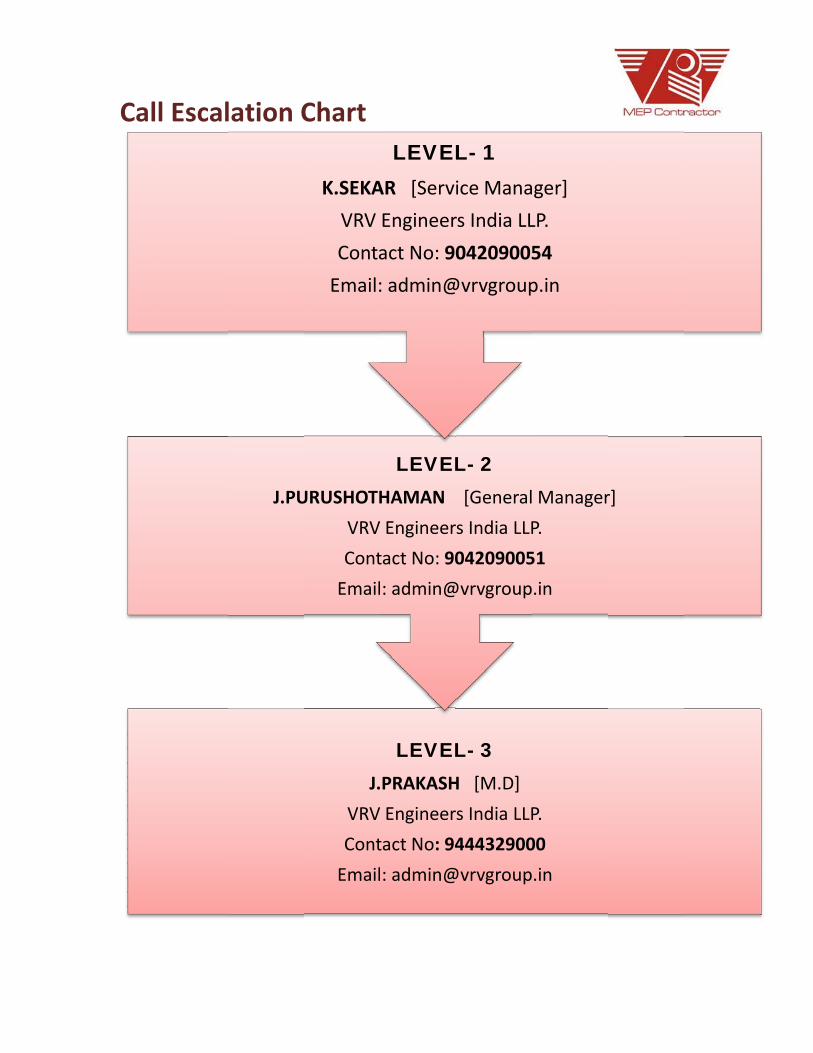
CALL ESCALATION CHART
Calll Escallation C
J.PU
Chart
J.
VRV
Cont
URUSHOTH
VRV
Cont
K.SEKA
VRV
Conta
Email:
LEVELPRAKASH
Engineer
tact No: 94
: admin@
LEVELHAMAN
Engineer
tact No: 90
: admin@
LEVELAR [Servi
Engineer
act No: 90
: admin@
L- 3H [M.D]
s India LLP
44432900
@vrvgroup
L- 2[General
s India LLP
04209005
@vrvgroup
L- 1ice Mana
rs India LL
04209005
@vrvgroup
P.
00
.in
Manager
P.
51
.in
ger]
LP.
54
p.in
r]

OEM/ SUPPLIERS CONTACT DETAILS
Sprinkler‐HP VRV ENGINEERS LLP
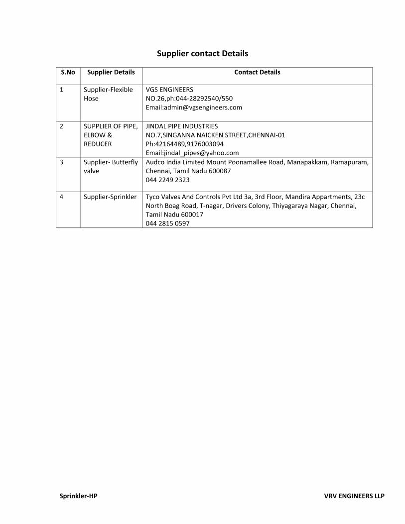
Supplier contact Details
S.No Supplier Details Contact Details
1 Supplier‐Flexible Hose
VGS ENGINEERS NO.26,ph:044‐28292540/550 Email:[email protected]
2 SUPPLIER OF PIPE, ELBOW & REDUCER
JINDAL PIPE INDUSTRIES NO.7,SINGANNA NAICKEN STREET,CHENNAI‐01 Ph:42164489,9176003094 Email:[email protected]
3 Supplier‐ Butterfly valve
Audco India Limited Mount Poonamallee Road, Manapakkam, Ramapuram, Chennai, Tamil Nadu 600087 044 2249 2323
4 Supplier‐Sprinkler Tyco Valves And Controls Pvt Ltd 3a, 3rd Floor, Mandira Appartments, 23c North Boag Road, T‐nagar, Drivers Colony, Thiyagaraya Nagar, Chennai, Tamil Nadu 600017 044 2815 0597

RECOMMENDED SPARES LIST

NIL
RECOMMENDED TOOLS FOR MAINTENANCE
SPRINKLER‐HP VRV ENGINEERS LLP
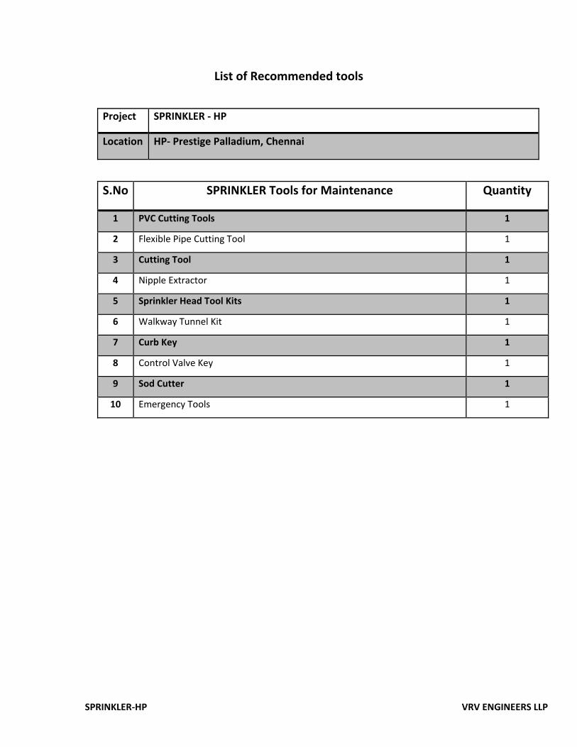
List of Recommended tools
Project SPRINKLER ‐ HP
Location HP‐ Prestige Palladium, Chennai
S.No SPRINKLER Tools for Maintenance Quantity
1 PVC Cutting Tools 1
2 Flexible Pipe Cutting Tool 1
3 Cutting Tool 1
4 Nipple Extractor 1
5 Sprinkler Head Tool Kits 1
6 Walkway Tunnel Kit 1
7 Curb Key 1
8 Control Valve Key 1
9 Sod Cutter 1
10 Emergency Tools 1

INVENTORY LIST / ASSET LIST

ATTIC STOCK /BALANCE MATERIAL

NIL

WO /PO COPY

ACCEPTED SNAG LIST

NIL
PRACTICAL COMPLETION CERTIFICATE
“VRV VILLA” No: 14/15, LDG Street, Little Mount, Saidapet, Chennai-600015 Land Line – 044 – 2235 1856 |www.vrvgroup.in
Tamil Nadu | Pondicherry | Kerala | Andhra Pradesh | Karnataka
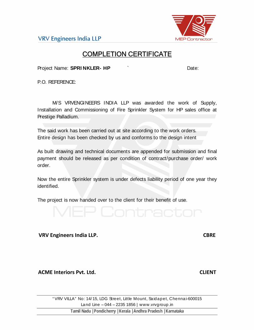
COMPLETION CERTIFICATE
Project Name: SPRINKLER- HP ` Date: P.O. REFERENCE:
M/S VRVENGINEERS INDIA LLP was awarded the work of Supply, Installation and Commissioning of Fire Sprinkler System for HP sales office at Prestige Palladium. The said work has been carried out at site according to the work orders. Entire design has been checked by us and conforms to the design intent As built drawing and technical documents are appended for submission and final payment should be released as per condition of contract/purchase order/ work order. Now the entire Sprinkler system is under defects liability period of one year they identified. The project is now handed over to the client for their benefit of use. VRV Engineers India LLP. CBRE
ACME Interiors Pvt. Ltd. CLIENT
TRAINING ATTENDANCE
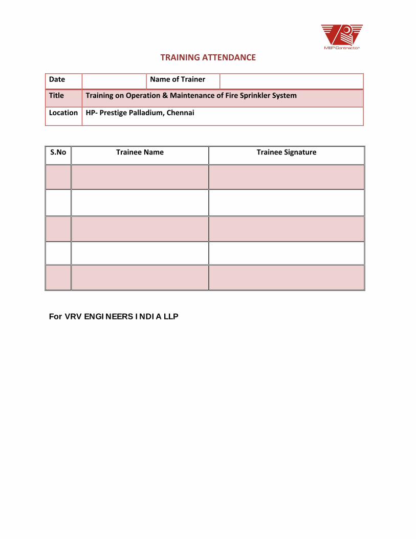
TRAINING ATTENDANCE
For VRV ENGINEERS INDIA LLP
S.No Trainee Name Trainee Signature
Date Name of Trainer
Title Training on Operation & Maintenance of Fire Sprinkler System
Location HP‐ Prestige Palladium, Chennai

EXTRA PLASTIC FOLDER FOR DRAWINGS / CD
Related Documents


![6WXGHQW 1DPH +D]HP 1DEHHO .KDPLV +DVZHK 6WXGHQW ,' … · 2018-12-11 · 6wxghqw ,' 3urorqjdwlrq &rvw dv d 5hphg\ iru &rqvwuxfwlrq &rqwudfwv 'hod\v 06f lq &rqvwuxfwlrq /dz +d]hp 1dehho](https://static.cupdf.com/doc/110x72/5ebf954d5e3bdf4555113041/6wxghqw-1dph-dhp-1dehho-kdplv-dvzhk-6wxghqw-2018-12-11-6wxghqw-3urorqjdwlrq.jpg)