James D. Holdeman Glenn Research Center, Cleveland, Ohio James R. Clisset University of Florida, Gainesville, Florida Jeffrey P. Moder Glenn Research Center, Cleveland, Ohio Spreadsheet Calculation of Jets in Crossflow: Opposed Rows of Slots Slanted at 45 NASA/TM—2011-215980 December 2011 https://ntrs.nasa.gov/search.jsp?R=20120011165 2020-07-03T09:44:14+00:00Z

Welcome message from author
This document is posted to help you gain knowledge. Please leave a comment to let me know what you think about it! Share it to your friends and learn new things together.
Transcript

James D. HoldemanGlenn Research Center, Cleveland, Ohio
James R. ClissetUniversity of Florida, Gainesville, Florida
Jeffrey P. ModerGlenn Research Center, Cleveland, Ohio
Spreadsheet Calculation of Jets in Crossfl ow:Opposed Rows of Slots Slanted at 45
NASA/TM—2011-215980
December 2011
https://ntrs.nasa.gov/search.jsp?R=20120011165 2020-07-03T09:44:14+00:00Z

NASA STI Program . . . in Profi le
Since its founding, NASA has been dedicated to the advancement of aeronautics and space science. The NASA Scientifi c and Technical Information (STI) program plays a key part in helping NASA maintain this important role.
The NASA STI Program operates under the auspices of the Agency Chief Information Offi cer. It collects, organizes, provides for archiving, and disseminates NASA’s STI. The NASA STI program provides access to the NASA Aeronautics and Space Database and its public interface, the NASA Technical Reports Server, thus providing one of the largest collections of aeronautical and space science STI in the world. Results are published in both non-NASA channels and by NASA in the NASA STI Report Series, which includes the following report types: • TECHNICAL PUBLICATION. Reports of
completed research or a major signifi cant phase of research that present the results of NASA programs and include extensive data or theoretical analysis. Includes compilations of signifi cant scientifi c and technical data and information deemed to be of continuing reference value. NASA counterpart of peer-reviewed formal professional papers but has less stringent limitations on manuscript length and extent of graphic presentations.
• TECHNICAL MEMORANDUM. Scientifi c
and technical fi ndings that are preliminary or of specialized interest, e.g., quick release reports, working papers, and bibliographies that contain minimal annotation. Does not contain extensive analysis.
• CONTRACTOR REPORT. Scientifi c and
technical fi ndings by NASA-sponsored contractors and grantees.
• CONFERENCE PUBLICATION. Collected papers from scientifi c and technical conferences, symposia, seminars, or other meetings sponsored or cosponsored by NASA.
• SPECIAL PUBLICATION. Scientifi c,
technical, or historical information from NASA programs, projects, and missions, often concerned with subjects having substantial public interest.
• TECHNICAL TRANSLATION. English-
language translations of foreign scientifi c and technical material pertinent to NASA’s mission.
Specialized services also include creating custom thesauri, building customized databases, organizing and publishing research results.
For more information about the NASA STI program, see the following:
• Access the NASA STI program home page at http://www.sti.nasa.gov
• E-mail your question via the Internet to help@
sti.nasa.gov • Fax your question to the NASA STI Help Desk
at 443–757–5803 • Telephone the NASA STI Help Desk at 443–757–5802 • Write to:
NASA Center for AeroSpace Information (CASI) 7115 Standard Drive Hanover, MD 21076–1320

James D. HoldemanGlenn Research Center, Cleveland, Ohio
James R. ClissetUniversity of Florida, Gainesville, Florida
Jeffrey P. ModerGlenn Research Center, Cleveland, Ohio
Spreadsheet Calculation of Jets in Crossfl ow:Opposed Rows of Slots Slanted at 45
NASA/TM—2011-215980
December 2011
National Aeronautics andSpace Administration
Glenn Research CenterCleveland, Ohio 44135

Acknowledgments
The authors would like to thank Mr. Richard E. Walker (Aerojet Liquid Rocket Company, retired), Dr. Ram Srinivasan (then of Garrett Turbine Engine Company), Professor William E. Lear of the University of Florida, Mr. Timothy D. Smith, andDr. C. John Marek (retired) of the NASA Glenn Research Center for their contributions to the NASA jets in crossfl ow (JIC) empirical model. The authors also wish to extend thanks to Messrs. David S. Liscinsky of the United Technologies Research Center, Robert Reynolds of Honeywell Engines, Richard E. Walker of Aerojet Liquid Rocket Company (retired), and ProfessorsDilip R. Ballal of the University of Dayton, John F. Foss of Michigan State University, William E. Lear of the University of Florida, and Hukam C. Mongia of Purdue University for reviewing these results.
Available from
NASA Center for Aerospace Information7115 Standard DriveHanover, MD 21076–1320
National Technical Information Service5301 Shawnee Road
Alexandria, VA 22312
Available electronically at http://www.sti.nasa.gov
Trade names and trademarks are used in this report for identifi cation only. Their usage does not constitute an offi cial endorsement, either expressed or implied, by the National Aeronautics and
Space Administration.
Level of Review: This material has been technically reviewed by technical management.
Supplementary Notes
Jim Holdeman, retired. A supplemental Microsoft Excel (Microsoft Corporation) spreadsheet TM-2011-215980-SUPPL1.xls is available from the NASA Center for AeroSpace Information, 443-757-5802.
NASA/TM—2011-215980 1
Spreadsheet Calculation of Jets in Crossflow: Opposed Rows of Slots Slanted at 45
James D. Holdeman1
National Aeronautics and Space Administration Glenn Research Center Cleveland, Ohio 44135
James R. Clisset
University of Florida Gainesville, Florida 32611
Jeffrey P. Moder
National Aeronautics and Space Administration Glenn Research Center Cleveland, Ohio 44135
Abstract
The purpose of this study was to extend the NASA jet-in-crossflow empirical model, implemented in the Excel (Microsoft Corporation) spreadsheet documented in NASA/TM—2005-213137, to the case of jets entering the mainstream flow from opposed rows of 45 slanted slots. The results in this report were obtained using a spreadsheet modified from the one posted with NASA/TM—2010-216100. The empirical model in this spreadsheet was not changed from the one posted with NASA/TM—2005-213137. The modifications in the current spreadsheet, which affect only 45 slanted slots and without which distributions for many of the cases reported here could not be calculated, were: 1) the function that causes lateral translation for flow from 45 slanted slots was corrected so distributions for round holes (as L/W = 1 slanted slots) do not translate and 2) the capability was added to allow 45 slots to slant in either direction so perpendicular configurations, where the slots are angled in opposite directions on top and bottom walls, could be calculated. The primary conclusion in this report is that the best mixing configuration for opposed rows of 45 slanted slots at any downstream distance is a parallel staggered configuration where the slots are angled in the same direction on top and bottom walls and one side is shifted by half the orifice spacing. Although distributions from perpendicular slanted slots are similar to those from parallel staggered configurations at some downstream locations, results for perpendicular slots are highly dependent on downstream distance and are no better than parallel staggered slots at locations where they are similar and are worse than parallel ones at other distances.
Nomenclature
AJ / AM jet-to-mainstream area ratio = ((/4)W2+(L/W-1)W2) / ((S)(H)) C (S/H) (sqrt (J)) Cd orifice discharge coefficient = (effective area)/(physical area) d actual physical diameter of a round hole DR jet-to-mainstream density ratio, J/M H duct height H/ d ratio of duct height to orifice diameter
1 James D. Holdeman, retired.
NASA/TM—2011-215980 2
J jet-to-mainstream momentum-flux ratio, (JVJ2) / (UM
2) L larger dimension of slot L/W ratio of larger to smaller dimension of slot S lateral spacing between equivalent locations of adjacent orifices S/H ratio of orifice spacing to duct height UM unmixed mainstream velocity VJ jet exit velocity W smaller dimension of slot = d / (sqrt(1+(L/W-1) / (4/))) x downstream coordinate; x = 0 at center of the first row of orifices y cross-stream coordinate z lateral coordinate dimensionless scalar
Introduction
The extensive studies of rows of non-reacting jets in crossflow (JIC) in rectangular, annular, reverse-flow, and cylindrical configurations that are summarized in Reference 1 were motivated by mixing of dilution jets in conventional gas turbine combustors. The studies summarized in References 2 to 4 focused on optimizing the mixing section in the Rich burn/Quick mix/Lean burn (RQL) combustor scheme in rectangular, annular, and cylindrical ducts for both reacting and non-reacting flows.
Later, the NASA JIC empirical model from Reference 1 (without the curvature effects) was implemented in the Excel spreadsheet reported in Reference 5. No changes were made to the empirical model in the spreadsheets posted with References 6 and 7, and these versions (and the current one) are backwardly compatible to the spreadsheet posted with Reference 5. Details discussed in the following reports apply to the empirical model used in this report but are not repeated: 1) description of the empirical model for a conserved scalar in JIC flowfields (Refs. 1, 5 to 7), 2) spreadsheet specifics (Refs. 5 to 7), 3) a listing of the correlation equations (Refs. 1 and 5), 4) listings of the original BASIC code (Ref. 5), 5) the “closest” experimental data (Ref. 5), 6) contour plots from exported data (Ref. 6), 7) comparison of results for aligned jets using both the symmetry and superposition models (Ref. 6), 8) a slideshow using profile plots (Ref. 6), 9) the addition of low resolution contour plots within the spreadsheet (Ref. 7), and 10) empirical model calculations for several cases of jet mixing in a confined crossflow (Refs. 5 to 7).
The objective of this study was to investigate flow from opposed rows of jets from slots slanted at 45 from the direction of the mainstream flow. The spreadsheet used in this report is derived from the one posted with Reference 7; however, two important changes were made that only affect slanted slot results: 1) the function that causes lateral translation for 45 slanted slots was corrected so distributions for round holes (as L/W = 1 slots) do not translate and 2) the capability was added to allow 45 slots to slant in either direction. Without these modifications, distributions for many of the cases reported herein could not be calculated.
Although experimental, CFD, and empirical model results for single-side injection from slanted slots have been shown previously (e.g., Ref. 1), empirical model results for opposed rows of slanted slots have not. CFD calculations for opposed rows of slanted slots in a rectangular duct are shown in References 1, 8, and 9. Experimental results were published in Reference 10 for several configurations of opposed rows of 45 slanted slots.
This report presents results using the NASA JIC empirical model for several configurations of opposed rows of 45 slanted slots.
NASA/TM—2011-215980 3
Flow Field Model
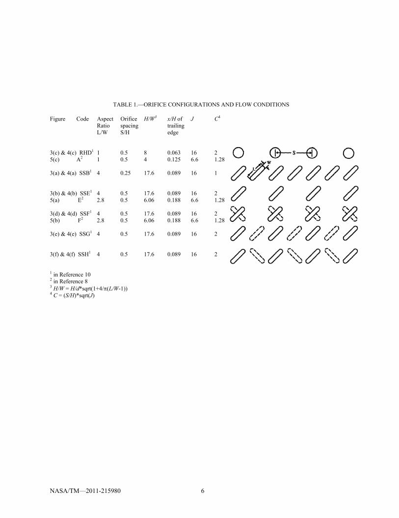
Figure 1 is a schematic of the basic flow field for a row of jets in a confined crossflow. For all calculations, the dimensionless flow and geometric variables that must be specified are the jet-to-mainstream density ratio DR (=J /M), jet-to-mainstream momentum-flux ratio J (=(JVJ
2) / (UM2)),
jet discharge coefficient Cd, orifice-spacing-to-duct-height ratio S/H, duct-height-to-orifice-diameter ratio H/d, and the dimensionless downstream distance x/H. For 45 slanted slots one also needs to specify the slot aspect ratio L/W and the slant direction.
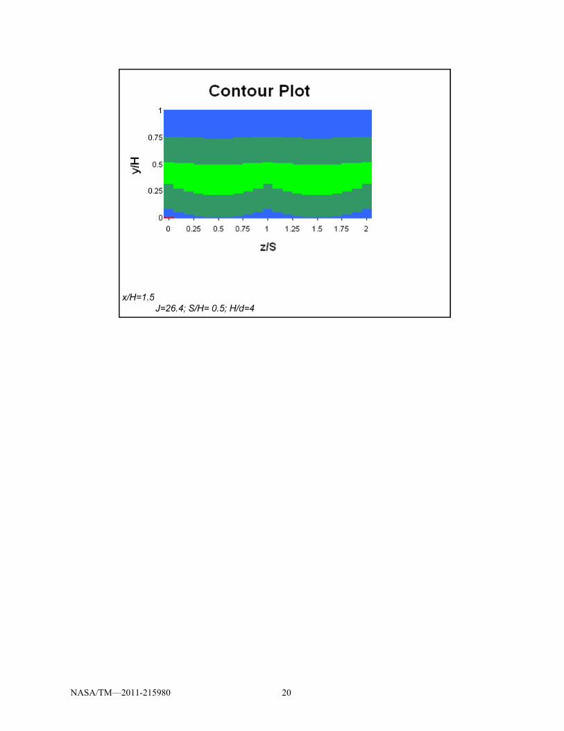
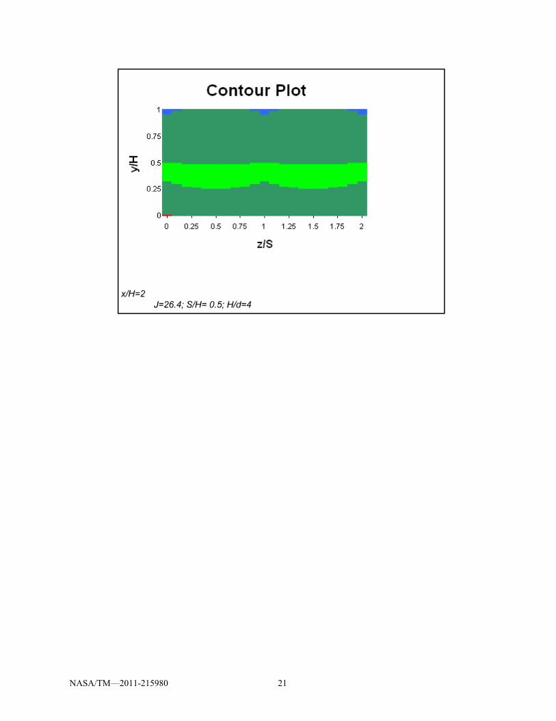
Correlation equations were developed for each of the dimensionless parameters needed to define the conserved scalar in all three spatial dimensions. Three-dimensional oblique plots of vertical scalar profiles and low resolution contour plots of are displayed in the spreadsheet. The dependent variable is shown on the horizontal axis in the profile plots and is the plotted variable in the contour plots. The vertical and oblique axes in the profile plots are the y and z directions. These are the axes of ordinates and abscissas in the contour plots. In the current report, unmixed jet fluid is = 1 and unmixed mainstream fluid is = 0.
Two effects were noted in the experimental results for one side injection from 45 slanted slots in References 1 and 9. These were: (1) the distributions for slanted slots shifted laterally with downstream distance and (2) the axes of the kidney-shaped contours was inclined with respect to the direction of the injection. The NASA JIC empirical model distributions for 45 slanted slots show the shift, but the inclination and asymmetry of the distribution is not modeled. It was reported in Reference 1 that slanted slots seem to result in augmentation of one vortex of the vortex pair that is typical of symmetric JIC’s, and the other is minimized.
In the JIC model all slots have semicircular ends with their diameter equal to the smaller dimension of the slot (which is W), so that L/W = 1 specifies a round hole. The spreadsheet always uses the superposition model described in References 5 to 7 when slanted slots are specified; thus, if round holes are specified as L/W = 1 slanted slots, it is unnecessary to use the two-row procedure described in Reference 7 where the same round-hold configuration was not specified on the top and bottom in any row (to avoid invoking the symmetry model). Note that x/H = 0 is at the center of the orifice and that the trailing edge of 45 slanted slots is at x/H = 0.5(1+(sin(π/4)(L/W-1))/(H/W).
For the results shown in this report, the translation function for 45 slanted slots is defined as:
z = S sin(a /2) if a < 1 z = S if a > 1 where a = ( x/H)(((L/W)-1)/1.8)(C/Coptimum)0.5 C = (S/H)√J
Coptimum = 1.25 for opposed rows Coptimum = 2.5 for single-side injection
The multiplier (L/W-1)/1.8 was added to the translation function for slanted slots so that the
predicted scalar distributions for L/W = 1 slanted slots (round holes) would not translate in the lateral (z) direction, and was normalized for L/W = 2.8 so that previously published empirical model results for single-side injection from 45 slanted slots would not change. Translation of 45 slots slanted in either direction was also added so the JIC spreadsheet could do perpendicular slanted slot configurations.
NASA/TM—2011-215980 4
Results and Discussion
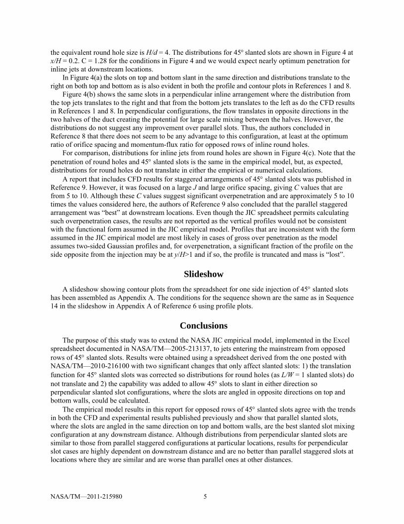
Figures 2 to 4 show spreadsheet results using the NASA JIC empirical model for opposed rows of jets with 45 slanted slots and round holes at conditions used in References 8 (CFD data) and 10 (experimental data). Schematics and details of the conditions investigated are given in Table 1.
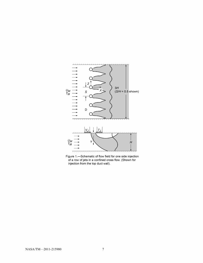
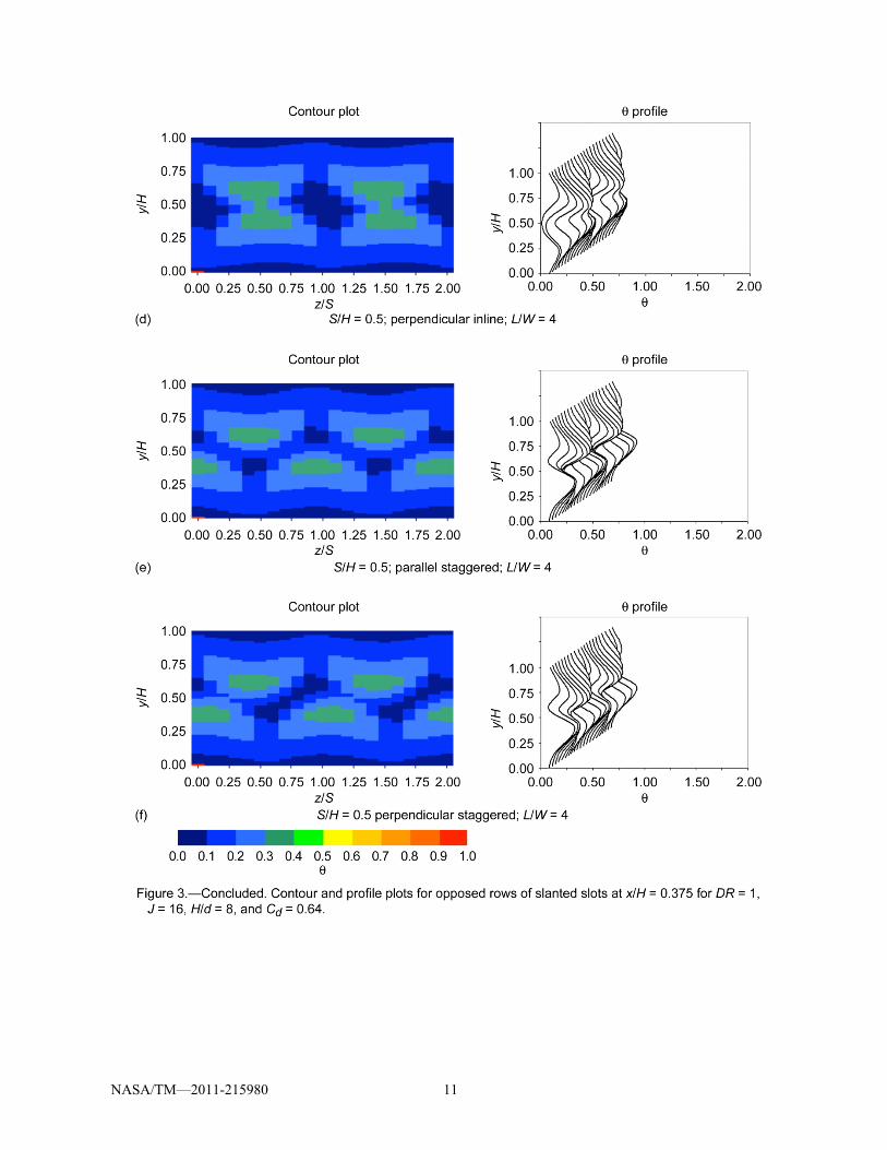
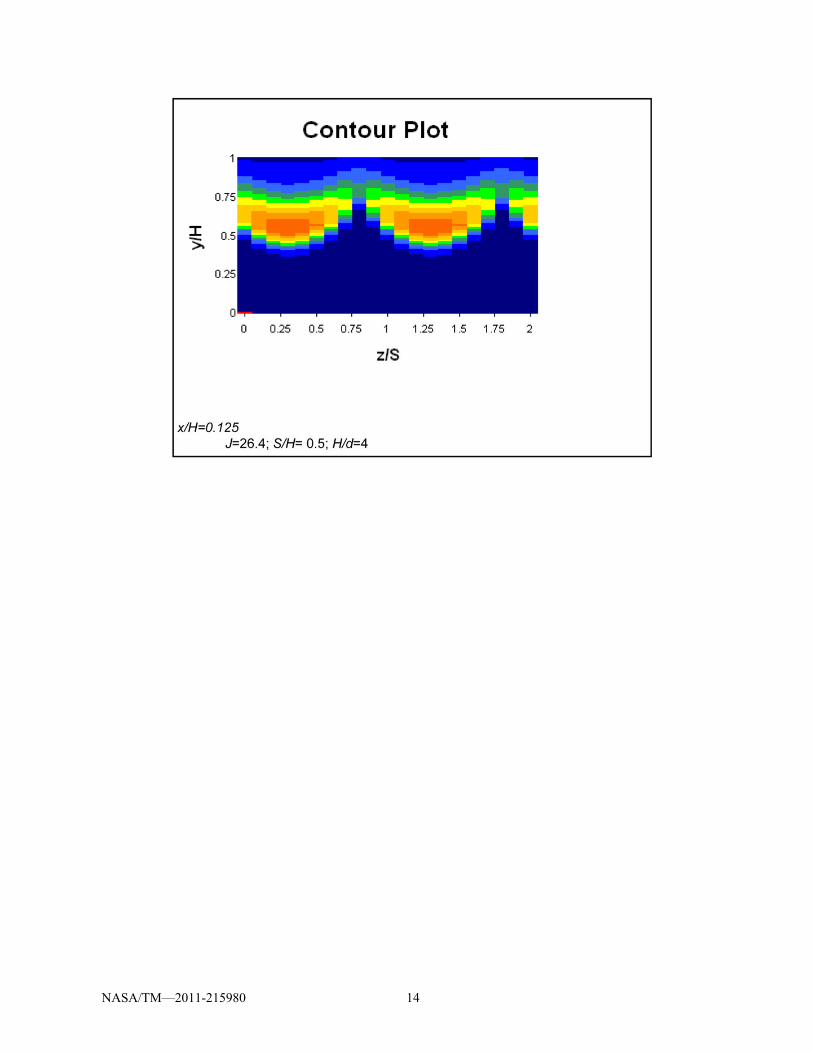
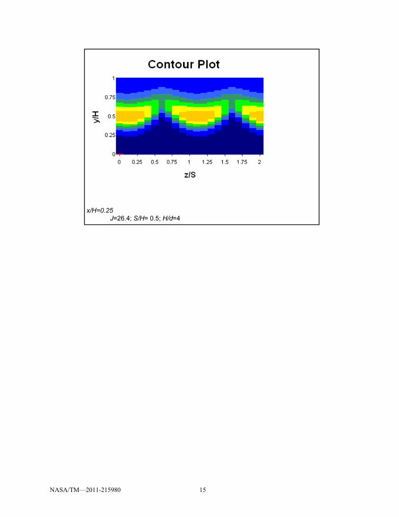
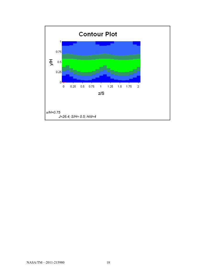
Figures 2 and 3 show empirical model calculations for the flow and orifice conditions of the experiments described in Reference 10. As the development and original publication of the NASA JIC empirical model pre-dated these experiments, the only influence the results in Reference 10 had on the empirical model were (1) to require that round holes (L/W = 1 slanted slots) must not translate, and (2) that the spreadsheet should be able to calculate perpendicular slanted slots which it could not do previously. Spreadsheet calculations were performed for opposed rows of 45 slanted slots with DR = 1, J = 16, H/d = 8 and Cd = 0.64 at downstream distances of x/H = 0.125 (Fig. 2) and x/H = 0.375 (Fig. 3).
Figures 2(a) and 3(a) show L/W = 4 slanted slot results from the empirical model for S/H = 0.25 (SSB in Ref. 10), and Figures 2(b) and 3(b) show results for S/H = 0.5 (SSE in Ref. 10). These are parallel inline configurations since the slots on the top and bottom walls have their centerlines aligned and the slots are slanted in the same direction.
The parameter C = (S/H)√J was shown in References 1 et al. to be an excellent indicator of penetration for jets in crossflow. For opposed rows of inline jets, optimum penetration occurs for round holes when C is approximately 1.25, underpenetration was obvious for C0.6, and overpenetration occurs for C 2.5. Thus, for the case of S/H = 0.25 and J = 16 (which gives C = 1), we would expect nearly optimum penetration for opposed rows of inline jets at downstream locations. For the case of S/H = 0.5 and J = 16 (which gives C = 2), we would expect over penetration for opposed rows of inline jets at downstream locations. Increased spacing between orifices (i.e., increasing S/H) results in increased penetration. The empirical model should not be used if S/H>1, and note that the jet penetration cannot exceed that of an unbounded JIC (infinite spacing and duct height) for the given J.
The distributions for round holes with S/H = 0.5 (RHD in Ref. 10) are shown in Figures 2(c) and 3(c). The empirical model distributions for round holes are the same as the slanted slot distributions shown in Figures 2(b) and 3(b) except that the distributions for round holes do not translate.
The configurations in Figures 2(d) and 3(d), 2(e) and 3(e), and 2(f) and 3(f) are respectively, SSF, SSG, and SSH in Reference 10. The configuration in parts (d) are L/W = 4 slanted slots at the same spacing (S/H = 0.5) as in parts (b) but the slots in parts (d) slant in opposite directions on top and bottom walls making a perpendicular inline configuration. The configuration in parts (e) are L/W = 4 slots at the same slant direction and spacing as in parts (b) but slots on one side of parts (e) are shifted by S/2 making a parallel staggered configuration. The configuration in parts (f) are similar to the perpendicular slots in parts (d) except that one side of the configuration in parts (f) is shifted by S/2 making a perpendicular staggered configuration.
For distributions with S/H = 0.5, there is virtually no interaction between jets from opposite sides at x/H = 0.125, and there is no obvious “best” configuration. Farther downstream at x/H = 0.375, the situation is quite different, and the parallel staggered configuration in Figure 3(e) is “best” as one would also conclude from perusing the experimental results in Reference 10. Although distributions for perpendicular slanted slots are similar to those for parallel staggered configurations at some downstream locations, results for perpendicular slanted slots are highly dependent on distance and are no better than parallel staggered slots at locations where they are similar and are worse than parallel ones at other distances.
The conditions in Figure 4 are the same as the CFD calculations for opposed rows of inline 45 slanted slots shown in references 1 and 8 (black and white figure in Ref. 1; color in Ref. 8), i.e., DR = 2.2, J = 6.6, S/H = 0.5, H/d = 4, and Cd = 1. Note that J is wrong in the title of Figure 12 in Reference 8, but is correct in Table 2 therein, and is correct in the title of Figure 29 in Reference 1. Note also that the configurations in Reference 1 and 8 are all inline ones and are similar to SSE, SSF, and RHD as shown in Table 1 but the aspect ratio (L/W) for the slanted slots is 2.8 in Figure 4(a) and (b) and
NASA/TM—2011-215980 5
the equivalent round hole size is H/d = 4. The distributions for 45 slanted slots are shown in Figure 4 at x/H = 0.2. C = 1.28 for the conditions in Figure 4 and we would expect nearly optimum penetration for inline jets at downstream locations.
In Figure 4(a) the slots on top and bottom slant in the same direction and distributions translate to the right on both top and bottom as is also evident in both the profile and contour plots in References 1 and 8.
Figure 4(b) shows the same slots in a perpendicular inline arrangement where the distribution from the top jets translates to the right and that from the bottom jets translates to the left as do the CFD results in References 1 and 8. In perpendicular configurations, the flow translates in opposite directions in the two halves of the duct creating the potential for large scale mixing between the halves. However, the distributions do not suggest any improvement over parallel slots. Thus, the authors concluded in Reference 8 that there does not seem to be any advantage to this configuration, at least at the optimum ratio of orifice spacing and momentum-flux ratio for opposed rows of inline round holes.
For comparison, distributions for inline jets from round holes are shown in Figure 4(c). Note that the penetration of round holes and 45 slanted slots is the same in the empirical model, but, as expected, distributions for round holes do not translate in either the empirical or numerical calculations.
A report that includes CFD results for staggered arrangements of 45 slanted slots was published in Reference 9. However, it was focused on a large J and large orifice spacing, giving C values that are from 5 to 10. Although these C values suggest significant overpenetration and are approximately 5 to 10 times the values considered here, the authors of Reference 9 also concluded that the parallel staggered arrangement was “best” at downstream locations. Even though the JIC spreadsheet permits calculating such overpenetration cases, the results are not reported as the vertical profiles would not be consistent with the functional form assumed in the JIC empirical model. Profiles that are inconsistent with the form assumed in the JIC empirical model are most likely in cases of gross over penetration as the model assumes two-sided Gaussian profiles and, for overpenetration, a significant fraction of the profile on the side opposite from the injection may be at y/H>1 and if so, the profile is truncated and mass is “lost”.
Slideshow
A slideshow showing contour plots from the spreadsheet for one side injection of 45 slanted slots has been assembled as Appendix A. The conditions for the sequence shown are the same as in Sequence 14 in the slideshow in Appendix A of Reference 6 using profile plots.
Conclusions
The purpose of this study was to extend the NASA JIC empirical model, implemented in the Excel
spreadsheet documented in NASA/TM—2005-213137, to jets entering the mainstream from opposed rows of 45 slanted slots. Results were obtained using a spreadsheet derived from the one posted with NASA/TM—2010-216100 with two significant changes that only affect slanted slots: 1) the translation function for 45 slanted slots was corrected so distributions for round holes (as L/W = 1 slanted slots) do not translate and 2) the capability was added to allow 45 slots to slant in either direction so perpendicular slanted slot configurations, where the slots are angled in opposite directions on top and bottom walls, could be calculated.
The empirical model results in this report for opposed rows of 45 slanted slots agree with the trends in both the CFD and experimental results published previously and show that parallel slanted slots, where the slots are angled in the same direction on top and bottom walls, are the best slanted slot mixing configuration at any downstream distance. Although distributions from perpendicular slanted slots are similar to those from parallel staggered configurations at particular locations, results for perpendicular slot cases are highly dependent on downstream distance and are no better than parallel staggered slots at locations where they are similar and are worse than parallel ones at other distances.
NASA/TM—2011-215980 6
TABLE 1.—ORIFICE CONFIGURATIONS AND FLOW CONDITIONS Figure Code Aspect Orifice H/W3 x/H of J C4 Ratio spacing trailing L/W S/H edge 3(c) & 4(c) RHD1 1 0.5 8 0.063 16 2 5(c) A2 1 0.5 4 0.125 6.6 1.28 3(a) & 4(a) SSB1 4 0.25 17.6 0.089 16 1 3(b) & 4(b) SSE1 4 0.5 17.6 0.089 16 2 5(a) E2 2.8 0.5 6.06 0.188 6.6 1.28 3(d) & 4(d) SSF1 4 0.5 17.6 0.089 16 2 5(b) F2 2.8 0.5 6.06 0.188 6.6 1.28 3(e) & 4(e) SSG1 4 0.5 17.6 0.089 16 2 3(f) & 4(f) SSH1 4 0.5 17.6 0.089 16 2 1 in Reference 10 2 in Reference 8 3 H/W = H/d*sqrt(1+4/(L/W-1)) 4 C = (S/H)*sqrt(J)
NASA/TM—2011-215980 7

NASA/TM—2011-215980 8

NASA/TM—2011-215980 9
NASA/TM—2011-215980 10
NASA/TM—2011-215980 11

NASA/TM—2011-215980 12

NASA/TM—2011-215980 13
NASA/TM—2011-215980 14
NASA/TM—2011-215980 15

NASA/TM—2011-215980 16

NASA/TM—2011-215980 17
NASA/TM—2011-215980 18

NASA/TM—2011-215980 19
NASA/TM—2011-215980 20
NASA/TM—2011-215980 21

NASA/TM—2011-215980 22
References
1. Holdeman, James D. Mixing of Multiple Jets With a Confined Subsonic Crossflow. Prog in Energy and Combust Sci, Vol. 19, pp. 31–70, 1993 (similar to AIAA Paper 91-2458 and NASA TM 104412, June 1991).
2. Holdeman, James D., Liscinsky, David S., Oechsle, Victor L., Samuelsen, G. Scott, and Smith, Clifford E. Mixing of Multiple Jets With a Confined Subsonic Crossflow: Part I - Cylindrical Ducts. J of Eng for Gas Turbines and Power, Vol. 119, No. 10, pp. 852–862, October 1997 (same as ASME Paper 96-GT-482 and NASA TM 107185, June 1996).
3. Holdeman, James D., Liscinsky, David S., and Bain, Daniel B. Mixing of Multiple Jets With a Confined Crossflow: Part II—Opposed Rows of Orifices in Rectangular Ducts. J of Eng for Gas Turbines and Power, Vol. 121. No. 7, pp. 551–553; July 1999 (same as ASME Paper 97-GT-439 and NASA TM 107461, June 1997).
4. Holdeman, James D., Vardakas, Mark A., and Chang, Clarence T. Mixing of Multiple Jets With a Confined Subsonic Crossflow: Part III—The Effects of Air Preheat and Number of Orifices on Flow and Emissions in an RQL Mixing Section. NASA/TM—2008-215151, March 2008 (similar to J of Fluids Eng, Vol. 129, No. 11, pp. 1460–1467, Nov. 2007; derived from NASA TM-1999-209431, September 1999).
5. Holdeman, James D., Smith, Timothy D., Clisset, James R., and Lear, William E. A Spreadsheet for the Mixing of a Row of Jets with a Confined Crossflow. NASA/TM—2005-213137, February 2005.
6. Holdeman, James D., Clisset, James R., Moder, Jeffrey P., and Lear, William E. On the Mixing of Single and Opposed Rows of Jets With a Confined Crossflow. NASA/TM—2006-214226, October 2006.
7. Holdeman, James D., Clisset, James R., and Moder, Jeffrey P. Spreadsheet Calculations for Jets in Crossflow: Opposed Rows of Inline and Staggered Holes and Single and Opposed Rows With Alternating Hole Sizes. NASA/TM—2010-216100, July 2010.
8. Holdeman, J.D., Reynolds, R., and White, C.A. Numerical Study of the Effects of Curvature and Convergence on Dilution Jet Mixing. AIAA-87-1953 and NASA TM-89878, June 1987.
9. Bain, D.B., Smith, C.E., and Holdeman, J.D. CFD Mixing Analysis of Jets Injected From Straight and Slanted Slots Into Confined Crossflow in Rectangular Ducts. AIAA-92-3087 and NASA TM-105699, July 1992.
10. Liscinsky, D.S., True B., Vranos A., and Holdeman, J.D. Experimental Study of Cross-Stream Mixing in a Rectangular Duct. AIAA-92-3090 and NASA TM-105694, July 1992.


Related Documents