IEEE TRANSACTIONS ON VEHICULAR TECHNOLOGY, VOL. 57, NO. 5, SEPTEMBER 2008 2933 Spreading Code Design for Downlink Space-Time-Frequency Spreading CDMA Siyang Liu, Student Member, IEEE, Zhendong Luo, Yuanan Liu, Member, IEEE, and Jinchun Gao, Member, IEEE Abstract—In this paper, we analyze the recently proposed down- link space-time-frequency spreading code-division multiple-access (STFS-CDMA) scheme. A spreading code design criterion is first derived for STFS-CDMA. From the spreading code design crite- rion, we can see that the two original spreading codes adopted in STFS-CDMA, i.e., the Walsh–Hadamard code (WHC) and the double-orthogonal code (DOC), both cannot achieve full space and frequency diversity, no matter how many users exist in the system. Then, a novel spreading code, i.e., permutated DOC (PDOC), is proposed. PDOC-coded STFS-CDMA (PDOC-STFS-CDMA) can obtain full space and frequency diversity when the number of users in the system is only one, but it cannot obtain full space and frequency diversity when the number of users is larger than one. To mitigate this problem, a zero-padded rotary fast Fourier trans- form code (ZPRFC) is proposed. Compared with WHC-coded STFS-CDMA (WHC-STFS-CDMA), DOC-coded STFS-CDMA (DOC-STFS-CDMA), and PDOC-STFS-CDMA, ZPRFC-coded STFS-CDMA (ZPRFC-STFS-CDMA) cannot only always obtain full space and frequency diversity but can also result in a low– complexity receiver at the cost of the reduction of the number of supporting users. Finally, the simulation results are given to com- pare with the performances of WHC-STFS-CDMA, DOC-STFS- CDMA, PDOC-STFS-CDMA, and ZPRFC-STFS-CDMA. Index Terms—Multiple-input–multiple-output (MIMO) systems, orthogonal frequency-division multiplexing (OFDM) systems, space-time-frequency spreading code-division multiple- access (STFS-CDMA). I. I NTRODUCTION C ODE-DIVISION multiple-access (CDMA) is a spread- spectrum multiple-access technique that allows multiple users to simultaneously share the same bandwidth [1]. Since the CDMA signal is spread over a wide frequency band, which is much greater than the coherence bandwidth, CDMA systems can obtain frequency diversity gain with the aid of a rake receiver. However, when the time delay spread is large, the rake receiver needs to concatenate an equalizer to fight against intersymbol interference (ISI). This will greatly increase the complexity of the receiver. Manuscript received December 20, 2006; revised July 7, 2007 and December 21, 2007. This work was supported in part by the NTT Docomo Beijing Communications Laboratories and in part by the National Natural Science Foundation of China under Grant 60573111. The review of this paper was coordinated by Prof. M. Juntti. S. Liu, Y. Liu, and J. Gao are with the School of Telecommuni- cation Engineering, Beijing University of Posts and Telecommunications, Beijing 100876, China (e-mail: [email protected]; yuliu@bupt. edu.cn; [email protected]). Z. Luo is with the Bell Labs Research China, Alcatel–Lucent, Beijing 100080, China, and also with the Department of Electronic Engineering, Tsinghua University, Beijing 100084, China (e-mail: [email protected]). Digital Object Identifier 10.1109/TVT.2008.917234 Orthogonal frequency-division multiplexing (OFDM) is a simple and effective technique for combating multipath prop- agation [2]. By adding a cyclic prefix (CP) at the beginning of each symbol, OFDM provides great immunity from the ISI. OFDM can also translate the frequency-selective fading chan- nel to the flat-fading channel by dividing the entire bandwidth into several parallel subchannels. This feature allows the simple one-tap equalizer to be adopted at the receiver. However, it also induces that the frequency diversity fails to be exploited in the system. As previously discussed, CDMA and OFDM have their own advantages and disadvantages. Therefore, combining OFDM with CDMA is a promising technique. The combination of these two techniques has already attracted much attention [3]– [6]. It cannot only avoid the ISI but can also allow us to exploit the frequency diversity. According to the different al- location manners of the spreading code, there are three basic structures of the combining scheme: 1) multicarrier CDMA (MC-CDMA); 2) multicarrier direct-sequence CDMA; and 3) multitone CDMA [6]. Over the past few years, multiple-input–multiple-output (MIMO) systems have become a research hotspot. One ad- vantage of MIMO systems is that they are capable of of- fering space diversity gain [7]–[9]. Therefore, if the proper combining method is employed, the combination of CDMA, OFDM, and MIMO can significantly improve the performance of the system by offering space, frequency, and time diversity. Several papers have already considered this problem [10]–[14]. In [10], two schemes, i.e., the space-time block-coded MC- CDMA and the cyclic delay diversity MC-CDMA, were given to utilize the space diversity. Vehkapera et al. [11], [12] investigated the combination of MC-CDMA systems with layered spatial multiplexing architectures. However, in the aforementioned studies, the spreading code and the space- time code were separately designed and directly combined. Moreover, the additional space dimension was not utilized to design the spreading code. Therefore, these combination methods are direct and not optimized. In [13], one differ- ent combination scheme was given for MIMO-OFDM-based spreading systems. In this scheme, the designed spreading code based on the Walsh–Hadamard code (WHC) was allocated not only over the time domain or the frequency domain but also over the space domain. Subsequently, the space-time-frequency spreading CDMA (STFS-CDMA) scheme, which is similar to the scheme proposed in [13], and its corresponding spreading code, i.e., the double-orthogonal code (DOC), were proposed. DOC-coded STFS-CDMA (DOC-STFS-CDMA), which is op- timized under the minimum mean square error (MMSE) 0018-9545/$25.00 © 2008 IEEE

Welcome message from author
This document is posted to help you gain knowledge. Please leave a comment to let me know what you think about it! Share it to your friends and learn new things together.
Transcript

IEEE TRANSACTIONS ON VEHICULAR TECHNOLOGY, VOL. 57, NO. 5, SEPTEMBER 2008 2933
Spreading Code Design for DownlinkSpace-Time-Frequency Spreading CDMA
Siyang Liu, Student Member, IEEE, Zhendong Luo, Yuanan Liu, Member, IEEE, and Jinchun Gao, Member, IEEE
Abstract—In this paper, we analyze the recently proposed down-link space-time-frequency spreading code-division multiple-access(STFS-CDMA) scheme. A spreading code design criterion is firstderived for STFS-CDMA. From the spreading code design crite-rion, we can see that the two original spreading codes adoptedin STFS-CDMA, i.e., the Walsh–Hadamard code (WHC) and thedouble-orthogonal code (DOC), both cannot achieve full space andfrequency diversity, no matter how many users exist in the system.Then, a novel spreading code, i.e., permutated DOC (PDOC), isproposed. PDOC-coded STFS-CDMA (PDOC-STFS-CDMA) canobtain full space and frequency diversity when the number ofusers in the system is only one, but it cannot obtain full space andfrequency diversity when the number of users is larger than one.To mitigate this problem, a zero-padded rotary fast Fourier trans-form code (ZPRFC) is proposed. Compared with WHC-codedSTFS-CDMA (WHC-STFS-CDMA), DOC-coded STFS-CDMA(DOC-STFS-CDMA), and PDOC-STFS-CDMA, ZPRFC-codedSTFS-CDMA (ZPRFC-STFS-CDMA) cannot only always obtainfull space and frequency diversity but can also result in a low–complexity receiver at the cost of the reduction of the number ofsupporting users. Finally, the simulation results are given to com-pare with the performances of WHC-STFS-CDMA, DOC-STFS-CDMA, PDOC-STFS-CDMA, and ZPRFC-STFS-CDMA.
Index Terms—Multiple-input–multiple-output (MIMO)systems, orthogonal frequency-division multiplexing (OFDM)systems, space-time-frequency spreading code-division multiple-access (STFS-CDMA).
I. INTRODUCTION
CODE-DIVISION multiple-access (CDMA) is a spread-spectrum multiple-access technique that allows multiple
users to simultaneously share the same bandwidth [1]. Since theCDMA signal is spread over a wide frequency band, which ismuch greater than the coherence bandwidth, CDMA systemscan obtain frequency diversity gain with the aid of a rakereceiver. However, when the time delay spread is large, therake receiver needs to concatenate an equalizer to fight againstintersymbol interference (ISI). This will greatly increase thecomplexity of the receiver.
Manuscript received December 20, 2006; revised July 7, 2007 andDecember 21, 2007. This work was supported in part by the NTT DocomoBeijing Communications Laboratories and in part by the National NaturalScience Foundation of China under Grant 60573111. The review of this paperwas coordinated by Prof. M. Juntti.
S. Liu, Y. Liu, and J. Gao are with the School of Telecommuni-cation Engineering, Beijing University of Posts and Telecommunications,Beijing 100876, China (e-mail: [email protected]; [email protected]; [email protected]).
Z. Luo is with the Bell Labs Research China, Alcatel–Lucent, Beijing100080, China, and also with the Department of Electronic Engineering,Tsinghua University, Beijing 100084, China (e-mail: [email protected]).
Digital Object Identifier 10.1109/TVT.2008.917234
Orthogonal frequency-division multiplexing (OFDM) is asimple and effective technique for combating multipath prop-agation [2]. By adding a cyclic prefix (CP) at the beginningof each symbol, OFDM provides great immunity from the ISI.OFDM can also translate the frequency-selective fading chan-nel to the flat-fading channel by dividing the entire bandwidthinto several parallel subchannels. This feature allows the simpleone-tap equalizer to be adopted at the receiver. However, it alsoinduces that the frequency diversity fails to be exploited in thesystem.
As previously discussed, CDMA and OFDM have their ownadvantages and disadvantages. Therefore, combining OFDMwith CDMA is a promising technique. The combination ofthese two techniques has already attracted much attention [3]–[6]. It cannot only avoid the ISI but can also allow us toexploit the frequency diversity. According to the different al-location manners of the spreading code, there are three basicstructures of the combining scheme: 1) multicarrier CDMA(MC-CDMA); 2) multicarrier direct-sequence CDMA; and3) multitone CDMA [6].
Over the past few years, multiple-input–multiple-output(MIMO) systems have become a research hotspot. One ad-vantage of MIMO systems is that they are capable of of-fering space diversity gain [7]–[9]. Therefore, if the propercombining method is employed, the combination of CDMA,OFDM, and MIMO can significantly improve the performanceof the system by offering space, frequency, and time diversity.Several papers have already considered this problem [10]–[14].In [10], two schemes, i.e., the space-time block-coded MC-CDMA and the cyclic delay diversity MC-CDMA, were givento utilize the space diversity. Vehkapera et al. [11], [12]investigated the combination of MC-CDMA systems withlayered spatial multiplexing architectures. However, in theaforementioned studies, the spreading code and the space-time code were separately designed and directly combined.Moreover, the additional space dimension was not utilizedto design the spreading code. Therefore, these combinationmethods are direct and not optimized. In [13], one differ-ent combination scheme was given for MIMO-OFDM-basedspreading systems. In this scheme, the designed spreadingcode based on the Walsh–Hadamard code (WHC) was allocatednot only over the time domain or the frequency domain but alsoover the space domain. Subsequently, the space-time-frequencyspreading CDMA (STFS-CDMA) scheme, which is similar tothe scheme proposed in [13], and its corresponding spreadingcode, i.e., the double-orthogonal code (DOC), were proposed.DOC-coded STFS-CDMA (DOC-STFS-CDMA), which is op-timized under the minimum mean square error (MMSE)
0018-9545/$25.00 © 2008 IEEE
2934 IEEE TRANSACTIONS ON VEHICULAR TECHNOLOGY, VOL. 57, NO. 5, SEPTEMBER 2008
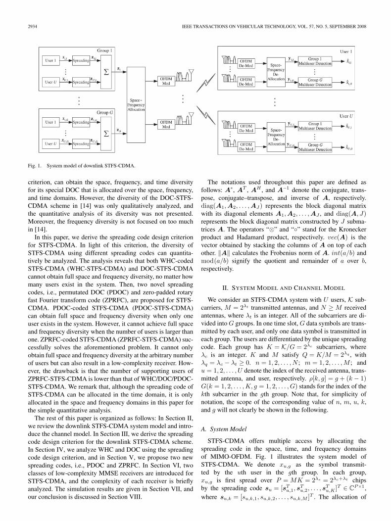
Fig. 1. System model of downlink STFS-CDMA.
criterion, can obtain the space, frequency, and time diversityfor its special DOC that is allocated over the space, frequency,and time domains. However, the diversity of the DOC-STFS-CDMA scheme in [14] was only qualitatively analyzed, andthe quantitative analysis of its diversity was not presented.Moreover, the frequency diversity is not focused on too muchin [14].
In this paper, we derive the spreading code design criterionfor STFS-CDMA. In light of this criterion, the diversity ofSTFS-CDMA using different spreading codes can quantita-tively be analyzed. The analysis reveals that both WHC-codedSTFS-CDMA (WHC-STFS-CDMA) and DOC-STFS-CDMAcannot obtain full space and frequency diversity, no matter howmany users exist in the system. Then, two novel spreadingcodes, i.e., permutated DOC (PDOC) and zero-padded rotaryfast Fourier transform code (ZPRFC), are proposed for STFS-CDMA. PDOC-coded STFS-CDMA (PDOC-STFS-CDMA)can obtain full space and frequency diversity when only oneuser exists in the system. However, it cannot achieve full spaceand frequency diversity when the number of users is larger thanone. ZPRFC-coded STFS-CDMA (ZPRFC-STFS-CDMA) suc-cessfully solves the aforementioned problem. It cannot onlyobtain full space and frequency diversity at the arbitrary numberof users but can also result in a low-complexity receiver. How-ever, the drawback is that the number of supporting users ofZPRFC-STFS-CDMA is lower than that of WHC/DOC/PDOC-STFS-CDMA. We remark that, although the spreading code ofSTFS-CDMA can be allocated in the time domain, it is onlyallocated in the space and frequency domains in this paper forthe simple quantitative analysis.
The rest of this paper is organized as follows: In Section II,we review the downlink STFS-CDMA system model and intro-duce the channel model. In Section III, we derive the spreadingcode design criterion for the downlink STFS-CDMA scheme.In Section IV, we analyze WHC and DOC using the spreadingcode design criterion, and in Section V, we propose two newspreading codes, i.e., PDOC and ZPRFC. In Section VI, twoclasses of low-complexity MMSE receivers are introduced forSTFS-CDMA, and the complexity of each receiver is brieflyanalyzed. The simulation results are given in Section VII, andour conclusion is discussed in Section VIII.
The notations used throughout this paper are defined asfollows: A∗, AT , AH , and A−1 denote the conjugate, trans-pose, conjugate–transpose, and inverse of A, respectively.diag(A1,A2, . . . ,AJ) represents the block diagonal matrixwith its diagonal elements A1,A2, . . . ,AJ , and diag(A, J)represents the block diagonal matrix constructed by J subma-trices A. The operators “⊗” and “◦” stand for the Kroneckerproduct and Hadamard product, respectively. vec(A) is thevector obtained by stacking the columns of A on top of eachother. ‖A‖ calculates the Frobenius norm of A. int(a/b) andmod(a/b) signify the quotient and remainder of a over b,respectively.
II. SYSTEM MODEL AND CHANNEL MODEL
We consider an STFS-CDMA system with U users, K sub-carriers, M = 2λt transmitted antennas, and N ≥ M receivedantennas, where λt is an integer. All of the subcarriers are di-vided into G groups. In one time slot, G data symbols are trans-mitted by each user, and only one data symbol is transmitted ineach group. The users are differentiated by the unique spreadingcode. Each group has K = K/G = 2λc subcarriers, whereλc is an integer. K and M satisfy Q = K/M = 2λq , withλq = λc − λt ≥ 0. n = 1, 2, . . . , N ; m = 1, 2, . . . ,M ; andu = 1, 2, . . . , U denote the index of the received antenna, trans-mitted antenna, and user, respectively. ρ[k, g] = g + (k − 1)G(k = 1, 2, . . . ,K, g = 1, 2, . . . , G) stands for the index of thekth subcarrier in the gth group. Note that, for simplicity ofnotation, the scope of the corresponding value of n, m, u, k,and g will not clearly be shown in the following.
A. System Model
STFS-CDMA offers multiple access by allocating thespreading code in the space, time, and frequency domainsof MIMO-OFDM. Fig. 1 illustrates the system model ofSTFS-CDMA. We denote xu,g as the symbol transmit-ted by the uth user in the gth group. In each group,xu,g is first spread over P = MK = 2λs = 2λc+λt chipsby the spreading code su = [sT
u,1, sTu,2, . . . , s
Tu,K ]T ∈ C
P×1,where su,k = [su,k,1, su,k,2, . . . , su,k,M ]T . The allocation of
LIU et al.: SPREADING CODE DESIGN FOR DOWNLINK SPACE-TIME-FREQUENCY SPREADING CDMA 2935
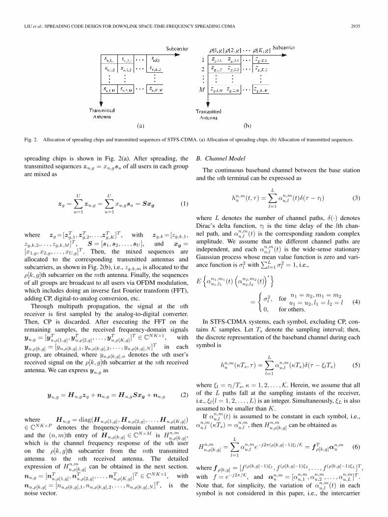
Fig. 2. Allocation of spreading chips and transmitted sequences of STFS-CDMA. (a) Allocation of spreading chips. (b) Allocation of transmitted sequences.
spreading chips is shown in Fig. 2(a). After spreading, thetransmitted sequences zu,g = xu,gsu of all users in each groupare mixed as
zg =U∑
u=1
zu,g =U∑
u=1
xu,gsu = Sxg (1)
where zg =[zTg,1,z
Tg,2,. . . ,z
Tg,K ]T , with zg,k =[zg,k,1,
zg,k,2,. . . , zg,k,M ]T , S = [s1, s2, . . . , sU ], and xg =[x1,g, x2,g, . . . , xU,g]T . Then, the mixed sequences areallocated to the corresponding transmitted antennas andsubcarriers, as shown in Fig. 2(b), i.e., zg,k,m is allocated to theρ[k, g]th subcarrier on the mth antenna. Finally, the sequencesof all groups are broadcast to all users via OFDM modulation,which includes doing an inverse fast Fourier transform (FFT),adding CP, digital-to-analog conversion, etc.
Through multipath propagation, the signal at the uthreceiver is first sampled by the analog-to-digital converter.Then, CP is discarded. After executing the FFT on theremaining samples, the received frequency-domain signalsyu,g = [yT
u,ρ[1,g],yTu,ρ[2,g], . . . ,y
Tu,ρ[K,g]]
T ∈ CNK×1, with
yu,ρ[k,g] = [yu,ρ[k,g],1, yu,ρ[k,g],2, . . . , yu,ρ[k,g],N ]T in eachgroup, are obtained, where yu,ρ[k,g],n denotes the uth user’sreceived signal on the ρ[k, g]th subcarrier at the nth receivedantenna. We can express yu,g as
yu,g = Hu,gzg + nu,g = Hu,gSxg + nu,g (2)
where Hu,g = diag(Hu,ρ[1,g],Hu,ρ[2,g], . . . ,Hu,ρ[K,g])∈ C
NK×P denotes the frequency-domain channel matrix,and the (n,m)th entry of Hu,ρ[k,g] ∈ C
N×M is Hn,mu,ρ[k,g],
which is the channel frequency response of the uth useron the ρ[k, g]th subcarrier from the mth transmittedantenna to the nth received antenna. The detailedexpression of Hn,m
u,ρ[k,g] can be obtained in the next section.
nu,g = [nTu,ρ[1,g],n
Tu,ρ[2,g], . . . ,n
Tu,ρ[K,g]]
T ∈ CNK×1, with
nu,ρ[k,g] = [nu,ρ[k,g],1, nu,ρ[k,g],2, . . . , nu,ρ[k,g],N ]T , is thenoise vector.
B. Channel Model
The continuous baseband channel between the base stationand the uth terminal can be expressed as
hn,mu (t, τ) =
L∑l=1
αn,mu,l (t)δ(τ − τl) (3)
where L denotes the number of channel paths, δ(·) denotesDirac’s delta function, τl is the time delay of the lth chan-nel path, and αn,m
u,l (t) is the corresponding random complexamplitude. We assume that the different channel paths areindependent, and each αn,m
u,l (t) is the wide-sense stationaryGaussian process whose mean value function is zero and vari-ance function is σ2
l with∑L
l=1 σ2l = 1, i.e.,
E{
αn1,m1u1,l1
(t)(αn2,m2
u2,l2(t))∗}
=
{σ2
l , forn1 = n2,m1 = m2
u1 = u2, l1 = l2 = l0, for others.
(4)
In STFS-CDMA systems, each symbol, excluding CP, con-tains K samples. Let Ts denote the sampling interval; then,the discrete representation of the baseband channel during eachsymbol is
hn,mu (κTs, τ) =
L∑l=1
αn,mu,l (κTs)δ(τ − ξlTs) (5)
where ξl = τl/Ts, κ = 1, 2, . . . ,K. Herein, we assume that allof the L paths fall at the sampling instants of the receiver,i.e., ξl(l = 1, 2, . . . , L) is an integer. Simultaneously, ξL is alsoassumed to be smaller than K.
If αn,mu,l (t) is assumed to be constant in each symbol, i.e.,
αn,mu,l (κTs) = αn,m
u,l , then Hn,mu,ρ[k,g] can be obtained as
Hn,mu,ρ[k,g] =
L∑l=1
αn,mu,l e−j2π(ρ[k,g]−1)ξl/K = fT
ρ[k,g]αn,mu (6)
where fρ[k,g] = [f (ρ[k,g]−1)ξ1 , f (ρ[k,g]−1)ξ2 , . . . , f (ρ[k,g]−1)ξL ]T ,with f = e−j2π/K, and αn,m
u = [αn,mu,1 , αn,m
u,2 , . . . , αn,mu,L ]T .
Note that, for simplicity, the variation of αn,mu,l (t) in each
symbol is not considered in this paper, i.e., the intercarrier
2936 IEEE TRANSACTIONS ON VEHICULAR TECHNOLOGY, VOL. 57, NO. 5, SEPTEMBER 2008
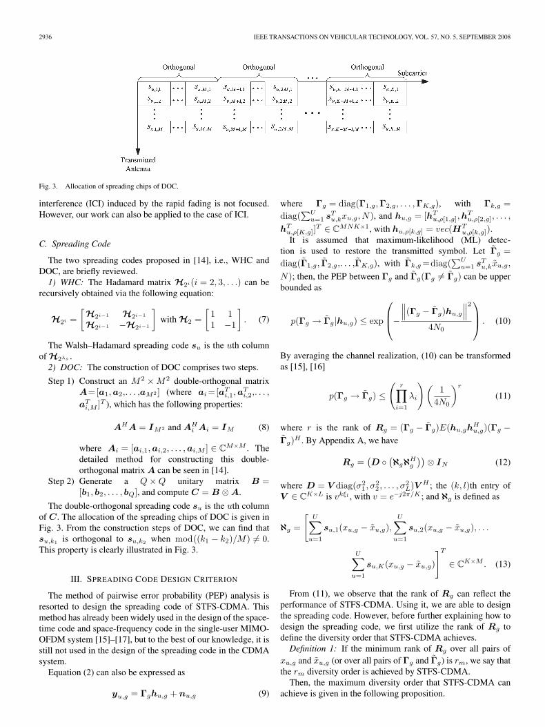
Fig. 3. Allocation of spreading chips of DOC.
interference (ICI) induced by the rapid fading is not focused.However, our work can also be applied to the case of ICI.
C. Spreading Code
The two spreading codes proposed in [14], i.e., WHC andDOC, are briefly reviewed.
1) WHC: The Hadamard matrix H2i(i = 2, 3, . . .) can berecursively obtained via the following equation:
H2i =[
H2i−1 H2i−1
H2i−1 −H2i−1
]with H2 =
[1 11 −1
]. (7)
The Walsh–Hadamard spreading code su is the uth columnof H2λs .
2) DOC: The construction of DOC comprises two steps.
Step 1) Construct an M2 × M2 double-orthogonal matrixA=[a1,a2,. . . ,aM2 ] (where ai =[aT
i,1,aTi,2,. . . ,
aTi,M ]T ), which has the following properties:
AHA = IM2 and AHi Ai = IM (8)
where Ai = [ai,1,ai,2, . . . ,ai,M ] ∈ CM×M . The
detailed method for constructing this double-orthogonal matrix A can be seen in [14].
Step 2) Generate a Q × Q unitary matrix B =[b1, b2, . . . , bQ], and compute C = B ⊗ A.
The double-orthogonal spreading code su is the uth columnof C. The allocation of the spreading chips of DOC is given inFig. 3. From the construction steps of DOC, we can find thatsu,k1 is orthogonal to su,k2 when mod((k1 − k2)/M) �= 0.This property is clearly illustrated in Fig. 3.
III. SPREADING CODE DESIGN CRITERION
The method of pairwise error probability (PEP) analysis isresorted to design the spreading code of STFS-CDMA. Thismethod has already been widely used in the design of the space-time code and space-frequency code in the single-user MIMO-OFDM system [15]–[17], but to the best of our knowledge, it isstill not used in the design of the spreading code in the CDMAsystem.
Equation (2) can also be expressed as
yu,g = Γghu,g + nu,g (9)
where Γg = diag(Γ1,g,Γ2,g, . . . ,ΓK,g), with Γk,g =diag(
∑Uu=1 sT
u,kxu,g, N), and hu,g = [hTu,ρ[1,g],h
Tu,ρ[2,g], . . . ,
hTu,ρ[K,g]]
T ∈ CMNK×1, with hu,ρ[k,g] = vec(HT
u,ρ[k,g]).It is assumed that maximum-likelihood (ML) detec-
tion is used to restore the transmitted symbol. Let Γg =diag(Γ1,g, Γ2,g,. . . ,ΓK,g), with Γk,g =diag(
∑Uu=1 sT
u,kxu,g,
N); then, the PEP between Γg and Γg(Γg �= Γg) can be upperbounded as
p(Γg → Γg|hu,g) ≤ exp
⎛⎜⎝−
∥∥∥(Γg − Γg)hu,g
∥∥∥2
4N0
⎞⎟⎠ . (10)
By averaging the channel realization, (10) can be transformedas [15], [16]
p(Γg → Γg) ≤(
r∏i=1
λi
)(1
4N0
)r
(11)
where r is the rank of Rg = (Γg − Γg)E(hu,ghHu,g)(Γg −
Γg)H . By Appendix A, we have
Rg =(D ◦
(ℵgℵH
g
))⊗ IN (12)
where D = V diag(σ21 , σ2
2 , . . . , σ2L)V H ; the (k, l)th entry of
V ∈ CK×L is vkξl , with v = e−j2π/K ; and ℵg is defined as
ℵg =
[U∑
u=1
su,1(xu,g − xu,g),U∑
u=1
su,2(xu,g − xu,g), . . .
U∑u=1
su,K(xu,g − xu,g)
]T
∈ CK×M . (13)
From (11), we observe that the rank of Rg can reflect theperformance of STFS-CDMA. Using it, we are able to designthe spreading code. However, before further explaining how todesign the spreading code, we first utilize the rank of Rg todefine the diversity order that STFS-CDMA achieves.
Definition 1: If the minimum rank of Rg over all pairs ofxu,g and xu,g (or over all pairs of Γg and Γg) is rm, we say thatthe rm diversity order is achieved by STFS-CDMA.
Then, the maximum diversity order that STFS-CDMA canachieve is given in the following proposition.
LIU et al.: SPREADING CODE DESIGN FOR DOWNLINK SPACE-TIME-FREQUENCY SPREADING CDMA 2937
Proposition 1: The maximum achievable diversity order (orthe full space and frequency diversity order) of STFS-CDMAis min{LMN,QMN}.
Proof: It is easy to verify that the rank of D and ℵgℵHg
satisfy rank(D)=rank(V diag(σ21 , σ2
2 ,. . . ,σ2L)V H)≤L and
rank(ℵgℵHg ) ≤ M , respectively. Then, we have
rank(D ◦
(ℵgℵH
g
))≤rank(D)rank
(ℵgℵH
g
)≤LM. (14)
Simultaneously, D ◦ (ℵgℵHg ) is a K×K(QM×QM) matrix.
This implies that rank(D ◦ (ℵgℵHg )) ≤ min{LM,QM}.
Correspondingly, we can get rank(Rg) = rank(D ◦(ℵgℵH
g ))rank(IN ) ≤ min{LMN,QMN}. Therefore, themaximum achievable diversity order of STFS-CDMA ismin{LMN,QMN}. �
From the proof of Proposition 1, we can see that full re-ceive space diversity N can always be obtained, but full trans-mit space diversity M cannot always be achieved. The transmitspace diversity only depends on the rank of ℵgℵH
g . Therefore,we give the following definition.
Definition 2: If rank(ℵgℵHg ) = M for any pair of xu,g and
xu,g , the full transmit space diversity M of STFS-CDMA isobtained, i.e., full space diversity MN is achieved.
Furthermore, full frequency diversity L cannot always beobtained either. Since the frequency diversity obtained dependson the channel condition, the number of subcarriers (i.e., therelative value of L and Q), and the design of the spreading code,we do not consider it separately as the space diversity, which isseparately considered in Definition 2. However, the frequencydiversity obtained can indirectly be echoed by the rank ofD ◦ (ℵgℵH
g ). Therefore, we have the following definition.Definition 3: If rank(D ◦ (ℵgℵH
g )) = min{LM,QM} forany pair of xu,g and xu,g , the full transmit space and frequencydiversity min{LM,QM} of STFS-CDMA is obtained, i.e.,the full space and frequency diversity min{LMN,QMN} ofSTFS-CDMA is obtained.
To summarize the preceding discussion, we give the spread-ing code design criterion.
A. Spreading Code Design Criterion
The spreading code should make the minimum rank ofℵgℵH
g and that of D ◦ (ℵgℵHg ) over all pairs of xu,g and
xu,g as large as possible. The optimum spreading codecan make rank(ℵgℵH
g ) = M and rank(D ◦ (ℵgℵHg )) =
min{LM,QM} for any pair of xu,g and xu,g and obtain fullspace and frequency diversity.
Regarding the spreading code design criterion, the followingremarks are given.
Remark 1: If K > LM , the maximum diversity order thatSTFS-CDMA can obtain is LMN , which is determined by thephysical channel condition. However, not all spreading codescan achieve this diversity. In fact, all spreading codes cannotachieve this diversity when K < LM .
Remark 2: Equation (13) indicates that the number of usersaffects the rank of ℵgℵH
g and further affects that of D ◦(ℵgℵH
g ). If the spreading code is not well designed, this effect
can induce a different diversity order when the number of usersis different. However, the well-designed spreading code caneliminate this effect, i.e., no matter how many users exist in thesystem, the same diversity order (maybe the maximum order)can be attained.
Remark 3: No matter which group in STFS-CDMA is con-sidered, the spreading code designed by the criterion is thesame. Therefore, only one group is focused on the rest of thepaper, and the subscript g is omitted for brevity of notation.
IV. ANALYSIS OF WHC-STFS-CDMA AND
DOC-STFS-CDMA
The diversity order of WHC-STFS-CDMA and DOC-STFS-CDMA is analyzed in this section by the spreading code designcriterion developed in Section III. Because the diversity maybe related with the number of users, we first investigate the di-versity of WHC-STFS-CDMA and that of DOC-STFS-CDMAwhen only one user exists in the system and then investigatethem when more than one user exists in the system.
Proposition 2: If only one user exists in the system, WHC-STFS-CDMA cannot obtain full space diversity. Correspond-ingly, it cannot achieve full space and frequency diversity.
Proof: If only one user exists in the system, (13) can beexpressed as
ℵ = [s1,1(x1 − x1), s1,2(x1 − x1), . . . , s1,K(x1 − x1)]T
= (x1 − x1) [s1,1, s1,2, . . . , s1,K ]T . (15)
Because s1 = [sT1,1, s
T1,2, . . . , s
T1,K ]T is the first column
of the Hadamard matrix H2λs , s1,i = s1,1 = 1M×1(i =2, 3, . . . , K), where 1M×1 denotes the M × 1 vector whoseelements are all one. Therefore, the rank of ℵ is one. Fullspace diversity cannot be obtained. In fact, even if s1 isthe other column of H2λs = H2λt+c , the rank of ℵ is stillone. This is because H2λs can be constructed by H2λt af-ter λc recursion. Therefore, s1,1 is one column of H2λt ,and s1,i = ±s1,1, i.e., the rank of ℵ is one. Correspond-ingly, we have rank(D ◦ (ℵℵH)) ≤ rank(D)rank(ℵℵH) =rank(D)rank(ℵ) ≤ L. The maximum achievable diversitycannot be achieved. �
Proposition 3: If only one user exists in the system, DOC-STFS-CDMA can obtain full space diversity, but it cannotalways achieve full space and frequency diversity.
Proof: We still use (15) to prove this proposition.Let Ω1 = [s1,1, s1,2, . . . , s1,M ]T and S1 = [s1,1, s1,2, . . . ,s1,K ]T . From the construction process of DOC, S1 = b1 ⊗Ω1, Ω1ΩH
1 = I , where b1 = [b1,1, b1,2, . . . , b1,Q]T is the firstcolumn of the unitary matrix B. Equation (15) can be ex-pressed as
ℵ = (x1 − x1)(b1 ⊗ Ω1) (16)
and then
ℵℵH = (b1 ⊗ Ω1)(b1 ⊗ Ω1)H = |x1 − x1|2(b1b
H1 ⊗ IM
).
(17)
2938 IEEE TRANSACTIONS ON VEHICULAR TECHNOLOGY, VOL. 57, NO. 5, SEPTEMBER 2008
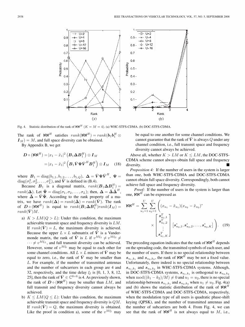
Fig. 4. Statistic distribution of the rank of ℵℵH (K = M = 4). (a) WHC-STFS-CDMA. (b) DOC-STFS-CDMA.
The rank of ℵℵH satisfies rank(ℵℵH) = rank(b1bH1 ⊗
IM ) = M , and full space diversity can be obtained.By Appendix B, we get
D ◦ (ℵℵH) = |x1 − x1|2(B1ΔBH
1
)⊗ IM
= |x1 − x1|2(B1V ΨV
HBH
1
)⊗ IM (18)
where B1 = diag(b1,1, b1,2, . . . , b1,Q), Δ = V ΨVH , Ψ =
diag(σ21 , σ2
2 , . . . , σ2L), and V is defined in (B.4).
Because B1 is a diagonal matrix, rank(B1ΔBH1 ) =
rank(Δ). Let Ψ = diag(σ1, σ2, . . . , σL); then, Δ = ΔΔH ,where Δ = V Ψ. According to the rank property of a ma-trix, we have rank(Δ) = rank(Δ) = rank(V ). The rankof D ◦ (ℵℵH) is equal to rank(B1ΔBH
1 )rank(IM ) =rank(V )M .
a) K > LM(Q > L): Under this condition, the maximumachievable transmit space and frequency diversity is LM .If rank(V ) = L, the maximum diversity is achieved.Because the upper L × L submatrix of V is a Vander-monde matrix, the rank of V is L if vMξ1 �= vMξ2 �=· · · �= vMξL , and full transmit diversity can be achieved.However, some of vMξl may be equal to each other forsome channel conditions. All L × L minors of V may beequal to zero, i.e., the rank of V may be smaller thanL. For example, if the number of transmitted antennasand the number of subcarriers in each group are 4 and32, respectively, and the time delay ξl is [0, 1, 3, 8, 12,25], then the rank of V ∈ C
8×6 is 4. As previously shown,the rank of D ◦ (ℵℵH) may be smaller than LM , andfull transmit and frequency diversity cannot always beachieved.
b) K ≤ LM(Q ≤ L): Under this condition, the maximumachievable transmit space and frequency diversity is QM .If rank(V ) = Q, the maximum diversity is obtained.Like the proof in condition a), some of the vMξl may
be equal to one another for some channel conditions. Wecannot guarantee that the rank of V is always Q under anychannel condition, i.e., full transmit space and frequencydiversity cannot always be achieved.
Above all, whether K > LM or K ≤ LM , the DOC-STFS-CDMA scheme cannot always obtain full space and frequencydiversity. �
Proposition 4: If the number of users in the system is largerthan one, both WHC-STFS-CDMA and DOC-STFS-CDMAcannot obtain full space diversity. Correspondingly, both cannotachieve full space and frequency diversity.
Proof: If the number of users in the system is larger thanone, ℵℵH can be expressed as
ℵℵH =U∑
u1=1
U∑u2=1
((xu1 − xu1)(xu2 − xu2)
∗
×
⎡⎢⎢⎢⎣
sTu1,1
sTu1,2
...sT
u1,K
⎤⎥⎥⎥⎦ [s∗
u2,1, s∗u2,2, . . . , s
∗u2,K
]). (19)
The preceding equation indicates that the rank of ℵℵH dependson the spreading code, the transmitted symbols of each user, andthe number of users. If there is no special relationship betweensu1,k1 and su2,k2 , the rank of ℵℵH may be not a fixed value.Unfortunately, there indeed is no special relationship betweensu1,k1 and su2,k2 in WHC-STFS-CDMA systems. Although,in DOC-STFS-CDMA systems, su1,k1 is orthogonal to su2,k2
when mod((k1 − k2)/M) �= 0 and u1 = u2, there is no specialrelationship between su1,k1 and su2,k2 when u1 �= u2. Fig. 4(a)and (b) shows the statistic distribution of the rank of ℵℵH
of WHC-STFS-CDMA and DOC-STFS-CDMA, respectively,when the modulation type of all users is quadratic phase-shiftkeying (QPSK), and the number of transmitted antennas andthe number of subcarriers are both 4. From Fig. 4, we cansee that the rank of ℵℵH is not always equal to M , i.e.,
LIU et al.: SPREADING CODE DESIGN FOR DOWNLINK SPACE-TIME-FREQUENCY SPREADING CDMA 2939
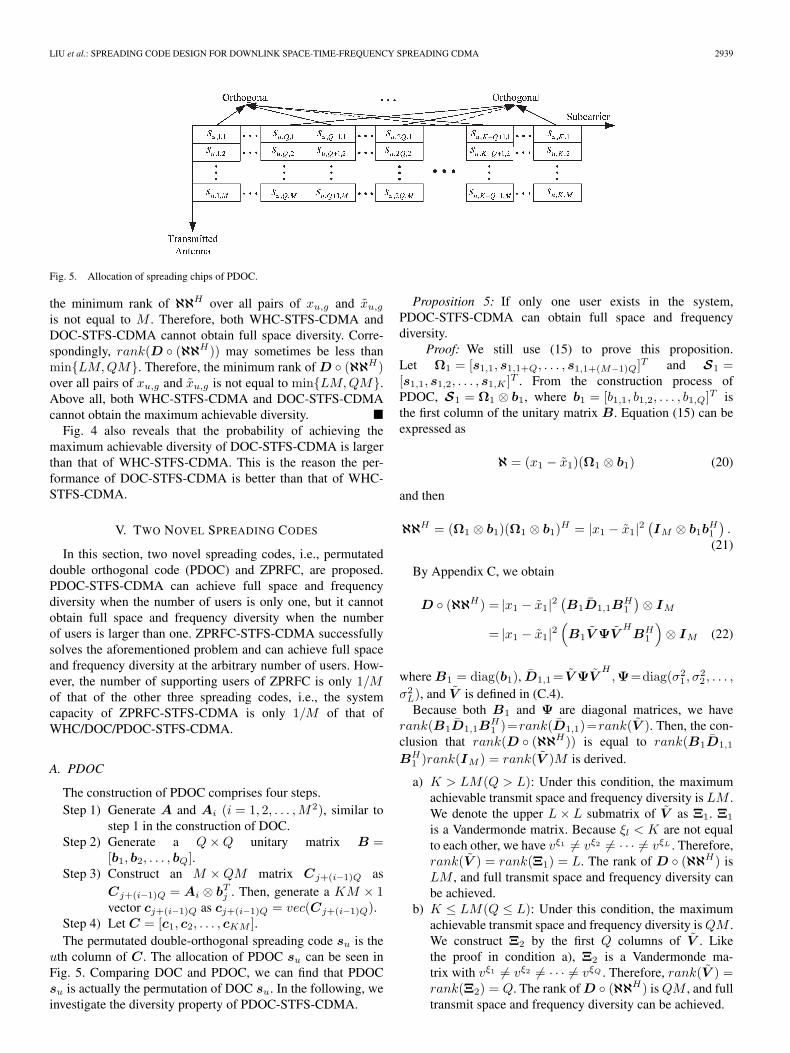
Fig. 5. Allocation of spreading chips of PDOC.
the minimum rank of ℵℵH over all pairs of xu,g and xu,g
is not equal to M . Therefore, both WHC-STFS-CDMA andDOC-STFS-CDMA cannot obtain full space diversity. Corre-spondingly, rank(D ◦ (ℵℵH)) may sometimes be less thanmin{LM,QM}. Therefore, the minimum rank of D ◦ (ℵℵH)over all pairs of xu,g and xu,g is not equal to min{LM,QM}.Above all, both WHC-STFS-CDMA and DOC-STFS-CDMAcannot obtain the maximum achievable diversity. �
Fig. 4 also reveals that the probability of achieving themaximum achievable diversity of DOC-STFS-CDMA is largerthan that of WHC-STFS-CDMA. This is the reason the per-formance of DOC-STFS-CDMA is better than that of WHC-STFS-CDMA.
V. TWO NOVEL SPREADING CODES
In this section, two novel spreading codes, i.e., permutateddouble orthogonal code (PDOC) and ZPRFC, are proposed.PDOC-STFS-CDMA can achieve full space and frequencydiversity when the number of users is only one, but it cannotobtain full space and frequency diversity when the numberof users is larger than one. ZPRFC-STFS-CDMA successfullysolves the aforementioned problem and can achieve full spaceand frequency diversity at the arbitrary number of users. How-ever, the number of supporting users of ZPRFC is only 1/Mof that of the other three spreading codes, i.e., the systemcapacity of ZPRFC-STFS-CDMA is only 1/M of that ofWHC/DOC/PDOC-STFS-CDMA.
A. PDOC
The construction of PDOC comprises four steps.Step 1) Generate A and Ai (i = 1, 2, . . . ,M2), similar to
step 1 in the construction of DOC.Step 2) Generate a Q × Q unitary matrix B =
[b1, b2, . . . , bQ].Step 3) Construct an M × QM matrix Cj+(i−1)Q as
Cj+(i−1)Q = Ai ⊗ bTj . Then, generate a KM × 1
vector cj+(i−1)Q as cj+(i−1)Q = vec(Cj+(i−1)Q).Step 4) Let C = [c1, c2, . . . , cKM ].The permutated double-orthogonal spreading code su is the
uth column of C. The allocation of PDOC su can be seen inFig. 5. Comparing DOC and PDOC, we can find that PDOCsu is actually the permutation of DOC su. In the following, weinvestigate the diversity property of PDOC-STFS-CDMA.
Proposition 5: If only one user exists in the system,PDOC-STFS-CDMA can obtain full space and frequencydiversity.
Proof: We still use (15) to prove this proposition.Let Ω1 = [s1,1, s1,1+Q, . . . , s1,1+(M−1)Q]T and S1 =[s1,1, s1,2, . . . , s1,K ]T . From the construction process ofPDOC, S1 = Ω1 ⊗ b1, where b1 = [b1,1, b1,2, . . . , b1,Q]T isthe first column of the unitary matrix B. Equation (15) can beexpressed as
ℵ = (x1 − x1)(Ω1 ⊗ b1) (20)
and then
ℵℵH = (Ω1 ⊗ b1)(Ω1 ⊗ b1)H = |x1 − x1|2(IM ⊗ b1b
H1
).
(21)
By Appendix C, we obtain
D ◦ (ℵℵH) = |x1 − x1|2(B1D1,1B
H1
)⊗ IM
= |x1 − x1|2(B1V ΨV
HBH
1
)⊗ IM (22)
where B1 = diag(b1), D1,1 = V ΨVH
,Ψ=diag(σ21 , σ2
2 , . . . ,
σ2L), and V is defined in (C.4).Because both B1 and Ψ are diagonal matrices, we have
rank(B1D1,1BH1 )=rank(D1,1)=rank(V ). Then, the con-
clusion that rank(D ◦ (ℵℵH)) is equal to rank(B1D1,1
BH1 )rank(IM ) = rank(V )M is derived.
a) K > LM(Q > L): Under this condition, the maximumachievable transmit space and frequency diversity is LM .We denote the upper L × L submatrix of V as Ξ1. Ξ1
is a Vandermonde matrix. Because ξl < K are not equalto each other, we have vξ1 �= vξ2 �= · · · �= vξL . Therefore,rank(V ) = rank(Ξ1) = L. The rank of D ◦ (ℵℵH) isLM , and full transmit space and frequency diversity canbe achieved.
b) K ≤ LM(Q ≤ L): Under this condition, the maximumachievable transmit space and frequency diversity is QM .We construct Ξ2 by the first Q columns of V . Likethe proof in condition a), Ξ2 is a Vandermonde ma-trix with vξ1 �= vξ2 �= · · · �= vξQ . Therefore, rank(V ) =rank(Ξ2) = Q. The rank of D ◦ (ℵℵH) is QM , and fulltransmit space and frequency diversity can be achieved.
2940 IEEE TRANSACTIONS ON VEHICULAR TECHNOLOGY, VOL. 57, NO. 5, SEPTEMBER 2008
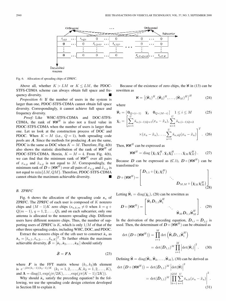
Fig. 6. Allocation of spreading chips of ZPRFC.
Above all, whether K > LM or K ≤ LM , the PDOC-STFS-CDMA scheme can always obtain full space and fre-quency diversity. �
Proposition 6: If the number of users in the system islarger than one, PDOC-STFS-CDMA cannot obtain full spacediversity. Correspondingly, it cannot achieve full space andfrequency diversity.
Proof: Like WHC-STFS-CDMA and DOC-STFS-CDMA, the rank of ℵℵH is also not a fixed value inPDOC-STFS-CDMA when the number of users is larger thanone. Let us look at the construction process of DOC andPDOC. When K = M (i.e., Q = 1), both spreading codepools are A. Since the methods for producing A are the same,PDOC is the same as DOC when K = M . Therefore, Fig. 4(b)also shows the statistic distribution of the rank of ℵℵH ofPDOC-STFS-CDMA. Herein, K = M = 4. From Fig. 4(b),we can find that the minimum rank of ℵℵH over all pairsof xu,g and xu,g is not equal to M . Correspondingly, theminimum rank of D ◦ (ℵℵH) over all pairs of xu,g and xu,g isnot equal to min{LM,QM}. Therefore, PDOC-STFS-CDMAcannot obtain the maximum achievable diversity. �
B. ZPRFC
Fig. 6 shows the allocation of the spreading code su ofZPRFC. The ZPRFC of each user is composed of K nonzerochips and (M − 1)K zero chips (su,k,m �= 0 when k = q +Q(m − 1), q = 1, 2, . . . , Q), and on each subcarrier, only oneantenna is allocated to the nonzero spreading chip. Differentusers have different nonzero chips. Thus, the number of sup-porting users of ZPRFC is K, which is only 1/M of that of theother three spreading codes, including WHC, DOC, and PDOC.
Extract the nonzero chips of the uth user to construct su assu = [su,1, su,2, . . . , su,K ]T . To further obtain the maximumachievable diversity, S = [s1, s2, . . . , sK ] should satisfy
S = FΛ (23)
where F is the FFT matrix whose (k1, k2)th elementis e−j2π(k1−1)(k2−1)/K (k1 = 1, 2, . . . ,K, k2 = 1, 2, . . . ,K),and Λ = diag(1, exp(jπ/2K), . . . , exp(jπ(K − 1)/2K)).
Why should su satisfy the preceding equation? In the fol-lowing, we use the spreading code design criterion developedin Section III to explain it.
Because of the existence of zero chips, the ℵ in (13) can berewritten as
ℵ =[(ℵ1)H , (ℵ2)H , . . . , (ℵM )H
]H(24)
where
ℵi = [0Q×(i−1) χi 0Q×(M−i) ] 1 ≤ i ≤ M (25)
χi =
[U∑
u=1
su,(i−1)Q+1(xu − xu),U∑
u=1
su,(i−1)Q+2
×(xu − xu), . . . ,U∑
u=1
su,iQ(xu − xu)
]T
. (26)
Then, ℵℵH can be expressed as
ℵℵH = diag(χ1χ
H1 , χ2χ
H2 , . . . , χM χH
M
). (27)
Because D can be expressed as (C.1), D ◦ (ℵℵH) can betransformed to
D ◦ (ℵℵH)=
⎡⎢⎣
D1,1 ◦(χ1χ
H1
). . .
DM,M ◦(χM χH
M
)⎤⎥⎦ .
(28)
Letting ℵi = diag(χi), (28) can be rewritten as
D ◦ (ℵℵH) =
⎡⎢⎣ ℵ1D1,1ℵ
H
1
. . .ℵMD1,1ℵ
H
M
⎤⎥⎦ . (29)
In the derivation of the preceding equation, Di,i = Dj,j isused. Then, the determinant of D ◦ (ℵℵH) can be obtained as
det(D ◦ (ℵℵH)
)=
M∏i=1
det(ℵiD1,1ℵ
H
i
)
= det(D1,1)MM∏i=1
∣∣∣det(ℵi)∣∣∣2 . (30)
Defining ℵ = diag(ℵ1, ℵ2, . . . , ℵM ), (30) can be derived as
det(D ◦ (ℵℵH)
)= det(D1,1)M
∣∣∣det(ℵ)∣∣∣2
= det(D1,1)M
∣∣∣∣∣QM∏k=1
U∑u=1
su,k(xu − xu)
∣∣∣∣∣2
.
(31)
LIU et al.: SPREADING CODE DESIGN FOR DOWNLINK SPACE-TIME-FREQUENCY SPREADING CDMA 2941
TABLE ICOMPLEXITY OF STFS-CDMA
To obtain the maximum achievable diversity QMN ,det(D ◦ (ℵℵH)) should not be equal to zero. Herein, weassume that Q ≤ L. The reason is that if the designed spreadingcode can obtain the maximum achievable diversity QMN un-der this condition, then it can also attain the maximum achiev-able diversity LMN if Q > L. From the proof of Proposition 5,we can obtain rank(D1,1) = Q, i.e., det(D1,1) �= 0. There-fore, the necessary and sufficient condition of the spreadingcode for obtaining the maximum achievable diversity is that∑U
u=1 su,k(xu − xu) (k = 1, 2, . . . , QM) cannot be equal tozero no matter which pair {xu, xu}, u = 1, 2, . . . , U is chosen.Using the matrix notation, each element of S(x − x) cannotbe equal to zero, unless x − x = 0, where x − x = [x1 −x1, x2 − x2, . . . , xU − xU ]T . A similar problem has previouslyarisen as the problem of the design of a full diversity space-time code and a space-frequency code [15]–[17]. Using theconclusions of [15]–[17], we can see that when su satisfies (25),the maximum achievable diversity can be obtained.
In a word, ZPRFC-STFS-CDMA obtains the maximumachievable diversity at the cost of the reduction of the numberof supporting users.
VI. MULTIUSER DETECTION AND COMPLEXITY ANALYSIS
In the derivation of the spreading code design criterion,ML detection is assumed to be used. However, in practicalsystems, ML cannot be implemented for its high complexity.In this paper, we employ the low-complexity MMSE detectionto detect the transmitted symbol.
Note that, because ZPRFC has zero chips, the relationshipof the received symbol and the transmitted symbol can besimplified as
yu,g = Hu,gSx + nu,g (32)
where Hu,g = diag(Hu,ρ[1,g], Hu,ρ[2,g], . . . , Hu,ρ[K,g]) ∈C
NK×K , Hu,ρ[k,g] is the (int((k − 1)/Q) + 1)th column ofHu,ρ[k,g], and S = [s1, s2, . . . , sU ] ∈ C
K×U .
A. MMSE Receiver
According to whether the spreading codes of other users areknown at the receiver, MMSE detection can be classified intoMMSE-1 detection and MMSE-2 detection [14].
1) MMSE-1 Detection: If the spreading codes of all activeusers are known at the receiver, the MMSE weight vector todetect the uth user can be expressed as
wTu,g = eT
u
(SHHH
u,gHu,gS + σ2IU
)−1SHHH
u,g (33)
for WHC/DOC/PDOC-STFS-CDMA and
wTu,g = eT
u
(S
HH
Hu,gHu,gS + σ2IU
)−1
SH
HHu,g (34)
for ZPRFC-STFS-CDMA, where all the elements of eu ∈C
U×1 are zero, except for the uth entry.2) MMSE-2 Detection: Generally, only the spreading code
of the uth user is known in the downlink receiver. Under thiscondition, the MMSE weight vector to detect the uth user canbe expressed as
wTu,g = sH
u
(HH
u,gHu,g + σ2IKM
)−1HH
u,g (35)
for WHC/DOC/PDOC-STFS-CDMA and
wTu,g = sH
u
(H
Hu,gHu,g + σ2IK
)−1
HHu,g (36)
for ZPRFC-STFS-CDMA.After computing the weight vector, the decision of xu,g can
be obtained by
xu,g = Q(wT
u,gyu,g
)(37)
where Q(·) denotes the hard decision of the variable accordingto the Euclidean distance criterion.
B. Complexity Analysis
The number of floating-point operations (flops) is usedto scale the complexity of the algorithm. One complexmultiplication/division needs six flops, and one complexaddition/subtraction needs two flops [18]. Note that the in-verse of a square matrix in MMSE detection is calculatedvia the singular value decomposition, which is referred to asthe most numerically stable way [18]–[20]. The complexity ofWHC/DOC/PDOC/ZPRFC-STFS-CDMA is shown in Table I.
Fig. 7 further illustrates the complexity of STFS-CDMAwhen N = 8, K = 32, and U = 32. Since the complexity ofboth MMSE detections of ZPRFC-STFS-CDMA is not corre-lated with the number of transmitted antennas, their complexitycurves are horizontal curves. When MMSE-1 detection is used,the complexity gap of WHC/DOC/PDOC-STFS-CDMA andZPRFC-STFS-CDMA is not too large. This is because the com-plexity of WHC/DOC/PDOC-STFS-CDMA using MMSE-1detection is only a linear function of the number of transmittedantennas. In practical downlink systems, the spreading codesof other users are mostly unknown at the receiver. Therefore,MMSE-2 detection is generally used. Since the complexityof WHC/DOC/PDOC-STFS-CDMA using MMSE-2 detectionis a cubic function of the number of transmitted antennas,
2942 IEEE TRANSACTIONS ON VEHICULAR TECHNOLOGY, VOL. 57, NO. 5, SEPTEMBER 2008
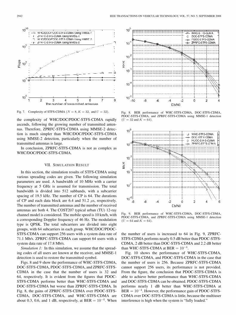
Fig. 7. Complexity of STFS-CDMA (N = 8, K = 32, and U = 32).
the complexity of WHC/DOC/PDOC-STFS-CDMA rapidlyascends, following the growing number of transmitted anten-nas. Therefore, ZPRFC-STFS-CDMA using MMSE-2 detec-tion is much simpler than WHC/DOC/PDOC-STFS-CDMAusing MMSE-2 detection, particularly when the number oftransmitted antennas is large.
In conclusion, ZPRFC-STFS-CDMA is not as complex asWHC/DOC/PDOC-STFS-CDMA.
VII. SIMULATION RESULT
In this section, the simulation results of STFS-CDMA usingvarious spreading codes are given. The following simulationparameters are used. A bandwidth of 10 MHz with a carrierfrequency at 5 GHz is assumed for transmission. The totalbandwidth is divided into 512 subbands, with a subcarrierspacing of 19.5 kHz. The number of CP is 64. The durationsof CP and each data block are 6.4 and 51.2 μs, respectively.The number of transmitted antennas and the number of receivedantennas are both 4. The COST207 typical urban (TU) 12-raychannel model is considered. The mobile speed is 10 km/h, witha corresponding Doppler frequency of 46 Hz. The modulationtype is QPSK. The total subcarriers are divided into eightgroups, with 64 subcarriers in each group. WHC/DOC/PDOC-STFS-CDMA can support 256 users with a system data rate of71.1 Mb/s. ZPRFC-STFS-CDMA can support 64 users with asystem data rate of 17.8 Mb/s.
Simulation 1: In this simulation, we assume that the spread-ing codes of all users are known at the receiver, and MMSE-1detection is used to restore the transmitted symbol.
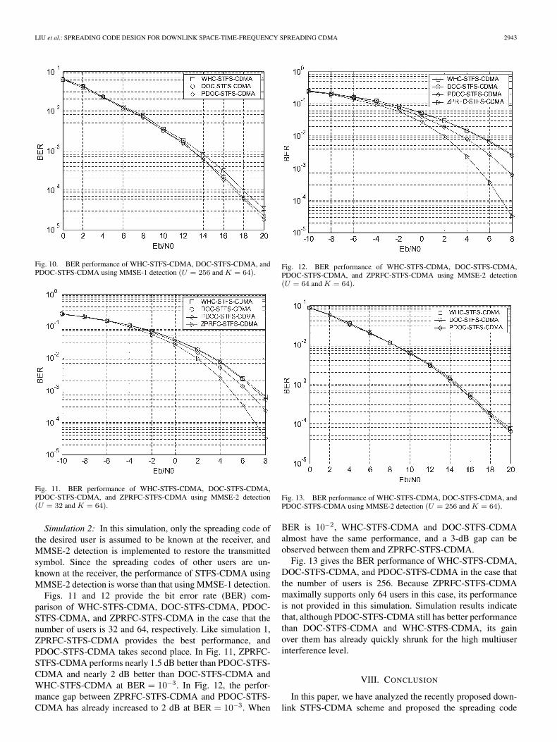
Figs. 8 and 9 show the performance of WHC-STFS-CDMA,DOC-STFS-CDMA, PDOC-STFS-CDMA, and ZPRFC-STFS-CDMA in the case that the number of users is 32 and64, respectively. It is evident from the figures that PDOC-STFS-CDMA performs better than WHC-STFS-CDMA andDOC-STFS-CDMA but worse than ZPRFC-STFS-CDMA. InFig. 8, the gains of ZPRFC-STFS-CDMA over PDOC-STFS-CDMA, DOC-STFS-CDMA, and WHC-STFS-CDMA areabout 0.3, 0.6, and 1 dB, respectively, at BER = 10−4. When
Fig. 8. BER performance of WHC-STFS-CDMA, DOC-STFS-CDMA,PDOC-STFS-CDMA, and ZPRFC-STFS-CDMA using MMSE-1 detection(U = 32 and K = 64).
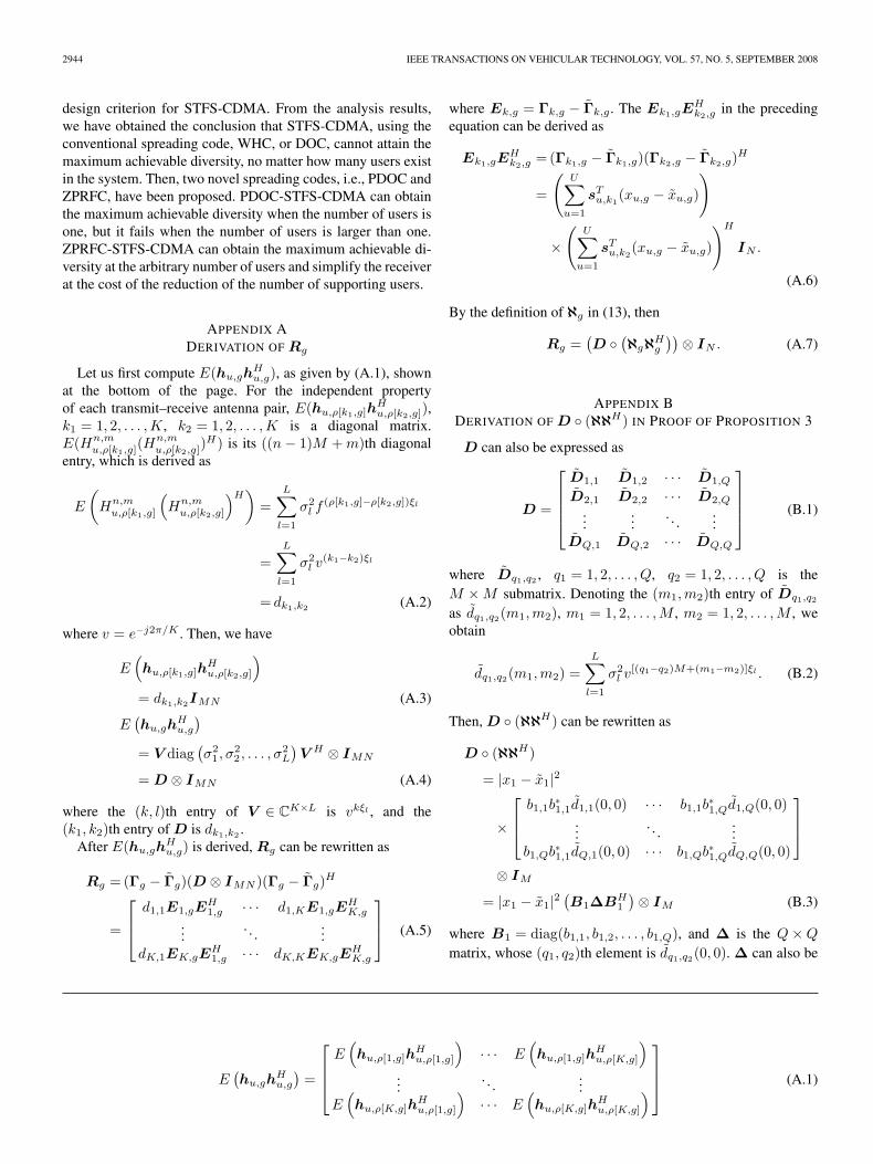
Fig. 9. BER performance of WHC-STFS-CDMA, DOC-STFS-CDMA,PDOC-STFS-CDMA, and ZPRFC-STFS-CDMA using MMSE-1 detection(U = 64 and K = 64).
the number of users is increased to 64 in Fig. 9, ZPRFC-STFS-CDMA performs nearly 0.5 dB better than PDOC-STFS-CDMA, 2 dB better than DOC-STFS-CDMA and 2.2 dB betterthan WHC-STFS-CDMA at BER = 10−4.
Fig. 10 shows the performance of WHC-STFS-CDMA,DOC-STFS-CDMA, and PDOC-STFS-CDMA in the case thatthe number of users is 256. Because ZPRFC-STFS-CDMAcannot support 256 users, its performance is not provided.From the figure, the conclusion that PDOC-STFS-CDMA isable to achieve better performance than WHC-STFS-CDMAand DOC-STFS-CDMA can be obtained. PDOC-STFS-CDMAperforms nearly 1 dB better than WHC-STFS-CDMA atBER = 10−4. However, the performance gain of PDOC-STFS-CDMA over DOC-STFS-CDMA is little, because the multiuserinterference is high when the system is “fully loaded.”
LIU et al.: SPREADING CODE DESIGN FOR DOWNLINK SPACE-TIME-FREQUENCY SPREADING CDMA 2943
Fig. 10. BER performance of WHC-STFS-CDMA, DOC-STFS-CDMA, andPDOC-STFS-CDMA using MMSE-1 detection (U = 256 and K = 64).
Fig. 11. BER performance of WHC-STFS-CDMA, DOC-STFS-CDMA,PDOC-STFS-CDMA, and ZPRFC-STFS-CDMA using MMSE-2 detection(U = 32 and K = 64).
Simulation 2: In this simulation, only the spreading code ofthe desired user is assumed to be known at the receiver, andMMSE-2 detection is implemented to restore the transmittedsymbol. Since the spreading codes of other users are un-known at the receiver, the performance of STFS-CDMA usingMMSE-2 detection is worse than that using MMSE-1 detection.
Figs. 11 and 12 provide the bit error rate (BER) com-parison of WHC-STFS-CDMA, DOC-STFS-CDMA, PDOC-STFS-CDMA, and ZPRFC-STFS-CDMA in the case that thenumber of users is 32 and 64, respectively. Like simulation 1,ZPRFC-STFS-CDMA provides the best performance, andPDOC-STFS-CDMA takes second place. In Fig. 11, ZPRFC-STFS-CDMA performs nearly 1.5 dB better than PDOC-STFS-CDMA and nearly 2 dB better than DOC-STFS-CDMA andWHC-STFS-CDMA at BER = 10−3. In Fig. 12, the perfor-mance gap between ZPRFC-STFS-CDMA and PDOC-STFS-CDMA has already increased to 2 dB at BER = 10−3. When
Fig. 12. BER performance of WHC-STFS-CDMA, DOC-STFS-CDMA,PDOC-STFS-CDMA, and ZPRFC-STFS-CDMA using MMSE-2 detection(U = 64 and K = 64).
Fig. 13. BER performance of WHC-STFS-CDMA, DOC-STFS-CDMA, andPDOC-STFS-CDMA using MMSE-2 detection (U = 256 and K = 64).
BER is 10−2, WHC-STFS-CDMA and DOC-STFS-CDMAalmost have the same performance, and a 3-dB gap can beobserved between them and ZPRFC-STFS-CDMA.
Fig. 13 gives the BER performance of WHC-STFS-CDMA,DOC-STFS-CDMA, and PDOC-STFS-CDMA in the case thatthe number of users is 256. Because ZPRFC-STFS-CDMAmaximally supports only 64 users in this case, its performanceis not provided in this simulation. Simulation results indicatethat, although PDOC-STFS-CDMA still has better performancethan DOC-STFS-CDMA and WHC-STFS-CDMA, its gainover them has already quickly shrunk for the high multiuserinterference level.
VIII. CONCLUSION
In this paper, we have analyzed the recently proposed down-link STFS-CDMA scheme and proposed the spreading code
2944 IEEE TRANSACTIONS ON VEHICULAR TECHNOLOGY, VOL. 57, NO. 5, SEPTEMBER 2008
design criterion for STFS-CDMA. From the analysis results,we have obtained the conclusion that STFS-CDMA, using theconventional spreading code, WHC, or DOC, cannot attain themaximum achievable diversity, no matter how many users existin the system. Then, two novel spreading codes, i.e., PDOC andZPRFC, have been proposed. PDOC-STFS-CDMA can obtainthe maximum achievable diversity when the number of users isone, but it fails when the number of users is larger than one.ZPRFC-STFS-CDMA can obtain the maximum achievable di-versity at the arbitrary number of users and simplify the receiverat the cost of the reduction of the number of supporting users.
APPENDIX ADERIVATION OF Rg
Let us first compute E(hu,ghHu,g), as given by (A.1), shown
at the bottom of the page. For the independent propertyof each transmit–receive antenna pair, E(hu,ρ[k1,g]h
Hu,ρ[k2,g]),
k1 = 1, 2, . . . ,K, k2 = 1, 2, . . . ,K is a diagonal matrix.E(Hn,m
u,ρ[k1,g](Hn,mu,ρ[k2,g])
H) is its ((n − 1)M + m)th diagonalentry, which is derived as
E
(Hn,m
u,ρ[k1,g]
(Hn,m
u,ρ[k2,g]
)H)
=L∑
l=1
σ2l f (ρ[k1,g]−ρ[k2,g])ξl
=L∑
l=1
σ2l v(k1−k2)ξl
= dk1,k2 (A.2)
where v = e−j2π/K . Then, we have
E(hu,ρ[k1,g]h
Hu,ρ[k2,g]
)= dk1,k2IMN (A.3)
E(hu,gh
Hu,g
)= V diag
(σ2
1 , σ22 , . . . , σ2
L
)V H ⊗ IMN
= D ⊗ IMN (A.4)
where the (k, l)th entry of V ∈ CK×L is vkξl , and the
(k1, k2)th entry of D is dk1,k2 .After E(hu,gh
Hu,g) is derived, Rg can be rewritten as
Rg = (Γg − Γg)(D ⊗ IMN )(Γg − Γg)H
=
⎡⎢⎣
d1,1E1,gEH1,g · · · d1,KE1,gE
HK,g
.... . .
...dK,1EK,gE
H1,g · · · dK,KEK,gE
HK,g
⎤⎥⎦ (A.5)
where Ek,g = Γk,g − Γk,g. The Ek1,gEHk2,g in the preceding
equation can be derived as
Ek1,gEHk2,g = (Γk1,g − Γk1,g)(Γk2,g − Γk2,g)H
=
(U∑
u=1
sTu,k1
(xu,g − xu,g)
)
×(
U∑u=1
sTu,k2
(xu,g − xu,g)
)H
IN .
(A.6)
By the definition of ℵg in (13), then
Rg =(D ◦
(ℵgℵH
g
))⊗ IN . (A.7)
APPENDIX BDERIVATION OF D ◦ (ℵℵH) IN PROOF OF PROPOSITION 3
D can also be expressed as
D =
⎡⎢⎢⎢⎣
D1,1 D1,2 · · · D1,Q
D2,1 D2,2 · · · D2,Q
......
. . ....
DQ,1 DQ,2 · · · DQ,Q
⎤⎥⎥⎥⎦ (B.1)
where Dq1,q2 , q1 = 1, 2, . . . , Q, q2 = 1, 2, . . . , Q is theM × M submatrix. Denoting the (m1,m2)th entry of Dq1,q2
as dq1,q2(m1,m2), m1 = 1, 2, . . . ,M , m2 = 1, 2, . . . , M , weobtain
dq1,q2(m1,m2) =L∑
l=1
σ2l v[(q1−q2)M+(m1−m2)]ξl . (B.2)
Then, D ◦ (ℵℵH) can be rewritten as
D ◦ (ℵℵH)
= |x1 − x1|2
×
⎡⎢⎣
b1,1b∗1,1d1,1(0, 0) · · · b1,1b
∗1,Qd1,Q(0, 0)
.... . .
...b1,Qb∗1,1dQ,1(0, 0) · · · b1,Qb∗1,QdQ,Q(0, 0)
⎤⎥⎦
⊗ IM
= |x1 − x1|2(B1ΔBH
1
)⊗ IM (B.3)
where B1 = diag(b1,1, b1,2, . . . , b1,Q), and Δ is the Q × Q
matrix, whose (q1, q2)th element is dq1,q2(0, 0). Δ can also be
E(hu,gh
Hu,g
)=
⎡⎢⎢⎣
E(hu,ρ[1,g]h
Hu,ρ[1,g]
)· · · E
(hu,ρ[1,g]h
Hu,ρ[K,g]
)...
. . ....
E(hu,ρ[K,g]h
Hu,ρ[1,g]
)· · · E
(hu,ρ[K,g]h
Hu,ρ[K,g]
)⎤⎥⎥⎦ (A.1)
LIU et al.: SPREADING CODE DESIGN FOR DOWNLINK SPACE-TIME-FREQUENCY SPREADING CDMA 2945
expressed as Δ = V ΨVH , where Ψ = diag(σ2
1 , σ22 , . . . , σ2
L),and
V =
⎡⎢⎢⎣
1 1 · · · 1vMξ1 vMξ2 · · · vMξL
......
. . ....
v(Q−1)Mξ1 v(Q−1)Mξ2 · · · v(Q−1)MξL
⎤⎥⎥⎦ . (B.4)
APPENDIX CDERIVATION OF D ◦ (ℵℵH) IN PROOF OF PROPOSITION 5
D can also be expressed as
D =
⎡⎢⎢⎣
D1,1 D1,2 · · · D1,M
D2,1 D2,2 · · · D2,M
......
. . ....
DM,1 DM,2 · · · DM,M
⎤⎥⎥⎦ (C.1)
where Dm1,m2 is the Q × Q submatrix. Denoting the (q1, q2)thentry of Dm1,m2 as dm1,m2(q1, q2), we obtain
dm1,m2(q1, q2) =L∑
l=1
σ2l v[(m1−m2)M+(q1−q2)]ξl . (C.2)
Then, D ◦ (ℵℵH) can be rewritten as
D ◦ (ℵℵH) = |x1 − x1|2
×
⎡⎢⎣
D1,1 ◦(b1b
H1
). . .
DM,M ◦(b1b
H1
)⎤⎥⎦
= |x1 − x1|2(D1,1 ◦
(b1b
H1
))⊗ IM
= |x1 − x1|2(B1D1,1B
H1
)⊗ IM (C.3)
where B1 = diag(b1). The third equation of (C.3) is de-rived for Di,i = Dj,j , which can been seen from (C.2).
D1,1 can also be expressed as D1,1 = V ΨVH
, where Ψ =diag(σ2
1 , σ22 , . . . , σ2
L), and V is shown as
V =
⎡⎢⎢⎣
1 1 · · · 1vξ1 vξ2 · · · vξL
......
. . ....
v(Q−1)ξ1 v(Q−1)ξ2 · · · v(Q−1)ξL
⎤⎥⎥⎦ . (C.4)
ACKNOWLEDGMENT
The authors would like to thank R. Zhang, G. Xie, andY. Wang for the numerous helpful discussions and the anony-mous reviewers for the insightful and constructive commentsthat significantly improved the quality of this paper.
REFERENCES
[1] L. Hanzo, L.-L. Yang, E.-L. Kuan, and K. Yen, Single- and Multi-CarrierCDMA: Multi-User Detection, Space-Time Spreading, Synchronisationand Standards. New York: Wiley, 2003.
[2] S. Hara and R. Prasad, Multicarrier Techniques for 4G Mobile Communi-cations. Boston, MA: Artech House, 2003.
[3] N. Yee, J.-P. Linnartz, and G. Fettweis, “Multicarrier CDMA in indoorwireless radio networks,” in Proc. IEEE PIMRC, Yokohama, Japan,Sep. 1993, pp. 109–113.
[4] V. M. DaSilva and E. S. Sousa, “Performance of orthogonal CDMA codesfor quasi-synchronous communication systems,” in Proc. IEEE ICUPC,Ottawa, ON, Canada, Oct. 1993, pp. 995–999.
[5] L. Hanzo, M. Münster, B. J. Choi, and T. Keller, OFDM and MC-CDMAfor Broadband Multi-User Communications, WLANs and Broadcasting.Chichester, U.K.: Wiley, 2003.
[6] S. Hara and R. Prasad, “Overview of multicarrier CDMA,” IEEE Com-mun. Mag., vol. 35, no. 12, pp. 126–133, Dec. 1997.
[7] V. Tarokh, H. Jafarkhani, and A. R. Calderbank, “Space-time blockcodes from orthogonal designs,” IEEE Trans. Inf. Theory, vol. 45, no. 5,pp. 1456–1467, Jul. 1999.
[8] V. Tarokh, N. Seshadri, and A. R. Calderbank, “Space-time codes forhigh data rate wireless communication: Performance criterion and codeconstruction,” IEEE Trans. Inf. Theory, vol. 44, no. 2, pp. 744–765,Mar. 1998.
[9] L. Zheng and D. N. C. Tse, “Diversity and multiplexing: A fundamentaltradeoff in multiple-antenna channels,” IEEE Trans. Inf. Theory, vol. 49,no. 5, pp. 1073–1096, May 2003.
[10] A. Lodhi, F. Said, M. Dohler, and A. H. Aghvami, “Performance com-parison of space-time block coded and cyclic delay diversity MC-CDMAsystems,” IEEE Wireless Commun., vol. 12, no. 2, pp. 38–45, Apr. 2005.
[11] M. Vehkapera, D. Tujkovic, Z. Li, and M. Juntti, “Receiver design for spa-tially layered downlink MC-CDMA system,” IEEE Trans. Veh. Technol.,vol. 54, no. 3, pp. 1042–1055, May 2005.
[12] M. Juntti, M. Vehkapera, J. Leinonen, Z. Li, and D. Tujkovic, “MIMOMC-CDMA communications for future cellular systems,” IEEE Commun.Mag., vol. 43, no. 2, pp. 118–124, Feb. 2005.
[13] R. Doostnejad, T. J. Lim, and E. S. Sousa, “On spreading codes for thedown-link in a multiuser MIMO/OFDM system,” in Proc. IEEE 58th Veh.Technol. Conf., Orlando, FL, Oct. 2003, vol. 4, pp. 498–502.
[14] Z. Luo, J. Liu, M. Zhao, Y. Liu, and J. Gao, “Double-orthogonal codedspace-time-frequency spreading CDMA scheme,” IEEE J. Sel. AreasCommun., vol. 24, no. 6, pp. 1244–1255, Jun. 2006.
[15] Z. Liu, Y. Xin, and G. B. Giannakis, “Linear constellation precodingfor OFDM with maximum multipath diversity and coding gains,” IEEETrans. Commun., vol. 51, no. 3, pp. 416–427, Mar. 2003.
[16] Z. Liu, Y. Xin, and G. B. Giannakis, “Space-time-frequency coded OFDMover frequency-selective fading channels,” IEEE Trans. Signal Process.,vol. 50, no. 10, pp. 2465–2476, Oct. 2002.
[17] W. Su, Z. Safar, and K. J. R. Liu, “Full-rate full-diversity space-frequencycodes with optimum coding advantage,” IEEE Trans. Inf. Theory, vol. 51,no. 1, pp. 229–249, Jan. 2005.
[18] G. H. Golub and C. F. Van Loan, Matrix Computations, 3rd ed.Baltimore, MD: Johns Hopkins Univ. Press, 1996.
[19] J. Benesty, Y. Huang, and J. Chen, “A fast recursive algorithm for opti-mum sequential signal detection in a BLAST system,” IEEE Trans. SignalProcess., vol. 51, no. 7, pp. 1722–1730, Jul. 2003.
[20] Z. Luo, S. Liu, M. Zhao, and Y. Liu, “A novel fast recursive MMSE-SIC detection algorithm for V-BLAST systems,” IEEE Trans. WirelessCommun., vol. 6, no. 6, pp. 2022–2026, Jun. 2007.
Siyang Liu (S’07) received the B.E. degreein management of business administration fromBeijing University of Posts and Telecommunications(BUPT), Beijing, China, in 2004, where he is cur-rently working toward the Ph.D. degree in electricalengineering with the School of TelecommunicationEngineering.
His research interests include space-time-frequency coding, OFDM, CDMA, channel esti-mation, and cognitive radio.
Zhendong Luo received the B.E. degree in in-formation engineering from the Chinese People’sPublic Security University, Beijing, China, in 1996and the Ph.D. degree in electrical engineering fromBeijing University of Posts and Telecommunications(BUPT) in 2006.
He is currently with the Bell Labs Research China,Alcatel–Lucent, Beijing, and also with the Depart-ment of Electronic Engineering, Tsinghua Univer-sity, Beijing. His research interests include MIMO,OFDM/OFDMA, CDMA, signal detection, channel
estimation, soft decoding, and adaptive modulation.
2946 IEEE TRANSACTIONS ON VEHICULAR TECHNOLOGY, VOL. 57, NO. 5, SEPTEMBER 2008
Yuanan Liu (M’93) received the B.E., M.Eng., andPh.D. degrees in electrical engineering from theUniversity of Electronic Science and Technology ofChina, Chengdu, China, in 1984, 1989, and 1992,respectively.
In 1984, he joined the 26th Institute of theElectronic Ministry of China to develop the iner-tia navigating system. In 1992, he began his firstpostdoctoral position with the EMC Laboratory,Beijing University of Posts and Telecommunications(BUPT), Beijing, China. In 1995, he started his
second postdoctoral position with the Broadband Mobile Laboratory, Depart-ment of System and Computer Engineering, Carleton University, Ottawa, ON,Canada. Since July 1997, he has been with the Wireless Communication Center,School of Telecommunication Engineering, BUPT, as a Professor, where heis involved in the development of next-generation cellular systems, wirelessLANs, Bluetooth applications for data transmission, EMC design strategiesfor high-speed digital systems, and low-cost, high-performance EMI and EMSmeasuring sites. His research interests include smart antennas for high-capacitymobiles, signal processing techniques in fading environments, EMC for high-speed digital systems, ISI suppression, OFDM, and multicarrier system design.
Dr. Liu is a fellow of the Institution of Engineering and Technology, U.K.;the Vice Chairman of Electromagnetic Environment and Safety of the ChinaCommunication Standards Association; the Vice Director of the Wireless andMobile Communication Committee, Communication Institute of China; and aSenior Member of the Electronic Institute of China.
Jinchun Gao (M’05) received M.S. degree fromBeijing University of Chemical Technology, Beijing,China, in 1987 and the Ph.D. degree in electroniccircuits and systems from Beijing University of Postsand Telecommunications (BUPT) in 2004.
She is currently a Professor with the Schoolof Telecommunication Engineering, BUPT. Her re-search interests include wireless communicationsand electrical contact reliability.
Related Documents


![St. Xavier’s College – Autonomous Mumbai Syllabus For … schemes [TDMA, FDMA, CDMA] Separating uplink and downlink traffic GSM migration PDC migration Cdmaone migration M-Commerce](https://static.cupdf.com/doc/110x72/5b3a8b1d7f8b9a1a678dbe06/st-xaviers-college-autonomous-mumbai-syllabus-for-schemes-tdma-fdma-cdma.jpg)


