Citation: Lazaro, A.; Porcel, A.; Lazaro, M.; Villarino, R.; Girbau, D. Spoofing Attacks on FMCW Radars with Low-Cost Backscatter Tags. Sensors 2022, 22, 2145. https:// doi.org/10.3390/s22062145 Academic Editors: Tarek Djerafi and Federico Alimenti Received: 23 January 2022 Accepted: 8 March 2022 Published: 10 March 2022 Publisher’s Note: MDPI stays neutral with regard to jurisdictional claims in published maps and institutional affil- iations. Copyright: © 2022 by the authors. Licensee MDPI, Basel, Switzerland. This article is an open access article distributed under the terms and conditions of the Creative Commons Attribution (CC BY) license (https:// creativecommons.org/licenses/by/ 4.0/). sensors Article Spoofing Attacks on FMCW Radars with Low-Cost Backscatter Tags Antonio Lazaro * , Arnau Porcel, Marc Lazaro , Ramon Villarino and David Girbau Department of Electronics, Electrics and Automatic Control Engineering, Rovira i Virgili University, 43007 Tarragona, Spain; [email protected] (A.P.); [email protected] (M.L.); [email protected] (R.V.); [email protected] (D.G.) * Correspondence: [email protected]; Tel.: +34-977-558-668 Abstract: This work studies the feasibility of using backscatter-modulated tags to introduce false information into a signal received by a frequency-modulated continuous-wave (FMCW) radar. A proof-of-concept spoofing device was designed in the 24 GHz ISM band. The spoofing device was based on an amplifier connected between two antennas, and modulation was carried out by switching the amplifier bias. The use of an amplifier allowed us to increase the level of spoofing signal compared with other modulated backscattering methods. The simulated and experimental results show that our method has the ability to generate a pair of false targets at different ranges and velocities depending on the modulation frequency of the chosen tag, since sidebands appear due to this modulation. Countermeasures to detect the spoofing attack based on changes in the slope of the frequency sweep between frames are also proposed. Keywords: automotive radar; mm wave radar; FMCW; spoofing; interference; backscatter 1. Introduction 1.1. Background and Motivation Frequency-modulated continuous-wave (FMCW) radars are widely used in short- range applications as an alternative to pulsed radars. Compared with continuous-wave (CW) radars, these radars allow a user to also determine the distance. The range of applica- tions for FMCW radars has increased significantly in recent years to different fields. Some of these applications include altimeters for unmanned aerial vehicles (UAV) [1] and air- crafts, drone detection, traffic radars, remote monitoring of human vital signs [2], accurate distance measurements [3], human activity classification [4], gesture recognition [5], and in-vehicle occupancy sensors [6]. However, one of the most significant applications is its use in the automotive field. Automotive radars include technologies that are part of modern advanced driver assistance systems (ADAS), camera-based computer vision systems, or, recently, LiDARS. Radars have some advantages, such as the signal not being affected by bad weather conditions (e.g., rain or fog) or dust, especially in computer vision systems or LiDARS [7]. Therefore, these systems are complementary, and automotive radars are considered a key technology in autonomous driving as they detect surrounding obstacles. Automotive radars available on the market operate in the millimeter-wave (mm wave) band. Short- range radars operate at the 24 GHz band, although lately, they are also moving to the 79–81 GHz band. Medium- and long-range radars operate at 77–81 GHz and 76–77 GHz, respectively. Most automotive radars are based on frequency-modulated continuous-wave (FMCW) radars that are capable of measuring the range and velocity of targets. Moreover, modern automotive radars use beam-forming and MIMO techniques [8] to detect the angle of arrival, thus allowing for an improvement in the positioning of objects. The use of the mm wave band offers the possibility of reaching a high bandwidth, which translates Sensors 2022, 22, 2145. https://doi.org/10.3390/s22062145 https://www.mdpi.com/journal/sensors

Welcome message from author
This document is posted to help you gain knowledge. Please leave a comment to let me know what you think about it! Share it to your friends and learn new things together.
Transcript

�����������������
Citation: Lazaro, A.; Porcel, A.;
Lazaro, M.; Villarino, R.; Girbau, D.
Spoofing Attacks on FMCW Radars
with Low-Cost Backscatter Tags.
Sensors 2022, 22, 2145. https://
doi.org/10.3390/s22062145
Academic Editors: Tarek Djerafi and
Federico Alimenti
Received: 23 January 2022
Accepted: 8 March 2022
Published: 10 March 2022
Publisher’s Note: MDPI stays neutral
with regard to jurisdictional claims in
published maps and institutional affil-
iations.
Copyright: © 2022 by the authors.
Licensee MDPI, Basel, Switzerland.
This article is an open access article
distributed under the terms and
conditions of the Creative Commons
Attribution (CC BY) license (https://
creativecommons.org/licenses/by/
4.0/).
sensors
Article
Spoofing Attacks on FMCW Radars with Low-CostBackscatter TagsAntonio Lazaro * , Arnau Porcel, Marc Lazaro , Ramon Villarino and David Girbau
Department of Electronics, Electrics and Automatic Control Engineering, Rovira i Virgili University,43007 Tarragona, Spain; [email protected] (A.P.); [email protected] (M.L.);[email protected] (R.V.); [email protected] (D.G.)* Correspondence: [email protected]; Tel.: +34-977-558-668
Abstract: This work studies the feasibility of using backscatter-modulated tags to introduce falseinformation into a signal received by a frequency-modulated continuous-wave (FMCW) radar. Aproof-of-concept spoofing device was designed in the 24 GHz ISM band. The spoofing device wasbased on an amplifier connected between two antennas, and modulation was carried out by switchingthe amplifier bias. The use of an amplifier allowed us to increase the level of spoofing signal comparedwith other modulated backscattering methods. The simulated and experimental results show that ourmethod has the ability to generate a pair of false targets at different ranges and velocities dependingon the modulation frequency of the chosen tag, since sidebands appear due to this modulation.Countermeasures to detect the spoofing attack based on changes in the slope of the frequency sweepbetween frames are also proposed.
Keywords: automotive radar; mm wave radar; FMCW; spoofing; interference; backscatter
1. Introduction1.1. Background and Motivation
Frequency-modulated continuous-wave (FMCW) radars are widely used in short-range applications as an alternative to pulsed radars. Compared with continuous-wave(CW) radars, these radars allow a user to also determine the distance. The range of applica-tions for FMCW radars has increased significantly in recent years to different fields. Someof these applications include altimeters for unmanned aerial vehicles (UAV) [1] and air-crafts, drone detection, traffic radars, remote monitoring of human vital signs [2], accuratedistance measurements [3], human activity classification [4], gesture recognition [5], andin-vehicle occupancy sensors [6]. However, one of the most significant applications is itsuse in the automotive field.
Automotive radars include technologies that are part of modern advanced driverassistance systems (ADAS), camera-based computer vision systems, or, recently, LiDARS.Radars have some advantages, such as the signal not being affected by bad weatherconditions (e.g., rain or fog) or dust, especially in computer vision systems or LiDARS [7].Therefore, these systems are complementary, and automotive radars are considered a keytechnology in autonomous driving as they detect surrounding obstacles. Automotiveradars available on the market operate in the millimeter-wave (mm wave) band. Short-range radars operate at the 24 GHz band, although lately, they are also moving to the79–81 GHz band. Medium- and long-range radars operate at 77–81 GHz and 76–77 GHz,respectively. Most automotive radars are based on frequency-modulated continuous-wave(FMCW) radars that are capable of measuring the range and velocity of targets. Moreover,modern automotive radars use beam-forming and MIMO techniques [8] to detect the angleof arrival, thus allowing for an improvement in the positioning of objects. The use ofthe mm wave band offers the possibility of reaching a high bandwidth, which translates
Sensors 2022, 22, 2145. https://doi.org/10.3390/s22062145 https://www.mdpi.com/journal/sensors

Sensors 2022, 22, 2145 2 of 25
into a higher resolution range. As a consequence of the development of millimeter-waveband technology for automotive radars and new mobile generations, the cost of theseradars has been significantly reduced and their use has been extended to other industrialapplications using alternative frequency bands such as the 24 GHz ISM band. Anotherconsequence of operating in the mm wave region of the spectrum is that automotive radarsare currently not significantly affected by interference from other systems. These radarsuse a part of the spectrum that other communication systems do not use. This technologywill become more widespread in the future, and both interference and attacks will becomea major security concern that should be addressed. Automotive radars are safety elementsin vehicles. Therefore, any cyberattack on these systems can pose a significant risk tosafety. These concerns will become more important when automatic vehicles becomecommercially available.
These cyberattacks intentionally target the malfunctioning of radars. They can beclassified into three main types [9]. The first type is radio jamming, which is the intentionaltransmission of radio frequency signals to saturate or block the receiver by decreasingthe signal-to-noise ratio [10]. A transmitter, tuned to the same frequency band, sendssignals with enough power to the radar. The most common types of jamming signals arecontinuous-wave (CW) signals, random noise, or modulated signals [11,12]. The purpose ofjamming in communication systems is to inhibit the reception of signals. Radar jamming hasbeen extensively studied in the literature [13,14] and is usually linked to electronic warfare(EW) [15], which has recently attracted interest in blocking transmissions from drones thatinvade restricted areas such as airports [16–19]. Jamming attacks on an automotive radarare described in [20].
The second type of attack is interferences, which are the introduction of unwantedsignals into the radar band from other systems. The difference from radio jamming isthat interferences are unintentional, and, in this case, the interference comes from com-munication signals of other users, e.g., from other systems sharing the same frequencyband. Some differences in the automotive field can be seen when compared with otherradar systems (such as military or aeronautic radars) due to the specificity of vehicularnetworks [21]. The interference of other vehicles equipped with a radar that works at thesame frequency band [22] (see Figure 1) is a potential source of interference that has beenaddressed in the literature [23–25]. A solution that avoids this type of interference is theuse of different modulation strategies that make the interference uncorrelated with theradar signal itself [26], or beamforming methods [27,28].
Finally, the third type of attack is known as spoofing, which is the retransmission ofradar signals to provide false information to the radar, misleading it in target detection,and increasing the risk of collision [29]. Figure 1 illustrates a typical road scenario showingthe three types of attacks on a victim radar that can confuse the detection of the real target.Since automotive radars have a direction-of-arrival detection capability, for a spoofingattack to be damaging, the spoofing device should be placed in the same lane as the victimradar. For example, Figure 2 shows a spoofing attack on the car-following model, wherethe victim radar is located behind the attacker’s vehicle. The attacker has the ability togenerate an artificial target less than a safe distance away, perform the attack, and causean alarm in the victim’s anti-collision system. A spoofing attack from a different lane isdetectable due to the wider angle of arrival.
In this work, jamming attacks are not considered since modern radars are designed tominimize their impact. In addition, jamming is relatively easy to detect. Thus, this work isfocused on attacks caused by spoofing.
1.2. Related Work
Studies on cyberattacks on FMCW radars, especially in the automotive field, havebeen recently reported. In [30–32], the methods for detecting and mitigating spoofingattacks against an automotive radar based on simulations of the car-following model havebeen proposed. However, few experimental examples of spoofing attacks can be found

Sensors 2022, 22, 2145 3 of 25
in the literature. Most of them are based on simulated platforms using software-definedradio (SDR) and evaluation radar kits used as spoofing devices. Spoofing attacks againstvehicular FMCW radar have recently been studied in [33], where experimental results havebeen implemented using SDR at 6 GHz. Experimental studies of cyberattacks introducingan interference from another source (a radar kit at 77 GHz from Texas Instruments) andstrategies based on the design of a detection threshold to minimize the attacks have alsorecently been presented in [34]. A spoofing device based on the use of another radar thatretransmits a replica of the signal has been presented in [35] for distance spoofing. Amethod for interference and spoofing mitigation based on a random-frequency hoppingradar (BlueFMCW) has recently been proposed in [36], including experimental validationwith a 77 GHz radar kit. In [37], a spoofing device prototype based on a phase-quadrature(IQ) mixer for FMCW radar at 5.8 GHz has been presented. The local oscillator wasextracted from the amplified radar signal and was mixed with a low-frequency spoofingsignal. The signal at the output of the mixer was amplified and transmitted throughthe antenna.
Spoofing attacks can also be performed on other radar applications [38–40]. In particu-lar, there is a growing interest in detecting unmanned aerial vehicles (UAV) [41] and oneof the detection techniques proposed is the use of FMCW radars, which are susceptible tosuffer attacks [42–44].
Backscattering communication is a data-transmission method based on the modulationof an incident RF signal from a reader. Backscattering is extensively used in radio frequencyidentification systems (RFID) and in low-power ambient backscatter, also known as RFbackscatter. Backscatter communication has proven to be indispensable for the deploy-ment of Internet of Things (IoT). As communications technology in the millimeter-wavefrequency band has matured, the interest in mm wave ID (MMID) and in communica-tions applications using backscatters at these bands has grown in recent years [45–47].These systems are characterized by the use of small directional reader antennas and highbandwidth for data handling. Radars with small modifications can be used as readersin these backscattering systems [48–51]. Therefore, backscatters can be used for distancemeasurements, localization, or sensing in combination with FMCW and UWB radars.
1.3. Contribution
The objective of this paper is to study a hypothetical spoofing attack on an FMCWradar using low-cost devices. The main contribution of this work is based on a noveland simple concept, consisting of using a semi-passive modulated transponder or tag, forspoofing applications, instead of using SDR or other radars to generate spoofing signals, aspresented in other works found in the literature. Simulated and experimental results showthat by changing the modulation frequency of the transponder, it is possible to generateghost targets at different distances and velocities in order to confuse the radar. Transpondermodulation can be easily implemented with a low-cost microcontroller without the needto implement complex modulations or complicated algorithms. Compared to passivebackscatters on reflection, the use of a gain-modulated transponder allows the level of thespoofing signal to be increased near to the echo of a small vehicle. Therefore, the spoofingsignal can exceed the threshold level set in the radars to eliminate clutter.
A proof-of-concept device has been designed using commercial off-the-shelf (COST)components and 3D-printed directive lens antennas integrated into a case. In addition,the device is portable and has low power consumption due the use of low-power SiGemonolithic microwave integrated circuit (MMIC) amplifiers (<12 mA at 3 V). Experimentalresults of false targets generation and detection are demonstrated using a 24 GHz FMCWradar. The proposed spoofing device does not require a local oscillator; therefore, it canbe scaled to other radar bands such as those licensed for automotive radar at 77 GHz.Therefore, the proposed device can be useful in experimentally testing countermeasurealgorithms to protect these radars from spoofing attacks.

Sensors 2022, 22, 2145 4 of 25
The paper is organized as follows. Section 2 describes the detection of modulatedbackscatter using an FMCW radar. A relatively simple and inexpensive device used toconfuse the radar is presented. Section 3 describes the design of the proposed solution.Simulated and experimental results are shown in Section 4. Some countermeasures used todetect the presence of a spoofing device based on backscatters are proposed in Section 5.Finally, conclusions are provided in Section 6.
Figure 1. Illustration of a road scenario where the victim’s radar receives the echo signal from a targetand is interfered with by another radar, a jamming transmitter, and an spoofing attack.
Figure 2. Scheme of a car-following model where the victim radar experiences a spoofing attack froma device installed in a car in the same lane, introducing a false target less than a safe distance away.
2. System Overview and Theoretical BackgroundFMCW Radar and Backscatter Detection
FMCW radars, such as those used in the automotive field, are characterized by theability to measure range and velocity. By adding MIMO structures based on virtualarrays [52], modern automotive radars can estimate the direction of arrival (DOA). Thiswork focuses on a basic one-channel FMCW radar. Figure 3 shows the main blocks of anFMCW radar. The radar transmitter basically consists of a VCO in which the control inputis modulated by a modulator. Today, these modulators are implemented with fast digital-to-analogue converters (DAC) that allow different waveforms to be configured. The mostcommonly used waveform is a single slope sawtooth. As a result, the transmitted signal is achirp-type in which the frequency varies from a minimum ( fmin) to a maximum ( fmax). Thebandwidth (B = fmax − fmin) determines the range resolution, ∆R = c/(2B), with c beingthe speed of light in a vacuum. Therefore, the range resolution of the highest automotivebands (77–81 GHz) is better due to the higher available bandwidth. Another importantparameter is the sweep slope defined as µ = B/T, with T being the sweep time. Thetransmitted wave propagates to the target and is backscattered and received by the radarreceiver. The FMCW radar front-end consists of a down-converter phase-quadrature mixer,the IF amplifiers, and the antialiasing low-pass filters. The phase and quadrature signals aresampled at a rate fs using fast analogue-to-digital converters (ADCs). The samples from the

Sensors 2022, 22, 2145 5 of 25
phase I[n] and quadrature Q[n] channels are sent to the processor (microcontroller or DSP),which performs the signal processing and target detection. The methods used to combatinterference between radars are based on the variations in the modulation waveform. Thus,the receiver is able to distinguish the signals sent by the radar itself, since it uses parametersfor which interference from other radars can be detected [23,26].
Figure 3. Block diagram of a generic FMCW radar used in the analysis.
In [33,35,38], spoofing devices based on a phase-quadrature modulator with an os-cillator were proposed. They proposed sending artificial chirp signals to generate ghostresponses with the same parameters as the victim radar but without transmitting the sig-nals. Therefore, detecting the IF signal to synchronize and tune the attack parameters isnecessary. The idea is to use another radar device with the same parameter as the victim’sradar. These spoofing devices are designed to generate errors in range. As a countermea-sure against this distance-spoofing attack, a random-chirp modulation was proposed tomake the modulation parameters difficult to tune.
This work investigates a possible attack using backscatter devices. The backscatterreturns the radar signal but introduces a modulation that generates a false response. Theretransmission of the same signal is independent of the type of radar and modulation usedby it, which makes applying countermeasures difficult. In addition, the devices are simplerthan those proposed in previous work and are based on low-cost components.
Figure 4 shows a schema of a simple backscatter typically used in RFID tags or incommunication systems based on backscattering. The communication principle in thesesystems is based on load modulation, which consists of switching the antenna load betweentwo impedances (ZON and ZOFF) for ON and OFF switch states, respectively, that havehigh reflection coefficients (e.g., short-circuit and open-circuit). A low-frequency modulatoris responsible for controlling the switch transmitting the data to the reader. The result is thechange in the backscattered field and therefore the modulation of the radar cross sectionof the tag. The modulation is carried out with an RF switch that works similar to a mixer.At microwave and millimeter-wave bands, this switch can be implemented using PIN orSchottky diodes. For example, Refs. [48,49] describe modulated backscatters for an FMCWradar-based range using reflection backscatters based on diodes.
Figure 4. Block diagram of a passive modulated backscatter in reflection based on a microwave switch.

Sensors 2022, 22, 2145 6 of 25
From the antenna scattering theory, the backscattered field can be expressed as thesum of two main contributions: the structural mode Eest, which depends on the shapeand materials that support the tag as a passive device, and the antenna or tag mode Em,which is the field re-radiated by the antenna that depends on the modulation. Therefore,the backscattered field Es(ZL) can be written as a function of the antenna load ZL [53,54]:
Es(ZL) = Re[(
Eest + Em · ΓL)ej2π fct
](1)
where Re() denotes the real part operator, fc is the carrier frequency of the incoming field,and ΓL is the power reflection coefficient that can be obtained from the load and the antennaimpedance Za using the following [55]:
ΓL =ZL − Z∗aZL + Za
(2)
The antenna mode is composed of multiple sidebands located at the harmonics ofthe modulation frequency (switching rate of the two impedances). The amplitude of thesesidebands depends on the Fourier coefficients cn (e.g., square wave coefficients). The powerreflection coefficient can be written as a Fourier series because it is a periodic function ofthe modulation frequency [50]:
ΓL = ∆Γ ·∞
∑k=0
∏(
t− kTm
Tm
)=
∞
∑n=−∞
cnej2πnTm (3)
where ∏(t) is the rectangular function with unit duration, fm = 1/Tm is the modulationfrequency, and ∆Γ = ΓON − ΓOFF is the difference between the reflection coefficients forthe two switch states.
The backscattered field Es can be written as follows:
Es(t) = Re
[(Eest + Em ·
∞
∑n=−∞
cnej2πnTm
)ej2π fct
](4)
Therefore, the received signal xR(t) is the signal backscattered by the tag, attenuateddue to propagation and delayed. The delay τ = 2r/c depends on the distance between thetransmitter and the tag:
r = r0 + v · t (5)
where r0 is the initial distance between the radar and the target or tag, and v is the relativevelocity between both. The effect of the movement adds a frequency shift fD to thefrequency components of the received signal due to the Doppler effect, given approximatelyby the following:
fD ≈ −2vλ
(6)
where λ is the wavelength at the center frequency. The sign of the Doppler frequency shiftdepends on the direction of movement.
The effect of the modulation causes the appearance of the sidebands. The responsefor the term n = 0 is superposed on the structural mode associated with the tag seen as apassive target. Since the amplitude of the Fourier coefficients decreases very fast with theindex n, in practice, only the first n = ±1 can be detected. Depending on the parameters,these sidebands terms can be used to generate ghost responses that can confuse the radar.
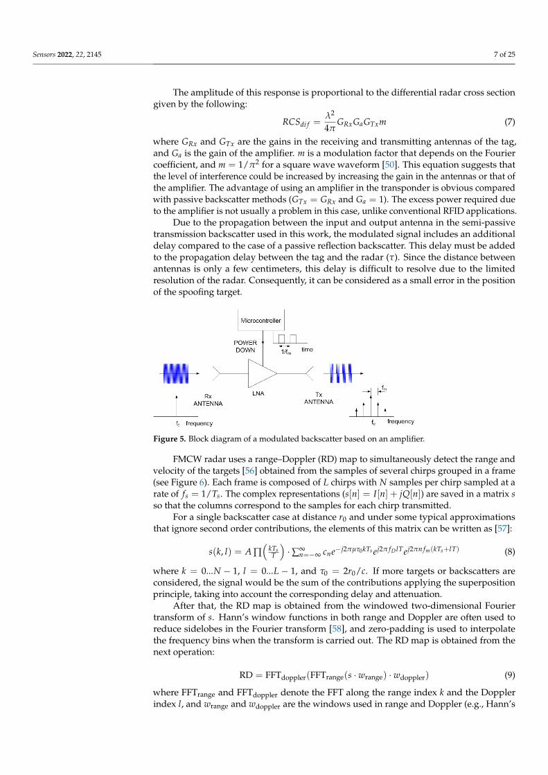
Other backscatter topologies can be used to increase the signal level by placing anamplifier between the tag’s receiving and transmitting antenna (see Figure 5). In this case,the modulation can be carried out by means of a switch or, as in this work, by changing thepower supply of the amplifier, taking advantage of its isolation in reverse.
Sensors 2022, 22, 2145 7 of 25
The amplitude of this response is proportional to the differential radar cross sectiongiven by the following:
RCSdi f =λ2
4πGRxGaGTxm (7)
where GRx and GTx are the gains in the receiving and transmitting antennas of the tag,and Ga is the gain of the amplifier. m is a modulation factor that depends on the Fouriercoefficient, and m = 1/π2 for a square wave waveform [50]. This equation suggests thatthe level of interference could be increased by increasing the gain in the antennas or that ofthe amplifier. The advantage of using an amplifier in the transponder is obvious comparedwith passive backscatter methods (GTx = GRx and Ga = 1). The excess power required dueto the amplifier is not usually a problem in this case, unlike conventional RFID applications.
Due to the propagation between the input and output antenna in the semi-passivetransmission backscatter used in this work, the modulated signal includes an additionaldelay compared to the case of a passive reflection backscatter. This delay must be addedto the propagation delay between the tag and the radar (τ). Since the distance betweenantennas is only a few centimeters, this delay is difficult to resolve due to the limitedresolution of the radar. Consequently, it can be considered as a small error in the positionof the spoofing target.
Figure 5. Block diagram of a modulated backscatter based on an amplifier.
FMCW radar uses a range–Doppler (RD) map to simultaneously detect the range andvelocity of the targets [56] obtained from the samples of several chirps grouped in a frame(see Figure 6). Each frame is composed of L chirps with N samples per chirp sampled at arate of fs = 1/Ts. The complex representations (s[n] = I[n] + jQ[n]) are saved in a matrix sso that the columns correspond to the samples for each chirp transmitted.
For a single backscatter case at distance r0 and under some typical approximationsthat ignore second order contributions, the elements of this matrix can be written as [57]:
s(k, l) = A ∏(
kTsT
)·∑∞
n=−∞ cne−j2πµτ0kTs ej2π fD lTej2πn fm(kTs+lT) (8)
where k = 0...N − 1, l = 0...L − 1, and τ0 = 2r0/c. If more targets or backscatters areconsidered, the signal would be the sum of the contributions applying the superpositionprinciple, taking into account the corresponding delay and attenuation.
After that, the RD map is obtained from the windowed two-dimensional Fouriertransform of s. Hann’s window functions in both range and Doppler are often used toreduce sidelobes in the Fourier transform [58], and zero-padding is used to interpolatethe frequency bins when the transform is carried out. The RD map is obtained from thenext operation:
RD = FFTdoppler(FFTrange(s · wrange) · wdoppler) (9)
where FFTrange and FFTdoppler denote the FFT along the range index k and the Dopplerindex l, and wrange and wdoppler are the windows used in range and Doppler (e.g., Hann’s

Sensors 2022, 22, 2145 8 of 25
window), respectively. The range R and velocity v depend on the 2D Fourier frequencies,fr and fv, respectively, and are obtained from the following expressions:
R =c fr
2µ(10)
v = −λ fv
2(11)
Figure 6. Diagram of the transmitted signal and calculation of the range–Doppler matrix from the Iand Q samples received.
The position of targets on the RD map can be detected by analyzing (8) and Figure 7.Of note, unmodulated passive targets are considered for the case of n = 0. A peak inthe RD map associated with the point closest to the pair of frequencies fr = 2Rµ/c andfD is observed. These frequencies correspond to the point with coordinates (R, v) on theRD map (see Figure 7a). The backscatter modulation produces a frequency shift overthe beat signal at the output of the mixer. Fast frequency components in the beat signalare interpreted by the radar as changes due to the delay produced by the propagationdistance between the radar and the target, whereas smooth phase changes between chirpsare associated with Doppler variations caused by the velocity at which the target moves.Three cases can be considered for the modulated backscatter. The first corresponds to ahigh modulating frequency, in which its value is an integer that is a multiple of half of thesampling frequency in Doppler ( fsd = 1/T). The half of the sampling frequency in Dopplercorresponds to the Nyquist frequency in this axis. In this case, sidebands fm apart on therange frequency axis are observed, producing ghost peaks on the RD map with coordinates(R + n∆R, v) (see Figure 7b). The second case occurs when fm < 1/T and corresponds tothe case of low-modulation frequencies in which the values are of the order of the changesproduced in the Doppler frequency. Therefore, due to its low-modulation frequency, thephase of this beat signal does not produce a significant change within each chirp (therefore,the range does not change with respect to an unmodulated tag) but introduces a slowphase variation between the chirps in the frame that can be interpreted by the radar as aDoppler shift when the Fourier transform is performed in Doppler. Consequently, twosidebands fm apart on the Doppler frequency axis appear, producing ghost peaks in theRD map with coordinates (R, v + n∆v) (see Figure 7c). The third case, shown in Figure 7d,is a combination of the cases from Figure 7b,c, where the modulation frequency is high butnot an integer that is a multiple of half of the sampling frequency in Doppler. In practice,

Sensors 2022, 22, 2145 9 of 25
the first sidebands (n = ±1) can only be detected for typical ranges because the harmonicsfall below the clutter.
For a certain spacing in the range ∆R and velocity ∆v between the ghost points andunmodulated point on the RD map, the backscatter modulation frequency fm is chosenusing the following expression:
fm = [(2µ · ∆R/c)÷ ( fsd/2)] · ( fsd/2)− 2∆v/λ (12)
where ÷ is the integer division. The first term of (12) determines a shift in range. Thespoofed target position is rounded to the nearest modulation frequency that does not pro-duce a Doppler shift. Then, a frequency shift is added to produce a shift in the velocity axis.
Figure 7. Ghost points introduced for the backscatter: (a) unmodulated case, (b) high-frequencymodulation case with a modulation frequency integer multiple of fsd/2, (c) low-frequency modulationcase, and (d) high-frequency modulation case where the modulation frequency is not an integermultiple of fsd/2.
Therefore, by changing the modulation frequency, the introduction of false targets onthe RD map around the physical position of the backscatter is possible. Thus, a backscatter-based tag located in a car or on the road can introduce points that can generate signals thatconfuse the radar, compromising the safety of the vehicle. The modulation frequency canbe easily changed by generating a pulse-width modulation (PWM) at the desired frequencyusing a low-cost and low-power microcontroller. Different frequencies profiles can besynthesized by varying the PWM signal as a function of time.
3. Spoofing Device Design
The spoofing device was based on an updated version of the backscatter tag presentedin [59,60]. The GaAs amplifier was replaced by a pair of lower-power-consumption am-plifiers, and the patch array was replaced by a lens antenna. The prototype used a silicon

Sensors 2022, 22, 2145 10 of 25
germanium MMIC (monolithic microwave integrated circuit) amplifier LNA_24_04 fromSilicon Radar GmbH. The typical gain of this amplifier between 24 GHz and 29 GHz is17 dB, with only 5.6 mA of current consumption at 3.3V. A second cascade amplifier wasadded to increase the differential radar cross section according to (7). The amplifier has ashutdown power-down control pin that is used to enable/disable the amplifier. With thismethod, quick, pulsed operation of several megahertz can be achieved, which is sufficientfor our application. Therefore, adding an expensive mm wave modulator to the system isnot necessary, since modulation of the RCS is carried out by switching the power-down pinof the amplifier. Consequently, the amplitude of the backscattered field can be controlled bya modulation signal connected to the power-control pin, as shown in Figure 5. A low-costSeeduino XIAO is used to generate the frequency-configurable PWM output. This moduleintegrates an Atmel ARM Cortex-M0 ATSAM21G18A-MU microcontroller operating ata clock frequency of 48 MHz. Of note, other microcontrollers that have PWM outputsand similar performance can also be chosen for this prototype. Generating different ghosttargets at distances and velocities according to (12) is possible by choosing the appropriatePWM frequency.
The input and output antennas of the prototype are integrated lens antennas (ILA).The antenna consists of a microstrip patch with a lens to increase the gain [61–63]. Thematerial used to manufacture the low-cost lenses using a 3D printer was polylactic acid(PLA). The dielectric data for PLA at millimeter band can be found in [64]. A dielectricconstant of 2.55 and a dissipation factor of 0.02 were considered for the PLA material at24 GHz for the antenna design. The lens was illuminated by a microstrip patch antennadesigned on Rogers 4003 substrate with a thickness of 16 mm , a dielectric permittivity of3.59, and a dissipation factor of 0.003.
Figure 8 schematically shows a ray-tracing analysis of the focal length of the extendedhemispherical lens. The optimal size of the lens extension of a conventional elliptical lensis given by the following [62]:
HL = R(√
εrL + 1√
εrL − 1− 1)
(13)
where RL is the radius of the lens in the vertical plane, H is the length of the extensionfrom the substrate, and εrL is the permittivity of the lens material (PLA). The radius RL wasfixed to the wavelength (λ0) in air at 24 GHz, and H is obtained from 13. The patch wasdesigned by taking into account that the PLA structure of the lens lays on it. The width ofthe patch W is assumed to be equal to half of the wavelength when considering an effectivepermittivity approximately equal to the average between the lens material (PLA) and thesubstrate εrs:
W =c
2 f0√(εrL + εrs)/2
(14)
Taking this width into account, a better estimate of the effective permittivity εre f fromthe effective permittivity of a microstrip line (case W > h) is possible [65]:
εre f =εrs + εrL
2+
εrs − εrL2
· (1 + 12h/W)−1/2 (15)
where h is the thickness of the substrate. The patch length was designed to be resonantat f0 = 24 GHz. Therefore, the effective length must be half of the wavelength calculatedfrom the effective dielectric permittivity. To adjust the resonance frequency to the desiredfrequency ( f0 = 24 GHz) and to take into account the fringing effect in the ends of thepatch, a length extension (∆L) is considered [65]:
L =c
2 f0√
εre f− 2∆L (16)

Sensors 2022, 22, 2145 11 of 25
where the length extension is estimated as [65]:
∆L = 0.412h(εre f + 0.3) · (W/h + 0.264)(εre f − 0.258) · (W/h + 0.8)
(17)
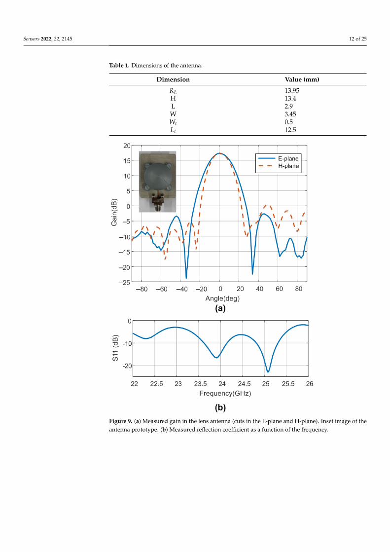
The design of the patch antenna, including the effect of the lens material and taper,was carried out with the Momentum software included in the Keysight ADS and withAnsys HFSS. A prototype antenna was manufactured, the sketch of which is presented inFigure 8. The gain and pattern diagram measurements were performed in a semi-anechoicchamber to avoid reflections of the environment, and a calibrated horn antenna was usedin the gain calibration. Measurements were performed using a PCB end launch connector(2.92 mm (K)) from Southwest Microwave. The measured gains at 24 GHz in the E-planeand H-plane are shown in Figure 9. The antenna has a maximum gain of 17.5 dB, asidelobe level better than 18 dB, and a−3 dB beamwidth of about 22 degrees in both planes.Figure 9 also shows the measured reflection coefficient of the prototype (S11) includingthe end launch connector. The return losses are better than 10 dB in the 24 GHz ISMband. The vector network analyzer (VNA) PNA E8364C from Agilent was used to performthese measurements.
Figure 8. Geometry and dimensions of the antenna.
Table 1 summarizes the dimensions of the antenna. Figure 10 shows a photograph ofthe prototype spoofing device. The dimensions of the device are 120 mm× 37 mm× 24 mm,including the protection box. We proved that the isolation between antennas is greater thanthe gain in the amplifiers, avoiding oscillation of the device due to the parasitic feedbackbetween the output and input antennas. From (6), the estimated differential radar crosssection is 13.6 dBsm. Figure 11 compares the typical values of RCS in the 24 GHz band forsome of the objects that can be found on the road, taken from the literature. The RCS valuedepends on different factors such as size, material, or orientation with respect to the radar.Thus, the average RCS of a pedestrian reported in the literature [66] is about −5 dBsm. Thisvalue is significantly lower than those for a car (10 dBsm), a motorcycle (5–8 dBsm) [67], ora guardrail (5–10 dBsm) [68]. Therefore, the designed spoofing device based on modulatedbackscatter has an RCS level comparable with that of a car and, therefore, can be confusedwith it.
Sensors 2022, 22, 2145 12 of 25
Table 1. Dimensions of the antenna.
Dimension Value (mm)
RL 13.95H 13.4L 2.9W 3.45Wt 0.5Lt 12.5
Figure 9. (a) Measured gain in the lens antenna (cuts in the E-plane and H-plane). Inset image of theantenna prototype. (b) Measured reflection coefficient as a function of the frequency.

Sensors 2022, 22, 2145 13 of 25
Figure 10. Photo of the prototype.
Figure 11. RCS level of different relevant road objects such as a car, a small van, a guardrail, abicycle, and a pedestrian at 24 GHz band.The peak differential radar cross section for the prototypeof modulated backscatter is shown as a red line.
4. Results4.1. Simulated Results
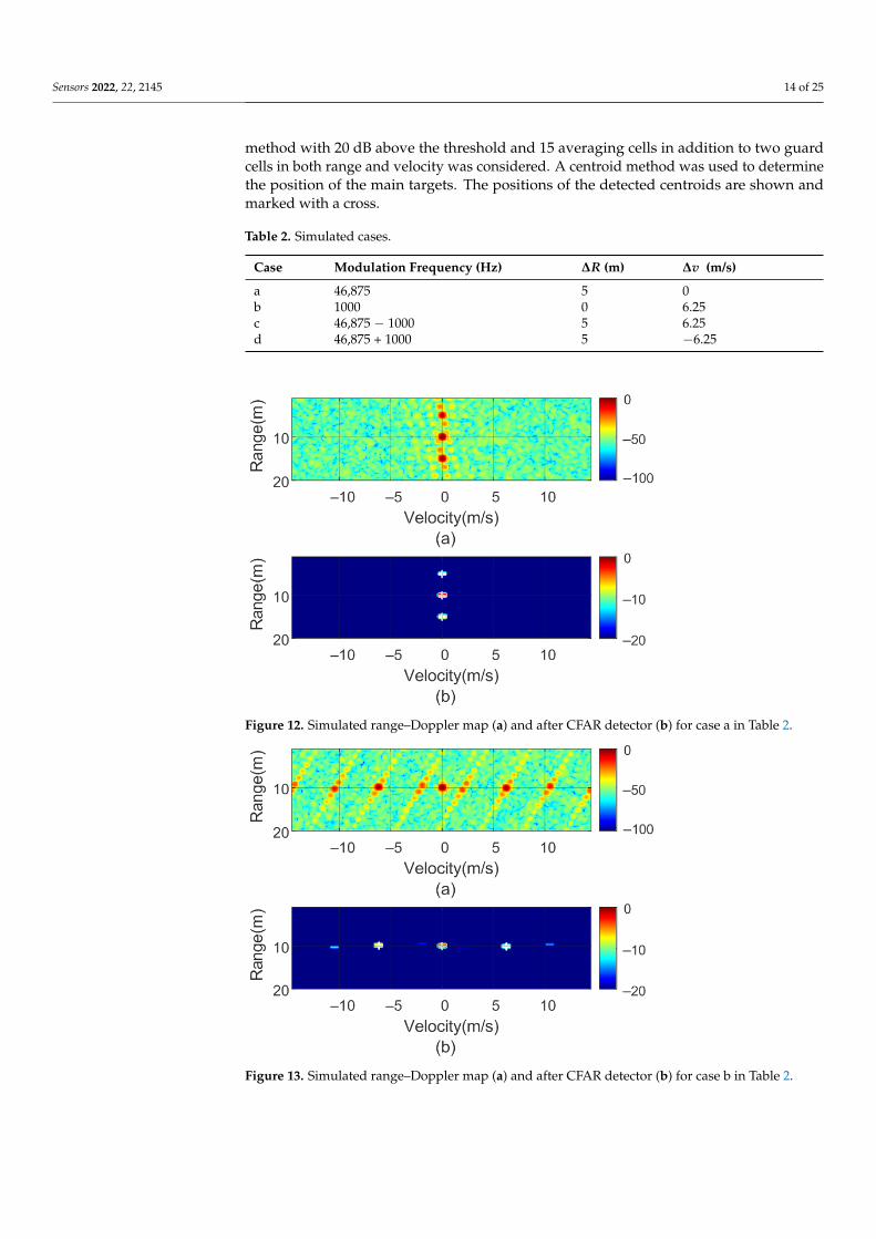
To verify the previous theory, a set of simulations were carried out, in which thepresence of cluttering interference from the scene was not considered. The synthetic signalsreceived were simulated from each target using (1)–(6). The data received were sampledat a rate of fs, and from (8), the 2D-FFT was performed to obtain the range–Doppler map.In the simulation, parameters similar to those used by the radar during the experimentswere chosen. Therefore, a total of 128 frames were taken with 256 points per frame in thenext simulations. The radar sweeps from the 24 GHz to 24.3 GHz frequency bands with asweep time of 250 µs. Figures 12–15 show the RD maps obtained for different modulationfrequencies corresponding to the cases described in Figure 7. Table 2 lists the frequenciesand the values of the offset positions ∆R and the offset velocities ∆v. A stationary spoofingdevice located at 10 m is considered in these examples. The figures show both the rawRD maps and these maps after having applied a CFAR detector. This detector is used toestimate a threshold that eliminates unwanted interference and sidelobes associated withFourier transforms of the windows. The threshold is obtained from the RD of the adjacentcells. Several methods exist, but in this work, the well-known cell-averaging (CA-CFAR)
Sensors 2022, 22, 2145 14 of 25
method with 20 dB above the threshold and 15 averaging cells in addition to two guardcells in both range and velocity was considered. A centroid method was used to determinethe position of the main targets. The positions of the detected centroids are shown andmarked with a cross.
Table 2. Simulated cases.
Case Modulation Frequency (Hz) ∆R (m) ∆v (m/s)
a 46,875 5 0b 1000 0 6.25c 46,875 − 1000 5 6.25d 46,875 + 1000 5 −6.25
Figure 12. Simulated range–Doppler map (a) and after CFAR detector (b) for case a in Table 2.
Figure 13. Simulated range–Doppler map (a) and after CFAR detector (b) for case b in Table 2.

Sensors 2022, 22, 2145 15 of 25
Figure 14. Simulated range–Doppler map (a) and after CFAR detector (b) for case c in Table 2.
Figure 15. Simulated range–Doppler map (a) and after CFAR detector (b) for case d in Table 2.
4.2. Experimental Validation
For the spoofing validation, a FMCW radar kit (EVAL-DEMORAD) from AnalogDevices Inc. (Norwood, MA, USA) was used (see Figure 16). The radar consists of twotransmitters and four receiver antennas that are based on the ADF5901 2-channel FMCWtransmitter and the ADF5904 4-channel receiver, both from Analog Devices Inc. The radaruses a patch antenna array design with a field of view (FOV) of approximately 120 degreesin azimuth and 15 degrees in elevation. The power transmitted by the radar is 8 dBm.The FMCW radar was configured to sweep within the ISM frequency band (24–24.3 GHz).The sampling frequency was 1.2 MHz, and the sweep time used was 250 µs. The pointsper frame were 256, and a total of 128 frames were used to obtain the range–Dopplermaps. The main parameters are summarized in Table 3. The designed spoofing deviceand the commercial radar kit were used in the experiment. A test software developedwith Python and Matlab based on the communication functions provided with the kitwas developed. The experiments were performed in an indoor environment (researchlaboratory). The following figures depict several cases for different modulation frequencies

Sensors 2022, 22, 2145 16 of 25
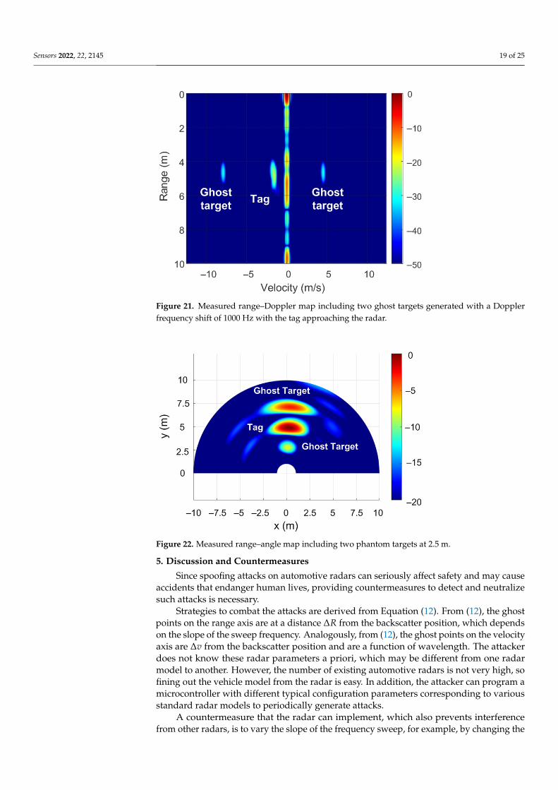
obtained from (12) for a range ∆R and a velocity ∆v. Figure 17 shows the measured RDmap after applying the CFAR detector considering a fm =1000 Hz. Therefore, accordingto the theory presented, two ghost targets are observed at the same distance from the tagor spoofing device (∆R = 0) but with a Doppler shift corresponding to δv = 6.25 m/s. Asecond case is presented in Figure 18. This case shows a spoofing device located at 6 m fromthe radar. It is also in motion to avoid cluttering interference due to static objects in thelaboratory and thus to better appreciate the results. A pair of ghost targets at ∆R = 3.5 mwithout Doppler shift (∆v = 0) are generated. The Doppler shift is observed to be dueto movement of the tag or spoofing device. The spoofing device is held by a walkingperson. Figures 19 and 20 show the same case but with the spoofing device moving in bothdirections (towards and away from the radar, respectively) with ∆R = 2.5 m and ∆v = 0.Figure 21 shows another case where a 6.5 m/s Doppler shift ( fm = 1000 Hz) was introducedinto a moving spoofing device (tag).
FMCW radars equipped with multiple receive and transmit antennas can estimatethe angle of arrival (AoA), showing the targets on range–angle maps. The ghost targetsgenerated by the backscatter tag used as a spoofing device can be observed on range–angle maps. The FFT-based algorithm for AoA detection is one of the most widely usedalgorithms because of its low complexity and ease of implementation [69]. Angle estimationis performed by processing the received signal at the array composed of multiple antennas.If a Fourier transform is performed in the spatial dimension through the receiving elements(known as angle FFT), distinguishing objects based on their AoA in azimuth will be possible.Since the EVAL-DEMORAD kit has two transmitting antennas and four receiving antennas,the angle resolution is limited; however, the ghost targets can be detected. Figure 22 showsthe range–angle map obtained from the FFT method using the EVAL-DEMORAD kit. Inthis example, a tag or spoofing device is located at 5 m from the radar and two ghosttargets are generated by programming the modulation frequency to ∆R = 2.5 m. Themeasurements in the last case have been performed in an outdoor scenario.
Figure 16. Image of EVAL-DEMORAD kit used in the experiments.

Sensors 2022, 22, 2145 17 of 25
Figure 17. Measured range–Doppler map including two ghost targets generated with a Dopplerfrequency shift of 1000 Hz keeping the tag static.
Table 3. Configuration of the FMCW radar.
Parameter Value
Start Frequency 24 GHzSweep bandwidth 300 MHz
Sweep slope 300/250 MHz/µsSweep time 250 µs
Sampling frequency 1.2 MbpsNumber of samples per chirp 256Number of chirps per frame 128
Transmit antennas 2Receive antennas 4
Figure 18. Measured range–Doppler map including two ghost targets at 3.5 m with the tag approach-ing the radar.

Sensors 2022, 22, 2145 18 of 25
Figure 19. Measured range–Doppler map including two ghost targets at 2.5 m with the tag approach-ing the radar.
Figure 20. Measured range–Doppler map including two phantom targets at 2.5 m with the tagmoving away from the radar.
Sensors 2022, 22, 2145 19 of 25
Figure 21. Measured range–Doppler map including two ghost targets generated with a Dopplerfrequency shift of 1000 Hz with the tag approaching the radar.
Figure 22. Measured range–angle map including two phantom targets at 2.5 m.
5. Discussion and Countermeasures
Since spoofing attacks on automotive radars can seriously affect safety and may causeaccidents that endanger human lives, providing countermeasures to detect and neutralizesuch attacks is necessary.
Strategies to combat the attacks are derived from Equation (12). From (12), the ghostpoints on the range axis are at a distance ∆R from the backscatter position, which dependson the slope of the sweep frequency. Analogously, from (12), the ghost points on the velocityaxis are ∆v from the backscatter position and are a function of wavelength. The attackerdoes not know these radar parameters a priori, which may be different from one radarmodel to another. However, the number of existing automotive radars is not very high, sofining out the vehicle model from the radar is easy. In addition, the attacker can program amicrocontroller with different typical configuration parameters corresponding to variousstandard radar models to periodically generate attacks.
A countermeasure that the radar can implement, which also prevents interferencefrom other radars, is to vary the slope of the frequency sweep, for example, by changing the

Sensors 2022, 22, 2145 20 of 25
duration of the chirp signal between frames. The algorithm compares the RD obtained withdifferent frequency slope chirps. This allows the ghost points to appear at different distancesor velocities between two consecutive range–Doppler maps. Consequently, identifyingthem is easy: by comparing the positions of the detected targets between sweeps.
The case in which the spoofing device introduces false targets at the same position(∆R = 0) but with different velocities (see Figure 7c) can be identified by considering thattwo peaks appear with the same amplitude but velocities equal to 2∆v but with oppositesigns, which cannot correspond to a true target. In this case, the position in the RD map isindependent of the sweep slope.
Unfortunately, the radar kit used in our experiments does not allow for arbitrarytransmission of the sequences to be chosen, so changing the chirp duration within theframe is not possible. To investigate the effect of the chirp, we could only change theduration between frames, shown in the following simulations.
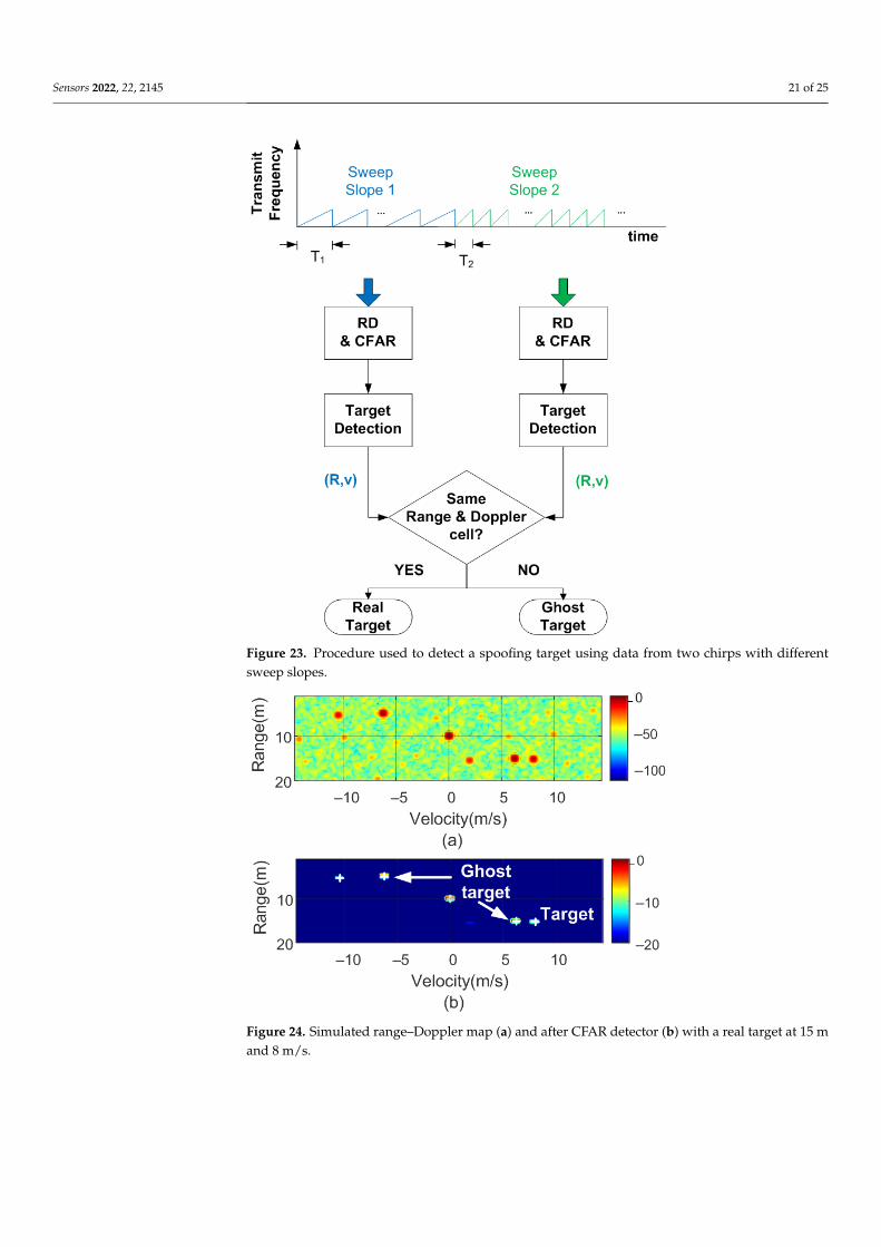
Figure 23 shows a schematic diagram of the proposed algorithm for determining ifa target is real or spoofed. The objective is to send a set of frames with a specific sweepslope, determining the list of potential targets, and then to send another set of frames witha different sweep slope (or frame duration). An example of the simulations performed isshown in Figures 24 and 25.
In the following example, a real target 15 m away and moving at 8 m/s towards theradar is considered. A stationary spoofing device is located 10 m away. The spoofing deviceis configured to generate ghost targets with values of ∆R = 5 m and ∆v = 6.25 m/s, anda nominal sweep slope µ. The simulated RD is shown in Figure 24. The crosses showthe potential targets detected by the algorithm. In subsequent sweeps, the value of thesweep slope is doubled. The corresponding RD is shown in Figure 25. As observed, thereal target preserves the same position and velocity, whereas the range of the spoofedtargets changes. Consequently, the countermeasure algorithm detects these false targetsand discards them. Finally, the use of this algorithm, which is easy to implement, does notprevent normal operation of the radar, the hardware of which remains the same. A similarmethod used to combat interferences and attackers has been recently proposed in [36] andconsists of splitting a chirp into multiple sub-chirps and randomizing every chirp period.Therefore, this random frequency hopping makes it difficult for the attacker to listen (e.g.,with an spectrum analyzer or receiver) to the victim’s radar signal to learn the main radarparameters (such as frequency range and slope). Although a backscattering-based methodpresents great flexibility in the design of the targets, due to the presence of the sidebands(since the modulation is not a single sideband), the targets appear in pairs, and a Dopplercoupling can be seen, as shown in Figure 7. Therefore, in the car-follower scenario shown inFigure 2, one target is closer to the radar and the other is behind the attacker. The victim’sradar considers the closest target to be less than a safe distance away. Consequently, theradar alerts a user to the threat of a collision. To avoid the pairs of peaks, more complexsingle-sideband (SSB) modulators must be implemented. In the case of backscatter in areflection, they can be implemented using a hybrid coupler loaded with switching devices(e.g., PIN diodes) or using IQ mixers in the case with a transponder in transmission.
Sensors 2022, 22, 2145 21 of 25
Figure 23. Procedure used to detect a spoofing target using data from two chirps with differentsweep slopes.
Figure 24. Simulated range–Doppler map (a) and after CFAR detector (b) with a real target at 15 mand 8 m/s.

Sensors 2022, 22, 2145 22 of 25
Figure 25. Simulated range–Doppler map (a) and after CFAR detector (b) with a real target at 15 mand 8 m/s with the slope changed.
6. Conclusions and Future Work
In this work, a simple low-cost spoofing device operating at 24 GHz based on mod-ulated backscatter was proposed. Our goal was to generate false targets, thus foolingvehicles that incorporate a mm wave FMCW radar. In contrast with other works in theliterature that use SDRs or other radars to generate spoofing signals, we proposed a simpledevice based on a modulated semi-passive transponder or tag. We demonstrated that, bychanging the modulation of this transponder, the generation of ghost targets to confusethe radar at different distances and velocities is possible. The transponder consists of twopatch antennas with dielectric lenses to achieve a high gain. Two low-noise amplifiers arecascade-connected between the two antennas. Modulation is achieved by switching thegain of the amplifiers. We showed that the combination of high gains of the antennas withthose of the amplifiers allows us to achieve a high differential RCS, comparable with thatof a car at 24 GHz. The victim radar detects a beat frequency change associated with thebackscatter modulation frequency. This frequency shift results in a ghost target, and themodulation frequency can be set to generate spoofing targets at different distances andvelocities. Several simulations have been carried out, and different spoofing measures havebeen validated using the designed tag and the FMCW radar kit (EVAL-DEMORAD) fromAnalog Devices. In both cases, RD maps have been generated. The results obtained agreewith those expected from theory, both for the simulations and for the measurements afterapplying the CA-CFAR detection algorithm.
Countermeasures mitigating the effects of potential spoofing using these devices basedon random variation in the radar sweep parameters, such as the sweep slope or the durationof the chirps, were proposed.
In addition, the low-cost device presented allows for the generation of artificial targetsthat can be used to calibrate radars in assembly lines, in technical vehicle-inspection centers,and indoors or to avoid clutter interference as an alternative to expensive commercialinstrumentation-based systems.
Author Contributions: Investigation and writing—original draft preparation, A.L. and A.P.; pro-totype manufacturing: M.L.; software: A.L. and M.L.; review and editing, R.V. and D.G.; projectadministration and supervision, A.L. All authors have read and agreed to the published version ofthe manuscript.

Sensors 2022, 22, 2145 23 of 25
Funding: This research was funded by the Spanish Government Project RTI2018-096019-B-C31,R2B2020 project, and grant PRE2019-089028 and by the EU’s European Regional DevelopmentFund (ERDF).
Institutional Review Board Statement: Not applicable.
Informed Consent Statement: Not applicable.
Data Availability Statement: The data presented in this study are available from the correspondingauthor upon request.
Conflicts of Interest: The authors declare no conflict of interest.
References1. Park, J.; Park, S.; Kim, D.H.; Park, S.O. Leakage mitigation in heterodyne FMCW radar for small drone detection with stationary
point concentration technique. IEEE Trans. Microw. Theory Tech. 2019, 67, 1221–1232. [CrossRef]2. Alizadeh, M.; Shaker, G.; De Almeida, J.C.M.; Morita, P.P.; Safavi-Naeini, S. Remote monitoring of human vital signs using
mm-wave FMCW radar. IEEE Access 2019, 7, 54958–54968. [CrossRef]3. Piotrowsky, L.; Jaeschke, T.; Kueppers, S.; Siska, J.; Pohl, N. Enabling high accuracy distance measurements with FMCW radar
sensors. IEEE Trans. Microw. Theory Tech. 2019, 67, 5360–5371. [CrossRef]4. Shrestha, A.; Li, H.; Le Kernec, J.; Fioranelli, F. Continuous human activity classification from FMCW radar with Bi-LSTM
networks. IEEE Sens. J. 2020, 20, 13607–13619. [CrossRef]5. Wang, Y.; Ren, A.; Zhou, M.; Wang, W.; Yang, X. A novel detection and recognition method for continuous hand gesture using
fmcw radar. IEEE Access 2020, 8, 167264–167275. [CrossRef]6. Alizadeh, M.; Abedi, H.; Shaker, G. Low-cost low-power in-vehicle occupant detection with mm-wave FMCW radar. In
Proceedings of the 2019 IEEE SENSORS, Montreal, QC, Canada, 27–30 October 2019; pp. 1–4.7. Rasshofer, R.H.; Spies, M.; Spies, H. Influences of weather phenomena on automotive laser radar systems. Adv. Radio Sci. ARS
2011, 9, 49. [CrossRef]8. Sun, S.; Petropulu, A.P.; Poor, H.V. MIMO radar for advanced driver-assistance systems and autonomous driving: Advantages
and challenges. IEEE Signal Process. Mag. 2020, 37, 98–117. [CrossRef]9. Currie, N.C.; Brown, C.E. Principles and Applications of Millimeter-Wave Radar; Artech House Norwood: Norwood, MA, USA, 1987.10. Poisel, R. Modern Communications Jamming Principles and Techniques; Artech House: Norwood, MA, USA, 2011.11. Gerstmair, M.; Melzer, A.; Onic, A.; Huemer, M. On the safe road toward autonomous driving: Phase noise monitoring in radar
sensors for functional safety compliance. IEEE Signal Process. Mag. 2019, 36, 60–70. [CrossRef]12. Jin, F.; Cao, S. Automotive Radar Interference Mitigation Using Adaptive Noise Canceller. IEEE Trans. Veh. Technol. 2019,
68, 3747–3754. [CrossRef]13. Graham, A. Communications, Radar and Electronic Warfare; John Wiley & Sons: Hoboken, NJ, USA, 2011.14. Lichtman, M.; Poston, J.D.; Amuru, S.; Shahriar, C.; Clancy, T.C.; Buehrer, R.M.; Reed, J.H. A communications jamming taxonomy.
IEEE Secur. Priv. 2016, 14, 47–54. [CrossRef]15. Schroer, R. Electronic warfare. [A century of powered flight: 1903–2003]. IEEE Aerosp. Electron. Syst. Mag. 2003, 18, 49–54.
[CrossRef]16. Matic, V.; Kosjer, V.; Lebl, A.; Pavic, B.; Radivojevic, J. Methods for Drone Detection and Jamming. In Proceedings of the 10th
International Conference on Information Society and Technology (ICIST), Kopaonik, Serbia, 8–11 March 2020; pp. 16–21.17. Tedeschi, P.; Oligeri, G.; Di Pietro, R. Leveraging jamming to help drones complete their mission. IEEE Access 2019, 8, 5049–5064.
[CrossRef]18. Wang, Y.; Zhan, Z.; Xue, B. Operation method of electronic warfare UAV. In Proceedings of the Global Intelligence Industry
Conference (GIIC 2018), International Society for Optics and Photonics, Beijing, China, 22–24 May 2018; Volume 10835, p. 108351L.19. Multerer, T.; Ganis, A.; Prechtel, U.; Miralles, E.; Meusling, A.; Mietzner, J.; Vossiek, M.; Loghi, M.; Ziegler, V. Low-cost jamming
system against small drones using a 3D MIMO radar based tracking. In Proceedings of the 2017 European Radar Conference(EURAD), Nuremberg, Germany, 11–13 October 2017; pp. 299–302.
20. Yan, C.; Xu, W.; Liu, J. Can you trust autonomous vehicles: Contactless attacks against sensors of self-driving vehicle. DEFCON2016, 24, 109.
21. Yeh, E.; Choi, J.; Prelcic, N.; Bhat, C.; Heath, R.W., Jr. Security in automotive radar and vehicular networks. Microw. J. 2016,submitted.
22. Wagner, M.; Sulejmani, F.; Melzer, A.; Meissner, P.; Huemer, M. Threshold-Free Interference Cancellation Method for AutomotiveFMCW Radar Systems. In Proceedings of the 2018 IEEE International Symposium on Circuits and Systems (ISCAS), Florence,Italy, 27–30 May 2018; pp. 1–4. [CrossRef]
23. Brooker, G.M. Mutual interference of millimeter-wave radar systems. IEEE Trans. Electromagn. Compat. 2007, 49, 170–181.[CrossRef]
24. Uysal, F. Phase-coded FMCW automotive radar: System design and interference mitigation. IEEE Trans. Veh. Technol. 2019,69, 270–281. [CrossRef]

Sensors 2022, 22, 2145 24 of 25
25. Dai, J.; Hao, X.; Li, P.; Li, Z.; Yan, X. Antijamming design and analysis of a novel pulse compression radar signal based on radaridentity and chaotic encryption. IEEE Access 2020, 8, 5873–5884. [CrossRef]
26. Alland, S.; Stark, W.; Ali, M.; Hegde, M. Interference in automotive radar systems: Characteristics, mitigation techniques, andcurrent and future research. IEEE Signal Process. Mag. 2019, 36, 45–59. [CrossRef]
27. Bechter, J.; Eid, K.; Roos, F.; Waldschmidt, C. Digital beamforming to mitigate automotive radar interference. In Proceedings ofthe 2016 IEEE MTT-S International Conference on Microwaves for Intelligent Mobility (ICMIM), San Diego, CA, USA, 19–20 May2016; pp. 1–4.
28. Bechter, J.; Rameez, M.; Waldschmidt, C. Analytical and experimental investigations on mitigation of interference in a DBFMIMO radar. IEEE Trans. Microw. Theory Tech. 2017, 65, 1727–1734. [CrossRef]
29. Chauhan, R. A Platform for False Data Injection in Frequency Modulated Continuous Wave Radar; Utah State University: Logan, UT,USA, 2014.
30. Shoukry, Y.; Martin, P.; Yona, Y.; Diggavi, S.; Srivastava, M. Pycra: Physical challenge-response authentication for active sensorsunder spoofing attacks. In Proceedings of the 22nd ACM SIGSAC Conference on Computer and Communications Security,Denver, CO, USA, 12–16 October 2015; pp. 1004–1015.
31. Dutta, R.G.; Guo, X.; Zhang, T.; Kwiat, K.; Kamhoua, C.; Njilla, L.; Jin, Y. Estimation of safe sensor measurements of autonomoussystem under attack. In Proceedings of the 54th Annual Design Automation Conference 2017, Austin, TX, USA, 18–22 June 2017;pp. 1–6.
32. Kapoor, P.; Vora, A.; Kang, K.D. Detecting and Mitigating Spoofing Attack Against an Automotive Radar. In Proceedings of the2018 IEEE 88th Vehicular Technology Conference (VTC-Fall), Chicago, IL, USA, 27–30 August 2018; pp. 1–6. [CrossRef]
33. Komissarov, R.; Wool, A. Spoofing attacks against vehicular FMCW radar. In Proceedings of the 5th Workshop on Attacks andSolutions in Hardware Security, Virtual Event, Korea, 19 November 2021; pp. 91–97.
34. Toker, O.; Alsweiss, S. Design of a cyberattack resilient 77 GHz automotive radar sensor. Electronics 2020, 9, 573. [CrossRef]35. Miura, N.; Machida, T.; Matsuda, K.; Nagata, M.; Nashimoto, S.; Suzuki, D. A low-cost replica-based distance-spoofing attack on
mmWave FMCW radar. In Proceedings of the 3rd ACM Workshop on Attacks and Solutions in Hardware Security Workshop,London, UK, 15 November 2019; pp. 95–100.
36. Moon, T.; Park, J.; Kim, S. BlueFMCW: Random frequency hopping radar for mitigation of interference and spoofing. EURASIP J.Adv. Signal Process. 2022, 2022, 1–17. [CrossRef]
37. Li, C.; Cummings, J.; Lam, J.; Graves, E.; Wu, W. Radar remote monitoring of vital signs. IEEE Microw. Mag. 2009, 10, 47–56.[CrossRef]
38. Nallabolu, P.; Li, C. A Frequency-Domain Spoofing Attack on FMCW Radars and Its Mitigation Technique Based on a Hybrid-Chirp Waveform. IEEE Trans. Microw. Theory Tech. 2021, 69, 5086–5098. [CrossRef]
39. Nashimoto, S.; Suzuki, D.; Miura, N.; Machida, T.; Matsuda, K.; Nagata, M. Low-cost distance-spoofing attack on FMCW radarand its feasibility study on countermeasure. J. Cryptogr. Eng. 2021, 11, 289–298. [CrossRef]
40. Rodriguez, D.; Wang, J.; Li, C. Spoofing attacks to radar motion sensors with portable RF devices. In Proceedings of the 2021IEEE Radio and Wireless Symposium (RWS), San Diego, CA, USA, 17–22 January 2021; pp. 73–75.
41. Guvenc, I.; Koohifar, F.; Singh, S.; Sichitiu, M.L.; Matolak, D. Detection, tracking, and interdiction for amateur drones. IEEECommun. Mag. 2018, 56, 75–81. [CrossRef]
42. Zhao, J.; Fu, X.; Yang, Z.; Xu, F. Radar-assisted UAV detection and identification based on 5G in the Internet of Things. Wirel.Commun. Mob. Comput. 2019, 2019, 2850263. [CrossRef]
43. Lykou, G.; Moustakas, D.; Gritzalis, D. Defending airports from UAS: A survey on cyber-attacks and counter-drone sensingtechnologies. Sensors 2020, 20, 3537. [CrossRef] [PubMed]
44. Wang, J.; Liu, Y.; Song, H. Counter-unmanned aircraft system (s)(C-UAS): State of the art, challenges, and future trends. IEEEAerosp. Electron. Syst. Mag. 2021, 36, 4–29. [CrossRef]
45. Matos, D.; da Cruz Jordão, M.D.; Correia, R.; Carvalho, N.B. Millimeter-Wave BiCMOS Backscatter Modulator for 5G-IoTApplications. IEEE Microw. Wirel. Components Lett. 2020, 31, 173–176. [CrossRef]
46. Eid, A.; Hester, J.G.; Tentzeris, M.M. Rotman Lens-Based Wide Angular Coverage and High-Gain Semipassive Architecture forUltralong Range mm-Wave RFIDs. IEEE Antennas Wirel. Propag. Lett. 2020, 19, 1943–1947. [CrossRef]
47. Daskalakis, S.; Georgiadis, A.; Kimionis, J.; Tentzeris, M. A printed millimeter-wave modulator and antenna array for low-complexity Gigabit-datarate backscatter communications. Res. Sq. 2021. [CrossRef]
48. Schmid, C.M.; Feger, R.; Stelzer, A. Millimeter-wave phase-modulated backscatter transponder for FMCW radar applications. InProceedings of the 2011 IEEE MTT-S International Microwave Symposium, Baltimore, MD, USA, 5–10 June 2011; pp. 1–4.
49. Stein, W.; Aleksieieva, A.; Roehr, S.; Vossiek, M. Phase modulated 61 GHz backscatter transponder for FMCW radar-basedranging. In Proceedings of the GeMiC 2014; German Microwave Conference, Aachen, Germany, 10–12 March 2014; pp. 1–4.
50. Lazaro, A.; Lorenzo, J.; Villarino, R.; Girbau, D. Backscatter transponder based on frequency selective surface for FMCW radarapplications. Radioengineering 2014, 23, 632–641.
51. Lazaro, A.; Ramos, A.; Girbau, D.; Villarino, R. A novel UWB RFID tag using active frequency selective surface. IEEE Trans.Antennas Propag. 2012, 61, 1155–1165. [CrossRef]
52. Kim, B.; Kim, S.; Lee, J. A novel DFT-based DOA estimation by a virtual array extension using simple multiplications for FMCWradar. Sensors 2018, 18, 1560. [CrossRef] [PubMed]

Sensors 2022, 22, 2145 25 of 25
53. Collin, R. Limitations of the Thevenin and Norton equivalent circuits for a receiving antenna. IEEE Antennas Propag. Mag. 2003,45, 119–124. [CrossRef]
54. Green, R.B. The General Theory of Antenna Scattering; The Ohio State University: Columbus, OH, USA, 1963.55. Nikitin, P.V.; Rao, K.S.; Lam, S.F.; Pillai, V.; Martinez, R.; Heinrich, H. Power reflection coefficient analysis for complex impedances
in RFID tag design. IEEE Trans. Microw. Theory Tech. 2005, 53, 2721–2725. [CrossRef]56. Rohling, H.; Kronauge, M. New radar waveform based on a chirp sequence. In Proceedings of the 2014 International Radar
Conference, Lille, France, 13–17 October 2014; pp. 1–4. [CrossRef]57. Lazaro, A.; Lazaro, M.; Villarino, R.; De Paco, P. New Radar Micro-Doppler Tag for Road Safety Based on the Signature of
Rotating Backscatters. IEEE Sens. J. 2020, 21, 8604–8612. [CrossRef]58. Harris, F.J. On the use of windows for harmonic analysis with the discrete Fourier transform. Proc. IEEE 1978, 66, 51–83.
[CrossRef]59. Lazaro, A.; Lazaro, M.; Villarino, R.; Girbau, D.; de Paco, P. Car2Car Communication Using a Modulated Backscatter and
Automotive FMCW Radar. Sensors 2021, 21, 3656. [CrossRef] [PubMed]60. Lazaro, A.; Villarino, R.; Lazaro, M.; Girbau, D.; dePaco, P. Modulated Backscattering transponder to increase the detectability of
pedestrians with automotive radar at 24 GHz. In Proceedings of the 2021 XXXIVth General Assembly and Scientific Symposiumof the International Union of Radio Science (URSI GASS), Rome, Italy, 28 August–4 September 2021; pp. 1–4.
61. Filipovic, D.F.; Gearhart, S.S.; Rebeiz, G.M. Double-slot antennas on extended hemispherical and elliptical silicon dielectric lenses.IEEE Trans. Microw. Theory Tech. 1993, 41, 1738–1749. [CrossRef]
62. Nguyen, N.T.; Rolland, A.; Boriskin, A.V.; Valerio, G.; Le Coq, L.; Sauleau, R. Size and weight reduction of integrated lensantennas using a cylindrical air cavity. IEEE Trans. Antennas Propag. 2012, 60, 5993–5998. [CrossRef]
63. Kamran Saleem, M.; Xie, M.; Alkanhal, M.A.; Saadi, M. Effect of dielectric materials on integrated lens antenna for millimeterwave applications. Microw. Opt. Technol. Lett. 2019, 61, 1079–1083. [CrossRef]
64. Boussatour, G.; Cresson, P.Y.; Genestie, B.; Joly, N.; Lasri, T. Dielectric characterization of polylactic acid substrate in the frequencyband 0.5–67 GHz. IEEE Microw. Wirel. Components Lett. 2018, 28, 374–376. [CrossRef]
65. Garg, R.; Bhartia, P.; Bahl, I.J.; Ittipiboon, A. Microstrip Antenna Design Handbook; Artech House: Norwood, MA, USA, 2001.66. Marchetti, E.; Du, R.; Norouzian, F.; Hoare, E.; Tran, T.Y.; Cherniakov, M.; Gashinova, M. Comparison of pedestrian reflectivities
at 24 and 300 GHz. In Proceedings of the 2017 18th International Radar Symposium (IRS), Prague, Czech Republic, 28–30 June2017; pp. 1–7.
67. Schipper, T.; Fortuny-Guasch, J.; Tarchi, D.; Reichardt, L.; Zwick, T. RCS measurement results for automotive related objects at23–27 GHz. In Proceedings of the 5th European Conference on Antennas and Propagation (EUCAP), Rome, Italy, 11–15 April2011; pp. 683–686.
68. Lin, J.; Chien, S.; Chen, Y.; Chen, C.C.; Sherony, R. 24 GHz and 77 GHz radar characteristics of metal guardrail for thedevelopment of metal guardrail surrogate for road departure mitigation system testing. In Proceedings of the 2019 IEEEIntelligent Transportation Systems Conference (ITSC), Auckland, New Zealand, 27–30 October 2019; pp. 3340–3346.
69. Abou-Khousa, M.A.; Simms, D.L.; Kharkovsky, S.; Zoughi, R. High-resolution short-range wideband FMCW radar measurementsbased on MUSIC algorithm. In Proceedings of the 2009 IEEE Instrumentation and Measurement Technology Conference,Singapore, 5–7 May 2009; pp. 498–501.
Related Documents