1 Rev.201402 Inductors-SPM Ordering Code SPM 2520 2R2 M P S A Product Code: SPM: Molding Inductor SPN : Coating Inductor(Normal) SPH :Coating Inductor(High Current ) Dimension (L X W): mm Code Dimension Code Dimension 1210 1.2 X 1.0 mm 5050 5.0 X 5.0 mm 2016 2.0 X 1.6 mm 6060 6.0 X 6.0 mm 2020 2.0 X 2.0 mm 7070 7.0 X 7.0 mm 2424 2.4 X 2.4 mm 8080 8.0 X 8.0 mm 2520 2.5 X 2.0 mm 1010 10 X 10 mm 3030 3.0 X 3.0 mm 1313 13 X 13 mm 4040 4.0 X 4.0 mm Inductor Value R22=0.22 uH 2R2=2.2 uH 220=22 uH 221=220 uH 102=1000 uH Tolerance Code: M: ±20% T: ±25% N: ±30% Specification: S:Standard C:High Current R:Low DCR M: Standard with vertical mark H:High Current with vertical mark T: Specific Spec Packaging Code: P: Embossed Reel (7”) E: Embossed Reel (13”) Thickness Code: Code Thick Code Thick Code Thick 5 0.5 E 1.5 L 3.0 7 0.7 F 1.6 M 3.5 9 0.9 G 1.8 N 4.0 A 1.0 H 2.0 P 4.5 B 1.1 I 2.4 Q 5.0 C 1.2 J 2.5 R 6.0 D 1.4 K 2.8 S 6.5

Welcome message from author
This document is posted to help you gain knowledge. Please leave a comment to let me know what you think about it! Share it to your friends and learn new things together.
Transcript
1 Rev.201402
Inductors-SPM
Ordering Code
SPM 2520 2R2 M P S A
Product Code: SPM: Molding Inductor SPN : Coating Inductor(Normal) SPH :Coating Inductor(High Current )
Dimension (L X W): mm
Code Dimension Code Dimension
1210 1.2 X 1.0 mm 5050 5.0 X 5.0 mm
2016 2.0 X 1.6 mm 6060 6.0 X 6.0 mm
2020 2.0 X 2.0 mm 7070 7.0 X 7.0 mm
2424 2.4 X 2.4 mm 8080 8.0 X 8.0 mm
2520 2.5 X 2.0 mm 1010 10 X 10 mm
3030 3.0 X 3.0 mm 1313 13 X 13 mm
4040 4.0 X 4.0 mm
Inductor Value
R22=0.22 uH 2R2=2.2 uH
220=22 uH 221=220 uH
102=1000 uH
Tolerance Code:
M: ±20%
T: ±25%
N: ±30%
Specification: S:Standard C:High Current R:Low DCR M: Standard with vertical mark H:High Current with vertical mark T: Specific Spec
Packaging Code: P: Embossed Reel (7”) E: Embossed Reel (13”)
Thickness Code:
Code Thick Code Thick Code Thick
5 0.5 E 1.5 L 3.0
7 0.7 F 1.6 M 3.5
9 0.9 G 1.8 N 4.0
A 1.0 H 2.0 P 4.5
B 1.1 I 2.4 Q 5.0
C 1.2 J 2.5 R 6.0
D 1.4 K 2.8 S 6.5
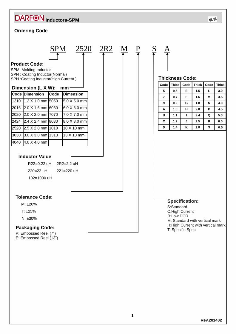
2 Rev.201402
Inductors-SPM Product Rang
Product Range
Molding Inductors (SPM Series)
Dimensions Hieght
(mm) (mm) max
SPM2016 2.0*1.6 1.0 0.24uH 2.2uH
SPM2520 2.5*2.0 1.2 0.47uH 2.2uH
SPM3030 3.0*3.0 1.2 0.47uH 10uH
SPM4040 4.0*4.0 1.2~2.0 0.1uH 10uH
SPM5050 5.0*5.0 1.2~3.0 0.1uH 15uH
SPM7070 7.0*7.0 1.2~5.0 0.1uH 10uH
SPM1010 10.0*10.0 4.0 0.36uH 68uH
SPM1313 13.0*13.0 5.0~6.0 0.15uH 150uH
DARFON ItemInductance range
0.1uH 1uH 10uH 100uH 1mH

3 Rev.201402
Inductors-SPM (Molding)
Molding Inductors (SPM Series)
▓Feature ▓Application 1. Magnetic shielded construction 2. Frequency range up to 3.0MHz 3. Higher rated current, capable handling at
high current spikes
-Notebook / Desktop applications -VGA card applications -DC-DC Converter applications -Low profile, high current power supplies
▓Standard External Dimensions
Series L
(mm) W
(mm) H
(mm) B
(mm)
Recommended Land Patterns
Package
A' (mm)
B (mm)
E (mm)
Reel Amount(pcs)
SPM2016□□□□PTA 2.0±0.1 1.6±0.1 1.0max 0.5±0.3 0.8 2.05 1.65 7” 3,000
SPM2520□□□□PTC 2.5±0.2 2.0±0.2 1.2max 0.5±0.3 1.2 2.8 2.0 7” 3,000
Series L
(mm) W
(mm) H
(mm) C
(mm) D
(mm)
Recommended Land Patterns
Package
A' (mm)
B (mm)
E (mm)
Reel Amount(pcs)
SPM3030□□□□PSC 3.2±0.2 3.0±0.2 1.2max 0.8±0.2 1.2±0.2 1.2 4.2 2.0 7” 2,000
SPM4040□□□□ESC 4.7±0.3 4.2±0.2 1.2max 0.8±0.3 2.0±0.3 2.4 5.4 2.5 13” 3,500
SPM4040□□□□ESH 4.7±0.3 4.2±0.2 2.0max 0.8±0.3 2.0±0.3 2.4 5.4 2.5 13” 2,000
SPM5050□□□□ESC 5.7±0.3 5.2±0.2 1.2max 1.0±0.3 2.5±0.3 3.0 7.0 3.5 13” 3,000
SPM5050□□□□ESE 5.7±0.3 5.2±0.2 1.5max 1.0±0.3 2.5±0.3 3.0 7.0 3.5 13” 3,000
SPM5050□□□□ESH 5.7±0.3 5.2±0.2 2.0max 1.0±0.3 2.5±0.3 3.0 7.0 3.5 13” 3,000
SPM5050□□□□ESL 5.7±0.3 5.2±0.2 3.0max 1.0±0.3 2.5±0.3 3.0 7.0 3.5 13” 2,000
SPM7070□□□□ESC 7.2±0.3 6.6±0.2 1.2max 1.5±0.3 3.0±0.3 4.0 8.5 3.5 13” 2,500
SPM7070□□□□ESE 7.0±0.3 6.5±0.2 1.5max 1.5±0.3 3.0±0.3 4.0 8.5 3.5 13” 2,000
SPM7070□□□□ESG 7.2±0.3 6.6±0.2 1.8max 1.5±0.3 3.0±0.3 4.0 8.5 3.5 13” 2,000
SPM7070□□□□ESL 6.95±0.35 6.6±0.2 3.0max 1.5±0.3 3.0±0.3 4.0 8.5 3.5 13” 1,500
SPM7070□□□□ERL 6.95±0.35 6.6±0.2 3.0max 1.5±0.3 3.0±0.3 4.0 8.5 3.5 13” 1,500
SPM7070□□□□ESQ 7.2±0.3 6.6±0.2 5.0max 1.5±0.3 3.0±0.3 4.0 8.5 3.5 13 1,000
SPM1010□□□□ESN 11.2±0.3 10.0±0.3 4.0max 2.0±0.5 3.0±0.5 5.5 13.5 4.0 13” 800
SPM1313□□□□ESQ 13.9±0.3 12.8±0.2 5.0max 2.0±0.5 5.0±0.5 8.0 14.5 6.0 13” 500
SPM1313□□□□ESR 13.9±0.3 12.8±0.2 6.0max 2.0±0.5 5.0±0.5 8.0 14.5 6.0 13” 500
1R0
4 Rev.201402
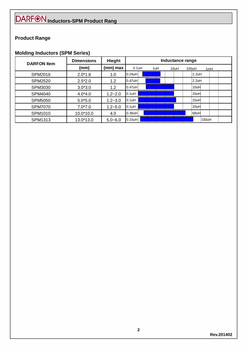
Inductors-SPM (Molding)
▓Part Numbers & Characteristics
SPM2016□□□□PTA (Thickness 1.0mm)
DARFON P/N Inductance
(uH)
Tolerance
DC Resistance (mΩ)
Heat Rating Current
DC Amps
Saturation Current
DC Amps Measuring Condition
Typ. Max. Idc(A) Typ. Isat(A) Typ.
SPM2016R24MPTA 0.24
± 20%
33 42 3.30 5.00
1MHz/1.0V
SPM2016R47MPTA 0.47 38 46 3.20 3.70
SPM2016R68MPTA 0.68 54 65 2.70 2.70
SPM20161R0MPTA 1.0 60 75 2.65 2.65
SPM20162R2MPTA 2.2 131 160 1.75 1.75
SPM2520□□□□PTC (Thickness 1.2mm)
DARFON P/N Inductance
(uH)
Tolerance
DC Resistance (mΩ)
Heat Rating Current
DC Amps
Saturation Current
DC Amps Measuring Condition
Typ. Max. Idc(A) Typ. Isat(A) Typ.
SPM2520R47MPTC 0.47
± 20%
30 39 3.90 4.80
1MHz/1.0V
SPM2520R68MPTC 0.68 36 47 3.40 3.70
SPM25201R0MPTC 1.0 45 59 3.10 3.60
SPM25202R2MPTC 2.2 90 117 2.20 2.40
SPM25203R3MPTC 3.3 120 156 1.90 2.10
SPM4040□□□□ESC (Thickness 1.2mm)
DARFON P/N Inductance
(uH)
Tolerance
DC Resistance (mΩ)
Heat Rating Current
DC Amps
Saturation Current
DC Amps Measuring Condition
Typ. Max. Idc(A) Typ. Isat(A) Typ.
SPM4040R47MESC 0.47
± 20%
19.0 21.0 6.00 6.80
100KHz/1.0V
SPM4040R68MESC 0.68 32.0 36.0 4.50 6.00
SPM40401R0MESC 1.0 43.0 47.0 4.20 5.20
SPM40401R5MESC 1.5 68.0 75.0 3.25 4.00
SPM40402R2MESC 2.2 79.4 83.5 2.75 3.50
SPM40403R3MESC 3.3 120.0 138.0 2.30 3.00
SPM40404R7MESC 4.7 175.0 195.0 1.80 2.80
SPM40406R8MESC 6.8 292.0 358.0 1.50 2.20
SPM4040100MESC 10 394.0 465.0 1.30 1.80
All test data are referenced to 25℃ambient.
※Isat: DC current(A) that will cause inductance to drop approximately 30%.
※Idc: DC current(A) that will cause an approximate △T of 40℃.

5 Rev.201402
Inductors-SPM (Molding)
SPM4040□□□□ESH (Thickness 2.0mm)
DARFON P/N Inductance
(uH)
Tolerance
DC Resistance (mΩ)
Heat Rating Current
DC Amps
Saturation Current
DC Amps Measuring Condition
Typ. Max. Idc(A) Typ. Isat(A) Typ.
SPM4040R22MESH 0.22
± 20%
6.0 6.6 9.00 12.50
100KHz/1.0V
SPM4040R47MESH 0.47 12.5 14.0 7.00 9.50
SPM4040R56MESH 0.56 14.0 16.0 6.50 9.00
SPM4040R68MESH 0.68 19.4 21.0 5.20 8.00
SPM40401R0MESH 1.0 24.0 27.0 4.50 7.00
SPM40401R5MESH 1.5 38.0 46.0 4.00 6.00
SPM40402R2MESH 2.2 52.0 58.0 3.00 5.00
SPM40403R3MESH 3.3 74.0 87.0 2.50 4.00
SPM40404R7MESH 4.7 92.0 105.0 2.20 3.00
SPM40406R8MESH 6.8 162.0 178.0 2.00 2.10
SPM4040100MESH 10 256.0 282.0 1.80 2.20
SPM5050□□□□ESC (Thickness 1.2mm)
DARFON P/N Inductance
(uH)
Tolerance
DC Resistance (mΩ)
Heat Rating Current
DC Amps
Saturation Current
DC Amps Measuring Condition
Typ. Max. Idc(A) Typ. Isat(A) Typ.
SPM50501R0MESC 1.0
± 20%
31.3 32.9 5.00 6.00
100KHz/1.0V
SPM50502R2MESC 2.2 67.0 76.0 3.50 4.00
SPM50503R3MESC 3.3 85.0 98.0 3.00 3.70
SPM50504R7MESC 4.7 145.0 163.0 2.30 2.70
SPM50506R8MESC 6.8 225.0 250.0 2.00 2.30
SPM5050□□□□ESE (Thickness 1.5mm)
DARFON P/N Inductance
(uH)
Tolerance
DC Resistance (mΩ)
Heat Rating Current
DC Amps
Saturation Current
DC Amps Measuring Condition
Typ. Max. Idc(A) Typ. Isat(A) Typ.
SPM50501R0MESE 1.0
± 20%
20.0 23.0 6.50 9.00
100KHz/1.0V
SPM50501R2MESE 1.2 22.5 26.0 6.00 8.00
SPM50502R2MESE 2.2 58.0 64.0 3.30 6.00
SPM50503R3MESE 3.3 65.0 72.0 3.20 5.00
SPM50504R7MESE 4.7 103.0 115.0 3.00 4.00
SPM50506R8MESE 6.8 167.0 180.0 2.50 3.20
SPM5050100MESE 10 220.0 246.0 2.00 3.00
All test data are referenced to 25℃ambient.
※Isat: DC current(A) that will cause inductance to drop approximately 30%.
※Idc: DC current(A) that will cause an approximate △T of 40℃.
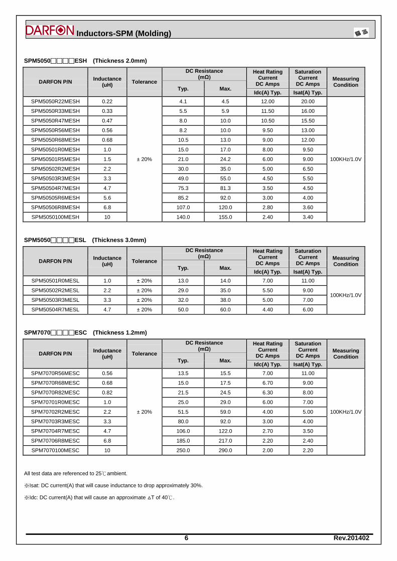
6 Rev.201402
Inductors-SPM (Molding)
SPM5050□□□□ESH (Thickness 2.0mm)
DARFON P/N Inductance
(uH)
Tolerance
DC Resistance (mΩ)
Heat Rating Current
DC Amps
Saturation Current
DC Amps Measuring Condition
Typ. Max. Idc(A) Typ. Isat(A) Typ.
SPM5050R22MESH 0.22
± 20%
4.1 4.5 12.00 20.00
100KHz/1.0V
SPM5050R33MESH 0.33 5.5 5.9 11.50 16.00
SPM5050R47MESH 0.47 8.0 10.0 10.50 15.50
SPM5050R56MESH 0.56 8.2 10.0 9.50 13.00
SPM5050R68MESH 0.68 10.5 13.0 9.00 12.00
SPM50501R0MESH 1.0 15.0 17.0 8.00 9.50
SPM50501R5MESH 1.5 21.0 24.2 6.00 9.00
SPM50502R2MESH 2.2 30.0 35.0 5.00 6.50
SPM50503R3MESH 3.3 49.0 55.0 4.50 5.50
SPM50504R7MESH 4.7 75.3 81.3 3.50 4.50
SPM50505R6MESH 5.6 85.2 92.0 3.00 4.00
SPM50506R8MESH 6.8 107.0 120.0 2.80 3.60
SPM5050100MESH 10 140.0 155.0 2.40 3.40
SPM5050□□□□ESL (Thickness 3.0mm)
DARFON P/N Inductance
(uH)
Tolerance
DC Resistance (mΩ)
Heat Rating Current
DC Amps
Saturation Current
DC Amps Measuring Condition
Typ. Max. Idc(A) Typ. Isat(A) Typ.
SPM50501R0MESL 1.0 ± 20% 13.0 14.0 7.00 11.00
100KHz/1.0V SPM50502R2MESL 2.2 ± 20% 29.0 35.0 5.50 9.00
SPM50503R3MESL 3.3 ± 20% 32.0 38.0 5.00 7.00
SPM50504R7MESL 4.7 ± 20% 50.0 60.0 4.40 6.00
SPM7070□□□□ESC (Thickness 1.2mm)
DARFON P/N Inductance
(uH)
Tolerance
DC Resistance (mΩ)
Heat Rating Current
DC Amps
Saturation Current
DC Amps Measuring Condition
Typ. Max. Idc(A) Typ. Isat(A) Typ.
SPM7070R56MESC 0.56
± 20%
13.5 15.5 7.00 11.00
100KHz/1.0V
SPM7070R68MESC 0.68 15.0 17.5 6.70 9.00
SPM7070R82MESC 0.82 21.5 24.5 6.30 8.00
SPM70701R0MESC 1.0 25.0 29.0 6.00 7.00
SPM70702R2MESC 2.2 51.5 59.0 4.00 5.00
SPM70703R3MESC 3.3 80.0 92.0 3.00 4.00
SPM70704R7MESC 4.7 106.0 122.0 2.70 3.50
SPM70706R8MESC 6.8 185.0 217.0 2.20 2.40
SPM7070100MESC 10 250.0 290.0 2.00 2.20
All test data are referenced to 25℃ambient.
※Isat: DC current(A) that will cause inductance to drop approximately 30%.
※Idc: DC current(A) that will cause an approximate △T of 40℃.

7 Rev.201402
Inductors-SPM (Molding)
SPM7070□□□□ESD (Thickness 1.4mm)
DARFON P/N Inductance
(uH)
Tolerance
DC Resistance (mΩ)
Heat Rating Current
DC Amps
Saturation Current
DC Amps Measuring Condition
Typ. Max. Idc(A) Typ. Isat(A) Typ.
SPM70706R8MESD 6.8 ± 20% 189.0 217.0 2.20 2.50 100KHz/1.0V
SPM7070□□□□ESE (Thickness 1.5mm)
DARFON P/N Inductance
(uH)
Tolerance
DC Resistance (mΩ)
Heat Rating Current
DC Amps
Saturation Current
DC Amps Measuring Condition
Typ. Max. Idc(A) Typ. Isat(A) Typ.
SPM7070R33MESE 0.33
± 20%
6.8 7.8 10.00 19.50
100KHz/1.0V
SPM7070R56MESE 0.56 9.5 11.0 9.00 14.00
SPM7070R68MESE 0.68 10.5 12.0 8.50 12.00
SPM7070R82MESE 0.82 15.0 17.0 7.00 10.00
SPM70701R0MESE 1.0 18.5 21.0 5.50 9.00
SPM70701R5MESE 1.5 37.0 42.5 5.00 7.00
SPM70702R2MESE 2.2 46.0 54.0 3.50 6.00
SPM70703R3MESE 3.3 54.0 63.0 3.30 5.50
SPM70704R7MESE 4.7 76.0 85.0 3.00 5.00
SPM70705R6MESE 5.6 96.0 118.0 2.80 4.50
SPM70706R8MESE 6.8 125.0 135.0 2.50 4.00
SPM7070100MESE 10 165.0 175.0 2.00 3.00
SPM7070□□□□ESG (Thickness 1.8mm)
DARFON P/N Inductance
(uH)
Tolerance
DC Resistance (mΩ)
Heat Rating Current
DC Amps
Saturation Current
DC Amps Measuring Condition
Typ. Max. Idc(A) Typ. Isat(A) Typ.
SPM7070R33MESG 0.33
± 20%
5.2 6.8 12.00 22.00
100KHz/1.0V
SPM7070R47MESG 0.47 7.3 8.4 11.00 17.00
SPM7070R68MESG 0.68 10.8 12.7 9.00 16.00
SPM7070R82MESG 0.82 13.4 15.9 8.00 14.00
SPM70701R0MESG 1.0 14.5 17.0 7.00 12.00
SPM70702R2MESG 2.2 31.0 35.0 5.00 8.00
SPM70703R3MESG 3.3 56.0 60.0 3.50 7.00
SPM70704R7MESG 4.7 68.0 70.0 3.20 5.50
SPM70706R8MESG 6.8 101.0 110.0 2.80 4.50
SPM70708R2MESG 8.2 124.0 142.0 2.50 4.00
SPM7070100MESG 10 155.0 166.0 2.00 3.00
All test data are referenced to 25℃ambient.
※Isat: DC current(A) that will cause inductance to drop approximately 30%.
※Idc: DC current(A) that will cause an approximate △T of 40℃.
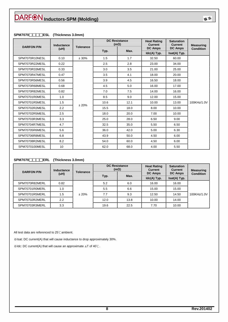
8 Rev.201402
Inductors-SPM (Molding)
SPM7070□□□□ESL (Thickness 3.0mm)
DARFON P/N Inductance
(uH)
Tolerance
DC Resistance (mΩ)
Heat Rating Current
DC Amps
Saturation Current
DC Amps Measuring Condition
Typ. Max. Idc(A) Typ. Isat(A) Typ.
SPM7070R10NESL 0.10 ± 30% 1.5 1.7 32.50 60.00
100KHz/1.0V
SPM7070R22MESL 0.22
± 20%
2.5 2.8 23.00 34.00
SPM7070R33MESL 0.33 3.0 3.5 21.00 25.00
SPM7070R47MESL 0.47 3.5 4.1 18.00 20.00
SPM7070R56MESL 0.56 3.9 4.5 16.50 18.00
SPM7070R68MESL 0.68 4.5 5.0 16.00 17.00
SPM7070R82MESL 0.82 7.0 7.5 14.00 16.00
SPM70701R0MESL 1.0 8.5 9.0 12.00 15.00
SPM70701R5MESL 1.5 10.6 12.1 10.00 13.00
SPM70702R2MESL 2.2 15.5 18.0 8.00 10.00
SPM70702R5MESL 2.5 18.0 20.0 7.00 10.00
SPM70703R3MESL 3.3 25.0 28.0 6.50 9.00
SPM70704R7MESL 4.7 32.5 35.0 5.50 6.50
SPM70705R6MESL 5.6 36.0 42.0 5.00 6.30
SPM70706R8MESL 6.8 43.9 50.0 4.50 6.00
SPM70708R2MESL 8.2 54.0 60.0 4.50 6.00
SPM7070100MESL 10 62.0 68.0 4.00 5.50
SPM7070□□□□ERL (Thickness 3.0mm)
DARFON P/N Inductance
(uH)
Tolerance
DC Resistance (mΩ)
Heat Rating Current
DC Amps
Saturation Current
DC Amps Measuring Condition
Typ. Max. Idc(A) Typ. Isat(A) Typ.
SPM7070R82MERL 0.82
± 20%
5.2 6.0 16.00 16.00
100KHz/1.0V
SPM70701R0MERL 1.0 5.5 6.6 15.00 15.00
SPM70701R5MERL 1.5 7.7 9.3 12.50 14.50
SPM70702R2MERL 2.2 12.0 13.8 10.00 14.00
SPM70703R3MERL 3.3 19.6 22.5 7.70 10.00
All test data are referenced to 25℃ambient.
※Isat: DC current(A) that will cause inductance to drop approximately 30%.
※Idc: DC current(A) that will cause an approximate △T of 40℃.

9 Rev.201402
Inductors-SPM (Molding)
SPM7070□□□□ESQ (Thickness 5.0mm)
DARFON P/N Inductance
(uH)
Tolerance
DC Resistance (mΩ)
Heat Rating Current
DC Amps
Saturation Current
DC Amps Measuring Condition
Typ. Max. Idc(A) Typ. Isat(A) Typ.
SPM7070R68MESQ 0.68
± 20%
3.3 3.6 18.00 17.00
100KHz/1.0V
SPM7070R82MESQ 0.82 4.6 4.9 16.50 17.00
SPM70701R0MESQ 1.0 4.5 5.3 14.50 16.00
SPM70701R5MESQ 1.5 6.0 7.5 11.50 15.00
SPM70702R2MESQ 2.2 9.0 10.2 10.50 13.50
SPM70703R3MESQ 3.3 14.0 15.0 9.00 12.00
SPM70704R7MESQ 4.7 23.0 25.0 6.50 8.00
SPM70705R6MESQ 5.6 31.5 34.4 6.00 7.00
SPM70706R8MESQ 6.8 31.0 35.5 5.50 6.50
SPM70708R2MESQ 8.2 40.0 43.0 5.00 5.50
SPM7070100MESQ 10 48.0 55.0 4.50 5.00
SPM1010□□□□ESN (Thickness 4.0mm)
DARFON P/N Inductance
(uH)
Tolerance
DC Resistance (mΩ)
Heat Rating Current
DC Amps
Saturation Current
DC Amps Measuring Condition
Typ. Max. Idc(A) Typ. Isat(A) Typ.
SPM10102R2MESN 2.2
± 20%
6.0 7.0 12.00 18.00
100KHz/1.0V
SPM10103R3MESN 3.3 10.8 11.8 10.00 16.00
SPM10104R7MESN 4.7 17.0 20.0 8.50 15.00
SPM10105R6MESN 5.6 20.0 23.0 8.00 14.00
SPM10106R8MESN 6.8 22.5 25.0 7.00 12.00
SPM10108R2MESN 8.2 25.0 27.0 6.50 9.00
SPM1010100MESN 10 27.0 30.0 6.50 8.50
SPM1010150MESN 15 40.0 45.0 6.30 7.00
SPM1010220MESN 22 60.0 66.0 5.00 5.50
SPM1010330MESN 33 85.0 92.0 4.00 4.50
SPM1010470MESN 47 130.0 145.0 3.30 3.50
All test data are referenced to 25℃ambient.
※Isat: DC current(A) that will cause inductance to drop approximately 30%.
※Idc: DC current(A) that will cause an approximate △T of 40℃.
10 Rev.201402
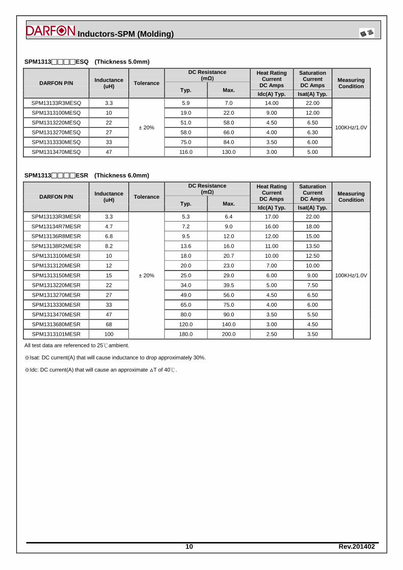
Inductors-SPM (Molding)
SPM1313□□□□ESQ (Thickness 5.0mm)
DARFON P/N Inductance
(uH)
Tolerance
DC Resistance (mΩ)
Heat Rating Current
DC Amps
Saturation Current
DC Amps Measuring Condition
Typ. Max. Idc(A) Typ. Isat(A) Typ.
SPM13133R3MESQ 3.3
± 20%
5.9 7.0 14.00 22.00
100KHz/1.0V
SPM1313100MESQ 10 19.0 22.0 9.00 12.00
SPM1313220MESQ 22 51.0 58.0 4.50 6.50
SPM1313270MESQ 27 58.0 66.0 4.00 6.30
SPM1313330MESQ 33 75.0 84.0 3.50 6.00
SPM1313470MESQ 47 116.0 130.0 3.00 5.00
SPM1313□□□□ESR (Thickness 6.0mm)
DARFON P/N Inductance
(uH)
Tolerance
DC Resistance (mΩ)
Heat Rating Current
DC Amps
Saturation Current
DC Amps Measuring Condition
Typ. Max. Idc(A) Typ. Isat(A) Typ.
SPM13133R3MESR 3.3
± 20%
5.3 6.4 17.00 22.00
100KHz/1.0V
SPM13134R7MESR 4.7 7.2 9.0 16.00 18.00
SPM13136R8MESR 6.8 9.5 12.0 12.00 15.00
SPM13138R2MESR 8.2 13.6 16.0 11.00 13.50
SPM1313100MESR 10 18.0 20.7 10.00 12.50
SPM1313120MESR 12 20.0 23.0 7.00 10.00
SPM1313150MESR 15 25.0 29.0 6.00 9.00
SPM1313220MESR 22 34.0 39.5 5.00 7.50
SPM1313270MESR 27 49.0 56.0 4.50 6.50
SPM1313330MESR 33 65.0 75.0 4.00 6.00
SPM1313470MESR 47 80.0 90.0 3.50 5.50
SPM1313680MESR 68 120.0 140.0 3.00 4.50
SPM1313101MESR 100 180.0 200.0 2.50 3.50
All test data are referenced to 25℃ambient.
※Isat: DC current(A) that will cause inductance to drop approximately 30%.
※Idc: DC current(A) that will cause an approximate △T of 40℃.
11 Rev.201402
Inductors-SPM (Molding)
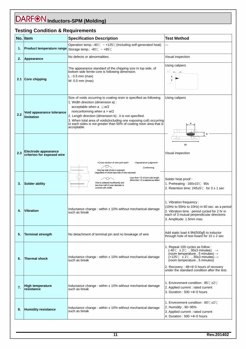
Testing Condition & Requirements
No. Item Specification Description Test Method
1. Product temperature range Operation temp.:-40℃ ~ +125℃(Including self-generated heat)
Storage temp.: -40℃ ~ +85℃
---
2. Appearance No defects or abnormalities. Visual inspection
2.1 Core chipping
The appearance standard of the chipping size in top side, of bottom side ferrite core is following dimension.
L : 0.5 mm (max)
W: 0.5 mm (max)
Using calipers
2.2 Void appearance tolerance
limitation
Size of voids occurring to coating resin is specified as following.
1. Width direction (dimension a) :
acceptable when a ≦w/2
nonconforming when a > w/2
2. Length direction (dimension b) : it is not specified.
3. When total area of voids(including one exposing coil) occurring to each sides is not greater than 50% of coating resin area that is acceptable
Using calipers
2.3 Electrode appearance criterion for exposed wire
Visual inspection
3. Solder ability The surface of terminal immersed shall be minimum of 90% covered with a new coating of solder
Solder heat proof :
1. Preheating : 160±10℃ 90s
2. Retention time: 245±5℃ for 3 ± 1 sec
4. Vibration Inductance change : within ± 10% without mechanical damage such as break
1. Vibration frequency :
(10Hz to 55Hz to 10Hz) in 60 sec. as a period
2. Vibration time : period cycled for 2 hr in each of 3 mutual perpendicular directions
3. Amplitude: 1.5mm max.
5. Terminal strength No detachment of terminal pin and no breakage of wire Add static load 4.9N(500gf) to inductor through hole of test board for 10 ± 2 sec
6. Thermal shock Inductance change : within ± 10% without mechanical damage such as break
1. Repeat 100 cycles as follow :
(-40℃ ± 2℃ , 30±3 minutes) → (room temperature , 5 minutes) → (+125℃ ± 2℃ , 30±3 minutes) → (room temperature , 5 minutes)
2. Recovery : 48+4/-0 hours of recovery under the standard condition after the test.
7. High temperature resistance
Inductance change : within ± 10% without mechanical damage such as break
1. Environment condition : 85℃±2℃
2. Applied current : rated current
3. Duration : 500 +4/-0 hours
8. Humidity resistance Inductance change : within ± 10% without mechanical damage such as break
1. Environment condition : 60℃±2℃
2. Humidity : 90~95%
3. Applied current : rated current
4. Duration : 500 +4/-0 hours
12 Rev.201402
Inductors-SPM (Molding)
No. Item Specification Description Test Method
9. Low temperature storage Inductance change : within ± 10% without mechanical damage such as break
Store temperature :
-40℃ ± 2℃ for total
500 +4/-0 hours
10. High temperature storage Inductance change : within ± 10% without mechanical damage such as break
Store temperature :
+125℃ ± 2℃ for total
500 +4/-0 hours
11 Inductance
a. Temperature: 25+/- 3℃
b. Relative Humidity: 45 to 75%RH c. Measuring equipment:
Current measure :Chroma 3302 + Chroma 1320
Within specified tolerance.
12 DC Resistance Measuring instrument: Chroma A165022 In accordance with electrical specification.
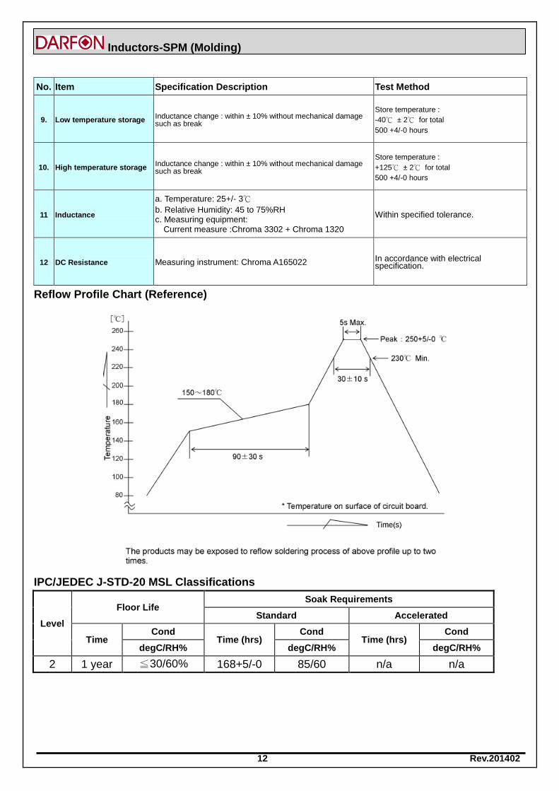
Reflow Profile Chart (Reference)
IPC/JEDEC J-STD-20 MSL Classifications
Level
Floor Life Soak Requirements
Standard Accelerated
Time Cond
Time (hrs) Cond
Time (hrs) Cond
degC/RH% degC/RH% degC/RH%
2 1 year ≦30/60% 168+5/-0 85/60 n/a n/a
13 Rev.201402
Inductors-SPM (Molding)
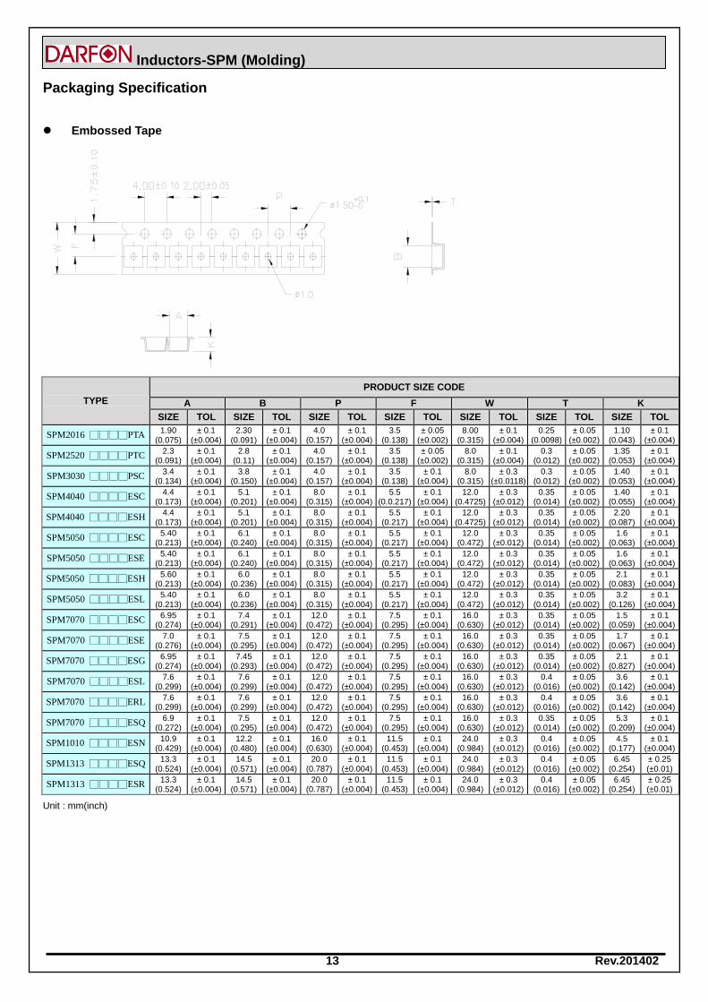
Packaging Specification
Embossed Tape
TYPE
PRODUCT SIZE CODE
A B P F W T K
SIZE TOL SIZE TOL SIZE TOL SIZE TOL SIZE TOL SIZE TOL SIZE TOL
SPM2016 □□□□PTA 1.90
(0.075) ± 0.1
(±0.004) 2.30
(0.091) ± 0.1
(±0.004) 4.0
(0.157) ± 0.1
(±0.004) 3.5
(0.138) ± 0.05
(±0.002) 8.00
(0.315) ± 0.1
(±0.004) 0.25
(0.0098) ± 0.05
(±0.002) 1.10
(0.043) ± 0.1
(±0.004)
SPM2520 □□□□PTC 2.3
(0.091) ± 0.1
(±0.004) 2.8
(0.11) ± 0.1
(±0.004) 4.0
(0.157) ± 0.1
(±0.004) 3.5
(0.138) ± 0.05
(±0.002) 8.0
(0.315) ± 0.1
(±0.004) 0.3
(0.012) ± 0.05
(±0.002) 1.35
(0.053) ± 0.1
(±0.004)
SPM3030 □□□□PSC 3.4
(0.134) ± 0.1
(±0.004) 3.8
(0.150) ± 0.1
(±0.004) 4.0
(0.157) ± 0.1
(±0.004) 3.5
(0.138) ± 0.1
(±0.004) 8.0
(0.315) ± 0.3
(±0.0118) 0.3
(0.012) ± 0.05
(±0.002) 1.40
(0.053) ± 0.1
(±0.004)
SPM4040 □□□□ESC 4.4
(0.173) ± 0.1
(±0.004) 5.1
(0.201) ± 0.1
(±0.004) 8.0
(0.315) ± 0.1
(±0.004) 5.5
(0.0.217) ± 0.1
(±0.004) 12.0
(0.4725) ± 0.3
(±0.012) 0.35
(0.014) ± 0.05
(±0.002) 1.40
(0.055) ± 0.1
(±0.004)
SPM4040 □□□□ESH 4.4
(0.173) ± 0.1
(±0.004) 5.1
(0.201) ± 0.1
(±0.004) 8.0
(0.315) ± 0.1
(±0.004) 5.5
(0.217) ± 0.1
(±0.004) 12.0
(0.4725) ± 0.3
(±0.012) 0.35
(0.014) ± 0.05
(±0.002) 2.20
(0.087) ± 0.1
(±0.004)
SPM5050 □□□□ESC 5.40
(0.213) ± 0.1
(±0.004) 6.1
(0.240) ± 0.1
(±0.004) 8.0
(0.315) ± 0.1
(±0.004) 5.5
(0.217) ± 0.1
(±0.004) 12.0
(0.472) ± 0.3
(±0.012) 0.35
(0.014) ± 0.05
(±0.002) 1.6
(0.063) ± 0.1
(±0.004)
SPM5050 □□□□ESE 5.40
(0.213) ± 0.1
(±0.004) 6.1
(0.240) ± 0.1
(±0.004) 8.0
(0.315) ± 0.1
(±0.004) 5.5
(0.217) ± 0.1
(±0.004) 12.0
(0.472) ± 0.3
(±0.012) 0.35
(0.014) ± 0.05
(±0.002) 1.6
(0.063) ± 0.1
(±0.004)
SPM5050 □□□□ESH 5.60
(0.213) ± 0.1
(±0.004) 6.0
(0.236) ± 0.1
(±0.004) 8.0
(0.315) ± 0.1
(±0.004) 5.5
(0.217) ± 0.1
(±0.004) 12.0
(0.472) ± 0.3
(±0.012) 0.35
(0.014) ± 0.05
(±0.002) 2.1
(0.083) ± 0.1
(±0.004)
SPM5050 □□□□ESL 5.40
(0.213) ± 0.1
(±0.004) 6.0
(0.236) ± 0.1
(±0.004) 8.0
(0.315) ± 0.1
(±0.004) 5.5
(0.217) ± 0.1
(±0.004) 12.0
(0.472) ± 0.3
(±0.012) 0.35
(0.014) ± 0.05
(±0.002) 3.2
(0.126) ± 0.1
(±0.004)
SPM7070 □□□□ESC 6.95
(0.274) ± 0.1
(±0.004) 7.4
(0.291) ± 0.1
(±0.004) 12.0
(0.472) ± 0.1
(±0.004) 7.5
(0.295) ± 0.1
(±0.004) 16.0
(0.630) ± 0.3
(±0.012) 0.35
(0.014) ± 0.05
(±0.002) 1.5
(0.059) ± 0.1
(±0.004)
SPM7070 □□□□ESE 7.0
(0.276) ± 0.1
(±0.004) 7.5
(0.295) ± 0.1
(±0.004) 12.0
(0.472) ± 0.1
(±0.004) 7.5
(0.295) ± 0.1
(±0.004) 16.0
(0.630) ± 0.3
(±0.012) 0.35
(0.014) ± 0.05
(±0.002) 1.7
(0.067) ± 0.1
(±0.004)
SPM7070 □□□□ESG 6.95
(0.274) ± 0.1
(±0.004) 7.45
(0.293) ± 0.1
(±0.004) 12.0
(0.472) ± 0.1
(±0.004) 7.5
(0.295) ± 0.1
(±0.004) 16.0
(0.630) ± 0.3
(±0.012) 0.35
(0.014) ± 0.05
(±0.002) 2.1
(0.827) ± 0.1
(±0.004)
SPM7070 □□□□ESL 7.6
(0.299) ± 0.1
(±0.004) 7.6
(0.299) ± 0.1
(±0.004) 12.0
(0.472) ± 0.1
(±0.004) 7.5
(0.295) ± 0.1
(±0.004) 16.0
(0.630) ± 0.3
(±0.012) 0.4
(0.016) ± 0.05
(±0.002) 3.6
(0.142) ± 0.1
(±0.004)
SPM7070 □□□□ERL 7.6
(0.299) ± 0.1
(±0.004) 7.6
(0.299) ± 0.1
(±0.004) 12.0
(0.472) ± 0.1
(±0.004) 7.5
(0.295) ± 0.1
(±0.004) 16.0
(0.630) ± 0.3
(±0.012) 0.4
(0.016) ± 0.05
(±0.002) 3.6
(0.142) ± 0.1
(±0.004)
SPM7070 □□□□ESQ 6.9
(0.272) ± 0.1
(±0.004) 7.5
(0.295) ± 0.1
(±0.004) 12.0
(0.472) ± 0.1
(±0.004) 7.5
(0.295) ± 0.1
(±0.004) 16.0
(0.630) ± 0.3
(±0.012) 0.35
(0.014) ± 0.05
(±0.002) 5.3
(0.209) ± 0.1
(±0.004)
SPM1010 □□□□ESN 10.9
(0.429) ± 0.1
(±0.004) 12.2
(0.480) ± 0.1
(±0.004) 16.0
(0.630) ± 0.1
(±0.004) 11.5
(0.453) ± 0.1
(±0.004) 24.0
(0.984) ± 0.3
(±0.012) 0.4
(0.016) ± 0.05
(±0.002) 4.5
(0.177) ± 0.1
(±0.004)
SPM1313 □□□□ESQ 13.3
(0.524) ± 0.1
(±0.004) 14.5
(0.571) ± 0.1
(±0.004) 20.0
(0.787) ± 0.1
(±0.004) 11.5
(0.453) ± 0.1
(±0.004) 24.0
(0.984) ± 0.3
(±0.012) 0.4
(0.016) ± 0.05
(±0.002) 6.45
(0.254) ± 0.25 (±0.01)
SPM1313 □□□□ESR 13.3
(0.524) ± 0.1
(±0.004) 14.5
(0.571) ± 0.1
(±0.004) 20.0
(0.787) ± 0.1
(±0.004) 11.5
(0.453) ± 0.1
(±0.004) 24.0
(0.984) ± 0.3
(±0.012) 0.4
(0.016) ± 0.05
(±0.002) 6.45
(0.254) ± 0.25 (±0.01)
Unit : mm(inch)
14 Rev.201402
Inductors-SPM (Molding)
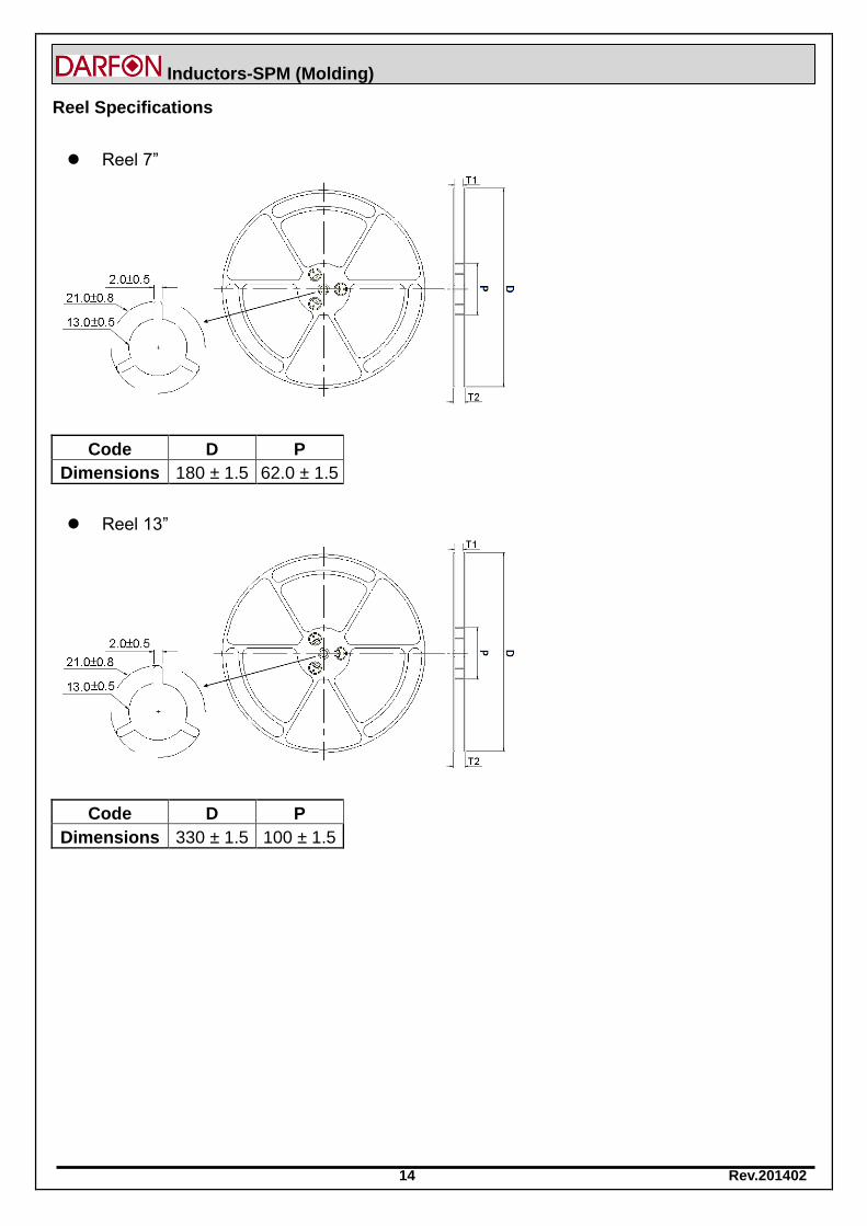
Reel Specifications
Reel 7”
Code D P
Dimensions 180 ± 1.5 62.0 ± 1.5
Reel 13”
Code D P
Dimensions 330 ± 1.5 100 ± 1.5
Related Documents