Model LVG-102, 103, 104 1 TECHNICAL MANUAL Henny Penny Split Vat & Full Vat Open Fryers – Gas Model LVG-102 Model LVG-103 Model LVG-104

Welcome message from author
This document is posted to help you gain knowledge. Please leave a comment to let me know what you think about it! Share it to your friends and learn new things together.
Transcript
Model LVG-102, 103, 104
1
TECHNICAL MANUAL
Henny Penny
Split Vat & Full VatOpen Fryers – Gas
Model LVG-102 Model LVG-103Model LVG-104
Model LVG-102, 103, 104
2
Model LVG-102, 103, 104
i
TABLE OF CONTENTS
Section Page
Section 1. TROUBLESHOOTING .............................................................................................. 1-1 1-1 Introduction .................................................................................................... 1-1 1-2 Safety .............................................................................................................. 1-1 1-3 Troubleshooting .............................................................................................. 1-2 1-4 Error Code Table ............................................................................................ 1-7
Section 2. INFO, FILTER & TEMP BUTTON STATS ............................................................... 2-1 2-1 INFO Button Stats .......................................................................................... 2-1 2-2 FILTER Button Stats ...................................................................................... 2-1 2-3 TEMP Button Stats ......................................................................................... 2-1 2-4 HP Info Mode ................................................................................................. 2-2 Section 3. LEVEL 1 PROGRAMMING ...................................................................................... 3-1 3-1 Modifying Product Settings ........................................................................... 3-1 3-2 AIF Clock ....................................................................................................... 3-3 3-3 Deep Clean Mode ........................................................................................... 3-4 3-4 Fryer Setup ..................................................................................................... 3-5
Section 4. LEVEL 2 PROGRAMMING ...................................................................................... 4-1 4-1 Advanced Product Settings ............................................................................ 4-1 4-2 E-Log (error code log) .................................................................................... 4-2 4-3 Passwords ....................................................................................................... 4-3 4-4 Alert Tone (and volume) ................................................................................ 4-3 4-5 Filter After ...................................................................................................... 4-4 4-6 Filter Time ...................................................................................................... 4-4
Section 5. LEVEL 3 PROGRAMMING ...................................................................................... 5-1 5-1 Additional Advanced Product Settings .......................................................... 5-1 5-2 Special Programming ..................................................................................... 5-2 5-3 Clock Set ........................................................................................................ 5-6 5-4 Data Comm & Heat Control ........................................................................... 5-6 5-5 Tech Mode ...................................................................................................... 5-7 5-6 Stats Mode ...................................................................................................... 5-12
Section 6. INFORMATION MODE ............................................................................................. 6-1 6-1 Info Mode ....................................................................................................... 6-1
Section 7. MAINTENANCE SECTION ...................................................................................... 7-1 7-1 Preventive Maintenance .................................................................................. 7-1 7-2 Oil Channel Clean-Out ................................................................................... 7-1 7-3 Control Panel and Menu Card Replacement .................................................. 7-2 7-4 High Temperature Limit Control .................................................................... 7-3 7-5 Main Power switch ......................................................................................... 7-5 7-6 Probe Replacement ......................................................................................... 7-6
FM06-040Revised 6-11-2015 AF
July 2010
Model LVG-102, 103, 104
ii
Section 7. MAINTENANCE SECTION (Continued) 7-7 Solenoid Valves .............................................................................................. 7-9 7-8 Drain Valve Actuators .................................................................................... 7-11 7-9 Filter Pump & Motor ...................................................................................... 7-12 7-10 AIF Pump ....................................................................................................... 7-14 7-11 AIF PC Board ................................................................................................. 7-14 7-12 Transformers .................................................................................................. 7-15 7-13 Filter Motor Relay .......................................................................................... 7-17 7-14 Gas Control Valves ......................................................................................... 7-17 7-15 Blower Motors ................................................................................................ 7-19 7-16 Drain Pan Switch ............................................................................................ 7-20 7-17 Filter & JIB Lights ......................................................................................... 7-21 7-18 Air Pressure Switches ..................................................................................... 7-22 7-19 Ignitor & Flame Sensor Assembly ................................................................. 7-23 7-20 Ignition Modules ............................................................................................ 7-24 7-21 Pressure Transducer ........................................................................................ 7-25
Section 8. PARTS SECTION 8-1 Introduction .................................................................................................... 8-1 8-2 Genuine Parts ................................................................................................. 8-1 8-3 When Ordering Parts ...................................................................................... 8-1 8-4 Prices .............................................................................................................. 8-1 8-5 Delivery .......................................................................................................... 8-1 8-6 Warranty ......................................................................................................... 8-1 8-7 Recommended Spare Parts for Distributors ................................................... 8-1
Apenndix A A-1 Wiring Diagrams & Scematics ....................................................................... A-1
TABLE OF CONTENTS
Section Page
July 2010
Model LVG-102, 103, 104
1-1
1-1. INTRODUCTION This section provides troubleshooting information in the form of an easy to read table.
Ifaproblemoccursduringthefirstoperationofanewfryer, recheck the installation per the Installation Section of the operator’s manual. Before troubleshooting, always recheck the operation pro- cedures per Section 3 of the operator’s manual.
SECTION 1. TROUBLESHOOTING
Where information is of particular importance or safety related, the words DANGER, WARNING, CAUTION, and NOTICE are used. Their usage is described below.
SAFETY ALERT SYMBOL is used with DANGER, WARNING, or CAUTION which indicates a personal injury type hazard.
NOTICE is used to highlight especially important information.
CAUTION used without the safety alert symbol indicates a potentially hazardous situation which, if not avoided, may result in property damage.
CAUTION indicates a potentially hazardous situation which, if not avoided, may result in minor or moderate injury.
WARNING indicates a potentially hazardous situation which, if not avoided, could result in death or serious injury.
DANGER INDICATES AN IMMINENTLY HAZARDOUS SITUATION WHICH, IF NOT AVOIDED, WILL RESULT IN DEATH OR SERIOUS INJURY.
1-2. SAFETY
Feb. 2010
Model LVG-102, 103, 104
1-2
1-3. TROUBLESHOOTING To isolate a malfunction, proceed as follows:
1. Clearlydefinetheproblem(orsymptom)andwhenit occurs.
2. Locate the problem in the Troubleshooting table.
3. Review all possible causes. Then, one-at-a-time work through the list of corrections until the problem is solved.
4. Refer to the maintenance procedures in the Maintenance Section to safely and properly make the checkout and repair needed.
If maintenance procedures are not followed correctly, injuries and/or property damage could result.
Feb. 2010
Model LVG-102, 103, 104
1-3
Problem Cause Correction
POWER SECTION
With power switch in • Open circuit • Check to see that unit is plugged in ON position, the fryer is completely inoperative • Check the breaker or fuse (NO POWER) at supply box • Check voltage at wall receptacle • Check MAIN POWER switch; replace if defective • Check cord and plug
• Reset transformer circuit breaker
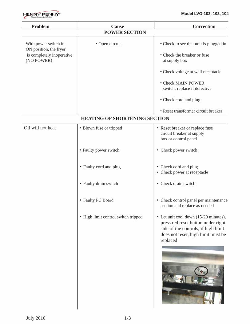
• Blown fuse or tripped • Reset breaker or replace fuse circuit breaker at supply box or control panel • Faulty power switch. • Check power switch • Faulty cord and plug • Check cord and plug • Check power at receptacle • Faulty drain switch • Check drain switch • Faulty PC Board • Check control panel per maintenance section and replace as needed • High limit control switch tripped • Let unit cool down (15-20 minutes), press red reset button under right side of the controls; if high limit does not reset, high limit must be replaced
HEATING OF SHORTENING SECTION
Oil will not heat
July 2010
Model LVG-102, 103, 104
1-4
Problem Cause Correction
HEATING OF SHORTENING SECTION (Continued)
• Drain valve open • Close drain valve (Continued) • Faulty temperature probe • Replace temperature probe
• Faulty gas valve • Check gas valve
Oil heating too slow • Low gas pressure • Have gas pressure checked
• Wire(s) loose • Tighten
• Burnt or charred wire • Replace wire and clean connection connectors
Oil overheating • Programming wrong • Check temperature setting in the program mode • Faulty PC board • Replace control board if heat indicator stays on past ready temperature • Faulty temperature probe • Check probe calibration and replace if temperature is off + 5 degress
• Faulty gas valve • Check gas valve
Oil will not heat
July 2008
Model LVG-102, 103, 104
1-5
Problem Cause Correction
OIL LEVEL SECTION
Oil foaming or boiling over vat • Water in oil • At end of a Cook Cycle, drain and clean vat; add fresh oil • Improper or bad oil • Use recommended oil •Improperfiltering •Refertotheprocedure onfilteringtheoil • Cold zone (bottom of vat) • Filter oil full of crumbs • Improper rinsing after • Rinse the vat thoroughly to remove cleaning the fryer any cleaning agent in the vat Oil will not drain from vat • Drain valve clogged with • Open valve, using cleaning brush, force crumbs through drain valve
• Faulty actuator • Replace actuator
• Oil channel clogged • Access the clean-out plug on the sides of the unit (see Oil Channel Clean-out Section)
Oil leaking • Obstruction in drain • Remove obstruction through drain valve • Faulty drain valve • Replace drain valve
Vatisunder-filled •LocationswithRTI,the •TheRTIsystemcanbediscon- 3-way valve is stuck open nected until RTI repairs the valve
• JIB is low or empty • Fill the JIB • JIB oil line is clogged or • Check JIB line collapsed
Bubblesinoilduring •Filterpanneedscleaned •Cleanfilterpanandchangepadentirefilteringprocess •Filterpannotcompletely •Makesurefilterpanreturnlineis engaged pushed completely into the receiver on the fryer • Filter pan clogged • Clean pan and change pad
•Damagedo-ringonfilter •ChangeO-ring line tube on fryer
Feb. 2011
Model LVG-102, 103, 104
1-6
Problem Cause Correction
FILTER MOTOR SECTION Filter motor runs but pumps oil slowly
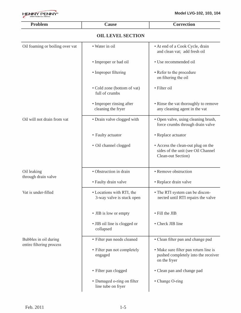
Filter motor will not run
“ISPOTFILLED”filtererror prompt
“CHECK PAN” prompt
“CHANGE FILTER PAD” prompt appears
• Filter line connections loose
• Drain pan o-rings damaged or missing
• Filter paper or pad clogged • Power cord for vat #1 is not plugged-in
• Thermal reset button on the rear of the pump motor is tripped
• All oil did not completely returnafterafiltercycle
• Filter pad clogged
• Filter drain pan missing
• Filter drain pan not completely engaged
• Filter drain interlock switch not engaged
• Filter pad has not been changed within a 24hr time period; Main power switch wasturnedoffduringfilter pad change
• Drain pan microswitch stuck
•Tightenallfilterlineconnections
• Install new o-rings
• Changefilterpaperorpad
• Plug power cord into receptacle
• Remove the right side panel and allow time for the motor to cool and then, using a screwdriver, press hard against the button until it clicks
• Have manager follow prompts• IsJIBfull?Ifnot,fillJIB
• Replacefilterpad/cleanpan.
• Find pan and install
•Adjustfilterdrainpanposition
• Check drain microswitch
•ReplaceoldfilterpadwithNEW filterpadwithmainpowerswitch turned on. *NOTE*24/7storereplace filtertwiceaday.
• Check drain microswitch
DISPLAYED PROMPT SECTION
Feb. 2011
Model LVG-102, 103, 104
1-7
1-4. ERROR CODES In the event of a control system failure, the digital display shows an error message. The message codes are shown in the DISPLAY column below. A constant tone is heard when an er-ror code is displayed, and to silence this tone, press any button.
Feb. 2011
DISPLAY CAUSE CORRECTION“E-4” Control board overheating Turn switch to OFF position, then turn switch back
to ON; if display shows “E-4”, the control board is getting too hot; check the louvers on each side of the unit for obstructions
“E-5”Oil overheating Turn switch to OFF position, then turn switch back
to ON; if display shows “E-5”, the heating circuits and temperature probe should be checked
“E-6A”Temperature probe open Turn switch to OFF position, then turn switch back
to ON; if display shows “E-6A”, the temperature probe should be checked
“E-6B”Temperature probe shorted checked Turn switch to OFF position, then turn switch back
to ON; if display shows “E-6B”, temperature probe should be
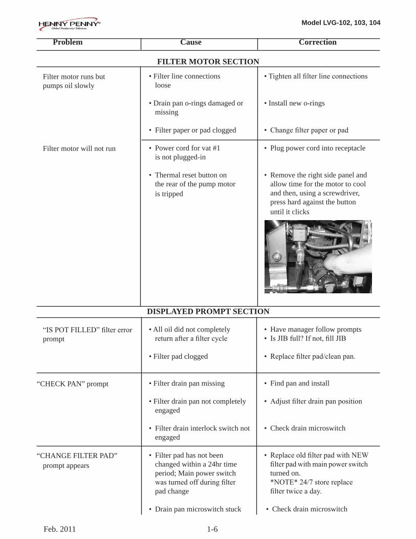
“E-10” E-10A- tripped above 300FE-10B- tripped below 300FE-10C- tripped while cookingE-10D- tripped <5min. of Auto FilterE-10F-trippedduringfiltercycleE-10M- tripped during melt modeE-10Y- tripped <5min of “YES” to “IS THE POT FULL?” prompt
Allow fryer to cool for 15-20 minutes; reset high limit by pressing down & releasing raisedside of the switch for the vat that is not operating; a single reset switch is found behind the door of each well; if high limit does not reset, high limit must be replaced
“E-15” Drain valve open Cleanand/orclosefishvatdrainvalve;ifcleanandclosed, have drain switch continuity checked
“E-18-A” “E-18-B” “E-18-C”
Left level sensor openRight level sensor openBoth level sensors open
Turn switch to OFF position, then turn switch back to ON; If display still indicates a failed sensor, check the connectors at the control board; check sensor & replace, if necessory
“E-20-A”“FAN SENSOR STUCK CLOSED”
Pressureswitchfailure/Wiringproblem
If fan is not running, have pressure switch checked; should be open circuit, if no air pressure If fan is running, wiring error
Model LVG-102, 103, 104
1-8
1-4. ERROR CODES (Continued)
Feb. 2011
DISPLAY CAUSE CORRECTION
“E-20-B” “NO DRAFT” “CHECK FAN”
PressureSwitchfailure/hoseloose
DraftFanfailure/lowvoltage/Flueor hood obstruction
Press power button to vat off and back on again, if E-20-B persists, have pressure switch checked; should be open circuit if no air pressure; make sure hose is connected to fan and pressure switch
Have draft fan checked; low voltage going to fan Checkthefryerflueandhoodsystemforobstructions
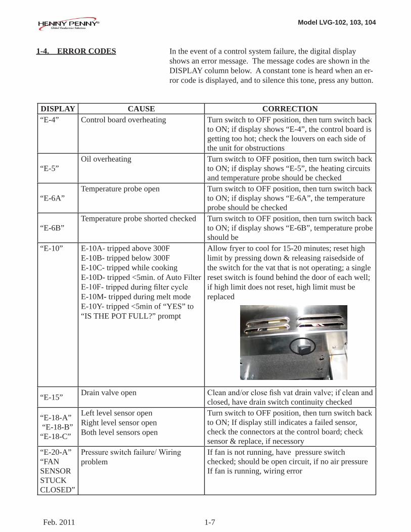
“E-20-D”
• Failuretoignite/noflamesense
• Plugged atmospheric equalization hole in regulator cap resultinginpilotflameslowlyfading
• Press power button to vat off and back on again, if E-20-D persists, check gas line connections; check gas shutoff valve; check ignitionmodule;checkgasvalve;checkflamesensor gap; check gas valve, and check ignition module wiring
• Clear obstruction from hole
“E-21”
Slow heat recovery Haveacertifiedservicetechniciancheckthefryerfor correct gas supply and pressure to the unit; have the gas valves checked; have unit checked for loose or burnt wires
“E-22”“NO HEAT”
Burner not igniting Have gas valve and heat circuit checked
“E-41” , “E-46”
Programming failure Turn switch to OFF, then back to ON; if display shows any of these error codes, re-initialize the controls; if error code persists, check control board and replace as needed
“E-47” Analog converter chip or 12 volt supply failure
Turn switch to OFF, then back to ON; if “E-47” persists, replace the PC board
“E-48” Input system error Turn switch to OFF, then back to ON; have control PC board replaced if “E-48” persists
“E-54-C”Temperature input error Turn switch to OFF, then back to ON; have control
PC board replaced if “E-54C” persists
Model LVG-102, 103, 104
1-9
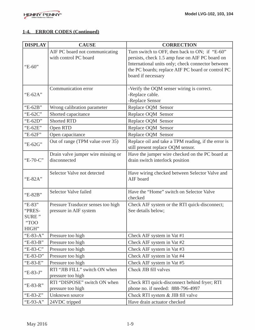
1-4. ERROR CODES (Continued)
May 2016
DISPLAY CAUSE CORRECTION
“E-60”
AIF PC board not communicating with control PC board
Turn switch to OFF, then back to ON; if “E-60” persists, check 1.5 amp fuse on AIF PC board on International units only; check connector between the PC boards; replace AIF PC board or control PC board if necessary
“E-62A”Communication error -Verify the OQM senser wiring is correct.
-Replace cable.-Replace Sensor
“E-62B” Wrong calibration parameter Replace OQM Sensor“E-62C” Shorted capacitance Replace OQM Sensor“E-62D” Shorted RTD Replace OQM Sensor“E-62E” Open RTD Replace OQM Sensor”E-62F” Open capacitance Replace OQM Sensor
”E-62G” Out of range (TPM value over 35) Replace oil and take a TPM reading, if the error is still present replace OQM sensor.
“E-70-C”Drain valve jumper wire missing or disconnected
Have the jumper wire checked on the PC board at drain switch interlock position
“E-82A”Selector Valve not detected Have wiring checked between Selector Valve and
AIF board
“E-82B” Selector Valve failed Have the “Home” switch on Selector Valve checked
“E-83”“PRES-SURE ” “TOO HIGH”
Pressure Trasducer senses too high pressure in AIF system
Check AIF system or the RTI quick-disconnect; See details below;
“E-83-A” Pressure too high Check AIF system in Vat #1“E-83-B” Pressure too high Check AIF system in Vat #2“E-83-C” Pressure too high Check AIF system in Vat #3“E-83-D” Pressure too high Check AIF system in Vat #4“E-83-E” Pressure too high Check AIF system in Vat #5
“E-83-J” RTI “JIB FILL” switch ON when pressure too high
CheckJIBfillvalves
“E-83-R” RTI “DISPOSE” switch ON when pressure too high
Check RTI quick-disconnect behind fryer; RTI phone no. if needed: 888-796-4997
“E-83-Z” Unknown source CheckRTIsystem&JIBfillvalve“E-93-A” 24VDC tripped Have drain actuator checked
Model LVG-102, 103, 104
2-1
SECTION 2. INFO, FILTER & TEMP BUTTON STATS
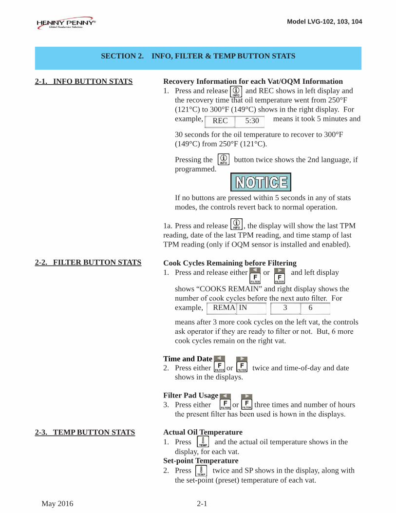
2-1. INFO BUTTON STATS
Recovery Information for each Vat/OQM Information1. Press and release and REC shows in left display and the recovery time that oil temperature went from 250°F (121°C) to 300°F (149°C) shows in the right display. For example, means it took 5 minutes and
30 seconds for the oil temperature to recover to 300°F (149°C) from 250°F (121°C).
Pressing the button twice shows the 2nd language, if programmed.
If no buttons are pressed within 5 seconds in any of stats modes, the controls revert back to normal operation.
1a. Press and release , the display will show the last TPM reading, date of the last TPM reading, and time stamp of last TPM reading (only if OQM sensor is installed and enabled).
Cook Cycles Remaining before Filtering1. Press and release either or and left display shows “COOKS REMAIN” and right display shows the numberofcookcyclesbeforethenextautofilter.For example,
means after 3 more cook cycles on the left vat, the controls askoperatoriftheyarereadytofilterornot.But,6more cook cycles remain on the right vat.
Time and Date2. Press either or twice and time-of-day and date shows in the displays.
Filter Pad Usage3. Press either or three times and number of hours thepresentfilterhasbeenusedishowninthedisplays.
Actual Oil Temperature1. Press and the actual oil temperature shows in the display, for each vat.Set-point Temperature2. Press twice and SP shows in the display, along with the set-point (preset) temperature of each vat.
REC 5:30
2-2. FILTER BUTTON STATS
2-3. TEMP BUTTON STATS
REMA IN 3 6
May 2016
Model LVG-102, 103, 104
2-2
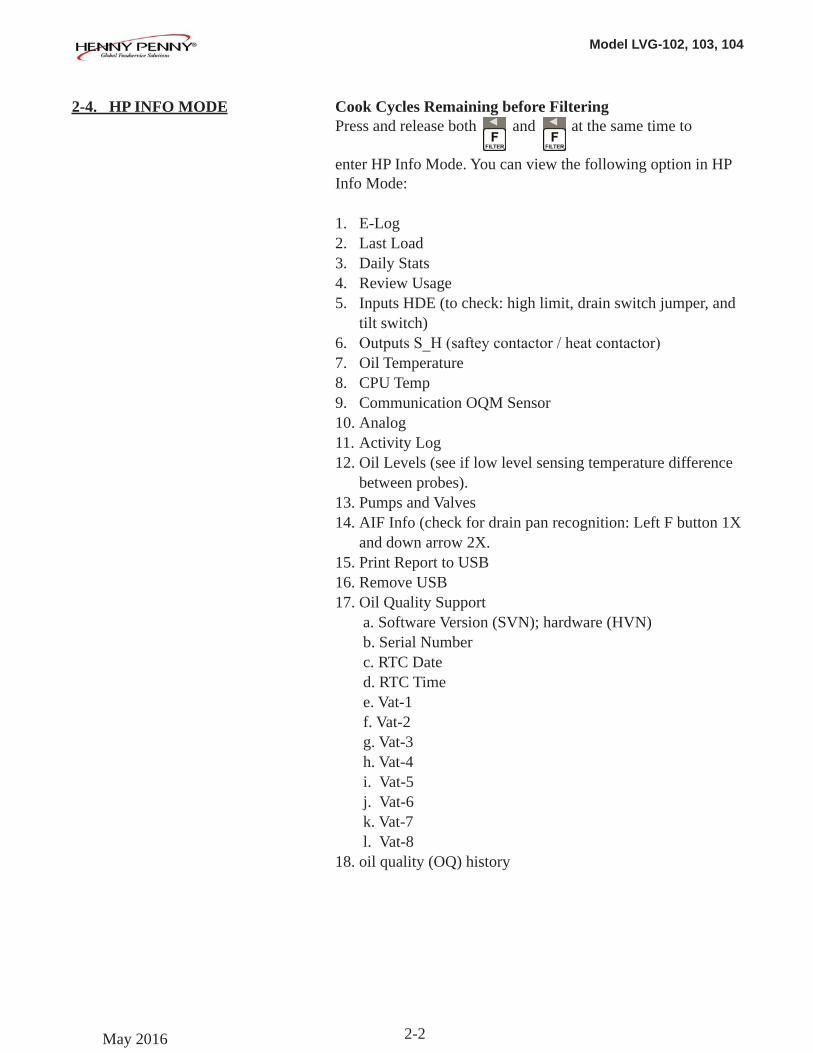
2-4. HP INFO MODE Cook Cycles Remaining before FilteringPress and release both and at the same time to enter HP Info Mode. You can view the following option in HP Info Mode:
1. E-Log2. Last Load3. Daily Stats4. Review Usage5. Inputs HDE (to check: high limit, drain switch jumper, and
tilt switch)6. OutputsS_H(safteycontactor/heatcontactor)7. Oil Temperature8. CPU Temp9. Communication OQM Sensor10. Analog11. Activity Log12. Oil Levels (see if low level sensing temperature difference
between probes).13. Pumps and Valves14. AIF Info (check for drain pan recognition: Left F button 1X
and down arrow 2X.15. Print Report to USB16. Remove USB17. Oil Quality Support
a. Software Version (SVN); hardware (HVN)b. Serial Numberc. RTC Dated. RTC Timee. Vat-1f. Vat-2g. Vat-3h. Vat-4i. Vat-5j. Vat-6k. Vat-7l. Vat-8
18. oil quality (OQ) history
May 2016
Model LVG-102, 103, 104
3-1
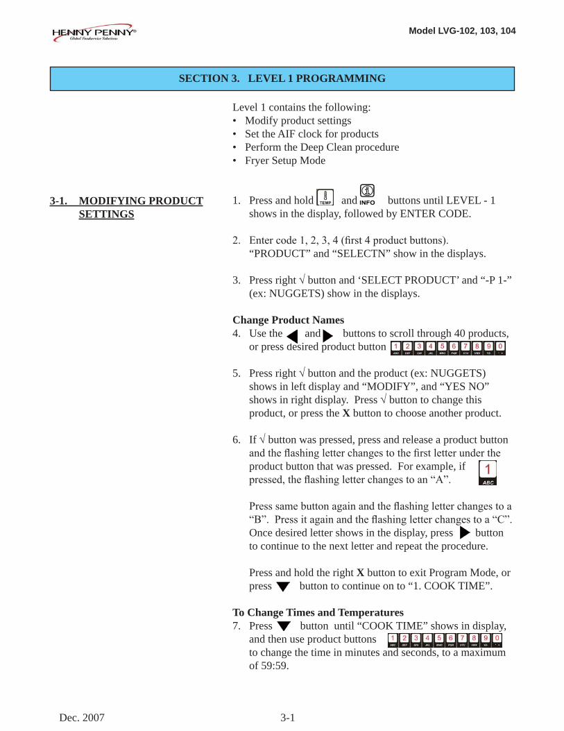
Level 1 contains the following:• Modify product settings• Set the AIF clock for products• Perform the Deep Clean procedure• Fryer Setup Mode
1. Press and hold and buttons until LEVEL - 1 shows in the display, followed by ENTER CODE.
2. Entercode1,2,3,4(first4productbuttons). “PRODUCT” and “SELECTN” show in the displays.
3. Press right √ button and ‘SELECT PRODUCT’ and “-P 1-” (ex: NUGGETS) show in the displays.
Change Product Names4. Use the and buttons to scroll through 40 products, or press desired product button
5. Press right √ button and the product (ex: NUGGETS) shows in left display and “MODIFY”, and “YES NO” shows in right display. Press √ button to change this product, or press the X button to choose another product.
6. If √ button was pressed, press and release a product button andtheflashingletterchangestothefirstletterunderthe product button that was pressed. For example, if pressed,theflashingletterchangestoan“A”.
Presssamebuttonagainandtheflashingletterchangestoa “B”.Pressitagainandtheflashingletterchangestoa“C”. Once desired letter shows in the display, press button to continue to the next letter and repeat the procedure.
Press and hold the right X button to exit Program Mode, or press button to continue on to “1. COOK TIME”.
To Change Times and Temperatures7. Press button until “COOK TIME” shows in display, and then use product buttons to change the time in minutes and seconds, to a maximum of 59:59.
SECTION 3. LEVEL 1 PROGRAMMING
3-1. MODIFYING PRODUCT SETTINGS
Dec. 2007
Model LVG-102, 103, 104
3-2
8. Press and release button and “TEMP” shows in the display, along with the preset temperature on the right side of the display.
Press the product buttons to change the temperature. The temperature range is 190°F
(88°C) to 380°F (193°C).
Cook ID Change9. Press button until “COOK ID” shows in the display
along with the product ID. For example, NUG would be the ID for nuggets. Use the product buttons to change the ID, following the same procedure as Steps 4 thru 6 above.
Alarms (Duty 1 & 2)10. Press button until “DUTY 1” shows in left display, and an alarm time in the right display. Press the product buttons to set an alarm. Ex., If a Cook Cycle was set at 3 minutes, and an alarm was to go off after 30 seconds into the Cook Cycle, “0:30” would be set in the display at this time. When the timer counts down to 2:30 the alarm sounds.
After alarm time is set, press button and “DUTY 2” shows in display, and a second alarm can be programmed.
Quality Timer11. Press button until QUAL TMR shows in display along
with preset holding time. Press product buttons to adjust hold time (2 hrs., 59 min. max.).
AIF Disable12. Press button until “AIF DISABLE” shows in display
along with “YES” or “NO”. Using and buttons change the display to “YES” if that product is to not be includedintheautomaticintermittentfiltrationoperation,or “NO” if it is to be included.
Assign Button13. Press button until “ASSIGN BTN” shows in the
display, along with the product (ex: NUGGETS). If this product already has a product button assigned to it, that LED will be lit. To assign other product buttons to that product, press and hold the product button for 3 seconds and that LED stays lit. To remove a product from a button, press and hold the product button with a lit LED and the LED goes out.
3-1. MODIFYING PRODUCT SETTINGS (Continued)
Feb. 2011
Model LVG-102, 103, 104
3-3
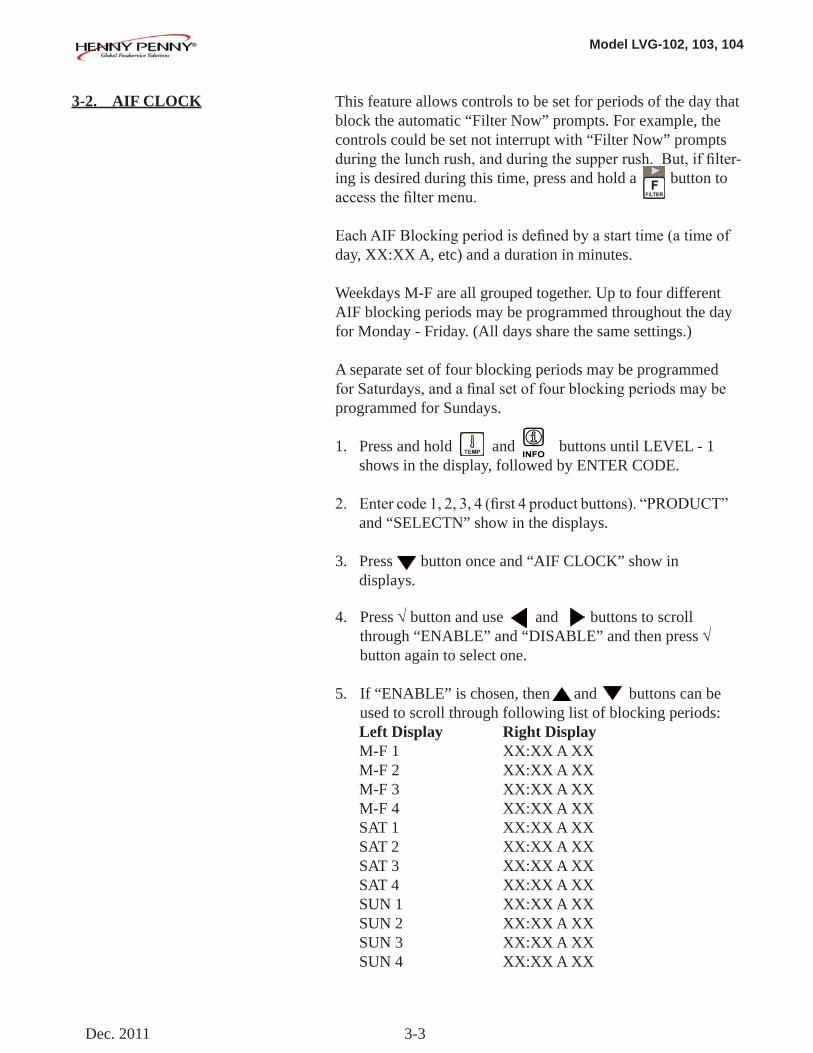
This feature allows controls to be set for periods of the day that block the automatic “Filter Now” prompts. For example, the controls could be set not interrupt with “Filter Now” prompts duringthelunchrush,andduringthesupperrush.But,iffilter-ing is desired during this time, press and hold a button to accessthefiltermenu. EachAIFBlockingperiodisdefinedbyastarttime(atimeofday, XX:XX A, etc) and a duration in minutes.
Weekdays M-F are all grouped together. Up to four different AIF blocking periods may be programmed throughout the day for Monday - Friday. (All days share the same settings.)
A separate set of four blocking periods may be programmed forSaturdays,andafinalsetoffourblockingperiodsmaybeprogrammed for Sundays.
1. Press and hold and buttons until LEVEL - 1 shows in the display, followed by ENTER CODE.
2. Entercode1,2,3,4(first4productbuttons).“PRODUCT” and “SELECTN” show in the displays.
3. Press button once and “AIF CLOCK” show in displays.
4. Press √ button and use and buttons to scroll through “ENABLE” and “DISABLE” and then press √ button again to select one.
5. If “ENABLE” is chosen, then and buttons can be used to scroll through following list of blocking periods: Left Display Right Display M-F 1 XX:XX A XX M-F 2 XX:XX A XX M-F 3 XX:XX A XX M-F 4 XX:XX A XX SAT 1 XX:XX A XX SAT 2 XX:XX A XX SAT 3 XX:XX A XX SAT 4 XX:XX A XX SUN 1 XX:XX A XX SUN 2 XX:XX A XX SUN 3 XX:XX A XX SUN 4 XX:XX A XX
3-2. AIF CLOCK
Dec. 2011
Model LVG-102, 103, 104
3-4
3-3. DEEP CLEAN MODE
3-2. AIF CLOCK (Continued)
In 12-hour clock mode, there are three items on each line: the start time“XX:XX”,theAorP(am/pm)setting,andthe“XX”duration.Usetheandbuttonstosettheseitems,whichflasheswhenthe item is selected.
To set a new start time setting, use the product buttons, to enter the new value.
PressthebuttontostepovertotheAM/PMsetting.TheAorPcan be toggled by pressing the ‘0’ product button.
Press the button again to step over to the duration value (in minutes). Enter a new value using the product buttons,
In 24-hour clock mode, there are only two items on each line: the time (XX:XX) and the duration (XX). Again, the and buttons step you between these items.
Press the right-side X button to exit out of AIF Clock programming mode.
This procedure allows a thorough cleaning of the vat by remov-ing caramelized oil from vat. See Section 4-3 in the Operator’s Manual for complete set of instructions.
Jan. 2008
Model LVG-102, 103, 104
3-5
This mode has the same settings as seen upon initial start-up of the fryer.
1. Press and hold and buttons until LEVEL - 1 shows in the display, followed by ENTER CODE.
2. Entercode1,2,3,4(first4productbuttons).“PRODUCT” and “SELECTN” show in the displays.
3. Press button 3 times and “FRYER SETUP” show in the displays.
4. Press √ button and *SETUP* *MODE* shows in displays, followed by, “LANGUAGE” on the left display, “ENGLISH” on the right display.
Use or buttons to change the operation display to, “FRANCAIS”, “CAN FREN”, “ESPANOL”, “PORTUG”, “DEUTSCHE”,“SVENSKA”,“РУССКИИ”.
Press to continue with other set-up items which include:• TEMP FORMAT - oF or oC• TIME FORMAT - 12-HR OR 24-HR• ENTER TIME - Time of day (use product buttons to change)• ENTER TIME - AM OR PM• DATE FORMAT - US OR INTERNATIONAL• ENTER DATE - Today’s date (use product buttons to change)• FRYER TYPE - GAS or ELEC• VAT TYPE - FULL OR SPLIT•DISPOSEBULKOIL-YES/NO(BULKhasRTIsystem) • SUPPLYBULKOIL-YES/NO(BULKhasRTIsystem)• DAYLIGHT SAVING TIME - 1.OFF; 2.US (2007 & after); 3.EURO; 4.FSA (US before 2007)• OIL QUALITY ENABLED (yes or no)• TPM WARN (value can be set to 0% - 40%)• TPM MAX (value can be set to 0% - 40%)
Unless otherwise indicated, use or to change settings.
3-4. FRYER SETUP
May. 2016

Model LVG-102, 103, 104
3-6
Model LVG-102, 103, 104
4-1
Used to access the following:• Advanced changes to product settings• Error code log• Password programming•AlertTone/Volume•No.ofcookcyclesbeforefilterissuggested•Automaticfiltertime
1. Press and hold and buttons until LEVEL - 2 shows in the display, followed by ENTER CODE.
2. Entercode1,2,3,4(first4productbuttons).“PROD” and “COMP” show in the displays.
3. Press right √ button and ‘SELECT PRODUCT’ and “-P 1-” show in the displays.
4. Use the and buttons to scroll through 40 products, or press the desired product button.
5. Press right √ button and product (ex: NUGGETS) shows in the left display and “MODIFY” “YES NO” shows in the right display. Press the √ button to change this product, or press the X button to choose another product.
>Load Compensation, Load Compensation Reference, Full Heat, PC Factor< 6. If √ button was pressed, “LD COMP” shows in the display
along with the load compensation value. This automatical-ly adjusts the time to account for the size and temperature of the cooking load. Press the product buttons to change this value of 0 to 20.
7. Press button until “LCMP REF” shows in the display along with the load compensation average temperature. (if load compensation is set to “OFF”, then “_ _ _” shows in display and setting cannot be programmed) This is the average cooking temperature for each product. The timer speeds up at temperatures above this setting and slows down at temperatures below this setting. Press the product buttons to change this value.
4-1. ADVANCED PRODUCT SETTINGS
SECTION 4. LEVEL 2 PROGRAMMING
Dec. 2007
Model LVG-102, 103, 104
4-2
4-1. ADVANCED PRODUCT SETTINGS (Continued)
8. Press button until “FULL HT” shows in display along with full heat value in seconds, which means heat is on as soon as a timer button is pressed, for a programmed length of time. Press product buttons
to change this value of 0 to 90 seconds.
9. Press button until “PC FACTOR” shows in display along with the proportional temperature, which helps keep the oil from over-shooting the setpoint temperature. Press product buttons to change this value of 0 to 50 degrees.
• Use button to go back to previous menu items. • PressXbuttonwhenfinishedwiththecurrentproduct,to return to the PRODUCT SELECTN step. • Press X button a second time to exit PROD COMP mode.
1. Press and hold and buttons until LEVEL - 2 shows in the display, followed by ENTER CODE.
2. Entercode1,2,3,4(first4productbuttons).“PROD” and “COMP” show in the displays.
3. Press button and “E-LOG” shows in the display.
4. Press right √ button and “A” plus the present date & time flashesonthedisplay,alongwith“*NOW*”.
5. Press and if an error was recorded, “B” and date, time, and error code information shows in display. This is the latest error code that the controls recorded.
6. Press and the next latest error code information can be seen. Up to 10 error codes (B to K) can be stored in the E-Log Section.
Press and hold the right √ button to view a brief description of the error.
4-2. E-LOG (error code log)
Feb. 2011
Model LVG-102, 103, 104
4-3
The 4-digit passwords can be changed for access to Set-Up, Usage, Level 1, Level 2, & Get Mgr.)
1. Press and hold and buttons until LEVEL - 2 shows in the display, followed by ENTER CODE.
2. Entercode1,2,3,4(first4productbuttons).“PROD” and “COMP” show in the displays.
3. Press button twice and “PASSWORD” shows in the display.
4. Press right √ button and “SET UP” shows in display. The Set up password can be changed at this time, or press once to change the USAGE password, twice for LEVEL 1 password, 3 times for LEVEL 2 password, or 4 times for GET MGR password. And then, follow instructions below.
5. If the password for Set Up Mode (for example) is to be changed, press right √ button and “MODIFY? “YES NO” shows in the display. Press right √ button to change the 4-digit password for the Set Up Mode, using the product buttons
6. Once new password is entered, “CONFIRM PASSWORD” shows in the display. Press √buttontoconfirm,orpressX to choose another password.
1. Press and hold and buttons until “LEVEL - 2” shows in the display, followed by “ENTER CODE”.
2. Entercode1,2,3,4(first4productbuttons).“PROD” and “COMP” show in the displays.
3. Press button 3 times and “ALERT TONE” shows in the display.
4. Press right √ button and “VOLUME” shows in display, along with volume value. Use the product buttons to set volume from 1 (softest) to 10 (loudest).
5. Once volume is set, press √ button and “TONE” shows in display, along with the tone value. Use the product buttons to set tone from 50 to 2000 Hz.
6. Press X to exit Alert Tone Mode.
4-3. PASSWORDS
4-4. ALERT TONE (and volume)
Dec. 2007
Model LVG-102, 103, 104
4-4
4-5. FILTER AFTER Thenumberofcookcyclesbetweenfilteringtheoilcaneasilybe programmed for all products.
1. Press and hold and buttons until LEVEL - 2 shows in the display, followed by ENTER CODE.
2. Entercode1,2,3,4(first4productbuttons).“PROD” and “COMP” show in the displays.
3. Press button 4 times and “FILR AFTR” shows in the left display.
4. Use the product buttons to set the numbertocookcyclesbetweenfilteringproceduresfrom0 to 99.
The length of time the fryer remains idle between cook cycles beforethecontrolssuggestfiltering.
1. Press and hold and buttons until LEVEL - 2 shows in the display, followed by ENTER CODE.
2. Entercode1,2,3,4(first4productbuttons).“PROD” and “COMP” show in the displays.
3. Press button 5 times and “FILR TIME” shows in the left display.
4. Use the product buttons to set a time between cook cycles from 0 to 18:00 hours.
For example, if “5:00” is programmed in the right display, if the vat was not used for 5 hours after a cook cycle, the controls would display “FILR NOW?” “YES NO”.
4-6. FILTER TIME
June 2008
Model LVG-102, 103, 104
5-1
SECTION 5. LEVEL 3 PROGRAMMING
Used to access the following:•TECHRESETS-ResetRecoveryFaults/Passwordsto defaults •SPCLPROG-Programfiltercontrolparametersandother items•CLOCKSET-Setthetime-of-dayclock/calendar• DATA COMM-Data Communications, LonWorks, MMC, etc.• HEAT CTRL-Program heat algorithm control parameters• TECH MODE-Control of outputs, display & button tests, etc.• STATS MODE-Review, reset operating stats, diagnostic logs, etc
1. Press and hold and buttons until LEVEL - 3 shows in the display, followed by ENTER CODE.
2. Entercode1,1,2,2,1,1,2,2(first2productbuttons),and “A. TECH” & “RESETS” show in the displays.
>Tech Resets< 3. Press right √ button and “RECOVERY FAULTS” shows in left display. Right display shows “CLR” and the number of recovery error recorded. Press √ button to reset the number to “0”.
4. Press button and “ALL PASSWORDS RESET” shows in left display. Press √ button to reset all passwords set in the controls.
• Use button to go back to previous menu items. • PressXbuttonwhenfinishedwiththecurrentitem,to return to the main menu. • Press X button a second time to exit Level 3 programming.
5-1. ADDITIONAL ADVANCED PRODUCT SETTINGS
June 2008
Model LVG-102, 103, 104
5-2
5-2. SPECIAL PROGRAMMING The Special Program Mode is used to set more detailed program-ming, such as:
SP-1 • ZONE - USA or Non-USA (default setpoints)SP-2 •System InitializationSP-3 •2nd Language: English, French, Candian- French, German, Spanish, Portuguese, Swedish, Russian, & NONE SP-4 •QuickConfiguration-CHKN+FISH;FF/HBR; CHKN; EMPTYSP-5 •Polish Duration - X:XX M:SSSP-6 •Drain Valve - NORMAL or MANUALSP-7 •EditS/N(SerialNumber)SP-8 •DecalLayout-UP/DOWNorDOWN/UPSP-9 •Recovery Test Limit - XXX SECSP-10 •Melt Cycle Select - 1.LIQUID; 2.SOLIDSP-11 •Has Add-Oil Port? - NO PORT; YES PORTSP-12 •Change Pad Reminder Time - XX HRSSP-13 •Pan Out = Pad Changed Time - XXX SECSP-14 •Auto-Fill Enabled? - YES; NOSP-15 •Auto-Fill Cycle Time? - XXX SECSP-16 •Auto-Fill Check JIB - XXX CNTSP-17 •Oil Full If Delta Above... - XXoF or CSP-18 • Oil Low If Delta Below... - XXoF or CSP-19 • Heat Allowed During Fill? - HEAT OK; NO HEATSP-20 • Always Ask “IS POT FILLED?” - YES; NOSP-21 • Oil Drain Time - XXX SECSP-22 • Oil WashTime - XXX SECSP-23 • Oil Rinse Time - XXX SECSP-24 • Oil Type Fill Time - XXX SECSP-25 • Repeat Fill Time - XXX SECSP-26 • RTD Air Cooling - X.XXo/SCSP-27 • RTD Cold Oil Surround - X.XXo/SCSP-28 • RTD Hot Oil Surround - X.XXo/SCSP-29 • Temp. Probe x Above Min. - XXX oF or CSP-30 • x Above Min. Hit Limit - XXX CNTSP-31 • Level RTD Air Cooling - X.XXo/SCSP-32 • Level RTD Oil Surround - X.XXo/SCSP-33 • New Pad-Max. Fill Time - XXX SECSP-34 • Old Pad-Max. Fill Time - XXX SECSP-35 • Fill To Top Time - XXX SECSP-36 • Reach Top Plus x Seconds - XXX SECSP-37 • Fill Until Pan Empty - XXX SECSP-38 • Valve Auto - Cycle Period - X:XX H:MMSP-39 •RefillDetectBy....-LVLPRBSorPRESSURESP-40 • Min. Wash PSI - XX.XX PSI
June 2008
Model LVG-102, 103, 104
5-3
5-2. SPECIAL PROGRAMMING (Continued)
SP-41 • Max. Bubble PSI - XX.XX PSISP-42 • Max. Wash Time - XXXX SECSP-43 • Old Pad Max. Wash Time - XXXX SECSP-44 • Min. Fill Time - XXX SECSP-45 • New Pad Max. Fill Time - XXXX SECSP-46 • Old Pad Max. Fill Time - XXXX SECSP-47 • Required Bubble PSI Hits - XXX CNTSP-48 • Pressure Trip Limit - XXX PSISP-49 • Pilot During Filter-PILOT OK or NO PILOT (GAS FRYERS ONLY)SP-50 • Filling - Low Heat On - XXX SECSP-51 • Filling - Low Heat Off - XXX SECSP-52 • Heat Error Enabled? - YES or NOSP-53 •WarmReturnLineEnabled?/Interval-H:MM (Hours/Minutes-OFFto4hours)SP-54 • Warm Return Line Time - M:SS (Minutes/Seconds-0:00to4Minutes)SP-55 • Enable R & D Displays? - YES or NO
Not all Special Program Mode functions are discussed in this section. To ensure proper operation of fryer, please consult Henny Penny Corp. before changing any of these settings. For more information on these functions, contact the Service Department at 1-800-417- 8405, or 1-937-456-8405.
To Enter Special Programming:
1. Press and hold and buttons until LEVEL - 3 shows in the display, followed by ENTER CODE.
2. Entercode1,1,2,2,1,1,2,2(first2productbuttons). 3. “A. TECH” & “RESETS” show in displays. Press and “B. SPCL” & “PROG” show in the displays.
Zone - USA/Non-USA (SP-1)4. Press √ button and “SP-1 ZONE” shows in the left display. Use and buttons to set the default set-points to USA specificationsornon-USAspecifications.
Initialize System (SP-2)5. Press button and “SP-1 DO SYSTEM INIT” scrolls in left display. To reset the controls to factory default settings, press and hold √ button and controls count down “IN 3”, “IN 2”, “IN 1”. Once display shows “-INIT-” & *DONE* the controls are reset to factory defaults.
Feb. 2011
Model LVG-102, 103, 104
5-4
2nd Language (SP-3)5. Press button and “SP-3 2ND LANGUAGE” scrolls in left display. Use and buttons to set to: ENGLISH; FRANCAIS; CAN FREN; ESPANOL; PORTUG; DEUTSHE;SVENSKA;РУССКИИor-NONE-.
By setting a second language in the controls, 2 languages can now be easlily chosen by pressing button twice during normal operation.
One language shows in left display and a second language shows in the right display. Pressing the √ button selects the language in the displays.
Quick Configuration (SP-4)5. Press button and “SP-4 QUICK CONFIG” shows in display. Use the and buttons to change the menu selectioninthecontrolsto:CHKN+FISH;FF/HBR;CHKN or EMPTY.
Polish Duration (SP-5)6. Press button and “SP-5 POLISH” shows in left display. Use product buttons to change polish time, from 5 minutes to a maximum of 10 minutes.
Drain Valve (SP-6)7. Press button and “SP-6 DRAIN VALVE” scrolls in the left display. Use the and buttons to change the right display to show “NORMAL” or “MANUAL”.
NORMAL means drain valves are controlled electronically and MANUAL means drain valves must be opened by hand.
Edit Unit Serial Number (SP-7)8. Press buttonand“SP-7S/N√EDIT” shows in the left display. Press the right √ button to enter the unit’s serial number in the controls, using the product buttons.
“STD” and “CUST” show in the right displays. Press the √ buttonunder“STD”andthefirst2lettersoftheserial number is the standard equipment code, press X button and a custom equipment code can be entered. THIS SERIAL NUMBER SHOULD MATCH THE SERIAL NUMBER ON THE DATA PLATE, ON THE DOOR.
5-2. SPECIAL PROGRAMMING (Continued)
Feb. 2011
Model LVG-102, 103, 104
5-5
5-2. SPECIAL PROGRAMMING (Continued)
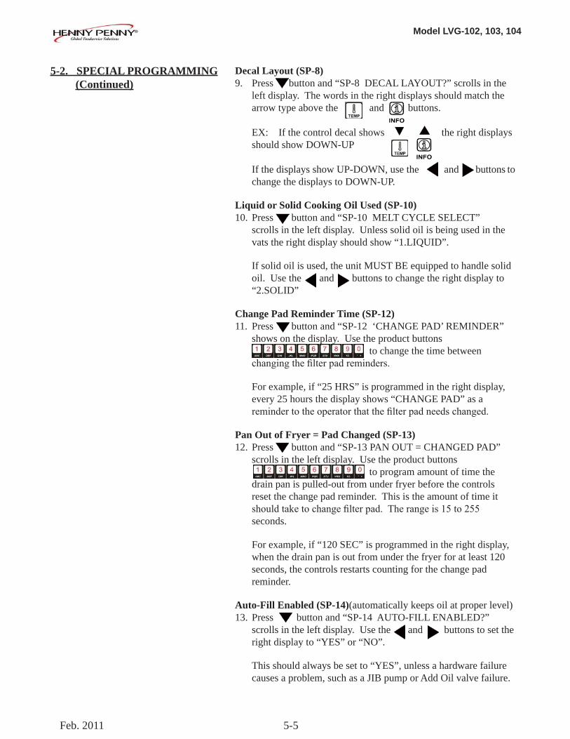
Decal Layout (SP-8)9. Press button and “SP-8 DECAL LAYOUT?” scrolls in the left display. The words in the right displays should match the arrow type above the and buttons.
EX: If the control decal shows the right displays should show DOWN-UP
If the displays show UP-DOWN, use the and buttons to change the displays to DOWN-UP.
Liquid or Solid Cooking Oil Used (SP-10)10. Press button and “SP-10 MELT CYCLE SELECT” scrolls in the left display. Unless solid oil is being used in the vats the right display should show “1.LIQUID”.
If solid oil is used, the unit MUST BE equipped to handle solid oil. Use the and buttons to change the right display to “2.SOLID”
Change Pad Reminder Time (SP-12)11. Press button and “SP-12 ‘CHANGE PAD’ REMINDER” shows on the display. Use the product buttons to change the time between changingthefilterpadreminders.
For example, if “25 HRS” is programmed in the right display, every 25 hours the display shows “CHANGE PAD” as a remindertotheoperatorthatthefilterpadneedschanged.
Pan Out of Fryer = Pad Changed (SP-13)12. Press button and “SP-13 PAN OUT = CHANGED PAD” scrolls in the left display. Use the product buttons to program amount of time the drain pan is pulled-out from under fryer before the controls reset the change pad reminder. This is the amount of time it shouldtaketochangefilterpad.Therangeis15to255 seconds.
For example, if “120 SEC” is programmed in the right display, when the drain pan is out from under the fryer for at least 120 seconds, the controls restarts counting for the change pad reminder.
Auto-Fill Enabled (SP-14)(automatically keeps oil at proper level) 13. Press button and “SP-14 AUTO-FILL ENABLED?” scrolls in the left display. Use the and buttons to set the right display to “YES” or “NO”.
This should always be set to “YES”, unless a hardware failure causes a problem, such as a JIB pump or Add Oil valve failure.
Feb. 2011
Model LVG-102, 103, 104
5-6
5-3. CLOCK SET 1. Press and hold and buttons until LEVEL - 3 shows in the display, followed by ENTER CODE.
2. Entercode1,1,2,2,1,1,2,2(first2productbuttons). 3. “A. TECH” & “RESETS” show in displays. Press button twice and “C. CLOCK” and “SET” show in the displays.
4. Press √ button and “CS-1 ENTER DATE MM-DD-YY” shows in the left display. Use the product buttons to set the date in right display.
5. Press button and “CS-2 ENTER TIME” shows in left displayandtimeflashesinrightdisplay.Useproduct buttons to change the time.
6. Press button and “CS-2 ENTER TIME” shows in left displayand“AM”or“PM”flashesinrightdisplay.Usethe buttons to change from AM to PM or vice-versa.
7. Press button and “CS-3 TIME FORMAT” shows in left display and “12-HR” or “24-HR” shows in right display. Use the buttons to change from a 12 hour time format to a 24 hour time format or vice-versa.
8. Press button and “CS-4 DAYLIGHT SAVING TIME” shows in the left display. Use the to change daylight saving time for your area: 1.OFF; 2.US (2007 & after); 3.EURO; or 4.FSA (US before 2007)
Data communications and heat controls settings are shown in Level 3 Program Mode. But, to ensure proper operation of fryer, please consult Henny Penny Corp. before changing any of these settings. For more information on these functions, contact the Service Department at 1-800-417- 8405, or 1-937-456-8405.
5-4. DATA COMM & HEAT CONTROL
June 2008
Model LVG-102, 103, 104
5-7
5-5. TECH MODE The TECH Mode has self-diagnostic information, which can be usedbycertifiedtechniciansfortroubleshootingpurposes,suchas:
T-1 • SoftwareT-2 • Fryer Type (Gas or Elec.) T-3 • Push Button TestT-4 • All On Display TestT-5 • Display Segments TestT-6 • Display Digits TestT-7 • Display Decimal Points TestT-8 • LED’s TestT-9 • Left Temp. Probe Calibration & OffsetT-10 • Left Level 1 Probe Calibration & OffsetT-11 • Left Level 2 Probe Calibration & OffsetT-12 • Right Temp. Probe Calibration & OffsetT-13 • Right Level 1 Probe Calibration & OffsetT-14 • Right Level 2 Probe Calibration & OffsetT-15 •CPUControlTemp.Calibration/Offset/HighestT-16 • View A - D ChannelT-17 • Digital Inputs T-18 • AIF InfoT-19 • Outputs TestT-20 • Pumps & Valves TestT-21 • Change Tech Code?T-22 • Total Initialization
Not all Tech Mode functions are discussed in this section. To ensure proper operation of fryer, please consult Henny Penny Corp. before changing any of these settings. For more information on these functions, contact the Service Department at 1-800-417- 8405, or 1-937-456-8405.
June 2008
Model LVG-102, 103, 104
5-8
5-5. TECH MODE (Continued) 1. To enter the TECH Mode, press and hold and buttons for 5 seconds, until display shows ”LEVEL 3”, followed by “ENTER CODE”.
2. Entercode1,1,2,2,1,1,2,2(first2productbuttons). “A. TECH” & “RESETS” show in the displays.
3. Press 5 times, and when display shows “F. TECH”, press the right √ button and T-1 “SOFTWARE” shows in the display, the firststepoftheTECHMode.Useandbuttonstotoggle through the steps.
Press the right X button twice, at anytime to return to normal operation.
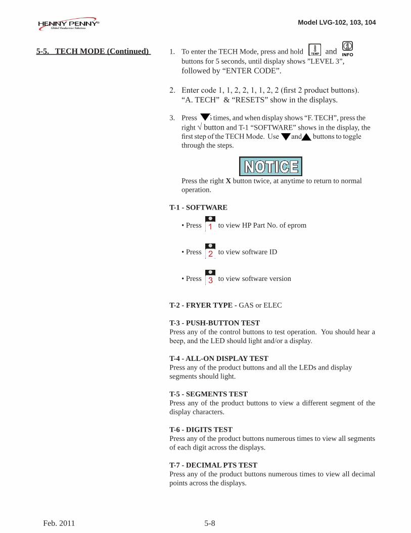
T-1 - SOFTWARE
• Press to view HP Part No. of eprom
• Press to view software ID
• Press to view software version
T-2 - FRYER TYPE - GAS or ELEC
T-3 - PUSH-BUTTON TESTPress any of the control buttons to test operation. You should hear a beep,andtheLEDshouldlightand/oradisplay.
T-4 - ALL-ON DISPLAY TESTPress any of the product buttons and all the LEDs and display segments should light.
T-5 - SEGMENTS TESTPress any of the product buttons to view a different segment of the display characters.
T-6 - DIGITS TESTPress any of the product buttons numerous times to view all segments of each digit across the displays.
T-7 - DECIMAL PTS TESTPress any of the product buttons numerous times to view all decimal points across the displays.
Feb. 2011
Model LVG-102, 103, 104
5-9
5-5. TECH MODE (Continued) T-8 - DECIMAL PTS TESTPress any of the product buttons numerous times to view each LED across the control panel.
T-17 - DIGITAL INPUTS - HDFH = HIGH LIMIT - If “H” is present, the high limit is good. If “-” shows then the high limit is tripped out (overheated) or disconnected. D = DRAIN SWITCH - If “D” is present, the drain handle (when applicable) is closed. If “-” shows then the drain is open or the switch is faulty. F = FAN (PRESSURE SWITCH) - If “F” is present, the pressure switch is good. If “-” shows in the display, the switch is faulty.
Press button and an underscore (“_”) indicates the input is not presently detected. A Checkmark (“√” ) indicates the signal is detecting a normal input. A blinking (“X”) indicates the signal is presently detected, but is detected as a half-wave (partially failed) input.
TheH,D,Fsignalsabovearewiredinseries.Thefirstsignalmissing out of this sequence l generally causes all signals to the right of it to be missing as well.
T-18 - AIF INFO (AIF PCB communicating with control PCB?)An “AIF √” means normal communications between the AIF PCB and the control PCB. “AIF X” means a problem with the communications between the PCBs.
Press button and “FILR IN” and “USE BY 1(ex)” shows in the displays. These displays shows which controls are using thefilteringsystem.
“USE BY 0” = not in use“USE BY 7” = used by AIF“USE BY 1 to 5” = used by control PCB
Press button and “CPU POSN” and “1 OF 3(ex)” shows in the displays. These displays shows which controls are plugged into which port on the AIF board.
For example, the left control should be plugged into port 1, and on a 3 control fryer, shows “1 OF 3” on the display.
If the right control is unplugged, then the left control would show “1 OF 2” instead of “1 OF 3”.
Feb. 2011
Model LVG-102, 103, 104
5-10
Press button and “INP E_P_” and “JL_R_DF_” shows in the displays.
AIF Board Inputs:E = Stop button E* = E-Stop pressed.P = Drain Pan M* = drain pan is missing.JL = JIB J* = JIB oil level is low.R = RTI R* = RTI System DetectedDF = RTI Discard Tank DF* = tank full
Press button and “OUT F_J_” and “N_DI_JFo” shows in the displays.
AIF Board Outputs:Current outputs status from AIF board.F = Filter Pump. (F* = Filter pump is on)J = JIB Pump. (J* = JIB pump is on)N = New Oil Pump. (N* = RTI new oil pump on)DI=DiscardValve. (DIo=RTIdisc.valveopen/DIc=closed)JF=JIBFillValve. (JFo=RTIJIBfillvalveopen/ JFc=closed)
Press button and “REQ F_J_” and “N_DI_JFo_” shows in the displays.
AIF Board Outputs Requested by the Control Board:Current outputs status from AIF board.F = Filter Pump. (F* = Filter pump is on)J = JIB Pump. (J* = JIB pump is on)N = New Oil Pump. (N* = RTI new oil pump on)DI=DiscardValve. (DIo=RTIdisc.valveopen/ DIc=closed))JF=JIBFillValve. (JFo=RTIJIBfillvalveopen/ JFc=closed)
T-19 - OUTPUTSF = FAN (PRESSURE SWITCH)- Press or to open and close the pressure switches S = SAFETY GAS VALVE (if available) - Press or to open and close the gas safety valves
I = IGNITION MODULE - Press or to open and close the outputs on the ignition modules
H = HEAT OUTPUTS - Press or to turn on and off the heating outputs (ex: gas valve)
5-5. TECH MODE (Continued)
Feb. 2011
Model LVG-102, 103, 104
5-11
5-5. TECH MODE (Continued) T-20 - PUMPS & VALVES Press √button and “VALVES” “DcRcAc” shows in displays.
Press to open and close the drain valves.
Press to open and close the return valves.
Press to open and close the add valves.
“DcRcAc” means valves are closed, “DoRoAo” means valves are open. (Driven by the control board)
Press button and “DISCARDc” and “JIBFILLc” shows in the displays. (Driven by the AIF board)
Press to open and close the RTI discard valve (display shows “DISCARDo” when open)
PresstoopenandclosetheRTIJIBfillvalve(displayshows“JIBFILLo” when open)
Press button and “PUMP FP_” and “JP_ NP_” shows in the displays. (Driven by the AIF board)
Presstoturnoffandonthefilterpump(displayshows“FP*”when on)
Press to turn off and on the JIB pump (display shows “JP*” when on)
Press to turn off and on the RTI new oil pump (display shows “NP*” when on)
Press button and “LIGHTS” and “FLT_ JLO_” shows in the displays. (Driven by the AIF board)
Press to turn off and on the FILTER light (display shows “FLT*” when on)
Press to turn off and on the JIB LOW light (display shows “JLO*” when on)
June 2008
Model LVG-102, 103, 104
5-12
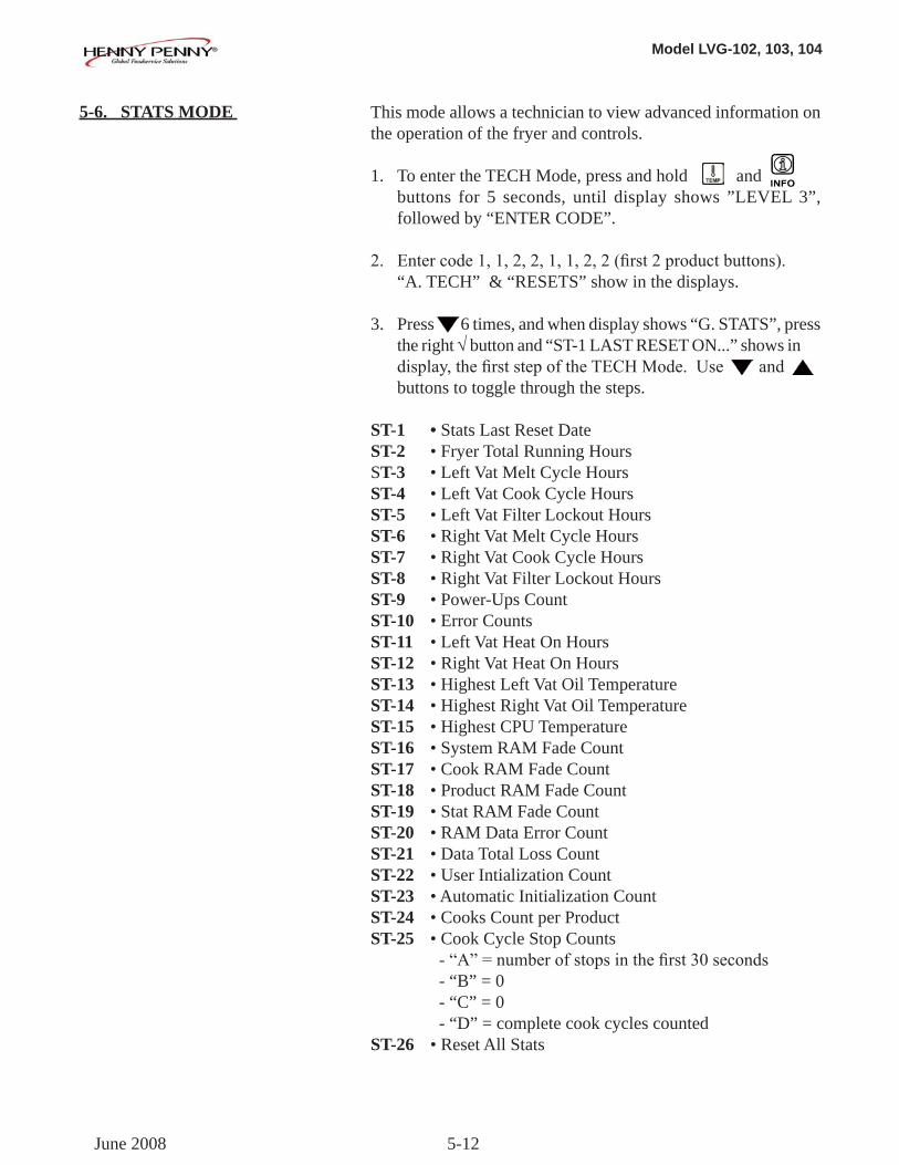
5-6. STATS MODE This mode allows a technician to view advanced information on the operation of the fryer and controls.
1. To enter the TECH Mode, press and hold and buttons for 5 seconds, until display shows ”LEVEL 3”, followed by “ENTER CODE”.
2. Entercode1,1,2,2,1,1,2,2(first2productbuttons). “A. TECH” & “RESETS” show in the displays.
3. Press 6 times, and when display shows “G. STATS”, press the right √ button and “ST-1 LAST RESET ON...” shows in display,thefirststepoftheTECHMode.Useand buttons to toggle through the steps.
ST-1 • Stats Last Reset DateST-2 • Fryer Total Running Hours ST-3 • Left Vat Melt Cycle HoursST-4 • Left Vat Cook Cycle HoursST-5 • Left Vat Filter Lockout HoursST-6 • Right Vat Melt Cycle HoursST-7 • Right Vat Cook Cycle HoursST-8 • Right Vat Filter Lockout HoursST-9 • Power-Ups CountST-10 • Error CountsST-11 • Left Vat Heat On HoursST-12 • Right Vat Heat On HoursST-13 • Highest Left Vat Oil TemperatureST-14 • Highest Right Vat Oil TemperatureST-15 • Highest CPU TemperatureST-16 • System RAM Fade CountST-17 • Cook RAM Fade CountST-18 • Product RAM Fade CountST-19 • Stat RAM Fade CountST-20 • RAM Data Error CountST-21 • Data Total Loss CountST-22 • User Intialization CountST-23 • Automatic Initialization CountST-24 • Cooks Count per ProductST-25 • Cook Cycle Stop Counts -“A”=numberofstopsinthefirst30seconds - “B” = 0 - “C” = 0 - “D” = complete cook cycles countedST-26 • Reset All Stats
June 2008
Model LVG-102, 103, 104
6-1
6-1. INFO MODE This mode gathers and stores historic information on the fryer and operator’s performance. Press and hold for 3 seconds, unitil *INFO* *MODE*” shows on the displays.
Press or buttons to access the steps and press √button to view the statistics within each step.
This mode includes the following information:
1. FILTER STATS - filteringinformationforthelast7days 2. REVIEW USAGE- information accumulated since the last time this data was manually reset 3. LAST LOAD - information about the most recent Cook Cycle, or the cycle presently in progress
Press X button to exit from the Information Mode.
1. FILTER STATS Press √button to select Filter Stats and then press and to select the day for which you want to view the stats. Then press or buttons to view the following stats:
•“FILTERED”=No.oftimesfiltered•“FLTBPSD”=No.oftimesfilteringwasskipped• “FLT AVG” = Average no. of cook cycles between filters
2. REVIEW USAGEPress √button to select Review Usage and press orbuttons to view the following:
FUNCTION DISPLAY EX:Day usage data was previously reset SINCE 9:32P 04-19-10Total number of cook cycles TOTAL COOKS 462Cook Cycles stopped before “PULL” QUIT COOK 4Number of hours fryer was on (left) L ON HRS 165Number of hours fryer was on (right) R ON HRS 160
SECTION 6. INFORMATION MODE
Feb. 2011
Model LVG-102, 103, 104
6-2
6-1. INFO MODE (Continued)
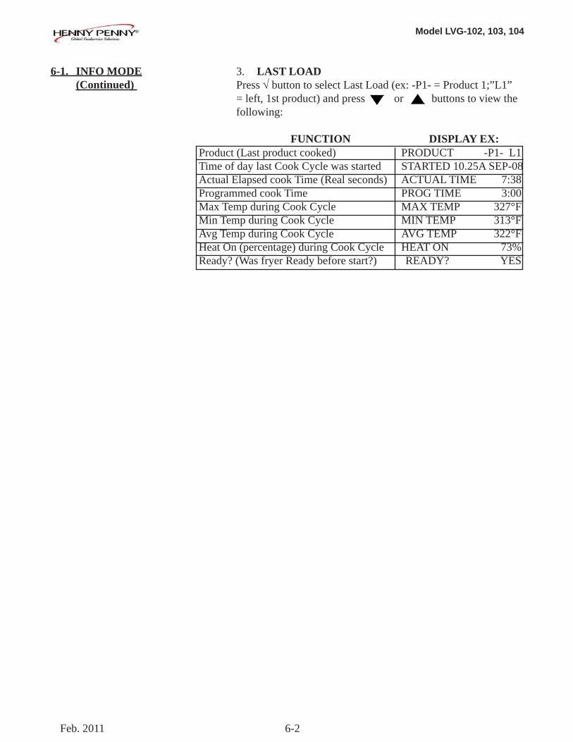
3. LAST LOADPress √button to select Last Load (ex: -P1- = Product 1;”L1” = left, 1st product) and press or buttons to view the following:
FUNCTION DISPLAY EX:Product (Last product cooked) PRODUCT -P1- L1Time of day last Cook Cycle was started STARTED 10.25A SEP-08Actual Elapsed cook Time (Real seconds) ACTUAL TIME 7:38Programmed cook Time PROG TIME 3:00Max Temp during Cook Cycle MAX TEMP 327°FMin Temp during Cook Cycle MIN TEMP 313°FAvg Temp during Cook Cycle AVG TEMP 322°FHeat On (percentage) during Cook Cycle HEAT ON 73%Ready? (Was fryer Ready before start?) READY? YES
Feb. 2011
Model LVG-102, 103, 104
7-1
To ensure a long life of fryers and their components, regular maintenance should be performed. Refer to the chart below.
Frequency Action Daily Mainteance Filter (See Maintenance Filtering Instructions Section in Operator’s Manual or PM Guide)
Daily Change Filter Pad (See Changing Filter Pad Section in Operator’s Manual or PM Guide)
Weekly Clean Behind Fryer (See PM Guide) Quarterly Change Filter Pan O-Rings (See PM Guide)
Quarterly Vat Deep Clean (See Deep Clean Mode Section in Operator’s Manual or PM Guide)
Quarterly Clean Blower Motors (See PM Guide)
SECTION 7. MAINTENANCE
7-1. PREVENTIVE MAINTENANCE
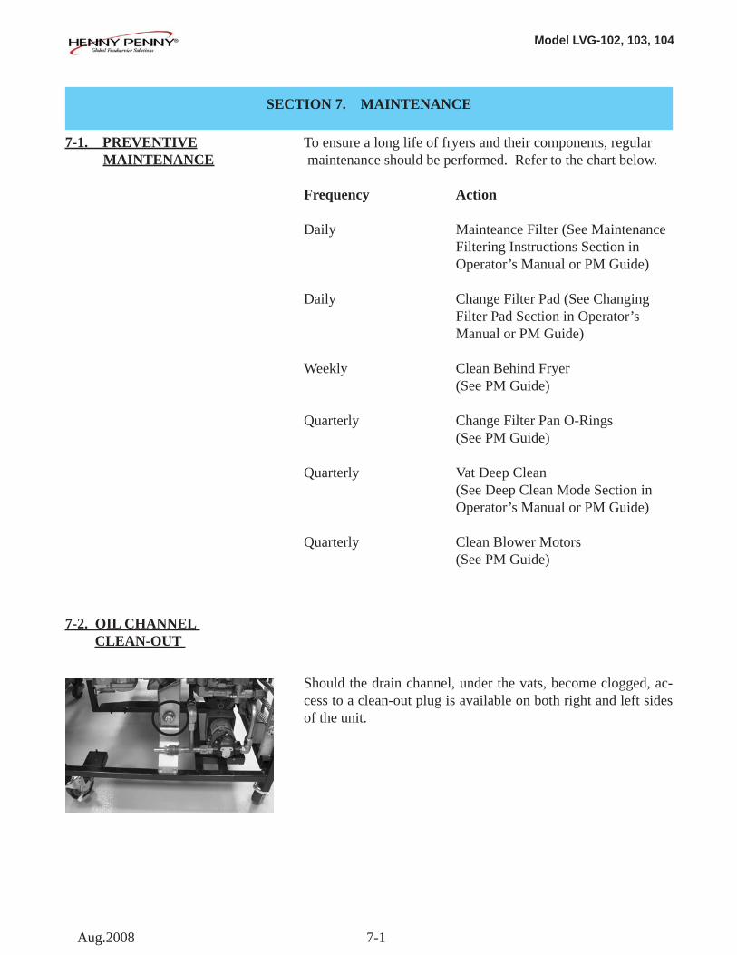
7-2. OIL CHANNEL CLEAN-OUT
Should the drain channel, under the vats, become clogged, ac-cess to a clean-out plug is available on both right and left sides of the unit.
Aug.2008
Model LVG-102, 103, 104
7-2
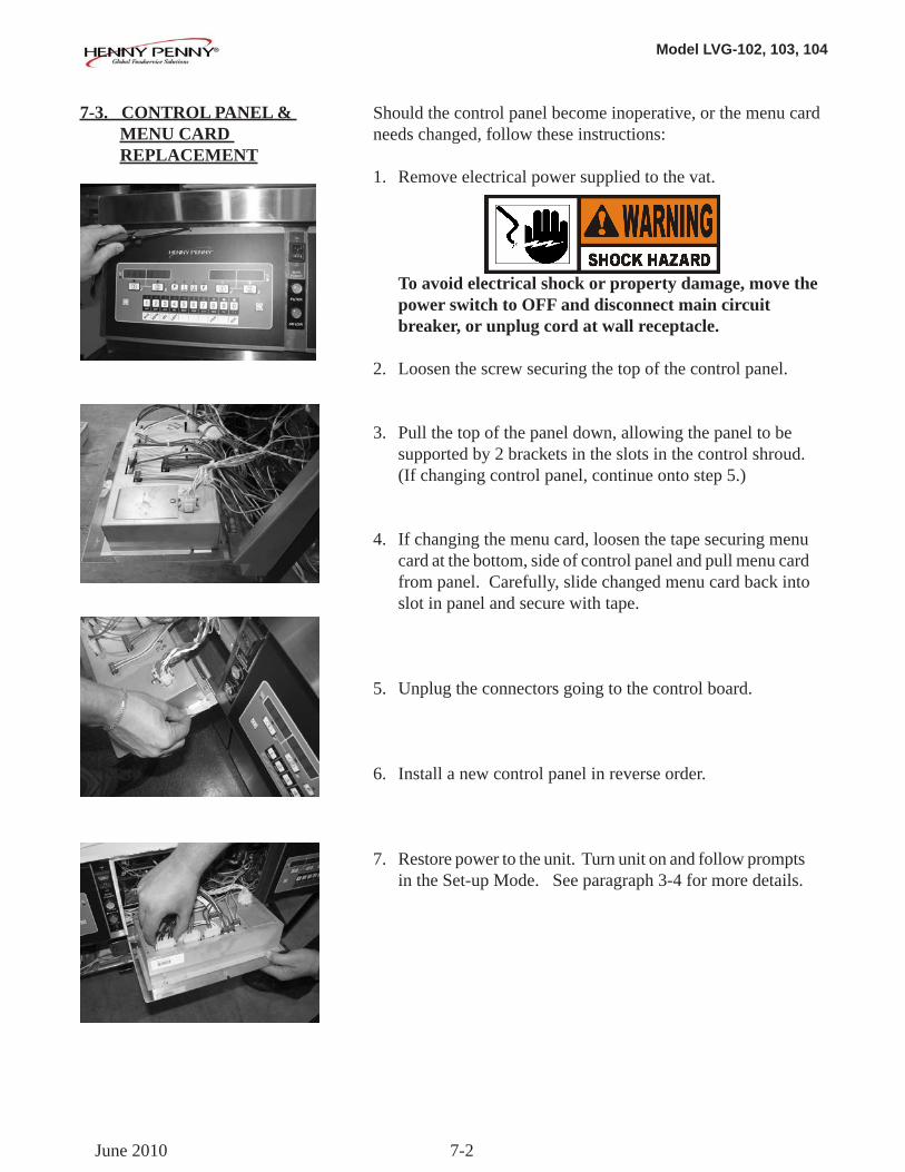
Should the control panel become inoperative, or the menu card needs changed, follow these instructions:
1. Remove electrical power supplied to the vat.
To avoid electrical shock or property damage, move the power switch to OFF and disconnect main circuit breaker, or unplug cord at wall receptacle. 2. Loosen the screw securing the top of the control panel.
3. Pull the top of the panel down, allowing the panel to be supported by 2 brackets in the slots in the control shroud. (If changing control panel, continue onto step 5.)
4. If changing the menu card, loosen the tape securing menu card at the bottom, side of control panel and pull menu card from panel. Carefully, slide changed menu card back into slot in panel and secure with tape.
5. Unplug the connectors going to the control board.
6. Install a new control panel in reverse order.
7. Restore power to the unit. Turn unit on and follow prompts in the Set-up Mode. See paragraph 3-4 for more details.
7-3. CONTROL PANEL & MENU CARD REPLACEMENT
June 2010
Model LVG-102, 103, 104
7-3
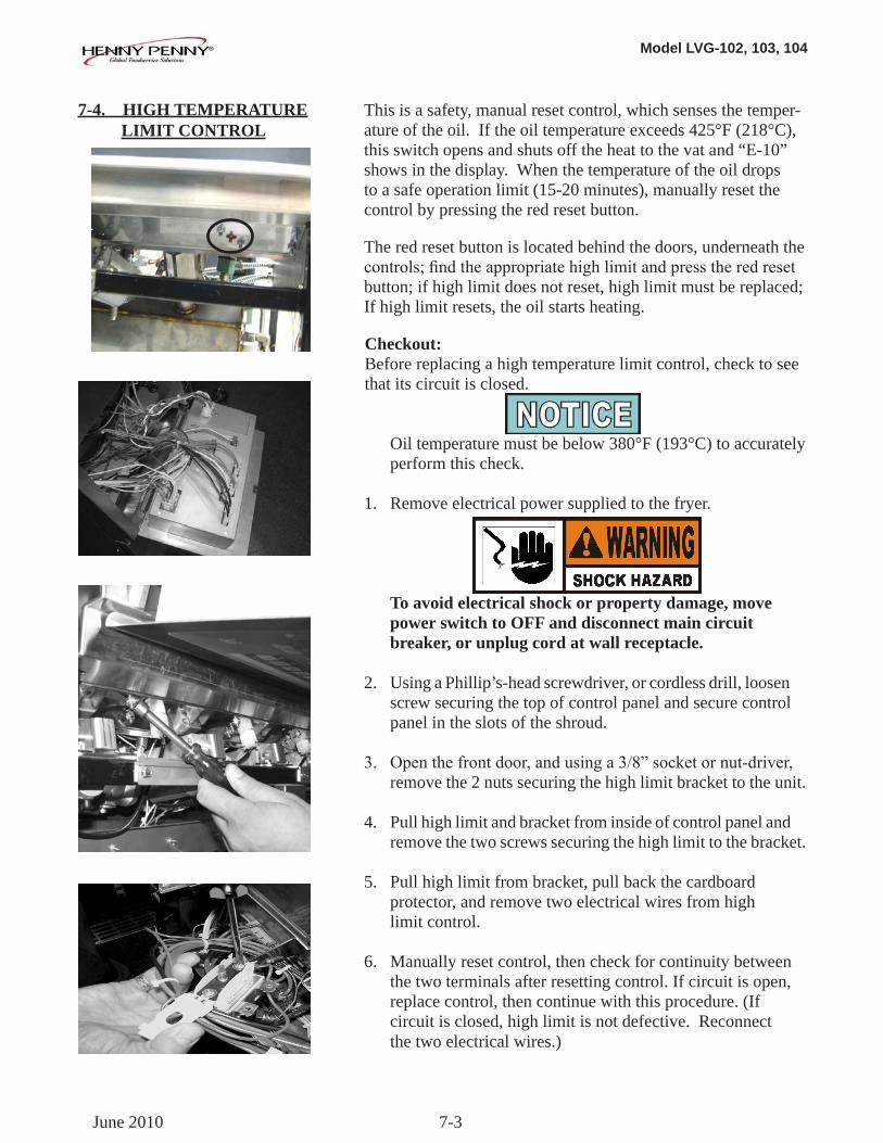
This is a safety, manual reset control, which senses the temper-ature of the oil. If the oil temperature exceeds 425°F (218°C), this switch opens and shuts off the heat to the vat and “E-10” shows in the display. When the temperature of the oil drops to a safe operation limit (15-20 minutes), manually reset the control by pressing the red reset button.
The red reset button is located behind the doors, underneath the controls;findtheappropriatehighlimitandpresstheredresetbutton; if high limit does not reset, high limit must be replaced; If high limit resets, the oil starts heating.
Checkout:Before replacing a high temperature limit control, check to seethat its circuit is closed.
Oil temperature must be below 380°F (193°C) to accurately perform this check.
1. Remove electrical power supplied to the fryer.
To avoid electrical shock or property damage, move power switch to OFF and disconnect main circuit breaker, or unplug cord at wall receptacle.
2. Using a Phillip’s-head screwdriver, or cordless drill, loosen screw securing the top of control panel and secure control panel in the slots of the shroud.
3. Openthefrontdoor,andusinga3/8”socketornut-driver, remove the 2 nuts securing the high limit bracket to the unit.
4. Pull high limit and bracket from inside of control panel and remove the two screws securing the high limit to the bracket.
5. Pull high limit from bracket, pull back the cardboard protector, and remove two electrical wires from high limit control.
6. Manually reset control, then check for continuity between the two terminals after resetting control. If circuit is open, replace control, then continue with this procedure. (If circuit is closed, high limit is not defective. Reconnect the two electrical wires.)
7-4. HIGH TEMPERATURE LIMIT CONTROL
June 2010
Model LVG-102, 103, 104
7-4
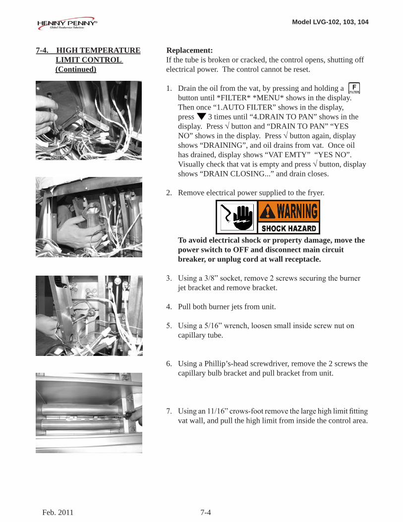
Replacement:If the tube is broken or cracked, the control opens, shutting off electrical power. The control cannot be reset.
1. Drain the oil from the vat, by pressing and holding a button until *FILTER* *MENU* shows in the display. Then once “1.AUTO FILTER” shows in the display, press 3 times until “4.DRAIN TO PAN” shows in the display. Press √button and “DRAIN TO PAN” “YES NO” shows in the display. Press √ button again, display shows “DRAINING”, and oil drains from vat. Once oil has drained, display shows “VAT EMTY” “YES NO”. Visually check that vat is empty and press √ button, display shows “DRAIN CLOSING...” and drain closes.
2. Remove electrical power supplied to the fryer.
To avoid electrical shock or property damage, move the power switch to OFF and disconnect main circuit breaker, or unplug cord at wall receptacle.
3. Usinga3/8”socket,remove2screwssecuringtheburner jet bracket and remove bracket.
4. Pull both burner jets from unit.
5. Usinga5/16”wrench,loosensmallinsidescrewnuton capillary tube.
6. Using a Phillip’s-head screwdriver, remove the 2 screws the capillary bulb bracket and pull bracket from unit.
7. Usingan11/16”crows-footremovethelargehighlimitfitting vat wall, and pull the high limit from inside the control area.
7-4. HIGH TEMPERATURE LIMIT CONTROL (Continued)
Feb. 2011
Model LVG-102, 103, 104
7-5
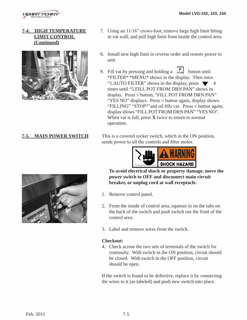
7. Usingan11/16”crows-foot,removelargehighlimitfitting in vat wall, and pull high limit from inside the control area.
8. Install new high limit in reverse order and restore power to unit.
9. Fill vat by pressing and holding a button until *FILTER* *MENU* shows in the display. Then once “1.AUTO FILTER” shows in the display, press 4 times until “5.FILL POT FROM DRN PAN” shows in display. Press √ button; “FILL POT FROM DRN PAN” “YES NO” displays. Press √ button again, display shows “FILLING”“STOP?”andoilfillsvat.Press√ button again, display shows “FILL POT FROM DRN PAN” “YES NO”. When vat is full, press X twice to return to normal operation.
7-4. HIGH TEMPERATURE LIMIT CONTROL (Continued)
This is a covered rocker switch, which in the ON position, sendspowertoallthecontrolsandfiltermotor.
To avoid electrical shock or property damage, move the power switch to OFF and disconnect main circuit breaker, or unplug cord at wall receptacle. 1. Remove control panel.
2. From the inside of control area, squeeze in on the tabs on the back of the switch and push switch out the front of the control area.
3. Label and remove wires from the switch.
Checkout:4. Check across the two sets of terminals of the switch for continuity. With switch in the ON position, circuit should be closed. With switch in the OFF position, circuit should be open.
If the switch is found to be defective, replace it by connecting the wires to it (as labeled) and push new switch into place.
7-5. MAIN POWER SWITCH
Feb. 2011
Model LVG-102, 103, 104
7-6
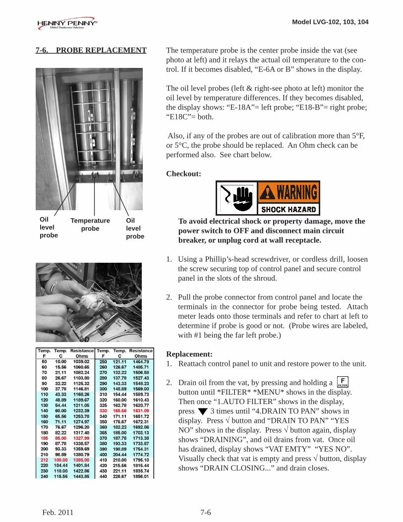
The temperature probe is the center probe inside the vat (see photo at left) and it relays the actual oil temperature to the con-trol. If it becomes disabled, “E-6A or B” shows in the display.
The oil level probes (left & right-see photo at left) monitor the oil level by temperature differences. If they becomes disabled, the display shows: “E-18A”= left probe; “E18-B”= right probe; “E18C”= both.
Also, if any of the probes are out of calibration more than 5°F, or 5°C, the probe should be replaced. An Ohm check can be performed also. See chart below.
Checkout:
To avoid electrical shock or property damage, move the power switch to OFF and disconnect main circuit breaker, or unplug cord at wall receptacle.
1. Using a Phillip’s-head screwdriver, or cordless drill, loosen the screw securing top of control panel and secure control panel in the slots of the shroud.
2. Pull the probe connector from control panel and locate the terminals in the connector for probe being tested. Attach meter leads onto those terminals and refer to chart at left to determine if probe is good or not. (Probe wires are labeled, with #1 being the far left probe.)
Replacement:1. Reattach control panel to unit and restore power to the unit.
2. Drain oil from the vat, by pressing and holding a button until *FILTER* *MENU* shows in the display. Then once “1.AUTO FILTER” shows in the display, press 3 times until “4.DRAIN TO PAN” shows in display. Press √button and “DRAIN TO PAN” “YES NO” shows in the display. Press √ button again, display shows “DRAINING”, and oil drains from vat. Once oil has drained, display shows “VAT EMTY” “YES NO”. Visually check that vat is empty and press √ button, display shows “DRAIN CLOSING...” and drain closes.
7-6. PROBE REPLACEMENT
Oillevelprobe
Oil levelprobe
Temperatureprobe
Feb. 2011
Model LVG-102, 103, 104
7-7
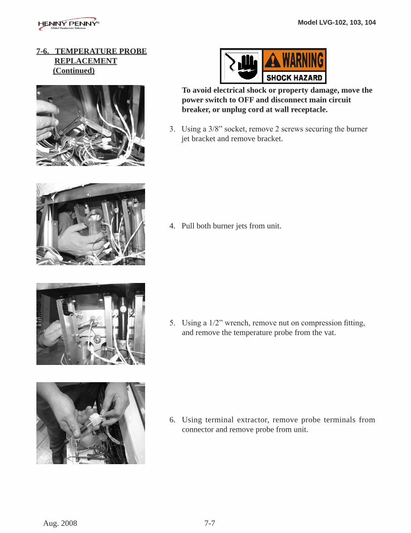
To avoid electrical shock or property damage, move the power switch to OFF and disconnect main circuit breaker, or unplug cord at wall receptacle.
3. Usinga3/8”socket,remove2screwssecuringtheburner jet bracket and remove bracket.
4. Pull both burner jets from unit.
5. Usinga1/2”wrench,removenutoncompressionfitting, and remove the temperature probe from the vat.
6. Using terminal extractor, remove probe terminals from connector and remove probe from unit.
7-6. TEMPERATURE PROBE REPLACEMENT (Continued)
Aug. 2008
Model LVG-102, 103, 104
7-8
7-6. TEMPERATURE PROBE REPLACEMENT (Continued)
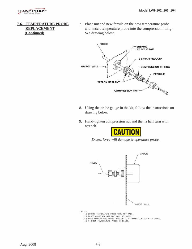
7. Place nut and new ferrule on the new temperature probe andinserttemperatureprobeintothecompressionfitting. See drawing below.
8. Using the probe gauge in the kit, follow the instructions on drawing below.
9. Hand-tighten compression nut and then a half turn with wrench.
Excess force will damage temperature probe.
Aug. 2008
Model LVG-102, 103, 104
7-9
8. Connect new temperature probe to connector and fasten connector onto control panel.
9. Replace control panel and reconnect power to vat.
10. Fill vat by pressing and holding a button until *FILTER* *MENU* shows in the display. Then once “1.AUTO FILTER” shows in the display, press 4 times until “5.FILL POT FROM DRN PAN” shows in display. Press √ button; “FILL POT FROM DRN PAN” “YES NO” displays. Press √ button again, display shows “FILLING”“STOP?”andoilfillsvat.Press√ button again, display shows “FILL POT FROM DRN PAN” “YES NO”. When vat is full, press X twice to return to normal operation.
Each vat has a solenoid plumbed-into the oil return lines. They are normally closed, but open when power is supplied, such as, thecontrolsarefillingthevats.
To avoid electrical shock or property damage, move the power switch to OFF and disconnect main circuit breaker, or unplug cord at wall receptacle.
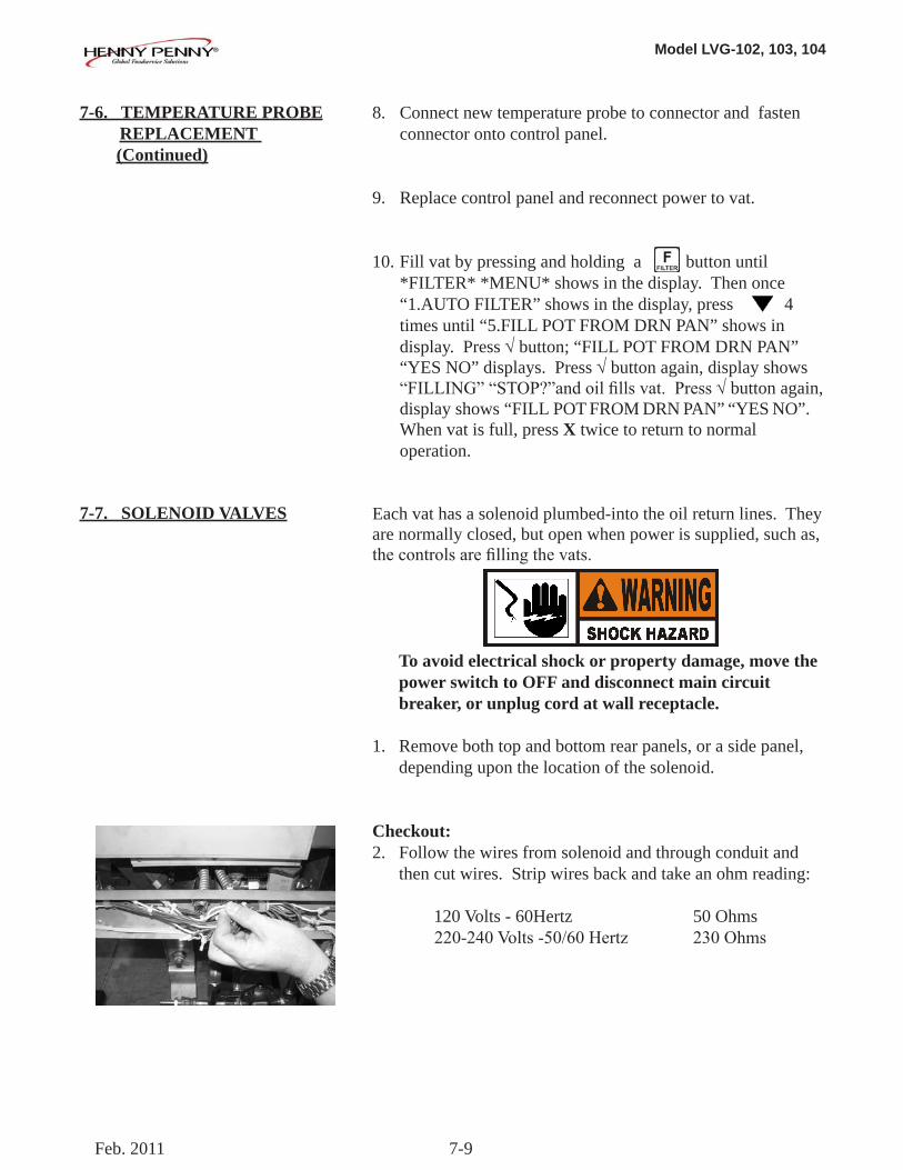
1. Remove both top and bottom rear panels, or a side panel, depending upon the location of the solenoid.
Checkout:2. Follow the wires from solenoid and through conduit and then cut wires. Strip wires back and take an ohm reading:
120 Volts - 60Hertz 50 Ohms220-240Volts-50/60Hertz 230Ohms
7-6. TEMPERATURE PROBE REPLACEMENT (Continued)
7-7. SOLENOID VALVES
Feb. 2011
Model LVG-102, 103, 104
7-10
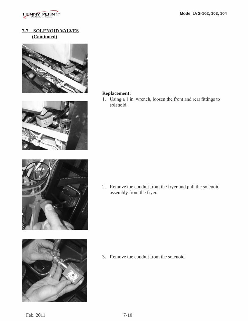
Replacement:1. Usinga1in.wrench,loosenthefrontandrearfittingsto solenoid.
2. Remove the conduit from the fryer and pull the solenoid assembly from the fryer.
3. Remove the conduit from the solenoid.
7-7. SOLENOID VALVES (Continued)
Feb. 2011
Model LVG-102, 103, 104
7-11
7-7. SOLENOID VALVES (Continued)
4. Removeelbowandfittingsfromsolenoidstemassembly, and attach them to new solenoid, using pipe sealent on the threads.
5. Reattach the conduit to new solenoid, threading the wires through the conduit.
6. Reattach the solenoid assembly to the fryer.
7. Reattach the conduit to fryer and connect the wires to the fryer using wire nuts.
8. Replace rear side panels or rear panels and reconnect power to the fryer.
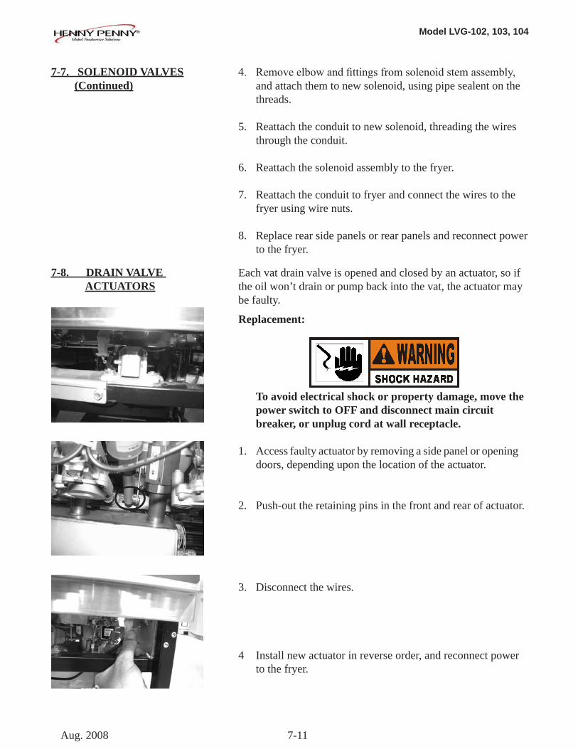
7-8. DRAIN VALVE ACTUATORS
Each vat drain valve is opened and closed by an actuator, so if the oil won’t drain or pump back into the vat, the actuator may be faulty.
Replacement:
To avoid electrical shock or property damage, move the power switch to OFF and disconnect main circuit breaker, or unplug cord at wall receptacle.
1. Access faulty actuator by removing a side panel or opening doors, depending upon the location of the actuator.
2. Push-out the retaining pins in the front and rear of actuator.
3. Disconnect the wires.
4 Install new actuator in reverse order, and reconnect power to the fryer.
Aug. 2008
Model LVG-102, 103, 104
7-12
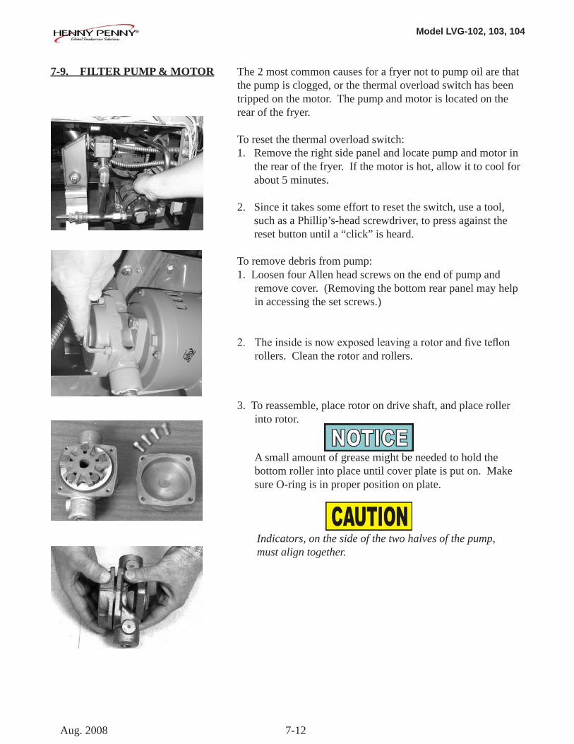
7-9. FILTER PUMP & MOTOR
The 2 most common causes for a fryer not to pump oil are that the pump is clogged, or the thermal overload switch has been tripped on the motor. The pump and motor is located on the rear of the fryer.
To reset the thermal overload switch:1. Remove the right side panel and locate pump and motor in the rear of the fryer. If the motor is hot, allow it to cool for about 5 minutes.
2. Since it takes some effort to reset the switch, use a tool, such as a Phillip’s-head screwdriver, to press against the reset button until a “click” is heard.
To remove debris from pump:1. Loosen four Allen head screws on the end of pump and remove cover. (Removing the bottom rear panel may help in accessing the set screws.)
2. Theinsideisnowexposedleavingarotorandfiveteflon rollers. Clean the rotor and rollers.
3. To reassemble, place rotor on drive shaft, and place roller into rotor.
A small amount of grease might be needed to hold the bottom roller into place until cover plate is put on. Make sure O-ring is in proper position on plate.
Indicators, on the side of the two halves of the pump, must align together.
Aug. 2008
Model LVG-102, 103, 104
7-13
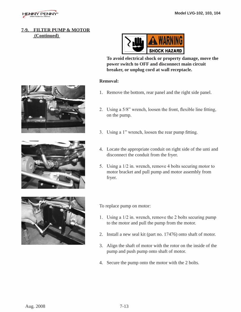
To avoid electrical shock or property damage, move the power switch to OFF and disconnect main circuit breaker, or unplug cord at wall receptacle.
Removal:
1. Remove the bottom, rear panel and the right side panel.
2. Usinga5/8”wrench,loosenthefront,flexiblelinefitting, on the pump.
3. Usinga1”wrench,loosentherearpumpfitting.
4. Locate the appropriate conduit on right side of the unti and disconnect the conduit from the fryer.
5. Usinga1/2in.wrench,remove4boltssecuringmotorto motor bracket and pull pump and motor assembly from fryer.
To replace pump on motor:
1.Usinga1/2in.wrench,removethe2boltssecuringpump to the motor and pull the pump from the motor.
2. Install a new seal kit (part no. 17476) onto shaft of motor.
3. Align the shaft of motor with the rotor on the inside of the pump and push pump onto shaft of motor.
4. Secure the pump onto the motor with the 2 bolts.
7-9. FILTER PUMP & MOTOR (Continued)
Aug. 2008
Model LVG-102, 103, 104
7-14
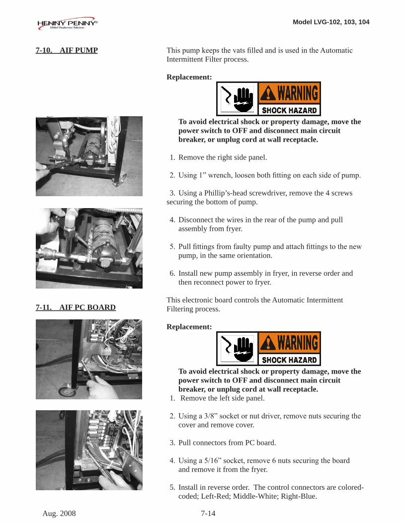
ThispumpkeepsthevatsfilledandisusedintheAutomaticIntermittent Filter process.
Replacement:
To avoid electrical shock or property damage, move the power switch to OFF and disconnect main circuit breaker, or unplug cord at wall receptacle.
1. Remove the right side panel.
2.Using1”wrench,loosenbothfittingoneachsideofpump. 3. Using a Phillip’s-head screwdriver, remove the 4 screws securing the bottom of pump.
4. Disconnect the wires in the rear of the pump and pull assembly from fryer.
5. Pullfittingsfromfaultypumpandattachfittingstothenew pump, in the same orientation.
6. Install new pump assembly in fryer, in reverse order and then reconnect power to fryer.
This electronic board controls the Automatic Intermittent Filtering process.
Replacement:
To avoid electrical shock or property damage, move the power switch to OFF and disconnect main circuit breaker, or unplug cord at wall receptacle. 1. Remove the left side panel.
2.Usinga3/8”socketornutdriver,removenutssecuringthe cover and remove cover.
3. Pull connectors from PC board.
4.Usinga5/16”socket,remove6nutssecuringtheboard and remove it from the fryer.
5. Install in reverse order. The control connectors are colored- coded; Left-Red; Middle-White; Right-Blue.
7-10. AIF PUMP
7-11. AIF PC BOARD
Aug. 2008
Model LVG-102, 103, 104
7-15
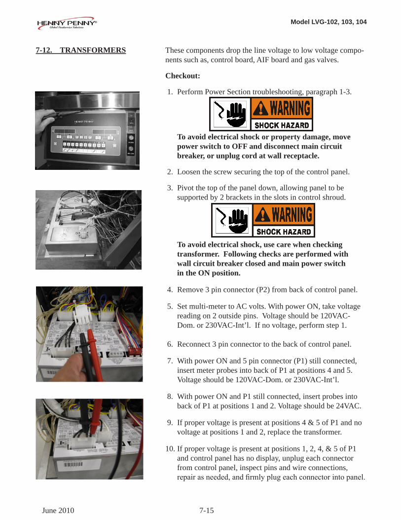
These components drop the line voltage to low voltage compo-nents such as, control board, AIF board and gas valves.
Checkout:
1. Perform Power Section troubleshooting, paragraph 1-3.
To avoid electrical shock or property damage, move power switch to OFF and disconnect main circuit breaker, or unplug cord at wall receptacle.
2. Loosen the screw securing the top of the control panel.
3. Pivot the top of the panel down, allowing panel to be supported by 2 brackets in the slots in control shroud.
To avoid electrical shock, use care when checking transformer. Following checks are performed with wall circuit breaker closed and main power switch in the ON position.
4. Remove 3 pin connector (P2) from back of control panel.
5. Set multi-meter to AC volts. With power ON, take voltage reading on 2 outside pins. Voltage should be 120VAC- Dom. or 230VAC-Int’l. If no voltage, perform step 1.
6. Reconnect 3 pin connector to the back of control panel.
7. With power ON and 5 pin connector (P1) still connected, insert meter probes into back of P1 at positions 4 and 5. Voltage should be 120VAC-Dom. or 230VAC-Int’l.
8. With power ON and P1 still connected, insert probes into back of P1 at positions 1 and 2. Voltage should be 24VAC.
9. If proper voltage is present at positions 4 & 5 of P1 and no voltage at positions 1 and 2, replace the transformer.
10. If proper voltage is present at positions 1, 2, 4, & 5 of P1 and control panel has no display, unplug each connector from control panel, inspect pins and wire connections, repairasneeded,andfirmlyplugeachconnectorintopanel.
7-12. TRANSFORMERS
June 2010
Model LVG-102, 103, 104
7-16
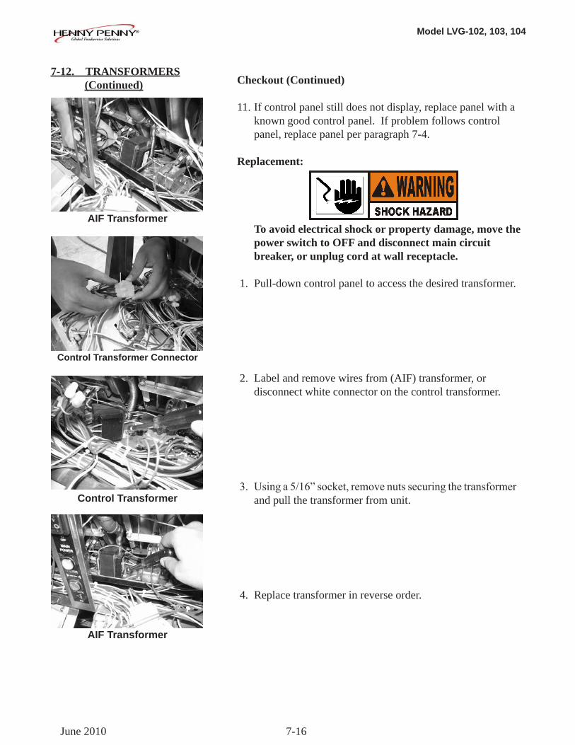
Checkout (Continued)
11. If control panel still does not display, replace panel with a known good control panel. If problem follows control panel, replace panel per paragraph 7-4.
Replacement:
To avoid electrical shock or property damage, move the power switch to OFF and disconnect main circuit breaker, or unplug cord at wall receptacle. 1. Pull-down control panel to access the desired transformer.
2. Label and remove wires from (AIF) transformer, or disconnect white connector on the control transformer.
3. Usinga5/16”socket,removenutssecuringthetransformer and pull the transformer from unit.
4. Replace transformer in reverse order.
7-12. TRANSFORMERS (Continued)
AIF Transformer
Control Transformer Connector
Control Transformer
AIF Transformer
June 2010
Model LVG-102, 103, 104
7-17
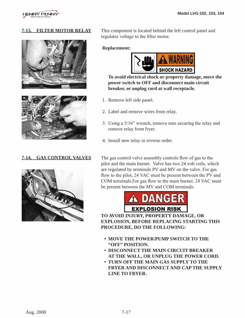
This component is located behind the left control panel and regulatesvoltagetothefiltermotor.
Replacement:
To avoid electrical shock or property damage, move the power switch to OFF and disconnect main circuit breaker, or unplug cord at wall receptacle. 1. Remove left side panel.
2. Label and remove wires from relay.
3. Usinga5/16”wrench,removenutssecuringtherelayand remove relay from fryer.
4. Install new relay in reverse order.
Thegascontrolvalveassemblycontrolsflowofgastothe pilot and the main burner. Valve has two 24 volt coils, which are regulated by terminals PV and MV on the valve. For gas flowtothepilot,24VACmustbepresentbetweenthePVandCOMterminals.Forgasflowtothemainburner,24VACmustbe present between the MV and COM terminals.
TO AVOID INJURY, PROPERTY DAMAGE, OR EXPLOSION, BEFORE REPLACING STARTING THIS PROCEDURE, DO THE FOLLOWING:
• MOVE THE POWER/PUMP SWITCH TO THE “OFF” POSITION. • DISCONNECT THE MAIN CIRCUIT BREAKER AT THE WALL, OR UNPLUG THE POWER CORD. • TURN OFF THE MAIN GAS SUPPLY TO THE FRYER AND DISCONNECT AND CAP THE SUPPLY LINE TO FRYER.
7-13. FILTER MOTOR RELAY
7-14. GAS CONTROL VALVES
Aug. 2008
Model LVG-102, 103, 104
7-18
7-14. GAS CONTROL VALVES (Control)
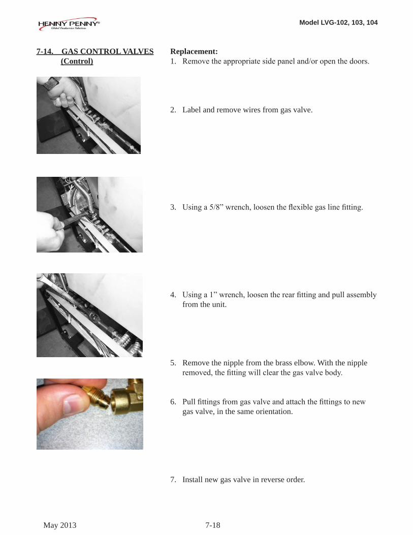
Replacement:1. Removetheappropriatesidepaneland/oropenthedoors.
2. Label and remove wires from gas valve.
3. Usinga5/8”wrench,loosentheflexiblegaslinefitting.
4. Usinga1”wrench,loosentherearfittingandpullassemblyfrom the unit.
5. Remove the nipple from the brass elbow. With the nipple removed,thefittingwillclearthegasvalvebody.
6. Pullfittingsfromgasvalveandattachthefittingstonewgas valve, in the same orientation.
7. Install new gas valve in reverse order.
May 2013
Model LVG-102, 103, 104
7-19
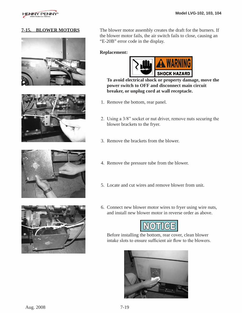
7-15. BLOWER MOTORS The blower motor assembly creates the draft for the burners. If the blower motor fails, the air switch fails to close, causing an “E-20B” error code in the display.
Replacement:
To avoid electrical shock or property damage, move the power switch to OFF and disconnect main circuit breaker, or unplug cord at wall receptacle.
1. Remove the bottom, rear panel.
2. Usinga3/8”socketornutdriver,removenutssecuringthe blower brackets to the fryer.
3. Remove the brackets from the blower.
4. Remove the pressure tube from the blower.
5. Locate and cut wires and remove blower from unit.
6. Connect new blower motor wires to fryer using wire nuts, and install new blower motor in reverse order as above.
Before installing the bottom, rear cover, clean blower intakeslotstoensuresufficientairflowtotheblowers.
Aug. 2008
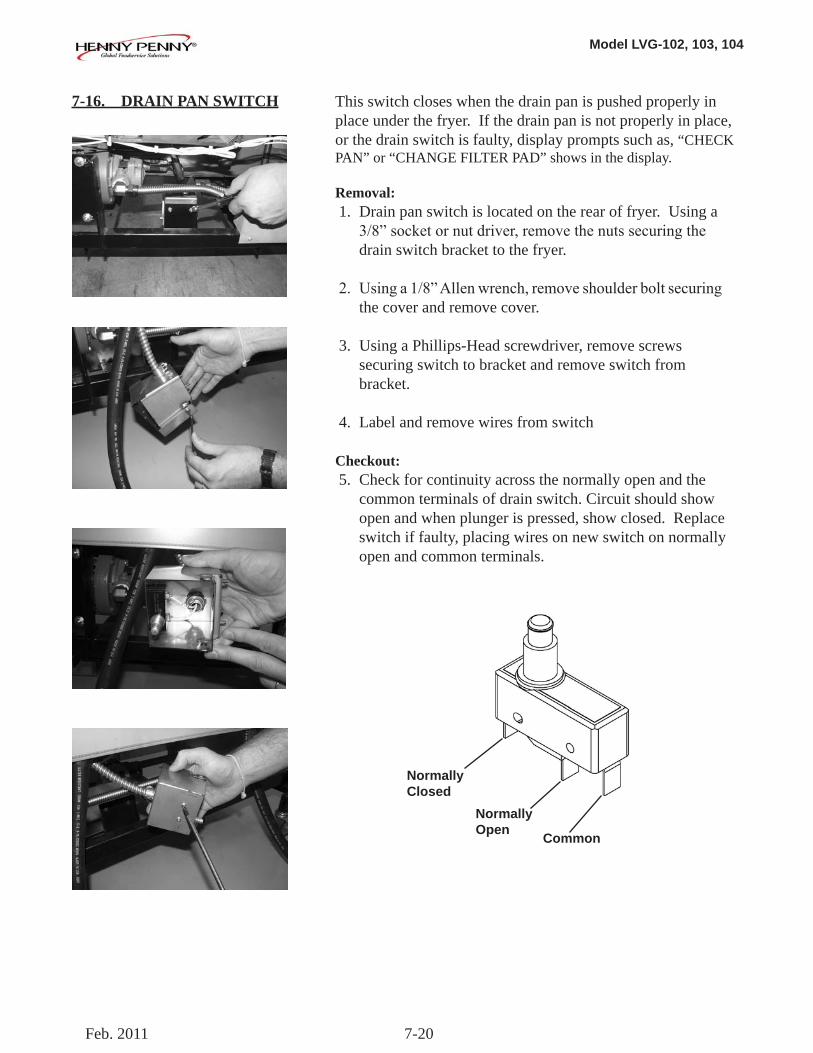
Model LVG-102, 103, 104
7-20
7-16. DRAIN PAN SWITCH This switch closes when the drain pan is pushed properly in place under the fryer. If the drain pan is not properly in place, or the drain switch is faulty, display prompts such as, “CHECK PAN” or “CHANGE FILTER PAD” shows in the display.
Removal: 1. Drain pan switch is located on the rear of fryer. Using a 3/8”socketornutdriver,removethenutssecuringthe drain switch bracket to the fryer.
2. Usinga1/8”Allenwrench,removeshoulderboltsecuring the cover and remove cover.
3. Using a Phillips-Head screwdriver, remove screws securing switch to bracket and remove switch from bracket.
4. Label and remove wires from switch
Checkout: 5. Check for continuity across the normally open and the common terminals of drain switch. Circuit should show open and when plunger is pressed, show closed. Replace switch if faulty, placing wires on new switch on normally open and common terminals.
Normally Closed
Normally Open Common
Feb. 2011
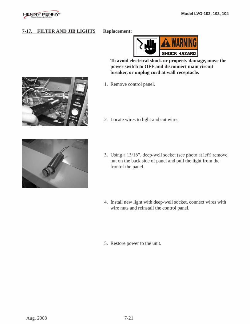
Model LVG-102, 103, 104
7-21
7-17. FILTER AND JIB LIGHTS Replacement:
To avoid electrical shock or property damage, move the power switch to OFF and disconnect main circuit breaker, or unplug cord at wall receptacle.
1. Remove control panel.
2. Locate wires to light and cut wires.
3. Usinga13/16”,deep-wellsocket(seephotoatleft)remove nut on the back side of panel and pull the light from the frontof the panel.
4. Install new light with deep-well socket, connect wires with wire nuts and reinstall the control panel.
5. Restore power to the unit.
Aug. 2008
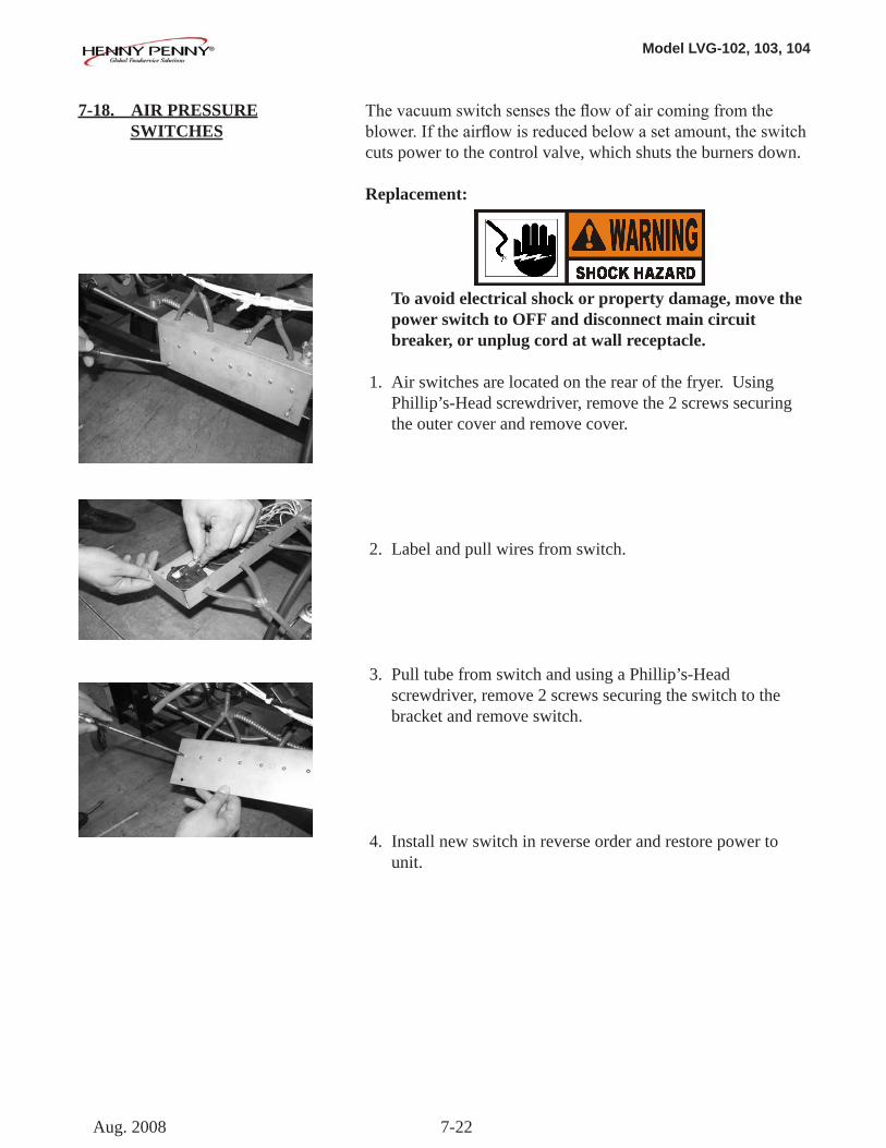
Model LVG-102, 103, 104
7-22
7-18. AIR PRESSURE SWITCHES
Thevacuumswitchsensestheflowofaircomingfromtheblower.Iftheairflowisreducedbelowasetamount,theswitchcuts power to the control valve, which shuts the burners down.
Replacement:
To avoid electrical shock or property damage, move the power switch to OFF and disconnect main circuit breaker, or unplug cord at wall receptacle.
1. Air switches are located on the rear of the fryer. Using Phillip’s-Head screwdriver, remove the 2 screws securing the outer cover and remove cover.
2. Label and pull wires from switch.
3. Pull tube from switch and using a Phillip’s-Head screwdriver, remove 2 screws securing the switch to the bracket and remove switch.
4. Install new switch in reverse order and restore power to unit.
Aug. 2008
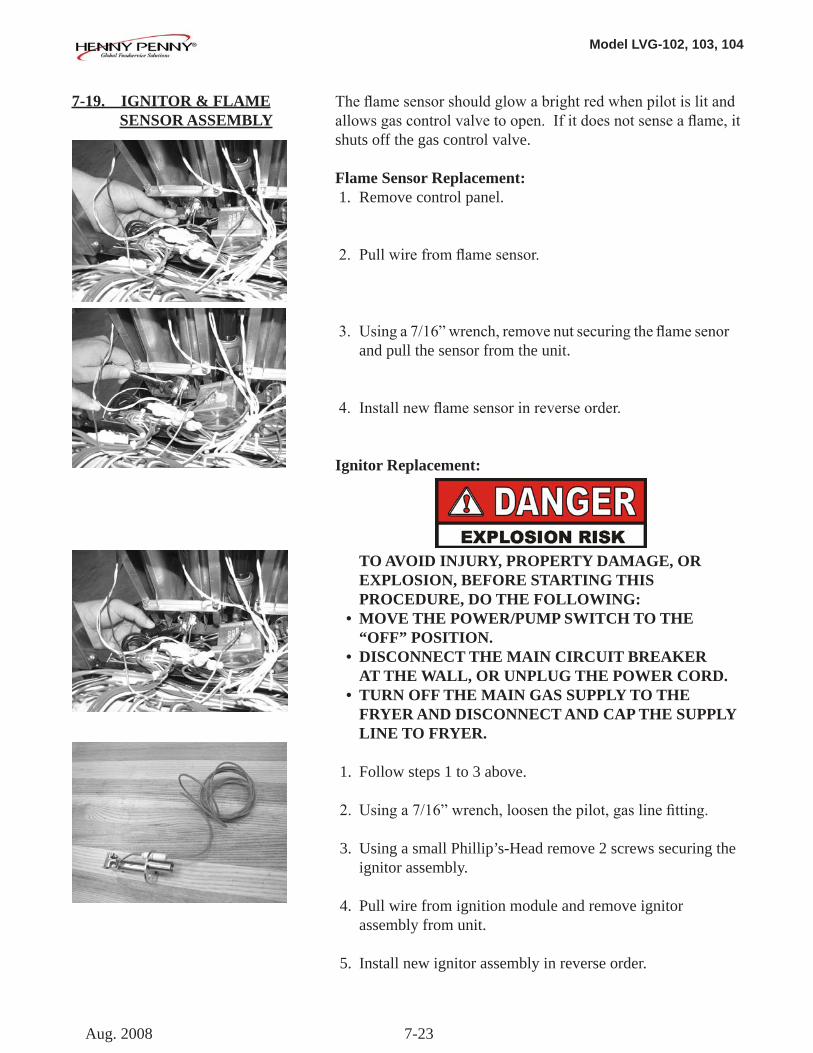
Model LVG-102, 103, 104
7-23
7-19. IGNITOR & FLAME SENSOR ASSEMBLY
Theflamesensorshouldglowabrightredwhenpilotislitandallowsgascontrolvalvetoopen.Ifitdoesnotsenseaflame,itshuts off the gas control valve.
Flame Sensor Replacement: 1. Remove control panel.
2. Pullwirefromflamesensor.
3. Usinga7/16”wrench,removenutsecuringtheflamesenor and pull the sensor from the unit.
4. Installnewflamesensorinreverseorder.
Ignitor Replacement:
TO AVOID INJURY, PROPERTY DAMAGE, OR EXPLOSION, BEFORE STARTING THIS PROCEDURE, DO THE FOLLOWING: • MOVE THE POWER/PUMP SWITCH TO THE “OFF” POSITION. • DISCONNECT THE MAIN CIRCUIT BREAKER AT THE WALL, OR UNPLUG THE POWER CORD. • TURN OFF THE MAIN GAS SUPPLY TO THE FRYER AND DISCONNECT AND CAP THE SUPPLY LINE TO FRYER.
1. Follow steps 1 to 3 above.
2. Usinga7/16”wrench,loosenthepilot,gaslinefitting.
3. Using a small Phillip’s-Head remove 2 screws securing the ignitor assembly.
4. Pull wire from ignition module and remove ignitor assembly from unit.
5. Install new ignitor assembly in reverse order.
Aug. 2008
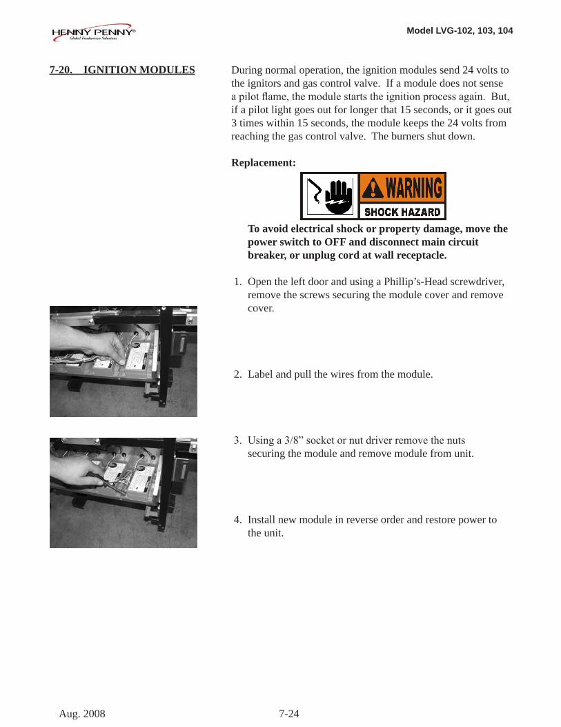
Model LVG-102, 103, 104
7-24
7-20. IGNITION MODULES During normal operation, the ignition modules send 24 volts to the ignitors and gas control valve. If a module does not sense apilotflame,themodulestartstheignitionprocessagain.But,if a pilot light goes out for longer that 15 seconds, or it goes out 3 times within 15 seconds, the module keeps the 24 volts from reaching the gas control valve. The burners shut down.
Replacement:
To avoid electrical shock or property damage, move the power switch to OFF and disconnect main circuit breaker, or unplug cord at wall receptacle.
1. Open the left door and using a Phillip’s-Head screwdriver, remove the screws securing the module cover and remove cover.
2. Label and pull the wires from the module.
3. Usinga3/8”socketornutdriverremovethenuts securing the module and remove module from unit.
4. Install new module in reverse order and restore power to the unit.
Aug. 2008
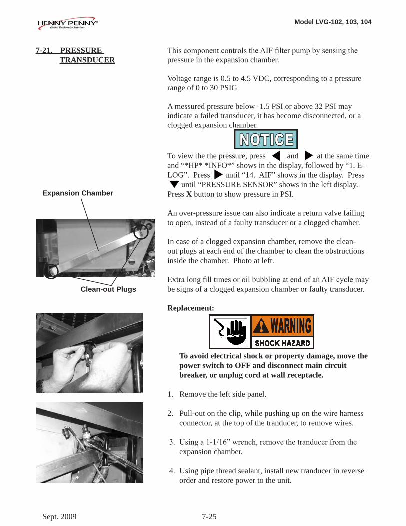
Model LVG-102, 103, 104
7-25
7-21. PRESSURE TRANSDUCER
ThiscomponentcontrolstheAIFfilterpumpbysensingthepressure in the expansion chamber.
Voltage range is 0.5 to 4.5 VDC, corresponding to a pressure range of 0 to 30 PSIG
A messured pressure below -1.5 PSI or above 32 PSI may indicate a failed transducer, it has become disconnected, or a clogged expansion chamber.
To view the the pressure, press and at the same time and “*HP* *INFO*” shows in the display, followed by “1. E-LOG”. Press until “14. AIF” shows in the display. Press until “PRESSURE SENSOR” shows in the left display. Press X button to show pressure in PSI.
An over-pressure issue can also indicate a return valve failing to open, instead of a faulty transducer or a clogged chamber.
In case of a clogged expansion chamber, remove the clean-out plugs at each end of the chamber to clean the obstructions inside the chamber. Photo at left.
ExtralongfilltimesoroilbubblingatendofanAIFcyclemaybe signs of a clogged expansion chamber or faulty transducer.
Replacement:
To avoid electrical shock or property damage, move the power switch to OFF and disconnect main circuit breaker, or unplug cord at wall receptacle.
1. Remove the left side panel.
2. Pull-out on the clip, while pushing up on the wire harness connector, at the top of the tranducer, to remove wires.
3. Usinga1-1/16”wrench,removethetranducerfromthe expansion chamber.
4. Using pipe thread sealant, install new tranducer in reverse order and restore power to the unit.
Clean-out Plugs
Expansion Chamber
Sept. 2009
Model LVG-102, 103, 104
8-1
8-1. INTRODUCTION This section lists the replaceable parts of the Henny Penny Model LVG fryer.
8-2. GENUINE PARTS Use only genuine Henny Penny parts in your fryer. Using a part of lesser quality or substitute design may result in damage to the unit or personal injury.
8-3. WHEN ORDERING PARTS Once the parts that you want to order have been found in the parts list, write down the following information:
Item Number 2 Part Number 60241 Example: Description High Limit
From the data plate, list the following information:
Product Number 01100 Serial Number 0001 Example: Voltage 208
8-4. PRICES Your distributor has a price parts list and will be glad to inform you of the cost of your parts order.
8-5. DELIVERY Commonly replaced items are stocked by your distributor and will be sent out when your order is received. Other parts will be ordered, by your distributor, from Henny Penny Corp. Normally, these will be sent to your distributor within three working days.
8-6. WARRANTY All replacement parts (except lamps and fuses) are warranted for 90 days against manufacturing defects and workmanship. If damage occurs during shipping, notify the carrier at once so thataclaimmaybeproperlyfiled.Refertowarrantyinthe front of this manual for other rights and limitations.
Recommended replacement parts, stocked by your distributor, are indicated with √in the parts lists. Please use care when ordering recommended parts, because all voltages and variations are marked. Distributors should order parts based upon common voltages and equipment sold in their territory.
8-7. RECOMMENDED SPARE PARTS FORDISTRIBUTORS
July 2008
SECTION 8. PARTS INFORMATION
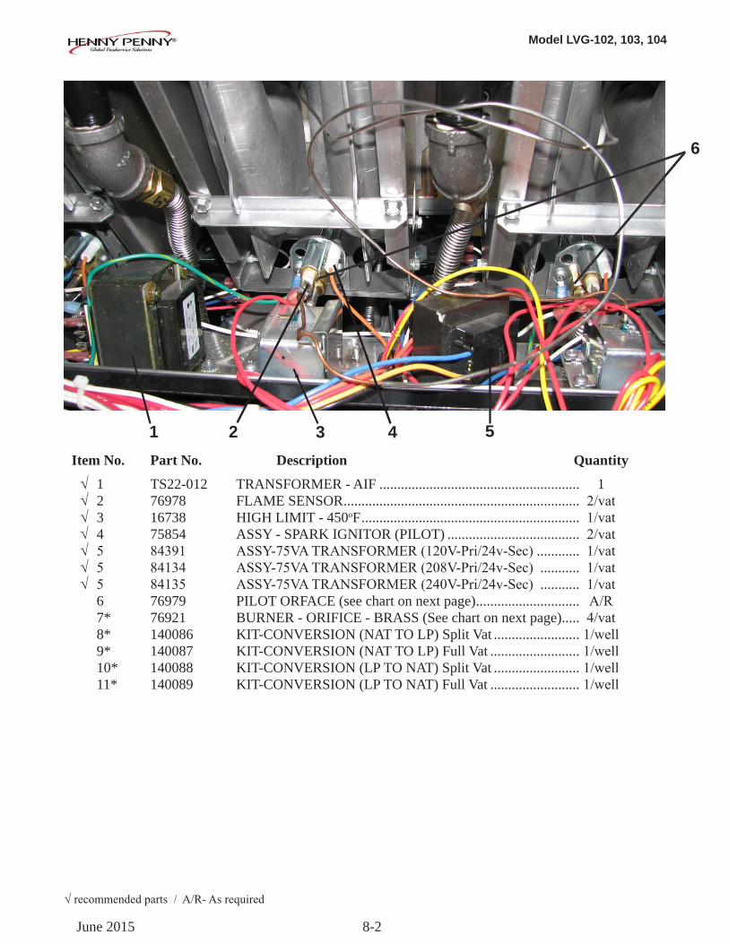
Model LVG-102, 103, 104
8-2
Item No. Part No. Description Quantity
√ 1 TS22-012 TRANSFORMER - AIF ........................................................ 1 √ 2 76978 FLAME SENSOR .................................................................. 2/vat √ 3 16738 HIGH LIMIT - 450oF ............................................................. 1/vat √ 4 75854 ASSY - SPARK IGNITOR (PILOT) ..................................... 2/vat √ 5 84391 ASSY-75VATRANSFORMER(120V-Pri/24v-Sec) ............ 1/vat √ 5 84134 ASSY-75VATRANSFORMER(208V-Pri/24v-Sec) ........... 1/vat √ 5 84135 ASSY-75VATRANSFORMER(240V-Pri/24v-Sec) ........... 1/vat 6 76979 PILOT ORFACE (see chart on next page) ............................. A/R 7* 76921 BURNER - ORIFICE - BRASS (See chart on next page) ..... 4/vat 8* 140086 KIT-CONVERSION (NAT TO LP) Split Vat ........................1/well 9* 140087 KIT-CONVERSION (NAT TO LP) Full Vat .........................1/well 10* 140088 KIT-CONVERSION (LP TO NAT) Split Vat ........................1/well 11* 140089 KIT-CONVERSION (LP TO NAT) Full Vat .........................1/well
1 2 3 4 5
6
√recommendedparts/A/R-Asrequired
June 2015
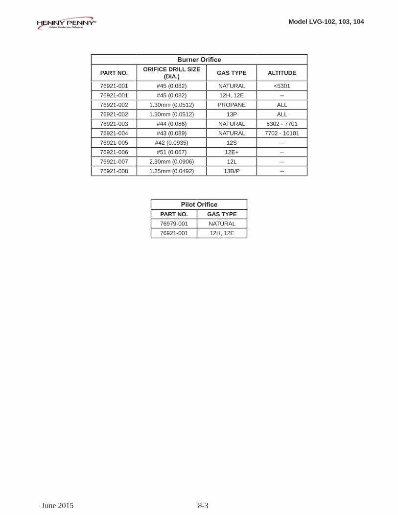
Model LVG-102, 103, 104
8-3
Burner Orifice
PART NO. ORIFICE DRILL SIZE (DIA.) GAS TYPE ALTITUDE
76921-001 #45 (0.082) NATURAL <530176921-001 #45 (0.082) 12H, 12E --76921-002 1.30mm (0.0512) PROPANE ALL76921-002 1.30mm (0.0512) 13P ALL76921-003 #44 (0.086) NATURAL 5302 - 770176921-004 #43 (0.089) NATURAL 7702 - 1010176921-005 #42 (0.0935) 12S --76921-006 #51 (0.067) 12E+ --76921-007 2.30mm (0.0906) 12L --76921-008 1.25mm (0.0492) 13B/P --
Pilot Orifice PART NO. GAS TYPE 76979-001 NATURAL76921-001 12H, 12E
June 2015
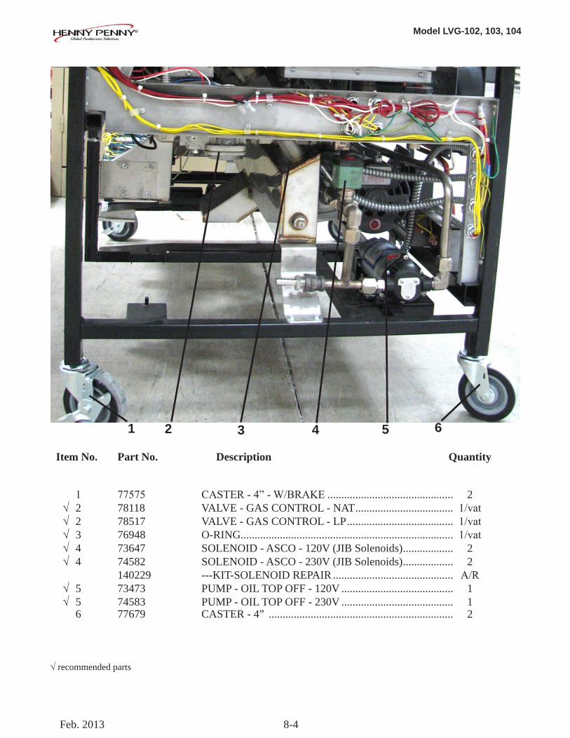
Model LVG-102, 103, 104
8-4
Item No. Part No. Description Quantity
1 77575 CASTER-4”-W/BRAKE ............................................. 2 √ 2 78118 VALVE - GAS CONTROL - NAT ................................... 1/vat √ 2 78517 VALVE - GAS CONTROL - LP ...................................... 1/vat √ 3 76948 O-RING ............................................................................ 1/vat √ 4 73647 SOLENOID - ASCO - 120V (JIB Solenoids) .................. 2 √ 4 74582 SOLENOID - ASCO - 230V (JIB Solenoids) .................. 2 140229 ---KIT-SOLENOID REPAIR ........................................... A/R √ 5 73473 PUMP - OIL TOP OFF - 120V ........................................ 1 √ 5 74583 PUMP - OIL TOP OFF - 230V ........................................ 1 6 77679 CASTER - 4” .................................................................. 2
√recommended parts
1 2 3 5 64
Feb. 2013
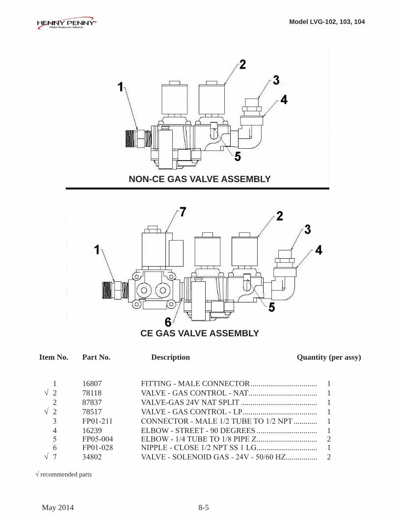
Model LVG-102, 103, 104
8-5
Item No. Part No. Description Quantity (per assy)
1 16807 FITTING - MALE CONNECTOR .................................. 1 √ 2 78118 VALVE - GAS CONTROL - NAT ................................... 1 2 87837 VALVE-GAS 24V NAT SPLIT ....................................... 1 √ 2 78517 VALVE - GAS CONTROL - LP ...................................... 1 3 FP01-211 CONNECTOR-MALE1/2TUBETO1/2NPT ............ 1 4 16239 ELBOW - STREET - 90 DEGREES ............................... 1 5 FP05-004 ELBOW-1/4TUBETO1/8PIPEZ ............................... 2 6 FP01-028 NIPPLE-CLOSE1/2NPTSS1LG ............................... 1 √ 7 34802 VALVE-SOLENOIDGAS-24V-50/60HZ ................ 2
√recommended parts
NON-CE GAS VALVE ASSEMBLY
CE GAS VALVE ASSEMBLY
May 2014
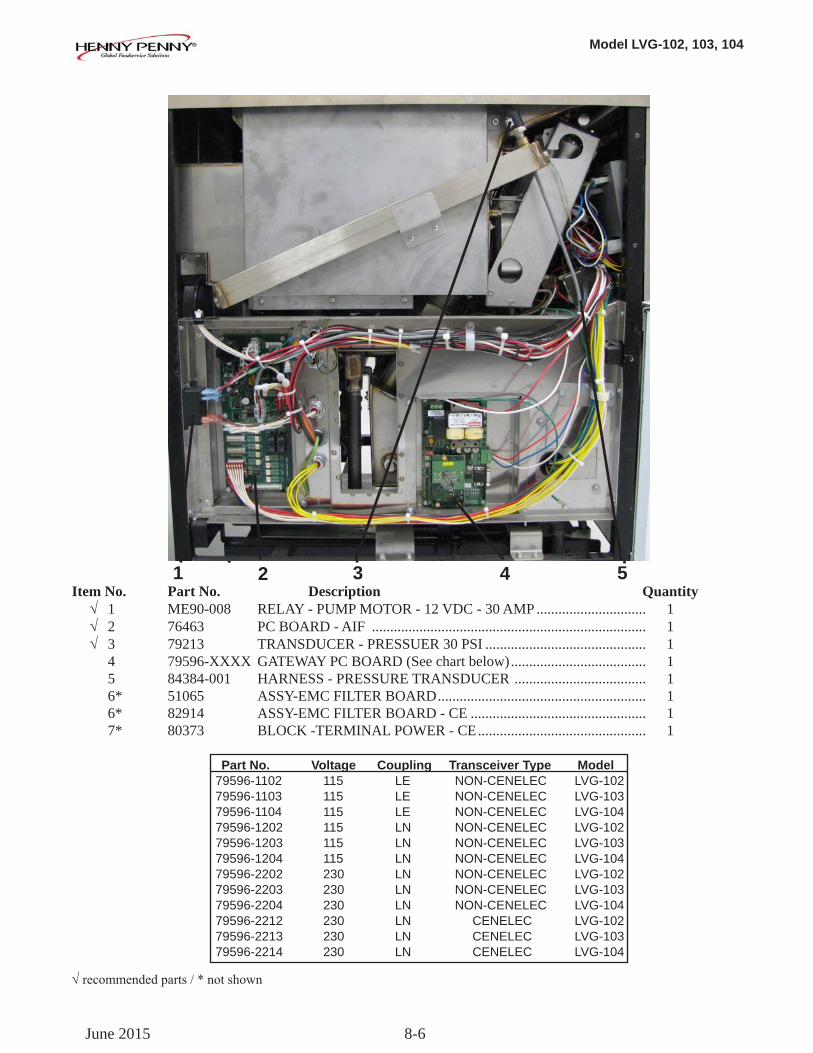
Model LVG-102, 103, 104
8-6
Item No. Part No. Description Quantity √ 1 ME90-008 RELAY - PUMP MOTOR - 12 VDC - 30 AMP .............................. 1 √ 2 76463 PC BOARD - AIF ........................................................................... 1 √ 3 79213 TRANSDUCER - PRESSUER 30 PSI ............................................ 1 4 79596-XXXX GATEWAY PC BOARD (See chart below) ..................................... 1 5 84384-001 HARNESS - PRESSURE TRANSDUCER .................................... 1 6* 51065 ASSY-EMC FILTER BOARD ......................................................... 1 6* 82914 ASSY-EMC FILTER BOARD - CE ................................................ 1 7* 80373 BLOCK -TERMINAL POWER - CE .............................................. 1 Part No. Voltage Coupling Transceiver Type Model 79596-1102 115 LE NON-CENELEC LVG-102 79596-1103 115 LE NON-CENELEC LVG-103 79596-1104 115 LE NON-CENELEC LVG-104 79596-1202 115 LN NON-CENELEC LVG-102 79596-1203 115 LN NON-CENELEC LVG-103 79596-1204 115 LN NON-CENELEC LVG-104 79596-2202 230 LN NON-CENELEC LVG-102 79596-2203 230 LN NON-CENELEC LVG-103 79596-2204 230 LN NON-CENELEC LVG-104 79596-2212 230 LN CENELEC LVG-102 79596-2213 230 LN CENELEC LVG-103 79596-2214 230 LN CENELEC LVG-104
1 2 3
√recommendedparts/*notshown
54
June 2015
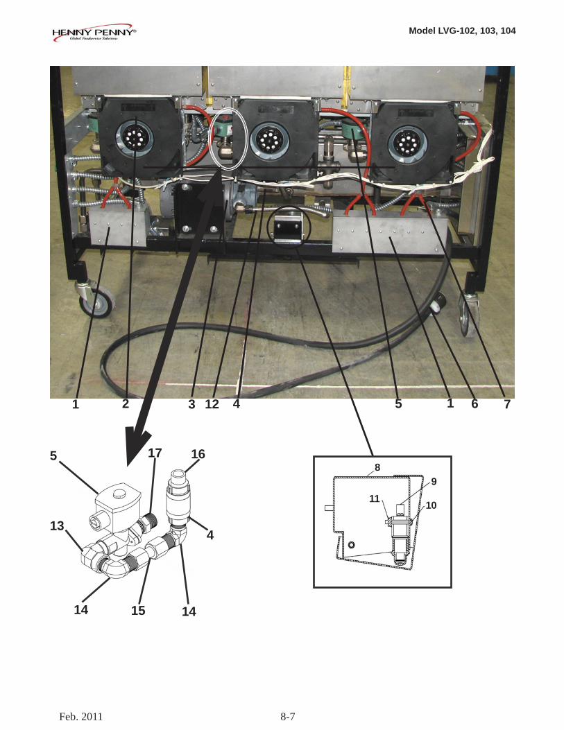
Model LVG-102, 103, 104
8-7
1 2 13 4 65 7
89
1011
12
5
13
14 15 14
17 16
4
Feb. 2011
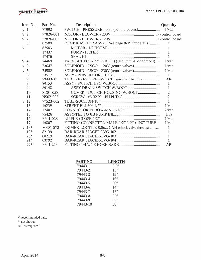
Model LVG-102, 103, 104
8-8
Item No. Part No. Description Quantity √ 1 77992 SWITCH - PRESSURE - 0.80 (behind covers)...................... 1/vat √ 2 77826-001 MOTOR - BLOWER - 230V ............................................ 1/controlboard √ 2 77826-002 MOTOR - BLOWER - 120V ............................................ 1/controlboard 3 67589 PUMP & MOTOR ASSY...(See page 8-19 for details) .......... 1 √ 67583 MOTOR-1/2HORSE ..................................................... 1 17437 PUMP - FILTER .............................................................. 1 17476 SEAL KIT ........................................................................ 1 √ 4 74469 VALVE-CHECK-1/2”(VatFill)(Useitem20onthreads) .... 1/vat √ 5 73647 SOLENOID - ASCO - 120V (return valves) .......................... 1/vat √ 5 74582 SOLENOID - ASCO - 230V (return valves) .......................... 1/vat 6 73517 ASSY - POWER CORD 120V ............................................... 1 7 79443-X TUBE - PRESSURE SWITCH (see chart below) .................. AR 8 80153 ASSY-SWITCHHSGW/BOOT .......................................... 1 9 80148 ASSY-DRAINSWITCHW/BOOT ................................. 1 10 SC01-058 COVER-SWITCHHOUSINGW/BOOT ...................... 2 11 NS02-005 SCREW - #6-32 X 1 PH PHD C ..................................... 2 √ 12 77523-002 TUBE-SUCTION-18” ............................................................ 1 13 16239 STREETELL90°1/2” ........................................................... 1/vat 14 17407 CONNECTOR-ELBOW-MALE-1/2” .................................... 2/vat 15 75426 ASSY-TEE TO JIB PUMP INLET ......................................... 1/va 16 FP01-028 NIPPLE-CLOSE-1/2”............................................................. 1/vat 17 16807 FITTING-CONNECTOR-MALE-1/2”NPTx5/8”TUBE ... 1/vat √ 18* MS01-572 PRIMER-LOCTITE-0.8oz. CAN (check valve threads) ........... 1 19* 82139 BAR-REAR SPACER-LVG-102 ............................................ 1 20* 80219 BAR-REAR SPACER-LVG-103 ............................................ 1 21* 83792 BAR-REAR SPACER-LVG-104 ............................................ 1 22* FP01-213 FITTING-1/4WYEHOSEBARB ......................................... AR
PART NO. LENGTH 79443-1 2.5” 79443-2 13” 79443-3 19” 79443-4 16” 79443-5 26” 79443-6 14” 79443-7 17” 79443-8 22” 79443-9 32” 79443-10 38”
√recommended parts* not shownAR as required
April 2014
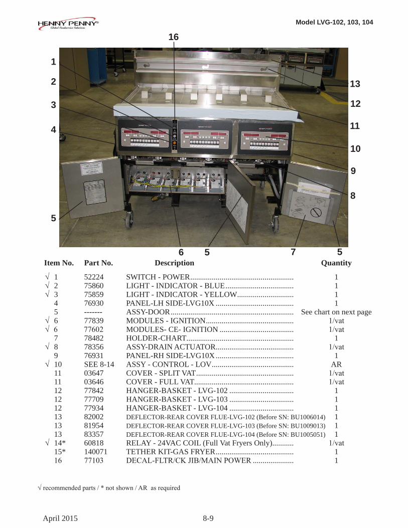
Model LVG-102, 103, 104
8-9
√recommendedparts/*notshown/ARasrequired
Item No. Part No. Description Quantity
√ 1 52224 SWITCH - POWER ..................................................... 1 √ 2 75860 LIGHT - INDICATOR - BLUE ................................... 1 √ 3 75859 LIGHT - INDICATOR - YELLOW ............................. 1 4 76930 PANEL-LH SIDE-LVG10X ........................................ 1 5 ------- ASSY-DOOR ............................................................... See chart on next page √ 6 77839 MODULES - IGNITION ............................................. 1/vat √ 6 77602 MODULES- CE- IGNITION ...................................... 1/vat 7 78482 HOLDER-CHART ....................................................... 1 √ 8 78356 ASSY-DRAIN ACTUATOR ........................................ 1/vat 9 76931 PANEL-RH SIDE-LVG10X ........................................ 1 √ 10 SEE 8-14 ASSY - CONTROL - LOV .......................................... AR 11 03647 COVER - SPLIT VAT .................................................. 1/vat 11 03646 COVER - FULL VAT................................................... 1/vat 12 77842 HANGER-BASKET - LVG-102 ................................. 1 12 77709 HANGER-BASKET - LVG-103 ................................. 1 12 77934 HANGER-BASKET - LVG-104 ................................. 1 13 82002 DEFLECTOR-REAR COVER FLUE-LVG-102 (Before SN: BU1006014) 1 13 81954 DEFLECTOR-REAR COVER FLUE-LVG-103 (Before SN: BU1009013) 1 13 83357 DEFLECTOR-REAR COVER FLUE-LVG-104 (Before SN: BU1005051) 1 √ 14* 60818 RELAY - 24VAC COIL (Full Vat Fryers Only)........... 1/vat 15* 140071 TETHER KIT-GAS FRYER ........................................ 1 16 77103 DECAL-FLTR/CKJIB/MAINPOWER ..................... 1
1
2
3
5
6 5
8
10
11
12
13
4
9
7 5
April 2015
16
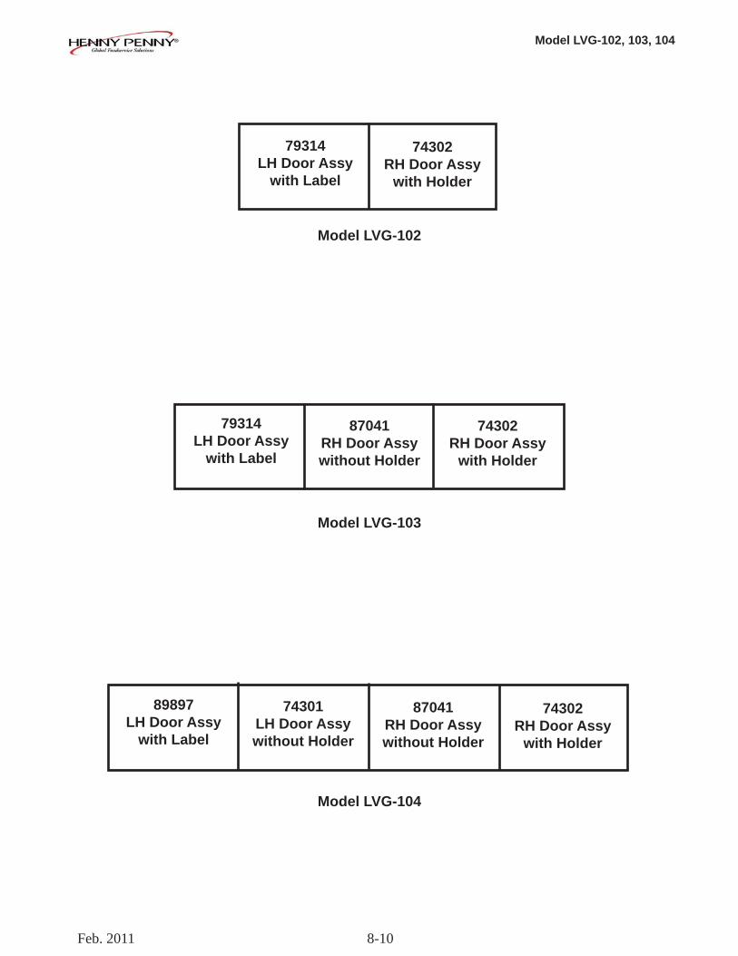
Model LVG-102, 103, 104
8-10
79314LH Door Assy
with Label
74302RH Door Assy
with Holder
74302RH Door Assy
with Holder
74302RH Door Assy
with Holder
79314LH Door Assy
with Label
89897LH Door Assy
with Label
87041RH Door Assywithout Holder
Model LVG-102
Model LVG-103
Model LVG-104
74301LH Door Assy without Holder
87041RH Door Assy without Holder
Feb. 2011
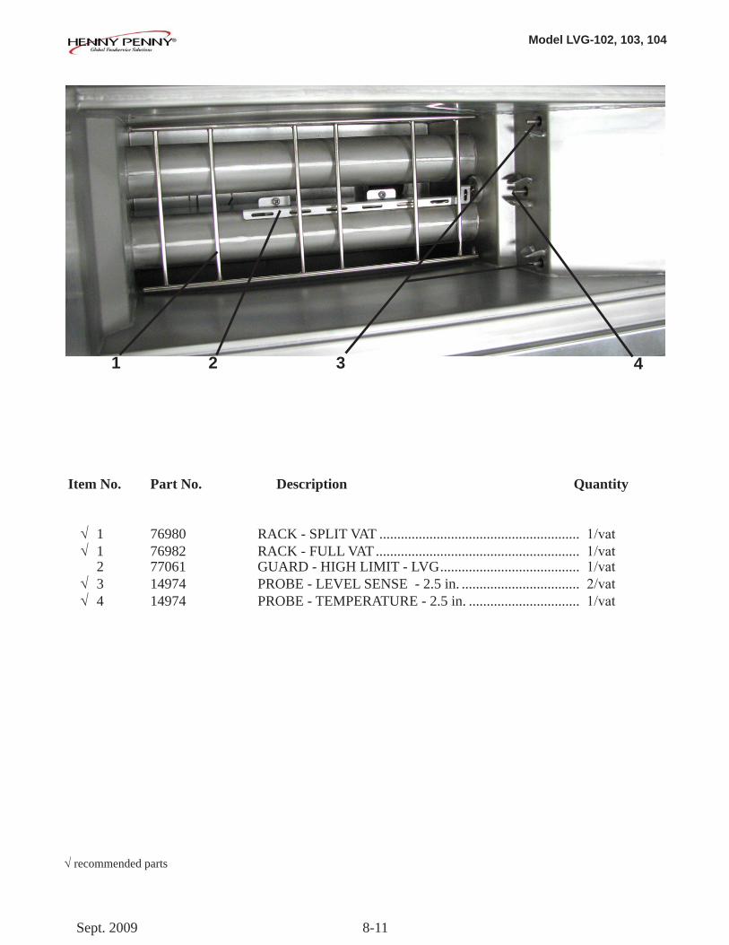
Model LVG-102, 103, 104
8-11
Item No. Part No. Description Quantity
√ 1 76980 RACK - SPLIT VAT ........................................................ 1/vat √ 1 76982 RACK - FULL VAT ......................................................... 1/vat 2 77061 GUARD - HIGH LIMIT - LVG ....................................... 1/vat √ 3 14974 PROBE - LEVEL SENSE - 2.5 in. ................................. 2/vat √ 4 14974 PROBE - TEMPERATURE - 2.5 in. ............................... 1/vat
32 41
√recommended parts
Sept. 2009
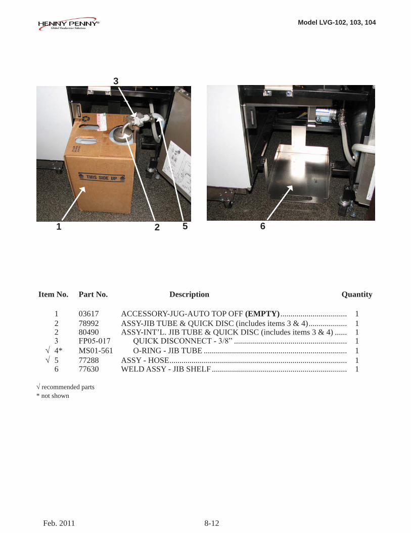
Model LVG-102, 103, 104
8-12
Item No. Part No. Description Quantity
1 03617 ACCESSORY-JUG-AUTO TOP OFF (EMPTY) ................................. 1 2 78992 ASSY-JIB TUBE & QUICK DISC (includes items 3 & 4) ................... 1 2 80490 ASSY-INT’L. JIB TUBE & QUICK DISC (includes items 3 & 4) ...... 1 3 FP05-017 QUICKDISCONNECT-3/8” ........................................................ 1 √ 4* MS01-561 O-RING - JIB TUBE ....................................................................... 1 √ 5 77288 ASSY - HOSE ........................................................................................ 1 6 77630 WELD ASSY - JIB SHELF ................................................................... 1
√recommended parts* not shown
1 2 5 6
3
Feb. 2011
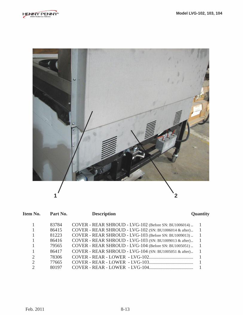
Model LVG-102, 103, 104
8-13
1 2
Item No. Part No. Description Quantity
1 83784 COVER - REAR SHROUD - LVG-102 (Before SN: BU1006014) .. 1 1 86415 COVER - REAR SHROUD - LVG-102 (SN: BU1006014 & after) .. 1 1 81223 COVER - REAR SHROUD - LVG-103 (Before SN: BU1009013) .. 1 1 86416 COVER - REAR SHROUD - LVG-103 (SN: BU1009013 & after) .. 1 1 79565 COVER - REAR SHROUD - LVG-104 (Before SN: BU1005051) .. 1 1 86417 COVER - REAR SHROUD - LVG-104 (SN: BU1005051 & after) .. 1 2 78306 COVER - REAR - LOWER - LVG-102 ..................................... 1 2 77665 COVER - REAR - LOWER - LVG-103 ..................................... 1 2 80197 COVER - REAR - LOWER - LVG-104 ..................................... 1
Feb. 2011
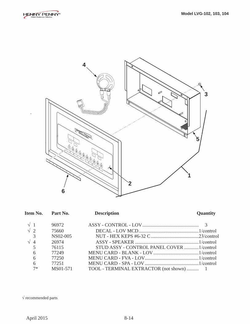
Model LVG-102, 103, 104
8-14
Item No. Part No. Description Quantity
√ 1 96972 ASSY - CONTROL - LOV .............................................. 3 √ 2 75660 DECAL - LOV MCD .................................................1/control 3 NS02-005 NUT - HEX KEPS #6-32 C .......................................23/control √ 4 26974 ASSY - SPEAKER ....................................................1/control 5 76115 STUD ASSY - CONTROL PANEL COVER ............1/control 6 77249 MENU CARD - BLANK - LOV .....................................1/control 6 77250 MENU CARD - FVA - LOV ............................................1/control 6 77251 MENU CARD - SPA - LOV ............................................1/control 7* MS01-571 TOOL - TERMINAL EXTRACTOR (not shown) .......... 1
√recommended parts
12
3
4
5
6
April 2015
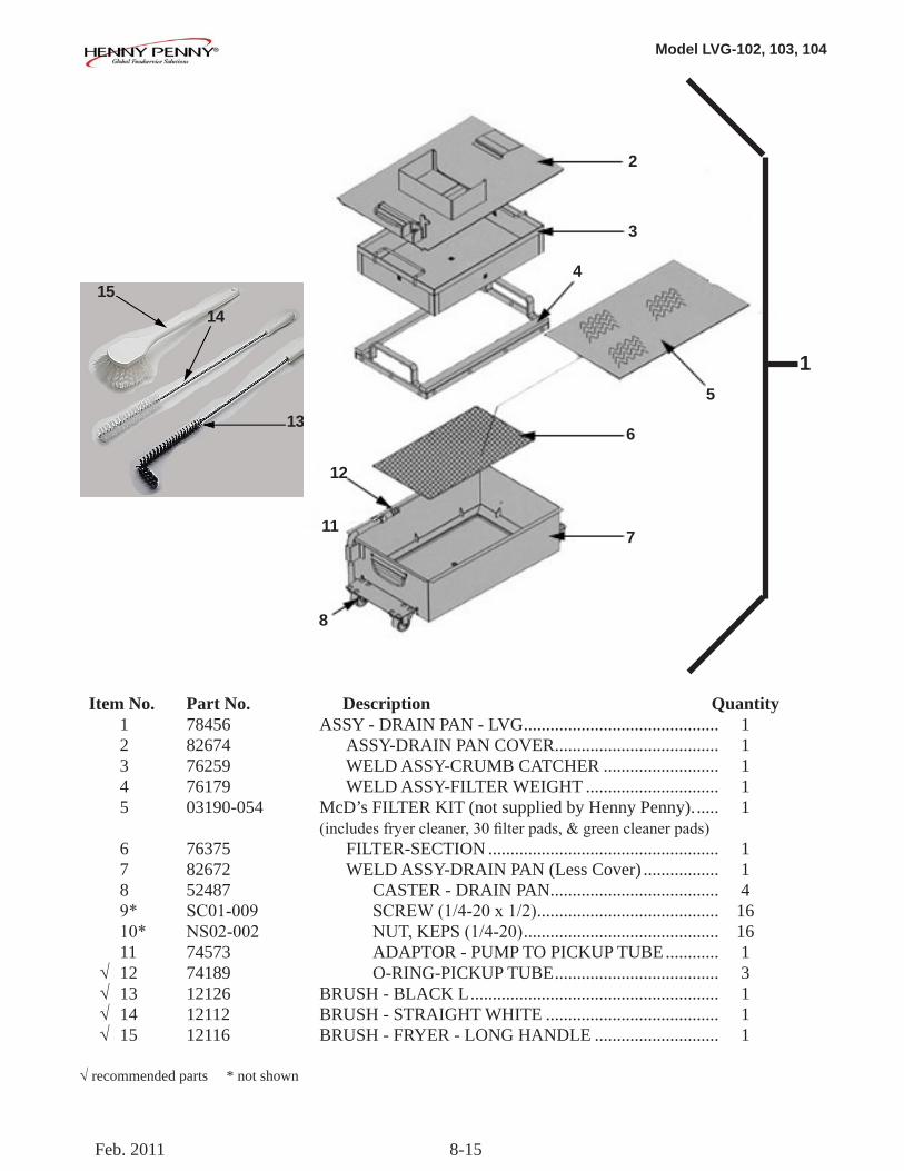
Model LVG-102, 103, 104
8-15
Item No. Part No. Description Quantity 1 78456 ASSY - DRAIN PAN - LVG ............................................ 1 2 82674 ASSY-DRAIN PAN COVER ..................................... 1 3 76259 WELD ASSY-CRUMB CATCHER .......................... 1 4 76179 WELD ASSY-FILTER WEIGHT .............................. 1 5 03190-054 McD’s FILTER KIT (not supplied by Henny Penny). ..... 1 (includesfryercleaner,30filterpads,&greencleanerpads) 6 76375 FILTER-SECTION .................................................... 1 7 82672 WELD ASSY-DRAIN PAN (Less Cover) ................. 1 8 52487 CASTER - DRAIN PAN ...................................... 4 9* SC01-009 SCREW(1/4-20x1/2) ......................................... 16 10* NS02-002 NUT,KEPS(1/4-20) ............................................ 16 11 74573 ADAPTOR - PUMP TO PICKUP TUBE ............ 1 √ 12 74189 O-RING-PICKUP TUBE ..................................... 3 √ 13 12126 BRUSH - BLACK L ........................................................ 1 √ 14 12112 BRUSH - STRAIGHT WHITE ....................................... 1 √ 15 12116 BRUSH - FRYER - LONG HANDLE ............................ 1
√recommended parts * not shown
1
13
1415
2
3
4
5
6
7
8
12
11
Feb. 2011
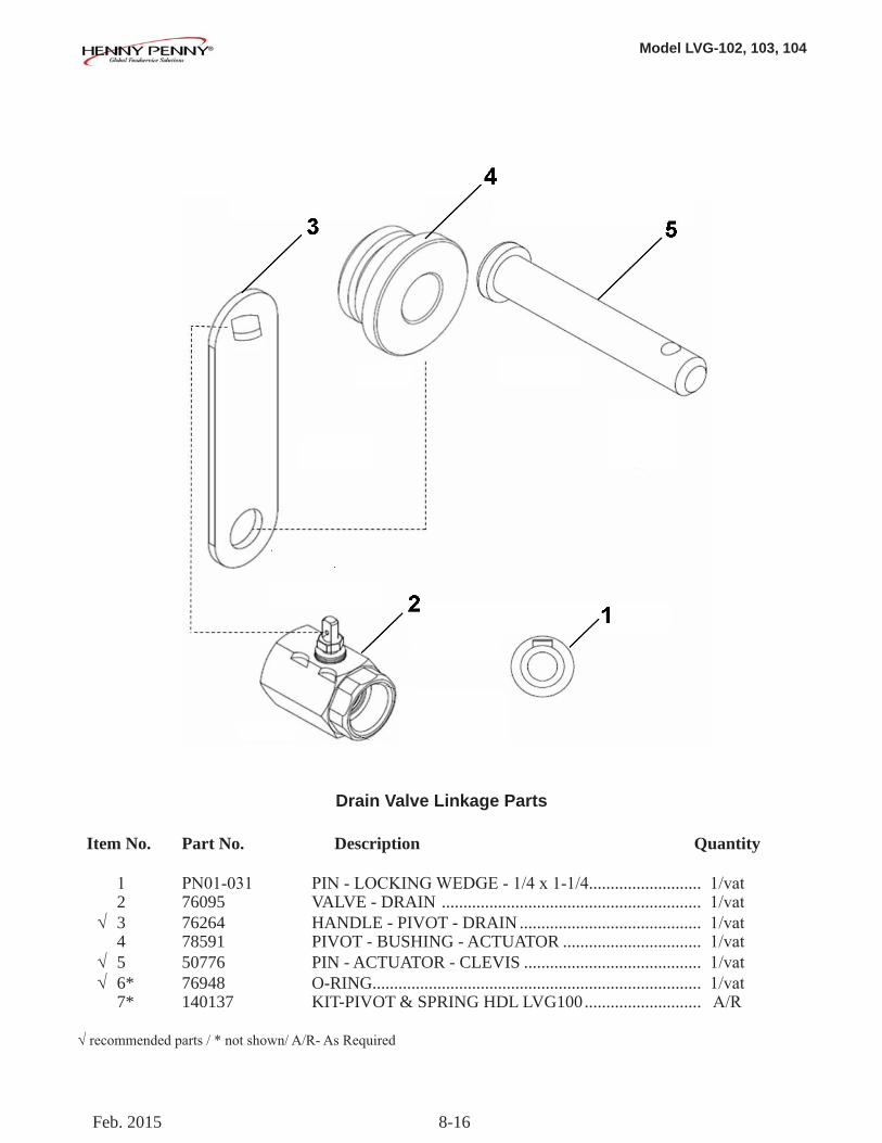
Model LVG-102, 103, 104
8-16
Item No. Part No. Description Quantity
1 PN01-031 PIN-LOCKINGWEDGE-1/4x1-1/4.......................... 1/vat 2 76095 VALVE - DRAIN ............................................................ 1/vat √ 3 76264 HANDLE - PIVOT - DRAIN .......................................... 1/vat 4 78591 PIVOT - BUSHING - ACTUATOR ................................ 1/vat √ 5 50776 PIN - ACTUATOR - CLEVIS ......................................... 1/vat √ 6* 76948 O-RING ............................................................................ 1/vat 7* 140137 KIT-PIVOT & SPRING HDL LVG100 ........................... A/R
√recommendedparts/*notshown/A/R-AsRequired
Drain Valve Linkage Parts
Feb. 2015
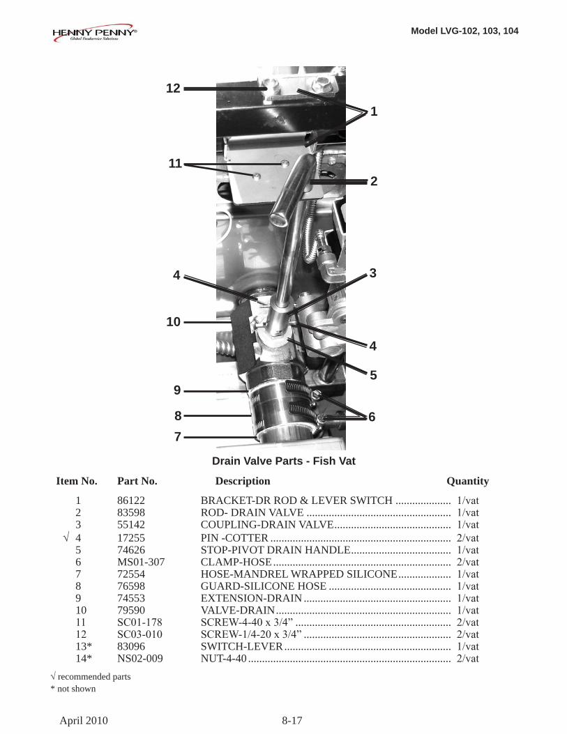
Model LVG-102, 103, 104
8-17
Item No. Part No. Description Quantity
1 86122 BRACKET-DR ROD & LEVER SWITCH .................... 1/vat 2 83598 ROD- DRAIN VALVE .................................................... 1/vat 3 55142 COUPLING-DRAIN VALVE .......................................... 1/vat √ 4 17255 PIN -COTTER ................................................................. 2/vat 5 74626 STOP-PIVOT DRAIN HANDLE .................................... 1/vat 6 MS01-307 CLAMP-HOSE ................................................................ 2/vat 7 72554 HOSE-MANDREL WRAPPED SILICONE ................... 1/vat 8 76598 GUARD-SILICONE HOSE ............................................ 1/vat 9 74553 EXTENSION-DRAIN ..................................................... 1/vat 10 79590 VALVE-DRAIN ............................................................... 1/vat 11 SC01-178 SCREW-4-40x3/4” ........................................................ 2/vat 12 SC03-010 SCREW-1/4-20x3/4” ..................................................... 2/vat 13* 83096 SWITCH-LEVER ............................................................ 1/vat 14* NS02-009 NUT-4-40 ......................................................................... 2/vat√recommended parts* not shown
Drain Valve Parts - Fish Vat
112
12
1
34
10
4
95
687
April 2010
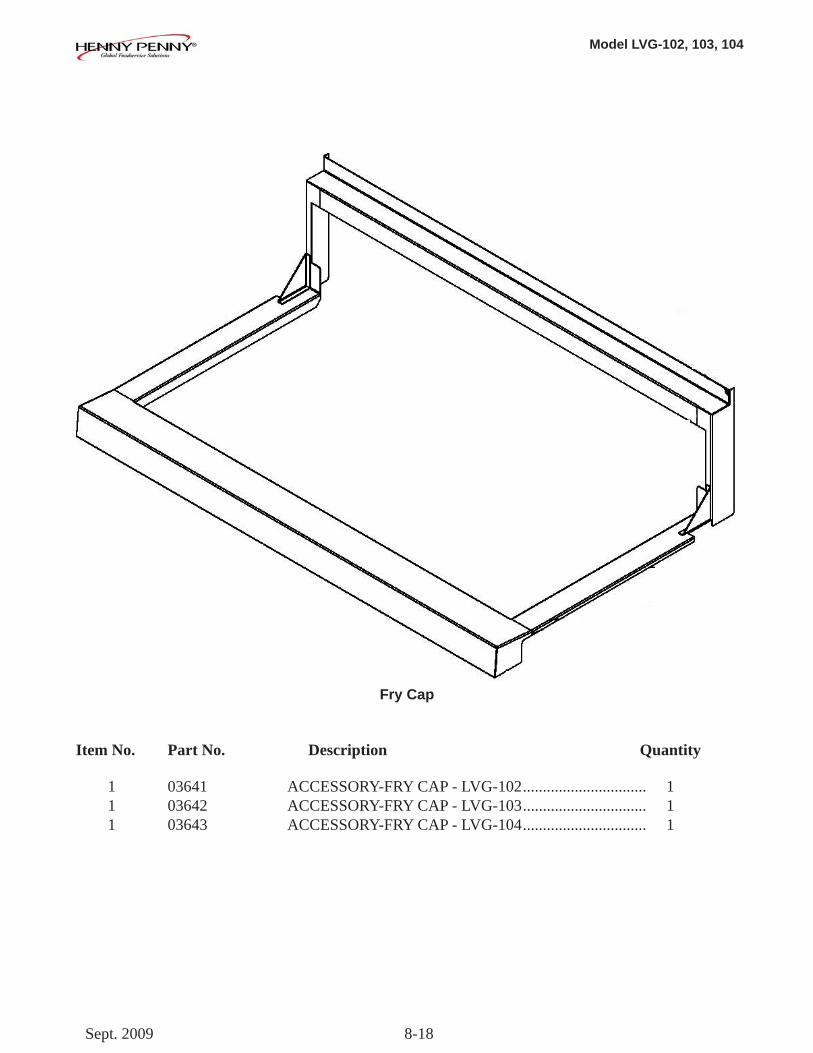
Model LVG-102, 103, 104
8-18
Item No. Part No. Description Quantity
1 03641 ACCESSORY-FRY CAP - LVG-102 ............................... 1 1 03642 ACCESSORY-FRY CAP - LVG-103 ............................... 1 1 03643 ACCESSORY-FRY CAP - LVG-104 ............................... 1
Fry Cap
Sept. 2009
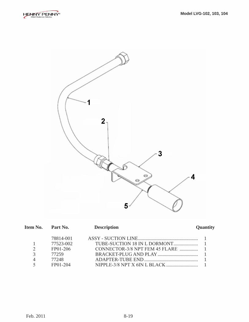
Model LVG-102, 103, 104
8-19
Item No. Part No. Description Quantity 78814-001 ASSY - SUCTION LINE ................................................. 1 1 77523-002 TUBE-SUCTION 18 IN L DORMONT .................... 1 2 FP01-206 CONNECTOR-3/8NPTFEM45FLARE ............... 1 3 77259 BRACKET-PLUG AND PLAY ................................. 1 4 77248 ADAPTER-TUBE END ............................................ 1 5 FP01-204 NIPPLE-3/8NPTX6INLBLACK .......................... 1
Feb. 2011
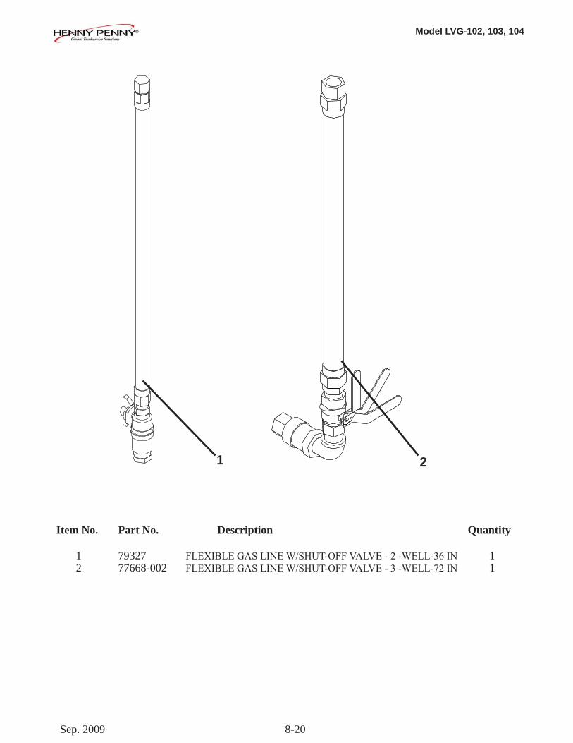
Model LVG-102, 103, 104
8-20
Item No. Part No. Description Quantity
1 79327 FLEXIBLEGASLINEW/SHUT-OFFVALVE-2-WELL-36IN 1 2 77668-002 FLEXIBLEGASLINEW/SHUT-OFFVALVE-3-WELL-72IN 1
1 2
Sep. 2009
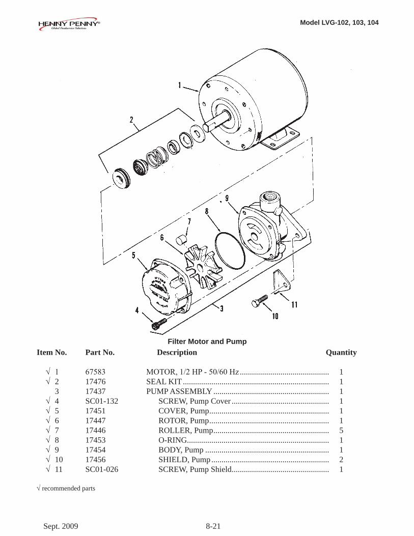
Model LVG-102, 103, 104
8-21
Item No. Part No. Description Quantity
√ 1 67583 MOTOR,1/2HP-50/60Hz ............................................ 1 √ 2 17476 SEAL KIT ........................................................................ 1 3 17437 PUMP ASSEMBLY ......................................................... 1 √ 4 SC01-132 SCREW, Pump Cover ................................................ 1 √ 5 17451 COVER, Pump ........................................................... 1 √ 6 17447 ROTOR, Pump ........................................................... 1 √ 7 17446 ROLLER, Pump ......................................................... 5 √ 8 17453 O-RING ...................................................................... 1 √ 9 17454 BODY, Pump ............................................................. 1 √ 10 17456 SHIELD, Pump .......................................................... 2 √ 11 SC01-026 SCREW, Pump Shield ................................................ 1
√recommended parts
Filter Motor and Pump
Sept. 2009
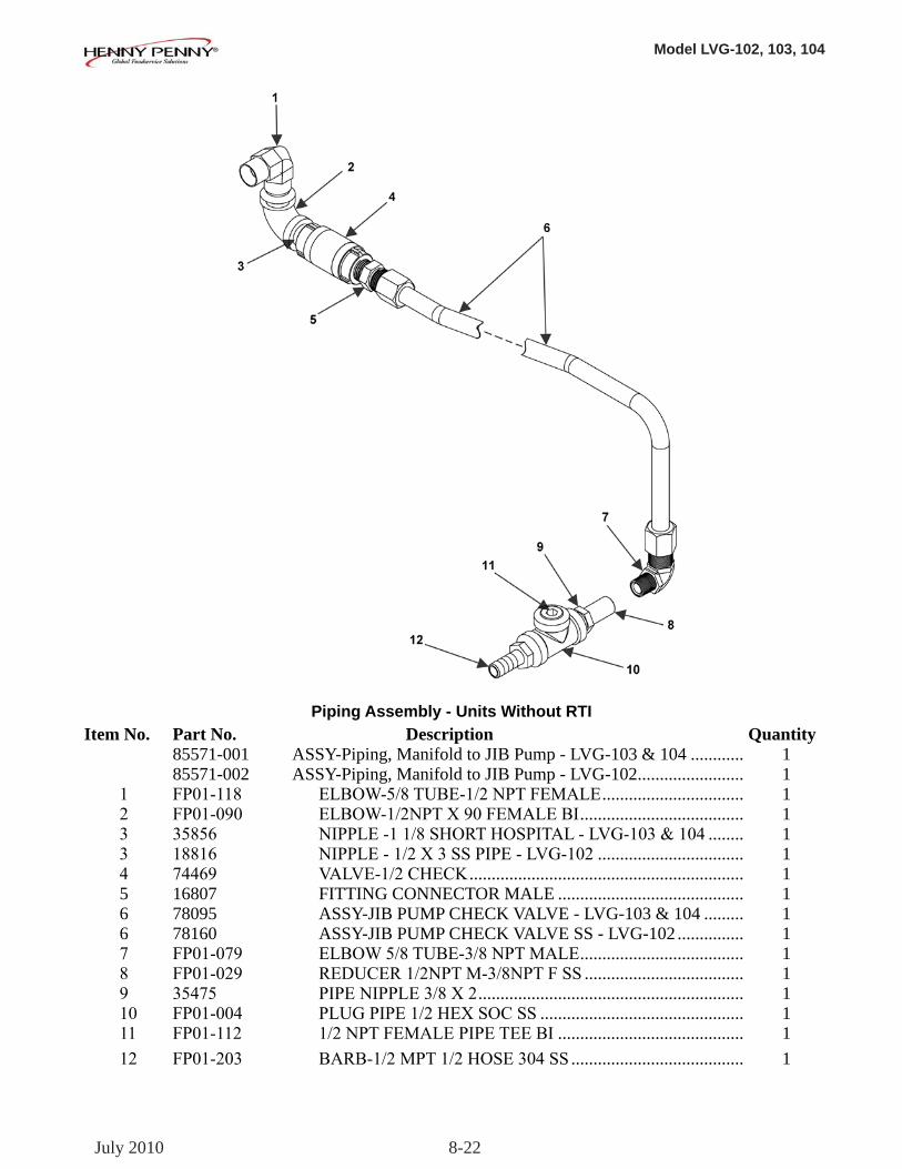
Model LVG-102, 103, 104
8-22
Item No. Part No. Description Quantity 85571-001 ASSY-Piping, Manifold to JIB Pump - LVG-103 & 104 ............ 1 85571-002 ASSY-Piping, Manifold to JIB Pump - LVG-102 ........................ 1 1 FP01-118 ELBOW-5/8TUBE-1/2NPTFEMALE ................................ 1 2 FP01-090 ELBOW-1/2NPTX90FEMALEBI ..................................... 1 3 35856 NIPPLE-11/8SHORTHOSPITAL-LVG-103&104 ........ 1 3 18816 NIPPLE-1/2X3SSPIPE-LVG-102 ................................. 1 4 74469 VALVE-1/2CHECK .............................................................. 1 5 16807 FITTING CONNECTOR MALE .......................................... 1 6 78095 ASSY-JIB PUMP CHECK VALVE - LVG-103 & 104 ......... 1 6 78160 ASSY-JIB PUMP CHECK VALVE SS - LVG-102 ............... 1 7 FP01-079 ELBOW5/8TUBE-3/8NPTMALE ..................................... 1 8 FP01-029 REDUCER1/2NPTM-3/8NPTFSS .................................... 1 9 35475 PIPENIPPLE3/8X2 ............................................................ 1 10 FP01-004 PLUGPIPE1/2HEXSOCSS .............................................. 1 11 FP01-112 1/2NPTFEMALEPIPETEEBI .......................................... 1 12 FP01-203 BARB-1/2MPT1/2HOSE304SS ....................................... 1
Piping Assembly - Units Without RTI
July 2010
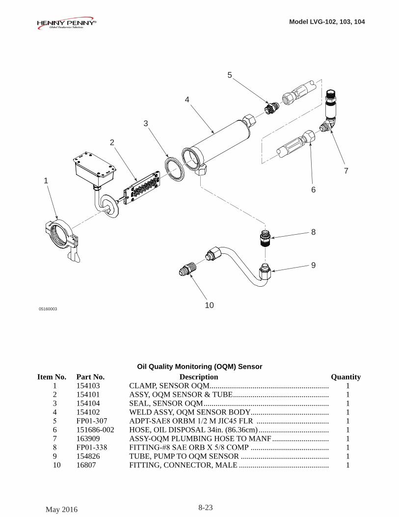
Model LVG-102, 103, 104
8-23
10
3
4
5
7
6
8
9
05160003
1
2
Oil Quality Monitoring (OQM) Sensor Item No. Part No. Description Quantity 1 154103 CLAMP, SENSOR OQM............................................................. 1 2 154101 ASSY, OQM SENSOR & TUBE ................................................. 1 3 154104 SEAL, SENSOR OQM ................................................................ 1 4 154102 WELD ASSY, OQM SENSOR BODY ........................................ 1 5 FP01-307 ADPT-SAE8ORBM1/2MJIC45FLR ..................................... 1 6 151686-002 HOSE, OIL DISPOSAL 34in. (86.36cm) .................................... 1 7 163909 ASSY-OQM PLUMBING HOSE TO MANF ............................. 1 8 FP01-338 FITTING-#8SAEORBX5/8COMP ........................................ 1 9 154826 TUBE, PUMP TO OQM SENSOR ............................................. 1 10 16807 FITTING, CONNECTOR, MALE .............................................. 1
May 2016
Model LVG-102, 103, 104
A-1
APPENDIX A. WIRING DIAGRAMS AND SCHEMATICS
APPENDIX A contains the wiring diagrams and schematics to support the LVG-100 series fryers.
A-1. WIRING DIAGRAMS AND SCHEMATICS
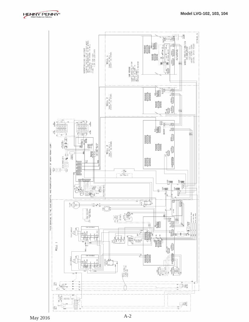
Model LVG-102, 103, 104
A-2May 2016
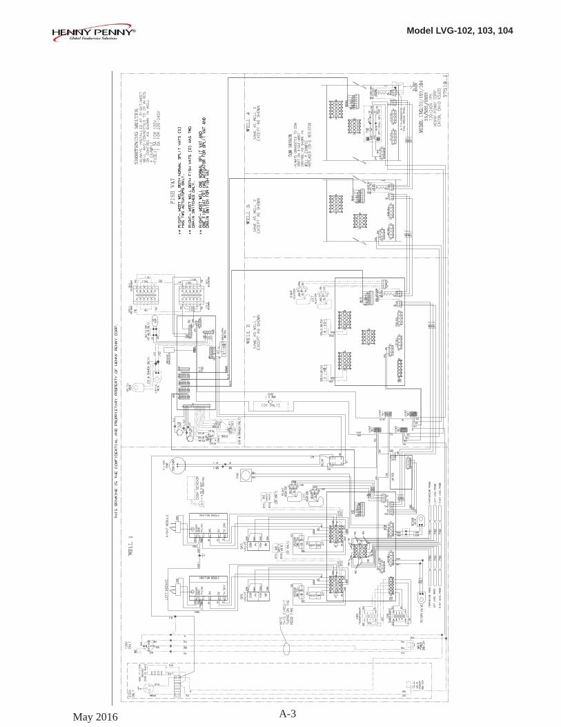
Model LVG-102, 103, 104
A-3May 2016
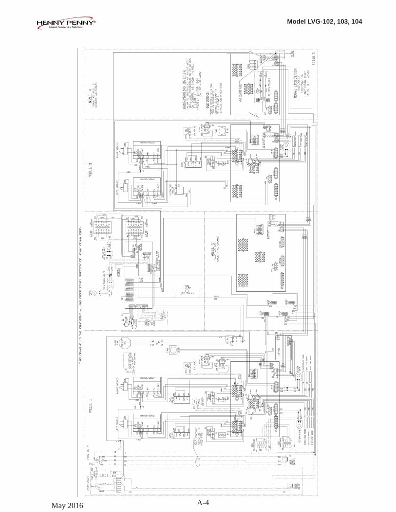
Model LVG-102, 103, 104
A-4May 2016
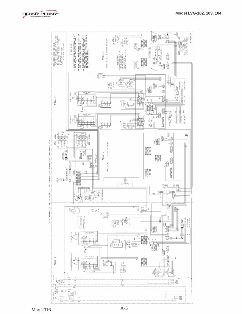
Model LVG-102, 103, 104
A-5May 2016
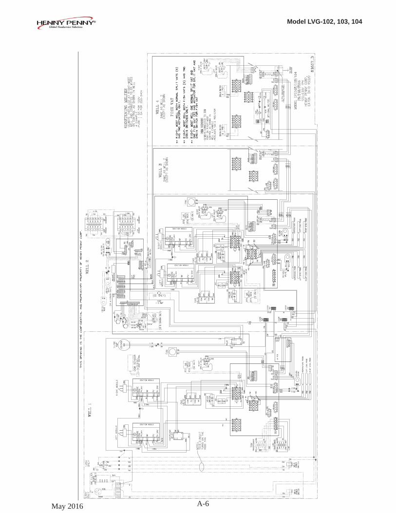
Model LVG-102, 103, 104
A-6May 2016
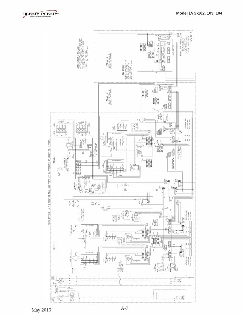
Model LVG-102, 103, 104
A-7May 2016
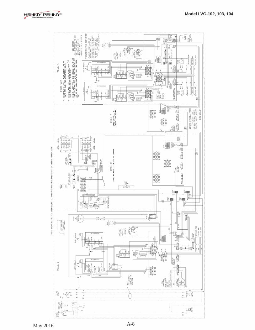
Model LVG-102, 103, 104
A-8May 2016
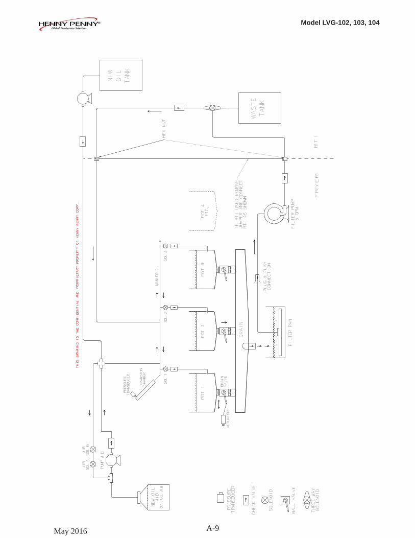
Model LVG-102, 103, 104
A-9May 2016
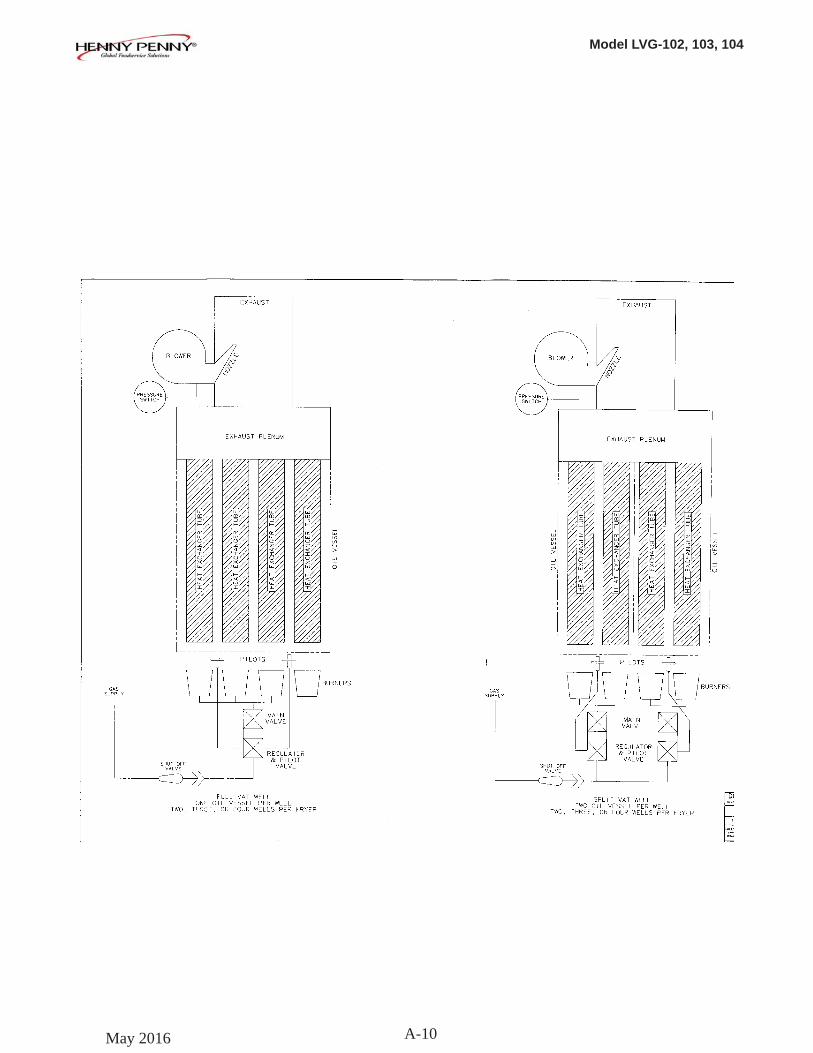
Model LVG-102, 103, 104
A-10May 2016
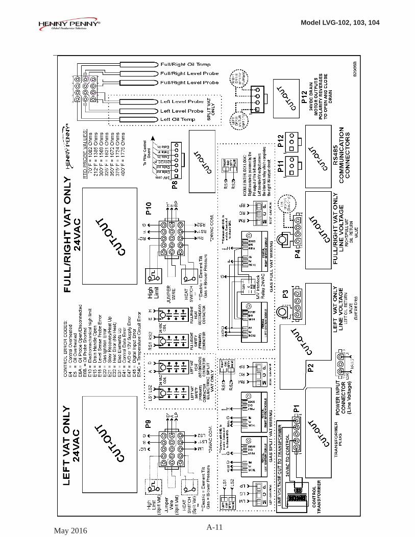
Model LVG-102, 103, 104
A-11May 2016
Related Documents


