1 Inverter NO. MODEL NO. MODEL 1 CJE36CD 2 3 4 Split-Type Air Conditioner

Welcome message from author
This document is posted to help you gain knowledge. Please leave a comment to let me know what you think about it! Share it to your friends and learn new things together.
Transcript
1
Inverter
NO. MODEL NO. MODEL
1 CJE36CD
2
3
4
Split-Type Air Conditioner
2
This manual is for professional
maintenance personnel only
3
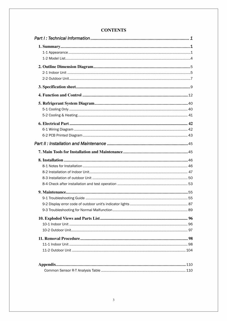
CONTENTS
Part I : Technical Information ................................................................................... 1
1. Summary ...................................................................................................................... 1
1-1 Appearance ...............................................................................................................................1
1-2 Model List..................................................................................................................................4
2. Outline Dimension Diagram ........................................................................................ 5
2-1 Indoor Unit ................................................................................................................................5
2-2 Outdoor Unit ..............................................................................................................................7
3. Specification sheet ........................................................................................................ 9
4. Function and Control ................................................................................................ 12
5. Refrigerant System Diagram ..................................................................................... 40
5-1 Cooling Only ........................................................................................................................... 40
5-2 Cooling & Heating .................................................................................................................. 41
6. Electrical Part ................................................................................................................ 42
6-1 Wiring Diagram ...................................................................................................................... 42
6-2 PCB Printed Diagram ............................................................................................................. 43
Part II : Installation and Maintenance .................................................................... 45
7. Main Tools for Installation and Maintenance ........................................................... 45
8. Installation ................................................................................................................. 46
8-1 Notes for Installation ............................................................................................................. 46
8-2 Installation of Indoor Unit ...................................................................................................... 47
8-3 Installation of outdoor Unit ................................................................................................... 50
8-4 Check after installation and test operation ......................................................................... 53
9. Maintenance ............................................................................................................... 55
9-1 Troubleshooting Guide .......................................................................................................... 55
9-2 Display error code of outdoor unit's indicator lights ............................................................ 87
9-3 Troubleshooting for Normal Malfunction .............................................................................. 89
10. Exploded Views and Parts List ................................................................................... 96
10-1 Indoor Unit ........................................................................................................................... 96
10-2 Outdoor Unit......................................................................................................................... 97
11. Removal Procedure .................................................................................................. 98
11-1 Indoor Unit ........................................................................................................................... 98
11-2 Outdoor Unit ...................................................................................................................... 104
Appendix ...................................................................................................................... 110
Common Sensor R-T Analysis Table ........................................................................................ 110
4
Part I : Technical Information
1. Summary
1-1 Appearance
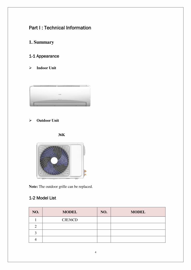
Indoor Unit
Outdoor Unit
36K
Note: The outdoor grille can be replaced.
1-2 Model List
NO. MODEL NO. MODEL
1 CJE36CD
2
3
4
5
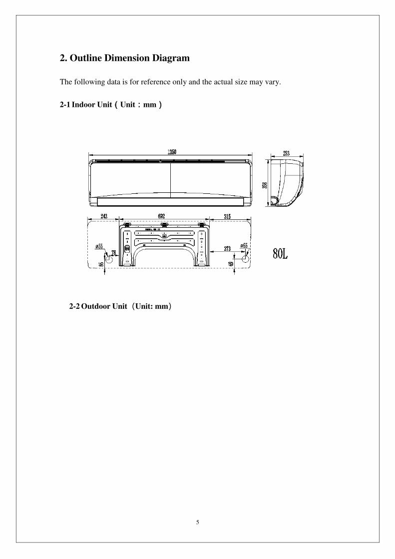
2. Outline Dimension Diagram
The following data is for reference only and the actual size may vary.
2-1 Indoor Unit(Unit:mm)
2-2 Outdoor Unit(Unit: mm)

6
3. Specification sheet(refer to Catalog)
7
4. Function and Control
4-1 H-Style
1) Remote Controller Introduction
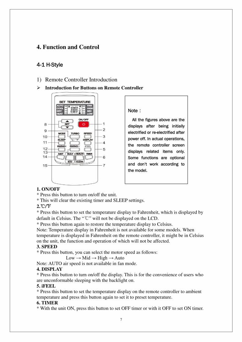
Introduction for Buttons on Remote Controller
1. ON/OFF
* Press this button to turn on/off the unit.
* This will clear the existing timer and SLEEP settings.
2./
* Press this button to set the temperature display to Fahrenheit, which is displayed by
default in Celsius. The “” will not be displayed on the LCD.
* Press this button again to restore the temperature display to Celsius.
Note: Temperature display in Fahrenheit is not available for some models. When
temperature is displayed in Fahrenheit on the remote controller, it might be in Celsius
on the unit, the function and operation of which will not be affected.
3. SPEED
* Press this button, you can select the motor speed as follows:
Low → Mid → High → Auto
Note: AUTO air speed is not available in fan mode.
4. DISPLAY
* Press this button to turn on/off the display. This is for the convenience of users who
are unconformable sleeping with the backlight on.
5. iFEEL
* Press this button to set the temperature display on the remote controller to ambient
temperature and press this button again to set it to preset temperature.
6. TIMER * With the unit ON, press this button to set OFF timer or with it OFF to set ON timer.
Note:
All the figures above are the
displays after being initially
electrified or re-electrified after
power off. In actual operations,
the remote controller screen
displays related items only.
Some functions are optional
and don’t work according to the model.

8
* Press this button once, a "ON(OFF)" will flash. Press “”or “ ” to set the number
of hours in which the unit will be turned ON/OFF, with an interval of 0.5 hour if less
than 10 hours, or 1 hour if longer than 10 hours and a range of 0.5-24 hours.
* Press it again to confirm the setting the "ON (OFF)" will stop flashing.
* If the timer button is not pressed longer than 10 seconds after the "ON (OFF)" start
flashing, the timer setting will be exited.
* If a timer setting is confirmed, pressing this button again will cancel it.
Note: When a ON timer is set, all function buttons (except SLEEP DISPLAY and
iFEEL can't be set ) are valid and when the ON time set is up, the unit will operate as
preset.
7. This button has two functions. a. HEALTH
* Press this button with the unit ON to activate health related functions, such as
negative ion, electrostatic precipitation, PM2.5 removal, etc, depending on the actual
configuration of each model.
* Press this button again to deactivate the HEALTH function.
b. iCLEAN
* Press this button with the unit OFF, the remote controller will display "CL" and the
unit will automatically clean dust off the evaporator and dry it, to increase the cooling
and heating efficiency.
* The iCLEAN function runs for approximately 30 minutes, during which if the unit
is turned on with the remote controller or this button is pressed again, the iCLEAN
will be deactivated.
8. or
* Each time the "" is pressed, the temperature setting will increase by 1 and each
time the "" is pressed, it will decrease by 1.
* a. lf the type of controller remote is YKR-H/101E or YKR-H/102E setting
temperature range is 16 ~32(60~90).
b. lf the type of controller remote is YKR-H/132E setting temperature range is 20
~28 (68~82).
c. Some area don't have the YKR-H/132E.Local regulation and actual object shall
prevail.
Note: The temperature cannot be set in AUTO or Fan mode, thus these two buttons
are not functional.
9. TURBO
* Press this button only in COOL or HEAT mode to set TURBO on or off to speedy
the cooling or heating.
* When TURBO is on the air speed is HIGH.
* When TURBO is off the air speed will restore to previous status.
10. MODE
* Press this button you can select the running mode as follows:
AUTO → COOL → DRY → HEAT →FAN
Note: HEAT mode is not available for cool only units.
11. SLEEP
9
* Press this button to enter SLEEP mode, which the unit will exit after 10 hours of
continuous operation and restore to the previous status.
Note: The SLEEP function cannot be activated in fan mode.
12. SWING
* Press this button to activate up/down swing and press it again to fix the swing
position.
13. SWING
* Press this button to activate left/right swing and press it again to fix the swing
position.
14. Anti-F
* The Anti-F functions when the unit is turned off with the remote controller in COOL,
DRY or AUTO mode. It will operate in HEAT mode (Fan mode for cool only units),
with the Indoor Unit motor running with weak flow for 3 minute before stop, to
remove the moisture within the evaporator so as to prevent it from giving bad smell
from mold.
* This function is not set in the factory. You may set it or cancel it any time you want
as follows: With both the unit and the remote controller OFF, point the remote
controller at the unit and press
"Anti-F" button once, the buzzer will sound 5 times after 5 times, indicating this
function is set. Once set, this function will remain valid except when the unit is power
off or until it is canceled.
* To cancel Anti-F:
1. Power off the unit.
2. With both the unit and the remote controller OFF, point the remote controller at the
unit and press this button once, the buzzer will sound 3 times after 5 times, indicating
this function is canceled.
Note:
* With Anti-F activated, it is advised not to turn ON the unit again before it is fully
OFF.
*Anti-F function will be invalid when OFF timer is set.
15.This button has two functions.
a. ELE.H (Optional)
* If this button is pressed in HEAT mode, the electric heating will be turned on/off.
b. ECO (Optional)
* If this button is pressed in COOL mode, the unit will enter the ECO mode which has
the lowest electricity consumption, and exit it automatically 8 hours after.
* Changing modes or turning off the remote controller will automatically cancel the
ECO function.
* Press ECO button in ECO mode to exit this mode. Note: The ECO mode only works
for inverter units.
2) Introduction for mode settings
Automatic operation mode
1. Press the "MODE" button, select the automatic operation mode.
2. By pressing the "SPEED" button, you can select the motor speed from LOW, MID,
HIGH, AUTO.
3. Press the "ON/OFF" button, the air-conditioner starts to operate.
4. Press the "ON/OFF" button again, the air-conditioner stops.
Note: In the fan operation mode the temperature settings is non-effective.

10
Cooling/Heating operation mode
1. Press the "MODE" button, select the Cooling or Heating operation mode.
2. By pressing the ""or ""button, you can set the temperature the display changes
as you touch the button.
3. By pressing the "SPEED" button, you can select the motor speed from LOW, MID,
HIGH, AUTO.
4. Press the "ON/OFF" button, the air-conditioner starts to operate.
5. Press the "ON/OFF" button again, the air-conditioner stops.
Note: The cold wind type has no heating function.
Fan operation mode
1. Press the "MODE" button, select the fan operation mode.
2. By pressing the "SPEED" button, you can select the motor speed from LOW, MID,
HIGH.
3. Press the "ON/OFF" button, the air-conditioner starts to operate.
4. Press the "ON/OFF" button again, the air-conditioner stops.
Note: In the fan operation mode the temperature settings is non-effective.
Drying operation mode
1. Press the "MODE" button, select the drying operation mode.
2. By pressing the ""or ""button, you can set the temperature the display changes as you touch the button.
3. By pressing the "SPEED" button, you can select the motor speed from LOW,
MID, HIGH, AUTO.
4. Press the "ON/OFF" button, the air-conditioner starts to operate.
5. Press the "ON/OFF" button again, the air-conditioner stops.
Backlight function (for remote controllers with such function only)
The remote controller has a backlight which can be turned on by pressing any button
for the convenience of operation in darkness. The backlight will be automatically
turned off if there is no operation within 10 seconds.
3) Precautions
• Before first time use of the remote controller install the batteries and ensure the "+"and "_" poles are correctly positioned.
• Ensure the remote controller is pointed to the signal receiving Window and that there is no obstruction in between and the distance is 8m at the maximum.
• Do not let the remote controller drop or fling it at will. Do not let any liquid in the remote controller.
Do not expose the remote controller directly to the sunlight or excessive heat.
• If the remote controller does not function normally remove the batteries for 30 second before reinstall them. If that doesn't work replace the batteries.
• When replacing the batteries do not mix the new batteries with old ones or mix batteries of different types which could cause failure of the remote controller.
• If the remote controller is not to be used for a long period of time remove the batteries first lest the leakage from them may damage the remote controller.
• Properly dispose the discarded batteries. Note:
1. This is a universal remote controller which provide all the function buttons. Please
understand that some of the buttons may not function, depending on the specific air
conditioner you have purchased. (If a specific function is not available on the air
conditioner, pressing the corresponding button will simply have no respond.)
11
2. HEAT and ELE.H functions are not available for cool only models, thus these two
buttons do not work correspondingly.
Battery use and replacement
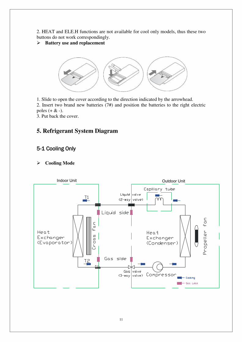
1. Slide to open the cover according to the direction indicated by the arrowhead.
2. Insert two brand new batteries (7#) and position the batteries to the right electric
poles (+ & -).
3. Put back the cover.
5. Refrigerant System Diagram
5-1 Cooling Only
Cooling Mode
Indoor Unit Outdoor Unit

12
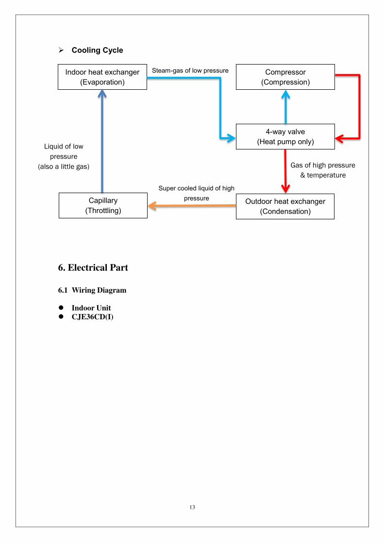
Cooling Cycle
5-2 Cooling & Heating
Cooling Mode
Indoor heat exchanger
(Evaporation)
Compressor
(Compression)
Outdoor heat exchanger
(Condensation)
Capillary
(Throttling)
Steam-gas of low pressure
Super cooled liquid of high
pressure
Liquid of low
pressure
(also a little gas)
Gas of high pressure &
temperature
Indoor Unit Outdoor Unit
13
Cooling Cycle
6. Electrical Part
6.1 Wiring Diagram
Indoor Unit
CJE36CD(I)
Indoor heat exchanger
(Evaporation)
Compressor
(Compression)
Outdoor heat exchanger
(Condensation)
Capillary
(Throttling)
Steam-gas of low pressure
Super cooled liquid of high
pressure
Liquid of low
pressure
(also a little gas) Gas of high pressure
& temperature
4-way valve
(Heat pump only)

14
Outdoor Unit
CJE36CD(O)

15
6-2 PCB Printed Diagram (NA)
Heating Mode
Heating Cycle
Indoor Unit Outdoor Unit
Indoor heat exchanger
(Evaporation)
Compressor
(Compression)
Outdoor heat exchanger
(Condensation)
Capillary
(Throttling)
Steam-gas of low
pressure
Super cooled liquid of high
pressure
Super cooled liquid of
low pressure
Gas of high pressure
& temperature
4-way valve
(Heat pump only)

16

17
Part II : Installation and Maintenance
7. Main Tools for Installation and Maintenance

18
8. Installation
8-1 Notes for Installation
Important Notices
Before installation, please contact with local authorized maintenance center, if
unit is not installed by the authorized maintenance center, the malfunction may
not solved, due to discommodious contact.
The air conditioner must be installed by professionals according to the national
wiring rules and this manual.
To move and install air conditioner to another place, please contact our local
special service center.
Requirements For Installation Position
Avoid places of inflammable or explosive gas leakage or where there are strongly
aggressive gases.
Avoid places subject to strong artificial electric/magnetic fields.
Avoid places subject to noise and resonance.
Avoid severe natural conditions (e.g. heavy lampblack, strong sandy wind, direct
sunshine or high temperature heat sources).
Avoid places within the reach of children.
Shorten the connection between the indoor and outdoor units.
Select where it is easy to perform service and repair and where the ventilation
good.
The outdoor unit shall not be installed in any way that could occupy an aisle,
stairway, exit, fire escape, catwalk or any other public area.
The outdoor unit shall be installed as far as possible from the doors and windows
of the neighbors as well as the green plants.
Requirements for operations at raised height
When carrying out installation at 2m or higher above the base level, safety belts
must be worn and ropes of sufficient strength be securely fasten to the outdoor
unit, to prevent falling that could cause personal injury or death as well as
property loss.
Requirements of the mounting structure
The mounting rack must meet the relevant national or industrial standards in
terms of strength with welding and connection areas rustproofed.
The mounting rack and its load carry surface shall be able to withstand 4 times or
above the weight of the unit, or 200kg, whichever is heavier.
The mounting rack of the outdoor unit shall be fastened with expansion bolt.
Ensure the secure installation regardless of what type of wall on which it is
installed, to prevent potential dropping that could hurt people.
Electrical Safety Requirements
Be sure to use the rated voltage and air conditioners dedicated circuit for the
power supply, and the power cord diameter must meet the national requirements.
Be sure to use the rated voltage and air conditioners dedicated
When the maximum current of air conditioner is ≥16A, it must use the air switch or leakage protection switch equipped with protection devices.
The normal operating range is 90%-110% of the local rated voltage.
The minimum clearance between the air conditioner and the combustibles is 1.5

19
m.
The power cable enables communication between the indoor and outdoor units.
You must first choose the right cable size before preparing it for connection.
Grounding Requirements
The air conditioner is the type I electrical appliance and must ensure a reliable
grounding.
Do not connect the grounding wire to a gas pipe, water pipe,lightning rod,
telephone line, or a circuit poorly grounded to the earth.
The grounding wire is specially designed and shall not be used for other purpose,
nor shall it be fastened with a common tapping screw.
Others
The connection method of the air conditioner and the power cord and the
interconnection method of each independent element shall be subject to the
wiring diagram affixed to the machine.
The model and rating value of the fuse shall be subject to the silkscreen on
corresponding controller or fuse sleeve.
8-2 Installation of Indoor Unit
Installation Parts-checking
Packing list of the indoor unit
NO. Name Quantity Unit
1 Indoor Unit 1 Set
2 Remote Controller 1 PC
3 Batteries(7#) 2 PC
4 Instructions 1 Set
5 Drain pipe 1 PC
NOTE:
※ All accessories shall be subject to actual packaging material, and if there is any
difference, please understand.
Selection of Installation location
Mounting plate

20
1. The wall for installation of the indoor unit shall be hard and firm, so as to prevent
vibration.
2. Use the "+" type screw to fasten the peg board, horizontally mount the peg board
on the wall, and ensure the lateral horizontal and longitudinal vertical.
3. Pull the peg board by hand after the installation, to confirm whether it is solid.
Wall-through Hole
1. Make a hole with an electric hammer or a
water drill at the predetermined position on
the wall for piping, which shall slant
outwardly by 5°-10°.
2. To protect the piping and the cables from
being damaged running through the wall,
and from the rodents that may inhabit in
the hollow wall, a pipe protecting ring shall
be installed and sealed with putty.
Note: Usually, the wall hole is Φ60mm~
Φ80mm. Avoid pre-buried power wire
and hard wall when making the hole.
Route of Pipeline
1. Depending on the position of the unit, the piping may be routed sideway from the
left or the right ( Fig 1 ), or vertically from the back( Fig 2 )(depending on the pipe
length of the indoor unit). In the case of sideway routing, cut off the outlet cutting
stock of the opposite side.
2. The power cord may be routed separately from the piping. Cut off the outlet cutting
stock and then run the power cord through the hole, keeping the remaining part as
a protection from rodents.
Drain pipe connection
1. Remove the mountings and pull the indoor unit pipe out of the housing.
2. Connect the connecting pipe to the indoor unit:
Aim at the pipe center, tighten the Taper nut with fingers, and then tighten the T
nut with a torque wrench, and the direction
is shown in diagram on the right. The torque
used is shown in the following table.
21
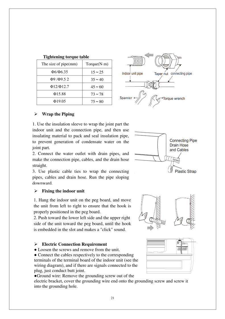
Tightening torque table
The size of pipe(mm) Torque(N·m)
Φ6/Φ6.35 15~25
Φ9 /Φ9.5 2 35~40
Φ12/Φ12.7 45~60
Φ15.88 73~78
Φ19.05 75~80
Wrap the Piping
Fixing the Indoor Unit
Fixing the indoor unit
Electric Connection Requirement
Loosen the screws and remove from the unit.
Connect the cables respectively to the corresponding
terminals of the terminal board of the indoor unit (see the
wiring diagram), and if there are signals connected to the
plug, just conduct butt joint.
Ground wire: Remove the grounding screw out of the
electric bracket, cover the grounding wire end onto the grounding screw and screw it
into the grounding hole.
1. Use the insulation sleeve to wrap the joint part the
indoor unit and the connection pipe, and then use
insulating material to pack and seal insulation pipe,
to prevent generation of condensate water on the
joint part.
2. Connect the water outlet with drain pipes, and
make the connection pipe, cables, and the drain hose
straight.
3. Use plastic cable ties to wrap the connecting
pipes, cables and drain hose. Run the pipe sloping
downward.
1. Hang the indoor unit on the peg board, and move
the unit from left to right to ensure that the hook is
properly positioned in the peg board.
2. Push toward the lower left side and the upper right
side of the unit toward the peg board, until the hook
is embedded in the slot and makes a "click" sound.
22
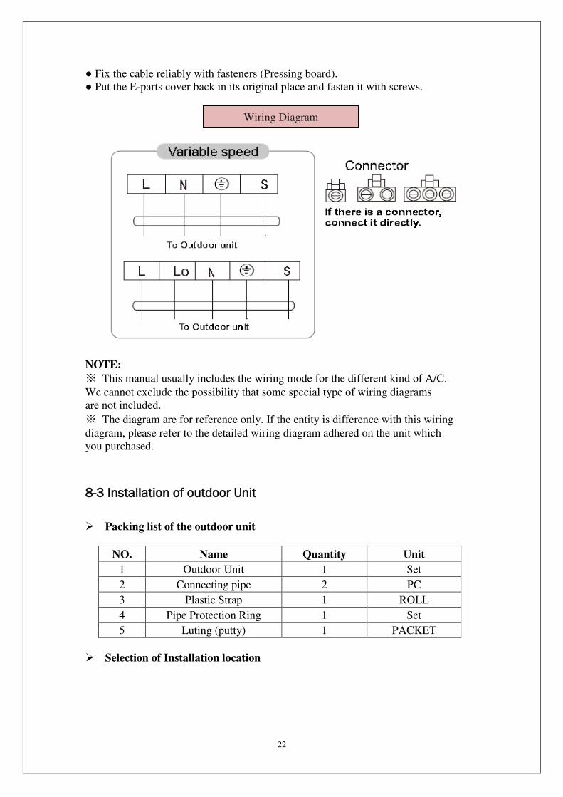
Fix the cable reliably with fasteners (Pressing board).
Put the E-parts cover back in its original place and fasten it with screws.
NOTE:
※ This manual usually includes the wiring mode for the different kind of A/C.
We cannot exclude the possibility that some special type of wiring diagrams
are not included.
※ The diagram are for reference only. If the entity is difference with this wiring
diagram, please refer to the detailed wiring diagram adhered on the unit which
you purchased.
8-3 Installation of outdoor Unit
Packing list of the outdoor unit
NO. Name Quantity Unit
1 Outdoor Unit 1 Set
2 Connecting pipe 2 PC
3 Plastic Strap 1 ROLL
4 Pipe Protection Ring 1 Set
5 Luting (putty) 1 PACKET
Selection of Installation location
Wiring Diagram
23
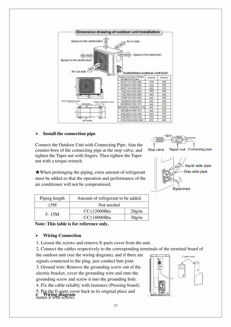
Install the connection pipe
Piping length Amount of refrigerant to be added
≤5M Not needed
5- 15M CC≤12000Btu 20g/m
CC≥18000Btu 30g/m
Note: This table is for reference only.
Wiring Connection
Wiring diagram
Connect the Outdoor Unit with Connecting Pipe: Aim the
counter-bore of the connecting pipe at the stop valve, and
tighten the Taper nut with fingers. Then tighten the Taper
nut with a torque wrench.
When prolonging the piping, extra amount of refrigerant
must be added so that the operation and performance of the
air conditioner will not be compromised.
1. Loosen the screws and remove E-parts cover from the unit.
2. Connect the cables respectively to the corresponding terminals of the terminal board of
the outdoor unit (see the wiring diagram), and if there are
signals connected to the plug, just conduct butt joint.
3. Ground wire: Remove the grounding screw out of the
electric bracket, cover the grounding wire end onto the
grounding screw and screw it into the grounding hole.
4. Fix the cable reliably with fasteners (Pressing board).
5. Put the E-parts cover back in its original place and
fasten it with screws.
24
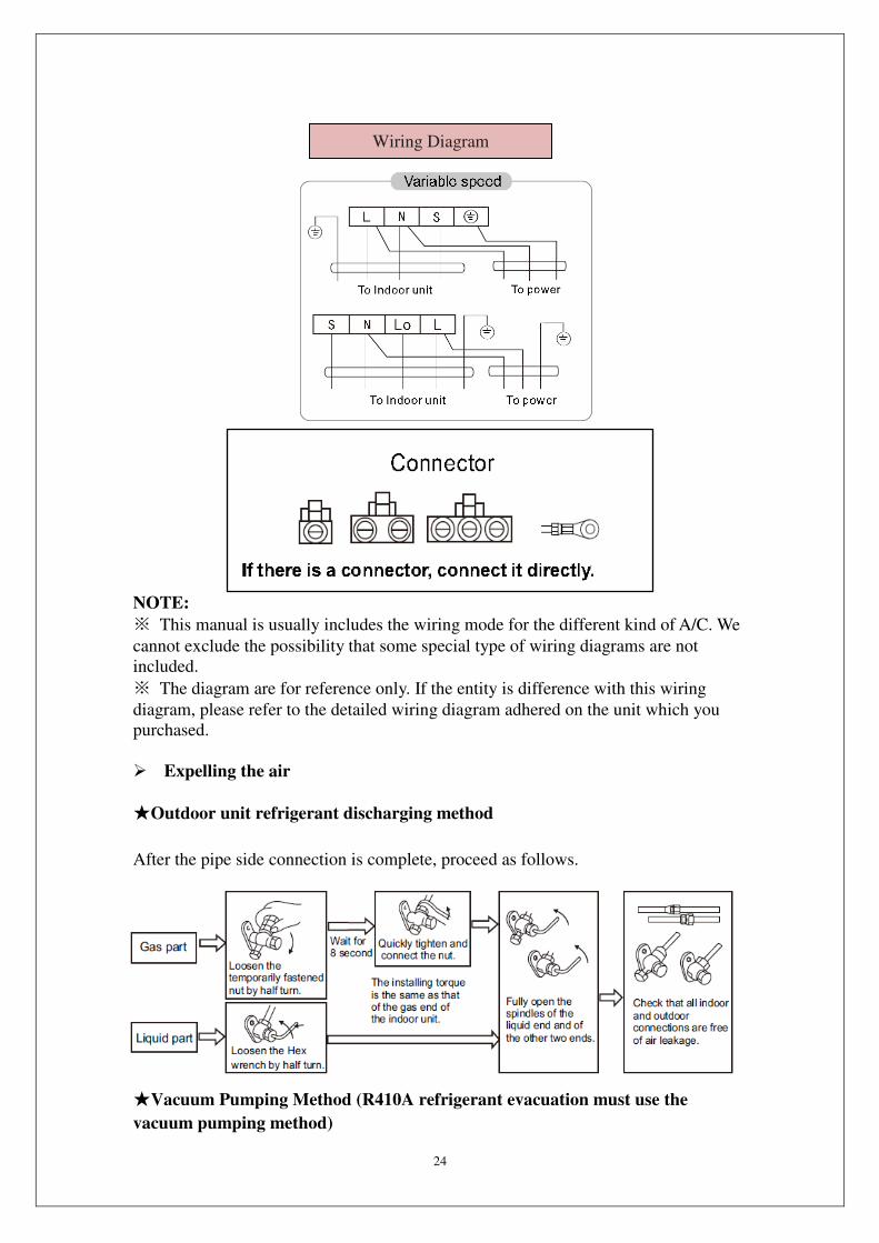
NOTE:
※ This manual is usually includes the wiring mode for the different kind of A/C. We
cannot exclude the possibility that some special type of wiring diagrams are not
included.
※ The diagram are for reference only. If the entity is difference with this wiring
diagram, please refer to the detailed wiring diagram adhered on the unit which you
purchased.
Expelling the air
Outdoor unit refrigerant discharging method
After the pipe side connection is complete, proceed as follows.
Vacuum Pumping Method (R410A refrigerant evacuation must use the
vacuum pumping method)
Wiring Diagram
25
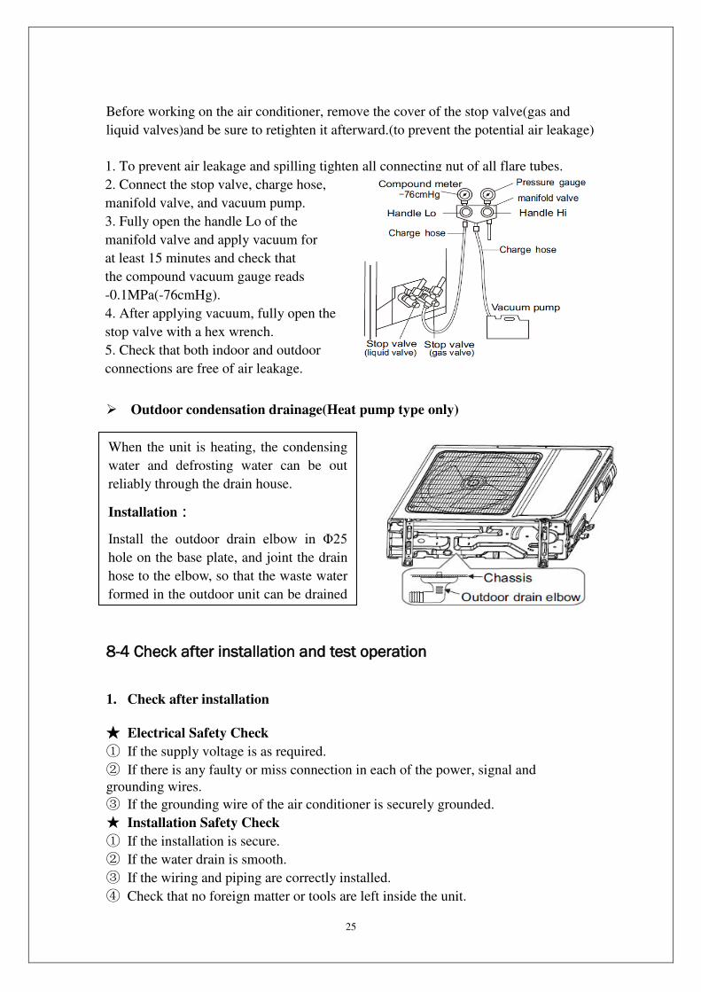
Before working on the air conditioner, remove the cover of the stop valve(gas and
liquid valves)and be sure to retighten it afterward.(to prevent the potential air leakage)
Outdoor condensation drainage(Heat pump type only)
8-4 Check after installation and test operation
1. Check after installation
Electrical Safety Check
① If the supply voltage is as required.
② If there is any faulty or miss connection in each of the power, signal and
grounding wires.
③ If the grounding wire of the air conditioner is securely grounded.
Installation Safety Check
① If the installation is secure.
② If the water drain is smooth.
③ If the wiring and piping are correctly installed.
④ Check that no foreign matter or tools are left inside the unit.
1. To prevent air leakage and spilling tighten all connecting nut of all flare tubes.
2. Connect the stop valve, charge hose,
manifold valve, and vacuum pump.
3. Fully open the handle Lo of the
manifold valve and apply vacuum for
at least 15 minutes and check that
the compound vacuum gauge reads
-0.1MPa(-76cmHg).
4. After applying vacuum, fully open the
stop valve with a hex wrench.
5. Check that both indoor and outdoor
connections are free of air leakage.
When the unit is heating, the condensing
water and defrosting water can be out
reliably through the drain house.
Installation:
Install the outdoor drain elbow in Φ25 hole on the base plate, and joint the drain
hose to the elbow, so that the waste water
formed in the outdoor unit can be drained
26
Leak test of the refrigerant
Depending on the installation method, the following methods may be used to check
for suspect leak, on areas such as the four connections of the outdoor unit and the
cores of the cut-off valves and t-valves:
① Bubble method: Apply of spray a uniform layer of soap water over the suspected
leak spot and observe carefully for bubble.
② Instrument method: Checking for leak by pointing the probe of the leak detector
according to the instruction to the suspect points of leak.
2. Test operation
Test preparation
※Verify that all piping and connection cables are well connected.
※Confirm that the values at the gas side the liquid-side are fully open.
※Connect the power cord to an independent power socket.
※Install batteries in remote control.
Test Operation method
① Turn on the power and push the ON/OFF switch button of the remote controller to
start the air conditioner.
② Select COOL, HEAT (not available on cool-only models), SWING and other
operation modes with the remote controller and see if the operation is ok.
9. Maintenance
9-1 Troubleshooting Guide
Many error codes many appears on this air conditionor, and this troubleshooting
guide is prepared for the maintenance personnel to detect the error position and the
parts to be replaced during the troubleshooting process. In this Guide, the
Troubleshooting Method is guided by the Error Name, and the Reference Code under
the General Index is the error code of the Indoor Unit unit of the mainstream model
supplied by the Company.
Example: “Indoor Unit coil sensor error” is coded as E3 in the error code of the
Indoor Unit unit, but appears as flash-out via the trouble light of the Outdoor Unit
machine. However, their troubleshooting method is the same, and use the same table
as well.
27
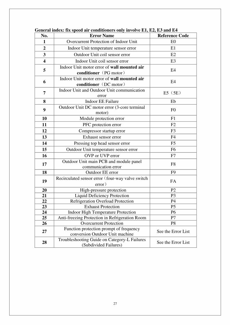
General index: fix speed air conditioners only involve E1, E2, E3 and E4
No. Error Name Reference Code
1 Overcurrent Protection of Indoor Unit E0
2 Indoor Unit temperature sensor error E1
3 Outdoor Unit coil sensor error E2
4 Indoor Unit coil sensor error E3
5 Indoor Unit motor error of wall mounted air
conditioner(PG motor) E4
6 Indoor Unit motor error of wall mounted air
conditioner(DC motor) E4
7 Indoor Unit and Outdoor Unit communication
error E5(5E)
8 Indoor EE Failure Eb
9 Outdoor Unit DC motor error (3-core terminal
motor) F0
10 Module protection error F1
11 PFC protection error F2
12 Compressor startup error F3
13 Exhaust sensor error F4
14 Pressing top head sensor error F5
15 Outdoor Unit temperature sensor error F6
16 OVP or UVP error F7
17 Outdoor Unit main PCB and module panel
communication error F8
18 Outdoor EE error F9
19 Recirculated sensor error(four-way valve switch
error) FA
20 High-pressure protection P2
21 Liquid Deficiency Protection P3
22 Refrigeration Overload Protection P4
23 Exhaust Protection P5
24 Indoor High Temperature Protection P6
25 Anti-freezing Protection in Refrigeration Room P7
26 Overcurrent Protection P8
27 Function protection prompt of frequency
conversion Outdoor Unit machine See the Error List
28 Troubleshooting Guide on Category-L Failures
(Subdivided Failures) See the Error List
28
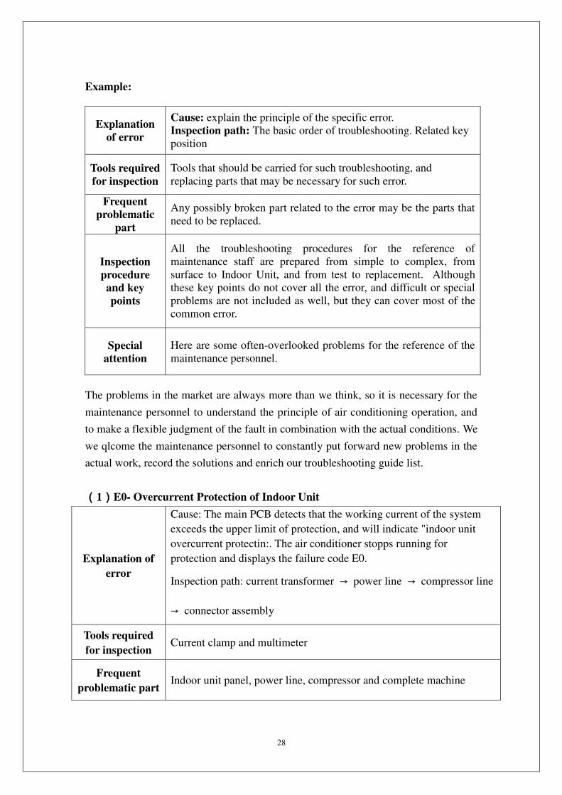
Example:
Explanation
of error
Cause: explain the principle of the specific error.
Inspection path: The basic order of troubleshooting. Related key
position
Tools required
for inspection
Tools that should be carried for such troubleshooting, and
replacing parts that may be necessary for such error.
Frequent
problematic
part
Any possibly broken part related to the error may be the parts that
need to be replaced.
Inspection
procedure
and key
points
All the troubleshooting procedures for the reference of
maintenance staff are prepared from simple to complex, from
surface to Indoor Unit, and from test to replacement. Although
these key points do not cover all the error, and difficult or special
problems are not included as well, but they can cover most of the
common error.
Special
attention
Here are some often-overlooked problems for the reference of the
maintenance personnel.
The problems in the market are always more than we think, so it is necessary for the
maintenance personnel to understand the principle of air conditioning operation, and
to make a flexible judgment of the fault in combination with the actual conditions. We
we qlcome the maintenance personnel to constantly put forward new problems in the
actual work, record the solutions and enrich our troubleshooting guide list.
(1)E0- Overcurrent Protection of Indoor Unit
Explanation of
error
Cause: The main PCB detects that the working current of the system
exceeds the upper limit of protection, and will indicate "indoor unit
overcurrent protectin:. The air conditioner stopps running for
protection and displays the failure code E0.
Inspection path: current transformer → power line → compressor line
→ connector assembly
Tools required
for inspection Current clamp and multimeter
Frequent
problematic part Indoor unit panel, power line, compressor and complete machine
29
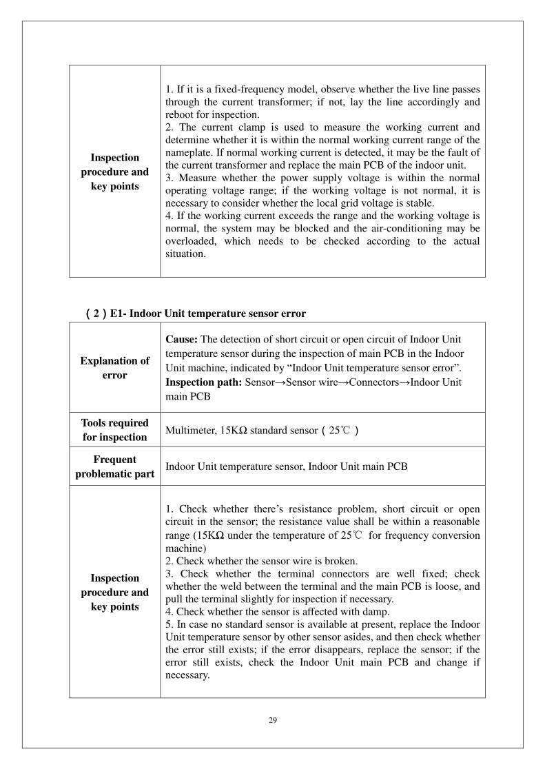
Inspection
procedure and
key points
1. If it is a fixed-frequency model, observe whether the live line passes
through the current transformer; if not, lay the line accordingly and
reboot for inspection.
2. The current clamp is used to measure the working current and
determine whether it is within the normal working current range of the
nameplate. If normal working current is detected, it may be the fault of
the current transformer and replace the main PCB of the indoor unit.
3. Measure whether the power supply voltage is within the normal
operating voltage range; if the working voltage is not normal, it is
necessary to consider whether the local grid voltage is stable.
4. If the working current exceeds the range and the working voltage is
normal, the system may be blocked and the air-conditioning may be
overloaded, which needs to be checked according to the actual
situation.
(2)E1- Indoor Unit temperature sensor error
Explanation of
error
Cause: The detection of short circuit or open circuit of Indoor Unit
temperature sensor during the inspection of main PCB in the Indoor
Unit machine, indicated by “Indoor Unit temperature sensor error”.
Inspection path: Sensor→Sensor wire→Connectors→Indoor Unit main PCB
Tools required
for inspection Multimeter, 15KΩ standard sensor(25)
Frequent
problematic part Indoor Unit temperature sensor, Indoor Unit main PCB
Inspection
procedure and
key points
1. Check whether there’s resistance problem, short circuit or open
circuit in the sensor; the resistance value shall be within a reasonable
range (15KΩ under the temperature of 25 for frequency conversion
machine)
2. Check whether the sensor wire is broken.
3. Check whether the terminal connectors are well fixed; check
whether the weld between the terminal and the main PCB is loose, and
pull the terminal slightly for inspection if necessary.
4. Check whether the sensor is affected with damp.
5. In case no standard sensor is available at present, replace the Indoor
Unit temperature sensor by other sensor asides, and then check whether
the error still exists; if the error disappears, replace the sensor; if the
error still exists, check the Indoor Unit main PCB and change if
necessary.
30
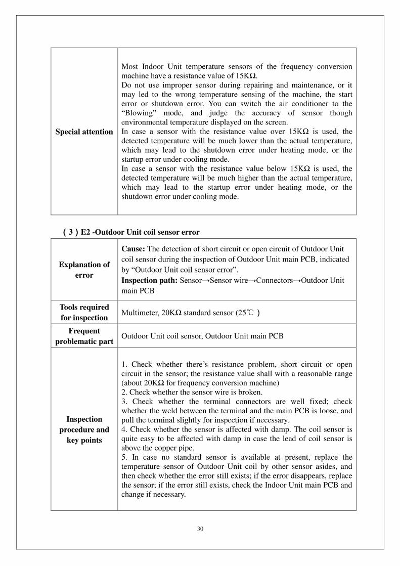
Special attention
Most Indoor Unit temperature sensors of the frequency conversion
machine have a resistance value of 15KΩ. Do not use improper sensor during repairing and maintenance, or it
may led to the wrong temperature sensing of the machine, the start
error or shutdown error. You can switch the air conditioner to the
“Blowing” mode, and judge the accuracy of sensor though
environmental temperature displayed on the screen.
In case a sensor with the resistance value over 15KΩ is used, the detected temperature will be much lower than the actual temperature,
which may lead to the shutdown error under heating mode, or the
startup error under cooling mode.
In case a sensor with the resistance value below 15KΩ is used, the detected temperature will be much higher than the actual temperature,
which may lead to the startup error under heating mode, or the
shutdown error under cooling mode.
(3)E2 -Outdoor Unit coil sensor error
Explanation of
error
Cause: The detection of short circuit or open circuit of Outdoor Unit
coil sensor during the inspection of Outdoor Unit main PCB, indicated
by “Outdoor Unit coil sensor error”.
Inspection path: Sensor→Sensor wire→Connectors→Outdoor Unit main PCB
Tools required
for inspection Multimeter, 20KΩ standard sensor (25)
Frequent
problematic part Outdoor Unit coil sensor, Outdoor Unit main PCB
Inspection
procedure and
key points
1. Check whether there’s resistance problem, short circuit or open
circuit in the sensor; the resistance value shall with a reasonable range
(about 20KΩ for frequency conversion machine)
2. Check whether the sensor wire is broken.
3. Check whether the terminal connectors are well fixed; check
whether the weld between the terminal and the main PCB is loose, and
pull the terminal slightly for inspection if necessary.
4. Check whether the sensor is affected with damp. The coil sensor is
quite easy to be affected with damp in case the lead of coil sensor is
above the copper pipe.
5. In case no standard sensor is available at present, replace the
temperature sensor of Outdoor Unit coil by other sensor asides, and
then check whether the error still exists; if the error disappears, replace
the sensor; if the error still exists, check the Indoor Unit main PCB and
change if necessary.
31
Special attention
Most Indoor Unit temperature sensors of the frequency conversion
machine have a resistance value of 20KΩ. Do not use improper sensor during repairing and maintenance, or it
may led to the start of protection mode due to wrong temperature
sensing of the machine, or the protection error.
In case a sensor with the resistance value over 20KΩ is used, the detected temperature will be much lower than the actual temperature,
which may lead to the frequent entering of defrost mode, the illusory
defrosting or the protection error during the cooling process.
In case a sensor with the resistance value below 20KΩ is used, the detected temperature will be much higher than the actual temperature,
which may lead to defrost error during the heating process, or the start
of protection during the cooling process.
(4)E3 -Indoor Unit coil sensor error
Explanation of
error
Cause: The detection of short circuit or open circuit of Indoor Unit
coil sensor during the inspection of Indoor Unit main PCB, indicated
by “Indoor Unit coil sensor error”.
Inspection path: Sensor→Sensor wire→Connectors→Indoor Unit main PCB
Tools required
for inspection Multimeter,, 5KΩ or 20KΩ standard sensoe(25)
Frequent
problematic part Indoor Unit temperature sensor, Indoor Unit main PCB
Inspection
procedure and
key points
1. Check whether there’s resistance problem, short circuit or open
circuit in the sensor; the resistance value shall with a reasonable range
(about 20KΩ for frequency conversion machine)
2. Check whether the sensor wire is broken.
3. Check whether the terminal connectors are well fixed; check
whether the weld between the terminal and the main PCB is loose., and
pull the terminal slightly for inspection if necessary.
4. Check whether the sensor is affected with damp. The coil sensor is
quite easy to be affected with damp in case the lead of coil sensor is
above the copper pipe.
5. In case no standard sensor is available at present, replace the
temperature sensor of Indoor Unit coil by other sensor asides, and then
check whether the error still exists; if the error disappears, replace the
sensor; if the error still exists, check the Indoor Unit main PCB and
change if necessary.

32
Special attention
Most Indoor Unit temperature sensors of the frequency conversion
machine have a resistance value of 20KΩ. Do not use improper sensor during repairing and maintenance, or it
may led to the start of anti-frosting or overheat protection mode due to
wrong temperature sensing of the machine.
In case a sensor with the resistance value over 20KΩ is used, the detected temperature will be much lower than the actual temperature,
which may lead to the high pressure of cold-blast protection system
during the heating process, or the frequent start of anti-freezing
protection during the cooling process.
n case a sensor with the resistance value below 20KΩ is used, the detected temperature will be much higher than the actual temperature,
which may lead to the frequent start of overheat protection mode
during the heating or the overload protection during the cooling
process.
33
(5)E4 -Indoor Unit motor error of wall mounted air conditioner(PG motor)
Explanation of
error
Cause: PG motor is equipped with speed feedback signal line. When
the feedback signal of speed is not received by the Indoor Unit main
PCB, it has no way to recognize the rotating speed of motor, which
will be indicated as “Indoor Unit motor error”. Main causes for the
disappearance of speed feedback signal are as follows:
The fan is stucked; 2. The speed feedback component in the motor is
broken; 3. Error of receiving circuit for the speed feedback signal from
the Indoor Unit main PCB.
:Is PG motor stucked→Speed feedback line→Speed
feedback terminal connector→Indoor Unit main PCB.
Tools required
for inspection Multimeter, A PG motor in normal working condition
Frequent
problematic part
Mechanical jam problem of Indoor Unit motor, PG motor, Indoor Unit
main PCB
Inspection
procedure and
key points
1. Check whether the motor can work for a period of time before the
error occurs. If yes, the reason of mechanical jam can be exclude.
2. Disconnect the power supply and move the fan blade of Indoor Unit
machine by hand to see if there’s any resistance. Some occasional
Indoor Unit motor error may relate to bearing coordination.
3. Reconnect the drive wire and speed feedback wire, thus to exclude
any motor error due to connector loosening.
4. Check whether the plug-in terminal of speed feedback on the PCB is
loose, and pull the terminal slightly for inspection if necessary.
5. Replace the motor in the faulted air conditioner with other PG motor
(do not fix it with the fan for the time being), if the main PCB still
indicates “Indoor Unit motor error”, then replace the Indoor Unit main
PCB; if the error disappears, replace the Indoor Unit motor.
Special attention
The Indoor Unit main PCB will not indicates “Indoor Unit motor
error” when the Indoor Unit motor is still rotating; sometimes such
error will not be reported when obvious motor problems exist (such as
the low-speed rotation due to damaged motor capacitors, or
non-uniform rotating speed due to abnormal speed feedback.
Therefore, patience of the maintenance staff is required for the
troubleshooting of motor error. You shall compare it with the normal
condition, and detect and solve the problem in a flexible way.

34
35
(6) E4- Indoor Unit motor error of wall mounted air conditioner (DC motor)
Explanation of
error
Cause: The Indoor Unit motor of some highly energy efficient models
is DC motor using a green plug through which the Indoor Unit main
PCB can drive the motor and sense the current rotational speed
feedback. When the Indoor Unit main PCB cannot receive the
rotational speed feedback signal of the motor, it will indicate “DC
motor error”. Disappearance of the rotational speed feedback signal
may be caused by:
1 The fan is stuck and cannot work; 2 The speed feedback element
inside the motor is destroyed; 3 There’s something wrong with the
speed feedback signal receiving circuit of the Indoor Unit main PCB.
Inspection path: Is DC motor stuck by foreign matter→motor destroyed → Motor terminal connectors→Indoor Unit main PCB
Tools required
for inspection Multimeter, a DC motor in normal working condition
Frequent
problematic part
Mechanical jam of Indoor Unit motor, Indoor Unit DC motor, Indoor
Unit main PCB
Inspection
procedure and
key points
1. Check whether the motor accelerates to extremely high speed before
the error occurs. If it can work for a period, the reason of mechanical
jam can be excluded.
2. Plug and unplug the terminal of the DC motor again to exclude any
motor error due to connector loosening, and pull the terminal slightly
for inspection if necessary.
3. Replace the motor in the faulted air conditioner with other DC motor
to plug in the Indoor Unit main PCB (do not fix it with the fan for the
time being), if the main PCB still indicates “DC motor error”, then
replace the Indoor Unit main PCB; if the error disappears, replace the
DC motor.
4. Multimeter can be used to distinguish whether it is main PCB
problem or motor problem by: connect the motor with the main PCB
and pay attention to the second (yellow) and fourth (black) wire from
the outermost side among four lines of the terminal of the DC motor.
After the air conditioner powers on in the cooling mode for a while, the
voltage between the yellow and black wires should rise gradually and
the motor should accelerates slowly, if the DC motor still won’t rotate,
then the DC motor is destroyed.
Special attention
Five lead wires division: Count from the outermost side of the four
wires of the DC motor terminal, the first blue wire is the speed
feedback wire with a voltage of 0.5-5V when the motor rotates; the
second yellow wire is the motor driving wire with a voltage of
2.0-7.5V when the motor rotates; the second white wire is 15V power
cord with a voltage of 15V in normal condition; the fourth black wire
is 0V DC earth wire which is the benchmark of all the voltage tests; the
fifth (red) wire is 310V wire which is strong with a voltage of 310V in
normal condition, so be careful of electric shock.
36
(7) E5(5E) -Indoor Unit and Outdoor Unit communication error
Explanation of
error
Cause: The frequency converter needs Indoor Unit and Outdoor Unit
communication.When the communication cannot be reached, the
Indoor Unit and Outdoor Unit units will indicate “Indoor Unit and
Outdoor Unit communication error”. Only “Indoor Unit main PCB,
connecting cable and Outdoor Unit main PCB” are related to
communication; but sometimes the communication error will be
indicated when the Outdoor Unit unit has no power and the Indoor
Unit unit cannot connect with the Outdoor Unit unit due to other errors,
then such situation shall be distinguished from “pure communication
error” and treated in a different way.
Inspection path: Check if the Outdoor Unit unit can power on and
work (normally, the indicator light will turn off after lighting for
several seconds, relay picks up, and PTC won’t heat seriously)
1. Can power on and work: Are the Indoor Unit unit and Outdoor Unit
unit matched→is the phase sequence of connecting wires of Indoor Unit and Outdoor Unit units correct (the live wire of the Indoor Unit
unit connects with that of the Outdoor Unit unit, the null wire of the
Indoor Unit unit connects with that of the Outdoor Unit
unit)→Connecting wires touched well→Indoor Unit main PCB replacement→Outdoor Unit main PCB replacement 2. Cannot power on and work: Can AC 220V be delivered to the
terminal block of the Outdoor Unit unit→Can the bridge rectifier and module panel generate DC 310V→Can the Outdoor Unit main PCB generate a low voltage power supply of DC 5V→Does the Outdoor Unit main PCB show the status of periodical reset.
Tools required
for inspection Multimeter, Indoor Unit main PCB in normal condition
Frequent
problematic part
Connecting wire phase sequence and contact, Indoor Unit main PCB,
Outdoor Unit main PCB, module panel
Inspection
procedure and
key points
1. Firstly, the IDU and the ODU should be matched and connected
properly.
2. Observe the Outdoor Unit main PCB, turn on the air conditioner,
three lights are all lighted up then off and the relay pulls in. If not, it is
power supply problem.
3. Connect the black signal line S to terminal N of ODU. Turn on the
A/C, if "E5" is still reported, the Outdoor Unit main PCB need to be
replaced. If "E5" is still reported at this time, go to step 4.
4. Change a new Indoor Unit main PCB, if the error code E5 remains,
then the problem should be on the Outdoor Unit main PCB.
37
Special attention
When the Outdoor Unit unit not power on: If the Indoor Unit
terminal board does not transmit 220V power, replace the Indoor Unit
main PCB; if the Outdoor Unit terminal board has 220V power, first
check if (fuse, reactor and bridge rectifier) are normal. There is still
something wrong, replace the whole set of Outdoor Unit control unit;
for the control unit composed of several function boards, try
disconnecting the weak-current data wires among several control
boards and then power the Outdoor Unit unit on, if the main PCB can
be powered on and initialized successfully, then it’s the module panel
problems; if the Outdoor Unit main PCB still cannot be powered on
and initialized, replace the Outdoor Unit main PCB.
38
(8) Eb –Indoor EE Failure
Explanation of
error
Cause: Many parameters need to be preset for the running of the indoor
unit of the air conditioner and such parameters are placed in a data
storage 8-feet chip, which is called "EEPROM" or "EE" for short. The
motor on the Indoor Unit main PCB can only work after reading the
data stored in EE and if not read, the failure code "Outdoor EE Failure"
will be indicated and raised in the indoor unit. Reasons for data not
being read are as follows:
1. wrong EE chip data format;
2. EE chip is broken;
3. bad contact of EE or fault of EE reading circuit;
4. backward installation of EE chip.
Inspection path: Indoor Unit main PCB.
Tools required
for inspection /
Frequent
problematic part Bad contact of EE, Indoor Unit main PCB.
Inspection
procedure and
key points
Replace the Indoor Unit main PCB directly.
39
(9) F0- Outdoor Unit DC motor error (3-core terminal motor)
Explanation of
error
Cause: Our frequency changing Outdoor Unit unit uses the 3-lead-wire
DC motor, or “Outdoor Unit driven DC motor” for short, after 2012. It
has no speed feedback circuit but 3 drive lead wires and its driving
principle is similar to that of the compressor. The main PCB will
indicate “Outdoor Unit DC motor error” when it detects imbalanced
current on the three lead wires of the driving motor.
Inspection path: Is the DC motor stuck by foreign matters→Motor terminal connectors→Outdoor Unit main PCB→Motor
Tools required
for inspection Outdoor Unit main PCB in normal condition
Frequent
problematic part
Mechanical jam of Outdoor Unit motor, Outdoor Unit main PCB,
Outdoor Unit DC motor
Inspection
procedure and
key points
1. First exclude the possibility of mechanical jam of Outdoor Unit fan
blades.。
2. Observe if the terminal of the motor is not connected firmly or the
order of lead wires is correct. If the Outdoor Unit motor of the newly
installed air conditioner rotates reversely, first observe if the color
order of the three lead wires is correct, or change the order of any two
of the three lead wires of the motor to see if the motor can rotate in the
forward direction.
3.The DC motor of this scheme is relatively simple and reliable, so the
problem is more likely to be caused by the drive part of the motor of
the Outdoor Unit main PCB. The maintenance personnel may as well
prepare matched Outdoor Unit main PCB before maintenance. If the
motor returns to normal after replacing the main PCB, then it’s the
main PCB problem; if it still indicates Outdoor Unit DC motor error,
then replace the Outdoor Unit DC motor.
Special attention
Unlike the 5-core Indoor Unit DC motor, there will be a process of
motor blade position locking before the 3-core DC motor with Outdoor
Unit drive starts to rotate. The fan blades will shake mechanically for
3-5 seconds and then rotate slowly, which is normal phenomenon.

40
(10) F1 -Module protection error
Explanation of
error
Cause: The power module is the part to directly drive the compressor
to work. It can protect the machine in time when overcurrent,
overvoltage or overheat occurs and stops the compressor from
working. It will, at the same time, send “shutdown request” to the
module panel. The error triggered by the “shutdown request” is called
“module protection error”.
Inspection path: Supply voltage → Compressor wire, reactor wire →
System blocked → Module panel damaged → Outdoor Unit main PCB
destroyed → Compressor destroyed
Tools required
for inspection
Multimeter, pressure gauge, megameter, module panel in normal
condition
Frequent
problematic part
Supply voltage, compressor wire, reactor, system pressure, module
panel, Outdoor Unit main PCB, compressor
41
Inspection
procedure and
key points
1. Is the order of compressor wires not correct, which makes the
compressor rotate reversely? Try exchanging the compressor wires on
U-V phase to see if the problem can be solved?
2. Check if the supply voltage is unstable and highly volatile, and test
if the system pressure is normal. High system pressure will cause
rotating problems to the compressor.
3. Is the module panel fixed to the radiator firmly? Will it cause pool
cooling? Is the Indoor Unit and Outdoor Unit heat exchanger dirty,
which lead to poor heat transfer and high system pressure?
4. If “module protection error” will be indicated immediately after
starting up, it is almost certain that it’s substantial error, having nothing
to do with supply voltage and system pressure, it is suggested to
observe if there is any component destroyed by strike arc near the
module panel; use the multimeter to test if the resistances between any
two compressor wires are the same. The resistances between any two
compressor wires in normal condition are tiny resistances at ohm level
and are basically equal; then use the megameter to measure if the
resistance insulation of the three compressor wires against the earth
wire is good (normally at MΩ level), and check if the reactor wire is well connected or the reactor is destroyed.
5. Test if the 15V and 5V (3.3V) power supply on the module panel is
stable and exclude the module panel error caused by power supply of
the Outdoor Unit main PCB.
6. Methods for judging whether the power module is damaged: use the
“diode position” of the multimeter to measure the features of P of the
module panel against U-V-W three phases respectively. Measure the
power module P-U, P-V and P-W, there is always infinite resistance at
one side and fixed on-state voltage at the other side (generally 0.5V);
measure the features between N-U, N-V and N-W in the same way, if
short circuit occurs during any measurement, then the module is
destroyed.
7. Replace with the module panel in normal condition for test. If the
test is normal after changing the module panel, then the original
module panel is destroyed.
8. After excluding problems of module, connecting wires, system and
power supply, distinguish by ear. If there is only electromagnetic sound
and the compressor does not work; or the sound of irregular running
appears after the compressor works for a while and then it shuts down
and indicates error; chances are that the compressor is blocked or
destroyed, consider replacing the compressor.
42
(11) F2- PFC protection error
Explanation of
error
Cause: PFC board is a component of the inverter air conditioner for
power factor correction and voltage boosting. When the PFC board
cannot perform power calibration as normal because of overcurrent and
overvoltage, it will indicate “PFC protection error” and its function
may also be integrated with the module panel or main PCB.
Inspection path: Supply voltage→AC and DC power path→PFC board data wire→PFC board→Main PCB
Tools required
for inspection Multimeter, PFC board in normal condition
Frequent
problematic part
Supply voltage, reactor, PFC board, module panel, Outdoor Unit main
PCB
Inspection
procedure and
key points
1. Check if the supply voltage is unstable and highly volatile or the
voltage is too low (below AC 135V)
2. The reactor is one of core parts of PFC. Check if the reactor itself is
destroyed and the reactor connecting wire is in poor connection, which
makes PFC functions not performed. Do not remove the reactor and
replace with short circuit by no means.
3. If “PFC protection error” will be indicated immediately after starting
up, it is almost certain that it’s substantial error, having nothing to do
with supply voltage, it is suggested to observe if there is any
component destroyed by strike arc near the module panel
4. Test if the 15V and 5V (3.3V) power supply on the PFC board is
stable and exclude the PFC board error caused by power supply of the
Outdoor Unit main PCB.
5. Replace with the PFC board in normal condition for test. If the test is
normal after changing the PFC board, then the original PFC board is
destroyed.
6. The possibility that there is something wrong with 15V or 5V power
of the module panel that causes the control power supply problem of
the PFC board is not excluded.
7. Some module panels integrate PFC function and compressor drive
function in one, so just replace with an integrated module panel.
8. For single-panel single-chip main PCBs, if PFC protection error
appears, and there is no problem in supply voltage, reactor connection
or reactor, just replace the controller of the Outdoor Unit unit.
43
(12) F3- Compressor out-of-step error
Explanation of
error
Cause: The module panel will constantly test the current of lead wires
of the compressor and calculate the position of the rotator of the
compressor when driving the compressor to work. When the
compressor deviates far from the normal operating status , it will
indicate “compressor out-of-step error” because the current of the
compressor wires is too high or it cannot detect the position of the
rotator. This error always follows “module protection error”, so they
have similar inspection methods.
Inspection path: supply voltage→Compressor wire, reactor wire→
System blocked→Module panel damaged→Outdoor Unit main PCB destroyed→Compressor destroyed
Tools required
for inspection Multimeter, pressure gauge, module panel in normal condition
Frequent
problematic part
Supply voltage, compressor wire, reactor, system pressure, module
panel, Outdoor Unit main PCB, compressor
Inspection
procedure and
key points
1. Is the order of compressor wires not correct, which makes the
compressor rotate reversely? Try exchanging the compressor wires on
U-V phase to see if the problem can be solved?
2. Check if the supply voltage is unstable and highly volatile, and test
if the system pressure is normal. High system pressure will cause
rotating problems to the compressor.
3. Is the module panel fixed to the radiator firmly? Will it cause pool
cooling? Is the Indoor Unit and Outdoor Unit heat exchanger dirty,
which lead to poor heat transfer and high system pressure?
4. If “compressor out-of-step error” will be indicated immediately after
starting up, it is almost certain that it’s substantial error, having nothing
to do with supply voltage and system pressure, it is suggested to
observe if there is any component destroyed by strike arc near the
module panel; use the multimeter to test if the resistances between any
two compressor wires are the same. The resistances between any two
compressor wires in normal condition are tiny resistances at ohm level
and are basically equal; then use the megameter to measure if the
resistance insulation of the three compressor wires against the earth
wire is good (normally at MΩ level), and check if the reactor wire is well connected or the reactor is destroyed. Check if the DC voltage
between P-N is too high (above 200V).
5. Test if the 15V and 5V (3.3V) power supply on the module panel is
stable and exclude the module panel error caused by power supply of
the Outdoor Unit main PCB.
6. Replace with the module panel in normal condition for test. If the
test is normal after changing the module panel, then the original
module panel is destroyed.
7. After excluding problems of module, connecting wires, system and
power supply, distinguish by ear. If there is only electromagnetic sound
and the compressor does not work; or the sound of irregular running
appears after the compressor works for a while and then it shuts down
and indicates error; chances are that the compressor is blocked or
destroyed, consider replacing the compressor.
44
Special attention
For the “compressor out-of-step error” and “module protection error”,
the former is calculated by the main chip of the module panel and the
latter is detected by the power module itself. They are abnormal
operating phenomenon of the compressor essentially. If there is
uncertainty about either error, analyze both together with similar
method. For inverter air conditioners that are in poor electrical
environment or are old, occasional occurrence of such errors is a
normal protection.
(13) F4- Exhaust sensor error
Explanation of
error
Cause: The Outdoor Unit main PCB will indicate “exhaust sensor
error” and send it to the Indoor Unit main PCB when it detects short
circuit or open circuit of the exhaust sensor.
Inspection path: Exhaust sensor→Sensor wire→Connectors→Outdoor Unit main PCB
Tools required
for inspection Multimeter, 50KΩ standard exhaust sensor (25)
Frequent
problematic part Exhaust sensor, Outdoor Unit main PCB
Inspection
procedure and
key points
1. Check if there is any evident resistance problem in the sensor.
Whether in short circuit or open circuit, the resistance should maintain
in a reasonable range (about 50KΩ when the compressor is not working and between 3 KΩ and 30 KΩ after the compressor works for a while, the corresponding exhaust temperature should be 100
-38).
2. Check if the sensor wire or the sensor connecting wire is damaged.
3. Check if the connecting terminal is connected firmly, the weld
between the terminal and the main PCB is loose; pull the terminal
slightly for inspection if necessary.
4. Check whether the sensor is affected with damp. The coil sensor is
quite easy to be affected with damp in case the lead wire of coil sensor
is above the copper pipe.
5. If there is no standard sensor at hand, exchange the exhaust sensor
with the one beside it to see if the error changes. If yes, there is
something wrong with the sensor and it should be replaced; if it still
indicates “Outdoor Unit coil sensor error”, replace the Outdoor Unit
main PCB.
Special attention
Most exhaust sensors have a standard resistance of 50KΩ (25). Do
not use improper sensor during maintenance, or the machine will sense
the exhaust temperature mistakenly and enters the protection state
frequently. For example, in the case where replace the 20KΩ coil sensor for the exhaust sensor by mistake, the exhaust temperature that
the Outdoor Unit main PCB senses will be higher than the actual
exhaust temperature, which will make normal air conditioners enter the
high exhaust temperature protection state frequently, and the
compressor frequency threshold will rise and lead to shutdown of the
compressor.
45
(14) F5 -Compressor top head sensor error
Explanation of
error
Cause: The compressor top head sensor is a compressor top head
temperature protection switch most of the time. It keeps closed (short
circuit) when the compressor temperature is normal and switches off
(open circuit) when the temperature is too high. The Outdoor Unit
main PCB will indicate “compressor top head sensor error” when it
senses disconnection of the compressor top head protection switch.
Inspection path: Compressor top head sensor (temperature protection
switch)→Sensor wire→Connectors→Outdoor Unit main PCB
Tools required
for inspection Pressure gauge, multimeter
Frequent
problematic part
System pressure, liquid deficiency, compressor top head sensor
(temperature protection switch), Outdoor Unit main PCB
Inspection
procedure and
key points
1. First check if the compressor top head temperature is too high
(above 110) and causes action of the compressor top head sensor
(temperature protection switch); reasons why the compressor top head
temperature is too high may be: the system is deficient in liquid and the
compressor idles; the system is blocked and the pressure of the
compressor is too high.
2. After excluding the possibility of the system problem, please note
that the temperature protection switch is closed normally. Test if the
terminals of the sensor are in the short-circuit condition with the
multimeter. In the case of open circuit, then there is something wrong
with the sensor or lead wires.
3. Check if the sensor wire or the sensor connecting wire is damaged.
4. Check if the connecting terminal is connected firmly, the weld
between the terminal and the main PCB is loose; pull the terminal
slightly for inspection if necessary.
5. Disconnect the power supply and short circuit a metal with the
compressor top head terminal of the Outdoor Unit main PCB. If the
compressor top head sensor error disappears after start up, then replace
the sensor; if the error still occurs, it’s probably the main PCB
problem, replace the Outdoor Unit main PCB.
Special attention
The compressor top head sensor is just a temperature switch which is
highly reliable and is less likely to go wrong generally. Pay more
attention to the system pressure and the compressor temperature.
46
(15)F6- Outdoor Unit temperature sensor error
Explanation of
error
Cause: The detection of short circuit or open circuit of Outdoor Unit
termperature sensor during the inspection of Outdoor Unit main PCB,
indicated by "Outdoor Unit termperature sensor error".
Inspection path: Sensor→Sensor wire→Connectors→Outdoor Unit main PCB
Tools required
for inspection Multimeter, 15KΩ standard sensor(25)
Frequent
problematic part Outdoor Unit temperature sensor, Outdoor Unit main PCB.
Inspection
procedure and
key points
1. Check whether there’s resistance problem, short circuit or open
circuit in the sensor; the resistance value shall be within a reasonable
range (15KΩ under the temperature of 25).
2. Check whether the sensor wire is broken.
3. Check whether the terminal connectors are well fixed; check
whether the weld between the terminal and the main PCB is loose, and
pull the terminal slightly for inspection if necessary.
4. Check whether the sensor is affected with damp.
5. In case no standard sensor is available at present, replace the
Outdoor Unit temperature sensor with the other sensor asides, and then
check whether the error still exists; if the error disappears, replace the
sensor; if the error still exists, it's possible that the main PCB is faulted,
change the Outdoor Unit main PCB.
Special attention
Most of the standard resistance values of the Outdoor Unit temperature
sensors are 15KΩ (hen temeperature is at 25), and the higher the
temeprautre is, the lower the resistance value is, and the lower the
temperature is, the higher the resistance value is. Do not use improper
sensor during repairing and maintenance, or it may led to the wrong
temperature sensing of the machine.
47
(16)F7-OVP or UVP error
Explanation of
error
Cause: All the inverter air conditioners are equipped with voltage
inspection circuits, but differnt models of machines have differnt
locations for the voltage inspection (on the modue panel or Outdoor
Unit main PCB). When the supply voltage is lower than 135V or
higher than 275V, the inspectio circuit would detect over or under
voltage protection signal and send it to the Outdoor Unit main PCB
and the Outdoor Unit main PCB would raise the alarm "OVP or UVP
error" and indicate it through the Indoor Unit motor.
Inspection path: supply voltage → Indoor Unit direct current voltage → reactor wiring → module panel → Outdoor Unit main PCB.
Tools required
for inspection Multimeter
Frequent
problematic part Supply voltage, reactor, moduel panel and Outdoor Unit main PCB.
Inspection
procedure and
key points
1. First, check the supply environment of the user, especially shall
check when the compressor of the air conditioner has been running for
a while. The normal supply voltage shall be between 198V and 242V
and the minimum work assurance range of the air conditioner shall be
within 165V and 265V and it shall be especially noted that the voltage
value shall not be decreased significantly after running of the
compressor (voltage decreasing by over 25V), because if the supply
voltage is decreased by a lot, it means the supply line capacity is
insufficient and the user is usually suggested to replace the circuit or
install a specizlied air conditioner supply voltage stabilizer.
2. For the Outdoor Unit machines with PFC panels (without separate
rectifier bridges), the operator shall ensure if the PFC function is on
with the direct current voltage grade of the multimeter. When the
compressor is running, voltage between P and N ends detected on the
test module panel or Outdoor Unit main PCB shall be over 200V and if
the voltage is below that range, it is possible that the reactor is faulted
or the PFC is broken.
3. When the air conditioner is switched on, if the compressor is not
running but there is a alarm of "OVP or UVP error" and the power
voltage detected with the multimeter is not below 150V, it's probably
the voltage inspection circuit is faulted. The operator shall check and
confirm the voltage inspection circuit is on which PCB first and then
replace it. The regular replacement: for the Outdoor Unit machine of
single panel single chip, replace the Outdoor Unit controller directly;
and for the machine of two panels, replace the module panel.
Special attention
For some models, OVP or UVP error signal is delivered through the
connector wires between the module panel and the Outdoor Unit main
PCB, thus it is possible the voltage signal is not delivered when the
communication between teh module panle and the Outdoor Unit main
PCB is not good. It is possible that the error is fause raised but after
some minutes that the error is finally confirmed as "Outdoor Unit main
PCB and module pannel communication error", which shall be
48
specially noted.
(17)F8-Outdoor Unit main PCB and module panel communication error
(exclusive of Outdoor Unit machine of single panel)
Explanation of
error
Cause: Only the models with the module panels separated with the
Outdoor Unit main PCBs may have this error. When the machine is
running normally, the module panel and the Outdoor Unit main PCB
would coordinate with each other on the communication to work and
when the communication is off, the Outdoor Unit main PCB would
raise the alarm of "main PCB and module panel communication error".
Only "module panel, data line and Outdoor Unit main PCB" are related
to such communication.
Inspection path: data line connection → module panel power →module panel →Outdoor Unit main PCB
Tools required
for inspection Multimeter and regular module panel.
Frequent
problematic part
Module panel and main control data line, module panel and Outdoor
Unit main PCB.
Inspection
procedure and
key points
1. First check if the communication connection line (mostly 4 chips)
between the module panel and main contrl panel gets loose and if the
connection is faulted.
2. Measure and check with a multimeter if the power from the Outdoor
Unit main PCB is normal and especially note that if the 5V (3.3V)
power is led to the module panel. Eleminate the possibility that it's not
running normally because there is no 5V (3.3V) power at the module
panel.
3. The maintenance personnel shall replace the module panel of the
faulted air conditioner with a regular module panel taken with him and
if the communication error disappears when the Outdoor Unit machine
is switched on, it means the original module panel is faulted and if the
error is still there, maybe the Outdoor Unit main PCB shall be
replaced.
(18)F9- outdoor EE error
49
Explanation of
error
Cause: Many parameters need to be preset for the running of the
Outdoor Unit unit of the air conditioner and such parameters are placed
in a data storage 8-feet chip, which is called "EEPROM" or "EE" for
short. The motor on the Outdoor Unit main PCB can only work after
reading the data stored in EE and if not read, the alarm "outdoor EE
error" would be reported and raised in the Indoor Unit machine.
Reasons for data not being read are as follows:
1. wrong EE chip data format;
2. EE chip is broken;
3. bad contact of EE or fault of EE reading circuit;
4. backward installation of EE chip.
Inspection path: Outdoor Unit main PCB.
Tools required
for inspection None.
Frequent
problematic part Bad contact of EE, Outdoor Unit main PCB.
Inspection
procedure and
key points
1. Replace the Outdoor Unit main PCB directly.
(19)FA- recirculated sensor error (only models of electronic expansion valves
are involved)
Explanation of
error
Cause: The recirculated sensors are only used on machine models of
electronic expanssion valves and the back temperature value is
considered as the basis for adjustment of the electronic expanssion
valve and determination if the four-way valve changes the position
normally during heating. When the main PCB detects open circuit or
short circuit of the recirculated sensor, it would raise an alarm of
"recirculated sensor error" and send it to the Indoor Unit main PCB to
indicate it.
Inspection path: four-way valve →recirculated sensor → sensor wire → connectors → Outdoor Unit main PCB
Tools required
for inspection Multimeter, pressure meter, normal 20KΩ recirculated sensor
Frequent
problematic part Four-way valve, recirculated sensor, Outdoor Unit main PCB.

50
Inspection
procedure and
key points
1. If the error appears in heating but not in cooling, first check if the
four-way valve failed to change the position or there is a back flow,
which can be estimated by measuring the high and low pressures with
the pressure meter; for the consideration of electricity control, we can
use a multimeter. During heating, check if the four-way valve terminal
can switch a circuit of 220V, if yes and the four-way valve still is
faulted in the position changing, the four-way valve is faulted; and if
there is no circuit over 220V in heating, it means the Outdoor Unit
main control valve is faulted.
2. If it is not the four-way valve that is faulted, check on the resistance
value and short circuit problems and the resistance value shall be
within a proper range (around 20KΩ at temperature of 25).
3. Check whether the terminal connectors are well fixed; check
whether the weld between the terminal and the main PCB is loose, and
pull the terminal slightly for inspection if necessary.
4. Check whether the sensor is affected with damp. For the recirculated
sensor, if the led is on the above and thecopper pipe is below, it is
possible to be damped.
5. The maintenance personnel can replace the possibly faulted
recirculated sensor with a normal one and if the error disappears, it
means the original recirculated sensor is faulated and needs to be
replaced; and if the error is still there, consider to replace the Outdoor
Unit main PCB.
51
(20) P2 - High-pressure protection
Explanation of
error
Cause: In standby state or when the equipment is running, the
high-pressure switch is disconnected three times (within 20 minutes)
and reported as " High-pressure protection";
Inspection path: high-pressure switch cable → connector →
high-pressure switch → main PCB
Tools required
for inspection Multimeter, connectoin line and high-pressure swtich
Frequent
problematic part
High-pressure swtich connectoin line, fluorine deficiency of unit and
high-pressure swtich
Inspection
procedure and
key points
1. Check whether the plug-in terminals are firmly connected and
whether the terminals and the main PCB are welded loosely. If
necessary, gently pull them to check;
2. Use a multimeter to measure whether it is disconnected;
3. Use the multimeter to check the state of the high-pressure swtich and
check whether it is in the OFF state (normally OFF, unusual
disconnection);
4. If the pressure is normal and the high-pressure switch is kept open, it
is positive that the pressure voltage is faulted;
5. If the pressure switch is normal and the connection line is tact and
the failure is still reported, replace the corresponding main PCB.
Special attention
The reason why high-pressure switches are often disconnected is the
leakage of equipment. When the high voltage switch is off, first check
whether the air conditioner's pressure is normal. If it is normal but the
failure is still displayed aftere replacing the Outdoor Unit main PCB, it
is possible that the connecting pipe may be too long or the Outdoor
Unit ambinet temperature is too low

52
(21) P3 –Liquid Deficiency Protection
Explanation of
error
Cause: The liquid volume of the system is less than 30%, which leads
to non-refrigeration and liquid shortage protection.
Inspection path: whether the valves of the outdoor unit are opened →
whether the evaporator, condenser, connectoin pipe are damanged or
cracked → whether the environmental temperature sensor and the coil
temperature sensor are damaged at the same time
Tools required
for inspection Hex nut, multimeter, pressure gauge
Frequent
problematic part Stop valve, evaporator, condenser and connection pipe
Inspection
procedure and
key points
1. Check the stop valve and turn it counterclockwise with hexagons to
see if the valve is not open and the opening is not enough;
2. Check whether the evaporator, condenser and connection pipe are
damaged or cracked, and focus on checking whether there is refrigerant
leakage in the welding part and connection pipe joint;
3. Measure the temperature sensor with the multimeter at ambient
temperature, and whether the coil temperature sensor has abnormal
resistance at the same time.
53
(22) P4 –Refrigeration Overload Protection
Explanation of
error
Cause: Outdoor coil sensor senses excessive temperature, prevents
compressor from overloading, and reduces frequency.
Inspection path: the system is dirty or blocked → the condenser is
dirty → Outdoor Unit coil sensor is faulated →AC motor not running
→ failure of divider resistance of controller
Tools required
for inspection Multimeter and pressure gauge
Frequent
problematic part Coil sensor, condenser and outdoor unit controller
Inspection
procedure and
key points
1. Check the coil sensor with a multimeter to see if the resistance value
is normal (20KΩ standard sensor, 25)
2. Use a pressure gauge to detect system pressure. If the system
pressure is high, it may cause Indoor Unit dirty blockage or poor
Outdoor Unit heat transfer, which may lead to high coil temperature.
3. Observe whether the speed of AC motor is too low, which leads to
poor heat transfer and high coil temperature.
4. Use a multimeter to check whether the voltage dividing resistance of
temperature sensor circuit of Outdoor Unit controller coil is abnormal.
If you don't know how to measure it, try to replace the Outdoor Unit
controller to check whether it returns to normal state.
54
(23) P5–Exhaust Protection
Explanation of
error
Cause: the exhaust sensor detects that the exhaust temperature is too
high and triggers the exhaust protection shutdown.
Inspection path: system pressure → indoor / outdoor air inlet →
exhaust sensor → Outdoor Unit panel
Tools required
for inspection Multimeter, pressure gauge, regular 50KΩ exhuast sensor (25)
Frequent
problematic part Indoor coil sensor
Inspection
procedure and
key points
1. Check if the system pressure is low, if is, usually it the shortage of
liquid that leads to excessive exhaust temperature protection;
2. Check whether the indoor/outdoor air inlet is blocked, such as
whether the evaporator or condenser is dirty or whether the filter is
dirty or blocked and if inlet is affected, remove the shield.
3. Check whether the air volume at the tuyere is too small, observe
whether the Indoor Unit fan blades are dirty blocked, and if dirty
blocked blades are found, clean the blades.
4. Measure the resistance drift of the exhaust sensor with a
multimeter at ambient temperature.

55

56
(24) P6–Indoor High Temperature Protection
Explanation of
error
Cause: Protection shutdown due to temperature of indoor coil.
Inspection path: indoor air inlet → indoor unit filter → indoor motor
→ indoor coil sensor
Tools required
for inspection Multimeter, pressure gauge, regular 20KΩ exhuast sensor (25)
Frequent
problematic part
1. Check whether the indoor air inlet is blocked or not, if it affects the
wind, remove the shield;
2.Check whether the filter is dirty or not. If dirty blockage is found in
the filter, clean the filter.
3. Check if the air volume at teh tuyere is too small and if the indoor
unit fan is blocked, if is, clean the motor.
4. Measure the drift of the inner disk sensor with a multimeter at
ambient temperature.
Inspection
procedure and
key points
P6 usually refers to the high temperature protection of the Indoor Unit
heating coil due to poor air inlet.

57
(25) P7–Anti-freezing Protection in Refrigeration Room
Explanation of
error
Cause: Protection shutdown due to temperature of indoor coil.
Inspection path: indoor air inlet → indoor unit filter → indoor motor
→ indoor coil sensor
Tools required
for inspection Multimeter, pressure gauge, regular 20KΩ exhuast sensor (25)
Frequent
problematic part Indoor coil sensor
Inspection
procedure and
key points
1. Check whether the indoor air inlet is blocked or not, if it affects the
wind, remove the shield;
2.Check whether the filter is dirty or not. If dirty blockage is found in
the filter, clean the filter.
3. Check if the air volume at teh tuyere is too small and if the indoor
unit fan is blocked, if is, clean the motor.
4. Measure the drift of the inner disk sensor with a multimeter at
ambient temperature.
Special attention P7 usually refers to the anti-freezing protection of the refrigeration
room due to poor air inlet.

58
(26) P8–Overcurrent Protection
Explanation of
error
Cause: Controller detects AC bus current exceeding the set protection
value, then limits and reduces the frequency.
Inspection path: system blockage → grid voltage→ outdoor unit
controller
Tools required
for inspection Multimeter, pressure gauge
Frequent
problematic part Grid voltage and outdoor unit controller
Inspection
procedure and
key points
1. Use a mutlimeter to detect and check if the bus voltage is too low,
causing the overcurrent protection.
2. Use a pressure gauge to check whether the pressure of the system
exceeds the standard. If the pressure exceeds the standard, it may lead
to dirty blockage of the system.
3. Replace the outdoor unit controller and if the unit returns to normal,
it is the problem of the controller.
Special attention
Generally, such protection occurs at high load, but should not occur at
low load and low temperature, and the priority of this protection is
after the protection of refrigeration against overload and exhaust.
59
( 27)Function protection prompt of frequency conversion Outdoor Unit
machine
Explanation of
error
Cause: In the regular running of the air conditioner, for some
nonfaulted status, it may need the compressor to shut down or limit or
lower the frequency so as to protect the normal operating of the entire
cooling system (eg. defrosting, slight undercooling, over pressure,
overcurrent, etc.). These problems are not considered as errors and
would not be reflected in the Indoor Unit machine, however as to make
sure the maintenance personnel is familar with the running status of the
air conditioner, three indicator lights are used on the Outdoor Unit
main PCB for reference of the maintenance personnel.
Including: over current protection, cooling overload protection, indoor
heating high temperature protection, indoor cooling freezing
protection, over pressure and under pressure protection.
Tools required
for inspection Multimeter.
Frequent
problematic part
Regular protection, system blockage, power supply not as usual,
resistance value of sensor drifts or is used wrong.
Inspection
procedure and
key points
1. Defrosting: with a defrosting signal, meaning the air conditioner is
under defrosting procedure and it is normal, but if there is frequent
defrosting, it shall be specifically noted if heat exchange of the
Outdoor Unit unit is faulted, if the motor revolving speed is low and if
the resistance value of the coil sensor is drifted or the temperature is
inaccurately measured or it is damaged.
2. Over current protection: it is more possible to appear under high
temperature cooling status and the over current of compressor is
usually reflected by over high load of the compressor. It is normal if
such protection appears under a very high temperature cooling status
but not under low temperature low load status.
3. Cooling overload protection: it is more possible when the frequency
conversion machine is under a high temperature cooling status. When
the outdoor coil sensor senses the temperature is too high, as to provent
the compressor from overload, it would possitively lower the
frequency and it is normal for the protection under the high
temperature cooling status.
4. Indoor high temperature heating protection: it is more possible when
the frequency conversion machine is under a high temperature heating
status. When the indoor coil sensor senses the temperature is too high,
as to provent the compressor from overload, it would possitively lower
the frequency and it is normal for the protection in a warm room.
5. Indoor cooling freezing protection: it is more possible to appear
under a low temperature cooling status. When the indoor coil sensor
senses the temperature is too low, as to prevent the heat exchanger of
the Indoor Unit machine from frosting, it would possitively lower the
frequency and it is normal for the protection in a low temperature
room.
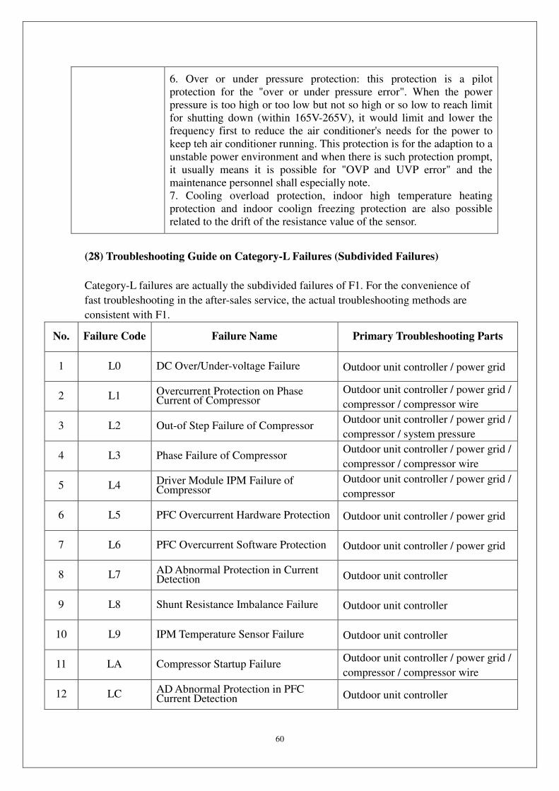
60
6. Over or under pressure protection: this protection is a pilot
protection for the "over or under pressure error". When the power
pressure is too high or too low but not so high or so low to reach limit
for shutting down (within 165V-265V), it would limit and lower the
frequency first to reduce the air conditioner's needs for the power to
keep teh air conditioner running. This protection is for the adaption to a
unstable power environment and when there is such protection prompt,
it usually means it is possible for "OVP and UVP error" and the
maintenance personnel shall especially note.
7. Cooling overload protection, indoor high temperature heating
protection and indoor coolign freezing protection are also possible
related to the drift of the resistance value of the sensor.
(28) Troubleshooting Guide on Category-L Failures (Subdivided Failures)
Category-L failures are actually the subdivided failures of F1. For the convenience of
fast troubleshooting in the after-sales service, the actual troubleshooting methods are
consistent with F1.
No. Failure Code Failure Name Primary Troubleshooting Parts
1 L0 DC Over/Under-voltage Failure Outdoor unit controller / power grid
2 L1 Overcurrent Protection on Phase Current of Compressor
Outdoor unit controller / power grid /
compressor / compressor wire
3 L2 Out-of Step Failure of Compressor Outdoor unit controller / power grid /
compressor / system pressure
4 L3 Phase Failure of Compressor Outdoor unit controller / power grid /
compressor / compressor wire
5 L4 Driver Module IPM Failure of Compressor
Outdoor unit controller / power grid /
compressor
6 L5 PFC Overcurrent Hardware Protection Outdoor unit controller / power grid
7 L6 PFC Overcurrent Software Protection Outdoor unit controller / power grid
8 L7 AD Abnormal Protection in Current Detection Outdoor unit controller
9 L8 Shunt Resistance Imbalance Failure Outdoor unit controller
10 L9 IPM Temperature Sensor Failure Outdoor unit controller
11 LA Compressor Startup Failure Outdoor unit controller / power grid /
compressor / compressor wire
12 LC AD Abnormal Protection in PFC Current Detection Outdoor unit controller
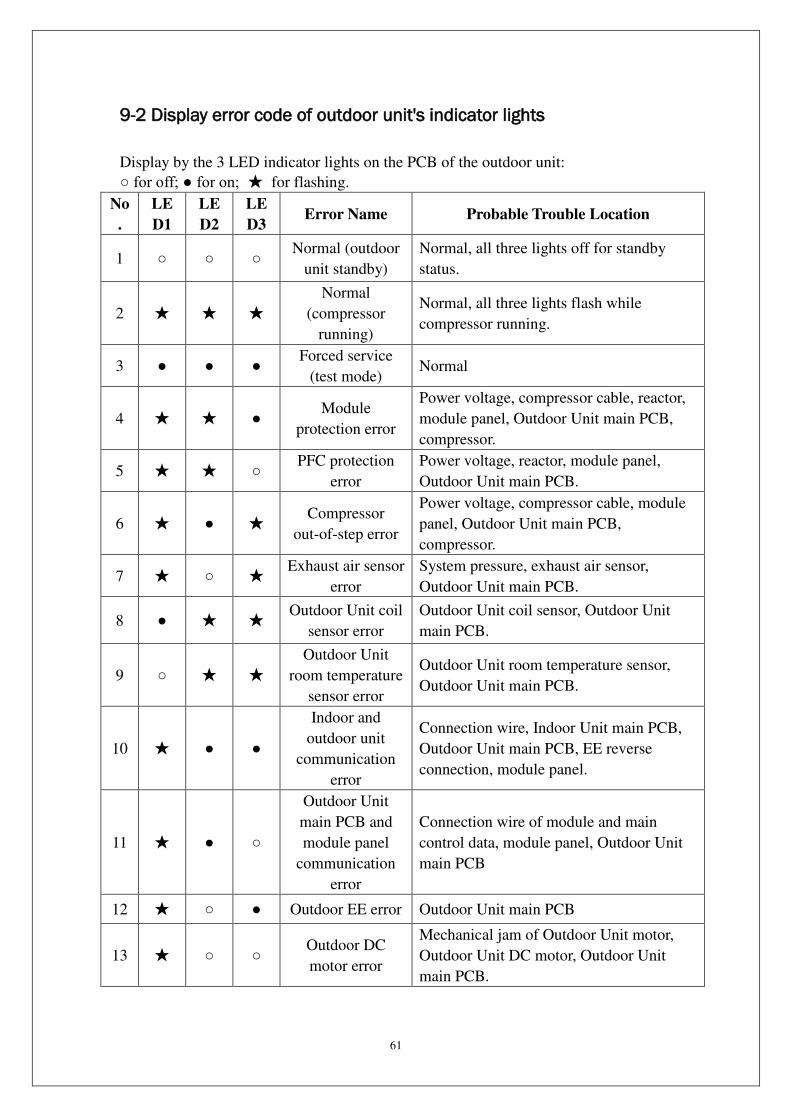
61
9-2 Display error code of outdoor unit's indicator lights
Display by the 3 LED indicator lights on the PCB of the outdoor unit:
for off; for on; for flashing.
No
.
LE
D1
LE
D2
LE
D3 Error Name Probable Trouble Location
1 Normal (outdoor
unit standby)
Normal, all three lights off for standby
status.
2
Normal
(compressor
running)
Normal, all three lights flash while
compressor running.
3 Forced service
(test mode) Normal
4 Module
protection error
Power voltage, compressor cable, reactor,
module panel, Outdoor Unit main PCB,
compressor.
5 PFC protection
error
Power voltage, reactor, module panel,
Outdoor Unit main PCB.
6 Compressor
out-of-step error
Power voltage, compressor cable, module
panel, Outdoor Unit main PCB,
compressor.
7 Exhaust air sensor
error
System pressure, exhaust air sensor,
Outdoor Unit main PCB.
8 Outdoor Unit coil
sensor error
Outdoor Unit coil sensor, Outdoor Unit
main PCB.
9
Outdoor Unit
room temperature
sensor error
Outdoor Unit room temperature sensor,
Outdoor Unit main PCB.
10
Indoor and
outdoor unit
communication
error
Connection wire, Indoor Unit main PCB,
Outdoor Unit main PCB, EE reverse
connection, module panel.
11
Outdoor Unit
main PCB and
module panel
communication
error
Connection wire of module and main
control data, module panel, Outdoor Unit
main PCB
12 Outdoor EE error Outdoor Unit main PCB
13 Outdoor DC
motor error
Mechanical jam of Outdoor Unit motor,
Outdoor Unit DC motor, Outdoor Unit
main PCB.

62
14
Indoor Unit room
temperature
sensor error
Indoor Unit room temperature sensor,
Indoor Unit main PCB.
15 Indoor Unit coil
sensor error
Indoor Unit coil sensor, Indoor Unit main
PCB.
16 Indoor motor
error
Mechanical jam of motor, Indoor Unit
motor, Indoor Unit main PCB.
17
Refer to tooling
display for other
errors
Entire set of Outdoor Unit controller.
18 Compressor cap
sensor error
System pressure, compressor cap sensor
(protection switch), Outdoor Unit main
PCB.
19 Recirculated
sensor error
Recirculated sensor, four-way valve switch
error, Outdoor Unit main PCB.
20
※ Compressor
overpower
protection
Power voltage, module panel, Outdoor
Unit main PCB.
21 ※ Over current
protection
Power voltage, system pressure, module
panel, Outdoor Unit main PCB.
22 Exhaust sensor
error
System pressure, exhaust sensor, Outdoor
Unit main PCB.
23
※ Cooling
overload
protection
Condenser, Outdoor Unit motor, capillary,
Outdoor Unit coil sensor, Outdoor Unit
main PCB.
24
※ Indoor high
temperature
heating protection
Evaporator, Indoor Unit motor, thin unit
connection pipe, Indoor Unit coil sensor,
Indoor Unit main PCB.
25
※ Indoor
cooling freezing
protection
Evaporator, Indoor Unit motor, capillary,
Indoor Unit coil sensor, Indoor Unit main
PCB.
26
Compressor shell
temperature
protection
Same as "18 Compressor cap sensor error".
27 ※ OVP or UPV
error
Power voltage, reactor, module panel,
Outdoor Unit main PCB.

63
9-3 Troubleshooting for Normal Malfunction
The Foremost Inspecting Items
① The input voltage must be within +10% tolerance of the rated Voltage. If it is not
the case, the air-conditioner will probably not work normally.
② Check the connecting cord between indoor unit and outdoor unit to see if it is
properly connected. The connecting must be done according to the wiring diagram,
please also notice that even different models may have the connecting cord of the
same specification. Please check if the marks at the connecting terminal and the marks
on the cord can match, otherwise, the air-conditioner will not work normally.
③ If the following phenomena are found, the problem is not from the air-conditioner
itself.
NO. Problems Causes
1
The motor is heard operating but
the air-conditioner does not work
when the indoor unit is powered on
Since the air-conditioner is powered on,
it will come to working condition as
long as you press the ON/OFF button of
the remote control and the Signal is well
received.
2
The compressor stops running but
the indoor motor keeps working
when it is at cooling mode with the
indoor temperature higher than set
temperature.
If you turn off the air-conditioner and
restart it immediately, it will return to
normal in 3 minutes, after that, the
air-conditioner will automatically adjust
the indoor motor speed to what you set.
3
The compressor works
discontinuously at dehumidifying
mode.
The air-conditioner will automatically
control the working of the compressor
according to the inside temperature.
4 The air-conditioner does not work
while the LED display is on.
The TIMER is set with the A/C; it will
be in hold on condition. If the TIMER
setting is cancelled, the air-conditioner
will return to normal working condition.
5
The compressor works
discontinuously at cooling and
dehumidifying mode, and the
indoor motor slows down.
The compressor stops Indoor Unit or the
motor slows down to prevent the indoor
heat exchanger from being frozen.
Fault Diagnosis by Symptom
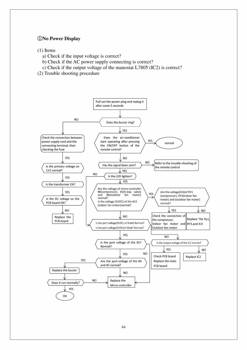
64
①No Power Display
(1) Items
a) Check if the input voltage is correct?
b) Check if the AC power supply connecting is correct?
c) Check if the output voltage of the manostat L7805 (IC2) is correct?
(2) Trouble shooting procedure
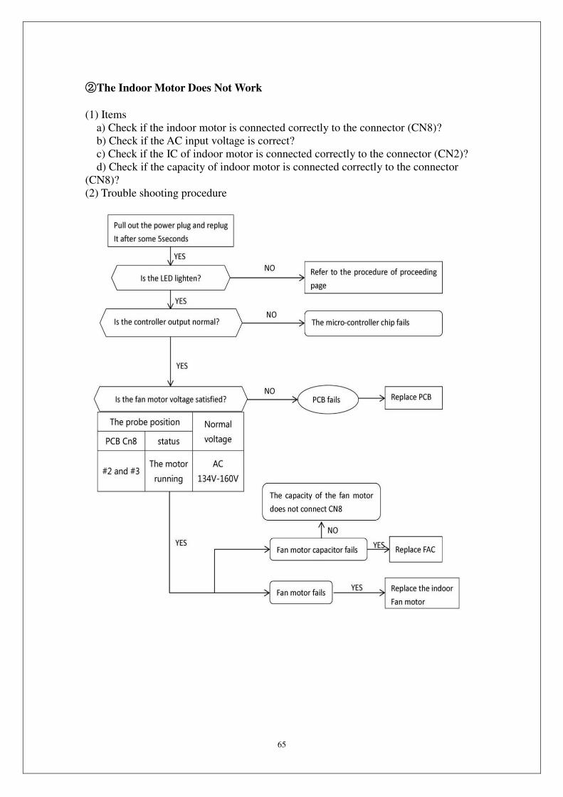
65
②The Indoor Motor Does Not Work
(1) Items
a) Check if the indoor motor is connected correctly to the connector (CN8)?
b) Check if the AC input voltage is correct?
c) Check if the IC of indoor motor is connected correctly to the connector (CN2)?
d) Check if the capacity of indoor motor is connected correctly to the connector
(CN8)?
(2) Trouble shooting procedure

66
③The Outdoor Unit Does Not Work
(1) Items
a) Check if the input voltage is correct?
b) Check if the wire connection of the outdoor connecting terminal is correct?
(2) Trouble shooting procedure

67
④The Step Motor Does Not Work
(1) Items
a) Check if the input voltage is correct?
b) Check if the step motor controlling the up-down movement firmly connected to
Cn2?
(2) Trouble shooting procedure
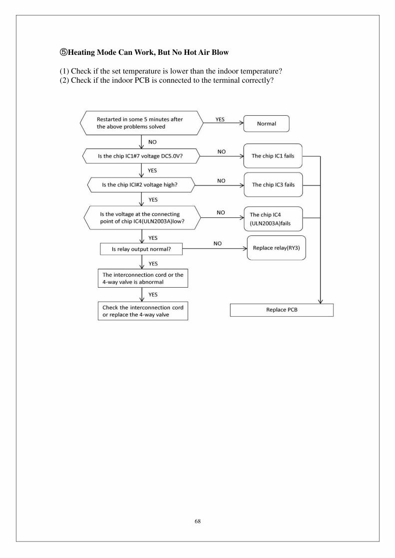
68
⑤Heating Mode Can Work, But No Hot Air Blow
(1) Check if the set temperature is lower than the indoor temperature?
(2) Check if the indoor PCB is connected to the terminal correctly?
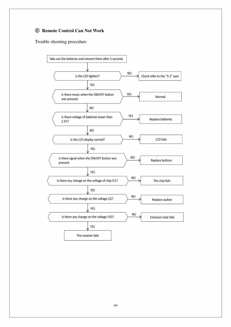
69
⑥ Remote Control Can Not Work
Trouble shooting procedure
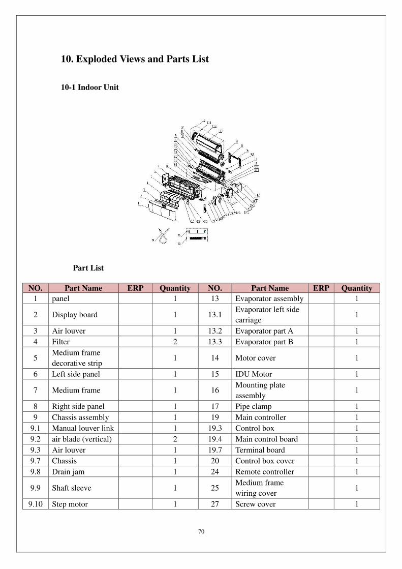
70
10. Exploded Views and Parts List
10-1 Indoor Unit
Part List
NO. Part Name ERP Quantity NO. Part Name ERP Quantity
1 panel 1 13 Evaporator assembly 1
2 Display board
1 13.1 Evaporator left side
carriage
1
3 Air louver 1 13.2 Evaporator part A 1
4 Filter 2 13.3 Evaporator part B 1
5 Medium frame
decorative strip
1 14 Motor cover
1
6 Left side panel 1 15 IDU Motor 1
7 Medium frame
1 16 Mounting plate
assembly
1
8 Right side panel 1 17 Pipe clamp 1
9 Chassis assembly 1 19 Main controller 1
9.1 Manual louver link 1 19.3 Control box 1
9.2 air blade (vertical) 2 19.4 Main control board 1
9.3 Air louver 1 19.7 Terminal board 1
9.7 Chassis 1 20 Control box cover 1
9.8 Drain jam 1 24 Remote controller 1
9.9 Shaft sleeve
1 25 Medium frame
wiring cover
1
9.10 Step motor 1 27 Screw cover 1

71
10 Bearing assembly 1 28 Outlet pipe assembly 1
11 Bearing fixed
chassis
1 29 Drain hose
12 Cross flow motor 1
10-2 Outdoor Unit
Part List
NO. Part Name ERP Quantity NO. Part Name ERP Quantity
1 Right side board
1 17 Condenser
assembly
1
2 E-parts cover
1 17.1 Condenser
assembly
1
3 Valve plate
1 17.2 Capillary
assembly
1
4 Stop valve 1 18 Top cover 1
5 Stop valve
1 19 4-way valve
tubing assembly
1
6 Compressor
assembly
1 19.1 4-way valve
1
7 Chassis
assembly
1 19.2
Suction pipe
assembly
1
7.1 Chassis
1 19.3 Discharge pipe
assembly
1
7.2 Compressor
footing bolt
3 20 Motor capacitor
1
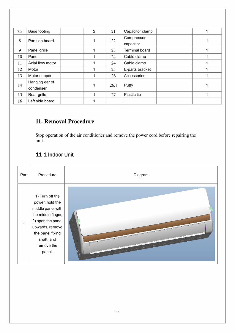
72
7.3 Base footing 2 21 Capacitor clamp 1
8 Partition board
1 22 Compressor
capacitor
1
9 Panel grille 1 23 Terminal board 1
10 Panel 1 24 Cable clamp 1
11 Axial flow motor 1 24 Cable clamp 1
12 Motor 1 25 E-parts bracket 1
13 Motor support 1 26 Accessories 1
14 Hanging ear of
condenser
1 26.1 Putty
1
15 Rear grille 1 27 Plastic tie 1
16 Left side board 1
11. Removal Procedure
Stop operation of the air conditioner and remove the power cord before repairing the
unit.
11-1 Indoor Unit
Part Procedure Diagram
1
1) Turn off the
power, hold the
middle panel with
the middle finger,
2) open the panel
upwards, remove
the panel fixing
shaft, and
remove the
panel.
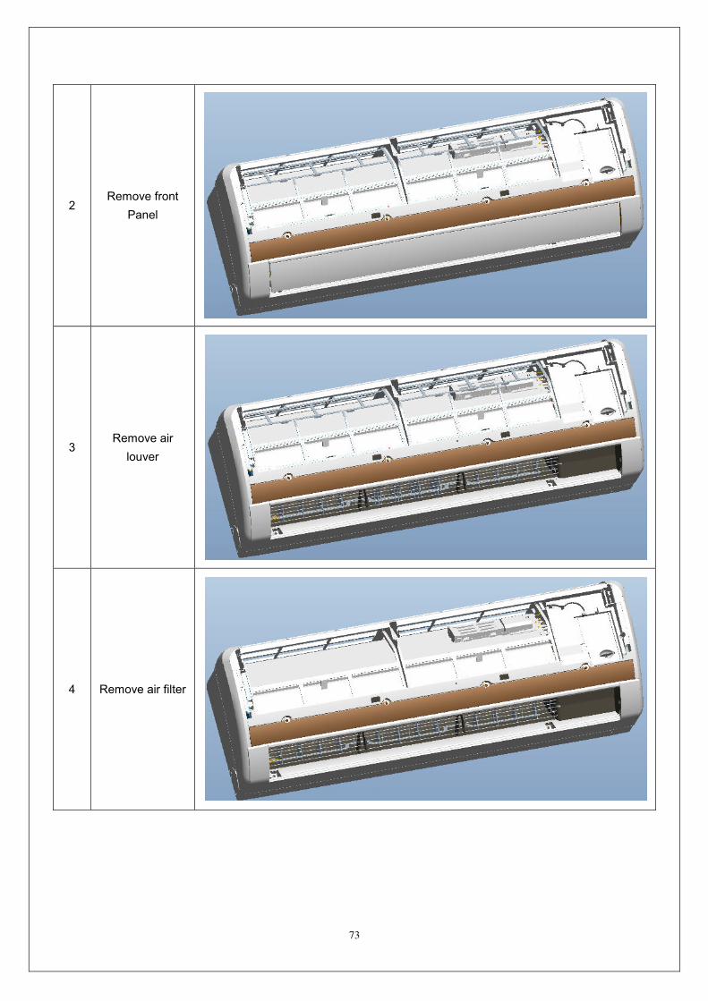
73
2 Remove front
Panel
3 Remove air
louver
4 Remove air filter
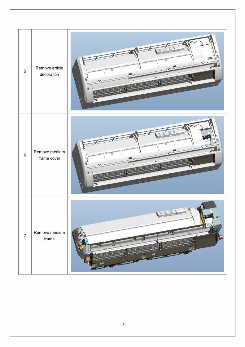
74
5 Remove article
decoration
6 Remove medium
frame cover
7 Remove medium
frame
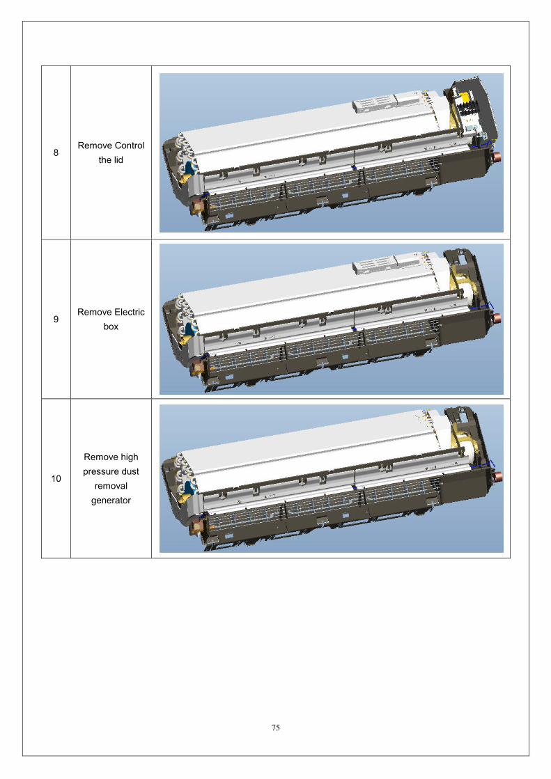
75
8 Remove Control
the lid
9 Remove Electric
box
10
Remove high
pressure dust
removal
generator
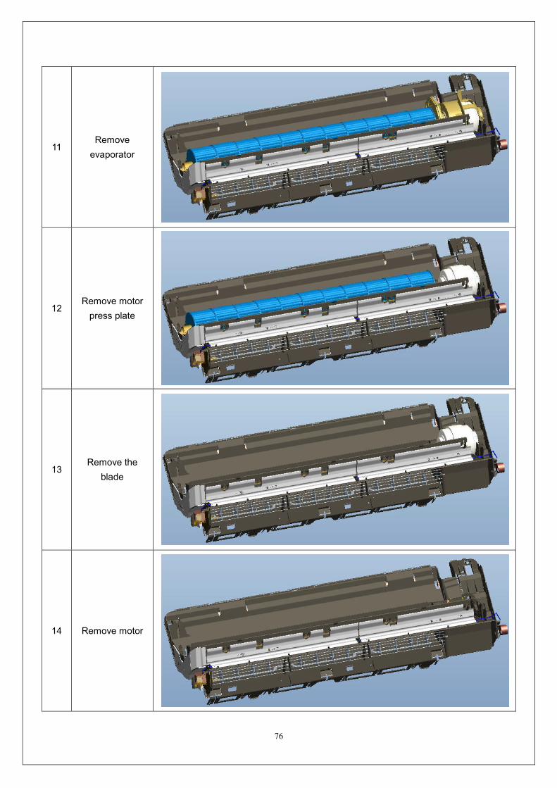
76
11 Remove
evaporator
12 Remove motor
press plate
13 Remove the
blade
14 Remove motor
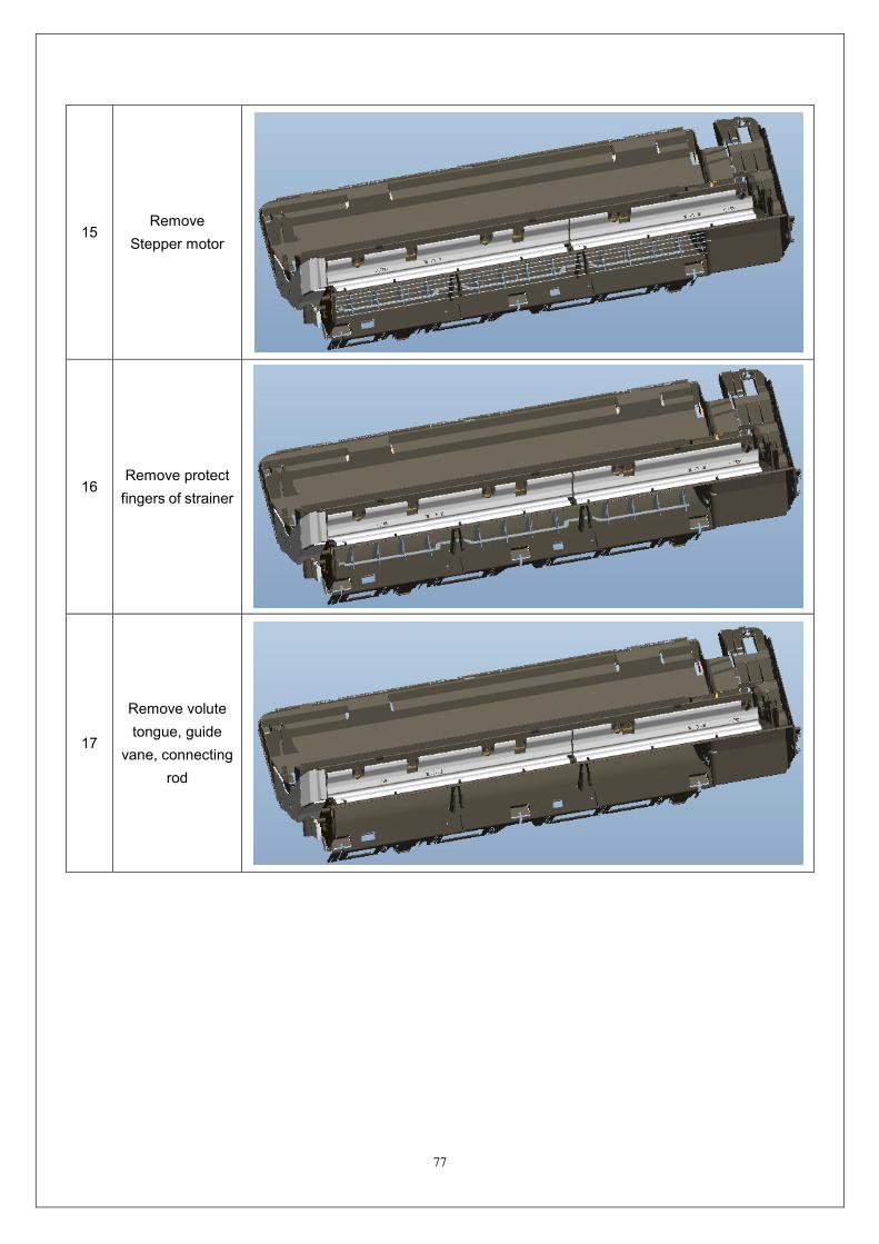
77
15 Remove
Stepper motor
16 Remove protect
fingers of strainer
17
Remove volute
tongue, guide
vane, connecting
rod

78
11-2 Outdoor Unit
Part Procedure Diagram
1
Turn off the power , remove connection
screws among top cover plate, front panel
and right side panel, then remove the top
cover.
2 Remove the control box cover
3
Remove connection screws between the
front grille and the front panel .Then
remove the front grille.
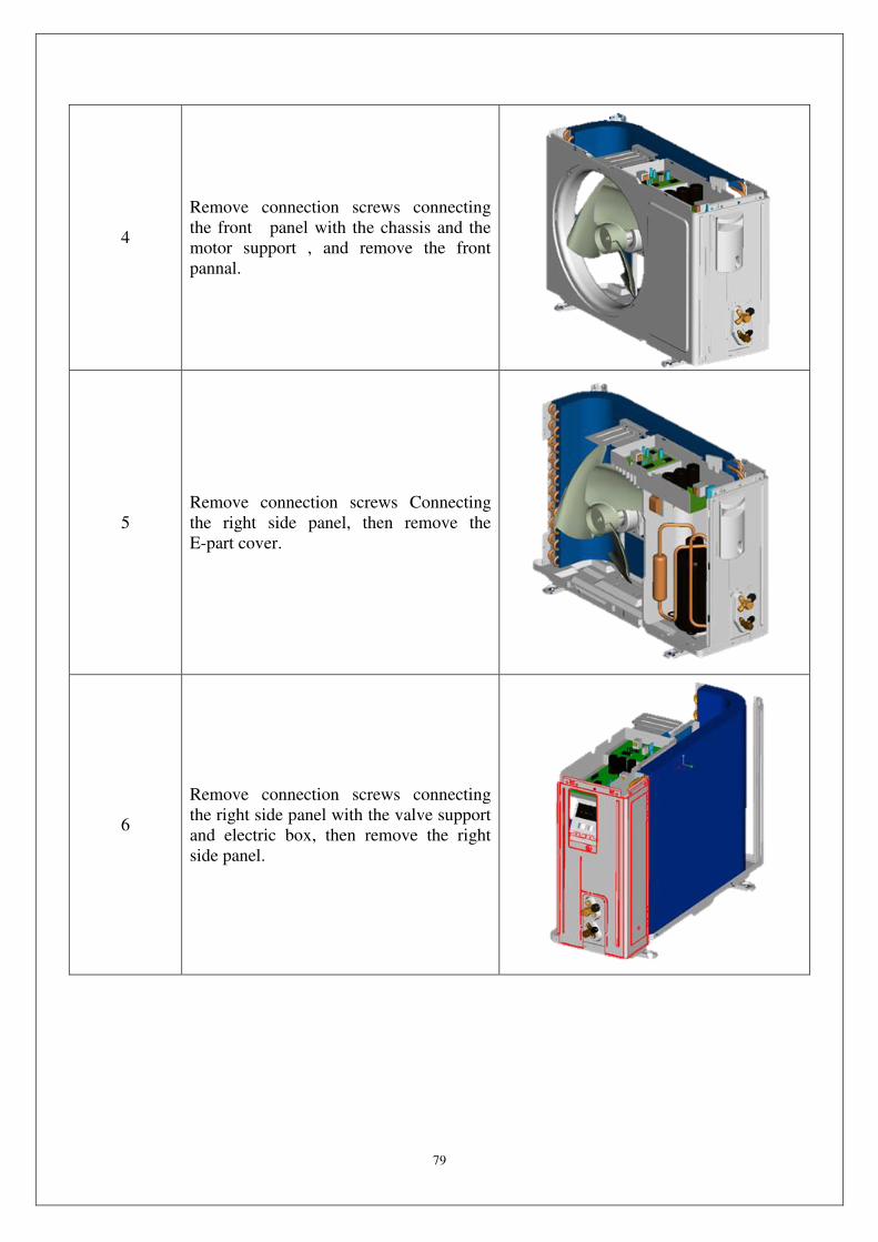
79
4
Remove connection screws connecting
the front panel with the chassis and the
motor support , and remove the front
pannal.
5
Remove connection screws Connecting
the right side panel, then remove the
E-part cover.
6
Remove connection screws connecting
the right side panel with the valve support
and electric box, then remove the right
side panel.

80
7 Remove the nut fixing the blade and then
remove the axial flow blade.
8
Remove the tapping screws fixing the
motor, pull out the lead-out wire and
remove the motor.
9
Loosen the wire and disconnect the
terminal. Lift to remove the electric box
assy.
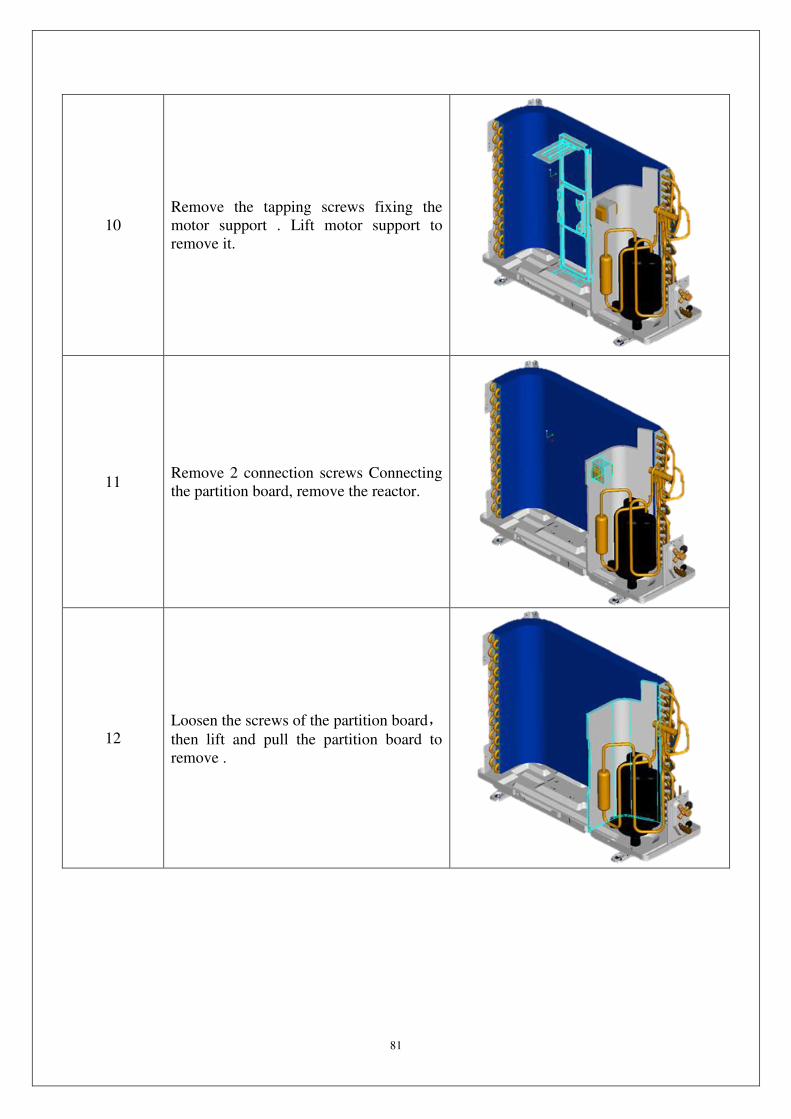
81
10
Remove the tapping screws fixing the
motor support . Lift motor support to
remove it.
11 Remove 2 connection screws Connecting
the partition board, remove the reactor.
12 Loosen the screws of the partition board,then lift and pull the partition board to
remove .
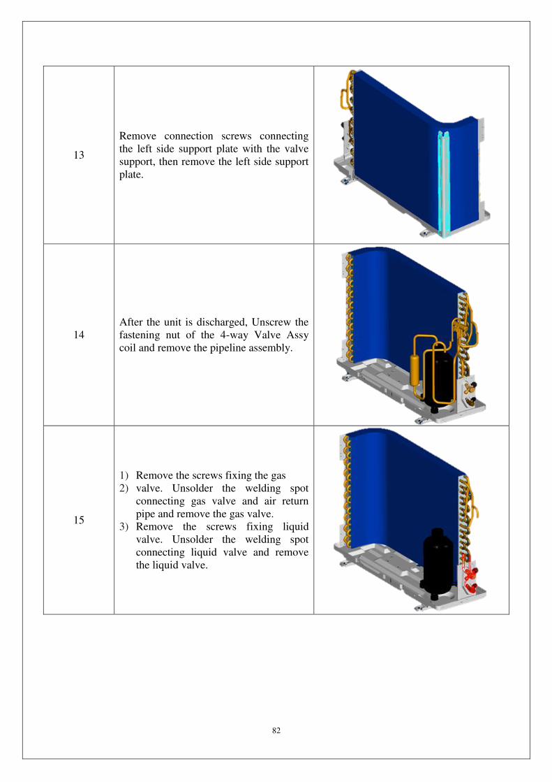
82
13
Remove connection screws connecting
the left side support plate with the valve
support, then remove the left side support
plate.
14
After the unit is discharged, Unscrew the
fastening nut of the 4-way Valve Assy
coil and remove the pipeline assembly.
15
1) Remove the screws fixing the gas
2) valve. Unsolder the welding spot
connecting gas valve and air return
pipe and remove the gas valve.
3) Remove the screws fixing liquid
valve. Unsolder the welding spot
connecting liquid valve and remove
the liquid valve.

83
16 Loosen 1 footing screws of valve plate,
remove the valve plate.
17 Loosen 3 footing screws of compressor,
Remove and remove the compressor.
18
Loosen 2 fixing screws Connecting
chassis, and remove the condenser. Last
remaining chassis.
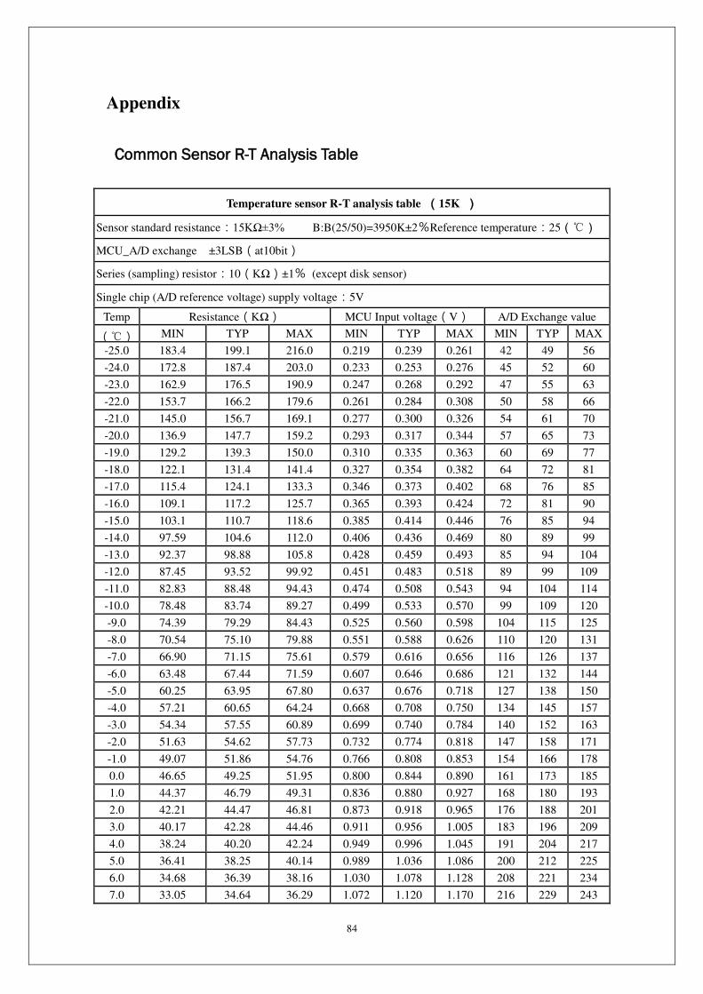
84
Appendix
Common Sensor R-T Analysis Table
Temperature sensor R-T analysis table (15K )
Sensor standard resistance:15KΩ±3% B:B(25/50)=3950K±2%Reference temperature:25()
MCU_A/D exchange ±3LSB(at10bit)
Series (sampling) resistor:10(KΩ)±1% (except disk sensor)
Single chip (A/D reference voltage) supply voltage:5V
Temp Resistance(KΩ) MCU Input voltage(V) A/D Exchange value
() MIN TYP MAX MIN TYP MAX MIN TYP MAX
-25.0 183.4 199.1 216.0 0.219 0.239 0.261 42 49 56
-24.0 172.8 187.4 203.0 0.233 0.253 0.276 45 52 60
-23.0 162.9 176.5 190.9 0.247 0.268 0.292 47 55 63
-22.0 153.7 166.2 179.6 0.261 0.284 0.308 50 58 66
-21.0 145.0 156.7 169.1 0.277 0.300 0.326 54 61 70
-20.0 136.9 147.7 159.2 0.293 0.317 0.344 57 65 73
-19.0 129.2 139.3 150.0 0.310 0.335 0.363 60 69 77
-18.0 122.1 131.4 141.4 0.327 0.354 0.382 64 72 81
-17.0 115.4 124.1 133.3 0.346 0.373 0.402 68 76 85
-16.0 109.1 117.2 125.7 0.365 0.393 0.424 72 81 90
-15.0 103.1 110.7 118.6 0.385 0.414 0.446 76 85 94
-14.0 97.59 104.6 112.0 0.406 0.436 0.469 80 89 99
-13.0 92.37 98.88 105.8 0.428 0.459 0.493 85 94 104
-12.0 87.45 93.52 99.92 0.451 0.483 0.518 89 99 109
-11.0 82.83 88.48 94.43 0.474 0.508 0.543 94 104 114
-10.0 78.48 83.74 89.27 0.499 0.533 0.570 99 109 120
-9.0 74.39 79.29 84.43 0.525 0.560 0.598 104 115 125
-8.0 70.54 75.10 79.88 0.551 0.588 0.626 110 120 131
-7.0 66.90 71.15 75.61 0.579 0.616 0.656 116 126 137
-6.0 63.48 67.44 71.59 0.607 0.646 0.686 121 132 144
-5.0 60.25 63.95 67.80 0.637 0.676 0.718 127 138 150
-4.0 57.21 60.65 64.24 0.668 0.708 0.750 134 145 157
-3.0 54.34 57.55 60.89 0.699 0.740 0.784 140 152 163
-2.0 51.63 54.62 57.73 0.732 0.774 0.818 147 158 171
-1.0 49.07 51.86 54.76 0.766 0.808 0.853 154 166 178
0.0 46.65 49.25 51.95 0.800 0.844 0.890 161 173 185
1.0 44.37 46.79 49.31 0.836 0.880 0.927 168 180 193
2.0 42.21 44.47 46.81 0.873 0.918 0.965 176 188 201
3.0 40.17 42.28 44.46 0.911 0.956 1.005 183 196 209
4.0 38.24 40.20 42.24 0.949 0.996 1.045 191 204 217
5.0 36.41 38.25 40.14 0.989 1.036 1.086 200 212 225
6.0 34.68 36.39 38.16 1.030 1.078 1.128 208 221 234
7.0 33.05 34.64 36.29 1.072 1.120 1.170 216 229 243
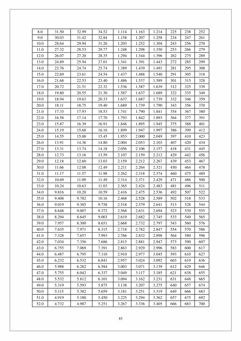
85
8.0 31.50 32.99 34.52 1.114 1.163 1.214 225 238 252
9.0 30.03 31.42 32.84 1.158 1.207 1.258 234 247 261
10.0 28.64 29.94 31.26 1.203 1.252 1.304 243 256 270
11.0 27.32 28.53 29.77 1.248 1.298 1.350 253 266 279
12.0 26.07 27.20 28.35 1.294 1.344 1.396 262 275 289
13.0 24.89 25.94 27.01 1.341 1.391 1.443 272 285 299
14.0 23.76 24.74 25.74 1.389 1.439 1.491 281 295 308
15.0 22.69 23.61 24.54 1.437 1.488 1.540 291 305 318
16.0 21.68 22.53 23.40 1.486 1.537 1.589 301 315 328
17.0 20.72 21.51 22.32 1.536 1.587 1.639 312 325 339
18.0 19.80 20.55 21.30 1.587 1.637 1.689 322 335 349
19.0 18.94 19.63 20.33 1.637 1.687 1.739 332 346 359
20.0 18.11 18.75 19.40 1.689 1.739 1.790 343 356 370
21.0 17.33 17.93 18.53 1.741 1.790 1.841 354 367 380
22.0 16.58 17.14 17.70 1.793 1.842 1.893 364 377 391
23.0 15.87 16.39 16.91 1.846 1.895 1.945 375 388 401
24.0 15.19 15.68 16.16 1.899 1.947 1.997 386 399 412
25.0 14.55 15.00 15.45 1.953 2.000 2.049 397 410 423
26.0 13.91 14.36 14.80 2.004 2.053 2.103 407 420 434
27.0 13.31 13.74 14.18 2.056 2.106 2.157 418 431 445
28.0 12.73 13.16 13.59 2.107 2.159 2.212 429 442 456
29.0 12.18 12.60 13.03 2.159 2.212 2.267 439 453 467
30.0 11.66 12.08 12.49 2.211 2.264 2.321 450 464 478
31.0 11.17 11.57 11.98 2.262 2.318 2.374 460 475 489
32.0 10.69 11.09 11.49 2.314 2.371 2.429 471 486 500
33.0 10.24 10.63 11.03 2.365 2.424 2.483 481 496 511
34.0 9.816 10.20 10.59 2.416 2.475 2.536 492 507 522
35.0 9.408 9.782 10.16 2.468 2.528 2.589 502 518 533
36.0 9.019 9.385 9.758 2.518 2.579 2.641 513 528 544
37.0 8.648 9.007 9.372 2.568 2.631 2.694 523 539 555
38.0 8.294 8.645 9.003 2.619 2.682 2.745 533 549 565
39.0 7.957 8.300 8.651 2.668 2.732 2.797 543 560 576
40.0 7.635 7.971 8.315 2.718 2.782 2.847 554 570 586
41.0 7.328 7.657 7.993 2.766 2.832 2.898 564 580 596
42.0 7.034 7.356 7.686 2.815 2.881 2.947 573 590 607
43.0 6.755 7.069 7.391 2.863 2.929 2.996 583 600 617
44.0 6.487 6.795 7.110 2.910 2.977 3.045 593 610 627
45.0 6.232 6.532 6.841 2.957 3.024 3.092 603 619 636
46.0 5.988 6.282 6.584 3.003 3.071 3.139 612 629 646
47.0 5.755 6.042 6.337 3.049 3.117 3.185 621 638 655
48.0 5.532 5.812 6.101 3.094 3.162 3.231 631 648 665
49.0 5.319 5.593 5.875 3.138 3.207 3.275 640 657 674
50.0 5.115 5.382 5.659 3.181 3.251 3.319 649 666 683
51.0 4.919 5.180 5.450 3.225 3.294 3.362 657 675 692
52.0 4.732 4.987 5.251 3.267 3.336 3.405 666 683 700

86
53.0 4.553 4.802 5.060 3.309 3.378 3.446 675 692 709
54.0 4.382 4.625 4.877 3.350 3.419 3.487 683 700 717
55.0 4.219 4.457 4.703 3.390 3.459 3.527 691 708 725
56.0 4.061 4.293 4.534 3.429 3.498 3.566 699 716 733
57.0 3.911 4.137 4.373 3.468 3.537 3.604 707 724 741
58.0 3.767 3.988 4.218 3.506 3.574 3.642 715 732 749
59.0 3.630 3.845 4.070 3.543 3.611 3.678 723 740 756
60.0 3.498 3.708 3.927 3.580 3.648 3.714 730 747 764
61.0 3.371 3.577 3.791 3.616 3.683 3.749 737 754 771
62.0 3.250 3.450 3.660 3.650 3.717 3.783 745 761 778
63.0 3.134 3.329 3.534 3.685 3.751 3.816 752 768 785
64.0 3.022 3.213 3.413 3.718 3.784 3.848 758 775 791
65.0 2.915 3.102 3.297 3.751 3.816 3.880 765 782 798
66.0 2.813 2.995 3.185 3.783 3.848 3.911 772 788 804
67.0 2.714 2.892 3.078 3.814 3.878 3.941 778 794 810
68.0 2.620 2.793 2.975 3.845 3.908 3.970 784 800 816
69.0 2.529 2.698 2.876 3.874 3.938 3.999 790 806 822
70.0 2.442 2.607 2.781 3.903 3.966 4.026 796 812 828
71.0 2.358 2.519 2.689 3.932 3.994 4.054 802 818 833
72.0 2.278 2.435 2.601 3.960 4.021 4.080 808 823 839
73.0 2.200 2.354 2.516 3.987 4.047 4.106 813 829 844
74.0 2.126 2.276 2.435 4.013 4.073 4.131 819 834 849
75.0 2.055 2.201 2.356 4.039 4.098 4.155 824 839 854
76.0 1.986 2.129 2.280 4.064 4.122 4.178 829 844 859
77.0 1.920 2.060 2.208 4.088 4.146 4.201 834 849 863
78.0 1.857 1.993 2.138 4.112 4.169 4.223 839 854 868
79.0 1.796 1.929 2.070 4.135 4.191 4.245 844 858 872
80.0 1.737 1.867 2.005 4.158 4.213 4.266 849 863 877
81.0 1.681 1.808 1.942 4.180 4.234 4.287 853 867 881
82.0 1.626 1.750 1.882 4.201 4.255 4.307 857 871 885
83.0 1.574 1.695 1.824 4.222 4.275 4.326 862 876 889
84.0 1.524 1.642 1.767 4.243 4.295 4.344 866 880 893
85.0 1.475 1.590 1.713 4.262 4.314 4.363 870 884 897
86.0 1.428 1.541 1.661 4.282 4.332 4.381 874 887 900
87.0 1.383 1.493 1.611 4.300 4.350 4.398 878 891 904
88.0 1.340 1.447 1.562 4.319 4.368 4.414 881 895 907
89.0 1.298 1.403 1.515 4.336 4.385 4.431 885 898 910
90.0 1.258 1.360 1.470 4.354 4.401 4.446 889 901 914
91.0 1.219 1.319 1.426 4.370 4.417 4.462 892 905 917
92.0 1.181 1.279 1.384 4.387 4.433 4.477 895 908 920
93.0 1.145 1.241 1.343 4.403 4.448 4.491 899 911 923
94.0 1.110 1.204 1.304 4.418 4.463 4.505 902 914 926
95.0 1.077 1.168 1.266 4.433 4.477 4.518 905 917 928
96.0 1.044 1.134 1.229 4.448 4.491 4.532 908 920 931
97.0 1.013 1.100 1.194 4.462 4.505 4.544 911 923 934
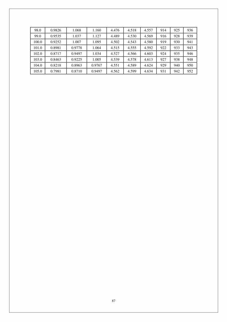
87
98.0 0.9826 1.068 1.160 4.476 4.518 4.557 914 925 936
99.0 0.9535 1.037 1.127 4.489 4.530 4.569 916 928 939
100.0 0.9252 1.007 1.095 4.502 4.543 4.580 919 930 941
101.0 0.8981 0.9778 1.064 4.515 4.555 4.592 922 933 943
102.0 0.8717 0.9497 1.034 4.527 4.566 4.603 924 935 946
103.0 0.8463 0.9225 1.005 4.539 4.578 4.613 927 938 948
104.0 0.8218 0.8963 0.9767 4.551 4.589 4.624 929 940 950
105.0 0.7981 0.8710 0.9497 4.562 4.599 4.634 931 942 952
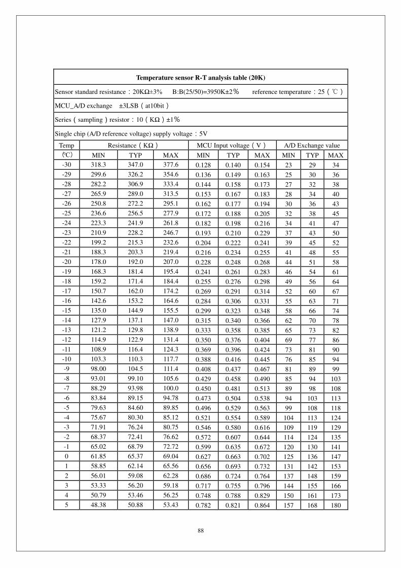
88
Temperature sensor R-T analysis table (20K)
Sensor standard resistance:20KΩ±3% B:B(25/50)=3950K±2% reference temperature:25()
MCU_A/D exchange ±3LSB(at10bit)
Series(sampling)resistor:10(KΩ)±1%
Single chip (A/D reference voltage) supply voltage:5V
Temp Resistance(KΩ) MCU Input voltage(V) A/D Exchange value
() MIN TYP MAX MIN TYP MAX MIN TYP MAX
-30 318.3 347.0 377.6 0.128 0.140 0.154 23 29 34
-29 299.6 326.2 354.6 0.136 0.149 0.163 25 30 36
-28 282.2 306.9 333.4 0.144 0.158 0.173 27 32 38
-27 265.9 289.0 313.5 0.153 0.167 0.183 28 34 40
-26 250.8 272.2 295.1 0.162 0.177 0.194 30 36 43
-25 236.6 256.5 277.9 0.172 0.188 0.205 32 38 45
-24 223.3 241.9 261.8 0.182 0.198 0.216 34 41 47
-23 210.9 228.2 246.7 0.193 0.210 0.229 37 43 50
-22 199.2 215.3 232.6 0.204 0.222 0.241 39 45 52
-21 188.3 203.3 219.4 0.216 0.234 0.255 41 48 55
-20 178.0 192.0 207.0 0.228 0.248 0.268 44 51 58
-19 168.3 181.4 195.4 0.241 0.261 0.283 46 54 61
-18 159.2 171.4 184.4 0.255 0.276 0.298 49 56 64
-17 150.7 162.0 174.2 0.269 0.291 0.314 52 60 67
-16 142.6 153.2 164.6 0.284 0.306 0.331 55 63 71
-15 135.0 144.9 155.5 0.299 0.323 0.348 58 66 74
-14 127.9 137.1 147.0 0.315 0.340 0.366 62 70 78
-13 121.2 129.8 138.9 0.333 0.358 0.385 65 73 82
-12 114.9 122.9 131.4 0.350 0.376 0.404 69 77 86
-11 108.9 116.4 124.3 0.369 0.396 0.424 73 81 90
-10 103.3 110.3 117.7 0.388 0.416 0.445 76 85 94
-9 98.00 104.5 111.4 0.408 0.437 0.467 81 89 99
-8 93.01 99.10 105.6 0.429 0.458 0.490 85 94 103
-7 88.29 93.98 100.0 0.450 0.481 0.513 89 98 108
-6 83.84 89.15 94.78 0.473 0.504 0.538 94 103 113
-5 79.63 84.60 89.85 0.496 0.529 0.563 99 108 118
-4 75.67 80.30 85.12 0.521 0.554 0.589 104 113 124
-3 71.91 76.24 80.75 0.546 0.580 0.616 109 119 129
-2 68.37 72.41 76.62 0.572 0.607 0.644 114 124 135
-1 65.02 68.79 72.72 0.599 0.635 0.672 120 130 141
0 61.85 65.37 69.04 0.627 0.663 0.702 125 136 147
1 58.85 62.14 65.56 0.656 0.693 0.732 131 142 153
2 56.01 59.08 62.28 0.686 0.724 0.764 137 148 159
3 53.33 56.20 59.18 0.717 0.755 0.796 144 155 166
4 50.79 53.46 56.25 0.748 0.788 0.829 150 161 173
5 48.38 50.88 53.43 0.782 0.821 0.864 157 168 180
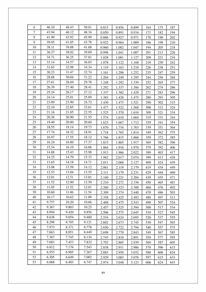
89
6 46.10 48.43 50.81 0.815 0.856 0.899 164 175 187
7 43.94 46.12 48.34 0.850 0.891 0.934 171 182 194
8 41.90 43.92 45.99 0.886 0.927 0.971 178 190 202
9 39.95 41.85 43.78 0.922 0.964 1.009 186 198 210
10 38.11 39.88 41.68 0.960 1.002 1.047 194 205 218
11 36.37 38.02 39.69 0.998 1.041 1.087 201 213 226
12 34.71 36.25 37.81 1.038 1.081 1.127 209 221 234
13 33.14 34.57 36.03 1.078 1.122 1.168 218 230 242
14 31.65 32.98 34.34 1.119 1.163 1.210 226 238 251
15 30.23 31.47 32.74 1.161 1.206 1.252 235 247 259
16 28.88 30.04 31.22 1.204 1.249 1.295 244 256 268
17 27.61 28.69 29.78 1.248 1.292 1.339 252 265 277
18 26.39 27.40 28.41 1.292 1.337 1.384 262 274 286
19 25.24 26.17 27.12 1.337 1.382 1.429 271 283 296
20 24.14 25.01 25.89 1.383 1.428 1.475 280 293 305
21 23.09 23.90 24.72 1.430 1.475 1.521 290 302 315
22 22.10 22.85 23.61 1.477 1.522 1.568 300 312 324
23 21.16 21.85 22.55 1.525 1.570 1.616 309 321 334
24 20.26 20.90 21.55 1.574 1.618 1.664 319 331 344
25 19.40 20.00 20.60 1.623 1.667 1.712 329 341 354
26 18.55 19.14 19.73 1.670 1.716 1.763 339 351 364
27 17.74 18.32 18.91 1.718 1.765 1.814 349 362 375
28 16.97 17.55 18.12 1.766 1.815 1.866 359 372 385
29 16.24 16.80 17.37 1.815 1.865 1.917 369 382 396
30 15.54 16.10 16.66 1.864 1.916 1.970 379 392 406
31 14.88 15.43 15.98 1.913 1.966 2.022 389 403 417
32 14.25 14.79 15.33 1.962 2.017 2.074 399 413 428
33 13.65 14.18 14.71 2.011 2.068 2.127 409 424 439
34 13.08 13.59 14.12 2.061 2.119 2.179 419 434 449
35 12.53 13.04 13.55 2.111 2.170 2.231 429 444 460
36 12.01 12.51 13.01 2.160 2.221 2.284 439 455 471
37 11.52 12.00 12.50 2.210 2.272 2.336 450 465 481
38 11.05 11.52 12.01 2.260 2.323 2.388 460 476 492
39 10.60 11.06 11.54 2.309 2.374 2.440 470 486 503
40 10.17 10.62 11.09 2.358 2.425 2.492 480 497 513
41 9.757 10.20 10.66 2.408 2.475 2.543 490 507 524
42 9.367 9.803 10.25 2.457 2.525 2.594 500 517 534
43 8.994 9.420 9.856 2.506 2.575 2.645 510 527 545
44 8.638 9.054 9.480 2.554 2.624 2.695 520 537 555
45 8.298 8.705 9.121 2.602 2.673 2.745 530 547 565
46 7.973 8.371 8.778 2.650 2.722 2.794 540 557 575
47 7.663 8.051 8.449 2.698 2.770 2.843 549 567 585
48 7.367 7.745 8.134 2.745 2.818 2.891 559 577 595
49 7.083 7.453 7.832 2.792 2.865 2.939 569 587 605
50 6.812 7.176 7.543 2.838 2.911 2.986 578 596 615
51 6.553 6.905 7.267 2.883 2.958 3.032 588 606 624
52 6.305 6.649 7.002 2.929 3.003 3.078 597 615 633
53 6.068 6.403 6.747 2.974 3.048 3.123 606 624 643
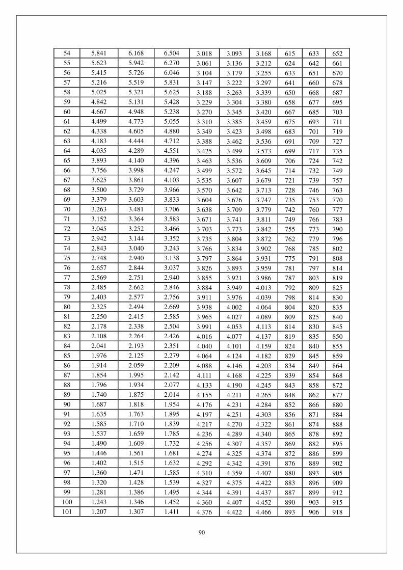
90
54 5.841 6.168 6.504 3.018 3.093 3.168 615 633 652
55 5.623 5.942 6.270 3.061 3.136 3.212 624 642 661
56 5.415 5.726 6.046 3.104 3.179 3.255 633 651 670
57 5.216 5.519 5.831 3.147 3.222 3.297 641 660 678
58 5.025 5.321 5.625 3.188 3.263 3.339 650 668 687
59 4.842 5.131 5.428 3.229 3.304 3.380 658 677 695
60 4.667 4.948 5.238 3.270 3.345 3.420 667 685 703
61 4.499 4.773 5.055 3.310 3.385 3.459 675 693 711
62 4.338 4.605 4.880 3.349 3.423 3.498 683 701 719
63 4.183 4.444 4.712 3.388 3.462 3.536 691 709 727
64 4.035 4.289 4.551 3.425 3.499 3.573 699 717 735
65 3.893 4.140 4.396 3.463 3.536 3.609 706 724 742
66 3.756 3.998 4.247 3.499 3.572 3.645 714 732 749
67 3.625 3.861 4.103 3.535 3.607 3.679 721 739 757
68 3.500 3.729 3.966 3.570 3.642 3.713 728 746 763
69 3.379 3.603 3.833 3.604 3.676 3.747 735 753 770
70 3.263 3.481 3.706 3.638 3.709 3.779 742 760 777
71 3.152 3.364 3.583 3.671 3.741 3.811 749 766 783
72 3.045 3.252 3.466 3.703 3.773 3.842 755 773 790
73 2.942 3.144 3.352 3.735 3.804 3.872 762 779 796
74 2.843 3.040 3.243 3.766 3.834 3.902 768 785 802
75 2.748 2.940 3.138 3.797 3.864 3.931 775 791 808
76 2.657 2.844 3.037 3.826 3.893 3.959 781 797 814
77 2.569 2.751 2.940 3.855 3.921 3.986 787 803 819
78 2.485 2.662 2.846 3.884 3.949 4.013 792 809 825
79 2.403 2.577 2.756 3.911 3.976 4.039 798 814 830
80 2.325 2.494 2.669 3.938 4.002 4.064 804 820 835
81 2.250 2.415 2.585 3.965 4.027 4.089 809 825 840
82 2.178 2.338 2.504 3.991 4.053 4.113 814 830 845
83 2.108 2.264 2.426 4.016 4.077 4.137 819 835 850
84 2.041 2.193 2.351 4.040 4.101 4.159 824 840 855
85 1.976 2.125 2.279 4.064 4.124 4.182 829 845 859
86 1.914 2.059 2.209 4.088 4.146 4.203 834 849 864
87 1.854 1.995 2.142 4.111 4.168 4.225 839 854 868
88 1.796 1.934 2.077 4.133 4.190 4.245 843 858 872
89 1.740 1.875 2.014 4.155 4.211 4.265 848 862 877
90 1.687 1.818 1.954 4.176 4.231 4.284 852 866 880
91 1.635 1.763 1.895 4.197 4.251 4.303 856 871 884
92 1.585 1.710 1.839 4.217 4.270 4.322 861 874 888
93 1.537 1.659 1.785 4.236 4.289 4.340 865 878 892
94 1.490 1.609 1.732 4.256 4.307 4.357 869 882 895
95 1.446 1.561 1.681 4.274 4.325 4.374 872 886 899
96 1.402 1.515 1.632 4.292 4.342 4.391 876 889 902
97 1.360 1.471 1.585 4.310 4.359 4.407 880 893 905
98 1.320 1.428 1.539 4.327 4.375 4.422 883 896 909
99 1.281 1.386 1.495 4.344 4.391 4.437 887 899 912
100 1.243 1.346 1.452 4.360 4.407 4.452 890 903 915
101 1.207 1.307 1.411 4.376 4.422 4.466 893 906 918
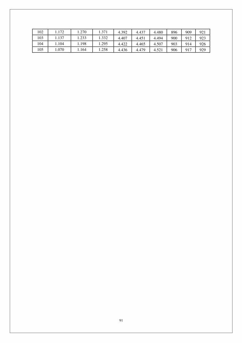
91
102 1.172 1.270 1.371 4.392 4.437 4.480 896 909 921
103 1.137 1.233 1.332 4.407 4.451 4.494 900 912 923
104 1.104 1.198 1.295 4.422 4.465 4.507 903 914 926
105 1.070 1.164 1.258 4.436 4.479 4.521 906 917 929

92
Temperature sensor R-T analysis table (50K)
Sensor standard resistance:50KΩ±2% B:B(25/50)=3950K±2% reference temperature:25()
MCU_A/D exchange ±2LSB(at8bit)
Series(sampling)resistor:5.1(KΩ)±1%
Single chip (A/D reference voltage) supply voltage:5V
Temp Resistance(KΩ) MCU Input voltage(V) A/D Exchange value
() MIN TYP MAX MIN TYP MAX MIN TYP MAX
-20 465.7 486.2 507.3 0.049 0.052 0.055 1 3 5
-19 439.7 458.7 478.3 0.052 0.055 0.058 1 3 5
-18 415.2 432.9 451.2 0.055 0.058 0.061 1 3 5
-17 392.2 408.8 425.8 0.059 0.062 0.065 1 3 5
-16 370.7 386.1 402 0.062 0.065 0.069 1 3 6
-15 350.5 364.8 379.6 0.066 0.069 0.072 1 4 6
-14 331.5 344.9 358.6 0.069 0.073 0.077 2 4 6
-13 313.7 326.2 339 0.073 0.077 0.081 2 4 6
-12 296.9 308.6 320.5 0.078 0.081 0.085 2 4 6
-11 281.2 292 303.2 0.082 0.086 0.090 2 4 7
-10 266.4 276.5 286.9 0.086 0.091 0.095 2 5 7
-9 252.4 261.8 271.5 0.091 0.096 0.100 3 5 7
-8 239.3 248.1 257.1 0.096 0.101 0.105 3 5 7
-7 226.9 235.1 243.6 0.102 0.106 0.111 3 5 8
-6 215.2 222.9 230.8 0.107 0.112 0.117 3 6 8
-5 204.3 211.5 218.8 0.113 0.118 0.123 4 6 8
-4 193.9 200.6 207.5 0.119 0.124 0.129 4 6 9
-3 184.1 190.4 196.8 0.125 0.130 0.136 4 7 9
-2 174.9 180.8 186.8 0.132 0.137 0.143 5 7 9
-1 166.2 171.7 177.3 0.138 0.144 0.150 5 7 10
0 158 163.1 168.4 0.146 0.152 0.158 5 8 10
1 150.2 155 159.9 0.153 0.159 0.166 6 8 10
2 142.9 147.4 152 0.161 0.167 0.174 6 9 11
3 136 140.2 144.5 0.169 0.175 0.182 7 9 11
4 129.4 133.3 137.4 0.177 0.184 0.191 7 9 12
5 123.2 126.9 130.6 0.186 0.193 0.201 8 10 12
6 117.3 120.8 124.3 0.195 0.203 0.210 8 10 13
7 111.8 115 118.3 0.205 0.212 0.220 8 11 13
8 106.5 109.6 112.6 0.215 0.222 0.231 9 11 14
9 101.5 104.4 107.2 0.225 0.233 0.241 10 12 14
10 96.82 99.47 102.2 0.235 0.244 0.253 10 12 15
11 92.34 94.83 97.35 0.247 0.255 0.264 11 13 16
12 88.1 90.43 92.79 0.258 0.267 0.276 11 14 16
13 84.08 86.26 88.47 0.270 0.279 0.289 12 14 17
14 80.26 82.31 84.37 0.282 0.292 0.302 12 15 17
15 76.64 78.55 80.49 0.295 0.305 0.315 13 16 18
16 73.2 74.99 76.8 0.308 0.318 0.329 14 16 19
17 69.93 71.62 73.31 0.322 0.332 0.343 14 17 20
18 66.83 68.41 69.99 0.336 0.347 0.358 15 18 20

93
19 63.88 65.36 66.85 0.351 0.362 0.373 16 19 21
20 61.08 62.47 63.86 0.366 0.377 0.389 17 19 22
21 58.42 59.72 61.02 0.382 0.393 0.405 18 20 23
22 55.88 57.1 58.32 0.398 0.410 0.422 18 21 24
23 53.47 54.61 55.76 0.415 0.427 0.439 19 22 24
24 51.18 52.25 53.32 0.433 0.445 0.457 20 23 25
25 49 50 51 0.450 0.463 0.476 21 24 26
26 46.88 47.86 48.84 0.468 0.481 0.495 22 25 27
27 44.87 45.82 46.78 0.487 0.501 0.515 23 26 28
28 42.95 43.88 44.82 0.506 0.521 0.535 24 27 29
29 41.12 42.03 42.95 0.526 0.541 0.557 25 28 30
30 39.38 40.27 41.17 0.546 0.562 0.578 26 29 32
31 37.73 38.59 39.47 0.567 0.584 0.601 27 30 33
32 36.15 37 37.85 0.588 0.606 0.624 28 31 34
33 34.64 35.47 36.3 0.611 0.629 0.647 29 32 35
34 33.21 34.02 34.83 0.633 0.652 0.671 30 33 36
35 31.84 32.63 33.42 0.656 0.676 0.696 32 35 38
36 30.54 31.31 32.08 0.680 0.700 0.722 33 36 39
37 29.29 30.04 30.8 0.704 0.726 0.748 34 37 40
38 28.11 28.84 29.58 0.729 0.751 0.774 35 38 42
39 26.97 27.69 28.41 0.755 0.778 0.802 37 40 43
40 25.89 26.59 27.29 0.781 0.805 0.830 38 41 44
41 24.86 25.54 26.22 0.807 0.832 0.858 39 43 46
42 23.87 24.53 25.2 0.835 0.861 0.887 41 44 47
43 22.93 23.57 24.23 0.862 0.889 0.917 42 46 49
44 22.03 22.66 23.29 0.891 0.919 0.948 44 47 51
45 21.17 21.78 22.4 0.920 0.949 0.978 45 49 52
46 20.34 20.94 21.54 0.949 0.979 1.010 47 50 54
47 19.56 20.14 20.73 0.979 1.010 1.042 48 52 55
48 18.8 19.37 19.94 1.010 1.042 1.075 50 53 57
49 18.08 18.63 19.2 1.041 1.075 1.109 51 55 59
50 17.39 17.93 18.48 1.073 1.107 1.143 53 57 61
51 16.73 17.26 17.79 1.105 1.140 1.177 55 58 62
52 16.1 16.61 17.13 1.138 1.175 1.212 56 60 64
53 15.5 15.99 16.5 1.172 1.209 1.247 58 62 66
54 14.92 15.4 15.9 1.205 1.244 1.283 60 64 68
55 14.36 14.83 15.32 1.239 1.279 1.320 61 66 70
56 13.83 14.29 14.76 1.274 1.315 1.357 63 67 71
57 13.32 13.77 14.23 1.309 1.351 1.394 65 69 73
58 12.83 13.27 13.71 1.346 1.388 1.432 67 71 75
59 12.36 12.79 13.22 1.382 1.425 1.471 69 73 77
60 11.91 12.33 12.75 1.418 1.463 1.510 71 75 79
61 11.48 11.89 12.3 1.455 1.501 1.549 73 77 81
62 11.07 11.46 11.87 1.492 1.540 1.588 74 79 83
63 10.67 11.06 11.45 1.530 1.578 1.628 76 81 85
64 10.29 10.67 11.05 1.568 1.617 1.668 78 83 87
65 9.927 10.29 10.66 1.607 1.657 1.708 80 85 89
66 9.577 9.931 10.29 1.646 1.696 1.749 82 87 92

94
67 9.24 9.585 9.94 1.684 1.736 1.790 84 89 94
68 8.916 9.253 9.599 1.723 1.777 1.831 86 91 96
69 8.605 8.934 9.271 1.763 1.817 1.872 88 93 98
70 8.307 8.627 8.955 1.803 1.858 1.914 90 95 100
71 8.02 8.331 8.652 1.843 1.899 1.955 92 97 102
72 7.744 8.048 8.36 1.883 1.939 1.997 94 99 104
73 7.479 7.775 8.079 1.923 1.981 2.039 96 101 106
74 7.224 7.512 7.809 1.963 2.022 2.081 99 104 109
75 6.979 7.26 7.549 2.004 2.063 2.123 101 106 111
76 6.743 7.017 7.299 2.044 2.104 2.165 103 108 113
77 6.516 6.783 7.059 2.085 2.146 2.208 105 110 115
78 6.298 6.558 6.827 2.126 2.187 2.250 107 112 117
79 6.088 6.342 6.603 2.167 2.229 2.292 109 114 119
80 5.886 6.133 6.388 2.207 2.270 2.334 111 116 121
81 5.691 5.932 6.181 2.248 2.311 2.375 113 118 124
82 5.504 5.739 5.982 2.289 2.353 2.417 115 120 126
83 5.323 5.552 5.789 2.329 2.394 2.459 117 123 128
84 5.149 5.373 5.604 2.370 2.435 2.500 119 125 130
85 4.982 5.2 5.425 2.410 2.476 2.542 121 127 132
86 4.82 5.033 5.253 2.450 2.517 2.583 123 129 134
87 4.665 4.872 5.087 2.491 2.557 2.624 126 131 136
88 4.515 4.717 4.927 2.531 2.598 2.664 128 133 138
89 4.371 4.568 4.772 2.571 2.638 2.705 130 135 140
90 4.232 4.424 4.623 2.610 2.677 2.745 132 137 143
91 4.097 4.285 4.479 2.650 2.717 2.785 134 139 145
92 3.968 4.151 4.341 2.688 2.756 2.824 136 141 147
93 3.843 4.021 4.207 2.727 2.796 2.864 138 143 149
94 3.722 3.897 4.077 2.766 2.834 2.903 140 145 151
95 3.606 3.776 3.952 2.805 2.873 2.941 142 147 153
96 3.494 3.66 3.832 2.843 2.911 2.979 144 149 155
97 3.386 3.548 3.716 2.880 2.949 3.017 145 151 156
98 3.281 3.439 3.603 2.918 2.986 3.054 147 153 158
99 3.181 3.335 3.495 2.955 3.023 3.091 149 155 160
100 3.083 3.233 3.39 2.991 3.060 3.128 151 157 162
101 2.989 3.136 3.288 3.028 3.096 3.164 153 159 164
102 2.898 3.041 3.19 3.064 3.132 3.200 155 160 166
103 2.811 2.95 3.096 3.099 3.168 3.235 157 162 168
104 2.726 2.862 3.004 3.135 3.203 3.270 159 164 169
105 2.644 2.777 2.916 3.169 3.237 3.304 160 166 171
106 2.565 2.695 2.83 3.204 3.271 3.338 162 167 173
107 2.488 2.615 2.748 3.238 3.305 3.372 164 169 175
108 2.415 2.538 2.667 3.272 3.339 3.404 166 171 176
109 2.343 2.464 2.59 3.305 3.371 3.437 167 173 178
110 2.274 2.392 2.515 3.338 3.404 3.469 169 174 180
111 2.207 2.323 2.443 3.370 3.435 3.500 171 176 181
112 2.143 2.255 2.373 3.401 3.467 3.531 172 178 183
113 2.08 2.19 2.305 3.433 3.498 3.562 174 179 184
114 2.02 2.127 2.239 3.464 3.528 3.592 175 181 186
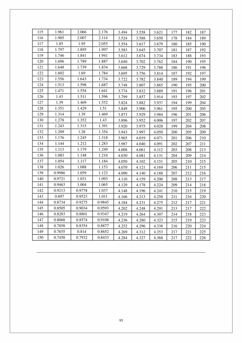
95
115 1.961 2.066 2.176 3.494 3.558 3.621 177 182 187
116 1.905 2.007 2.114 3.524 3.588 3.650 178 184 189
117 1.85 1.95 2.055 3.554 3.617 3.679 180 185 190
118 1.797 1.895 1.997 3.583 3.645 3.707 181 187 192
119 1.746 1.841 1.941 3.612 3.674 3.734 183 188 193
120 1.696 1.789 1.887 3.640 3.702 3.762 184 190 195
121 1.648 1.739 1.834 3.668 3.729 3.788 186 191 196
122 1.602 1.69 1.784 3.695 3.756 3.814 187 192 197
123 1.556 1.643 1.734 3.722 3.782 3.840 189 194 199
124 1.513 1.598 1.687 3.748 3.807 3.865 190 195 200
125 1.471 1.554 1.641 3.774 3.832 3.889 191 196 201
126 1.43 1.511 1.596 3.799 3.857 3.914 193 197 202
127 1.39 1.469 1.552 3.824 3.882 3.937 194 199 204
128 1.351 1.429 1.51 3.849 3.906 3.961 195 200 205
129 1.314 1.39 1.469 3.873 3.929 3.984 196 201 206
130 1.278 1.352 1.43 3.896 3.952 4.006 197 202 207
131 1.243 1.315 1.391 3.920 3.975 4.028 199 204 208
132 1.209 1.28 1.354 3.943 3.997 4.050 200 205 209
133 1.176 1.245 1.318 3.965 4.019 4.071 201 206 210
134 1.144 1.212 1.283 3.987 4.040 4.091 202 207 211
135 1.113 1.179 1.249 4.008 4.061 4.112 203 208 213
136 1.083 1.148 1.216 4.030 4.081 4.131 204 209 214
137 1.054 1.117 1.184 4.050 4.102 4.151 205 210 215
138 1.026 1.088 1.153 4.070 4.121 4.169 206 211 215
139 0.9986 1.059 1.123 4.090 4.140 4.188 207 212 216
140 0.9721 1.031 1.093 4.110 4.159 4.206 208 213 217
141 0.9463 1.004 1.065 4.129 4.178 4.224 209 214 218
142 0.9213 0.9778 1.037 4.148 4.196 4.241 210 215 219
143 0.897 0.9523 1.011 4.166 4.213 4.258 211 216 220
144 0.8734 0.9275 0.9845 4.184 4.231 4.275 212 217 221
145 0.8505 0.9034 0.9593 4.202 4.248 4.291 213 217 222
146 0.8283 0.8801 0.9347 4.219 4.264 4.307 214 218 223
147 0.8068 0.8574 0.9108 4.236 4.280 4.323 215 219 223
148 0.7858 0.8354 0.8877 4.252 4.296 4.338 216 220 224
149 0.7655 0.814 0.8652 4.269 4.312 4.353 217 221 225
150 0.7458 0.7932 0.8433 4.284 4.327 4.368 217 222 226
Related Documents