SAFETY WARNING Only qualified personnel should install and service the equipment. The installation, starting up, and servicing of heating, ventilating, and air-conditioning equipment can be hazardous and requires specific knowledge and training. Improperly installed, adjusted or altered equipment by an unqualified person could result in death or serious injury. When working on the equipment, observe all precautions in the literature and on the tags, stickers, and labels that are attached to the equipment. March 2022 SS-SVX001D-EN Installation, Operation, and Maintenance Split System Air Conditioners Odyssey™™ with Symbio™™ Controls Cooling Condenser, R-410A 5 to 25 Tons and R-22 Dry Charge 7.5, 10, 15 and 20 Tons (60 Hz) TTA0724*A/D TTA0904*A/D TTA1204*C/D TTA1504*D TTA1804*C/D TTA2404*C/D TTA3004*C TTA0902*A TTA1202*A TTA1802*D TTA2402*D (50 Hz) TTA0604DA/D TTA0764DA/D TTA1014DC/D TTA1264DD TTA1564DC/D TTA2014DC/D TTA2514DC

Welcome message from author
This document is posted to help you gain knowledge. Please leave a comment to let me know what you think about it! Share it to your friends and learn new things together.
Transcript
SSAAFFEETTYY WWAARRNNIINNGGOnly qualified personnel should install and service the equipment. The installation, starting up, and servicing of heating, ventilating, and air-conditioningequipment can be hazardous and requires specific knowledge and training. Improperly installed, adjusted or altered equipment by an unqualified personcould result in death or serious injury. When working on the equipment, observe all precautions in the literature and on the tags, stickers, and labels thatare attached to the equipment.
March 2022 SSSS--SSVVXX000011DD--EENN
Installation, Operation, and Maintenance
Split System Air ConditionersOdyssey™™with Symbio™™ControlsCooling Condenser, R-410A 5 to 25 Tons andR-22 Dry Charge 7.5, 10, 15 and 20 Tons
((6600 HHzz))TTA0724*A/DTTA0904*A/DTTA1204*C/DTTA1504*DTTA1804*C/DTTA2404*C/DTTA3004*CTTA0902*ATTA1202*ATTA1802*DTTA2402*D
((5500 HHzz))TTA0604DA/DTTA0764DA/DTTA1014DC/DTTA1264DDTTA1564DC/DTTA2014DC/DTTA2514DC

©2022 SS-SVX001D-EN
IntroductionRead this manual thoroughly before operating orservicing this unit.
Warnings, Cautions, and NoticesSafety advisories appear throughout this manual asrequired. Your personal safety and the properoperation of this machine depend upon the strictobservance of these precautions.
The three types of advisories are defined as follows:
WARNINGIndicates a potentially hazardous situationwhich, if not avoided, could result in death orserious injury.
CAUTIONIndicates a potentially hazardous situationwhich, if not avoided, could result in minor ormoderate injury. It could also be used to alertagainst unsafe practices.
NOTICEIndicates a situation that could result inequipment or property-damage onlyaccidents.
Important Environmental ConcernsScientific research has shown that certain man-madechemicals can affect the earth’s naturally occurringstratospheric ozone layer when released to theatmosphere. In particular, several of the identifiedchemicals that may affect the ozone layer arerefrigerants that contain Chlorine, Fluorine and Carbon(CFCs) and those containing Hydrogen, Chlorine,Fluorine and Carbon (HCFCs). Not all refrigerantscontaining these compounds have the same potentialimpact to the environment. Trane advocates theresponsible handling of all refrigerants-includingindustry replacements for CFCs and HCFCs such assaturated or unsaturated HFCs and HCFCs.
Important Responsible RefrigerantPracticesTrane believes that responsible refrigerant practicesare important to the environment, our customers, andthe air conditioning industry. All technicians whohandle refrigerants must be certified according to localrules. For the USA, the Federal Clean Air Act (Section608) sets forth the requirements for handling,reclaiming, recovering and recycling of certainrefrigerants and the equipment that is used in theseservice procedures. In addition, some states ormunicipalities may have additional requirements thatmust also be adhered to for responsible managementof refrigerants. Know the applicable laws and followthem.
WWAARRNNIINNGGPPrrooppeerr FFiieelldd WWiirriinngg aanndd GGrroouunnddiinnggRReeqquuiirreedd!!FFaaiilluurree ttoo ffoollllooww ccooddee ccoouulldd rreessuulltt iinn ddeeaatthh oorrsseerriioouuss iinnjjuurryy..AAllll ffiieelldd wwiirriinngg MMUUSSTT bbee ppeerrffoorrmmeedd bbyy qquuaalliiffiieeddppeerrssoonnnneell.. IImmpprrooppeerrllyy iinnssttaalllleedd aanndd ggrroouunnddeeddffiieelldd wwiirriinngg ppoosseess FFIIRREE aanndd EELLEECCTTRROOCCUUTTIIOONNhhaazzaarrddss.. TToo aavvooiidd tthheessee hhaazzaarrddss,, yyoouu MMUUSSTT ffoolllloowwrreeqquuiirreemmeennttss ffoorr ffiieelldd wwiirriinngg iinnssttaallllaattiioonn aannddggrroouunnddiinngg aass ddeessccrriibbeedd iinn NNEECC aanndd yyoouurr llooccaall//ssttaattee//nnaattiioonnaall eelleeccttrriiccaall ccooddeess..
WWAARRNNIINNGGPPeerrssoonnaall PPrrootteeccttiivvee EEqquuiippmmeenntt ((PPPPEE))RReeqquuiirreedd!!FFaaiilluurree ttoo wweeaarr pprrooppeerr PPPPEE ffoorr tthhee jjoobb bbeeiinngguunnddeerrttaakkeenn ccoouulldd rreessuulltt iinn ddeeaatthh oorr sseerriioouuss iinnjjuurryy..TTeecchhnniicciiaannss,, iinn oorrddeerr ttoo pprrootteecctt tthheemmsseellvveess ffrroommppootteennttiiaall eelleeccttrriiccaall,, mmeecchhaanniiccaall,, aanndd cchheemmiiccaallhhaazzaarrddss,, MMUUSSTT ffoollllooww pprreeccaauuttiioonnss iinn tthhiiss mmaannuuaallaanndd oonn tthhee ttaaggss,, ssttiicckkeerrss,, aanndd llaabbeellss,, aass wweellll aass tthheeiinnssttrruuccttiioonnss bbeellooww::
•• BBeeffoorree iinnssttaalllliinngg//sseerrvviicciinngg tthhiiss uunniitt,,tteecchhnniicciiaannss MMUUSSTT ppuutt oonn aallll PPPPEE rreeqquuiirreedd ffoorrtthhee wwoorrkk bbeeiinngg uunnddeerrttaakkeenn ((EExxaammpplleess;; ccuuttrreessiissttaanntt gglloovveess//sslleeeevveess,, bbuuttyyll gglloovveess,, ssaaffeettyyggllaasssseess,, hhaarrdd hhaatt//bbuummpp ccaapp,, ffaallll pprrootteeccttiioonn,,eelleeccttrriiccaall PPPPEE aanndd aarrcc ffllaasshh ccllootthhiinngg))..AALLWWAAYYSS rreeffeerr ttoo aapppprroopprriiaattee SSaaffeettyy DDaattaaSShheeeettss ((SSDDSS)) aanndd OOSSHHAA gguuiiddeelliinneess ffoorrpprrooppeerr PPPPEE..
•• WWhheenn wwoorrkkiinngg wwiitthh oorr aarroouunndd hhaazzaarrddoouusscchheemmiiccaallss,, AALLWWAAYYSS rreeffeerr ttoo tthhee aapppprroopprriiaatteeSSDDSS aanndd OOSSHHAA//GGHHSS ((GGlloobbaall HHaarrmmoonniizzeeddSSyysstteemm ooff CCllaassssiiffiiccaattiioonn aanndd LLaabbeelllliinngg ooffCChheemmiiccaallss)) gguuiiddeelliinneess ffoorr iinnffoorrmmaattiioonn oonnaalllloowwaabbllee ppeerrssoonnaall eexxppoossuurree lleevveellss,, pprrooppeerrrreessppiirraattoorryy pprrootteeccttiioonn aanndd hhaannddlliinnggiinnssttrruuccttiioonnss..
•• IIff tthheerree iiss aa rriisskk ooff eenneerrggiizzeedd eelleeccttrriiccaallccoonnttaacctt,, aarrcc,, oorr ffllaasshh,, tteecchhnniicciiaannss MMUUSSTT ppuuttoonn aallll PPPPEE iinn aaccccoorrddaannccee wwiitthh OOSSHHAA,, NNFFPPAA7700EE,, oorr ootthheerr ccoouunnttrryy--ssppeecciiffiicc rreeqquuiirreemmeennttssffoorr aarrcc ffllaasshh pprrootteeccttiioonn,, PPRRIIOORR ttoo sseerrvviicciinnggtthhee uunniitt.. NNEEVVEERR PPEERRFFOORRMM AANNYY SSWWIITTCCHHIINNGG,,DDIISSCCOONNNNEECCTTIINNGG,, OORR VVOOLLTTAAGGEE TTEESSTTIINNGGWWIITTHHOOUUTT PPRROOPPEERR EELLEECCTTRRIICCAALL PPPPEE AANNDDAARRCC FFLLAASSHH CCLLOOTTHHIINNGG.. EENNSSUURREEEELLEECCTTRRIICCAALL MMEETTEERRSS AANNDD EEQQUUIIPPMMEENNTT AARREEPPRROOPPEERRLLYY RRAATTEEDD FFOORR IINNTTEENNDDEEDDVVOOLLTTAAGGEE..

SS-SVX001D-EN 3
WWAARRNNIINNGGFFoollllooww EEHHSS PPoolliicciieess!!FFaaiilluurree ttoo ffoollllooww iinnssttrruuccttiioonnss bbeellooww ccoouulldd rreessuulltt iinnddeeaatthh oorr sseerriioouuss iinnjjuurryy..
•• AAllll TTrraannee ppeerrssoonnnneell mmuusstt ffoollllooww tthheeccoommppaannyy’’ss EEnnvviirroonnmmeennttaall,, HHeeaalltthh aanndd SSaaffeettyy((EEHHSS)) ppoolliicciieess wwhheenn ppeerrffoorrmmiinngg wwoorrkk ssuucchh aasshhoott wwoorrkk,, eelleeccttrriiccaall,, ffaallll pprrootteeccttiioonn,, lloocckkoouutt//ttaaggoouutt,, rreeffrriiggeerraanntt hhaannddlliinngg,, eettcc.. WWhheerree llooccaallrreegguullaattiioonnss aarree mmoorree ssttrriinnggeenntt tthhaann tthheesseeppoolliicciieess,, tthhoossee rreegguullaattiioonnss ssuuppeerrsseeddee tthheesseeppoolliicciieess..
•• NNoonn--TTrraannee ppeerrssoonnnneell sshhoouulldd aallwwaayyss ffoolllloowwllooccaall rreegguullaattiioonnss..
WWAARRNNIINNGGRReeffrriiggeerraanntt uunnddeerr HHiigghh PPrreessssuurree!!FFaaiilluurree ttoo ffoollllooww iinnssttrruuccttiioonnss bbeellooww ccoouulldd rreessuulltt iinnaann eexxpplloossiioonn wwhhiicchh ccoouulldd rreessuulltt iinn ddeeaatthh oorrsseerriioouuss iinnjjuurryy oorr eeqquuiippmmeenntt ddaammaaggee..SSyysstteemm ccoonnttaaiinnss rreeffrriiggeerraanntt uunnddeerr hhiigghh pprreessssuurree..RReeccoovveerr rreeffrriiggeerraanntt ttoo rreelliieevvee pprreessssuurree bbeeffoorreeooppeenniinngg tthhee ssyysstteemm.. SSeeee uunniitt nnaammeeppllaattee ffoorrrreeffrriiggeerraanntt ttyyppee.. DDoo nnoott uussee nnoonn--aapppprroovveeddrreeffrriiggeerraannttss,, rreeffrriiggeerraanntt ssuubbssttiittuutteess,, oorr rreeffrriiggeerraannttaaddddiittiivveess..
WWAARRNNIINNGGEExxpplloossiioonn HHaazzaarrdd!!FFaaiilluurree ttoo ffoollllooww iinnssttrruuccttiioonnss bbeellooww ccoouulldd rreessuulltt iinnaann eexxpplloossiioonn wwhhiicchh ccoouulldd rreessuulltt iinn ddeeaatthh oorrsseerriioouuss iinnjjuurryy,, aanndd eeqquuiippmmeenntt ddaammaaggee..NNEEVVEERR bbyyppaassss ssyysstteemm ssaaffeettiieess iinn oorrddeerr ttoo ppuummppddoowwnn tthhee uunniitt ccoommppoonneenntt''ss rreeffrriiggeerraanntt iinnttoo tthheemmiiccrroocchhaannnneell hheeaatt eexxcchhaannggeerr ((MMCCHHEE)) ccooiill.. DDooNNOOTT ddeepprreessss tthhee ccoommpprreessssoorr ccoonnttaaccttoorr ssiinnccee iitteeffffeeccttiivveellyy bbyyppaasssseess tthhee hhiigghh--pprreessssuurree ccoonnttrrooll..
WWAARRNNIINNGGRReeffrriiggeerraanntt uunnddeerr HHiigghh PPrreessssuurree!!FFaaiilluurree ttoo ffoollllooww iinnssttrruuccttiioonnss bbeellooww ccoouulldd rreessuulltt iinnaann eexxpplloossiioonn wwhhiicchh ccoouulldd rreessuulltt iinn ddeeaatthh oorrsseerriioouuss iinnjjuurryy oorr eeqquuiippmmeenntt ddaammaaggee..SSyysstteemm ccoonnttaaiinnss rreeffrriiggeerraanntt uunnddeerr hhiigghh pprreessssuurree..RReeccoovveerr rreeffrriiggeerraanntt ttoo rreelliieevvee pprreessssuurree bbeeffoorreeooppeenniinngg tthhee ssyysstteemm.. SSeeee uunniitt nnaammeeppllaattee ffoorrrreeffrriiggeerraanntt ttyyppee.. DDoo nnoott uussee nnoonn--aapppprroovveeddrreeffrriiggeerraannttss,, rreeffrriiggeerraanntt ssuubbssttiittuutteess,, oorr rreeffrriiggeerraannttaaddddiittiivveess..
CopyrightThis document and the information in it are theproperty of Trane, and may not be used or reproducedin whole or in part without written permission. Tranereserves the right to revise this publication at any time,and to make changes to its content without obligationto notify any person of such revision or change.
TrademarksAll trademarks referenced in this document are thetrademarks of their respective owners.
Revision History• Updated the Model Number Description chapter.
• Updated the Installation chapter.
• Updated the Charging Data and Pressure Curveschapter.
• Updated the Dimensional Data chapter.
• Updated the Wiring Diagram Matrix and DeviceLocation chapter.
IInnttrroodduuccttiioonn

4 SS-SVX001D-EN
Model Number Description. . . . . . . . . . . . . . . . . 5Cooling Condenser . . . . . . . . . . . . . . . . . . . . . . . 5
General Information . . . . . . . . . . . . . . . . . . . . . . . . 6Unit Description . . . . . . . . . . . . . . . . . . . . . . . . . . 6
Pre-Installation . . . . . . . . . . . . . . . . . . . . . . . . . . . . . 7Unit Inspection . . . . . . . . . . . . . . . . . . . . . . . . . . . 7
Inspection Checklist . . . . . . . . . . . . . . . . . . . 7
Testing for Leaks . . . . . . . . . . . . . . . . . . . . . . . . . 7
Lifting Recommendations . . . . . . . . . . . . . . . . . 7
Clearances . . . . . . . . . . . . . . . . . . . . . . . . . . . . . . . 7
Unit Mounting. . . . . . . . . . . . . . . . . . . . . . . . . . . . 8Structural Preparation . . . . . . . . . . . . . . . . . 8Rooftop Mounting . . . . . . . . . . . . . . . . . . . . 8Ground Level Mounting . . . . . . . . . . . . . . . 8
Installation Checklist . . . . . . . . . . . . . . . . . . . . . . 8Refrigerant Piping. . . . . . . . . . . . . . . . . . . . . 8Electrical Wiring . . . . . . . . . . . . . . . . . . . . . . 9
Dimensional Data . . . . . . . . . . . . . . . . . . . . . . . . . 10Cooling Condenser . . . . . . . . . . . . . . . . . . . . . . 10
Weights . . . . . . . . . . . . . . . . . . . . . . . . . . . . . . . . . . . 19Cooling Condenser . . . . . . . . . . . . . . . . . . . . . . 19
Installation . . . . . . . . . . . . . . . . . . . . . . . . . . . . . . . . 21Refrigerant Piping Guidelines. . . . . . . . . . . . . 21
Refrigerant Piping Procedures (OutdoorUnits). . . . . . . . . . . . . . . . . . . . . . . . . . . . . . . . . . . 22
Refrigerant Piping Procedures (IndoorUnit). . . . . . . . . . . . . . . . . . . . . . . . . . . . . . . . . . . . 23
Leak Check . . . . . . . . . . . . . . . . . . . . . . . . . . . . . . 23System Evacuation. . . . . . . . . . . . . . . . . . . 24
Insulating and Isolating RefrigerantLines . . . . . . . . . . . . . . . . . . . . . . . . . . . . . . . . . . . 24
Refrigerant Charging Procedure . . . . . . . . . . 25Charging Levels. . . . . . . . . . . . . . . . . . . . . . 26
Liquid Charging . . . . . . . . . . . . . . . . . . . . . . . . . 27
Electrical Wiring . . . . . . . . . . . . . . . . . . . . . . . . . 27Unit Power Supply . . . . . . . . . . . . . . . . . . . 28Low Voltage Wiring . . . . . . . . . . . . . . . . . . 28Symbio™ Controls . . . . . . . . . . . . . . . . . . . 28Field Wiring . . . . . . . . . . . . . . . . . . . . . . . . . 29Refrigerant Circuit. . . . . . . . . . . . . . . . . . . . 30
Pre-Start. . . . . . . . . . . . . . . . . . . . . . . . . . . . . . . . . . . 31Control Circuit Features . . . . . . . . . . . . . . . . . . 31
Discharge Temperature Limit(DTL). . . . . . . . . . . . . . . . . . . . . . . . . . . . . . . . 31Low Outdoor Ambient Cooling . . . . . . . . 31Evaporator Defrost Control(EDC) . . . . . . . . . . . . . . . . . . . . . . . . . . . . . . . 31Low Pressure Cut-Out (LPC). . . . . . . . . . . 31High Pressure Cut-Out (HPCO) . . . . . . . . 31Internal Overload Protector(IOL) . . . . . . . . . . . . . . . . . . . . . . . . . . . . . . . . 31
Troubleshooting. . . . . . . . . . . . . . . . . . . . . . . . . . . 32
Service Test Mode. . . . . . . . . . . . . . . . . . . . . . . . . 33
Maintenance . . . . . . . . . . . . . . . . . . . . . . . . . . . . . . 34Monthly . . . . . . . . . . . . . . . . . . . . . . . . . . . . . . . . 34
Annually (Cooling Season) . . . . . . . . . . . . . . . 34
Coil Cleaning . . . . . . . . . . . . . . . . . . . . . . . . . . . . 34Microchannel (MCHE) Coils . . . . . . . . . . . 34
Maintenance Log . . . . . . . . . . . . . . . . . . . . . . . . 36
Charging Data and Pressure Curves . . . . . . . 37
Wiring Diagram Matrix and DeviceLocation . . . . . . . . . . . . . . . . . . . . . . . . . . . . . . . . . . . 38
Warranty . . . . . . . . . . . . . . . . . . . . . . . . . . . . . . . . . . 39For Commercial Unitary EquipmentRated 25 Tons and Under and RelatedAccessories . . . . . . . . . . . . . . . . . . . . . . . . . . . . . 39
Basic Warranty . . . . . . . . . . . . . . . . . . . . . . 39Exclusions and Limitations . . . . . . . . . . . 39
Table of Contents
SS-SVX001D-EN 5
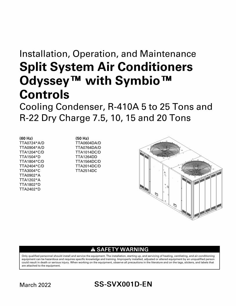
Model Number DescriptionCooling Condenser
Digit 1, 2, 3— Unit Function
TTA = Split System Cooling
Digit 4, 5, 6 — Tonnage
060 = 5 Tons (50Hz)072 = 6 Tons (60 Hz)076 = 6.25 Tons (50Hz)090 = 7.5 Tons (60 Hz)101 = 8.33 Tons (50Hz)120 = 10 Tons (60 Hz)126 = 10.4 Tons (50Hz)150 = 12.5 Tons (60 Hz)156 = 13.0 Tons (50Hz)180 = 15 Tons (60 Hz)201 = 16.7 Tons (50Hz)240 = 20 Tons (60 Hz)251 = 20.9 Tons (50Hz)300 = 25 Tons (60Hz)
Digit 7 — Refrigerant
2 = R-224 = R-410A
Digit 8 — Voltage
3 = 208-230 Vac - 3 PH (60Hz)4 = 460 Vac - 3 PH (60Hz)W = 575 Vac - 3 PH (60Hz)D = 380–415 Vac- 3 PH (50Hz)K= 380 Vac - 3 PH (60Hz)
Digit 9 — Refrigeration Circuit/Stage
A = 1 Compressor/1 Line/1 Stage (Single)C= 2 Compressors/1 Line/2 Stage (Manifold)D = 2 Compressors/2 Line/2 Stage (Dual)
Digit 10 —Major Design Sequence
A = Rev AB = Rev B
Digit 11 —Minor Design Sequence
A = Rev A
Digit 12, 13 — Service Digits
**
Digit 14 — Efficiency Generation
A = Generation AB = Generation B
Digit 15— Controls
S = Symbio™
Digit 16— None
0 = None
Digit 17— Coil Protection
1 = Standard Coil w/ Hail Guard5 = Complete Coat Condenser Coil with HailGuard (MCHE)
Digit 18, 19, 20— None
0 = None
Digit 21— Communications Options
0 = No Option1 = Advanced Diagnostics and BACnet® BAS2 = Advanced Diagnostics and LonTalk®Communications Interface (LCI)
Digit 22 to 40 —None
0 = None

6 SS-SVX001D-EN
General InformationThis manual describes proper installation, operation,and maintenance procedures for air-cooled systems.By carefully reviewing the information within thismanual and following the instructions, the risk ofimproper operation and/or component damage will beminimized. It is important that periodic maintenance beperformed to help assure trouble free operation.Should equipment failure occur, contact a qualifiedservice organization with qualified, experienced HVACtechnicians to properly diagnose and repair thisequipment.
IImmppoorrttaanntt:: All phases of this installation must complywith the NATIONAL, STATE & LOCALCODES. In addition to local codes, theinstallation must conform with NationalElectric Code -ANSI/NFPA NO. 70 LATESTREVISION.
Any individual installing, maintaining, or servicing thisequipment must be properly trained, licensed andqualified.
IImmppoorrttaanntt:: Do not remove the VFD without firstcontacting technical support! Forperformance-related questions anddiagnostic support in North America call 1-877-872-6363. Any return requires a claimnumber FIRST. Removal of the VFD prior tothis step will void the unit’s warranties.
Installation procedures should be performed in thesequence that they appear in this manual. Do notdestroy or remove the manual from the unit. The
manual should remain weather-protected with the unituntil all installation procedures are complete.
NNoottee:: It is not the intention of this manual to cover allpossible variations in systems that may occur orto provide comprehensive informationconcerning every possible contingency that maybe encountered during an installation. Ifadditional information is required or if specificproblems arise that are not fully discussed in thismanual, contact your local sales office.
Use the “Installation Checklist,” p. 8 provided in thismanual to verify that all necessary installationprocedures have been completed. Do not use thechecklist as a substitute for reading the informationcontained in this manual. Read this entire manualbefore beginning installation procedures.
Unit DescriptionThese condensers come with single, dual andmanifolded compressor options. Single compressoroutdoor units feature a single refrigeration circuitrequiring only one set of refrigerant lines. Dualcompressor/dual circuit models give true stand-byprotection; if one compressor fails, the second willautomatically start-up. During light load conditions,only one compressor will operate to save energy.Thedual manifolded scroll compressors come with twostages of capacity modulation and a singlerefrigeration circuit.

SS-SVX001D-EN 7
Pre-InstallationUnit InspectionInspect material carefully for any shipping damage. Ifdamaged, it must be reported to, and claims madeagainst the transportation company. Compare theinformation that appears on the unit nameplate withordering and submittal data to ensure the proper unitwas shipped. Available power supply must becompatible with electrical characteristics specified oncomponent nameplates. Replace damaged parts withauthorized parts only.
IImmppoorrttaanntt:: Units ordered with a VFD cannot be fieldconverted to 460 V from 208-230 or from208-230 V to 460 V.
Inspection ChecklistTo protect against loss due to damage incurred intransit, complete the following checklist upon receipt ofthe unit.
☐ Inspect individual pieces of the shipment beforeaccepting the unit. Check for obvious damage to theunit or packing material.
☐ Inspect the unit for concealed damage before it isstored and as soon as possible after delivery.Concealed damage must be reported within 15days. If concealed damage is discovered, stopunpacking the shipment. Do not remove damagedmaterial from the receiving location. Take photos ofthe damage if possible. The owner must providereasonable evidence that the damage did not occurafter delivery.
☐ Notify the carrier’s terminal of damage immediatelyby phone and by mail. Request an immediate jointinspection of the damage by the carrier and theconsignee.
☐ Notify the sales representative and arrange forrepair. Do not repair the unit until the damage isinspected by the carrier’s representative.
Testing for LeaksAll units are shipped with a holding charge of nitrogenin each circuit and should be leak tested beforeinstallation.
1. Remove the access panel.
2. Locate the liquid line or suction line access valve foreach circuit.
3. Install gauges to determine if the circuits are stillpressurized. If not, the charge has escaped andshould be repaired as required to obtain a leak-freecircuit.
Lifting Recommendations
WWAARRNNIINNGGIImmpprrooppeerr UUnniitt LLiifftt!!FFaaiilluurree ttoo pprrooppeerrllyy lliifftt uunniitt iinn aa LLEEVVEELL ppoossiittiioonnccoouulldd rreessuulltt iinn uunniitt ddrrooppppiinngg aanndd ppoossssiibbllyyccrruusshhiinngg ooppeerraattoorr//tteecchhnniicciiaann wwhhiicchh ccoouulldd rreessuulltt iinnddeeaatthh oorr sseerriioouuss iinnjjuurryy,, aanndd eeqquuiippmmeenntt oorrpprrooppeerrttyy--oonnllyy ddaammaaggee..TTeesstt lliifftt uunniitt aapppprrooxxiimmaatteellyy 2244 iinncchheess ((6611 ccmm)) ttoovveerriiffyy pprrooppeerr cceenntteerr ooff ggrraavviittyy lliifftt ppooiinntt.. TToo aavvooiiddddrrooppppiinngg ooff uunniitt,, rreeppoossiittiioonn lliiffttiinngg ppooiinntt iiff uunniitt iissnnoott lleevveell..
NNOOTTIICCEEEEqquuiippmmeenntt DDaammaaggee!!UUssee sspprreeaaddeerr bbaarrss ttoo pprreevveenntt ssttrraappss ffrroommddaammaaggiinngg tthhee uunniitt.. IInnssttaallll tthhee bbaarrss bbeettwweeeenn lliiffttiinnggssttrraappss,, bbootthh uunnddeerrnneeaatthh tthhee uunniitt aanndd aabboovvee tthheeuunniitt ttoo pprreevveenntt tthhee ssttrraappss ffrroomm ccrruusshhiinngg tthhee uunniittccaabbiinneett oorr ddaammaaggiinngg tthhee ffiinniisshh..
Before preparing the unit for lifting, estimate theapproximate center of gravity for lifting safety. Becauseof placement of internal components, the unit weightmay be unevenly distributed. See “Weights,” p. 19 forapproximate unit weights.
The crated unit can be moved using a forklift of suitablecapacity. For lifting the unit, attach lifting straps orslings securely to the lifting holes at each corner (seeunit drawings in “Weights,” p. 19). Use spreader barsto protect the unit casing from damage. Test lift theunit to determine proper balance and stability.
ClearancesProvide enough space around the unit to allowunrestricted access to all service points. Refer to the“Dimensional Data,” p. 10 for unit dimensions andminimum required service and free air clearances.Observe the following points to ensure proper unitoperation.
1. Do not install the unit under a low overhang.Condenser discharge must not be restricted—referto notes in “Dimensional Data drawings,” p. 10.
IImmppoorrttaanntt:: Do not obstruct condenser dischargeair. This can result in warm airrecirculation through the coil.
2. Do not locate the unit in a position where runoffwater, or falling snow from roof, can fall into the fandischarge openings.
3. Condenser intake air is supplied from three or foursides of the unit. Adhere to the minimum requiredclearances given in unit dimensional drawings (see

8 SS-SVX001D-EN
“Dimensional Data,” p. 10).
Unit Mounting
WWAARRNNIINNGGRRiisskk ooff RRooooff CCoollllaappssiinngg!!FFaaiilluurree ttoo eennssuurree pprrooppeerr ssttrruuccttuurraall rrooooff ssuuppppoorrttccoouulldd ccaauussee tthhee rrooooff ttoo ccoollllaappssee,, wwhhiicchh ccoouullddrreessuulltt iinn ddeeaatthh oorr sseerriioouuss iinnjjuurryy aanndd pprrooppeerrttyyddaammaaggee..CCoonnffiirrmm wwiitthh aa ssttrruuccttuurraall eennggiinneeeerr tthhaatt tthhee rrooooffssttrruuccttuurree iiss ssttrroonngg eennoouugghh ttoo ssuuppppoorrtt tthheeccoommbbiinneedd wweeiigghhtt ooff tthhee rrooooffccuurrbb,, tthhee uunniitt,, aanndd aannyyaacccceessssoorriieess..
Structural Preparation
NNOOTTIICCEERRooooff DDaammaaggee!!SSyysstteemm ccoonnttaaiinnss ooiill aanndd rreeffrriiggeerraanntt uunnddeerr hhiigghhpprreessssuurree.. RRooooffss sshhoouulldd bbee pprrootteecctteedd ffrroommeexxppoossuurree ttoo ooiillss aanndd rreeffrriiggeerraanntt iinn tthhee ssyysstteemm.. IIffrrooooffttoopp iiss nnoott pprrootteecctteedd,, ddaammaaggee ttoo tthhee rrooooff mmaayyooccccuurr..
IImmppoorrttaanntt:: Refer to local building codes for properinstallation. All installation must complywith local building codes.
Rooftop MountingIf the unit will be roof mounted, determine for certainthat the structure is strong enough to support the unitand any required accessories, see “Weights,” p. 19.The unit should be elevated on a level, field fabricatedfour-inch steel or wood 4" x 4" mounting frame.Complete the frame and secure it into position beforelifting the unit to the roof. The mounting frame mustsupport a minimum of three of the unit’s four sides andshould span roof supports to distribute the load on theroof.
Figure 1. Roof mounted unit
Outdoor Unit
Gas (Suction)Line - Insulated
Liquid LineInsulated
Unit MountingChannels
Elevation(Mounting Frame)
Roof Trussing
Ceiling
Roof Construction
6”Radius
Ground Level MountingFor ground level installation, the unit base should beadequately supported and hold the unit near level. Theinstallation must meet the guidelines set forth in localcodes. The support should extend two inches beyondthe unit base channels at all points. The unit andsupport must be isolated from any adjacent structureto prevent possible noise or vibration problems. Anyground level location must comply with requiredclearances given in the unit dimensional drawings (see“Dimensional Data,” p. 10).
Installation ChecklistComplete this checklist once the unit is installed toverify that all recommended procedures have beenaccomplished before starting the system. Do notoperate the system until all items covered by thischecklist are complete.
☐ Inspect unit location for proper required serviceclearances.
☐ Inspect unit location for proper free air clearances.
☐ Inspect unit location for secure, level mountingposition.
☐ Remove coil protection boards on microchannelunits.
☐ Verify condenser fans turn freely without rubbingand are properly tightened on the shafts.
Refrigerant Piping☐ Properly sized/constructed liquid and suction lines
connected to stubs at both the indoor and outdoorunits?
☐ Insulated the entire suction line?
PPrree--IInnssttaallllaattiioonn

SS-SVX001D-EN 9
☐ Insulated portions of liquid line exposed toextremes in temperature?
☐ Performed initial leak test?
☐ Evacuated each refrigerant circuit to 500 microns?
☐ Charged each circuit with proper amount of R-410A/R-22?
Electrical Wiring☐ Provided unit power wiring (with disconnect) to
proper terminals in the unit control enclosure?
☐ Installed system indoor thermostat or zone sensor?
☐ Installed system low voltage interconnecting wiringto proper terminals of outdoor unit, indoor unit andsystem thermostat or zone sensor?
☐ Checked all electrical connections to verify all areproperly tightened and connected?
☐ Verified operation of crankcase heaters?
PPrree--IInnssttaallllaattiioonn

10 SS-SVX001D-EN
Dimensional DataCooling CondenserFigure 2. Height, width and depth measurements
H
WD
H
WD
H - in. (mm) W - in. (mm) D - in. (mm)
TTA060, 072, 076, 090 (R-410A) and TTA090(R-22) 39.2 (996) 42.1 (1070) 36.3 (922)
TTA101, 120 (R-410A) and TTA120 (R-22) 39.2 (996) 51.9 (1317) 39.3 (999)
TTA126, 150 (R-410A) 45.2 (1150) 51.9 (1317) 39.3 (999)
TTA156, 180, 201, 240 (R-410A) and TTA180,240 (R-22) 45.2 (1150) 94.8 (2407) 45.4 (1152)
TTA251, 300 (R-410A) 51.2 (1302) 94.8 (2407) 45.4 (1152)
NNoottee:: Full dimensional data available on next pages.

SS-SVX001D-EN 11
Figure 3. 5, 6, 6.25, 7.5 ton R-410A and 7.5 R-22 condensing, single compressor – in (mm)
1/16”(1.2)
SERVICE PANEL
LINE VOLTAGECONTROL WIRING
SUCTION LINE
LIQUID LINE
SERVICE PANEL SIDE
4 5/16” (109)
1 5/16” (33)
2 13/16” (72)
3 3/16” (81)
9 5/16”(236)
16 5/16”(415)
27 13/16”(706)
35 3/8”(898)
6”(152)
6”(152)
34 11/16”(881)
22 11/16”(577)
34 15/16”(887)
36 5/16”(922)
WITH HAIL GUARD
1 7/8” (47)
2 7/8” (74)41 2/16”(1044)
41 15/16”(1065)
WITH HAIL GUARD
20 15/16”(531)
39 3/16”(996)
17 7/16”(442)
11 13/16”(300)
3” (76)
35 1/16”(890)41 15/16”
(1065)
1 13/16” (47) 28 11/16”(729)
2 5/16” (59)
2 5/16” (59)
SERVICE PANEL
SERVICE CLEARANCE48” (1219.2) (SEE NOTE 2FOR CLEARANCE)
SEE NOTE 1
REFRIGERANT GUAGE ACCESS
CONTROLWIRING
(OPTIONAL)
7/16” (11.11) DIA. ISOLATOR MOUNTINGHOLES (OUTSIDE HOLES - 4 PLACES)
BOTTOMOF UNIT
SEE NOTE 4 HAIL GUARD(OPTIONAL)
HAIL GUARD(OPTIONAL)
SEE NOTE 3 NOTES:1. ACCESS OPENING IS FOR FIELD INSTALLED BAYLOAM ACCESSORY.2. MINIMUM CLEARANCE FOR PROPER OPERATION IS 36” ( 914.4) FROM WALLS, SHRUBBERY, PRIVACY FENCES ETC. MINIMUM CLEARANCE BETWEEN ADJACENT UNITS IS 72” (1828.8). RECOMMENDED SERVICE CLEARANCE 48” (1219.2)3. TOP DISCHARGE AREA SHOULD BE UNRESTRICTED FOR 100” (2540) MINIMUM. UNIT SHOULD BE PLACED SO ROOF RUN-OFF WATER OR FALLING SNOW FROM ROOF DOES NOT POUR/FALL DIRECTLY ON UNIT4. OUTDOOR AIR TEMPERATURE SENSOR OPENING (DO NOT BLOCK OPENING)
DDiimmeennssiioonnaall DDaattaa

12 SS-SVX001D-EN
Figure 4. 5, 6, 6.25, 7.5 ton condensing, dual compressor – in (mm)
1/16”(1.2)
SERVICE PANEL
SERVICE PANEL SIDE
6”(152)
6”(152)
34 11/16”(881)
22 11/16”(577)
34 15/16”(887)
36 5/16”(922)
WITH HAIL GUARD
1 7/8” (47)
2 7/8” (74)
41 2/16”(1044)
41 15/16”(1065)
WITH HAIL GUARD
20 15/16”(531)
39 3/16”(996)
17 7/16”(442)
11 13/16”(300)
3” (76)
35 1/16”(890)41 1/16”
(1042)
1 13/16” (47) 28 11/16”(729)
2 5/16” (59)
2 5/16” (59)
SERVICE PANEL
SERVICE CLEARANCE48” (1219.2) (SEE NOTE 2FOR CLEARANCE)
SEE NOTE 1
REFRIGERANT GUAGE ACCESS
CONTROLWIRING(OPTIONAL)
7/16” (11.11) DIA. ISOLATOR MOUNTINGHOLES (OUTSIDE HOLES - 4 PLACES)
BOTTOMOF UNIT
SEE NOTE 4 HAIL GUARD(OPTIONAL)
SEE NOTE 3NOTES:1. ACCESS OPENING IS FOR FIELD INSTALLED BAYLOAM ACCESSORY.2. MINIMUM CLEARANCE FOR PROPER OPERATION IS 36” ( 914.4) FROM WALLS, SHRUBBERY, PRIVACY FENCES ETC. MINIMUM CLEARANCE BETWEEN ADJACENT UNITS IS 72” (1828.8). RECOMMENDED SERVICE CLEARANCE 48” (1219.2)3. TOP DISCHARGE AREA SHOULD BE UNRESTRICTED FOR 100” (2540) MINIMUM. UNIT SHOULD BE PLACED SO ROOF RUN-OFF WATER OR FALLING SNOW FROM ROOF DOES NOT POUR/FALL DIRECTLY ON UNIT4. OUTDOOR AIR TEMPERATURE SENSOR OPENING (DO NOT BLOCK OPENING)
4 5/16” (109)
27 13/16”(706)
11 5/16”(288)
7 13/16”(199)
9 5/16”(236)
6 3/8”(162)
35 3/8”(898)
HAIL GUARD(OPTIONAL) LINE VOLTAGE
CONTROL WIRING
SUCTION LINE
LIQUID LINE
1 5/16” (33)
2 1/4” (57)4 3/8” (111)
DDiimmeennssiioonnaall DDaattaa
SS-SVX001D-EN 13
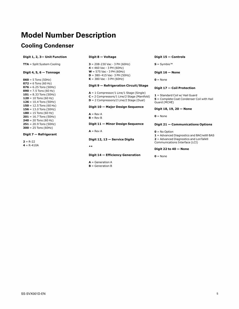
Figure 5. 8.33, 10 ton R-410A and 10 ton R-22 condensing, manifolded compressor – in (mm)
11 13/16”(300)
17 7/16”(442)
20 15/16”(531)
1 7/8” (47)
2 7/8” (73) 50 7/8”(1293)
51 11/16”(1312)
WITH HAIL GUARD
39 3/16”(996)
HAIL GUARD(OPTIONAL)
HAIL GUARD(OPTIONAL)
SEE NOTE 1
CONTROLWIRING(OPTIONAL)
REFRIGERANT GAUGE ACCESS
NOTES:1. ACCESS OPENING IS FOR FIELD INSTALLED BAYLOAM ACCESSORY.2. MINIMUM CLEARANCE FOR PROPER OPERATION IS 36” ( 914.4) FROM WALLS, SHRUBBERY, PRIVACY FENCES ETC. MINIMUM CLEARANCE BETWEEN ADJACENT UNITS IS 72” (1828.8). RECOMMENDED SERVICE CLEARANCE 48” (1219.2)3. TOP DISCHARGE AREA SHOULD BE UNRESTRICTED FOR 100” (2540) MINIMUM. UNIT SHOULD BE PLACED SO ROOF RUN-OFF WATER OR FALLING SNOW FROM ROOF DOES NOT POUR/FALL DIRECTLY ON UNIT4. OUTDOOR AIR TEMPERATURE SENSOR OPENING (DO NOT BLOCK OPENING)
SERVICE PANEL
SERVICE PANEL SIDE
6”(152)
6”(152)
37 11/16”(958)
25 11/16”(653)
37 15/16”(964)
39 5/16”(999)
WITH HAIL GUARD
3” (76)
44 3/4”(1137)50 3/4”
(1290)
1 11/16” (43)
31 11/16”(805)
2 3/16” (56)
1 11/16” (43)
7/16” (11.1) DIA. ISOLATOR MOUNTINGHOLES (OUTSIDE HOLES - 4 PLACES)
BOTTOMOF UNIT
SERVICE CLEARANCE48” (1219.2) (SEE NOTE 2FOR CLEARANCE)
9 5/16”(236)
16 5/16”(415)
27 13/16”(706)
35 3/8”(898)
2 13/16” (72)
4 1/4” (109)
1 1/4” (33)
3 3/16” (81)
LINE VOLTAGE
CONTROL WIRING
SUCTION LINE
LIQUID LINE
SERVICE PANEL
SEE NOTE 4
SEE NOTE 3
DDiimmeennssiioonnaall DDaattaa

14 SS-SVX001D-EN
Figure 6. 8.33, 10 ton condensing, dual compressor – in (mm)
11 13/16”(300)
17 3/8”(441)
20 15/16”(531)
1 7/8” (47)
2 7/8” (73) 50 3/4”(1290)
51 11/16”(1312)
WITH HAIL GUARD
6 3/8”(162)
7 13/16”(199)
9 5/16”(236)
11 5/16”(288)
[288]
27 13/16”(706)
35 3/8”(898)
2 1/4” (56)
4 3/8” (110)
1 5/16” (33)
4 5/16” (109)
39 3/16”(996)
HAIL GUARD(OPTIONAL)
SERVICE PANEL
HAIL GUARD(OPTIONAL) LINE VOLTAGE
CONTROL WIRING
SUCTION LINE
LIQUID LINE
SEE NOTE 1
CONTROLWIRING(OPTIONAL)
REFRIGERANT GAUGE ACCESS
SEE NOTE 4
SEE NOTE 3 NOTES:1. ACCESS OPENING IS FOR FIELD INSTALLED BAYLOAM ACCESSORY.2. MINIMUM CLEARANCE FOR PROPER OPERATION IS 36” ( 914.4) FROM WALLS, SHRUBBERY, PRIVACY FENCES ETC. MINIMUM CLEARANCE BETWEEN ADJACENT UNITS IS 72” (1828.8). RECOMMENDED SERVICE CLEARANCE 48” (1219.2)3. TOP DISCHARGE AREA SHOULD BE UNRESTRICTED FOR 100” (2540) MINIMUM. UNIT SHOULD BE PLACED SO ROOF RUN-OFF WATER OR FALLING SNOW FROM ROOF DOES NOT POUR/FALL DIRECTLY ON UNIT4. OUTDOOR AIR TEMPERATURE SENSOR OPENING (DO NOT BLOCK OPENING)
SERVICE PANEL
SERVICE PANEL SIDE
6”(152)
6”(152)
37 11/16”(958)
25 11/16”(653)
37 15/16”(964)
39 5/16”(999)
WITH HAIL GUARD
3” (76)
44 3/4”(1137)50 3/4”
(1290)
1 11/16” (43)
31 11/16”(805)
2 3/16” (56)
1 11/16” (43)
7/16” (11.1) DIA. ISOLATOR MOUNTINGHOLES (OUTSIDE HOLES - 4 PLACES)
BOTTOMOF UNIT
SERVICE CLEARANCE48” (1219.2) (SEE NOTE 2FOR CLEARANCE)
DDiimmeennssiioonnaall DDaattaa

SS-SVX001D-EN 15
Figure 7. 10.4, 12.5 ton condensing, dual compressor – in (mm)
14 5/16”(363)
23 7/16”(595)
26 15/16”(684)
1 7/8” (47)
2 7/8” (73) 50 7/8”(1293)
51 11/16”(1312)
WITH HAIL GUARD
6 3/8”(162)
7 7/8”(199)
9 5/16”(236)
11 3/8”(288)
[288]
33 13/16”(859)
41 3/8”(1050)
2 1/4” (56)
3 3/16” (80)
1 5/16” (33)
4 5/16” (109)
45 1/4”(1150)
HAIL GUARD(OPTIONAL)
SERVICE PANEL
HAIL GUARD(OPTIONAL) LINE VOLTAGE
CONTROL WIRING
SUCTION LINE
LIQUID LINE
SEE NOTE 1
CONTROLWIRING(OPTIONAL)
REFRIGERANT GAUGE ACCESS
SEE NOTE 3
SEE NOTE 2 NOTES:1. MINIMUM CLEARANCE FOR PROPER OPERATION IS 36” ( 914.4) FROM WALLS, SHRUBBERY, PRIVACY FENCES ETC. MINIMUM CLEARANCE BETWEEN ADJACENT UNITS IS 72” (1828.8). RECOMMENDED SERVICE CLEARANCE 48” (1219.2)2. TOP DISCHARGE AREA SHOULD BE UNRESTRICTED FOR 100” (2540) MINIMUM. UNIT SHOULD BE PLACED SO ROOF RUN-OFF WATER OR FALLING SNOW FROM ROOF DOES NOT POUR/FALL DIRECTLY ON UNIT3. OUTDOOR AIR TEMPERATURE SENSOR OPENING (DO NOT BLOCK OPENING)
SERVICE PANEL
SERVICE PANEL SIDE
6”(152)
6”(152)
37 11/16”(958)
25 11/16”(653)
37 7/8”(962)
39 5/16”(999)
WITH HAIL GUARD
3” (76)
44 3/4”(1137)50 3/4”
(1290)
1 11/16” (43)
31 11/16”(805)
2 3/16” (56)
1 11/16” (43)
7/16” (11.1) DIA. ISOLATOR MOUNTINGHOLES (OUTSIDE HOLES - 4 PLACES)
BOTTOMOF UNIT
SERVICE CLEARANCE48” (1219.2) (SEE NOTE 1FOR CLEARANCE)
DDiimmeennssiioonnaall DDaattaa

16 SS-SVX001D-EN
Figure 8. 13, 15, 16.7 and 20 ton R-410A and 15, 20 ton R-22 condensing, dual compressor – in (mm)
45 3/8”(1152)
WITH HAIL GUARD
44”(1118)
25 5/8”(651)
9”(229)
9”(229)
1/16”(2)
93 1/32”(2363)
3/16” (5)
35 1/16”(891)
10 9/16” (268)
12 11/16”(322)
13 1/2”(343)
14 5/16” (364)
10 1/8” (257)
94 3/4”(2407)
WITH HAIL GUARD
8 5/8” (219)
24 5/8”(625)
27 1/8”(689)
35 7/16”(900) 40 11/16”
(1033) 44 3/4”(1137)
1/2” (13)
15/16 (24)
6 5/8 (168)9 1/4 (235)
6 5/16 (160)3 11/16 (94)
7 1/16” (179)
9 3/16” (233)
6 9/16” (167)
3 3/8 (86)
37 1/16”(941)
20 1/16”(510)
5 5/8”(143)
4 1/4”(108)
12 5/8”(321)
14 1/2”(368)
14 1/2”(368)
31 7/8”(810)
34 5/8”(879)
3 3/16 (81)
93 3/8”(2372)
87”(2210)
2 5/16”(59)
6 15/16”(176)
36 15/16”(938)
41 9/16”(1056)
SEE NOTE 2
SEE NOTE 3
DETAIL A
SERVICE PANELSERVICE CLEARANCE48” (1219.2) (SEE NOTE 1FOR CLEARANCE)
HAIL GUARD(OPTIONAL)
HAIL GUARD(OPTIONAL)
LINE VOLTAGE
CONTROL WIRING
SUCTION LINES
WITHOUT HAIL GUARD(UNIT COIL)
HAIL GUARD(OPTIONAL)
LIQUID LINES
SERVICE PANEL SIDE
BOTTOM OF UNIT
7/16” (11.1) DIA. ISOLATOR MOUNTINGHOLES (OUTSIDE HOLES - 4 PLACES)
LIQUID LINES
SUCTION LINES
REFRIGERANT ACCESS
SUCTION LINES
LINE VOLTAGE
NOTES:1. MINIMUM CLEARANCE FOR PROPER OPERATION IS 36” ( 914.4) FROM WALLS, SHRUBBERY, PRIVACY FENCES ETC. MINIMUM CLEARANCE BETWEEN ADJACENT UNITS IS 72” (1828.8). RECOMMENDED SERVICE CLEARANCE 48” (1219.2)2. TOP DISCHARGE AREA SHOULD BE UNRESTRICTED FOR 100” (2540) MINIMUM. UNIT SHOULD BE PLACED SO ROOF RUN-OFF WATER OR FALLING SNOW FROM ROOF DOES NOT POUR/FALL DIRECTLY ON UNIT3. OUTDOOR AIR TEMPERATURE SENSOR OPENING (DO NOT BLOCK OPENING)
DDiimmeennssiioonnaall DDaattaa
SS-SVX001D-EN 17
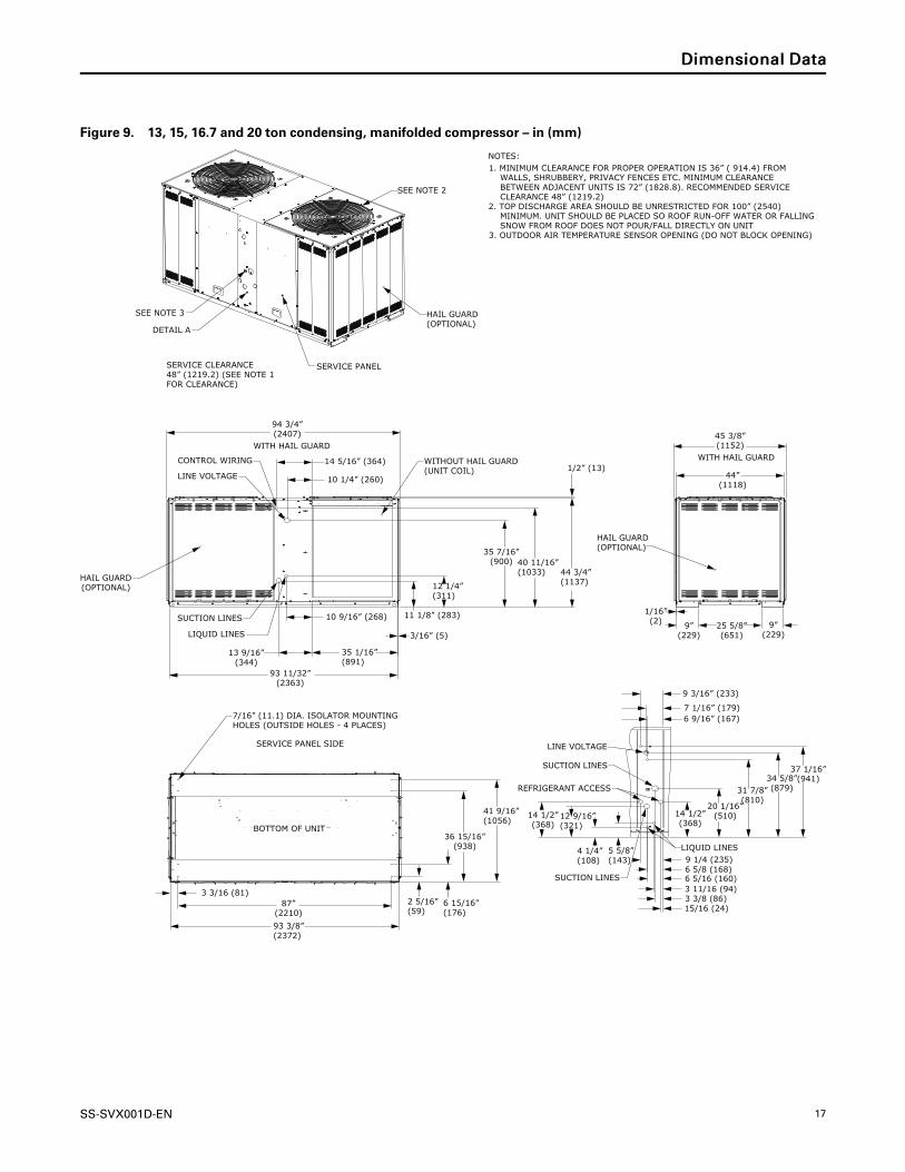
Figure 9. 13, 15, 16.7 and 20 ton condensing, manifolded compressor – in (mm)
45 3/8”(1152)
WITH HAIL GUARD
44”(1118)
25 5/8”(651)
9”(229)
9”(229)
1/16”(2)
93 11/32”(2363)
3/16” (5)
35 1/16”(891)
10 9/16” (268)
13 9/16”(344)
14 5/16” (364)
10 1/4” (260)
94 3/4”(2407)
WITH HAIL GUARD
11 1/8” (283)
12 1/4”(311)
35 7/16”(900) 40 11/16”
(1033) 44 3/4”(1137)
1/2” (13)
9 1/4 (235)
7 1/16” (179)
9 3/16” (233)
6 9/16” (167)
37 1/16”(941)
20 1/16”(510)
5 5/8”(143)
4 1/4”(108)
12 9/16”(321)
14 1/2”(368)
14 1/2”(368)
31 7/8”(810)
34 5/8”(879)
3 3/16 (81)
93 3/8”(2372)
87”(2210)
2 5/16”(59)
6 15/16”(176)
36 15/16”(938)
41 9/16”(1056)
SEE NOTE 2
SEE NOTE 3
DETAIL A
SERVICE PANELSERVICE CLEARANCE48” (1219.2) (SEE NOTE 1FOR CLEARANCE)
HAIL GUARD(OPTIONAL)
HAIL GUARD(OPTIONAL)
LINE VOLTAGE
CONTROL WIRING
SUCTION LINES
WITHOUT HAIL GUARD(UNIT COIL)
HAIL GUARD(OPTIONAL)
LIQUID LINES
SERVICE PANEL SIDE
BOTTOM OF UNIT
7/16” (11.1) DIA. ISOLATOR MOUNTINGHOLES (OUTSIDE HOLES - 4 PLACES)
LIQUID LINES
SUCTION LINES
REFRIGERANT ACCESS
SUCTION LINES
LINE VOLTAGE
NOTES:1. MINIMUM CLEARANCE FOR PROPER OPERATION IS 36” ( 914.4) FROM WALLS, SHRUBBERY, PRIVACY FENCES ETC. MINIMUM CLEARANCE BETWEEN ADJACENT UNITS IS 72” (1828.8). RECOMMENDED SERVICE CLEARANCE 48” (1219.2)2. TOP DISCHARGE AREA SHOULD BE UNRESTRICTED FOR 100” (2540) MINIMUM. UNIT SHOULD BE PLACED SO ROOF RUN-OFF WATER OR FALLING SNOW FROM ROOF DOES NOT POUR/FALL DIRECTLY ON UNIT3. OUTDOOR AIR TEMPERATURE SENSOR OPENING (DO NOT BLOCK OPENING)
15/16 (24)
6 5/8 (168)6 5/16 (160)3 11/16 (94)3 3/8 (86)
DDiimmeennssiioonnaall DDaattaa

18 SS-SVX001D-EN
Figure 10. 20.9 and 25 ton condensing, manifolded compressor – in (mm)
93 1/4” (2369)
10 7/16” (266)13 5/8”(346)
35 3/16”(893)
10 1/4”(260)
12”(304)
41 7/16”(1052)
46 11/16”(1186)
1/2”(13)10 1/8”
(257)
14 3/16”(360)
45 3/8”(1152)
44 3/16”(1122)
9”(229)
9”(229)
25 5/8”(651)
13/16” (21)1 9/16” (40)
8 1/4”(210)
7” (177)6 1/2” (164)
9 1/16” (230)
14 1/2”(368)
24 3/8”(620)
37 7/8”(962)
40 5/8”(1032)43 1/16”
(1093)
6 3/16” (157)
4 3/16”(107)
2 3/16”(55)
4 5/8”(118)
34 5/8”(880)
4 5/8”(118)
3”(76)
87” (2211)
93” (2363)
50 3/4”(1289)
SERVICE PANEL
DETAIL A
SEE NOTE 2
OPTIONAL REAR ACCESSDIMENSIONAL DETAIL
CONTROL WIRINGLINE VOLTAGE
SUCTION LINE
LIQUID LINE
BOTTOM OF UNIT
SERVICE PANEL SIDE
LIQUID LINE
REFRIGERANT GAUGE ACCESS
SUCTION LINE
LINE VOLTAGECONTROL WIRING
FRONT DETAIL ADIMENSIONAL DETAIL
SEE NOTE 3
NOTES:1. MINIMUM CLEARANCE FOR PROPER OPERATION IS 36” ( 914.4) FROM WALLS, SHRUBBERY, PRIVACY FENCES ETC. MINIMUM CLEARANCE BETWEEN ADJACENT UNITS IS 72” (1828.8). RECOMMENDED SERVICE CLEARANCE 48” (1219.2)2. TOP DISCHARGE AREA SHOULD BE UNRESTRICTED FOR 100” (2540) MINIMUM. UNIT SHOULD BE PLACED SO ROOF RUN-OFF WATER OR FALLING SNOW FROM ROOF DOES NOT POUR/FALL DIRECTLY ON UNIT3. OUTDOOR AIR TEMPERATURE SENSOR OPENING (DO NOT BLOCK OPENING)
HAIL GUARD(OPTIONAL)
HAIL GUARD(OPTIONAL)
HAIL GUARD(OPTIONAL)
SERVICE CLEARANCE48” (1219.2) (SEE NOTE 1FOR CLEARANCE)
7/16” (11.1) DIA. ISOLATOR MOUNTINGHOLES (OUTSIDE HOLES - 4 PLACES)
WITH HAIL GUARD
DDiimmeennssiioonnaall DDaattaa
SS-SVX001D-EN 19
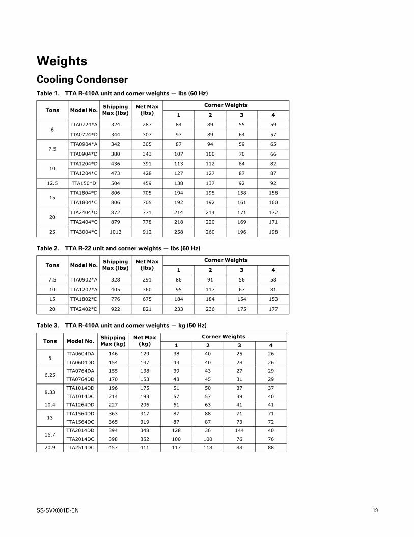
WeightsCooling CondenserTable 1. TTA R-410A unit and corner weights — lbs (60 Hz)
Tons Model No.ShippingMax (lbs)
Net Max(lbs)
CornerWeights
1 2 3 4
6TTA0724*A 324 287 84 89 55 59
TTA0724*D 344 307 97 89 64 57
7.5TTA0904*A 342 305 87 94 59 65
TTA0904*D 380 343 107 100 70 66
10TTA1204*D 436 391 113 112 84 82
TTA1204*C 473 428 127 127 87 87
12.5 TTA150*D 504 459 138 137 92 92
15TTA1804*D 806 705 194 195 158 158
TTA1804*C 806 705 192 192 161 160
20TTA2404*D 872 771 214 214 171 172
TTA2404*C 879 778 218 220 169 171
25 TTA3004*C 1013 912 258 260 196 198
Table 2. TTA R-22 unit and corner weights — lbs (60 Hz)
Tons Model No.ShippingMax (lbs)
Net Max(lbs)
CornerWeights
1 2 3 4
7.5 TTA0902*A 328 291 86 91 56 58
10 TTA1202*A 405 360 95 117 67 81
15 TTA1802*D 776 675 184 184 154 153
20 TTA2402*D 922 821 233 236 175 177
Table 3. TTA R-410A unit and corner weights — kg (50 Hz)
Tons Model No.ShippingMax (kg)
Net Max(kg)
CornerWeights
1 2 3 4
5TTA0604DA 146 129 38 40 25 26
TTA0604DD 154 137 43 40 28 26
6.25TTA0764DA 155 138 39 43 27 29
TTA0764DD 170 153 48 45 31 29
8.33TTA1014DD 196 175 51 50 37 37
TTA1014DC 214 193 57 57 39 40
10.4 TTA1264DD 227 206 61 63 41 41
13TTA1564DD 363 317 87 88 71 71
TTA1564DC 365 319 87 87 73 72
16.7TTA2014DD 394 348 128 36 144 40
TTA2014DC 398 352 100 100 76 76
20.9 TTA2514DC 457 411 117 118 88 88

20 SS-SVX001D-EN
Figure 11. TTA072, 090, 120, 150, TTA060, 076, 101, TTA0902*A, 1202*A
#1
#2
#3
#4
LIFTING HOLES (BOTH SIDES)
SERVICEACCESS
Figure 12. TTA180, 240, 300, TTA156, 201, 251, TTA1802*D, 2402*D
SERVICEACCESSSERVICEACCESS
#1
#2
#3
#4
LIFTING HOLES(BOTH SIDES)
WWeeiigghhttss

SS-SVX001D-EN 21
InstallationRefrigerant Piping GuidelinesFigure 13. Allowable elevation difference: TTA above indoor unit
Contact manufacturer for review
Figure 14. Allowable elevation difference: TTA or TWA below indoor unit
Acceptable liquid-riser height based on total liquid-line length(below indoor unit)
Contact manufacturer for review
NNoottee:: Route refrigerant piping for minimum linear length, minimum number of bends and fittings.
IImmppoorrttaanntt:: Read Application Guide SS-APG008*–ENthoroughly before installing this unit.

22 SS-SVX001D-EN
Refrigerant Piping Procedures(Outdoor Units)
WWAARRNNIINNGGRR--441100AA RReeffrriiggeerraanntt uunnddeerr HHiigghheerrPPrreessssuurree tthhaann RR--2222!!FFaaiilluurree ttoo uussee pprrooppeerr eeqquuiippmmeenntt oorr ccoommppoonneennttss aassddeessccrriibbeedd bbeellooww,, ccoouulldd rreessuulltt iinn eeqquuiippmmeenntt ffaaiilliinnggaanndd ppoossssiibbllyy eexxppllooddiinngg,, wwhhiicchh ccoouulldd rreessuulltt iinnddeeaatthh,, sseerriioouuss iinnjjuurryy,, oorr eeqquuiippmmeenntt ddaammaaggee..TThhee uunniittss ddeessccrriibbeedd iinn tthhiiss mmaannuuaall uussee RR--441100AArreeffrriiggeerraanntt wwhhiicchh ooppeerraatteess aatt hhiigghheerr pprreessssuurreesstthhaann RR--2222.. UUssee OONNLLYY RR--441100AA rraatteedd sseerrvviicceeeeqquuiippmmeenntt oorr ccoommppoonneennttss wwiitthh tthheessee uunniittss.. FFoorrssppeecciiffiicc hhaannddlliinngg ccoonncceerrnnss wwiitthh RR--441100AA,, pplleeaasseeccoonnttaacctt yyoouurr llooccaall TTrraannee rreepprreesseennttaattiivvee..
WWAARRNNIINNGGRReeffrriiggeerraanntt uunnddeerr HHiigghh PPrreessssuurree!!FFaaiilluurree ttoo ffoollllooww iinnssttrruuccttiioonnss bbeellooww ccoouulldd rreessuulltt iinnaann eexxpplloossiioonn wwhhiicchh ccoouulldd rreessuulltt iinn ddeeaatthh oorrsseerriioouuss iinnjjuurryy oorr eeqquuiippmmeenntt ddaammaaggee..SSyysstteemm ccoonnttaaiinnss rreeffrriiggeerraanntt uunnddeerr hhiigghh pprreessssuurree..RReeccoovveerr rreeffrriiggeerraanntt ttoo rreelliieevvee pprreessssuurree bbeeffoorreeooppeenniinngg tthhee ssyysstteemm.. SSeeee uunniitt nnaammeeppllaattee ffoorrrreeffrriiggeerraanntt ttyyppee.. DDoo nnoott uussee nnoonn--aapppprroovveeddrreeffrriiggeerraannttss,, rreeffrriiggeerraanntt ssuubbssttiittuutteess,, oorr rreeffrriiggeerraannttaaddddiittiivveess..
WWAARRNNIINNGGEExxpplloossiioonn HHaazzaarrdd!!FFaaiilluurree ttoo ffoollllooww iinnssttrruuccttiioonnss bbeellooww ccoouulldd rreessuulltt iinnaann eexxpplloossiioonn wwhhiicchh ccoouulldd rreessuulltt iinn ddeeaatthh oorrsseerriioouuss iinnjjuurryy,, aanndd eeqquuiippmmeenntt ddaammaaggee..NNEEVVEERR bbyyppaassss ssyysstteemm ssaaffeettiieess iinn oorrddeerr ttoo ppuummppddoowwnn tthhee uunniitt ccoommppoonneenntt''ss rreeffrriiggeerraanntt iinnttoo tthheemmiiccrroocchhaannnneell hheeaatt eexxcchhaannggeerr ((MMCCHHEE)) ccooiill.. DDooNNOOTT ddeepprreessss tthhee ccoommpprreessssoorr ccoonnttaaccttoorr ssiinnccee iitteeffffeeccttiivveellyy bbyyppaasssseess tthhee hhiigghh--pprreessssuurree ccoonnttrrooll..
Each unit ships with a holding charge of dry nitrogen.The nitrogen should be removed and the entire systemevacuated (at the proper time) to avoid possiblecontamination.
1. Remove the compressor service access panel.
2. Locate the liquid and suction line access valves.Check that the piping connection stubs (Figure 15,p. 22) line up properly with the holes in the unitcabinet.
Figure 15. Outdoor units - refrigerant piping (with drynitrogen)
Gas Line Gauge Port
ManifoldGauges
Liquid Line Gauge Port
3. Install gauges to determine if the circuits are stillpressurized. If not, the charge has escaped andshould be repaired as required to obtain a leak-freecircuit. If the circuits are still pressurized, use thegauges to slowly release the nitrogen charge to theatmosphere and remove both seal caps from theoutdoor unit connection stubs.
NNOOTTIICCEESSyysstteemm CCoommppoonneenntt DDaammaaggee!!DDoo nnoott rreemmoovvee tthhee sseeaall ccaappss ffrroomm rreeffrriiggeerraannttccoonnnneeccttiioonnss uunnttiill pprreeppaarreedd ttoo bbrraazzee rreeffrriiggeerraannttlliinneess ttoo tthhee ccoonnnneeccttiioonnss.. EExxcceessssiivvee eexxppoossuurree ttooaattmmoosspphheerree ((>> 55 mmiinn..)) mmaayy aallllooww mmooiissttuurree oorr ddiirrttttoo ccoonnttaammiinnaattee tthhee ssyysstteemm,, ddaammaaggiinngg vvaallvvee sseeaallssaanndd ccaauussiinngg iiccee ffoorrmmaattiioonn iinn ssyysstteemm ccoommppoonneennttss..
IInnssttaallllaattiioonn

SS-SVX001D-EN 23
WWAARRNNIINNGGEExxpplloossiioonn HHaazzaarrdd aanndd DDeeaaddllyy GGaasseess!!FFaaiilluurree ttoo ffoollllooww aallll pprrooppeerr ssaaffee rreeffrriiggeerraanntthhaannddlliinngg pprraaccttiicceess ccoouulldd rreessuulltt iinn ddeeaatthh oorr sseerriioouussiinnjjuurryy..NNeevveerr ssoollddeerr,, bbrraazzee oorr wweelldd oonn rreeffrriiggeerraanntt lliinneess oorraannyy uunniitt ccoommppoonneennttss tthhaatt aarree aabboovvee aattmmoosspphheerriiccpprreessssuurree oorr wwhheerree rreeffrriiggeerraanntt mmaayy bbee pprreesseenntt..AAllwwaayyss rreemmoovvee rreeffrriiggeerraanntt bbyy ffoolllloowwiinngg tthheegguuiiddeelliinneess eessttaabblliisshheedd bbyy tthhee EEPPAA FFeeddeerraall CClleeaannAAiirr AAcctt oorr ootthheerr ssttaattee oorr llooccaall ccooddeess aass aapppprroopprriiaattee..AAfftteerr rreeffrriiggeerraanntt rreemmoovvaall,, uussee ddrryy nniittrrooggeenn ttoobbrriinngg ssyysstteemm bbaacckk ttoo aattmmoosspphheerriicc pprreessssuurree bbeeffoorreeooppeenniinngg ssyysstteemm ffoorr rreeppaaiirrss.. MMiixxttuurreess ooffrreeffrriiggeerraannttss aanndd aaiirr uunnddeerr pprreessssuurree mmaayy bbeeccoommeeccoommbbuussttiibbllee iinn tthhee pprreesseennccee ooff aann iiggnniittiioonn ssoouurrcceelleeaaddiinngg ttoo aann eexxpplloossiioonn.. EExxcceessssiivvee hheeaatt ffrroommssoollddeerriinngg,, bbrraazziinngg oorr wweellddiinngg wwiitthh rreeffrriiggeerraannttvvaappoorrss pprreesseenntt ccaann ffoorrmm hhiigghhllyy ttooxxiicc ggaasseess aannddeexxttrreemmeellyy ccoorrrroossiivvee aacciiddss..
4. Cut, fit and braze tubing, starting at the outdoor unitand work toward the indoor unit. See “ChargingLevels,” p. 26.
NNoottee:: Use long radius ells for all 90° bends.
All brazing should be done using a 2 to 3 psig drynitrogen purge flowing through the pipe beingbrazed, see Figure 15, p. 22.
NNOOTTIICCEESSyysstteemm CCoommppoonneenntt DDaammaaggee!!IInnssttaallll aa rreegguullaattiinngg vvaallvvee bbeettwweeeenn tthhee nniittrrooggeennssoouurrccee aanndd tthhee ggaauuggee mmaanniiffoolldd.. UUnnrreegguullaatteeddpprreessssuurree ccaann ddaammaaggee ssyysstteemm ccoommppoonneennttss..
NNOOTTIICCEESSyysstteemm CCoommppoonneenntt DDaammaaggee!!WWeett--wwrraapp aallll vvaallvveess aanndd pprrootteecctt ppaaiinntteedd ssuurrffaacceessffrroomm eexxcceessssiivvee hheeaatt.. HHeeaatt ccaann ddaammaaggee ssyysstteemmccoommppoonneennttss aanndd tthhee uunniitt ffiinniisshh..
5. Shut off nitrogen supply. Shut off the manifoldvalve for the line that is connected to the suctionline access valve. Disconnect the line from theaccess valve.
Refrigerant Piping Procedures(Indoor Unit)Once liquid and suction lines are complete to therefrigerant connections on the indoor unit, remove thegauge port core(s) on the indoor unit connection stubsto release the dry nitrogen charge.
NNOOTTIICCEEUUnniitt DDaammaaggee!!DDoo nnoott aappppllyy hheeaatt ttoo rreemmoovvee sseeaall ccaappss uunnttiill tthheeggaauuggee ppoorrtt ccoorreess hhaavvee bbeeeenn rreemmoovveedd.. IIff sseeaall ccaappssaarree iinnttaacctt,, aapppplliiccaattiioonn ooff hheeaatt mmaayy ggeenneerraatteeeexxcceessssiivvee pprreessssuurree iinn tthhee uunniitt aanndd rreessuulltt iinnddaammaaggee ttoo tthhee ccooiill oorr eexxppaannssiioonn vvaallvvee..
1. Remove both seal caps from the indoor unitconnection stubs.
NNOOTTIICCEEUUnniitt DDaammaaggee!!DDoo nnoott rreemmoovvee tthhee sseeaall ccaappss ffrroomm rreeffrriiggeerraannttccoonnnneeccttiioonnss uunnttiill pprreeppaarreedd ttoo bbrraazzee rreeffrriiggeerraannttlliinneess ttoo tthhee ccoonnnneeccttiioonnss.. DDuuee ttoo tthhee hhiigghhhhyyggrroossccooppiicc pprrooppeerrttiieess ooff tthhee RR--441100AA ooiill,,eexxcceessssiivvee eexxppoossuurree ttoo aattmmoosspphheerree wwiillll aalllloowwmmooiissttuurree ttoo ccoonnttaammiinnaattee tthhee ssyysstteemm,, ddaammaaggiinnggtthhee ccoommpprreessssoorr..
2. Turn on nitrogen supply. Nitrogen enters throughthe liquid line gauge port.
3. Braze the liquid line connections.
4. Open the gauge port on the suction line and thenbraze the suction line to the connection stub.Nitrogen will bleed out the open gauge port on thesuction line.
5. Shut off nitrogen supply.
Leak CheckWWAARRNNIINNGG
EExxpplloossiioonn HHaazzaarrdd!!FFaaiilluurree ttoo ffoollllooww tthheessee iinnssttrruuccttiioonnss ccoouulldd rreessuulltt iinnddeeaatthh oorr sseerriioouuss iinnjjuurryy oorr eeqquuiippmmeenntt oorr pprrooppeerrttyy--oonnllyy ddaammaaggee..UUssee oonnllyy ddrryy nniittrrooggeenn wwiitthh aa pprreessssuurree rreegguullaattoorr ffoorrpprreessssuurriizziinngg uunniitt.. DDoo nnoott uussee aacceettyylleennee,, ooxxyyggeenn oorrccoommpprreesssseedd aaiirr oorr mmiixxttuurreess ccoonnttaaiinniinngg tthheemm ffoorrpprreessssuurree tteessttiinngg.. DDoo nnoott uussee hhyyddrrooggeenn mmiixxttuurreessccoonnttaaiinniinngg rreeffrriiggeerraanntt aanndd aaiirr aabboovvee aattmmoosspphheerriiccpprreessssuurree ffoorr pprreessssuurree tteessttiinngg aass tthheeyy mmaayy bbeeccoommeeffllaammmmaabbllee aanndd ccoouulldd rreessuulltt iinn aann eexxpplloossiioonn..RReeffrriiggeerraanntt,, wwhheenn uusseedd aass aa ttrraaccee ggaass sshhoouulldd oonnllyybbee mmiixxeedd wwiitthh ddrryy nniittrrooggeenn ffoorr pprreessssuurriizziinngg uunniittss..
WWAARRNNIINNGGEExxpplloossiioonn HHaazzaarrdd!!FFaaiilluurree ttoo ffoollllooww ssaaffee lleeaakk tteesstt pprroocceedduurreess bbeelloowwccoouulldd rreessuulltt iinn ddeeaatthh oorr sseerriioouuss iinnjjuurryy oorreeqquuiippmmeenntt oorr pprrooppeerrttyy--oonnllyy--ddaammaaggee..NNeevveerr uussee aann ooppeenn ffllaammee ttoo ddeetteecctt ggaass lleeaakkss.. UUssee aalleeaakk tteesstt ssoolluuttiioonn ffoorr lleeaakk tteessttiinngg..
IInnssttaallllaattiioonn

24 SS-SVX001D-EN
After the brazing operation of refrigerant lines to boththe outdoor and indoor unit is completed, the fieldbrazed connections must be checked for leaks.Pressurize the system through the gauge port with drynitrogen to 200 psi. Use soap bubbles or other leak-checking methods to ensure that all field joints are leakfree. If not, release pressure, repair and repeat leak test.
System Evacuation1. After completion of leak check, evacuate the
system.
2. Attach appropriate hoses from manifold gauge togas and liquid line pressure taps.
NNoottee:: Unnecessary switching of hoses can beavoided and complete evacuation of all linesleading to sealed system can beaccomplished with manifold center hose andconnecting branch hose to a cylinder of R-410A/R–22 and vacuum pump.
3. Attach center hose of manifold gauges to vacuumpump.
NNOOTTIICCEEOOppeerraattiinngg UUnnddeerr VVaaccuuuumm!!FFaaiilluurree ttoo ffoollllooww tthheessee iinnssttrruuccttiioonnss wwiillll rreessuulltt iinnccoommpprreessssoorr ffaaiilluurree..DDoo nnoott ooppeerraattee oorr aappppllyy ppoowweerr ttoo tthhee ccoommpprreessssoorrwwhhiillee uunnddeerr aa vvaaccuuuumm..
4. Evacuate the system to hold a 500 micron vacuum.
5. Close off valve to vacuum pump and observe themicron gauge. If gauge pressure rises above 500microns in one minute, then evacuation isincomplete or the system has a leak.
6. If vacuum gauge does not rise above 500 microns in10 minutes, the evacuation should be complete.
NNOOTTIICCEEEEqquuiippmmeenntt DDaammaaggee!!CChhaarrggee wwiitthh aacccceessss ppoorrtt oonn tthhee lliiqquuiidd lliinnee oonnllyy..
7. With vacuum pump and micron gauge blanked off,open valve on refrigerant cylinder and allowrefrigerant pressure to build up to about 80 psig.
8. Close valve on the refrigerant supply cylinder. Closevalves on manifold gauge set and removerefrigerant charging hoses from liquid and gasgauge ports.
9. Leak test the entire system. Using properprocedures and caution, as described in theprevious section, repair any leaks found and repeatthe leak test.
Insulating and IsolatingRefrigerant LinesInsulate the entire suction line with refrigerant pipinginsulation. Also insulate any portion of the liquid lineexposed to temperature extremes. Insulate and isolateliquid and suction lines from each other. Isolaterefrigerant lines from the structure and any duct work.
IImmppoorrttaanntt::
1. To prevent possible noise or vibrationproblems, be certain to isolaterefrigerant lines from the building.
2. All suction and hot gas bypass piping (ifinstalled) should be insulated from thetermination in the air handler to thecondensing unit cabinet entry. Failureto do so can cause condensate drip offand performance degradation.
3. Prior to starting a unit, it is advisable tohave the approved oils available in theevent oil needs to be added to thesystem.
4. Refer to Application Guide SS-APG008*-EN for units needingadditional oil and for oil amounts.
NNOOTTIICCEEEEqquuiippmmeenntt DDaammaaggee!!TThhiiss iiss PPOOEE ooiill,, wwhhiicchh rreeaaddiillyy aabbssoorrbbss mmooiissttuurree..AAllwwaayyss uussee nneeww ooiill aanndd nneevveerr lleeaavvee ccoonnttaaiinneerrssooppeenn ttoo aattmmoosspphheerree wwhhiillee nnoott iinn uussee..
Table 4. R-410A TTA approved oils
Unit Model Number Approved Oils
TTA0604DA, TTA0604DD,TTA0724*A, TTA0724*D,TTA0764DD, TTA0904*D,TTA0764DA, TTA0904*A,TTA1014DC, TTA1014DD,TTA1204*C, TTA1204*D,TTA1264DD, TTA1504*D,TTA1564DD, TTA1804*D,TTA1564DC, TTA1804*C,TTA2014DD, TTA2404*D
Trane Oil Part NumberOIL00094 (1 quart container)
TTA1014DA, TTA1204*A,TTA2014DC, TTA2404*C,TTA2514DC, TTA3004*C
Trane Oil Part NumberOIL00079 (1 quart container)
or OIL00080 (1 galloncontainer)
Table 5. R-22 TTA approved oils
Unit Model Number Approved Oils
TTA0902*A, TTA1202*A,TTA1802*B, TTA2402*B
Trane Oil Part NumberOIL00094
(1 quart container)
For units equipped with compressors containing siteglasses, the oil level must be visible through the sight
IInnssttaallllaattiioonn

SS-SVX001D-EN 25
glass when the compressor is running under stabilizedconditions and a few minutes after the compressor hasstopped.
Refrigerant Charging ProcedureIf charging by weight, refer to “Charging Levels,” p. 26for starting change. If refrigerant adjustments areneeded because of length of line, refer to the ChargingCharts and Superheat values available on unit accesspanels.
Refer to Wiring Matrix and Device Location Matrix forlist of charging charts and super heat tables available ine-Library. Charge by weight through the gauge port onthe liquid line.
NNootteess::
• Refrigerant should only be charged in theliquid state.
• When possible, always charge therefrigerant into the liquid line of the unit.
• If the entire charge can’t be charged into theliquid line, the balance of the unit chargecan be metered through a chargingmanifold set as liquid — preferably througha schrader valve into the suction line to thecompressor — only while the compressor isrunning.
• Check and adjust superheat using thesuperheat table, then re-check chargingcharts to determine if charge corrections arenecessary. Refer to Charging Data for list ofsuper heat tables available in e-Library.
NNOOTTIICCEEEEqquuiippmmeenntt DDaammaaggee!!NNeevveerr cchhaarrggee lliiqquuiidd rreeffrriiggeerraanntt iinnttoo tthhee ssuuccttiioonnlliinnee ooff tthhee uunniitt wwiitthh tthhee ccoommpprreessssoorr ooffff..
Figure 16. Outdoor units - refrigerant piping
Gas Line Gauge Port
Liquid Line Gauge Port
ManfoldGuages
IInnssttaallllaattiioonn
26 SS-SVX001D-EN
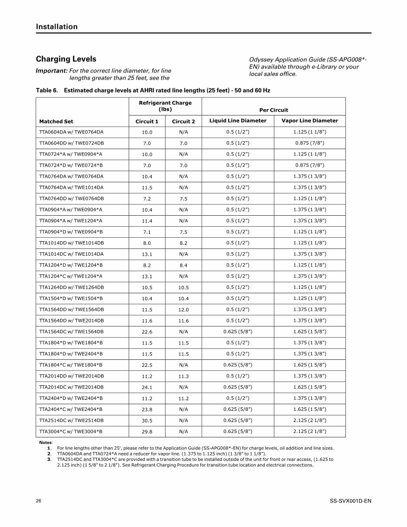
Charging LevelsIImmppoorrttaanntt:: For the correct line diameter, for line
lengths greater than 25 feet, see the
Odyssey Application Guide (SS-APG008*-EN) available through e-Library or yourlocal sales office.
Table 6. Estimated charge levels at AHRI rated line lengths (25 feet) - 50 and 60 Hz
Matched Set
Refrigerant Charge(lbs) Per Circuit
Circuit 1 Circuit 2 Liquid Line Diameter Vapor Line Diameter
TTA0604DA w/ TWE0764DA 10.0 N/A 0.5 (1/2”) 1.125 (1 1/8”)
TTA0604DD w/ TWE0724DB 7.0 7.0 0.5 (1/2”) 0.875 (7/8")
TTA0724*A w/ TWE0904*A 10.0 N/A 0.5 (1/2”) 1.125 (1 1/8”)
TTA0724*D w/ TWE0724*B 7.0 7.0 0.5 (1/2”) 0.875 (7/8")
TTA0764DA w/ TWE0764DA 10.4 N/A 0.5 (1/2”) 1.375 (1 3/8”)
TTA0764DA w/ TWE1014DA 11.5 N/A 0.5 (1/2”) 1.375 (1 3/8”)
TTA0764DD w/ TWE0764DB 7.2 7.5 0.5 (1/2”) 1.125 (1 1/8”)
TTA0904*A w/ TWE0904*A 10.4 N/A 0.5 (1/2”) 1.375 (1 3/8”)
TTA0904*A w/ TWE1204*A 11.4 N/A 0.5 (1/2”) 1.375 (1 3/8”)
TTA0904*D w/ TWE0904*B 7.1 7.5 0.5 (1/2”) 1.125 (1 1/8”)
TTA1014DD w/ TWE1014DB 8.0 8.2 0.5 (1/2”) 1.125 (1 1/8”)
TTA1014DC w/ TWE1014DA 13.1 N/A 0.5 (1/2”) 1.375 (1 3/8”)
TTA1204*D w/ TWE1204*B 8.2 8.4 0.5 (1/2”) 1.125 (1 1/8”)
TTA1204*C w/ TWE1204*A 13.1 N/A 0.5 (1/2”) 1.375 (1 3/8”)
TTA1264DD w/ TWE1264DB 10.5 10.5 0.5 (1/2”) 1.125 (1 1/8”)
TTA1504*D w/ TWE1504*B 10.4 10.4 0.5 (1/2”) 1.125 (1 1/8”)
TTA1564DD w/ TWE1564DB 11.5 12.0 0.5 (1/2”) 1.375 (1 3/8”)
TTA1564DD w/ TWE2014DB 11.6 11.6 0.5 (1/2”) 1.375 (1 3/8”)
TTA1564DC w/ TWE1564DB 22.6 N/A 0.625 (5/8”) 1.625 (1 5/8”)
TTA1804*D w/ TWE1804*B 11.5 11.5 0.5 (1/2”) 1.375 (1 3/8”)
TTA1804*D w/ TWE2404*B 11.5 11.5 0.5 (1/2”) 1.375 (1 3/8”)
TTA1804*C w/ TWE1804*B 22.5 N/A 0.625 (5/8”) 1.625 (1 5/8”)
TTA2014DD w/ TWE2014DB 11.2 11.3 0.5 (1/2”) 1.375 (1 3/8”)
TTA2014DC w/ TWE2014DB 24.1 N/A 0.625 (5/8”) 1.625 (1 5/8”)
TTA2404*D w/ TWE2404*B 11.2 11.2 0.5 (1/2”) 1.375 (1 3/8”)
TTA2404*C w/ TWE2404*B 23.8 N/A 0.625 (5/8”) 1.625 (1 5/8”)
TTA2514DC w/ TWE2514DB 30.5 N/A 0.625 (5/8”) 2.125 (2 1/8”)
TTA3004*C w/ TWE3004*B 29.8 N/A 0.625 (5/8”) 2.125 (2 1/8”)
Notes:1. For line lengths other than 25', please refer to the Application Guide (SS-APG008*-EN) for charge levels, oil addition and line sizes.2. TTA0604DA and TTA0724*A need a reducer for vapor line. (1.375 to 1.125 inch) (1 3/8” to 1 1/8”).3. TTA2514DC and TTA3004*C are provided with a transition tube to be installed outside of the unit for front or rear access, (1.625 to
2.125 inch) (1 5/8" to 2 1/8"). See Refrigerant Charging Procedure for transition tube location and electrical connections.
IInnssttaallllaattiioonn
SS-SVX001D-EN 27
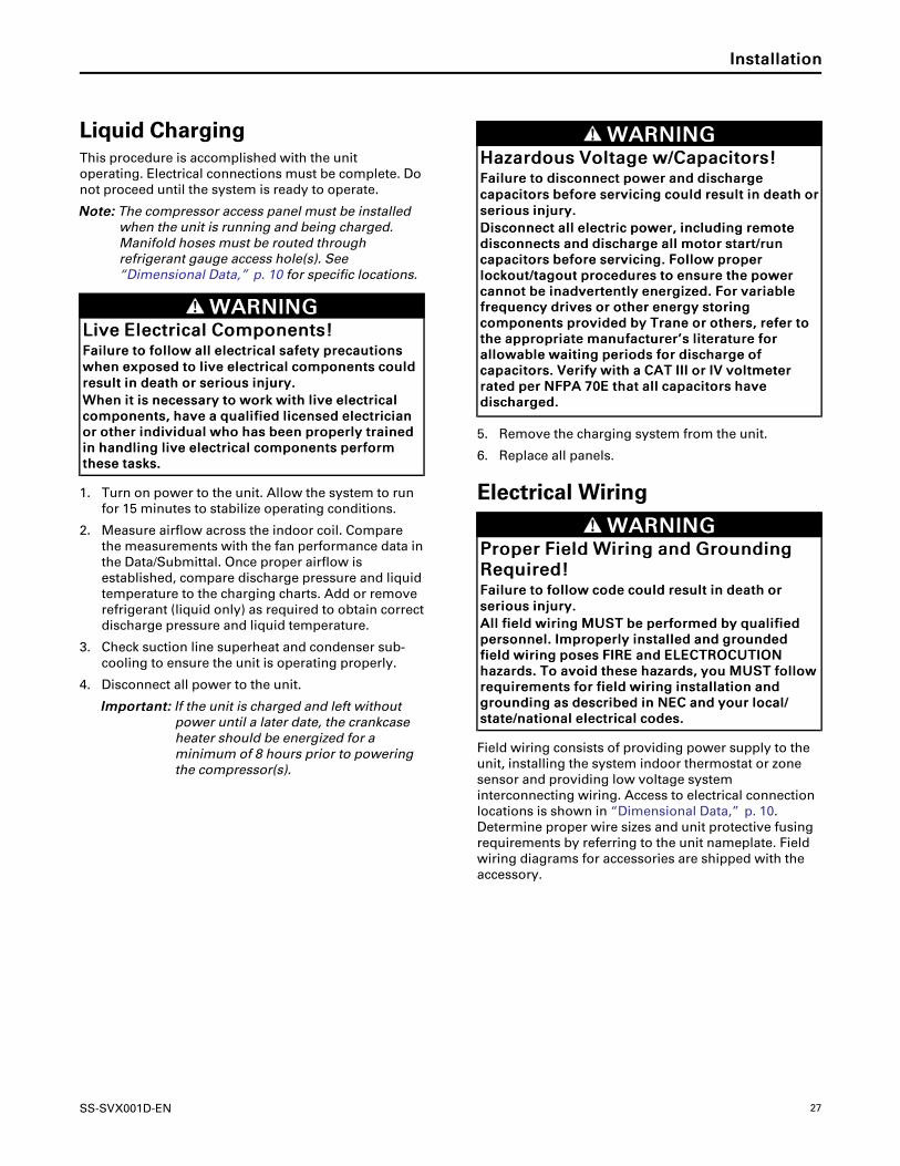
Liquid ChargingThis procedure is accomplished with the unitoperating. Electrical connections must be complete. Donot proceed until the system is ready to operate.
NNoottee:: The compressor access panel must be installedwhen the unit is running and being charged.Manifold hoses must be routed throughrefrigerant gauge access hole(s). See“Dimensional Data,” p. 10 for specific locations.
WWAARRNNIINNGGLLiivvee EElleeccttrriiccaall CCoommppoonneennttss!!FFaaiilluurree ttoo ffoollllooww aallll eelleeccttrriiccaall ssaaffeettyy pprreeccaauuttiioonnsswwhheenn eexxppoosseedd ttoo lliivvee eelleeccttrriiccaall ccoommppoonneennttss ccoouullddrreessuulltt iinn ddeeaatthh oorr sseerriioouuss iinnjjuurryy..WWhheenn iitt iiss nneecceessssaarryy ttoo wwoorrkk wwiitthh lliivvee eelleeccttrriiccaallccoommppoonneennttss,, hhaavvee aa qquuaalliiffiieedd lliicceennsseedd eelleeccttrriicciiaannoorr ootthheerr iinnddiivviidduuaall wwhhoo hhaass bbeeeenn pprrooppeerrllyy ttrraaiinneeddiinn hhaannddlliinngg lliivvee eelleeccttrriiccaall ccoommppoonneennttss ppeerrffoorrmmtthheessee ttaasskkss..
1. Turn on power to the unit. Allow the system to runfor 15 minutes to stabilize operating conditions.
2. Measure airflow across the indoor coil. Comparethe measurements with the fan performance data inthe Data/Submittal. Once proper airflow isestablished, compare discharge pressure and liquidtemperature to the charging charts. Add or removerefrigerant (liquid only) as required to obtain correctdischarge pressure and liquid temperature.
3. Check suction line superheat and condenser sub-cooling to ensure the unit is operating properly.
4. Disconnect all power to the unit.
IImmppoorrttaanntt:: If the unit is charged and left withoutpower until a later date, the crankcaseheater should be energized for aminimum of 8 hours prior to poweringthe compressor(s).
WWAARRNNIINNGGHHaazzaarrddoouuss VVoollttaaggee ww//CCaappaacciittoorrss!!FFaaiilluurree ttoo ddiissccoonnnneecctt ppoowweerr aanndd ddiisscchhaarrggeeccaappaacciittoorrss bbeeffoorree sseerrvviicciinngg ccoouulldd rreessuulltt iinn ddeeaatthh oorrsseerriioouuss iinnjjuurryy..DDiissccoonnnneecctt aallll eelleeccttrriicc ppoowweerr,, iinncclluuddiinngg rreemmootteeddiissccoonnnneeccttss aanndd ddiisscchhaarrggee aallll mmoottoorr ssttaarrtt//rruunnccaappaacciittoorrss bbeeffoorree sseerrvviicciinngg.. FFoollllooww pprrooppeerrlloocckkoouutt//ttaaggoouutt pprroocceedduurreess ttoo eennssuurree tthhee ppoowweerrccaannnnoott bbee iinnaaddvveerrtteennttllyy eenneerrggiizzeedd.. FFoorr vvaarriiaabblleeffrreeqquueennccyy ddrriivveess oorr ootthheerr eenneerrggyy ssttoorriinnggccoommppoonneennttss pprroovviiddeedd bbyy TTrraannee oorr ootthheerrss,, rreeffeerr ttootthhee aapppprroopprriiaattee mmaannuuffaaccttuurreerr’’ss lliitteerraattuurree ffoorraalllloowwaabbllee wwaaiittiinngg ppeerriiooddss ffoorr ddiisscchhaarrggee ooffccaappaacciittoorrss.. VVeerriiffyy wwiitthh aa CCAATT IIIIII oorr IIVV vvoollttmmeetteerrrraatteedd ppeerr NNFFPPAA 7700EE tthhaatt aallll ccaappaacciittoorrss hhaavveeddiisscchhaarrggeedd..
5. Remove the charging system from the unit.
6. Replace all panels.
Electrical Wiring
WWAARRNNIINNGGPPrrooppeerr FFiieelldd WWiirriinngg aanndd GGrroouunnddiinnggRReeqquuiirreedd!!FFaaiilluurree ttoo ffoollllooww ccooddee ccoouulldd rreessuulltt iinn ddeeaatthh oorrsseerriioouuss iinnjjuurryy..AAllll ffiieelldd wwiirriinngg MMUUSSTT bbee ppeerrffoorrmmeedd bbyy qquuaalliiffiieeddppeerrssoonnnneell.. IImmpprrooppeerrllyy iinnssttaalllleedd aanndd ggrroouunnddeeddffiieelldd wwiirriinngg ppoosseess FFIIRREE aanndd EELLEECCTTRROOCCUUTTIIOONNhhaazzaarrddss.. TToo aavvooiidd tthheessee hhaazzaarrddss,, yyoouu MMUUSSTT ffoolllloowwrreeqquuiirreemmeennttss ffoorr ffiieelldd wwiirriinngg iinnssttaallllaattiioonn aannddggrroouunnddiinngg aass ddeessccrriibbeedd iinn NNEECC aanndd yyoouurr llooccaall//ssttaattee//nnaattiioonnaall eelleeccttrriiccaall ccooddeess..
Field wiring consists of providing power supply to theunit, installing the system indoor thermostat or zonesensor and providing low voltage systeminterconnecting wiring. Access to electrical connectionlocations is shown in “Dimensional Data,” p. 10.Determine proper wire sizes and unit protective fusingrequirements by referring to the unit nameplate. Fieldwiring diagrams for accessories are shipped with theaccessory.
IInnssttaallllaattiioonn

28 SS-SVX001D-EN
Unit Power SupplyThe installer must provide line voltage circuit(s) to theunit main power terminals as shown by the unit wiringdiagrams. Adhesive backed diagrams are affixed insidethe control box cover panel. Wiring diagrams are alsoavailable through e-Library or by contacting a localsales office. Power supply must include a disconnectswitch in a location convenient to the unit. Ground theunit according to local codes and provide flexibleconduit if codes require and/or if vibration transmissionmay cause noise problems.
IImmppoorrttaanntt:: All wiring must comply with applicablelocal and national (NEC) codes. Type andlocation of disconnect switches mustcomply with all applicable codes.
WWAARRNNIINNGGPPrrooppeerr FFiieelldd WWiirriinngg aanndd GGrroouunnddiinnggRReeqquuiirreedd!!FFaaiilluurree ttoo ffoollllooww ccooddee ccoouulldd rreessuulltt iinn ddeeaatthh oorrsseerriioouuss iinnjjuurryy..AAllll ffiieelldd wwiirriinngg MMUUSSTT bbee ppeerrffoorrmmeedd bbyy qquuaalliiffiieeddppeerrssoonnnneell.. IImmpprrooppeerrllyy iinnssttaalllleedd aanndd ggrroouunnddeeddffiieelldd wwiirriinngg ppoosseess FFIIRREE aanndd EELLEECCTTRROOCCUUTTIIOONNhhaazzaarrddss.. TToo aavvooiidd tthheessee hhaazzaarrddss,, yyoouu MMUUSSTT ffoolllloowwrreeqquuiirreemmeennttss ffoorr ffiieelldd wwiirriinngg iinnssttaallllaattiioonn aannddggrroouunnddiinngg aass ddeessccrriibbeedd iinn NNEECC aanndd yyoouurr llooccaall//ssttaattee//nnaattiioonnaall eelleeccttrriiccaall ccooddeess..
NNOOTTIICCEEUUssee CCooppppeerr CCoonndduuccttoorrss OOnnllyy!!FFaaiilluurree ttoo uussee ccooppppeerr ccoonndduuccttoorrss ccoouulldd rreessuulltt iinneeqquuiippmmeenntt ddaammaaggee aass tthhee eeqquuiippmmeenntt wwaass nnoottddeessiiggnneedd oorr qquuaalliiffiieedd ttoo aacccceepptt ootthheerr ttyyppeess ooffccoonndduuccttoorrss..
Low Voltage WiringMount the indoor thermostat, zone sensor, orprogrammable zone sensor in accordance with thecorresponding thermostat installation instructions.Install color-coded, weather-proof, multi-wire cableaccording to the Condenser and Air Handler Pairingguide (SS-SVN016*-EN).
NNoottee:: Refer to thermostat or zone sensor wireinstallation guide for proper wire gauge.
Symbio™™ ControlsWiring shown with dashed lines is to be furnished andinstalled by the customer. All customer supplied wiringmust be copper only and must conform to NEC andlocal electrical codes. Codes may require line of sightbetween disconnect switch and unit.
Figure 17. Symbio™™ jobsite connections
Zone Sensor See Note 2
T’statSee Note 2
Air Handler
Disconnect Switch(By Others)
Disconnect Switch(By Others)See Note 1
ElectricHeat Accessory
Disconnect Switch(By Others)See Note 1
B
A
B
D
EC
PPoowweerr WWiirreess
AA.. 3 wires, line voltage for 3 phase, 1 grounding wire**
BB.. 3 wires, line voltage for 3 phase, (2 wires for singlephase) 1 grounding wire**
CCoonnttrrooll WWiirreess
CC.. Cooling only (or Cooling with Heat) thermostat: 4 to7 wires depending on stages of cooling and electricheat
DD.. Wiring between indoor and outdoor unit: 5 to 11wires depending on unit control options*
EE.. Zone Sensor: 4 to 7 wires depending on zone sensormodel*
CCoommmmuunniiccaattiioonn ssiiggnnaall wwiirreess rreeqquuiirree sshhiieellddeeddttwwiisstteedd ppaaiirrss..
Use factory-supplied 165 ft. length of Comlink cablewith a PVC jacket, 18/1 PR, stranded shield, 25 PF/FTplenum rated for the field communication signalwiring. Refer to wiring diagram schematics foridentification of shielded twisted pairs.
IInnssttaallllaattiioonn
SS-SVX001D-EN 29
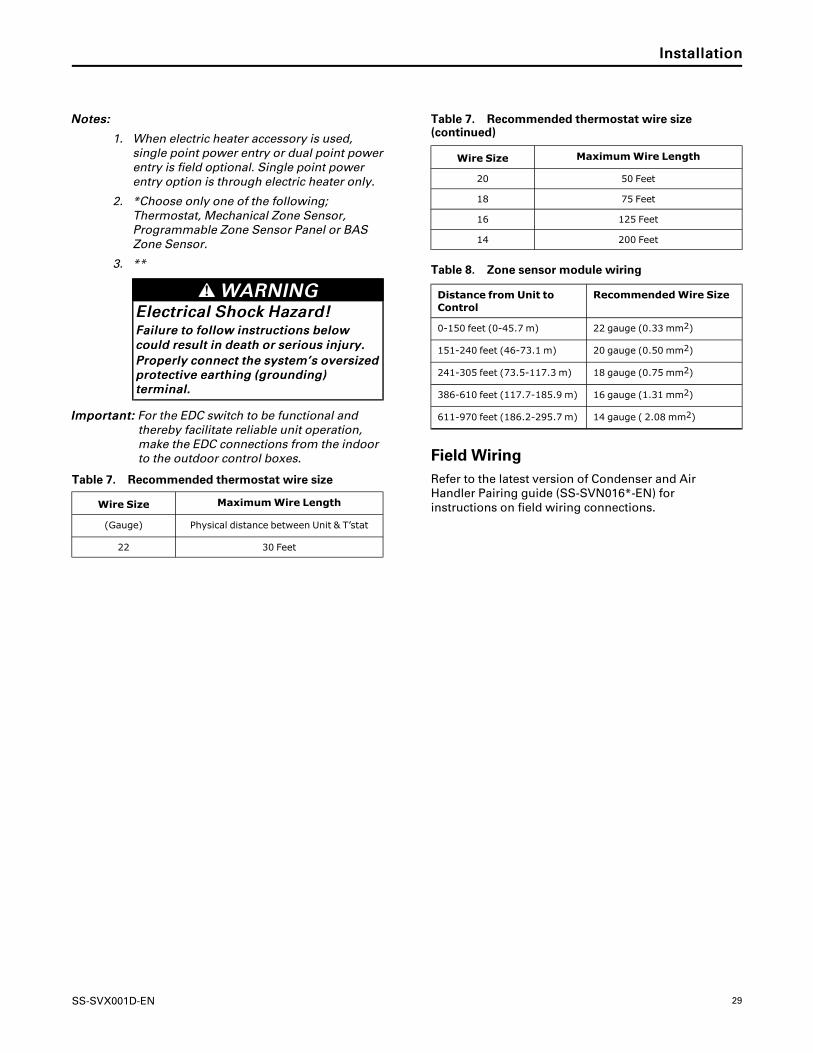
NNootteess::
1. When electric heater accessory is used,single point power entry or dual point powerentry is field optional. Single point powerentry option is through electric heater only.
2. *Choose only one of the following;Thermostat, Mechanical Zone Sensor,Programmable Zone Sensor Panel or BASZone Sensor.
3. **
WWAARRNNIINNGGEElleeccttrriiccaall SShhoocckk HHaazzaarrdd!!FFaaiilluurree ttoo ffoollllooww iinnssttrruuccttiioonnss bbeelloowwccoouulldd rreessuulltt iinn ddeeaatthh oorr sseerriioouuss iinnjjuurryy..PPrrooppeerrllyy ccoonnnneecctt tthhee ssyysstteemm’’ss oovveerrssiizzeeddpprrootteeccttiivvee eeaarrtthhiinngg ((ggrroouunnddiinngg))tteerrmmiinnaall..
IImmppoorrttaanntt:: For the EDC switch to be functional andthereby facilitate reliable unit operation,make the EDC connections from the indoorto the outdoor control boxes.
Table 7. Recommended thermostat wire size
Wire Size MaximumWire Length
(Gauge) Physical distance between Unit & T’stat
22 30 Feet
Table 7. Recommended thermostat wire size(continued)
Wire Size MaximumWire Length
20 50 Feet
18 75 Feet
16 125 Feet
14 200 Feet
Table 8. Zone sensor module wiring
Distance from Unit toControl
RecommendedWire Size
0-150 feet (0-45.7 m) 22 gauge (0.33 mm2)
151-240 feet (46-73.1 m) 20 gauge (0.50 mm2)
241-305 feet (73.5-117.3 m) 18 gauge (0.75 mm2)
386-610 feet (117.7-185.9 m) 16 gauge (1.31 mm2)
611-970 feet (186.2-295.7 m) 14 gauge ( 2.08 mm2)
Field WiringRefer to the latest version of Condenser and AirHandler Pairing guide (SS-SVN016*-EN) forinstructions on field wiring connections.
IInnssttaallllaattiioonn

30 SS-SVX001D-EN
Refrigerant Circuit
Figure 18. Typical split system cooling refrigerant circuit — microchannel
FILTER DRIER
NOTE A: ONLY ONE INDOOR COIL REFRIGERANT ENTRY AND EXIT CIRCUIT IS SHOWN. ALL MODELS HAVE MULTIPLE ENTRY AND EXIT CIRCUITS.NOTE B: DUAL CIRCUIT MODELS HAVE 2 REFRIGERATION CIRCUITS. MANIFOLD CIRCUIT MODELS HAVE 2 COMPRESSORS BUT 1 REFRIGERATION CIRCUIT.
TXV
S
D
COMPRESSOR
LOW PRESSURESWITCH (LPCO)
FIELD SUPPLIEDINTER-CONNECTING
TUBING
OU
TD
OO
R C
OIL
IND
OO
R C
OIL
EXPANSIONVALVE BULB
EQUALIZERTUBE
NOTE A
NOTE A
HIGH PRESSURESWITCH (HPCO)
GAUGECONNECTION
DISCHARGETEMPERATURE
LIMIT (DTL)
AIR
AIR
GAUGECONNECTION
INDICATES DIRECTION OFREFRIGERANT FLOW
COOLING ONLY CIRCUIT DIAGRAM
IInnssttaallllaattiioonn

SS-SVX001D-EN 31
Pre-StartControl Circuit FeaturesNNoottee:: Not all of these features may be required for your
unit, check electrical schematic.
Discharge Temperature Limit (DTL)The control’s sensor is located on the discharge line.This device will shut off the compressor and theoutdoor fan(s) if the discharge temperature exceeds theDTL setting. Once the discharge temperature hasreturned to normal, the compressor will cycle back on.
Low Outdoor Ambient CoolingAll Odyssey units with Symbio™ 700 controls havecooling capabilities down to 0°F as standard. Attemperatures below 50°F, some reduction in coolingcapacity can be expected. When the optional LowAmbient Accessory kit is field installed, the full capacityof the unit is available down to 0°F.
Evaporator Defrost Control (EDC)This control is located in the Air Handler. The control’ssensing tube is embedded vertically in the evaporatorcoil, near the center. This device will stop thecompressor if the indoor coil temperature drops belowits setting. The indoor air will still circulate across thecoil bringing the temperature of the coil back up to thecut-in temperature of the evaporator defrost control.
Low Pressure Cut-Out (LPC)This control’s sensor is located in the suction (gas) line,near the compressor. This control will stop the
compressor and the outdoor fans if suction pressuredrops below the Low Pressure Cut-Out setting. Oncethe suction pressure has returned to normal, thecompressor and outdoor fans will cycle back on.
High Pressure Cut-Out (HPCO)This control’s sensor is located in the discharge line.This device will shut off the compressor and theoutdoor fan(s) if the discharge pressure exceeds theHigh Pressure Cut-Out’s setting. Once the dischargepressure has returned to normal, the compressor willcycle back on.
WWAARRNNIINNGGPPrreevveenntt IInnjjuurryy!!DDuuee ttoo aaggeennccyy ssaaffeettyy rreeqquuiirreemmeennttss,, nnoo sscchhrraaddeerrccoorree iiss ttoo bbee iinnssttaalllleedd bbeenneeaatthh tthhee HHPPCCOO.. RReemmoovvaallooff tthhee HHPPCCOO wwiitthhoouutt eevvaaccuuaattiinngg tthhee ssyysstteemm cchhaarrggeeccoouulldd ccaauussee iinnjjuurryy aanndd rreelleeaassee ooff rreeffrriiggeerraanntt..
Internal Overload Protector (IOL)This device is embedded in the compressor. It will shutoff the compressor if the discharge temperature of thecompressor exceeds its design trip temperature.
NNoottee:: The IOL will put the compressor back inoperation once the compressor motor heat hasdropped below the trip setting; however, a checkof the refrigerant and electrical systems shouldbe made to determine the cause and becorrected.

32 SS-SVX001D-EN
Troubleshooting
WWAARRNNIINNGGLLiivvee EElleeccttrriiccaall CCoommppoonneennttss!!FFaaiilluurree ttoo ffoollllooww aallll eelleeccttrriiccaall ssaaffeettyy pprreeccaauuttiioonnsswwhheenn eexxppoosseedd ttoo lliivvee eelleeccttrriiccaall ccoommppoonneennttss ccoouullddrreessuulltt iinn ddeeaatthh oorr sseerriioouuss iinnjjuurryy..WWhheenn iitt iiss nneecceessssaarryy ttoo wwoorrkk wwiitthh lliivvee eelleeccttrriiccaallccoommppoonneennttss,, hhaavvee aa qquuaalliiffiieedd lliicceennsseedd eelleeccttrriicciiaannoorr ootthheerr iinnddiivviidduuaall wwhhoo hhaass bbeeeenn pprrooppeerrllyy ttrraaiinneeddiinn hhaannddlliinngg lliivvee eelleeccttrriiccaall ccoommppoonneennttss ppeerrffoorrmmtthheessee ttaasskkss..
Refer to the latest version of the Symbio™ 700Applications Guide (ACC-APG001*-EN) for details ontroubleshooting the control system.

SS-SVX001D-EN 33
Service Test Mode
The Symbio™ 700 supports a Service Test Mode thatcan be used to energize the various components of thesystem, either to support general system startup tasksor to support troubleshooting. The user can initiateService Test Mode through the controller userinterfaces, including the Symbio Service andInstallation mobile application.
The modes shown below can be initiated. Dependingon the equipment configuration, the controller will
energize the appropriate outputs. A user-selectedtimeout value will determine how long the controllerwill remain in any given state once initiated. Fordetailed information on how each Service Test State isinterpreted based on the equipment’s configuration,refer to the Symbio 700 Odyssey Controls ApplicationGuide ((ACC-APG001*-EN).
Figure 19. Symbio 700 service test mode

34 SS-SVX001D-EN
MaintenanceWWAARRNNIINNGG
HHaazzaarrddoouuss VVoollttaaggee ww//CCaappaacciittoorrss!!FFaaiilluurree ttoo ddiissccoonnnneecctt ppoowweerr aanndd ddiisscchhaarrggeeccaappaacciittoorrss bbeeffoorree sseerrvviicciinngg ccoouulldd rreessuulltt iinn ddeeaatthh oorrsseerriioouuss iinnjjuurryy..DDiissccoonnnneecctt aallll eelleeccttrriicc ppoowweerr,, iinncclluuddiinngg rreemmootteeddiissccoonnnneeccttss aanndd ddiisscchhaarrggee aallll mmoottoorr ssttaarrtt//rruunnccaappaacciittoorrss bbeeffoorree sseerrvviicciinngg.. FFoollllooww pprrooppeerrlloocckkoouutt//ttaaggoouutt pprroocceedduurreess ttoo eennssuurree tthhee ppoowweerrccaannnnoott bbee iinnaaddvveerrtteennttllyy eenneerrggiizzeedd.. FFoorr vvaarriiaabblleeffrreeqquueennccyy ddrriivveess oorr ootthheerr eenneerrggyy ssttoorriinnggccoommppoonneennttss pprroovviiddeedd bbyy TTrraannee oorr ootthheerrss,, rreeffeerr ttootthhee aapppprroopprriiaattee mmaannuuffaaccttuurreerr’’ss lliitteerraattuurree ffoorraalllloowwaabbllee wwaaiittiinngg ppeerriiooddss ffoorr ddiisscchhaarrggee ooffccaappaacciittoorrss.. VVeerriiffyy wwiitthh aa CCAATT IIIIII oorr IIVV vvoollttmmeetteerrrraatteedd ppeerr NNFFPPAA 7700EE tthhaatt aallll ccaappaacciittoorrss hhaavveeddiisscchhaarrggeedd..
NNOOTTIICCEEOOppeerraattiinngg UUnnddeerr VVaaccuuuumm!!FFaaiilluurree ttoo ffoollllooww tthheessee iinnssttrruuccttiioonnss wwiillll rreessuulltt iinnccoommpprreessssoorr ffaaiilluurree..DDoo nnoott ooppeerraattee oorr aappppllyy ppoowweerr ttoo tthhee ccoommpprreessssoorrwwhhiillee uunnddeerr aa vvaaccuuuumm..
Perform all of the indicated maintenance procedures atthe intervals scheduled. This will prolong the life of theunit and reduce the possibility of costly equipmentfailure.
MonthlyConduct the following maintenance inspections onceper month.
☐ Check unit wiring to ensure all connections are tightand that the wiring insulation is intact.
☐ Inspect the condenser coils for dirt and debris. If thecoils appear dirty, clean them.
☐ With the unit operating in the cooling mode, checkthe suction and discharge pressures and comparethem with Pressure Curve values. Record thesereadings on the “Maintenance Log,” p. 36.
Annually (Cooling Season)The following maintenance procedures must beperformed at the beginning of each cooling season toensure efficient unit operation.
☐ Perform all of the monthly maintenanceinspections.
☐ With the unit operating, check unit superheat andrecord the reading in the “Maintenance Log,” p. 36.
☐ Remove any accumulation of dust and/or dirt fromthe unit casing.
☐ Remove corrosion from any surface and repaint.Check the gasket around the control panel door toensure it fits correctly and is in good condition toprevent water leakage.
☐ Inspect the control panel wiring to ensure that allconnections are tight and that the insulation isintact.
NNoottee:: Condenser fan motors are permanentlylubricated.
☐ Check refrigerant piping and fittings for leaks
☐ Inspect the condenser coils for dirt and debris. If thecoils appear dirty, clean them.
Coil CleaningRegular coil maintenance, including annual cleaning-enhances the unit's operating efficiency by minimizing:
• compressor head pressure and amperage draw• water carryover• fan brake horsepower• static pressure losses
At least once each year — or more often if the unit islocated in a “dirty” environment — clean the coil usingthe instructions outlined below. Be sure to follow theseinstructions as closely as possible to avoid damagingthe coils.
Microchannel (MCHE) Coils
NNOOTTIICCEECCooiill DDaammaaggee!!FFaaiilluurree ttoo ffoollllooww iinnssttrruuccttiioonnss bbeellooww ccoouulldd rreessuulltt iinnccooiill ddaammaaggee..DDOO NNOOTT uussee aannyy ddeetteerrggeennttss wwiitthh mmiiccrroocchhaannnneellccoonnddeennsseerr ccooiillss..UUssee pprreessssuurriizzeedd wwaatteerr oorr aaiirr OONNLLYY,, wwiitthh pprreessssuurreennoo ggrreeaatteerr tthhaann 660000ppssii..FFoorr aaddddiittiioonnaall iinnffoorrmmaattiioonn rreeggaarrddiinngg tthhee pprrooppeerrmmiiccrroocchhaannnneell ccooiill cclleeaanniinngg pprroocceedduurree,, rreeffeerr ttoo RRTT--SSVVBB8833**--EENN
Due to the soft material and thin walls of the MCHEcoils, the traditional field maintenance methodrecommended for Round Tube Plate Fin (RTPF) coilsdoes not apply to microchannel coils. Moreover,chemical cleaners are a risk factor to MCHE due to thematerial of the coil. The manufacturer does notrecommend the use of chemical cleaners to cleanmicrochannel coils. Using chemical cleaners could leadto warranty claims being further evaluated for validityand failure analysis.
The recommended cleaning method for microchannelcondenser coils is pressurized water or air with a non-pinpoint nozzle and an ECU of at least 180 withpressure no greater than 600 psi. To minimize the risk

SS-SVX001D-EN 35
of coil damage, approach the cleaning of the coil withthe pressure washer aimed perpendicular to the face of
the coil during cleaning. Optimum clearance betweenthe sprayer nozzle and the microchannel coil is 1”–3”.
MMaaiinntteennaannccee

36 SS-SVX001D-EN
Maintenance LogDate
Ambient
Temp.
(°F)
EvaporatorEnteringAir
Compressor
Superheat(°F)
(atcompressor)
Subcooling(°F)
(atliquidline)
DryBulb
Wet
Bulb
SuctionPressure
DischargePressure
Circuit#1
Circuit#2
Circuit#1
Circuit#2
(C1)
(C2)
(C1)
(C2)
Note:Performeachinspectiononcepermonth(duringcoolingseason)whileunitisoperating.
MMaaiinntteennaannccee

SS-SVX001D-EN 37
Charging Data and Pressure Curves
Table 9. TTA Charging data and pressure curves
Condenser Air HandlerRefrigerant Charging CurveSuperheat and Charge Table Pressure Curves
TTA0604DA* TWE0764DA* 436759020001 436759020001
TTA0724*A* TWE0904*A* 436759030001 436759030001
TTA0604DD* TWE0724DB* 436759040001 436759530001
TTA0724*D* TWE0724*B* 436759050001 436759540001
TTA0764DA* TWE0764DA* 436765800001 436765800001
TTA0764DA* TWE1014DA* 436760750001 436760750001
TTA0904*A* TWE0904*A* 436765810001 436765810001
TTA0904*A* TWE1204*A* 436759750001 436759750001
TTA0764DD* TWE0764DB* 436765820001 436766300001
TTA0904*D* TWE0904*B* 436765830001 436766240001
TTA1014DA* TWE1014DA* 436759100001 436759100001
TTA1204*A* TWE1204*A* 436759110001 436759110001
TTA1014DC* TWE1014DA* 436759120001 436759120001
TTA1204*C* TWE1204*A* 436759130001 436759130001
TTA1014DD TWE1014DB* 436759140001 436759570001
TTA1204*D TWE1204*B 436759150001 436759580001
TTA1264DD* TWE1264DB* 436765880001 436766310001
TTA1504*D* TWE1504*B* 436765890001 436766250001
TTA1564DD* TWE1564DB* 436765900001 436765900001
TTA1564DD* TWE2014DB* 436760760001 436760760001
TTA1804*D* TWE1804*B* 436765910001 436765910001
TTA1804*D* TWE2404*B* 436759740001 436759740001
TTA1564DC* TWE1564DB* 436765920001 436765920001
TTA1804*C* TWE1804*B* 436765930001 436765930001
TTA2014DD* TWE2014DB* 436759220001 436759220001
TTA2404*D* TWE2404*B* 436759230001 436759230001
TTA2014DC* TWE2014DB* 436759240001 436759240001
TTA2404*C* TWE2404*B* 436759250001 436759250001
TTA2514DC* TWE2514DB* 436759260001 436759260001
TTA3004*C* TWE3004*B* 436759270001 436759270001
TTA0902*A* TWE0902*A* 436759440001 N/A
TTA1202*A* TWE1202*A* 436759450001 N/A
TTA1802*D* TWE180B* 436759460001 N/A
TTA2402*D* TWE240B* 436759470001 N/A
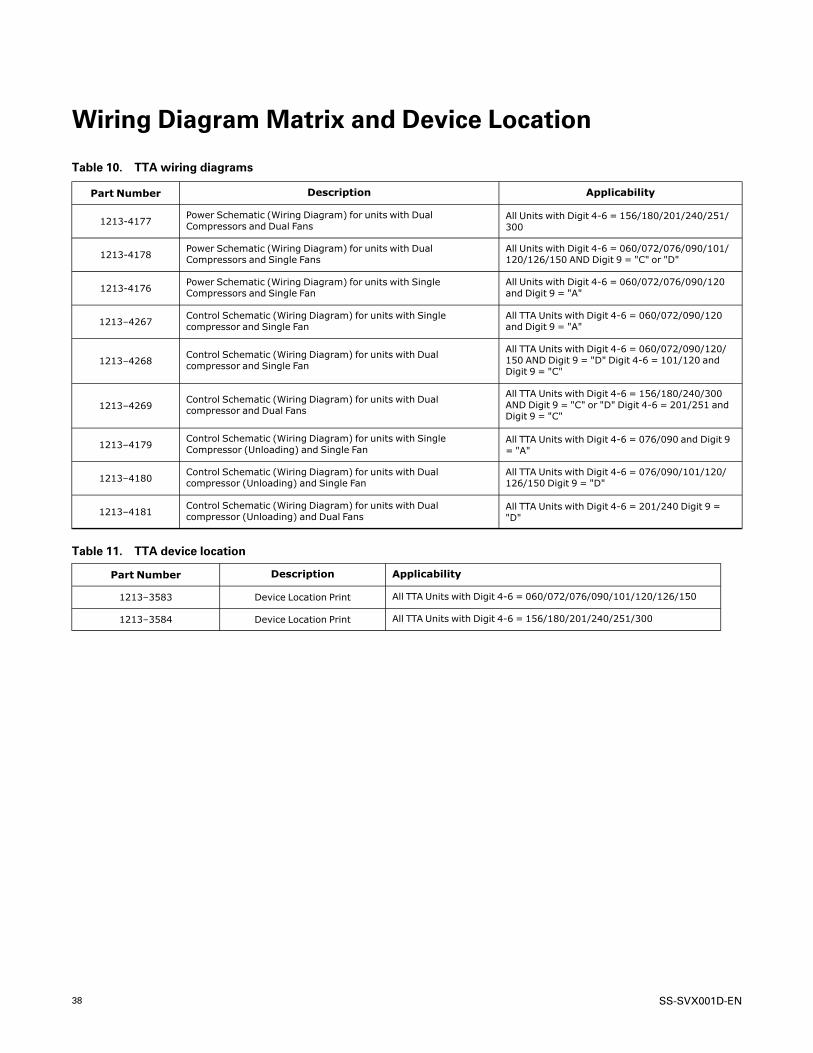
38 SS-SVX001D-EN
Wiring DiagramMatrix and Device Location
Table 10. TTA wiring diagrams
Part Number Description Applicability
1213-4177Power Schematic (Wiring Diagram) for units with DualCompressors and Dual Fans
All Units with Digit 4-6 = 156/180/201/240/251/300
1213-4178Power Schematic (Wiring Diagram) for units with DualCompressors and Single Fans
All Units with Digit 4-6 = 060/072/076/090/101/120/126/150 AND Digit 9 = "C" or "D"
1213-4176Power Schematic (Wiring Diagram) for units with SingleCompressors and Single Fan
All Units with Digit 4-6 = 060/072/076/090/120and Digit 9 = "A"
1213–4267Control Schematic (Wiring Diagram) for units with Singlecompressor and Single Fan
All TTA Units with Digit 4-6 = 060/072/090/120and Digit 9 = "A"
1213–4268Control Schematic (Wiring Diagram) for units with Dualcompressor and Single Fan
All TTA Units with Digit 4-6 = 060/072/090/120/150 AND Digit 9 = "D" Digit 4-6 = 101/120 andDigit 9 = "C"
1213–4269Control Schematic (Wiring Diagram) for units with Dualcompressor and Dual Fans
All TTA Units with Digit 4-6 = 156/180/240/300AND Digit 9 = "C" or "D" Digit 4-6 = 201/251 andDigit 9 = "C"
1213–4179Control Schematic (Wiring Diagram) for units with SingleCompressor (Unloading) and Single Fan
All TTA Units with Digit 4-6 = 076/090 and Digit 9= "A"
1213–4180Control Schematic (Wiring Diagram) for units with Dualcompressor (Unloading) and Single Fan
All TTA Units with Digit 4-6 = 076/090/101/120/126/150 Digit 9 = "D"
1213–4181Control Schematic (Wiring Diagram) for units with Dualcompressor (Unloading) and Dual Fans
All TTA Units with Digit 4-6 = 201/240 Digit 9 ="D"
Table 11. TTA device location
Part Number Description Applicability
1213–3583 Device Location Print All TTA Units with Digit 4-6 = 060/072/076/090/101/120/126/150
1213–3584 Device Location Print All TTA Units with Digit 4-6 = 156/180/201/240/251/300

SS-SVX001D-EN 39
WarrantyFor Commercial UnitaryEquipment Rated 25 Tons andUnder and Related AccessoriesPPrroodduuccttss CCoovveerreedd — This warranty is extended byTrane, and applies to the following products:
• All packaged and split system air conditioners andheat pumps have a rated capacity of 25 tons andunder.
• All packaged combinations gas/electric airconditioners having a rated capacity of 25 tons andunder.
• All packaged combination gas/electric airconditioners having a rated capacity of 1.5 through5 tons single phase electric power and used forcommercial applications. (As used in this warranty,a commercial application is any application wherethe end purchaser uses the product for other thanpersonal, family or household purposes.)
• All accessories for the above products which aresold by Trane and applied in accordance with Tranespecifications.
Basic WarrantyThe warrantor warrants for a period of twelve (12)months from the initial start-up or eighteen (18)months from date of shipment, whichever is sooner,that the products covered by this warranty (1) are freefrom defects in material and manufacture, and (2) havethe capacities and ratings set forth in the warrantor’scatalogs and bulletins. If any part of your airconditioner fails because of a manufacturing defect,Warrantor will furnish without charge the requiredreplacement part.
If the heat exchanger fails because of a manufacturingdefect within five years from the date of start-up,Warrantor will furnish without charge a replacementheat exchanger. In addition, if the optional, factoryinstalled, stainless steel heat exchanger fails becauseof a manufacturing defect within ten years from thedate of start-up, Warrantor will furnish without chargea replacement heat exchanger.
Any local transportation, related service labor anddiagnosis calls are not included. In addition, if thesealed motor-compressor fails because of amanufacturing defect within the second through fifthyear from the date of original purchase, Warrantor willfurnish without charge the required replacementcompressor.
Exclusions and LimitationsThe warrantor’s obligations and liabilities under thiswarranty are limited to furnishing F.O.B. factory orwarehouse at the warrantor-designated shipping point,freight allowed to Buyer’s city (or port of export forshipments outside the conterminous United States) areplacement product or, at the option of the warrantor,parts for the repair of the product not conforming tothis warranty and which have been returned to thewarrantor.
The warrantor’s warranty is conditional on theCustomer providing written notice to the warrantorwithin thirty (30) days of the discovery of the defect. Noproduct shall be returned to the warrantor without thewarrantor’s written permission. No liability whatevershall attach to warrantor until said products have beenfully paid for and then said liability shall be limited tothe purchase price of the equipment shown to bedefective.
The warranty does not apply to any compressor or gas-fired heat exchanger which has been repaired oraltered in such manner as, in the judgement of thewarrantor, affects its stability or reliability. Thiswarranty does not cover (1) any heat exchanger whichhas been fired with an improper type of fuel (2) a heatexchanger which is installed in a beauty parlor, drycleaning establishment, de-greasing plant or in anycorrosive atmosphere; or (3) any heat exchanger whichis not shown to be defective by the warrantor’sinspection.
This warranty does not cover damage due to accident,abuse, improper use, external causes, freezing,corrosion, erosion or deterioration. Localtransportation, related service labor, air filters,diagnosis calls, refrigerant and related items are notcovered.
THE WARRANTY AND LIABILITY SET FORTH HEREINARE IN LIEU OF ALL OTHER WARRANTIES ANDLIABILITIES, WHETHER IN CONTRACT OR INNEGLIGENCE, EXPRESS OR IMPLIED, IN LAW OR INFACT, INCLUDING IMPLIED WARRANTIES ORMERCHANTABILITY AND FITNESS FOR APARTICULAR PURPOSE AND ANY IMPLIEDWARRANTIES OTHERWISE ARISING FROM THECOURSE OF DEALING OR TRADE. IN NO EVENTSHALL THE WARRANTOR BE LIABLE FOR ANYINCIDENTAL OR CONSEQUENTIAL DAMAGES.
The warrantor makes certain further warrantyprotection available on an optional, extra-cost basis.Any further warranty must be in writing. If you wishfurther help or information concerning this warranty,contact: Trane — Warrantor, 2701 Wilma RudolphBlvd., Clarksville, TN 37040

Trane and American Standard create comfortable, energy efficient indoor environments forcommercial and residential applications. For more information, please visit trane. com oramericanstandardair.com.
Trane and American Standard have a policy of continuous product and product data improvement and reserve the right to change design andspecifications without notice. We are committed to using environmentally conscious print practices.
SS-SVX001D-EN 05 Mar 2022
Supersedes SS-SVX001C-EN (September 2021) ©2022
Related Documents