Submitted To: Presented By : Mr. Devendra Pratap Singh SHISHU PAL Ms. Kanika Jindal 1213331191 Ms. Gitanjali Anand ECE.(3 rd Year) A SEMINAR PRESENTATION on

Welcome message from author
This document is posted to help you gain knowledge. Please leave a comment to let me know what you think about it! Share it to your friends and learn new things together.
Transcript

Submitted To: Presented By :
Mr. Devendra Pratap Singh SHISHU PAL
Ms. Kanika Jindal 1213331191
Ms. Gitanjali Anand ECE.(3rd Year)
A
SEMINAR PRESENTATION
on
Contents
Introduction
Evolution
Motivation
Technology description
Circuit Diagram
Advantages/disadvantages
Future Aspects
Real time Applications
References
INTRODUCTION
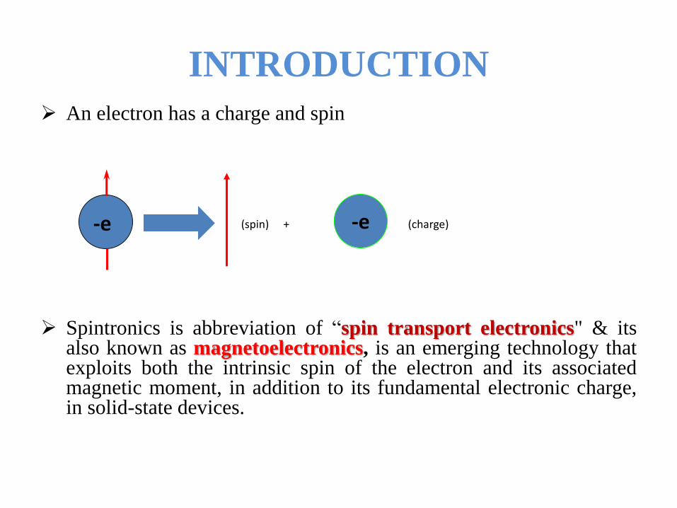
An electron has a charge and spin
(spin) + (charge)
Spintronics is abbreviation of “spin transport electronics" & itsalso known as magnetoelectronics, is an emerging technology thatexploits both the intrinsic spin of the electron and its associatedmagnetic moment, in addition to its fundamental electronic charge,in solid-state devices.
-e-e
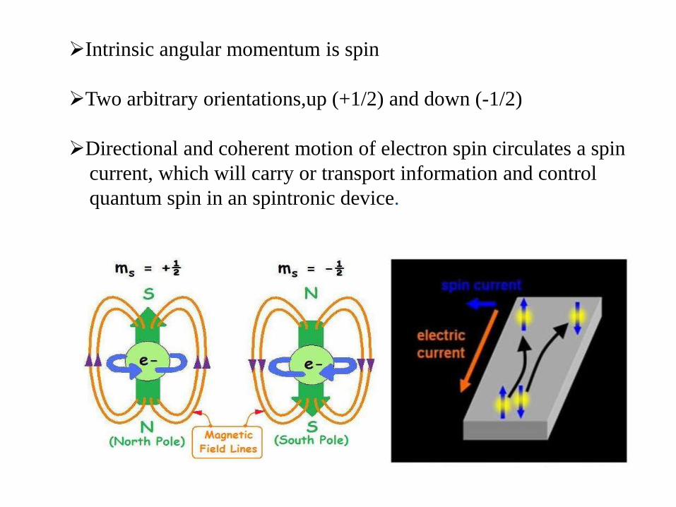
Intrinsic angular momentum is spin
Two arbitrary orientations,up (+1/2) and down (-1/2)
Directional and coherent motion of electron spin circulates a spin
current, which will carry or transport information and control
quantum spin in an spintronic device.
EVOLUTION
Failure of Moore’s Law :
Moore’s Law states that ” the number of transistors on a siliconchip will roughly double every eighteen months.”
But now the transistors & other components have reached nanoscaledimensions and further reducing size lead to Quantum effect.
1988 France, GMR discovery is accepted as birth of spintronics
Spintronics devices offer the possibility of enhanced functionality,higher speed, and reduced power consumption
MOTIVATION
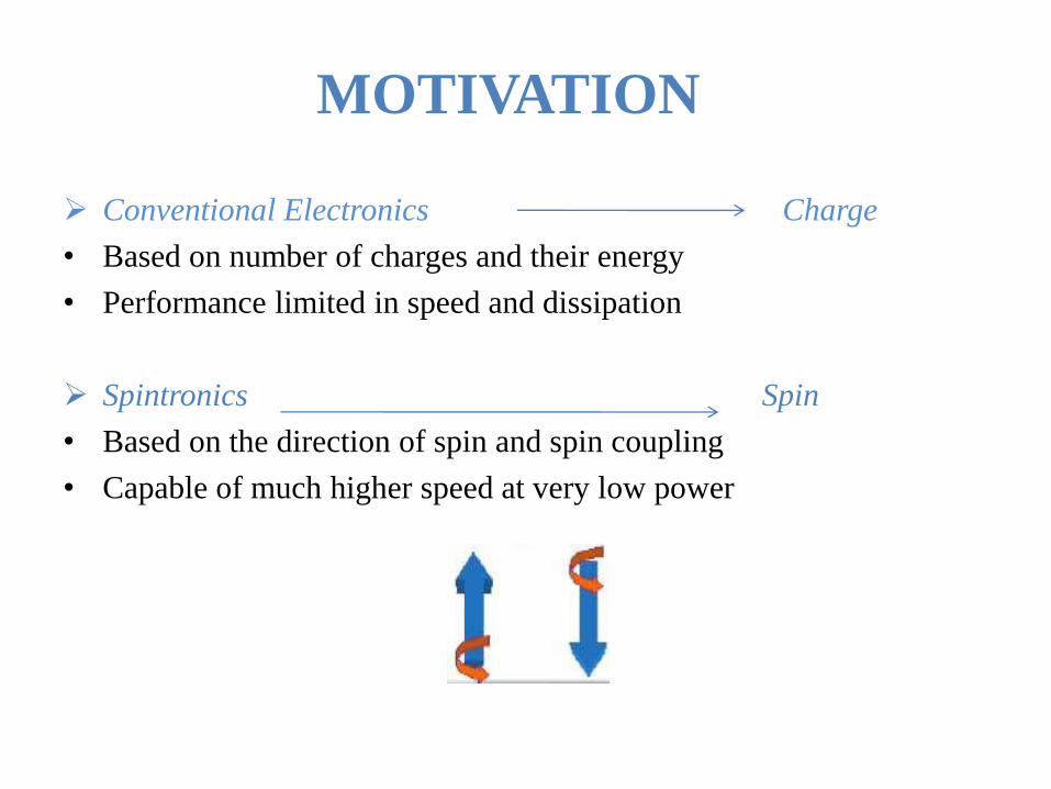
Conventional Electronics Charge
• Based on number of charges and their energy
• Performance limited in speed and dissipation
Spintronics Spin
• Based on the direction of spin and spin coupling
• Capable of much higher speed at very low power

TECHNOLOGY
Spin can assume one of the two states relative to the magnetic
field, called spin up or spin down.
The states, spin up or spin down, can be used to represent
‘1’ and ‘0’ in binary logic
The simplest method of generating a spin- polarised current in a
metal is to pass the current through a ferromagnetic material. The
most common application of this effect is a giant
magnetoresistance (GMR) device
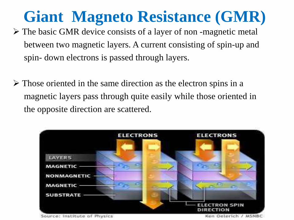
Giant Magneto Resistance (GMR) The basic GMR device consists of a layer of non -magnetic metal
between two magnetic layers. A current consisting of spin-up and
spin- down electrons is passed through layers.
Those oriented in the same direction as the electron spins in a
magnetic layers pass through quite easily while those oriented in
the opposite direction are scattered.
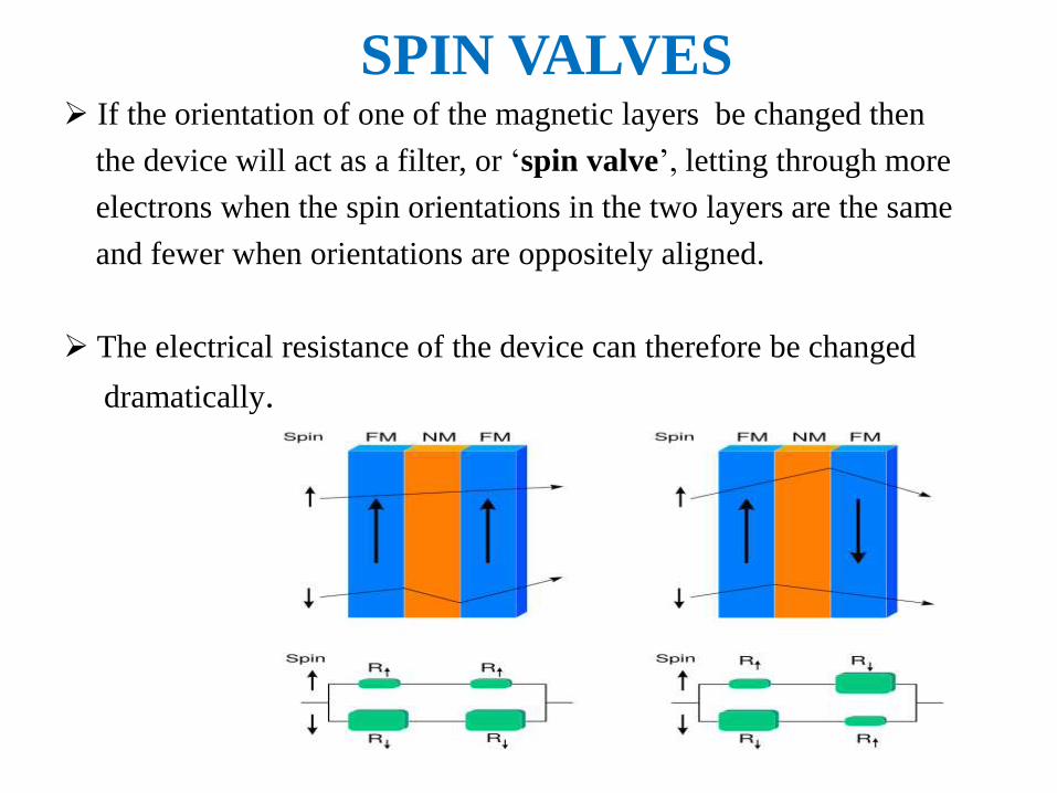
SPIN VALVES If the orientation of one of the magnetic layers be changed then
the device will act as a filter, or ‘spin valve’, letting through more
electrons when the spin orientations in the two layers are the same
and fewer when orientations are oppositely aligned.
The electrical resistance of the device can therefore be changed
dramatically.
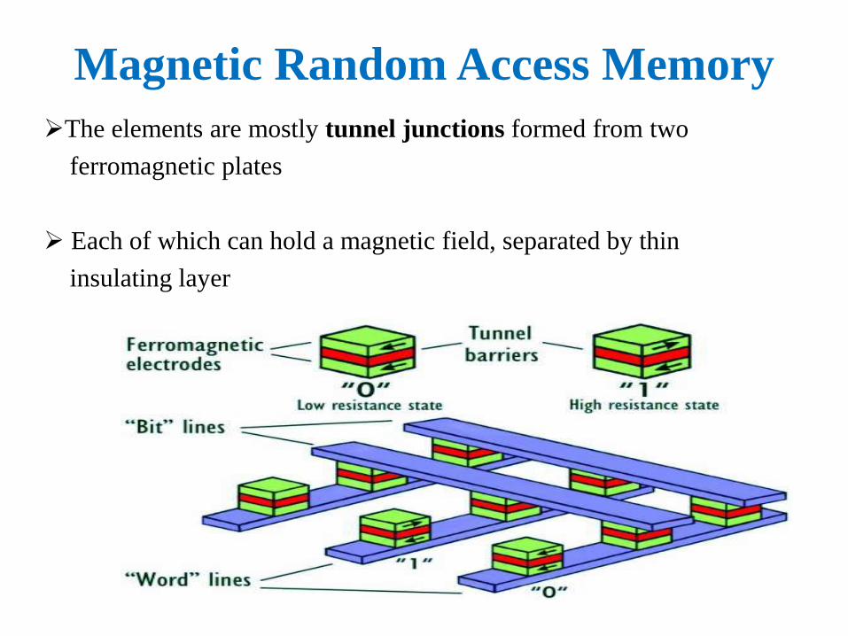
Magnetic Random Access Memory
The elements are mostly tunnel junctions formed from two
ferromagnetic plates
Each of which can hold a magnetic field, separated by thin
insulating layer
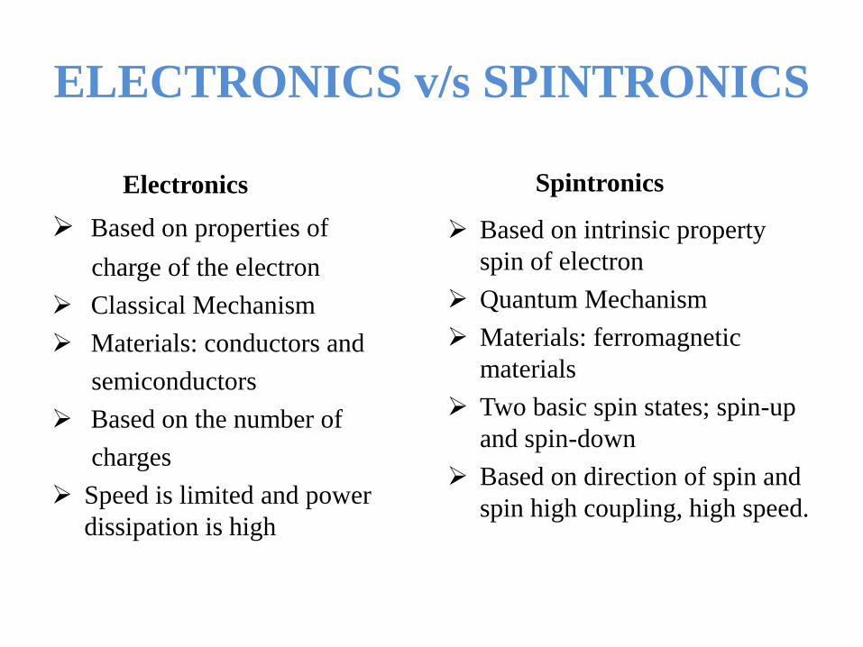
ELECTRONICS v/s SPINTRONICS
Electronics
Based on properties of
charge of the electron
Classical Mechanism
Materials: conductors and
semiconductors
Based on the number of
charges
Speed is limited and power
dissipation is high
Spintronics
Based on intrinsic property
spin of electron
Quantum Mechanism
Materials: ferromagnetic
materials
Two basic spin states; spin-up
and spin-down
Based on direction of spin and
spin high coupling, high speed.
ADVANTAGE OF SPINTRONICS
Low power consumption.
Less heat dissipation.
Spintronics memory is non-volatile.
Takes up lesser space on chip, thus more compact.
The MRAM has all the properties of DRAM ,SRAM and ROM .
Spintronics does not require unique and specialized
semiconductors.
Common metals such as Fe, Al, Ag , etc. can be used.
FUTURE ASPECTS
Hard drives up to 1.2 petabytes
Magnetic RAM chips
Spin FET using quantum tunneling
Integrating spin-devices with current microelectronics and
computing
And research is still going on…

REALTIME APPLICATION
iPod nano
Laptop hard drives
Cell phone
4GB Compact Flash card
Spin- based Transistor
Commercial products.. .
REFERENCES
1. Electronic measurement and control of spin transport
2. en.wikipedia.org/wiki/Spintronics
3. http://www.slideshare.net
4. http://seminarproject.com
5. www.physik.uni-regensburg.de/.../Spintronics

Thanks for your attention…!!!
Any Queries ??
Related Documents