Spin-up flow of ferrofluids: Asymptotic theory and experimental measurements Arlex Chaves, 1 Markus Zahn, 2 and Carlos Rinaldi 1 1 Department of Chemical Engineering, University of Puerto Rico, Mayagüez Campus, P.O. Box 9046, Mayagüez PR 00681-9046, Puerto Rico 2 Department of Electrical Engineering and Computer Science, Massachusetts Institute of Technology, 77 Massachusetts Avenue, Cambridge, Massachusetts 02139, USA Received 28 May 2007; accepted 1 February 2008; published online 28 May 2008 We treat the flow of ferrofluid in a cylindrical container subjected to a uniform rotating magnetic field, commonly referred to as spin-up flow. A review of theoretical and experimental results published since the phenomenon was first observed in 1967 shows that the experimental data from surface observations of tracer particles are inadequate for the assessment of bulk flow theories. We present direct measurements of the bulk flow by using the ultrasound velocity profile method, and torque measurements for water and kerosene based ferrofluids, showing the fluid corotating with the field in a rigid-body-like fashion throughout most of the bulk region of the container, except near the air-fluid interface, where it was observed to counter-rotate. We obtain an extension of the spin diffusion theory of Zaitsev and Shliomis, using the regular perturbation method. The solution is rigorously valid for K 3 / 2, where K is the Langevin parameter evaluated by using the applied field magnitude, and provides a means for obtaining successively higher contributions of the nonlinearity of the equilibrium magnetization response and the spin-magnetization coupling in the magnetization relaxation equation. Because of limitations in the sensitivity of our apparatus, experiments were carried out under conditions for which 1. Still, under such conditions the predictions of the analysis are in good qualitative agreement with the experimental observations. An estimate of the spin viscosity is obtained from comparison of flow measurements and theoretical results of the extrapolated wall velocity from the regular perturbation method. The estimated value lies in the range of 10 -8 –10 -12 kg m s -1 and is several orders of magnitude higher than that obtained from dimensional analysis of a suspension of noninteracting particles in a Newtonian fluid. © 2008 American Institute of Physics. DOI: 10.1063/1.2907221 I. INTRODUCTION A. Spin-up flow of ferrofluids The phenomenon of spin-up flow of a ferrofluid, a stable colloidal suspension of permanently magnetized nanopar- ticles, in a cylindrical container and subjected to an applied rotating magnetic field which is uniform in the absence of the ferrofluid has received considerable attention in the de- velopment of the field of ferrohydrodynamics. 1–14 Typically, experiments are carried out by placing a sample of ferrofluid in a cylindrical container subjected to a rotating magnetic field. This setup is suitable for studying the coupling between internal angular momentum, related to the “spin” of the sub- continuum magnetic particles, and the macroscopic or “ex- ternal” angular momentum, related to the experimentally ob- servable macroscopic flow of the suspension. In a stationary cylindrical container, surface velocity profiles show the fer- rofluid rotating, rigid-body-like, in a direction which depends on the applied magnetic field amplitude, frequency, and ro- tation direction. Such essentially rigid-body motion is ob- served in the inner core of the ferrofluid and extends close to the stationary cylindrical vessel wall. To make such observa- tions, tracer particles are often placed on the rotating free surface—ferrofluid is opaque making probing of bulk flow profiles through optical methods difficult. The usage of such free surface tracers limits the accuracy of measurements close to the container wall. Furthermore, interfacial curvature coupled with magnetic surface shear stresses drives a surface flow, 7 making free surface measurements unsuitable in deter- mining the bulk flow. Related works using either unstable or concentrated sus- pensions of particles or using non-uniform magnetic fields include Brown and Horsnell, 15 Kagan et al., 16 and Calugaru et al. 17 These authors report observations where the magnetic fluid switches between co-rotation and counter-rotation with respect to the applied magnetic field depending on magnetic field amplitude and frequency. Explicitly, Brown and Horsnell 15 observed corotation of field and fluid for low ap- plied fields and counter-rotation for high applied magnetic fields, whereas Kagan et al. 16 and Calugaru et al. 17 observed counter-rotation for low applied magnetic fields and corota- tion for higher applied fields. Observations of counter-rotation of field and fluid led Brown and Horsnell 15 to investigate the direction in which the cylindrical container would rotate if it could freely do so. This represents an indirect measurement of the torque ex- erted by the ferrofluid on the container wall. One would ex- pect the counter-rotating fluid to drag the cylindrical con- tainer with it, but experiments show the container corotating PHYSICS OF FLUIDS 20, 053102 2008 1070-6631/2008/205/053102/18/$23.00 © 2008 American Institute of Physics 20, 053102-1 Downloaded 18 Feb 2011 to 18.90.7.11. Redistribution subject to AIP license or copyright; see http://pof.aip.org/about/rights_and_permissions

Welcome message from author
This document is posted to help you gain knowledge. Please leave a comment to let me know what you think about it! Share it to your friends and learn new things together.
Transcript
Spin-up flow of ferrofluids: Asymptotic theory and experimentalmeasurements
Arlex Chaves,1 Markus Zahn,2 and Carlos Rinaldi11Department of Chemical Engineering, University of Puerto Rico, Mayagüez Campus,P.O. Box 9046, Mayagüez PR 00681-9046, Puerto Rico2Department of Electrical Engineering and Computer Science, Massachusetts Institute of Technology,77 Massachusetts Avenue, Cambridge, Massachusetts 02139, USA
�Received 28 May 2007; accepted 1 February 2008; published online 28 May 2008�
We treat the flow of ferrofluid in a cylindrical container subjected to a uniform rotating magneticfield, commonly referred to as spin-up flow. A review of theoretical and experimental resultspublished since the phenomenon was first observed in 1967 shows that the experimental data fromsurface observations of tracer particles are inadequate for the assessment of bulk flow theories. Wepresent direct measurements of the bulk flow by using the ultrasound velocity profile method, andtorque measurements for water and kerosene based ferrofluids, showing the fluid corotating with thefield in a rigid-body-like fashion throughout most of the bulk region of the container, except near theair-fluid interface, where it was observed to counter-rotate. We obtain an extension of the spindiffusion theory of Zaitsev and Shliomis, using the regular perturbation method. The solution isrigorously valid for �K��3 /2, where �K is the Langevin parameter evaluated by using the appliedfield magnitude, and provides a means for obtaining successively higher contributions of thenonlinearity of the equilibrium magnetization response and the spin-magnetization coupling in themagnetization relaxation equation. Because of limitations in the sensitivity of our apparatus,experiments were carried out under conditions for which ��1. Still, under such conditions thepredictions of the analysis are in good qualitative agreement with the experimental observations. Anestimate of the spin viscosity is obtained from comparison of flow measurements and theoreticalresults of the extrapolated wall velocity from the regular perturbation method. The estimated valuelies in the range of 10−8–10−12 kg m s−1 and is several orders of magnitude higher than thatobtained from dimensional analysis of a suspension of noninteracting particles in a Newtonianfluid. © 2008 American Institute of Physics. �DOI: 10.1063/1.2907221�
I. INTRODUCTION
A. Spin-up flow of ferrofluids
The phenomenon of spin-up flow of a ferrofluid, a stablecolloidal suspension of permanently magnetized nanopar-ticles, in a cylindrical container and subjected to an appliedrotating magnetic field which is uniform in the absence ofthe ferrofluid has received considerable attention in the de-velopment of the field of ferrohydrodynamics.1–14 Typically,experiments are carried out by placing a sample of ferrofluidin a cylindrical container subjected to a rotating magneticfield. This setup is suitable for studying the coupling betweeninternal angular momentum, related to the “spin” of the sub-continuum magnetic particles, and the macroscopic or “ex-ternal” angular momentum, related to the experimentally ob-servable macroscopic flow of the suspension. In a stationarycylindrical container, surface velocity profiles show the fer-rofluid rotating, rigid-body-like, in a direction which dependson the applied magnetic field amplitude, frequency, and ro-tation direction. Such essentially rigid-body motion is ob-served in the inner core of the ferrofluid and extends close tothe stationary cylindrical vessel wall. To make such observa-tions, tracer particles are often placed on the rotating freesurface—ferrofluid is opaque making probing of bulk flowprofiles through optical methods difficult. The usage of such
free surface tracers limits the accuracy of measurementsclose to the container wall. Furthermore, interfacial curvaturecoupled with magnetic surface shear stresses drives a surfaceflow,7 making free surface measurements unsuitable in deter-mining the bulk flow.
Related works using either unstable or concentrated sus-pensions of particles or using non-uniform magnetic fieldsinclude Brown and Horsnell,15 Kagan et al.,16 and Calugaruet al.17 These authors report observations where the magneticfluid switches between co-rotation and counter-rotation withrespect to the applied magnetic field depending on magneticfield amplitude and frequency. Explicitly, Brown andHorsnell15 observed corotation of field and fluid for low ap-plied fields and counter-rotation for high applied magneticfields, whereas Kagan et al.16 and Calugaru et al.17 observedcounter-rotation for low applied magnetic fields and corota-tion for higher applied fields.
Observations of counter-rotation of field and fluid ledBrown and Horsnell15 to investigate the direction in whichthe cylindrical container would rotate if it could freely do so.This represents an indirect measurement of the torque ex-erted by the ferrofluid on the container wall. One would ex-pect the counter-rotating fluid to drag the cylindrical con-tainer with it, but experiments show the container corotating
PHYSICS OF FLUIDS 20, 053102 �2008�
1070-6631/2008/20�5�/053102/18/$23.00 © 2008 American Institute of Physics20, 053102-1
Downloaded 18 Feb 2011 to 18.90.7.11. Redistribution subject to AIP license or copyright; see http://pof.aip.org/about/rights_and_permissions
with the field, whereas the fluid counter-rotates. Such obser-vations have since been corroborated by Kagan et al.16 andRosensweig et al.7
Various authors1–5,7,10,11,14 have attempted theoreticalanalyses aimed at explaining experimental observations offree surface flow profiles. The spin diffusion theory, due toZaitsev and Shliomis,2 assumes that the magnetic fieldthroughout the ferrofluid region is uniform, with concomitantuniform magnetization of the ferrofluid. The resultingmagnetic body couple is uniform, whereas the magneticbody force is exactly zero. Within the assumptions of theiranalysis, the ferrofluid flow field is analytically determinedby using the phenomenological structured continuumtheory18–20 which includes the effects of antisymmetricstresses, body couples, and couple stresses representing theshort-range surface transport of internal angular momentum.The spin-diffusion results of Zaitsev and Shliomis2 were sub-sequently used to estimate the magnitude of the phenomeno-logical coefficient of spin viscosity, appearing in the com-monly accepted constitutive form of the couple stresspseudodyadic, as well as to analyze/interpret experimentalobservations.6,7 Unfortunately, as pointed out by Rosensweiget al.,7 this analysis fails to correctly predict the experimen-tally observed free surface flow magnitude and direction.
The spin-diffusion theory2 and other7,10,11 analysesadapted therefrom assume that the fluid magnetization is pro-portional to the magnetic field, limiting the solution range tolow values of the applied magnetic field where the Langevinparameter �, appearing in the equilibrium magnetization re-lation, is negligible ��→0�. Also, these analyses neglect orare inconsistent with the spin-magnetization coupling in thephenomenological magnetization relaxation equation �7� ofShliomis.21 This can be most clearly seen in Ref. 2 where themagnetization equation lacks the ��x��M�x� term on theright hand side of Eq. �7�. It is neglected in, or rather isinconsistent with, the analysis the Rosensweig et al.7 andKaloni10 when they assume that the field and magnetizationare uniform throughout the ferrofluid. This is illustratedwhen one considers that a position dependent spin field, asobtained in their contributions, is inconsistent with a uniformmagnetic field and magnetization, as assumed in their treat-ments, in the magnetization relaxation equation �7�. Theimportance of the spin-magnetization coupling term��x��M�x� in predicting novel ferrofluid behavior has beenshown previously by Zahn and co-workers,22–25 where thesituation of plane-Pouseuille/Couette flow of ferrofluid sub-jected to alternating and rotating magnetic fields was ana-lyzed.
An alternative theoretical explanation for the observedflow phenomena was developed by Glazov.3–5 The analysisconsiders the effect of higher-order spatial harmonics, ex-pected to occur in practice due to nonidealities in the statorwinding distribution, e.g., due to slot effects. Essentially,Glazov’s analysis considers the same phenomenologicaltheory used by Zaitsev and Shliomis2 and others,7,10,11 butneglects contributions due to couple-stresses in the ferrof-luid. Glazov’s analysis, in its various forms and stages, es-sentially concludes that the flow would not occur in the ab-sence of the higher-order harmonics when a two pole
winding distribution is used as the source of the appliedmagnetic field. Hence, according to Glazov, experimental ob-servations of spin-up flow are entirely attributed to imperfec-tions in the experimental apparatus and the concomitanthigher-order spatial harmonics in the magnetic field distribu-tion. Still, the predictions of Glazov fail to explain the ex-perimentally observed counter-rotation of field and ferrofluidat the free surface.7
At least three other hypotheses have subsequently beenadvanced in the literature to explain the observed phenomena�i� that the flow is entirely driven by free surface curvatureand surface excess forces;7 �ii� that the observed phenom-enon results due to a shear stress dependent slip boundarycondition26 on the ferrofluid translational velocity coupledwith a spin-slip boundary condition;10,27 and �iii� that an en-ergy dissipation mechanism gives rise to temperature gradi-ents, with concomitant gradients in magnetic properties, re-sulting in magnetic body forces which drive flow in thedirection opposite field rotation.14,28
That surface curvature dependent flows indeed occur inferrofluids was demonstrated by the experiments of Rosens-weig et al.7 In their study, free surface rotation rate and di-rection were measured for the meniscus formed by a dilutewater based ferrofluid in a 9.5 mm internal diameter capil-lary tube subjected to uniform rotating magnetic fields ofincreasing amplitude. The shape of the meniscus wasswitched from concave to convex by modifying the capillarysurface properties. With a concave meniscus the magneticfield and fluid were observed to counter-rotate, whereas mag-netic field and fluid were observed to corotate with a convexmeniscus. Additionally, Rosensweig et al.7 observed that theangular rotation rate of the free surface increased as the in-ternal diameter of the cylindrical container decreased. This,they remarked, is contrary to usual expectations in viscousflows. These observations led Rosensweig et al.7 to concludethat “surface stress rather than volumetric stress is respon-sible for the spin-up phenomenon.”
Another explanation was suggested by Kaloni,10 who at-tributed the experimental observations of Ref. 7 to a slipvelocity boundary condition. Kaloni obtained the transla-tional and spin velocity fields between two stationary coaxialcylinders subjected to an externally applied uniform rotatingmagnetic field. However, Kaloni failed to make definite pre-dictions based on the magnitude and direction of spin-upflows in ferrofluids under typical experimental conditions.
A third theory, due to Shliomis et al.,28 suggested thatspin-up flow is driven by nonuniformity of magnetic perme-ability due to radial temperature gradients produced by vis-cous dissipation in the microeddies that arise around the ro-tating particles, especially at high magnetic field frequencies.This view was analytically extended by Pshenichnikovet al.,14 predicting counter-rotation of fluid and field for fre-quencies below 105 s−1�16 kHz� and a maximum of the ve-locity profile located at r=RO /�3 3 �RO is the radius of theouter container�, independent of the properties of the fluid. Inaddition, Pshenichnikov et al. claimed that for low frequen-cies and amplitudes of the magnetic field the flow is drivenonly by tangential magnetic stresses on the free boundary ofthe fluid.
053102-2 Chaves, Zahn, and Rinaldi Phys. Fluids 20, 053102 �2008�
Downloaded 18 Feb 2011 to 18.90.7.11. Redistribution subject to AIP license or copyright; see http://pof.aip.org/about/rights_and_permissions
Chaves et al.29 reported experimental bulk velocity pro-file measurements obtained by using the ultrasound velocityprofile �UVP� method for ferrofluid under a uniform rotatingmagnetic field. These measurements showed rigid-body-likeazimuthal velocity profiles co-rotating with the field through-out the bulk of the container, in qualitative agreement withthe predictions of Ref. 2. Likewise, it was observed that theflow direction at the free surface is opposite to the directionof field rotation as in Ref. 7. These experiments suggest thattwo different mechanisms operate in driving the flow; sur-face shear stresses for the fluid near the top free surface andvolumetric effects for the bulk. Furthermore, these observa-tions demonstrate that surface flow measurements are inap-propriate in the assessment of bulk flow theories.
Herein, we present a complete characterization of bulkflow during spin up using the UVP method, with correspond-ing torque measurements on the surface of the cylindricalcontainer for two different volumes of fluid. Water and kero-sene based ferrofluids were used with several volumetric par-ticle fractions obtained by dilution of the more concentratedcommercial ferrofluid. Because the experiments were carriedout at non-negligible values of the magnetic field, whereasthe spin diffusion theory2 strictly applies in the limit of zerofield, we begin by presenting an asymptotic solution of theferrohydrodynamic problem, extending the results of Ref. 2.
B. Analytical approach
Motivated by the experimental evidence presented byChaves et al.,29 where bulk velocity profiles for ferrofluid ina cylindrical container showed qualitative agreement withthe spin-diffusion theory, we extend this theory using theregular perturbation method. To this end, the magnetizationrelaxation equation �7� used in our analysis includes a termof O��3� in the equilibrium magnetization expression, Eq.�8�, in contrast to the usual assumption of Meq=�iH, whichonly includes the term of order O���. In addition, the term��x��M�x� enters the analysis at first order.
In order to solve the coupled ferrohydrodynamic equa-tions, we will apply a regular perturbation expansion in pow-ers of the small parameter
���0�iK
2�
�, �1�
where �0�4�10−7 H /m is the permeability of free space,�i is the ferrofluid’s initial susceptibility, K is the amplitudeof the magnetic field, and � is the effective relaxation time ofthe particles. A similar approach, using f� as the perturba-tion parameter, was used by Rinaldi and Zahn25 to analyzethe problem of plane-Poiseuille/Couette flow of ferrofluidsubjected to externally applied alternating and rotating mag-netic fields. There, it was shown that, as a consequence of thesimplified geometry, the magnetic field and magnetizationcould be analytically obtained to any order n independentlyof the translational and spin velocity field. This ceases to bethe case in the analogous problem of spin-up flow of ferrof-luid in a cylindrical container, requiring determination of the�n−1�th order fields before obtaining the nth order fields.Thus, in the present contribution we consecutively obtain the
zeroth-and first-order terms in the regular perturbation ex-pansion of all relevant field quantities for the spin-up flow ofa ferrofluid in a cylindrical container when the externallyapplied rotating magnetic field is uniform in the absence offerrofluid. The solution procedure consists of determining thezeroth-order magnetic quantities, from which the resultingmagnetic force and couples are calculated. These are used inturn to obtain the zeroth-order translational and spin velocityfields. The zeroth-order fields thus obtained are subsequentlyused to determine the first-order magnetic field and magne-tization with concomitant first-order magnetic forces andcouples used in determining the first-order flow fields. Thesesteps illustrate the procedure used to obtain the effects of thespin-magnetization coupling to any order in �, with conver-gence for ��1.
II. ANALYSIS OF FLOW AND TORQUE
Conceptually, we consider the experimental situation il-lustrated in Fig. 1, consisting of an infinite column of ferrof-luid contained in a nonmagnetic cylinder of radius RO andmagnetic permeability �0 whose outer wall is constrained tobe stationary due to an externally applied mechanical torque.The column of ferrofluid is assumed to be long enough inthe z-direction such that end effects may be considerednegligible. We are therefore solving for the fields in the bulkand thereby eliminating all aforementioned free-surface-curvature effects, the analysis and effects of which we leaveto future contributions. The cylinder is placed in the gap of amagnetic field source, which, for definiteness, we choose tobe the idealization of a two-pole magnetic machine stator.The stator winding is modeled as a surface current distribu-tion in the z-direction with real amplitude K�� , t� located at
FIG. 1. Schematic illustration of the coupled ferrohydrodynamic problemfor spin-up flow. The azimuthal velocity component and axially directedspin velocity are obtained for a long column of ferrofluid of external radiusRO subjected to a uniform rotating magnetic field perpendicular to the axisof the cylinder. The magnetic field source is modeled as a z-directed surfacecurrent distribution K�� , t�iz, which is backed by a material of infinite mag-netic permeability, �→ .
053102-3 Spin-up flow of ferrofluids: Asymptotic theory Phys. Fluids 20, 053102 �2008�
Downloaded 18 Feb 2011 to 18.90.7.11. Redistribution subject to AIP license or copyright; see http://pof.aip.org/about/rights_and_permissions
radius r=RO, and which sinusoidally varies with time at ra-dian frequency f and is sinusoidally distributed with angle�,
K��,t� = Re�Kej�ft−m��iz. �2�
The current distribution is backed with a material of infinitemagnetic permeability, �→ . Here, j��−1 is the imagi-nary number, m is an integer which for a uniform magneticfield source is 1, and K is the surface current peak amplitude,taken to be real so that, without loss of generality, we havechosen a phase angle of zero for the current distribution. Wehave made the radii of the ferrofluid container and statorequal for simplicity in the analysis. An air gap would haveintroduced another region where Maxwell’s equations, in themagnetoquasistatic limit, would have to be applied andsolved.
A. Governing equations
We use the set of ferrohydrodynamic equations summa-rized in Refs. 25 and 30. The first is the continuity equation,which assumes that the ferrofluid is a homogeneous dilutecolloidal dispersion of magnetic particles �subcontinuumunits� in an incompressible liquid carrier,
� · v = 0 , �3�
where v is the mass average velocity of the fluid. The secondexpresses conservation of linear momentum,
�Dv
Dt= �g + �0M · �H − �p + 4� � � 1
2� � v − ��
+ ��2v . �4�
This equation takes into account the asymmetry of the vis-cous stress tensor, a consequence of body couples exerted onthe subcontinuum units. In Eq. �4� � is the density, g is thegravitational acceleration, p is the pressure, M is the magne-tization vector of the suspension, H is the applied magneticfield vector, � is the vortex viscosity �a dynamical parameteranalogous to the shear viscosity and which characterizes theasymmetric component of the Cauchy stress�, � is the spinvelocity vector, and � is the suspension-scale shear viscosity.The second term on the right hand side of Eq. �4� representsthe magnetic body forces due to field inhomogeneities,whereas the fourth term represents the antisymmetric com-ponent of the Cauchy stress, occurring when the particlesrotate at a rate different than half the local vorticity of theflow. A dilute limit expression for monodisperse nanoparticlesuspensions in Newtonian fluids is available for the vortexviscosity,
� = 1.5�h�0, �5�
where �h is the hydrodynamic volume fraction of suspendedparticles and �0 is the shear viscosity of the suspendingfluid.31
The spin velocity in the ferrofluid is governed by theinternal angular momentum equation,
�ID�
Dt= �0M�H − 2�1
2� � v − �� + ���2� , �6�
where I is the moment of inertia density of the suspensionand �� is the coefficient of spin viscosity. The first term onthe right hand side of Eq. �6� represents the external bodycouple density acting on the structured continuum wheneverthe local magnetization is not aligned to the applied magneticfield. The second term is the antisymmetric vector of theCauchy stress and represents the interchange of momentumbetween internal angular and macroscopic linear forms. Thethird term represents the diffusion of internal angular mo-mentum between contiguous material elements, which hasbeen generally neglected by fixing the coefficient of spinviscosity to zero. This assumption results in zero flow, as canbe easily verified from the analysis presented below.
The suspension magnetization M represents the localalignment of subcontinuum units and as such must also obeya balance equation. The original equation21 has been the sub-ject of much recent debate,32–37 but is still regarded as correctfor low applied field amplitude and frequency, i.e., when thelocal magnetization is not far from its equilibrium value. Themagnetization relaxation equation, as it is usually called, isthen
�M
�t+ � · �vM� = ��M −
1
��M − Meq� . �7�
In Eq. �7�, the first term on the right hand side represents theeffect of particle rotation on M�x�, whereas the second termaccounts for orientational diffusion of M�x� toward an equi-librium value. The equilibrium magnetization Meq for a su-perparamagnetic ferrofluid is given by the Langevinrelation,11
Meq
�Md= L���
H
�H�= coth � −
1
�� H
�H�, � =
�0MdHVc
kBT.
�8�
Here, L��� is the Langevin function and � is the Langevinparameter, a measure of the relative magnitudes of magneticand thermal energy. Note that H is the local amplitude of themagnetic field, not to be confused later in our solution withK, the scale of the field. In Eq. �8� Md is the domain mag-netization of the magnetic nanoparticles, kB is Boltzmann’sconstant, T is the absolute temperature, and Vc is the volumeof the magnetic cores. The use of an effective relaxationtime,
1
�=
1
�B+
1
�N, �9�
is commonly assumed because relaxation can simultaneouslyoccur by the Brownian and Néel mechanisms. The Brownianrelaxation time is given by
�B =3�0Vh
kBT, �10�
with Vh the hydrodynamic particle volume, and the Néel re-laxation time is given by
053102-4 Chaves, Zahn, and Rinaldi Phys. Fluids 20, 053102 �2008�
Downloaded 18 Feb 2011 to 18.90.7.11. Redistribution subject to AIP license or copyright; see http://pof.aip.org/about/rights_and_permissions
�N =1
f0expKaVc
kBT� , �11�
where f0 is a characteristic frequency of the magneticmaterial,11 Ka is the magnetocrystalline anisotropy constantof the magnetite nanoparticles, and Vc is the magneticvolume.
All that remains to complete our description areMaxwell’s equations in the magnetoquasistatic limit,38,39
��H = 0, � · �M + H� = 0 , �12�
and the corresponding interfacial boundary conditions for themagnetic field, namely, continuity of the normal componentof magnetic induction and the jump in the tangential mag-netic field due to surface currents,
n · ��H + M�a − �H + M�b� = 0 , �13�
n� �Ha − Hb� = K , �14�
in which n is a unit vector locally normal to the interfacepointing from phase b to phase a.
B. Fluid boundary conditions
In an attempt to provide an alternate explanation for theobservations of Rosensweig et al.,7 Kaloni10 considered theeffect of different boundary conditions on the translationaland spin velocity fields, in the framework of the Zaitsev andShliomis2 analysis. Boundary conditions in structured con-tinuum theories have been under debate for a longtime.20,26,27,40–42 The boundary conditions used by Kaloni10
are a coefficient-of-friction � dependent slip velocity,
v − vs =1
��n� �n · T� n�� �15�
and a generalized spin-slip condition,
� − �s =�
2� � v . �16�
Here n is an outward-directed normal unit vector at theboundary, T the Cauchy stress tensor in the fluid, vs and �s
are the wall linear and spin velocities, respectively, and ���0,1� is an adjustable coefficient.
The translational slip velocity boundary condition �15�dates back to Lamb’s43 arguments of slip being opposed byfrictional forces at the wall and has been championed byvarious authors.26,27 However, as the slip “friction coeffi-cient” � is inversely proportional to particle radius,26 theseeffects should be negligible in ferrofluids, where characteris-tic particle diameters are of the order of 10 nm.
The spin-slip boundary condition �16� is a linear combi-nation of the two cases of zero spin and zero asymmetricstress boundary conditions and is the subject of even furthercontroversy.20,26,27,40–42 The first case ��=0� corresponds tothe possibility of no spin slip of the particles near the walldue to strong particle-wall interaction. In the second case��=1�, the particles rotate at the local vorticity of the fluid,hence antisymmetric stresses are absent in the wall. Thisboundary condition was initially proposed by Condiff and
Dahler20 and is a simple ad hoc alternative, with a singleadjustable parameter � to the general tensorial boundary con-dition proposed by Aero.27
C. Scaling of the governing equations
Scaling of the governing equations is required in order toformulate a regular perturbation problem which permits ananalytical solution by decoupling the ferrohydrodynamicequations �3�–�12�. Field quantities are scaled with respect totheir expected characteristic values. The resulting scaledvariables are denoted by an overtilde and are assumed to beof order unity,
M =M
�iK, H =
H
K, � = RO � , r =
r
RO, t = ft ,
p =p
�, v =
v
Ul, � =
�
�, �17�
where Ul and � are the characteristic translational and spinvelocities44 and � is the characteristic pressure assumed tobe ��. As the linear velocity is driven by rotation of theparticles, we have chosen for the scale of the linear velocityUl=�RO. The characteristic spin velocity is then determinedby substituting the scaled variables of Eq. �17� in the internalangular momentum equation �6�, neglecting the moment ofinertia term. Grouping terms we obtain
0 =�0�iK
2
��M� H + 2�� v − 4� +
��
�RO2 �2� . �18�
The M�H term in Eq. �18� is not order unity, as the crossproduct is order sin � with � the lag angle between magne-tization and magnetic field. Under conditions for which f��1, which usually apply in ferrofluids, sin �� f�.Hence, to make the first term on the right hand side of Eq.�18� of order unity, we choose as the characterisitc spin ve-locity
� =�0�iK
2 f
�, �19�
and consequently
p =�p
�0��iK2 f
, � =��
�0�iK2 f
, v =�v
�0�iK2 fRO
.
�20�
The resulting scaled governing equations, neglecting inertialterms in the linear momentum equation, are
0 =�
� f
M · �H − �p + 2�
��� � +
�e
��2v , �21�
0 =1
f
M� H + 2�� v − 4� +4�
�e�2 �2� , �22�
f�M
�t+ f�v · �M = f��� M − M +
Meq
�iK, �23�
053102-5 Spin-up flow of ferrofluids: Asymptotic theory Phys. Fluids 20, 053102 �2008�
Downloaded 18 Feb 2011 to 18.90.7.11. Redistribution subject to AIP license or copyright; see http://pof.aip.org/about/rights_and_permissions
�� H = 0 , �24�
� · ��iM + H� = 0 . �25�
In the preceding equations, we have defined �e��+� andintroduced the dimensionless parameter �,
�2 �4�RO
2 �
�e��. �26�
As can be observed in Eq. �21�–�23�, the parameter f
could also be used as a perturbation parameter, as done byRinaldi.45 Though that would permit decoupling of the equa-tions, the resulting solution would still be limited to the case�→0 as the equilibrium magnetization would have to beassumed linear with the applied field. For the case of a dilute��→0� ferrofluid, the perturbation parameter � is related tothe Langevin parameter �, as can be shown using the follow-ing expression for the initial susceptibility of a diluteferrofluid,11
�i =��0Md
2d3
18kBT, �27�
the Brownian relaxation time �10�, and the vortex viscosity�5�, obtaining
� =2
3�K
2 =2
3
�2
�H�2, �28�
where �K is the Langevin parameter evaluated for the char-acteristic magnetic field amplitude K,
�K =�0MdKVc
kBT. �29�
Note that � is a phenomenologically valid perturbation pa-rameter, not limited to dilute ferrofluids, as it has been de-rived from the phenomenological equations describing ferro-hydrodynamics and is not a function of position. TheLangevin parameter � would not be an appropriate perturba-tion parameter as it would depend on the local magneticfield, and hence on position. Furthermore, the connection�28� between � and �K is only applicable in the dilute limitfor which Eqs. �5�, �10�, and �27� apply, hence we choose tocontinue our solution in terms of the parameter �.
Expanding the Langevin function in a power series in �and using Eq. �28�, the Meq term can be expressed as afunction of the perturbation parameter �,
Meq
�iK= H 1 −
�
10�H�2 +
�2
70�H�4 + O��3�� . �30�
Equation �30� is substituted in Eq. �23� to obtain
f�M
�t+ f�v · �M
= f��� M − M + H
� 1 −�
10�H�2 +
�2
70�H�4 + O��3�� . �31�
Thus, choosing � as the perturbation parameter allows de-coupling of the equations as well as considering the effectsof non-negligible magnetic fields.
D. Zeroth order problem
In order to apply the regular perturbation method, weexpand all field quantities in powers of the parameter � andgroup coefficients of like powers of � to obtain the set ofequations for each order of the problem. The correspondingset of equations for the zeroth order problem are
�� H0 = 0, �32�
� · ��iM0 + H0� = 0, �33�
f�M0
�t= H0 − M0, �34�
0 =�
f�M0 · �H0 − �p0 +
2�
��� �0 +
�e
��0
2v , �35�
0 =1
f
M0� H0 + 2�� v0 − 4�0 +4�
�e�2 �2� . �36�
As can be seen, the zeroth order magnetic field and magne-tization can be independently solved of the hydrodynamicproblem.
1. Zeroth order magnetic field and magnetization
We assume that the magnetic field and magnetizationhave a functional form similar to Eq. �2� with m=1,
H0�r,�, t� = Re��Hr,0�r�ir + H�,0�r�i��ej�t−�� , �37�
M0�r,�, t� = Re��Mr,0�r�ir + M�,0�r�i��ej�t−�� , �38�
where the hat denotes a complex quantity. By using Eq. �38�in Eq. �34�, we obtain expressions for the zeroth order mag-netization components as a function of the zeroth order com-ponents of the magnetic field,
M�,0�r� =H�,0
1 + j f
, Mr,0�r� =Hr,0
1 + j f
. �39�
Now, substituting this in Eq. �33� and using Eq. �32�, weobtain the following system of differential equations for theazimuthal and radial components of the magnetic field:
d�rH�,0�dr
+ jHr,0 = 0, �40�
d�rHr,0�dr
= jH�,0, �41�
with solution given by
Hr,0 = C1,0 + C2,0r −2, �42�
053102-6 Chaves, Zahn, and Rinaldi Phys. Fluids 20, 053102 �2008�
Downloaded 18 Feb 2011 to 18.90.7.11. Redistribution subject to AIP license or copyright; see http://pof.aip.org/about/rights_and_permissions
H�,0 = − j�C1,0 − C2,0r −2� . �43�
Because the solution range includes r=0, the constant C2,0
must be zero, so that the magnetic field remains finite at theorigin. The constant C1,0 is obtained using the tangentialjump condition, Eq. �14� written in dimensionless form,
H�,0�r = 1� = − 1. �44�
The resulting expressions for the complex amplitudes of thezeroth order magnetic field are
Hr,0 = − j, H�,0 = − 1. �45�
This result demonstrates that the zeroth order magnetic fieldis uniform in the cylinder gap.
2. Zeroth order magnetic body force and body couple
With expressions for the zeroth order magnetization �39�and magnetic field �45�, we obtain expressions for the mag-netic body force and magnetic body couple. Since the zerothorder magnetic field is uniform, the magnetic body force
M0 · �H0 is clearly zero. The zeroth order body couple is
lz,0 = �M0� H0�z = f
1 + f2
. �46�
3. Zeroth order linear and spin velocity fields
The zeroth order magnetic body force is zero, whereasthe zeroth order body couple is constant. Thus, to obtain thetranslational and spin velocity fields, we solve the linear andinternal angular momentum equations �35� and �36�, assum-ing steady flow in axisymmetric cylindrical coordinates. Theresulting equations governing v�,0�r� and �z,0�r� are theazimuthal component of the zeroth order linear momentum,
�e
�
d
dr 1
r
d�rv�,0�dr
� −2�
�
d�z,0
dr= 0, �47�
and the z-component of the zeroth order internal angular mo-mentum,
1
r
d
drr
d�z,0
dr� 4�
�e�2 +
2
r
d�rv�,0�dr
− 4�z,0 +1
1 + f2
= 0.
�48�
In order to solve for v�,0�r� and �z,0�r�, we introduce the
vorticity z,0 of the zeroth order translational velocity in Eq.�47� and then carry out the integration to yield an expressionfor the zeroth order vorticity,
z,0 =2�
�e�z,0 +
�
�eC1, �49�
which we replace in Eq. �48� to yield a nonhomogeneousmodified Bessel equation of order zero for the z-componentof spin velocity,
1
r
d
drr
d�z,0
dr� − �2�z,0 = −
�2
2C1 −
�e�2
4��1 + f2�
. �50�
The corresponding solution is
�z,0�r� =C1
2+ C2I0��r� +
�e
4��1 + f2�
, �51�
where I0�x� is the modified Bessel function of first kind,order zero. The constant that accompanies the modifiedBessel function of the second kind of order zero, K0�x�, hasbeen fixed equal to zero so that the solution remains finite atr=0. Using Eq. �51� in Eq. �49� and integrating, we candetermine the zeroth order translational velocity. The expres-sions for the constants C1 and C2 were determined using theboundary conditions �15� and �16� to obtain
�z,0�r� =1
4�*�1 + f2���e 1 −
I0��r�I0��� � − ��
I2���I0���� ,
�52�
v�,0�r� =�
2��*�1 + f2�
I1���I0���
r −I0��r�I1���
� . �53�
In Eqs. �52� and �53�, we have defined the parameter �* as
�* � � − ��� − 1�I2���I0���
. �54�
Therefore, the linear and spin velocity fields are intimatelyrelated to the value of � and therefore to the value of the spinviscosity ��. As ��→0 �or �→ �, the translational velocitytends to zero, whereas the spin velocity becomes uniform inthe gap. Comparison between Eq. �53� and the expressionreported by Ref. 2, shows that our zeroth order analysis cor-responds to the spin diffusion result, albeit allowing a moregeneral boundary condition for the spin velocity.
E. First order problem
The set of equations for the first order problem are ob-tained using the same procedure as for the zeroth order prob-lem, resulting in
�� H1 = 0 , �55�
� · ��iM1 + H1� = 0 , �56�
f�M1
�t+ fv0 · �M0
= f��0� M0� − M1 + H1 −H0
10�H0�2, �57�
0 =�
� f
�M0 · �H1 + M1 · �H0�
− �p1 +2�
��� �1 +
�e
��2v1, �58�
053102-7 Spin-up flow of ferrofluids: Asymptotic theory Phys. Fluids 20, 053102 �2008�
Downloaded 18 Feb 2011 to 18.90.7.11. Redistribution subject to AIP license or copyright; see http://pof.aip.org/about/rights_and_permissions
0 =1
f
�M0� H1 + M1� H0�
+ 2�� v1 − 4�1 +4�
�e�2 �2�1. �59�
In the same form as for the zeroth order problem, the mag-netic field and magnetization can be independently obtainedof the hydrodynamic problem. The solution strategy will besimilar to the zeroth order problem.
1. First order magnetic field and magnetization
Focusing on the first order magnetization relaxation Eq.�57�, it is clear that the second term of the left hand side iszero owing to the uniformity of the zeroth order magneticfield, whereas the norm of the zeroth order magnetic fieldequals unity,
�H0� = 1. �60�
We obtain the components of the first order magnetizationequation from Eq. �57�,
Mr,1 =1
1 + j f
Hr,1 − f�z,0M�,0 −Hr,0
10� , �61�
M�,1 =1
1 + j f
H�,1 + f�z,0Mr,0 −H�,010
� . �62�
Using Eqs. �61� and �62� together with Eqs. �55� and�56�, we obtain a system of equations similar to Eqs. �40�and �41�, however, in this case the flux continuity equationhas a forcing function that involves the radial derivative ofthe z-directed component of spin velocity. This system ofequations can be reduced to an equidimensional differentialequation with a Bessel forcing function for the azimuthalcomponent of the magnetic field,
d
dr r
d�rH�,1�dr
� − jH�,1 = ArI1��r� , �63�
where A has been defined as
A ��e��i f
4�*�1 + �i + j f�� f − j�2�j + f�I0���. �64�
The particular solution can be determined by using themethod of variation of parameters. The solutions for the azi-muthal and radial components of the magnetic field are
H�,1�r� =A
�2 I1��r�r
− I1���� , �65�
Hr,1�r� = jA
2� I0��r� + I2��r� −
2I1����
� . �66�
In Eq. �65�, it can be shown that the limit of I1��r� / r when rtends to zero is � /2. By using Eqs. �65� and �66� in Eqs. �61�and �62�, one can obtain the components of the first ordermagnetization.
2. First order magnetic body force and body couple
The first order magnetic body force is
f1�x� = M0 · �H1 + M1 · �H0. �67�
Owing to the homogeneity of the zeroth order magnetic field,the second term of Eq. �67� is clearly zero. As can be shownby taking the curl of this equation, and using the fact that thezeroth order magnetic field is uniform, the first order bodyforce is potential,
�� f1�x� = �� �M0 · �H1� = M0 · ���� H1� = 0 ,
�68�
and can be expressed as the gradient of a scalar fieldf�x�=−��. This is relevant as a potential magnetic forcedoes not result in macroscopic flow. The first order bodycouple is given by
l1�x� = M0� H1 + M1� H0, �69�
which can be shown to have the form
lz,1�r� = B + GI0��r� , �70�
where the constants B and G are defined as
B � ��� − �e��7 − f
2 + 2 f4� f
20�*�1 + f2�3
− 2 fI1���
��5�e�i�2 + �i� f2 + ���1 + �i�2 + f
2�
��7� − 2 − �4 + �� f2 + 2�� − 1� f
4�/
�20�*��1 + f2�3��1 + �i�2 + f
2�I0��� , �71�
G ��e f��1 + �i�2 − f
4�
4�*�1 + f2�3��1 + �i�2 + f
2�I0���. �72�
3. First order linear and spin velocity fields
To solve the internal angular and linear momentumequations, we use the same procedure as for the zeroth orderproblem to obtain the following nonhomogeneous modifiedBessel differential equation with Bessel forcing function forthe spin velocity,
1
r
d
drr
d�z,1
dr� − �2�z,1 = −
�2
2C1 −
�e�2
4� f
�B + I0��r�G� ,
�73�
with particular solution given by
053102-8 Chaves, Zahn, and Rinaldi Phys. Fluids 20, 053102 �2008�
Downloaded 18 Feb 2011 to 18.90.7.11. Redistribution subject to AIP license or copyright; see http://pof.aip.org/about/rights_and_permissions
�z,1�r� =C1
2+ C2I0��r� +
�e
4� f
B −�
2rI1��r�G� . �74�
By using Eq. �74�, the first order vorticity is obtained andthen the first order azimuthal component of velocity. Theconstants C1 and C2 were determined from the first orderno-slip boundary condition for the velocity and the first orderspin velocity boundary condition. By substituting C1 and C2
in Eq. �74�, one obtains the expressions for the z-directedspin velocity,
�z,1�r� =1
8��* fI0����2���� − �e��I1���2G + I2���B�
+ �eI0��r��− 2�B + ��e − ����I1���G + 2���
− 1�I2���G� + I0�����e�*�2B − rI1��r��G�
+ 2���e − ���I2���G� , �75�
and the azimuthal component of the linear velocity,
v�,1�r� =�
4� f
� I1��r��− 2�B + ��e − ����I1���G + 2��� − 1�I2���G� + B
�*�I0���−
G
�*�
+r��� − �e��I1���2G + I2����B − I0���G�
�*I0���+ r�B − I2��r�G�� . �76�
F. Second order problem
The second order magnetization equation is
f�M2
�t+ f�v0 · �M1 + v1 · �M0� = f��0� M1 + �1� M0� − M2 + H2 −
H1
10�H0�2 +
H0
5 1
14�Hr,0
4 + H�,04 � − �Hr,0Hr,1
+ H�,0H�,1� +1
7Hr,0
2 H�,02 � . �77�
In Eq. �77�, the fifth, sixth, and seventh terms on the right hand side correspond to the �2 term of Eq. �30�. These terms areequivalent to
H0�Hr,04 + H�,0
4 � = 2�sin�5t − 5��ir − cos�5t − 5��i�� , �78�
H0�Hr,0Hr,1 + H�,0H�,1� =1
r�2 ��b�rI0��r� + �a − b�rI1��� − �a + b�I1��r��cos�3t − 3�� + �ar�I0��r� − �a + b�rI1���
+ �− a + b�I1��r��sin�3t − 3��ir +1
r�2 ��br�I0��r� + �a − b�rI1��� − �a + b�I1��r��cos�3t − 3��
+ �ar�I0��r� − �a + b�rI1��� + �− a + b�I1��r��sin�3t − 3��i� �79�
H0Hr,02 H�,0
2 = �− sin�5t − 5��ir + cos�5t − 5��i�� , �80�
where
a = −�i�e�
2 f2�2 + �i�
4�*�1 + f2�2� f
2 + �1 + �i�2��I0���, �81�
b = −�i�e�
2 f�1 + �i − f2�
4�*�1 + f2�2� f
2 + �1 + �i�2��I0���. �82�
The contributions due to the fifth and seventh terms ofEq. �77� cancel, as seen from Eqs. �78� and �80�. From Eq.�79�, one finds that the fundamental and third harmonic ofthe applied field will have to be considered in solving for the
second order magnetic fields. This will require assuming thefollowing functional forms for the magnetic field and mag-netization:
H = Re�H11ej�f t−�� + H2
3ej�3f t−3�� , �83�
M = Re�M11ej�f t−�� + M2
3ej�3f t−3�� . �84�
Thus two magnetic field problems would have to be solvedto obtain the second order force and couple. While this is notdifficult, it is lengthy and tedious and we therefore leave oursolution at the first order.
053102-9 Spin-up flow of ferrofluids: Asymptotic theory Phys. Fluids 20, 053102 �2008�
Downloaded 18 Feb 2011 to 18.90.7.11. Redistribution subject to AIP license or copyright; see http://pof.aip.org/about/rights_and_permissions
G. Torque on the cylindrical container
Having obtained the translational and spin velocityfields, we proceed to derive an expression for the torque onthe surface of the cylinder. The hydrodynamic torque on thecontainer is given by
LO = �s
dS · �− T� r + C� , �85�
where T is the stress tensor with a symmetric Newtonian partand an asymmetric part whose phenomenological form waspresented by Condiff and Dahler,20
T = − pI + ���v + �vT� + ��� · v�I + �� · ��� v − 2�� .
�86�
In Eq. �86�, I is the unit tensor, p is the pressure, and � is thealternating unit tensor. Further, C is the surface couple stresstensor representing the diffusive transport of internal angularmomentum between contiguous material elements18 withconstitutive form
C = ����� + ��T� + ��� · ��I . �87�
In addition to the expected viscous contributions to thetorque, surface excess magnetic forces could also contributeto the measured torque. Surface excess forces arise as a con-sequence of the change in magnetization at the fluid-wallinterface and can be determined by evaluating the jump inthe Maxwell stress tensor across the wall-fluid interface,
LM = r� �n · TM� . �88�
In this, r is the position vector, n is the unit outward normalvector of the surface, which in our case is ir, and TM is theMaxwell stress tensor, which for an incompressible ferrofluidis given by Refs. 11, 24, and 39,
TM = BH − 12�0H2I . �89�
In Eq. �89�, B=�0�H+M�. The azimuthal component of thesurface excess magnetic force is relevant with respect to anaxial torque and is given by
f� = ��BrH���r=RO+ − ��BrH���r=RO
− . �90�
Using the continuity conditions for the normal magnetic fluxand the tangential component of magnetic field intensity, oneobtains that
f� = Br��H��r=RO+ − �H��r=RO
− � = 0, �91�
showing that the surface excess magnetic force does not con-tribute to the torque. Returning to Eq. �85�, an expression forthe torque can be obtained by introducing the constitutiveexpressions for stress �Eq. �86�� and surface couple stresstensor �Eq. �87�� in Eq. �85� obtaining
LO = �0
l �0
2 �r2 d
drv�
r� + �
d
dr�rv�� − 2�r�z
+ ��d�z
dr�rd�dz , �92�
where l is the height of the cylinder. Introducing the scaled
variables of Eq. �16� and carrying out the integration, weobtain the general dimensionless expression for torque on theinner surface of the cylinder,
LO = 2�i f ��
r2 d
dr v�
r� +
d
dr�rv�� − 2r�z
+4�
�e�2
d�z
dr�
r=1
, �93�
where LO=LO / ��0K2Vf� and Vf is the fluid volume. Expand-ing v� and �z in powers, of the parameter � and groupingcoefficients of like powers, we obtain the dimensionlessz-directed torque,
LO,z =LO,z
�0K2Vf= − �i f
1 + f2
+ 2B +GI1����
���+ O��2� . �94�
where B and G are given by Eqs. �71� and �72�, respectively.The expression for torque given in Eq. �94� takes into ac-count contributions from antisymmetric and couple stresses.In order to quantify the magnitude of antisymmetric stresses,we take the limit of Eq. �94� when �→ , obtaining
lim�→
LO,z = −�i
1 + 2 1 −
�7 − 2 + 24�
20�1 + 2�2�� + O��2� .
�95�
Comparison of Eqs. �94� and �95� will show that contri-butions due to antisymmetric stresses dominate the torque ina ferrofluid in spin-up flow. These antisymmetric stresses arethe result of the spin of the particles on the wall of the cyl-inder, as a consequence of magnetic body couples. This isverified below by comparison to the experimental torquemeasurements. In addition, the sole estimated parameter in
Eq. �95� is the relaxation time in f � f�, suggesting thatthe agreement between the magnitude of the theoretical pre-dictions and experimental measurements of torque will con-firm that the relaxation time has been estimated correctly.
III. APPARATUS AND EXPERIMENTAL METHOD
A. Ferrofluid characterization
Water �EMG705�0� and kerosene �EMG900�0� basedferrofluids obtained from Ferrotec Corporation �Nashua,New Hampshire USA� were used for the torque and flowmeasurements. In order to obtain fluids with different physi-cal and magnetic properties, these ferrofluids were dilutedusing de-ionized water for EMG705�0 and a suitable solventobtained from Ferrotec for EMG900�0. Table I shows resultsfor mass density obtained by using the gravimetric methodand shear viscosity obtained by using a STRESSTECH HRrheometer with double gap geometry. Measurements of shearviscosity versus shear rate between 10 and 110 s−1 confirmthat these ferrofluids display Newtonian behavior under theseconditions. Magnetic properties such as saturation magneti-zation and initial susceptibility were obtained from magneti-zation curves at 300 K using a MPMS-XL7 SQUID magne-
053102-10 Chaves, Zahn, and Rinaldi Phys. Fluids 20, 053102 �2008�
Downloaded 18 Feb 2011 to 18.90.7.11. Redistribution subject to AIP license or copyright; see http://pof.aip.org/about/rights_and_permissions
tometer �Quantum Design, San Diego CA USA�. Thesemagnetization curves were corrected for the demagnetizationeffect, using a demagnetization factor of 0.5, which corre-sponds to the cylindrical container geometry.46 The initialsusceptibility was obtained from the slope of the magnetiza-tion curves at low fields, whereas the saturation magnetiza-tion was obtained from the asymptotic value at high fields.11
The magnetic volume fractions were estimated by using therelation Ms=�Md, and a value of 446 kA /m for the domainmagnetization of magnetite.
The median particle diameter of the ferrofluids was de-termined from direct measurements of particle diameter bytransmission electron microscopy �TEM� assuming that theparticle size distribution obeys a log-normal distributionfunction. TEM measurements yield the number median di-ameter Dpg which is ideally related to the volume mediandiameter Dpgv by the expression
ln Dpgv = ln Dpg + 3 ln2 �g, �96�
where �g is the geometric deviation.In order to obtain a better comparison between theoreti-
cal results and experimental measurements, we obtained aneffective Brownian relaxation time that takes into accountthe effect of particle size polydispersity observed inferrofluids,47
�B � �0
nv�Dp��B�Dp�
dDp�−1
=�o
2kBTDpgv
3 exp�− 9/2 ln2 �g� ,
�97�
where nv�Dp� is the log-normal particle volume distributionfunction. In deriving Eq. �97�, it was assumed that the par-ticle hydrodynamic diameter is the same as the particle corediameter. Table II shows the values for the median particlediameter and effective Brownian relaxation times for our fer-rofluids.
Sound velocity was measured by using an attachment tothe DOP 2000 ultrasound velocimeter �Signal Processing,Lausanne, Switzerland�. This measurement is based on the
phase analysis of an echo generated by a mobile screw whenit is moved over a known distance. The sound velocities forEMG705�0 and EMG900�2 were 1450 and 1150 m /s,respectively.
B. Torque measurements
Torque measurements were made by using a rotationalviscometer �Brookfield Engineering Laboratories, modelLV-III�, Brookfield, MA USA� as a torque meter, with a fullscale range of −6.73–67.3 �N m. The viscometer measuresthe torque needed to keep a spindle rotating at a constantangular velocity �including zero rotation�. Because we areconcerned with torque measurements on the inner surface ofa cylindrical container, we replaced the standard stainlesssteel spindles with custom hollow polycarbonate spindles of12 and 28 ml volumes. The polycarbonate spindle filled withferrofluid was centered in the gap of a two-pole, three-phaseinduction motor stator winding. In all experiments, the angu-lar velocity of the inner spindle was set to zero.
A rotating magnetic field was obtained by exciting thethree-phase winding of a magnetic induction motor usingbalanced three-phase currents each with 120° phase differ-ence from each other. We do this by grounding one phase,exciting the remaining two phases with sinusoidal voltages at�60° phase difference, and letting the neutral point float.This results in balanced three-phase currents in the windingsto create clockwise or counterclockwise rotating magneticfields. The amplitude, frequency, and direction of the fieldcan be controlled by using the signal generator or linear am-plifier gain. The length and diameter of the stator windingwere 77.7 and 63.6 mm, respectively.
Measurements of the magnetic fields produced by thestator, with and without ferrofluid in the cylindrical con-tainer, were made by using a gaussmeter �Sypris Test &Measurement, Orlando, FL USA� with a three-axis probe�model ZOA73�. From these measurements, it was deter-mined that the stator produces a magnetic field of4.54 mT rms /A rms of input current in the absence of theferrofluid. The radial field in homogeneity was determined tobe 2.2% from axis to outer container radius at midheight,with a maximum of 6% at the top of the container, whileaxial field in homogeneity was �4% from middle to 3
4 heightand 21% to top, along the gap axis.
In all experiments the direction of the rotating field wasset clockwise in order to obtain positive torque measure-ments and thereby utilize the full instrument range. Revers-ing the field rotation direction merely reversed the directionof torque and flow.
The torque required to restrain the spindle from rotatingwas measured for field frequencies from 25 to 500 Hz andfield amplitudes from 0 to 17.0 mT rms, for the two differentvolumes of fluid. This series of measurements was made forboth ferrofluids and their dilutions. Figure 2 presents typicalmeasurements of torque as a function of applied magneticfield amplitude and frequency for the EMG705�0 ferrofluidusing a spindle with 12 ml of ferrofluid.
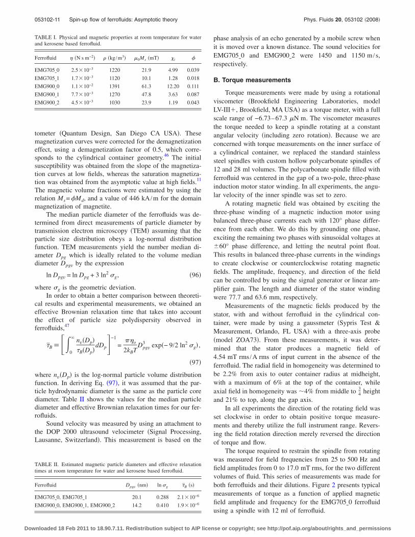
TABLE I. Physical and magnetic properties at room temperature for waterand kerosene based ferrofluid.
Ferrofluid � �N s m−2� � �kg /m3� �0Ms �mT� �i �
EMG705�0 2.5�10−3 1220 21.9 4.99 0.039
EMG705�1 1.7�10−3 1120 10.1 1.28 0.018
EMG900�0 1.1�10−2 1391 61.3 12.20 0.111
EMG900�1 7.7�10−3 1270 47.8 3.63 0.087
EMG900�2 4.5�10−3 1030 23.9 1.19 0.043
TABLE II. Estimated magnetic particle diameters and effective relaxationtimes at room temperature for water and kerosene based ferrofluid.
Ferrofluid Dpgv �nm� ln �g �B �s�
EMG705�0, EMG705�1 20.1 0.288 2.1�10−6
EMG900�0, EMG900�1, EMG900�2 14.2 0.410 1.9�10−6
053102-11 Spin-up flow of ferrofluids: Asymptotic theory Phys. Fluids 20, 053102 �2008�
Downloaded 18 Feb 2011 to 18.90.7.11. Redistribution subject to AIP license or copyright; see http://pof.aip.org/about/rights_and_permissions
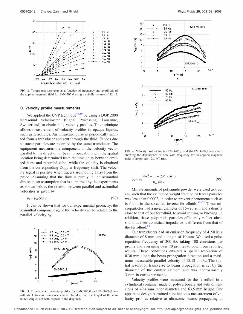
C. Velocity profile measurements
We applied the UVP technique48,49 by using a DOP 2000ultrasound velocimeter �Signal Processing, Lausanne,Switzerland� to obtain bulk velocity profiles. This techniqueallows measurement of velocity profiles in opaque liquids,such as ferrofluids. An ultrasonic pulse is periodically emit-ted from a transducer and sent through the fluid. Echoes dueto tracer particles are recorded by the same transducer. Theequipment measures the component of the velocity vectorparallel to the direction of beam propagation, with the spatiallocation being determined from the time delay between emit-ted burst and recorded echo, while the velocity is obtainedfrom the corresponding Doppler frequency shift. The veloc-ity signal is positive when tracers are moving away from theprobe. Assuming that the flow is purely in the azimuthaldirection, an assumption that is supported by the experimentsas shown below, the relation between parallel and azimuthalvelocities is given by
v� = v� cos � . �98�
It can be shown that for our experimental geometry, theazimuthal component v� of the velocity can be related to theparallel velocity by
v� = v�
�Ro2 + xp − 2Ro cos �
Ro sin �. �99�
Minute amounts of polyamide powder were used as trac-ers, such that the estimated weight fraction of tracer particleswas less than 0.0002, in order to prevent phenomena such asis found in the so-called inverse ferrofluids.50–53 These mi-croparticles had a mean diameter of 15–20 �m and a densityclose to that of our ferrofluid, to avoid settling or buoying. Inaddition, these polyamide particles efficiently reflect ultra-sound as their acoustical impedance is different from that ofthe ferrofluid.54
Our transducers had an emission frequency of 4 MHz, adiameter of 8 mm, and a length of 10 mm. We used a pulserepetition frequency of 200 Hz, taking 100 emissions perprofile and averaging over 70 profiles to obtain our reportedresults. These conditions ensured a spatial resolution of0.36 mm along the beam propagation direction and a maxi-mum measurable parallel velocity of 18.12 mm /s. The spa-tial resolution transverse to beam propagation is set by thediameter of the emitter element and was approximately3 mm in our experiments.
Velocity profiles were measured for the ferrofluid in acylindrical container made of polycarbonate and with dimen-sions of 49.4 mm inner diameter and 63.5 mm height. Ourapparatus design permitted simultaneous measurement of ve-locity profiles relative to ultrasonic beams propagating at
FIG. 2. Torque measurements as a function of frequency and amplitude ofthe applied magnetic field for EMG705�0 using a spindle volume of 12 ml.
FIG. 3. Experimental velocity profiles for EMG705�0 and EMG900�2 fer-rofluids. Ultrasonic transducers were placed at half the height of the con-tainer. Angles are with respect to the diagonal.
FIG. 4. Velocity profiles for �a� EMG705�0 and �b� EMG900�2 ferrofluidsshowing the dependence of flow with frequency for an applied magneticfield of amplitude 12.3 mT rms.
053102-12 Chaves, Zahn, and Rinaldi Phys. Fluids 20, 053102 �2008�
Downloaded 18 Feb 2011 to 18.90.7.11. Redistribution subject to AIP license or copyright; see http://pof.aip.org/about/rights_and_permissions
three distinct angles �using three ultrasonic transducers� rela-tive to the diagonal. A cover was used to eliminate the freesurface and thereby avoid interfacial effects which couldconfound our measurements. Although, the DOP 2000 doesnot require calibration, we verified the correct operation ofour experimental setup by measuring the velocity profile forglycerin and ferrofluid in a cylindrical Couette flow geom-etry and found good agreement with theory.
The rotating magnetic field was generated by using thethree-phase, two-pole magnetic induction motor stator wind-ing described in Sec. III B. Experiments were carried out forfield frequencies between 20 and 120 Hz and amplitudes be-tween 8.3 and 14.3 mT rms.
The first set of experiments was made in such a way asto allow us to verify the existence, direction, and uniformityof the flow in the bulk of the fluid. To this end, we used threetransducers at angles of 7.1°, 11.7°, and 14.2° placed at halfthe height of a container with cover. In obtaining theseangles, we have taken into account the diffraction angle pre-dicted by Snell’s law when the ultrasonic beam passesthrough the container-fluid interface. In this experiment, thedirection of field rotation was set counterclockwise so that apositive velocity measurement implied corotation of fieldand fluid. As is observed in Fig. 3 and for the whole interval
of frequencies and amplitude of the magnetic field studied,we always found corotation of field and fluid in the bulk ofthe fluid and a linear dependence of the velocity with radialposition �i.e., rigid-body-like motion� over most of the fluid.In addition, the velocity profiles measured by each one of thetransducers superimpose, indicating that the flow is uniformand azimuthal in the plane. Another important observation ofthese experiments �Fig. 3�, is that the velocity maximumoccurs at different radial positions for the two fluids, evenunder identical experimental conditions. This is important asthe expression for flow obtained by Pshenichnikov et al.14
does not predict variation in the maximum position with fluidtype. The results of similar experiments at various field fre-quencies and amplitudes are shown in Figs. 4 and 5, where asingle probe angle is shown for simplicity as all three probesprovide similar results.
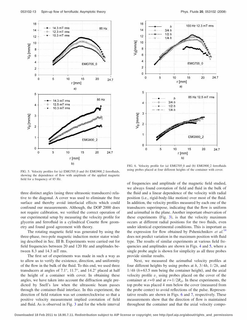
Next, we measured the azimuthal velocity profiles atfour different heights by using probes at h, 3 /4h, 1 /2h, and1 /4h �h=63.5 mm being the container height�, and the axialvelocity profile vz using probes placed on the cover of thecontainer at r=0 and at r=1 /2RO. In these experiments, thetop probe was placed 4 mm below the cover �measured fromthe probe center� to avoid reflections of the pulse. Represen-tative results are shown in Figs. 6 and 7, respectively. Thesemeasurements show that the direction of flow is maintainedthroughout the container and that the axial velocity compo-
FIG. 5. Velocity profiles for �a� EMG705�0 and �b� EMG900�2 ferrofluids,showing the dependence of flow with amplitude of the applied magneticfield for a frequency of 85 Hz.
FIG. 6. Velocity profile for �a� EMG705�0 and �b� EMG900�2 ferrofluidsusing probes placed at four different heights of the container with cover.
053102-13 Spin-up flow of ferrofluids: Asymptotic theory Phys. Fluids 20, 053102 �2008�
Downloaded 18 Feb 2011 to 18.90.7.11. Redistribution subject to AIP license or copyright; see http://pof.aip.org/about/rights_and_permissions
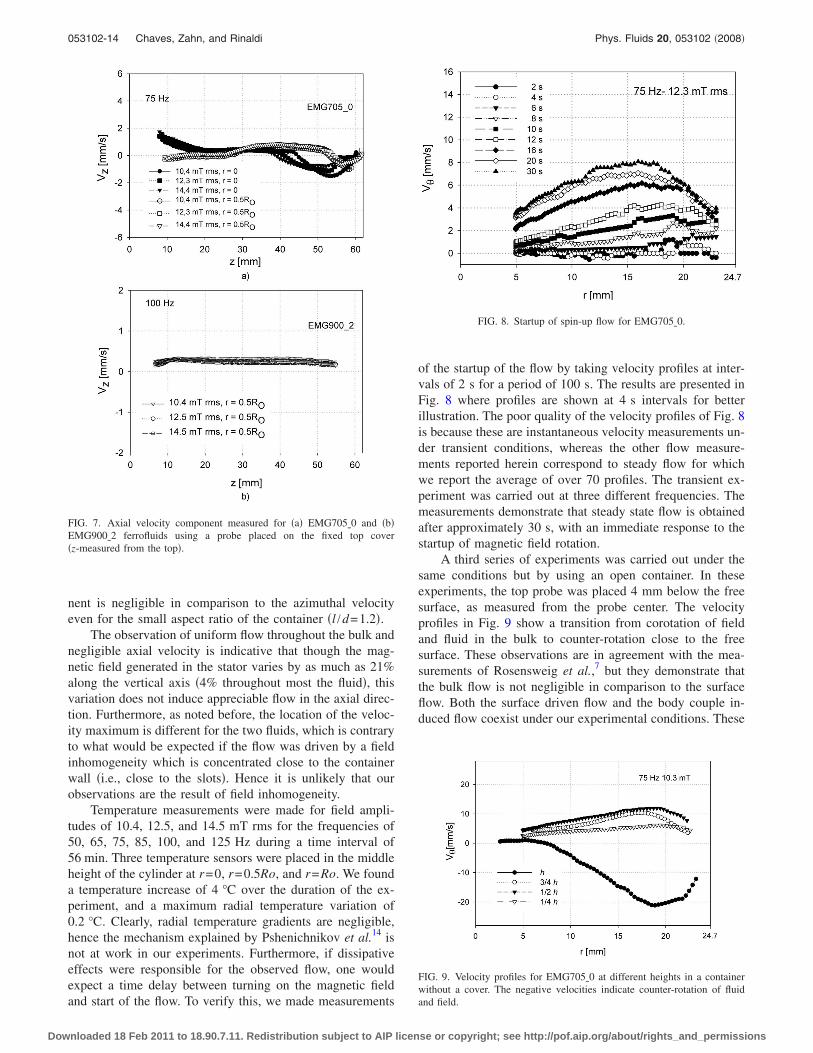
nent is negligible in comparison to the azimuthal velocityeven for the small aspect ratio of the container �l /d=1.2�.
The observation of uniform flow throughout the bulk andnegligible axial velocity is indicative that though the mag-netic field generated in the stator varies by as much as 21%along the vertical axis �4% throughout most the fluid�, thisvariation does not induce appreciable flow in the axial direc-tion. Furthermore, as noted before, the location of the veloc-ity maximum is different for the two fluids, which is contraryto what would be expected if the flow was driven by a fieldinhomogeneity which is concentrated close to the containerwall �i.e., close to the slots�. Hence it is unlikely that ourobservations are the result of field inhomogeneity.
Temperature measurements were made for field ampli-tudes of 10.4, 12.5, and 14.5 mT rms for the frequencies of50, 65, 75, 85, 100, and 125 Hz during a time interval of56 min. Three temperature sensors were placed in the middleheight of the cylinder at r=0, r=0.5Ro, and r=Ro. We founda temperature increase of 4 °C over the duration of the ex-periment, and a maximum radial temperature variation of0.2 °C. Clearly, radial temperature gradients are negligible,hence the mechanism explained by Pshenichnikov et al.14 isnot at work in our experiments. Furthermore, if dissipativeeffects were responsible for the observed flow, one wouldexpect a time delay between turning on the magnetic fieldand start of the flow. To verify this, we made measurements
of the startup of the flow by taking velocity profiles at inter-vals of 2 s for a period of 100 s. The results are presented inFig. 8 where profiles are shown at 4 s intervals for betterillustration. The poor quality of the velocity profiles of Fig. 8is because these are instantaneous velocity measurements un-der transient conditions, whereas the other flow measure-ments reported herein correspond to steady flow for whichwe report the average of over 70 profiles. The transient ex-periment was carried out at three different frequencies. Themeasurements demonstrate that steady state flow is obtainedafter approximately 30 s, with an immediate response to thestartup of magnetic field rotation.
A third series of experiments was carried out under thesame conditions but by using an open container. In theseexperiments, the top probe was placed 4 mm below the freesurface, as measured from the probe center. The velocityprofiles in Fig. 9 show a transition from corotation of fieldand fluid in the bulk to counter-rotation close to the freesurface. These observations are in agreement with the mea-surements of Rosensweig et al.,7 but they demonstrate thatthe bulk flow is not negligible in comparison to the surfaceflow. Both the surface driven flow and the body couple in-duced flow coexist under our experimental conditions. These
FIG. 7. Axial velocity component measured for �a� EMG705�0 and �b�EMG900�2 ferrofluids using a probe placed on the fixed top cover�z-measured from the top�.
FIG. 8. Startup of spin-up flow for EMG705�0.
FIG. 9. Velocity profiles for EMG705�0 at different heights in a containerwithout a cover. The negative velocities indicate counter-rotation of fluidand field.
053102-14 Chaves, Zahn, and Rinaldi Phys. Fluids 20, 053102 �2008�
Downloaded 18 Feb 2011 to 18.90.7.11. Redistribution subject to AIP license or copyright; see http://pof.aip.org/about/rights_and_permissions
experiments further show that surface velocity profile mea-surements are inappropriate in assessing theoretical analysesof the bulk flow as these do not represent the flow behaviorin the bulk of the fluid.
IV. COMPARISON BETWEEN THEORETICALPREDICTIONS AND EXPERIMENTALMEASUREMENTS
Glazov3 analyzed the phenomenon of spin-up flow usinga set of equations similar to Eqs. �3�–�14�, but setting ��=0. The result was that flow is not expected when ferrofluidin a cylindrical container is subjected to a uniform rotatingmagnetic field. Glazov then attributed the experimental ob-servations of Moskowitz and Rosensweig1 to field inhomo-geneity. To demonstrate this, Glazov obtained a general so-lution for flow using higher spatial harmonics, m�1 in Eq.�2�, to simulate the rotating magnetic field generated in amultipole magnetic induction machine stator for twoasymptotic cases: ��1 and ��1. Only a qualitative com-parison of the predictions for the case of ��1 can be madewith our experimental measurements, as our experimentswere made at moderate amplitudes of the magnetic field�0.4���1.25�. The velocity profiles predicted by Glazov’stheory are of similar shape to the measured velocity profilesfor EMG705�0, however, Glazov’s theory cannot describethe boundary layer character of the velocity profiles forEMG900�2. In addition, Glazov predicts that the flow direc-tion reverses, becoming contrary to the field direction, when�h 0.12, with �h the hydrodynamic volume fraction of par-ticles. Velocity profiles measured by using EMG902�1, with�h�0.18, showed that the fluid corotates with the magneticfield even for this hydrodynamic volume fraction of mag-netic particles, hence Glazov’s theory does not explain ourexperimental observations.
From our measurements, it is clear that the bulk fluidcorotates with the magnetic field, therefore the results ofKaloni10 for a slip boundary condition in the translationalvelocity do not agree to the experiments. Furthermore, theexperimental results described above show that thermal ef-fects are not responsible for the observed flow, hence thetheories presented by Shliomis28 and Pshenichnikov et al.14
do not explain the observed flow. Finally, as can be seen inFig. 9, even though surface effects dominate at the free sur-face, as observed by Rosensweig et al.,7 the bulk flow is notnegligible in comparison. These observations leave us withthe original spin diffusion theory of Zaitsev and Shliomis2 asthe only published model in �at least qualitative� agreementwith our measurements.
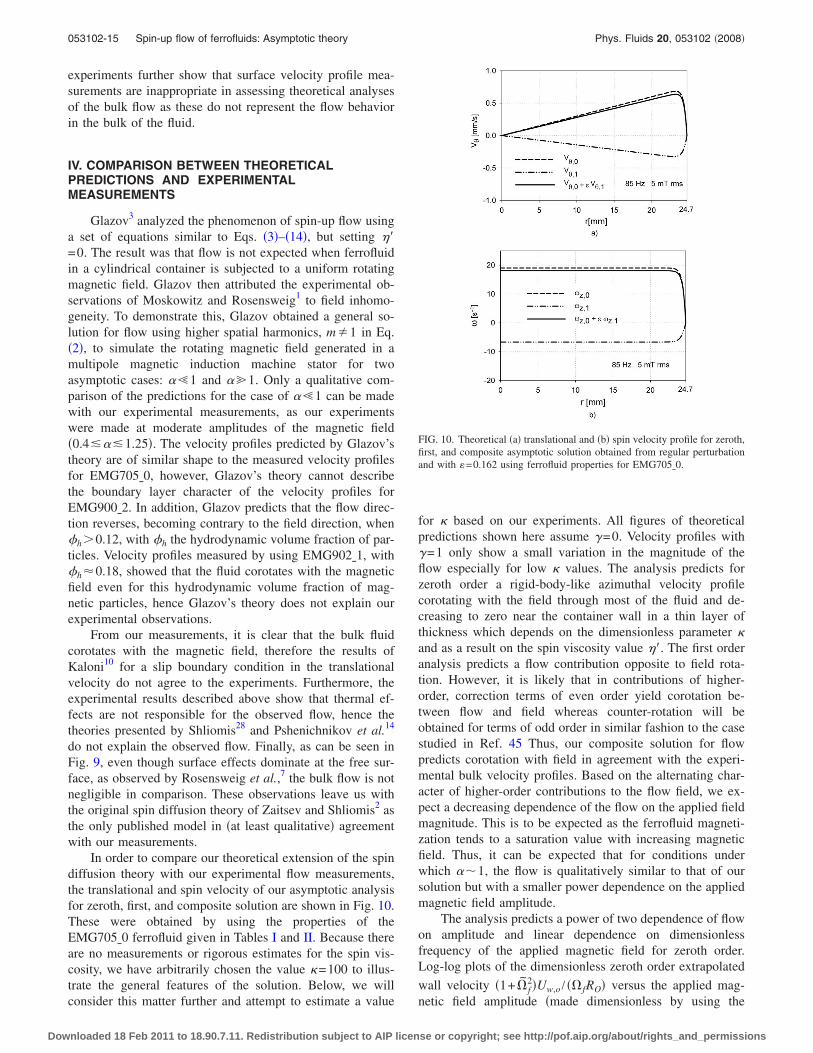
In order to compare our theoretical extension of the spindiffusion theory with our experimental flow measurements,the translational and spin velocity of our asymptotic analysisfor zeroth, first, and composite solution are shown in Fig. 10.These were obtained by using the properties of theEMG705�0 ferrofluid given in Tables I and II. Because thereare no measurements or rigorous estimates for the spin vis-cosity, we have arbitrarily chosen the value �=100 to illus-trate the general features of the solution. Below, we willconsider this matter further and attempt to estimate a value
for � based on our experiments. All figures of theoreticalpredictions shown here assume �=0. Velocity profiles with�=1 only show a small variation in the magnitude of theflow especially for low � values. The analysis predicts forzeroth order a rigid-body-like azimuthal velocity profilecorotating with the field through most of the fluid and de-creasing to zero near the container wall in a thin layer ofthickness which depends on the dimensionless parameter �and as a result on the spin viscosity value ��. The first orderanalysis predicts a flow contribution opposite to field rota-tion. However, it is likely that in contributions of higher-order, correction terms of even order yield corotation be-tween flow and field whereas counter-rotation will beobtained for terms of odd order in similar fashion to the casestudied in Ref. 45 Thus, our composite solution for flowpredicts corotation with field in agreement with the experi-mental bulk velocity profiles. Based on the alternating char-acter of higher-order contributions to the flow field, we ex-pect a decreasing dependence of the flow on the applied fieldmagnitude. This is to be expected as the ferrofluid magneti-zation tends to a saturation value with increasing magneticfield. Thus, it can be expected that for conditions underwhich ��1, the flow is qualitatively similar to that of oursolution but with a smaller power dependence on the appliedmagnetic field amplitude.
The analysis predicts a power of two dependence of flowon amplitude and linear dependence on dimensionlessfrequency of the applied magnetic field for zeroth order.Log-log plots of the dimensionless zeroth order extrapolated
wall velocity �1+ f2�Uw,o / � fRO� versus the applied mag-
netic field amplitude �made dimensionless by using the
FIG. 10. Theoretical �a� translational and �b� spin velocity profile for zeroth,first, and composite asymptotic solution obtained from regular perturbationand with �=0.162 using ferrofluid properties for EMG705�0.
053102-15 Spin-up flow of ferrofluids: Asymptotic theory Phys. Fluids 20, 053102 �2008�
Downloaded 18 Feb 2011 to 18.90.7.11. Redistribution subject to AIP license or copyright; see http://pof.aip.org/about/rights_and_permissions
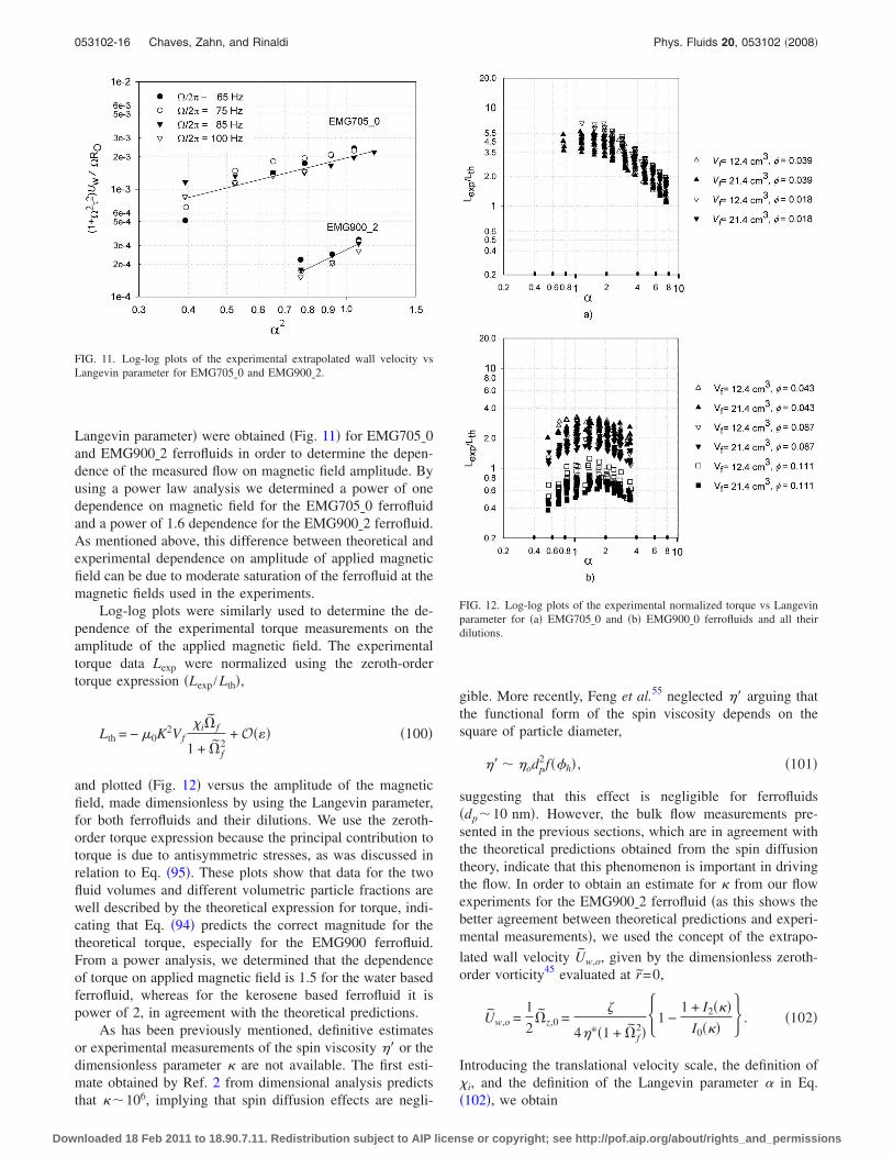
Langevin parameter� were obtained �Fig. 11� for EMG705�0and EMG900�2 ferrofluids in order to determine the depen-dence of the measured flow on magnetic field amplitude. Byusing a power law analysis we determined a power of onedependence on magnetic field for the EMG705�0 ferrofluidand a power of 1.6 dependence for the EMG900�2 ferrofluid.As mentioned above, this difference between theoretical andexperimental dependence on amplitude of applied magneticfield can be due to moderate saturation of the ferrofluid at themagnetic fields used in the experiments.
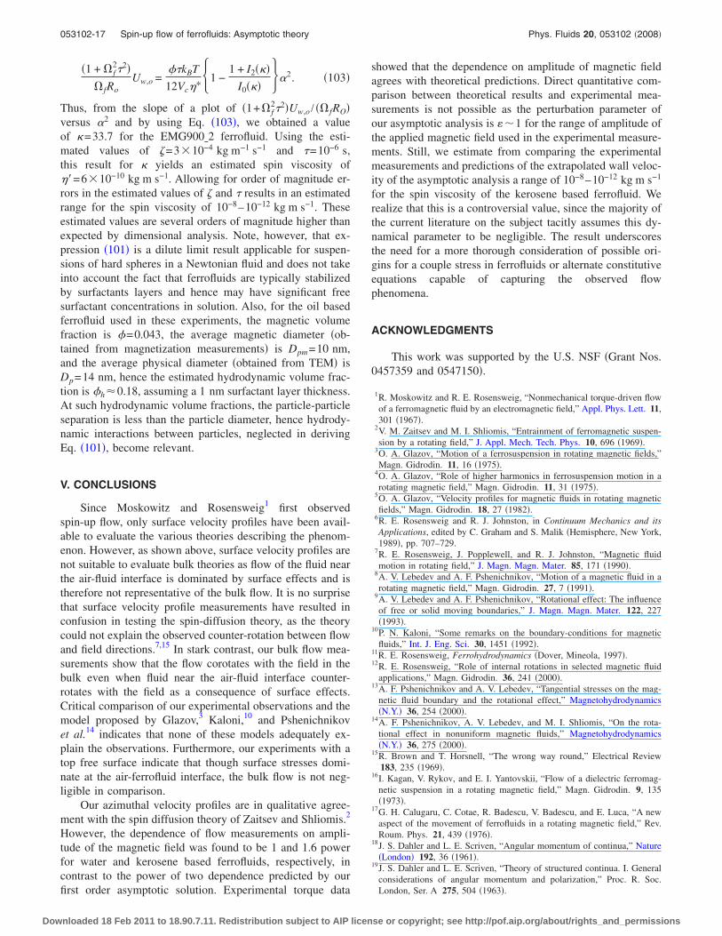
Log-log plots were similarly used to determine the de-pendence of the experimental torque measurements on theamplitude of the applied magnetic field. The experimentaltorque data Lexp were normalized using the zeroth-ordertorque expression �Lexp /Lth�,
Lth = − �0K2Vf�i f
1 + f2
+ O��� �100�
and plotted �Fig. 12� versus the amplitude of the magneticfield, made dimensionless by using the Langevin parameter,for both ferrofluids and their dilutions. We use the zeroth-order torque expression because the principal contribution totorque is due to antisymmetric stresses, as was discussed inrelation to Eq. �95�. These plots show that data for the twofluid volumes and different volumetric particle fractions arewell described by the theoretical expression for torque, indi-cating that Eq. �94� predicts the correct magnitude for thetheoretical torque, especially for the EMG900 ferrofluid.From a power analysis, we determined that the dependenceof torque on applied magnetic field is 1.5 for the water basedferrofluid, whereas for the kerosene based ferrofluid it ispower of 2, in agreement with the theoretical predictions.
As has been previously mentioned, definitive estimatesor experimental measurements of the spin viscosity �� or thedimensionless parameter � are not available. The first esti-mate obtained by Ref. 2 from dimensional analysis predictsthat ��106, implying that spin diffusion effects are negli-
gible. More recently, Feng et al.55 neglected �� arguing thatthe functional form of the spin viscosity depends on thesquare of particle diameter,
�� � �odp2 f��h� , �101�
suggesting that this effect is negligible for ferrofluids�dp�10 nm�. However, the bulk flow measurements pre-sented in the previous sections, which are in agreement withthe theoretical predictions obtained from the spin diffusiontheory, indicate that this phenomenon is important in drivingthe flow. In order to obtain an estimate for � from our flowexperiments for the EMG900�2 ferrofluid �as this shows thebetter agreement between theoretical predictions and experi-mental measurements�, we used the concept of the extrapo-
lated wall velocity Uw,o, given by the dimensionless zeroth-order vorticity45 evaluated at r=0,
Uw,o =1
2z,0 =
�
4�*�1 + f2��1 −
1 + I2���I0��� � . �102�
Introducing the translational velocity scale, the definition of�i, and the definition of the Langevin parameter � in Eq.�102�, we obtain
FIG. 11. Log-log plots of the experimental extrapolated wall velocity vsLangevin parameter for EMG705�0 and EMG900�2.
FIG. 12. Log-log plots of the experimental normalized torque vs Langevinparameter for �a� EMG705�0 and �b� EMG900�0 ferrofluids and all theirdilutions.
053102-16 Chaves, Zahn, and Rinaldi Phys. Fluids 20, 053102 �2008�
Downloaded 18 Feb 2011 to 18.90.7.11. Redistribution subject to AIP license or copyright; see http://pof.aip.org/about/rights_and_permissions
�1 + f2�2�
fRoUw,o =
��kBT
12Vc�*�1 −1 + I2���
I0��� ��2. �103�
Thus, from the slope of a plot of �1+ f2�2�Uw,o / � fRO�
versus �2 and by using Eq. �103�, we obtained a valueof �=33.7 for the EMG900�2 ferrofluid. Using the esti-mated values of �=3�10−4 kg m−1 s−1 and �=10−6 s,this result for � yields an estimated spin viscosity of��=6�10−10 kg m s−1. Allowing for order of magnitude er-rors in the estimated values of � and � results in an estimatedrange for the spin viscosity of 10−8–10−12 kg m s−1. Theseestimated values are several orders of magnitude higher thanexpected by dimensional analysis. Note, however, that ex-pression �101� is a dilute limit result applicable for suspen-sions of hard spheres in a Newtonian fluid and does not takeinto account the fact that ferrofluids are typically stabilizedby surfactants layers and hence may have significant freesurfactant concentrations in solution. Also, for the oil basedferrofluid used in these experiments, the magnetic volumefraction is �=0.043, the average magnetic diameter �ob-tained from magnetization measurements� is Dpm=10 nm,and the average physical diameter �obtained from TEM� isDp=14 nm, hence the estimated hydrodynamic volume frac-tion is �h�0.18, assuming a 1 nm surfactant layer thickness.At such hydrodynamic volume fractions, the particle-particleseparation is less than the particle diameter, hence hydrody-namic interactions between particles, neglected in derivingEq. �101�, become relevant.
V. CONCLUSIONS
Since Moskowitz and Rosensweig1 first observedspin-up flow, only surface velocity profiles have been avail-able to evaluate the various theories describing the phenom-enon. However, as shown above, surface velocity profiles arenot suitable to evaluate bulk theories as flow of the fluid nearthe air-fluid interface is dominated by surface effects and istherefore not representative of the bulk flow. It is no surprisethat surface velocity profile measurements have resulted inconfusion in testing the spin-diffusion theory, as the theorycould not explain the observed counter-rotation between flowand field directions.7,15 In stark contrast, our bulk flow mea-surements show that the flow corotates with the field in thebulk even when fluid near the air-fluid interface counter-rotates with the field as a consequence of surface effects.Critical comparison of our experimental observations and themodel proposed by Glazov,3 Kaloni,10 and Pshenichnikovet al.14 indicates that none of these models adequately ex-plain the observations. Furthermore, our experiments with atop free surface indicate that though surface stresses domi-nate at the air-ferrofluid interface, the bulk flow is not neg-ligible in comparison.
Our azimuthal velocity profiles are in qualitative agree-ment with the spin diffusion theory of Zaitsev and Shliomis.2
However, the dependence of flow measurements on ampli-tude of the magnetic field was found to be 1 and 1.6 powerfor water and kerosene based ferrofluids, respectively, incontrast to the power of two dependence predicted by ourfirst order asymptotic solution. Experimental torque data
showed that the dependence on amplitude of magnetic fieldagrees with theoretical predictions. Direct quantitative com-parison between theoretical results and experimental mea-surements is not possible as the perturbation parameter ofour asymptotic analysis is ��1 for the range of amplitude ofthe applied magnetic field used in the experimental measure-ments. Still, we estimate from comparing the experimentalmeasurements and predictions of the extrapolated wall veloc-ity of the asymptotic analysis a range of 10−8–10−12 kg m s−1
for the spin viscosity of the kerosene based ferrofluid. Werealize that this is a controversial value, since the majority ofthe current literature on the subject tacitly assumes this dy-namical parameter to be negligible. The result underscoresthe need for a more thorough consideration of possible ori-gins for a couple stress in ferrofluids or alternate constitutiveequations capable of capturing the observed flowphenomena.
ACKNOWLEDGMENTS
This work was supported by the U.S. NSF �Grant Nos.0457359 and 0547150�.
1R. Moskowitz and R. E. Rosensweig, “Nonmechanical torque-driven flowof a ferromagnetic fluid by an electromagnetic field,” Appl. Phys. Lett. 11,301 �1967�.
2V. M. Zaitsev and M. I. Shliomis, “Entrainment of ferromagnetic suspen-sion by a rotating field,” J. Appl. Mech. Tech. Phys. 10, 696 �1969�.
3O. A. Glazov, “Motion of a ferrosuspension in rotating magnetic fields,”Magn. Gidrodin. 11, 16 �1975�.
4O. A. Glazov, “Role of higher harmonics in ferrosuspension motion in arotating magnetic field,” Magn. Gidrodin. 11, 31 �1975�.
5O. A. Glazov, “Velocity profiles for magnetic fluids in rotating magneticfields,” Magn. Gidrodin. 18, 27 �1982�.
6R. E. Rosensweig and R. J. Johnston, in Continuum Mechanics and itsApplications, edited by C. Graham and S. Malik �Hemisphere, New York,1989�, pp. 707–729.
7R. E. Rosensweig, J. Popplewell, and R. J. Johnston, “Magnetic fluidmotion in rotating field,” J. Magn. Magn. Mater. 85, 171 �1990�.
8A. V. Lebedev and A. F. Pshenichnikov, “Motion of a magnetic fluid in arotating magnetic field,” Magn. Gidrodin. 27, 7 �1991�.
9A. V. Lebedev and A. F. Pshenichnikov, “Rotational effect: The influenceof free or solid moving boundaries,” J. Magn. Magn. Mater. 122, 227�1993�.
10P. N. Kaloni, “Some remarks on the boundary-conditions for magneticfluids,” Int. J. Eng. Sci. 30, 1451 �1992�.
11R. E. Rosensweig, Ferrohydrodynamics �Dover, Mineola, 1997�.12R. E. Rosensweig, “Role of internal rotations in selected magnetic fluid
applications,” Magn. Gidrodin. 36, 241 �2000�.13A. F. Pshenichnikov and A. V. Lebedev, “Tangential stresses on the mag-
netic fluid boundary and the rotational effect,” Magnetohydrodynamics�N.Y.� 36, 254 �2000�.
14A. F. Pshenichnikov, A. V. Lebedev, and M. I. Shliomis, “On the rota-tional effect in nonuniform magnetic fluids,” Magnetohydrodynamics�N.Y.� 36, 275 �2000�.
15R. Brown and T. Horsnell, “The wrong way round,” Electrical Review183, 235 �1969�.
16I. Kagan, V. Rykov, and E. I. Yantovskii, “Flow of a dielectric ferromag-netic suspension in a rotating magnetic field,” Magn. Gidrodin. 9, 135�1973�.
17G. H. Calugaru, C. Cotae, R. Badescu, V. Badescu, and E. Luca, “A newaspect of the movement of ferrofluids in a rotating magnetic field,” Rev.Roum. Phys. 21, 439 �1976�.
18J. S. Dahler and L. E. Scriven, “Angular momentum of continua,” Nature�London� 192, 36 �1961�.
19J. S. Dahler and L. E. Scriven, “Theory of structured continua. I. Generalconsiderations of angular momentum and polarization,” Proc. R. Soc.London, Ser. A 275, 504 �1963�.
053102-17 Spin-up flow of ferrofluids: Asymptotic theory Phys. Fluids 20, 053102 �2008�
Downloaded 18 Feb 2011 to 18.90.7.11. Redistribution subject to AIP license or copyright; see http://pof.aip.org/about/rights_and_permissions
20D. W. Condiff and J. S. Dahler, “Fluid mechanical aspects of antisymmet-ric stress,” Phys. Fluids 7, 842 �1964�.
21M. I. Shliomis, “Effective viscosity of magnetic suspensions,” Sov. Phys.JETP 34, 1291�1972�.
22M. Zahn and D. R. Greer, “Ferrohydrodynamic pumping in spatially uni-form sinusoidally time-varying magnetic fields,” J. Magn. Magn. Mater.149, 165 �1995�.
23M. Zahn and L. L. Pioch, “Ferrofluid flows in AC and traveling wavemagnetic fields with effective positive, zero or negative dynamic viscos-ity,” J. Magn. Magn. Mater. 201, 144 �1999�.
24C. Rinaldi and H. Brenner, “Body versus surface forces in continuummechanics: Is the Maxwell stress tensor a physically objective Cauchystress?” Phys. Rev. E 65, 036615 �2002�.
25C. Rinaldi and M. Zahn, “Effects of spin viscosity on ferrofluid flowprofiles in alternating and rotating magnetic fields,” Phys. Fluids 14, 2847�2002�.
26P. Brunn, “The velocity slip of polar fluids,” Rheol. Acta 14, 1039 �1975�.27E. L. Aero, A. N. Bulygin, and E. V. Kuvshinski, “Asymmetric hydrome-
chanics,” J. Lumin. 29, 333 �1965�.28M. I. Shliomis, T. P. Lyubimova, and D. V. Lyubimov, “Ferrohydrodynam-
ics: an essay on the progress of ideas,” Chem. Eng. Commun. 67, 275�1988�.
29A. Chaves, C. Rinaldi, S. Elborai, X. He, and M. Zahn, “Bulk flow inferrofluids in a uniform rotating magnetic field,” Phys. Rev. Lett. 96,194501 �2006�.
30R. E. Rosensweig, “Continuum equations for magnetic and dielectric flu-ids with internal rotations,” J. Chem. Phys. 121, 1228 �2000�.
31H. Brenner, “Rheology of two-phase systems,” Annu. Rev. Fluid Mech. 2,137 �1970�.
32M. I. Shliomis, “Concerning one gyromagnetic effect in a liquid paramag-net,” Sov. Phys. JETP 39, 701 �1974�.
33M. I. Shliomis, “Ferrohydrodynamics: Testing a third magnetization equa-tion,” Phys. Rev. E 64, 060501 �2001�.
34M. I. Shliomis, “Comment on Magnetoviscosity and relaxation in ferrof-luids,” Phys. Rev. E 64, 063501 �2001�.
35B. U. Felderhof, “Steady-state magnetoviscosity of a dilute ferrofluid,”Magn. Gidrodin. 36, 329 �2000�.
36B. U. Felderhof, “Magnetoviscosity and relaxation in ferrofluids,” Phys.Rev. E 62, 3848 �2000�.
37B. U. Felderhof, “Reply to “Comment on ‘Magnetoviscosity and relax-ation in ferrofluids’”,” Phys. Rev. E 64, 063502 �2001�.
38J. A. Stratton, Electromagnetic Theory �McGraw-Hill, New York, 1941�.39J. R. Melcher, Continuum Electromechanics �MIT, Cambridge, 1981�.40K. A. Kline, “Predictions from polar fluid theory which are independent of
spin boundary-condition,” Trans. Soc. Rheol. 19, 139 �1975�.41S. C. Cowin, “Note on Predictions from polar fluid theory which are
independent of spin boundary-condition,” Trans. Soc. Rheol. 20, 195�1976�.
42K. A. Kline, “Discussion of Predictions from polar fluid theory which areindependent of spin boundary-conditions,” J. Rheol. 26, 317 �1982�.
43H. Lamb, Hydrodynamics, 6th ed. �Dover, New York, 1945�.44W. M. Deen, Analysis of Transport Phenomena �Oxford University Press,
New York, 1998�.45C. Rinaldi, “Continuum modeling of polarizable systems,” Ph.D. thesis,
Massachussetts Institute of Technology, 2002.46A. Rosenthal, C. Rinaldi, T. Franklin, and M. Zahn, “Torque measure-
ments in spin-up flow of ferrofluids,” J. Fluids Eng. 126, 198 �2004�.47A. Chaves, F. Gutman, and C. Rinaldi, “Torque and bulk flow of ferrofluid
in an annular gap subjected to a rotating magnetic field,” J. Fluids Eng.129, 412 �2007�.
48Y. Takeda, “Velocity profile measurement by ultrasonic Doppler method,”Exp. Therm. Fluid Sci. 10, 444 �1995�.
49Y. Takeda, “Ultrasonic Doppler method for velocity profile measurementin fluid dynamics and fluid engineering,” Exp. Fluids 26, 177 �1999�.
50B. J. de Gans, C. Blom, J. Mellema, and A. P. Philipse, “Preparation andmagnetisation of a silica-magnetite inverse ferrofluid,” J. Magn. Magn.Mater. 201, 11 �1999�.
51B. J. de Gans, C. Blom, A. P. Philipse, and J. Mellema, “Linear viscoelas-ticity of an inverse ferrofluid,” Phys. Rev. E 60, 4518 �1999�.
52B. J. de Gans, H. Hoekstra, and J. Mellema, “Non-linear magnetorheologi-cal behaviour of an inverse ferrofluid,” Faraday Discuss. 112, 209 �1999�.
53B. J. de Gans, N. j. Duin, D. van den Ende, and J. Mellema, “The influ-ence of particle size on the magnerheological properties of an inverseferrofluid,” J. Chem. Phys. 113, 2032 �2000�.
54D. Brito, H.-C. Nataf, P. Cardin, J. Aubert, and J.-P. Masson, “UltrasonicDoppler velocimetry in liquid gallium,” Exp. Fluids 31, 653 �2001�.
55S. Feng, A. Graham, J. Abbott, and H. Brenner, “Antisymmetric stressesin suspensions: vortex viscosity and energy dissipation,” J. Fluid Mech.563, 97 �2006�.
053102-18 Chaves, Zahn, and Rinaldi Phys. Fluids 20, 053102 �2008�
Downloaded 18 Feb 2011 to 18.90.7.11. Redistribution subject to AIP license or copyright; see http://pof.aip.org/about/rights_and_permissions
Related Documents