Hindawi Publishing Corporation Mathematical Problems in Engineering Volume 2009, Article ID 242396, 18 pages doi:10.1155/2009/242396 Research Article Spin-Stabilized Spacecrafts: Analytical Attitude Propagation Using Magnetic Torques Roberta Veloso Garcia, 1 Maria Cec´ ılia F. P. S. Zanardi, 2 and H ´ elio Koiti Kuga 1 1 Space Mechanic and Control Division, National Institute for Space Research (INPE), Sao Paulo, S˜ ao Jos´ e dos Campos 12227-010, Brazil 2 Department of Mathematics, Group of Orbital Dynamics and Planetology, Sao Paulo State University (UNESP), Sao Paulo, Guaratinguet´ a 12516-410, Brazil Correspondence should be addressed to Roberta Veloso Garcia, [email protected] Received 28 July 2009; Accepted 4 November 2009 Recommended by Antonio Prado An analytical approach for spin-stabilized satellites attitude propagation is presented, considering the influence of the residual magnetic torque and eddy currents torque. It is assumed two approaches to examine the influence of external torques acting during the motion of the satellite, with the Earth’s magnetic field described by the quadripole model. In the first approach is included only the residual magnetic torque in the motion equations, with the satellites in circular or elliptical orbit. In the second approach only the eddy currents torque is analyzed, with the satellite in circular orbit. The inclusion of these torques on the dynamic equations of spin stabilized satellites yields the conditions to derive an analytical solution. The solutions show that residual torque does not affect the spin velocity magnitude, contributing only for the precession and the drift of the spacecraft’s spin axis and the eddy currents torque causes an exponential decay of the angular velocity magnitude. Numerical simulations performed with data of the Brazilian Satellites SCD1 and SCD2 show the period that analytical solution can be used to the attitude propagation, within the dispersion range of the attitude determination system performance of Satellite Control Center of Brazil National Research Institute. Copyright q 2009 Roberta Veloso Garcia et al. This is an open access article distributed under the Creative Commons Attribution License, which permits unrestricted use, distribution, and reproduction in any medium, provided the original work is properly cited. 1. Introduction This paper aims at analyzing the rotational motion dynamics of spin-stabilized Earth’s artificial satellites, through derivation of an analytical attitude prediction. Emphasis is placed on modeling the torques steaming from residual magnetic and eddy currents perturbations, as well as their influences on the satellite angular velocity and space orientation. A spherical coordinated system fixed in the satellite is used to locate the spin axis of the satellite in relation

Welcome message from author
This document is posted to help you gain knowledge. Please leave a comment to let me know what you think about it! Share it to your friends and learn new things together.
Transcript

Hindawi Publishing CorporationMathematical Problems in EngineeringVolume 2009, Article ID 242396, 18 pagesdoi:10.1155/2009/242396
Research ArticleSpin-Stabilized Spacecrafts: Analytical AttitudePropagation Using Magnetic Torques
Roberta Veloso Garcia,1 Maria Cecılia F. P. S. Zanardi,2and Helio Koiti Kuga1
1 Space Mechanic and Control Division, National Institute for Space Research (INPE), Sao Paulo,Sao Jose dos Campos 12227-010, Brazil
2 Department of Mathematics, Group of Orbital Dynamics and Planetology, Sao Paulo State University(UNESP), Sao Paulo, Guaratingueta 12516-410, Brazil
Correspondence should be addressed to Roberta Veloso Garcia, [email protected]
Received 28 July 2009; Accepted 4 November 2009
Recommended by Antonio Prado
An analytical approach for spin-stabilized satellites attitude propagation is presented, consideringthe influence of the residual magnetic torque and eddy currents torque. It is assumed twoapproaches to examine the influence of external torques acting during the motion of the satellite,with the Earth’s magnetic field described by the quadripole model. In the first approach is includedonly the residual magnetic torque in the motion equations, with the satellites in circular or ellipticalorbit. In the second approach only the eddy currents torque is analyzed, with the satellite incircular orbit. The inclusion of these torques on the dynamic equations of spin stabilized satellitesyields the conditions to derive an analytical solution. The solutions show that residual torque doesnot affect the spin velocity magnitude, contributing only for the precession and the drift of thespacecraft’s spin axis and the eddy currents torque causes an exponential decay of the angularvelocity magnitude. Numerical simulations performed with data of the Brazilian Satellites (SCD1and SCD2) show the period that analytical solution can be used to the attitude propagation, withinthe dispersion range of the attitude determination system performance of Satellite Control Centerof Brazil National Research Institute.
Copyright q 2009 Roberta Veloso Garcia et al. This is an open access article distributed underthe Creative Commons Attribution License, which permits unrestricted use, distribution, andreproduction in any medium, provided the original work is properly cited.
1. Introduction
This paper aims at analyzing the rotational motion dynamics of spin-stabilized Earth’sartificial satellites, through derivation of an analytical attitude prediction. Emphasis is placedon modeling the torques steaming from residual magnetic and eddy currents perturbations,as well as their influences on the satellite angular velocity and space orientation. A sphericalcoordinated system fixed in the satellite is used to locate the spin axis of the satellite in relation

2 Mathematical Problems in Engineering
to the terrestrial equatorial system. The directions of the spin axis are specified by the rightascension (α) and the declination (δ) as represented in Figure 1. The magnetic residual torqueoccurs due to the interaction between the Earth magnetic field and the residual magneticmoment along the spin axis of the satellite. The eddy currents torque appears due to theinteraction of such currents circulating along the satellite structure chassis and the Earth’smagnetic field.
The torque analysis is performed through the quadripole model for the Earth’smagnetic field and the satellite in circular and elliptical orbits. Essentially an analyticalaveraging method is applied to determine the mean torque over an orbital period.
To compute the average components of both the residual magnetic and eddy currenttorques in the satellite body frame reference system (satellite system), an average time inthe fast varying orbit element, the mean anomaly, is utilized. This approach involves severalrotation matrices, which are dependent on the orbit elements, right ascension and declinationof the satellite spin axis, the magnetic colatitudes, and the longitude of ascending node of themagnetic plane.
Unlike the eddy currents torques, it is observed that the residual magnetic torque doesnot have component along the spin axis; however, it has nonzero components in satellitebody x-axis and y-axis. Afterwards, the inclusion of such torques on the rotational motiondifferential equations of spin-stabilized satellites yields the conditions to derive an analyticalsolution [1]. The theory is developed accounting also for orbit elements time variation,not restricted to circular orbits, giving rise to some hundreds of curvature integrals solvedanalytically.
In order to validate the analytical approach, the theory developed has been appliedfor the spin-stabilized Brazilian Satellites (SCD1 and SCD2), which are quite appropriatedfor verification and comparison of the theory with the data generated and processed by theSatellite Control Center (SCC) of Brazil National Research Institute (INPE). The oblatenessof the orbital elements is taken into account.
The behaviors of right ascension, declination, and spin velocity of the spin axis withthe time are presented and the results show the agreement between the analytical solutionand the actual satellite behavior.
2. Geomagnetic Field
It is well known that the Earth’s magnetic field can be obtained by the gradient of a scalarpotential V [2]; it means that
−→B = −∇V, (2.1)
with the magnetic potential V given by
V(r ′, φ, θ
)= rT
k∑
n=1
(rTr
)n+1 n∑
m=0
(gmn cosmθ + hmn senmθ
)Pmn
(φ), (2.2)
where rT is the Earth’s equatorial radius, gmn , hmn are the Gaussian coefficients, Pmn (φ) arethe Legendre associated polynomial and r, φ, θ mean the geocentric distance, the localcolatitudes, and local longitude, respectively.

Mathematical Problems in Engineering 3
K j
k = s
90◦ − δ
α
Equatorial planeJ
i
I
Spin plane
Figure 1: Orientation of the spin axis (s): equatorial system (I, J , K), satellite body frame reference system(i, j, k), right ascension (α), and declination (δ) of the spin axis.
In terms of spherical coordinates, the geomagnetic field can be expressed by [2],
−→B = Brr + Bφφ + Bθθ, (2.3)
with
Br = −∂V
∂r, Bφ = − 1
r
∂V
∂φ, Bθ = −
1rsenφ
∂V∂θ
. (2.4)
For the quadripole model, it is assumed that n equals 1 and 2 and m equals 0, 1 and 2 in (2.2).After straightforward computations, the geomagnetic field can be expressed by [3, 4]
Br = 2(rTr
)3
f1(θ, φ
)+ 3
(rTr
)4
f2(θ, φ
), (2.5)
Bφ = −(rTr
)3
f3(θ, φ
)−(rTr
)4
f4(θ, φ
), (2.6)
Bθ = −1
senφ
{(rTr
)3
f5(θ, φ
)+(rTr
)4
f6(θ, φ
)+ 2
(rTr
)4
f7(θ, φ
)}
, (2.7)
where the functions fi, i = 1, 2 , . . . , 7, are shown in [3] and depend on the Gaussiancoefficients g2
2 , h11, h
12, h
22 .
In the Equator reference system, the geomagnetic field is expressed by [2]
BX =(Br cos δ + Bφsen δ
)cos α − Bθsenα, (2.8)
BY =(Br cos δ + Bφsen δ
)senα − Bθ cos α, (2.9)
BZ = Brsen δ + Bφ cos δ, (2.10)

4 Mathematical Problems in Engineering
where α and δ are the right ascension and declination of the satellite position vector,respectively, which can be obtained in terms of the orbital elements; Br , Bφ, and Bθ are givenby (2.5), (2.6), and (2.7), respectively.
In a satellite reference system, in which the axis z is along the spin axis, thegeomagnetic field is given by [4, 5]
−→B = Bxi + Byj + Bzk, (2.11)
where
Bx = − BXsenα + BY cosα,
By = −BXsen δ cosα − BY sen δ senα + BZ cos δ,
Bz = − BX cos δ cosα − BY cos δ senα + BZsen δ,
(2.12)
with BX , BY , and BZ given by (2.8)–(2.10).
3. Residual and Eddy Currents Torques
Magnetic residual torques result from the interaction between the spacecraft’s residualmagnetic field and the Earth’s magnetic fields. If −→m is the magnetic moment of the spacecraftand
−→B is the geomagnetic field, then the residual magnetic torques are given by [2]
−→Nr =
−→m × −→B. (3.1)
For the spin-stabilized satellite, with appropriate nutation dampers, the magnetic moment ismostly aligned along the spin axis and the residual torque can be expressed by [5]
−→Nr =Msk ×
−→B, (3.2)
where Ms is the satellite magnetic moment along its spin axis and k is the unit vector alongthe spin axis of the satellite.
By substituting the geomagnetic field (2.11) in (3.1), the instantaneous residual torqueis expressed by
−→Nr =Ms
(− Byi + Bxj
). (3.3)
On the other hand, the eddy currents torque is caused by the spacecraft spinning motion. If−→W is the spacecraft’s angular velocity vector and p is the Foucault parameter representingthe geometry and material of the satellite chassis [2], then this torque may be modeled by [2]
−→Ni = p
−→B ×
(−→B × −→W
). (3.4)

Mathematical Problems in Engineering 5
For a spin-stabilized satellite, the spacecraft’s angular velocity vector and the satellitemagnetic moment, along the z-axis and induced eddy currents torque, can be expressed by[5, 6]
−→Ni = pW
(−Bx Bzi − ByBz j +
(B2y + B
2x
)k). (3.5)
4. Mean Residual and Eddy Currents Torques
In order to obtain the mean residual and eddy currents torques, it is necessary to integratethe instantaneous torques
−→Nr and
−→Ni, given in (3.3) and (3.5), over one orbital period T as
−→Nrm =
1T
∫ ti + T
ti
−→Nrdt,
−→Nim =
1T
∫ ti + T
ti
−→Nidt, (4.1)
where t is the time ti the initial time, and T the orbital period. Changing the independentvariable to the fast varying true anomaly, the mean residual and eddy currents torque can beobtained by [4]
−→Nrm =
1T
∫υi+2π
υi
−→Nr
r2
hdυ,
−→Nim =
1T
∫υi+2π
υi
−→Ni
r2
hdυ, (4.2)
where υi is the true anomaly at instant ti, r is the geocentric distance, and h is the specificangular moment of orbit.
To evaluate the integrals of (4.2), we can use spherical trigonometry properties,rotation matrix associated with the references systems, and the elliptic expansions of the trueanomaly in terms of the mean anomaly [7], including terms up to first order in the eccentricity(e). Without losing generality, for the sake of simplification of the integrals, we consider theinitial time for integration equal to the instant that the satellite passes through perigee. Afterextensive but simple algebraic developments, the mean residual and eddy currents torquescan be expressed by [3, 6]
−→Nrm =Nrxmi +Nrymj,
−→Nim =
pW
2π
(Nixmi +Niymj +Nizmk
), (4.3)
with
Nrxm =Ms
2π(A sen δ cosα + B sen δ senα − C sen δ),
Nrym =Ms
2π(− D senα + E cos δ)
(4.4)
and Nixm, Niym, Nizm as well as the coefficients A, B, C, D, and E are presented in theappendix. It is important to observe that the mean components of these torques depend on theattitude angles (δ, α) and the orbital elements (orbital major semi-axis: a, orbital eccentricity:e, longitude of ascending node: Ω, argument of perigee: ω, and orbital inclination: i).

6 Mathematical Problems in Engineering
5. The Rotational Motion Equations
The variations of the angular velocity, the declination, and the ascension right of the spin axisfor spin-stabilized artificial satellites are given by Euler equations in spherical coordinates [5]as
W =1Iz
Nz,
δ =1
IzWNy,
α =1
IzWCos δNx,
(5.1)
where Iz is the moment of inertia along the spin axis and Nx, Ny, Nz are the components ofthe external torques in the satellite body frame reference system. By substituting Nrm, givenin (4.3), in (5.1), the equations of motion are
dW
dt= 0, (5.2)
dδ
dt=Nrym
IzW, (5.3)
dα
dt=
Nrxm
IzW cos δ, (5.4)
where it is possible to observe that the residual torque does not affect the satellite angularvelocity (because its z-axis component is zero).
By substituting Nim, given in (4.3), in (5.1), the equations of motion are
dW
dt=pW
2πIzNizm, (5.5)
dδ
dt=pW
2πIzNiym, (5.6)
dα
dt=
p
2πIz cos δNixm. (5.7)
The differential equations of (5.2)–(5.4) and (5.5)–(5.7) can be integrated assuming that theorbital elements (I, Ω, w) are held constant over one orbital period and that all other termson right-hand side of equations are equal to initial values.

Mathematical Problems in Engineering 7
6. Analysis of the Angular Velocity Magnitude
The variation of the angular velocity magnitude, given by (5.5), can be expressed as:
dW
W= k dt, with k =
Nizmp
2 πIz. (6.1)
If the parameter k is considered constant for one orbital period, then the analytical solutionof (6.1) is
W =W0ekt, (6.2)
where W0 is the initial angular velocity. If the coefficient k < 0 in (6.2), then the angularvelocity magnitude decays with an exponential profile.
7. Analysis of the Declination and Right Ascension of Spin Axis
For one orbit period, the analytical solutions of (5.3)-(5.4) and (5.6)-(5.7) for declination andright ascension of spin axis, respectively, can simply be expressed as,
δ = k1t + δ0, (7.1)
α = k2t + α0, (7.2)
with:
(i) for the case where the residual magnetic torque is considered in the motionequations,
k1 =Nrym
IzWo,
k2 =Nrym
IzWo cos δo,
(7.3)
(ii) for the case where the eddy currents torque is considered in the motion equations,
k1 =pNiym
2πIz,
k2 =pNiym
2πIz cos δo,
(7.4)
where W0, δ0, and α0 are the initial values for spin velocity, declination, and right ascensionof spin axis.

8 Mathematical Problems in Engineering
Table 1: INPE’s Satellite Control Center Data (index SCC) and computed results with the satellite inelliptical orbit and under the influence of the residual magnetic torque (index QER) for declination andright ascension and SCD1 (in degrees).
Day αSCC αQER αSCC − αQER δSCC δQER δSCC − δQER
22/08/93 282.70 282.7000 0.0000 79.64 79.6400 0.000023/08/93 282.67 282.7002 −0.0302 79.35 79.6399 −0.289924/08/93 283.50 282.6999 0.8001 79.22 79.6394 −0.419425/08/93 283.01 282.7004 0.3096 78.95 79.6395 −0.689526/08/93 282.43 282.7015 −0.2715 78.70 79.6399 −0.939927/08/93 281.76 282.7019 −0.9419 78.48 79.6398 −1.159828/08/93 281.01 282.7019 −1.6919 78.27 79.6393 −1.369329/08/93 280.18 282.7024 −2.5224 78.08 79.6392 −1.559230/08/93 279.29 282.7036 −3.4136 77.91 79.6396 −1.729631/08/93 278.34 282.7043 −4.3643 77.78 79.6397 −1.859701/09/93 277.36 282.7044 −5.3444 77.67 79.6391 −1.9691
The solutions presented in (7.1) and (7.2), for the spin velocity magnitude, declinationand right ascension of the spin axis, respectively, are valid for one orbital period. Thus, forevery orbital period, the orbital data must be updated, taking into account at least the maininfluences of the Earth’s oblateness. With this approach, the analytical theory will be close tothe real attitude behavior of the satellite.
8. Applications
The theory developed has been applied to the spin-stabilized Brazilian Satellites (SCD1and SCD2) for verification and comparison of the theory against data generated by theSatellite Control Center (SCC) of INPE. Operationally, SCC attitude determination comprises[8, 9] sensors data preprocessing, preliminary attitude determination, and fine attitudedetermination. The preprocessing is applied to each set of data of the attitude sensors thatcollected every satellite that passes over the ground station. Afterwards, from the wholepreprocessed data, the preliminary attitude determination produces estimates to the spinvelocity vector from every satellite that passes over a given ground station. The fine attitudedetermination takes (one week) a set of angular velocity vector and estimates dynamicalparameters (angular velocity vector, residual magnetic moment, and Foucault parameter).Those parameters are further used in the attitude propagation to predict the need of attitudecorrections. Over the test period, there are not attitude corrections. The numerical comparisonis shown considering the quadripole model for the geomagnetic field and the results of thecircular and elliptical orbits. It is important to observe that, by analytical theory that includedthe residual torque, the spin velocity is considered constant during 24 hours. In all numericalsimulations, the orbital elements are updated, taking into account the main influences of theEarth’s oblateness.
9. Results for SCD1 Satellite
The initial conditions of attitude had been taken on 22 of August of 1993 to the 00:00:00 GMT,supplied by the INPE’s Satellite Control Center (SCC). Tables 1, 2, and 3 show the results

Mathematical Problems in Engineering 9
Table 2: INPE’s Satellite Control Center Data (index SCC) and computed results with the satellite incircular orbit and under the influence of the residual magnetic torque (index QCR) for declination andright ascension and SCD1 (in degrees).
Day αSCC αQCR αSCC − αQCR δSCC δQCR δSCC − δQCR
22/08/93 282.70 282.7000 0 79.64 79.6400 023/08/93 282.67 282.7216 −0.0516 79.35 79.6251 −0.275124/08/93 283.50 282.7151 0.7849 79.22 79.6172 −0.397225/08/93 283.01 282.6737 0.3363 78.95 79.6182 −0.668226/08/93 282.43 282.5877 −0.1577 78.70 79.6303 −0.930327/08/93 281.76 282.4526 −0.6926 78.48 79.6552 −1.175228/08/93 281.01 282.2631 −1.2531 78.27 79.6940 −1.424029/08/93 280.18 282.0158 −1.83588 78.08 79.7473 −1.667330/08/93 279.29 281.7091 −2.4191 77.91 79.8140 −1.904031/08/93 278.34 281.3439 −3.0039 77.78 79.8962 −2.116201/09/93 277.36 280.9240 −3.5640 77.67 79.9892 −2.3191
with the data from SCC and computed values by the present analytical theory, consideringthe quadripole model for the geomagnetic field and the satellite in circular and elliptical orbit,under influence of the residual and eddy currents torques.
The mean deviation errors for the right ascension and declination are shown in Table 4for different time simulations. The behavior of the SCD1 attitude over 11 days is shown inFigure 2. It is possible to note that mean error increases with the time simulation. For morethan 3 days, the mean error is bigger than the required dispersion range of SCC.
Over the 3 days of test period, better results are obtained for the satellite in circularorbit with the residual torque. In this case, the difference between theory and SCC data hasmean deviation error in right ascension of 0.2444◦ and −0.2241◦ for the declination. Bothare within the dispersion range of the attitude determination system performance of INPE’sControl Center.
In Table 5 is shown the computed results to spin velocity when the satellite is underinfluence of the eddy currents torque, and its behavior over 11 days is shown in Figure 3. Themean error deviation for the spin velocity is shown in Table 6 for different time simulation.For the test period of 3 days, the mean deviation error in spin velocity was of −0.0312 rpm andis within the dispersion range of the attitude determination system performance of INPE’sControl Center.
10. Results for SCD2 Satellite
The initial conditions of attitude had been taken on 12 February 2002 at 00:00:00 GMT,supplied by the SCC. In the same way for SCD1, Tables 7, 8, and 9 presented the results withthe data from SCC and computed values by circular and elliptical orbits with the satelliteunder the influence of the residual magnetic torque and eddy currents torque.
The mean deviation errors are shown in Table 10 for different time simulations. Forthis satellite, there is no significant difference between the circular and elliptical orbits whenconsidering the residual magnetic torque. The behavior of the SCD2 attitude over 12 days isshown in Figure 4.

10 Mathematical Problems in Engineering
Table 3: INPE’s Satellite Control Center Data (index SCC) and computed results with the satellite incircular orbit and under the influence of the eddy current torque (index QCI) for declination and rightascension and SCD1 (in degrees).
Day αSCC αQCI αSCC − αQCI δSCC δQCI δSCC − δQCI
22/08/93 282.70 282.7000 0.0000 79.64 79.6400 0.000023/08/93 282.67 282.6848 −0.0148 79.35 79.6490 −0.299024/08/93 283.50 282.6723 0.8277 79.22 79.6457 −0.425725/08/93 283.01 282.6621 0.3479 78.95 79.6352 −0.685226/08/93 282.43 282.6538 −0.2238 78.70 79.6220 −0.922027/08/93 281.76 282.6468 −0.8868 78.48 79.6092 −1.129228/08/93 281.01 282.6412 −1.6312 78.27 79.6001 −1.330129/08/93 280.18 282.6366 −2.4566 78.08 79.5942 −1.514230/08/93 279.29 282.6331 −3.3431 77.91 79.5913 −1.681331/08/93 278.34 282.6305 −4.2905 77.78 79.5904 −1.810401/09/93 277.36 282.6287 −5.2687 77.67 79.5909 −1.9209
Table 4: Mean deviations for different time simulations for declination and right ascension and SCD1 (indegrees).
Time Simulation (days) 11 8 3 2αSCC − αQER −1.5882 −0.5435 0.2566 −0.0151αSCC − αQCR −1.0779 −0.3587 0.2444 −0.0258αSCC − αQCI −1.5400 −0.5047 0.2710 0.0074δαSCC − δαQER −1.0896 −0.8034 −0.2364 −0.1449δSCC − δQCR −1.1707 −0.8172 −0.2241 −0.1376δSCC − δQCI −1.0653 −0.7882 −0.2416 −0.1495
Table 5: INPE’s Satellite Control Center Data (index SCC) and computed results for spin velocity, with thesatellite in circular orbit and under the influence of the eddy currents torque (index QCI) (in rpm).
Day WSCC WQCI WSCC −WQCI
22/08/93 86.2100 86.2100 0.000023/08/93 86.0400 86.3156 −0.275624/08/93 85.8800 86.4985 −0.618525/08/93 85.8000 86.7144 −0.914426/08/93 85.7300 86.9439 −1.213927/08/93 85.6600 87.1719 −1.511928/08/93 85.5800 87.3631 −1.783129/08/93 85.5100 87.5296 −2.019630/08/93 85.4400 87.6657 −2.225731/08/93 85.3700 87.7658 −2.395801/09/ 93 85.3100 87.8426 −2.5326
Table 6: Mean deviations for different time simulations for spin velocity and SCD1 (in degrees).
Time Simulation (days) 11 8 3 2WSCC −WQCI (rpm) −0.1475 −0.1091 −0.0312 −0.0144

Mathematical Problems in Engineering 11
109876543210
(days)
QERQCR
QCIINPE
277
278
279
280
281
282
283
284R
ight
asce
nsio
nSC
D1(d
eg)
(a)
109876543210
(days)
QERQCR
QCIINPE
77.5
78
78.5
79
79.5
80
Dec
linat
ion
SCD
1(d
eg)
(b)
Right ascension
109876543210
(days)
QERQCRQCI
−6
−5
−4
−3
−2
−1
0
1
Mea
ner
ror
dev
iati
onSC
D1(d
eg)
(c)
Declination
109876543210
(days)
QERQCRQCI
−2.5
−2
−1.5
−1
−0.5
0M
ean
erro
rd
evia
tion
SCD
1(d
eg)
(d)
Figure 2: Evolution of the declination (δ) and right ascension (α) of satellite spin axis for SCD1 and itsmean deviation error.
Over the test period of the 12 days with the satellite in elliptical orbit and consideringthe residual magnetic torque, the difference between theory and SCC data has mean deviationerror in right ascension of −0.1266 and −0.1358 in the declination. Both torques are within thedispersion range of the attitude determination system performance of INPE’s Control Center,and the solution can be used for more than 12 days.
In Table 11 the computed results to spin velocity are shown when the satellite isunder the influence of the eddy currents torque. The mean deviation error for the spinvelocity is shown in Table 12 for different time simulation. For the test period, the meandeviation error in spin velocity was of 0.0253 rpm and it is within the dispersion range ofthe attitude determination system performance of INPE’s Control Center. The behavior ofthe spin velocity is shown in Figure 5.

12 Mathematical Problems in Engineering
Table 7: INPE’s Satellite Control Center Data (index SCC) and computed results with the satellite inelliptical orbit and under the influence of the residual magnetic torque (index QER) for declination andright ascension and SCD2 (in degrees).
Day αSCC αQER αSCC − αQER δSCC δQER δSCC − δQER
12/02/02 278.71 278.710000 0.0000 63.47 63.470000 0.000013/02/02 278.73 278.709999 0.0200 63.45 63.469998 −0.020014/02/02 278.74 278.710000 0.0300 63.42 63.470002 −0.050015/02/02 278.74 278.710000 0.0300 63.39 63.470005 −0.080016/02/02 278.72 278.709999 0.0100 63.36 63.470002 −0.110017/02/02 278.68 278.709999 −0.0300 63.33 63.470000 −0.140018/02/02 278.63 278.710000 −0.0800 63.31 63.470003 −0.160019/02/02 278.57 278.710001 −0.1400 63.29 63.470006 −0.180020/02/02 278.50 278.710000 −0.2100 63.27 63.470004 −0.200021/02/02 278.42 278.709999 −0.2900 63.25 63.470000 −0.220022/02/02 278.33 278.710000 −0.3800 63.24 63.470002 −0.230023/02/02 278.23 278.710002 −0.4800 63.23 63.470006 −0.2400
109876543210
Time (days)
INPE spin velocityComputed W
8.9
8.95
9
9.05
9.1
9.15
9.2
9.25
SCD
1sp
inve
loci
ty(r
pm)
Figure 3: Evolution of the spin velocity (W) for SCD1.
11. Mean Pointing Deviation
For the tests, it is important to observe the deviation between the actual SCC supplied andthe analytically computed attitude, for each satellite. It can be computed by
θ = cos−1(i ic + j jc + k kc
), (11.1)
where (i, j, k) indicates the unity vectors computed by SCC and (ic, jc, kc) indicates the unityvector computed by the presented theory.

Mathematical Problems in Engineering 13
Table 8: INPE’s Satellite Control Center Data (index SCC) and computed results with the satellite incircular orbit and under the influence of the residual magnetic torque (index QCR) for declination andright ascension and SCD2 (in degrees).
Day αSCC αQCR αSCC − αQCR δSCC δQCR δSCC − δQCR
12/02/02 278.71 278.710000 0 63.47 63.470000 013/02/02 278.73 278.7113 0.01870 63.45 63.4692 −0.019214/02/02 278.74 278.7127 0.02733 63.42 63.4683 −0.048215/02/02 278.74 278.7141 0.0259 63.39 63.4673 −0.077316/02/02 278.72 278.7155 0.0045 63.36 63.4664 −0.106417/02/02 278.68 278.7168 −0.0368 63.33 63.4654 −0.135418/02/02 278.63 278.7180 −0.0880 63.31 63.4646 −0.154619/02/02 278.57 278.7191 −0.1491 63.29 63.4638 −0.173820/02/02 278.50 278.7200 −0.2200 63.27 63.4631 −0.193121/02/02 278.42 278.7207 −0.3007 63.25 63.4625 −0.212522/02/02 278.33 278.7212 −0.3913 63.24 63.4621 −0.222123/02/02 278.23 278.7215 −0.4916 63.23 63.4618 −0.2318
Table 9: INPE’s Satellite Control Center Data (index SCC) and computed results with the satellite incircular orbit and under the influence of the eddy currents torque (index QCI) for declination and rightascension and SCD2 (in degrees).
Day αSCC αQCI αSCC − αQCI δSCC δQCI δSCC − δQCI
12/02/02 278.71 278.7100 0.0000 63.47 63.4700 0.000013/02/02 278.73 278.7170 0.0130 63.45 63.4921 −0.042114/02/02 278.74 278.7261 0.0139 63.42 63.5119 −0.091915/02/02 278.74 278.7371 0.0029 63.39 63.5268 −0.136816/02/02 278.72 278.7497 −0.0296 63.36 63.5352 −0.175217/02/02 278.68 278.7635 −0.0835 63.33 63.5370 −0.207018/02/02 278.63 278.7772 −0.1472 63.31 63.5345 −0.224519/02/02 278.57 278.7912 −0.2212 63.29 63.5302 −0.240220/02/02 278.50 278.8044 −0.3043 63.27 63.5285 −0.258521/02/02 278.42 278.8159 −0.3959 63.25 63.5334 −0.283422/02/02 278.33 278.8253 −0.4953 63.24 63.5477 −0.307723/02/02 278.23 278.8321 −0.6021 63.23 63.5724 −0.3423
Table 10: Mean deviations for different time simulation for declination and right ascension and SCD2 (indegrees).
Time Simulation (days) 12 8 5 2αSCC − αQER −0.1266 −0.0200 0.0180 0.0100αSCC − αQCR −0.1334 −0.0247 −0.0153 −0.0093αSCC − αQCI −0.1875 −0.0565 −0.0139 0.0065δαSCC − δαQER −0.1358 −0.0925 −0.0520 −0.0099δSCC − δQCR −0.1312 −0.0894 −0.0502 −0.0096δSCC − δQCI −0.1925 −0.1397 −0.1088 −0.0210

14 Mathematical Problems in Engineering
Table 11: INPE’s Satellite Control Center Data (index SCC) and computed results of spin velocity, with thesatellite in circular orbit and under the influence of the eddy currents torque (index QCI) (in rpm).
Day WSCC WQCI WSCC −WQCI
12/02/02 34.4800 34.4800 0.000013/02/02 34.4200 34.4942 −0.074214/02/02 34.3700 34.4572 −0.087215/02/02 34.3100 34.3561 −0.0461716/02/02 34.2600 34.1831 0.076917/02/02 34.2000 33.9323 0.267818/02/02 34.1400 34.6059 −0.465919/02/02 34.0800 34.2108 −0.130820/02/02 34.0200 33.7703 0.249721/02/02 33.9600 33.3067 0.653322/02/02 33.9000 32.8493 1.050823/02/02 33.8300 32.4199 1.4101
Table 12: Mean deviations for different time simulations for spin velocity and SCD1 (in degrees).
Time simulation (days) 12 8 5 2WSCC −WQCI 0.0253 −0.0060 −0.0027 −0.0039
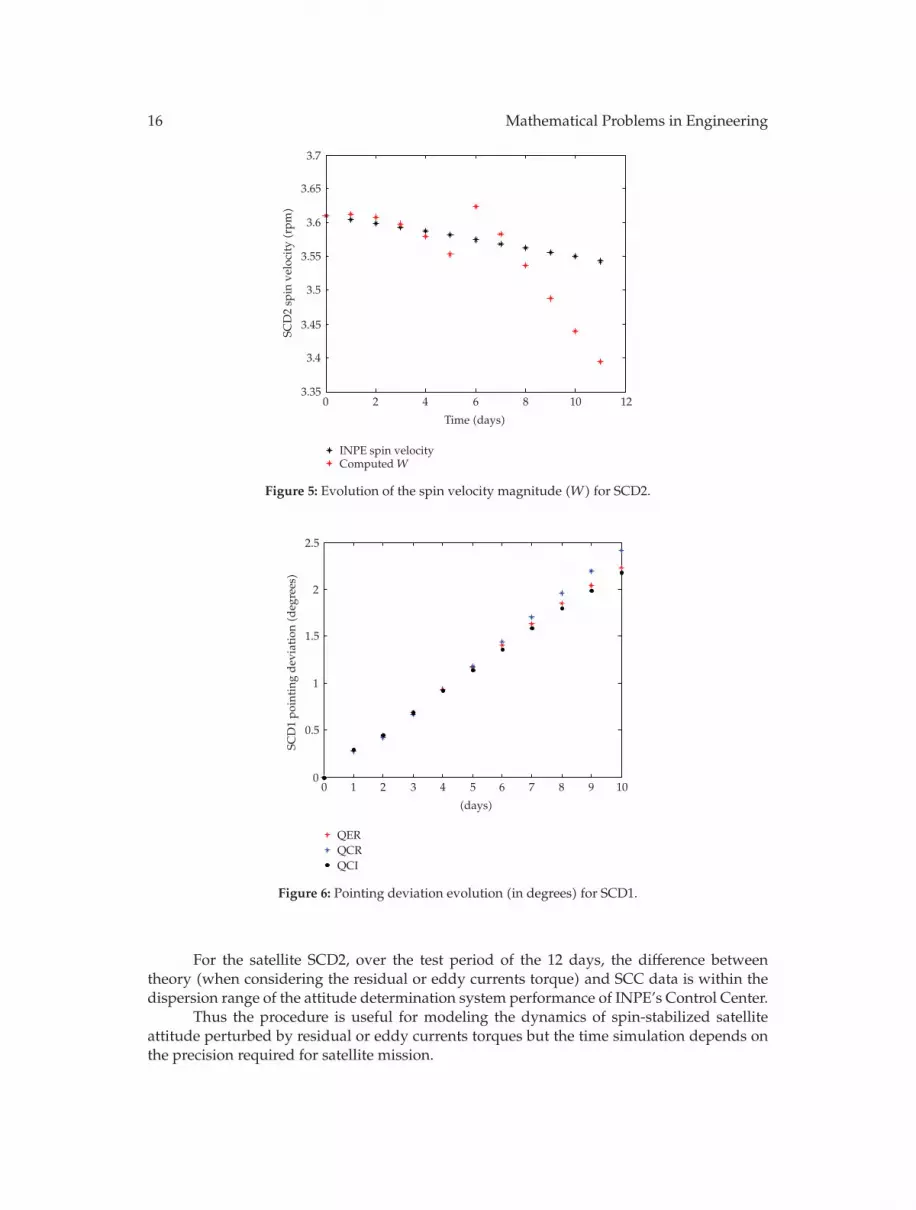
Figures 6 and 7 present the pointing deviations for the test period. The mean pointingdeviation for the SCD1 for different time simulations are presented in Table 13. Over thetest period of 11 days, the mean pointing deviation with the residual magnetic torque andelliptical orbit was 1.1553◦, circular orbit was 1.2003◦, and eddy currents torque with circularorbit was 1.1306◦. The test period of SCD1 shows that the pointing deviation is higher than theprecision required for SCC. Therefore for SCD1, this analytical approach should be evaluatedby a time less than 11 days.
For SCD2, the mean pointing deviation considering the residual magnetic torque andelliptical orbit was 0.1538, residual magnetic torque and circular orbit was 0.1507, and eddycurrent torque was 0.2160. All the results for SCD2 are within the dispersion range of theattitude determination system performance of INPE’s Control Center of 0.5◦.
12. Summary
In this paper an analytical approach was presented to the spin-stabilized satellite attitudepropagation taking into account the residual and eddy currents torque. The meancomponents of these torques in the satellite body reference system have been obtained andthe theory shows that, unlike the eddy currents torque, there is no residual torque componentalong the spin axis (z-axis). Therefore this torque does not affect the spin velocity magnitude,but it can cause a drift in the satellite spin axis.
The theory was applied to the spin-stabilized Brazilian satellites SCD1 and SCD2 inorder to validate the analytical approach, using quadripole model for geomagnetic field andthe satellite in circular and elliptical orbits.

Mathematical Problems in Engineering 15
121086420
(days)
QERQCR
QCIINPE
278.1
278.2
278.3
278.4
278.5
278.6
278.7
278.8
278.9R
ight
asce
nsio
nSC
D2(d
eg)
(a)
121086420
(days)
QERQCR
QCIINPE
63.2
63.25
63.3
63.35
63.4
63.45
63.5
63.55
63.6
Dec
linat
ion
SCD
2(d
eg)
(b)
Right ascension
121086420
(days)
QERQCRQCI
−0.7
−0.6
−0.5
−0.4
−0.3
−0.2
−0.1
0
0.1
Mea
ner
ror
dev
iati
onSC
D2(d
eg)
(c)
Declination
121086420
(days)
QERQCRQCI
−0.35
−0.3
−0.25
−0.2
−0.15
−0.1
−0.05
0
0.05
Mea
ner
ror
dev
iati
onSC
D2(d
eg)
(d)
Figure 4: Evolution of the declination (δ) and right ascension (α) of satellite spin axis for SCD2 and itsmean deviation error.
Table 13: Mean pointing deviation for SCD1.
Time simulation (days) 11 8 3 2θQER 1.1553 0.8226 0.2448 0.1450θQCR 1.2003 0.8288 0.2326 0.1376θQCI 1.1306 0.8071 0.2503 0.1495
The result of the 3 days of simulations of SCD1, considering the residual magnetictorque, shows a good agreement between the analytical solution and the actual satellitebehavior. For more than 3 days, the pointing deviation is higher than the precision requiredfor SCC (0.5◦).
16 Mathematical Problems in Engineering
121086420
Time (days)
INPE spin velocityComputed W
3.35
3.4
3.45
3.5
3.55
3.6
3.65
3.7
SCD
2sp
inve
loci
ty(r
pm)
Figure 5: Evolution of the spin velocity magnitude (W) for SCD2.
109876543210
(days)
QERQCRQCI
0
0.5
1
1.5
2
2.5
SCD
1po
inti
ngd
evia
tion
(deg
rees)
Figure 6: Pointing deviation evolution (in degrees) for SCD1.
For the satellite SCD2, over the test period of the 12 days, the difference betweentheory (when considering the residual or eddy currents torque) and SCC data is within thedispersion range of the attitude determination system performance of INPE’s Control Center.
Thus the procedure is useful for modeling the dynamics of spin-stabilized satelliteattitude perturbed by residual or eddy currents torques but the time simulation depends onthe precision required for satellite mission.

Mathematical Problems in Engineering 17
121086420
(days)
QERQCRQCI
0
0.05
0.1
0.15
0.2
0.25
0.3
0.35
0.4
0.45
SCD
2po
inti
ngd
evia
tion
(deg
rees)
Figure 7: Pointing deviation evolution (in degrees) for SCD2.
Appendix
The coefficients of the mean components of the residual magnetic torques, given by (2.9), areexpressed by
A =7∑
i = 1
aia +7∑
i = 1
aib, B =7∑
i = 1
bia +7∑
i = 1
bib, C =7∑
i = 1
cia +7∑
i = 1
cib,
D =7∑
i = 1
aia +7∑
i = 1
aib, E =7∑
i = 1
bia +7∑
i = 1
bib,
(A.1)
where aib, bib, cjb, i = 1, 2, . . . , 7; j = 1, . . . , 4, can be got by Garcia in [3]. It is important to notethat the parcel bib is associated with the quadripole model and the satellite in an ellipticalorbit. For circular, orbit, bib is zero.
The mean components Nixm, Niym, Nizm of the eddy currents torque are expressed by
Nixm =14 712∑
i = 1
trx(i) +18 426∑
i = 1
Nx(i),
Niym =14 712∑
i = 1
try(i) +53 765∑
i = 1
Ny(i),
Nizm =7 350∑
i = 1
tr z(i) +21 435∑
i = 1
Nz(i),
(A.3)
where trx(i), try(i), tr z(i), Nx(i), Ny(i), and Nz(i) are presented by Pereira [6].
18 Mathematical Problems in Engineering
The terms aib, bib, cjb, trx(i), try(i), tr z(i), Nx(i), Ny(i), and Nz(i) depend on orbitalelements (a, e, I, Ω, w) and attitude angles (δ, α).
Acknowledgment
This present work was supported by CNPq (National Counsel of Technological and ScientificDevelopment).
References
[1] L. C. Thomas and J. O. Cappelari, “Attitude determination and prediction of spin-stabilized satellites,”The Bell System Technical Journal, pp. 1656–1726, 1964.
[2] J. R. Wertz, Spacecraft Attitude Determination and Control, D. Reidel, Dordrecht, The Netherlands, 1978.[3] R. V. Garcia, Satelites estabilizados por rotacao e torque magnetico residual, Dissertacao de Mestrado,
Faculdade de Engenharia, UNESP, Guaratingueta, Brazil, 2007.[4] M. C. Zanardi, “Dinamica da atitude de satelites artificiais,” Tese de Livre Docencia, Universidade
Estadual Paulista, Guaratingueta, Brazil, 2005.[5] H. K. Kuga, W. C. C. Silva, and U. T. V. Guedes, “Dynamics of attitude for spin stabilized satellites,”
Tech. Rep. INPE-4403, INPE, Sao Jose dos Campos, Brazil, 1987.[6] A. J. Pereira, “Propagacao da atitude de satelites estabilizados por totacao com torque induzido,”
Trabalho de Conclusao de Curso, Faculdade de Engenharia, UNESP, Guaratingueta, Brazil, 2006.[7] D. Brouwer and G. M. Clemence, Methods of Celestial Mechanics, Academic Press, New York, NY, USA,
1961.[8] V. Orlando, H. K. Kuga, and U. T. V. Guedes, “Flight dynamics leop and routine operations for SCD2,
the INPE’s second environmental data collecting satellite,” Advances in the Astronautical Sciences, vol.100, no. 2, pp. 1003–1013, 1998.
[9] H. K. Kuga, V. Orlando, and R. V. F. Lopes, “Flight dynamics operations during LEOP for the INPE’ssecond environmental data collection satellite SCD2,” Journal of the Brazilian Society of MechanicalSciences and Engineering, vol. 21, pp. 339–344, 1999.
Related Documents