Journal of Magnetism and Magnetic Materials 81 (1989) 209-220 North-Holland, Amsterdam 209 SPIN REORIENTATION EFFEm ON MAGNETIZATION - APPLICATION TO Nd,Fe,,B C.N. CHRISTODOULOU, E.B. BOLTICH and T.B. MASSALSKI MEMS Department, Carnegie-Mellon University, Pittsburgh, PA 15213, USA Received 4 October 1988; in revised form 20 March 1989 Spin reorientation is a phenomenon observed frequently in magnetic materials and is responsible for changes in magnetization as a function of temperature. In this study an analytical model is described which accounts for such changes in magnetization. Three different magnetization vs. temperature measurements are described which confirm the occurrence of spin reorientation and indicate the exact temperature at which it occurs (application to Nd,Fe,,B intermetallic compound). The analytical solution of the model enables one to determine the K,/K, ratio of the first- (K,) and second-order (K2) anisotropy constants as a function of temperature. Also, this model clearly demonstrates the effect of crystal orientation (angle between the c-axis and the applied magnetic field) on the magnetization vs. temperature behavior; one can take advantage of this in order to achieve a maximum or a minimum effect. The effect of the presence of the third-order (K,) anisotropy constant is also discussed. 1. Introduction Spin reorientations are very important phenom- ena in magnetic materials. This is especially true in permanent magnets because spin reorientation may deteriorate their magnetic properties in the temperature range where the easy direction of magnetization is not the c-axis. Therefore, the easy direction of magnetization is an important property that must be known as a function of temperature. Spin reorientation temperatures are determined by measuring the magnetization as a function of temperature in the presence of a magnetic field [1,2]. The change of magnetization at a tempera- ture where spin reorientation occurs is observed as an inflection point (i.e. cone to axis), or as a sharp peak (i.e. axis to plane). However, the determina- tion of the spin reorientation temperature is not always straightforward. There are some special orientations of the c-axis of the crystal with re- spect to the direction of the applied magnetic field which may result in rather complex features of the magnetization vs. temperature behavior, which sometimes create confusion, or misinterpretation. Recently, Boltich et al. [3], using computer simula- tion of spin reorientation in polycrystalline mate- rials (assuming two uniaxial single domain par- ticles with their c-axes perpendicular to each other), showed some expected special features of magnetization vs. temperature, in the presence of both a small and a large magnetic field. In the present paper, an analytical model is proposed which predicts the form of the magneti- zation vs. temperature curves for an assembly of non-interacting single-domain particles having a tetragonal crystal structure which: (a) are all aligned with their c-axes parallel to one another and where the Z-angle between the alignment direction and the applied magnetic field is gener- ally between 0” and 90 O, and (b) have their c-axes randomly oriented in space. The axis to cone to plane, or reverse, and the axis to plane, or reverse, spin reorientation for each of the above cases (a) and (b) is discussed below. The effect of the presence of a non-zero (but close to zero) K, anisotropy constant is also considered. All of these cases are examined in the presence of a very small positive, zero or a very small negative magnetic field. 0304-8853/89/$03.50 0 Elsevier Science Publishers B.V. (North-Holland Physics Publishing Division)

Welcome message from author
This document is posted to help you gain knowledge. Please leave a comment to let me know what you think about it! Share it to your friends and learn new things together.
Transcript
Journal of Magnetism and Magnetic Materials 81 (1989) 209-220
North-Holland, Amsterdam
209
SPIN REORIENTATION EFFEm ON MAGNETIZATION - APPLICATION TO Nd,Fe,,B
C.N. CHRISTODOULOU, E.B. BOLTICH and T.B. MASSALSKI
MEMS Department, Carnegie-Mellon University, Pittsburgh, PA 15213, USA
Received 4 October 1988; in revised form 20 March 1989
Spin reorientation is a phenomenon observed frequently in magnetic materials and is responsible for changes in magnetization as a function of temperature. In this study an analytical model is described which accounts for such changes in magnetization. Three different magnetization vs. temperature measurements are described which confirm the occurrence of
spin reorientation and indicate the exact temperature at which it occurs (application to Nd,Fe,,B intermetallic compound). The analytical solution of the model enables one to determine the K,/K, ratio of the first- (K,) and second-order (K2)
anisotropy constants as a function of temperature. Also, this model clearly demonstrates the effect of crystal orientation (angle between the c-axis and the applied magnetic field) on the magnetization vs. temperature behavior; one can take advantage of this in order to achieve a maximum or a minimum effect. The effect of the presence of the third-order (K,) anisotropy constant is also discussed.
1. Introduction
Spin reorientations are very important phenom- ena in magnetic materials. This is especially true in permanent magnets because spin reorientation may deteriorate their magnetic properties in the temperature range where the easy direction of magnetization is not the c-axis. Therefore, the easy direction of magnetization is an important property that must be known as a function of temperature.
Spin reorientation temperatures are determined by measuring the magnetization as a function of temperature in the presence of a magnetic field [1,2]. The change of magnetization at a tempera- ture where spin reorientation occurs is observed as an inflection point (i.e. cone to axis), or as a sharp peak (i.e. axis to plane). However, the determina- tion of the spin reorientation temperature is not always straightforward. There are some special orientations of the c-axis of the crystal with re- spect to the direction of the applied magnetic field which may result in rather complex features of the magnetization vs. temperature behavior, which sometimes create confusion, or misinterpretation.
Recently, Boltich et al. [3], using computer simula- tion of spin reorientation in polycrystalline mate- rials (assuming two uniaxial single domain par- ticles with their c-axes perpendicular to each other), showed some expected special features of magnetization vs. temperature, in the presence of both a small and a large magnetic field.
In the present paper, an analytical model is proposed which predicts the form of the magneti- zation vs. temperature curves for an assembly of non-interacting single-domain particles having a tetragonal crystal structure which: (a) are all aligned with their c-axes parallel to one another and where the Z-angle between the alignment direction and the applied magnetic field is gener- ally between 0” and 90 O, and (b) have their c-axes randomly oriented in space.
The axis to cone to plane, or reverse, and the axis to plane, or reverse, spin reorientation for each of the above cases (a) and (b) is discussed below. The effect of the presence of a non-zero (but close to zero) K, anisotropy constant is also considered. All of these cases are examined in the presence of a very small positive, zero or a very small negative magnetic field.
0304-8853/89/$03.50 0 Elsevier Science Publishers B.V. (North-Holland Physics Publishing Division)
210 C.N. Chrisfodoulou et al. / Spin reorientation effect
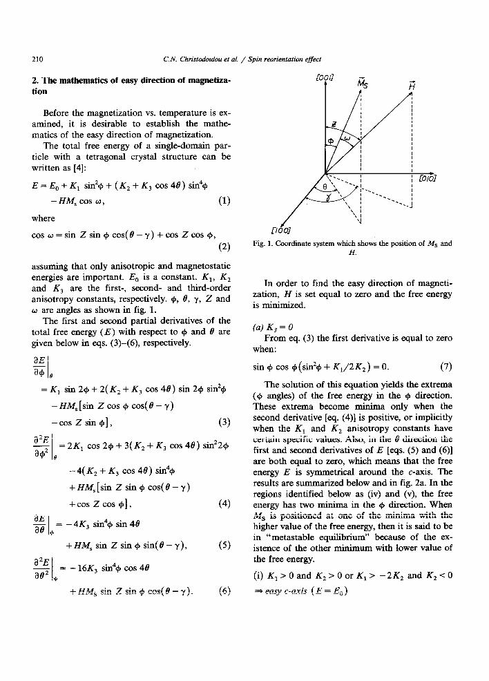
2. The mathematics of easy direction of magnetiza- tion
Before the magnetization vs. temperature is ex- amined, it is desirable to establish the mathe- matics of the easy direction of magnetization.
The total free energy of a single-domain par- ticle with a tetragonal crystal structure can be written as [4]:
E=E,+K, sin2$+(K2+K3 ~0~48) sin4$
-HM, cos w, (1)
where
cosu=sinzsin+cos(e-y)+coszcos~,
(2)
assuming that only anisotropic and magnetostatic energies are important. E, is a constant. K,, K, and K, are the first-, second- and third-order anisotropy constants, respectively. +, 8, y, Z and w are angles as shown in fig. 1.
The first and second partial derivatives of the total free energy (E) with respect to cp and B are given below in eqs. (3)-(6), respectively.
aE
G,
=K, sin2cp+2(K2+K, cos4B) sin2+si&
-HM,[sin Z cos $I cos(8 - y)
-cos Zsin+], (3)
l12E - =2K, cos2++3(K,+K, ~0~48) sin22+ a+2 0
- 4( K, + K, cos 48) sin4Cp
+HM,[sin Zsin+cos(@-y)
+cos zcos $1, (4)
aE ae,
= - 4K, sin4+ sin 48
+HM, sin Zsin+ sin(8-y),
a2E -= ae2 .+
- 16K, sin4+ cos 48
+HM, Sk zSin$COS(8-y). (6)
Fig. 1. Coordinate system which shows the position of MS and H.
In order to find the easy direction of magneti- zation, H is set equal to zero and the free energy is minimized.
(a) K, = 0 From eq. (3) the first derivative is equal to zero
when:
sin C#I cos +(sin2+ + K,/2K2) = 0. (7)
The solution of this equation yields the extrema (C#I angles) of the free energy in the CJJ direction. These extrema become minima only when the second derivative [eq. (4)] is positive, or implicitly when the K, and K, anisotropy constants have certain specific values. Also, in the 8 direction the first and second derivatives of E [eqs. (5) and (6)] are both equal to zero, which means that the free energy E is symmetrical around the c-axis. The results are summarized below and in fig. 2a. In the regions identified below as (iv) and (v), the free energy has two minima in the $I direction. When MS is positioned at one of the minima with the higher value of the free energy, then it is said to be in “metastable equilibrium” because of the ex- istence of the other minimum with lower value of the free energy.
(i) K,>Oand K,>OorK,> -2K2 and K,<O
=+ easy c-axis ( E = E,, )
C.N. Christodoulou et al. / Spin reorientation effect 211
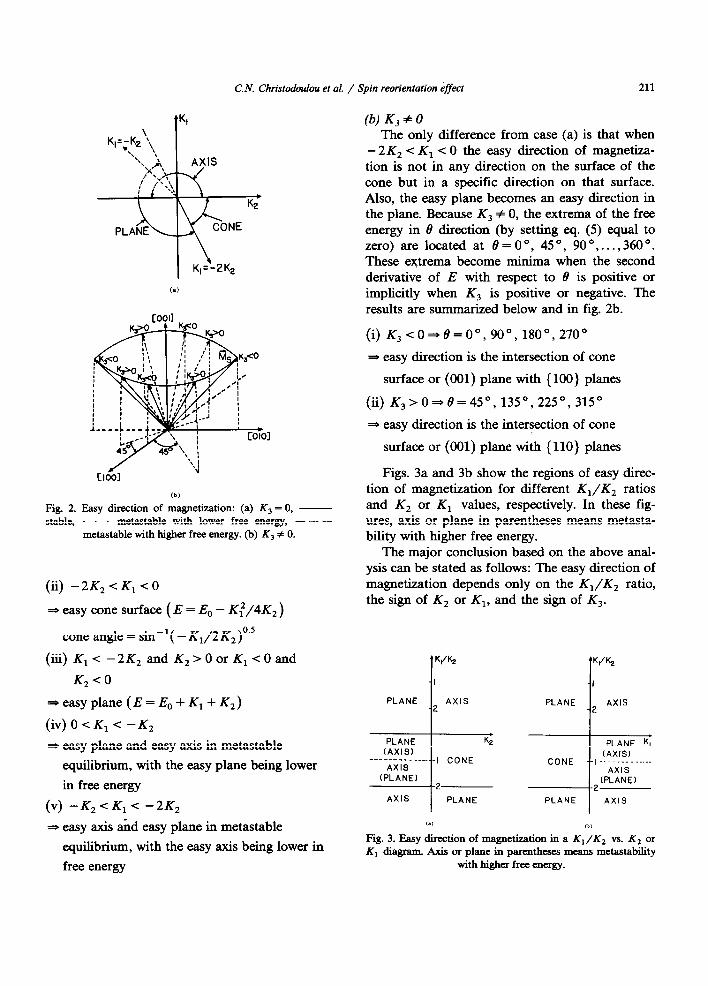
(b)
Fig. 2. Easy direction of magnetization: (a) K, = 0, -
stable, .-e-. metastable with lower free energy, - - -
metastable with higher free energy. (b) K, # 0.
(ii) -2K,<K, co
* easy cone surface (E = E, - Kf/4K2)
cone angle = sin-‘( -K,/2K,)0’5
(iii) K,< -2K, and K,>OorK,<Oand
K, < 0
*easyplane (E=E,+K,+K,)
(iv)O<K,< -K,
* easy plane and easy axis in metastable
equilibrium, with the easy plane being lower
in free energy
(v) -K,<K,< -2K,
3 easy axis and easy plane in metastable
equilibrium, with the easy axis being lower in
free energy
The only difference from case (a) is that when - 2 K, < K, < 0 the easy direction of magnetiza- tion is not in any direction on the surface of the cone but in a specific direction on that surface. Also, the easy plane becomes an easy direction in the plane. Because K3 # 0, the extrema of the free energy in 8 direction (by setting eq. (5) equal to zero) are located at 8=0”, 45”, 90” ,..., 360”. These extrema become minima when the second derivative of E with respect to 0 is positive or implicitly when K, is positive or negative. The results are summarized below and in fig. 2b.
(i) K,~O~~=O”,900,1800,270”
* easy direction is the intersection of cone
surface or (001) plane with {lOO} planes
(ii) K,>O-6’=45°, 135O,225”, 315”
3 easy direction is the intersection of cone
surface or (001) plane with (110) planes
Figs. 3a and 3b show the regions of easy direc- tion of magnetization for different K,/K, ratios and K, or K, values, respectively. In these fig- ures, axis or plane in parentheses means metasta- bility with higher free energy.
The major conclusion based on the above anal- ysis can be stated as follows: The easy direction of magnetization depends only on the K1/K2 ratio, the sign of K, or K,, and the sign of K3.
I
PLANE AXIS -2
PLANE
I
2 AXIS
AXIS I
PLANE PLANE I
AXIS
,.) Cb)
Fig. 3. Easy direction of magnetization in a K,/K, vs. K, or K, diagram. Axis or plane in parentheses means metastability
with higher free energy.
212 C.N. Christodoulou et al. / Spin reorientation effect
3. Magnetization as a function of temperature
The phenomenological model used in this study refers to an assembly of non-interacting single-do- main particles having a tetragonal crystal struc- ture, the mathematics of which were described previously by eqs. (l)-(6).
The anisotropy constants K, and K, are, in general, functions of temperature. Therefore, the temperature dependence of magnetization is an indirect reflection of its dependence on the ani- sotropy constants K, and K,. In the presence of spin reorientation, the magnetization vs. tempera- ture behavior is strongly dependent upon both the magnitude of the measuring field and the mag- netic history of the sample. Below, we consider the temperature dependence of magnetization under three different experimental conditions.
(Cl
H = O+. The sample is initially saturated in the forward direction at the lowest tempera- ture. Then, the field is decreased until the internal magnetic field (H) is small (see be- low) and positive, and the magnetization vs. temperature curve is recorded. H = 0. The sample is initially saturated in the forward direction at the lowest temperature. Then the field is decreased until the internal magnetic field (H) is exactly zero, and the magnetization vs. temperature curve is re- corded. H = O-. The sample is initially saturated in the forward direction at the lowest tempera- ture. The field is removed and an inverse field is applied which is greater than the nucleation field in the 8 direction but smaller than that in the + direction. The magnitude of the field is then decreased until the internal magnetic field (H) becomes very small (see below) and negative, and the magnetization vs. tempera- ture curve is recorded.
For each of the above cases, the effect of orien- tation (angle between the c-axis and applied mag- netic field) and the presence of a zero or a non-zero K, anisotropy constant has been examined. The magnitudes of the measuring magnetic fields (H = O+ and H = O-) are assumed to be close to zero and far from the nucleation fields in both the 9 and 8 directions. Under these conditions, the posi-
tion of the MS is determined solely by the ani- sotropy energy. The following types of spin re- orientation are considered: (1) axis to cone to plane (2) axis to plane (3) plane to cone to axis (4) plane to axis (5) cone to plane or cone to axis In the analysis that follows, any reference to “magnetic field’ will imply “internal magnetic field”, unless it is stated otherwise.
3.1. Axis to cone to plane spin reorientation
3.1.1. H = 0 “, K3 = 0, aligned particles Because of the presence of a small positive
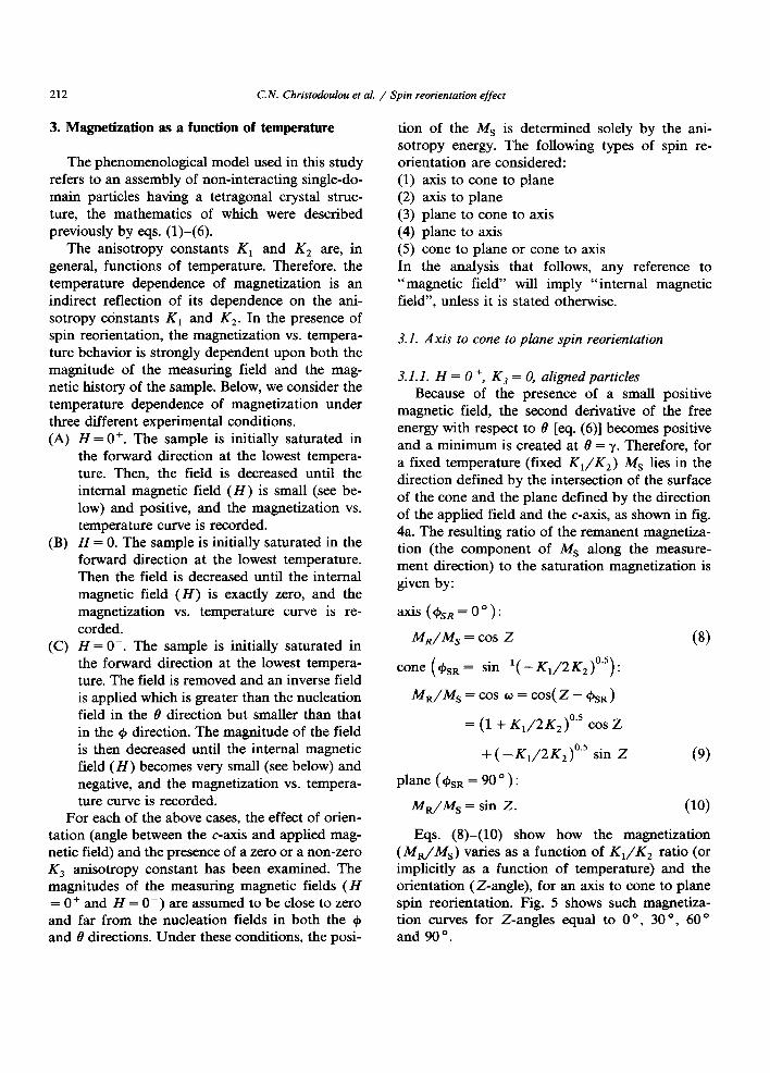
magnetic field, the second derivative of the free energy with respect to 8 [eq. (6)] becomes positive and a minimum is created at 8 = y. Therefore, for a fixed temperature (fixed K1/K2) MS lies in the direction defined by the intersection of the surface of the cone and the plane defined by the direction of the applied field and the c-axis, as shown in fig. 4a. The resulting ratio of the remanent magnetiza- tion (the component of MS along the measure- ment direction) to the saturation magnetization is given by:
axis (& = 00):
M,/M, = cos z (8)
cone ( +SR = siC’( - K,/2K,)0’5) :
M~A!f,=cos u=cos(z-r#J,,)
= (1 + K,/2K,)‘.’ cos Z
+ ( - K,/2K,)‘.’ sin Z (9)
plane (&a = 90”):
Ms/kfs = sin Z. (10)
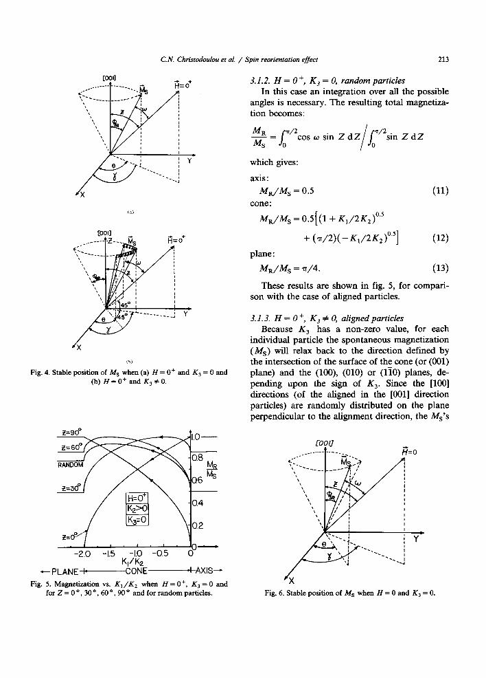
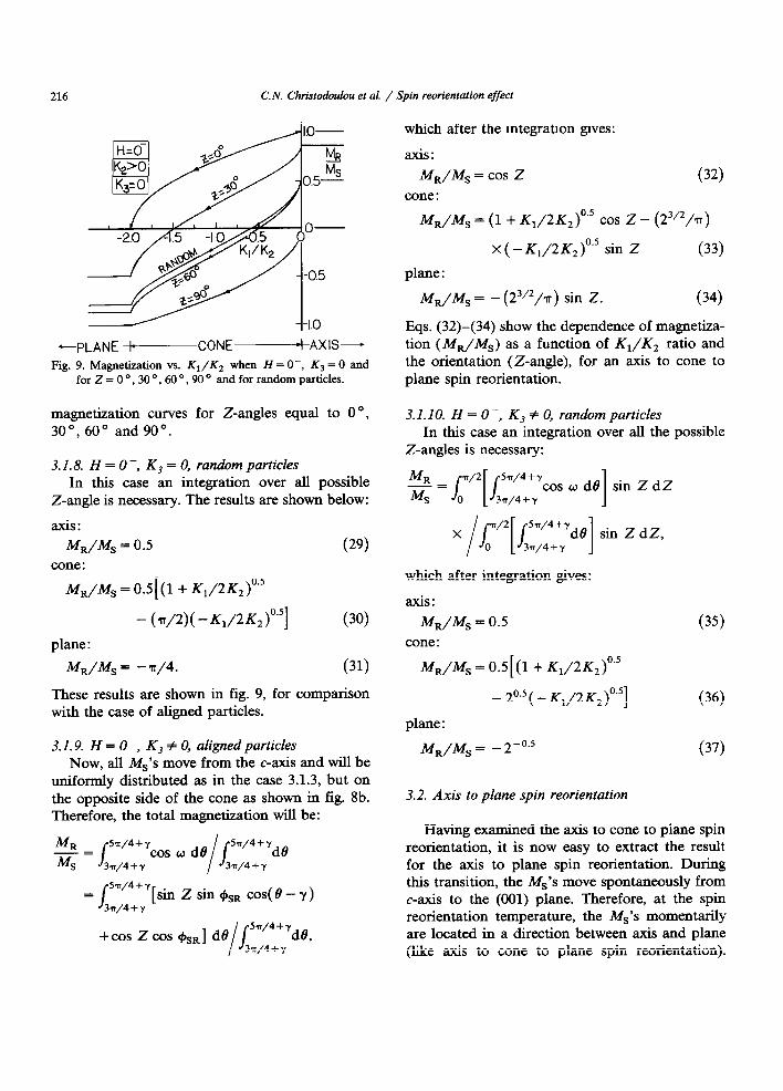
Eqs. @-(lo) show how the magnetization (MiJMs) varies as a function of K,/K, ratio (or implicitly as a function of temperature) and the orientation (Z-angle), for an axis to cone to plane spin reorientation. Fig. 5 shows such magnetiza- tion curves for Z-angles equal to 0 O, 30 O, 60 o and 90”.
C.N. Christodoulou et al. / Spin reorientation effect 213
(b)
Fig. 4. Stable position of iUs when (a) H = O+ and K, = 0 and (b) H=O+ and K,#O.
-1.0 -0.5 o-
-2.0 -1.5 0 Wk
+-- PLANE-CONEAAXiS-
Fig. 5. Magnetization vs. K,/K, when H = O+, K, = 0 and for Z = 0 O, 30 O, 60 O, 90 o and for random particles.
3.1.2. H = 0 ‘; K3 = 0, random particles In this case an integration over all the possible
angles is necessary. The resulting total magnetiza- tion becomes:
MR J n/2 -= MS
cos w sin Z dZ I J n/2 sin Z dZ
0 0
which gives:
axis:
MJn4, = 0.5 (11)
MdM, = OS[ (1 + K,/2K,)“’
+ (~/~)(-KI/~K,)~“]
plane :
MJM, = T/4.
(12)
03)
These results are shown in fig. 5, for compari- son with the case of aligned particles.
3.1.3. H = 0 ‘; K3 # 0, aligned particles Because K, has a non-zero value, for each
individual particle the spontaneous magnetization (Ms) will relax back to the direction defined by the intersection of the surface of the cone (or (001) plane) and the (NO), (010) or (110) planes, de- pending upon the sign of K3. Since the [NO] directions (of the aligned in the [OOl] direction particles) are randomly distributed on the plane perpendicular to the alignment direction, the MS’s
Fig. 6. Stable position of MS when H = 0 and K, = 0.
214 C.N. Christodoulou et al. / Spin reorientation effect
will be distributed in such a way that their projec- tions on the plane perpendicular to the alignment direction are uniformly distributed f45O from the projection of the applied field on the same plane. This is illustrated in fig. 4b and is indepen- dent of the sign of K,.
The total magnetization will be the sum of the contribution of each of the MS’s situated as de- scribed above. Therefore:
MR y=?T/4 -=
4 J cos w dt’
I J
Y =v4dB
Y-“/4 Y--“/4
sin Z sin +sa cos(8-7)
+cos 2 cos @SRI de I
Jy+11/4dB y--n/4
which after the integration gives:
axis:
M,/Ms = cos Z
cone : (14)
A4dMs = (23/2/n)( - K,/2K,)O.’ sin 2
+ (1 + K,/2K2)0.5 cos z (15)
plane :
MJiVs = (23/2/~) sin Z. (16)
KI& -PLANE -+-----CONE-AXIS--
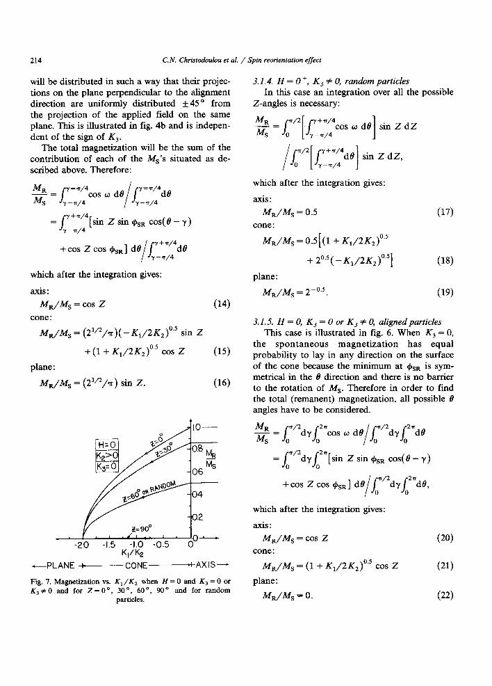
Fig. 7. Magnetization vs. K,/K, when H = 0 and K, = 0 or K,#O and for Z=O”, 30°, 60”, 90“ and for random
particles.
3.1.4. H = 0 ‘, K, # 0, random particles In this case an integration over all the possible
Z-angles is necessary:
cos w dB sin Z dZ 1
which after the integration gives:
axis:
MdM, = 0.5
cone : (17)
MJM, = 0.5[ (1 + K,/2K2)0’5
+ 20.5 ( - K,/2K2)0.5]
plane :
MdM, = 2-“.5.
(18)
(19)
3.1 S. H = 0, KJ = 0 or K, # 0, aligned particles This case is illustrated in fig. 6. When K3 = 0,
the spontaneous magnetization has equal probability to lay in any direction on the surface Of the cone because the minimum at +sR iS sym- metrical in the 8 direction and there is no barrier to the rotation of Ms. Therefore in order to find the total (remanent) magnetization, all possible 8 angles have to be considered.
2 = [‘2d$2=cos o dt$‘2d~~2ndt’
= [‘2dyi2V[sin Z sin +sn c0s(e -y)
+cos Z cos &a] de I
[“dvi2”dt9:
which after the integration gives:
axis:
MdM, = cos Z
cone :
M&M, = (1 + K,/2K,)‘.’ cos Z
plane :
MdM, = 0.
(20)
(21)
(22)
C.N. Christodoulou et al. / Spin reorientation effect
In the case when K, # 0, the Ms’s will be uniformally distributed in fixed directions on the surface of the cone, resulting in the same magneti- zation as when K, = 0.
The results in eqs. (20)-(22) show how the magnetization (Ma/MS) changes with respect to KJK, (or implicitly with temperature) and the orientation (Z-angle) for an axis to cone to plane spin reorientation. These results are shown in fig. 7 for Z-angles equal to O”, 30”, 60” and 90”.
3.1.6. H = 0, K3 = 0 or K3 + 0, random particles In this case all the possible Z-angles have to be
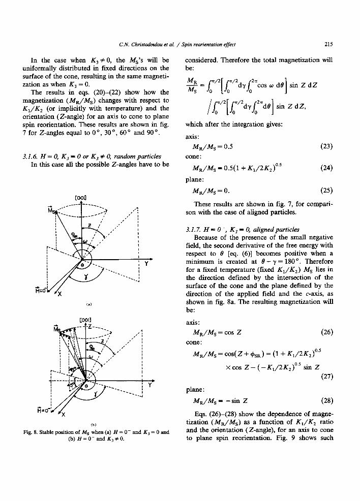
Fig. 8. Stable position of M, when (a) H = O- and K3 = 0 and (b) H = 0- and K, # 0.
considered. Therefore the total magnetization be:
215
will
2 = [“[ [‘2du/021cos w d/3] sin Z dZ
/e2[ c’2dyi2ndS] sin Z dZ,
which after the integration gives:
axis:
MrJA4s = 0.5
cone :
(23)
MdA4, = 0.5(1+ K,/2K2)‘.’ (24)
plane :
MIJA4, = 0. (25)
These results are shown in fig. 7, for compari- son with the case of aligned particles.
3.1.7. H = 0 -, K, = 0, aligned particles Because of the presence of the small negative
field, the second derivative of the free energy with respect to 8 [eq. (6)] becomes positive when a minimum is created at 8 - y = 180 O. Therefore for a fixed temperature (fixed K,/K,) MS lies in the direction defined by the intersection of the surface of the cone and the plane defined by the direction of the applied field and the c-axis, as shown in fig. 8a. The resulting magnetization will be:
axis:
Ma/MS = cos z (26) cone :
MJM, = cos( Z + &) = (1 + K,/2K,)‘.’
x cos Z - ( - K,/2K2)0.5 sin Z
(27)
plane :
MR/Ms = -sin z (28)
Eqs. (26)-(28) show the dependence of magne- tization (Mn/Ms) as a function of K,/K, ratio and the orientation (Z-angle), for an axis to cone to plane spin reorientation. Fig. 9 shows such
216 C. N. Christodocdou et al. / Spin reorientation effect
-PLANE WCONEbAXIS-
Fig. 9. Magnetization vs. K,/K, when H = O-, K, = 0 and for Z = 0 O, 30 O, 60 O, 90 o and for random particles.
magnetization curves for Z-angles equal to 0 O, 30°, 60° and 90”.
3.1.8. H = 0 -, K, = 0, random particles In this case an integration over all possible
Z-angle is necessary. The results are shown below:
axis: Ma/MS = 0.5 (29)
cone :
M,/M, = OS[ (1 + K,/2K,)0’5
- b/2)( -KI/‘~K,)~‘~] (30)
plane :
M,/hf, = -a/4. (31)
These results are shown in fig. 9, for comparison with the case of aligned particles.
3.1.9. H = 0 -, K, # 0, aligned particles Now, all MS’s move from the c-axis and will be
uniformly distributed as in the case 3.1.3, but on the opposite side of the cone as shown in fig. 8b. Therefore, the total magnetization will be:
Ma 5?T/4+y -= MS $
cos w de I
/ 5n/4+yde
3n/4 + y 3T/4 + y
= r,z+y[Gn z sin qBSR cos(8 - y)
+cos Z cos c&RI dr9 I
/5T’4+yd8, 3n/4 -I- y
which after the integration gives:
axis:
MJM, = cos Z
cone : (32)
MJMs = (1 + K,/2K,)0’5 cos Z - (2”‘/4
x (- K,/2K2)‘.’ sin Z (33)
plane :
M,/M, = - (23’2/~) sin Z. (34)
Eqs. (32)-(34) show the dependence of magnetiza- tion (MdM,) as a function of K,/K, ratio and the orientation (Z-angle), for an axis to cone to plane spin reorientation.
3.1. IO. H = 0 -, Kj # 0, random particles In this case an integration over all the possible
Z-angles is necessary:
which after integration gives:
axis:
MJM, = 0.5
cone :
MJM, = 0.5 [ (1 + K,/2K2)0.5
- 2°.5 ( - K,/2K2)0.5]
plane :
MR/Ms = - 2-“.5
(35)
(36)
(37)
3.2. Axis to plane spin reorientation
Having examined the axis to cone to plane spin reorientation, it is now easy to extract the result for the axis to plane spin reorientation. During this transition, the MS’s move spontaneously from c-axis to the (001) plane. Therefore, at the spin reorientation temperature, the MS’s momentarily are located in a direction between axis and plane (like axis to cone to plane spin reorientation).
C. N. Christodoulou et al. / Spin reorientation effect 217
+ H=O+ (K,=O)
, Hz0 (K,=O)
-I t (Cl
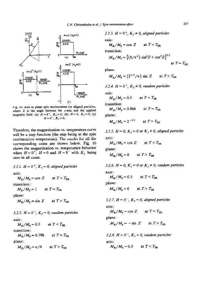
Fig. 10. Axis to plane spin reorientation for aligned particles, where Z is the angle between the c-axis and the applied
magnetic field: (a) H = O+, K3 = 0; (b) H = 0, K, = 0; (c) H=O-, K,=O.
Therefore, the magnetization vs. temperature curve will be a step function (the step being at the spin reorientation temperature). The results for all the corresponding cases are shown below. Fig. 10 shows the magnetization vs. temperature behavior when H=O+, H=O and H=O-with K, being
zero in all cases.
3.2. I. H = 0 ‘, K3 = 0, aligned particles
axis:
MR/Ms = cos z at Tc TSR
transition :
MR/h!i, = 1 at T = TSR
plane :
MJM, = sin Z at T > TSR
3.2.2. H = 0 +, K, = 0, random particles
axis:
MJM, = 0.5 at T < TSR
transition :
M,/M, = 0.798 at T= TSR
plane :
M,/M, = n/4 at T> TSR
3.2.3. H = 0 .t, Kj # 0, aligned particles
axis:
M,/M, = cos Z at T-C TSR
transition :
M,/M, = [(8/n’) sin2Z + cos2Z] ‘J
at T= TSR
plane :
M,/M, = (23/2/n) sin Z at T> TSR
3.2.4. H = O’, Kj # 0, random particles
axis:
M,/M, = 0.5 at T < TSR
transition :
M,/M, = 0.866 at T = TSR
plane :
M,/M, = 2 -OS at T > TSR
3.2.5. H = 0, K, = 0 or K, # 0, aligned particles
axis:
M,/M, = cos Z at T< TSR
plane :
M,/M, = 0 at T> TSR
3.2.6. H = 0, K3 = 0 or K3 # 0, random particles
axis:
M,/M, = 0.5 at T-C TSR
plane :
M,/M, = 0 at T> TSR
3.2.7. H = 0 -, K, = 0, aligned particles
axis:
M,/M, = cos Z at T-C TSR
plane :
M,/M, = -sin Z at T > TSR
3.2.8. H = 0; Kj = 0, random particles
axis:
M,/M, = 0.5 at T < TSR
218 C.N. Christodoulou et al. / Spin reorientation effect
plane :
MJM, = -T/4 at T> TSR
3.2.9. H = 0 -, K, # 0, aligned particles
axis:
MdM, = cos Z
plane :
at T < TSR
MS/MS = - (23’2/4) sin Z at T> TSR
3.2. IO. H = 0 -, Kj # 0, random particles
axis:
M,/M, = 0.5 at T < TSR
plane:
M,/M, = -2-“.5 at T > TSR
3.3. Plane to cone to axis spin reorientation
When H = O+, the results are the same (for the corresponding regions) as those in the case of an axis to cone to plane spin reorientation. In the case where H = O-, the magnetization curves are exactly the same as in the H = O+ case, but with opposite sign.
When H = 0 and K, = 0, MdM, is equal to zero throughout the entire temperature range and no changes in magnetization occur. This is be- cause statistically there is equal probability for the MS’s to be directed anywhere out of plane (in the absence of a magnetic field), resulting in a zero average magnetization.
In the case where H = 0 and K, # 0 the MS’s
will be directed above or below the plane, but in a specific portion of the surface of a cone (as shown in fig. 4b plus the mirror image with respect to the xy plane). In this case the resulting magnetization will be: (i) Aligned particles
plane :
M,/M, = (23’2/7r
cone :
M,/M, = ( 23’2/a
axis: M,/M, = 0
) sin Z
)( -K,/2K,)0.5 sin Z
(ii) Random particles
plane:
MdM, = 2-“.5
cone :
M,/M, = 2-“.5( - K,/2K,)‘.’
axis:
M,/M, = 0
3.4. Plane to axis spin reorientation
When H = O+, the results are the same (for the corresponding regions) as those in the case of an axis to plane spin reorientation. When H = O-,
the magnetization curve is exactly the same as in the case where H = O+, but with opposite sign. When H = 0 and K, = 0, M,JM, is equal to zero throughout the entire temperature range. The rea- son for this is the same as explained in the para- graph above.
In the case where H = 0 and K, # 0 the magne- tization will be as follows: (i) Aligned particles
plane :
M,/M, = (23’2/~) sin Z at T< TSR
axis:
MJM, = 0 at T > TSR
(ii) Random particles
plane :
M,JM, = 2-“.5 at T < TSR
axis:
M,/M, = 0 at T> TSR.
3.5. Cone to plane or cone to axis spin reorientation
When K, = 0 or K, # 0, the results are the same as in the corresponding part of cases 1 and 3. The only difference is when K, # 0, the magne- tization curve for H = 0 is the same with that of H = O+. The reason for this is that after saturation and removal of the magnetic field the MS’s will be locked in the same positions whether the magnetic field is zero, or is slightly positive.
C.N. Christodoulou et al. / Spin reorientation effect 219
4. Experimental results - discussion
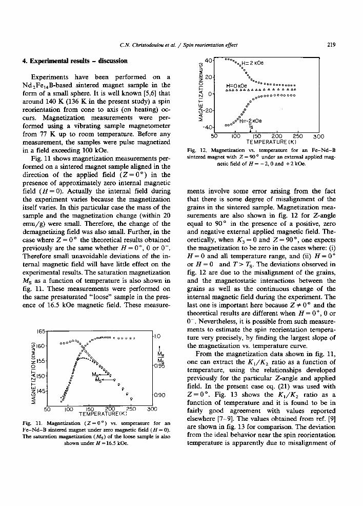
Experiments have been performed on a Nd,Fe,,B-based sintered magnet sample in the form of a small sphere. It is well known [5,6] that around 140 K (136 K in the present study) a spin reorientation from cone to axis (on heating) oc- curs. Magnetization measurements were per- formed using a vibrating sample magnetometer from 77 K up to room temperature. Before any measurement, the samples were pulse magnetized in a field exceeding 100 kOe.
Fig. 11 shows magnetization measurements per- formed on a sintered magnet sample aligned in the direction of the applied field (Z = 0 “) in the presence of approximately zero internal magnetic field (H = 0). Actually the internal field during the experiment varies because the magnetization itself varies. In this particular case the mass of the sample and the magnetization change (within 20 emu/g) were small. Therefore, the change of the demagnetizing field was also small. Further, in the case where Z = 0 o the theoretical results obtained previously are the same whether H = O+, 0 or O-. Therefore small unavoidable deviations of the in- ternal magnetic field will have little effect on the experimental results. The saturation magnetization Ms as a function of temperature is also shown in fig. 11. These measurements were performed on the same presaturated “loose” sample in the pres- ence of 16.5 kOe magnetic field. These measure-
Fig. 11. Magnetization (Z= O”) vs. temperature for an Fe-Nd-B sintered magnet under zero magnetic field (H = 0). The saturation magnetization (Ms) of the loose sample is also
shown under H = 16.5 kOe.
1 I & I I 50 100 I50 200 250 300
TEMPERATURE(K)
Fig. 12. Magnetization vs. temperature for an Fe-Nd-B sintered magnet with Z = 90 o under an external applied mag-
netic field of H = - 2.0 and + 2 kOe.
ments involve some error arising from the fact that there is some degree of misalignment of the grains in the sintered sample. Magnetization mea- surements are also shown in fig. 12 for Z-angle equal to 90” in the presence of a positive, zero and negative external applied magnetic field. The- oretically, when K3 = 0 and Z = 90 O, one expects the magnetization to be zero in the cases where: (i) H = 0 and all temperature range, and (ii) H = O+ or H = O- and T > T,. The deviations observed in fig. 12 are due to the misalignment of the grains, and the magnetostatic interactions between the grains as well as the continuous change of the internal magnetic field during the experiment. The last one is important here because Z # 0 o and the theoretical results are different when H = O+, 0 or O-. Nevertheless, it is possible from such measure- ments to estimate the spin reorientation tempera- ture very precisely, by finding the largest slope of the magnetization vs. temperature curve.
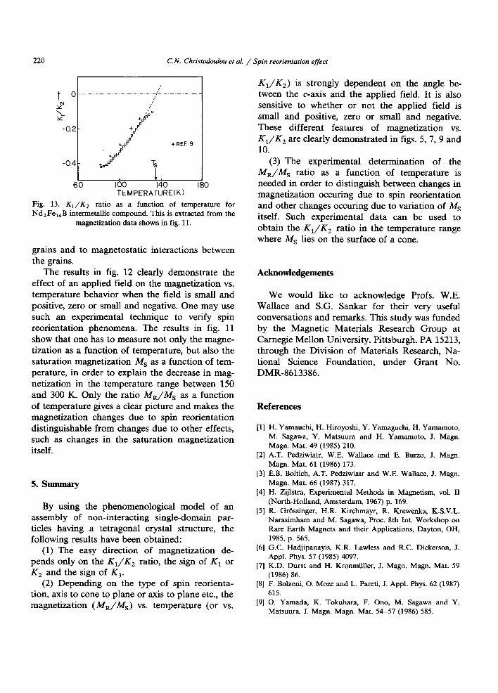
From the magnetization data shown in fig. 11, one can extract the K,/K, ratio as a function of temperature, using the relationships developed previously for the particular Z-angle and applied field. In the present case eq. (21) was used with z=o”. Fig. 13 shows the K,/K, ratio as a function of temperature and it is found to be in fairly good agreement with values reported elsewhere [7-91. The values obtained from ref. [9] are shown in fig. 13 for comparison. The deviation from the ideal behavior near the spin reorientation temperature is apparently due to misalignment of
220 C.N. Christodoulou et al. / Spin reorientation effect
+
2 1’
\ 3’ 0
Y +
-0.2 + f
+REF.9
I + I 60 100 140 180
TEMPERATURE(K)
Fig. 13. K,/K, ratio as a function of temperature for Nd,Fe,,B intermetaBic compound. This is extracted from the
magnetization data shown in fig. 11.
K1/K2) is strongly dependent on the angle be- tween the c-axis and the applied field. It is also sensitive to whether or not the applied field is small and positive, zero or small and negative. These different features of magnetization vs. K,/K, are clearly demonstrated in figs. 5, 7, 9 and 10.
(3) The experimental determination of the Ma/M, ratio as a function of temperature is needed in order to distinguish between changes in magnetization occuring due to spin reorientation and other changes occuring due to variation of MS itself. Such experimental data can be used to obtain the K,/K, ratio in the temperature range where MS lies on the surface of a cone.
grains and to magnetostatic interactions between the grains.
The results in fig. 12 clearly demonstrate the effect of an applied field on the magnetization vs. temperature behavior when the field is small and positive, zero or small and negative. One may use such an experimental technique to verify spin reorientation phenomena. The results in fig. 11 show that one has to measure not only the magne- tization as a function of temperature, but also the saturation magnetization MS as a function of tem- perature, in order to explain the decrease in mag- netization in the temperature range between 150 and 300 K. Only the ratio Ma/M, as a function of temperature gives a clear picture and makes the magnetization changes due to spin reorientation distinguishable from changes due to other effects, such as changes in the saturation magnetization itself.
5. summary
By using the phenomenological model of an assembly of non-interacting single-domain par- ticles having a tetragonal crystal structure, the following results have been obtained:
(1) The easy direction of magnetization de- pends only on the K,/K, ratio, the sign of K, or K, and the sign of K,.
(2) Depending on the type of’ spin reorienta- tion, axis to cone to plane or axis to plane etc., the magnetization (Ma/M,) vs. temperature (or vs.
Acknowledgements
We would like to acknowledge Profs. W.E. Wallace and S.G. Sankar for their very useful conversations and remarks. This study was funded by the Magnetic Materials Research Group at Carnegie Mellon University, Pittsburgh, PA 15213, through the Division of Materials Research, Na- tional Science Foundation, under Grant No. DMR-8613386.
References
PI
121
[31
[41
PI
161
[71
PI
[91
H. Yamauchi, H. Hiroyoshi, Y. Yamaguchi, H. Yamamoto, M. Sagawa, Y. Matsuura and H. Yamamoto, J. Magn. Magn. Mat. 49 (1985) 210. A.T. Pedziwiatr, W.E. Wallace and E. Burro, J. Magn. Magn. Mat. 61 (1986) 173.
E.B. Boltich, A.T. Pedziwiatr and W.E. Wallace, J. Magn. Magn. Mat. 66 (1987) 317.
H. Zijlstra, Experimental Methods in Magnetism, vol. II
(North-Holland, Amsterdam, 1967) p. 169.
R. Grassinger, H.R. Kirchmayr, R. Krewenka, K.S.V.L. Narasimham and M. Sagawa, Proc. 8th Int. Workshop on
Rare Earth Magnets and their Applications, Dayton, OH, 1985, p. 565. G.C. Hadjipanayis, K.R. Lawless and R.C. Dickerson, J. Appl. Phys. 57 (1985) 4097. K.D. Durst and H. Kronmiiller, J. Magn. Magn. Mat. 59 (1986) 86. F. Bolzoni, 0. Moze and L. Pareti, J. Appl. Phys. 62 (1987) 615.
0. Yamada, K. Tokuhara, F. Ono, M. Sagawa and Y. Matsuura, J. Magn. Magn. Mat. 54-57 (1986) 585.
Related Documents