SPICE Examples ROCHESTER INSTITUTE OF TECHNOLOGY MICROELECTRONIC ENGINEERING SPICE Examples Using OrCAD PSPICE and WINSPICE Dr. Lynn Fuller Microelectronic Engineering Rochester Institute of Technology © March 20, 2011 Dr. Lynn Fuller Page 1 Rochester Institute of Technology Microelectronic Engineering Rochester Institute of Technology 82 Lomb Memorial Drive Rochester, NY 14623-5604 Tel (585) 475-2035 Fax (585) 475-5041 Dr. Fuller’s Webpage: http://people.rit.edu/lffeee Email: [email protected] Dept Webpage: http://www.microe.rit.edu 3-20-2011 SPICE_Examples_OrCAD_WinSPICE_Fuller.ppt

Spice Examples Orcad Winspice Fuller
Oct 22, 2014
Welcome message from author
This document is posted to help you gain knowledge. Please leave a comment to let me know what you think about it! Share it to your friends and learn new things together.
Transcript
SPICE Examples
ROCHESTER INSTITUTE OF TECHNOLOGY
MICROELECTRONIC ENGINEERING
SPICE Examples Using OrCAD PSPICE and WINSPICE
Dr. Lynn FullerMicroelectronic Engineering
Rochester Institute of Technology
© March 20, 2011 Dr. Lynn Fuller Page 1
Rochester Institute of Technology
Microelectronic Engineering
Rochester Institute of Technology82 Lomb Memorial DriveRochester, NY 14623-5604
Tel (585) 475-2035Fax (585) 475-5041
Dr. Fuller’s Webpage: http://people.rit.edu/lffeeeEmail: [email protected]
Dept Webpage: http://www.microe.rit.edu
3-20-2011 SPICE_Examples_OrCAD_WinSPICE_Fuller.ppt
SPICE Examples
OUTLINE
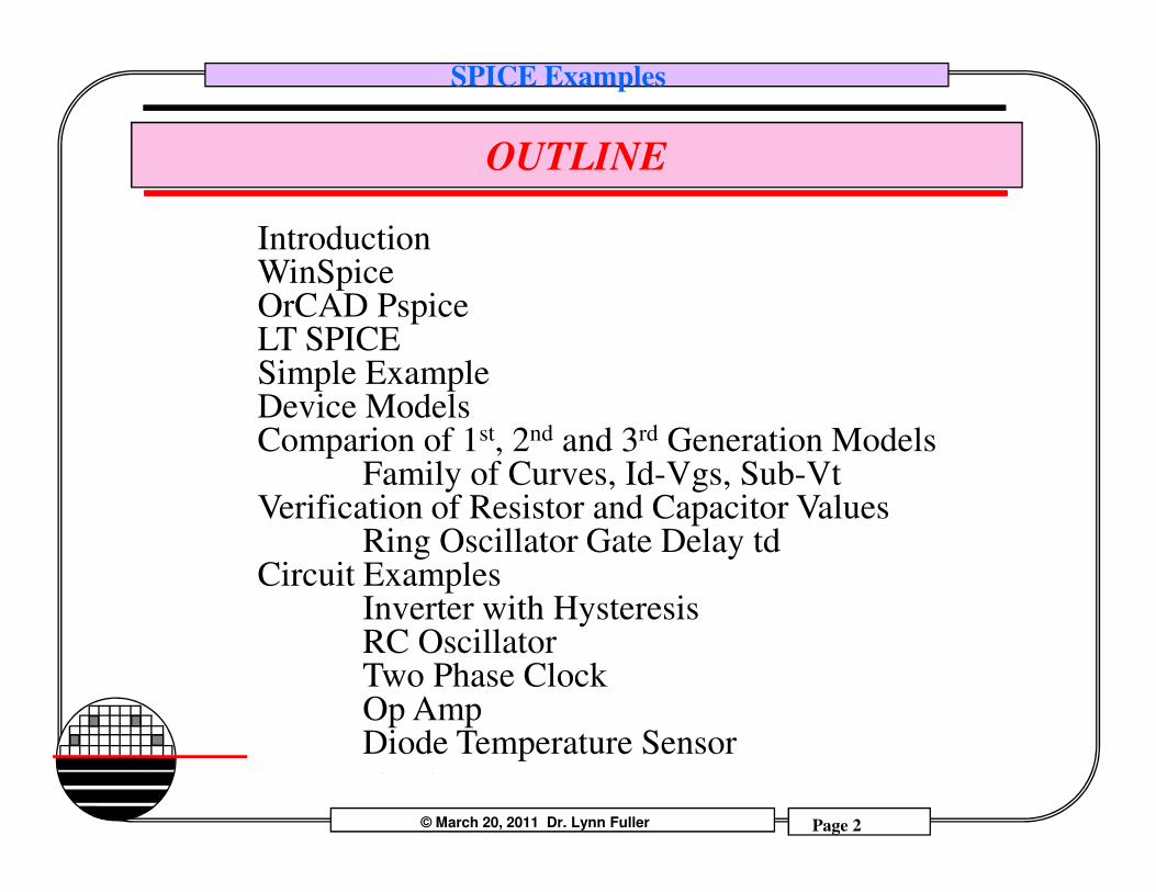
IntroductionWinSpiceOrCAD PspiceLT SPICESimple ExampleDevice ModelsComparion of 1st, 2nd and 3rd Generation Models
© March 20, 2011 Dr. Lynn Fuller Page 2
Rochester Institute of Technology
Microelectronic Engineering
Comparion of 1 , 2 and 3 Generation ModelsFamily of Curves, Id-Vgs, Sub-Vt
Verification of Resistor and Capacitor ValuesRing Oscillator Gate Delay td
Circuit ExamplesInverter with HysteresisRC OscillatorTwo Phase ClockOp AmpDiode Temperature Sensor
SPICE Examples
INTRODUCTION
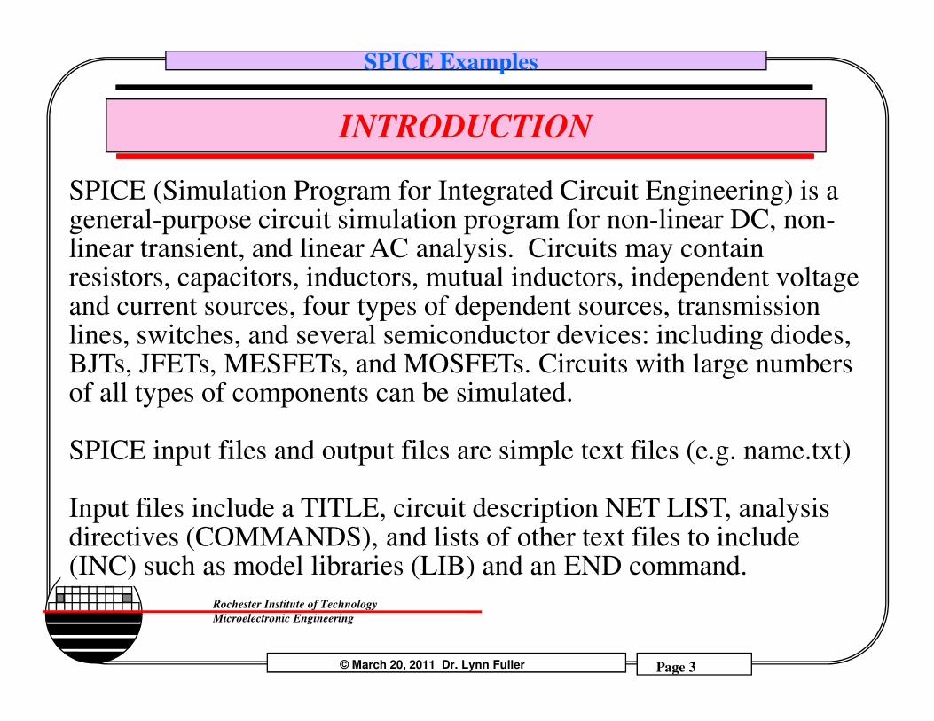
SPICE (Simulation Program for Integrated Circuit Engineering) is a general-purpose circuit simulation program for non-linear DC, non-linear transient, and linear AC analysis. Circuits may contain resistors, capacitors, inductors, mutual inductors, independent voltage and current sources, four types of dependent sources, transmission lines, switches, and several semiconductor devices: including diodes, BJTs, JFETs, MESFETs, and MOSFETs. Circuits with large numbers
© March 20, 2011 Dr. Lynn Fuller Page 3
Rochester Institute of Technology
Microelectronic Engineering
BJTs, JFETs, MESFETs, and MOSFETs. Circuits with large numbers of all types of components can be simulated.
SPICE input files and output files are simple text files (e.g. name.txt)
Input files include a TITLE, circuit description NET LIST, analysis directives (COMMANDS), and lists of other text files to include (INC) such as model libraries (LIB) and an END command.
SPICE Examples
INTRODUCTION
PSpice Lite 9.2 is one of the OrCAD family of products, from Cadence Design Systems, Inc., offering a complete suite of electronic design tools. It is free and includes limited versions of OrCAD Capture, for schematic capture, PSpice for analog circuit simulation and Pspice A/D for mixed analog and digital circuit simulation. PSpice Lite 9.2 is limited to 64 nodes, 10 transistors, two operational amplifiers and 65 primitive digital devices. See page 35 (xxxv) of the PSpice Users Guide.
© March 20, 2011 Dr. Lynn Fuller Page 4
Rochester Institute of Technology
Microelectronic Engineering
LT SPICE – is a free SPICE simulator with schematic capture from Linear Technology. It is quite similar to Pspice Lite but is not limited in the number of devices or nodes. Linear Technology (LT) is one of the industry leaders in analog and digital integrated circuits. Linear Technology provides a complete set of SPICE models for LT components.
WINSPICE – is a low cost fully capable SPICE simulator for windows computers. The full version is approximately $75. It does not include a schematic editor. (but is
available from third party)
SPICE Examples
EXAMPLE OF SIMPLE SPICE INPUT FILE
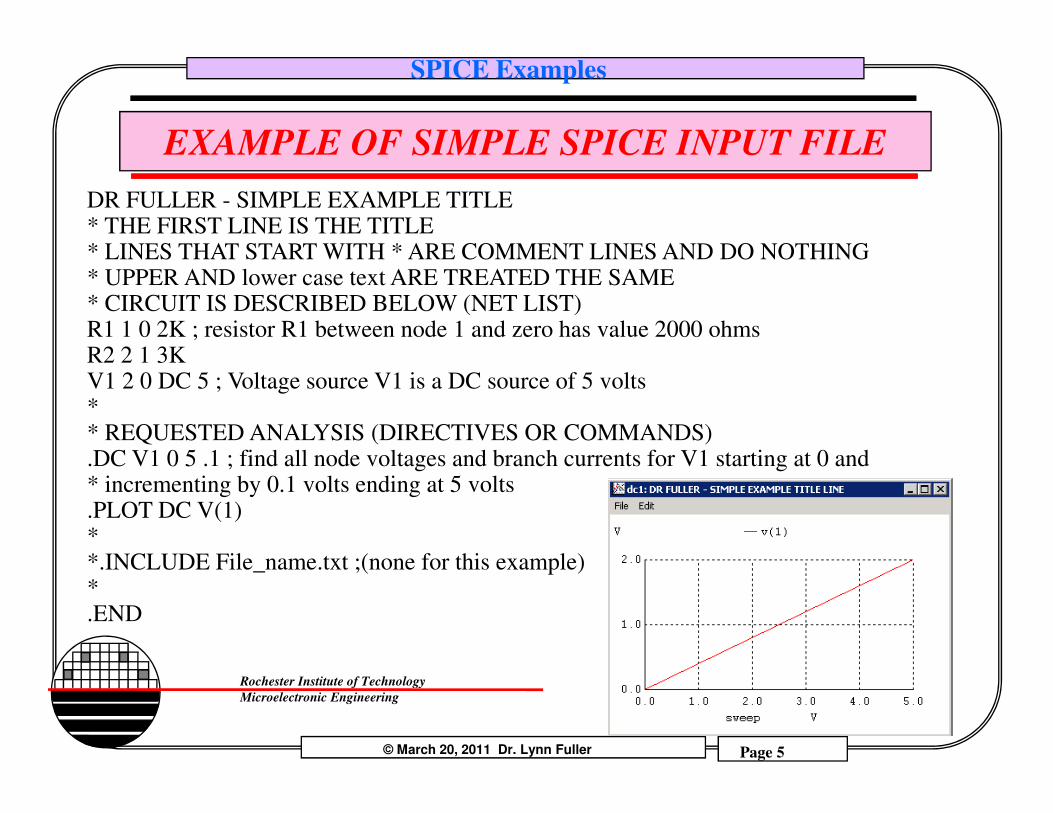
DR FULLER - SIMPLE EXAMPLE TITLE* THE FIRST LINE IS THE TITLE* LINES THAT START WITH * ARE COMMENT LINES AND DO NOTHING* UPPER AND lower case text ARE TREATED THE SAME* CIRCUIT IS DESCRIBED BELOW (NET LIST)R1 1 0 2K ; resistor R1 between node 1 and zero has value 2000 ohmsR2 2 1 3KV1 2 0 DC 5 ; Voltage source V1 is a DC source of 5 volts*
© March 20, 2011 Dr. Lynn Fuller Page 5
Rochester Institute of Technology
Microelectronic Engineering
** REQUESTED ANALYSIS (DIRECTIVES OR COMMANDS).DC V1 0 5 .1 ; find all node voltages and branch currents for V1 starting at 0 and * incrementing by 0.1 volts ending at 5 volts.PLOT DC V(1)**.INCLUDE File_name.txt ;(none for this example)*.END
SPICE Examples
CREATING THE INPUT FILE
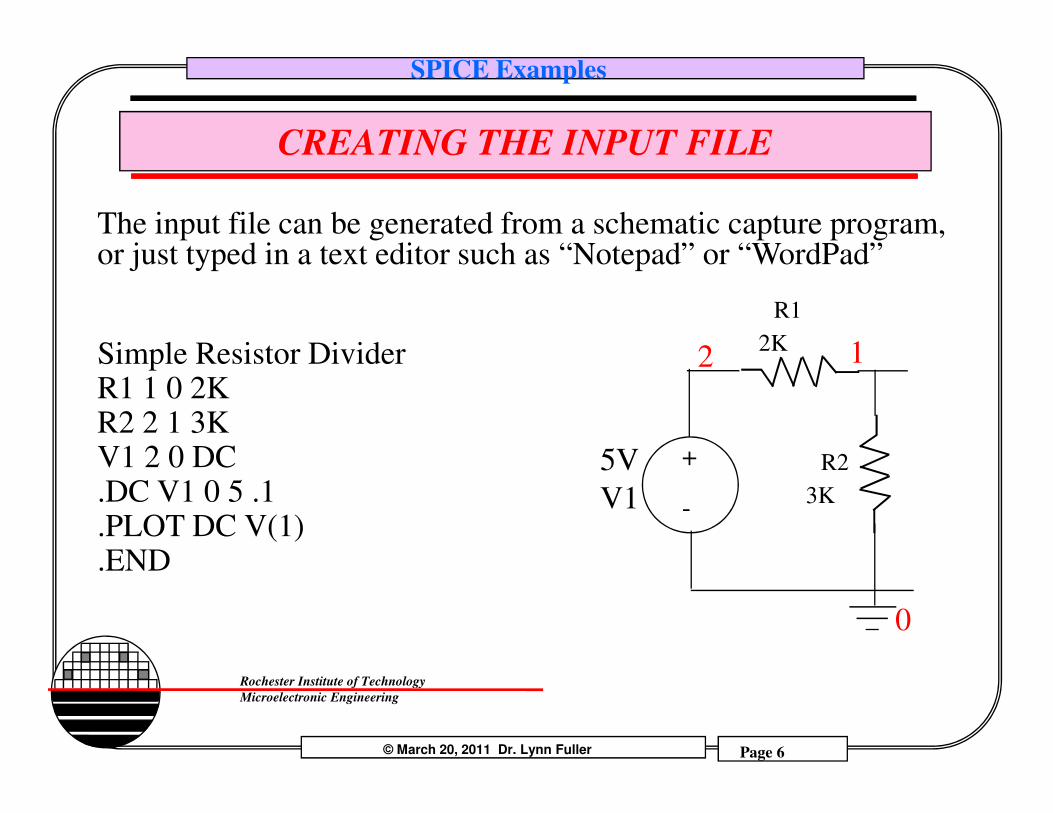
The input file can be generated from a schematic capture program, or just typed in a text editor such as “Notepad” or “WordPad”
Simple Resistor DividerR1 1 0 2KR2 2 1 3K
R1
2K2 1
© March 20, 2011 Dr. Lynn Fuller Page 6
Rochester Institute of Technology
Microelectronic Engineering
R2 2 1 3KV1 2 0 DC .DC V1 0 5 .1 .PLOT DC V(1).END
0
5V
V1
R2
3K
+
-
SPICE Examples
WINSPICE3
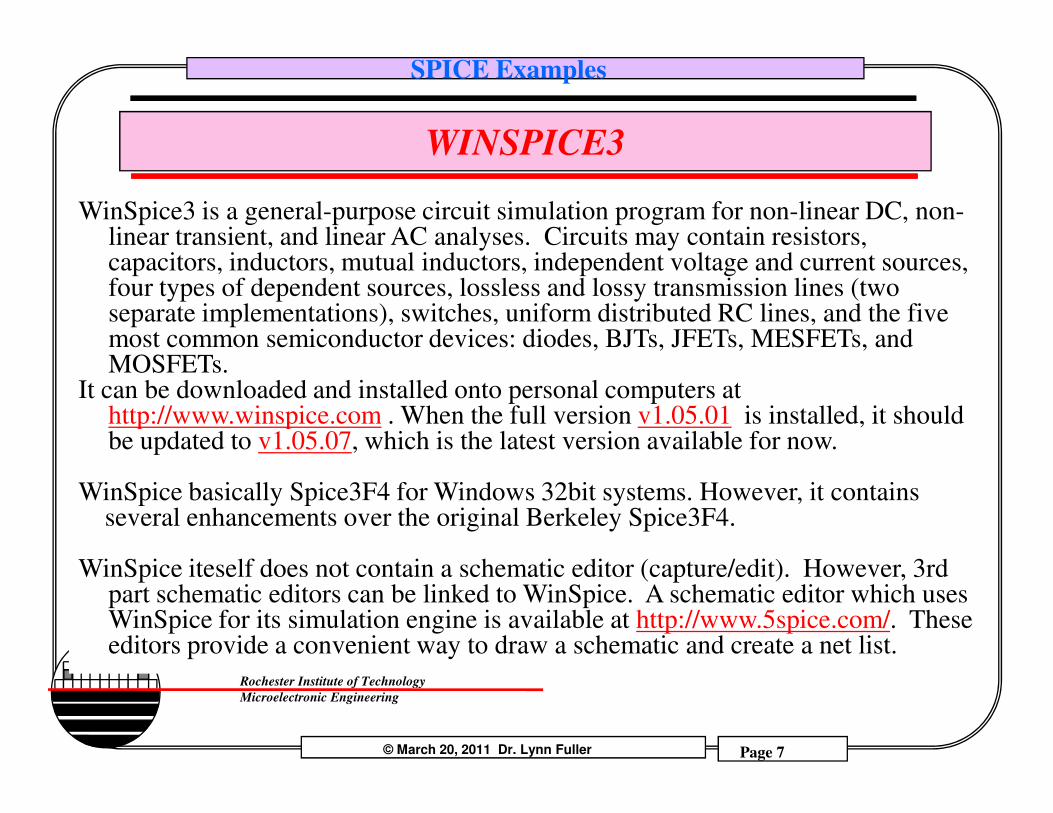
WinSpice3 is a general-purpose circuit simulation program for non-linear DC, non-linear transient, and linear AC analyses. Circuits may contain resistors, capacitors, inductors, mutual inductors, independent voltage and current sources, four types of dependent sources, lossless and lossy transmission lines (two separate implementations), switches, uniform distributed RC lines, and the five most common semiconductor devices: diodes, BJTs, JFETs, MESFETs, and MOSFETs.
It can be downloaded and installed onto personal computers at http://www.winspice.com . When the full version v1.05.01 is installed, it should
© March 20, 2011 Dr. Lynn Fuller Page 7
Rochester Institute of Technology
Microelectronic Engineering
http://www.winspice.com . When the full version v1.05.01 is installed, it should be updated to v1.05.07, which is the latest version available for now.
WinSpice basically Spice3F4 for Windows 32bit systems. However, it contains several enhancements over the original Berkeley Spice3F4.
WinSpice iteself does not contain a schematic editor (capture/edit). However, 3rd part schematic editors can be linked to WinSpice. A schematic editor which uses WinSpice for its simulation engine is available at http://www.5spice.com/. These editors provide a convenient way to draw a schematic and create a net list.
SPICE Examples
RUNNING WINSPICE
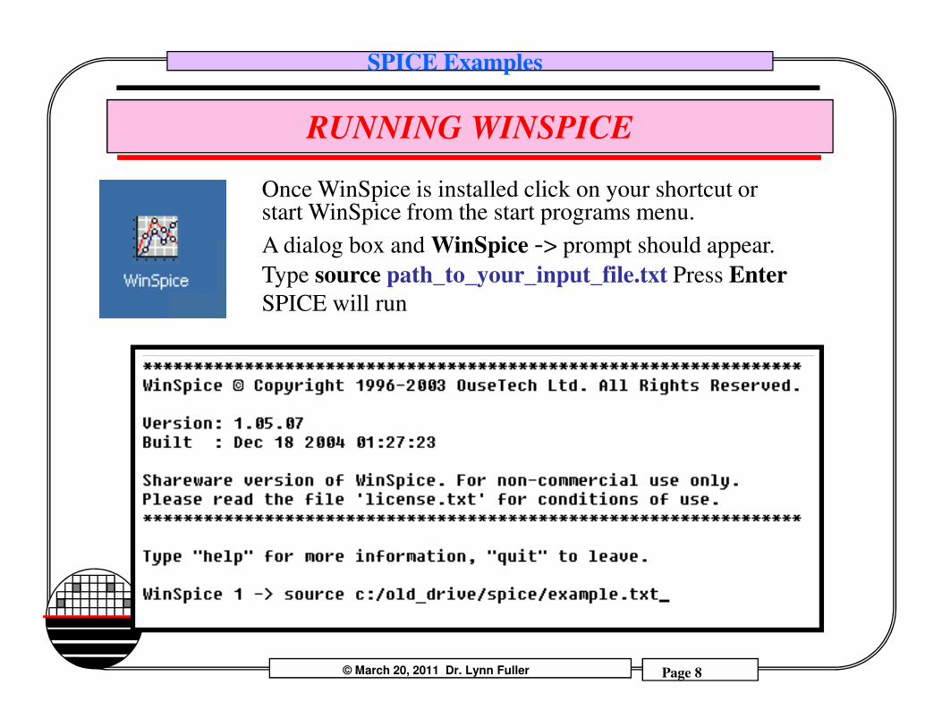
Once WinSpice is installed click on your shortcut or start WinSpice from the start programs menu.
A dialog box and WinSpice -> prompt should appear.
Type source path_to_your_input_file.txt Press Enter
SPICE will run
© March 20, 2011 Dr. Lynn Fuller Page 8
Rochester Institute of Technology
Microelectronic Engineering
SPICE Examples
OrCAD PSpice Lite 9.2
PSpice Lite 9.2 is one of the OrCAD family of products offering a complete suite of electronic design tools. These products are available from Cadence Design Systems, Inc. PSpice Lite 9.2 includes limited versions of OrCAD Capture, for schematic capture, PSpice for analog circuit simulation and Pspice A/D for mixed analog and digital circuit simulation. PSpice Lite 9.2 is limited to 64 nodes, 10 transistors, two operational amplifiers and 65 primitive
© March 20, 2011 Dr. Lynn Fuller Page 9
Rochester Institute of Technology
Microelectronic Engineering
analog and digital circuit simulation. PSpice Lite 9.2 is limited to 64 nodes, 10 transistors, two operational amplifiers and 65 primitive digital devices. See page 35 (xxxv) of the PSpice Users Guide.
SPICE Examples
BEFORE YOU START
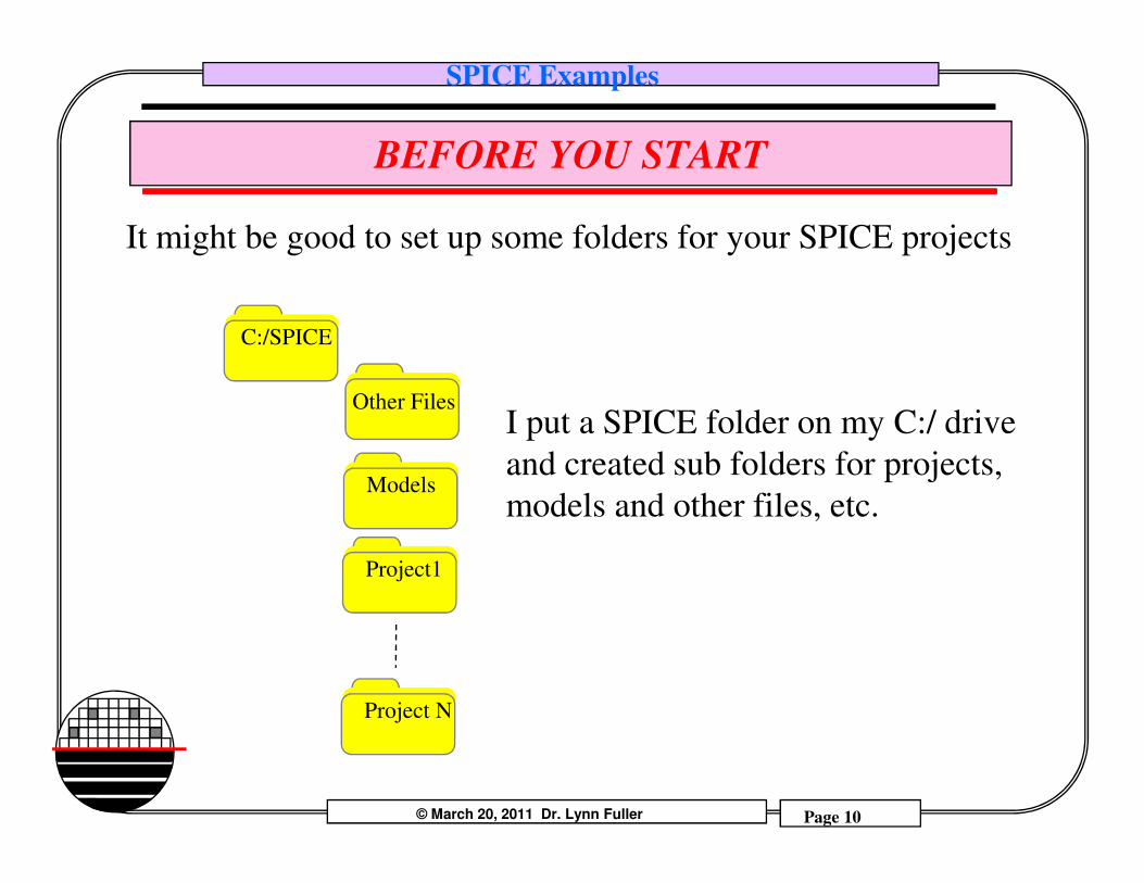
It might be good to set up some folders for your SPICE projects
C:/SPICE
Other FilesI put a SPICE folder on my C:/ drive
© March 20, 2011 Dr. Lynn Fuller Page 10
Rochester Institute of Technology
Microelectronic Engineering
Models
Project1
Project N
and created sub folders for projects,
models and other files, etc.
SPICE Examples
START SCHEMATIC CAPTURE OrCAD PSpice Lite 9.2
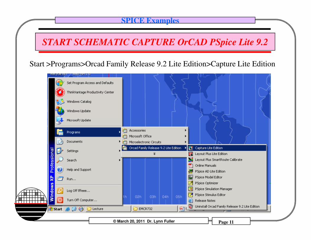
Start >Programs>Orcad Family Release 9.2 Lite Edition>Capture Lite Edition
© March 20, 2011 Dr. Lynn Fuller Page 11
Rochester Institute of Technology
Microelectronic Engineering
SPICE Examples
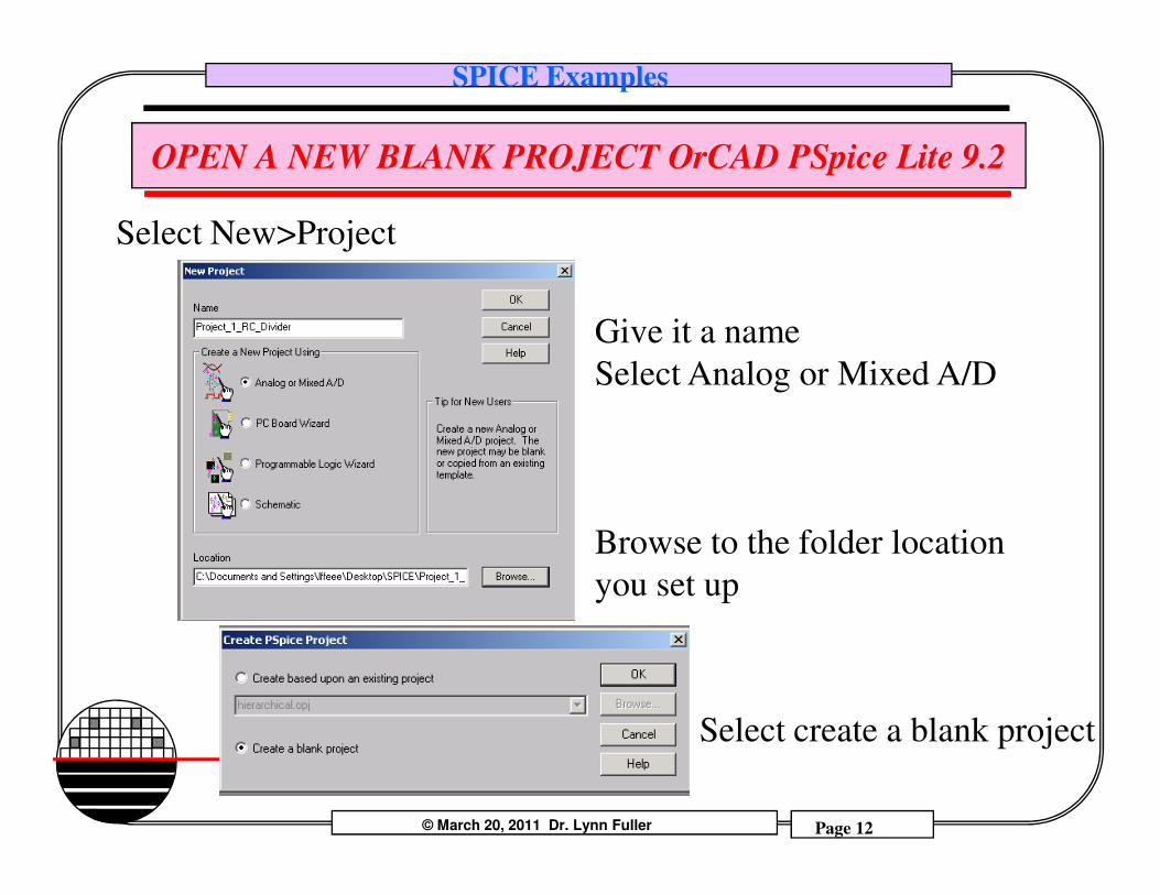
OPEN A NEW BLANK PROJECT OrCAD PSpice Lite 9.2
Select New>Project
Give it a name
Select Analog or Mixed A/D
© March 20, 2011 Dr. Lynn Fuller Page 12
Rochester Institute of Technology
Microelectronic Engineering
Browse to the folder location
you set up
Select create a blank project
SPICE Examples
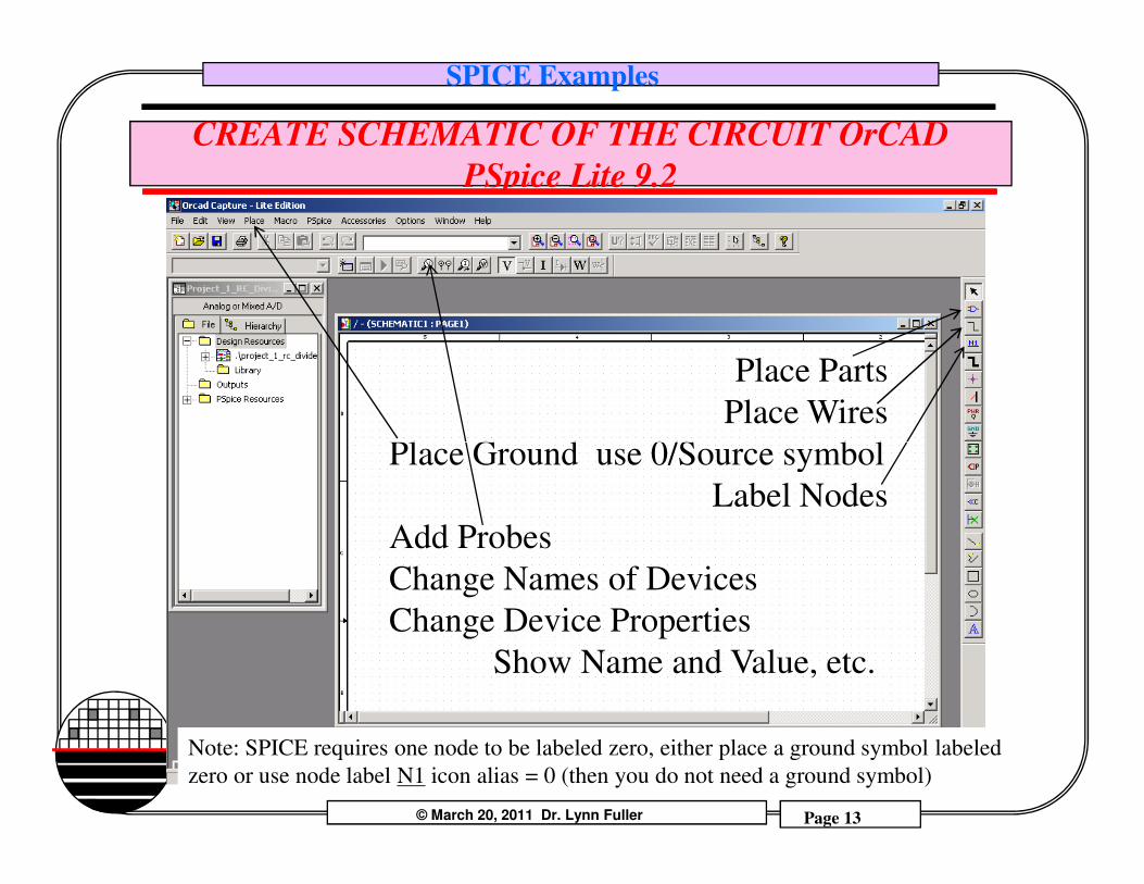
CREATE SCHEMATIC OF THE CIRCUIT OrCAD
PSpice Lite 9.2
Place Parts
Place Wires
Place Ground use 0/Source symbol
© March 20, 2011 Dr. Lynn Fuller Page 13
Rochester Institute of Technology
Microelectronic Engineering
Place Ground use 0/Source symbol
Label Nodes
Add Probes
Change Names of Devices
Change Device Properties
Show Name and Value, etc.
Note: SPICE requires one node to be labeled zero, either place a ground symbol labeled
zero or use node label N1 icon alias = 0 (then you do not need a ground symbol)
SPICE Examples
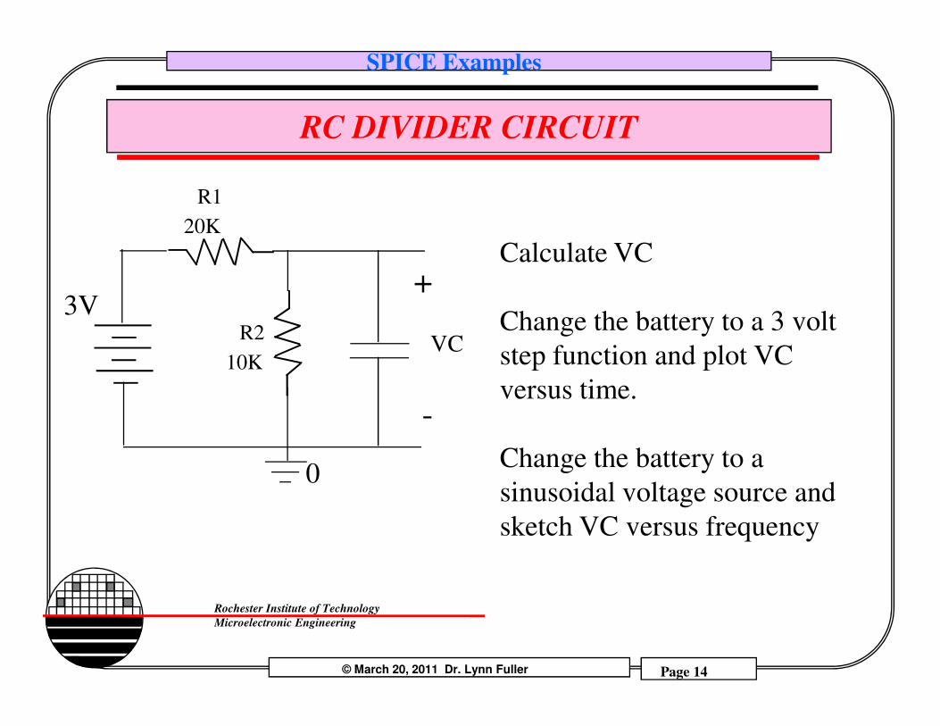
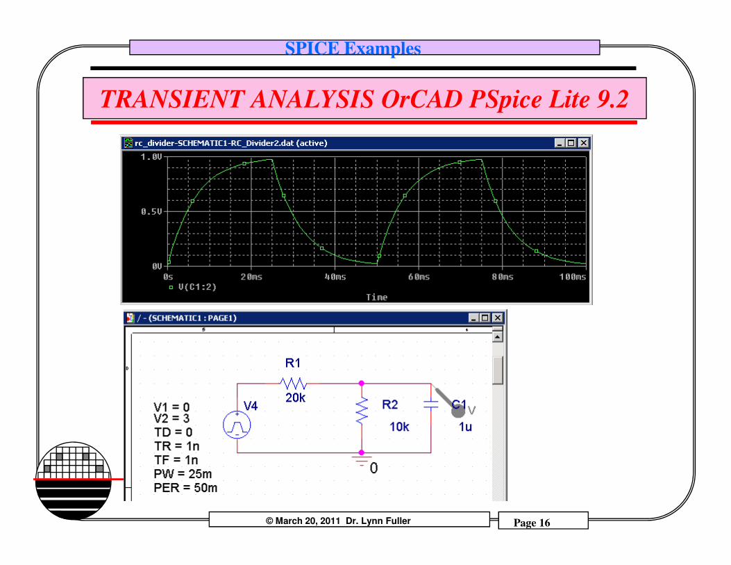
RC DIVIDER CIRCUIT
3V
R1
20K
VC
+
R2
10K
Calculate VC
Change the battery to a 3 volt
step function and plot VC
© March 20, 2011 Dr. Lynn Fuller Page 14
Rochester Institute of Technology
Microelectronic Engineering
0
-
10K step function and plot VC
versus time.
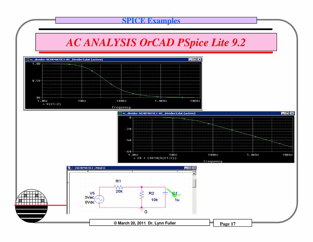
Change the battery to a
sinusoidal voltage source and
sketch VC versus frequency
SPICE Examples
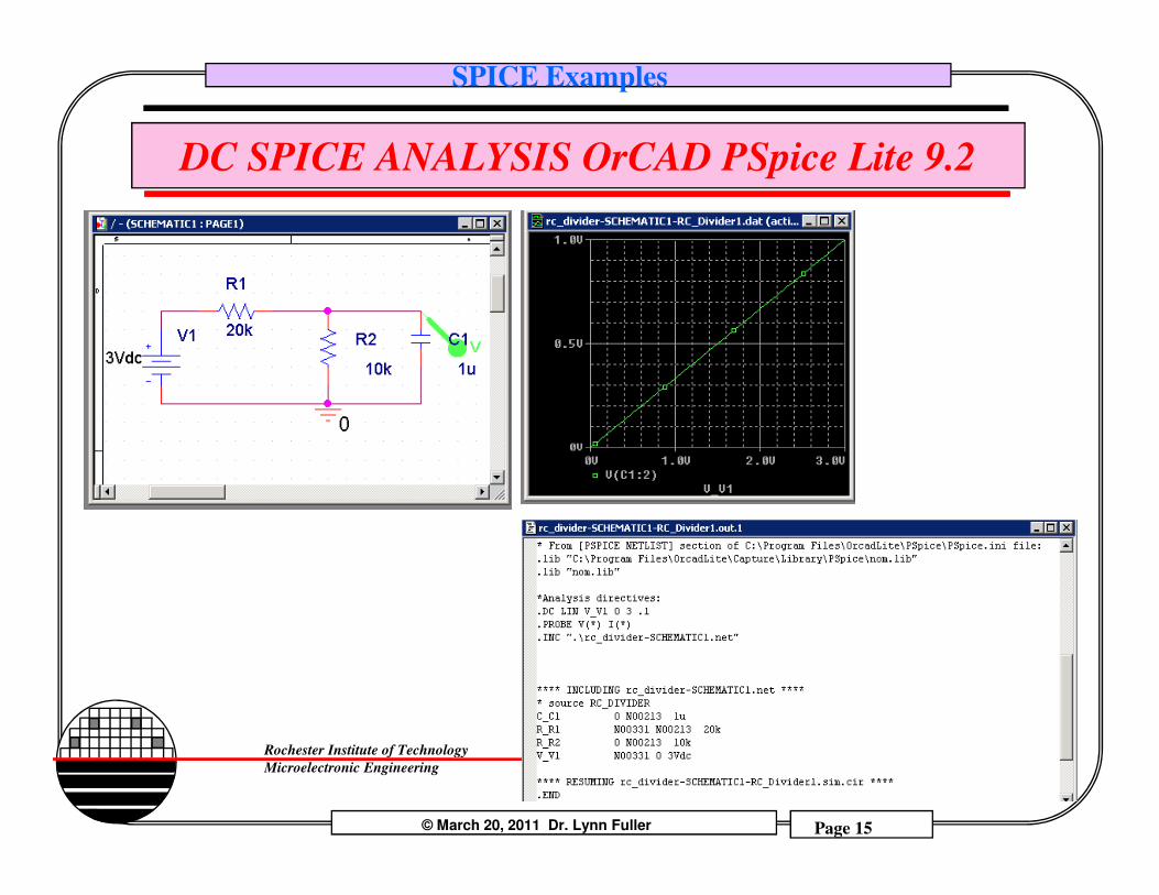
DC SPICE ANALYSIS OrCAD PSpice Lite 9.2
© March 20, 2011 Dr. Lynn Fuller Page 15
Rochester Institute of Technology
Microelectronic Engineering
SPICE Examples
TRANSIENT ANALYSIS OrCAD PSpice Lite 9.2
© March 20, 2011 Dr. Lynn Fuller Page 16
Rochester Institute of Technology
Microelectronic Engineering
SPICE Examples
AC ANALYSIS OrCAD PSpice Lite 9.2
© March 20, 2011 Dr. Lynn Fuller Page 17
Rochester Institute of Technology
Microelectronic Engineering
SPICE Examples
MOSFET, BJT AND DIODE MODELS
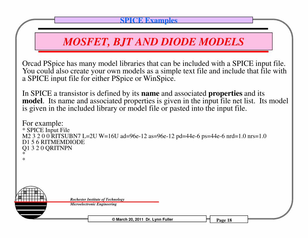
Orcad PSpice has many model libraries that can be included with a SPICE input file. You could also create your own models as a simple text file and include that file with a SPICE input file for either PSpice or WinSpice.
In SPICE a transistor is defined by its name and associated properties and its model. Its name and associated properties is given in the input file net list. Its model is given in the included library or model file or pasted into the input file.
For example:
© March 20, 2011 Dr. Lynn Fuller Page 18
Rochester Institute of Technology
Microelectronic Engineering
For example:* SPICE Input FileM2 3 2 0 0 RITSUBN7 L=2U W=16U ad=96e-12 as=96e-12 pd=44e-6 ps=44e-6 nrd=1.0 nrs=1.0 D1 5 6 RITMEMDIODEQ1 3 2 0 QRITNPN**
SPICE Examples
MOSFET, BJT AND DIODE MODELS
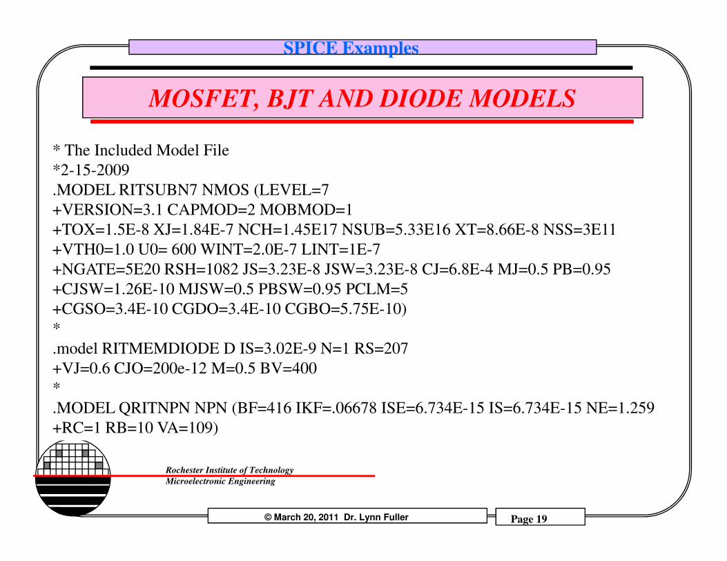
* The Included Model File
*2-15-2009
.MODEL RITSUBN7 NMOS (LEVEL=7
+VERSION=3.1 CAPMOD=2 MOBMOD=1
+TOX=1.5E-8 XJ=1.84E-7 NCH=1.45E17 NSUB=5.33E16 XT=8.66E-8 NSS=3E11
+VTH0=1.0 U0= 600 WINT=2.0E-7 LINT=1E-7
+NGATE=5E20 RSH=1082 JS=3.23E-8 JSW=3.23E-8 CJ=6.8E-4 MJ=0.5 PB=0.95
+CJSW=1.26E-10 MJSW=0.5 PBSW=0.95 PCLM=5
© March 20, 2011 Dr. Lynn Fuller Page 19
Rochester Institute of Technology
Microelectronic Engineering
+CJSW=1.26E-10 MJSW=0.5 PBSW=0.95 PCLM=5
+CGSO=3.4E-10 CGDO=3.4E-10 CGBO=5.75E-10)
*
.model RITMEMDIODE D IS=3.02E-9 N=1 RS=207
+VJ=0.6 CJO=200e-12 M=0.5 BV=400
*
.MODEL QRITNPN NPN (BF=416 IKF=.06678 ISE=6.734E-15 IS=6.734E-15 NE=1.259
+RC=1 RB=10 VA=109)
SPICE Examples
SIMULATION PROGRAM FOR INTEGRATED CIRCUIT ENGINEERING
MOSFET Device models used by SPICE (Simulation Program for
Integrated Circuit Engineering) simulators can be divided into three
classes: First Generation Models (Level 1, Level 2, Level 3 Models),
Second Generation Models (BISM, HSPICE Level 28, BSIM2) and
Third Generation Models (BSIM3, Level 7, Level 49, etc.) The
newer generations can do a better job with short channel effects,
© March 20, 2011 Dr. Lynn Fuller Page 20
Rochester Institute of Technology
Microelectronic Engineering
newer generations can do a better job with short channel effects,
local stress, transistors operating in the sub-threshold region, gate
leakage (tunneling), noise calculations, temperature variations and
the equations used are better with respect to convergence during
circuit simulation.
SPICE Examples
MOSFET SPICE MODEL LEVELS
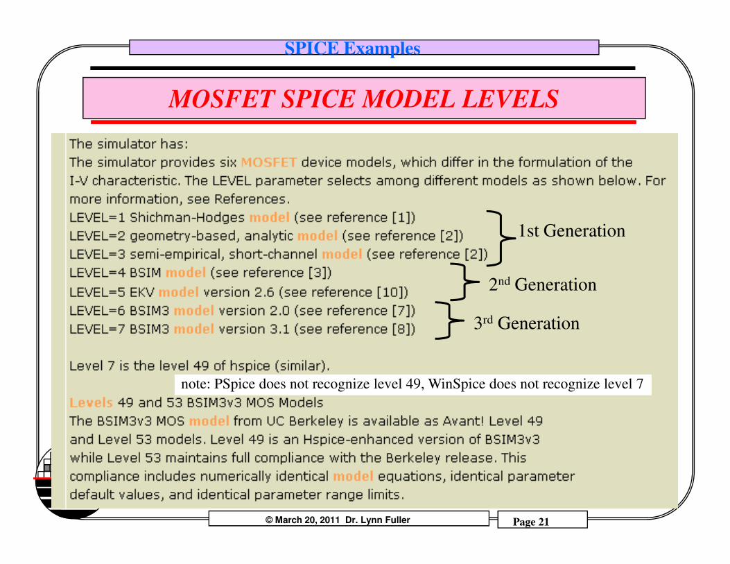
1st Generation
2nd Generation
© March 20, 2011 Dr. Lynn Fuller Page 21
Rochester Institute of Technology
Microelectronic Engineering
2nd Generation
3rd Generation
note: PSpice does not recognize level 49, WinSpice does not recognize level 7
SPICE Examples
RIT MOSFET SPICE MODELS
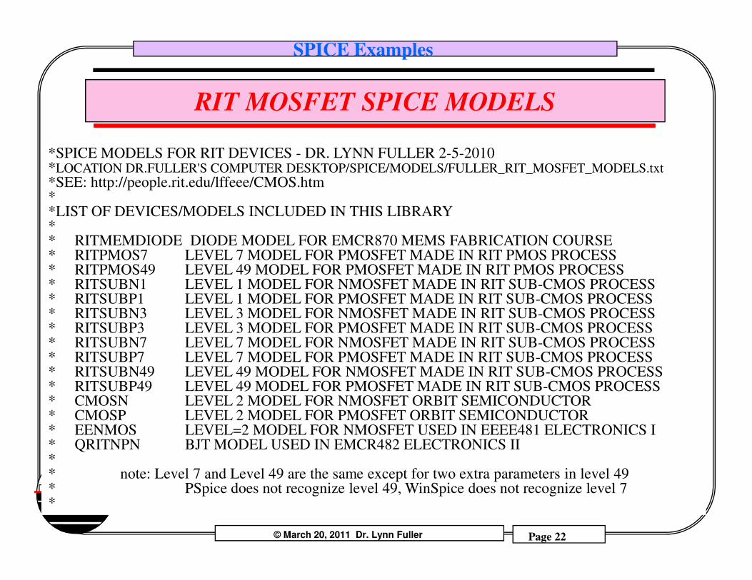
*SPICE MODELS FOR RIT DEVICES - DR. LYNN FULLER 2-5-2010*LOCATION DR.FULLER'S COMPUTER DESKTOP/SPICE/MODELS/FULLER_RIT_MOSFET_MODELS.txt*SEE: http://people.rit.edu/lffeee/CMOS.htm**LIST OF DEVICES/MODELS INCLUDED IN THIS LIBRARY** RITMEMDIODE DIODE MODEL FOR EMCR870 MEMS FABRICATION COURSE* RITPMOS7 LEVEL 7 MODEL FOR PMOSFET MADE IN RIT PMOS PROCESS* RITPMOS49 LEVEL 49 MODEL FOR PMOSFET MADE IN RIT PMOS PROCESS* RITSUBN1 LEVEL 1 MODEL FOR NMOSFET MADE IN RIT SUB-CMOS PROCESS* RITSUBP1 LEVEL 1 MODEL FOR PMOSFET MADE IN RIT SUB-CMOS PROCESS
© March 20, 2011 Dr. Lynn Fuller Page 22
Rochester Institute of Technology
Microelectronic Engineering
* RITSUBN1 LEVEL 1 MODEL FOR NMOSFET MADE IN RIT SUB-CMOS PROCESS* RITSUBP1 LEVEL 1 MODEL FOR PMOSFET MADE IN RIT SUB-CMOS PROCESS* RITSUBN3 LEVEL 3 MODEL FOR NMOSFET MADE IN RIT SUB-CMOS PROCESS* RITSUBP3 LEVEL 3 MODEL FOR PMOSFET MADE IN RIT SUB-CMOS PROCESS* RITSUBN7 LEVEL 7 MODEL FOR NMOSFET MADE IN RIT SUB-CMOS PROCESS* RITSUBP7 LEVEL 7 MODEL FOR PMOSFET MADE IN RIT SUB-CMOS PROCESS* RITSUBN49 LEVEL 49 MODEL FOR NMOSFET MADE IN RIT SUB-CMOS PROCESS* RITSUBP49 LEVEL 49 MODEL FOR PMOSFET MADE IN RIT SUB-CMOS PROCESS* CMOSN LEVEL 2 MODEL FOR NMOSFET ORBIT SEMICONDUCTOR* CMOSP LEVEL 2 MODEL FOR PMOSFET ORBIT SEMICONDUCTOR* EENMOS LEVEL=2 MODEL FOR NMOSFET USED IN EEEE481 ELECTRONICS I* QRITNPN BJT MODEL USED IN EMCR482 ELECTRONICS II** note: Level 7 and Level 49 are the same except for two extra parameters in level 49* PSpice does not recognize level 49, WinSpice does not recognize level 7*
SPICE Examples
LEVEL=1, RIT SUB-CMOS 150 PROCESS
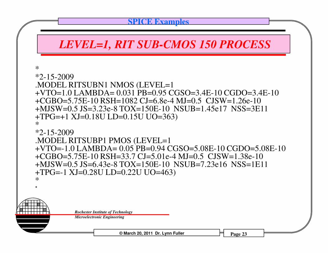
**2-15-2009.MODEL RITSUBN1 NMOS (LEVEL=1 +VTO=1.0 LAMBDA= 0.031 PB=0.95 CGSO=3.4E-10 CGDO=3.4E-10 +CGBO=5.75E-10 RSH=1082 CJ=6.8e-4 MJ=0.5 CJSW=1.26e-10 +MJSW=0.5 JS=3.23e-8 TOX=150E-10 NSUB=1.45e17 NSS=3E11 +TPG=+1 XJ=0.18U LD=0.15U UO=363)*
© March 20, 2011 Dr. Lynn Fuller Page 23
Rochester Institute of Technology
Microelectronic Engineering
**2-15-2009.MODEL RITSUBP1 PMOS (LEVEL=1 +VTO=-1.0 LAMBDA= 0.05 PB=0.94 CGSO=5.08E-10 CGDO=5.08E-10 +CGBO=5.75E-10 RSH=33.7 CJ=5.01e-4 MJ=0.5 CJSW=1.38e-10 +MJSW=0.5 JS=6.43e-8 TOX=150E-10 NSUB=7.23e16 NSS=1E11 +TPG=-1 XJ=0.28U LD=0.22U UO=463)**
SPICE Examples
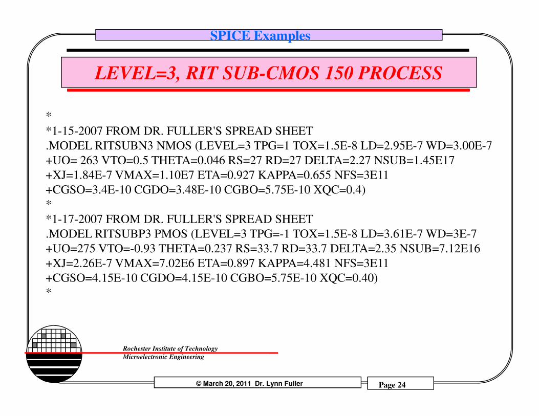
LEVEL=3, RIT SUB-CMOS 150 PROCESS
*
*1-15-2007 FROM DR. FULLER'S SPREAD SHEET
.MODEL RITSUBN3 NMOS (LEVEL=3 TPG=1 TOX=1.5E-8 LD=2.95E-7 WD=3.00E-7
+UO= 263 VTO=0.5 THETA=0.046 RS=27 RD=27 DELTA=2.27 NSUB=1.45E17
+XJ=1.84E-7 VMAX=1.10E7 ETA=0.927 KAPPA=0.655 NFS=3E11
+CGSO=3.4E-10 CGDO=3.48E-10 CGBO=5.75E-10 XQC=0.4)
*
© March 20, 2011 Dr. Lynn Fuller Page 24
Rochester Institute of Technology
Microelectronic Engineering
*
*1-17-2007 FROM DR. FULLER'S SPREAD SHEET
.MODEL RITSUBP3 PMOS (LEVEL=3 TPG=-1 TOX=1.5E-8 LD=3.61E-7 WD=3E-7
+UO=275 VTO=-0.93 THETA=0.237 RS=33.7 RD=33.7 DELTA=2.35 NSUB=7.12E16
+XJ=2.26E-7 VMAX=7.02E6 ETA=0.897 KAPPA=4.481 NFS=3E11
+CGSO=4.15E-10 CGDO=4.15E-10 CGBO=5.75E-10 XQC=0.40)
*
SPICE Examples
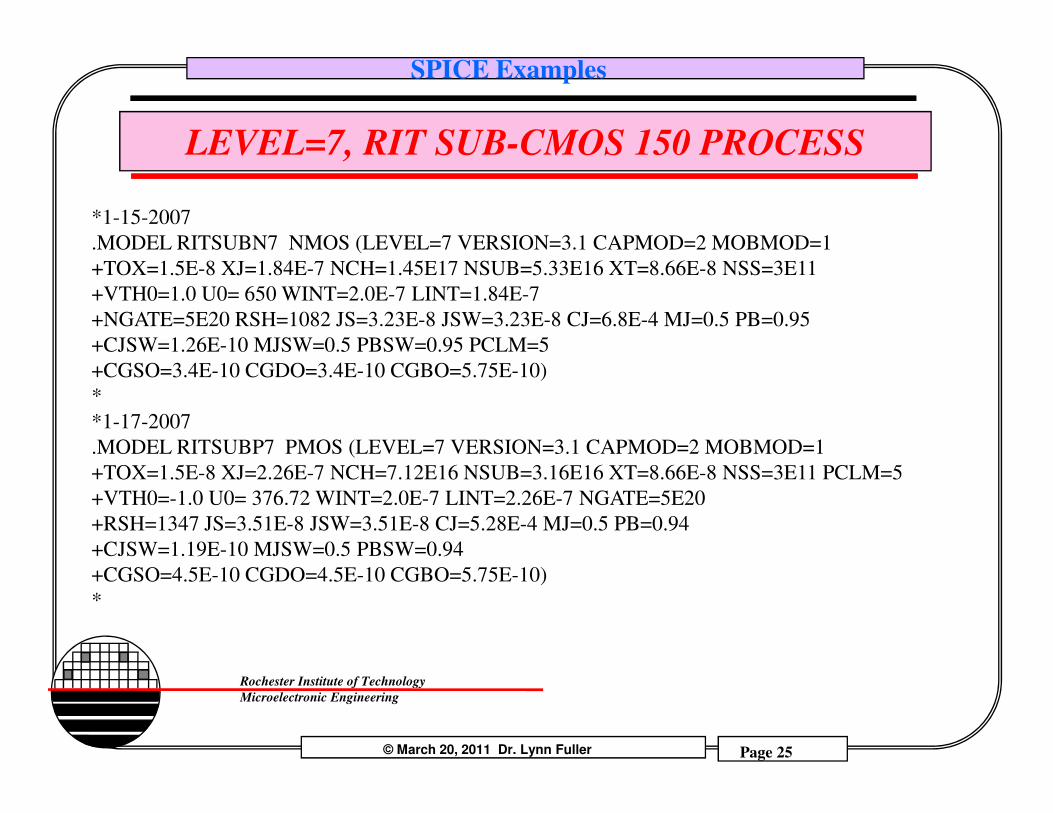
LEVEL=7, RIT SUB-CMOS 150 PROCESS
*1-15-2007
.MODEL RITSUBN7 NMOS (LEVEL=7 VERSION=3.1 CAPMOD=2 MOBMOD=1
+TOX=1.5E-8 XJ=1.84E-7 NCH=1.45E17 NSUB=5.33E16 XT=8.66E-8 NSS=3E11
+VTH0=1.0 U0= 650 WINT=2.0E-7 LINT=1.84E-7
+NGATE=5E20 RSH=1082 JS=3.23E-8 JSW=3.23E-8 CJ=6.8E-4 MJ=0.5 PB=0.95
+CJSW=1.26E-10 MJSW=0.5 PBSW=0.95 PCLM=5
+CGSO=3.4E-10 CGDO=3.4E-10 CGBO=5.75E-10)
*
© March 20, 2011 Dr. Lynn Fuller Page 25
Rochester Institute of Technology
Microelectronic Engineering
*
*1-17-2007
.MODEL RITSUBP7 PMOS (LEVEL=7 VERSION=3.1 CAPMOD=2 MOBMOD=1
+TOX=1.5E-8 XJ=2.26E-7 NCH=7.12E16 NSUB=3.16E16 XT=8.66E-8 NSS=3E11 PCLM=5
+VTH0=-1.0 U0= 376.72 WINT=2.0E-7 LINT=2.26E-7 NGATE=5E20
+RSH=1347 JS=3.51E-8 JSW=3.51E-8 CJ=5.28E-4 MJ=0.5 PB=0.94
+CJSW=1.19E-10 MJSW=0.5 PBSW=0.94
+CGSO=4.5E-10 CGDO=4.5E-10 CGBO=5.75E-10)
*
SPICE Examples
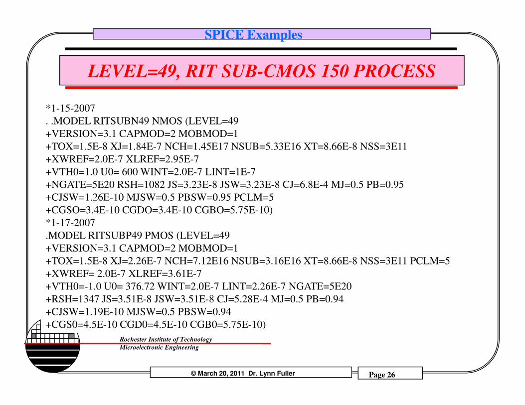
LEVEL=49, RIT SUB-CMOS 150 PROCESS
*1-15-2007
. .MODEL RITSUBN49 NMOS (LEVEL=49
+VERSION=3.1 CAPMOD=2 MOBMOD=1
+TOX=1.5E-8 XJ=1.84E-7 NCH=1.45E17 NSUB=5.33E16 XT=8.66E-8 NSS=3E11
+XWREF=2.0E-7 XLREF=2.95E-7
+VTH0=1.0 U0= 600 WINT=2.0E-7 LINT=1E-7
+NGATE=5E20 RSH=1082 JS=3.23E-8 JSW=3.23E-8 CJ=6.8E-4 MJ=0.5 PB=0.95
+CJSW=1.26E-10 MJSW=0.5 PBSW=0.95 PCLM=5
© March 20, 2011 Dr. Lynn Fuller Page 26
Rochester Institute of Technology
Microelectronic Engineering
+CJSW=1.26E-10 MJSW=0.5 PBSW=0.95 PCLM=5
+CGSO=3.4E-10 CGDO=3.4E-10 CGBO=5.75E-10)
*1-17-2007
.MODEL RITSUBP49 PMOS (LEVEL=49
+VERSION=3.1 CAPMOD=2 MOBMOD=1
+TOX=1.5E-8 XJ=2.26E-7 NCH=7.12E16 NSUB=3.16E16 XT=8.66E-8 NSS=3E11 PCLM=5
+XWREF= 2.0E-7 XLREF=3.61E-7
+VTH0=-1.0 U0= 376.72 WINT=2.0E-7 LINT=2.26E-7 NGATE=5E20
+RSH=1347 JS=3.51E-8 JSW=3.51E-8 CJ=5.28E-4 MJ=0.5 PB=0.94
+CJSW=1.19E-10 MJSW=0.5 PBSW=0.94
+CGS0=4.5E-10 CGD0=4.5E-10 CGB0=5.75E-10)
SPICE Examples
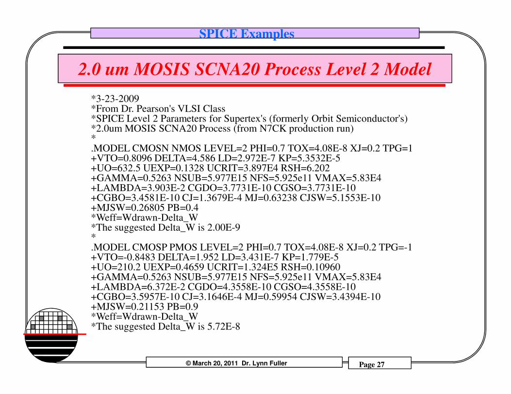
2.0 um MOSIS SCNA20 Process Level 2 Model
*3-23-2009*From Dr. Pearson's VLSI Class*SPICE Level 2 Parameters for Supertex's (formerly Orbit Semiconductor's)*2.0um MOSIS SCNA20 Process (from N7CK production run)*.MODEL CMOSN NMOS LEVEL=2 PHI=0.7 TOX=4.08E-8 XJ=0.2 TPG=1+VTO=0.8096 DELTA=4.586 LD=2.972E-7 KP=5.3532E-5+UO=632.5 UEXP=0.1328 UCRIT=3.897E4 RSH=6.202+GAMMA=0.5263 NSUB=5.977E15 NFS=5.925e11 VMAX=5.83E4+LAMBDA=3.903E-2 CGDO=3.7731E-10 CGSO=3.7731E-10+CGBO=3.4581E-10 CJ=1.3679E-4 MJ=0.63238 CJSW=5.1553E-10
© March 20, 2011 Dr. Lynn Fuller Page 27
Rochester Institute of Technology
Microelectronic Engineering
+CGBO=3.4581E-10 CJ=1.3679E-4 MJ=0.63238 CJSW=5.1553E-10+MJSW=0.26805 PB=0.4 *Weff=Wdrawn-Delta_W*The suggested Delta_W is 2.00E-9*.MODEL CMOSP PMOS LEVEL=2 PHI=0.7 TOX=4.08E-8 XJ=0.2 TPG=-1+VTO=-0.8483 DELTA=1.952 LD=3.431E-7 KP=1.779E-5+UO=210.2 UEXP=0.4659 UCRIT=1.324E5 RSH=0.10960+GAMMA=0.5263 NSUB=5.977E15 NFS=5.925e11 VMAX=5.83E4+LAMBDA=6.372E-2 CGDO=4.3558E-10 CGSO=4.3558E-10+CGBO=3.5957E-10 CJ=3.1646E-4 MJ=0.59954 CJSW=3.4394E-10+MJSW=0.21153 PB=0.9 *Weff=Wdrawn-Delta_W*The suggested Delta_W is 5.72E-8
SPICE Examples
RIT METAL GATE PMOS
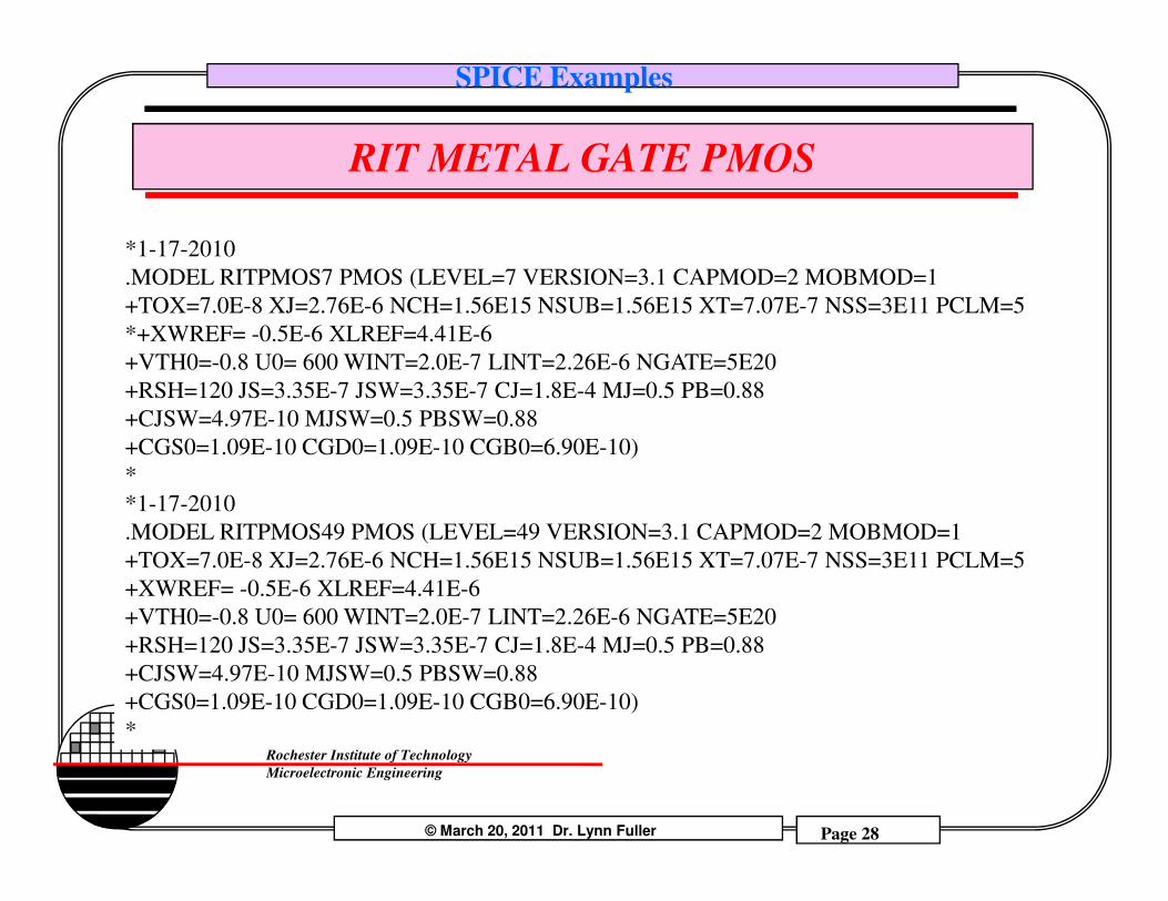
*1-17-2010
.MODEL RITPMOS7 PMOS (LEVEL=7 VERSION=3.1 CAPMOD=2 MOBMOD=1
+TOX=7.0E-8 XJ=2.76E-6 NCH=1.56E15 NSUB=1.56E15 XT=7.07E-7 NSS=3E11 PCLM=5
*+XWREF= -0.5E-6 XLREF=4.41E-6
+VTH0=-0.8 U0= 600 WINT=2.0E-7 LINT=2.26E-6 NGATE=5E20
+RSH=120 JS=3.35E-7 JSW=3.35E-7 CJ=1.8E-4 MJ=0.5 PB=0.88
+CJSW=4.97E-10 MJSW=0.5 PBSW=0.88
+CGS0=1.09E-10 CGD0=1.09E-10 CGB0=6.90E-10)
© March 20, 2011 Dr. Lynn Fuller Page 28
Rochester Institute of Technology
Microelectronic Engineering
+CGS0=1.09E-10 CGD0=1.09E-10 CGB0=6.90E-10)
*
*1-17-2010
.MODEL RITPMOS49 PMOS (LEVEL=49 VERSION=3.1 CAPMOD=2 MOBMOD=1
+TOX=7.0E-8 XJ=2.76E-6 NCH=1.56E15 NSUB=1.56E15 XT=7.07E-7 NSS=3E11 PCLM=5
+XWREF= -0.5E-6 XLREF=4.41E-6
+VTH0=-0.8 U0= 600 WINT=2.0E-7 LINT=2.26E-6 NGATE=5E20
+RSH=120 JS=3.35E-7 JSW=3.35E-7 CJ=1.8E-4 MJ=0.5 PB=0.88
+CJSW=4.97E-10 MJSW=0.5 PBSW=0.88
+CGS0=1.09E-10 CGD0=1.09E-10 CGB0=6.90E-10)
*
SPICE Examples
OTHER DEVICE MODELS
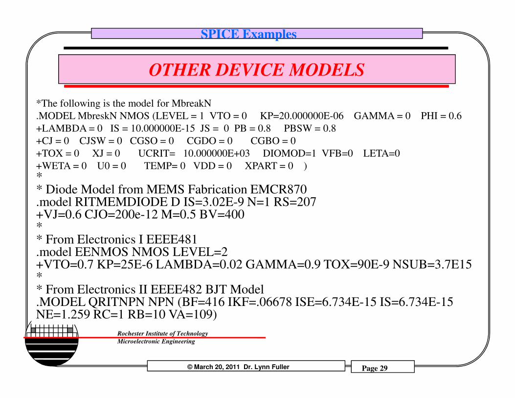
*The following is the model for MbreakN
.MODEL MbreskN NMOS (LEVEL = 1 VTO = 0 KP=20.000000E-06 GAMMA = 0 PHI = 0.6
+LAMBDA = 0 IS = 10.000000E-15 JS = 0 PB = 0.8 PBSW = 0.8
+CJ = 0 CJSW = 0 CGSO = 0 CGDO = 0 CGBO = 0
+TOX = 0 XJ = 0 UCRIT= 10.000000E+03 DIOMOD=1 VFB=0 LETA=0
+WETA = 0 U0 = 0 TEMP= 0 VDD = 0 XPART = 0 ) ** Diode Model from MEMS Fabrication EMCR870.model RITMEMDIODE D IS=3.02E-9 N=1 RS=207
© March 20, 2011 Dr. Lynn Fuller Page 29
Rochester Institute of Technology
Microelectronic Engineering
.model RITMEMDIODE D IS=3.02E-9 N=1 RS=207+VJ=0.6 CJO=200e-12 M=0.5 BV=400** From Electronics I EEEE481.model EENMOS NMOS LEVEL=2+VTO=0.7 KP=25E-6 LAMBDA=0.02 GAMMA=0.9 TOX=90E-9 NSUB=3.7E15** From Electronics II EEEE482 BJT Model.MODEL QRITNPN NPN (BF=416 IKF=.06678 ISE=6.734E-15 IS=6.734E-15 NE=1.259 RC=1 RB=10 VA=109)
SPICE Examples
IMPORTING THE INCLUDE FILES INTO LTSPICE
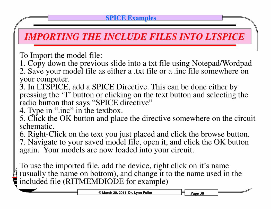
To Import the model file:1. Copy down the previous slide into a txt file using Notepad/Wordpad2. Save your model file as either a .txt file or a .inc file somewhere on your computer.3. In LTSPICE, add a SPICE Directive. This can be done either by pressing the ‘T’ button or clicking on the text button and selecting the radio button that says “SPICE directive”
© March 20, 2011 Dr. Lynn Fuller Page 30
Rochester Institute of Technology
Microelectronic Engineering
radio button that says “SPICE directive”4. Type in “.inc” in the textbox.5. Click the OK button and place the directive somewhere on the circuit schematic.6. Right-Click on the text you just placed and click the browse button.7. Navigate to your saved model file, open it, and click the OK button again. Your models are now loaded into your circuit.
To use the imported file, add the device, right click on it’s name (usually the name on bottom), and change it to the name used in the included file (RITMEMDIODE for example)
SPICE Examples
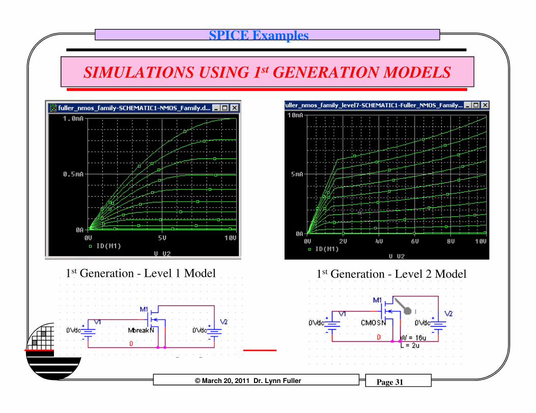
SIMULATIONS USING 1st GENERATION MODELS
© March 20, 2011 Dr. Lynn Fuller Page 31
Rochester Institute of Technology
Microelectronic Engineering
1st Generation - Level 2 Model1st Generation - Level 1 Model
SPICE Examples
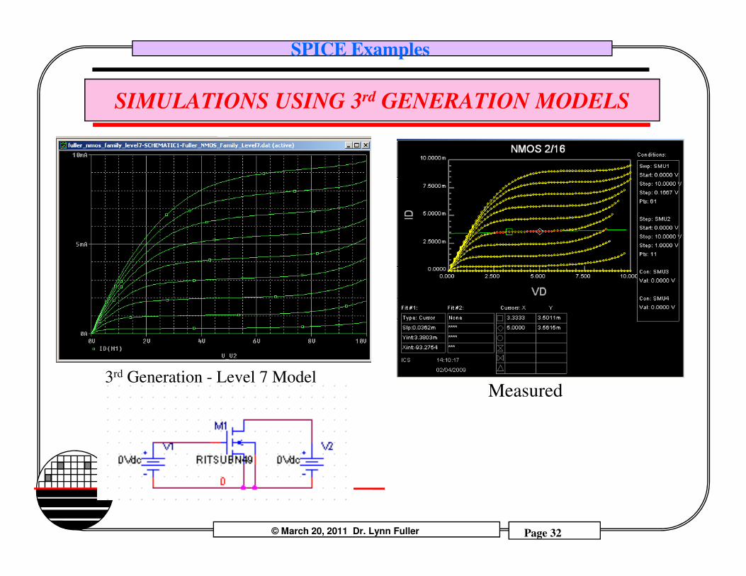
SIMULATIONS USING 3rd GENERATION MODELS
© March 20, 2011 Dr. Lynn Fuller Page 32
Rochester Institute of Technology
Microelectronic Engineering
3rd Generation - Level 7 ModelMeasured
SPICE Examples
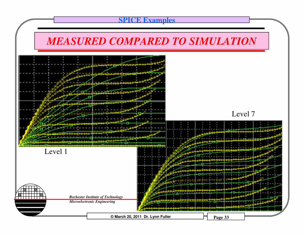
MEASURED COMPARED TO SIMULATION
Level 7
© March 20, 2011 Dr. Lynn Fuller Page 33
Rochester Institute of Technology
Microelectronic Engineering
Level 1
Level 7
SPICE Examples
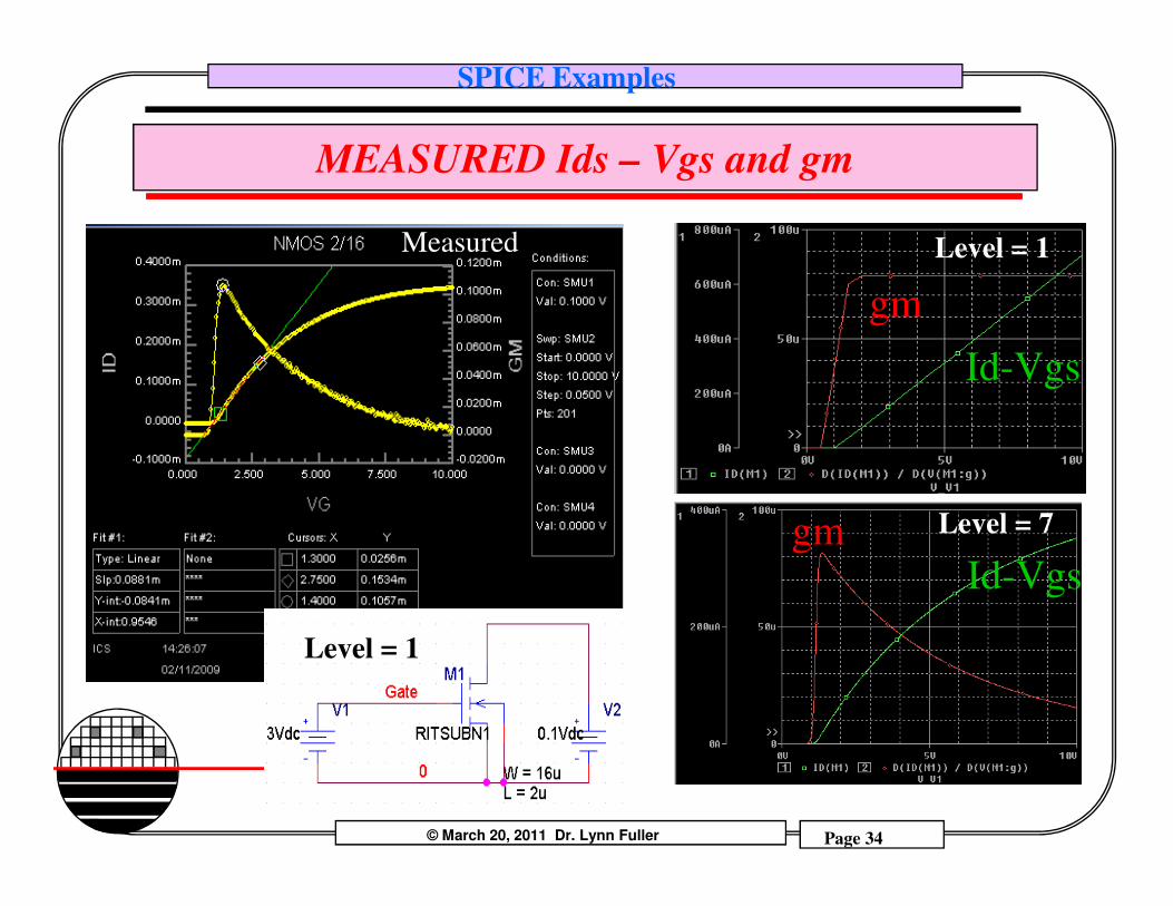
MEASURED Ids – Vgs and gm
gm
Id-Vgs
Level = 1Measured
© March 20, 2011 Dr. Lynn Fuller Page 34
Rochester Institute of Technology
Microelectronic Engineering
gmId-Vgs
Level = 7
Level = 1
SPICE Examples
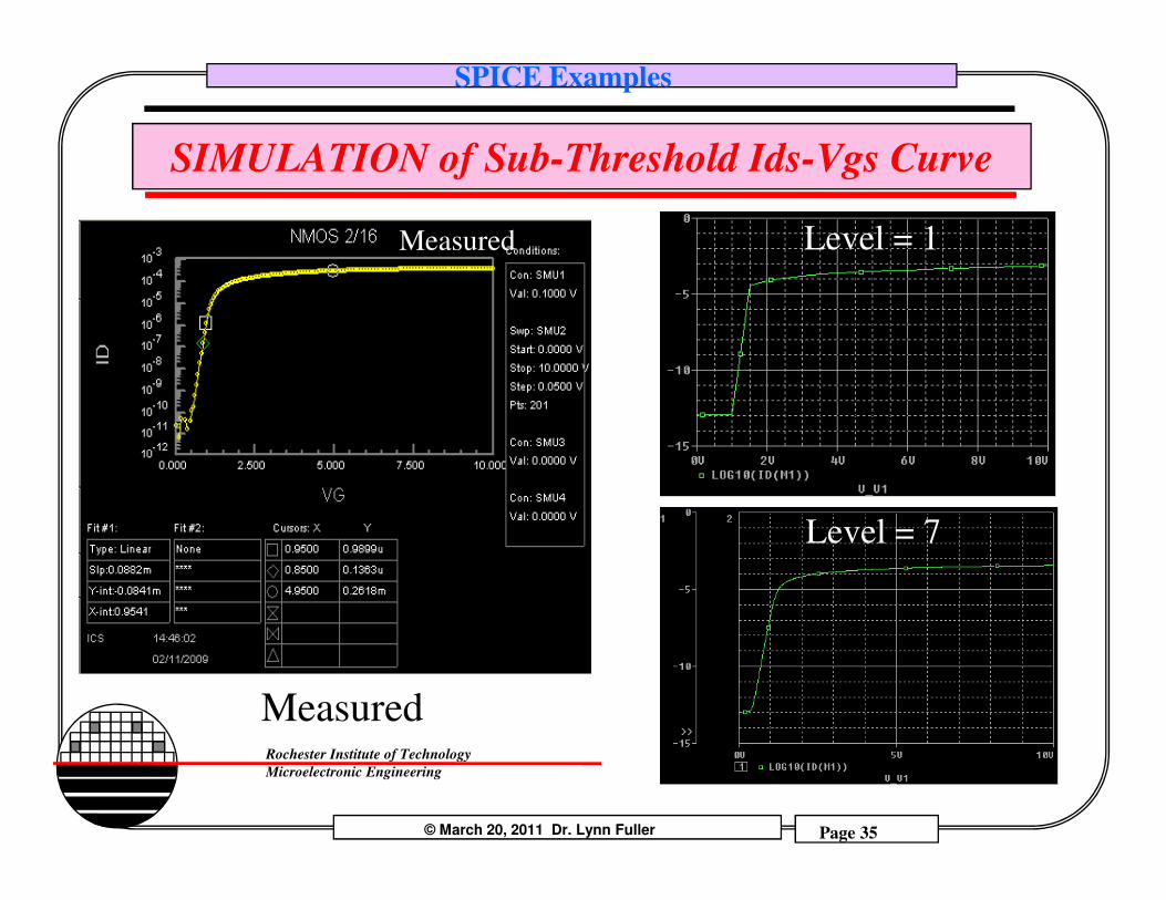
SIMULATION of Sub-Threshold Ids-Vgs Curve
Level = 1Measured
© March 20, 2011 Dr. Lynn Fuller Page 35
Rochester Institute of Technology
Microelectronic Engineering
Level = 7
Measured
SPICE Examples
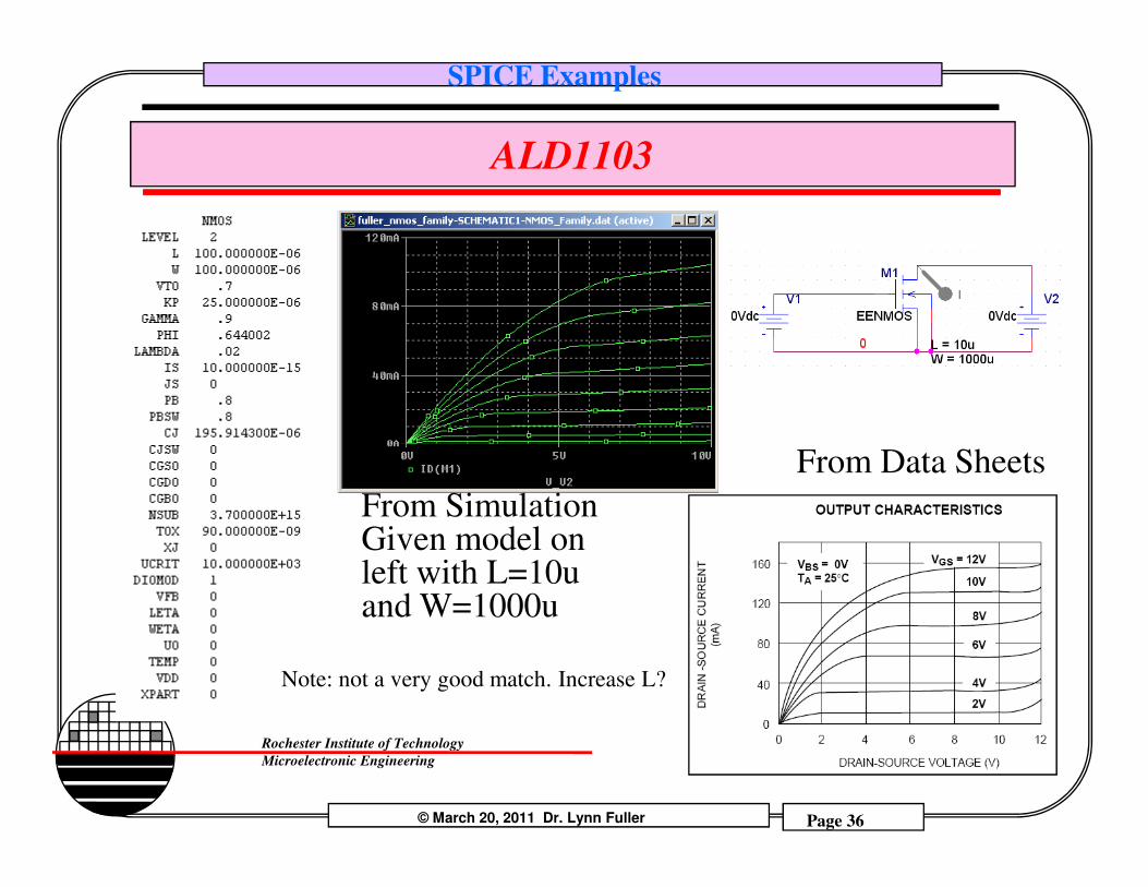
ALD1103
From Data Sheets
© March 20, 2011 Dr. Lynn Fuller Page 36
Rochester Institute of Technology
Microelectronic Engineering
From Data Sheets
From SimulationGiven model on left with L=10u and W=1000u
Note: not a very good match. Increase L?
SPICE Examples
CONCLUSION FROM DC MODEL COMPARISON
Third generation MOSFET models such as Level 7 for OrCAD PSPICE or Level 49 models for WinSpice give better results than any of the 1st or 2nd generation models. These models are different for different processes (such as RIT’s Sub-CMOS 150 or RIT’s Adv-CMOS 150 processes)
© March 20, 2011 Dr. Lynn Fuller Page 37
Rochester Institute of Technology
Microelectronic Engineering

SPICE Examples
FAMILY OF CURVES FOR RIT SUB-CMOS NMOSFET, Dr. Lynn Fuller, 1-15-2007
*LINE ABOVE IS TITLE
*START WIN SPICE AND ENTER LOCATION AND NAME OF INPUT FILE
*THIS FILE IS FAMILYN.TXT
*EXAMPLE: winspice> source c:/spice/familyn.txt
*THE TRANSISTOR MODELS ARE IN THE FILE NAMED BELOW
.INCLUDE E:\SPICE\WINSPICE\RIT_MICROE_MODELS.TXT
*CIRCUIT DESCRIPTION
*VOLTAGE SOURCES
V1 1 0 DC 5
V2 2 0 DC 1
V3 3 0 DC 2
V4 4 0 DC 3
V5 5 0 DC 4
SIMULATION OF MOSFET IDS-VDS FAMILY
© March 20, 2011 Dr. Lynn Fuller Page 38
Rochester Institute of Technology
Microelectronic Engineering
V5 5 0 DC 4
V6 6 0 DC 5
*TRANSISTORS
M1 7 2 0 0 RITSUBN3 L=2U W=16U ad=96e-12 as=96e-12 pd=44e-6 ps=44e-6 nrd=0.025 nrs=0.025
M2 8 3 0 0 RITSUBN3 L=2U W=16U ad=96e-12 as=96e-12 pd=44e-6 ps=44e-6 nrd=0.025 nrs=0.025
M3 9 4 0 0 RITSUBN3 L=2U W=16U ad=96e-12 as=96e-12 pd=44e-6 ps=44e-6 nrd=0.025 nrs=0.025
M4 10 5 0 0 RITSUBN3 L=2U W=16U ad=96e-12 as=96e-12 pd=44e-6 ps=44e-6 nrd=0.025 nrs=0.025
M5 11 6 0 0 RITSUBN3 L=2U W=16U ad=96e-12 as=96e-12 pd=44e-6 ps=44e-6 nrd=0.025 nrs=0.025
*CURRENT METERS (VOLTAGE SOURCES OF VALUE = ZERO)
VD1 1 7 DC 0
VD2 1 8 DC 0
VD3 1 9 DC 0
VD4 1 10 DC 0
VD5 1 11 DC 0
*REQUESTED ANALYSIS
.OP
.DC V1 0 5 .1
.PRINT DC I(VD1) I(VD2) I(VD3) I(VD4) I(VD5)
.PLOT DC I(VD1) I(VD2) I(VD3) I(VD4) I(VD5)
.END0

SPICE Examples
ANOTHER WAY TO GET A FAMILY OF CURVES
nmos family of curves.incl Fuller_RIT_MOSFET_MODELS.txt*m1 2 1 0 0 cmosn W= 10u L= 5uvd 2 0 dc 5vg 1 0 dc 5***************************dc sweep analysis****
1
Vg=1
+
-
Vd = 0.1
+
-
M1
2
© March 20, 2011 Dr. Lynn Fuller Page 39
Rochester Institute of Technology
Microelectronic Engineering
***dc sweep analysis****.dc vd 0 5 10m vg 0 5 .5************************.end
Vg=1
0
SPICE Examples
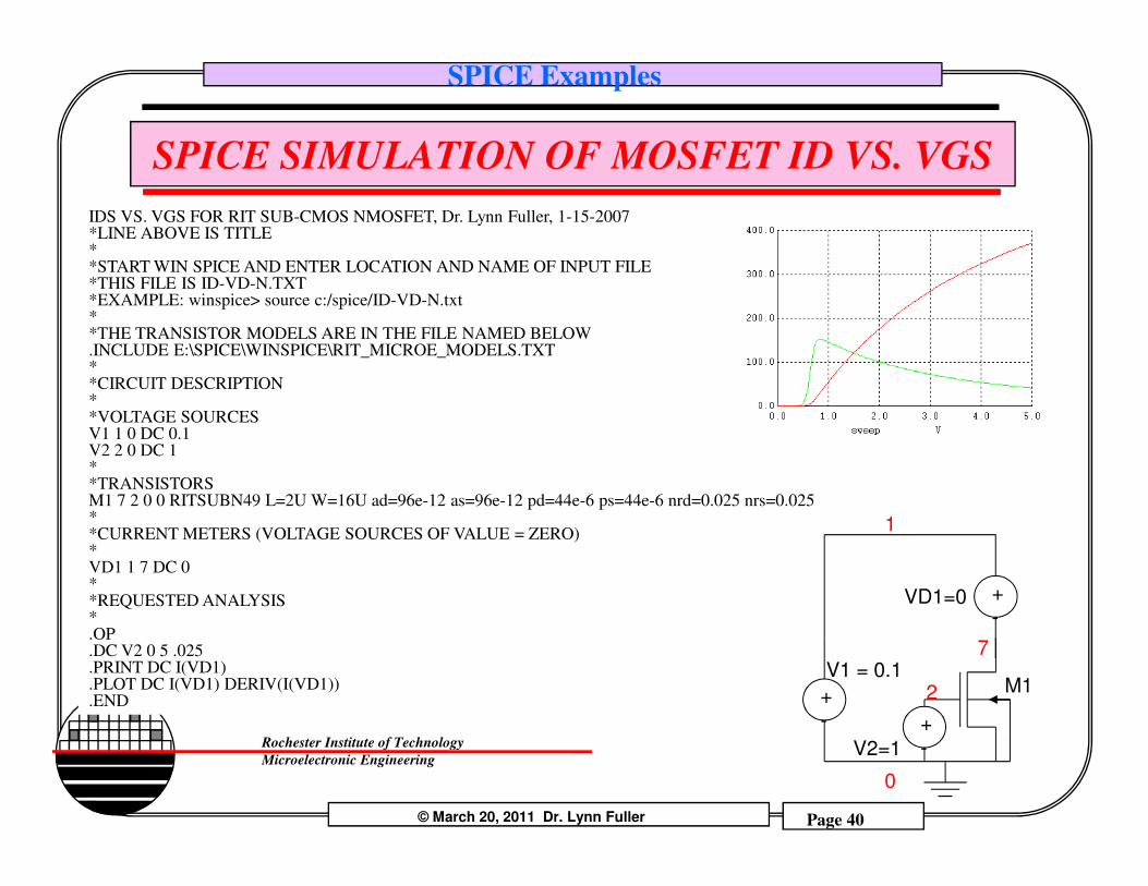
SPICE SIMULATION OF MOSFET ID VS. VGS
IDS VS. VGS FOR RIT SUB-CMOS NMOSFET, Dr. Lynn Fuller, 1-15-2007*LINE ABOVE IS TITLE**START WIN SPICE AND ENTER LOCATION AND NAME OF INPUT FILE*THIS FILE IS ID-VD-N.TXT*EXAMPLE: winspice> source c:/spice/ID-VD-N.txt**THE TRANSISTOR MODELS ARE IN THE FILE NAMED BELOW.INCLUDE E:\SPICE\WINSPICE\RIT_MICROE_MODELS.TXT**CIRCUIT DESCRIPTION**VOLTAGE SOURCESV1 1 0 DC 0.1V2 2 0 DC 1
© March 20, 2011 Dr. Lynn Fuller Page 40
Rochester Institute of Technology
Microelectronic Engineering
V2 2 0 DC 1**TRANSISTORSM1 7 2 0 0 RITSUBN49 L=2U W=16U ad=96e-12 as=96e-12 pd=44e-6 ps=44e-6 nrd=0.025 nrs=0.025**CURRENT METERS (VOLTAGE SOURCES OF VALUE = ZERO)*VD1 1 7 DC 0**REQUESTED ANALYSIS*.OP.DC V2 0 5 .025.PRINT DC I(VD1).PLOT DC I(VD1) DERIV(I(VD1)).END
1
2
V2=1
+-
V1 = 0.1
+-
M1
VD1=0 +-
7
0
SPICE Examples
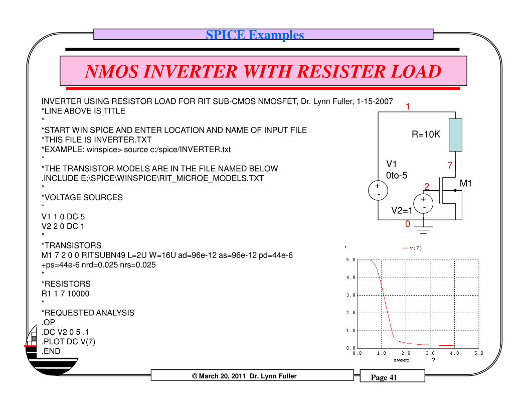
NMOS INVERTER WITH RESISTER LOAD
INVERTER USING RESISTOR LOAD FOR RIT SUB-CMOS NMOSFET, Dr. Lynn Fuller, 1-15-2007
*LINE ABOVE IS TITLE
*
*START WIN SPICE AND ENTER LOCATION AND NAME OF INPUT FILE
*THIS FILE IS INVERTER.TXT
*EXAMPLE: winspice> source c:/spice/INVERTER.txt
*
*THE TRANSISTOR MODELS ARE IN THE FILE NAMED BELOW
.INCLUDE E:\SPICE\WINSPICE\RIT_MICROE_MODELS.TXT
*
*VOLTAGE SOURCES
*
1
2
V10to-5
+-
M1
R=10K
7
+-
© March 20, 2011 Dr. Lynn Fuller Page 41
Rochester Institute of Technology
Microelectronic Engineering
*
V1 1 0 DC 5
V2 2 0 DC 1
*
*TRANSISTORS
M1 7 2 0 0 RITSUBN49 L=2U W=16U ad=96e-12 as=96e-12 pd=44e-6
+ps=44e-6 nrd=0.025 nrs=0.025
*
*RESISTORS
R1 1 7 10000
*
*REQUESTED ANALYSIS
.OP
.DC V2 0 5 .1
.PLOT DC V(7)
.END
V2=1 -
0
SPICE Examples
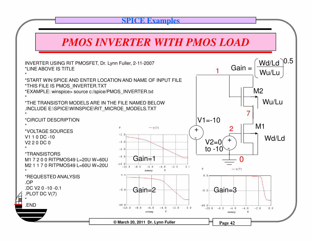
PMOS INVERTER WITH PMOS LOAD
INVERTER USING RIT PMOSFET, Dr. Lynn Fuller, 2-11-2007
*LINE ABOVE IS TITLE
*
*START WIN SPICE AND ENTER LOCATION AND NAME OF INPUT FILE
*THIS FILE IS PMOS_INVERTER.TXT
*EXAMPLE: winspice> source c:/spice/PMOS_INVERTER.txt
*
*THE TRANSISTOR MODELS ARE IN THE FILE NAMED BELOW
.INCLUDE E:\SPICE\WINSPICE\RIT_MICROE_MODELS.TXT
*
*CIRCUIT DESCRIPTION
1
V1=-10
Wu/Lu
7
Gain = Wd/Ld
Wu/Lu
0.5
M2
© March 20, 2011 Dr. Lynn Fuller Page 42
Rochester Institute of Technology
Microelectronic Engineering
*CIRCUIT DESCRIPTION
*
*VOLTAGE SOURCES
V1 1 0 DC -10
V2 2 0 DC 0
*
*TRANSISTORS
M1 7 2 0 0 RITPMOS49 L=20U W=60U
M2 1 1 7 0 RITPMOS49 L=60U W=20U
*
*REQUESTED ANALYSIS
.OP
.DC V2 0 -10 -0.1
.PLOT DC V(7)
*
.END
Gain=1
Gain=2 Gain=3
2
V2=0to -10
+
-
V1=-10
+
-
M1
Wd/Ld
0
SPICE Examples
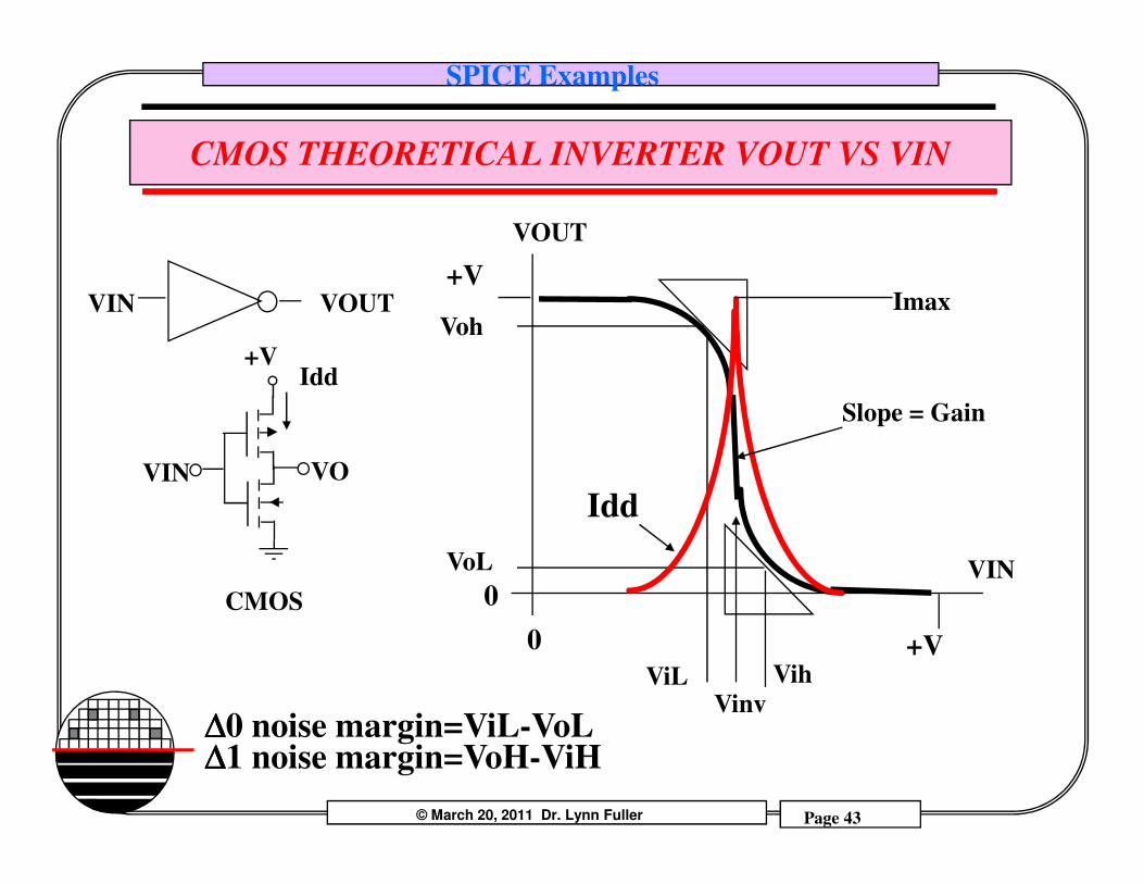
CMOS THEORETICAL INVERTER VOUT VS VIN
VIN VOUT
+VIdd
+V
VohImax
VOUT
Slope = Gain
© March 20, 2011 Dr. Lynn Fuller Page 43
Rochester Institute of Technology
Microelectronic Engineering
VIN
CMOS
VO
+V0
0
ViL
VoL
Vih
VIN
Idd
∆∆∆∆0 noise margin=ViL-VoL∆∆∆∆1 noise margin=VoH-ViH
Vinv
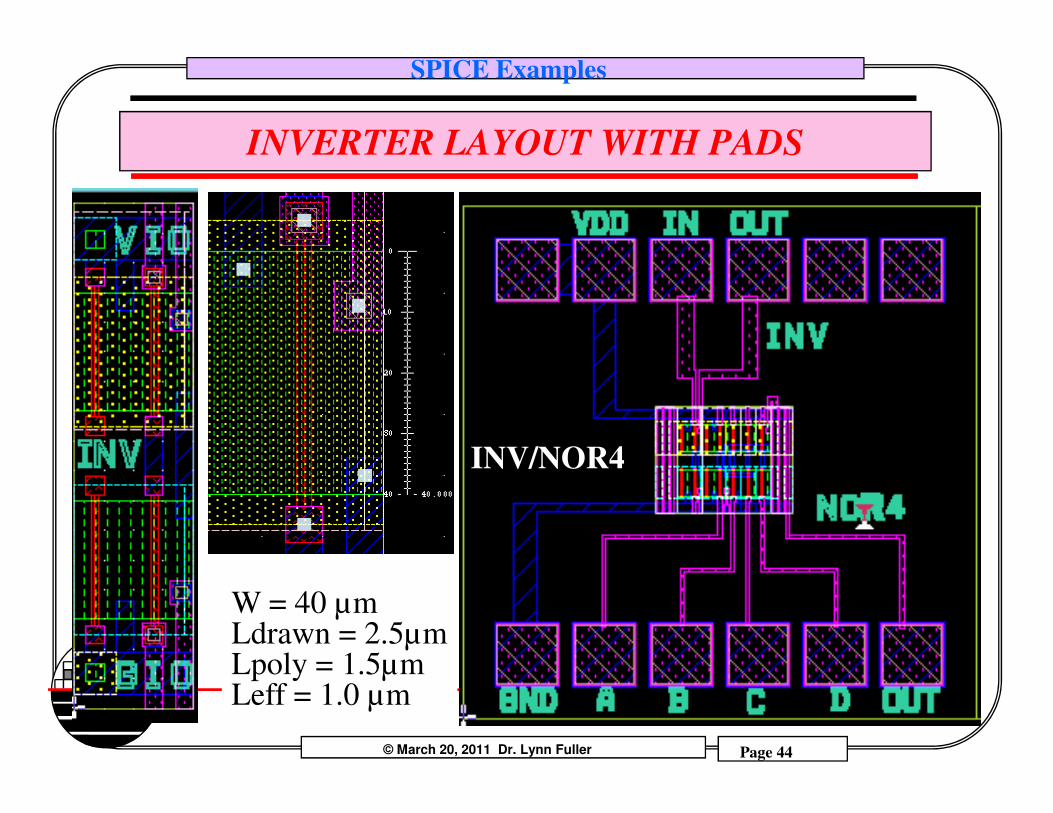
SPICE Examples
INVERTER LAYOUT WITH PADS
© March 20, 2011 Dr. Lynn Fuller Page 44
Rochester Institute of Technology
Microelectronic Engineering
INV/NOR4
W = 40 µmLdrawn = 2.5µmLpoly = 1.5µmLeff = 1.0 µm
SPICE Examples
DC SIMULATION OF INVERTER VOUT & I VS VIN
© March 20, 2011 Dr. Lynn Fuller Page 45
Rochester Institute of Technology
Microelectronic Engineering
SPICE Examples
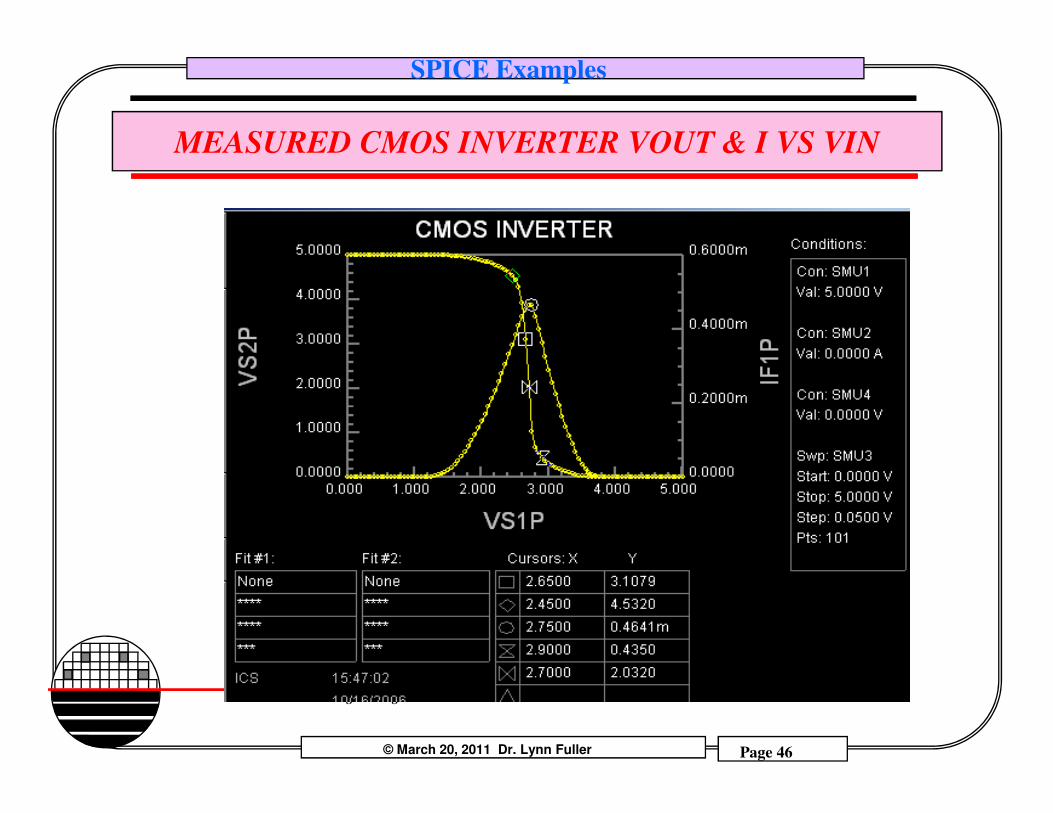
MEASURED CMOS INVERTER VOUT & I VS VIN
© March 20, 2011 Dr. Lynn Fuller Page 46
Rochester Institute of Technology
Microelectronic Engineering
SPICE Examples
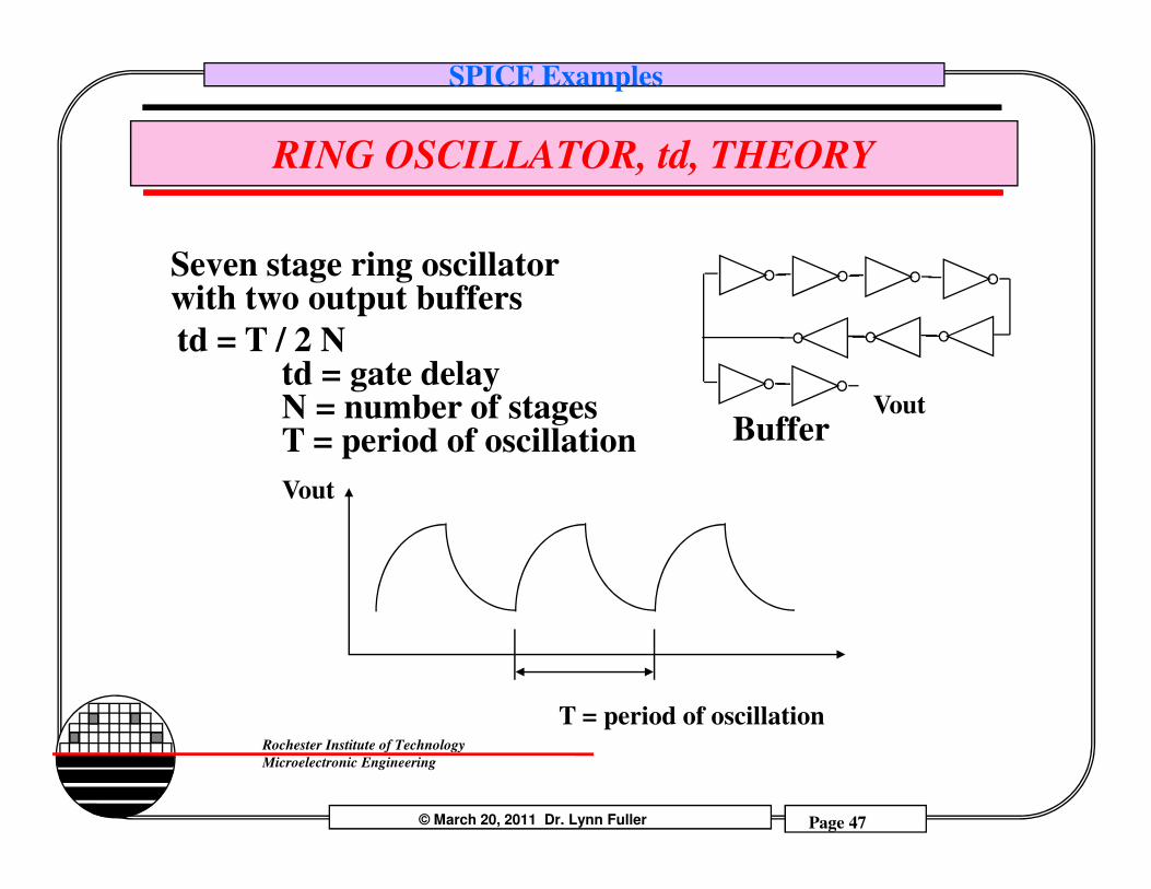
RING OSCILLATOR, td, THEORY
td = T / 2 Ntd = gate delayN = number of stagesT = period of oscillation
Vout
Seven stage ring oscillatorwith two output buffers
Buffer
© March 20, 2011 Dr. Lynn Fuller Page 47
Rochester Institute of Technology
Microelectronic Engineering
T = period of oscillation
T = period of oscillation
Vout
Buffer
SPICE Examples
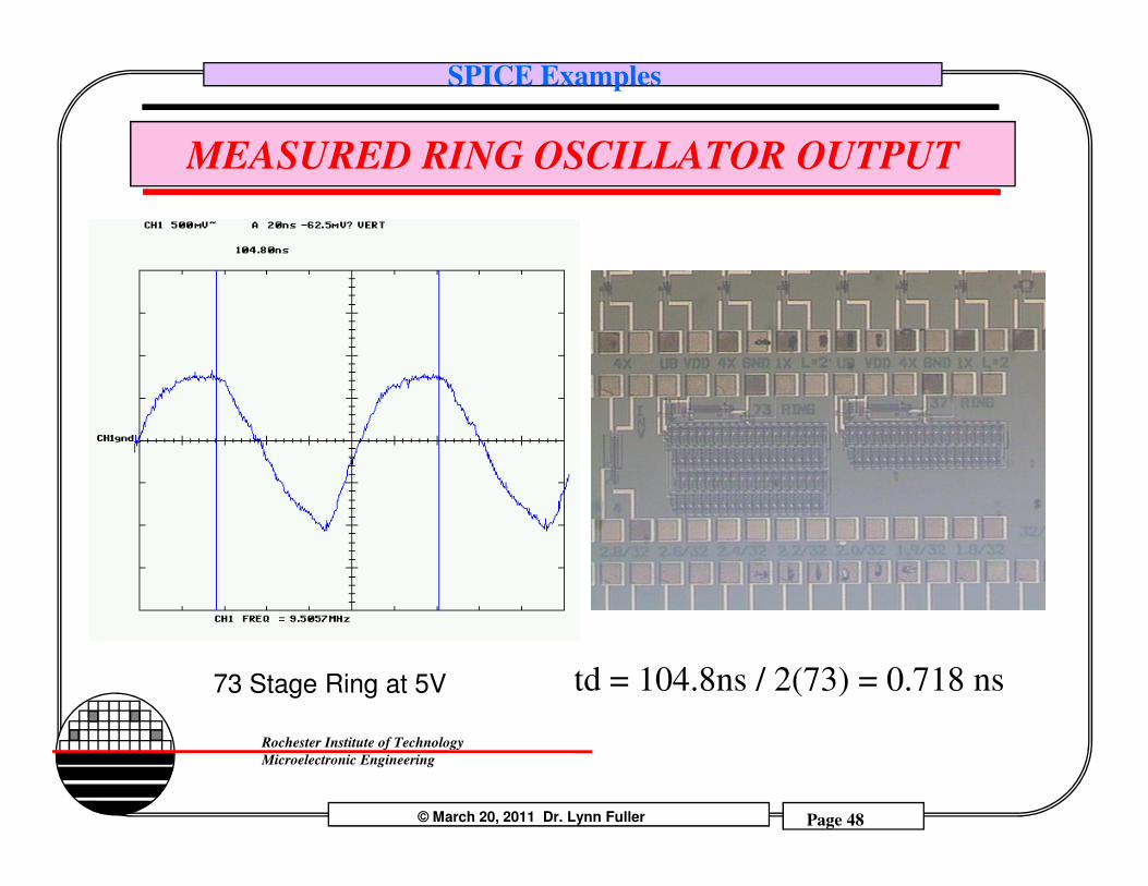
MEASURED RING OSCILLATOR OUTPUT
© March 20, 2011 Dr. Lynn Fuller Page 48
Rochester Institute of Technology
Microelectronic Engineering
73 Stage Ring at 5V td = 104.8ns / 2(73) = 0.718 ns
SPICE Examples
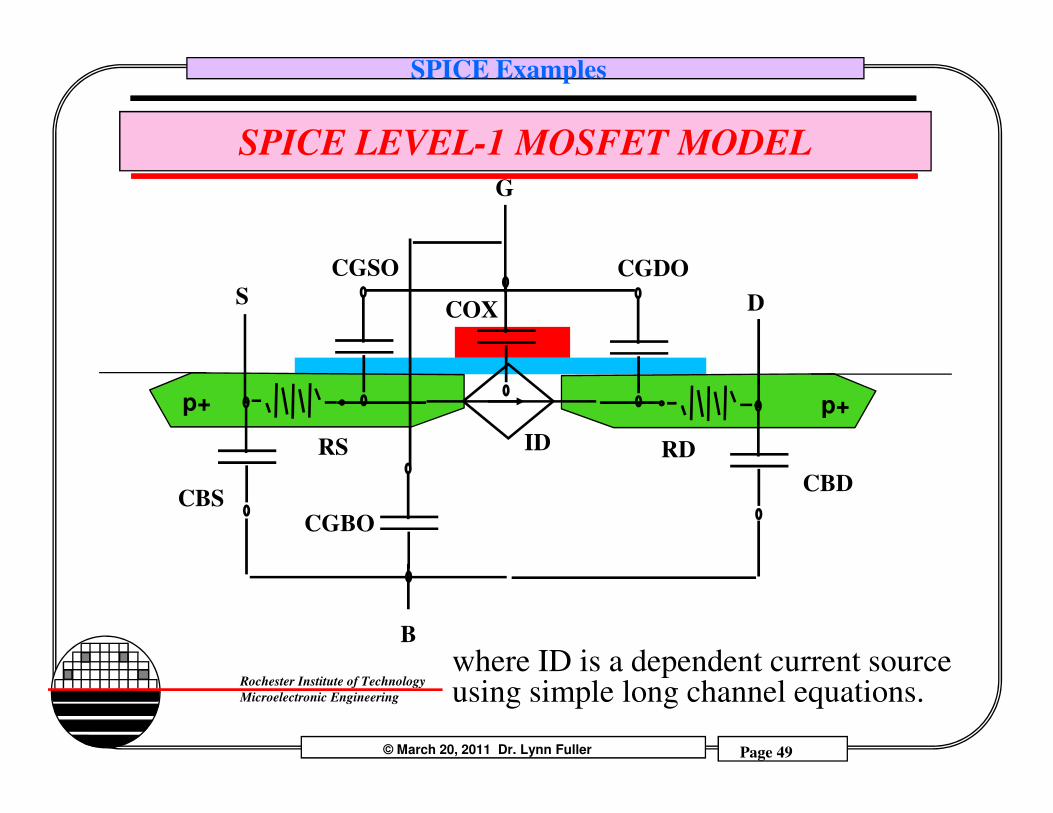
SPICE LEVEL-1 MOSFET MODEL
p+ p+
S
G
D
CGDO
COX
CGSO
© March 20, 2011 Dr. Lynn Fuller Page 49
Rochester Institute of Technology
Microelectronic Engineering
p+ p+
CBDCBS
RS RDID
CGBO
B
where ID is a dependent current source using simple long channel equations.

SPICE Examples
AC MODEL FOR MOSFETS
The parameters that effect the AC response of a MOSFET are the resistance and capacitance values.
RS,RS Source/Drain Series Resistance, ohmsRSH Sheet Resistance of Drain/Source, ohmsCGSO,CGDO Zero Bias Gate-Source/Drain Capacitance, F/m of widthCGBO Zero Bias Gate-Substrate Capacitance, F/m of lengthCJ DS Bottom Junction Capacitance, F/m2CJSW DS Side Wall Junction Capacitance, F/m of perimeter
© March 20, 2011 Dr. Lynn Fuller Page 50
Rochester Institute of Technology
Microelectronic Engineering
CJ DS Bottom Junction Capacitance, F/m2CJSW DS Side Wall Junction Capacitance, F/m of perimeterMJ Junction Grading Coefficient, 0.5MJSW Side Wall Grading Coefficient, 0.5
These are combined with the transistors L, W Length and WidthAS,AD Area of the Source/DrainPS,PD Perimeter of the Source/DrainNRS,NRD Number of squares Contact to Channel
SPICE Examples
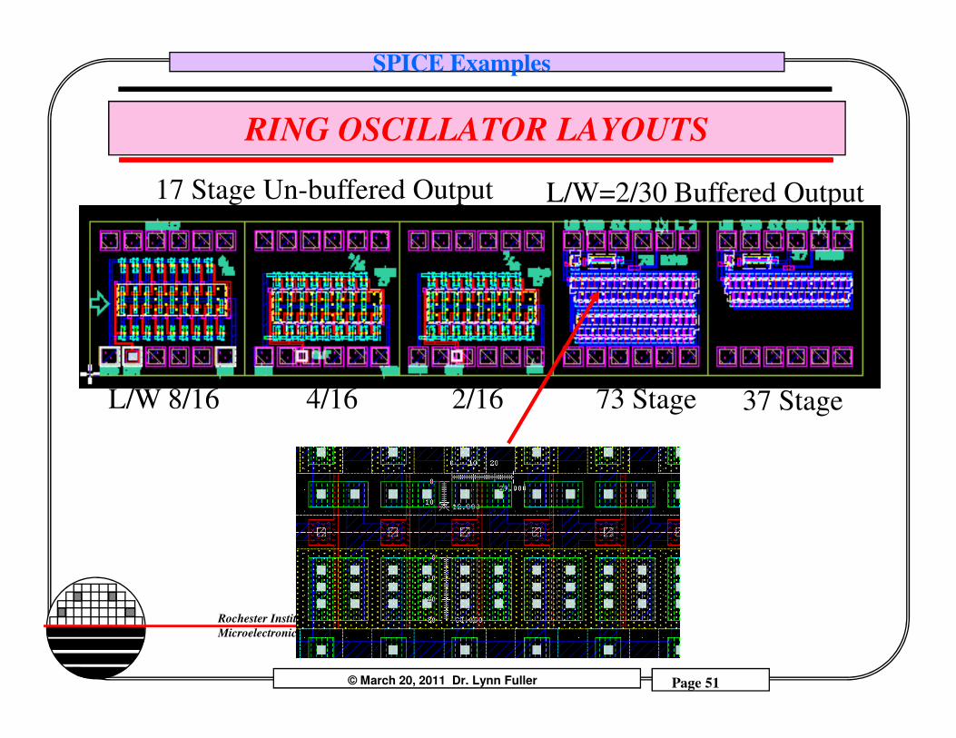
RING OSCILLATOR LAYOUTS
17 Stage Un-buffered Output L/W=2/30 Buffered Output
© March 20, 2011 Dr. Lynn Fuller Page 51
Rochester Institute of Technology
Microelectronic Engineering
L/W 8/16 4/16 2/16 73 Stage 37 Stage
SPICE Examples
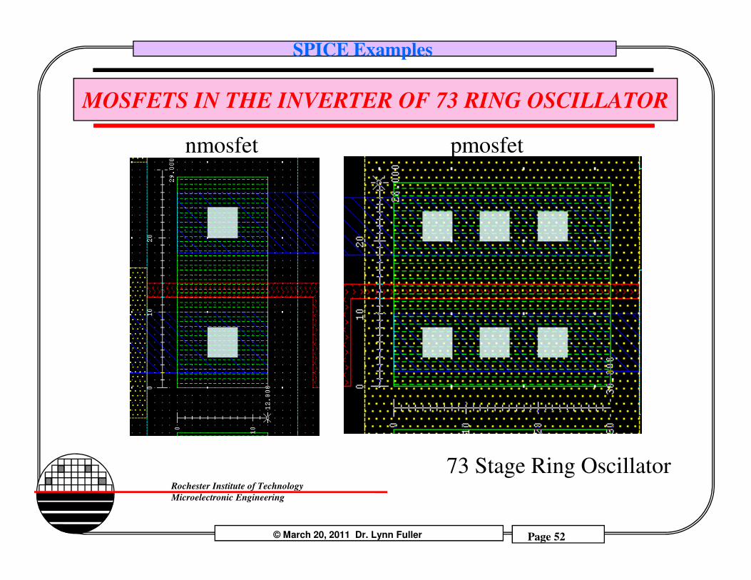
MOSFETS IN THE INVERTER OF 73 RING OSCILLATOR
nmosfet pmosfet
© March 20, 2011 Dr. Lynn Fuller Page 52
Rochester Institute of Technology
Microelectronic Engineering
73 Stage Ring Oscillator
SPICE Examples
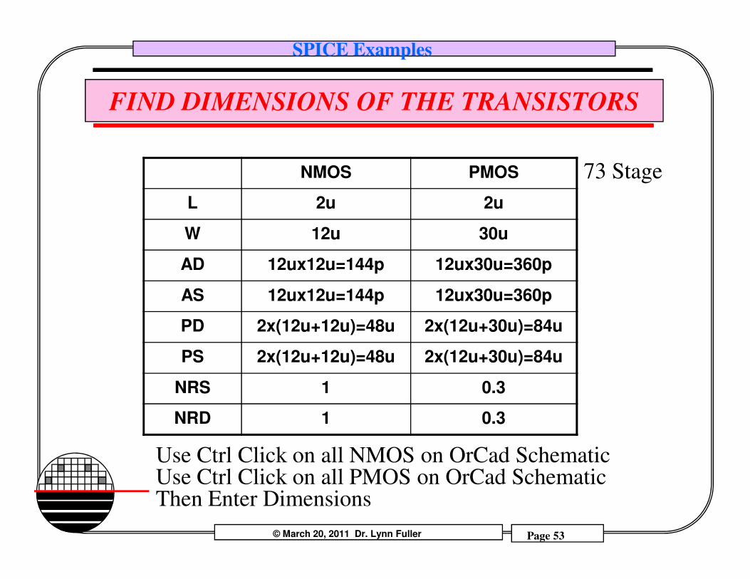
FIND DIMENSIONS OF THE TRANSISTORS
NMOS PMOS
L 2u 2u
W 12u 30u
AD 12ux12u=144p 12ux30u=360p
AS 12ux12u=144p 12ux30u=360p
73 Stage
© March 20, 2011 Dr. Lynn Fuller Page 53
Rochester Institute of Technology
Microelectronic Engineering
AS 12ux12u=144p 12ux30u=360p
PD 2x(12u+12u)=48u 2x(12u+30u)=84u
PS 2x(12u+12u)=48u 2x(12u+30u)=84u
NRS 1 0.3
NRD 1 0.3
Use Ctrl Click on all NMOS on OrCad SchematicUse Ctrl Click on all PMOS on OrCad SchematicThen Enter Dimensions
SPICE Examples
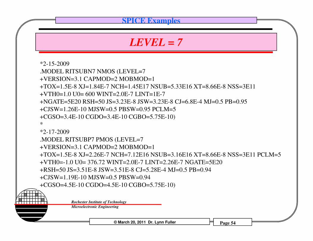
LEVEL = 7
*2-15-2009
.MODEL RITSUBN7 NMOS (LEVEL=7
+VERSION=3.1 CAPMOD=2 MOBMOD=1
+TOX=1.5E-8 XJ=1.84E-7 NCH=1.45E17 NSUB=5.33E16 XT=8.66E-8 NSS=3E11
+VTH0=1.0 U0= 600 WINT=2.0E-7 LINT=1E-7
+NGATE=5E20 RSH=50 JS=3.23E-8 JSW=3.23E-8 CJ=6.8E-4 MJ=0.5 PB=0.95
+CJSW=1.26E-10 MJSW=0.5 PBSW=0.95 PCLM=5
+CGSO=3.4E-10 CGDO=3.4E-10 CGBO=5.75E-10)
© March 20, 2011 Dr. Lynn Fuller Page 54
Rochester Institute of Technology
Microelectronic Engineering
*
*2-17-2009
.MODEL RITSUBP7 PMOS (LEVEL=7
+VERSION=3.1 CAPMOD=2 MOBMOD=1
+TOX=1.5E-8 XJ=2.26E-7 NCH=7.12E16 NSUB=3.16E16 XT=8.66E-8 NSS=3E11 PCLM=5
+VTH0=-1.0 U0= 376.72 WINT=2.0E-7 LINT=2.26E-7 NGATE=5E20
+RSH=50 JS=3.51E-8 JSW=3.51E-8 CJ=5.28E-4 MJ=0.5 PB=0.94
+CJSW=1.19E-10 MJSW=0.5 PBSW=0.94
+CGSO=4.5E-10 CGDO=4.5E-10 CGBO=5.75E-10)

SPICE Examples
SIMULATED OUTPUT AT 10 VOLTS
© March 20, 2011 Dr. Lynn Fuller Page 55
Rochester Institute of Technology
Microelectronic Engineering
Three Stage Ring Oscillator with Transistor Parameters for 73 Stage Ring Oscillator and Supply of 10 volts
td = T / 2N = 3.5nsec / 2 / 3
td = 0.583 nsec
SPICE Examples
SIMULATED OUTPUT AT 5 VOLTS
© March 20, 2011 Dr. Lynn Fuller Page 56
Rochester Institute of Technology
Microelectronic Engineering
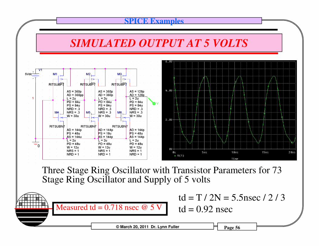
Three Stage Ring Oscillator with Transistor Parameters for 73 Stage Ring Oscillator and Supply of 5 volts
td = T / 2N = 5.5nsec / 2 / 3
td = 0.92 nsecMeasured td = 0.718 nsec @ 5 V
SPICE Examples
CONCLUSION
Since the measured and the simulated gate delays, td are close to correct, then the SPICE model must be close to correct. The inverter gate delay depends on the values of the internal capacitors and resistances of the transistor.
Specifically: RS, RS, RSH
© March 20, 2011 Dr. Lynn Fuller Page 57
Rochester Institute of Technology
Microelectronic Engineering
RS, RS, RSHCGSO, CGDO, CGBOCJ, CJSW
These are combined with the transistors L, W Length and WidthAS,AD Area of the Source/DrainPS,PD Perimeter of the Source/DrainNRS,NRD Number of squares Contact to Channel
SPICE Examples
INVERTER WITH HYSTERESIS
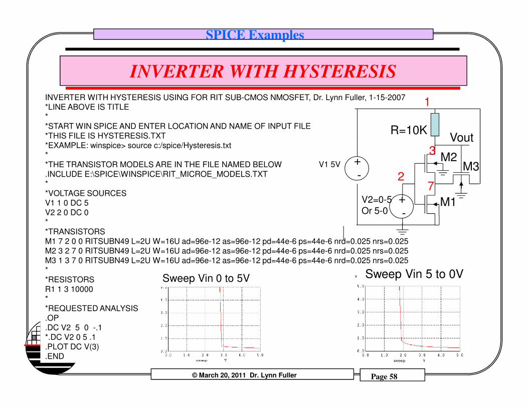
INVERTER WITH HYSTERESIS USING FOR RIT SUB-CMOS NMOSFET, Dr. Lynn Fuller, 1-15-2007
*LINE ABOVE IS TITLE
*
*START WIN SPICE AND ENTER LOCATION AND NAME OF INPUT FILE
*THIS FILE IS HYSTERESIS.TXT
*EXAMPLE: winspice> source c:/spice/Hysteresis.txt
*
*THE TRANSISTOR MODELS ARE IN THE FILE NAMED BELOW
.INCLUDE E:\SPICE\WINSPICE\RIT_MICROE_MODELS.TXT
*
*VOLTAGE SOURCES
V1 1 0 DC 5
1
2V1 5V +
-
V2=0-5 M1
R=10K
7
3Vout
M3M2
+
© March 20, 2011 Dr. Lynn Fuller Page 58
Rochester Institute of Technology
Microelectronic Engineering
V1 1 0 DC 5
V2 2 0 DC 0
*
*TRANSISTORS
M1 7 2 0 0 RITSUBN49 L=2U W=16U ad=96e-12 as=96e-12 pd=44e-6 ps=44e-6 nrd=0.025 nrs=0.025
M2 3 2 7 0 RITSUBN49 L=2U W=16U ad=96e-12 as=96e-12 pd=44e-6 ps=44e-6 nrd=0.025 nrs=0.025
M3 1 3 7 0 RITSUBN49 L=2U W=16U ad=96e-12 as=96e-12 pd=44e-6 ps=44e-6 nrd=0.025 nrs=0.025
*
*RESISTORS
R1 1 3 10000
*
*REQUESTED ANALYSIS
.OP
.DC V2 5 0 -.1
*.DC V2 0 5 .1
.PLOT DC V(3)
.END
V2=0-5Or 5-0
M1
Sweep Vin 0 to 5V Sweep Vin 5 to 0V
+
-
SPICE Examples
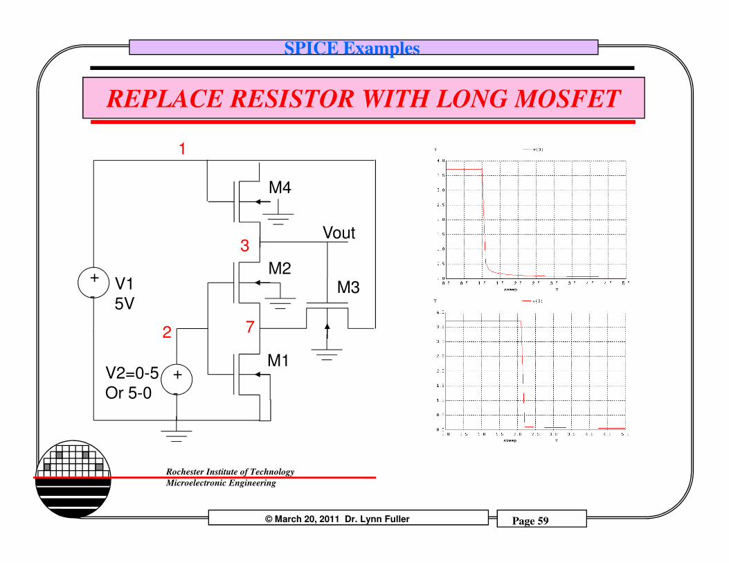
REPLACE RESISTOR WITH LONG MOSFET
1
V1+
3Vout
M3M2
M4
© March 20, 2011 Dr. Lynn Fuller Page 59
Rochester Institute of Technology
Microelectronic Engineering
2
V1
5V
+
-
V2=0-5
Or 5-0
+
-
M1
7
M3
SPICE Examples
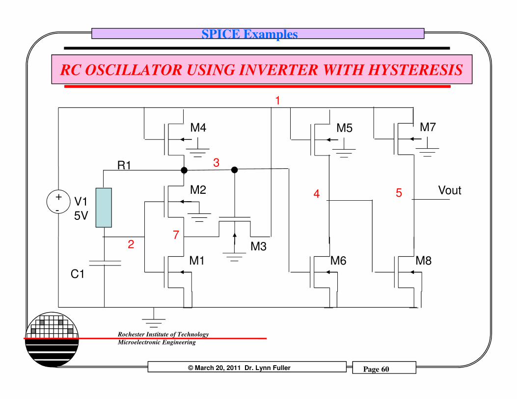
RC OSCILLATOR USING INVERTER WITH HYSTERESIS
1
V1+
3
VoutM2
M4
R1
M5
4 5
M7
© March 20, 2011 Dr. Lynn Fuller Page 60
Rochester Institute of Technology
Microelectronic Engineering
2
V1
5V
+
-
M1
7M3
C1M6 M8
4
SPICE Examples
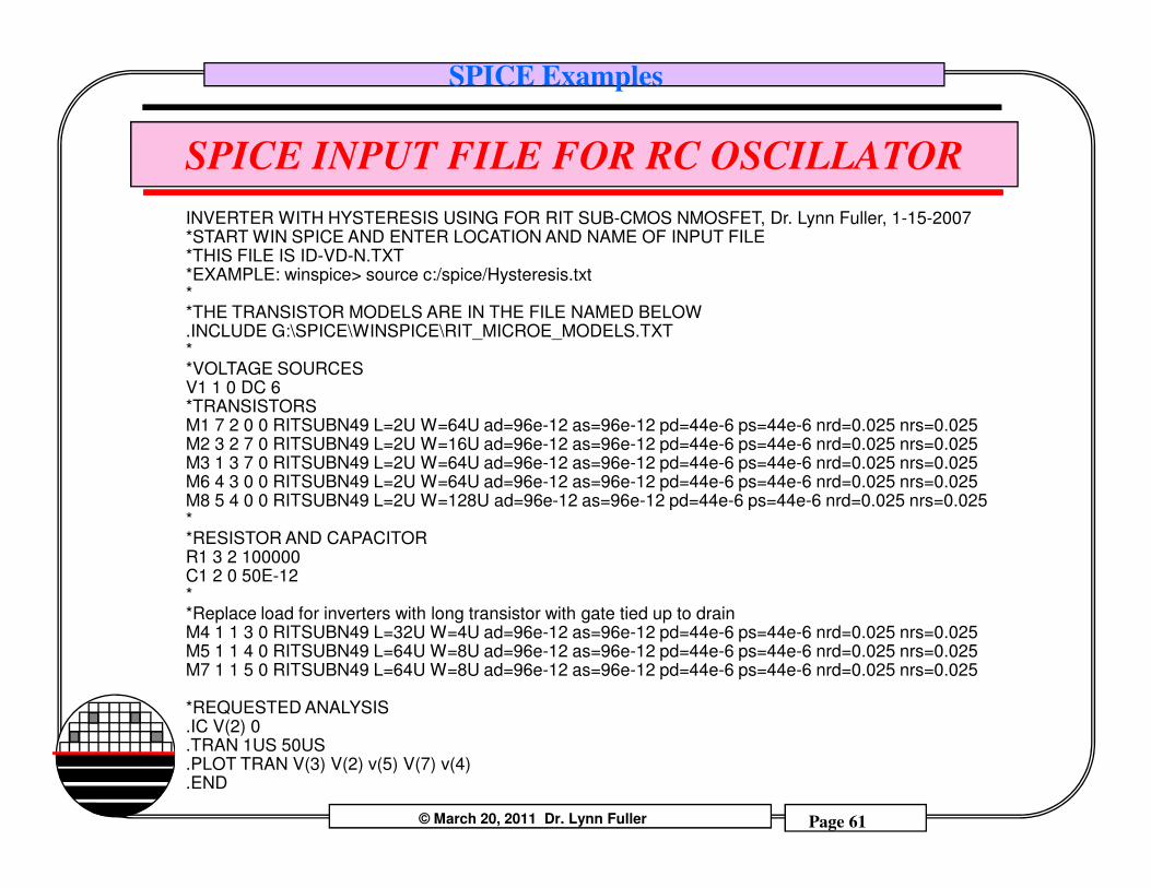
SPICE INPUT FILE FOR RC OSCILLATOR
INVERTER WITH HYSTERESIS USING FOR RIT SUB-CMOS NMOSFET, Dr. Lynn Fuller, 1-15-2007*START WIN SPICE AND ENTER LOCATION AND NAME OF INPUT FILE*THIS FILE IS ID-VD-N.TXT*EXAMPLE: winspice> source c:/spice/Hysteresis.txt**THE TRANSISTOR MODELS ARE IN THE FILE NAMED BELOW.INCLUDE G:\SPICE\WINSPICE\RIT_MICROE_MODELS.TXT**VOLTAGE SOURCESV1 1 0 DC 6*TRANSISTORSM1 7 2 0 0 RITSUBN49 L=2U W=64U ad=96e-12 as=96e-12 pd=44e-6 ps=44e-6 nrd=0.025 nrs=0.025M2 3 2 7 0 RITSUBN49 L=2U W=16U ad=96e-12 as=96e-12 pd=44e-6 ps=44e-6 nrd=0.025 nrs=0.025
© March 20, 2011 Dr. Lynn Fuller Page 61
Rochester Institute of Technology
Microelectronic Engineering
M2 3 2 7 0 RITSUBN49 L=2U W=16U ad=96e-12 as=96e-12 pd=44e-6 ps=44e-6 nrd=0.025 nrs=0.025M3 1 3 7 0 RITSUBN49 L=2U W=64U ad=96e-12 as=96e-12 pd=44e-6 ps=44e-6 nrd=0.025 nrs=0.025M6 4 3 0 0 RITSUBN49 L=2U W=64U ad=96e-12 as=96e-12 pd=44e-6 ps=44e-6 nrd=0.025 nrs=0.025M8 5 4 0 0 RITSUBN49 L=2U W=128U ad=96e-12 as=96e-12 pd=44e-6 ps=44e-6 nrd=0.025 nrs=0.025**RESISTOR AND CAPACITORR1 3 2 100000C1 2 0 50E-12**Replace load for inverters with long transistor with gate tied up to drainM4 1 1 3 0 RITSUBN49 L=32U W=4U ad=96e-12 as=96e-12 pd=44e-6 ps=44e-6 nrd=0.025 nrs=0.025M5 1 1 4 0 RITSUBN49 L=64U W=8U ad=96e-12 as=96e-12 pd=44e-6 ps=44e-6 nrd=0.025 nrs=0.025M7 1 1 5 0 RITSUBN49 L=64U W=8U ad=96e-12 as=96e-12 pd=44e-6 ps=44e-6 nrd=0.025 nrs=0.025
*REQUESTED ANALYSIS.IC V(2) 0.TRAN 1US 50US.PLOT TRAN V(3) V(2) v(5) V(7) v(4).END
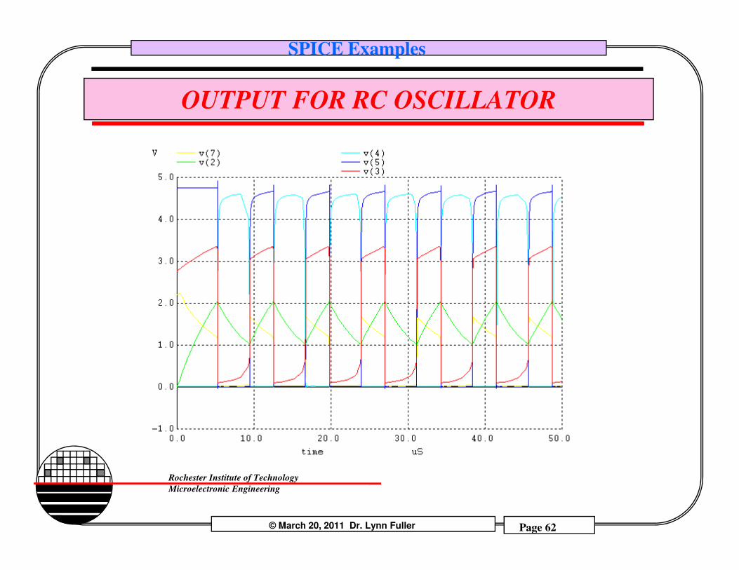
SPICE Examples
OUTPUT FOR RC OSCILLATOR
© March 20, 2011 Dr. Lynn Fuller Page 62
Rochester Institute of Technology
Microelectronic Engineering
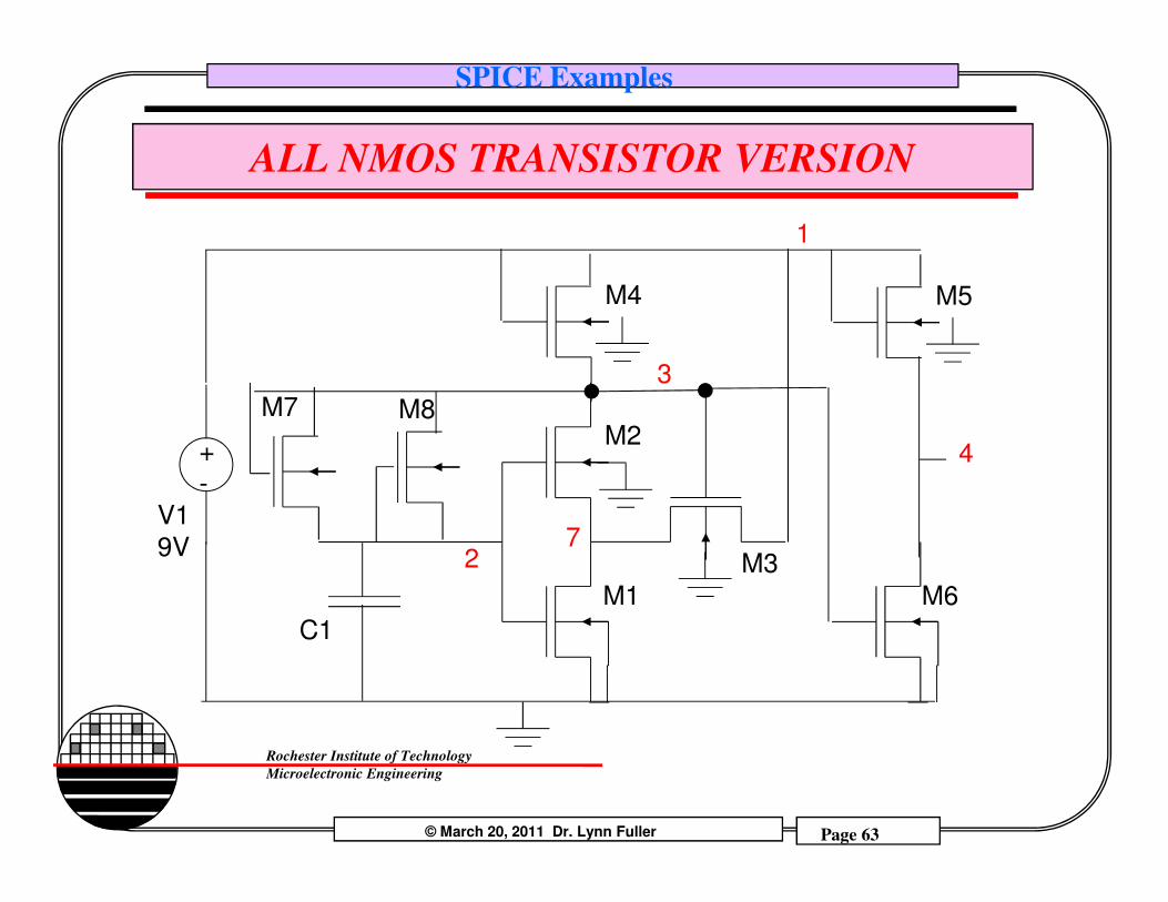
SPICE Examples
ALL NMOS TRANSISTOR VERSION
1
+
3
M2
M4 M5
4
M7 M8
© March 20, 2011 Dr. Lynn Fuller Page 63
Rochester Institute of Technology
Microelectronic Engineering
2
V1
9V
+
-
M1
7M3
C1
M6
4
SPICE Examples
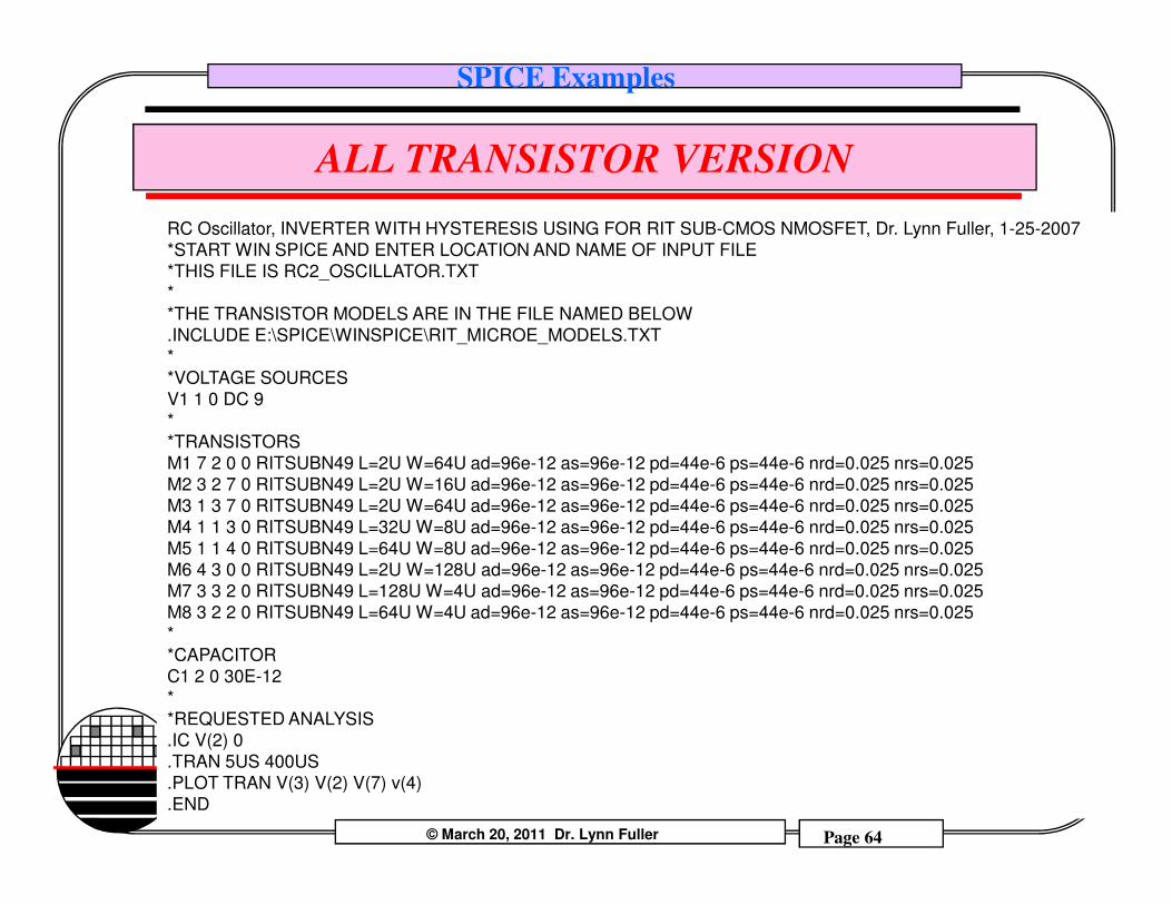
ALL TRANSISTOR VERSION
RC Oscillator, INVERTER WITH HYSTERESIS USING FOR RIT SUB-CMOS NMOSFET, Dr. Lynn Fuller, 1-25-2007
*START WIN SPICE AND ENTER LOCATION AND NAME OF INPUT FILE
*THIS FILE IS RC2_OSCILLATOR.TXT
*
*THE TRANSISTOR MODELS ARE IN THE FILE NAMED BELOW
.INCLUDE E:\SPICE\WINSPICE\RIT_MICROE_MODELS.TXT
*
*VOLTAGE SOURCES
V1 1 0 DC 9
*
*TRANSISTORS
© March 20, 2011 Dr. Lynn Fuller Page 64
Rochester Institute of Technology
Microelectronic Engineering
M1 7 2 0 0 RITSUBN49 L=2U W=64U ad=96e-12 as=96e-12 pd=44e-6 ps=44e-6 nrd=0.025 nrs=0.025
M2 3 2 7 0 RITSUBN49 L=2U W=16U ad=96e-12 as=96e-12 pd=44e-6 ps=44e-6 nrd=0.025 nrs=0.025
M3 1 3 7 0 RITSUBN49 L=2U W=64U ad=96e-12 as=96e-12 pd=44e-6 ps=44e-6 nrd=0.025 nrs=0.025
M4 1 1 3 0 RITSUBN49 L=32U W=8U ad=96e-12 as=96e-12 pd=44e-6 ps=44e-6 nrd=0.025 nrs=0.025
M5 1 1 4 0 RITSUBN49 L=64U W=8U ad=96e-12 as=96e-12 pd=44e-6 ps=44e-6 nrd=0.025 nrs=0.025
M6 4 3 0 0 RITSUBN49 L=2U W=128U ad=96e-12 as=96e-12 pd=44e-6 ps=44e-6 nrd=0.025 nrs=0.025
M7 3 3 2 0 RITSUBN49 L=128U W=4U ad=96e-12 as=96e-12 pd=44e-6 ps=44e-6 nrd=0.025 nrs=0.025
M8 3 2 2 0 RITSUBN49 L=64U W=4U ad=96e-12 as=96e-12 pd=44e-6 ps=44e-6 nrd=0.025 nrs=0.025
*
*CAPACITOR
C1 2 0 30E-12
*
*REQUESTED ANALYSIS
.IC V(2) 0
.TRAN 5US 400US
.PLOT TRAN V(3) V(2) V(7) v(4)
.END
SPICE Examples
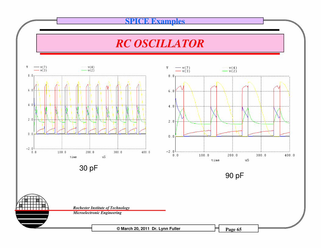
RC OSCILLATOR
© March 20, 2011 Dr. Lynn Fuller Page 65
Rochester Institute of Technology
Microelectronic Engineering
30 pF90 pF
SPICE Examples
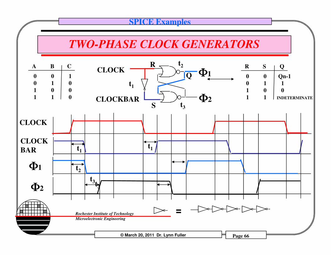
TWO-PHASE CLOCK GENERATORS
CLOCKBAR
CLOCK ΦΦΦΦ1
ΦΦΦΦ2
CLOCK
t3
t2
t1
QS
0 0 Qn-1
0 1 1
1 0 0
1 1 INDETERMINATE
RCB
0 0 1
0 1 0
1 0 0
1 1 0
A
S
R
Q
© March 20, 2011 Dr. Lynn Fuller Page 66
Rochester Institute of Technology
Microelectronic Engineering
ΦΦΦΦ1
ΦΦΦΦ2
CLOCK
BAR t1
t3
t1
t2
=
t3
SPICE Examples
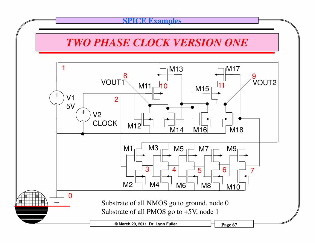
TWO PHASE CLOCK VERSION ONE
2V1
5V
+
-
1
V2
CLOCK
+
-
8 9
M11
M13
M15
M17
VOUT1 VOUT210 11
© March 20, 2011 Dr. Lynn Fuller Page 67
Rochester Institute of Technology
Microelectronic EngineeringSubstrate of all NMOS go to ground, node 0
Substrate of all PMOS go to +5V, node 1
M3 M5
M4 M6
3 4
M1
M2
0
CLOCK-
765
M9
M10
M7
M8
M12M14 M16 M18
SPICE Examples
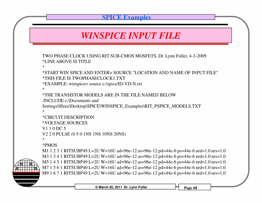
WINSPICE INPUT FILE
TWO PHASE CLOCK USING RIT SUB-CMOS MOSFETS, Dr. Lynn Fuller, 4-3-2009
*LINE ABOVE IS TITLE
*
*START WIN SPICE AND ENTER> SOURCE "LOCATION AND NAME OF INPUT FILE"
*THIS FILE IS TWOPHASECLOCK1.TXT
*EXAMPLE: winspice> source c:/spice/ID-VD-N.txt
*
*THE TRANSISTOR MODELS ARE IN THE FILE NAMED BELOW
.INCLUDE c:\Documents and
© March 20, 2011 Dr. Lynn Fuller Page 68
Rochester Institute of Technology
Microelectronic Engineering
.INCLUDE c:\Documents and
Settings\lffeee\Desktop\SPICE\WINSPICE_Examples\RIT_PSPICE_MODELS.TXT
*
*CIRCUIT DESCRIPTION
*VOLTAGE SOURCES
V1 1 0 DC 5
V2 2 0 PULSE (0 5 0 1NS 1NS 10NS 20NS)
*
*PMOS
M1 1 2 3 1 RITSUBP49 L=2U W=16U ad=96e-12 as=96e-12 pd=44e-6 ps=44e-6 nrd=1.0 nrs=1.0
M3 1 3 4 1 RITSUBP49 L=2U W=16U ad=96e-12 as=96e-12 pd=44e-6 ps=44e-6 nrd=1.0 nrs=1.0
M5 1 4 5 1 RITSUBP49 L=2U W=16U ad=96e-12 as=96e-12 pd=44e-6 ps=44e-6 nrd=1.0 nrs=1.0
M7 1 5 6 1 RITSUBP40 L=2U W=16U ad=96e-12 as=96e-12 pd=44e-6 ps=44e-6 nrd=1.0 nrs=1.0
M9 1 6 7 1 RITSUBP49 L=2U W=16U ad=96e-12 as=96e-12 pd=44e-6 ps=44e-6 nrd=1.0 nrs=1.0
SPICE Examples
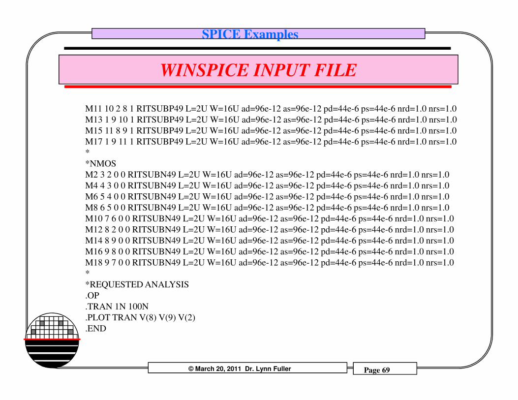
WINSPICE INPUT FILE
M11 10 2 8 1 RITSUBP49 L=2U W=16U ad=96e-12 as=96e-12 pd=44e-6 ps=44e-6 nrd=1.0 nrs=1.0
M13 1 9 10 1 RITSUBP49 L=2U W=16U ad=96e-12 as=96e-12 pd=44e-6 ps=44e-6 nrd=1.0 nrs=1.0
M15 11 8 9 1 RITSUBP49 L=2U W=16U ad=96e-12 as=96e-12 pd=44e-6 ps=44e-6 nrd=1.0 nrs=1.0
M17 1 9 11 1 RITSUBP49 L=2U W=16U ad=96e-12 as=96e-12 pd=44e-6 ps=44e-6 nrd=1.0 nrs=1.0
*
*NMOS
M2 3 2 0 0 RITSUBN49 L=2U W=16U ad=96e-12 as=96e-12 pd=44e-6 ps=44e-6 nrd=1.0 nrs=1.0
M4 4 3 0 0 RITSUBN49 L=2U W=16U ad=96e-12 as=96e-12 pd=44e-6 ps=44e-6 nrd=1.0 nrs=1.0
M6 5 4 0 0 RITSUBN49 L=2U W=16U ad=96e-12 as=96e-12 pd=44e-6 ps=44e-6 nrd=1.0 nrs=1.0
© March 20, 2011 Dr. Lynn Fuller Page 69
Rochester Institute of Technology
Microelectronic Engineering
M6 5 4 0 0 RITSUBN49 L=2U W=16U ad=96e-12 as=96e-12 pd=44e-6 ps=44e-6 nrd=1.0 nrs=1.0
M8 6 5 0 0 RITSUBN49 L=2U W=16U ad=96e-12 as=96e-12 pd=44e-6 ps=44e-6 nrd=1.0 nrs=1.0
M10 7 6 0 0 RITSUBN49 L=2U W=16U ad=96e-12 as=96e-12 pd=44e-6 ps=44e-6 nrd=1.0 nrs=1.0
M12 8 2 0 0 RITSUBN49 L=2U W=16U ad=96e-12 as=96e-12 pd=44e-6 ps=44e-6 nrd=1.0 nrs=1.0
M14 8 9 0 0 RITSUBN49 L=2U W=16U ad=96e-12 as=96e-12 pd=44e-6 ps=44e-6 nrd=1.0 nrs=1.0
M16 9 8 0 0 RITSUBN49 L=2U W=16U ad=96e-12 as=96e-12 pd=44e-6 ps=44e-6 nrd=1.0 nrs=1.0
M18 9 7 0 0 RITSUBN49 L=2U W=16U ad=96e-12 as=96e-12 pd=44e-6 ps=44e-6 nrd=1.0 nrs=1.0
*
*REQUESTED ANALYSIS
.OP
.TRAN 1N 100N
.PLOT TRAN V(8) V(9) V(2)
.END
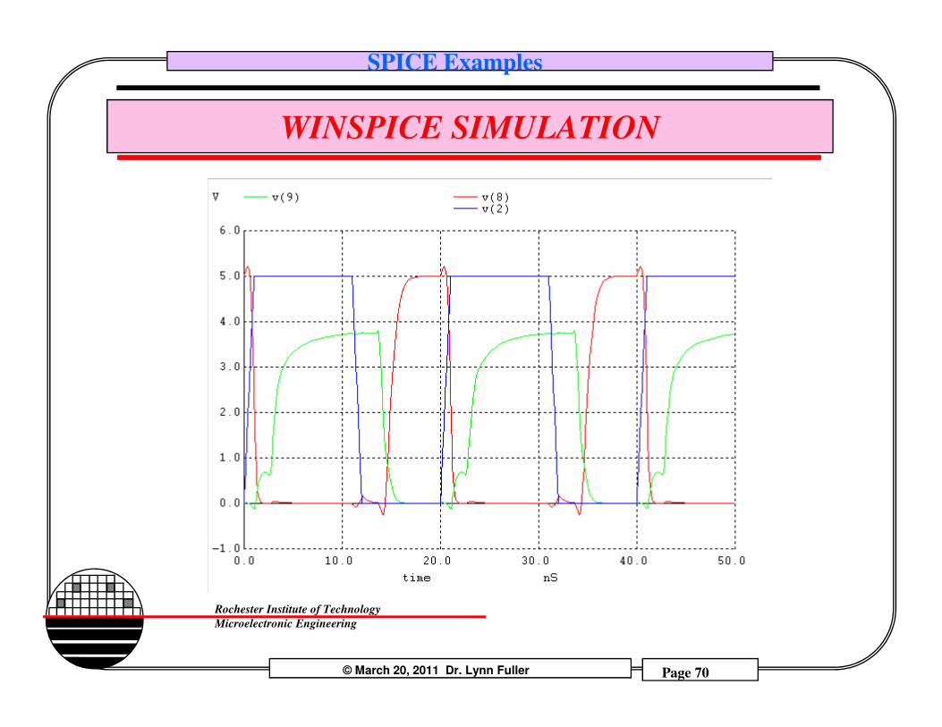
SPICE Examples
WINSPICE SIMULATION
© March 20, 2011 Dr. Lynn Fuller Page 70
Rochester Institute of Technology
Microelectronic Engineering
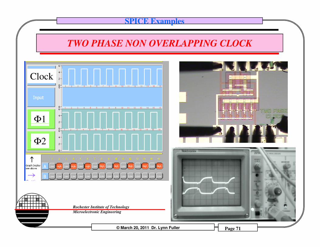
SPICE Examples
TWO PHASE NON OVERLAPPING CLOCK
Clock
Φ1
© March 20, 2011 Dr. Lynn Fuller Page 71
Rochester Institute of Technology
Microelectronic Engineering
Φ1
Φ2
SPICE Examples
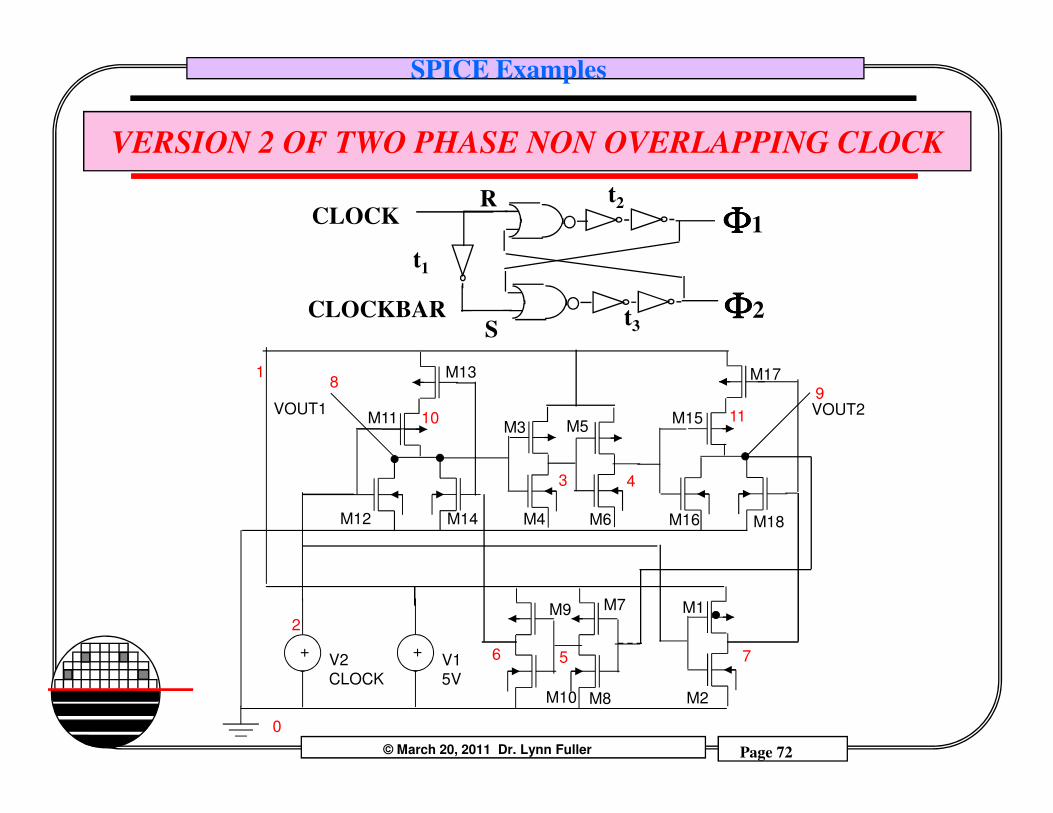
VERSION 2 OF TWO PHASE NON OVERLAPPING CLOCK
CLOCKBAR
CLOCK ΦΦΦΦ1
ΦΦΦΦ2t3
t2
t1
S
R
18
9
M13 M17
VOUT1 VOUT2
© March 20, 2011 Dr. Lynn Fuller Page 72
Rochester Institute of Technology
Microelectronic Engineering
2
V1
5V
+
-
0
V2
CLOCK
+
-
M5
M7
M6 M16
3 4
M3
M4
76
M1
M2
5
M9
M10
M11
M12 M14
M15
M18
M8
VOUT1 VOUT210 11
SPICE Examples
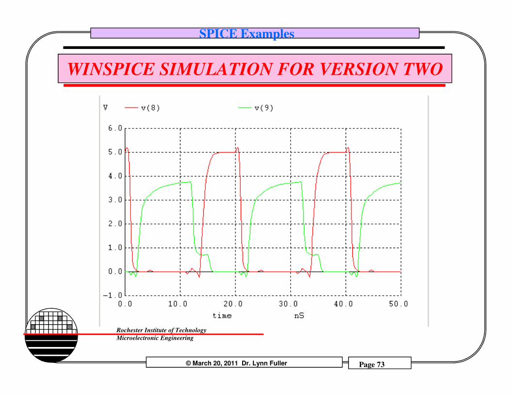
WINSPICE SIMULATION FOR VERSION TWO
© March 20, 2011 Dr. Lynn Fuller Page 73
Rochester Institute of Technology
Microelectronic Engineering
SPICE Examples
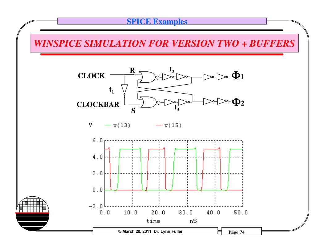
WINSPICE SIMULATION FOR VERSION TWO + BUFFERS
CLOCKBAR
CLOCK ΦΦΦΦ1
ΦΦΦΦ2t3
t2
t1
S
R
© March 20, 2011 Dr. Lynn Fuller Page 74
Rochester Institute of Technology
Microelectronic Engineering
SPICE Examples
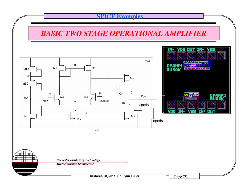
BASIC TWO STAGE OPERATIONAL AMPLIFIER
© March 20, 2011 Dr. Lynn Fuller Page 75
Rochester Institute of Technology
Microelectronic Engineering
SPICE Examples
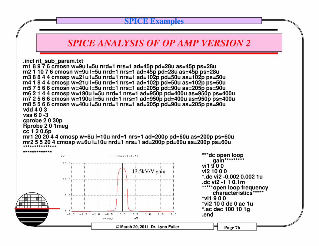
SPICE ANALYSIS OF OP AMP VERSION 2
.incl rit_sub_param.txtm1 8 9 7 6 cmosn w=9u l=5u nrd=1 nrs=1 ad=45p pd=28u as=45p ps=28um2 1 10 7 6 cmosn w=9u l=5u nrd=1 nrs=1 ad=45p pd=28u as=45p ps=28um3 8 8 4 4 cmosp w=21u l=5u nrd=1 nrs=1 ad=102p pd=50u as=102p ps=50um4 1 8 4 4 cmosp w=21u l=5u nrd=1 nrs=1 ad=102p pd=50u as=102p ps=50um5 7 5 6 6 cmosn w=40u l=5u nrd=1 nrs=1 ad=205p pd=90u as=205p ps=90um6 2 1 4 4 cmosp w=190u l=5u nrd=1 nrs=1 ad=950p pd=400u as=950p ps=400u m7 2 5 6 6 cmosn w=190u l=5u nrd=1 nrs=1 ad=950p pd=400u as=950p ps=400u m8 5 5 6 6 cmosn w=40u l=5u nrd=1 nrs=1 ad=205p pd=90u as=205p ps=90uvdd 4 0 3vss 6 0 -3cprobe 2 0 30pRprobe 2 0 1meg
© March 20, 2011 Dr. Lynn Fuller Page 76
Rochester Institute of Technology
Microelectronic Engineering
cprobe 2 0 30pRprobe 2 0 1megcc 1 2 0.6pmr1 20 20 4 4 cmosp w=6u l=10u nrd=1 nrs=1 ad=200p pd=60u as=200p ps=60umr2 5 5 20 4 cmosp w=6u l=10u nrd=1 nrs=1 ad=200p pd=60u as=200p ps=60u**************************** ***dc open loop
gain*********vi1 9 0 0vi2 10 0 0 *.dc vi2 -0.002 0.002 1u.dc vi2 -1 1 0.1m*****open loop frequency
characteristics******vi1 9 0 0 *vi2 10 0 dc 0 ac 1u*.ac dec 100 10 1g.end
13.5kV/V gain
SPICE Examples
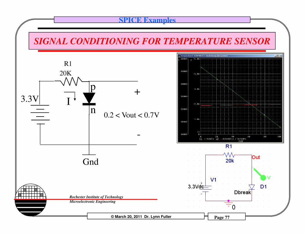
SIGNAL CONDITIONING FOR TEMPERATURE SENSOR
p
nI3.3V
R1
20K
0.2 < Vout < 0.7V
+
© March 20, 2011 Dr. Lynn Fuller Page 77
Rochester Institute of Technology
Microelectronic Engineering
Gnd
0.2 < Vout < 0.7V
-
SPICE Examples
REFERENCES
1. MOSFET Modeling with SPICE, Daniel Foty, 1997, Prentice Hall, ISBN-0-13-227935-5
2. Operation and Modeling of the MOS Transistor, 2nd Edition, Yannis Tsividis, 1999, McGraw-Hill, ISBN-0-07-065523-5
3. UTMOST III Modeling Manual-Vol.1. Ch. 5. From Silvaco International.4. ATHENA USERS Manual, From Silvaco International.5. ATLAS USERS Manual, From Silvaco International.6. Device Electronics for Integrated Circuits, Richard Muller and Theodore
© March 20, 2011 Dr. Lynn Fuller Page 78
Rochester Institute of Technology
Microelectronic Engineering
6. Device Electronics for Integrated Circuits, Richard Muller and Theodore Kamins, with Mansun Chan, 3rd Edition, John Wiley, 2003, ISBN 0-471-59398-2
7. ICCAP Manual, Hewlet Packard8. PSpice Users Guide.
Related Documents