SPI and I2C communication with CMA3000-D01 TN80 Murata Electronics Oy 1/14 www.muratamems.fi Rev. 0.4 SPI and I2C communication with CMA3000-D01 using MSP430 ultra low-power microcontroller 1 INTRODUCTION The objective of this document is to show how to set up SPI/I2C communication between Murata Electronics Oy CMA3000-D01 digital acceleration sensor component and a Texas Instruments MSP430 microcontroller. In the code examples: The MSP430 MCU is configured CMA3000-D01 measurement mode is activated An interrupt is used to read acceleration output data registers when new data is available Please refer to document "CMA3000-D0X Product Family Specification 8281000" for further information on CMA3000-D01 register addressing and SPI/I2C communication. For MSP430 related information please see Texas Instruments web pages (http://www.ti.com). 2 DEVELOPMENT HARDWARE Figure 1. From left to right, eZ430-RF2500, adapter PCB VTI29631 and CMA3000-D01 chip carrier

Welcome message from author
This document is posted to help you gain knowledge. Please leave a comment to let me know what you think about it! Share it to your friends and learn new things together.
Transcript
SPI and I2C communication with CMA3000-D01
TN80
Murata Electronics Oy 1/14
www.muratamems.fi Rev. 0.4
SPI and I2C communication with CMA3000-D01 using MSP430 ultra low-power microcontroller
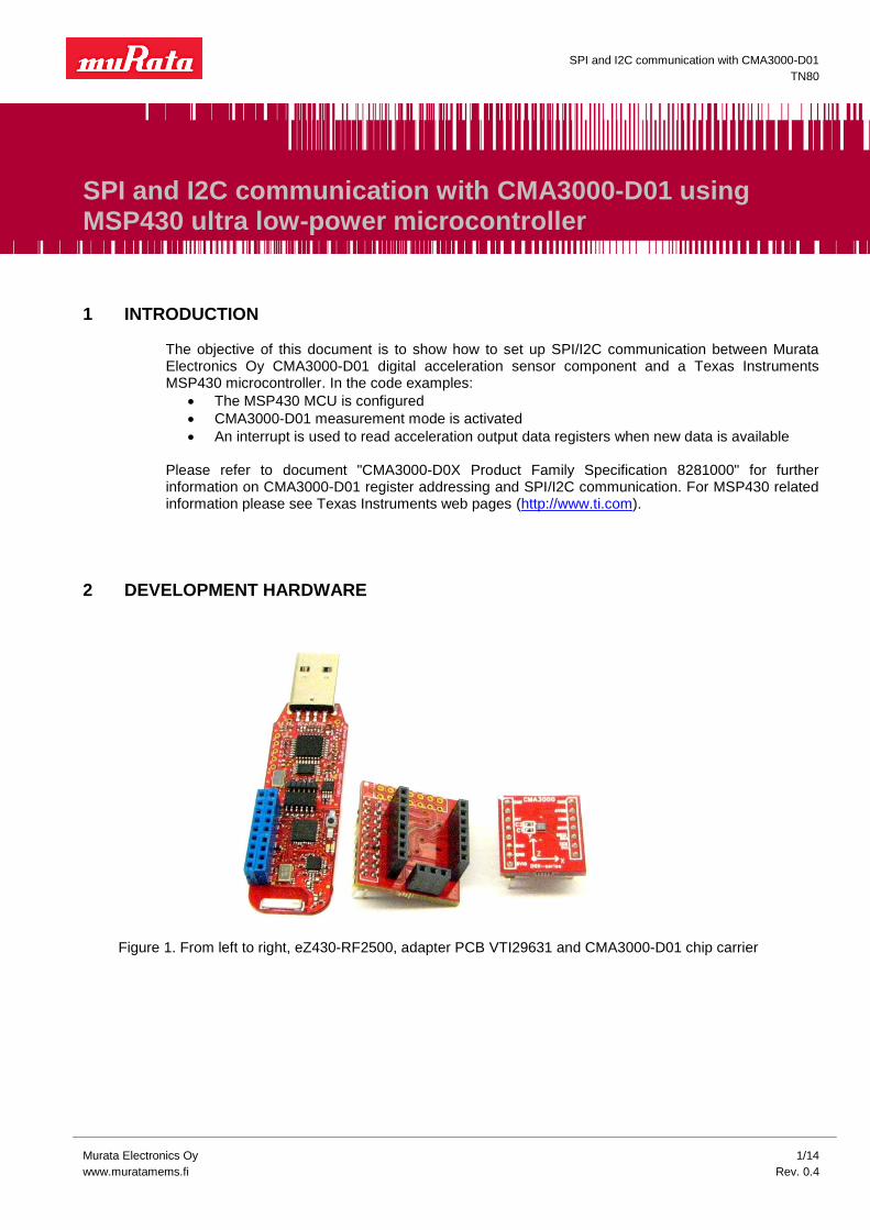
1 INTRODUCTION The objective of this document is to show how to set up SPI/I2C communication between Murata Electronics Oy CMA3000-D01 digital acceleration sensor component and a Texas Instruments MSP430 microcontroller. In the code examples:
The MSP430 MCU is configured
CMA3000-D01 measurement mode is activated
An interrupt is used to read acceleration output data registers when new data is available
Please refer to document "CMA3000-D0X Product Family Specification 8281000" for further information on CMA3000-D01 register addressing and SPI/I2C communication. For MSP430 related information please see Texas Instruments web pages (http://www.ti.com).
2 DEVELOPMENT HARDWARE
Figure 1. From left to right, eZ430-RF2500, adapter PCB VTI29631 and CMA3000-D01 chip carrier
Interfacing CMA3000-D01 to an MSP430
TN80
Murata Electronics Oy 2/14
www.muratamems.fi Rev. 0.4
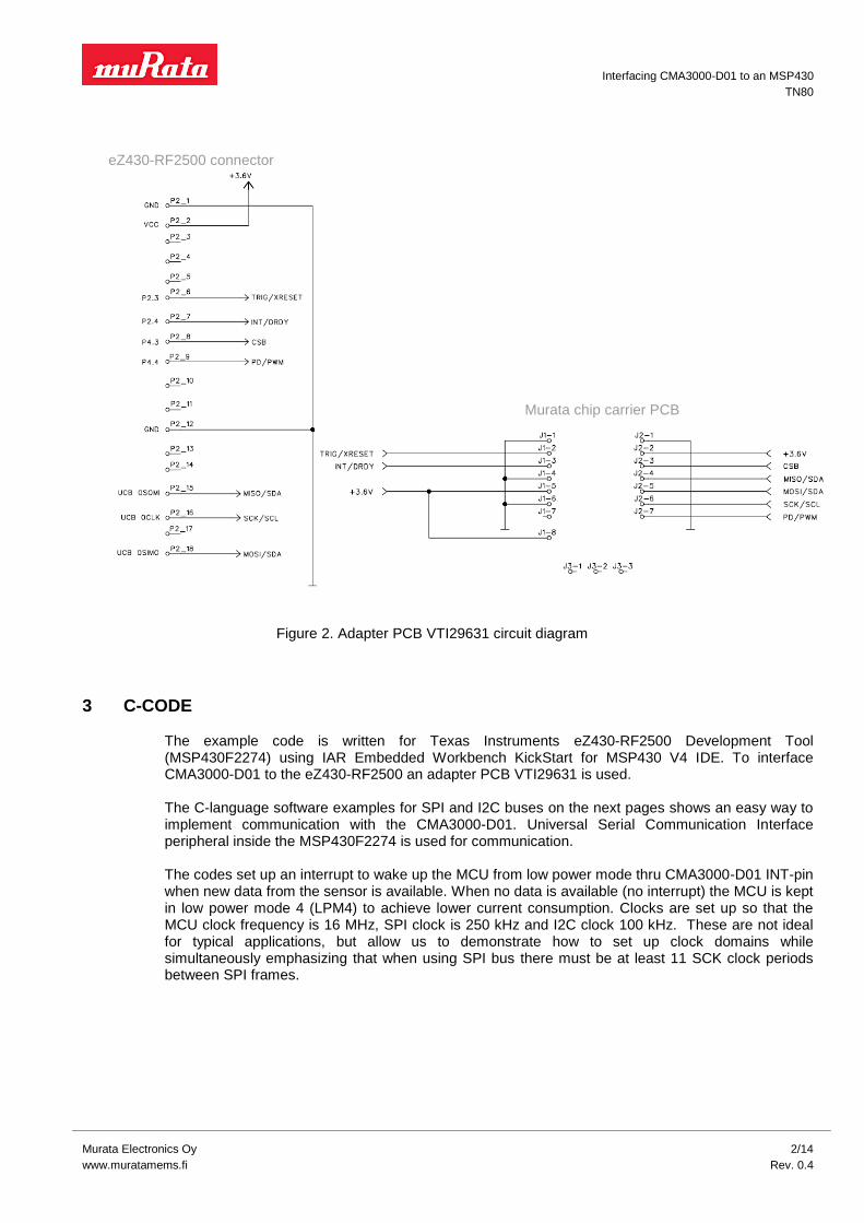
3 C-CODE The example code is written for Texas Instruments eZ430-RF2500 Development Tool (MSP430F2274) using IAR Embedded Workbench KickStart for MSP430 V4 IDE. To interface CMA3000-D01 to the eZ430-RF2500 an adapter PCB VTI29631 is used.
The C-language software examples for SPI and I2C buses on the next pages shows an easy way to implement communication with the CMA3000-D01. Universal Serial Communication Interface peripheral inside the MSP430F2274 is used for communication. The codes set up an interrupt to wake up the MCU from low power mode thru CMA3000-D01 INT-pin when new data from the sensor is available. When no data is available (no interrupt) the MCU is kept in low power mode 4 (LPM4) to achieve lower current consumption. Clocks are set up so that the MCU clock frequency is 16 MHz, SPI clock is 250 kHz and I2C clock 100 kHz. These are not ideal for typical applications, but allow us to demonstrate how to set up clock domains while simultaneously emphasizing that when using SPI bus there must be at least 11 SCK clock periods between SPI frames.
Figure 2. Adapter PCB VTI29631 circuit diagram
eZ430-RF2500 connector
Murata chip carrier PCB

Interfacing CMA3000-D01 to an MSP430
TN80
Murata Electronics Oy 3/14
www.muratamems.fi Rev. 0.4
3.1 SPI Interface Example Code flowchart:
Figure 3. SPI Example Code Flowchart

Interfacing CMA3000-D01 to an MSP430
TN80
Murata Electronics Oy 4/14
www.muratamems.fi Rev. 0.4
C-Code Example, SPI Interface //******************************************************************************
// MSP430F2274 Demo - USCI_B0, SPI Interface to CMA3000 Acceleration Sensor
//
// Uses Texas Instruments eZ430-RF2500 Development Tool with Murata Adapter PCB
// VTI29631A0. Wireless connection not used.
//
//******************************************************************************
// CONSTANTS
#define XTAL 16000000L
#define TICKSPERMS (XTAL / 1000 / 5 - 1)
#define TICKSPERUS (TICKSPERMS / 1000)
// LIBRARIES
#include "msp430x22x4.h"
// PORT DEFINITIONS
#define PORT_INT_IN P2IN
#define PORT_INT_OUT P2OUT
#define PORT_INT_DIR P2DIR
#define PORT_INT_IE P2IE
#define PORT_INT_IES P2IES
#define PORT_INT_IFG P2IFG
#define PORT_INT_VECTOR PORT2_VECTOR
#define PORT_CSB_OUT P4OUT
#define PORT_CSB_DIR P4DIR
#define PORT_SPI_DIR P3DIR
#define PORT_SPI_SEL P3SEL
// REGISTER AND FLAG DEFINITIONS
#define TX_BUFFER UCB0TXBUF
#define RX_BUFFER UCB0RXBUF
#define IRQ_REG IFG2
#define RX_IFG UCB0RXIFG
#define SPI_CTL0 UCB0CTL0
#define SPI_CTL1 UCB0CTL1
#define SPI_BR0 UCB0BR0
#define SPI_BR1 UCB0BR1
// CMA3000 Registers
#define WHO_AM_I 0x00
#define REVID 0x01
#define CTRL 0x02
#define STATUS 0x03
#define RSTR 0x04
#define INT_STATUS 0x05
#define DOUTX 0x06
#define DOUTY 0x07
#define DOUTZ 0x08
#define MDTHR 0x09
#define MDFFTMR 0x0A
#define FFTHR 0x0B
#define I2C_ADDR 0x0C
Interfacing CMA3000-D01 to an MSP430
TN80
Murata Electronics Oy 5/14
www.muratamems.fi Rev. 0.4
// Control Register setup
#define G_RANGE_2 0x80 // 2g range
#define INT_LEVEL_LOW 0x40 // INT active high
#define MDET_NO_EXIT 0x20 // Remain in motion detection mode
#define I2C_DIS 0x10 // I2C disabled
#define MODE_PD 0x00 // Power Down
#define MODE_100 0x02 // Measurement mode 100 Hz ODR
#define MODE_400 0x04 // Measurement mode 400 Hz ODR
#define MODE_40 0x06 // Measurement mode 40 Hz ODR
#define MODE_MD_10 0x08 // Motion detection mode 10 Hz ODR
#define MODE_FF_100 0x0A // Free fall detection mode 100 Hz ODR
#define MODE_FF_400 0x0C // Free fall detection mode 400 Hz ODR
#define INT_DIS 0x01 // Interrupts enabled
// PIN DEFINITIONS
#define PIN_INT BIT4
#define PIN_CSB BIT3
#define PIN_MOSI BIT1
#define PIN_MISO BIT2
#define PIN_SCK BIT3
// FUNCTION PROTOTYPES
unsigned char ReadRegister(unsigned char Address);
unsigned char WriteRegister(unsigned char Address, unsigned char Data);
void wait_ms(unsigned short ms);
void wait_us(unsigned short us);
unsigned char Data;
unsigned char RevID;
unsigned char Xdata;
unsigned char Ydata;
unsigned char Zdata;
void main(void)
{
WDTCTL = WDTPW + WDTHOLD; // Stop watchdog timer
BCSCTL1 = CALBC1_16MHZ; // Set DCO to calibrated 16MHz
DCOCTL = CALDCO_16MHZ;
BCSCTL2 |= DIVS_3; // SMCLK to 2 MHz
PORT_INT_DIR &= ~PIN_INT;
PORT_INT_IE |= PIN_INT; // INT pin interrupt enabled
PORT_INT_IES = 0x00; // Generate interrupt on Lo to Hi edge
PORT_INT_IFG &= ~PIN_INT; // Clear interrupt flag
PORT_CSB_DIR |= PIN_CSB;
PORT_CSB_OUT |= PIN_CSB; // Unselect acceleration sensor
PORT_SPI_SEL |= PIN_MOSI | PIN_MISO | PIN_SCK; // P3.3,2,1 USCI_B0 option select
PORT_SPI_DIR |= BIT0; // P3.0 output direction
// Initialize SPI interface to acceleration sensor
SPI_CTL0 |= UCSYNC | UCMST | UCMSB | UCCKPH; // SPI master, 8 data bits, MSB first,
// clock idle low, data output on falling edge
Interfacing CMA3000-D01 to an MSP430
TN80
Murata Electronics Oy 6/14
www.muratamems.fi Rev. 0.4
SPI_CTL1 |= UCSSEL1; // SMCLK as clock source
SPI_BR0 = 0x08; // Low byte of division factor for baud rate (250 kHz)
SPI_BR1 = 0x00; // High byte of division factor for baud rate
SPI_CTL1 &= ~UCSWRST; // Start SPI hardware
RevID = ReadRegister(REVID); // Read REVID register
wait_us(44); // 11 * tsck
Data = WriteRegister(CTRL, G_RANGE_2 | I2C_DIS | MODE_400); // Activate measurement mode: 2g/400Hz
wait_us(44);
Xdata = ReadRegister(DOUTX); // Dummy read to generate first INT pin Lo to Hi
// transition in all situations, also while debugging
__bis_SR_register(LPM4_bits + GIE); // Enter LPM4 w/interrupt
}
// Port 2 interrupt service routine, INT pin
#pragma vector=PORT_INT_VECTOR
__interrupt void Port_INT_ISR(void)
{
if (PORT_INT_IN & PIN_INT)
{
Xdata = ReadRegister(DOUTX); // Read DOUTX register
wait_us(44); // 11 * tsck
Ydata = ReadRegister(DOUTY); // Read DOUTY register
wait_us(44);
Zdata = ReadRegister(DOUTZ); // Read DOUTZ register
PORT_INT_IFG &= ~PIN_INT; // Clear interrupt flag
}
}
// Read a byte from the acceleration sensor
unsigned char ReadRegister(unsigned char Address)
{
unsigned char Result;
Address <<= 2; // Address to be shifted left by 2 and RW bit to be reset
PORT_CSB_OUT &= ~PIN_CSB; // Select acceleration sensor
Result = RX_BUFFER; // Read RX buffer just to clear interrupt flag
TX_BUFFER = Address; // Write address to TX buffer
while (!(IRQ_REG & RX_IFG)); // Wait until new data was written into RX buffer
Result = RX_BUFFER; // Read RX buffer just to clear interrupt flag
TX_BUFFER = 0; // Write dummy data to TX buffer
while (!(IRQ_REG & RX_IFG)); // Wait until new data was written into RX buffer
Result = RX_BUFFER; // Read RX buffer
PORT_CSB_OUT |= PIN_CSB; // Deselect acceleration sensor
// Return new data from RX buffer
return Result;
}

Interfacing CMA3000-D01 to an MSP430
TN80
Murata Electronics Oy 7/14
www.muratamems.fi Rev. 0.4
// Write a byte to the acceleration sensor
unsigned char WriteRegister(unsigned char Address, unsigned char Data)
{
unsigned char Result;
Address <<= 2; // Address to be shifted left by 2
Address |= 2; // RW bit to be set
PORT_CSB_OUT &= ~PIN_CSB; // Select acceleration sensor
Result = RX_BUFFER; // Read RX buffer just to clear interrupt flag
TX_BUFFER = Address; // Write address to TX buffer
while (!(IRQ_REG & RX_IFG)); // Wait until new data was written into RX buffer
Result = RX_BUFFER; // Read RX buffer just to clear interrupt flag
TX_BUFFER = Data; // Write data to TX buffer
while (!(IRQ_REG & RX_IFG)); // Wait until new data was written into RX buffer
Result = RX_BUFFER; // Read RX buffer
PORT_CSB_OUT |= PIN_CSB; // Deselect acceleration sensor
return Result;
}
// wait ms
void wait_ms(unsigned short ms)
{
unsigned short a, b;
for (a = ms; a > 0; a--) // outer loop takes 5 ck per round
for (b = TICKSPERMS; b > 0; b--) // inner loop takes 5 ck per round
asm("nop");
}
// wait us
void wait_us(unsigned short us)
{
unsigned short a;
us *= TICKSPERUS;
for (a = us; a > 0; a--) // loop takes 5 ck per round
asm("nop");
}
Interfacing CMA3000-D01 to an MSP430
TN80
Murata Electronics Oy 8/14
www.muratamems.fi Rev. 0.4
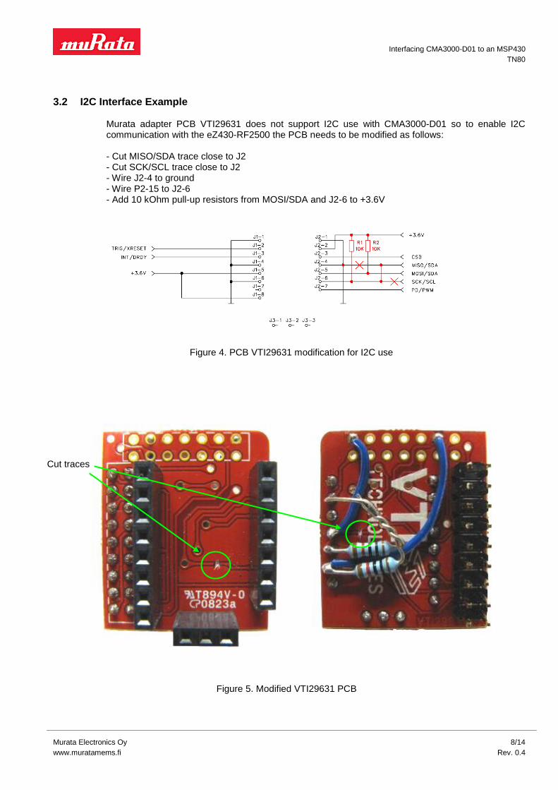
3.2 I2C Interface Example
Murata adapter PCB VTI29631 does not support I2C use with CMA3000-D01 so to enable I2C communication with the eZ430-RF2500 the PCB needs to be modified as follows:
- Cut MISO/SDA trace close to J2 - Cut SCK/SCL trace close to J2 - Wire J2-4 to ground - Wire P2-15 to J2-6 - Add 10 kOhm pull-up resistors from MOSI/SDA and J2-6 to +3.6V
Figure 4. PCB VTI29631 modification for I2C use
Figure 5. Modified VTI29631 PCB
Cut traces
Interfacing CMA3000-D01 to an MSP430
TN80
Murata Electronics Oy 9/14
www.muratamems.fi Rev. 0.4
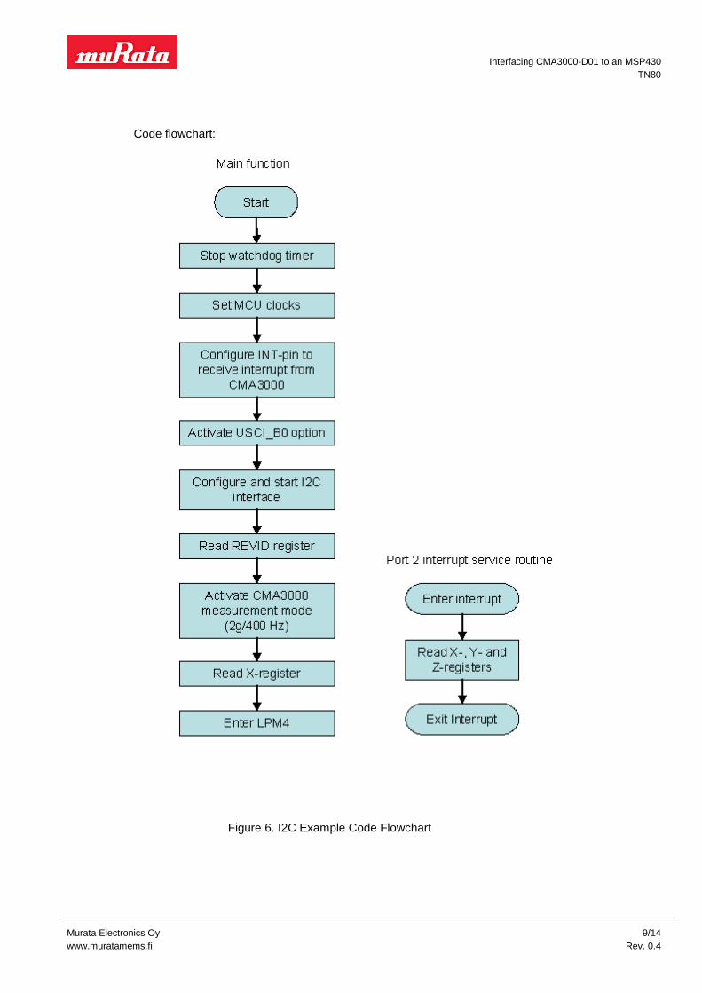
Code flowchart:
Figure 6. I2C Example Code Flowchart

Interfacing CMA3000-D01 to an MSP430
TN80
Murata Electronics Oy 10/14
www.muratamems.fi Rev. 0.4
C-Code Example, I2C Interface //******************************************************************************
// MSP430F2274 Demo - USCI_B0, I2C Interface to CMA3000 Acceleration Sensor
//
// Uses Texas Instruments eZ430-RF2500 Development Tool with Murata Adapter PCB
// VTI29631A0. Wireless connection not used. Adapter PCB VTI29631 needs to be
// modified for I2C to work.
//
//******************************************************************************
// LIBRARIES
#include "msp430x22x4.h"
// PORT DEFINITIONS
#define PORT_INT_IN P2IN
#define PORT_INT_DIR P2DIR
#define PORT_INT_IE P2IE
#define PORT_INT_IES P2IES
#define PORT_INT_IFG P2IFG
#define PORT_INT_VECTOR PORT2_VECTOR
#define PORT_I2C_DIR P3DIR
#define PORT_I2C_SEL P3SEL
#define PORT_I2C_OUT P3OUT
// REGISTER AND FLAG DEFINITIONS
#define TX_BUFFER UCB0TXBUF
#define RX_BUFFER UCB0RXBUF
#define IRQ_REG IFG2
#define RX_IFG UCB0RXIFG
#define TX_IFG UCB0TXIFG
// CMA3000 Registers
#define WHO_AM_I 0x00
#define REVID 0x01
#define CTRL 0x02
#define STATUS 0x03
#define RSTR 0x04
#define INT_STATUS 0x05
#define DOUTX 0x06
#define DOUTY 0x07
#define DOUTZ 0x08
#define MDTHR 0x09
#define MDFFTMR 0x0A
#define FFTHR 0x0B
#define I2C_ADDR 0x0C
// Control Register setup
#define G_RANGE_2 0x80 // 2g range
#define INT_LEVEL_LOW 0x40 // INT active high
#define MDET_NO_EXIT 0x20 // Remain in motion detection mode
#define I2C_DIS 0x10 // I2C disabled
#define MODE_PD 0x00 // Power Down
#define MODE_100 0x02 // Measurement mode 100 Hz ODR
#define MODE_400 0x04 // Measurement mode 400 Hz ODR
#define MODE_40 0x06 // Measurement mode 40 Hz ODR
#define MODE_MD_10 0x08 // Motion detection mode 10 Hz ODR
#define MODE_FF_100 0x0A // Free fall detection mode 100 Hz ODR
#define MODE_FF_400 0x0C // Free fall detection mode 400 Hz ODR
#define INT_DIS 0x01 // Interrupts enabled

Interfacing CMA3000-D01 to an MSP430
TN80
Murata Electronics Oy 11/14
www.muratamems.fi Rev. 0.4
// PIN DEFINITIONS
#define PIN_INT BIT4
#define PIN_CSB BIT3
#define PIN_MOSI BIT1
#define PIN_MISO BIT2
#define PIN_SCK BIT3
// FUNCTION PROTOTYPES
unsigned char ReadRegister(unsigned char Address);
unsigned char WriteRegister(unsigned char Address, unsigned char Data);
unsigned char Data;
unsigned char RevID;
unsigned char Xdata;
unsigned char Ydata;
unsigned char Zdata;
void main(void)
{
WDTCTL = WDTPW + WDTHOLD; // Stop watchdog timer
BCSCTL1 = CALBC1_16MHZ; // Set DCO to calibrated 16MHz
DCOCTL = CALDCO_16MHZ;
BCSCTL2 |= DIVS_3; // SMCLK to 2 MHz
PORT_INT_DIR &= ~PIN_INT;
PORT_INT_IE |= PIN_INT; // INT pin interrupt enabled
PORT_INT_IES = 0x00; // Generate interrupt on Lo to Hi edge
PORT_INT_IFG &= ~PIN_INT; // Clear interrupt flag
// Initialize I2C interface to acceleration sensor
PORT_I2C_DIR |= BIT0; // Set port 3 pin 0 as output and set high.
PORT_I2C_OUT |= BIT0;
UCB0CTL1 |= UCSWRST; // Put state machine in reset
UCB0CTL1 |= UCSSEL_2; // SMCLK as clock source
PORT_I2C_SEL |= BIT2 | BIT1; // Set port 3 pins 1 and 2 for I2C peripheral
UCB0CTL0 |= UCMST + UCSYNC + UCMODE_3; // I2C mode, master, synchronous
UCB0BR0 = 20; // 2MHz/20 = 100kHz
UCB0BR1 = 0;
UCB0I2CSA = 0x1C; // Slave Address is 1Ch
UCB0CTL1 &= ~UCSWRST; // Start I2C state machine
RevID = ReadRegister(REVID); // Read REVID register
Data = WriteRegister(CTRL, G_RANGE_2 | MODE_400); // Activate measurement mode: 2g/400Hz
Xdata = ReadRegister(DOUTX); // Dummy read to generate first INT pin Lo to Hi transition
// in all situations, also while debugging
__bis_SR_register(LPM4_bits + GIE); // Enter LPM4 w/interrupt
}
Interfacing CMA3000-D01 to an MSP430
TN80
Murata Electronics Oy 12/14
www.muratamems.fi Rev. 0.4
// Port 2 interrupt service routine, INT pin
#pragma vector=PORT_INT_VECTOR
__interrupt void Port_INT_ISR(void)
{
if (PORT_INT_IN & PIN_INT)
{
Xdata = ReadRegister(DOUTX); // Read DOUTX register
wait_us(110); // 11 * tscl
Ydata = ReadRegister(DOUTY); // Read DOUTY register
wait_us(110);
Zdata = ReadRegister(DOUTZ); // Read DOUTZ register
PORT_INT_IFG &= ~PIN_INT; // Clear interrupt flag
}
}
// Read a byte from the acceleration sensor
unsigned char ReadRegister(unsigned char Address)
{
unsigned char Result;
// Read data from I2C slave device at the DeviceAddress specified.
UCB0CTL1 |= UCTR + UCTXSTT; // I2C TX, start condition
while (!(IRQ_REG & TX_IFG)); // Wait for slave address transmit to complete
TX_BUFFER = Address; // Load TX buffer with register address
while (!(IRQ_REG & TX_IFG)); // Wait for transmit to complete
IRQ_REG &= ~TX_IFG; // Clear USCI_B0 TX int flag
// Send restart with transmit/receive bit NOT set
UCB0CTL1 &= ~UCTR; // Toggle transmitter bit
UCB0CTL1 |= UCTXSTT; // I2C start condition
while(UCB0CTL1 & UCTXSTT); // Wait for start to complete
UCB0CTL1 |= UCTXSTP; // I2C stop condition
while (!(IRQ_REG & RX_IFG)); // Wait for receive buffer to fill
Result = RX_BUFFER; // Fill receive data buffer with received byte
while (UCB0CTL1 & UCTXSTP); // Wait for stop condition to complete
IRQ_REG &= ~RX_IFG; // Clear USCI_B0 RX int flag
// Return new data from RX buffer
return Result;
}
Interfacing CMA3000-D01 to an MSP430
TN80
Murata Electronics Oy 13/14
www.muratamems.fi Rev. 0.4
// Write a byte to the acceleration sensor
unsigned char WriteRegister(unsigned char Address, unsigned char Data)
{
// Write data to I2C slave device at the DeviceAddress specified.
UCB0CTL1 |= UCTR + UCTXSTT; // I2C TX, start condition
while (!(IRQ_REG & TX_IFG)); // Wait for slave address transmit to complete
TX_BUFFER = Address; // Load TX buffer with register address
while (!(IRQ_REG & TX_IFG)); // Wait for transmit to complete
TX_BUFFER = Data; // Load TX buffer with data byte
while (!(IRQ_REG & TX_IFG)); // Wait for transmit to complete
UCB0CTL1 |= UCTXSTP; // I2C stop condition
while (UCB0CTL1 & UCTXSTP); // Wait for stop condition to complete
IRQ_REG &= ~TX_IFG; // Clear USCI_B0 TX int flag
return 0;
}

Interfacing CMA3000-D01 to an MSP430
TN80
Murata Electronics Oy 14/14
www.muratamems.fi Rev. 0.4
4 RESULT WAVEFORMS
There is no display on the development hardware so a logic analyzer was used to verify the results.
Figure 7 (SPI) and Figure 9 (I2C) show how the register reading is triggered from the CMA3000-D01 INT-pin. After the interrupt has activated, the output registers are read out in sequence, while making sure that In the case of SPI bus the communication frame spacing will be at least 11 SCK cycles.
In Figure 8 (SPI) and Figure 10 (I2C) it can be seen how the interrupt takes place immediately after CMA3000-D01 has new data available for reading. It also shows how the INT pin is automatically cleared by reading the acceleration output data.
Figure 7. SPI waveforms when reading DOUTX- DOUTY- and DOUTZ-registers
Figure 8. Register reading is triggered by CMA3000-D01's INT signal, SPI bus
Figure 9. I2C waveforms when reading DOUTX- DOUTY- and DOUTZ-registers
Figure 10. Register reading is triggered by CMA3000-D01's INT signal, I2C bus
Related Documents