SPE/IADC-173822-MS Field Trial of Well Control Solutions with a Dual Gradient Drilling System John H. Cohen, and Roger Stave, Enhanced Drilling; Espen Hauge, and Dag Ove Molde, Statoil Copyright 2015, SPE/IADC Managed Pressure Drilling and Underbalanced Operations Conference and Exhibition This paper was prepared for presentation at the SPE/IADC Managed Pressure Drilling and Underbalanced Operations Conference & Exhibition held in Dubai, UAE, 13–14 April 2015. This paper was selected for presentation by an SPE/IADC program committee following review of information contained in an abstract submitted by the author(s). Contents of the paper have not been reviewed by the Society of Petroleum Engineers or the International Association of Drilling Contractors and are subject to correction by the author(s). The material does not necessarily reflect any position of the Society of Petroleum Engineers or the International Association of Drilling Contractors, its officers, or members. Electronic reproduction, distribution, or storage of any part of this paper without the written consent of the Society of Petroleum Engineers or the International Association of Drilling Contractors is prohibited. Permission to reproduce in print is restricted to an abstract of not more than 300 words; illustrations may not be copied. The abstract must contain conspicuous acknowledgment of SPE/IADC copyright. Abstract Well control has been a major obstacle for introducing dual gradient systems for deep water drilling, involving both new and more complex procedures and equipment. Here test results using a new dual gradient drilling (DGD) system to control simulated well control events are presented. After successfully drilling a Statoil well with Enhanced Drilling’s dual gradient solution (EC-Drill) at the Troll (Kjøsnes et al. 2014) field on the Norwegian continental shelf, the well was plugged and made ready for 48 hours of controlled testing. Several tests were run, each designed to determine the functionality of the system; to detect and handle liquid loss, gas and liquid influx, gas migration in the riser, and circulation of gas through the subsea pump module. The detection tests were carried out with a reduced riser level and an open annular, to quantify the capability of the system to detect volume imbalances while drilling. Three circulation tests with increasing amount of gas injected through the drillstring were performed. After the influx was detected, the annular was closed, and the flow was routed from the well through a bypass line to the subsea pump module. A topside choke in the mud return line was actively used to apply backpressure with the objective to control bottom-hole pressure, while circulating the gas from the well. In the last test gas was allowed to migrate into the marine drilling riser with a reduced riser level and open annular. The paper will present the planning and preparations as well as the results. Introduction As water depths have increased in offshore drilling the difficulty of staying in the drilling window, between pore and fracture pressure, has become more challenging. The narrow drilling window makes early influx/loss detection of major importantce. In addition the required number of casing strings to complete the well has risen to the point where economic viability of some wells is no longer possible. Dual Gradient Drilling (DGD) offers a means to solve these problems (Schubert et al. 1999). A Joint Industry Project run under the Research Council of Norway’s Demo 2000 program examined expanding an existing pre Blow Out Preventer (BOP) DGD system for use in post-BOP operations. This new system is called Controlled Mud Pressure (CMP ® ). The following are results of field test of critical elements and procedures needed to prove and advance the CMP concept.

Welcome message from author
This document is posted to help you gain knowledge. Please leave a comment to let me know what you think about it! Share it to your friends and learn new things together.
Transcript
SPE/IADC-173822-MS
Field Trial of Well Control Solutions with a Dual Gradient Drilling System
John H. Cohen, and Roger Stave, Enhanced Drilling; Espen Hauge, and Dag Ove Molde, Statoil
Copyright 2015, SPE/IADC Managed Pressure Drilling and Underbalanced Operations Conference and Exhibition
This paper was prepared for presentation at the SPE/IADC Managed Pressure Drilling and Underbalanced Operations Conference & Exhibition held in Dubai, UAE,13–14 April 2015.
This paper was selected for presentation by an SPE/IADC program committee following review of information contained in an abstract submitted by the author(s).Contents of the paper have not been reviewed by the Society of Petroleum Engineers or the International Association of Drilling Contractors and are subject tocorrection by the author(s). The material does not necessarily reflect any position of the Society of Petroleum Engineers or the International Association of DrillingContractors, its officers, or members. Electronic reproduction, distribution, or storage of any part of this paper without the written consent of the Society of PetroleumEngineers or the International Association of Drilling Contractors is prohibited. Permission to reproduce in print is restricted to an abstract of not more than 300 words;illustrations may not be copied. The abstract must contain conspicuous acknowledgment of SPE/IADC copyright.
Abstract
Well control has been a major obstacle for introducing dual gradient systems for deep water drilling,involving both new and more complex procedures and equipment. Here test results using a new dualgradient drilling (DGD) system to control simulated well control events are presented. After successfullydrilling a Statoil well with Enhanced Drilling’s dual gradient solution (EC-Drill) at the Troll (Kjøsnes etal. 2014) field on the Norwegian continental shelf, the well was plugged and made ready for 48 hours ofcontrolled testing. Several tests were run, each designed to determine the functionality of the system; todetect and handle liquid loss, gas and liquid influx, gas migration in the riser, and circulation of gasthrough the subsea pump module. The detection tests were carried out with a reduced riser level and anopen annular, to quantify the capability of the system to detect volume imbalances while drilling. Threecirculation tests with increasing amount of gas injected through the drillstring were performed. After theinflux was detected, the annular was closed, and the flow was routed from the well through a bypass lineto the subsea pump module. A topside choke in the mud return line was actively used to applybackpressure with the objective to control bottom-hole pressure, while circulating the gas from the well.In the last test gas was allowed to migrate into the marine drilling riser with a reduced riser level and openannular.
The paper will present the planning and preparations as well as the results.
IntroductionAs water depths have increased in offshore drilling the difficulty of staying in the drilling window,between pore and fracture pressure, has become more challenging. The narrow drilling window makesearly influx/loss detection of major importantce. In addition the required number of casing strings tocomplete the well has risen to the point where economic viability of some wells is no longer possible. DualGradient Drilling (DGD) offers a means to solve these problems (Schubert et al. 1999). A Joint IndustryProject run under the Research Council of Norway’s Demo 2000 program examined expanding anexisting pre Blow Out Preventer (BOP) DGD system for use in post-BOP operations. This new systemis called Controlled Mud Pressure (CMP®). The following are results of field test of critical elements andprocedures needed to prove and advance the CMP concept.
Well Control MethodologyThere are many philosophies around well control, and DGD offers even more options. As originallyconfigured, CMP would use a dynamic kill method. In a dynamic kill, the rig pumps are never shut off.Slowing down the speed of the subsea pump increases the bottom-hole pressure to stop the influx. Flowto the pump is diverted from above the BOP to below the BOP and the well closed in as flow continues.The influx is pumped up through the CMP pump.
The process was subjected to a risk assessment using expert personnel from one of the members of theJIP, a major operator. The evaluation team was multidisciplinary, including drilling engineers, wellcontrol specialists, rig managers, rig superintendents and others involved in well control. This riskassessment determined that, although fesibile, the change from conventional well control to dynamic killwas too significant a departure from accepted practices to employ on a rig or to get regulatory permission.The risk assessment also determined well control approaches closer to the “Drillers Method” would beeasier to implement and gain regulatory approval as the first step in implementing DGD.
The CMP technical team then went back and developed new well control procedures for use with a dualgradient system. The complications come from the drilling fluid in the drill pipe. Since this represents acolumn of fluid back to the surface it cannot be allowed to exert pressure on the well bottom. There aretwo methods to overcome the problem; 1) let the drill pipe U-tube into the annulus. This could take severalminutes and the entire time formation fluids would be entering into the well bore. 2) Use a drill string flowvalve that would support a portion of the drilling fluid in the drill string keeping this pressure frominfluencing the well bore pressure. This second concept was used to develop the well control procedures.It allows the rig pumps to be stopped upon confirmation of an influx and the BOP to be closed to allowthe well to come to equilibrium quicker, and thus further limiting the influx size. In the new procedurethat was developed, the subsea CMP pump was transitioned from constant inlet pressure / variable speedcontrol to constant speed / pressure boost upon confirmation of a kick and starting a well control event/ kick circulation. A surface choke was used to control the standpipe pressure, just like conventional. Theconstant speed / pressure boost from the CMP pump should be sufficient to support the heavy fluid columnback to surface at the end of the circulation process. The new procedures were vetted by some of the riskassessment team and this was presented to the CMP Technical committee as the approved method.
This exercise demonstrated that there are multiple ways to handle well control using a DGD system.The choice may ultimately be a method that is more comfortable to current crews and regulatory agencies.In addition to the primary well control method discussed above, the CMP team developed contingencywell control procedures in case of equipment failure or excessive influx size. These were presented andvetted by the CMP Technical Committee. The Technical Committee was made up of members from eachof the JIP participants, all having extensive drilling experience. The well control methodology andprocedures were used in guiding the tests to demonstrate the CMP systems ability to circulate out aninflux.
DGD BasicsDGD enables drilling beyond the shoe depth limits of single gradient drilling (Schubert et al. 1999). DGDcomes in many forms, but in the most basic the riser top is filled either completely or partially with a riserfluid (the base fluid can be a gas.), and the remainder of the riser and well are filled with drilling fluid(Stave 2014). The base fluid is typically lighter and the drilling fluid heavier. The resultant pressure profilein the well better matches the natural pore/fracture pressure gradients allowing longer sections to be drilled(Ziegler 2012). Figure 1 shows a schematic diagram of single gradient versus dual gradient drilling. Theinflection in the pressure gradient is at the interface (mud line in this case) between the two fluids.
2 SPE/IADC-173822-MS
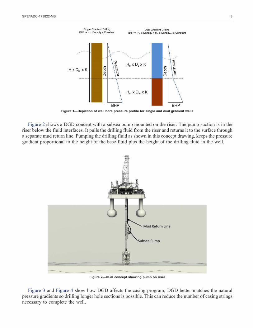
Figure 2 shows a DGD concept with a subsea pump mounted on the riser. The pump suction is in theriser below the fluid interfaces. It pulls the drilling fluid from the riser and returns it to the surface througha separate mud return line. Pumping the drilling fluid as shown in this concept drawing, keeps the pressuregradient proportional to the height of the base fluid plus the height of the drilling fluid in the well.
Figure 3 and Figure 4 show how DGD affects the casing program; DGD better matches the naturalpressure gradients so drilling longer hole sections is possible. This can reduce the number of casing stringsnecessary to complete the well.
Figure 1—Depiction of well bore pressure profile for single and dual gradient wells
Figure 2—DGD concept showing pump on riser
SPE/IADC-173822-MS 3
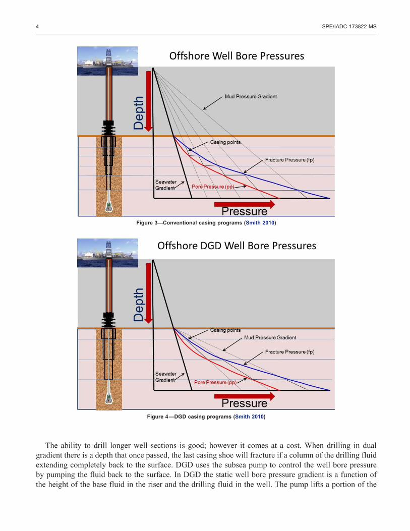
The ability to drill longer well sections is good; however it comes at a cost. When drilling in dualgradient there is a depth that once passed, the last casing shoe will fracture if a column of the drilling fluidextending completely back to the surface. DGD uses the subsea pump to control the well bore pressureby pumping the fluid back to the surface. In DGD the static well bore pressure gradient is a function ofthe height of the base fluid in the riser and the drilling fluid in the well. The pump lifts a portion of the
Figure 3—Conventional casing programs (Smith 2010)
Figure 4—DGD casing programs (Smith 2010)
4 SPE/IADC-173822-MS
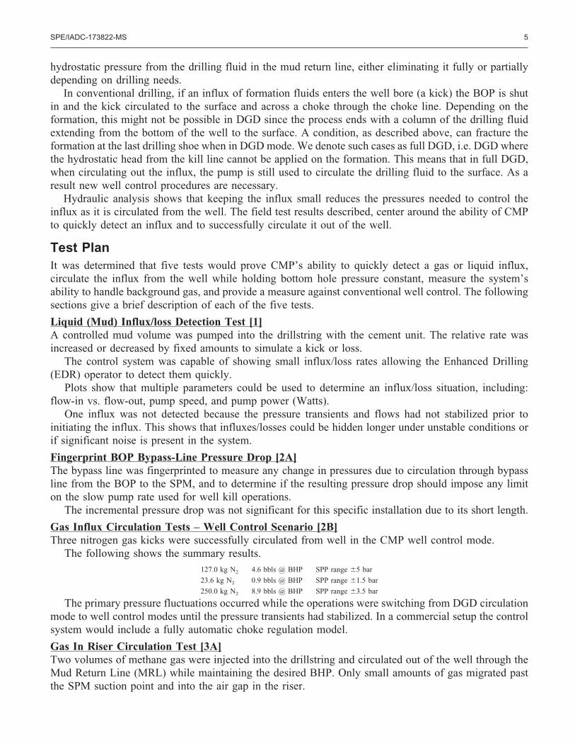
hydrostatic pressure from the drilling fluid in the mud return line, either eliminating it fully or partiallydepending on drilling needs.
In conventional drilling, if an influx of formation fluids enters the well bore (a kick) the BOP is shutin and the kick circulated to the surface and across a choke through the choke line. Depending on theformation, this might not be possible in DGD since the process ends with a column of the drilling fluidextending from the bottom of the well to the surface. A condition, as described above, can fracture theformation at the last drilling shoe when in DGD mode. We denote such cases as full DGD, i.e. DGD wherethe hydrostatic head from the kill line cannot be applied on the formation. This means that in full DGD,when circulating out the influx, the pump is still used to circulate the drilling fluid to the surface. As aresult new well control procedures are necessary.
Hydraulic analysis shows that keeping the influx small reduces the pressures needed to control theinflux as it is circulated from the well. The field test results described, center around the ability of CMPto quickly detect an influx and to successfully circulate it out of the well.
Test PlanIt was determined that five tests would prove CMP’s ability to quickly detect a gas or liquid influx,circulate the influx from the well while holding bottom hole pressure constant, measure the system’sability to handle background gas, and provide a measure against conventional well control. The followingsections give a brief description of each of the five tests.
Liquid (Mud) Influx/loss Detection Test [1]A controlled mud volume was pumped into the drillstring with the cement unit. The relative rate wasincreased or decreased by fixed amounts to simulate a kick or loss.
The control system was capable of showing small influx/loss rates allowing the Enhanced Drilling(EDR) operator to detect them quickly.
Plots show that multiple parameters could be used to determine an influx/loss situation, including:flow-in vs. flow-out, pump speed, and pump power (Watts).
One influx was not detected because the pressure transients and flows had not stabilized prior toinitiating the influx. This shows that influxes/losses could be hidden longer under unstable conditions orif significant noise is present in the system.
Fingerprint BOP Bypass-Line Pressure Drop [2A]The bypass line was fingerprinted to measure any change in pressures due to circulation through bypassline from the BOP to the SPM, and to determine if the resulting pressure drop should impose any limiton the slow pump rate used for well kill operations.
The incremental pressure drop was not significant for this specific installation due to its short length.
Gas Influx Circulation Tests – Well Control Scenario [2B]Three nitrogen gas kicks were successfully circulated from well in the CMP well control mode.
The following shows the summary results.127.0 kg N2 4.6 bbls @ BHP SPP range �5 bar
23.6 kg N2 0.9 bbls @ BHP SPP range �1.5 bar
250.0 kg N2 8.9 bbls @ BHP SPP range �3.5 bar
The primary pressure fluctuations occurred while the operations were switching from DGD circulationmode to well control modes until the pressure transients had stabilized. In a commercial setup the controlsystem would include a fully automatic choke regulation model.
Gas In Riser Circulation Test [3A]Two volumes of methane gas were injected into the drillstring and circulated out of the well through theMud Return Line (MRL) while maintaining the desired BHP. Only small amounts of gas migrated pastthe SPM suction point and into the air gap in the riser.
SPE/IADC-173822-MS 5
At 600 lpm top fill rate and 17.5 kg methane injected; nearly all the gas was circulated up the MRL.Only 1% of the LEL was seen as free gas in the riser. When the riser fluid level was raised, only 5% ofthe LEL was measured in the air gap.
At 1200 lpm top fill rate and 17.5 kg methane injected; nearly all the gas was circulated up the MRLwith only 12% of the LEL seen as free gas in the riser. When the riser level was raised, up to 31% of theLEL was measured.
This test demonstrated the capability of the system to control BHP with normal to high levels of“drilled gas” present.
In general, the primary return path of entrained “drilled gas” was through the pump with only verysmall amounts migrating up the riser. When compared to a conventional operation where all of themethane would have been circulated up the riser to exit out the flowline, the LEL concentrationsexperienced during the test were likely to have been significantly less than what would have been seenin conventional operations with the same methane injection rates.
The topfill pump’s ability to control/limit the gas migration rate past the SPM inlet was basicallydebunked (as we had suspected from other ‘real’ well information obtained during the test preparationphase). Thus, the key benefits of the topfill pump should be, 1) to controllable change out the static mudin the riser; and 2) to lubricate the riser slip joint as needed (not verified in the tests) and not the potentialability in controlling the gas migration flow path.
Gas Influx Detection Tests [3B]Controlled nitrogen volumes were pumped into the drillstring to simulate a kick. The relative rate ofnitrogen injection was varied by fixed amounts to represent different sized influxes.
The control system was capable of showing small influx rates allowing the EDR operator to detectthem quickly.
The influxes were successfully circulated out through riser and MRL.
Small Gas Kick In Riser Circulation Test [4]The objective was to controllably circulate a small gas kick out in drilling mode without using the wellcontrol operations. The test failed, under the existing operational conditions, with drilling mud unloadingfrom the riser and onto the drillfloor.
Results would have been different had the mud level in the riser been at 200 m vs 100 m and the kickvolume injected as designated in the procedures (1 bbl vs 10 bbls @ bottomhole conditions). Using a slowcirculation rate would also have helped. Previous tests showed that influx volumes of up to 1 bbl couldbe circulated out without using well control procedures.
Conventional Well Control [5]A gas kick was circulated out conventionally to compare to CMP.
250.0 kg N2, 8.9 bbls @ BHP, SPP range �5 bar.The primary pressure fluctuations occurred while the operations were switching from influx placement
to well control modes until the pressure transients had stabilized.
6 SPE/IADC-173822-MS
EquipmentCMP Equipment (Figure 5)
1 Subsea pump Module - SPM
2 Modified riser joint - interface joint with outlet to SPM suction. Pressure sensors used to monitor riser fluid level and provide input for controlsystem.
4 Mud Return Line - return line to rig mud system incorporated in riser.
16 Flow Head - To direct return mud flow as required.
10 Umbilical & Umbilical Winch - Used to provide power and control for pump operation.
9 Control Container - Monitors sensors on CMP equipment and provides power and control through umbilical to SPM.
8 Office/Tool Container - Remote control panel at drillers’ station.
23 Nitrogen/Methane Injection Skid and Manifold - Connection, pressure flow gauge, regulator, and interface between nitrogen bottles/bundlesand rig standpipe manifold. Methane bottles added to this injection skid.
11 Top fill pump is installed and connected to riser and mud supply. Mud was introduced as a mud wall/curtain.
ResultsRapid detection of an influx or loss is important for well control. The pressures needed to control theexpansion of the influx as it is circulated out of the well are proportional to its volume at the bottom ofthe well. Early loss detection is needed to prevent them from becoming major losses. CMP has severalparameters to quickly detect influxes and losses. The primary detection parameters are change in pumpperformance. If more fluid enters the well, then the pump must work harder to pump the additional fluidvolume up to the drilling vessel; conversely if the well experiences losses, the pump does not need to workas hard to return the reduced fluid to the drilling vessel. This change in pump performance is an earlyindicator of an influx or loss. For rapid changes it is more sensitive than pit gain and is not subject to theuncertainty entered from vessel heave. In addition the riser pressure sensor at the pump suction point canalso be an early detector. As formation fluid enters or leaves the well, the level in the riser changes untilthe control system can respond and change the pump performance to account for the influx or loss. Theriser pressure change is an early influx/loss detection parameter, and may show up before the pumpperformance. In addition to these parameters the CMP control system measures flow into the well andflow out of the well, a difference in these measurements is a sign of an influx or loss. Early detectionallows the driller to take appropriate action to limit the influx or loss.
SPE/IADC-173822-MS 7
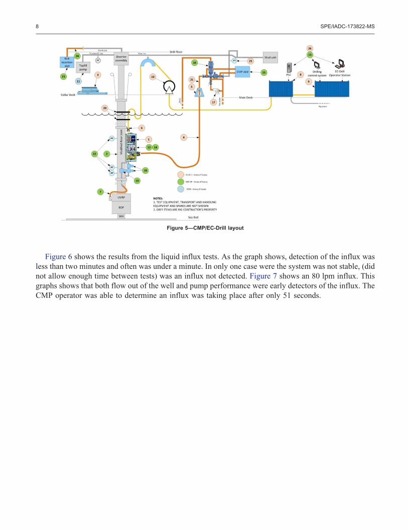
Figure 6 shows the results from the liquid influx tests. As the graph shows, detection of the influx wasless than two minutes and often was under a minute. In only one case were the system was not stable, (didnot allow enough time between tests) was an influx not detected. Figure 7 shows an 80 lpm influx. Thisgraphs shows that both flow out of the well and pump performance were early detectors of the influx. TheCMP operator was able to determine an influx was taking place after only 51 seconds.
Figure 5—CMP/EC-Drill layout
8 SPE/IADC-173822-MS
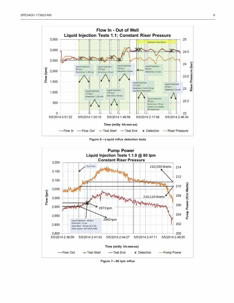
Figure 6—Liquid influx detection tests
Figure 7—80 lpm influx
SPE/IADC-173822-MS 9
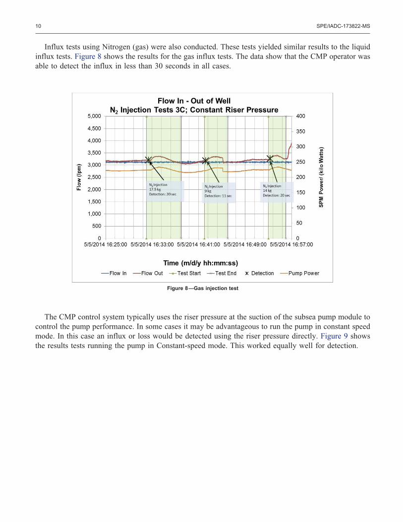
Influx tests using Nitrogen (gas) were also conducted. These tests yielded similar results to the liquidinflux tests. Figure 8 shows the results for the gas influx tests. The data show that the CMP operator wasable to detect the influx in less than 30 seconds in all cases.
The CMP control system typically uses the riser pressure at the suction of the subsea pump module tocontrol the pump performance. In some cases it may be advantageous to run the pump in constant speedmode. In this case an influx or loss would be detected using the riser pressure directly. Figure 9 showsthe results tests running the pump in Constant-speed mode. This worked equally well for detection.
Figure 8—Gas injection test
10 SPE/IADC-173822-MS
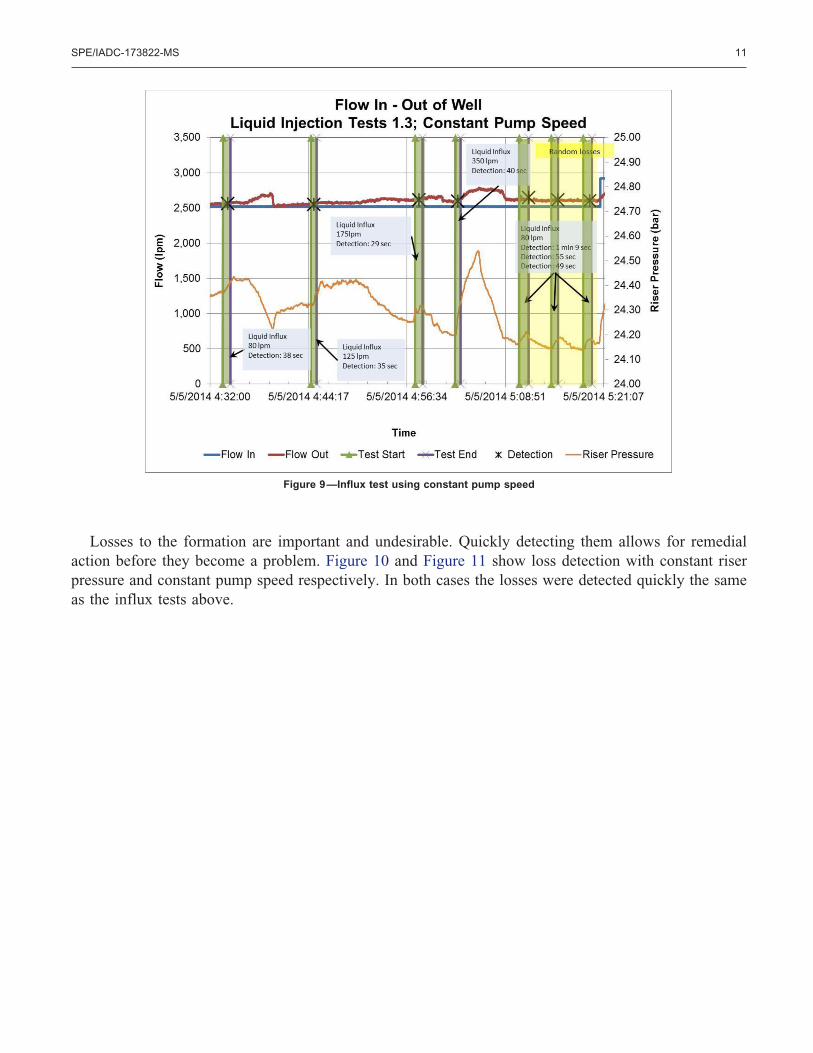
Losses to the formation are important and undesirable. Quickly detecting them allows for remedialaction before they become a problem. Figure 10 and Figure 11 show loss detection with constant riserpressure and constant pump speed respectively. In both cases the losses were detected quickly the sameas the influx tests above.
Figure 9—Influx test using constant pump speed
SPE/IADC-173822-MS 11
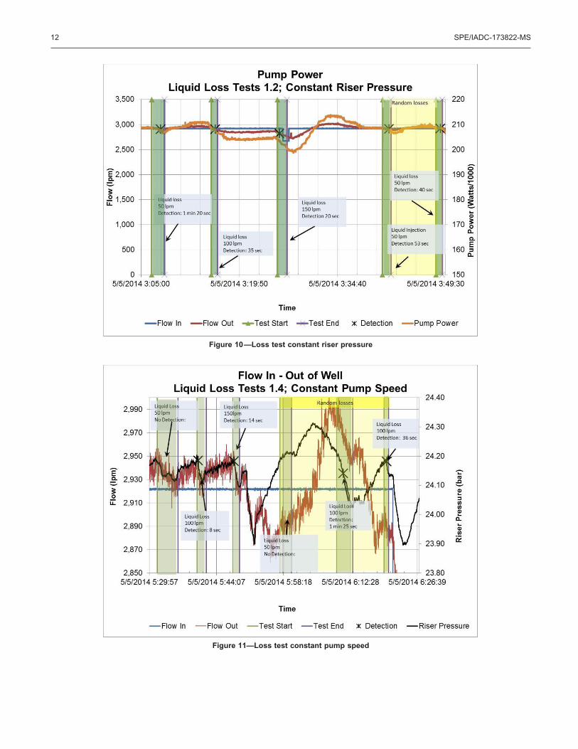
Figure 10—Loss test constant riser pressure
Figure 11—Loss test constant pump speed
12 SPE/IADC-173822-MS
Influx/Loss Detection SummaryThe tests demonstrate that the CMP control system can quickly detect an influx or loss to the well bore.This is the first step in keeping any well safe. Detection was possible using both constant riser pressureand constant pump speed modes. In most cases the influx/loss was detected in less than one minute.
Gas Influx Circulation Tests – Well Control ScenarioOnce an influx (kick) has been detected it must be circulated from the well. There are two procedures forcirculating an influx out of the well depending on the size of the influx. The first method is for an influxlarge enough to justify well control mode. This means shutting the well in by closing the BOP and thencirculating the influx up the well past the BOP to the surface. In conventional drilling the influx iscirculated up the choke line where a choke is used to control well pressures. In full dual gradient drillingthis is not possible because the drilling fluid is heavier than in conventional drilling and at the conclusionof the process a column of mud will extend from the well bottom to the surface. This will create too highpressures and the formations in the well bore may fracture causing a potential dangerous situation. InDGD the fluid must circulate through the pump so that, as before, the fluid in the mud return line ispumped to the surface by the subsea pump removing this pressure from the well bore.
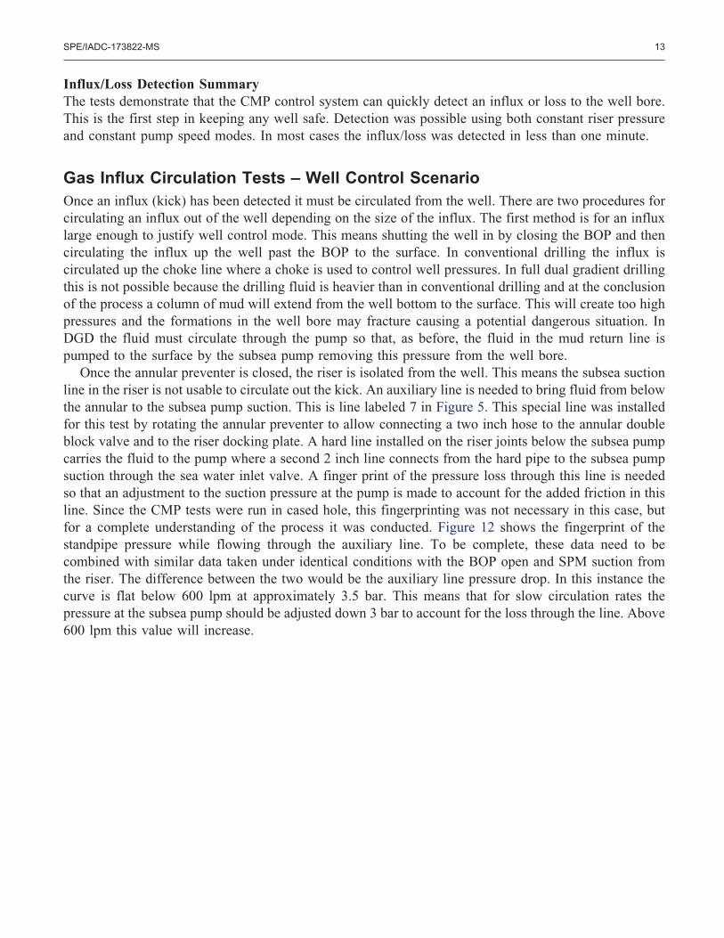
Once the annular preventer is closed, the riser is isolated from the well. This means the subsea suctionline in the riser is not usable to circulate out the kick. An auxiliary line is needed to bring fluid from belowthe annular to the subsea pump suction. This is line labeled 7 in Figure 5. This special line was installedfor this test by rotating the annular preventer to allow connecting a two inch hose to the annular doubleblock valve and to the riser docking plate. A hard line installed on the riser joints below the subsea pumpcarries the fluid to the pump where a second 2 inch line connects from the hard pipe to the subsea pumpsuction through the sea water inlet valve. A finger print of the pressure loss through this line is neededso that an adjustment to the suction pressure at the pump is made to account for the added friction in thisline. Since the CMP tests were run in cased hole, this fingerprinting was not necessary in this case, butfor a complete understanding of the process it was conducted. Figure 12 shows the fingerprint of thestandpipe pressure while flowing through the auxiliary line. To be complete, these data need to becombined with similar data taken under identical conditions with the BOP open and SPM suction fromthe riser. The difference between the two would be the auxiliary line pressure drop. In this instance thecurve is flat below 600 lpm at approximately 3.5 bar. This means that for slow circulation rates thepressure at the subsea pump should be adjusted down 3 bar to account for the loss through the line. Above600 lpm this value will increase.
SPE/IADC-173822-MS 13
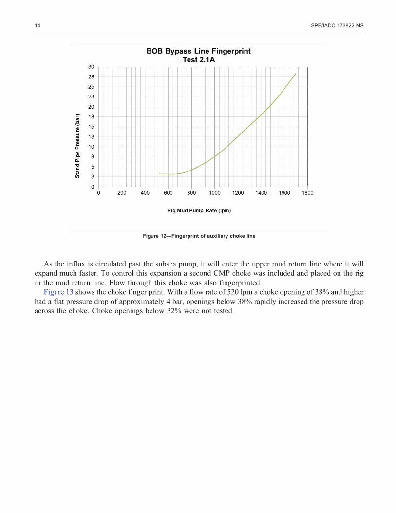
As the influx is circulated past the subsea pump, it will enter the upper mud return line where it willexpand much faster. To control this expansion a second CMP choke was included and placed on the rigin the mud return line. Flow through this choke was also fingerprinted.
Figure 13 shows the choke finger print. With a flow rate of 520 lpm a choke opening of 38% and higherhad a flat pressure drop of approximately 4 bar, openings below 38% rapidly increased the pressure dropacross the choke. Choke openings below 32% were not tested.
Figure 12—Fingerprint of auxiliary choke line
14 SPE/IADC-173822-MS
Simulated influxes were created and pumped down the drill pipe. Nitrogen was injected into thestandpipe manifold, thus displacing and replacing mud in the drill pipe. The pressures used at the surfacewere selected so that at the bit three different influx sizes were produced. These influx sizes equaled 1,4 and 9 barrels of compressed gas at the bit. After pumping the gas down the drillpipe and through thebit, the rig pumps were stopped and the BOP closed. No adjustment was made in the height of the fluidin the riser when the rig pumps were stopped, so at the start of each test a pressure anomaly occurs as thesystem is restarted.
The objective was to circulate out the influxes and maintain bottom-hole pressure within �5 bar. Afterthe initial pressure spike from restarting the rig pumps the system successfully circulated out the influxeswhile maintaining the �5 bar limit. Figure 14 and Figure 15 show the results from the 9 bbl and the 1bbl influx circulation tests. In both cases the system was able to hold the bottom-hole pressure to withinthe �5 bar margin.
Figure 13—Fingerprint of CMP choke at 520 lpm
SPE/IADC-173822-MS 15
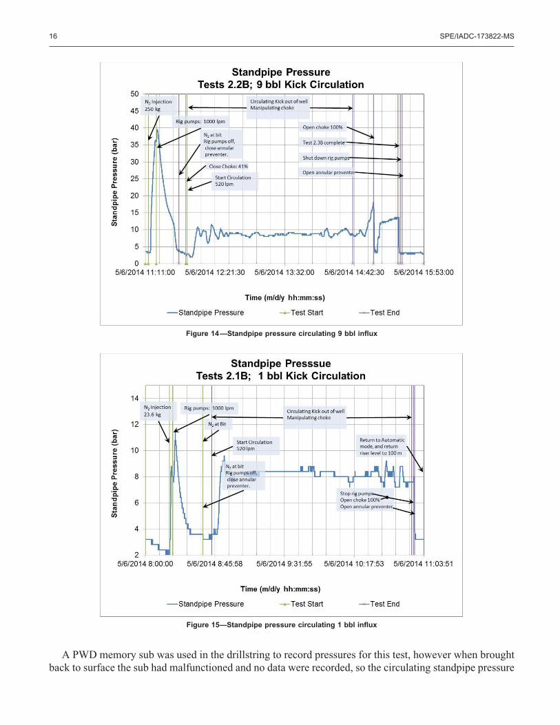
A PWD memory sub was used in the drillstring to record pressures for this test, however when broughtback to surface the sub had malfunctioned and no data were recorded, so the circulating standpipe pressure
Figure 14—Standpipe pressure circulating 9 bbl influx
Figure 15—Standpipe pressure circulating 1 bbl influx
16 SPE/IADC-173822-MS
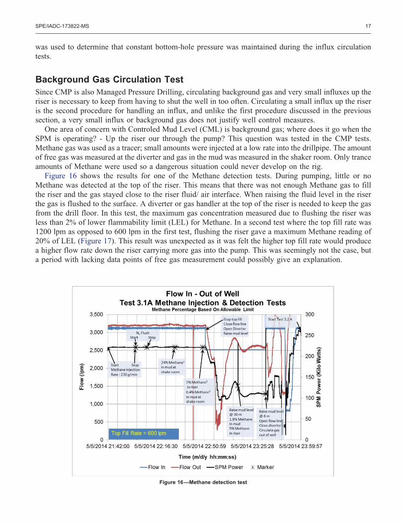
was used to determine that constant bottom-hole pressure was maintained during the influx circulationtests.
Background Gas Circulation TestSince CMP is also Managed Pressure Drilling, circulating background gas and very small influxes up theriser is necessary to keep from having to shut the well in too often. Circulating a small influx up the riseris the second procedure for handling an influx, and unlike the first procedure discussed in the previoussection, a very small influx or background gas does not justify well control measures.
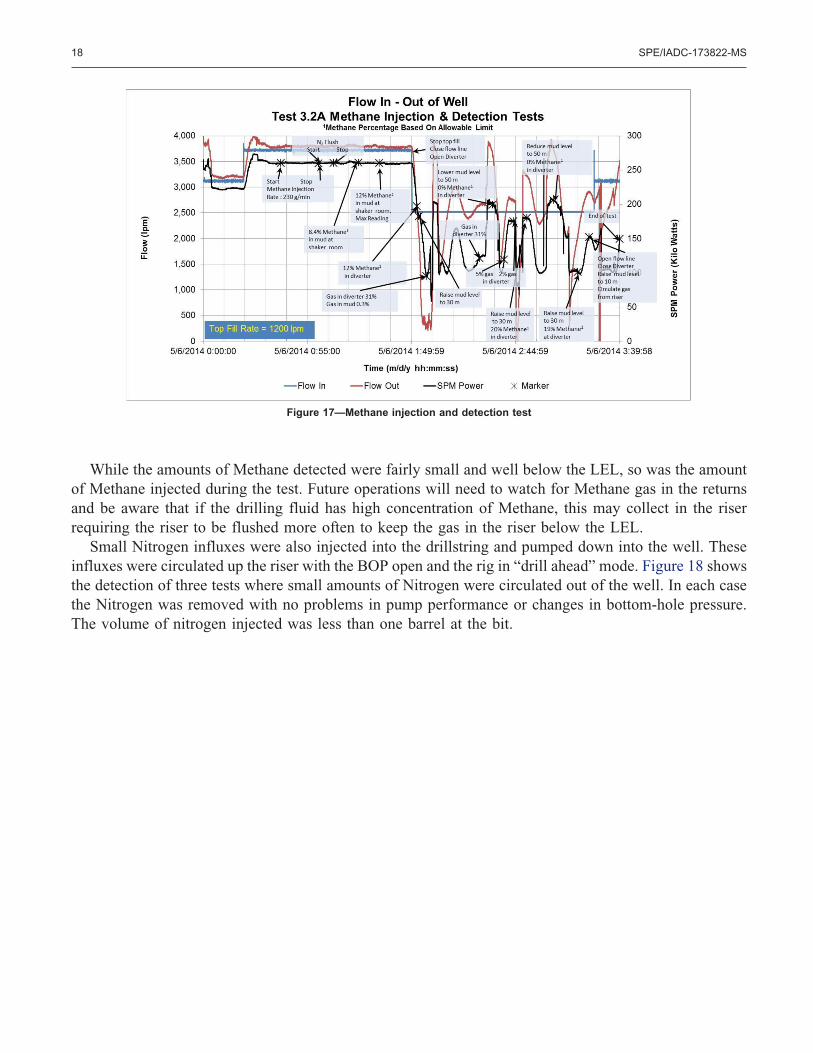
One area of concern with Controled Mud Level (CML) is background gas; where does it go when theSPM is operating? - Up the riser our through the pump? This question was tested in the CMP tests.Methane gas was used as a tracer; small amounts were injected at a low rate into the drillpipe. The amountof free gas was measured at the diverter and gas in the mud was measured in the shaker room. Only tranceamounts of Methane were used so a dangerous situation could never develop on the rig.
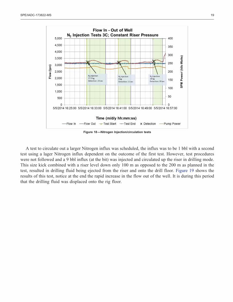
Figure 16 shows the results for one of the Methane detection tests. During pumping, little or noMethane was detected at the top of the riser. This means that there was not enough Methane gas to fillthe riser and the gas stayed close to the riser fluid/ air interface. When raising the fluid level in the riserthe gas is flushed to the surface. A diverter or gas handler at the top of the riser is needed to keep the gasfrom the drill floor. In this test, the maximum gas concentration measured due to flushing the riser wasless than 2% of lower flammability limit (LEL) for Methane. In a second test where the top fill rate was1200 lpm as opposed to 600 lpm in the first test, flushing the riser gave a maximum Methane reading of20% of LEL (Figure 17). This result was unexpected as it was felt the higher top fill rate would producea higher flow rate down the riser carrying more gas into the pump. This was seemingly not the case, buta period with lacking data points of free gas measurement could possibly give an explanation.
Figure 16—Methane detection test
SPE/IADC-173822-MS 17
While the amounts of Methane detected were fairly small and well below the LEL, so was the amountof Methane injected during the test. Future operations will need to watch for Methane gas in the returnsand be aware that if the drilling fluid has high concentration of Methane, this may collect in the riserrequiring the riser to be flushed more often to keep the gas in the riser below the LEL.
Small Nitrogen influxes were also injected into the drillstring and pumped down into the well. Theseinfluxes were circulated up the riser with the BOP open and the rig in “drill ahead” mode. Figure 18 showsthe detection of three tests where small amounts of Nitrogen were circulated out of the well. In each casethe Nitrogen was removed with no problems in pump performance or changes in bottom-hole pressure.The volume of nitrogen injected was less than one barrel at the bit.
Figure 17—Methane injection and detection test
18 SPE/IADC-173822-MS
A test to circulate out a larger Nitrogen influx was scheduled, the influx was to be 1 bbl with a secondtest using a lager Nitrogen influx dependent on the outcome of the first test. However, test procedureswere not followed and a 9 bbl influx (at the bit) was injected and circulated up the riser in drilling mode.This size kick combined with a riser level down only 100 m as opposed to the 200 m as planned in thetest, resulted in drilling fluid being ejected from the riser and onto the drill floor. Figure 19 shows theresults of this test, notice at the end the rapid increase in the flow out of the well. It is during this periodthat the drilling fluid was displaced onto the rig floor.
Figure 18—Nitrogen Injection/circulation tests
SPE/IADC-173822-MS 19
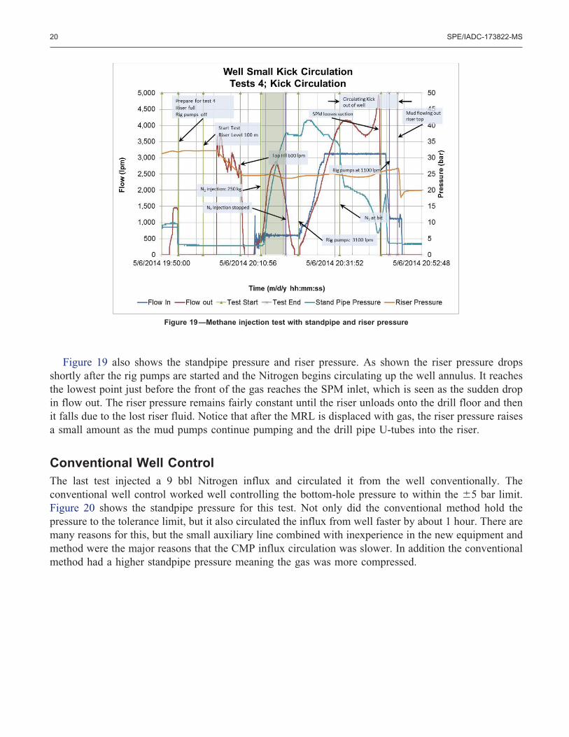
Figure 19 also shows the standpipe pressure and riser pressure. As shown the riser pressure dropsshortly after the rig pumps are started and the Nitrogen begins circulating up the well annulus. It reachesthe lowest point just before the front of the gas reaches the SPM inlet, which is seen as the sudden dropin flow out. The riser pressure remains fairly constant until the riser unloads onto the drill floor and thenit falls due to the lost riser fluid. Notice that after the MRL is displaced with gas, the riser pressure raisesa small amount as the mud pumps continue pumping and the drill pipe U-tubes into the riser.
Conventional Well ControlThe last test injected a 9 bbl Nitrogen influx and circulated it from the well conventionally. Theconventional well control worked well controlling the bottom-hole pressure to within the �5 bar limit.Figure 20 shows the standpipe pressure for this test. Not only did the conventional method hold thepressure to the tolerance limit, but it also circulated the influx from well faster by about 1 hour. There aremany reasons for this, but the small auxiliary line combined with inexperience in the new equipment andmethod were the major reasons that the CMP influx circulation was slower. In addition the conventionalmethod had a higher standpipe pressure meaning the gas was more compressed.
Figure 19—Methane injection test with standpipe and riser pressure
20 SPE/IADC-173822-MS

ConclusionsThe tests were considered a success as they showed the following.
● Well control is manageable with the CMP Dual Gradient Drilling system.● The system is very capable of detecting an influx early and keeping it small● Influxes can be detected with the system in constant riser pressure mode or in constant pump speed
mode● Gas and liquid influxes are detectable with the CMP system● If small, an influx can circulate up the riser using proper gas handling equipment● Lager influxes can circulate out of the well in well control mode (BOP shut), but circulated
through the subsea pump to keep bottom hole pressures below the fracture pressure● In these tests, most background gas circulated through the pump and over to the shakers● Some background gas enters the riser void● Background gas entering the riser can be flushed by raising the riser level● A diverter or gas handler is needed at the top of riser to flush riser gas● Standpipe pressure, and thus bottom-hole pressure, is maintained relatively constant using the
CMP choke during circulation of an influx.
The CMP Dual Gradient Drilling system is ready for the next step in development; Using the systemin single gradient mode to test and prove procedures in an actual drilling environment. Experience withoil based muds and gas influxes is also necessary, but this situation should be an improvement as in mostcases the gas should not breakout of solution until it is above the pump. This means the pump will onlyhave to circulate fluid and not a multi-phase fluid where it efficiency can quickly be reduced with highgas concentrations.
Figure 20—Conventional Well Control
SPE/IADC-173822-MS 21

ReferencesSchubert, J.J., Seland, S., Johansen, T.J., and Juvkam-Wold, H. C. Greater Kick Tolerance and Fewer
Casing Strings Make Dual Gradient Drilling a Winner, Paper presented at the IADC Well ControlConference of the Americas, Houston, TX August 26, 1999
Stave, R, 2014. Implementation of Dual Gradient Drilling. Presented at OTC Houston, Texas, 5 – 8May 2014. OTC 25222-MS
Ziegler R. A Step Change in Safety: Drilling Deepwater Wells With Riser Margin. Presented at OTCHouston, Texas, 30 April – 3 May 2012. OTC 22889
Cohen, J.H., Smith K., Falk, K., and Begagic, J., Dual Gradient Drilling Methods: Their Layouts andPressure Profiles. IADC Dual Gradient Drilling Workshop, Houston, Texas, May 5, 2010
Kjøsnes, I., Godhavn, J., Molde, D., et al.; Toolbox for floaters; SPE/IADC MPD & UBO Conference& Exhibition; Madrid, Spain 8-9 April 2014
22 SPE/IADC-173822-MS
Related Documents