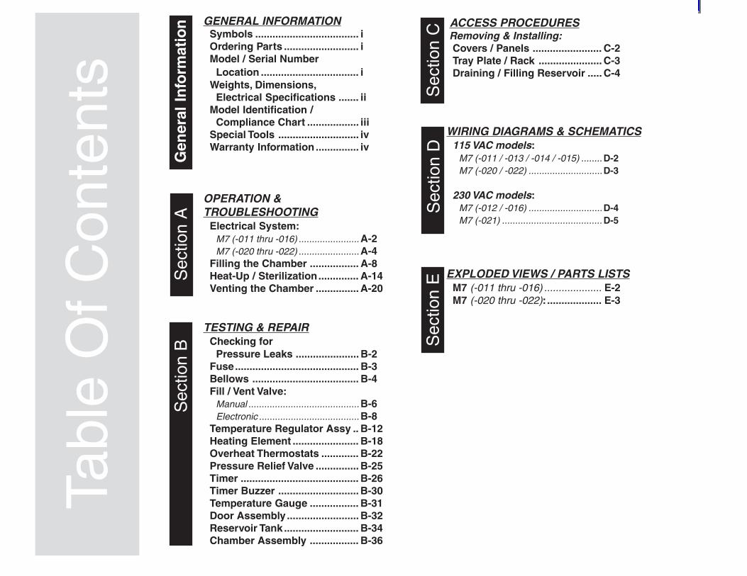
FOR USE BY MIDMARK TRAINED TECHNICIANS ONLY Service and Parts Manual SF-1855 Part No. 004-0454-00 Rev. D (6/25/12) SpeedClave Steam Sterilizers Model Numbers: M7 M7 -011 thru -016 -020 thru -022 Serial Number Prefixes: MH, MJ, MK, ML, MM, MN, V V ®

Welcome message from author
This document is posted to help you gain knowledge. Please leave a comment to let me know what you think about it! Share it to your friends and learn new things together.
Transcript
FOR USE BY MIDMARK TRAINED TECHNICIANS ONLY
Service andParts Manual
SF-1855 Part No. 004-0454-00 Rev. D (6/25/12)
SpeedClaveSteam Sterilizers
Model Numbers:
M7M7
-011 thru -016
-020 thru -022
Serial Number Prefixes:
MH, MJ, MK, ML, MM, MN, V
V
®
Tabl
e O
f Con
tent
sGENERAL INFORMATION
Symbols .................................... iOrdering Parts .......................... iModel / Serial Number
Location .................................. iWeights, Dimensions,
Electrical Specifications ....... iiModel Identification /
Compliance Chart .................. iiiSpecial Tools ............................ ivWarranty Information ............... iv
OPERATION &TROUBLESHOOTING
Electrical System:M7 (-011 thru -016) .......................A-2M7 (-020 thru -022) .......................A-4
Filling the Chamber ................. A-8Heat-Up / Sterilization.............. A-14Venting the Chamber ............... A-20
TESTING & REPAIRChecking for
Pressure Leaks ...................... B-2Fuse........................................... B-3Bellows ..................................... B-4Fill / Vent Valve:
Manual ..........................................B-6Electronic ......................................B-8
Temperature Regulator Assy .. B-12Heating Element ....................... B-18Overheat Thermostats ............. B-22Pressure Relief Valve ............... B-25Timer ......................................... B-26Timer Buzzer ............................ B-30Temperature Gauge ................. B-31Door Assembly ......................... B-32Reservoir Tank .......................... B-34Chamber Assembly ................. B-36
ACCESS PROCEDURES Removing & Installing:
Covers / Panels ........................ C-2Tray Plate / Rack ...................... C-3Draining / Filling Reservoir ..... C-4
WIRING DIAGRAMS & SCHEMATICS115 VAC models:
M7 (-011 / -013 / -014 / -015) ........ D-2M7 (-020 / -022) ............................D-3
230 VAC models:M7 (-012 / -016) ............................D-4M7 (-021) ...................................... D-5
EXPLODED VIEWS / PARTS LISTSM7 (-011 thru -016) .................... E-2M7 (-020 thru -022): ................... E-3
Gen
eral
In
form
atio
n
Sec
tion
ES
ectio
n E
Sec
tion
C
Sec
tion
AS
ectio
n B
Sec
tion
D
i© Midmark Corporation 2004 SF-1854
General Information
MA511502i
R
Symbols
CautionIndicates a potentially hazardous situationwhich could result in injury if not avoided.
Equipment AlertIndicates a potentially hazardous situationwhich could result in equipment damage if not avoided.
NoteAmplifies a procedure, practice, or condition.
Indicates that the component the check mark appearsbeside should be tested before replacing it.In Section A, test the components in the order indicated.(ex. 1st then, 2nd )
Refer to Section B for component testing procedures.
Ordering Parts
The following information is required when ordering parts:• Serial number & model number• Part number for desired part.
[Refer to Section E: Exploded Views / Parts Lists]
Non-warranty parts orders may be faxed to Midmark usingthe Fax Order Form in the back of this manual.
For warranty parts orders, call Midmark's Technical ServiceDepartment with the required information.Hours: 8:00 am until 5:00 pm EST [Monday - Friday]Phone: 1-(800)-Midmark
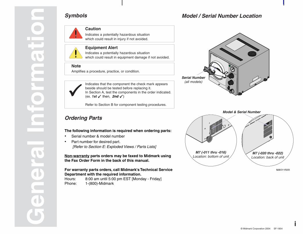
Model / Serial Number Location
Gen
eral
Info
rmat
ion
Serial Number
(all models)
Model & Serial Number
M7 (-011 thru -016)Location: bottom of unit
M7 (-020 thru -022)Location: back of unit
ii
General Information
© Midmark Corporation 2004 SF-1854
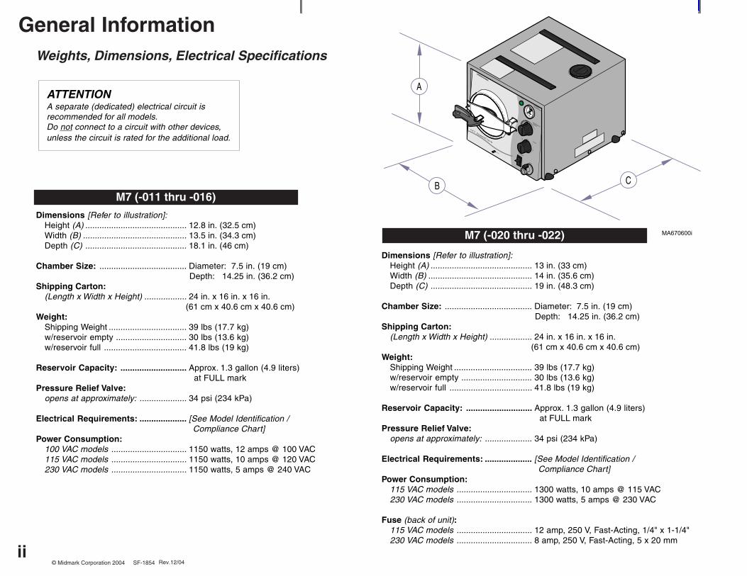
Weights, Dimensions, Electrical Specifications
Dimensions [Refer to illustration]:Height (A) ........................................... 12.8 in. (32.5 cm)Width (B) ............................................ 13.5 in. (34.3 cm)Depth (C) ........................................... 18.1 in. (46 cm)
Chamber Size: ..................................... Diameter: 7.5 in. (19 cm) Depth: 14.25 in. (36.2 cm)
Shipping Carton:(Length x Width x Height) .................. 24 in. x 16 in. x 16 in. (61 cm x 40.6 cm x 40.6 cm)
Weight:Shipping Weight ................................. 39 lbs (17.7 kg)w/reservoir empty .............................. 30 lbs (13.6 kg)w/reservoir full ................................... 41.8 lbs (19 kg)
Reservoir Capacity: ............................ Approx. 1.3 gallon (4.9 liters) at FULL markPressure Relief Valve:
opens at approximately: .................... 34 psi (234 kPa)
Electrical Requirements: .................... [See Model Identification / Compliance Chart]
Power Consumption:100 VAC models ................................ 1150 watts, 12 amps @ 100 VAC115 VAC models ................................ 1150 watts, 10 amps @ 120 VAC230 VAC models ................................ 1150 watts, 5 amps @ 240 VAC
M7 (-011 thru -016)
ATTENTIONA separate (dedicated) electrical circuit isrecommended for all models.Do not connect to a circuit with other devices,unless the circuit is rated for the additional load.
B
A
C
R
Dimensions [Refer to illustration]:Height (A) ........................................... 13 in. (33 cm)Width (B) ............................................ 14 in. (35.6 cm)Depth (C) ........................................... 19 in. (48.3 cm)
Chamber Size: ..................................... Diameter: 7.5 in. (19 cm) Depth: 14.25 in. (36.2 cm)
Shipping Carton:(Length x Width x Height) .................. 24 in. x 16 in. x 16 in. (61 cm x 40.6 cm x 40.6 cm)
Weight:Shipping Weight ................................. 39 lbs (17.7 kg)w/reservoir empty .............................. 30 lbs (13.6 kg)w/reservoir full ................................... 41.8 lbs (19 kg)
Reservoir Capacity: ............................ Approx. 1.3 gallon (4.9 liters) at FULL markPressure Relief Valve:
opens at approximately: .................... 34 psi (234 kPa)
Electrical Requirements: .................... [See Model Identification / Compliance Chart]
Power Consumption:115 VAC models ................................ 1300 watts, 10 amps @ 115 VAC230 VAC models ................................ 1300 watts, 5 amps @ 230 VAC
Fuse (back of unit):115 VAC models ................................ 12 amp, 250 V, Fast-Acting, 1/4" x 1-1/4"230 VAC models ................................ 8 amp, 250 V, Fast-Acting, 5 x 20 mm
M7 (-020 thru -022)
Rev.12/04
iii© Midmark Corporation 2004 SF-1854
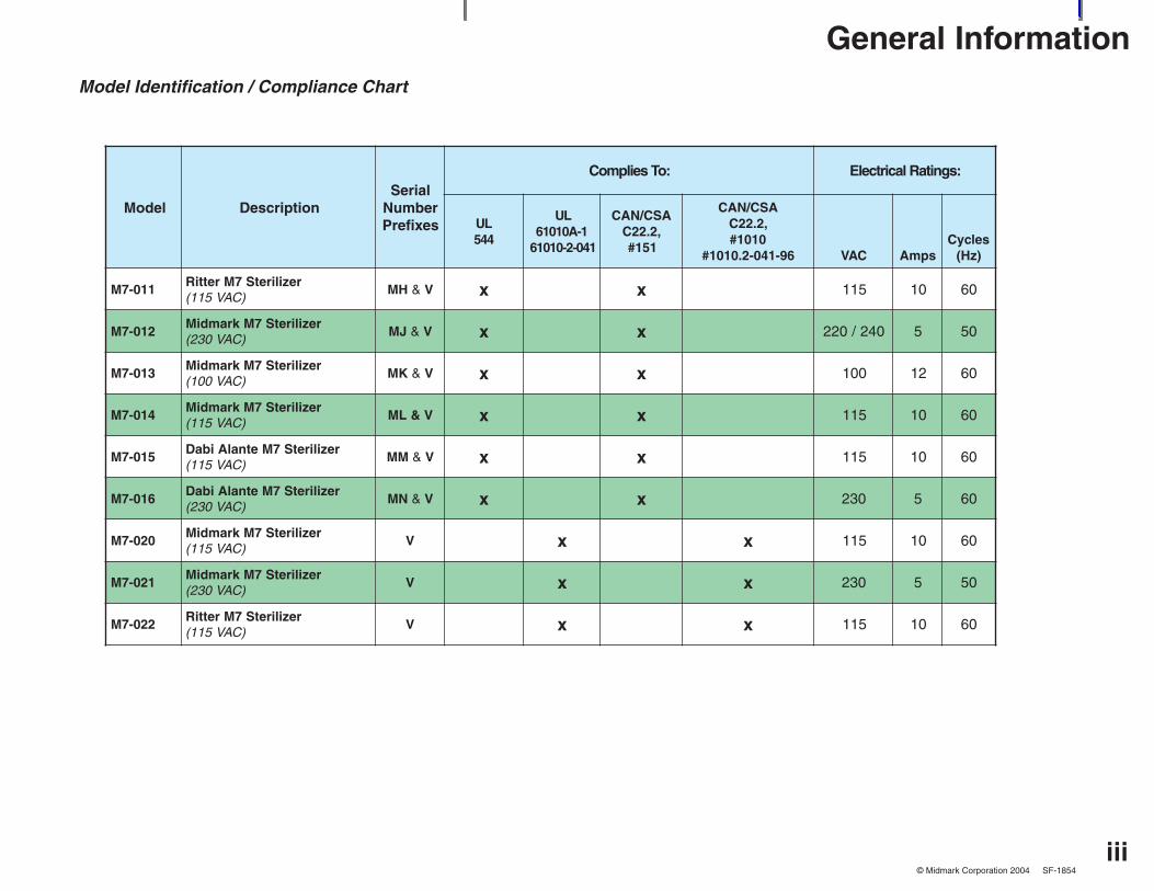
General InformationModel Identification / Compliance Chart
ledoM noitpircseDlaireSrebmuNsexiferP
:oTseilpmoC :sgnitaRlacirtcelE
LU445
LU1-A01016
140-2-01016
ASC/NAC,2.22C
151#
ASC/NAC,2.22C
0101#69-140-2.0101# CAV spmA
selcyC)zH(
110-7MreziliretS7MrettiR
)CAV511(HM & V x x 511 01 06
210-7MreziliretS7MkramdiM
)CAV032(JM & V x x 042/022 5 05
310-7MreziliretS7MkramdiM
)CAV001(KM & V x x 001 21 06
410-7MreziliretS7MkramdiM
)CAV511(V&LM x x 511 01 06
510-7MreziliretS7MetnalAibaD
)CAV511(MM & V x x 511 01 06
610-7MreziliretS7MetnalAibaD
)CAV032(NM & V x x 032 5 06
020-7MreziliretS7MkramdiM
)CAV511(V x x 511 01 06
120-7MreziliretS7MkramdiM
)CAV032(V x x 032 5 05
220-7MreziliretS7MrettiR
)CAV511(V x x 511 01 06
iv
General Information
© Midmark Corporation 2004 SF-1854
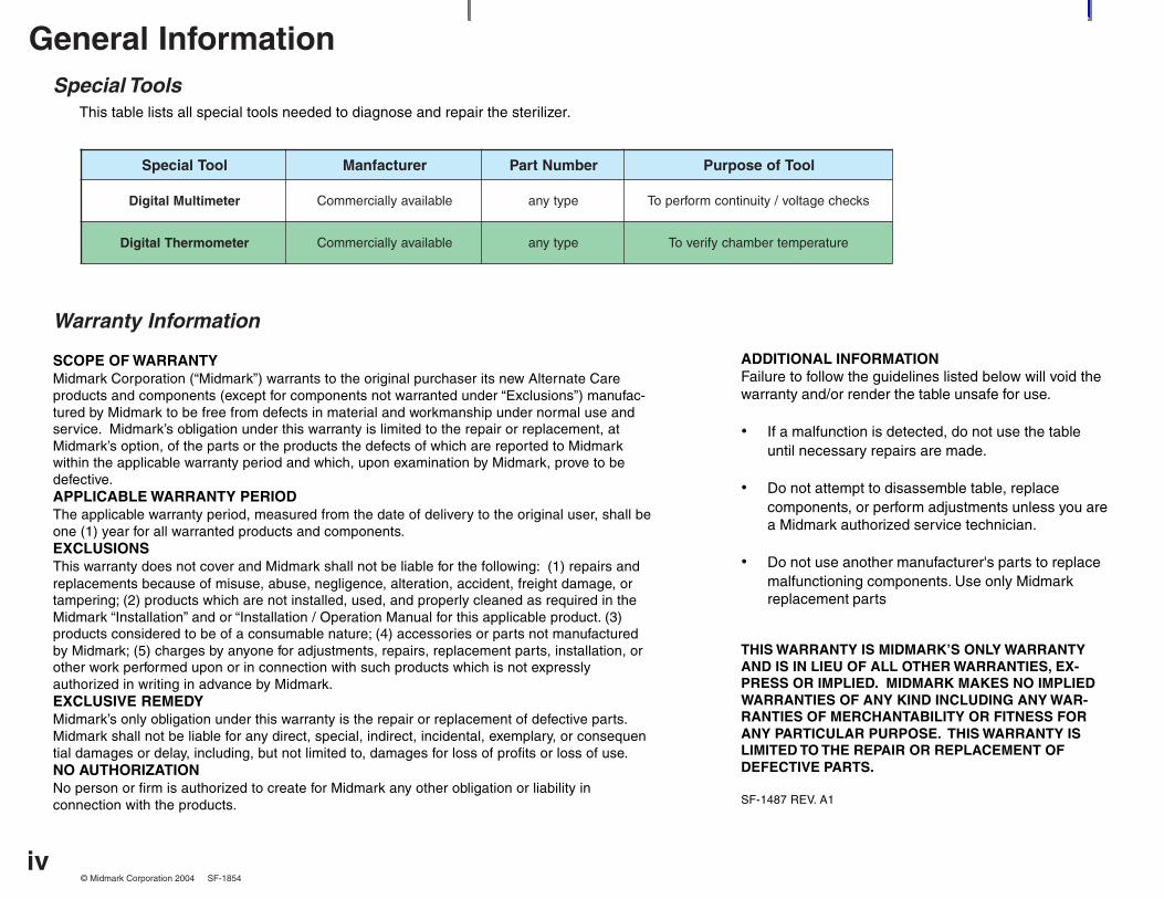
Special ToolsThis table lists all special tools needed to diagnose and repair the sterilizer.
looTlaicepS rerutcafnaM rebmuNtraP looTfoesopruP
retemitluMlatigiD elbaliavayllaicremmoC epytyna skcehcegatlov/ytiunitnocmrofrepoT
retemomrehTlatigiD elbaliavayllaicremmoC epytyna erutarepmetrebmahcyfirevoT
Warranty Information
SCOPE OF WARRANTYMidmark Corporation (“Midmark”) warrants to the original purchaser its new Alternate Careproducts and components (except for components not warranted under “Exclusions”) manufac-tured by Midmark to be free from defects in material and workmanship under normal use andservice. Midmark’s obligation under this warranty is limited to the repair or replacement, atMidmark’s option, of the parts or the products the defects of which are reported to Midmarkwithin the applicable warranty period and which, upon examination by Midmark, prove to bedefective.APPLICABLE WARRANTY PERIODThe applicable warranty period, measured from the date of delivery to the original user, shall beone (1) year for all warranted products and components.EXCLUSIONSThis warranty does not cover and Midmark shall not be liable for the following: (1) repairs andreplacements because of misuse, abuse, negligence, alteration, accident, freight damage, ortampering; (2) products which are not installed, used, and properly cleaned as required in theMidmark “Installation” and or “Installation / Operation Manual for this applicable product. (3)products considered to be of a consumable nature; (4) accessories or parts not manufacturedby Midmark; (5) charges by anyone for adjustments, repairs, replacement parts, installation, orother work performed upon or in connection with such products which is not expresslyauthorized in writing in advance by Midmark.EXCLUSIVE REMEDYMidmark’s only obligation under this warranty is the repair or replacement of defective parts.Midmark shall not be liable for any direct, special, indirect, incidental, exemplary, or consequential damages or delay, including, but not limited to, damages for loss of profits or loss of use.NO AUTHORIZATIONNo person or firm is authorized to create for Midmark any other obligation or liability inconnection with the products.
ADDITIONAL INFORMATIONFailure to follow the guidelines listed below will void thewarranty and/or render the table unsafe for use.
• If a malfunction is detected, do not use the tableuntil necessary repairs are made.
• Do not attempt to disassemble table, replacecomponents, or perform adjustments unless you area Midmark authorized service technician.
• Do not use another manufacturer's parts to replacemalfunctioning components. Use only Midmarkreplacement parts
THIS WARRANTY IS MIDMARK’S ONLY WARRANTYAND IS IN LIEU OF ALL OTHER WARRANTIES, EX-PRESS OR IMPLIED. MIDMARK MAKES NO IMPLIEDWARRANTIES OF ANY KIND INCLUDING ANY WAR-RANTIES OF MERCHANTABILITY OR FITNESS FORANY PARTICULAR PURPOSE. THIS WARRANTY ISLIMITED TO THE REPAIR OR REPLACEMENT OFDEFECTIVE PARTS.
SF-1487 REV. A1
A-1
Operation & Troubleshooting
Models:Serial Numbers:
© Midmark Corporation 2004 SF-1854
Sec
tion
AOperation &Troubleshooting
Mode PageElectrical System:
M7 (-011 thru -016) ........................... A-2
M7 (-020 thru -022) ........................... A-4
Filling the Chamber .............................. A-8
Heat Up / Sterilization ........................... A-14
Venting the Chamber ............................ A-20
A-2
Operation & Troubleshooting
Models:Serial Numbers:
© Midmark Corporation 2004 SF-1854
OverheatThermostat(Manual-Reset)
OverheatThermostat
(Auto-Reset)
Heating Element
TemperatureRegulator
Relay
HeaterLight
TimerBuzzer
Timer
Com.
Com.
MA670901i
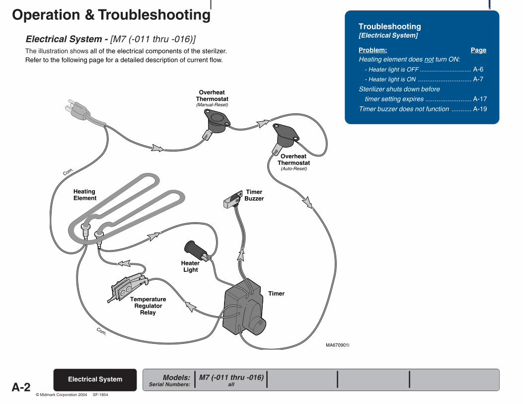
Electrical System - [M7 (-011 thru -016)]The illustration shows all of the electrical components of the sterilzer.Refer to the following page for a detailed description of current flow.
Troubleshooting[Electrical System]
Problem: PageHeating element does not turn ON:
- Heater light is OFF ............................... A-6
- Heater light is ON ............................. A-7
Sterilizer shuts down before
timer setting expires ......................... A-17
Timer buzzer does not function ........... A-19
Electrical System M7 (-011 thru -016)all
A-3
Operation & Troubleshooting
Models:Serial Numbers:
© Midmark Corporation 2004 SF-1854
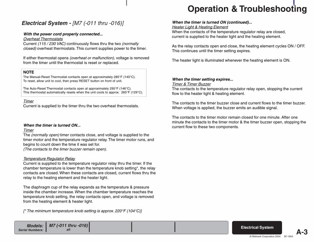
Electrical System - [M7 (-011 thru -016)]
With the power cord properly connected...Overheat ThermostatsCurrent (115 / 230 VAC) continuously flows thru the two (normallyclosed) overheat thermostats. This current supplies power to the timer.
If either thermostat opens (overheat or malfunction), voltage is removedfrom the timer until the thermostat is reset or replaced.
NOTEThe Manual-Reset Thermostat contacts open at approximately 285°F (140°C).To reset, allow unit to cool, then press RESET button on front of unit.
The Auto-Reset Thermostat contacts open at approximately 295°F (146°C).This thermostat automatically resets when the unit cools to approx. 265°F (129°C).
TimerCurrent is supplied to the timer thru the two overheat thermostats.
When the timer is turned ON...TimerThe (normally open) timer contacts close, and voltage is supplied to thetimer motor and the temperature regulator relay. The timer motor runs, andbegins to count down the time it was set for.(The contacts to the timer buzzer remain open).
Temperature Regulator RelayCurrent is supplied to the temperature regulator relay thru the timer. If thechamber temperature is lower than the temperature knob setting*, the relaycontacts are closed. When these contacts are closed, current flows thru therelay to the heating element and the heater light.
The diaphragm cup of the relay expands as the temperature & pressureinside the chamber increase. When the chamber temperature reaches thetemperature knob setting, the relay contacts open, and voltage is removedfrom the heating element & heater light.
[* The minimum temperature knob setting is approx. 220°F (104°C)]
When the timer is turned ON (continued)...Heater Light & Heating ElementWhen the contacts of the temperature regulator relay are closed,current is supplied to the heater light and the heating element.
As the relay contacts open and close, the heating element cycles ON / OFF.This continues until the timer setting expires.
The heater light is illuminated whenever the heating element is ON.
When the timer setting expires...Timer & Timer BuzzerThe contacts to the temperature regulator relay open, stopping the currentflow to the heater light & heating element.
The contacts to the timer buzzer close and current flows to the timer buzzer.When voltage is applied, the buzzer emits an audible signal.
The contacts to the timer motor remain closed for one minute. After oneminute the contacts to the timer motor & the timer buzzer open, stopping thecurrent flow to these two components.
Electrical SystemM7 (-011 thru -016)all
A-4
Operation & Troubleshooting
Models:Serial Numbers:
© Midmark Corporation 2004 SF-1854
Heating Element
TemperatureRegulator
Relay
HeaterLight
TimerBuzzer
Timer
Com.
Com.
OverheatThermostat(Manual-Reset)
OverheatThermostat
(Auto-Reset)
Fill / VentSwitch
Fill / VentValve
Fuse
Com. MA670900i
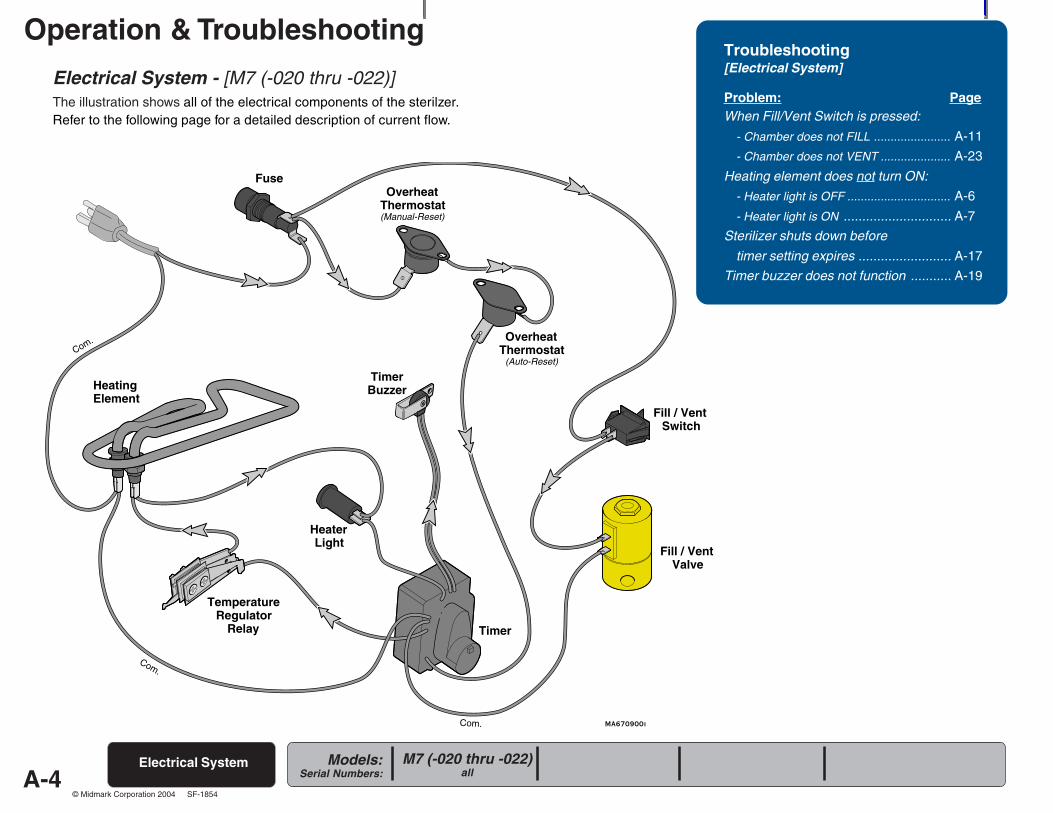
Electrical System - [M7 (-020 thru -022)]The illustration shows all of the electrical components of the sterilzer.Refer to the following page for a detailed description of current flow.
Electrical System M7 (-020 thru -022)all
Troubleshooting[Electrical System]
Problem: PageWhen Fill/Vent Switch is pressed:
- Chamber does not FILL ....................... A-11
- Chamber does not VENT ..................... A-23
Heating element does not turn ON:
- Heater light is OFF ............................... A-6
- Heater light is ON ............................. A-7
Sterilizer shuts down before
timer setting expires ......................... A-17
Timer buzzer does not function ........... A-19
A-5
Operation & Troubleshooting
Models:Serial Numbers:
© Midmark Corporation 2004 SF-1854
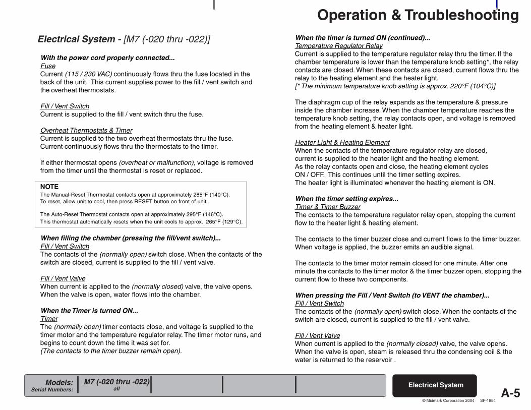
Electrical System - [M7 (-020 thru -022)]
With the power cord properly connected...FuseCurrent (115 / 230 VAC) continuously flows thru the fuse located in theback of the unit. This current supplies power to the fill / vent switch andthe overheat thermostats.
Fill / Vent SwitchCurrent is supplied to the fill / vent switch thru the fuse.
Overheat Thermostats & TimerCurrent is supplied to the two overheat thermostats thru the fuse.Current continuously flows thru the thermostats to the timer.
If either thermostat opens (overheat or malfunction), voltage is removedfrom the timer until the thermostat is reset or replaced.
NOTEThe Manual-Reset Thermostat contacts open at approximately 285°F (140°C).To reset, allow unit to cool, then press RESET button on front of unit.
The Auto-Reset Thermostat contacts open at approximately 295°F (146°C).This thermostat automatically resets when the unit cools to approx. 265°F (129°C).
When filling the chamber (pressing the fill/vent switch)...Fill / Vent SwitchThe contacts of the (normally open) switch close. When the contacts of theswitch are closed, current is supplied to the fill / vent valve.
Fill / Vent ValveWhen current is applied to the (normally closed) valve, the valve opens.When the valve is open, water flows into the chamber.
When the Timer is turned ON...TimerThe (normally open) timer contacts close, and voltage is supplied to thetimer motor and the temperature regulator relay. The timer motor runs, andbegins to count down the time it was set for.(The contacts to the timer buzzer remain open).
Electrical SystemM7 (-020 thru -022)all
When the timer is turned ON (continued)...Temperature Regulator RelayCurrent is supplied to the temperature regulator relay thru the timer. If thechamber temperature is lower than the temperature knob setting*, the relaycontacts are closed. When these contacts are closed, current flows thru therelay to the heating element and the heater light.[* The minimum temperature knob setting is approx. 220°F (104°C)]
The diaphragm cup of the relay expands as the temperature & pressureinside the chamber increase. When the chamber temperature reaches thetemperature knob setting, the relay contacts open, and voltage is removedfrom the heating element & heater light.
Heater Light & Heating ElementWhen the contacts of the temperature regulator relay are closed,current is supplied to the heater light and the heating element.As the relay contacts open and close, the heating element cyclesON / OFF. This continues until the timer setting expires.The heater light is illuminated whenever the heating element is ON.
When the timer setting expires...Timer & Timer BuzzerThe contacts to the temperature regulator relay open, stopping the currentflow to the heater light & heating element.
The contacts to the timer buzzer close and current flows to the timer buzzer.When voltage is applied, the buzzer emits an audible signal.
The contacts to the timer motor remain closed for one minute. After oneminute the contacts to the timer motor & the timer buzzer open, stopping thecurrent flow to these two components.
When pressing the Fill / Vent Switch (to VENT the chamber)...Fill / Vent SwitchThe contacts of the (normally open) switch close. When the contacts of theswitch are closed, current is supplied to the fill / vent valve.
Fill / Vent ValveWhen current is applied to the (normally closed) valve, the valve opens.When the valve is open, steam is released thru the condensing coil & thewater is returned to the reservoir .
A-6
Operation & Troubleshooting
Models:Serial Numbers:
© Midmark Corporation 2004 SF-1854
R
MA670800i
Refer To: PageOperation & Troubleshooting ................ A-1
Component Testing / Repair ................. B-1
Access Procedures .............................. C-1
Wiring Diagrams ................................... D-1
Exploded Views / Part Numbers ........... E-1
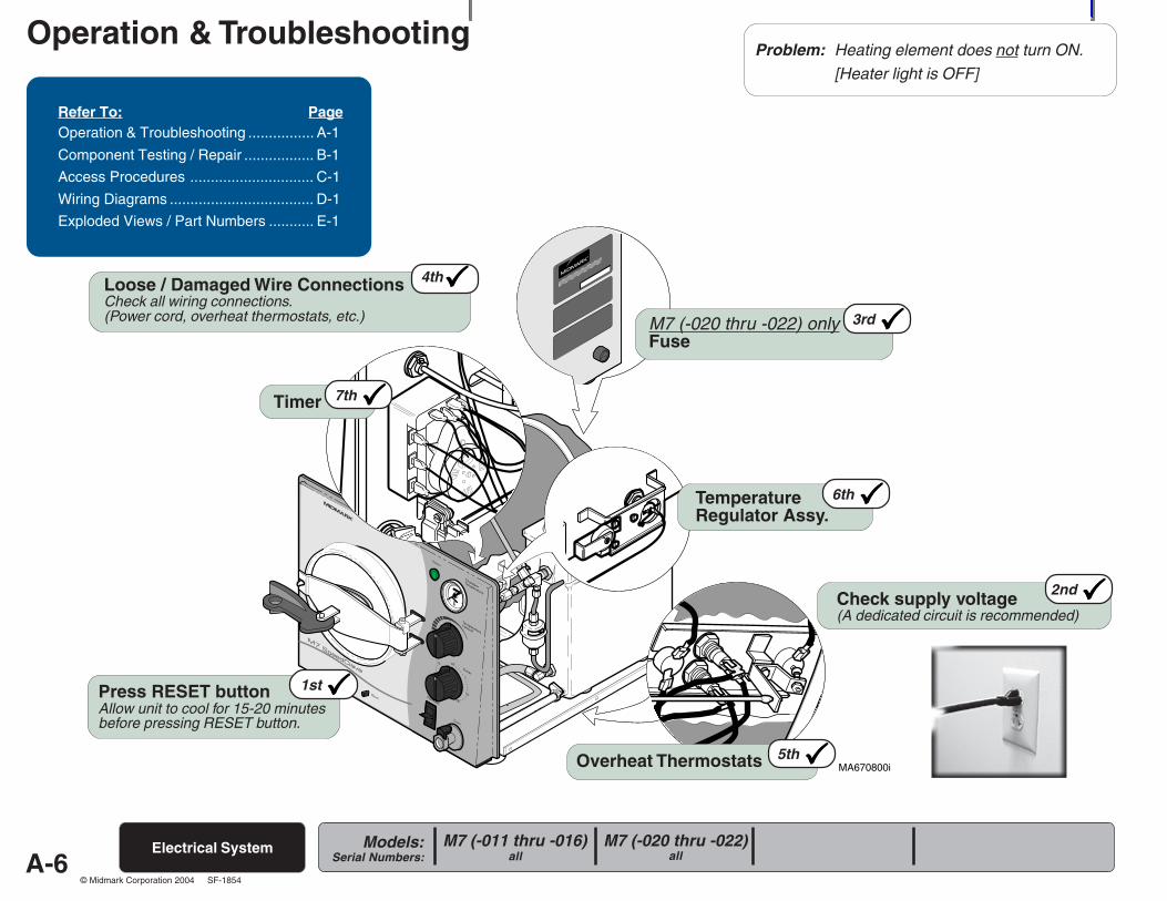
Check supply voltage(A dedicated circuit is recommended)
2nd
3rdM7 (-020 thru -022) onlyFuse
5thOverheat Thermostats
1stPress RESET buttonAllow unit to cool for 15-20 minutesbefore pressing RESET button.
6thTemperatureRegulator Assy.
7thTimer
4thLoose / Damaged Wire ConnectionsCheck all wiring connections.(Power cord, overheat thermostats, etc.)
Problem: Heating element does not turn ON.[Heater light is OFF]
Electrical System M7 (-020 thru -022)all
M7 (-011 thru -016)all
A-7
Operation & Troubleshooting
Models:Serial Numbers:
© Midmark Corporation 2004 SF-1854
MA672300i
R
Electrical System
Refer To: PageOperation & Troubleshooting ................ A-1
Component Testing / Repair ................. B-1
Access Procedures .............................. C-1
Wiring Diagrams ................................... D-1
Exploded Views / Part Numbers ........... E-1
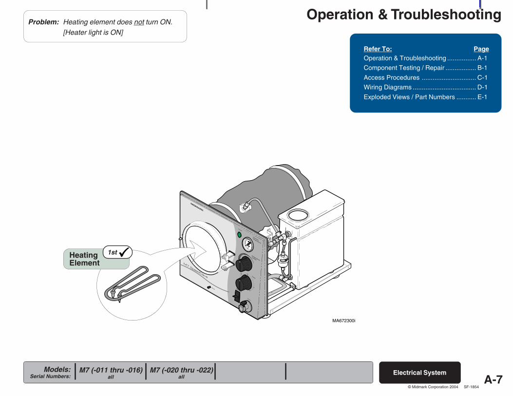
Problem: Heating element does not turn ON.[Heater light is ON]
HeatingElement
1st
M7 (-020 thru -022)all
M7 (-011 thru -016)all
A-8
Operation & Troubleshooting
Models:Serial Numbers:
© Midmark Corporation 2004 SF-1854
MA671500i
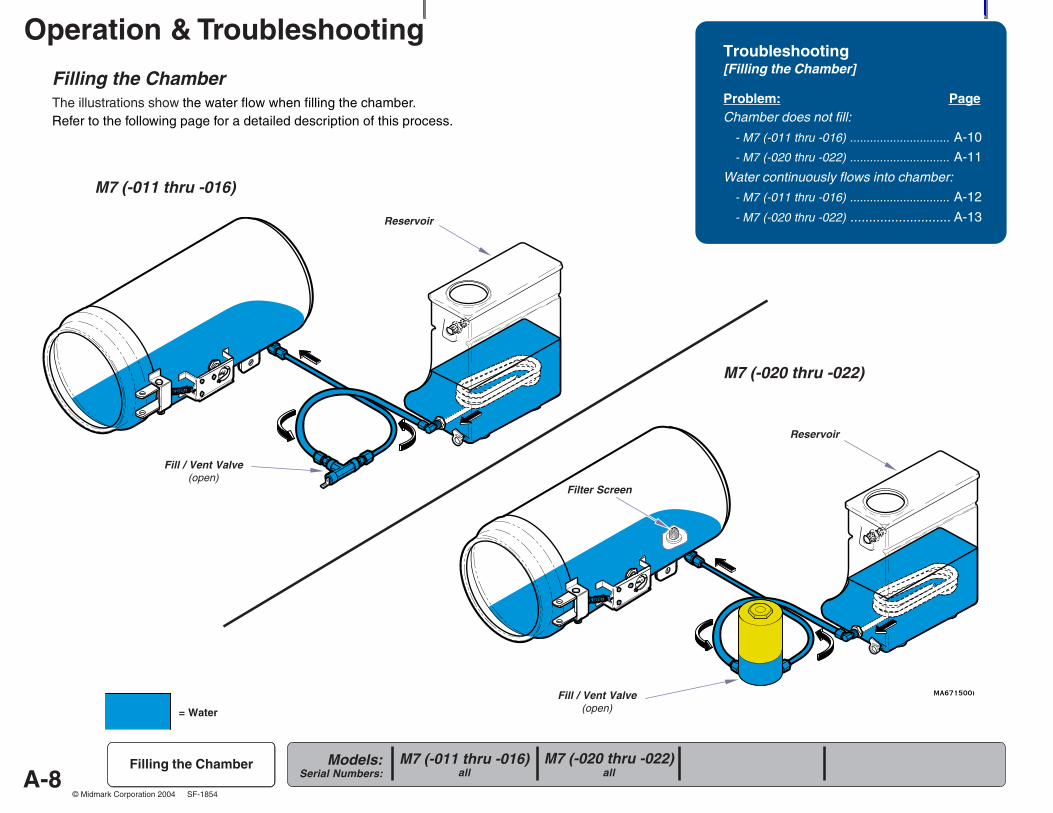
Filling the ChamberThe illustrations show the water flow when filling the chamber.Refer to the following page for a detailed description of this process.
Troubleshooting[Filling the Chamber]
Problem: PageChamber does not fill:
- M7 (-011 thru -016) .............................. A-10
- M7 (-020 thru -022) .............................. A-11
Water continuously flows into chamber:
- M7 (-011 thru -016) .............................. A-12
- M7 (-020 thru -022) ........................... A-13
Filling the Chamber
Fill / Vent Valve(open)
Reservoir
Fill / Vent Valve(open)
Reservoir
Filter Screen
M7 (-011 thru -016)
M7 (-020 thru -022)
= Water
M7 (-020 thru -022)all
M7 (-011 thru -016)all
A-9
Operation & Troubleshooting
Models:Serial Numbers:
© Midmark Corporation 2004 SF-1854
Filling the Chamber
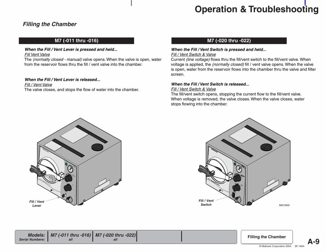
When the Fill / Vent Lever is pressed and held...Fill Vent ValveThe (normally closed - manual) valve opens. When the valve is open, waterfrom the reservoir flows thru the fill / vent valve into the chamber.
When the Fill / Vent Lever is released...Fill / Vent ValveThe valve closes, and stops the flow of water into the chamber.
Filling the Chamber
M7 (-011 thru -016)
When the Fill / Vent Switch is pressed and held...Fill / Vent Switch & ValveCurrent (line voltage) flows thru the fill/vent switch to the fill/vent valve. Whenvoltage is applied, the (normally closed) fill / vent valve opens. When the valveis open, water from the reservoir flows into the chamber thru the valve and filterscreen.
When the Fill / Vent Switch is released...Fill / Vent Switch & ValveThe fill/vent switch opens, stopping the current flow to the fill/vent valve.When voltage is removed, the valve closes. When the valve closes, waterstops flowing into the chamber.
M7 (-020 thru -022)
MA512903i
R R
Fill / VentLever
Fill / VentSwitch
M7 (-020 thru -022)all
M7 (-011 thru -016)all
A-10
Operation & Troubleshooting
Models:Serial Numbers:
© Midmark Corporation 2004 SF-1854
MA672400i
R
Refer To: PageOperation & Troubleshooting ................ A-1
Component Testing / Repair ................. B-1
Access Procedures .............................. C-1
Wiring Diagrams ................................... D-1
Exploded Views / Part Numbers ........... E-1
M7 (-011 thru -016)all
Filling the Chamber
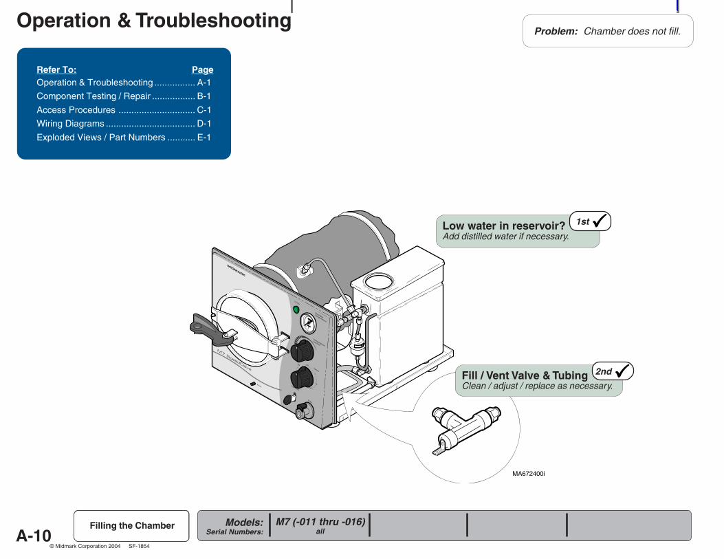
Problem: Chamber does not fill.
1stLow water in reservoir?Add distilled water if necessary.
2ndFill / Vent Valve & TubingClean / adjust / replace as necessary.
A-11
Operation & Troubleshooting
Models:Serial Numbers:
© Midmark Corporation 2004 SF-1854
MA672500i
R
Refer To: PageOperation & Troubleshooting ................ A-1
Component Testing / Repair ................. B-1
Access Procedures .............................. C-1
Wiring Diagrams ................................... D-1
Exploded Views / Part Numbers ........... E-1
M7 (-020 thru -022)all
Filling the Chamber
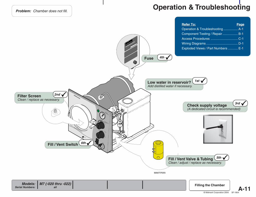
Check supply voltage(A dedicated circuit is recommended)
3rd
4thFuse
Fill / Vent Switch 6th
5thFill / Vent Valve & TubingClean / adjust / replace as necessary.
Problem: Chamber does not fill.
1stLow water in reservoir?Add distilled water if necessary.
2ndFilter ScreenClean / replace as necessary.
A-12
Operation & Troubleshooting
Models:Serial Numbers:
© Midmark Corporation 2004 SF-1854
MA672400i
R
Refer To: PageOperation & Troubleshooting ................ A-1
Component Testing / Repair ................. B-1
Access Procedures .............................. C-1
Wiring Diagrams ................................... D-1
Exploded Views / Part Numbers ........... E-1
M7 (-011 thru -016)all
Filling the Chamber
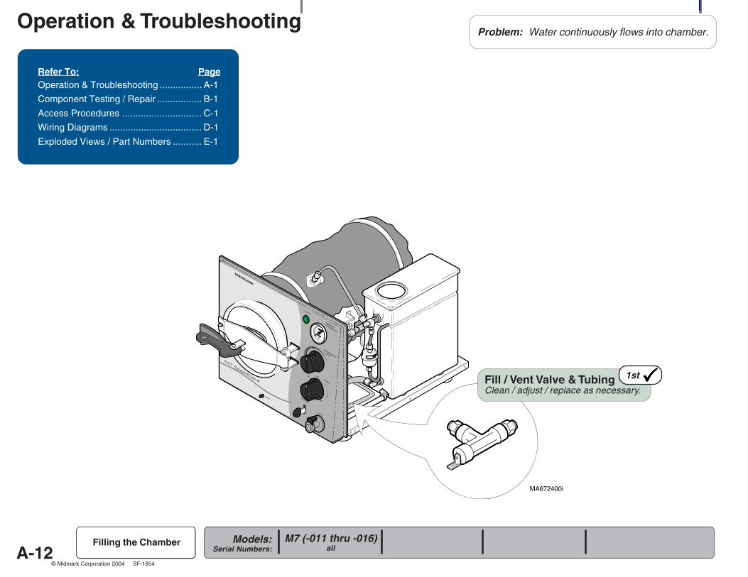
Problem: Water continuously flows into chamber.
1stFill / Vent Valve & TubingClean / adjust / replace as necessary.
A-13
Operation & Troubleshooting
Models:Serial Numbers:
© Midmark Corporation 2004 SF-1854
R
MA672600i
Refer To: PageOperation & Troubleshooting ................ A-1
Component Testing / Repair ................. B-1
Access Procedures .............................. C-1
Wiring Diagrams ................................... D-1
Exploded Views / Part Numbers ........... E-1
M7 (-020 thru -022)all
Filling the Chamber
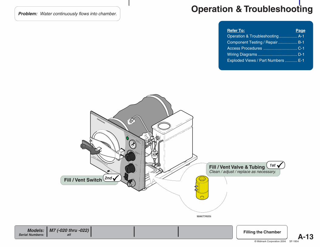
Fill / Vent Switch 2nd
1stFill / Vent Valve & TubingClean / adjust / replace as necessary.
Problem: Water continuously flows into chamber.
A-14
Operation & Troubleshooting
Models:Serial Numbers:
© Midmark Corporation 2004 SF-1854
MA672000i
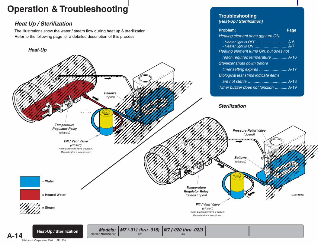
Heat Up / SterilizationThe illustrations show the water / steam flow during heat up & sterilization.Refer to the following page for a detailed description of this process.
Troubleshooting[Heat-Up / Sterilization]
Problem: PageHeating element does not turn ON:
- Heater light is OFF ............................... A-6- Heater light is ON ............................. A-7
Heating element turns ON, but does not
reach required temperature .............. A-16
Sterilizer shuts down before
timer setting expires ......................... A-17
Biological test strips indicate items
are not sterile ................................... A-18
Timer buzzer does not function ........... A-19
Heat-Up / Sterilization
TemperatureRegulator Relay
(closed)
Sterilization
Heat-Up
Bellows(open)
Pressure Relief Valve(closed)
= Water
= Heated Water
= Steam
Bellows(closed)
TemperatureRegulator Relay(closed / open)
Fill / Vent Valve(closed)
Note: Electronic valve is shown.Manual valve is also closed.
Fill / Vent Valve(closed)
Note: Electronic valve is shown.Manual valve is also closed.
M7 (-020 thru -022)all
M7 (-011 thru -016)all
A-15
Operation & Troubleshooting
Models:Serial Numbers:
© Midmark Corporation 2004 SF-1854
MA672100i
R
Heat-Up / Sterilization
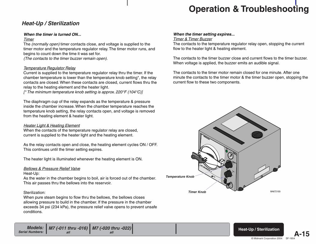
Heat-Up / Sterilization
When the timer is turned ON...TimerThe (normally open) timer contacts close, and voltage is supplied to thetimer motor and the temperature regulator relay. The timer motor runs, andbegins to count down the time it was set for.(The contacts to the timer buzzer remain open).
Temperature Regulator RelayCurrent is supplied to the temperature regulator relay thru the timer. If thechamber temperature is lower than the temperature knob setting*, the relaycontacts are closed. When these contacts are closed, current flows thru therelay to the heating element and the heater light.[* The minimum temperature knob setting is approx. 220°F (104°C)]
The diaphragm cup of the relay expands as the temperature & pressureinside the chamber increase. When the chamber temperature reaches thetemperature knob setting, the relay contacts open, and voltage is removedfrom the heating element & heater light.
Heater Light & Heating ElementWhen the contacts of the temperature regulator relay are closed,current is supplied to the heater light and the heating element.
As the relay contacts open and close, the heating element cycles ON / OFF.This continues until the timer setting expires.
The heater light is illuminated whenever the heating element is ON.
Bellows & Pressure Relief ValveHeat-Up:As the water in the chamber begins to boil, air is forced out of the chamber.This air passes thru the bellows into the reservoir.
Sterilization:When pure steam begins to flow thru the bellows, the bellows closesallowing pressure to build in the chamber. If the pressure in the chamberexceeds 34 psi (234 kPa), the pressure relief valve opens to prevent unsafeconditions.
When the timer setting expires...Timer & Timer BuzzerThe contacts to the temperature regulator relay open, stopping the currentflow to the heater light & heating element.
The contacts to the timer buzzer close and current flows to the timer buzzer.When voltage is applied, the buzzer emits an audible signal.
The contacts to the timer motor remain closed for one minute. After oneminute the contacts to the timer motor & the timer buzzer open, stopping thecurrent flow to these two components.
Temperature Knob
Timer Knob
M7 (-020 thru -022)all
M7 (-011 thru -016)all
A-16
Operation & Troubleshooting
Models:Serial Numbers:
© Midmark Corporation 2004 SF-1854
MA672700i
R
Refer To: PageOperation & Troubleshooting ................ A-1
Component Testing / Repair ................. B-1
Access Procedures .............................. C-1
Wiring Diagrams ................................... D-1
Exploded Views / Part Numbers ........... E-1
M7 (-020 thru -022)all
M7 (-011 thru -016)all
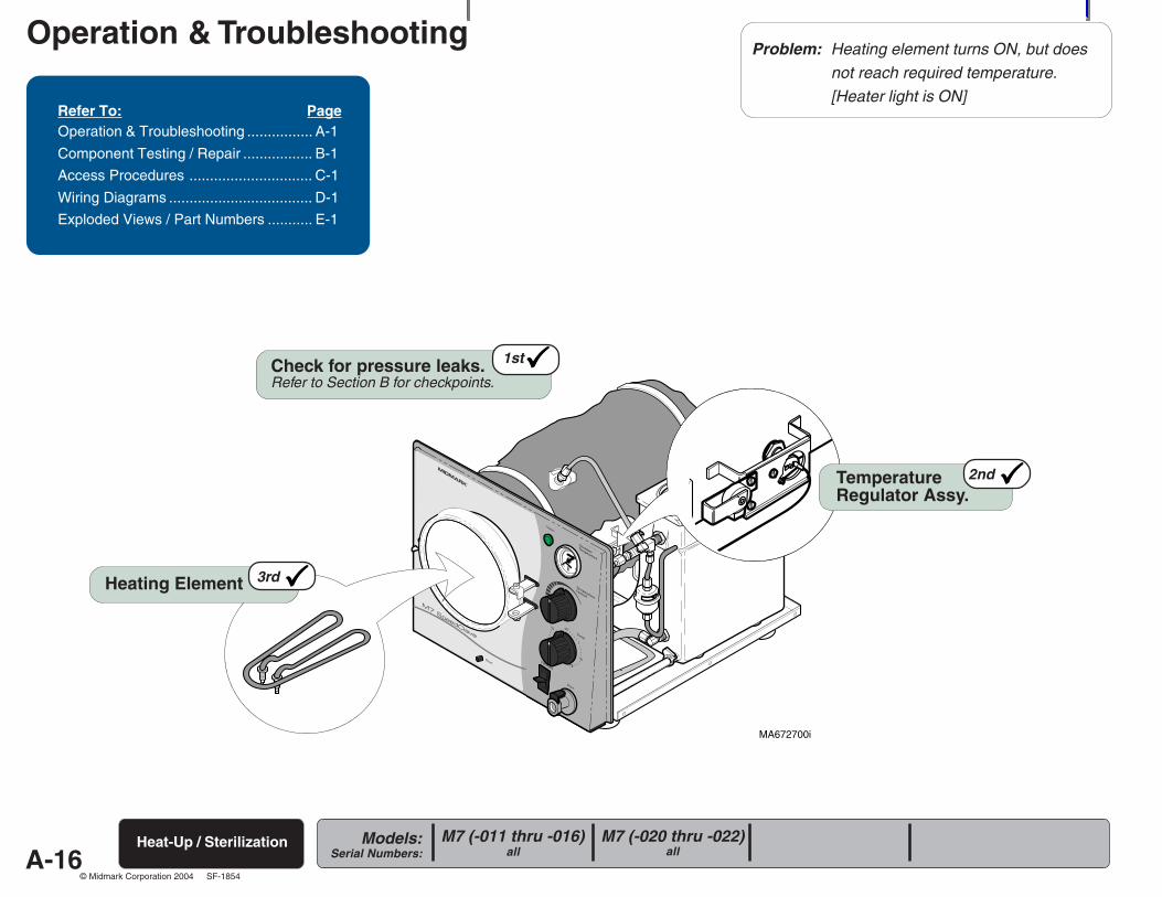
Heat-Up / Sterilization
Problem: Heating element turns ON, but doesnot reach required temperature.[Heater light is ON]
2ndTemperatureRegulator Assy.
3rdHeating Element
1stCheck for pressure leaks.Refer to Section B for checkpoints.
A-17
Operation & Troubleshooting
Models:Serial Numbers:
© Midmark Corporation 2004 SF-1854
R
MA672800i
Refer To: PageOperation & Troubleshooting ................ A-1
Component Testing / Repair ................. B-1
Access Procedures .............................. C-1
Wiring Diagrams ................................... D-1
Exploded Views / Part Numbers ........... E-1
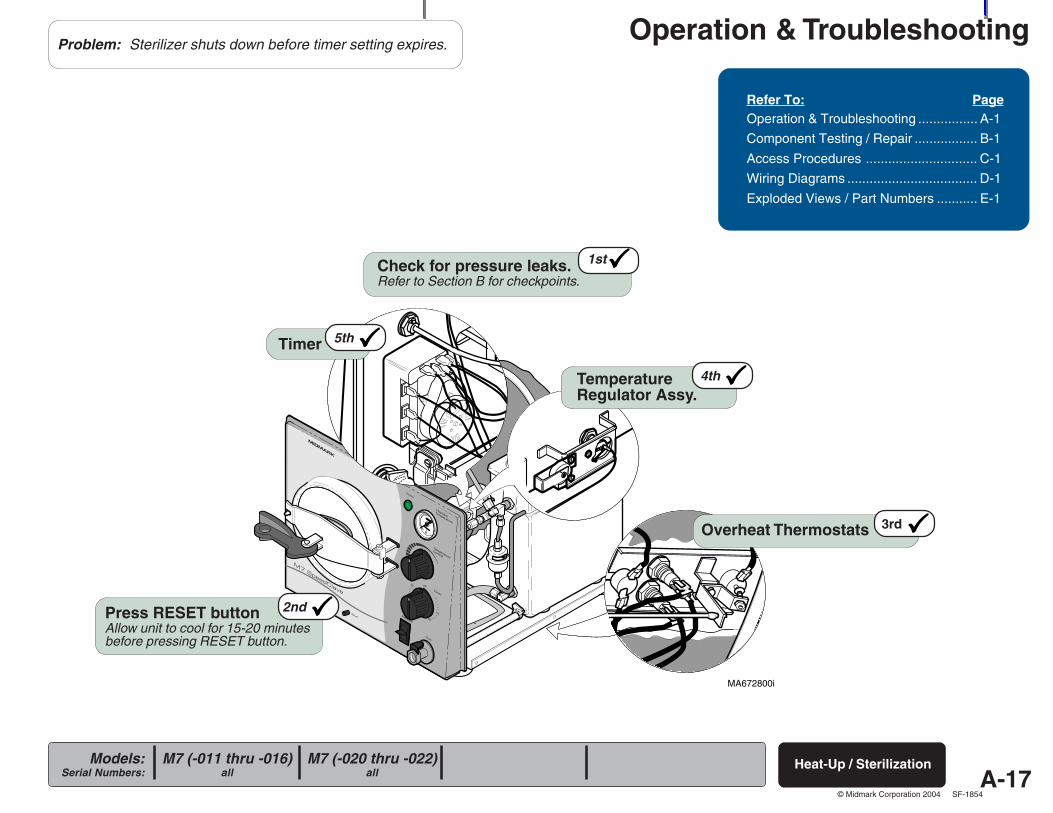
Heat-Up / Sterilization
Problem: Sterilizer shuts down before timer setting expires.
3rdOverheat Thermostats
2ndPress RESET buttonAllow unit to cool for 15-20 minutesbefore pressing RESET button.
4thTemperatureRegulator Assy.
5thTimer
1stCheck for pressure leaks.Refer to Section B for checkpoints.
M7 (-020 thru -022)all
M7 (-011 thru -016)all
A-18
Operation & Troubleshooting
Models:Serial Numbers:
© Midmark Corporation 2004 SF-1854
R
MA672900i
Refer To: PageOperation & Troubleshooting ................ A-1
Component Testing / Repair ................. B-1
Access Procedures .............................. C-1
Wiring Diagrams ................................... D-1
Exploded Views / Part Numbers ........... E-1
M7 (-020 thru -022)all
M7 (-011 thru -016)all
Heat-Up / Sterilization
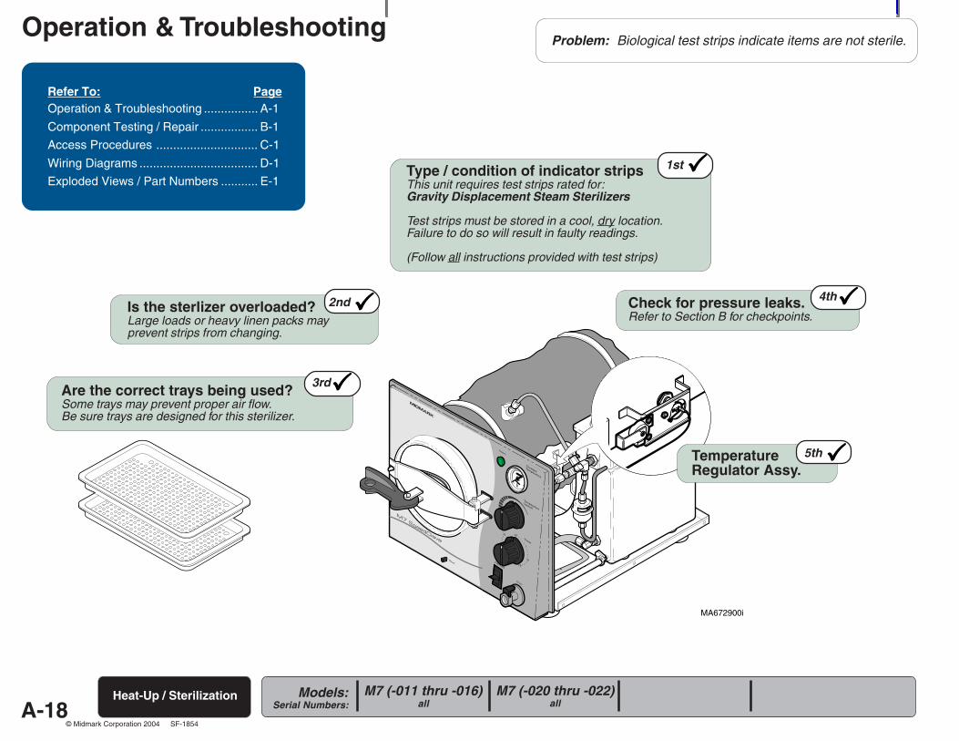
5thTemperatureRegulator Assy.
4thCheck for pressure leaks.Refer to Section B for checkpoints.
Problem: Biological test strips indicate items are not sterile.
Is the sterlizer overloaded?Large loads or heavy linen packs mayprevent strips from changing.
2nd
Type / condition of indicator stripsThis unit requires test strips rated for:Gravity Displacement Steam Sterilizers
Test strips must be stored in a cool, dry location.Failure to do so will result in faulty readings.
(Follow all instructions provided with test strips)
1st
3rdAre the correct trays being used?Some trays may prevent proper air flow.Be sure trays are designed for this sterilizer.
A-19
Operation & Troubleshooting
Models:Serial Numbers:
© Midmark Corporation 2004 SF-1854
R
MA672900i
Refer To: PageOperation & Troubleshooting ................ A-1
Component Testing / Repair ................. B-1
Access Procedures .............................. C-1
Wiring Diagrams ................................... D-1
Exploded Views / Part Numbers ........... E-1
Heat-Up / Sterilization
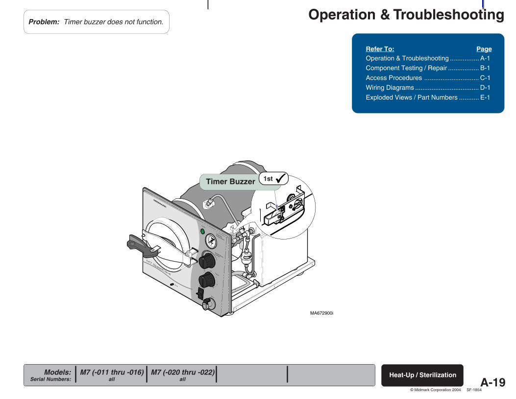
Problem: Timer buzzer does not function.
1stTimer Buzzer
M7 (-020 thru -022)all
M7 (-011 thru -016)all
A-20
Operation & Troubleshooting
Models:Serial Numbers:
© Midmark Corporation 2004 SF-1854
MA672200i
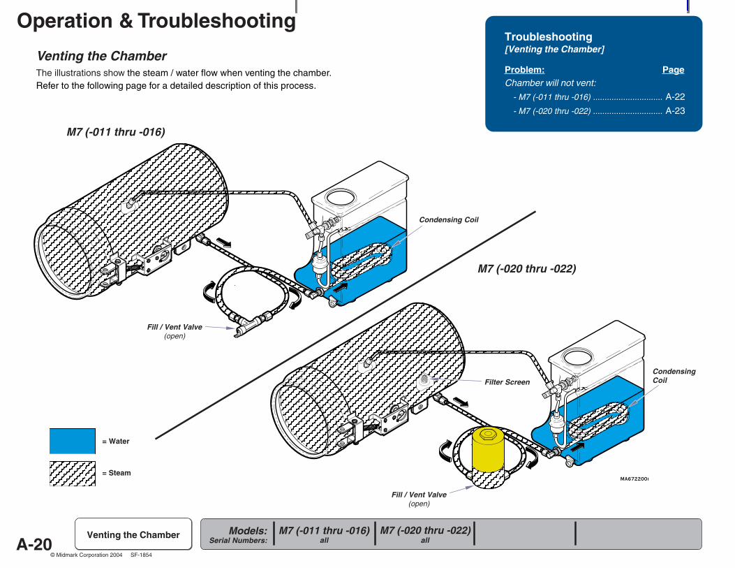
Venting the ChamberThe illustrations show the steam / water flow when venting the chamber.Refer to the following page for a detailed description of this process.
Troubleshooting[Venting the Chamber]
Problem: PageChamber will not vent:
- M7 (-011 thru -016) .............................. A-22
- M7 (-020 thru -022) .............................. A-23
Venting the Chamber
Fill / Vent Valve(open)
M7 (-011 thru -016)
M7 (-020 thru -022)
= Water
Fill / Vent Valve(open)
Condensing Coil
= Steam
CondensingCoilFilter Screen
M7 (-020 thru -022)all
M7 (-011 thru -016)all
A-21
Operation & Troubleshooting
Models:Serial Numbers:
© Midmark Corporation 2004 SF-1854
MA512903i
R R
Venting the Chamber
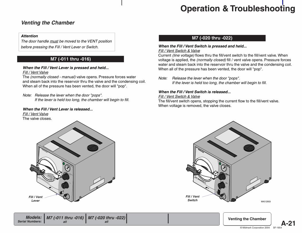
AttentionThe door handle must be moved to the VENT position
before pressing the Fill / Vent Lever or Switch.
When the Fill / Vent Lever is pressed and held...Fill / Vent ValveThe (normally closed - manual) valve opens. Pressure forces waterand steam back into the reservoir thru the valve and the condensing coil.When all of the pressure has been vented, the door will "pop".
Note: Release the lever when the door "pops".If the lever is held too long, the chamber will begin to fill.
When the Fill / Vent Lever is released...Fill / Vent ValveThe valve closes.
Venting the Chamber
M7 (-011 thru -016)
When the Fill / Vent Switch is pressed and held...Fill / Vent Switch & ValveCurrent (line voltage) flows thru the fill/vent switch to the fill/vent valve. Whenvoltage is applied, the (normally closed) fill / vent valve opens. Pressure forceswater and steam back into the reservoir thru the valve and the condensing coil.When all of the pressure has been vented, the door will "pop".
Note: Release the lever when the door "pops".If the lever is held too long, the chamber will begin to fill.
When the Fill / Vent Switch is released...Fill / Vent Switch & ValveThe fill/vent switch opens, stopping the current flow to the fill/vent valve.When voltage is removed, the valve closes.
M7 (-020 thru -022)
Fill / VentLever
Fill / VentSwitch
M7 (-020 thru -022)all
M7 (-011 thru -016)all

A-22
Operation & Troubleshooting
Models:Serial Numbers:
© Midmark Corporation 2004 SF-1854
MA672400i
R
1stFill / Vent Valve & TubingClean / adjust / replace as necessary.
Refer To: PageOperation & Troubleshooting ................ A-1
Component Testing / Repair ................. B-1
Access Procedures .............................. C-1
Wiring Diagrams ................................... D-1
Exploded Views / Part Numbers ........... E-1
M7 (-011 thru -016)all
Problem: Chamber will not vent.
Venting the Chamber
A-23
Operation & Troubleshooting
Models:Serial Numbers:
© Midmark Corporation 2004 SF-1854
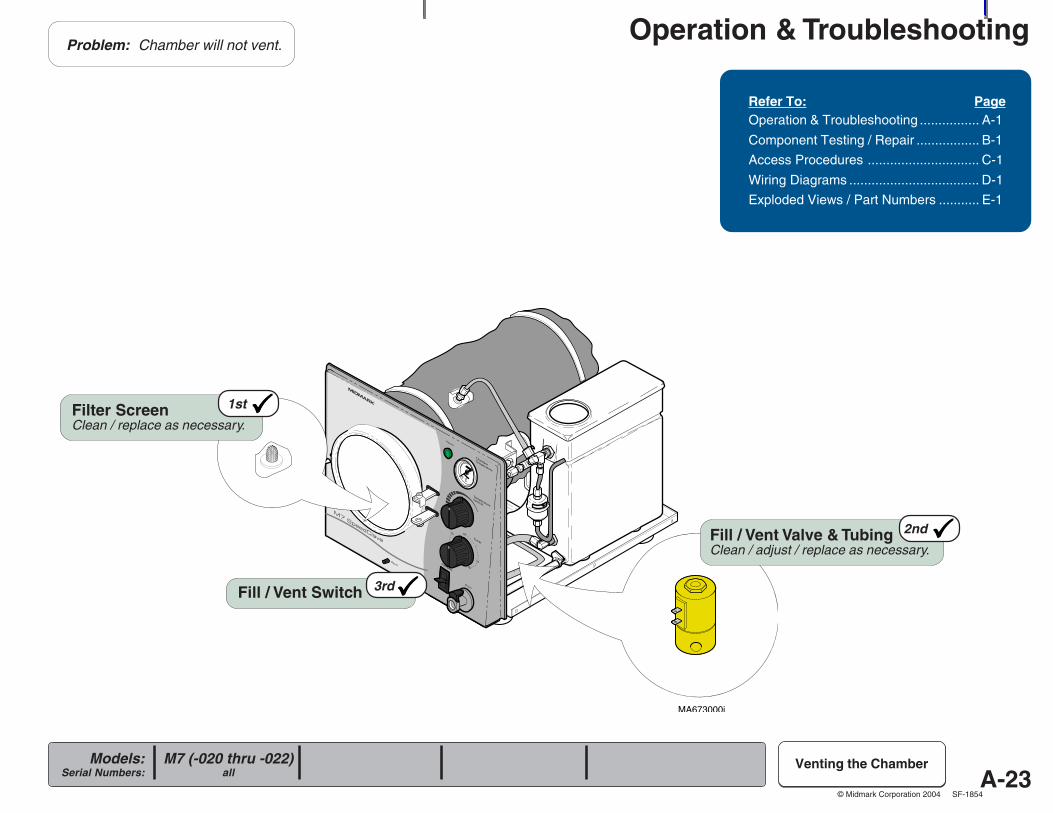
MA673000i
R
Fill / Vent Switch 3rd
2ndFill / Vent Valve & TubingClean / adjust / replace as necessary.
1stFilter ScreenClean / replace as necessary.
Refer To: PageOperation & Troubleshooting ................ A-1
Component Testing / Repair ................. B-1
Access Procedures .............................. C-1
Wiring Diagrams ................................... D-1
Exploded Views / Part Numbers ........... E-1
Problem: Chamber will not vent.
Venting the ChamberM7 (-020 thru -022)all

Component Testing & Repair
B-1Models:
Serial Numbers:
© Midmark Corporation 2004 SF-1854
Sec
tion
BComponent / Procedure PageChecking For Pressure Leaks .............. B-2
Fuse [M7 (-020 thru -022) only] ............ B-3
Bellows ............................................... B-4
Fill / Vent Valve:
Manual .............................................. B-6
Electronic .......................................... B-8
Temperature Regulator Assy. ............... B-12
Heating Element ................................... B-18
Overheat Thermostats .......................... B-22
Pressure Relief Valve ........................... B-25
Timer Assembly.................................... B-26
Timer Buzzer ........................................ B-30
Temperature Gauge ............................. B-31
Door Assembly ..................................... B-32
Reservoir Tank ..................................... B-34
Chamber Assembly .............................. B-36
Testing & Repair
Component Testing & Repair
B-2Models:
Serial Numbers:
© Midmark Corporation 2004 SF-1854
R
MA673100i
Components Page
Bellows ............................................... B-4
Fill / Vent Valve:
Manual .............................................. B-6
Electronic .......................................... B-8
Pressure Relief Valve ........................... B-25
Door Assembly ..................................... B-32
Checking forPressure Leaks
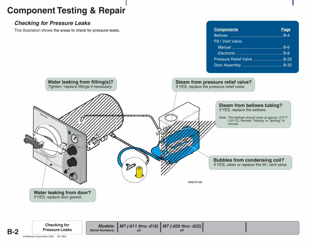
Checking for Pressure LeaksThis illustration shows the areas to check for pressure leaks.
Water leaking from fitting(s)?Tighten / replace fittings if necessary.
Steam from pressure relief valve?If YES, replace the pressure relief valve.
Water leaking from door?If YES, replace door gasket.
M7 (-020 thru -022)all
M7 (-011 thru -016)all
Steam from bellows tubing?If YES, replace the bellows.
Note: The bellows should close at approx. 215°F(101°C). Periodic "hissing' or "spitting" isnormal.
Bubbles from condensing coil?If YES, clean or replace the fill / vent valve.
Component Testing & Repair
B-3Models:
Serial Numbers:
© Midmark Corporation 2004 SF-1854
MA511501i
R
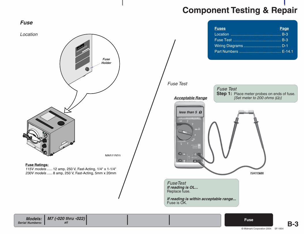
Fuse
Fuse Ratings:115V models ...... 12 amp, 250 V, Fast-Acting, 1/4" x 1-1/4"230V models ...... 8 amp, 250 V, Fast-Acting, 5mm x 20mm
Fuse
LocationFuses Page
Location ............................................... B-2
Fuse Test ............................................. B-2
Wiring Diagrams ................................... D-1
Fuse Rating ...............................6.3A, 250V
Type T, 5 x 20mm
Part Number ............................ 015-0346-20
Fuses Page
Location ............................................... B-3
Fuse Test ............................................. B-3
Wiring Diagrams ................................... D-1
Part Numbers ....................................... E-14.1
Fuse Test
FuseHolder
M7 (-020 thru -022)all
FuseTestIf reading is OL...Replace fuse.
If reading is within acceptable range...Fuse is OK.
less than 5 ΩΩΩΩΩ
Fuse TestStep 1: Place meter probes on ends of fuse.
[Set meter to 200 ohms (Ω)]Acceptable Range
Component Testing & Repair
B-4Models:
Serial Numbers:
© Midmark Corporation 2004 SF-1854
R
MA673301i
Bellows M7 (-020 thru -022)all
M7 (-011 thru -016)all
Bellows
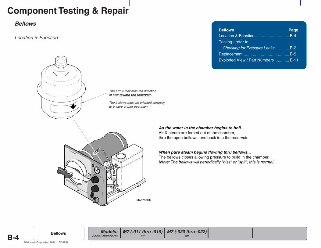
Location & Function
As the water in the chamber begins to boil...Air & steam are forced out of the chamber,thru the open bellows, and back into the reservoir.
When pure steam begins flowing thru bellows...The bellows closes allowing pressure to build in the chamber.[Note: The bellows will periodically "hiss" or "spit", this is normal.
Bellows PageLocation & Function .............................. B-4
Testing - refer to:
Checking for Pressure Leaks ............ B-2
Replacement ........................................ B-5
Exploded View / Part Numbers ............. E-11
The arrow indicates the directionof flow toward the reservoir.
The bellows must be oriented correctlyto ensure proper operation.
Component Testing & Repair
B-5Models:
Serial Numbers:
© Midmark Corporation 2004 SF-1854
MA673401i
Bellows - continued
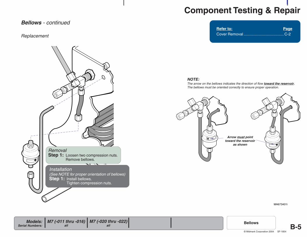
Replacement
Refer to: PageCover Removal ..................................... C-2
RemovalStep 1: Loosen two compression nuts.
Remove bellows.
NOTE:The arrow on the bellows indicates the direction of flow toward the reservoir.The bellows must be oriented correctly to ensure proper operation.
Arrow must pointtoward the reservoir
as shown
M7 (-020 thru -022)all
M7 (-011 thru -016)all
Bellows
Installation(See NOTE for proper orientation of bellows)Step 1: Install bellows.
Tighten compression nuts.
Component Testing & Repair
B-6Models:
Serial Numbers:
© Midmark Corporation 2004 SF-1854
MA673500i
R
Fill / Vent Valve (manual)
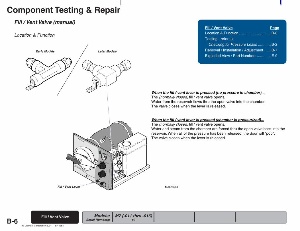
Location & Function
When the fill / vent lever is pressed (no pressure in chamber)...The (normally closed) fill / vent valve opens.Water from the reservoir flows thru the open valve into the chamber.The valve closes when the lever is released.
When the fill / vent lever is pressed (chamber is pressurized)...The (normally closed) fill / vent valve opens.Water and steam from the chamber are forced thru the open valve back into thereservoir. When all of the pressure has been released, the door will "pop".The valve closes when the lever is released.
Fill / Vent Valve PageLocation & Function .............................. B-6
Testing - refer to:
Checking for Pressure Leaks ............ B-2
Removal / Installation / Adjustment ...... B-7
Exploded View / Part Numbers ............. E-9
Fill / Vent Valve M7 (-011 thru -016)all
Fill / Vent Lever
Early Models Later Models
Component Testing & Repair
B-7Models:
Serial Numbers:
© Midmark Corporation 2004 SF-1854
MA673600i
DISTANCE "A"
Fill / Vent Valve (manual) - continued
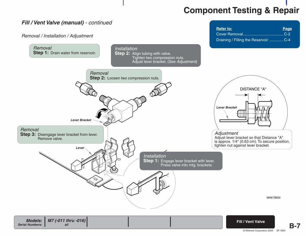
Removal / Installation / Adjustment
Refer to: PageCover Removal ..................................... C-2
Draining / Filling the Reservoir ............. C-4
Fill / Vent ValveM7 (-011 thru -016)all
RemovalStep 1: Drain water from reservoir.
RemovalStep 2: Loosen two compression nuts.
Lever Bracket
RemovalStep 3: Disengage lever bracket from lever.
Remove valve.
Lever
InstallationStep 1: Engage lever bracket with lever.
Press valve into mtg. brackets.
Lever Bracket
InstallationStep 2: Align tubing with valve.
Tighten two compression nuts.Adjust lever bracket. (See Adjustment)
AdjustmentAdjust lever bracket so that Distance "A"is approx. 1/4" (0.63 cm). To secure position,tighten nut against lever bracket.
Component Testing & Repair
B-8Models:
Serial Numbers:
© Midmark Corporation 2004 SF-1854
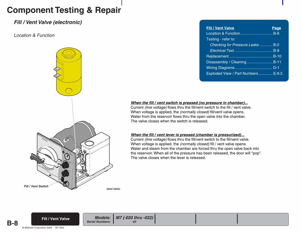
Fill / Vent Valve (electronic)
Location & Function
When the fill / vent switch is pressed (no pressure in chamber)...Current (line voltage) flows thru the fill/vent switch to the fill / vent valve.When voltage is applied, the (normally closed) fill/vent valve opens.Water from the reservoir flows thru the open valve into the chamber.The valve closes when the switch is released.
When the fill / vent lever is pressed (chamber is pressurized)...Current (line voltage) flows thru the fill/vent switch to the fill/vent valve.When voltage is applied, the (normally closed) fill / vent valve opens.Water and steam from the chamber are forced thru the open valve back intothe reservoir. When all of the pressure has been released, the door will "pop".The valve closes when the lever is released.
Fill / Vent Valve PageLocation & Function .............................. B-8
Testing - refer to:
Checking for Pressure Leaks ............ B-2
Electrical Test .................................... B-9
Replacement ........................................ B-10
Disassembly / Cleaning ........................ B-11
Wiring Diagrams ................................... D-1
Exploded View / Part Numbers ............. E-9.3
Fill / Vent Valve M7 (-020 thru -022)all
R
MA673800iFill / Vent Switch
Component Testing & Repair
B-9Models:
Serial Numbers:
© Midmark Corporation 2004 SF-1854
MA674000i
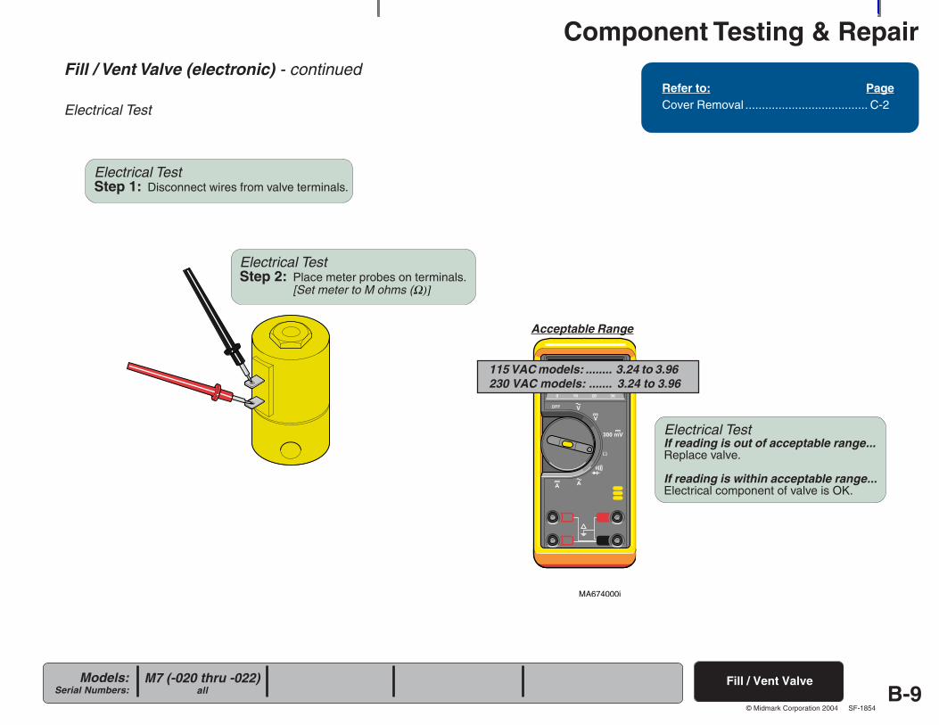
Fill / Vent Valve (electronic) - continued
Electrical Test
Refer to: PageCover Removal ..................................... C-2
Fill / Vent ValveM7 (-020 thru -022)all
Electrical TestIf reading is out of acceptable range...Replace valve.
If reading is within acceptable range...Electrical component of valve is OK.
Electrical TestStep 1: Disconnect wires from valve terminals.
Electrical TestStep 2: Place meter probes on terminals.
[Set meter to M ohms (Ω)]
Acceptable Range
115 VAC models: ........ 3.24 to 3.96230 VAC models: ....... 3.24 to 3.96
Component Testing & Repair
B-10Models:
Serial Numbers:
© Midmark Corporation 2004 SF-1854
MA677901i
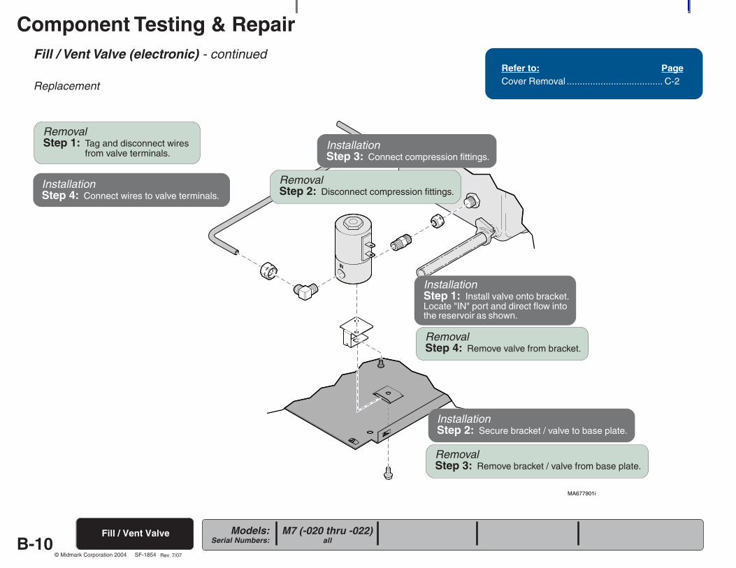
Fill / Vent Valve (electronic) - continued
Replacement
Fill / Vent Valve
Refer to: PageCover Removal ..................................... C-2
RemovalStep 1: Tag and disconnect wires
from valve terminals.
RemovalStep 2: Disconnect compression fittings.
RemovalStep 4: Remove valve from bracket.
RemovalStep 3: Remove bracket / valve from base plate.
InstallationStep 2: Secure bracket / valve to base plate.
InstallationStep 3: Connect compression fittings.
InstallationStep 4: Connect wires to valve terminals.
M7 (-020 thru -022)all
Rev. 7/07
InstallationStep 1: Install valve onto bracket.Locate "IN" port and direct flow intothe reservoir as shown.
Component Testing & Repair
B-11Models:
Serial Numbers:
© Midmark Corporation 2004 SF-1854
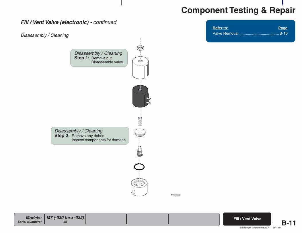
Fill / Vent Valve (electronic) - continued
Disassembly / Cleaning
Refer to: PageValve Removal ..................................... B-10
Fill / Vent Valve
Disassembly / CleaningStep 1: Remove nut.
Disassemble valve.
Disassembly / CleaningStep 2: Remove any debris.
Inspect components for damage.
M7 (-020 thru -022)all
Component Testing & Repair
B-12Models:
Serial Numbers:
© Midmark Corporation 2004 SF-1854
R
MA674200i
Temperature RegulatorAssembly
M7 (-020 thru -022)all
M7 (-011 thru -016)all
Temperature Regulator Assembly
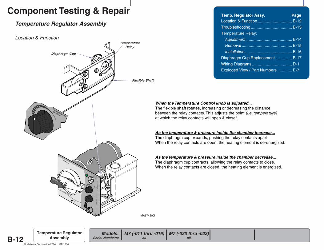
Location & Function
When the Temperature Control knob is adjusted...The flexible shaft rotates, increasing or decreasing the distancebetween the relay contacts. This adjusts the point (i.e. temperature)at which the relay contacts will open & close*.
As the temperature & pressure inside the chamber increase...The diaphragm cup expands, pushing the relay contacts apart.When the relay contacts are open, the heating element is de-energized.
As the temperature & pressure inside the chamber decrease...The diaphragm cup contracts, allowing the relay contacts to close.When the relay contacts are closed, the heating element is energized.
Temp. Regulator Assy. PageLocation & Function .............................. B-12
Troubleshooting .................................... B-13
Temperature Relay:
Adjustment ........................................ B-14
Removal ............................................ B-15
Installation ......................................... B-16
Diaphragm Cup Replacement .............. B-17
Wiring Diagrams ................................... D-1
Exploded View / Part Numbers ............. E-7
Diaphragm Cup
Flexible Shaft
TemperatureRelay
Component Testing & Repair
B-13Models:
Serial Numbers:
© Midmark Corporation 2004 SF-1854
MA674201i
Diaphragm Cup
TemperatureRelay
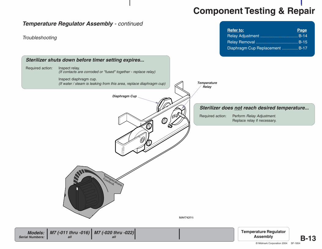
Temperature Regulator Assembly - continued
Troubleshooting
Refer to: PageRelay Adjustment ................................. B-14
Relay Removal ..................................... B-15
Diaphragm Cup Replacement .............. B-17
M7 (-020 thru -022)all
M7 (-011 thru -016)all
Temperature RegulatorAssembly
Sterilizer does not reach desired temperature...
Required action: Perform Relay Adjustment.Replace relay if necessary.
Sterilizer shuts down before timer setting expires...
Required action: Inspect relay.(If contacts are corroded or "fused" together - replace relay)
Inspect diaphragm cup.(If water / steam is leaking from this area, replace diaphragm cup)
Component Testing & Repair
B-14Models:
Serial Numbers:
© Midmark Corporation 2004 SF-1854
R
MA674400i
Temperature RegulatorAssembly
M7 (-020 thru -022)all
M7 (-011 thru -016)all
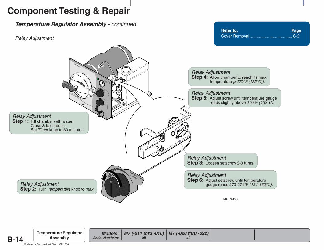
Temperature Regulator Assembly - continued
Relay Adjustment
Refer to: PageCover Removal ..................................... C-2
Relay AdjustmentStep 1: Fill chamber with water.
Close & latch door.Set Timer knob to 30 minutes.
Relay AdjustmentStep 2: Turn Temperature knob to max.
Relay AdjustmentStep 3: Loosen setscrew 2-3 turns.
Relay AdjustmentStep 4: Allow chamber to reach its max.
temperature [>270°F (132°C)].
Relay AdjustmentStep 5: Adjust screw until temperature gauge
reads slightly above 270°F (132°C).
Relay AdjustmentStep 6: Adjust setscrew until temperature
gauge reads 270-271°F (131-132°C).
Component Testing & Repair
B-15Models:
Serial Numbers:
© Midmark Corporation 2004 SF-1854
R
MA674500i
Temperature RegulatorAssembly
M7 (-020 thru -022)all
M7 (-011 thru -016)all
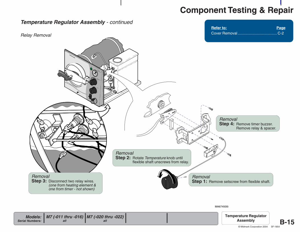
Temperature Regulator Assembly - continued
Relay Removal
Refer to: PageCover Removal ..................................... C-2
RemovalStep 1: Remove setscrew from flexible shaft.
RemovalStep 3: Disconnect two relay wires.
(one from heating element &one from timer - not shown)
RemovalStep 4: Remove timer buzzer.
Remove relay & spacer.
RemovalStep 2: Rotate Temperature knob until
flexible shaft unscrews from relay.
Component Testing & Repair
B-16Models:
Serial Numbers:
© Midmark Corporation 2004 SF-1854
R
MA674501i
Temperature RegulatorAssembly
M7 (-020 thru -022)all
M7 (-011 thru -016)all
Temperature Regulator Assembly - continued
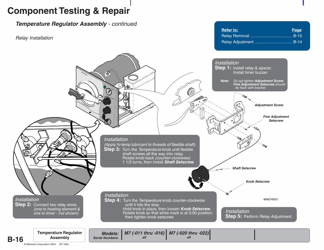
Relay Installation
Refer to: PageRelay Removal ..................................... B-15
Relay Adjustment ................................. B-14
Adjustment Screw
Fine AdjustmentSetscrew
InstallationStep 1: Install relay & spacer.
Install timer buzzer.
Note: Do not tighten Adjustment Screw.Fine Adjustment Setscrew should be flush with bracket.
InstallationStep 2: Connect two relay wires.
(one to heating element &one to timer - not shown)
Installation(Apply hi-temp lubricant to threads of flexible shaft)Step 3: Turn the Temperature knob until flexible
shaft screws all the way into relay.Rotate knob back (counter-clockwise)1 1/2 turns, then install Shaft Setscrew.
InstallationStep 4: Turn the Temperature knob counter-clockwise
until it hits the stop.Hold knob in place, then loosen Knob Setscrew.Rotate knob so that white mark is at 3:00 position, then tighten knob setscrew.
Shaft Setscrew
Knob Setscrew
InstallationStep 5: Perform Relay Adjustment.
Component Testing & Repair
B-17Models:
Serial Numbers:
© Midmark Corporation 2004 SF-1854
MA674700i
Temperature RegulatorAssembly
M7 (-020 thru -022)all
M7 (-011 thru -016)all
Temperature Regulator Assembly - continued
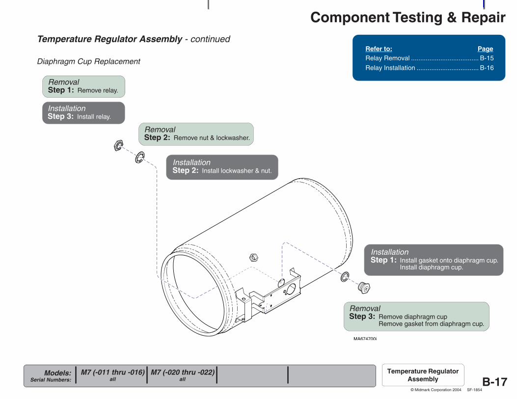
Diaphragm Cup Replacement
Refer to: PageRelay Removal ..................................... B-15
Relay Installation .................................. B-16
RemovalStep 2: Remove nut & lockwasher.
RemovalStep 3: Remove diaphragm cup
Remove gasket from diaphragm cup.
InstallationStep 1: Install gasket onto diaphragm cup.
Install diaphragm cup.
InstallationStep 2: Install lockwasher & nut.
RemovalStep 1: Remove relay.
InstallationStep 3: Install relay.
Component Testing & Repair
B-18Models:
Serial Numbers:
© Midmark Corporation 2004 SF-1854
Heating Element
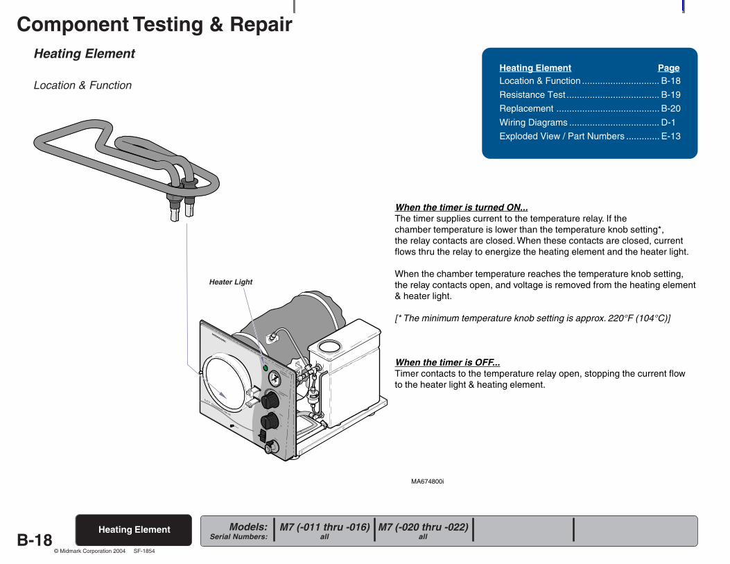
Location & Function
Heating Element PageLocation & Function .............................. B-18
Resistance Test .................................... B-19
Replacement ........................................ B-20
Wiring Diagrams ................................... D-1
Exploded View / Part Numbers ............. E-13
Heating Element
MA674800i
R
Heater Light
When the timer is turned ON...The timer supplies current to the temperature relay. If thechamber temperature is lower than the temperature knob setting*,the relay contacts are closed. When these contacts are closed, currentflows thru the relay to energize the heating element and the heater light.
When the chamber temperature reaches the temperature knob setting,the relay contacts open, and voltage is removed from the heating element& heater light.
[* The minimum temperature knob setting is approx. 220°F (104°C)]
When the timer is OFF...Timer contacts to the temperature relay open, stopping the current flowto the heater light & heating element.
M7 (-020 thru -022)all
M7 (-011 thru -016)all
Component Testing & Repair
B-19Models:
Serial Numbers:
© Midmark Corporation 2004 SF-1854
MA674900i
Heating Element - continued
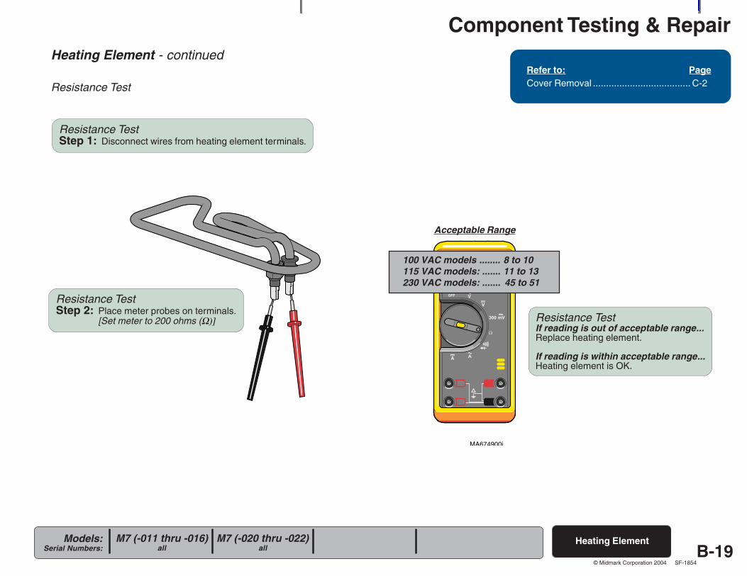
Resistance Test
Refer to: PageCover Removal ..................................... C-2
Heating Element
Resistance TestIf reading is out of acceptable range...Replace heating element.
If reading is within acceptable range...Heating element is OK.
Resistance TestStep 2: Place meter probes on terminals.
[Set meter to 200 ohms (Ω)]
Acceptable Range
M7 (-020 thru -022)all
M7 (-011 thru -016)all
Resistance TestStep 1: Disconnect wires from heating element terminals.
100 VAC models ........ 8 to 10115 VAC models: ....... 11 to 13230 VAC models: ....... 45 to 51
Component Testing & Repair
B-20Models:
Serial Numbers:
© Midmark Corporation 2004 SF-1854
MA675000i
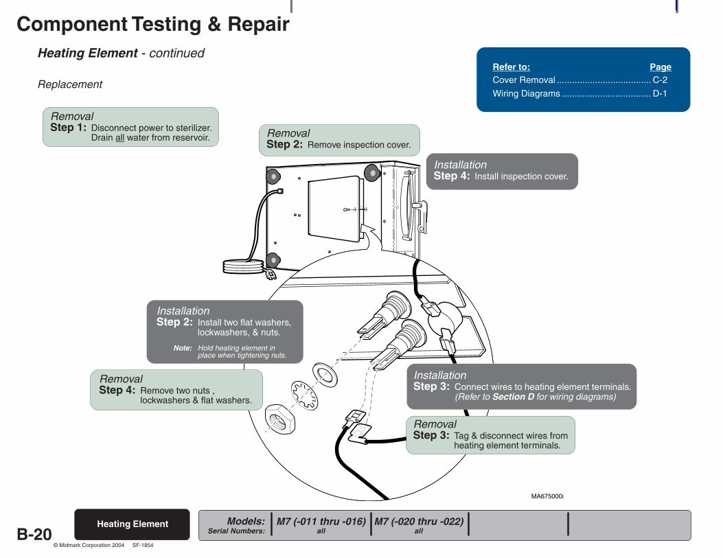
Heating Element - continued
Replacement
Heating Element M7 (-020 thru -022)all
M7 (-011 thru -016)all
Refer to: PageCover Removal ..................................... C-2
Wiring Diagrams ................................... D-1
RemovalStep 1: Disconnect power to sterilizer.
Drain all water from reservoir. RemovalStep 2: Remove inspection cover.
RemovalStep 4: Remove two nuts ,
lockwashers & flat washers.
InstallationStep 2: Install two flat washers,
lockwashers, & nuts.
Note: Hold heating element inplace when tightening nuts.
RemovalStep 3: Tag & disconnect wires from
heating element terminals.
InstallationStep 3: Connect wires to heating element terminals.
(Refer to Section D for wiring diagrams)
InstallationStep 4: Install inspection cover.
Component Testing & Repair
B-21Models:
Serial Numbers:
© Midmark Corporation 2004 SF-1854
MA675200i
(Early Models)Spacer Bracket*
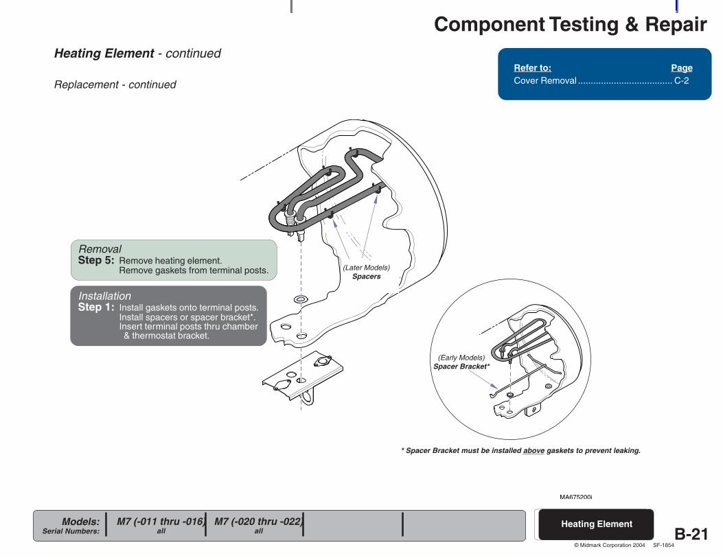
Heating Element - continued
Replacement - continued
Refer to: PageCover Removal ..................................... C-2
Heating ElementM7 (-020 thru -022)all
M7 (-011 thru -016)all
RemovalStep 5: Remove heating element.
Remove gaskets from terminal posts. (Later Models)Spacers
InstallationStep 1: Install gaskets onto terminal posts.
Install spacers or spacer bracket*.Insert terminal posts thru chamber & thermostat bracket.
* Spacer Bracket must be installed above gaskets to prevent leaking.
Component Testing & Repair
B-22Models:
Serial Numbers:
© Midmark Corporation 2004 SF-1854
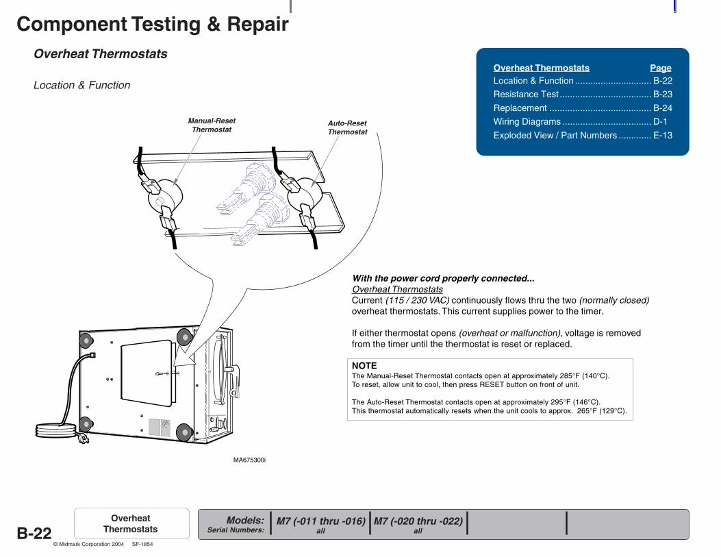
Overheat Thermostats
Location & Function
Overheat Thermostats PageLocation & Function .............................. B-22
Resistance Test .................................... B-23
Replacement ........................................ B-24
Wiring Diagrams ................................... D-1
Exploded View / Part Numbers ............. E-13
M7 (-020 thru -022)all
M7 (-011 thru -016)all
OverheatThermostats
MA675300i
Manual-ResetThermostat
Auto-ResetThermostat
With the power cord properly connected...Overheat ThermostatsCurrent (115 / 230 VAC) continuously flows thru the two (normally closed)overheat thermostats. This current supplies power to the timer.
If either thermostat opens (overheat or malfunction), voltage is removedfrom the timer until the thermostat is reset or replaced.
NOTEThe Manual-Reset Thermostat contacts open at approximately 285°F (140°C).To reset, allow unit to cool, then press RESET button on front of unit.
The Auto-Reset Thermostat contacts open at approximately 295°F (146°C).This thermostat automatically resets when the unit cools to approx. 265°F (129°C).
Component Testing & Repair
B-23Models:
Serial Numbers:
© Midmark Corporation 2004 SF-1854
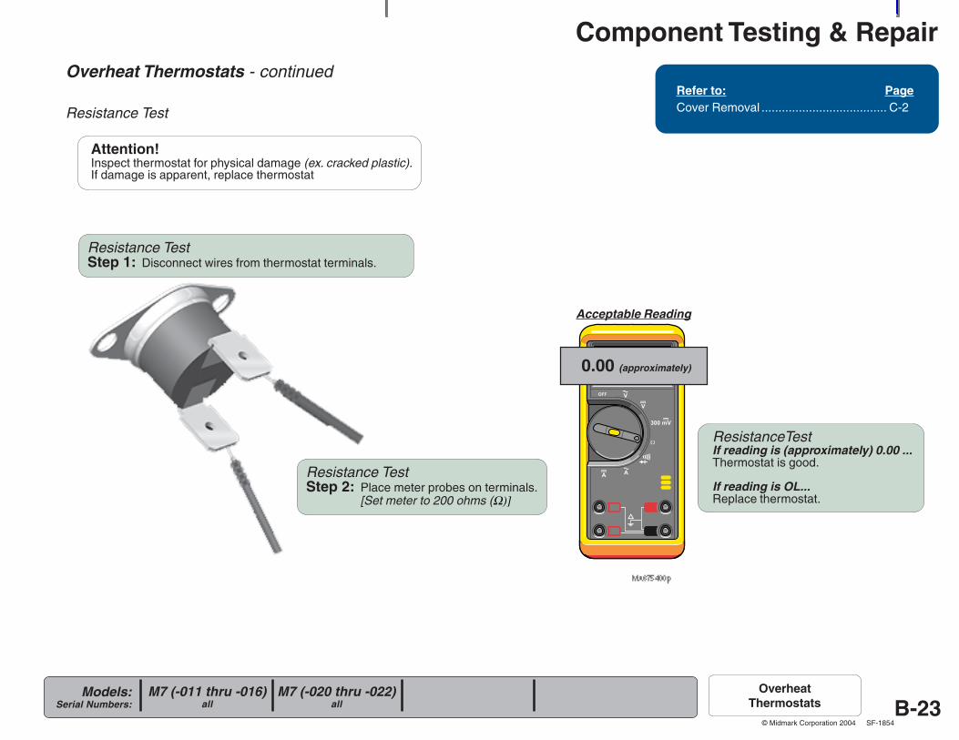
Overheat Thermostats - continued
Resistance Test
Refer to: PageCover Removal ..................................... C-2
M7 (-020 thru -022)all
M7 (-011 thru -016)all
OverheatThermostats
Resistance TestStep 2: Place meter probes on terminals.
[Set meter to 200 ohms (Ω)]
Resistance TestStep 1: Disconnect wires from thermostat terminals.
ResistanceTestIf reading is (approximately) 0.00 ...Thermostat is good.
If reading is OL...Replace thermostat.
0.00 (approximately)
Acceptable Reading
Attention!Inspect thermostat for physical damage (ex. cracked plastic).If damage is apparent, replace thermostat
Component Testing & Repair
B-24Models:
Serial Numbers:
© Midmark Corporation 2004 SF-1854
MA675500i
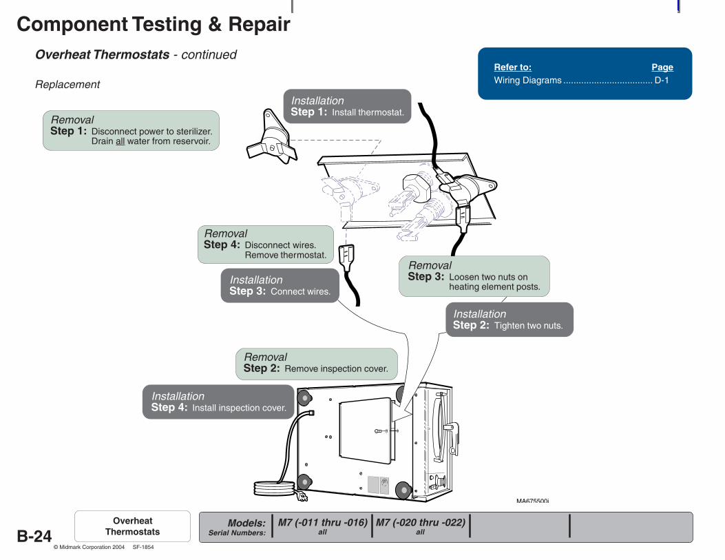
Overheat Thermostats - continued
Replacement
M7 (-020 thru -022)all
M7 (-011 thru -016)all
OverheatThermostats
RemovalStep 1: Disconnect power to sterilizer.
Drain all water from reservoir.
RemovalStep 2: Remove inspection cover.
RemovalStep 3: Loosen two nuts on
heating element posts.
InstallationStep 1: Install thermostat.
RemovalStep 4: Disconnect wires.
Remove thermostat.
InstallationStep 2: Tighten two nuts.
InstallationStep 3: Connect wires.
InstallationStep 4: Install inspection cover.
Refer to: PageWiring Diagrams ................................... D-1
Component Testing & Repair
B-25Models:
Serial Numbers:
© Midmark Corporation 2004 SF-1854
MA675700i
R
Pressure Relief Valve
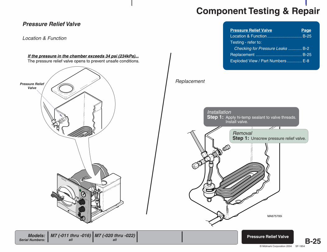
Location & Function
Pressure Relief Valve
Pressure ReliefValve
If the pressure in the chamber exceeds 34 psi (234kPa)...The pressure relief valve opens to prevent unsafe conditions.
M7 (-020 thru -022)all
M7 (-011 thru -016)all
Pressure Relief Valve PageLocation & Function .............................. B-25
Testing - refer to:
Checking for Pressure Leaks ............ B-2
Replacement ........................................ B-25
Exploded View / Part Numbers ............. E-8
Replacement
RemovalStep 1: Unscrew pressure relief valve.
InstallationStep 1: Apply hi-temp sealant to valve threads.
Install valve.
Component Testing & Repair
B-26Models:
Serial Numbers:
© Midmark Corporation 2004 SF-1854
R
MA675800i
Timer
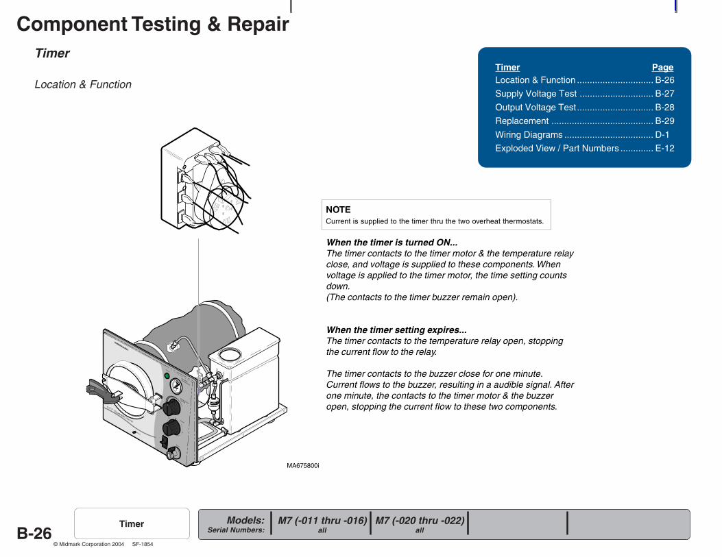
Location & Function
Timer PageLocation & Function .............................. B-26
Supply Voltage Test ............................. B-27
Output Voltage Test.............................. B-28
Replacement ........................................ B-29
Wiring Diagrams ................................... D-1
Exploded View / Part Numbers ............. E-12
M7 (-020 thru -022)all
M7 (-011 thru -016)all
Timer
NOTECurrent is supplied to the timer thru the two overheat thermostats.
When the timer is turned ON...The timer contacts to the timer motor & the temperature relayclose, and voltage is supplied to these components. Whenvoltage is applied to the timer motor, the time setting countsdown.(The contacts to the timer buzzer remain open).
When the timer setting expires...The timer contacts to the temperature relay open, stoppingthe current flow to the relay.
The timer contacts to the buzzer close for one minute.Current flows to the buzzer, resulting in a audible signal. Afterone minute, the contacts to the timer motor & the buzzeropen, stopping the current flow to these two components.
Component Testing & Repair
B-27Models:
Serial Numbers:
© Midmark Corporation 2004 SF-1854
MA676000i
Timer - continued
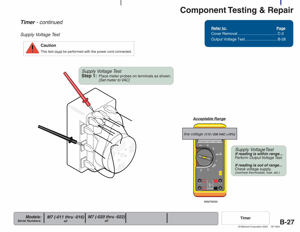
Supply Voltage Test
CautionThis test must be performed with the power cord connected.
Refer to: PageCover Removal ..................................... C-2
Output Voltage Test.............................. B-28
line voltage (115 / 230 VAC +10%)
Supply Voltage TestStep 1: Place meter probes on terminals as shown.
[Set meter to VAC]
Supply VoltageTestIf reading is within range...Perform Output Voltage Test.
If reading is out of range...Check voltage supply.(overheat thermostats, fuse, etc.)
Acceptable Range
M7 (-020 thru -022)all
M7 (-011 thru -016)all
Timer
Component Testing & Repair
B-28Models:
Serial Numbers:
© Midmark Corporation 2004 SF-1854
MA675900i
Timer - continued
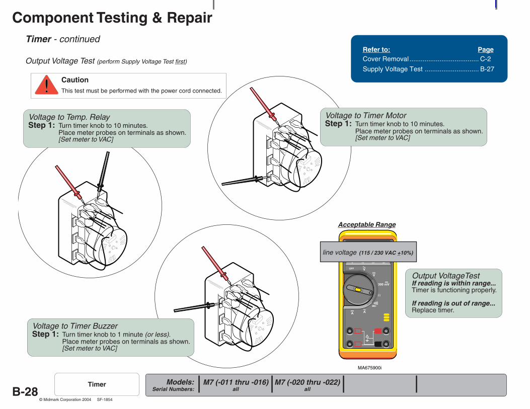
Output Voltage Test (perform Supply Voltage Test first)
CautionThis test must be performed with the power cord connected.
M7 (-020 thru -022)all
M7 (-011 thru -016)all
Timer
Voltage to Temp. RelayStep 1: Turn timer knob to 10 minutes.
Place meter probes on terminals as shown.[Set meter to VAC]
Voltage to Timer MotorStep 1: Turn timer knob to 10 minutes.
Place meter probes on terminals as shown.[Set meter to VAC]
Voltage to Timer BuzzerStep 1: Turn timer knob to 1 minute (or less).
Place meter probes on terminals as shown.[Set meter to VAC]
Acceptable Range
line voltage (115 / 230 VAC +10%)
Output VoltageTestIf reading is within range...Timer is functioning properly.
If reading is out of range...Replace timer.
Refer to: PageCover Removal ..................................... C-2
Supply Voltage Test ............................. B-27
Component Testing & Repair
B-29Models:
Serial Numbers:
© Midmark Corporation 2004 SF-1854
MA521501i
R
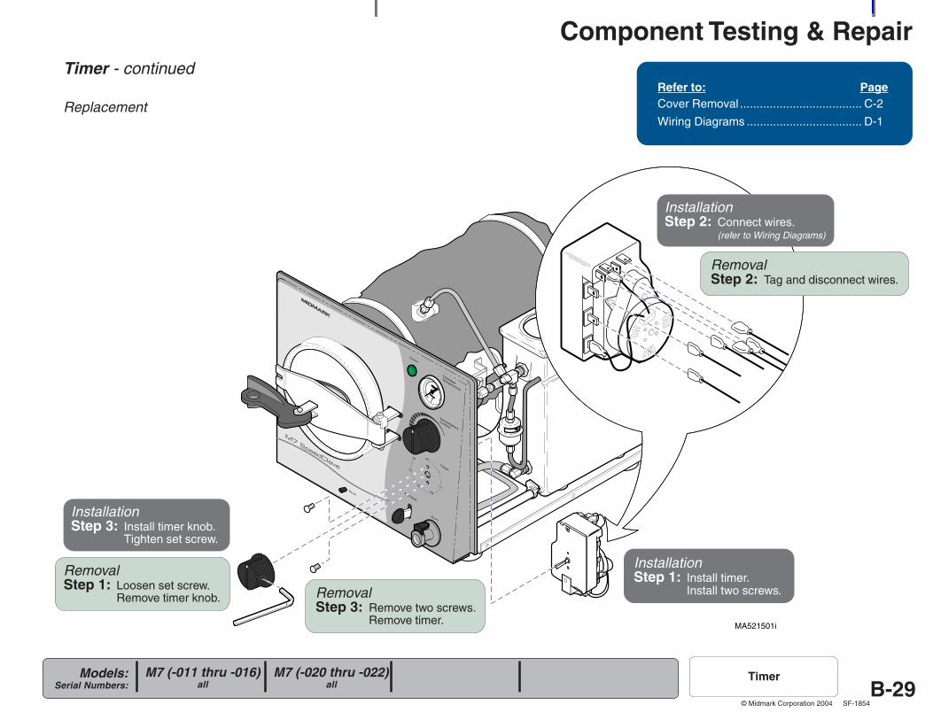
Timer - continued
ReplacementRefer to: PageCover Removal ..................................... C-2
Wiring Diagrams ................................... D-1
M7 (-020 thru -022)all
M7 (-011 thru -016)all
Timer
RemovalStep 1: Loosen set screw.
Remove timer knob.
RemovalStep 2: Tag and disconnect wires.
RemovalStep 3: Remove two screws.
Remove timer.
InstallationStep 1: Install timer.
Install two screws.
InstallationStep 2: Connect wires.
(refer to Wiring Diagrams)
InstallationStep 3: Install timer knob.
Tighten set screw.
Component Testing & Repair
B-30Models:
Serial Numbers:
© Midmark Corporation 2004 SF-1854
R
MA676100i
Timer Buzzer
Location & Function
Timer Buzzer M7 (-020 thru -022)all
M7 (-011 thru -016)all
Timer Buzzer PageLocation & Function .............................. B-30
Testing - refer to:
Timer ............................................... B-28
Replacement & Volume Adjustment ..... B-30
Exploded View / Part Numbers ............. E-12
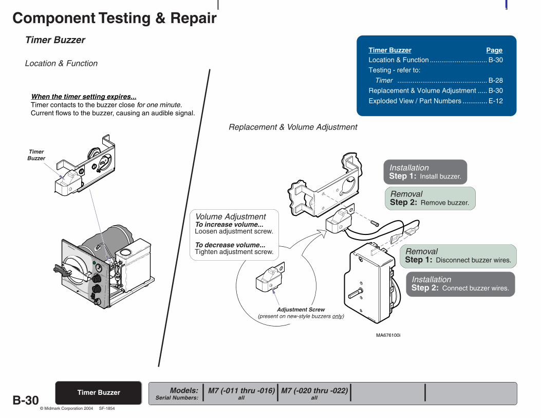
Replacement & Volume Adjustment
When the timer setting expires...Timer contacts to the buzzer close for one minute.Current flows to the buzzer, causing an audible signal.
RemovalStep 1: Disconnect buzzer wires.
RemovalStep 2: Remove buzzer.
InstallationStep 1: Install buzzer.
InstallationStep 2: Connect buzzer wires.
TimerBuzzer
Volume AdjustmentTo increase volume...Loosen adjustment screw.
To decrease volume...Tighten adjustment screw.
Adjustment Screw(present on new-style buzzers only)
Component Testing & Repair
B-31Models:
Serial Numbers:
© Midmark Corporation 2004 SF-1854
MA252301i
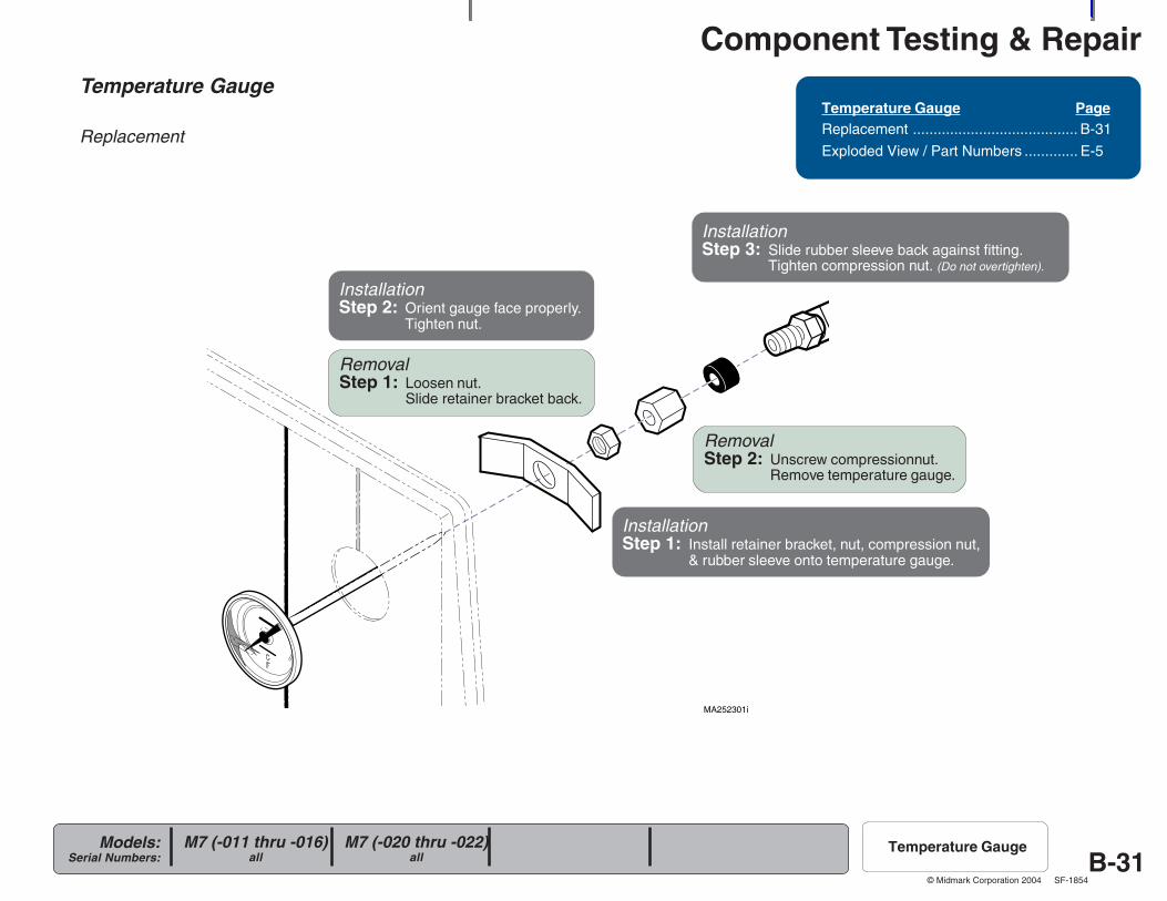
Temperature Gauge
Replacement
Temperature Gauge PageReplacement ........................................ B-31
Exploded View / Part Numbers ............. E-5
M7 (-020 thru -022)all
M7 (-011 thru -016)all
Temperature Gauge
RemovalStep 1: Loosen nut.
Slide retainer bracket back.
RemovalStep 2: Unscrew compressionnut.
Remove temperature gauge.
InstallationStep 1: Install retainer bracket, nut, compression nut,
& rubber sleeve onto temperature gauge.
InstallationStep 2: Orient gauge face properly.
Tighten nut.
InstallationStep 3: Slide rubber sleeve back against fitting.
Tighten compression nut. (Do not overtighten).
Component Testing & Repair
B-32Models:
Serial Numbers:
© Midmark Corporation 2004 SF-1854
R
MA676200i
R
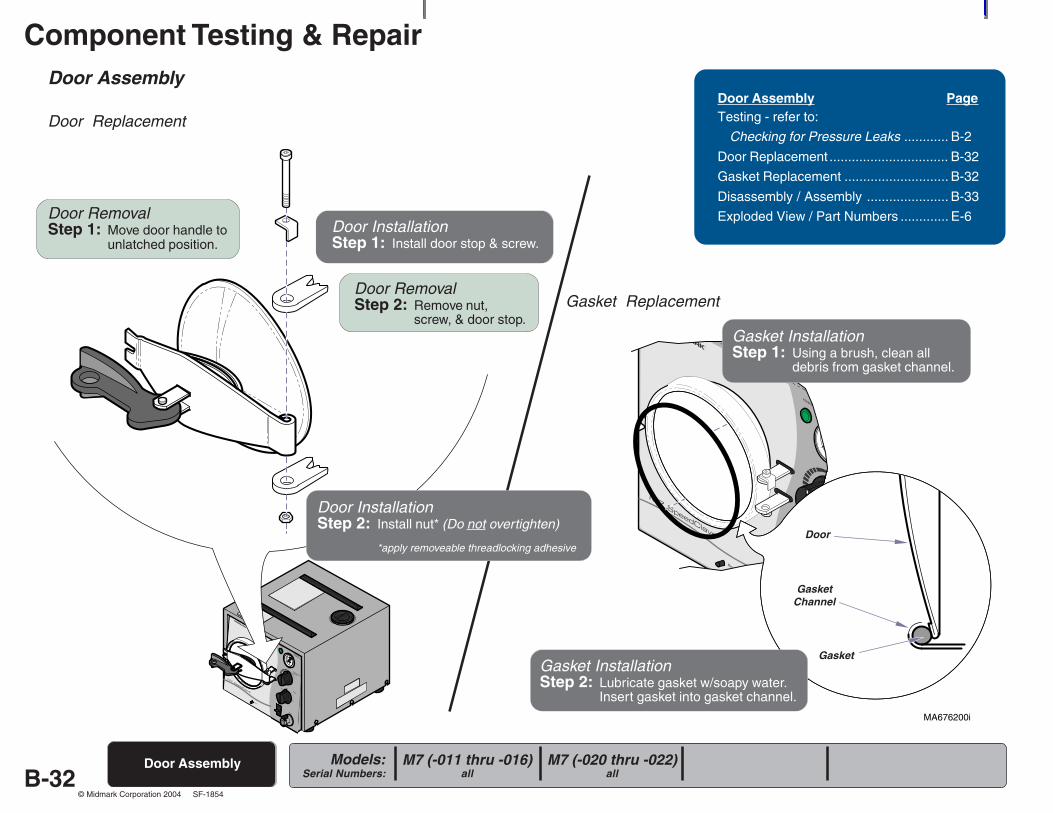
Door Assembly
Door Replacement
Door Assembly
Door Assembly PageTesting - refer to:
Checking for Pressure Leaks ............ B-2
Door Replacement ................................ B-32
Gasket Replacement ............................ B-32
Disassembly / Assembly ...................... B-33
Exploded View / Part Numbers ............. E-6
Gasket Replacement
threadlocking adhesive.
Door RemovalStep 1: Move door handle to
unlatched position.
Door RemovalStep 2: Remove nut,
screw, & door stop.
Door InstallationStep 1: Install door stop & screw.
Gasket InstallationStep 1: Using a brush, clean all
debris from gasket channel.
Gasket InstallationStep 2: Lubricate gasket w/soapy water.
Insert gasket into gasket channel.
Door
GasketChannel
Gasket
M7 (-020 thru -022)all
M7 (-011 thru -016)all
Door InstallationStep 2: Install nut* (Do not overtighten)
*apply removeable threadlocking adhesive
Component Testing & Repair
B-33Models:
Serial Numbers:
© Midmark Corporation 2004 SF-1854
MA522701i
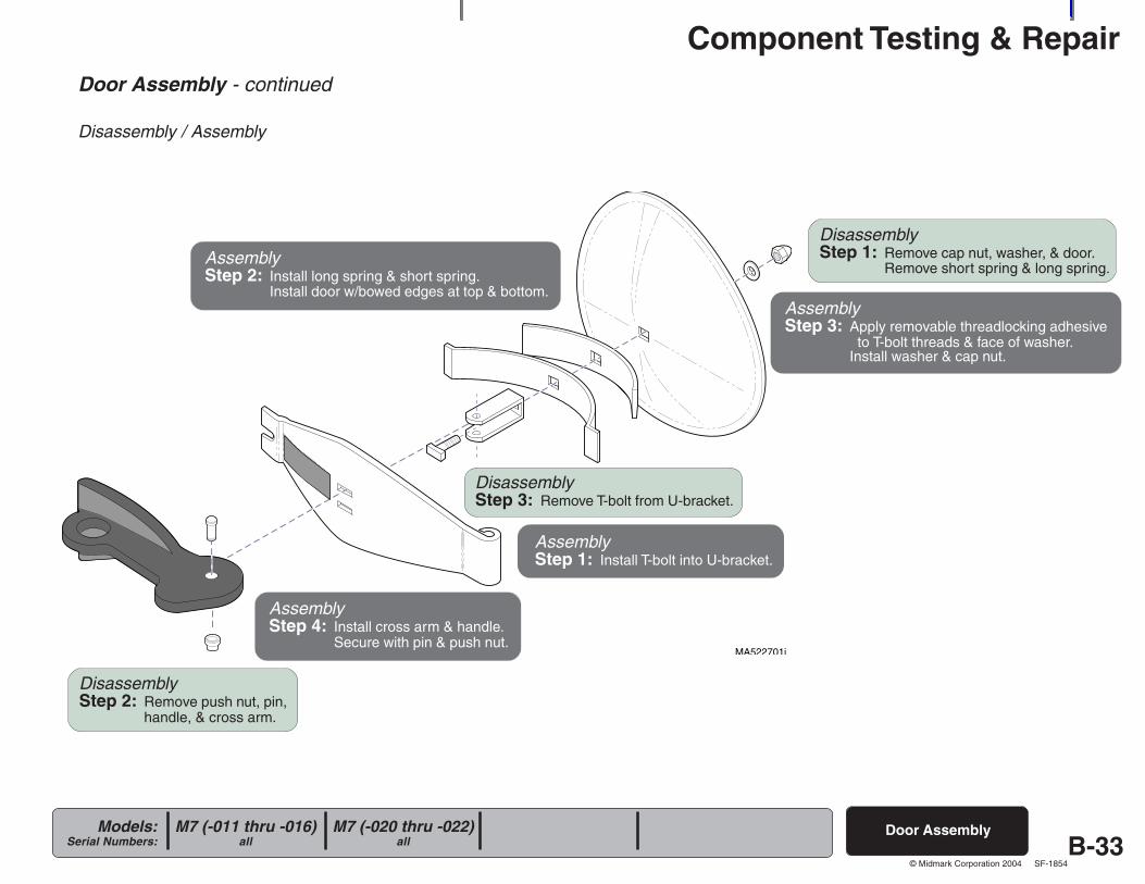
DisassemblyStep 1: Remove cap nut, washer, & door.
Remove short spring & long spring.
DisassemblyStep 3: Remove T-bolt from U-bracket.
AssemblyStep 1: Install T-bolt into U-bracket.
AssemblyStep 2: Install long spring & short spring.
Install door w/bowed edges at top & bottom.AssemblyStep 3: Apply removable threadlocking adhesive
to T-bolt threads & face of washer.Install washer & cap nut.
DisassemblyStep 2: Remove push nut, pin,
handle, & cross arm.
AssemblyStep 4: Install cross arm & handle.
Secure with pin & push nut.
Door Assembly - continued
Disassembly / Assembly
Door AssemblyM7 (-020 thru -022)all
M7 (-011 thru -016)all
Component Testing & Repair
B-34Models:
Serial Numbers:
© Midmark Corporation 2004 SF-1854
MA523001i
R
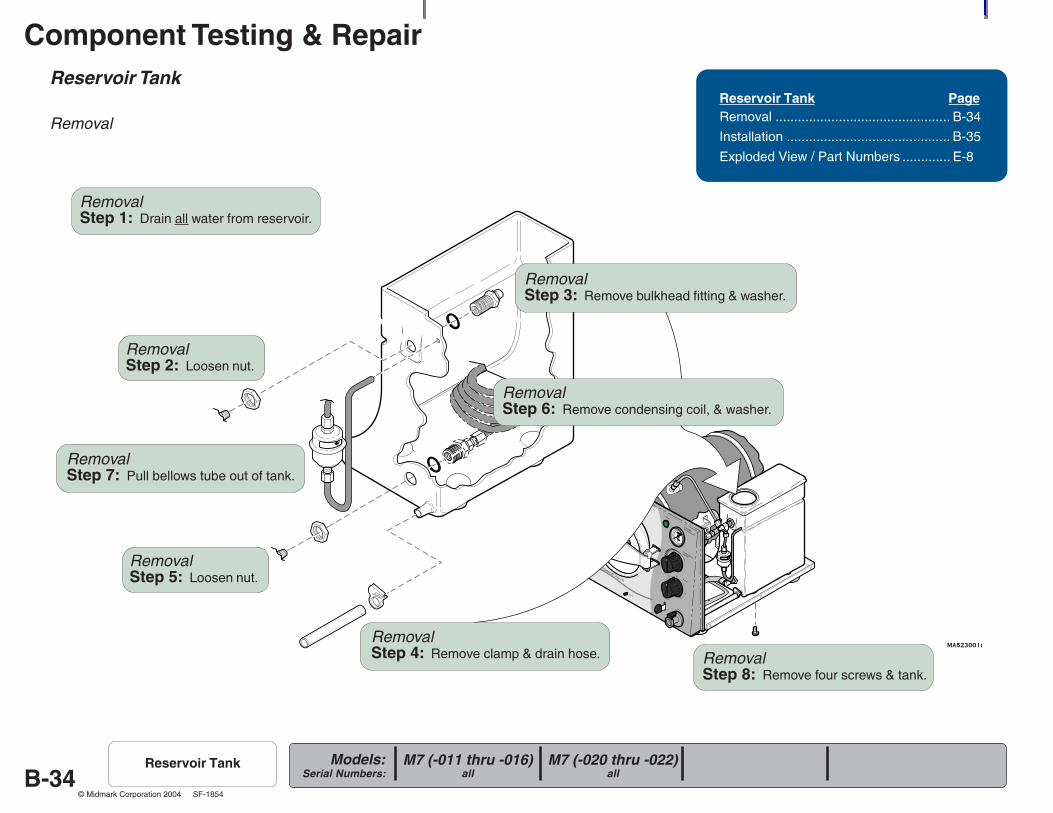
Reservoir Tank
Removal
Reservoir Tank PageRemoval ............................................... B-34
Installation ............................................ B-35
Exploded View / Part Numbers ............. E-8
M7 (-020 thru -022)all
M7 (-011 thru -016)all
Reservoir Tank
RemovalStep 1: Drain all water from reservoir.
RemovalStep 7: Pull bellows tube out of tank.
RemovalStep 8: Remove four screws & tank.
RemovalStep 2: Loosen nut.
RemovalStep 3: Remove bulkhead fitting & washer.
RemovalStep 5: Loosen nut.
RemovalStep 6: Remove condensing coil, & washer.
RemovalStep 4: Remove clamp & drain hose.
Component Testing & Repair
B-35Models:
Serial Numbers:
© Midmark Corporation 2004 SF-1854
MA523001i
R
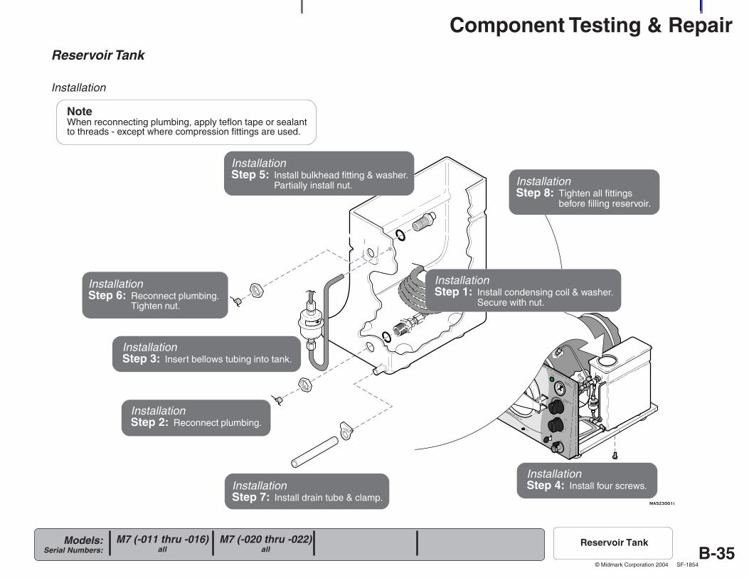
Reservoir Tank
Installation
InstallationStep 1: Install condensing coil & washer.
Secure with nut.
InstallationStep 3: Insert bellows tubing into tank.
InstallationStep 4: Install four screws.
InstallationStep 5: Install bulkhead fitting & washer.
Partially install nut.
InstallationStep 7: Install drain tube & clamp.
InstallationStep 8: Tighten all fittings
before filling reservoir.
NoteWhen reconnecting plumbing, apply teflon tape or sealantto threads - except where compression fittings are used.
InstallationStep 6: Reconnect plumbing.
Tighten nut.
InstallationStep 2: Reconnect plumbing.
M7 (-020 thru -022)all
M7 (-011 thru -016)all
Reservoir Tank
Component Testing & Repair
B-36Models:
Serial Numbers:
© Midmark Corporation 2004 SF-1854
MA523101i
R
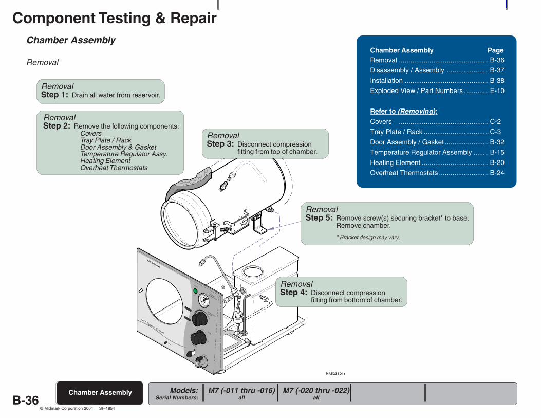
Chamber Assembly
Removal
Chamber Assembly
Chamber Assembly PageRemoval ............................................... B-36
Disassembly / Assembly ...................... B-37
Installation ............................................ B-38
Exploded View / Part Numbers ............. E-10
Refer to (Removing):Covers ............................................... C-2
Tray Plate / Rack .................................. C-3
Door Assembly / Gasket ....................... B-32
Temperature Regulator Assembly ........ B-15
Heating Element ................................... B-20
Overheat Thermostats .......................... B-24
M7 (-020 thru -022)all
M7 (-011 thru -016)all
RemovalStep 1: Drain all water from reservoir.
RemovalStep 2: Remove the following components:
CoversTray Plate / RackDoor Assembly & GasketTemperature Regulator Assy.Heating ElementOverheat Thermostats
RemovalStep 3: Disconnect compression
fitting from top of chamber.
RemovalStep 4: Disconnect compression
fitting from bottom of chamber.
RemovalStep 5: Remove screw(s) securing bracket* to base.
Remove chamber.
* Bracket design may vary.
Component Testing & Repair
B-37Models:
Serial Numbers:
© Midmark Corporation 2004 SF-1854
MA253301i
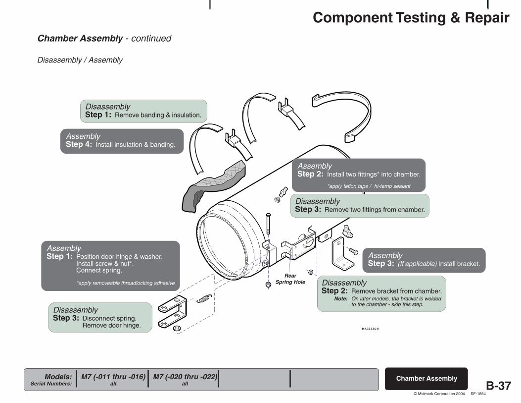
Chamber Assembly - continued
Disassembly / Assembly
Chamber AssemblyM7 (-020 thru -022)all
M7 (-011 thru -016)all
DisassemblyStep 1: Remove banding & insulation.
DisassemblyStep 2: Remove bracket from chamber. Note: On later models, the bracket is welded
to the chamber - skip this step.
DisassemblyStep 3: Remove two fittings from chamber.
DisassemblyStep 3: Disconnect spring.
Remove door hinge.
AssemblyStep 1: Position door hinge & washer.
Install screw & nut*.Connect spring.
*apply removeable threadlocking adhesive
AssemblyStep 2: Install two fittings* into chamber.
*apply teflon tape / hi-temp sealant
AssemblyStep 3: (If applicable) Install bracket.
AssemblyStep 4: Install insulation & banding.
RearSpring Hole
Component Testing & Repair
B-38Models:
Serial Numbers:
© Midmark Corporation 2004 SF-1854
MA523101i
R
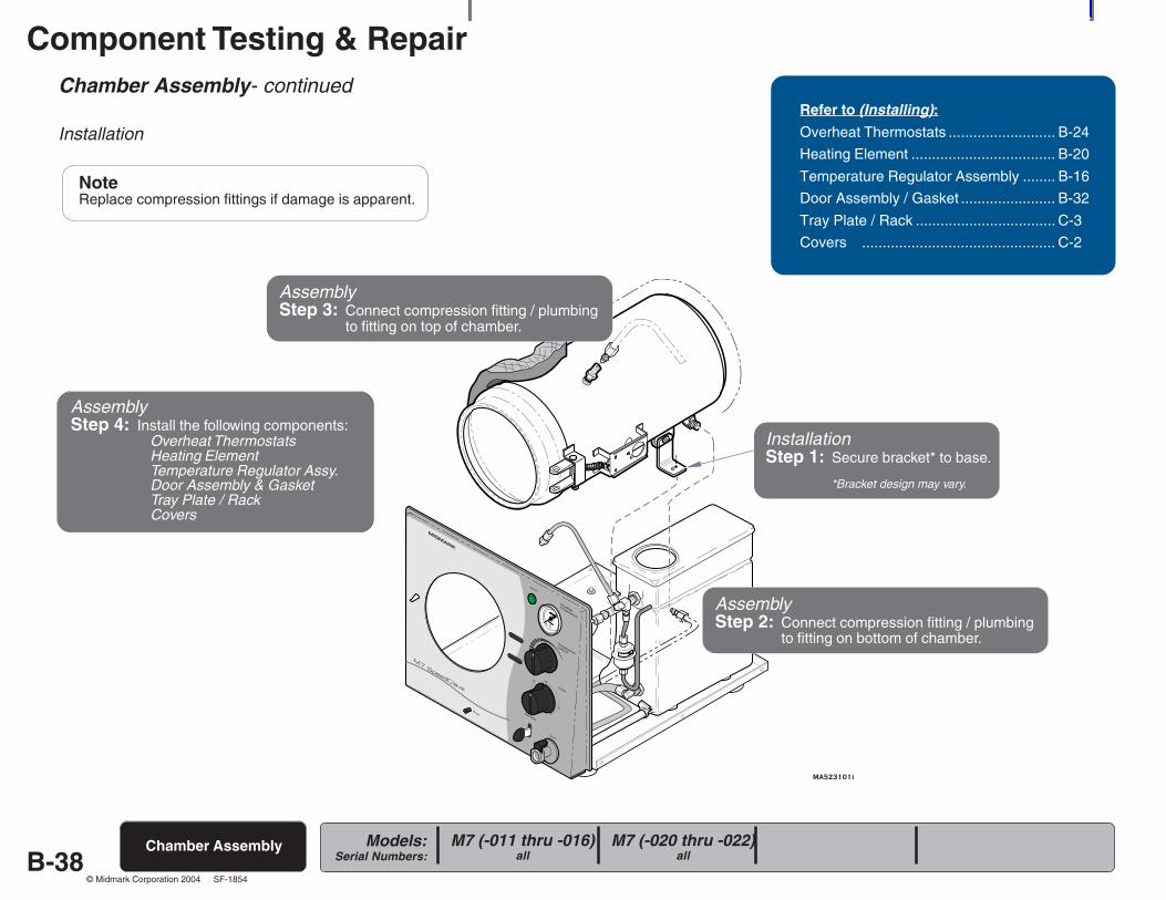
Chamber Assembly- continued
Installation
Chamber Assembly
Refer to (Installing):Overheat Thermostats .......................... B-24
Heating Element ................................... B-20
Temperature Regulator Assembly ........ B-16
Door Assembly / Gasket ....................... B-32
Tray Plate / Rack .................................. C-3
Covers ............................................... C-2
M7 (-020 thru -022)all
M7 (-011 thru -016)all
InstallationStep 1: Secure bracket* to base.
*Bracket design may vary.
AssemblyStep 2: Connect compression fitting / plumbing
to fitting on bottom of chamber.
AssemblyStep 3: Connect compression fitting / plumbing
to fitting on top of chamber.
AssemblyStep 4: Install the following components:
Overheat ThermostatsHeating ElementTemperature Regulator Assy.Door Assembly & GasketTray Plate / RackCovers
NoteReplace compression fittings if damage is apparent.
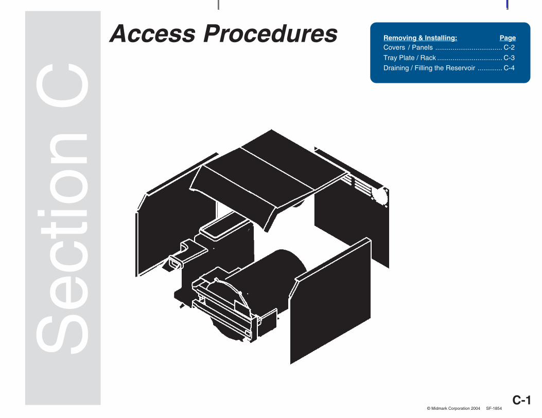
C-1
Access Procedures
Models:Serial Numbers:
© Midmark Corporation 2004 SF-1854
Sec
tion
CRemoving & Installing: PageCovers / Panels ................................... C-2
Tray Plate / Rack .................................. C-3
Draining / Filling the Reservoir ............. C-4
Access Procedures
C-2
Access Procedures
Models:Serial Numbers:
© Midmark Corporation 2004 SF-1854
MA521401i
R
Covers / Panels
Removal / Installation
Covers / Panels
Refer To: PageOperation & Troubleshooting ................ A-1
Component Testing / Repair ................. B-1
Access Procedures .............................. C-1
Wiring Diagrams ................................... D-1
Exploded Views / Part Numbers ........... E-1
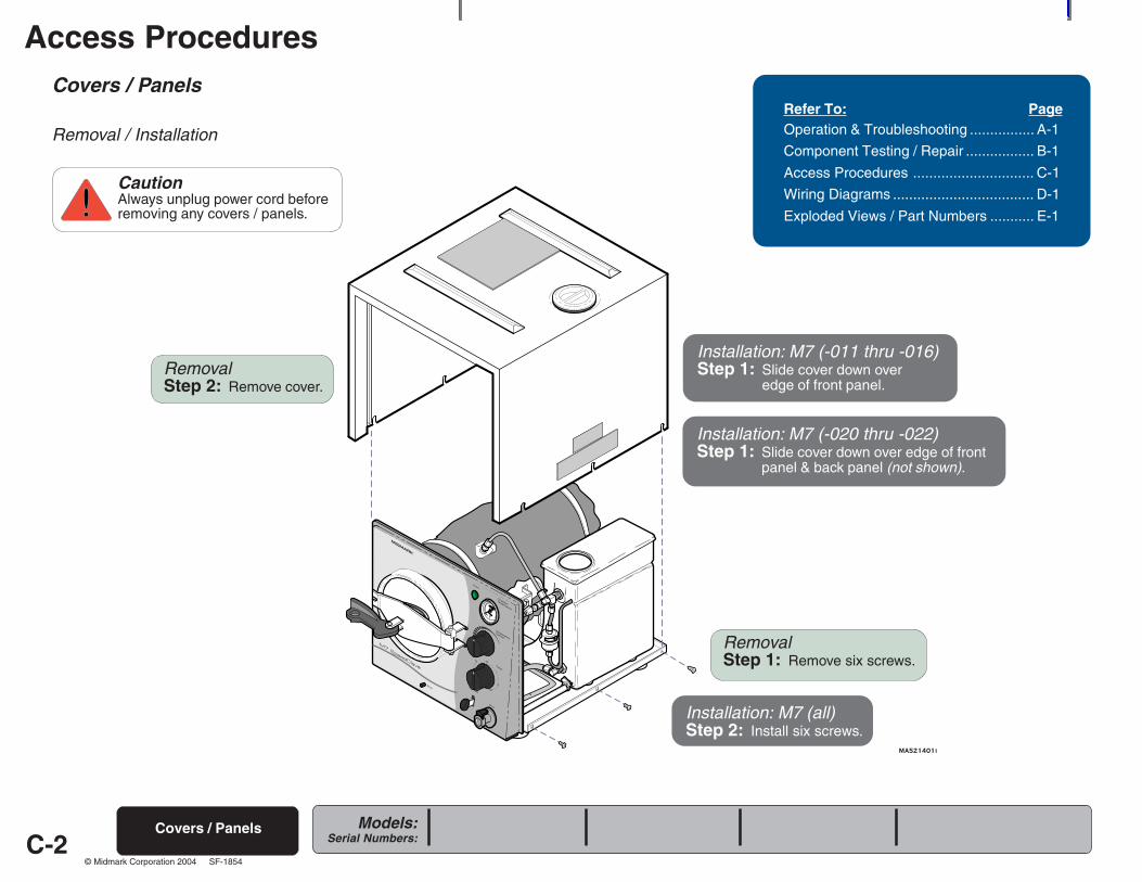
CautionAlways unplug power cord beforeremoving any covers / panels.
Installation: M7 (-011 thru -016)Step 1: Slide cover down over
edge of front panel.
Installation: M7 (-020 thru -022)Step 1: Slide cover down over edge of front
panel & back panel (not shown).
RemovalStep 1: Remove six screws.
RemovalStep 2: Remove cover.
Installation: M7 (all)Step 2: Install six screws.
C-3
Access Procedures
Models:Serial Numbers:
© Midmark Corporation 2004 SF-1854
R
Tray Plate / Rack
Tray Plate / Rack
Removal / InstallationRefer To: PageOperation & Troubleshooting ................ A-1
Component Testing / Repair ................. B-1
Access Procedures .............................. C-1
Wiring Diagrams ................................... D-1
Exploded Views / Part Numbers ........... E-1
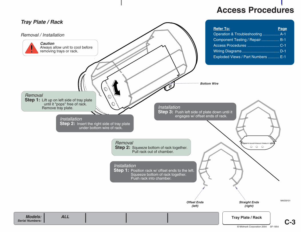
CautionAlways allow unit to cool beforeremoving trays or rack.
RemovalStep 1: Lift up on left side of tray plate
until it "pops" free of rack.Remove tray plate.
Offset Ends(left)
Straight Ends(right)
RemovalStep 2: Squeeze bottom of rack together.
Pull rack out of chamber.
InstallationStep 1: Position rack w/ offset ends to the left.
Squeeze bottom of rack together.Push rack into chamber.
InstallationStep 3: Push left side of plate down until it
engages w/ offset ends of rack.InstallationStep 2: Insert the right side of tray plate
under bottom wire of rack.
ALL
Bottom Wire
C-4
Access Procedures
Models:Serial Numbers:
© Midmark Corporation 2004 SF-1854
MA514002
Draining / FillingReservoir
Draining / Filling the ReservoirRefer To: PageOperation & Troubleshooting ................ A-1
Component Testing / Repair ................. B-1
Access Procedures .............................. C-1
Wiring Diagrams ................................... D-1
Exploded Views / Part Numbers ........... E-1
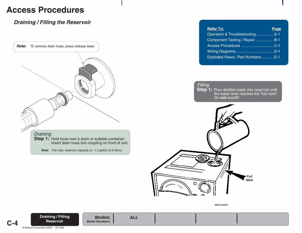
DrainingStep 1: Hold hose over a drain or suitable container.
Insert drain hose into coupling on front of unit.
Note: The max. reservoir capacity is: 1.3 gallon (4.9 liters)
Note: To remove drain hose, press release lever.
FillingStep 1: Pour distilled water into reservoir until
the water level reaches the "full mark".Do not overfill!
ALL
FullMark
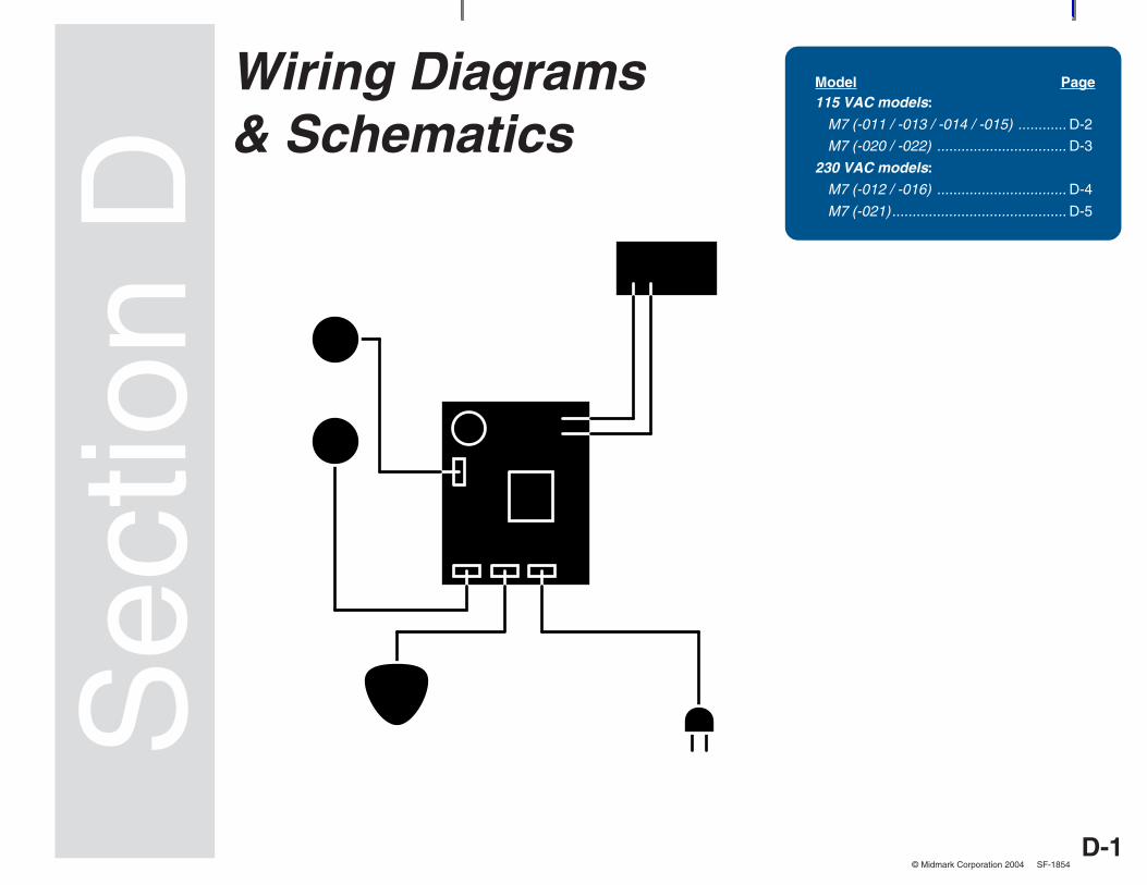
D-1Models:
Serial Numbers:
© Midmark Corporation 2004 SF-1854
Wiring Diagrams
Sec
tion
DWiring Diagrams& Schematics
Model Page115 VAC models:
M7 (-011 / -013 / -014 / -015) ............ D-2
M7 (-020 / -022) ................................ D-3
230 VAC models:
M7 (-012 / -016) ................................ D-4
M7 (-021)........................................... D-5

D-2Models:
Serial Numbers:
© Midmark Corporation 2004 SF-1854
Wiring Diagrams
TIMERSWITCH
TEMPERATUREREGULATOR
RELAY
HEATING ELEMENT
HEATER LIGHT
TIMER BUZZER
TIMER MOTOR
NC
NC
"A"
BLACK WHITE
BLACK
YELLOW
WHITE YELLOW
WH
ITE
WH
ITE
YELLOW
"B" "C"
NC
MANUAL-RESETOVERHEAT
THERMOSTAT( LOW WATER )
AUTO-RESETOVERHEAT
THERMOSTAT( LOW WATER )
GR
EE
N
AUTO-RESETOVERHEAT
THERMOSTAT( LOW WATER )
BLACK
RE
D
WHITE
WHITE
YE
LLO
W
YELLOW
WHITE
WH
ITE
GR
EE
N
GROUND
HEATING ELEMENT
TEMPERATUREREGULATOR
RELAY
TIMERASSEMBLY
POWER CORD
TIMERBUZZER
YELLOWYELLOW
RE
D
MANUAL-RESETOVERHEAT
THERMOSTAT( LOW WATER )
HEATER LIGHT
YE
LLO
W
WH
ITE
3
2
1TM
B
015-1815-00WIRING HARNESS
Refer To: PageOperation & Troubleshooting ................ A-1
Component Testing / Repair ................. B-1
Access Procedures .............................. C-1
Wiring Diagrams ................................... D-1
Exploded Views / Part Numbers ........... E-1
Wiring Diagrams
M7 (-011)all
M7 (-013)all
M7 (-014)all
M7 (-015)all
Wiring Diagrams(115 VAC Models)
Rev. 5/09
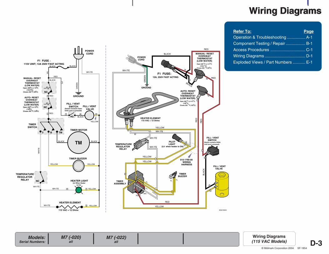
D-3Models:
Serial Numbers:
© Midmark Corporation 2004 SF-1854
Wiring Diagrams
POWERCORD
FILL / VENTVALVE
TIMER MOTOR
TIMER BUZZER
HEATER LIGHT
HEATER ELEMENT
NC
NC
NC
MANUAL- RESETOVERHEAT
THERMOSTAT(LOW WATER)
AUTO- RESETOVERHEAT
THERMOSTAT(LOW WATER)
TIMERSWITCH
TEMPERATUREREGULATOR
RELAY
F1 FUSE :115V UNIT; 12A 250V FAST ACTING
YELLOW
WH
ITE
GROUND
BLACK
GR
EE
N
WH ITE
3 B TM
Open 285 oF (+/-12
oF)
(140.5 oC)
Closes 200 oF (93
oC)
Open 295 oF (+/-12
oF)
(146oC)
Closes 265 oF (129
oC)
1
TM
FILL / VENTSWITCH
NO
115 VAC = 12 Ohms
(Lit When HeaterIs On)
(Switch Contacts OpenUntil Lever is pressed)
567
RED8
3
7
9
14
2
BLACK
BLACK
RED
BLACK
BLACK BLACK
YELLOW YELLOW
WH ITEWH ITE
YELLOW
YELLOWWH ITE
MA676900i
RED
TM
13
POWERCORD
FILL / VENTVALVE
TIMERASSEMBLY
TIMERBUZZER
PILOTLIGHT
MANUAL- RESETOVERHEAT
THERMOSTAT(LOW WATER)
AUTO- RESETOVERHEAT
THERMOSTAT(LOW WATER)
TEMPERATUREREGULATOR
RELAY
F1 FUSE: 12A, 250V FAST ACTING
WH
YL
YL
YLYL
GROUND
RD
015-1790-00WIRING
HARNESS
Open 285 oF (+/-12
oF)
(140.5 oC)
Closes 200 oF (93
oC)
Open 295 oF (+/-12
oF)
(146oC)
Closes 265 oF (129
oC)
FILL / VENTSWITCH
(Switch contacts OPENuntil lever is pressed)
21
1
2
4
4
5
3
5
6
7
6
89
8
3
7
BLACK
WH ITE
GR
EE
N
YELLOW
RED
BLACK
HEATER ELEMENT115 VAC = 12 Ohms
WH ITE
WH ITE
WH ITE
YELLOW
YELLOW
YELLOW
RE
D
REDB
LAC
K
(Lit when heater is ON)
RE
D
RED
Refer To: PageOperation & Troubleshooting ................ A-1
Component Testing / Repair ................. B-1
Access Procedures .............................. C-1
Wiring Diagrams ................................... D-1
Exploded Views / Part Numbers ........... E-1
Wiring Diagrams
M7 (-020)all
M7 (-022)all
Wiring Diagrams(115 VAC Models)
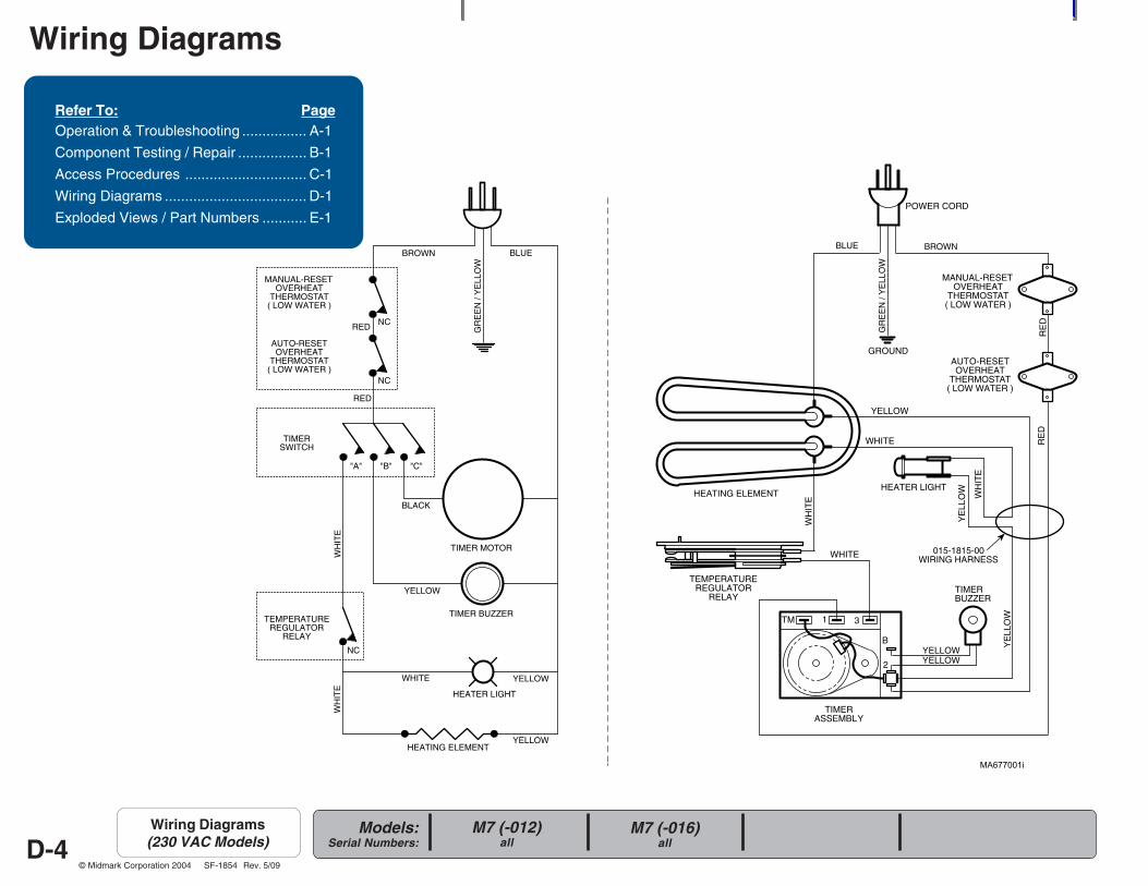
D-4Models:
Serial Numbers:
© Midmark Corporation 2004 SF-1854
Wiring Diagrams
TIMERSWITCH
TEMPERATUREREGULATOR
RELAY
HEATING ELEMENT
HEATER LIGHT
TIMER BUZZER
TIMER MOTOR
NC
NC
"A"
BLACK
YELLOW
WHITE YELLOW
WH
ITE
WH
ITE
YELLOW
"B" "C"
NC
MANUAL-RESETOVERHEAT
THERMOSTAT( LOW WATER )
AUTO-RESETOVERHEAT
THERMOSTAT( LOW WATER )
BROWN BLUE
GR
EE
N /
YE
LLO
W
BROWN
AUTO-RESETOVERHEAT
THERMOSTAT( LOW WATER )
RE
D
WHITE
YE
LLO
W
YELLOW
WHITE
WH
ITE
GROUND
HEATING ELEMENT
TEMPERATUREREGULATOR
RELAY
TIMERASSEMBLY
POWER CORD
TIMERBUZZER
YELLOWYELLOW
RE
D
MANUAL-RESETOVERHEAT
THERMOSTAT( LOW WATER )
HEATER LIGHT
YE
LLO
W
WH
ITE
3
2
1TM
B
BLUE
RED
RED
GR
EE
N /
YE
LLO
W
015-1815-00WIRING HARNESS
Refer To: PageOperation & Troubleshooting ................ A-1
Component Testing / Repair ................. B-1
Access Procedures .............................. C-1
Wiring Diagrams ................................... D-1
Exploded Views / Part Numbers ........... E-1
M7 (-012)all
M7 (-016)all
Wiring Diagrams(230 VAC Models)
Rev. 5/09
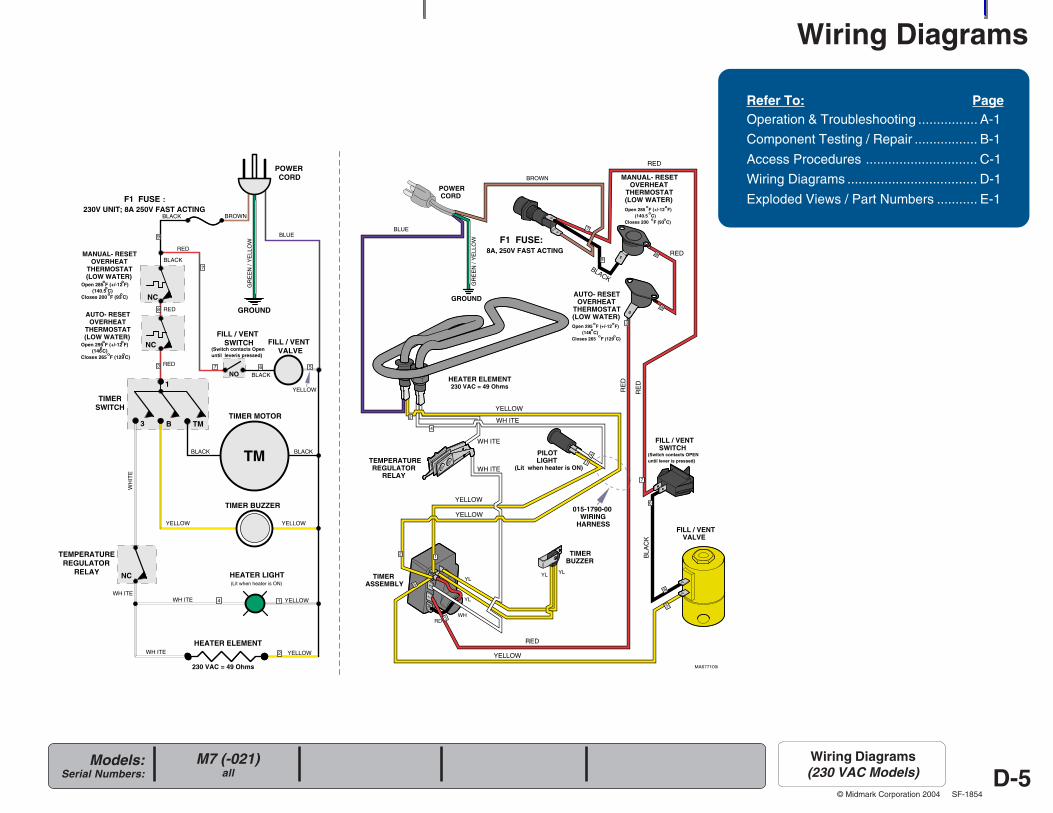
D-5Models:
Serial Numbers:
© Midmark Corporation 2004 SF-1854
Wiring Diagrams
POWERCORD
FILL / VENTVALVE
TIMER MOTOR
TIMER BUZZER
HEATER LIGHT
HEATER ELEMENT
NC
NC
NC
MANUAL- RESETOVERHEAT
THERMOSTAT(LOW WATER)
AUTO- RESETOVERHEAT
THERMOSTAT(LOW WATER)
TIMERSWITCH
TEMPERATUREREGULATOR
RELAY
F1 FUSE :230V UNIT; 8A 250V FAST ACTING
YELLOW
WH
ITE
GROUND
BLUE
GR
EE
N /
YE
LLO
W
BROWN
3 B TM
Open 285 oF (+/-12
oF)
(140.5 oC)
Closes 200 oF (93
oC)
Open 295 oF (+/-12
oF)
(146oC)
Closes 265 oF (129
oC)
1
TM
FILL / VENTSWITCH
NO
230 VAC = 49 Ohms
(Switch contacts Openuntil leveris pressed)
567
RED8
3
7
9
14
2
BLACK
RED
BLACK
BLACK BLACK
YELLOW YELLOW
WH ITEWH ITE
YELLOW
YELLOWWH ITE
MA677100i
RED
TM
13
POWERCORD
FILL / VENTVALVE
TIMERASSEMBLY
TIMERBUZZER
PILOTLIGHT
MANUAL- RESETOVERHEAT
THERMOSTAT(LOW WATER)
AUTO- RESETOVERHEAT
THERMOSTAT(LOW WATER)
TEMPERATUREREGULATOR
RELAY
F1 FUSE: 8A, 250V FAST ACTING
WH
YL
YL
YLYL
RD
015-1790-00WIRING
HARNESS
Open 285 oF (+/-12
oF)
(140.5 oC)
Closes 200 oF (93
oC)
Open 295 oF (+/-12
oF)
(146oC)
Closes 265 oF (129
oC)
FILL / VENTSWITCH
(Switch contacts OPENuntil lever is pressed)
21
1
2
4
4
5
3
5
6
7
6
89
8
3
7
YELLOW
RED
BLACK
WH ITE
WH ITE
WH ITE
YELLOW
YELLOW
YELLOW
RE
D
REDB
LAC
K
(Lit when heater is ON)
RE
D
RED
(Lit when heater is ON)
BLACK
BLUE
GROUND
GR
EE
N /
YE
LLO
W
BROWN
HEATER ELEMENT230 VAC = 49 Ohms
Refer To: PageOperation & Troubleshooting ................ A-1
Component Testing / Repair ................. B-1
Access Procedures .............................. C-1
Wiring Diagrams ................................... D-1
Exploded Views / Part Numbers ........... E-1
M7 (-021)all
Wiring Diagrams(230 VAC Models)

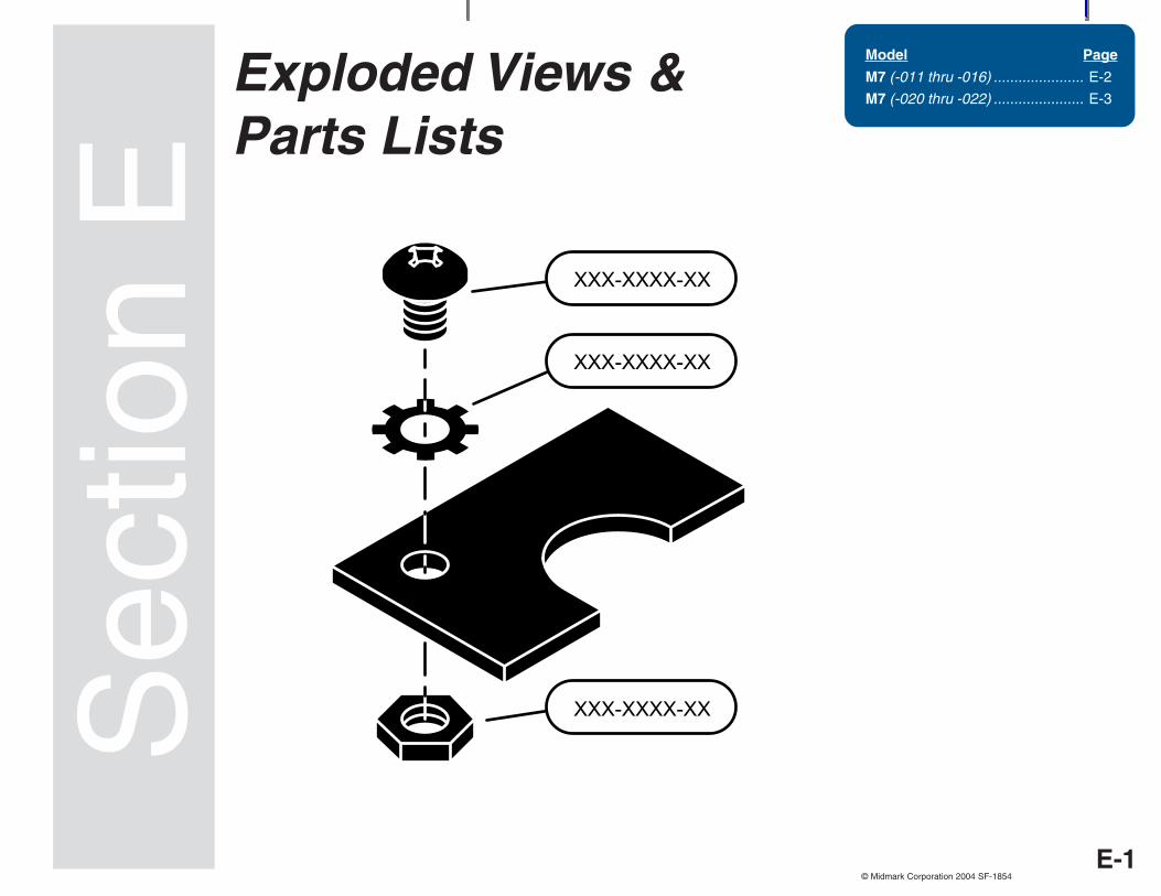
Always Specify Model & Serial Number
Models:Serial Numbers:
© Midmark Corporation 2004 SF-1854
Exploded Views &Parts Lists
Sec
tion
EModel Page
M7 (-011 thru -016) ...................... E-2
M7 (-020 thru -022) ...................... E-3
E-1
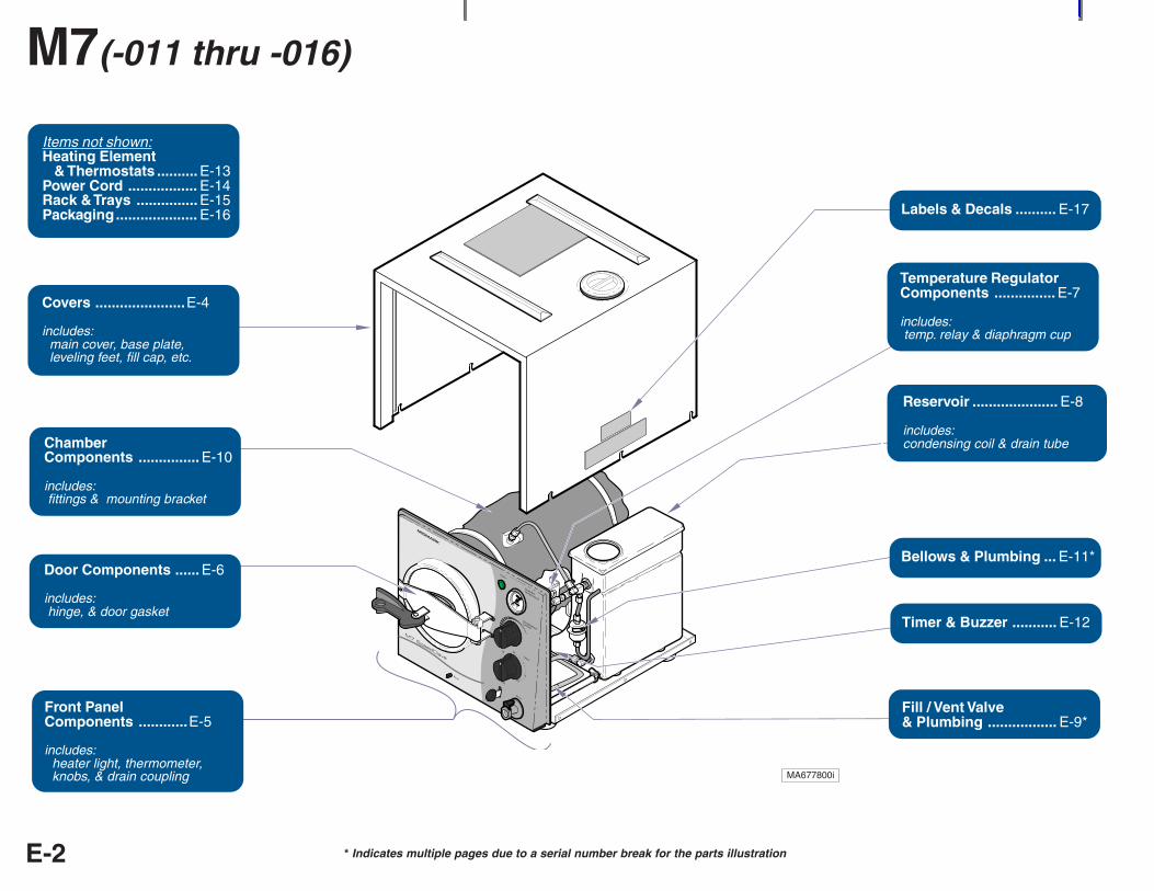
R
* Indicates multiple pages due to a serial number break for the parts illustrationE-2
M7(-011 thru -016)
MA677800i
Fuses .............. E-15
Reservoir ..................... E-8
includes:condensing coil & drain tube
Fuses .............. E-15
Covers ......................E-4
includes: main cover, base plate, leveling feet, fill cap, etc.
ChamberComponents ............... E-10
includes: fittings & mounting bracket
Door Components ...... E-6
includes: hinge, & door gasket
Front PanelComponents ............E-5
includes: heater light, thermometer, knobs, & drain coupling
Temperature RegulatorComponents ............... E-7
includes: temp. relay & diaphragm cup
Bellows & Plumbing ... E-11*
Timer / Buzzer ............. E-12Timer & Buzzer ........... E-12
Labels & Decals .......... E-17
Fill / Vent Valve& Plumbing ................. E-9*
Items not shown:Heating Element & Thermostats .......... E-13Power Cord ................. E-14Rack & Trays ............... E-15Packaging.................... E-16
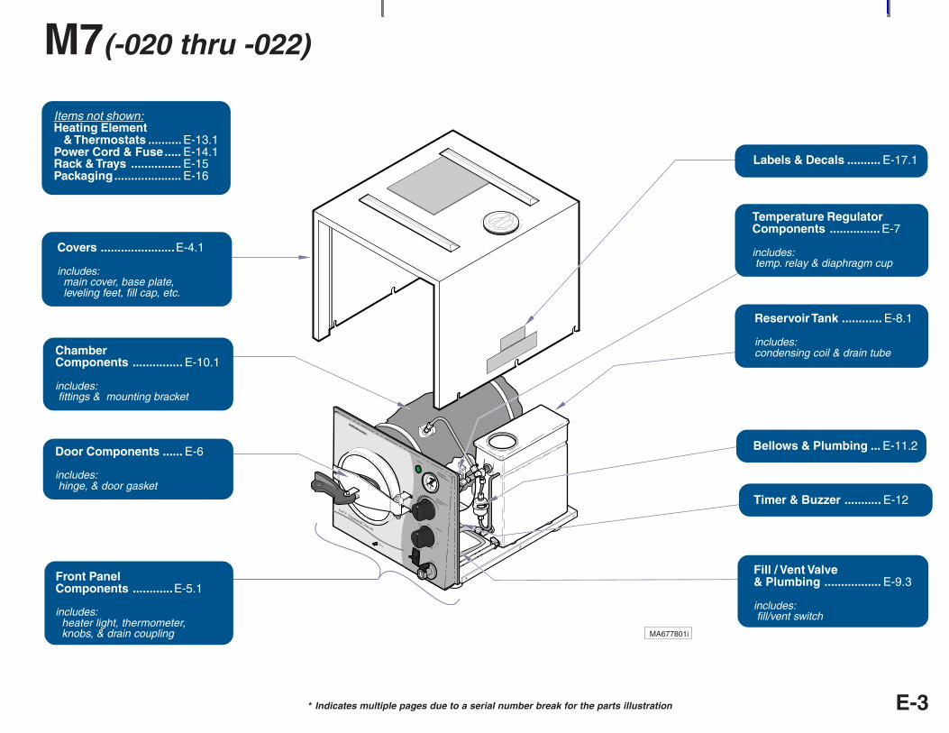
* Indicates multiple pages due to a serial number break for the parts illustration E-3
M7(-020 thru -022)
MA677801i
R
Reservoir Tank ............ E-8.1
includes:condensing coil & drain tube
Temperature RegulatorComponents ............... E-7
includes: temp. relay & diaphragm cup
Bellows & Plumbing ... E-11.2
Timer & Buzzer ........... E-12
Labels & Decals .......... E-17.1
Fill / Vent Valve& Plumbing ................. E-9.3
includes: fill/vent switch
Items not shown:Heating Element & Thermostats .......... E-13.1Power Cord & Fuse..... E-14.1Rack & Trays ............... E-15Packaging.................... E-16
Covers ......................E-4.1
includes: main cover, base plate, leveling feet, fill cap, etc.
ChamberComponents ............... E-10.1
includes: fittings & mounting bracket
Door Components ...... E-6
includes: hinge, & door gasket
Front PanelComponents ............E-5.1
includes: heater light, thermometer, knobs, & drain coupling
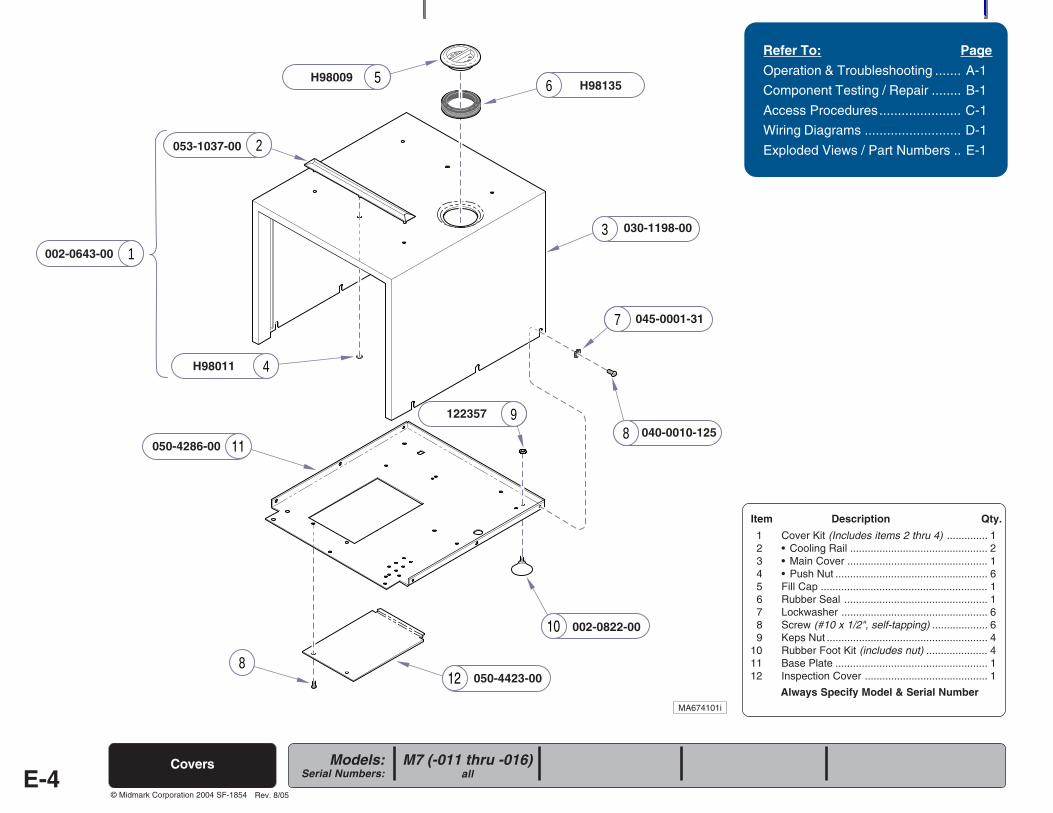
Always Specify Model & Serial Number
Models:Serial Numbers:
© Midmark Corporation 2004 SF-1854
5 6
2
3
4
9
7
8
128
1
10
11
E-4
Refer To: Page
Operation & Troubleshooting ....... A-1
Component Testing / Repair ........ B-1
Access Procedures...................... C-1
Wiring Diagrams .......................... D-1
Exploded Views / Part Numbers .. E-1
Covers
050-4423-00
H98009
030-1198-00
053-1037-00
H98135
H98011
045-0001-31
040-0010-125
122357
002-0822-00
050-4286-00
M7 (-011 thru -016)all
Rev. 8/05
MA674101i
002-0643-00
Item Description Qty.
1 Cover Kit (Includes items 2 thru 4) .............. 12 • Cooling Rail ............................................... 23 • Main Cover ................................................ 14 • Push Nut .................................................... 65 Fill Cap ......................................................... 16 Rubber Seal ................................................. 17 Lockwasher .................................................. 68 Screw (#10 x 1/2", self-tapping) ................... 69 Keps Nut ....................................................... 4
10 Rubber Foot Kit (includes nut) ..................... 411 Base Plate .................................................... 112 Inspection Cover .......................................... 1
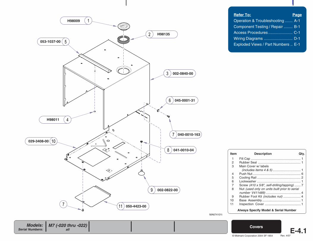
Always Specify Model & Serial Number
Models:Serial Numbers:
© Midmark Corporation 2004 SF-1854
11
10
Refer To: Page
Operation & Troubleshooting ....... A-1
Component Testing / Repair ........ B-1
Access Procedures ...................... C-1
Wiring Diagrams .......................... D-1
Exploded Views / Part Numbers .. E-1
M7 (-020 thru -022)all
Covers
Item Description Qty.
1 Fill Cap ......................................................... 12 Rubber Seal ................................................. 13 Main Cover w/ labels
(includes items 4 & 5) ................................ 14 Push Nut ....................................................... 65 Cooling Rail .................................................. 26 Lockwasher .................................................. 17 Screw (#10 x 5/8", self-drilling/tapping) ....... 78 Nut (used only on units built prior to serial
number V411489) ........................................ 49 Rubber Foot Kit (includes nut) .................... 4
10 Base Assembly ............................................ 111 Inspection Cover ......................................... 1
MA674101i
H98009
053-1037-00
H98135
H98011
002-0840-00
045-0001-31
040-0010-163
041-0010-04
002-0822-00
050-4423-00
029-3408-00
E-4.1Rev. 4/07
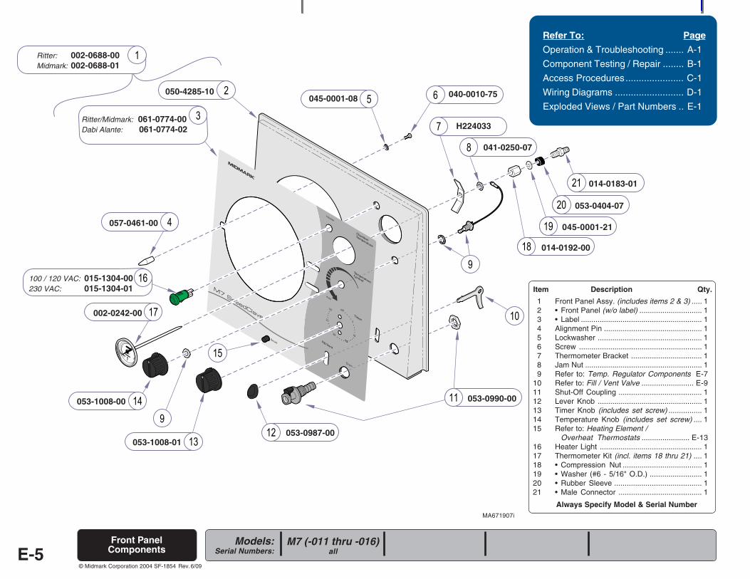
Always Specify Model & Serial Number
Models:Serial Numbers:
© Midmark Corporation 2004 SF-1854
Item Description Qty.
1 Front Panel Assy. (includes items 2 & 3) ..... 12 • Front Panel (w/o label) .............................. 13 • Label .......................................................... 14 Alignment Pin ............................................... 15 Lockwasher .................................................. 16 Screw ........................................................... 17 Thermometer Bracket .................................. 18 Jam Nut ........................................................ 19 Refer to: Temp. Regulator Components E-7
10 Refer to: Fill / Vent Valve ......................... E-911 Shut-Off Coupling ........................................ 112 Lever Knob .................................................. 113 Timer Knob (includes set screw) ................ 114 Temperature Knob (includes set screw) .... 115 Refer to: Heating Element /
Overheat Thermostats ....................... E-1316 Heater Light ................................................. 117 Thermometer Kit (incl. items 18 thru 21) .... 118 • Compression Nut ...................................... 119 • Washer (#6 - 5/16" O.D.) ......................... 120 • Rubber Sleeve .......................................... 121 • Male Connector ........................................ 1
Refer To: Page
Operation & Troubleshooting ....... A-1
Component Testing / Repair ........ B-1
Access Procedures...................... C-1
Wiring Diagrams .......................... D-1
Exploded Views / Part Numbers .. E-1
M7 (-011 thru -016)allE-5
Front PanelComponents
MA671907i
Ritter: 002-0688-00Midmark: 002-0688-01
Ritter/Midmark: 061-0774-00Dabi Alante: 061-0774-02
050-4285-10
057-0461-00
045-0001-08 040-0010-75
H224033
041-0250-07
014-0183-01
053-0404-07
014-0192-00
053-0990-00
053-0987-00053-1008-01
053-1008-00
100 / 120 VAC: 015-1304-00230 VAC: 015-1304-01
002-0242-00
Rev. 6/09
045-0001-21
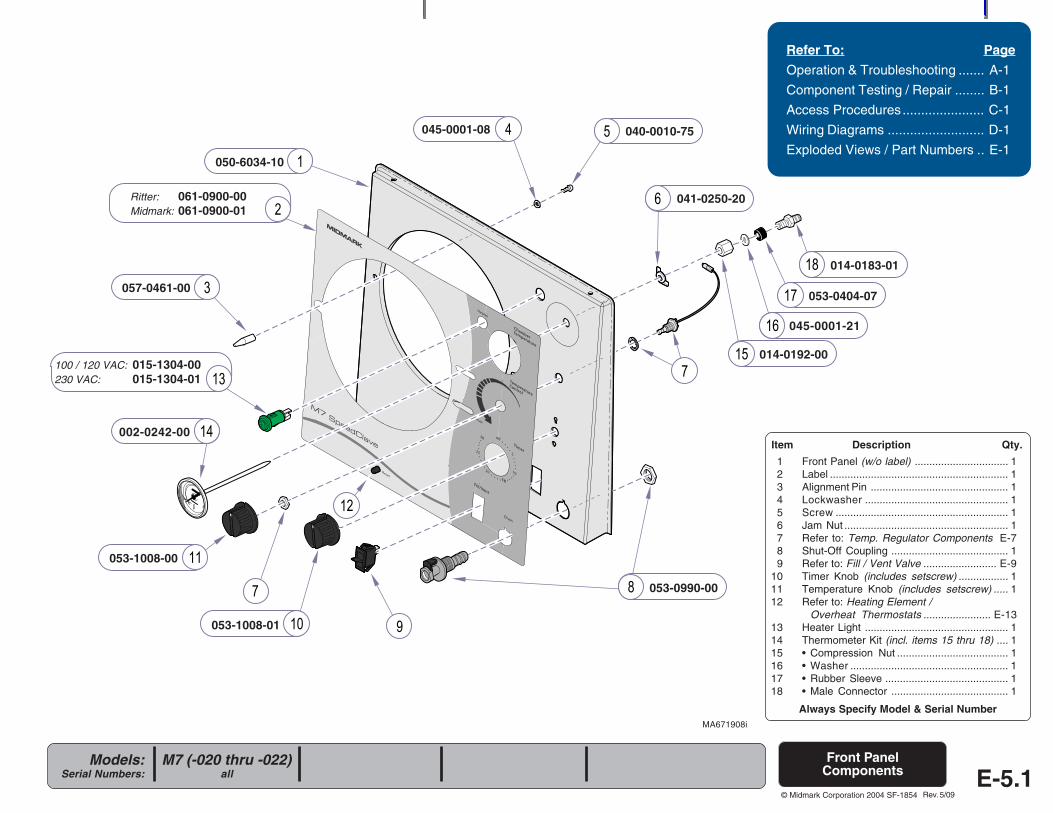
Always Specify Model & Serial Number
Models:Serial Numbers:
© Midmark Corporation 2004 SF-1854
Refer To: Page
Operation & Troubleshooting ....... A-1
Component Testing / Repair ........ B-1
Access Procedures...................... C-1
Wiring Diagrams .......................... D-1
Exploded Views / Part Numbers .. E-1
MA671908i
Front PanelComponents
Item Description Qty.
1 Front Panel (w/o label) ................................ 12 Label ............................................................. 13 Alignment Pin ............................................... 14 Lockwasher ................................................. 15 Screw ........................................................... 16 Jam Nut ........................................................ 17 Refer to: Temp. Regulator Components E-78 Shut-Off Coupling ........................................ 19 Refer to: Fill / Vent Valve ......................... E-9
10 Timer Knob (includes setscrew) ................. 111 Temperature Knob (includes setscrew) ..... 112 Refer to: Heating Element /
Overheat Thermostats ....................... E-1313 Heater Light ................................................. 114 Thermometer Kit (incl. items 15 thru 18) .... 115 • Compression Nut ...................................... 116 • Washer ...................................................... 117 • Rubber Sleeve .......................................... 118 • Male Connector ........................................ 1
050-6034-10
Ritter: 061-0900-00Midmark: 061-0900-01
057-0461-00
045-0001-08 040-0010-75
041-0250-20
014-0183-01
053-0404-07
014-0192-00100 / 120 VAC: 015-1304-00230 VAC: 015-1304-01
002-0242-00
053-1008-01
053-1008-00
053-0990-00
M7 (-020 thru -022)all E-5.1
Rev. 5/09
045-0001-21
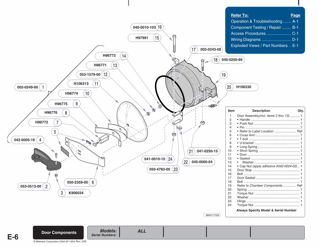
Always Specify Model & Serial Number
Models:Serial Numbers:
© Midmark Corporation 2004 SF-1854
19
15
16
18
17
2
4
6
8
9
3
5
12
14
7
111
10
24
23
21
20
22
13
002-0249-00
Item Description Qty.
1 Door Assembly(incl. items 2 thru 13) ........... 12 • Handle ....................................................... 13 • Push Nut .................................................... 14 • Pin ............................................................. 15 • Refer to Label Location ......................... Ref6 • Cross Arm.................................................. 17 • T-bolt ......................................................... 18 • U-bracket ................................................... 19 • Long Spring ............................................... 1
10 • Short Spring .............................................. 111 • Door ........................................................... 112 • Gasket ....................................................... 113 • Washer ................................................... 114 • Cap Nut (apply adhesive #042-0024-02) .. 115 Door Stop ..................................................... 116 Bolt ............................................................... 117 Door Gasket ................................................. 118 Bolt ............................................................... 119 Refer to Chamber Components ............... Ref20 Spring ........................................................... 121 Torque Nut ................................................... 122 Washer ......................................................... 123 Hinge ............................................................ 124 Torque Nut ................................................... 1
Refer To: Page
Operation & Troubleshooting ....... A-1
Component Testing / Repair ........ B-1
Access Procedures ...................... C-1
Wiring Diagrams .......................... D-1
Exploded Views / Part Numbers .. E-1
E-6Door Components
MA511703i
053-0513-00
K906034
042-0005-16
050-2359-00
H96772
H96776
H96775
H96774
H106313
H96771
H96773
H97991
040-0010-103
002-0243-00
040-0250-69
H106330
041-0250-15
045-0000-04
050-4783-00
041-0010-10
ALL
053-1579-00
Rev. 5/05
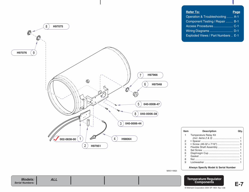
Always Specify Model & Serial Number
Models:Serial Numbers:
© Midmark Corporation 2004 SF-1854
Refer To: Page
Operation & Troubleshooting ....... A-1
Component Testing / Repair ........ B-1
Access Procedures ...................... C-1
Wiring Diagrams .......................... D-1
Exploded Views / Part Numbers .. E-1
Item Description Qty.
1 Temperature Relay Kit(incl. items 2 & 3) ...................................... 1
2 • Spacer ....................................................... 13 • Screw (#6-32 x 7/16") ................................ 34 Flexible Shaft Assembly ............................... 15 Set Screw ..................................................... 16 Diaphragm Cup ............................................ 17 Gasket .......................................................... 18 Nut ................................................................ 19 Lockwasher .................................................. 1
Temperature RegulatorComponents
MA511902i
002-0838-00
H97951
H98064
040-0006-44
040-0008-47
H97948
H97966
H97076
H97075
ALL
E-7
040-0006-38
Rev 1/08
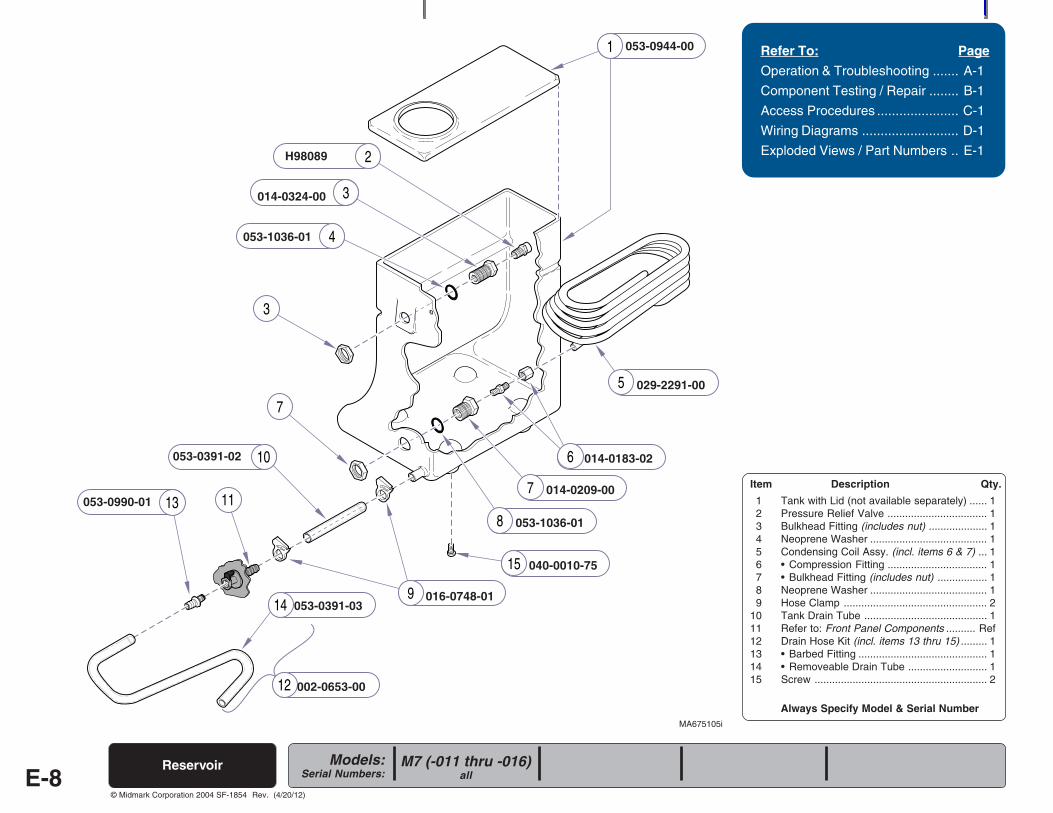
Always Specify Model & Serial Number
Models:Serial Numbers:
© Midmark Corporation 2004 SF-1854
2
3
4
7
3
11
12
149
15
8
7
6
13
10
5
1
Item Description Qty.
1 Tank with Lid (not available separately) ...... 12 Pressure Relief Valve .................................. 13 Bulkhead Fitting (includes nut) .................... 14 Neoprene Washer ........................................ 15 Condensing Coil Assy. (incl. items 6 & 7) ... 16 • Compression Fitting .................................. 17 • Bulkhead Fitting (includes nut) ................. 18 Neoprene Washer ........................................ 19 Hose Clamp ................................................. 2
10 Tank Drain Tube .......................................... 111 Refer to: Front Panel Components .......... Ref12 Drain Hose Kit (incl. items 13 thru 15) ......... 113 • Barbed Fitting ............................................ 114 • Removeable Drain Tube ........................... 115 Screw ........................................................... 2
Refer To: Page
Operation & Troubleshooting ....... A-1
Component Testing / Repair ........ B-1
Access Procedures ...................... C-1
Wiring Diagrams .......................... D-1
Exploded Views / Part Numbers .. E-1
M7 (-011 thru -016)all
ReservoirE-8
053-0944-00
029-2291-00
014-0183-02
014-0209-00
053-1036-01
040-0010-75
016-0748-01
002-0653-00
053-0391-03
053-0990-01
053-0391-02
053-1036-01
014-0324-00
H98089
MA675105i
Rev. (4/20/12)
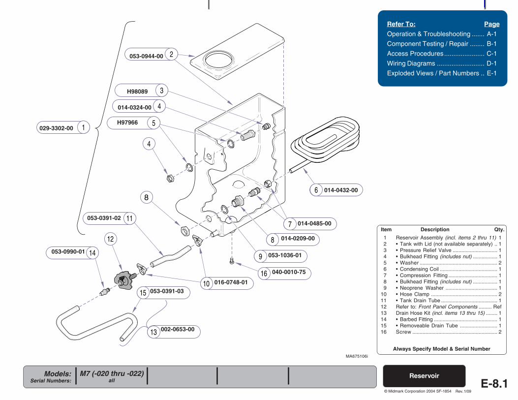
Always Specify Model & Serial Number
Models:Serial Numbers:
© Midmark Corporation 2004 SF-1854
Item Description Qty.
1 Reservoir Assembly (incl. items 2 thru 11) 12 • Tank with Lid (not available separately) .. 13 • Pressure Relief Valve ............................... 14 • Bulkhead Fitting (includes nut) ................. 15 • Washer ...................................................... 26 • Condensing Coil ........................................ 17 • Compression Fitting .................................. 18 • Bulkhead Fitting (includes nut) ................. 19 • Neoprene Washer .................................... 1
10 • Hose Clamp .............................................. 211 • Tank Drain Tube ....................................... 112 Refer to: Front Panel Components ......... Ref13 Drain Hose Kit (incl. items 13 thru 15) ........ 114 • Barbed Fitting ............................................ 115 • Removeable Drain Tube .......................... 116 Screw ........................................................... 2
Refer To: Page
Operation & Troubleshooting ....... A-1
Component Testing / Repair ........ B-1
Access Procedures...................... C-1
Wiring Diagrams .......................... D-1
Exploded Views / Part Numbers .. E-1
Reservoir
MA675106i
M7 (-020 thru -022)all E-8.1
Rev. 1/09
3
7
8
9
10
1
2
5
6
4
4
12
11
14
15
16
8
13
053-0944-00
014-0432-00
014-0485-00
014-0209-00
053-1036-01
040-0010-75
016-0748-01
053-0391-03
053-0990-01
053-0391-02
H97966
014-0324-00
H98089
029-3302-00
002-0653-00
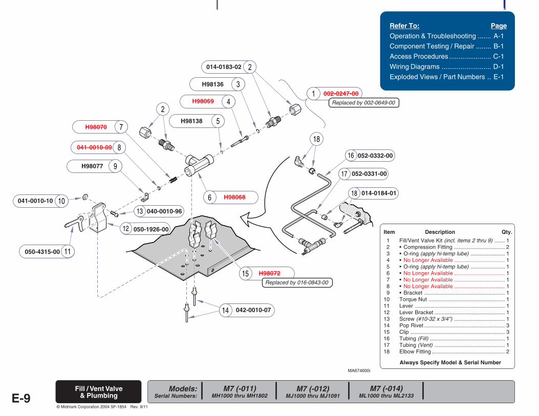
Always Specify Model & Serial Number
Models:Serial Numbers:
© Midmark Corporation 2004 SF-1854
15
14
13
12
16
17
1810
11
18
050-4315-00
002-0247-00
MA674600i
Fill / Vent Valve& Plumbing
Refer To: Page
Operation & Troubleshooting ....... A-1
Component Testing / Repair ........ B-1
Access Procedures ...................... C-1
Wiring Diagrams .......................... D-1
Exploded Views / Part Numbers .. E-1
Item Description Qty.
1 Fill/Vent Valve Kit (incl. items 2 thru 9) ....... 12 • Compression Fitting .................................. 23 • O-ring (apply hi-temp lube) ....................... 14 • No Longer Available .................................. 15 • O-ring (apply hi-temp lube) ....................... 16 • No Longer Available .................................. 17 • No Longer Available .................................. 18 • No Longer Available .................................. 19 • Bracket ...................................................... 1
10 Torque Nut ................................................... 111 Lever ............................................................ 112 Lever Bracket ............................................... 113 Screw (#10-32 x 3/4") .................................. 114 Pop Rivet ...................................................... 315 Clip ............................................................... 316 Tubing (Fill) .................................................. 117 Tubing (Vent) ............................................... 118 Elbow Fitting ................................................. 2
E-9
H98070
014-0183-02
H98069
H98136
H98138
H98068
041-0010-09
H98077
041-0010-10
050-1926-00
040-0010-96
042-0010-07
H98072
052-0332-00
052-0331-00
014-0184-01
M7 (-011)MH1000 thru MH1802
M7 (-012)MJ1000 thru MJ1091
M7 (-014)ML1000 thru ML2133
Rev. 9/11
Replaced by 002-0649-00
Replaced by 016-0843-00
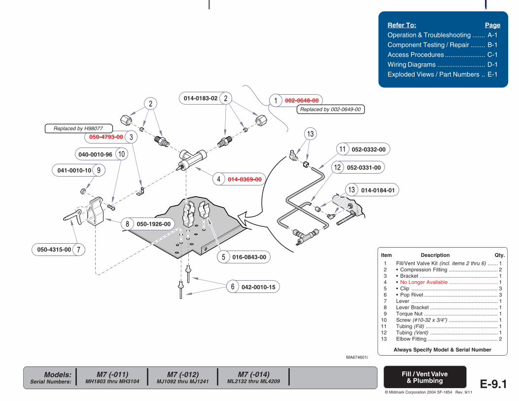
Always Specify Model & Serial Number
Models:Serial Numbers:
© Midmark Corporation 2004 SF-1854
8
13
12
11
13
E-9.1
Refer To: Page
Operation & Troubleshooting ....... A-1
Component Testing / Repair ........ B-1
Access Procedures ...................... C-1
Wiring Diagrams .......................... D-1
Exploded Views / Part Numbers .. E-1
MA674601i
002-0648-00014-0183-02
014-0369-00
050-4793-00
Item Description Qty.
1 Fill/Vent Valve Kit (incl. items 2 thru 6) ....... 12 • Compression Fitting .................................. 23 • Bracket ...................................................... 14 • No Longer Available .................................. 15 • Clip ............................................................ 36 • Pop Rivet ................................................... 37 Lever ............................................................ 18 Lever Bracket ............................................... 19 Torque Nut ................................................... 1
10 Screw (#10-32 x 3/4") .................................. 111 Tubing (Fill) .................................................. 112 Tubing (Vent) ............................................... 113 Elbow Fitting ................................................. 2
016-0843-00
042-0010-15
050-4315-00
050-1926-00
041-0010-10
040-0010-96052-0332-00
052-0331-00
014-0184-01
M7 (-011)MH1803 thru MH3104
M7 (-012)MJ1092 thru MJ1241
M7 (-014)ML2132 thru ML4209
Fill / Vent Valve& Plumbing
Rev. 9/11
Replaced by 002-0649-00
Replaced by H98077
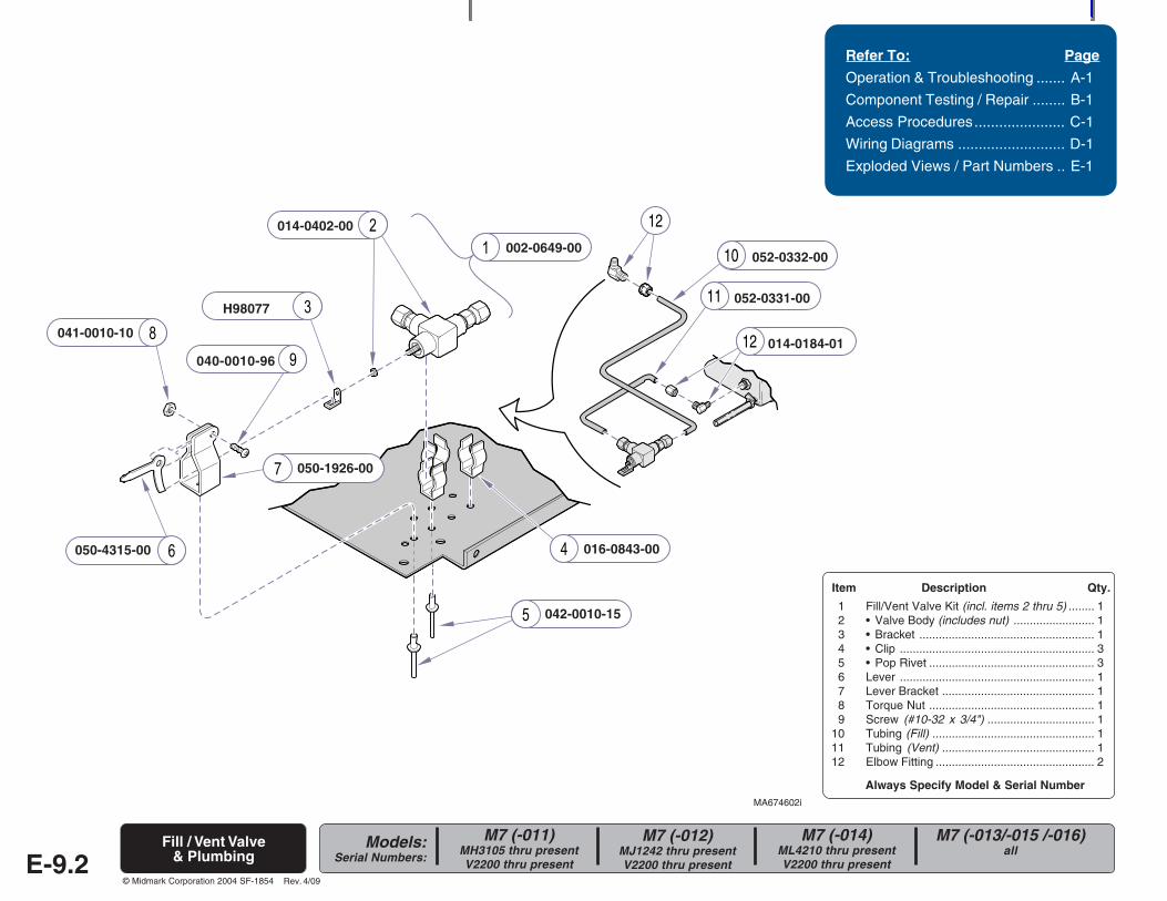
Always Specify Model & Serial Number
Models:Serial Numbers:
© Midmark Corporation 2004 SF-1854
7
12
11
10
12
MA674602i
002-0649-00
Refer To: Page
Operation & Troubleshooting ....... A-1
Component Testing / Repair ........ B-1
Access Procedures...................... C-1
Wiring Diagrams .......................... D-1
Exploded Views / Part Numbers .. E-1
E-9.2
014-0402-00
Item Description Qty.
1 Fill/Vent Valve Kit (incl. items 2 thru 5) ........ 12 • Valve Body (includes nut) ......................... 13 • Bracket ...................................................... 14 • Clip ............................................................ 35 • Pop Rivet ................................................... 36 Lever ............................................................ 17 Lever Bracket ............................................... 18 Torque Nut ................................................... 19 Screw (#10-32 x 3/4") ................................. 1
10 Tubing (Fill) .................................................. 111 Tubing (Vent) ............................................... 112 Elbow Fitting ................................................. 2
H98077
016-0843-00
042-0010-15
050-4315-00
050-1926-00
041-0010-10
040-0010-96
052-0332-00
052-0331-00
014-0184-01
M7 (-011)MH3105 thru presentV2200 thru present
M7 (-012)MJ1242 thru presentV2200 thru present
M7 (-014)ML4210 thru presentV2200 thru present
M7 (-013/-015 /-016)all
Fill / Vent Valve& Plumbing
Rev. 4/09
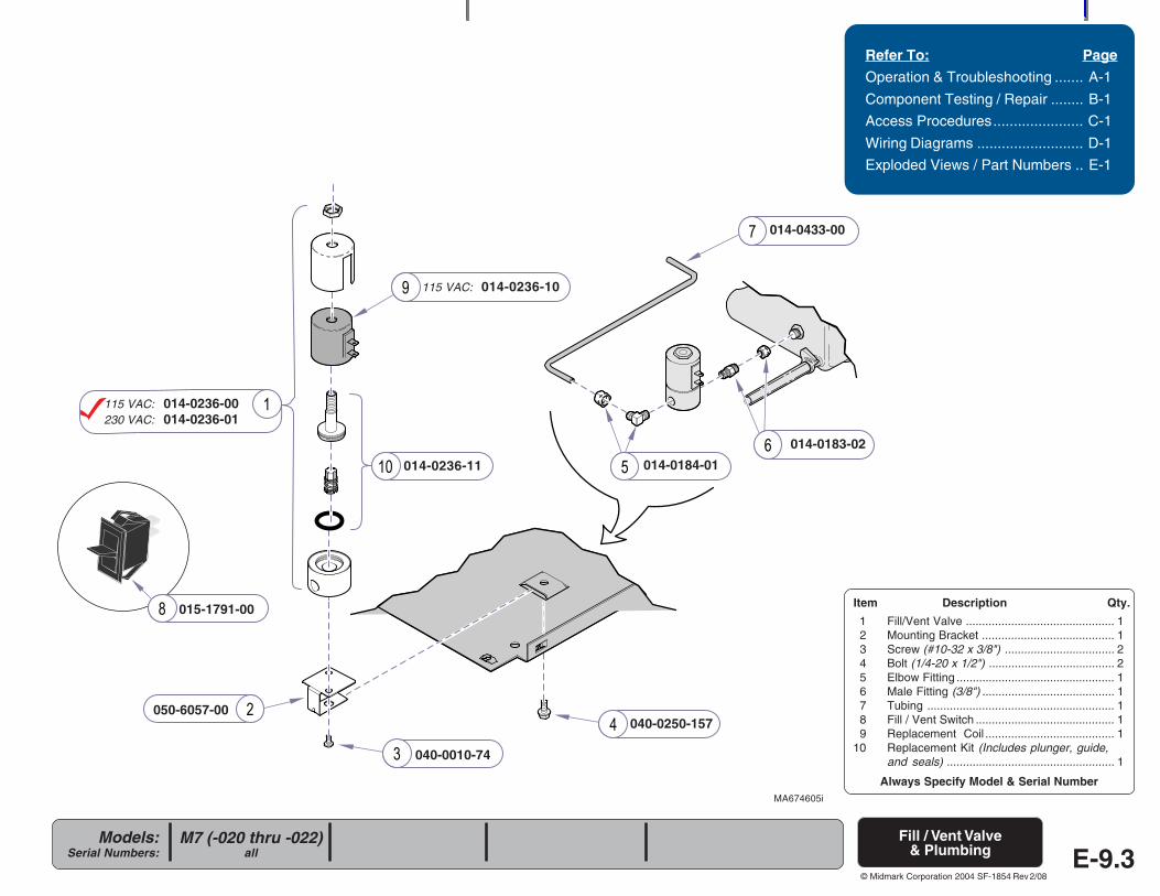
Always Specify Model & Serial Number
Models:Serial Numbers:
© Midmark Corporation 2004 SF-1854
050-6057-00
040-0010-74
040-0250-157
014-0433-00
014-0183-02
014-0184-01
115 VAC: 014-0236-00230 VAC: 014-0236-01
Refer To: Page
Operation & Troubleshooting ....... A-1
Component Testing / Repair ........ B-1
Access Procedures...................... C-1
Wiring Diagrams .......................... D-1
Exploded Views / Part Numbers .. E-1
MA674605i
M7 (-020 thru -022)all E-9.3
015-1791-00
Fill / Vent Valve& Plumbing
115 VAC: 014-0236-10
014-0236-11
Item Description Qty.
1 Fill/Vent Valve .............................................. 12 Mounting Bracket ......................................... 13 Screw (#10-32 x 3/8") .................................. 24 Bolt (1/4-20 x 1/2") ....................................... 25 Elbow Fitting ................................................. 16 Male Fitting (3/8") ......................................... 17 Tubing .......................................................... 18 Fill / Vent Switch ........................................... 19 Replacement Coil ........................................ 1
10 Replacement Kit (Includes plunger, guide,and seals) .................................................... 1
Rev 2/08
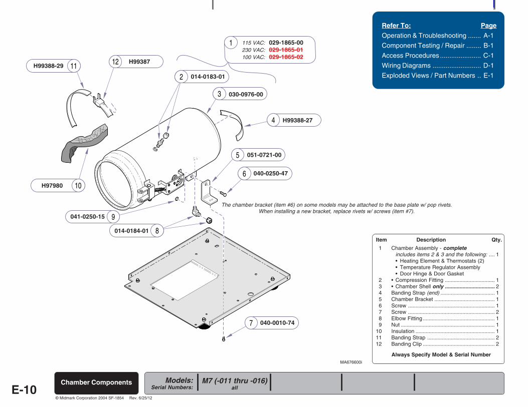
Always Specify Model & Serial Number
Models:Serial Numbers:
© Midmark Corporation 2004 SF-1854
12
10
4
6
5
7
9
8
3
2
1
11
Refer To: Page
Operation & Troubleshooting ....... A-1
Component Testing / Repair ........ B-1
Access Procedures ...................... C-1
Wiring Diagrams .......................... D-1
Exploded Views / Part Numbers .. E-1
Item Description Qty.
1 Chamber Assembly - completeincludes items 2 & 3 and the following: .... 1• Heating Element & Thermostats (2)• Temperature Regulator Assembly• Door Hinge & Door Gasket
2 • Compression Fitting .................................. 13 • Chamber Shell only .................................. 24 Banding Strap (end) ..................................... 15 Chamber Bracket ......................................... 16 Screw ........................................................... 17 Screw ........................................................... 28 Elbow Fitting ................................................. 19 Nut ................................................................ 1
10 Insulation ...................................................... 111 Banding Strap .............................................. 212 Banding Clip ................................................. 2
MA676600i
115 VAC: 029-1865-00230 VAC: 029-1865-01100 VAC: 029-1865-02
014-0183-01
030-0976-00
H99388-27
051-0721-00
040-0250-47
040-0010-74
014-0184-01
041-0250-15
H97980
H99387H99388-29
The chamber bracket (item #6) on some models may be attached to the base plate w/ pop rivets.When installing a new bracket, replace rivets w/ screws (item #7).
Chamber ComponentsE-10
M7 (-011 thru -016)all
Rev. 6/25/12
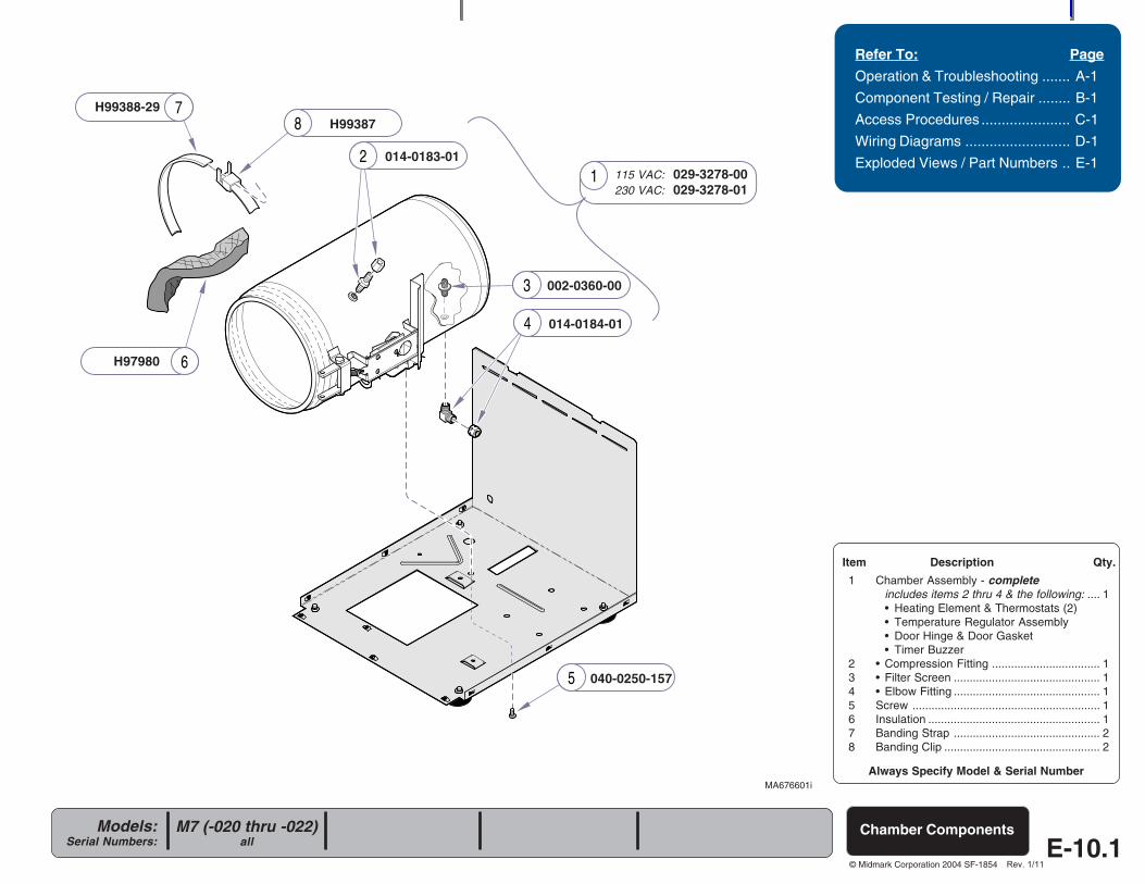
Always Specify Model & Serial Number
Models:Serial Numbers:
© Midmark Corporation 2004 SF-1854E-10.1
78
6
5
2
4
1
3
Refer To: Page
Operation & Troubleshooting ....... A-1
Component Testing / Repair ........ B-1
Access Procedures ...................... C-1
Wiring Diagrams .......................... D-1
Exploded Views / Part Numbers .. E-1
Item Description Qty.
1 Chamber Assembly - completeincludes items 2 thru 4 & the following: .... 1• Heating Element & Thermostats (2)• Temperature Regulator Assembly• Door Hinge & Door Gasket• Timer Buzzer
2 • Compression Fitting .................................. 13 • Filter Screen .............................................. 14 • Elbow Fitting .............................................. 15 Screw ........................................................... 16 Insulation ...................................................... 17 Banding Strap .............................................. 28 Banding Clip ................................................. 2
Chamber ComponentsM7 (-020 thru -022)all
MA676601i
115 VAC: 029-3278-00230 VAC: 029-3278-01
014-0183-01
040-0250-157
014-0184-01
H97980
H99387H99388-29
002-0360-00
Rev. 1/11
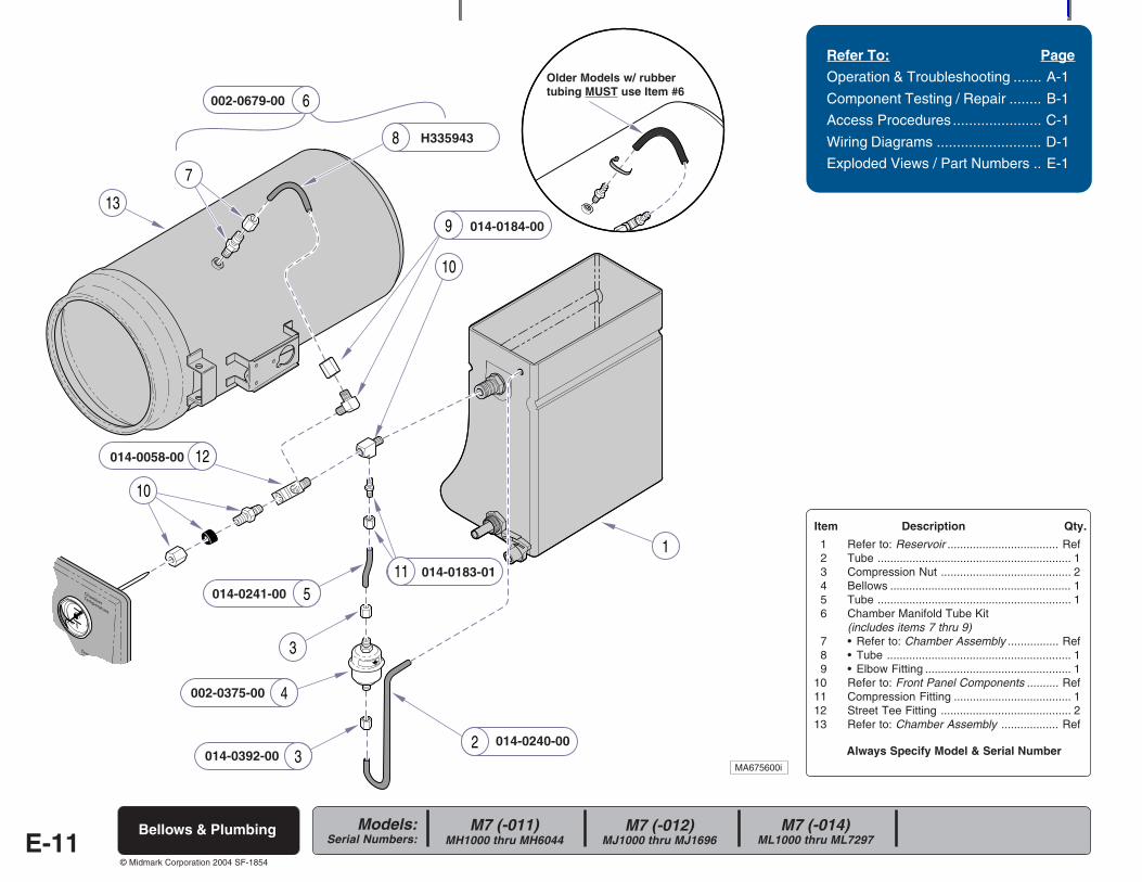
Always Specify Model & Serial Number
Models:Serial Numbers:
© Midmark Corporation 2004 SF-1854
5
3
4
3
1
2
13
7
6
10
8
9
10
11
12
Refer To: Page
Operation & Troubleshooting ....... A-1
Component Testing / Repair ........ B-1
Access Procedures ...................... C-1
Wiring Diagrams .......................... D-1
Exploded Views / Part Numbers .. E-1
Item Description Qty.
1 Refer to: Reservoir ................................... Ref2 Tube ............................................................. 13 Compression Nut ......................................... 24 Bellows ......................................................... 15 Tube ............................................................. 16 Chamber Manifold Tube Kit
(includes items 7 thru 9)7 • Refer to: Chamber Assembly ................ Ref8 • Tube .......................................................... 19 • Elbow Fitting .............................................. 1
10 Refer to: Front Panel Components .......... Ref11 Compression Fitting ..................................... 112 Street Tee Fitting ......................................... 213 Refer to: Chamber Assembly .................. Ref
E-11Bellows & Plumbing
014-0240-00
M7 (-011)MH1000 thru MH6044
M7 (-012)MJ1000 thru MJ1696
M7 (-014)ML1000 thru ML7297
014-0392-00
002-0375-00
014-0241-00
014-0183-01
014-0058-00
014-0184-00
H335943
Older Models w/ rubbertubing MUST use Item #6
002-0679-00
MA675600i
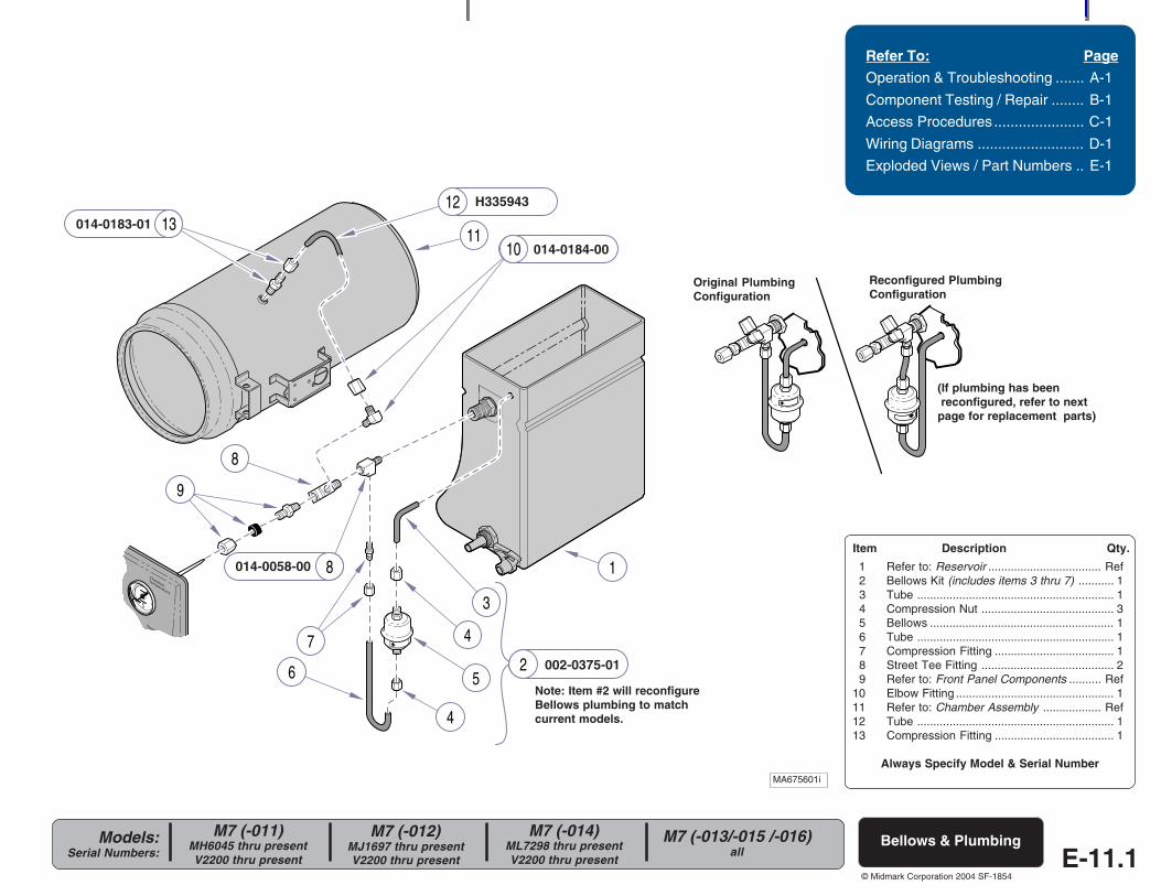
Always Specify Model & Serial Number
Models:Serial Numbers:
© Midmark Corporation 2004 SF-1854
1
12
4
11
8
9
8
6 5
3
47
1013
2
Refer To: Page
Operation & Troubleshooting ....... A-1
Component Testing / Repair ........ B-1
Access Procedures ...................... C-1
Wiring Diagrams .......................... D-1
Exploded Views / Part Numbers .. E-1
Item Description Qty.
1 Refer to: Reservoir ................................... Ref2 Bellows Kit (includes items 3 thru 7) ........... 13 Tube ............................................................. 14 Compression Nut ......................................... 35 Bellows ......................................................... 16 Tube ............................................................. 17 Compression Fitting ..................................... 18 Street Tee Fitting ......................................... 29 Refer to: Front Panel Components .......... Ref
10 Elbow Fitting ................................................. 111 Refer to: Chamber Assembly .................. Ref12 Tube ............................................................. 113 Compression Fitting ..................................... 1
Bellows & Plumbing
MA675601i
002-0375-01
014-0058-00
014-0184-00
H335943
M7 (-011)MH6045 thru presentV2200 thru present
M7 (-012)MJ1697 thru presentV2200 thru present
M7 (-014)ML7298 thru presentV2200 thru present
M7 (-013/-015 /-016)all E-11.1
014-0183-01
Note: Item #2 will reconfigureBellows plumbing to matchcurrent models.
(If plumbing has been reconfigured, refer to nextpage for replacement parts)
Original PlumbingConfiguration
Reconfigured PlumbingConfiguration
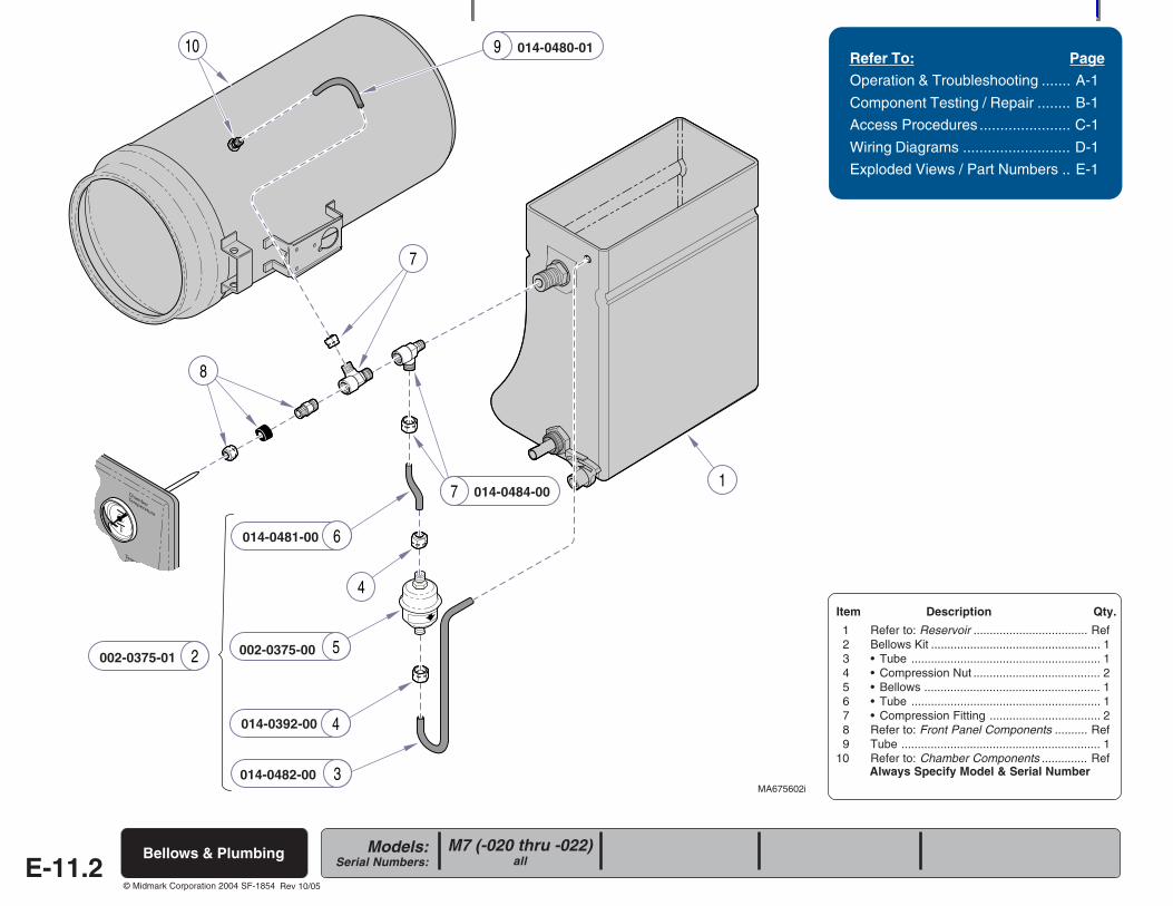
Always Specify Model & Serial Number
Models:Serial Numbers:
© Midmark Corporation 2004 SF-1854
6
4
5
4
17
7
8
910
3
2
Refer To: Page
Operation & Troubleshooting ....... A-1
Component Testing / Repair ........ B-1
Access Procedures ...................... C-1
Wiring Diagrams .......................... D-1
Exploded Views / Part Numbers .. E-1
Item Description Qty.
1 Refer to: Reservoir ................................... Ref2 Bellows Kit .................................................... 13 • Tube .......................................................... 14 • Compression Nut ....................................... 25 • Bellows ...................................................... 16 • Tube .......................................................... 17 • Compression Fitting .................................. 28 Refer to: Front Panel Components .......... Ref9 Tube ............................................................. 1
10 Refer to: Chamber Components .............. Ref
E-11.2Bellows & Plumbing
MA675602i014-0482-00
014-0392-00
002-0375-00
014-0481-00
014-0480-01
M7 (-020 thru -022)all
014-0484-00
002-0375-01
Rev 10/05
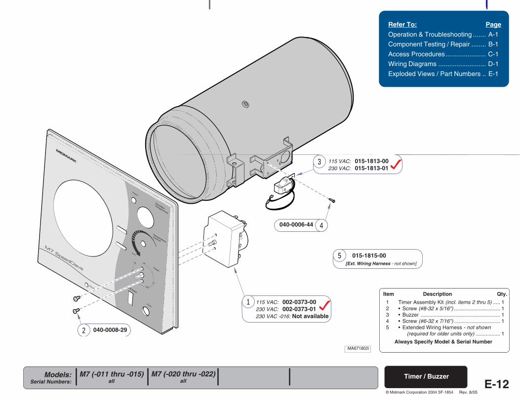
Always Specify Model & Serial Number
Models:Serial Numbers:
© Midmark Corporation 2004 SF-1854
R
4
2
3
5
1
Refer To: Page
Operation & Troubleshooting ....... A-1
Component Testing / Repair ........ B-1
Access Procedures...................... C-1
Wiring Diagrams .......................... D-1
Exploded Views / Part Numbers .. E-1
Item Description Qty.
1 Timer Assembly Kit (incl. items 2 thru 5) ..... 12 • Screw (#8-32 x 5/16") ................................ 13 • Buzzer ....................................................... 14 • Screw (#6-32 x 7/16") ................................ 15 • Extended Wiring Harness - not shown
(required for older units only) ................. 1
040-0006-44
MA671802i
Timer / Buzzer
115 VAC: 002-0373-00230 VAC: 002-0373-01230 VAC -016: Not available
040-0008-29
115 VAC: 015-1813-00230 VAC: 015-1813-01
015-1815-00[Ext. Wiring Harness - not shown]
E-12
MA671801i
Rev. 8/05
M7 (-011 thru -015)all
M7 (-020 thru -022)all
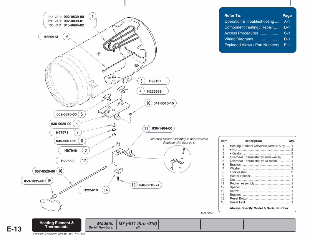
Always Specify Model & Serial Number
Models:Serial Numbers:
© Midmark Corporation 2004 SF-1854
9
10
11
12
1314
15
16
Refer To: Page
Operation & Troubleshooting ....... A-1
Component Testing / Repair ........ B-1
Access Procedures ...................... C-1
Wiring Diagrams .......................... D-1
Exploded Views / Part Numbers .. E-1
Item Description Qty.
1 Heating Element (includes items 2 & 3) ...... 12 • Nut ............................................................. 23 • Gasket ....................................................... 24 Overheat Thermostat (manual-reset) .......... 15 Overheat Thermostat (auto-reset) ............... 16 Bracket ......................................................... 17 Washer ......................................................... 28 Lockwasher .................................................. 29 Heater Spacer .............................................. 1
10 Nut ................................................................ 111 Rocker Assembly ......................................... 112 Spacer .......................................................... 113 Screw ........................................................... 114 Bracket ......................................................... 115 Reset Button ................................................ 116 Reset Rod .................................................... 1
E-13
MA673901i
115 VAC: 002-0839-00230 VAC: 002-0839-01100 VAC: 015-0894-02
H97949
H98137
H225639
002-0370-00
030-0929-00
H97971
045-0001-56
030-1484-00
057-0520-00
053-1035-00
H225619040-0010-74
H225620
041-0010-10
H225913
Old-style rocker assembly is not available.Replace with item #11.
M7 (-011 thru -016)all
Heating Element &Thermostats
Rev. 6/09
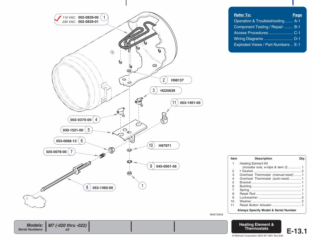
Always Specify Model & Serial Number
Models:Serial Numbers:
© Midmark Corporation 2004 SF-1854
9
10
11
Refer To: Page
Operation & Troubleshooting ....... A-1
Component Testing / Repair ........ B-1
Access Procedures...................... C-1
Wiring Diagrams .......................... D-1
Exploded Views / Part Numbers .. E-1
Item Description Qty.
1 Heating Element Kit(includes nuts, e-clips & item 2) ............... 1
2 • Gasket ...................................................... 23 Overheat Thermostat (manual-reset) ........ 14 Overheat Thermostat (auto-reset) ............. 15 Bracket ......................................................... 16 Bushing ........................................................ 17 Spring ........................................................... 18 Reset Rod .................................................... 19 Lockwasher ................................................. 2
10 Washer ......................................................... 211 Reset Button Actuator ................................. 1
Heating Element &Thermostats
MA673903i
115 VAC: 002-0839-00230 VAC: 002-0839-01
H225639
002-0370-00
E-13.1M7 (-020 thru -022)
all
H98137
030-1521-00
H97971
045-0001-56
053-1461-00
053-1460-00
053-0068-13
025-0078-00
Rev 6/09
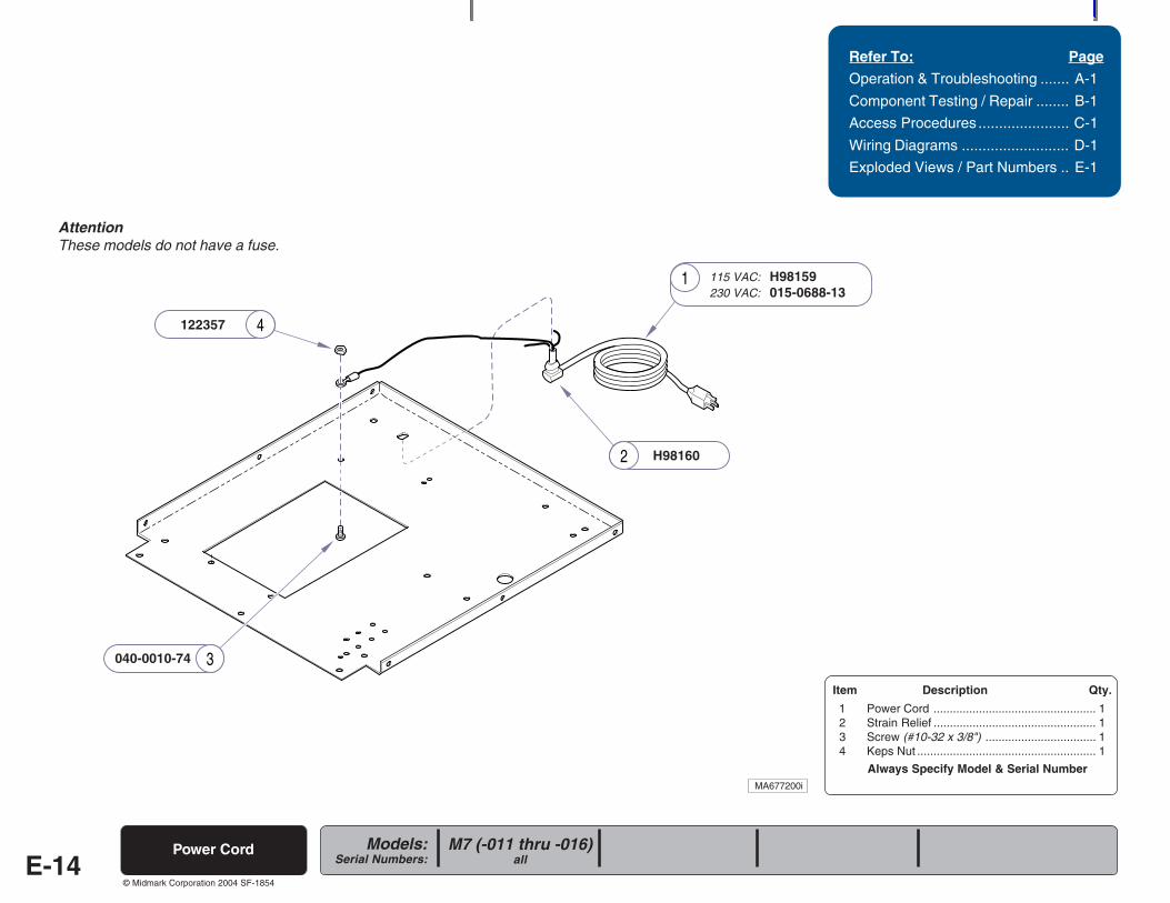
Always Specify Model & Serial Number
Models:Serial Numbers:
© Midmark Corporation 2004 SF-1854
4
2
3
1
Refer To: Page
Operation & Troubleshooting ....... A-1
Component Testing / Repair ........ B-1
Access Procedures ...................... C-1
Wiring Diagrams .......................... D-1
Exploded Views / Part Numbers .. E-1
Item Description Qty.
1 Power Cord .................................................. 12 Strain Relief .................................................. 13 Screw (#10-32 x 3/8") .................................. 14 Keps Nut ....................................................... 1
H98160
MA677200i
E-14Power Cord
115 VAC: H98159230 VAC: 015-0688-13
122357
040-0010-74
AttentionThese models do not have a fuse.
M7 (-011 thru -016)all
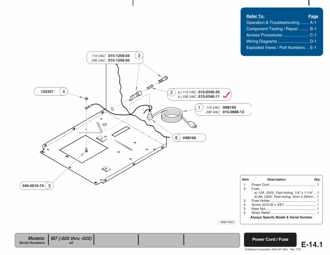
Always Specify Model & Serial Number
Models:Serial Numbers:
© Midmark Corporation 2004 SF-1854
4
6
5
1
3
2
E-14.1
Refer To: Page
Operation & Troubleshooting ....... A-1
Component Testing / Repair ........ B-1
Access Procedures ...................... C-1
Wiring Diagrams .......................... D-1
Exploded Views / Part Numbers .. E-1
MA677201i
Power Cord / FuseM7 (-020 thru -022)all
Item Description Qty.
1 Power Cord .................................................. 12 Fuse:
a) 12A, 250V, Fast-Acting, 1/4" x 1-1/4" ... 1b) 8A, 250V, Fast-Acting, 5mm x 20mm ... 1
3 Fuse Holder .................................................. 14 Screw (#10-32 x 3/8") .................................. 15 Keps Nut ....................................................... 16 Strain Relief .................................................. 1
115 VAC: H98159230 VAC: 015-0688-13
a.) 115 VAC: 015-0346-35b.) 230 VAC: 015-0346-11
115 VAC: 015-1259-04230 VAC: 015-1259-05
122357
040-0010-74
H98160
Rev. 7/05
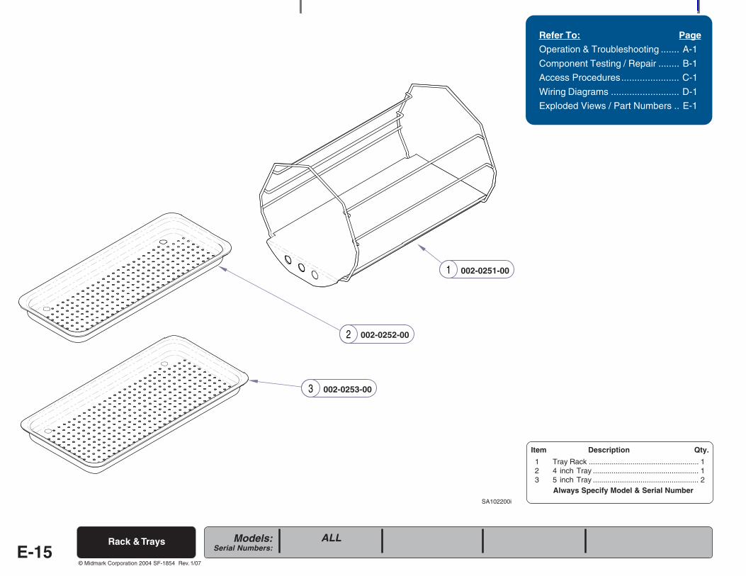
Always Specify Model & Serial Number
Models:Serial Numbers:
© Midmark Corporation 2004 SF-1854
2
3
1
Refer To: Page
Operation & Troubleshooting ....... A-1
Component Testing / Repair ........ B-1
Access Procedures...................... C-1
Wiring Diagrams .......................... D-1
Exploded Views / Part Numbers .. E-1
SA102200i
Rack & Trays
Item Description Qty.
1 Tray Rack ..................................................... 12 4 inch Tray ................................................... 13 5 inch Tray ................................................... 2
002-0251-00
002-0253-00
002-0252-00
E-15ALL
Rev. 1/07
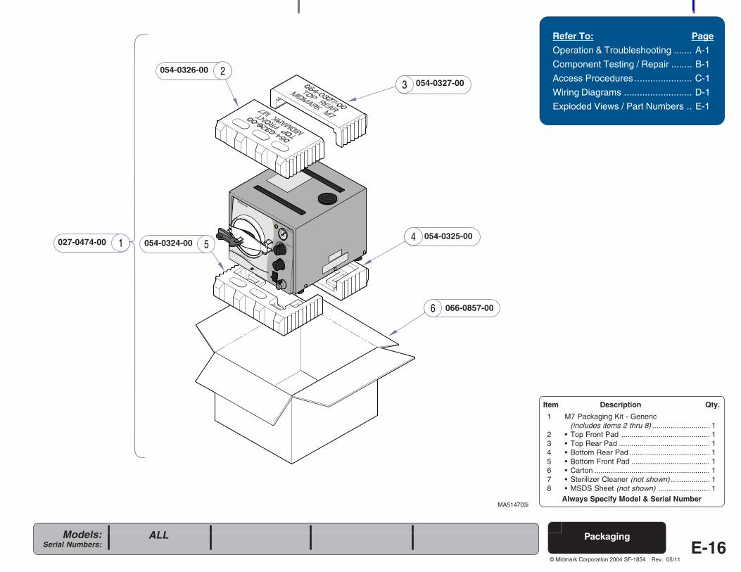
Always Specify Model & Serial Number
Models:Serial Numbers:
© Midmark Corporation 2004 SF-1854
2
5
3
4
6
1
R
Packaging
Refer To: Page
Operation & Troubleshooting ....... A-1
Component Testing / Repair ........ B-1
Access Procedures ...................... C-1
Wiring Diagrams .......................... D-1
Exploded Views / Part Numbers .. E-1
054-0326-00
MA514703i
Item Description Qty.
1 M7 Packaging Kit - Generic(includes items 2 thru 8) ............................ 1
2 • Top Front Pad ........................................... 13 • Top Rear Pad ............................................ 14 • Bottom Rear Pad ....................................... 15 • Bottom Front Pad ...................................... 16 • Carton ........................................................ 17 • Sterilizer Cleaner (not shown) ................... 18 • MSDS Sheet (not shown) ......................... 1
ALL
054-0327-00
054-0325-00054-0324-00
066-0857-00
E-16
027-0474-00
Rev. 05/11
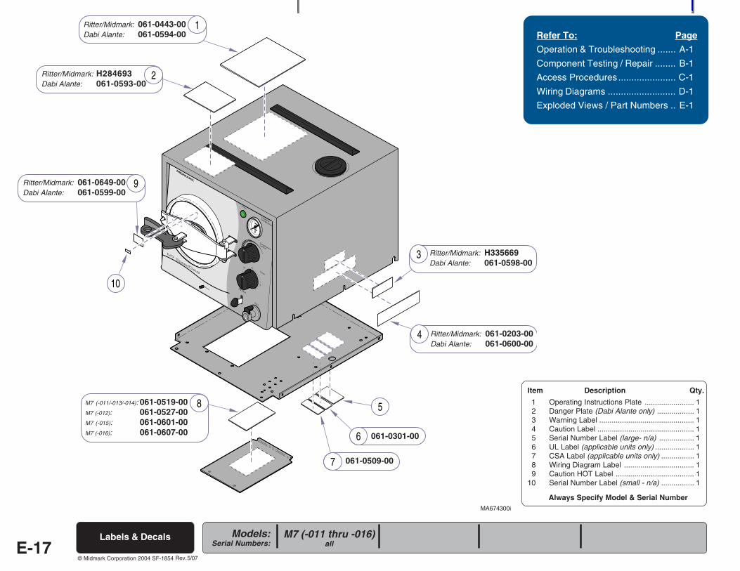
Always Specify Model & Serial Number
Models:Serial Numbers:
© Midmark Corporation 2004 SF-1854
R
6
7
10
5
1
3
4
9
8
2
Labels & Decals
Refer To: Page
Operation & Troubleshooting ....... A-1
Component Testing / Repair ........ B-1
Access Procedures ...................... C-1
Wiring Diagrams .......................... D-1
Exploded Views / Part Numbers .. E-1
Ritter/Midmark: 061-0443-00Dabi Alante: 061-0594-00
MA674300i
Item Description Qty.
1 Operating Instructions Plate ........................ 12 Danger Plate (Dabi Alante only) .................. 13 Warning Label .............................................. 14 Caution Label ............................................... 15 Serial Number Label (large- n/a) ................. 16 UL Label (applicable units only) ................... 17 CSA Label (applicable units only) ................ 18 Wiring Diagram Label .................................. 19 Caution HOT Label ...................................... 1
10 Serial Number Label (small - n/a) ................ 1
E-17
Ritter/Midmark: H335669Dabi Alante: 061-0598-00
Ritter/Midmark: 061-0203-00Dabi Alante: 061-0600-00
061-0301-00
061-0509-00
M7 (-011/-013/-014): 061-0519-00M7 (-012): 061-0527-00M7 (-015): 061-0601-00M7 (-016): 061-0607-00
Ritter/Midmark: 061-0649-00Dabi Alante: 061-0599-00
M7 (-011 thru -016)all
Ritter/Midmark: H284693Dabi Alante: 061-0593-00
Rev. 5/07
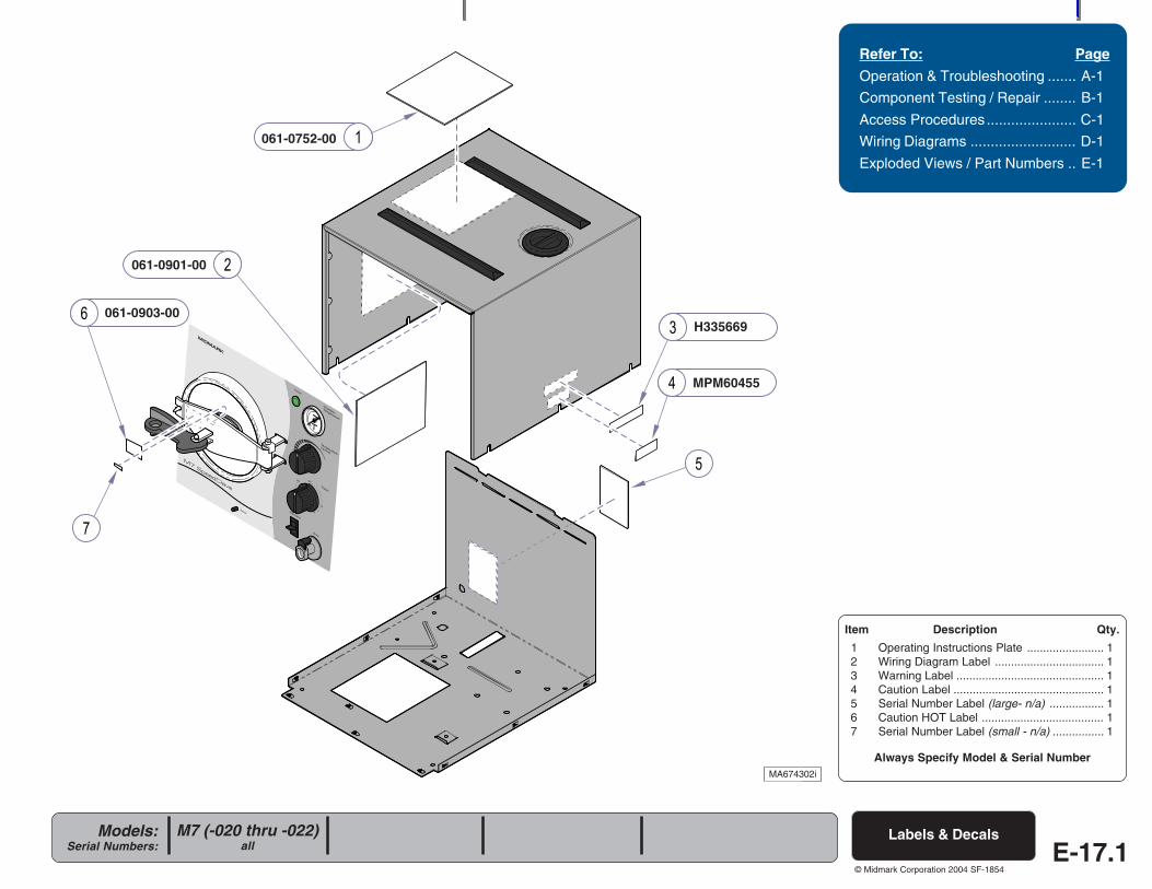
Always Specify Model & Serial Number
Models:Serial Numbers:
© Midmark Corporation 2004 SF-1854
R
E-17.1Labels & Decals
Refer To: Page
Operation & Troubleshooting ....... A-1
Component Testing / Repair ........ B-1
Access Procedures ...................... C-1
Wiring Diagrams .......................... D-1
Exploded Views / Part Numbers .. E-1
MA674302i
061-0752-00
061-0901-00
061-0903-00H335669
MPM60455
Item Description Qty.
1 Operating Instructions Plate ........................ 12 Wiring Diagram Label .................................. 13 Warning Label .............................................. 14 Caution Label ............................................... 15 Serial Number Label (large- n/a) ................. 16 Caution HOT Label ...................................... 17 Serial Number Label (small - n/a) ................ 1
M7 (-020 thru -022)all

COMMENTS
The Technical Publications Department of Midmark Corporation takes pride in its manuals. We are sure that our manuals will fill all your needs when you are perform-ing scheduled maintenance, servicing, or repairs on a Midmark product. However, if you find any errors or feel there should be a change, addition, or deletion to themanuals, please let us know. We will correct any errors that we are made aware of and we will review requests for changes, additions, or deletions to the manuals andincorporate those requests deemed appropriate. If you see something in one of our manuals that you like or dislike, please let us know. Also, if there is something youfeel we could do to produce a better manual, please let us know.
If an error is found, please list the page and paragraph/figure in which the error was found along with a brief description of what the error is. If the correction to the erroris known, please include that information also. If a change, addition, or deletion is being requested, please list the page and paragraph/figure needing the change, alongwith a brief description of how you feel the paragraph/figure should be changed.
Please fax or mail a copy of this completed comment sheet to:
Page Number Paragraph/Figure Description
Midmark CorporationATTN: Technical Publications Dept.60 Vista DriveVersailles, Ohio 45380Fax: (937) 526-5542
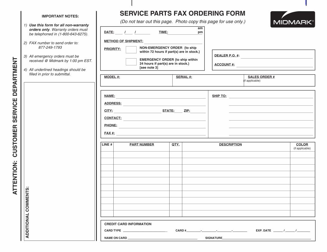
SERVICE PARTS FAX ORDERING FORM(Do not tear out this page. Photo copy this page for use only.)
IMPORTANT NOTES:
1) Use this form for all non-warrantyorders only. Warranty orders mustbe telephoned in (1-800-643-6275).
2) FAX number to send order to:877-249-1793
3) All emergency orders must bereceived @ Midmark by 1:00 pm EST.
4) All underlined headings should befilled in prior to submittal.
AT
TE
NT
ION
: C
US
TOM
ER
SE
RV
ICE
DE
PAR
TM
EN
T
AD
DIT
ION
AL
CO
MM
EN
TS
:
NAME: SHIP TO:
ADDRESS:
CITY: STATE: ZIP:
CONTACT:
PHONE:
FAX #:
MODEL #: SERIAL #: SALES ORDER # (if applicable)
LINE # PART NUMBER QTY. DESCRIPTION COLOR(if applicable)
CREDIT CARD INFORMATION
CARD TYPE __________________________ _ CARD #_________-_________-_________-_________ EXP. DATE ______ / ______ / ________
NAME ON CARD ___________________________________________ SIGNATURE_______________________________________________________
DATE: / / TIME:
METHOD OF SHIPMENT:
PRIORITY: NON-EMERGENCY ORDER to shipwithin 72 hours if part(s) are in stock.
EMERGENCY ORDER to ship within24 hours if part(s) are in stock.[see note 3]
DEALER P.O. #:
ACCOUNT #:
ampm

Midmark Corporation60 Vista DriveP.O. Box 286Versailles, OH 45380-0286Phone: 937-526-3662Fax: 937-526-5542
www.midmark.com
Subject to change without notice.Refer to www.Documark.com for latest revision.
Related Documents