Vol-5 Issue-4 2019 IJARIIE-ISSN(O)-2395-4396 10661 www.ijariie.com 758 SPEED CONTROL OF INDUCTION MOTOR USING VSI BASED ON PWM/ SVPWM TECHNIQUES A. Parvathi 1 , Dr.G. Venkataramana 2 1 P.G.Student , Department of Electrical and Electronics Engineering, GITAS, A.P, India. 2, Assistant Professor, Department of Electrical and Electronics Engineering, GITAS, A.P, India. ABSTRACT Pulse Width Modulation variable speed drives are increasingly applied in many new industrial applications that require superior performance. Recently, developments in power electronics and semiconductor technology have lead improvements in power electronic systems. Hence, different circuit configurations namely multilevel inverters have become popular and considerable interest by researcher are given on them. Variable voltage and frequency supply to a.c drives is invariably obtained from a three-phase voltage source inverter. A number of Pulse width modulation (PWM) schemes are used to obtain variable voltage and frequency supply. The most widely used PWM schemes for three-phase voltage source inverters are carrier-based sinusoidal PWM and space vector PWM (SVPWM). There is an increasing trend of using space vector PWM (SVPWM) because of their easier digital realization and better dc bus utilization. This project focuses on step by step development SVPWM implemented on an Induction motor. The model of a three-phase a voltage source inverter is discussed based on space vector theory. Simulation results are obtained using MATLAB/Simu link environment for effectiveness of the study. Keyword : - Pulse width modulation , three-phase voltage , Sinusoidal Pulse Width Modulation 1. Introduction Three phase voltage-fed PWM inverters are recently showing growing popularity for multi-megawatt industrial drive applications. The main reasons for this popularity are easy sharing of large voltage between the series devices and the improvement of the harmonic quality at the output as compared to a two level inverter. In the lower end of power, GTO devices are being replaced by IGBTs because of their rapid evolution in voltage and current ratings and higher switching frequency. The Space Vector Pulse Width Modulation of a three level inverter provides the additional advantage of superior harmonic quality and larger under-modulation range that extends the modulation factor to 90.7% from the traditional value of 78.5% in Sinusoidal Pulse Width Modulation. An adjustable speed drive (ASD) is a device used to provide continuous range process speed control (as compared to discrete speed control as in gearboxes or multi-speed motors). An ASD is capable of adjusting both speed and torque from an induction or synchronous motor. An electric ASD is an electrical system used to control motor speed. ASDs may be referred to by a variety of names, such as variable speed drives, adjustable frequency drives or variable frequency inverters. The latter two terms will only be used to refer to certain AC systems, as is often the practice, although some DC drives are also based on the principle of adjustable frequency. Figure 1: Comparison of range process speed control

Welcome message from author
This document is posted to help you gain knowledge. Please leave a comment to let me know what you think about it! Share it to your friends and learn new things together.
Transcript
Vol-5 Issue-4 2019 IJARIIE-ISSN(O)-2395-4396
10661 www.ijariie.com 758
SPEED CONTROL OF INDUCTION MOTOR
USING VSI BASED ON PWM/ SVPWM
TECHNIQUES
A. Parvathi1, Dr.G. Venkataramana
2
1P.G.Student , Department of Electrical and Electronics Engineering, GITAS, A.P, India.
2, Assistant Professor, Department of Electrical and Electronics Engineering, GITAS, A.P, India.
ABSTRACT Pulse Width Modulation variable speed drives are increasingly applied in many new industrial applications that
require superior performance. Recently, developments in power electronics and semiconductor technology have
lead improvements in power electronic systems. Hence, different circuit configurations namely multilevel inverters
have become popular and considerable interest by researcher are given on them. Variable voltage and frequency
supply to a.c drives is invariably obtained from a three-phase voltage source inverter. A number of Pulse width
modulation (PWM) schemes are used to obtain variable voltage and frequency supply. The most widely used PWM
schemes for three-phase voltage source inverters are carrier-based sinusoidal PWM and space vector PWM
(SVPWM). There is an increasing trend of using space vector PWM (SVPWM) because of their easier digital
realization and better dc bus utilization. This project focuses on step by step development SVPWM implemented on
an Induction motor. The model of a three-phase a voltage source inverter is discussed based on space vector theory.
Simulation results are obtained using MATLAB/Simu link environment for effectiveness of the study.
Keyword : - Pulse width modulation , three-phase voltage , Sinusoidal Pulse Width Modulation
1. Introduction
Three phase voltage-fed PWM inverters are recently showing growing popularity for multi-megawatt industrial
drive applications. The main reasons for this popularity are easy sharing of large voltage between the series devices
and the improvement of the harmonic quality at the output as compared to a two level inverter. In the lower end of
power, GTO devices are being replaced by IGBTs because of their rapid evolution in voltage and current ratings and
higher switching frequency. The Space Vector Pulse Width Modulation of a three level inverter provides the
additional advantage of superior harmonic quality and larger under-modulation range that extends the modulation
factor to 90.7% from the traditional value of 78.5% in Sinusoidal Pulse Width Modulation.
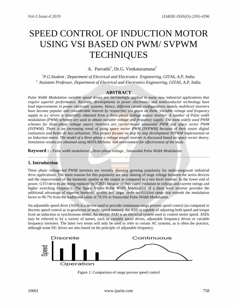
An adjustable speed drive (ASD) is a device used to provide continuous range process speed control (as compared to
discrete speed control as in gearboxes or multi-speed motors). An ASD is capable of adjusting both speed and torque
from an induction or synchronous motor. An electric ASD is an electrical system used to control motor speed. ASDs
may be referred to by a variety of names, such as variable speed drives, adjustable frequency drives or variable
frequency inverters. The latter two terms will only be used to refer to certain AC systems, as is often the practice,
although some DC drives are also based on the principle of adjustable frequency.
Figure 1: Comparison of range process speed control
Vol-5 Issue-4 2019 IJARIIE-ISSN(O)-2395-4396
10661 www.ijariie.com 759
1.1 Latest Improvements
• Microprocessor-based controllers eliminate analog, potentiometer-based adjustments.
• Digital control capability.
• Built-in Power Factor correction.
• Radio Frequency Interference (RFI) filters.
• Short Circuit Protection (automatic shutdown).
• Advanced circuitry to detect motor rotor position by sampling power at terminals, ASD and motor circuitry
combined to keep power waveforms sinusoidal, minimizing power losses.
• Motor Control Centers (MCC) coupled with the ASD using real-time monitors to trace motor- drive system
performance.
• Higher starting torques at low speeds (up to 150% running torque) up to 500 HP, in voltage source drives.
• Load-commutated Inverters coupled with synchronous motors. (Precise speed control in constant torque
applications.
Adjustable speed drives are the most efficient (98% at full load) types of drives. They are used to control the
speeds of both AC and DC motors. They include variable frequency/voltage AC motor controllers for squirrel-cage
motors, DC motor controllers for DC motors, eddy current clutches for AC motors (less efficient), wound-rotor
motor controllers for wound-rotor AC motors (less efficient) and cyclo converters (less efficient).
Pulse Width Modulation variable speed drives are increasingly applied in many new industrial
applications that require superior performance. Recently, developments in power electronics and semiconductor
technology have lead improvements in power electronic systems. Hence, different circuit configurations namely
multilevel inverters have become popular and considerable interest by researcher are given on them.Variable
voltage and frequency supply to drives is invariably obtained from a three-phase voltage source inverter. A number
of Pulse width modulation (PWM) schemes are used to obtain variable voltage and frequency supply. The most
widely used PWM schemes for three-phase voltage source inverters are carrier-based sinusoidal PWM and space
vector PWM (SVPWM). There is an increasing trend of using space vector PWM (SVPWM) because of their
easier digital realization and better dc bus utilization.
This project focuses on step by step development SVPWM implemented on an Induction motor. The model of a
three-phase a voltage source inverter is discussed based on space vector theory. Simulation results are obtained
using MATLAB/Simulink environment for effectiveness of the study.
2.Voltage Source Inverters The main objective of static power converters is to produce an ac output waveform from a dc power
supply. These are the types of waveforms required in adjustable speed drives (ASDs), uninterruptible power
supplies (UPS), static var compensators, active filters, flexible ac transmission systems (FACTS), and voltage
compensators, which are only a few applications. For sinusoidal ac outputs, the magnitude, frequency, and phase
should be controllable.
According to the type of ac output waveform, these topologies can be considered as voltage source
inverters (VSIs), where the independently controlled ac output is a voltage waveform. These structures are the most
widely used because they naturally behave as voltage sources as required by many industrial applications, such as
adjustable speed drives (ASDs), which are the most popular application of inverters. Similarly, these topologies can
be found as current source inverters (CSIs), where the independently controlled ac output is a current waveform.
These structures are still widely used in medium-voltage industrial applications, where high-quality voltage
waveforms are required. Static power converters, specifically inverters, are constructed from power switches and
the ac output waveforms are therefore made up of discrete values. This leads to the generation of waveforms that
feature fast transitions rather than smooth ones.
Vol-5 Issue-4 2019 IJARIIE-ISSN(O)-2395-4396
10661 www.ijariie.com 760
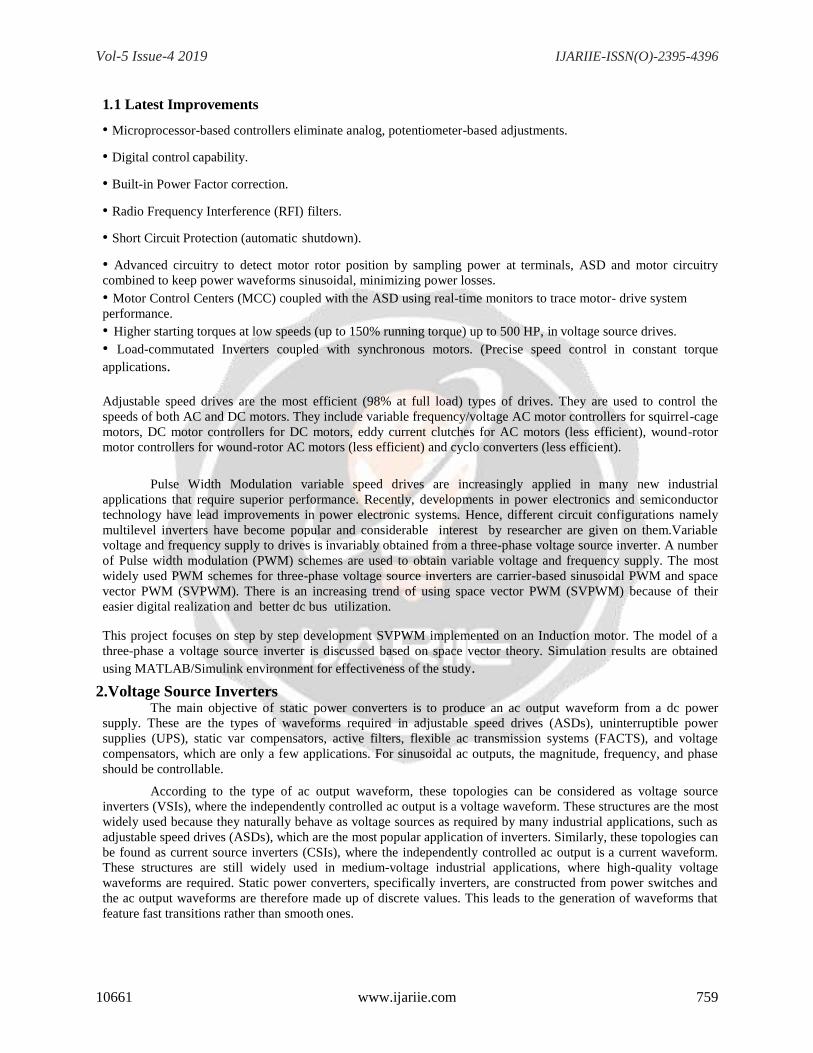
For instance, the ac output voltage produced by the VSI of a standard ASD is a three- level waveform (Fig. 1c).
Although this waveform is not sinusoidal as expected (Fig. 1b), its fundamental component behaves as such. This
behavior should be ensured by a modulating technique that controls the amount of time and the sequence used to
switch the power valves on and off. The modulating techniques most used are the carrier-based technique (e.g.,
sinusoidal pulse width modulation, SPWM), the space-vector (SV) technique, and the selective-harmonic-
elimination (SHE) technique.
Fig. 2: The AC output voltage produced by the VSI of a standard ASD
a) The electrical power conversion topology;
b) The ideal input (ac mains) and output (load) waveforms; and
c) The actual input (ac mains) and output (load) waveforms.
Single-Phase Voltage Source Inverters
Single-phase voltage source inverters (VSIs) can be found as half-bridge and full-bridge topologies. Although the
power range they cover is the low one, they are widely used in power supplies, single-phase UPSs, and currently to
form elaborate high-power static power topologies, such as for instance, the multicell configurations.
Half-Bridge VSI
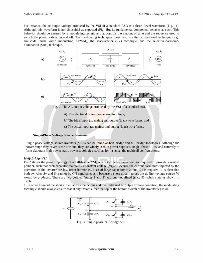
Fig.2 shows the power topology of a half-bridge VSI, where two large capacitors are required to provide a neutral
point N, such that each capacitor maintains a constant voltage (Vi)/2. Because the current harmonics injected by the
operation of the inverter are low-order harmonics, a set of large capacitors (C+ and C-) is required. It is clear that
both switches S+ and S- cannot be ON simultaneously because a short circuit across the dc link voltage source Vi
would be produced. There are two defined (states 1 and 2) and one undefined (state 3) switch state as shown in
Table
1. In order to avoid the short circuit across the dc bus and the undefined ac output voltage condition, the modulating
technique should always ensure that at any instant either the top or the bottom switch of the inverter leg is on.
Fig. 3: Single-phase half-bridge VSI.
Vol-5 Issue-4 2019 IJARIIE-ISSN(O)-2395-4396
10661 www.ijariie.com 761
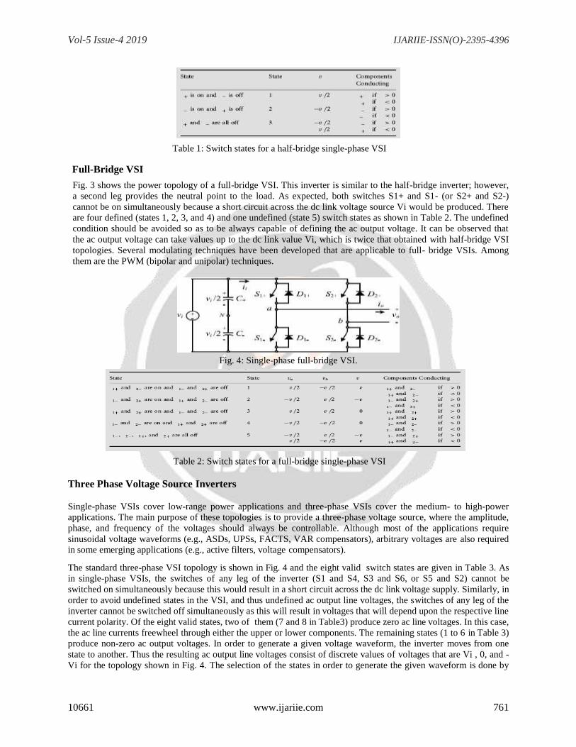
Table 1: Switch states for a half-bridge single-phase VSI
Full-Bridge VSI
Fig. 3 shows the power topology of a full-bridge VSI. This inverter is similar to the half-bridge inverter; however,
a second leg provides the neutral point to the load. As expected, both switches S1+ and S1- (or S2+ and S2-)
cannot be on simultaneously because a short circuit across the dc link voltage source Vi would be produced. There
are four defined (states 1, 2, 3, and 4) and one undefined (state 5) switch states as shown in Table 2. The undefined
condition should be avoided so as to be always capable of defining the ac output voltage. It can be observed that
the ac output voltage can take values up to the dc link value Vi, which is twice that obtained with half-bridge VSI
topologies. Several modulating techniques have been developed that are applicable to full- bridge VSIs. Among
them are the PWM (bipolar and unipolar) techniques.
Fig. 4: Single-phase full-bridge VSI.
Table 2: Switch states for a full-bridge single-phase VSI
Three Phase Voltage Source Inverters
Single-phase VSIs cover low-range power applications and three-phase VSIs cover the medium- to high-power
applications. The main purpose of these topologies is to provide a three-phase voltage source, where the amplitude,
phase, and frequency of the voltages should always be controllable. Although most of the applications require
sinusoidal voltage waveforms (e.g., ASDs, UPSs, FACTS, VAR compensators), arbitrary voltages are also required
in some emerging applications (e.g., active filters, voltage compensators).
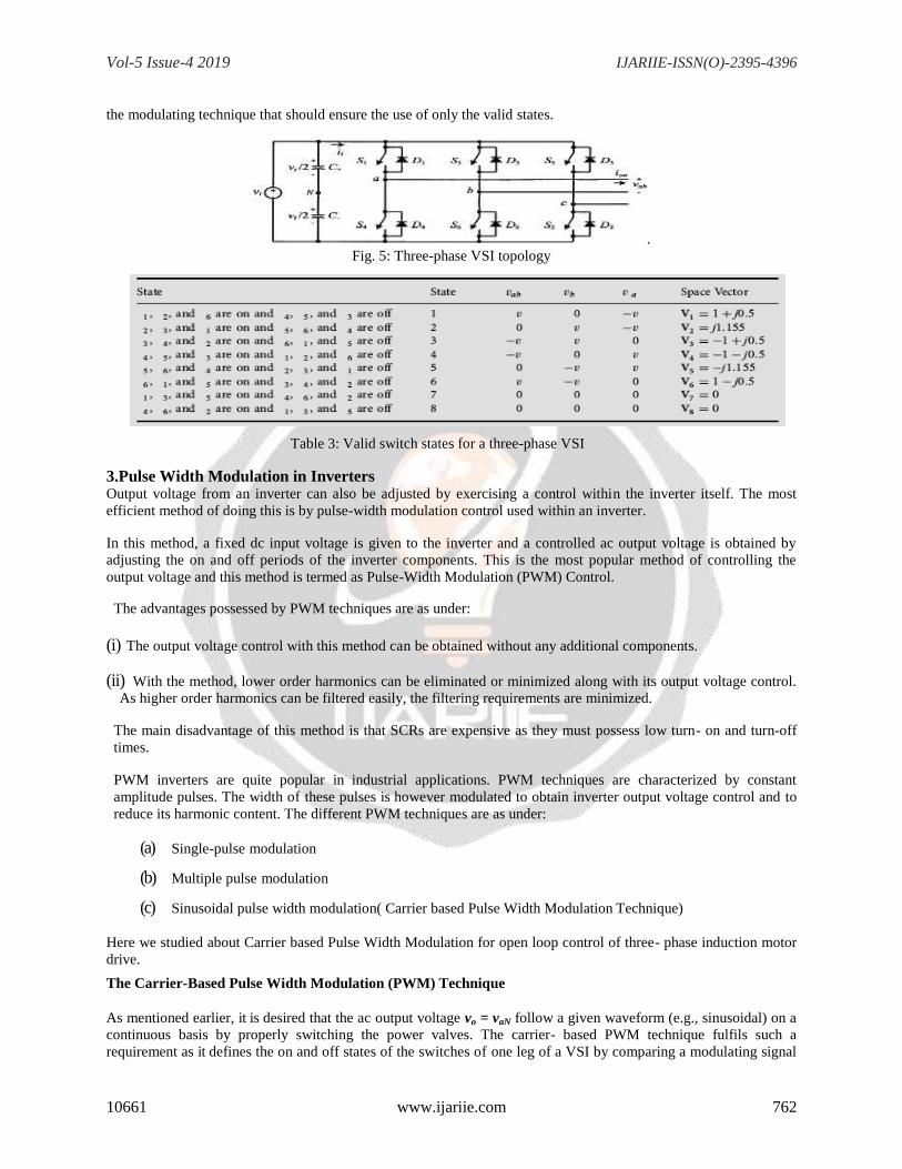
The standard three-phase VSI topology is shown in Fig. 4 and the eight valid switch states are given in Table 3. As
in single-phase VSIs, the switches of any leg of the inverter (S1 and S4, S3 and S6, or S5 and S2) cannot be
switched on simultaneously because this would result in a short circuit across the dc link voltage supply. Similarly, in
order to avoid undefined states in the VSI, and thus undefined ac output line voltages, the switches of any leg of the
inverter cannot be switched off simultaneously as this will result in voltages that will depend upon the respective line
current polarity. Of the eight valid states, two of them (7 and 8 in Table3) produce zero ac line voltages. In this case,
the ac line currents freewheel through either the upper or lower components. The remaining states (1 to 6 in Table 3)
produce non-zero ac output voltages. In order to generate a given voltage waveform, the inverter moves from one
state to another. Thus the resulting ac output line voltages consist of discrete values of voltages that are Vi , 0, and -
Vi for the topology shown in Fig. 4. The selection of the states in order to generate the given waveform is done by
Vol-5 Issue-4 2019 IJARIIE-ISSN(O)-2395-4396
10661 www.ijariie.com 762
the modulating technique that should ensure the use of only the valid states.
.
Fig. 5: Three-phase VSI topology
Table 3: Valid switch states for a three-phase VSI
3.Pulse Width Modulation in Inverters Output voltage from an inverter can also be adjusted by exercising a control within the inverter itself. The most
efficient method of doing this is by pulse-width modulation control used within an inverter.
In this method, a fixed dc input voltage is given to the inverter and a controlled ac output voltage is obtained by
adjusting the on and off periods of the inverter components. This is the most popular method of controlling the
output voltage and this method is termed as Pulse-Width Modulation (PWM) Control.
The advantages possessed by PWM techniques are as under:
(i) The output voltage control with this method can be obtained without any additional components.
(ii) With the method, lower order harmonics can be eliminated or minimized along with its output voltage control.
As higher order harmonics can be filtered easily, the filtering requirements are minimized.
The main disadvantage of this method is that SCRs are expensive as they must possess low turn- on and turn-off
times.
PWM inverters are quite popular in industrial applications. PWM techniques are characterized by constant
amplitude pulses. The width of these pulses is however modulated to obtain inverter output voltage control and to
reduce its harmonic content. The different PWM techniques are as under:
(a) Single-pulse modulation
(b) Multiple pulse modulation
(c) Sinusoidal pulse width modulation( Carrier based Pulse Width Modulation Technique)
Here we studied about Carrier based Pulse Width Modulation for open loop control of three- phase induction motor
drive.
The Carrier-Based Pulse Width Modulation (PWM) Technique
As mentioned earlier, it is desired that the ac output voltage vo = vaN follow a given waveform (e.g., sinusoidal) on a
continuous basis by properly switching the power valves. The carrier- based PWM technique fulfils such a
requirement as it defines the on and off states of the switches of one leg of a VSI by comparing a modulating signal
Vol-5 Issue-4 2019 IJARIIE-ISSN(O)-2395-4396
10661 www.ijariie.com 763
vc (desired ac output voltage) and a triangular waveform v∆ (carrier signal). In practice, when vc > v∆ the switch S+ is
on and the switch S- is off; similarly, when vc < v∆ the switch S+ is off and the switch S- is on.
A special case is when the modulating signal vc is a sinusoidal at frequency fc and amplitude v^c, and the triangular
signal v∆ is at frequency f∆ and amplitude v^∆. This is the sinusoidal PWM (SPWM) scheme. In this case, the
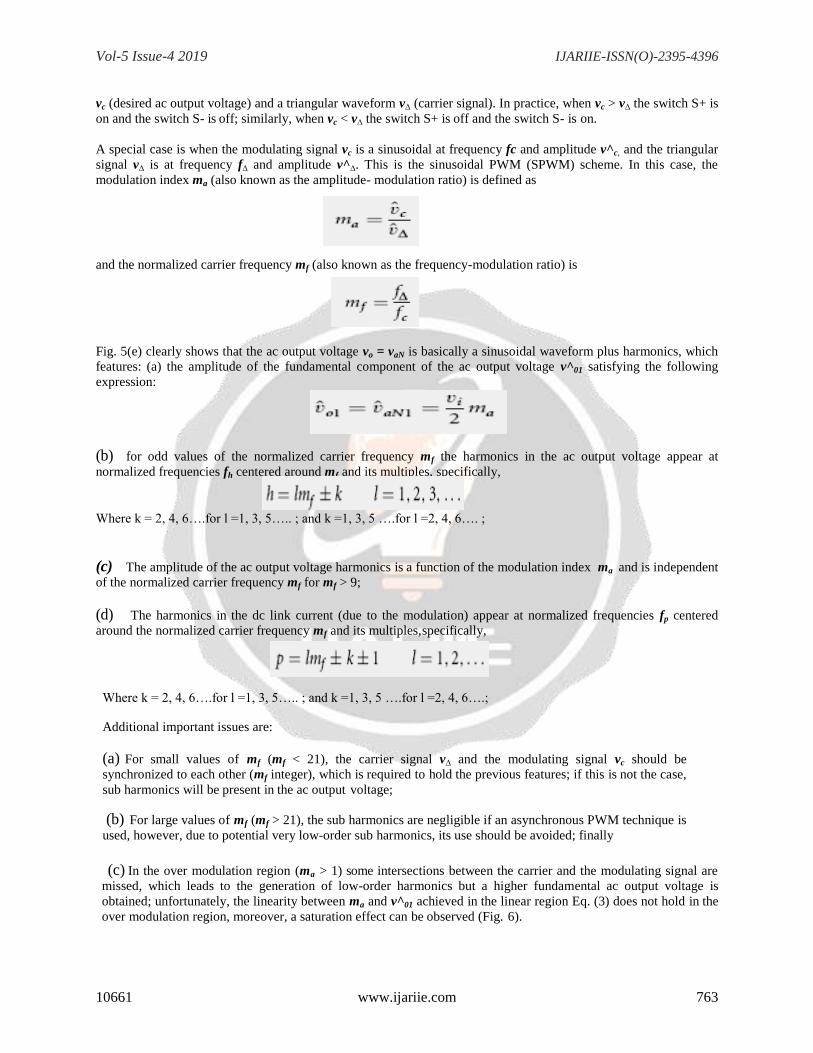
modulation index ma (also known as the amplitude- modulation ratio) is defined as
and the normalized carrier frequency mf (also known as the frequency-modulation ratio) is
Fig. 5(e) clearly shows that the ac output voltage vo = vaN is basically a sinusoidal waveform plus harmonics, which
features: (a) the amplitude of the fundamental component of the ac output voltage v^01 satisfying the following
expression:
(b) for odd values of the normalized carrier frequency mf the harmonics in the ac output voltage appear at
normalized frequencies fh centered around mf and its multiples, specifically,
Where k = 2, 4, 6….for l =1, 3, 5….. ; and k =1, 3, 5 ….for l =2, 4, 6…. ;
(c) The amplitude of the ac output voltage harmonics is a function of the modulation index ma and is independent
of the normalized carrier frequency mf for mf > 9;
(d) The harmonics in the dc link current (due to the modulation) appear at normalized frequencies fp centered
around the normalized carrier frequency mf and its multiples, specifically,
Where k = 2, 4, 6….for l =1, 3, 5….. ; and k =1, 3, 5 ….for l =2, 4, 6….;
Additional important issues are:
(a) For small values of mf (mf < 21), the carrier signal v∆ and the modulating signal vc should be
synchronized to each other (mf integer), which is required to hold the previous features; if this is not the case,
sub harmonics will be present in the ac output voltage;
(b) For large values of mf (mf > 21), the sub harmonics are negligible if an asynchronous PWM technique is
used, however, due to potential very low-order sub harmonics, its use should be avoided; finally
(c) In the over modulation region (ma > 1) some intersections between the carrier and the modulating signal are
missed, which leads to the generation of low-order harmonics but a higher fundamental ac output voltage is
obtained; unfortunately, the linearity between ma and v^01 achieved in the linear region Eq. (3) does not hold in the
over modulation region, moreover, a saturation effect can be observed (Fig. 6).

Vol-5 Issue-4 2019 IJARIIE-ISSN(O)-2395-4396
10661 www.ijariie.com 764
Fig. 6: The half-bridge VSI. Ideal waveforms for the SPWM (ma =0.8, mf =9):
(a) carrier and modulating signals; (b) switch S+ state; (c) switch S- state; (d) ac output voltage; (e)
ac output voltage spectrum; (f) ac output current; (g) dc current; (h) dc current spectrum; (i)
switch S+ current; (j) diode D+ current
Fig. 7: Fundamental ac component of the output voltage in a Half- bridge VSI SPWM modulated.
Vol-5 Issue-4 2019 IJARIIE-ISSN(O)-2395-4396
10661 www.ijariie.com 765
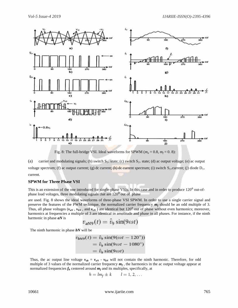
Fig. 8: The full-bridge VSI. Ideal waveforms for SPWM (ma = 0.8, mf = 0. 8):
(a) carrier and modulating signals; (b) switch S1+ state; (c) switch S2+ state; (d) ac output voltage; (e) ac output
voltage spectrum; (f) ac output current; (g) dc current; (h) dc current spectrum; (i) switch S1+current; (j) diode D1+
current.
SPWM for Three Phase VSI
This is an extension of the one introduced for single-phase VSIs. In this case and in order to produce 120⁰ out-of-
phase load voltages, three modulating signals that are 120⁰ out of phase
are used. Fig. 8 shows the ideal waveforms of three-phase VSI SPWM. In order to use a single carrier signal and
preserve the features of the PWM technique, the normalized carrier frequency mf should be an odd multiple of 3.
Thus, all phase voltages (vaN , vbN , and vcN ) are identical but 120⁰ out of phase without even harmonics; moreover,
harmonics at frequencies a multiple of 3 are identical in amplitude and phase in all phases. For instance, if the ninth
harmonic in phase aN is
The ninth harmonic in phase bN will be
Thus, the ac output line voltage vab = vaN - vbN will not contain the ninth harmonic. Therefore, for odd
multiple of 3 values of the normalized carrier frequency mf , the harmonics in the ac output voltage appear at
normalized frequencies fh centered around mf and its multiples, specifically, at
Vol-5 Issue-4 2019 IJARIIE-ISSN(O)-2395-4396
10661 www.ijariie.com 766
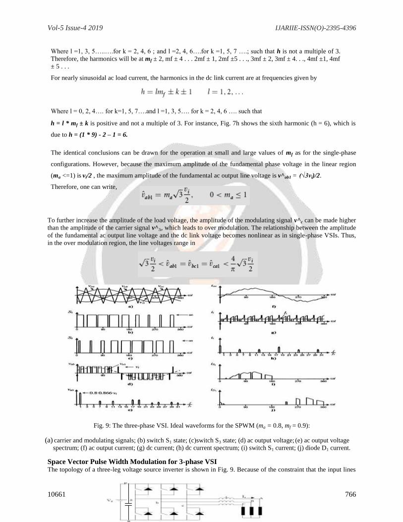
Where l =1, 3, 5…..….for k = 2, 4, 6 ; and l =2, 4, 6….for k =1, 5, 7 ….; such that h is not a multiple of 3.
Therefore, the harmonics will be at mf ± 2, mf ± 4 . . . 2mf ± 1, 2mf ±5 . . ., 3mf ± 2, 3mf ± 4. . ., 4mf ±1, 4mf
± 5 . . .
For nearly sinusoidal ac load current, the harmonics in the dc link current are at frequencies given by
Where l = 0, 2, 4…. for k=1, 5, 7….and l =1, 3, 5…. for k = 2, 4, 6 …. such that
h = l * mf ± k is positive and not a multiple of 3. For instance, Fig. 7h shows the sixth harmonic (h = 6), which is
due to h = (1 * 9) - 2 – 1 = 6.
The identical conclusions can be drawn for the operation at small and large values of mf as for the single-phase
configurations. However, because the maximum amplitude of the fundamental phase voltage in the linear region
(ma <=1) is vi/2 , the maximum amplitude of the fundamental ac output line voltage is v^ab1 = (√3vi)/2.
Therefore, one can write,
To further increase the amplitude of the load voltage, the amplitude of the modulating signal v^c can be made higher
than the amplitude of the carrier signal v^∆, which leads to over modulation. The relationship between the amplitude
of the fundamental ac output line voltage and the dc link voltage becomes nonlinear as in single-phase VSIs. Thus,
in the over modulation region, the line voltages range in
Fig. 9: The three-phase VSI. Ideal waveforms for the SPWM (ma = 0.8, mf = 0.9):
(a) carrier and modulating signals; (b) switch S1 state; (c)switch S3 state; (d) ac output voltage; (e) ac output voltage
spectrum; (f) ac output current; (g) dc current; (h) dc current spectrum; (i) switch S1 current; (j) diode D1 current.
Space Vector Pulse Width Modulation for 3-phase VSI The topology of a three-leg voltage source inverter is shown in Fig. 9. Because of the constraint that the input lines
Vol-5 Issue-4 2019 IJARIIE-ISSN(O)-2395-4396
10661 www.ijariie.com 767
must never be shorted and the output current must always be continuous a voltage source inverter can assume only
eight distinct topologies. These topologies are shown on Fig. 10. Six out of these eight topologies produce a nonzero
output voltage and are known as non-zero switching states and the remaining two topologies produce zero output
voltage and are known as zero switching states.
Fig. 10: Topology of a three-leg voltage source inverter
Implementing SVPWM
The SVPWM can be implemented by using wither sector selection algorithm or by using a carrier based space
vector algorithm.
The types of SVPWM implementations are:-
a) Sector selection based space vector modulation
b) Reduced switching Space vector modulation
c) Carrier based space vector modulation
d) Reduced switching carrier based space vector modulation.
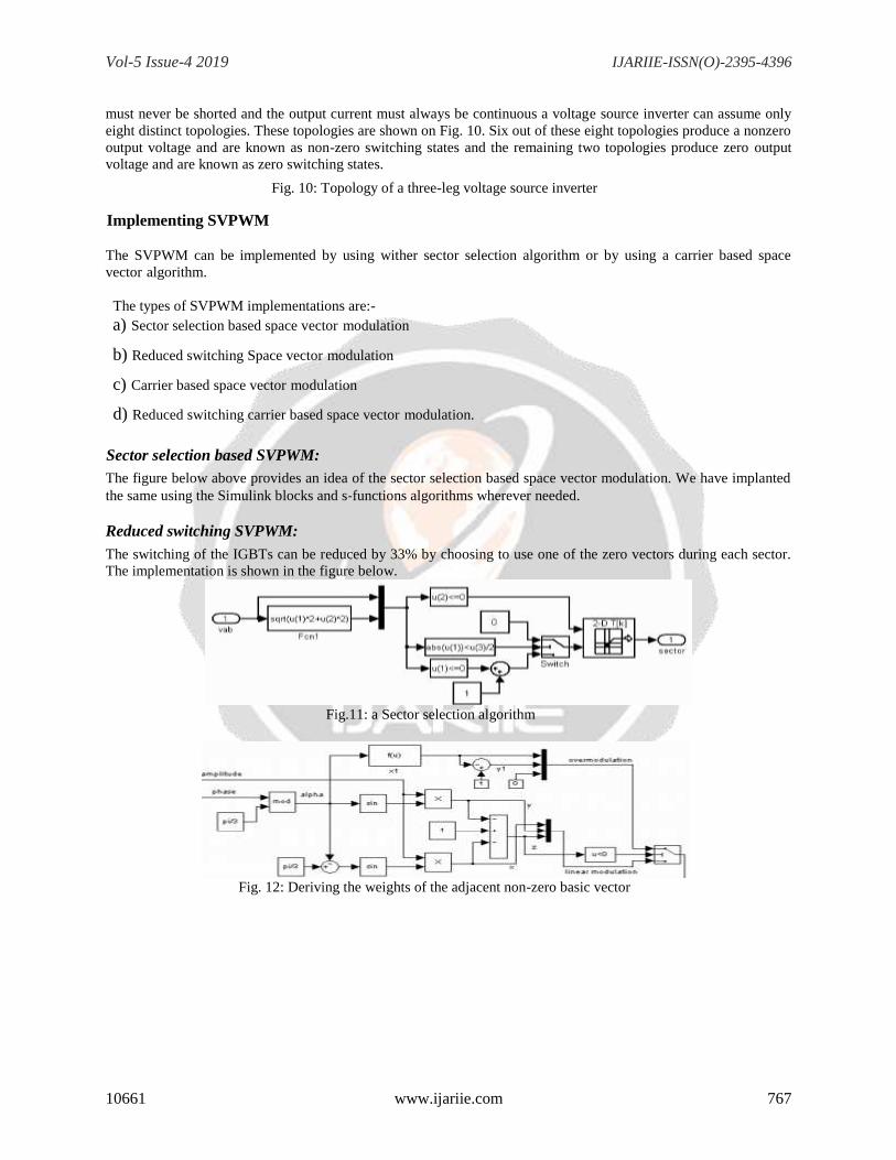
Sector selection based SVPWM:
The figure below above provides an idea of the sector selection based space vector modulation. We have implanted
the same using the Simulink blocks and s‐functions algorithms wherever needed.
Reduced switching SVPWM:
The switching of the IGBTs can be reduced by 33% by choosing to use one of the zero vectors during each sector.
The implementation is shown in the figure below.
Fig.11: a Sector selection algorithm
Fig. 12: Deriving the weights of the adjacent non-zero basic vector
Vol-5 Issue-4 2019 IJARIIE-ISSN(O)-2395-4396
10661 www.ijariie.com 768
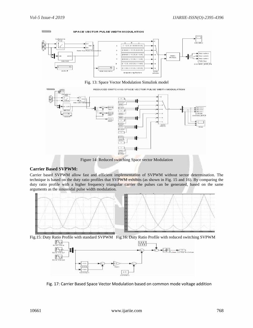
Fig. 13: Space Vector Modulation Simulink model
Figure 14: Reduced switching Space vector Modulation
Carrier Based SVPWM:
Carrier based SVPWM allow fast and efficient implementation of SVPWM without sector determination. The
technique is based on the duty ratio profiles that SVPWM exhibits (as shown in Fig. 15 and 16). By comparing the
duty ratio profile with a higher frequency triangular carrier the pulses can be generated, based on the same
arguments as the sinusoidal pulse width modulation.
Fig.15: Duty Ratio Profile with standard SVPWM Fig.16: Duty Ratio Profile with reduced switching SVPWM
Fig. 17: Carrier Based Space Vector Modulation based on common mode voltage addition
Vol-5 Issue-4 2019 IJARIIE-ISSN(O)-2395-4396
10661 www.ijariie.com 769
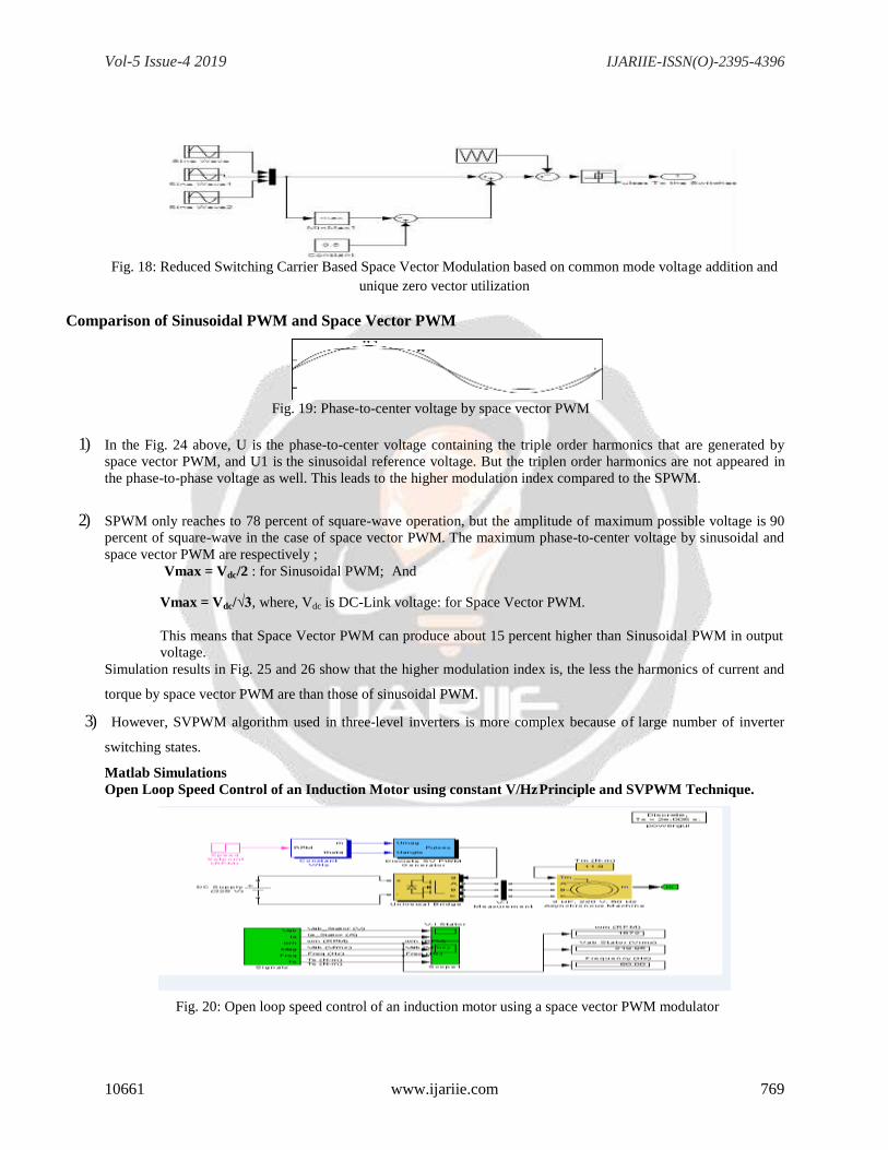
Fig. 18: Reduced Switching Carrier Based Space Vector Modulation based on common mode voltage addition and
unique zero vector utilization
Comparison of Sinusoidal PWM and Space Vector PWM
Fig. 19: Phase-to-center voltage by space vector PWM
1) In the Fig. 24 above, U is the phase-to-center voltage containing the triple order harmonics that are generated by
space vector PWM, and U1 is the sinusoidal reference voltage. But the triplen order harmonics are not appeared in
the phase-to-phase voltage as well. This leads to the higher modulation index compared to the SPWM.
2) SPWM only reaches to 78 percent of square-wave operation, but the amplitude of maximum possible voltage is 90
percent of square-wave in the case of space vector PWM. The maximum phase-to-center voltage by sinusoidal and
space vector PWM are respectively ;
Vmax = Vdc/2 : for Sinusoidal PWM; And
Vmax = Vdc/√3, where, Vdc is DC-Link voltage: for Space Vector PWM.
This means that Space Vector PWM can produce about 15 percent higher than Sinusoidal PWM in output
voltage.
Simulation results in Fig. 25 and 26 show that the higher modulation index is, the less the harmonics of current and
torque by space vector PWM are than those of sinusoidal PWM.
3) However, SVPWM algorithm used in three-level inverters is more complex because of large number of inverter
switching states.
Matlab Simulations
Open Loop Speed Control of an Induction Motor using constant V/Hz Principle and SVPWM Technique.
Fig. 20: Open loop speed control of an induction motor using a space vector PWM modulator
Vol-5 Issue-4 2019 IJARIIE-ISSN(O)-2395-4396
10661 www.ijariie.com 770
Circuit description: A 3-phase squirrel-cage motor rated 3 HP, 220 V, 60 Hz, 1725 rpm is fed by a 3-phase MOSFET inverter connected
to a DC voltage source of 325 V. The inverter is modeled using the "Universal Bridge" block and the motor by the
"Asynchronous Machine" block. Its stator leakage inductance Lls is set to twice its actual value to simulate the
effect of a smoothing reactor placed between the inverter and the machine. The load torque applied to the machine‟s
shaft is constant and set to its nominal value of 11.9 N.m.
The firing pulses to the inverter are generated by the "Space-Vector PWM modulator" block of the SPS library. The
chopping frequency is set to 1980 Hz and the input reference vector to "Magnitude-Angle".
Speed control of the motor is performed by the "Constant V/Hz" block. The magnitude and frequency of the stator
voltages are set based on the speed setpoint. By varying the stator voltages magnitude in proportion with frequency,
the stator flux is kept constant.
Demonstration:
Started the simulation. Since the initial states values have been automatically loaded, the simulation should start in
steady-state.The initial motor speed should be 1720 RPM and the rms value of the stator voltages should be
220V@60Hz.
At 0.1s, the speed set point is changed from 1725 to 1300 RPM. You can observe the system dynamic looking inside
Scope 1. When the motor reaches a constant speed of 1275 RPM, the stator voltage rms value is down to 165.8V
and the frequency to 45.2 Hz.
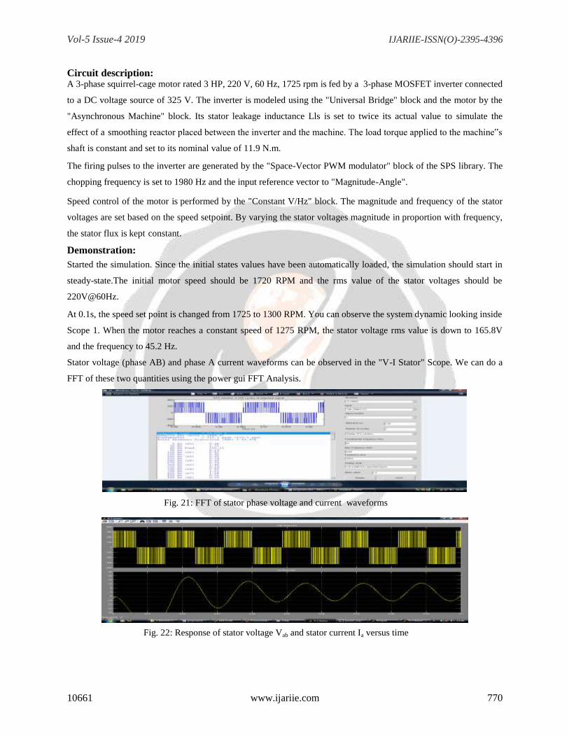
Stator voltage (phase AB) and phase A current waveforms can be observed in the "V-I Stator" Scope. We can do a
FFT of these two quantities using the power gui FFT Analysis.
Fig. 21: FFT of stator phase voltage and current waveforms
Fig. 22: Response of stator voltage Vab and stator current Ia versus time
Vol-5 Issue-4 2019 IJARIIE-ISSN(O)-2395-4396
10661 www.ijariie.com 771
Fig. 23: Response of Speed (in rpm) of rotor, stator voltage (Vab), Freq and Te of the Induction Motor versus time
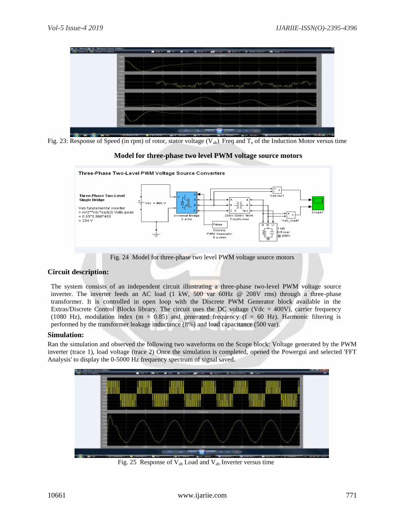
Model for three-phase two level PWM voltage source motors
Fig. 24 Model for three-phase two level PWM voltage source motors
Circuit description:
The system consists of an independent circuit illustrating a three-phase two-level PWM voltage source
inverter. The inverter feeds an AC load (1 kW, 500 var 60Hz @ 208V rms) through a three-phase
transformer. It is controlled in open loop with the Discrete PWM Generator block available in the
Extras/Discrete Control Blocks library. The circuit uses the DC voltage (Vdc = 400V), carrier frequency
(1080 Hz), modulation index (m = 0.85) and generated frequency (f = 60 Hz). Harmonic filtering is
performed by the transformer leakage inductance (8%) and load capacitance (500 var).
Simulation:
Ran the simulation and observed the following two waveforms on the Scope block: Voltage generated by the PWM
inverter (trace 1), load voltage (trace 2) Once the simulation is completed, opened the Powergui and selected 'FFT
Analysis' to display the 0-5000 Hz frequency spectrum of signal saved.
Fig. 25 Response of Vab Load and Vab Inverter versus time

Vol-5 Issue-4 2019 IJARIIE-ISSN(O)-2395-4396
10661 www.ijariie.com 772
Fig. 26 'FFT Analysis' to display the 0-5000 Hz frequency spectrum of signal saved
4. CONCLUSIONS
As seen from the above discussion Space Vector PWM is superior as compared to Sinusoidal pulse width
modulation in many aspects like :
1) The Modulation Index is higher for SVPWM as compared to SPWM.
2) The output voltage is about 15% more in case of SVPWM as compared to SPWM.
3) The current and torque harmonics produced are much less in case of SVPWM.
However despite all the above mentioned advantages that SVPWM enjoys over SPWM, SVPWM algorithm used in
three-level inverters is more complex because of large number of inverter switching states.
Hence we see that there is a certain trade off that exists while using SVPWM for inverters for Adjustable speed
Drive Operations. Due to this we have to choose carefully as to which of the two techniques to use weighing the
pros and cons of each method.
REFERENCES
1 Vinod Kumar , Syed Sarfaraz Nawaz(2016) Design and Implementation of Inverter for driving Induction
Motor using DSPACE, IJRASET, Volume 4 Issue 10, ISSN: 2321-9653.
2 Himanshu Doraya, Richa Parmar, Bipul Kumar ,Mal Chand Sharma (2014) Performance Comparison
between PWM Based Inverter and SVPWM Based Inverter, International Journal of Advanced Research in
Electrical, Electronics and Instrumentation Engineering, Vol. 3, Issue 10.
3 Moumita Deb (2013) Control of voltage source inverter for adjustable speed drivea study report, research
article ,ISSN:-2321-9262
4 O. Ogasawara, H. Akagi, and A. Nabel, “A novel PWM scheme of voltage source inverters based on space
vector theory,” in Proc. EPE European Conf. Power Electronics and Applications, 1989, pp. 1197–1202.
5 M. Depenbrock, “Pulsewidth control of a 3-phase inverter with nonsinusoidal phase voltages,” in Proc. IEEE-
IAS Int. Semiconductor Power Conversion Conf., Orlando, FL, 1975, pp. 389–398.
6 J. A. Houldsworth and D. A. Grant, “The use of harmonic distortion to increase the output voltage of a three-
phase PWM inverter,” IEEE Trans. Ind. Applicat., vol. 20, pp. 1224– 1228, Sept./Oct. 1984.
7 Modern Power Electronics and AC Drives, by Bimal K. Bose. Prentice Hall Publishers, 2001
8 Power Electronics by Dr. P.S. Bimbhra. Khanna Publishers, New Delhi, 2003. 3rd
Edition.
Related Documents