International Research Journal of Engineering and Technology (IRJET) e-ISSN: 2395-0056 Volume: 06 Issue: 02 | April 2019 www.irjet.net p-ISSN: 2395-0072 © 2019, IRJET | Impact Factor value: 7.211 | ISO 9001:2008 Certified Journal | Page 2973 SPEED BREAKER POWER GENERATION Laukik Kharche 1 , Kalpesh Jadhav 2 , Pranay Gawas 3 , Chaitali Gharat 4 1,2,3,4 Bharati Vidyapeeth College of Engineering, Department of Mechanical Engineering, Navi-Mumbai, Maharashtra, India. ---------------------------------------------------------------------***---------------------------------------------------------------------- Abstract - The project is about the design and manufacturing of speed breaker power generator. In this project we are trying to utilize one such source. Electricity is generated by replacing the traditional speed breakers with some simple mechanism. As vehicles pass over the speed breakers, the speed breaker itself goes down due to weight of the vehicle which results in displacement of a rack gear which rotates the pinion connected to shaft of the generator which in turn produces electricity. This method is an effective way to produce electricity as the numbers of vehicles on the road are ever increasing. Also, the cost of fabrication of the model is low. It can be effectively placed near traffic lights, at the entrance of parking lots and any other place where the traffic density is high. As vehicle passes over it, it starts moving. This method provides an efficient way to generate electricity from the kinetic energy of moving vehicles in roads, highways, parking lots etc. In this report we explain in detail the various stages of research, design and manufacturing which was involved in the construction of various components such as springs, generator, rack and pinion mechanism. Most of the parts are assembled by the students themselves. It also mentions the reason behind using the specific materials and methods of construction for effective working of the system. In short, this report includes an overview of design and research undertaken in making the project successful. The mantra of the group “In engineering, everything has a reason” is highlighted in the following report. Keywords: Non - Conventional energy source, generator, rack and pinion mechanism, speed breaker power, shaft, guiding pipes. 1. INTRODUCTION TO SPEED BREAKERS Speed bumps (or speed breakers) are the common name for a family of traffic calming devices that use vertical deflection to slow motor-vehicle traffic in order to improve safety conditions. Variations include the speed hump, speed cushion, and speed table. The use of vertical deflection devices is widespread around the world, and they are most commonly found to enforce a low speed limit, under 40 km/h (25 mph) or lower. Although speed bumps are effective in keeping vehicle speeds down, their use is sometimes controversial as they can increase traffic noise, may damage vehicles if traversed at too great a speed, and slow emergency vehicles. Poorly- designed speed bumps that stand too tall or with too-sharp an angle can be disruptive for drivers, and may be difficult to navigate for vehicles with low ground clearance, even at very low speeds. Many sports cars have this problem with such speed bumps. Speed bumps can also pose serious hazards to motorcyclists and bicyclists if they are not clearly visible, though in some cases a small cut across the bump allows those vehicles to traverse without impediment. Speed bumps cost Rs.1000-2000 and may need replacement over time due to wear. 1.1 MOTIVATION An energy crisis is any significant bottleneck in the supply of energy resources to an economy. Industrial development and population growth have led to a surge in the global demand for energy in recent years. There is a current global need for clean and renewable energy sources. Fossil fuels are non-renewable and require finite resources, which are dwindling because of high cost and environmentally damaging retrieval techniques. So, the need for cheap and obtainable resources is greatly needed. [1] 1.2 MODIFICATIONS This project attempts to show how energy can be tapped and used at a commonly used system, the road speed breakers. The number of vehicles passing over the speed breaker in roads is increasing day by day. A large amount of energy is wasted at the speed breakers through the dissipation of heat and also through friction, every time a vehicle passes over it. There is great possibility of tapping this energy and generating power by making the speed-breaker as a power generation unit. The generated power can be used for the lamps, near the speed breakers. The present work an attempt has been made to fabricate a bump, which can utilize the kinetic energy of vehicles in power generation. This type of bump is best suited for the places where the speed breaker is a necessity. The places like Toll bridges or on vehicle parking stands are best for its utilization. The work also discusses the shortcomings of existing methods and the ways it is countered by this method.

Welcome message from author
This document is posted to help you gain knowledge. Please leave a comment to let me know what you think about it! Share it to your friends and learn new things together.
Transcript
International Research Journal of Engineering and Technology (IRJET) e-ISSN: 2395-0056
Volume: 06 Issue: 02 | April 2019 www.irjet.net p-ISSN: 2395-0072
© 2019, IRJET | Impact Factor value: 7.211 | ISO 9001:2008 Certified Journal | Page 2973
SPEED BREAKER POWER GENERATION
Laukik Kharche1, Kalpesh Jadhav2, Pranay Gawas3, Chaitali Gharat4
1,2,3,4Bharati Vidyapeeth College of Engineering, Department of Mechanical Engineering, Navi-Mumbai, Maharashtra, India.
---------------------------------------------------------------------***----------------------------------------------------------------------
Abstract - The project is about the design and manufacturing of speed breaker power generator. In this project we are trying to utilize one such source. Electricity is generated by replacing the traditional speed breakers with some simple mechanism. As vehicles pass over the speed breakers, the speed breaker itself goes down due to weight of the vehicle which results in displacement of a rack gear which rotates the pinion connected to shaft of the generator which in turn produces electricity. This method is an effective way to produce electricity as the numbers of vehicles on the road are ever increasing. Also, the cost of fabrication of the model is low. It can be effectively placed near traffic lights, at the entrance of parking lots and any other place where the traffic density is high. As vehicle passes over it, it starts moving. This method provides an efficient way to generate electricity from the kinetic energy of moving vehicles in roads, highways, parking lots etc. In this report we explain in detail the various stages of research, design and manufacturing which was involved in the construction of various components such as springs, generator, rack and pinion mechanism. Most of the parts are assembled by the students themselves. It also mentions the reason behind using the specific materials and methods of construction for effective working of the system. In short, this report includes an overview of design and research undertaken in making the project successful. The mantra of the group “In engineering, everything has a reason” is highlighted in the following report. Keywords: Non - Conventional energy source, generator, rack and pinion mechanism, speed breaker power, shaft, guiding pipes. 1. INTRODUCTION TO SPEED BREAKERS Speed bumps (or speed breakers) are the common name for a family of traffic calming devices that use vertical deflection to slow motor-vehicle traffic in order to improve safety conditions. Variations include the speed hump, speed cushion, and speed table. The use of vertical deflection devices is widespread around the world, and they are most commonly found to enforce a low speed limit, under 40 km/h (25 mph) or lower. Although speed bumps are effective in keeping vehicle speeds down, their use is sometimes controversial as they
can increase traffic noise, may damage vehicles if traversed at too great a speed, and slow emergency vehicles. Poorly-designed speed bumps that stand too tall or with too-sharp an angle can be disruptive for drivers, and may be difficult to navigate for vehicles with low ground clearance, even at very low speeds. Many sports cars have this problem with such speed bumps. Speed bumps can also pose serious hazards to motorcyclists and bicyclists if they are not clearly visible, though in some cases a small cut across the bump allows those vehicles to traverse without impediment. Speed bumps cost Rs.1000-2000 and may need replacement over time due to wear. 1.1 MOTIVATION
An energy crisis is any significant bottleneck in the supply of energy resources to an economy. Industrial development and population growth have led to a surge in the global demand for energy in recent years. There is a current global need for clean and renewable energy sources. Fossil fuels are non-renewable and require finite resources, which are dwindling because of high cost and environmentally damaging retrieval techniques. So, the need for cheap and obtainable resources is greatly needed. [1] 1.2 MODIFICATIONS This project attempts to show how energy can be tapped and used at a commonly used system, the road speed breakers. The number of vehicles passing over the speed breaker in roads is increasing day by day. A large amount of energy is wasted at the speed breakers through the dissipation of heat and also through friction, every time a vehicle passes over it. There is great possibility of tapping this energy and generating power by making the speed-breaker as a power generation unit. The generated power can be used for the lamps, near the speed breakers. The present work an attempt has been made to fabricate a bump, which can utilize the kinetic energy of vehicles in power generation. This type of bump is best suited for the places where the speed breaker is a necessity. The places like Toll bridges or on vehicle parking stands are best for its utilization. The work also discusses the shortcomings of existing methods and the ways it is countered by this method.
International Research Journal of Engineering and Technology (IRJET) e-ISSN: 2395-0056
Volume: 06 Issue: 02 | April 2019 www.irjet.net p-ISSN: 2395-0072
© 2019, IRJET | Impact Factor value: 7.211 | ISO 9001:2008 Certified Journal | Page 2974
2. LITERATURE REVIEW 2.1 SPEED BREAKER POWER GENERATION It is very significant to design pollution free energy generation system. Speed breaker Power Generator (SBPG) is the most emerging technique which produces electrical power with minimum input. An experimental study to generate the electricity by SBPG is described in this paper. In this system, a rack and pinions mechanism is used for the production of electricity. When a car reaches on the speed breaker, the rack moves downward to generate linear to rotary motion using pinions. The rotary motion is transferred to DC generator which generates DC power which is stored in batteries same as in solar technology. The generated power can be used for the domestic purpose or commercially, which are present near the speed breaker. This examined that SBPG is generating 273.24W on single push under the application of 400kg. In an hour, passing 100 cars of 400kg can generate 54.59 kWh. This mechanism utilizes both downward as well as the upward motion of the rack. [2] 2.2 ELECTRICITY GENERATION BY SPEED BREAKER Energy is the primary need for survival of all organisms in the universe. Everything what happens in the surrounding is the expression of flow of energy in one of the forms. But in this fast moving world, population is increasing day by day and the conventional energy sources are lessening. The extensive usage of energy has resulted in an energy crisis over the few years. Therefore to overcome this problem we need to implement the techniques of optimal utilization of conventional sources for conservation of energy. This paper includes how to utilize the energy which is wasted when the vehicles passes over a speed breaker. Lots of energy is generated when vehicle passes over it. We can tap the energy generated and produce power by using the speed breaker as power generating unit. The kinetic energy of the moving vehicles can be converted into mechanical energy of the shaft through rack and pinion mechanism. Then, this mechanical energy will be converted to electrical energy using generator which will be saved with the use of a battery. [3]
3. METHODOLOGY 3.1 VARIOUS MECHANISMS AVAILABLE
Table1. Available Mechanisms
Serial No.
Type of Mechanism
Available
Advantages Disadvantages
01 Spring coil mechanism
Consumes less space.
More durable. Better recoil.
Accelerated corrosion due to
lower temperatures. Sudden impact can
cause spring breakage.
02 Rack- Pinion mechanism
Less backlash Greater feedback
Accurate displacement
More guiding supports are
required Additional gear
reduction required 03 Crank-shaft
mechanism No direct
connection with speed breaker
Easier to maintain
Heavier in construction
Occupies more space
04 Roller mechanism
Easier in construction
Less costly
Less efficiency Slippage
Things to be considered while selecting a mechanism, 1) Practical Approach – It was seen that whether modeling the selected mechanism is practically possible or not. 2) Cost of the total project – The total cost of the project must be limited. 3) Feasibility - The construction of the project must be easy and can be done at a student level. Additionally, availability of certain components or processes is seen. 4) Efficiency – The efficiency obtained from the mechanism must be high.
3.2 METHOD SELECTED – RACK AND PINION MECHANISM Electricity is a basic part of nature and it is one of our most widely used forms of energy. A large amount of energy is wasted at the speed breakers through the dissipation of heat and also through friction, every time a vehicle passes over it. In this research, a roller is fitted in between a speed breaker and some kind of a grip is provided on the speed breaker so that when a vehicle passes over speed breaker it gets displaced in vertically downward direction distance 7 cm. The rack which is connected to the speed breaker also moves down simultaneously with same distance 7 cm. The rack is in mesh with the pinion which is coupled with the shaft of gear which have 72 teeth which then meshed with pinion with 32 teeth which is coupled with the generator motor. This whole mechanism converts linear displacement in rotary motion. Hence shaft of generator rotates which generates current proportional to the number of revolutions of pinion. This produced current is stored in battery for future use. Later the rack gets displaced to the original position due to spring mechanism.

International Research Journal of Engineering and Technology (IRJET) e-ISSN: 2395-0056
Volume: 06 Issue: 02 | April 2019 www.irjet.net p-ISSN: 2395-0072
© 2019, IRJET | Impact Factor value: 7.211 | ISO 9001:2008 Certified Journal | Page 2975
4. DESIGN 4.1 DESIGN APPROACH The main objective of design phase is to make use of waste materials for manufacturing of the modified speed breaker. During brainstorming we decided what could be better than if we could use scrap car parts and did exactly the same. Everyday hundreds of cars get dumped into junkyard due to some tragic events. Most of the major components of our project are derived from used cars. The most important component i.e. the “Rack and Pinion” mechanism was extracted from steering mechanism of a car. Also the springs which return the speed breaker to its original position were obtained from suspension of a car. This serves dual purpose, firstly it uses waste material from cars and another, that it is suitable to handle the weights of similar class vehicles passing over the speed breaker. Also we needed to simplify the design in such a way that we could manufacture it using the techniques available to as at our level. We decided to use a bottom up approach for our design. For example, starting from the base plate, we used welding techniques to make supporting pipe structures on it. Then we could support the two springs which will be used to bring back the speed breaker into its original position into those pipes. In this way we could accomplish the changes or modifications necessary to design during manufacturing phase. For designing CAD model of our project we have chosen to use solid works because of its ease to use and seamless, integrated workflow design. First we created all the main components one by one in solid works and then assembled them to make complete design.
4.2 DESIGN OF VARIOUS COMPONENTS OF THE SYSTEM
A) Base Plate As discussed earlier the main purpose of base plate is to support the entire assembly. It houses two guidance pipes for the springs. It is as shown in fig.2.
Table2. Specifications of Base Plate
Dimensions (mm)
Length 678 Breadth 275 Height 1
Inner Diameter 104 Outer Diameter 114
Quantity 1
Fig 2. Base Plate
B) Top Plate Top plate is the uppermost part of the mechanism on which the actual speed breakers lie. Similar to the base plate it also has guidance pipes for the spring. It is as shown in fig.3.
Table3. Specifications of Top Plate
Dimensions (mm)
Length 678 Breadth 275 Height 1
Inner Diameter 63 Outer Diameter 73
Quantity 1
Fig3. Top Plate

International Research Journal of Engineering and Technology (IRJET) e-ISSN: 2395-0056
Volume: 06 Issue: 02 | April 2019 www.irjet.net p-ISSN: 2395-0072
© 2019, IRJET | Impact Factor value: 7.211 | ISO 9001:2008 Certified Journal | Page 2976
C) Springs The main function of the spring is to provide a reaction force after the vehicle passes over the speed breaker. This restores the speed breaker back to its original position. It is as shown in fig.4.
Table4. Specifications of Spring
Dimensions (mm)
Length 370 No of turns 10 Diameter 72
Wire Diameter 10 Quantity 2
Fig 4. Spring D) Rack And Pinion Rack & Pinion is used to transfer vertical motion due to vehicle in rotary motion of the motor. This part is obtained from steering mechanism of a car, and then coupled with an idler in order to increase the number of rotations. It is as shown in the fig.5.
Table5. Specifications of Idle gear & Rack
Fig 5. Rack and pinion with Idle gear
D) Motor And The Main Gear Motor is an essential component which converts mechanical energy into electrical energy. It is coupled with main gear which will be coupled to idle gear in order to increase the number of rotations of motor. It is as shown in the fig. 6, 7.
Table 6. Specifications of Motor and Gear
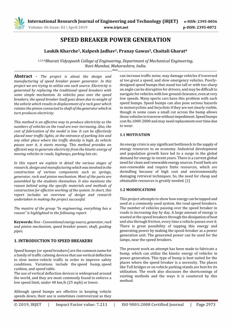
Fig 6. Main Gear Fig 7. Motor 4.3 DESIGN AND ASSEMBLY The following parts are assembled using a bottom up approach. The base plate lies at the lower most parts which would lie underground. Then the springs are fitted around the guidance pipes of the base plate. These springs provide upward force which will bring back the speed breaker to its original position. Then the top plate is fitted into the springs using guidance pipes. This acts as the actual speed breaker. Then the rack and pinion is fitted at the center of the top plate so that it can absorb maximum force of the vehicle. The rack and pinion are coupled with two idler gears one of which is then coupled to the motor. The partial assembly is shown in the figure 8 below.
International Research Journal of Engineering and Technology (IRJET) e-ISSN: 2395-0056
Volume: 06 Issue: 02 | April 2019 www.irjet.net p-ISSN: 2395-0072
© 2019, IRJET | Impact Factor value: 7.211 | ISO 9001:2008 Certified Journal | Page 2977
Fig 8. Partial Assembly
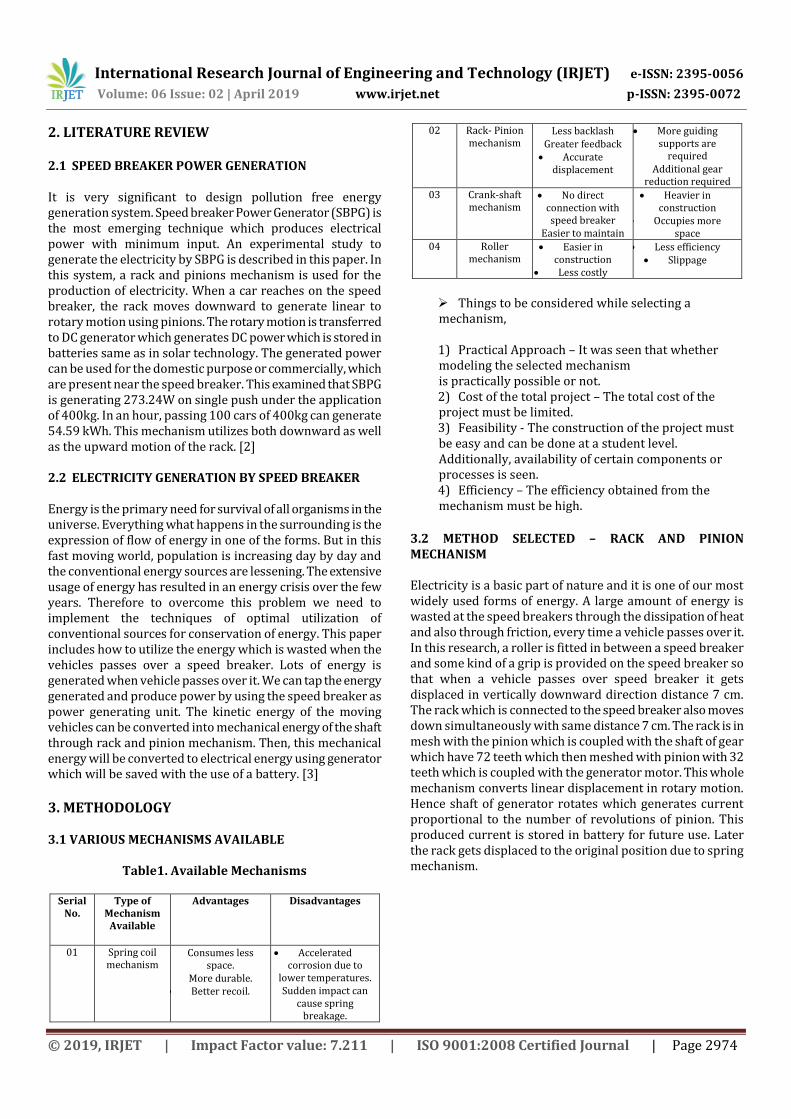
5. MANUFACTURING 5.1 MANUFACTURING PARTS A) Base Assembly: This part is mainly made by welding technique. The two guidance pipes are welded to the base plate which is 1 mm thick as shown in the fig. The pinion housing which has the main pinion and also one of the idler gears is welded to the base plate. It is as shown below,
Fig 9. Base with Pinion Housing
B) Top Assembly: The rack is joint to the top portion by welding. Similarly the guidance pipes are also welded to the top plate. It is shown in fig.10.
Fig 10. Top Plate with Rack
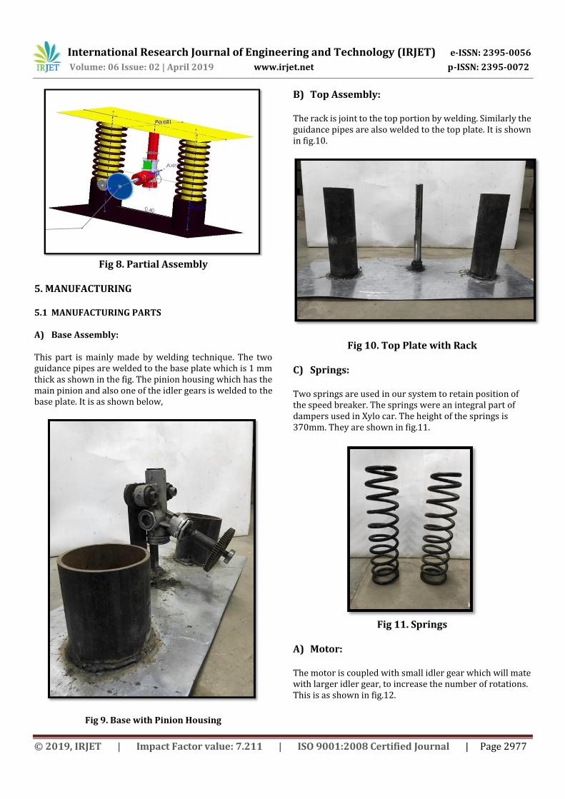
C) Springs: Two springs are used in our system to retain position of the speed breaker. The springs were an integral part of dampers used in Xylo car. The height of the springs is 370mm. They are shown in fig.11.
Fig 11. Springs
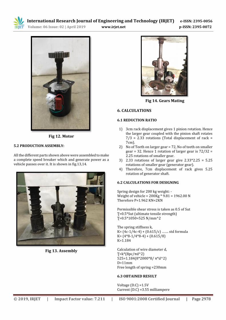
A) Motor: The motor is coupled with small idler gear which will mate with larger idler gear, to increase the number of rotations. This is as shown in fig.12.
International Research Journal of Engineering and Technology (IRJET) e-ISSN: 2395-0056
Volume: 06 Issue: 02 | April 2019 www.irjet.net p-ISSN: 2395-0072
© 2019, IRJET | Impact Factor value: 7.211 | ISO 9001:2008 Certified Journal | Page 2978
Fig 12. Motor
5.2 PRODUCTION ASSEMBLY:
All the different parts shown above were assembled to make a complete speed breaker which and generate power as a vehicle passes over it. It is shown in fig.13,14.
Fig 13. Assembly
Fig 14. Gears Mating
6. CALCULATIONS 6.1 REDUCTION RATIO
1) 3cm rack displacement gives 1 pinion rotation. Hence the larger gear coupled with the pinion shaft rotates 7/3 = 2.33 rotations (Total displacement of rack = 7cm).
2) No of Teeth on larger gear = 72, No of teeth on smaller gear = 32. Hence 1 rotation of larger gear is 72/32 = 2.25 rotations of smaller gear.
3) 2.33 rotations of larger gear give 2.33*2.25 = 5.25 rotations of smaller gear (generator gear).
4) Therefore, 7cm displacement of rack gives 5.25 rotation of generator shaft.
6.2 CALCULATIONS FOR DESIGNING Spring design for 200 kg weight: - Weight of vehicle = 200Kg * 9.81 = 1962.00 N Therefore P=1.962 KN=2KN Permissible shear stress is taken as 0.5 of Sut Ʈ=0.5*Sut (ultimate tensile strength) Ʈ=0.5*1050=525 N/mm^2 The spring stiffness k, K= (4c-1/4c-4) + (0.615/c) ……. std formula K= (4*8-1/4*8-4) + (0.615/8) K=1.184 Calculation of wire diameter d, Ʈ=k*(8pc/πd^2) 525=1.184(8*2000*8/ π*d^2) D=11mm Free length of spring =230mm 6.3 OBTAINED RESULT Voltage (D.C) =1.5V Current (D.C) =3.55 milliampere

International Research Journal of Engineering and Technology (IRJET) e-ISSN: 2395-0056
Volume: 06 Issue: 02 | April 2019 www.irjet.net p-ISSN: 2395-0072
© 2019, IRJET | Impact Factor value: 7.211 | ISO 9001:2008 Certified Journal | Page 2979
7. COST REPORT The cost breakdown is as follows;
Table 7. Cost Report
8. CONCLUSION In the coming days, demand for electricity will be very high as it is increasing every day, speed breaker power generator will prove a great boom to the world in the Future. The Aim of this research is to introduce another innovative method of green power generation in order to contribute toward developing the world by enriching it with utilization of available resources in more useful manner. Any country, especially Nigeria and other developing nations, can only develop when there is steady and available power supply for its citizens and not by getting breakdown in middle course of time or unreliable power sources. Now time has come for using these types of Innovative ideas and it should be brought into practice. It is suggested that further developments should be done to minimize above mentioned challenges. This research can also be modified by using camshaft and pulley stem or concepts of fluid mechanics can be used instead of gears, so as to minimize the inherent
complexities and difficulties. By using the concept of power generation new ideas should be introduced which would help in reduction of friction and increase the efficiency of the generators.
9. FUTURE SCOPE
1) Heavy vehicles can generate high torque using larger pinion and powerful generator and hence the power generated from them will be quite high.
2) More suitable and compact mechanisms to enhance efficiency could be created.
3) As these systems are installed on open roads, water accumulates in heavy rainfall regions which may be a threat for working of this system. So, waterproof system can be developed to use this system in heavy rainfall regions also.
4) Multiple generators could be connected so that power generated would be more.
ACKNOWLEDGEMENT We have immense pleasure in successful completion of this work titled “Speed Breaker Power Generation”. The special environment at Bharati Vidyapeeth College of Engineering that always supports educational activities facilitated our work on this project, special thanks to our Principal. We acknowledge the support, guidance and encouragement extended for this project by our Head of Mechanical Department Prof. Sandhya Jadhav who responded promptly and enthusiastically to our requests, despite of congested schedules. We are also thankful to our project coordinator Prof. A.S.Bhongade and our project guide Prof. D.S.Kharade for providing us technical support. We thank our parents and friends, who encouraged us to extend our reach. With their help and support, we have been able to complete this work well and on time.
REFERENCES [1] D mitriev, "Electric Power Generating Speed Bump," ed: Google Patents, 2012. [2] Ali Azam, "Speed Breaker Power Generation", IJAET, Volume 7, Page 2, 2014. [3] Aniket Mishra, "Electricity Generation By Speed Breaker", IJES, Volume 2, Page 25, 2013.
Serial No.
Name of Component Quantity Cost (Rs.)
01 Galvanized steel sheet
2 350
02 Metal Pipes (O.D = 72mm)
2 250
03 Metal Pipes (O.D = 114mm)
2 350
04 Rack and Pinion 1 700
05 Motor 1 1200
06 Bearings 2 200
07 Bolts 2 20
08 Nuts 2 10
09 Washers 4 12
10 Support Material 1 240
11 Welding Electrodes 12 80
12 Speed Breaker 1 500
Total Cost(Rs) 3412
Related Documents