DF-51609 — Page 1 of 6 GENERAL System Sensor SpectrAlert Series strobes, horns, and combina- tion horn/strobes are UL listed for primary signaling in life safety systems and meet ADA public mode visible signaling requirements. SpectrAlert products can be connected to the alarm indicating cir- cuit of a fire alarm control panel and are compatible with DC line supervision. The SpectrAlert product line mounts to standard backboxes using a universal mounting plate included with each unit. An optional small footprint mounting plate fits to a single-gang box. An accessory backbox skirt gives a cosmetic finish to a 4" x 4" x 1-1/2" or a 2" x 4" x 1-7/8" surface-mounted backbox. All strobe and horn/strobe mounting options require only one screw attach- ment of product to plate. These products are designed for 12 and 24 VDC and full-wave rec- tified unfiltered power. Full-wave rectified operation requires more current than DC operation. For detailed current draw information, consult the Current Draw Tables (page 2). The horn/strobe com- bination products are factory-assembled with jumper wires for in- tandem operation. For independent wiring of horn and strobe, re- move jumper wires. When wired for independent operation, the strobe will continue to run while the horn can be silenced. How- ever, the strobe must be running for horn to operate. Horns — The SpectrAlert Series horns and horn/strobes pro- vide two different field-selectable/reversible tones, a high-low field- selectable/reversible sound output setting (low setting on 24-volt models only) and a field-selectable/reversible temp 3 pattern or non-temporal continuous pattern. These field-selectable features are accomplished using pins and jumpers located on the back of each SpectrAlert horn and horn/strobe. An accessory module is not needed to make these field selections. The horn on horn/strobe models will operate on a coded power supply. Those horn-only models with “HC” in their part numbers will also operate on a coded power supply. The horn and horn/strobe series includes weatherproof models. Strobes — The ADA-compliant SpectrAlert strobes are elec- tronic visible warning signals that flash at 1 Hz over their operating voltage range. These products are available in 24-volt models at 15, 15/75, 75 and 110 candela intensities and in 12-volt models at 15 and 15/75 candela intensities. The strobe series includes weath- erproof models. SpectrAlert products feature dramatic reductions in current requirements. Sync•Circuit Module (MDL) — The Sync•Circuit Mod- ule is available for synchronization of strobes and horns and can synchronize two Style Y (class B) circuits or one Style Z (class A) circuit. The module can also generate a synchronized temp 3 tone for System Sensor’s Multi-Alert™ and PA400 horn products.* The synchronization module allows the SpectrAlert horns on combina- tion horn/strobes to be silenced on two-wire systems. SpectrAlert’s Sync•Circuit Module can be daisy-chained for multiple zone syn- chronization. The module does not operate on a coded power sup- ply. *For Multi-Alert and PA400: Strobes must be wired to a continuous source of power (non-coded power supply). S4011 & S5512 (P1215, P121575, P2415, P241575, P2475, P24110). S5512 (S1215, S121575, S2415, S241575, S2475, S24110). S4011 (HC12/24). SpectrAlert™, Sync•Circuit™, and Multi-Alert™ are trade- marks of System Sensor, a division of Pittway Corporation. CS549 (P2415A, P241575A, P2475A, P24110A, S2415A, S241575A, S2475A, S24110A). CS548 (H12/24A, HC12/24A). 0B8A4.AY (P1215, P121575, P2415, P241575, P2475, P24110, S1215, S121575, S2415, S241575, S2475, S24110, H12/24). 0D4A7.AY (HC12/24). MEA California State Fire Marshal 7135-1209:173 (P1215, P121575, P2415, P241575, P2475, P24110). 7125-1209:174 (S1215, S121575, S2415, S241575, S2475, S24110). 7135-1209:143 (H12/24, HC12/24). 319-96-E (P1215, P121575, P2415, P241575, P2475, P24110, S1215, S121575, S2415, S241575, S2475, S24110, H12/24, HC12/24). March 30, 2000 Section: Audio/Visual Devices G-250 SpectrAlert™ Series Horns, Strobes, and Horn/Strobes This document is not intended to be used for installation purposes. We try to keep our product information up-to-date and accurate. We cannot cover all specific applications or anticipate all requirements. All specifications are subject to change without notice. For more information, contact Fire•Lite Alarms, One Fire-Lite Place, Northford, Connecticut 06472. Phone: (800) 627- 3473, Toll Free FAX: (877) 699-4105, FAX Back:(888) 388-3299 WEB: www.firelite.com 51609p1.jpg

Welcome message from author
This document is posted to help you gain knowledge. Please leave a comment to let me know what you think about it! Share it to your friends and learn new things together.
Transcript

DF-51609 — Page 1 of 6
GENERALSystem Sensor SpectrAlert Series strobes, horns, and combina-tion horn/strobes are UL listed for primary signaling in life safetysystems and meet ADA public mode visible signaling requirements.
SpectrAlert products can be connected to the alarm indicating cir-cuit of a fire alarm control panel and are compatible with DC linesupervision. The SpectrAlert product line mounts to standardbackboxes using a universal mounting plate included with each unit.An optional small footprint mounting plate fits to a single-gang box.An accessory backbox skirt gives a cosmetic finish to a 4" x 4" x1-1/2" or a 2" x 4" x 1-7/8" surface-mounted backbox. All strobeand horn/strobe mounting options require only one screw attach-ment of product to plate.
These products are designed for 12 and 24 VDC and full-wave rec-tified unfiltered power. Full-wave rectified operation requires morecurrent than DC operation. For detailed current draw information,consult the Current Draw Tables (page 2). The horn/strobe com-bination products are factory-assembled with jumper wires for in-tandem operation. For independent wiring of horn and strobe, re-move jumper wires. When wired for independent operation, thestrobe will continue to run while the horn can be silenced. How-ever, the strobe must be running for horn to operate.
Horns — The SpectrAlert Series horns and horn/strobes pro-vide two different field-selectable/reversible tones, a high-low field-selectable/reversible sound output setting (low setting on 24-voltmodels only) and a field-selectable/reversible temp 3 pattern ornon-temporal continuous pattern. These field-selectable featuresare accomplished using pins and jumpers located on the back ofeach SpectrAlert horn and horn/strobe. An accessory module isnot needed to make these field selections. The horn on horn/strobemodels will operate on a coded power supply. Those horn-onlymodels with “HC” in their part numbers will also operate on acoded power supply. The horn and horn/strobe series includesweatherproof models.
Strobes — The ADA-compliant SpectrAlert strobes are elec-tronic visible warning signals that flash at 1 Hz over their operatingvoltage range. These products are available in 24-volt models at15, 15/75, 75 and 110 candela intensities and in 12-volt models at15 and 15/75 candela intensities. The strobe series includes weath-erproof models. SpectrAlert products feature dramatic reductionsin current requirements.
Sync•Circuit Module (MDL) — The Sync•Circuit Mod-ule is available for synchronization of strobes and horns and cansynchronize two Style Y (class B) circuits or one Style Z (class A)circuit. The module can also generate a synchronized temp 3 tonefor System Sensor’s Multi-Alert™ and PA400 horn products.* Thesynchronization module allows the SpectrAlert horns on combina-tion horn/strobes to be silenced on two-wire systems. SpectrAlert’sSync•Circuit Module can be daisy-chained for multiple zone syn-chronization. The module does not operate on a coded power sup-ply.
*For Multi-Alert and PA400: Strobes must be wired to a continuoussource of power (non-coded power supply).
S4011 & S5512 (P1215, P121575, P2415,P241575, P2475, P24110). S5512 (S1215,S121575, S2415, S241575, S2475, S24110).S4011 (HC12/24).
SpectrAlert™, Sync•Circuit™, and Multi-Alert™ are trade-marks of System Sensor, a division of Pittway Corporation.
CS549 (P2415A, P241575A, P2475A, P24110A,S2415A, S241575A, S2475A, S24110A).CS548 (H12/24A, HC12/24A).
0B8A4.AY (P1215, P121575,P2415, P241575, P2475, P24110,S1215, S121575, S2415, S241575,S2475, S24110, H12/24). 0D4A7.AY (HC12/24).
MEA
CaliforniaState FireMarshal
7135-1209:173 (P1215, P121575, P2415,P241575, P2475, P24110).7125-1209:174 (S1215, S121575,S2415, S241575, S2475, S24110).7135-1209:143 (H12/24, HC12/24).
319-96-E (P1215, P121575,P2415, P241575, P2475,P24110, S1215, S121575,S2415, S241575, S2475,S24110, H12/24, HC12/24).
March 30, 2000
Section: Audio/Visual Devices
G-250
SpectrAlert™ SeriesHorns, Strobes, and Horn/Strobes
This document is not intended to be used for installation purposes. We try to keep our productinformation up-to-date and accurate. We cannot cover all specific applications or anticipate allrequirements. All specifications are subject to change without notice. For more information,contact Fire•Lite Alarms, One Fire-Lite Place, Northford, Connecticut 06472. Phone: (800) 627-3473, Toll Free FAX: (877) 699-4105, FAX Back:(888) 388-3299WEB: www.firelite.com
5160
9p1.
jpg
Page 2 of 6 — DF-51609
FEATURES• 24-volt strobe models: 15, 15/75, 75 and 110 candela.• 12-volt strobe models: 15 and 15/75 candela.• Horn models operate on 12 and 24 volts.• Low current draw: reductions as high as 45%.• Two field-selectable/reversible horn tones:
— 3000 Hz interrupted — electromechanical• Field-selectable/reversible high-low dBA output on horn
(low output on 24-volt models only):— 101 peak dBA @ 10 ft. high output.*— 96 peak dBA @ 10 ft. low output.*
• Field-selectable/reversible temp 3 pattern or non-temp 3 con-tinuous pattern on horn.
• Horn/strobe can be wired either in tandem or independently.• Weatherproof strobes, horns, and horn/strobes available.• Horns for use with coded power supply available.• Universal mounting plate included with each unit.• One-screw mounting of strobe and horn/strobe to mounting
plate.• SpectrAlert strobe and horn/strobe take up no room in the
backbox.
• Single-gang mounting without the use of a mounting plate(horn model only).
• Self-contained screw covers.• Aesthetically pleasing design.• Synchronize horn and strobe with Sync•Circuit™ module
(MDL).• Silence horn on horn/strobe over a single pair of wires using
a Sync•Circuit module (MDL).*Sound output varies with tone and output options selected; soundlevels based upon anechoic room measurements.
SPECIFICATIONSInput terminals: 12 to 18 AWG (3.25 mm² to 0.51 mm²).
Dimensions: see diagrams page 3.
Weight, horn only: 7.2 oz. (204 g).
Weight, strobe and horn/strobe: 8.8 oz. (250 g).
Mounting: see diagrams page 4.
Operating temperature: 32°F to 120°F (0°C to 49°C).
Operating voltage range:** 12 V: 10.5 - 17 V. 24 V: 20 - 30V.
** These products should be operated within their rated voltagerange. UL does, however, test functional integrity to -20% and+10% of manufacturer's stated ranges.
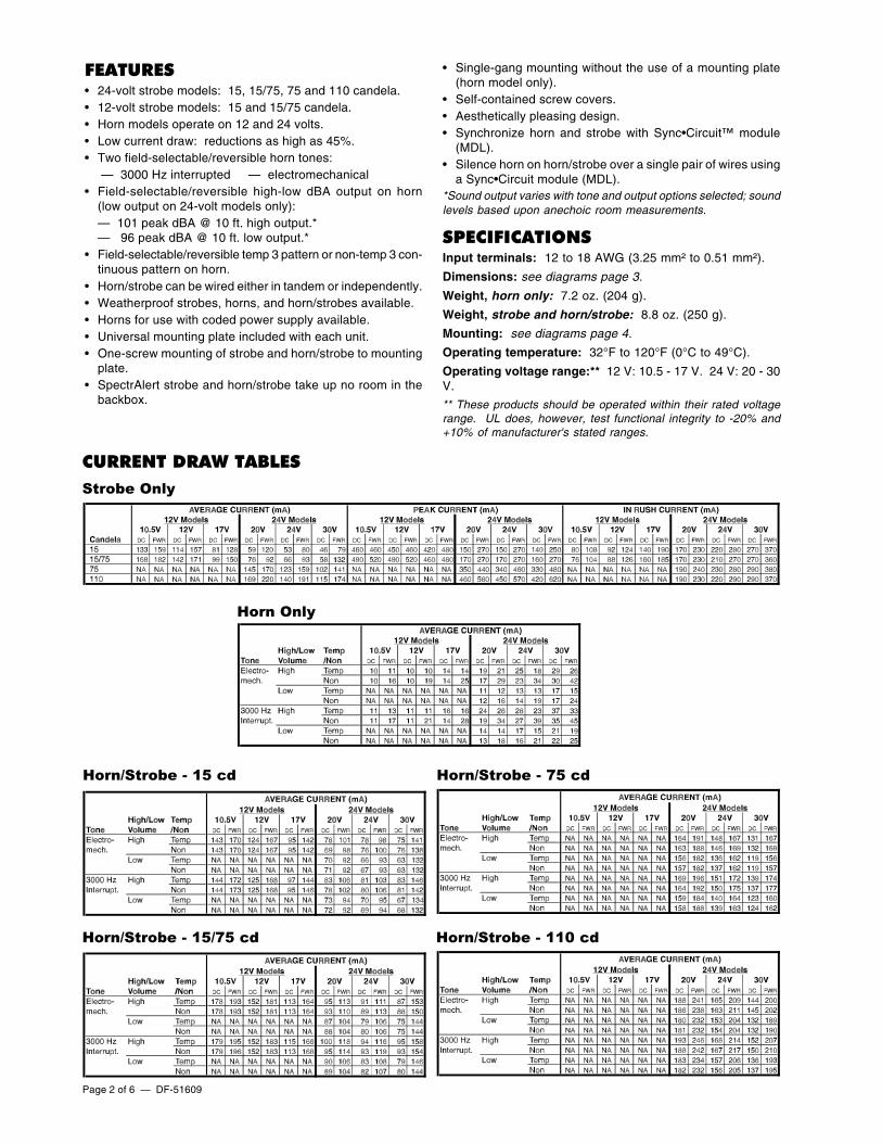
CURRENT DRAW TABLESStrobe Only
Horn Only
Horn/Strobe - 15 cd Horn/Strobe - 75 cd
Horn/Strobe - 15/75 cd Horn/Strobe - 110 cd
DF-51609 — Page 3 of 6
ENGINEERING SPECIFICATIONSGeneral — SpectrAlert horns, strobes and horn/strobesshall be capable of mounting to a standard 4" x 4" x 1-1/2"(10.16 x 10.16 x 3.81 cm) backbox or a single-gang 2" x 4" x1-1/2" (5.08 x 10.16 x 3.81 cm) backbox using the universalmounting plate included with each SpectrAlert product. Also,SpectrAlert products, when used in conjunction with the ac-cessory Sync•Circuit Module, shall be powered from a non-coded power supply and shall operate on 12 or 24 volts. 12-volt rated devices shall have an operating voltage range of10.5 - 17 volts. 24-volt rated devices shall have an operatingvoltage range of 20 - 30 volts. SpectrAlert products shall havean operating temperature of 32°F to 120°F (0°C to 49°C) andoperate from a regulated DC or full-wave rectified, unfilteredpower supply.
Horn — Horn shall be a System Sensor SpectrAlert model_________ capable of operating at 12 and 24 volts. Horn shallbe listed to UL 464 for fire protective signaling systems. Thehorn shall have two tone options, two audibility options (at 24volts) and the option to switch between a temporal 3 patternand a non-temporal continuous pattern. The horn-only modelshall NOT operate on a coded power supply except thosemodels (model numbers contain “HC”) designed to do so.
Strobe — Strobe shall be a System Sensor SpectrAlertmodel _________ listed to UL 1971 and be approved for fireprotective service. The strobe shall be wired as a primarysignaling notification appliance and comply with the Americanswith Disabilities Act requirements for visible signaling appli-ances, flashing at 1 Hz over the strobe’s entire operating volt-age range. The strobe light shall consist of a xenon flash tubeand associated lens/reflector system.
Horn/Strobe Combination — Horn/strobe shall be aSystem Sensor SpectrAlert model _________ listed to UL 1971and UL 464 and shall be approved for fire protective service.Horn/strobe shall be wired as a primary signaling notificationappliance and comply with the Americans with Disabilities Actrequirements for visible signaling appliances, flashing at 1 Hzover its entire operating voltage range. The strobe light shallconsist of a xenon flash tube and associated lens/reflectorsystem. The horn shall have two tone options, two audibilityoptions (at 24 volts) and the option to switch between a tem-poral 3 pattern and a non-temporal continuous pattern. Strobesshall be powered independently of the sounder with the re-moval of factory-installed jumper wires. The horn on horn/strobe models shall operate on a coded or non-coded powersupply.
Module — Module shall be a System Sensor Sync•Circuitmodel _________ listed to UL 464 and shall be approved forfire protective service. The module shall synchronizeSpectrAlert strobes at 1 Hz and horns at temporal 3. Also, themodule shall silence the horns on horn/strobe models, whileoperating the strobes, over a single pair of wires. The moduleshall be capable of mounting to a 4-11/16" (119.0625 mm)square x 2-1/8" (53.975 mm) deep backbox and shall controltwo Style Y (class B) or one Style Z (class A) circuit. Moduleshall be capable of multiple zone synchronization by daisy-chaining multiple modules together and resynchronizing eachother along the chain. The Module shall NOT operate on acoded power supply.
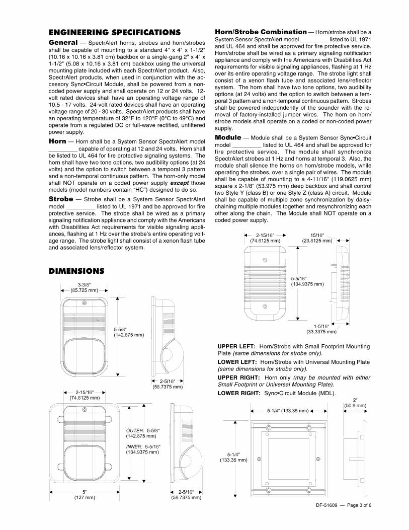
DIMENSIONS
UPPER LEFT: Horn/Strobe with Small Footprint MountingPlate (same dimensions for strobe only).
LOWER LEFT: Horn/Strobe with Universal Mounting Plate(same dimensions for strobe only).
UPPER RIGHT: Horn only (may be mounted with eitherSmall Footprint or Universal Mounting Plate).
LOWER RIGHT: Sync•Circuit Module (MDL).
Page 4 of 6 — DF-51609
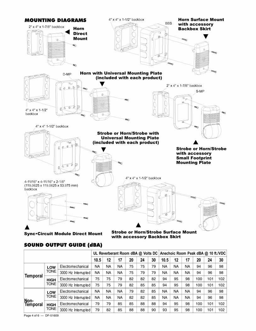
MOUNTING DIAGRAMS
SOUND OUTPUT GUIDE (dBA)
HornDirectMount
Horn Surface Mountwith accessoryBackbox Skirt
Horn with Universal Mounting Plate(included with each product)
Strobe or Horn/Strobe withUniversal Mounting Plate
(included with each product)
Sync•Circuit Module Direct Mount Strobe or Horn/Strobe Surface Mountwith accessory Backbox Skirt
Strobe or Horn/Strobewith accessorySmall FootprintMounting Plate
UL Reverberant Room dBA @ Volts DC Anechoic Room Peak dBA @ 10 ft./VDC10.5 12 17 20 24 30 10.5 12 17 20 24 30
TemporalLOWTONE
Electromechanical NA NA NA 75 75 79 NA NA NA 94 96 98
3000 Hz Interrupted NA NA NA 75 79 79 NA NA NA 94 96 98
HIGHTONE
Electromechanical 75 75 79 82 82 82 94 95 98 100 101 102
3000 Hz Interrupted 75 75 79 82 85 85 94 95 98 100 101 102
Non-Temporal
LOWTONE
Electromechanical NA NA NA 79 82 85 NA NA NA 94 96 98
3000 Hz Interrupted NA NA NA 82 82 85 NA NA NA 94 96 98
HIGHTONE
Electromechanical 79 79 85 85 88 88 94 95 98 100 101 102
3000 Hz Interrupted 79 82 85 88 88 90 93 95 98 100 101 102

DF-51609 — Page 5 of 6
WIRING DIAGRAMSNOTE: Do NOT loop wires under terminal screws.
Tandem Operation
Independent Operation
Horns silenced over two-wire circuit.• Any mix of horn/strobes or strobe-only devices is
acceptable.
• Horn control connects to interruptible powersource.
Temp 3 coding of Multi-Alertand PA400 sounders.NOTE: Strobes must be powered from non-codedsupply.
DIAGRAM NOTES:
1) Any mix of SpectrAlert horn/strobe, strobe-only, or horn-only devices is allowable for Zone 1.
2) No devices or horn-only are allowed on Zone 2. If no de-vices are installed on Zone 2, terminate EOL resistor athorn control terminal.
Page 6 of 6 — DF-51609
PR
OD
UCT
LIN
E IN
FOR
MA
TIO
N
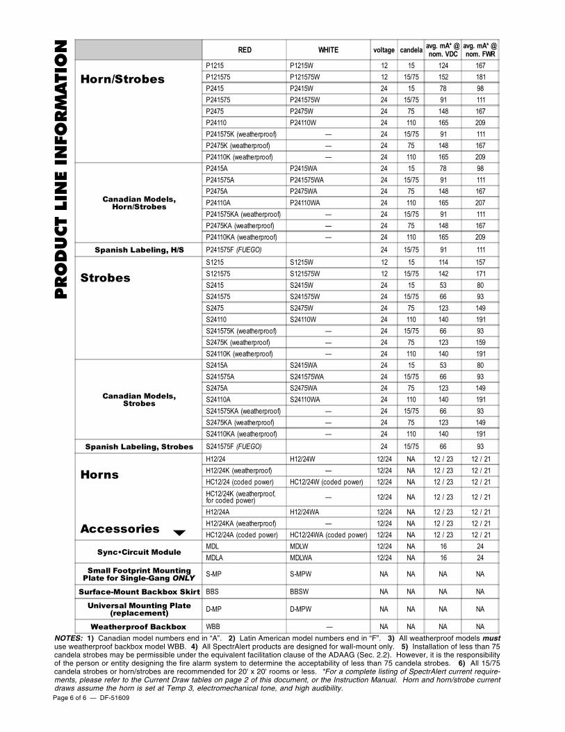
NOTES: 1) Canadian model numbers end in “A”. 2) Latin American model numbers end in “F”. 3) All weatherproof models mustuse weatherproof backbox model WBB. 4) All SpectrAlert products are designed for wall-mount only. 5) Installation of less than 75candela strobes may be permissible under the equivalent facilitation clause of the ADAAG (Sec. 2.2). However, it is the responsibilityof the person or entity designing the fire alarm system to determine the acceptability of less than 75 candela strobes. 6) All 15/75candela strobes or horn/strobes are recommended for 20' x 20' rooms or less. *For a complete listing of SpectrAlert current require-ments, please refer to the Current Draw tables on page 2 of this document, or the Instruction Manual. Horn and horn/strobe currentdraws assume the horn is set at Temp 3, electromechanical tone, and high audibility.
RED WHITE voltage candela avg. mA* @nom. VDC
avg. mA* @nom. FWR
Horn/Strobes P1215 P1215W 12 15 124 167 P121575 P121575W 12 15/75 152 181 P2415 P2415W 24 15 78 98 P241575 P241575W 24 15/75 91 111 P2475 P2475W 24 75 148 167 P24110 P24110W 24 110 165 209 P241575K (weatherproof) — 24 15/75 91 111 P2475K (weatherproof) — 24 75 148 167 P24110K (weatherproof) — 24 110 165 209
Canadian Models,Horn/Strobes
P2415A P2415WA 24 15 78 98 P241575A P241575WA 24 15/75 91 111 P2475A P2475WA 24 75 148 167 P24110A P24110WA 24 110 165 207 P241575KA (weatherproof) — 24 15/75 91 111 P2475KA (weatherproof) — 24 75 148 167 P24110KA (weatherproof) — 24 110 165 209
Spanish Labeling, H/S P241575F (FUEGO) 24 15/75 91 111
Strobes S1215 S1215W 12 15 114 157 S121575 S121575W 12 15/75 142 171 S2415 S2415W 24 15 53 80 S241575 S241575W 24 15/75 66 93 S2475 S2475W 24 75 123 149 S24110 S24110W 24 110 140 191 S241575K (weatherproof) — 24 15/75 66 93 S2475K (weatherproof) — 24 75 123 159 S24110K (weatherproof) — 24 110 140 191
Canadian Models,Strobes
S2415A S2415WA 24 15 53 80 S241575A S241575WA 24 15/75 66 93 S2475A S2475WA 24 75 123 149 S24110A S24110WA 24 110 140 191 S241575KA (weatherproof) — 24 15/75 66 93 S2475KA (weatherproof) — 24 75 123 149 S24110KA (weatherproof) — 24 110 140 191
Spanish Labeling, Strobes S241575F (FUEGO) 24 15/75 66 93
Horns
Accessories
H12/24 H12/24W 12/24 NA 12 / 23 12 / 21 H12/24K (weatherproof) — 12/24 NA 12 / 23 12 / 21 HC12/24 (coded power) HC12/24W (coded power) 12/24 NA 12 / 23 12 / 21 HC12/24K (weatherproof, for coded power) — 12/24 NA 12 / 23 12 / 21
H12/24A H12/24WA 12/24 NA 12 / 23 12 / 21 H12/24KA (weatherproof) — 12/24 NA 12 / 23 12 / 21 HC12/24A (coded power) HC12/24WA (coded power) 12/24 NA 12 / 23 12 / 21
Sync•Circuit Module MDL MDLW 12/24 NA 16 24 MDLA MDLWA 12/24 NA 16 24
Small Footprint MountingPlate for Single-Gang ONLY S-MP S-MPW NA NA NA NA
Surface-Mount Backbox Skirt BBS BBSW NA NA NA NA
Universal Mounting Plate(replacement) D-MP D-MPW NA NA NA NA
Weatherproof Backbox WBB — NA NA NA NA
Related Documents