Clemson University TigerPrints All Dissertations Dissertations 12-2011 Spectral Engineering of Optical Fiber rough Active Nanoparticle Doping Tiffany Lindstrom-james Clemson University, [email protected] Follow this and additional works at: hps://tigerprints.clemson.edu/all_dissertations Part of the Materials Science and Engineering Commons is Dissertation is brought to you for free and open access by the Dissertations at TigerPrints. It has been accepted for inclusion in All Dissertations by an authorized administrator of TigerPrints. For more information, please contact [email protected]. Recommended Citation Lindstrom-james, Tiffany, "Spectral Engineering of Optical Fiber rough Active Nanoparticle Doping" (2011). All Dissertations. 861. hps://tigerprints.clemson.edu/all_dissertations/861

Welcome message from author
This document is posted to help you gain knowledge. Please leave a comment to let me know what you think about it! Share it to your friends and learn new things together.
Transcript

Clemson UniversityTigerPrints
All Dissertations Dissertations
12-2011
Spectral Engineering of Optical Fiber ThroughActive Nanoparticle DopingTiffany Lindstrom-jamesClemson University, [email protected]
Follow this and additional works at: https://tigerprints.clemson.edu/all_dissertations
Part of the Materials Science and Engineering Commons
This Dissertation is brought to you for free and open access by the Dissertations at TigerPrints. It has been accepted for inclusion in All Dissertations byan authorized administrator of TigerPrints. For more information, please contact [email protected].
Recommended CitationLindstrom-james, Tiffany, "Spectral Engineering of Optical Fiber Through Active Nanoparticle Doping" (2011). All Dissertations. 861.https://tigerprints.clemson.edu/all_dissertations/861

SPECTRAL ENGINEERING OF OPTICAL FIBER THROUGH
ACTIVE NANOPARTICLE DOPING
A Dissertation Presented to
The Graduate School of Clemson University
In Partial Fulfillment
of the Requirements for the Degree Doctor of Philosophy
Materials Science and Engineering
by
Tiffany Lindstrom-James December 2011
Accepted by:
John Ballato, Committee Chair Philip Brown
Stephen Foulger Eric Skaar

ii
ABSTRACT
The spectral engineering of optical fiber is a method of intentional doping
of the core region in order to absorb/emit specific wavelengths of light therby
providing enhanced performance over current fibers. Efforts here focused on
developing an understanding of optically active nanoparticles based on alkaline
earth fluorides that could be easily and homogeneously incorporated into the
core of a silica based optical fiber preform and result in efficient and tailorable
spectral emissions.
Doped and undoped calcium, strontium and barium fluoride nanoparticles
were successfully synthesized and characterized for their physical, chemical, and
optical behavior. Distinct spectroscopic differences as a result of different host
materials, varying rare earth doping levels and processing conditions, indicated
the ability to influence the spectral behavior of the doped nanoparticle. By
using photoluminescence to predict diffusion behavior, the application of a simple
one dimensional model for diffusion provided a method for predicting the
diffusion coefficient of europium ions in alkaline earth fluorides with order of
magnitude accuracy.
Modified chemical vapor deposition derived silica preforms were
individually solution doped with europium doped alkaline earth fluoride
nanoparticles. By using the rare earth doped alkaline earth fluoride nanoparticles
as the dopant materials in the core of optical fiber preforms, the resultant optical

iii
properties of the glass were significantly influenced by their presence in the core.
The incorporation of these rare earth doped alkaline earth fluoride nanoparticles
was found to significantly influence the local chemical and structural environment
about the rare earth ion, demonstrated homogeneity and uniform distribution of
the rare earth dopant and resulted in specifically unique spectral behavior when
compared to conventional doping methods. A more detailed structural model of
the doped core glass region has been developed based on the spectral behavior
of these active fiber preforms.
It has been shown that rare earth doping of alkaline earth fluoride
nanoparticles provides a material which can be ‘tuned’ to specific applications
through the use of different host materials, processing conditions and doping
levels of the rare earth and when used as dopant materials for active optical
fibers, provides a means to tailor the optical behavior.

iv
DEDICATION
To my beautiful, amazing, tenacious, witty, bright blue-eyed babies, Kirin
and Cooper…. I started this quest with the intent to better our lives as a family
and I end it hoping I have shown you to persevere, endure and remain strong no
matter what the universe throws in your way. The road to success is not always
the shortest distance between two points, but if you lead with your heart, you can
never go wrong. I couldn’t have done this without you, I am so very proud to be
your mom, and I love you to infinity and back…
To my sweet, angel baby Griffin…..I know you have been with me every
step of the way. Thanks for being my inspiration in times of desperation and the
sunshine when things have seemed the darkest. You were one tough little guy,
and you have taught me so much about life, inner strength and unconditional
love. Oh and thanks for being my guardian angel; It’s a tough job, but I think
you are handling it beautifully.

v
ACKNOWLEDGEMENTS
Many thanks, first and foremost, to my advisor and friend, John Ballato. I
realize this took a bit longer than you had anticipated but your patience and
understanding during the many trials and tribulations of my life made this
endeavor much ‘easier’ and definitely have not gone unnoticed. My kids gained
the most as a result and I will be forever indebted to you for it.
Thanks to my committee members, Phil Brown, Eric Skaar and Steve
Foulger. You all have managed to push me along in subtle ways through the
course of my academic career and I leave here with much appreciation for your
wisdom and thoughtfulness.
To my AMRL-Clemson Family and the entire staff at Clemson Elementary
School; your tremendous support over the course of the last two years whether
in the lab or in my home is a gift I will forever treasure. Each of you have helped
me get to this point in some way, whether it was providing a much needed laugh,
venting session, hug, adult beverage, lab work, yard work or sitting services.
Thank you.
Much gratitude is owed to my dear friend and true colleague, Kate
Stevens. Thanks for treating me like an equal when I felt like a peon, finding a
way to help me breathe when the academic part of my world had me by the
throat, reminding me I was, in fact, worthy of this and most of all, being my friend

vi
when life would have me think I had none. You are an amazing woman and I am
so honored to call you my friend. Thank you.
And that leaves MaryAlice Lohmeier, my soul sister. The reason I finally
get Oprah and Gayle. There are no words that can convey what it has meant to
me to have you in my life. At times when I thought there was no way I was going
to survive, you were always there to tell me I absolutely would. I could not have
done this part without you. Period. Thank you, love you and now, I’m done, so
we can go play!
This five year journey has been long and arduous, with many personal
tragedies along the way. The people I have been blessed with in my life, who
have supported me through all the ups and downs, have provided me an
opportunity to enhance the lives of my children and given me the courage to
carry on when most would have packed their toys and gone home. They say
friends are the family you choose so…. to my family of choice as well as the
family I was lucky to be born into….I am humbled by your love and unending
support and I thank you all from the bottom of my heart.

vii
TABLE OF CONTENTS
Page
TITLE PAGE ....................................................................................................... i
ABSTRACT ........................................................................................................ ii
DEDICATION .................................................................................................... iv
ACKNOWLEDGEMENTS .................................................................................. v
LIST OF TABLES .............................................................................................. ix
LIST OF FIGURES ............................................................................................ x
CHAPTER
I. OVERVIEW ...................................................................................... 1
Purpose Statement ..................................................................... 21
References .................................................................................. 22
II. ACTIVE NANOPARTICLES: CHARACTERIZATION OF
ALKALINE EARTH FLUORIDE NANOPARTICLES ............. 27
Introduction ................................................................................ 28
Experimental Procedures ........................................................... 38
Results and Discussion .............................................................. 45
Physical Characterization .................................................. 45
Emission Behavior ............................................................ 54
Phonon Energy Assessment ............................................. 59
Thermal Effects on Optical Behavior ................................. 63
Optically Estimated Diffusion Coefficients ......................... 86
Summary .................................................................................... 93
References ................................................................................. 94

viii
Table of Contents (Continued)
Page
III. APPLICATIONS: USING RARE EARTH DOPED ALKALINE
EARTH NANOPARTICLES FOR
SPECTRAL ENGINEERING OF OPTICAL FIBER ................. 99
Introduction .............................................................................. 100
Experimental Procedures ......................................................... 110
Results and Discussion ............................................................ 113
Spectral Behavior ............................................................ 113
Vibrational Energy ........................................................... 119
Fluorescence Lifetime ..................................................... 123
Summary .................................................................................. 128
References ............................................................................... 129
IV. CONCLUSIONS ........................................................................... 132
V. FUTURE WORK ........................................................................... 135
VI. APPENDICES .............................................................................. 139
A: Nanoparticle Batch Calculations ...................................... 140
B: ADDP Synthesis and Characterization ............................ 143
C: Eu2+ Characterization ...................................................... 149
D: Other Optically Active Alkaline Earth Fluoride
Nanoparticles ...................................................... 163

ix
LIST OF TABLES
Table Page
2.1 Alkaline Earth Fluoride Nanoparticle Size Analysis .......................... 50
2.2 Summary of Raman Vibrational Energies for
Alkaline Earth Fluoride Nanoparticles .......................................... 53
2.3 Average Size of Core and Core/Shell
Alkaline Earth Fluoride Nanoparticles .......................................... 65
2.4 Calculated Diffusion Coefficients for Eu3+ in
Alkaline Earth Fluoride Nanoparticles .......................................... 87
4.1 Calculated Eu3+ Hypersensitivity Ratios for
Nanoparticles and Nanoparticle doped Preforms .................... 117

x
LIST OF FIGURES
Figure Page
1.1 Electronic Wavefunctions of a Gd3+ ion .............................................. 4
1.2 Energy Level Diagram of the Trivalent Lanthanide Ions .................... 6
1.3 Fluorescence and Up-Conversion Mechanism .................................. 7
1.4 Schematic of Optical Fiber ............................................................... 17
2.1 Schematic of Ligand Capped Nanoparticle ...................................... 30
2.2 Trivalent Europium Energy Level Diagram ....................................... 34
2.3 TEM Images of Calcium Fluoride Nanoparticles .............................. 47
2.4 TEM Images of Strontium Fluoride Nanoparticles ............................ 48
2.5 TEM Images of Barium Fluoride Nanoparticles ................................ 49
2.6 X-Ray Diffraction Patterns of
Alkaline Earth Fluoride Nanoparticles .......................................... 51
2.7 Raman Spectra of Calcium Fluoride Nanoparticles ......................... 52
2.8 Raman Spectra of Strontium Fluoride Nanoparticles ....................... 52
2.9 Raman Spectra of Barium Fluoride Nanoparticles ........................... 53
2.10 Emission Spectra of Various Europium Doped
Alkaline Earth Fluoride Nanoparticles .......................................... 57
2.11 Effect of Europium Concentration on Hypersensitivity Ratio ............ 58
2.12 Phonon Sideband Spectra for 5Eu:(AE)F2 Nanoparticles ................ 61
2.13 Phonon Sideband Spectra for 15Eu:(AE)F2 Nanoparticles .............. 61

xi
List of Figures (Continued)
Figure Page
2.14 Phonon Sideband Spectra for 25Eu:(AE)F2 Nanoparticles .............. 62
2.15 20Eu:CaF2 Core and 1 Shell Nanoparticle Emission Spectra
as a function of time at 650ºC ...................................................... 70
2.16 20Eu:CaF2 2 Shell and 3 Shell Nanoparticle Emission Spectra
as a function of time at 650ºC ...................................................... 71
2.17 Hypersensitivity Ratio as a function of time at 650ºC
for 20Eu:CaF2 Core/Shell Nanoparticles ...................................... 72
2.18 Ratio of Eu2+/Eu3+ as a function of time at 650ºC
for 20Eu:CaF2 Core/Shell Nanoparticles ..................................... 72
2.19 20Eu:SrF2 Core and 1 Shell Nanoparticle Emission Spectra
as a function of time at 650ºC ...................................................... 76
2.20 20Eu:SrF2 2 Shell and 3 Shell Nanoparticle Emission Spectra
as a function of time at 650ºC ...................................................... 77
2.21 Hypersensitivity Ratio as a function of time at 650ºC
for 20Eu:SrF2 Core/Shell Nanoparticles ....................................... 78
2.22 20Eu:BaF2 Core and 1 Shell Nanoparticle Emission Spectra
as a function of time at 650ºC ..................................................... 79
2.23 20Eu:BaF2 2 Shell and 3 Shell Nanoparticle Emission Spectra
as a function of time at 650ºC ..................................................... 80

xii
List of Figures (Continued)
Figure Page
2.24 Hypersensitivity Ratio as a function of time at 650ºC
for 20Eu:BaF2 Core/Shell Nanoparticles .................................... 81
2.25 20Eu:(AE)F2 Core Nanoparticle Emission Spectra ......................... 88
2.26 20Eu:(AE)F2 Core/1 Shell Nanoparticle Emission Spectra ............. 89
2.27 20Eu:(AE)F2 Core/2 Shell Nanoparticle Emission Spectra .............. 90
2.28 20Eu:(AE)F2 Core/3 Shell Nanoparticle Emission Spectra ............. 91
2.29 Hypersensitivity Ratio as a function of time at 650ºC
by Core/Shell Nanoparticle Type ............................................... 92
3.1 Schematic of Local Structure of SiO2 glass ................................... 102
3.2 Schematic of Local Structure of Modified SiO2 glass .................... 102
3.3 Emission Spectra of Eu:(AE)F2 doped Silica Preforms ................. 116
3.4 Comparison of Eu:(AE)F2 Nanoparticle and
Eu:(AE)F2 Nanoparticle Doped Preform
Hypersensitivity Ratios ............................................................. 117
3.5 Schematic of Local Structure of a Eu:(AE)F2 Nanoparticle
Doped SiO2 glass ................................................................... 118
3.6 Phonon Sideband Spectra for Eu:(AE)F2 Nanoparticle
Doped Silica Preforms ........................................................... 121
3.7 Raman Spectra of Heat Treated Alkaline Earth Fluoride
Nanoparticles ......................................................................... 122

xiii
List of Figures (Continued)
Figure Page
3.8 Fluorescence Decay Curves for Eu:(AE)F2 Nanoparticle
Doped Silica Preforms ........................................................... 125
3.9 Fluorescence Lifetime as a function of Preform Type ................... 126
A.1 Batch Sheet for Basic Core and Basic Core Rare Earth
Doped Alkaline Earth Fluoride Nanoparticles ......................... 141
A.2 Batch Sheet for Core/Shell Rare Earth Doped
Alkaline Earth Fluoride Nanopaticles .................................... 142
B.1 Emission Spectra of As-Made ADDP ........................................... 145
B.2 Raman Spectra of As-Made ADDP .............................................. 146
B.3 Summary of TGA Analysis of Undoped Alkaline Earth
Fluoride Nanoparticles Made with ADDP .............................. 148
C.1 TEM Images of 20Eu:CaF2 Core/Shell Nanoparticles .................. 153
C.2 Photoluminescence Spectra of 20Eu:CaF2 Core/Shell
Nanoparticles as a function of time at 650ºC ........................ 154
C.3 XPS of Eu4d Region of 20Eu:CaF2 Core Nanoparticles ............... 157
C.4 XPS of Eu4d Region of
20Eu:CaF2 Core/1 Shell Nanoparticles ................................ 157
C.5 XPS of Eu4d Region of
20Eu:CaF2 Core/2 Shell Nanoparticles ................................ 158

xiv
List of Figures (Continued)
Figure Page
C.6 XPS of Eu4d Region of
20Eu:CaF2 Core/3 Shell Nanoparticles ................................ 158
C.7 Mossbauer Spectra of 20Eu:CaF2 Core/3 Shell
Nanoparticles Heated for 75 minutes at 650ºC .................... 162
D.1 X-Ray Diffraction Pattern of
Magnesium Fluoride Nanoparticles ...................................... 165
D.2 Emission Spectra of 5Eu:MgF2 Nanoparticles .............................. 166
D.3 Emission Spectra of 15Eu:MgF2 Nanoparticles ............................ 167
D.4 Emission Spectra of 25Eu:MgF2 Nanoparticles ............................ 168
D.5 20Eu:MgF2 Core Nanoparticle Emission Spectra
as a function of time at 650ºC ............................................. 169
D.6 20Eu:MgF2 1 Shell Nanoparticle Emission Spectra
as a function of time at 650ºC ............................................. 169
D.7 20Eu:MgF2 2 Shell Nanoparticle Emission Spectra
as a function of time at 650ºC ............................................. 170
D.8 20Eu:MgF2 3 Shell Nanoparticle Emission Spectra
as a function of time at 650ºC ............................................. 170
D.9 Transmission Measurement of a 15Cr:CaF2/Al
Nanoparticle Doped Optical Fiber Preform ........................ 174

1
CHAPTER I
OVERVIEW
The spectral engineering of optical fiber is a method of intentional doping
of the core region in order to absorb/emit specific wavelengths of light thereby
providing enhanced performance over current fibers. The development of
optically active fibers has been driven by the continuing demand for more
efficient, cost effective and easily produced fiber amplifiers which operate in the
telecommunications transmission window of 1550 nm1.1,1,2. These fibers are
produced by doping the core region of an optical fiber, commonly silica glass,
with optically active rare earth ions.
The most commonly known amplifier is the erbium doped fiber amplifier
(EDFA) which provides amplification in the 1550 nm regime. Other rare earth
doped glasses such as fluorides, tellurides and chalcogenides are of interest for
amplification of the 1300 nm region due to their low phonon energy and
increased solubility of rare earth ions, however, their mechanical and chemical
properties, in addition to their inability to be spliced efficiently to commercial silica
optical fiber, limit their use. Fluoride fibers, in particular melt at temperatures
considerably lower than silica making fusing of the two fibers difficult1.3-1.5.
Rare earth ion emissions in silica fiber are limited by the phonon energy of
the glass matrix and the solubility of the ions into the matrix. This makes control

2
of the distribution and concentration of the dopant ions of primary interest for
improving overall active fiber spectroscopic characteristics.1.4,1.6.
Given this desire for improved performance, efforts here focused on
providing a material that could be easily and homogeneously incorporated (i.e., is
soluble) into the core of a silica-based optical fiber preform and result in efficient,
and potentially tailorable spectral emissions. Therefore, this dissertation
advances the fundamental understanding of the behavior of optically active
nanoparticles, based on alkaline-earth fluorides, through the synthesis,
characterization (physical, chemical and optical ) and ultimately, use as primary
core dopants in optical fiber. This initial overview serves to provide a general
background, definitions and foundation for the study of these optically active
materials.
Optically Active Materials:
Rare Earth Elements and Spectroscopy
The f-block elements of the periodic table are comprised of two groups, 14
elements each, the lanthanides and actinides. Lanthanides are referred to as the
‘rare earths’. The term rare earth has its origins in the early discovery of these
elements and refers to the fact they were originally found in scarce minerals and
the difficulty in obtaining them in a pure state by chemical extraction1.7. The

3
lanthanide elements are generally defined as those which the 4f orbitals are
progressively filled. This includes cerium (z=58) to lutetium (z=71)1.8. The
actinides include thorium (z=90) to lawrencium (z=103) and involve the filling of
5f shell electrons. The first commercial application of these materials was a gas
mantle consisting of 99% ThO2 and 1% CeO2 in 1891 which enabled widespread
use of incandescent gas lamps1.8. Current notable commercial use of lanthanum
is in the batteries of hybrid vehicles, cerium (the most abundant of the rare earth
elements) is most notably known for its use in catalytic converters, europium (as
well as terbium) is widely used as a phosphor in color television tubes and has
more recently been used as an anti-counterfeiting phosphor in the European
Union’s paper currency1.9.
The electronic configuration of the lanthanide series is found to be that of
the Xenon structure plus the corresponding number of 4f electrons, [Xe]fn , where
n=1-14. Ionization preferentially removes any 6s and 5d electrons which results
in the 3+ oxidation state as generally the most stable state for these
elements1.10-1.12. The radii of both the atomic and ionic species are found to
decrease with increasing atomic number and is referred to as the lanthanide
contraction. Due to limited screening by the 4f electrons, there is an increase in
effective nuclear charge and the 4f electrons become more tightly bound with
increasing atomic number1.11. The 4f electrons are ‘inside’ the 5s, 5p and 6s
orbitals, (Figure 1.1), which results in a shielding affect from bonding with
neighboring atoms, making their electronic and magnetic spectra virtually

4
independent of environment1.13, and results in well defined, sharp bands in the
absorption spectra of the corresponding ionic species1.12.
Figure 1.1. Electronic Wavefunctions of a Gd3+ ion1.8.
The observed infrared and visible optical spectra of trivalent rare earth
ions are a consequence of transitions of electrons between 4f energy levels, or
the ground state and excited states of the ions. Energy levels are represented in
figure 1.2 as reported by Dieke and White in 19631.14. The lowest energy level is
referred to as the ground state, with higher energy levels referred to as excited
states. Each level is designated using the Russell-Saunders or spin-coupling
scheme which takes into account the spin (s) and momentum (orbital (L) and

5
angular (J)) of the electrons in the atom or ion and is given in the general
form1.11-1.13.
(2s+1)LJ
An influx of energy, or absorption, can lead to two different effects in rare earth
ions: fluorescence and up-conversion. The probability the electron will move
between states is dictated by guidelines known as the selection rules1.10-1.13. The
likelihood an electron will choose one energy level over another depends upon
the amount of change (with regard to spin, momentum) required between the
states, i.e. the electron will decay ‘along the path of least resistance’ when given
the proper amount of energy to do so. For example, the ground state of Er3+ is
4I15/2 and the first excited state is 4I13/2. There is a small difference between
angular momentum values, making the probability of this transition high, whereas
a transition to one a higher energy state, 2D5/2, requires a change to all three
quantum states, making the probability of transition low.

6
Figure 1.2.. Energy level diagram of the trivalent lanthanide ions1.14

7
Fluorescence, depicted in figure 1.3a, occurs as electrons are excited into
higher energy levels by the absorption of photons. The electrons then relax to a
lower energy state. The resultant energy emitted by the photon is less than that
of the incident photon.
Figure 1.3. a) General fluorescence mechanism, b) general up- conversion
mechanism1.10
Up-conversion, figure 1.3b, results when excited electrons absorb another
photon and are excited to even higher energy levels. The electron eventually
decays back to a lower energy state and in doing so, results in an emission of a
photon whose energy is greater than the initial incident photon. This
phenomenon does not necessarily produce photons of higher energy if the
electron only relaxes to an energy level above the incident photon but below the

8
excited state. Generally, up-conversion describes a process by which an excited
electron absorbs one or more ‘extra’ photons and moves to a higher energy level,
regardless of emission wavelength1.8,1.10. Up-conversion is a fairly unusual
process which tends to require a high flux of incident light or a long radiative
lifetime such that it can occur prior to fluorescence.
In systems where co-doping is employed (two different rare earth ions
present), energy transfer or sharing of energy between ions can occur. By
partnering specific rare earth ions to allow their intrinsic states to communicate
with each other, scientists can create innovative solutions that take advantage of
energy transfer mechanisms which could otherwise be deemed detrimental, as
was demonstrated by the use of Yb3+ energy transfer to Er3+ to improve pumping
efficiency of solid state lasers. However, same species energy transfer can also
occur, which is detrimental to the overall rare earth behavior and result in
reduced efficiency and lower emissions1.10.
Energy out of a system generally is classified as either radiative (light,
photons) or non-radiative (heat, phonons). The quantum efficiency of the system
is therefore affected by the concentrations of single rare earth ions or co-doping,
as well as the host material containing the emitting ions. In order to quantify the
quantum efficiency of a given rare earth system, excited state lifetime
measurements are used. The theoretical radiative lifetime, τ, is the time for
natural (spontaneous) emission to occur after exciting the ion to a specific

9
wavelength. These values are found by monitoring emission as a function of
time while exciting a sample with a pulse or modulated excitation1.15. Quantum
efficiency is used to account for the difference between theoretical and measured
lifetime values and reveals non-radiative losses due to heat and/or host material.
The total lifetime is the sum of the measured lifetime and the contribution from
the host material, or the non-radiative lifetime1.4,1.15.
Optically Active Materials:
Alkaline Earth Fluorides as Hosts
Rare earths are used as dopants in various materials, as defined by the
application. Rare earth doped glasses allow for broader emission and
absorption spectral properties (with respect to crystalline hosts), making them
ideal for many optical fiber devices. Other applications require crystalline hosts
for their inherently superior thermal properties and narrower linewidths1.15.
Regardless of type of use, the final characteristics of luminescent devices are
dependent upon the optical properties resulting from the ion-host interactions. In
order to increase the efficiency of a given device, the excitation efficiency needs
to be increased. The quantum efficiency of a material system is give as a ratio of
the emitted to absorbed photons and varies between 0 to 1. A quantum
efficiency of less than one implies a portion of the absorbed energy has been lost
to non-radiative processes, i.e., heat, phonons1.16. The lower the vibrational

10
energy of the host material, the less the non-radiative contribution to electron
decay, which ultimately increases the quantum efficiency. Therefore, choosing a
host material is a crucial step in the design of optical devices.
The vibrational energy of a host material is a result of the inherent
oscillations between ions in solids about an equilibrium position. If the difference
in energy levels is comparable to that of the lattice vibrations, any emission
becomes more difficult, as the relaxation path is more likely to generate phonons
(heat), rather than photons (light), or it takes more energy/phonons to stimulate
the decay1.16.
When looking at conventional luminescent materials, fluorides emerge as
advantageous host materials due to their low intrinsic vibrational energies which
extend transmission to the far ultra-violet and infrared spectral regimes, minimally
quench the excited state of rare earth ions, have high transparency over a wide
wavelength range, high iconicity and fundamentally reduce absorption when
compared to oxide based materials1.17,1.18.
In choosing what specific fluorides to use, looking at the interaction
between rare earth (RE) ions and host is useful, as well as the luminescent
efficiency of the materials. Lanthanum trifluoride, LaF3, is a very suitable host
because the RE3+ can easily substitute for the La3+ of the same valency1.19. The
vibrational or phonon energy of LaF3 is reported to be ~350 cm-1, has a high RE
solubility and has significant environmental and thermal stability1.20.

11
Alkaline earth (calcium, strontium and barium) fluorides possess similar
characteristics and have been studied in limited areas. Their cubic lattice
structure enables transmission for a wide range of wavelengths as well as
indicates independence of absorption from induced polarization. They have
similarly matched refractive index values that can be exactly matched to a glass
or polymer for use in composite materials.1.21-1.23. The cubic fluoride structure
also allows for the aggregation and clusters of RE3+ ions, making the distance
between the active ions short and interactions strong1.24, implying a propensity
for ease of energy transfer when the materials are co-doped with differing RE3+
ions.
More specifically, CaF2 is reported to exhibit transparency over a
wide range of wavelengths, can easily be doped with trivalent rare earth ions and
with the incorporation of rare earths, an increase of refractive index results,
making it a desirable material for active waveguides1.21,1.23,1.25. Moreover, the
substitution of RE3+ ions for Ca2+ ions results in broad absorption and emission
bands, due to the necessary charge compensation, which is important in optical
device development1.23. Barium fluoride, BaF2, is found to have transparency in
the visible and near-IR region1.26. In addition, BaF2 has slight solubility in water
and is non- hygroscopic, and due to its cubic structure, has one refractive index
and can be exactly matched to a glass or polymer matrix material to avoid
significant light scattering, making it desirable for use of composites 1.22,1.26,1.27.

12
In the realm of glass making, alkaline earth elements are known to serve
as glass modifiers. These elements are added to assist in the formation of a
glass; they form highly ionic bonds with oxygen which can serve to modify the
local network structure within a glass1.28. The addition of an alkaline earth
perturbs the short range order of the silica glass matrix by affecting the inter-
atom connectivity and the silica bond angles1.29. Commercially, bulk laser glasses
typically require the presence of glass modifier ions such as Ca2+ to ‘open’ up the
silicate structure to aid in RE solubility1.10.
Application of Optically Active Materials:
Rare Earth Doped Nanoparticles
Particles with diameters ranging from a few to 100 nanometers with
chemical and physical properties that can differ from those of the analogous bulk
material are termed nanoparticles1.30,1.31. In recent years, this nanotechnology
has been used in a variety of applications from drug carriers to pigments,
catalysts to sensors and magnetic to optical materials1.32. The unique size and
shape tuning abilities of these materials are of particular interest in the optical
community because they provide a wide range of physical properties not found in
their bulk counterparts and have a higher chemical reactivity which allows the
creation of ceramic and transparent ceramic materials at lower
temperatures1.22,1.25,1.33. Several methods are employed to synthesize
13
nanoparticles such as gas and laser evaporation, sol-gel reaction, microemulsion
and hydrothermal treatment1.22,1.30,1.33.
Of interest here is the development of nanoparticles which efficiently up
and down convert light which can easily be incorporated into bulk polymeric or
glass matrices. This requires active rare earth dopants in low vibrational energy
hosts, dispersion of the nanoparticles in organic solvents, as well as a refractive
index that can be matched to a polymer or glass composite host for designing
practical optical devices. Materials made of alkaline earth fluorides are a means
of satisfying the host and refractive index requirements and synthesis of the
nanoparticles with different surfactants/ligands (the attachment of long chain
hydrocarbons to the surface) is a key component in facilitating their dispersibility
in organic solvents . Previous studies1.34-1.36 to produce nanoparticles involving
LaPO4 and LaF3 as the host for rare earth ions are the foundation for
experimentation in this work.
In 2002, Stouwdam and van Veggel reported their ability to produce rare
earth doped lanthanum fluoride particles that disperse well in organic
solvents1.34, 1.35. Upon verification of rare earth incorporation via emission spectra
and lifetime measurements, they determined that as dopant level increased,
luminescent lifetime increased. This implied a relationship between surface ions
and quenching effects and suggested a layer of undoped host material around
the particles could improve the overall luminescence1.35. Rare earth doped

14
inorganic core-shell nanoparticles produced by Hasse, et. al, yielded a LaPO4
shell around a CePO4: Tb core1.36 and rare earth doped LaPO4 with undoped
LaPO4 shells1.37 which improved quantum yield. However, these particles were
made with a high-temperature procedure which eliminates any organic groups on
their surface, making it extremely difficult to disperse in organic solvents.
By modifying a solution-precipitation method initially developed by Dang,
et. al,1.38 for LaF3 nanoparticles, van Veggel, et. al, produced surface-coated
nanoparticles of LaF3 and LaPO4 doped with a variety of rare-earth ions1.39 and
further improved their luminescent properties by utilizing organic materials or
ligands1.40. These core-shell nanoparticles were developed based on the
following premises: 1. The core is doped with luminescent ions and the shell is
not. 2. The use of a ligand will improve the solubility of the particles in an
organic solvent, control particle growth, prevent clustering and improve
luminescence. 3. LaF3 is presumed to provide low enough vibrational energy to
allow emission of lanthanide ions in the visible and near infrared1.39,1.40.
Core-shell nanoparticles were taken further by DiMaio, et. al,1.41, 1.42 with
the development of complex architectures which utilize the shells as luminescent
layers allowing for energy transfer between rare earth ions. Using LaF3 as a
host, these particles provide the ability to tailor emissions as well as provide a
system to study the ‘basic science’ of rare earth ions. By enhancing van

15
Veggel’s solution precipitation approach, these complex core-shell nanoparticles
are easily produced and dispersible in organic solvents.
Alkaline earth (calcium, strontium and barium) fluoride (AEF2)
nanoparticles possess similar characteristics to RE doped LaF3 nanoparticles
and have been studied in limited areas. Bender et. al,1.27 produced neodymium
doped BaF2 particles, on the order of 100 nm, Lian, et. al,1.26 synthesized erbium
doped BaF2 particles using a reverse microemulsion technique for use in
composite polymer matrices and Hua et. al,1.22 produced 50-150 nm BaF2:Ce3+
particles using a 2-octanol/water microemulsion reaction. Previous studies by
Wang, et. al,1.21 reported synthesis of 15-20 nm Eu3+:CaF2 particles via a low
temperature solution precipitation process, Labeguerie et. al,1.25, produced
Eu3+:CaF2 nanoparticles on the order of 15 nm utilizing a non-aqueous process
to limit introduction of hydroxide groups and Sun & Li1.33 synthesized single
crystal CaF2 350 nm nanocubes using a hydrothermal procedure. CaF2, SrF2 and
BaF2 particles of sizes ranging from 20 to greater than 100 nm made by flame
synthesis are also reported by Grass and Stark1.43 These processes prove the
ability to make alkaline earth nanoparticles by various means, however, none of
these methods provide a way in which organic constituents can be incorporated,
making them interesting but not practical for application.

16
Application of Optically Active Materials:
Fundamentals of Optical Fiber
In general terms, an optical fiber is a thin, cylindrical piece of glass about
the diameter of a human hair (~125 μm) through which light can travel. This light
can be turned on and off and gradually changed in amplitude, phase or
frequency dependent upon the information being transmitted by that light. When
compared to other communication technology such as copper cable, radio or
microwave transmission, optical fiber has distinct advantages as it is less
affected by noise, does not conduct electricity and can carry data over long
distances at extremely high rates. Optical fibers were first contemplated in the
early 1960s, with Kao and Hockham first suggesting that low loss optical fiber
could be a viable and competitive means for telecommunications and Corning
Glass Works producing optical fiber with losses of less than 10 dB/km in 1970.
Since that time, the commercial and scientific applications of optical fiber has
been vast and varied due to the realization that very small changes in material
properties result in big gains in transmission distances and uses1.44-1.46.
The basic structure of an optical fiber is pictured in Figure 1.4a. A core
(where the light travels) of refractive index n0 is surrounded by a cladding layer of
lower refractive index n1. The difference in refractive index is required to ‘trap’
any light within the waveguide core. In order to achieve this total internal
reflectance, the light inside the fiber must be incident at an angle greater than the

17
critical angle, ϴc, at the interface (illustrated in Figure 1.4b) and is given
by1.45,1.46:
ϴc = (
)
Figure 1.4. Left: Generic optical fiber cross-section of core radius r.
Right: demonstration of light propagation path at critical angle, ϴc

18
In order to achieve the mandatory difference in refractive index, the core
and clad are comprised of two different materials which are transparent to light in
the transmission space. To avoid losses due to scattering and defects, the
materials of choice are generally limited to either glasses or certain polymers.
Commercial optical fiber is typically comprised of silica (SiO2) and germania
(GeO2) in the core region and pure SiO2 in the cladding, however, for specialty
applications manipulation of core glass composition with the addition of dopant
materials, such as rare earth elements, is employed1.46.
Conventional fabrication of optical fibers requires the production of a
preform with the desired refractive index profile in macroscopic dimensions. To
make the preform, chemical vapor deposition (CVD) techniques are used in one
of two processes to produce high purity and precise index profiles. Modified
Chemical Vapor Deposition (MCVD) and Plasma-Assisted Chemical Vapor
Deposition (PCVD) are considered ‘inside’ processes, whereby submicron
particles (soot) of the desired compositional constituents are deposited layer by
layer inside a rotating silica substrate tube, which is then sintered. Outside
Chemical Vapor Deposition (OCVD) and Vapor Axial Deposition (VAD) are
methods by which the soot is deposited layer by layer on the outside of a thin,
rotating, cylindrical target or bait rod, which must be removed before sintering1.45.
Beyond telecommunications, optical fibers are of interest in the areas of
amplification and lasing1.4,1.45-1.47. By incorporating rare earth ions into the core

19
of an optical fiber, the glass has the ability to absorb light at one wavelength and
emit at another1.47, which results in desired amplification or gain of the optical
signals over wide spectral bandwidths1.46. Pure silica glass is not readily doped
with RE3+ due to the absence of network modifiers, making the local structure
very rigid and virtually eliminating non-bridging Si-O groups. This influences the
coordination of the RE3+, limits solubility and leads to clustering of the ions within
the glass. Clustering has detrimental effects on the luminescence qualities of the
RE3+ by inducing loss of ion excitations, resulting in decreasing luminescence
lifetime with increasing RE3+ concentration1.47,1.48. To increase the solubility of
RE3+, decrease the effects of clustering and somewhat control RE3+ absorption
and fluorescence spectra co-doping with materials that alter these spectroscopic
properties is employed. Aluminum is commonly incorporated and typically works
as a network modifier by sharing non-bridging oxygen ions with RE3+ and
reducing clustering, as well as aiding in solubility1.47. Alkali and alkaline earth
metals may also be included as co-dopants to alter the host glass composition
for better RE3+ incorporation1.47,1.48. Ultimately, the addition of co-dopants is to
tailor the absorption and emission spectra and improve the glass-forming ability
of the host glass for the desired application1.47.
The conventional method developed in the late 1980s for incorporating
rare earth ions into optical fiber preforms is referred to as solution doping1.49,
where an aqueous solution of rare earths and aluminum, usually as chloride
salts, is used in an additional step during the MCVD process. Recently,

20
materials on the nanoscale have been receiving interest as an alternate method
of delivering the same dopants to the core of an optical fiber preform. Liekki
Corporation1.50 has developed a method using OVD technology referred to as
“Direct Nanoparticle Deposition” where Er and Al rich ‘crystallites’ are created
through evaporation/condensation of atomized liquid raw materials.
Blanc et al.1.6 and Dussidier1.51 report using commercially available
nanopowders of rare earth and calcium chloride and Pordasky et al.1.4 used
alumina and erbium oxide nanopowders suspended in the soaking solution of the
traditional solution doping method and 100-250 nm particles are reported to form
during the subsequent MCVD processing. Both groups report this results in
localized areas of Er/Al that influence the overall fiber performance. However,
this method is only a small variation of conventional solution doping and the
isolated areas referred to as nanoparticles are too large to allow acceptable
transmission as a result of scattering.
Work by Draka Communications (France)1.52 and Alcatel Research and
Innovations (France)1.2 ,where erbium doped nanoparticles are synthesized and
then used in the solution doping step, results in fiber with improved performance
when compared to conventional Er/Al solution doped fiber. This method
demonstrates the ability to use rare earth doped nanoparticles for dopant delivery
to the core of an optical fiber, however, these nanoparticles are comprised of the
traditional co-dopant Er and Al ions.

21
Purpose Statement
This study aimed to advance the spectral engineering of optical fiber by
providing a unique method to control local area chemistry within the core of an
optical fiber through the fundamental understanding and utilization of optically
active alkaline earth fluoride nanoparticles.

22
References
1.1 Bjarklev, A., Optical Fiber Amplifiers: Design and System Applications, Artech House, Boston, 1993.
1.2 Le Sauze, A., Simonneau, C., Pastouret, A., Gicquel, D., Bigot, L., Choblet, S., Jurdyc, A.M., Jacquier, B., Bayart, D. and Gasca, L., “Nanoparticle Doping Process: towards a better control of erbium incorporation in MCVD fibers for optical amplifiers,” in Optical Amplifiers and Their Applications, OSA Technical Digest Series, (Optical Society of America, 2003), paper WC5.
1.3 Tanabe, S., “Optical properties and local structure of rare-earth-doped amplifier for broadband telecommunication,” Journal of Alloys and Compounds, 408-412 [2006] 675.
1.4 Podrazky, O., Kasik, I., Pospisilova, M. and Matejec, V., “Use of nanoparticles for preparation of rare-earth doped silica fibers,” Physica Status Solidi C, 6 [2009] 2228.
1.5 Gupta, M.C. and Ballato, J., ed., Handbook of Photonics, CRC Press, Boca Raton, Florida, 2007
1.6 Blanc, W., Dussardier, B., Monnom, G., Peretti, R., Jurdyc, A., Jacquier, B., Foret, M. and Roberts, A., “Erbium emission properties in nanostructured fibers,” Applied Optics, 48 [2009] G119.
1.7 Barrett, S.D. and Dehsi, S.S., The Structure of Rare-Earth Metal Surfaces, Imperial College Press, London, 2001.
1.8 Apsinall, H.C., Chemistry of f-Block Elements, Gordon & Breach Sci. Pub., Singapore, 2001.
1.9 www.cnbc.com/id/4000207130/How_Are_Rare_Earth_Elements_Used
1.10 Digonnet, M.J.F. ed., Rare-Earth-Doped Fiber Lasers and Amplifiers, Marcel Dekker, Inc., New York, New York, 2001.
1.11 Brown, D., Halides of the Lanthanides and Actinides, Wiley-Interscience, London, 1968.
1.12 Kaltsoyannis, N. and Scott, P., The f Elements, Oxford University Press, New York, 1999.
1.13 Cotton, S., Lanthanide and Actinide Chemistry, John Wiley & Sons Ltd., West Sussex, England, 2006.

23
1.14 Dieke, G.H. and Crosswhite, H.M., “ The Spectra of the Doubly and Triply Ionized Rare Earths,” Applied Optics, 2 [1963] 675.
1.15 Demas, J.N., Excited State Lifetime Measurements, Academic Press, New York, New York, 1983.
1.16 Garcia Sole, J., Bausa, L.E. and Jaque, D., An Introduction to the Optical Spectroscopy of Inorganic Solids, Wiley & Sons, West Sussex, England, 2005.
1.17 Joubert, M.F., Guyot, Y., Jacquier, B., Chaminade, J.P., and Garcia, A., “Fluoride Crystals and high lying excited states of rare earth ions,” Journal of Fluorine Chemistry, 107 [2001] 235.
1.18 Wang, Z.L., Z.W. Quan, Jia, P.Y., Lin, C.K., Luo, Y., Chen, Y., Fang, J., Zhou, W., O’Connor, C.J. and Lin, J., “A Facile Synthesis and Photoluminescent Properties of Redispersible CeF3, CeF3:Tb3+, and CeF3:Tb3+/LaF3 (Core/Shell) Nanoparticles,” Chemistry of Materials, 18 [2006] 2030.
1.19 Chen, D., Wang, Y., Yu, Y, and Huang, P., “Structure and Optical Spectroscopy of Eu-Doped Glass Ceramics Containing GdF3 Nanocrystals,” Journal of Physical Chemistry, 112 [2008] 18943.
1.20 Dejneka, M.J., “The luminescence and structure of novel transparent oxyfluoride glass-ceramics,” Journal of Non-Crystalline Solids, 239 [1998] 149.
1.21 Wang, F. Fan, X. Pi, D. and Wang, M., “Synthesis and luminescence behavior of Eu3+-doped CaF2 nanoparticles,” Solid State Communications, 133 [2005] 775.
1.22 Hua, R., Zang, C., Shao, C., Xie, D. and Shi, C., “Synthesis of barium fluoride nanoparticles from microemulsion,” Nanotechnology, 14 [2003] 588.
1.23 Lucca, A., Jacquemet, M., Druon, F., Balembois, F., Georges, P., Camy, P., Doualan, J.L., and Moncorge, R., “High-power tunable diode-pumped Tb3+:CaF2 laser,” Optics Letters, 29 [2004] 1879.
1.24 Petit, V., Camy, P., Doualana, J.L., and Moncorge, R., “cw and tunable laser operation of Yb3+ in Nd:Yb:CaF2,” Applied Physics Letters, 88 [2006] 051111.

24
1.25 Labeguerie, J., Gredin, P., Mortier, M., Patriarche, G., and de Kozak, A., “Syntheses of Fluoride Nanoparticles in Non-Aqueous Nanoreactors. Luminescence Study of Eu3+:CaF2,” Zeitschrift fur anorganische und allgemeine Chemie, 632 [2006] 1538.
1.26 Lian, H., Liu, J., Ye, Z., and Shi, C., “Synthesis and photoluminescence properties of erbium-doped BaF2 nanoparticles,” Chemical Physics Letters, 386 [2004] 291.
1.27 Bender, C.M., Burlitch, J.M., Barber, D. and Pollock, C., “Synthesis and Fluorescence of Neodymium-Doped Barium Fluoride Nanoparticles,” Chemistry of Materials, 12 [2000] 1969.
1.28 Shelby, J.E., Introduction to Glass Science and Technology, Royal Society of Chemistry, Cambridge, 1997.
1.29 Manolescu, G., Poumellec, B., Burov, E. and Gasca, L., “Raman extra wide band silica based glasses for amplification in telecommunications,” Glass Technology: European Journal of Glass Science and Technology Part A, 50 [2009] 143.
1.30 Iskandar, F., “Nanoparticle processing for optical applications- A review,” Advanced Powder Technology, 20 [2009] 283.
1.31 Auffan, M., Rose, J., Bottero, J.Y., Lowry, G.V., Jolivet, J.P. and Wiesner, M.R., “Towards a definition of inorganic nanoparticles from an environmental, health and safety perspective,” Nature Nanotechnology, 4 [2009] 634.
1.32 Roco, M.C., “Nanotechnology: convergence with modern biology and medicine,” Current Opinion in Biotechnology, 14 [2003] 337.
1.33 Sun, X. and Li, Y., “Size-controllable luminescent single crystal CaF2
nanocubes,” Chemical Communications, [2003] 1768.
1.34 Hebbink, G.A., Stouwdam, J.W., Reinhoudt, D.N. and van Veggel, F.C.J.M., “Lanthanide(III)-Doped nanoparticles that Emit in the Near-Infrared,” Advanced Materials, 14 [2002] 1147.
1.35 Stouwdam, J.W. and van Veggel, F.C.J.M., “Near-infrared Emission of redispersible Er3+, Nd3+ and Ho3+ Doped LaF3 Nanoparticles,” Nano Letters, 2 [2002] 733.
1.36 Kömpe, K., Borchert, H., Storz, J., Lobo, A., Adam, S., Moller, T. and Haase, M., “Green-emitting CePO4:Tb/LaPO4 core-shell Nanoparticles with 70% Photoluminescence Quantum Yield,” Angewandte Chemie, 42 [2003] 5513.

25
1.37 Lehmann, O., Kömpe, K. and Haase, M., “Synthesis of Eu3+-doped core and Core/shell nanoparticles and Direct spectroscopic Identification of Dopant sites at the Surface and in the Interior of the Particles,” Journal of the American Chemical Society, 126 [2004] 14935.
1.38 Zhou, J., Wu, Z., Zhang, Z., Liu, W., and Dang, H., “Study on an antiwear and extreme pressure additive of surface coated LaF3 nanoparticles in liquid paraffin,” Wear, 249 [2001] 333.
1.39 Stouwdam, J.W., Hebbink, G.A., Huskens, J. and van Veggel, F.C.J.M., “Lanthanide –Doped Nanoparticles with Excellent Luminescent Properties in Organic Media,” Chemistry of Materials, 15 [2003] 4604.
1.40 Stouwdam, J.W., and van Veggel, F.C.J.M., “Improvement in the Luminescence Properties and Processability of LaF3/Ln and LaPO4 Nanoparticles by Surface Modification,” Langmuir, 20 [2004] 11763.
1.41 DiMaio, J.R., Kokuoz, B., James, T.L., and Ballato, J., “Structural Determination of Light-Emitting Inorganic Nanoparticles with Complex Core/Shell Architectures,” Advanced Materials, 19 [2007] 3266.
1.42 DiMaio, J.R., Sabatier, C., Kokuoz, B., and Ballato, J., “Controlling Energy Transfer between Multiple Dopants in a Single Nanoparticle,” Proceedings of the National Academy of Sciences, 105 [2008] 1809.
1.43 Grass, R.N. and Stark, W.J., “Flame synthesis of calcium-, strontium-, barium fluoride nanoparticles and sodium chloride,” Chemical Communications, [2005] 1767.
1.44 Bailey, D. and Wright, E., Practical Fiber Optics, Elsevier, Oxford, 2003.
1.45 Bass, Michael and Van Stryland, E.W., eds., Fiber Optics Handbook, McGraw-Hill, New York, 2002.
1.46 Senior, J.M., Optical Fiber Communications, Prentice Hall, Hertfordshire, 1992.
1.47 Mendez, A. and Morse, T.F., Specialty Optical Fibers Handbook, Elsevier, Burlington, MA, 2007.
1.48 Ainslie, B.J., “A Review of the Fabrication and Properties of Erbium-Doped Fibers for Optical Amplifiers,” Journal of Lightwave Technology, 9 [1991] 220.
1.49 Townsend, J.E., Poole, S.B., and Payne, D.N., “Solution-Doping Technique for Fabrication of Rare Earth Doped Optical Fibres,” Electronics Letters, 23 [1987] 329.

26
1.50 Tammela, S., Soderlund, M., Koponen, J., Philippov, V. and Stenius, P., “The Potential of Direct Nanoparticle Deposition for the Next Generation of Optical Fibers,” Proceedings of SPIE Photonics West, 6116-16 [2006].
1.51 Dussardier, B., Blanc, W., and Monnom, G., “Luminescent Ions in Silica-Based Optical Fibers,” Fiber and Integrated Optics, 27 [2008] 484.
1.52 Boivin, D., Fohn, T., Burov, E., Pasouret, A., Gonnet, C, Cavani, O., Collet, C. and Lempereur, S., “Quenching investigation on New Erbium Doped Fibers using MCVD Nanoparticle Doping Process,” Proceedings of SPIE, 7580 [2010] 75802B-1.

27
CHAPTER II
ACTIVE NANOPARTICLES:
CHARACTERIZATION OF ALKALINE EARTH FLUORIDE NANOPARTICLES
In order to determine a material that could be homogeneously and easily
incorporated into the core of an optical fiber preform, an understanding of the
fundamental structural and optical characteristics of lanthanide doped alkaline
earth fluoride materials in nanoparticle form was obtained through a series of
physical and spectroscopic measurements. Calcium, strontium and barium
fluoride nanoparticles were synthesized with varying levels of rare earth dopant
for determination of the basic morphology and luminescent behavior of these
nano-systems, as well as the local area environment of the lanthanide ion and
thermally induced changes to the behavior.

28
Introduction
Why nanoparticles?
There are consistently acknowledged limitations for rare earth doped silica
fiber produced via the conventional solution doping MCVD method:
1. Rare earth solubility is low in silica2.1,2.2
2. Rare earth concentration must remain low to avert clustering
and subsequently, quenching effects of the rare earth ion
emissions2.1,2.2,2.3
3. Scattering due to inhomogeneities in the core region result in
fiber with high attenuation when compared to communication
fiber2.3,2.4
Traditional solution doping uses alumina and rare earth salts as co-dopant
materials as a means to incorporate the rare earth ions into the glass matrix,
however, these limitations remain. Therefore, a material which could sufficiently
deliver lanthanide ions to the core region of these fibers, while alleviating these
spectroscopic challenges would be ideal, and led to this investigation of rare
earth doped alkaline earth fluoride nanoparticles.
In order to address the difficulties of scattering effects of active optical
fibers, rare earth doped nanoparticles were chosen for investigation.
Nanoparticles are defined to be on the order of 1-100 nm, provide a wide range

29
of physical properties not found in their bulk counterparts and are readily doped
with rare earth ions2.5-2.8. Their size proves to be advantageous for this
application, as any dopant used in conventional fiber lasers and amplifiers should
be sufficiently small enough to keep scattering loss within acceptable limits2.4.
Additionally, nanoparticles can be augmented with organic ligands during
synthesis to improve the solubility of the particles in an organic solvent, control
particle growth, prevent clustering and in some cases, improve luminescence.
Capping ligands are most commonly used due to the chemical stability they
provide at extreme values of pH2.9. By coating the nanoparticles with surfactants
or ‘stabilizing ligands’, the dispersability of the nanoparticles is increased, which
aids in homogeneous incorporation of the materials into composite matrices such
as polymers and glass2.10,2.11.
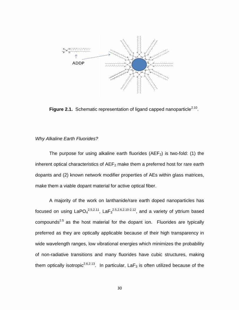
The ligands used are typically comprised of a polar inorganic ‘head’ which
coordinates to the nanoparticle surface and a nonpolar alkyl hydrocarbon ‘tail’.
For simplicity, a previously successful ligand used in the production of LaF3
nanoparticles was chosen2.10-2.12, ammonium di-n-octadectyldithiophosphate
(ADDP), [NH4]-[S2P(OC18H37)2], for use in this study. Lo et al.,2.10 characterized
lanthanide doped LaF3 nanoparticles which were capped with di-n-
octadectyldithiophosphate ligands and suggest the schematic depicted in Figure
2.1 represents this type of ‘coated’ nanoparticle.
30
Figure 2.1. Schematic representation of ligand capped nanoparticle2.10.
Why Alkaline Earth Fluorides?
The purpose for using alkaline earth fluorides (AEF2) is two-fold: (1) the
inherent optical characteristics of AEF2 make them a preferred host for rare earth
dopants and (2) known network modifier properties of AEs within glass matrices,
make them a viable dopant material for active optical fiber.
A majority of the work on lanthanide/rare earth doped nanoparticles has
focused on using LaPO42.5,2.11, LaF3
2.5,2.6,2.10-2.12, and a variety of yttrium based
compounds2.5 as the host material for the dopant ion. Fluorides are typically
preferred as they are optically applicable because of their high transparency in
wide wavelength ranges, low vibrational energies which minimizes the probability
of non-radiative transitions and many fluorides have cubic structures, making
them optically isotropic2.6,2.13. In particular, LaF3 is often utilized because of the

31
additional advantage of ease of species exchange, i.e., a RE3+ ion readily
substitutes for a La3+ ion in the host matrix. The vibrational energy of LaF3 is
lower than that of oxide counterparts (~350 cm-1 vs. ~1000 cm-1)2.14,2.15 which
additionally minimizes quenching of the excited state of the chosen rare earth
ion.
Low vibrational energy is especially important for RE3+ ions emitting in the
near infrared due to their propensity to quench via high energy vibrations2.6.
Fluorides made with alkaline earth elements (Ca, Sr, Ba) exhibit comparable and
in some cases, lower vibrational energy than LaF3, making them viable and
interesting candidates for optically active nanoparticle applications2.7,2.16-2.18.
In order to address the difficulties associated with rare earth solubility and
concentration effects, conventional solution doping involves the incorporation of
aluminum to act as a network modifier in the glass network. Alkali and alkaline
earth ions are incorporated into a glass network to act as modifiers as well. The
alkaline earth ions occupy interstitial spaces within the glass structure and cause
the creation of non-bridging oxygens (NBO), which results in a reduction in the
overall connectivity of the glass network. This acts to improve the mass-
transport- related properties of the glass and therefore, improve solubility of
dopant ions2.19,2.20.

32
Europium as a Spectral Probe
The trivalent europium ion, Eu3+, is widely used as a probe to investigate
the environment around lanthanide ions in different host materials due to its
unique optical properties2.21-2.23, in addition to being used practically as a red light
emitter in various LED and phosphor applications2.24.
The Eu3+ ion has a fluorescence spectrum which consists of transitions
originating from the 5DJ levels, in particular the 5D0, to the 7FJ (J= 0-6) levels of
the 4f6 configuration2.21,2.25 (Figure 2.2). The 7F0 ground state is considered non-
degenerate as well as the emitting 5D0 state, which results in a simple energy
level structure (neither state is split by the crystal field) and straightforward
information about the excited state2.24. Additionally, the emission and excitation
transitions between the 5D0 and 7FJ (J >1) levels, can be used to identify any
crystallographic or local area environment changes about the Eu3+ ion within a
given host material. The splitting of the emission lines is dependent upon the
symmetry of the ligand field about the Eu3+, as it can remove the degeneracy of a
given 2S+1LJ term partially or completely. The Eu3+ 7FJ levels are closely spaced,
with energy level differences on the order of kT, so they are populated at room
temperature unlike other lanthanides and well-defined spectral emissions exist
when a sample is excited at 393 nm2.26. The intensity and splitting patterns of the
resultant luminescent emission spectra are primarily indicative of the
environment around the Eu3+ in the host, allowing for comparison of host material

33
to host material. The 5D07FJ transitions are therefore considered a very suitable
corollary to survey the transition probabilities of the rare earths in different host
materials.
Transitions between levels of the 4fn configuration technically are
forbidden but this constraint is relaxed by perturbations by the host crystal (or
glass) including local crystal symmetry and phonon spectrum2.25. Electric dipole
transitions can be hypersensitive, that is their intensity is strongly dependent
upon local structure (hence chemistry), when the ΔJ = 0, ±2 and such transitions
are enhanced by crystal asymmetry. On the other hand, magnetic dipole
transitions are insensitive to host crystal symmetry as there are no material-
dependent factors in their linestrength. In the specific case of Eu3+, the 5D07F2
transition is electric dipole, with its intensity very sensitive to its surrounding. The
hypersensitivity ratio, HR, is the relative emission spectral ratio of the electric
dipole emission (5D07F2 for Eu3+) to the magnetic dipole emission (5D0
7F1 for
Eu3+) and its value is a qualitative measure of the nature and symmetry of the
rare earth ion within a lattice host. The hypersensitivity ratio will increase with
increasing asymmetry within a crystal lattice. For Eu3+ emissions, the magnetic
dipole transition, 5D07F1, is used as the normalization peak for spectra
comparison, due to this aforementioned lack of dependency on
environment2.26,2.27.

34
Figure 2.2. a) Trivalent europium (Eu3+) Energy level diagram2.26,
b)Corresponding Eu3+ emission spectrum2.28.
b.
a.

35
Lattice vibrations from the host crystal cause dopant ions to be displaced
from their equilibrium positions and as a result, the electric field about the ion is
altered. These vibrations are then coupled to the electronic levels of the system
and are equivalent to an electron-phonon interaction, which can result in
sidebands of the phonon frequency being induced on the electronic levels. In
some instances, it is possible to identify these distinct sidebands in optical
spectra which correlate directly to specific phonon frequencies associated with
the host crystal2.29.
By exciting a europium doped material at 613 nm (the 5D07F2 electric
dipole emission), a sideband feature/peak will appear on the higher energy side
of the peak corresponding to the 5D07F0 transition (~464 nm). The energetic
difference between the two peaks is the vibrational or phonon energy of the host
material2.30 and is termed the phonon sideband (PSB)2.26,2.30,2.31. This provides
an optical method to obtain the vibrational energies of the host materials to
compare to Raman measurements. PSB gives specific information about the
local influence of the host vibrations on the rare earth along with its
environment2.26.

36
Thermal Influence on Optical Properties of Nanoparticles
Beyond the scientific ‘wow’ factor of novel nanoscale materials,
determining the practicality of these particles for use in various applications is
necessary. Incorporating these materials into composites comprised of glass will
require processing at elevated temperatures for extended periods of time.
Therefore, the influence of thermal conditions on the internal structure and
optical properties of the nanoparticles is of great interest. With structures on the
order of a few nanometers, diffusion is expected to play a significant role in the
resulting emission behavior of the nanoparticles.
DiMaio et al., determined that diffusion of a rare earth ion could be
reasonably approximated using optical methods2.32. The photoluminescence
emissions were used to approximate the severity of diffusion within structured
LaF3 nanoparticles. Europium doped LaF3 core nanoparticles with varying shell
thickness of undoped LaF3 were used to study these effects. Core, one and two
shell LaF3 nanoparticles were heat treated at 650⁰C in fifteen minute intervals
and the emission spectra was monitored. At elevated temperatures it was found
that the diffusion of the ions was significant enough to result in emission color
changes from emissions of higher Eu3+ manifolds as a result of a reduction in
concentration quenching of the Eu3+ ions and an approximated 1-dimensional
diffusion coefficient on the same order of magnitude of their bulk counterparts
was reported. This suggested the particles were stable for applications in

37
ambient conditions and the diffusion rate may be reduced with modifications to
the core/shell structure. This study was used as a template for investigating the
time at elevated temperature effects of the alkaline earth fluoride nanoparticles
produced in this study.

38
Experimental Procedures
Nanoparticle Synthesis
Basic Core: Individual alkaline earth nitrates, AE(NO3)2, (Alfa Aesar), were
dissolved in deionized water and added dropwise at a rate of ~0.5 ml/min, to a
250 rpm stirring, clear solution of 175 ml of 1:1 water:ethanol, 0.630 g
ammonium fluoride, (NH4F), and 3.07 g of ammonium di-n-
octadecyldithiophosphate, (ADDP), [NH4]-[S2P(OC18H37)2], maintained at 75ºC in
a water bath. All batching proportions were calculated using an ExcelTM
spreadsheet equipped with the appropriate calculations to yield the correct molar
ratios for synthesis (Appendix A). ADDP was produced in the lab, specifically for
use in this synthesis process. The procedure and pertinent information about its
production and behavior can be found in Appendix B.
It was observed that with each drop of AE(NO3)2 solution, an opaque ‘spot’
would appear and dissipate in the stirring solution, implying the formation of an
insoluble product. Following the complete addition of the nitration solutions, the
resulting mixture had a slightly opaque color and was allowed to stir in a water
bath at 75ºC for 2 hours at 250 rpm. The solution was removed from the water
bath, poured equally into 50ml centrifuge tubes (VWR International) and allowed
to cool to room temperature. It was observed, upon cooling, solid white material
precipitated out of solution and loosely settled to the bottom of the centrifuge
tubes.

39
After cooling, cleaning of the solid material was completed using the
following procedure. The solution/precipitant filled tubes were centrifuged
(Damon/IEC Division CU-5000) at 3000 rpm for 15 minutes to separate solid
product from solution. The excess, clear solution was discarded and an
additional ~40 ml of equal parts water/ethanol was added to each centrifuge
tube, sonicated (VWR Scientific Products Aquasonic Model 150HT) for ~20
minutes to re-suspend the solid material in solution and centrifuged for 15
minutes at 3000 rpm. The excess, clear solution was discarded and the solid,
white precipitant was dried for ~24 hours over phosphorous pentoxide, P2O5, in
a dessicator. The solid material was then dispersed by sonicating for 15 minutes
following the addition of 5 ml of dichloromethane (Acros, anhydrous, AcroSeal,
99.9%), and precipitated with addition of 20 ml of ethanol (Acros, 200 proof).
The solution was then centrifuged for 15 minutes at 3000 rpm, the excess, clear
liquid was discarded and the resulting solid, white material was dried for 2 days
over P2O5 in a desiccator.
Basic Core Doped: A combination of AE(NO3)2, (Alfa Aesar) and europium
nitrate, Eu(NO3)3•6H2O, (Alfa Aesar, 99.9%) were dissolved in deionized water
and added dropwise at a rate of ~0.5 ml/min, to a 250 rpm stirring, clear solution
of 175 ml of 1:1 water:ethanol, 0.630 g ammonium fluoride, (NH4F), and 3.07 g
of ammonium di-n-octadecyldithiophosphate, (ADDP), [NH4]-[S2P(OC18H37)2],
maintained at 75ºC in a water bath. All batching proportions were calculated
using an ExcelTM spreadsheet equipped with the appropriate calculations to yield
40
the correct molar ratios for synthesis (Appendix A). ADDP was produced in the
lab, specifically for use in this synthesis process. The procedure and pertinent
information about its production and behavior can be found in Appendix B.
It was observed that with each drop of AE(NO3)2 solution, an opaque
‘spot’ would appear and dissipate in the stirring solution, implying the formation of
an insoluble product. Following the complete addition of the nitration solutions,
the resulting mixture had a slightly opaque color and was allowed to stir at 75ºC
in a water bath for 2 hours at 250 rpm. The solution was removed from the water
bath, poured equally into 50 ml centrifuge tubes (VWR International) and allowed
to cool to room temperature. It was observed, upon cooling, solid white material
precipitated out of solution and loosely settled to the bottom of the centrifuge
tubes.
After cooling, cleaning of the solid material was completed using the
following procedure. The solution/precipitant filled tubes were centrifuged
(Damon/IEC Division CU-5000) at 3000 rpm for 15 minutes to separate solid
product from solution. The excess, clear solution was discarded and an
additional ~40 ml of equal parts water/ethanol was added to each centrifuge
tube, sonicated (VWR Scientific Products Aquasonic Model 150HT) for ~20
minutes to re-suspend the solid material in solution and centrifuged for 15
minutes at 3000rpm. The excess, clear solution was discarded and the solid,
white precipitant was dried for ~24 hours over phosphorous pentoxide, P2O5, in a

41
desiccator. The solid material was then dispersed by sonicating for 15 minutes
following the addition of 5 ml of dichloromethane (Acros, anhydrous, AcroSeal,
99.9%), and precipitated with addition of 20 ml of ethanol (Acros, 200 proof).
The solution was then centrifuged for 15 minutes at 3000rpm, the excess, clear
liquid was discarded and the resulting solid, white material was dried for 2 days
over P2O5 in a desiccator.
Europium Core Doped AEF2 with Undoped AEF2 Shells: : A combination of
AE(NO3)2, (Alfa Aesar) and europium nitrate, Eu(NO3)3•6H2O, (Alfa Aesar,
99.9%) were dissolved in deionized water and added dropwise at a rate of about
0.5 ml/min, to a 250 rpm stirring, clear solution of 175 ml of 1:1 water:ethanol,
0.630 g ammonium fluoride, (NH4F), and 3.07 g of ammonium di-n-
octadecyldithiophosphate, (ADDP), [NH4]-[S2P(OC18H37)2], maintained at 75ºC in
a water bath. All batching proportions were calculated using an ExcelTM
spreadsheet equipped with the appropriate calculations to yield the correct molar
ratios for synthesis (Appendix A). Following the complete addition of the nitrate
solutions, the resulting mixture had a slightly opaque color and was allowed to
stir at 75ºC for 20 minutes at 250 rpm to form the core particles doped with 20
mole percent europium. A portion of the stirring solution was then removed by
bulb syringe, was equally portioned into 50 ml centrifuge tubes (VWR
International) and set aside to cool to room temperature. Next, an aqueous
NH4F solution and an AE(NO3)2 solution were added alternately to the still stirring
core solution, to yield a layer of undoped AEF2, referred to as a core/shell

42
nanoparticle. This process was repeated until a total of three shells were grown.
It was observed, upon cooling, solid white material precipitated out of solution
and loosely settled to the bottom of the centrifuge tubes with each step.
After cooling, cleaning of the solid material was completed using the
following procedure. The solution/precipitant filled tubes were centrifuged
(Damon/IEC Division CU-5000) at 3000 rpm for 15 minutes to separate solid
product from solution. The excess, clear solution was discarded and an
additional ~40 ml of equal parts water/ethanol was added to each centrifuge
tube, sonicated (VWR Scientific Products Aquasonic Model 150HT) for ~20
minutes to re-suspend the solid material in solution and centrifuged for 15
minutes at 3000 rpm. The excess, clear solution was discarded and the solid,
white precipitant was dried for ~24 hours over phosphorous pentoxide, P2O5, in
a desiccator. The solid material was then dispersed by sonicating for 15 minutes
following the addition of 5 ml of dichloromethane (Acros, anhydrous, AcroSeal,
99.9%), and precipitated with addition of 20 ml of ethanol (Acros, 200 proof).
The solution was then centrifuged for 15 minutes at 3000 rpm, the excess, clear
liquid was discarded and the resulting solid, white material was dried for 2 days
over P2O5 in a desiccator.
X-Ray Diffraction (XRD)
In order to determine the crystallinity of the resultant basic core
nanoparticles and verify phase purity, x-ray diffraction was performed on the

43
dried powders using a Scintag XDS 4000 using CuKα radiation. Crystalline
phases within a material can be identified by their unique diffraction pattern.
Diffraction occurs from crystals oriented at the angle, ϴ, that satisfies Bragg’s
law: 2dsinϴ = nλ. In XRD, a powder sample is bombarded with a monochromatic
beam at an appropriate wavelength, λ, and a diffracted beam results at the
appropriate, ϴ, to satisfy Bragg’s equation. The final diffraction pattern
corresponds to specific interplanar spacing and identifies the crystallinity and
composition of the sample using JCPDS standards2.32,2.33.
Transmission Electron Microscopy (TEM)
High resolution transmission electron microscopy (HRTEM) was
performed on the nanoparticle powders to provide nanometer scale images
which were used to visually determine particle size and shape. Less than 0.001 g
of each powder type was suspended in ~10 ml of tetrahydrafuran (Acros,
anhydrous, Acroseal, 99.9%), and a single drop of the solution was placed on a
200 mesh copper grid (Ted Pella, Inc., Support films, formvar/carbon), allowed to
dry and used for analysis. HRTEM was performed on a Hitachi H9500 operating
at an accelerating voltage of 300kV.
Raman Spectroscopy

44
Raman spectroscopy is a method to study vibrational modes of a given
material. Here, it was used to determine the vibrational energy due to lattice
vibrations of the alkaline earth fluorides in nanoparticle form.
A laser excites/interacts with phonons in the material, causing scattering
(Raman shift, reported in cm-1), which results in the incident laser photons being
shifted with respect to their incident energy. The shift is a direct measure of the
vibrational energy of the system2.34,2.35. Nanoparticles were measured with a
Senterra 178 Raman Microscope (Bruker Optics) operating at a laser wavelength
of 532 nm, laser power of 20 mW and integration time of 100 s.
Photoluminescence Measurements
Emission and excitation spectra were determined for all europium doped
AEF2 nanoparticle samples using a Jobin Yvon Fluorolog 3 specrofluorometer
with a double grating configuration, an excitation bandpass of 2 nm and a scan
rate of 0.1-1 nm/min. Emission scans were perfomed at an excitation
wavelength of 393 nm. Phonon sideband (PSB) measurements were performed
at an emission wavelength of 613 nm.

45
Results and Discussion
Physical Characterization: Morphology, Size and Vibrational Energy
Particles were synthesized using a modified version of
solution/precipitation synthesis previously developed2.36,2.37 for LaF3
nanoparticles. Calcium, strontium and barium fluoride nanoparticles were
produced and ADDP was used as the ligand. The ligand aids in controlling the
growth of the particles by weakly coordinating to the host ions, but they
coordinate strongly enough to deter aggregation2.38. The presence of the ligand
also allows dispersability of the materials in organic solvents such as THF and
dichloromethane (DCM).
Morphology and Particle Size Analysis
Figures 2.3-2.5 are representative TEM images of alkaline earth fluoride
nanoparticles produced. The shape of the individual nanoparticles, particularly
strontium fluoride hosted nanoparticles in figure 2.4, aid in demonstrating the
cubic nature of the fluoride host. Particle size analysis was completed by
measuring a broad sampling of identified particles (n > 150) via TEM imaging.
The average particle size of the alkaline earth nanoparticles is shown to increase
with increasing atomic radius of alkaline earth ion (Table 2.1). It should be noted
that this method was not optimized kinetically for uniform particle growth,
however, the aim here was to produce sufficiently small particles (<50 nm) for
later use.

46
Verification of Crystallinity
Figure 2.6 shows the XRD patterns of the alkaline earth fluoride
nanoparticles. The patterns exhibit prominent peaks in accordance with JCPDS
standards (35-0816, 06-0262, 04-0452, and 41-1443) of the cubic CaF2, SrF2
and BaF2 crystals, which verifies the successful synthesis of the individual AEF2
nanoparticles.
Vibrational Energy of Alkaline Earth Fluorides
In order to further verify the successful synthesis of alkaline earth fluoride
nanoparticles, Raman analysis was completed on the individual as-made,
undoped nanopowders as well as heat treated samples of the undoped powders.
The Raman spectra of each of the undoped alkaline earth fluoride nanoparticles
are depicted in figures 2.7-2.9. A well-defined change in vibrational energy (VE)
is demonstrated with mass for the fluoride systems (VEBa-F < VESr-F < VECa-F ).
Values correlate well with published values (table 2.2) and the trend is
corroborated by different measurement techniques2.42-2.44.

47
Figure 2.3. TEM images of as-made calcium fluoride, CaF2, nanoparticles.

48
Figure 2.4. TEM images of as-made strontium fluoride, SrF2, nanoparticles.

49
Figure 2.5. TEM images of as-made barium fluoride, BaF2, nanoparticles.

50
Table 2.1
Alkaline Earth Fluoride Nanoparticle Size Analysis
CaF2 SrF2 BaF2
Average Size
(nm)9.2 19.5 24.3
Standard
Deviation1.9 4.3 5.8
Mode
(nm)8.4 17.6 20.9
Median
(nm)8.4 18.5 23.3

51
Figure 2.6. X-Ray diffraction patterns indicate a match with fluorite crystal
structure of CaF2, SrF2, and BaF2.

52
Figure 2.7. Raman spectra for undoped CaF2 nanoparticles.
Figure 2.8. Raman spectra for undoped SrF2 nanoparticles.

53
Figure 2.9. Raman spectra for undoped BaF2 nanoparticles.
Table 2.2
Summary of Raman Vibrational Energies for
Alkaline Earth Fluoride Nanoparticles
Host
Material
As
Measured
(cm-1)
Reported
Value
(cm-1)
Reference
CaF2 320 323 2.39
SrF2 280 285 2.40
BaF2 238 240 2.41

54
Emission Behavior
Calcium, Strontium and Barium fluoride nanoparticles were doped
separately with 5, 15 and 25 mole percent europium and their
photoluminescence was measured at an excitation wavelength of 393 nm. The
resulting spectra (normalized to the 590 nm transition) are summarized in figure
2.10. The signature emissions of Eu3+ are clearly demonstrated with single
peaks at 590 and 610 nm. In comparing the 5 mole percent Eu3+ doped
samples (figure 2.10a), the CaF2 nanoparticles show a similar site environment
between the 7F1 and 7F2 levels, while the SrF2 and BaF2 exhibit a marked
difference in these two emissions. The 5D07F4 emission (~700nm) for each of
the individual lattices best indicates the difference between the alkaline earth
hosts, as the spectral linewidth narrows from host to host, and the extent of the
resultant splitting of the emission inverts which implies a change in the ligand
field about the Eu3+ ions within the host crystal. This difference in behavior
correlates to the change in host ion size- as the radius of the ion increases, the
‘area’ influenced by the ligand field associated with the ion increases, and
impacts the local environment of the Eu3+ ion in the lattice. In figures 2.10b and
2.10c, there are increasing electric dipole 7F2 emissions for the SrF2 and BaF2
nanoparticles while the CaF2 emissions remain relatively constant. The low
intensity emissions from the 5D1 manifold are seen in the inset portions of figure
2.10 at ~536nm (5D17F1) and ~554nm (5D1
7F2). These emissions appear to
decrease with increasing europium content. Eu3+ transitions are sensitive to

55
quenching (reduction in emission and therefore, decrease in emission intensity)
due to dipole-dipole interactions and the 5D1, 5D2 and 5D3 manifolds have
negligible visible emission when concentrations of Eu3+ are greater than about
three percent2.26,2.37.
In order to assess the differences in environment for the different alkaline
earth fluorides, the hypersensitivity ratio (HR) for each of the nanoparticle types
was calculated and plotted as a function of europium concentration (figure 2.11).
The environment for the Eu3+ in the CaF2 is markedly different from the SrF2 and
BaF2 and the HR is seen to remain relatively constant (~1), indicating a
consistent environment around the Eu3+ ion, despite the increase in europium
content. There is a slight increase in HR with increasing europium content for
the SrF2 and BaF2 nanoparticles, which indicates an increase in asymmetry as a
result. The difference in behavior between the hosts may be explained by the
differences in host ion size; the incorporation of larger amounts of Eu3+ within the
smaller Ca2+ sites (rCa =0.112 nm) is more influenced by the electric field about
the dopant ion as a result of the required charge compensation, therefore the
electric charges about the Eu3+ ion are in closer proximity to one another and
increasing the amount of Eu3+ does not change the electric dipole transition
(5D07F2) significantly. Whereas, the larger diameter host ions of the Sr2+
(rSr =0.125 nm) and Ba2+ (rBa = 0.142 nm) are more influenced with the increase
in required charge compensation as a result of the presence of more Eu3+ ions.

56
This difference in emission behavior between the host ions demonstrates
the ability to control/engineer the spectral behavior of the rare earth ion by the
choice of alkaline earth as well as the dopant level. This provides a potential tool
for tailoring these nanoparticles for specific emissions when used within glass
preforms.

57
Figure 2.10. Emission spectra of AEF2 nanoparticles doped with
europium a) 5 mol% b) 15 mol% c) 25 mol%.
a.
b.
c.

58
Figure 2.11. Effect of europium concentration on hypersensitivity ratio

59
Phonon Energy Assessment
The vibrational energy of the host lattice for the Eu3+ can be determined
using the excitation of its hypersensitive peak, 5D07F2 (λem = 613 nm). The
resulting excitation spectra for a sample doped with europium at an emission
wavelength of 613 nm will yield a peak at a wavelength of ~464 nm (21551 cm-1)
and the phonon sideband is defined as a shoulder/peak on the higher energy
side of the hypersensitive peak. The energetic difference between these two
peaks is then defined to be the vibrational or phonon energy of the host
material2.30.
The phonon sideband excitation spectra (λem = 613 nm) for various doping
levels of Eu3+ in AEF2 nanoparticles and the corresponding change in energy
with respect to the 464 nm peak are shown in figures 2.12-2.14. The wavelength
(x-axis) is reported in cm-1 to allow for calculation of the energy difference.
The sideband for CaF2 becomes more distinct with increasing europium
content, with an average phonon energy of 295 cm-1. The SrF2 is found to have
an average value of 276 cm-1 and the BaF2 has an average value of 255 cm-1.
The values calculated here vary by less than two percent of each other and
indicate a well-defined trend with mass:
BaF2 < SrF2< CaF2

60
These values and this trend corroborates with previously published values2.39-2.41
and match well with measured values found via Raman spectroscopy on
undoped alkaline earth nanoparticle powders (Table 2.2).

61
Figure 2.12. PSB excitation spectra and corresponding ΔE464 for 5Eu:AEF2 nps
Figure 2.13 PSB excitation spectra and corresponding ΔE464 for 15Eu:AEF2 nps

62
Figure 2.14. PSB excitation spectra and corresponding ΔE464 for 25Eu:AEF2 nps

63
Thermal Effects on Optical Behavior of Eu:AEF2 nanoparticles
Understanding the effects that elevated temperatures will have on the
emission and structural characteristics of nanoparticles is necessary for further
utilization of these materials in composite systems. In order to analyze these
effects in Eu:AEF2 nanoparticles a replicate experiment to the LaF3 study
detailed earlier by DiMaio et al.,2.37 was completed for these nanoparticles.
Twenty mole percent europium doped AEF2 nanoparticles were
individually produced with three additional layers or shells of undoped AEF2
added in stages. To eliminate batch to batch variation, each set of particles was
produced from the same core batch, i.e. 20Eu:CaF2 nanoparticles (core) were
made and three additional layers of undoped CaF2 were added in stages. Upon
the completion of each stage, a portion of the particles was removed to isolate
each type of particle: core (20Eu:CaF2), one shell (core with one CaF2 addition),
two shell (core with two CaF2 additions) and three shell (core with three CaF2
additions). Samples were then heat treated at 650⁰C in fifteen minute intervals,
for a total of 75 minutes. Following each time interval, photoluminescence was
measured.

64
Particle Size Analysis
Particle size analysis of the core and core/shell 20Eu:AEF2 nanoparticles
produced was completed by measuring a broad sampling of identified
nanoparticles (n > 100) via TEM imaging. The average particles sizes for each
type and host lattice are summarized in Table 2.3. They show the self-shelled
particles have average diameters progressively increasing from the original core
diameter and particle size distributions coincide with those reported by
Jacobsohn et al.,2.13,2.45 It should be noted that this synthesis method for
core/shell AEF2 nanoparticles was not optimized kinetically for uniform particle
growth, however, the aim here was to produce europium core doped particles
with increasing amounts of undoped host material. This was verified by the
particle size analysis, therefore, the particles were used in this experiment to
further understand the thermal influence on europium emission behavior when
incorporated into alkaline earth nanoparticles.

65
TABLE 2.3
Average Size in nm of Core and Core/Shell
Alkaline Earth Fluoride Nanoparticles
In order to best analyze the diffusion behavior in these nanoparticles, the
alkaline earth fluorides emission spectra as they are progressively heat treated
and hypersensitivity ratios are assessed individually, then the behavior of each
type of nanoparticle are compared to assess the differences (if any) in alkaline
earth host material.
Core 1 Shell 2 Shells 3 Shells
Eu:CaF2 8.3 10.7 13.9 35
Eu:SrF2 10.2 11.4 12.2 24.2
Eu:BaF2 20 35.8 68.2 105.3

66
Calcium Fluoride, CaF2
The emission spectra (λex = 393 nm) and representative TEM images for
the individual particle types of 20Eu:CaF2 are seen in figures 2.15 and 2.16. The
core particles are found to have an average particle size of ~8 ± 1 nm. There is a
steady increase in particle size with the addition of undoped CaF2, (Table 2.3),
and the increase and distribution is similar to that reported by Jacobsohn et al.2.13
In all four emission spectra, the 5D0 signature transitions are consistently
present, with a general overall increase in intensity seen with increasing time at
temperature. Upon looking at the overall emission behavior as a function of size,
the 610 nm emission is noted to increase with the introduction of undoped shells
of CaF2. The hypersensitivity ratio is calculated and presented in figure 2.17.
The difference in hypersensitivity ratios between particle type (core vs. 1 shell vs.
2 shell, vs. 3 shell) indicates that the environment about the Eu3+ ion is different
for each particle type and is especially apparent in the 3 shell case. There is a
distinct difference seen in the particles with largest volume of undoped CaF2
available to the Eu3+. The hypersensitivity here changes, indicating the
environment about the rare earth is more asymmetric as more volume is
available for the Eu3+ to diffuse into, as well as the more time the Eu3+ is given to
diffuse from the core to the surface of the nanoparticle. This induced
concentration gradient with the additional volume of undoped material allows for
the relief of high concentration effects seen in the smaller particles and the

67
change in HR and emissions. This indicates a progressive movement/diffusion
of the Eu3+ within the nanoparticle itself- increased intensity as a result of a
decrease in concentration as the Eu3+ ions diffuse/ ‘spread out’ to alleviate Eu3+
ion-ion quenching effects which is evidenced by the increased intensity of the
610nm emission with increasing available undoped volume..
Upon further examination of the 2 shell and 3 shell emission spectra
(figure 2.16), a broad transition peak is seen at approximately ~424 nm. This
peak emission corresponds to the 4f7 4f65d1 transition of the Eu2+ ion and is
broad due to the influence of lattice vibrations of the local surroundings on the 5d
wave function of the ion, which is not shielded from adjacent ligand fields by the
5s and 5p electrons2.46. This reduction of Eu3+ Eu2+ ion in this host material is
a well-documented phenomenon in bulk2.47-2.49 CaF2 and nanocrystal2.47,2.50 CaF2
form. The Eu2+ emissions in the 2 shell sample reach maximum intensity after 30
minutes at temperature, while the Eu2+ emissions decrease as the amount of
heat treatment time increases. To further understand the interplay between the
Eu3+ and Eu2+ within these samples, the ratio of their emissions is plotted in
Figure 2.18. The Eu2+ emission is not seen in either as made sample(unfired),
and both samples demonstrate a decrease in Eu2+ emissions as the emissions
due to the hypersensitive Eu3+ transition increase. This implies a greater stability
of Eu3+ in these materials as well as a conversion to behavior similar to that of
the bulk. Hong and Kawano2.48 Eu3+ doped thin films heated to 600ºC resulted in
strong Eu2+ photoluminescence intensities at 425 nm and large concentration

68
quenching at Eu3+ doping levels greater than one mole percent. The rare earth
doped compounds are not believed to be decomposed at the high temperature
because the influence of crystal fields of the ligand ions about the RE3+ and due
to the high dissociation energies between alkaline earth and fluorine ions. They
attribute the strong Eu2+ photoluminescence as a result of the ease of
substitution for Eu2+ (rEu2+ = 0.125 nm) into a Ca2+ site (0.112 nm).
Luminescence peaks associated with the 5D0 manifold of Eu3+ were seen to
increase with temperature as well.
Pandey et al.,2.47 report a similar behavior in nano CaF2:Eu phosphors.
They found that during heating, in air, the conversion of Eu3+ Eu2+ began at
~573K (500⁰C) and reached a maximum at ~873K (600⁰C). After prolonged
heating at ~973K (700⁰C), the europium containing nanocrystals are reported to
agglomerate and the sample was converted to ‘bulk’, as the sample no longer
contains Eu2+ emission and the Eu3+ emission spectra is similar to that of their
bulk CaF2 samples.
Luo et al.,2.49 addressed the reduction of Eu3+ Eu2+ in glass ceramics
containing SrF2 crystals. Eu2+ emissions are greatly influenced by composition
and structure of the host material. When trivalent Eu ions are doped into bulk
materials containing AE2+, Eu3+ replaces the AE2+ ion. In order to keep charge
balance, two Eu3+ ions substitute for three AE2+ ions to form an EuAE• defect and
one cation vacancy with two negative charges, VAE ″ is created. The vacancy

69
acts as a donor electron while the EuAE• defect becomes an acceptor of
electrons. By thermal stimulation, the electrons in the vacancy defect, VAE ″ were
transferred to a EuAE• site and Eu3+ ions reduce to Eu2+ ions. In Kroger-Vink
notation, the reactions for the calcium fluoride nanoparticles are:
3CaCa + 2Eu3+ = 3Ca2+ + 2 EuCa• + VCa
″
VCa ″ = VCa
x + 2e-
2 EuCa• + 2e- = 2EuCa
x
3CaCa + 2Eu3+ = 3Ca2+ + 2EuCax + VCa
″
Verification and quantification of the amount of Eu2+ by other measurement
techniques was attempted (Appendix C), however, this was an anomalous case
and was noted but was not pertinent for pursuit in this study.

70
Figure 2.15. 20Eu:CaF2 emission spectra as a function of time at 650⁰C and
corresponding TEM images for a) Core particles b) 1 CaF2 shell particles
a.
b.

71
Figure 2.16. 20Eu:CaF2 emission spectra as a function of time at 650⁰C
and corresponding TEM images for a) 2 CaF2 shell particles b) 3 CaF2
shell particles
a.
b.

72
Figure 2.17. Comparison of individual 20Eu:CaF2 nanoparticles
hypersensitivity ratio as a function of time at 650⁰C
Figure 2.18. Ratio of Eu2+ to Eu3+ as a function of time at 650⁰C in
Eu:CaF2 nanoparticle

73
Strontium Fluoride, SrF2
The emission spectra (λem = 393 nm) and representative TEM images for
the individual particle types of 20Eu:SrF2 are seen in figures 2.19 and 2.20. The
core particles are found to have an average particle size of ~10 ± 1.3 nm. There
is a steady increase in particle size with the addition of undoped SrF2, (Table
2.3). The increase in size per shell for the first two shells is very small, ~1 nm
per addition, while the 3 shell is more than double that of the original core
particle.
In all four emission spectra, the 5D0 signature transitions are consistently
present, with the linewidths narrowing and intensities decreasing following the
first addition of excess undoped material. It appears that environment about the
Eu3+ ions in SrF2 remains relatively consistent in emission and is reflected in the
hypersensitivity ratios (figure 2.21). The low value of HR also suggests a more
symmetric environment exists about the Eu3+ ions within the SrF2 host lattice,
however, there is a slight increase for each particle type with increasing time at
temperature. There appears to be a slight splitting of the 5D07F2 emission that
grows more pronounced with heat treatment and additional undoped SrF2 layers.
The induced concentration gradient with the additional volume of undoped
material allows for the relief of high concentration effects seen in the emissions of
core particles (figure 2.19a), which results in narrower emission linewidths and
more distinct splitting patterns as is evidenced in the 5D07F4 (~695 nm)

74
transition of the 1 shell (figure 2.19b), 2 shell (figure 2.20a) and 3 shell (figure
2.20b) particles. Therefore, it is concluded that the local environment about the
Eu3+ ion in SrF2 nanoparticles remains relatively consistent in elevated
temperature conditions as well as with increased particle size, based on emission
behavior. However, the extremely small increase in particle size from core to 1
and 2 shell particles suggest the HR values remain relatively consistent because
the particles themselves are remaining relatively similar in size, making changes
in the local environment about the Eu3+ ion less significant.
Barium Fluoride, BaF2
The emission spectra (λem = 393 nm) and representative TEM images for
the individual particle types of 20Eu:BaF2 are seen in figures 2.22 and 2.23. The
core particles are found to have an average particle size of ~20 ± 2.7 nm. There
is a steady increase in particle size with the addition of undoped BaF2, (Table
2.3), with average diameters of the shelled particles significantly larger than the
original core particles, as also reported in [2.13].
The emissions of the 5D0 manifold are distinct and become constant with
increasing particle size and time at elevated temperature for the europium doped
BaF2 nanoparticles. The environment about the Eu3+ ion in this host lattice is
constant with increasing time, and is demonstrated by the hypersensitivity ratio
trend in figure 2.24. This indicates a stable environment for the Eu3+ ion,

75
suggesting similar diffusion behavior to that of LaF3 (ref 2.37), and the large size
of the particles from core to 3 shell nanoparticle provides sufficient relief of
concentration quenching to provide a stable and consistent environment for the
Eu3+ ions.

76
Figure 2.19. 20Eu:SrF2 emission spectra as a function of time at 650⁰C and
corresponding TEM images for a) Core particles b) 1 SrF2 shell particles
a.
b.

77
Figure 2.20. 20Eu:SrF2 emission spectra as a function of time at 650⁰C and
corresponding TEM images for a) 2 SrF2 shell particles b) 3 SrF2 shell particles
a.
b.

78
Figure 2.21. Comparison of individual 20Eu:SrF2 nanoparticles
hypersensitivity ratio as a function of time at 650⁰C

79
Figure 2.22. 20Eu:BaF2 emission spectra as a function of time at 650⁰C and
corresponding TEM images for a) Core particles b) 1 BaF2 shell particles
a.
b.

80
Figure 2.23. 20Eu:BaF2 emission spectra as a function of time at 650⁰C and
corresponding TEM images for a) 2 BaF2 shell particles b) 3 BaF2 shell particles
a.
b.

81
Figure 2.24. Comparison of individual 20Eu:BaF2 nanoparticles
hypersensitivity ratio as a function of time at 650⁰C

82
Comparison of Alkaline Earth Fluoride Hosts
In order to determine differences between alkaline earth host species, the
emission spectra for the individual particle types (figures 2.25-2.28) was
compared and analysis of the corresponding hypersensitivity ratios (figure 2.29)
was used. It should be noted that in all spectra there is a low intensity, broad
emission at ~440 nm, which is due to the presence of ADDP in the unfired (as-
made) samples (Appendix B).
Core
Within the core nanoparticles (figure 2.25), there are low intensity
emissions from the 5D1 and 5D2 manifolds for all three alkaline earth species.
CaF2 and SrF2 show a decrease in intensity for these emissions with processing
time and temperature, while the 5D07F0 emission (~577 nm) increases. This
correlates with the increase in HR (figure 2.29a), suggesting a slight shift to a
more asymmetric environment as a result of thermal stimulation. The BaF2
nanoparticle emissions show no change in the higher manifold emissions with
time, while the 5D07F0 emission increases to its maximum at thirty minutes and
remains constant. The low intensity of these emissions for all samples can be
attributed to the quenching due to dipole-dipole interactions for the 5D2 and 5D1
manifolds as a result of the high concentration of Eu present within the core
particle2.26,2.37.

83
1 Shell
The difference in behavior begins to become more distinct with the
addition of undoped host material . Here, the 1 shell CaF2 sample (figure 2.26a)
begins to have emissions due to Eu2+ (~424 nm) with little change in intensity
with processing conditions, while the Eu3+ 5D1 and 5D0 manifold emissions begin
to reduce, suggesting the Eu2+ emissions are dominant under these processing
conditions as the concentration gradient is introduced for CaF2. The interaction
of the different ligand fields and the difference in charge compensation as a
result of the conversion of a portion of the Eu3+ ions to Eu2+ ions will have an
effect on the overall electric field of the ions in the lattice, as evidenced by an
increase in the hypersensitivity ratio (figure 2.29b).
The 1 shell SrF2 5D1 and 5D0 emissions (figure 2.26b) decrease in intensity
and broaden suggesting the movement within the host lattice to a less stable,
more asymmetric environment, which is further substantiated by the slight
increase in HR with processing time (figure 2.29b). The 1 shell BaF2 (figure
2.26c) shows a slight increase in the higher manifold emissions and the 5D07F0
emission increases with increasing processing time. The HR for BaF2 decreases
after thirty minutes and remains constant. This suggests the Eu3+ ions have
diffused sufficiently within the excess volume provided by the first shell to reach a
stable state.

84
2 Shell
In the 2 shell nanoparticle type, Eu2+ emissions (figure 2.27a) from the
CaF2 lattice overwhelm the higher manifold emissions of Eu3+, while the 5D1 and
5D2 manifold emissions (figure 2.27b) increase in SrF2 and in addition to the 5D1
and 5D2 manifold emissions, 5D3 emissions (figure 2.27c) emerge in BaF2. The
increase in emissions from higher manifolds of the Eu3+ within the BaF2 lattice
with increasing processing time is indicative of the reduction of concentration
quenching as a result of the Eu3+ diffusion. This coupled with the lower phonon
energy of the BaF2, enables the transitions in this region. There is a distinct
difference in the HR (figure 2.29c) between the CaF2 when compared to the SrF2
and BaF2—the ligand field about the Eu2+ ion is different than that of the Eu3+ ion
and will influence the overall asymmetry of the lattice sites. SrF2 shows a slight
increase in HR with time, which implies a change in the local environment for the
Eu3+ that can be attributed to the diffusion of the Eu3+ into the undoped volume.
The HR of BaF2 in this case decreases following the onset of heat treatment and
remains constant. This suggests the environment of the Eu3+ ion is more stable,
making more intense emissions from the higher manifolds more likely.

85
3 Shell
In the case of the three shell nanoparticles, the most pronounced
differences between the host materials are exhibited. The emissions from the
Eu2+ within the 3 shell CaF2 (figure 2.28a) decrease with processing time while
the HR (figure 2.29d) increases by nearly 4x, indicating a highly asymmetric
environment. The 5D07F0 (as well as the 5D0
7F2) emission increases with
processing time, confirming the conversion of Eu2+ Eu3+ with the overall
concentration of europium diffused into a larger volume. At smaller volumes, it
can be assumed that the europium ions are in closer proximity to one another
and causing larger distortions to the crystal lattice with incorporation into the
smaller Ca2+ sites (rCa2+ = 0.112 nm, rEu2+=0.125 nm) as well as more interaction
with the ligand field of adjacent ions. As the europium diffuses into a larger
volume by thermal stimulation, this interaction is reduced and the overall
behavior of the Eu:CaF2 nanoparticle reverts to that of its bulk counterpart as
suggested by Pandey et al.2.47.
The 3 shell SrF2 (figure 2.28b) shows a reduction in 5D1 and 5D2 emissions
and the 5D07F0 emission increases with processing time. The reduction in
higher manifold emissions may be a result of interactions of surface atoms
interacting with a phosphorous oxide layer that forms when the dithiophosphate
ligands are oxidized during heat treatment indicated by the low intensity, broad
transition centered at ~440 nm (inset, figure 2.28b). The 3 shell SrF2

86
hypersensitivity ratio (figure 2.29d), shows a slight increase with processing time,
indicating there is some diffusion of the Eu3+ which results in a slightly more
asymmetric environment.
The BaF2 3 shell has pronounced, increasing emissions from the 5D1, 5D2
and 5D3 manifolds with increasing processing time and the HR decreases upon
heating, remains constant and low in value. This can be attributed to the
reduction in concentration quenching as a result of the Eu3+ diffusion from the
core region to the undoped shell volume as well as the low phonon energy of this
host material.
Optically-Estimated Diffusion Coefficients
Using the emission spectra as evidence of diffusion, the diffusion
coefficient for europium in each alkaline earth fluoride host can be estimated.
The diffusion coefficient was calculated by applying a simple one-dimensional
approximation2.51:
L = Diffusion length in meters (average radius of the nanoparticle)
t = time at which steady state diffusion is assumed in seconds
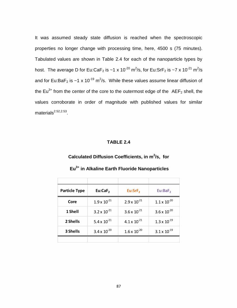
87
It was assumed steady state diffusion is reached when the spectroscopic
properties no longer change with processing time, here, 4500 s (75 minutes).
Tabulated values are shown in Table 2.4 for each of the nanoparticle types by
host. The average D for Eu:CaF2 is ~1 x 10-20 m2/s, for Eu:SrF2 is ~7 x 10-21 m2/s
and for Eu:BaF2 is ~1 x 10-19 m2/s. While these values assume linear diffusion of
the Eu3+ from the center of the core to the outermost edge of the AEF2 shell, the
values corroborate in order of magnitude with published values for similar
materials2.52,2.53.
TABLE 2.4
Calculated Diffusion Coefficients, in m2/s, for
Eu3+ in Alkaline Earth Fluoride Nanoparticles
Particle Type Eu:CaF2 Eu:SrF2 Eu:BaF2
Core 1.9 x 10⁻²¹ 2.9 x 10⁻²¹ 1.1 x 10⁻²⁰
1 Shell 3.2 x 10⁻²¹ 3.6 x 10⁻²¹ 3.6 x 10⁻²⁰
2 Shells 5.4 x 10⁻²¹ 4.1 x 10⁻²¹ 1.3 x 10⁻¹⁹
3 Shells 3.4 x 10⁻²⁰ 1.6 x 10⁻²⁰ 3.1 x 10⁻¹⁹

88
Figure 2.25. Core Photoluminescence Spectra for a) 20Eu:CaF2
b) 20Eu:SrF2 c) 20Eu:BaF2
a.
b.
c.

89
Figure 2.26. 1 Shell Photoluminescence Spectra for a) CaF2( 20Eu:CaF2)
b)SrF2(20Eu:SrF2) c) BaF2( 20Eu:BaF2)
a.
b.
c.

90
Figure 2.27. 2 Shell Photoluminescence Spectra for a) CaF2(CaF2(20Eu:CaF2))
b) SrF2(SrF2(20Eu:SrF2)) c) BaF2(BaF2( 20Eu:BaF2))
a.
b.
c.

91
Figure 2.28. 3 Shell Photoluminescence Spectra for a)
CaF2(CaF2(CaF2(20Eu:CaF2))) b)SrF2(SrF2(SrF2(20Eu:SrF2)))
c)BaF2(BaF2(BaF2(20Eu:BaF2)))
a.
b.
c.

92
Figure 2.29. Local Eu3+ environment within AEF2 nanoparticles
comparison by particle type as represented in the hypersensitivity ratio as
a function of time at temperature.

93
Summary
Various calcium, strontium and barium fluoride nanoparticles which are
dispersible in organic solvents were successfully produced and characterized for
their physical, chemical and optical behavior. Distinct spectroscopic differences
between the different host materials were demonstrated, as well as for varying
rare earth dopant levels. The hypersensitivity dependence exhibited with varying
dopant level indicates an ability to control/influence emission of the rare earth
dopant which has not been seen before. There is a prominent influence of
processing on the spectroscopy of these nanoparticles as well. The variations in
emission behavior and subsequently, the hypersensitivity ratio, of the heat
treated nanoparticles demonstrate a difference in environment for the rare earth
ion from host to host. By applying a simple one dimensional model for diffusion,
an order of magnitude accuracy for predicting the diffusion coefficient of
europium ions in alkaline earth fluorides was shown, and demonstrates that
photoluminescence is a useful tool to predict diffusion behavior.
Overall, it has been demonstrated that by rare earth doping alkaline earth
fluoride nanoparticles it is possible to engineer their spectroscopic behavior. The
ability to ‘tune’ these materials to specific applications through the use of different
host materials, processing conditions and doping levels make rare earth doped
alkaline earth nanoparticles a viable option for use as dopant materials in active
optical fiber.

94
References
2.1 Bjarklev, A., Optical Fiber Amplifiers: Design and System Applications, Artech House, Boston, 1993.
2.2 Peretti, R., Jurdyc, A.M., Jacquier, B., Blanc, W., Dussardier, B., “Spectroscopic signature of phosphate crystallization in erbium-doped optical fibre preforms,” Optical Materials, 33 [2011] 835.
2.3 Mahmoud, F., Muller, H.R., Morl, K., Bartlet, H., “Scattering loss in Nd-doped silica based optical fibers,” Optick, 113 [2002] 421.
2.4 Blanc, W., Mauroy, v., Nguyen, L, Shivakiran Bhaktha, B.N., Sebbah, P., Pal, B.P., Dussardier, B., “Fabrication of Rare Earth-Doped Transparent Glass Ceramic Optical Fibers by Modified Chemical Vapor Deposition,” Journal of the American Ceramic Society, 94 [8] 2315.
2.5 Sudarsan, V., van Veggel, F.C.J.M., Herring, A., and Raudsepp, M., “Surface Eu3+ ions are different than ‘bulk’ Eu3+ ions in crystalline doped LaF3 nanoparticles,” Journal of Materials Chemistry, 15 [2005] 1332.
2.6 Stouwdam, J.W. and van Veggel, F.C.J.M., “ Near-infrared Emission of Redispersible Er3+, Nd3+, and Ho3+ Doped LaF3 Nanoparticles,” NanoLetters, 2 [2002] 733.
2.7 Labeguerie, J., Gredin, P., Mortier, M., Patriarche, G. and de Kozak, A., “Synthesis of Fluoride Nanoparticles in Non-Aqueous Nanoreactors. Luminescence Study of Eu3+:CaF2,” Zeitschrift fur anorganische und allgemeine Chemie, 632 [2006] 1538.
2.8 Kömpe, K., Borchert, H., Storz, J., Lobo, A., Adam, S., Moller, T. and Haase, M., “Green-emitting CePO4:Tb/LaPO4 core-shell Nanoparticles with 70% Photoluminescence Quantum Yield,” Angewandte Chemie, 42 [2003] 5513.
2.9 Viswanatha, R. and Sarma, D.D., in Nanomaterials Chemistry; Rao, C.N.R., Muller, A., and Cheetham, A.K., Eds., Wiley-VCH, Weinheim, 2007.
2.10 Lo, A.Y.H, Sudarsan, V., Sivakumar, S., van Veggel, F. and Schurko, R.W., “Multinuclear Solid-State NMR Spectroscopy of Doped Lanthanum Fluoride Nanoparticles,” Journal of the American Chemical Society, 129 [2007] 4687.

95
2.11 Stouwdam, J.W. and van Veggel, F.C.J.M., “Improvement in the Luminescence Properties and Processability of LaF3/Ln and LaPO4/Ln Nanoparticles by Surface Modification,” Langmuir, 20 [2004] 11763.
2.12 DiMaio, J.R., Kokuoz, B., James, T.L. and Ballato, J., “Structural Determination of Light-Emitting Inorganic Nanoparticles with Complex Core/Shell Architectures,” Advanced Materials, 19 [2007] 3266.
2.13 Jacobsohn, L.G., Kucera, C.J., James, T.L., Sprinkle, K.B., DiMaio, J.R., Kokuoz, B., Yazgan-Kokuoz, B., DeVol, T.A., Ballato, J., “Preparation and Characterization of Rare Earth Doped Fluoride Nanoparticles,” Materials, 3 [2010] 2053.
2.14 Dejneka, M.J., “The luminescence and structure of novel transparent oxyfluoride glass-ceramics,” Journal of Non-Crystalline Solids, 239 [1998] 149.
2.15 Frantz, J.D., and Mysen, B.O., “Raman spectra and structure of BaO-SiO2, SrO-SiO2, and CaO-SiO2 melts to 1600C,” Chemical Geology 121 [1995] 155.
2.16 Lian, H., Liu, J., Ye, Z., and Shi, C., “Synthesis and photoluminescence properties of erbium-doped BaF2 nanoparticles,” Chemical Physics Letters, 386 [2004] 291.
2.17 Sun, X. and Li, Y., “Size-controllable luminescent single crystal CaF2
nanocubes,” Chemical Communications, [2003] 1768.
2.18 Grass, R.N. and Stark, W.J., “Flame synthesis of calcium-, strontium,
barium fluoride nanoparticles and sodium chloride,” Chemical
Communications, [2005] 1767.
2.19 Varshneya, A.K., Fundamentals of Inorganic Glasses, Academic Press,
Inc., San Diego, 1994.
2.20 Kalampounias, A.G., “IR and Raman spectroscopic studies of sol-gel
derived alkaline-earth silicate glasses,” Bulletin of Material Science, 34
[2011] 299.
2.21 Buschow, K.H., Jurgen, H., Cahn, R.W., Flemings, M.C., Ilshner, B.,
Kramer, E.J., Mahajan, S., eds., Encyclopedia of Materials Science &
Technology, Elsevier, 2001, Oxford, 2616.

96
2.22 Bueno, L.A., Gouveia-Neto, A.S., da Costa, E.B., Messaddeq, Y. and Ribeiro, S.J.L., “Structural and Spectroscopic study of oxyfluoride glasses and glass-ceramics using europium ion as a structural probe,” Journal of Physics: Condensed Matter, 20 [2008] 145201.
2.23 Sudarsan, V., van Veggel, F.C.J.M., Herring, R.A. and Raudsepp, M., “Surface Eu3+ ions are different than “bulk” ions in crystalline doped LaF3 nanoparticles,” Journal of Materials Chemistry, 15 [2005] 1332.
2.24 Cotton, S., Lanthanide and Actinide Chemistry, Wiley & Sons, West Sussex, 2006.
2.25 Blasse, G. and Grabmaier, B.C., Luminescent Materials, Springer-Verlag, Berlin Heidelburg, 1994.
2.26 Dejneka, M., Snitzer, E., Riman, R.E., “Blue, green and red fluorescence and energy transfer of Eu3+ in fluoride glasses,” Journal of Luminescence, 65 [1995] 227.
2.27 Xie, F., Liang, H., Chen, B., Xu, J. and Fuquan, G., “Luminescence analysis of Eu complexes containing diphenanthryl β-diketone ligands doped silicone rubber,” Journal of Material Science, 45 [2010] 405.
2.28 Hawkins, T.W., “The Optical and Spectroscopic Characterization of Rare Earth Doped Tellurite Glasses and Fibers,” Masters Thesis, Clemson University, December 2005.
2.29 Fox, M., Optical Properties of Solids, “ Oxford University Press, Oxford, 2001.
2.30 Tanabe, S., Hirao, K. and Soga, N., “Local structure of rare-earth ions in fluorophosphates glasses by phonon sideband and Mossbauer spectroscopy,” Journal of Non-Crystalline Solids, 142 [1992] 148.
2.31 Ballato, J., Esmacher, R., Schwartz, R. and Dejneka, M., “Phonon sideband spectroscopy and 1550 nm luminescence from Eu3+ and Er3+ doped ferroelectric PLZT for active electro-optic applications,” Journal of Luminescence, 86 [2000] 101.
2.32 Omar, M.A., Elementary Solid State Physics: Principles and Applications,
Addison-Wesley, Menlo Park, CA, 1975.
2.33 Feldman, L.C., and Mayer, J.W., Fundamentals of Surface and Thin Film
Analysis, North-Holland, New York, New York, 1986.

97
2.34 Lever, A.B.P., Inorganic Electronic Spectroscopy, Elsevier, Amsterdam,
1984.
2.35 “Raman Spectroscopy,” www.chemsoc.org/entries/2004/birmingham-
jones/raman.html
2.36 Payne, S.A., Caird, J.A., Chase, L.L., Smith, L.K., Nielsen, N.D., and
Krupke, W.F., “Spectroscopy and gain measurements of Nd3+ in SrF2 and
other fluorite-structure hosts,” Journal of the Optical Society of America B,
8 [1991], 726.
2.37 DiMaio, J., Kokuoz, B., James, T.L., Harkey, T., Monofsky, D., and Ballato, J., “Photoluminescent Characterization of Atomic Diffusion in Core-Shell Nanoparticles,” Optics Express, 16 [2008] 11769.
2.38 Koch, C.C., Ovid’ko, I.A., Seal, S., and Veprek, S., Structural
Nanocrystalline Materials Fundamentals and Applications, Cambridge,
New York, 2007.
2.39 Faulques, E., Wery, J., Dulieu, B., Seybert, C., and Perry, D.L.,
“Synthesis, Fabrication, and Photoluminescence of CaF2 Doped with Rare
Earth Ions,” Journal of Fluorescence, 8 [1998] 283.
2.40 Ponader, C.W., Youngman, R.E., and Smith, C.M., “Structural Studies of
(Ca,Sr)F2 Single Crystals with Raman and NMR Spectroscopies,” Journal
of the American Ceramic Society, 88 [2005] 2447.
2.41 Kadlec, F., Simon, P., and Raimboux, N., “Vibrational spectra of
superionic crystals (BaF2)1-x(LaF3)x,” Journal of Physics and Chemistry of
Solids, 60 [1999] 861.
2.42 Kaiser, W., Spitzer, W.G., Kaiser, R.H., Howarth, L.E., “Infrared Properties
of CaF2, SrF2, and BaF2,” Physical Review, 127 [1962] 1950.
2.43 Bosomworth, D.R., “Far-Infrared Optical Properties of CaF2, SrF2, BaF2
and CdF2,” Physical Review, 157 [1967] 157.
2.44 Richman, I., “Longitudinal Optical Phonons in CaF2, SrF2 and BaF2,”
Journal of Chemical Physics, 41 [1964] 2836.
2.45 Jacobsohn, L.G., McPherson, C.L., Sprinkle, K.B., Yukihara, E.G, DeVol,
T.A., Ballato, J., “Scintillation of rare earth doped fluoride nanoparticles,”
Applied Physics Letters, 99 [2011] 113111.
98
2.46 Justel, T. in Luminescence, Ronda, C. ed., Wiley-VCH, Weinheim, 2008.
2.47 Pandey, C., Dhopte, S.M., Muthal, P.L., Kondawar, V.K. and Moharil, S.V.,
“Eu3+ <-> Eu2+ redox reactions in bulk and nano CaF2:Eu,” Radiation
Effects & Defects in Solids, 162 [2007] 651.
2.48 Hong, B., and Kawano, K., “Luminescence studies of rare earth ions-
doped CaF2 and MgF2 films for wavelength conversion,” Journal of Alloys
and Compounds, 408-412 [2006] 838.
2.49 Luo, Q., Xvsheng, Q., Fan, X., Liu, S., Yang, H. and Zhang, X, “Reduction
and luminescence of europium ions in glass ceramics containing SrF2
nanocrystals,” Journal of Non-Crystalline Solids, 354 [2008] 4691.
2.50 Hong, B. and Kawano, K., “Reduction of Eu2+-activated nanoparticles by
unique TCRA treatment,” Journal of Alloys and Compounds, 451 [2008]
276.
2.51 Balluffi, R.W., Allen, S.M., Craig Carter, W., Kinetics of Materials, John
Wiley and Sons, Hoboken, 2005.
2.52 Cherniak, D.J., Zhang, X.Y., Wayne, N.K., Watson, E.B., “Sr, Y and REE
diffusion in fluorite,” Chemical Geology, 181 [2001] 99.
2.53 Cherniak, D.J., “REE diffusion in calcite,” Earth and Planetary Science
Letters, 160 [1998] 273.

99
CHAPTER III
APPLICATIONS: USING RARE EARTH DOPED ALKALINE EARTH
FLUORIDE NANOPARTICLES FOR THE SPECTRAL ENGINEERING OF
OPTICAL FIBER
Providing a practical use of the alkaline earth fluoride nanoparticles
studied in this work was a prime objective. Here, europium doped alkaline earth
nanoparticles are incorporated into the core of an optical fiber preform in order to
study their influence on the optical properties of an otherwise commodity glass
like silica with the intent of providing the ability to tailor emissions in resultant
optical fiber.

100
Introduction
Rare Earth Doping of Silica Glass
Demand for active devices which improve the optical signals within a long-
haul optical fiber network (fiber amplifiers) and lasers based on single mode
fibers for high power generation necessitated the development of methods to
incorporate rare earth ions into the core of an optical fiber4.1-4.5. Over the years,
two primary processes have been employed: gas/vapor phase doping4.3 or
solution doping4.4, as an additional step in the fabrication of a modified chemical
vapor deposition (MCVD) silica preform.
Glass Formation and Structure
In order to understand the intricacies of doping a silica glass, a basic
understanding of how a glass forms and the local area structure which comprises
the glass matrix is necessary. Glass is defined as ‘an amorphous solid
completely lacking in long range, periodic atomic structure and exhibiting a
region of glass transformation behavior’3.6. This material is conventionally formed
by the cooling of a substance from a molten state and can be constituted of any
inorganic, organic or metallic elements/material which exhibits this glass
transition behavior3.7. However, the lack of long range order in these materials
does not imply the absence of short range order, which is considered to be on
the order of a few angstroms. It is the short range order or local structure, which
characterizes a particular glass3.10.

101
There are three basic building blocks that constitute the basis for glass
formation: network formers, intermediates and modifiers3.6-3.8. Network formers,
also known as glass forming oxides, include silica (SiO2), boric oxide (B2O3) and
phosphorous pentoxide (P2O5)3.6-3.9. These substances readily form single
component glasses and serve as the ‘backbone’ in multi-component glasses3.6.
Other substances such as alumina (Al2O3), gallium oxide (Ga2O3) and germania
(GeO2), may also act as glass formers in certain instances3.6. The primary
network former used in the fabrication of optical fiber is SiO2, while GeO2 is used
as an additive to impact the optical properties of the fibers3.1-3.2. A schematic
depiction of a glass comprised solely of SiO2 is shown in figure 3.1.
Intermediates are components that are generally added to a glass batch to
enhance and stabilize the glass system3.8. Elements used in this capacity
include oxides of Ti, Al, Pb, Zn, and Zr3.6-3.8. Typical solution doped active fibers
utilize Al to act as a modifier/intermediate to aid in rare earth solubility within the
rigid structure of a SiO2 glass matrix..

102
Figure 3.1. A two–dimensional representation of the local area structure
within a SiO2 glass3.6. Open circles are oxygen atoms, black circles are
silicon atoms.
Figure 3.2. A two dimensional representation of the local area structure within a
SiO2 glass which has been modified with Na2O and CaO3.6.

103
Network modifiers are elements that are added to a glass composition to
assist in the formation of a glass. Oxide modifiers include alkali oxides (Na2O)
and alkaline earth oxides (CaO). Modifiers are also known as fluxes, which act
to reduce processing temperatures and can improve many of the properties of
the resulting glass product such as durability and strength3.6,3.8. A schematic
depiction of a SiO2 glass which has been modified is shown in figure 3.2.
Traditional Methods of Rare Earth Incorporation
In the MCVD process, a thin porous fused silica layer is deposited on the
inner surface of a substrate tube by the oxidation of a halide vapor of silicon
tetrachloride, SiCl4. Cladding material or soot is ‘layed down” first, followed by
the core soot which is typically comprised of silica (SiO2) doped with germania
(GeO2) for control over the refractive index of the fiber. The soot is then
densified at temperatures in excess of 2000ºC, and the tube is collapsed to
produce a concentric, uniform, glass fiber preform with the desired refractive
index profile3.1,3.3,3.4,3.11. The incorporation of rare earth dopants via vapor phase
addition is completed during the core deposition step, where small quantities of
vapor comprised of volatile rare earth compounds (halides, chelates) are
carried downstream by the reactant flow within the substrate tube, oxidized in the
hot zone and thereby incorporated into the core soot. This method requires
modifications to the MCVD laydown/deposition process itself, to provide the
dopant materials to the location of interest within the preform3.3. Additionally, this

104
method proves difficult to achieve high concentrations of rare earth dopant in the
core, requires very precise temperature control to maintain dopant concentration
and limits the potential for incorporation of more than one dopant ion3.4. Halide
compounds of rare earth ions have low volatility, in general, making their
incorporation at the high temperatures of MCVD processing more difficult3.1.
In 1987, Townsend et al.3.4, reported the method now known as solution
doping, and is the most commonly used for rare earth incorporation. In this case,
the fiber preform is fabricated using MCVD, where conventional cladding soot is
deposited, after which the core soot layers are deposited at a reduced
temperature to produce an unsintered porous soot. The soot-filled tube is then
removed from the MCVD lathe and aqueous solutions of the desired dopant
precursors are poured into the center of the tube, allowed to remain/soak for one
hour, drained and allowed to dry. The doped soot tube is then returned to the
lathe and the soot is subsequently sintered and collapsed per standard operating
conditions.
Much work has been reported on the optimization of this technique to
determine reproducible deposition and uniform doping along the length of the
preform, the effect of solvent used, and desired doping concentrations3.5,3.12. Low
rare earth solubility and rare earth clustering is a result of the difficulty of
incorporating large quantities of lanthanide ions into the rigid SiO2 network. The
incorporation of network intermediates or modifiers, such as alumina (Al2O3) and

105
phosphate (P2O5), has been determined to be a crucial addition to the solution
doping process to allow better control of rare earth concentration and profile
within the core3.1,3.13,3.14. These modified glasses allow for higher concentrations
of rare earth dopants without clustering effects as the modifier ions ‘open up’ the
silicate structure which aids in solubility3.13.
When solution doping at a ratio of modifier to rare earth of greater than
one, the spectral emissions of rare earth ions within the active fibers are more
typical of those seen from a rare earth doped bulk oxide glass. This indicates the
rare earth ions and co-dopant/modifier ions are in close proximity of each other,
providing a modified local environment about the rare earth ion. Phosphorous is
considered more useful in this incorporation when compared to aluminum,
however, phosphorous can cause an increase in the base-line loss of the optical
fiber, making Al the preferred co-dopant. With the addition of Al, a broadening of
emission spectra results and it prevents depletion of the rare earth in the core
during preform fabrication at high temperatures. High Al concentration is
preferred to improve fiber performance, however, at aluminum concentrations
greater than one mole percent, a defect at the core clad interface may be
generated that can lead to scattering of the signal within the fiber core3.15.

106
Adaptation/Variation of Rare Earth Incorporation
Numerous studies have been reported3.16-3.23 in which the incorporation by
MCVD/solution doping of rare earth ions into the core of an optical fiber preform
has been modified to better utilize the addition of glass modifier ions, in some
cases to manipulate the defects seen at the core/clad interface, and a re-tooled
method of vapor phase deposition, through the use of nanoparticle constituents.
Liekki Corporation of Lohja, Finland has developed a “Direct Nanoparticle
Deposition” (DND) technology3.16, where outside chemical vapor deposition
(OVD) is used. Very similar to vapor phase deposition, the glass is doped in
flame where the glass particles are formed using atomized liquid raw materials.
Particles comprised of refractive index changing materials (alumina, germania)
and doping materials (Yb, Er, Nd) are formed through evaporation/condensation
with a small size distribution of 10-100 nm, are evenly distributed of the length of
the fiber preform in the core region. Liekki reports this results in broad
absorption and emission cross sections as a result of a highly doped core with
improved emissions.
Blanc et al.,3.17,3.18 and Dussadier3.19, report a method where
commercially available nanopowders of rare earth chlorides and calcium chloride
are used in the soaking solution to incorporate Ca2+ and Er3+ ions into a MCVD
fabricated preform by solution doping. Through the subsequent high temperature
processing, germania and phosphorous are added to the core and erbium doped
107
particles are formed in-situ on the order of 100-250 nm. This technique is an
extension of particles grown in bulk Cd-S-Se silicate glasses, where Cd
nanoparticles of 2-6 nm are grown in commercially made borosilicate glasses
during annealing at 650ºC3.24. Blanc reports an increase in the number of
nanoparticles with increasing calcium concentration, a dependence of emission
broadening with an increase in calcium concentration and signature emissions of
Er3+ present. This method appears to manipulate the formation of the core/clad
interface defect4.10, to form nanoparticles in this region with desirable emission
properties. The fibers made as a result of this process are reported to have high
losses due to scattering and the average nanoparticle size is considered too
large to allow acceptable transmission4.12. As these particles are made in-situ,
and result in particles greater than 100 nm in diameter, this method is not a direct
corollary to what was done in this study, but it is a method which is trying to
achieve similar properties out of the resulting fiber.
Podrasky et al.4.15, reports a similar method to Blanc, by using alumina
and erbium oxide nanopowders in the solution doping step, with water as the
aqueous media and phosphorous is present in the core region of the preform.
These nanoparticles are produced during the high temperature sintering process
of MCVD and improved intensity of erbium emissions result when compared to
conventionally solution doped preforms containing erbium and aluminum. This is
concluded to be a result of the reduction in quenching by virtue of better
homogeneity of erbium ion concentration distribution within the preform.

108
Boivin, et al., of Draka Communications (France)4.16, has developed a
method in which erbium doped alumina nanoparticles are “synthesized in a soft
chemical way”, on the order of 5-50 nm, put in an aqueous suspension and
“incorporated using the classical liquid doping technique.” They claim this
method results in fibers exhibiting standard erbium emission behavior with much
lower aluminum content, and improved fiber performance from the homogenous
distribution of erbium along the fiber length.
La Sauze et al., of Alcatel Research & Innovation (France)4.17, detail the
use of ‘erbium doped nanoparticles’ which are synthesized in a preliminary step
and are ‘inserted’ within the glass matrix via classical soaking process. The
resulting fiber shows similar bandwidth and power conversion efficiency when
compared to alumino-silica fibers and high homogeneity.
Recent work by the Ballato group4.17 utilized Tb3+- and Eu3+-doped
lanthanum fluoride, LaF3, nanoparticles dispersed in water/ethanol to traditionally
solution dope a MCVD produced optical preform. The resulting glass produced
designer emission spectra through tailored energy transfer. This demonstrated
the feasibility of using nanoparticles produced in this lab as rare earth host
materials to readily incorporate RE3+ ions into silica glass preforms.
All of the methods discussed here suggest the use of nanoparticles in
various forms as dopant delivery, provides high homogeneity in the distribution
of the rare earth ions as well as suggests the opportunity exists for further control

109
over the local environment of the rare earth ion, and potentially control over the
specific emissions themselves. Here, the use of rare earth doped alkaline
fluoride nanoparticles to solution dope demonstrates an impact on not only the
‘bulk’ homogeneity characteristics of the rare earth ion as previously reported, it
will show an impact on the local surroundings/environment of the rare earth ion
which results in a change in emission behavior, indicating the ability to tailor or
engineer the spectral emissions of an optical fiber preform.

110
Experimental Procedures
Nanoparticle Synthesis
Five mole percent europium doped calcium, strontium and barium fluoride
nanoparticles were produced as per the details in Chapter 2, Experimental
Procedures, Basic Core Doped.
Preform Fabrication
The combination of modified chemical vapor deposition (MCVD) and
solution doping was used to fabricate GeO2-SiO2 core/ SiO2 clad optical fiber
preforms. Four individually solution doped preforms were produced: 5Eu:CaF2,
5Eu:SrF2, 5Eu:BaF2 and Eu/Al doped.
MCVD was carried out on the SG Controls lathe at COMSET Laboratories
per standard operating conditions. Clad soot was deposited at temperatures
above 1500⁰C inside a standard silica tube from a reactant stream of silicon
tetrachloride, SiCl4. The porous, core soot layers were then deposited at 1600⁰C
from a reactant stream of SiCl4 and germanium tetrachloride, GeCl4 at an
approximate ratio of 14:1 in excess oxygen. The unsintered, porous soot
preform was removed from the lathe, inserted into a vertical holding table/vice
and the individual solution* was drawn into the open centerline of the preform
and allowed to soak for one hour, drained and dried overnight, in air. The
precursor doped preform was then returned to the lathe where it was heated

111
progressively to insure burnoff of excess solvent in an oxygen, O2, atmosphere.
The soot was then sintered to reduce porosity at 1650⁰C (Sr & Ba preforms),
1750⁰C (Ca) or 1600⁰C (Eu/Al). The soot was then consolidated into solid glass
at 2000ºC and the centerline was collapsed.
*The nanoparticles were individually suspended in anhydrous
tetrahydrafuran (THF) to achieve a doping level of nanoparticles in
solution of 0.1M. Nanoparticles were batched by weight and added to 150
ml of THF, sonicated for 30 minutes to insure a uniform suspension and
made approximately one hour before the solution doping step. This
solution results in a preform which is doped to ~2500 parts per million of
5Eu:AEF2 nanoparticles (estimated values based on Reference [3.4, 3.5])
The Eu/Al solution was made to a ratio of 0.1M/1M in a solution containing
equal parts water and ethanol.
Photoluminescence
Emission and phonon sideband measurements were performed on
polished, 10 mm cross-sections of the doped glass preforms using a Jobin Yvon
Fluorolog Tau 3 fluorometer as detailed in Chapter 2, Experimental Procedures,
Photoluminescence.
112
Raman Spectroscopy
Vibrational energies were determined for heat treated undoped alkaline
earth fluoride nanoparticles via Raman spectroscopy. Raman measurements
were completed on a Senterra 178 Raman Microscope (Bruker Optics) operating
at a laser wavelength of 532 nm, laser power of 20 mW and integration time of
100 s , as detailed in Chapter 2, Experimental Procedures, Raman
Spectroscopy.
Lifetime Measurements
Lifetime measurements of the core doped glass preforms were completed
by Prof. M. Bass and co-workers at CREOL, the University of Central Florida.
The system set-up is detailed in Reference 3.25. Measurements were completed
at a pump wavelength of 464 nm and data was collected for the 613 nm
emissions at room temperature, at three different time settings per sample.
Background measurements were collected and subtracted from each
corresponding data set, and the lifetime, τ, was calculated.

113
Results and Discussion
Spectral Behavior
The emission spectra (λex = 393 nm) from the 5Eu:(AE)F2 nanoparticles
and the corresponding nanoparticle doped preforms are shown in Figure 3.3. All
spectra were normalized to the intensity of the 5D07F1 magnetic dipole
transition since such transitions are insensitive to the local environment. The
Eu3+ in the as-made nanoparticles emits characteristically at 590 nm (5D07F1)
and 610 nm (5D0—7F2) as well as at about 650 nm (5D0
7F3) and 695 nm
(5D07F4). As discussed in Chapter 2 , there is a marked difference in europium
environment between that of the CaF2 hosted nanoparticles and the SrF2 and
BaF2 nanoparticles, as further demonstrated by the different values of
hypersensitivity ratio (Table 3.1). The hypersensitivity ratio, HR, is the relative
emission ratio of the electric dipole emission (5D07F2 for Eu3+) to the magnetic
dipole emission (5D07F1 for Eu3+) and its value is a good measure of the nature
and symmetry of the rare earth ion within a host material.
In the 5Eu:(AE)F2 nanoparticle doped preforms, the emissions are
predominately that of the 5D0 manifold of Eu3+, with single peaks at ~590 nm
(5D07F1), 610 nm (5D0—
7F2), 650 nm (5D07F3) and ~700nm (5D0
7F4), which
directly correlates to the emissions of the as-made nanoparticles. In contrast, the
conventionally Eu-doped preform emissions are also shown in figure 3.3b, which
correspond to the 4f65d14f7 transition of Eu2+ that emits at ~424 nm, as

114
previously reported3.26. This stark change in emission behavior (Eu3+ vs. Eu2+ )
indicates a distinct change in local environment for the Eu ion which can be
assumed to be directly related to the change in precursor dopant as well as
distinguishes differences between the nanoparticle and glass preforms. In
examining the hypersensitivity ratios of the nanoparticles to their corresponding
preforms (Table 3.1, figure 3.5), this distinct difference in the environment about
the europium ion is demonstrated. Changes in the structural and chemical
surroundings of the europium ion are evidenced by the hypersensitivity ratio
(figure 3.5). The extensive change in HR between the doped nanoparticle and
the corresponding nanoparticle doped preform for each alkaline earth type
demonstrates the change in structural environment of the Eu ion as it changes
from the highly ordered, cubic structure to that of the random structure of the
glass. The hypersensitivity ratio changes significantly in the glass preforms from
that of the nanoparticles - the 610 nm emission becomes the dominant emission
in the glass host matrix, indicating that the environment about the rare earth ion
is much more symmetric in the fluoride crystal than that of the oxide glass. In
comparing Eu:AEF2 doped preforms, the change in local chemical environment
for the europium ion becomes evident, as the SrF2 and BaF2 doped preforms
appear to have similar hypersensitivity ratios, while the CaF2 doped preform has
a lower HR, indicating a slightly more ordered environment when compared to
the other preforms. This difference may be correlated to the slightly opaque core
of the CaF2 preform, while the SrF2 and BaF2 preforms were transparent. This

115
physical difference in the glass suggests the nanoparticles were more ‘in-tact’
following the high temperature processing of the CaF2 doped preform, indicating
the Eu3+ ion environment did not change as significantly as the other cases.
However, the difference in surroundings is consistent with its as-made
nanoparticle counterparts. . This also suggests that SrF2 and BaF2 nanoparticles
are more influenced by the surrounding SiO2 matrix, due to the larger volume
they occupy upon incorporation and subsequently diffuse into at elevated
temperatures. The change in emission behavior between the conventional
solution doped preform and the nanoparticle doped preforms suggest that the
nanoparticles, though oxidized during the MCVD process, yield a spatial
localization of the rare earth ion in the glass host, and the rare earth ion largely
remains near the volume originally comprised by the nanoparticle. The Eu3+
emissions demonstrated by the preforms are reasonably similar to that of the
heat treated, multi-shell nanoparticle emissions, further substantiating the rare
earth ion is ‘insulated’ from the surrounding silica matrix by the immediate
surrounding remaining from their original nanoparticle host. Figure 3.5 is a
schematic representation of the believed local structural environment of the rare
earth within the core region of the silica optical fiber preform.

116
Figure 3.3. a) Emission spectra of precursor europium doped (AE)F2
nanoparticles, b) Emission spectra of 5Eu:(AE)F2 nanoparticle doped silica
preforms
a.
b.

117
Table 4.1
Calculated Eu3+ Hypersensitivity Ratios
Material Type
(5D07F2)/(
5D07F1)
5Eu:CaF2 nanoparticles
1.045
5Eu:CaF2 doped preform
2.18
5Eu:SrF2 nanoparticles
0.623
5Eu:SrF2 doped preform
3.04
5Eu:BaF2 nanoparticles
0.717
5Eu:BaF2 doped preform
3.06
Figure 3.4. Comparison of hypersensitivity ratio, nanoparticle vs.
nanoparticle doped preform.

118
Figure 3.5. Schematic representation of Eu:(AE)F2 nanoparticle
incorporation into the core region of a silica optical fiber preform.

119
Vibrational Energy
The influence of the change in environment is further evidenced by the
analysis of the phonon or vibrational energy of the different materials systems.
Phonon sideband spectroscopy, PSB, measurements (details in Chapter 2) were
completed on the nanoparticles and their preform counterparts, shown in Figure
3.6. Additionally, an attempt to simulate the behavior of the alkaline earth
fluoride nanoparticles during MCVD processing and for comparison to the PSB ,
undoped (AE)F2 nanoparticles were heat treated for one hour at 700ºC and
1100ºC, in air. These particles were then analyzed using Raman spectroscopy
to determine the vibrational energies of the presumed oxidized alkaline earth
host component of the nanoparticles (figure 3.7).
The PSB associated with the alkaline earth fluorides was previously
determined, (detailed in Chapter 2) to be ~250 cm-1 for CaF2, ~280 cm-1 for SrF2
and ~320 cm-1 in the as-made nanoparticles (figure 3.6a). In comparison, the
first sideband associated with PSB measurements for the corresponding
nanoparticle doped preforms (figure 3.6b) yield vibrational energies for Ca-O =
965 cm-1, Sr-O = 1001 cm-1, Ba-O = 992 cm-1. The vibrational energy of a Si-O
bond in the glass is reported3.27 to be very close to these values, at ~1050 cm-1,
however, a detailed study of Raman spectra of alkaline earth oxide-silicates at
1600ºC by Frantz and Mysen3.28, report a second component of this value to be
associated with the alkaline earth oxide present in the glass matrix, and

120
approximate the vibrational energy of Ca-O, Sr-O and Ba-O to be ~915 cm-1.
Here, the values for these alkaline earth species are shown to be less than the
silica, indicating the influence of the alkaline earth ion on the environment of the
Eu ion, despite the proximity of the Si-O. The Raman analysis of the heat
treated nanoparticles (figure 3.7) determined the vibrational energies to be: Ca-O
= 965 cm-1, Sr-O = 951 cm-1 and Ba-O = 934 cm-1, with these values similar to
that reported by Frantz and Mysen3.28 as well as the values determined by PSB.
It is interesting to note, the Raman shift associated with the alkaline earth
fluorides is still present in the heat treated nanoparticles (figure 3.7a and figures
2.7-2.9)., indicating the complete oxidation of the nanoparticles themselves does
not take place at elevated temperatures. The comparison of the PSB of the
conventionally doped preform to the nanoparticle doped preforms (figure 3.7b)
indicates the chemical and vibrational environment differences of the local
europium surroundings, evidenced by the lack of a sideband presence in the
Eu/Al solution doped preform. Further, in comparing the different alkaline earth
hosts, the environments can be viewed as completely different, supporting the
postulation that the incorporation of rare earths via alkaline earth fluoride
nanoparticle hosts provides a predictable localized environment for the rare earth
ion, and in turn, a method to predetermine the emissions of an optical glass fiber.

121
Figure 3.6. Phonon Sideband (ΔE) measurements (λem=613 nm) for
a)Eu:(AE)F2 precursor nanoparticles, b) Eu:(AE)F2 nanoparticle doped
preforms (CaF2, SrF2, BaF2, Eu/Al)
a.
b.

122
Figure 3.7. Raman spectra of undoped (AE)F2 nanoparticles heat treated
for one hour at a) 700ºC b) 1100ºC
a.
b.

123
Fluorescence Lifetime
The length of time between the absorption of a photon and the
subsequent emission of another photon can be very short (< 1 nanosecond) or
long (> 1 millisecond) and this time interval is referred to as the fluorescence
lifetime. The interaction of the emitting ion with its local environment affects this
decay. Investigating the rare earth ions interaction with the glass matrix by
evaluating the lifetime offers information about the local microstructure in the
vicinity of the doped ion and the glass matrix itself3.28-3.30.
Resultant decay curves for the three 5Eu:(AE)F2 doped preforms are
shown in Figure 3.8. These values are found by monitoring emission as a
function time while exciting the sample with a pulse or modulated excitation and
data is then plotted with a semi-logarithmic scale with the slope of the resulting
line corresponding to the fluorescence lifetime3.31,3.32. If the decay contains more
than one exponential component, the curve will deviate from a linear slope.
The calculated lifetime values are summarized in Figure 3.9. The curves
for Eu:BaF2 doped preform present single slope or monoexponential decay, with
an average lifetime of 2.69 ms. The Eu:CaF2 doped preform presents two
distinct decay components (calculated values are within 2% of each other); a
slow decay of 1.96 ms and a fast decay of 3.71μs. The Eu:SrF2 doped preform
has a slow decay component of 2.19 ms, however, a hardly noticeable fast decay
component varies from 7 μs to 13.7 μs. The higher vibrational energy of the

124
CaF2 as compared to SrF2 and BaF2 is an indication of the shorter lifetime
exhibited and the difference in the surroundings from one host material to the
next. This may explain the weak, but distinct fast decay component of the CaF2
preform and the single lifetime of the BaF2 doped preform. In glasses with low
vibrational energy, the europium ions have a more ionic local environment which
supports relatively long fluorescent lifetime. Here, the lifetime values increase
with decreasing vibrational energy of the host alkaline earth fluoride, further
suggesting the environment about the europium ion is coincident with the original
dopant nanoparticle matrix, with less influence from the silica glass matrix.

125
Figure 3.8. Fluorescence decay curves for a) 5Eu:CaF2 doped preform,
b) 5Eu:SrF2 doped preform, c) 5Eu:BaF2 doped preform (legend denotes
corresponding slow and fast decay values)
a.
b.
c.

126
Figure 3.9. Fluorescence lifetime as a function of preform type.

127
Summary
Various rare earth doped alkaline earth fluoride nanoparticles were
successfully used as dopant delivery materials in the fabrication of optical fiber
preforms. As a result, the optical properties of the preforms were significantly
influenced by their incorporation in the core region.
The spectral emissions of the nanoparticle solution doped preforms were
characteristic of the rare earth ions, Eu3+, demonstrating homogeneity and
uniform distribution of the nanoparticles along the length of the preform, and in
turn the europium is evenly distributed. The preform emissions correlated to the
emission of their precursor dopant nanoparticles, suggesting the tailoring or
engineering of the resultant optical fiber emissions is possible.
The distinct differences in the local chemical and structural environment
about the europium ion, as evidenced by the emissions, hypersensitivity ratio and
vibrational energies, demonstrate the impact the presence of the alkaline earth
nanoparticles have as dopant materials. Additionally, fluorescence lifetimes of
the nanoparticle doped preforms were shown increase with decreasing
vibrational energy of the nanoparticle host material, indicating the local
environment of the dopant nanoparticle is retained and influence the overall
fluorescence behavior of the rare earth ion within the optical fiber preform.
A more detailed local structural model of the doped core glass region has
been developed based on the resulting optical behavior which illustrates the

128
belief that the rare earth ion is ‘insulated’ from the surrounding silica matrix by the
immediate surroundings remaining from the original nanoparticle host.
Overall, it has been shown that the use of rare earth doped alkaline
fluoride nanoparticles as a dopant material by means of the conventional solution
doping method for active optical fiber provides a method to tailor or engineer its
spectral behavior. The ability to ‘tune’ the resultant spectral emissions through
the choice of alkaline earth host, rare earth dopant and rare earth dopant
concentration within the nanoparticle prior to solution doping has been
demonstrated.

129
References
3.1 Bjarklev, A., Optical Fiber Amplifiers: Design and System Applications, Artech House, Boston, 1993.
3.2 Senior, J.M., Optical Fiber Communications Principles and Practice, Prentice Hall, Hertfordshire, 1992.
3.3 Poole, S.B., Payne, D.N., and Fermann, M.E., “Fabrication of Low-Loss Optical Fibres Containing Rare Earth Ions,” Electronics Letters, 21 [1985] 737.
3.4 Townsend, J.E., Poole, S.B., and Payne, D.N., “Solution-Doping Technique for Fabrication of Rare Earth Doped Optical Fibres,” Electronics Letters, 23 [1987] 329.
3.5 Khopin, V.F., Umnikov, A.A., Gur’yanov, A.N., Bubnov, M.M., Senatorov, A.K. and Dianov, E.M., “Doping of Optical Fiber Preforms via Porous Silica Layer Infiltration with Salt Solutions,” Inorganic Materials, 41 [2005] 363.
3.6 Shelby, J.E., Introduction to Glass Science and Technology, The Royal Society of Chemistry, Cambridge, 1997.
3.7 Paul, A., Chemistry of Glasses, Chapman and Hall, New York, 1990.
3.8 Vashneya, A.K., Fundamentals of Inorganic Glasses, Academic Press, Inc., San Diego, California, 1994.
3.9 Volf, M.B., Chemical Approach to Glass, Elsevier, New York, 1974.
3.10 Kingery, W.D., Bowen, H.K., Uhlmann, D.R., Introduction to Ceramics, John Wiley and Sons, New York, 1976.
3.11 Langner, A., Shotz, G., Such, M., Kayser, T., Grimm, S., Kirchof, J., Krause, V., and Rehmann, G., “A new material for high power laser fibers,” Proceedings of SPIE, 6873 [2008] 687311-1.
3.12 Dhar, A., Pal, A., Paul, M.C., Ray, P., Maiti, H.S., and Sen, R., “The mechanism of rare earth incorporation in solution doping process,” Optics Express, 16 [2008] 12835.
3.13 Digonnet, M.J.F. ed., Rare-Earth-Doped Fiber Lasers and Amplifiers, Marcel Dekker, Inc., New York, New York, 2001.
3.14 Weber, M.J. in Ultrastructure Processing of Advanced Materials, Uhlmann, D.R. and Ulrich, D.R. eds., 1992.

130
3.15 Dhar, A., Das, S., Maiti, H.S. and Sen, R., “Fabrication of high aluminum containing rare-earth doped fiber without core-clad interface defects,” Optics Communications, 283 [210] 2344.
3.16 Tammela, S., Soderlund, M., Koponen, J., Philippov, V. and Stenius, P., “The Potential of Direct Nanoparticle Deposition for the Next Generation of Optical Fibers,” Proceedings of SPIE Photonics West, 6116-16 [2006].
3.17 Blanc, W., Dussardier, B., Monnom, G., Peretti, R., Jurdyc, A., Jacquier, B., Foret, M. and Roberts, A., “Erbium emission properties in nanostructured fibers,” Applied Optics, 48 [2009] G119.
3.18 Blanc, W., Dussardier, B., and Paul, M.C., “Er-doped oxide nanoparticles in silica-based optical fibers,” Physics and Chemistry of Glasses: European Journal of Glass Science and Technology Part A50, 1 [2009] 79.
3.19 Dussardier, B., Blanc, W., and Monnom, G., “Luminescent Ions in Silica-Based Optical Fibers,” Fiber and Integrated Optics, 27 [2008] 484.
3.20 Podrazky, O., Kasik, I., Pospisilova, M. and Matejec, V., “Use of nanoparticles for preparation of rare-earth doped silica fibers,” Physica Status Solidi C, 6 [2009] 2228.
3.21 Boivin, D., Fohn, T., Burov, E., Pasouret, A., Gonnet, C, Cavani, O., Collet, C. and Lempereur, S., “Quenching investigation on New Erbium Doped Fibers using MCVD Nanoparticle Doping Process,” Proceedings of SPIE, 7580 [2010] 75802B-1.
3.22 Le Sauze, A., Simonneau, C., Pastouret, A., Gicquel, D., Bigot, L., Choblet, S., Jurdyc, A.M., Jacquier, B., Bayart, D. and Gasca, L., “Nanoparticle Doping Process: towards a better control of erbium incorporation in MCVD fibers for optical amplifiers,” in Optical Amplifiers and Their Applications, OSA Technical Digest Series, (Optical Society of America, 2003), paper WC5.
3.23 Kucera, C., Kokuoz, B., Edmondson, D., Griese, D., Miller, M., James, A., Baker, W. and Ballato, J., “Designer emission spectra through tailored energy transfer in nanoparticle-doped silica preforms,” Optics Letters, 34 [2009] 2339.
3.24 Cereyon, A., Jurdyc, A., Martinez, V., Burov, E., Pastouret, A., and Champagnon, B., “Raman amplification in nanoparticles doped glasses,” Journal of Non-Crystalline Solids, 354 [2008] 3458.

131
3.25 Turri, G., Sudesh, V., Richardson, M., Bass, M., Toncelli, A. and Tonelli, M., “Temperature-dependent spectroscopic properties of Tm3+ in germinate, silica and phosphate glasses: A comparative study,” Journal of Applied Physics, 103 [2008] 093104.
3.26 Oh, K., Morse, T.F., Reinhart, L. Kilian, A. and Risen, Jr., W.M., “Spectroscopic analysis of a Eu-doped aluminosilicate optical fiber preform,” Journal of Non-Crystalline Solids, 149 [1992] 229.
3.27 Tanabe, S., “Optical properties and local structure of rare-earth-doped amplifier for broadband telecommunication,” Journal of Alloys and Compounds, 408-412 [2006] 675.
3.28 Frantz, J.D., and Mysen, B.O., “Raman spectra and structure of BaO-SiO2, SrO-SiO2, and CaO-SiO2 melts to 1600C,” Chemical Geology 121 [1995] 155.
3.29 www.assaymetrics.com/fluorescence_lifetime.htm
3.30 www.olympusview.com/theory/glossary.html
3.31 Herrmann, A., Fibikar, S. and Ehrt, D., “Time-resolved fluorescence measurements on Eu3+ and Eu2+ doped glasses,” Journal of Non-Crystalline Solids, 355 [2009] 2093.
3.32 Demas, J.N., Excited State Lifetime Measurements, Academic Press, New York, New York, 1983.

132
CHAPTER IV
CONCLUSIONS
This study aimed to advance the spectral engineering of active optical
fiber by providing a novel method to control local chemistry about the site of the
rare-earth dopant within the core of the optical fiber. Optically active
nanoparticles based on alkaline earth fluorides were investigated and used as
the primary core additives in optical fiber preforms to establish this alternative
method.
Doped and undoped calcium, strontium and barium fluoride nanoparticles
were successfully synthesized and characterized for their physical, chemical, and
optical behavior. Distinct spectroscopic differences as a result of the different
host materials and varying rare earth dopant levels were demonstrated. Through
evaluation of specific spectroscopic traits (hypersensitivity ratios,
photoluminescence) of the dopant rare earth ion, the resulting emissions of the
rare earth dopant were determined to be influenced by alkaline earth host and
dopant concentration. Variations in emission behavior and hypersensitivity ratio
of heat treated nanoparticles demonstrated a difference in local environment for
the rare earth ion from host to host, which provides another means of controlling
the spectroscopic behavior of the alkaline earth fluoride nanoparticles. By using
photoluminescence to predict diffusion behavior, the application of a simple one
dimensional model for diffusion provided a method for predicting the diffusion

133
coefficient of europium ions in alkaline earth fluorides with order of magnitude
accuracy.
By using the rare earth doped alkaline earth fluoride nanoparticles as the
dopant materials in the core of optical fiber preforms, the resultant optical
properties of the glass were significantly influenced by their presence in the core.
The spectral emissions of the nanoparticle doped preforms demonstrated
homogeneity and uniform distribution of the rare earth dopant. Additionally, the
emissions of the preforms correlated directly to the emissions of the precursor
dopant nanoparticles, rather than the emissions of a conventionally doped optical
fiber preform. This difference in spectral behavior as well as the correlation of
emissions to the original nanoparticles, provide additional proof that this method
provides a means to tailor the optical behavior of the resulting optical fiber. The
optical behavior resulting from these nanoparticle doped preforms provided
information with regards to the chemical and structural environment of the rare
earth ion within the silica glass matrix. As a result, a more detailed structural
model of the doped core glass region was developed which illustrates the
‘insulation’ of the rare earth ions from the surrounding silica matrix by the
immediate surroundings from the original rare earth ion’s nanoparticle host.
It has been shown that rare earth doping of alkaline earth fluoride
nanoparticles provides a material which can be ‘tuned’ to specific applications
through the use of different host materials, processing conditions and doping

134
levels of the rare earth. Furthermore, these nanoparticles were successfully
used as dopant delivery materials in the fabrication of active optical fiber. As a
result, it was shown that the resulting optical fiber can be tailored to specific
spectral emissions through the choice of alkaline earth host, dopant and dopant
concentration. Such tailoring is critical to the continued value-added
advancement in optical fiber technologies.
135
CHAPTER V
FUTURE WORK
In order to maintain the focus of the study presented here with regards to
alkaline earth fluoride nanoparticles and their use in optical fiber, there were
results and questions which arose through the analysis of the findings which
were deemed beyond the scope of this study. Therefore, the following are
recommended pursuits that would be beneficial to further the understanding of
various aspects of the materials and phenomenona discovered over the course
of experimentation.
Alkaline Earth Fluoride Nanoparticles
First, a further optimization of the synthesis process is suggested. The
synthesis method chosen was not optimized for the specific kinetics of growth
and nucleation for alkaline earth fluorides, and is reflected in the broad particle
size distribution noted for the basic core and core/shell nanoparticle types. An
investigation of this nature may also aid in explaining the difference in ‘shelling’
behavior between the host species.
Second, a study of the phenomenon which results in divalent europium ion
emissions from calcium fluoride hosted core/shell nanoparticles when heat
treated while the strontium and barium fluoride exhibit trivalent europium ion
136
emissions under the same conditions. Initial attempts to quantify the Eu2+ were
inconclusive, however, a study which analyzes the effects of size of the host ion
with respect to the europium ion emission is suggested. This should include a
study of the crystal field effects of the interaction of the host ion and dopant ion
and any charge compensation effects.
Finally, an investigation of other alkaline earth host materials and doping
of the nanoparticles with optically active ions is of interest. Magnesium fluoride,
MgF2, is a tetragonal rather than cubic crystal system and the alkaline earth has
a smaller ionic radius than that of Ca2+, Sr2+, and Ba2+. If made in the core/shell
capacity and heat treated, this may give insight into the size effects associated
with the Eu3+/Eu2+ phenomenon. Work was begun in this regard, however, the
different crystal structure did not allow a direct comparison of the MgF2 to the
CaF2, SrF2 and BaF2 and was not pursued further (Appendix D).
The doping of the nanoparticles with optically active transition metal ions
is also of interest, specifically chromium. Solid state materials which lase in the
near infrared region are of extreme interest and the incorporation of chromium in
forsterite (MgSiO2) and YAG (Y3Al5O12) has been studied at length due to their
emissions in the near IR. The technology presented here lends itself to the
possibility of an ‘easier’ method of doping materials with chromium for use in
other practical applications. Work was begun in this regard (Appendix D),
however, transition metal chemistry and optical behavior is quite different from

137
that of rare earth ions, and pursuit of this study would be a dissertation in and of
itself.
Glass and Optical Fiber
The current study used the traditional concentration of dopant in solution
(0.1 M dopant solution) for simplicity in order to determine the feasibility of using
the nanoparticles in this application. A study which investigates variations in
nanoparticle concentration in order to optimize the rare earth doping levels in the
resulting optical fiber preform, and the impact the changes in doping level has on
the resulting optical behavior is recommended. This would provide further
evidence of the extent of control that exists over spectral behavior when using
this method.
The control over the spectral behavior of optical fiber demonstrated
though the use of rare earth doped alkaline earth fluoride nanoparticles as the
dopant delivery material suggests this technique will lend itself to other types of
dopants within the nanoparticles. The incorporation of Cr4+ into the core of an
optical fiber is of particular interest because this would result in a fiber amplifier
which can be used from 1.3-1.6 μm. However, this requires the separate growth
of a of rod single crystal Cr4+ doped YAG which is then placed inside a silica rod
and drawn into fiber. If Cr3+/Cr4+ doped alkaline earth fluoride nanoparticles
could be fabricated with the simple synthesis method detailed here, and used to
solution dope a silica fiber preform, this would provide a more cost effective and

138
simple process for fabricating preforms of this type. Attempts using chromium
doped calcium and magnesium fluoride nanoparticles were made (Appendix D),
however, a full study was not completed.

139
APPENDICES

140
APPENDIX A
NANOPARTICLE BATCH CALCULATIONS
The following spreadsheets were used for calculating batching ratios when
making various alkaline earth fluoride nanoparticles. Figure A.1 is the batch
sheet used to make basic core and basic core doped nanoparticles, Figure A.2 is
the batch sheet used in making the core/shell nanoparticles. Pertinent
corresponding calculations are highlighted in color in each figure. Batch ratio
refers to the multiplier used to increase batch size. The BASE value is multiplied
by the batch ratio to yield the ACTUAL value in each case, and is the actual
amount weighed for use in the synthesis.

141
AE = Alkaline Earth, RE = Rare Earth, MW = Molecular Weight in grams/mol
Figure A.1. Batch sheet for basic core and basic core rare earth doped
alkaline earth fluoride nanoparticles

142
AE = Alkaline Earth, RE = Rare Earth, MW = Molecular Weight in grams/mol
Figure A.2. Batch sheet for core/shell rare earth doped alkaline earth
fluoride nanoparticles

143
APPENDIX B
ADDP SYNTHESIS AND CHARACTERIZATION
Synthesis of ADDP
The following procedure was used to produce the ligand, ammonium di-n-
octadecyldithiophosphate (ADDP):
1. Add 19 grams of 1-Octadecanol (Acros Organics, 95%) and 4.4 grams of
phosphorous pentasulfate (Acros Organics, 98+%) to a 500 ml glass,
round bottom flask with a football stir bar.
2. Place the flask in a room temperature water bath and close the system
under a nitrogen purge, and ramp the water bath to 75⁰C while stirring at
about 200 rpm.
3. Once the contents of the flask are completely melted, (about 5-10 minutes
after the water bath reaches temperature), stir for 3 hours.
4. Remove flask from water bath and remove nitrogen purge.
5. Cool contents of flask, while stirring, for approximately 10 minutes.
6. Add 50 ml dichloromethane (Acros, Acroseal, anhydrous, 99.9%) to the
flask, and stir at room temperature for 15 minutes.
7. Stop stirring, remove stir bar and allow solids in the flask to settle to
bottom of flask.

144
8. Pour liquid mixture into filter paper, (Whatman Grade 5 filter paper), lined
funnel set in a beaker and allow to filter until all the original contents are
separated. Discard the solids and filter paper in the solid waste container.
9. Pour the resulting filtrate liquid in a 500 ml round bottom flask and attach
the flask to the rotovap (Yamato RE200 Rotary Evaporator). Rotovap the
liquid to remove dichloromethane and dry to a powder, approximately 45
minutes. There should be solid, white material in the flask at the end of
this step.
10. Remove the flask and add 50 ml of hexanes (BDH, ACS) and agitate the
flask by hand, in a circular motion, until the solids are completely dissolved
into the hexanes. The solution will have a slightly opaque color, but
should be transparent.
11. Bubble in NH4, ammonia gas, (National Specialty Gases, Anhydrous) for
approximately 30 seconds, adding in excess, rotating the flask while
adding. The contents of the flask will be a bright white, thick slurry after
this step.
12. Add excess hexanes to the flask (~ 50 ml at a time), and pour contents
into a vacuum filter to separate the solid, wet ADDP. Continue adding
hexanes until all of the white material from the flask is removed to the
filter.
13. Place the solid, white material in a glass petri dish and dry over
phosphorous pentoxide (EMD, ACS) for 2 days.

145
Characterization of ADDP
Photoluminescence
In order to verify the contribution, if any, of the ADDP to the spectra of the
various as-made europium doped alkaline earth fluoride nanoparticles,
photoluminescence was measured for a bulk sample of ADDP. The sample was
excited at the same excitation wavelength (393 nm) as the various nanoparticles
and the resultant emission spectra is shown in Figure B.1.
Figure B.1. Emission spectra of as-made ADDP, λex=393 nm.

146
Raman Spectroscopy
In order to verify the contribution, if any, of the ADDP to the Raman
measurements of the various undoped, as-made, alkaline earth fluoride
nanoparticles, a Raman spectra was collected for a bulk sample of ADDP and is
shown in figure B.2.
Figure B.2. Raman spectra for as-made ADDP.

147
Thermogravimetric Analysis
Thermogravimetric analysis was completed on as-made alkaline earth
nanoparticles to determine the decomposition temperature of the attached ADDP
and to estimate the amount of ligand believed attached to the different
nanoparticle types. Figure B.3 summarizes the resulting thermogravimetric
analysis on the individual alkaline earth fluoride nanoparticles and the ligand,
ADDP, itself.
It was found that the nanoparticles are ‘capped’ with ~35-60% ligand, by
weight, when calculated between the onset of decomposition temperature and
650⁰C. The amount of ADDP increases with increasing particle size, and hence,
the increase in available surface area for coordination with the ligand.
Interestingly, there is also a steady increase in the onset of decomposition with
increasing particle size, at temperatures higher than for the ADDP alone. This
indicates that more of the ligand dithiophosphate headgroups are coordinated
directly to the surface of the nanoparticle, rather than each other, thereby,
requiring more thermal energy (higher temperature) to ‘remove’ the higher
volume of ligand at the surface of the nanoparticle.

148
Figure B.3. TGA analysis of undoped, alkaline earth fluoride nanoparticles
made with ADDP. Inset: Full summary TGA scan, demonstrating decomposition
with temperature.
Material
Onset
Decomposition
Temperature
TD
% Weight
Loss
@ 650⁰C
Final
Decomposition
Temperature
TDf
MgF2 250 36 363
CaF2 265 36 318
SrF2 270 56 318
BaF2 318 61 370
ADDP 232 89 337

149
APPENDIX C
Eu2+ CHARACTERIZATION
In order to address the divalent europium emissions seen solely in the
heat treated 20Eu:CaF2 nanoparticles, additional measurements were performed
on these particles. X-Ray Photoelectric Spectroscopy (XPS) and Mossbauer
Spectroscopy were attempted as means potentially to quantify and characterize
the existence of Eu2+ ions within these core/shell nanoparticles.
The XPS study was completed by Erin Garber and reported in her senior
thesis for the materials science and engineering department at Clemson
University (included here) with the XPS measurements conducted by JoAn
Hudson in the Clemson University Electron Microscopy Laboratory. Mossbauer
spectroscopy was completed by Charles Johnson at the University of Tennessee
Space Institute. Results and comments from Dr. Johnson are found in this
appendix.
The results from both studies were inconclusive and further understanding
of this anomalous behavior was not pursued (making it an area for future study),
as it was not pertinent to the current study beyond noting the difference in
europium emission behavior between europium doped alkaline earth fluoride
hosts.

150
XPS Study by Erin Garber
Determination of Eu Species in Eu Doped CaF2 Nanoparticles
A method previously developed for studying rare earth diffusion via optical
means yielded two studies of core/shell nanoparticles. In europium doped LaF3
nanoparticles, the diffusion coefficient was approximated to order of magnitude
accuracy using the photoluminescence measurements of systematically heat
treated particles as a marker/measurer of extent of diffusion3. When the study
was replicated with alkaline earth elements (Ca, Sr, Ba) as a host material for the
europium, an anomalous peak/emission was found in the Eu:CaF2 3 shell
particles1. Upon further investigation, the peak was attributed to the Eu2+
emission. However, this can be a somewhat uncommon state for Eu and a
means of verifying and quantifying the presence of the Eu2+ species was sought.
Here, X-Ray Photoelectric Spectroscopy, a surface x-ray technique is explored
as a possible method for identifying and quantifying Eu species within heat
treated Eu doped 3 shell CaF2 nanoparticles.
In this study, 20 mole percent Eu doped core/shell CaF2 nanoparticles will
be fabricated and heat treated. This research will specifically investigate the use
of X-Ray Photoelectric Spectroscopy (XPS) for determining Eu species in rare
earth doped nanoparticles.

151
EXPERIMENTAL
In order to complete an XPS study on core/shell Eu:CaF2 nanoparticles
the following needed to be complete to verify anomalous photoluminescence
behavior: production of Eu doped CaF2 core/shell nanoparticles, TEM imaging,
and simultaneous heat treatment and photoluminescence measurements of
nanoparticles
Nanoparticles were produced using a previously developed solution
doping extraction method2. Particles were doped with 20 mol% Eu in the core
with Calcium Fluoride as the host and shell material. Particles were annealed in a
tube furnace at 650C in 15 minute intervals for 75 minutes. Photoluminescence
measurements were taken after each interval using a Jobin Yvon Fluorolog-322.
TEM was completed on a Hitachi 7600 scope. XPS measurements were taken
using an XPS-Kratos Axis 165. XPS was tested for its capability to determine and
quantify chemical composition. XPS uses x-rays to excite electrons from their
ground state to their excited state. The energy needed for excitation is called the
electron binding energy and is given in electron volts (eV). An element’s binding
energy is not only unique to that element, but is different for electrons in each of
its atomic sub shells. For instance, the binding energy for Eu3d (electrons in n=3
l=3) will be different for those in Eu4d (electrons in n=4 l=3). Analysis of the 4d
region is preferred to the 3d because binding energies are both lower and easier
observed. Less energy is needed to excite electrons in the outer shells of an

152
element, than the inner shells. Analysis of binding energies specific to an
element’s oxidation state is more complex. It involves research of XPS findings
on compounds specific to the elements oxidation states and comparing the data.
The publications researched in this study, compared EuO and Eu2O3 to evaluate
binding energies for Eu2+ and Eu3+ in the 4d region4,5. Casa XPS Version 2.3.15
was used to calibrate and compare the XPS results.

153
RESULTS
Transmission Electron Microscopy (TEM)
Figure C.1 confirms that there is an average increase in particle size with each
additional CaF2 shell.
Figure C.1. Representative TEM images of A) Core, B) 1 Shell, C) 2 Shell and
D) 3 Shell Eu:CaF2 nanoparticles.
A) B)
C) D)

154
Photoluminescence
A. B.
C. D.
Figure C.2. Photoluminescence spectra of Eu:CaF2 nanoparticles fired at 650C
for the A) core, B) 1 shell, C) 2 shell, and D) 3 shell types.

155
Figure C.2 shows the results of the photoluminescence test. All measurements
were taken at an excitation of 393 nm. In Figure C.2B, an emission peak at 425
nm characteristic of Eu2+ begins to show. The intensity of the 425 nm peak
increases with each additional shell. This is consistent with the theory that Eu
emission will increase as it diffuses from the core to the surface as shells are
added3. Figure C.2D shows that the intensity of the Eu2+ peak increases to a
point higher than that of the Eu3+ emission in the 3 shell particles. These
photoluminescence results with respect to each type of particle are important to
consider for analysis of the XPS study.
X-ray Photoelectric Spectroscopy (XPS)
All XPS data was analyzed using CasaXPS version 2.3.15 software, and
calibrated using the contaminant carbon to 284.6 eV.
According to research found on XPS measurements for Eu species,
binding energies for Eu3+ fall within a range of approximately 134-147 eV4,5.
Binding energies that range 125-134 eV are characteristic of Eu2+. CasaXPS
confirms a definite peak at 135.5 eV for core particles in the Eu4d region and
possibly second peak around 141 eV (figure C.3). These results suggest that the
rare earth in the CaF2 particles can only be characterized by Eu3+. However, the
photoluminescence data of core particles did not show the characteristic Eu2+

156
peak so it was necessary to consider XPS data for the 1 shell, 2 shell and 3 shell
particles instead.
Unfortunately, the XPS scans for the shelled CaF2 particles fail to show
any Eu at all (Figures C.4-C.6). Photoluminescence has proven that Eu exists in
all particles (core, 1shell, 2shell, 3shell) and therefore the problem lies with the
technique used. XPS is a surface scanning technique which scans the surface of
a sample to a depth of ~1 nm. It is extremely accurate in analyzing compounds of
uniform elemental concentration. However, in the shelled Eu:CaF2, particles, Eu
diffuses from the core to the surface of the nanoparticle. This creates a
concentration gradient of the Eu in the particles. Although some of the Eu
diffuses to the particle surface, the amount is too small to be detected by XPS.
Therefore, XPS is insufficient to accurately determine the Eu species in these
particles.

157
Figure C.3. XPS of Eu4d Region of 20Eu:CaF2 Core Particles
Figure C.4. XPS of Eu4d Region of 20Eu:CaF2 1Shell Particles
Eu 4d
Eu 3d3/2 Eu 3d
Eu 3d5/2
Eu MNN Eu 4s Eu 4p1/2 Eu 4p3/2
Eu 4p
Eu 4d3/2
Eu 4d
Eu 4d5/2
Eu 5s Eu 5p3/2
Eu 5p
Eu 5p1/2
x 101
210
220
230
240
250
260
270
CP
S
148 144 140 136 132 128 124
Bi ndi ng E nergy (eV)
Eu 4d
Eu 3d3/2
Eu 3d
Eu 3d5/2
Eu MNN Eu 4s Eu 4p1/2 Eu 4p3/2
Eu 4p
Eu 4d3/2
Eu 4d
Eu 4d5/2
Eu 5s Eu 5p3/2
Eu 5p
Eu 5p1/2
x 101
205
210
215
220
225
230
235
240
CP
S
144 140 136 132 128
Bi ndi ng E nergy (eV)

158
Figure C.5. XPS of Eu4d Region of 20Eu:CaF2 2 Shell Particles
Figure C.6. XPS of Eu4d Region of 20Eu:CaF2 3 Shell Particles
Eu 4d
Eu 3d3/2 Eu 3d
Eu 3d5/2
Eu MNN Eu 4s Eu 4p1/2 Eu 4p3/2
Eu 4p
Eu 4d3/2
Eu 4d
Eu 4d5/2
Eu 5s Eu 5p3/2
Eu 5p
Eu 5p1/2
x 101
200
205
210
215
220
225
230
235
CP
S
148 144 140 136 132 128 124
Bi ndi ng E nergy (eV)
EG-27-3 shell
Eu 3d3/2 Eu 3d
Eu 3d5/2
Eu MNN Eu 4s Eu 4p1/2 Eu 4p3/2
Eu 4p
Eu 4d3/2
Eu 4d
Eu 4d5/2
Eu 5s Eu 5p3/2
Eu 5p
Eu 5p1/2
x 102
18
20
22
24
26
28
30
32
34
36
CPS
144 140 136 132 128 124
Bi ndi ng E nergy (eV)

159
CONCLUSION
Analysis of the XPS data was done using of CasaXPS Version 2.3.15 to compare
binding energies reported by to be characteristic of Eu2+ and Eu3+. XPS data was
found was unable to detect any Eu in the 1 shell, 2 shell and 3 shell particles
which is inconsistent of results of the photoluminescence spectra. Due to a
concentration gradient of Eu in shelled particles, the surface scan used to
measure XPS is inefficient for characterizing the Eu in these CaF2 particles.
FUTURE WORK
Other testing equipment will be investigated to accurately characterize the
valence of Eu in the CaF2 nanoparticles. Mössbauer spectroscopy will be
considered first. By the use of gamma rays in this technique, it is one of the most
sensitive in terms of energy solutions and has the capability of detecting changes
in energy of just a few parts per 1011. Further research will be done before
attempting this spectroscopy technique. If the research supports the classification
of valence state for these nanoparticles, plans will be made to run this test.

160
REFERENCES
C.1. James, Tiffany L. “Characterization of Rare Earth Doped Alkali Earth Nanoparticles.” A Research Proposal for PhD Candidacy (2008).
C.2. DiMaio, Jeffrey R., Baris Kokuoz, Tiffany L. James, and John Ballato. "Structural Determination of Light-Emitting Inorganic Nanoparticles with Complex Core/Shell Architectures." Advanced Materials 19 (2007): 3266-3270.
C.3. DiMaio, J., B. Kokuoz, T.L. James, T. Harkey, D. Monofsky, and J. Ballato. "Photoluminescent Characterization of Atomic Diffusion in Core/Shell Nanoparticles." Optics Express 16 (2008): 11769-11775.
C.4. Cario, Laurent , Pierre Palvadeau, Alain Lafond, Catherine Deudon, Yves Moe¨lo, Benoıˆt Corraze, and Alain Meerschaut. "Mixed-Valence State of Europium in the Misfit Layer Compound (EuS)1.173NbS2." Chemical Materials 15 (2003): 943-950.
C.5. Wu, Honge, Xuyong Yang, Hongbin Lv, and Kaizhong Yin. "Preparation and optical properties of Eu3+/Eu2+ in phosphors based on exchanging Eu3+-zeolite 13X." Journal of Alloys and Compounds 480 (2009): 867-869.
C.6. Casa XPS Version 2.3.15 Software

161
Mossbauer Spectroscopy
Three shell 20Eu:CaF2 nanoparticles which had been fired for 75 minutes
at 650C were measured to determine the presence of Eu2+ ions in the sample via
Mossbauer spectroscopy. The resulting scan is shown in figure C.7.
Results indicate there is no distinction between the Eu3+ ions and Eu2+
ions and it was suggested that the Eu2+ concentration was too low to detect with
this technique. The Eu3+ line is shifted to the right, indicating the ion is in an
oxygen environment rather than a fluoride environment.
The photoluminescence measurements (Chapter 2) of these particles
clearly exhibit emissions due to Eu2+, however, attempts to substantiate the Eu2+
ions quantitatively with alternate spectroscopy methods were inconclusive.

162
Figure C.7. Mossbauer spectra of 3 Shell 20Eu:CaF2 nanoparticles fired
for 75 minutes at 650ºC.

163
APPENDIX D
OTHER OPTICALLY ACTIVE
ALKALINE EARTH FLUORIDE NANOPARTICLES
Other alkaline earth host materials and doping of the nanoparticles with
other optically active ions is of interest. Initial experimentation involving the
alkaline earth magnesium as a host material and doping silica preforms with
CaF2 and MgF2 nanoparticles doped with the transition metal chromium is
detailed below. Magnesium fluoride, MgF2, is a tetragonal rather than cubic
crystal system and the alkaline earth has a smaller ionic radius than that of Ca2+,
Sr2+, and Ba2+. The difference in crystal structure did not allow for direct
comparison to the other alkaline earth hosts, therefore, the MgF2 nanoparticle
survey was limited and included here.
Magnesium Fluoride, MgF2
Magnesium fluoride nanoparticles were doped with various concentrations
of europium as per the procedure detailed in Chapter 2, Nanoparticle Synthesis,
Basic Core Doped and Europium Core Doped AEF2 with Undoped AEF2 Shells .
Figure D.1 shows the XRD pattern of the magnesium fluoride nanoparticles. The
pattern exhibits prominent peaks in accordance with JCPDS standards (70-0212)

164
of the tetragonal crystal, which verifies the successful synthesis of the MgF2
nanoparticles.
Magnesium fluoride nanoparticles were doped separately with 5, 15 and
25 mole percent europium and their photoluminescence was measured at an
excitation wavelength of 393nm. The resulting spectra (normalized to the 590nm
transition) are shown in figures D.2-D4, as well as comparison spectra for all of
the alkaline earth nanoparticles. The signature emissions of Eu3+ are clearly
demonstrated with peaks at 590 and 610 nm. A prominent peak at ~437nm
corresponds to the ligand, ADDP, used in synthesizing the nanoparticles
(Appendix B).
Twenty mole percent europium doped MgF2 nanoparticles were individually
produced with a three additional layers or shells of undoped MgF2 added in
stages. Samples were then heat treated at 650⁰C in fifteen minute intervals, for
a total of 75 minutes. Following each time interval, photoluminescence was
measured, with the resulting emission spectra for each nanoparticle type shown
in figures D.5-D.8. The signature Eu3+ emissions are seen for each nanoparticle
type, regardless of processing conditions, similar to the SrF2 and BaF2 host
materials studied. However, it appears the presence of the ligand has more of
an effect on the emission behavior than the other alkaline earth hosts studied,
for all nanoparticle types and conditions (Chapter 2, Thermal Effects on Optical
Behavior of Eu:AEF2 Nanoparticles)

165
Figure D.1. X-Ray diffraction pattern for magnesium fluoride
nanoparticles, matched to JCPDS card 70-0212.

166
Figure D.2. Emission spectra of a) 5Eu:MgF2 nanoparticles b) all
5Eu:AEF2 nanoparticles.

167
Figure D.3. Emission spectra of a) 15Eu:MgF2 nanoparticles b) all
15Eu:AEF2 nanoparticles..

168
Figure D.4. Emission spectra of a) 25Eu:MgF2 nanoparticles, b) all
25Eu:AEF2 nanoparticles.

169
Figure D.5. Emission spectra as a function of time at 650⁰C for core
20Eu:MgF2 nanoparticles.
Figure D.6. Emission spectra as a function of time at 650⁰C for 1 shell
MgF2/Core 20Eu:MgF2 nanoparticles.

170
Figure D.7. Emission spectra as a function of time at 650⁰C for 2 MgF2
shells/Core 20Eu:MgF2 nanoparticles.
Figure D.8. Emission spectra as a function of time at 650⁰C for 3 MgF2
shells / Core 20Eu:MgF2 nanoparticles.

171
Chromium doped Alkaline Earth Fluoride Nanoparticles
Solid state materials which lase in the near infrared region are of extreme
interest and the incorporation of tetravalent chromium (Cr4+) in forsterite
(MgSiO2) and YAG (Y3Al5O12) has been studied at length due to their emissions
in the near IR. Given the spectral behavior demonstrated by the nanoparticle
doped preforms in this study, The doping of the nanoparticles with other optically
active ions was also of interest, specifically the transition metal chromium, for
incorporation into fiber preforms.
Transition metal spectroscopy is a result of optical transitions from 3d
electrons rather than the 4f electrons of the lanthanide series, making their
chemical and optical behavior very different, therefore, initial experimentation
was begun to try and determine the feasibility of making this type of nanoparticle
and using it as a dopant delivery material, but a full study was not completed.
Chromium doped calcium fluoride and magnesium fluoride particles were
synthesized using the procedure outlined in Chapter 2, Nanoparticle Synthesis,
Basic Core Doped,
Synthesis of 15 mole percent chromium doped calcium fluoride
nanoparticles, was successfully completed with the resulting nanoparticles
similar to the various other rare earth doped calcium fluoride nanoparticles.
Alternatively, the synthesis of 15 mole percent chromium doped magnesium
fluoride nanoparticles was unsuccessful. At this doping level, there was a distinct

172
separation of the magnesium fluoride and chromium approximately 5-10 minutes
after the final dropwise addition of the chromium solution while stirring. Two
solids (one white, one purple) were noted within the stirring solution, as though
the chromium had completely separated from the magnesium fluoride particles.
Upon this finding, the nanoparticles were remade with varying concentrations of
chromium until a successful synthesis was completed with 7.5 mole percent
chromium doped magnesium fluoride nanoparticles. The maximum doping level
of calcium fluoride has not been determined, nor has a reason for this separation
been determined.
Various combinations of the 15Cr:CaF2 and 7.5Cr:MgF2 nanoparticles,
with and without aluminum, (15Cr:CaF2, 15Cr:CaF2/Al, 7.5Cr:MgF2/15Cr:CaF2,
7.5Cr:MgF2/15Cr:CaF2/Al) were placed in solution to core dope optical fiber
preforms per the procedure detailed in Chapter 3, Preform Fabrication. Polished
cross-sections of the resulting core doped glass were measured by Professor
Uwe Hommerich at Hampton University, in an attempt to determine the
transmission behavior of the glass preform.
The resulting transmission measurements (example in Figure D.9) were
deemed inconclusive as there is no clear band structure indicating Cr4+
absorption measuring through the core. It was suggested that the lack of color in
the doped region indicates a very low doping concentration or no Cr
incorporation at all. Samples doped with Cr3+ and Cr4+ tend to have a green or

173
blue tint to them, indicating the presence of these ions. These results
suggest the chromium concentration is too low to sufficiently absorb and , going
forward it is suggested that attempts to increase the overall doping level of the
chromium within the preform be completed. The solutions used to solution dope
the fiber preform were made based on the conventional method of solution
doping (0.1M nanoparticles in solution), for which the resulting glass preform is
estimated to contain 2500 ppm of the nanoparticle along the length of the core of
the preform. For conventional solution doping, typical codopant solutions of rare
earth salts and aluminum are made at a ratio of 0.1M to 1M. This suggests an
increase in the molar ratio of chromium doped nanoparticle in solution can be
increased and should be optimized to increase the total amount of chromium
contained in the core, rather than the nanoparticle content, in order to determine
if this method is viable for producing Cr4+ doped silica fiber.

174
600 700 800 900 1000 1100
0
5
10
15
20
25
30
35
40
45
50
55
60
65
70
75
80
85
90
95
100
Tra
nsm
issio
n (
%)
wavelength
LA01811-disk-side
LA01811-disk
LA01811-cylinder
cylinder-center
disk-core
disk-side
Figure D.9. Transmission measurement of a 15Cr:CaF2/Al doped optical
fiber preform.
Related Documents


![5-2 High-Spectral Density Multiplexing Trans- mission and ... · gle optical fiber [1]-[4]. To increase the optical-spectral efficiency, an optical frequency inter-leaving technique](https://static.cupdf.com/doc/110x72/5ed940fc6714ca7f47696c50/5-2-high-spectral-density-multiplexing-trans-mission-and-gle-optical-fiber.jpg)