Specifying Software Connectors Marco Antonio Barbosa 1 Lu´ ıs Soares Barbosa 1 Departamento de Inform´ atica – Universidade do Minho Campus de Gualtar 4710-057 – Braga – Portugal {marco.antonio,lsb}@di.uminho.pt Abstract. Orchestrating software components, often from independent suppliers, became a central concern in software construction. Actually, as relevant as components themselves, are the ways in which they can be put together to interact and cooperate in order to achieve some com- mon goal. Such is the role of the so-called software connectors: external coordination devices which ensure the flow of data and enforce synchroni- zation constraints within a component’s network. This paper introduces a new model for software connectors, based on relations extended in time, which aims to provide support for light inter-component dependency and effective external control. 1 Introduction The expression software connector was coined by software architects to repres- ent the interaction patterns among components, the latter regarded as basic computational elements or information repositories. Their aim is to mediate the communication and coordination activities among components, acting as a sort of glueing code between them. Examples range from simple channels or pipes, to event broadcasters, synchronisation barriers or even more complex structures encoding client-server protocols or hubs between databases and applications. Although component-based development [19, 25, 15] became accepted in in- dustry as a new effective paradigm for Software Engineering and even considered its cornerstone for the years to come, there is still a need for precise ways to document and reason about the high-level structuring decisions which define a system’s software architecture. Conceptually, there are essentially two ways of regarding component-based software development. The most wide-spread, which underlies popular technolo- gies like, e.g., Corba [24], DCom [14] or JavaBeans [16], reflects what could be called the object orientation legacy. A component, in this sense, is essentially a collection of objects and, therefore, component interaction is achieved by mech- anisms implementing the usual method call semantics. As F. Arbab stresses in [3] this

Welcome message from author
This document is posted to help you gain knowledge. Please leave a comment to let me know what you think about it! Share it to your friends and learn new things together.
Transcript
Specifying Software Connectors
Marco Antonio Barbosa1
Luıs Soares Barbosa1
Departamento de Informatica – Universidade do MinhoCampus de Gualtar
4710-057 – Braga – Portugal{marco.antonio,lsb}@di.uminho.pt
Abstract. Orchestrating software components, often from independentsuppliers, became a central concern in software construction. Actually,as relevant as components themselves, are the ways in which they canbe put together to interact and cooperate in order to achieve some com-mon goal. Such is the role of the so-called software connectors: externalcoordination devices which ensure the flow of data and enforce synchroni-zation constraints within a component’s network. This paper introducesa new model for software connectors, based on relations extended in time,which aims to provide support for light inter-component dependency andeffective external control.
1 Introduction
The expression software connector was coined by software architects to repres-ent the interaction patterns among components, the latter regarded as basiccomputational elements or information repositories. Their aim is to mediate thecommunication and coordination activities among components, acting as a sortof glueing code between them. Examples range from simple channels or pipes,to event broadcasters, synchronisation barriers or even more complex structuresencoding client-server protocols or hubs between databases and applications.
Although component-based development [19, 25, 15] became accepted in in-dustry as a new effective paradigm for Software Engineering and even consideredits cornerstone for the years to come, there is still a need for precise ways todocument and reason about the high-level structuring decisions which define asystem’s software architecture.
Conceptually, there are essentially two ways of regarding component-basedsoftware development. The most wide-spread, which underlies popular technolo-gies like, e.g., Corba [24], DCom [14] or JavaBeans [16], reflects what could becalled the object orientation legacy. A component, in this sense, is essentially acollection of objects and, therefore, component interaction is achieved by mech-anisms implementing the usual method call semantics. As F. Arbab stresses in[3] this
induces an asymmetric, unidirectional semantic dependency of users
(of services) on providers (...) which subverts independence of com-
ponents, contributes to the breaking of their encapsulation, and leads
to a level of inter-dependence among components that is no looser
than that among objects within a component.
An alternative point of view is inspired by research on coordination languages[13, 21] and favors strict component decoupling in order to support a looserinter-component dependency. Here computation and coordination are clearlyseparated, communication becomes anonymous and component interconnectionis externally controlled. This model is (partially) implemented in JavaSpaceson top of Jini [20] and fundamental to a number of approaches to component-ware which identify communication by generic channels as the basic interactionmechanism — see, e.g., Reo [3] or Piccola [23, 18].
Adopting the latter point of view, this paper focuses on the specification ofsoftware connectors either as relations over a temporarily labelled data domain(representing the flow of messages) or as relations extended in time, i.e., definedwith respect to a a memory of past computations encoded as an internal statespace. The latter model extends the former just as a labelled transition systemextends a simple relation. Formally, we resort to coalgebraic structures [22] tomodel such extended relations, pursuing a previous line of research on applyingcoalgebra theory to the semantics of component-based software development(see, eg, [5, 6, 17].).
The paper is organized as follows: a semantic model for software connec-tors is introduced in section 2 and illustrated with the specification of one ofthe most basic connectors: the asynchronous channel. The model is further de-veloped in section 3 which introduces a systematic way of building connectors byaggregation of ports as well as two combinators encoding, respectively, a form ofconcurrent composition and a generalization of pipelining. Section 4 illustratesthe expressiveness of this model through the discussion of some typical examplesfrom the literature. Finally, section 5 summarizes what has been achieved andenumerates a few research questions for the future.Notation. The paper resorts to standard mathematical notation emphasizing apointfree specification style (as in, e.g., [9]) which leads to more concise descrip-tions and increased calculation power. The underlying mathematical universe isthe category of sets and set-theoretic functions whose composition and identityare denoted by · and id, respectively. Notation (φ → f, g) stands for a con-ditional statement: if φ then apply function f else g. As usual, the basic setconstructs are product (A × B), sum, or disjoint union, (A + B) and functionspace (BA). We denote by π1 : A × B −→ A the first projection of a productand by ι1 : A −→ A + B the first embedding in a sum (similarly for the oth-ers). Both × and + extend to functions in the usual way and, being universalconstructions, a canonical arrow is defined to A × B from any set C and, sym-metrically, from A + B to any set C, given functions f : C −→ A, g : C −→ Band l : A −→ C, h : B −→ C, respectively. The former is called a split and
denoted by 〈f, g〉, the latter an either and denoted by [l, h], satisfying
k = 〈f, g〉 ⇔ π1 · k = f ∧ π2 · k = g (1)k = [l, h] ⇔ k · ι1 = l ∧ k · ι2 = h (2)
Notation BA is used to denote function space, i.e., the set of (total) functionsfrom A to B. It is also characterized by an universal property: for all functionf : A×C −→ B, there exists a unique f : A −→ BC , called the curry of f , suchthat f = ev · (f × C). Finally, we also assume the existence of a few basic sets,namely ∅, the empty set and 1, the singleton set. Note they are both ‘degenerate’cases of, respectively, sum and product (obtained by applying the iterated versionof those combinators to a nullary argument). Given a value v of type X, thecorresponding constant function is denoted by v : 1 −→ x. Of course all setconstructions are made up to isomorphism. Therefore, set B = 1 + 1 is taken asthe set of boolean values true and false. Finite sequences of X are denoted by X∗.Sequences are observed, as usual, by the head (head) and tail (tail) functions,and built by singleton sequence construction (singl) and concatenation (_).
2 Connectors as Coalgebras
2.1 Connectors
According to Allen and Garlan [1] an expressive notation for software connectorsshould have three properties. Firstly, it should allow the specification of commonpatterns of architectural interaction, such as remote call, pipes, event broad-casters, and shared variables. Secondly, it should scale up to the description ofcomplex, eventually dynamic, interactions among components. For example, indescribing a client–server connection we might want to say that the server mustbe initialized by the client before a service request becomes enabled. Finally,it should allow for fine-grained distinctions between small variations of typicalinteraction patterns.
In this paper a connector is regarded as a glueing device between softwarecomponents, ensuring the flow of data and synchronization constraints. Soft-ware components interact through anonymous messages flowing through a con-nector network. The basic intuition, borrowed from the coordination paradigm,is that connectors and components are independent devices, which make thelatter amenable to external coordination by the former.
Connectors have interface points, or ports, through which messages flow. Eachport has an interaction polarity (either input or output), but, in general, connect-ors are blind with respect to the data values flowing through them. Consequently,let us assume D as the generic type of such values. The simplest connector onecan think of — the synchronous channel — can be modelled just as a function[[ • � // • ]] : D −→ D. The corresponding temporal constraint — that inputand output occur simultaneously — is built-in in the very notion of a function.Such is not the case, however, of an asynchronous channel whose synchroniza-tion constraints entails the need for the introduction of some sort of temporal
information in the model. Therefore, we assume that, on crossing the borders ofa connector, every data value becomes labelled by a time stamp which representsa (rather weak) notion of time intended to express order of occurrence. As in [3],temporal simultaneity is simply understood as atomicity, in the sense that twoequally tagged input or output events are supposed to occur in an atomic way,that is, without being interleaved by other events.
In such a setting, the semantics of a connector C, with m input and n outputports, is given by a relation
[[C]] : (D× T)n −→ (D× T)m (3)
The asynchronous channel, in particular, is specified by
[[ • � // • ]] ⊆ (D× T)× (D× T) = {((d, t), (d′, t′)) | d′ = d ∧ t′ > t}
This simple model was proposed by the authors in [7], where its expressivepower and reasoning potential is discussed. Note that with the explicit represent-ation of a temporal dimension one is able to model non trivial synchronizationrestrictions. Relations, on the other hand, cater for non deterministic behaviour.For example, a lossy channel, i.e., one that can loose information, therefore mod-eling unreliable communication, is specified by a correflexive relation over D×T,i.e., a subset of the identity IdD×T.
On the other hand it seems difficult to express in this model the FIFO require-ment usually associated to an asynchronous channel. The usual way to expresssuch constraints, requiring a fine-grain control over the flow of data, resorts toinfinite data structures, typically streams, i.e., infinite sequences, of messages (asin [4, 3] or [8]). An alternative, more operational, approach, to be followed in thesequel, is the introduction of some form of internal memory in the specificationof connectors. Let U be its type, which, in the asynchronous channel example,is defined as a sequence of D values, i.e., U = D∗, representing explicitly thebuffering of incoming messages. The asynchronous channel is, then, given by thespecification of two ports to which two operations over D∗, corresponding to thereception and delivery of a D value, are associated. The rationale is that theoperations are activated by the arrival of a data element (often referred to as amessage) to the port. Formally,
receive : D∗ ×D → D∗
= _ ·(id× singl)deliver : D∗ → D∗ × (D + 1)
= 〈tl, hd〉
Grouping them together leads to a specification of the channel as an elementarytransition structure over D∗, i.e., a pointed coalgebra 〈[] ∈ D∗, c : D∗ −→ (D∗ ×(D + 1))(D+1)〉 where
c = D∗ × (D + 1) dr−−−−→ D∗ × D + D∗ receive+deliver−−−−−−−−→ D∗ + D∗ × (D + 1)'−−−−→ D∗ × 1 + D∗ × (D + 1)
[id×ι2,id]−−−−−−→ D∗ × (D + 1)
Note how this specification meets all the exogenous synchronization con-straints, including the enforcing of a strict FIFO discipline. The temporal di-mension, however, is no more explicit, but built-in in coalgebra dynamics. Weshall come back to this in section 5. For the moment, however, let us elaborate onthis example to introduce a general model of software connectors as coalgebras.
2.2 The General Model
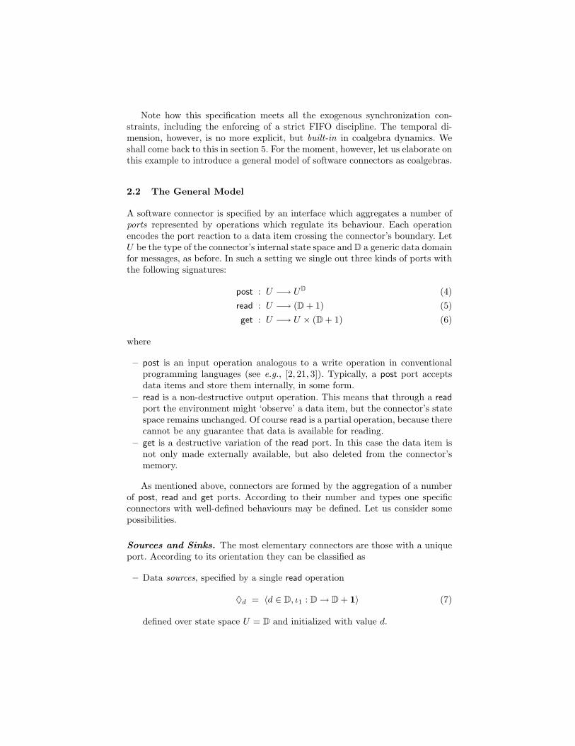
A software connector is specified by an interface which aggregates a number ofports represented by operations which regulate its behaviour. Each operationencodes the port reaction to a data item crossing the connector’s boundary. LetU be the type of the connector’s internal state space and D a generic data domainfor messages, as before. In such a setting we single out three kinds of ports withthe following signatures:
post : U −→ UD (4)read : U −→ (D + 1) (5)get : U −→ U × (D + 1) (6)
where
– post is an input operation analogous to a write operation in conventionalprogramming languages (see e.g., [2, 21, 3]). Typically, a post port acceptsdata items and store them internally, in some form.
– read is a non-destructive output operation. This means that through a readport the environment might ‘observe’ a data item, but the connector’s statespace remains unchanged. Of course read is a partial operation, because therecannot be any guarantee that data is available for reading.
– get is a destructive variation of the read port. In this case the data item isnot only made externally available, but also deleted from the connector’smemory.
As mentioned above, connectors are formed by the aggregation of a numberof post, read and get ports. According to their number and types one specificconnectors with well-defined behaviours may be defined. Let us consider somepossibilities.
Sources and Sinks. The most elementary connectors are those with a uniqueport. According to its orientation they can be classified as
– Data sources, specified by a single read operation
♦d = 〈d ∈ D, ι1 : D→ D + 1〉 (7)
defined over state space U = D and initialized with value d.
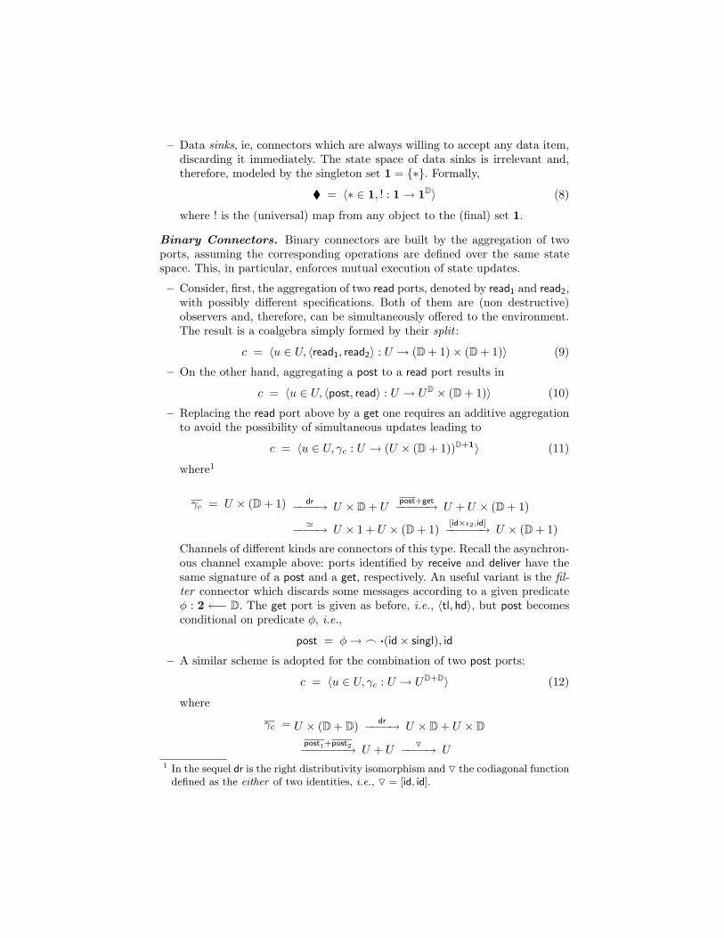
– Data sinks, ie, connectors which are always willing to accept any data item,discarding it immediately. The state space of data sinks is irrelevant and,therefore, modeled by the singleton set 1 = {∗}. Formally,
� = 〈∗ ∈ 1, ! : 1→ 1D〉 (8)
where ! is the (universal) map from any object to the (final) set 1.
Binary Connectors. Binary connectors are built by the aggregation of twoports, assuming the corresponding operations are defined over the same statespace. This, in particular, enforces mutual execution of state updates.
– Consider, first, the aggregation of two read ports, denoted by read1 and read2,with possibly different specifications. Both of them are (non destructive)observers and, therefore, can be simultaneously offered to the environment.The result is a coalgebra simply formed by their split :
c = 〈u ∈ U, 〈read1, read2〉 : U → (D + 1)× (D + 1)〉 (9)
– On the other hand, aggregating a post to a read port results in
c = 〈u ∈ U, 〈post, read〉 : U → UD × (D + 1)〉 (10)
– Replacing the read port above by a get one requires an additive aggregationto avoid the possibility of simultaneous updates leading to
c = 〈u ∈ U, γc : U → (U × (D + 1))D+1〉 (11)
where1
γc = U × (D + 1) dr−−−−→ U × D + Upost+get−−−−−→ U + U × (D + 1)
'−−−−→ U × 1 + U × (D + 1)[id×ι2,id]−−−−−−→ U × (D + 1)
Channels of different kinds are connectors of this type. Recall the asynchron-ous channel example above: ports identified by receive and deliver have thesame signature of a post and a get, respectively. An useful variant is the fil-ter connector which discards some messages according to a given predicateφ : 2 ←− D. The get port is given as before, i.e., 〈tl, hd〉, but post becomesconditional on predicate φ, i.e.,
post = φ→_ ·(id× singl), id
– A similar scheme is adopted for the combination of two post ports:
c = 〈u ∈ U, γc : U → UD+D〉 (12)
where
γc = U × (D + D) dr−−−−→ U × D + U × Dpost1+post2−−−−−−−→ U + U
O−−−−→ U1 In the sequel dr is the right distributivity isomorphism and O the codiagonal function
defined as the either of two identities, i.e., O = [id, id].
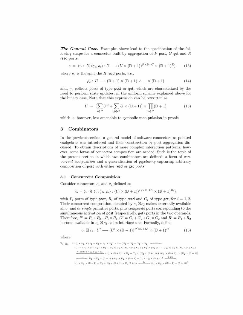
The General Case. Examples above lead to the specification of the fol-lowing shape for a connector built by aggregation of P post, G get and Rread ports:
c = 〈u ∈ U, 〈γc, ρc〉 : U −→ (U × (D + 1))P×D+G × (D + 1)R〉 (13)
where ρc is the split the R read ports, i.e.,
ρc : U −→ (D + 1)× (D + 1)× . . .× (D + 1) (14)
and, γc collects ports of type post or get, which are characterized by theneed to perform state updates, in the uniform scheme explained above forthe binary case. Note that this expression can be rewritten as
U = (∑i∈P
UD +∑j∈G
U × (D + 1))×∏k∈R
(D + 1) (15)
which is, however, less amenable to symbolic manipulation in proofs.
3 Combinators
In the previous section, a general model of software connectors as pointedcoalgebras was introduced and their construction by port aggregation dis-cussed. To obtain descriptions of more complex interaction patterns, how-ever, some forms of connector composition are needed. Such is the topic ofthe present section in which two combinators are defined: a form of con-current composition and a generalisation of pipelining capturing arbitrarycomposition of post with either read or get ports.
3.1 Concurrent Composition
Consider connectors c1 and c2 defined as
ci = 〈ui ∈ Ui, 〈γi, ρi〉 : (Ui × (D + 1))Pi×D+Gi × (D + 1)Ri〉
with Pi ports of type post, Ri of type read and Gi of type get, for i = 1, 2.Their concurrent composition, denoted by c1 � c2 makes externally availableall c1 and c2 single primitive ports, plus composite ports corresponding to thesimultaneous activation of post (respectively, get) ports in the two operands.Therefore, P ′ = P1+P2+P1×P2, G′ = G1+G2+G1×G2 and R′ = R1+R2
become available in c1 � c2 as its interface sets. Formally, define
c1 � c2 : U ′ −→ (U ′ × (D + 1))P ′×D+G′ × (D + 1)R′ (16)
whereγc1�c2
= U1 × U2 × (P1 + P2 + P1 × P2) × D + (G1 + G2 + G1 × G2) '−−−−−−−→
(U1 × (P1 × D + G1) × U2 + U1 × U2 × (P2 × D + G2) + U1 × (P1 × D + G1) × U2 × (P2 × D + G2)
γ1×id+id×γ2+γ1×γ2−−−−−−−−−−−−−−−−−−→ (U1 × (D + 1)) × U2 + U1 × (U2 × (D + 1)) + (U1 × (D + 1)) × (U2 × (D + 1))
'−−−−−−−→ U1 × U2 × (D + 1) + U1 × U2 × (D + 1) + U1 × U2 × (D + 1)2O+id−−−−−−−→
U1 × U2 × (D + 1) + U1 × U2 × (D + 1) × U2(D + 1) '−−−−−−−→ U1 × U2 × ((D + 1) + (D + 1))2
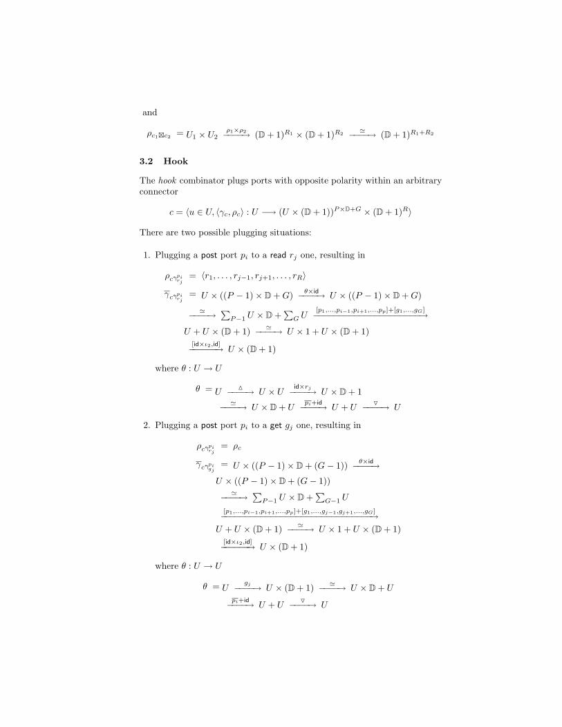
and
ρc1�c2 = U1 × U2ρ1×ρ2−−−−→ (D + 1)R1 × (D + 1)R2
'−−−−→ (D + 1)R1+R2
3.2 Hook
The hook combinator plugs ports with opposite polarity within an arbitraryconnector
c = 〈u ∈ U, 〈γc, ρc〉 : U −→ (U × (D + 1))P×D+G × (D + 1)R〉
There are two possible plugging situations:
1. Plugging a post port pi to a read rj one, resulting in
ρc�pirj
= 〈r1, . . . , rj−1, rj+1, . . . , rR〉
γc�pirj
= U × ((P − 1)× D + G) θ×id−−−−→ U × ((P − 1)× D + G)
'−−−−→∑
P−1 U × D +∑
G U[p1,...,pi−1,pi+1,...,pp]+[g1,...,gG]−−−−−−−−−−−−−−−−−−−−−→
U + U × (D + 1) '−−−−→ U × 1 + U × (D + 1)[id×ι2,id]−−−−−−→ U × (D + 1)
where θ : U → U
θ = UM−−−−→ U × U
id×rj−−−−→ U × D + 1'−−−−→ U × D + U
pi+id−−−−→ U + UO−−−−→ U
2. Plugging a post port pi to a get gj one, resulting in
ρc�pirj
= ρc
γc�pigj
= U × ((P − 1)× D + (G− 1)) θ×id−−−−→U × ((P − 1)× D + (G− 1))
'−−−−→∑
P−1 U × D +∑
G−1 U
[p1,...,pi−1,pi+1,...,pp]+[g1,...,gj−1,gj+1,...,gG]−−−−−−−−−−−−−−−−−−−−−−−−−−−−−−→U + U × (D + 1) '−−−−→ U × 1 + U × (D + 1)
[id×ι2,id]−−−−−−→ U × (D + 1)
where θ : U → U
θ = Ugj−−−−→ U × (D + 1) '−−−−→ U × D + U
pi+id−−−−→ U + UO−−−−→ U
Note that, according to the definition above, if the result of a reaction at aport of type read or get is of type 1, which encodes the absence of any dataitem to be read, the associated post is not activated and, consequently, theinteraction does not become effective.Such unsuccessful read attempt can alternatively be understood as a pendingread request. In this case the intended semantics for interaction with theassociated post port is as follows: successive read attempts are performeduntil communication occurs. This version of hook is denoted by �p
r c andeasily obtained by replacing, in the definition of θ above, step
U × D + Upi+id−−−−→ U + U
by
U × D + Upi+θ−−−−→ U + U
Both forms of the hook combinator can be applied to a whole sequence ofpairs of opposite polarity ports, the definitions above extending as expected.The two combinators introduced in this section can also be put togetherto define a form of sequential composition in situations where all the postports of the second operand (grouped in in) are connected to all the readand get ports of the first (grouped in out). It is assumed that hooks betweentwo single ports extend smoothly to any product of ports (as arising fromconcurrent composition) in which they participate. Formally, we define byabbreviation
c1 ; c2abv= (c1 � c2) �in
out (17)
andc1 ./ c2
abv= �inout (c1 � c2) (18)
4 Examples
This section discusses how some typical software connectors can be definedin the model proposed in this paper.
4.1 Broadcasters and Mergers
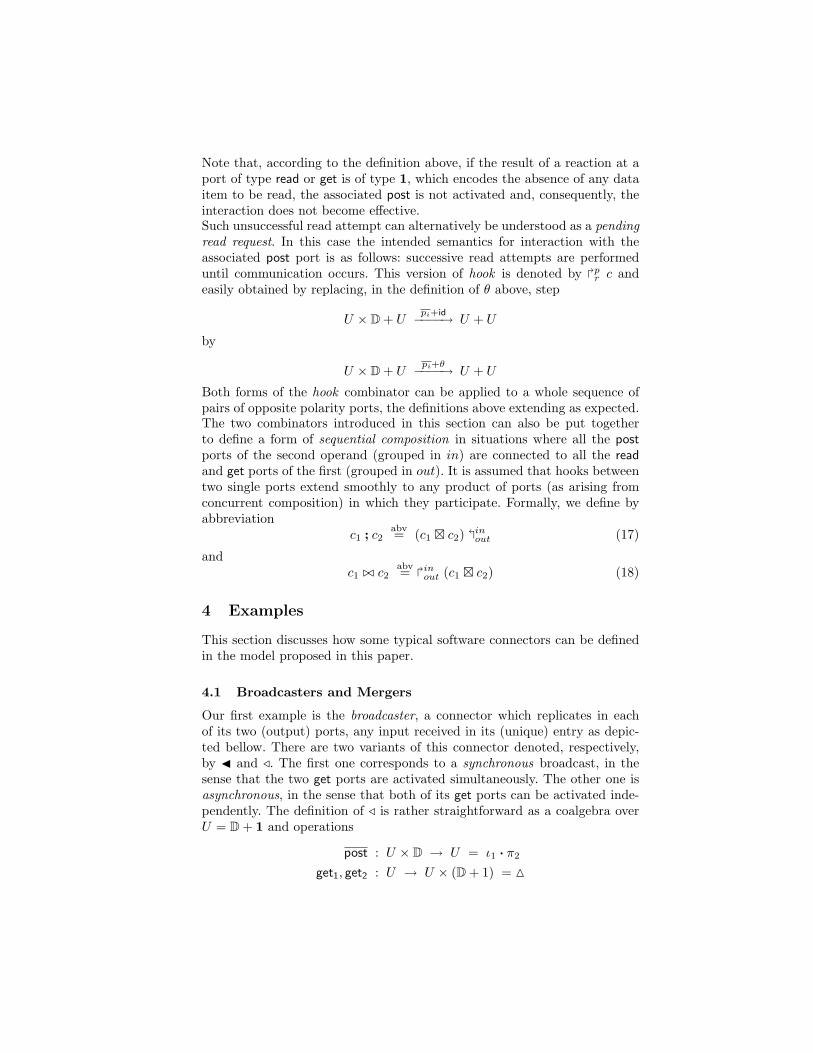
Our first example is the broadcaster, a connector which replicates in eachof its two (output) ports, any input received in its (unique) entry as depic-ted bellow. There are two variants of this connector denoted, respectively,by J and /. The first one corresponds to a synchronous broadcast, in thesense that the two get ports are activated simultaneously. The other one isasynchronous, in the sense that both of its get ports can be activated inde-pendently. The definition of / is rather straightforward as a coalgebra overU = D + 1 and operations
post : U × D → U = ι1 · π2
get1, get2 : U → U × (D + 1) = M
get1
post � •
77
''get2
Fig. 1. The broadcaster connector.
where M is the diagonal function, defined by M= 〈id, id〉. The synchronouscase, however, requires the introduction of two boolean flags initialized to〈false, false〉 to witness the presence of get requests at both ports. The ideais that a value is made present at both the get ports if it has been previouslyreceived, as before, and there exists two reading requests pending. Formally,let U = (D + 1)× (B× B) and define
post : U × D → U = 〈ι1 · π2, π2 · π1〉get1 : U → U × (D + 1) = (=∗ ·π1 → 〈id, π1〉, getaux1)
wheregetaux1 = (π2 · π2 → 〈(ι2 · ∗)× (false× false), π1〉, 〈id× (true× id), ι2 · ∗〉)
I.e., if there is no information stored flag ∗ is returned and the state leftunchanged. Otherwise, an output is performed but only if there is a previousrequest at the other port. If this is not the case the reading request is recordedat the connector’s state. This definition precludes the possibility of a readingunless there are reading requests at both ports. The fact that both requestsare served depends on their interaction with the associated post ports, i.e.,on the chosen hook discipline (see the synchronization barrier example insubsection 4.3). The definition of get2 is similar but for the boolean flagsupdate:
getaux2 = (π1 · π2 → 〈(ι2 · ∗)× (false× false), π1〉, 〈id× (id× true), ι2 · ∗〉)
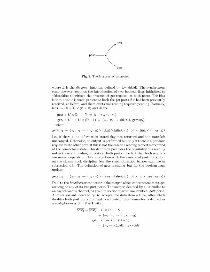
Dual to the broadcaster connector is the merger which concentrates messagesarriving at any of its two post ports. The merger, denoted by ., is similar toan asynchronous channel, as given in section 2, with two identical post ports.Another variant, denoted by I, accepts one data item a time, after whichdisables both post ports until get is activated. This connector is defined asa coalgebra over U = D + 1 with
post1 = post2 : U × D → U
= (=∗ ·π1 → π1, ι1 · π2)get : U → U × (D + 1)
= (=∗→ 〈M, id〉, 〈ι2 · ∗, id〉)
post1
��• � // get
post2
FF
Fig. 2. The merger connector.
4.2 Drains
A drain is a symmetric connector with two inputs, but no output, points.Operationally, every message arriving to an end–point of a drain is simplylost. A drain is synchronous when both post operations are required to beactive at the same time, and asynchronous otherwise. In both case, no in-formation is saved and, therefore U = 1. Actually, drains are used to enforcesynchronisation in the flow of data. Formally, an asynchronous drain is givenby coalgebra
[[ • � O � • ]] : 1 // 1D+D
where both post ports are modelled by the (universal) function to 1, i.e.,post1 = !U×D = post2. The same operations can be composed in a productto model the synchronous variant:
[[ • � H � • ]] : U // UD×D
defined by
1× (D× D)∼=−−−−→ 1× D× 1× D post 1×post 2−−−−−−−−−→ 1× 1 !−−−−→ 1
There is an important point to make here. Note that in this definition twopost ports were aggregated by a product, instead of resorting to the more com-mon additive context. Such is required to enforce their simultaneous activationand, therefore, to meet the expected synchrony constraint. This type of portaggregation also appears as a result of concurrent composition. In general, whenpresenting a connector’s interface, we shall draw a distinction between singleand composite ports, the latter corresponding to the simultaneous activation oftwo or more of the former.
Composite ports, on the other hand, entail the need for a slight generalisationof hook. In particular it should cater for the possibility of a post port requiring,say, two values of type D be plugged to two (different) read or get ports. Such ageneralisation is straightforward and omitted here (but used below on examplesinvolving drains).
4.3 Synchronization Barrier
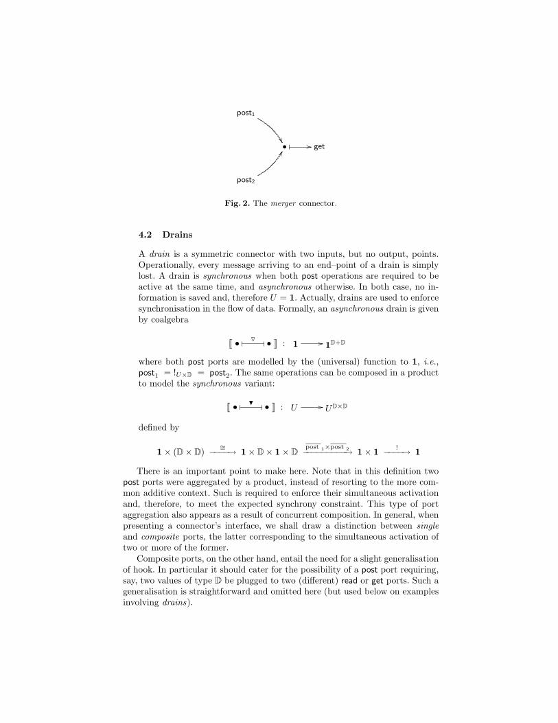
In the coordination literature a synchronization barrier is a connector used toenforce mutual synchronization between two channels (as σ1 and σ2 below).This is achieved by the composition of two synchronous broadcasters with twoof their get ports connected by a synchronous drain. As expected, data itemsread at extremities o1 and o2 are read simultaneously. The composition patternis depicted in figure 3, which corresponds to the following expression:
(J � J) ./ (( • � σ1 // • ) � ( • � H � • ) � ( • � σ2 // • )) (19)
• � σ1 // o1
i1� •
77
'' •_H
_•
i2� •
77
'' • � σ2 // o2
Fig. 3. A synchronization barrier.
4.4 The Dining Philosophers
Originally posed and solved by Dijkstra in 1965, the dinning philosophers prob-lem provides a good example to experiment an exogenous coordination model ofthe kind proposed in this paper 2. In the sequel we discuss two possible solutionsto this problem.
2 The basic version reads as follows. Five philosophers are seated around a table. Eachphilosopher has a plate of spaghetti and needs two forks to eat it. When a philosophergets hungry, he tries to acquire his left and right fork, one at a time, in either order.If successful in acquiring two forks, he eats for a while, then puts down the forksand continues to think.
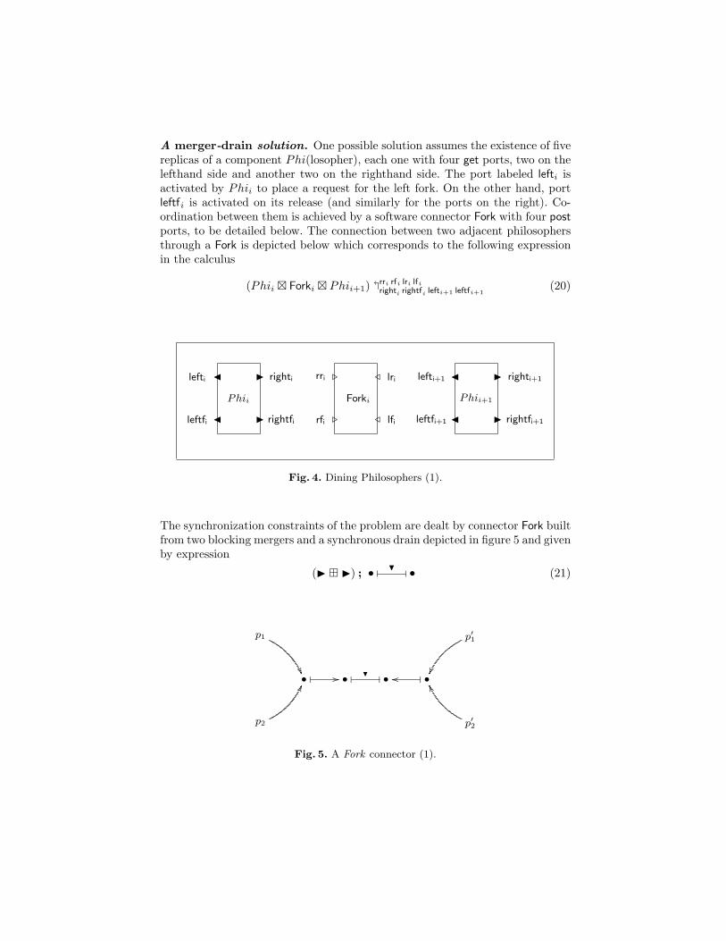
A merger-drain solution. One possible solution assumes the existence of fivereplicas of a component Phi(losopher), each one with four get ports, two on thelefthand side and another two on the righthand side. The port labeled lefti isactivated by Phii to place a request for the left fork. On the other hand, portleftfi is activated on its release (and similarly for the ports on the right). Co-ordination between them is achieved by a software connector Fork with four postports, to be detailed below. The connection between two adjacent philosophersthrough a Fork is depicted below which corresponds to the following expressionin the calculus
(Phii � Forki � Phii+1) �rri rfi lri lfi
righti rightfi lefti+1 leftfi+1(20)
J
J I
Ileftfi
lefti righti
rightfi
Phii
.
. /
/rfi
rri lri
lfi
Forki
J
J I
Ileftfi+1
lefti+1 righti+1
rightfi+1
Phii+1
Fig. 4. Dining Philosophers (1).
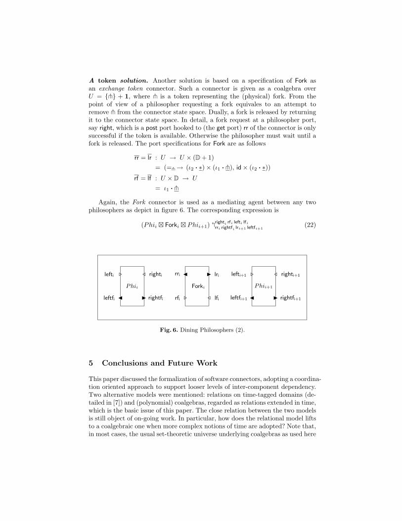
The synchronization constraints of the problem are dealt by connector Fork builtfrom two blocking mergers and a synchronous drain depicted in figure 5 and givenby expression
(I � I) ; • � H � • (21)
p1
��
p′1
��• � // • � H � • •�oo
p2
HH
p′2
VV
Fig. 5. A Fork connector (1).
A token solution. Another solution is based on a specification of Fork asan exchange token connector. Such a connector is given as a coalgebra overU = {t} + 1, where t is a token representing the (physical) fork. From thepoint of view of a philosopher requesting a fork equivales to an attempt toremove t from the connector state space. Dually, a fork is released by returningit to the connector state space. In detail, a fork request at a philosopher port,say right, which is a post port hooked to (the get port) rr of the connector is onlysuccessful if the token is available. Otherwise the philosopher must wait until afork is released. The port specifications for Fork are as follows
rr = lr : U → U × (D + 1)= (=t→ (ι2 · ∗)× (ι1 · t), id× (ι2 · ∗))
rf = lf : U × D → U
= ι1 · t
Again, the Fork connector is used as a mediating agent between any twophilosophers as depict in figure 6. The corresponding expression is
(Phii � Forki � Phii+1) �righti rfi lefti lfi
rri rightfi lri+1 leftfi+1(22)
J
. /
Ileftfi
lefti righti
rightfi
Phii
.
J I
/rfi
rri lri
lfi
Forki
J
. /
Ileftfi+1
lefti+1 righti+1
rightfi+1
Phii+1
Fig. 6. Dining Philosophers (2).
5 Conclusions and Future Work
This paper discussed the formalization of software connectors, adopting a coordina-tion oriented approach to support looser levels of inter-component dependency.Two alternative models were mentioned: relations on time-tagged domains (de-tailed in [7]) and (polynomial) coalgebras, regarded as relations extended in time,which is the basic issue of this paper. The close relation between the two modelsis still object of on-going work. In particular, how does the relational model liftsto a coalgebraic one when more complex notions of time are adopted? Note that,in most cases, the usual set-theoretic universe underlying coalgebras as used here
lacks enough structure to extend such relations over (richly structured) timeduniverses.
Resorting to coalgebras to specify software connectors has the main advant-age of being a smooth extension of the previous relational model. Actually, anyrelation can be seen as a coalgebra over the singleton set, i.e., U = 1. Moreover,techniques of coalgebraic analysis, namely bisimulation, can be used to reasonabout connectors and, in general, architectural design descriptions. In fact, al-though in this paper the emphasis was placed on connector modeling and ex-pressiveness, the model supports a basic calculus in which connector equivalenceand refinement can be discussed (along the lines of [17]). The model comparesquite well to the more classic stream-based approaches (see e.g., [10, 8, 3]), whichcan be recovered as the final interpretation of the coalgebraic specifications pro-posed here.
A lot of work remains to be done. Our current concerns include, in particu-lar, the full development of a calculus of software connectors emerging from thecoalgebraic semantic framework and its use in reasoning about typical softwarearchitectural patterns [1, 12] and their laws. How easily this work scales up toaccommodate dynamically re-configurable architectures, as in, e.g., [11] or [26],remains an open challenging question. We are also currently working on the de-velopment of an Haskell based platform for prototyping this model, allowingthe user to define and compose, in an interactive way, his/her own software con-nectors.
Acknowledgements. This research was carried on in the context of the PUReProject supported by Fct, the Portuguese Foundation for Science and Techno-logy, under contract POSI/ICHS/44304/2002.
References
1. R. Allen and D. Garlan, A formal basis for architectural connection, ACM TOSEM6 (1997), no. 3, 213–249.
2. F. Arbab, Reo: A channel-based coordination model for component composition,Mathematical Structures in Computer Science, 14 (2004), no. 3, 329–366.
3. , Abstract behaviour types: a foundation model for components and theircomposition, Proc. First International Symposium on Formal Methods for Com-ponents and Objects (FMCO’02) (F. S. de Boer, M. Bonsangue, S. Graf, and W.-P.de Roever, eds.), Springer Lect. Notes Comp. Sci. (2852), 2003, pp. 33–70.
4. F. Arbab and J. Rutten, A coinductive calculus of component connectors, CWITech. Rep. SEN-R0216, CWI, Amsterdam, 2002, To appear in the proceedings ofWADT’02.
5. L. S. Barbosa, Components as processes: An exercise in coalgebraic modeling,FMOODS’2000 - Formal Methods for Open Object-Oriented Distributed Systems(S. F. Smith and C. L. Talcott, eds.), Kluwer Academic Publishers, September2000, pp. 397–417.
6. , Towards a Calculus of State-based Software Components, Journal of Uni-versal Computer Science 9 (2003), no. 8, 891–909.
7. M.A. Barbosa and L.S. Barbosa, A Relational Model for Component Interconnec-tion, Journal of Universal Computer Science 10 (2004), no. 7, 808–823.
8. K. Bergner, A. Rausch, M. Sihling, A. Vilbig, and M. Broy, A Formal Model forComponentware, Foundations of Component-Based Systems (Gary T. Leavens andMurali Sitaraman, eds.), Cambridge University Press, 2000, pp. 189–210.
9. R. Bird and O. Moor, The algebra of programming, Series in Computer Science,Prentice-Hall International, 1997.
10. M. Broy, Semantics of finite and infinite networks of communicating agents, Dis-tributed Computing (1987), no. 2.
11. G. Costa and G. Reggio, Specification of abstract dynamic data types: A temporallogic approach, Theor. Comp. Sci. 173 (1997), no. 2.
12. J. Fiadeiro and A. Lopes, Semantics of architectural connectors, Proc. ofTAPSOFT’97, Springer Lect. Notes Comp. Sci. (1214), 1997, pp. 505–519.
13. D. Gelernter and N. Carrier, Coordination languages and their significance, Com-munication of the ACM 2 (1992), no. 35, 97–107.
14. R. Grimes, Profissional dcom programming, Wrox Press, 1997.15. He Jifeng, Liu Zhiming, and Li Xiaoshan, A contract-oriented approach to
component-based programming, Proc. of FACS’03, (Formal Approaches to Com-ponent Software) (Pisa) (Z. Liu, ed.), Spetember 2003.
16. V. Matena and B Stearns, Applying entreprise javabeans: Component-based devel-opment for the j2ee platform, Addison-Wesley, 2000.
17. Sun Meng and L. S. Barbosa, On refinement of generic software components,10th Int. Conf. Algebraic Methods and Software Technology (AMAST) (Stirling)(C. Rettray, S. Maharaj, and C. Shankland, eds.), Springer Lect. Notes Comp. Sci.(3116), 2004, pp. 506–520.
18. O. Nierstrasz and F. Achermann, A calculus for modeling software components,Proc. First International Symposium on Formal Methods for Components andObjects (FMCO’02) (F. S. de Boer, M. Bonsangue, S. Graf, and W.-P. de Roever,eds.), Springer Lect. Notes Comp. Sci. (2852), 2003, pp. 339–360.
19. O. Nierstrasz and L. Dami, Component-oriented software technology, Object-Oriented Software Composition (O. Nierstrasz and D. Tsichritzis, eds.), Prentice-Hall International, 1995, pp. 3–28.
20. S. Oaks and H. Wong, Jini in a nutshell, O’Reilly and Associates, 2000.21. G. Papadopoulos and F. Arbab, Coordination models and languages, Advances in
Computers — The Engineering of Large Systems, vol. 46, 1998, pp. 329–400.22. J. Rutten, Elements of stream calculus (an extensive exercise in coinduction), Tech.
report, CWI, Amsterdam, 2001.23. J.-G. Schneider and O. Nierstrasz, Components, scripts, glue, Software Architec-
tures - Advances and Applications (L. Barroca, J. Hall, and P. Hall, eds.), Springer-Verlag, 1999, pp. 13–25.
24. R. Siegel, CORBA: Fundamentals and programming, John Wiley & Sons Inc, 1997.25. C. Szyperski, Component software, beyond object-oriented programming, Addison-
Wesley, 1998.26. M. Wermelinger and J. Fiadeiro, Connectors for mobile programs, IEEE Trans. on
Software Eng. 24 (1998), no. 5, 331–341.
Related Documents