35A-2 Vacuum Booster and Brake Master Cylinder Hydraulic Booster and Brake Master Cylinder Front Disc Brake Front Drum Brake Item Specifications FG84 FE83 FE84 Vacuum booster Boosting type Vacuum tandem type Diaphragm diameter inch φ8 + φ9 φ9 + φ10 Manufacturer BOSCH AUTOMOTIVE SYSTEMS Brake master cylinder Inner diameter mm {in.} φ30.16 {1.19} φ31.75 {1.25} Stroke Front mm {in.} 17.4 {0.69} 16.0 {0.63} Rear mm {in.} 14.6 {0.57} 16.0 {0.63} Manufacturer NISSIN KOGYO Item Specifications Hydraulic booster Boosting type Hydraulic type Manufacturer BOSCH AUTOMOTIVE SYSTEMS Brake master cylinder Inner diameter mm {in.} φ33.34 {1.31} Stroke Front mm {in.} 17.5 {0.69} Rear mm {in.} 16.0 {0.63} Manufacturer BOSCH AUTOMOTIVE SYSTEMS Item Specifications FE83, FE84 FE85 Brake type Twin caliper type Effective diameter for braking mm {in.} φ235 {9.25} φ252 {9.92} Disc rotor outer diameter × thickness mm {in.} φ293 × 40 {11.5 × 1.57} φ310 × 40 {12.2 × 1.57} Caliper piston inner diameter mm {in.} φ51.1 {2.01} φ54 {2.13} Thickness of pad mm {in.} 14 {0.55} 14 {0.55} Item Specifications 2-leading type (with auto adjuster) Brake type Wheel cylinder inner diameter mm {in.} φ31.75 {1.25} Brake drum inner diameter mm {in.} φ320 {12.6} Brake lining width × thickness mm {in.} 75 × 8.8 {2.95 × 0.35} SPECIFICATIONS

Welcome message from author
This document is posted to help you gain knowledge. Please leave a comment to let me know what you think about it! Share it to your friends and learn new things together.
Transcript
35A-2
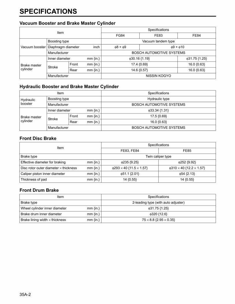
Vacuum Booster and Brake Master Cylinder
Hydraulic Booster and Brake Master Cylinder
Front Disc Brake
Front Drum Brake
ItemSpecifications
FG84 FE83 FE84
Vacuum booster
Boosting type Vacuum tandem type
Diaphragm diameter inch φ8 + φ9 φ9 + φ10
Manufacturer BOSCH AUTOMOTIVE SYSTEMS
Brake master cylinder
Inner diameter mm {in.} φ30.16 {1.19} φ31.75 {1.25}
StrokeFront mm {in.} 17.4 {0.69} 16.0 {0.63}
Rear mm {in.} 14.6 {0.57} 16.0 {0.63}
Manufacturer NISSIN KOGYO
Item Specifications
Hydraulic booster
Boosting type Hydraulic type
Manufacturer BOSCH AUTOMOTIVE SYSTEMS
Brake master cylinder
Inner diameter mm {in.} φ33.34 {1.31}
StrokeFront mm {in.} 17.5 {0.69}
Rear mm {in.} 16.0 {0.63}
Manufacturer BOSCH AUTOMOTIVE SYSTEMS
ItemSpecifications
FE83, FE84 FE85
Brake type Twin caliper type
Effective diameter for braking mm {in.} φ235 {9.25} φ252 {9.92}
Disc rotor outer diameter × thickness mm {in.} φ293 × 40 {11.5 × 1.57} φ310 × 40 {12.2 × 1.57}
Caliper piston inner diameter mm {in.} φ51.1 {2.01} φ54 {2.13}
Thickness of pad mm {in.} 14 {0.55} 14 {0.55}
Item Specifications
2-leading type (with auto adjuster)Brake type
Wheel cylinder inner diameter mm {in.} φ31.75 {1.25}
Brake drum inner diameter mm {in.} φ320 {12.6}
Brake lining width × thickness mm {in.} 75 × 8.8 {2.95 × 0.35}
SPECIFICATIONS
35A-22
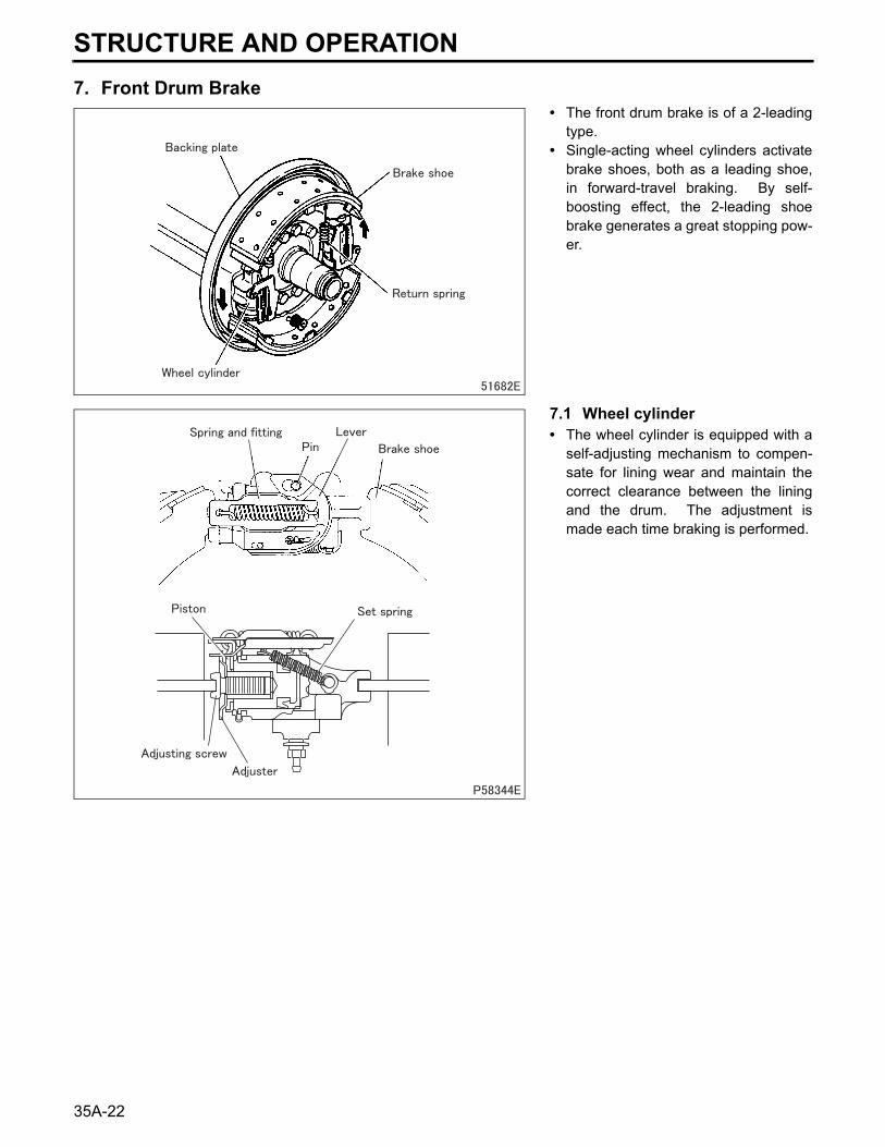
7. Front Drum Brake• The front drum brake is of a 2-leading
type.• Single-acting wheel cylinders activate
brake shoes, both as a leading shoe,in forward-travel braking. By self-boosting effect, the 2-leading shoebrake generates a great stopping pow-er.
7.1 Wheel cylinder• The wheel cylinder is equipped with a
self-adjusting mechanism to compen-sate for lining wear and maintain thecorrect clearance between the liningand the drum. The adjustment ismade each time braking is performed.
STRUCTURE AND OPERATION
35A
35A-23
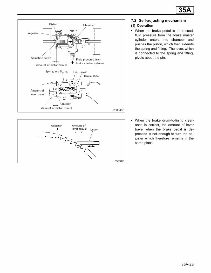
7.2 Self-adjusting mechanism(1) Operation• When the brake pedal is depressed,
fluid pressure from the brake mastercylinder enters into chamber andpushes the piston, which then extendsthe spring and fitting. The lever, whichis connected to the spring and fitting,pivots about the pin.
• When the brake drum-to-lining clear-ance is correct, the amount of levertravel when the brake pedal is de-pressed is not enough to turn the ad-juster which therefore remains in thesame place.
35A-24
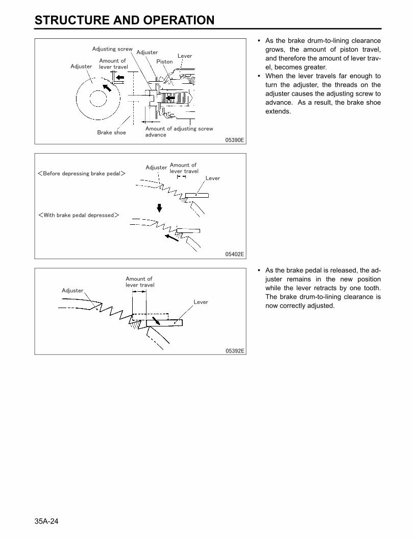
• As the brake drum-to-lining clearancegrows, the amount of piston travel,and therefore the amount of lever trav-el, becomes greater.
• When the lever travels far enough toturn the adjuster, the threads on theadjuster causes the adjusting screw toadvance. As a result, the brake shoeextends.
• As the brake pedal is released, the ad-juster remains in the new positionwhile the lever retracts by one tooth.The brake drum-to-lining clearance isnow correctly adjusted.
STRUCTURE AND OPERATION
35A
35A-25
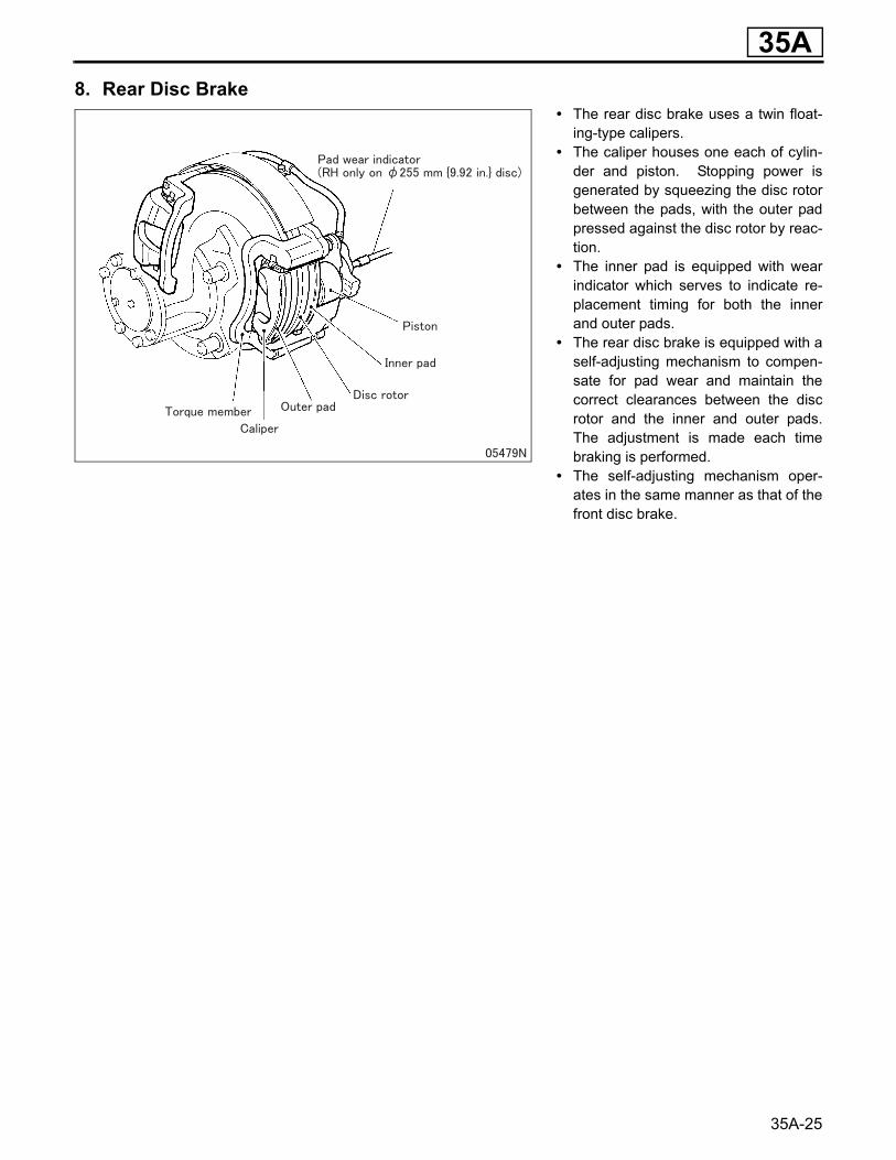
8. Rear Disc Brake• The rear disc brake uses a twin float-
ing-type calipers.• The caliper houses one each of cylin-
der and piston. Stopping power isgenerated by squeezing the disc rotorbetween the pads, with the outer padpressed against the disc rotor by reac-tion.
• The inner pad is equipped with wearindicator which serves to indicate re-placement timing for both the innerand outer pads.
• The rear disc brake is equipped with aself-adjusting mechanism to compen-sate for pad wear and maintain thecorrect clearances between the discrotor and the inner and outer pads.The adjustment is made each timebraking is performed.
• The self-adjusting mechanism oper-ates in the same manner as that of thefront disc brake.
35A-26
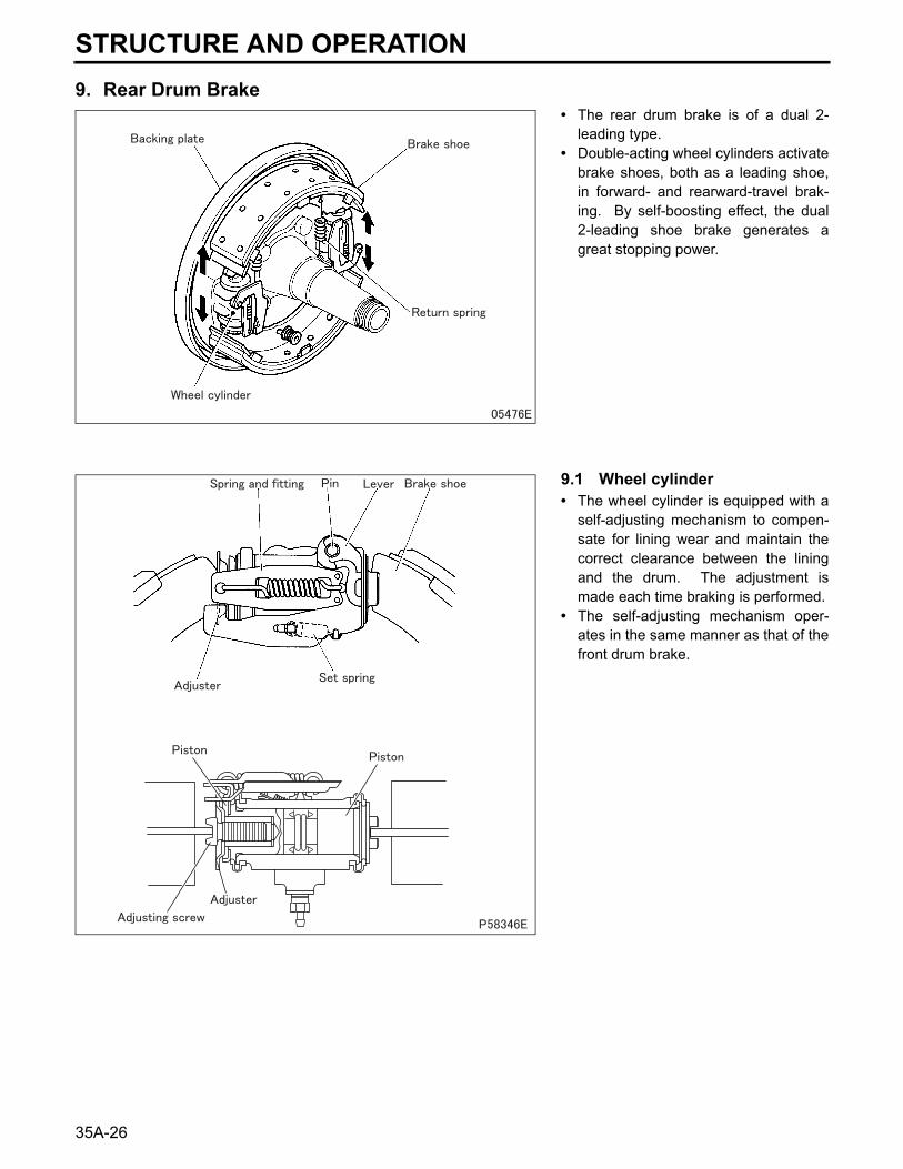
9. Rear Drum Brake• The rear drum brake is of a dual 2-
leading type.• Double-acting wheel cylinders activate
brake shoes, both as a leading shoe,in forward- and rearward-travel brak-ing. By self-boosting effect, the dual2-leading shoe brake generates agreat stopping power.
9.1 Wheel cylinder• The wheel cylinder is equipped with a
self-adjusting mechanism to compen-sate for lining wear and maintain thecorrect clearance between the liningand the drum. The adjustment ismade each time braking is performed.
• The self-adjusting mechanism oper-ates in the same manner as that of thefront drum brake.
STRUCTURE AND OPERATION
35A
35A-3
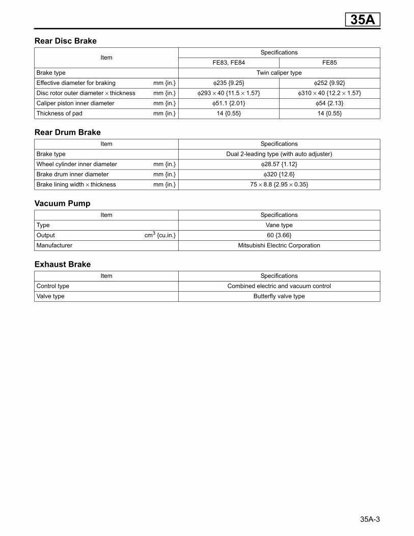
Rear Disc Brake
Rear Drum Brake
Vacuum Pump
Exhaust Brake
ItemSpecifications
FE83, FE84 FE85
Brake type Twin caliper type
Effective diameter for braking mm {in.} φ235 {9.25} φ252 {9.92}
Disc rotor outer diameter × thickness mm {in.} φ293 × 40 {11.5 × 1.57} φ310 × 40 {12.2 × 1.57}
Caliper piston inner diameter mm {in.} φ51.1 {2.01} φ54 {2.13}
Thickness of pad mm {in.} 14 {0.55} 14 {0.55}
Item Specifications
Brake type Dual 2-leading type (with auto adjuster)
Wheel cylinder inner diameter mm {in.} φ28.57 {1.12}
Brake drum inner diameter mm {in.} φ320 {12.6}
Brake lining width × thickness mm {in.} 75 × 8.8 {2.95 × 0.35}
Item Specifications
Type Vane type
Output cm3 {cu.in.} 60 {3.66}
Manufacturer Mitsubishi Electric Corporation
Item Specifications
Control type Combined electric and vacuum control
Valve type Butterfly valve type
35A-30
Wheel BrakeSymptoms Brake application
one sided
Insu
ffici
ent s
topp
ing
pow
er
Red
uced
ped
al tr
avel
Noise and shock when brake ped-
al depressed
ReferenceGr
Possible causes Brak
e dr
ag (s
low
dis
enga
gem
ent a
fter p
edal
rele
ase)
Stop
ping
pow
er d
iffer
ent f
rom
righ
t to
left
Uns
tabl
e st
oppi
ng p
ower
Lock
ing
poin
t var
ies
Oth
er
Noi
se g
ener
ated
whe
n w
heel
s ar
e tu
rned
with
jack
ed-u
pve
hicl
e
Con
tinuo
us n
oise
dur
ing
brak
e ap
plic
atio
n (a
t low
veh
icle
sp
eed)
Oth
er
Wheel brake
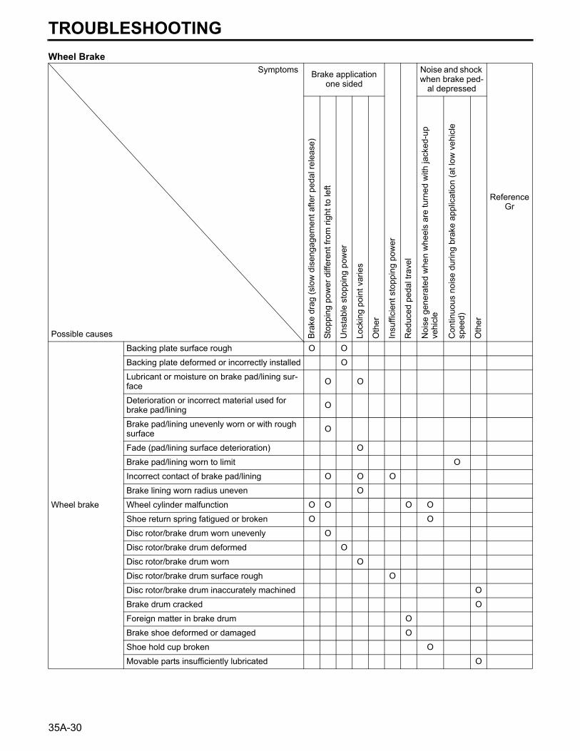
Backing plate surface rough O O
Backing plate deformed or incorrectly installed O
Lubricant or moisture on brake pad/lining sur-face O O
Deterioration or incorrect material used for brake pad/lining O
Brake pad/lining unevenly worn or with rough surface O
Fade (pad/lining surface deterioration) O
Brake pad/lining worn to limit O
Incorrect contact of brake pad/lining O O O
Brake lining worn radius uneven O
Wheel cylinder malfunction O O O O
Shoe return spring fatigued or broken O O
Disc rotor/brake drum worn unevenly O
Disc rotor/brake drum deformed O
Disc rotor/brake drum worn O
Disc rotor/brake drum surface rough O
Disc rotor/brake drum inaccurately machined O
Brake drum cracked O
Foreign matter in brake drum O
Brake shoe deformed or damaged O
Shoe hold cup broken O
Movable parts insufficiently lubricated O
TROUBLESHOOTING
35A
35A-31
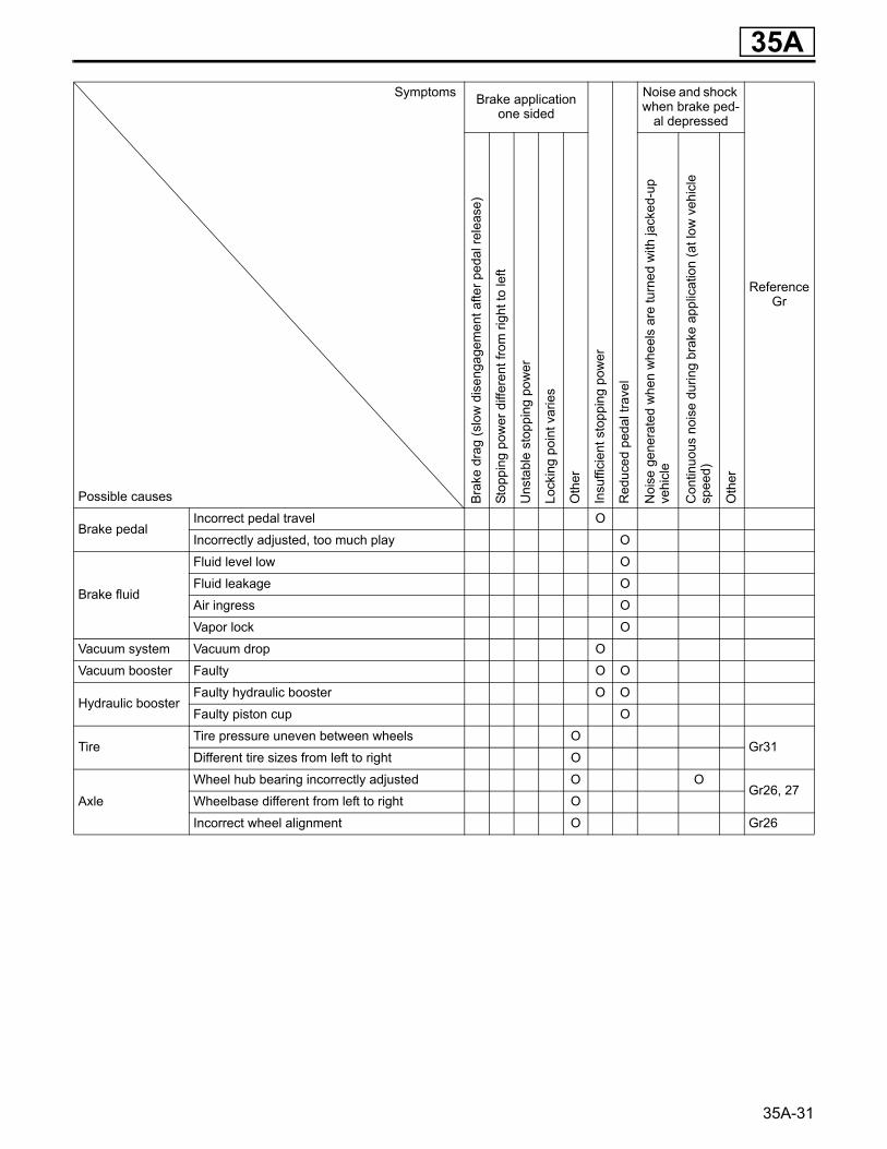
Symptoms Brake application one sided
Insu
ffici
ent s
topp
ing
pow
er
Red
uced
ped
al tr
avel
Noise and shock when brake ped-
al depressed
ReferenceGr
Possible causes Brak
e dr
ag (s
low
dis
enga
gem
ent a
fter p
edal
rele
ase)
Stop
ping
pow
er d
iffer
ent f
rom
righ
t to
left
Uns
tabl
e st
oppi
ng p
ower
Lock
ing
poin
t var
ies
Oth
er
Noi
se g
ener
ated
whe
n w
heel
s ar
e tu
rned
with
jack
ed-u
pve
hicl
e
Con
tinuo
us n
oise
dur
ing
brak
e ap
plic
atio
n (a
t low
veh
icle
sp
eed)
Oth
er
Brake pedalIncorrect pedal travel O
Incorrectly adjusted, too much play O
Brake fluid
Fluid level low O
Fluid leakage O
Air ingress O
Vapor lock O
Vacuum system Vacuum drop O
Vacuum booster Faulty O O
Hydraulic boosterFaulty hydraulic booster O O
Faulty piston cup O
TireTire pressure uneven between wheels O
Gr31Different tire sizes from left to right O
Axle
Wheel hub bearing incorrectly adjusted O OGr26, 27
Wheelbase different from left to right O
Incorrect wheel alignment O Gr26
35A-32
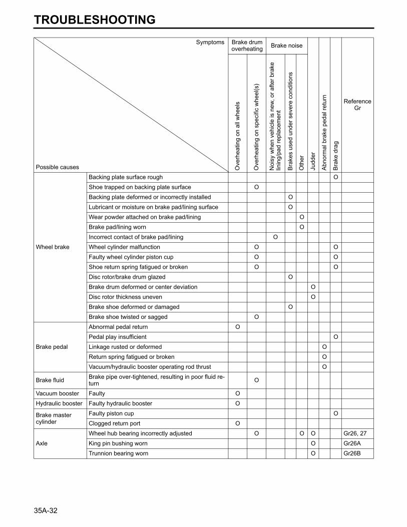
Symptoms Brake drum overheating Brake noise
Judd
er
Abno
rmal
bra
ke p
edal
retu
rn
Bra
ke d
rag
ReferenceGr
Possible causes Ove
rhea
ting
on a
ll w
heel
s
Ove
rhea
ting
on s
peci
fic w
heel
(s)
Noi
sy w
hen
vehi
cle
is n
ew, o
r afte
r bra
ke
linin
g/pa
d re
plac
emen
t
Bra
kes
used
und
er s
ever
e co
nditi
ons
Oth
er
Wheel brake
Backing plate surface rough O
Shoe trapped on backing plate surface O
Backing plate deformed or incorrectly installed O
Lubricant or moisture on brake pad/lining surface O
Wear powder attached on brake pad/lining O
Brake pad/lining worn O
Incorrect contact of brake pad/lining O
Wheel cylinder malfunction O O
Faulty wheel cylinder piston cup O O
Shoe return spring fatigued or broken O O
Disc rotor/brake drum glazed O
Brake drum deformed or center deviation O
Disc rotor thickness uneven O
Brake shoe deformed or damaged O
Brake shoe twisted or sagged O
Brake pedal
Abnormal pedal return O
Pedal play insufficient O
Linkage rusted or deformed O
Return spring fatigued or broken O
Vacuum/hydraulic booster operating rod thrust O
Brake fluid Brake pipe over-tightened, resulting in poor fluid re-turn O
Vacuum booster Faulty O
Hydraulic booster Faulty hydraulic booster O
Brake master cylinder
Faulty piston cup O
Clogged return port O
Axle
Wheel hub bearing incorrectly adjusted O O O Gr26, 27
King pin bushing worn O Gr26A
Trunnion bearing worn O Gr26B
TROUBLESHOOTING
35A
35A-33
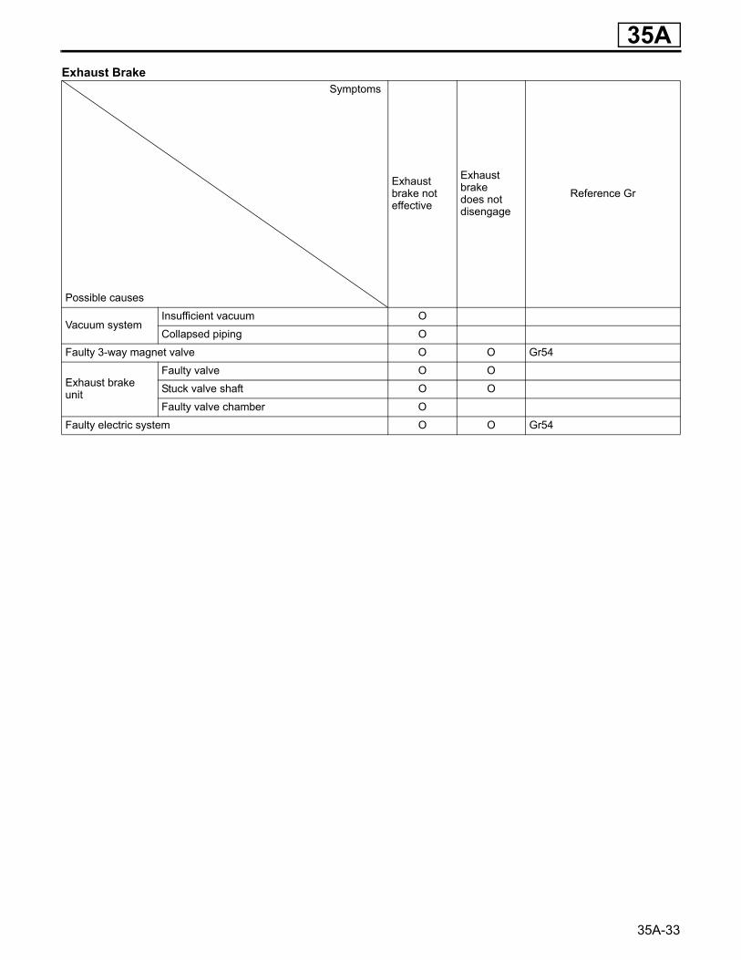
Exhaust BrakeSymptoms
Exhaust brake noteffective
Exhaust brakedoes not disengage
Reference Gr
Possible causes
Vacuum systemInsufficient vacuum O
Collapsed piping O
Faulty 3-way magnet valve O O Gr54
Exhaust brake unit
Faulty valve O O
Stuck valve shaft O O
Faulty valve chamber O
Faulty electric system O O Gr54
35A
35A-45
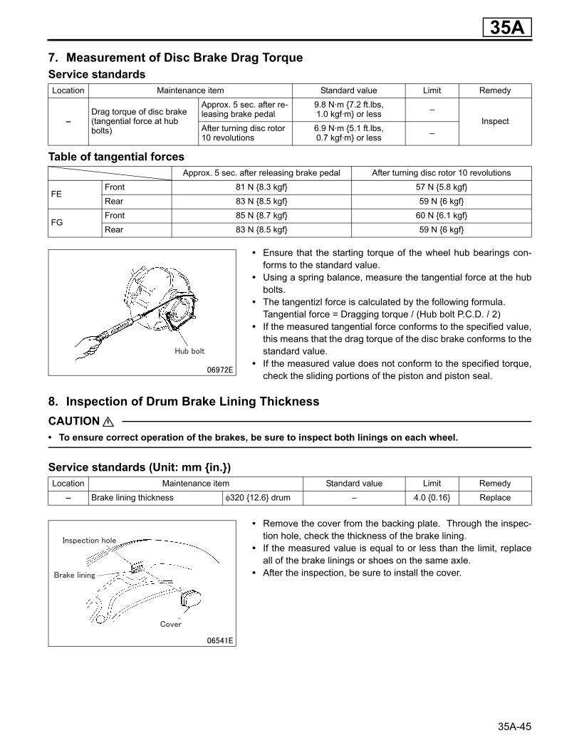
7. Measurement of Disc Brake Drag TorqueService standards
Table of tangential forces
• Ensure that the starting torque of the wheel hub bearings con-forms to the standard value.
• Using a spring balance, measure the tangential force at the hubbolts.
• The tangentizl force is calculated by the following formula.Tangential force = Dragging torque / (Hub bolt P.C.D. / 2)
• If the measured tangential force conforms to the specified value,this means that the drag torque of the disc brake conforms to thestandard value.
• If the measured value does not conform to the specified torque,check the sliding portions of the piston and piston seal.
8. Inspection of Drum Brake Lining ThicknessCAUTION• To ensure correct operation of the brakes, be sure to inspect both linings on each wheel.
Service standards (Unit: mm {in.})
• Remove the cover from the backing plate. Through the inspec-tion hole, check the thickness of the brake lining.
• If the measured value is equal to or less than the limit, replaceall of the brake linings or shoes on the same axle.
• After the inspection, be sure to install the cover.
Location Maintenance item Standard value Limit Remedy
–Drag torque of disc brake (tangential force at hub bolts)
Approx. 5 sec. after re-leasing brake pedal
9.8 N·m {7.2 ft.lbs,1.0 kgf·m} or less –
InspectAfter turning disc rotor 10 revolutions
6.9 N·m {5.1 ft.lbs,0.7 kgf·m} or less –
Approx. 5 sec. after releasing brake pedal After turning disc rotor 10 revolutions
FEFront 81 N {8.3 kgf} 57 N {5.8 kgf}
Rear 83 N {8.5 kgf} 59 N {6 kgf}
FGFront 85 N {8.7 kgf} 60 N {6.1 kgf}
Rear 83 N {8.5 kgf} 59 N {6 kgf}
Location Maintenance item Standard value Limit Remedy
– Brake lining thickness φ320 {12.6} drum – 4.0 {0.16} Replace
35A-46
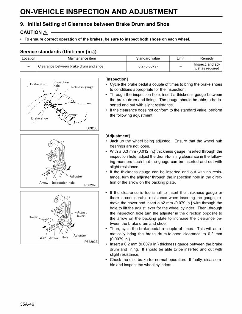
9. Initial Setting of Clearance between Brake Drum and ShoeCAUTION• To ensure correct operation of the brakes, be sure to inspect both shoes on each wheel.
Service standards (Unit: mm {in.})
[Inspection]• Cycle the brake pedal a couple of times to bring the brake shoes
to conditions appropriate for the inspection.• Through the inspection hole, insert a thickness gauge between
the brake drum and lining. The gauge should be able to be in-serted and out with slight resistance.
• If the clearance does not conform to the standard value, performthe following adjustment.
[Adjustment]• Jack up the wheel being adjusted. Ensure that the wheel hub
bearings are not loose.• With a 0.3 mm {0.012 in.} thickness gauge inserted through the
inspection hole, adjust the drum-to-lining clearance in the follow-ing manners such that the gauge can be inserted and out withslight resistance.
• If the thickness gauge can be inserted and out with no resis-tance, turn the adjuster through the inspection hole in the direc-tion of the arrow on the backing plate.
• If the clearance is too small to insert the thickness gauge orthere is considerable resistance when inserting the gauge, re-move the cover and insert a φ2 mm {0.079 in.} wire through thehole to lift the adjust lever for the wheel cylinder. Then, throughthe inspection hole turn the adjuster in the direction opposite tothe arrow on the backing plate to increase the clearance be-tween the brake drum and shoe.
• Then, cycle the brake pedal a couple of times. This will auto-matically bring the brake drum-to-shoe clearance to 0.2 mm{0.0079 in.}.
• Insert a 0.2 mm {0.0079 in.} thickness gauge between the brakedrum and lining. It should be able to be inserted and out withslight resistance.
• Check the disc brake for normal operation. If faulty, disassem-ble and inspect the wheel cylinders.
Location Maintenance item Standard value Limit Remedy
– Clearance between brake drum and shoe 0.2 {0.0079} – Inspect, and ad-just as required
ON-VEHICLE INSPECTION AND ADJUSTMENT
Related Documents


