Indian Standard IS : 811-1987 ( RealTiied 1995 ) SPECIFICATIONFOR COLDFORMEDLIGHTGAUGESTRUCTURAL STEELSECTIONS ( Second Revision) Third Reprint OCTOBER1998 UDC 669*14*018*29-243-131.2 0 Copyright 1989 BUREAU OF INDIAN STANDARDS MANAK BHAVAN, 9 BAHADUR SHAH ZAFAR MARG NEW DELHI 110002 Gr 11 hfuy 1989

Welcome message from author
This document is posted to help you gain knowledge. Please leave a comment to let me know what you think about it! Share it to your friends and learn new things together.
Transcript
Indian Standard
IS : 811-1987 ( RealTiied 1995 )
SPECIFICATIONFOR COLDFORMEDLIGHTGAUGESTRUCTURAL
STEELSECTIONS
( Second Revision ) Third Reprint OCTOBER1998
UDC 669*14*018*29-243-131.2
0 Copyright 1989
BUREAU OF INDIAN STANDARDS MANAK BHAVAN, 9 BAHADUR SHAH ZAFAR MARG
NEW DELHI 110002
Gr 11 hfuy 1989

IS:811-1987
Indian Standard
SPECIFICATION FOR COLD FORMED LIGHT GAUGE STRUCTURAL
STEEL SECTIONS
(Second Revision)
Structural Sections Sectional Committee, SMDC 6
Chairman SHRI M. DHAR
Flat No. 56, Kailash Apartments Lala Laioat Rai Mara
N;w Delhi -
Members
SHRI V. K. AGRAWAL SHRI N. G. SHARMA (Alternate)
SHRI R. N. AGGARWAL SHRI B. K. SRIVASTAVA (Alternate)
SHRI S. BANERJEE SHRI N. BHATTACHARYA SHRI B. B. CHAKRAVERTI
SHRI A. K. S~oht~ (Alternare) SHRI D. S. DESAI SHRI B. K. DUTTA
SHRI S. S. SAHA (Alternate) SHRI S. K. GANGULY SHRI S. C. CHADHA
SHRI M. P. JASUJA
JOINT DIRECTOR STANDARDS (WAGON I), RDSO JOINT DIRECTOR STANDARDS (B&S) SB, RDSO
( Ahernare) SHRI A. J. JOSHI
SHRI A. G. RAMA RAO (Alrernare) LT-COL KULWANT SINGH
MAJ S. B. PURI (Alternate) SHRI S. K. MITRA
SHRI S. DUTTA (Alternate) SHRI P. K. MUKHERJEE
SHRI AMIT KUMAR BHATTACHARYA (Alternare) SHRI A. P. BHATNAGAR
SHRI P. K. DEBNATH (Ahernare) SHRI KAMMAL PRAKASH
SHRI C. S. KANNAN (Alternate) SHRI P. V. NAIK SHRI N. S. R. V. RAJU
SHRI D. KRISHNAMURTHY (Alrernare) SHRI S. K. SADHU
SHRI S. C. CHAKRAVARTI (Ahernare) SHRI M. C. SARANGDHAR
SHRI M, K. CHATTERJEE (Alfernare) SHRI S. K. SARNA
SHRI G. N. RAO (Alternafe) SHRI K. R. SENGUPTA
SHRI B. P. GHOSH (Alternate) SHRI S. N. SINGH
SHRI C. K. NAG (Alfernare) SHRI K. S. SRINIVASAN
SHRI A. K. LAL (Alternate)
Represenring
Hindustan Aluminium Corporation Ltd, Renukoot
Steel Authority of India Ltd (Bokaro Steel Plant), Bokaro
Steel Re-Rolling Mills Association of India, Calcutta Garden Reach Shipbuilder & Engineers Ltd. Calcutta Superintendence Co of India (Pvt) Ltd. Calcutta
M. N. Dastur & Co Pvt Ltd. Calcutta Iron & Steel Control, Calcutta
Institution of Engineers (India). Calcutta Directorate General of Supplies & Disposals (Inspection Wing),
New Delhi Steel Authority of India Ltd (Research & Development Centre
for Iron & Steel), Ranchi Ministry of Railways
Steel Authority of India Ltd (Bhilai Steel Plrnt), Bhilai
Engineer-in-Chief’s Branch, Army Headquarters, New Delhi
Indian Iron & Steel Co Ltd. Burnpur
Braithwaite & Co Ltd, Calcutta
Steel Authority of India Ltd ( Durgapur Steel Plant ), Durgapur
Metallurgical & Engineering Consultants (India) Ltd. Ranchi
Richardson & Cruddas Ltd, Bombay Hindustan Shipyard Ltd, Visakhapatnam
Jessop & Co Ltd. Calcutta
Stup & Co Ltd. Bombay
Visakhapatnam Steel Project, Vishakhapatnam
Joint Plant Committee, Calcutta
EMC Steelal Ltd. Calcutta
National Buildings Organization, New Delhi
BUREAU OF INDIAN STANDARDS MANAK BHAVAN. 9 BAHADUR SHAH ZAFAR MARG
NEW DELHI 110002
I

IS : 811-1987
Members
Snnt K. SURYANARAYANAN
SHRI G. M. MENON (Alrernare) SH~I D. THIRUVENGADAM
SHRI K. V. VIJAYARAGHAVAN (Alrernare) SHRI S. G. TUDEKAR
SHRI J. N. BHAMBRY (Alrernare) SHRI P. VISHWAKARMA
SHRI A. HAQUE (Alrernare) SHRI B. MUKHERJI,
Director (Strut & Met)
Representing
Indian Aluminium Co Ltd, Calcutta
Tube Products of India, Madras
Steel Authority of India Ltd (Rourkela Steel Plant), Rourkela
Tata Iron & Steel Co Ltd, Jamshedpur
Director General, BIS (Ex-ofrcio Member)
Secretary Seal S. S. SETHI
Joint Director (Strut & Met), BlS
Panel for Revision of IS : 81 I-1965, SMDC 6 : PII
Convener
SHHI D. THIRUVENGADAM
Members
Tube Products of India Ltd. Madras
SHWI K. V. VIJAYARACHAVAN (Alrernare to Shri D. Thiruvengadam)
SIIRI’ C. S. CHADHA SHRI S. V. KANSARA (Alrernare)
SIIRI A. B. DACHA SHRI S. S. NAIR (Ahernare)
SIIHI S. K. DATTA SIIHI B. P. DE RI~I’R~sENTATIVE
SRC Roll Forming Pvt Ltd, Bombay
Press Metal Corporation Ltd. Bombay
Richardson & Cruddas Ltd. Bombay M. N. Dastur & Co Private Ltd. Calcutta Hindustan Steel Works Construction Ltd. Calcutta
IS:811-1987
Indian Standard
SPECIFICATION FOR COLD FORMED LIGHT GAUGE STRUCTURAL
STEEL SECTIONS
(Second Revision)
0. FOREWORD
0.1 This Indian Standard (Second Revision) was adopted by the Bureau of Indian Standards on 22 July 1987, after the draft finalized by the Structural Sections Sectional Committee had been approved by the Structural and Metals Division Council.
0.2 This standard is one of a series of Indian Standards being published under the Steel Economy Programme. This was first published in 1961 and revised in 1965.
In this revision, the following major modifications have been effected:
a) a series of zed sections with lips has been added,
b) box sections and the strength properties of the various profiles have been deleted, and
c) the sectional properties have been expressed to three significant figures.
0.3 Cold formed light gauge steel sections are produced from,steel strips or sheets generally not thicker than 10 mm. For mass production, they are formed most economically by cold-rolling, while smaller quantities of special shapes are most economically produced on press brakes. The later process with its versatility of shape variation makes this type of construction as adoptable to special requirements as reinforced concrete is in. its field of use. Members are connected by spot, fillet, plug or slot welds; by screws, bolts; cold rivets or any other special device.
0.3.1 For the load carrying members like ‘Z’ sections, it is recommended to manufacture these sections by cold roll forming process.
0.3.2 This type of construction is appropriate and economical in one or more of the following conditions:
a) Where moderate loads made the thicker hot rolled shapes uneconomical (for example, joists, purlins, girts, roof trusses, complete framing for one and two storeyed residential, commercial and industrial structures, and stringer beams in conveyors);
b) Where it is desired {hat load carrying members should also provide useful surface (for example, floor panels and roof decks mostly installed without any shoring and wall* panels); and
c) Where sub-assemblies of such members may be pre-fabricated in the plant, reducing site erection to a minimum of simple operations.
0.4 It is not intended that the freedom of designers and/or manufacturers should be limited to the use of sections listed in this standard. The flexibility of the forming process and the great variety of shapes which may be formed of sheet and strip steel are such that substantial economy may often be effected in meeting the end requirements by the use of special sections. However, ‘the designer is advised to seek the advice of manufacturers or fabricators before specifying special sections.
0.5 In the preparation of this standard, assistance has been drawn from BS 2994-1976 ‘Specification for Cold Rolled Steel Sections’, issued by the British Standards Institution.
0.6 Illustrative examples given in Appendix A of IS : 81 l-1965 have been deleted. The designers are advised to refer IS : SOI-1975* and SP 6(5)-19807 which stipulate the design criteria and commentary/ illustrative examples respectively on the use of cold formed steel sections for structural purposes.
0.7 For the purpose of deciding whether a particular requirement of this standard is complied with, the final value, observed or calculated, expressing the result of a test or analysis, shall be rounded off in accordance with IS : 2-1960$. The number of significant places retained in the rounded off value should be the same as that of the specified value in this standard.
*Code of practice for use of cold formed light gauge steel structural members in general building construction (.firsr revision).
tSpecifkation for cold-formed. light-gauge steel structures (.firsr revision ).
iRules for rounding off numerical values (w~iwtl).
3
IS:811-1987
1. SCOPE
1.1 This standard lays down dimensions, mass, sectional properties and requirements for corrosion protection for cold formed light gauge open wall steel sections for structural and other general applications, having minimum thickness of 1.25 mm.
2. DEFINITIONS
2.0 For the purpose of this standard, the following definitions shall apply.
2.1 Y-Y Axis - A line parallel to the axis of web of section ( in the case of channels) or parallel to the webs (in the case of hat sections and rectangular sections) or parallel to either flange (in the case of angles and square sections), and passing through the centre of gravity of the profile of the section.
2.2 X-X Axis’- A line passing through the centre of gravity of the profile of the section and at right angles to the Y-Y Axis.
2.3 U-U Axis- It is the major principal axis.
2.4 V- V Axis- It is the minor principal axis.
3. DESIGNATION
3.1 Cold formed light gauge sections shall be designated by figures denoting depth (mm) X width (mm) X thickness (mm) of the section.
4. SYMBOLS
4.1 Letter symbols used in this standard have been indicated in Tables 1 to 11. More explicit definitions for certain symbols used in the tables are given below:
= f = h = Ri = t =
Led = M =
= fx = I; = = 2; = = 2; = rxx = ryy = ruu = rvv = c, =
cy =
x0 = J = c, =
cross-sectional area of the profile, width of the section, height of the section, international radius at curve, thickness of the metal, reduced thickness of the section at curve, calculated mass of the profile per unit length, moment of inertia about the X-X axis, moment of inertia about the Y-Y axis, product moment of inertia, moment of inertia about U-U axis, moment of inertia about V-V axis, modulus of section about the X-X axis, modulus of section about the Y-Y axis, radius of gyration about the X-X axis, radius of gyration about the Y-Y axis, radius of gyration about the U-U axis, radius of gyration about the V-V axis, distance of centre of gravity from X-X axis, distance of centre‘ of gravity from Y-Y axis, shear centre, torsional constant, and warping constant.
5. MATERIAL
5.1 Sheet and strip used for making the cold- formed sections shall conform to a grade not lower than St 34-1079 of 1S : 1079-i973*.
51.1 Sheet and strip conforming to IS : 513- 19867 (other than Grade ‘0’) may also be used for sections where load bearing is not a design criteria, for example, false ceiling, sections for frames of doors and windows.
6. BASIS OF CALCULATION
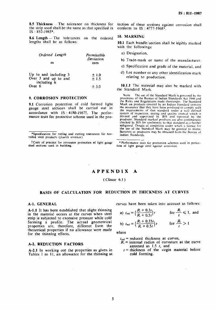
6.1 Material, when subjected to cold-forming processes, develops slight thinning at the curves. The actual strin width. therefore. reouired to form the section is’ slightly less than cts theoretical width. Reduction factor assumed for this thinning effect has been taken as Of925 in accordance with Appendix A by assuming internal radius at curve as I:5t.
7. DIMENSIONS AND PROPERTIES
7.1 The dimensions of the different profiles of cold formed light gauge steel sections shall be as given in Tables 1 to 10.
7.1.1 lnternal radius’ at curves shall generally be taken as 1.5t.
7.2 Mass and sectional properties. of various profiles of cold formed light gauge steel sections are given in Tables I to IO.
7.2.1 The properties of the 90” corners are given in Table I I.
7.2.2 The density of steel of 7.85 g/cm3 has been assumed in calculating the mass.
7.2.3 The sectional properties, as given in Tables I to I I, have been calculated assuming Ri as i:5f.
8. TOLERANCES
8.1 General -- Unless otherwise agreed between the manufacturer and the purchaser. tolerances as specified in 8.2 to 8.4 shall apply.
8.2 Straightness - The straightness of any length shall be such that the offset does not
exceed -& of that length, when measured along
both the X-X and Y-Y axis.
8.3 Profile-The deviation of the profile dimensions shall not exceed +_ 0.5 mm. The deviation from the angle of 90° shall not exceed f I”.
8.4 Twist-The section shall be reasonably free from twist.
*Specification for cold-rolled low carbon steel sheets and strips ( rltird revision).
tspecification for hot-rolled carbon steel sheet and strip ( f/lid rfwision ).
4
IS:811-1987
8.5 Thickness - The tolerance on thickness for the strip used shall be the same as that specified in IS : 852-1985*.
8.6 Length-The tolerances on the ordered lengths shall be as follows:
Ordered Length
m
Permissible Deviation
mm
Up to and including 3 Over 3 and up to and
including 6 Over 6
f 1.0 * 1.5
+ 3.0
9. CORROSION PROTECTION
9.1 Corrosion protection of cold formed light gauge steel sections shall be carried out in accordance with IS : 4180-19677. The perfor- mance tests for protective scheme used in the pro-
*Specification for rolling and cutting tolerances for hot- roiled steel products (,juurr/t revision ).
t&de of practice for corrosion protection of light gauge steel sections used in building.
tection of these sections against corrosion shail conform to IS : 4777-1968”.
IO. MARKING
10.1 with
a)
b)
c)
d)
Each bundle/section shall be ikgibly marked the followings:
Designation,
Trade-mark or name of the manufacturer,
Specification and grade of the material, and
Lot number or any other identification mark relating to production.
10.1.1 The material may also be marked with the Standard Mark.
No~t - The use of the Standard Mark is governed by the provisions of the Bureau of Indian Standards Act 19X6 and the Rules and Regulations made thereunder. The Standard Mark on products covered by an Indian Standard conwys the assurance that they haw been produced to comply utth the requirements of that standard under a u.cII defined system of inspection. testing and quality control which 1s devised and supervised by BIS and operated hy the producer. Standard marked products arc also continuousI>, checked by BIS for conformity to that standard as a further safeguard. Details of conditions under uhich a licencc for the use of the Standard Mark may be granted to manu- facturers or producers may he obtained from the Bureau of Indian Standards.
l Performance tests for protection schemes used in protcc- tion of light gauge steel against corrosion.
APPEN DIX A
( Clause 6. I )
BASIS OF CALCULATION FOR REDUCTION IN THICKNESS AT CURVES
A-l. GENERAL curves have been taken into account as follows:
A-l.1 It has been established that slight thinning in the material occurs at the curves when steel strip is subjected to excessive pressure while cold forming a profile. The actual geometrical properties are, therefore, different from the theoretical properties if no allowance were made for the thinning effects.
A-2. REDUCTION FACTORS
A-2.1 In working out the properties as given in Tables 1 to 1 I, an allowance for the thinning at
R, + 0.31 a) ‘A = ( R, + 0.5t It
b) tred = ( ti;;$=jtt) t
for+ < 1, and
for
where
[red = reduced thickness at curves, Ri = internal radius of curvature at the curve
assumed as 1.5 t, and t = thickness of the virgin material before
cold forming.
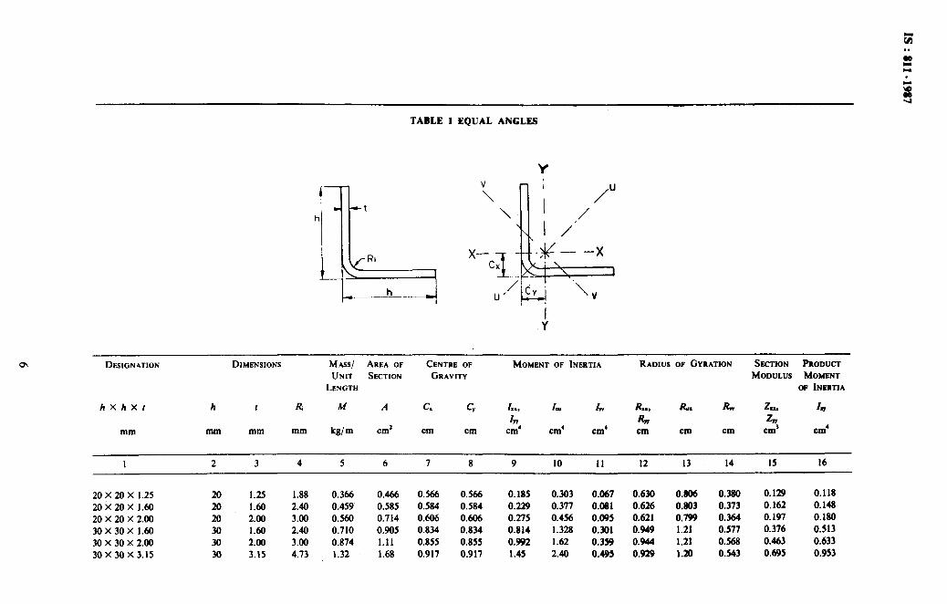
TABLE 1 EQUAL ANGLES
Y
;
/
\ I ‘” I /./
x- cx TT L -g---x
U’
/&. ‘\ L-J V
,! DESIGNATION
hXhXf
mm
DIMENSIONS MA.SS/ AREA OF CENTRE OF MOMENT OF IIW~~TIA RADIUS OF GYRATION SECTION Pnomm
UNIT SECTION GRAVITY MODULUS MOMENT
LENGTH OF INIWM
h t Ri M A G c, A., I, I, R-9 R. Rw z-. 4 47 RW 47
mm mm mm kg/m cm* cm cm cm’ cm’ cm’ cm cm cm cm’ cm’
I 2 3 4 5 6 7 8 9 IO II 12 13 14 I5 16
20 X 20 X 1.25 20 1.25 I.88 0.366 0.466 0.566 0.566 0.185 0.303 0.067 0.630 0.806 0.380 0.129 0.118 2oi2ox I.60 20 1.60 2.40 0.459 0.585 0.584 0.584 0.229 0.377 0.081 0.626 0.803 0.373 0.162 0.148 20 x 20 x 2.00 20 2.00 3.00 0.560 0.714 o.HM 0.606 0.275 0.456 0.095 0.621 0.799 0.364 0.197 0.180 30 x 30 x I.60 30 I.60 2.40 0.710 0.905 0.834 0.834 0.814 1.328 0.301 0.949 1.21 0.577 0.376 0.513 30 x 30 x 2.00 30 2.00 3.00 0.874 I.11 0.855 0.855 0.992 1.62 0.359 0.944 1.21 0.568 0.463 0.633 30 x 30 x 3.15 3a 3.15 4.73 1.32 1.68 0.917 0.917 1.45 2.40 0.495 0.929 1.20 0.543 0.695 0.953

40 x 40 x 1.60 40X40X2.00
40 X 40 x 2.55 40 x 40 x 3.15
50 X 50 ,X 2.00
50 X 50 X 2.55
50 x 50 x 3.15
50 x 50 x 4.00
6OX60~2.00 60X.60X2.55 60 x 60 x 3.15
60 X 60 X 4.00 70 x 70 x 3.15 70 x 70 x 4.00
70 X 70 X 5.00 80 X 80 X 3.15
80 X 80 X 4.00
80 X 80 X 5.00 80 X 80 X 6.00
100 x 100 x 3.15 100x 100X4.00
100X 100x5.00
100X 100X6.00
40
z 40 50
50 50
50
60
60 60
60 70
70 70 80
80
80 80
100 100 100
IO0
1.60 2.40 0.962 1.22 I .08 2.00 3.00 I.19 I.51 I.11 2.55 3.82 1.49 1.90 I.13 3.15 4.73 I.81 2.31 I.17 2.00 3.00 I.50 I.91 1.36 2.55 3.82 1.89 2.41 1.38 3.15 4.73 2.30 2.94 I .42 4.00 6.00 2.87 3.66 1.46 2.00 3.00 I .82 2.31 1.60 2.55 3.82 2.29 2.92 1.63 3.15 4.73 2.80 3.57 I.66 4.00 6.00 3.50 4.46 I.71 3.15 4.73 3.29 4.20 1.92 4.00 6.00 4.13 5.26 I .96 5.00 7.50 5.07 6.46 2.01 3.15 4.73 3.79 4.83 2.16 4.00 6.00 4.75 6.06 2.21 5.00 7.50 5.86 7.46 2.26 6.00 9.00 6.93 8.83 2.32 3.15 4.73 4.78 6.09 2.66 4.00 6.00 6.01 7.66 2.71 5.00 7.50 7.43 9.46 2.76 6.00 9.00 8.81 II.2 2.82
I.08 I .98 3.21 0.747 1.27 1.62 I.10 2.43 3.95 0.902 I.27 1.62 I.13 3.02 4.93 I.10 1.26 I.61 1.17 3.62 5.95 1.28 I.25 1.62 1.36 4.83 7.84 1.82 I.589 2.02 1.38 6.04 9.83 2.24 1.58 2.02
I .42 7.28 II.9 2.65 I.58 2.02
1.46 8.95 14.7 3.17 I.56 2.01
1.60 8.46 13.7 3.22 I.91 2.43
I .63 10.6 17.2 3.98 1.90 2.43
1.66 12.8 20.9 4.75 1.90 2.42
I.71 15.9 26.0 5.74 1.90 2.42
1.92 20.7 33.6 7.74 2.22 2.83
I.96 25.7 41.9 9.43 2.21 2.82
2.01 31.2 51.2 II.2 2.20 2.82
2.16 31.2 50.6 II.8 2.54 3.24
2.21 38.8 63.3 14.4 2.53 3.23
2.26 47.4 77.5 17.3 2.52 3.22
2.32 55.5 91.2 19.8 2.50 3.22
2.66 61.9 100.0 23.6 3.19 4.06 2.71 77.3 125.0 29.2 3.18 4.05
2.76 94.8 154.0 35.2 3.17 4.01
2.82 III.0 182.0 40.8 3.15 4.03
0.781 0.679 1.23
0.772 0.839 1.53
0.760 I .05 I .95
0.746 1.28 2.33
0.976 I .33 3.01
0.964 1.67 3.80
0.950 2.03 4.63
0.932 2.53 5.78
I.18 J .92 5.24
I.17 2.43 6.62
1.15 2.96 8.09
I.14 3.70 10.1
1.36 4.07 12.9
1.34 5.09 16.2
1.32 6.26 20.0
1.56 5.35 19.4
I.54 6.71 24.4
1.52 8.26 30. I
I.50 9.77 35.7
I .97 8.14 38.2
1.95 10.6 48.2
1.93 13.1 59.6
I.91 15.5 70.8

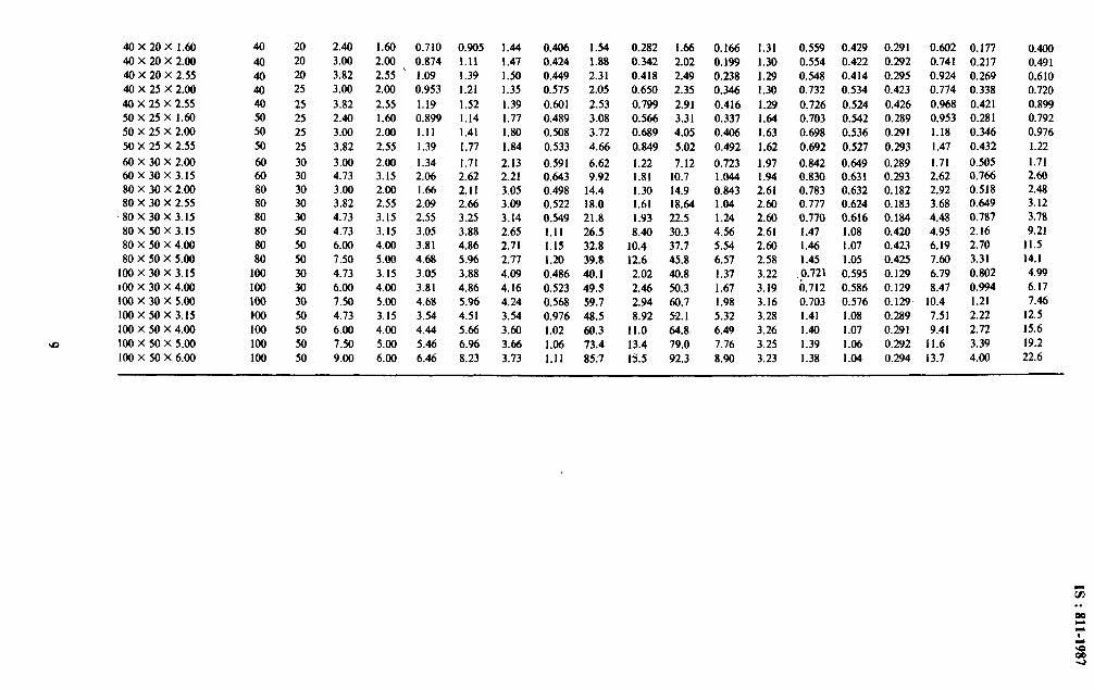
t; TABLE 2 UNEQUAL ANGLES . .
z
/U V
x_- - x -.--X
cx 8
U’ m-c” I- v V
00
DESIGNATION
hX bX I
mm
DIMENSIONS MASS/ AREA OF CENTRE OF MOMENT OF INERTIA RADIUS OF GYRATION ANGLE SECTION PRODUCT
UNx SECTION GRAVITY MODULUS MOMENT OF
LENGTH INERTIA
h b R 1 M A c. c, I,, In I, h. R.. & Rvv 2.. n, I a mm mm mm mm kg/m cm’ cm cm cm’ cm’ cm’ cm’ cm cm cm tan0 cm’ cm3 cm’
I 2 3 4 5 6 7 8 9 IO II I2 13 14 IS 16 17 18 19 20
20 X 15 X 1.25 20 I5 1.88 1.25 0.317 0.404 0.644 0.382 0.167 0.083 0.21 I 0.039 0.643 0.452 0.31 I 0.584 0.123 0.074 0.075
20X 15 x 1.60 20 I5 2.40 1.60 0.396 0.505 0.664 0.400 0.205 0.102 0.260 0.047 0.638 0.448 0.304 0.588 0.154 0.092 0.093
20 x 15 x 2.00 20 I5 3.00 2.00 0.482 0.614 0.688 0.420 0.245 0.121 0.312 0.054 0.632 0.444 0.296 0.592 0.187 0.112 0.113
30 X I5 X 1.25 30 I5 I .88 1.25 0.415 0.529 1.082 0.307 0.506 0.093 0.544 0.054 0.978 0.418 0.321 0.291 0.264 0.078 0.131
30 X I5 x 1.60 30 I5 2.40 1.60 0.522 0.665 1.106 0.323 0.628 0.114 0.676 0.066 0.972 0.415 0.315 0.293 0.332 0.097 0.165
30 X I5 x 2.00 30 I5 3.00 2.00 0.639 0.814 I.133 0.341 0.757 0.137 0.816 0.078 0.964 0.410 0.309 0.295 0.406 0.118 0.200
30 X 20 x 1.60 30 20 2.40 1.60 0.585 0.745 0.996 0.476 0.703 0.261 0.831 0.134 0.972 0.592 0 424 0.473 0.351 0.172 0.269
30 X 20 x 2.00 30 20 3.00 2.00 0.717 0.914 1.02 0.495 0.852 0.316 1.01 0.159 0.966 0.588 0.417 0.476 0.431 0.210 0.330
40 x 20 x 1.60
40 x 20 x 2.00
40 X 20 X 2.55 40 X 25 X 2.00
40 X 25 X 2.55
SO X 25 X 1.60 SO X 25 X 2.00
SO X 25 X 2.55
60 x 30 x 2.00 60 x 30 x 3.15 80 x 30 X 2.00 80 X 30 X 2.55
‘80 X 30 X 3.15
80 x so X 3.15 80 X SO X 4.00 80 X SO X 5.00
100 x 30 x 3.15
100X30X4.00 100x30X5.00
100 X so X 3.15
100 X so X 4.00 100x50x5.00
100 X SO X 6.00
40 20
40 20
40 20
40 25
40 2s so 25 SO 25 so 2s
60 30 60 30 80 30 80 30 80 30 80 SO 80 SO 80 SO
100 30 100 30
100 30 mo SO 100 SO
100 SO
100 SO
2.40 1.60 0.710 0.905 1.44 0.406 1.54 0.282 1.66 0.166 1.31 0.559 0.429 0.291 0.602 0.177 0.400 3.00 2.00 0.874 1.11 1.47 0.424 1.88 0.342 2.02 0.199 1.30 0.554 0.422 0.292 0.741 0.217 0.491 3.82 2.55 ’ 1.09 1.39 1.50 0.449 2.31 0.418 2.49 0.238 1.29 0.548 0.414 0.295 0.924 0.269 0.610 3.00 2.00 0.953 1.21 1.35 0.575 2.05 0.650 2.35 0.346 1.30 0.732 0.534 0.423 0.774 0.338 0.720
3.82 2.55 1.19 1.52 1.39 0.601 2.53 0.799 2.91 0.416 1.29 0.726 0.524 0.426 0.968 0.421 0.899
2.40 1.60 0.899 1.14 1.77 0.489 3.08 0.566 3.31 0.337 1.64 0.703 0.542 0.289 0.953 0.281 0.792
3.00 2.00 1.11 1.41 1.80 0.508 3.72 0.689 4.05 0.406 1.63 0.698 0.536 0.291 1.18 0.346 0.976
3.82 2.55 1.39 1.77 1.84 0.533 4.66 0.849 5.02 0.492 1.62 0.692 0.527 0.293 1.47 0.432 1.22
3.00 2.00 1.34 1.71 2.13 0.591 6.62 1.22 7.12 0.723 1.97 0.842 0.649 0.289 1.71 0.505 1.71
4.73 3.15 2.06 2.62 2.21 0.643 9.92 1.81 10.7 1.044 1.94 0.830 0.63 I 0.293 2.62 0.766 2.60
3.00 2.00 1.66 2.11 3.05 0.498 14.4 1.30 14.9 0.843 2.61 0.783 0.632 0.182 2.92 0.518 2.48
3.82 2.55 2.09 2.66 3.09 0.522 18.0 1.61 18.64 1.04 2.60 0.777 0.624 0.183 3.68 0.649 3.12
4.73 3.15 2.55 3.25 3.14 0.549 21.8 1.93 22.5 1.24 2.60 0.770 0.616 0.184 4.48 0.787 3.78
4.73 3.15 3.05 3.88 2.65 1.11 26.5 8.40 30.3 4.56 2.61 I .47 I .08 0.420 4.95 2.16 9.21
6.00 4.00 3.81 4.86 2.71 1.15 32.8 10.4 37.7 5.54 2.60 1.46 1.07 0.423 6.19 2.70 11.5
1.50 5.00 4.68 5.96 2.77 1.20 39.8 12.6 45.8 6.57 2.58 1.45 1 .os 0.425 7.60 3.31 14.1
4.73 3.15 3.05 3.88 4.09 0.486 40.1 2.02 40.8 1.37 3.22 0.721 0.595 0.129 6.79 0.802 4.99
6.00 4.00 3.81 4.86 4.16 0.523 49.5 2.46 50.3 1.67 3.19 il.712 0.586 0.129 8.47 0.994 6.17
7.M 5.00 4.68 5.96 4.24 0.568 59.7 2.94 60.7 1.98 3.16 0.703 0.576 0.129 10.4 1.21 7.46
4.73 3.15 3.54 4.51 3.54 0.976 48.5 8.92 52.1 5.32 3.28 I .41 1.08 0.289 7.51 2.22 12.5
6.00 4.00 4.44 5.66 3.60 I .02 60.3 11.0 64.8 6.49 3.26 1.40 1.07 0.291 9.41 2.72 15.6
7.50 5.00 5.46 6.96 3.66 1.06 73.4 13.4 79.0 7.76 3.25 1.39 1.06 0.292 11.6 3.39 19.2
9.00 6.00 6.46 8.23 3.73 1.11 85.7 15.5 92.3 8.90 3.23 1.38 1.04 0.294 13.7 4.00 22.6
.
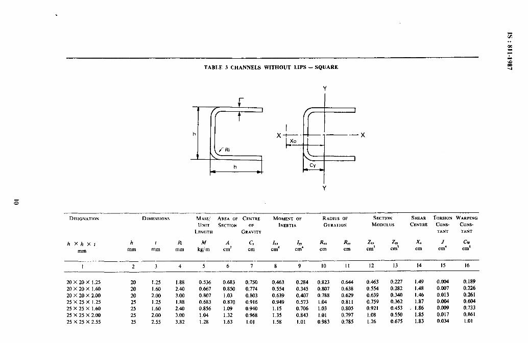
TABLE 3 CHANNELS WITHOUT LIPS - SQUARE
Y
h
Y
DISIGNATION
h XhXf
mm
DIMENSIONS MASS/ AREA OF CENTRE MOMENT OF RADIUS OF SECTION SHEAR TORSION WARPING
UNIT SECTION OF INERTIA GYRATION MODULUS CENTRE CONS- CONS-
LENGTH GRAVITY TANT TANT
h I R, M A cy I. I IYY RX. RYY 2,x ZW X0 J CW mm mm mm kg/m cm2 cm cm’ cm’ cm cm cm’ cm3 cm cm’ cm6
I 2 3 4 5 6 7 8 9 IO II 12 13 14 15 16
20X20X 1.25 20 1.25 1.88 0.536 0.683 0.750 0.463 0.284 0.823 0.644 0.463 0.227 1.49 0.004 0.189 20X20X 1.60 20 1.60 2.40 0.667 0.850 0.774 0.554 0.345 0.807 0.638 0.554 0.282 1.48 0.007 0,226 20 x 20 x 2.00 20 2.00 3.00 0.807 1.03 0.803 0.639 0.407 0.788 0.629 0.639 0.340 1.46 0.013 0.261 25X25X 1.25 25 1.25 1.88 0.683 0.870 0.916 0.949 0.573 1.04 0.811 0.759 0.362 1.87 0.004 0.604 25X25X1.60 25 1.60 2.40 0.856 1.09 0.940 1.15 0.706 1.03 0.805 0.921 0.453 , 1.86 0.009 0.733 25 X 25 X 2.00 25 2.00 3.00 1.04 1.32 0.968 1.35 0.843 1.01 0.797 1.08 0.550 1.85 0.017 0.861 25 X 25 X 2.55 25 2.55 3.82 i.28 1.63 1.01 1.58 1.01 0.983 0.785 1.26 0.675 1.83 0.034 1.01
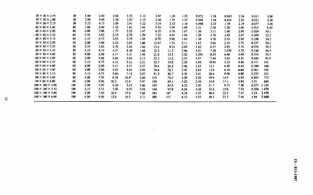
30X30X 1.63 30 x 30 x ;.OO 30 x 30 x 3.15
40X40X 1.60 40 X 40 X 2.00
1 40 X 40 X 2.55 40 x 40 x 3.15
50 x 50 x 2.00
50 X 50 X 2.55 50x50x3.15
50 x 50 x 4.00
60X60X2.00 60 x 60 x 3.15
60 X 60 X 4.00
80 X 80 X 2.00 80X80X3.15
80 X 80 X 5.00
80 X 80 X 6.00 100x 100x 2.00
100x 100x3.15
100x 100x 5.00
100X 100X6.00
30 1.60 2.40 1.04 1.33 1.12 2.07 1.26 1.25 0.972 1.38 0.663 2.24 0.011 1.90 30 2.00 3.00 1.28 1.63 1.13 2.46 1.51 1.23 0.964 1.64 0.811 2.23 0.021 2.26 30 3.15 4.73 1.89 2.41 1.22 3.33 2.13 1.18 0.940 2.22 1.19 2.19 0.077 3.06 40 1.60 2.40 1.42 1.81 1.44 5.16 3.09 1.69 1.31 2.58 1.20 3.00 0.015 8.42 40 2.00 3.00 1.75 2.23 1.47 6.22 3.76 1.67 1.30 3.11 1.48 2.99 0.029 10.1 40 2.55 3.82 2.18 2.78 1.50 7.52 4.61 1.64 1.29 3.76 1.85 2.97 0.059 12.3 40 3.15 4.73 2.63 3.35 1.54 8.76 5.46 1.62 1.28 4.38 2.22 2.96 0.108 14.3 50 2.00 3.00 2.22 2.83 1.80 12.67 7.U 2.11 1.63 5.04 2.35 3.75 0.037 32.1 50 2.55 3.82 2.78 3.54 1.84 15.4 9.33 2.09 1.62 6.17 2.95 3.74 0.076 39.3 50 3.15 4.73 3.37 4.30 1.88 18.2 11.2 2.06 1.61 7.28 3.570 3.72 0.140 46.3 50 4.00 6.00 4.17 5.31 1.94 21.6 13.5 2.02 1.594 8.65 4.40 3.69 0.276 55.1 Ml 2.00 3.00 2.69 3.43 2.13 22.3 13.2 2.55 1.97 7.44 3.42 4.51 0.045 81.9 60 3.15 4.73 4.12 5.2~ 2.21 32.7 19.8 2.50 1.94 10.91 5.23 4.48 0.171 121 60 4.00 6.00 5.11 6.51 2.27 39.4 24.2 2.46 1.93 13.1 6.49 4.45 0.340 144 80 2.00 3.00 3.63 4.63 2.80 54.6 32.1 3.43 2.63 13.6 6.16 6.04 0.061 356 80 3.15 4.73 5.60 7. i3 2.87 81.5 48.7 3.38 2.61 20.4 9.50 6.00 0.233 531 80 5.00 7.50 8.58 10.9, 3.00 119 72.6 3.29 2.58 29.6 14.5 5.95 0.893 773 80 6.00 9.00 10.2 12.9 3.07 136 84.1 3.25 2.56 33.9 17.1 5.92 I:51 884
100 2.00 3.00 4.58 5.83 3.46 109 63.4 4.32 3.30 21.7 9.71 7.56 0.077 1 110
100 3.15 4.73 7.08 9.02 3.54 164 97.0 4.26 3.28 32.8 15.0 7.53 0.296 1 670
100 5.00 7.50 10.9 13.9 3.66 243 147 4.18 3.25 48.6 23.2 7.47 1.14 2470
100 6.00 9.00 12.9 16.5 3.73 280 171 4.13 3.23 56.1 27.3 7.44 1.94 2860
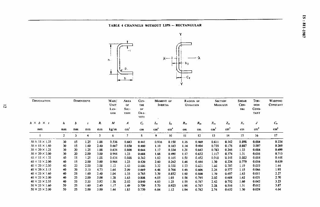
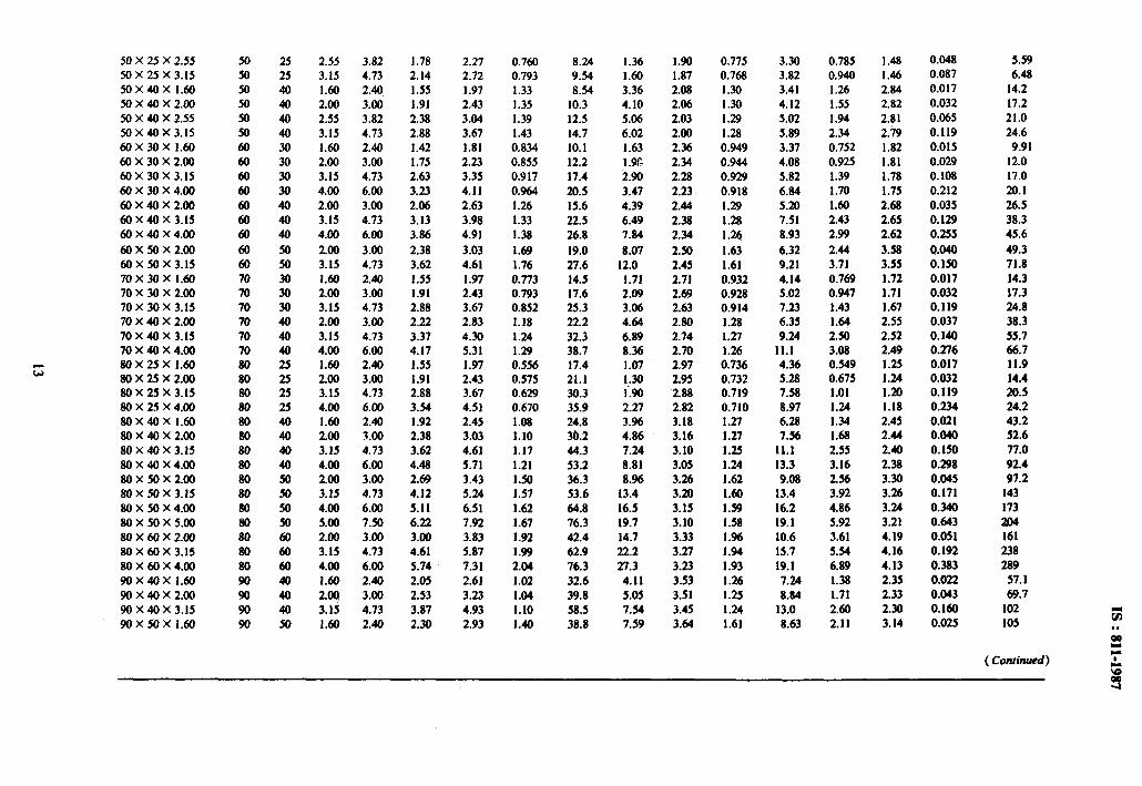
TABLE 4 CHANNELS WITHOUT LIPS - RECTANGULAR
DESIGNATION DIMENSIONS MASS/ AREA CEN- MOMENT OF RADIUS OF SECTION SHEAR TOR- WARPING
UNIT OF TRE INERTIA GYRATION MODULUS CEN- SlON CONSTANT
LEN- SEC- OF TRE CONS-
GTH TION GRA- TANT
VITY
hXbX f h b I R, M A cy .I I In R.. Rw xx z ZW X0 J cw
mm mm mm mm mm kg/m cm* cm cm’ cm’ cm cm cm’ cm’ cm cm’ cm”
I 2 3 4 5 6 7 8 9 10 II 12 13 14 15 16 17
30 x 15 x 1.25 30 15 1.25 1.88 0.536 0.683
30 x 15 x 1.60 30 15 1.60 2.40 0.667 0.850
30X20X 1.25 30 20 1.25 1.88 0.634 0.808 30 x 20 x 2.00 30 20 2.00 3.00 0.964 1.23
40 X 15 X 1.25 40 :5 1.25 1.88 0.634 0.808 40 X 15 x 2.00 40 15 2.00 3.00 0.964 1.23
40 x 20 x 2.00 40 20 2.00 3.00 1.12 1.43
40 x 20 x 3.15 40 2fl 3.15 4.73 1.64 2.09
40X25X1.60 40 25 1.60 2.40 1.04 1.33
40 X 25 X 2.00 40 25 2.00 3.00 1.28 1.63 40 X 25 X 2.55 40 25 2.55 3.82 1.58 2.02 50X25X 1.60 50 25 1.60 2.40 1.17 1.49
50 X 25 X 2.00 50 25 2.00 3.00 1.44 1.83
0.441 0.916 0.150 1.16 0.469 0.611 0.142 0.898 0.004 0.224
0.460 1.10 0.183 1.14 0.464 0.735 0.176 0.887 0.007 0.269
0.644 1.17 0.334 1.21 0.643 0.783 0.246 1.33 0.004 0.499
0.688 1.68 0.490 1.17 0.632 1.t17 0.374 1.31 0.016 0.713
0.382 1.82 0.165 1.50 0.452 0.910 0.148 0.802 0.004 0.448
0.420 2.643 0.242 1.46 0.444 1.30 0.224 0.779 0.016 0.639
0.606 3.32 0.550 1.53 0.62 t 1.66 0.395 1.19 0.019 1.44
0.669 4.48 0.768 1.46 0.606 2.24 0.577 1.15 0.066 1.95
0.785 3.39 0.852 1.60 0.800 1.70 0.497 1.63 0.011 2.27
0.808 4.05 1.03 1.58 0.795 2.02 0.608 1.62 0.021 2.70
0.840 4.83 1.25 1.55 0.187 2.42 0.752 1.60 0.042 3.23
0.709 5.70 0.923 1.96 0.787 2.28 0.516 1.51 a.012 3.87
0.730 6.84 1.12 1.94 0.782 2.74 0.632 1.50 0.024 4.64
50 X 25 X 2.55
50 X 25 X 3.15 50X40X 1.60
50X40X2.00
50 X 40 X 2.55 50x40x3.15
60 x 30 X 1.60
60 x 30 X 2.00
60 x 30 X 3.15
60X30X4.00
60x40x2.00
60 x 40 X 3.15
60X40X4.00
60X50X2.00 60x50x3.15
70X30X 1.60 70 x 30 x 2.00 70 x 30 x 3.15
70 x 40 x 2.00
70 X 40 X 3.15 70 x 40 x 4.00 80 X 25 X 1.60
80 X 25 X 2.00 a0 x 25 x 3.15
a0 x 25 X 4.00
80X40X 1.60 80x40x2.00
80x40x3.15
80x40X4.00
a0 x 50 X 2.00 80x50x3.15
80x50X4.00
80 x 50 X 5.00
80x60X2.00
80 x 60 X 3.15 80 x 60 x 4.00
90X40X 1.60 90x40x2.00
90 x 40 x 3.15
90X50X 1.60
50 25 2.55 3.82 1.78 2.27 0.760 a.24 1.36 1.90 0.775 3.30 0.785 1.48 0.048
50 25 3.15 4.73 2.14 2.72 0.793 9.54 1.60 1.87 0.768 3.82 0.940 1.46 0.087
50 40 1.60 2.40 1.55 1.97 1.33 8.54 3.36 2.08 1.30 3.41 1.26 2.84 0.017
50 40 2.00 3.00 1.91 2.43 1.35 10.3 4.10 2.06 1.30 4.12 1.55 2.82 0.032
50 40 2.55 3.82 2.38 3.04 1.39 12.5 5.06 2.03 1.29 5.02 1.94 2.81 0.065
50 40 3.15 4.73 2.88 3.67 1.43 14.7 6.02 2.00 1.28 5.89 2.34 2.79 0.119
60 30 1.60 2.40 1.42 1.81 0.834 10.1 1.63 2.36 0.949 3.37 0.752 1.82 0.015
60 30 2.00 3.00 1.75 2.23 0.855 12.2 1.w 2.34 0.944 4.08 0.925 1.81 0.029
60 30 3.15 4.73 2.63 3.35 0.917 17.4 2.90 2.28 0.929 5.82 1.39 1.78 0.108
60 30 4.00 6.00 3.23 4.11 0.964 20.5 3.47 2.23 0.918 6.84 1.70 1.75 0.212
60 40 2.00 3.00 2.06 2.63 1.26 15.6 4.39 2.44 1.29 5.20 1.60 2.68 0.035
60 40 3.15 4.73 3.13 3.98 1.33 22.5 6.49 2.38 1.28 7.51 2.43 2.65 0.129
60 40 4.00 6.00 3.86 4.91 1.38 26.8 7.84 2.34 1.26 8.93 2.99 2.62 0.255
60 50 2.00 3.00 2.38 3.03 1.69 19.0 8.07 2.w 1.63 6.32 2.44 3.58 0.040
60 50 3.15 4.73 3.62 4.61 1.76 27.6 12.0 2.45 1.61 9.21 3.71 3.55 0.150
70 30 1.60 2.40 1.55 1.97 0.773 14.5 1.71 2.71 0.932 4.14 0.769 1.72 0.017
70 30 2.00 3.00 1.91 2.43 0.793 17.6 2.09 2.69 0.928 5.02 0.947 1.71 0.032
70 30 3.15 4.73 2.88 3.67 0.852 25.3 3.06 2.63 0.914 7.23 1.43 1.67 0.119
70 40 2.00 3.00 2.22 2.83 1.18 22.2 4.64 2.80 1.28 6.35 1.64 2.55 0.037
70 40 3.15 4.73 3.37 4.30 1.24 32.3 6.89 2.74 1.27 9.24 2.50 2.52 0.140
70 40 4.00 6.00 4.17 5.31 1.29 38.7 a.36 2.70 1.26 11.1 3.08 2.49 0.276
a0 25 1.60 2.40 1.55 1.97 0.556 17.4 1.07 2.97 0.736 4.36 0.549 I.25 0.017
80 25 2.00 3.00 1.91 2.43 0.575 21.1 1,30 2.95 0.732 5.28 0.675 1.24 0.032
80 25 3.15 4.73 2.88 3.67 0.629 30.3 1.90 2.88 0.719 7.58 1.01 1.20 0.119
a0 25 4.00 6.00 3.54 4.51 0.670 35.9 2.27 2.82 0.710 8.97 1.24 1.18 0.234
a0 40 1.60 2.40 1.92 2.45 1.08 24.8 3.w 3.18 1‘27 6.28 1.34 2.45 0.021
80 40 2.00 3.00 2.38 3.03 1.10 30.2 4.86 3.16 1.27 1.56 1.68 2.44 0.040
80 40 3.15 4.73 3.62 4.61 1.17 44.3 7.24 3.10 1.25 11.1 2.55 2.40 0.150
a0 40 4.00 6.00 4.48 5.71 1.21 53.2 8.81 3.05 1.24 13.3 3.16 2.38 0.298
a0 50 2.00 3.00 2.69 3.43 1.50 36.3 8.96 3.26 1.62 9.08 2.56 3.30 0.045
80 50 3.15 4.73 4.12 5.24 1.57 53.6 13.4 3.20 1.60 13.4 3.92 3.26 0.171
a0 54l 4.00 6.00 5.11 6.51 1.62 64.8 16.5 3.15 1.59 16.2 4.86 3.24 0.340
80 50 5.00 7.50 6.22 7.92 1.67 76.3 19.7 3.10 1.58 19.1 5.92 3.21 0.643
80 60 2.00 3.00 3.00 3.83 1.92 42.4 14.7 3.33 1.96 10.6 3.61 4.19 0.051
a0 60 3.15 4.73 4.61 5.87 1.99 62.9 22.2 3.27 1.94 15.7 5.54 4.16 0.192
80 60 4.00 6.00 5.74 7.31 2.04 76.3 27.3 3.23 1.93 19.1 6.89 4.13 0.383
90 40 1.60 2.40 2.05 2.61 1.02 32.6 4.11 3.53 1.26 7.24 1.38 2.35 0.022
90 40 2.00 3.00 2.53 3.23 1.04 39.8 5.05 3.51 1.25 8.84 1.71 2.33 0.043
90 40 3.15 4.73 3.87 4.93 1.10 58.5 7.54 3.45 1.24 13.0 2.60 2.30 0.160
90 50 1.60 2.40 2.30 2.93 1.40 38.8 7.59 3.64 1.61 8.63 2.11 3.14 0.025
5.59
6.48
14.2
17.2
21.0
24.6
9.91
12.0
17.0
m.1
26.5
38.3 45.6
49.3
71.8
14.3 17.3 24.8
38.3
55.7 66.7 11.9 14.4 20.5 24.2
43.2 52.6
77.0
92.4
97.2 143
173
204 161
238 289
57.1
69.7
102
105 t; . .
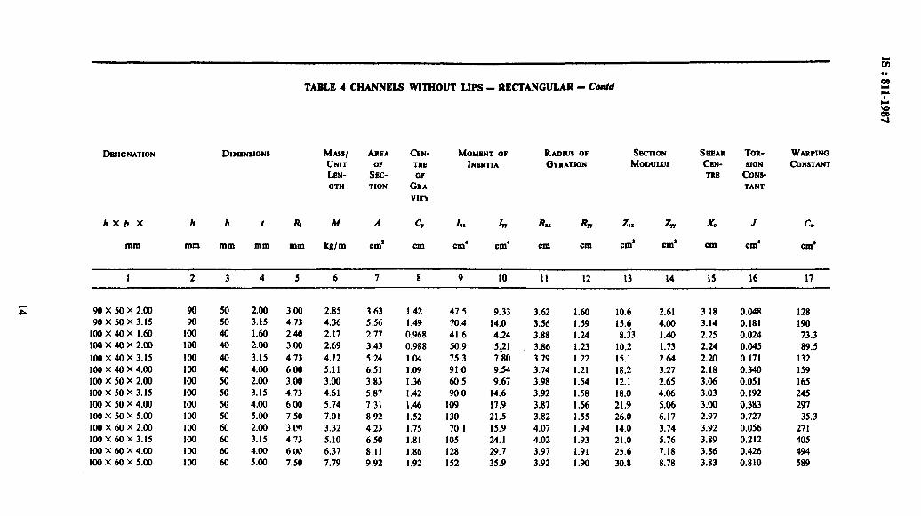
TABLE 4 CHANNELS WITHOUT LIPS - RECTANGULAR - Cd
MAW hEA CEN-
UNIT TRE
hN- iii- OP
OTH TION GRA- VITY
WIMENT 0P
INERTIA
RADIUS OF GYRATION
!hZTION
MODULUS
sHEAR Ton- WARPING
CEN- SION CONSTANT
TRE CONS-
TANT
hxb X h b I A M A c, I,, In R,, Rn A, z, XQ J c.
mm mm mm mm mm kg/m cm’ cm cm’ cm’ cm cm Cd Cm’ Cm Cm’ cm‘
I 2 3 4 5 6 7 8 9 10 II I2 13 14 IS I6 I7
90 x 50 x 2.00 90 90 x 50 x 3.15 90
100x40x 1.60 100 100x40x2.00 100 100 x 40 x 3.15 100 100x40x4.00 100 100x50x2.00 100 100 x 50 x 3.15 I00 lOcl x 50 x 4.00 IO0 100x50x5.00 lo0 loo x 60 x 2.00 I00 100x60x3.15 I00 100x60x4.00 100 100x60x5.00 100
50 50 40 40
40 40 50 50 50 50 60 60 60 60
2.00 3.00 2.85 3.63 3.15 4.13 4.36 5.56 1.60 2.40 2.17 2.17 2.00 3:Oo 2.69 3.43 3.15 4.13 4.12 5.24 4.00 6.00 5.11 6.51 2.00 3.00 3.im 3.83 3.15 4.73 4.61 5.87 4.00 6.00 5.74 7.31 5.00 7.50 7.01 8.92 2.00 3.e-l 3.32 4.23 3.15 4.73 5.10 6.50 4.00 6.W 6.37 8.11 5.00 7.50 7.19 9.92
1.42 47.5 9.33 3.62 1.60 10.6 2.61 3.18 0.048 128 I .49 70.4 14.0 3.56 1.59 15.5 4.00 3.14 0.181 190 0.968 41.6 4.24 3.88 1.24 8.33 1.40 2.25 0.024 73.3 0.988 50.9 5.21 3.86 1.23 10.2 1.73 2.24 0.045 89.5 1.04 75.3 7.80 3.79 1.22 15.1 2.64 2.20 0.171 132 1.09 91.0 9.54 3.74 1.21 18.2 3.27 2.18 0.340 I59 1.36 60.5 9.67 3.98 I.54 12.1 2.65 3.06 0.051 165 I .42 90.0 14.6 3.92 1.58 18.0 4.06 3.03 0.192 245 I.46 I09 17.9 3.87 I.56 21.9 5.06 3.00 0.383 297 1.52 130 21.5 3.82 1.55 26.0 6.17 2.91 0.721 35.3 1.75 70.1 15.9 4.07 1.94 14.0 3.74 3.92 0.056 271 1.81 105 24.1 4.02 1.93 21.0 5.76 3.89 0.212 405 1.86 128 29.7 3.97 I.91 25.6 7.18 3.86 0.426 494 1.92 152 35.9 3.92 1.90 30.8 8.78 3.83 0.810 589
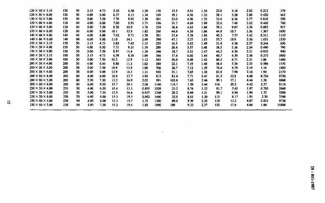
,120 x 50 x 3.15 120 50 3.15 4.73 5.10 6.50 1.29 138 15.5 4.61 1.54 23.0 4.18 2.82 0.212 379 120 x 50 x 4.00 120 50 4.00 6.00 6.37 8.11 1.34 169 19.1 4.56 1.53 28.1 5.20 2.80 0.426 462 120 X 50 x 5.00 120 50 5.00 7.50 7.79 9.92 i.39 201 23.0 4.50 1.52 33.6 6.36 2.77 0.810 550 120 X 60 x 4.00 120 60 4.00 6.00 7.00 8.91 1.71 196 31.7 4.69 1.89 32.6 7.40 3.62 0.468 766 120 x $0 x 5.00 120 60 5.00 7.50 8.58 10.9 1.76 234 38.4 4.63 1.88 39.1 9.07 3.59 0.893 917 120 X 60 X 6.00 120 60 6.00 9.00 10.1 12.9 1.82 269 44.6 4.58 1.86 44.9 10.7 3.56 1.507 1050 140x60x4.00 140 60 4.00 6.00 7.62 9.71 1.59 281 33.4 5.38 1.86 40.2 7.57 3.42 0.511 1110 140X60X6.00 140 60 6.00 9.00 11.0 14.1 I.69 390 47. I 5.27 1.83 55.7 10.9 3.36 1.651 1530 150 x 50 x 3.15 150 50 3.15 4.73 5.85 7.45 1.15 235 16.5 5.62 1.49 31.4 4.30 2.57 0.244 650 150X50X4.00 150 50 4.00 6.00 7.31 9.31 1.19 289 20.4 5.57 1.48 38.5 5.36 2.54 0.490 790 150X50x5.00 150 50 5.00 7.50 8.97 11.4 1.24 346 24.7 5.51 1.47 46.2 6.56 2.51 0.935 940 180 X 50 x 3.15 180 50 3.15 4.73 6.59 8.39 1.04 366 17.4 6.60 1.44 40.7 4.39 2.36 0.275 1000 180 X 50 X 5.00 180 50 5.00 7.50 10.2 12.9 1.12 543 26.0 6.48 1.42 60.3 6.71 2.31 1.06 1460 200X50X4.00 200 xl 4.00 6.00 8.88 11.3 1.02 584 22.1 7.19 1.40 58.4 5.54 2.22 0.596 1570 200X50X5.00 200 50 5.00 7.50 10.9 13.9 1.06 706 26.7 7.12 1.39 70.6 6.79 2.19 1.14 1880 200X50X6.00 200 50 6.00 9.00 12.9 16.5 1.11 818 31.1 7.05 1.38 81.8 7.98 2.16 1.94 2170
200X80X4.00 200 80 4.00 6.00 10.8 13.7 1.98 815 83.4 7.71 2.47 81.5 13.8 4.48 0.724 5730 200 X 80 X 5.00 200 80 5.00 7.50 13.3 16.9 2.02 991 102.0 7.65 2.46 99.1 17.1 4.44 1.39 6960 200X80X6.00 200 80 6.00 9.00 15.7 20.1 2.08 1160 119.7 7.59 2.44 116 20.2 4.42 2.37 8110 250X50X4.00 250 50 4.00 6.00 10.4 13.3 0.893 1020 23.2 8.76 1.32 81.7 5.65 1.97 0.703 2660 250X50X5.00 250 50 5.00 7.50 12.9 16.4 0.937 1240 28.2 8.69 1.31 99.1 6.94 1.94 1.35 3200 250X50X6.00 250 50 6.00 9.00 15.3. 19.5 0.982 1440 32.8 8.61 1.30 115 8.17 1.91 2.30 3700 250X80X4.00 250 80 4.00 6.00 12.3 15.7 1.75 1380 89.0 9.39 2.38 110 13.2 4.07 0.831 9730 250 X 80 X 5.00 250 80 5.00 7.50 15.2 19.4 1.80 1690 109 9.33 2.37 135 17.6 4.04 1.60 11800
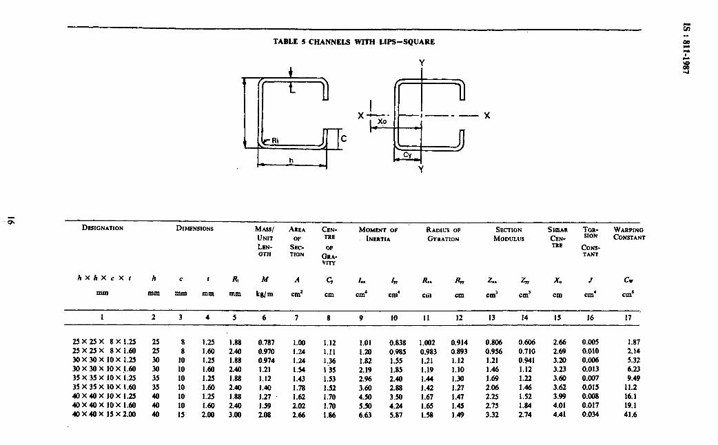
TABLE 5 CHANNELS WITH LIPS-SQUARE
DESIGNATION DIMENSIONS MAsSi AREA CeN- MOMENT OF RADIUS OF SECTION SHEAR TOR- WARPING
UNIT OF TRE INERTIA GYRATION MODULUS CeN- SlON CONSTANT
LEN- SEC- OF TRE CONS- GTH TION C&A- TANT
VIN
hxhxcxr h C t A M A C., I, Iv R.. R,, 2.. z, Xo J cw
maI mm mm mm mm kg/m cm’ cm cm’ cm’ CkiI Cm cm’ cm’ cm cm’ cm‘
1 2 3 4 5 6 7 8 9 10 II I2 13 14 15 16 17 ’
25X25X 8X1.25 25 8 1.25 1.88 0.787 1.00 1.12 1.01 0.838 1.002 0.914 0.806 0.606 2.66 25 X 25 X 8 X 1.60 25 8 1.60 2.40 0.970 1.24 1.11 1.20 0.985 0.983 0.893 0.956 0.710 2.69 30x30x10x1.25 30 10 1.25 1.88 0.974 1.24 1.36 1.82 1.55 1.21 1.12 1.21 0.941 3.20 30x30x10x_l.60 30 10 1.60 2.40 1.21 1.54 1’35 2.19 1.85 1.19 1.10 1.46 1.12 3.23 35 x35x 10x 1.25 35 10 1.25 1.88 1.12 1.43 1.53 2.96 2.40 1.44 1.30 1.69 1.22 3.60 35 X 35 x 10x 1.60 35 10 1.60 2.40 1.40 1.78 1.52 3.60 2.88 1.42 1.27 2.06 1.46 3.62 40X40x10x1.25 40 10 1.25 1.88 1.27 1.62 1.70 4.50 3.50 1.67 1.47 2.25 1.52 3.99 40x40x10x1.60 40 10
::: 2.40
iii 202 2:66
1 70 1:u
5.50 4.24 1.65 1.45 2.75 1.84 4.01 40X40X 15x2.00 40 15 3.00 6.63 5.87 1.58 1.49 3.32 2.74 4.41
0.005 1.87 0.010 2.14 0.0% 5.32 0.013 6.23 0.007 9.49 0.015 11.2 0.008 16.1 0.017 19.1 0.034 41.6

50X50X 10x 1.60 50 10 1.60 2.40 1.96 2.50 2.04 11.0 8.05 2.10 1.80 4.42 2.72 4.78 0.021 48.7 50 x 50 x 15 x 2.00 50 15 2.00 3.00 2.56 3.26 2.20 13.6 11.1 2.04 1.85 5.42 3.97 5.21 0.042 93.8 60X60X 15X2.00 60 15 2.00 3.00 3.03 3.86 2.55 24.0 18.6 2.50 2.20 8.01 5.40 5.99 0.050 192 60 X 60 X 15 X 2.55 60 15 2.55 3.82 3.76 4.80 2.54 29.2 22.4 2.47 2.16 9.73 6.49 6.02 0.102 226 60 X 60 x 20 x 3.15 60 20 3.15 4.73 4.77 6.08 2.70 34.7 29.3 2.39 2.20 11.6 8.88 6.46 0.196 395 80X80X 15X2.00 80 15 2.00 3.00 3.97 5.06 3.23 58.4 42.3 . 3.40 2.89 14.6 8.86 7.53 0.066 641 80 jc 80 X 20 X 3.15 80 20 3.15 4.73 6.25 7.97 3.39 86.9 67.0 3.30 2.90 21.7 14.54 8.02 0.258 1210 80 X 80 X 25 X 4.00 80 25 4.00 6.00 8.02 10.2 3.55 106 87.0 3.21 2.92 26.4 19.6 8.47 0.531 1940 80 X 80 X 25 X 5.00 80 25 5.00 7.50 9.69 12.3 3.54 123 101 3.16 2.86 30.8 22.6 8.55 0.995 2190
100X 100X 15X2.00 100 15 2.00 3.00 4.91 6.26 3.90 115 79.9 4.29 3.58 23.1 13.1 9.06 0.082 1720 100 X 100 x 20 x 3.15 100 20 3.15 4.73 7.74 9.86 4.07 174 127 4.21 3.59 34.9 21.5 9.55 0.321 3080 100X 100X25X4.00 100 25 4.00 6.00 9.91 12.6 4.24 215 166 4.12 3.62 43.0 28.7 10.0 0.659 4660 100X 100X25X5.00 100 25 5.00 7.50 12.0 15.3 4.27 255 194.9 4.07 3.56 50.9 33.6 10.1 1.24 5340
sj

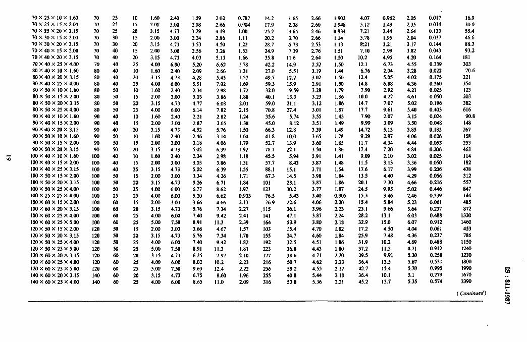
TABLE 6 CHANNELS WITH LIPS-RECTANGULAR G . .
2
Y c h
z
DESIGNATION DIMENSIONS M-1 AREA CENTRE MOMENT OF RADIUS OF SECTION &EAR TORSION WARPING
UNIT OF OF INERTIA GYRATION MODULUS CENTRE CONSTANT CONSTANT
LENGTH SECTION GRAVITY z hXbxcXt h b c I R M A c, II I 1, Rx Ryy ix z GY X0 J cw
mm mm mm mm mm mm kg/m cm* cm cm’ cm’ cm cm cm’ cm’ cm cm’ cm’
I 2 3 4 5 6 7 8 9 10 II 12 13 14 15 16 17 18
30 X 15 x 10 x 1.15 30 15 10 1.25 1.88 0.679 0.866 0.651 1.05 0.292 1.10 0.581 0.697 0.344 1.66 0.004 1.03 30 X 15 x 10 x 1.60 30 15 10 1.60 2.40 0.832 1.06 0.649 1.22 0.337 1.07 0.564 0.815 0.395 1.68 0.009 1.14 40 X 20 X 10 X 1.25 40 20 10 1.25 1.88 0.816 1.12 0.790 2.62 0.657 1.53 0.767 1.31 0.543 2.00 0.006 3.06 40X 20X 10x 1.60 40 20 10 1.60 2.40 1.08 1.38 0.781 3.14 0.713 1.51 0.748 1.57 0.637 2.01 0.011 3.47 50 X 25 X 10 X 1.25 50 25 10 1.25 1.88 1.07 1.37 0.924 5.23 1.22 1.96 0.946 2.09 0.776 2.33 0.007 7.59 50 X 25 X 10 X 1.60 50 25 10 1.60 2.40 1.33 1.70 0.920 6.36 1.46 1.93 0.926 2.54 0.923 2.33 0.014 8.78 50X25X15X2.00 50 25 15 2.00 3.00 1.17 2.26 1.05 7.19 2.08 1.86 0.960 3.12 1.43 2.67 0.029 17.8 SO X 40 X 10 X 1.25 50 40 10 1.25 1.88 1.37 1.74 1.58 7.46 3.81 2.07 1.48 2.98 1.57 3.78 0.009 23.5 50X40X 10x 1.60 50 40 10 1.60 2.40 1.71 2.18 1.58 9.17 4.62 2.05 1.46 3.67 1.91 3.80 0.018 28.0 50 X 40 x I5 x 2.00 50 40 15 2.00 3.00 2.24 2.86 1.73 11.2 6.45 1.98 1.50 4.50 2.85 4.20 0.037 55.1 so X 40 x 15 x 3.15 50 40 15 3.15 4.73 3.29 4.19 1.72 15.4 8.63 1.92 1.44 6.16 3.79 4.28 0.133 69.7 60 X 30 x 10 x 1.60 60 30 10 1.60 2.40 1.59 2.02 1.05 11.2 2.44 2.36 1.10 3.73 1.25 2.65 0.017 19.4 6oX3OXl5X2.00 60 30 15 2.00 3.00 2.08 2.66 1.18 13.9 3.48 2.29 1.14 4.64 1.92 3.00 0.034 36.1 60x30x20x3.15 60 30 20 3.15 4.73 3.29 4.19 1.30 19.4 5.34 2.15 1.13 6.46 3.14 3.35 0.133 72.6 60 X 30 x 20 x 4.00 60 30 20 4.00 6.00 3.94 5.02 1.29 21.9 5.92 2.09 1.09 7.31 3.47 3.40 0.254 76.4 60X40X 15X2.00 60 40 15 2.00 UJO 2.40 3.06 1.63 17.3 6.95 2.38 1.51 5.76 2.93 4.00 0.040 12.2 60 X 40 x 20 x 3.15 60 40 20 3.15 4.73 3.78 4.82 1.76 24.5 10.8 2.26 1.50 8.16 4.83 4.40 0.154 148 60X40X20X4.00 60 40 20 4.00 6.00 4.57 5.82 1.75 28.20 12.3 2.20 1.45 9.40 5.46 4.46 0.296 162
70X25X 10x 1.60 70 25 7OX25XlSX2.QO 70 25 70X45X20X3.15 70 25 70X30X 15x2.00 70 30 70 X 30 x 20 x 3.15 70 30 70X40X 15x2.00 70 40 70 X 40 x 20 x 3.15 70 40 70 X 40 X 25 X 4.00 70 40 80 X 40 x IO X 1.60 80 40 80 X 40 X 20 X 3.15 80 40 80 X 40 X 25 X 4.00 80 40 80 X 50 X 10 X 1.60 80 50 80 X 50 X 15 X 2.00 80 50 80X50X20x3.15 80 50 80 X 50 X 25 X 4.00 80 50 90X40X 10x 1.60 90 40 90X40X 15X2.00 90 40 90X40X20x3.15 90 40 90 x 50 x 10 x 1.60 90 50 90X50X 15X2.00 90 50 90 X 50 X 20 X 3.15 90 50
z 100X40X 10x 1.60 100 40 100X40X 15X2.00 100 40 100X40X25X3.15 100 40 100 X 50 X 15 X 2.00 100 50 100 X 50 X 20 X 3.15 100 50 100X50X25X4.00 100 50 100 X 25 X 25 X 4.00 100 25 100X60X lSX2.00 100 60 100x60x20x3.15 100 60 100X60X25X4.00 100 60 100X60X25X5.00 100 60 l2OX5OXl5X2.00 120 50 120x50x2Qx3.15 120 50 120X50X25X4.00 120 50 l2OX5OX25X5.00 120 50 120 x 60 x 20 x 3.15 120 60 1200606025X4.00 120 60 120X60X25X5.00 120 60 140 x 60 x 20 x 3.15 140 60 140X60X25X4.00 140 60
10 1.60 2.40 1.59 2.02 0.787 14.2 1.65 2.66 1.903 4.07 0.962 2.05 0.017
I5 2.00 3.00 2.08 2.66 0.904 17.9 2.38 2.60 1.948 5.12 1.49 2.35 0.034
20 3.15 4.73 3.29 4.19 1.00 25.2 3.65 2.46 0.934 7.21 2.44 2.64 0.133
15 2.00 3.00 2.24 2.86 I.11 20.2 3.70 2.66 1.14 5.78 1.95 2.84 0.037
20 3.15 4.73 3.53 4.50 1.22 28.7 5.73 2.53 1.13 8T21 3.21 3.17 0.144
I5 2.00 3.00 2.56 3.26 1.53 24.9 7.39 2.76’ 1.51 7.10 2.99 3.82 0.043
20 3.15 4.73 4.03 5.13 1.66 35.8 11.6 2.64 1.50 10.2 4.95 4.20 0.164
25 4.00 6.00 5.20 6.62 1.78 42.2 14.9 2.52 1.50 12.1 6.73 4.55 0.339
10 1.60 2.40 2.09 2.66 1.31 27.0 5.51 3.19 1.44 6.76 2.04 3.28 0.022
20 3.15 4.73 4.28 5.45 1.57 49.7 12.2 3.02 1.50 12.4 5.05 4.02 0.175
25 4.00 6.00 5.51 7.02 1.69 59.3 15.9 2.91 1.50 14.8 6.88 4.36 0.360 10 1.60 2.40 2.34 2.98 I .72 32.0 9.59 3.28 1.79 7.99 2.92 4.21 0.025
I5 2.00 3.00 3.03 3.86 1.88 40.1 13.3 3.23 1.86 10.0 4.21 4.61 0.050
20 3.15 4.73 4.77 6.08 2.01 59.0 21.1 3.12 1.86 14.7 7.07 5.02 0.1%
25 4.00 6.00 6.14 7.82 2.15 70.8 27.4 3.01 1.87 17.7 9.61 5.40 0.403
10 1.60 2.40 2.21 2.82 1.24 35.6 5.74 3.55 1.43 7.90 2.07 3.15 0.024
15 2.00 3.00 2.87 3.65 1.38 45.0 8.12 3.51 1.49 9.99 3.09 3.50 0.048
20 3.15 4.73 4.52 5.76 1.50 66.3 12.8 3.39 1.49 14.72 5.13 3.85 0.185
IO 1.60 2.40 2.46 3.14 1.64 41.8 10.0 3.65 1.78 9.29 2.91 4.06 0.026
I5 2.00 3.00 3.18 4.06 1.79 52.7 13.9 3.60 1.85 11.7 4.34 4.44 0.053
20 3.15 4.73 5.02 6.39 I .92 78.1 22.1 3.50 1.86 17.4 7.20 4.84 0.206
10 1.60 2.40 2.34 2.98 1.18 45.5 5.94 3.91 1.41 9.09 2.10 3.02 0.025
I5 2.00 3.00 3.03 3.86 1.31 57.7 8.43 3.87 1.48 11.5 3.13 3.36 0.050
25 3.15 4.73 5.02 6.39 1.55 88.1 15.1 3.71 1.54 17.6 6.17 3.99 0.206
15 2.00 3.00 3.34 4.26 1.71 67.3 14.5 3.98 1.84 13.5 4.40 4.29 0.056
20 3.15 4.73 5.26 6.71 I.84 101 23.1 3.87 1.86 m.l 7.30 4.66 0.216
25 4.00 6.00 6.77 8.62 1.97 123 30.2 3.77 1.87 24.5 9.95 5.02 0.446
25 4.00 6.00 5.20 6.62 0.933 76.5 5.43 3.40 0.905 15.3 3.46 2.46 0.339
I5 2.00 3.00 3.66 4.66 2.13 76.9 22.6 4.06 220 15.4 5.84 5.23 0.061
20 3.15 4.73 5.76 7.34 2.27 115 36.1 3.96 2.23 23.1 9.66 5.64 0.237
25 4.00 6.00 7.40 9.42 2.41 141 47.1 3.81 2.24 28.2 13.1 6.03 0.488
25 5.00 7.50 8.91 11.3 2.39 164 53.9 3.80 218 32.9 15.0 6.07 0.912
I5 2.00 3.00 3.66 4.67 1.57 103 15.4 4.70 1.82 17.2 4.50 4.04 0.061
20 3.15 4.73 5.76 7.34 1.70 155 24.7 4.60 1.84 25.9 7.48 4.36 0.237
25 4.00 6.00 7.40 9.42 1.82 192 32.5 4.51 1.86 31.9 10.2 4.69 0.488
25 5.00 7.50 8.91 11.3 1.81 223 36.8 4.43 1.80 37.2 11.5 4.71 0.912
20 3.15 4.73 6.25 7.97 2.10 177 38.6 4.71 2.m 29.5 9.91 5.30 0.258
25 4.00 6.00 8.02 10.2 2.23 216 50.7 4.62 2.23 36.4 13.5 5.61 0.531
25 5.00 7.50 9.68 12.4 2.22 256 58.2 4.55 2.17 42.7 15.4 5.70 0.995
20 3.15 4.73 6.75 8.60 1.96 255 40.8 5.44 2.18 36.4 10.1 5.1 0.279
25 4.00 6.00 8.65 11.0 2.09 316 53.8 5.36 2.21 45.2 13.7 5.35 0.574
16.9 30.0 55.4 46.6 88.3 93.2
181 303
70.6 221 354 123 203 382 616
90.8 148 267 158 253 463 114 182 438 312 557 847 144 485 872
1330 1460 453 786
1150 1240 1230 1800 1990 1670
t; . .
2390 s CI
(Continued) I G
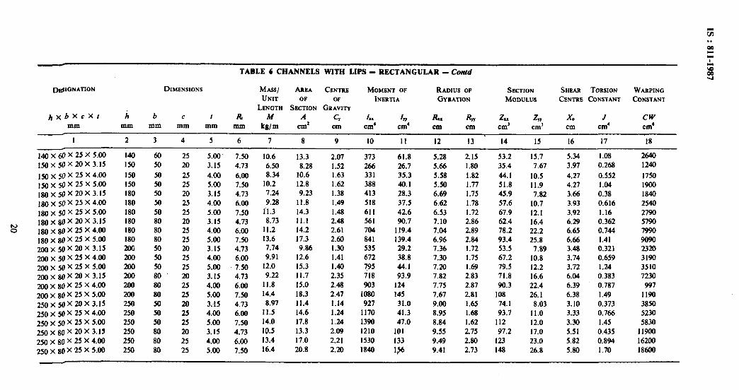
TABLE 6 CHANNELS WITH LIPS - RECTANGULAR - Contd
D@3NATION DIMENSIONS Mm AImA CENTRE MOMENT 0F RADIUS OF SEcTION SHEAR TORSION WARPING UNIT OF OF INERTIA GYRATION MODULLJS CENT~E CONSTANT CONSTANT
j#xbXcXt h
LENGTH SECTION GRAVITY b c I Rc M A CY 1, 47 Rx R, Z. z, x0 J CW
mm mm mm mm mm mm kg/m cm2 cm cm’ cm’ cm cm cm’ cm’ cm cm’ cm”
I 2 3 4 5 6 7 8 9 10 11 I2 13 14 15 16 17 18
l4oX6OX25X5.00 150 X 50 X 20 X 3.15
150 X 50 X 25 X 4.00 150 X 50 X 25 X 5.00 180X50X20X3.15 180X50X25X4.00 180 X 50 X 25 X 5.00 180X80X20X3.15 180 X 80 X 25 X 4.00 180 X 80 X 25 X 5.00 200 X 50 x 20 x 3.15 200 X 50 X 25 X 4.00 u)o X 50 X 25 X 5.00 2OOX8OXmX3.15 200 X 80 X 25 X 4.00 200 X 80 X 25 X 5.00 250X50X20X3.15 250 X 50 X 25 X 4.00 250 X 50 X 25 X 5.00 250X80X20X3.15
250 X 80 X 25 X 4.00 250X80X25X5.00
140 60 25 5.00 7.50 10.6 13.3 2.07 373 61.8 5.28 2.15 53.2 15.7 5.34 1.08 2640 I50 50 20 3.15 4.73 6.50 8.28 1.52 266 26.7 5.66 1.80 35.4 7.67 3.97 0.268 1240 150 50 25 4.00 6.00 8.34 10.6 1.63 331 35.3 5.58 1.82 44.1 10.5 4.27 0.552 1750 I50 50 25 5.00 7.50 10.2 12.8 1.62 388 40.1 5.50 1.77 51.8 11.9 4.27 1.04 1900 180 50 20 3.15 4.73 7.24 9.23 1.38 413 28.3 6.69 1.75 45.9 7.82 3.66 0.38 1840 180 50 25 4.00 6.00 9.28 11.8 I .49 518 37.5 6.62 1.78 57.6 10.7 3.93 0.616 2540 180 50 25 5.00 7.50 1’1.3 14.3 1.48 611 42.6 6.53 1.72 67.9 12.1 3.92 1.16 2790 180 80 20 3.15. 4.73 8.73 11.1 2.48 561 90.7 7.10 2.86 62.4 16.4 6.29 0.362 5790 180 80 25 4.00 6.00 11.2 14.2 2.61 704 119.4 7.04 2.89 78.2 22.2 6.65 0.744 7990 180 80 25 5.00 7.50 13.6 17.3 2.60 841 139.4 6.96 2.84 93.4 25.8 6.66 1.41 9090 200 50 m 3.15 4.73 7.74 9.86 1.30 535 29.2 7.36 1.72 53.5 7.89 3.48 0.321 23m 200 50 25 4.00 6.00 9.91 12.6 1.41 672 38.8 7.30 1.75 67.2 10.8 3.74 0.659 3190 200 50 25 5.00 7.50 12.0 15.3 1.40 795 44.1 7.20 1.69 79.5 12.2 3.72 1.24 3510 200 80 20 3.15 4.73 9.22 11.7 2.35 718 93.9 7.82 2.83 71.8 16.6 6.04 0.383 7230 200 80 25 4.00 6.00 11.8 15.0 2.48 903 124 7.75 2.87 90.3 22.4 6.39 0.787 997 200 80 25 5.00 7.50 14.4 18.3 2.47 1080 145 7.67 2.81 IO8 26. I 6.38 1.49 1190 250 50 m 3.15 4.73 8.97 11.4 1.14 927 31.0 9.00 1.65 74.1 8.03 3.10 0.373 3850 250 50 25 4.00 6.00 11.5 14.6 1.24 1170 41.3 8.95 1.68 93.7 11.0 3.33 0.766 5230 250 50 25 5.00 7.50 14.0 17.8 1.24 1390 47.0 8.84 1.62 112 12.0 3.30 I .45 5830 250 80 m 3.15 4.73 10.5 13.3 2.09 1210 101 9.55 2.75 97.2 17.0 5.51 0.435 11900 250 80 25 4.00 6.00 13.4 17.0 2.21 1530 133 9.49 2.80 123 23.0 5.82 0.894 16200 250 80 25 5.00 7.50 16.4 20.8 2.20 1840 1$6 9.41 2.73 148 26.8 5.80 1.70 18600
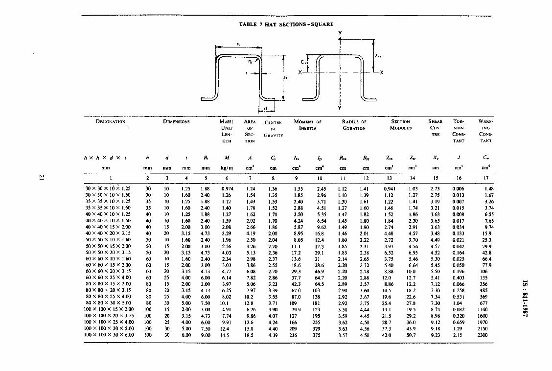
TABLE 7 HAT SECTIONS-SQUARE
b= h
Y
DESIGNATION DIMENSIONS MASS/ AREA C~NTWE MOMENT OF RADIUS OF SECTION SHEAR TOR- WARP-
UNIT OF Ok INERTIA GYRATION MODULUS CEN- SION ING
LEN- SEC- GHAVITY TRE CONS- CONS-
GTH TION TANT TANT
hXhXdX I h d I Ri M A cy *x I 47 RX, RW 2.. z, x0 J cw
mm mm mm mm mm kg/m cm* cm cm’ cm’ cm cm cm’ cm’ cm cm’ cm6
I 2 3 4 5 6 7 8 9 10 II 12 13 14 I5 16 17
30 x 30 x ib 2 1.25 30 10 1.25 1.88 0.974 1.24 1.36 1.55 2.45 1.12 1.41 0.941 1.03 2.73 0.006 1.48
30X30X 10X 1.60 30 10 1.60 2.40 1.26 1.54 1.35 1.85 2.96 1.10 1.39 1.12 1.27 2.75 0.013 1.67 35 X 35 X IO X 1.25 35 10 1.25 1.88 1.12 1.43 1.53 2.40 3.71 1.30 1.61 1.22 1.41 3.19 0.007 3.26 35 x 35 x 10 x 1.60 35 10 1.60 2.40 1.40 1.78 1.52 2.88 4.5 I 1.27 1.60 1.46 1.74 3.21 0.015 3.74 40 X 40 X 10 X 1.25 40 10 1.25 1.88 1.27 1.62 I .70 3.50 5.35 1.47 1.82 1.52 1.86 3.63 0.008 6.55 40X40X 10x 1.60 40 10 1.60 2.40 1.59 2.02 1.70 4.24 6.54 1.45 1.80 1.84 2.30 3.65 0.017 7.65 40X40X ISX2.00 40 I5 2.00 3.00 2.08 2.66 1.86 5.87 9.62 1.49 1.90 2.74 2.91 3.63 0.034 9.74 40 X 40 X 20 X 3.15 40 20 3.15 4.73 3.29 4.19 2.00 8.95 16.8 1.46 2.01 4.48 4.57 3.48 0.133 15.9 50 X 50 X 10 X 1.60 50 10 1.60 2.40 1.96 2.50 2.04 8.05 12.4 1.80 2.22 2.72 3.70 4.49 0.021 25.3 50X50X 15X2.00 50 I5 2.00 3.00 2.56 3.26 2.20 11.1 17.3 1.85 2.31 3.97 4.56 4.57 0.042 29.9 50x50x20x3.15 50 20 3.15 4.73 4.03 5.13 2.36 17.2 29.1 1.83 2.38 6.52 6.95 4.52 0.164 42.8 60X60X 10X 1.60 60 10 1.60 2.40 2.34 2.98 2.37 13.6 21 2.14 2.65 3.75 5.46 5.30 0.025 66.4 60X60X 15X2.00 60 I5 2.00 3.00 3.03 3.86 2.55 18.6 28.6 2.20 2.72 5.40 6.64 5.45 0.050 77.9 60x60x20x3.15 60 20 3.15 4.73 4.77 6.08 2.70 29.3 46.9 2.20 2.78 8.88 10.0 5.50 0.196 106 60 X 60 X 25 X 4.00 60 25 4.00 6.00 6.14 7.82 2.86 37.7 64.7 2.20 2.88 12.0 12.7 5.41 0.403 135 80X80X 15X2.00 80 15 2.00 3.00 3.97 5.06 3.23 42.3 64.5 2.89 3.57 8.86 12.2 7.12 0.066 356 80 X 80 X 20 X 3.15 80 20 3.15 4.73 6.25 7.97 3.39 67.0 103 2.90 3.60 14.5 18.2 7.30 0.258 485 80 X 80 X 25 X 4.00 80 25 4.00 6.00 8.02 10.2 3.55 87.0 138 2.92 3.67 19.6 22.6 7.34 0.531 569 80 X 80 X 30 X 5.00 80 30 5.00 1.50 10.1 12.8 3.71 109 181 2.92 3.75 25.4 27.8 7.30 1.04 677
100X 100X 15X2.00 100 15 2.00 3.00 4.91 6.26 3.90 79.9 123 3.58 4.44 13.1 19.5 8.74 0.082 1140 100 X 100 X 20 X 3.15 100 20 3.15 4.73 7.74 9.86 4.07 127 195 3.59 4.45 21.5 29.2 8.98 0.320 16cKl 100X 100X25X4.00 100 25 4.00 6.00 9.91 12.6 4.24 166 255 3.62 4.50 28.7 36.0 9.12 0.659 1970 100X100X30X5.00 100 30 5.00 7.50 12.4 15.8 4.40 209 329 3.63 4.56 37.3 43.9 9.18 1.29 2150 100X 100X30X6.00 100 30 6.00 9.00 14.5 18.5 4.39 236 375 3.57 4.50 42.0 50.7 9.23 2.15 2300
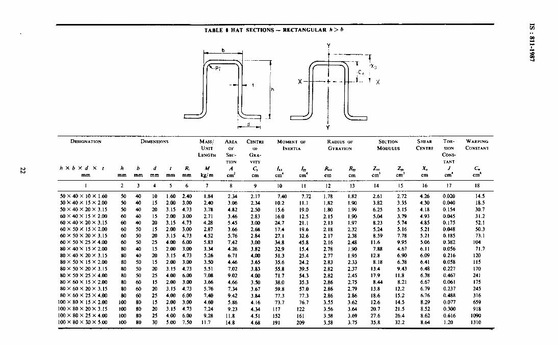
TABLE 8 HAT SECTIONS - RECTANGULAR h > 6
DESIGNATION DIMENSIONS MASS/ AREA CENTRE MOMENT 0~ RADIUS OF SECTION SHEAR TOR- WARPING
UNIT OF OF INERTIA GYRATION MODULUS CENTRE SION CONSTANT
LENGTH SEC- GRA- CONS-
TION VITY TANT
k hXbXd X t h b d t R, M A c, ,I I IYY R.. RW 2.x z, x0 J cw
mm mm mm mm mm mm kg/m cm’ cm cm’ cm’ cm cm cm’ cm’ cm cm’ cm6
I 2 3 4
50 x 40 x 10 x 1350 50 40 IO 50 k 40 x I5 x 2.00 5o 40 I5 50 X 40 X 20 X 3.15 50 40 m 6oX4oX 15x2.oo 60 40 I5 60x40x20x3.15 60 40 20 60X50X 15X2.00 60 50 15 60 X 50 X 20 X 3.15 60 50 20 60 X 50 X 25 X 4.00 60 50 25 8OX4OX ISX2.00 80 40 I5 80 x 40 x 20 x 3.15 80 40 20 80 X 50 X I5 X 2.00 80 50 I5 80X50X20X3.15 80 50 m 80 X 50 X 25 X 4.00 80 50 25 80X60X 15X2.00 80 60 I5 80X60X20X3.15 80 60 20 80 X 60 X 25 X 4.00 ao 60 25
100 X 80 X 15 X 2.00 loo 80 I5 loo X 80 X 20 X 3.15 100 80 m loo X 80 X 25 X 4.00 loo 80 25 lOOX8OX3OX5.OO loo 80 30
5 6 7 8 9 10 II 12 13 14 I5 I6
1.60 2.40 1.84 2.34 2.17 7.40 7.72 1.78 I.82 2.61 2.72 4.26 2.00 3.00 2.40 3.06 2.34 10.2 11.1 1.82 I.90 3.82 3.35 4.30 3.15 4.73 3.78 4.82 2.50 15.6 19.0 I.80 1.99 6.25 5.15 4. I8 2.00 3.00 2.71 3.46 2.83 16.0 12.5 2.15 I.90 5.04 3.79 4.93 3.15 4.73 4.28 5.45 3.00 24.7 21.1 2.13 I .97 8.23 5.74 4.85 2.00 3.00 2.87 3.66 2.68 17.4 19.6 2.18 2.32 5.24 5.16 5.21 3.15 4.73 4.52 5.76 2.84 27. I 32.6 2.17 2.38 a.59 7.78 5.21 4.00 6.00 5.83 7.42 3.00 34.8 45.8 2.16 2.48 11.6 9.95 5.06 2.00 3.00 3.34 4.26 3.82 32.9 15.4 2.78 I.90 7.88 4.67 6.11 3.15 4.73 5.26 6.71 4.00 51.3 25.4 2.77 I .95 12.8 6.90 6.09 2.00 3.00 3.50 4.46 3.65 35.6 24.2 2.83 2.33 8.18 6.38 6.41 3.15 4.73 5.51 7.02 3.83 55.8 39.5 2.82 2.37 13.4 9.43 6.48 4.00 6.00 7.08 9.02 4.00 71.7 54.3 2.82 2.45 17.9 11.8 6.38 2.00 3.00 3.66 4.66 3.5o 38.0 35.3 2.86 2.75 8.44 a.21 6.67 3.15 4.73 5.76 7.34 3.67 59.8 57.0 2.86 2.79 13.8 12.2 6.79 4.00 6.00 7.40 9.42 3.84 77.3 17.3 2.86 2.86 18.6 15.2 6.76 2.00 3.00 4.60 5.86 4.16 73.1 76.7 3.55 3.62 12.6 14.5 8.29 3.15 4.73 7.24 9.23 4.34 117 122 3.56 3.64 20.7 21.5 8.52 4.00 6.00 9.28 11.8 4.51 I52 I61 3.58 3.69 27.6 26.4 8.62 5.00 7.50 11.7 14.8 4.68 191 209 3.58 3.75 35.8 32.2 8.64
17 I8
0.020 14.5 0.040 18.5 0.154 30.7 0.045 31.2 0.175 52.1 0.048 50.3 0.185 73.1 0.382 104 0.056 71.7 0.216 I20 0.058 115 0.227 170 0.467 241 0.061 175 0.237 245 0.488 316 0.077 659 0.300 918 0.616 1090 1.20 1310

TABLE 9 HAT SECTIONS - RECTANGULAR b> L
DESIGNATION DIMENSIONS MASS/ AREA CENTRE MOMENT OF RADIUS OF SECTION SHEAR TORSION WARPING
UNIT OF OF INERTIA GYRATION MODULUS CENTRE CONSTANT CONSTANT
LENGTH SECTION GRAVITY
hXbXd x I h b d I Ri M A G I 47 RX. R, 2, z, Xo J cw mm mm mm mm mm mm Wm cm* cm 2 cm’ cm cm cm’ cm’ cm cm’ cm6
I 2 3 4 5 6 7 8 9 IO II I2 13 14 I5 I6 I7 I8
30X 50x IO x I.25 30 50 IO I.25 1.88 I.17 I .49 I.14 1.90 7.05 I.13 2.17 I .02 2.09 3.16 0.008 5.30 30x50x10X1.60 30 50 10 1.60 2.40 I.46 1.86 I.13 2.28 8.61 I.11 2.15 1.22 2.58 3.18 0.016 6. I4
40x50x10X1.25 40 50 IO I.25 1.88 1.37 1.74 I.58 3.81 8.53 I.48 2.21 1.57 2.53 3.84 0.009 II.5
40X50X IOX 1.60 40 50 IO I.60 2.40 I.71 2.18 1.58 4.62 10.5 I.46 2. I9 I.91 3.14 3.86 0.018 13.6
40X 60X I5 X 2.00 40 60 I5 2.00 3.00 2.40 3.06 1.63 6.95 21.8 I.51 2.67 2.93 5.08 4. IO 0.040 25.2 40X60X20X3.15 40 60 20 3.15 4.13 3.78 4.82 I .76 10.8 36.7 I.50 2.76 4.83 7.83 4.04 0. I54 32.4

TABLE 10 LIPPED ZED SECTIONS - EQUAL FLANGES
Y
h -+1
DESIGNATION MASS/ AREA MOMENT OF INERTIA RAD- ANGLE SECTION MODULUS PRO- TOR- WARP-
DIMENSIONS UNIT OF IUS OF DUCT SION ING
LEN- SEC- GYRA- MOM- CONS- CONS-
GTH TION TION ENT TANT TANT
OF IN-
ERTIA
hXb X t M A I In I I, kg/m cm* cG4 cm’ ci4 cm’
Ah-R, ZX, Z, ZtU ZVV I ‘I J cw mm cm tane cm’ cm’ cm’ cm’ cm’ cm’ cm6
I 2 3 4 5 6 I 8 9 10 II 12 13 14’ 15 16
80X40x20x1.60 2.34 2.98 29.1 14.2 38.1 4.61 1.24 0.627 7.27 3.63 7.31 2.02 15.3 0.025 80X 40x 20x 2.00 2.81 3.66 35.1 17.0 46.5 5.49 1.23 0.623 8.77 4.35 8.89 2.40 18.41 0.048 80X 40x 20x 2.30 3.25 4.14 39.2 18.8 52.0 6.10 1.21 0.619 9.81 4.84 10.0 2.66 20.5 0.072 80 X40X 20 X 2.55 3.56 4.54 42.5 20.2 56.2 6.56 1.20 0.616 10.6 5.22 10.9 2.86 22.2 0.096 80X40X 20X 3.15 4.28 5.45 49.1 23.2 65.3 7.51 1.17 0.610 12.4 6.03 12.8 3.28 25.7 0.175 85X40X20X l&l 2.40 3.06 33.6 14.2 43.0 4.80 1.25 0.5ii 7.90 3.63 7.87 2.08 16.5 0.026 85 X 40 X20X 2.00 2.95 3.76 40.5 17.0 51.8 5.73 1.24 0.568 9.54 4.35 9.58 2.48 19.8 0.049 85 X40X 20X 2.30 3.34 4.26 45.4 18.8 57.9 6.36 1.22 0.565 10.7 4.84 10.8 2.76 22.1 0.074
85 X 40 X20X 2.55 3.66 4.67 49.2 20.2 62.6 6.84 1.21 0.562 11.6 5.22 11.8 2.96 23.8 0.099 85 X 40 x20X 3.15 4.40 5.60 57.6 23.2 72.9 7.84 1.18 0.555 13.6 6.03 13.9 3.40 27.6 0.180 90X40X20X 1.60 2.46 3.14 38.5 14.2 47.7 4.99 1.26 0.526 8.55 3.63 8.47 2.15 17.6 0.026 90X40x20X2.00 3.03 3.86 46.5 17.0 51.5 5.95 1.24 0.521 10.3 4.35 10.3 2.56 21.1 0.059
172 206 230 248 288 I95 234 260 281 326 219 263
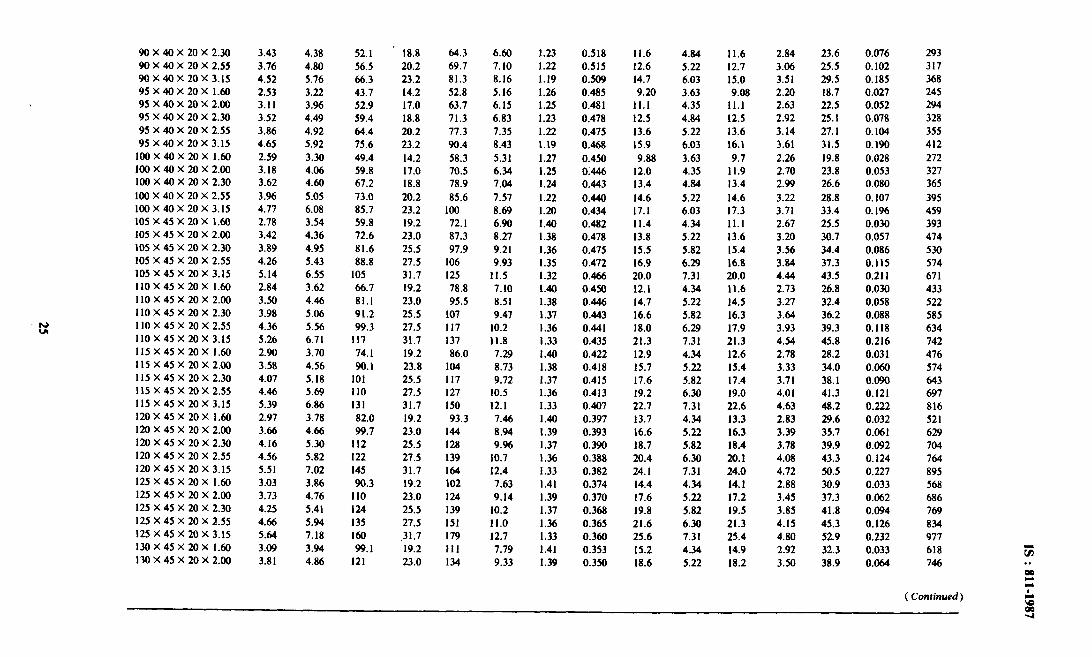
90x40x20x2.30 3.43 4.38 52.1 18.8 64.3 6.60 1.23 0.518 II.6 4.84 11.6 2.84 23.6 0.076 293
90 X 40 x 20 x 2.55 3.16 4.80 56.5 20.2 69.7 7.10 1.22 0.515 12.6 5.22 12.7 3.06 25.5 0.102 317
90 x 40 x 20 x 3.15 4.52 5.76 66.3 23.2 81.3 8.16 1.19 0.509 14.7 6.03 15.0 3.51 29.5 0.185 368
95X40X20X 1.60 2.53 3.22 43.7 14.2 52.8 5.16 1.26 0.485 9.20 3.63 9.08 2.20 18.7 0.027 245
95 x 40 x 20 x 2.00 3.11 3.96 52.9 17.0 63.7 6.15 1.25 0.481 II.1 4.35 II.1 2.63 22.5 0.052 294
95 x 40 x 20 x 2.30 3.52 4.49 59.4 18.8 71.3 6.83 1.23 0.478 12.5 4.84 12.5 2.92 25. I 0.078 328
95 X 40 X 20 X 2.55 3.86 4.92 64.4 20.2 77.3 7.35 1.22 0.475 13.6 5.22 13.6 3.14 27. I 0.104 355
95 x 40 x 20 x 3.15 4.65 5.92 75.6 23.2 90.4 8.43 I.19 0.468 15.9 6.03 16.1 3.61 31.5 0.190 412
100x40x20x I.60 2.59 3.30 49.4 14.2 58.3 5.31 1.27 0.450 9.88 3.63 9.7 2.26 19.8 0.028 272
100x40x20x2.00 3.18 4.06 59.8 17.0 70.5 6.34 1.25 0.446 12.0 4.35 11.9 2.70 23.8 0.053 327 100 X 40 X 20 X 2.30 3.62 4.60 67.2 18.8 78.9 7.04 1.24 0.443 13.4 4.84 13.4 2.99 26.6 0.080 365
100 X 40 X 20 X 2.55 3.96 5.05 73.0 20.2 85.6 1.57 1.22 0.440 14.6 5.22 14.6 3.22 28.8 0.107 395 100 x 40 x 20 x 3.15 4.77 6.08 85.7 23.2 100 8.69 I.20 0.434 17.1 6.03 17.3 3.71 33.4 0. I96 459 105X45X20X 1.60 2.78 3.54 59.8 19.2 72. I 6.90 1.40 0.482 11.4 4.34 II.1 2.67 25.5 0.030 393 I05 x 45 x 20 x 2.00 3.42 4.36 72.6 23.0 87.3 8.27 1.38 0.478 13.8 5.22 13.6 3.u) 30.7 0.057 474 I05 x 45 x 20 x 2.30 3.89 4.95 81.6 25.5 97.9 9.21 1.36 0.475 15.5 5.82 15.4 3.56 34.4 0.086 530 105 X 45 X 20 X 2.55 4.26 5.43 88.8 21.5 I06 9.93 1.35 0.412 16.9 6.29 16.8 3.84 37.3 0.115 574 105x45x20x3.15 5.14 6.55 105 31.7 I25 II.5 1.32 0.466 20.0 7.31 20.0 4.44 43.5 0.21 I 671 110X45X20X I.60 2.84 3.62 66.7 19.2 78.8 7.10 1.40 0.450 12.1 4.34 11.6 2.13 26.8 0.030 433 110X45X20X2.00 3.50 4.46 81.1 23.0 95.5 8.51 1.38 0.446 14.7 5.22 14.5 3.27 32.4 0.058 522 110X45X20X2.30 3.98 5.06 91.2 25.5 107 9.41 1.37 0.443 16.6 5.82 16.3 3.64 36.2 0.088 585 110X45X20X2.55 4.36 5.56 99.3 27.5 II7 10.2 1.36 0.441 18.0 6.29 17.9 3.93 39.3 0.118 634 I IO x 45 x 20 x 3.15 5.26 6.71 I17 31.7 137 II.8 1.33 0.435 21.3 7.31 21.3 4.54 45.8 0.216 742 llSX45X2OX 1.60 2.90 3.70 74.1 19.2 86.0 7.29 1.40 0.422 12.9 4.34 12.6 2.78 28.2 0.03 I 476 I I5 X 45 x 20 x 2.00 3.58 4.56 90.1 23.8 I04 8.73 1.38 0.418 15.7 5.22 15.4 3.33 34.0 0.060 574 115X45X20X2.30 4.07 5.18 101 25.5 I17 9.72 1.37 0.415 17.6 5.82 17.4 3.71 38. I 0.090 643 115X45X20X2.55 4.46 5.69 110 27.5 127 10.5 1.36 0.413 19.2 6.30 19.0 4.01 41.3 0.121 697 115X45x20x3.15 5.39 6.86 I31 31.7 150 12.1 1.33 0.407 22.7 7.31 22.6 4.63 48.2 0.222 816 120X45X20X 1.60 2.97 3.78 82.0 19.2 93.3 7.46 1.40 0.397 13.7 4.34 13.3 2.83 29.6 0.032 521 I20 x 45 x 20 x 2.00 3.66 4.66 99.7 23.0 144 8.94 1.39 0.393 16.6 5.22 16.3 3.39 35.7 0.061 629 120 X 45 x 20 x 2.30 4.16 5.30 II2 25.5 128 9.% I .37 0.390 18.7 5.82 18.4 3.78 39.9 0.092 704 120 X 45 X 20 X 2.55 4.56 5.82 122 27.5 139 10.7 1.36 0.388 20.4 6.30 20.1 4.08 43.3 0.124 764 120 X 45 x 20 x 3.15 5.51 7.02 I45 31.7 I64 12.4 1.33 0.382 24. I 7.31 24.0 4.72 50.5 0.227 895 125X45X20X I.60 3.03 3.86 90.3 19.2 102 7.63 1.41 0.374 14.4 4.34 14. I 2.88 30.9 0.033 568 125 X 45 X 20 X 2.00 3.73 4.76 110 23.0 124 9.14 1.39 0.370 17.6 5.22 17.2 3.45 37.3 0.062 686 125 X 45 X 20 X 2.30 4.25 5.41 124 25.5 139 10.2 1.37 0.368 19.8 5.82 19.5 3.85 41.8 0.094 769 I25 X 45 X 20 X 2.55 4.66 5.94 I35 27.5 I51 II.0 I.36 0.365 21.6 6.30 21.3 4.15 45.3 0.126 834 125 X 45 X 20 X 3.15 5.64 7.18 I60 ‘31.7 179 12.7 1.33 0.360 25.6 7.31 25.4 4.80 52.9 0.232 917 130X45X20X 1.60 3.09 3.94 99.1 19.2 t11 7.79 1.41 0.353 15.2 434 14.9 2.92 32.3 0.033 618 I30 x 45 x 20 x 2.00 3.81 4.86 121 23.0 134 9.33 1.39 0.350 18.6 5.22 18.2 3.50 38.9 0.064 746
( Continued)

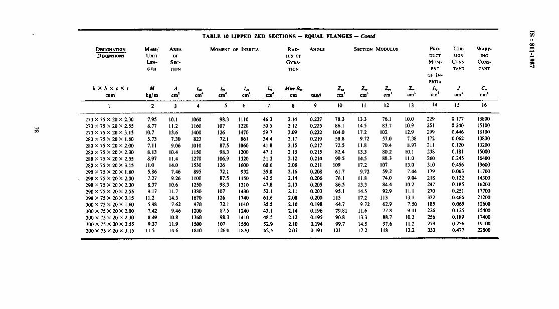
TABLE 10 LIPPED ZED SECTIONS - EQUAL FLANGES - Cod
DIWGNATION MASS/ AREA MOMENT OF INERTIA RAD- ANGLE SECTION MODULUS PRO- TOR- WARP-
DIMENSIONS UNIT OF IUS OF DUCT SION ING
LEN- SEC- GYRA- MOM- CONS- CONS-
GTH TION TION ENT TANT TANT
OF IN-
ERTIA
hXbX cXr M A Ir, UY I 1, Mitt-R, h, z, zu. L hr J cw mm kg/m cm2 cm’ cm’ cm’ cm tan0 cm’ cm’ cm’ cm’ cm’ cm’ cm”
I 2 3 4 5 6 7 8 9 10 I1 12 13 14 15 16
130X45X20X2.30 4.34 5.52 136 25.5 151 10.4 1.37 0.347 20.9 5.82 20.6 3.91 43.6 0.096 836 130 X 45 X 20 X 2.55 4.76 6.07 148 27.5 165 11.2 1.36 0.345 22.8 6.30 22.5 4.22 47.3 0.129 908 130 x 45 x 20 x 3.15 5.76 7.34 176 31.7 194 13.0 1.33 0.340 27.0 7.31 26.9 4.88 55.3 0.237 1060
140X60X20X 1.60 3.60 4.58 141 40.2 167 14.7 1.79 0.449 20.2 6.74 19.3 4.38 56.8 0.039 1400 140 X 60 X 20 x 2.00 4.44 5.66 173 48.5 203 17.8 1.77 0.445 24.7 8.22 23.7 5.28 69.0 0.074 1700 140 X 60 X 20 X 2.30 5.06 6.44 195 54.3 230 19.9 1.76 0.443 27.9 9.22 26.9 5.91 77.6 0.112 1910 140X60X20X2.55 5.57 7.09 213 58.8 251 21.6 1.74 0.441 30.5 10.0 29.5 6.41 84.5 0.151 2100 140 X 60 X 20 X 3.15 6.75 8.60 255 68.7 298 25.3 1.71 0.435 36.4 11.8 35.4 7.48 99.8 0.279 2500 150x60x20x 1.60 3.72 4.74 166 40.2 191 15.4 1.80 0.406 22.1 6.79 21.2 4.50 61.1 0.040 1600 I50X60x20x2.00 4.60 5.86 203 48.5 233 18.6 1.78 0.403 27.0 8.22 26.0 5.43 74.3 0.077 1970 150X60X20X2.30 5.24 6.68 229 54.3 263 20.8 1.76 0.401 30.6 9.22 29.5 6.08 83.6 0.116 2220 150 X 60 X 20 X 2.55 5.77 7.34 251 58.8 287 22.6 1.75 0.399 33.5 10.0 32.4 6.59 91.0 0.157 2420 150X60X20X3.15 7.00 8.91 300 68.7 342 26.4 1.72 0.394 40.0 11.8 38.9 7.70 108 0.289 2870 160X60X20X 1.60 3.85 4.90 193 40.2 217 16.0 1.80 0.370 24.1 6.79 23.1 4.60 65.5 0.042 1870 160X60X20X2.00 4.75 6.06 236 48.5 265 19.3 1.78 0.367 29.5 8.22 28.4 5.56 79.6 0.080 2270 160 X 60 X 20 X 2.30 5.42 6.90 267 54.3 300 21.6 1.77 0.365 33.4 9.22 32.2 6.22 89.6 0.120 2560 160 X 60 X 20 X 2.55 5.97 7.60 292 58.8 328 23.4 1.76 0.363 36.5 10.0 35.4 6.75 97.5 0.162 2790 160 X 60 X 20 X 3.15 7.24 9.23 349 68.7 391 27.4 1.72 0.358 43.7 11.8 42.6 7.90 115.3 0.300 3310 170X60X20X 1.60 3.97 5.06 222 40.2 246 16.5 1.81 0.339 26.1 6.79 25.1 4.70 69.8 0.043 2130 !7OX6OX2OX2.00 4.9 1 6.26 272 48.5 301 19.9 1.78 0.337 32.0 8.22 30.9 5.67 84.9 0.082 2600 170X60X20X2.30 5.60 7.14 308 54.3 340 22.3 1.77 0.334 36.3 9.22 35.1 6.36 95.5 0.124 2920 170 X 60 X 20 X 2.55 6.17 7.86 337 58.8 372 24.2 1.75 0.332 39.7 10.0 38.5 6.90 104 0.168 3190 170X60X20X3.15 7.49 9.54 404 68.7 444 28.4 1.72 0.328 47.5 11.8 46.3 8.07 123 0.310 3780 180X60X20x 1.60 4.10 5.22 254 40.2 277 17.0 1.80 0.313 28.2 6.79 27.2 4.78 74.2 0.044 2430 180X60X20X2.00 5.07 6.46 311 48.5 339 20.5 1.78 0.310 34.6 8.22 33.5 5.78 90.2 0.085 2940 180 X 60 X 20 X 2.30 5.78 7.36 353 54.3 384 23.0 1.77 0.308 39.2 9.22 38.0 6.48 102 0.128 3320 180 X 60 X 20 X 2.55 6.37 8.11 386 58.8 420 25.0 1.76 0.306 42.9 10.0 41.7 7.03 111 0.174 3620 180 X 60 X 20 X 3.15 7.74 9.86 463 68.7 502 29.3 1.72 0.302 51.4 11.8 50.3 8.24 131 0.321 4290 190 X 60 X 20 x 1.60 4.22 5.38 289 40.2 311 17.5 1.80 0.289 30.4 6.79 29.3 4.84 78.5 0.046 2720 190x60x20x2.00 5.22 6.67 354 48.5 381 21.1 1.78 0.287 37.3 8.22 36.1 5.88 95.5 0.088 3310
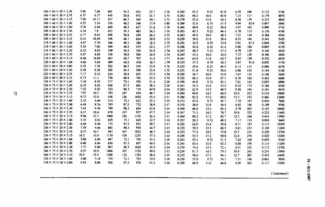
190X60X20X2.30 5.96 7.60 401 54.3 432 23.7 1.76 0.285 42.2 9.22 41.0 6.59 108 0.132 3740 190x 60x 20x 2.55 6.57 8.37 439 58.8 472 25.7 1.75 0.283 46.2 10.0 45.0 7.15 117 0.179 4070 190 x60x 20 x 3.15 7.98 10.17 527 68.7 565 30.1 1.72 0.279 55.4 11.8 54.3 8.38 139 0.331 4840 200x60x20x1.60 4.35 5.54 326 40.2 348 17.9 1.80 0.269 32.6 6.79 31.5 4.94 82.9 0.047 3040 200x60x20x2.00 5.38 6.86 400 48.5 427 21.6 1.78 0.266 40.0 8.22 38.8 5.97 101 0.090 3710 200 X 60 X 20 X 2.30 6.14 7.8 453 54.3 483 24.3 1.76 0.265 45.3 9.22 44.1 6.70 113 0.136 4180 200 x60x 20x 2.55 6.77 8.62 496 58.8 529 26.3 1.75 0.263 49.6 10.0 48.5 7.27 124 0.184 4560 200 X60X 20X 3.15 8.23 10.49 596 68.7 634 30.9 1.72 0.259 59.6 11.8 58.4 8.52 146 0.341 5420 210X60X20X 1.60 4.47 5.70 366 40.2 388 18.3 1.79 0.251 34.9 6.79 33.8 5.01 87.2 0.048 3390 210 X 60 x20x 2.00 5.54 7.06 449 48.5 475 22.1 1.77 0.248 42.8 8.22 41.6 6.06 106 0.093 4130 210 X 60 X20X 2.30 6.32 8.05 509 54.3 539 24.8 1.76 0.247 48.5 9.22 47.3 6.79 119 0.140 4650 210X 60X 20X 2.55 6.97 8.88 558 58.8 590 26.9 1.74 0.245 53.1 10.0 52.0 7.37 130 0.190 5080 210 X60X 20 X 3.15 8.48 10.80 667 68.7 707 31.6 1.71 0.241 63.8 11.8 62.7 8.65 154 0.352 6030 220X60X20X 1.60 4.60 5.86 409 40.2 430 18.7 1.79 0.235 37.2 6.79 36.1 5.07 91.6 0.050 3750 220 x60x 20x 2.00 5.70 7.26 502 48.5 528 22.6 1.76 0.232 45.6 8.22 44.5 6.13 III 0.096 4570 220X 60X 20X 2.30 6.50 8.28 569 54.3 598 25.4 1.75 0.231 51.8 9.22 50.6 6.88 125 0.145 5160 220 X60X 20 X 2.55 7.17 9.13 624 58.8 655 27.5 1.74 0.229 56.7 10.0 55.6 7.47 131 0.196 5620 220x 60x 20 x 3.15 8.73 11.1 750 68.8 786 32.3 1.70 0.226 68.1 11.8 67.1 8.76 162 0.362 6680 230X75X20X1.60 5.10 6.50 517 72.1 558 31.4 2.20 0.290 45.0 9.72 43.1 7.01 141 0.055 6990 230 X 75 X 20 X 2.00 6.32 8.06 636 87.5 686 38.1 2.18 0.287 55.3 11.8 53.2 8.52 172 0.106 8550 230 X 75 X 20X 2.30 7.23 9.20 723 98.3 778 42.9 2.16 0.285 62.9 13.3 60.5 9.58 194 0.161 9670 230X 75 X 20X 2.55 7.97 10.2 793 107 854 46.7 2.14 0.284 69.0 14.5 66.6 10.4 212 0.218 10600 230X 75 X20X 3.15 9.72 12.4 956 126 1030 55.2 2.11 0.280 83.2 17.2 80.6 12.3 253 0.404 12600 240X75X20X 1.60 5.23 6.66 512 72.1 612 32.1 2.19 0.272 47.6 9.72 45.7 7.10 147 0.056 7680 240x 75x 20x 2.00 6.48 8.26 703 87.5 752 38.9 2.17 0.270 58.6 11.8 56.5 8.62 180 0.109 9390 240X 75X 20X 2.30 7.41 9.44 799 98.3 854 43.8 2.16 0.269 66.6 13.3 64.3 9.70 203 0.165 10600 240X 75 X 20 X 2.55 8.17 10.4 878 107 937 47.7 2.14 0.267 73.1 14.5 70.7 10.6 222 0.223 11600 240 x 75 x20x 3.15 9.96 12.7 1060 126 1130 56.4 2.11 0.264 88.2 17.2 85.7 12.5 264 0.414 13900 250X75X20X 1.60 5.35 6.82 629 72.1 669 32.7 2.19 0.257 50.3 9.72 48.5 7.17 153 0.058 8400 250X 75X 20X 2.00 6.64 8.46 775 87.5 822 39.7 2.17 0.255 62.0 11.8 59.8 8.71 187 0.112 10300 250X 75X 20X 2.30 7.59 9.66 881 98.3 934 44.7 2.15 0.353 70.5 13.3 68.2 9.81 212 0.169 11600 250 X 75 X20X 2.55 8.37 10.7 967 107 1025 48.7 2.14 0.252 77.4 14.5 75.0 10.7 231 0.229 12700 250X75X20X3.15 10.2 13.0 1170 126 1235 57.5 2.10 0.249 93.3 17.2 90.8 12.6 276 0.428 15200 260X75X20X 1.60 5.98 6.98 697 72.1 729 33.3 2.18 0.243 53.1 9.72 51.3 7.24 160 0.059 9160 260x 75X 20X 2.00 6.80 8.66 850 87.5 897 40.5 2.16 0.241 65.4 11.8 63.3 8.80 195 0.114 11200 260X 75X 20X 2.30 7.77 9.90 967 98.3 1020 45.5 2.14 0.279 74.4 13.3 72.1 9.91 221 0.173 12700 260 X 75 X20X 2.55 8.57 10.9 1060 107 1120 49.6 2.13 0.238 81.7 14.5 79.3 10.8 241 0.234 13900 260X 75 x20x 3.15 10.5 13.3 1280 126 1350 58.6 2.10 0.235 98.6 17.2 96.1 12.7 287 0.435 16600 270X75X20X 1.60 5.60 7.14 755 72.1 793 33.9 2.18 0.230 55.9 9.72 54.1 7.31 166 0.061 9960 270 X 75 X20X 2.00 6.95 8.86 930 87.5 976 41.2 2.16 0.228 68.9 11.8 66.8 8.89 203 0.117 12200
( Conrinwd )
DESIGNATION
DIMENSIONS
hXbXcXr
mm
I
TABLE 10 LIPPED ZED SECTIONS - EQUAL FLANGES - Contd
MAW AREA MOMENT OF INERTIA RAD- ANGLE SECTION MODULUS PRO- TOR- WARP-
UNIT OF IUS OF DUCT SION ING
LfiN- SEC- GYRA- MOM- CONS- CONS-
GTH TION TlON ENT TANT TANT
OF IN-
ERTIA
M A I, Iyy YY I I, Min-R.
kg/m cm! cm’ cm’ cm’ cm’ cm tad 2 c3 c2 ,f;;, $ .;I c2e
2 3 4 5 6 7 8 9 IO II I2 13 14 15 16
270 x 75 X 20 X 2.30 1.95 10.1 1060 98.3 1110 46.3 2.14 0.227 78.3 13.3 76. I 10.0 229 0.177 13800 270 X 75 X 20 X 2.55 8.77 11.2 1160 107 1220 50.5 2.12 0.225 86.1 14.5 83.7 10.9 251 0.240 ISlOO 270 X 75 X 20 X 3.15 10.7 13.6 1400 126 1470 59.7 2.09 0.222 104.0 17.2 102 12.9 299 0.446 18100 280X75X20X 1.60 5.13 7.30 823 72. I 861 34.4 2.17 0.219 58.8 9.12 57.0 7.38 172 0.062 10800 280 X 75 X 20 X 2.00 7.11 9.06 1010 87.5 1060 41.8 2.15 0.217 72.5 11.8 70.4 8.97 211 0.120 13200 280 X 75 X 20 X 2.30 8.13 10.4 1150 98.3 1200 47.1 2.13 0.215 82.4 13.3 80.2 10.1 238 0.181 l5000 280 X 75 X 20 X 2.55 8.97 11.4 1270 106.9 1320 51.3 2.12 0.214 90.5 14.5 88.3 11.0 260 0.245 16400 280 X 75 X 20 X 3.15 11.0 14.0 1530 126 1600 60.6 2.08 0.211 109 17.2 107 13.0 310 0.456 19600 290X75X20X 1.60 5.86 1.46 895 72.1 932 35.0 2.16 0.208 61.7 9.72 59.2 7.44 179 0.063 11700
_ 290X75X20X2.00 7.27 9.26 1100 87.5 I150 42.5 2.14 0.206 76.1 11.8 74.0 9.04 218 0.122 14300 290 X 75 X 20 X 2.30 8.37 10.6 I250 98.3 1310 47.8 2.13 0.205 86.5 13.3 84.4 10.2 247 0.185 16200 290 X 75 X 20 X 2.55 9.17 11.7 I380 107 1430 52.1 2.11 0.203 95.1 14.5 92.9 11.1 270 0.251 17700 290 x 75 x 20 x 3.15 11.2 14.3 1670 126 1740 61.6 2.08 0.200 115 17.2 113 13.1 322 0.466 21200 300X75X20X 1.60 5.98 7.62 970 72.1 1010 35.5 2.10 0.198 64.7 9.72 62.9 7.50 185 0.065 12600 300 x 75 x 20 x 2.00 7.42 9.46 1200 87.5 1240 43.1 2.14 0.1% 79.81 11.6 77.8 9.11 226 0.125 15400 300 x 75 X 20 X 2.30 8.49 10.8 1360 98.3 1410 48.5 2.12 0.195 90.8 13.3 88.7 10.3 256 0.189 17400 300 x 75 X 20 X 2.55 9.31 11.9 1500 107 1550 52.9 2.10 0.194 99.1 14.5 91.6 11.2 279 0.256 19100 300X75X20X3.15 11.5 14.6 1810 126.0 1870 62.5 2.07 0.191 121 17.2 118 13.2 333 0.477 22800

IS : 811-t987
TABLE 11 PROPERTIES AND DIMENSIONS OF 90” CORNER
THICKNESS RADIUS REDUCED MASS/ /bEA OF MOMENT CENTRE
THICKNESS UNIT SECTION OF OF
LENGTH INERTIA GRAVITY
I R, &a+. m A I,.= I, cx = c,
mm mm mm b/m mm2 mm* mm
I 2 3 4 5 6 7
1.25 I.87 1.16 0.035 1.60 2.40 I.48 0.057 2.00 3.00 1.85 0.089 2.30 3.45 2.13 0. II8 2.55 3.82 2.36 0.145 3.15 4.12 2.91 0.222 4.00 6.00 3.70 0.358 5.00 7.50 4.62 0.559 6.00 9.00 5.55 0.805
4.45 2.54 1.52
7.29 6.82 1.94
II.4 16.7 2.42 IS.1 29.1 2.79 18.5 44.01 3.09 28.3 102 3.82 45.6 266 4.85 71.2 65.1 6.06
102 I350 1.27
29

Bureau of Indian Standards
BIS is a statutory institution established under the Bureau oflndian StandardsAcf, 1986 to promote harmonious development of the activities of standardization, marking and quality certification of goods and attending to connected matters in the country.
Copyright
BIS has the copyright of all its publications. No part of these publications may be reproduced in any form without the prior permission in writing of BIS. This does not preclude the free use, in the course of implementing the standard, of necessary details, such as symbols and sizes, type or grade deiignations. Enquiries relating to copyright be addressed to the Director {‘Publications), BIS.
Review of Indian Standards
Amendments are issued to standards as the need arises on the basis of comments. Standards are also reviewed periodically; a standard along with amendments is reaffirmed when such review indicates that no changes are needed; if the review indicates that changes are needed, it is taken up for reviiion. Users of Indian Standards should ascertain that they are in possession of the latest amendments or edition by referring to the latest issue of ‘BIS Handbook’ and ‘Standards : Monthly Additions’.
Amendments Issued Since Publication
Amend No. Date of Issue Text Affected
Headquarters:
BUREAU OF INDIAN STANDARDS
Manak Bhavan, 9 Bahadur Shah Zafar Marg, New Delhi 110002 Telephones : 323 01 31,323 94 02, 323 33 75
Telegrams: Manaksanstha ( Common to
all offices )
Regional Offices: Telephone
Central : Manak Bhavan, 9 Bahadur Shah Zafar Marg 32376 17 NEW DELHI 110002 323 3841
Eastern : l/14 C. I. T. Scheme VII M, V. I. P. Road, Maniktola CALCUTTA 700054
Northern : SC0 335-336, Sector 34-A, CHANDIGARH 160022
I
337 84 99, 337 85 61 337 86 26, 337 86 62
1
60 38 43 602025
Southern : C. 1. T. Campus, IV Cross Road, CHENNAI 600113
I
23502 16,2350442 235 15 19,235 23 15
Western : Manakalaya, E9 MIDC, Marol, Andheri (East) MUMBAI 400093
832 92 95,832 78 58 8327891,8327892
Branches : AHMADABAD. BANGALORE. BHOPAL. BHUBANESHWAR. COIMBATORE. FARIDABAD. GHAZIABAD. GUWAHATI. HYDERABAD. JAIPUR. KANPUR. LUCKNOW. NAGPUR. PATNA. PUNE. THIRUVANANTHAPURAM.
Related Documents