5x 800MW YADADRI TPS AIR CONDITIONING SYSTEM MASTER DRAWING LIST WITH SCHEDULE OF SUBMISSION SPECIFICATION No: PE-TS-417-553-A002 SECTION : I SUB-SECTION : E REV 00 SHEET 3 OF 6 1.1 P S. NO. DRAWING NO DRG./ DOC. TITLE SCH. WEEK (FROM DATE OF LOI) 19. PE-V0-417-553-A023 TDS OF INSULATION MATERIAL (DUCT INSULATION, DUCT LINING, PIPE INSULATION) FOR AIR CONDITIONING SYSTEM 12 20. PE-V0-417-553-A024 TDS AND GA OF FRESH AIR FANS FOR AIR CONDITIONING SYSTEM 12 21. PE-V0-417-553-A026 TDS AND GA OF AIR COOLED PRECISION AC UNITS ALONG WITH FOUNDATION DETAILS FOR AIR CONDITIONING SYSTEM 12 22. PE-V0-417-553-A027 TDS AND GA OF FOR 3-WAY MIXING VALVE FOR AIR CONDITIONING SYSTEM 8 23. PE-V0-417-553-A028 TDS AND GA OF HEATERS AND HUMIDIFIER FOR AIR CONDITIONING SYSTEM 7 24. PE-V0-417-553-A029 TDS AND GA OF FIRE DAMPER WITH ACTUATOR FOR AIR CONDITIONING SYSTEM 10 25. PE-V0-417-553-A030 TDS AND GA OF VALVES (BALANCING VALVE, GATE VALVE, CHECK VALVE , Y ATRAINER) FOR AIR CONDITIONING SYSTEM 9 26. PE-V0-417-553-A031 TDS AND GA OF SUPPLY / RETURN AIR DIFFUSER/GRILL FOR AIR CONDITIONING SYSTEM 8 27. PE-V0-417-553-A032 TDS OF GI SHEET FOR AIR CONDITIONING SYSTEM 5 28. PE-V0-417-553-A033 TDS OF PIPES FOR AIR CONDITIONING SYSTEM 5 29. PE-V0-417-553-A034 TDS AND GA OF EXPANSION TANK, MAKEUP WATER TANK AND SOFT WATER TANK FOR AIR CONDITIONING SYSTEM 5 30. PE-V0-417-553-A035 TDS AND GA OF FILTERS FOR AIR CONDITIONING SYSTEM 10 31. PE-V0-417-553-A036 TDS FOR INSTRUMENTS (GAUGES-TEM, PR, LVL, PRES: SWITCH-TEMP,LVL, DP: SENSORS-TEMP, HUM ETC) FOR AIR CONDITIONING SYSTEM 12 32. PE-V0-417-553-A037 TDS FOR PLC FOR AIR CONDITIONING SYSTEM 20 33. PE-V0-417-553-A038** PID FOR MAIN PLANT, SERVICE BUILDING, ADMIN BUILDING, ESP BUILDING, FGD CONTROL ROOM, DM PLANT ETC FOR AIR CONDITIONING SYSTEM 8 34. PE-V0-417-553-A039 TYPICAL DETAILS DUCT FABRICATION DRAWING / SUPPORT / ERECTION. INSULATION OF DUCTING / PIPING & EQUIPMENTS CHILLED AND CONDENSER WATER PIPE ERECTION 7 35. PE-V0-417-553-A040** AHU ROOM LAYOUT WITH FOUNDATION DETAIL FOR UPS BATTERY CHARGER ROOM AT 32.5M 17 36. PE-V0-417-553-A040A AC DUCT LAYOUT FOR UPS BATTERY CHARGER ROOM AT 32.5M & SWAS ROOM AT 0 M 17 37. PE-V0-417-553-A041** AHU ROOM LAYOUT WITH FOUNDATION DETAILS FOR CONTROL ROOM AREAS AT 17M 16 38. PE-V0-417-553-A041A AC DUCT LAYOUT DRAWING FOR CONTROL ROOM AREAS FOR MAIN PLANT AT 17M 16 Page 601 of 794

Welcome message from author
This document is posted to help you gain knowledge. Please leave a comment to let me know what you think about it! Share it to your friends and learn new things together.
Transcript
5x 800MW YADADRI TPS AIR CONDITIONING SYSTEM
MASTER DRAWING LIST WITH SCHEDULE OF SUBMISSION
SPECIFICATION No: PE-TS-417-553-A002
SECTION : I
SUB-SECTION : E
REV 00
SHEET 3 OF 6
1.1
P E M - 6 6 6 6 - 0
S. NO. DRAWING NO DRG./ DOC. TITLE
SCH. WEEK (FROM
DATE OF LOI)
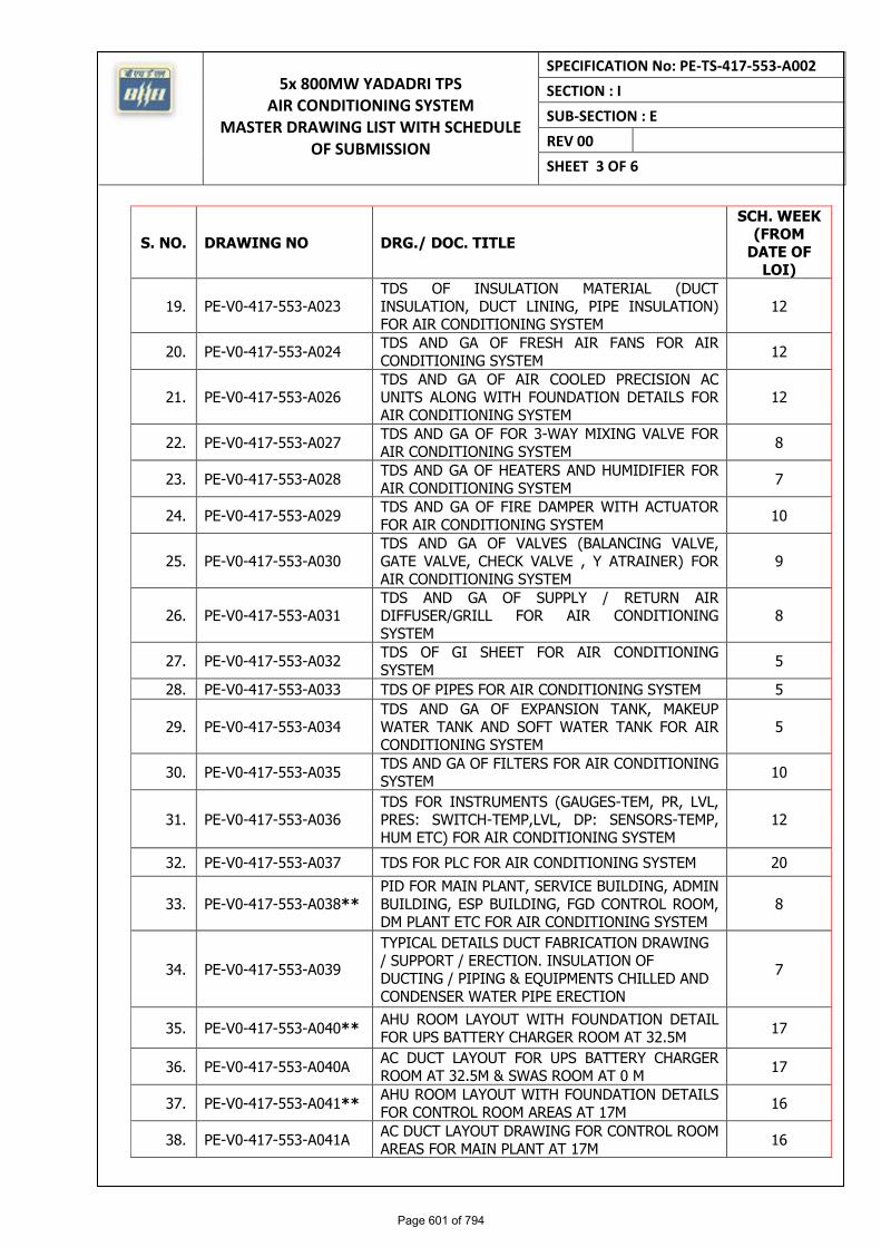
19. PE-V0-417-553-A023 TDS OF INSULATION MATERIAL (DUCT INSULATION, DUCT LINING, PIPE INSULATION) FOR AIR CONDITIONING SYSTEM
12
20. PE-V0-417-553-A024 TDS AND GA OF FRESH AIR FANS FOR AIR CONDITIONING SYSTEM
12
21. PE-V0-417-553-A026 TDS AND GA OF AIR COOLED PRECISION AC UNITS ALONG WITH FOUNDATION DETAILS FOR AIR CONDITIONING SYSTEM
12
22. PE-V0-417-553-A027 TDS AND GA OF FOR 3-WAY MIXING VALVE FOR AIR CONDITIONING SYSTEM
8
23. PE-V0-417-553-A028 TDS AND GA OF HEATERS AND HUMIDIFIER FOR AIR CONDITIONING SYSTEM
7
24. PE-V0-417-553-A029 TDS AND GA OF FIRE DAMPER WITH ACTUATOR FOR AIR CONDITIONING SYSTEM
10
25. PE-V0-417-553-A030 TDS AND GA OF VALVES (BALANCING VALVE, GATE VALVE, CHECK VALVE , Y ATRAINER) FOR AIR CONDITIONING SYSTEM
9
26. PE-V0-417-553-A031 TDS AND GA OF SUPPLY / RETURN AIR DIFFUSER/GRILL FOR AIR CONDITIONING SYSTEM
8
27. PE-V0-417-553-A032 TDS OF GI SHEET FOR AIR CONDITIONING SYSTEM
5
28. PE-V0-417-553-A033 TDS OF PIPES FOR AIR CONDITIONING SYSTEM 5
29. PE-V0-417-553-A034 TDS AND GA OF EXPANSION TANK, MAKEUP WATER TANK AND SOFT WATER TANK FOR AIR CONDITIONING SYSTEM
5
30. PE-V0-417-553-A035 TDS AND GA OF FILTERS FOR AIR CONDITIONING SYSTEM
10
31. PE-V0-417-553-A036 TDS FOR INSTRUMENTS (GAUGES-TEM, PR, LVL, PRES: SWITCH-TEMP,LVL, DP: SENSORS-TEMP, HUM ETC) FOR AIR CONDITIONING SYSTEM
12
32. PE-V0-417-553-A037 TDS FOR PLC FOR AIR CONDITIONING SYSTEM 20
33. PE-V0-417-553-A038** PID FOR MAIN PLANT, SERVICE BUILDING, ADMIN BUILDING, ESP BUILDING, FGD CONTROL ROOM, DM PLANT ETC FOR AIR CONDITIONING SYSTEM
8
34. PE-V0-417-553-A039
TYPICAL DETAILS DUCT FABRICATION DRAWING / SUPPORT / ERECTION. INSULATION OF DUCTING / PIPING & EQUIPMENTS CHILLED AND CONDENSER WATER PIPE ERECTION
7
35. PE-V0-417-553-A040** AHU ROOM LAYOUT WITH FOUNDATION DETAIL FOR UPS BATTERY CHARGER ROOM AT 32.5M
17
36. PE-V0-417-553-A040A AC DUCT LAYOUT FOR UPS BATTERY CHARGER ROOM AT 32.5M & SWAS ROOM AT 0 M
17
37. PE-V0-417-553-A041** AHU ROOM LAYOUT WITH FOUNDATION DETAILS FOR CONTROL ROOM AREAS AT 17M
16
38. PE-V0-417-553-A041A AC DUCT LAYOUT DRAWING FOR CONTROL ROOM AREAS FOR MAIN PLANT AT 17M
16
Page 601 of 794
5x 800MW YADADRI TPS AIR CONDITIONING SYSTEM
MASTER DRAWING LIST WITH SCHEDULE OF SUBMISSION
SPECIFICATION No: PE-TS-417-553-A002
SECTION : I
SUB-SECTION : E
REV 00
SHEET 4 OF 6
1.1
P E M - 6 6 6 6 - 0
S. NO. DRAWING NO DRG./ DOC. TITLE
SCH. WEEK (FROM
DATE OF LOI)
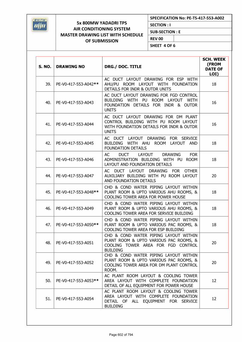
39. PE-V0-417-553-A042** AC DUCT LAYOUT DRAWING FOR ESP WITH AHU/PU ROOM LAYOUT WITH FOUNDATION DETAILS FOR INDR & OUTDR UNITS
18
40. PE-V0-417-553-A043
AC DUCT LAYOUT DRAWING FOR FGD CONTROL BUILDING WITH PU ROOM LAYOUT WITH FOUNDATION DETAILS FOR INDR & OUTDR UNITS
16
41. PE-V0-417-553-A044
AC DUCT LAYOUT DRAWING FOR DM PLANT CONTROL BUILDING WITH PU ROOM LAYOUT WITH FOUNDATION DETAILS FOR INDR & OUTDR UNITS
16
42. PE-V0-417-553-A045 AC DUCT LAYOUT DRAWING FOR SERVICE BUILDING WITH AHU ROOM LAYOUT AND FOUNDATION DETAILS
18
43. PE-V0-417-553-A046 AC DUCT LAYOUT DRAWING FOR ADMINISTRATION BUILDING WITH PU ROOM LAYOUT AND FOUNDATION DETAILS
18
44. PE-V0-417-553-A047 AC DUCT LAYOUT DRAWING FOR OTHER AUXILIARY BUILDING WITH PU ROOM LAYOUT AND FOUNDATION DETAILS
20
45. PE-V0-417-553-A048** CHD & COND WATER PIPING LAYOUT WITHIN PLANT ROOM & UPTO VARIOUS AHU ROOMS, & COOLING TOWER AREA FOR POWER HOUSE
18
46. PE-V0-417-553-A049 CHD & COND WATER PIPING LAYOUT WITHIN PLANT ROOM & UPTO VARIOUS AHU ROOMS, & COOLING TOWER AREA FOR SERVICE BUILDING
18
47. PE-V0-417-553-A050** CHD & COND WATER PIPING LAYOUT WITHIN PLANT ROOM & UPTO VARIOUS PAC ROOMS, & COOLING TOWER AREA FOR ESP BUILDING
18
48. PE-V0-417-553-A051
CHD & COND WATER PIPING LAYOUT WITHIN PLANT ROOM & UPTO VARIOUS PAC ROOMS, & COOLING TOWER AREA FOR FGD CONTROL BUILDING
20
49. PE-V0-417-553-A052
CHD & COND WATER PIPING LAYOUT WITHIN PLANT ROOM & UPTO VARIOUS PAC ROOMS, & COOLING TOWER AREA FOR DM PLANT CONTROL ROOM.
20
50. PE-V0-417-553-A053** AC PLANT ROOM LAYOUT & COOLING TOWER AREA LAYOUT WITH COMPLETE FOUNDATION DETAIL OF ALL EQUIPMENT FOR POWER HOUSE
12
51. PE-V0-417-553-A054
AC PLANT ROOM LAYOUT & COOLING TOWER AREA LAYOUT WITH COMPLETE FOUNDATION DETAIL OF ALL EQUIPMENT FOR SERVICE BUILDING
12
Page 602 of 794
5x 800MW YADADRI TPS AIR CONDITIONING SYSTEM
MASTER DRAWING LIST WITH SCHEDULE OF SUBMISSION
SPECIFICATION No: PE-TS-417-553-A002
SECTION : I
SUB-SECTION : E
REV 00
SHEET 5 OF 6
1.1
P E M - 6 6 6 6 - 0
S. NO. DRAWING NO DRG./ DOC. TITLE
SCH. WEEK (FROM
DATE OF LOI)
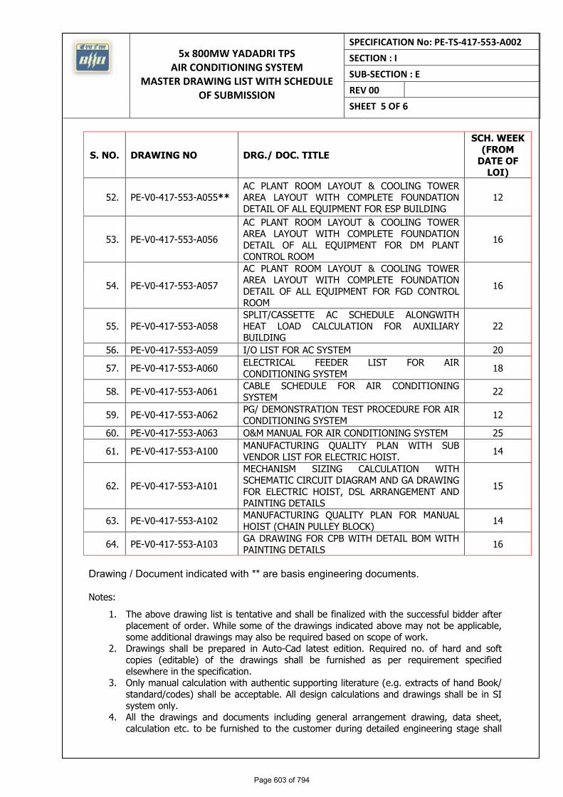
52. PE-V0-417-553-A055** AC PLANT ROOM LAYOUT & COOLING TOWER AREA LAYOUT WITH COMPLETE FOUNDATION DETAIL OF ALL EQUIPMENT FOR ESP BUILDING
12
53. PE-V0-417-553-A056
AC PLANT ROOM LAYOUT & COOLING TOWER AREA LAYOUT WITH COMPLETE FOUNDATION DETAIL OF ALL EQUIPMENT FOR DM PLANT CONTROL ROOM
16
54. PE-V0-417-553-A057
AC PLANT ROOM LAYOUT & COOLING TOWER AREA LAYOUT WITH COMPLETE FOUNDATION DETAIL OF ALL EQUIPMENT FOR FGD CONTROL ROOM
16
55. PE-V0-417-553-A058 SPLIT/CASSETTE AC SCHEDULE ALONGWITH HEAT LOAD CALCULATION FOR AUXILIARY BUILDING
22
56. PE-V0-417-553-A059 I/O LIST FOR AC SYSTEM 20
57. PE-V0-417-553-A060 ELECTRICAL FEEDER LIST FOR AIR CONDITIONING SYSTEM
18
58. PE-V0-417-553-A061 CABLE SCHEDULE FOR AIR CONDITIONING SYSTEM
22
59. PE-V0-417-553-A062 PG/ DEMONSTRATION TEST PROCEDURE FOR AIR CONDITIONING SYSTEM
12
60. PE-V0-417-553-A063 O&M MANUAL FOR AIR CONDITIONING SYSTEM 25
61. PE-V0-417-553-A100 MANUFACTURING QUALITY PLAN WITH SUB VENDOR LIST FOR ELECTRIC HOIST.
14
62. PE-V0-417-553-A101
MECHANISM SIZING CALCULATION WITH SCHEMATIC CIRCUIT DIAGRAM AND GA DRAWING FOR ELECTRIC HOIST, DSL ARRANGEMENT AND PAINTING DETAILS
15
63. PE-V0-417-553-A102 MANUFACTURING QUALITY PLAN FOR MANUAL HOIST (CHAIN PULLEY BLOCK)
14
64. PE-V0-417-553-A103 GA DRAWING FOR CPB WITH DETAIL BOM WITH PAINTING DETAILS
16
Drawing / Document indicated with ** are basis engineering documents.
Notes:
1. The above drawing list is tentative and shall be finalized with the successful bidder after placement of order. While some of the drawings indicated above may not be applicable, some additional drawings may also be required based on scope of work.
2. Drawings shall be prepared in Auto-Cad latest edition. Required no. of hard and soft copies (editable) of the drawings shall be furnished as per requirement specified elsewhere in the specification.
3. Only manual calculation with authentic supporting literature (e.g. extracts of hand Book/ standard/codes) shall be acceptable. All design calculations and drawings shall be in SI system only.
4. All the drawings and documents including general arrangement drawing, data sheet, calculation etc. to be furnished to the customer during detailed engineering stage shall
Page 603 of 794
5x 800MW YADADRI TPS AIR CONDITIONING SYSTEM
MASTER DRAWING LIST WITH SCHEDULE OF SUBMISSION
SPECIFICATION No: PE-TS-417-553-A002
SECTION : I
SUB-SECTION : E
REV 00
SHEET 6 OF 6
1.1
P E M - 6 6 6 6 - 0
include / indicate the following details for clarity w.r.t. Inspection, construction, erection and maintenance etc.: -
a) All drawings and documents shall indicate the list of all reference drawings including general arrangement.
b) All drawings shall include / show plan, elevation, side view, cross - section, skin section, blow - up view; all major self-manufactured and bought out items shall be labeled and included in BOQ / BOM in tabular form.
c) Painting schedule shall also be made as a part of general arrangement drawing of each equipment / items indicating at least 3 trade names.
d) All the drawings required to be furnished to customer during detailed engineering stage shall include technical parameters, details of paints and lubrication, hardness and BOQ / BOM in tabular form indicating all major components including bought out items and their quantity, material of construction indicating its applicable code / standard, weight, make etc.
e) Drawings/ documents to be submitted for purchasers review/ approval shall be under Revision A, B, C… etc. while drawings /documents to be submitted thereafter for customer’s approval after purchaser’s approval shall be under R-0, 1, 2, 3 ….etc.
f) Drawings and documents not covered above but required to check safety of machines/ system, shall be submitted during detailed engineering stage without any commercial implication.
g) All drawings shall include "B.O.M" and indicate quantity, material of construction, make along with IS/BS No., Technical parameters, dimensions, hardness, machining symbol and tolerance, requirement of radiography and hydraulic tests, painting details, elevation, side view, plan, skin section and blow-up view for clarity.
h) All drawings shall be prepared as per BHEL's title block and shall bear BHEL's drawing No.
i) Schedule of drawings submissions, comment incorporations & approval shall be as stipulated in the specifications. The successful bidder shall depute his design personnel to BHEL’s/ Customer’s/ Consultant’s office for across the table resolution of issues and to get documents approved in the stipulated time.
j) Bidder to follow the following the drawing submission schedule:
k) 1st submission of drawings from date of LOI as per the submission schedule.
l) Every revised submission incorporating comments – within 7 days.
m) Bidder to submit revised drawings complete in all respects incorporating all comments. Any incomplete drawing submitted shall be treated as non-submission with delays attributable to bidder’s account. For any clarification/ discussion required to complete the drawings, the bidder shall himself depute his personal to BHEL for across the table discussions/ finalizations/ submissions of drawings.
Page 604 of 794
5X800 MW YADADRI TPS
AIR CONDITIONING SYSTEM FORMAT FOR OPERATION AND
MAINTENANCE MANUAL
SPECIFICATION No: PE‐TS‐417‐553‐A002 SECTION : I
SUB‐SECTION : E
REV 00 DATE: FEB 2021 SHEET 1
SECTION-I
SUB-SECTION-E
ANNEXURE-VII
FORMAT FOR OPERATION AND MAINTENANCE MANUAL
Page 605 of 794
5X800 MW YADADRI TPS
AIR CONDITIONING SYSTEM FORMAT FOR OPERATION AND
MAINTENANCE MANUAL
SPECIFICATION No: PE‐TS‐417‐553‐A002 SECTION : I
SUB‐SECTION : E
REV 00 DATE: FEB 2021 SHEET 2
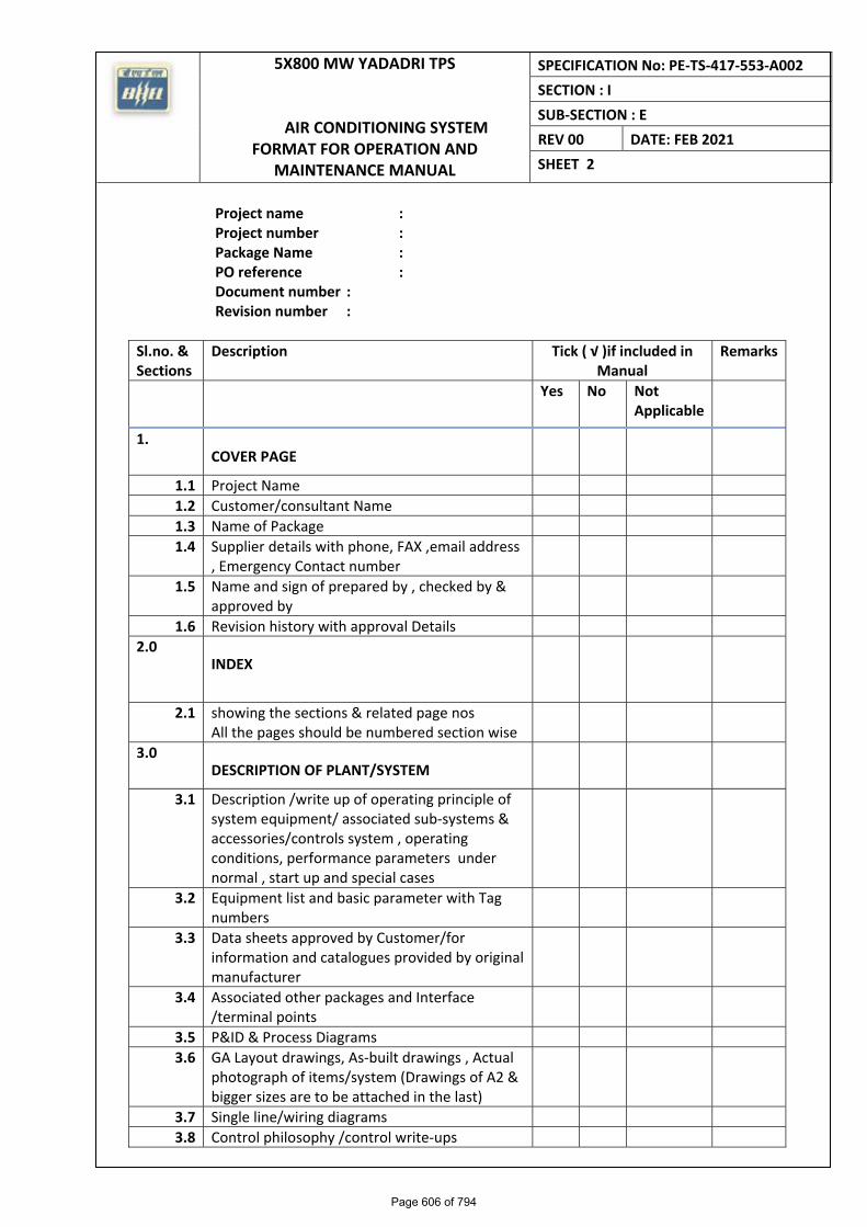
Project name : Project number : Package Name : PO reference : Document number : Revision number :
Sl.no. & Sections
Description Tick ( √ )if included in Manual
Remarks
Yes No Not Applicable
1. COVER PAGE
1.1 Project Name
1.2 Customer/consultant Name
1.3 Name of Package
1.4 Supplier details with phone, FAX ,email address , Emergency Contact number
1.5 Name and sign of prepared by , checked by & approved by
1.6 Revision history with approval Details
2.0 INDEX
2.1 showing the sections & related page nos All the pages should be numbered section wise
3.0 DESCRIPTION OF PLANT/SYSTEM
3.1 Description /write up of operating principle of system equipment/ associated sub‐systems & accessories/controls system , operating conditions, performance parameters under normal , start up and special cases
3.2 Equipment list and basic parameter with Tag numbers
3.3 Data sheets approved by Customer/for information and catalogues provided by original manufacturer
3.4 Associated other packages and Interface /terminal points
3.5 P&ID & Process Diagrams
3.6 GA Layout drawings, As‐built drawings , Actual photograph of items/system (Drawings of A2 & bigger sizes are to be attached in the last)
3.7 Single line/wiring diagrams
3.8 Control philosophy /control write‐ups
Page 606 of 794
5X800 MW YADADRI TPS AIR CONDITIONING
SYSTEM FORMAT FOR OPERATION AND
MAINTENANCE MANUAL
SPECIFICATION No: PE‐TS‐417-553-A002 SECTION : I
SUB‐SECTION : E
REV 00 DATE: FEB2021 SHEET 3
Sl.no. & Sections
Description Tick ( √ )if included in Manual
Remarks
Yes No Not Applicable
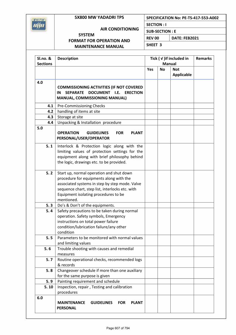
4.0 COMMISSIONING ACTIVITIES (IF NOT COVERED IN SEPARATE DOCUMENT I.E. ERECTION MANUAL, COMMISSIONING MANUAL)
4.1 Pre‐Commissioning Checks
4.2 handling of items at site
4.3 Storage at site
4.4 Unpacking & Installation procedure
5.0 OPERATION GUIDELINES FOR PLANT PERSONAL/USER/OPERATOR
5. 1 Interlock & Protection logic along with the limiting values of protection settings for the equipment along with brief philosophy behind the logic, drawings etc. to be provided.
5. 2 Start up, normal operation and shut down procedure for equipments along with the associated systems in step by step mode. Valve sequence chart, step list, interlocks etc. with Equipment isolating procedures to be mentioned.
5. 3 Do’s & Don’t of the equipments.
5. 4 Safety precautions to be taken during normal operation. Safety symbols, Emergency instructions on total power failure condition/lubrication failure/any other condition
5. 5 Parameters to be monitored with normal values and limiting values
5. 6 Trouble shooting with causes and remedial measures
5. 7 Routine operational checks, recommended logs & records
5. 8 Changeover schedule if more than one auxiliary for the same purpose is given
5. 9 Painting requirement and schedule
5. 10 Inspection, repair , Testing and calibration procedures
6.0 MAINTENANCE GUIDELINES FOR PLANT PERSONAL
Page 607 of 794
5X800 MW YADADRI TPS
AIR CONDITIONING SYSTEM FORMAT FOR OPERATION AND
MAINTENANCE MANUAL
SPECIFICATION No: PE‐TS‐417‐553‐A002 SECTION : I
SUB‐SECTION : E
REV 00 DATE: FEB2021 SHEET 4
Sl.no. & Sections
Description Tick ( √ )if included in Manual
Remarks
Yes No Not Applicable
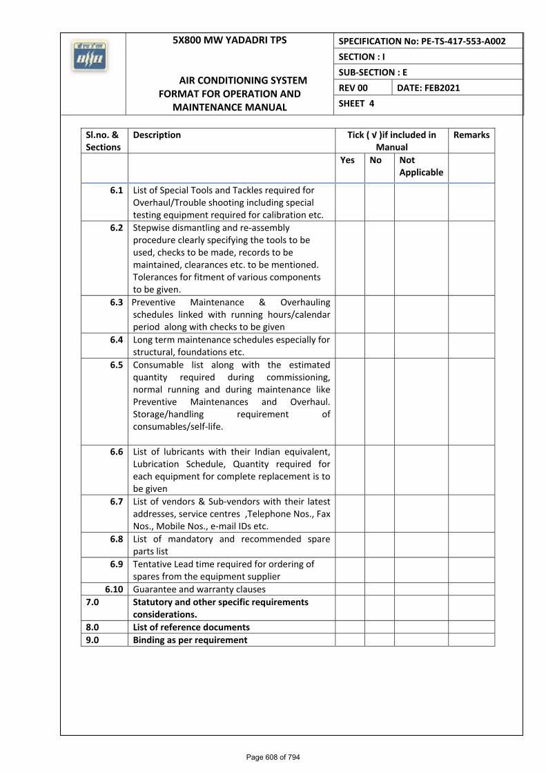
6.1 List of Special Tools and Tackles required for Overhaul/Trouble shooting including special testing equipment required for calibration etc.
6.2 Stepwise dismantling and re‐assembly procedure clearly specifying the tools to be used, checks to be made, records to be maintained, clearances etc. to be mentioned. Tolerances for fitment of various components to be given.
6.3 Preventive Maintenance & Overhauling schedules linked with running hours/calendar period along with checks to be given
6.4 Long term maintenance schedules especially for structural, foundations etc.
6.5 Consumable list along with the estimated quantity required during commissioning, normal running and during maintenance like Preventive Maintenances and Overhaul. Storage/handling requirement of consumables/self‐life.
6.6 List of lubricants with their Indian equivalent, Lubrication Schedule, Quantity required for each equipment for complete replacement is to be given
6.7 List of vendors & Sub‐vendors with their latest addresses, service centres ,Telephone Nos., Fax Nos., Mobile Nos., e‐mail IDs etc.
6.8 List of mandatory and recommended spare parts list
6.9 Tentative Lead time required for ordering of spares from the equipment supplier
6.10 Guarantee and warranty clauses
7.0 Statutory and other specific requirements considerations.
8.0 List of reference documents
9.0 Binding as per requirement
Page 608 of 794
5X800 MW YADADRI TPS
AIR CONDITIONING SYSTEM SITE STORAGE AND PRESERVATION
SPECIFICATION No: PE‐TS‐417‐553-A002 SECTION : I
SUB‐SECTION : E
REV 00 DATE: FEB 2021
SHEET
SECTION-I
SUB-SECTION-E
ANNEXURE-VIII
SITE STORAGE AND PRESERVATION
Page 609 of 794
PROJECT ENGINEERING MANAGEMENT, POWER SECTOR
BHARAT HEAVY ELECTRICALS LIMITED-NOIDA
Page 291 of 374
Page 610 of 794
CONTENT
1 SCOPE OF THE DOCUMENT
2 PURPOSE OF STORAGE & PRESERVATION
3 MEASURES TO BE TAKEN FOR STORAGE AND PRESERVATION
a) GENERAL STORAGE REQUIREMENTS
b) GENERAL PRESERVATION REQUIREMENTS
c) GENERAL INSPECTION REQUIREMENTS
4 TYPE OF STORAGE FOR VARIOUS EQUIPMENT
5. CONCLUSION
6. STACKING ARRANGEMENT FOR PLATES AND STRUCTURAL STEEL
Page 292 of 374
Page 611 of 794
1. SCOPE OF THE DOCUMENT
This guideline is prepared in intent to provide proper site storage and preservation of the
Mechanical, Electrical and C & I items / equipment supplied under various bought out
packages/items. This storage procedure shall be followed at different power plant sites by
concerned agency for storage and preservation from the date of equipment received at
site until the same are erected and handed over to the customer.
2. PURPOSE OF STORAGE & PRESERVATION
Many of the items may be required to be kept in stores for long period. It shall therefore
be essential that proper methods of storage and preservation be applied so that items do
not deteriorate, loose some of their properties and become unusable due to atmospheric
conditions and biological elements.
3. MEASURES TO BE TAKEN FOR STORAGE, HANDLING & PRESERVATION
a) GENERAL STORAGE REQUIREMENTS
1. To the extent feasible, materials should be stored near the point of erection. The
storage areas should have adequate unloading and handling facilities with adequate
passage space for movement of material handling equipment such as cranes, fork lift
trucks, etc. The storage of materials shall be properly planned to minimise time loss
during retrieval of items required for erection.
2. The outdoor storage areas as well as semi-closed stores shall be provided with
adequate drainage facilities to prevent water logging. Adequacy of these facilities shall
be checked prior to monsoon.
3. The storage sheds shall be built in conformity with fire safety requirements. The stores
shall be provided with adequate lights and fire extinguishers. ‘No smoking’ signs shall
be placed at strategic locations. Safety precautions shall be strictly enforced.
4. Adequate lighting facility shall be provided in storage areas and storage sheds and
security personnel positioned to ensure enforcement of security measures to prevent
theft and loss of materials.
5. Adequate number of competent stores personnel and security staff shall be deployed
to efficiently store and maintain the equipment / material.
7. The equipment shall be stored in an orderly manner, preserving their identification
slips, tags and instruction booklets, etc., required during erection. The storage of
materials shall be equipment-wise. Loose parts shall be stored in sheds on racks,
Page 1 of 13Page 293 of 374
Page 612 of 794
preserving the identification marks and tags in good condition. The group codes shall
be displayed on the racks
6. At no time shall any materials be stored directly on ground. All materials shall be
stored minimum 200 mm above the ground preferably on wooden sleepers
b) GENERAL PRESERVATION REQUIREMENTS
1. All special measures to prevent corrosion shall be taken like keeping material in dry
condition, avoiding the equipment coming in contact with corrosive fluid like water,
acid etc.
2. Materials which carry protective coating shall not be wrapped in paper, cloth, etc., as
these are liable to absorb and retain moisture. The material shall be inspected and in
case of signs of wear or damages to protective coating, that portion shall be cleaned
with approved solution and coated with an approved protective paint. Complete record
of all such observations and protective measures taken shall be maintained.
3. Generally equipment supplied at site are properly greased or rust protective oil is
applied on machined/ fabricated components. However periodic inspection shall be
carried out to ensure that protection offered is intact.
4. While handling the equipment, no dragging on the ground is permitted. Avoid using
wire rope for lifting coated components. Use polyester slings (if possible) otherwise
protective material (e.g. clothes, wood block etc.) should be used while handling the
components with rope / slings
5. For Equipment supplied with finished paint, touch paint shall be done in case any
surface paint gets peeled off during handling. Otherwise such surfaces shall
necessarily be wrapped with polythene to avoid any corrosion. Further for equipment
wherein finish coat is to be applied at site, site to ensure that equipment is received
with primer coat applied.
6. It shall be ensured by periodic inspection that plastic inserts are intact in tapped holes,
wherever applicable.
7. Pipes shall be blown with air periodically and it shall be ensured that there is no
obstruction.
8. Silica gel or approved equivalent moisture absorbing material in small cotton bags
shall be placed and tied at various points on the equipment, wherever necessary.
9. Heavy rotating parts in assembled conditions shall be periodically rotated to prevent
corrosion/jamming due to prolonged storage.
Page 2 of 13Page 294 of 374
Page 613 of 794
10. All the electrical equipment such as motors, generators, etc. shall be tested for
insulation resistance at least once in three months and a record of such measured
insulation values shall be maintained.
11. Following preservatives/preservation methods can be used depending upon type of
equipment
a. Rust preventive fluid (RPF)
b. Rust protective paints
c. Tarpaulin covers, in case of outdoor storage
d. De-oxy aluminate for weld-ments
c) GENERAL INSPECTION REQUIREMENTS
1. Period inspection of materials with specific reference to –
� Ingress of moisture and corrosion damages.
� Damage to protective coating.
� Open ends in pipes, vessels and equipment -
- In case any open ends are noticed, same shall be capped.
2. Any damages to equipment / materials.
- In case of any damages, these shall be promptly notified and in all cases, the
repairs / rectification shall be carried out.
- Any items found damaged or not suitable as per project requirements shall be
removed from site. If required to store temporarily, they shall be clearly
marked and stored separately to prevent any inadvertent use.
Page 3 of 13Page 295 of 374
Page 614 of 794
4. TYPE OF STORAGE FOR VARIOUS EQUIPMENT
The types of storage are broadly classified under the following heads:
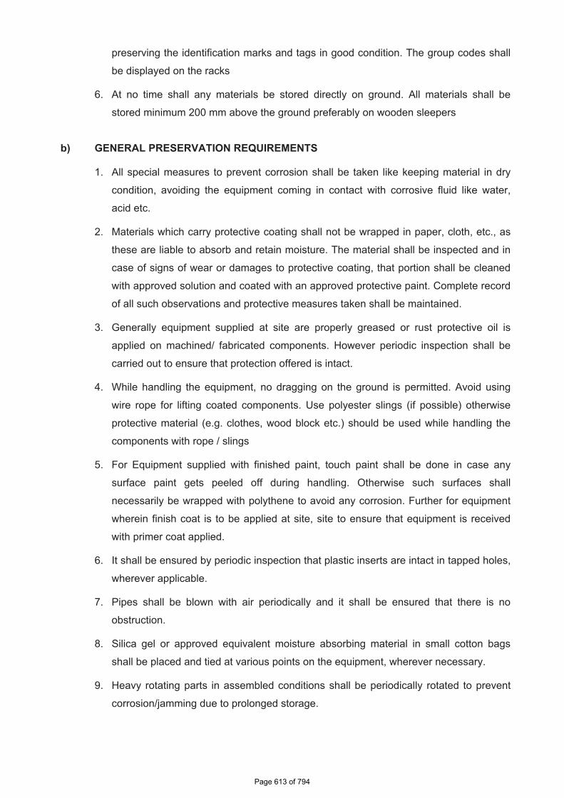
i Closed storage with dry and dust free atmosphere. (C )
The closed shed can be constructed by using cold-rolled / tubular components for
structure and corrugated asbestos sheets / galvanised iron sheets for roofing. Brick
walls / asbestos sheets can be used to cover all the sides. The floor of the shed can
be finished with plain cement concrete suitably glazed. The shed shall be provided
with proper ventilation and illumination.
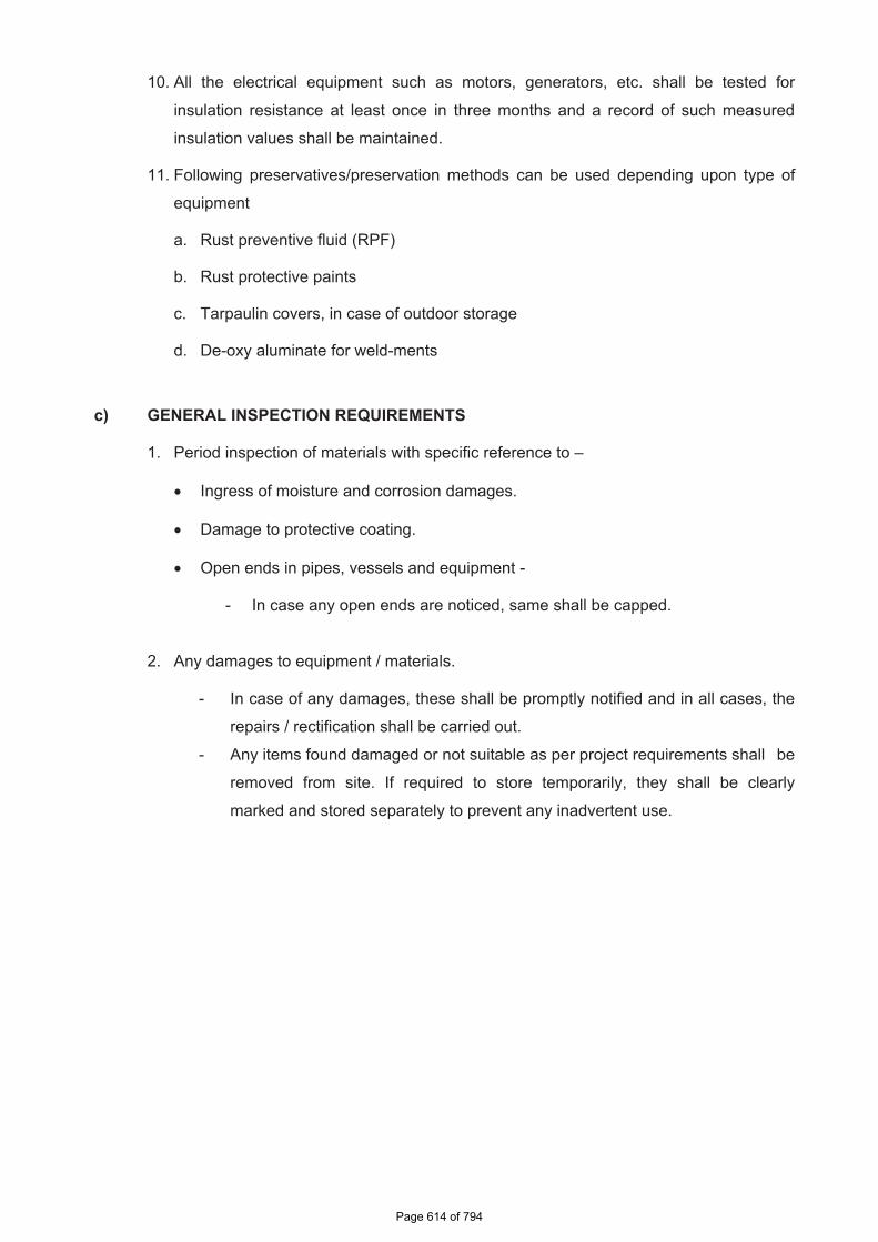
ii Semi-closed storage. (S)
The semi closed shed can be constructed by using cold-rolled / tubular components
for structure and corrugated / asbestos sheets for roofing. The floor shall be brick
paved. If required a small portion of sides can be covered to protect components from
rainwater splashing onto the components.
Page 4 of 13Page 296 of 374
Page 615 of 794
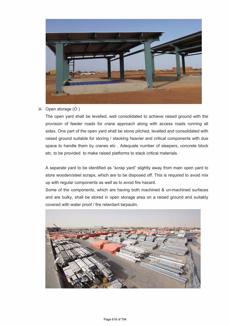
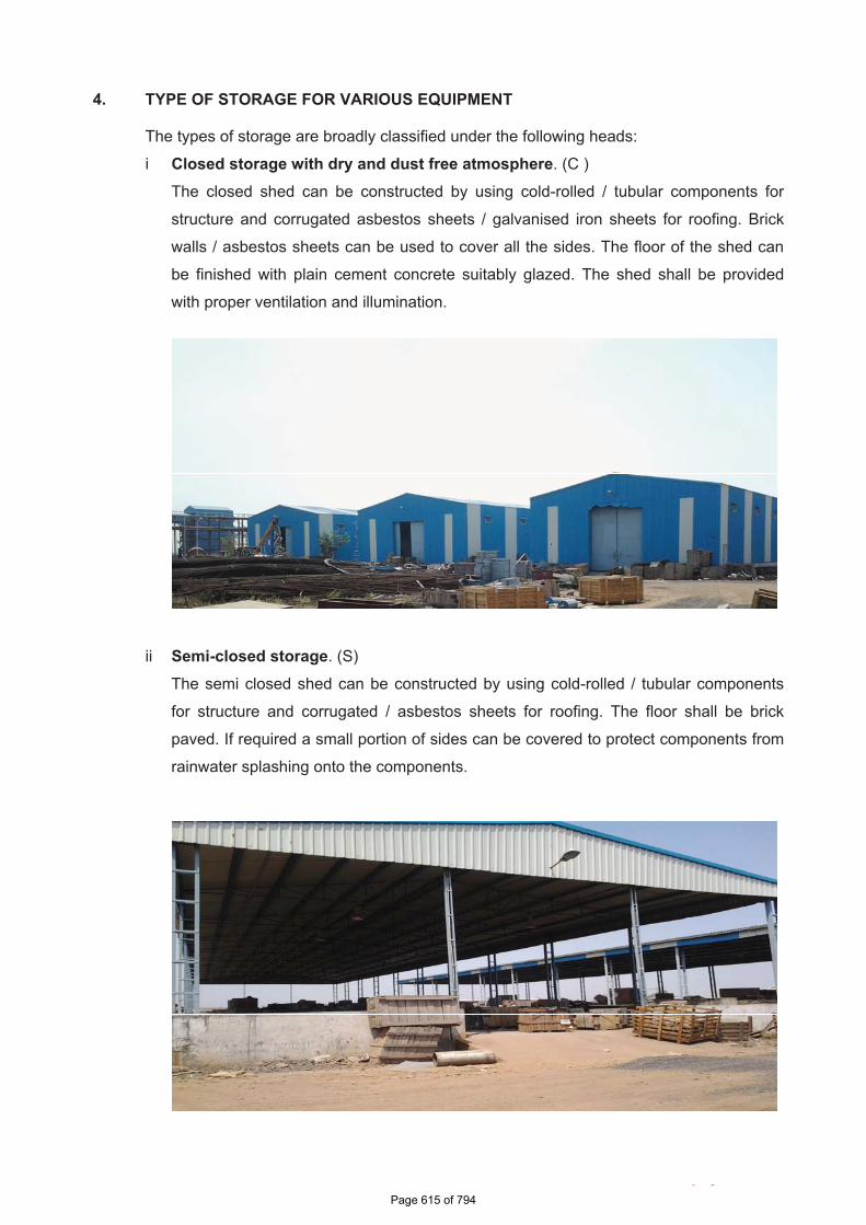
iii Open storage (O )
The open yard shall be levelled, well consolidated to achieve raised ground with the
provision of feeder roads for crane approach along with access roads running all
sides. One part of the open yard shall be stone pitched, levelled and consolidated with
raised ground suitable for storing / stacking heavier and critical components with due
space to handle them by cranes etc . Adequate number of sleepers, concrete block
etc. to be provided to make raised platforms to stack critical materials.
A separate yard to be identified as “scrap yard” slightly away from main open yard to
store wooden/steel scraps, which are to be disposed off. This is required to avoid mix
up with regular components as well as to avoid fire hazard.
Some of the components, which are having both machined & un-machined surfaces
and are bulky, shall be stored in open storage area on a raised ground and suitably
covered with water proof / fire retardant tarpaulin.
Page 5 of 13Page 297 of 374
Page 616 of 794
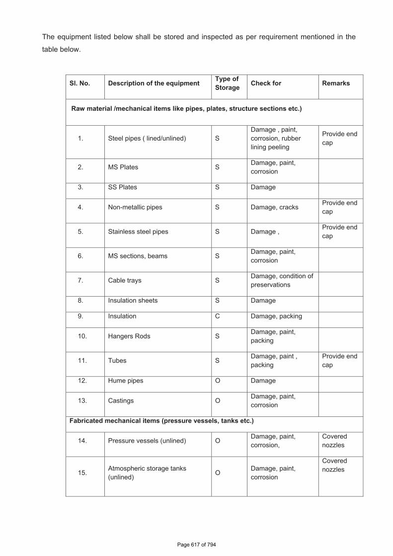
The equipment listed below shall be stored and inspected as per requirement mentioned in the
table below.
Sl. No. Description of the equipment Type of Storage Check for Remarks
Raw material /mechanical items like pipes, plates, structure sections etc.)
1. Steel pipes ( lined/unlined) S Damage , paint, corrosion, rubber lining peeling
Provide end cap
2. MS Plates S Damage, paint, corrosion
3. SS Plates S Damage
4. Non-metallic pipes S Damage, cracks Provide end cap
5. Stainless steel pipes S Damage , Provide end cap
6. MS sections, beams S Damage, paint, corrosion
7. Cable trays S Damage, condition of preservations
8. Insulation sheets S Damage
9. Insulation C Damage, packing
10. Hangers Rods S Damage, paint, packing
11. Tubes S Damage, paint , packing
Provide end cap
12. Hume pipes O Damage
13. Castings O Damage, paint, corrosion
Fabricated mechanical items (pressure vessels, tanks etc.)
14. Pressure vessels (unlined) O Damage, paint, corrosion,
Coverednozzles
15. Atmospheric storage tanks (unlined) O Damage, paint,
corrosion
Coverednozzles
Page 6 of 13Page 298 of 374
Page 617 of 794
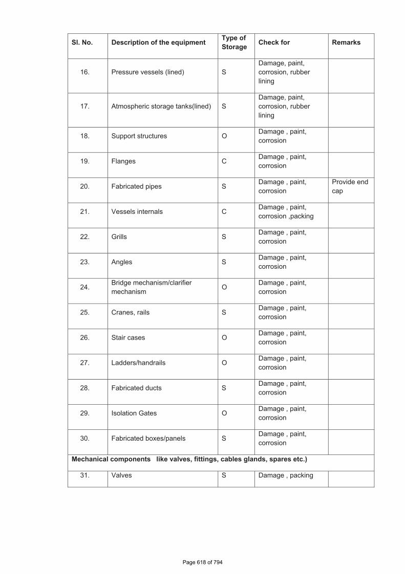
Sl. No. Description of the equipment Type of Storage Check for Remarks
16. Pressure vessels (lined) S Damage, paint, corrosion, rubber lining
17. Atmospheric storage tanks(lined) S Damage, paint, corrosion, rubber lining
18. Support structures O Damage , paint, corrosion
19. Flanges C Damage , paint, corrosion
20. Fabricated pipes S Damage , paint, corrosion
Provide end cap
21. Vessels internals C Damage , paint, corrosion ,packing
22. Grills S Damage , paint, corrosion
23. Angles S Damage , paint, corrosion
24. Bridge mechanism/clarifier mechanism O Damage , paint,
corrosion
25. Cranes, rails S Damage , paint, corrosion
26. Stair cases O Damage , paint, corrosion
27. Ladders/handrails O Damage , paint, corrosion
28. Fabricated ducts S Damage , paint, corrosion
29. Isolation Gates O Damage , paint, corrosion
30. Fabricated boxes/panels S Damage , paint, corrosion
Mechanical components like valves, fittings, cables glands, spares etc.)
31. Valves S Damage , packing
�
�
Page 7 of 13Page 299 of 374
Page 618 of 794
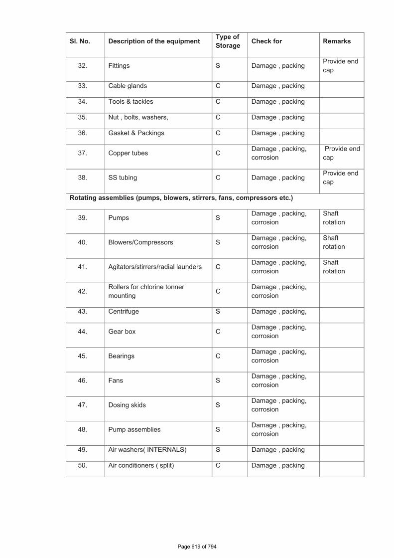
Sl. No. Description of the equipment Type of Storage Check for Remarks
32. Fittings S Damage , packing Provide end cap
33. Cable glands C Damage , packing
34. Tools & tackles C Damage , packing
35. Nut , bolts, washers, C Damage , packing
36. Gasket & Packings C Damage , packing
37. Copper tubes C Damage , packing, corrosion
Provide end cap
38. SS tubing C Damage , packing Provide end cap
Rotating assemblies (pumps, blowers, stirrers, fans, compressors etc.)
39. Pumps S Damage , packing, corrosion
Shaftrotation
40. Blowers/Compressors S Damage , packing, corrosion
Shaftrotation
41. Agitators/stirrers/radial launders C Damage , packing, corrosion
Shaftrotation
42. Rollers for chlorine tonner mounting C Damage , packing,
corrosion
43. Centrifuge S Damage , packing,
44. Gear box C Damage , packing, corrosion
45. Bearings C Damage , packing, corrosion
46. Fans S Damage , packing, corrosion
47. Dosing skids S Damage , packing, corrosion
48. Pump assemblies S Damage , packing, corrosion
49. Air washers( INTERNALS) S Damage , packing
50. Air conditioners ( split) C Damage , packing
�
Page 8 of 13Page 300 of 374
Page 619 of 794
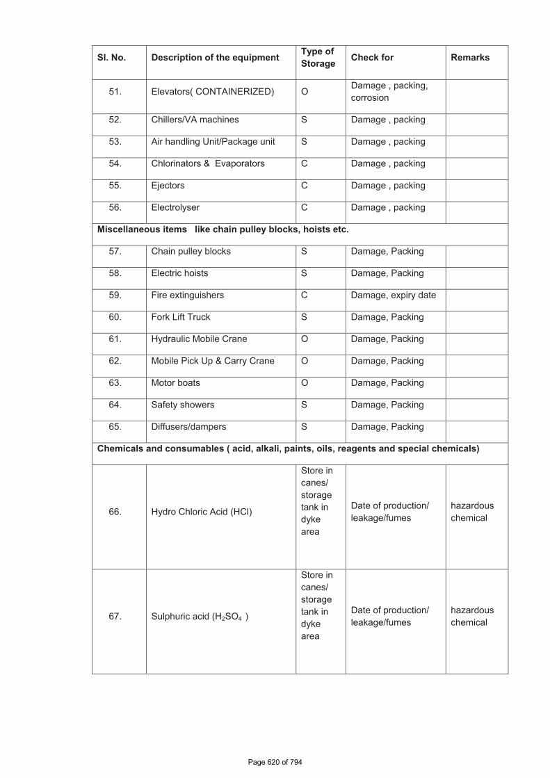
Sl. No. Description of the equipment Type of Storage Check for Remarks
51. Elevators( CONTAINERIZED) O Damage , packing, corrosion
52. Chillers/VA machines S Damage , packing
53. Air handling Unit/Package unit S Damage , packing
54. Chlorinators & Evaporators C Damage , packing
55. Ejectors C Damage , packing
56. Electrolyser C Damage , packing
Miscellaneous items like chain pulley blocks, hoists etc.
57. Chain pulley blocks S Damage, Packing
58. Electric hoists S Damage, Packing
59. Fire extinguishers C Damage, expiry date
60. Fork Lift Truck S Damage, Packing
61. Hydraulic Mobile Crane O Damage, Packing
62. Mobile Pick Up & Carry Crane O Damage, Packing
63. Motor boats O Damage, Packing
64. Safety showers S Damage, Packing
65. Diffusers/dampers S Damage, Packing
Chemicals and consumables ( acid, alkali, paints, oils, reagents and special chemicals)
66. Hydro Chloric Acid (HCl)
Store in canes/ storage tank in dykearea
Date of production/ leakage/fumes
hazardous chemical
67. Sulphuric acid (H2SO4 )
Store in canes/ storage tank in dykearea
Date of production/ leakage/fumes
hazardous chemical
�
�
Page 9 of 13Page 301 of 374
Page 620 of 794
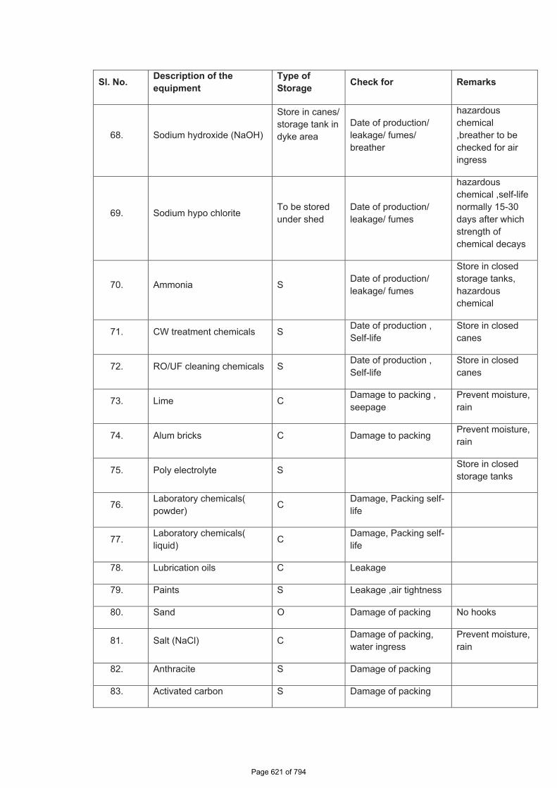
�
Sl. No. Description of the equipment
Type of Storage Check for Remarks
68. Sodium hydroxide (NaOH)
Store in canes/ storage tank in dyke area
Date of production/ leakage/ fumes/ breather
hazardous chemical ,breather to be checked for air ingress
69. Sodium hypo chlorite To be stored under shed
Date of production/ leakage/ fumes
hazardous chemical ,self-life normally 15-30 days after which strength of chemical decays
70. Ammonia S Date of production/ leakage/ fumes
Store in closed storage tanks, hazardous chemical
71. CW treatment chemicals S Date of production , Self-life
Store in closed canes
72. RO/UF cleaning chemicals S Date of production , Self-life
Store in closed canes
73. Lime C Damage to packing , seepage
Prevent moisture, rain
74. Alum bricks C Damage to packing Prevent moisture, rain
75. Poly electrolyte S Store in closed storage tanks
76. Laboratory chemicals( powder) C Damage, Packing self-
life
77. Laboratory chemicals( liquid) C Damage, Packing self-
life
78. Lubrication oils C Leakage
79. Paints S Leakage ,air tightness
80. Sand O Damage of packing No hooks
81. Salt (NaCl) C Damage of packing, water ingress
Prevent moisture, rain
82. Anthracite S Damage of packing
83. Activated carbon S Damage of packing
Page 10 of 13Page 302 of 374
Page 621 of 794
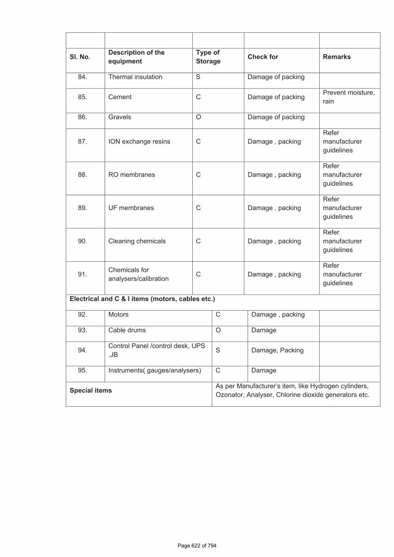
Sl. No. Description of the equipment
Type of Storage Check for Remarks
84. Thermal insulation S Damage of packing
85. Cement C Damage of packing Prevent moisture, rain
86. Gravels O Damage of packing
87. ION exchange resins C Damage , packing Refermanufacturer guidelines
88. RO membranes C Damage , packing Refermanufacturer guidelines
89. UF membranes C Damage , packing Refermanufacturer guidelines
90. Cleaning chemicals C Damage , packing Refermanufacturer guidelines
91. Chemicals for analysers/calibration C Damage , packing
Refermanufacturer guidelines
Electrical and C & I items (motors, cables etc.)
92. Motors C Damage , packing
93. Cable drums O Damage
94. Control Panel /control desk, UPS ,JB S Damage, Packing
95. Instruments( gauges/analysers) C Damage
Special items As per Manufacturer’s item, like Hydrogen cylinders, Ozonator, Analyser, Chlorine dioxide generators etc.
Page 11 of 13Page 303 of 374
Page 622 of 794

5. CONCLUSION
Concerned storage agency at site should make sure that loss in equipment performance
and wear & tear are minimised through proper storage and preservation. The above are
broad guidelines and cover major equipment / materials. However specific storage
practices shall be followed as per manufacturer recommendation. All the necessary
measures even in addition to the ones mentioned above, if found necessary, should be
taken to achieve the objective.
Page 12 of 13Page 304 of 374
Page 623 of 794
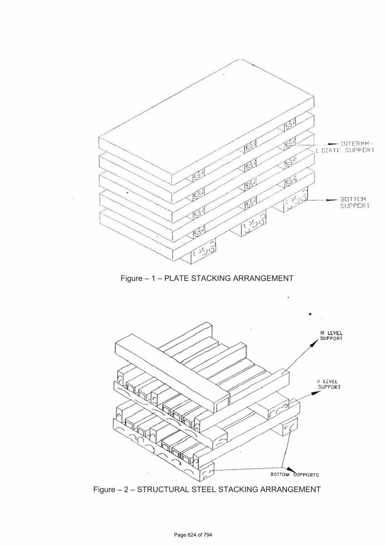
Figure – 1 – PLATE STACKING ARRANGEMENT
Figure – 2 – STRUCTURAL STEEL STACKING ARRANGEMENT
Page 13 of 13Page 305 of 374
Page 624 of 794
5 X 800MW YADADRI TPS AIR CONDITIONING SYSTEM
SPECIFICATION No: PE‐TS‐417‐553‐A002 SECTION : I
SUB‐SECTION : E
REV 00
SHEET 1 OF 1
SECTION-I
SUB-SECTION-E
ANNEXURE-IX
PACKING PROCEDURE
(REFER SUB-SECTION C2-B)
Page 625 of 794
�5x800MW�YADADRI�TPS��AIR�CONDITIONING�SYSTEM�
CLARIFIED�WATER�ANALYSIS��
SPECIFICATION�No:�PE�TS�417�553�A002�SECTION�:�I�SUB�SECTION�:�E�REV�00�SHEET��1�OF��1� �
ANNEXURE-X
CLARIFIED WATER ANALYSIS
Page 626 of 794
DOCUMENT TITLE: DESIGN MEMORANDUM FOR DM PLANT 5 X 800 MW YADADRI – NALGONDA TPS
BHEL DOCUMENT NO.: 4-WT-500-01135 DEPARTMENT: WATER BUSINESS GROUP REV. NO. 04 DATE:16.10.2019 Page: 11 of 69
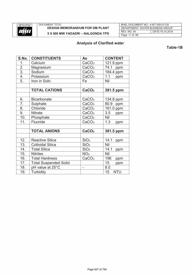
Analysis of Clarified water
Table-1B
S.No. CONSTITUENTS As CONTENT 1. Calcium CaCO3 121.9 ppm 2. Magnesium CaCO3 74.1 ppm 3. Sodium CaCO3 184.4 ppm 4. Potassium CaCO3 1.1 ppm 5. Iron in Soln. Fe Nil
TOTAL CATIONS CaCO3 381.5 ppm
6. Bicarbonate CaCO3 134.8 ppm 7. Sulphate CaCO3 80.9 ppm 8. Chloride CaCO3 161.0 ppm 9. Nitrate CaCO3 3.5 ppm 10. Phosphate CaCO3 Nil 11. Fluoride CaCO3 1.3 ppm
TOTAL ANIONS CaCO3 381.5 ppm
12. Reactive Silica SiO2 14.1 ppm 13. Colloidal Silica SiO2 Nil 14. Total Silica SiO2 14.1 ppm 15. Nitrites NO2 Nil 16. Total Hardness CaCO3 196 ppm 17. Total Suspended Solid 15 ppm 18. pH value at 25°C - 8.0 19. Turbidity 15 NTU
Note:
3) For the purpose of Design inlet analysis to DM plant, the following have been considered on the Raw water analysis and above clarified water analysis has been arrived. i) Chlorine dosing rate of 5ppm in PT plant ii) Alum dosing rate of 50ppm in PT plant iii) Lime dosing rate of 20ppm in PT plant iv) Poly electrolyte (PE) dosing rate of 1ppm in PT plant
4) Other parameters not indicated in above list has been considered as nil.
Page 627 of 794
�5�X�800MW�YADADRI�TPS�
AIR�CONDITIONING�SYSTEM�(SWITCHYARD�AREA)�
�
SPECIFICATION�No:�PE�TS�417�553�A00��SECTION�:�II��SUB�SECTION�:�C1���REV:�00� �SHEET��1�OF�1����
SECTION-II
SUB-SECTION-C1
SPECIFIC TECHNICAL REQUIREMENT –SWITCHYARD AREA WITH ANNEXURE – I, II, III & SWITCHYARD CONTROL BUILDING DRAWINGS
�����������
Page 628 of 794
������������� ������� ������������������������������������������������
����������������������������������
����� �������� ���!��!"#$!��%!���&
��'(� ����� ��&�&#
�������)��������������#
Page 1 of 14
INTENT, SYSTEM DESCRIPTION, DESIGN CRITERIA AND SCOPE
1.0 INTENT OF SPECIFICATION i. This specification covers design, manufacture, inspection, testing at bidder's and/ or his sub vendor’s
work(s), packing, transportation to site, handling at site, erection, testing and commissioning, final painting and carrying out acceptance tests at site of Air - Conditioning System as detailed in this section of specification for Switchyard Control Building of 5 x 800 MW, YADADRI TPS, NALGONDA.
ii. The requirement(s) specified under this section of this specification shall be considered as part of this section. In case of variance between sections, the requirement of this section shall prevail for switchyard scope. TSGENCO contract specification provided as Annexure-III shall be referred strictly. Requirements of the same regarding system specification & applicable for switchyard part shall be provided by the contractor without any deviation.
iii. It is not the intent to specify herein all the details of design and manufacture. However, the equipment shall conform in all respects to high standards of design, engineering and workmanship and shall be capable of performing the required duties in a manner acceptable to Purchaser/ Customer, who will interpret the meaning of drawings and specifications and shall be entitled to reject any work or material, which in his judgment is not in full accordance herewith.
iv. The bidder shall be deemed to have understood completely all the tender drawings and documents and quoted accordingly.
v. The bidder has to note carefully the parameters, estimated capacities of equipment indicated and the tender drawing in the specification are only for guidance of the bidder. The system shall be designed as per relevant standards/ codes and exact capacities and quantities are to be estimated by the bidder. All such estimations and design calculations shall be submitted for Purchaser’s approval.
vi. Deviation: In case of any deviation, the bidder shall indicate separately the deviations clause-wise with respect to the specification in the ‘Schedule of Deviation’ given in this specification. Deviations in any other form including clarifications / assumptions / etc will not be considered and it will be construed that the bid conforms strictly to the specification.
vii. The contract shall be on Unit Rate Basis for the package. In case of change in the input after placement of order the additions/ deletions to the scope shall be settled on the basis of unit rates agreed between the Purchaser and Contractor.
viii. During contract stage, quantities of various items of BOQ may vary to any extent and same unit rates will be applicable.
ix. The Purchaser, Consultant and Customer in this specification stand for BHEL, TCE and TSGENCO respectively. The successful bidder shall be referred to as Contractor.
1.1.0 AIR CONDITIONING REQUIREMENTS
1.1.1 Air Conditioning for Switchyard Control building
Air conditiong system for various areas of switchyard control building shall be provided as below:
Page 629 of 794
������������� ������� ������������������������������������������������
����������������������������������
����� �������� ���!��!"#$!��%!���&
��'(� ����� ��&�&#
�������)��������������#
Page 2 of 14
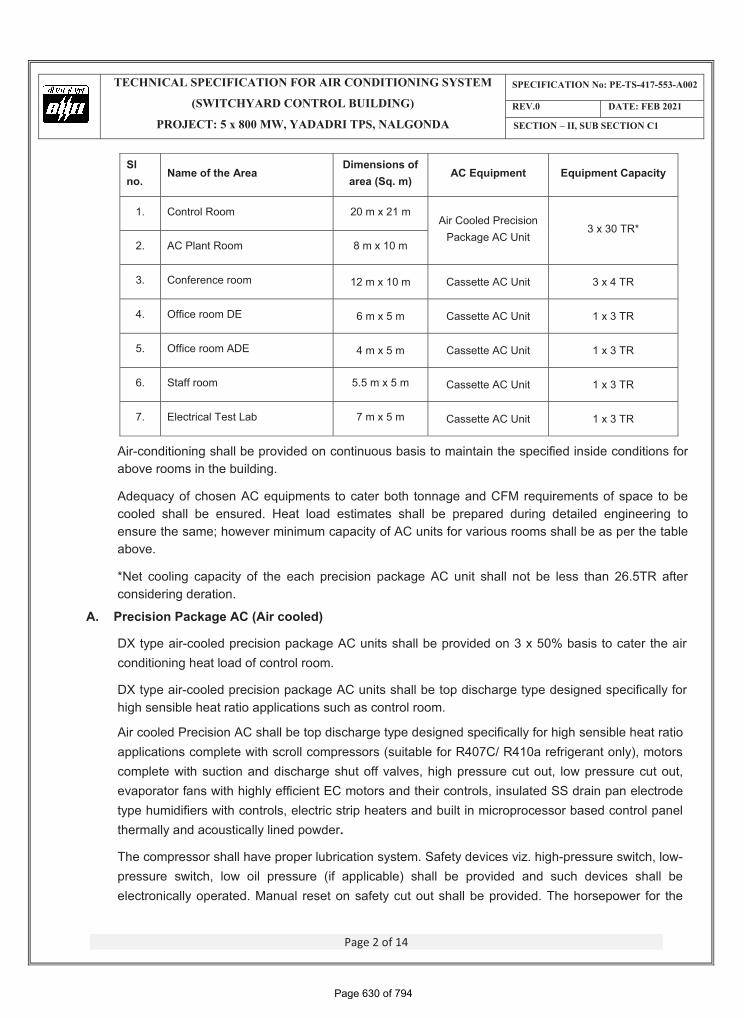
Sl no.
Name of the Area Dimensions of
area (Sq. m) AC Equipment Equipment Capacity
1. Control Room 20 m x 21 m Air Cooled Precision
Package AC Unit 3 x 30 TR*
2. AC Plant Room 8 m x 10 m
3. Conference room 12 m x 10 m Cassette AC Unit 3 x 4 TR
4. Office room DE 6 m x 5 m Cassette AC Unit 1 x 3 TR
5. Office room ADE 4 m x 5 m Cassette AC Unit 1 x 3 TR
6. Staff room 5.5 m x 5 m Cassette AC Unit 1 x 3 TR
7. Electrical Test Lab 7 m x 5 m Cassette AC Unit 1 x 3 TR
Air-conditioning shall be provided on continuous basis to maintain the specified inside conditions for above rooms in the building.
Adequacy of chosen AC equipments to cater both tonnage and CFM requirements of space to be cooled shall be ensured. Heat load estimates shall be prepared during detailed engineering to ensure the same; however minimum capacity of AC units for various rooms shall be as per the table above.
*Net cooling capacity of the each precision package AC unit shall not be less than 26.5TR after considering deration.
A. Precision Package AC (Air cooled)
DX type air-cooled precision package AC units shall be provided on 3 x 50% basis to cater the air conditioning heat load of control room.
DX type air-cooled precision package AC units shall be top discharge type designed specifically for high sensible heat ratio applications such as control room.
Air cooled Precision AC shall be top discharge type designed specifically for high sensible heat ratio applications complete with scroll compressors (suitable for R407C/ R410a refrigerant only), motors complete with suction and discharge shut off valves, high pressure cut out, low pressure cut out, evaporator fans with highly efficient EC motors and their controls, insulated SS drain pan electrode type humidifiers with controls, electric strip heaters and built in microprocessor based control panel thermally and acoustically lined powder.
The compressor shall have proper lubrication system. Safety devices viz. high-pressure switch, low-pressure switch, low oil pressure (if applicable) shall be provided and such devices shall be electronically operated. Manual reset on safety cut out shall be provided. The horsepower for the
Page 630 of 794
������������� ������� ������������������������������������������������
����������������������������������
����� �������� ���!��!"#$!��%!���&
��'(� ����� ��&�&#
�������)��������������#
Page 3 of 14
compressor motor shall be adequately sized or 110% of the rated power required for the unit including drive loss.
Capacity control shall be devised by providing at least two compressors.
One (1) No. fan and fin type air cooled condenser vapor inlet and liquid outlet connection for refrigerant, drain connection etc. One (1) no. evaporator coil and fan having direct expansion type copper tubes and aluminium fins. The evaporator fan shall be DIDW forward curved centrifugal fan.
The precision PAC unit shall have electronic expansion valve for superheat control.
The packaged AC units shall be kept in AHU room whereas condensing unit shall be kept outside nearby AHU room and the two are connected with suitably insulated copper refrigerant piping.
Outlet of all the package units shall be collected in a common plenum chamber through flexible canvass connection & volume control dampers. The conditioned air is then distributed to various AC areas through supply air duct along with diffuser (with volume control damper) running above false ceiling. The return air from all these areas shall be collected above false ceiling & shall be taken back to the AHU room. The return air to AHU room will be mixed with a fixed amount of fresh air before being circulated again.
On/ off trip indications for Precision AC unit components shall be available at the unit mounted micro-processor based local panel.
Equipment specification for Air cooled Precision package AC unit mentioned under Cl. no. 6.12.02 of TSGENCO specification for Air conditioning system shall be also be adhered to.
�( Ceiling Mounted Cassette Type Unit (Multi Flow Type)The Cassette AC units will be complete with indoor evaporator unit, outdoor condensing units, hermetically sealed rotary/scroll compressor, filters, piping, valves, refrigerant strainer, Controls, instruments, control panel/ starter panels, vibration isolator pads and cordless remote control units. Outdoor unit shall comprise of hermetically sealed reciprocating/ rotary compressors mounted on vibration isolators, propeller type axial flow fans and copper tube aluminum finned coils all assembled in a sheet metal casing. The casing and the total unit shall be properly treated and shall be weatherproof type. They shall be compact in size and shall have horizontal discharge of air. Outdoor units will be placed on outer wall or top of roof. The indoor units shall be Ceiling Mounted Cassette type. The housing of the unit shall be powder coated galvanized steel. All the indoor units regardless of their difference in capacity should have same decorative panel size for harmonious aesthetic point of view. Unit shall have four way supply air grills on sides and return air grill in center. Removable and washable polypropylene filters shall be provided. They shall be complete with multifunction cordless remote control unit with special features like programmable timer, sleep mode and soft dry mode etc. Copper refrigerant piping, wiring of indoor/outdoor unit shall be provided inline with distribution of AC units in various rooms and placement of outdoor units as per layout/ site conditions.
Suitable Voltage stabilizers shall be provided for each of the cassette AC units.
Page 631 of 794
������������� ������� ������������������������������������������������
����������������������������������
����� �������� ���!��!"#$!��%!���&
��'(� ����� ��&�&#
�������)��������������#
Page 4 of 14
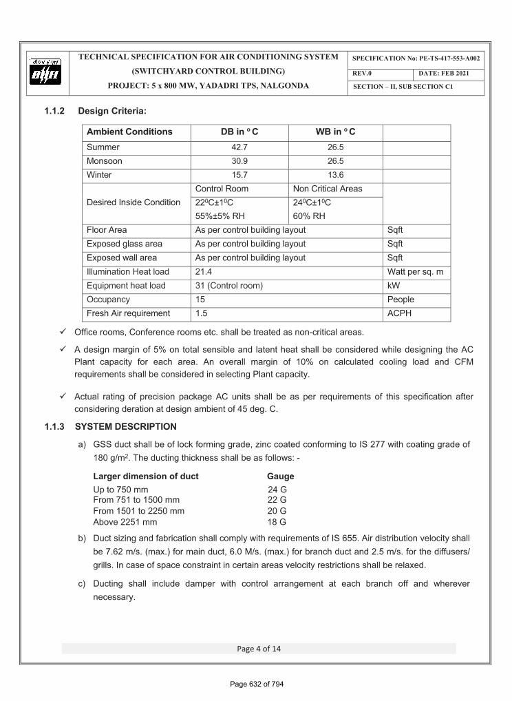
1.1.2 Design Criteria:
Ambient Conditions DB in o C WB in o CSummer 42.7 26.5 Monsoon 30.9 26.5 Winter 15.7 13.6
Desired Inside Condition Control Room Non Critical Areas 220C±10C55%±5% RH
240C±10C60% RH
Floor Area As per control building layout Sqft Exposed glass area As per control building layout Sqft Exposed wall area As per control building layout Sqft Illumination Heat load 21.4 Watt per sq. m Equipment heat load 31 (Control room) kW Occupancy 15 People Fresh Air requirement 1.5 ACPH
� Office rooms, Conference rooms etc. shall be treated as non-critical areas.
� A design margin of 5% on total sensible and latent heat shall be considered while designing the AC Plant capacity for each area. An overall margin of 10% on calculated cooling load and CFM requirements shall be considered in selecting Plant capacity.
� Actual rating of precision package AC units shall be as per requirements of this specification after considering deration at design ambient of 45 deg. C.
1.1.3 SYSTEM DESCRIPTION
a) GSS duct shall be of lock forming grade, zinc coated conforming to IS 277 with coating grade of 180 g/m2. The ducting thickness shall be as follows: -
Larger dimension of duct Gauge Up to 750 mm 24 G From 751 to 1500 mm 22 G From 1501 to 2250 mm 20 G Above 2251 mm 18 G
b) Duct sizing and fabrication shall comply with requirements of IS 655. Air distribution velocity shall be 7.62 m/s. (max.) for main duct, 6.0 M/s. (max.) for branch duct and 2.5 m/s. for the diffusers/ grills. In case of space constraint in certain areas velocity restrictions shall be relaxed.
c) Ducting shall include damper with control arrangement at each branch off and wherever necessary.
Page 632 of 794
������������� ������� ������������������������������������������������
����������������������������������
����� �������� ���!��!"#$!��%!���&
��'(� ����� ��&�&#
�������)��������������#
Page 5 of 14
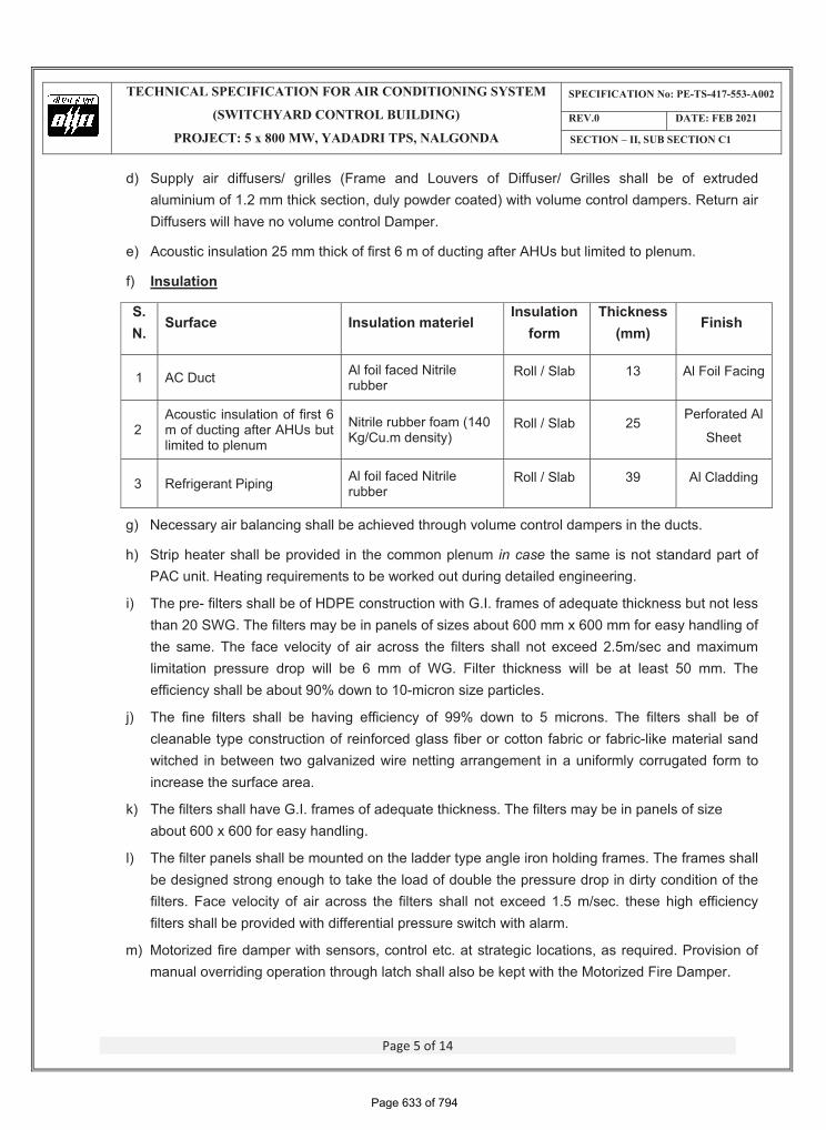
d) Supply air diffusers/ grilles (Frame and Louvers of Diffuser/ Grilles shall be of extruded aluminium of 1.2 mm thick section, duly powder coated) with volume control dampers. Return air Diffusers will have no volume control Damper.
e) Acoustic insulation 25 mm thick of first 6 m of ducting after AHUs but limited to plenum.
f) Insulation
S. N.
Surface Insulation materiel Insulation
form Thickness
(mm)Finish
1 AC Duct Al foil faced Nitrile rubber
Roll / Slab 13 Al Foil Facing
2Acoustic insulation of first 6 m of ducting after AHUs but limited to plenum
Nitrile rubber foam (140 Kg/Cu.m density)
Roll / Slab 25 Perforated Al
Sheet
3 Refrigerant Piping Al foil faced Nitrile rubber
Roll / Slab 39 Al Cladding
g) Necessary air balancing shall be achieved through volume control dampers in the ducts.
h) Strip heater shall be provided in the common plenum in case the same is not standard part of PAC unit. Heating requirements to be worked out during detailed engineering.
i) The pre- filters shall be of HDPE construction with G.I. frames of adequate thickness but not less than 20 SWG. The filters may be in panels of sizes about 600 mm x 600 mm for easy handling of the same. The face velocity of air across the filters shall not exceed 2.5m/sec and maximum limitation pressure drop will be 6 mm of WG. Filter thickness will be at least 50 mm. The efficiency shall be about 90% down to 10-micron size particles.
j) The fine filters shall be having efficiency of 99% down to 5 microns. The filters shall be of cleanable type construction of reinforced glass fiber or cotton fabric or fabric-like material sand witched in between two galvanized wire netting arrangement in a uniformly corrugated form to increase the surface area.
k) The filters shall have G.I. frames of adequate thickness. The filters may be in panels of size about 600 x 600 for easy handling.
l) The filter panels shall be mounted on the ladder type angle iron holding frames. The frames shall be designed strong enough to take the load of double the pressure drop in dirty condition of the filters. Face velocity of air across the filters shall not exceed 1.5 m/sec. these high efficiency filters shall be provided with differential pressure switch with alarm.
m) Motorized fire damper with sensors, control etc. at strategic locations, as required. Provision of manual overriding operation through latch shall also be kept with the Motorized Fire Damper.
Page 633 of 794
������������� ������� ������������������������������������������������
����������������������������������
����� �������� ���!��!"#$!��%!���&
��'(� ����� ��&�&#
�������)��������������#
Page 6 of 14
n) Supply air diffusers/ grilles (Frame and Louvers of Diffuser/Grilles shall be of at least 20 SWG GI sheet and 22 SWG M.S. No grilles should by any chance make any rattling sound during continuous operation. All grilles shall match the decor of the space duly powder coated) with volume control dampers.
o) 1 x 100% capacity Fresh Air Unit consisting of Air Inlet Louver with Bird Screen, Dry panel HDPE filters, Tube Axial Flow Fan with Drive Motor, Volume control damper, Supports and supporting structures etc. shall be provided for AHU Room. A differential pressure sensor shall be provided across each set of filters to initiate alarm when the pressure difference across the filters exceeds a pre-determined value, warranting cleaning/ replacement of filters.
P) MS brackets, M.S. frame & PVC drain piping for indoor & outdoor units respectively and fixing hardware like anchor bolts, nuts, fittings etc. as would be necessary for installation of above equipment shall be provided by the contractor.
1.1.4 OPERATION PHILOSOPHY
The Precision Air Conditioners shall be operated from the respective unit mounted microprocessor based control console.
i. The Precision Air Conditioners shall have following operating controls:
� ON/ OFF thermostatic control of the compressor of Precision Air Conditioners to maintain the desired room temperature.
� Room RH control (wherever required) with the help of humidifier & heater installed within AC units getting sense from the humidistat placed in the return air path.
ii. The compressor of each Precision Air Conditioner shall be incorporated with the following safety controls and interlocks:
� High refrigerant pressure cutout. � Low refrigerant pressure cutout. � Cutout due to overload of all drive motors. � Stopping of evaporator fans in case of fire in the respective zone. � Closing of fire dampers at the supply duct from Precision Air Conditioners in case of fire with
the sense from duct/ room mounted fire/ smoke detector through zonal fire panel.
iii. Interlocks
The system components shall be interlocked with one another in the following way: The compressor shall not start unless: � The condenser fans are running. � The evaporator fans are running.
iv. The electric strip heater shall not be energized unless the respective evaporator fans are running. The Strip heaters will trip with the help of safety thermostat in case the temperature of air at the downstream side of the heaters exceeds a pre-determined value.
Page 634 of 794
������������� ������� ������������������������������������������������
����������������������������������
����� �������� ���!��!"#$!��%!���&
��'(� ����� ��&�&#
�������)��������������#
Page 7 of 14
� Equipment Specification shall be as per TSGENCO Technical specification attached as Annexure III to Sec-II, Sub Section C1.
1.1.5 CONTROL PHILOSOPHY OF THE PRECISION AC SYSTEM OF SWITCHYARD CONTROL BUILDING One no. PLC (RIO) panel with operator’s engineering cum workstation (OWES) shall be provided in the switchyard control building for control and monitoring of switchyard Air conditioning system. This RIO panel will be an extended node to main PLC’s of Air conditioning system situated in main plant local AHU control room of TG1 and TG2 buildings i.e. Unit 1 & 2, Stage#1 AHU Control Room & Unit 3 & 4, and Stage #2 AHU Control Room. This RIO panel and HMI shall derive supply from the same UPS provided to main PLC’s. Necessary ACDB’s (redundant) needs to be provided.
This RIO panel shall be networked with both stage PLC’s of Air conditioning system in both stage#1 & stage#2 plants.
Fiber optic cable, patch cords, converters at both the ends shall be in contractor’s scope. Field instruments redundancy shall be as per specification.
All the technical specifications of PLC RIO panel shall be same as that of PLC RIO panel provided in the main plant portion of this tender. These panels shall comply to C&I Technical specification of AC system, in Sec-I, Sub Section C4 of this specification.
1.1.6 ELECTRICAL REQUIREMENTS FOR AC SYSTEM One (1) no. drawn-out type HVAC power distribution board (PDB) for extending power supplies to precision packaged units, fresh air fan, fire dampers and ventilation fans of cable spreader room, battery room & LT switchgear room shall be provided. The same will be located in AC plant room. Two nos. incomers of suitable capacity, 3 ph. 4-wire rating will be provided for HVAC power distribution panel with an electrical changeover switch.
PDB shall have suitable provisions to be compatible with plant PLC based control system for control & monitoring of vital AC signals from remote location.
20% spare feeders (of each type & rating) shall be provided in the PDB as per customer specification.
The purchaser will provide 3-ph. power supply points for cassette AC units.
Interlocking of PDB shall be done with Fire Alarm Panel to trip HVAC system in case of fire and actuate the fire dampers.
This panel in scope shall comply all concerned requirements of TSGENCO specification for 415 Switchgear provided as Annexure III to Sec-II, Sub Section C1.
PLC RIO panel to be placed in switchyard control room shall derive its DC supply from the UPS package meant for entire PLC system of the main plant.
All required instruments, transducers, switches required for control & monitoring of vital air conditioning system shall be provided.
Page 635 of 794
������������� ������� ������������������������������������������������
����������������������������������
����� �������� ���!��!"#$!��%!���&
��'(� ����� ��&�&#
�������)��������������#
Page 8 of 14
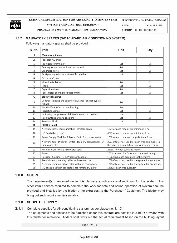
1.1.7 MANDATORY SPARES (SWITCHYARD AIR CONDITIONING SYSTEM) Following mandatory spares shall be provided:
S. No. Item Unit Qty I Mandatory Spares A Precision AC units 1 Pre filters for PAC unit Set 2 2 Bearing for outdoor unit and indoor unit Set 2 3 Expansion valve Set 2 4 Refrigerant gas in non-returnable cylinder Lot 2 B Cassette AC unit 5 Vibration Isolators. Set 26 Filters Set 2 7 Expansion valve Set 2 8 Fan - motor bearing for outdoor unit. Set 2 C Electrical Spares 9 Control, Isolating and selectors switches (of each type &
rating) Set 2
10 MCB/ MCCB (of each type & rating) Set 2 11 Indicating Lamps Lot 2 12 Indicating Lamps cover of different color and holders Lot 2 13 Push Buttons of various colors Lot 2 14 Terminal Blocks Lot 2 D PLC RIO Panel 15 Network cards, Communication Interface cards 10% for each type or but minimum 2 no. 16 I/O Cards (Each type) 40% for each type or but minimum 2 no. 19 Power Supply Modules & Power Packs for control system 10% for each type and range but min 2 no.
20 Network Items (Network switch/ LIU unit/ Transceiver/ FO patch cord etc.)
20% of total nos. used for each type and model in the system or min 4(four) no. whichever is more.
21 MCB (Miniature case circuit breaker) 2 Nos. for each type and rating. 22 Fuses 200% or min 10 no's for each type and rating 23 Racks for housing I/O & Processor Modules 1(One) no. each type used in the system 24 Prefab interconnecting cables with connectors 10% of total nos. used in the system for each type. 25 Network communication cable with end connectors 10% of total nos. used in the system for each type. 26 I/O bus cables with connectors for remote I/O units 1 no. of each type & length
2.0.0 SCOPE The requirement(s) mentioned under this clause are indicative and minimum for the system. Any other item / service required to complete the work for safe and sound operation of system shall be provided and installed by the bidder at no extra cost to the Purchaser / Customer. The bidder may bring out such requirement(s) suitably.
2.1.0 SCOPE OF SUPPLY
2.1.1 Complete supplies for Air-conditioning system (as per clause no. 1.1.0) The equipments and services to be furnished under this contract are detailed in a BOQ provided with this tender for reference. Bidders shall work out the actual requirement based on the building layout
Page 636 of 794
������������� ������� ������������������������������������������������
����������������������������������
����� �������� ���!��!"#$!��%!���&
��'(� ����� ��&�&#
�������)��������������#
Page 9 of 14
enclosed with this specification. The items though not specifically mentioned but required for safe and satisfactory operation of the system will also be treated as included and the same shall be supplied at NO EXTRA COST to BHEL.
The Bill of Quantities shall be read in conjunction with the Instructions to Bidders, General and Special Conditions of Contract, Technical Specifications, and Drawings. The quantities given in the Bill of Quantities are estimated and provisional, and are given to provide a common basis for bidding. The basis of payment will be the actual quantities of work ordered and carried out, as measured by the Contractor and verified by the Purchaser and valued at the rates and prices bid in the priced Bill of Quantities.
A rate or price shall be entered against each item in the priced Bill of Quantities. The cost of Items against which the Contractor has failed to enter a rate or price shall be deemed to be covered by other rates and prices entered in the Bill of Quantities.
The whole cost of complying with the provisions of the Contract shall be included in the Items provided in the priced Bill of Quantities, and where no Items are provided, the cost shall be deemed to be distributed among the rates and prices entered for the related Items of Work.
General directions and descriptions of work and materials are not necessarily repeated nor summarized in the Bill of Quantities. References to the relevant sections of the Contract documentation shall be made before entering prices against each item in the priced Bill of Quantities.
Miscellaneous items like hardware, fixtures etc. shall be deemed to be included under the relevant BOQ items and bidders shall consider the same while quoting for BOQ items.
2.1.2 Besides, the Bidder shall take a note of the following while preparing his offer:
a) Supply of power & control cables have been excluded from contractor’s scope of supply. Bidders shall submit the requirement of power & control cables (cable size, type & quantity) for AC system along with their respective bids. BHEL will provide power & control cables to the vendor as free issue item. Contractor shall have to choose their cables from the available sizes as listed in Annexure – I to Section-1 and contractor shall make necessary modifications in their equipment for termination of these cables.
b) Bidder shall choose make of materials from list enclosed in Annexure-II to this section. However final applicable make is subject to ultimate customer approval. Bidder can provide any other make that is not included in the list only if it is acceptable to ultimate customer without any cost implication to BHEL.
c) Supply and laying of Fiber optic cable along with all accessories for networking of PLC (RIO) panel with main PLCs of different main plant control rooms is in contractor’s scope of works.
d) Purchaser will lay two incomer cables upto contractor’s HVAC PDB in AC Plant room. The contractor shall do termination of the same. Cabling (laying & termination) further to other equipments, panels etc and for control & interlocking of various equipments shall be in contractor’s scope. The bidders in their offers shall include supply of cable accessories such as lugs, glands, cable tags & markers etc.
Page 637 of 794
������������� ������� ������������������������������������������������
����������������������������������
����� �������� ���!��!"#$!��%!���&
��'(� ����� ��&�&#
�������)��������������#
Page 10 of 14
e) Necessary cable trays will be supplied on free issue basis to the contractor, however necessary hardware for fixing the same on walls or elsewhere shall be included by the bidders in their offers.
f) Earthing material viz. (GS flat 75 x 10, 50 x 6 & 25 x 3 mm) will also be supplied on free issue basis to contractor; however the bidders in their respective bids shall give requirement.
g) Instruments like differential pressure sensor, temperature transducers, switches etc shall be provided for completeness of the system wherever required as per TSGENCO specification.
h) Contractor shall submit valid Type test report for approval by Customer. Fresh type test of equipment is not envisaged. It is presumed that equipment offered is duly type tested.
i) In case the type test reports are found un-satisfactory, tests shall be carried out afresh by contractor without any additional cost implication to BHEL.
j) Bidder shall submit quality plan of the items of this system during detailed engineering stage in standard BHEL quality plan format for customer approval.
k) Obtaining, "As Built" certification from purchaser or Customer on applicable drawings. Completing documentation as per specification requirement shall be in contractor scope of services.
2.1.3 SCOPE OF SERVICES
2.1.3.1 Erection, Testing & Commissioning (ETC) requirements
i. The scope of ETC shall include receipt of material at site, safe storage of material, handling of equipment/material at site, erection of equipment /material at site including fabrication, equipment and system testing, commissioning of the entire system. The bidder shall arrange all material, consumables plus tools & tackles required for completion of ETC work.
ii. Conducting performance guarantee tests to the satisfaction of Customer/ Purchaser and handing over of the system to Customer / Purchaser. Bidder shall submit the PG test procedure at the time of detailed engineering for approval by customer/ purchaser.
iii. It is the responsibility of the contractor to abide to Guaranteed power consumption for Air conditioning system inline with the requirements of Sec-III, Sub Section 6 of the Complete plant portion of this tender.
iv. It is the responsibility of the contractor to maintain the system till it is handed over to customer / Purchaser.
v. Cables laying for incomers to the AC Power distribution board (PDB) shall be done by the purchaser. The contractor has to lay and terminate all the other power and control cables supplied under the present scope.
vi. The contractor shall do earthing of all installation under the present scope.
vii. All machinery - tools & tackles and consumables required for erection / commissioning of the system shall be arranged by the bidder.
Page 638 of 794
������������� ������� ������������������������������������������������
����������������������������������
����� �������� ���!��!"#$!��%!���&
��'(� ����� ��&�&#
�������)��������������#
Page 11 of 14
viii. Bidder shall ensure that sufficient quantities of commissioning spares are made available for timely completion of commissioning of the system. The bidder shall furnish a list of Commissioning spares that will be brought by him. The unused commissioning spares shall be returnable to the Bidder.
ix. Piping from water tap-off to inlet of pan humidifier. The purchaser at one point near control room shall provide water tap-off.
x. Piping from overflow of pan humidifier & AC unit (disposal of condensate) to the nearest drain point.
xi. Cable laying & termination between Fire Alarm Panel (FAP) & PDB for HVAC system in order to switch off the system in case of fire.
xii. Laying & fixing of cable trays on walls or elsewhere. The bidder in their offer shall include necessary hardware for the same.
xiii. Painting of all the equipments shall be as per customer specification.
xiv. Refrigerant piping, liquid line valves, suction, discharge valves, HP gauge provision shall be as per the standards and customer requirement.
xv. After completion of erection and commissioning of the system, the bidder shall train site engineers of Purchaser/Customer so that they are fully conversant with both electrical and mechanical part of this package.
2.1.3.2 Civil Works
Major civil works such as room & foundations for various HVAC equipments shall be in purchaser’s scope. However following shall be in contractor scope of services:
a. Wall openings at suitable locations for duct, refrigerant/ drain piping, Fresh Air unit shall be made by the contractor. Associated civil works such as grouting, filling up crevices/cut outs etc during installations of equipments shall also be in contractor’s scope. Any other damage caused to civil works during ETC work of the equipment/system shall be made good to the original finish by the contractor at no extra cost to the purchaser.
b. Furnishing of details for construction of outdoor unit's mounting arrangement.
c. Providing necessary guidance to/ coordination with civil contractor so that appropriate sized / correctly located cut outs are made (by civil contractor) in false ceiling for installation of grilles / diffusers / return air.
However in case wall openings / cut outs have not been provided for either duct laying, louver fixing, or fresh air fan, the same shall have to be made by the Contractor.
d. Minor modifications, alterations in system installation as per customer's specific requirements shall be done without any extra cost to purchaser.
Page 639 of 794
������������� ������� ������������������������������������������������
����������������������������������
����� �������� ���!��!"#$!��%!���&
��'(� ����� ��&�&#
�������)��������������#
Page 12 of 14
2.2 Exclusions
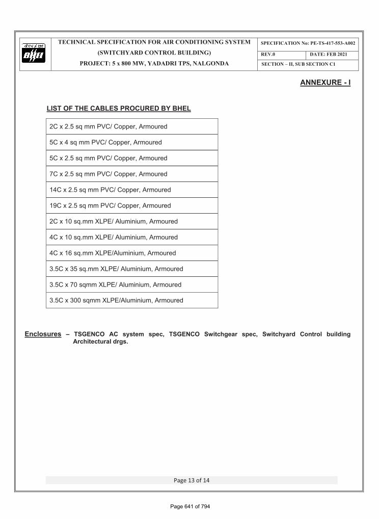
i. Supply of Cable trays for laying cables. Installation wherever required is in contractor scope. ii. Supply of power and control cables. The bidder shall chose from the BHEL procured cables listed in
Annexure-I to this section & furnish quantity and type of cables required complete system in their respective bids. Laying & termination is in contractor scope.
iii. Various rooms and foundations for locating air conditioning equipments. iv. Supply & installation of false ceiling. v. Underdeck insulation of the air-conditioned areas. vi. Supply of GI flat for earthing of equipments.
2.3 Handing & Taking Over It is the responsibility of the contractor to maintain the system till it is handed over. The system/ equipment before being handed over shall be subjected to successful run test as per approved PG Test procedure. The contractor shall rectify any defect noted during the period. This running test shall be in addition to the performance tests specified earlier.
2.4 Inspection & Testing All equipments shall be inspected prior to dispatch in line with relevant IS, approved GTP/ drawing, technical specification & BHEL/ customer approved QAP.
NOTE� Following portions of Sec-I – Complete plant area of this technical specification is applicable for Sec-
II- Switchyard area too as indicated in Index: � SUB SECTION C1 – Customer specification.
� SUB SECTION C2, C2A Technical Requirement, C2B – Project specific general requirement, C2C – Painting specifications.
� SUB SECTION C4 – Technical Specification (C & I Portion) � SUB SECTION D – Standard Technical Specifications
� SUB SECTION E – Annexure V, VII, VIII, IX
Page 640 of 794
������������� ������� ������������������������������������������������
����������������������������������
����� �������� ���!��!"#$!��%!���&
��'(� ����� ��&�&#
�������)��������������#
Page 13 of 14
ANNEXURE - I
LIST OF THE CABLES PROCURED BY BHEL
2C x 2.5 sq mm PVC/ Copper, Armoured
5C x 4 sq mm PVC/ Copper, Armoured
5C x 2.5 sq mm PVC/ Copper, Armoured
7C x 2.5 sq mm PVC/ Copper, Armoured
14C x 2.5 sq mm PVC/ Copper, Armoured
19C x 2.5 sq mm PVC/ Copper, Armoured
2C x 10 sq.mm XLPE/ Aluminium, Armoured
4C x 10 sq.mm XLPE/ Aluminium, Armoured
4C x 16 sq.mm XLPE/Aluminium, Armoured
3.5C x 35 sq.mm XLPE/ Aluminium, Armoured
3.5C x 70 sqmm XLPE/ Aluminium, Armoured
3.5C x 300 sqmm XLPE/Aluminium, Armoured
Enclosures – TSGENCO AC system spec, TSGENCO Switchgear spec, Switchyard Control building Architectural drgs.
Page 641 of 794
������������� ������� ������������������������������������������������
����������������������������������
����� �������� ���!��!"#$!��%!���&
��'(� ����� ��&�&#
�������)��������������#
Page 14 of 14
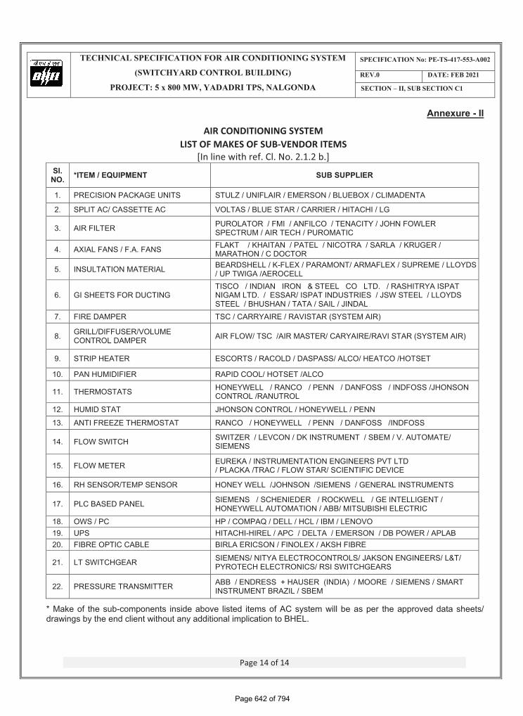
Annexure - II
AIR CONDITIONING SYSTEM LIST OF MAKES OF SUB�VENDOR ITEMS
[In line with ref. Cl. No. 2.1.2 b.] SI.
NO. *ITEM / EQUIPMENT SUB SUPPLIER
1. PRECISION PACKAGE UNITS STULZ / UNIFLAIR / EMERSON / BLUEBOX / CLIMADENTA
2. SPLIT AC/ CASSETTE AC VOLTAS / BLUE STAR / CARRIER / HITACHI / LG
3. AIR FILTER PUROLATOR / FMI / ANFILCO / TENACITY / JOHN FOWLER SPECTRUM / AIR TECH / PUROMATIC
4. AXIAL FANS / F.A. FANS FLAKT / KHAITAN / PATEL / NICOTRA / SARLA / KRUGER / MARATHON / C DOCTOR
5. INSULTATION MATERIAL BEARDSHELL / K-FLEX / PARAMONT/ ARMAFLEX / SUPREME / LLOYDS / UP TWIGA /AEROCELL
6. GI SHEETS FOR DUCTING TISCO / INDIAN IRON & STEEL CO LTD. / RASHITRYA ISPAT NIGAM LTD. / ESSAR/ ISPAT INDUSTRIES / JSW STEEL / LLOYDS STEEL / BHUSHAN / TATA / SAIL / JINDAL
7. FIRE DAMPER TSC / CARRYAIRE / RAVISTAR (SYSTEM AIR)
8. GRILL/DIFFUSER/VOLUME CONTROL DAMPER AIR FLOW/ TSC /AIR MASTER/ CARYAIRE/RAVI STAR (SYSTEM AIR)
9. STRIP HEATER ESCORTS / RACOLD / DASPASS/ ALCO/ HEATCO /HOTSET
10. PAN HUMIDIFIER RAPID COOL/ HOTSET /ALCO
11. THERMOSTATS HONEYWELL / RANCO / PENN / DANFOSS / INDFOSS /JHONSON CONTROL /RANUTROL
12. HUMID STAT JHONSON CONTROL / HONEYWELL / PENN
13. ANTI FREEZE THERMOSTAT RANCO / HONEYWELL / PENN / DANFOSS /INDFOSS
14. FLOW SWITCH SWITZER / LEVCON / DK INSTRUMENT / SBEM / V. AUTOMATE/ SIEMENS
15. FLOW METER EUREKA / INSTRUMENTATION ENGINEERS PVT LTD / PLACKA /TRAC / FLOW STAR/ SCIENTIFIC DEVICE
16. RH SENSOR/TEMP SENSOR HONEY WELL /JOHNSON /SIEMENS / GENERAL INSTRUMENTS
17. PLC BASED PANEL SIEMENS / SCHENIEDER / ROCKWELL / GE INTELLIGENT / HONEYWELL AUTOMATION / ABB/ MITSUBISHI ELECTRIC
18. OWS / PC HP / COMPAQ / DELL / HCL / IBM / LENOVO 19. UPS HITACHI-HIREL / APC / DELTA / EMERSON / DB POWER / APLAB 20. FIBRE OPTIC CABLE BIRLA ERICSON / FINOLEX / AKSH FIBRE
21. LT SWITCHGEAR SIEMENS/ NITYA ELECTROCONTROLS/ JAKSON ENGINEERS/ L&T/ PYROTECH ELECTRONICS/ RSI SWITCHGEARS
22. PRESSURE TRANSMITTER ABB / ENDRESS + HAUSER (INDIA) / MOORE / SIEMENS / SMART INSTRUMENT BRAZIL / SBEM
* Make of the sub-components inside above listed items of AC system will be as per the approved data sheets/ drawings by the end client without any additional implication to BHEL.
Page 642 of 794
Telangana State Power Generation Corporation Ltd. EPC Bid Document 1x800 MW Kothagudem TPS e-PCT/TS/K/02/2014-15
DEVELOPMENT CONSULTANTS (e-PCT-TS-K-02-2014-15-Vol IIID-SECTION-I)
VOLUME : IIID
SECTION-I
TECHNICAL SPECIFICATION FOR
AIR CONDITIONING SYSTEM
Annexure IIIto
Technical Spec. for Air Conditioning System ofSwitchyard Control Building (Sec-II, Sub Section-C1)
Page 643 of 794
Telangana State Power Generation Corporation Ltd. EPC Bid Document 1x800 MW Kothagudem TPS e-PCT/TS/K/02/2014-15
DEVELOPMENT CONSULTANTS (e-PCT-TS-K-02-2014-15-Vol IIID-SECTION-I)
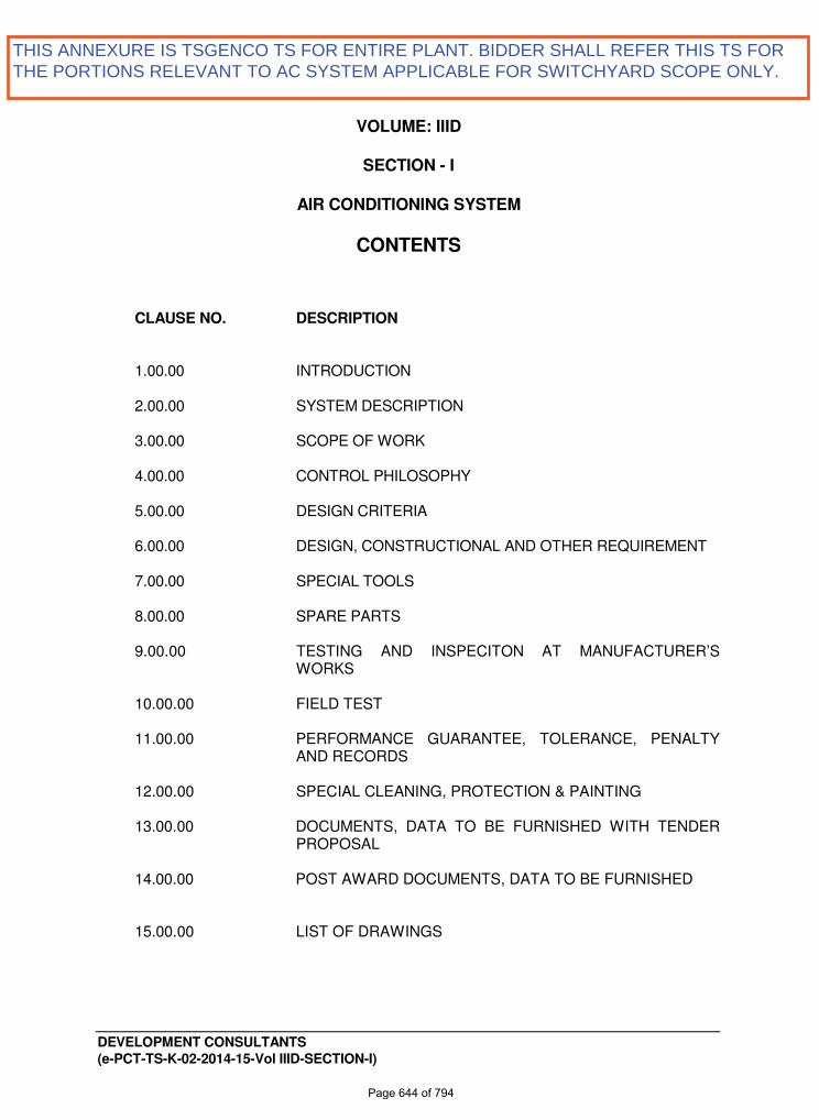
VOLUME: IIID
SECTION - I
AIR CONDITIONING SYSTEM
CONTENTS
CLAUSE NO. DESCRIPTION 1.00.00 INTRODUCTION 2.00.00 SYSTEM DESCRIPTION 3.00.00 SCOPE OF WORK 4.00.00 CONTROL PHILOSOPHY 5.00.00 DESIGN CRITERIA 6.00.00 DESIGN, CONSTRUCTIONAL AND OTHER REQUIREMENT 7.00.00 SPECIAL TOOLS 8.00.00 SPARE PARTS
9.00.00 TESTING AND INSPECITON AT MANUFACTURER’S
WORKS 10.00.00 FIELD TEST 11.00.00 PERFORMANCE GUARANTEE, TOLERANCE, PENALTY
AND RECORDS
12.00.00 SPECIAL CLEANING, PROTECTION & PAINTING
13.00.00 DOCUMENTS, DATA TO BE FURNISHED WITH TENDER PROPOSAL
14.00.00 POST AWARD DOCUMENTS, DATA TO BE FURNISHED
15.00.00 LIST OF DRAWINGS
THIS ANNEXURE IS TSGENCO TS FOR ENTIRE PLANT. BIDDER SHALL REFER THIS TS FORTHE PORTIONS RELEVANT TO AC SYSTEM APPLICABLE FOR SWITCHYARD SCOPE ONLY.
Page 644 of 794
Telangana State Power Generation Corporation Ltd. EPC Bid Document 1x800 MW Kothagudem TPS e-PCT/TS/K/02/2014-15
DEVELOPMENT CONSULTANTS V.IIID/S-1 : 1 (e-PCT-TS-K-02-2014-15-Vol IIID-SECTION-I)
VOLUME: IIID SECTION – I
AIR CONDITIONING SYSTEM
1.00.00 INTRODUCTION 1.01.00 The purpose of the system is to provide Air Conditioning System for the
different areas of 1X800 MW Supercritical Thermal Power Plant, Stage – VII Unit #12 at Kothagudem Thermal Power Station, Telangana.
Various control rooms in power station, housing a group of sophisticated and
precision control panels and desks call for controlled environment for proper functioning and for the comfort of working personnel.
2.00.00 SYSTEM DESCRIPTION 2.01.00 The air conditioning system shall cover the following areas as a minimum:
a. Power House Building including Control Room
i. Unit Control Room ii. Control Equipment Room (CER) iii. Shift Charge Engineers’ Rooms iv. Computer Room v. Uninterrupted Power Supply (UPS) Room vi. Steam and Water Analyzer (SWAS) Panel Room (Dry Panel) vii. Excitation room viii. AVR room ix. Relay panel room x. Other Office areas like Telephone Exchange Room,
Conference Hall, library, Laboratory Rooms etc, if any, on the operating floor
b. Service Building
i. Maintenance Office areas, conference rooms, lecture rooms
and any other areas needs Air Conditioning.
ii. AC plant control room (in Central AC plant equipment room proposed to be located in ground floor of Service Building)
c. ESP Control Room. d. VFD Control Room (if applicable)
e. Ash Handling Plant Control Room
f. DM plant control room, office and Laboratory area.
Page 645 of 794
Telangana State Power Generation Corporation Ltd. EPC Bid Document 1x800 MW Kothagudem TPS e-PCT/TS/K/02/2014-15
DEVELOPMENT CONSULTANTS V.IIID/S-1 : 2 (e-PCT-TS-K-02-2014-15-Vol IIID-SECTION-I)
g. Switchyard Control Room. h. Chemical Laboratory Building. i. Coal Handling Plant control room
j. Any other Local Control Rooms / Cubicles of different Auxiliary
Buildings housing Programmable Logic Controllers (PLC) Panels and other Input / Output (I/O) modules
k. Rooms having the equipment required controlled temperature by
nature for their operating feature.
l. Any other area requiring Air conditioning as per manufacturer’s recommendation.
All the buildings described above shall preferably be provided with separate air
conditioning systems because they may be far apart from each other. 2.02.00 For the Power House Building and the attached Service Building, one Common
Central Chilled type Air Conditioning plant shall be provided with individual Air Handling Units / Fan-Coil Units (as applicable) for the Unit Control Room, Control Equipment Room, Shift Charge Engineer’s Room, Computer Room, Uninterrupted Power Supply (UPS) Room, Excitation Room, AVR Room, Relay Panel Room, SWAS (Dry Panel) Room, all Laboratory Rooms and other Office areas, Telephone Exchange Room, Conference Hall, and Library etc, if any, on the operating floor.
2.03.00 Water Cooled Precision air Conditioners of 3 x 50% capacity shall be provided
for the ESP Control room, VFD Control Room (if applicable), AHP Control Room, DM Plant Control Room and its associated office and Laboratory and Chemical Laboratory Building. Condenser cooling water for these Air Conditioners shall be supplied from main plant ACW system through Non-Chemical Water Treatment Device. Provision of a Fresh Air unit consisting of Air Inlet Louver with Bird Screen, Dry panel HDPE filters, Tube Axial Flow Fan with Drive Motor, Volume control damper, Supports and supporting structures etc. shall be provided for each PAC Room.
2.04.00 Air Cooled Packaged Units (Precision Type) will be used for air conditioning of
the Switch Yard Control room and CHP Control room. Provision of a Fresh Air unit consisting of Air Inlet Louver with Bird Screen, Dry panel HDPE filters, Tube Axial Flow Fan with Drive Motor, Volume control damper, Supports and supporting structures etc. shall be provided for each PAC Room.
2.05.00 Air cooled non duct able Split Air Conditioners shall be provided for Rooms /
cubicles housing Programmable Logic Controllers (PLC) and other Input / Output (I/O) modules or any other area requiring for Air conditioning. Required no. of AC units of suitable capacity should be selected with 100% units as stand-by for AC areas having 24 hours operation. For AC areas with less than 12 hours operation, stand-by units may be avoided if multiple units are installed.
Page 646 of 794
Telangana State Power Generation Corporation Ltd. EPC Bid Document 1x800 MW Kothagudem TPS e-PCT/TS/K/02/2014-15
DEVELOPMENT CONSULTANTS V.IIID/S-1 : 3 (e-PCT-TS-K-02-2014-15-Vol IIID-SECTION-I)
2.06.00 The systems described above are only minimum requirement. Any other
area/areas, if felt by the Bidder himself or by the Purchaser/their consultant, or if demanded by the process/equipment should be air conditioned, shall be included in Bidder's scope of work.
2.07.00 The foregoing and subsequent clauses specify the equipment/system for
general guidance only. Any other equipment and /or materials necessary to ensure safe and satisfactory erection, commissioning and operation of the plant shall be supplied.
2.08.00 The air conditioning requirement for different areas are as follows: 2.08.01 One Common Central chilled water Air Conditioning system consisting of
2x100% Packaged Screw type Chiller Units associated with 2 x 100 % capacity Chilled water pumps, 2 x 100 % capacity Condenser water pumps , 2 x 100 % capacity Cooling towers and controls & instrumentation to serve the Unit Control room, Control Equipment room, Computer room, UPS room, SWAS (Dry Panel) room and Shift Charge Engineer’s room, AVR Room, Excitation Room, Relay Panel Room, Other Office areas, telephone exchange room, Conference Hall, library and Laboratory etc, if any, located in the Power House building and all the floors of the attached Service Building.
Clarified water shall be used as the make-up to cooling towers. This condenser cooling water will be treated through the Non-Chemical Water Softening Equipment installed in the common header of Condenser water pump outlets.
2.08.02 Unit Control Room & Shift Charge Engineer’s Room, Computer Room, Control
Equipment Room and UPS room in the Control Building will be served by at least 2 nos. each of 50% capacity AHUs located in the AHU Room.
For SWAS (Dry Panel) Room and Shift Charge Engineer’s Room, AVR Room, Excitation Room, Relay Panel Room, Other Office areas, Telephone Exchange Room, Conference Hall, Library and Laboratory etc, if any, and the attached Service Building individual AHUs/ Fan Coil Units shall be provided. Each floor of Service Building shall have separate AHUs. For each room / area at least 2 nos. AHU/FCU shall be provided.
However, the combination of areas to be served by AHUs / FCUs will depend
upon the actual layout when the building drawings will be finalized. 2.08.03 1 x 100% capacity Fresh Air Unit consisting of Air Inlet Louver with Bird Screen,
Dry panel HDPE filters, Tube Axial Flow Fan with Drive Motor, Volume control damper, Supports and supporting structures etc. shall be provided for each AHU Room serving critical areas like Control Room, Control Equipment Room, UPS room, AVR Room, Excitation Room, Relay Panel Room, Telephone Exchange Room, Laboratory, etc.
� � For other non-critical areas like Office areas, Conference Hall, Library, various
floors of Service Building fresh air will be inducted in the AHU room through the wall mounted rain protection cowl with bird screen and a volume control damper.
Page 647 of 794
Telangana State Power Generation Corporation Ltd. EPC Bid Document 1x800 MW Kothagudem TPS e-PCT/TS/K/02/2014-15
DEVELOPMENT CONSULTANTS V.IIID/S-1 : 4 (e-PCT-TS-K-02-2014-15-Vol IIID-SECTION-I)
1 x 100% capacity Fresh Air Unit consisting of Air Inlet Louver with Bird Screen,
Dry panel HDPE filters, Tube Axial Flow Fan with Drive Motor, Volume control damper, Supports and supporting structures etc. shall be provided for each PAC Room serving critical areas like ESP Control Room, VFD Control Room (if applicable), Ash Handling Plant Control Room, Chemical Laboratory Building, DM Plant Control Room, Office and Laboratory area, Switchyard Control Room and Coal Handling Plant Control Room etc.
Fresh air for small areas like SWAS room, AC plant control room, small office
and control rooms fresh air will be inducted through door opening. 2.08.04 1 x 100 % capacity Electrode Type Humidifier with associated controls and
accessories shall be provided in each AHU room serving critical areas of Power House Building.
2.08.05 Provision of Duct mounted Electric Strip heater and High Efficiency Filter shall
also be kept with the common supply duct from the AHUs serving critical areas like Unit Control Room, Shift Charge Engineer’s Room, Computer Room, Control Equipment Room, UPS Room. AVR Room, Excitation Room, Relay Panel Room, telephone exchange room, Laboratory, etc.
Duct mounted Electric Strip heater shall be provided with the common supply
duct for non-critical areas like Office, Conference Hall, library, various floors of Service Building etc.
2.08.06 Smoke Evacuation system consisting of smoke exhaust fans with ducting,
motorized isolating dampers and rain protection cowl with bird screen shall be located in AHU rooms serving control room and associated areas of Power House building.
2.08.07 Exhaust fans of required capacity & quantity to be provided for Central AC plant
equipment room. 3.00.00 SCOPE OF WORK Scope has been defined under subsequent Clauses. 3.01.00 Central Chilled Water Air Conditioning Plant (Common for Power House Building and Service Building) The central chilled water AC plant consists of the following equipment: 3.01.01 Two (2) Nos. (one as running and one as stand-by ) Water Cooled Screw
Chiller Unit of adequate capacity and each consisting of:
a) One(1) / Two(2) Nos. Screw Compressors (As per Manufacturer’s standard).
Type: Rotary Screw type, hermetic/semi- hermetic, directly driven, R-
134a duty.
Page 648 of 794
Telangana State Power Generation Corporation Ltd. EPC Bid Document 1x800 MW Kothagudem TPS e-PCT/TS/K/02/2014-15
DEVELOPMENT CONSULTANTS V.IIID/S-1 : 5 (e-PCT-TS-K-02-2014-15-Vol IIID-SECTION-I)
Accessories include suction and discharge shut-off valves, discharge
check valve, oil Separator, oil heater, HP, LP, Low oil level cutout, high winding temperature cutout through PTC sensors, Motor overload cutout, liquid Injection system, integrated pressure relief valve, oil service valve, Step less Automatic capacity control arrangement with automatic unloaded starting device, Anti Recycle device, Heater, Setting and Overhauling tools, foundation bolts, vibration isolating device etc.
Adequately sized Induction Motor (for the above compressors)
suitable for 415V ± 10%, 3 phase, 50Hz ± 5% AC. AC Supply.
b) One(1) No. Refrigerant Condenser.
Type :Water cooled, horizontal, shell and tube R-134a duty & capacity to match the above compressor with integrally finned copper tubes with steel shell having adequate surface area to cater to the requirement of the above compressor & to provide sub-cooling by 2 Deg. C at least.
Design fouling factor : Not less than .0002 Hr. Sq. M. 0C/Kcal (.001
Hr-Sq. ft 0F/BTU).
Heat removal and water flow rate :To be calculated and furnished by be Bidder.
Accessories: Relief valve, vent connection with valve, De-scaling
connection, charging connection, water flow switch, drain connection with valve. Thermo-well connections on water side, liquid trap etc.
c) One(1) No. Refrigerant Chiller.
Type : Horizontal shell and tube direct expansion/flooded type
R-134a/water duty with copper tube having adequate surface area to provide superheating by 3 Deg.C.
Design fouling factor : Not less than 0.00013 hr-Sq. m. C/Kcal (0.00065
hr-Sq. ft. Deg. F./ BTU).
Heat removal and Water flow rate: To be calculated and furnished by the Bidder.
Accessories: Liquid and water connection provided with thermo-wells,
water flow switch and pressure gauge connections.
At least 39 mm thick insulation of Aluminium foil faced Nitrile Rubber /XLPE or equal, with removable type insulated flange cover, water side drain connection with valve in every portion of the chiller isolated by baffle plates.
Page 649 of 794
Telangana State Power Generation Corporation Ltd. EPC Bid Document 1x800 MW Kothagudem TPS e-PCT/TS/K/02/2014-15
DEVELOPMENT CONSULTANTS V.IIID/S-1 : 6 (e-PCT-TS-K-02-2014-15-Vol IIID-SECTION-I)
d) Piping & Auxiliaries : Common base frame for compressor,
condenser, chiller unit fabricated of M.S. angles, channels etc. anchor bolts, nuts, hot gas piping, cold gas piping, liquid refrigerant piping all of seamless steel or ERW steel pipes, insulation of cold gas piping with minimum 39 mm thick Aluminium foil faced Nitrile Rubber /XLPE or equal liquid valves, muffler if needed, gauges and instrument piping, filters, drier, moisture indicator isolating valves etc. as may be required for safe and trouble free operation. The entire chiller package assembly shall be installed with spring type vibration isolation devices (One set for each chiller unit)
Equipment drain water connection with siphon and valves, fittings etc.
up to the nearest drain point with proper insulation shall also be included.
e) Controls: Electronic expansion valve, solenoid valve in the refrigerant
circuit, operating temperature sensor and anti freeze thermostat/ sensor.
Microprocessor based control panel of each chiller unit will provide
safety against high & low refrigerant pressure, low oil pressure, freezing of chilled water, overload, winding heating and single phasing and phase reversal of compressor by means of high & low pressure transmitter, oil pressure transmitter, temperature sensors & transmitter, O/L relays, Thermistor relays, etc. and other safety Controls including Over/Under voltage and voltage unbalance protection, over/under current and current unbalance protection and others as per manufacturer’s standard.
It will also provide capacity control by sensing low chilled water return
temperature through operating temperature sensor and motorized sliding valve. Other safety devices like flow switches for the condensers and chillers, compressor unloaded starting device shall also be provided through Microprocessor based control panel. (One set for each chiller). Such Microprocessor based Control Panel shall be provided with 20% extra properly wired I/O units.
f) Oil and Refrigerant: First charge of refrigerant R-134a and oil for the
above chiller units. 3.01.02 Condenser cooling water piping of MS ERW (heavy grade) complete with
valves, fittings, hangers / supports. between cooling towers and condensers (of Screw Chiller Units) including the condenser cooling water pumps complete with valves, bends, strainers, fittings, instruments, hangers and supports etc. Equipment drain water connection and valves, fittings etc. up to the nearest drain point shall also be included. A single line diagram in this connection is to be furnished by the Bidder.
Page 650 of 794
Telangana State Power Generation Corporation Ltd. EPC Bid Document 1x800 MW Kothagudem TPS e-PCT/TS/K/02/2014-15
DEVELOPMENT CONSULTANTS V.IIID/S-1 : 7 (e-PCT-TS-K-02-2014-15-Vol IIID-SECTION-I)
3.01.03 Chilled water piping connecting the chillers(of Screw Chiller Units), chilled
water pumps and cooling coils of air handling units / FCUs and expansion tank, complete with valves, bends, strainers, fittings, instruments, hangers and supports, insulation etc. A single line diagram in this connection is to be furnished by the Bidder.
The insulation shall be at least 39mm thick Aluminium foil faced Nitrile Rubber
/XLPE or equal (Refer elsewhere for detailed specification of insulation). For Chilled water drain pipes the insulation thickness shall be at least 26 mm.
3.01.04 Make up water piping of medium class GI complete with fittings, hangers /
supports from Make-up Water tank through booster pumps (1R+1S) to various points of consumption like cooling tower sumps, expansion tank and Humidifiers.
3.01.05 Two (2) Nos. (1 working + 1 Stand-by) Condenser Cooling Water Pumps to
meet the requirement of the Central Chilled Water plant. Type : Centrifugal, horizontally split casing / end suction type, single stage
directly coupled to electric motor and mounted on a common base frame. Speed : Preferably not more than 1500 rpm. Capacity and Head : To be calculated and furnished by the Bidder. Duty : Continuously running. Accessories : Pressure gauges at suction and discharge, isolating valves, all
integral piping, required for sealing, cooling etc. strainers, check valves, flexible coupling guard, foundation bolts and nuts etc. and other standard accessories as may be necessary for successful operation. Vibration isolators shall also be supplied. Condenser water pumps shall be provided with mechanical seals.
Motor for the above : Adequately sized TEFC, squirrel cage induction motor,
suitable for 415 V ±_10%, 3 pH, 50 Hz ± 5% supply. 3.01.06 Two (2) Nos. (1 working + 1 stand-by) Chilled Water Circulating Pumps for all
areas. Type : Centrifugal, horizontally split casing / end suction type, single stage
directly coupled to electric motor and mounted on a common base frame. Speed : Preferably not more than 1500 rpm. Capacity and Head : To be calculated and furnished by the Bidder. Accessories : Pressure gauges at suction and discharge, isolating valves, all
integral piping required for sealing, cooling etc. strainers, check valves, flexible coupling guard, foundation bolts and nuts, complete insulation with minimum 39 mm thick Nitrile Rubber /XLPE or equal with 24G aluminium sheet cladding. For the pumps, vibration isolators shall also be supplied. Chilled water pumps shall be provided with mechanical seals.
Page 651 of 794
Telangana State Power Generation Corporation Ltd. EPC Bid Document 1x800 MW Kothagudem TPS e-PCT/TS/K/02/2014-15
DEVELOPMENT CONSULTANTS V.IIID/S-1 : 8 (e-PCT-TS-K-02-2014-15-Vol IIID-SECTION-I)
Duty : Continuously running. Adequately sized, TEFC squirrel cage induction motor suitable for 415 V ±
10%, 3 Phase, 50 Hz ±5% supply for the above. 3.01.07 Two (2) Nos. (1 working + 1 stand-by) Cooling Tower Induced draft
cross/counter flow type to meet the requirement of the Central Chilled water plant. Design Wet bulb temp. will be 27.6 0C with a approach (Maximum) of 4.0 0C.
Construction of various components will be as under: Casing : FRP Louver : FRP Fill : PVC Drift eliminator : PVC Strainer : Brass wire mesh Headers and pipe connection : G.I. Basin : R.C.C./FRP
Nuts and Bolts etc. : Suitable corrosion resistant material i.e. G.I. or cadmium plated.
Accessories include supports, supporting structure, make-up water piping
with float valve, drain connection with siphon and valve, over flow and quick fill connections etc.
3.01.08 Expansion Tank The expansion tank shall be made of G.I or FRP and shall be of adequate
thickness & suitably reinforced. It shall be complete with make-up connection with float valve, quick fill connection, overflow connection and drain connection with valve. The tank shall be provided with level gauge glass and shall be completely insulated with 6 mm thick Aluminium foil faced Nitrile Rubber /XLPE or equal. The capacity shall be selected based on 1.2% of circulated chilled water capacity. Filtered water shall be supplied as make-up.
3.01.09 Make-up water Tank
The Make-up water tank shall be made of G.I or FRP and shall be of adequate thickness & suitably reinforced. It shall be complete with make-up connection with float valve, quick fill connection, overflow connection and drain connection with valve. The tank shall be provided with level gauge glass. This tank will supply make-up water to Cooling towers, Expansion tank and
Page 652 of 794
Telangana State Power Generation Corporation Ltd. EPC Bid Document 1x800 MW Kothagudem TPS e-PCT/TS/K/02/2014-15
DEVELOPMENT CONSULTANTS V.IIID/S-1 : 9 (e-PCT-TS-K-02-2014-15-Vol IIID-SECTION-I)
humidifiers. The tank size is to be designed based on capacity to hold water for 15 minutes of make-up water requirement for above.
3.01.10 Two (2) Nos. (1R+ 1S) Make-up Water Booster pumps. Mono block type centrifugal pump to supply make-up water from the Make-up
water tank to the Cooling towers, Expansion tank and humidifiers, each complete with drive motor, common base plate, isolating valves, non return valve etc.
3.01.11 One(1) No. on line Non-chemical water treatment equipment to suit the
common condenser water header. The equipment shall be complete with flanges at ends and supports.
3.02.00 Air Handling Units/Fan Coil Units with controls Number and individual capacities of Air Handling Units/Fan Coil Units should be
calculated and furnished by the Bidder. Each A.H.U. shall consist of the following:
3.02.01 DIDW Centrifugal Fan having forward/backward curved blades and belt driven
by TEFC squirrel cage Induction motor suitable for AC 415V ± 10%, 3 Ph, 50 Hz ±5% supply shall be provided. M.S. Scroll casing of the fan will be suitably painted.
Accessories include V-belts with pulleys, belt guard, supporting frame, volume
control damper etc. NOTE: For small FCUs single phase motors shall be used. 3.02.02 1 No. Cooling Coil will be provided in each AHU. The cooling coil will be chilled
water circulating type. Construction will be seamless copper tubes with aluminium fins, number of fins
as per manufacturer's standard but not greater than five (5) per Cm. [thirteen (13) per inch].
Design fouling factor will be 0.00013 hr-Sq. m.- 0C/Kcal. 3.02.03 Panel type dry HDPE filter having an efficiency of 90% down to 10 micron size
particles will be provided. A differential pressure sensor shall be provided across the filters to initiate alarm when the pressure difference across the filters exceeds a pre determined value, warranting cleaning /replacement of filters.
3.02.04 AHU will have Double skin G.I casing (Sand witched panel with internal
insulation of min. 25mm thick TF quality Expanded polystyrene/ PUF) with inspection facilities, supports made in a 16-G M.S. structure of sectionalized construction with one coat of rust proof anti-corrosive paints followed by two coats of final paint and complete with insulated SS drain pan, insulated drain piping etc. The AHUs shall be cabinet type with Fan section, Coil section and filter section. Adequate space between Filter section and Coil section shall be
Page 653 of 794
Telangana State Power Generation Corporation Ltd. EPC Bid Document 1x800 MW Kothagudem TPS e-PCT/TS/K/02/2014-15
DEVELOPMENT CONSULTANTS V.IIID/S-1 : 10 (e-PCT-TS-K-02-2014-15-Vol IIID-SECTION-I)
kept for maintenance purpose and proper air flow. Fan section also shall have
adequate maintenance space all around the fan and motor. 3.02.05 One set of operating controls consisting of motorized modulating 3-way mixing
valve with cooling coils of AHUs and FCUs with temperature sensor, transmitter and actuator for controlling the flow of chilled water, will be provided. Small FCUs shall have multi-speed motor.
3.03.00 Fresh Air System Fresh air unit for Control room areas and areas served by Precision air
conditioners shall consist of a tube axial flow/centrifugal fan with drive motor, inlet louver with bird screen, dry panel HDPE filters, volume control damper, supports, supporting structures etc. 1 x100% capacity Fresh air unit shall be provided in each AHU room / PAC room. A differential pressure sensor shall be provided across each set of filters to initiate alarm when the pressure difference across the filters exceeds a pre determined value, warranting cleaning /replacement of filters.
For Fan coil unit, there shall be provision for suitable arrangement of fresh air intake from the nearest evaporative cooling units. For Service Building and other non-critical areas, fresh air opening with air inlet louver and a volume control damper shall be provided in the AHU room.
3.04.00 High Efficiency Filter High efficiency filter having an efficiency of 99 % down to 5 microns mounted in
supply air duct is to be provided for air conditioning of all control rooms and allied area. A differential pressure sensor shall be provided across the filters to initiate alarm when the pressure difference across the filters exceeds a pre determined value, warranting cleaning /replacement of filters.
3.05.00 Electrode Type Humidifier
Electrode humidifier consists of high temperature Polypropylene water tank, electrodes, auto flash cycle activated on demand from the microprocessor based control system with humidity sensor, located in the AHU room for control room areas of Power House building. This Humidifier shall also be complete with make up connection with float valve, overflow connection and drain connection with valve.
3.06.00 Electric Strip Heaters Electric strip heaters will be of adequate capacity mounted in supply air duct
with thermostat, humidistat, air stat/safety thermostat and controlling temperature sensor etc. (For winter heating purpose and for monsoon reheat purpose.) for control room areas of Power House building.
Electric strip heaters will be of adequate capacity mounted in supply air duct
with thermostat, air stat/safety thermostat and controlling temperature sensor etc. (For winter heating purpose) for various floors of Service Building.
Page 654 of 794
Telangana State Power Generation Corporation Ltd. EPC Bid Document 1x800 MW Kothagudem TPS e-PCT/TS/K/02/2014-15
DEVELOPMENT CONSULTANTS V.IIID/S-1 : 11 (e-PCT-TS-K-02-2014-15-Vol IIID-SECTION-I)
3.07.00 Smoke Exhaust System Smoke Evacuation system consisting of smoke exhaust fan with ducting and
motorized isolating dampers with cowl & bird screen shall be located in AHU rooms servicing Control room areas of Power House building. The fan and motor shall be designed to withstand a temperature of 400 Degree C for 2 hours.
3.08.00 Duct Work Duct work includes: a) G. I. Duct having zinc deposition of at least 180 gm/m². b) Damper with control arrangement at each branch off and wherever
necessary. c) All supply & return air grilles and diffusers made of extruded aluminum
powder coated and complete with volume control dampers (for SA grilles/diffusers only) and supporting frames.
d) Flexible connections of rubberized canvas. e) Hangers and supports.
f) Sealing compound and jointing gasket for ducts.
g) 13 mm thick Aluminium foil faced Nitrile Rubber /XLPE or equal or equivalent thermal insulation for the entire air conditioning ducting.
h) Acoustic insulation of 25 mm thick open cell erosion resistant Nitrile
Rubber foam of density min. 140 Kg/CuM provided in the ducting up to a length of 6 M from the Air Handling Unit / Precision Air Conditioner outlet.
i) Motorized fire damper with sensors, control etc. at strategic locations,
as required. Provision of manual overriding operation through latch shall also be kept with the Motorized Fire Damper.
3.09.00 Water Cooled Precision Air Conditioners (Applicable for ESP Control room, VFD Control Room (if applicable), AHP
Control Room, Chemical Laboratory Building and DM Plant Control Room and its associated Office and Laboratory)
Water Cooled Precision Air Conditioners shall be complete with scroll
compressors (suitable for R-410/407c refrigerant) and water cooled shell and tube condensers, interconnecting refrigerant piping (duly insulated) between condensers and PAC units, evaporator fans with highly efficient EC motors and their controls, high efficiency filters, cooling coils with electronic expansion valve, electrode type humidifiers with controls, electric strip heaters, thermally and acoustically lined powder coated MS casing, insulated SS drain pan, insulated
Page 655 of 794
Telangana State Power Generation Corporation Ltd. EPC Bid Document 1x800 MW Kothagudem TPS e-PCT/TS/K/02/2014-15
DEVELOPMENT CONSULTANTS V.IIID/S-1 : 12 (e-PCT-TS-K-02-2014-15-Vol IIID-SECTION-I)
drain piping, and built-in microprocessor based control panel. Such Air Conditioners will be associated with air distribution system consisting of
a GI duct - work as elaborated above, Non Chemical Water Treatment Equipment at the inlet to the condensers of PAC .Condenser cooling water will be fed to the condenser from the Plant ACW system.
3x 50% capacity Precision AC Units are to be provided each for each PAC room. Provision of introducing fresh air into the PAC unit room shall be kept through
Fresh Air Unit as described earlier. 3.10.00 Air Cooled Precision Air Conditioners (Applicable for Switch Yard Control room and CHP Control room) Air Cooled Precision Air Conditioners shall be complete with scroll compressors
(suitable for R-407C / 410A refrigerant) and remote air cooled condensers, interconnecting refrigerant piping (duly insulated) between outdoor condensers and indoor PAC units, evaporator fans with highly efficient EC motors and their controls, high efficiency filters, cooling coils with electronic expansion valve, insulated SS drain pan electrode type humidifiers with controls, electric strip heaters and built-in microprocessor based control panel thermally and acoustically lined powder coated MS casing and insulated drain piping. Such Air Conditioners will be associated with air distribution system consisting of a GI duct - work as elaborated above.
3x 50% capacity Precision AC Units are to be provided each for each PAC room.
Provision of introducing fresh air into the PAC Unit Room shall be kept through
Fresh air unit as described earlier. 3.11.00 Air Cooled Non Duct-able Split Air Conditioners (Applicable for rooms/cubicles housing PLC and other I/O units, computer room
and any other area requiring air conditioning) Air Cooled Non Duct-able Split Air Conditioners shall be complete with
hermetically sealed rotary compressors and air cooled condensers in the outdoor units with powder coated GI casing, built-in electrical items & supports and Indoor units housing dry panel type HDPE filters, cooling coils, evaporator fans with two speed drive motors, all encased in powder coated GI casings with swiveling type supply air grilles and decorative RA grilles and interconnecting refrigerant piping (duly insulated) between outdoor and indoor units and insulated drain piping, microprocessor based cordless remote control panel and 240V, single phase MCB with connecting cable for each split unit.
Required no. of suitable capacity should be selected with 100% units as stand-by for all rooms/ cubicles housing PLC and other I/O units/ computer room running for 24 hours. For AC areas with less than 12 hours operation, stand-by units may be avoided if multiple units are installed.
Page 656 of 794
Telangana State Power Generation Corporation Ltd. EPC Bid Document 1x800 MW Kothagudem TPS e-PCT/TS/K/02/2014-15
DEVELOPMENT CONSULTANTS V.IIID/S-1 : 13 (e-PCT-TS-K-02-2014-15-Vol IIID-SECTION-I)
3.12.00 Electrical Work 3.12.01 One (1) 415 V Motor Control Centre (MCC) for operation and control of the
complete Central AC system required for the Power House Building and the associated Service Building. The MCC be shall be located in the central Air-Conditioning Plant room.
Each MCC shall be fed by 2 x 100% incoming feeders, which shall be located
at either end of the panel. 3.12.02 One (1) no. Local Starter Panel (LSP) for each AHU room of Power House
Building and attached Service Building. This LSP will house In-coming MCB, outgoing starter for all drives located in AHU room and MCB for heaters, humidifiers and FCUs.
3.12.03 One (1) 415V Power Distribution Board (PDB) each for supplying power to
the PAC units of each Auxiliary Building. Each PDB shall be fed by 2 x 100% incoming feeders, which shall be located at
either end of the panel. 3.12.04 Non Duct-able Split units shall be fed from local distribution board / nearest
power source available in the respective building. 3.12.05 All the Electrical items as described above shall be as per relevant volume of
the technical specification on electrical work. 3.12.06 DDC Based Control Panel
I. Control, monitoring, operating and safety controls & interlocks, indication and audio-visual annunciation for all AC equipment of the Central Chilled Water Plant and AHU rooms shall be activated from central DDC based Control Panel located in the AC plant control room.
II. Power shall be fed to this DDC Panel from the MCC located in the Central AC
plant room. This DDC panel shall be interfaced with the MCC, Individual Microprocessor based Control panels of Chillers and LSPs located in AHU rooms.
III. This DDC panel shall be associated with two nos. Workstations (Engineering &
Operating).
IV. The DDC System shall consist of: �� One (1) no. DDC panel housing Direct Digital Controllers for Central Air
Conditioning System. The DDC panel shall be suitable for HMI interfacing directly with sensors, actuators and environmental delivery systems (i.e., all component equipment and accessories of AC system), controls and monitoring for the central AC System. This Control system along with one work station shall be complete with necessary software & Licenses (OS cum ES) for control
Page 657 of 794
Telangana State Power Generation Corporation Ltd. EPC Bid Document 1x800 MW Kothagudem TPS e-PCT/TS/K/02/2014-15
DEVELOPMENT CONSULTANTS V.IIID/S-1 : 14 (e-PCT-TS-K-02-2014-15-Vol IIID-SECTION-I)
and monitoring of the Central AC System and generation of alarm list, report etc.
�� One (1) no work station complete with suitable Central Processing Unit (CPU) Key Board, Mouse and Video Display Unit (VDU) with 21 inches monitor.
�� Necessary battery back up for RAM for 24 hours continuous operation during power failure and necessary UPS and battery charger with minimum 30 minutes back up.
�� Necessary UPS Battery & Charger for DDC System back up shall be provided in the AC Plant Control Room.
�� Necessary interface hardware and software for interconnection with other
system for two-way data transfer for information exchange. The data format, the exact number of points etc. shall be finalized during detailed engineering stage.
� All other necessary hard wares to make the system complete and functional.
� One Common Hooter for audio annunciation of any malfunction of AC
equipment and systems. �� System earthing and panel earthing of the DDC Panel.
�� The DDC shall have inbuilt PID function’s for precise control of the process
parameters. � The user friendly programming shall be done via Windows software.
�� Interlock list for equipment should be incorporated in the operator station.
�� Alarm List (Process & System), Event List , Different level of security.
�� The DDC Control system and its HMI shall have necessary Graphic user
interface for display of the processes with indication of devices and instruments. In case of alarms the alarm indication window will be displayed on the screen to attract the attention of the operator and generate output for audio-visual annunciation.
�� Various controls and annunciations to be provided in DDC panel shall be as per
clause no. 4.00.00: Control Philosophy. 3.12.07 Local Push Button Stations Local Push Button Stations shall be provided for each drive motor and
equipment (Cooling Tower Fan Motors, FCUs and Make-up Water Booster Pump Motors etc.), suitably located near drives and equipment of each AC system. LPBS shall consist of one no. emergency Red Stop P.B (pressed to latch and turn to release type) for each drive.
Page 658 of 794
Telangana State Power Generation Corporation Ltd. EPC Bid Document 1x800 MW Kothagudem TPS e-PCT/TS/K/02/2014-15
DEVELOPMENT CONSULTANTS V.IIID/S-1 : 15 (e-PCT-TS-K-02-2014-15-Vol IIID-SECTION-I)
Local Push Button Stations shall be as per the relevant Volume of the electrical specification.
For Other detail VOLUME : II-F shall be referred to. 3.12.08 Local Distribution Board (240V)
Local Distribution Boards containing Switch / MCB for Non Duct-able Split Air Conditioners detail specification VOLUME : II-F shall be referred to.
3.12.09 Drive Motors
i) Motors shall be supplied with mounting and coupling hard wares such as base plate, coupling, coupling guard, anchor bolts and nuts, all hardware etc.
ii) Design ambient temperature of all motors for air conditioning system
shall be 50°C.
iii) Motors shall have class F insulation but the temperature rise shall be limited to that of class B over an ambient temperature of 50°C.
iv) The motor nameplate kilowatt rating multiplied by the motor nameplate
service factor shall be at least 15% greater than the driven equipment operating range maximum brake kilowatt.
v) Motors rated 30 KW and above shall be provided with space heater
suitable for 240 V, 50 Hz, 1 Ph. AC.
vi) Motors rated below 250 watts shall be suitable for 240 V, 50 Hz, 1 Ph. AC. Motors rated 250 watts and up to 160 KW shall be suitable for 415V±10%, 3-Phase, 50Hz±5% AC.
vii) Motors rated above 110 KW shall be fed by Air Circuit Breaker and
others of lower rating shall be fed by MCB/MCCB.
viii) All motor enclosures shall conform to the degree of protection IP-55 unless otherwise specified. Motor for outdoor or semi-outdoor service shall be of weather proof construction.
ix) All drive motors shall be as per relevant Volume of the Electrical
Specification. 3.12.10 All Power, Control and Instrumentation cabling as required and conforming to
the requirement of relevant Volume of Electrical Specification. 3.12.11 Grounding of all electrical items as per relevant Volume of Electrical
Specification. 3.13.00 Suspended Ceiling work with supporting grids, hangers etc. for all the air
conditioned areas. The Suspended Ceiling shall be complete with 12mm thick GYPSUM board at various elevations including supplying, fixing snap grid
Page 659 of 794
Telangana State Power Generation Corporation Ltd. EPC Bid Document 1x800 MW Kothagudem TPS e-PCT/TS/K/02/2014-15
DEVELOPMENT CONSULTANTS V.IIID/S-1 : 16 (e-PCT-TS-K-02-2014-15-Vol IIID-SECTION-I)
systems of approved manufacturer with 40 mm X 50 mm cross tees and 40 mm X 50 mm end channels including MS hangers, cleats, supports, turn-
buckles, ties placed around 1200 mm (Max.) centre to centre for forming frame
work to support snap grid systems and lighting fixtures including all ancillary work at site like providing of various cut outs, holes, recess, trap door (removable panels), wherever shown, welding to reinforcement to hangers, if required, grouting of hangers and complete with all finish in super decorating manner, providing openings for lighting and air conditioning fixtures including painting of all structural with two coats of approved primer and final paint and also complete with all materials as per working drawings, and direction of engineers.
3.14.00 Under-deck Insulation work for all the air conditioned areas.Roofs of AC spaces
are insulated with 25 mm thick EPS (Under-deck) for roofs not exposed to Sun and 50mm thick EPS (Under-deck) for roofs exposed to Sun.
3.15.00 Supply, Erection, Testing and Commissioning 3.15.01 Erection, testing and commissioning of all the equipment and accessories
mentioned herein above including supply of all grouting pieces, all matching flanges, connecting flanges, valves and other fittings bolts, nuts, gaskets and supporting arrangement as required, are included in the scope of work.
3.15.02 Base plate and foundation plates including anchor bolts, nuts, loose fittings etc.
for equipment and as would be necessary for erection and complete anchoring of steel materials for the pipes, hangers and supports for water chilling unit and other equipment, are to be supplied.
3.15.03 At least 39 mm thick Aluminium foil faced Nitrile rubber / XLPE insulation on
refrigerant piping as required for the Precision type PAC units and 26 mm thick similar insulation for Non Duct-able Split units.
3.15.04 Supply, erection, testing and commissioning of all electrical drives and
equipment mentioned herein above including supply erection, testing and commissioning of cables, cable trays, grounding of all drives and equipment for each AC plant and system as required for efficient and trouble-free operation and successful commercial operation, are included in the scope of work.
Erection, testing and commissioning of electrical drive motors and equipment
shall be as per relevant volume of the specification. 3.16.00 Consumables All consumables such as grease and lubricating oil for one year’s trouble free
operation after handing over, are to be included. 3.17.00 Spare parts Supply of recommended spare parts for three years trouble free operation and
maintenance is to be included.
Page 660 of 794
Telangana State Power Generation Corporation Ltd. EPC Bid Document 1x800 MW Kothagudem TPS e-PCT/TS/K/02/2014-15
DEVELOPMENT CONSULTANTS V.IIID/S-1 : 17 (e-PCT-TS-K-02-2014-15-Vol IIID-SECTION-I)
3.18.00 Special tools and tackles Supply of special tools and tackles including tool box required for operation,
maintenance and overhauling of the system is to be done. 3.19.00 Documents Drawing, data, characteristic curves and instruction manuals for the equipment
and system as detailed herein after and as described in the relevant volume of the specification are required.
3.20.00 Training of Purchaser’s Personnel Contractor is to arrange for training of purchaser’s personnel for operation and
maintenance of the plant and equipment supplied. 3.21.00 General Above clauses specify the equipment for general guidance only. Any other
equipment and/or materials necessary to ensure safe and satisfactory erection, commissioning and operation of the plant shall be supplied.
4.00.00 CONTROL PHILOSOPHY 4.01.00 Chilled Water Air Conditioning System The chilled water plant shall operate with 2 x 100% capacity Packaged Screw
Chiller unit (1R+1S), 2x100% capacity (One no. working and one no. Standby), condenser water (CW) pumps, 1x100% capacity (One no. working and one no. Standby), chilled water (CHW) pumps, 2x100% capacity (One no. working and one no. Standby) induced draft-cooling towers.
All the equipment of this system shall be operated from the DDC system work
stations located in the AC plant room. Furthermore cooling tower fans, make up Water Booster Pumps and FCUs shall also be operated from their individual local Push-button stations.
One no. Local starter Panel shall be installed in each AHU room which will
feed power to all the AHU fans, motors of 3-way mixing valves of AHUs, Fresh air fans (wherever applicable), Smoke Exhaust fans (wherever applicable) and their motorized isolating dampers, Fire damper motors, Electric heaters and Humidifiers and FCUs of SWAS rooms, UPS Room. This equipment located in each AHU room and SWAS/ UPS Room shall be operated and controlled from the workstations through DDC system located in the AC Plant Room as well as from these Local Starter Panels.
FCU/s for AC Plant Control room shall be operated from the workstations
through DDC system and from their local Push-Button stations.
Page 661 of 794
Telangana State Power Generation Corporation Ltd. EPC Bid Document 1x800 MW Kothagudem TPS e-PCT/TS/K/02/2014-15
DEVELOPMENT CONSULTANTS V.IIID/S-1 : 18 (e-PCT-TS-K-02-2014-15-Vol IIID-SECTION-I)
The Packaged Screw Chilling units shall incorporate microprocessor based control panel, which will also be interfaced with the DDC system.
The Packaged Screw Chilling units can be started only when its associated
cooling tower fans, condenser & chilled water pumps are in operation. All the drives of the AC system shall be manually started / restarted through
DDC from the work stations after any trip. The chilled water system shall be provided with the following safety &
operating controls:
(i) Operating Control: Room temperature control with the help of modulating 3-way chilled water
flow regulating valve with the cooling coil of AHUs / FCUs through the central DDC system, getting sense from the temperature sensor and associated transmitter placed in the return air path.
Chilled water temperature control based on the room load with the help of
operating temperature sensor and controlling through compressor’s automatic unloading mechanism for screw chillers through the built-in Microprocessor based control panel of Packaged Screw Chiller. This control shall also be possible through the central DDC system.
Room RH control with the help of humidifiers (if required) & duct mounted re-
heaters through the central DDC system getting sense from the RH & Temperature sensors and their associated transmitters placed in the return air path inside AHU rooms.
(ii) Safety Control:
The chilled water system shall be incorporated with the following safety
controls and interlocks:
High discharge pressure cutout (HP).
Low suction pressure cutout (LP).
Low oil level cutout
High winding temperature cutout through PTC sensors
Low chilled water temperature cutout by anti-freeze thermostat /temperature
sensor for Screw chiller.
Cutout due to low flow of chilled water & condenser water by flow switches.
Cutout due to overload of all drive motors. High air temperature cutout by safety thermostat / temperature sensor for
duct mounted electric heaters.
Page 662 of 794
Telangana State Power Generation Corporation Ltd. EPC Bid Document 1x800 MW Kothagudem TPS e-PCT/TS/K/02/2014-15
DEVELOPMENT CONSULTANTS V.IIID/S-1 : 19 (e-PCT-TS-K-02-2014-15-Vol IIID-SECTION-I)
Low cooling tower sump water level cutout for CW pumps. (Alarm for low
water level in expansion tank & humidifier as applicable shall be provided). Stopping of AHU fans in case of fire in the respective zone through the
central DDC system.
Short circuit protection. Closing of fire dampers at the air supply duct from AHUs in case of fire with
the sense from room mounted fire/smoke detector through zonal fire panel and the DDC system.
Heater for compressors, which will be energized during compressor idling
time. This safety control shall be actuated through the built-in Microprocessor based control panel of each Screw chiller.
Safety controls of Screw chillers will also include Over/Under voltage and
voltage unbalance protection, Single phase & Phase reversal preventor, over/under current and current unbalance protection and others as per manufacturer’s standard.
(iii) Interlocks:
The system components shall be interlocked with one another in the following
way: The Screw Compressor shall not start unless: At least one cooling tower fan is running. At least one condenser water pump is running. At least one chilled water pump is running. The duct mounted electric strip heater shall not be energized unless the
respective AHU fans are running.
All the above Interlocking shall be actuated through the DDC Panel. On-Off-trip status for all the drives, electric heaters & humidifiers (if required)
shall be available at the work stations of the DDC Panel located in the respective AC plant rooms.
Motors of fire dampers provided in supply air duct of AHU shall remain
energized in normal condition to effect opening of dampers. In the event of fire, the motors of fire dampers will be de-energized and the damper will close due to spring action, the relevant AHU fan motors will be tripped at the same time. These dampers shall be operated through the DDC Panel getting signal from relevant duct mounted smoke detectors / fire alarm panel.
Page 663 of 794
Telangana State Power Generation Corporation Ltd. EPC Bid Document 1x800 MW Kothagudem TPS e-PCT/TS/K/02/2014-15
DEVELOPMENT CONSULTANTS V.IIID/S-1 : 20 (e-PCT-TS-K-02-2014-15-Vol IIID-SECTION-I)
Provision for one common audio annunciation for any kind of malfunctioning
in AC plant shall be kept through a hooter located in the AC Plant Control Room and suitably interfaced with the DDC Panel.
The control system shall comprise central DDC Panels with two workstations
located in the AC Plant control room.
The basic function of the system is as follows: - To closely control and monitor inside temperature and humidity condition
inside the air-conditioned spaces.
To optimize / minimize energy consumption by automated operation. To provide centralized monitoring and control for various mechanical facilities
including sequential start / stop of the whole AC system.
To generate maintenance data and alarms.
To maintain records of plant operation. Programmed start / stop of individual AHU as per operating requirements and
for maintaining the room temperature / RH by controlling the 3 way mixing valves at chilled water line, humidifier and duct heater.
Programmed start / stop of individual FCU as per operating requirements and
for maintaining the room temperature by controlling the 3 way mixing valves at chilled water line.
Safe and reliable operation, supervision & control, alarm & event
management and optimization, maintenance management of the entire AC system shall be accomplished with the DDC system.
The DDC system shall be interfaced with:
The Air Conditioning MCC.
The Microprocessor based control panels of Screw Chiller.
The LSPs located in each AHU rooms.
The Temperature and RH sensors and their associated transmitters located
in the AHU rooms.
The Temperature sensors located in the rooms served by FCUs.
The zonal fire panels/ duct mounted smoke detectors.
The two work stations and the Hooter.
Page 664 of 794
Telangana State Power Generation Corporation Ltd. EPC Bid Document 1x800 MW Kothagudem TPS e-PCT/TS/K/02/2014-15
DEVELOPMENT CONSULTANTS V.IIID/S-1 : 21 (e-PCT-TS-K-02-2014-15-Vol IIID-SECTION-I)
4.02.00 Air Conditioning System with Water-Cooled Precision Air Conditioner This system will operate round the clock for ESP Control Rooms, VFD
Control Room (if applicable), Ash Handling Plant Control room, DM Plant Control room with associated office and Laboratory.
Water Cooled Precision Air Conditioners of 3x50% (Two nos. working and
one no. Standby) capacity shall be provided for ESP Control Rooms, VFD Control Room (if applicable), Ash Handling Plant Control room, DM Plant Control room with associated office and Laboratory.
Condenser cooling water for the Precision Air Conditioners shall be supplied directly from the ACW system.
The Precision Air Conditioners shall be operated from the respective unit
mounted microprocessor based control console.
(i) Operating Control The Precision Air Conditioners shall have following operating controls: • ON / OFF thermostatic control of the compressor of Precision Air
Conditioners to maintain the desired room temperature. • Superheat control by means of electronic expansion valve, wherever
applicable. • Room RH control (wherever required) with the help of humidifier &
heater installed within AC units getting sense from the humidistat placed in the return air path.
(ii) Safety Control
The compressor of each Precision Air Conditioner shall be incorporated with the following safety controls and interlocks:
• High refrigerant pressure cutout. • Low refrigerant pressure cutout. • Low Oil Pressure Cut out (if applicable). • Cutout due to overload of all drive motors. • Stopping of evaporator fans in case of fire in the respective zone. • Closing of fire dampers at the supply duct from Precision Air
Conditioners in case of fire with the sense from duct/room mounted fire/smoke detector through zonal fire panel.
Page 665 of 794
Telangana State Power Generation Corporation Ltd. EPC Bid Document 1x800 MW Kothagudem TPS e-PCT/TS/K/02/2014-15
DEVELOPMENT CONSULTANTS V.IIID/S-1 : 22 (e-PCT-TS-K-02-2014-15-Vol IIID-SECTION-I)
• Low condenser water flow cutout. (iii) Interlocks
The system components shall be interlocked with one another in the following way:
The compressor shall not start unless:
a) Condenser water flow is low.
b) The evaporator fans are running.
The electric strip heater shall not be energized unless the respective evaporator fans are running. The Strip heaters will trip with the help of safety thermostat in case the temperature of air at the downstream side of the heaters exceeds a pre-determined value.
On-Off-trip indications for all the drives & electric heaters shall be provided at the unit mounted microprocessor based control console.
4.03.00 Air Conditioning System With Air-Cooled Precision Air Conditioner This system will operate round the clock for Switch Yard Control room and
Coal Handling Plant Control Room. Air Cooled Precision Air Conditioners of 3x50% (Two nos. working and one
no. Standby) capacity shall be provided for Switch Yard Control room and Coal Handling Plant Control Room.
The Precision Air Conditioners shall be operated from the respective unit
mounted microprocessor based control console.
(i) Operating Control The Precision Air Conditioners shall have following operating controls: • ON / OFF thermostatic control of the compressor of Precision Air
Conditioners to maintain the desired room temperature. • Superheat control by means of electronic expansion valve, wherever
applicable. • Room RH control (wherever required) with the help of humidifier &
heater installed within AC units getting sense from the humidistat placed in the return air path.
(ii) Safety Control
The compressor of each Precision Air Conditioner shall be incorporated with the following safety controls and interlocks:
Page 666 of 794
Telangana State Power Generation Corporation Ltd. EPC Bid Document 1x800 MW Kothagudem TPS e-PCT/TS/K/02/2014-15
DEVELOPMENT CONSULTANTS V.IIID/S-1 : 23 (e-PCT-TS-K-02-2014-15-Vol IIID-SECTION-I)
• High refrigerant pressure cutout. • Low refrigerant pressure cutout. • Low Oil Pressure Cut out (if applicable). • Cutout due to overload of all drive motors. • Stopping of evaporator fans in case of fire in the respective zone. • Closing of fire dampers at the supply duct from Precision Air
Conditioners in case of fire with the sense from duct/room mounted fire/smoke detector through zonal fire panel.
(iii) Interlocks
The system components shall be interlocked with one another in the following way:
The compressor shall not start unless:
a) The condenser fans are running. b) The evaporator fans are running.
The electric strip heater shall not be energized unless the respective evaporator fans are running. The Strip heaters will trip with the help of safety thermostat in case the temperature of air at the downstream side of the heaters exceeds a pre-determined value.
On-Off-trip indications for all the drives & electric heaters shall be provided at the unit mounted microprocessor based control console.
4.04.00 Non Duct Able Split Air Conditioners
Non-duct able Split air-conditioners will be controlled from the unit mounted Control panel or from the cordless hand operated remote.
5.00.00 DESIGN CRITERIA 5.01.00����� The design outside conditions are taken from Meteorological Station at
Khammam nearest to Kothagudem Thermal Power Station area. For designing of the equipment, outdoor conditions shall be considered as
follows:
Outdoor design condition : Summer : 42.6 Deg. C (DB), 26.6 Deg. C (WB) Monsoon : 30.9 Deg. C (DB), 25.8 Deg. C (WB) Winter : 20.8 Deg. C (DB),
Page 667 of 794
Telangana State Power Generation Corporation Ltd. EPC Bid Document 1x800 MW Kothagudem TPS e-PCT/TS/K/02/2014-15
DEVELOPMENT CONSULTANTS V.IIID/S-1 : 24 (e-PCT-TS-K-02-2014-15-Vol IIID-SECTION-I)
18.4 Deg. C (WB)
Inside design condition : 22.0 Deg. C ± 1 Deg. C DB & RH 55 % ±
5% for critical areas like control room, control equipment rooms, computer room, UPS rooms, AVR rooms etc.
24.0 Deg. C ± 1 Deg. C DB & RH not
exceeding 60% for the non-critical areas like offices, conference room, SWAS room, etc. and the areas served by split air conditioners.
For service building the inside conditions shall be 24.0 Deg. C ± 1 Deg. C DB & RH not exceeding 60% in all seasons except winter. In winter a DB temperature of 22.0 Deg. C shall be maintained.
Any equipment/process demanding any other (less) temperature shall be
provided with.
Floor area : As per actual layout
Roof area : As per actual layout
Glass area : As per actual layout. All windows in the Air Conditioned shall be provided with light coloured Venetian blind
Lighting load : 21.4 Watt/sq.m (or actual) for all areas
except shift charge engineer's room & service building where 16 watt per sq.m (or actual) shall be considered.
Occupancy : One (1) person in 12 sq.m (or actual)
Equipment/Panel load : As actual.
Solar load : Solar and transmission load through walls,
roofs, doors, windows, glazing, floors etc. should be considered.
Ventilation Air : Fresh air at the rate of 1.5 air changes per
hour for the control rooms and 1 air change per hour for office areas or at least 34 Cu. M/Hr. per person, whichever is higher, should be considered to achieve pressurization of air conditioned space and to meet the ventilation requirement of occupants.
Page 668 of 794
Telangana State Power Generation Corporation Ltd. EPC Bid Document 1x800 MW Kothagudem TPS e-PCT/TS/K/02/2014-15
DEVELOPMENT CONSULTANTS V.IIID/S-1 : 25 (e-PCT-TS-K-02-2014-15-Vol IIID-SECTION-I)
Other loads : Heat load due to AHU fan motor, duct friction etc. shall be considered while finding total heat load.
Plant sizing : Plant sizing is to be done by allowing 5%
margin on total sensible and latent heat calculated on the basis of above design considerations. An overall margin of 10% on calculated cooling load shall be considered in selecting Plant capacity.
All Condenser cooling water pumps and chilled water pumps, AHUS and FCUS shall have further, 10% margin on their flow capacities.
Insulation : Roof over AC space exposed to sun will be
provided with 50 mm thick expanded polystyrene or equivalent. Roof over AC spaces not exposed to sun will be provided with similar insulation of 25mm thickness.
5.02.00 Individual air handling equipment shall be provided for individual facilities.
Chilled water flow control valve (3-way), strip heater and electrode humidifier are provided for maintaining inside conditions.
5.03.00 All water piping for the make-up at cooling tower sump, Electrode humidifiers,
Expansion tank and Make-up water tank etc. shall be provided by the bidder. Such make-up water piping shall be taken from the nearest clarified water header.
5.04.00 Electric power supply will be 415V ± 10%, 3 phase, 50 Hz. ± 5% A C. 5.05.00 The basic proposal by the bidder shall be for equipment strictly according to the
technical specification. The location of air conditioning equipment, layout of ducting, piping etc. shall be designed by the bidder and approved by the Consultants/Owner.
5.06.00 The bidder shall satisfy himself regarding the refrigerating capacity required for
maintaining the end conditions inside AC spaces before submitting the offer. For this purpose, the basis of computing air-conditioning load mentioned earlier is to be referred. The bidder shall have to guarantee the end conditions mentioned earlier.
5.07.00 Codes and Standards
Design, manufacture, inspection and testing of the equipment covered by the specification shall unless otherwise specified conform to the latest edition of the standards and codes including all addenda mentioned below :
IS-659 : Safety code for air-conditioning
IS-660 : Safety code for mechanical refrigeration
Page 669 of 794
Telangana State Power Generation Corporation Ltd. EPC Bid Document 1x800 MW Kothagudem TPS e-PCT/TS/K/02/2014-15
DEVELOPMENT CONSULTANTS V.IIID/S-1 : 26 (e-PCT-TS-K-02-2014-15-Vol IIID-SECTION-I)
ASHRAE-23 : Standard method of testing and rating [67 Standards] air conditioner.
AR1-450-6 : Standards for water cooled refrigerant Condenser. ASME Sec. VII : Unfired pressure vessels IS-4503 : Shell and tube type heat exchanger. ASHRAE 22-72 : Method of testing for rating water cooled
refrigerant condenser. ANSI-8-31.5 : Refrigeration piping. ANSI-8-9.1 : Safety code for mechanical refrigeration. AR1-410 : Standard for air cooling and air heating coils. AR1-210 : Standard for unitary air conditioning equipment. IS-3588 : Specification for electrical axial flow fans. AMCA-210 : Methods of performance test for fans. BS-2831 : Methods of test for air filters used in AC and
general ventilation. IS-4671 : Expanded polystyrene for thermal insulation
purpose. IS-702 : Industrial bitumen. IS-1239 : Heavy class Pipes for sizes upto 150 mm dia. IS-8188 : For Water conditioning. IS-325 : 3 phase induction motors. IS-4029 : Guide line for testing 3 phase induction motor. IS-210 : Specification grey iron casting. IS-2062 : Structural steel
AMCA -Bulletin No. : Standard code of testing centrifugal and axial 210 flow fans
IS-2825 : Code of practice for welding mild steel IS-2676 : Dimensions for wrought aluminum and aluminum
alloy sheets and strips.
Page 670 of 794
Telangana State Power Generation Corporation Ltd. EPC Bid Document 1x800 MW Kothagudem TPS e-PCT/TS/K/02/2014-15
DEVELOPMENT CONSULTANTS V.IIID/S-1 : 27 (e-PCT-TS-K-02-2014-15-Vol IIID-SECTION-I)
ASHRAE Code : for various filter IS-655 : Specification for metal air ducts
BS-4735 : Horizontal Burning for XLPE insulation BS- 4370 Part-1 : Dimensional Stability for XLPE Insulation ASTM D 1056 : Water Absorption for XLPE Insulation Pump design and testing should correspond to the procedure mentioned in
IS-1520. 5.08.00 The refrigerant for Split units shall be R-22 as per ARI designation. 5.09.00 For requirements of materials of construction, 5.00.00 of this section shall be
referred to. 5.10.00 Special Note In case any discrepancy is found between requirements of this section and
those mentioned in other sections, stipulations of this section shall prevail. 6.00.00 DESIGN, CONSTRUCTIONAL AND OTHER REQUIREMENT 6.01.00 General Instruction to the Tenderer 6.01.01 The Tenderer shall refer only to those of the following clauses which are
applicable for this particular project as detailed in clause 1.00.00 and 2.00.00 of this specification. The clauses which are not applicable for this project shall be ignored.
6.02.00 General Design, Constructional and other Requirement 6.02.01 All the equipment shall be capable of withstanding the stresses which may be
experienced during normal operation and test. 6.02.02 All the equipment shall be designed to permit inter-changeability of parts and
ease of access during inspection, maintenance, installation and repair of various parts.
6.02.03 All parts subject to substantial temperature changes shall be designed and
supported such as to permit free expansion or contraction without resulting in leakages, harmful distortion, misalignment or play.
6.02.04 Proposals for repair or any similar operations involving the plugging, welding,
boring or addition of metal to the original castings shall be submitted to the Purchaser/Consulting Engineer and approval shall be received before any such
Page 671 of 794
Telangana State Power Generation Corporation Ltd. EPC Bid Document 1x800 MW Kothagudem TPS e-PCT/TS/K/02/2014-15
DEVELOPMENT CONSULTANTS V.IIID/S-1 : 28 (e-PCT-TS-K-02-2014-15-Vol IIID-SECTION-I)
work is carried out. Drawing showing details and locations of such modifications shall be submitted to the Purchaser/Consulting Engineer for his records.
6.02.05 All equipment shall be heavy duty type suitable for installation in heavy
industries and for long period of uninterrupted service. 6.02.06 All materials used shall conform to the specification and shall be new and first
class in all respects. 5.02.07 Anchor bolts, nuts and seating steel work shall be supplied with the equipment.
Only hexagonal nuts shall be used for holding down the equipment, with proper lock nuts. All bolt holes shall be spot faced for nuts. In specific cases where not necessary, spot facing may be omitted.
6.02.08 Casting and welding shall conform to their respective specifications and shall
be free from flaws and objectionable imperfections, machined true and in a workmanlike manner.
6.02.09 The separate pieces of equipment shall be marked with unit number The
assembly drawings shall indicate part number of each equipment and unit number for easy correlation.
6.02.10 Coupling guards and belt guards shall be furnished as applicable. 6.02.11 All equipment, ducts, pipes, controls etc. shall be fully treated against corrosion
and sealed against moisture, sand and dust ingress. 6.02.12 All plant including ducts and pipes as well as machines shall be vibration
isolated, or otherwise treated so that :
• No excessive vibration is felt in the floors or walls of the rooms served by any machine.
• The mechanically induced vibration levels in floors, walls and ceilings of rooms are sufficiently small as to limit the radiation of the sound level to the rooms within acceptable levels.
6.03.00 Packaged Screw Chillers
A. Refrigerant Compressors (Twin Screw Type)
I. The compressor may be designed either for direct or for indirect drive.
II. The compressor assembly shall be adequately designed for minimum vibration and noise disturbances.
III. The shaft seal shall be of proven design.
IV. All safety devices against high-pressure refrigerant, low-pressure
refrigerant and low oil pressure shall be provided, High winding temperature through PTC sensor. The compressor units must be provided with oil pressure regulator.
Page 672 of 794
Telangana State Power Generation Corporation Ltd. EPC Bid Document 1x800 MW Kothagudem TPS e-PCT/TS/K/02/2014-15
DEVELOPMENT CONSULTANTS V.IIID/S-1 : 29 (e-PCT-TS-K-02-2014-15-Vol IIID-SECTION-I)
V. The horsepower of the compressor motor shall be sized for 115% of maximum rated power required for the unit including the drive loss.
VI. The compressors shall be provided with built-in-unloaded starting device. The compressor shall have automatic capacity control device preferably built-in-type to match reduced refrigeration load.
VII. Capacity control must be achieved by use of slide valve, which
provides fully modulating capacity control from 100% to 10% (20%, at least) of full load. The slide valve shall be actuated by oil pressure controlled by external solenoid valves.
VIII. The oil separator should be effective enough to incur gravity drop out
of oil from the refrigerant gas before it enters the condenser.
B. Heat Exchangers (Condensers and Chillers)
I. All condensers shall be of shell and tube type with water in the tubes and refrigerant in the shell.
II. All chillers for chilled water plant shall also be shell and tube type with
water either in tubes or outside the tubes.
III. The heat exchanger shall be designed for a minimum working pressure of 10.5 kg/cm2 gauge on the water side and 11.3 kg/cm2 on the refrigerant side and shall generally conform to the latest ASME CODE for unfired pressure vessels Section- VIII. The design pressure shall have a reasonable margin over the maximum working pressure.
IV. The average velocity of water in tubes shall not be more than 2.5
m/sec.
V. Water heads or refrigerant heads of the heat exchangers shall be as not to allow leakage of fluid from one pass to the other.
VI. Tube supports of adequate strength shall be provided to prevent the
tubes from sagging and vibrating.
VII. The overall fouling factor for the condensers and chillers shall be 0.0002 and 0.00013 Hr.M2 oC /K Cal respectively.
VIII. The condensers shall be designed to provide at least 2 °C sub cooling
of refrigerant under rated design condition. The water chillers also shall be designed to superheat the refrigerant by at least 3 °C under rated design condition.
IX. Testing and other design feature of the heat exchanger shall meet the
requirements of TEMA Class-C heat exchangers or approved equal.
Page 673 of 794
Telangana State Power Generation Corporation Ltd. EPC Bid Document 1x800 MW Kothagudem TPS e-PCT/TS/K/02/2014-15
DEVELOPMENT CONSULTANTS V.IIID/S-1 : 30 (e-PCT-TS-K-02-2014-15-Vol IIID-SECTION-I)
X. The heat exchangers shall have open able water boxes for ease in maintenance.
XI. The tube for water chillers shall be of deoxidised copper with or without integral fins. The tubes for the condensers shall also be copper with integral fins. The tube wall thickness at any point shall not be less than 18 SWG.
XII. The baffle plates and the tube sheets shall be made of steel. The
shell shall be made up of seamless tube or shall be fabricated from flange quality steel plate (ASTM-A285 Grade-C). The tube support plates shall be made of flange quality carbon steel plates and shall be as per TEMA Standard.
XIII. The heat exchangers shall be provided with vent valve, relief valve,
and/or safety fusible plug on refrigerant side and vent valve and drain valve on water side (at every section of the baffled shell of heat exchanger).
XIV. The tenderer shall quote packaged units having compressor,
condenser and chiller assembly together in a single framework and mounted on a common base plate. Provision for refrigerant charging and chemical cleaning of water tubes shall be provided.
XV. Each heat exchanger shall be provided with water flow switch. This
shall be interlocked with the control of the individual refrigeration system/corresponding compressor drive.
XVI. All the heat exchangers shall be provided, with standard connections
like thermo wells, inspection valve and antifreeze thermostat / temperature sensor and external equaliser connection for expansion valves for chiller. Insulation shall be terminated in such a manner that it will not be damaged during removal of bolts, covers etc. Separate covers similar to flange covers shall be constructed to facilitate easy removal.
6.04.00 Water Pumps 6.04.01 Each pump shall be of horizontal split casing / end suction centrifugal type,
directly coupled to electric drive motor and mounted on a common base plate. Pumps having motor of 5 HP capacity or below can be of mono-block construction, provided its materials of construction are as mentioned below and motor is as per desired motor specification.
The pump shall be complete with casing, impeller, renewable type wearing
rings, shaft, shaft sleeve, bearings, stuffing box, Mechanical Seal (if applicable), cowlings, base plate etc. as applicable. The design pressure for the casing shall not be less than 16 bar for chilled water pumps.
Page 674 of 794
Telangana State Power Generation Corporation Ltd. EPC Bid Document 1x800 MW Kothagudem TPS e-PCT/TS/K/02/2014-15
DEVELOPMENT CONSULTANTS V.IIID/S-1 : 31 (e-PCT-TS-K-02-2014-15-Vol IIID-SECTION-I)
6.04.02 Pump head-capacity characteristics shall be gradually rising from operating to shut off point without any zone of instability. The pump BHP-flow characteristics shall be preferably be non-over loading type beyond rated capacity point.
6.04.03 Operating speed of the pump shall not preferably be more than 1500 rpm.
Vibration isolations of efficiency 90% (approx.) shall be provided. 6.04.04 Material of the pump shall preferably as follows (all material shall be of tested
quality).
a) Casing : Cast Iron, as per IS 210, Gr FG 260 for both CHW & CW pumps. (As per manufacturer’s Standard)
b) Impeller : Bronze to IS: 318 Grade 2
c) Shaft : Carbon Steel C-45.
d) Shaft sleeve : Bronze e) Wearing ring : Bronze f) Base Plate : Cast Iron
6.04.05 Pumps shall be provided with suitable bearings sized adequately to take the
maximum possible unbalance load occurring due to all mechanical and hydraulic reasons.
6.04.06 Pump and drives shall be directly coupled through a flexible coupling.
Suitable coupling guard shall be provided for each pump. 6.04.07 Each pump shall be completed with pressure gauge at the suction and
discharge, isolating valves, all integral piping required for sealing and cooling, casing drain and vent connections etc. The pressure gauge of pump will be connected with a siphon and a two-position brass cock.
6.04.08 The rated BHP of the motor shall provide for 15% margin over the rated BHP
of the pump. For other electrical particulars of the motor refer detailed specification of the motors.
6.04.09 The design of the pumps shall conform to the relevant IS Code. 6.04.10 Major rotating components of the pumps like impellers, balancing drums etc.
shall be individually balanced statically and finally each pump shall be dynamically balanced.
6.04.11 The critical speed of the pump shall be at least 20% above the operating
speed.
Page 675 of 794
Telangana State Power Generation Corporation Ltd. EPC Bid Document 1x800 MW Kothagudem TPS e-PCT/TS/K/02/2014-15
DEVELOPMENT CONSULTANTS V.IIID/S-1 : 32 (e-PCT-TS-K-02-2014-15-Vol IIID-SECTION-I)
6.04.12 All pumps and motors shall be aligned properly, and bolted and doweled to a
common base frame. 6.05.00 Induced Draft Cooling Towers 6.05.01 The cooling towers shall be cross flow induced draft type with FRP casing &
sump with air entry on all four sides and air discharge on top. The fan motor shall be easily accessible from outside and out of moist air stream.
The internals shall be of stainless steel SS or MS epoxy painted to withstand
corrosive atmosphere. The tower shall be of low height, suitable for round the clock operation at location in the space shown in the applicable drawings. The tenderer shall confirm that the tower supplied by them can be accommodated in the space shown in the drawing.
6.05.02 Cooling tower shall be of sufficient capacity to cool the rated amount of water
through the specified range at the design W.B. temperature. 6.05.03 The structural frame work of the tower including all members and
connections shall be designed for operating loads and prevailing wind pressure. Steel members shall be MS epoxy painted and be of sufficient size to safely withstand all imposed loads.
6.05.04 FRP casing sheets shall be clamped on close centre to the structural steel
members. Rubber neoprene gaskets must be used on all bolted joints as a seal against water leakage.
6.05.05 Louvers shall be of fixed type. 6.05.06 The fan deck shall be of ample strength to support all loads normally
encountered in operation and maintenance. Stiffeners shall be provided on the under side.
6.05.07 Galvanised steel ladder with safety cage and hand railing shall be provided in
such a number and locations as necessary to give safe and complete access to all parts to tower requiring occasional inspection or adjustment. An access door shall be provided for fan deck and the cell for ready access to the interior parts of the tower.
6.05.08 Fills shall be of extended area of formed PVC suitable to withstand hot water
temperature of 55°C. 6.05.09 Louvers and drift eliminators shall be of PVC/FRP construction. 6.05.10 Eliminators shall be provided in removable sections & installed in the cell of
the tower. The number of deflection in the eliminators shall be so arranged as to reduce drift loss to 0.2% of the water circulated.
Page 676 of 794
Telangana State Power Generation Corporation Ltd. EPC Bid Document 1x800 MW Kothagudem TPS e-PCT/TS/K/02/2014-15
DEVELOPMENT CONSULTANTS V.IIID/S-1 : 33 (e-PCT-TS-K-02-2014-15-Vol IIID-SECTION-I)
6.05.11 The water distribution system shall be open basin with gravity feed nozzles. The system shall be self draining and non-clogging and designed for flexible operation and ready accessibility. All main piping connection shall be brought out and end in flanges, to flexible connection.
6.05.12 The cold water basin shall be of F.R.P. construction. The basin shall be
complete with float valve for male up water control, a drain and overflow connection. The make-up water supply pipe shall be positioned at least double the pipe diameter above the maximum water level in the basin. The water basin shall be constructed such as to provide a coarse strainer of Brass wire mesh easily accessible from outside.
6.05.13 Fan shall be of the propeller type, cast aluminium and multi bladed aerofoil
construction with adjustable pitch. The entire fan assembly shall be statically balanced. Outlet velocity of air shall be not less than 610 meters per minutes and the fan tip speed shall not exceed 4570 meters per minute.
6.05.14 Each fan shall be gear driven. Where reduction gears are used, housing shall
be of heavy cast iron construction with large oil reservoir and complete with supply of oil.
6.05.15 Fan motors shall be of the totally enclosed fan cooled type and of the
required capacities. Motor shall preferably be located outside the moist air stream.
6.05.16 Fan drive shaft using reduction gearing shall be dynamically balanced and
connected through flexible couplings. 6.05.17 The mechanical equipment assembly shall be adequately supported on the
fan deck. 6.05.18 Fan discharge hatch shall be covered with galvanised wire mesh to prevent
birds nesting during idle periods. 6.05.19 All nuts, bolts and fasteners used in the cooling tower shall be stainless steel
/ Nickel or chrome plated. 6.06.00 Piping
A. Refrigerant Piping
I. Refrigerant piping shall be of M.S. seamless (as per IS-1239, Part-I heavy grade) or copper tube (IS-5493). Welding rings shall be used for smaller pipes. Weld preparation of joints, cleaning of pipes shall be carried out as per relevant code.
II. Pressure drop in hot gas, liquid and suction lines should not exceed
the value corresponding to 2 °F (1.1 Deg C) change in saturation temperature of the fluid.
Page 677 of 794
Telangana State Power Generation Corporation Ltd. EPC Bid Document 1x800 MW Kothagudem TPS e-PCT/TS/K/02/2014-15
DEVELOPMENT CONSULTANTS V.IIID/S-1 : 34 (e-PCT-TS-K-02-2014-15-Vol IIID-SECTION-I)
III. Velocity in the discharge and suction pipe of the refrigerant shall not be too high as to create undue vibration and noise, velocity in the vertical length of discharge and suction pipe of the refrigerant shall be high enough to carry the entrained oil in the refrigerant, even in case of unit running at lowest partial capacity. An angle type drain valve with male flare outlet connection will be installed at the bottom end of each vertical riser pipe to drain any accumulated oil.
IV. Instrument piping for gauges, switches etc. shall be copper only.
Capillary tubes will be used wherever possible. For field-mounted instruments, this is not applicable.
V. Spacing and location of hanger shall conform to preferred engineering
practice. Hangers and supports shall be made up of structural steel sections. The design of the hangers and supports shall provide for suitable protection to insulation on the pipes, wherever applicable. All materials for anchoring the hangers with reinforced concrete work or building structural beams and columns shall be furnished by the Bidder.
VI. Liquid-moisture indicator with leak proof glass on opposite sides shall
be provided in the liquid line for facilitating visual inspection of liquid refrigerant charge.
VII. The liquid line shall be provided with Drier-Strainer.
B. Water Piping
I. Condenser cooling water piping and chilled water piping for 150 NB or
below GI-Heavy Class conforming to IS-1239, Part-I, for higher sizes black steel pipe, heavy grade conforming to IS-3589, Fe 410 grade. Drain water piping shall be of M.S. heavy grade.
II. The piping shall be so designed that the water velocity through the
piping shall not exceed 2.5 m/sec and also the piping friction drop shall be limited to 4 m per hundred meters of pipe length. Pipe sizes indicated in tender drawings shall be followed.
III. The pipes shall be of plain end in case of M.S. Pipes (i.e., suitable for
welded connections) as far as possible.
IV. Counter-flanges for connecting to flanges on valves or equipment shall be made of IS-2062 or superior and shall preferably be slip on type, suitable for welding on the piping in case of M.S. Piping.
V. All bolts and nuts for flange connection shall be hexagonal carbon
steel type as per IS-1363 and with the material and other requirements as per IS-1367. All threaded valves shall be provided with nipples and flanged pairs on both sides to permit flanged connections for ease of removal / replacement of valves.
VI. Bends, fittings fabricated at site are not acceptable. The Contractor
shall use the standard fittings / bends, as per IS-1239, Part-II.
Page 678 of 794
Telangana State Power Generation Corporation Ltd. EPC Bid Document 1x800 MW Kothagudem TPS e-PCT/TS/K/02/2014-15
DEVELOPMENT CONSULTANTS V.IIID/S-1 : 35 (e-PCT-TS-K-02-2014-15-Vol IIID-SECTION-I)
VII. Spacing and location of hanger shall conform to preferred engineering
practice. Hangers and supports shall be made up of structural steel sections. The design of the hangers and supports shall provide for suitable protection to insulation on the pipes, wherever applicable. All materials for anchoring the hangers with reinforced concrete work or building structural beams and columns shall be furnished by the
Bidder. The supports within the plant room shall be of structural/pipe
supports from the floor, provided by the A.C. Contractor.
VIII. The flanged joints for water line will use canvas, impregnated rubber gasket. Compressed fiber gaskets shall be used with flat face flanges and raised face slip-on flanges. Spiral wound gaskets shall be used with raised face flanges, except for raised face slip-on flanges. Gaskets containing asbestos are not acceptable.
Gaskets shall be suitable for the design pressures and temperatures: -
i) Compressed Fiber Gaskets: Compressed fiber gaskets shall be in
accordance with ANSI B16.21, and materials shall be suitable for a maximum working pressure of 40 bar and a maximum working temperature of 400° C. Gaskets shall be dimensioned to suit the contact facing. They shall be full faced for flat face flanges and shall extend to the inside edge of the boltholes on raised face flanges. Gaskets for plain finished surfaces shall be not less than 1.6 mm thick and for serrated surfaces shall be not less than 2.4 mm thick.
ii) Spiral Wound Gaskets: Spiral wound gaskets shall be constructed of a
continuous stainless steel ribbon wound into a spiral with non-asbestos filler between adjacent coils. The gasket shall be inserted into a steel gauge ring whose outside diameter shall fit inside the flange bolts properly positioning the gasket. The gauge ring shall serve to limit the compression of the gasket to the proper value. Compressed gasket thickness shall be 3.3 mm ±0.1 mm.
iii) Ring Joint Gaskets: Ring joint gaskets shall be octagonal in cross
section and shall have dimensions conforming to ANSI B16.20. Material shall be suitable for the service conditions encountered and shall be softer than the flange material.
iv) Rubber Gaskets: Rubber gasket materials shall be cloth inserted sheet
rubber and shall conform to ANSI B16.21. They shall be full face and 1.6mm thick.
The material should be able to withstand adequate strength in compression
without damage. Pipe lines should be such installed that any equipment or valves can be removed by disconnecting flange bolts and nuts union joints. If necessary, a short piece joint to be installed for easy removal. All threads for screwed joints should be properly made. The threads will be covered to make a leak proof joint. Pipes passing through any building structure will pass through a pipe sleeve. The thickness of pipe sleeve will be not less than the
Page 679 of 794
Telangana State Power Generation Corporation Ltd. EPC Bid Document 1x800 MW Kothagudem TPS e-PCT/TS/K/02/2014-15
DEVELOPMENT CONSULTANTS V.IIID/S-1 : 36 (e-PCT-TS-K-02-2014-15-Vol IIID-SECTION-I)
thickness of the passing pipe itself. A rubber grommet or such other material will protect pipes entering any equipment.
IX. All drainpipes will use ‘tee’ fitting instead of elbows or bends. ‘Tee’
fitting should be such installed that the plug can be removed and any section of pipe can be cleaned. Drain valves will be located at lowest point of pipelines. If necessary more than one drain valve will be
installed to facilitate complete drainage from pipe. Condensate drain
piping shall be insulated as per the specification.
X. Water filling valve and air vent shall be installed on the highest point of pipeline. If necessary more than one valve is to be installed for satisfactory operation or maintenance of the plant. In case of insulated pipes the connections for pressure gauge, thermometer, drain valve, purge valve, filling valve and any such other accessories, the connection should be long enough such that the requisite pipe insulation can be carried out on the main pipe. The connecting pipes or fittings will be insulated separately if necessary. Location of instruments, fittings, fixtures shall be as in single line flow diagram. Location / sizes of air vents are also indicated.
XI. The insulation will be fixed as per manufacturer’s recommendation.
Where valves, pipe fittings etc. occur, access to both shall be provided. Flange insulation shall be in two halves for easy removal without affecting insulation covering adjacent parts. Insulation of valves shall be with provision of aluminium valve boxes with hinged cover / halves.
XII. Piping arrangement and alignment shall be as per layout.
6.07.00 Valves & Accessories
A. General
Valve pressure classes, sizes, types, body materials, and end preparations shall generally be as described herein. Special features and special application valves shall be utilized where required.
Valves specified to have flanged, socket-welded, or screwed connections shall have ends prepared in accordance with the applicable ANSI standards. Steel flanges shall be raised face type unless otherwise required. Cast iron and bronze flanges shall be flat-faced type. Butt-welding ends shall be prepared in accordance with 2.11.5 Butt Weld End Preparation and Piping Fit-Up.
Steel body gate, globe, angle, and check valves shall be designed and constructed in accordance with ANSI B16.34 as applicable. Valve bodies and bonnets shall be designed to support the valve operators (hand wheel, gear, or motor) with the valve in any position, without external support.
B. Steel Body Valves 50 mm and Smaller
Page 680 of 794
Telangana State Power Generation Corporation Ltd. EPC Bid Document 1x800 MW Kothagudem TPS e-PCT/TS/K/02/2014-15
DEVELOPMENT CONSULTANTS V.IIID/S-1 : 37 (e-PCT-TS-K-02-2014-15-Vol IIID-SECTION-I)
Steel body valves 50 mm and smaller shall have forged steel bodies. Forged steel valves complying with the standards and specifications listed in Table 126.1 of ANSI B31.1 shall be used within the manufacturer's specified pressure temperature ratings with the following limitations. The use of Class l500, 2500, and 4500 forged steel valves shall be limited in accordance with the pressure temperature ratings specified in ANSI B16.34, and the criteria established in MSS SP-84.
Class 800, 1500, 2500 and 4500 forged steel valves shall be constructed as
follows: - a) Class 800 valves shall have bolted bonnet joints. Class 1500, 2500 and
4500 valves shall have pressure seal, integral, or breech lock bonnet joints. Gate, globe, and angle valves shall have outside screw and yoke construction.
b) All valves, except gate valves, shall have seats of the integral type.
Gate valves shall have renewable seats. c) Class 1500, 2500, and 4500 valves shall be of loose back seat design. d) Class 1500, 2500, and 4500 globe valves shall be of the Y-pattern type. e) Valve ends shall be socket-weld type unless otherwise required. f) Except as otherwise required, check valves shall be of the guided piston
or swing disk type. All check valves shall be designed for installation in either horizontal piping or vertical piping with upward flow.
C. Steel Body Valves 65 mm and Larger
Steel body valves 65 mm and larger shall have cast steel bodies. The face-to-
face and end-to-end dimensions shall conform to ANSI B16.10. The use of these valves shall be in accordance with the pressure temperature ratings specified in ANSI B16.34 as applicable.
Gate, globe, and angle valves shall be provided with back seating construction;
and shall be of outside screw and yoke construction. Gate valves 100 mm and larger shall have flexible wedge disks. Split disks shall not be permitted. Valves shall have full size ports, except where venturi ports are specifically permitted to Engineer’s approval. The use of valves with venturi ports shall be limited to selected large diameter, high-pressure valve applications.
Class 150, 300, and 400 valves 65 mm and larger shall be constructed as
follows: - i) Bonnet joints shall be of the bolted flanged type having flat face flange
facings for Class 150 valves; and male and female facings for Class 300 and 400 valves.
ii) Body ends shall be butt weld type unless otherwise required.
Page 681 of 794
Telangana State Power Generation Corporation Ltd. EPC Bid Document 1x800 MW Kothagudem TPS e-PCT/TS/K/02/2014-15
DEVELOPMENT CONSULTANTS V.IIID/S-1 : 38 (e-PCT-TS-K-02-2014-15-Vol IIID-SECTION-I)
Class 800, 900, 1500, 2500, and 4500 valves 65 mm and larger shall be constructed as follows: -
i) Bonnet joints shall be of the pressure seal or breech-lock type. ii) All Class 800, 900, 1500, 2500, and 4500 valves shall have grease-
lubricated antifriction bearing yoke sleeves. iii) Body ends shall be butt weld type unless otherwise required. Check valves used on pump discharge installations, and on other applications
in which the valves may be subjected to significant reverse flow water hammer or fluid surges, shall be of the non slam tilting disk type. All other check valves shall be of the guided piston, swing disk, or double disk spring check type. The use of double disk spring check valves shall be limited to 350 mm and larger cold-water services. All check valves shall be designed for installation in either horizontal or vertical piping with upward flow. Stop check valves, where specified, shall be Y-pattern globe type.
D. Iron Body Valves
Iron body gate, globe, and check valves shall have iron bodies with bronze trim.
The face-to-face dimensions shall be in accordance with ANSI B16.10. These valves shall have flanged bonnet joints. Gate and globe valves shall be of the outside screw and yoke construction. Body seats shall be of the renewable type. Gate valves shall be of the wedge disk type. Lined cast iron body diaphragm and check valves used with lined piping shall be flanged body with liner and diaphragm material suitable for the service.
E. Butterfly Valves
Rubber-seated butterfly valves shall be generally constructed in accordance
with AWWA C504 Standard for Rubber-Seated Butterfly Valves. The valves shall also generally conform to the requirements of MSS Standard Practice SP-67, Butterfly Valves. Valves of the wafer or lug wafer type shall be designed for installation between two ANSI flanges. Valves with flanged ends shall be faced and drilled in accordance with ANSI B16.1. The selected use of butterfly valves shall be in accordance with the pressure temperature ratings specified in AWWA C504, the pressure temperature ratings specified by the manufacturer as per the following criteria: -
a) Butterfly valves shall generally be used for 150 mm and larger cold-
water services only. b) Butterfly valves for buried service shall be of cast iron body material and
shall be equipped with flanged ends. c) Cast iron butterfly valves shall have pressure class selected based on
the piping design pressure as follows:
Piping Design Pressure Valve Class i) 1.8 bar and below Class 25
Page 682 of 794
Telangana State Power Generation Corporation Ltd. EPC Bid Document 1x800 MW Kothagudem TPS e-PCT/TS/K/02/2014-15
DEVELOPMENT CONSULTANTS V.IIID/S-1 : 39 (e-PCT-TS-K-02-2014-15-Vol IIID-SECTION-I)
ii) Above 1.8 bar to 5.2 bar Class 75 iii) Above 5.2 bar to 10.3 bar Class 150
d) Cast iron butterfly valves shall be limited to use with piping systems
having a design temperature of 50 C or less. e) Butterfly valves for other than buried service shall be of carbon steel or
cast iron body material depending on the service application. Valves 600 mm and larger in size shall be equipped with flanged ends. Valves 500 mm and smaller in size shall be of the wafer type, or lug wafer type, if used with steel piping; and shall be flanged if used with other piping materials (cast iron, etc.).
f) Carbon steel butterfly valves shall be limited to use with piping systems
having a design temperature of 65 C or less. Carbon steel butterfly valves shall have pressure class selected in accordance with the pressure temperature ratings specified in ANSI B16.34 for 600 mm and smaller valves. Valves 750 mm and larger in size shall be selected and specified based on the piping design pressure and temperature, without reference to a specific pressure class.
Metal seated or Teflon seal ring seated butterfly valves for special service
applications shall be of the wafer or lug wafer type; and shall be designed for installation between ANSI flanges. The use of these valves shall be in accordance with the pressure temperature ratings specified by the manufacturer.
F. Bronze Body Valves
Bronze gate and globe valves 50 mm and smaller shall have union bonnet
joints and screwed ends. Bronze gate and globe valves used in control air service shall have brazed joint ends. Gate valves shall be inside screw, rising stem type with solid wedge disks. Globe valves shall have renewable seats and disks.
Bronze check valves 50 mm and smaller shall be Y-pattern swing disk type or
guided piston type designed for satisfactory operation in both horizontal piping and vertical piping with upward flow.
Bronze valves 65 mm and larger shall have bolted flange bonnet joints and
flanged ends. Gate and globe valves shall be of the outside screw rising stem construction. Gate valves shall have either integral or renewable seats. Globe valves shall have renewable seats.
The use of these valves shall be in accordance with the pressure temperature
ratings specified by the manufacturer and in accordance with the criteria established in MSS SP-80. Bronze valves shall generally be Class 200, and shall be limited to service with piping systems having design pressures of 14 bar or less, and design temperatures of 65°C or less.
Page 683 of 794
Telangana State Power Generation Corporation Ltd. EPC Bid Document 1x800 MW Kothagudem TPS e-PCT/TS/K/02/2014-15
DEVELOPMENT CONSULTANTS V.IIID/S-1 : 40 (e-PCT-TS-K-02-2014-15-Vol IIID-SECTION-I)
Bronze valves shall generally be limited to a size of 80 mm or less.
G. Plug Valves Plug valves shall be of the eccentric, lubricated, or Teflon sleeve plug type, as
required by the service. Plug valve bodies shall conform to the requirements of ANSI for dimensions, material thickness, and material specifications. Bonnets shall be of the bolted flange type. Body ends shall be flanged, faced, and drilled
for installation between ANSI flanges. The use of these valves shall be in
accordance with the pressure temperature ratings specified by the manufacturer.
H. Ball Valves
All ball valves shall have full area ports, Teflon seats & seals, and chrome plated carbon steel or stainless steel balls. Ball valve bodies 50 mm and smaller shall have threaded end connections. Ball valves 65 mm and larger shall have flanged ends. The valves shall not require lubrication. The use of these valves shall be in accordance with the pressure temperature ratings specified by the manufacturer.
I. Check Valves
These shall be swing check type with material of construction as given above. The body shall be of cast iron with flanged ends.
J. Flow Regulating-Cum-Measuring Valves
These are special valves to be installed at the outlet of each cooling coil/heating coil as shown in drawings. The Contractor shall also supply measurement it including manometer. The valves shall be of variable orifice design double regulating type. The valve shall have measurement ports for connecting the manometers. The Contractor shall supply all calibration charts etc. The valve shall have provision for locking at pre set flow condition and it shall be possible to close the valve and again open up to this pre set point. The valves shall be of gun-metal/bronze construction.
K. 3-Way Mixing Valves
These are special valves to be installed at the outlet of each AHU heating coil
as shown in drawings. The motor shall be actuator based controlled. The valve shall operate from the sense of the room thermostat. The Contractor shall also supply measurement kit including manometer. The valves shall be of variable orifice design double regulating type. The valve shall have measurement ports for connecting the manometers. The Contractor shall supply all calibration charts etc. The valve shall have provision for locking at pre-set flow condition and it shall be possible to close the valve and again open up to this pre set point. The valves shall be of gunmetal / bronze construction.
L. Refrigerant Valves
Page 684 of 794
Telangana State Power Generation Corporation Ltd. EPC Bid Document 1x800 MW Kothagudem TPS e-PCT/TS/K/02/2014-15
DEVELOPMENT CONSULTANTS V.IIID/S-1 : 41 (e-PCT-TS-K-02-2014-15-Vol IIID-SECTION-I)
All refrigerant valves as may be applicable shall have Brass body with flange connection or sweat connection for welding or brazing to pipe. For copper pipes size 5/8” and below flare connection will be acceptable. The valve body and bonnet connection shall have bolted and welded connection.
It is preferable to have Teflon gland packing for the valves construction of the
discs of the valves shall be either globe or angle type. The valve seat shall have white metal lining or any equivalent soft replaceable lining. The valves shall be of tested quality. Leak proof-ness of the valves shall be tested at
minimum 1.5 times the design pressure for the system but not less than 35
Kg / Sq. Cm. 6.08.00 Air Handling Equipment 6.08.01 Air Handling Units
A. FAN The fans shall be forward/backward curve bladed centrifugal type. The
number of fans per unit shall be as per standard of the manufacturer. The impeller and the scroll casing of the fans shall be made of steel and protected with suitable painting as per Manufacturer’s standard.
The fan shaft shall be of Carbon steel. Bearing shall be heavy-duty self-
aligning type. The fans shall be dynamically balanced. The motor shall be adequately rated to prevent overload.
B. DRIVE
Centrifugal fans shall be equipped with V-belt drive and belt tensioning
arrangement. All belts shall be sized with 1.1 service factor. All belt drive shall be equipped with removable guards to avoid accidental hazards. There shall be a minimum of two belts per drive.
C. DRY FILTER
The filter media shall be designed to hold dust and prevent it from being
dislodged by vibration or other cause and passing through filter. The filters shall be of dry panel type. The filter shall have G.I. frames of
adequate thickness but not less than 20 SWG suitable for long use in an industrial plant. The filters may be in panels of sizes about 600 mm x 600 mm for easy handling of the same. The face velocity of air across the filters shall not exceed 2.5m/sec and maximum limitation pressure drop will be 6 mm of WG. Filter thickness will be at least 50 mm. The efficiency shall be about 90% down to 10-micron size particles.
D. COOLING COIL
The cooling coil for chilled water shall consist of seamless copper tubes with
aluminium fins. There shall be preferably only one cooling coil per AHU or as per manufacturer’s standard.
Page 685 of 794
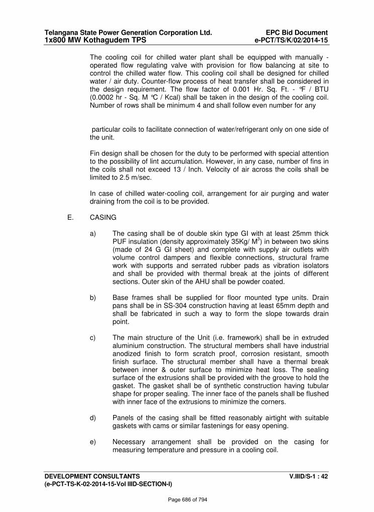
Telangana State Power Generation Corporation Ltd. EPC Bid Document 1x800 MW Kothagudem TPS e-PCT/TS/K/02/2014-15
DEVELOPMENT CONSULTANTS V.IIID/S-1 : 42 (e-PCT-TS-K-02-2014-15-Vol IIID-SECTION-I)
The cooling coil for chilled water plant shall be equipped with manually -
operated flow regulating valve with provision for flow balancing at site to control the chilled water flow. This cooling coil shall be designed for chilled water / air duty. Counter-flow process of heat transfer shall be considered in the design requirement. The flow factor of 0.001 Hr. Sq. Ft. - °F / BTU (0.0002 hr - Sq. M °C / Kcal) shall be taken in the design of the cooling coil. Number of rows shall be minimum 4 and shall follow even number for any
particular coils to facilitate connection of water/refrigerant only on one side of
the unit. Fin design shall be chosen for the duty to be performed with special attention
to the possibility of lint accumulation. However, in any case, number of fins in the coils shall not exceed 13 / Inch. Velocity of air across the coils shall be limited to 2.5 m/sec.
In case of chilled water-cooling coil, arrangement for air purging and water
draining from the coil is to be provided.
E. CASING
a) The casing shall be of double skin type GI with at least 25mm thick PUF insulation (density approximately 35Kg/ M3) in between two skins (made of 24 G GI sheet) and complete with supply air outlets with volume control dampers and flexible connections, structural frame work with supports and serrated rubber pads as vibration isolators and shall be provided with thermal break at the joints of different sections. Outer skin of the AHU shall be powder coated.
b) Base frames shall be supplied for floor mounted type units. Drain
pans shall be in SS-304 construction having at least 65mm depth and shall be fabricated in such a way to form the slope towards drain point.
c) The main structure of the Unit (i.e. framework) shall be in extruded
aluminium construction. The structural members shall have industrial anodized finish to form scratch proof, corrosion resistant, smooth finish surface. The structural member shall have a thermal break between inner & outer surface to minimize heat loss. The sealing surface of the extrusions shall be provided with the groove to hold the gasket. The gasket shall be of synthetic construction having tubular shape for proper sealing. The inner face of the panels shall be flushed with inner face of the extrusions to minimize the corners.
d) Panels of the casing shall be fitted reasonably airtight with suitable
gaskets with cams or similar fastenings for easy opening.
e) Necessary arrangement shall be provided on the casing for measuring temperature and pressure in a cooling coil.
Page 686 of 794
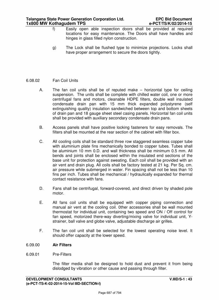
Telangana State Power Generation Corporation Ltd. EPC Bid Document 1x800 MW Kothagudem TPS e-PCT/TS/K/02/2014-15
DEVELOPMENT CONSULTANTS V.IIID/S-1 : 43 (e-PCT-TS-K-02-2014-15-Vol IIID-SECTION-I)
f) Easily open able inspection doors shall be provided at required locations for easy maintenance. The Doors shall have handles and hinges in glass filled nylon construction.
g) The Lock shall be flushed type to minimize projections. Locks shall
have proper arrangement to secure the doors tightly. 6.08.02 Fan Coil Units
A. The fan coil units shall be of reputed make – horizontal type for ceiling suspension. The units shall be complete with chilled water coil, one or more centrifugal fans and motors, cleanable HDPE filters, double wall insulated condensate drain pan with 15 mm thick expanded polystyrene (self extinguishing quality) insulation sandwiched between top and bottom sheets of drain pan and 18 gauge sheet steel casing panels. Horizontal fan coil units shall be provided with auxiliary secondary condensate drain pans.
B. Access panels shall have positive locking fasteners for easy removals. The
filters shall be mounted at the rear section of the cabinet with filter box.
C. All cooling coils shall be standard three row staggered seamless copper tube with aluminium plate fins mechanically bonded to copper tubes. Tubes shall be aluminium 10 mm 0.D. and wall thickness shall be minimum 0.5 mm. All bends and joints shall be enclosed within the insulated end sections of the base unit for protection against sweating. Each coil shall be provided with an air vent and drain plug. All coils shall be factory tested at 21 kg. Per Sq. cm. air pressure while submerged in water. Fin spacing shall not be less than 10 fins per inch. Tubes shall be mechanical / hydraulically expanded for thermal contact resistance with fans.
D. Fans shall be centrifugal, forward-covered, and direct driven by shaded pole
motor.
E. All fans coil units shall be equipped with copper piping connection and manual air vent at the cooling coil. 0ther accessories shall be wall mounted thermostat for individual unit, containing two speed and ON / Off control for fan speed, motorized there-way diverting/mixing valve for individual unit, Y-strainer, ball valve and globe valve, adjustable discharge air grilles.
F. The fan coil unit shall be selected for the lowest operating noise level. It
should offer capacity at the lower speed. 6.09.00 Air Filters 6.09.01 Pre-Filters The filter media shall be designed to hold dust and prevent it from being
dislodged by vibration or other cause and passing through filter.
Page 687 of 794
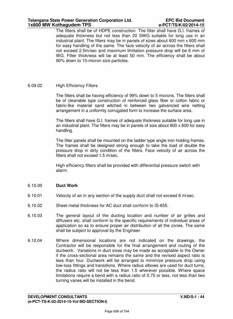
Telangana State Power Generation Corporation Ltd. EPC Bid Document 1x800 MW Kothagudem TPS e-PCT/TS/K/02/2014-15
DEVELOPMENT CONSULTANTS V.IIID/S-1 : 44 (e-PCT-TS-K-02-2014-15-Vol IIID-SECTION-I)
The filters shall be of HDPE construction. The filter shall have G.I. frames of adequate thickness but not less than 20 SWG suitable for long use in an industrial plant. The filters may be in panels of sizes about 600 mm x 600 mm for easy handling of the same. The face velocity of air across the filters shall not exceed 2.5m/sec and maximum limitation pressure drop will be 6 mm of WG. Filter thickness will be at least 50 mm. The efficiency shall be about 90% down to 10-micron size particles.
6.09.02 High Efficiency Filters The filters shall be having efficiency of 99% down to 5 microns. The filters shall
be of cleanable type construction of reinforced glass fiber or cotton fabric or fabric-like material sand witched in between two galvanized wire netting arrangement in a uniformly corrugated form to increase the surface area.
The filters shall have G.I. frames of adequate thickness suitable for long use in
an industrial plant. The filters may be in panels of size about 600 x 600 for easy handling.
The filter panels shall be mounted on the ladder type angle iron holding frames.
The frames shall be designed strong enough to take the load of double the pressure drop in dirty condition of the filters. Face velocity of air across the filters shall not exceed 1.5 m/sec.
High efficiency filters shall be provided with differential pressure switch with alarm.
6.10.00 Duct Work 6.10.01 Velocity of air in any section of the supply duct shall not exceed 8 m/sec. 6.10.02 Sheet metal thickness for AC duct shall conform to IS-655. 6.10.03 The general layout of the ducting location and number of air grilles and
diffusers etc. shall conform to the specific requirements of individual areas of application so as to ensure proper air distribution of all the zones. The same shall be subject to approval by the Engineer.
6.10.04 Where dimensional locations are not indicated on the drawings, the
Contractor will be responsible for the final arrangement and routing of the ductwork. Variations in duct sizes may be made as acceptable to the Owner if the cross-sectional area remains the same and the revised aspect ratio is less than four. Ductwork will be arranged to minimize pressure drop using low-loss fittings and transitions. Where radius elbows are used for duct turns, the radius ratio will not be less than 1.5 wherever possible. Where space limitations require a bend with a radius ratio of 0.75 or less, not less than two turning vanes will be installed in the bend.
Page 688 of 794
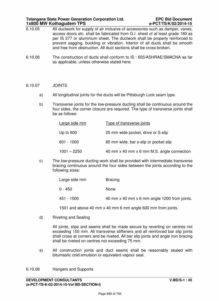
Telangana State Power Generation Corporation Ltd. EPC Bid Document 1x800 MW Kothagudem TPS e-PCT/TS/K/02/2014-15
DEVELOPMENT CONSULTANTS V.IIID/S-1 : 45 (e-PCT-TS-K-02-2014-15-Vol IIID-SECTION-I)
6.10.05 All ductwork for supply of air inclusive of accessories such as damper, vanes, access doors etc. shall be fabricated from G.I. sheet of at least grade 180 as per IS 277 or aluminium sheet. The ductwork shall be properly reinforced to prevent sagging, buckling or vibration. Interior of all ducts shall be smooth and free from obstruction. All duct sections shall be cross-broken.
6.10.06 The construction of ducts shall conform to IS : 655/ASHRAE/SMACNA as far
as applicable, unless otherwise stated here. 6.10.07 JOINTS
a) All longitudinal joints for the ducts will be Pittsburgh Lock seam type.
b) Transverse joints for the low-pressure ducting shall be continuous around the four sides, the corner closure are required. The type of transverse joints shall be as follows:
Large side mm Type of transverse joints
Up to 600 25 mm wide pocket, drive or S-slip
601 - 1000 85 mm wide, bar s-slip or pocket slip
1001 – 2250 40 mm x 40 mm x 6 mm M.S. angle connection
c) The low-pressure ducting work shall be provided with intermediate transverse
bracing continuous around the four sides between the joints according to the following sizes:
Large side mm Bracing
0 - 450 None
451 - 1500 40 mm x 40 mm x 6 mm angle 1200 from joints.
1501 and above 40 mm x 40 mm 6 mm angle 600 mm from joints.
d) Riveting and Sealing
All joints, slips and seams shall be made secure by reverting on centres not
exceeding 150 mm. All transverse stiffeners and all reinforced bar slip joints shall cross at corners and be riveted. All bar slip joints and angle iron bracing shall be riveted on centres not exceeding 75 mm.
e) All construction joints and duct seams shall be reasonably sealed with
bitumastic cold emulsion or equivalent vapour seal. 6.10.08 Hangers and Supports
Page 689 of 794
Telangana State Power Generation Corporation Ltd. EPC Bid Document 1x800 MW Kothagudem TPS e-PCT/TS/K/02/2014-15
DEVELOPMENT CONSULTANTS V.IIID/S-1 : 46 (e-PCT-TS-K-02-2014-15-Vol IIID-SECTION-I)
a) All ductwork shall be provided with adequate hangers or supports to ensure rigid support and to prevent vibration. Spacing of duct supports shall not exceed 3 m centres.
b) Hangers shall be suspended from the building steel with provision for
necessary auxiliaries, or special steel members, or by hooks fixed to the embedded plates provided in the ceiling.
c) Hangers for all ducts shall be trapeze type with the shelf construction
from 35 mm x 35 mm x 5 mm angle iron and hung by two steel rods each of not less than 10 mm dia. for ducts, with larger side less than
2250 mm while for those greater than 2250 mm shall be with 50 x 50
x 5 angles and rods not less than 16 mm dia.
d) All hangers and supports shall be as per drawings / specifications. When vertical ducts pass through floor slab, they shall be supported by means of collars, constructed of steel structural angles securely fastened about the girth of the duct and bitumastic compound between the horizontal leg of the supporting angle and the floor. The duct aspect ratio shall not be more than 4: 1. Turning vanes are required to be provided with bend more than 45 Deg.
6.10.09 Access Doors All main ductwork shall be accessible throughout using tight fitted hinged
access doors. Doors shall have to be cemented on sponge rubber gaskets. Angle joints shall be provided with felt or rubber gaskets for leak-tightness of the joints.
Access doors/panels are to be provided at following places: Near each fire damper Near each heater coil Near each filter bank In case access doors are to be installed in the insulated ducts, the access
door panel should be suitably insulated, such that it can be operated without damaging the duct insulation and there should be no condensation either on the access doors or on the duct when the plant is running.
6.10.10 Flexible Connection Rubber impregnated canvas or equal flexible connections of at least 150 mm
length shall be provided at each connection between ductwork and fan units. 6.10.11 Dampers
i) SPLITTER DAMPER
Splitter dampers in branch take off shall be provided. Dampers blades shall be minimum 16 SWG thick. Alternatively catcher shall be provided in right angle tee of ducts.
Page 690 of 794
Telangana State Power Generation Corporation Ltd. EPC Bid Document 1x800 MW Kothagudem TPS e-PCT/TS/K/02/2014-15
DEVELOPMENT CONSULTANTS V.IIID/S-1 : 47 (e-PCT-TS-K-02-2014-15-Vol IIID-SECTION-I)
ii) FIRE DAMPER
Fire dampers shall be provided as per the requirement mentioned elsewhere in the specification. The fire dampers shall be of motorised / solenoid/fusible link type operated by smoke detectors of the zone fire fighting system. The fire damper shall be smoke-tight type and shall have 120 min. fire rating. Provision shall be kept for manual operation of the damper.
Blade thickness : At least 16G CRCA Frame : At least 40 x 40 x 3 mm Angle.
Motorised Fire Dampers shall be rated for 240 V, 50 Hz, 1 Ph., AC supply.
Motor for Fire dampers shall be continuously rated. These Dampers shall close on de-energisation and open on energisation of Motor. Provision shall be kept for manual operation of the Damper.
Fire dampers will be provided at the supply/exhaust duct for fire-rated
walls/floors as required by National Fire Protection Association (NFPA) and International Building Code (IBC).
iii) ACTUATORS
The actuators will be UL listed.
Dampers will be equipped with operators of sufficient power to control
dampers, without flutter or hunting, through the entire operating range at air velocities at least 20 percent greater than maximum design velocity. Operators will have sufficient power on closure to provide tight sealing against maximum system pressures. Damper actuators will be designed to provide a minimum of 200 percent of the torque required to operate the damper and to meet the air leakage criteria. Damper actuators will not be less than 2.26 N-m (20 inch-pounds). Each damper section will contain one or more damper actuators. Jack-shafting of the section is not permitted.
Operators functioning in sequence with other operators will have adjustable
operating ranges and set points.
Spring-return operators will be provided for two-position control or on reversible operators where required for fail-safe operation.
Electric motor operators for modulating control will be reversible type.
Locations where temperatures fall below minimum operating temperature of operator will be heated.
When dampers are installed on ducts to be externally thermally insulated,
each damper operator will be equipped with stand-off mounting brackets, bases, or adapters to provide clearance between the duct and operator not less than the thickness of insulation. Standoff mounting items will be integral with the operator or standard accessory of damper manufacturer.
Page 691 of 794
Telangana State Power Generation Corporation Ltd. EPC Bid Document 1x800 MW Kothagudem TPS e-PCT/TS/K/02/2014-15
DEVELOPMENT CONSULTANTS V.IIID/S-1 : 48 (e-PCT-TS-K-02-2014-15-Vol IIID-SECTION-I)
iv) OPPOSED MULTIPLE LOUVRE DAMPER
Opposed multiple louvers dampers shall be provided at the fan outlets and wherever mentioned in the drawings, specification and fan schedule. Each blade of the dampers shall be provided with bronze, gunmetal or nylon bearing at each end of its spindle. The spindle with bearing shall be mounted in a strong structural framework. Operating lever with fixing device for keeping the damper at the desired position shall be fitted for the manually operated dampers.
Operating level will be fixed on an indicator to show the percentage of opening of the damper in all cases except for the application with grilles and nozzles.
Velocity across the dampers shall not exceed 10 m/sec. Damper blades at
fan outlet shall be made up of 16 gauge M.S. 6.10.12 Diffusers, Grilles, Registers - Conventional Design Design of grilles & diffusers shall be such as to create desired throw and
spread of air and shall be approved by the purchaser/engineer. All diffusers and grilles shall be made up of powder coated sheet steel /
extruded aluminium with finish painting. Design of all diffusers and grilles shall be made by the Contractor matching with the lighting and other fittings and to be approved by the Engineer. Each supply air diffusers shall be fitted with opposed blade damper, built-in vanes and louvers arranged as per manufacturer’s standard design.
Side throw type supply registers shall have two sets of adjustable louvers with
opposed blade dampers. The front of louvers shall be horizontal to provide horizontal deflection and the rear set of vertical louvers shall adjust vertical deflection. The dampers shall have horizontal opposed blades regulated by an operating lever in the frame. All wall type exhaust / return air grilles shall have one set of louvers in the front. The louvers shall be fitted such as to remain in position by friction grip. All supply air grilles shall have one set of opposed multiple louver dampers at the inlet. The dampers shall be gang operated and will have a device to keep the dampers fixed in one position.
The grille frame and louvers shall be manufactured of at least 20 SWG GI
sheet and 22 SWG M.S. respectively. No grilles should by any chance make any rattling sound during continuous operation. All grilles shall match the decor of the space.
All grilles/diffusers shall be fitted with suitable gasket to prevent air leakage. 6.11.00 Insulation 6.11.01 Thermal Insulation
Page 692 of 794
Telangana State Power Generation Corporation Ltd. EPC Bid Document 1x800 MW Kothagudem TPS e-PCT/TS/K/02/2014-15
DEVELOPMENT CONSULTANTS V.IIID/S-1 : 49 (e-PCT-TS-K-02-2014-15-Vol IIID-SECTION-I)
A. The following items are to be insulated:
I. Refrigerant suction piping from the evaporator coil outlet up to the compressor inlet shall be insulated with minimum 39 mm thick aluminium foil faced Nitrile rubber/ XLPE for Screw type Package Water Chilling Unit and 26 mm Nitrile Rubber/XLPE with 30G Aluminium sheet Cladding for Precision/ Split Air Conditioner. For better efficiency of operation the liquid line running side by side with the suction line may be insulated together with the suction line already mentioned.
II. Double skin Casing of the cabinet type air-handling unit with at least 25 mm thick Poly Urethane Foam (PUF)/ EPS sandwiched between them.
III. Supply air duct and part of the return air duct passing through non
conditioned space, if any, with at least 13mm thick aluminium foil faced Nitrile Rubber / XLPE Insulation.
IV. Entire chilled water-piping, valves, chilled water circulating pumps,
and chillers with 39 mm thick aluminium foil faced Nitrile rubber/XLPE.
The portion of Chilled water piping exposed to atmosphere shall be insulated with 50 mm thick (TF quality) expanded polystyrene and finished with chicken wire mesh, 12 mm thick sand-cement plaster and an overall cladding of 30G Al. sheet.
V. Drain Piping from AHU/Precision ACs /Split AC unit/ FCU and Chillers
shall be insulated with 13 mm/ 6mm (for FCU and Split units) thick aluminium foil faced Nitrile Rubber/ XLPE.
VI. Screw type Packaged Chiller and Chilled Water Pump shall be
insulated with 39 mm thick aluminium foil faced Nitrile Rubber/ XLPE.
VII. Chilled water Expansion tank drain piping with 6 mm thick aluminium foil faced Nitrile Rubber/XLPE.
VIII. Insulation of Precision AC Unit/ Split AC Unit shall be as per
manufacture’s standard.
IX. Roof of AC spaces shall be insulated with 25 mm thick EPS (under deck) for not exposed to sun and 50mm thick EPS (under deck) for exposed to sun.
B. Insulation shall be fixed as per manufacturer’s recommendation. Due care
shall be taken to avoid damage to vapour arresters and insulation.
C. Extra insulation thickness shall be provided at duct pipe hangers and special care shall be taken to seal the insulation and hanger member penetrations and instruments and accessories tapings.
Page 693 of 794
Telangana State Power Generation Corporation Ltd. EPC Bid Document 1x800 MW Kothagudem TPS e-PCT/TS/K/02/2014-15
DEVELOPMENT CONSULTANTS V.IIID/S-1 : 50 (e-PCT-TS-K-02-2014-15-Vol IIID-SECTION-I)
D. Special care shall be taken to provide satisfactory insulation for valves, flanges, vessel connections etc. with proper facility for maintenance and inspection.
E. Insulated ducts crossing the floors shall have to be normally protected from
damage and water splashing by providing suitable cladding up to 300 mm from the floor level.
6.11.02 Acoustic Insulation
All supply air ducts in the air conditioning system shall be insulated with Acoustic insulation of 25 mm thick open cell erosion resistant Nitrile Rubber foam of density min. 140 Kg/CuM provided in the ducting up to a length of 6 M from the Air Handling Unit / Precision Air Conditioner.
6.12.00 Precision / Split AC Units 6.12.01 Water Cooled Precision Air Conditioners
A. Compressor
The compressor shall be hermetically sealed scroll type medium speed, single acting type designed for R-407C/410A duty. The compressor shall be complete with crank case heater (to be energised when compressor is on off cycle).
The compressor shall have proper lubrication system. Safety devices viz. high-pressure switch, low-pressure switch, low oil pressure (if applicable) shall be provided and such devices shall be electronically operated. Manual reset on safety cut out shall be provided. The horsepower for the compressor motor shall be adequately sized or 110% of the rated power required for the unit including drive loss.
Capacity control shall be devised by providing at least two compressors.
B. Condenser
All condensers shall be of shell and tube type with water in the tubes and
refrigerant in the shell. The heat exchanger shall be designed for a minimum working pressure of
10.5 kg/cm2 gauge on the water side and 19.0 / 27.0 kg/cm2 for R-407C / 410A on the refrigerant side and shall generally conform to the latest ASME CODE for unfired pressure vessels Section- VIII. The design pressure shall have a reasonable margin over the maximum working pressure.
The average velocity of water in tubes shall not be more than 2.5 m/sec.
Page 694 of 794
Telangana State Power Generation Corporation Ltd. EPC Bid Document 1x800 MW Kothagudem TPS e-PCT/TS/K/02/2014-15
DEVELOPMENT CONSULTANTS V.IIID/S-1 : 51 (e-PCT-TS-K-02-2014-15-Vol IIID-SECTION-I)
Water heads or refrigerant heads of the heat exchangers shall be as not to allow leakage of fluid from one pass to the other.
Tube supports of adequate strength shall be provided to prevent the tubes
from sagging and vibrating. The overall fouling factor for the condensers shall be 0.0002 Hr.M2oC/K.Cal. The condensers shall be designed to provide at least 2 °C sub cooling of
refrigerant under rated design condition. Testing and other design feature of the heat exchanger shall meet the
requirements of TEMA Class-C heat exchangers or approved equal. The heat exchangers shall have open able water boxes for ease in
maintenance. The tubes for the condensers shall also be copper with integral fins. The tube
wall thickness at any point shall not be less than 18 SWG. The baffle plates and the tube sheets shall be made of steel. The shell shall
be made up of seamless tube or shall be fabricated from flange quality steel plate (ASTM-A285 Grade-C). The tube support plates shall be made of flange quality carbon steel plates and shall be as per TEMA Standard.
The heat exchangers shall be provided with vent valve, relief valve, and/or
safety fusible plug on refrigerant side and vent valve and drain valve on water side (at every section of the baffled shell of heat exchanger).
The tenderer shall quote packaged units having compressor, condenser and
evaporator assembly together in a single framework and mounted on a common base plate. Provision for refrigerant charging and chemical cleaning of water tubes shall be provided.
Each heat exchanger shall be provided with water flow switch. This shall be
interlocked with the control of the individual refrigeration system/ corresponding compressor drive.
All the heat exchangers shall be provided, with standard connections like
thermo wells, inspection valve and antifreeze thermostat and external equaliser connection for expansion valves. Insulation shall be terminated in such a manner that it will not be damaged during removal of bolts, covers etc. Separate covers similar to flange covers shall be constructed to facilitate easy removal.
The design pressure shall have a reasonable margin over the maximum working pressure.
C. Evaporator Cooling Coil
The cooling coil shall be direct expansion type with multi-row deoxidised copper tubes with aluminium fins. Air velocity across the coil shall be limited
Page 695 of 794
Telangana State Power Generation Corporation Ltd. EPC Bid Document 1x800 MW Kothagudem TPS e-PCT/TS/K/02/2014-15
DEVELOPMENT CONSULTANTS V.IIID/S-1 : 52 (e-PCT-TS-K-02-2014-15-Vol IIID-SECTION-I)
to 2.5 m/sec. The coils shall be pressure tested and thoroughly dehydrated before assembling.
The coil shall be placed to make the system draw through type. Refrigerant feed control shall be by electronic expansion valve. Temperature control shall be through microprocessor based control panel. Insulated condensate drain pan of SS construction shall be provided within the unit.
The unit shall be factory assembled, wired, with inter connecting refrigerant
piping and built-in microprocessor based control console and tested as per the relevant code.
The cooling coil shall be to produce the capacity required under specified coil condition and air quantity. Heat load calculation to check the system selection shall be carried out and submitted by the tenderer.
D. Evaporator Fan The fan shall be heavy duty DIDW centrifugal type statically and dynamically
balanced with forward/backward curve blade, directly driven by high efficiency EC motors. Fan wheels and casing shall be constructed of steel and mounted on steel shaft. The bearings shall be ball bearing type mounted on vibration absorbing rubber mounts. The fan motor shall be mounted within the cabinet. Motor horsepower shall be sized for 120% of the rated power required.
The supply fan shall be sized to deliver the required air quantity against the
total external static pressure required for the system application, after taking care of all internal static pressure requirements of the units.
E. High Efficiency Filter
A set of High efficiency filters will be located inside the PAC unit cabinet. The
filters shall be high efficiency of 99% down to 5 microns. The filters shall be of cleanable type construction of reinforced glass fiber or cotton fabric or fabric-like material sand witched in between two galvanized wire netting arrangement in a uniformly corrugated form to increase the surface area.
The filters shall have G.I. frames of adequate thickness suitable for long use in
an industrial plant. The filters may be in panels of size about 600 x 600 for easy handling them.
The filter panels shall be mounted on the ladder type angle iron holding frames.
The frames shall be designed strong enough to take the load of double the pressure drop in dirty condition of the filters. Face velocity of air across the filters shall preferably not exceed 1.5 m/sec.
F. Humidifier
The humidifier shall be of Electrode type and shall be placed inside the PAC
unit cabinet. The humidifier shall be electronically controlled through the built-in microprocessor based control panel of the unit. A provision of make-up water connection with the humidifier shall be kept with the Unit cabinet.
Page 696 of 794
Telangana State Power Generation Corporation Ltd. EPC Bid Document 1x800 MW Kothagudem TPS e-PCT/TS/K/02/2014-15
DEVELOPMENT CONSULTANTS V.IIID/S-1 : 53 (e-PCT-TS-K-02-2014-15-Vol IIID-SECTION-I)
G. Electric Strip Heater
The PAC unit will be provided wit built-in electric strip heater electronically controlled through the built-in microprocessor based control panel of the unit. Such control includes both operating and safety controls with the sense of air temperature at the RA path and at the downstream side of the heater respectively.
H. Casing and Cabinet All components shall be housed in a welded sheet metal cabinet of double skin
of not less than 22 G thick MS powder coated sheets. The gap between two skins is filled up with at least 25mmthick PUF/ EPS insulation. Different sections will be constructed with framework and connected with each other in an airtight manner through gaskets, thermal barriers and sealant.
Removable panels shall be constructed of framed 1.6 mm sheet steel with
angle iron framing. Units shall be provided with 316 L.S.S. fasteners for easy removal and access for servicing. Air handling section of evaporator shall be provided with an acoustic lining of 25 mm thick fiberglass covered with fiber glass cloth and perforated aluminium sheet on the inside surface of the unit casing.
The return air opening shall be on the front face with a matching grille of
same colour finish. 6.12.02 Air Cooled Precision Air Conditioners
A Compressor
The compressor shall be hermetically sealed scroll type medium speed, single acting type designed for R-407C/410A duty. The compressor shall be complete with crank case heater (to be energised when compressor is on off cycle).
The compressor shall have proper lubrication system. Safety devices viz. high-pressure switch, low-pressure switch, low oil pressure (if applicable) shall be provided and such devices shall be electronically operated. Manual reset on safety cut out shall be provided. The horsepower for the compressor motor shall be adequately sized or 110% of the rated power required for the unit including drive loss.
Capacity control shall be devised by providing at least two compressors.
B Condenser (Outdoor Unit)
The Condenser shall be of Air Cooled type and shall be constructed of copper tube with aluminum fins. Tubes shall be designed for a minimum working pressure of 30 kg/ sq. cm. The condenser shall be complete with
Page 697 of 794
Telangana State Power Generation Corporation Ltd. EPC Bid Document 1x800 MW Kothagudem TPS e-PCT/TS/K/02/2014-15
DEVELOPMENT CONSULTANTS V.IIID/S-1 : 54 (e-PCT-TS-K-02-2014-15-Vol IIID-SECTION-I)
fans with drive motors and shall be provided with charging connection, safety relief valve and standard accessories, all encased in a powder coated GI casing with built-in electrical items and supporting frame. The condenser shall have the matching capacity with the compressor. There shall be a provision of isolating switch for the fans.
C Evaporator Cooling Coil
The cooling coil shall be direct expansion type with multi-row deoxidised copper tubes with aluminium fins. Air velocity across the coil shall be limited to 2.5 m/sec. The coils shall be pressure tested and thoroughly dehydrated before assembling.
The coil shall be placed to make the system draw through type. Refrigerant feed control shall be by electronic expansion valve. Temperature control shall be through microprocessor based control panel. Insulated condensate drain pan of SS construction shall be provided within the unit.
The unit shall be factory assembled, wired, with inter connecting refrigerant
piping and built-in microprocessor based control console and tested as per the relevant code.
The cooling coil shall be to produce the capacity required under specified coil condition and air quantity. Heat load calculation to check the system selection shall be carried out and submitted by the tenderer.
D. Evaporator Fan The fan shall be heavy duty DIDW centrifugal type statically and dynamically
balanced with forward/backward curve blade, directly driven by high efficiency EC motors. Fan wheels and casing shall be constructed of steel and mounted on steel shaft. The bearings shall be ball bearing type mounted on vibration absorbing rubber mounts. The fan motor shall be mounted within the cabinet. Motor horsepower shall be sized for 120% of the rated power required.
The supply fan shall be sized to deliver the required air quantity against the
total external static pressure required for the system application, after taking care of all internal static pressure requirements of the units.
E. High Efficiency Filter
A set of High efficiency filters will be located inside the PAC unit cabinet. The
filters shall be high efficiency of 99% down to 5 microns. The filters shall be of cleanable type construction of reinforced glass fiber or cotton fabric or fabric-like material sand witched in between two galvanized wire netting arrangement in a uniformly corrugated form to increase the surface area.
The filters shall have G.I. frames of adequate thickness suitable for long use in
an industrial plant. The filters may be in panels of size about 600 x 600 for easy handling them.
Page 698 of 794
Telangana State Power Generation Corporation Ltd. EPC Bid Document 1x800 MW Kothagudem TPS e-PCT/TS/K/02/2014-15
DEVELOPMENT CONSULTANTS V.IIID/S-1 : 55 (e-PCT-TS-K-02-2014-15-Vol IIID-SECTION-I)
The filter panels shall be mounted on the ladder type angle iron holding frames.
The frames shall be designed strong enough to take the load of double the pressure drop in dirty condition of the filters. Face velocity of air across the filters shall preferably not exceed 1.5 m/sec.
F. Humidifier
The humidifier shall be of Electrode type and shall be placed inside the PAC
unit cabinet. The humidifier shall be electronically controlled through the built-in
microprocessor based control panel of the unit. A provision of make-up water connection with the humidifier shall be kept with the Unit cabinet.
G. Electric Strip Heater
The PAC unit will be provided wit built-in electric strip heater electronically controlled through the built-in microprocessor based control panel of the unit.
Such control includes both operating and safety controls with the sense of air temperature at the RA path and at the downstream side of the heater respectively.
H. Casing and Cabinet
All components shall be housed in a welded sheet metal cabinet of double skin
of not less than 22 G thick MS powder coated sheets. The gap between two skins is filled up with at least 25mmthick PUF/ EPS insulation. Different sections will be constructed with framework and connected with each other in an airtight manner through gaskets, thermal barriers and sealant.
Removable panels shall be constructed of framed 1.6 mm sheet steel with
angle iron framing. Units shall be provided with 316 L.S.S. fasteners for easy removal and access for servicing. Air handling section of evaporator shall be provided with an acoustic lining of 25 mm thick fiberglass covered with fiber glass cloth and perforated aluminium sheet on the inside surface of the unit casing.
The return air opening shall be on the front face with a matching grille of
same colour finish. 6.12.03 Non-Duct able Split Type Air Conditioning Units
A. General I. The split type room air conditioner consists of two units one Indoor unit
(Evaporator) & an Outdoor unit (Condenser). It will be complete with all components to perform filtering and cooling of air in all seasons except winter. The refrigerant condenser will be air-cooled. The unit will be suitable for wall mounting.
Page 699 of 794
Telangana State Power Generation Corporation Ltd. EPC Bid Document 1x800 MW Kothagudem TPS e-PCT/TS/K/02/2014-15
DEVELOPMENT CONSULTANTS V.IIID/S-1 : 56 (e-PCT-TS-K-02-2014-15-Vol IIID-SECTION-I)
II. The unit shall have normal rating capacity as per the schedule mentioned elsewhere in the specification measured at a room temperature 24 °C DB and RH not exceeding 65% under design outside conditions specified elsewhere. The capacity variation should not be more than 5%.
B. Indoor Unit
I. The indoor unit consists of panel type dry filter, cooling coil, evaporator
fan etc. II. The filter is panel type dry having an efficiency of 90% down to 10-
micron size Particles. The filter media shall be designed to hold dust, sand and prevent if from being dislodged by vibration or other cause and passing through filter. The face velocity of air across the filters shall not exceed 2.5 m / sec.
III. Cooling coil will be direct expansion type made of seamless copper
tubes with aluminum fins, number of fins as per manufacturer’s standard but not more than 13 per inch & R22. The coils should be located at the suction side of the Evaporator Fans. Velocity of air across the coils shall be limited to 2.5 m/sec.
IV. Piping accessories like Hot gas piping, cold gas piping and liquid
refrigerant pipeline all made of copper complete with at least 26 mm thick Aluminium foil faced Nitrile rubber / XLPE or equivalent insulation interconnecting indoor and outdoor units, liquid line valves, liquid refrigerant piping, gauges and instruments, filter-drier, moisture indicator, isolating valves etc., shall be provided as may be required for safe and trouble free operation.
V. The evaporator fan shall be Centrifugal, DIDW with forward Curved
blades directly driven by TEFC squirrel cage induction motor operating in AC 240 V ± 10%, 1 Ph, 50 Hz ± 5% supply, with 3- step speed control. The evaporator fan shall be both statically and dynamically balanced.
VI. Sheet metal casing with inspection facilities, made of Powder coated
M.S. sheet and complete with suitable refrigerant pipe connections, insulated drain pan, insulated drain piping, supply and return air opening with decorative grilles with automatically swiveling louvers (for supply air grilles). The casing should be insulated inside to prevent condensation. This shall be provided from inside surface to limit the noise.
C. Outdoor Unit I. The outdoor unit shall consist of a compressor, air cooled condenser
with liberally sized aluminium finned copper tube coil and low noise directly driven fan and totally enclosed weather proof motor housed in power coated MS casing.
Page 700 of 794
Telangana State Power Generation Corporation Ltd. EPC Bid Document 1x800 MW Kothagudem TPS e-PCT/TS/K/02/2014-15
DEVELOPMENT CONSULTANTS V.IIID/S-1 : 57 (e-PCT-TS-K-02-2014-15-Vol IIID-SECTION-I)
II. The Compressor shall be rotary type with R-22 refrigerant of specified
capacity & motor. The compressor assembly shall be adequately designed for minimum vibration and noise disturbances. The compressor rotor assembly shall be dynamically balanced. The shaft seal shall be of proven design. The horsepower for the compressor motor shall be sized for 115% of rated power required for the unit including the drive loss.
III. Accessories like Suction and discharge valves, safety valve, HP and LP
cut out switches, powder coated sheet metal casing, vibration-isolating device, foundation bolts, built in Electricals like starters, switch fuse units, relays, contactors. The speed of the compressor should not exceed 1500 rpm.
IV. Air-cooled condenser with directly driven axial flow fan & adequately
sized drive motors (TEFC squirrel cage Induction type) with relief valve, hot gas connection, charging connection with valve, louver at the intake & exhaust of air, and other standard accessories. The condenser fan shall be both statically and dynamically balanced.
V. The heat exchangers shall be designed for a minimum design test
pressure of 20.33 Kg/m2 on the refrigerant pipe. The design pressure shall have a reasonable margin over the maximum working pressure. Tube supports of adequate strength shall be provided to prevent the tubes from sagging and vibrating. The condensers shall be designed to provide at least 4oC sub cooling of refrigerant under rated design condition. The unit should be operating free from any vibration and noise.
VI. The piping will be thermally insulated wherever required such that there
is no condensation on the outside of the piping. The insulation will be of Aluminium foil faced XLPE or Nitrile rubber or equivalent.
VII. Refrigerant piping shall be either of M.S. seamless (as per IS-1239,
Part-I heavy grade) or copper tube (IS-5493) or ASA-9-31.5). Pressure drop in hot gas, liquid and suction lines should not exceed the value corresponding to 2 oF change in saturation temperature of the refrigerant. Velocity in the discharge and suction pipe of the refrigerant shall not be so high as to create undue vibration and noise, velocity in the vertical length of discharge and suction pipe of the refrigerant shall be high enough to carry the entrained oil in the refrigerant, even in case of unit running at lowest partial capacity. Instrument piping for gauges, switches etc. shall be of copper only.
VIII. All the above equipment along with the electrical items like starter,
contactor and other controls shall be encased in a powder coated MS casing. The casing shall be complete with supports fabricated out of MS angles, & sheets (duly painted), anchor bolts, nuts etc. The entire unit shall be installed with rubber pad type vibration isolators.
Page 701 of 794
Telangana State Power Generation Corporation Ltd. EPC Bid Document 1x800 MW Kothagudem TPS e-PCT/TS/K/02/2014-15
DEVELOPMENT CONSULTANTS V.IIID/S-1 : 58 (e-PCT-TS-K-02-2014-15-Vol IIID-SECTION-I)
IX. All refrigerant valves as may be applicable shall have steel or brass
body with flange connection or socket connection for welding or brazing to pipe. For copper pipes size 5/8” and below flare connection will be acceptable. It is preferable to have the stems of rising stems inside screw type. The valve body and bonnet connection shall have bolted or welded connection.
X. It is preferable to have Teflon gland packing for the valves. The
construction of the discs of the valves shall be either globe or angle type. The valve seat shall have white metal lining or any equivalent soft replaceable lining. The valves shall be of tested quality. Leak tightness of the valves shall be tested at minimum 1.5 times the design pressure for the system.
6.13.00 Fresh Air System 6.13.01 For critical areas like control room, control equipment room etc., outside fresh
air will be inducted into the AHU room/ PAC room through a Fresh Air system consisting of an inlet louver, dry panel type filter, a fan with a short duct (if necessary), SA register and mixed with the return air in AHU room/ PAC room.
For other non-critical areas like service building fresh air will be inducted in the
AHU room through the wall mounted rain protection cowl with bird screen and a volume control damper.
6.14.00 Miscellaneous Items 6.14.01 Heater
A. Strip heater
I. Heating equipment wherever required shall be electrical type. All frame members, control box cover and associated sheet metal parts are to be heavy gauge steel with corrosion resistance treatment. Heating equipment may be required for winter heating as well as for reheating. Reheating heaters may be used for winter heating also.
II. Electric heaters will be fin-tube type of specified KW rating, with fins
permanently brazed to metal sheath. The metal sheath and fins will be of G.I. sheet material.
III. Wherever electric heaters are installed in the ductwork, size of ducts
should be suitably increased to offset the additional resistance created by the heaters. All heaters shall be mounted on such insulators that there shall be no leakage current under all weather condition including high humidity operation. The mounting frame shall be suitably grounded by earth wires / earth leads of two points.
Page 702 of 794
Telangana State Power Generation Corporation Ltd. EPC Bid Document 1x800 MW Kothagudem TPS e-PCT/TS/K/02/2014-15
DEVELOPMENT CONSULTANTS V.IIID/S-1 : 59 (e-PCT-TS-K-02-2014-15-Vol IIID-SECTION-I)
IV. An air stat is to be installed such that in case there is no circulation of air over the heater coils the heaters will be de-energised. Wherever the heaters are installed in the ductwork the terminal block will be such positioned in a junction box that it will be outside the ductwork in an accessible position. The junction box will be vermin proof, rat proof and provided with a hinged cover. A caution plate as per I.E. rules will also be provided. Access door will be provided in the duct near the heating coil for easy inspection and removal / replacement / fixing of individual strip heaters. The capacity of heaters will be distributed over three phases.
V. In case of reheating the heater will be controlled by humidity sensor & humidity transmitter and in case of winter heaters it will be controlled by temperature sensor & temperature transmitter.
B. Electric Room Heater
Electric Room Heaters shall be with High / Low control.
Electric Room Heaters shall be suitable for AC 240 V ± 10%, 1 Ph,
50 Hz ± 5% supply. 6.14.02 Electrode Humidifier
A. Electrode humidifier consists of high temperature Polypropylene water tank, electrodes, auto flash cycle activated on demand from the microprocessor based control system with humidity sensor, located in the AHU / PAC room. Such Humidifier shall be controlled by its own stand-alone microprocessor based control panel. Alarm indication will be provided for low water level in the water tank.
B. Whenever the relative humidity of the conditioned space reaches the
minimum allowable percentage of humidity, the humidifier shall be energized to restore the relative humidity. The humidifier shall be such controlled that it shall not exceed the maximum allowable limit of relative humidity in the conditioned space. The humidifier shall be sized and designed accordingly.
6.14.03 Non Chemical Water Treatment Equipment
A. The water treatment equipment is a 1 M long pipeline, which once installed, stops the formation of scale in the heat exchange zones completely.
B. The water treatment equipment consists of Metal Cell and Core and is
installed on line after the pumps and before the heat exchange zone. The distance of the heat exchange zone should not be more than 30 M and there should not be any static area between the water treatment equipment and heat exchange area.
6.15.00 False Ceiling 6.15.01 Scope
Page 703 of 794
Telangana State Power Generation Corporation Ltd. EPC Bid Document 1x800 MW Kothagudem TPS e-PCT/TS/K/02/2014-15
DEVELOPMENT CONSULTANTS V.IIID/S-1 : 60 (e-PCT-TS-K-02-2014-15-Vol IIID-SECTION-I)
The work under this Section shall include the supply and installation of
suspended ceiling using GYPSUM boards together with the suspension system as shown on drawing or specified in Schedule with all materials labour and equipment. The work shall also include providing of openings in the ceiling for lighting, air conditioning diffusers etc. as shown on drawings or instructed by the Engineer.
6.15.02. Installation
A. Suspension System General
Suspension system shall consist of the grid supporting the ceiling panels, intermediate runner supports for the grid if any and hangers, wall angles etc. required to suspend the grid or the runners from structural walls, slabs and beams or trusses.
All members of the suspension system shall be of sufficient strength and
rigidity to carry the ceiling boards or sheets in a true and level plane without exceeding a deflection of 1/360th of their span. All joints in ceiling panels shall run straight and cross joint shall be securely fixed to walls. All drillings of structural concrete or welding to steel for installation of the suspension system shall be included in the rate. All M S sections used for supports etc. shall be given one coat of synthetic enamel paint over a coat of red lead primer.
Metal Grid Suspension System Aluminium grid ceiling system shall be "Beadlock" as manufactured by W A
Beard shell and Co. Pvt. Ltd. or approved equal. Steel grid ceiling system shall be jolly snap grid as manufactured by Anil Hardboards Ltd. or approved equal.
Angle cleats or other suitable fixing device shall be fixed to the structural
beam or slab above for fixing of hangers. Main runners shall be hung by MS flats, angles or 12 g or heavier galvanized tie wire hangers at maximum 1.2 centres. Extra hangers shall be provided at light fixtures that are supported from the ceiling system. The spacing of main and cross runners shall be as shown on drawings.
The cross tees shall intersect main runners in pattern shown on drawing and
positively looked together with intersection clips. All perimeter areas shall have angle mouldings fixed to vertical wall surfaces & end tees shall rest on the moulding, unless otherwise shown on drawings.
B. CEILING PANELS
Installation of Ceiling panels shall be strictly as per manufacturer's instruction.
Page 704 of 794
Telangana State Power Generation Corporation Ltd. EPC Bid Document 1x800 MW Kothagudem TPS e-PCT/TS/K/02/2014-15
DEVELOPMENT CONSULTANTS V.IIID/S-1 : 61 (e-PCT-TS-K-02-2014-15-Vol IIID-SECTION-I)
For exposed grid ceiling system, tile hold down clips shall be used at the rate
of minimum one per 1.2 meter length of perimeter. These shall however be omitted in access panels which shall be located as per the instruction of the Engineer.
For concealed grid ceiling system, tiles shall be fixed to the supporting grid in
manner shown on drawing or as specified by the manufacturer. Where V- joints in tiles are called for in drawings, these shall be in true lines. Where flush surface is required, the joints shall be filled with approved filler material and finished to give a neat uniform surface. Where shown on drawings and
schedule of items, 6 mm thick cement: lime: sand surface of ceiling boards
and finished in a true and even surface without undulations suitable for subsequent painting. Special care shall be taken to neatly finish the ceiling at junctions with walls, light fixtures, diffusers etc.
6.15.03 Acceptance Criteria
Finished ceiling shall be at the correct plane and present a pleasing and uniform appearance, free from sags, warps, figures or damaged boards. Joints, exposed grids etc. shall be in true lines and symmetrically placed in manner shown on drawings. Cut outs for light fixtures, diffusers etc. shall be of exact dimensions and in exact locations.
6.15.04 Rates
Shall be lump sum rates for complete items called for in the "Schedule of Items". No extra payment will be made for arrangement for lighting fixtures, air conditioning diffusers, access panels, etc. The rate shall include all cutting and wastage from standard size sheets, boards, runners, etc.
6.16.00 Electrical Items 6.16.01 General Electrical Specification For detailed General Electrical Specification, relevant Electrical section, as
applicable, shall be followed. 6.16.02 Drive Motor For detailed technical specification of motors, relevant Electrical section, as
applicable, shall be followed. 6.16.03 Local Push Button Station (LPBS) For detailed technical specification of Local Push Button Station (LPBS) system
relevant Electrical section, as applicable, shall be followed. 6.16.04 Power Distribution Board For detailed technical specification of Power Distribution Board relevant
Electrical section, as applicable, shall be followed.
Page 705 of 794
Telangana State Power Generation Corporation Ltd. EPC Bid Document 1x800 MW Kothagudem TPS e-PCT/TS/K/02/2014-15
DEVELOPMENT CONSULTANTS V.IIID/S-1 : 62 (e-PCT-TS-K-02-2014-15-Vol IIID-SECTION-I)
6.16.05 Cables For detailed technical specification of Cables relevant Electrical section, as
applicable, shall be followed. 6.16.06 Cable Trays and Racks For detailed technical specification of Cable Trays relevant Electrical section,
as applicable, shall be followed. 6.16.07 Grounding For detailed technical specification of Grounding relevant Electrical section, as
applicable, shall be followed. 6.16.08 DDC System For detailed technical specification of DDC System relevant part of the
specification shall be referred to. 6.17.00 Controls & Instrumentation 6.17.01 Control System
A. All control shall be electrical / electronic type depending upon the requirement & as specified under the specification.
B. Chilled Water System Controls
All safety controls against high refrigerant pressure, low refrigerant pressure,
low oil pressure, high and low voltage, compressor over-load and protection against freezing of the water chiller, low flow condenser cooling water & chilled water shall be provided.
All safety controls against antifreeze protection, pump cavitations, motor
protection etc. shall be provided. Operating thermostat/ temperature sensor sensing outlet water temperature of
chiller shall be provided for each compressor. This thermostat/ temperature sensor shall control the liquid line solenoid valve in conjunction with the capacity controller for Screw type. Automatically operated heaters with safety thermostats & automatic unloaded starting device shall be provided for the compressor. Antifreeze thermostat to trip off respective compressor shall be provided for each compressor.
C. Direct Expansion System Controls
All devices for automatic refrigerant flow control by thermostatic expansion
valve sensed by the superheat in suction line, solenoid valves in the liquid line to operate in conjunction with automatic capacity control of compressor by room thermostat (as applicable) sensing from the inside temperature of the
Page 706 of 794
Telangana State Power Generation Corporation Ltd. EPC Bid Document 1x800 MW Kothagudem TPS e-PCT/TS/K/02/2014-15
DEVELOPMENT CONSULTANTS V.IIID/S-1 : 63 (e-PCT-TS-K-02-2014-15-Vol IIID-SECTION-I)
conditioned space is to be provided. High pressure and low-pressure cut out, low oil pressure cut out (if applicable), high and low voltage protection, compressor motor overload protection shall be provided. Automatically operated crank case heater with safety thermostats shall be provided for reciprocating compressors.
D. Air Handling Unit Controls
The temperature of all conditioned spaces shall be maintained / controlled by a modulating type 3 way mixing valve. The modulating motor will be operated by getting sense from the temperature sensor and associated transmitter placed in the return air path. There shall also be control valves in the chilled water line (for chilled water units) for manual control of chilled water flow into the cooling coil. These control valves shall be flow regulating cum measuring type with precision adjustment arrangement.
E. Annunciations
Audio-visual alarm facility is envisaged of the system. Details of the
annunciation system shall be as per mentioned elsewhere and as per requirement.
6.17.02 Miscellaneous Instruments
A. The pressure indicators and temperature indicators shall have minimum 150 mm size dial. The pressure gauges shall be Bourdon type and complete with isolating/valves. The pressure gauge shall conform to IS: 3624 and temperature gauge as per BS: 1041.
B. Water flow switch shall be vane actuator type or differential pressure type,
with adjustable actuation set point. The level switch shall be ball float operated magnetic type complete with cage. The switch case shall be weather proof conforming to NEMA-4.
C. Apart from the thermostat, pressure switches, level switches and level
indicators specified in this tender document, the local instruments shall also be furnished as a part of the system as shown in drawings enclosed and as per functional requirement.
D. The range of controls and instruments should be such that the operating
ranges are preferably in the mid scale. The accuracy should not be less than + 1% of full scale deflection. The repeatability of readings shall be + 1%. The differential in controls should be such that the equipment is able to operate at desired settings or maintain desired condition.
E. The scale of pressure indicators for refrigerants units will be in kg/cm2.
Saturation temperature of the refrigerant in use, at the corresponding
Page 707 of 794
Telangana State Power Generation Corporation Ltd. EPC Bid Document 1x800 MW Kothagudem TPS e-PCT/TS/K/02/2014-15
DEVELOPMENT CONSULTANTS V.IIID/S-1 : 64 (e-PCT-TS-K-02-2014-15-Vol IIID-SECTION-I)
pressure should also be indicated in the scale. The suction and oil gauge shall be compound gauge. The scale of pressure indicator for pumps will be in meter. The temperature indicator’s scale will be in °C. The range should be such that even when the equipment is idle and the temperature of the medium is at such variance, the indicator will not be damaged.
F. All instruments should be such selected and installed that they are easily
readable from the floor. 7.00.00 SPECIAL TOOLS The supplier shall furnish a complete set of all special tools, wrenches etc.
with necessary toolboxes as required for erection, operation & maintenance, overhaul or complete replacement of any equipment supplied under this specification. The supplier shall enclose a list of such tools recommended by them.
8.00.00 SPARE PARTS 8.01.00 The supplier shall furnish and quote the Mandatory spare parts for the
complete Air Conditioning System Equipment as per the list attached in the other part of the specification.
9.00.00 TESTING AND INSPECITON AT MANUFACTURER’S WORKS 9.01.00 The manufacturer shall conduct all tests required to ensure that the
equipment furnished shall conform to the requirements of this specification and in compliance with the requirement of the applicable codes.
9.02.00 Following tests shall be carried out during and after completion of different
component parts as applicable and in accordance with the requirements of the applicable codes.
9.03.00 Material analysis and testing shall be carried out. 9.04.00 Hydraulic test for pressure parts including piping of VAM & its components,
pumps, compressors & its components, vessels etc. 9.05.00 Dynamic balancing of all the rotating parts is to be done. 9.06.00 Performance test of Vapor Absorption Chiller, pump, compressors,
condenser, cooling towers and air handling units shall be done as per code procedure.
9.07.00 Tests on motors as per Indian Standard IS-325 and IS-4029. 9.08.00 Other tests, as necessary and recommended by the manufacturer.
Page 708 of 794
Telangana State Power Generation Corporation Ltd. EPC Bid Document 1x800 MW Kothagudem TPS e-PCT/TS/K/02/2014-15
DEVELOPMENT CONSULTANTS V.IIID/S-1 : 65 (e-PCT-TS-K-02-2014-15-Vol IIID-SECTION-I)
Test certificates and reports shall be made available to the Purchaser / Engineer on the above tests, for approval and before despatch of equipment.
The representatives of Purchaser / Engineer shall be given full access to all
tests. The Tenderer shall inform the Purchaser within 21 days prior to important shop tests so that if the Purchaser / Engineer so desires, their representatives can witness the tests.
Cost of conducting all shop tests shall be borne by the supplier. 10.00.00 FIELD TEST 10.01.00 Overall performance of the air conditioning system with peak summer and
monsoon outside conditions as well as individual equipment shall be tested after complete installation at site. Duration of such test shall be 72 hours. This test shall be carried out to determine whether the plant meets the performance requirements specified here in and shall include measurements of all parameters under various outside conditions and establishment of correct supply of equipment. All testing and calibrating instruments required for this purpose shall be supplied by the contractor.
10.02.00 Inspection and testing of duct work All component and duct work supplied shall be subjected to inspection and
testing as per relevant codes and standard. 10.03.00 All ductwork shall be carefully examined to determine their performance with
the specification with respect of dimensions, materials, marking, leakage, workmanship and other requirement.
10.04.00 The contractor shall give assistance for all site tests of the equipment
according to prescribed procedure laid down by the Manufacturer / Engineer. 11.00.00 PERFORMANCE GUARANTEE, TOLERANCE, PENALTY AND RECORDS 11.01.00 The Tenderer shall have to guarantee the performance of individual
equipment. The Tenderer shall also guarantee maintenance of the inside conditions as indicated under “design criteria”.
11.02.00 Rectification of Deficient Performance If the shop / site performance tests indicate the failure of the guaranteed
performance of the equipment concerned, the tenderer will be given sometime to make good the deficiency at his own cost by incorporating the necessary modification, alteration and replacement.
11.03.00 Test Records
Page 709 of 794
Telangana State Power Generation Corporation Ltd. EPC Bid Document 1x800 MW Kothagudem TPS e-PCT/TS/K/02/2014-15
DEVELOPMENT CONSULTANTS V.IIID/S-1 : 66 (e-PCT-TS-K-02-2014-15-Vol IIID-SECTION-I)
The certificates and records of the above mentioned tests should be submitted to the Purchaser for approval. The manufacturer shall maintain records of all tests required in the specification for at least 5 years. A list of records shall be submitted to the Purchaser on completion of the job. The Purchaser shall be able to obtain certified copies of such records at any time.
12.00.00 SPECIAL CLEANING, PROTECTION & PAINTING 12.01.00 Internal surface of all parts shall be cleaned to remove loose scale and dirt.
The external surface of the motor and end shield shall be sand blasted to remove all rust, scale etc. All sharp edge shall also be removed. Welded rods, studs and other foreign objects shall be removed prior to final assembly. Excess oil and grease shall be removed by wiping.
12.02.00 All parts shall be painted with two (2) coats of rust preventing paint. One (1)
cost of final paint shall be applied over and above the rust proof paint before despatch of material.
12.03.00 All equipment shall be boxed / created or otherwise protected for shipment.
Dry nitrogen desiccant and other protection shall be provided as may be necessary.
13.00.00 DOCUMENTS, DATA TO BE FURNISHED WITH TENDER PROPOSAL 13.01.00 Beside submitting the enclosed Proposal Exhibit Sheets duly filled in, the
proposal shall also include the following drawings, curves and information wherever applicable.
Preliminary cooling and heating load calculation is to be furnished. 13.02.00 Preliminary equipment layout drawings of the air conditioning plant room,
AHU room and preliminary ducting layout drawing are to be furnished. 13.03.00 Manufacturer’s catalogue and literatures incorporating outline and sectional
drawings and ducting data for the following equipment: Screw Compressor Water-cooled Condensers Chiller Air Handling Unit (Fan, cooling coil & filter) Drive motors for various equipment as applicable Condenser cooling & chilled water pumps Cooling tower Non chemical water treatment
Page 710 of 794
Telangana State Power Generation Corporation Ltd. EPC Bid Document 1x800 MW Kothagudem TPS e-PCT/TS/K/02/2014-15
DEVELOPMENT CONSULTANTS V.IIID/S-1 : 67 (e-PCT-TS-K-02-2014-15-Vol IIID-SECTION-I)
Water-cooled precision air conditioner Air-cooled precision air conditioner
Air-cooled Non Duct able Split Air-conditioner Fan Coil Unit
Motor Direct Digital Controller
13.04.00 Manufacturer’s selection chart for the following equipment:
Water-cooled Screw Chiller AHU Water-cooled precision air conditioner Air-cooled precision air conditioner Air-cooled Non Duct-able Split Unit Pump Cooling Tower Fan Fan Coil Unit
13.05.00 Manufacturer’s catalogues and literatures on air conditioning system,
instruments and controls. 13.06.00 Sectional drawings for air diffusers and grilles, as applicable. 13.07.00 Manufacturer’s data sheets for filters and refrigerant. 13.08.00 Drive list 13.09.00 A detailed experience list about supply for system of similar type for similar
application mentioning in each case the salient technical parameters, date of commissioning and name of customers.
13.10.00 A comprehensive write-up and / or brochure on details of manufacturing and
testing facilities in the shop of the manufacturer. 13.11.00 Any other relevant data and particulars. 14.00.00 POST AWARD DOCUMENTS, DATA TO BE FURNISHED 14.01.00 Description of the system offered. 14.02.00 Sizing calculations for all equipment and accessories which include cooling
and heating load calculations, system pressure drop calculations, duct sizing calculations, pump capacity calculation, calculations for AHUs/FCUs and fresh air fans.
Page 711 of 794
Telangana State Power Generation Corporation Ltd. EPC Bid Document 1x800 MW Kothagudem TPS e-PCT/TS/K/02/2014-15
DEVELOPMENT CONSULTANTS V.IIID/S-1 : 68 (e-PCT-TS-K-02-2014-15-Vol IIID-SECTION-I)
14.03.00 Particulars of drawings, data, instruction manual and Drive List. 14.03.01 Equipment layout drawing for
Packaged Screw Chiller Air conditioning plant room Air handling unit room Cooling Tower Pump Expansion Tank Make-up Water Tank Water-cooled precision air conditioner Air-cooled precision air conditioner Air-cooled Non Duct-able Split Unit Fan Coil Unit
14.03.02 Schematic flow and instrumentation diagram of the complete system
indicating the limits of supply and erection. 14.03.03 Ducting layout drawing showing the details of duct sizes, duct joints, duct
insulation, duct supports, diffusers, grilles, dampers etc. 14.03.04 Layout drawings showing the route of Steam piping, refrigerant piping and
cooling water piping with details of insulation hangers, supports etc. 14.03.05 Outline drawings incorporating all principal dimensions, civil foundation
drawings and weight etc. and also sectional drawings incorporating data of material of construction wherever applicable for following equipments:
Water-cooled Screw Chilling Unit Air handling unit Water-cooled precision air conditioner
Air-cooled precision air conditioner Air-cooled Non Duct-able Split Air conditioner Drive motor for above equipment as applicable Cooling tower Expansion tank Make-up Water Tank Fan coil unit 14.03.06 Drawings and data sheets of each of Equipment and Instruments. 14.03.07 Drawings and data sheets for air filters, refrigerant / filter drier. 14.03.08 Write up on system interlock and / or interlock block diagram. 14.03.09 Electrical schematic and wiring diagram for control panel and the system as
applicable with back-up write-up. 14.03.10 Control panel / Switchgear outline drawings, bill of instruments and drawings
showing construction of control panel / switchgear.
Page 712 of 794
Telangana State Power Generation Corporation Ltd. EPC Bid Document 1x800 MW Kothagudem TPS e-PCT/TS/K/02/2014-15
DEVELOPMENT CONSULTANTS V.IIID/S-1 : 69 (e-PCT-TS-K-02-2014-15-Vol IIID-SECTION-I)
14.03.11 Reflected False Ceiling Plan indicating detail of supports/ hangers, grids, fixing detail of Grilles and diffusers and lighting fixtures etc.
14.03.12 Fixing/ application detail of under deck insulation indicating type and
thickness and weight of insulation. 14.03.13 Other drawings and data. 14.03.14 Material test certificates. 14.03.15 Shop test reports and certificates. 14.03.16 0peration, maintenance and overhauling manuals shall be provided as per
following specification. OPERATION AND MAINTENANCE MANUAL The successful tenderer, shall prepare, during the project execution stage a
manual giving details of operation and maintenance instructions. The manual will be comprehensive manual and will be provided by the Engineer. The manual shall cover but not limited to the following aspects:
i) Equipment description with design particulars. ii) Installation and Maintenance Instruction including preventive
maintenance requirements. iii) Instruction for pre-commissioning check-up, operation. iv) Trouble shooting. v) Spare Parts list. vi) Lubricant and lubrication schedule vii) Control logic and inter connection and calibration of controls. viii) System description ix) Necessary drawings, illustration x) List of manufacturer’s name and catalogues xi) Safety instructions.
The manual shall be securely bound in hard back durable folder with proper
indexing and separators. 15.00.00 List of Drawings
Sl. No.
Drawing No. Description
01. 13A06-003-DWG-VA-001
Schematic Diagram of Package Screw Chiller Unit
02. 13A06-003-DWG-VA-002
Schematic Diagram of Water Cooled Precision Air Conditioner
03. 13A06-003-DWG-VA-003
Schematic Diagram for Common Chilled Water Type Air
Page 713 of 794
Telangana State Power Generation Corporation Ltd. EPC Bid Document 1x800 MW Kothagudem TPS e-PCT/TS/K/02/2014-15
DEVELOPMENT CONSULTANTS V.IIID/S-1 : 70 (e-PCT-TS-K-02-2014-15-Vol IIID-SECTION-I)
Conditioning System of Power House and Service Building
04. 13A06-003-DWG-VA-004
Schematic Diagram of Air Cooled Precision Air Conditioner
05. 13A06-003-DWG-VA-003
Schematic Diagram of Air Cooled Split AC Unit
Page 714 of 794
Telangana State Power Generation Corporation Ltd. EPC Bid Document 1x800 MW Kothagudem TPS e-PCT/TS/K/02/2014-15
DEVELOPMENT CONSULTANTS (e-PCT/TS/K/02/2014-15/V-A/SEC-VII)
VOLUME: V-A
SECTION-VII
TECHNICAL SPECIFICATION FOR
415V PMCC/MCC, 415V ACDB AND 220V DCDB
Annexure III to
Technical Specification for Air Conditioning System ofSwitchyard Control building (Sec-II, Sub Section-C1)
Page 715 of 794
Telangana State Power Generation Corporation Ltd. EPC Bid Document 1x800 MW Kothagudem TPS e-PCT/TS/K/02/2014-15
DEVELOPMENT CONSULTANTS (e-PCT/TS/K/02/2014-15/V-A/SEC-VII)
CONTENTS
CLAUSE NO. DESCRIPTION
1.00.00 SCOPE OF SUPPLY
2.00.00 CODES AND STANDARDS
3.00.00 DESIGN CRITERIA
4.00.00 SPECIFIC REQUIREMENTS
5.00.00 TESTS
6.00.00 DRAWINGS, DATA AND MANUALS
ATTACHMENTS
ANNEXURE-A RATINGS AND REQUIREMENTS
ANNEXURE-B PROTECTIONS
ANNEXURE-C FITTINGS & ACCESSORIES
ANNEXURE-D BUS TRANSFER SCHEME FOR PMCC
DRAWINGS
TYPICAL SINGLE LINE DIAGRAM
TYPICAL CONTROL SCHEMATIC
THIS ANNEXURE IS TSGENCO TS FOR ENTIRE PLANT. BIDDER SHALL REFER THIS TS FOR THEPORTIONS RELEVANT TO PDB FOR AC SYSTEM APPLICABLE FOR SWITCHYARD SCOPE ONLY.
Page 716 of 794
Telangana State Power Generation Corporation Ltd. EPC Bid Document 1x800 MW Kothagudem TPS e-PCT/TS/K/02/2014-15
DEVELOPMENT CONSULTANTS V.V-A/S-VII : 1 (e-PCT/TS/K/02/2014-15/V-A/SEC-VII)
VOLUME :V-A
SECTION-VII
TECHNICAL SPECIFICATION FOR
415V PMCC/MCC, 415V ACDB AND 220V DCDB
1.00.00 SCOPE OF SUPPLY
1.01.01 Requisite nos. of following equipment shall be furnished with all accessories :-
a. Power cum Motor Control Centre (PMCC) b. Motor Control Centres (MCC) b. A.C. Distribution Board (DB) c. D.C. Distribution Board (DB) d. D.C. Starters e. Lockout Switches f. A.C./D.C. fuse boards
1.01.02 The base channel frame with hardware and lifting angles.
1.01.03 One set of special tools and tackles.
1.01.04 Set of accessories as listed below :
a) Breaker lifting and handling trolley.
b) Test cabinet with coupling cables for testing the breaker in drawout position.
c) Racking in/out handle for breakers.
1.01.05 12kV rubber mats shall be provided both at front and rear of LT Switchgear.
1.01.06 Mandatory Spare parts.
1.01.07 All relevant drawings, data and instruction manuals.
2.00.00 CODES AND STANDARDS
2.01.01 All equipment and materials shall be designed, manufactured and tested in accordance with the latest applicable Indian Standards (IS) and IEC except where modified and/or supplemented by this specification.
2.01.02 Equipment and material conforming to any other international standard which ensures equal or better quality, may be accepted. In such case, copies of the English version of the standard adopted shall be submitted along with the bid.
2.01.03 The electrical installation shall meet the requirements of Indian Electricity Rules as amended upto date and relevant IS Code of Practice. In addition, other rules and regulations applicable to the work shall be followed.
Page 717 of 794
Telangana State Power Generation Corporation Ltd. EPC Bid Document 1x800 MW Kothagudem TPS e-PCT/TS/K/02/2014-15
DEVELOPMENT CONSULTANTS V.V-A/S-VII : 2 (e-PCT/TS/K/02/2014-15/V-A/SEC-VII)
3.00.00 DESIGN CRITERIA
3.01.00 The PMCCs/MCCs/DBs will be used to provide power, control and protection for 415/240V A.C. and 220V D.C. auxiliary services (Motors & Feeders) of generating units.
3.02.00 Duty involves direct-on-line starting of large squirrel cage motors below 175kW. The starting current varies from 6 to 8 times rated current at very low power factor.
3.03.00 The equipment will be located in a hot, humid and tropical atmosphere, highly
polluted at places with coal dust and/or fly ash.
3.04.00 For continuous operation at specified ratings, the temperature rise of various equipment/components shall be limited to the permissible values stipulated in relevant standards and/or this specification.
3.05.00 Equipment ratings and quantities are detailed in the enclosed drawings and annexure. Equipment shall be furnished in strict compliance with the same.
3.06.00 All equipment and components thereof shall be capable of withstanding the mechanical forces and thermal stresses of the short-circuit currents without any damage or deterioration of the materials.
3.07.00 The PMCCs/ MCCs / DBs shall have two incomers and one bus-coupler. In addition to electrical interlocks, mechanical castle key interlock shall be provided between the two incomers and the bus-coupler so that any two of the three may be closed at a time.
3.08.00 Busbars of PMCCs shall be sized to carry continuously the associated transformer secondary current plus a 20% margin.
Busbars of MCC/DBs shall be sized to carry continuously the total running load of MCC/DB plus a 20% margin.
3.09.00 In cubicle of incomers & bus section breakers/MCCBs shall be identical to the associated busbar rating.
3.10.00 For continuous operation at specified ratings, the temperature rise of various equipment/components shall be limited to the permissible values specified in relevant standards and/or this specification.
3.11.00 Circuit breakers shall not produce any harmful over voltage during switching off of induction motors. If required, surge protective devices shall be included in the scope of supply to limit over voltages.
3.12.00 Incomers, Bus-couplers & outgoing feeders rated upto & including 630A shall be MCCB controlled. Above 630A all incomers, Bus-couplers & outgoing Feeders shall be ACB controlled. For critical loads ACB controlled feeders shall be provided which will be decided during detail engineering.
3.13.00 All motor rated 110kW & above, below 175kW shall be ACB controlled. Motor rated upto 110kW shall be contactor operated.
Page 718 of 794
Telangana State Power Generation Corporation Ltd. EPC Bid Document 1x800 MW Kothagudem TPS e-PCT/TS/K/02/2014-15
DEVELOPMENT CONSULTANTS V.V-A/S-VII : 3 (e-PCT/TS/K/02/2014-15/V-A/SEC-VII)
3.14.00 MCC & PMCC shall have sufficient number of spare modules (at least 20% of various sizes used with a minimum of 1 no. for each rating and type).
3.15.00 Outgoing feeders of PMCC shall be limited to minimum number of different sizes so that max. standardization is achieved from MCCB & contactor size point of view.
3.16.00 Incomers & bus section breakers of PMCCs/MCCs shall have provisions for remote operation from control room.
3.17.00 All breaker operated motor feeder shall be supplied from PMCC.
3.18.00 One no. Normal/Emergency switchgear to cater power supply to important emergency load / motors for safe shut-down of unit including 220V battery chargers shall be provided for each unit. The main incoming supply shall be from 415V unit service switchgear. When main incoming supply fails, reserve incoming supply shall be switched ON automatically from 415V station service switchgear. In case of total failure of AC supply of the power station, the supply from DG shall be switched ON automatically.
3.19.00 Each switchgear shall be provided with two bus sections, two incomer and a bus coupler rated for 100% of the loads connected to the switchgear.
3.20.00 For each auxiliary or load, one feeder shall be provided except for the following cases:
One feeder for a maximum 2 nos. isolator motor operating mechanism.
3.21.00 The switchgears shall be provided with suitable number and type of outgoing feeders for the respective auxiliary loads of the system/area, power supply feeders to various panels, lighting transformer, space heating panels, control cabinets and all other loads encountered in the plant. In addition, following feeders shall be provided in each bus section of each switchgear.
a) Bus VT module: One (1) no.
b) Switchgear test supply module: One (1) no.
c) 240V, 1 phase essential supply module with five nos. 1 phase outlets: One (1) no.
Necessary 415V/240V dry type transformer shall be provided.
d) Alarm module for common alarm for outgoing feeder fault: One (1) no.
e) DC supply alarm module for incomer, bus coupler fault: One (1) no.
3.22.00 Each feeder shall be provided with two nos. interposing relays for start & stop. These interposing relays shall be located in separate IPR panel described under C&I specification.
Page 719 of 794
Telangana State Power Generation Corporation Ltd. EPC Bid Document 1x800 MW Kothagudem TPS e-PCT/TS/K/02/2014-15
DEVELOPMENT CONSULTANTS V.V-A/S-VII : 4 (e-PCT/TS/K/02/2014-15/V-A/SEC-VII)
4.00.00 SPECIFIC REQUIREMENTS
4.01.00 Construction
4.01.01 PMCC / MCC / DB shall be indoor, metal-clad, air insulated and floor mounting type. All MCCs shall be fully draw out type and DBs shall be fixed type. ACB modules of PMCCs/MCCs shall be fully drawout type. MCCB / Switch Fuse modules shall also be fully drawout type. The design and construction shall be such as to allow extension at either end.
4.01.02 All PMCC/MCC shall be of double front construction. 4.01.03 PMCC /MCC/DB enclosure shall be dust and splash proof, conforming to a
degree of protection IP-54. All switchboard frames and load bearing members shall be fabricated using suitable mild steel structural sections or pressed and shaped cold rolled sheet steel of thickness 2.0mm. Frames shall be enclosed in cold rolled sheet steel of thickness 1.6 mm. Doors and covers shall also be of cold rolled sheet steel thickness 1.6 mm. Stiffeners shall be provided wherever necessary. The gland plate thickness shall be 3.0 mm for hot/cold rolled sheet steel and 4.0 mm for non-magnetic material.
4.01.04 PMCC / MCC / DB assembly shall comprise a continuous line up of dead
front, free-standing vertical sections, housing the control modules in multi tier formation.
4.01.05 The design shall be fully compartmentalized with metal/insulating partitions between compartments. The working height shall be limited within 750 mm to 1800 mm from floor level.
4.01.06 Each control module shall be housed in a separate compartment, complete
with an individual front access door having sufficient opening with concealed type hinges. Each vertical section shall have a removal back cover. All doors and covers shall be gasketed.
4.01.07 All push buttons, lamps, indicating instruments shall be flush / semi-flush mounted on respective module compartment.
4.01.08 A full height vertical cable chamber with cable supports shall be provided in each section to facilitate unit wiring. The chamber shall be liberally sized to accommodate all cables and shall have removable cover at the front for access.
4.01.09 A horizontal wireway, extending the entire length, shall be provided at the top of each PMCC / MCC / DB for inter panel wiring.
4.01.10 The width of the cable alley shall not be less than 250 mm.
4.02.00 Bus and Bus Taps
4.02.01 All PMCCs/MCCs/DBs shall be provided with three phase & neutral bus bars . All DCDBs shall be provided with two busbars. All busbar compartments shall be completely enclosed.
Page 720 of 794
Telangana State Power Generation Corporation Ltd. EPC Bid Document 1x800 MW Kothagudem TPS e-PCT/TS/K/02/2014-15
DEVELOPMENT CONSULTANTS V.V-A/S-VII : 5 (e-PCT/TS/K/02/2014-15/V-A/SEC-VII)
4.02.02 The main buses and connections shall be of high conductivity Aluminium / Aluminium alloy, sized for specified current ratings with maximum temperature limited to 85oc (i.e., 35oC rise over 50oC ambient).
4.02.03 Vertical busbars shall be designed for minimum current rating of 200A. Separate vertical busbars shall be provided for each vertical panel.
4.02.04 All bus connections shall be silver plated. Adequate contact pressure shall be ensured by means of two-bolt connection with plain and spring washers and locknuts.
Bimetallic connector shall be furnished for connection between dissimilar metals.
4.02.05 Busbars and connections shall be fully insulated for working voltage with adequate phase/ground clearances. Insulating sleeves for busbars and shrouds for joints and tap-off points shall be provided.
Bus insulators shall be flame retardant, non-hygroscopic track-resistant type with high creepage surface.
4.02.06 Busbars shall be supported and braced to withstand the stresses due to maximum short circuit current and also to take care of any thermal expansion.
4.02.07 Busbars shall be colour coded for easy identification and so located that the sequence R-Y-B shall be from left to right, top to bottom or front to rear when viewed from the front of the assembly.
4.03.00 Control Modules
4.03.01 Draw-out type control module shall have self-aligning power/control disconnects. All disconnects shall be silver plated to ensure good contacts.
4.03.02 The design shall be such as to permit easy withdrawal/reinsertion of the unit with guide rails to ensure correct alignment.
4.03.03 Control Module shall house the control components for a circuit such as switch fuse / MCCB, contactors, relays, push buttons, lamps etc. as per requirement of the control circuit.
4.03.04 The equipment layout shall provide sufficient working space in between the components and subject to Owner's approval.
4.03.05 Various module/compartment sizes shall be multiple of one basic unit to facilitate modifications at site. Suitable provision for this purpose should also be incorporated in the vertical bus bars.
4.03.06 Draw-out type control modules of same size and type shall be electrically and physically interchangeable.
4.04.00 Air Circuit Breaker
4.04.01 Circuit breaker shall be provided on the incomer having minimum interrupting capacity equal to the 50kA(r.m.s) fault level.
Page 721 of 794
Telangana State Power Generation Corporation Ltd. EPC Bid Document 1x800 MW Kothagudem TPS e-PCT/TS/K/02/2014-15
DEVELOPMENT CONSULTANTS V.V-A/S-VII : 6 (e-PCT/TS/K/02/2014-15/V-A/SEC-VII)
4.04.02 Circuit breaker shall be three pole, single throw, air-break type with independent manual spring closing, trip-free mechanism and shunt trip. However Incomer breaker shall be four pole type.
4.04.03 Circuit breaker shall be draw-out type, having service, test & isolated position with positive indication for each position.
4.04.04 Circuit breakers of identical rating shall be physically and electrically interchangeable.
4.04.05 Each breaker shall be provided with microprocessor based protection unit having three overload protection with adjustable current and time, three short circuit protection with adjustable current and time and three instantaneous short circuit protection. The operating characteristic shall be suitable for co-ordination with down-stream fuses.
4.04.06 Circuit breakers shall be provided with motor wound spring charging mechanism. Spring charging shall take place automatically after each breaker closing operation. One open-close-open operation of the circuit breaker shall be possible after failure of power supply to the motor. In addition, facility for manual charging of spring shall be provided.
4.04.07 Mechanical safety interlock shall be provided to prevent the circuit breaker from being racked in or out of the service position when the breaker is closed. It shall not be possible to open the circuit breaker door cubicle unless the breaker is in ‘OFF’ position.
4.04.08 Automatic safety shutters shall be provided to cover up the stationary disconnects when the breaker is withdrawn.
4.04.09 Each breaker shall be provided with an emergency manual trip, mechanical ON-OFF indicator, an operation counter and spring mechanism charge/discharge indicator, and electrical anti-pumping feature.
4.04.10 In addition to the auxiliary contacts required for normal breaker operation and indication, each breaker shall be provided with the following for interlocking purpose :-
a. Position/Cell switch with 4 NO + 4 NC contacts.
b. Auxiliary switch, with minimum 6NO + 6NC contacts,
4.04.11 Spring charge limit switch shall be provided for breakers with motor wound spring charging mechanism. These limit switches shall be provided with minimum 2NO + 2NC contact.
4.04.12 Limit/auxiliary switches shall be convertible type, that is, suitable for changing N.O. contact to N.C. and vice-versa.
4.04.13 Each breakers operated feeder shall be provided with protective devices as specified in Annexure–B.
Page 722 of 794
Telangana State Power Generation Corporation Ltd. EPC Bid Document 1x800 MW Kothagudem TPS e-PCT/TS/K/02/2014-15
DEVELOPMENT CONSULTANTS V.V-A/S-VII : 7 (e-PCT/TS/K/02/2014-15/V-A/SEC-VII)
4.05.00 Switches
4.05.01 Switches shall be triple pole, air break, AC23 motor duty for motor feeders and AC22 heavy duty for other feeders.
Motors duty switches shall be capable of safely making and breaking the locked rotor current of the associated motor circuit.
4.05.02 The switch shall have a quick-make, quick-break mechanism operated by a suitable external handle, complete with position indicator. This handle shall have provision for padlocking in ON and OFF position.
4.05.03 The compartment door shall be interlocked mechanically with the switch such that the door cannot be opened unless the switch is in OFF position. Means shall be provided for releasing this interlock at any time.
4.05.04 Switches shall be capable of withstanding the let-through fault current of back-up fuses or circuit breakers.
4.05.05 Wherever two incoming switches and one bus-section switch are provided for an assembly, these shall be mechanically/key interlocked to ensure that only two out of the three can be closed at time.
Wherever two incoming switches are provided for an assembly, these shall be mechanically/key interlocked to ensure that one of the two can be closed at time.
4.05.06 All incoming and outgoing feeders shall be provided with bolted disconnect link for isolation of neutral if necessary.
4.06.00 Fuses
4.06.01 Fuses shall be HRC, preferably link type, with a minimum interrupting capacity equal to the short circuit current of the LT system. Fuses shall be mounted on insulated fuse carriers, which are mounted on fuse bases. Wherever it is not possible to mount fuses on carriers, fuses shall be directly mounted on plug-in type of base. In such cases, one set of insulated fuse pulling handles shall be supplied with each board.
4.06.02 Fuses shall be furnished complete with fuse bases and fittings of such design as to permit easy and safe replacement of fuse element.
Visible indication shall be provided on blowing of the fuse.
4.06.03 Motor fuse characteristics and ratings shall be chosen to ride over starting period without blowing. The fuse on incoming feeder wherever provided, shall be chosen to provide discrimination with motor/feeder fuses.
4.07.00 Moulded Case Circuit Breaker (MCCB)
4.07.01 The MCCBs shall be of drawout type with trip-free operating mechanism of quick make & quick break type. Each MCCB shall be equipped with thermal release for thermal overload and magnetic release for short circuit protection on each pole.
Page 723 of 794
Telangana State Power Generation Corporation Ltd. EPC Bid Document 1x800 MW Kothagudem TPS e-PCT/TS/K/02/2014-15
DEVELOPMENT CONSULTANTS V.V-A/S-VII : 8 (e-PCT/TS/K/02/2014-15/V-A/SEC-VII)
4.07.02 MCCBs / MPCBs shall be suitable for manual closing and opening and also automatic trip on overload and short circuit. MCCB shall have intermediate position to indicate trip condition.
4.07.03 The MCCBs shall be provided with mechanical ON-OFF indicator at the front panel. The MCCB handles, after the breaker tripped due to faults, shall occupy a mean position indicating trip condition.
4.07.04 The compartment door shall be interlocked mechanically with the MCCB such that the door cannot be opened unless the MCCB is in OFF position. Means shall be provided for releasing this interlock at any time.
4.07.05 All feeders of PMCC / MCC rated up to & including 630 Amp shall be provided with MCCB. Air circuit breaker shall be provided for feeders rated above 630 Amp. For critical loads ACB controlled feeders shall be provided which will be decided during detailed engineering.
4.07.06 Motors rating above 110 KW will be operated by Air circuit breaker and protected by consolidated numerical motor protection relay.
4.08.00 A.C. Starter
4.08.01 Contactors
a. The contactors shall be three pole, air break type designed for duty class III - Category AC3 (for unidirectional motor) with non-bouncing silver/ silver alloy contacts. Contacts for reversible motors will be of AC4 duty.
b. Each contactor shall be provided with minimum two (2) normally open and two (2) normally closed auxiliary contacts rated 10 A at 240V A.C.
c. Reversing contacts shall be electrically and mechanically interlocked.
d. Contactors with delayed dropout feature shall be provided for some essential auxiliaries. These contactors shall not dropout on power failure if the voltage is restored within 3 seconds.
4.08.02 Protection
a. Thermal overload relays shall be three element, positive acting, ambient temperature compensated with adjustable settings.
b. Single phase preventor relay shall be provided, preferably as an inbuilt feature of thermal overload relay.
c. Relays shall be manual reset type with two changeover potential-free contacts. Resetting of relays shall be possible with compartment door closed. Colour of the resetting button shall be BLACK.
d. Relays may be direct acting or C.T. operated, depending on current rating. C.T.s shall be included in the scope of supply.
e. Motor starters shall have type '2' co-ordination according to IEC 947-4.
Page 724 of 794
Telangana State Power Generation Corporation Ltd. EPC Bid Document 1x800 MW Kothagudem TPS e-PCT/TS/K/02/2014-15
DEVELOPMENT CONSULTANTS V.V-A/S-VII : 9 (e-PCT/TS/K/02/2014-15/V-A/SEC-VII)
f. Earth fault relays with adjustable settings and time delays fed from core balance CT shall be provided.
g. Numerical / Digital Motor protection relay with short circuit, over load, earth fault, locked rotor and unbalance (NPS) load protection functions shall be provided for motor rated above 90 kW.
4.09.00 Control Transformer
4.09.01 LT Switchboard control supply
The Bidder shall provide one (1) no. adequately rated 415V/110V Control Transformer in each bus section with necessary taps and auto changeover facility for providing control power supply to various modules of the board, except motor feeders. Each motor feeder shall be provided with 415/110V control transformer of adequate capacity (min. 75VA) for control supply to such module. The sizing of control transformer shall be carried out by the Bidder considering the actual load of power contactors, auxiliary contactors, indicating lamps and other equipment in the module circuit. An additional load of 15watts shall be considered for each module for remote auxiliary relays and lamps to be connected in the control circuit of modules. Bidder shall also ensure that control transformer are adequately designed for meeting the momentary loading requirements and the voltage drop during this condition shall not be more than 5%. Each transformer shall be sized for catering to control supply of both bus sections.
4.09.02 LT Switchboard space heater supply
The Bidder shall provide one (1) no. adequately rated 415V/240V Control Transformer in each bus section with necessary taps and auto changeover facility for providing power supply to panel space heater, Motor space heater of motor rated 30 KW & above, Panel Illumination & Socket. The supply of these two (2) nos. control transformer are tapped from incoming supply of 415V PMCC/MCC before the incoming breaker. Incoming circuit to the space heater auxiliary bus shall be through isolating switch HRC fuse and neutral link of suitable rating. The supply of different modules shall be tapped individually from the auxiliary bus bars. Control supply healthy indication shall be provided. Each transformer shall be sized for catering to space heater supply of both bus sections.
4.10.00 D.C. Starters
4.10.01 D.C. Starter for emergency oil pump shall be fixed resistance type, designed to provide fast acceleration during starting.
4.10.02 DC starters shall be complete with switch-fuse units, contactors, resistors, relays, meters, push-buttons, lamps, etc.
4.10.03 Starters shall be furnished in totally enclosed floor-mounting, sheet steel cubicles complete with a hinged front access door. Minimum thickness of sheet steel shall be 2mm.
4.10.04 The cubicle enclosure shall provide dust and humidity protection, the degree of protection being not less than IP-54.
Page 725 of 794
Telangana State Power Generation Corporation Ltd. EPC Bid Document 1x800 MW Kothagudem TPS e-PCT/TS/K/02/2014-15
DEVELOPMENT CONSULTANTS V.V-A/S-VII : 10 (e-PCT/TS/K/02/2014-15/V-A/SEC-VII)
The resistor enclosure shall be provided with ventilating louvers and wire mesh guard and shall have a degree of protection IP-23.
4.10.05 Cubicle space heater shall be provided to maintain internal temperature above dew point. Heater shall be furnished with switch-fuse unit and thermostat control.
4.11.00 Relays
4.11.01 All incoming and bus-coupler circuits and circuit breaker operated outgoing feeders shall be provided with numerical relays. Breaker operated motor feeders shall be provided with numerical motor protection relay.
4.11.02 The numerical relays shall have provisions for interfacing with Plant DDCMIS / PLC.
4.11.03 Relays shall be of drawout design with built-in testing facilities. Small auxiliary relays may be in non-drawout execution.
4.11.04 All protective relays, auxiliary relays, and timers shall be provided with hand reset operation indicator (flag).
4.11.05 Relays shall be rated for operation on 110V secondary voltage and 5 A or 1 A. Number and rating of relay contacts shall suit the job requirements.
4.12.00 Control and Indication
4.12.01 Circuit breakers shall be wired up for local and remote operation. Each breaker cubicle shall be equipped with the following :
i) One (1) TEST-NORMAL-TRIAL selector switch with pistol grip handle and key interlock for breakers with motor wound spring charging mechanism.
ii) On-Off control switches shall have three positions (T-N-C) and shall be spring return to 'Neutral' from close and trip positions. They shall have two contacts closing in close position and two contacts closing in trip positions, and shall have Pistol Grip handles. Lost motion feature shall be provided wherever required.
iii) Following indicating lamps on the front of the compartment:
Breaker open - GREEN
Breaker closed - RED
Breaker tripped - AMBER
Spring charged - WHITE
Trip Ckt. Healthy - BLUE
Motor Space heater ‘ON’ for motor circuit - YELLOW
Page 726 of 794
Telangana State Power Generation Corporation Ltd. EPC Bid Document 1x800 MW Kothagudem TPS e-PCT/TS/K/02/2014-15
DEVELOPMENT CONSULTANTS V.V-A/S-VII : 11 (e-PCT/TS/K/02/2014-15/V-A/SEC-VII)
4.12.02 Push button shall be heavy duty, oil tight, push to actuate type with integral escutcheon plate marked with its function.
4.12.03 Each push button shall have minimum two (2) nos. normally open and two (2) nos. normally closed contacts rated 10 A at 240 V.
4.12.04 One (1) NORMAL-TRIAL selector switch shall be provided for all motor feeders.
4.12.05 Selectors switches shall be stay-put, rotary type with escutcheon plates marked to indicate the function and positions, and shall be lockable in each position. Selector switch contacts shall be rated for 10A at 240 V A.C.
4.12.06 Selector switches shall be provided with minimum three (3) contact blocks of 1 NO + 1 NC each.
The exact requirements of contacts shall be decided by the Tenderers taking into account the scheme requirement and spares.
4.12.07 Lamps shall be clustered LED type with series resistor and coloured lens. Lens and lamps shall be replaceable from the front. Lamps shall be located just above the associated push button/control switch
4.12.08 The general scheme of connections for control, interlock and protection is shown in the enclosed drawings. Detailed requirements of individual circuits will be intimated later to the successful bidder, who shall develop and furnish the schemes accordingly.
4.13.00 Meters
4.13.01 All indicating instruments (96 x 96 mm) shall be switchboard type, with 250` scale, anti-glare glass and accuracy class of ± 2% full scale. Each meter shall have zero adjuster on the front.
4.13.02 Motor ammeter shall be suitable to indicate starting current (6 to 8 times full load current) for DOL starting of motor.
Motor ammeter shall be provided for motor rated 30 kW and above and for critical drives, to be finalized during detail engineering.
4.13.03 All incomers, tie feeders, circuit breaker operated motor feeders shall be provided with 3-phase multifunction meter with pulse output and communication port for interfacing with Plant DDCMIS / PLC.
4.13.04 Meter selector switches shall be maintained contact, stay-put type, with knob handle. Ammeter and voltmeter selector switches shall be four position type. Ammeter selector switches shall have made before break contacts, to prevent open circuiting of CT secondary.
4.14.00 Current Transformer
4.14.01 Current Transformer, shall be cast resin type rated 10 VA. All secondary connections shall be bought out to terminal blocks where wye or delta connection will be made.
Page 727 of 794
Telangana State Power Generation Corporation Ltd. EPC Bid Document 1x800 MW Kothagudem TPS e-PCT/TS/K/02/2014-15
DEVELOPMENT CONSULTANTS V.V-A/S-VII : 12 (e-PCT/TS/K/02/2014-15/V-A/SEC-VII)
4.14.02 Accuracy class of the current transformers shall be:
a) Class PS for REF
b) Class 5P20 for other relaying.
c) Class 1.0 ISF < 5 for metering.
d) Class 0.5 ISF < 5 for metering (Incomer & Bus coupler of PMCC)
Other CT particulars like ratio, burden, knee point, excitation current & secondary resistance shall be decided by the bidder.
4.14.03 CT secondary shall be rated for 1A for metering & either 5A or 1A for protection.
4.15.00 Voltage Transformer
4.15.01 Voltage transformers shall be cast-resin, drawout type and shall have an accuracy class of 1.0. Voltage transformer mounted on breaker carriage is not acceptable. For Incomer and bus coupler of PMCC accuracy class of voltage transformer shall be 0.5.
4.15.02 High voltage windings of voltage transformer shall be protected by current limiting fuses. The voltage transformer and fuses shall be completely disconnected and visibly grounded in fully draw out position.
4.15.03 Secondary winding MCBs, sized to prevent overload shall be installed in all ungrounded secondary leads. MCBs shall be suitably located to permit easy replacement while the switchgear/PMCC is energized.
4.15.04 Both primary side & secondary side fuse failure / voltage loss monitoring system of VT shall be provided.
4.16.00 Transducers
4.16.01 Transducer for conversion of AC electrical quantities such as voltage, current, KW etc. shall be supplied as required for remote connection to Plant DDCMIS / PLC. All transducers shall be dual output type.
4.16.02 The transducers for indicating type instruments shall be of very low burden type having 4-20 mA DC linear, galvanically isolated output, compatible with secondary instruments and Plant DDCMIS system.
4.17.00 Secondary Wiring
4.17.01 The PMCC/MCC/DB shall be fully wired at the factory to ensure proper functioning of control, protection and interlocking schemes.
4.17.02 Fuse and links shall be provided to permit individual circuit isolation from bus wires without disturbing other circuits. All spare contacts of relays, push buttons and other devices shall be wired upto terminal blocks.
Page 728 of 794
Telangana State Power Generation Corporation Ltd. EPC Bid Document 1x800 MW Kothagudem TPS e-PCT/TS/K/02/2014-15
DEVELOPMENT CONSULTANTS V.V-A/S-VII : 13 (e-PCT/TS/K/02/2014-15/V-A/SEC-VII)
4.17.03 Wiring shall be done with flexible, 1100V grade, fire resistance PVC insulated switchboard wires with stranded Copper conductors of 2.5 mm2 for control & current circuits and 1.5 mm2 for voltage circuits.
4.17.04 Each wire shall be identified, at both ends, with permanent markers bearing wire numbers as per Contractor's wiring diagrams.
4.17.05 Wire terminations shall be made with crimping type connector with insulating sleeves. Wires shall not be spliced between terminals. Separate colour code shall be used for AC & DC circuit wiring for easy identification.
4.18.00 Terminal Blocks
4.18.01 Terminal blocks shall be 1100V grade box-clamp type with marking strips similar to ELMEX 10 mm2 or equal. Terminals for C.T. secondary leads shall have provision for shorting.
4.18.02 Terminal blocks used for interface with DDCMIS / PLC via termination cabinet shall be suitably sized to facilitate proper termination of interconnecting cables.
4.18.03 Not more than two wires shall be connected to any terminal. Spare terminals equal in number to 20% active terminals shall be furnished.
4.18.04 Terminal blocks shall be located to allow easy access. Wiring shall be so arranged that individual wires of an external cable can be connected to consecutive terminals.
4.19.00 Cable Terminations
4.19.01 PMCC shall be designed for cable entry from bottom. MCC/DB shall be designed for cable entry both from top and bottom. Actual configuration shall be intimated later sufficient space shall be provided for ease of termination and connection.
4.19.02 Power cables shall be 1100V, Copper/Aluminum conductor, XLPE insulated, armoured, FRLSH PVC overall sheathed.
Control cables shall be 1100V, PVC insulated, armoured, PVC overall sheathed with 2.5 mm2 stranded Copper conductor.
4.19.03 All provisions and accessories shall be furnished for termination and connection of cables, including removable gland plates, cable supports, crimp type tinned Copper/Aluminium lugs, brass compression glands with tapered washer (Power Cables only) and Terminal blocks.
4.19.04 Sufficient space shall be provided between the lower most power cable termination and gland plate for easy cable connection.
4.20.00 Bus Duct Connection
4.20.01 Bus duct connections shall be furnished along with transition panel, if required. Unless mentioned otherwise bus duct connections shall generally be from the top.
Page 729 of 794
Telangana State Power Generation Corporation Ltd. EPC Bid Document 1x800 MW Kothagudem TPS e-PCT/TS/K/02/2014-15
DEVELOPMENT CONSULTANTS V.V-A/S-VII : 14 (e-PCT/TS/K/02/2014-15/V-A/SEC-VII)
4.20.02 All connecting bus work shall have the same continuous current rating as associated PMCC bus and shall be fully braced for the LT system short circuit current.
4.20.03 All provisions such as matching flange and other accessories shall be furnished for connection to bus duct.
4.21.00 Ground Bus
4.21.01 A Cu / Al ground bus rated to carry the maximum fault current, shall extend full length of the MCC/DB.
4.21.02 The ground bus shall be provided with two-bolt drilling with G.I. bolts & nuts at each end to receive 50 x 6 mm G.I. flats.
4.21.03 All stationary structures shall be directly connected to the ground bus for effective grounding.
4.21.04 The frame of draw out module shall be grounded at all times except when the power disconnects are separated by a safe distance.
4.21.05 All hinged doors shall be earthed through flexible copper braid wire.
4.22.00 Nameplate
4.22.01 Nameplate of approved design shall be provided for each control compartment and also at the top of each PMCC / MCC / DB.
4.22.02 The material of the name plate shall be anodized aluminium / lamicoid or approved equal, 3 mm thick, with white letter on black background. Name plates shall be minimum 20 x 75 mm for instrument / devices and 40 x 150 mm for panels.
4.22.03 Caution notice on suitable metal plate shall be affixed at the back of each vertical panel.
4.23.00 Space Heater
4.23.01 Panel and motor space heater shall be fed from separate AC auxiliary busbars running throughout the switchboard. The space heater bus shall be fed from control transformer described earlier. Suitable terminals shall also be provided to facilitate energisation of the control transformer from outside during long shutdown of the board.
4.23.02 Each vertical section of the PMCC / MCC / DB shall be furnished with thermostat controlled space heater and 5A, 5 pin plug socket.
4.23.03 In addition, motor feeders 30 KW and above shall be wired up for feeding motor space heater through starter auxiliary ‘OFF’ contacts.
4.23.04 Cubicle heater, Motor heater and plug socket circuit shall be provided with individual MCB/switch fuse units.
Page 730 of 794
Telangana State Power Generation Corporation Ltd. EPC Bid Document 1x800 MW Kothagudem TPS e-PCT/TS/K/02/2014-15
DEVELOPMENT CONSULTANTS V.V-A/S-VII : 15 (e-PCT/TS/K/02/2014-15/V-A/SEC-VII)
4.24.00 A.C./D.C. Power Supplies
4.24.01 Necessary 415V AC and 220V DC power supplies as required for control and service shall be arranged by the contractor. Single feeder shall be arranged for A.C. supply and duplicate feeder shall be arranged for D.C. supply.
4.24.02 Isolating switch fuse units shall be provided at each switchgear for the incoming supplies, 4-pole, single throw for A.C. and 2-pole, double throw for D.C. Molded case circuit breaker (MCCB) shall also be accepted as an alternative.
4.24.03 Bus-wires of adequate capacity shall be provided to distribute the incoming supplies to different cubicles. Isolating switch fuse units / MCCB shall be provided at each cubicle for A.C/D.C. supplies.
4.24.04 A.C. load shall be so distributed as to present a balanced loading on three-phase supply system.
4.25.00 Tropical Protection
All equipment, accessories and wiring shall have fungus protection, involving special treatment of insulation and metal against fungus, insects & corrosion.
Screens of corrosion resistant material shall be furnished on all ventilating louvers to prevent the entrance of insects.
4.26.00 Painting
4.26.01 All steel surfaces shall be sand blasted, grounded and pickled as required to produce a smooth, clean surface free of scale, grease & rust.
4.26.02 After cleaning, the surfaces shall be given a phosphate coating followed by two coats of high quality primer and stoved after each coat.
4.26.03 For paint shade of finish coat, refer clause no.1.16.00 of Section E1, Volume V-A.
4.26.04 Sufficient quantity of touch-up paint shall be furnished for application at site.
4.26.05 Caution notice plate shall be affixed at the back of each vertical panel.
5.00.00 TESTS
5.01.00 All equipment shall be completely assembled, wired, adjusted and tested at the factory as per the relevant standards.
5.02.00 Routine Test
The tests shall include but not necessarily be limited to the following :-
a. Operation under simulated service condition to ensure accuracy of wiring, correctness of control scheme and proper functioning of the equipment.
Page 731 of 794
Telangana State Power Generation Corporation Ltd. EPC Bid Document 1x800 MW Kothagudem TPS e-PCT/TS/K/02/2014-15
DEVELOPMENT CONSULTANTS V.V-A/S-VII : 16 (e-PCT/TS/K/02/2014-15/V-A/SEC-VII)
b. All wiring and current carrying part shall be given appropriate High Voltage Test.
c. Primary current & voltages shall be applied to all instrument transformers.
d. Routine test shall be carried out on all equipment such as circuit breakers, switch - fuse, contactors, relays, meters etc.
5.03.00 Type Tests
The type test certificates for the following tests carried out on an identical & similar type of switchgear shall be furnished. The date of tests shall be within the last five years.
a. Temperature rise Test
b. Short time current test on main circuit and earth circuit.
c. Verification of making and breaking capacity.
Type test certificates of any equipment shall be furnished if so designed by the purchaser/ owner. Otherwise the equipment shall have to be type tested free of charge, to prove the design. Type test performed before five (5) years are not acceptable.
6.00.00 DRAWINGS, DATA & MANUALS
6.01.00 Drawings, Data & Manuals shall be submitted in triplicate with the bid and in quantities and procedures as specified in General Conditions of Contract and/or elsewhere in the specification for approval and subsequent distribution after the issue of 'Letter of Intent'.
6.02.00 To be submitted with the bid :-
a. General arrangement drawing showing constructional features, space required in front for withdrawals, power & control cable entry points etc.
b. Typical foundation plan
c. Typical control schematic
d. Bill of materials
e. Type test reports on circuit breaker
f. Technical leaflets on :- i) Circuit breaker ii) Switch-fuse units iii) Contactors iv) Relays, meters, push buttons, selector switches etc. v) Glands/terminals blocks
Page 732 of 794
Telangana State Power Generation Corporation Ltd. EPC Bid Document 1x800 MW Kothagudem TPS e-PCT/TS/K/02/2014-15
DEVELOPMENT CONSULTANTS V.V-A/S-VII : 17 (e-PCT/TS/K/02/2014-15/V-A/SEC-VII)
6.03.00 To be submitted for Owner / Purchaser’s Approval and Distribution All relevant drawings and data pertaining to the equipment like GTP, GA
drawing, foundation plan, BOM, control & schematics, QAP, etc. shall be submitted by the Bidder for approval of Owner/Owner’s consultant. Also refer clause no. 1.19.02(u) of Section-I of Volume – V-A: Technical Specifications for Electrical Equipment & Accessories.
Page 733 of 794
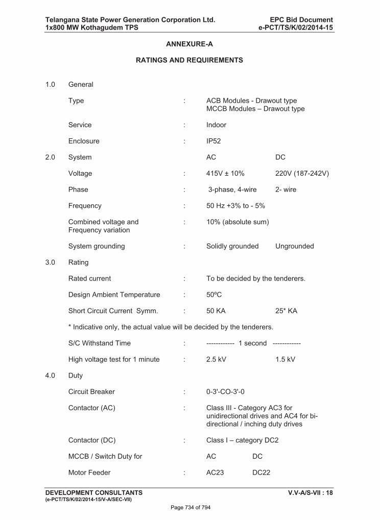
Telangana State Power Generation Corporation Ltd. EPC Bid Document 1x800 MW Kothagudem TPS e-PCT/TS/K/02/2014-15
DEVELOPMENT CONSULTANTS V.V-A/S-VII : 18 (e-PCT/TS/K/02/2014-15/V-A/SEC-VII)
ANNEXURE-A
RATINGS AND REQUIREMENTS
1.0 General
Type : ACB Modules - Drawout type MCCB Modules – Drawout type
Service : Indoor
Enclosure : IP52
2.0 System AC DC
Voltage : 415V ± 10% 220V (187-242V)
Phase : 3-phase, 4-wire 2- wire
Frequency : 50 Hz +3% to - 5%
Combined voltage and : 10% (absolute sum) Frequency variation
System grounding : Solidly grounded Ungrounded
3.0 Rating
Rated current : To be decided by the tenderers.
Design Ambient Temperature : 50ºC
Short Circuit Current Symm. : 50 KA 25* KA
* Indicative only, the actual value will be decided by the tenderers.
S/C Withstand Time : ------------ 1 second ------------
High voltage test for 1 minute : 2.5 kV 1.5 kV
4.0 Duty
Circuit Breaker : 0-3'-CO-3'-0
Contactor (AC) : Class III - Category AC3 for unidirectional drives and AC4 for bi-directional / inching duty drives
Contactor (DC) : Class I – category DC2
MCCB / Switch Duty for AC DC
Motor Feeder : AC23 DC22
Page 734 of 794
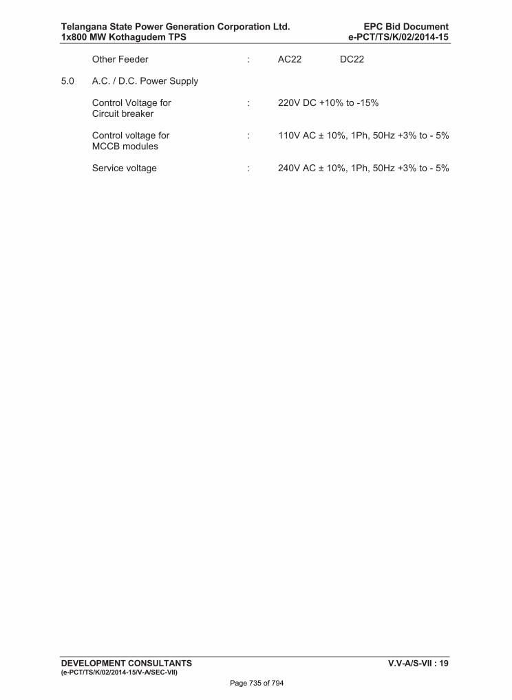
Telangana State Power Generation Corporation Ltd. EPC Bid Document 1x800 MW Kothagudem TPS e-PCT/TS/K/02/2014-15
DEVELOPMENT CONSULTANTS V.V-A/S-VII : 19 (e-PCT/TS/K/02/2014-15/V-A/SEC-VII)
Other Feeder : AC22 DC22
5.0 A.C. / D.C. Power Supply
Control Voltage for : 220V DC +10% to -15% Circuit breaker
Control voltage for : 110V AC ± 10%, 1Ph, 50Hz +3% to - 5% MCCB modules
Service voltage : 240V AC ± 10%, 1Ph, 50Hz +3% to - 5%
Page 735 of 794
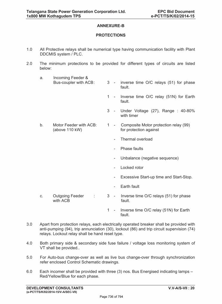
Telangana State Power Generation Corporation Ltd. EPC Bid Document 1x800 MW Kothagudem TPS e-PCT/TS/K/02/2014-15
DEVELOPMENT CONSULTANTS V.V-A/S-VII : 20 (e-PCT/TS/K/02/2014-15/V-A/SEC-VII)
ANNEXURE-B
PROTECTIONS
1.0 All Protective relays shall be numerical type having communication facility with Plant DDCMIS system / PLC.
2.0 The minimum protections to be provided for different types of circuits are listed below:
a. Incoming Feeder & Bus-coupler with ACB : 3 - inverse time O/C relays (51) for phase
fault.
1 - Inverse time O/C relay (51N) for Earth fault.
3 - Under Voltage (27), Range : 40-80% with timer
b. Motor Feeder with ACB: 1 - Composite Motor protection relay (99) (above 110 kW) for protection against
- Thermal overload
- Phase faults
- Unbalance (negative sequence)
- Locked rotor
- Excessive Start-up time and Start-Stop.
- Earth fault
c. Outgoing Feeder : 3 - Inverse time O/C relays (51) for phase with ACB fault.
1 - Inverse time O/C relay (51N) for Earth fault.
3.0 Apart from protection relays, each electrically operated breaker shall be provided with anti-pumping (94), trip annunciation (30), lockout (86) and trip circuit supervision (74) relays. Lockout relay shall be hand reset type.
4.0 Both primary side & secondary side fuse failure / voltage loss monitoring system of VT shall be provided..
5.0 For Auto-bus change-over as well as live bus change-over through synchronization refer enclosed Control Schematic drawings.
6.0 Each incomer shall be provided with three (3) nos. Bus Energised indicating lamps – Red/Yellow/Blue for each phase.
Page 736 of 794
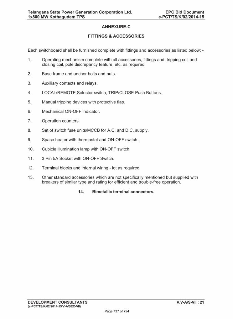
Telangana State Power Generation Corporation Ltd. EPC Bid Document 1x800 MW Kothagudem TPS e-PCT/TS/K/02/2014-15
DEVELOPMENT CONSULTANTS V.V-A/S-VII : 21 (e-PCT/TS/K/02/2014-15/V-A/SEC-VII)
ANNEXURE-C
FITTINGS & ACCESSORIES
Each switchboard shall be furnished complete with fittings and accessories as listed below: -
1. Operating mechanism complete with all accessories, fittings and tripping coil and closing coil, pole discrepancy feature etc. as required.
2. Base frame and anchor bolts and nuts.
3. Auxiliary contacts and relays.
4. LOCAL/REMOTE Selector switch, TRIP/CLOSE Push Buttons.
5. Manual tripping devices with protective flap.
6. Mechanical ON-OFF indicator.
7. Operation counters.
8. Set of switch fuse units/MCCB for A.C. and D.C. supply.
9. Space heater with thermostat and ON-OFF switch.
10. Cubicle illumination lamp with ON-OFF switch.
11. 3 Pin 5A Socket with ON-OFF Switch.
12. Terminal blocks and internal wiring - lot as required.
13. Other standard accessories which are not specifically mentioned but supplied with breakers of similar type and rating for efficient and trouble-free operation.
14. Bimetallic terminal connectors.
Page 737 of 794
Telangana State Power Generation Corporation Ltd. EPC Bid Document 1x800 MW Kothagudem TPS e-PCT/TS/K/02/2014-15
DEVELOPMENT CONSULTANTS V.V-A/S-VII : 22 (e-PCT/TS/K/02/2014-15/V-A/SEC-VII)
ANNEXURE-D
BUS TRANSFER SCHEME FOR PMCC
1.0 The manual bus transfer shall be arranged in such a way that any of the following modes of operation is possible.
1.1 Manual Bus Transfer
a) Without voltage interruption
This means by allowing momentary parallel operation of two sources.
b) With voltage interruption
i) Slow Transfer
ii) Fast Transfer
NOTE : For CHP/AHP system ‘Manual bus transfer without voltage interruption’ and ‘dead bus transfer with voltage interruption’ shall be provided.
Synchronization of Incomer & Bus coupler for each of the 415V PMCC shall be implemented through PLC in CHP electrical cum control room building. Synchronization check relay, guard relay and auxiliary relay shall be provided in each PMCC. Synchroscope along with cut off switch, double voltmeter, double frequency meter shall be provided in the Main CHP electrical building cum control room. Separate synchronization switch and trip selector switch for each of the PMCC shall also be provided in the CHP electrical building cum control room.
Page 738 of 794
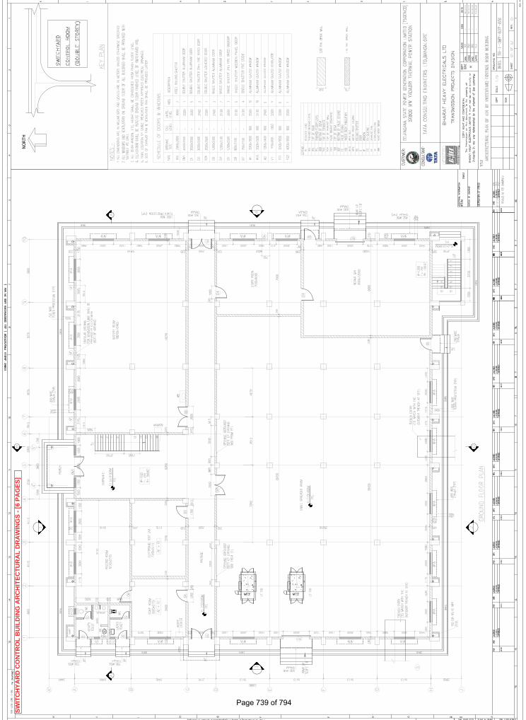
NORT
HS
WIT
CH
YA
RD
CO
NT
RO
LB
UIL
DIN
GA
RC
HIT
EC
TU
RA
LD
RA
WIN
GS
-[6
PA
GE
S]
Page 739 of 794
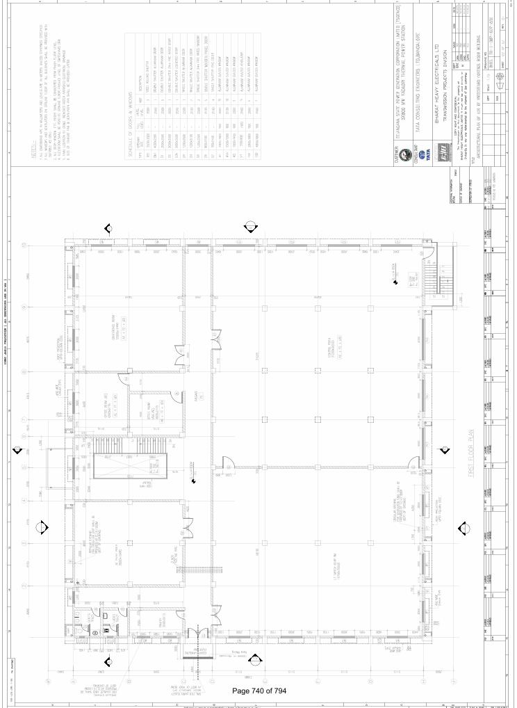
Page 740 of 794
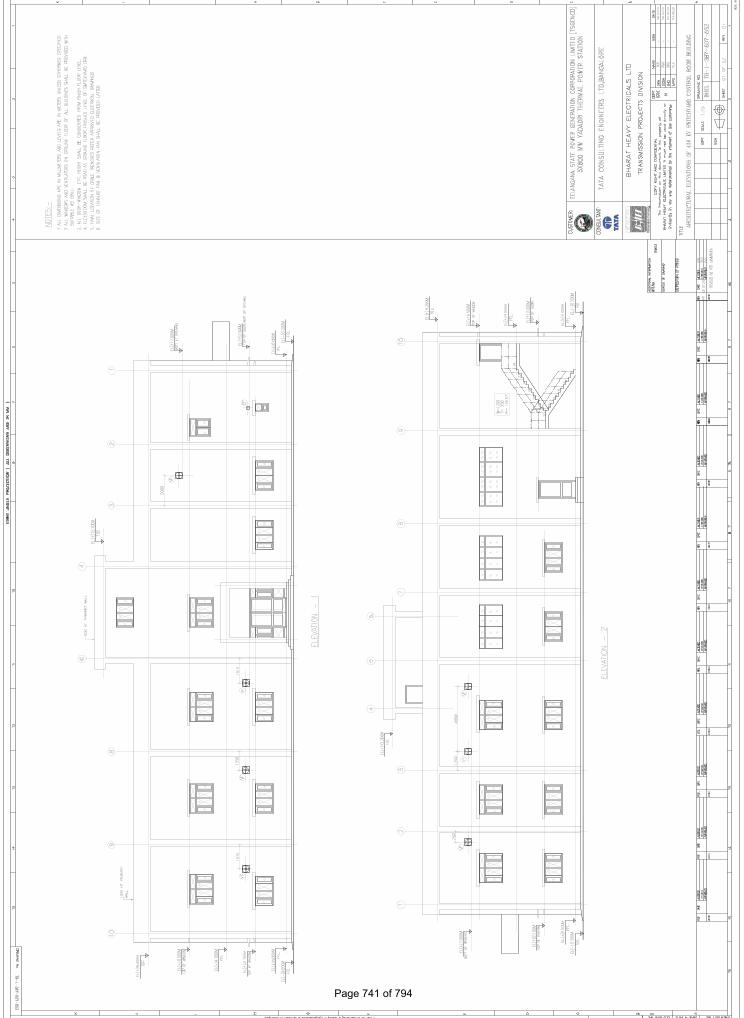
Page 741 of 794
Page 742 of 794
Page 743 of 794
Page 744 of 794
5 X 800 MW YADADRI TPS AIR CONDITIONING SYSTEM INSPECTION AND TESTING
SPECIFICATION No: PE-TS-417-553-A002
SECTION : II
SUB-SECTION : 1
REV 00
SHEET 1 OF 4
1.1
P E M - 6 6 6 6 - 0
SECTION-II
SUB-SECTION-1
INSPECTION AND TESTING
Page 745 of 794
5 X 800 MW YADADRI TPS AIR CONDITIONING SYSTEM INSPECTION AND TESTING
SPECIFICATION No: PE-TS-417-553-A002
SECTION : II
SUB-SECTION : 1
REV 00
SHEET 2 OF 4
1.1
P E M - 6 6 6 6 - 0
1.01.00 Inspection and Tests during Manufacture. 1.01.01 The method and techniques to be used by the Bidder for the control of quality during
manufacture of all plant and equipment shall be agreed with the Owner. 1.01.02 The Owner’s general requirements with respect to quality control and the required
shop tests are set out elsewhere in this specification. 1.01.03 Before any item of plant or equipment leaves its place of manufacture the Owner shall
be given the option of witnessing inspections and tests for compliance with the specification and related standards.
1.01.04 Advance notice shall be given to the Owner as agreed in the Contract, prior to the
stage of manufacture being reached, and the piece of plant must be held at this stage until the Owner has inspected the piece, or has advised in writing that inspection is waived. If having consulted the Owner and given reasonable notice in writing of the date on which the piece of plant will be available for inspection, the Owner does not attend the Bidder may proceed with manufacture having forwarded to the Owner duly certified copies of his own inspection and test results. The owner’s representative shall have at all reasonable times access to bidder’s or his sub-vendor’s premises and shall have power to inspect/ examine materials and workmanship or equipment under manufacture.
The Bidder shall forthwith forward to the engineer duly certified copies of the Test
Certificates in six copies (one to the Purchaser and five to the Consulting Engineer) for approval. Further nine (9) copies of Shop Test Certificates shall be bound with Instruction Manuals referred to elsewhere. For electrical equipment, routine tests as per relevant IS spec are to be carried out on all equipment. Type tests are also to be carried out on selected equipment as detailed in the specs of concerned electrical equipment.
1.01.05 Under no circumstances any repair or welding of castings be carried out without the consent of the Engineer. Proof of the effectiveness of each repair by radiographic and/or other non-destructive testing technique, shall be provided to the Engineer.
1.01.06 All the individual and assembled rotating parts shall be statically and dynamically
balanced in the works. Where accurate alignment is necessary for component parts of machinery normally
assembled on site, the Bidder shall allow for trial assembly prior to dispatch from place of manufacture.
1.01.07 All materials used for the manufacture of equipment covered under this specification
shall be of tested quality. Relevant test certificates shall be made available to the
Page 746 of 794
5 X 800 MW YADADRI TPS AIR CONDITIONING SYSTEM INSPECTION AND TESTING
SPECIFICATION No: PE-TS-417-553-A002
SECTION : II
SUB-SECTION : 1
REV 00
SHEET 3 OF 4
1.1
P E M - 6 6 6 6 - 0
Purchaser. The certificates shall include tests for mechanical properties and chemical analysis of representative material. Equipment or parts coming under any statutory Regulations shall be certified by a Competent Authority under the regulations in the specified format.
1.01.08 All pressure parts connected to pumping main shall be subjected to hydraulic testing
at a pressure of 150% of shut-off head for a period not less than one hour. Other parts shall be tested for one and half times the maximum operating pressure, for a period not less than one hour.
1.01.09 All necessary non-destructive examinations shall be performed to meet the applicable
code requirements. 1.01.10 All welding procedures adopted for performing welding work shall be qualified in
accordance with the requirements of Section-IX of ASME code or IBR as applicable. All welded joints for pressure parts shall be tested by liquid penetrant examination according to the method outlined in ASME Boiler and Pressure Vessel code. Radiography, magnetic particle examination magnuflux and ultrasonic testing shall be employed wherever necessary/ recommended by the applicable code. At least 10% of all major but welding joints shall be radiographed unless otherwise stipulated.
Statutory payments in respect of IBR approvals including inspection shall be made by
the bidder. Bidder’s scope shall include to preparation of all necessary documents, co-ordination and follow-up for above approval. Owner shall only forward assistance/endorsement of documents /design /drawings /reports/records to be submitted for approval as stipulated/ required by Statutory Authorities till registration of the unit and clearance for commercial operation.
1.02.00 Performance Tests at Site 1.02.01 The full requirements for testing the system shall be agreed between the Owner and
the Bidder prior to Award of Contract. The completely erected System shall be tested by the Bidder on site under normal operating conditions. The Bidder shall also ensure the correct performance of the System under abnormal conditions, i.e. the correct working of the various emergency and safety devices, interlocks, etc.
1.02.02 The Bidder shall provide complete details of his normal procedures for testing, for the
quality of erection and for the performance of the erected plant. These tests shall include site pressure test on all erected pipe work to demonstrate the quality of the piping and the adequacy of joints made at site.
1.02.03 The Bidder shall furnish the quality procedures to be adopted for assuring quality from
the receipt of material at site, during storage, erection, pre-commissioning to tests on completion and commissioning of the complete system/equipment.
1.03.00 For details of specific tests required on individual equipment refer to respective
section of this specification.
Page 747 of 794
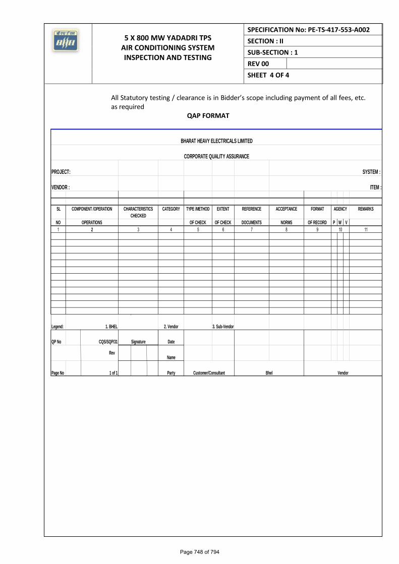
5 X 800 MW YADADRI TPS AIR CONDITIONING SYSTEM INSPECTION AND TESTING
SPECIFICATION No: PE-TS-417-553-A002
SECTION : II
SUB-SECTION : 1
REV 00
SHEET 4 OF 4
1.1
P E M - 6 6 6 6 - 0
All Statutory testing / clearance is in Bidder’s scope including payment of all fees, etc. as required
QAP FORMAT
PROJECT:
VENDOR :
SL COMPONENT /OPERATION CHARACTERISTICS
CHECKED
CATEGORY TYPE /METHOD EXTENT REFERENCE ACCEPTANCE FORMAT REMARKS
NO OPERATIONS OF CHECK OF CHECK DOCUMENTS NORMS OF RECORD P W V
1 2 3 4 5 6 7 8 9 11
Legend: 1. BHEL 2. Vendor 3. Sub-Vendor
QP No CQS/SQP/31 Signature Date
Name
Page No 1 of 1 Party
Rev
Customer/Consultant Bhel Vendor
10
AGENCY
BHARAT HEAVY ELECTRICALS LIMITED
CORPORATE QUALITY ASSURANCE
SYSTEM :
ITEM :
Page 748 of 794
5 X 800MW YADADRI TPS AIR CONDITIONING SYSTEM
LIST OF DOCUMENTS TO BE SUBMITTED WITH BID
SPECIFICATION No: PE‐TS‐417‐553‐A002 SECTION : III SUB‐SECTION : 2
REV: 00
SHEET 1 OF 1
BIDDER SHOULD SUBMIT THE SIGNED AND STAMPED COPY OF THE FOLLOWING DOCUMENTS:
1. Compliance cum confirmation certificate 2. Guaranteed power consumption 3. Un priced format for main package 4. Un priced format for mandatory spare 5. Deviation schedule /No deviation certificate in attached format ‘Deviation
sheet (Cost of withdrawal)’. 6. Pre bid clarification schedule
Page 749 of 794
5X800 MW YADADRI TPS
AIR CONDITIONING SYSTEM COMPLIANCE CUM CONFIRMATION
CERTIFICATE
SPECIFICATION No: PE‐TS‐417‐553‐A002 SECTION : III SUB‐SECTION : 3
REV. NO. 00 DATE: FEB2021SHEET: 1 OF 2
COMPLIANCE CUM CONFIRMATION CERTIFICATE
The bidder shall confirm compliance with following by signing / stamping this compliance certificate (every sheet) and furnish same with the offer.
a) The scope of supply, technical details, construction features, design parameters etc. shall be as per technical specification & there are no exclusions, other than those mentioned under “exclusion and those resolved as per ‘Schedule of Deviations’, with regard to same.
b) There are no other deviations w.r.t. specifications other than those furnished in the
‘Schedule of Deviations’. Any other deviation, stated or implied, taken elsewhere in the offer stands withdrawn unless specifically brought out in the ‘Schedule of Deviations’
c) Bidder shall submit QP in the event of order based on the guidelines given in the
specification & QP enclosed therein. QP will be subject to BHEL / CUSTOMER approval & customer hold points for inspection / testing shall be marked in the QP at the contract stage. Inspection / testing shall be witnessed as per same apart from review of various test certificates/ Inspection records etc. This is within the contracted price without any extra implications to BHEL after award of the contract.
d) All drawings/ data‐sheets / calculations etc. submitted along with the offer shall not be
taken cognizance off. e) The offered materials shall be either equivalent or superior to those specified in the
specification & shall meet the specified / intended duty requirements. In case the material specified in the specifications is not compatible for intended duty requirements then same shall be resolved by the bidder with BHEL during the pre‐bid discussions, otherwise BHEL / Customer’s decision shall be binding on the bidder whenever the deficiency is pointed out.
For components where materials are not specified, same shall be suitable for intended duty, all materials shall be subject to approval in the event of order.
f) The commissioning spares shall be supplied on ‘As Required Basis’ & prices for same
included in the base price itself. g) All sub vendors shall be subject to BHEL / CUSTOMER approval in the event of order.
h) Guarantee for plant/equipment shall be as per relevant clause of GCC / SCC / Other Commercial Terms & Conditions
i) In the event of order, all the material required for completing the job at site shall be supplied by the bidder within the ordered price even if the same are additional to approved billing break up, approved drawing or approved Bill of quantities within the scope of work as tender specification. This clause will apply in case during site commissioning, additional requirements emerges due to customer and / or consultant’s comments. No extra claims shall be put on this account
Page 750 of 794
5X800 MW YADADRI TPS
VENTILATION SYSTEM COMPLIANCE CUM CONFIRMATION
CERTIFICATE
SPECIFICATION No: PE‐TS‐417‐554‐A002 SECTION : III SUB‐SECTION : 3
REV. NO. 00 DATE: FEB2021SHEET: 2 OF 2
j) Schedule of drawings submissions, comment incorporations & approval shall be as stipulated in the specifications. The successful bidder shall depute his design personnel to BHEL’s / Customer’s / Consultant’s office for across the table resolution of issues and to get documents approved in the stipulated time.
k) As built drawings shall be submitted as and when required during the project execution.
l) The bidder has not tempered with this compliance cum confirmation certificate and if at
any stage any tempering in the signed copy of this document is noticed then same shall be treated as breach of contract and suitable actions shall be taken against the bidder.
m) Successful bidder shall furnish detailed erection manual for each of the equipment
supplied under this contract at least 3 months before the scheduled erection of the concerned equipment / component or along with supply of concerned equipment / component whichever is earlier.
n) Document approval by customer under Approval category or information category shall
not absolve the vendor of their contractual obligations of completing the work as per specification requirement. Any deviation from specified requirement shall be reported by the vendor in writing and require written approval. Unless any change in specified requirement has been brought out by the vendor during detail engineering in writing while submitting the document to customer for approval, approved document (with implicit deviation) will not be cited as a reason for not following the specification requirement.
o) In case vendor submits revised drawing after approval of the corresponding drawing, any
delay in approval of revised drawing shall be to vendor’s account and shall not be used as a reason for extension in contract completion.
Page 751 of 794
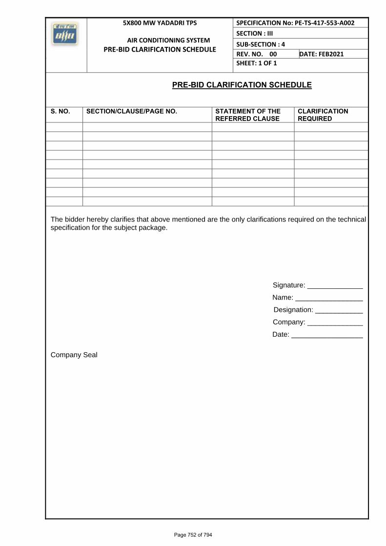
5X800 MW YADADRI TPS
AIR CONDITIONING SYSTEM PRE‐BID CLARIFICATION SCHEDULE
SPECIFICATION No: PE‐TS‐417‐553‐A002 SECTION : III SUB‐SECTION : 4
REV. NO. 00 DATE: FEB2021SHEET: 1 OF 1
PRE-BID CLARIFICATION SCHEDULE
S. NO. SECTION/CLAUSE/PAGE NO. STATEMENT OF THE REFERRED CLAUSE
CLARIFICATION REQUIRED
The bidder hereby clarifies that above mentioned are the only clarifications required on the technical specification for the subject package.
Signature: ______________
Name: _________________
Designation: ____________
Company: ______________
Date: __________________
Company Seal
Page 752 of 794
5 X 800 MW YADADRI TPS
AC SYSTEM NO DEVIATION CERTIFICATE
SPECIFICATION No: PE-TS-417-553-A002
SECTION : II
SUB-SECTION : 5
REV: 00
SHEET 1 OF 1
1.1
P E M - 6 6 6 6 - 0
DEVIATION SHEET (COST OF WITHDRAWAL)
Page 753 of 794
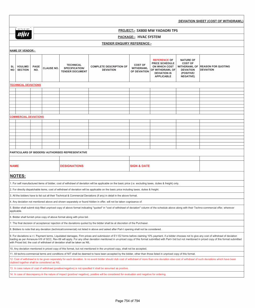
SL NO
VOULME/ SECTION
PAGE NO. CLAUSE NO.
TECHNICAL SPECIFICATION/
TENDER DOCUMENT
COMPLETE DESCRIPTION OF DEVIATION
COST OF WITHDRAWL
OF DEVIATION
REFERENCE OF PRICE SCHEDULE ON WHICH COST
OF WITHDRAWL OF DEVIATION IS APPLICABLE
NATURE OF COST OF
WITHDRAWL OF DEVIATION (POSITIVE/ NEGATIVE)
1. For self manufactured items of bidder, cost of withdrawl of deviation will be applicable on the basic price (i.e. excluding taxes, duties & freight) only.
2. For directly dispatchable items, cost of withdrawl of deviation will be applicable on the basic price including taxes, duties & freight.
9. For deviations w.r.t. Payment terms, Liquidated damages, Firm prices and submission of E1/ E2 forms before claiming 10% payment, if a bidder chooses not to give any cost of withdrawl of deviation loading as per Annexure-VIII of GCC, Rev-06 will apply. For any other deviation mentioned in un-priced copy of this format submitted with Part-I bid but not mentioned in priced copy of this format submitted with Priced bid, the cost of withdrawl of deviation shall be taken as NIL.
8. Bidders to note that any deviation (technical/commercial) not listed in above and asked after Part-I opening shall not be considered.
3. All the bidders have to list out all their Technical & Commercial Deviations (if any) in detail in the above format.
4. Any deviation not mentioned above and shown separately or found hidden in offer, will not be taken cognizance of.
5. Bidder shall submit duly filled unpriced copy of above format indicating "quoted" in "cost of withdrawl of deviation" column of the schedule above along with their Techno-commercial offer, wherever applicable.
6. Bidder shall furnish price copy of above format along with price bid.
7. The final decision of acceptance/ rejection of the deviations quoted by the bidder shall be at discretion of the Purchaser.
COMMERCIAL DEVIATIONS
TENDER ENQUIRY REFERENCE:-
10. Any deviation mentioned in priced copy of this format, but not mentioned in the un-priced copy, shall not be accepted.
NAME DESIGNATIONS SIGN & DATE
NOTES:
ANNEXURE-II: DEVIATION SHEET (COST OF WITHDRAWL)
PROJECT:-
PACKAGE:-
NAME OF VENDOR:-
TECHNICAL DEVIATIONS
REASON FOR QUOTING DEVIATION
13. In case nature of cost of withdrawl (positive/negative) is not specified it shall be assumed as positive.
14. In case of descrepancy in the nature of impact (positive/ negative), positive will be considered for evaluation and negative for ordering.
11. All techno-commercial terms and conditions of NIT shall be deemed to have been accepted by the bidder, other than those listed in unpriced copy of this format.
PARTICULARS OF BIDDERS/ AUTHORISED REPRESENTATIVE
12. Cost of withdrawl is to be given seperately for each deviation. In no event bidder should club cost of withdrawl of more than one deviation else cost of withdrawl of such deviations which have been clubbed together shall be considered as NIL.
Page 1 of 1
2X490 MW NTPC NCTPP, DADRI STAGE-II (FGD)
HVAC SYSTEM
2X500 MW NTPC MOUDA TPP, STAGE-I (FGD)3 X 660 MW NABINAGAR TPP (FGD)
Page 516 of 525
5X800 MW YADADRI TPS
Page 754 of 794
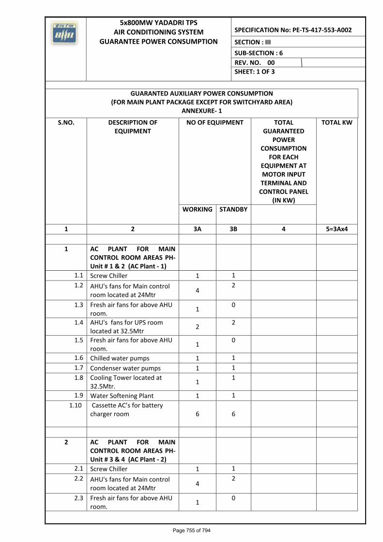
5x800MW YADADRI TPS AIR CONDITIONING SYSTEM
GUARANTEE POWER CONSUMPTION
SPECIFICATION No: PE-TS-417-553-A002
SECTION : III
SUB-SECTION : 6
REV. NO. 00
SHEET: 1 OF 3
GUARANTED AUXILIARY POWER CONSUMPTION (FOR MAIN PLANT PACKAGE EXCEPT FOR SWITCHYARD AREA)
ANNEXURE- 1
S.NO. DESCRIPTION OF EQUIPMENT
NO OF EQUIPMENT TOTAL GUARANTEED
POWER CONSUMPTION
FOR EACH EQUIPMENT AT MOTOR INPUT TERMINAL AND
CONTROL PANEL (IN KW)
TOTAL KW
WORKING STANDBY
1 2 3A 3B 4 5=3Ax4
1 AC PLANT FOR MAIN CONTROL ROOM AREAS PH-Unit # 1 & 2 (AC Plant - 1)
1.1 Screw Chiller 1 1
1.2 AHU's fans for Main control room located at 24Mtr
4 2
1.3 Fresh air fans for above AHU room.
1 0
1.4 AHU's fans for UPS room located at 32.5Mtr
2 2
1.5 Fresh air fans for above AHU room.
1 0
1.6 Chilled water pumps 1 1
1.7 Condenser water pumps 1 1
1.8 Cooling Tower located at 32.5Mtr.
1 1
1.9 Water Softening Plant 1 1
1.10 Cassette AC’s for battery charger room
6 6
2 AC PLANT FOR MAIN CONTROL ROOM AREAS PH-Unit # 3 & 4 (AC Plant - 2)
2.1 Screw Chiller 1 1
2.2 AHU's fans for Main control room located at 24Mtr
4 2
2.3 Fresh air fans for above AHU room.
1 0
Page 755 of 794
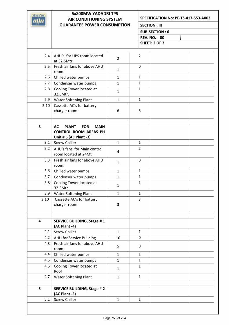
5x800MW YADADRI TPS AIR CONDITIONING SYSTEM
GUARANTEE POWER CONSUMPTION
SPECIFICATION No: PE-TS-417-553-A002
SECTION : III
SUB-SECTION : 6
REV. NO. 00
SHEET: 2 OF 3
2.4 AHU's for UPS room located at 32.5Mtr
2 2
2.5 Fresh air fans for above AHU room.
1 0
2.6 Chilled water pumps 1 1
2.7 Condenser water pumps 1 1
2.8 Cooling Tower located at 32.5Mtr.
1 1
2.9 Water Softening Plant 1 1
2.10 Cassette AC’s for battery charger room
6 6
3 AC PLANT FOR MAIN CONTROL ROOM AREAS PH Unit # 5 (AC Plant -3)
3.1 Screw Chiller 1 1
3.2 AHU's fans for Main control room located at 24Mtr
4 2
3.3 Fresh air fans for above AHU room.
1 0
3.6 Chilled water pumps 1 1
3.7 Condenser water pumps 1 1
3.8 Cooling Tower located at 32.5Mtr.
1 1
3.9 Water Softening Plant 1 1
3.10 Cassette AC’s for battery charger room
3 3
4 SERVICE BUILDING, Stage # 1 (AC Plant -4)
4.1 Screw Chiller 1 1
4.2 AHU for Service Building 10 0
4.3 Fresh air fans for above AHU room.
5 0
4.4 Chilled water pumps 1 1
4.5 Condenser water pumps 1 1
4.6 Cooling Tower located at Roof
1 1
4.7 Water Softening Plant 1 1
5 SERVICE BUILDING, Stage # 2 (AC Plant -5)
5.1 Screw Chiller 1 1
Page 756 of 794
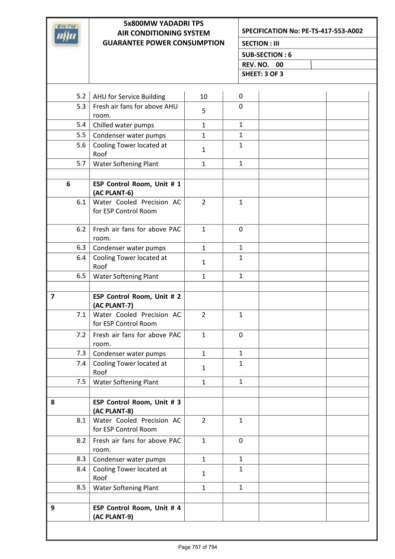
5x800MW YADADRI TPS AIR CONDITIONING SYSTEM
GUARANTEE POWER CONSUMPTION
SPECIFICATION No: PE-TS-417-553-A002
SECTION : III
SUB-SECTION : 6
REV. NO. 00
SHEET: 3 OF 3
5.2 AHU for Service Building 10 0
5.3 Fresh air fans for above AHU room.
5 0
5.4 Chilled water pumps 1 1
5.5 Condenser water pumps 1 1
5.6 Cooling Tower located at Roof
1 1
5.7 Water Softening Plant 1 1
6 ESP Control Room, Unit # 1 (AC PLANT-6)
6.1 Water Cooled Precision AC for ESP Control Room
2 1
6.2 Fresh air fans for above PAC room.
1 0
6.3 Condenser water pumps 1 1
6.4 Cooling Tower located at Roof
1 1
6.5 Water Softening Plant 1 1
7 ESP Control Room, Unit # 2 (AC PLANT-7)
7.1 Water Cooled Precision AC for ESP Control Room
2 1
7.2 Fresh air fans for above PAC room.
1 0
7.3 Condenser water pumps 1 1
7.4 Cooling Tower located at Roof
1 1
7.5 Water Softening Plant 1 1
8 ESP Control Room, Unit # 3 (AC PLANT-8)
8.1 Water Cooled Precision AC for ESP Control Room
2 1
8.2 Fresh air fans for above PAC room.
1 0
8.3 Condenser water pumps 1 1
8.4 Cooling Tower located at Roof
1 1
8.5 Water Softening Plant 1 1
9 ESP Control Room, Unit # 4 (AC PLANT-9)
Page 757 of 794
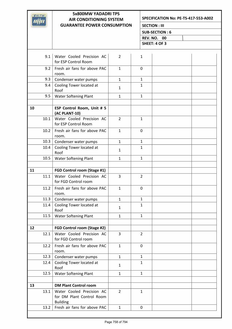
5x800MW YADADRI TPS AIR CONDITIONING SYSTEM
GUARANTEE POWER CONSUMPTION
SPECIFICATION No: PE-TS-417-553-A002
SECTION : III
SUB-SECTION : 6
REV. NO. 00
SHEET: 4 OF 3
9.1 Water Cooled Precision AC for ESP Control Room
2 1
9.2 Fresh air fans for above PAC room.
1 0
9.3 Condenser water pumps 1 1
9.4 Cooling Tower located at Roof
1 1
9.5 Water Softening Plant 1 1
10 ESP Control Room, Unit # 5 (AC PLANT-10)
10.1 Water Cooled Precision AC for ESP Control Room
2 1
10.2 Fresh air fans for above PAC room.
1 0
10.3 Condenser water pumps 1 1
10.4 Cooling Tower located at Roof
1 1
10.5 Water Softening Plant 1 1
11 FGD Control room (Stage #1)
11.1 Water Cooled Precision AC for FGD Control room
3 2
11.2 Fresh air fans for above PAC room.
1 0
11.3 Condenser water pumps 1 1
11.4 Cooling Tower located at Roof
1 1
11.5 Water Softening Plant 1 1
12 FGD Control room (Stage #2)
12.1 Water Cooled Precision AC for FGD Control room
3 2
12.2 Fresh air fans for above PAC room.
1 0
12.3 Condenser water pumps 1 1
12.4 Cooling Tower located at Roof
1 1
12.5 Water Softening Plant 1 1
13 DM Plant Control room
13.1 Water Cooled Precision AC for DM Plant Control Room Building
2 1
13.2 Fresh air fans for above PAC 1 0
Page 758 of 794
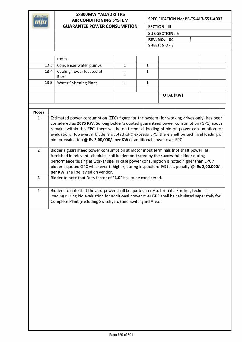
5x800MW YADADRI TPS AIR CONDITIONING SYSTEM
GUARANTEE POWER CONSUMPTION
SPECIFICATION No: PE-TS-417-553-A002
SECTION : III
SUB-SECTION : 6
REV. NO. 00
SHEET: 5 OF 3
room.
13.3 Condenser water pumps 1 1
13.4 Cooling Tower located at Roof
1 1
13.5 Water Softening Plant 1 1
TOTAL (KW)
Notes
1 Estimated power consumption (EPC) figure for the system (for working drives only) has been considered as 2075 KW. So long bidder's quoted guaranteed power consumption (GPC) above remains within this EPC, there will be no technical loading of bid on power consumption for evaluation. However, if bidder's quoted GPC exceeds EPC, there shall be technical loading of bid for evaluation @ Rs 2,00,000/- per KW of additional power over EPC.
2 Bidder’s guaranteed power consumption at motor input terminals (not shaft power) as furnished in relevant schedule shall be demonstrated by the successful bidder during performance testing at works/ site. In case power consumption is noted higher than EPC / bidder's quoted GPC whichever is higher, during inspection/ PG test, penalty @ Rs 2,00,000/- per KW shall be levied on vendor.
3 Bidder to note that Duty factor of “1.0” has to be considered.
4 Bidders to note that the aux. power shall be quoted in resp. formats. Further, technical loading during bid evaluation for additional power over GPC shall be calculated separately for Complete Plant (excluding Switchyard) and Switchyard Area.
Page 759 of 794
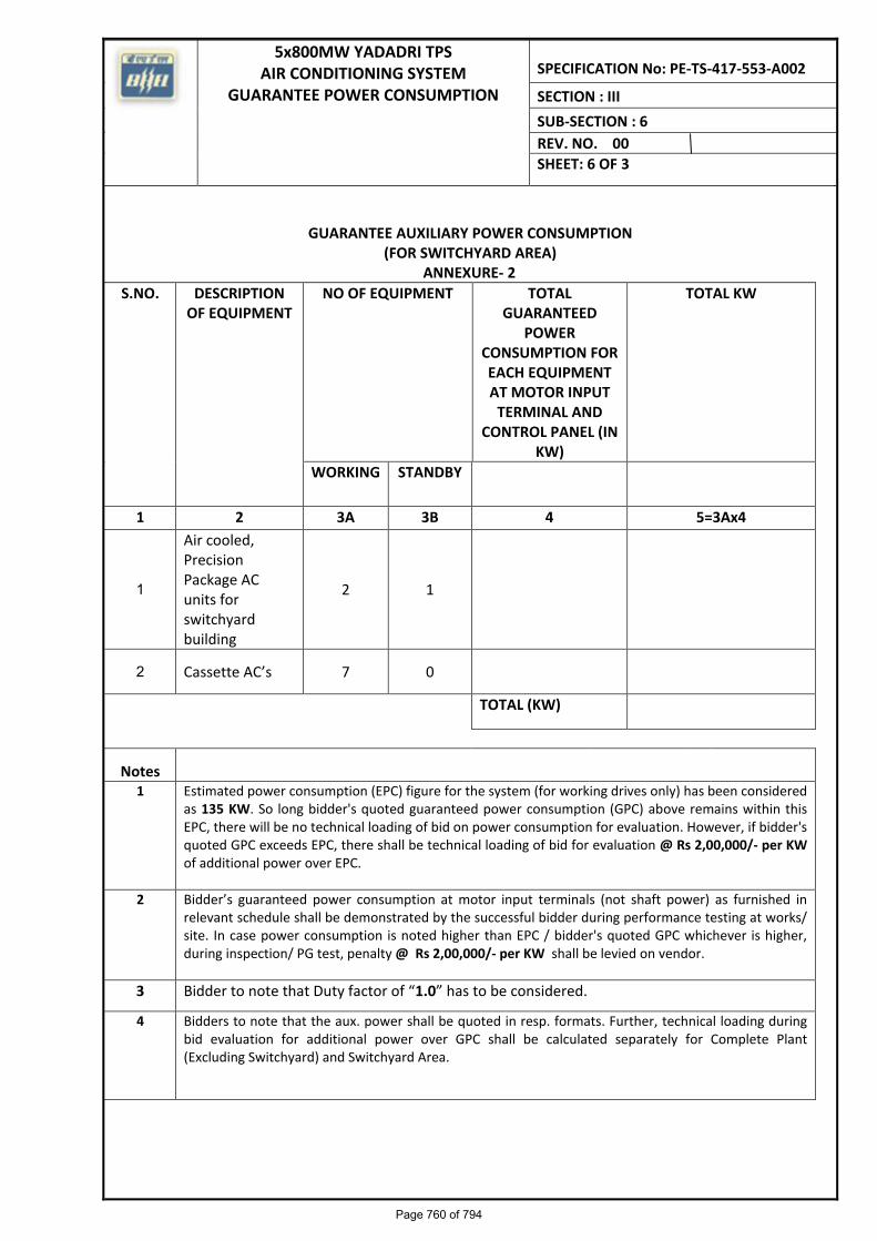
5x800MW YADADRI TPS AIR CONDITIONING SYSTEM
GUARANTEE POWER CONSUMPTION
SPECIFICATION No: PE-TS-417-553-A002
SECTION : III
SUB-SECTION : 6
REV. NO. 00
SHEET: 6 OF 3
GUARANTEE AUXILIARY POWER CONSUMPTION
(FOR SWITCHYARD AREA) ANNEXURE- 2
S.NO. DESCRIPTION OF EQUIPMENT
NO OF EQUIPMENT TOTAL GUARANTEED
POWER CONSUMPTION FOR EACH EQUIPMENT AT MOTOR INPUT
TERMINAL AND CONTROL PANEL (IN
KW)
TOTAL KW
WORKING STANDBY
1 2 3A 3B 4 5=3Ax4
1
Air cooled, Precision Package AC units for switchyard building
2 1
2 Cassette AC’s 7 0
TOTAL (KW)
Notes
1 Estimated power consumption (EPC) figure for the system (for working drives only) has been considered as 135 KW. So long bidder's quoted guaranteed power consumption (GPC) above remains within this EPC, there will be no technical loading of bid on power consumption for evaluation. However, if bidder's quoted GPC exceeds EPC, there shall be technical loading of bid for evaluation @ Rs 2,00,000/- per KW of additional power over EPC.
2 Bidder’s guaranteed power consumption at motor input terminals (not shaft power) as furnished in relevant schedule shall be demonstrated by the successful bidder during performance testing at works/ site. In case power consumption is noted higher than EPC / bidder's quoted GPC whichever is higher, during inspection/ PG test, penalty @ Rs 2,00,000/- per KW shall be levied on vendor.
3 Bidder to note that Duty factor of “1.0” has to be considered.
4 Bidders to note that the aux. power shall be quoted in resp. formats. Further, technical loading during bid evaluation for additional power over GPC shall be calculated separately for Complete Plant (Excluding Switchyard) and Switchyard Area.
Page 760 of 794
5x800MW YADADRI TPS AIR CONDITIONING SYSTEM
SPECIFICATION No: PE‐TS‐417‐553‐A002 SECTION : III
SUB‐SECTION : 7
REV 00
SHEET 1 OF 1
SECTION-III
SUB-SECTION-7
INPUT DRAWINGS (MECHANICAL LAYOUT DRAWINGS SHOWING LOCATION OF
EQUIPMENT/PLOT PLAN/OTHER BUILDING GA’S)
Page 761 of 794
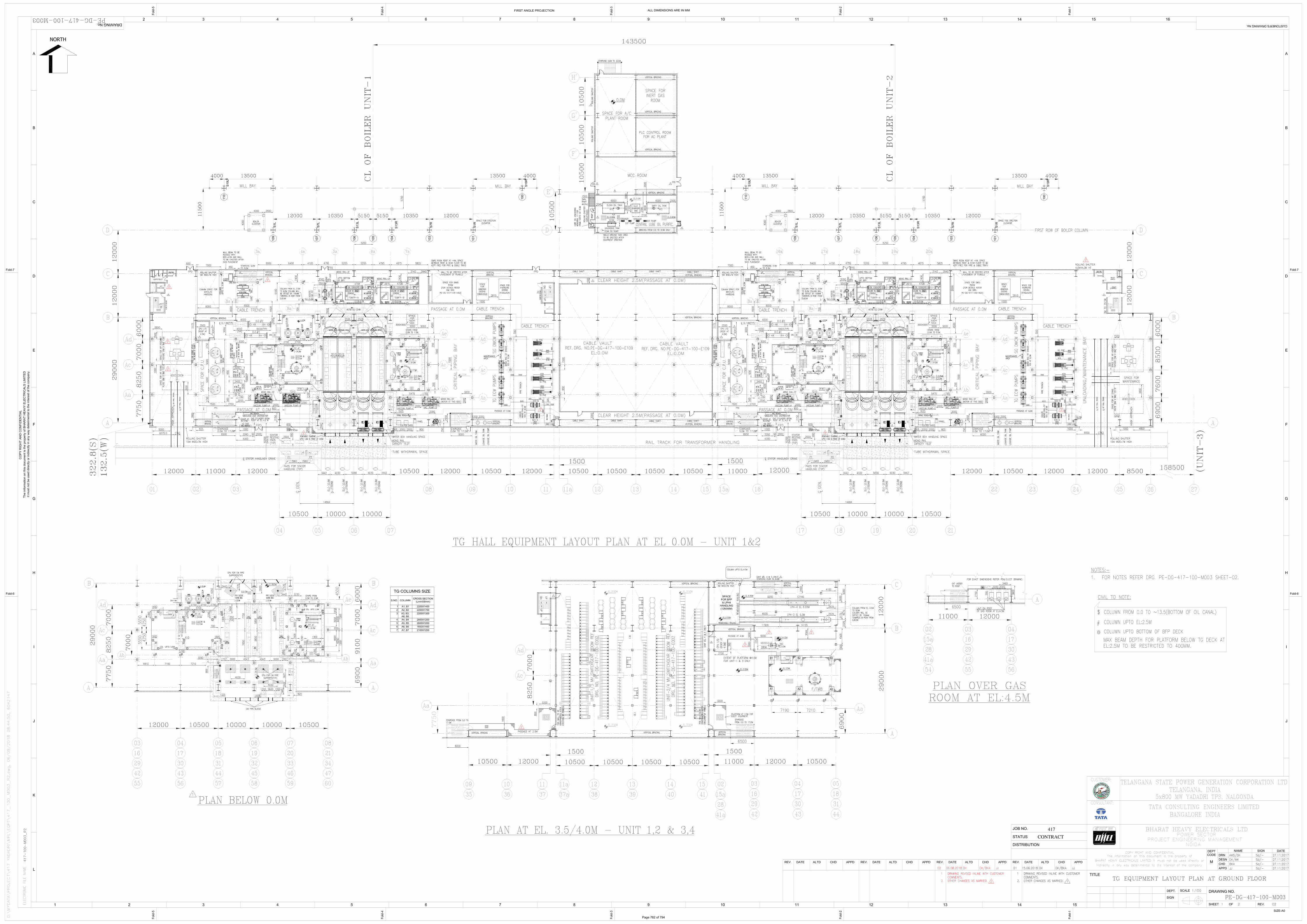
Page 762 of 794
6074979
Rectangle
6074979
Rectangle
6074979
Rectangle
6074979
Text Box
AC PLANT#1 HOUSING CHILLERS, PUMPS AND COOLING TOWER OF POWERHOUSE UNIT #1 &2
6074979
Text Box
AC AREA THROUGH FCU. THE AC REQUIREMENTS SHALL BE MET THROUGH CHILLERS LOCATED IN AC PLANT#1
6074979
Text Box
AC AREA THROUGH FCU. THE AC REQUIREMENTS SHALL BE MET THROUGH CHILLERS LOCATED IN AC PLANT#1
6074979
Text Box
FOR TENDER PURPOSE ONLY
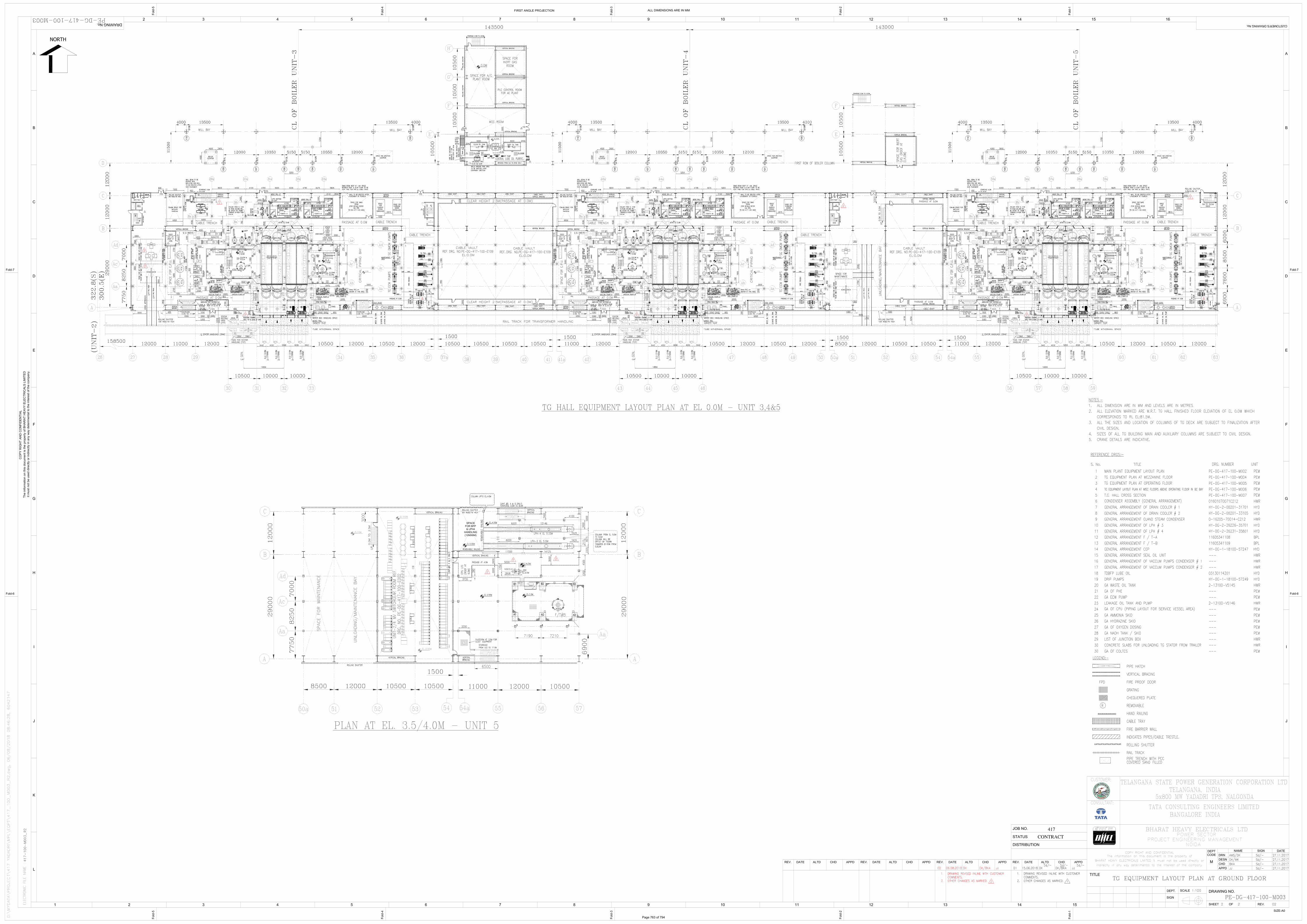
Page 763 of 794
6074979
Rectangle
6074979
Rectangle
6074979
Rectangle
6074979
Rectangle
6074979
Rectangle
6074979
Text Box
AC AREA THROUGH FCU. THE AC REQUIREMENTS SHALL BE MET THROUGH CHILLERS LOCATED IN AC PLANT#2
6074979
Text Box
AC AREA THROUGH FCU. THE AC REQUIREMENTS SHALL BE MET THROUGH CHILLERS LOCATED IN AC PLANT#2
6074979
Text Box
AC AREA THROUGH FCU. THE AC REQUIREMENTS SHALL BE MET THROUGH CHILLERS LOCATED IN AC PLANT#3
6074979
Text Box
AC PLANT#2 HOUSING CHILLERS, PUMPS AND COOLING TOWERS (AT 32.5M) OF POWERHOUSE UNIT #3 &4
6074979
Text Box
AC PLANT#3 HOUSING CHILLERS, PUMPS AND COOLING TOWERS (AT 32.5M) OF UNIT #5
6074979
Text Box
FOR TENDER PURPOSE ONLY
Related Documents