30.05.19 Rev.G DS_MFD_RS232_RevG_0519.docx Page 1/24 Specification MFM / MFC RS-232 Data Communication Introduction Axetris offers Mass Flow Meter (MFM) and Controller (MFC) modules, as well as standalone Mass Flow Meters and Controllers. All products feature both analog and digital interface input / output capabilities. Therefore Axetris is able to deliver exactly the required device interface that fits the communication system of each customer application. The goal of this document is to describe in detail all the RS-232 communication features, allowing the customer to quickly connect multiple devices with a single bus wire to their command unit system, establishing a safe and reliable communication. For RS-485 refer to the document MFM / MFC RS-485 Data Communication. Mass Flow Meters / Controllers with RS-232 interface MFM 202X MFC 2022 MFM 21XX MFM 22XX MFC 2222 MFC 21XX Mass Flow Meter Mass Flow Meter OEM Modules Mass Flow Controller OEM Modules Mass Flow Controller Standalone

Welcome message from author
This document is posted to help you gain knowledge. Please leave a comment to let me know what you think about it! Share it to your friends and learn new things together.
Transcript

30.05.19 Rev.G DS_MFD_RS232_RevG_0519.docx Page 1/24
Specification
MFM / MFC RS-232 Data Communication
Introduction
Axetris offers Mass Flow Meter (MFM) and Controller (MFC) modules, as well as standalone Mass Flow Meters and Controllers. All products feature both analog and digital interface input / output capabilities. Therefore Axetris is able to deliver exactly the required device interface that fits the communication system of each customer application. The goal of this document is to describe in detail all the RS-232 communication features, allowing the customer to quickly connect multiple devices with a single bus wire to their command unit system, establishing a safe and reliable communication. For RS-485 refer to the document MFM / MFC RS-485 Data Communication.
Mass Flow Meters / Controllers with RS-232 interface
MFM 202X MFC 2022 MFM 21XX MFM 22XX MFC 2222 MFC 21XX
Mass Flow Meter Mass Flow Meter
OEM Modules
Mass Flow Controller OEM Modules
Mass Flow Controller Standalone

30.05.19 Rev.G DS_MFD_RS232_RevG_0519.docx Page 2/24
Table of contents
1 General Description 3
2 Pin assignment for Modules 6 3 Pin assignment for stand alone types 7 3.1 D-SUB connector – 9 pins (standard) ..................................................................................... 7
4 RS-232 Functional description 8 4.1 Device input / output configuration .......................................................................................... 8
4.2 Meter modules MFM 2020 / MFM 2021 / MFM 2220 ............................................................. 8
4.3 Controller modules MFC 2022, MFC 2222 ...........................................................................10
4.4 MFM 2120 / MFC 2122 .........................................................................................................11
5 Interface specification 13 5.1 RS232 serial communication settings ...................................................................................13
5.2 Command format ..................................................................................................................13
5.3 Response format ...................................................................................................................13
5.4 Analog set point and valve override (input) ...........................................................................13
5.5 Analog gas flow and PID_out (output) ..................................................................................14
5.6 Analog readout circuit for 4…20 mA option ..........................................................................14
6 Commands & variables list definition 15 6.1 Command to read/write variables .........................................................................................15
6.2 List of commands ..................................................................................................................15
6.3 List of variables .....................................................................................................................16
7 Coding - decoding digital data 17 7.1 Decoding the digital gas flow output .....................................................................................17
7.2 Coding the digital set point input ...........................................................................................17
7.3 Coding - decoding the digital valve override variable ...........................................................18
7.4 Decoding the temperature.....................................................................................................18
7.5 Coding - decoding Gasinfo RW command ............................................................................18
7.6 Decoding the offset value......................................................................................................19
7.7 Coding - decoding the low pass filter value ..........................................................................19
8 Transmission errors 20 9 FAQ & communication examples 21 10 Caution 24 10.1 Product damage ....................................................................................................................24
10.2 Danger of life .........................................................................................................................24
11 Important Notice / Disclaimer 24
30.05.19 Rev.G DS_MFD_RS232_RevG_0519.docx Page 3/24
Abbreviations, Terms and Definitions
MFM Mass Flow Meter MSB/LSB Most Significant Bit / Least Significant Bit
MFC Mass Flow Controller RD/RW Read / Read and Write
% O.R. Percent Of Reading RS-232 EIA Serial bus standard protocol according to EIA-232
% F.S. Percent of Full Scale RS-232 TTL Serial bus standard protocol with TTL level
sccm Standard cubic centimetre per minute at reference conditions of 1013 mbar absolute pressure and 0°C temperature.
RS-485 Serial bus standard protocol according to EIA-485 for digital multipoint system communication
uccm User defined standard cubic centimetre per minute at reference conditions of 1013 mbar absolute pressure and 0°C temperature. (Term defined by Axetris)
RS-485 HD RS-485 FD
RS-485 Half Duplex (2 wires) RS-485 Full Duplex (4 wires)
1 General Description
Axetris MFM / MFC modules are capable of communicating by means of analog and digital communication interfaces. The analog input / output is either of voltage type (0…5 V) or current type (4…20 mA).
The serial interface protocol is based on a master slave communication between the device and typically a computer. To respond to the important diversity of applications of such devices, and to deliver the right level of integration complexity, Axetris has developed two levels of communication to fit with the customer’s integration.
- The customer mode communication level which is the ready-to-use level for high-end applications with standard communication capabilities.
- The service mode communication level that allows RD/RW of low level information, such as calibration parameters or filter gains.
All Axetris Mass flow products of the MFM /MFC 2000 series are factory calibrated for a specific gas type, flow range, input pressure range and reference conditions. The devices are fully temperature compensated for a temperature range from 0…50 °C. The parameters for filter and PID parameter are factory set and support almost all common applications. For special conditions they can be tuned and changed by the customer (functionality available on request).
Multi-gas and/or multi-range calibration is possible; the device contains up to 8 channels that can be selected any time with the digital communication protocol. Using other gases and/or other ranges of the ones calibrated in the device is strongly discouraged. False measurements and/or uncontrolled flows will occur in such cases.
To facilitate the communication with the MFMs / MFCs a GUI (Graphical User Interface) interface based on the Labview (National Instrument) program is available. You may consult with the Axetris team in case of need.
30.05.19 Rev.G DS_MFD_RS232_RevG_0519.docx Page 4/24
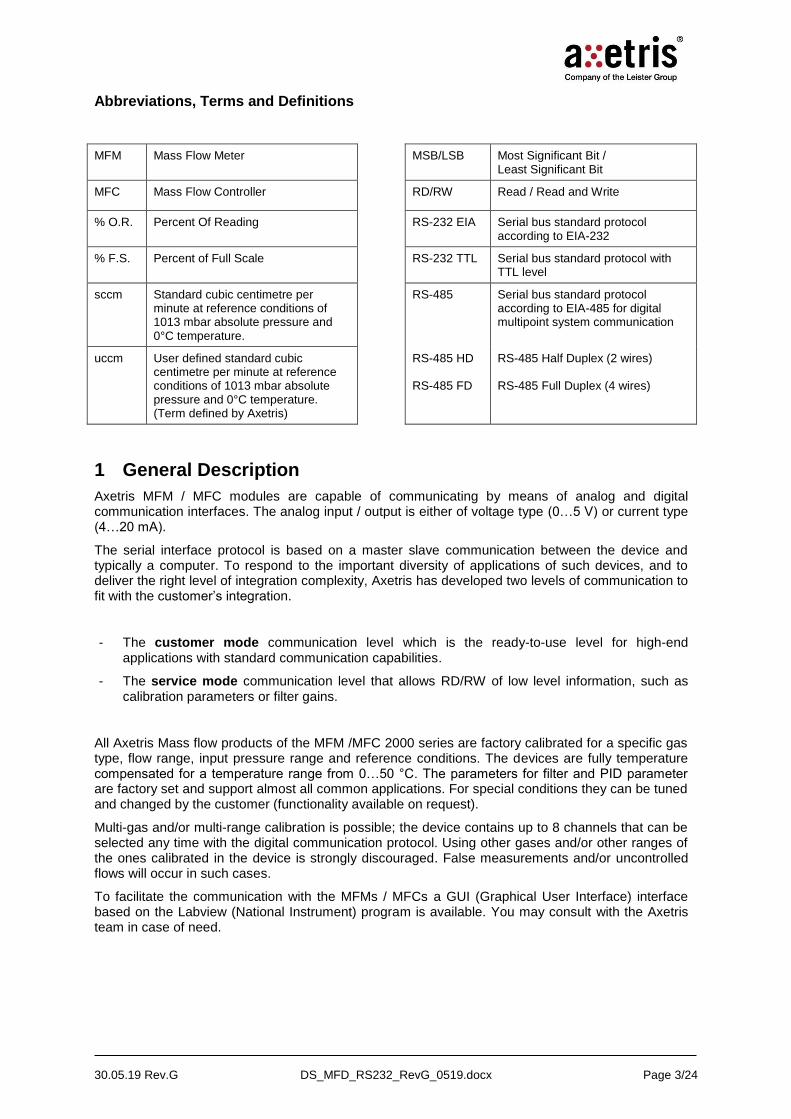
Depending on the device type, a meter or a controller, module or standalone, the communication interface features are summarized for the customer mode in Table 1.
Type Analog output Analog input Digital output1 Digital input
Me
ter
MFM 2020 MFM 2220
Gas flow 0…5 V - Gas flow Temperature Gas calibration info.
Offset zeroing Channel selection2
MFM 2120 Gas flow 0…5 V - Gas flow Temperature Gas calibration info.
Offset zeroing Channel selection
MFM 2130 Gas flow 4…20 mA - Gas flow Temperature Gas calibration info.
Offset zeroing Channel selection
Me
ter
wit
h P
ID
ou
tpu
t MFM 2X21
Gas flow 0…5 V PID_out 0…5 V
Set point 0…5 V Valve override
Gas flow Temperature Gas calibration info. PID Controller Output
Set point Valve override Offset zeroing Channel selection
Bid
irecti
on
al
Me
ter
MFM 2X23 Gas flow 0…5 V Gas flow 4…20 mA3
- Gas flow Temperature Gas calibration info.
Offset zeroing Channel selection
Co
ntr
oll
er
MFC 2022 Gas flow 0…5 V PID_out 0…5 V
Set point 0…5 V Valve override
Gas flow Temperature Gas calibration info. PID Controller Output
Set point Valve override Offset zeroing Channel selection
MFC 2222 Gas flow 0…5 V Set point 0…5 V Valve override
Gas flow Temperature Gas calibration info. PID Controller Output
Set point Valve override Offset zeroing Channel selection
MFC 2122 Gas flow 0…5 V Set point 0…5 V Valve override
Gas flow Temperature Gas calibration info. PID Controller Output
Set point Valve override Offset zeroing Channel selection
MFC 2132 Gas flow 4…20 mA Set point 4…20 mA Valve override
Gas flow Temperature Gas calibration info. PID Controller Output
Set point Valve override Offset zeroing Channel selection
Table 1 Type comparison and product functionality including main communication features in customer mode.
MFx 20xx: Modules without housing and RS-232 TTL level Interface MFx 22xx: Modules without housing and RS-232 EIA level Interface MFx 21xx Types with housing and RS-232 EIA Interface
1 Only main customer mode digital output information is listed in this table. For access to internal data available
in the service mode, see chapter 6.
2 In case of multi-gas, multi-range calibration of the device. Up to 8 channels are available (2 channels are
reserved for factory only, 6 channels are reserved for customer’s needs)
3 Only available as MFM 2223
30.05.19 Rev.G DS_MFD_RS232_RevG_0519.docx Page 5/24
-Data & command
(Digital I/O)
Gas flow meter (Analog/Digital)
Sensor
Chip
Sensor
T
uP
T Compensation
Linearization
EEPROM
Parameters
Calibration Data
DA
DA
Gas flow In
Heater
regulation
Gas flow Out
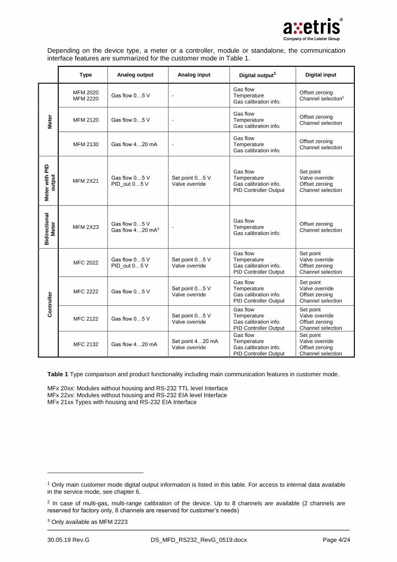
Figure 1 Block diagram of the MFM 2100 and MFM 2200 series of mass flow meter
-
Set point(Analog/Digital)
Data & command(Digital I/O)
Gas flow meter (Analog/Digital)
Sensor
Chip
Sensor
T
uP
T Compensation
Linearization
EEPROM
Parameters
Calibration Data
-+ PID
ControllerValve Driver
DA
DA
Gas flow In
PID_out
Heater
regulation
Valve override(Analog/Digital)
PID_out(Analog/Digital)
Gas flow Out
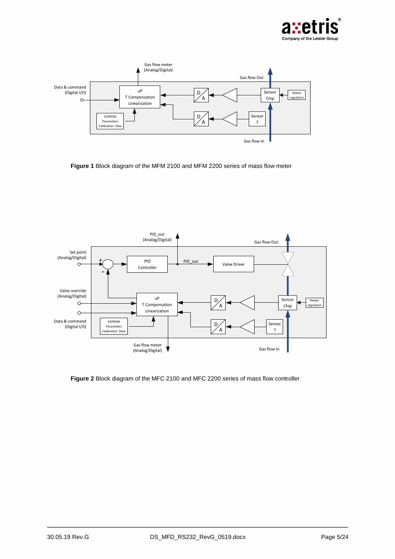
Figure 2 Block diagram of the MFC 2100 and MFC 2200 series of mass flow controller
30.05.19 Rev.G DS_MFD_RS232_RevG_0519.docx Page 6/24
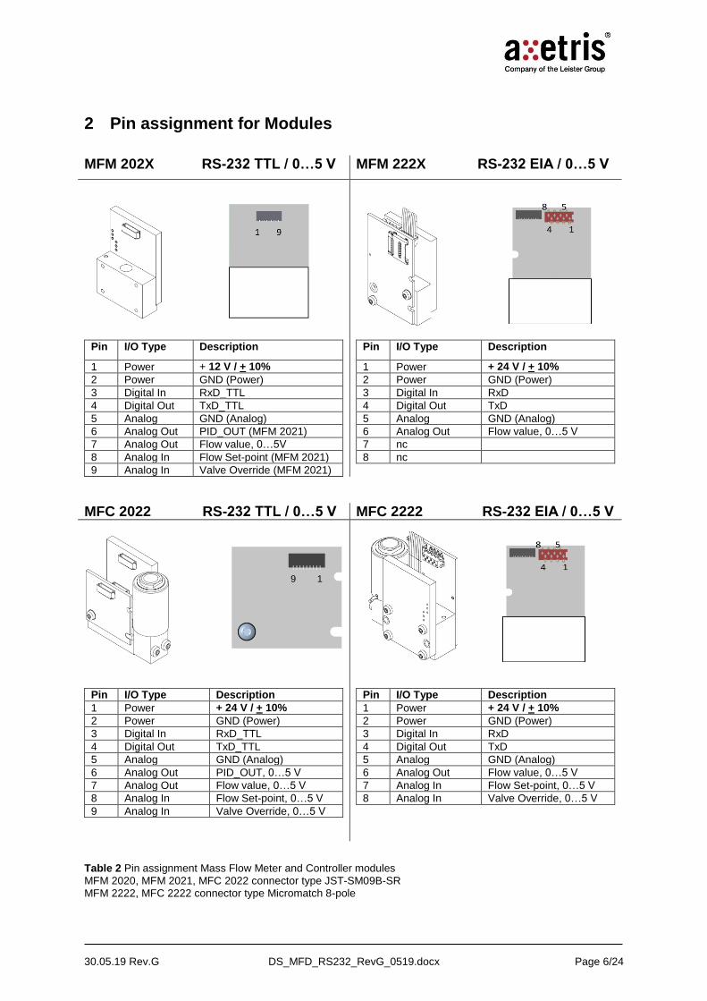
2 Pin assignment for Modules
MFM 202X RS-232 TTL / 0…5 V MFM 222X RS-232 EIA / 0…5 V
Pin I/O Type Description
1 Power + 12 V / + 10%
2 Power GND (Power)
3 Digital In RxD_TTL
4 Digital Out TxD_TTL
5 Analog GND (Analog)
6 Analog Out PID_OUT (MFM 2021)
7 Analog Out Flow value, 0…5V
8 Analog In Flow Set-point (MFM 2021)
9 Analog In Valve Override (MFM 2021)
Pin I/O Type Description
1 Power + 24 V / + 10%
2 Power GND (Power)
3 Digital In RxD
4 Digital Out TxD
5 Analog GND (Analog)
6 Analog Out Flow value, 0…5 V
7 nc
8 nc
MFC 2022 RS-232 TTL / 0…5 V MFC 2222 RS-232 EIA / 0…5 V
Pin I/O Type Description
1 Power + 24 V / + 10%
2 Power GND (Power)
3 Digital In RxD_TTL
4 Digital Out TxD_TTL
5 Analog GND (Analog)
6 Analog Out PID_OUT, 0…5 V
7 Analog Out Flow value, 0…5 V
8 Analog In Flow Set-point, 0…5 V
9 Analog In Valve Override, 0…5 V
Pin I/O Type Description
1 Power + 24 V / + 10%
2 Power GND (Power)
3 Digital In RxD
4 Digital Out TxD
5 Analog GND (Analog)
6 Analog Out Flow value, 0…5 V
7 Analog In Flow Set-point, 0…5 V
8 Analog In Valve Override, 0…5 V
Table 2 Pin assignment Mass Flow Meter and Controller modules
MFM 2020, MFM 2021, MFC 2022 connector type JST-SM09B-SR MFM 2222, MFC 2222 connector type Micromatch 8-pole
9 1

30.05.19 Rev.G DS_MFD_RS232_RevG_0519.docx Page 7/24
3 Pin assignment for standalone types
3.1 D-SUB connector – 9 pins (standard)
Figure 3 Top view D-SUB 9 poles connector
MFM 2120/ MFC 2122 RS-232 / 0…5 V
MFM 2130/ MFC 2132 RS-232 / 4…20 mA
Pin I/O Type Description
1 Power + 24 V / + 10%
2 Power GND (Power)
3 Digital In RxD
4 Digital Out TxD
5 nc
6 Analog GND GND
7 Analog Out Flow value, 0…5V
8 Analog In Flow Set-point (MFC), 0…5V
9 Analog In Valve Override (MFC), 0V close / 5V open
Pin I/O Type Description
1 Power + 24 V / + 10%
2 Power GND (Power)
3 Digital In RxD
4 Digital Out TxD
5 nc
6 Analog GND GND
7 Analog Out Flow value, 4…20 mA
8 Analog In Flow Set-point (MFC), 4…2mA
9 Analog In Valve Override (MFC), 0V close / 5V open
Table 3 Pin assignment for D-SUB 9 connector
1 5
6 9
30.05.19 Rev.G DS_MFD_RS232_RevG_0519.docx Page 8/24
4 RS-232 Functional description
4.1 Device input / output configuration
There is no default configuration setup. Due to the many possibilities that are available, the devices are delivered with features which correspond to the customer requirements. Analog input / output is either of voltage type (0…5 V) or current type (4…20 mA). The digital input / output is RS-232. RS-485 is also available (RS-485 Half Duplex MFM 2x40, MFC 2x42 ; RS-485 Full Duplex MFM 2x50, MFC 2x52, see document “MFM / MFC RS-485 Data Communication”). The type of the analog input / output, voltage or current, is set by the manufacturer at the factory level. The way the customer wants to communicate with the device, analog or digital, can be set later at any time with the corresponding digital command. This configuration is stored in an EEPROM forcing the device to start always in the same configuration. There is no reset feature that would bring back the device to a “basic” configuration.
Each device will send the hexadecimal code FFHex and then 53Hex after turn-on when the device is ready to communicate and to operate (after 3 seconds).
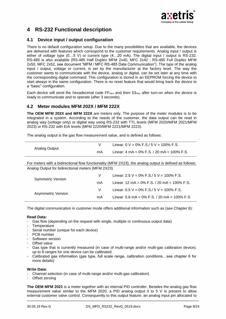
4.2 Meter modules MFM 202X / MFM 222X
The OEM MFM 202X and MFM 222X are meters only. The purpose of the meter modules is to be integrated in a system. According to the needs of the customer, the data output can be read in analog way (voltage only) or digital way using RS-232 with TTL levels (MFM 2020/MFM 2021/MFM 2023) or RS-232 with EIA levels (MFM 2220/MFM 2221/MFM 2223). The analog output is the gas flow measurement value, and is defined as follows:
Analog Output V
mA
Linear: 0 V = 0% F.S./ 5 V = 100% F.S.
Linear: 4 mA = 0% F.S. / 20 mA = 100% F.S
For meters with a bidirectional flow functionality (MFM 2X23), the analog output is defined as follows:
Analog Output for bidirectional meters (MFM 2X23)
Symmetric Version V
mA
Linear: 2.5 V = 0% F.S./ 5 V = 100% F.S.
Linear: 12 mA = 0% F.S. / 20 mA = 100% F.S.
Asymmetric Version V
mA
Linear: 0.5 V = 0% F.S./ 5 V = 100% F.S.
Linear: 5.6 mA = 0% F.S. / 20 mA = 100% F.S
The digital communication in customer mode offers additional information such as (see Chapter 6): Read Data: - Gas flow (depending on the request with single, multiple or continuous output data) - Temperature - Serial number (unique for each device) - PCB number - Software version - Offset value - Gas type that is currently measured (in case of multi-range and/or multi-gas calibration device).
up to 8 ranges for one device can be calibrated. - Calibrated gas information (gas type, full scale range, calibration conditions…see chapter 6 for
more details) Write Data: - Channel selection (in case of multi-range and/or multi-gas calibration) - Offset zeroing The OEM MFM 2021 is a meter together with an internal PID controller. Besides the analog gas flow measurement value similar to the MFM 2020, a PID analog output 0 to 5 V is present to allow external customer valve control. Consequently to this output feature, an analog input pin allocated to

30.05.19 Rev.G DS_MFD_RS232_RevG_0519.docx Page 9/24
the valve override command is present to permit immediate shut-off or purge position of the external valve (0 V input – 0 V PID output 100 % close / 5 V input – 5 V PID output 100 % open). This analog valve override command is prior to any other command (analog or digital input). The valve override command is also possible digitally. For the set point, a cut off limit at 1 % F.S. is available on request and is factory settable only. Besides the MFM 2020 communication capabilities (see list above), the MFM 2021 digital communication in customer mode offers: Read Data: - Set point - PID_out - Valve override state - Selected input mode for the set point (analog or digital) Write Data: - Set point - Valve override - Input mode for the set point (analog or digital) Service Mode In service mode, much more digital data is accessible to allow the customer to adapt the device to his own needs, i.e. device trimming, filter parameters, or even customer calibration for channels 3 to 8 (1 and 2 are accessible only by the manufacturer and are factory calibrated), thus allowing to fully adapt the device to particular customer requirements. See chapter 6, Commands & variables list definition, for more information on those additional possibilities.
30.05.19 Rev.G DS_MFD_RS232_RevG_0519.docx Page 10/24
4.3 Controller modules MFC 2022, MFC 2222 The MFC 2022 and MFC 2222 are small compact gas flow controller modules including an advanced internal PID controller with a fast acting solenoid valve. Its main purpose is to be integrated into an OEM system. According to the needs of the customer, the data output can be read in analog (voltage or digital modes using RS-232 TTL (MFC 2022) or RS-232 EIA (MFC 2222). Analog voltage input / output is selected as default input when not specified otherwise during ordering. The preferred way to communicate with the device, analog or digital, can be set later at any time with the corresponding digital command. This configuration is stored in an EEPROM making the device starting always in the same configuration.
The analog output is the gas flow measurement value Voltage (0…5 V), They are configured at the factory level. The digital communication in customer mode offers additional information (see chapter 6 how to code – decode the digital data): Read Data: - Gas flow (depending on the request with single, multiple or continuous output data) - Temperature - Serial number (unique for each device) - PCB number - Software version - Offset value - Gas type that is currently measured (in case of multi-range and/or multi-gas calibration device).
Up to 8 ranges for one device can be calibrated. - Calibrated gas information (gas type, full scale range, calibration conditions, see chapter 6 for
more details) - Set point - PID_out - Valve override state - Selected input mode for the set point (analog or digital) Write Data: - Channel selection (in case of multi-range and/or multi-gas calibration) - Offset zeroing - Set point - Valve override - Input mode for the set point (analog or digital)
30.05.19 Rev.G DS_MFD_RS232_RevG_0519.docx Page 11/24
4.4 MFM 2120 / MFC 2122 Standalone types
The MFM 2120 is a standalone meter. Its purpose is to be a ready-to-use gas flow meter with standard gas fittings. According to the needs of the customer, the data output can be read in analog (voltage or current) or digital using RS-232 (EIA 232) with direct connection to the PC. Analog voltage or analog current input / output is selected as default at the factory level when ordering. The way the customer wants to communicate with the device, analog or digital, can be set later at any time with the corresponding digital command. This configuration is stored in EEPROM making the device starting always in the same configuration. The analog output is the gas flow measurement value. Voltage (0…5 V) or current (4…20 mA) outputs are available. They are configured at the factory level. The digital communication in customer mode offers additional information (see chapter 6 how to code – decode the digital data): Read Data: - Gas flow (depending on the request with single, multiple or continuous output data) - Temperature - Serial number (unique for each device) - PCB number - Software version - Offset value - Gas type that is currently measured (in case of multi-range and/or multi-gas calibration device).
Up to 8 ranges for one device can be calibrated. - Calibrated gas information (gas type, full scale range, calibration conditions…see chapter 6 for
more details) Write Data: - Channel selection (in case of multi-range and/or multi-gas calibration) - Offset zeroing The MFC 2122 is a standalone gas flow controller containing an advanced internal PID controller with a rapid solenoid valve. Its purpose is to be a ready-to-use gas flow controller with standard gas fittings. According to the needs of the customer, the data output can be read in analog (voltage or current) or digital modes using RS-232 (direct connection to the PC). Analog voltage or analog current input / output are set at the factory level when ordering. The way the customer wants to communicate with the device, analog or digital, can be set later at any time with the corresponding digital command. This configuration is stored in an EEPROM making the device starting always in the same configuration. An analog input is the set point of the gas flow. Voltage (0…5 V) or current (4…20 mA) inputs is available. It is configured at the factory level. The analog output is the gas flow measure. Voltage (0…5 V) or current (4…20 mA) output is available. It is configured at the factory level. Besides the analog gas flow control, the customer can take direct control of the valve in an analog or digital way. The analog valve override feature allows immediate close or purge position of the valve. The analog valve override command is prior to any other command (analog or digital input). The digital override command is permitting not only to set the close and purge position but also any intermediate position of the valve. A cut off limit at 1 % F.S. is available on request and is factory settable only. The MFC 2122 digital communication in customer mode offers: Read Data: - Gas flow (depending on the request with single, multiple or continuous output data) - Temperature - Serial number (unique for each device) - PCB number - Software version

30.05.19 Rev.G DS_MFD_RS232_RevG_0519.docx Page 12/24
- Offset value - Gas type that is currently measured (in case of multi-range and/or multi-gas calibration device).
Up to 8 ranges for one device can be calibrated. - Calibrated gas information (gas type, full scale range, calibration conditions, see chapter 6 for
more details) - Set point - PID_out - Valve override state - Selected input mode for the set point (analog or digital) Write Data: - Channel selection (in case of multi-range and/or multi-gas calibration) - Offset zeroing - Set point - Valve override - Input mode for the set point (analog or digital) In service mode, even more digital data is accessible to allow customer device setup, device trimming or even customer calibration for channel 3 to 8, 1 and 2 are reserved for Axetris, to fully adapt the device to particular customer applications. See chapter 6, list of requests and variables, for more information on those additional possibilities.

30.05.19 Rev.G DS_MFD_RS232_RevG_0519.docx Page 13/24
5 Interface specification
5.1 RS-232 serial communication settings
- Baud rate: 57600
- Data: 8 bits
- Stop bit: 1
- Parity: Odd
- Flow control: No handshake
- Levels: TTL Levels for the MFM 2020 / 2021 / 2023 and MFC 2022.
EIA 232 (direct connection to a PC) for the standalone modules MFM 2120 / MFC 2122
When writing a data into the EEPROM, the maximum data rate is limited to 100 Bytes/sec. Do not write parameter command when the device is active. No update calculation is performed when writing data to the memory.
5.2 Command format
Req code
Req code Param1 ChecksumTx
Tx
Req code Param1 ChecksumTx Param 224
Each request begins with a one-character code identifying the request. If the request to be sent is coded on more than one byte, a checksum has to be added at the end of the command. The checksum is the sum of all the preceding bytes value, including the request byte, truncated to the last 8 bits of the results.
5.3 Response format
Req code Data1 Data2 ChecksumRx
The response format is similar to the command format. The response sentence always begins with the repeat of the requested code, followed by data. The sentence ends with a checksum. Note that the STOP request has no response.
5.4 Analog set point and valve override (input)
If the analog input mode is selected, the set point is analog (the current input is only for the standalone MFC 2122). The valve override feature overrules the set point. The table hereafter lists the values that are possible to apply and their effects on the flow control.
Table 4: Analog input values for MFCs 2022 / 2222 / 2122
Parameters Unit Min. Value
Max. Value
Resolution Remark
Set point V 0 5 0.30518 mV Values are linearly interpreted between 0V = closed and 5 V = 100 % F.S.
Set point mA 4 20 976.5 uA Values are linearly interpreted between 4mA = closed and 20 mA = 100 % F.S.
Valve override V 0…0.2 4.8…5 - 0 V = close, 5 V = forced open (purge mode > F.S.)
The purge mode is forcing the valve to be full open and the flow is higher than F.S.
The recovery from an analog valve override state is given by any analog value between 0.2 V and 4.8 V. The device is then returned to normal mode with the PID controller on. In the digital mode, it is

30.05.19 Rev.G DS_MFD_RS232_RevG_0519.docx Page 14/24
the last set point value stored in the memory that will be used to control the flow. In analog mode, the flow will be set to the value present at the analog input pin.
5.5 Analog gas flow and PID_out (output)
The gas flow output is always available independently of the selected mode (analog or digital input). The analog output is either a voltage or a current. Only for the MFC 2022, the analog PID_out is available to drive an external valve provided by the customer. The table hereafter lists the analog values that are readable at the output.
Table 5: Analog output values for MFCs 2022 / 2122
Parameters Unit Min. Value
Max. Value
Resolution Remark
Gas flow V 0 5 0.30518 mV Values are linearly interpreted between 0 V = 0 % F.S. and 5 V = 100 % F.S.
Gas flow mA 4 20 976.5 uA Values are linearly interpreted between 4m A = closed and 20 mA = open F.S.
Note: 110 % F.S. is reserved for margin. Therefore the maximum voltage output is 5.5 V and the maximum current output is 21.6 mA. Specifications guaranteed up to 100% F.S. (5V)
5.6 Analog readout circuit for 4…20 mA option
In the standalone MFM 2130 / MFC 2132 devices, the 4…20 mA current loop analog output is performed with a specific integrated voltage-to-current converter circuit.
Many design solutions exist to read a current loop output circuit. From the very basic solution with a single load resistor (typically 250 Ω, 4 mA = 1 V, 20 mA = 5 V) to convert current into voltage for reading the value with a DAC, or a proprietary solution, or a specific current-to-voltage converter circuit (i.e. Burr-Brown® RCV420), or a scientific instrument measuring the current, the chosen solution will fit with the system design constraints.
The adequate readout technique is left to the customer’s choice according to own preferences and constraints.

30.05.19 Rev.G DS_MFD_RS232_RevG_0519.docx Page 15/24
6 Commands & variables list definition
6.1 Command to read/write variables
Command name Hex Parameters after command
READ_VAR_INT16 0X61 Variable ID
WRITE_VAR_INT16 0X62 Variable ID + Value of 2 bytes (higher bit first)
READ_VAR_CHAR 0X63 Variable ID
WRITE_VAR_CHAR 0X64 Variable ID + Value of 1 bytes (higher bit first)
IMPORTANT: Continuous writing to persistent variables should be avoided if there is no intention to change their value. It will shorten the life time of the EEPROM
See chapter 9 for examples.
6.2 List of commands
Gas flow1
Command name Hex Parameters Customer
mode
Service
mode
Response
SEND_ONE_DATA 0X31 None (single request) WR WR 1 Flow value
SEND_N_DATA 0X32 Nx1byte WR WR N Flow values
SEND_CONTINUOUS 0X33 None, terminate with STOP WR WR Flow values (each 3.5 ms)
STOP 0X34 None WR WR None
Device number / configuration ID / gas information / Change mode password
WRITE_SERIAL 0X67 Serial number (16 bytes) X WR Request code
READ_SERIAL 0X68 None RD RD Serial num.
READ_CONFIG_ID 0X76 None RD RD Config. ID
READ_EXT_GASINFO 0X73 None RD RD Gas info. table (17 bytes)
WRITE_EXT_GASINFO2 0X74 Gas info. table (17 bytes) X WR Gas info. table (17 bytes)
WRITE_PWD 0X70 Request to change mode WR WR Contact Axetris
Calibration parameters
WRITE_PARAM2 0X35 Write interpolation parameters X WR Contact Axetris
READ_PARAM 0X36 Read interpolation parameters X RD Contact Axetris
Sensor raw data
READ_RAW_DATA3 0X66 Request to read calib. tables X RD Contact Axetris
WRITE_RAWDATA 0X65 2x144 bytes data X X Contact Axetris
1 All the RD/WR variables coded with more than 1 byte are MSB first.
2 Only for customer’s channels 3 to 8. Channels 1 and 2 are reserved for the manufacturer.
3 Only for manufacturer’s channels 1 and 2.

30.05.19 Rev.G DS_MFD_RS232_RevG_0519.docx Page 16/24
6.3 List of variables
Gas flow
Variable name Hex EEPROM persistence
Data
type
Customer mode
Service mode
Information
Serialnumber_PCB 0X00 yes unit16 RD RD HW identification
SWVersion 0X01 yes unit16 RD RD 2 bytes (e.g. 3012dec = 30.12)
Offset_zero 0X03 no unit8
RW
RW
WR: 0:= none, 1:= activate auto zeroing, 2:= reset
RD: 0:= zeroing / reset done,
1:= zeroing ongoing,
3:= Error offset out of range
Offset_value 0X04 yes int16 RD RD See chapter 6 for decoding
Gastype 0X06 yes unit8 RW RW Channel selection [1…8]
ADC_Temp 0X0F no unit16 RD RD Temperature
ADC_AuxIn 0X37 no uint16 RD RD ADC Voltage Aux Input
Gas flow controller
CtrlNominal 0X14 no unit16 RW RW Set point mass flow
V_OverrideState 0X1E no unit16 RW RW See chapter 7 for coding -
decoding
NomFlowInputSel 0X1F yes uint8
RW
RW
Select desired input for set point, 0Hex = digital input, 1Hex= analog input
Calibration and PID parameters
DA_U_Gain 0X0B yes unit16 X RW DAC gain voltage output
DA_U_Offset 0X0C yes unit16 X RW DAC offset voltage output
AuxIn_PGA3Gain 0x35 yes unit8 X RW Gain PGA3, auxiliary input
AuxIn_PGAOff 0x36 yes unit8 X RW Offset PGA3, auxiliary input
KFactor1 0x07 yes unit8 X RW Factor digital noise filter 1st ord.
nominalU_Off 0x27 yes Int16 X RW Offset of nominal voltage input
NominalU_Gain 0x28 yes unit8 X RW Gain of nominal voltage input
CtrlParam_P2 0x17 yes unit16 X RW PID controller proportional el.
CtrlParam_I 0x18 yes unit16 X RW PID controller integral element
CtrlParam_D 0x19 yes unit16 X RW PID controller differential el.
CtrlParam_ISumLimit 0x1A yes unit16 X RW PID contr. integral sum. limit
CtrlParam_ISum 0x1B no unit16 X RD Actual PID controller ISum.
PID_out 0x16 no unit16 RD RD PID controller output (12 bits)
1 KFactor is dedicated to gastype. See chapter 7 for coding – decoding values.
2 PID parameters are dedicated to gas type.
30.05.19 Rev.G DS_MFD_RS232_RevG_0519.docx Page 17/24
7 Coding – decoding digital data
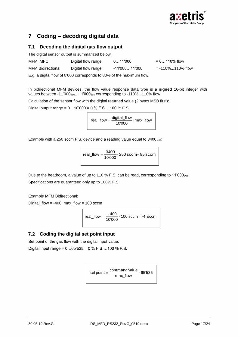
7.1 Decoding the digital gas flow output
The digital sensor output is summarized below:
MFM, MFC Digital flow range 0…11'000 = 0…110% flow
MFM Bidirectional Digital flow range -11'000…11'000 = -110%...110% flow
E.g. a digital flow of 8'000 corresponds to 80% of the maximum flow.
In bidirectional MFM devices, the flow value response data type is a signed 16-bit integer with values between -11'000dec…11'000dec corresponding to -110%...110% flow.
Calculation of the sensor flow with the digital returned value (2 bytes MSB first):
Digital output range = 0…10’000 = 0 % F.S….100 % F.S.
max_flow10'000
owdigital_flreal_flow
Example with a 250 sccm F.S. device and a reading value equal to 3400Dec:
Due to the headroom, a value of up to 110 % F.S. can be read, corresponding to 11’000Dec
Specifications are guaranteed only up to 100% F.S.
Example MFM Bidirectional:
Digital_flow = -400, max_flow = 100 sccm
7.2 Coding the digital set point input
Set point of the gas flow with the digital input value:
Digital input range = 0…65’535 = 0 % F.S….100 % F.S.
65'535max_flow
value commandpoint set
sccm 85 sccm 250 10'000
3400real_flow
sccm -4 sccm 100 10'000
- 400 real_flow

30.05.19 Rev.G DS_MFD_RS232_RevG_0519.docx Page 18/24
Example with a 250 sccm F.S. device and a set point of 110 sccm:
See chapter 9 for an example how to code this command in the RS232 serial communication protocol.
7.3 Coding – decoding the digital valve override variable
Valve override variable “V_OverrideState” is type uint16.
The two bytes full range are (0…65535)dec = (0x0000…0xFFFF)Hex
A value range between (0…4'095)dec allows to directly control the valve position from 0 corresponding to a closed valve to 4'095 corresponding to a fully open valve (purge mode). Any value in between correspond to a valve position, the resulting flow will be a nonlinear function of this value and a consistent offset is necessary to obtain a flow.
Setting the value to 32'768dec (0x8000) enables PID control using either a digital or analog setpoint according to the selected mode.
Other values are not used.
7.4 Decoding the temperature
The ADC_Temp variable returns the temperature on two bytes (High value / Low value).
To calculate the corresponding temperature in C, transform the value from hexadecimal to decimal then use the following formula:
7.5 Coding - decoding Gasinfo RW command
The Gasinfo variable is linked to a channel. Select first the channel with the variable Gastype before read/write the gas information.
REQUEST GASINFO CHECKSUM
Gas ID
[Semi E52-
0703]
max Flow
[according
unit code]
Unit Code
Reference
Pressure
[mbar a]
Reference
Temperature
[°C]
Calibration
Pressure
[mbar a]
Calibration
Temperature
[°C]
Heat
Capacity
[J/(kg*K)]
Heat
Conduct.
[1/100 * mW/
(m*K)
Gas Density
[g/m3]
uint16 uint16 uint8 uint16 int8 int8 uint16 uint16 uint16uint16
Gas_ID:
According the Semi E52-0703 standard:
Air Ar CO2 He H2 CH4 N2 O2
8 4 25 1 7 28 13 15
Hex0x70A3 Dec28'835 65'535 F.S. [sccm] 250
[sccm] 110point set
C]o[01.0
60.1-65535
(Temp_dec)
Cop_Device_Tem
30.05.19 Rev.G DS_MFD_RS232_RevG_0519.docx Page 19/24
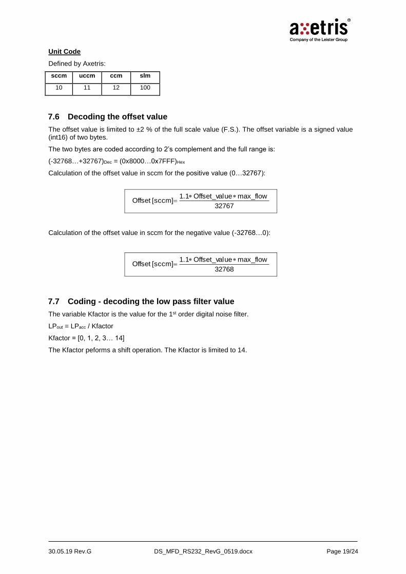
Unit Code
Defined by Axetris:
sccm uccm ccm slm
10 11 12 100
7.6 Decoding the offset value
The offset value is limited to ±2 % of the full scale value (F.S.). The offset variable is a signed value (int16) of two bytes.
The two bytes are coded according to 2’s complement and the full range is:
(-32768…+32767)Dec = (0x8000…0x7FFF)Hex
Calculation of the offset value in sccm for the positive value (0…32767):
32767
max_flow ueOffset_val 1.1[sccm] Offset
Calculation of the offset value in sccm for the negative value (-32768…0):
32768
max_flow ueOffset_val 1.1[sccm] Offset
7.7 Coding - decoding the low pass filter value
The variable Kfactor is the value for the 1st order digital noise filter.
LPout = LPacc / Kfactor
Kfactor = [0, 1, 2, 3… 14]
The Kfactor peforms a shift operation. The Kfactor is limited to 14.
30.05.19 Rev.G DS_MFD_RS232_RevG_0519.docx Page 20/24
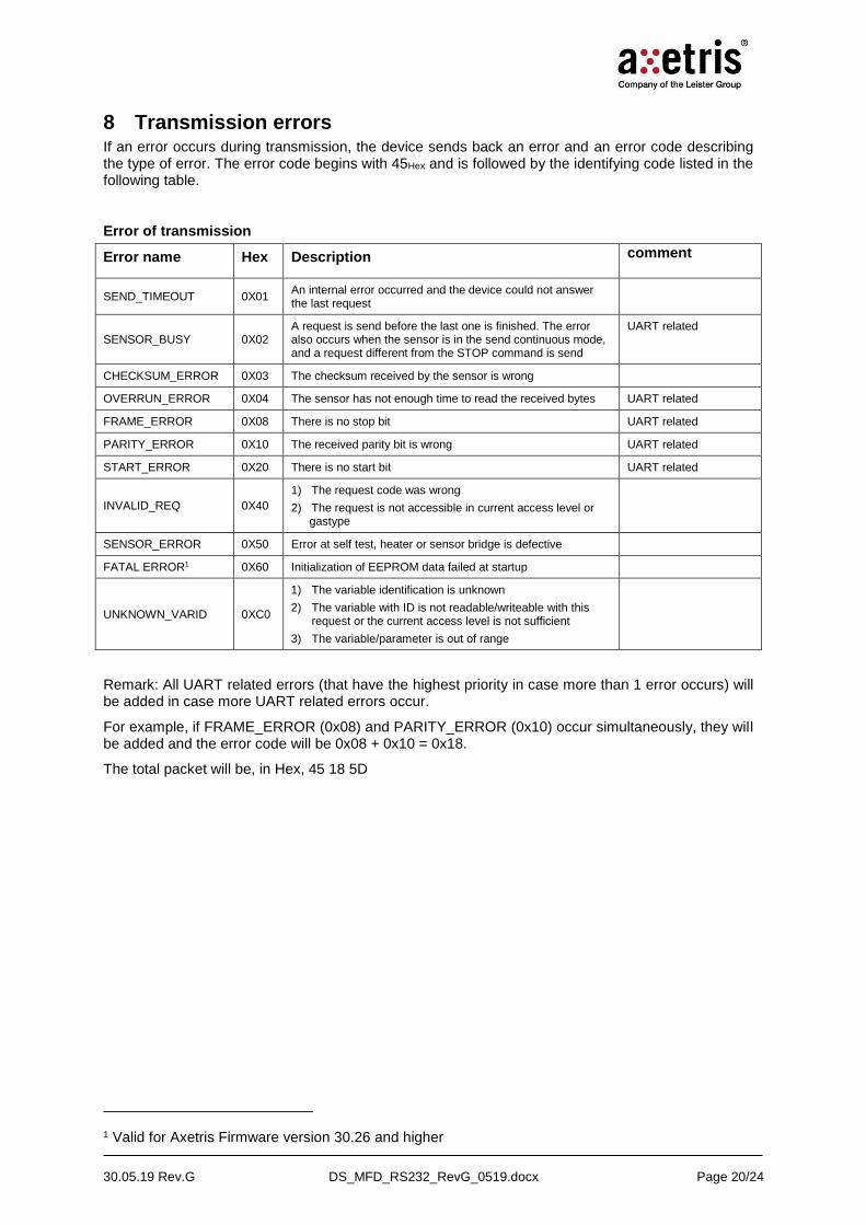
8 Transmission errors If an error occurs during transmission, the device sends back an error and an error code describing the type of error. The error code begins with 45Hex and is followed by the identifying code listed in the following table.
Error of transmission
Error name Hex Description comment
SEND_TIMEOUT 0X01 An internal error occurred and the device could not answer the last request
SENSOR_BUSY 0X02 A request is send before the last one is finished. The error also occurs when the sensor is in the send continuous mode, and a request different from the STOP command is send
UART related
CHECKSUM_ERROR 0X03 The checksum received by the sensor is wrong
OVERRUN_ERROR 0X04 The sensor has not enough time to read the received bytes UART related
FRAME_ERROR 0X08 There is no stop bit UART related
PARITY_ERROR 0X10 The received parity bit is wrong UART related
START_ERROR 0X20 There is no start bit UART related
INVALID_REQ 0X40
1) The request code was wrong
2) The request is not accessible in current access level or gastype
SENSOR_ERROR 0X50 Error at self test, heater or sensor bridge is defective
FATAL ERROR1 0X60 Initialization of EEPROM data failed at startup
UNKNOWN_VARID 0XC0
1) The variable identification is unknown
2) The variable with ID is not readable/writeable with this request or the current access level is not sufficient
3) The variable/parameter is out of range
Remark: All UART related errors (that have the highest priority in case more than 1 error occurs) will be added in case more UART related errors occur.
For example, if FRAME_ERROR (0x08) and PARITY_ERROR (0x10) occur simultaneously, they will be added and the error code will be 0x08 + 0x10 = 0x18.
The total packet will be, in Hex, 45 18 5D
1 Valid for Axetris Firmware version 30.26 and higher

30.05.19 Rev.G DS_MFD_RS232_RevG_0519.docx Page 21/24
9 FAQ & communication examples
- What happens when switching on the device?
The device sends on Tx 0xFF and 3 seconds later 0x53 meaning it is ready to communicate and to operate. The mode is the one that was set when the device was switched off. In digital input mode the flow is set to zero. No change occurs until a new set point is transmitted. In analog input mode, the device after sending 0x53 sets the flow immediately to the analog value that is present at the set point input pin.
Data direction Hex data Flow Remark
Rx None -
Tx FF 53
is zero in digital control mode
is equal to set point in analog control mode
0x53 is transmitted 3 sec. later once the device is ready to operate
- In which input mode is the device and how it can be change?
The input mode is set at the factory level according to the ordered configuration. However it is possible to check it or to change the input with the following command:
To check the input mode:
Data direction Hex data Flow Remark
Rx 63 1F 82 - request – variable ID – checksum
Tx 63 - The device sends back the request
To change the input mode:
Data direction Hex data Flow Remark
Rx 64 1F 00 83
64 1F 01 84
Last value independently of the previous mode
Set point according to analog value present at the input pin
Set the digital input mode
Set the analog input mode
Tx 64
64
The device sends back the request
- How to write a set point?
The digital set point range is (0…65535)Dec = (0x0000…0xFFFF)Hex = (0%...100%) F.S.
Data direction Hex data Flow Remark
Rx
62 14 00 00 76
62 14 02 90 08
62 14 80 00 F6
62 14 FF FF 74
0 % F.S.
1 % F.S.
50 % F.S.
100 % F.S.
Zero flow
Cut off limit value if present (on request)
Flow set at 50 % of the F.S.
Flow set at 100 % of the F.S.
Tx 62 The device sends back the request
30.05.19 Rev.G DS_MFD_RS232_RevG_0519.docx Page 22/24
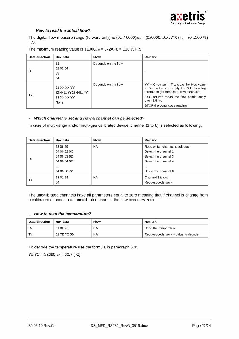
- How to read the actual flow?
The digital flow measure range (forward only) is (0…10000)Dec = (0x0000…0x2710)Hex = (0...100 %) F.S.
The maximum reading value is 11000Dec = 0x2AF8 = 110 % F.S.
Data direction Hex data Flow Remark
Rx
31
32 02 34
33
34
Depends on the flow
.
Tx
31 XX XX YY
32 HH LL YY 32 HH LL YY
33 XX XX YY
None
Depends on the flow YY = Checksum. Translate the Hex value in Dec value and apply the 6.1 decoding formula to get the actual flow measure
0x33 returns measured flow continuously each 3.5 ms
STOP the continuous reading
- Which channel is set and how a channel can be selected?
In case of multi-range and/or multi-gas calibrated device, channel (1 to 8) is selected as following.
Data direction Hex data Flow Remark
Rx
63 06 69
64 06 02 6C
64 06 03 6D
64 06 04 6E
…
64 06 08 72
NA Read which channel is selected
Select the channel 2
Select the channel 3
Select the channel 4
…
Select the channel 8
Tx 63 01 64
64
NA Channel 1 is set
Request code back
The uncalibrated channels have all parameters equal to zero meaning that if channel is change from a calibrated channel to an uncalibrated channel the flow becomes zero.
- How to read the temperature?
Data direction Hex data Flow Remark
Rx 61 0F 70 NA Read the temperature
Tx 61 7E 7C 5B NA Request code back + value to decode
To decode the temperature use the formula in paragraph 6.4:
7E 7C = 32380Dec = 32.7 [C]
30.05.19 Rev.G DS_MFD_RS232_RevG_0519.docx Page 23/24
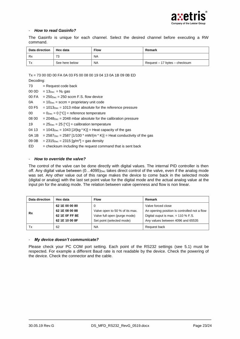
- How to read Gasinfo?
The Gasinfo is unique for each channel. Select the desired channel before executing a RW command.
Data direction Hex data Flow Remark
Rx 73 NA
Tx See here below NA Request – 17 bytes – checksum
Tx = 73 00 0D 00 FA 0A 03 F5 00 08 00 19 04 13 0A 1B 09 0B ED
Decoding:
73 = Request code back
00 0D = 13Dec = N2 gas
00 FA = 250Dec = 250 sccm F.S. flow device
0A = 10Dec = sccm = proprietary unit code
03 F5 = 1013Dec = 1013 mbar absolute for the reference pressure
00 = 0Dec = 0 [C] = reference temperature
08 00 = 2048Dec = 2048 mbar absolute for the calibration pressure
19 = 25Dec = 25 [C] = calibration temperature
04 13 = 1043Dec = 1043 [J/(kg K)] = Heat capacity of the gas
0A 1B = 2587Dec = 2587 [1/100 mW/(m K)] = Heat conductivity of the gas
09 0B = 2315Dec = 2315 [g/m3] = gas density
ED = checksum including the request command that is sent back
- How to override the valve?
The control of the valve can be done directly with digital values. The internal PID controller is then off. Any digital value between (0…4095)Dec takes direct control of the valve, even if the analog mode was set. Any other value out of this range makes the device to come back in the selected mode (digital or analog) with the last set point value for the digital mode and the actual analog value at the input pin for the analog mode. The relation between valve openness and flow is non linear.
Data direction Hex data Flow Remark
Rx
62 1E 00 00 80
62 1E 08 00 88
62 1E 0F FF 8E
62 1E 10 00 8F
0
Valve open to 50 % of its max.
Valve full open (purge mode)
Set point (selected mode)
Valve forced close
An opening position is controlled not a flow
Digital ouput is max. = 110 % F.S.
Any values between 4096 and 65535
Tx 62 NA Request back
- My device doesn’t communicate?
Please check your PC COM port setting. Each point of the RS232 settings (see 5.1) must be respected. For example a different Baud rate is not readable by the device. Check the powering of the device. Check the connector and the cable.
30.05.19 Rev.G DS_MFD_RS232_RevG_0519.docx Page 24/24
10 Caution
10.1 Product damage
Read all instructions carefully before using the device.
The MFM anemometric mass flow sensors are not designed to sense liquid flow and damage will result if liquid is passed through the sensor.
The sensor is not suited for measuring aggressive or corrosive gases. Use only non-corrosive, dry, clean and dry gases. Gas loaded with particles can eventually clog the sensor.
The appliance must not be used in damp or moist surroundings.
Use only accessories that are indicated in the instructions for use or are recommended by the manufacturer.
Failure to comply with these instructions can result in product damage.
10.2 Danger of life
These sensors employ a heated element.
The heated element is above the ambient temperature. The sensor must not be used with flammable or explosive gases or mixtures.
Unprofessional gas handling can cause injury or death. The use of mass flow meters should only be performed by qualified personnel.
Do not use this product as safety or emergency stop device or in any other application where failure of the product could result in personal injury or death.
11 Important Notice / Disclaimer
The information furnished by Axetris is believed to be correct and accurate. However, Axetris shall not be held liable to recipient or any third party of any damages, including but not limited to personal injury, property damage, loss of profits, loss of use, interrupt of business or indirect, special incidental or consequential damages, of any kind, in connection with or arising out of the furnishing, performance or use of technical data herein. No obligation or liability to recipient or any third party shall arise or flow out of Axetris rendering of technical or other services
© 05.2019 AXETRIS AG – Company of the Leister Group
Swiss Made Quality. Axetris is an ISO 9001 certified enterprise. Specifications are subject to change without prior notice
Related Documents