Specification Line® GA Series Original Instructions Service Manual This manual is updated as new information and models are released. Visit our website for the latest manual. Part Number GA_SM 08/18

Welcome message from author
This document is posted to help you gain knowledge. Please leave a comment to let me know what you think about it! Share it to your friends and learn new things together.
Transcript

Specification Line®GA Series
Original InstructionsService ManualThis manual is updated as new information and models are released. Visit our website for the latest manual.
Part Number GA_SM 08/18
Safety Notices
nWarningRead this manual thoroughly before operating, installing or performing maintenance on the equipment. Failure to follow instructions in this manual can cause property damage, injury or death.
DANGERDo not install or operate equipment that has been misused, abused, neglected, damaged, or altered/modified from that of original manufactured specifications.
DANGERUse appropriate safety equipment during installation and servicing.
DANGERAll utility connections and fixtures must be maintained in accordance with Local and national codes.
nWarningDo not damage the refrigeration circuit when installing, maintaining or servicing the unit.
nWarningAuthorized Service Representatives are obligated to follow industry standard safety procedures, including, but not limited to, local/national regulations for disconnection / lock out / tag out procedures for all utilities including electric, gas, water and steam.
nWarningDo not store or use gasoline or other flammable vapors or liquids in the vicinity of this or any other appliance. Never use flammable oil soaked cloths or combustible cleaning solutions, for cleaning.
nWarningThis product contains chemicals known to the State of California to cause cancer and/or birth defects or other reproductive harm. Operation, installation, and servicing of this product could expose you to airborne particles of glasswool or ceramic fibers, crystalline silica, and/or carbon monoxide. Inhalation of airborne particles of glasswool or ceramic fibers is known to the State of California to cause cancer. Inhalation of carbon monoxide is known to the State of California to cause birth defects or other reproductive harm.
nWarningDo not use electrical appliances inside the food storage compartments of the appliance, unless they are of the type recommended by the manufacturer.
nWarningUse caution when handling metal surface edges of all equipment.
nWarningThis appliance is not intended for use by persons (including children) with reduced physical, sensory or mental capabilities, or lack of experience and knowledge, unless they have been given supervision concerning use of the appliance by a person responsible for their safety. Do not allow children to play with this appliance.
,CautionUse caution handling, moving and use of the R290 refrigerators to avoid either damaging the refrigerant tubing or increasing the risk of a leak. Components shall be replaced with like components. Servicing shall be done by a factory authorized service personnel to minimize the risk of possible ignition due to incorrect parts or improper service.
Notice�Proper installation, care and maintenance are essential for maximum performance and trouble-free operation of your equipment. Visit our website www.wbtkitchencare.com for manual updates, translations, or contact information for service agents in your area.
Notice�Warranty may be deemed invalid if other than authorized OEM (original equipment manufacture) replacement parts are used in Delfield equipment.

Part Number GA_SM 08/18 3
Table of Contents
Section 1General Information
Model Numbers .......................................................... 5Serial Number Information ........................................ 5Warranty Information ................................................ 5Regulatory Certifications ........................................... 5
Section 2Installation
Location ....................................................................... 7Clearance Requirements ............................................ 7Drain Connections ...................................................... 7
Floor Drain Required .......................................................... 7Weight, Capacity & Dimensions of Equipment ........ 8Electrical Service ......................................................... 9
Ground Fault Circuit Interrupter .................................... 9Electrical Specification Chart .......................................... 9Energy Use ...........................................................................10
Leg & Caster Installation .......................................... 11Level & Stable ............................................................ 12Shelf Installation ....................................................... 12Reversible Door Instructions ................................... 12
Applicable to Full Door Models ...................................12Roll-In & Roll-Thru Installation ................................ 13New Hinge Cartridge Installation ............................ 14Accessory Interior Drawer Installation ................... 14T-1 Tray Slide Installation ......................................... 15T-2 Tray Slide Installation ......................................... 16T-3 Tray Slide Installation ......................................... 17T-4 Rack Slide Installation ........................................ 18Optional Foot Pedal Installation Instructions ........ 19
Section 3Operation
Refrigerator & Freezer Operation ............................ 21Refrigerator & Freezer Start Up ............................... 21
Evaporator Fan Operation .............................................22Heated Cabinet Operation ....................................... 22Heated Cabinet Start Up ......................................... 22
Fan Operation .....................................................................22High Temperature Safety Device .................................23
Power Down .............................................................. 23Home Screen ............................................................. 23TouchScreen Password ............................................. 24Configuration Screen ............................................... 25Settings Screen ......................................................... 25Units ........................................................................... 26Defrost Type (Refrigerator & Freezer) ..................... 26Set Box Temperature ................................................ 27Alarm Management .................................................. 28Network Connection ................................................ 28Interior Light ............................................................. 29Time / Date ................................................................ 30Language ................................................................... 30LCD Brightness .......................................................... 31Manual Defrost ......................................................... 31Web Application ....................................................... 31
KitchenConnect .................................................................31Mobile Application ................................................... 31
Specification Line Connect ............................................31Application Operation ............................................. 32
Equipment Management ...............................................32
Section 4Maintenance
Responsibility ........................................................... 33Interior Cleaning ....................................................... 34
Gaskets ..................................................................................34Preventing Blower Coil Corrosion ...............................34
Exterior Cleaning ...................................................... 34Drain ......................................................................................34Doors/Hinges .....................................................................34
Cleaning the Condenser Coil ................................... 34
Section 5Troubleshooting
Problem -> Cause -> Correction Chart .................... 35
4 Part Number GA_SM 08/18
Table of Contents (continued)
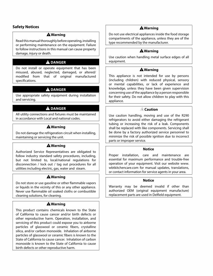
Section 6Control
Service Screens ......................................................... 37Frame Heater (Freezer Only) .........................................37Rapid Pull Down (Refrigerator Only) ..........................37Diagnostics ..........................................................................38Relay Status .........................................................................38Data History ........................................................................39Energy Chart .......................................................................39Temperature Chart ...........................................................39Temperature Probes .........................................................40Relay Outputs .....................................................................40Network Connection .......................................................41Set Up Connection ...........................................................41Complete Network Setup ..............................................42Add A Network Screen ....................................................42IP Address Setup Screen .................................................43Password ..............................................................................43Firmware Update ..............................................................44Reset Factory Settings .....................................................45Alarm History Screen .......................................................45Alarm Screens .....................................................................46Refrigerator & Freezer Alarms .......................................47
Section 7Component Check Procedures
Evaporator Fan Access .............................................. 49Condenser Fan Access .............................................. 50Unit Air Flow Design ................................................. 50Frame Heater Routing .............................................. 51Door Hinges .............................................................. 52Temperature Probe Resistance ................................ 53LED Light Replacement ............................................ 54Door Gasket .............................................................. 55
Section 8Refrigeration
R290Charging Procedures ................................................ 57System Contamination Clean-up ............................. 58Mild System Contamination Clean-Up Procedure . 59Severe Contamination Clean-Up Procedure ........... 59Filter Driers................................................................ 60Refrigerant Re-Use Policy ........................................ 60Properties of R-290 (Propane) ................................. 61Service Procedures ................................................... 62Review ....................................................................... 63Normal Operating Temperatures ............................ 64
1 Section Reach-In Refrigerator ...................................642 Section Reach-In Refrigerator ...................................673 Section Reach-In Refrigerator ...................................701 Section Reach-In Freezer ............................................732 Section Reach-In Freezer ............................................763 Section Reach-In Freezer ............................................791 Section Pass-Thru Refrigerator .................................822 Section Pass-Thru Refrigerator .................................851 Section Pass-Thru Freezer ...........................................882 Section Pass-Thru Freezer ...........................................91
Section 9Diagrams
Refrigerator Wiring Diagram ................................... 95Freezers With One Compressor Wiring Diagram .... 96Freezers With Two Compressors Wiring Diagram .. 97One Section Dual Temperature Wiring Diagram .... 98Two Section Dual Temperature Wiring Diagram .... 99One Section Heated Cabinet Wiring Diagram ......100Two Section Heated Cabinet Wiring Diagram ......101
Part Number GA_SM 08/18 5
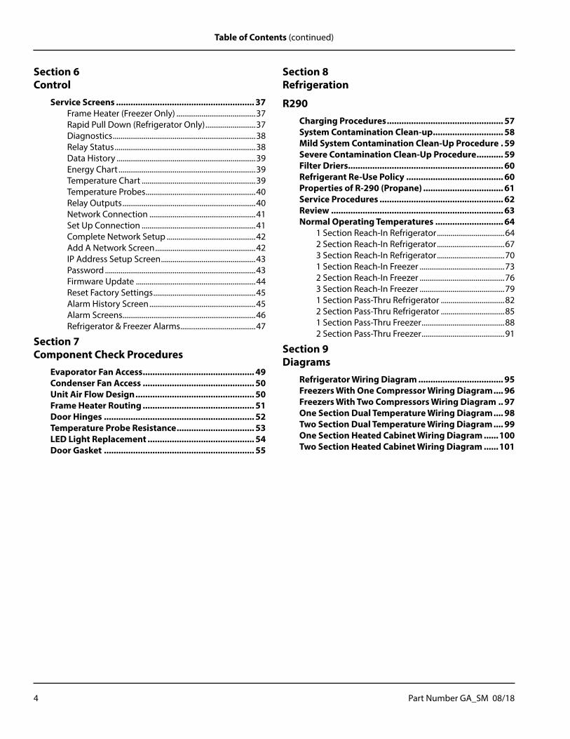
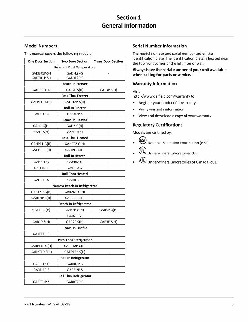
Model NumbersThis manual covers the following models:
One Door Section Two Door Section Three Door Section
Reach-In Dual Temperature
GADBR1P-SHGADTR1P-SH
GADFL2P-SGADRL2P-S
-
Reach-In Freezer
GAF1P-S(H) GAF2P-S(H) GAF3P-S(H)
Pass-Thru Freezer
GAFPT1P-S(H) GAFPT2P-S(H) -
Roll-In Freezer
GAFRI1P-S GAFRI2P-S -
Reach-In Heated
GAH1-G(H) GAH2-G(H) -
GAH1-S(H) GAH2-S(H) -
Pass-Thru Heated
GAHPT1-G(H) GAHPT2-G(H) -
GAHPT1-S(H) GAHPT2-S(H) -
Roll-In Heated
GAHRI1-G GAHRI2-G -
GAHRI1-S GAHRI2-S -
Roll-Thru Heated
GAHRT1-S GAHRT2-S -
Narrow Reach-In Refrigerator
GAR1NP-G(H) GAR2NP-G(H) -
GAR1NP-S(H) GAR2NP-S(H) -
Reach-In Refrigerator
GAR1P-G(H) GAR2P-G(H) GAR3P-G(H)
- GAR2P-GL -
GAR1P-S(H) GAR2P-S(H) GAR3P-S(H)
Reach-In Fishfile
GARFF1P-D - -
Pass-Thru Refrigerator
GARPT1P-G(H) GARPT2P-G(H) -
GARPT1P-S(H) GARPT2P-S(H) -
Roll-In Refrigerator
GARRI1P-G GARRI2P-G -
GARRI1P-S GARRI2P-S -
Roll-Thru Refrigerator
GARRT1P-S GARRT2P-S -
Serial Number InformationThe model number and serial number are on the identification plate. The identification plate is located near the top front corner of the left interior wall.
Always have the serial number of your unit available when calling for parts or service.
Warranty InformationVisit http://www.delfield.com/warranty to:
• Register your product for warranty.
• Verify warranty information.
• View and download a copy of your warranty.
Regulatory CertificationsModels are certified by:
• National Sanitation Foundation (NSF)
• Underwriters Laboratories (UL)
• Underwriters Laboratories of Canada (cUL)
Section 1General Information
6 Part Number GA_SM 08/18
General Information Section 1
THIS PAGE INTENTIONALLY LEFT BLANK
Part Number GA_SM 08/18 7
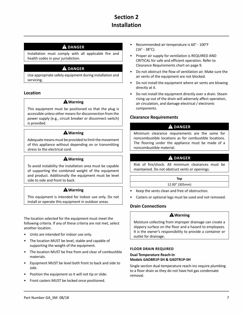
DANGERInstallation must comply with all applicable fire and health codes in your jurisdiction.
DANGERUse appropriate safety equipment during installation and servicing.
Location
nWarningThis equipment must be positioned so that the plug is accessible unless other means for disconnection from the power supply (e.g., circuit breaker or disconnect switch) is provided.
nWarningAdequate means must be provided to limit the movement of this appliance without depending on or transmitting stress to the electrical cord.
nWarningTo avoid instability the installation area must be capable of supporting the combined weight of the equipment and product. Additionally the equipment must be level side to side and front to back.
nWarningThis equipment is intended for indoor use only. Do not install or operate this equipment in outdoor areas.
The location selected for the equipment must meet the following criteria. If any of these criteria are not met, select another location.
• Units are intended for indoor use only.
• The location MUST be level, stable and capable of supporting the weight of the equipment.
• The location MUST be free from and clear of combustible materials.
• Equipment MUST be level both front to back and side to side.
• Position the equipment so it will not tip or slide.
• Front casters MUST be locked once positioned.
• Recommended air temperature is 60° - 100°F (16° - 38°C).
• Proper air supply for ventilation is REQUIRED AND CRITICAL for safe and efficient operation. Refer to Clearance Requirements chart on page 9.
• Do not obstruct the flow of ventilation air. Make sure the air vents of the equipment are not blocked.
• Do not install the equipment where air vents are blowing directly at it.
• Do not install the equipment directly over a drain. Steam rising up out of the drain will adversely affect operation, air circulation, and damage electrical / electronic components.
Clearance Requirements
DANGERMinimum clearance requirements are the same for noncombustible locations as for combustible locations. The flooring under the appliance must be made of a noncombustible material.
DANGERRisk of fire/shock. All minimum clearances must be maintained. Do not obstruct vents or openings.
Top
12.00” (305mm)
• Keep the vents clean and free of obstruction.
• Casters or optional legs must be used and not removed.
Drain Connections
nWarningMoisture collecting from improper drainage can create a slippery surface on the floor and a hazard to employees. It is the owner’s responsibility to provide a container or outlet for drainage.
FLOOR DRAIN REQUIREDDual Temperature Reach-In Models GADBR1P-SH & GADTR1P-SH
Single section dual temperature reach-ins require plumbing to a floor drain as they do not have hot gas condensate removal.
Section 2Installation
8 Part Number GA_SM 08/18
Installation Section 2
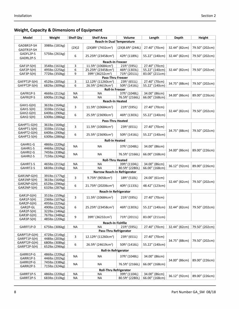
Weight, Capacity & Dimensions of EquipmentModel Weight Shelf Qty Shelf Area Volume Length Depth Height
Reach-In Dual TemperatureGADBR1P-SHGADTR1P-SH
398lbs (181kg) (2X)2 (2X)8ft2 (7432cm2) (2X)8.6ft3 (244L) 27.40” (70cm) 32.44” (82cm) 79.50” (202cm)
GADFL2P-SGADRL2P-S
575lbs (261kg) 6 25.25ft2 (23458cm2) 42ft3 (1189L) 55.22” (140cm) 32.44” (82cm) 79.50” (202cm)
Reach-In FreezerGAF1P-S(H) 354lbs (161kg) 3 11.5ft2 (10684cm2) 21ft3 (595L) 27.40” (70cm)
32.44” (82cm) 79.50” (202cm)GAF2P-S(H) 495lbs (225kg) 6 25.25ft2 (23458cm2) 46ft3 (1303L) 55.22” (140cm)GAF3P-S(H) 772lbs (350kg) 9 39ft2 (36232cm2) 71ft3 (2011L) 83.00” (211cm)
Pass-Thru FreezerGAFPT1P-S(H) 452lbs (205kg) 3 12.12ft2 (11260cm2) 23ft3 (651L) 27.40” (70cm) 34.75” (88cm) 79.50” (202cm)GAFPT2P-S(H) 682lbs (309kg) 6 26.5ft2 (24619cm2) 50ft3 (1416L) 55.22” (140cm)
Roll-In FreezerGAFRI1P-S 466lbs (211kg) NA NA 37ft3 (1048L) 34.00” (86cm) 34.00” (86cm) 89.00” (226cm)GAFRI2P-S 690lbs (313kg) NA NA 76.5ft3 (2166L) 66.00” (168cm)
Reach-In HeatedGAH1-G(H) 361lbs (164kg) 3 11.5ft2 (10684cm2) 21ft3 (595L) 27.40” (70cm)
32.44” (82cm) 79.50” (202cm)GAH1-S(H) 333lbs (151kg)GAH2-G(H) 640lbs (290kg) 6 25.5ft2 (23690cm2) 46ft3 (1303L) 55.22” (140cm)GAH2-S(H) 630lbs (286kg)
Pass-Thru HeatedGAHPT1-G(H) 361lbs (164kg) 3 11.5ft2 (10684cm2) 23ft3 (651L) 27.40” (70cm)
34.75” (88cm) 79.50” (202cm)GAHPT1-S(H) 333lbs (151kg)GAHPT2-G(H) 640lbs (290kg) 6 25.5ft2 (23690cm2) 50ft3 (1416L) 55.22” (140cm)GAHPT2-S(H) 630lbs (286kg)
Roll-In HeatedGAHRI1-G 486lbs (220kg) NA NA 37ft3 (1048L) 34.00” (86cm)
34.00” (86cm) 89.00” (226cm)GAHRI1-S 446lbs (202kg)GAHRI2-G 745lbs (338kg) NA NA 76.5ft3 (2166L) 66.00” (168cm)GAHRI2-S 715lbs (324kg)
Roll-Thru HeatedGAHRT1-S 465lbs (211kg) NA NA 39ft3 (1104L) 34.00” (86cm) 36.12” (92cm) 89.00” (226cm)GAHRT2-S 683lbs (310kg) NA NA 80.5ft3 (2280L) 66.00” (168cm)
Narrow Reach-In RefrigeratorGAR1NP-G(H) 391lbs (177kg) 3 9.75ft2 (9058cm2) 18ft3 (510L) 24.00” (61cm)
32.44” (82cm) 79.50” (202cm)GAR1NP-S(H) 361lbs (164kg)GAR2NP-G(H) 652lbs (296kg) 6 21.75ft2 (20206cm2) 40ft3 (1133L) 48.42” (123cm)GAR2NP-S(H) 632lbs (287kg)
Reach-In RefrigeratorGAR1P-G(H) 351lbs (159kg) 3 11.5ft2 (10684cm2) 21ft3 (595L) 27.40” (70cm)
32.44” (82cm) 79.50” (202cm)
GAR1P-S(H) 236lbs (107kg)GAR2P-G(H) 495lbs (225kg)
6 25.25ft2 (23458cm2) 46ft3 (1303L) 55.22” (140cm)GAR2P-GL 490lbs (222kg)GAR2P-S(H) 322lbs (146kg)GAR3P-G(H) 767lbs (348kg) 9 39ft2 (36232cm2) 71ft3 (2011L) 83.00” (211cm)GAR3P-S(H) 485lbs (220kg)
Reach-In FishfileGARFF1P-D 675lbs (306kg) NA NA 21ft3 (595L) 27.40” (70cm) 32.44” (82cm) 79.50” (202cm)
Pass-Thru RefrigeratorGARPT1P-G(H) 472lbs (214kg) 3 12.12ft2 (11260cm2) 23ft3 (651L) 27.40” (70cm)
34.75” (88cm) 79.50” (202cm)GARPT1P-S(H) 448lbs (203kg)GARPT2P-G(H) 680lbs (308kg) 6 26.5ft2 (24619cm2) 50ft3 (1416L) 55.22” (140cm)GARPT2P-S(H) 652lbs (296kg)
Roll-In RefrigeratorGARRI1P-G 486lbs (220kg) NA NA 37ft3 (1048L) 34.00” (86cm)
34.00” (86cm) 89.00” (226cm)GARRI1P-S 446lbs (202kg)GARRI2P-G 745lbs (338kg) NA NA 76.5ft3 (2166L) 66.00” (168cm)GARRI2P-S 715lbs (324kg)
Roll-Thru RefrigeratorGARRT1P-S 486lbs (220kg) NA NA 39ft3 (1104L) 34.00” (86cm) 36.12” (92cm) 89.00” (226cm)GARRT2P-S 683lbs (310kg) NA NA 80.5ft3 (2280L) 66.00” (168cm)
Part Number GA_SM 08/18 9
Section 2 Installation
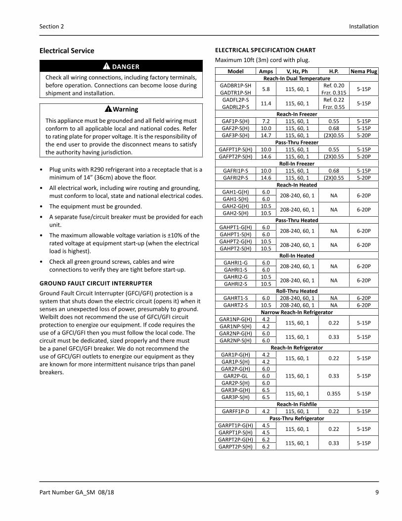
Electrical Service
DANGERCheck all wiring connections, including factory terminals, before operation. Connections can become loose during shipment and installation.
nWarningThis appliance must be grounded and all field wiring must conform to all applicable local and national codes. Refer to rating plate for proper voltage. It is the responsibility of the end user to provide the disconnect means to satisfy the authority having jurisdiction.
• Plug units with R290 refrigerant into a receptacle that is a minimum of 14” (36cm) above the floor.
• All electrical work, including wire routing and grounding, must conform to local, state and national electrical codes.
• The equipment must be grounded.
• A separate fuse/circuit breaker must be provided for each unit.
• The maximum allowable voltage variation is ±10% of the rated voltage at equipment start-up (when the electrical load is highest).
• Check all green ground screws, cables and wire connections to verify they are tight before start-up.
GROUND FAULT CIRCUIT INTERRUPTERGround Fault Circuit Interrupter (GFCI/GFI) protection is a system that shuts down the electric circuit (opens it) when it senses an unexpected loss of power, presumably to ground. Welbilt does not recommend the use of GFCI/GFI circuit protection to energize our equipment. If code requires the use of a GFCI/GFI then you must follow the local code. The circuit must be dedicated, sized properly and there must be a panel GFCI/GFI breaker. We do not recommend the use of GFCI/GFI outlets to energize our equipment as they are known for more intermittent nuisance trips than panel breakers.
ELECTRICAL SPECIFICATION CHARTMaximum 10ft (3m) cord with plug.
Model Amps V, Hz, Ph H.P. Nema PlugReach-In Dual Temperature
GADBR1P-SHGADTR1P-SH 5.8 115, 60, 1 Ref. 0.20
Frzr. 0.315 5-15P
GADFL2P-SGADRL2P-S 11.4 115, 60, 1 Ref. 0.22
Frzr. 0.55 5-15P
Reach-In FreezerGAF1P-S(H) 7.2 115, 60, 1 0.55 5-15PGAF2P-S(H) 10.0 115, 60, 1 0.68 5-15PGAF3P-S(H) 14.7 115, 60, 1 (2X)0.55 5-20P
Pass-Thru FreezerGAFPT1P-S(H) 10.0 115, 60, 1 0.55 5-15PGAFPT2P-S(H) 14.6 115, 60, 1 (2X)0.55 5-20P
Roll-In FreezerGAFRI1P-S 10.0 115, 60, 1 0.68 5-15PGAFRI2P-S 14.6 115, 60, 1 (2X)0.55 5-20P
Reach-In HeatedGAH1-G(H) 6.0 208-240, 60, 1 NA 6-20PGAH1-S(H) 6.0GAH2-G(H) 10.5 208-240, 60, 1 NA 6-20PGAH2-S(H) 10.5
Pass-Thru HeatedGAHPT1-G(H) 6.0 208-240, 60, 1 NA 6-20PGAHPT1-S(H) 6.0GAHPT2-G(H) 10.5 208-240, 60, 1 NA 6-20PGAHPT2-S(H) 10.5
Roll-In HeatedGAHRI1-G 6.0 208-240, 60, 1 NA 6-20PGAHRI1-S 6.0GAHRI2-G 10.5 208-240, 60, 1 NA 6-20PGAHRI2-S 10.5
Roll-Thru HeatedGAHRT1-S 6.0 208-240, 60, 1 NA 6-20PGAHRT2-S 10.5 208-240, 60, 1 NA 6-20P
Narrow Reach-In RefrigeratorGAR1NP-G(H) 4.2 115, 60, 1 0.22 5-15PGAR1NP-S(H) 4.2GAR2NP-G(H) 6.0 115, 60, 1 0.33 5-15PGAR2NP-S(H) 6.0
Reach-In RefrigeratorGAR1P-G(H) 4.2 115, 60, 1 0.22 5-15PGAR1P-S(H) 4.2GAR2P-G(H) 6.0
115, 60, 1 0.33 5-15PGAR2P-GL 6.0GAR2P-S(H) 6.0GAR3P-G(H) 6.5 115, 60, 1 0.355 5-15PGAR3P-S(H) 6.5
Reach-In FishfileGARFF1P-D 4.2 115, 60, 1 0.22 5-15P
Pass-Thru RefrigeratorGARPT1P-G(H) 4.5 115, 60, 1 0.22 5-15PGARPT1P-S(H) 4.5GARPT2P-G(H) 6.2 115, 60, 1 0.33 5-15PGARPT2P-S(H) 6.2
10 Part Number GA_SM 08/18
Installation Section 2
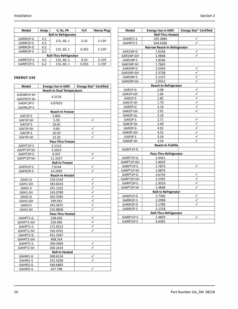
Model Amps V, Hz, Ph H.P. Nema PlugRoll-In Refrigerator
GARRI1P-G 4.5 115, 60, 1 0.33 5-15PGARRI1P-S 4.5GARRI2P-G 6.2 115, 60, 1 0.355 5-15PGARRI2P-S 6.2
Roll-Thru RefrigeratorGARRT1P-S 4.5 115, 60, 1 0.33 5-15PGARRT2P-S 6.2 115, 60, 1 0.355 5-15P
ENERGY USE
Model Energy Use in kWh Energy Star® CertifiedReach-In Dual Temperature
GADBR1P-SHGADTR1P-SH 4.2576
GADFL2P-SGADRL2P-S
4.87025
Reach-In FreezerGAF1P-S 5.863
GAF1P-SH 5.59 GAF2P-S 10.65
GAF2P-SH 9.69 GAF3P-S 10.50
GAF3P-SH 12.20 Pass-Thru Freezer
GAFPT1P-S 5.1112GAFPT1P-SH 5.2623GAFPT2P-S 9.337
GAFPT2P-SH 11.3327 Roll-In Freezer
GAFRI1P-S 7.6144 GAFRI2P-S 14.3393
Reach-In HeatedGAH1-G 159.3144
GAH1-GH 183.6433 GAH1-S 141.1322
GAH1-SH 145.0789 GAH2-G 302.5585
GAH2-GH 299.055 GAH2-S 245.5875
GAH2-SH 233.8808 Pass-Thru Heated
GAHPT1-G 228.636 GAHPT1-GH 234.906 GAHPT1-S 171.9222
GAHPT1-SH 192.0701 GAHPT2-G 421.2567
GAHPT2-GH 408.354GAHPT2-S 290.2969
GAHPT2-SH 300.2424 Roll-In Heated
GAHRI1-G 308.6124 GAHRI1-S 241.5638 GAHRI2-G 560.6883GAHRI2-S 427.798
Model Energy Use in kWh Energy Star® CertifiedRoll-Thru Heated
GAHRT1-S 295.3889 GAHRT2-S 504.6286
Narrow Reach-In RefrigeratorGAR1NP-G 1.9248
GAR1NP-GH 1.9848 GAR1NP-S 1.8296
GAR1NP-SH 1.7665GAR2NP-G 2.5934
GAR2NP-GH 2.3738 GAR2NP-S 2.1157
GAR2NP-SH 2.0552 Reach-In Refrigerator
GAR1P-G 2.08 GAR1P-GH 1.66 GAR1P-S 1.85
GAR1P-SH 1.70 GAR2P-G 3.18
GAR2P-GH 2.91 GAR2P-GL 3.18GAR2P-S 2.71
GAR2P-SH 2.49 GAR3P-G 4.92
GAR3P-GH 4.55 GAR3P-S 3.59
GAR3P-SH 3.54 Reach-In Fishfile
GARFF1P-DPass-Thru Refrigerator
GARPT1P-G 2.4461GARPT1P-GH 2.4620GARPT1P-S 1.7873
GARPT1P-SH 1.9876GARPT2P-G 3.6743
GARPT2P-GH 3.5395 GARPT2P-S 2.3019
GARPT2P-SH 2.4898 Roll-In Refrigerator
GARRI1P-G 2.7366 GARRI1P-S 2.2998 GARRI2P-G 5.1789 GARRI2P-S 5.1258
Roll-Thru RefrigeratorGARRT1P-S 2.4859 GARRT2P-S 4.6395

Part Number GA_SM 08/18 11
Section 2 Installation
RefrigerationModel Heat of
Rejection (BTU)BTU/Hour Capacity
R290 Charge
Reach-In Dual TemperatureGADBR1P-SHGADTR1P-SH
Ref. 232 Frzr. 401
Ref. 1431 Frzr. 1094
Ref. 78g Frzr. 62g
GADFL2P-SGADRL2P-S
Ref. 420 Frzr. 790
Ref. 1920 Frzr. 2035
Ref. 113g Frzr. 93g
Reach-In FreezerGAF1P-S(H) 790 2035 93gGAF2P-S(H) 1380 2485 109gGAF3P-S(H) 1800 4070 (2X)110g
Pass-Thru FreezerGAFPT1P-S(H) 930 2035 93gGAFPT2P-S(H) 1630 4070 (2X)110g
Roll-In FreezerGAFRI1P-S 1401 2261 109gGAFRI2P-S 2458 4523 (2X)110g
Narrow Reach-In RefrigeratorGAR1NP-G(H) 540 1860 113gGAR1NP-S(H) 390 1860 113gGAR2NP-G(H) 890 2470 113gGAR2NP-S(H) 590 2470 113g
Reach-In RefrigeratorGAR1P-G(H) 570 1920 113gGAR1P-S(H) 420 1920 113gGAR2P-G(H) 930 2540 113gGAR2P-GL 1606 3370 113g
GAR2P-S(H) 620 2540 113gGAR3P-G(H) 1400 3865 118gGAR3P-S(H) 940 3865 118g
Reach-In FishfileGARFF1P-D 570 1920 113g
Pass-Thru RefrigeratorGARPT1P-G(H) 690 1860 113gGARPT1P-S(H) 460 1860 113gGARPT2P-G(H) 1260 3760 113gGARPT2P-S(H) 800 3760 113g
Roll-In RefrigeratorGARRI1P-G 800 2470 113gGARRI1P-S 680 2470 113gGARRI2P-G 1460 3760 118gGARRI2P-S 1230 3760 118g
Roll-Thru RefrigeratorGARRT1P-S 830 2470 113gGARRT2P-S 1530 3760 118g
Leg & Caster Installation
nWarningThe unit must be installed in a stable condition with the front wheels locked. Locking the front casters after installation is the owner’s and operator’s responsibility.
nWarningUse a jack to lift the refrigeration unit off the ground just far enough to remove the leg/caster. Place blocking underneath the unit. Do not work underneath a raised unit without proper blocking. Do not lift the unit more than necessary to remove the leg/caster. Lifting the unit too far can make the unit unstable.
,CautionAll single-section units require that the swivel casters be mounted on the front and rigid casters be mounted on the rear.
To install the legs or casters:
1. Remove unit from skid.
NOTE: The bolts used to hold the unit to the skid should be re-used as the fourth hex head bolt for each caster or leg plate installation. The bolt should not measure over 2” (5cm) in length.
2. Raise unit to access leg/caster mounting holes on bottom of unit.
3. Attach the legs or casters to bottom of cabinet using hex head bolts.
12 Part Number GA_SM 08/18
Installation Section 2
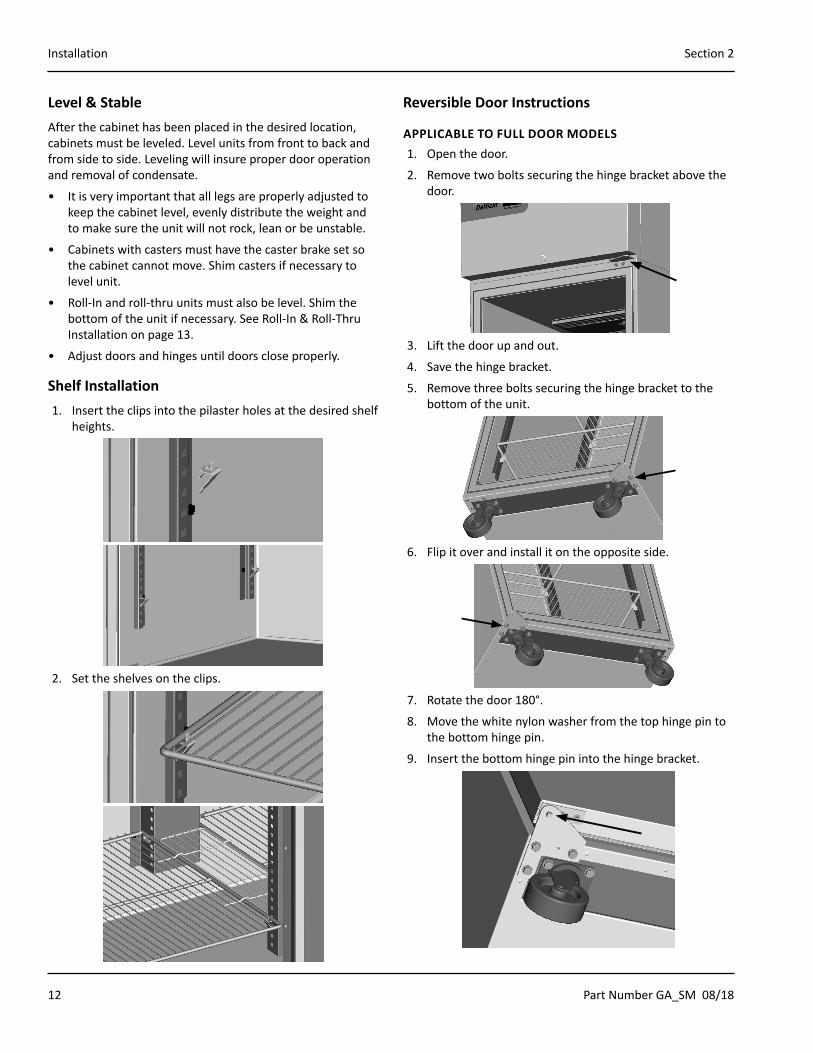
Level & StableAfter the cabinet has been placed in the desired location, cabinets must be leveled. Level units from front to back and from side to side. Leveling will insure proper door operation and removal of condensate.
• It is very important that all legs are properly adjusted to keep the cabinet level, evenly distribute the weight and to make sure the unit will not rock, lean or be unstable.
• Cabinets with casters must have the caster brake set so the cabinet cannot move. Shim casters if necessary to level unit.
• Roll-In and roll-thru units must also be level. Shim the bottom of the unit if necessary. See Roll-In & Roll-Thru Installation on page 13.
• Adjust doors and hinges until doors close properly.
Shelf Installation1. Insert the clips into the pilaster holes at the desired shelf
heights.
2. Set the shelves on the clips.
Reversible Door Instructions
APPLICABLE TO FULL DOOR MODELS1. Open the door.
2. Remove two bolts securing the hinge bracket above the door.
3. Lift the door up and out.
4. Save the hinge bracket.
5. Remove three bolts securing the hinge bracket to the bottom of the unit.
6. Flip it over and install it on the opposite side.
7. Rotate the door 180°.
8. Move the white nylon washer from the top hinge pin to the bottom hinge pin.
9. Insert the bottom hinge pin into the hinge bracket.

Part Number GA_SM 08/18 13
Section 2 Installation
10. Locate the provided alternate top hinge bracket.
11. Place the hinge bracket over the top hinge pin.
12. Open the door.
13. Using the original screws install the hinge bracket on the new side in the vacant lock holes.
14. Check for proper closure and gasket seal.
15. Adjust hinges as needed.
Roll-In & Roll-Thru InstallationNOTE: Local area codes may dictate other installation requirements not mentioned.
1. Verify unit is level with 4’ Level. Shim as needed. Depending on the height of the shims, stainless trim may be needed to fill in a large gap between the unit and the floor.
2. Remove door sweep before making door adjustments.
3. Adjust doors hinges so door closes by itself.
• A properly adjusted door will close and seal when the door is held open 3” or less with no assistance.
4. Reinstall door sweep. It may need to be reinstalled in new holes so that it does not interfere with the door closing.
• If it is too tight to ramp it will hold door open.• Make sure sweep is just touching ramp when closed.
Sweep just touching ramp
Unit
Ramp
Door
5. Verify once again that the door will close and seal when held open 3” or less.
6. If this is a multi-section unit make sure door stays shut or closes by itself when other doors are shut.
7. Using silicone, seal the ramp to the floor; seal the unit to the floor and walls. The silicone will make sure that no water can get under the unit or ramps. If shims and stainless trim are added they also need to be sealed to the unit and the floor.

14 Part Number GA_SM 08/18
Installation Section 2
New Hinge Cartridge Installation• Full doors have a cartridge hinge on both the bottom and
top of the door.
• Half doors only have one cartridge hinge, the bottom hinge of the bottom half door and the top hinge of the top half door.
1. Install the new cartridge into the door as received. The new cartridge will be in the CLOSED position.
2. As you unload the hinge tension be careful to hold on tight because you should feel the strong spring tension as you rotate the hinge. Place the hinge bracket on the square hinge pin and rotate it ½ turn to the outside of the door.
3. After the hinge has been rotated, it will now be in the OPEN position and NOT under spring tension.
4. Mount the door back onto the cabinet with the door OPEN. The door should now close properly.
5. Begin closing the door, the door should finish closing on it’s own. If the door stays open remove the door and hinge bracket.
6. Using the hinge bracket rotate the square peg on the cartridge until you feel tension and resistance if you move the hinge in either direction. The hinge is now in the CLOSED position. Repeat instructions starting with step 2.
Accessory Interior Drawer Installation1. Accessory drawer installation requires two tracks and a
drawer.
2. Hang the drawer tracks on the pilaster strips across from each other. Verify the tracks are lined up evenly.
3. Slide the drawer box into the tracks slowly. When the drawer box is half way in it will hit a STOP. Lift the front of the drawer up slightly to continue.
Part Number GA_SM 08/18 15
Section 2 Installation
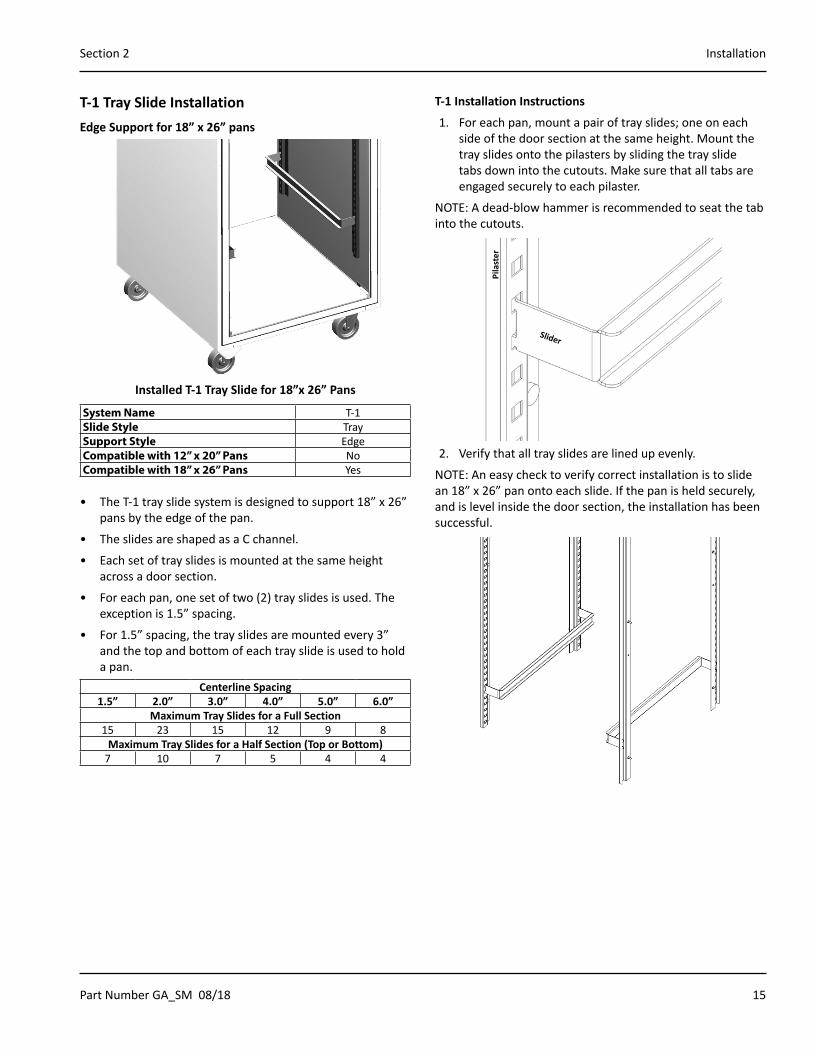
T-1 Tray Slide InstallationEdge Support for 18” x 26” pans
Installed T-1 Tray Slide for 18”x 26” Pans
System Name T-1Slide Style TraySupport Style EdgeCompatible with 12” x 20” Pans NoCompatible with 18” x 26” Pans Yes
• The T-1 tray slide system is designed to support 18” x 26” pans by the edge of the pan.
• The slides are shaped as a C channel.
• Each set of tray slides is mounted at the same height across a door section.
• For each pan, one set of two (2) tray slides is used. The exception is 1.5” spacing.
• For 1.5” spacing, the tray slides are mounted every 3” and the top and bottom of each tray slide is used to hold a pan.
Centerline Spacing1.5” 2.0” 3.0” 4.0” 5.0” 6.0”
Maximum Tray Slides for a Full Section15 23 15 12 9 8
Maximum Tray Slides for a Half Section (Top or Bottom)7 10 7 5 4 4
T-1 Installation Instructions
1. For each pan, mount a pair of tray slides; one on each side of the door section at the same height. Mount the tray slides onto the pilasters by sliding the tray slide tabs down into the cutouts. Make sure that all tabs are engaged securely to each pilaster.
NOTE: A dead-blow hammer is recommended to seat the tab into the cutouts.
Pila
ster
Slider
2. Verify that all tray slides are lined up evenly.
NOTE: An easy check to verify correct installation is to slide an 18” x 26” pan onto each slide. If the pan is held securely, and is level inside the door section, the installation has been successful.
16 Part Number GA_SM 08/18
Installation Section 2
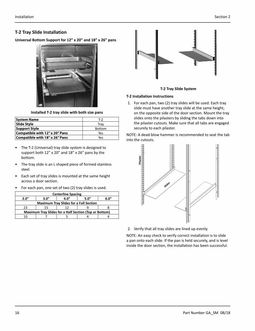
T-2 Tray Slide InstallationUniversal Bottom Support for 12” x 20” and 18” x 26” pans
Installed T-2 tray slide with both size pans
System Name T-2Slide Style TraySupport Style BottomCompatible with 12” x 20” Pans YesCompatible with 18” x 26” Pans Yes
• The T-2 (Universal) tray slide system is designed to support both 12” x 20” and 18” x 26” pans by the bottom.
• The tray slide is an L shaped piece of formed stainless steel.
• Each set of tray slides is mounted at the same height across a door section.
• For each pan, one set of two (2) tray slides is used.Centerline Spacing
2.0” 3.0” 4.0” 5.0” 6.0”Maximum Tray Slides for a Full Section
23 15 12 9 8Maximum Tray Slides for a Half Section (Top or Bottom)10 7 5 4 4
T-2 Tray Slide System
T-2 Installation Instructions
1. For each pan, two (2) tray slides will be used. Each tray slide must have another tray slide at the same height, on the opposite side of the door section. Mount the tray slides onto the pilasters by sliding the tabs down into the pilaster cutouts. Make sure that all tabs are engaged securely to each pilaster.
NOTE: A dead-blow hammer is recommended to seat the tab into the cutouts.
Pila
ster
Slider
2. Verify that all tray slides are lined up evenly.
NOTE: An easy check to verify correct installation is to slide a pan onto each slide. If the pan is held securely, and is level inside the door section, the installation has been successful.
Part Number GA_SM 08/18 17
Section 2 Installation
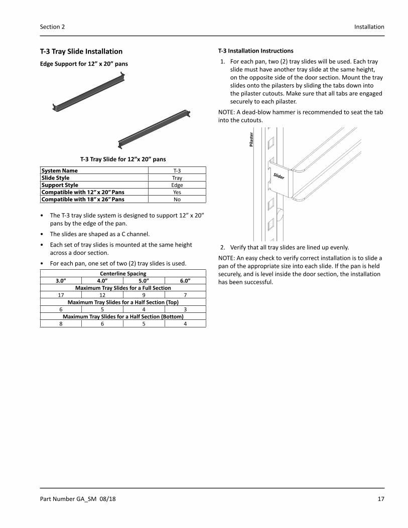
T-3 Tray Slide InstallationEdge Support for 12” x 20” pans
T-3 Tray Slide for 12”x 20” pans
System Name T-3Slide Style TraySupport Style EdgeCompatible with 12” x 20” Pans YesCompatible with 18” x 26” Pans No
• The T-3 tray slide system is designed to support 12” x 20” pans by the edge of the pan.
• The slides are shaped as a C channel.
• Each set of tray slides is mounted at the same height across a door section.
• For each pan, one set of two (2) tray slides is used.Centerline Spacing
3.0” 4.0” 5.0” 6.0”Maximum Tray Slides for a Full Section
17 12 9 7Maximum Tray Slides for a Half Section (Top)
6 5 4 3Maximum Tray Slides for a Half Section (Bottom)
8 6 5 4
T-3 Installation Instructions
1. For each pan, two (2) tray slides will be used. Each tray slide must have another tray slide at the same height, on the opposite side of the door section. Mount the tray slides onto the pilasters by sliding the tabs down into the pilaster cutouts. Make sure that all tabs are engaged securely to each pilaster.
NOTE: A dead-blow hammer is recommended to seat the tab into the cutouts.
Pila
ster
Slider
2. Verify that all tray slides are lined up evenly.
NOTE: An easy check to verify correct installation is to slide a pan of the appropriate size into each slide. If the pan is held securely, and is level inside the door section, the installation has been successful.
18 Part Number GA_SM 08/18
Installation Section 2
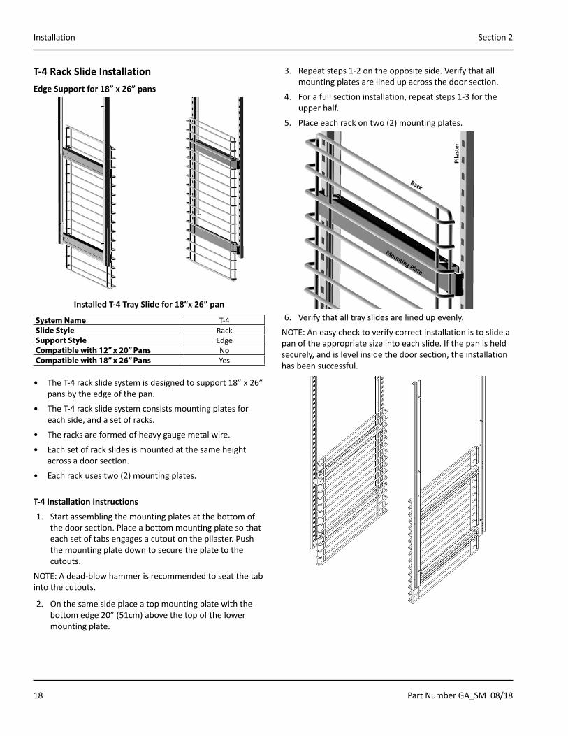
T-4 Rack Slide InstallationEdge Support for 18” x 26” pans
Installed T-4 Tray Slide for 18”x 26” pan
System Name T-4Slide Style RackSupport Style EdgeCompatible with 12” x 20” Pans NoCompatible with 18” x 26” Pans Yes
• The T-4 rack slide system is designed to support 18” x 26” pans by the edge of the pan.
• The T-4 rack slide system consists mounting plates for each side, and a set of racks.
• The racks are formed of heavy gauge metal wire.
• Each set of rack slides is mounted at the same height across a door section.
• Each rack uses two (2) mounting plates.
T-4 Installation Instructions
1. Start assembling the mounting plates at the bottom of the door section. Place a bottom mounting plate so that each set of tabs engages a cutout on the pilaster. Push the mounting plate down to secure the plate to the cutouts.
NOTE: A dead-blow hammer is recommended to seat the tab into the cutouts.
2. On the same side place a top mounting plate with the bottom edge 20” (51cm) above the top of the lower mounting plate.
3. Repeat steps 1-2 on the opposite side. Verify that all mounting plates are lined up across the door section.
4. For a full section installation, repeat steps 1-3 for the upper half.
5. Place each rack on two (2) mounting plates.
Pila
ster
Rack
Mounting Plate
6. Verify that all tray slides are lined up evenly.
NOTE: An easy check to verify correct installation is to slide a pan of the appropriate size into each slide. If the pan is held securely, and is level inside the door section, the installation has been successful.
Part Number GA_SM 08/18 19
Section 2 Installation
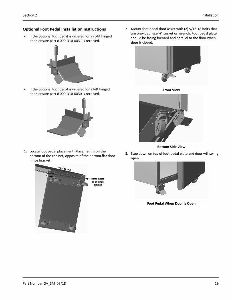
Optional Foot Pedal Installation Instructions• If the optional foot pedal is ordered for a right hinged
door, ensure part # 000-D10-0031 is received.
• If the optional foot pedal is ordered for a left hinged door, ensure part # 000-D10-0030 is received.
1. Locate foot pedal placement. Placement is on the bottom of the cabinet, opposite of the bottom flat door hinge bracket.
Bottom flat door hinge
bracket
Front of unit
2. Mount foot pedal door assist with (2) 5/16-18 bolts that are provided, use ½” socket or wrench. Foot pedal plate should be facing forward and parallel to the floor when door is closed.
Front View
Bottom Side View
3. Step down on top of foot pedal plate and door will swing open.
Foot Pedal When Door Is Open

20 Part Number GA_SM 08/18
Installation Section 2
THIS PAGE INTENTIONALLY LEFT BLANK

Part Number GA_SM 08/18 21
DANGERThe on-site supervisor is responsible for ensuring that operators are made aware of the inherent dangers of operating this equipment.
DANGERDo not operate any appliance with a damaged cord or plug. All repairs must be performed by a qualified service company.
DANGERKeep power cord AWAY from HEATED surfaces. DO NOT immerse power cord in water. DO NOT let power cord hang over edge of table or counter.
nWarningDo not contact moving parts.
nWarningAll covers and access panels must be in place and properly secured, before operating this equipment.
nWarningThe operator of this equipment is solely responsible for ensuring safe holding temperature levels for all food items. Failure to do so could result in unsafe food products for customers.
nWarningOverloading shelves can damage equipment or cause bodily injury.
nWarningDamp or wet hands may stick to cold surfaces.
nWarningDo not block the supply and return air grills or the air space around the air grills. Keep plastic wrappings, paper, labels, etc. from being airborne and lodging in the grills. Failure to keep the air grills clear will result in unsatisfactory operation of the system.
,CautionDo not throw items into the storage area. Failure to heed this recommendation could result in damage to the interior of the cabinet or to the blower coil.
Refrigerator & Freezer Operation• Delfield refrigerators are designed to maintain an
operational temperature of 36°F to 40°F (2°C to 4°C).
• Delfield freezers are designed to maintain an operational temperature of 0°F (-18°C).
Refrigerator & Freezer Start Up
Note�Display responds to finger touch only. Do not use utensils or other objects to operate the display. Use of these objects could damage the display.
This also covers anytime power is disconnected then reconnected.
1. Plug the unit in.
2. The screen will appear after a 30 second delay.
3. Select the power icon, located on the right of the screen.
!!
4. The touchscreen will move through the following two screens.
!
° F32
!
64
Section 3Operation
22 Part Number GA_SM 08/18
Operation Section 3
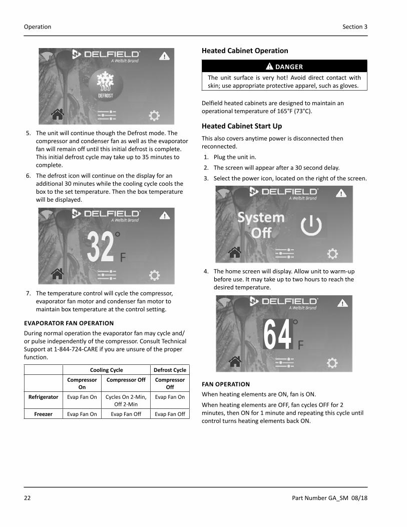
!!
5. The unit will continue though the Defrost mode. The compressor and condenser fan as well as the evaporator fan will remain off until this initial defrost is complete. This initial defrost cycle may take up to 35 minutes to complete.
6. The defrost icon will continue on the display for an additional 30 minutes while the cooling cycle cools the box to the set temperature. Then the box temperature will be displayed.
!
° F32
!
7. The temperature control will cycle the compressor, evaporator fan motor and condenser fan motor to maintain box temperature at the control setting.
EVAPORATOR FAN OPERATIONDuring normal operation the evaporator fan may cycle and/or pulse independently of the compressor. Consult Technical Support at 1-844-724-CARE if you are unsure of the proper function.
Cooling Cycle Defrost Cycle
Compressor On
Compressor Off Compressor Off
Refrigerator Evap Fan On Cycles On 2-Min, Off 2-Min
Evap Fan On
Freezer Evap Fan On Evap Fan Off Evap Fan Off
Heated Cabinet Operation
DANGERThe unit surface is very hot! Avoid direct contact with skin; use appropriate protective apparel, such as gloves.
Delfield heated cabinets are designed to maintain an operational temperature of 165°F (73°C).
Heated Cabinet Start Up This also covers anytime power is disconnected then reconnected.
1. Plug the unit in.
2. The screen will appear after a 30 second delay.
3. Select the power icon, located on the right of the screen.
!!
4. The home screen will display. Allow unit to warm-up before use. It may take up to two hours to reach the desired temperature.
!
° F32
!
64FAN OPERATIONWhen heating elements are ON, fan is ON.
When heating elements are OFF, fan cycles OFF for 2 minutes, then ON for 1 minute and repeating this cycle until control turns heating elements back ON.
Part Number GA_SM 08/18 23
Section 3 Operation
HIGH TEMPERATURE SAFETY DEVICEAn automatic reset type safety device is mounted above the heater(s) behind the vertical air duct(s). This safety switch will open if the temperature exceeds 220°F (105°C) in the event of a fan failure or air duct obstruction. Whenever the switch opens, power to the heaters is interrupted. Once the safety switch cools sufficiently to automatically reset, operation of the heaters will resume.
Power Down1. From the settings screen, select Unit Standby.
Interior Light
Language
Time / Date
LCD Brightness
Password
Unit Standby
Reset Factory Settings
Manual Defrost
Firmware Update
!
2. Access to this page requires the manager password.
3. Slide over the System Power button to off.
4. Setting system power to off will shut down the cooling or heating system only. Power will remain to control.
Unit Standby
Back
System Power
Setting system power to off will shut down the cooling or heating
system only. Power will remain to control.
ON
!
Settings Screen\Unit Standby
5. If the unit is a heated cabinet, allow unit to cool down.
6. Clean equipment as discussed in the maintenance section of this manual.
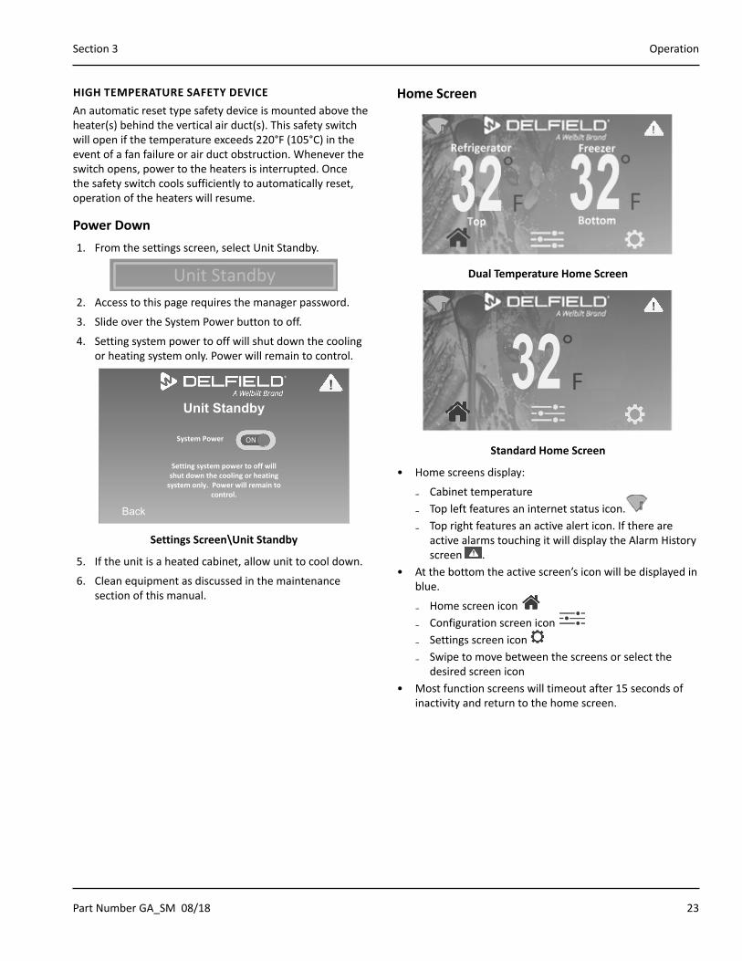
Home Screen
Dual Temperature Home Screen
!
° F32
!
Standard Home Screen
• Home screens display:
₋ Cabinet temperature ₋ Top left features an internet status icon. ₋ Top right features an active alert icon. If there are
active alarms touching it will display the Alarm History screen .
• At the bottom the active screen’s icon will be displayed in blue.
₋ Home screen icon ₋ Configuration screen icon ₋ Settings screen icon ₋ Swipe to move between the screens or select the
desired screen icon• Most function screens will timeout after 15 seconds of
inactivity and return to the home screen.
24 Part Number GA_SM 08/18
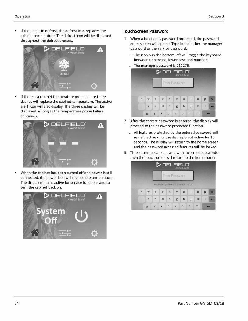
Operation Section 3
• If the unit is in defrost, the defrost icon replaces the cabinet temperature. The defrost icon will be displayed throughout the defrost process.
!!
• If there is a cabinet temperature probe failure three dashes will replace the cabinet temperature. The active alert icon will also display. The three dashes will be displayed as long as the temperature probe failure continues.
!
- - -!
• When the cabinet has been turned off and power is still connected, the power icon will replace the temperature. The display remains active for service functions and to turn the cabinet back on.
!!
TouchScreen Password1. When a function is password protected, the password
enter screen will appear. Type in the either the manager password or the service password.
₋ The icon ˄ in the bottom left will toggle the keyboard between uppercase, lower case and numbers.
₋ The manager password is 211276.
2. After the correct password is entered, the display will proceed to the password protected function.
₋ All features protected by the entered password will remain active until the display is not active for 10 seconds. The display will return to the home screen and the password accessed features will be locked.
3. Three attempts are allowed with incorrect passwords then the touchscreen will return to the home screen.
Part Number GA_SM 08/18 25
Section 3 Operation
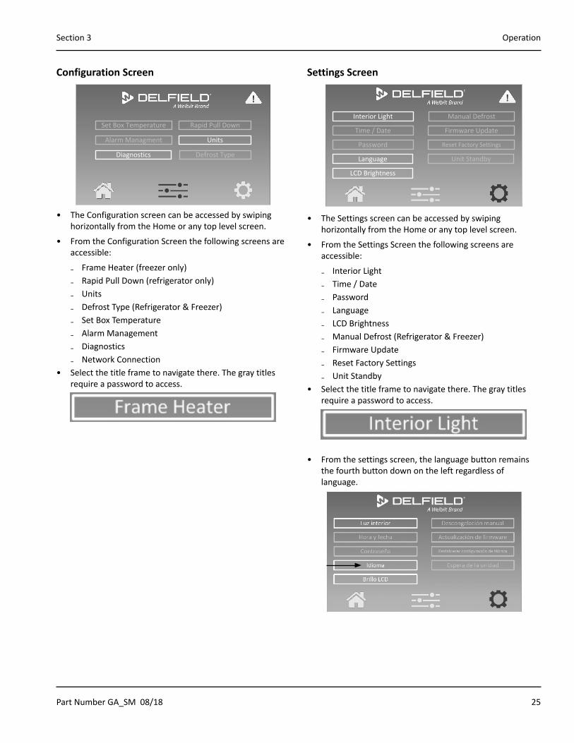
Configuration Screen
Defrost Type
Rapid Pull DownSet Box Temperature
Units
Diagnostics
Alarm Managment
!
• The Configuration screen can be accessed by swiping horizontally from the Home or any top level screen.
• From the Configuration Screen the following screens are accessible:
₋ Frame Heater (freezer only) ₋ Rapid Pull Down (refrigerator only) ₋ Units ₋ Defrost Type (Refrigerator & Freezer) ₋ Set Box Temperature ₋ Alarm Management ₋ Diagnostics ₋ Network Connection
• Select the title frame to navigate there. The gray titles require a password to access.
Settings Screen
Interior Light
Language
Time / Date
LCD Brightness
Password
Unit Standby
Reset Factory Settings
Manual Defrost
Firmware Update
!
• The Settings screen can be accessed by swiping horizontally from the Home or any top level screen.
• From the Settings Screen the following screens are accessible:
₋ Interior Light ₋ Time / Date ₋ Password ₋ Language ₋ LCD Brightness ₋ Manual Defrost (Refrigerator & Freezer) ₋ Firmware Update ₋ Reset Factory Settings ₋ Unit Standby
• Select the title frame to navigate there. The gray titles require a password to access.
• From the settings screen, the language button remains the fourth button down on the left regardless of language.
26 Part Number GA_SM 08/18
Operation Section 3
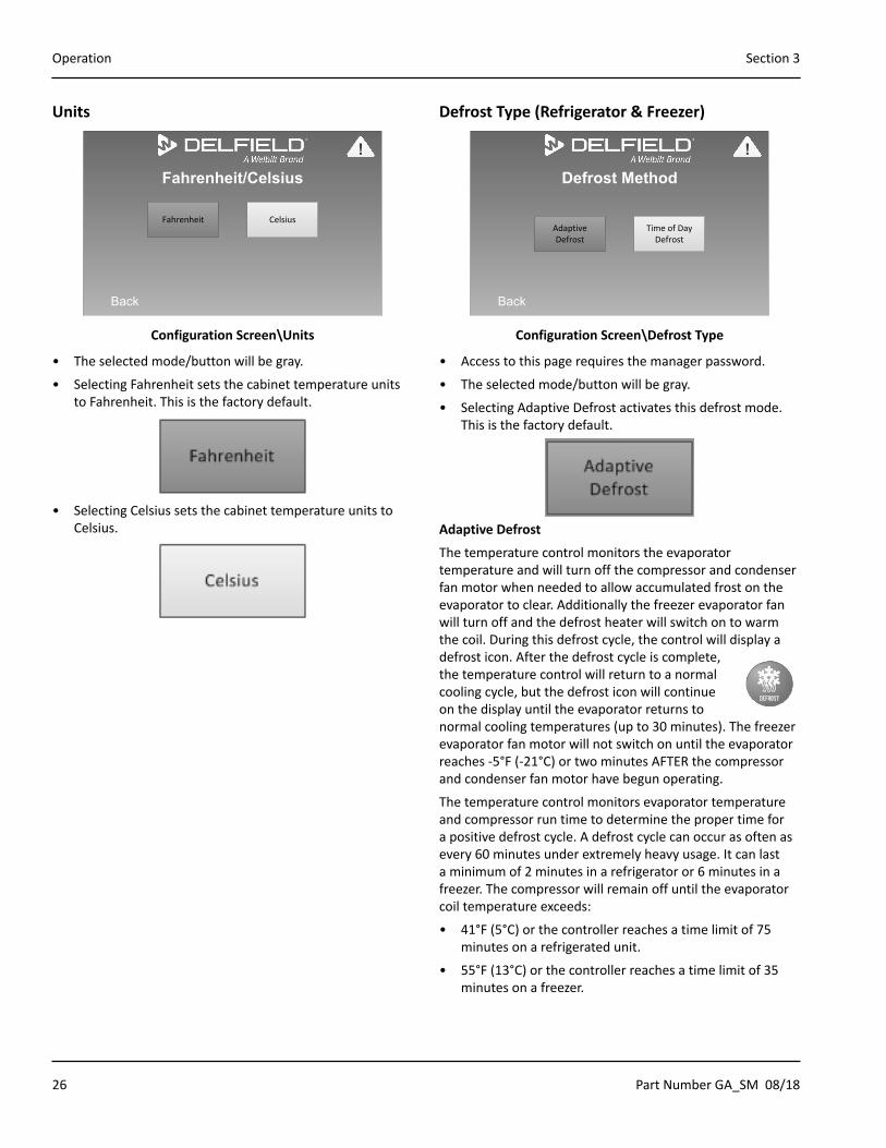
Units
Fahrenheit/Celsius
Back
CelsiusFahrenheit
!
Configuration Screen\Units
• The selected mode/button will be gray.
• Selecting Fahrenheit sets the cabinet temperature units to Fahrenheit. This is the factory default.
• Selecting Celsius sets the cabinet temperature units to Celsius.
Defrost Type (Refrigerator & Freezer)
Defrost Method
Back
Time of Day Defrost
Adaptive Defrost
!
Configuration Screen\Defrost Type
• Access to this page requires the manager password.
• The selected mode/button will be gray.
• Selecting Adaptive Defrost activates this defrost mode. This is the factory default.
Adaptive Defrost
The temperature control monitors the evaporator temperature and will turn off the compressor and condenser fan motor when needed to allow accumulated frost on the evaporator to clear. Additionally the freezer evaporator fan will turn off and the defrost heater will switch on to warm the coil. During this defrost cycle, the control will display a defrost icon. After the defrost cycle is complete, the temperature control will return to a normal cooling cycle, but the defrost icon will continue on the display until the evaporator returns to normal cooling temperatures (up to 30 minutes). The freezer evaporator fan motor will not switch on until the evaporator reaches -5°F (-21°C) or two minutes AFTER the compressor and condenser fan motor have begun operating.
The temperature control monitors evaporator temperature and compressor run time to determine the proper time for a positive defrost cycle. A defrost cycle can occur as often as every 60 minutes under extremely heavy usage. It can last a minimum of 2 minutes in a refrigerator or 6 minutes in a freezer. The compressor will remain off until the evaporator coil temperature exceeds:
• 41°F (5°C) or the controller reaches a time limit of 75 minutes on a refrigerated unit.
• 55°F (13°C) or the controller reaches a time limit of 35 minutes on a freezer.

Part Number GA_SM 08/18 27
Section 3 Operation
Time of Day Defrost
• Selecting Time of Day Defrost activates this defrost mode.
• Time of Day Defrost requires defrost times to be set up.
Back
Defrost Times Hour Minutes AM/PM
4rs
AM: 00rs
Hour Minutes AM/PM
6rs
PM: 00rs
10rs
AM: 00rs
10rs
PM: 00rs
rs
AM: rs
2rs
PM: 00rs
!
Configuration Screen\Defrost Type\Time of Day Defrost
• Six defrost times are allowed.
• A blank hour and minutes will be an inactive time.
• If no defrost times are assigned, no defrost will occur.
• Increase and decrease the defrost time settings using the up and down arrows.
• Hours 1 through 12 will be available if a 12 hour clock format has been selected on the Time/Date page. The AM/PM icon will allow you to switch between the two.
• Hours 1 through 23 will be available if a 24 hour clock format has been selected on the Time/Date page.
• Minutes can be set 00 through 59.
Set Box Temperature
Set Box Temperature
Back
35.6 rs
-1.4 rs
Refrigerator Freezer
!
Configuration Screen\Set Box Temperature Screen For Dual Temperature Cabinet Shown
• Access to this page requires the manager password.
• Increase and decrease the cabinet temperature set point using the up and down arrows.
• Set point can only be adjusted within the set point limits.
• Refrigeration factory setting is 35.6°F, set point limits are 30°F and 60°F.
• Freezer factory setting is -1.4°F, set point limits are -5°F and 36°F.
• Heated cabinet factory setting is 165°F, set point limits are 120°F and 200°F.
28 Part Number GA_SM 08/18
Operation Section 3
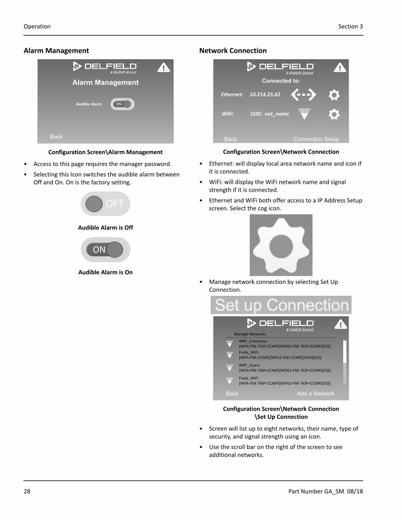
Alarm Management
Alarm Management
Back
!
Audible Alarm ON
Configuration Screen\Alarm Management
• Access to this page requires the manager password.
• Selecting this Icon switches the audible alarm between Off and On. On is the factory setting.
Audible Alarm is Off
ON
Audible Alarm is On
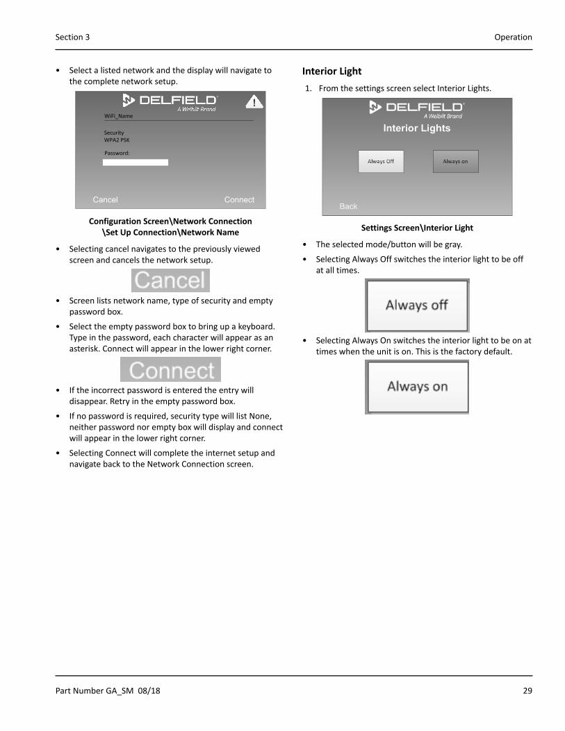
Network Connection
Connected to:
Back Connection Setup
Ethernet: 10.214.25.62
WiFi: SSID: net_name
!
Configuration Screen\Network Connection
• Ethernet: will display local area network name and icon if it is connected.
• WiFi: will display the WiFi network name and signal strength if it is connected.
• Ethernet and WiFi both offer access to a IP Address Setup screen. Select the cog icon.
• Manage network connection by selecting Set Up Connection.
Back Add a Network
WBT_Enterprise[WPA-PSK-TKIP=CCMP][WPA2-PSK-TKIP+CCMP][ESS]
Manage Networks
Freds_WiFi[WPA-PSK-CCMP][WPA2-PSK-CCMP][WPS][ESS]
WBT_Guest[WPA-PSK-TKIP=CCMP][WPA2-PSK-TKIP+CCMP][ESS]
Freds_WiFi[WPA-PSK-TKIP=CCMP][WPA2-PSK-TKIP+CCMP][ESS]
!
Configuration Screen\Network Connection \Set Up Connection
• Screen will list up to eight networks, their name, type of security, and signal strength using an icon.
• Use the scroll bar on the right of the screen to see additional networks.
Part Number GA_SM 08/18 29
Section 3 Operation
• Select a listed network and the display will navigate to the complete network setup.
Cancel Connect
Security WPA2 PSK
WiFi_Name
Password:
!
Configuration Screen\Network Connection \Set Up Connection\Network Name
• Selecting cancel navigates to the previously viewed screen and cancels the network setup.
• Screen lists network name, type of security and empty password box.
• Select the empty password box to bring up a keyboard. Type in the password, each character will appear as an asterisk. Connect will appear in the lower right corner.
• If the incorrect password is entered the entry will disappear. Retry in the empty password box.
• If no password is required, security type will list None, neither password nor empty box will display and connect will appear in the lower right corner.
• Selecting Connect will complete the internet setup and navigate back to the Network Connection screen.
Interior Light1. From the settings screen select Interior Lights.
Settings Screen\Interior Light
• The selected mode/button will be gray.
• Selecting Always Off switches the interior light to be off at all times.
• Selecting Always On switches the interior light to be on at times when the unit is on. This is the factory default.
30 Part Number GA_SM 08/18
Operation Section 3
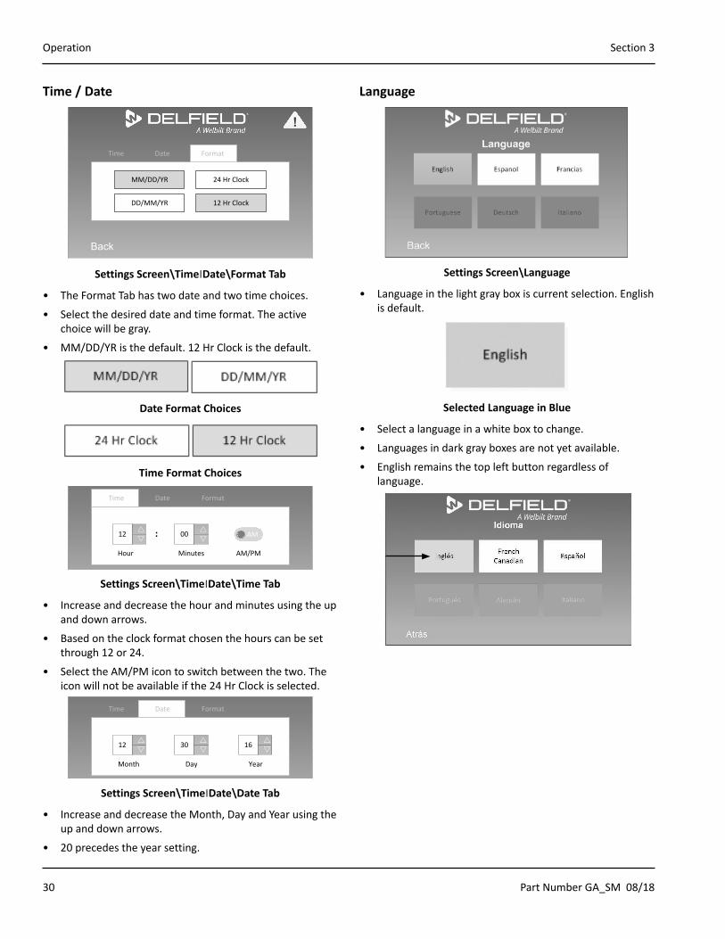
Time / Date
Back
Time Date Format
MM/DD/YR
DD/MM/YR
24 Hr Clock
12 Hr Clock
!
Settings Screen\Time׀Date\Format Tab
• The Format Tab has two date and two time choices.
• Select the desired date and time format. The active choice will be gray.
• MM/DD/YR is the default. 12 Hr Clock is the default.
Date Format Choices
Time Format Choices
Back
12 rs
00 rs
AM:
Time Date Format
Hour Minutes AM/PM
!
Settings Screen\Time׀Date\Time Tab
• Increase and decrease the hour and minutes using the up and down arrows.
• Based on the clock format chosen the hours can be set through 12 or 24.
• Select the AM/PM icon to switch between the two. The icon will not be available if the 24 Hr Clock is selected.
Back
Time Date Format
12 rs
30 rs
16 rs
Month Day Year
!
Settings Screen\Time׀Date\Date Tab
• Increase and decrease the Month, Day and Year using the up and down arrows.
• 20 precedes the year setting.
Language
Settings Screen\Language
• Language in the light gray box is current selection. English is default.
Selected Language in Blue
• Select a language in a white box to change.
• Languages in dark gray boxes are not yet available.
• English remains the top left button regardless of language.

Part Number GA_SM 08/18 31
Section 3 Operation
LCD Brightness
LCD Brightness
Back
!
Settings Screen\LCD Brightness
• LCD default is 50%.
• Slide the small circle along the line to the right to increase the brightness, left to decrease.
NOTE: Adjusting brightness to 60% or less will increase the life of the display.
Manual Defrost
Manual Defrost
Back
Defrost ON
!
Settings Screen\Manual Defrost
• Access to this page requires the manager password.
• Off is the factory setting.
• When On is selected the defrost will cycle once and return to normal operation.
ON
Web Application
KITCHENCONNECTThis online application is an equipment monitoring tool.
Register:
1. Navigate to https://www.welbiltdigital.com/
2. Select Register.
3. Enter Information in at least the required fields.
4. Select Submit.
5. Enter your email and password.
6. Select Login.
Mobile Application
SPECIFICATION LINE CONNECTThis mobile application is an equipment monitoring tool.
To Download The Mobile Application:
1. Open either Apple iTunes or Google PlayStore.
2. Search for Specification Line Connect.
3. Select and install.
4. Open the application. The Welbilt W logo is the application icon.
32 Part Number GA_SM 08/18
Operation Section 3
Application OperationSet Up A Site
1. Select + Add Site.
2. Fill in all site information. All fields are required.
₋ Site ID (Max 30 Characters) ₋ Site Name (Max 20 Characters) ₋ Site Manager Name (Max 20 Characters) ₋ Site Email ID (Max 50 Characters) ₋ Site Address (Max 50 Characters) ₋ Country (From a Menu) ₋ State (From a Menu ₋ City (Max 20 Characters) ₋ Postal Code (Max 10 Characters)
3. Select Choose Site Location to put a pin on the map.
4. Select Submit.
5. The new site will be added to the home page.
Edit Or Delete Site
1. Select the menu icon next to the site.
2. Edit and Delete Site are available actions.
3. Edit will bring up the site information page.
4. Delete will require confirmation.
Set Up Equipment
1. Select the menu icon next to the site.
2. Select View Equipments.
3. Select + Add.
4. Fill in all equipment information. All fields are required.
NOTE: Serial number entered must match equipment.
₋ Equipment Serial Number (Max 30 Characters) ₋ Equipment Name (Max 20 Characters) ₋ Equipment Type (From a Menu) ₋ Equipment Model (From a Menu)
5. Select Submit.
6. The new equipment will be connected to the site.
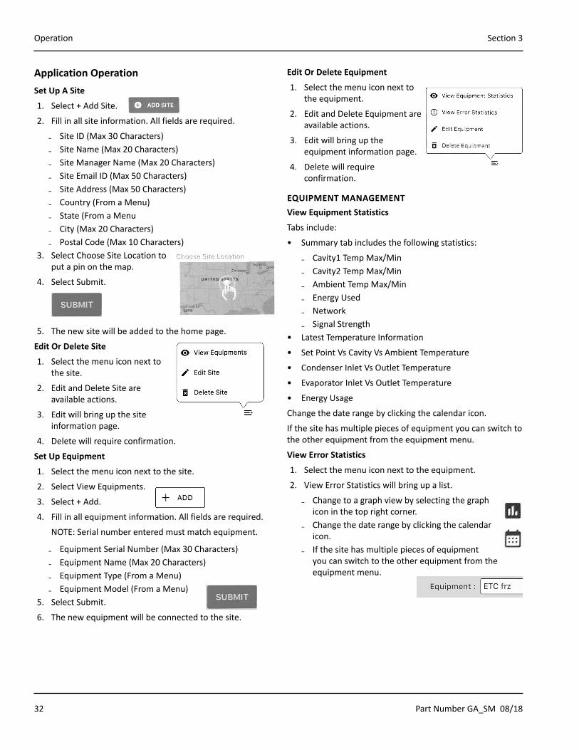
Edit Or Delete Equipment
1. Select the menu icon next to the equipment.
2. Edit and Delete Equipment are available actions.
3. Edit will bring up the equipment information page.
4. Delete will require confirmation.
EQUIPMENT MANAGEMENTView Equipment Statistics
Tabs include:
• Summary tab includes the following statistics:
₋ Cavity1 Temp Max/Min ₋ Cavity2 Temp Max/Min ₋ Ambient Temp Max/Min ₋ Energy Used ₋ Network ₋ Signal Strength
• Latest Temperature Information
• Set Point Vs Cavity Vs Ambient Temperature
• Condenser Inlet Vs Outlet Temperature
• Evaporator Inlet Vs Outlet Temperature
• Energy Usage
Change the date range by clicking the calendar icon.
If the site has multiple pieces of equipment you can switch to the other equipment from the equipment menu.
View Error Statistics
1. Select the menu icon next to the equipment.
2. View Error Statistics will bring up a list.
₋ Change to a graph view by selecting the graph icon in the top right corner.
₋ Change the date range by clicking the calendar icon.
₋ If the site has multiple pieces of equipment you can switch to the other equipment from the equipment menu.
Part Number GA_SM 08/18 33
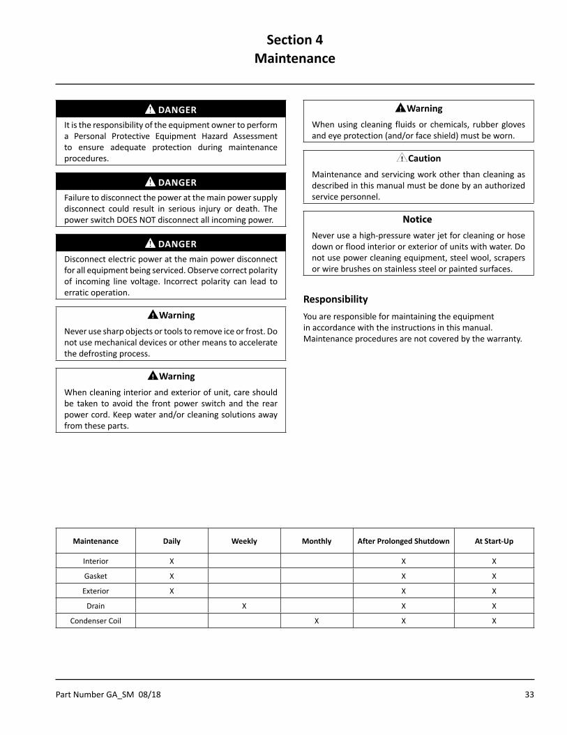
DANGERIt is the responsibility of the equipment owner to perform a Personal Protective Equipment Hazard Assessment to ensure adequate protection during maintenance procedures.
DANGERFailure to disconnect the power at the main power supply disconnect could result in serious injury or death. The power switch DOES NOT disconnect all incoming power.
DANGERDisconnect electric power at the main power disconnect for all equipment being serviced. Observe correct polarity of incoming line voltage. Incorrect polarity can lead to erratic operation.
nWarningNever use sharp objects or tools to remove ice or frost. Do not use mechanical devices or other means to accelerate the defrosting process.
nWarningWhen cleaning interior and exterior of unit, care should be taken to avoid the front power switch and the rear power cord. Keep water and/or cleaning solutions away from these parts.
nWarningWhen using cleaning fluids or chemicals, rubber gloves and eye protection (and/or face shield) must be worn.
,CautionMaintenance and servicing work other than cleaning as described in this manual must be done by an authorized service personnel.
Notice�Never use a high-pressure water jet for cleaning or hose down or flood interior or exterior of units with water. Do not use power cleaning equipment, steel wool, scrapers or wire brushes on stainless steel or painted surfaces.
ResponsibilityYou are responsible for maintaining the equipment in accordance with the instructions in this manual. Maintenance procedures are not covered by the warranty.
Section 4Maintenance
Maintenance Daily Weekly Monthly After Prolonged Shutdown At Start-Up
Interior X X X
Gasket X X X
Exterior X X X
Drain X X X
Condenser Coil X X X
34 Part Number GA_SM 08/18
Maintenance Section 4
Interior CleaningThe interior can be cleaned using soap and warm water. If this isn’t sufficient, try ammonia and water or a nonabrasive liquid cleaner.
GASKETSGaskets require regular cleaning to prevent mold and mildew build up and also to retain the elasticity of the gasket. Clean them with water and mild soap (not citrus based). Avoid full strength cleaning products on gaskets as this can cause them to become brittle and crack. Never use sharp tools or knives to scrape or clean the gasket. Gaskets can be easily replaced and do not require the use of tools or an authorized service person. The gaskets are dart style and can be pulled out of the groove in the door. Place gasket in warm water to make the material more pliable for installation. Dry and press into place.
PREVENTING BLOWER COIL CORROSIONTo help prevent corrosion of the blower coil, store all acidic items, such as pickles and tomatoes, in seal-able containers. Immediately wipe up all spills.
Exterior Cleaning
Notice�Never use an acid based cleaning solution on exterior panels! Many food products have an acidic content, which can deteriorate the finish. Be sure to clean the stainless steel surfaces of ALL food products.
Clean the area around the unit as often as necessary to maintain cleanliness and efficient operation.
Wipe exterior surfaces with a damp cloth rinsed in water to remove dust and dirt from the outside of the unit. Always rub with the “grain” of the stainless steel to avoid marring the finish. If a greasy residue persists, use a damp cloth rinsed in a mild dish soap and water solution. Wipe dry with a clean, soft cloth.
Never use steel wool or abrasive pads for cleaning. Never use chlorinated, citrus based or abrasive cleaners.
Stainless steel exterior panels have a clear coating that is stain resistant and easy to clean. Products containing abrasives will damage the coating and scratch the panels. Daily cleaning may be followed by an application of stainless steel cleaner which will eliminate water spotting and fingerprints. Early signs of stainless steel breakdown are small pits and cracks. If this has begun, clean thoroughly and start to apply stainless steel cleaners in attempt to restore the steel.
Wipe casters with a damp cloth to prevent corrosion.
DRAINEach refrigerated unit has a drain located inside the unit that removes the condensation from the evaporator coil and routes it to an external condensate evaporator pan. Each drain can become loose or disconnected during normal use. If you notice water accumulation on the inside of the unit, be sure the drain tube is connected to the evaporator drain pan. If water is collecting underneath the unit, make sure the end of the drain tube is in the condensate evaporator. The leveling of the unit is important as the units are designed to drain properly when level. Be sure all drain lines are free of obstructions.
DOORS/HINGESOver time and with heavy-use doors, the hinges may become loose. If this happens, tighten the screws that mount the hinge brackets to the frame of the unit. Loose or sagging doors can cause the hinges to pull out of the frame, which may damage both the doors and the hinges. In some cases this may require qualified service agents or maintenance personnel to perform repairs.
Cleaning the Condenser CoilIn order to maintain proper refrigeration performance, the condenser fins must be cleaned of dust, dirt and grease regularly. It is recommended that this be done monthly. If conditions are such that the condenser is totally blocked in a month, the frequency of cleaning should be increased. Clean the condenser with a vacuum cleaner or stiff brush. If extremely dirty, a commercially available condenser cleaner may be required.
Failure to maintain a clean condenser coil can initially cause high temperatures and excessive run times. Continuous operation with a dirty or clogged condenser coil can result in compressor failure. Neglecting the condenser coil cleaning procedures will void any warranties associated with the compressor and cost to replace the compressor.

Part Number GA_SM 08/18 35
Problem -> Cause -> Correction Chart
Problem Cause Correction
Cabinet not running
Fuse blown or circuit breaker tripped. Replace fuse or reset circuit breaker.
Power cord unplugged. Plug in power cord.
Thermostat set too high. Set thermostat to lower temperature.
System is off. Turn system on.
Cabinet in defrost cycle.(Refrigerator and Freezer models)
Wait for defrost cycle to finish.
Condensing unit runs for
long periods or continuously
Excessive amount of warm product placed in cabinet.
Allow adequate time for product to cool down.
Prolonged door openings or door(s) ajar. Make sure door(s) are closed when not in use. Avoid prolonged door openings.
Door gasket(s) not sealing properly. Check gasket condition. Adjust door or replace gasket if necessary.
Dirty condenser coil. Clean the condenser coil.
Evaporator coil iced over. Turn unit off and allow coil to defrost.Make sure thermostat is not set too cold.
Also, check gasket condition.
Cabinet temperature is too
high
Thermostat set too high. Set thermostat to lower temperature.
Poor air circulation in cabinet. Re-arrange product to allow proper air circulation.
Excessive amount of warm product placed in cabinet.
Allow adequate time for product to cool down.
Prolonged door openings or door(s) ajar. Make sure door(s) are closed when not in use. Avoid prolonged door openings.
Dirty condenser coil. Clean the condenser coil.
Evaporator coil iced over. Turn unit off and allow coil to defrost.Make sure thermostat is not set too cold.
Also, check gasket condition.
Cabinet is noisy Loose part(s). Locate and tighten loose part(s).
Refrigerator is freezing product
Thermostat is set too low. Set thermostat to higher temperature.
Dirty condenser coil. Clean the condenser coil.
Not enough cabinet clearance for proper refrigeration system operation.
Move cabinet or make other adjustments to gain proper cabinet clearances.
Compressor will not start
Low voltage to cabinet. Check and correct incoming voltage to cabinet.
Section 5Troubleshooting

36 Part Number GA_SM 08/18
Troubleshooting Section 5
THIS PAGE INTENTIONALLY LEFT BLANK

Part Number GA_SM 08/18 37
Service ScreensOperator screens are covered in Section 3, Operation.
The manager password is 211276.
FRAME HEATER (FREEZER ONLY)
Frame Heater
Back
Always OffAlways on Power Save
!
Configuration Screen\Frame Heater
• Access to this page requires the manager password.
• The selected mode/button will be gray.
• These buttons control the length of time that heat is applied to the door perimeter.
• Selecting the Always On icon switches the frame heater to be on at times when the unit is on. Use this mode if excessive condensation is observed on the door opening.
• Selecting the Always Off icon switches the frame heater to be off at all times.
• Selecting the Power Save icon switches the frame heater to be on only when the compressor is on. Power save mode will use less energy than always on while occasionally heating the door to remove condensation. This is the factory default.
RAPID PULL DOWN (REFRIGERATOR ONLY)
Rapid Pull Down
Back
OFF
!
Configuration Screen\Rapid Pull Down
• Access to this page requires the manager password.
• When the rapid pull down is turned on the set point is lowered to 30°F for 60 minutes.
• It can be turned off any time during the 60 minutes of rapid pull down.
• Selecting this Icon switches the rapid pull down feature between Off and On.
Rapid Pull Down Feature is Off
ON
Rapid Pull Down Feature is On
Section 6Control
38 Part Number GA_SM 08/18
Control Section 6
DIAGNOSTICS
Diagnostics
Back
Relay Status Temperature Probes
Data History Relay Outputs
!
Configuration Screen\Diagnostics
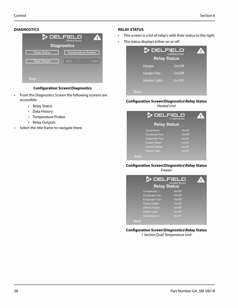
• From the Diagnostics Screen the following screens are accessible:
• Relay Status• Data History• Temperature Probes• Relay Outputs
• Select the title frame to navigate there.
RELAY STATUS• This screen is a list of relay’s with their status to the right.
• The status displays either on or off.
Relay StatusHeater: On/Off
Heater Fan: On/Off
Interior Light: On/Off
Back
Heated
!
Configuration Screen\Diagnostics\Relay Status Heated Unit
Relay Status Compressor: On/Off Condenser Fan: On/Off Evaporator Fan: On/Off
Frame Heater: On/Off
Defrost Heater: On/Off
Interior Light: On/Off
Back
Freezer
!
Configuration Screen\Diagnostics\Relay Status Freezer
Relay StatusCompressor 1: On/OffCondenser Fan: On/OffEvaporator Fan: On/OffFrame Heater: On/OffDefrost Heater: On/OffInterior Light: On/OffCompressor 2: On/Off
Back
Split System
!
Configuration Screen\Diagnostics\Relay Status 1 Section Dual Temperature Unit

Part Number GA_SM 08/18 39
Section 6 Control
DATA HISTORY
Data History
Back
Download Diagnostics View Energy Chart
Average Base Temperature: XXX.X°X
(Past 7 Days)
Average KwH per day:XXX.X KwH
(Past 7 Days)
Download HAACP & Energy View Temperature Chart
!
Configuration Screen\Diagnostics\Data History
• Average Cabinet Temperature for the past 7 days is displayed.
• Average energy use in KwH per day for the past 7 days is displayed.
• From the Data History Screen the following screens are accessible:
• View Energy Chart• View Temperature Chart
• Select the title frame to navigate there.
• Selecting a download title navigates to the Download data screens.
1. Insert USB memory device into USB port located bottom of the front shroud to the left of the control display. Skip this if updating via wireless.
2. Touch start button to begin download.
3. Do not remove device until prompted.
4. Select Back to return to return to home screen.
5. Remove USB device memory device if used.
ENERGY CHART
Energy Chart
Back
!
Configuration Screen\Diagnostics\ Data History\Energy Chart
• Graph of energy usage in KwH per day over the past seven days.
TEMPERATURE CHART
Temperature Chart
Back
!
Configuration Screen\Diagnostics\ Data History\Temperature Chart
• Graph of cabinet temperature per day over the past seven days.
• Two temperature screens will be available for dual temperature units. Use the next icon to navigate to the second screen.

40 Part Number GA_SM 08/18
Control Section 6
TEMPERATURE PROBES• This screen is a list of temperature probes with their
current value.
Temperature and HumidityBox Temperature: XXX.X°X
Ambient Temperature: XXX.X°X
Relative Humidity: XX%
Back
Heated
!
Configuration Screen\Diagnostics\Temperature Probes Heated Unit
Temperature and HumidityBox Temperature: 36.4°FCond. Inlet Temperature: XXX.X°XCond. Outlet Temperature: XXX.X°XEvap. Inlet Temperature: XXX.X°XEvap. Outlet Temperature: XXX.X°XAmbient Temperature: XXX.X°XRelative Humidity: XX%
Back
Refg, Frz, Split
!
Configuration Screen\Diagnostics\Temperature Probes 1 Section Dual Temperature Unit
RELAY OUTPUTS• Access to this page requires the service password.
• This screen lists the relays available for a service person to energize.
• Selecting the Press to Activate icon will energize the relay for 5 seconds.
• Only one relay can be activated at a time.
• During the 5 second energize period the icon will be green and read, Relay Activated.
Relay OutputsCompressor:Condenser Fan:Evaporator Fan:Frame Heaters:Defrost Heater:Interior Light:
Back
Press to Activate
Press to Activate
Press to Activate
Press to Activate
Press to Activate
Press to Activate
Freezer
!
Configuration Screen\Diagnostics\Relay Outputs Freezer
Relay OutputsCompressor 1:Compressor 2:Condenser Fan:Evaporator Fan:Frame Heaters:Defrost Heater:Interior Light:
Back
Press to Activate
Press to Activate
Press to Activate
Press to Activate
Press to Activate
Press to Activate
Press to Activate
Split system
!
Configuration Screen\Diagnostics\Relay Outputs 1 Section Dual Temperature Unit

Part Number GA_SM 08/18 41
Section 6 Control
NETWORK CONNECTION
Connected to:
Back Connection Setup
Ethernet: 10.214.25.62
WiFi: SSID: net_name
!
Configuration Screen\Network Connection
• Ethernet: will display local area network name and icon if it is connected.
• WiFi: will display the WiFi network name and signal strength if it is connected.
• Ethernet and WiFi both offer access to a IP Address Setup screen. Select the cog icon.
• Manage the networks by selecting Set Up Connection.
SET UP CONNECTION
Back Add a Network
WBT_Enterprise[WPA-PSK-TKIP=CCMP][WPA2-PSK-TKIP+CCMP][ESS]
Manage Networks
Freds_WiFi[WPA-PSK-CCMP][WPA2-PSK-CCMP][WPS][ESS]
WBT_Guest[WPA-PSK-TKIP=CCMP][WPA2-PSK-TKIP+CCMP][ESS]
Freds_WiFi[WPA-PSK-TKIP=CCMP][WPA2-PSK-TKIP+CCMP][ESS]
!
Configuration Screen\Network Connection \Set Up Connection
• Screen will list up to eight networks, their name, type of security, and signal strength using an icon.
• Use the scroll bar on the right of the screen to see additional networks.
• Select a listed network and the display will navigate to the complete that network’s setup.
• Select the words on the screen to add a network.

42 Part Number GA_SM 08/18
Control Section 6
COMPLETE NETWORK SETUP
Cancel Connect
Security WPA2 PSK
WiFi_Name
Password:
!
Configuration Screen\Network Connection \Set Up Connection\Network Name
• Selecting cancel navigates to the previously viewed screen and cancels the network setup.
• Screen lists network name, type of security and empty password box.
• Select the empty password box to bring up a keyboard. Type in the password, each character will appear as an asterisk. Connect will appear in the lower right corner.
• If the incorrect password is entered the entry will disappear. Retry in the empty password box.
• If no password is required, security type will list None, neither password nor empty box will display and connect will appear in the lower right corner.
• Selecting Connect will complete the internet setup and navigate back to the Network Connection screen.
ADD A NETWORK SCREEN
Cancel Connect
Network name:
Enter information for wireless network to add
Encryption type:
Security Type:
Security Key:
No authentication (Open) q
None q
Start this connection automatically
Connect even if the network is not broadcasting
!
Configuration Screen\Network Connection \Set Up Connection\Add a Network
• Selecting cancel navigates to the previously viewed screen and cancels adding the network.
• Fill in the network name. Select the empty box to bring up a keyboard.
• The security pulldown menu will have the following options. Select by touching the type.
• No authentication (open)• WEP• WPA2-Personal• WPA-Personal• WPA2-Enterprise• WPA-Enterprise
• The encryption pulldown menu will have different options depending on the security chose. The full list of options are below. Select by touching the type.
• None• WEP• AES• TKIP
• Select the empty Security Key box to bring up a keyboard. Type in the pasword, each character will appear as an asterisk.
• If network is No authentication (open), the Security Key box will be grayed out and not functional.
• Select or deselect the start the connection automatically box.
• Select or deselect the connect even if the network is not broadcasting box.
• Selecting Connect will complete the network setup and navigate back to the Network Connection screen.
• If the network does not properly setup, the Add A Network Screen will stay active.
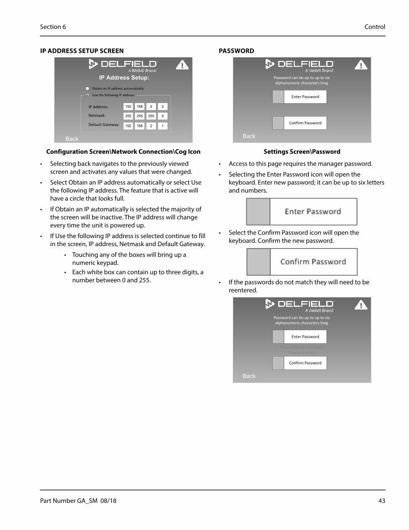
Part Number GA_SM 08/18 43
Section 6 Control
IP ADDRESS SETUP SCREEN
IP Address Setup:
Back
IP Address:
Default Gateway:
Netmask:
192 2 2168
255 255 0255
192 2 1168
Obtain an IP address automatically
Use the following IP address:
!
Configuration Screen\Network Connection\Cog Icon
• Selecting back navigates to the previously viewed screen and activates any values that were changed.
• Select Obtain an IP address automatically or select Use the following IP address. The feature that is active will have a circle that looks full.
• If Obtain an IP automatically is selected the majority of the screen will be inactive. The IP address will change every time the unit is powered up.
• If Use the following IP address is selected continue to fill in the screen, IP address, Netmask and Default Gateway.
• Touching any of the boxes will bring up a numeric keypad.
• Each white box can contain up to three digits, a number between 0 and 255.
PASSWORD
Back
Enter Password
Confirm Password
Password can be up to up to six alphanumeric characters long
!
Settings Screen\Password
• Access to this page requires the manager password.
• Selecting the Enter Password icon will open the keyboard. Enter new password; it can be up to six letters and numbers.
• Select the Confirm Password icon will open the keyboard. Confirm the new password.
• If the passwords do not match they will need to be reentered.
Back
Enter Password
Confirm Password
Password can be up to up to six alphanumeric characters long
Passwords do not matchPlease re-enter
!

44 Part Number GA_SM 08/18
Control Section 6
FIRMWARE UPDATE
Update Firmware
Back
START
1. Insert USB memory device into USB port located behind louvered access panel on end shroud or at back of upper machine compartment.2. Touch start button to begin download.3. Do not remove device until prompted.3. Touch “Back” to return to “Home Screen”.
!
Settings Screen\Firmware Update With Manager Password
• Access to this page requires the manager password.
1. Insert USB memory device into USB port located on bottom of the front shroud to the left of the control display. Skip this if updating via wireless.
2. Touch start button to begin download.
Updating Firmware
UpdatingDo not remove memory
device or disconnect power from unit
!
Firmware Updating In Process Screen
3. Do not remove device until prompted.
Update Firmware
Back
Firmware Update Complete
Remove USB memory device if used
!
Firmware Update Complete Screen
4. Remove USB device memory device if used.
Check Firmware Version with Firmware Update Screen
From the Settings Screen, select Firmware Update.
Instead of using the manager password, use the service password, 9014766419.
Settings Screen\Firmware Update With Service Password
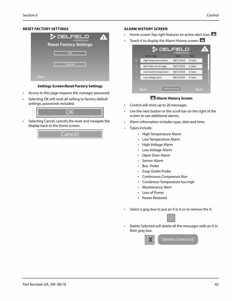
Part Number GA_SM 08/18 45
Section 6 Control
RESET FACTORY SETTINGS
Reset Factory Settings
Back
OK
Cancel
!
Settings Screen\Reset Factory Settings
• Access to this page requires the manager password.
• Selecting OK will reset all setting to factory default settings, passwords included.
• Selecting Cancel, cancels the reset and navigate the display back to the home screen.
ALARM HISTORY SCREEN• Home screen Top right features an active alert icon.
• Touch it to display the Alarm History screen.
Back Next
High temperature Alarm 08/27/2016 3:15pm
Alarm Type Date Time
Box Probe out of range 08/27/2016 3:15pm
Cond outlet temperature 08/27/2016 3:15pm
Low voltage alarm 08/27/2016 3:15pm
Delete Selected
!
\Alarm History Screen
• Control will store up to 20 messages.
• Use the next button or the scroll bar on the right of the screen to see additional alarms.
• Alarm information includes type, date and time.
• Types include:
• High Temperature Alarm• Low Temperature Alarm• High Voltage Alarm• Low Voltage Alarm• Open Door Alarm• Sensor Alarm• Box Probe• Evap Outlet Probe• Continuous Compressor Run• Condenser Temperature too high• Maintenance Alert• Loss of Power• Power Restored
• Select a gray box to put an X in it or to remove the X.
• Delete Selected will delete all the messages with an X in their gray box.

46 Part Number GA_SM 08/18
Control Section 6
ALARM SCREENS• From the Home screen select the active alert icon to go
to the Alarm History screen.
• Select the alarm type to navigate to the alarm screen.
High Temperature Alarm
Back
Box above acceptable temperatures in excess of 60
minutes.
!
\Alarm History Screen\High Temperature Alarm
Low Temperature Alarm
Back
Box below acceptable temperatures in excess of 60
minutes.
!
\Alarm History Screen\Low Temperature Alarm
Open Door Alarm
Back
Door opened for greater than 1 minute.
!
\Alarm History Screen\Open Door Alarm
Temperature Probe Alarm
Back
Possible temperature probe (s) failure. Open “Temperature
Probes” screen in Diagnostics.To replace:
Contact KitchenCare844-724-CARE (2273)
!
\Alarm History Screen\Sensor Alarm
Box Probe Error
Back
Refrigerator operating in Safe Mode.
Call KitchenCare immediately.844-724-CARE (2273)
!
\Alarm History Screen\Box Temperature Probe Error
Loss of Power Alarm
Back
Loss of Power:Date and time stamp
Power Restored:Date and time stamp
!
\Alarm History Screen\Loss Of Power Alarm
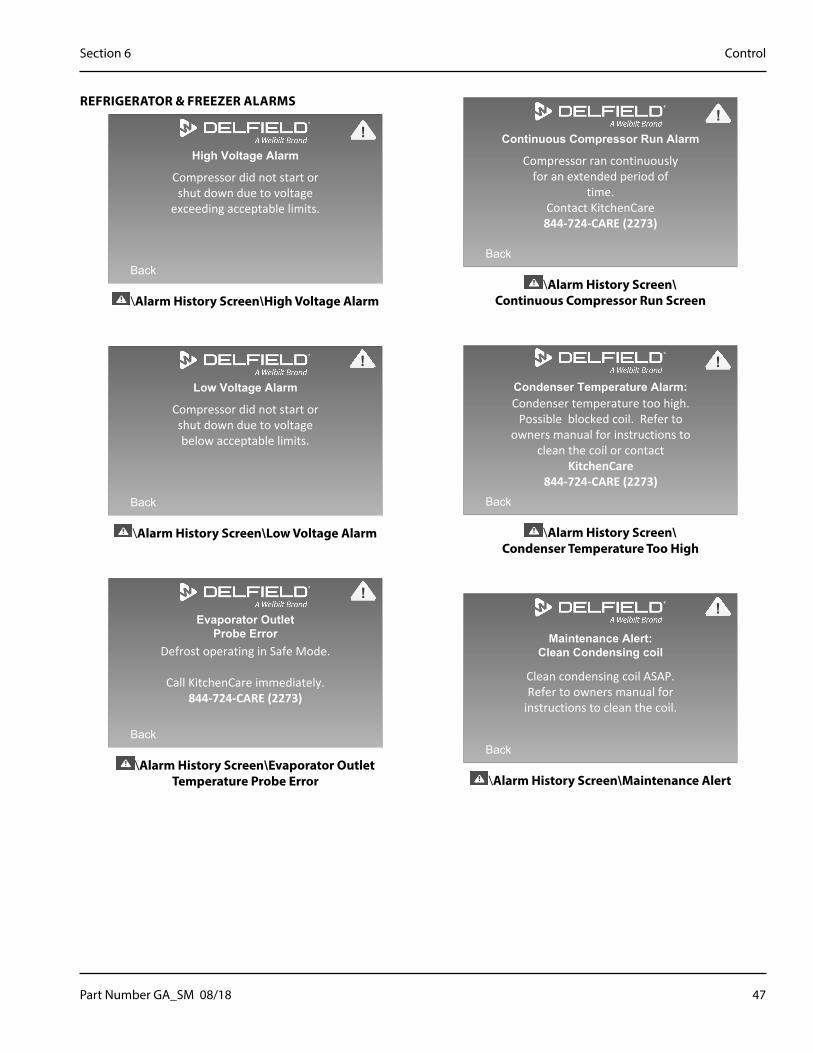
Part Number GA_SM 08/18 47
Section 6 Control
REFRIGERATOR & FREEZER ALARMS
High Voltage Alarm
Back
Compressor did not start or shut down due to voltage
exceeding acceptable limits.
!
\Alarm History Screen\High Voltage Alarm
Low Voltage Alarm
Back
Compressor did not start or shut down due to voltage below acceptable limits.
!
\Alarm History Screen\Low Voltage Alarm
Evaporator OutletProbe Error
Back
Defrost operating in Safe Mode.
Call KitchenCare immediately.844-724-CARE (2273)
!
\Alarm History Screen\Evaporator Outlet Temperature Probe Error
Continuous Compressor Run Alarm
Back
Compressor ran continuously for an extended period of
time.Contact KitchenCare844-724-CARE (2273)
!
\Alarm History Screen\ Continuous Compressor Run Screen
Condenser Temperature Alarm:
Back
Condenser temperature too high. Possible blocked coil. Refer to
owners manual for instructions to clean the coil or contact
KitchenCare844-724-CARE (2273)
!
\Alarm History Screen\ Condenser Temperature Too High
Maintenance Alert:Clean Condensing coil
Back
Clean condensing coil ASAP. Refer to owners manual for
instructions to clean the coil.
!
\Alarm History Screen\Maintenance Alert
48 Part Number GA_SM 08/18
Control Section 6
THIS PAGE INTENTIONALLY LEFT BLANK

Part Number GA_SM 08/18 49
Evaporator Fan Access• Evaporator fan wiring connections are accessed from
the top through the evaporator box lid.
• Access the evaporator fans inside the cabinet through the air baffle in the interior top.
Evaporator box lid
Evaporator box lid
View with box lid removed for access to fan wiring connections
View with box lid removed for access to fan wiring connections
Interior view of air baffle
Interior view of air baffle
View with air baffle removed for access to evaporator fans
View with air baffle removed for access to evaporator fans
Section 7Component Check Procedures
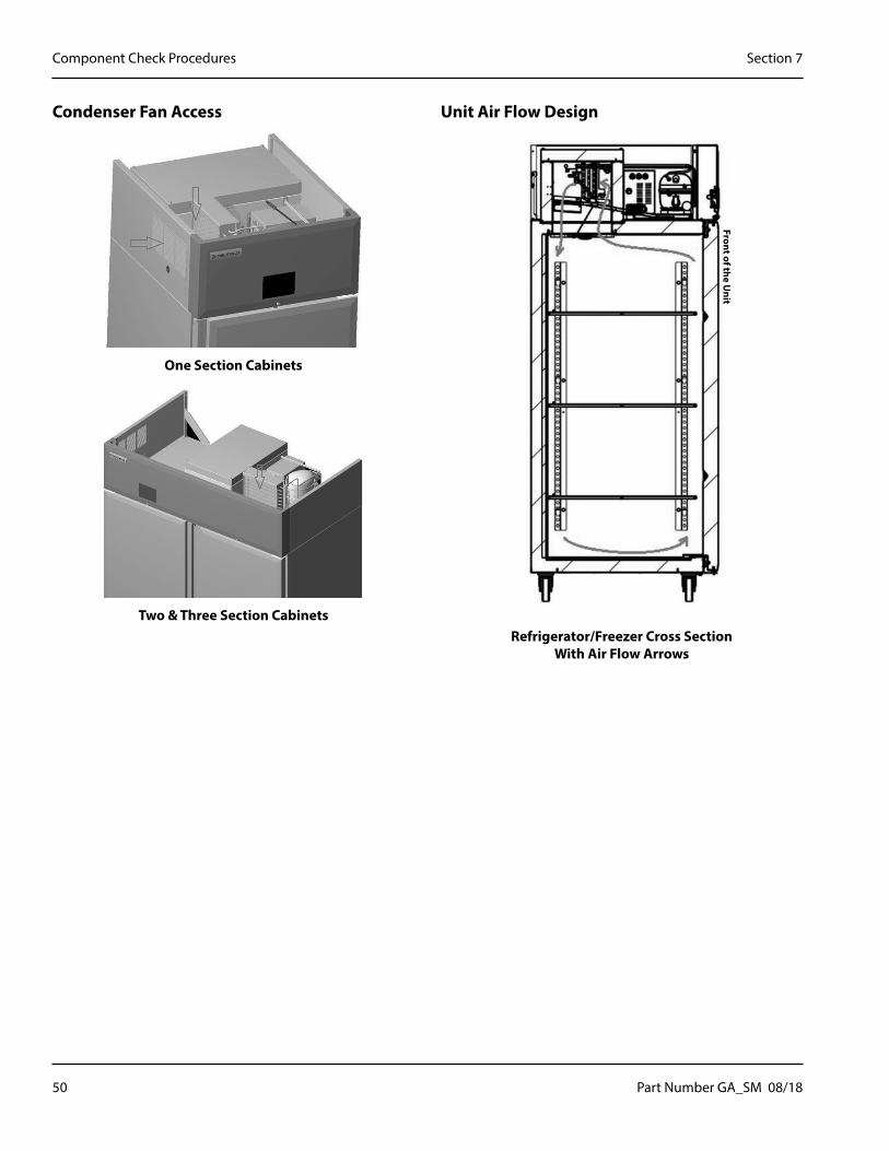
50 Part Number GA_SM 08/18
Component Check Procedures Section 7
Condenser Fan Access
One Section Cabinets
Two & Three Section Cabinets
Unit Air Flow Design
Front of the Unit
Refrigerator/Freezer Cross Section With Air Flow Arrows
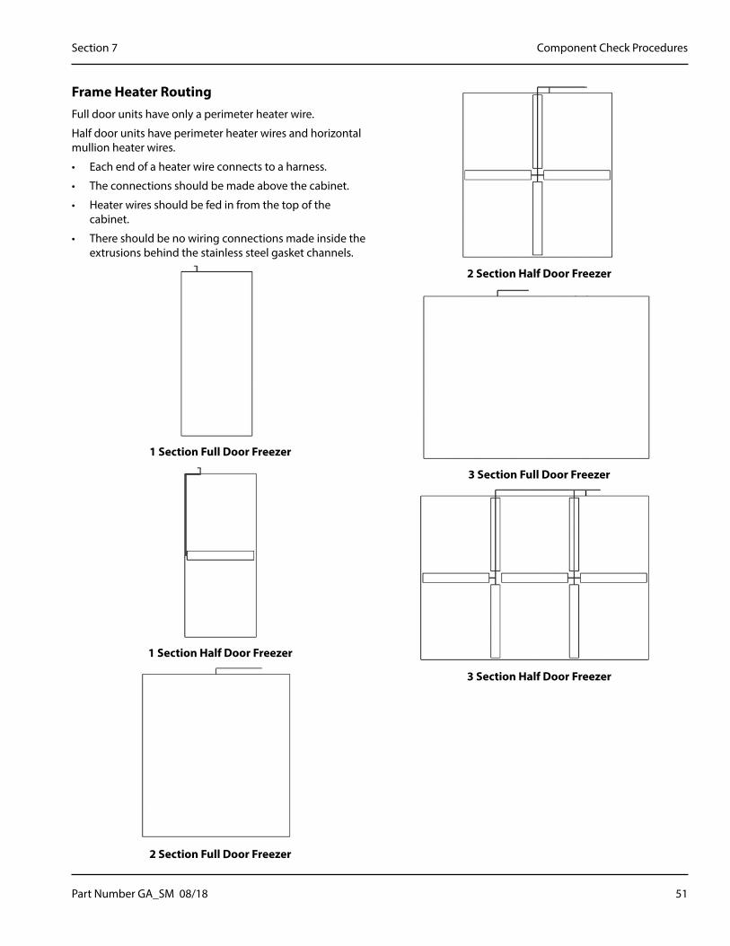
Part Number GA_SM 08/18 51
Section 7 Component Check Procedures
Frame Heater RoutingFull door units have only a perimeter heater wire.
Half door units have perimeter heater wires and horizontal mullion heater wires.
• Each end of a heater wire connects to a harness.
• The connections should be made above the cabinet.
• Heater wires should be fed in from the top of the cabinet.
• There should be no wiring connections made inside the extrusions behind the stainless steel gasket channels.
1 Section Full Door Freezer
1 Section Half Door Freezer
2 Section Full Door Freezer
2 Section Half Door Freezer
3 Section Full Door Freezer
3 Section Half Door Freezer
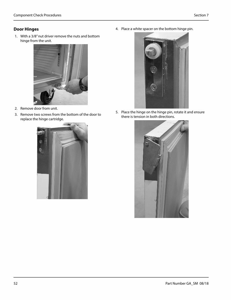
52 Part Number GA_SM 08/18
Component Check Procedures Section 7
Door Hinges1. With a 3/8” nut driver remove the nuts and bottom
hinge from the unit.
2. Remove door from unit.
3. Remove two screws from the bottom of the door to replace the hinge cartridge.
4. Place a white spacer on the bottom hinge pin.
5. Place the hinge on the hinge pin, rotate it and ensure there is tension in both directions.
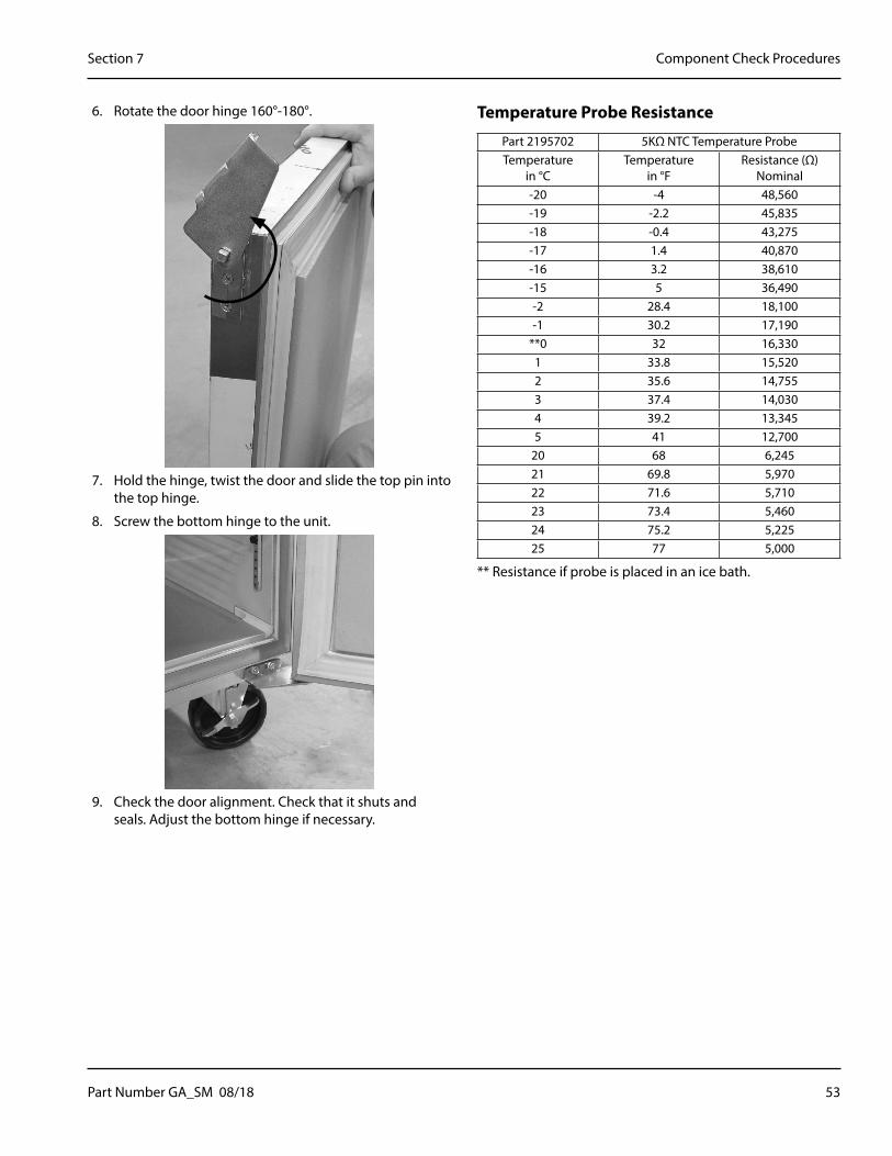
Part Number GA_SM 08/18 53
Section 7 Component Check Procedures
6. Rotate the door hinge 160°-180°.
7. Hold the hinge, twist the door and slide the top pin into the top hinge.
8. Screw the bottom hinge to the unit.
9. Check the door alignment. Check that it shuts and seals. Adjust the bottom hinge if necessary.
Temperature Probe Resistance
Part 2195702 5KΩ NTC Temperature ProbeTemperature
in °CTemperature
in °FResistance (Ω)
Nominal-20 -4 48,560-19 -2.2 45,835-18 -0.4 43,275-17 1.4 40,870-16 3.2 38,610-15 5 36,490-2 28.4 18,100-1 30.2 17,190
**0 32 16,3301 33.8 15,5202 35.6 14,7553 37.4 14,0304 39.2 13,3455 41 12,700
20 68 6,24521 69.8 5,97022 71.6 5,71023 73.4 5,46024 75.2 5,22525 77 5,000
** Resistance if probe is placed in an ice bath.

54 Part Number GA_SM 08/18
Component Check Procedures Section 7
LED Light ReplacementImportant Notes
• Tools Required: T6 Torx Bit & Phillips Head screwdriver
• Keep track of the light cover, all screws and wires. They will be reused.
Removal
1. Unscrew the light fixture from the unit.
Two (2) Screws Secure the Light in the Unit
2. Unscrew the light from the cover with the T6 torx bit.
Four (4) Screws Secure the Light Cover On
3. Press the center of a raised tab to release the wire. Remove the wire. Repeat on second tab for second wire.
Pressing the Center of the Raised Tab Releases the Wire
4. Discard the old light.
Reinstall
5. Press the center of a raised tab and insert a wire. Repeat on second tab with second wire. The wires are interchangeable.
6. Screw the cover back on the light.
7. Screw the light fixture back into the unit.
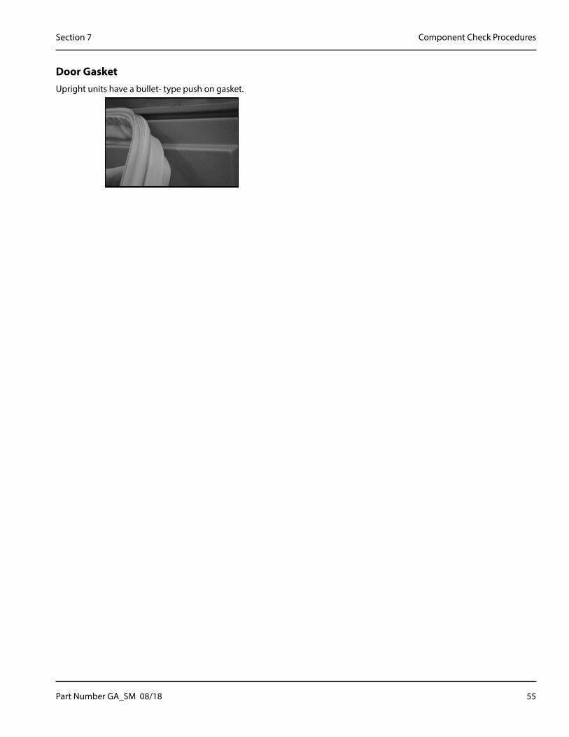
Part Number GA_SM 08/18 55
Section 7 Component Check Procedures
Door GasketUpright units have a bullet- type push on gasket.

56 Part Number GA_SM 08/18
Component Check Procedures Section 7
THIS PAGE INTENTIONALLY LEFT BLANK

Part Number GA_SM 08/18 57
R290Important�
We assume no responsibility for the use of contaminated refrigerant. Damage resulting from the use of contaminated refrigerant is the sole responsibility of the servicing company.
Connections
1. Suction side of the compressor through the suction service valve.
2. Discharge side of the compressor through the discharge service valve.
Charging Procedures
Important�The charge is critical on all Reach-In units. Use a scale or a charging cylinder to ensure the proper charge is installed.
1. Disconnect power to the unit.
2. Close the vacuum pump valve, the low side service valve, and the low side manifold gauge valve.
3. Open the high side manifold gauge valve and the high side service valve.
4. Open the charging cylinder and add the proper refrigerant charge (shown on nameplate) through the discharge service valve.
5. Let the system “settle” for 2 to 3 minutes.
6. Connect power up the unit.
7. Close the high side valve on the manifold gauge set. Add any remaining vapor charge through the suction service valve (if necessary).
NOTE: Manifold gauges must be removed properly to ensure that no refrigerant contamination or loss occurs.
8. Make sure that all the vapor in the charging hoses is drawn into the Reach-In before disconnecting the charging hoses.
A. Run the Reach-In cooling mode.
B. Close the high side service valve at the Reach-In.
C. Open the low side service valve at the Reach-In.
D. Open the high and low side valves on the manifold gauge set. Any refrigerant in the lines will be pulled into the low side of the system.
E. Allow the pressures to equalize while the Reach-In is running.
F. Close the low side service valve at the Reach-In.
G. Remove the hoses from the Reach-In and install the caps.
Section 8Refrigeration
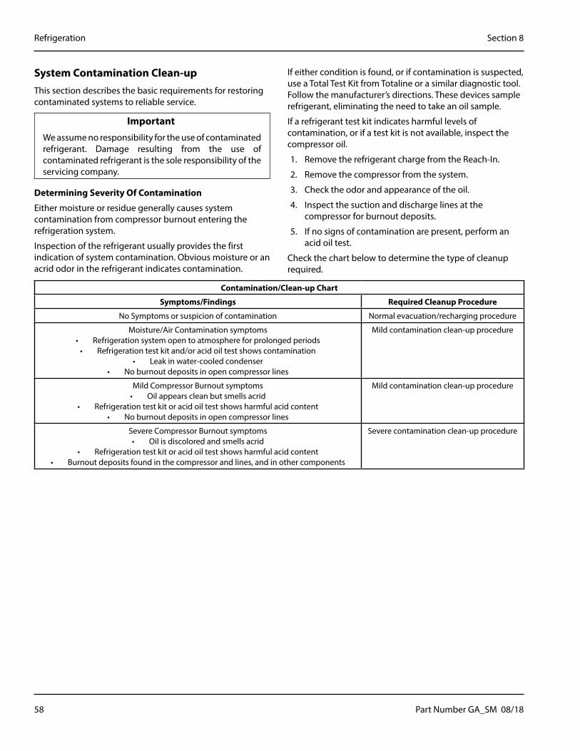
58 Part Number GA_SM 08/18
Refrigeration Section 8
System Contamination Clean-upThis section describes the basic requirements for restoring contaminated systems to reliable service.
Important�We assume no responsibility for the use of contaminated refrigerant. Damage resulting from the use of contaminated refrigerant is the sole responsibility of the servicing company.
Determining Severity Of Contamination
Either moisture or residue generally causes system contamination from compressor burnout entering the refrigeration system.
Inspection of the refrigerant usually provides the first indication of system contamination. Obvious moisture or an acrid odor in the refrigerant indicates contamination.
If either condition is found, or if contamination is suspected, use a Total Test Kit from Totaline or a similar diagnostic tool. Follow the manufacturer’s directions. These devices sample refrigerant, eliminating the need to take an oil sample.
If a refrigerant test kit indicates harmful levels of contamination, or if a test kit is not available, inspect the compressor oil.
1. Remove the refrigerant charge from the Reach-In.
2. Remove the compressor from the system.
3. Check the odor and appearance of the oil.
4. Inspect the suction and discharge lines at the compressor for burnout deposits.
5. If no signs of contamination are present, perform an acid oil test.
Check the chart below to determine the type of cleanup required.
Contamination/Clean-up Chart
Symptoms/Findings Required Cleanup Procedure
No Symptoms or suspicion of contamination Normal evacuation/recharging procedure
Moisture/Air Contamination symptoms• Refrigeration system open to atmosphere for prolonged periods
• Refrigeration test kit and/or acid oil test shows contamination• Leak in water-cooled condenser
• No burnout deposits in open compressor lines
Mild contamination clean-up procedure
Mild Compressor Burnout symptoms• Oil appears clean but smells acrid
• Refrigeration test kit or acid oil test shows harmful acid content• No burnout deposits in open compressor lines
Mild contamination clean-up procedure
Severe Compressor Burnout symptoms• Oil is discolored and smells acrid
• Refrigeration test kit or acid oil test shows harmful acid content• Burnout deposits found in the compressor and lines, and in other components
Severe contamination clean-up procedure

Part Number GA_SM 08/18 59
Section 8 Refrigeration
Mild System Contamination Clean-Up Procedure1. Replace any failed components.
2. If the compressor is good, change the oil.
3. Replace the liquid line drier.
NOTE: If the contamination is from moisture, use heat lamps during evacuation. Position them at the compressor, condenser and evaporator prior to evacuation.
Important�Dry nitrogen is recommended for this procedure. This will prevent CFC release.
4. Follow the normal evacuation procedure, except replace the evacuation step with the following:
A. Pull vacuum to 1000 microns. Break the vacuum with dry nitrogen and sweep the system. Pressurize to a minimum of 5 PSI.
B. Pull vacuum to 500 microns. Break the vacuum with dry nitrogen and sweep the system. Pressurize to a minimum of 5 PSI.
C. Change the vacuum pump oil.
D. Pull vacuum to 250 microns. Run the vacuum pump for ½ hour on self-contained models, 1 hour on remotes.
NOTE: You may perform a standing vacuum test to make a preliminary leak check. You should use an electronic leak detector after system charging to be sure there are no leaks.
5. Charge the system with the proper refrigerant to the nameplate charge.
6. Operate the Reach-In unit.
Severe System Contamination Clean-Up Procedure1. Remove the refrigerant charge.
2. Remove the compressor.
3. Remove the liquid line drier.
4. Replace the capillary tube.
5. Wipe away any burnout deposits from suction and discharge lines at compressor.
6. Sweep through the open system with dry nitrogen.
Important�Refrigerant sweeps are not recommended, as they release CFC’s into the atmosphere.
7. Install a new compressor and new start components.
8. Install a suction line filter-drier (with acid and moisture removal capability) of adequate size. Place the filter drier as close to the compressor as possible.
9. Install inlet and outlet access valves.
10. Install a new liquid line drier.
11. Follow the normal evacuation procedure, except replace the evacuation step with the following:
A. a) Pull vacuum to 1000 microns. Break the vacuum with dry nitrogen and sweep the system. Pressurize to a minimum of 5 PSI.
B. Change the vacuum pump oil.
C. Pull vacuum to 500 microns. Break the vacuum with dry nitrogen and sweep the system. Pressurize to a minimum of 5 PSI.
D. Change the vacuum pump oil.
E. Pull vacuum to 250 microns. Run the vacuum pump for ½ hour on self-contained models, 1 hour on remotes.
NOTE: You may perform a standing vacuum test to make a preliminary leak check. You should use an electronic leak detector after system charging to be sure there are no leaks.
12. Charge the system with the proper refrigerant to the nameplate charge.
13. Operate the Reach-In unit for one hour. Then check the pressure drop across the suction line filter-drier.
A. If the pressure drop is less than 1 PSI, the filter-drier should be adequate for complete clean up.
B. If the pressure drop exceeds 1 PSI, change the suction line filter-drier and the liquid line drier.

60 Part Number GA_SM 08/18
Refrigeration Section 8
Repeat steps 8 through 13 until the pressure drop is acceptable.
14. Operate the Reach-In unit for 48-72 hours. Then remove the suction line filter-drier and change the liquid line drier.
15. Follow normal evacuation procedures.
Filter DriersThe size of the filter-drier is important. Using an improperly sized filter-drier will cause the Reach-In unit to be improperly charged with refrigerant. OEM driers must be used.
Important�Driers are covered as a warranty part. Driers must be replaced any time the system is opened for repairs.
Refrigerant Re-Use PolicyWe recommend the use of:
1. New Refrigerant
• Must be of original nameplate type.
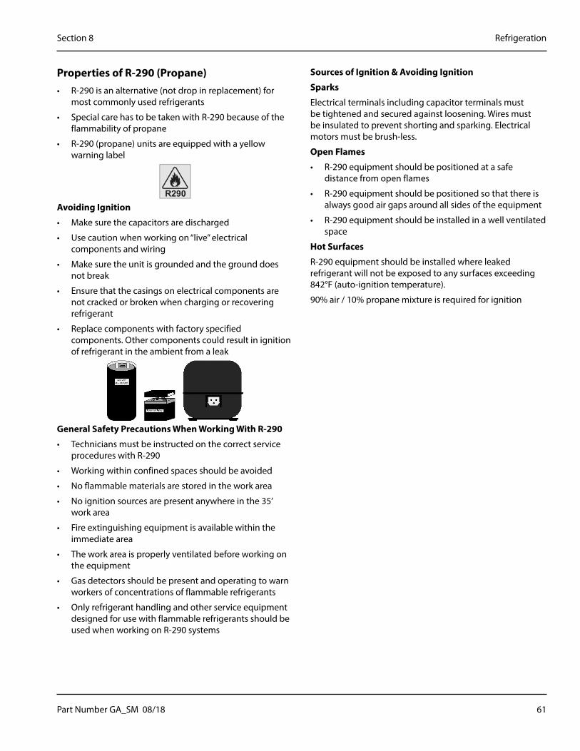
Part Number GA_SM 08/18 61
Section 8 Refrigeration
Properties of R-290 (Propane)• R-290 is an alternative (not drop in replacement) for
most commonly used refrigerants
• Special care has to be taken with R-290 because of the flammability of propane
• R-290 (propane) units are equipped with a yellow warning label
Avoiding Ignition
• Make sure the capacitors are discharged
• Use caution when working on “live” electrical components and wiring
• Make sure the unit is grounded and the ground does not break
• Ensure that the casings on electrical components are not cracked or broken when charging or recovering refrigerant
• Replace components with factory specified components. Other components could result in ignition of refrigerant in the ambient from a leak
General Safety Precautions When Working With R-290
• Technicians must be instructed on the correct service procedures with R-290
• Working within confined spaces should be avoided
• No flammable materials are stored in the work area
• No ignition sources are present anywhere in the 35’ work area
• Fire extinguishing equipment is available within the immediate area
• The work area is properly ventilated before working on the equipment
• Gas detectors should be present and operating to warn workers of concentrations of flammable refrigerants
• Only refrigerant handling and other service equipment designed for use with flammable refrigerants should be used when working on R-290 systems
Sources of Ignition & Avoiding Ignition
Sparks
Electrical terminals including capacitor terminals must be tightened and secured against loosening. Wires must be insulated to prevent shorting and sparking. Electrical motors must be brush-less.
Open Flames
• R-290 equipment should be positioned at a safe distance from open flames
• R-290 equipment should be positioned so that there is always good air gaps around all sides of the equipment
• R-290 equipment should be installed in a well ventilated space
Hot Surfaces
R-290 equipment should be installed where leaked refrigerant will not be exposed to any surfaces exceeding 842°F (auto-ignition temperature).
90% air / 10% propane mixture is required for ignition

62 Part Number GA_SM 08/18
Refrigeration Section 8
Service Procedures• Always use gas detection equipment when working on
R-290 systems
• Set the alarm to 15% of the LFL (Lower Flammability Level)
• Make sure all ignition sources are removed from the work area
• Maintain a 35’ area work area free of any ignition source
• Flames, sparks, and static electricity can ignite leaking refrigerant
• Always reclaim and purge system (twice) before using torch on system
• Always run the unit a minimum of 5 minutes before reclaiming refrigerant
• Follow evacuation (500 microns minimum) & purging procedures
Passive recovery
Charging with R-290
• Charging with R-290 is similar to charging systems with hydrocarbons
• Like all blend refrigerants, R-290 systems must be charged with liquid to maintain correct composition of the blend
• Be sure that the unit is grounded before charging
• It is very important to take care NOT to overfill the system
• Hydrocarbon charge sizes are typically 40% to 50% less than that of fluorocarbons
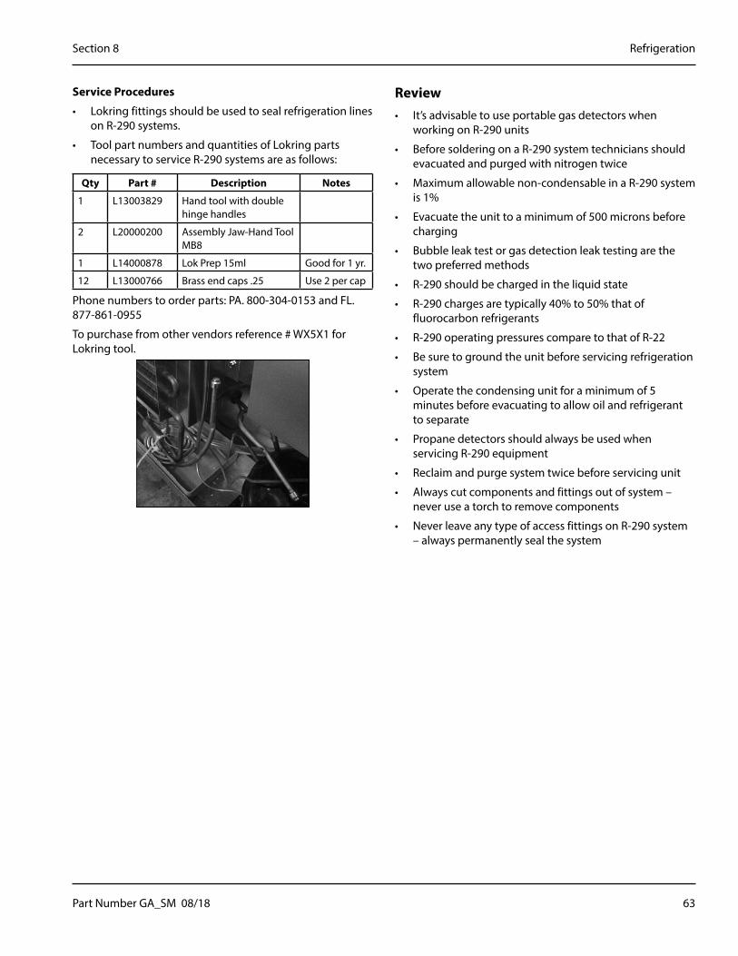
Part Number GA_SM 08/18 63
Section 8 Refrigeration
Service Procedures
• Lokring fittings should be used to seal refrigeration lines on R-290 systems.
• Tool part numbers and quantities of Lokring parts necessary to service R-290 systems are as follows:
Qty Part # Description Notes
1 L13003829 Hand tool with double hinge handles
2 L20000200 Assembly Jaw-Hand Tool MB8
1 L14000878 Lok Prep 15ml Good for 1 yr.
12 L13000766 Brass end caps .25 Use 2 per cap
Phone numbers to order parts: PA. 800-304-0153 and FL. 877-861-0955
To purchase from other vendors reference # WX5X1 for Lokring tool.
Review• It’s advisable to use portable gas detectors when
working on R-290 units
• Before soldering on a R-290 system technicians should evacuated and purged with nitrogen twice
• Maximum allowable non-condensable in a R-290 system is 1%
• Evacuate the unit to a minimum of 500 microns before charging
• Bubble leak test or gas detection leak testing are the two preferred methods
• R-290 should be charged in the liquid state
• R-290 charges are typically 40% to 50% that of fluorocarbon refrigerants
• R-290 operating pressures compare to that of R-22
• Be sure to ground the unit before servicing refrigeration system
• Operate the condensing unit for a minimum of 5 minutes before evacuating to allow oil and refrigerant to separate
• Propane detectors should always be used when servicing R-290 equipment
• Reclaim and purge system twice before servicing unit
• Always cut components and fittings out of system – never use a torch to remove components
• Never leave any type of access fittings on R-290 system – always permanently seal the system

64 Part Number GA_SM 08/18
Refrigeration Section 8
Normal Operating Temperatures
1 SECTION REACH-IN REFRIGERATOR
75°F (24°C) Ambient / 32°F (0°C) Box Temperature
Evaporator Inlet
Evaporator Outlet
Suction Line
Compressor Top
Compressor Bottom
Condenser Inlet
Condenser Outlet
10°F 14°F 49°F 94°F 91°F 103°F 84°F
-12°C -10°C 9°C 34°C 33°C 39°C 29°C
10°F
14°F
104°F94°F
103°F
49°F
91°F
84°F

Part Number GA_SM 08/18 65
Section 8 Refrigeration
1 SECTION REACH-IN REFRIGERATOR
86°F (30°C) Ambient / 32°F (0°C) Box Temperature
Evaporator Inlet
Evaporator Outlet
Suction Line
Compressor Top
Compressor Bottom
Condenser Inlet
Condenser Outlet
11°F 14°F 57°F 105°F 103°F 116°F 91°F
-12°C -10°C 14°C 41°C 39°C 47°C 33°C
11°F
14°F
104°F105°F
116°F
57°F
103°F
91°F

66 Part Number GA_SM 08/18
Refrigeration Section 8
1 SECTION REACH-IN REFRIGERATOR
100°F (38°C) Ambient / 32°F (0°C) Box Temperature
Evaporator Inlet
Evaporator Outlet
Suction Line
Compressor Top
Compressor Bottom
Condenser Inlet
Condenser Outlet
10°F 14°F 63°F 123°F 120°F 135°F 103°F
-12°C -10°C 17°C 51°C 49°C 57°C 39°C
10°F
14°F
104°F123°F
135°F
63°F
120°F
103°F

Part Number GA_SM 08/18 67
Section 8 Refrigeration
2 SECTION REACH-IN REFRIGERATOR
75°F (24°C) Ambient / 32°F (0°C) Box Temperature
Evaporator Inlet
Evaporator Outlet
Suction Line
Compressor Top
Compressor Bottom
Condenser Inlet
Condenser Outlet
11°F 18°F 46°F 100°F 93°F 110°F 87°F
-12°C -8°C 8°C 38°C 34°C 43°C 31°C
11°F
18°F
104°F100°F
110°F
46°F
93°F
87°F
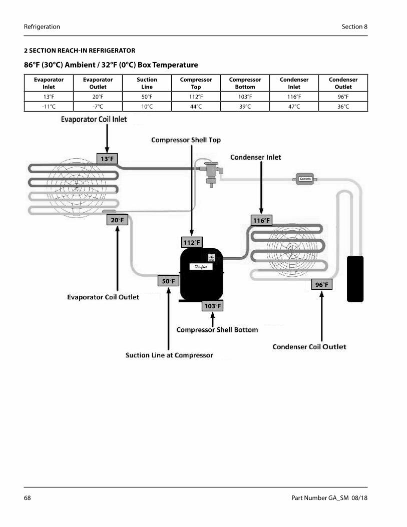
68 Part Number GA_SM 08/18
Refrigeration Section 8
2 SECTION REACH-IN REFRIGERATOR
86°F (30°C) Ambient / 32°F (0°C) Box Temperature
Evaporator Inlet
Evaporator Outlet
Suction Line
Compressor Top
Compressor Bottom
Condenser Inlet
Condenser Outlet
13°F 20°F 50°F 112°F 103°F 116°F 96°F
-11°C -7°C 10°C 44°C 39°C 47°C 36°C
13°F
20°F
104°F112°F
116°F
50°F
103°F
96°F

Part Number GA_SM 08/18 69
Section 8 Refrigeration
2 SECTION REACH-IN REFRIGERATOR
100°F (38°C) Ambient / 32°F (0°C) Box Temperature
Evaporator Inlet
Evaporator Outlet
Suction Line
Compressor Top
Compressor Bottom
Condenser Inlet
Condenser Outlet
11°F 18°F 52°F 131°F 120°F 142°F 107°F
-12°C -8°C 11°C 55°C 49°C 61°C 42°C
11°F
18°F
104°F131°F
142°F
52°F
120°F
107°F

70 Part Number GA_SM 08/18
Refrigeration Section 8
3 SECTION REACH-IN REFRIGERATOR
75°F (24°C) Ambient / 32°F (0°C) Box Temperature
Evaporator Inlet
Evaporator Outlet
Suction Line
Compressor Top
Compressor Bottom
Condenser Inlet
Condenser Outlet
17°F 25°F 52°F 113°F 102°F 114°F 91°F
-8°C -4°C 11°C 45°C 39°C 46°C 33°C
17°F
25°F
104°F113°F
114°F
52°F
102°F
91°F

Part Number GA_SM 08/18 71
Section 8 Refrigeration
3 SECTION REACH-IN REFRIGERATOR
86°F (30°C) Ambient / 32°F (0°C) Box Temperature
Evaporator Inlet
Evaporator Outlet
Suction Line
Compressor Top
Compressor Bottom
Condenser Inlet
Condenser Outlet
18°F 25°F 54°F 122°F 111°F 125°F 98°F
-8°C -4°C 12°C 50°C 44°C 52°C 37°C
18°F
25°F
104°F122°F
125°F
54°F
111°F
98°F
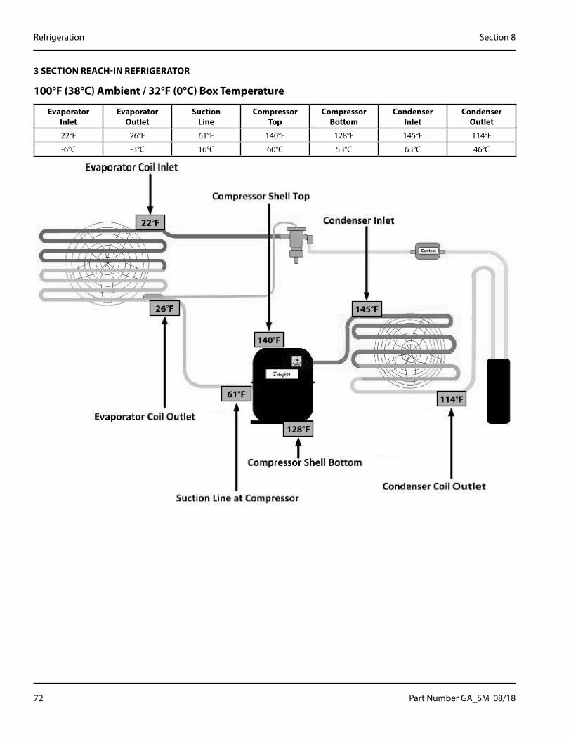
72 Part Number GA_SM 08/18
Refrigeration Section 8
3 SECTION REACH-IN REFRIGERATOR
100°F (38°C) Ambient / 32°F (0°C) Box Temperature
Evaporator Inlet
Evaporator Outlet
Suction Line
Compressor Top
Compressor Bottom
Condenser Inlet
Condenser Outlet
22°F 26°F 61°F 140°F 128°F 145°F 114°F
-6°C -3°C 16°C 60°C 53°C 63°C 46°C
22°F
26°F
104°F140°F
145°F
61°F
128°F
114°F

Part Number GA_SM 08/18 73
Section 8 Refrigeration
1 SECTION REACH-IN FREEZER
75°F (24°C) Ambient / 32°F (0°C) Box Temperature
Evaporator Inlet
Evaporator Outlet
Suction Line
Compressor Top
Compressor Bottom
Condenser Inlet
Condenser Outlet
-22°F -20°F 8°F 114°F 103°F 120°F 88°F
-30°C -29°C -13°C 46°C 39°C 49°C 31°C
-22°F
-20°F
104°F114°F
120°F
8°F
103°F
88°F

74 Part Number GA_SM 08/18
Refrigeration Section 8
1 SECTION REACH-IN FREEZER
86°F (30°C) Ambient / 32°F (0°C) Box Temperature
Evaporator Inlet
Evaporator Outlet
Suction Line
Compressor Top
Compressor Bottom
Condenser Inlet
Condenser Outlet
-22°F -20°F 13°F 129°F 117°F 140°F 97°F
-30°C -29°C -11°C 54°C 47°C 60°C 36°C
-22°F
-20°F
104°F129°F
140°F
13°F
117°F
97°F

Part Number GA_SM 08/18 75
Section 8 Refrigeration
1 SECTION REACH-IN FREEZER
100°F (38°C) Ambient / 32°F (0°C) Box Temperature
Evaporator Inlet
Evaporator Outlet
Suction Line
Compressor Top
Compressor Bottom
Condenser Inlet
Condenser Outlet
-19°F -16°F 20°F 145°F 132°F 157°F 111°F
-28°C -27°C -7°C 63°C 56°C 69°C 44°C
-19°F
-16°F
104°F145°F
157°F
20°F
132°F
111°F

76 Part Number GA_SM 08/18
Refrigeration Section 8
2 SECTION REACH-IN FREEZER
75°F (24°C) Ambient / 32°F (0°C) Box Temperature
Evaporator Inlet
Evaporator Outlet
Suction Line
Compressor Top
Compressor Bottom
Condenser Inlet
Condenser Outlet
-18°F -13°F 22°F 117°F 108°F 132°F 84°F
-28°C -25°C -6°C 47°C 42°C 56°C 29°C
-18°F
-13°F
104°F117°F
132°F
22°F
108°F
84°F
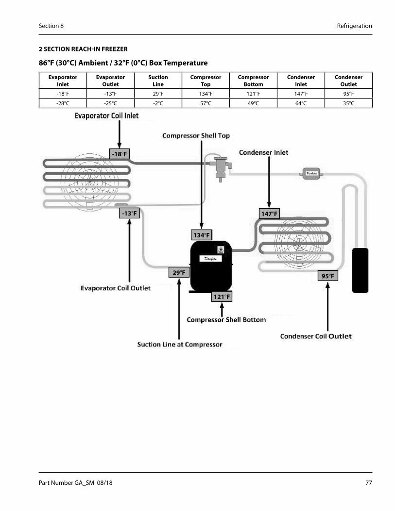
Part Number GA_SM 08/18 77
Section 8 Refrigeration
2 SECTION REACH-IN FREEZER
86°F (30°C) Ambient / 32°F (0°C) Box Temperature
Evaporator Inlet
Evaporator Outlet
Suction Line
Compressor Top
Compressor Bottom
Condenser Inlet
Condenser Outlet
-18°F -13°F 29°F 134°F 121°F 147°F 95°F
-28°C -25°C -2°C 57°C 49°C 64°C 35°C
-18°F
-13°F
104°F134°F
147°F
29°F
121°F
95°F

78 Part Number GA_SM 08/18
Refrigeration Section 8
2 SECTION REACH-IN FREEZER
100°F (38°C) Ambient / 32°F (0°C) Box Temperature
Evaporator Inlet
Evaporator Outlet
Suction Line
Compressor Top
Compressor Bottom
Condenser Inlet
Condenser Outlet
-17°F -12°F 35°F 152°F 139°F 165°F 109°F
-27°C -24°C 2°C 67°C 59°C 74°C 43°C
-17°F
-12°F
104°F152°F
165°F
35°F
139°F
109°F

Part Number GA_SM 08/18 79
Section 8 Refrigeration
3 SECTION REACH-IN FREEZER
75°F (24°C) Ambient / 32°F (0°C) Box Temperature
Evaporator Inlet
Evaporator Outlet
Suction Line
Compressor Top
Compressor Bottom
Condenser Inlet
Condenser Outlet
-23°F -17°F 43°F 134°F 120°F 142°F 91°F
-31°C -27°C 6°C 57°C 49°C 61°C 33°C
-23°F
-17°F
104°F134°F
142°F
43°F
120°F
91°F

80 Part Number GA_SM 08/18
Refrigeration Section 8
3 SECTION REACH-IN FREEZER
86°F (30°C) Ambient / 32°F (0°C) Box Temperature
Evaporator Inlet
Evaporator Outlet
Suction Line
Compressor Top
Compressor Bottom
Condenser Inlet
Condenser Outlet
-22°F -16°F 48°F 146°F 130°F 152°F 100°F
-30°C -27°C 9°C 63°C 54°C 67°C 38°C
-22°F
-16°F
104°F146°F
152°F
48°F
130°F
100°F

Part Number GA_SM 08/18 81
Section 8 Refrigeration
3 SECTION REACH-IN FREEZER
100°F (38°C) Ambient / 32°F (0°C) Box Temperature
Evaporator Inlet
Evaporator Outlet
Suction Line
Compressor Top
Compressor Bottom
Condenser Inlet
Condenser Outlet
-21°F -16°F 59°F 161°F 145°F 166°F 112°F
-29°C -27°C 15°C 72°C 63°C 74°C 44°C
-21°F
-16°F
104°F161°F
166°F
59°F
145°F
112°F

82 Part Number GA_SM 08/18
Refrigeration Section 8
1 SECTION PASS-THRU REFRIGERATOR
75°F (24°C) Ambient / 32°F (0°C) Box Temperature
Evaporator Inlet
Evaporator Outlet
Suction Line
Compressor Top
Compressor Bottom
Condenser Inlet
Condenser Outlet
4°F 15°F 44°F 107°F 84°F 112°F 85°F
-16°C -9°C 7°C 42°C 29°C 44°C 29°C
4°F
15°F
104°F107°F
112°F
44°F
84°F
85°F

Part Number GA_SM 08/18 83
Section 8 Refrigeration
1 SECTION PASS-THRU REFRIGERATOR
86°F (30°C) Ambient / 32°F (0°C) Box Temperature
Evaporator Inlet
Evaporator Outlet
Suction Line
Compressor Top
Compressor Bottom
Condenser Inlet
Condenser Outlet
6°F 18°F 48°F 123°F 95°F 123°F 96°F
-14°C -8°C 9°C 51°C 35°C 51°C 36°C
6°F
18°F
104°F123°F
123°F
48°F
95°F
96°F

84 Part Number GA_SM 08/18
Refrigeration Section 8
1 SECTION PASS-THRU REFRIGERATOR
100°F (38°C) Ambient / 32°F (0°C) Box Temperature
Evaporator Inlet
Evaporator Outlet
Suction Line
Compressor Top
Compressor Bottom
Condenser Inlet
Condenser Outlet
9°F 18°F 52°F 142°F 109°F 145°F 110°F
-13°C -8°C 11°C 61°C 43°C 63°C 43°C
9°F
18°F
104°F142°F
145°F
52°F
109°F
110°F
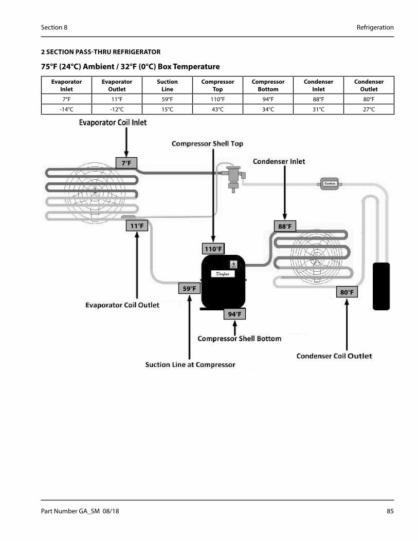
Part Number GA_SM 08/18 85
Section 8 Refrigeration
2 SECTION PASS-THRU REFRIGERATOR
75°F (24°C) Ambient / 32°F (0°C) Box Temperature
Evaporator Inlet
Evaporator Outlet
Suction Line
Compressor Top
Compressor Bottom
Condenser Inlet
Condenser Outlet
7°F 11°F 59°F 110°F 94°F 88°F 80°F
-14°C -12°C 15°C 43°C 34°C 31°C 27°C
7°F
11°F
104°F110°F
88°F
59°F
94°F
80°F

86 Part Number GA_SM 08/18
Refrigeration Section 8
2 SECTION PASS-THRU REFRIGERATOR
86°F (30°C) Ambient / 32°F (0°C) Box Temperature
Evaporator Inlet
Evaporator Outlet
Suction Line
Compressor Top
Compressor Bottom
Condenser Inlet
Condenser Outlet
6°F 11°F 66°F 127°F 108°F 98°F 93°F
-14°C -12°C 19°C 53°C 42°C 37°C 34°C
6°F
11°F
104°F127°F
98°F
66°F
108°F
93°F

Part Number GA_SM 08/18 87
Section 8 Refrigeration
2 SECTION PASS-THRU REFRIGERATOR
100°F (38°C) Ambient / 32°F (0°C) Box Temperature
Evaporator Inlet
Evaporator Outlet
Suction Line
Compressor Top
Compressor Bottom
Condenser Inlet
Condenser Outlet
7°F 12°F 75°F 147°F 126°F 113°F 106°F
-14°C -11°C 24°C 64°C 52°C 45°C 41°C
7°F
12°F
104°F147°F
113°F
75°F
126°F
106°F

88 Part Number GA_SM 08/18
Refrigeration Section 8
1 SECTION PASS-THRU FREEZER
75°F (24°C) Ambient / 32°F (0°C) Box Temperature
Evaporator Inlet
Evaporator Outlet
Suction Line
Compressor Top
Compressor Bottom
Condenser Inlet
Condenser Outlet
-26°F -21°F 30°F 125°F 86°F 115°F 88°F
-32°C -29°C -1°C 52°C 30°C 46°C 31°C
-26°F
-21°F
104°F125°F
115°F
30°F
86°F
88°F

Part Number GA_SM 08/18 89
Section 8 Refrigeration
1 SECTION PASS-THRU FREEZER
86°F (30°C) Ambient / 32°F (0°C) Box Temperature
Evaporator Inlet
Evaporator Outlet
Suction Line
Compressor Top
Compressor Bottom
Condenser Inlet
Condenser Outlet
-24°F -19°F 42°F 139°F 99°F 130°F 101°F
-31°C -28°C 6°C 59°C 37°C 54°C 38°C
-24°F
-19°F
104°F139°F
130°F
42°F
99°F
101°F
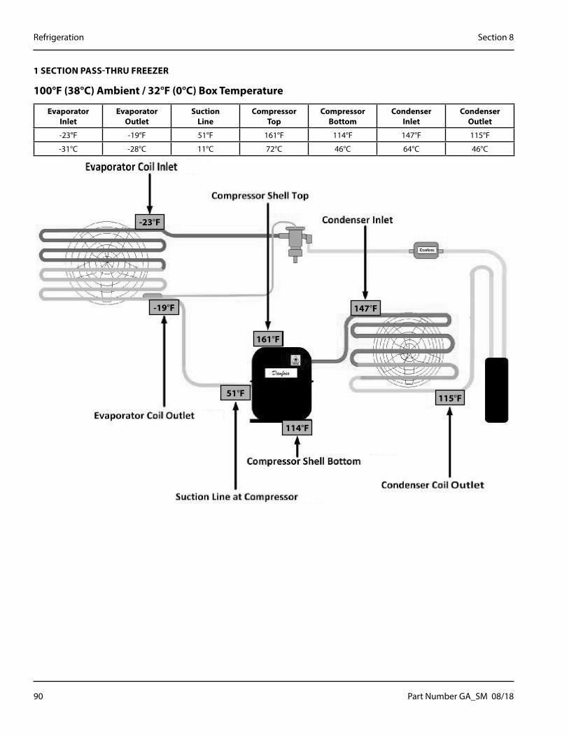
90 Part Number GA_SM 08/18
Refrigeration Section 8
1 SECTION PASS-THRU FREEZER
100°F (38°C) Ambient / 32°F (0°C) Box Temperature
Evaporator Inlet
Evaporator Outlet
Suction Line
Compressor Top
Compressor Bottom
Condenser Inlet
Condenser Outlet
-23°F -19°F 51°F 161°F 114°F 147°F 115°F
-31°C -28°C 11°C 72°C 46°C 64°C 46°C
-23°F
-19°F
104°F161°F
147°F
51°F
114°F
115°F

Part Number GA_SM 08/18 91
Section 8 Refrigeration
2 SECTION PASS-THRU FREEZER
75°F (24°C) Ambient / 32°F (0°C) Box Temperature
Evaporator Inlet
Evaporator Outlet
Suction Line
Compressor Top
Compressor Bottom
Condenser Inlet
Condenser Outlet
-21°F -15°F 31°F 131°F 116°F 140°F 93°F
-29°C -26°C -1°C 55°C 47°C 60°C 34°C
-21°F
-15°F
104°F131°F
140°F
31°F
116°F
93°F

92 Part Number GA_SM 08/18
Refrigeration Section 8
2 SECTION PASS-THRU FREEZER
86°F (30°C) Ambient / 32°F (0°C) Box Temperature
Evaporator Inlet
Evaporator Outlet
Suction Line
Compressor Top
Compressor Bottom
Condenser Inlet
Condenser Outlet
-21°F -15°F 42°F 143°F 128°F 152°F 103°F
-29°C -26°C 6°C 62°C 53°C 67°C 39°C
-21°F
-15°F
104°F143°F
152°F
42°F
128°F
103°F

Part Number GA_SM 08/18 93
Section 8 Refrigeration
2 SECTION PASS-THRU FREEZER
100°F (38°C) Ambient / 32°F (0°C) Box Temperature
Evaporator Inlet
Evaporator Outlet
Suction Line
Compressor Top
Compressor Bottom
Condenser Inlet
Condenser Outlet
-20°F -15°F 52°F 159°F 143°F 168°F 114°F
-29°C -26°C 11°C 71°C 62°C 76°C 46°C
-20°F
-15°F
104°F159°F
168°F
52°F
143°F
114°F

94 Part Number GA_SM 08/18
Refrigeration Section 8
THIS PAGE INTENTIONALLY LEFT BLANK
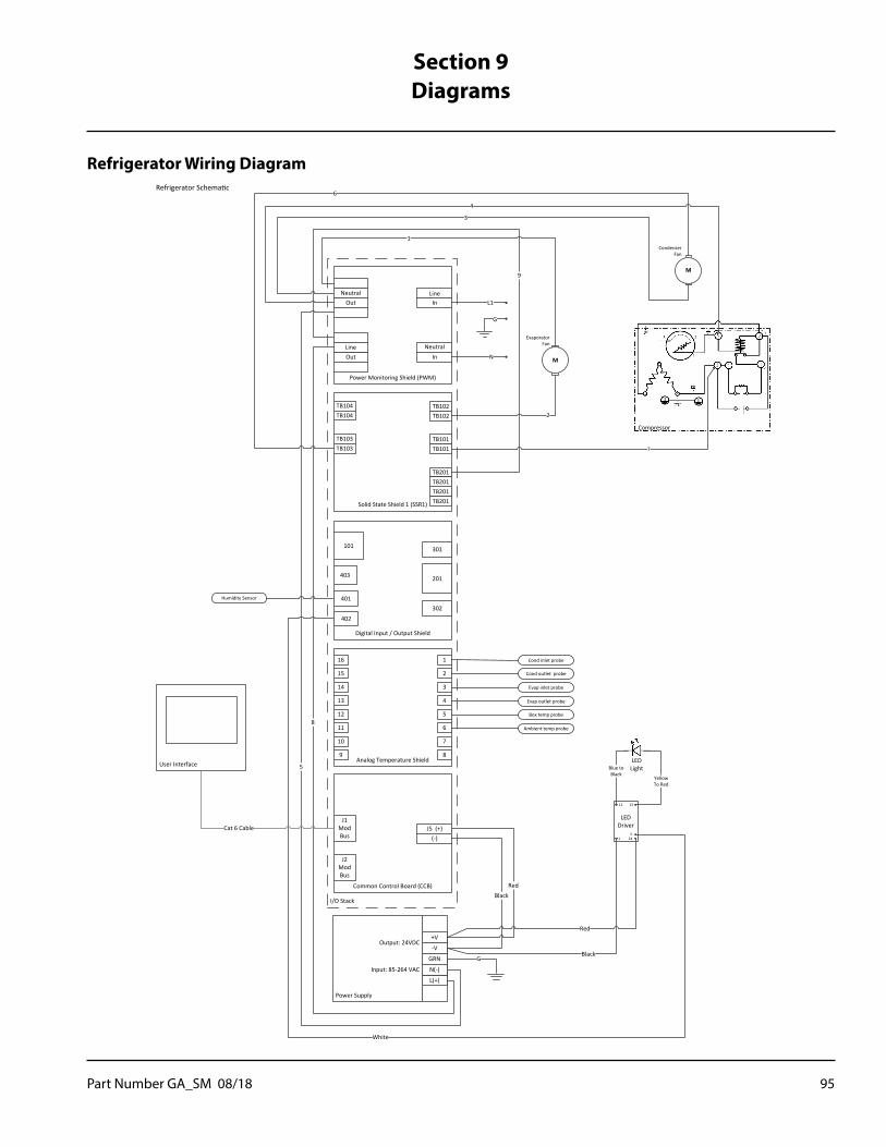
Part Number GA_SM 08/18 95
Refrigerator Wiring Diagram
Power Monitoring Shield (PWM)
OutNeutral
OutLine
InNeutral
In
Common Control Board (CCB)
J2 Mod Bus
J5 (+)(-)
Analog Temperature Shield
1
Solid State Shield 1 (SSR1)
TB201TB201
TB201TB201
TB101TB101
TB102TB102
TB103TB103
TB104TB104
2
3
4
5
6
7
8
16
15
14
13
12
11
10
9
J1 Mod Bus
I/O Stack
Refrigerator Schematic
Cond inlet probe
Cond outlet probe
Evap inlet probe
Evap outlet probe
Box temp probe
Ambient temp probe
L1
N
9
Power Supply
L(+)
+V
-V
GRN
N(-)
Output: 24VDC
Input: 85-264 VAC
8
5
G
G
4
M
Compressor
6
CondenserFan
M
EvaporatorFan
3
1
2
BlackRed
LED Driver
51
12 13
24
White
YellowTo Red
Blue toBlack
LEDLight
Black
Red
User Interface
Cat 6 Cable
7
Digital Input / Output Shield
101
201
302
403
402
401
301
Humidity Sensor
Line
Section 9Diagrams

96 Part Number GA_SM 08/18
Diagrams Section 9
Freezers With One Compressor Wiring Diagram
Power Monitoring Shield (PWM)
OutNeutral
OutLine
InNeutral
In
Common Control Board (CCB)
J2 Mod Bus
J5 (+)(-)
Solid State Shield 2 (SSR2)
TB201TB201
TB201TB201
TB101TB101
TB102TB102
Analog Temperature Shield
1
TB103TB103
TB104TB104
Solid State Shield 1 (SSR1)
TB201TB201
TB201TB201
TB101TB101
TB102TB102
TB103TB103
TB104TB104
2
3
4
5
6
7
8
16
15
14
13
12
11
10
9
J1 Mod Bus
I/O Stack
Freezer Schematic
Cond inlet probe
Cond outlet probe
Evap inlet probe
Evap outlet probe
Box temp probe
Ambient temp probe
L1
N
1
14
Power Supply
L(+)
+V
-V
GRN
N(-)
Output: 24VDC
Input: 85-264 VAC
2
3
G
G
5
M
Compressor
11
CondenserFan
M
EvaporatorFan
10
Defrost
Heater
Frame
Heater12
13
8
6
7
9
BlackRed
LED Driver
51
12 13
24
White
YellowTo Red
Blue toBlack
LEDLight
Black
Red
User Interface
Cat 6 Cable
4
Humidity Sensor
Digital Input / Output Shield
101
201
302
403
402
401
301
Line
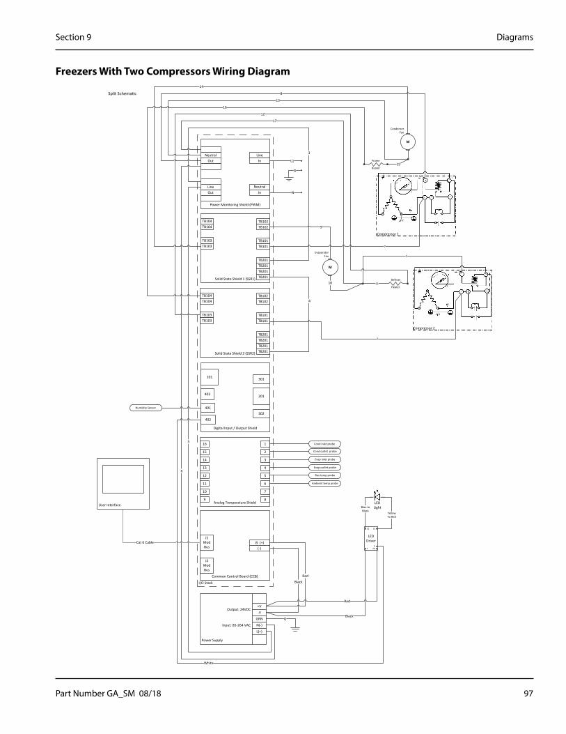
Part Number GA_SM 08/18 97
Section 9 Diagrams
Freezers With Two Compressors Wiring Diagram
Power Monitoring Shield (PWM)
OutNeutral
OutLine
InNeutral
In
Common Control Board (CCB)
J2 Mod Bus
J5 (+)(-)
Solid State Shield 2 (SSR2)
TB201TB201
TB201TB201
TB101TB101
TB102TB102
Analog Temperature Shield
1
TB103TB103
TB104TB104
Solid State Shield 1 (SSR1)
TB201TB201
TB201TB201
TB101TB101
TB102TB102
TB103TB103
TB104TB104
2
3
4
5
6
7
8
16
15
14
13
12
11
10
9
J1 Mod Bus
I/O Stack
Split Schematic
Cond inlet probe
Cond outlet probe
Evap inlet probe
Evap outlet probe
Box temp probe
Ambient temp probe
L1
N
3
4
Power Supply
L(+)
+V
-V
GRN
N(-)
Output: 24VDC
Input: 85-264 VAC
5
6
G
G
8
M
Compressor 1
14
CondenserFan
M
EvaporatorFan
13
11Defrost
Heater
Frame
Heater15
16
17
9
10
12
BlackRed
LED Driver
51
12 13
24
White
YellowTo Red
Blue toBlack
LEDLight
Black
Red
User Interface
Cat 6 Cable
7
1
2
Compressor 2
Humidity Sensor
Digital Input / Output Shield
101
201
302
403
402
401
301
Line
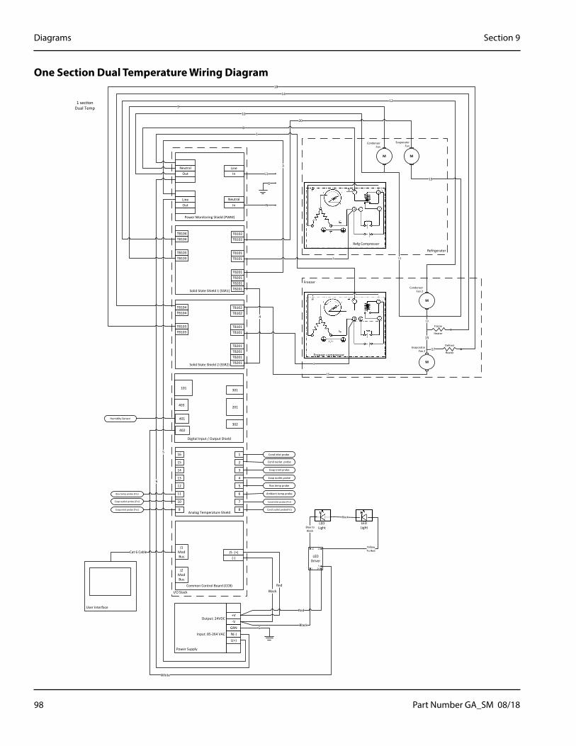
98 Part Number GA_SM 08/18
Diagrams Section 9
One Section Dual Temperature Wiring Diagram
Power Monitoring Shield (PWM)
OutNeutral
OutLine
InNeutral
In
Common Control Board (CCB)
J2 Mod Bus
J5 (+)(-)
Solid State Shield 2 (SSR2)
TB201TB201
TB201TB201
TB101TB101
TB102TB102
Analog Temperature Shield
1
TB103TB103
TB104TB104
Solid State Shield 1 (SSR1)
TB201TB201
TB201TB201
TB101TB101
TB102TB102
TB103TB103
TB104TB104
2
3
4
5
6
7
8
16
15
14
13
12
11
10
9
J1 Mod Bus
I/O Stack
1 section Dual Temp
Cond inlet probe
Cond outlet probe
Evap inlet probe
Evap outlet probe
Box temp probe
Ambient temp probe
L1
N
3
4
Power Supply
L(+)
+V
-V
GRN
N(-)
Output: 24VDC
Input: 85-264 VAC
5
6
G
G
10
M
Refg Compressor
9
CondenserFan
8
Frame
Heater
12
20
18
BlackRed
LED Driver
51
12 13
24
White
Blue toBlack
LEDLight
Black
RedUser Interface
Cat 6 Cable
7 11
2
Freezer compressor
YellowTo Red
Black
LEDLight
M
19
M
CondenserFan 2
M
EvaporatorFan 2
Defrost
Heater
15
1
EvaporatorFan
Refrigerator
13
14
17
16
Freezer
Humidity Sensor
Digital Input / Output Shield
101
201
302
403
402
401
301
Cond inlet probe (Frz)
Cond outlet probe(Frz)Evap inlet probe (Frz)
Evap outlet probe (Frz)
Box temp probe (Frz)
Line
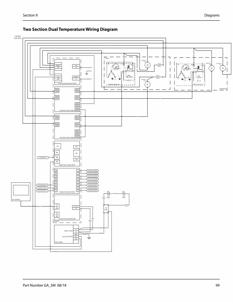
Part Number GA_SM 08/18 99
Section 9 Diagrams
Two Section Dual Temperature Wiring Diagram
Power Monitoring Shield (PWM)
OutNeutral
OutLine
InNeutral
In
Common Control Board (CCB)
J2 Mod Bus
J5 (+)(-)
Solid State Shield 2 (SSR2)
TB201TB201
TB201TB201
TB101TB101
TB102TB102
Analog Temperature Shield
1
TB103TB103
TB104TB104
Solid State Shield 1 (SSR1)
TB201TB201
TB201TB201
TB101TB101
TB102TB102
TB103TB103
TB104TB104
2
3
4
5
6
7
8
16
15
14
13
12
11
10
9
J1 Mod Bus
I/O Stack
1 section Dual Temp
Cond inlet probe (Refg)
Cond outlet probe(Refg)
Evap inlet probe (Refg)
Evap outlet probe (Refg)
Box temp probe (Refg)
Ambient temp probe
L1
N
2
1
Power Supply
L(+)
+V
-V
GRN
N(-)
Output: 24VDC
Input: 85-264 VAC
3
4
G
G
15
21
13
Frame
Heater
9
19
14
BlackRed
LED Driver
51
12 13
24
White
Blue toBlack
LEDLight
Black
Red
User Interface
Cat 6 Cable
5
Freezer compressor
YellowTo Red
Black
LEDLight
M
CondenserFan 2
M
EvaporatorFan 2
Defrost
Heater12
22
8
18
11
Freezer
M
Refg Compressor
CondenserFan
M
EvaporatorFan
Refrigerator
6
7
10
17
16 20
Cond inlet probe (Refg)
Cond outlet probe(Refg)
Cond inlet probe (Frz)
Cond outlet probe(Frz)Evap inlet probe (Frz)
Evap outlet probe (Frz)
Box temp probe (Frz)
Humidity Sensor
Digital Input / Output Shield
101
201
302
403
402
401
301
Line
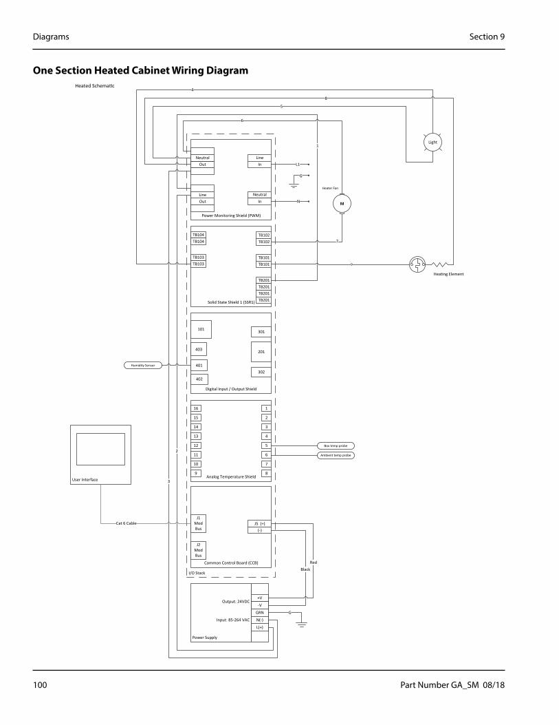
100 Part Number GA_SM 08/18
Diagrams Section 9
One Section Heated Cabinet Wiring Diagram
Power Monitoring Shield (PWM)
OutNeutral
OutLine
InNeutral
In
Common Control Board (CCB)
J2 Mod Bus
J5 (+)(-)
Analog Temperature Shield
1
Solid State Shield 1 (SSR1)
TB201TB201
TB201TB201
TB101TB101
TB102TB102
TB103TB103
TB104TB104
2
3
4
5
6
7
8
16
15
14
13
12
11
10
9
J1 Mod Bus
I/O Stack
Heated Schematic
Box temp probe
Ambient temp probe
L1
N
1
Power Supply
L(+)
+V
-V
GRN
N(-)
Output: 24VDC
Input: 85-264 VAC
2
3
G
G
8
Heating Element
4
M
Heater Fan
5
6
7
BlackRed
User Interface
Cat 6 Cable
9
Light
Humidity Sensor
Digital Input / Output Shield
101
201
302
403
402
401
301
Line

Part Number GA_SM 08/18 101
Section 9 Diagrams
Two Section Heated Cabinet Wiring Diagram
Power Monitoring Shield (PWM)
OutNeutral
OutLine
InNeutral
In
Common Control Board (CCB)
J2 Mod Bus
J5 (+)(-)
Analog Temperature Shield
1
Solid State Shield 1 (SSR1)
TB201TB201
TB201TB201
TB101TB101
TB102TB102
TB103TB103
TB104TB104
2
3
4
5
6
7
8
16
15
14
13
12
11
10
9
J1 Mod Bus
I/O Stack
Heated Schematic
Box temp probe
Ambient temp probe
L1
N
1
Power Supply
L(+)
+V
-V
GRN
N(-)
Output: 24VDC
Input: 85-264 VAC
2
3
G
G
125
M
HeaterFan
6
7
8
BlackRed
User Interface
Cat 6 Cable
Light
Heating Element
Heating Element
17
111 0
6
8
2
4
7 3
Coil
Contactor
1316
14
15
4
M
HeaterFan
9
10
18
Humidity Sensor
Digital Input / Output Shield
101
201
302
403
402
401
301
Line

102 Part Number GA_SM 08/18
Diagrams Section 9
THIS PAGE INTENTIONALLY LEFT BLANK

DELFIELD 980 SOUTH ISABELLA ROAD, MOUNT PLEASANT, MI 48858
800-733-8821 WWW.DELFIELD.COM
©2017 Welbilt Inc. except where explicitly stated otherwise. All rights reserved. Continuing product improvement may necessitate change of specifications without notice.
Part Number GA_SM 08/18
Welbilt provides the world’s top chefs, and premier chain operators or growing independents with industry leading equipment and solutions. Our cutting-edge designs and lean manufacturing tactics are powered by deep knowledge, operator insights, and culinary expertise. All of our products are backed by KitchenCare® – our aftermarket, repair, and parts service.
CLEVELANDCONVOTHERM®
DELFIELD®FITKITCHEN™
FRYMASTER®GARLAND
KOLPAK®LINCOLN
MANITOWOC®MERCO®
MERRYCHEF®MULTIPLEX®
WWW.WELBILT.COM
Related Documents