CODE HSS 1997 617 3 Specification for the Design of Steel Hollow Structural Sections April 15. 1997 ERJ CAN INSTITUTE OF STEEL CONSTRUCTI ON, INC. One East Wacker Drive, Suite 3100, Chicago, IL6060 1 ·2001

Welcome message from author
This document is posted to help you gain knowledge. Please leave a comment to let me know what you think about it! Share it to your friends and learn new things together.
Transcript
CODE HSS 1997
6173
Specification for the Design of
Steel Hollow Structural Sections
April 15. 1997
ERJCAN INSTITUTE OF STEEL CONSTRUCTION, INC. One East Wacker Drive, Suite 3100, Chicago, IL60601·2001
" SPECIFICATION FOR THE DESIGN OF STEEL HOLLOW STRUCTURAL SECTIONS
Copyright €:I 1997
by
American lnstitule of Sleel Construction, Inc.
All righls resen'ed. This book or allY pari Ihereof must not be reproduced in any form without the
written pennission of the publisher.
The information presented in tbis publication bas been prepared in accordance with recognized engineering principles and is for general information only. While it is believed to be accurate, this information should not be used or relied upon for any specific application witbout competent professional examination and verification of its accuracy, suitability, and applicability by a licensed professional engineer, designer, or architect. The publication of the material contained herein is not intended as a representation or warranty on the part of the American Institute of Steel Construction or of any other person named herein, that this information is suitable for any general or particular use or offreedom from infringement of any patent or patents. Anyone making use of this information assumes all liability arising from such usc.
Caution must be exercised when relying upon other specifications and codes developed by other bodies and incorporated by reference herein since such material may be modified or amended from time to time subsequent to the printing of this edition. Tbe Institute bears no responsibility for such material other than to refer to it and incorporate it by reference at the time of the initial publication of this edition.
Printed in the United States of America
AMEJUCAN 1'IS11Tt1TE Of STEELCONSTRL:C"nON
\. V1 0>
SPECIFlCAnON FOR THE DESIGN OF STEEL HOLLOW STRUCTURAL SECTIONS III
Table of Contents Symbols Preface
Specification for the Design of Steel Hollow Structural Sections
. v vii
I. I. Scope . . . . . . . . I 1.2. Malerial . . . . . . . . . . . 1
I. Struclural Steel . . . . I 2. DesIgn Wall Thickness 2
1.3. Loads and Load Combinalions 2
2.1. Effective et Area for Tension Members. 2 2.2. Local Buck.hng . . . . . . . . . 4
I. ClassIfication. . .. .. . . .. 4 2. DesIgn by Plastic Analysis . . . 4 3. DeSIgn in Seismic Applications 5
2.3. Limiting Slenderness Ratios 5
3. 1. Design for Tension .......... 5
4. 1. Effective Length and Slenderness Limitations 5 I. Effective Length . . . . . 5 2. Design by PlastIc Analysis 6
4.2. Design for Compression 6
5. 1. Design for Flexure 7 5.2. Design for Shear . 8
6. DesIgn for Torsion 9
7.1. DeSIgn for Combined Flexure and Axial Force 9 7.2. Design for Combined Tomon, Shear, Flexure, andlor Axial Force 10
8. Concentrated Forces on HSS . . . . . . . . . . . . . II 8. 1. Concentrated Force DIstributed Transversely .... II 8.2. Concentrated Force Distnbuted Longitudmally at the
Center of the HSS Face . . . . . . . . . . . . . . . . 12 8.3. Concentrated Axial Force on Ihe End of a Rectangular HSS
WIth a Cap Plate . . . . . . . . . . . . . 12
9.1 . General Provisions for Connections and Fasteners . 13 I. Through Bolts . . 13 2. Special Connectors . 13 3. TenSIOn Connectors . 13
IY SPECIFICATION FOR THE DESIGN OF STEEL HOu.oW STRUCTURAL SECTIONS
9.2. Welds ..... . ....... . 9.3. Other Connection Requirements
I. Shear Rupture Strength .. 2. TenSIOn Rupture Strength 3. PunchJng Shear Rupture Strength 4. Eccentric Connections . .
9.4. HSS- to-HSS Truss Connections I. DefinItions of Parameters 2. Criteria for Round HSS . .
2a. Limits of Applicability . 2b. Branches with Axial Loads 2c. Branches with Flexure . . . 2d. Branches with Combined Axial Loads and Flexure .
3. Criteria for Rectangular HSS . . . . . . . . . . . . . . . . 3a. Limits of Applicability . . . . . .. . . ... ... . 3b. Branches with Axial Loads in T-, Y- and Cross-connections 3c. Branches with Axial Loads in Gapped K-connections 3d. Branches with Bendmg . . . .
10. General Requirements for HSS Fabncauon
Commentary
1.1. 1.2. 1.3.
Scope . Material Loads and Load Combinations
2.1. Effective Net Area for Tension Members . 2.2 Local Buckling . .
3. 1. Design for Tension
4.1. Effecllve Length and Slenderness Limitations 4.2. Design for Compression
5.1. DeSign for Aexure 5.2. Design for Shear .
6. DeSign for TorsIOn
13 14 14 15 15 15 15 16 16 17 17 18 18 18 19 19 20 21
22
23 25 27
29 29
30
30 31
35 36
37
7.1 . Design for Combined Aexure and Axial Force 39 7.2. DeSign for Combined Torsion, Shear, Aexure, andlor Axial Force 40
8. Concentrated Forces on HSS ...... . .. . . .
9.1. General Provisions for Connections and Fasteners. 9.2. Welds . . .......... . . 9.3. Other Connection Requirements .. .. . . 9.4. HSS-to-HSS Truss Connections . .. .. .
10. General Requirements for HSS Fabrication
References
AMFJUCAN lNSlTTUTEOf STEELCONSTRUCTlON
41
43 43 44 45
48
50
<7> SPECIFICATION FOR THE DESIGN OF STEEL HOLLOW STRUCfURAL SECTIONS v
, ' V1 1.0
Symbols A area used to calculate A, A, gross area of cross-section A, effecllve net area for tension member All net area A. web area 8 overall width of rectangular HSS 8 . overall width of rectangular HSS branch member in a truss connection C HSS torsional constanl D outside diameter of round HSS D. outside diameter of round HSS branch member in a truss connection E modulus of elasticity F;r critical stress for column bu kling
crilical stress for local buckhng en rica) stress for torsion
F:t nominal SlfC~S for rectangular HSS shear resistance F. mintmum specified tensile mength of the HSS F'Kr critical !.hear stress F. nummum specified yield stress of the HSS F', \ minimum specified yield strength of plate or connecting clement that is welded
to an HSS F.. nunimum specified yield strength of HSS branch member in a truss connections H overall height of rectangular HSS H. overall height of rectangular HSS branch member in a truss connection K compression member effective length factor L conneClion length
length of weld 4 unbraced length 4 effeClive weld length L,.. maxmlUm unbraced length for plastic moment M, in plastiC analysis L, maximum unbraced length for yield moment M, M. nom mal /lexural strength M" pla~lic moment of sectlon M, yield mOment of section M, required /lexural strenglh M" resultant required /lex ural strength for round HSS M, smaller moment at end of an unbraced length in plastic analysis M, larger moment at end of an un braced length in plastic analysis N beanng length of concentrated load along length of HSS P,. nominal axial strength Po reqUired aXial strength p. addillonal axial load for the moment in a rectangular HSS branch P, axial Yield load Q effecllve area factor Q, conneclton resistance reduction factor for compresSion in HSS (Section 8.1).
parameter u",d for tru" connections as defined 10 Secllon 9.4
v, SPECIFICATION FOR THE DESIGN OF STEEL HOLLOW STRUCTURAL SECTIONS
Q. parameler used for truss connecUons as defined in Section 9.4 Qp parameler used for truss connecUons as defined in Secllon 9.4 Rf reduclion faclor for wind forces on exposed HSS R, nominal strength of HSS and conneclions 10 HSS S elastic seclion modulus S<!! effecllve elaslic section modulus for thin-walled rectangular HSS T.. nominal torsional strength T.. reqUIred torsional strength U shear lag faclOr, parameter used for truss connections as defined in SectIOn 9.4 V, nominal shear strength V. required shear strength Z plastic section modulus a length of essentially constant shear In a beam b nat WIdth of rectangular HSS nange or SIde, whICh is permitted to be taken as
8 - 31 b, widlh of plate or connecting elemenl that IS welded to an HSS b,. parameter used for truss conneclions as defined in Secuon 9.4 b,.. parameter used for truss conneCUons as defined in SectIon 9.4 c constant for bending in rectangular HSS branches of tru~~ conneCllons d bolt dl3meter e eccentricity in K-connections f stress g gap between branch members In a gapped K-connecuon " nat WIdth of rectangular HSS web or SIde, which is penllltted to be taken as
H - 31 k distance from point of application of concentrated force 10 crilical section of HSS I member length r radIUS of gyrauon r, radIUS of gyralion aboul the y-axis
design HSS wall thickness as given in Section 1.2 I, thickness of plate or connecling element thai is welded 10 an HSS I. thickness of branch member in an HSS truss connection !! plale thlckne;s (Secuon 8.3.3) x eccentricity for shear lag a branch angle with respect to chord as illustrated in FIgure C9.4- 1 a parameter used for truss connections as defined in Sectton 9.4 ~ parameter used for truss connecUons as defined in Secllon 9.4 ~". parameler used for truss connecUons as defined In Secllon 9.4 ~ .... para meIer used for truss connectIOns as defined In SectIon 9.4 ~ ..... parameter used for truss connecllons", defined in Secllon 9.4 y parameter used for truss conneClJons a~ defined in SeellO" 9.4 cp rCMstance factor l] parameter used for truss connections as defined in Secllon 9.4 A wall slenderness
constant for type of load in round HSS truss connections A. column slenderness A, maXImum wall slenderness for compact section A,. maximum wall slenderness for non-compact seclion a angle bel ween branch and chord ~ parameter used for truss conneCUons as defined III Secuon 9 .4
A"'If.RICAN INSTTTt'TE. Of STUl. CO~STRl'cnos
SPECIFICATION FOR THE DESIGN OF STEEL HOLLOW STRUCTURAL SECTIONS vii
PREFACE
The AISC Load and Resistance Factor Design (LRFD) Specification/or Structural Steel Buildings is intended to cover the common design criteria in routine office practice. Accordingly, it is not feasible to also cover the many special and unique problems encountered within the full range of structural design practice. This AISC Specification/or the Design o/Steel Hollow Structural Sections is a separate document that addresses one such topic: the design and construction of building systems that utilize steel hollow structural sections (HSS). A list of Symbols and a non-mandatory Commentary with background information are provided.
The AlSC Committee on Specifications, Task Committee ll8-Structural Tubing is responsible for its ongoing development. Additionally, the AlSC Committee on Specificatjon has enhanced these provisions through careful scrutiny. discussion, suggestion for improvements, and endorsement.
By the AISC Committee on Specifications, Task Committee II S-Structural Tubing,
D. R. Sherman, Chairman R. e. Kaehler L. A. Kloiber 1. A. Packer
F. 1. Palmer 1. M. Rieles 1. A. Yura e. 1. Carter, Secretary
'HI SPECIACATION FOR THE DESIGN OF STEEL HOLLOW STRUCTURAL SECfIONS
AMERICAN 1NS1TIVfE OF Sna. CONSTRUCT1ON
o o vJ cr, ....
SPECIFICATION FOR THE DESIGN OF STEEL HOLWW STRUCTURAL SECTIONS
1.1. SCOPE
Specification for the Design of
Steel Hollow Structural Sections
Apnl 15. 1997
This Specification is intended for the design of round and rectangular hollow structural sections (HSS) that are used as s!ructural members in buildings and the design of connections to HSS. HSS include: (I) prismatic structural shapes and (2) products of a pipe or tubing mill that meet the geometric tolerances, tensile requirements and chemical requirements of a standard specification. Rectangular HSS include square and rectangular cross-sections Ihat have rounded corners within the tolerances of an appropriate product specification. Only unstiffened non-composite HSS in non-fatigue applications are considered in this Specification.
This Specification is a supplement to the AISC Load and Resistance Factor Design Specification for Structural Steel Bui/dings (AISC, 1993), hereinafter referred to as the LRFD Specification. In some cases, criteria taken from the LRFD Specification have been modified to appear in non-dimensional form and to apply directly to rectangular HSS, which have two webs. For situations that are not covered in this Specification, the criteria in the LRFD Specification shall apply. [n seismic applications, HSS shall also be designed to meet the requirements of the AISC Seismic Provisions for Structural Steel Buildings (AISC, 1997).
1.2. MATERIAL
1. Structural Steel
HSS malerial that meets the requirements in one of the following ASTM speCIfications is approved for use under this Specification:
ASTM A53-96 Grade B, "Standard Specification for Pipe, Steel, Black and Hot-Dipped, Zinc-Coated, Welded and Seamless"
ASTM A500-93, "Standard Specification for Cold-Formed Welded
AMERICAN INSTTTVrEOf' SllXL. CONSTRucnON
2 SPECIFICATION FOR THE DESIGN OF STEEL HOLLOW STRUCTURAL SECTIONS
and Seamless Carbon Steel Struclural Tubing in Rounds and Shapes"
ASTM A501 -93, "Standard Specification for HOI-Formed Welded and Seamless Carbon Sleel Structural Tubing"
ASTM A618-95, "Standard Specificalion for HOI-Formed Welded and Seamless High-Strength Low-Alloy Structural Tubing"
ASTM A847-93, "Slandard Specification for Cold-Formed Welded and Seamless High Strenglh, Low Alloy Structural Tubing with Improved Almospheric Corrosion Resistance"
Cenified mill lesl reports or certified reports of tesls made by the fabricalor or a qualified lesting laboralory thai meet the requirements in ASTM A370 and the governing specification shall constilute sufficienl evidence of conformily with one of the above ASTM standards. If reque led, the fabricalor shall provide an affidavit stating that the structural steel furnished meets the requirements of the grade specified.
2. Design Wall Thickness
The design wall thickness I shall be used in calcu lalions involving the HSS wall thickness. When the design wall thickness is not known, it is permilled 10 be taken as 0.93 times the nominal wall thickness.
1.3. LOADS AND LOAD COMBlNATIO S
In the absence of other applicable building code provisions, the load combinations of LRFD Specification Section A4 shall apply.
If permilled by the applicable building code, wind forces on the projected areas of exposed HSS are permitted to be reduced by the factor R, from the forces on frameworks with similar configurations but using sections or shapes with nat elements. R,shall be taken as follows:
(a) For round HSS , R, = 2/3. (b) For rectangular HSS with outside comer radii that are greater than or equal
to 0.05 times the widlh 8 and wind force acting on the short side (8 ), R, = 0.4 + 0.68 IH!. 213, where H is the depth of the HSS.
(c) For rectangular HSS under other conditions, R, = 1.0.
2.1. EFFECTIVE NET AREA FOR TENSION MEMBERS
The effective nel area A. for lension members shall be delermined as follows:
A.=AU (2.1-1)
(a) For a welded conneclion that is continuous around the perimeter, A = A" where A, is the gross area and U = I .
(b) For connections WIth concentric gusset plates and slolled HSS, A = A .. where the net area A. al the end of the gussel plate is the gross area minus the product of the thickness and 100al width of material that is removed to form the slots, and
U= l -rxIL)!.0.9 (2.1-2)
AMERICAN INsmvrE OF STEEL CONSTRUCTION
, ' , SPECIFICATION FOR THE DESIGN OF STEEL HOLLOW STRUCTURAL SECTIONS
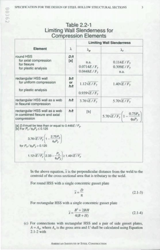
Table 2.2-1 Limiting Wall Slenderness for
Compression Elements ~
Element
round HSS
I A A~lml+a" Slende:~ess
1 fa1 n.a. for axial compression for flexure for plastic analysis
rectangular HSS wall for uniform compression
for plastic analysis
rectangular HSS wall as a web in flexural compression
rectangular HSS wall as a web in combined flexure and axial compression
0.0714£1 Fy 0.0448£1 Fy
-I-M or 1.12" £1 Fy hit
0.939V£1 Fy
hit 3.76"£1 Fy
hit [b]
(8j DJ! must be tess than or equal to O.448E / F" (b For Pu /toP,S 0.t25
6,fE / F ( 2.75Pu) 3.7 , t ---" . ..-, lor Pu /toP, > 0.125
1.12 E / F,(2.33 - Pu)~ 1.49,fE / F, toP,
....:...---
0.114£ 1 Fy 0.309£1 Fy
0 .3 .
1.40"£1 Fy
5.7oV£1 Fy
5.7 £1 Fy I _ 0.75Pu 'bPy
3
In the above equatIon, i is the perpendicular distance from the weld to the centroid of the cross-sectional area that is tributary to the weld.
For round HSS with a single concentric gusset plate
- D x=J[
For reclangular HSS with a single concentric gusset plate
_ B'+2BH
x 4(B+H)
(2.1-3)
(2. 1-4)
(c) For connections with rectangular HSS and a pair of side gusset plates, A = A" where A, is the gross area and U shall be calculated using Equation 2.1-2 with
AMERICAN INSTTTUJ'EOP STm... CON5nllCTlON
4 SPECIRCA nON FOR THE OESIGN OF STEEL HOu.oW STRUCTURAL SECTIONS
x 4(B+H)
where
L = length of the connection 10 the directoon of loadmg D = outside diameter of round HSS B = overall width of rectangular HSS H = overall heighl of reclangular HSS
(2.1-5)
Larger values of U are permilled to be used when justified by lesls or ralional criteria. For other end-connecllon configurations. U shall be delermined by tests or rational criteria.
2.2 LOCAL BUCKLING
I. Classification of Steel Sections
HSS are classified for local buckling of the wall in compression as compact, non-compact. or slender-element croSS-sectiOns accordmg to the limiting waJl slenderness rallOS A,. and A., 10 Table 2.2-1. For an HSS to quahfy as compacl, the wall slenderness raUo A must be less than or equal to A,.. If A exceeds A,. but is less than or equal to Ao Ihe HSS is non-compact. If A exceeds Ao the HSS is a slender-clement cross-section. The wall slenderness ratio shall be calculated as follows:
(a) For round HSS. A = DII. where D IS the outside diameter and I is the wall thlckne ... This Specificauon IS apphcable only to round HSS with A less than or equal to 0.448£11;. where £ is the modulus of elastiCity and F, is the minimum specified yield Mress.
(b) For nanges of reclangular HSS. A = bll, where b is Ihe clear dislance between webs less the inside comer radius at each web and I is the wall thickness. If the comer radiUS IS not known. b IS pemlllled 10 be taken as the overall nange width B mlOus three Urnes the wall thickness I.
(c) For webs of rectangular HSS, A = "II. where" IS the clear distance between flanges less the inside comer radius at each flange and I is Ihe walllhickness. If the comer radius is nol known, h is permllled 10 be laken as Ihe overall web depth H minus three limes the wallihickness I.
2. Design by Plastic Analysis
Design by plastic analysis IS permitted when A IS less than or equal 10 A,. for plaslic analysis as defined in Table 2.2-1.
3. Design in eismic Applications
In seismic apphcations, A shall also meetlhe requiremenls in Ihe AISC Seismic Provisions/or Slruclural Sleel Buildings (AISC. 1997).
23. LIMITING SLENDERNESS RATIOS
For compression members, the slenderness ralio Kllr preferably should nol exceed 200.
For tension members, the slenderness ralio Ilr preferably should not exceed 300.
SPECIFICATION FOR THE OESIGN OF STEEL HOLLOW STRUCTURAL SECTIONS 5
Members that are primanly tension members but that are subject to some compression under other load conditions need not satisfy the compression slenderness IIm1l.
For bracing members In seIsmic applications. IIr shall meet the requirements in AISC SeismIC Prol'isions!or Structural Steel Buildmgs.
3.1. DESIG FOR TENSION
The deSIgn strength of tension members $,P" shall be the lower value obtained according to the limit states of yielding in the gross section and fracture in the net section.
(a) For yielding on the gross area:
$,=0.9
I! = f;A,
(b) For rupture on the net effective area:
where
Ar = effective net area A, = gross area of HSS
$,=0.75
P,. ;;;: F.A ..
F, = specified minimum yield strength F,. = specified mjnimum tensile strength P" = nominal axial strength
4.1. EFFECTIVE LE GTH AND SLENDERNESS LIMITATIONS
I. Effective Length
(3.1-1)
(3.1-2)
The effective length factor K for compression members shall be taken as follows or as determined by rational analysis:
(a) In trusses that are made with HSS branch (web) members that are welded around their full penmeter to continuous HSS chord members, the effective length factor K used to modify the length between panel points for in-plane buck.IIng, or between locations of lateral bracing for out-of-plane budding, shall be not less than :
K = 0.75 for branch members K = 0.9 for chord members
(b) In trusses that are made with HSS branch members that do not meet the requirements in Section 4.1.1 (a) or with non-HSS branch members connected to continuous HSS chord members. the effective length factor K used to modIfy the length between panel points for in-plane buck.ling shall be not less than:
K = 1.0 for branch members K = 0.9 for chord members
AMERICAN lNSlTTUTE OF STEEl.. CONSTRUC1l0N
6 SPECIFICATION FOR THE DESIGN OF STEEL HOLLOW STRUCTURAL SECTIONS
(c) In frames for which lateral stabilily is provided by diagonal bracing, shear walls or equivalent means, K shall be taken as unily, unless a lesser value can be justified by rational analysis.
(d) In frames for which lateral stabilily is dependanl upon the flexural sliffness of ngidly connecled beams and columns, K shall be detennined by rational analysis.
2. Design by Plastic Analysis
Design by plastic analysis is permitted if the column slenderness parameter A,. is less than or equallo I .SK and the axial force in columns of unbraced frames due 10 factored gravity loads plus faclored laleral loads does nOI exceed <1>, times 0.75F,A, .
4.2. DESIGN FOR COMPRESSION
The design strength for flexural buckling of compresSIon members <l>J': shall be delennined as follows :
<1>, = 0.85 P,. :;:: Fer A,
F" shall be detennined as follows:
(a) For]..,..JQ S 1.5
- Q~ F" - Q(0.658 )F,
(b) For A,..JQ > 1.5
F.. = [0.877] F.. t', A; .,
where
Q shall be determined as follows :
(a) For A S A, in Section 2.2, Q = I (b) For A > A,. in Section 2.2, for round HSS with A < 0.448E/~
Q 0.0379E +l F,(D/I) 3
For rectangular HSS.
effecti ve area Q A,
(4.2-1)
(4.2-2)
(4.2-3)
(4.2-4)
(4.2-5)
(4.2-6)
where the effective area is equal to the summation of the effective areas of the sides using
AMElucAf'i INS1TTUTE OF STEFl. CONSTRUC11ON
SPECIFI ATION FOR THE DESIGN OF STEEL HOLLOW STRUCTURAL SECTIONS 7
b = 191 - ~[1 _0.38 1_ ~] S.b , . I ''V7 (bll) '17
with f = P. IA,.
5.1. DESIGN FOR FLEXURE
The design flexural strength ¢I"M, shall be delermined as follows:
¢I. = 0.9
<a) For round HSS, for A ~ A" in Seclion 2.2,
M.=Mp=F,Z
for A,. d. s. A,
M =(0.0207 K. I)F.S , DII F. + ,
for A,. < A S. 0.448£ IF,
M =0.330£ S , DII
(b) For rectangular HSS, for A ~ A,. in Section 2.2,
M.=Mp=F.Z
for A,. < A s. A,
where
M,=F,S
for A> A,.
M, = F,S<f{
(4.2·7)
(5.1-1 )
(5.1-2)
(5.1-3)
(5.14)
(5.1-5)
(5.1-6)
where S., IS the effective section modulus with the effeclive width of the compression flange taken as
b,=1.911- fE[I _O.38 1 - fE] S.b (5.1-7) 'I F. (bll) 'I F; L, is not limited for HSS strUctures designed by elastic analysis. Design by plastic analysis is pcnniued for compact round HSS wilh A less than or equal 10 0.0448£11; and for reclangular HSS with A less than or equal 10 A" in Section 2.2. For reclangular HSS bent aboul the major axis,lhe lalerally unbraced length 4 of Ihe compression flange adjacenl lo plastic hinge local ions thai are associaled wilh the failure mechanism shall nOI exceed L,.. where
AMERICAN lNSTTTUTE OF STEa. CO/'olSTllUCTlON
8 SPECIRCATION FOR THE DESIGN OF STEEL HOLLOW STRUCTURAL SECTIONS
5,000 + 3,OOO(M, 1M, ) 3,OOOr. F, r, ~ Jr"
and
F., = specified mjOlmum yield stress M, = smaller momenl at the end of the un braced length M, = larger moment at the end of the un braced length r, = radius of gyration about the minor axis
(5.1-8)
M\IM2 is positive when moments cause reverse curvature and negative for single curvature
For seismic applications, refer to A15C Seismic Provisions for Strllctural Steel Blli/dings (AI5C, 1997).
5.2. DESIGN FOR SHEAR
The design shear strength of unstiffened H55 41. V, shall be detemuned as follows:
(a) For round H55 with
41. = 0.9
a 3.2(£1 F,)' -$ D (Dltt'
and A. $ A.,. in Table 2.2-1,
V, = 0.3F,A,
(b) For rectangular H55,
V" = F"A ....
where
A.= 2Ht
F. shall be detemUned as follows :
(i) For hitS 2.45-4£ I F,
F.= 0.6F,
(ii) For 2.45-4£ I F, < hit $ 3.07-4£ IF,
F. = 0.6F, (2.45-4£ IF,) I (h I t)
(iii) For 3.07-4£ I F; < hit $ 260
F. = 0.458lt'£ I (h It)'
6. DESIGN FOR TORSIO
The des'gn torsional strength q,TT, shall be detemUned as follows :
AMllUCAN lNSTmII'E OF STEfl. CONSTRUCTION
(5 .2- 1)
(5.2-2)
(5.2-3)
(5.2-4)
(5.2-5)
(5.2-6)
(5.2-7)
SPECIFICATION FOR THE DESIGN OF STEEL HOLLOW STRUCTURAL SECTIONS 9
$T=0.9
T. =F;,C
where C IS the HSS tOrsIonal constant
F;, shall be dctennined as follows:
(a) For round HSS. F;, shall be the larger of
1.23£ d 0.6£ LI D (DII)'" an (DII)JIl
bUI shall nOI exceed 0.61';.
(b) For rectangular HSS. for II I I 5 2.45~£ I I';
Fa = 0.61';
for 2.45~£ I I'; < h I I 5 3.07~£ IF,
F" =0.6F,(2.45~£1F, )/(1111)
for3.07 £IF, <h11526O
F" = 0.4581<'£ I (h I I)'
7.1. DESIGN FOR COMBINED FLEXURE AND AXJAL FORCE
(6- 1)
(6-2)
(6-3)
(6-4)
(6-5)
The inlcmclion of flexure and axial force shall be limiled by Equalions 7.1-1 and 7.1-2.
(a) For P. I $P.. ~ 0.2
~+~( M.x + M" )5 1.0 $P. 9 $oM~ $oM"
(b) For P. I $P' < 0.2
--+ --+-- 5 . P. ( M.x M") I 0 2$P. $oMu $oM ..
where
p" = required axial tensile or compressive strength
(7.1-1)
(7.1-2)
P,. = nominal tensile or compressive strength determined in accordance with Seclions 3.1 or 4.2
M. = required flexural strength detennined in accordance with LRFD Speci-ficallon Section C 1
M,. = nominal flexural strength detennined in accordance with Section 5.1 x = subscript relating symbol to strong axis bending y = subscript relating symbol to weak axis bending $ = $, from Section 3.1 for lens ion
= 0.85 for compression $. = 0.90
AMF..RICAN LNsrrn.rre OF STEEL CONSTROCllON
10 SPECIFICATION FOR TIlE DESIGN OF STEEL HOLLOW STRUCfURAL SECTIONS
For biaxial nexure of round HSS that are laterally unbraced along their length and with end conditions such that the effective length factor K is the same for any direction of bending, the design is permitted to be based upon a single resultant moment M.,.. where:
(7.1-3)
Alternatively, use of the provisions in LRFD Specification Appendix H.3b is permitted.
7.2. DESIGN FOR COMBINED TORSION, SHEAR, FLEXURE, AND/OR AXIAL FORCE
When the required torsional strength IS significant, the interaction of torsion, shear, nexure, andlor axial force shall be limited by Equation 7.2-1 .
(7.2-1)
In the above equation,
p. = required axial tensile or compressive strength p.. = nominal tensile or compressive strength detemuned tn accordance with
Sections 3. I or 4.2 M. = required nexural strength determined in accordance with LRFD Speci-
fication Section C I M, = lesser of F, Sand M, determined in accordance with Section 5. I S = elastic section modulus V. = required shear strength at the section corresponding to M. V" = nominal shear slrength dClcnnined in accordance with Section 5.2 7;. = required torsional strength 7; = nominal torsional strength determined in accordance with Section 6
, = " from Section 3. I for tension = 0.85 for compression
" =" =,,= 0.90
8. CONCENTRATED FORCES 0 HSS
The design strength ,R, at locations of concentrated forces on unstiffened HSS shall be determined from the applicable criteria in Sections 8. I through 8.3.
8.1. Concentrated Force Distributed Transversely
When a concentrated force is distributed transversely to the axis of the HSS, the design strength ,R, shall be determined as follows:
(a) For round H5S,
,= 1.0
R _ 5F,r , - I - 0.8Ib
IID Qf (8.1-1)
AMfR..lCAN IJIIS'TTT1J1"E Of Sna CONSllUX"nON
'" , )
~,
0" 0',
SPEClFICATION FOR THE DESIGN OF STEEL HOLLOW STRUCfURAL SECfIONS II
where
b, = Ihe widlh of the load Q, = I for lension in the HSS
= I - 0.3J1I; - 0.3iflF,)'" I for compression in Ihe HSS f = the magnitude of the maximum compression stress in the HSS due to
axial force and bending at the location of the concentrated force
(b) For rectangular HSS,
4j> = 1.0
101';/ R. = (811) b l " 1';1 Ilbl
where
b l = the width of the loaded plate I I = the thickness of the loaded plate 1';1 = minimum specified yield strength of the loaded plate
(8.1-2)
When the force is distributed across the full width of the rectangular HSS, the limit state of local web yielding shall be checked for both tensile and compressive forces and the limit state of web crippling shall be checked for compressive forces. For local web yielding,
4j> = 1.0
R. = 21';1(5k + N) (8. I -3)
For web crippling,
4j> = 0.75
R. = 1.6t'[1 + 3NIh]VEF, (8.1-4)
where
k = outside comer radius of the HSS, which if not known is pemlitted to be taken as 1.51
N = bearing length of the load along the length of the HSS II = nat width of side wall of the HSS as defined in Section 2.2. I
When the force is distributed across a width of the rectangular HSS that is greater than 0.858 but less than 8 - 21, the design strength shall not exceed 4j>R., where
4j> = 1.0
R. = 0.61'; 1(211 + 2b,,)
where b" = I Ob, 1(81 t) " b,
(8. I -5)
When compressive forces coincide on opposite faces of the reclangular HSS, the limit state of compression buckling of the webs shall be checked and the design st rength shall not exceed 4j>R., where
AMERICAN I NSTIT\ITE OF STEEL CONSTRUC110N
12 SPECIRCATION FOR THE DESIGN OF STEEL HOLLOW STRUCTURAL SECTIONS
R.
$ = 0.90
48rlEif h
8.2. Concentrated Force Distributed Longitudinally at the Center of the HSS Face
(8.1-6)
When a concentrated force is distributed longitudinally along the axis of the HSS at the center of the HSS face, the design strength $R. shall be detemlined as follows :
(a) For round HSS ,
$ = 1.0
R. = 5F, 1'( I + 0.25N 1 D)Q,
where
N = bearing length of the load along the length of the HSS Qj= I for tension in the HSS
= I - 0.3f1F, - 0.3([1F,)'" I for compression in the HSS
(8.2-1 )
f = the magnitude of the maximum compression stress in the HSS due to axial force and bending at the location of the concentrated force
(b) For rectangular HSS,
$= 1.0
R. F,r [2N +4,f 1 -1\I BlQ, I - I, 1 B B J
where 1\ is the thickness of the loaded plate.
8.3. Concentrated Axial Force on the End of a Rectangular HSS with a Cap Plate
(8.2-2)
When a concentrated force acts on the end of an HSS with a cap plate and along the axis of the HSS, the design strength $R. ; hall be determlDed for each loaded wall a follows. The limit state of local wall yielding shall be checked for both tensile and compressive forces and the limit state of wall crippling shall be checked for compressive forces. For local wall yieldi ng,
$= 1.0
R. = (51\ + NlF,I" BF,I (8.3-1)
For wall crippling,
$ = 0.75
(8.3-2)
where
AMERICAN INS11T\1TEOf SlnL CO~STRurnON
SPECIFICATION FOR TIlE DESIGN OF STEEL HOLLOW STRUcruRAL SECTIONS 13
I, = thicleness of cap plate N = beanng length of the load across the width of the HSS
9.1. GE ERAL PROVISIO S FOR CONNECfIONS A 0 FASTENERS
The provisIons of LRFD SpecIfication Section J 1.1 through J 1.11 and the provIsions for bolls and threaded pans in LRFD SpecificatIon Section J3.1 through J3 .11 shall apply with the following additions and modifications.
1. Through Bolts
When connections are made using bolls that pass completely through an unstiffened HSS, the bolts shall be installed to only the snug-tight condition and the connection shall be considered to be a shear bearing connection. The bearing strength per loaded wall is (jlR., where
e:> = 0.75
R. = 1.8F, dl
where
F. = minimum specifIed yield strength of the HSS d = boll diameter I = HSS wall thicleness
2. pecial Connectors
(9. 1-1)
The design strength of special connector.; other than the bolts considered in LRFD SpecIfication Table J3.2 shall be verified by tests.
3. Tension Connectors
When bolts or other connectors in tension are attached to an HSS wall, the strength of the HSS wall shall be determined by rational analysis.
9.2 WELDS
The non-unIformity of load transfer along the line of weld due to differences in relallve neXlb,lity of HSS walls In HSS-to-H S and similar connections shall be considered in proportioning such connections. In such cases, the strength of fillet welds hall be determined from LRFD Specificaton Section 12.4, exclud· ing the allernative in Appendix J2.4, and the effective weld length 4 of groove and fillet welds shall be hmited as follows:
(aJ In T·, Yo. and Cross-connections with rectangular HSS as defined in Section 9.4,
4 = 2H, + B. for a S 50 degrees
4 = 2H, for a ~ 60 degrees
(9.2-1 )
(9.2-2)
Linear interpolation shall be used to deterntine L, for values of a between 50 and 60 degrees.
(bJ In gapped K-connections with rectangular HSS as defined in Section 9.4,
L, = 2H' + 28, for a S 50 degrees (9.2-3)
AMERICAN lNsrmrrE Of STEEL CONSllUJC1lON
14 SPECIRCATION FOR THE DESIG OF STEEL HOLLOW STRUcnJRAL SECTIONS
L, = 2H. + 8. for a ~ 60 degrees (9.2-4)
Linear interpolallon shall be used to detennme L, for values of a between 50 and 60 degrees.
(e) When a transverse plate is welded to the face of an HSS member,
where
L,=2~ F"I b, S2b, 8/1 F",I,
(9.2-5)
H. = width of branch member wall that is parallel to the axis of the chord member, in.
8. = width of branch member wall that is transverse to the axis of the chord member. in.
a = leasl angle between branch member and chord member 8 = width of chord member wall to which plate is attached, in. b, = width of attached plate, in.
= thickness of chord member wall, in. I, = thleknes of attached plate, in. F" = yield strength of HSS, ksi F., = yield strength of plate, ksi
In lieu of the above, other rational critena are penOlued.
9.3. OTHER CONNECTION REQUIREMENTS
The provisions of LRFD Specification Sections J4 through J 10 shall apply with the following additions and modifications.
/. Shear Rupture Strength
The design shear rupture strength along a path adjacent to a fillet weld on the HSS wall shall be taken as ~R .. where
where
I = HSS wall thickness L = length of weld
2. Tension Rupture Strength
~ = 0.75
R, = 0.6F,IL (9.3-1)
The design tension rupture strength along a path adjacent 10 a fillet weld on the HSS wall shall be laken as ~R" where
q, = 0.75
R, = F.IL (9.3-2)
where
I = HSS wall thIckness
SPECIFICATION FOR THE DESIGN OF STEEL HOLLOW STRUCTURAL SECTIONS 15
3.
L= length of weld
Punching Shear Rupture Strength
When a plate that is parallel to the longitudinal axis of an HSS and projects from the wall is subjected to a load that is parallel but eccentric or has a component perpendIcular to the HSS Wall,
where
$, = 0.75
$, = 0.90 f = maximum stress in the plale perpendicular to the HSS wall I, = plate thickness F. = HSS tensile strength 1 = HSS wall thickness
(9.3·3)
4. Eccentric Connections
For trusses that are made with HSS that are connected by welding branch members to chord members, eccentricities within the limits of applicability in Section 9.4 are pemlitted without consideration of the resulting moments for the deSIgn of the connection, except in faugue applications. In fatigue applications, refer to AWS DI .I.
9,4. HSS·TO·HSS TRUSS CONNECTIONS
HSS·to-HSS truss connections are defined as connections that consist of one or more branch members that are directly welded to a continuous chord that passes through the connection and shall be classified as follows :
(I) When the punching load in a branch member is equilibrated by beam shear in the chord member, the connection shall be classified as aT-connection when the branch is perpendicular to the chord and a Y·connection otherwise.
(2) When the punching load in a branch member is essentially equilibrated by loads to other branch member(s) on the sanne side of the jOtOt, the connection shall be classified as a K·connection.
(3) When the punching load is transmitted through the chord member and is equilibrated by branch member(s) on the opposite side, the connection shall be classified as a Cross-connection.
When branch members transmit part of their load as K·connections and part of their load as T·, Y" or Cross·connections, the design strength shall be determined by interpolation on the proportion of each in total .
For the purposes of this SpeCIfication, the centerlines of the branch member(s) and the chord members shall lie in a single plane and K·connections shall be used in the gapped configuration. For other configurations such as a multi-planar connection, a conneelion with a branch member that is offset so that its centerline does not intersect with the centerline of the chord, or when an overlapped K-connection is used. the provisions of AWS DI.I, other verified design procedures, tests, or rauonal analysis shall be used.
AMEJUCAN lNsTnurE Of STEEl CONSTROC"IlON
16 SPECIFICATION FOR THE DESIGN OF STEEL HOLLOW STRUCTURAL SECTIONS
l. Definitions of Parameters ~ = the width ratio; the ratio of branch diameler to chord diameter = D.ID
for round HSS; the ratio of overall branch width to chord width = B.IB for rectangular HSS.
y = the chord slenderness ratio: the ratio of one-half the diameter to the wall thickness = D 121 for round HSS; the ratio of one-half the width to wall thickness = B 1 21 for rectangular HSS.
11 = the load length parameter, applicable only to rectangular HSS; the ratio of the length of contact of the branch with the chord in the plane of the connection to the chord width = NIB, where N = H. 1 sine and e is the angle between the branch and chord.
~ = the gap ratio; the ratio of the gap between the branches of a gapped K-connection to the width of the chord; = g 1 D for round HSS; = g 1 B for rectangular HSS.
2, Criteria for Round HSS
The design strength of the branch $P. and/or q,M, for axial loads in the branch and for flexure in the branch, respectively, shall be determined from the lintit states of chord wall plastification, punching shear rupture and general coUapse as applicable below.
The interaction of stress due to chord member forces and local branch connection forces shall be considered. The chord-stress interaction parameter Q, shall be determined as
Q,= 1.0 -l..yO'
where U is the utilization ratio given by
0' - (....!'...-J' + (M. J' - A,F, SF,
and
I.. = 0.030 for axial load in the branch
= 0.044 for in-plane bending in the branch = 0.018 for out-of-plane bending in the branch
P. = required axial strength in chord A, = chord gross area F, = chord yield stress M. = larger required flexural strength in chord and connection S = chord elastic section modulus
2a, Limits of Applicability
(9.4-1)
(9.4-2)
The criteria herein are applicable only when the connection configuration is within the following lintits of applicability:
I) joint eccentricity: -{).55D S e S 0.25D, where D is the chord diameter and e is positive away from the branches
2) branch angle: e., 30' 3) wall stiffness: ratio of diameter to wall thickness less than or equal to 50 for
AMERICAN lNS111VTE OF STEFl.. CONSllUJCn ON
SPEClFICATION FOR THE DESIGN OF STEEL HOlLOW STRUcruRAL SECTIONS 17
chords and branches m T-, Y- and K-connecllOns and less Ihan or equal 10 40 for chords of Cross-connecllons
4) width rallo: 0.2 < D.I D S 1.0 5) gap: g greater Ihan or equal to the sum of the bronch wall thicknesses
2b. Branches with Axial Loads
ForT-, Y-, and gapped K-conneclions, lhe design strength oflhe bronch q,P, shall be delermlOed from Ihe hmil stales of chord wall plasllticalJOn and punching shear ruplure. For Cross-connecllons, the design strength of Ihe branch q,P, shall be delenruned from the Ii mil sImes of chord wall plasllticallon, punching shear ruplure and general collapse.
I. For Ihe hmil Slale of chord wall plasliticalion,
q, = 0.8
p"sina = t'F, [61113Q,JQ,
where
0.3 For ~ S 0.6. Q. = 1.0
For ~ > 0.6, Q, Jl(l - 0.833~ )
a = cbord ovalilallon parameler = 1.7 for T- and Y-conneclions = 1.0 + 0.7g I Do. 1 S (Y. < 1.7 for gapped K-connecuons = 2.4 for Cross-conneclions
2. For Ihe hnul Slale of punching shear ruplure,
q, = 0.95
P, sma = lID"I(0.6F,)
3. For the hmn Slale of general collapse,
q, = 0.8
p,sma = t'F,( 1.9 + 7.2~)Q"Qf
2c. Branches with F1exu~
(9.4-3)
(9.4-4)
(9.4-5)
ForT-, Y-, gapped K-. and Cross-connecllons,lhe design strenglh of the branch q,M. shall be delemllned from the limn states of chord wall plastitication and punching shear rupture.
I. For the limit state of chord wall plastiticalion,
q, = 0.8
M"sma = t'F, [D. I 41 [611~Q.JQf (9.4-6)
where
18 SPEClJ-1CATION FOR THE DESIGN OF STEEL HOLLOW STRUCTURAL SECTIONS
Q. = (2~1 + 0p6) QI Ua - 061)
For ~ :!> 0.6, Q~ = 1.0
For ~ > 0.6, Q~ ~(I _ ~3833~) a = chord ovalization parameter
= 0.67 for in-plane bending = 1.5 for out-of-plane bending
For combinations of in-plane and out-of-plane bending, a shall be determined by interpolation and Q,shall be detennined with interpolated values of A..
2. For the lirrut state of punching shear rupture,
,= 0.95
M.,sin9 = Di,1(0.6F,) (9.4-7)
2d. Branches with Comhined Axial Loads a nd Flexure
The interaction of combined axial loads and nexure in HSS-to-HSS truss connections shall meet the following requirement:
where
p. = required axial strenglh of the branch M. = required nexural strength of the branch
3. Criteria For Rectangular HSS
(9.4-8)
The design axial strength ,p. and the design nexural strength ,M, of the branch shall be detennined from the limit states of chord wall plastification. punching shear rupture, sidewall strength, and uneven load rustnbution as applicable below.
The interaction of stress due 10 chord member forces and local branch connection forces shall be considered With the chord-stress interaction parameter Q,. where
Q, = I when the chord is in teoslon
= 1.3 - O.4U / ~:!> I when the chord is in compression
U_I~I+IM'I - A,F, SF,
where
p. = required axial strength of the chord M. = required nexural strength of the chord
AMERICAN iNSTmTTE OF STEEL CONSTRUCTJON'
(9.4-9)
(9.4-10)
W J
SPEClACATION FOR THE DESIG~ OF STEEL HOLLOW STRUcruRAL SECTIONS 19
3a. Limits of Applicabilily
The crilena herein are applicable only when the conneclion configuration i within the follOWing limits:
I) JOIOI eccentriCIty: -1J.55H ~ ~ ~ 0.25H, where H IS Ihe chord depth and ~ is positive away from the branches
2) branch angle: e ~ 30' 3) wall stlfTnes : ratio of wall WIdth 10 wall thIckness less Ihan or equal 10 35
for chords and branches; also less than or equal 10 1.25 E 1 I\-" forbranches incompression
4) Slrenglh:F, less Ihan or equal 10 52 ksi for chord and branches 5) chord aspecl ratio: 0.5 S ralio of deplh 10 widlh ~ 2.0
6) ductility: 1\ 1 F. S 0 .8 7) other hmlts apply for specific cnleria
3b. Branches wilh Axial Loads in T., Y- a nd Cross-connections
ForT·, Yo. and Cross-connections, the design strenglh ofthe branch 'P. shall be delerrruned from Ihe lirrul slales of chord wall plaslificatlon, punching shear rupture, SIdewall strength, and uneven load d,stnbutlon.
I. For Ibe Iorrul stale of chord wall plasti ficatlon ,
,= 1.0
p,.sinO = I\r[ 2"., + ~ 4 ~ ] Q, 1-" (1-)
(9.4-11)
This linlll slale need nOI be checked when ~ > 0.85 nor when ~ < 0.25.
2. For Ihe hrrul Siale of punching shear ruplure,
,= 0.95
p,. sma = 0.61\ IBD\2'1 + 2~ ... J (9.4-12)
In the above equalion, Ihe effeclive outside punchIOg parameler ~ ... = 5~/'I shall nOI exceed ~. ThIS I1mil slate need n01 be checked when
~ > 1- I 1'1 nor when ~ < 0.85.
3. For the Iomll stale of sidewall strenglh, the deSIgn strength for branches in lension shall be laken as Ihe design strength for local SIdewall yielding. For Ihe Iirrul slale of sidewall strength, the deSIgn slrength for branches 10
compression shall be laken as the lesser of Ihe deSIgn slrengths for local sidewall yielding and sidewall crippling. This limil Slale need nol be checked unless the chord member and branch member have Ihe same widlh (~= 1.0).
For the hnlll Slale of local yielding,
, = 1.0 for a branch in lension = 0.8 for a branch in compression
p,. sinO = 211\ (5k + N) (9.4- 13)
AMEaICAH lNsmurE OF STEEL CONSTRUCllON
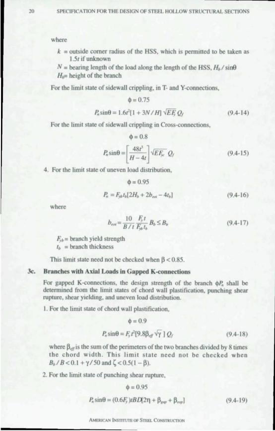
20 SPECIFICATION FOR THE DESIGN OF STEEL HOLLOW STRUcruRAL SECTIONS
where
k = outside comer radius of the HSS, which is pemlJlled 10 be laken as 1.51 if unknown
N = beanng lenglh of the load along the length of the HSS, H, I sine Ho= height of the branch
For the limil stale of sidewall crippling, in T- and V-connections,
~= 0.75
P., sinO = 1.61'[ I + 3N I HI m Qf
For the limit state of sidewall crippling in Cross-connections,
~= 0.8
p., sinO =[ 481' ] .JEF,.- Qf H - 41
4. For the limit state of uneven load distribution,
cjI = 0.95
P., = F,.I.[2H, + 2b_ - 41,1
where
1(. = branch yield strength I. = branch thickness
This limit state need not be checked when P < 0.85.
3<:. Branches with Axial Loads in Gapped K-connections
(9.4- 14)
(9.4-15)
(9.4-16)
(9.4-17)
For gapped K-connections. Ihe design strength of the branch <l>P., shall be delemuned from the hmil states of chord wall plasoficallon, punchmg shear ruplure, shear yielding, and uneven load distribution.
I. For Ihe limit state of chord wall plasllfication,
<1>= 0.9
p.,sinO = F, t'[9.8p" Vy 1 Qf (9.4- 18)
where P<f1is the sum of the perimeters of the two branches divided by 8 times Ihe chord widlh. Thi s limit late need not be checked when B,I B <0. 1 +'1'150 and ~ <0.5(1 - Pl.
2. For the limit state of punching shear rupture,
cjI = 0.95
/!sinO = (0.61( )IB~211 + P .... + P ... 1 (9.4- 19)
AMERICAN iNS1lT1.1T'E OF STUL CONSTRUC11ON
-
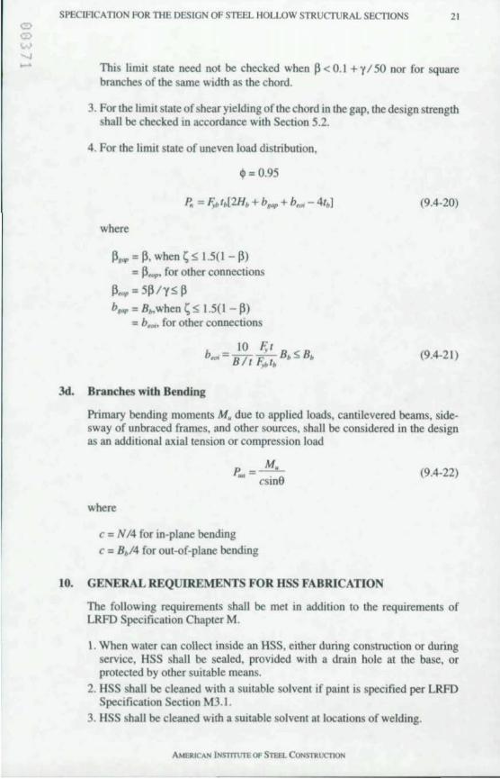
SPECIFICATION FOR THE DESIGN OF STEEL HOLLOW STRUCTURAL SECTIONS 21
This limil siale need not be checked when P < 0.1 + 'Y 1 50 nor for square branches of the same width as the chord.
3. Forthe limit state of shear yielding of the chord in the gap. the design strength shall be checked in accordance with Section 5.2.
4. For the limil state of uneven load distribution.
q, = 0.95
P, = F ... I, [2H, + b,,,,, + b~ - 41,1 (9.4-20)
where
P,,,, = P. when ~ ~ \.5(1 - P) = ~HIp' for other connections
p"", = 5P/'Y~ P b"", = B,.when ~ ~ \.5(1 - P)
= bf'Oj' for other connections
(9.4-21)
3d. Branches with Bending
Primary bending moments M, due to applied loads. cantilevered beams. sidesway of unbraced frames. and other sources. shall be considered in the design as an additional axial tension or compression load
p. =~ IMl csine
(9.4-22)
where
c = N 14 for in-plane bending
c = B,/4 for out-of-plane bending
10. GENERAL REQUIREMENTS FOR HSS FABRICATION
The following requirements shall be met in addition to the requirements of LRFD Specification Chapter M.
I . When water can collect inside an HSS. either during construction or during service. HSS shall be sealed. provided with a drain hole at the base. or protected by other suitable means.
2. HSS shall be cleaned with a suitable solvent if paint is specified per LRFD Specification Section M3.\.
3. HSS shall be cleaned with a suitable solvent at locations of welding.
AMERICAN iNSlTTUTE OF STEEL CONSTRlICnON
22 SPECIFICATION FOR THE DESIGN OF STEEL HOLLOW STRUCTURAL SECTIONS
AMERICAN INS'11Tl1rE Of STEEL CONSTRUC'1l0N
SPECIFICATION FOR THE DESIGN OF STEEL HOLLOW STRUCTURAL SECTIONS 23
Commentary April 15. 1997
1.1. SCOPE
For the purposes of this Specification, HSS are defined as hollow structural sect.ions with constant wall thickness and a round, square or rectangular cross~ section that is constant along the length of the member. HSS are manufactured by forming skelp (strip or plate) to the desired shape and joining the edges with a continuously welded seam. Although the teml pipe is commonly associated with round members that are used for fluid transmission, only steel pipe products that are used for structural purposes are included in the HSS definition. Published information is available describing the details of the various methods used to manufacture HSS (STI, 1996; Graham, 1965).
Because the design requirements for pressure containment systems are more stringent than those for structural members, this Specification does not apply to members for which pressure cont.ainment is essential. Several other potential applications are also excluded from the scope of this Specification: (I) buried cylindrical shapes for which soi l interact jon is an important factor in the required strength; (2) stiffened HSS; (3) composite HSS; and, (4) HSS in fatigue applications. However, it is not intended that HSS with connection elements that also stiffen the cross-section be excluded from the scope.
Non-HSS products such as fabricated pipes and stiffened shells are excluded from the scope of this Specification. These are defined as members that are formed by shaping plates and joining them with one or more longitudinal seam welds, but neither in a tubing mill nor in accordance with a product specification. Although it is certainly possible to fabricate large pipes and shells to the same degree of perfection as is commonly obtained with manufactured HSS, such quality is not universally assured by standard product specifications. Because the buckling strength of cylindrical sections is greatly influenced by geometric imperfections. there is good justification for excluding such products from the scope of this Specification. Accordingly, it is left to the Structural Engineer of Record to detennine the suitability of such products for use with this Specification.
HSS are efficient structural members for the resistance of compressive and torsional forces. Consequently, they are increasingly selected in structural
AMERICAN INsm"UTE OF STEEL CONSTRUC1l0N
24 SPECIFICATION FOR THE DESIGN OF STEEL HOLLOW STRUcruRAL SECTIONS
applications such as columns and members in plane trusses or space frames. HSS generally have a lower ratio of exposed surface area 10 volume when compared with other shapes, which results in reduced painllng, fireproofing, and mamtenance expense. AddItionally, the" low re I lance 10 external Ouid Oow proVIdes a d,stinct advantage for frameworks that are exposed to wind or water currents. The use of HSS has been Iiffilted m the past by difficulty in joming members, but modem fabncating technology has overcome this disadvantage.
ThIs SpeCIfication combines design guidehnes from several sources. The pnmary basis for the recommendations is the design philosophy and cntena contained in the LRFD Specification. Because much of the LRFD Specification reOects the behavior of wide Oange members, modifications have been made where HSS have been shown to behave differently or when interpretation of LRFD cntena to HSS applications can be c1anfied or simplified. Such modifications are explained in this Commentary. The cntena have also been modified to appear in a non-dimensional form. Following is a general cross-reference from Sections in this Specificauon to the relevant Sections and related AppendIces in the LRFD Specification.
J.J 1.2
J.3 2.1 2.2
2.3 3.1 4 . 1 4.2 5.1 5.2 6. 7.1 7.2 8. 9.1 9.2 9.3
9.4 10.
Scope Matenal I. Structural Steel 2. Design Wall Thtckness Loads and Load Combinations EffectIve Net Area for Tension Members Local Buckling I. Classification of Steel Sections 2. Design by Plastic Analysis 3. Design in Seismic Applications Limiting Slenderness Ratios DesIgn for Tension Effective Length and Slenderness Limitations Design for Compre sion Design for Flexure Design for Shear Design for Torsion Design for Combined Flexure and Axial Force Design for Combined Torsion, Shear, Flexure, andlor Axial Force Concentrated Forces on HSS General ProviSIons for Connections and Fasteners Welds Other Connection Requirements I. Shear Rupture Strength 2. Tension Rupture Strength 3. Punching Shear Rupture Strength 4. Eccentnc Connections HSS-to-HSS Truss Connections General Requirements for HSS Fabncation
AI
A3.1
A4 B3
B5.! B5.2
B7 01 EI E2 FI F2
HI H2 KI
JI,B 12
14.1 14.2
15.1
M
In areas where the LRFD Specification contains lottie d,rect guidance for the
AMERICAN lNSTTT\1TE OF STf.EL CONSTRl.ICT1ON
SPEClFICA TION FOR THE DESIGN OF STEEL HOLLOW STRUcruRAL SECTIONS 25
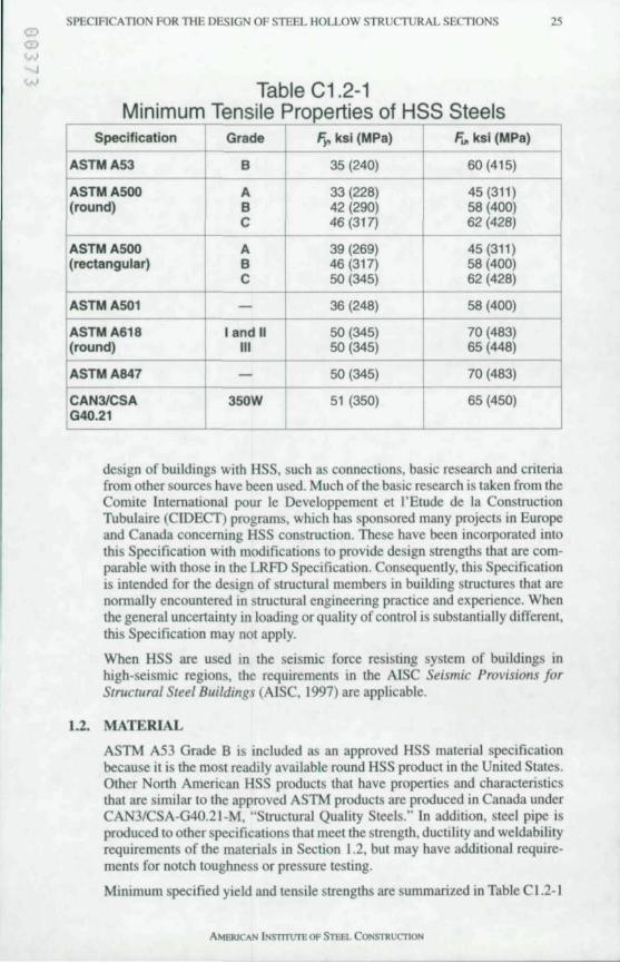
Table C1.2-1 Minimum Tensile Properties of HSS Steels
Specification Grade F" ksi (MPa) F .. ksl (MPa)
ASTMA53 B 35 (240) 60(415)
ASTM A500 A 33 (228) 45(311) l(rOUnd) B 42 (290) 58 (400)
C 46 (317) 62 (428)
ASTMA500 A 39 (269) 45(311) (rectangular) B 46 (317) 58 (400)
C 50 (345) 62 (428)
ASTMA501 - 36 (248) 58 (400)
ASTM A618 I and II 50 (345) 70 (483) (round) III 50 (345) 65 (448)
-ASTMA847 - 50 (345) 70 (483)
CAN3ICSA 350W 51 (350) 65 (450) IG40.21
-
design of buildings wilh HSS. such as conneclions, basic research and crileria from other sources have been used. Much of the basic research is taken from the Comile International pour Ie Oeveloppemenl et I'Etude de la Consuuction Tubulaire (CfOECl) programs, which has sponsored many projects in Europe and Canada concerning HSS construction. These have been incorporated into this Specification with modifications to provide design strengths that are com· parable with those in the LRFD Specification. Consequently, this Specification is intended for the design of structural members in building structures that are normally encountered in structural engineering practice and experience. When the general uncenainty in loading or quality of control is substantially different, this Specification may not apply.
When HSS are used in the seismic force resisting system of bui ldings in high-seismic regions, the requirements in the AISC Seismic Provisions for Structural Steel Buildings (AISC, 1997) are applicable.
1.2. MATERIAL
ASTM A53 Grade B is included as an approved HSS material specification because it is the mOSt readily available round HSS product in the United States. Other Nonh American HSS products that have propenies and characteristics that are similar to the approved ASTM products are produced in Canada under CAN3/CSA-G40.21-M, "Suuctural Quality Steels." In addition, steel pipe is produced to other specifications that meet the strength, ducti lity and weldability requirements of the materials in Section 1.2, but may have additional requirements for notch toughness or pressure testing.
Minimum specified yield and tensi le strengths are summarized in Table C 1.2-1
AMERJCAN INSTITUTE OF STEEL CONSTRucnON
26 SPECIFICATION FOR THE DESIGN OF STEEL HOLLOW STRUCTURAL SEcrlONS
•• • .0
L>
LO
... u ,: ... • • " • ••• • ! u
• • 5
for various HSS malerial specifications and grades. Round HSS can be readily obtained in mosl of the material specifications and grades in Table CI.2-1, although atmospheric-corrosion-resistant material (ASTM A618 and A847) may require a special order. For rectangular HSS, ASTM A500 Grade B is the most commonly available material and a special order would be required for any other material. Depending upon size, either welded or seamless round HSS can be obtained. In North America, however, all ASTM A500 rectangular HSS for structural purposes are welded. Rectangular HSS differ from box sections in that they have uniform thickness except for some thickening in the rounded comers.
Even though ASTM A501 includes rectangular HSS, hot-formed rectangular HSS are not currently produced in the United States. CAN3/CSA G40.21 includes hot-formed Class Hand cold-fonned Class C. However, Class H rectangular HSS are produced by hot-finishing HSS that were manufactured by cold-forming. Hot-formed HSS have relatively low levels of residual tress, which enhances their perfonnance in compression and may provide better ductilily in the comers of rectangular HSS.
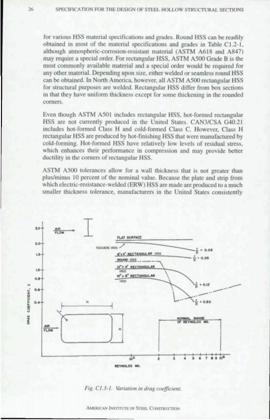
ASTM A500 tolerances allow for a wall thickness that is not greater than plus/minus 10 percent of the nominal value. Because the plate and strip from which eleclric-resistance-welded (ERW) HSS are made are produced to a much smaller thickness tolerance, manufacturers in the Umted Stales consistently
AI!! 'LOW I
H
T .... .!!!.-n.ow
• '4'.' . '10-
Fig. C/.3·/. Variation In drag coejficltn(
SPECIHCA TION FOR THE DESIGN OF STEEL HOLLOW STRUCTURAL SECTIONS 27
Section
Square HSS
Round HSS
S -
8-ln. x 4-ln. HS
12-ln. x 4-ln. H
1 o-In. x 6-ln. H
SS
SS
Table C1.3-1 Drag Coefficients
Corner Radius C cl2.03 -
0.058 2.03 1.00
- 1.25 0.62
0.058 1.4 0.69
0.128 1.0 0.49
0.208 0.8 0.39
produce ERW HSS with a wall thickness Ihal is near Ihe lower-bound wall thickness limit Consequenlly, AISC and the Sleel Tube Instilule of North America (STI) recommend thaI 0.93 times the nominal wall thickness should be used for calculalions involving engineering design properties of ERW HSS. This results in a mass variation that is similar to that found in other structural shapes. Submerged-are-welded (SAW) HSS are produced with a wall thickness Ihal is near the nominal thickness and require no such reductton. The design wall thickness and section properties based upon this thickness have been tabulaled in AISC and STI publications since 1997.
1.3. LOADS AND LOAD COMBINATIONS
In many instances, the members in a framing system have no influence on the type or magnilude of Ihe loads thaI mUSI be considered in design. This is certainly true for dead loads. live loads and impacI loads. Horizontal crane forces, when they are prescnt, and wind forces on enclosed structures arc also nol influenced by the Iype of members used in the framing syslem. Consequenlly, reference is made in this Specification 10 the applicable building code, ASCE 7 or the
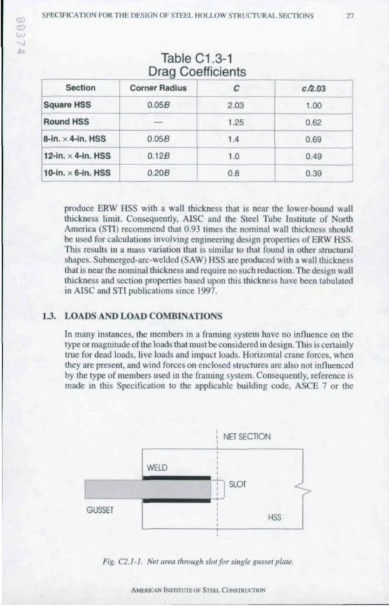
NET SECTION , ,
WELD , , ,
r ] SLOT
, GUSSET , ,
HSS , ,
Fig. C2. / · / . Net area through slOl for single gusset plate.
AMERJCAN INSTlTUTE Of STEIl. CONS11wcn ON
28 SPEC1Fl ATION FOR TIlE DESIGN OF STEEL HOLLOW STRUCTURAL SECTIONS
provisions of LRFD Specificauon Secuon A4. There are, however, two situallons In whIch the use of HSS may allow a reducllon In the design forces that must be consIdered: wind forces on exposed frameworks and pressures created by the enclosed nature of the HSS.
Wind forces on exposed frameworks can occur enher In the final structural configuratIOn or during construction. The shape of a round HSS has a lower reSIstance to nuid now than shapes with nat elements (e.g., W-shapes) and, therefore, reduces the wind forces. The gencral determination of wind pressures is given in the applicable building code or ASCE 7 when building codes do not apply. The determination of wind forces on exposed frameworks is a complex problem involving the solidarity ratio, shIelding and Wind angle. In the absence of other Wind-force reduction provisions that conSIder member shape, the provisions in this Specification can be used.
Wind forces on an exposed profile are proponlonal to a drag coefficient C, which
L
L
B
i i -I 1-
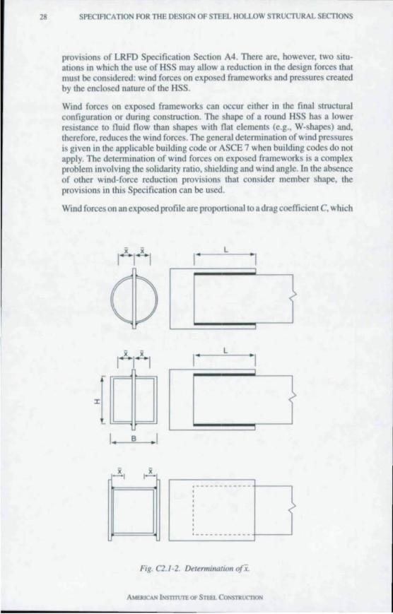
Fig. C2. J -2. Deltnnmalion o/i
AMERICAN iNS'mUTEOf STEEL CONSntl'C11oN
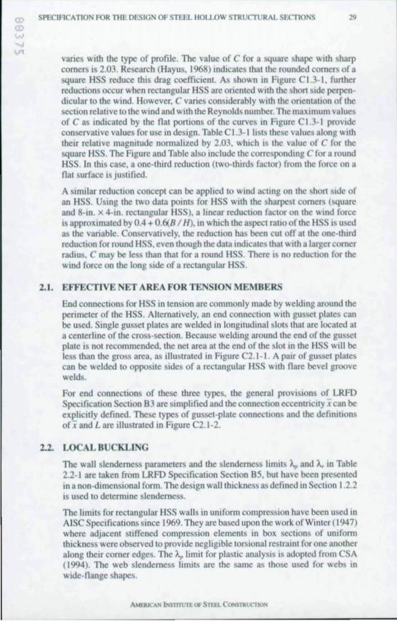
SPECIFlCATtON FOR THE DESIGN OF S1BOL HOlLOW STRUCTURAL SECTIONS 29
varies with the type of profile. The value of C for a square shape WIth sharp comers is 2.03. Research (Hayus. 1968) indicates that the rounded comers ofa square HSS reduce thIs drag coefficient. As shown In FIgure C 1.3-1. funher reducllons occur when rectangular HSS are oriented WIth the shon SIde perpendicular to the wind. However, C varies considerably with the onentation of the section relative lothe wind and with the Reynolds number The maximum values of C as indIcated by the nat ponions of the curves In Figure C \.3-1 proVIde conservative values for use in design. Table C 1.3- 1 lists these values along WIth the" relallve magnitude normalized by 2.03. wluch is the value of C for the square HSS . The Figure and Table also Include the corresponding C for a round HSS. In this case. a one-third reduction (two-thirds factor) from the force on a nat surface is Justified.
A SImIlar reductIOn concept can be applied to Wind acting on the shon SIde of an HSS. Using the two data points for HSS Wllh the sharpest comers (square and 8-In. x 4-In. rectangular HSS), a hnear reducllon factor on the Wind foree is approxImated by 0.4 + 0.6(8/ H), in whIch the aspect ratIO of the HSS IS used as the variable. Conservatively. the reducllon has been cut off at the one-thIrd reducllon for round HSS, even though the data indIcates that WIth a larger comer radIUS. C may be les than that for a round HSS. There IS no reducllon for the wind force on the long side of a rectangular HSS.
2.1. EFFECTIVE ET AREA FOR TE SIO MEMBERS
End connections for HSS in tension are commonly made by welding around the perimeter of the HSS. Alternatively, an end connection with gusset plates can be used. Single gusset plates are welded in longitudinal slots that arc located at a centerline of the cross-section. Because welding around the end of the gusset plate IS not recommended, the net area at the end of the slot In the HSS will be less than the gross area. as illustrated in Figure C2.1-1. A pair of gusset plates can be welded to opposite sides of a rectangular HSS WIth nare bevel groove welds.
For end connections of these three types. the general proVISIons of LRFD Speclficallon ection B3 are simplified and the connecllon eccentncllY i can be expllcllly defined. These types of gusset-plate connectIons and the defiOlllons ofi and L are illustrated in Figure C2.1-2.
2.2. LOCAL BUCKLING
The wall slenderness parameters and the slenderness limIts A, and A,. in Table 2.2-1 are taken from LRFD Specificallon Secllon B5. but have been presented in a non-dimensional form. The design wall thickness as defined In Section 1.2.2 is used to determine slenderness.
The limits for rectangular HSS walls in uniform compression have been used in AISC Specifications since 1969. They are based upon the work of Winter (1947) where adjacent stiffened compression elements in box sections of Uniform thickness were observed to provide negligible torsIonal restraint for one another along their comer edges. The A,. limit for plastic analysis IS adopted from CSA (1994). The web slenderness IInnts are the same as those used for webs In wlde-nange shapes.
AMI1UC~ lNsTn\.m. Of STIEL CONS'l'aUCTlo N
JO SPECIFICATION FOR THE DESIGN OF STEEL HOLLOW STRUCTURAL SECTIONS
The A. limit for round HSS in compression was first used by AISC in the 1978 AISC ASD Specificallon. It was recommended by Schilling (1965) based upon research at Cornell University that produced provIsions in the 1968 AISI Cold-Fonned Specification (Winter, (968). The same limit was also used to define a compact shape in bendtng in the 1978 AlSC ASD SpeCIfication. However, the limits for A,. and A. were changed in the 1986 AISC LRFD Specification based upon experimental research on round HSS in bending (Sherman, 1985 and Galambos, 1988). Excluding the use of round HSS with D / I> 0.448£ / F, was also recommended by Schilling (1965).
Lower values of A, are specified for high-seismic design in the AISC Seismic Provisions for Structural Sleel Buildings (A ISC, 1997) based upon tests (Lui & Goel, 1987) that have shown that rectangular HSS braces subjected to reversed axial load fracture catastrophically under relallvely few cycles if a local buckle fonns. This was confinned more recently in tests (Shennan, 1995) when local buckling did not occur with low values of A,. Rectangular braces sustained over 500 cycles, even though general column buckling did occur. In test when local buckling did occur (with high values of A,), specimens failed in less than 40 cycles. The seismic A. IS based upon on tests (Lui & Goel, 1987) of HSS that had a small enough b / t so that braces perfonned satisfactorily for members WIth reasonable column slenderness. Filling the rectangular HSS with lean concrete (concrete mIxed with a low proportIOn of cement) has been shown to effectively stiffen the HSS walls and improve cyclic perfonnance. Because fracture at a low number of cycles is also possible with eold-fonned round HSS braces that fonn local buckles, the limiting A, in compression in the AISC Seismic Provisions was chosen to be the same as for plastic analysis.
3.1. DESIGN FOR TE SIO
Except for HSS that are subjected to cyclic load reversals, there is no infonnation that the factors governing the strength of HSS 10 tenSIon differ from those for other structural shapes. Therefore, the criteria in Section 3.1 are identical to those in LRFD Specification Section OJ. However. because the number of different end connection types that are practical for HSS IS limited. the determination afthe net effective area At can be simplified as it has been in Section 2.1 .
4. 1. EFFECTIVE LENGTH AND SLENDERNESS LIMITATIONS
The high torsional strength and stiffness of an HSS proVIdes increased restraint for members that frame into it when compared to that provided by other structural shapes. For example. the connection between an HSS branch member and a continuous HSS chord member is commonly made with a continuous weld around the perimeter of the branch member. In such a connection. the chord then provides considerable end restraint both in-plane and out-of-plane of the truss; the HSS branch member also provides a degree of lateral restraint against rotation of the chord. In both cases, advantage can be taken of the end restraint by using the effective lengths in Section 4. 1.1 (a). The use of K equal to 0.75 for the branch members and 0.9 for the chord between bracing points is based upon the recommendations of CIDECT research (Rondal, 1992).
It IS important to note that even though end restramt is present, II is still reasonable to assume that the truss joints are pmned. Secondary moments due
SPECtRCATION FOR THE DESIGN OF STEEL HOLLOW STRUCTURAL SECTIONS J I
to end fixity may be neglected unless the joint eccentricity exceeds the limits of applicability in Section 9.4 or fatigue is a design consideration. For fatigue applications. refer to AWS D 1.1.
The provisions for unbraced frames and braced frames are taken from the LRFD Specification. Values of K for compression members in frames can be determined from the alignment charts and equations in the corresponding LRFD Specification Commentary.
4.2. DESIGN FOR COMPRESSION
The axial compressive strength of an HSS is innuenced by its method of production. shape. and dimensions and is further complicated by large differences between theoretical predictions and experimental results for local buckling. especially for round HSS . Rather than repeat the excellent discussions that can be found elsewhere concerning the behavior of various hollow cross-sections (Schilling. 1965; McGuire. 1968; Galambos. 1988; and Sherman. 1992). the results and basis for the design equations is explained herein. Some of the major considerations that must be included in a comprehensive criteria for HSS are as follows :
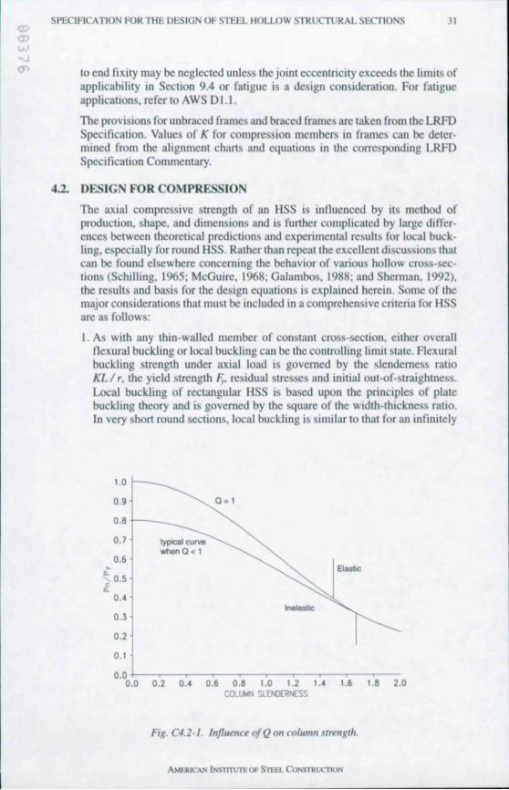
I. As with any thin-walled member of constant cross-section. either overall nexural buckling or local buckling can be the controlling limit state. Flexural buck.ling strength under axial load is governed by the slenderness ratio KL I r. the yield strength F~ residual stresses and initial out-of-straightness. Local buckling of rectangular HSS is based upon the principles of plate buckling theory and is governed by the square of the width-thickness ratio. In very short round sections. local buck.ling is similar to that for an infinitely
~
1.0 r-__
0.9
0.8 +--_
0.7 typtcaJ curve whenO < 1
0.6
a . l
~ O . S .t
Elastic
0.' lnelas1lC
O.l
0.2
0.1
0.0 +-~-~-~-~~-~-~~,-~----:-0.0 0.2 0.' 0.6 0.8 1.0 1.2 1.' 1.6 1.8 2.0
COLUMN SLENDERNESS
Fig. C4.2- J. I"fluellce ofQ on colum" stretlgtJz.
AMERICAN lNSlTTlnli OF STEEl.. CONSTRucnON
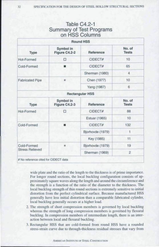
32 SPECIFICATION FOR THE DESIGN OF STEEL HOLLOW STRUCTURAL SECTIONS
Table C4.2-1 Summary of Test Programs
on HSS Columns
f ~
Round HSS ~
Symbol In No. of Type Figure C4.2-2 Reference Tests
+ Hot-Formed 0 CIDECTI 10
~
Cold· Formed
~ • CIDECT# 65
Sherman (1980) 4
Fabricated Pipe • Chen (1977) 1 10
Yang (1987) 6
Rectangular HSS l- i
Symbol in No. of
J Type Figure C4.2-3 Reference Tests
Hot-Formed 0 CIDECTI 88
t Cold· Formed
Esluar (1965) 10
• 1 CIDECT# 132
Bjorhovde (1979) 1
r Cold-Formed
Key (1985) 11
* 1 Bjorhovde (1979) 19 Stress Relieved
Sherman (1969) 2
, No reference clled for CIDECT data
wide plate and the ratio of the length to the thickness is of prime importance. For longer round sections, the local buckling configuration consists of approximately square waves along the length and around the CIrcumference and the strength is a function of the ratio of the diameter to the thickness. The local buckhng strength of thin round sections IS extremely sensitive to initial distortion from the perfect cylindrical surface. Because manufactured HSS generally have less initial distortion than a comparable fabricated cylinder, local buckhng generally occurs at a higher load.
2. The strength of short compression members is governed by local bucklmg whereas the strength of long compression members IS governed by nexural buckhng. In compressIOn members of mternlediate length. there is an interaction between local and nexural buckling.
3. Rectangular HSS that are cold-formed from round HSS have a rounded stress-strain curve due to through-thickness residual stresses that vary from
AMERICAN INST11VTEOf SlUJ CONSTRliMlON
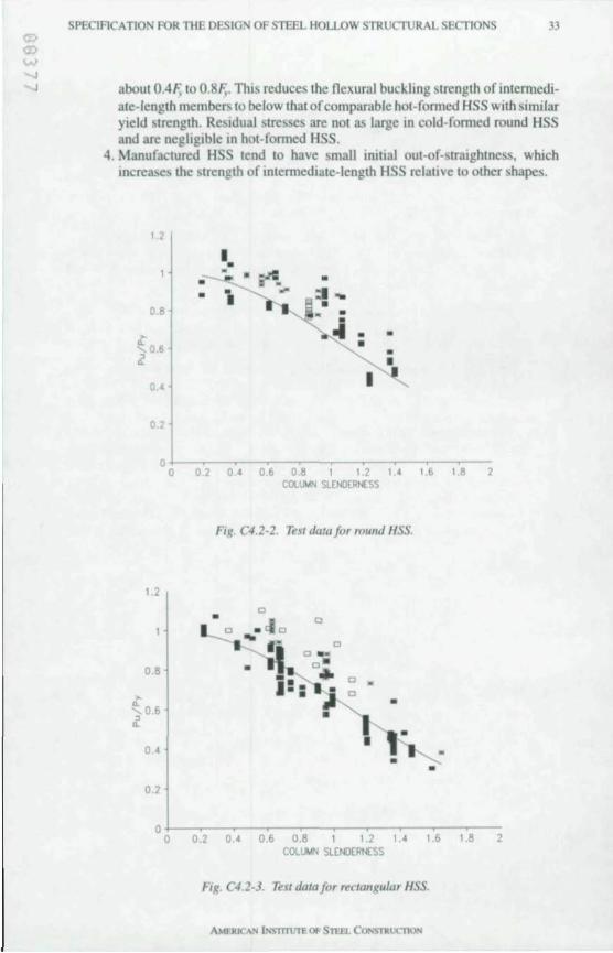
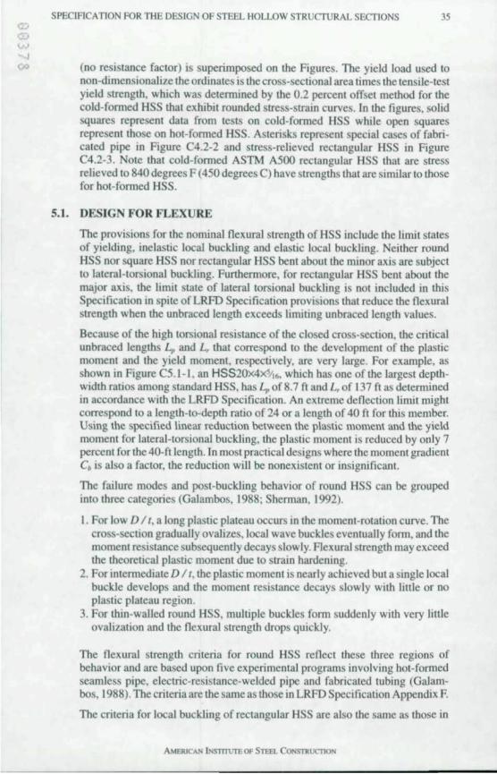
SPECIACATION FOR THE DESIG OF STEEL HOLLOW STRUCTURAL SECTIONS 33
aboul 0.4F, 10 0.8F,. This reduces the nexural buckling strenglh of inlemlediate-Ienglh members 10 below thai of comparable hOI-formed HSS with similar yield strenglh. ResIdual stresses are not as large in cold-fomled round HSS and are negltglble In hot-fomled HSS.
4. Manufactured HSS tend to have small inItIal out-of-stralghtness. which Increases the strength of Intermediate-length HSS relaltve to other shapes.
t.2
0.8
> Q.. 0.6 , ..
o.
0.2
0
t.2
0.8
> Q. 0.6 , ..
0.'
0.2
0
I • • • • • • =1 __ • -- • •
!'II • • - • • I
0.2 O. 0.' 0.8 I t.2 u Ib COLUt./"I SlEI'CERt£SS
Fig. C4.2-2. Test data for roulld HSS.
" ~• ° .°<10
... G ° 0 _ . 0·
- ... ° 1-· • •• • c
-•
•
~ •
1.8 2
o~~--~--~~--~--~~--~----~ o 0.2 0.4 0.6 0.8 1 1.2 1.4 1.6 1.8 2 COlU"" SLENOCR":SS
Fig. C42-3. Ttsl dala for ",clangular HSS
34 SPECIFICATION FOR THE DESIGN OF STEEL HOLLOW STRUCTURAL SECTIONS
Because many HSS have a wall slenderness ratio Ihal exceeds An the equations for nexural buckling include the interaction with local buckling as given in LRFD Specification Appendix B. In effect, Ihe local buckling reduction factor Q reduces the yield stress in both the inelastic nexural buckling equation and in the slenderness A.-. Its innuence is illuslrated in Figure C4.2-1 . Of course, if A is less than or equal to An the local buckling reduction factor Q is equal to unity and the equations reduce to the nexura1 buckling equations of LRFD Specification Chapter E.
For round HSS, Q has its origins in the critical stress from local buckling test data with conservative adjustments in an early AISI Specification (Winter, 1968). The constants have been further adjusted for a non-dimensional foml and a design strength format rather than an allowable stress fonnal.
The effective width equation that is used to obtain Q for rectangular HSS is also from an early AISI Specification (Winter, 1968). The constants in this equation were established for closed cross-sections with uniform thickness.
The nexural buckling equations and ~, equal to 0.85 are the same as those used in the LRFD Specification and can be used conservatively for all HSS. However, for hot-fomled HSS or ASTM A500 Grade 0 HSS, which have lower residual stresses but are generally unavailable in the United States, a higher resistance factor could be justified and would give factored resistances that are comparable to those in other specifications that use multiple column curves. This is based upon the extensive CIDECT column test program in Europe and several less extensive studies in North America, as summarized in Table C4.2- 1. A large amount ofCIDECT data for seamless HSS is not included. The test data for HSS in axial compression are illustrated in Figure C4.2-2 for round HSS and Figure C4.2-3 for rectangular HSS. The curve for the LRFD nominal column strength
MnlMp
1.0
SIbO.74
Lp . B.T 40'
Ud=24
0.07 (7 percent)
HSS 2Ox4x5l16
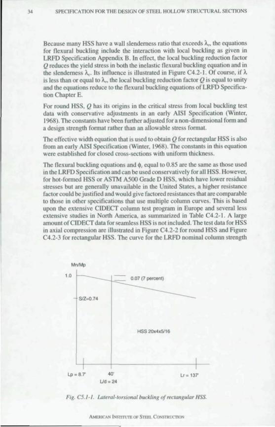
Lr . 137'
Fig. C5.J-J. Lalt ral-lorsional buckling o/ lYe/angular HSS.
AMERICAN lNSlTTUTE OF STEfL CONSTROCI1ON
W 4
SPECIFICATION FOR THE DESIGN OF STEEL HOLLOW STRUCTURAL SECTIONS 35
0<> (no resistance factor) is superimposed on the Figures. The yield load used to non-dimensionalize the ordinates is the cross-sectional area times the tensile-test yield strength, which was determined by the 0.2 percent offset method for the cold-formed HSS that exhibit rounded stress-strain curves. In the figures, solid squares represent data from tests on cold-formed HSS while open squares represent those on hot-formed HSS. Asterisks represent special cases of fabricated pipe in Figure C4.2-2 and stress-relieved rectangular HSS in Figure C4.2-3. Note that cold-formed ASTM A500 rectangular HSS that are stress relieved to 840 degrees F (450 degrees C) have strengths that are similarto those for hot-formed HSS.
5.1. DESIGN FOR FLEXURE
The provisions for the nominal flexural strength of HSS include the limit states of yielding, inelastic local buckling and elastic local buckling. Neither round HSS nor square HSS nor rectangular HSS bent about the minor axis are subject to lateral-torsional buckling. FurthernlOre, for rectangular HSS bent about the major axis, the limit state of lateral lorsional buckling is not included in this Specification in spite of LRFD Specification provisions that reduce the flexural strength when the unbraced length exceeds limiting unbraced length values.
Because of the high torsional resistance of the closed cross-section, the critical unbraced lengths I-, and L, that correspond to the development of the plastic moment and the yield moment, respectively, are very large. For example, as shown in Figure C5.1-1. an HSS20x4x'/16, which has one of the largest depthwidth ratios among standard HSS, has Lp of8.7 ft and L,of 137 ft as determined in accordance with the LRFD Specification. An extreme deflection limit might correspond to a length-to-depth ratio of 24 or a length of 40 ft for this member. Using the specified linear reduction between the plastic moment and the yield moment for lateral-torsional buckling, the plastic moment is reduced by only 7 percent forthe40-ft length. In most practical designs where the moment gradient C. is also a factor, the reduction will be nonexistent or insignificant.
The failure modes and post-buckling behavior of round HSS can be grouped into three categories (Galambos, 1988; Shernlan, 1992).
I. For low D / t, a long plastic plateau occurs in the moment-rotation curve. The cross-section gradually oYalizes, local wave buckles eventually form, and the moment resistance subsequently decays slowly. Flexural strength may exceed the theoretical plastic moment due to strain hardening.
2. For intermediate D / I, the plastic moment is nearly achieved but a single local buckle develops and the moment resistance decays slowly with little or no plastic plateau region.
3. For thin-walled round HSS, mUltiple buckles form suddenly with very little ovalization and the flexural strength drops quickly.
The flexural strength criteria for round HSS reflect these three regions of behavior and arc based upon five experimental programs involving hot-formed seamless pipe, electric-resistance-welded pipe and fabricated tubing (Galambos, 1988). The criteria are the sarne as those in LRFD Specification Appendix F.
The criteria for local buckling of rectangular HSS are also the same as those in
AMERICAN iNS1TJUT'E OF STEEL CONSTRUC1l0N
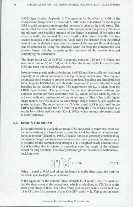
36 SPECIFICATION FOR THE DESIGN OF STEEL HOLLOW STRUCTURAL SECTIONS
LRFD Specification Appendix F. The equation for the effective width of the compression nange when b 1 (exceeds A, is the same as thai used for rectangular HSS in axial compression except that the Slress IS taken as the yield stress. This implies Ihalthe slress in the comers of the compression nange is at yield when Ihe uhimale posl-buckling strength of the nange is reached. When using the effeclive widlh, Ihe nominal nexuraJ slrength is delermined from the effective section modulus to the compression nange using the distance from the shifted neutral axis. A slighlly conservative estimale of the nominal nexural strength can be obtained by using the effective widlh for bolh the compression and tension nange, thereby maintaining Ihe symmelry of Ihe cross-section and simplifying the calculation.
The shape faclor (ZI S) for HSS is generally belween 1.15 and 1.4. Hence, the maximum limit on Mp of 1.5M, in LRFD Specification Chapter F is satisfied for HSS and need nOI be explicitly checked.
In order 10 usc plaslic analysis fordesign , the HSS must have sufficient rotational capacilY at the plaslic momenl to develop the hinge mechanism. This requires a compact cross-section to prevenl premalure local buckling and lateral bracing for rectangular HSS thai are bent about the major axis to preventlaleraJ-Iorsional buckling in the vicinilY of hinges. The requiremenl for L,., is taken from the LRFD Specificalion. The provisions for the wall slenderness definong the compaci section are morc restrictive than A". which defines when Mp can be achieved withoul consideration of rotational capacity. This is due to the higher shape factors for HSS relative to wide-nange shapes where A" also appUes 10 plastic analysis. The more restrictive D 1 ( for round HSS is also used in the LRFD Specificalion and the b 1 ( limit for reclangular HSS is based upon test resuhs for cold-formed sections (Korol, 1972), which are mosl frequenlly used in North America.
5.2. DESIGN FOR SHEAR
Little infonnation is available on round HSS subjected to transverse shear and recommendalions are based upon crileria for local buckling of cylinders subjecled to lorsion (Galambos, 1988). Because torsion is generally conSlant along the member lenglh and transverse shear usually has a gradienl, the shear span a in the Umit for the nominal shear strength V. is a length of nearly conSlant shear. Local buckling due 10 torsion is dependant upon the length of the cylinder, excepl for long members. The shear yield strength can be achieved withoullocal buckling when
(C5.2-1)
Using t , equal 10 0.6F, and tiling the length L as Ihe shear span, the Iimil for the shear span 10 depth ratio is obtained.
In the equalion for Ihe nominal shear strength V, of round HSS, il is assumed that the shear Slress at the neutral axis, which is calculated as VQllb, is at the shear yield stress of 0.6F,. For a thin round seclion with radius R and thickness I, I is rrR' l, the firsl moment of area Q is 2R'1, and b = 21. This gives the stress
AMERJCAN iNSTtTtJI"E OF STEEL CONST1U.1Cn ON
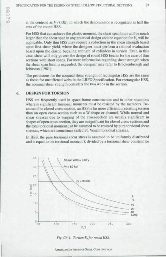
SPECIFI ATION FOR THE DESIGN OF STEEL HOLLOW STRUCf\JRAL SECTIONS 37
at the centroid as V / (ltRr), in which the denominator is recognized as half the area of the round HSS.
For HSS that can achIeve the plastic moment, the shear span limit WIll be much larger than the shear span In any practical design and the equation for V. will be apphcable. Only thin HSS may requJre a reductIOn In the shear strength based upon first shear yield, where the designer must perform a rational evaluation based upon the elastic buckling strength of cylinders In torsion. Even in this case, shear will only govern the design of round HSS beams for the case of thin sections with shon spans. For more infomlation regarding shear strength when the shear span lintit IS exceeded, the designer may refer to Brockenbrough and Johnston (1981 ).
The provisions for the nominal shear strength of rectangular HSS are the same as those for unstiffened webs in the LRFD Specification . For rectangular HSS, the nominaJ shear strength considers the two webs 10 the section.
6. DESIG FOR TORSION
HSS are frequently used 10 space-frame construction and in other situations wherein significant torsional moments must be resisted by the members. Because of its closed cross-~ction. an HSS is far more efficient In resistmg torsion than an open cross-section such as a W-shape or channel. WhIle normal and shear stresses due to warping of the cross-section are usually signIficant in shapes of open cross-section, they are insignificant for closed cross-sections and the total torsional moment can be assumed to be resisted by pure torsional shear stresses, which are someumes called SI. Venant torsional stresses.
In HSS. the pure torsional shear stress is assumed to be unifomlly distributed and is equal to the torsional moment T,. divided by a torsional shear constant for
35
25
~ 15
10
5
Shear yield ::: O.SFy
t------'I----'''--..>..,.Fy = 36 ksI
.!, D
10
-__ :-:-:::::::::::::-_-=== 20 -----_ 40 -------- Long
o+-----~----__ ----~----~------50 100 150 200 250 300
0/ '
Fig. C6-J. Torsion Fc.,forround HSS.
AMEIUCAN 1NST11l1TE OF STEfl. CONSTRUC"1lON
38 SPECIFICA nON FOR THE DESIGN OF STEEL HOLLOW STRUCTURAL SECTIONS
the cross-section C. In a Untit state (annat. the nominal torsional resisting moment is the shear constant times the critical shear stress F;,.
For a round HSS, the torsional shear constant is equal to the polar moment of inertia divided by the radius:
C = It(D' - tr.) = It(D - 1)' 1 32D12 2
(C6-1)
where D, is the inside diameter.
For a rectangular HSS, the torsional shear constant is obtained as 2tA. using the membrane analogy (Timoshenko, 1956), where AD is the area bounded by the mjdline of the section. Conservatively assuming an outside comer radius that is equal to 21, the midline comer radius is 1.51 and
9(4 -It) AD = (8 - I) (H - I) - 4 t' (C6-2)
which yields
c = 2(8 - I) (H - 1)1 - 4.5(4 -It)t' (C6-3)
The resistance factor and "ommal strengths used for torsion are the same as those used for flexural shear.
When considering local buckling in round HSS subjected to torsion, most structural members will either be long or of moderate length and the criteria for short cylinders will not apply. The elastic local buckling strength of long cylinders is unaffected by end conditions and the critical stress is as given by Galambos (1988) as:
£ = K,E " (D 11)J12
(C6-4)
The theoretical value of K, is 0.73 but a value of 0.6 is recommended to account for initial imperfections. An equation for the critical elastic local stress for round HSS of moderate length (L> 5.LD' I I) where the edges at the ends are not fixed against rotation is given by Schilling (1965) and Galambos (1988) as:
£ = 1.23£ " ..JLlD(D I I)'"
(C6-5)
This equation includes a 15 percent reduction to account for initial imperfections.
The local buckling equations are plotted in Figure C6-1 with modulus of elasticity £ equal to 29.000 ksi . Although there is some inconsistency concerning the division between long and moderately long HSS, it appears from Figure C6-1 that the expression for sections of moderate length is valid for most practical lengths. It is also evident lhat it would be uneconomical to neglect the increase in torsional strength for members of moderate lenglh. Therefore, in this Specification, the length effect is included for the simple end conditions and the approximately 10 percent increase in buckling strength is neglected for edges
AMERICAN iNSTtlllTE OF STFFJ.. C ONSTRlJCnON
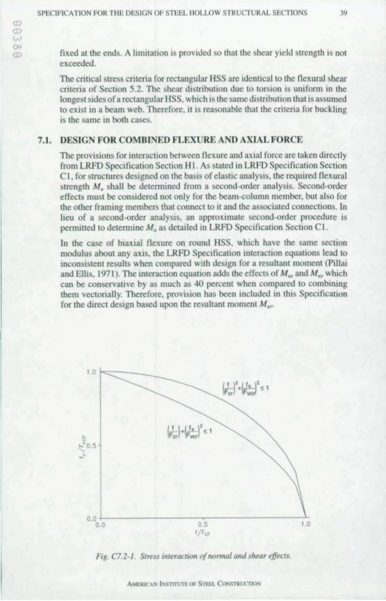
SPECIFlCA nON FOR THE DESIGN OF STEEL HOLLOW STRUCTU RAL SECTIONS 39
fixed at the ends. A limitation is provided so that the shear yield strength is not exceeded.
The critical stress criteria for rectangular HSS are identical to the nexural shear criteria of Section 5.2. The shear distribution due to torsion is unifonn in the longest sides of a rectangular HSS, which is the same distribution that is assumed to exist in a beam web. Therefore, it is reasonable that the criteria for buckling is the same in both cases.
7.1. DESIGN FOR COMBINED FLEXURE AND AXIAL FORCE
The provisions for interaction between nexure and axia l force are taken directly from LRFD Specification Section H I. As stated in LRFD Specification Section C I, for structures designed on the basis of elastic analysis, the required nexural strength M. shall be determined from a second-order analysis. Second-order effects must be considered not only for the beam-column member, but also for the other framing members that connect to it and the associated connections. In lieu of a second-order analysis, an approximate second-order procedure is permitted to determine M. as detailed in LRFD Specification Section C I.
In the case of biaxial nexure on round HSS, which have the same section modulus about any axis, the LRFD Specification interaction equations lead to inconsistent results when compared with design for a resultant moment (Pillai and Ellis, 1971 ). The interaction equation adds the effects of M~ and M .. which can be conservative by as much as 40 percent when compared to combining them vectorially. Therefore, provision has been included in this Specification for the direct design based upon the resultant moment M".
, u
1.0 1"'-=:::::---_
~O.5
o.o-l--------~---------'-: 0.0 0.5 1.0
flFer
Fig. C7.2-J SI"!S interactiQn ojnonna/ and sltear ~JJtC's.
AMEJuCAN INSTmJTE OF STEfl. CONSTRlK'TlON
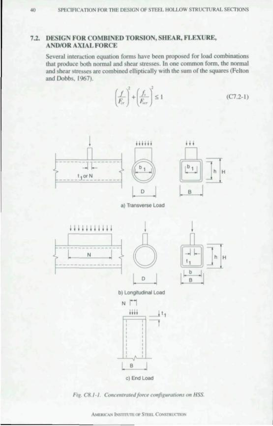
40 SPECIFI ATION FOR THE DESIGN OF STEEL HOLLOW STRUCTURAL SECTIONS
7.2. DESIGN FOR COMBI ED TORSIO ,SHEAR, FLEXURE, AND/OR AXIAL FORCE
Several inleraction equation forms have been proposed for load combinalions that produce bolh nomlal and shear stresses. In one common form. the normal and shear stresses are com boned elliplically WIth the sum of the squares (Felton and Dobbs. 1967).
(LJ' + (.£.)' !> I F;, F ... r
111111 II
_____ I, ~~ ______ _ e §]H
----"'N __ I
a) Transverse Load
6 b) Longrtudlnal Load
N
c) End Load
FiR. C8. }·} ConCt!nlra'~dfo,.a config urations on HSS
A MERICA.N INSTllUTEOf Sllll CONSnU.lC°T1ON
h H
(C7.2-I)
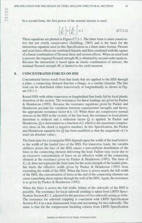
SPECIFICATION FOR THE DESIGN OF STEEL HOLLOW STRUCTURAL SECTIONS 41
In a second fonn, Ihe fir.;1 power of Ihe nonnal Slresses is used.
(L)+ (.L)' $ I F;, ~r
(C7.2-2)
These equal ions are ploned in Figure C7.2-1. The laller form IS more conservalive bUI nOI overly conservative (Schilling, 1965) and is the basis for the interaction equatIOn used in this Specification In a limit-states fOmlal. Flexure and aXial force effeclS are combmed linearly and then combined with the square of a Imear combinalion of nexural shear and lorsion effects. When an axial load is presenl, the required nexural strength M, is obtained by second-order analysis. Because the interaction is based upon an elastic combination of stresses, the nominal nexural slrength M, is limiled to the yield moment.
8. CONCENTRATED FORCES ON HSS
Concentrated forces result from line loads that are applied to the HSS through a plate. a connecting element that h~ a flange. or a similar element. The line load can be distributed either transversely or longitudinally as shown in Figure CS. I- 1.
Round HSS with either transverse or longitudinal hne loads fail by local plastic distortIOn of the secllon. The resistances for these loadings arc given by Packer & Henderson (1992). Because the resistance equallons given by Packer and Henderson account for variations between experimental strengths and theory. the appropnate resistance factor $ is 1.0. When there are compressive nom,al stresses in the HSS 10 the vicinity of the line load. the resistance to local plastic distMlon is reduced and a reduction factor Q, is applied. In Packer and Hender.;on, Q, is detennined as a function off, which is the maximum compressive stress in the chord (a negative number). In thI; Specification. the Packer and Henderson equation for Othas been modified so that the magnitude offis used (an absolute value).
The limit state for a rectangular HSS depends upon the width of the load relative to the width of the loaded face of the HSS. For transver.;e loads. the variable stiffness across the face of the HSS causes a non-Uniform distribution of the force In the connectIng element delivcnng the load. Failure may occur due to an excessive concentration of force on an effective width of the connecting element at the resi>!ance given by Packer & Hender.;on (1992). The limit of F"llbl does not represent the limit state for the axtal strength of the loaded plate. but hmits the effective width given by Packer & Henderson (1992) from exceed 109 the width of the HSS. When the force I; across nearly the full width of the HSS. the concentration of force at the end of the connectmg element can cause a punchmg shear rupture through the wall of the HSS. Again, the resistance is as given by Packer & Henderson ( 1992).
When the force is across the full width, failure of the sidewalls of the HSS is poSSible. The resistance for local sidewall yielding is taken from LRFD Specificallon Section K 1.3. adjusted for the presence of two sidewalls actmg as webs. The resistance for sidewall crippling is consistent with LRFD Specification Section K 1.4 in a non-dimensional fonn and accounting for two sidewalls. The same IS true for the compressIOn buckling criteria from LRFD Specification
AMEJUCAN II'STITlTTE OF STEEL CO~STRurnON
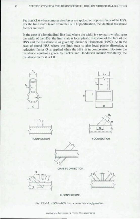
42 SPECIACATION R)R THE DESIGN OF STEEL HOLLOW STRUCTURAL SECTIONS
Seclion KI .6 when compressive forces are apploed on opposite faces of the HSS . For the limit states taken from the LRFO Specification, the identical resistance factors are used.
In the case of a longitudinal line load where the width IS very narrow relative to the width of the HSS, the limit state is local plasuc distonion of the face of the HSS and the reSIStance IS as given by Packer & Henderson (1992). As in the case of round HSS where the limit state is also local plastic distonion, a reduction factor Q, is applied when the HSS IS in compression. Because the resistance equations given by Packer and Henderson melude variability, the resistance factor <I> is 1.0.
Db
Ii Bb ...A
v tb :.. ,
H D B
8 ' ----~-.:.--------------
T·CONNECTION Y-CONNECTION
CAOSS.cONNECTION g
... K·CONNECTIONS
Fig- C9.4-J. HSS-Io-HSS truss connution configurations
~
(:) W 00
SPEClFlCA TlON FOR THE DESIGN OF STEEL HOLLOW STRUCTURAL SECTIONS 43
>J Another type of concentrated force on a rectangular HSS is on the end of a capped column supporting a beam or joist as in Figure C8.1-1 c. Because the load is on only one side of Ihe HSS, the resistance for local yielding is taken directly from LRFD K 1.3. The criteria for crippling of the HSS wall is taken from LRFD Specification Equation KI-4 with the depth taken as one-half the full width of the HSS, B12. This is based upon a model in which the force is assumed to spread out at 45 degrees in both directions from the center point of the load width. The force will be across the full width of the side at a depth no greater than B I 2, below which crippling will not occur.
9.1. GENERAL PROVISIONS FOR CONNECTIONS AND FASTENERS
Because HSS are frequently combined with other shapes in structures using standard simple shear or moment connections, the general provisions of LRFD Specification Sections J 1.1 through J 1. 11 apply even though several of these provisions are not directly applicable to the HSS.
Although welding is the most frequently used method for making attachments to HSS, there are a variety of methods for using bolts or mechanical fasteners. When ASTM A325, A490 or A307 bolts are used to make an attachment to one wall of an HSS using an open end or access hole to install the nut so that all plies of the connection are in contact within the grip ofthe bolt, the provision ofLRFD Specification Section J3 apply. These provisions also apply to other portions of a structure that includes HSS . However, if a bolt passes completely through the HSS, an attempt to fully tension the bolt would distort the cross section of the HSS wall and the specified minimum installed tension could not be achieved without damaging the member. Therefore, through-bolts should only be installed in the snug-tight condition. The bearing strength of such connections as given in Section 9.1.1 is consistent with that in LRFD SpecifIcation Section J8. The designer should note that some connection details do not distribute the load to both walls equally. Additionally, some details may induce bending in the through-boll.
There are a variety of blind bolts, unique installation methods, welded studs and special connectors that could be used with HSS. Many of these alternatives are still in a developmental stage and general criteria for their use are not available. In such cases, test data must be used to justify their suitability for a particular application.
With any connection configuration where the fasteners transmit a tensile force to the HSS wall, a rational analysis must be used to determine the appropriate limit states. These may include a yield-line mechanism in the HSS wall andlor pull-out through the HSS wall in addition to applicable limit states for the fasteners subject to tension.
9.2. WELDS
These provisions are based upon similar provisions in AWS D 1.1 . The design strength of a connection, for a member welded to a wall of an HSS, is a function of the geometric parameters of the connected members. It is often less than the strength of the member and in many cases cannot be increased by increasing the weld strength. The weld, however, must be sized to provide for the uneven
AMERICAN INS'ITI1J1C: OF SlCEL CONSTRucnON
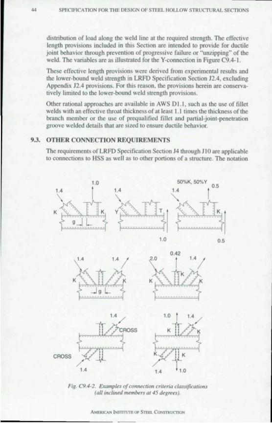
44 SPECIFICATION FOR THE DESIGN OF STEEL HOLLOW STRUCTURAL SECTIONS
distribUlion of load along the weld line allhe required strength. The effective length provisions included in this SecllOn are inlended 10 provide for ductile joinl behavior through prevenlion of progressive failure or "unzipping" of the weld. The variables are as illustraled for the Y-connection in Figure C9.4-1.
These effeclive lenglh provisions were derived from experimental resuhs and the lower-bound weld strength 10 LRFD Specification Section J2.4, excluding Appendix J2.4 provisions. For Ihis reason, the provisions herein are conservalively limiled 10 the lower-bound weld strenglh provisions.
Olher rational approaches are available in AWS D 1.1, such as the use of fillel welds with an effective throalthickness of alleasl 1.1 times Ihe thickness ofthe branch member or the use of prequalified fillet and partial-joint-penetration groove welded details that are sized to ensure ductile behavior.
9.3. OTHER CONNECTION REQurREMENTS
The requirements of LRFD Specifical10n Section J4 through J 10 are applicable to connections to HSS as well as to other portJons of a structure. The notation
1.0
1.4 1.4
5O%K, 50"'" Y 0.5
1.4
'&fI.~ 1::P-'~ 1.0
0.42
CROSS
1.4 1.0
Fig. C9.4-2. Examples of connection criluia classIfications (01/ inclined m~mbers 0145 degrees).
0.5
)
w 0>
SPECIFICATION FOR THE DESIGN OF STEEL HOLLOW STRUCTURAL SECTIONS 45
w for shear rupture strength and tension ruplure strength in LRFD Specification Section J4 have been modified when applied specifically to the HSS. An additional limit state for punching shear has been added based upon failures that were observed in tests of single plate connections to HSS (Sherman, 1996).
The tension force in a unit length of the plate is ftp. Limiting this force to the through-thickness shear strength of the HSS for the two welded planes on the sides of the plate,
ft, :5 2(0.6F, )/ (C9.3-1)
The punching shear rupture criterion includes the standard resistance factors of 0.9 for yielding and 0.75 for rupture. For a single plate connection, the stress! is a bending stress that results from the factored shear acting at an eccentricity (Sherman and Ales, 1991). A simple and conservative criterion is obtained by setting! equal to the yield strength of the plate F..". which is the maximum possible value. This reduces the above equation (with resistance factors) to
(C9.3-2)
An exception to LRFD Specification Sect jon 15.1 on eccentric connections is that bending moments caused by eccentricities in HSS-to-HSS truss connections need not be considered for connection design as long as the eccentricities are within the limilS of applicability in Section 9.4. These eccentricities have been included in the database upon which the connection strength criteria in Section 9.4 have been based.
9.4. HSS-TO-HSS TRUSS CONNECTIONS
A wide variety of connection configurations is possible where branch members are directly welded to a chord that is continuous through the connection. The criteria in this specification are limited to a few of the configurations that are typically used for planar HSS trusses in building applications: T-. Yo, gapped Kand Cross-connections as Illustrated in Figure C9.4-1.
Overlapped K-connections are not covered in this Specification because they are more expensive to fabricate than connections with a gap, especially for round HSS. For this and other connection configurations that are not included in Figure C9.4-1. the design must be based upon the requirements in AWS D 1.1, experimental test results or other verified deslgn procedures. Design procedures such as those contained in the recommendations of Intemationallnstitute of Welding (ITW, 1989) would generally be acceptable.
The criterion that is used for the design strength of a branch of a gapped K-connection is based upon the mechanism of load transfer rather than the configuration of the connection. The gapped K-connection criteria apply only when the branch axial force IS equilibrated by that is other branch members on the same side of the chord. If the force is equilibrated by shear in the chord, the criteria for a T- or Y-connection apply. If the load is transferred through the chord, the criteria for a Cross-connection must be used. Examples of these principles are shown in Figure C9.4-2. When the load is equilibrated by a combination of two of the mechanisms, the design strength is detemtined by interpolation
AMERICAN INSTITUTE OF STEEl.. CONSTR0CJ10N
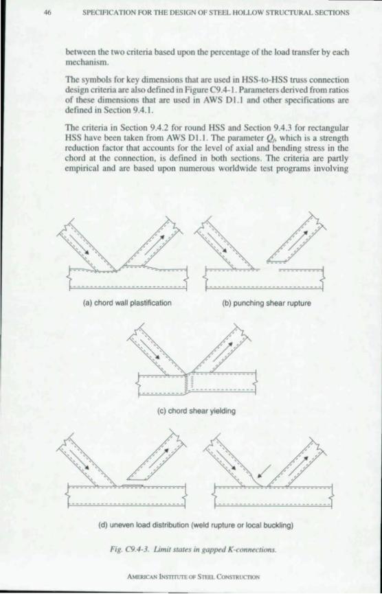
46 SPECIFICATION FOR THE DESIGN OF STEEL HOLLOW STRUCTURAL SECTIONS
belween the two criteria based upon the percentage of the load transfer by each mechanism.
The symbols for key dimensions that are used on HSS-Io-HSS truss connection deSIgn cnleria are also defmed on Figure C9.4- I. Parameters derived from ratios of the dImenSIons thai are used in AWS 01 .1 and other specificalions are defined on SectIon 9.4.1.
The criteria in Seclion 9.4.2 for round HSS and Seclion 9.4.3 for rectangular HSS have been laken from AWS 01.1. The parameter Q" which is a strenglh reduclion faclor Ihat accounlS for the level of axial and bending stress in the chord al the connection, is deflOed in bolh sections. The crileria are partly empirical and are based upon numerous worldwide lest programs involving
(a) chord wall plastification (b) punching shear rupture
(c) chord shear yieldIng
(d) uneven load distribution (weld ruplure or local buckling)
Fig C9.4-3. limit stoles In gap~d K-connulions.
AMERICAN LNSTtTtn"E OF STEEL CONSTRUCT1ON
SPEClFlCATtON FOR THE DESIGN OF STEEL HOLLOW STRUC'TURAL SECTIONS 47
hundreds of leSls. Smce Ihe crileria are in some cases rhe resu/( of empirical curve filting. rhey may not be accurate oUlside the range of lested parameters. AWS D 1.1 does nOI contam a sel of limits of applicabililY for round HSS excepI for an upper limil on yield strength of 60 ksi. The HSS matenal specifications lisled in Secllon 3. I meet this limilation. However. since Ihe database used by various international specifications and design recommendations is essentially rhe same. the II11l1LS of appllcabilllY given by Packer and Henderson (1992) for round HSS have been used in Seelion 9.4.2a.
The crilena in Section 9.4.3 for reclangular HSS are similar 10 those in olher established HSS design specifications and recommendalions Ihroughout the world. They include Ihe Ilmils of applicabililY for rectangular HSS connections in Section 9.4.3a.
The criteria place limits on the magnitude of the component of the branch force that IS perpendicular to the chord for various limit Slates. These limit states include:
I. Chord wall plastlficatron: HIgh local stresses and d,storllons occur in rhe vicinity of the jolOt. These are rhe result of bend 109 in the wall of the chord.
2. Punching shear ruplure : For chords with thin walls. shear stresses through the rhlcknes of the chord around Ihe perimeter of Ihe branch result in a tearing out of material. which can be the controlling limit state.
3. GeneraJ collapse: This is most common in Cross-connections where the branches arc in compression or in other situations when the load is transferred through the chord. I! results in a squashing ofa round IlSS chord ora buckling of the side wall of a rectangular HSS chord. The sidewall strength criteria in Section 9.4.3b. are based upon similar provisions in LRFD Specification Sections K 1.3. K 1.4 and K 1.6. They have been modIfied to accounl for the presence of two sidewall, in the HSS and rhe buckling criteria have been expressed in a non-dImensional fom1 .
4. Uneven load dlstnbution: In connections where the branch is equal or nearly equal 10 width to Ihe chord. the mcrease in the stiffness of the chord wall from its center toward Its sides concentrates rhe transfer of the branch force toward rhe sid .. of the chord and might cause a premature fal lure of the branch.
These limit state~ are iIluMrated In Figure C9.4-3. In some sltuation~. it can be detennined beforehand Ihat a panicular limil state will not apply. For example. chord wall plastification will not occur in rectangular HSS T-connectlons when the branch ha; the same or nearly the same width as the chord. Hence. ranges of parameters arc indIcated 10 Section 9.4.3b and Section 9.4.3c when a IIntit state need not be checked. In Section 9.4.3c. one such limit is given as P.I B ~ O. I + Y I 50. whIch" based upon Packer and Henderson (1992). ThIs is a depar1ure from AWS D 1.1 . which specifies a limil of p", ~ O. I + y I 50.
Since the criteria place a hmit on rhe force Ihat the branch can carry. it IS not always poSSIble to develop the full strength of Ihe branch ",rhout reinforcing the chord with stIffeners. It ;hould be noted that such remforcement Involves expensive fabrication_ To mtnimize cost. it may be more desirable to maximize the efficiency of the connection with respect to the force that can be developed in the branch. Consider the following suggestions:
AMtRICAN ''''STTfl!TE.OF STEfL Cor.:Sl1{l:(TJON
48 SPECIRCATION FOR THE DESIGN OF STE~L HOLLOW STRUcrURAL SECTIONS
I. Chord members should be relallvely thick and branch members should be relatively thin. This is efficient for the strength of the connection and thinner branches reduce the required weld SIze. If the branch member is JOined to develop its wall strength. There may be some compromise required in the deSIgn of com pressIon chord members because larger sizes with thinner walls make efficient compression members. ThIs. however. may be detnmental to the strength of the connection.
2. All members should have D / I or b / I values below the limn that would classify them as thin-walled sections. Tenslon-only branches are a possible exceptIon.
3. The angle belween the branch member and chord member should be greater than 30 degrees. Th,s is efficient for the truss layout and aVOIds difficult welding and inspection requirements and unccnainties in design criteria as well.
4. Branch member width should be kept narrower than the chord member width to avoid difficult welding details and Inspecllon at the edges.
5. Gapped connections are preferred to overlapped connections. Although the lalter are more effiCIent for connecuon strength. they increase the fabncation cost due to the Increased difficulty injoint preparauon. particularly with round HSS.
If the connection IS madequate to carry the branch reqUIred strength. the chord and branch members can be resized to Improve the connecllon efficiency. the connection can be locally reinforced. or a jOint can may be used. External or internal local remforcement is expensive to fabncatc and the former may be unsatisfactory from a funcllonal or aesthetic viewpoint. However. filhng the chord with concrete In the vicimty of the conneCllon IS a sallsfactory method of reinforcing the joint loint cans consist of a segment in the vicinity of the connection that has the same outer dlluenMon as the rest of the chord but a larger wall thickness. This rcquires bUll-welded splices to the rest of the chord. which can Slgmficantly mcrease fabricatIon cost. AWS 01.1 contains proviSIons for the design of JOint cans including required length.
Secllon 9.4.3c is taken from AWS 01.1. The addlllonal axIal tension or compression load p. due to nexure in truss members IS generally subject to a lower reSIstance factor than that used In beam bending. The defimllon of c. although gIven In a simplified form. is consistent WIth that gIven mAWS 01.1.
10. GENERAL REQUIREME TS FOR H S FABRICATIO
The general prov;."ons for fabncallon. erecllon. and quality comrol as specified in LRFO Specification Chapter M are also applicable to HSS. In addition. the follOWing HSS-speclfic concerns are addressed:
I. Because the mterioror an HSS is difficull 10 mspecl. some concern has been expressed regardmg Internal corrosIon. However. good design praclice can eliminate the concern and the need for expensive protecllon. Corrosion occurs In the presence of oxygen and waler. In an enclosed building. it is improbable that Ihere would be sufficient reintroduclion of moisture to cause severe corrosion. Therefore. Internal corrosion protection IS a considerallon only in HSS thaI are expo;ed to wealher.
SPECIRCATION FOR THE DESIGN OF STEEL HOLLOW STRUCTURAL SECTIONS 49
In a sealed HSS, mtemal corrosion cannot progress beyond the point where the oxygen or moisture necessary for chenucal oxidation is consumed (AISI, 1970). The oxidation depth IS mSlgnificant when the corrosion process must stop. even when a corrosive atmosphere eXists at the time of sealing. If fine operungs exist at connections. moisture and air can entcr the HSS through capillary aClIon or by aspiratjon due 10 the partial vacuum thai is created if the HSS is cooled rapidly (8lodgell, 1967). This can be prevented by providing pressure-equah~mg holes in locations that make it Impossible for water to now into the HSS by gravity.
Situations where conservative practice would recommend an internal protective coating melude: (I) open HSS where changes in the air volume by ventilation or direct now of water is possible; and, (2) open HSS subject to a temperature gradient that would cause condensation. In such instances it may also be prudent to use a mjnimum '/,.- in . wall thickness.
HSS that are filled or partially filled with concrete should not be sealed. In the event of fire, water in the concrete will vaporize and may create pressure sufficient to burst a sealed HSS. Care should be taken to ensure that water does not remain in the HSS during or after construction, since the expan ion caused by freezing can create pressure that is suffiCient to burst an HSS
Galvanized HSS assemblies should not be completely sealed because rapid pressure changes during the galvanizing process tend to burst sealed assemblies.
2. As a result of manufacturing, a light oil coating IS generally present on the outer surface of the HSS. If pajnt is specified. HSS IllUSt be cleaned of this oil coaling With a suitable solvent; see the Steel Structures Paillling Manual . (SSPC,I99I)
3. To avoid weld contamination, the light oil coating that is generally present after manufacturing an HSS should be removed with a suitable solvent in locations where welding will be perfomled. In cases where an external coating has been applied at the mill , the coating should be removed at the location of welding or tbe manufacturer should be consulted regarding the uitability of welding m the presence of the coating.
AMFJUCAN lNsrrnnEOF STEfl.. CONSTRUCTtON
~ SPECIFICATION FOR THE DESIGN OF STEEL HOLLOW STRUCTURAL SECTIONS
References AISC, Seismic Provisions for Structural Steel Buildmgs, American Institute of Steel
Construction, Chicago, IL, 1997.
AISC, Load and Resistance Design Specification for Structural Steel Buildings, American Institute of Sleel Construction, Chicago, IL, 1993.
ASCE, Minimum DeSIgn Loadsfor Buildings and Other Structures, American Society of Civil Engmccrs. Reston, VA, 1995.
AISI, Interior Corrosion of Structural Steel Closed Stctions, American Iron and Steel Inslllute. Bulletin 18, February, Washmgton. DC., 1970.
Bjorhovde R. and P. C. Blfkemoe, "LImll State Design of HSS Columns", Canadian Journal of CIVIl Engmeering, Vol. 6, No.2, June (pp. 276-291),1979.
Blodgett, O. w., "The Question of Corrosion in Hollow Steel Sections," Welding Design Studies in Steel Structures, Lmcoln Electric, 0610.163, August, Cleveland,OH, 1967.
Brockenbrough, R. B. and B. G. Johnston, USS Steel Design Manual, United States Steel Corporation. Pittsburgh, PA, 1981.
CSA Standard S16.1 Limit States Design of Steel Structures, Canadian Standards Association, Rexdale, Ontario, Canada, 1994.
Chen, W. F. and D. A. Ross, ''Tests of Fabricated Tubular Columns," Journal of the Structural Division, Vol. 103, sn, paper 12809, ASCE, Reston, VA, 1977.
Estuar, F. R. and L. Tall, ''The Column Strength of H t-Rolled Tubular Shapes-An Experimental Evaluation," Frit= Engineering Laboratory Repon No. 296.1, lehigh University, Bethlehem, PA, 1965.
Felton, L. P. and M. W. Dobbs, "Optimum Design of Tubes for Bendmg and Torsion," Journal of the Structural DlI'ision, Vol. 93, ST4, paper 5397, ASCE, Reston, VA, 1967.
Galambos, T. V, Guide to Design Criteria for Metal Compression Members, Structural Stability Research Council, John Wiley & Sons. New York, NY, 1988.
Graham, R. R, "Manufaclure and Use of Structural Tubmg," JOllmal of Metals, September, 1965.
Hayus, F. Drag Measurements on One Square Sectioll and 7i~'o Rectangular Sections with Differellt Comer Radii, English Translation of elDECT Report I-NKI -68-41, September, 1968.
IlW. Design recommendations for Hollow Structural Section JOints- Predominantly
SPECLFICATLON FOR THE DESIGN OF STEEL HOLLOW STRUCTURAL SECTIONS 51
Statically Loaded. 2nd ed .. International Institute of Welding Subeommission XV-E. Doc. XV- 582-85. lIW Annual Assembly, Helsinki, Finland, 1989.
Key, P. W. and G. J. Hancock, An Experimental/m'estigatlOn of the Column Behaviour of Cold-Fonned Square Hollow Sections, Reseasch Repon R493, University of Sydney, Sydney, AustralIa. 1985.
Korol. R. M " The Plastic Behaviour of Hollow Structural Sec/iolls with Implication for Design, Canadian Structural Engineering Conference, 1972.
LUI, Z. and Goel. S. c.. Investigation of Concrete Filled Steel Tllbes under Cyclic Bending and Bllckling, UMCE Repon 87-3, University of Michigan, Ann Arbor, MI,1981 .
Packer. J. A. and Henderson, 1. E., Design Gllide for Hollow Struclllral Section Connections, Canadian Institute of Steel Construction. Willowdale, Ontario, Canada, 1992.
Rondal, J., Structllral Stability of Hollow Sections. Comite Internahonal pour Ie Developpement etl'Etude de la Construction Tubulaire, Verlag TUV Rheinland GmbH. Koln, Germany, 1992.
SchIlling. C. G .. "Buckling Strength of Circulas Tubes," JOllmal of the Structllral Dil'ision, Vol. 91. ST5. paper 4520. ASCE, Reston, VA. 1965.
Sherman, D. R. and Lukas, D. E., "TorsIOnally Stiff Columns Under Eccentnc Loads," JOllmal of the Structllral Division. Vol. 96, ST2. paper 7090. ASCE. Reston. VA , 1969.
Sherman. D. R .. Local Bllcklin~ BehaviorofTllblilar Strut Type Beam-Collllllns, Civil Engtneenng Depanment Repon, University of Wisconsin-Milwaukee. Milwaukee, WI. 1980.
Sherman. D. R .. "Bending Equations for Circular Tubes," Proceedings AII/lllal Tech nical Session, Structural Stability Research CounCIl, Lehigh Univer>tty, Bethlehem, PA. 1985.
Sherman. D. R. and Ales, 1. M .. ''The Design of Sheas Tabs WIth Tubulas Columns," Proceedmgs of the 1991 A1SC National Steel Constrllction ConferenCt, AISC, Chicago. IL. 1991.
Sherman, D. R .. "Tubular Members," Constructional S"el Design-An fI"emational Gllide. edited by PJ . Dowltng. J.H. Harding. and R. BJorhovde. Chapter 2.4, pp. 91-104. Elsevier Applied Science. London. England. 1992.
Sherman, D. R., Stability Related Deterioration of Structllres, 1995 Theme Conference, Structural Stability Reseasch Council. lehIgh University, Bethlehem, PA, 1995.
SSPC. Steel Structllres Paintmg Manllal, Steel Structures Painting Council. Pittsburgh. PA. 1991.
ST!. Principle Prodllcers and Capabilities, Steel Tube Institute, Mentor, OH, 1996.
Timoshenko. S., Strength of Materials, Part II, 3rd ed., D. Van Nostrand Company, Inc. 1956.
AMERJ<:AN INsTrTLrre OF Sn:a CO~ST1n '<i1OS

~~ SPECIFICATION FOR THE DESIGN OF STELl HOLLOW STRl'CTURAL SECTIO:-;,
WinJer, G., CommenlOry f!1I Ihe SpecifiCDlioll fIJr Ihe Desigll Of Cold-Formed Sleel Members. American Iron and Sleelln~lilule, WashinglOn, D. ,,1968.
Yang, X. M" "SlUdy of Carrying Capacity of Fabricated TubularColumns Under Axial Compression." Proceedillgs Ali/ilia/ Tecilll/ca/ Sessioll, Structural Stability Research CouncIl, Lehigh niversity, Bethlehem. PA, 1987.
American Instilute or Stet'l Conslruclion. Inc. One East Wacker Orh e. Suite 3100 Chlcago.IL6060I·2001
Pub, No_ S.\.I6H (5\ttt97)
Related Documents