Specification for Line Pipe API SPECIFICATION 5L FORTY-THIRD EDITION, MARCH 2004 EFFECTIVE DATE: OCTOBER 2004 ERRATA DECEMBER 2004 Copyright American Petroleum Institute Provided by IHS under license with API Licensee=Chevron Texaco API 22 loc/6 usr Part 1/1000001100 Not for Resale, 06/06/2006 19:07:11 MDT No reproduction or networking permitted without license from IHS --`,``,``,``,`,`,``,`,``,,``,`,-`-`,,`,,`,`,,`---

Welcome message from author
This document is posted to help you gain knowledge. Please leave a comment to let me know what you think about it! Share it to your friends and learn new things together.
Transcript

Specification for Line Pipe
API SPECIFICATION 5LFORTY-THIRD EDITION, MARCH 2004EFFECTIVE DATE: OCTOBER 2004ERRATA DECEMBER 2004
Copyright American Petroleum Institute Provided by IHS under license with API Licensee=Chevron Texaco API 22 loc/6 usr Part 1/1000001100
Not for Resale, 06/06/2006 19:07:11 MDTNo reproduction or networking permitted without license from IHS
--`,``,``,``,`,`,``,`,``,,``,`,-`-`,,`,,`,`,,`---

Copyright American Petroleum Institute Provided by IHS under license with API Licensee=Chevron Texaco API 22 loc/6 usr Part 1/1000001100
Not for Resale, 06/06/2006 19:07:11 MDTNo reproduction or networking permitted without license from IHS
--`,``,``,``,`,`,``,`,``,,``,`,-`-`,,`,,`,`,,`---

Specification for Line Pipe
Upstream Segment
API SPECIFICATION 5LFORTY-THIRD EDITION, MARCH 2004EFFECTIVE DATE: OCTOBER 2004ERRATA DECEMBER 2004
Copyright American Petroleum Institute Provided by IHS under license with API Licensee=Chevron Texaco API 22 loc/6 usr Part 1/1000001100
Not for Resale, 06/06/2006 19:07:11 MDTNo reproduction or networking permitted without license from IHS
--`,``,``,``,`,`,``,`,``,,``,`,-`-`,,`,,`,`,,`---

SPECIAL NOTES
API publications necessarily address problems of a general nature. With respect to partic-ular circumstances, local, state, and federal laws and regulations should be reviewed.
API is not undertaking to meet the duties of employers, manufacturers, or suppliers towarn and properly train and equip their employees, and others exposed, concerning healthand safety risks and precautions, nor undertaking their obligations under local, state, or fed-eral laws.
Information concerning safety and health risks and proper precautions with respect to par-ticular materials and conditions should be obtained from the employer, the manufacturer orsupplier of that material, or the material safety data sheet.
Nothing contained in any API publication is to be construed as granting any right, byimplication or otherwise, for the manufacture, sale, or use of any method, apparatus, or prod-uct covered by letters patent. Neither should anything contained in the publication be con-strued as insuring anyone against liability for infringement of letters patent.
Generally, API standards are reviewed and revised, reafÞrmed, or withdrawn at least everyÞve years. Sometimes a one-time extension of up to two years will be added to this reviewcycle. This publication will no longer be in effect Þve years after its publication date as anoperative API standard or, where an extension has been granted, upon republication. Statusof the publication can be ascertained from the API Standards department telephone (202)682-8000. A catalog of API publications, programs and services is published annually andupdated biannually by API, and available through Global Engineering Documents, 15 Inv-erness Way East, M/S C303B, Englewood, CO 80112-5776.
This document was produced under API standardization procedures that ensure appropri-ate notiÞcation and participation in the developmental process and is designated as an APIstandard. Questions concerning the interpretation of the content of this standard or com-ments and questions concerning the procedures under which this standard was developedshould be directed in writing to the Director of the Standards department, American Petro-leum Institute, 1220 L Street, N.W., Washington, D.C. 20005. Requests for permission toreproduce or translate all or any part of the material published herein should be addressed tothe Director, Business Services.
API standards are published to facilitate the broad availability of proven, sound engineer-ing and operating practices. These standards are not intended to obviate the need for apply-ing sound engineering judgment regarding when and where these standards should beutilized. The formulation and publication of API standards is not intended in any way toinhibit anyone from using any other practices.
Any manufacturer marking equipment or materials in conformance with the markingrequirements of an API standard is solely responsible for complying with all the applicablerequirements of that standard. API does not represent, warrant, or guarantee that such prod-ucts do in fact conform to the applicable API standard.
All rights reserved. No part of this work may be reproduced, stored in a retrieval system, or transmitted by any means, electronic, mechanical, photocopying, recording, or otherwise,
without prior written permission from the publisher. Contact the Publisher, API Publishing Services, 1220 L Street, N.W., Washington, D.C. 20005.
Copyright © 2004 American Petroleum Institute
Copyright American Petroleum Institute Provided by IHS under license with API Licensee=Chevron Texaco API 22 loc/6 usr Part 1/1000001100
Not for Resale, 06/06/2006 19:07:11 MDTNo reproduction or networking permitted without license from IHS
--`,``,``,``,`,`,``,`,``,,``,`,-`-`,,`,,`,`,,`---

FOREWORD
API publications may be used by anyone desiring to do so. Every effort has been made bythe Institute to assure the accuracy and reliability of the data contained in them; however, theInstitute makes no representation, warranty, or guarantee in connection with this publicationand hereby expressly disclaims any liability or responsibility for loss or damage resultingfrom its use or for the violation of any federal, state, or municipal regulation with which thispublication may conßict.
Suggested revisions are invited and should be submitted to API, Standards department,1220 L Street, NW, Washington, DC 20005.
iii
Copyright American Petroleum Institute Provided by IHS under license with API Licensee=Chevron Texaco API 22 loc/6 usr Part 1/1000001100
Not for Resale, 06/06/2006 19:07:11 MDTNo reproduction or networking permitted without license from IHS
--`,``,``,``,`,`,``,`,``,,``,`,-`-`,,`,,`,`,,`---

Copyright American Petroleum Institute Provided by IHS under license with API Licensee=Chevron Texaco API 22 loc/6 usr Part 1/1000001100
Not for Resale, 06/06/2006 19:07:11 MDTNo reproduction or networking permitted without license from IHS
--`,``,``,``,`,`,``,`,``,,``,`,-`-`,,`,,`,`,,`---

CONTENTS
Page
1 SCOPE . . . . . . . . . . . . . . . . . . . . . . . . . . . . . . . . . . . . . . . . . . . . . . . . . . . . . . . . . . . . . . . 11.1 Purpose and Coverage . . . . . . . . . . . . . . . . . . . . . . . . . . . . . . . . . . . . . . . . . . . . . . 11.2 Product SpeciÞcation Level (PSL) . . . . . . . . . . . . . . . . . . . . . . . . . . . . . . . . . . . . 11.3 Grades . . . . . . . . . . . . . . . . . . . . . . . . . . . . . . . . . . . . . . . . . . . . . . . . . . . . . . . . . . 11.4 Dimensions. . . . . . . . . . . . . . . . . . . . . . . . . . . . . . . . . . . . . . . . . . . . . . . . . . . . . . . 11.5 Units . . . . . . . . . . . . . . . . . . . . . . . . . . . . . . . . . . . . . . . . . . . . . . . . . . . . . . . . . . . . 1
2 REFERENCES . . . . . . . . . . . . . . . . . . . . . . . . . . . . . . . . . . . . . . . . . . . . . . . . . . . . . . . . 1
3 DEFINITIONS. . . . . . . . . . . . . . . . . . . . . . . . . . . . . . . . . . . . . . . . . . . . . . . . . . . . . . . . . 2
4 INFORMATION TO BE SUPPLIED BY THE PURCHASER . . . . . . . . . . . . . . . . . . 3
5 PROCESS OF MANUFACTURE AND MATERIAL . . . . . . . . . . . . . . . . . . . . . . . . . 65.1 Process of Manufacture . . . . . . . . . . . . . . . . . . . . . . . . . . . . . . . . . . . . . . . . . . . . . 65.2 Cold Expansion . . . . . . . . . . . . . . . . . . . . . . . . . . . . . . . . . . . . . . . . . . . . . . . . . . . 85.3 Material . . . . . . . . . . . . . . . . . . . . . . . . . . . . . . . . . . . . . . . . . . . . . . . . . . . . . . . . . 85.4 Heat Treatment. . . . . . . . . . . . . . . . . . . . . . . . . . . . . . . . . . . . . . . . . . . . . . . . . . . . 85.5 Skelp End Welds in Helical Seam Pipe. . . . . . . . . . . . . . . . . . . . . . . . . . . . . . . . . 85.6 Traceability. . . . . . . . . . . . . . . . . . . . . . . . . . . . . . . . . . . . . . . . . . . . . . . . . . . . . . . 8
6 MATERIAL REQUIREMENTS . . . . . . . . . . . . . . . . . . . . . . . . . . . . . . . . . . . . . . . . . . 86.1 Chemical Properties. . . . . . . . . . . . . . . . . . . . . . . . . . . . . . . . . . . . . . . . . . . . . . . . 86.2 Mechanical Properties . . . . . . . . . . . . . . . . . . . . . . . . . . . . . . . . . . . . . . . . . . . . . . 9
7 DIMENSIONS, WEIGHTS, LENGTHS, DEFECTS, AND END FINISHES. . . . . . 107.1 SpeciÞed Dimensions . . . . . . . . . . . . . . . . . . . . . . . . . . . . . . . . . . . . . . . . . . . . . 107.2 Diameter. . . . . . . . . . . . . . . . . . . . . . . . . . . . . . . . . . . . . . . . . . . . . . . . . . . . . . . . 107.3 Wall Thickness . . . . . . . . . . . . . . . . . . . . . . . . . . . . . . . . . . . . . . . . . . . . . . . . . . . 117.4 Weight . . . . . . . . . . . . . . . . . . . . . . . . . . . . . . . . . . . . . . . . . . . . . . . . . . . . . . . . . 117.5 Length . . . . . . . . . . . . . . . . . . . . . . . . . . . . . . . . . . . . . . . . . . . . . . . . . . . . . . . . . 117.6 Straightness . . . . . . . . . . . . . . . . . . . . . . . . . . . . . . . . . . . . . . . . . . . . . . . . . . . . . 127.7 Jointers . . . . . . . . . . . . . . . . . . . . . . . . . . . . . . . . . . . . . . . . . . . . . . . . . . . . . . . . . 127.8 Workmanship and Defects. . . . . . . . . . . . . . . . . . . . . . . . . . . . . . . . . . . . . . . . . . 127.9 Pipe Ends . . . . . . . . . . . . . . . . . . . . . . . . . . . . . . . . . . . . . . . . . . . . . . . . . . . . . . . 14
8 COUPLINGS (PSL 1 ONLY). . . . . . . . . . . . . . . . . . . . . . . . . . . . . . . . . . . . . . . . . . . . 158.1 Material . . . . . . . . . . . . . . . . . . . . . . . . . . . . . . . . . . . . . . . . . . . . . . . . . . . . . . . . 158.2 Tensile Tests . . . . . . . . . . . . . . . . . . . . . . . . . . . . . . . . . . . . . . . . . . . . . . . . . . . . . 158.3 Dimensions. . . . . . . . . . . . . . . . . . . . . . . . . . . . . . . . . . . . . . . . . . . . . . . . . . . . . . 158.4 Inspection . . . . . . . . . . . . . . . . . . . . . . . . . . . . . . . . . . . . . . . . . . . . . . . . . . . . . . . 15
9 INSPECTION AND TESTING . . . . . . . . . . . . . . . . . . . . . . . . . . . . . . . . . . . . . . . . . . 159.1 Test Equipment . . . . . . . . . . . . . . . . . . . . . . . . . . . . . . . . . . . . . . . . . . . . . . . . . . 159.2 Testing of Chemical Composition . . . . . . . . . . . . . . . . . . . . . . . . . . . . . . . . . . . . 159.3 Testing of Mechanical Properties . . . . . . . . . . . . . . . . . . . . . . . . . . . . . . . . . . . . 159.4 Hydrostatic Tests . . . . . . . . . . . . . . . . . . . . . . . . . . . . . . . . . . . . . . . . . . . . . . . . . 179.5 Dimensional Testing . . . . . . . . . . . . . . . . . . . . . . . . . . . . . . . . . . . . . . . . . . . . . . 189.6 Surface Inspection . . . . . . . . . . . . . . . . . . . . . . . . . . . . . . . . . . . . . . . . . . . . . . . . 18
v
04
04
04
04
04
Copyright American Petroleum Institute Provided by IHS under license with API Licensee=Chevron Texaco API 22 loc/6 usr Part 1/1000001100
Not for Resale, 06/06/2006 19:07:11 MDTNo reproduction or networking permitted without license from IHS
--`,``,``,``,`,`,``,`,``,,``,`,-`-`,,`,,`,`,,`---

Page
9.7 Visual Inspection . . . . . . . . . . . . . . . . . . . . . . . . . . . . . . . . . . . . . . . . . . . . . . . . . 189.8 Nondestructive Inspection . . . . . . . . . . . . . . . . . . . . . . . . . . . . . . . . . . . . . . . . . . 189.9 Disposition of Pipe Containing Defects . . . . . . . . . . . . . . . . . . . . . . . . . . . . . . . 229.10 Test Methods . . . . . . . . . . . . . . . . . . . . . . . . . . . . . . . . . . . . . . . . . . . . . . . . . . . . 229.11 Invalidation of Tests . . . . . . . . . . . . . . . . . . . . . . . . . . . . . . . . . . . . . . . . . . . . . . . 239.12 Retests . . . . . . . . . . . . . . . . . . . . . . . . . . . . . . . . . . . . . . . . . . . . . . . . . . . . . . . . . 239.13 Reprocessing . . . . . . . . . . . . . . . . . . . . . . . . . . . . . . . . . . . . . . . . . . . . . . . . . . . . 24
10 MARKING . . . . . . . . . . . . . . . . . . . . . . . . . . . . . . . . . . . . . . . . . . . . . . . . . . . . . . . . . . 2410.1 General . . . . . . . . . . . . . . . . . . . . . . . . . . . . . . . . . . . . . . . . . . . . . . . . . . . . . . . . . 2410.2 Location of Markings. . . . . . . . . . . . . . . . . . . . . . . . . . . . . . . . . . . . . . . . . . . . . . 2510.3 Sequence of Markings . . . . . . . . . . . . . . . . . . . . . . . . . . . . . . . . . . . . . . . . . . . . . 2510.4 Bundle IdentiÞcation . . . . . . . . . . . . . . . . . . . . . . . . . . . . . . . . . . . . . . . . . . . . . . 2610.5 Length . . . . . . . . . . . . . . . . . . . . . . . . . . . . . . . . . . . . . . . . . . . . . . . . . . . . . . . . . 2610.6 Couplings . . . . . . . . . . . . . . . . . . . . . . . . . . . . . . . . . . . . . . . . . . . . . . . . . . . . . . . 2610.7 Die Stamping . . . . . . . . . . . . . . . . . . . . . . . . . . . . . . . . . . . . . . . . . . . . . . . . . . . . 2610.8 Thread IdentiÞcation . . . . . . . . . . . . . . . . . . . . . . . . . . . . . . . . . . . . . . . . . . . . . . 2710.9 Thread CertiÞcation . . . . . . . . . . . . . . . . . . . . . . . . . . . . . . . . . . . . . . . . . . . . . . . 2710.10 Pipe Processor Markings . . . . . . . . . . . . . . . . . . . . . . . . . . . . . . . . . . . . . . . . . . . 27
11 COATING AND PROTECTION . . . . . . . . . . . . . . . . . . . . . . . . . . . . . . . . . . . . . . . . . 2711.1 Coatings . . . . . . . . . . . . . . . . . . . . . . . . . . . . . . . . . . . . . . . . . . . . . . . . . . . . . . . . 2711.2 Thread Protectors . . . . . . . . . . . . . . . . . . . . . . . . . . . . . . . . . . . . . . . . . . . . . . . . . 27
12 DOCUMENTS . . . . . . . . . . . . . . . . . . . . . . . . . . . . . . . . . . . . . . . . . . . . . . . . . . . . . . . 2712.1 CertiÞcation . . . . . . . . . . . . . . . . . . . . . . . . . . . . . . . . . . . . . . . . . . . . . . . . . . . . . 2712.2 Retention of Records . . . . . . . . . . . . . . . . . . . . . . . . . . . . . . . . . . . . . . . . . . . . . . 28
13 PIPE LOADING . . . . . . . . . . . . . . . . . . . . . . . . . . . . . . . . . . . . . . . . . . . . . . . . . . . . . . 28
APPENDIX A SPECIFICATION FOR WELDED JOINTERS (NORMATIVE) . . . . . 79APPENDIX B REPAIR OF DEFECTS BY WELDING (NORMATIVE) . . . . . . . . . . 81APPENDIX C REPAIR WELDING PROCEDURE (NORMATIVE). . . . . . . . . . . . . . 83APPENDIX D ELONGATION TABLE (NORMATIVE) . . . . . . . . . . . . . . . . . . . . . . . 89APPENDIX E DIMENSIONS, WEIGHTS, AND TEST PRESSURES
ÑSI UNITS (NORMATIVE) . . . . . . . . . . . . . . . . . . . . . . . . . . . . . . . . . 93APPENDIX F SUPPLEMENTARY REQUIREMENTS (NORMATIVE). . . . . . . . . 121APPENDIX G GUIDED-BEND TEST JIG DIMENSIONS (NORMATIVE). . . . . . . 131APPENDIX H PURCHASER INSPECTION (NORMATIVE) . . . . . . . . . . . . . . . . . . 143APPENDIX I MARKING INSTRUCTIONS FOR API LICENSEES
(NORMATIVE) . . . . . . . . . . . . . . . . . . . . . . . . . . . . . . . . . . . . . . . . . . . 145APPENDIX J SUMMARY OF DIFFERENCES BETWEEN PSL 1 AND PSL 2
(INFORMATIVE) . . . . . . . . . . . . . . . . . . . . . . . . . . . . . . . . . . . . . . . . . 149APPENDIX K END LOAD COMPENSATION FOR HYDROSTATIC
TEST PRESSURES IN EXCESS OF 90% OF SPECIFIEDMINIMUM YIELD STRENGTH (NORMATIVE) . . . . . . . . . . . . . . . 151
APPENDIX M CONVERSION PROCEDURES. . . . . . . . . . . . . . . . . . . . . . . . . . . . . . 153
vi
04
04
04
04
04
04
Copyright American Petroleum Institute Provided by IHS under license with API Licensee=Chevron Texaco API 22 loc/6 usr Part 1/1000001100
Not for Resale, 06/06/2006 19:07:11 MDTNo reproduction or networking permitted without license from IHS
--`,``,``,``,`,`,``,`,``,,``,`,-`-`,,`,,`,`,,`---

Page
Figures1 Belled End for Bell and Spigot Joint . . . . . . . . . . . . . . . . . . . . . . . . . . . . . . . . . . . 282 Line Pipe and Couplings . . . . . . . . . . . . . . . . . . . . . . . . . . . . . . . . . . . . . . . . . . . . . 283 Orientation of Tensile Test Specimens . . . . . . . . . . . . . . . . . . . . . . . . . . . . . . . . . . 294 Tensile Test Specimens . . . . . . . . . . . . . . . . . . . . . . . . . . . . . . . . . . . . . . . . . . . . . . 305 Flattening Tests . . . . . . . . . . . . . . . . . . . . . . . . . . . . . . . . . . . . . . . . . . . . . . . . . . . . 316 API Standard penetrameter . . . . . . . . . . . . . . . . . . . . . . . . . . . . . . . . . . . . . . . . . . . 317 Examples of Maximum Distribution Patterns of Indicated
Circular Slag-inclusion and Gas-pocket-type Discontinuities . . . . . . . . . . . . . . . . 328 Examples of Maximum Distribution Patterns of Indicated
Elongated Slag-inclusion-type Discontinuities . . . . . . . . . . . . . . . . . . . . . . . . . . . 339 Guided-bend Test Specimen . . . . . . . . . . . . . . . . . . . . . . . . . . . . . . . . . . . . . . . . . . 3310 Jig for Guided-bend Test . . . . . . . . . . . . . . . . . . . . . . . . . . . . . . . . . . . . . . . . . . . . . 34B-1 Resultant Cavity for Undercut Repair (PSL 2 Only) . . . . . . . . . . . . . . . . . . . . . . . 82C-1 Transverse Tensile Test Specimen . . . . . . . . . . . . . . . . . . . . . . . . . . . . . . . . . . . . . 85C-2 Guided-bend Test Specimen . . . . . . . . . . . . . . . . . . . . . . . . . . . . . . . . . . . . . . . . . . 85C-3 Jig for Guided-bend Test . . . . . . . . . . . . . . . . . . . . . . . . . . . . . . . . . . . . . . . . . . . . . 86C-4 Nick-break Test Specimen . . . . . . . . . . . . . . . . . . . . . . . . . . . . . . . . . . . . . . . . . . . 87F-1 Impact Test Specimen Tapered End Allowance . . . . . . . . . . . . . . . . . . . . . . . . . . 126F-2 Charpy V-notch and Drop-weight Tear Test Specimen Locations . . . . . . . . . . . . 127
Tables1 Process of Manufacture and Product SpeciÞcation Level (PSL) . . . . . . . . . . . . . . 352A PSL 1 Chemical Requirements for heat and Product Analyses
by Percentage of Weight . . . . . . . . . . . . . . . . . . . . . . . . . . . . . . . . . . . . . . . . . . . . . 362B PSL 2 Chemical Requirements for Heat and Product Analyses
by Percentage of Weight . . . . . . . . . . . . . . . . . . . . . . . . . . . . . . . . . . . . . . . . . . . . . 363A Tensile Requirements for PSL 1 . . . . . . . . . . . . . . . . . . . . . . . . . . . . . . . . . . . . . . . 373B Tensile Requirements for PSL 2 . . . . . . . . . . . . . . . . . . . . . . . . . . . . . . . . . . . . . . . 374 Standard-wall Threaded line Pipe Dimensions, Weights, and
Test Pressures (U.S. Customary and SI Units) . . . . . . . . . . . . . . . . . . . . . . . . . . . . 385 Heavy-wall Threaded Line Pipe Dimensions, Weights, and
Test Pressures (U.S. Customary and SI Units) . . . . . . . . . . . . . . . . . . . . . . . . . . . . 396A Plain-end Line Pipe Dimensions, Weights per Unit Length, and
Test Pressures for Sizes 0.405 through 1.900 (U.S. Customary Units) . . . . . . . . . 406B Plain-end Line Pipe Dimensions, Weights per Unit Length, and
Test Pressures for Sizes 2
3
/
8
through 5
9
/
16
(U.S. Customary Units) . . . . . . . . . . . 416C Plain-end Line Pipe Dimensions, Weights per Unit Length, and
Test Pressures for Sizes 6
5
/
8
through 80 (U.S. Customary Units) . . . . . . . . . . . . . 447 Tolernces for Diameter of Pipe Body . . . . . . . . . . . . . . . . . . . . . . . . . . . . . . . . . . . 688 Tolerance for Diameter at Pipe Ends . . . . . . . . . . . . . . . . . . . . . . . . . . . . . . . . . . . 689 Tolerances for Wall Thickness . . . . . . . . . . . . . . . . . . . . . . . . . . . . . . . . . . . . . . . . 6810 Tolerances for Weight . . . . . . . . . . . . . . . . . . . . . . . . . . . . . . . . . . . . . . . . . . . . . . . 6911 Tolerances on Lengths. . . . . . . . . . . . . . . . . . . . . . . . . . . . . . . . . . . . . . . . . . . . . . . 6912 Coupling Dimensions, Weights, and Tolerances . . . . . . . . . . . . . . . . . . . . . . . . . . 7013 Maximum Inspection Lot Size for Tensile Testing. . . . . . . . . . . . . . . . . . . . . . . . . 7114 Relationship between Pipe Dimensions and Required Charpy Specimens . . . . . . 7114A Relationship between Pipe Dimensions and Transverse Tensile Specimens. . . . . 7215 ASTM Hole-type IQI for Fluorscopic Inspection . . . . . . . . . . . . . . . . . . . . . . . . . 7216 ASTM Hole-type IQI for Radiographic Inspection . . . . . . . . . . . . . . . . . . . . . . . . 7317 ISO Wire-type IQI for Fluroscopic Inspection . . . . . . . . . . . . . . . . . . . . . . . . . . . . 7318 ISO Wire-type IQI for Radiographic Inspection . . . . . . . . . . . . . . . . . . . . . . . . . . 73
vii
04
04
04
04
04
Copyright American Petroleum Institute Provided by IHS under license with API Licensee=Chevron Texaco API 22 loc/6 usr Part 1/1000001100
Not for Resale, 06/06/2006 19:07:11 MDTNo reproduction or networking permitted without license from IHS
--`,``,``,``,`,`,``,`,``,,``,`,-`-`,,`,,`,`,,`---

Page
19 ASTM Wire-type IQI for Fluoroscopic Inspection . . . . . . . . . . . . . . . . . . . . . . . . 7420 ASTM Wire-type IQI for Radiographic Inspection . . . . . . . . . . . . . . . . . . . . . . . . 7421 Elongated Slag-inclusion-type Discontinuities . . . . . . . . . . . . . . . . . . . . . . . . . . . 7422 Circular Slag-inclusion-type and Gas-pocket-type Discontinuities. . . . . . . . . . . . 7523 Acceptance Limits. . . . . . . . . . . . . . . . . . . . . . . . . . . . . . . . . . . . . . . . . . . . . . . . . . 7524 Pipe Weld Seam Nondestructive Inspection Methods . . . . . . . . . . . . . . . . . . . . . . 7525 Pipe Body Nondestructive Inspection MethodsÑSeamless . . . . . . . . . . . . . . . . . 7626 Reference Indicators . . . . . . . . . . . . . . . . . . . . . . . . . . . . . . . . . . . . . . . . . . . . . . . . 7627 Retention of Records. . . . . . . . . . . . . . . . . . . . . . . . . . . . . . . . . . . . . . . . . . . . . . . . 77C-1 Guided-bend Test Jig Dimensions . . . . . . . . . . . . . . . . . . . . . . . . . . . . . . . . . . . . . 87D-1 Elongation Table (U.S. Customary Units) . . . . . . . . . . . . . . . . . . . . . . . . . . . . . . . 89D-2 Elongation Table (SI Units). . . . . . . . . . . . . . . . . . . . . . . . . . . . . . . . . . . . . . . . . . . 91E-6APlain-end Line Pipe Dimensions, Weights per Unit Length,
and Test Pressures for Sizes 0.405 Through 1.900 (SI Units) . . . . . . . . . . . . . . . . 93E-6B Plain-end Line Pipe Dimensions, Weights per Unit Lenght,
and test Pressures for Sizes 2
3
/
8
through 5
9
/
16
(SI Units) . . . . . . . . . . . . . . . . . . . 94E-6C Plain-end Line Pipe Dimensions, Weights per Unit Length,
and Test Pressures for Sizes 6
5
/
8
through 80 (SI Units). . . . . . . . . . . . . . . . . . . . . 97F-1 Minimum Wall Thickness to Obtain Transverse Charpy V-notch
Test Specimens . . . . . . . . . . . . . . . . . . . . . . . . . . . . . . . . . . . . . . . . . . . . . . . . . . . 127F-2 Dimensions, Weights per Unit Length, and Test Pressures for TFL Pipe . . . . . . 128F-3 Minimum All-heat Average Absorbed Energy Requirements for
Stress Fractor
f
of 0.72 . . . . . . . . . . . . . . . . . . . . . . . . . . . . . . . . . . . . . . . . . . . . . 128G-1 Guided-bend Test Jig Dimensions . . . . . . . . . . . . . . . . . . . . . . . . . . . . . . . . . . . . 131
viii
04
04
04
Copyright American Petroleum Institute Provided by IHS under license with API Licensee=Chevron Texaco API 22 loc/6 usr Part 1/1000001100
Not for Resale, 06/06/2006 19:07:11 MDTNo reproduction or networking permitted without license from IHS
--`,``,``,``,`,`,``,`,``,,``,`,-`-`,,`,,`,`,,`---

1
Specification for Line Pipe
1 Scope
1.1 PURPOSE AND COVERAGE
The purpose of this speciÞcation is to provide standards forpipe suitable for use in conveying gas, water, and oil in boththe oil and natural gas industries.
This speciÞcation covers seamless and welded steel linepipe. It includes plain-end, threaded-end, and belled-end pipe,as well as through-the-ßowline (TFL) pipe and pipe withends prepared for use with special couplings.
Although the plain-end line pipe meeting this speciÞcationis primarily intended for Þeld makeup by circumferentialwelding, the manufacturer will not assume responsibility forÞeld welding.
1.2 PRODUCT SPECIFICATION LEVEL (PSL)
This speciÞcation establishes requirements for two productspeciÞcation levels (PSL 1 and PSL 2). These two PSL desig-nations deÞne different levels of standard technical require-ments. PSL 2 has mandatory requirements for carbonequivalent, notch toughness, maximum yield strength, andmaximum tensile strength. These and other differences aresummarized in Appendix J.
Requirements that apply to only PSL 1 or only PSL 2 areso designated. Requirements that are not designated to a spe-ciÞc PSL apply to both PSL 1 and PSL 2.
The purchaser may add requirements to purchase ordersfor either PSL 1 or PSL 2, as provided by the supplementaryrequirements (Appendix F) and other options (4.2 and 4.3).
1.3 GRADES
The grades (see the note) covered by this speciÞcation arethe standard Grades A25, A, B, X42, X46, X52, X56, X60,X65, X70 and X80; and any intermediate grades (grades thatare higher than X42, intermediate to two sequential standardgrades, and agreed upon by the purchaser and manufacturer).
PSL 1 pipe can be supplied in Grades A25 through X70.PSL 2 pipe can be supplied in Grades B through X80.Class II (Cl II) steel is rephosphorized and probably has
better threading properties than Class I (Cl I). Because ClassII (Cl II) has higher phosphorus content than Class I (Cl I), itmay be somewhat more difÞcult to bend.
Pipe manufactured as Grade X60 or higher shall not besubstituted for pipe ordered as Grade X52 or lower withoutpurchaser approval.
Note: The grade designations are dimensionless. Grades A and B donot include reference to the speciÞed minimum yield strength; how-ever, other grade designations are composed of the letter A or X, fol-lowed by the Þrst two digits of the speciÞed minimum yield strengthin U.S. Customary units.
1.4 DIMENSIONS
The sizes used herein are dimensionless designations,which are derived from the speciÞed outside diameter as mea-sured in U.S. Customary units, and provide a convenientmethod of referencing pipe size within the text and tables (butnot for order descriptions). Pipe sizes 23/8 and larger areexpressed as integers and fractions; pipe sizes smaller than23/8 are expressed to three decimal places. These sizesreplace the "size designation" and the "nominal size designa-tion" used in the previous edition of this speciÞcation. Usersof this speciÞcation who are accustomed to specifying nomi-nal sizes rather than OD sizes are advised to familiarize them-selves with these new size designations used in thisspeciÞcation, especially the usage in Tables 4, 5, and 6A.
PSL 1 pipe can be supplied in sizes ranging from 0.405through 80.
PSL 2 pipe can be supplied in sizes ranging from 4
1
/
2
through 80.Dimensional requirements on threads and thread gages,
stipulations on gaging practice, gage speciÞcations and certi-Þcation, as well as instruments and methods for inspection ofthreads are given in API Standard 5B and are applicable tothreaded products covered by this speciÞcation.
1.5 UNITS
U.S. Customary units are used in this speciÞcation; SI(metric) units are shown in parentheses in the text and inmany tables. The values stated in either U.S. Customary unitsor SI units are to be regarded separately as standard. The val-ues stated are not necessarily exact equivalents; therefore,each system is to be used independently of the other, withoutcombining values for any speciÞc order item.
See Appendix M for speciÞc information about roundingprocedures and conversion factors.
2 References
2.1
This speciÞcation includes by reference, either in totalor in part, the latest editions of the following API and industrystandards:
APIRP 5A3
Thread Compounds for Casing, Tubing,and Line Pipe
Spec 5B
Specification for Threading, Gauging, andThread Inspection of Casing, Tubing, andLine Pipe Threads
RP 5L1
Recommended Practice for RailroadTransportation of Line Pipe
RP 5L3
Recommended Practice for ConductingDrop-Weight Tear Tests on Line Pipe
Copyright American Petroleum Institute Provided by IHS under license with API Licensee=Chevron Texaco API 22 loc/6 usr Part 1/1000001100
Not for Resale, 06/06/2006 19:07:11 MDTNo reproduction or networking permitted without license from IHS
--`,``,``,``,`,`,``,`,``,,``,`,-`-`,,`,,`,`,,`---

2 API S
PECIFICATION
5L
RP 5LW
Recommended Practice for Transporta-tion of Line Pipe on Barges and MarineVessels
Std 1104
Welding of Pipelines and Related Facilities
AAR
1
Section 1
General Rules Governing the Loading ofCommodities on Open Top Cars
Section 2
Rules Governing the Loading of SteelProducts Including Pipe on Open Top Cars
ASME
2
ASME Boiler and Pressure Vessel Code,Section IX, Welding & BrazingQualificationsASME Code for Pressure Piping B31.8,Gas Transmission and Distribution PipingSystems
ASNT
3
SNT-TC-1A
Recommended Practice No. SNT-TC-1A
ASTM
4
A 370
Methods and Definitions for MechanicalTesting of Steel Products
A 751
Test Methods, Practices, and Definitionsfor Chemical Analysis of Steel Products
E 4
Practices for Force Verification of TestingMachines
E 8
Test Methods for Tension Testing of Metal-lic Materials
E 29
Practice for Using Significant Digits inTest Data to Determine Conformance withSpecifications
E 83
Practice for Verification and Classifica-tion of Extensometers
E 94
Standard Guide for RadiographicExamination
E 165
Standard Test Method for Liquid PenetrantExamination
E 213
Standard Practice for Ultrasonic Exami-nation of Metal Pipe and Tubing
E 273
Standard Practice for Ultrasonic Exami-nation of the Welded Zone of Welded Pipeand Tubing
E 309
Standard Practice for Eddy-Current Exam-ination of Steel Tubular Products UsingMagnetic Saturation
E 570
Standard Practice for Flux Leakage Exam-ination of Ferromagnetic Steel TubularProducts
E 709
Standard Guide for Magnetic ParticleExamination
2.2
Requirements of standards included by reference in thisspeciÞcation are essential to the safety and interchangeabilityof the equipment produced.
2.3
Standards referenced in this speciÞcation may bereplaced by other international or national standards that canbe shown to meet the requirements of the referenced stan-dard. Manufacturers who use other standards in lieu of stan-dards referenced herein are responsible for documenting theequivalency of the standards.
3 Definitions
For the purposes of this speciÞcation, the following deÞni-tions apply:
3.1 calibration:
The adjustment of instruments to aknown basic reference, often traceable to the National Insti-tute of Standards and Technology or an equivalent organiza-tion.
3.2 carload:
The quantity of pipe loaded on a rail car forshipment from the pipe-making facilities.
3.3 cold expanded pipe:
Pipe that, while at ambientmill temperature, has received a permanent increase in out-side diameter or circumference of at least 0.3%, throughoutits length, by internal hydrostatic pressure in closed dies or byan internal expanding mechanical device.
3.4 defect:
An imperfection of sufÞcient magnitude towarrant rejection of the product based on the stipulations ofthis speciÞcation.
3.5 heat:
The metal produced by a single cycle of a batchmelting process.
3.6 heat analysis:
The chemical analysis representativeof a heat as reported by the metal producer.
3.7 imperfection:
A discontinuity or irregularity in theproduct detected by methods outlined in this speciÞcation.
3.8 inspection lot:
A deÞnite quantity of product manu-factured under conditions that are considered uniform for theattribute to be inspected.
3.9 manufacturer:
A Þrm, company, or corporationresponsible for marking the product to warrant that it con-forms to this speciÞcation. The manufacturer may be, asapplicable, a pipe mill or processor; a maker of couplings; or
1
American Association of Railroads, Operations and MaintenanceDepartment, Mechanical Division, 50 F Street, N.W. Washington,D.C. 20001.
2
ASME International, 3 Park Avenue, New York, New York 10016-5990.
3
American Society for Nondestructive Testing, Inc., 1711 ArlingtonLane, P.O. Box 28518, Columbus, Ohio 43228-0518.
4
American Society for Testing and Materials, 100 Barr HarborDrive, West Conshohocken, Pennsylvania 19428-2959.
04
Copyright American Petroleum Institute Provided by IHS under license with API Licensee=Chevron Texaco API 22 loc/6 usr Part 1/1000001100
Not for Resale, 06/06/2006 19:07:11 MDTNo reproduction or networking permitted without license from IHS
--`,``,``,``,`,`,``,`,``,,``,`,-`-`,,`,,`,`,,`---

S
PECIFICATION
FOR
L
INE
P
IPE
3
a threader. The manufacturer is responsible for compliancewith all of the applicable provisions of this speciÞcation.
3.10 may:
Used as a verb to indicate that a provision isoptional.
3.11 pipe mill:
A Þrm, company, or corporation that oper-ates pipe-making facilities.
3.12 processor:
A Þrm, company, or corporation thatoperates facilities capable of heat treating pipe made by apipe mill.
3.13 product analysis:
A chemical analysis of the pipe,plate, or skelp.
3.14 PSL:
Abbreviation for product speciÞcation level.
3.15 shall:
Used to indicate that a provision is mandatory.
3.16 should:
Used to indicate that a provision is not man-datory but is recommended as good practice.
3.17 special processes:
Final operations performedduring pipe manufacturing that affect attribute compliancerequired in this speciÞcation (except chemistry and dimen-sions). The applicable special processes are as follows:
3.18 standardization:
The adjustment of a nondestruc-tive inspection instrument to an arbitrary reference value.
3.19 undercut:
A groove melted into the parent metaladjacent to the weld toe and left unÞlled by the depositedweld metal.
4 Information to be Supplied by the Purchaser (See Note 1)
4.1
In placing orders for line pipe to be manufactured inaccordance with API Spec 5L, the purchaser should specifythe following on the purchase order:
4.2
The purchaser should also state on the purchase orderhis requirements concerning the following stipulations, whichare optional with the purchaser:
Manufacturing Condition Special Processes
a. Seamless:1. As-rolled (nonexpanded) Final reheating and hot sizing or stretch reduction. Cold Þnishing, if applied, and repair welding.
Nondestructive inspection2. As-rolled (expanded) Cold expansion, nondestructive inspection, and repair welding.3. Heat treated Heat treatment, nondestructive inspection, and repair welding.
b. Welded without Þller metal:1. As-rolled (nonexpanded) Seam welding, nondestructive inspection and sizing. If applicable, seam heat treatment and repail
welding.2. As-rolled (cold expanded) Seam welding, cold expansion, and nondestructive inspection. If applicable, seam heat treatment,
and repair welding.3. Heat treated Seam welding, full body heat treatment, and nondestructive inspection. If applicable, repair welding.
c. Welded with Þller metal:1. As-rolled (nonexpanded) Pipe forming, seam welding, nondestructive inspection, and repair welding.2. As-rolled (expanded) Seam welding, expansion, nondestructive inspection, and repair welding.3. Heat treated Seam welding, nondestructive inspection, repair welding, and full body heat treatment.
04
Information Reference
CertiÞcat e of compliance, general Paragraph 12.1CertiÞcate of compliance, with test results Paragraph 12.1 and SR 15Cold expanded or nonexpanded pipe Paragraph 5.2High carbon equivalent pipe Paragraph 6.1.3.2Optional fracture toughness: test type, temperature, and Charpy energy value Paragraph 6.2.5 and SR5, SR6, and SR19Acceptance and maximum percent of jointers Paragraph 7.7Jointers for threaded pipe Paragraph 7.7Thread compound Paragraph 7.9.2Reduced negative tolerance for wall thickness Tables 9 and 10Power-tight makeup Paragraph 7.9.2SpeciÞc edition of Spec 5L for pipe and couplings Paragraph 7.9.2Alternative bevel or end preparation, plain-end pipe Paragraph 7.9.3
04
04
04
Copyright American Petroleum Institute Provided by IHS under license with API Licensee=Chevron Texaco API 22 loc/6 usr Part 1/1000001100
Not for Resale, 06/06/2006 19:07:11 MDTNo reproduction or networking permitted without license from IHS
--`,``,``,``,`,`,``,`,``,,``,`,-`-`,,`,,`,`,,`---

4 API S
PECIFICATION
5L
4.3
The following stipulations are subject to agreement between the purchaser and the manufacturer:
Alternative minimum hydrostatic test pressure Paragraph 9.4.3Hydrostatic test pressure,, maximum Paragraph 9.4.3Special inspection of electric welded seams Paragraph 9.8.3 and SR17Alternative inspection of laser welded seams Paragraph 9.8.3 and SR17Type of penetrameter for radiological inspection Paragraph 9.8.4.2Bare pipe; temporary and special coatomgs Paragraph 11.1Special nondestructive inspection for laminations Paragraph 7.8.10Demonstration of capability of magnetic particle inspection method Paragraph 9.8.6.3Through-the-Flowline (TFL) Pipe SR7Length tolerance and jointer allowance for TFL pipe Paragraph SR7.3
Marking RequirementsAlternative length units Paragraph 10.5 and 1.5Additional markings for compatible standards Paragraph 10.1.3 and I.1.3Marking location and sequence for welded pipe, size 16 and larger Paragraph 1.2c and I.2.3Die stamping of pipe or plate Paragraphs 10.7 and I.7
Method of welding jointers Paragraph A.1Purchaser inspection Appendix HInspection location Paragraph H.2Monogram marking (see Note 2) Paragraph I.1
Information Reference
Alternative heat treatment for electric weld seams Paragraph 5.1.3.3Alternative heat treatment for laser weld seams Paragraph 5.1.3.4Quenching and tempering of Grade B pipe Paragraph 5.4Skelp end welds at pipe ends Paragraph 5.5Chemical composition Paragraph 6.1.1Intermediate grade Paragraphs 6.1.1 and 6.2.1Carbon equivalent limit (PSL 2)
Grade X80 Paragraph 6.1.3.2 Seamless with wall thickness > 0.800 in (20.3 mm) Paragraph 6.1.3.2 High carbon equivalent pipe Paragraph 6.1.3.2
Charpy specimen size for optional fracture toughness Paragraph SR5.3Type of notch for drop weight tear test specimens SR6.3Internal diameter tolerance Paragraph 7.2Intermediate diameter Paragraph 7.1Intermediate wall thickness Paragraph 7.1Skelp end welds at jointer welds Paragraph 7.7Hydrostatic test for threaded and coupled pipe Paragraph 9.4.1Higher hydrostatic test pressure Paragraph 9.4.3End load compensation for hydrotest producing stress > 90% SMYS Paragraph 9.4.3 and Appendix KSupplementary hydrostatic test Paragraph 9.4.4Diameter tolerance for nonstandard hydrotest Table 7Alternative penetrameter for radiological inspection Paragraph 9.8.4.2Alternative reinspection method for gas-metal-arc welds Paragraph 9.8.5.4Technique for nondestructive inspection of electric welds and laser welds Paragraph SR17.2Length tolerances applied to carloads Table 11Nonstandard length and length tolerances Paragraph 7.5 Welded couplings Paragraph 8.1NDT for repair of pipe body by welding Paragraph B.1.1Repair of weld seams of electric welded pipe Paragraphs 9.8.5.6 and B.1.2Repair of weld seams of laser welded pipe Paragraphs 9.8.5.6 and B.1.2 Repair of heat-treated pipe by welding Paragraph B.1.3
Information Reference
04
04
04
04
04
04
Copyright American Petroleum Institute Provided by IHS under license with API Licensee=Chevron Texaco API 22 loc/6 usr Part 1/1000001100
Not for Resale, 06/06/2006 19:07:11 MDTNo reproduction or networking permitted without license from IHS
--`,``,``,``,`,`,``,`,``,,``,`,-`-`,,`,,`,`,,`---

S
PECIFICATION
FOR
L
INE PIPE 5
Note:
1. Nothing in this speciÞcation should be interpreted as indicating a preference by the committee for any material or process or as indicatingequality between the various materials or processes. In the selection of materials and processes, the purchaser has to be guided by experience andby the service for which the pipe is intended.
2. Users of this speciÞcation should note that there is no longer a requirement for marking a product with the API monogram. The American Petro-leum Institute continues to license use of the monogram on products covered by this speciÞcation, but it is administered by the staff of the Instituteseparately from the speciÞcation. The policy describing use of the monogram is contained in Appendix I. No other use of the monogram is permit-ted. Licensees mark products in accordance with Appendix I or Section 10, and nonlicensees mark products in accordance with Section 10.
Reprocessing by heat-treatment Paragraphs 9.13 and SR5.5Disposition of product rejected by purchaser Paragraph H.4Marking requirements
Marking of couplings without die stamping Paragraphs 10.1.2 and I.1.2Marking on interior instead of exterior (welded pipe < size 16, and seamless pipe) Paragraphs 10.2b and I.2.2Color code marking for grade Paragraphs 10.3.5 and I.3.5; SR3Nonstandard units of length Paragraphs 10.5 and I.5Location for length markings Paragraphs 10.5a and I.5aUse of cold die stamping Paragraphs 10.7 and I.7
Information Reference
04
Copyright American Petroleum Institute Provided by IHS under license with API Licensee=Chevron Texaco API 22 loc/6 usr Part 1/1000001100
Not for Resale, 06/06/2006 19:07:11 MDTNo reproduction or networking permitted without license from IHS
--`,``,``,``,`,`,``,`,``,,``,`,-`-`,,`,,`,`,,`---

6 API SPECIFICATION 5L
5 Process of Manufacture and Material
5.1 PROCESS OF MANUFACTURE
Pipe furnished to this speciÞcation shall be either seamlessor welded as deÞned in 5.1.1, 5.1.2, and 5.1.3 and shall belimited to the product speciÞcation levels, grades, types ofpipe, and size limitations speciÞed in Table 1.
5.1.1 Seamless Process
The seamless process is a process of hot working steel toform a tubular product without a welded seam. If necessary, thehot worked tubular product may be subsequently cold Þnishedto produce the desired shape, dimensions, and properties.
5.1.2 Welding Processes
5.1.2.1 Without Filler Metal
5.1.2.1.1 Continuous Welding
Continuous welding is a process of forming a seam byheating the skelp in a furnace and mechanically pressing theformed edges together wherein successive coils of skelp havebeen joined together to provide a continuous ßow of steel forthe welding mill. (This process is a type of butt-welding.)
5.1.2.1.2 Electric Welding
Electric welding is a process of forming a seam by electric-resistance or electric-induction welding wherein the edges tobe welded are mechanically pressed together and the heat forwelding is generated by the resistance to ßow of the electriccurrent.
5.1.2.1.3 Laser Welding
Laser welding is a welding process that uses a laser beamand a keyholing technique to produce melting and coales-cence of the edges to be welded. The edges may be preheated.Shielding is obtained entirely from an externally supplied gasor gas mixture.
5.1.2.2 With Filler Metal
5.1.2.2.1 Submerged-Arc Welding
Submerged-arc welding is a welding process that producescoalescence of metals by heating them with an arc or arcsbetween a bare metal consumable electrode or electrodes andthe work. The arc and molten metal are shielded by a blanketof granular, fusible material on the work. Pressure is not used,and part or all of the Þller metal is obtained from the elec-trodes.
5.1.2.2.2 Gas Metal-Arc Welding
Gas metal-arc welding is a welding process that producescoalescence of metals by heating them with an arc or arcsbetween a continuous consumable electrode and the work.Shielding is obtained entirely from an externally supplied gasor gas mixture. Pressure is not used, and the Þller metal isobtained from the electrode.
5.1.3 Types of Pipe
5.1.3.1 Seamless Pipe
Seamless pipe is produced by the seamless process deÞnedin 5.1.1.
5.1.3.2 Continuous Welded Pipe
Continuous welded pipe is deÞned as pipe that has one lon-gitudinal seam produced by the continuous welding processdeÞned in 5.1.2.1.1. (This is a type of butt-welded pipe.)
5.1.3.3 Electric Welded Pipe
Electric welded pipe is deÞned as pipe that has one longitu-dinal seam produced by the electric welding process deÞnedin 5.1.2.1.2.
5.1.3.3.1 PSL 1 Electric Welded Pipe
For grades higher than X42, the weld seam and the entireheat affected zone shall be heat treated so as to simulate anormalizing heat treatment (see note), except that by agree-ment between the purchaser and the manufacturer alternativeheat treatments or combinations of heat treatment and chemi-cal composition may be substituted. Where such substitutionsare made, the manufacturer shall demonstrate the effective-ness of the method selected using a procedure that is mutuallyagreed upon. This procedure may include, but is not necessar-ily limited to, hardness testing, microstructural evaluation, ormechanical testing. For grades X42 and lower, the weld seamshall be similarly heat treated, or the pipe shall be processedin such a manner that no untempered martensite remains.
Note: During the manufacture of electric welded pipe, the product isin motion through the surrounding air. Normalizing is usuallydeÞned with Òcooling in still air;Ó hence the phrase "to simulate anormalizing heat treatment" is used here.
5.1.3.3.2 PSL 2 Electric Welded Pipe
Electric welding shall be performed with a minimumwelder frequency of 100 kHz.
For all grades, the weld seam and the entire heat affectedzone shall be heat treated so as to simulate a normalizing heattreatment (see note in 5.1.3.3.1), except that by agreementbetween the purchaser and the manufacturer alternative heattreatments or combinations of heat treatment and chemical
Copyright American Petroleum Institute Provided by IHS under license with API Licensee=Chevron Texaco API 22 loc/6 usr Part 1/1000001100
Not for Resale, 06/06/2006 19:07:11 MDTNo reproduction or networking permitted without license from IHS
--`,``,``,``,`,`,``,`,``,,``,`,-`-`,,`,,`,`,,`---

SPECIFICATION FOR LINE PIPE 7
composition may be substituted. Where such substitutions aremade, the manufacturer shall demonstrate the effectiveness ofthe method selected using a procedure that is mutually agreedupon. This procedure may include, but is not necessarily lim-ited to, hardness testing, microstructural evaluation, ormechanical testing.
5.1.3.4 Laser Welded Pipe
Laser welded pipe is deÞned as pipe that has one longitudi-nal seam produced by the laser welding process deÞned in5.1.2.1.3.
The weld seam and the entire heat affected zone of laserwelded pipe shall be heat treated so as to simulate a normaliz-ing heat treatment, except that by agreement between the pur-chaser and manufacturer, an alternative process may besubstituted. Where such substitution is made, the manufac-turer shall demonstrate the effectiveness of the methodselected, using a procedure that is mutually agreed upon. Thisprocedure may include, but is not necessarily limited to, hard-ness testing, microstructural evaluation, or mechanical test-ing.
Note: During the manufacture of laser welded pipe, the product is inmotion through the surrounding air. Normalizing is usually deÞnedwith Òcooling in still air;Ó hence the phrase Òto simulate a normaliz-ing heat treatmentÓ is used here.
5.1.3.5 Longitudinal Seam Submerged-Arc Welded Pipe
Longitudinal seam submerged-arc welded pipe is deÞnedas pipe that has one longitudinal seam produced by the auto-matic submerged-arc welding process deÞned in 5.1.2.2.1. Atleast one pass shall be on the inside and at least one pass shallbe on the outside. (This type of pipe is also known as sub-merged-arc welded pipe.)
5.1.3.6 Gas Metal-Arc Welded Pipe
Gas metal-arc welded pipe is deÞned as pipe that has onelongitudinal seam produced by the continuous gas metal-arcwelding process deÞned in 5.1.2.2.2. At least one pass shallbe on the inside and at least one pass shall be on the outside.
5.1.3.7 Combination Gas Metal-Arc and Submerged-Arc Welded Pipe
Combination gas metal-arc and submerged-arc weldedpipe is deÞned as pipe that has one longitudinal seam pro-duced by a combination of the welding processes deÞned in5.1.2.2.1 and 5.1.2.2.2. The gas metal-arc welding processshall be continuous and Þrst, and followed by the automaticsubmerged-arc welding process with at least one pass on theinside and at least one pass on the outside.
5.1.3.8 Double Seam Submerged-Arc Welded Pipe
Double seam submerged-arc welded pipe is deÞned as pipethat has two longitudinal seams produced by the automaticsubmerged-arc welding process deÞned in 5.1.2.2.1. Theseams shall be approximately 180¡ apart. For each seam, atleast one pass shall be on the inside and at least one pass shallbe on the outside. All weld tests shall be performed afterforming and welding.
5.1.3.9 Double Seam Gas Metal-Arc Welded Pipe
Double seam gas metal-arc welded pipe is deÞned as pipethat has two longitudinal seams produced by the gas metal-arc welding process deÞned in 5.1.2.2.2. The seams shall beapproximately 180¡ apart. For each seam, at least one passshall be on the inside and at least one pass shall be on the out-side. All weld tests shall be performed after forming andwelding.
5.1.3.10 Double Seam Combination Gas Metal-Arc and Submerged-Arc Welded Pipe
Double seam combination gas metal-arc and submerged-arc welded pipe is deÞned as pipe that has two longitudinalseams produced by a combination of the welding processesdeÞned in 5.1.2.2.1 and 5.1.2.2.2. The seams shall be approx-imately 180¡ apart. For each seam, the gas metal-arc weldingshall be continuous and Þrst, and followed by the automaticsubmerged-arc welding process with at least one pass on theinside and at least one pass on the outside. All weld tests shallbe performed after forming and welding.
5.1.3.11 Helical Seam Submerged-Arc Welded Pipe
Helical seam submerged-arc welded pipe is deÞned as pipethat has one helical seam produced by the automatic sub-merged-arc welding process deÞned in 5.1.2.2.1. At least onepass shall be on the inside and at least one pass shall be on theoutside. (This type of pipe is also known as spiral weld pipe.)
5.1.4 Types of Seam Welds
5.1.4.1 Electric Weld
An electric weld is a longitudinal seam weld produced bythe electric welding process deÞned in 5.1.2.1.2.
5.1.4.2 Laser Weld
A laser weld is a longitudinal seam weld produced by thelaser welding process deÞned in 5.1.2.1.3.
5.1.4.3 Submerged-arc Weld
A submerged-arc weld is a longitudinal or helical seamweld produced by the submerged-arc welding process deÞnedin 5.1.2.2.1.
Copyright American Petroleum Institute Provided by IHS under license with API Licensee=Chevron Texaco API 22 loc/6 usr Part 1/1000001100
Not for Resale, 06/06/2006 19:07:11 MDTNo reproduction or networking permitted without license from IHS
--`,``,``,``,`,`,``,`,``,,``,`,-`-`,,`,,`,`,,`---

8 API SPECIFICATION 5L
5.1.4.4 Gas Metal-arc Weld
A gas metal-arc weld is a longitudinal seam weld producedin whole or in part by the continuous gas metal-arc weldingprocess deÞned in 5.1.2.2.2.
5.1.4.5 Skelp End Weld
A skelp end weld is a seam weld that joins plate or skelpends together in helical seam pipe.
5.1.4.6 Jointer Weld
A jointer weld is a circumferential seam weld that joinstwo pieces of pipe together.
5.1.4.7 Tack Weld
A tack weld is a seam weld used to align the abutting edgesuntil the Þnal seam welds are produced. Tack welds shall bemade by the following: (a) manual or semi-automatic sub-merged-arc welding, (b) electric welding, (c) gas metal-arcwelding, (d) ßux cored arc welding, or (e) shielded metal-arcwelding using low hydrogen electrodes. Tack welds shall beremoved by machining or remelting during subsequent weld-ing of the seam.
5.2 COLD EXPANSION
Pipe furnished to this speciÞcation, except continuouswelded, shall be either nonexpanded or cold expanded (see3.3) at the option of the manufacturer, unless otherwise speci-Þed on the purchase order. Suitable provision shall be incor-porated to protect the weld from contact with the internalexpanding mechanical device during mechanical expansion.
5.3 MATERIAL
5.3.1 Plate and Skelp for Helical Seam Pipe
The width of plate or skelp used to manufacture helicalseam pipe shall not be less than 0.8 or more than 3.0 times theoutside diameter of the pipe.
5.3.2 Repairs by Welding of Plate or Skelp (PSL 2 Only)
The plate or skelp used for PSL 2 pipe shall not containany repair welds.
5.4 HEAT TREATMENT
The heat treating process shall be performed in accor-dance with a documented procedure. Pipe furnished to thisspeciÞcation may be as-rolled, normalized, normalized and
tempered, subcritically stress relieved, or subcritically agehardened; and X Grades may be quenched and tempered.Grade B pipe that is quenched and tempered shall be seam-less and shall be by agreement between the purchaser and themanufacturer. See Section 10 for applicable markingrequiremments.
5.5 SKELP END WELDS IN HELICAL SEAM PIPE
Junctions of skelp end welds and helical seam welds inÞnished pipe shall be permitted only at distances greaterthan 12 in. (305 mm) from the pipe ends. By agreementbetween the purchaser and the manufacturer, skelp endwelds shall be permitted at the pipe ends, provided there is acircumferential separation of at least 6 in. (152 mm)between the skelp end weld and the helical seam weld at theapplicable pipe ends. Skelp end welds in Þnished pipe shallbe properly prepared for welding and shall be made by auto-matic submerged-arc welding, automatic gas metal-arcwelding, or a combination of both processes.
5.6 TRACEABILITY
5.6.1 PSL 1 Traceability Requirements
The manufacturer shall establish and follow procedures formaintaining heat and/or lot identity until all required heatand/or lot tests are performed and conformance with speciÞ-cation requirements is shown.
5.6.2 PSL 2 Heat and Lot Traceability Requirements
The manufacturer shall comply with SR 15.2.
6 Material Requirements6.1 CHEMICAL PROPERTIES
6.1.1 Chemical Composition
The composition of steel used for the manufacture of pipefurnished to this speciÞcation shall conform to the chemicalrequirements given in Table 2A (for PSL 1) or Table 2B (forPSL 2). The composition of intermediate grades (higher thanX42) shall conform to the chemical requirements of the nexthigher standard grade. For Grades X42 and higher, by agree-ment between the purchaser and the manufacturer, elementsother those listed in Tables 2A and 2B (which include colum-bium [niobium], vanadium, and titanium via the notes to thetables) may be used; however, care should be exercised indetermining the alloying content for any given size and wallthickness of pipe, because the addition of such otherwisedesirable elements may affect the weldability of the pipe.
04
Copyright American Petroleum Institute Provided by IHS under license with API Licensee=Chevron Texaco API 22 loc/6 usr Part 1/1000001100
Not for Resale, 06/06/2006 19:07:11 MDTNo reproduction or networking permitted without license from IHS
--`,``,``,``,`,`,``,`,``,,``,`,-`-`,,`,,`,`,,`---

SPECIFICATION FOR LINE PIPE 9
6.1.2 Elements Analyzed
As a minimum, each required analysis shall include thefollowing elements:
a. Carbon, manganese, phosphorus, sulfur, chromium,columbium [niobium], copper, molybdenum, nickel, silicon,titanium, and vanadium.b. Boron. (But if the heat analysis indicates a boron contentless than 0.001%, then no boron determination is required forthe product analysis.)c. Any other alloying element added during steelmaking fora purpose other than deoxidation.
6.1.3 Carbon Equivalent (PSL 2 only)
6.1.3.1 Calculation of Carbon Equivalent
For PSL 2 pipe, carbon equivalent (CE) calculations shallbe based on the product analyses and shall be calculated asfollows. All carbon equivalent results shall be reported:
a. When the carbon content is less than or equal to 0.12%,the carbon equivalent shall be calculated using the followingformula for CE(Pcm) [see Note 1]:
If the heat analysis indicates a boron content less than0.001%, then the product analysis need not include boron,and the boron content can be considered as zero for theCE(Pcm) calculation.b. When the carbon content is greater than 0.12%, the carbonequivalent shall be calculated using the following formula forCE(IIW) [see Note 2]:
6.1.3.2 Maximum Carbon Equivalent
The carbon equivalent shall not exceed the following:
a. For Grade X80 pipe, for all grades of seamless pipe havinga speciÞed wall thickness greater than 0.800 in. (20.3 mm),and for pipe designated by the purchaser as high carbonequivalent pipe, the value agreed upon between the purchaserand the manufacturer.b. For pipe not covered in Item a above, a CE(Pcm) of 0.25%or a CE(IIW) of 0.43%, whichever is applicable.
Note 1: The CE(Pcm) formula for low carbon steel is commonlycalled the Ito-Bessyo formula. CE(Pcm) is in fact the chemical por-tion of the full formula. Reference: Y. Ito & K. Bessyo, ÒWeldabilityFormula of High Strength Steels Related to Heat Affected ZoneCracking,Ó Journal of Japanese Welding Society, 1968, 37, (9), 938.
Note 2: The CE(IIW) formula is commonly called the IIW [Interna-tional Institute of Welding] formula. Reference: Technical Report,1967, IIW doc. IX-535-67.
6.2 MECHANICAL PROPERTIES
6.2.1 Tensile Properties
PSL 1 Grades A25, A, B, X42, X46, X52, X56, X60, X65,and X70 shall conform to the tensile requirements speciÞedin Table 3A.
PSL 2 Grades B, X42, X46, X52, X56, X60, X65, X70,and X80 shall conform to the tensile requirements speciÞedin Table 3B.
Other grades intermediate to the listed grades between X42and X80 shall conform to tensile requirements agreed uponbetween the purchaser and the manufacturer, and the require-ments shall be consistent with those speciÞed in Table 3A (forPSL 1 pipe) or Table 3B (for PSL2 pipe).
For cold expanded pipe, the ratio of body yield strengthand body ultimate tensile strength of each test pipe on whichbody yield strength and body ultimate tensile strength aredetermined, shall not exceed 0.93. The yield strength shall bethe tensile stress required to produce a total elongation of0.5% of the gage length as determined by an extensometer.When elongation is recorded or reported, the record or reportshall show the nominal width of the test specimen when stripspecimens are used and the diameter and gage length whenround bar specimens are used, or shall state when full sectionspecimens are used. For Grade A25 pipe, the manufacturermay certify that the material furnished has been tested andmeets the mechanical requirements of Grade A25.
6.2.2 Flattening Test Acceptance Criteria
Acceptance criteria for ßattening tests shall be as follows:
a. For electric welded pipe in grades higher than A25, andlaser welded pipe smaller than 123/4.
1. For Grade X60 and higher pipe with a speciÞed wallthickness equal to or greater than to 0.500 in (12.7mm),ßatten to two-thirds of the original outside diameter with-out weld opening. For all other combinations of pipegrade and speciÞed wall thickness, ßatten to one-half ofthe original outside diameter without weld opening.2. For pipe with a D/t greater than 10, continue ßatteningto one-third of the original OD without cracks or breaksother than in the weld.3. For all pipe D/t, continue ßattening until opposite wallsof the pipe meet; no evidence of lamination or burnt metalshall develop during the entire test.
b. For grade A25 welded pipe, ßatten to three-fourths of theoriginal OD without weld fracture. Continue ßattening to60% of the original OD without cracks or breaks other than inthe weld.
CE(Pcm) C Si30------ Mn
20-------- Cu
20------- Ni
60------ Cr
20------ Mo
15-------- V
10------ 5B+ + + + + + + +=
CE(IIW) C Mn6
-------- Cr Mo V+ +( )5
----------------------------------- Ni Cu+( )15
------------------------+ + +=04
Copyright American Petroleum Institute Provided by IHS under license with API Licensee=Chevron Texaco API 22 loc/6 usr Part 1/1000001100
Not for Resale, 06/06/2006 19:07:11 MDTNo reproduction or networking permitted without license from IHS
--`,``,``,``,`,`,``,`,``,,``,`,-`-`,,`,,`,`,,`---

10 API SPECIFICATION 5L
Note 1: For all ßattening tests, the weld extends to a distance on eachside of the weld line of 1/4 in (6.4mm) for pipe smaller than size 23/8,and 1/2 in (12.7mm) for pipe size 23/8 or larger.
Note 2: For electric welded pipe that is processed through a hotstretch mill and is ßattened prior to such treatment, the original out-side diameter is as designated by the manufacturer; for all othercases, the original outside diameter is the speciÞed outside diameter.
6.2.3 Bend Tests
Welded Grade A25 pipe of size 23/8 and smaller shall betested according to 9.3.3. No cracks shall occur in any portionof the pipe, and no opening shall occur in the weld.
Note: For all bend tests, the weld extends to a distance on each sideof the weld line of 1/4 in (6.4mm) for pipe smaller than size 23/8, and1/2 in (12.7mm) for pipe of size 23/8.
6.2.4 Manipulation Tests for Submerged-arc, Gas Metal-arc, and Laser Welds
Submerged-arc and gas metal-arc welds in pipe of all sizes,and laser welds in pipe of sizes 123/4 and larger, shall betested by the guided-bend test (see 9.3.4).
6.2.5 Fracture Toughness Tests
6.2.5.1 Charpy Impact Tests for PSL 1
For PSL 1 pipe, Charpy impact testing is not required.
6.2.5.2 Charpy Impact Tests for PSL 2
For pipe in the size and wall thickness combinations givenin Table 14, Charpy V-notch tests shall be conducted in accor-dance with the requirements of 9.10.4 and the following:
a. The test temperature shall be + 32¡F (0¡C); however, pipetested at a lower temperature is also acceptable if it meets allother applicable fracture toughness requirements below.b. For all grades, the required minimum average (set of threespecimens) absorbed energy for each heat based on full sizespecimens shall be 20 ft-lb (27 J) for transverse specimens or30 ft-lb (41 J) for longitudinal specimens, whichever is appli-cable per Table 14.c. For all grades, the shear area of each specimen shall bereported for each heat.d. For X80 only, the required minimum all-heat averageabsorbed energy for the entire order item, based on full sizeCharpy specimens shall be 50 ft-lb (68 J) for transverse spec-imens; or 75 ft-lb (101 J) for longitudinal specimens,whichever is applicable per Table 14. If the all-heat averageof the order does not meet the applicable requirement, themanufacturer shall be responsible for the replacement ofheats to bring the average up to the required level.e. For X80 only, the required minimum shear area shall beeither 40% for each heat and 70% for the all-heat average ofthe order based on the Charpy test, or 40% for each heat and
60% for the all-heat average based on the drop-weight teartest. The drop-weight tear test option only applies for weldedpipe in sizes 20 or larger. If the all-heat average of the orderdoes not meet the required percentage of shear area, the man-ufacturer shall be responsible for the replacement of heats asnecessary to bring the average up to the required level.
6.2.5.3 Supplementary Fracture Toughness Tests
In addition to the requirements in 6.2.6.1 and 6.2.6.2, whenso speciÞed on the purchase order, the manufacturer shallconduct fracture toughness tests in accordance with Supple-mentary Requirement 5 and/or 6 (see SR5 and SR6 ofAppendix F) or any combination of these, and shall furnish areport of results showing compliance with the supplementaryrequirements speciÞed. The purchaser shall specify on thepurchase order the testing temperature for SR5 and SR6 andthe Charpy V-notch absorbed energy for SR5B.
6.2.6 Metallographic Examination
For PSL 1 electric welded pipe in grades higher than X42,for PSL 2 electric welded pipe in all grades, and for laserwelded pipe in all grades, full body normalized pipeexcluded, compliance with the requirement in 5.1.3.3 and5.1.3.4 to heat treat the entire heat affected zone shall be dem-onstrated by metallographic examination of a weld cross sec-tion. Such examinations shall be performed at least once peroperating shift (12 hours maximum) and whenever changesof grade, diameter, or wall thickness are made and wheneversigniÞcant excursions from operating heat treatment condi-tions are encountered.
7 Dimensions, Weights, Lengths, Defects, and End Finishes
7.1 SPECIFIED DIMENSIONS
Line pipe shall be furnished in the outside diameters andwall thicknesses speciÞed on the purchase order; such dimen-sions shall be in accordance with one of the following:
a. As given in Table 4, 5, 6A, 6B, 6C, E-6A, E-6B, or E-6C,whichever is applicable.b. By agreement between the purchaser and the manufac-turer, intermediate to the values given in Table 6A, 6B, 6C, E-6A, E-6B, or E-6C, whichever is applicable.
7.2 DIAMETER
The outside diameter shall be within the tolerances speci-Þed in Tables 7 and 8. For threaded pipe, the outside diameterat the threaded ends shall be such that the thread length, L4,and the number of full-crest threads in that length are withinthe applicable dimensions and tolerances speciÞed in APIStandard 5B.
04
Copyright American Petroleum Institute Provided by IHS under license with API Licensee=Chevron Texaco API 22 loc/6 usr Part 1/1000001100
Not for Resale, 06/06/2006 19:07:11 MDTNo reproduction or networking permitted without license from IHS
--`,``,``,``,`,`,``,`,``,,``,`,-`-`,,`,,`,`,,`---

SPECIFICATION FOR LINE PIPE 11
Pipe of sizes 20 and smaller shall permit the passage overthe ends, for a distance of 4 in. (101.6 mm), of a ring gagethat has a bore diameter not larger than the pipeÕs speciÞedoutside diameter plus the applicable plus tolerance shown inTable 8. For submerged-arc welded pipe, ring gages may beslotted or notched to permit passage of the gage over the weldreinforcement. Ring gage measurements shall be made atleast once per 4 hours per operating shift.
Diameter measurements of pipe larger than size 20 shall bemade with a diameter tape. Diameter measurements of pipesizes 20 and smaller shall be made with a snap gage, caliper,or other device that measures actual diameter across a singleplane, except that the manufacturer shall have the option ofusing a diameter tape. Diameter measurements shall be madeat least once per 4 hours per operating shift.
Any pipe found to be out of tolerance is cause for individ-ual diameter measurement of all pipe back to the last, and upto the next, two sequential pipes measured and found to bewithin tolerance.
By agreement between the purchaser and the manufacturer,the tolerances on the outside diameter at the pipe ends may beapplied instead to the inside diameter at the pipe ends.
7.3 WALL THICKNESS
Each length of pipe shall be measured for conformance tothe speciÞed wall thickness requirements. The wall thicknessat any location shall be within the tolerances speciÞed inTable 9, except that the weld area shall not be limited by theplus tolerance. Wall thickness measurements shall be madewith a mechanical caliper or with a properly calibrated non-destructive inspection device of appropriate accuracy. In caseof dispute, the measurement determined by use of themechanical caliper shall govern. The mechanical caliper shallbe Þtted with contact pins having circular cross sections of 1/4in. (6.4 mm) diameter. The end of the pin contacting theinside surface of the pipe shall be rounded to a maximumradius of 11/2 in. (38.1 mm) for pipe of size 65/8 or larger, andto a maximum radius of d/4 for pipe smaller than size 65/8,with a minimum radius of 1/8 in. (3.2 mm). The end of the pincontacting the outside surface of the pipe shall be either ßat orrounded to a radius of not less than 11/2 in. (38.1 mm).
7.4 WEIGHT
Each length of pipe of size 59/16 or larger shall be weighedseparately; lengths of pipe smaller than size 59/16 shall beweighed either individually or in convenient groups, at theoption of the manufacturer. For all sizes of pipe, the orderitem weights and, where applicable, the carload weights shallbe determined. Threaded-and-coupled pipe shall be weighedwith the couplings screwed on but without thread protectors,except for carload determinations for which proper allowanceshall be made for the weight of the thread protectors.Threaded-and-coupled pipe may be weighed before the cou-
plings are attached, provided that allowance is made for theweight of the couplings.
For plain-end pipe, the weights determined as describedabove shall conform to the calculated weights, within the tol-erances speciÞed in Table 10. For threaded-and-coupled pipe,the weights determined as described above shall conform tothe calculated weights or adjusted calculated weights, withinthe tolerances speciÞed in Table 10.
Full-length calculated weights shall be determined inaccordance with the following equation:
where
WL = calculated weight of a piece of pipe of length L, lb (kg),
wpe = plain-end weight per unit length rounded to the nearest 0.01 lb/ft (0.01 kg/m),
L = length of pipe, including end Þnish, as deÞned in 7.5, ft (m),
ew = weight gain or loss due to end Þnish, lb (kg). For plain-end pipe, ew equals 0.
The plain-end weight per unit length, wpe, shall be calcu-lated using the following equation and rounded to the nearest0.01 lb/ft (0.01 kg/m):
U.S. Customary unit equation (lb/ft) = wpe = 10.69 (D Ð t)tSI unit equation (kg/m) = wpe = 0.024 66 (D Ð t)t
where
D = speciÞed outside diameter, in. (mm),
t = speciÞed wall thickness, in. (mm).
7.5 LENGTH
Unless otherwise agreed between the purchaser and themanufacturer, pipe shall be furnished in the nominal lengthsand within the length tolerances shown in Table 11, as speci-Þed on the purchase order. For threaded-and-coupled pipe,the length shall be measured to the outer face of the coupling.The length of threaded-and-coupled pipe may be determinedbefore the couplings are attached, provided that proper allow-ance is made for the length of the couplings. Each length ofpipe shall be measured, except that pipe made in lengths thatare uniform within 0.1 ft (0.03 m) need not be individuallymeasured, provided that the accuracy of the length is veriÞedat least once per 4 hours per operating shift. Any pipe foundto be out of tolerance is cause for individual measurement ofall pipe back to the last, and up to the next, two sequentialpipes measured and found to be within tolerance.
WL Wpe L´( ) ew+=
Copyright American Petroleum Institute Provided by IHS under license with API Licensee=Chevron Texaco API 22 loc/6 usr Part 1/1000001100
Not for Resale, 06/06/2006 19:07:11 MDTNo reproduction or networking permitted without license from IHS
--`,``,``,``,`,`,``,`,``,,``,`,-`-`,,`,,`,`,,`---

12 API SPECIFICATION 5L
The accuracy of length measuring devices for lengths ofpipe less than 100 ft (30 m) shall be ± 0.1 ft (0.03 m).
7.6 STRAIGHTNESS
Pipe smaller than size 41/2 in Grades A25, A, and B shallbe reasonably straight. All other pipe shall be randomlychecked for straightness; deviation from a straight line shallnot exceed 0.2% of the length. Measurement may be madeusing a taut string or wire from end to end along the side ofthe pipe, measuring the greatest deviation.
7.7 JOINTERS
When speciÞed on the purchase order, jointers (two lengthsof pipe coupled together by the manufacturer or two lengthsof pipe welded together by the manufacturer in accordancewith the requirements of Appendix A) may be furnished;however, no length used in making a jointer shall be less than5.0 ft (1.52 m).
For helical seam submerged-arc welded pipe, the junctionsof skelp end welds and helical seam welds shall be permittedonly at distances greater than 12 in. (304.8 mm) from jointerwelds. By agreement between the purchaser and the manu-facturer, skelp end welds in Þnished pipe shall be permitted atjointer welds, provided that there is a circumferential separa-tion of at least 6 in. (152.4 mm) between the junction of theskelp end weld and the jointer weld and the junction of thehelical seam and the jointer weld.
Double joints are not within the purview of API SpeciÞca-tion 5L. Double joints are deÞned as lengths of pipe weldedtogether by parties other than the manufacturer or lengthswelded together by the manufacturer in accordance withrequirements other than those in Appendix A.
7.8 WORKMANSHIP AND DEFECTS
Imperfections of the types described in 7.8.1Ð7.8.14 thatexceed the speciÞed criteria shall be considered defects. Themanufacturer shall take all reasonable precautions to mini-mize recurring imperfections, damage, and defects.
7.8.1 Dents
The pipe shall contain no dents greater than 1/4 in. (6.4mm), measured as the gap between the lowest point of thedent and a prolongation of the original contour of the pipe.The length of the dent in any direction shall not exceed one-half the diameter of the pipe. All cold-formed dents deeperthan 1/8 in. (3.2 mm) with a sharp bottom gouge shall be con-sidered a defect. The gouge may be removed by grinding.
7.8.2 Offset of Plate Edges
For pipe with Þller metal welds having speciÞed wallthicknesses of 0.500 in. (12.7 mm) and less, the radial offset
(misalignment) of plate edges in the weld seams shall not begreater than 1/16 in. (1.6 mm). For pipe with Þller metal weldshaving speciÞed wall thicknesses over 0.500 in. (12.7 mm),the radial offset shall not be greater than 0.125 t or 1/8 in. (3.2mm), whichever is smaller. For electric welded pipe, theradial offset of plate edges plus ßash trim shall be no greaterthan 0.060 in. (1.5 mm). For laser welded pipe, the radial off-set of plate edges plus weld reinforcement trim shall be nogreater than 0.060 in. (1.5 mm).
7.8.3 Out-of-line Weld Bead for Pipe with Filler Metal Welds
Out-of-line weld bead (off-seam weld) shall not be causefor rejection, provided that complete penetration and com-plete fusion have been achieved, as indicated by nondestruc-tive inspection.
7.8.4 Height of Outside and Inside Weld Beads—Submerged-arc Welds
The weld bead shall not extend above the prolongation ofthe original surface of the pipe by more than the following:
Weld beads higher than permitted by the requirements ofthis paragraph may be ground to acceptable limits at theoption of the manufacturer.
The height of the weld bead shall in no case come below aprolongation of the surface of the pipe (outside or inside theweld bead) except that contouring by grinding, otherwisecovered in this speciÞcation, shall be permitted.
7.8.5 Height of Flash of Electric Welded Pipe
The outside ßash of electric welded pipe shall be trimmedto an essentially ßush condition.
The inside ßash of electric welded pipe shall not extendabove the prolongation of the original inside surface of thepipe more than 0.060 in. (1.5 mm).
7.8.6 Height of Weld Reinforcement of Laser Welded Pipe
The outside weld reinforcement of laser welded pipe shallbe trimmed to an essentially ßush condition. The inside weldreinforcement of laser welded pipe shall not extend above theprolongation of the original inside surface of the pipe morethan 0.060 in. (1.5 mm). Laser welds may have underÞlls,which are acceptable within the limits of 7.8.13.
SpeciÞed Wall Thickness Maximum Height of Weld Bead1/2 in. (12.7 mm) and under
Over 1/2 in. (12.7 mm)
1/8 in. (3.2 mm)3/16 in. (4.8 mm)
Copyright American Petroleum Institute Provided by IHS under license with API Licensee=Chevron Texaco API 22 loc/6 usr Part 1/1000001100
Not for Resale, 06/06/2006 19:07:11 MDTNo reproduction or networking permitted without license from IHS
--`,``,``,``,`,`,``,`,``,,``,`,-`-`,,`,,`,`,,`---

SPECIFICATION FOR LINE PIPE 13
7.8.7 Trim of Inside Flash of Electric Welded Pipe and Trim of Inside Weld Reinforcement of Laser Welded Pipe
The depth of groove resulting from removal of the internalßash of electric welded pipe or removal of the internal weldreinforcement of laser welded pipe shall not be greater thanthat listed below for the various wall thicknesses. Depth ofgroove is deÞned as the difference between the wall thicknessmeasured approximately 1 in. (25.4 mm) from the weld lineand the remaining wall under the groove.
7.8.8 Hard Spots
Any hard spot having a minimum dimension greater than 2in. (50.8 mm) in any direction and a hardness greater than orequal to 35 HRC (327 HB) shall be rejected. The section ofpipe containing the hard spot shall be removed as a cylinder.
The surface of cold-formed welded pipe shall be examinedvisually to detect irregularities in the curvature of the pipe.When this examination fails to disclose mechanical damageas the cause of the irregular surface but indicates that theirregular surface may be attributed to a hard spot, the hard-ness and dimensions of the area shall be determined. If hard-ness and dimensions exceed the aforementioned rejectioncriteria, the hard spot shall be removed.
7.8.9 Cracks, Sweats, and Leaks
All cracks, sweats, and leaks shall be considered defects.
7.8.10 Laminations (See Note)
Any lamination or inclusion extending into the face orbevel of the pipe and having a visually determined transversedimension exceeding 1/4 in. (6.4 mm) is considered a defect.Pipe containing such defects shall be cut back until no lami-nation or inclusion is greater than 1/4 in. (6.4 mm).
Any lamination in the body of the pipe exceeding both ofthe following is considered a defect:
a. Greater than or equal to 3/4 in. (19.0 mm) in the minordimension.b. Greater than or equal to 12 in.2 (7742 mm2) in area.
Disposition of such defects shall be in accordance with 9.9,Item c or d. No speciÞc inspection by the manufacturer isrequired unless the purchaser speciÞes special nondestructiveinspection on the purchase order.
Note: A lamination is an internal metal separation creating layersgenerally parallel to the surface.
7.8.11 Arc Burns
Arc burns are localized points of surface melting caused byarcing between electrode or ground and pipe surface and shallbe considered defects (see note).
Disposition of pipe containing arc burns shall be in accor-dance with 9.7.6, except that removal of defects by grindingshall be subject to the following additional condition. Arcburns may be removed by grinding, chipping, or machining.The resultant cavity shall be thoroughly cleaned and checkedfor complete removal of damaged material by etching with a10% solution of ammonium persulfate or a 5% solution ofnital.
Note: Contact marks, deÞned as intermittent marks adjacent to theweld line, resulting from the electrical contact between the elec-trodes supplying the welding current and the pipe surface, are notdefects.
7.8.12 Undercuts
Undercutting can best be located visually.
a. Minor undercutting on either the inside or the outside ofthe pipe is deÞned as follows and is acceptable without repairor grinding:
1. Maximum depth of 1/32 in. (0.8 mm) and not exceed-ing 12.5% of the speciÞed wall thickness with a maximumlength of one-half the speciÞed wall thickness and notmore than two such undercuts in any 1 ft (0.3 m) of theweld length.2. Maximum depth of 1/64 in. (0.4 mm) any length.
b. Undercutting not classiÞed as minor shall be considered adefect. Disposition shall be as follows:
1. Undercut defects not exceeding 1/32 in. (0.8mm) indepth and not exceeding 12.5% of the speciÞed wallthickness shall be removed by grinding in accordancewith 9.9, Item a.2. Disposition of undercuts greater in depth than 1/32 in.(0.8mm) or 12.5% of the speciÞed wall thickness shall bein accordance with 9.9, Item b, c, or d.
7.8.13 Underfills
UnderÞll of laser welded pipe is a depression on the weldface or root surface extending below the adjacent surface ofthe base metal. UnderÞlls can best be located visually.
a. UnderÞlls on the inside of the pipe shall be considered adefect. b. Minor underÞlls on the outside of the pipe are deÞned asfollows and are acceptable without repair or grinding.
1. Maximum depth not exceeding 5% of the speciÞed wallthickness with a maximum length of two times the speciÞedwall thickness, with a remaining wall thickness of 87.5% of
SpeciÞed Wall Thickness (t)
Maximum Depth of Trim
£ 0.150 in. (3.8 mm) 0.10 t> 0.150 in. (3.8 mm) and < 0.301
in. (7.6 mm) 0.015 in. (0.4 mm)
³ 0.301 in. (7.6 mm) and greater 0.05 t
04
04
04
Copyright American Petroleum Institute Provided by IHS under license with API Licensee=Chevron Texaco API 22 loc/6 usr Part 1/1000001100
Not for Resale, 06/06/2006 19:07:11 MDTNo reproduction or networking permitted without license from IHS
--`,``,``,``,`,`,``,`,``,,``,`,-`-`,,`,,`,`,,`---

14 API SPECIFICATION 5L
the speciÞed wall thickness, and not more than two suchunderÞlls in any 1 ft (0.3 m) of weld length. Furthermore,the coincident combination of underÞlls, other imperfec-tions, grinds, and weld trim on the outside and insidesurfaces of laser welded pipe shall not reduce the remainingwall thickness to less than that permitted in Table 9.2. Maximum depth of 1/64 in. (0.4 mm), any length.
c. Disposition of external underÞlls that are not classiÞed asminor shall be in accordance with 9.9 except that the lengthof grind to remove underÞlls shall not exceed 6 in. (152.4mm) in any 1 ft (0.30 m) of weld length or 12 in. (0.30 m) inany 5 ft (1.52 m) of weld length. Disposition of internalunderÞlls shall be in accordance with 9.9, Items b, c, or d.
7.8.14 Other Defects
Any OD or ID surface imperfection that has a depth greaterthan 12.5% of the speciÞed wall thickness shall be considereda defect.
7.9 PIPE ENDS
7.9.1 General
The pipe ends shall be plain, threaded, belled, or preparedfor special couplings, as speciÞed on the purchase order.Helical seam pipe shall not be threaded. The inside and out-side edges of the ends of all pipe shall be free of burrs.
7.9.2 Threaded Ends (PSL 1 only)
Threaded ends shall conform to the threading, threadinspection, and gaging requirements speciÞed in API Standard5B. One end of each length of threaded pipe shall be providedwith a coupling conforming to the requirements of Section 8,in effect at the date of manufacture of each coupling (see Note1), and the other end with thread protection conforming to therequirements of 11.2. Couplings shall be screwed onto thepipe handling-tight (see Note 2), except that they shall beapplied power-tight if so speciÞed on the purchase order. Athread compound shall be applied to cover the full surface ofeither the coupling or pipe engaged thread before making upthe joint. All exposed threads shall be coated with this threadcompound. Unless otherwise speciÞed on the purchase order,the manufacturer may use any thread compound that meets theperformance objectives set forth in API RP 5A3. A storagecompound of distinct color may be substituted for this threadcompound on all exposed threads. Whichever compound isused shall be applied to a surface that is clean and reasonablyfree of moisture and cutting ßuids.
Notes:
1. Unless otherwise speciÞed on the purchase order, it is not man-datory that both the pipe and coupling of each threaded and coupledproduct be manufactured to the same edition of this speciÞcation.
2. Handling-tight shall be deÞned as sufÞciently tight that the cou-pling cannot be removed except by using a wrench. The purpose ofmaking up couplings handling-tight is to facilitate removal of thecouplings for cleaning and inspecting threads and applying freshthread compound before laying the pipe. This procedure has beenfound necessary to prevent thread leakage, especially in gas lines,because manufacturer-applied couplings made up power-tight,although leak-proof at the time of makeup, may not always remainso after transportation, handling, and laying.
7.9.3 Plain Ends
Unless otherwise speciÞed on the purchase order, plain-endpipe shall be furnished with ends beveled to an angle of 30degrees (+ 5 degrees, Ð 0 degrees) measured from a line drawnperpendicular to the axis of the pipe, and with a root face of 1/16
in. ± 1/32 in. (1.6 ± 0.8 mm) (see Note). For seamless pipewhere internal machining is required to maintain the root facetolerance, the angle of the internal taper, measured from thelongitudinal axis, shall be no larger than the following:
For the removal of an internal burr on welded pipe largerthan size 41/2, the internal taper, measured from the longitudi-nal axis, shall be no larger than 7¡.
For pipe sizes 23/8 and larger, the pipe ends shall be cutsquare within 1/16 in. (1.6 mm). Pipe ends from each end-Þn-ishing machine shall be checked for compliance at least onceper 4 hours per operating shift.
Both ends of pipe with Þller metal welds shall have theinside reinforcement removed for a distance of approximately4 in. (101.6 mm) from the end of the pipe.
Note: The purchaser is directed to the applicable code for the recom-mended angle of pipe bevel.
7.9.4 Belled Ends (PSL 1 only)
When so speciÞed on the purchase order, pipe with speci-Þed wall thickness 0.141 in. (3.6 mm) and less shall be fur-nished with one end belled for bell and spigot joints inaccordance with Figure 1. The belled end shall be visuallyinspected for workmanship and defects.
SpeciÞed Wall Thickness, in. (mm)
Maximum Angle of Taper (degrees)
Less than 0.418 (10.6) 7
0.418 through 0.555(10.6 through 14.1)
91/2
0.556 through 0.666(Greater than 14.1 through 16.9)
11
Over 0.666 (16.9) 14
04
04
Copyright American Petroleum Institute Provided by IHS under license with API Licensee=Chevron Texaco API 22 loc/6 usr Part 1/1000001100
Not for Resale, 06/06/2006 19:07:11 MDTNo reproduction or networking permitted without license from IHS
--`,``,``,``,`,`,``,`,``,,``,`,-`-`,,`,,`,`,,`---

SPECIFICATION FOR LINE PIPE 15
7.9.5 Ends Prepared for Special Couplings (PSL 1 only)
When so speciÞed on the purchase order, pipe shall be fur-nished with ends suitable for use with special couplings suchas Dresser, Victaulic, or other equivalent special couplings.Such pipe shall be sufÞciently free from indentations, projec-tions, or roll marks for a distance of 8 in. (203 mm) from theend of the pipe to permit proper makeup of coupling.
8 Couplings (PSL 1 only)
8.1 MATERIAL
Couplings for Grades A and B pipe shall be seamless andshall be made of a grade of material at least equal in mechan-ical properties to that of the pipe. Couplings for Grade A25pipe shall be seamless or welded and shall be made of steel.By agreement between the purchaser and the manufacturer,welded couplings may be supplied on pipe of sizes 14 andlarger, if the couplings are properly marked.
8.2 TENSILE TESTS
A tensile test shall be made on each heat of steel fromwhich couplings are produced, and the coupling manufacturershall maintain a record of such tests. This record shall beopen to inspection by the purchaser. If such a test is made onÞnished couplings, either round specimens proportioned asspeciÞed in ASTM E 8, Test Methods for Tension Testing ofMetallic Materials, or strip specimens shall be used at theoption of the manufacturer.
8.3 DIMENSIONS
Couplings shall conform to the dimensions and tolerancesshown in Table 12 (see note) and Figure 2.
Note: Couplings given in Table 12 are suitable for pipe havingdimensions as given in Tables 4 and 5.
8.4 INSPECTION
Couplings shall be free from blisters, pits, cinder marks,and other defects that would impair the efÞciency of the cou-pling or break the continuity of the thread.
9 Inspection and Testing
9.1 TEST EQUIPMENT
If test equipment, whose calibration or veriÞcation isrequired under the provisions of the speciÞcation, is subjectedto unusual or severe conditions sufÞcient to make its accuracyquestionable, recalibration or reveriÞcation shall be per-formed prior to further use of the equipment.
9.2 TESTING OF CHEMICAL COMPOSITION
9.2.1 Heat Analyses
The steel manufacturer shall determine the analysis of eachheat of steel used in the manufacture of pipe speciÞed on thepurchase order. The analysis so determined shall conform tothe requirements of 6.1.1.
For Grade X80, heat analysis limits have not been deÞned,only product analysis limits.
9.2.2 Product Analyses
9.2.2.1 Sampling Frequency
The manufacturer shall determine the analysis of two sam-ples representing each heat of steel used for the production ofpipe under this speciÞcation.
9.2.2.2 Sampling Methods
9.2.2.2.1 Seamless Pipe
At the option of the manufacturer, samples used for prod-uct analyses shall be taken either from tensile test specimensor from the Þnished pipe.
9.2.2.2.2 Welded Pipe
At the option of the manufacturer, samples used for productanalyses shall be taken from either Þnished pipe, plate, skelp,tensile test specimens, or ßattening test specimens. The loca-tion of the samples shall be a minimum of 90¡ from the weld oflongitudinally welded pipe. For helical seam pipe, the samplelocation shall be at a position not less than one quarter of thedistance between adjacent weld convolutions as measured fromeither edge of the weld. For pipe manufactured from plate orskelp, the product analyses may be made by the supplier of theplate or skelp providing the analyses are made in accordancewith the frequency requirement of this speciÞcation.
9.2.3 Test Reports
9.2.3.1 When required by the purchaser, for Grade A25,the manufacturer shall certify that the pipe furnished was pro-duced in conformance with the requirements for chemicalproperties and tests of API SpeciÞcation 5L.
9.2.3.2 Chemical analyses required by this speciÞcationshall be reported to the purchaser when SR15 or PSL 2 isspeciÞed.
9.3 TESTING OF MECHANICAL PROPERTIES
9.3.1 Tensile Tests
9.3.1.1 Tensile Test Specimens
As shown in Figure 3, tensile test orientation shall be in thelongitudinal direction for all sizes of hot worked or heat treated
Copyright American Petroleum Institute Provided by IHS under license with API Licensee=Chevron Texaco API 22 loc/6 usr Part 1/1000001100
Not for Resale, 06/06/2006 19:07:11 MDTNo reproduction or networking permitted without license from IHS
--`,``,``,``,`,`,``,`,``,,``,`,-`-`,,`,,`,`,,`---

16 API SPECIFICATION 5L
seamless pipe and all welded pipe less than size 85/8. Forseamless pipe, a transverse round bar or ring expansion speci-men may be substituted for the longitudinal specimen byagreement between the purchaser and manufacturer. For weldpipe and cold expanded seamless pipe size 85/8 and larger, ten-sile test orientation shall be in the transverse direction. At theoption of the manufacturer, the specimen may be either fullsection, strip specimen, or round bar specimens as speciÞed in9.3.1.3, 9.3.1.4, and Figure 4. The type, size, and orientation ofthe specimens shall be reported. Testing of strip specimensshall be with suitable curved-face testing grips, or ßat-face test-ing grips if the grip areas of the specimens have been machinedto reduce the curvature or have been ßattened without heating.For strip specimens, the speciÞed width in the gage length shallbe either 11/2 in. (38.1 mm) or 3/4 in. (19.0 mm) for pipe of size31/2 or smaller; either 11/2 in. (38.1 mm) or 1 in. (25.4 mm) forpipe of size larger than 31/2 up to size 65/8, inclusive; and 11/2in. (38.1 mm) for pipe larger than size 65/8.
Note: Conventionally produced seamless line pipe has been demon-strated to exhibit isotropic behavior with similar mechanical proper-ties in the longitudinal and transverse directions (see API SC5Agenda Item 4191, Task Group on Line Pipe Minutes, June 2003).However, transverse test results on an individual pipe may exhibityield and tensile properties different from the longitudinal values.Be aware that ßattening of seamless strip tensile specimens willaffect the transverse test results and will not reßect the actual trans-verse properties. The purchaser should determine at the time of pur-chase whether additional testing iin the transverse direction isnecessary to meet the design requirements for the speciÞc pipelinedesign in question.
9.3.1.2 Tensile Testing Frequency
Tensile tests shall be made at the frequency of one test perinspection lot as shown in Table 13.
9.3.1.3 Longitudinal Tensile Tests
At the option of the manufacturer, longitudinal tests may uti-lize a full section specimen (see Figure 4, SubÞgure B), a stripspecimen (see Figure 4, SubÞgure C), or for pipe with wallthickness greater than 0.750 in. (19.1 mm) a 0.500-in. (12.7-mm) diameter round bar specimen (see Figure 4, SubÞgure D).The strip specimen shall be tested without ßattening.
9.3.1.4 Transverse Tensile Tests
The transverse tensile properties shall be determined, at theoption of the manufacturer, by one of the following methods:
a. The yield strength, ultimate tensile strength, and elonga-tion values shall be determined on either a ßattenedrectangular specimen (see Figure 4, SubÞgure E) or on around bar specimen (see Figure 4, SubÞgure G).
b. The yield strength shall be determined by the ring expan-sion method (see Figure 4, SubÞgure A) with the ultimate
strength and elongation values determined from a ßattenedrectangular specimen.
The same method of testing shall be employed for all lotsin an order item. All transverse tensile specimens shall be asshown in Figure 4. All specimens shall represent the full wallthickness of the pipe from which the specimen was cut,except for round bar tensile specimens.
Transverse round bar specimens are to be secured fromnonßattened pipe sections. The test specimen size shall be asgiven in Table 14A, unless the next larger test specimen sizeis used or unless the manufacturer and purchaser agree to theuse of the next smaller test specimen size. For pipe sizes toosmall to obtain a 0.250 in. (6.4 mm) specimen, round bar ten-sile test specimens shall not be used.
9.3.1.5 Weld Tensile Tests
Weld tensile test specimens shall be taken at 90¡ to theweld with the weld at the center as shown in Figures 3 and 4and shall represent the full wall thickness of the pipe fromwhich the specimen was cut. Weld reinforcement may beremoved at the manufacturerÕs option. Weld tensile tests neednot include determination of yield strength and elongation.
9.3.2 Flattening Tests
Flattening tests shall be performed for electric welded,continuous welded, and laser welded pipe. Test specimensshall be at least 21/2 in (63.5mm) long. Frequency of testing,sample location, test orientation, and applicable pipe sizesshall be as shown in Figure 5. For electric welded pipe that isto be processed through a hot stretch mill, the ßattening testspecimens shall be obtained either prior to or after such treat-ment, at the option of the manufacturer.
9.3.3 Bend Tests
One full section specimen of appropriate length, cut from alength of pipe from each lot of 25 tons (22.7 Mg), or fractionthereof, for pipe of nominal size 1.900 and smaller, and fromeach lot of 50 tons (45.5 Mg), or fraction thereof, for pipe ofsize 23/8 shall be bent cold through 90¡, around a mandrelhaving a diameter not greater than twelve times the outsidediameter of the pipe being tested, with the weld locatedapproximately 45¡ from the point of contact of the specimenwith the mandrel.
9.3.4 Guided-Bend Tests
The test specimens shall be taken from the helical or eachlongitudinal seam weld in a length of pipe from each lot of 50lengths or less of each combination of speciÞed outside diam-eter, speciÞed wall thickness, and grade; and from a skelp endweld in a length of pipe from each lot of 50 lengths or less ofeach combination of speciÞed outside diameter, speciÞed
04
04
Copyright American Petroleum Institute Provided by IHS under license with API Licensee=Chevron Texaco API 22 loc/6 usr Part 1/1000001100
Not for Resale, 06/06/2006 19:07:11 MDTNo reproduction or networking permitted without license from IHS
--`,``,``,``,`,`,``,`,``,,``,`,-`-`,,`,,`,`,,`---

SPECIFICATION FOR LINE PIPE 17
wall thickness, and grade of Þnished helical seam pipe con-taining skelp end welds. The test specimens shall not containrepair welds.
9.3.5 Fracture Toughness Tests
9.3.5.1 Charpy Test Specimens
The Charpy test specimens shall be prepared in accor-dance with ASTM A 370, Methods and DeÞnitions forMechanical Testing of Steel Products. The specimen sizeand orientation shall be as given in Table 14, except that itshall be permissible to use 2/3 or 1/2 size test specimens asrequired when the absorbed energy is expected to exceed80% of the full scale capacity of the testing machine. TheCharpy specimens shall be taken from the body of the pipe.For welded pipe, the location shall be 90¡ from the weldseam. Notch orientation shall be through the wall thicknessas shown in Figure F-3 of Appendix F.
9.3.5.2 Charpy Testing Frequency
The minimum test frequency shall be one test per heat percombination of pipe size and speciÞed wall thickness. Animpact test shall consist of three specimens; the reportedresults shall be the three individual specimen values and theaverage of the three specimens.
9.3.5.3 Drop-Weight Tear Test Specimen and Test Frequency
When the drop-weight tear test option is selected (see6.2.5.3), refer to SR6.
9.4 HYDROSTATIC TESTS
9.4.1 Hydrostatic Test Requirements
Each length of pipe shall withstand, without leakage, aninspection hydrostatic test to at least the pressure speciÞed in9.4.3. Test pressures for all sizes of seamless pipe and forwelded pipe in sizes 18 and smaller, shall be held for not lessthan 5 seconds. Test pressures for welded pipe in sizes 20 andlarger shall be held for not less than 10 seconds. For threaded-and-coupled pipe, the test shall be applied with the couplingsmade up power-tight if power-tight makeup is speciÞed onthe purchase order, except that pipe sizes larger than 123/4may be tested in the plain-end condition. For threaded pipefurnished with couplings made up handling-tight, the hydro-static test shall be made on the pipe in the plain-end orthreads-only condition or with couplings applied, unless oth-erwise agreed by the purchaser and the manufacturer.
9.4.2 Verification of Hydrostatic Test
In order to ensure that every length of pipe is tested to therequired test pressure, each tester (except those on which con-tinuous welded pipe is tested) shall be equipped with arecording gage that will record the test pressure and durationof time the pressure is applied to each length of pipe, or shallbe equipped with some positive and automatic or interlockingdevice to prevent pipe from being classiÞed as tested until thetest requirements (pressure and time) have been compliedwith. Such records or charts shall be available for examina-tion at the manufacturerÕs facility by the purchaserÕs inspec-tors. The test pressure measuring device shall be calibrated bymeans of a dead weight tester, or equivalent, within the 4months prior to each use. Retention of calibration recordsshall be as speciÞed in 12.2.
9.4.3 Test Pressures
The minimum test pressure shall be the standard test pres-sure given in Tables 4, 5, 6A, 6B, 6C, E-6A, E-6B, or E-6C;the alternative test pressure given in Tables 6A, 6B, 6C, E-6A,E-6B, or E-6C if so speciÞed in the purchase order; a pressurehigher than standard, at the discretion of the manufacturerunless speciÞcally limited by the purchaser; or a pressurehigher than standard, as agreed between the purchaser and themanufacturer (see Note 1). The minimum test pressures forgrades, outside diameters, and speciÞed wall thicknesses notlisted shall be computed by the equation given in Note 2below. For all sizes of Grade A25 pipe smaller than 59/16 andall sizes of Grade A and B pipe smaller than 23/8, the testpressure has been arbitrarily assigned. Where the unlistedwall thickness is intermediate to wall thicknesses whose testpressures have been arbitrarily assigned, the test pressure forthe intermediate wall thickness shall be equal to the test pres-sure speciÞed for the next heavier wall thickness. When com-puted pressures are not an exact multiple of 10 psi (100 kPa),they shall be rounded to the nearest 10 psi (100 kPa).
When the purchase order speciÞes a hydrostatic test pres-sure that will produce a hoop stress greater than 90% of thespeciÞed minimum yield strength, by agreement between thepurchaser and the manufacturer, the hydrostatic test pressureshall be determined in accordance with Appendix K.
Note 1: The hydrostatic test pressures given herein are inspectiontest pressures, are not intended as a basis for design, and do not nec-essarily have any direct relationship to working pressures.
Note 2: The test pressures given in Tables 4, 5, 6A, 6B, 6C, E-6A, E-6B, and E-6C were computed by the following equations (see Foot-notes a through d) and rounded to the nearest 10 psi (100 kPa):
04
Copyright American Petroleum Institute Provided by IHS under license with API Licensee=Chevron Texaco API 22 loc/6 usr Part 1/1000001100
Not for Resale, 06/06/2006 19:07:11 MDTNo reproduction or networking permitted without license from IHS
--`,``,``,``,`,`,``,`,``,,``,`,-`-`,,`,,`,`,,`---

18 API SPECIFICATION 5L
U.S. Customary Unit Equation SI Unit Equation
where
P = hydrostatic test pressure in psi (kPa),
S = Þber stress in psi (MPa), equal to a percentage of the speciÞed minimum yield strength for the various sizes as shown in the tabulation below,
t = speciÞed wall thickness, in. (mm),
D = speciÞed outside diameter, in. (mm).
9.4.4 Supplementary Hydrostatic Tests
By agreement between the purchaser and the manufacturer,for Grade X42 and higher, the manufacturer shall make addi-tional internal pressure tests, which may involve one or moreof the following methods. In all supplementary hydrostatictests, the formula shown in 9.4.3 shall be used for stress cal-culations. The conditions of testing shall be as agreed upon.
a. Hydrostatic destructive tests in which the minimum lengthof the specimen is ten times the outside diameter of the pipe,but need not exceed 40 ft (12.2 m).
b. Full-length destructive tests made by the hydrostatic pres-sure water column method.
c. Hydrostatic transverse yield strength tests using accuratestrain gages (see note).
Note: Acceptable gages are the roller-chain ring-expansion gage, themetallic bonded resistance strain gage, or other suitable gages ofsimilar accuracy.
9.5 DIMENSIONAL TESTING
The accuracy of all measuring instruments used for accep-tance or rejection, except ring and plug thread gages andweighing devices, shall be veriÞed at least once per operatingshift (12 hours maximum).
Verifying the accuracy of measuring devices such as snapgages and drift mandrels shall consist of inspection for wearand conformance to speciÞed dimensions. Verifying the accu-racy of rules, length measuring tapes, and other nonadjustablemeasuring devices shall consist of a visual check for legibilityof markings and general wear of Þxed reference points. Theadjustable and nonadjustable designation of measuringdevices utilized by the manufacturer shall be documented.
The veriÞcation procedure for working ring and plugthread gages shall be documented. The accuracy of all weigh-ing devices shall be veriÞed at periods not to exceed thoserequired by the manufacturerÕs documented procedure inaccordance with National Institute of Standards and Technol-ogy (NIST) standards or equivalent regulations in the countryof manufacture of products made to this speciÞcation.
If measuring equipment, whose calibration or veriÞcationis required under the provisions of the speciÞcation, is sub-jected to unusual or severe conditions sufÞcient to make itsaccuracy questionable, recalibration or reveriÞcation shall beperformed before using the equipment.
9.6 SURFACE INSPECTION
Except as allowed by 9.6.2, each pipe shall be visuallyinspected to detect surface defects (see 7.8). Such inspectionshall be over the entire external surface. Visual inspectionshall cover as much of the internal surface as is practical.
Note: Typically, the entire inside surface of large diameter weldedpipe with Þller metal is visually inspected from inside the pipe.
9.6.1 It shall be permissible for visual inspection to bereplaced by other inspection methods that have a demon-strated capability of detecting surface defects.
9.7 VISUAL INSPECTION
Visual inspection shall be conducted by personnel who aretrained to detect and evaluate surface imperfections, and havevisual acuity that meets the applicable requirements of ASNTSNT-TC-1A, or equivalent.
9.8 NONDESTRUCTIVE INSPECTION
9.8.1 Qualification of Personnel
As a minimum, ASNT SNT-TC-1A, or equivalent, shall bethe basis of qualiÞcation for NDT personnel (excluding the
Percent of SpeciÞedMinimum Yield Strength
Grade Size
StandardTest
Pressure
AlternativeTest
Pressure
A25 59/16a 60 ÑA ³ 23/8b 60 75B ³ 23/8b 60 75
X42through X80 £ 59/16 60c 75d
> 59/16 and £ 85/8 60c 75d
> 85/8 and < 20 85c 85d
³ 20 90c 90d
aTest pressures were limited to 2,800 psi (19 300 kPa). Test pressuresfor other sizes were established arbitrarily.bTest pressures were limited to 2,500 psi (17 200 kPa) for 31/2 andsmaller, and to 2,800 psi (19 300 kPa) for sizes larger than 31/2. Testpressures for other sizes were established arbitrarily.cTest pressures for Grades X42 through X80 were limited to 3,000 psi(20 700 kPa) to accommodate hydrostatic tester limitations.dTest pressures for Grades X42 through X80 were limited to 7,260 psi(50 000 kPa) for sizes < 16 and 3,630 psi (25 000 kPa) for sizes ³ 16.
P 2StD
--------= P 2000StD
-----------------=
04
04
Copyright American Petroleum Institute Provided by IHS under license with API Licensee=Chevron Texaco API 22 loc/6 usr Part 1/1000001100
Not for Resale, 06/06/2006 19:07:11 MDTNo reproduction or networking permitted without license from IHS
--`,``,``,``,`,`,``,`,``,,``,`,-`-`,,`,,`,`,,`---

SPECIFICATION FOR LINE PIPE 19
visual method). Personnel shall be requaliÞed for anymethod previously qualiÞed, if they have not performed NDTin that method for a period exceeding 12 months. NDT shallbe conducted by Level I, II, or III personnel.
Evaluation of indications shall be performed by Level Ipersonnel under the supervision of Level II or III personnel,or by Level II or III personnel.
9.8.2 Standard Practices for Inspection
Except as allowed in Table 26, for other than surfaceinspection (see 9.6) and wall thickness veriÞcation, therequired inspections shall be performed in accordance withthe applicable ASTM standards, or equivalent, as follows:
a. Electromagnetic (ßux leakage) E 570
b. Electromagnetic (eddy-current) E 309
c. Ultrasonic E 213
d. Ultrasonic (weld seam) E 273
e. Magnetic Particle E 709
f. Radiographic E 94
g. Liquid Penetrant E 165
9.8.3 Methods of Inspection
Except for Grade A25 pipe, the weld seams of welded pipeof sizes 23/8 and larger shall be nondestructively inspectedfull length (100%) for the entire thickness, in accordance withthe applicable methods given in Table 24. In addition, theskelp end weld in Þnished helical seam pipe shall be nonde-structively inspected in accordance with the applicable meth-ods given in Table 24.
All PSL 2 seamless pipe and PSL 1 Grade B quenched andtempered seamless pipe (see 5.4) shall be nondestructivelyinspected full length (100%) in accordance with the applica-ble methods given in Table 25. When speciÞed on the pur-chase order, other PSL 1 seamless pipe shall benondestructively inspected in accordance with the applicablemethods given in Table 25.
By agreement between the purchaser and the manufacturerand when speciÞed on the purchase order, electric welds andlaser welds shall be nondestructively inspected in accordancewith SR17 (see Appendix F).
The location of equipment in the manufacturerÕs facilityshall be at the discretion of the manufacturer, except that
a. required nondestructive inspection of weld seams of coldexpanded pipe shall be performed after cold expansion; and
b. \required nondestructive inspection of seamless pipe shalltake place after all heat treating and cold expansion opera-tions, if performed, but may take place before cropping,beveling, and end sizing.
9.8.3.1 Pipe End Weld Inspection
When an automated ultrasonic or electromagnetic inspectionsystem (combined equipment, operating procedures, and per-sonnel) is applied to meet the requirements of 9.8.3, the weld atthe end of the pipe that is not covered by the automated inspec-tion system shall be inspected for defects by ultrasonic anglebeam or radiographic methods as appropriate.
For submerged-arc welded pipe and gas metal-arc weldedpipe, the weld at each pipe end for a minimum distance of 8in. (200 mm) shall be inspected by radiographic methods.The results of such radiographic inspection shall be recordedon either Þlm or another imaging medium.
9.8.3.2 Pipe End Inspection—Seamless
When an automated ultrasonic or electromagnetic inspec-tion system (combined equipment, operating procedures, andpersonnel) is applied to meet the requirements of 9.8.3, theend of the pipe that is not covered by the automated inspec-tion system shall be inspected for defects either by ultrasonicangle beam or magnetic particle methods, at the option of themanufacturer.
9.8.4 Radiological Inspection—Weld Seams
9.8.4.1 Radiological Inspection Equipment
The homogeneity of weld seams examined by radiologicalmethods shall be determined by means of X-rays directedthrough the weld material in order to create a suitable imageon a radiographic Þlm, a ßuorescent screen, or another X-rayimaging medium, provided that the required sensitivity isdemonstrated.
9.8.4.2 Radiological Sensitivity Reference Standard
Unless otherwise speciÞed on the purchase order, the refer-ence standard shall be the ASTM hole-type image qualityindicator (IQI) described in 9.8.4.3, the ASTM wire-typeimage quality indicator described in 9.8.4.4, or the ISO wire-type image quality indicator described in 9.8.4.4. By agree-ment between the purchaser and the manufacturer, other stan-dard image quality indicators may be used, provided that anequivalent or better sensitivity is achieved.
9.8.4.3 ASTM Hole-type Image Quality Indicator
When ASTM hole-type image quality indicators are used,they shall be in accordance with ASTM Standard E 1025. Theimage quality indicator shall be placed parallel and adjacentto the weld, on shim material that is radiologically similar tothe pipe material and is sufÞciently thick to be capable of pro-viding a Þlm density at the IQI location that approximates theÞlm density at the adjacent weld seam location. For ßuoro-
04
Copyright American Petroleum Institute Provided by IHS under license with API Licensee=Chevron Texaco API 22 loc/6 usr Part 1/1000001100
Not for Resale, 06/06/2006 19:07:11 MDTNo reproduction or networking permitted without license from IHS
--`,``,``,``,`,`,``,`,``,,``,`,-`-`,,`,,`,`,,`---

20 API SPECIFICATION 5L
scopic inspection, the thickness of the image quality indicatorused shall be as given in Table 15 for the applicable weldthickness. For radiographic inspection, the thickness of theimage quality indicator used shall be as given in Table 16 forthe applicable weld thickness.
9.8.4.4 Wire-type Image Quality Indicators
When ISO wire-type image quality indicators are used,they shall be Fe 1/7, Fe 6/12, or Fe 10/16, in accordance withISO Standard 1027, and the essential wire diameters shall beas given in Tables 17 and 18 for the applicable weld and wallthicknesses. When ASTM wire-type image quality indicatorsare used, they shall be in accordance with ASTM Standard E747, and the essential wire diameters shall be as given inTables 19 and 20 for the applicable weld and wall thick-nesses. The image quality indicator used shall be placedacross the weld at a location representative of full weld rein-forcement and shall contain both essential wire diameters;alternatively, two image quality indicators shall be used, oneplaced across the weld and the other placed on the base metal.
9.8.4.5 Verification of Standardization
For dynamic methods at operational speeds, an imagequality indicator shall be used to check the sensitivity andadequacy of the technique on one pipe in every lot of 50 pipe,but at least once per 4 hours per operating shift. For initialadjustment of the technique using the image quality indicator,the pipe may be held in a stationary position. For Þlm radio-graphic methods, an image quality indicator shall appear oneach exposure.
For hole-type IQIs, proper deÞnition and sensitivity isattained when the essential hole is clearly visible to the opera-tor. For wire-type IQIs, proper deÞnition and sensitivity isattained when the essential wire diameters of the image qual-ity indicator used are clearly visible to the operator in theapplicable area (weld or pipe body).
9.8.4.6 Acceptance Limits for Radiological Inspection
Radiological inspection shall be capable of detecting weldimperfections and defects as described in 9.8.4.7 and 9.8.4.8.
9.8.4.7 Imperfections Observed During Radiological Inspection
The maximum acceptable size and distribution of slaginclusion and/or gas pocket imperfections are given in Tables21 and 22 and Figures 7 and 8 (see note).
The important factors to be considered in determining ifimperfections are acceptable are the size and spacing of theimperfections and the sum of their diameters in an establisheddistance. For simplicity, the distance is established as any 6-in. (150-mm) length. Imperfections of this type usually occur
in an aligned pattern, but no distinction is made betweenaligned and scattered patterns. Also, the distribution patternmay be of assorted sizes.
Note: Unless the imperfections are elongated, it cannot be deter-mined with assurance whether the radiological indications representslag inclusions or gas pockets. Therefore, the same limits apply toall circular-type imperfections.
9.8.4.8 Defects Observed During Radiological Inspection
Cracks, lack of complete penetration, lack of completefusion, and imperfections greater in size and/or distributionthan shown in Tables 21 and 22 and Figures 7 and 8, as indi-cated by radiological inspection, shall be considered defects.
Pipe containing such defects shall be given any of the dis-positions speciÞed in 9.9.
9.8.4.9 Traceability of Film Radiographs
Radiographs shall be traceable to the pipe identity.
9.8.5 Ultrasonic and Electromagnetic Inspection
9.8.5.1 Equipment
Equipment utilizing ultrasonic or electromagnetic princi-ples and capable of continuous and uninterrupted inspectionof the weld seam of welded pipe or the outside and/or insidesurfaces of seamless pipe shall be used, as appropriate. Theequipment shall be standardized with an applicable referencestandard as described in 9.8.5.2 at least once per 8 hours peroperating shift to demonstrate its effectiveness and theinspection procedures. The equipment shall be adjusted toproduce well-deÞned indications when the reference standardis inspected in accordance with 9.8.5.2.
For welded pipe, the equipment shall be capable ofinspecting through the entire thickness of the weld seam asfollows:
a. for electric welded pipe and laser welded pipe, the weldline plus 1/16 inch (1.6 mm) of adjacent parent metal on eachside of the weld line.b. for pipe welded with Þller metal, the weld metal plus 1/16
in. (1.6 mm) of adjacent parent metal on each side of the weldmetal.
Note: Restrictions on residual magnetism in pipe are given in 9.8.7.
9.8.5.2 Ultrasonic and Electromagnetic Inspection Reference Standards
Each reference standard shall have its outside diameter andwall thickness within the tolerances speciÞed for the produc-tion pipe to be inspected and may be of any convenient lengthas determined by the manufacturer.
Copyright American Petroleum Institute Provided by IHS under license with API Licensee=Chevron Texaco API 22 loc/6 usr Part 1/1000001100
Not for Resale, 06/06/2006 19:07:11 MDTNo reproduction or networking permitted without license from IHS
--`,``,``,``,`,`,``,`,``,,``,`,-`-`,,`,,`,`,,`---

SPECIFICATION FOR LINE PIPE 21
Reference standards shall contain one or more machinednotches or one or more radially drilled holes as speciÞed inTable 26.
Reference indicators shall be separated by a distance sufÞ-cient to produce separate and distinguishable signals.
Reference standards shall be identiÞed. The dimensionsand type of reference indicators shall be veriÞed by a docu-mented procedure.
The manufacturer shall use a documented procedure toestablish the reject threshold for ultrasonic or electromagneticinspection. The applicable reference indicators given in Table26 shall be capable of being detected under normal operatingconditions. Such capability shall be demonstrated dynami-cally, either on-line or off-line at the option of the manufac-turer, using a speed of movement between the pipe and thetransducer that simulates the inspection to be used for the pro-duction pipe.
When a drilled hole is used to establish the reject thresholdfor electromagnetic inspection of sizes 23/8 and larger wherethe intended application is
a. the inspection of the weld seam of welded pipe; or b. the concurrent inspection of the OD and ID surfaces ofseamless pipe.
It shall additionally be veriÞed that the equipment as sostandardized produces indications, from both ID and ODnotches in the reference standard, that are equal to or greaterthan the reject threshold established using the drilled hole.
9.8.5.3 Records Verifying System Ability
Inspection system records shall be maintained to documentthe veriÞcation of the system abilities in detecting referenceindicators as stated in 9.8.5.2. These records shall includestandardization and operating procedures, equipment descrip-tion, personnel qualiÞcations, and dynamic test data demon-strating the system abilities for detecting the referenceindicators.
9.8.5.4 Acceptance Limits
Table 23 gives the height of acceptance limit signals pro-duced by reference indicators.
For welded pipe, any imperfection that produces a signalgreater than the applicable acceptance limit signal given inTable 23 shall be considered a defect unless the imperfectioncausing the indication is a surface imperfection that is not adefect as described in 7.8.
For seamless pipe, any surface imperfection that producesa signal greater than the applicable acceptance limit signalgiven in Table 23 shall be considered a defect unless theimperfection causing the indication is not a defect asdescribed in 7.8.
In addition, for gas metal-arc welds, any continuous indi-cation greater than 1 in. (25 mm) in length, regardless of sig-
nal height, but greater than the background noise shall bereinspected by radiographic methods in accordance with9.8.4.1 through 9.8.4.8 or by other techniques as agreed uponbetween the purchaser and the manufacturer.
9.8.5.5 Disposition of Defects Observed During Ultrasonic and Electromagnetic Inspection
Pipe containing defects shall be given any of the disposi-tions speciÞed in 9.9.
9.8.5.6 Weld Repair
Defects in weld seams made with Þller metal found byultrasonic methods of inspection may be repaired by weldingand reinspected nondestructively in accordance with Appen-dix B.
For PSL 1 pipe, defects in weld seams made without Þllermetal found by ultrasonic or electromagnetic methods ofinspection may be repaired by welding and reexamined non-destructively in accordance with Appendix B, only by agree-ment between the purchaser and the manufacturer.
For PSL 2 pipe, defects in weld seams made without Þllermetal shall not be repaired by welding.
9.8.6 Magnetic Particle Inspection
9.8.6.1 Magnetic Particle Inspection of Seamless Pipe
When magnetic particle inspection is employed to inspectfor longitudinal defects, the entire outside surface shall beinspected. The depth of all imperfections revealed by mag-netic particle inspection shall be determined; and when foundto be greater than 12.5% of the speciÞed wall thickness, shallbe considered a defect. Pipe containing defects shall be givenany of the dispositions speciÞed in 9.9.
9.8.6.2 Equipment
The equipment used for magnetic particle inspection shallproduce a magnetic Þeld of sufÞcient intensity to indicateimperfections of the following character in the external sur-face of the pipe: cracks, seams, and slivers.
9.8.6.3 Magnetic Particle Inspection Reference Standard
If requested by the purchaser, arrangements shall be madeby the manufacturer to perform a demonstration for the pur-chaserÕs representative during production of the purchaserÕsorder. Such demonstration shall be based on pipe in processor sample lengths of similar pipe retained by the manufac-turer for that purpose that exhibit natural or artiÞcially pro-duced defects of the character stated in 9.8.6.2.
Copyright American Petroleum Institute Provided by IHS under license with API Licensee=Chevron Texaco API 22 loc/6 usr Part 1/1000001100
Not for Resale, 06/06/2006 19:07:11 MDTNo reproduction or networking permitted without license from IHS
--`,``,``,``,`,`,``,`,``,,``,`,-`-`,,`,,`,`,,`---
22 API SPECIFICATION 5L
9.8.6.4 Acceptance Limits
The manufacturer shall mark each magnetic particle indi-cation and subsequently explore each indication with respectto the depth of the imperfection. Imperfections that requiregrinding or chipping to determine their depth shall be com-pletely removed by grinding, or by cutting off, or may berepaired by welding and reinspected nondestructively inaccordance with Appendix B.
9.8.7 Residual Magnetism Measurement Requirements
The requirements of this paragraph apply only to testingwithin the pipe manufacturing facility. Measurements ofresidual magnetism on pipe, subsequent to leaving the pipemanufacturing facility, may be affected by procedures andconditions imposed on the pipe during and after shipment.
a. The longitudinal magnetic Þeld shall be measured onplain-end pipe of sizes 65/8 and larger, and all smaller plain-end pipe that is inspected full length by magnetic methods oris handled by magnetic equipment prior to loading. Suchmeasurements shall be taken on the root face or square cutface of Þnished plain-end pipe.b. Measurements shall be made using a Hall-effect gaussme-ter or other type of calibrated instrument. However, in case ofdispute, measurements made with a Hall-effect gaussmetershall govern. The gaussmeter shall be operated in accordancewith written instructions demonstrated to produce accurateresults.c. Measurements shall be made on each end of a pipe to beselected at least once per 4 hours per operating shift. d. Pipe magnetism shall be measured subsequent to anyinspection that utilizes a magnetic Þeld, prior to loading forshipment from the manufacturerÕs facility. For pipe handledwith electromagnetic equipment after measurement of mag-netism, such handling shall be performed in a mannerdemonstrated not to cause residual magnetism in excess ofthe levels stipulated in Item e.e. As a minimum, four readings shall be taken approximately90¡ apart around the circumference of each end of the pipe.The average of the four readings shall not exceed 30 gauss(3.0 mT), and no one reading shall exceed 35 gauss (3.5 mT)when measured with a Hall-effect gaussmeter, or equivalentvalues when measured with other types of instruments.f. Any pipe that does not meet the requirements of Item e,shall be considered defective. In addition, all pipe producedbetween the defective pipe and the last acceptable pipe shallbe individually measured. Alternatively, if the pipe produc-tion sequence is documented, pipe may be measured inreverse sequence beginning with the pipe produced prior tothe defective pipe until at least three consecutively producedpipes meet the requirements; pipe produced prior to the threeacceptable pipes need not be measured.
Pipe produced after the defective pipe shall be measuredindividually until at least three consecutive pipes meet therequirements.
Measurements made on pipe in stacks or bundles are notconsidered valid.
All defective pipe shall be demagnetized full length, andremeasured until at least three consecutive pipes meet therequirements.
9.9 DISPOSITION OF PIPE CONTAINING DEFECTS
Pipe containing a defect shall be given one of the followingdispositions:
a. The defect shall be removed by grinding in such a waythat the ground area blends in smoothly with the contour ofthe pipe. Complete removal of the defect shall be veriÞed,and the wall thickness in the ground area shall be as speciÞedin 7.3. (For arc burns, see also 7.8.11.)b. The defective area shall be repaired by welding in accor-dance with Appendix B, except that, for PSL 2 pipe, defectsin pipe body or in seam welds made without Þller metal shallnot be repaired by welding.c. The section of pipe containing the defect shall be cut offwithin the limits of requirements on length.d. The entire pipe shall be rejected.
9.10 TEST METHODS
9.10.1 Methods of Chemical Analysis
Methods and practices relating to chemical analysis shallbe performed in accordance with ASTM A 751, Methods,Practices, and DeÞnitions for Chemical Analysis of SteelProducts. Calibrations performed shall be traceable to estab-lished standards.
9.10.2 Tensile Test
9.10.2.1 Test Method
The tensile testing procedure shall conform to the require-ments of ASTM A 370, Methods and DeÞnitions for Mechan-ical Testing of Steel Products. All tensile tests, excepttransverse weld and ring tests, shall include yield strength,ultimate tensile strength, and elongation determinations andshall be performed with the specimens at room temperature.The strain rate shall be in accordance with the requirementsof ASTM A 370.
9.10.2.2 Equipment
Tensile test machines shall have been calibrated within 15months preceding any test in accordance with the proceduresof ASTM E 4, Practices for Load VeriÞcation of TestingMachines. Where yield strength is determined by the use of
Copyright American Petroleum Institute Provided by IHS under license with API Licensee=Chevron Texaco API 22 loc/6 usr Part 1/1000001100
Not for Resale, 06/06/2006 19:07:11 MDTNo reproduction or networking permitted without license from IHS
--`,``,``,``,`,`,``,`,``,,``,`,-`-`,,`,,`,`,,`---

SPECIFICATION FOR LINE PIPE 23
extensometers, such extensometers shall be calibrated withinthe preceding 15 months in accordance with the proceduresof ASTM E 83, Method of VeriÞcation and ClassiÞcation ofExtensometers.
9.10.3 Guided-Bend Test
One face-bend and one root-bend specimen, both conform-ing to Figure 9, shall be bent approximately 180¡ in a jig sub-stantially in accordance with Figure 11. For any combinationof speciÞed outside diameter, speciÞed wall thickness, andgrade, the maximum value for jig dimension A in Figure 10may be calculated using the equation shown. The manufac-turer shall use a jig based on this dimension, or a smallerdimension at his option; however, to minimize the number ofjigs required, standard values for dimension A have beenselected for pipe sizes 123/4 and larger. These values are listedfor each size, speciÞed wall thickness, and grade in AppendixG. For intermediate grades or speciÞed wall thicknesses, thenext smaller standard value for dimension A shall be used.When dimension A is greater than 9 in. (228.6 mm), thelength of the specimen required to contact the male die neednot exceed 9 in. (228.6 mm). For pipe with wall thicknessover 0.750 in. (19.1 mm), a reduced wall specimen as shownin Figure 10 may be used at the option of the manufacturer.Reduced wall specimens shall be tested in a jig with the Adimension calculated for 0.750 in. (19.1 mm) wall pipe of theappropriate size and grade. The specimens (a) shall not frac-ture completely; (b) shall not reveal any cracks or ruptures inthe weld metal greater than 1/8 in. (3.2 mm) in length regard-less of depth; and (c) shall not reveal any cracks or ruptures inthe parent metal, heat affected zone, or fusion line longer than1/8 in. (3.2 mm) and deeper than 12.5% of the speciÞed wallthickness; except cracks that occur at the edges of the speci-men and are less than 1/4 in. (6.4 mm) long shall not be causefor rejection in (b) or (c) above regardless of depth.
9.10.4 Charpy Test
Charpy tests shall be conducted in accordance with ASTMA 370, except that the individual absorbed energy test value(actual for full-size specimens, and converted for subsizespecimens) is required to be not less than three-fourths of therequired minimum average absorbed energy value speciÞedfor full-size specimens.
For purposes of determining conformance with theseCharpy V-notch fracture toughness requirements, observedand calculated values shall be rounded to the nearest wholenumber in accordance with the rounding method of ASTM E29, Practice for Using SigniÞcant Digits in Test Data toDetermine Conformance with SpeciÞcations. Observed val-ues that are rounded will be referred to as individual readings.
For tests using subsize specimens to determine absorbedenergy, the observed individual readings and the calculatedaverage of the three individual readings per test shall be con-
verted to full-size equivalent values by dividing such readingsby the ratio of the specimen width tested to the full-size spec-imen width. For acceptance, full-size equivalent values shallmeet the applicable requirements speciÞed for full-size speci-mens (see 6.2.5.2, 6.2.5.3, and the Þrst paragraph above).
9.11 INVALIDATION OF TESTS
9.11.1 If the elongation of any tensile test specimen is lessthan that speciÞed and any part of the fracture takes place out-side of the middle half of the gage length or in a punched orscribed mark within the reduced section, the test is consideredinvalid and a replacement test shall be allowed.
9.11.2 For any of the mechanical tests in Section 6, any testspecimen that shows defective preparation or material imper-fections unrelated to the intent of the particular mechanicaltest, whether observed before or after testing, may be dis-carded and replaced by another specimen from the samelength of pipe.
9.12 RETESTS
9.12.1 Recheck Analyses
If the product analyses of both samples representing theheat fail to conform to the speciÞed requirements, at the man-ufacturerÕs option either the heat shall be rejected or theremainder of the heat shall be tested individually for con-formance to the speciÞed requirements. If the product analy-sis of only one of the samples representing the heat fails toconform to the speciÞed requirements, at the manufacturerÕsoption either the heat shall be rejected or two recheck analy-ses shall be made using two additional samples from the heat.If both recheck analyses conform to the speciÞed require-ments, the heat shall be accepted, except for the pipe, plate, orskelp from which the initial sample that failed was taken. Ifone or both recheck analyses fail to conform to the speciÞedrequirements, at the manufacturerÕs option either the heatshall be rejected or the remainder of the heat shall be testedindividually for conformance to the speciÞed requirements.
For such individual testing, analyses for only the rejectingelement or elements need be determined.
Samples for recheck analyses shall be taken in the samelocation as speciÞed for product analysis samples.
9.12.2 Retests
If the tensile test specimen representing a lot of pipe fails toconform to the speciÞed requirements, the manufacturer mayelect to retest two additional lengths from the same lot. Ifboth retested specimens conform to the speciÞed require-ments, all the lengths in a lot shall be accepted, except thelength from which the initial specimen was taken. If one orboth of the retested specimens fail to conform to the speciÞedrequirements, the manufacturer may elect to individually test
04
Copyright American Petroleum Institute Provided by IHS under license with API Licensee=Chevron Texaco API 22 loc/6 usr Part 1/1000001100
Not for Resale, 06/06/2006 19:07:11 MDTNo reproduction or networking permitted without license from IHS
--`,``,``,``,`,`,``,`,``,,``,`,-`-`,,`,,`,`,,`---

24 API SPECIFICATION 5L
the remaining lengths in the lot, in which case determinationsare required only for the particular requirements with whichthe specimens failed to comply in the preceding tests. Speci-mens for retest shall be taken in the same manner as the spec-imen that failed to meet the minimum requirements.
9.12.3 Flattening Retest
Flattening retest provisions are as follows:
a. Nonexpanded electric welded pipe in grades higher thanA25 and nonexpanded laser welded pipe smaller than 123/4,produced in single lengthsÑThe manufacturer may elect toretest any failed end until the requirements are met, providingthe Þnished pipe is not less than 80% of its length after initialcropping.b. Nonexpanded electric welded pipe produced in gradeshigher than A25 and nonexpanded laser-welded pipe smallerthan 123/4, produced in multiple lengthsÑThe manufacturermay elect to retest each end of each individual length if anytest fails. The retests for each end of each individual lengthshall be made with the weld alternately at 0¡ and 90¡.c. Cold-expanded electric welded pipe in grades higher thanA25; all welded Grade A25 in sizes 27/8 and larger; and cold-expanded laser welded pipe smaller than size 123/4ÑThemanufacturer may elect to retest one end from each of twoadditional lengths of the same lot. If both retests are accept-able, all lengths in the lot shall be accepted, except theoriginal failed length. If one or both retests fail, the manufac-turer may elect to repeat the test on specimens cut from oneend of each of the remaining individual lengths in the lot.
9.12.4 Bend Retest
If the specimen fails to conform to the speciÞed require-ments, the manufacturer may elect to make retests on speci-mens cut from two additional lengths from the same lot. If allretest specimens conform to the speciÞed requirements, alllengths in the lot shall be accepted, except the length fromwhich the initial specimen was taken. If one or more of theretest specimens fail to conform to the speciÞed require-ments, the manufacturer may elect to repeat the test on speci-mens cut from the individual lengths remaining in the lot.
9.12.5 Guided-Bend Retest
If one or both of the guided-bend specimens fail to con-form to the speciÞed requirements, the manufacturer mayelect to repeat the tests on specimens cut from two additionallengths of pipe from the same lot. If such specimens conformto the speciÞed requirements, all lengths in the lot shall beaccepted, except the length initially selected for test. If any ofthe retested specimens fail to pass the speciÞed requirements,the manufacturer may elect to test specimens cut from theindividual lengths remaining in the lot. The manufacturer
may also elect to retest any length that has failed to pass thetest by cropping back and cutting two additional specimensfrom the same end. If the requirements of the original test aremet by both of these additional tests, that length shall beacceptable. No further cropping and retesting is permitted.Specimens for retests shall be taken in the same manner asspeciÞed in 9.10.3.
9.12.6 Charpy Retests
In the event that a set of Charpy test specimens fails to meetthe acceptance criteria, the manufacturer may elect to replacethe lot of material involved or alternatively to test two morelengths from that lot. If both of the new tests meet the accep-tance criteria, then all pipe in that heat, with the exception ofthe original selected length, shall be considered to meet therequirement. Failure of either of the two additional tests shallrequire testing of each length in the lot for acceptance.
9.13 REPROCESSING
If any mechanical property test result for a lot of pipe, asdeÞned in 9.3, fails to conform to the applicable require-ments, the manufacturer may elect to heat treat the lot of pipein accordance with the requirements of 5.4, consider it a newlot, test it in accordance with all requirements of 6.2 and 9.3,SR5, and SR6 that are applicable to the order item, and pro-ceed in accordance with the applicable requirements of thisspeciÞcation. After one reprocessing heat treatment, any addi-tional reprocessing heat treatment shall be subject to agree-ment with the purchaser.
For non-heat treated pipe, any reprocessing heat treatmentshall be subject to agreement with the purchaser. For heattreated pipe, any reprocessing with a different type of heattreatment (see 5.4) shall be subject to agreement with the pur-chaser.
10 Marking
10.1 GENERAL
Pipe and pipe couplings manufactured in conformancewith this speciÞcation shall be marked by the manufacturer asspeciÞed herein (see note).
Note: Users of this speciÞcation should note that there is no longer arequirement for marking a product with the API monogram. APIcontinues to license use of the monogram on products covered bythis speciÞcation, but it is administered by the staff of the Instituteseparately from the speciÞcation. The policy describing use of themonogram is contained in Appendix I. No other use of the mono-gram is permitted. Licensees mark products in conformance withSection 10 or Appendix I and nonlicensees mark products in con-formance with Section 10.
10.1.1 The required marking on pipe shall be as speciÞedhereinafter.
04
Copyright American Petroleum Institute Provided by IHS under license with API Licensee=Chevron Texaco API 22 loc/6 usr Part 1/1000001100
Not for Resale, 06/06/2006 19:07:11 MDTNo reproduction or networking permitted without license from IHS
--`,``,``,``,`,`,``,`,``,,``,`,-`-`,,`,,`,`,,`---

SPECIFICATION FOR LINE PIPE 25
10.1.2 The required marking on couplings shall be diestamped unless otherwise agreed between the purchaser andthe manufacturer, in which case it shall be paint stenciled.
10.1.3 Additional markings including those for compatiblestandards following the speciÞcation marking are allowedand may be applied as desired by the manufacturer or asrequested by the purchaser.
10.2 LOCATION OF MARKINGS
The location of identiÞcation markings shall be as follows:
a. Size 1.900 or smallerÑDie stamped on a metal tag Þxedto the bundle or may be printed on the straps or banding clipsused to tie the bundle.b. Seamless pipe in all other sizes and welded pipe smallerthan size 16ÑPaint stencil on the outside surface starting at apoint between 18 in. and 30 in. (457.2 mm and 762 mm) fromthe end of the pipe in the sequence shown in 10.3, exceptwhen agreed between the purchaser and the manufacturersome or all of the markings may be placed on the inside sur-face in a sequence convenient to the manufacturer.c. Welded pipe size 16 or largerÑPaint stencil on the insidesurface starting at a point no less than 6 in. (152.4 mm) fromthe end of the pipe in a sequence convenient to the manufac-turer, unless otherwise speciÞed by the purchaser.
10.3 SEQUENCE OF MARKINGS
The sequence of identiÞcation markings shall be as speci-Þed in 10.3.1 through 10.3.10.
10.3.1 Manufacturer
ManufacturerÕs name or mark shall be the Þrst identifyingmark.
10.3.2 Specification
"Spec 5L" shall be marked when the product is in completecompliance with this speciÞcation.
10.3.3 Compatible Standards
Products in compliance with multiple compatible stan-dards may be marked with the name of each standard.
10.3.4 Specified Dimensions
The speciÞed outside diameter and the speciÞed wall thick-ness shall be marked, except that, for the speciÞed outsidediameter, any ending zero digits to the right of the decimalneed not be included in such markings.
10.3.5 Grade and Class
The symbols to be used are as follows:
For grades intermediate to X42 and X80, the symbol shallbe X followed by the Þrst two digits of the speciÞed mini-mum yield strength in U.S. Customary units.
By agreement between the purchaser and the manufacturerand when so speciÞed on the purchase order, the grade shall beidentiÞed by color in accordance with SR3 (see Appendix F).
Note: See 1.3 for limitations on downgrading.
10.3.6 Product Specification Level
The symbols to be used are as follows:
a. PSL 1 PSL1b. PSL 2 PSL2
The PSL marking shall be placed immediately after thegrade symbol.
10.3.7 Process of Manufacture
The symbols to be used are as follows:
a. Seamless pipe Sb. Welded pipe, except continuous Ec. Welded and laser weldedd. Continuous welded pipe Fe. Laser welded pipe L
10.3.8 Heat Treatment
The symbols to be used are as follows:
a. Normalized or normalized and HNtempered
b. Subcritical stress relieved HSc. Subcritical age hardened HAd. Quench and tempered HQ
10.3.9 Test Pressure
When the speciÞed hydrostatic test pressure is higher thanthe tabulated pressure (Tables 4, 5, 6A, 6B, 6C, E-6A, E-6B,or E-6C, whichever is applicable), the word "TESTED" shallbe marked, immediately followed by the speciÞed test pres-
Grade (see Note) Symbol
A25, Class I A25A25, Class II A25R
A AB B
X42 X42X46 X46X52 X52X56 X56X60 X60X65 X65X70 X70X80 X80
Copyright American Petroleum Institute Provided by IHS under license with API Licensee=Chevron Texaco API 22 loc/6 usr Part 1/1000001100
Not for Resale, 06/06/2006 19:07:11 MDTNo reproduction or networking permitted without license from IHS
--`,``,``,``,`,`,``,`,``,,``,`,-`-`,,`,,`,`,,`---

26 API SPECIFICATION 5L
sure (in pounds per square inch for pipe ordered in U.S. Cus-tomary units, or in hundreds of kilopascals for pipe ordered inSI units).
10.3.10 Supplementary Requirements
See Appendix F for supplementary requirements.
10.3.11 Examples
a. Size 14, 0.375 in. (9.5 mm) speciÞed wall thickness,Grade B, PSL 2, seamless, plain-end pipe should be paintstenciled as follows, using the values that are appropriate forthe pipe dimensions speciÞed on the purchase order:
AB CO Spec 5L 14 0.375 B PSL2 Sor
AB CO Spec 5L 355.6 9.5 B PSL2 Sb. Size 65/8, 0.280 in. (7.1 mm) speciÞed wall thickness,Grade B, PSL 1, electric welded, plain-end pipe should bepaint stenciled as follows, using the values that are appropri-ate for the pipe dimensions speciÞed on the purchase order:
AB CO Spec 5L 6.625 0.280 B PSL1 Eor
AB CO Spec 5L 168.3 7.1 B PSL1 Ec. Size 41/2, 0.237 in. (6.0 mm) speciÞed wall thickness,Grade A25, Class I, continuous welded, threaded-end pipeshould be paint stenciled as follows, using the values that areappropriate for the pipe dimensions speciÞed on the purchaseorder:
AB CO Spec 5L 4.5 0.237 A25 PSL1 For
AB CO Spec 5L 114.3 6.0 A25 PSL1 Fd. Size 14, 0.375 in. (9.5 mm) speciÞed wall thickness,Grade X70, PSL 2, seamless, quenched and tempered, plain-end pipe should be paint stenciled as follows, using the valuesthat are appropriate for the pipe dimensions speciÞed on thepurchase order:
AB CO Spec 5L 14 0.375 X70 PSL2 S HQor
AB CO Spec 5L 355.6 9.5 X70 PSL2 S HQe. Size 123/4, 0.330 in. (8.4 mm) speciÞed wall thickness,Grade X42, PSL 1, seamless plain-end pipe should be paintstenciled as follows, using the values that are appropriate forthe pipe dimensions speciÞed on the purchase order:
AB CO Spec 5L 12.75 0.330 X42 PSL1 Sor
AB CO Spec 5L 323.9 8.4 X42 PSL1 S f. Size 65/8, 0.216 in. (5.5 mm) speciÞed wall thickness,Grade X42, PSL 1, laser welded, plain-end pipe should bepaint stenciled as follows, using the values that are appropri-ate for the pipe dimensions speciÞed on the purchase order:
AB CO Spec 5L 6.625 0.216 X42 PSL1 Lor
AB CO Spec 5L 168.3 5.5 X42 PSL1 L g. Size 24, 0.406 in. (10.3 mm) speciÞed wall thickness,Grade X42, PSL 2 helical seam submerged-arc welded plain-end pipe should be paint stenciled as follows, using the valuesthat are appropriate for the pipe dimensions speciÞed on thepurchase order:
AB CO Spec 5L 24 0.406 X42 PSL2 Eor
AB CO Spec 5L 610 10.3 X42 PSL2 E
10.4 BUNDLE IDENTIFICATION
For pipe of size 1.900 or smaller, the identiÞcation mark-ings speciÞed in 10.3 shall be placed on the tag, strap, or clipused to tie the bundle. For example, size 1.900, 0.145 in. (3.7mm) speciÞed wall thickness, Grade B, electric welded,plain-end pipe should have the following marking, using thevalues that are appropriate for the pipe dimensions speciÞedon the purchase order:
AB CO Spec 5L 1.9 0.145 B PSL1 Eor
AB CO Spec 5L 48.3 3.7 B PSL1 E
10.5 LENGTH
In addition to the identiÞcation markings stipulated in 10.2,10.3, and 10.4, the length shall be marked as follows, usingfeet and tenths of a foot for pipe ordered in U.S. Customaryunits, or meters to two decimal places for pipe ordered in SIunits, unless a different measuring and marking format hasbeen agreed upon by the purchaser and the manufacturer:
a. For pipe larger than size 1.900, the length, as measured onthe Þnished pipe, shall be paint stenciled on the outside sur-face at a location convenient to the manufacturer, or byagreement between the purchaser and the manufacturer, onthe inside surface at a convenient location.b. For pipe of size 1.900 or smaller, the total length of pipe inthe bundle shall be marked on the tag, band, or clip.
10.6 COUPLINGS
All couplings in sizes 23/8 and larger shall be identiÞedwith the manufacturerÕs name or mark and "Spec 5L".
10.7 DIE STAMPING
Cold die stamping is prohibited on all pipe with speciÞedwall thickness of 0.156 in. (4.0 mm) or less and all pipe ofgrades higher than A25 and not subsequently heat treated,except by agreement between the purchaser and the manufac-turer and when so speciÞed on the purchase order, pipe orplate may be cold die stamped. The manufacturer at hisoption may hot die stamp [200¡F (93¡C) or higher] plate orpipe, cold die stamp plate or pipe if it is subsequently heattreated, and cold die stamp couplings. Cold die stamping
Copyright American Petroleum Institute Provided by IHS under license with API Licensee=Chevron Texaco API 22 loc/6 usr Part 1/1000001100
Not for Resale, 06/06/2006 19:07:11 MDTNo reproduction or networking permitted without license from IHS
--`,``,``,``,`,`,``,`,``,,``,`,-`-`,,`,,`,`,,`---

SPECIFICATION FOR LINE PIPE 27
shall be done with rounded or blunt dies. All die stampingshall be at least 1 in. (25.4 mm) from the weld for all gradesexcept Grade A25.
10.8 THREAD IDENTIFICATION
At the manufacturerÕs option, threaded-end pipe may beidentiÞed by stamping or stenciling the pipe adjacent to thethreaded ends, with the manufacturerÕs name or mark, "Spec5B" (to indicate the applicable threading speciÞcation), thespeciÞed outside diameter of the pipe, and the letters "LP" (toindicate the type of thread). The thread marking may beapplied to products that do or do not bear the API monogram.For example, size 65/8 threaded-end pipe may be marked asfollows, using the value that is appropriate for the pipe out-side diameter speciÞed on the purchase order:
AB CO Spec 5B 6.625 LPor
AB CO Spec 5B 168.3 LPIf the product is clearly marked elsewhere with the manu-
facturerÕs identiÞcation, his name or mark, as above, may beomitted.
10.9 THREAD CERTIFICATION
The use of the letters "Spec 5B" as provided in 10.8 shallconstitute a certiÞcation by the manufacturer that the threadsso marked comply with the requirements in API Standard 5Bbut should not be construed by the purchaser as a representa-tion that the product so marked is, in its entirety, in accor-dance with any API speciÞcation. Manufacturers who use theletters "Spec 5B" for thread identiÞcation are required to haveaccess to properly certiÞed API master pipe gages.
10.10 PIPE PROCESSOR MARKINGS
Pipe heat treated by a processor other than the original pipemanufacturer shall be marked as stipulated in 10.1, 10.2,10.3, 10.4, 10.5, 10.6, and 10.7. The processor shall removeany marking that does not indicate the new condition of theproduct as a result of heat treating (such as prior grade iden-tity and original pipe manufacturerÕs name or logo).
11 Coating and Protection11.1 COATINGS
Unless otherwise speciÞed in the purchase order, pipe shallbe supplied either uncoated (bare) or with a temporary exter-nal coating to minimize rusting in transit, at the option of themanufacturer. Temporary coatings should be hard to thetouch and smooth, with minimum sags.
If the purchaser requires pipe to be uncoated, or to have atemporary or special coating, the purchase order should sostate.
For special coatings, the purchase order should statewhether the coating is to be applied full length, or with aspeciÞed cutback (uncoated distance at each pipe end).Unless otherwise speciÞed, the manufacturer has the optionto leave the pipe ends either coated or uncoated, and theoption to apply a temporary coating to the pipe ends.
11.2 THREAD PROTECTORS
On pipe smaller than size 23/8, the thread protectors shall besuitable fabric wrappings or suitable metal, Þber, or plastic pro-tectors. On pipe of sizes 23/8 and larger, the thread protectorsshall be of such design, material, and mechanical strength toprotect the thread and end of the pipe from damage under nor-mal handling and transportation conditions. The thread protec-tors shall cover the full length of the thread on the pipe andexclude water and dirt from the thread during transportationand the period of normal storage. The normal storage periodshall be considered approximately one year. The thread formsin protectors shall be such that the pipe threads are not dam-aged by the protectors. Protector material shall contain no com-pounds capable of causing corrosion or promoting adherenceof the protectors to the threads and shall be suitable for servicetemperatures of Ð 50¡F to + 150¡F (Ð 46¡C to + 66¡C).
12 Documents
12.1 CERTIFICATION
12.1.1 PSL 1 Certification Requirements
The manufacturer shall, upon request by the purchaser, fur-nish to the purchaser a certiÞcate of compliance stating thatthe material has been manufactured, sampled, tested, andinspected in accordance with this speciÞcation and has beenfound to meet the requirements.
A Material Test Report, CertiÞcate of Compliance or simi-lar document printed from or used in electronic form from anelectronic data interchange (EDI) transmission shall beregarded as having the same validity as a counterpart printedin the certiÞerÕs facility. The content of the EDI transmitteddocument must meet the requirements of this speciÞcationand conform to any existing EDI agreement between the pur-chaser and supplier.
Where additional information is required, including theresults of mechanical testing, SR15 shall be speciÞed on thepurchase order (see Appendix F).
12.1.2 PSL 2 Certification Requirements
The manufacturer shall provide to the purchaser certiÞ-cates of compliance and test results in compliance withSR15.1 (see Appendix F).
Copyright American Petroleum Institute Provided by IHS under license with API Licensee=Chevron Texaco API 22 loc/6 usr Part 1/1000001100
Not for Resale, 06/06/2006 19:07:11 MDTNo reproduction or networking permitted without license from IHS
--`,``,``,``,`,`,``,`,``,,``,`,-`-`,,`,,`,`,,`---

28 API S
PECIFICATION
5L
12.2 RETENTION OF RECORDS
Tests and inspections requiring retention of records in thisspeciÞcation are shown in Table 27. Such records shall beretained by the manufacturer and shall be made available tothe purchaser upon request for a 3-year period after the dateof purchase from the manufacturer.
13 Pipe Loading
When the manufacturer is responsible for the shipment ofpipe, the manufacturer shall prepare and follow loading dia-grams which detail how the pipe is arranged, protected, andsecured on trucks, railcars, barges or oceangoing vessels, asapplicable. The loading shall be designed to prevent end dam-
age, abrasion, peening, and fatigue cracking. The loadingshall comply with any rules, codes, standards, or recom-mended practices which are applicable. Examples of thesemay include but are not limited to:
American Association of RailroadsÑ
General Rules Gov-erning the Loading of Commodities on Open Top Cars
American Association of American RailroadsÑ
Rules Gov-erning the Loading of Steel Products Including Pipe on OpenTop Cars
API RP 5L1Ñ
Recommended Practice for Railroad Trans-portation of Line Pipe
API RP 5LWÑ
Recommended Practice for Transportationof Line Pipe on Barges and Marine Vessels
Figure 2—Line Pipe and Couplings
O.D.
11/2 in.(38.1 mm) Minimum depth
of bell
I.D. of bell = O.D. of pipe + 1/16 in., +1/32, — 0 (1.6, +0.8, — 0 mm)I.D. to be measured 1/4 in. (6.4 mm) from end
End beveloptional
D d
t
NL
b
Q W
BASIC POWER-TIGHT MAKEUP HAND-TIGHT MAKEUP
Note: See Tables 4 and 5 for pipe dimensions, Table 12 for coupling dimensions, and API Std 5B for thread details.
Figure 1—Belled End for Bell and Spigot Joint
Copyright American Petroleum Institute Provided by IHS under license with API Licensee=Chevron Texaco API 22 loc/6 usr Part 1/1000001100
Not for Resale, 06/06/2006 19:07:11 MDTNo reproduction or networking permitted without license from IHS
--`,``,``,``,`,`,``,`,``,,``,`,-`-`,,`,,`,`,,`---

S
PECIFICATION
FOR
L
INE
P
IPE
29
Figure 3—Orientation of Tensile Test Specimens
SEAMLESS PIPE
WELDED PIPE
SIZELongitudinal Seam
< 85/8
³ 85/8
A*B
C
Weld seam
Weld seam
AA 90°
180 °
Helical Seam
A
Weld seam
1 /4 a m
in
a
Weld seam
1 /2 a
B
C
Notes:A = Longitudinal specimen (any circumferential location for seamless).B = Transverse specimen. For double seam pipe, the specimen shall be taken from a location midway between the welds.C = Transverse weld specimen.* For cold expanded seamless pipe size 85/8 and larger, all tensile tests shall be in the transverse direction.
a
Copyright American Petroleum Institute Provided by IHS under license with API Licensee=Chevron Texaco API 22 loc/6 usr Part 1/1000001100
Not for Resale, 06/06/2006 19:07:11 MDTNo reproduction or networking permitted without license from IHS
--`,``,``,``,`,`,``,`,``,,``,`,-`-`,,`,,`,`,,`---

30 API S
PECIFICATION
5L
Figure 4—Tensile Test Specimens
A — Ring Expansion Specimen
B — Full Section Specimen
C — Strip Specimen
E — Strip Specimen, Base Metal
F — Strip Specimen, Weld
G — Round Bar SpecimenD — Round Bar Specimen
TRANSVERSE SPECIMENSLONGITUDINAL SPECIMENS
Reduced section21/4 in. min.(57.2 mm)
Reduced section21/4 in. min.(57.2 mm)
Reduced section21/4 in. min.(57.2 mm)
Approx. 11/2 in.(38.1 mm)
Approx. 11/2 in.(38.1 mm)
Approx. 11/2 in.(38.1 mm)(See Footnotes 1 & 3)
(See Footnotes2 & 3)
(See Footnotes2 & 3)
t
t1 in. R min.(25.4 mm)
1 in. R min.(25.4 mm)
1 in. R min.(25.4 mm)
Gagelength
2.000 in. – 0.005 in.(50.8 – 0.1 mm)
Gagelength
2.000 in. ± 0.005 in.(50.8 mm ± 0.1 mm)
A
D
G R
R
D
A
G
G Gage length 2.000– 0.005
50.8– 0.1
D Diameter 0.500– 0.010
12.7– 0.2
R Radius of fillet, min. 3/8 10
A Length of reducedsection, min.
21/4 60
in. mm
G Gage length 2.0000.005
50.80.1
D Diameter 0.5000.010
12.70.2
R Radius of fillet, min. 3/8 10
A Length of reducedSection, min.
21/4 60
in. mm
– –
– –
35.60.1
8.9– 0.2
6
45
mm
–
–
–1.4000.005
0.3500.007
1/4
13/4
in.
0.500-in. (12.7-mm)Specimen
0.350-in. (8.9-mm)Specimen
For pipe with wall thickness of 0.750 in. (19.1 mm) or greater
Centerline of specimenas near midwall of pipeas possible
t
1.0000.005
25.40.1
0.2500.005
6.40.1
3/16 4.8
11/4 31.8
in. mm
–
– –
–
0.250-in. (6.4-mm)Specimen
Notes:1. See 9.3.1.1 for alternative gage width.2. Flattening of transverse and weld specimens shall be performed at room temperature.3. Hot ßattening, artiÞcial aging, or heat treatment of tensile specimens is not permitted.
04
Copyright American Petroleum Institute Provided by IHS under license with API Licensee=Chevron Texaco API 22 loc/6 usr Part 1/1000001100
Not for Resale, 06/06/2006 19:07:11 MDTNo reproduction or networking permitted without license from IHS
--`,``,``,``,`,`,``,`,``,,``,`,-`-`,,`,,`,`,,`---

S
PECIFICATION
FOR
L
INE
P
IPE
31
Figure 5—Flattening Tests
Figure 6—API Standard Penetrameter
WeldingCrop end Two test*
specimens
Flattenwith weld
Flattenwith weld
Flattenwith weld
Two test specimens,one from each side
of weld stop
End of coil location
Intermediate locations
ELECTRIC WELDED PIPE GRADES HIGHER THAN A25 AND LASER WELDED PIPE SMALLER THAN SIZE 123/4NONEXPANDED IN MULTIPLE LENGTHS
ELECTRIC WELDED PIPE IN GRADES HIGHER THAN A25 NONEXPANDED PRODUCED IN SINGLE LENGTHS
GRADE A25 WELDED PIPE SIZE 27/8 AND LARGER
Welding Single length
Crop endOne test specimen
Crop endone test specimen
Lot of 50 tons orfraction thereof
One test specimen; specimen from one length
Weld StopLocation
Flattenwith weld
ELECTRIC WELDED PIPE IN GRADES HIGHER THAN A25 AND LASER WELDED PIPESMALLER THAN SIZE 123/4 COLD EXPANDED
Lot of 100 lengths orfraction thereof
One test specimen from one length
Note: See 9.3.2
Crop endTwo test specimens*
End of coil location
04
T
1/2 in.(13 mm)
11/2 in.(38 mm)
Identifying Number
15
Notes:�1.�The diameter of each hole shall be 1/16 in. (1.6 mm).�2.�Holes shall be round and drilled perpendicular to the surface.�3.�Holes shall be free of burrs, but edges shall not be chamfered.�4.�Each penetrameter shall carry a lead identification number as given in Tables 14 and 15.��
Copyright American Petroleum Institute Provided by IHS under license with API Licensee=Chevron Texaco API 22 loc/6 usr Part 1/1000001100
Not for Resale, 06/06/2006 19:07:11 MDTNo reproduction or networking permitted without license from IHS
--`,``,``,``,`,`,``,`,``,,``,`,-`-`,,`,,`,`,,`---

32 API S
PECIFICATION
5L
Figure 7—Examples of Maximum Distribution Patterns of Indicated Circular Slag-inclusion and Gas-pocket-type Discontinuities
Example 1: Two 1/8 in. (3.2 mm) discontinuities
Example 2: One 1/8 in. (3.2 mm), one 1/16 in. (1.6 mm), two 1/32 in. (0.8 mm) discontinuities
Example 3: One 1/8 in. (3.2 mm), one 1/32 in. (0.8 mm), six 1/64 in. (0.4 mm) discontinuities
Example 4: Four 1/16 in. (1.6 mm) discontinuities
Example 5: Two 1/16 in. (1.6 mm), four 1/32 in. (0.8 mm) discontinuities
Example 8: Scattered, three 1/32 in. (0.8 mm), ten 1/64 in. (0.4 mm) discontinuities
Example 6: Eight 1/32 in. (0.8 mm) discontinuities
Example 7: Sixteen 1/64 in. (0.4 mm) discontinuities
Copyright American Petroleum Institute Provided by IHS under license with API Licensee=Chevron Texaco API 22 loc/6 usr Part 1/1000001100
Not for Resale, 06/06/2006 19:07:11 MDTNo reproduction or networking permitted without license from IHS
--`,``,``,``,`,`,``,`,``,,``,`,-`-`,,`,,`,`,,`---

SPECIFICATION FOR LINE PIPE 33
Figure 9—Guided-bend Test Specimen
Example 1: One 1/2 in. (12.7 mm) discontinuity
Example 2: Two 1/4 in. (6.4 mm) discontinuities
Example 3: Three 1/8 in. (3.2 mm) discontinuities
Reduced wallthickness
Reduced wallthickness
Specimen edges may beoxygen cut and may alsobe machined
Weld
11/2 in.(38.1 mm)
1/16 in. max.(1.6 mm)
6 in. (152.4 mm) min.
Wall thickness(t)
Weld reinforcement shall be removedfrom both faces
Reduced Wall SpecimensOptional for Wall Thickness Over 0.750 in. (19.1 mm)
FACE BEND
ROOT BEND
07.0
8.71( .nim .ni 0
)mm
07.0
mm 8.71( .nim .ni 0
)
Note: Use jig dimensions for0.750 in. (19.1 mm) wall whentesting with reducedwall specimens.
This material removedbefore or after flatteningat manufacturer’s option.
See 9.8.3.
SUBMERGED-ARC AND GAS METAL-ARC WELDED PIPE
Reduced wallthickness
Reduced wallthickness
Specimen edges may beoxygen cut and may alsobe machined
Weld
11/2 in.(38.1 mm)
1/16 in. max.(1.6 mm)
6 in. (152.4 mm) min.
Wall thickness(t)
Weld reinforcement shall be removedfrom both faces
Reduced Wall SpecimensOptional for Wall Thickness Over 0.750 in. (19.1 mm)
FACE BEND
ROOT BEND
mm 8.71( .nim .ni 007.0
)
nim .ni 007.0
mm 8.71( .
)
This material removedbefore or after flatteningat manufacturer’s option.
LASER WELDED PIPE 123/4 AND LARGER
Note: Use jig dimensions for0.750 in. (19.1 mm) wall whentesting with reducedwall specimens.
Figure 8—Examples of Maximum Distribution Patterns of Indicated Elongated Slag-inclusion-type Discontinuities
04
Copyright American Petroleum Institute Provided by IHS under license with API Licensee=Chevron Texaco API 22 loc/6 usr Part 1/1000001100
Not for Resale, 06/06/2006 19:07:11 MDTNo reproduction or networking permitted without license from IHS
--`,``,``,``,`,`,``,`,``,,``,`,-`-`,,`,,`,`,,`---

34 API S
PECIFICATION
5L
Figure 10—Jig for Guided-bend Test
As required As required
2 in.(50.8 mm)
1/4 in. (6.4 mm)
1/8 in. (3.2 mm)
18t
2t
2t
5t + 2 in.(5t + 50.8 mm)
Tappedmounting hole 2t
2t
Shoulders hardened andgreased. Hardenedrollers may be substituted. 1/2 in.
(12.7 mm)3t
A
B
2t
3/8 in. (9.5 mm)
3/4 in. (19.0 mm)
RB
RA
20t24t
RA
B3/4 in. min.(19.0 mm) A
t
Rollert + 1/16 in.
(t + 1.6 mm)
A2
Adjustable Type Wrap-Around Type
Alternate Jigs
where
1.15 = Peaking factor,D = Specified OD, in. (mm),t = Specified wall thickness of pipe,e = Strain.
A = — t1.15 (D — 2t)
(e — 2e — 1)Dt
for Grade A = 0.1675for Grade B = 0.1375
for Grade X42 = 0.1375for Grade X46 = 0.1325for Grade X52 = 0.1250for Grade X56 = 0.1175for Grade X60 = 0.1125for Grade X65 = 0.1100for Grade X70 = 0.1025for Grade X80 = 0.0900
in./in. (mm/mm)
RA = 1/2 AB (in.) = A + 2t + 0.125 in.
B (mm) = A + 2t + 3.2 mmRB = 1/2 B
Note: See 9.10.3
7t + 1/16 in. max(7t + 1.6 mm)
7/8 in. min.(22.2 mm)
04
04
Copyright American Petroleum Institute Provided by IHS under license with API Licensee=Chevron Texaco API 22 loc/6 usr Part 1/1000001100
Not for Resale, 06/06/2006 19:07:11 MDTNo reproduction or networking permitted without license from IHS
--`,``,``,``,`,`,``,`,``,,``,`,-`-`,,`,,`,`,,`---

S
PECIFICATION
FOR
L
INE
P
IPE
35
Table 1—Process of Manufacture and Product Specification Level (PSL)
Process of Manufacture
PSL 1
a
PSL 2
b
Grade Grade
A25
c
A & B X42 through X70 B through X80
Type of Pipe
Seamless X X X X
Welded without Filler Metal
Continuous welded
c
X
Electric welded X X X X
Laser welded X X X
Welded with Filler Metal
Longitudinal seam submerged-arc welded X X X
Gas metal-arc welded X X X
Combination gas metal-arc welded and sub-arc welded X X X
Double seam submerged-arc welded
d
X X X
Double seam gas metal-arc welded
d
X X X
Double seam combination gas metal-arc welded andsubmerged-arc welded
d
X X X
Helical seam submerged-arc welded
e
X X X
Type of Pipe End
Belled end
f
X X X
Plain end X X X X
Plain end for special coupling X X X
Threaded end
g
X X
a
PSL 1 is limited to sizes from 0.405 through 80.
b
PSL 2 is limited to sizes from 4
1
/
2
through 80.
c
Grade A25, and thus continuous welded pipe (which is limited to A25), is limited to sizes 5
9
/
16
and smaller.
d
Double seam pipe is limited to sizes 36 and larger.
e
Helical seam pipe is limited to sizes 4
1
/
2
and larger.
f
Belled end pipe is limited to wall thicknesses of 0.141 in. (3.6 mm) and less; sizes are limited to 8
5
/
8
and smaller.
g
Threaded pipe and couplings are limited to sizes 20 and smaller; helical seam pipe is excluded.
Copyright American Petroleum Institute Provided by IHS under license with API Licensee=Chevron Texaco API 22 loc/6 usr Part 1/1000001100
Not for Resale, 06/06/2006 19:07:11 MDTNo reproduction or networking permitted without license from IHS
--`,``,``,``,`,`,``,`,``,,``,`,-`-`,,`,,`,`,,`---

36 API S
PECIFICATION
5L
Table 2A—PSL 1 Chemical Requirements for Heat and Product Analyses by Percentage of Weight
(1) (2) (3) (4) (5) (6) (7)
Grade & ClassCarbon,
Maximum
a
Manganese, Maximum
a
Phosphorus Sulfur, Maximum
Titanium,MaximumMinimum Maximum Other
SeamlessA25, Cl I 0.21 0.60 0.030 0.030A25, Cl II 0.21 0.60 0.045 0.080 0.030
A 0.22 0.90 0.030 0.030B 0.28 1.20 0.030 0.030 0.04 b, c, d
X42 0.28 1.30 0.030 0.030 0.04 c, dX46, X52, X56 0.28 1.40 0.030 0.030 0.04 c, d
X60
f
, 0.28 1.40 0.030 0.030 0.04 c, dX65
f
, X70
f
0.28 1.40 0.030 0.030 0.06 c, dWelded
A25, Cl I 0.21 0.60 0.030 0.030A25, Cl II 0.21 0.60 0.045 0.080 0.030
A 0.22 0.90 0.030 0.030B 0.26 1.20 0.030 0.030 0.04 b, c, d
X42 0.26 1.30 0.030 0.030 0.04 c, dX46, X52, X56 0.26 1.40 0.030 0.030 0.04 c, d
X60
f
0.26 1.40 0.030 0.030 0.04 c, dX65
f
0.26 1.45 0.030 0.030 0.06 c, dX70
f
0.26 1.65 0.030 0.030 0.06 c, d
Table 2B—PSL 2 Chemical Requirements for Heat and Product Analyses by Percentage of Weight
(1) (2) (3) (4) (5) (6) (7)
GradeCarbon,
Maximum
a
Manganese, Maximum
a
Phosphorus, Maximum Sulfur, Maximum
Titanium, Maximum Other
Seamless
B 0.24 1.20 0.025 0.015 0.04 c, d, eX42 0.24 1.30 0.025 0.015 0.04 c, d
X46, X52, X56, X60
f
0.24 1.40 0.025 0.015 0.04 c, dX65
f
, X70
f
X80
f
0.24 1.40 0.025 0.015 0.06 c, d
Welded
B 0.22 1.20 0.025 0.015 0.04 c, d, eX42 0.22 1.30 0.025 0.015 0.04 c, d
X46, X52, X56 0.22 1.40 0.025 0.015 0.04 c, dX60
f
0.22 1.40 0.025 0.015 0.04 c, dX65
f
0.22 1.45 0.025 0.015 0.06 c, dX70
f
0.22 1.65 0.025 0.015 0.06 c, dX80
f
0.22 1.85 0.025 0.015 0.06 c, d
Footnotes to Tables 2A and 2B:
a
For each reduction of 0.01% below the speciÞed maximum carbon content, an increase of 0.05% above the speciÞed maximum manganesecontent is permissible, up to a maximum of 1.50% for Grades X42 through X52, up to a maximum of 1.65% for grades higher than X52 butless than X70, and up to 2.00% for Grades X70 and higher.
b
The sum of columbium [niobium] and vanadium contents shall not exceed 0.03%, except that, by agreement between the purchaser and themanufacturer, an alternative maximum may be established.
c
Columbium [niobium], vanadium, or combinations thereof may be used at the discretion of the manufacturer.
d
The sum of the columbium [niobium], vanadium, and titanium contents shall not exceed 0.15%.
e
The sum of the columbium [niobium], and vanadium contents shall not exceed 0.06% except that, by agreement between the purchaser andthe manufacturer, an alternative maximum may be established.
f
Other chemical compositions may be furnished by agreement between purchaser and manufacturer, providing that the limits of footnote d, andthe tabular limits for phosphorus and sulfur are met.
04
04
Copyright American Petroleum Institute Provided by IHS under license with API Licensee=Chevron Texaco API 22 loc/6 usr Part 1/1000001100
Not for Resale, 06/06/2006 19:07:11 MDTNo reproduction or networking permitted without license from IHS
--`,``,``,``,`,`,``,`,``,,``,`,-`-`,,`,,`,`,,`---

S
PECIFICATION
FOR
L
INE
P
IPE
37
Table 3A—Tensile Requirements for PSL 1
(1) (2) (3) (4)
Grade
Yield Strength,Minimum
UltimateTensile Strength,
Minimum Elongationin 2 in. (50.8 mm),Minimum, Percentpsi MPa psi MPa
A25 25,000 (172) 45,000 (310) aA 30,000 (207) 48,000 (331) aB 35,000 (241) 60,000 (414) a
X42 42,000 (290) 60,000 (414) aX46 46,000 (317) 63,000 (434) aX52 52,000 (359) 66,000 (455) aX56 56,000 (386) 71,000 (490) aX60 60,000 (414) 75,000 (517) aX65 65,000 (448) 77,000 (531) aX70 70,000 (483) 82,000 (565) a
Table 3B—Tensile Requirements for PSL 2
(1) (2) (3) (4) (5) (6)
Grade
Yield Strength,Minimum
Yield Strength,Maximum
b
UltimateTensile Strength,
Minimum
UltimateTensile Strength,
Maximum
c
Elongationin 2 in. (50.8 mm),Minimum, Percentpsi MPa psi MPa psi MPa psi MPa
B 35,000 (241) 65,000
d
(448) 60,000 (414) 110,000 (758) aX42 42,000 (290) 72,000 (496) 60,000 (414) 110,000 (758) aX46 46,000 (317) 76,000 (524) 63,000 (434) 110,000 (758) aX52 52,000 (359) 77,000 (531) 66,000 (455) 110,000 (758) aX56 56,000 (386) 79,000 (544) 71,000 (490) 110,000 (758) aX60 60,000 (414) 82,000 (565) 75,000 (517) 110,000 (758) aX65 65,000 (448) 87,000 (600) 77,000 (531) 110,000 (758) aX70 70,000 (483) 90,000 (621) 82,000 (565) 110,000 (758) aX80 80,000 (552) 100,000
e
(690) 90,000 (621) 120,000 (827) a
Footnotes to Tables 3A and 3B:
a
The minimum elongation in 2 in. (50.8 mm) shall be that determined by the following equation:
U.S. Customary Unit Equation SI Unit Equation
where
e
= minimum elongation in 2 in. (50.8 mm) in percent rounded to the nearest percent.
A
= applicable tensile test specimen area, as follows:a. For round bar specimens:Ñ 0.20 in.
2
(130 mm
2
) for the 0.500 in. and 0.350 in. specimens,Ñ 0.10 in.
2
(65 mm
2
) for the 0.250 in. specimen.b. For full section specimens, the smaller of (i) 0.75 in.
2
(485 mm
2
) and (ii) the cross-sectional area of the test specimen, calculated using the speciÞed outside diameter of the pipe and the speciÞed wall thickness of the pipe, rounded to the nearest 0.01 in.
2
(10 mm
2
); c. For strip specimens, the smaller of (i) 0.75 in.
2 (485 mm2) and (ii) the cross-sectional area of the test specimen, calculated using the speciÞed width of the test specimen and the speciÞed wall thickness of the pipe, rounded to the nearest 0.01 in.2 (10 mm2).
U = speciÞed minimum ultimate tensile strength in psi (MPa).
See Appendix D for the speciÞed minimum elongation values for various tensile specimen sizes and grades.bMaximum yield strength for an intermediate grade shall be the maximum for the next higher listed grade.cAll intermediate grades have a maximum ultimate tensile strength of 110,000 psi (758 MPa).dMaximum yield strength for Grade B pipe in sizes subject to longitudinal testing is 72,000 psi (496 MPa).eFor wall thickness greater than 0.984 in. (25.0 mm), the maximum yield strength shall be determined by agreement between the purchaser andthe manufacturer.
e 625,000 A0.2
U0.9---------= e 1,944 A0.2
U0.9---------=
Copyright American Petroleum Institute Provided by IHS under license with API Licensee=Chevron Texaco API 22 loc/6 usr Part 1/1000001100
Not for Resale, 06/06/2006 19:07:11 MDTNo reproduction or networking permitted without license from IHS
--`,``,``,``,`,`,``,`,``,,``,`,-`-`,,`,,`,`,,`---

38 API SPECIFICATION 5L
Table 4—Standard-wall Threaded Line Pipe Dimensions, Weights, and Test Pressures(U.S. Customary and SI Units)
(1) (2) (3) (4) (5) (6) (7) (8) (9)
Size
SpeciÞed Outside
DiameterD
SpeciÞed Wall Thickness
t
Calculated Weight
Calculated Inside
Diameterb
d
Plain-end Weight perUnit Length
wpe
Threads and Couplinga
ew
GradeA25
GradeA
GradeB
in. mm in. mm lb/ft kg/m lb kg in. mm psi 100 kPac psi 100 kPac psi 100 kPac
0.405 0.405 10.3 0.068 1.7 0.24 0.36 0.20 0.09 0.269 6.9 700 48 700 48 700 480.540 0.540 13.7 0.088 2.2 0.43 0.62 0.20 0.09 0.364 9.3 700 48 700 48 700 480.675 0.675 17.1 0.091 2.3 0.57 0.84 0.20 0.09 0.493 12.5 700 48 700 48 700 480.840 0.840 21.3 0.109 2.8 0.85 1.28 0.20 0.09 0.622 15.7 700 48 700 48 700 481.050 1.050 26.7 0.113 2.9 1.13 1.70 0.20 0.09 0.824 20.9 700 48 700 48 700 48
1.315 1.315 33.4 0.133 3.4 1.68 2.52 0.20 0.09 1.049 26.6 700 48 700 48 700 481.660 1.660 42.2 0.140 3.6 2.27 3.43 0.60 0.27 1.380 35.0 1000 69 1000 69 1100 761.900 1.900 48.3 0.145 3.7 2.72 4.07 0.40 0.18 1.610 40.9 1000 69 1000 69 1100 7623/8 2.375 60.3 0.154 3.9 3.66 5.42 1.20 0.54 2.067 52.5 1000 69 1000 69 1100 7627/8 2.875 73.0 0.203 5.2 5.80 8.69 1.80 0.82 2.469 62.6 1000 69 1000 69 1100 76
31/2 3.500 88.9 0.216 5.5 7.58 11.31 1.80 0.82 3.068 77.9 1000 69 1000 69 1100 764 4.000 101.6 0.226 5.7 9.12 13.48 3.20 1.45 3.548 90.2 1200 83 1200 83 1300 90
41/2 4.500 114.3 0.237 6.0 10.80 16.02 4.40 2.00 4.026 102.3 1200 83 1200 83 1300 9059/16 5.563 141.3 0.258 6.6 14.63 21.92 5.60 2.54 5.047 128.1 1200 83 1200 83 1300 9065/8 6.625 168.3 0.280 7.1 18.99 28.22 7.20 3.27 6.065 154.1 Ñ Ñ 1200 83 1300 90
85/8 8.625 219.1 0.277 7.0 24.72 36.61 14.80 6.72 8.071 205.1 Ñ Ñ 1160 79 1350 9285/8 8.625 219.1 0.322 8.2 28.58 42.65 14.00 6.36 7.981 202.7 Ñ Ñ 1340 93 1570 108103/4 10.750 273.1 0.279 7.1 31.23 46.57 20.00 9.08 10.192 258.9 Ñ Ñ 930 65 1090 75103/4 10.750 273.1 0.307 7.8 34.27 51.03 19.20 8.72 10.136 257.5 Ñ Ñ 1030 71 1200 83103/4 10.750 273.1 0.365 9.3 40.52 60.50 17.40 7.90 10.020 254.5 Ñ Ñ 1220 85 1430 98
123/4 12.750 323.9 0.330 8.4 43.81 65.35 32.60 14.80 12.090 307.1 Ñ Ñ 930 64 1090 75123/4 12.750 323.9 0.375 9.5 49.61 73.65 30.80 13.98 12.000 304.9 Ñ Ñ 1060 73 1240 85
14 14.000 355.6 0.375 9.5 54.62 81.08 24.60 11.17 13.250 336.6 Ñ Ñ 960 66 1130 7716 16.000 406.4 0.375 9.5 62.64 92.98 30.00 13.62 15.250 387.4 Ñ Ñ 840 58 980 6818 18.000 457.0 0.375 9.5 70.65 104.84 35.60 16.16 17.250 438.0 Ñ Ñ 750 52 880 6020 20.000 508.0 0.375 9.5 78.67 116.78 42.00 19.07 19.250 489.0 Ñ Ñ 680 46 790 54
Note: See Figure 2.aWeight gain due to end Þnishing. See 7.4.bThe calculated inside diameters are given here for information (see 7.2).c100 kPa = 1 bar
Minimum Test Pressure
Copyright American Petroleum Institute Provided by IHS under license with API Licensee=Chevron Texaco API 22 loc/6 usr Part 1/1000001100
Not for Resale, 06/06/2006 19:07:11 MDTNo reproduction or networking permitted without license from IHS
--`,``,``,``,`,`,``,`,``,,``,`,-`-`,,`,,`,`,,`---

SPECIFICATION FOR LINE PIPE 39
Table 5—Heavy-wall Threaded Line Pipe Dimensions, Weights, and Test Pressures(U.S. Customary and SI Units)
(1) (2) (3) (4) (5) (6) (7) (8) (9)
Size
SpeciÞed Outside
DiameterD
SpeciÞed Wall Thickness
t
Calculated Weight
Calculated Inside
Diameterb
d
Plain-End Weight perUnit Length
wpe
Threads and Couplinga
ew
GradeA25
GradeA
GradeB
in. mm in. mm lb/ft kg/m lb kg in. mm psi 100 kPac psi 100 kPac psi 100 kPac
0.405 0.405 10.3 0.095 2.4 0.31 0.47 0.02 0.01 0.215 5.5 850 59 850 59 850 590.540 0.540 13.7 0.119 3.0 0.54 0.79 0.05 0.02 0.302 7.7 850 59 850 59 850 590.675 0.675 17.1 0.126 3.2 0.74 1.10 0.07 0.03 0.423 10.7 850 59 850 59 850 590.840 0.840 21.3 0.147 3.7 1.09 1.61 0.12 0.05 0.546 13.9 850 59 850 59 850 591.050 1.050 26.7 0.154 3.9 1.48 2.19 0.18 0.08 0.742 18.9 850 59 850 59 850 59
1.315 1.315 33.4 0.179 4.5 2.17 3.21 0.23 0.10 0.957 24.4 850 59 850 59 850 591.660 1.660 42.2 0.191 4.9 3.00 4.51 0.58 0.56 1.278 32.4 1300 90 1500 103 1600 1101.900 1.900 48.3 0.200 5.1 3.63 5.43 0.36 0.16 1.500 38.1 1300 90 1500 103 1600 11023/8 2.375 60.3 0.218 5.5 5.03 7.43 1.09 0.50 1.939 49.3 1300 90 2500 172 2500 17227/8 2.875 73.0 0.276 7.0 7.67 11.39 1.57 0.71 2.323 59.0 1300 90 2500 172 2500 172
31/2 3.500 88.9 0.300 7.6 10.26 15.24 1.76 0.80 2.900 73.7 1300 90 2500 172 2500 1724 4.000 101.6 0.318 8.1 12.52 18.68 3.00 1.36 3.364 85.4 1700 117 2800 193 2800 193
41/2 4.500 114.3 0.337 8.6 15.00 22.42 3.99 1.81 3.826 97.1 1700 117 2700 187 2800 19359/16 5.563 141.3 0.375 9.5 20.80 30.88 4.94 2.24 4.813 122.3 1700 117 2430 167 2800 19365/8 6.625 168.3 0.432 11.0 28.60 42.67 5.65 2.56 5.761 146.3 Ñ Ñ 2350 162 2740 189
85/8 8.625 219.1 0.500 12.7 43.43 64.64 11.47 5.20 7.625 193.7 Ñ Ñ 2090 144 2430 168103/4 10.750 273.1 0.500 12.7 54.79 81.55 15.32 6.95 9.750 247.7 Ñ Ñ 1670 116 1950 134123/4 12.750 323.9 0.500 12.7 65.48 97.46 28.74 13.04 11.750 298.5 Ñ Ñ 1410 97 1650 113
aWeight gain due to end Þnishing (see 7.4).bThe calculated inside diameters are given here for information (see 7.2).c100 kPa = 1 bar
Minimum Test Pressure
Copyright American Petroleum Institute Provided by IHS under license with API Licensee=Chevron Texaco API 22 loc/6 usr Part 1/1000001100
Not for Resale, 06/06/2006 19:07:11 MDTNo reproduction or networking permitted without license from IHS
--`,``,``,``,`,`,``,`,``,,``,`,-`-`,,`,,`,`,,`---

40 API SPECIFICATION 5L
Table 6A—Plain-end Line Pipe Dimensions, Weights per Unit Length, and Test Pressures forSizes 0.405 Through 1.900 (U.S. Customary Units)
(1) (2) (3) (4) (5) (6) (7) (8) (9) (10)
Size
SpeciÞed Outside
DiameterD
(in.)
SpeciÞed Wall Thickness
t(in.)
Plain-end Weight perUnit Length
wpe(lb/ft)
Calculated Inside
Diametera
d(in.)
GradeA25
Minimum Test Pressure (psi)b
Std. Alt. Std. Alt.
0.405 0.405 0.068 0.24 0.269 700 700 Ñ 700 Ñ0.405 0.405 0.095 0.31 0.215 850 850 Ñ 850 Ñ
0.540 0.540 0.088 0.43 0.364 700 700 Ñ 700 Ñ0.540 0.540 0.119 0.54 0.302 850 850 Ñ 850 Ñ
0.675 0.675 0.091 0.57 0.493 700 700 Ñ 700 Ñ0.675 0.675 0.126 0.74 0.423 850 850 Ñ 850 Ñ
0.840 0.840 0.109 0.85 0.622 700 700 Ñ 700 Ñ0.840 0.840 0.147 1.09 0.546 850 850 Ñ 850 Ñ0.840 0.840 0.294 1.72 0.252 1000 1000 Ñ 1000 Ñ
1.050 1.050 0.113 1.13 0.824 700 700 Ñ 700 Ñ1.050 1.050 0.154 1.48 0.742 850 850 Ñ 850 Ñ1.050 1.050 0.308 2.44 0.434 1000 1000 Ñ 1000 Ñ
1.315 1.315 0.133 1.68 1.049 700 700 Ñ 700 Ñ1.315 1.315 0.179 2.17 0.957 850 850 Ñ 850 Ñ1.315 1.315 0.358 3.66 0.599 1000 1000 Ñ 1000 Ñ
1.660 1.660 0.140 2.27 1.380 1000 1200 Ñ 1300 Ñ1.660 1.660 0.191 3.00 1.278 1300 1800 Ñ 1900 Ñ1.660 1.660 0.382 5.22 0.896 1400 2200 Ñ 2300 Ñ
1.900 1.900 0.145 2.72 1.610 1000 1200 Ñ 1300 Ñ1.900 1.900 0.200 3.63 1.500 1300 1800 Ñ 1900 Ñ1.900 1.900 0.400 6.41 1.100 1400 2200 Ñ 2300 Ñ
Note: See Table E-6A for SI unit values corresponding to the U.S. Customary unit values given in this table.aThe calculated inside diameters are given here for information (see 7.2).bThe test pressures given in Tables 6A, 6B, and 6C apply to Grades A25, A, B, X42, X46, X52, X56, X60, X65, X70, and X80 only. See 9.4.3 for pressures appli-cable to other grades.
Grade A Grade B
Copyright American Petroleum Institute Provided by IHS under license with API Licensee=Chevron Texaco API 22 loc/6 usr Part 1/1000001100
Not for Resale, 06/06/2006 19:07:11 MDTNo reproduction or networking permitted without license from IHS
--`,``,``,``,`,`,``,`,``,,``,`,-`-`,,`,,`,`,,`---

SPECIFICATION FOR LINE PIPE 41
Table 6B —Plain-end Line Pipe Dimensions, Weights per Unit Length, and Test Pressures forSizes 23/8 through 59/16 (U.S. Customary Units)
(1) (2) (3) (4) (5) (6) (7) (8) (9) (10) (11) (12) (13) (14) (15) (16)
Size
SpeciÞed Outside
DiameterD
(in.)
SpeciÞed Wall
Thicknesst
(in.)
Plain-end Weight perUnit Length
wpe(lb/ft)
Calculated Inside
Diametera
d(in.)
GradeA25
GradeA
GradeB
GradeX42
GradeX46
GradeX52
GradeX56
GradeX60
GradeX65
GradeX70
GradeX80
23/8c 2.375 0.083 2.03 2.209 Std. 600 1260 1470 1760 1930 2180 2350 2520 2730 2940 ÑAlt. Ñ 1570 1830 2200 2410 2730 2940 3150 3410 3670 Ñ
23/8c 2.375 0.109 2.64 2.157 Std. 800 1650 1930 2310 2530 2860 3000 3000 3000 3000 ÑAlt. Ñ 2070 2410 2890 3170 3580 3860 4130 4470 4820 Ñ
23/8c 2.375 0.125 3.01 2.125 Std. 1000 1890 2210 2650 2910 3000 3000 3000 3000 3000 ÑAlt. Ñ 2370 2500 3320 3630 4110 4420 4740 5130 5530 Ñ
23/8c 2.375 0.141 3.37 2.093 Std. 1000 2140 2490 2990 3000 3000 3000 3000 3000 3000 ÑAlt. Ñ 2500 2500 3740 4100 4630 4990 5340 5790 6230 Ñ
23/8 2.375 0.154 3.66 2.067 Std. 1000 2330 2500 3000 3000 3000 3000 3000 3000 3000 ÑAlt. Ñ 2500 2500 4090 4470 5060 5450 5840 6320 6810 Ñ
23/8 2.375 0.172 4.05 2.031 Std. 1100 2500 2500 3000 3000 3000 3000 3000 3000 3000 ÑAlt. Ñ 2500 2500 4560 5000 5650 6080 6520 7060 7260 Ñ
23/8 2.375 0.188 4.40 1.999 Std. 1200 2500 2500 3000 3000 3000 3000 3000 3000 3000 ÑAlt. Ñ 2500 2500 4990 5460 6170 6650 7120 7260 7260 Ñ
23/8 2.375 0.218 5.03 1.939 Std. 1300 2500 2500 3000 3000 3000 3000 3000 3000 3000 ÑAlt. Ñ 2500 2500 5780 6330 7160 7260 7260 7260 7260 Ñ
23/8 2.375 0.250 5.68 1.875 Std. 1400 2500 2500 3000 3000 3000 3000 3000 3000 3000 ÑAlt. Ñ 2500 2500 6630 7260 7260 7260 7260 7260 7260 Ñ
23/8 2.375 0.281 6.29 1.813 Std. 1400 2500 2500 3000 3000 3000 3000 3000 3000 3000 ÑAlt. Ñ 2500 2500 7260 7260 7260 7260 7260 7260 7260 Ñ
23/8 2.375 0.436 9.04 1.503 Std. 1400 2500 2500 3000 3000 3000 3000 3000 3000 3000 ÑAlt. Ñ 2500 2500 7260 7260 7260 7260 7260 7260 7260 Ñ
27/8c 2.875 0.083 2.48 2.709 Std. 600 1040 1210 1460 1590 1800 1940 2080 2250 2430 Ñ
Alt. Ñ 1300 1520 1820 1990 2250 2430 2600 2810 3030 Ñ27/8c 2.875 0.109 3.22 2.657 Std. 800 1360 1590 1910 2090 2370 2550 2730 2960 3000 Ñ
Alt. Ñ 1710 1990 2390 2620 2960 3180 3410 3700 3980 Ñ27/8c 2.875 0.125 3.67 2.625 Std. 1000 1570 1830 2190 2400 2710 2920 3000 3000 3000 Ñ
Alt. Ñ 1960 2280 2740 3000 3390 3650 3910 4240 4570 Ñ27/8c 2.875 0.141 4.12 2.593 Std. 1000 1770 2060 2470 2710 3000 3000 3000 3000 3000 Ñ
Alt. Ñ 2210 2500 3090 3380 3830 4120 4410 4780 5150 Ñ27/8 2.875 0.156 4.53 2.563 Std. 1000 1950 2280 2730 3000 3000 3000 3000 3000 3000 Ñ
Alt. Ñ 2440 2500 3420 3740 4230 4560 4880 5290 5700 Ñ27/8 2.875 0.172 4.97 2.531 Std. 1000 2150 2500 3000 3000 3000 3000 3000 3000 3000 Ñ
Alt. Ñ 2500 2500 3770 4130 4670 5030 5380 5830 6280 Ñ27/8 2.875 0.188 5.40 2.499 Std. 1000 2350 2500 3000 3000 3000 3000 3000 3000 3000 Ñ
Alt. Ñ 2500 2500 4120 4510 5100 5490 5890 6380 6870 Ñ27/8 2.875 0.203 5.80 2.469 Std. 1000 2500 2500 3000 3000 3000 3000 3000 3000 3000 Ñ
Alt. Ñ 2500 2500 4450 4870 5510 5930 6350 6880 7260 Ñ27/8 2.875 0.216 6.14 2.443 Std. 1100 2500 2500 3000 3000 3000 3000 3000 3000 3000 Ñ
Alt. Ñ 2500 2500 4730 5180 5860 6310 6760 7260 7260 Ñ27/8 2.875 0.250 7.02 2.375 Std. 1200 2500 2500 3000 3000 3000 3000 3000 3000 3000 Ñ
Alt. Ñ 2500 2500 5480 6000 6780 7260 7260 7260 7260 Ñ27/8 2.875 0.276 7.67 2.323 Std. 1300 2500 2500 3000 3000 3000 3000 3000 3000 3000 Ñ
Alt. Ñ 2500 2500 6050 6620 7260 7260 7260 7260 7260 Ñ27/8 2.875 0.552 13.71 1.771 Std. 1400 2500 2500 3000 3000 3000 3000 3000 3000 3000 Ñ
Alt. Ñ 2500 2500 7260 7260 7260 7260 7260 7260 7260 Ñ
31/2c 3.500 0.083 3.03 3.334 Std. 600 850 1000 1200 1310 1480 1590 1710 1850 1990 ÑAlt. Ñ 1070 1250 1490 1640 1850 1990 2130 2310 2490 Ñ
31/2c 3.500 0.109 3.95 3.282 Std. 800 1120 1310 1570 1720 1940 2090 2240 2430 2620 ÑAlt. Ñ 1400 1640 1960 2150 2430 2620 2800 3040 3270 Ñ
Minimum Test Pressure (psi)b
Copyright American Petroleum Institute Provided by IHS under license with API Licensee=Chevron Texaco API 22 loc/6 usr Part 1/1000001100
Not for Resale, 06/06/2006 19:07:11 MDTNo reproduction or networking permitted without license from IHS
--`,``,``,``,`,`,``,`,``,,``,`,-`-`,,`,,`,`,,`---

42 API SPECIFICATION 5L
31/2c 3.500 0.125 4.51 3.250 Std. 1000 1290 1500 1800 1970 2230 2400 2570 2790 3000 ÑAlt. Ñ 1610 1880 2250 2460 2790 3000 3210 3480 3750 Ñ
31/2c 3.500 0.141 5.06 3.218 Std. 1000 1450 1690 2030 2220 2510 2710 2900 3000 3000 ÑAlt. Ñ 1810 2120 2540 2780 3140 3380 3630 3930 4230 Ñ
31/2c 3.500 0.156 5.58 3.188 Std. 1000 1600 1870 2250 2460 2780 3000 3000 3000 3000 ÑAlt. Ñ 2010 2340 2810 3080 3480 3740 4010 4350 4680 Ñ
31/2 3.500 0.172 6.12 3.156 Std. 1000 1770 2060 2480 2710 3000 3000 3000 3000 3000 ÑAlt. Ñ 2210 2500 3100 3390 3830 4130 4420 4790 5160 Ñ
31/2 3.500 0.188 6.66 3.124 Std. 1000 1930 2260 2710 2970 3000 3000 3000 3000 3000 ÑAlt. Ñ 2420 2500 3380 3710 4190 4510 4830 5240 5640 Ñ
31/2 3.500 0.216 7.58 3.068 Std. 1000 2220 2500 3000 3000 3000 3000 3000 3000 3000 ÑAlt. Ñ 2500 2500 3890 4260 4810 5180 5550 6020 6480 Ñ
31/2 3.500 0.250 8.69 3.000 Std. Ñ 2500 2500 3000 3000 3000 3000 3000 3000 3000 ÑAlt. Ñ 2500 2500 4500 4930 5570 6000 6430 6960 7260 Ñ
31/2 3.500 0.281 9.67 2.938 Std. Ñ 2500 2500 3000 3000 3000 3000 3000 3000 3000 ÑAlt. Ñ 2500 2500 5060 5540 6260 6740 7230 7260 7260 Ñ
31/2 3.500 0.300 10.26 2.900 Std. 1300 2500 2500 3000 3000 3000 3000 3000 3000 3000 ÑAlt. Ñ 2500 2500 5400 5910 6690 7200 7260 7260 7260 Ñ
31/2 3.500 0.600 18.60 2.300 Std. Ñ 2500 2500 3000 3000 3000 3000 3000 3000 3000 ÑAlt. Ñ 2500 2500 7260 7260 7260 7260 7260 7260 7260 Ñ
4c 4.000 0.083 3.48 3.834 Std. Ñ 750 870 1050 1150 1290 1390 1490 1620 1740 ÑAlt. Ñ 930 1090 1310 1430 1620 1740 1870 2020 2180 Ñ
4c 4.000 0.109 4.53 3.782 Std. 600 980 1140 1370 1500 1700 1830 1960 2130 2290 ÑAlt. Ñ 1230 1430 1720 1880 2130 2290 2450 2660 2860 Ñ
4c 4.000 0.125 5.18 3.750 Std. Ñ 1130 1310 1580 1730 1950 2100 2250 2440 2630 ÑAlt. Ñ 1410 1640 1970 2160 2440 2630 2810 3050 3280 Ñ
4c 4.000 0.141 5.82 3.718 Std. 800 1270 1480 1780 1950 2200 2370 2540 2750 2960 ÑAlt. Ñ 1590 1850 2220 2430 2750 2960 3170 3440 3700 Ñ
4c 4.000 0.156 6.41 3.688 Std. Ñ 1400 1640 1970 2150 2430 2620 2810 3000 3000 ÑAlt. Ñ 1760 2050 2460 2690 3040 3280 3510 3800 4100 Ñ
4 4.000 0.172 7.04 3.656 Std. 1000 1550 1810 2170 2370 2680 2890 3000 3000 3000 ÑAlt. Ñ 1940 2260 2710 2970 3350 3610 3870 4190 4520 Ñ
4 4.000 0.188 7.66 3.624 Std. 1200 1690 1970 2370 2590 2930 3000 3000 3000 3000 ÑAlt. Ñ 2120 2470 2960 3240 3670 3950 4230 4580 4940 Ñ
4 4.000 0.226 9.12 3.548 Std. 1200 2030 2370 2850 3000 3000 3000 3000 3000 3000 ÑAlt. Ñ 2540 2800 3560 3900 4410 4750 5090 5510 5930 Ñ
4 4.000 0.250 10.02 3.500 Std. Ñ 2250 2630 3000 3000 3000 3000 3000 3000 3000 ÑAlt. Ñ 2800 2800 3940 4310 4880 5250 5630 6090 6560 Ñ
4 4.000 0.281 11.17 3.438 Std. Ñ 2530 2800 3000 3000 3000 3000 3000 3000 3000 ÑAlt. Ñ 2800 2800 4430 4850 5480 5900 6320 6850 7260 Ñ
4 4.000 0.318 12.52 3.364 Std. 1700 2800 2800 3000 3000 3000 3000 3000 3000 3000 ÑAlt. Ñ 2800 2800 5010 5490 6200 6680 7160 7260 7260 Ñ
41/2c 4.500 0.083 3.92 4.334 Std. Ñ 660 770 930 1020 1150 1240 1330 1440 1550 1770Alt. Ñ 830 970 1160 1270 1440 1550 1660 1800 1940 2210
41/2c 4.500 0.125 5.85 4.250 Std. 800 1000 1170 1400 1530 1730 1870 2000 2170 2330 2670Alt. Ñ 1250 1460 1750 1920 2170 2330 2500 2710 2920 3330
41/2c 4.500 0.141 6.57 4.218 Std. Ñ 1130 1320 1580 1730 1960 2110 2260 2440 2630 3000Alt. Ñ 1410 1650 1970 2160 2440 2630 2820 3060 3290 3760
41/2c 4.500 0.156 7.24 4.188 Std. 1000 1250 1460 1750 1910 2160 2330 2500 2700 2910 3000Alt. Ñ 1560 1820 2180 2390 2700 2910 3120 3380 3640 4160
Table 6B (Continued)—Plain-end Line Pipe Dimensions, Weights per Unit Length, and Test Pressures forSizes 23/8 through 59/16 (U.S. Customary Units)
(1) (2) (3) (4) (5) (6) (7) (8) (9) (10) (11) (12) (13) (14) (15) (16)
Size
SpeciÞed Outside
DiameterD
(in.)
SpeciÞed Wall
Thicknesst
(in.)
Plain-end Weight perUnit Length
wpe(lb/ft)
Calculated Inside
Diametera
d(in.)
GradeA25
GradeA
GradeB
GradeX42
GradeX46
GradeX52
GradeX56
GradeX60
GradeX65
GradeX70
GradeX80
Minimum Test Pressure (psi)b
Copyright American Petroleum Institute Provided by IHS under license with API Licensee=Chevron Texaco API 22 loc/6 usr Part 1/1000001100
Not for Resale, 06/06/2006 19:07:11 MDTNo reproduction or networking permitted without license from IHS
--`,``,``,``,`,`,``,`,``,,``,`,-`-`,,`,,`,`,,`---

SPECIFICATION FOR LINE PIPE 43
41/2 4.500 0.172 7.96 4.156 Std. Ñ 1380 1610 1930 2110 2390 2570 2750 2980 3000 3000Alt. Ñ 1720 2010 2410 2640 2980 3210 3440 3730 4010 4590
41/2 4.500 0.188 8.67 4.124 Std. 1200 1500 1750 2110 2310 2610 2810 3000 3000 3000 3000Alt. Ñ 1880 2190 2630 2880 3260 3510 3760 4070 4390 5010
41/2 4.500 0.203 9.32 4.094 Std. Ñ 1620 1890 2270 2490 2810 3000 3000 3000 3000 3000Alt. Ñ 2030 2370 2840 3110 3520 3790 4060 4400 4740 5410
41/2 4.500 0.219 10.02 4.062 Std. 1200 1750 2040 2450 2690 3000 3000 3000 3000 3000 3000Alt. Ñ 2190 2560 3070 3360 3800 4090 4380 4750 5110 5840
41/2 4.500 0.237 10.80 4.026 Std. 1200 1900 2210 2650 2910 3000 3000 3000 3000 3000 3000Alt. Ñ 2370 2770 3320 3630 4110 4420 4740 5140 5530 6320
41/2 4.500 0.250 11.36 4.000 Std. Ñ 2000 2330 2800 3000 3000 3000 3000 3000 3000 3000Alt. Ñ 2500 2800 3500 3830 4330 4670 5000 5420 5830 6670
41/2 4.500 0.281 12.67 3.938 Std. Ñ 2250 2620 3000 3000 3000 3000 3000 3000 3000 3000Alt. Ñ 2800 2800 3930 4310 4870 5250 5620 6090 6560 7260
41/2 4.500 0.312 13.97 3.876 Std. Ñ 2500 2800 3000 3000 3000 3000 3000 3000 3000 3000Alt. Ñ 2800 2800 4370 4780 5410 5820 6240 6760 7260 7260
41/2 4.500 0.337 15.00 3.826 Std. 1700 2700 2800 3000 3000 3000 3000 3000 3000 3000 3000Alt. Ñ 2800 2800 4720 5170 5840 6290 6740 7260 7260 7260
41/2 4.500 0.438 19.02 3.624 Std. Ñ 2800 2800 3000 3000 3000 3000 3000 3000 3000 3000Alt. Ñ 2800 2800 6130 6720 7260 7260 7260 7260 7260 7260
41/2 4.500 0.531 22.53 3.438 Std. Ñ 2800 2800 3000 3000 3000 3000 3000 3000 3000 3000Alt. Ñ 2800 2800 7260 7260 7260 7260 7260 7260 7260 7260
41/2 4.500 0.674 27.57 3.152 Std. Ñ 2800 2800 3000 3000 3000 3000 3000 3000 3000 3000Alt. Ñ 2800 2800 7260 7260 7260 7260 7260 7260 7260 7260
59/16c 5.563 0.083 4.86 5.397 Std. Ñ 540 630 750 820 930 1000 1070 1160 1250 1430
Alt. Ñ 670 780 940 1030 1160 1250 1340 1450 1570 179059/16
c 5.563 0.125 7.27 5.313 Std. 670 810 940 1130 1240 1400 1510 1620 1750 1890 2160Alt. Ñ 1010 1180 1420 1550 1750 1890 2020 2190 2360 2700
59/16c 5.563 0.156 9.02 5.251 Std. 840 1010 1180 1410 1550 1750 1880 2020 2190 2360 2690
Alt. Ñ 1260 1470 1770 1930 2190 2360 2520 2730 2940 337059/16 5.563 0.188 10.80 5.187 Std. 1010 1220 1420 1700 1870 2110 2270 2430 2640 2840 3000
Alt. Ñ 1520 1770 2130 2330 2640 2840 3040 3290 3550 406059/16 5.563 0.219 12.51 5.125 Std. 1180 1420 1650 1980 2170 2460 2650 2830 3000 3000 3000
Alt. Ñ 1770 2070 2480 2720 3070 3310 3540 3840 4130 472059/16 5.563 0.258 14.63 5.047 Std. 1200 1670 1950 2340 2560 2890 3000 3000 3000 3000 3000
Alt. Ñ 2090 2430 2920 3200 3620 3900 4170 4520 4870 557059/16 5.563 0.281 15.87 5.001 Std. 1520 1820 2120 2550 2790 3000 3000 3000 3000 3000 3000
Alt. Ñ 2270 2650 3180 3490 3940 4240 4550 4920 5300 606059/16 5.563 0.312 17.51 4.939 Std. 1680 2020 2360 2830 3000 3000 3000 3000 3000 3000 3000
Alt. Ñ 2520 2800 3530 3870 4370 4710 5050 5470 5890 673059/16 5.563 0.344 19.19 4.875 Std. 1860 2230 2600 3000 3000 3000 3000 3000 3000 3000 3000
Alt. Ñ 2780 2800 3900 4270 4820 5190 5570 6030 6490 726059/16 5.563 0.375 20.80 4.813 Std. 2020 2430 2800 3000 3000 3000 3000 3000 3000 3000 3000
Alt. Ñ 2800 2800 4250 4650 5260 5660 6070 6570 7080 726059/16 5.563 0.500 27.06 4.563 Std. 2700 2800 2800 3000 3000 3000 3000 3000 3000 3000 3000
Alt. Ñ 2800 2800 5660 6200 7010 7260 7260 7260 7260 726059/16 5.563 0.625 32.99 4.313 Std. 2800 2800 2800 3000 3000 3000 3000 3000 3000 3000 3000
Alt. Ñ 2800 2800 7080 7260 7260 7260 7260 7260 7260 7260
Table 6B (Continued)—Plain-end Line Pipe Dimensions, Weights per Unit Length, and Test Pressures forSizes 23/8 through 59/16 (U.S. Customary Units)
(1) (2) (3) (4) (5) (6) (7) (8) (9) (10) (11) (12) (13) (14) (15) (16)
Size
SpeciÞed Outside
DiameterD
(in.)
SpeciÞed Wall
Thicknesst
(in.)
Plain-end Weight perUnit Length
wpe(lb/ft)
Calculated Inside
Diametera
d(in.)
GradeA25
GradeA
GradeB
GradeX42
GradeX46
GradeX52
GradeX56
GradeX60
GradeX65
GradeX70
GradeX80
Minimum Test Pressure (psi)b
Copyright American Petroleum Institute Provided by IHS under license with API Licensee=Chevron Texaco API 22 loc/6 usr Part 1/1000001100
Not for Resale, 06/06/2006 19:07:11 MDTNo reproduction or networking permitted without license from IHS
--`,``,``,``,`,`,``,`,``,,``,`,-`-`,,`,,`,`,,`---

44 API SPECIFICATION 5L
59/16 5.563 0.750 38.59 4.063 Std. 2800 2800 2800 3000 3000 3000 3000 3000 3000 3000 3000Alt. Ñ 2800 2800 7260 7260 7260 7260 7260 7260 7260 7260
Note: See Table E-6B for SI unit values corresponding to the U.S. Customary unit values given in this table.aThe calculated inside diameters are given here for information (see 7.2).bThe test pressures given in Tables 6A, 6B, and 6C apply to Grades A25, A, B, X42, X46, X52, X56, X60, X65, X70, and X80 only. See 9.4.3 for pressures appli-cable to other grades.cPipe that has this combination of speciÞed outside diameter and speciÞed wall thickness is special plain-end pipe; other combinations given in this table are regu-lar plain-end pipe. Pipe that has a combination of speciÞed outside diameter and speciÞed wall thickness that is intermediate to the tabulated values is consideredto be special plain-end pipe if the next lower tabulated value is for special plain-end pipe; other intermediate combinations are considered to be regular plain-endpipe. (See Table 10 for the applicable weight tolerances.)
Table 6C —Plain-end Line Pipe Dimensions, Weights per Unit Length, and Test Pressures forSizes 65/8 through 80 (U.S. Customary Units)
(1) (2) (3) (4) (5) (6) (7) (8) (9) (10) (11) (12) (13) (14) (15)
Size
SpeciÞed Outside
DiameterD
(in.)
SpeciÞed Wall
Thicknesst
(in.)
Plain-end Weight perUnit Length
wpe(lb/ft)
Calculated Inside
Diametera
d(in.)
GradeA
GradeB
GradeX42
GradeX46
GradeX52
GradeX56
GradeX60
GradeX65
GradeX70
GradeX80
65/8c 6.625 0.083 5.80 6.459 Std. 450 530 790 860 980 1050 1130 1220 1320 1500Alt. 560 660 790 860 980 1050 1130 1220 1320 1500
65/8c 6.625 0.109 7.59 6.407 Std. 590 690 1040 1140 1280 1380 1480 1600 1730 1970Alt. 740 860 1040 1140 1280 1380 1480 1600 1730 1970
65/8c 6.625 0.125 8.69 6.375 Std. 680 790 1190 1300 1470 1580 1700 1840 1980 2260Alt. 850 990 1190 1300 1470 1580 1700 1840 1980 2260
65/8c 6.625 0.141 9.77 6.343 Std. 770 890 1340 1470 1660 1790 1920 2080 2230 2550Alt. 960 1120 1340 1470 1660 1790 1920 2080 2230 2550
65/8c 6.625 0.156 10.79 6.313 Std. 850 990 1480 1620 1840 1980 2120 2300 2470 2830Alt. 1060 1240 1480 1620 1840 1980 2120 2300 2470 2830
65/8 6.625 0.172 11.87 6.281 Std. 930 1090 1640 1790 2030 2180 2340 2530 2730 3000Alt. 1170 1360 1640 1790 2030 2180 2340 2530 2730 3120
65/8 6.625 0.188 12.94 6.249 Std. 1020 1190 1790 1960 2210 2380 2550 2770 2980 3000Alt. 1280 1490 1790 1960 2210 2380 2550 2770 2980 3410
65/8 6.625 0.203 13.94 6.219 Std. 1100 1290 1930 2110 2390 2570 2760 2990 3000 3000Alt. 1380 1610 1930 2110 2390 2570 2760 2990 3220 3680
65/8 6.625 0.219 15.00 6.187 Std. 1190 1390 2080 2280 2580 2780 2980 3000 3000 3000Alt. 1490 1740 2080 2280 2580 2780 2980 3220 3470 3970
65/8 6.625 0.250 17.04 6.125 Std. 1360 1580 2380 2600 2940 3000 3000 3000 3000 3000Alt. 1700 1980 2380 2600 2940 3170 3400 3680 3960 4530
65/8 6.625 0.280 18.99 6.065 Std. 1520 1780 2660 2920 3000 3000 3000 3000 3000 3000Alt. 1900 2220 2660 2920 3300 3550 3800 4120 4440 5070
65/8 6.625 0.312 21.06 6.001 Std. 1700 1980 2970 3000 3000 3000 3000 3000 3000 3000Alt. 2120 2470 2970 3250 3670 3960 4240 4590 4940 5650
65/8 6.625 0.344 23.10 5.937 Std. 1870 2180 3000 3000 3000 3000 3000 3000 3000 3000Alt. 2340 2730 3270 3580 4050 4360 4670 5060 5450 6230
65/8 6.625 0.375 25.05 5.875 Std. 2040 2380 3000 3000 3000 3000 3000 3000 3000 3000Alt. 2550 2800 3570 3910 4420 4750 5090 5520 5940 6790
65/8 6.625 0.432 28.60 5.761 Std. 2350 2740 3000 3000 3000 3000 3000 3000 3000 3000Alt. 2800 2800 4110 4500 5090 5480 5870 6360 6850 7260
65/8 6.625 0.500 32.74 5.625 Std. 2720 2800 3000 3000 3000 3000 3000 3000 3000 3000Alt. 2800 2800 4750 5210 5890 6340 6790 7260 7260 7260
Table 6B (Continued)—Plain-end Line Pipe Dimensions, Weights per Unit Length, and Test Pressures forSizes 23/8 through 59/16 (U.S. Customary Units)
(1) (2) (3) (4) (5) (6) (7) (8) (9) (10) (11) (12) (13) (14) (15) (16)
Size
SpeciÞed Outside
DiameterD
(in.)
SpeciÞed Wall
Thicknesst
(in.)
Plain-end Weight perUnit Length
wpe(lb/ft)
Calculated Inside
Diametera
d(in.)
GradeA25
GradeA
GradeB
GradeX42
GradeX46
GradeX52
GradeX56
GradeX60
GradeX65
GradeX70
GradeX80
Minimum Test Pressure (psi)b
Minimum Test Pressure (psi)b
Copyright American Petroleum Institute Provided by IHS under license with API Licensee=Chevron Texaco API 22 loc/6 usr Part 1/1000001100
Not for Resale, 06/06/2006 19:07:11 MDTNo reproduction or networking permitted without license from IHS
--`,``,``,``,`,`,``,`,``,,``,`,-`-`,,`,,`,`,,`---

SPECIFICATION FOR LINE PIPE 45
65/8 6.625 0.562 36.43 5.501 Std. 2800 2800 3000 3000 3000 3000 3000 3000 3000 3000Alt. 2800 2800 5340 5850 6620 7130 7260 7260 7260 7260
65/8 6.625 0.625 40.09 5.375 Std. 2800 2800 3000 3000 3000 3000 3000 3000 3000 3000Alt. 2800 2800 5940 6510 7260 7260 7260 7260 7260 7260
65/8 6.625 0.719 45.39 5.187 Std. 2800 2800 3000 3000 3000 3000 3000 3000 3000 3000Alt. 2800 2800 6840 7260 7260 7260 7260 7260 7260 7260
65/8 6.625 0.750 47.10 5.125 Std. 2800 2800 3000 3000 3000 3000 3000 3000 3000 3000Alt. 2800 2800 7130 7260 7260 7260 7260 7260 7260 7260
65/8 6.625 0.864 53.21 4.897 Std. 2800 2800 3000 3000 3000 3000 3000 3000 3000 3000Alt. 2800 2800 7260 7260 7260 7260 7260 7260 7260 7260
65/8 6.625 0.875 53.78 4.875 Std. 2800 2800 3000 3000 3000 3000 3000 3000 3000 3000Alt. 2800 2800 7260 7260 7260 7260 7260 7260 7260 7260
85/8c 8.625 0.125 11.36 8.375 Std. 520 610 910 1000 1130 1220 1300 1410 1520 1740Alt. 650 760 910 1000 1130 1220 1300 1410 1520 1740
85/8c 8.625 0.156 14.12 8.313 Std. 650 760 1140 1250 1410 1520 1630 1760 1900 2170Alt. 810 950 1140 1250 1410 1520 1630 1760 1900 2170
85/8 8.625 0.188 16.96 8.249 Std. 780 920 1370 1500 1700 1830 1960 2130 2290 2620Alt. 980 1140 1370 1500 1700 1830 1960 2130 2290 2620
85/8 8.625 0.203 18.28 8.219 Std. 850 990 1480 1620 1840 1980 2120 2290 2470 2820Alt. 1060 1240 1480 1620 1840 1980 2120 2290 2470 2820
85/8 8.625 0.219 19.68 8.187 Std. 910 1070 1600 1750 1980 2130 2290 2480 2670 3000Alt. 1140 1330 1600 1750 1980 2130 2290 2480 2670 3050
85/8 8.625 0.250 22.38 8.125 Std. 1040 1220 1830 2000 2260 2430 2610 2830 3000 3000Alt. 1300 1520 1830 2000 2260 2430 2610 2830 3040 3480
85/8 8.625 0.277 24.72 8.071 Std. 1160 1350 2020 2220 2510 2700 2890 3000 3000 3000Alt. 1450 1690 2020 2220 2510 2700 2890 3130 3370 3850
85/8 8.625 0.312 27.73 8.001 Std. 1300 1520 2280 2500 2820 3000 3000 3000 3000 3000Alt. 1630 1900 2280 2500 2820 3040 3260 3530 3800 4340
85/8 8.625 0.322 28.58 7.981 Std. 1340 1570 2350 2580 2910 3000 3000 3000 3000 3000Alt. 1680 1960 2350 2580 2910 3140 3360 3640 3920 4480
85/8 8.625 0.344 30.45 7.937 Std. 1440 1680 2510 2750 3000 3000 3000 3000 3000 3000Alt. 1790 2090 2510 2750 3110 3350 3590 3890 4190 4790
85/8 8.625 0.375 33.07 7.875 Std. 1570 1830 2740 3000 3000 3000 3000 3000 3000 3000Alt. 1960 2280 2740 3000 3390 3650 3910 4240 4570 5220
85/8 8.625 0.438 38.33 7.749 Std. 1830 2130 3000 3000 3000 3000 3000 3000 3000 3000Alt. 2290 2670 3200 3500 3960 4270 4570 4950 5330 6090
85/8 8.625 0.500 43.43 7.625 Std. 2090 2430 3000 3000 3000 3000 3000 3000 3000 3000Alt. 2610 2800 3650 4000 4520 4870 5220 5650 6090 6960
85/8 8.625 0.562 48.44 7.501 Std. 2350 2740 3000 3000 3000 3000 3000 3000 3000 3000Alt. 2800 2800 4110 4500 5080 5470 5860 6350 6840 7260
85/8 8.625 0.625 53.45 7.375 Std. 2610 2800 3000 3000 3000 3000 3000 3000 3000 3000Alt. 2800 2800 4570 5000 5650 6090 6520 7070 7260 7260
85/8 8.625 0.719 60.77 7.187 Std. 2800 2800 3000 3000 3000 3000 3000 3000 3000 3000Alt. 2800 2800 5250 5750 6500 7000 7260 7260 7260 7260
85/8 8.625 0.750 63.14 7.125 Std. 2800 2800 3000 3000 3000 3000 3000 3000 3000 3000Alt. 2800 2800 5480 6000 6780 7260 7260 7260 7260 7260
85/8 8.625 0.812 67.82 7.001 Std. 2800 2800 3000 3000 3000 3000 3000 3000 3000 3000Alt. 2800 2800 5930 6500 7260 7260 7260 7260 7260 7260
85/8 8.625 0.875 72.49 6.875 Std. 2800 2800 3000 3000 3000 3000 3000 3000 3000 3000Alt. 2800 2800 6390 7000 7260 7260 7260 7260 7260 7260
Table 6C (Continued)—Plain-end Line Pipe Dimensions, Weights per Unit Length, and Test Pressures forSizes 65/8 through 80 (U.S. Customary Units)
(1) (2) (3) (4) (5) (6) (7) (8) (9) (10) (11) (12) (13) (14) (15)
Size
SpeciÞed Outside
DiameterD
(in.)
SpeciÞed Wall
Thicknesst
(in.)
Plain-end Weight perUnit Length
wpe(lb/ft)
Calculated Inside
Diametera
d(in.)
GradeA
GradeB
GradeX42
GradeX46
GradeX52
GradeX56
GradeX60
GradeX65
GradeX70
GradeX80
Minimum Test Pressure (psi)b
Copyright American Petroleum Institute Provided by IHS under license with API Licensee=Chevron Texaco API 22 loc/6 usr Part 1/1000001100
Not for Resale, 06/06/2006 19:07:11 MDTNo reproduction or networking permitted without license from IHS
--`,``,``,``,`,`,``,`,``,,``,`,-`-`,,`,,`,`,,`---

46 API SPECIFICATION 5L
85/8 8.625 1.000 81.51 6.625 Std. 2800 2800 3000 3000 3000 3000 3000 3000 3000 3000Alt. 2800 2800 7260 7260 7260 7260 7260 7260 7260 7260
103/4c 10.750 0.156 17.67 10.438 Std. 520 610 1040 1130 1280 1380 1480 1600 1730 1970Alt. 650 760 1040 1130 1280 1380 1480 1600 1730 1970
103/4c 10.750 0.188 21.23 10.374 Std. 630 730 1250 1370 1550 1660 1780 1930 2080 2380Alt. 790 920 1250 1370 1550 1660 1780 1930 2080 2380
103/4c 10.750 0.203 22.89 10.344 Std. 680 790 1350 1480 1670 1800 1930 2090 2250 2570Alt. 850 990 1350 1480 1670 1800 1930 2090 2250 2570
103/4 10.750 0.219 24.65 10.312 Std. 730 860 1450 1590 1800 1940 2080 2250 2420 2770Alt. 920 1070 1450 1590 1800 1940 2080 2250 2420 2770
103/4 10.750 0.250 28.06 10.250 Std. 840 980 1660 1820 2060 2210 2370 2570 2770 3000Alt. 1050 1220 1660 1820 2060 2210 2370 2570 2770 3160
103/4 10.750 0.279 31.23 10.192 Std. 930 1090 1850 2030 2290 2470 2650 2870 3000 3000Alt. 1170 1360 1850 2030 2290 2470 2650 2870 3090 3530
103/4 10.750 0.307 34.27 10.136 Std. 1030 1200 2040 2230 2520 2720 2910 3000 3000 3000Alt. 1290 1500 2040 2230 2520 2720 2910 3160 3400 3880
103/4 10.750 0.344 38.27 10.062 Std. 1150 1340 2280 2500 2830 3000 3000 3000 3000 3000Alt. 1440 1680 2280 2500 2830 3050 3260 3540 3810 4350
103/4 10.750 0.365 40.52 10.020 Std. 1220 1430 2420 2660 3000 3000 3000 3000 3000 3000Alt. 1530 1780 2420 2660 3000 3230 3460 3750 4040 4620
103/4 10.750 0.438 48.28 9.874 Std. 1470 1710 2910 3000 3000 3000 3000 3000 3000 3000Alt. 1830 2140 2910 3190 3600 3880 4160 4500 4850 5540
103/4 10.750 0.500 54.79 9.750 Std. 1670 1950 3000 3000 3000 3000 3000 3000 3000 3000Alt. 2090 2440 3320 3640 4110 4430 4740 5140 5530 6330
103/4 10.750 0.562 61.21 9.626 Std. 1880 2200 3000 3000 3000 3000 3000 3000 3000 3000Alt. 2350 2740 3730 4090 4620 4980 5330 5780 6220 7110
103/4 10.750 0.625 67.65 9.500 Std. 2090 2440 3000 3000 3000 3000 3000 3000 3000 3000Alt. 2620 2800 4150 4550 5140 5530 5930 6420 6920 7260
103/4 10.750 0.719 77.10 9.312 Std. 2410 2800 3000 3000 3000 3000 3000 3000 3000 3000Alt. 2800 2800 4780 5230 5910 6370 6820 7260 7260 7260
103/4 10.750 0.812 86.26 9.126 Std. 2720 2800 3000 3000 3000 3000 3000 3000 3000 3000Alt. 2800 2800 5390 5910 6680 7190 7260 7260 7260 7260
103/4 10.750 0.875 92.37 9.000 Std. 2800 2800 3000 3000 3000 3000 3000 3000 3000 3000Alt. 2800 2800 5810 6370 7200 7260 7260 7260 7260 7260
103/4 10.750 0.938 98.39 8.874 Std. 2800 2800 3000 3000 3000 3000 3000 3000 3000 3000Alt. 2800 2800 6230 6820 7260 7260 7260 7260 7260 7260
103/4 10.750 1.000 104.23 8.750 Std. 2800 2800 3000 3000 3000 3000 3000 3000 3000 3000Alt. 2800 2800 6640 7260 7260 7260 7260 7260 7260 7260
103/4 10.750 1.250 126.94 8.250 Std. 2800 2800 3000 3000 3000 3000 3000 3000 3000 3000Alt. 2800 2800 7260 7260 7260 7260 7260 7260 7260 7260
123/4c 12.750 0.172 23.13 12.406 Std. 490 570 960 1050 1190 1280 1380 1490 1610 1830Alt. 610 710 960 1050 1190 1280 1380 1490 1610 1830
123/4c 12.750 0.188 25.25 12.374 Std. 530 620 1050 1150 1300 1400 1500 1630 1750 2010Alt. 660 770 1050 1150 1300 1400 1500 1630 1750 2010
123/4c 12.750 0.203 27.23 12.344 Std. 570 670 1140 1250 1410 1520 1620 1760 1890 2170Alt. 720 840 1140 1250 1410 1520 1620 1760 1890 2170
123/4c 12.750 0.219 29.34 12.312 Std. 620 720 1230 1340 1520 1640 1750 1900 2040 2340Alt. 770 900 1230 1340 1520 1640 1750 1900 2040 2340
123/4 12.750 0.250 33.41 12.250 Std. 710 820 1400 1530 1730 1870 2000 2170 2330 2670Alt. 880 1030 1400 1530 1730 1870 2000 2170 2330 2670
Table 6C (Continued)—Plain-end Line Pipe Dimensions, Weights per Unit Length, and Test Pressures forSizes 65/8 through 80 (U.S. Customary Units)
(1) (2) (3) (4) (5) (6) (7) (8) (9) (10) (11) (12) (13) (14) (15)
Size
SpeciÞed Outside
DiameterD
(in.)
SpeciÞed Wall
Thicknesst
(in.)
Plain-end Weight perUnit Length
wpe(lb/ft)
Calculated Inside
Diametera
d(in.)
GradeA
GradeB
GradeX42
GradeX46
GradeX52
GradeX56
GradeX60
GradeX65
GradeX70
GradeX80
Minimum Test Pressure (psi)b
Copyright American Petroleum Institute Provided by IHS under license with API Licensee=Chevron Texaco API 22 loc/6 usr Part 1/1000001100
Not for Resale, 06/06/2006 19:07:11 MDTNo reproduction or networking permitted without license from IHS
--`,``,``,``,`,`,``,`,``,,``,`,-`-`,,`,,`,`,,`---

SPECIFICATION FOR LINE PIPE 47
123/4 12.750 0.281 37.46 12.188 Std. 790 930 1570 1720 1950 2100 2250 2440 2620 3000Alt. 990 1160 1570 1720 1950 2100 2250 2440 2620 3000
123/4 12.750 0.312 41.48 12.126 Std. 880 1030 1750 1910 2160 2330 2500 2700 2910 3000Alt. 1100 1280 1750 1910 2160 2330 2500 2700 2910 3330
123/4 12.750 0.330 43.81 12.090 Std. 930 1090 1850 2020 2290 2460 2640 2860 3000 3000Alt. 1160 1360 1850 2020 2290 2460 2640 2860 3080 3520
123/4 12.750 0.344 45.62 12.062 Std. 970 1130 1930 2110 2390 2570 2750 2980 3000 3000Alt. 1210 1420 1930 2110 2390 2570 2750 2980 3210 3670
123/4 12.750 0.375 49.61 12.000 Std. 1060 1240 2100 2300 2600 2800 3000 3000 3000 3000Alt. 1320 1540 2100 2300 2600 2800 3000 3250 3500 4000
123/4 12.750 0.406 53.57 11.938 Std. 1150 1340 2270 2490 2810 3000 3000 3000 3000 3000Alt. 1430 1670 2270 2490 2810 3030 3250 3520 3790 4330
123/4 12.750 0.438 57.65 11.874 Std. 1240 1440 2450 2690 3000 3000 3000 3000 3000 3000Alt. 1550 1800 2450 2690 3040 3270 3500 3800 4090 4670
123/4 12.750 0.500 65.48 11.750 Std. 1410 1650 2800 3000 3000 3000 3000 3000 3000 3000Alt. 1760 2060 2800 3070 3470 3730 4000 4330 4670 5330
123/4 12.750 0.562 73.22 11.626 Std. 1590 1850 3000 3000 3000 3000 3000 3000 3000 3000Alt. 1980 2310 3150 3450 3900 4200 4500 4870 5250 5990
123/4 12.750 0.625 81.01 11.500 Std. 1760 2060 3000 3000 3000 3000 3000 3000 3000 3000Alt. 2210 2570 3500 3830 4330 4670 5000 5420 5830 6670
123/4 12.750 0.688 88.71 11.374 Std. 1940 2270 3000 3000 3000 3000 3000 3000 3000 3000Alt. 2430 2800 3850 4220 4770 5140 5500 5960 6420 7260
123/4 12.750 0.750 96.21 11.250 Std. 2120 2470 3000 3000 3000 3000 3000 3000 3000 3000Alt. 2650 2800 4200 4600 5200 5600 6000 6500 7000 7260
123/4 12.750 0.812 103.63 11.126 Std. 2290 2670 3000 3000 3000 3000 3000 3000 3000 3000Alt. 2800 2800 4550 4980 5630 6060 6500 7040 7260 7260
123/4 12.750 0.875 111.08 11.000 Std. 2470 2800 3000 3000 3000 3000 3000 3000 3000 3000Alt. 2800 2800 4900 5370 6070 6530 7000 7260 7260 7260
123/4 12.750 0.938 118.44 10.874 Std. 2650 2800 3000 3000 3000 3000 3000 3000 3000 3000Alt. 2800 2800 5250 5750 6500 7000 7260 7260 7260 7260
123/4 12.750 1.000 125.61 10.750 Std. 2800 2800 3000 3000 3000 3000 3000 3000 3000 3000Alt. 2800 2800 5600 6130 6930 7260 7260 7260 7260 7260
123/4 12.750 1.062 132.69 10.626 Std. 2800 2800 3000 3000 3000 3000 3000 3000 3000 3000Alt. 2800 2800 5950 6510 7260 7260 7260 7260 7260 7260
123/4 12.750 1.125 139.81 10.500 Std. 2800 2800 3000 3000 3000 3000 3000 3000 3000 3000Alt. 2800 2800 6300 6900 7260 7260 7260 7260 7260 7260
123/4 12.750 1.250 153.67 10.250 Std. 2800 2800 3000 3000 3000 3000 3000 3000 3000 3000Alt. 2800 2800 7000 7260 7260 7260 7260 7260 7260 7260
14c 14.000 0.188 27.76 13.624 Std. 480 560 960 1050 1190 1280 1370 1480 1600 1830Alt. 600 710 960 1050 1190 1280 1370 1480 1600 1830
14c 14.000 0.203 29.94 13.594 Std. 520 610 1040 1130 1280 1380 1480 1600 1730 1970Alt. 650 760 1040 1130 1280 1380 1480 1600 1730 1970
14c 14.000 0.210 30.96 13.580 Std. 540 630 1070 1170 1330 1430 1530 1660 1790 2040Alt. 680 790 1070 1170 1330 1430 1530 1660 1790 2040
14c 14.000 0.219 32.26 13.562 Std. 560 660 1120 1220 1380 1490 1600 1730 1860 2130Alt. 700 820 1120 1220 1380 1490 1600 1730 1860 2130
14c 14.000 0.250 36.75 13.500 Std. 640 750 1280 1400 1580 1700 1820 1970 2130 2430Alt. 800 940 1280 1400 1580 1700 1820 1970 2130 2430
14c 14.000 0.281 41.21 13.438 Std. 720 840 1430 1570 1770 1910 2050 2220 2390 2730Alt. 900 1050 1430 1570 1770 1910 2050 2220 2390 2730
Table 6C (Continued)—Plain-end Line Pipe Dimensions, Weights per Unit Length, and Test Pressures forSizes 65/8 through 80 (U.S. Customary Units)
(1) (2) (3) (4) (5) (6) (7) (8) (9) (10) (11) (12) (13) (14) (15)
Size
SpeciÞed Outside
DiameterD
(in.)
SpeciÞed Wall
Thicknesst
(in.)
Plain-end Weight perUnit Length
wpe(lb/ft)
Calculated Inside
Diametera
d(in.)
GradeA
GradeB
GradeX42
GradeX46
GradeX52
GradeX56
GradeX60
GradeX65
GradeX70
GradeX80
Minimum Test Pressure (psi)b
Copyright American Petroleum Institute Provided by IHS under license with API Licensee=Chevron Texaco API 22 loc/6 usr Part 1/1000001100
Not for Resale, 06/06/2006 19:07:11 MDTNo reproduction or networking permitted without license from IHS
--`,``,``,``,`,`,``,`,``,,``,`,-`-`,,`,,`,`,,`---

48 API SPECIFICATION 5L
14 14.000 0.312 45.65 13.376 Std. 800 940 1590 1740 1970 2120 2270 2460 2650 3000Alt. 1000 1170 1590 1740 1970 2120 2270 2460 2650 3030
14 14.000 0.344 50.22 13.312 Std. 880 1030 1750 1920 2170 2340 2510 2720 2920 3000Alt. 1110 1290 1750 1920 2170 2340 2510 2720 2920 3340
14 14.000 0.375 54.62 13.250 Std. 960 1130 1910 2090 2370 2550 2730 2960 3000 3000Alt. 1210 1410 1910 2090 2370 2550 2730 2960 3190 3640
14 14.000 0.406 59.00 13.188 Std. 1040 1220 2070 2270 2560 2760 2960 3000 3000 3000Alt. 1310 1520 2070 2270 2560 2760 2960 3200 3450 3940
14 14.000 0.438 63.50 13.124 Std. 1130 1310 2230 2450 2770 2980 3000 3000 3000 3000Alt. 1410 1640 2230 2450 2770 2980 3190 3460 3720 4250
14 14.000 0.469 67.84 13.062 Std. 1210 1410 2390 2620 2960 3000 3000 3000 3000 3000Alt. 1510 1760 2390 2620 2960 3190 3420 3700 3990 4560
14 14.000 0.500 72.16 13.000 Std. 1290 1500 2550 2790 3000 3000 3000 3000 3000 3000Alt. 1610 1880 2550 2790 3160 3400 3640 3950 4250 4860
14 14.000 0.562 80.73 12.876 Std. 1450 1690 2870 3000 3000 3000 3000 3000 3000 3000Alt. 1810 2110 2870 3140 3550 3820 4090 4440 4780 5460
14 14.000 0.625 89.36 12.750 Std. 1610 1880 3000 3000 3000 3000 3000 3000 3000 3000Alt. 2010 2340 3190 3490 3950 4250 4550 4930 5310 6070
14 14.000 0.688 97.91 12.624 Std. 1770 2060 3000 3000 3000 3000 3000 3000 3000 3000Alt. 2210 2580 3510 3840 4340 4680 5010 5430 5850 6680
14 14.000 0.750 106.23 12.500 Std. 1930 2250 3000 3000 3000 3000 3000 3000 3000 3000Alt. 2410 2800 3830 4190 4740 5100 5460 5920 6380 7260
14 14.000 0.812 114.48 12.376 Std. 2090 2440 3000 3000 3000 3000 3000 3000 3000 3000Alt. 2610 2800 4140 4540 5130 5520 5920 6410 6900 7260
14 14.000 0.875 122.77 12.250 Std. 2250 2630 3000 3000 3000 3000 3000 3000 3000 3000Alt. 2800 2800 4460 4890 5530 5950 6380 6910 7260 7260
14 14.000 0.938 130.98 12.124 Std. 2410 2800 3000 3000 3000 3000 3000 3000 3000 3000Alt. 2800 2800 4780 5240 5920 6380 6830 7260 7260 7260
14 14.000 1.000 138.97 12.000 Std. 2570 2800 3000 3000 3000 3000 3000 3000 3000 3000Alt. 2800 2800 5100 5590 6310 6800 7260 7260 7260 7260
14 14.000 1.062 146.88 11.876 Std. 2730 2800 3000 3000 3000 3000 3000 3000 3000 3000Alt. 2800 2800 5420 5930 6710 7220 7260 7260 7260 7260
14 14.000 1.125 154.84 11.750 Std. 2800 2800 3000 3000 3000 3000 3000 3000 3000 3000Alt. 2800 2800 5740 6280 7100 7260 7260 7260 7260 7260
14 14.000 1.250 170.37 11.500 Std. 2800 2800 3000 3000 3000 3000 3000 3000 3000 3000Alt. 2800 2800 6380 6980 7260 7260 7260 7260 7260 7260
16c 16.000 0.188 31.78 15.624 Std. 420 490 840 920 1040 1120 1200 1300 1400 1600Alt. 530 620 840 920 1040 1120 1200 1300 1400 1600
16c 16.000 0.203 34.28 15.594 Std. 460 530 910 990 1120 1210 1290 1400 1510 1730Alt. 570 670 910 990 1120 1210 1290 1400 1510 1730
16c 16.000 0.219 36.95 15.562 Std. 490 570 980 1070 1210 1300 1400 1510 1630 1860Alt. 620 720 980 1070 1210 1300 1400 1510 1630 1860
16c 16.000 0.250 42.09 15.500 Std. 560 660 1120 1220 1380 1490 1590 1730 1860 2130Alt. 700 820 1120 1220 1380 1490 1590 1730 1860 2130
16c 16.000 0.281 47.22 15.438 Std. 630 740 1250 1370 1550 1670 1790 1940 2090 2390Alt. 790 920 1250 1370 1550 1670 1790 1940 2090 2390
16 16.000 0.312 52.32 15.376 Std. 700 820 1390 1520 1720 1860 1990 2150 2320 2650Alt. 880 1020 1390 1520 1720 1860 1990 2150 2320 2650
16 16.000 0.344 57.57 15.312 Std. 770 900 1540 1680 1900 2050 2190 2380 2560 2920Alt. 970 1130 1540 1680 1900 2050 2190 2380 2560 2920
Table 6C (Continued)—Plain-end Line Pipe Dimensions, Weights per Unit Length, and Test Pressures forSizes 65/8 through 80 (U.S. Customary Units)
(1) (2) (3) (4) (5) (6) (7) (8) (9) (10) (11) (12) (13) (14) (15)
Size
SpeciÞed Outside
DiameterD
(in.)
SpeciÞed Wall
Thicknesst
(in.)
Plain-end Weight perUnit Length
wpe(lb/ft)
Calculated Inside
Diametera
d(in.)
GradeA
GradeB
GradeX42
GradeX46
GradeX52
GradeX56
GradeX60
GradeX65
GradeX70
GradeX80
Minimum Test Pressure (psi)b
Copyright American Petroleum Institute Provided by IHS under license with API Licensee=Chevron Texaco API 22 loc/6 usr Part 1/1000001100
Not for Resale, 06/06/2006 19:07:11 MDTNo reproduction or networking permitted without license from IHS
--`,``,``,``,`,`,``,`,``,,``,`,-`-`,,`,,`,`,,`---

SPECIFICATION FOR LINE PIPE 49
16 16.000 0.375 62.64 15.250 Std. 840 980 1670 1830 2070 2230 2390 2590 2790 3000Alt. 1050 1230 1670 1830 2070 2230 2390 2590 2790 3190
16 16.000 0.406 67.68 15.188 Std. 910 1070 1810 1980 2240 2420 2590 2800 3000 3000Alt. 1140 1330 1810 1980 2240 2420 2590 2800 3020 3450
16 16.000 0.438 72.86 15.124 Std. 990 1150 1950 2140 2420 2610 2790 3000 3000 3000Alt. 1230 1440 1950 2140 2420 2610 2790 3020 3260 3630
16 16.000 0.469 77.87 15.062 Std. 1060 1230 2090 2290 2590 2790 2990 3000 3000 3000Alt. 1320 1540 2090 2290 2590 2790 2990 3240 3490 3630
16 16.000 0.500 82.85 15.000 Std. 1130 1310 2230 2440 2760 2980 3000 3000 3000 3000Alt. 1410 1640 2230 2440 2760 2980 3190 3450 3630 3630
16 16.000 0.562 92.75 14.876 Std. 1260 1480 2510 2750 3000 3000 3000 3000 3000 3000Alt. 1580 1840 2510 2750 3110 3340 3580 3630 3630 3630
16 16.000 0.625 102.72 14.750 Std. 1410 1640 2790 3000 3000 3000 3000 3000 3000 3000Alt. 1760 2050 2790 3050 3450 3630 3630 3630 3630 3630
16 16.000 0.688 112.62 14.624 Std. 1550 1810 3000 3000 3000 3000 3000 3000 3000 3000Alt. 1940 2260 3070 3360 3630 3630 3630 3630 3630 3630
16 16.000 0.750 122.27 14.500 Std. 1690 1970 3000 3000 3000 3000 3000 3000 3000 3000Alt. 2110 2460 3350 3630 3630 3630 3630 3630 3630 3630
16 16.000 0.812 131.84 14.376 Std. 1830 2130 3000 3000 3000 3000 3000 3000 3000 3000Alt. 2280 2660 3620 3630 3630 3630 3630 3630 3630 3630
16 16.000 0.875 141.48 14.250 Std. 1970 2300 3000 3000 3000 3000 3000 3000 3000 3000Alt. 2460 2800 3630 3630 3630 3630 3630 3630 3630 3630
16 16.000 0.938 151.03 14.124 Std. 2110 2460 3000 3000 3000 3000 3000 3000 3000 3000Alt. 2640 2800 3630 3630 3630 3630 3630 3630 3630 3630
16 16.000 1.000 160.35 14.000 Std. 2250 2630 3000 3000 3000 3000 3000 3000 3000 3000Alt. 2800 2800 3630 3630 3630 3630 3630 3630 3630 3630
16 16.000 1.062 169.59 13.876 Std. 2390 2790 3000 3000 3000 3000 3000 3000 3000 3000Alt. 2800 2800 3630 3630 3630 3630 3630 3630 3630 3630
16 16.000 1.125 178.89 13.750 Std. 2530 2800 3000 3000 3000 3000 3000 3000 3000 3000Alt. 2800 2800 3630 3630 3630 3630 3630 3630 3630 3630
16 16.000 1.188 188.11 13.624 Std. 2670 2800 3000 3000 3000 3000 3000 3000 3000 3000Alt. 2800 2800 3630 3630 3630 3630 3630 3630 3630 3630
16 16.000 1.250 197.10 13.500 Std. 2800 2800 3000 3000 3000 3000 3000 3000 3000 3000Alt. 2800 2800 3630 3630 3630 3630 3630 3630 3630 3630
18c 18.000 0.188 35.80 17.624 Std. 380 440 750 820 920 990 1070 1150 1240 1420Alt. 470 550 750 820 920 990 1070 1150 1240 1420
18c 18.000 0.219 41.63 17.562 Std. 440 510 870 950 1080 1160 1240 1340 1450 1650Alt. 550 640 870 950 1080 1160 1240 1340 1450 1650
18c 18.000 0.250 47.44 17.500 Std. 500 580 990 1090 1230 1320 1420 1530 1650 1890Alt. 630 730 990 1090 1230 1320 1420 1530 1650 1890
18c 18.000 0.281 53.23 17.438 Std. 560 660 1110 1220 1380 1490 1590 1730 1860 2120Alt. 700 820 1110 1220 1380 1490 1590 1730 1860 2120
18 18.000 0.312 58.99 17.376 Std. 620 730 1240 1360 1530 1650 1770 1920 2060 2360Alt. 780 910 1240 1360 1530 1650 1770 1920 2060 2360
18 18.000 0.344 64.93 17.312 Std. 690 800 1360 1490 1690 1820 1950 2110 2270 2600Alt. 860 1000 1360 1490 1690 1820 1950 2110 2270 2600
18 18.000 0.375 70.65 17.250 Std. 750 880 1490 1630 1840 1980 2130 2300 2480 2830Alt. 940 1090 1490 1630 1840 1980 2130 2300 2480 2830
18 18.000 0.406 76.36 17.188 Std. 810 950 1610 1760 1990 2150 2300 2490 2680 3000Alt. 1020 1180 1610 1760 1990 2150 2300 2490 2680 3070
Table 6C (Continued)—Plain-end Line Pipe Dimensions, Weights per Unit Length, and Test Pressures forSizes 65/8 through 80 (U.S. Customary Units)
(1) (2) (3) (4) (5) (6) (7) (8) (9) (10) (11) (12) (13) (14) (15)
Size
SpeciÞed Outside
DiameterD
(in.)
SpeciÞed Wall
Thicknesst
(in.)
Plain-end Weight perUnit Length
wpe(lb/ft)
Calculated Inside
Diametera
d(in.)
GradeA
GradeB
GradeX42
GradeX46
GradeX52
GradeX56
GradeX60
GradeX65
GradeX70
GradeX80
Minimum Test Pressure (psi)b
Copyright American Petroleum Institute Provided by IHS under license with API Licensee=Chevron Texaco API 22 loc/6 usr Part 1/1000001100
Not for Resale, 06/06/2006 19:07:11 MDTNo reproduction or networking permitted without license from IHS
--`,``,``,``,`,`,``,`,``,,``,`,-`-`,,`,,`,`,,`---

50 API SPECIFICATION 5L
18 18.000 0.438 82.23 17.124 Std. 880 1020 1740 1900 2150 2320 2480 2690 2900 3000Alt. 1100 1280 1740 1900 2150 2320 2480 2690 2900 3310
18 18.000 0.469 87.89 17.062 Std. 940 1090 1860 2040 2300 2480 2660 2880 3000 3000Alt. 1170 1370 1860 2040 2300 2480 2660 2880 3100 3540
18 18.000 0.500 93.54 17.000 Std. 1000 1170 1980 2170 2460 2640 2830 3000 3000 3000Alt. 1250 1460 1980 2170 2460 2640 2830 3070 3310 3630
18 18.000 0.562 104.76 16.876 Std. 1120 1310 2230 2440 2760 2970 3000 3000 3000 3000Alt. 1410 1640 2230 2440 2760 2970 3180 3450 3630 3630
18 18.000 0.625 116.09 16.750 Std. 1250 1460 2480 2720 3000 3000 3000 3000 3000 3000Alt. 1560 1820 2480 2720 3070 3310 3540 3630 3630 3630
18 18.000 0.688 127.32 16.624 Std. 1380 1610 2730 2990 3000 3000 3000 3000 3000 3000Alt. 1720 2010 2730 2990 3380 3630 3630 3630 3630 3630
18 18.000 0.750 138.30 16.500 Std. 1500 1750 2980 3000 3000 3000 3000 3000 3000 3000Alt. 1880 2190 2980 3260 3630 3630 3630 3630 3630 3630
18 18.000 0.812 149.20 16.376 Std. 1620 1890 3000 3000 3000 3000 3000 3000 3000 3000Alt. 2030 2370 3220 3530 3630 3630 3630 3630 3630 3630
18 18.000 0.875 160.18 16.250 Std. 1750 2040 3000 3000 3000 3000 3000 3000 3000 3000Alt. 2190 2550 3470 3630 3630 3630 3630 3630 3630 3630
18 18.000 0.938 171.08 16.124 Std. 1880 2190 3000 3000 3000 3000 3000 3000 3000 3000Alt. 2350 2740 3630 3630 3630 3630 3630 3630 3630 3630
18 18.000 1.000 181.73 16.000 Std. 2000 2330 3000 3000 3000 3000 3000 3000 3000 3000Alt. 2500 2800 3630 3630 3630 3630 3630 3630 3630 3630
18 18.000 1.062 192.29 15.876 Std. 2120 2480 3000 3000 3000 3000 3000 3000 3000 3000Alt. 2660 2800 3630 3630 3630 3630 3630 3630 3630 3630
18 18.000 1.125 202.94 15.750 Std. 2250 2630 3000 3000 3000 3000 3000 3000 3000 3000Alt. 2800 2800 3630 3630 3630 3630 3630 3630 3630 3630
18 18.000 1.188 213.51 15.624 Std. 2380 2770 3000 3000 3000 3000 3000 3000 3000 3000Alt. 2800 2800 3630 3630 3630 3630 3630 3630 3630 3630
18 18.000 1.250 223.82 15.500 Std. 2500 2800 3000 3000 3000 3000 3000 3000 3000 3000Alt. 2800 2800 3630 3630 3630 3630 3630 3630 3630 3630
20c 20.000 0.219 46.31 19.562 Std. 390 460 830 910 1020 1100 1180 1280 1380 1580Alt. 490 570 830 910 1020 1100 1180 1280 1380 1580
20c 20.000 0.250 52.78 19.500 Std. 450 530 950 1040 1170 1260 1350 1460 1580 1800Alt. 560 660 950 1040 1170 1260 1350 1460 1580 1800
20c 20.000 0.281 59.23 19.438 Std. 510 590 1060 1160 1320 1420 1520 1640 1770 2020Alt. 630 740 1060 1160 1320 1420 1520 1640 1770 2020
20 20.000 0.312 65.66 19.376 Std. 560 660 1180 1290 1460 1570 1680 1830 1970 2250Alt. 700 820 1180 1290 1460 1570 1680 1830 1970 2250
20 20.000 0.344 72.28 19.312 Std. 620 720 1300 1420 1610 1730 1860 2010 2170 2480Alt. 770 900 1300 1420 1610 1730 1860 2010 2170 2480
20 20.000 0.375 78.67 19.250 Std. 680 790 1420 1550 1760 1890 2030 2190 2360 2700Alt. 840 980 1420 1550 1760 1890 2030 2190 2360 2700
20 20.000 0.406 85.04 19.188 Std. 730 850 1530 1680 1900 2050 2190 2380 2560 2920Alt. 910 1070 1530 1680 1900 2050 2190 2380 2560 2920
20 20.000 0.438 91.59 19.124 Std. 790 920 1660 1810 2050 2210 2370 2560 2760 3000Alt. 990 1150 1660 1810 2050 2210 2370 2560 2760 3150
20 20.000 0.469 97.92 19.062 Std. 840 980 1770 1940 2190 2360 2530 2740 2950 3000Alt. 1060 1230 1770 1940 2190 2360 2530 2740 2950 3380
20 20.000 0.500 104.23 19.000 Std. 900 1050 1890 2070 2340 2520 2700 2930 3000 3000Alt. 1130 1310 1890 2070 2340 2520 2700 2930 3150 3600
Table 6C (Continued)—Plain-end Line Pipe Dimensions, Weights per Unit Length, and Test Pressures forSizes 65/8 through 80 (U.S. Customary Units)
(1) (2) (3) (4) (5) (6) (7) (8) (9) (10) (11) (12) (13) (14) (15)
Size
SpeciÞed Outside
DiameterD
(in.)
SpeciÞed Wall
Thicknesst
(in.)
Plain-end Weight perUnit Length
wpe(lb/ft)
Calculated Inside
Diametera
d(in.)
GradeA
GradeB
GradeX42
GradeX46
GradeX52
GradeX56
GradeX60
GradeX65
GradeX70
GradeX80
Minimum Test Pressure (psi)b
Copyright American Petroleum Institute Provided by IHS under license with API Licensee=Chevron Texaco API 22 loc/6 usr Part 1/1000001100
Not for Resale, 06/06/2006 19:07:11 MDTNo reproduction or networking permitted without license from IHS
--`,``,``,``,`,`,``,`,``,,``,`,-`-`,,`,,`,`,,`---

SPECIFICATION FOR LINE PIPE 51
20 20.000 0.562 116.78 18.876 Std. 1010 1180 2120 2330 2630 2830 3000 3000 3000 3000Alt. 1260 1480 2120 2330 2630 2830 3030 3290 3540 3630
20 20.000 0.625 129.45 18.750 Std. 1130 1310 2360 2590 2930 3000 3000 3000 3000 3000Alt. 1410 1640 2360 2590 2930 3150 3380 3630 3630 3630
20 20.000 0.688 142.03 18.624 Std. 1240 1440 2600 2850 3000 3000 3000 3000 3000 3000Alt. 1550 1810 2600 2850 3220 3630 3630 3630 3630 3630
20 20.000 0.750 154.34 18.500 Std. 1350 1580 2840 3000 3000 3000 3000 3000 3000 3000Alt. 1690 1970 2840 3110 3510 3630 3630 3630 3630 3630
20 20.000 0.812 166.56 18.376 Std. 1460 1710 3000 3000 3000 3000 3000 3000 3000 3000Alt. 1830 2130 3070 3360 3630 3630 3630 3630 3630 3630
20 20.000 0.875 178.89 18.250 Std. 1580 1840 3000 3000 3000 3000 3000 3000 3000 3000Alt. 1970 2300 3310 3620 3630 3630 3630 3630 3630 3630
20 20.000 0.938 191.14 18.124 Std. 1690 1970 3000 3000 3000 3000 3000 3000 3000 3000Alt. 2110 2460 3550 3630 3630 3630 3630 3630 3630 3630
20 20.000 1.000 203.11 18.000 Std. 1800 2100 3000 3000 3000 3000 3000 3000 3000 3000Alt. 2250 2630 3630 3630 3630 3630 3630 3630 3630 3630
20 20.000 1.062 215.00 17.876 Std. 1910 2230 3000 3000 3000 3000 3000 3000 3000 3000Alt. 2390 2790 3630 3630 3630 3630 3630 3630 3630 3630
20 20.000 1.125 227.00 17.750 Std. 2030 2360 3000 3000 3000 3000 3000 3000 3000 3000Alt. 2530 2800 3630 3630 3630 3630 3630 3630 3630 3630
20 20.000 1.188 238.91 17.624 Std. 2140 2490 3000 3000 3000 3000 3000 3000 3000 3000Alt. 2670 2800 3630 3630 3630 3630 3630 3630 3630 3630
20 20.000 1.250 250.55 17.500 Std. 2250 2630 3000 3000 3000 3000 3000 3000 3000 3000Alt. 2800 2800 3630 3630 3630 3630 3630 3630 3630 3630
20 20.000 1.312 262.10 17.376 Std. 2360 2760 3000 3000 3000 3000 3000 3000 3000 3000Alt. 2800 2800 3630 3630 3630 3630 3630 3630 3630 3630
20 20.000 1.375 273.76 17.250 Std. 2480 2800 3000 3000 3000 3000 3000 3000 3000 3000Alt. 2800 2800 3630 3630 3630 3630 3630 3630 3630 3630
22c 22.000 0.219 50.99 21.562 Std. 360 420 750 820 930 1000 1080 1160 1250 1430Alt. 450 520 750 820 930 1000 1080 1160 1250 1430
22c 22.000 0.250 58.13 21.500 Std. 410 480 860 940 1060 1150 1230 1330 1430 1640Alt. 510 600 860 940 1060 1150 1230 1330 1430 1640
22c 22.000 0.281 65.24 21.438 Std. 460 540 970 1060 1200 1290 1380 1490 1610 1840Alt. 570 670 970 1060 1200 1290 1380 1490 1610 1840
22 22.000 0.312 72.34 21.376 Std. 510 600 1070 1170 1330 1430 1530 1660 1790 2040Alt. 640 740 1070 1170 1330 1430 1530 1660 1790 2040
22 22.000 0.344 79.64 21.312 Std. 560 660 1180 1290 1460 1580 1690 1830 1970 2250Alt. 700 820 1180 1290 1460 1580 1690 1830 1970 2250
22 22.000 0.375 86.69 21.250 Std. 610 720 1290 1410 1600 1720 1840 1990 2150 2450Alt. 770 890 1290 1410 1600 1720 1840 1990 2150 2450
22 22.000 0.406 93.72 21.188 Std. 660 780 1400 1530 1730 1860 1990 2160 2330 2660Alt. 830 970 1400 1530 1730 1860 1990 2160 2330 2660
22 22.000 0.438 100.96 21.124 Std. 720 840 1510 1650 1860 2010 2150 2330 2510 2870Alt. 900 1050 1510 1650 1860 2010 2150 2330 2510 2870
22 22.000 0.469 107.95 21.062 Std. 770 900 1610 1770 2000 2150 2300 2490 2690 3000Alt. 960 1120 1610 1770 2000 2150 2300 2490 2690 3070
22 22.000 0.500 114.92 21.000 Std. 820 950 1720 1880 2130 2290 2450 2660 2860 3000Alt. 1020 1190 1720 1880 2130 2290 2450 2660 2860 3270
22 22.000 0.562 128.79 20.876 Std. 920 1070 1930 2120 2390 2570 2760 2990 3000 3000Alt. 1150 1340 1930 2120 2390 2570 2760 2990 3220 3630
Table 6C (Continued)—Plain-end Line Pipe Dimensions, Weights per Unit Length, and Test Pressures forSizes 65/8 through 80 (U.S. Customary Units)
(1) (2) (3) (4) (5) (6) (7) (8) (9) (10) (11) (12) (13) (14) (15)
Size
SpeciÞed Outside
DiameterD
(in.)
SpeciÞed Wall
Thicknesst
(in.)
Plain-end Weight perUnit Length
wpe(lb/ft)
Calculated Inside
Diametera
d(in.)
GradeA
GradeB
GradeX42
GradeX46
GradeX52
GradeX56
GradeX60
GradeX65
GradeX70
GradeX80
Minimum Test Pressure (psi)b
Copyright American Petroleum Institute Provided by IHS under license with API Licensee=Chevron Texaco API 22 loc/6 usr Part 1/1000001100
Not for Resale, 06/06/2006 19:07:11 MDTNo reproduction or networking permitted without license from IHS
--`,``,``,``,`,`,``,`,``,,``,`,-`-`,,`,,`,`,,`---

52 API SPECIFICATION 5L
22 22.000 0.625 142.81 20.750 Std. 1020 1190 2150 2350 2660 2860 3000 3000 3000 3000Alt. 1280 1490 2150 2350 2660 2860 3070 3320 3580 3630
22 22.000 0.688 156.74 20.624 Std. 1130 1310 2360 2590 2930 3000 3000 3000 3000 3000Alt. 1410 1640 2360 2590 2930 3150 3380 3630 3630 3630
22 22.000 0.750 170.37 20.500 Std. 1230 1430 2580 2820 3000 3000 3000 3000 3000 3000Alt. 1530 1790 2580 2820 3190 3630 3630 3630 3630 3630
22 22.000 0.812 183.92 20.376 Std. 1330 1550 2790 3000 3000 3000 3000 3000 3000 3000Alt. 1660 1940 2790 3060 3450 3630 3630 3630 3630 3630
22 22.000 0.875 197.60 20.250 Std. 1430 1670 3000 3000 3000 3000 3000 3000 3000 3000Alt. 1790 2090 3010 3290 3630 3630 3630 3630 3630 3630
22 22.000 0.938 211.19 20.124 Std. 1530 1790 3000 3000 3000 3000 3000 3000 3000 3000Alt. 1920 2240 3220 3530 3630 3630 3630 3630 3630 3630
22 22.000 1.000 224.49 20.000 Std. 1640 1910 3000 3000 3000 3000 3000 3000 3000 3000Alt. 2050 2390 3440 3630 3630 3630 3630 3630 3630 3630
22 22.000 1.062 237.70 19.876 Std. 1740 2030 3000 3000 3000 3000 3000 3000 3000 3000Alt. 2170 2530 3630 3630 3630 3630 3630 3630 3630 3630
22 22.000 1.125 251.05 19.750 Std. 1840 2150 3000 3000 3000 3000 3000 3000 3000 3000Alt. 2300 2680 3630 3630 3630 3630 3630 3630 3630 3630
22 22.000 1.188 264.31 19.624 Std. 1940 2270 3000 3000 3000 3000 3000 3000 3000 3000Alt. 2430 2800 3630 3630 3630 3630 3630 3630 3630 3630
22 22.000 1.250 277.27 19.500 Std. 2050 2390 3000 3000 3000 3000 3000 3000 3000 3000Alt. 2560 2800 3630 3630 3630 3630 3630 3630 3630 3630
22 22.000 1.312 290.15 19.376 Std. 2150 2500 3000 3000 3000 3000 3000 3000 3000 3000Alt. 2680 2800 3630 3630 3630 3630 3630 3630 3630 3630
22 22.000 1.375 303.16 19.250 Std. 2250 2630 3000 3000 3000 3000 3000 3000 3000 3000Alt. 2800 2800 3630 3630 3630 3630 3630 3630 3630 3630
22 22.000 1.438 316.08 19.124 Std. 2350 2750 3000 3000 3000 3000 3000 3000 3000 3000Alt. 2800 2800 3630 3630 3630 3630 3630 3630 3630 3630
22 22.000 1.500 328.72 19.000 Std. 2450 2800 3000 3000 3000 3000 3000 3000 3000 3000Alt. 2800 2800 3630 3630 3630 3630 3630 3630 3630 3630
24c 24.000 0.250 63.47 23.500 Std. 380 440 790 860 980 1050 1130 1220 1310 1500Alt. 470 550 790 860 980 1050 1130 1220 1310 1500
24c 24.000 0.281 71.25 23.438 Std. 420 490 890 970 1100 1180 1260 1370 1480 1690Alt. 530 610 890 970 1100 1180 1260 1370 1480 1690
24 24.000 0.312 79.01 23.376 Std. 470 550 980 1080 1220 1310 1400 1520 1640 1870Alt. 590 680 980 1080 1220 1310 1400 1520 1640 1870
24 24.000 0.344 86.99 23.312 Std. 520 600 1080 1190 1340 1440 1550 1680 1810 2060Alt. 650 750 1080 1190 1340 1440 1550 1680 1810 2060
24 24.000 0.375 94.71 23.250 Std. 560 660 1180 1290 1460 1580 1690 1830 1970 2250Alt. 700 820 1180 1290 1460 1580 1690 1830 1970 2250
24 24.000 0.406 102.40 23.188 Std. 610 710 1280 1400 1580 1710 1830 1980 2130 2440Alt. 760 890 1280 1400 1580 1710 1830 1980 2130 2440
24 24.000 0.438 110.32 23.124 Std. 660 770 1380 1510 1710 1840 1970 2140 2300 2630Alt. 820 960 1380 1510 1710 1840 1970 2140 2300 2630
24 24.000 0.469 117.98 23.062 Std. 700 820 1480 1620 1830 1970 2110 2290 2460 2810Alt. 880 1030 1480 1620 1830 1970 2110 2290 2460 2810
24 24.000 0.500 125.61 23.000 Std. 750 880 1580 1730 1950 2100 2250 2440 2630 3000Alt. 940 1090 1580 1730 1950 2100 2250 2440 2630 3000
24 24.000 0.562 140.81 22.876 Std. 840 980 1770 1940 2190 2360 2530 2740 2950 3000Alt. 1050 1230 1770 1940 2190 2360 2530 2740 2950 3370
Table 6C (Continued)—Plain-end Line Pipe Dimensions, Weights per Unit Length, and Test Pressures forSizes 65/8 through 80 (U.S. Customary Units)
(1) (2) (3) (4) (5) (6) (7) (8) (9) (10) (11) (12) (13) (14) (15)
Size
SpeciÞed Outside
DiameterD
(in.)
SpeciÞed Wall
Thicknesst
(in.)
Plain-end Weight perUnit Length
wpe(lb/ft)
Calculated Inside
Diametera
d(in.)
GradeA
GradeB
GradeX42
GradeX46
GradeX52
GradeX56
GradeX60
GradeX65
GradeX70
GradeX80
Minimum Test Pressure (psi)b
Copyright American Petroleum Institute Provided by IHS under license with API Licensee=Chevron Texaco API 22 loc/6 usr Part 1/1000001100
Not for Resale, 06/06/2006 19:07:11 MDTNo reproduction or networking permitted without license from IHS
--`,``,``,``,`,`,``,`,``,,``,`,-`-`,,`,,`,`,,`---

SPECIFICATION FOR LINE PIPE 53
24 24.000 0.625 156.17 22.750 Std. 940 1090 1970 2160 2440 2630 2810 3000 3000 3000Alt. 1170 1370 1970 2160 2440 2630 2810 3050 3280 3630
24 24.000 0.688 171.45 22.624 Std. 1030 1200 2170 2370 2680 2890 3000 3000 3000 3000Alt. 1290 1510 2170 2370 2680 2890 3100 3350 3610 3630
24 24.000 0.750 186.41 22.500 Std. 1130 1310 2360 2590 2930 3000 3000 3000 3000 3000Alt. 1410 1640 2360 2590 2930 3150 3380 3630 3630 3630
24 24.000 0.812 201.28 22.376 Std. 1220 1420 2560 2800 3000 3000 3000 3000 3000 3000Alt. 1520 1780 2560 2800 3170 3630 3630 3630 3630 3630
24 24.000 0.875 216.31 22.250 Std. 1310 1530 2760 3000 3000 3000 3000 3000 3000 3000Alt. 1640 1910 2760 3020 3410 3630 3630 3630 3630 3630
24 24.000 0.938 231.25 22.124 Std. 1410 1640 2950 3000 3000 3000 3000 3000 3000 3000Alt. 1760 2050 2950 3240 3630 3630 3630 3630 3630 3630
24 24.000 1.000 245.87 22.000 Std. 1500 1750 3000 3000 3000 3000 3000 3000 3000 3000Alt. 1880 2190 3150 3450 3630 3630 3630 3630 3630 3630
24 24.000 1.062 260.41 21.876 Std. 1590 1860 3000 3000 3000 3000 3000 3000 3000 3000Alt. 1990 2320 3350 3630 3630 3630 3630 3630 3630 3630
24 24.000 1.125 275.10 21.750 Std. 1690 1970 3000 3000 3000 3000 3000 3000 3000 3000Alt. 2110 2460 3540 3630 3630 3630 3630 3630 3630 3630
24 24.000 1.188 289.71 21.624 Std. 1780 2080 3000 3000 3000 3000 3000 3000 3000 3000Alt. 2230 2600 3630 3630 3630 3630 3630 3630 3630 3630
24 24.000 1.250 304.00 21.500 Std. 1880 2190 3000 3000 3000 3000 3000 3000 3000 3000Alt. 2340 2730 3630 3630 3630 3630 3630 3630 3630 3630
24 24.000 1.312 318.21 21.376 Std. 1970 2300 3000 3000 3000 3000 3000 3000 3000 3000Alt. 2460 2800 3630 3630 3630 3630 3630 3630 3630 3630
24 24.000 1.375 332.56 21.250 Std. 2060 2410 3000 3000 3000 3000 3000 3000 3000 3000Alt. 2580 2800 3630 3630 3630 3630 3630 3630 3630 3630
24 24.000 1.438 346.83 21.124 Std. 2160 2520 3000 3000 3000 3000 3000 3000 3000 3000Alt. 2700 2800 3630 3630 3630 3630 3630 3630 3630 3630
24 24.000 1.500 360.79 21.000 Std. 2250 2630 3000 3000 3000 3000 3000 3000 3000 3000Alt. 2800 2800 3630 3630 3630 3630 3630 3630 3630 3630
24 24.000 1.562 374.66 20.876 Std. 2340 2730 3000 3000 3000 3000 3000 3000 3000 3000Alt. 2800 2800 3630 3630 3630 3630 3630 3630 3630 3630
26c 26.000 0.250 68.82 25.500 Std. 350 400 730 800 900 970 1040 1130 1210 1380Alt. 430 500 730 800 900 970 1040 1130 1210 1380
26c 26.000 0.281 77.26 25.438 Std. 390 450 820 890 1010 1090 1170 1260 1360 1560Alt. 490 570 820 890 1010 1090 1170 1260 1360 1560
26 26.000 0.312 85.68 25.376 Std. 430 500 910 990 1120 1210 1300 1400 1510 1730Alt. 540 630 910 990 1120 1210 1300 1400 1510 1730
26 26.000 0.344 94.35 25.312 Std. 480 560 1000 1100 1240 1330 1430 1550 1670 1910Alt. 600 690 1000 1100 1240 1330 1430 1550 1670 1910
26 26.000 0.375 102.72 25.250 Std. 520 610 1090 1190 1350 1450 1560 1690 1820 2080Alt. 650 760 1090 1190 1350 1450 1560 1690 1820 2080
26 26.000 0.406 111.08 25.188 Std. 560 660 1180 1290 1460 1570 1690 1830 1970 2250Alt. 700 820 1180 1290 1460 1570 1690 1830 1970 2250
26 26.000 0.438 119.69 25.124 Std. 610 710 1270 1390 1580 1700 1820 1970 2120 2430Alt. 760 880 1270 1390 1580 1700 1820 1970 2120 2430
26 26.000 0.469 128.00 25.062 Std. 650 760 1360 1490 1690 1820 1950 2110 2270 2600Alt. 810 950 1360 1490 1690 1820 1950 2110 2270 2600
26 26.000 0.500 136.30 25.000 Std. 690 810 1450 1590 1800 1940 2080 2250 2420 2770Alt. 870 1010 1450 1590 1800 1940 2080 2250 2420 2770
Table 6C (Continued)—Plain-end Line Pipe Dimensions, Weights per Unit Length, and Test Pressures forSizes 65/8 through 80 (U.S. Customary Units)
(1) (2) (3) (4) (5) (6) (7) (8) (9) (10) (11) (12) (13) (14) (15)
Size
SpeciÞed Outside
DiameterD
(in.)
SpeciÞed Wall
Thicknesst
(in.)
Plain-end Weight perUnit Length
wpe(lb/ft)
Calculated Inside
Diametera
d(in.)
GradeA
GradeB
GradeX42
GradeX46
GradeX52
GradeX56
GradeX60
GradeX65
GradeX70
GradeX80
Minimum Test Pressure (psi)b
Copyright American Petroleum Institute Provided by IHS under license with API Licensee=Chevron Texaco API 22 loc/6 usr Part 1/1000001100
Not for Resale, 06/06/2006 19:07:11 MDTNo reproduction or networking permitted without license from IHS
--`,``,``,``,`,`,``,`,``,,``,`,-`-`,,`,,`,`,,`---

54 API SPECIFICATION 5L
26 26.000 0.562 152.83 24.876 Std. 780 910 1630 1790 2020 2180 2330 2530 2720 3000Alt. 970 1130 1630 1790 2020 2180 2330 2530 2720 3110
26 26.000 0.625 169.54 24.750 Std. 870 1010 1820 1990 2250 2420 2600 2810 3000 3000Alt. 1080 1260 1820 1990 2250 2420 2600 2810 3030 3460
26 26.000 0.688 186.16 24.624 Std. 950 1110 2000 2190 2480 2670 2860 3000 3000 3000Alt. 1190 1390 2000 2190 2480 2670 2860 3100 3330 3630
26 26.000 0.750 202.44 24.500 Std. 1040 1210 2180 2390 2700 2910 3000 3000 3000 3000Alt. 1300 1510 2180 2390 2700 2910 3120 3380 3630 3630
26 26.000 0.812 218.64 24.376 Std. 1120 1310 2360 2590 2920 3000 3000 3000 3000 3000Alt. 1410 1640 2360 2590 2920 3150 3370 3630 3630 3630
26 26.000 0.875 235.01 24.250 Std. 1210 1410 2540 2790 3000 3000 3000 3000 3000 3000Alt. 1510 1770 2540 2790 3150 3630 3630 3630 3630 3630
26 26.000 0.938 251.30 24.124 Std. 1300 1520 2730 2990 3000 3000 3000 3000 3000 3000Alt. 1620 1890 2730 2990 3380 3630 3630 3630 3630 3630
26 26.000 1.000 267.25 24.000 Std. 1380 1620 2910 3000 3000 3000 3000 3000 3000 3000Alt. 1730 2020 2910 3180 3600 3630 3630 3630 3630 3630
28c 28.000 0.250 74.16 27.500 Std. 320 380 680 740 840 900 960 1040 1130 1290Alt. 400 470 680 740 840 900 960 1040 1130 1290
28c 28.000 0.281 83.26 27.438 Std. 360 420 760 830 940 1010 1080 1170 1260 1450Alt. 450 530 760 830 940 1010 1080 1170 1260 1450
28 28.000 0.312 92.35 27.376 Std. 400 470 840 920 1040 1120 1200 1300 1400 1600Alt. 500 590 840 920 1040 1120 1200 1300 1400 1600
28 28.000 0.344 101.70 27.312 Std. 440 520 930 1020 1150 1240 1330 1440 1550 1770Alt. 550 650 930 1020 1150 1240 1330 1440 1550 1770
28 28.000 0.375 110.74 27.250 Std. 480 560 1010 1110 1250 1350 1450 1570 1690 1930Alt. 600 700 1010 1110 1250 1350 1450 1570 1690 1930
28 28.000 0.406 119.76 27.188 Std. 520 610 1100 1200 1360 1460 1570 1700 1830 2090Alt. 650 760 1100 1200 1360 1460 1570 1700 1830 2090
28 28.000 0.438 129.05 27.124 Std. 560 660 1180 1300 1460 1580 1690 1830 1970 2250Alt. 700 820 1180 1300 1460 1580 1690 1830 1970 2250
28 28.000 0.469 138.03 27.062 Std. 600 700 1270 1390 1570 1690 1810 1960 2110 2410Alt. 750 880 1270 1390 1570 1690 1810 1960 2110 2410
28 28.000 0.500 146.99 27.000 Std. 640 750 1350 1480 1670 1800 1930 2090 2250 2570Alt. 800 940 1350 1480 1670 1800 1930 2090 2250 2570
28 28.000 0.562 164.84 26.876 Std. 720 840 1520 1660 1880 2020 2170 2350 2530 2890Alt. 900 1050 1520 1660 1880 2020 2170 2350 2530 2890
28 28.000 0.625 182.90 26.750 Std. 800 940 1690 1850 2090 2250 2410 2610 2810 3000Alt. 1000 1170 1690 1850 2090 2250 2410 2610 2810 3210
28 28.000 0.688 200.87 26.624 Std. 880 1030 1860 2030 2300 2480 2650 2870 3000 3000Alt. 1110 1290 1860 2030 2300 2480 2650 2870 3100 3540
28 28.000 0.750 218.48 26.500 Std. 960 1130 2030 2220 2510 2700 2890 3000 3000 3000Alt. 1210 1410 2030 2220 2510 2700 2890 3130 3380 3630
28 28.000 0.812 236.00 26.376 Std. 1040 1220 2190 2400 2710 2920 3000 3000 3000 3000Alt. 1310 1520 2190 2400 2710 2920 3130 3390 3630 3630
28 28.000 0.875 253.72 26.250 Std. 1130 1310 2360 2590 2930 3000 3000 3000 3000 3000Alt. 1410 1640 2360 2590 2930 3150 3380 3630 3630 3630
28 28.000 0.938 271.36 26.124 Std. 1210 1410 2530 2770 3000 3000 3000 3000 3000 3000Alt. 1510 1760 2530 2770 3140 3630 3620 3630 3630 3630
28 28.000 1.000 288.63 26.000 Std. 1290 1500 2700 2960 3000 3000 3000 3000 3000 3000Alt. 1610 1880 2700 2960 3340 3630 3630 3630 3630 3630
Table 6C (Continued)—Plain-end Line Pipe Dimensions, Weights per Unit Length, and Test Pressures forSizes 65/8 through 80 (U.S. Customary Units)
(1) (2) (3) (4) (5) (6) (7) (8) (9) (10) (11) (12) (13) (14) (15)
Size
SpeciÞed Outside
DiameterD
(in.)
SpeciÞed Wall
Thicknesst
(in.)
Plain-end Weight perUnit Length
wpe(lb/ft)
Calculated Inside
Diametera
d(in.)
GradeA
GradeB
GradeX42
GradeX46
GradeX52
GradeX56
GradeX60
GradeX65
GradeX70
GradeX80
Minimum Test Pressure (psi)b
Copyright American Petroleum Institute Provided by IHS under license with API Licensee=Chevron Texaco API 22 loc/6 usr Part 1/1000001100
Not for Resale, 06/06/2006 19:07:11 MDTNo reproduction or networking permitted without license from IHS
--`,``,``,``,`,`,``,`,``,,``,`,-`-`,,`,,`,`,,`---

SPECIFICATION FOR LINE PIPE 55
30c 30.000 0.250 79.51 29.500 Std. 300 350 630 690 780 840 900 980 1050 1200Alt. 380 440 630 690 780 840 900 980 1050 1200
30c 30.000 0.281 89.27 29.438 Std. 340 390 710 780 880 940 1010 1100 1180 1350Alt. 420 490 710 780 880 940 1010 1100 1180 1350
30 30.000 0.312 99.02 29.376 Std. 370 440 790 860 970 1050 1120 1220 1310 1500Alt. 470 550 790 860 970 1050 1120 1220 1310 1500
30 30.000 0.344 109.06 29.312 Std. 410 480 870 950 1070 1160 1240 1340 1440 1650Alt. 520 600 870 950 1070 1160 1240 1340 1440 1650
30 30.000 0.375 118.76 29.250 Std. 450 530 950 1040 1170 1260 1350 1460 1580 1800Alt. 560 660 950 1040 1170 1260 1350 1460 1580 1800
30 30.000 0.406 128.44 29.188 Std. 490 570 1020 1120 1270 1360 1460 1580 1710 1950Alt. 610 710 1020 1120 1270 1360 1460 1580 1710 1950
30 30.000 0.438 138.42 29.124 Std. 530 610 1100 1210 1370 1470 1580 1710 1840 2100Alt. 660 770 1100 1210 1370 1470 1580 1710 1840 2100
30 30.000 0.469 148.06 29.062 Std. 560 660 1180 1290 1460 1580 1690 1830 1970 2250Alt. 700 820 1180 1290 1460 1580 1690 1830 1970 2250
30 30.000 0.500 157.68 29.000 Std. 600 700 1260 1380 1560 1680 1800 1950 2100 2400Alt. 750 880 1260 1380 1560 1680 1800 1950 2100 2400
30 30.000 0.562 176.86 28.876 Std. 670 790 1420 1550 1750 1890 2020 2190 2360 2700Alt. 840 980 1420 1550 1750 1890 2020 2190 2360 2700
30 30.000 0.625 196.26 28.750 Std. 750 880 1580 1730 1950 2100 2250 2440 2630 3000Alt. 940 1090 1580 1730 1950 2100 2250 2440 2630 3000
30 30.000 0.688 215.58 28.624 Std. 830 960 1730 1900 2150 2310 2480 2680 2890 3000Alt. 1030 1200 1730 1900 2150 2310 2480 2680 2890 3300
30 30.000 0.750 234.51 28.500 Std. 900 1050 1890 2070 2340 2520 2700 2930 3000 3000Alt. 1130 1310 1890 2070 2340 2520 2700 2930 3150 3600
30 30.000 0.812 253.36 28.376 Std. 970 1140 2050 2240 2530 2730 2920 3000 3000 3000Alt. 1220 1420 2050 2240 2530 2730 2920 3170 3410 3630
30 30.000 0.875 272.43 28.250 Std. 1050 1230 2210 2420 2730 2940 3000 3000 3000 3000Alt. 1310 1530 2210 2420 2730 2940 3150 3410 3630 3630
30 30.000 0.938 291.41 28.124 Std. 1130 1310 2360 2590 2930 3000 3000 3000 3000 3000Alt. 1410 1640 2360 2590 2930 3150 3380 3630 3630 3630
30 30.000 1.000 310.01 28.000 Std. 1200 1400 2520 2760 3000 3000 3000 3000 3000 3000Alt. 1500 1750 2520 2760 3120 3360 3600 3630 3630 3630
30 30.000 1.062 328.53 27.876 Std. 1270 1490 2680 2930 3000 3000 3000 3000 3000 3000Alt. 1590 1860 2680 2930 3310 3630 3630 3630 3630 3630
30 30.000 1.125 347.26 27.750 Std. 1350 1580 2840 3000 3000 3000 3000 3000 3000 3000Alt. 1690 1970 2840 3110 3510 3630 3630 3630 3630 3630
30 30.000 1.188 365.90 27.624 Std. 1430 1660 2990 3000 3000 3000 3000 3000 3000 3000Alt. 1780 2080 2990 3280 3630 3630 3630 3630 3630 3630
30 30.000 1.250 384.17 27.500 Std. 1500 1750 3000 3000 3000 3000 3000 3000 3000 3000Alt. 1880 2190 3150 3450 3630 3630 3630 3630 3630 3630
32c 32.000 0.250 84.85 31.500 Std. 280 330 590 650 730 790 840 910 980 1130Alt. 350 410 590 650 730 790 840 910 980 1130
32c 32.000 0.281 95.28 31.438 Std. 320 370 660 730 820 890 950 1030 1110 1260Alt. 400 460 660 730 820 890 950 1030 1110 1260
32 32.000 0.312 105.69 31.376 Std. 350 410 740 810 910 980 1050 1140 1230 1400Alt. 440 510 740 810 910 980 1050 1140 1230 1400
32 32.000 0.344 116.41 31.312 Std. 390 450 810 890 1010 1080 1160 1260 1350 1550Alt. 480 560 810 890 1010 1080 1160 1260 1350 1550
Table 6C (Continued)—Plain-end Line Pipe Dimensions, Weights per Unit Length, and Test Pressures forSizes 65/8 through 80 (U.S. Customary Units)
(1) (2) (3) (4) (5) (6) (7) (8) (9) (10) (11) (12) (13) (14) (15)
Size
SpeciÞed Outside
DiameterD
(in.)
SpeciÞed Wall
Thicknesst
(in.)
Plain-end Weight perUnit Length
wpe(lb/ft)
Calculated Inside
Diametera
d(in.)
GradeA
GradeB
GradeX42
GradeX46
GradeX52
GradeX56
GradeX60
GradeX65
GradeX70
GradeX80
Minimum Test Pressure (psi)b
Copyright American Petroleum Institute Provided by IHS under license with API Licensee=Chevron Texaco API 22 loc/6 usr Part 1/1000001100
Not for Resale, 06/06/2006 19:07:11 MDTNo reproduction or networking permitted without license from IHS
--`,``,``,``,`,`,``,`,``,,``,`,-`-`,,`,,`,`,,`---

56 API SPECIFICATION 5L
32 32.000 0.375 126.78 31.250 Std. 420 490 890 970 1100 1180 1270 1370 1480 1690Alt. 530 620 890 970 1100 1180 1270 1370 1480 1690
32 32.000 0.406 137.12 31.188 Std. 460 530 960 1050 1190 1280 1370 1480 1600 1830Alt. 570 670 960 1050 1190 1280 1370 1480 1600 1830
32 32.000 0.438 147.78 31.124 Std. 490 570 1030 1130 1280 1380 1480 1600 1720 1970Alt. 620 720 1030 1130 1280 1380 1480 1600 1720 1970
32 32.000 0.469 158.08 31.062 Std. 530 620 1110 1210 1370 1480 1580 1710 1850 2110Alt. 660 770 1110 1210 1370 1480 1580 1710 1850 2110
32 32.000 0.500 168.37 31.000 Std. 560 660 1180 1290 1460 1580 1690 1830 1970 2250Alt. 700 820 1180 1290 1460 1580 1690 1830 1970 2250
32 32.000 0.562 188.87 30.876 Std. 630 740 1330 1450 1640 1770 1900 2050 2210 2530Alt. 790 920 1330 1450 1640 1770 1900 2050 2210 2530
32 32.000 0.625 209.62 30.750 Std. 700 820 1480 1620 1830 1970 2110 2290 2460 2810Alt. 880 1030 1480 1620 1830 1970 2110 2290 2460 2810
32 32.000 0.688 230.29 30.624 Std. 770 900 1630 1780 2010 2170 2320 2520 2710 3000Alt. 970 1130 1630 1780 2010 2170 2320 2520 2710 3100
32 32.000 0.750 250.55 30.500 Std. 840 980 1770 1940 2190 2360 2530 2740 2950 3000Alt. 1050 1230 1770 1940 2190 2360 2530 2740 2950 3380
32 32.000 0.812 270.72 30.376 Std. 910 1070 1920 2100 2380 2560 2740 2970 3000 3000Alt. 1140 1330 1920 2100 2380 2560 2740 2970 3200 3630
32 32.000 0.875 291.14 30.250 Std. 980 1150 2070 2260 2560 2760 2950 3000 3000 3000Alt. 1230 1440 2070 2260 2560 2760 2950 3200 3450 3630
32 32.000 0.938 311.47 30.124 Std. 1060 1230 2220 2430 2740 2950 3000 3000 3000 3000Alt. 1320 1540 2220 2430 2740 2950 3170 3430 3630 3630
32 32.000 1.000 331.39 30.000 Std. 1130 1310 2360 2590 2930 3000 3000 3000 3000 3000Alt. 1410 1640 2360 2590 2930 3150 3380 3630 3630 3630
32 32.000 1.062 351.23 29.876 Std. 1190 1390 2510 2750 3000 3000 3000 3000 3000 3000Alt. 1490 1740 2510 2750 3110 3350 3580 3630 3630 3630
32 32.000 1.125 371.31 29.750 Std. 1270 1480 2660 2910 3000 3000 3000 3000 3000 3000Alt. 1580 1850 2660 2910 3290 3540 3630 3630 3630 3630
32 32.000 1.188 391.30 29.624 Std. 1340 1560 2810 3000 3000 3000 3000 3000 3000 3000Alt. 1670 1950 2810 3070 3470 3630 3630 3630 3630 3630
32 32.000 1.250 410.90 29.500 Std. 1410 1640 2950 3000 3000 3000 3000 3000 3000 3000Alt. 1760 2050 2950 3230 3630 3630 3630 3630 3630 3630
34c 34.000 0.250 90.20 33.500 Std. 260 310 560 610 690 740 790 860 930 1060Alt. 330 390 560 610 690 740 790 860 930 1060
34c 34.000 0.281 101.29 33.438 Std. 300 350 620 680 770 830 890 970 1040 1190Alt. 370 430 620 680 770 830 890 970 1040 1190
34 34.000 0.312 112.36 33.376 Std. 330 390 690 760 860 920 990 1070 1160 1320Alt. 410 480 690 760 860 920 990 1070 1160 1320
34 34.000 0.344 123.77 33.312 Std. 360 420 760 840 950 1020 1090 1180 1270 1460Alt. 460 530 760 840 950 1020 1090 1180 1270 1460
34 34.000 0.375 134.79 33.250 Std. 400 460 830 910 1030 1110 1190 1290 1390 1590Alt. 500 580 830 910 1030 1110 1190 1290 1390 1590
34 34.000 0.406 145.80 33.188 Std. 430 500 900 990 1120 1200 1290 1400 1500 1720Alt. 540 630 900 990 1120 1200 1290 1400 1500 1720
34 34.000 0.438 157.14 33.124 Std. 460 540 970 1070 1210 1300 1390 1510 1620 1860Alt. 580 680 970 1070 1210 1300 1390 1510 1620 1860
34 34.000 0.469 168.11 33.062 Std. 500 580 1040 1140 1290 1390 1490 1610 1740 1990Alt. 620 720 1040 1140 1290 1390 1490 1610 1740 1990
Table 6C (Continued)—Plain-end Line Pipe Dimensions, Weights per Unit Length, and Test Pressures forSizes 65/8 through 80 (U.S. Customary Units)
(1) (2) (3) (4) (5) (6) (7) (8) (9) (10) (11) (12) (13) (14) (15)
Size
SpeciÞed Outside
DiameterD
(in.)
SpeciÞed Wall
Thicknesst
(in.)
Plain-end Weight perUnit Length
wpe(lb/ft)
Calculated Inside
Diametera
d(in.)
GradeA
GradeB
GradeX42
GradeX46
GradeX52
GradeX56
GradeX60
GradeX65
GradeX70
GradeX80
Minimum Test Pressure (psi)b
Copyright American Petroleum Institute Provided by IHS under license with API Licensee=Chevron Texaco API 22 loc/6 usr Part 1/1000001100
Not for Resale, 06/06/2006 19:07:11 MDTNo reproduction or networking permitted without license from IHS
--`,``,``,``,`,`,``,`,``,,``,`,-`-`,,`,,`,`,,`---

SPECIFICATION FOR LINE PIPE 57
34 34.000 0.500 179.06 33.000 Std. 530 620 1110 1220 1380 1480 1590 1720 1850 2120Alt. 660 770 1110 1220 1380 1480 1590 1720 1850 2120
34 34.000 0.562 200.89 32.876 Std. 600 690 1250 1370 1550 1670 1790 1930 2080 2380Alt. 740 870 1250 1370 1550 1670 1790 1930 2080 2380
34 34.000 0.625 222.99 32.750 Std. 660 770 1390 1520 1720 1850 1990 2150 2320 2650Alt. 830 970 1390 1520 1720 1850 1990 2150 2320 2650
34 34.000 0.688 245.00 32.624 Std. 730 850 1530 1680 1890 2040 2190 2370 2550 2910Alt. 910 1060 1530 1680 1890 2040 2190 2370 2550 2910
34 34.000 0.750 266.58 32.500 Std. 790 930 1670 1830 2060 2220 2380 2580 2780 3000Alt. 990 1160 1670 1830 2060 2220 2380 2580 2780 3180
34 34.000 0.812 288.08 32.376 Std. 860 1000 1810 1980 2240 2410 2580 2790 3000 3000Alt. 1070 1250 1810 1980 2240 2410 2580 2790 3010 3440
34 34.000 0.875 309.84 32.250 Std. 930 1080 1950 2130 2410 2590 2780 3000 3000 3000Alt. 1160 1350 1950 2130 2410 2590 2780 3010 3240 3630
34 34.000 0.938 331.52 32.124 Std. 990 1160 2090 2280 2580 2780 2980 3000 3000 3000Alt. 1240 1450 2090 2280 2580 2780 2980 3230 3480 3630
34 34.000 1.000 352.77 32.000 Std. 1060 1240 2220 2440 2750 2960 3000 3000 3000 3000Alt. 1320 1540 2220 2440 2750 2960 3180 3440 3630 3630
34 34.000 1.062 373.94 31.876 Std. 1120 1310 2360 2590 2920 3000 3000 3000 3000 3000Alt. 1410 1640 2360 2590 2920 3150 3370 3630 3630 3630
34 34.000 1.125 395.36 31.750 Std. 1190 1390 2500 2740 3000 3000 3000 3000 3000 3000Alt. 1490 1740 2500 2740 3100 3340 3570 3630 3630 3630
34 34.000 1.188 416.70 31.624 Std. 1260 1470 2640 2890 3000 3000 3000 3000 3000 3000Alt. 1570 1830 2640 2890 3270 3520 3630 3630 3630 3630
34 34.000 1.250 437.62 31.500 Std. 1320 1540 2780 3000 3000 3000 3000 3000 3000 3000Alt. 1650 1930 2780 3040 3440 3630 3630 3630 3630 3630
36c 36.000 0.250 95.54 35.500 Std. 250 290 530 580 650 700 750 810 880 1000Alt. 310 360 530 580 650 700 750 810 880 1000
36c 36.000 0.281 107.30 35.438 Std. 280 330 590 650 730 790 840 910 980 1120Alt. 350 410 590 650 730 790 840 910 980 1120
36 36.000 0.312 119.03 35.376 Std. 310 360 660 720 810 870 940 1010 1090 1250Alt. 390 460 660 720 810 870 940 1010 1090 1250
36 36.000 0.344 131.12 35.312 Std. 340 400 720 790 890 960 1030 1120 1200 1380Alt. 430 500 720 790 890 960 1030 1120 1200 1380
36 36.000 0.375 142.81 35.250 Std. 380 440 790 860 980 1050 1130 1220 1310 1500Alt. 470 550 790 860 980 1050 1130 1220 1310 1500
36 36.000 0.406 154.48 35.188 Std. 410 470 850 930 1060 1140 1220 1320 1420 1620Alt. 510 590 850 930 1060 1140 1220 1320 1420 1620
36 36.000 0.438 166.51 35.124 Std. 440 510 920 1010 1140 1230 1310 1420 1530 1750Alt. 550 640 920 1010 1140 1230 1310 1420 1530 1750
36 36.000 0.469 178.14 35.062 Std. 470 550 980 1080 1220 1310 1410 1520 1640 1880Alt. 590 680 980 1080 1220 1310 1410 1520 1640 1880
36 36.000 0.500 189.75 35.000 Std. 500 580 1050 1150 1300 1400 1500 1630 1750 2000Alt. 630 730 1050 1150 1300 1400 1500 1630 1750 2000
36 36.000 0.562 212.90 34.876 Std. 560 660 1180 1290 1460 1570 1690 1830 1970 2250Alt. 700 820 1180 1290 1460 1570 1690 1830 1970 2250
36 36.000 0.625 236.35 34.750 Std. 630 730 1310 1440 1630 1750 1880 2030 2190 2500Alt. 780 910 1310 1440 1630 1750 1880 2030 2190 2500
36 36.000 0.688 259.71 34.624 Std. 690 800 1440 1580 1790 1930 2060 2240 2410 2750Alt. 860 1000 1440 1580 1790 1930 2060 2240 2410 2750
Table 6C (Continued)—Plain-end Line Pipe Dimensions, Weights per Unit Length, and Test Pressures forSizes 65/8 through 80 (U.S. Customary Units)
(1) (2) (3) (4) (5) (6) (7) (8) (9) (10) (11) (12) (13) (14) (15)
Size
SpeciÞed Outside
DiameterD
(in.)
SpeciÞed Wall
Thicknesst
(in.)
Plain-end Weight perUnit Length
wpe(lb/ft)
Calculated Inside
Diametera
d(in.)
GradeA
GradeB
GradeX42
GradeX46
GradeX52
GradeX56
GradeX60
GradeX65
GradeX70
GradeX80
Minimum Test Pressure (psi)b
Copyright American Petroleum Institute Provided by IHS under license with API Licensee=Chevron Texaco API 22 loc/6 usr Part 1/1000001100
Not for Resale, 06/06/2006 19:07:11 MDTNo reproduction or networking permitted without license from IHS
--`,``,``,``,`,`,``,`,``,,``,`,-`-`,,`,,`,`,,`---

58 API SPECIFICATION 5L
36 36.000 0.750 282.62 34.500 Std. 750 880 1580 1730 1950 2100 2250 2440 2630 3000Alt. 940 1090 1580 1730 1950 2100 2250 2440 2630 3000
36 36.000 0.812 305.44 34.376 Std. 810 950 1710 1870 2110 2270 2440 2640 2840 3000Alt. 1020 1180 1710 1870 2110 2270 2440 2640 2840 3250
36 36.000 0.875 328.55 34.250 Std. 880 1020 1840 2010 2280 2450 2630 2840 3000 3000Alt. 1090 1280 1840 2010 2280 2450 2630 2840 3060 3500
36 36.000 0.938 351.57 34.124 Std. 940 1090 1970 2160 2440 2630 2810 3000 3000 3000Alt. 1170 1370 1970 2160 2440 2630 2810 3050 3280 3630
36 36.000 1.000 374.15 34.000 Std. 1000 1170 2100 2300 2600 2800 3000 3000 3000 3000Alt. 1250 1460 2100 2300 2600 2800 3000 3250 3500 3630
36 36.000 1.062 396.64 33.876 Std. 1060 1240 2230 2440 2760 2970 3000 3000 3000 3000Alt. 1330 1550 2230 2440 2760 2970 3190 3450 3630 3630
36 36.000 1.125 419.42 33.750 Std. 1130 1310 2360 2590 2930 3000 3000 3000 3000 3000Alt. 1410 1640 2360 2590 2930 3150 3380 3630 3630 3630
36 36.000 1.188 442.10 33.624 Std. 1190 1390 2490 2730 3000 3000 3000 3000 3000 3000Alt. 1490 1730 2490 2730 3090 3330 3560 3630 3630 3630
36 36.000 1.250 464.35 33.500 Std. 1250 1460 2630 2880 3000 3000 3000 3000 3000 3000Alt. 1560 1820 2630 2880 3250 3500 3630 3630 3630 3630
38 38.000 0.312 125.70 37.376 Std. 300 340 620 680 770 830 890 960 1030 1180Alt. 370 430 620 680 770 830 890 960 1030 1180
38 38.000 0.344 138.47 37.312 Std. 330 380 680 750 850 910 980 1060 1140 1300Alt. 410 480 680 750 850 910 980 1060 1140 1300
38 38.000 0.375 150.83 37.250 Std. 360 410 750 820 920 990 1070 1150 1240 1420Alt. 440 520 750 820 920 990 1070 1150 1240 1420
38 38.000 0.406 163.16 37.188 Std. 380 450 810 880 1000 1080 1150 1250 1350 1540Alt. 480 560 810 880 1000 1080 1150 1250 1350 1540
38 38.000 0.438 175.87 37.124 Std. 410 480 870 950 1080 1160 1240 1350 1450 1660Alt. 520 610 870 950 1080 1160 1240 1350 1450 1660
38 38.000 0.469 188.17 37.062 Std. 440 520 930 1020 1160 1240 1330 1440 1560 1780Alt. 560 650 930 1020 1160 1240 1330 1440 1560 1780
38 38.000 0.500 200.44 37.000 Std. 470 550 990 1090 1230 1330 1420 1540 1660 1890Alt. 590 690 990 1090 1230 1330 1420 1540 1660 1890
38 38.000 0.562 224.92 36.876 Std. 530 620 1120 1220 1380 1490 1600 1730 1860 2130Alt. 670 780 1120 1220 1380 1490 1600 1730 1860 2130
38 38.000 0.625 249.71 36.750 Std. 590 690 1240 1360 1540 1660 1780 1920 2070 2370Alt. 740 860 1240 1360 1540 1660 1780 1920 2070 2370
38 38.000 0.688 274.42 36.624 Std. 650 760 1370 1500 1690 1830 1960 2120 2280 2610Alt. 810 950 1370 1500 1690 1830 1960 2120 2280 2610
38 38.000 0.750 298.65 36.500 Std. 710 830 1490 1630 1850 1990 2130 2310 2490 2840Alt. 890 1040 1490 1630 1850 1990 2130 2310 2490 2840
38 38.000 0.812 322.80 36.376 Std. 770 900 1620 1770 2000 2150 2310 2500 2690 3000Alt. 960 1120 1620 1770 2000 2150 2310 2500 2690 3080
38 38.000 0.875 347.26 36.250 Std. 830 970 1740 1910 2160 2320 2490 2690 2900 3000Alt. 1040 1210 1740 1910 2160 2320 2490 2690 2900 3320
38 38.000 0.938 371.63 36.124 Std. 890 1040 1870 2040 2310 2490 2670 2890 3000 3000Alt. 1110 1300 1870 2040 2310 2490 2670 2890 3110 3550
38 38.000 1.000 395.53 36.000 Std. 950 1110 1990 2180 2460 2650 2840 3000 3000 3000Alt. 1180 1380 1990 2180 2460 2650 2840 3080 3320 3630
38 38.000 1.062 419.35 35.876 Std. 1010 1170 2110 2310 2620 2820 3000 3000 3000 3000Alt. 1260 1470 2110 2310 2620 2820 3020 3270 3520 3630
Table 6C (Continued)—Plain-end Line Pipe Dimensions, Weights per Unit Length, and Test Pressures forSizes 65/8 through 80 (U.S. Customary Units)
(1) (2) (3) (4) (5) (6) (7) (8) (9) (10) (11) (12) (13) (14) (15)
Size
SpeciÞed Outside
DiameterD
(in.)
SpeciÞed Wall
Thicknesst
(in.)
Plain-end Weight perUnit Length
wpe(lb/ft)
Calculated Inside
Diametera
d(in.)
GradeA
GradeB
GradeX42
GradeX46
GradeX52
GradeX56
GradeX60
GradeX65
GradeX70
GradeX80
Minimum Test Pressure (psi)b
Copyright American Petroleum Institute Provided by IHS under license with API Licensee=Chevron Texaco API 22 loc/6 usr Part 1/1000001100
Not for Resale, 06/06/2006 19:07:11 MDTNo reproduction or networking permitted without license from IHS
--`,``,``,``,`,`,``,`,``,,``,`,-`-`,,`,,`,`,,`---

SPECIFICATION FOR LINE PIPE 59
38 38.000 1.125 443.47 35.750 Std. 1070 1240 2240 2450 2770 2980 3000 3000 3000 3000Alt. 1330 1550 2240 2450 2770 2980 3200 3460 3630 3630
38 38.000 1.188 467.50 35.624 Std. 1130 1310 2360 2590 2930 3000 3000 3000 3000 3000Alt. 1410 1640 2360 2590 2930 3150 3380 3630 3630 3630
38 38.000 1.250 491.07 35.500 Std. 1180 1380 2490 2720 3000 3000 3000 3000 3000 3000Alt. 1480 1730 2490 2720 3080 3320 3550 3630 3630 3630
40 40.000 0.312 132.37 39.376 Std. 280 330 590 650 730 790 840 910 980 1120Alt. 350 410 590 650 730 790 840 910 980 1120
40 40.000 0.344 145.83 39.312 Std. 310 360 650 710 800 870 930 1010 1080 1240Alt. 390 450 650 710 800 870 930 1010 1080 1240
40 40.000 0.375 158.85 39.250 Std. 340 390 710 780 880 950 1010 1100 1180 1350Alt. 420 490 710 780 880 950 1010 1100 1180 1350
40 40.000 0.406 171.84 39.188 Std. 370 430 770 840 950 1020 1100 1190 1280 1460Alt. 460 530 770 840 950 1020 1100 1190 1280 1460
40 40.000 0.438 185.24 39.124 Std. 390 460 830 910 1020 1100 1180 1280 1380 1580Alt. 490 570 830 910 1020 1100 1180 1280 1380 1580
40 40.000 0.469 198.19 39.062 Std. 420 490 890 970 1100 1180 1270 1370 1480 1690Alt. 530 620 890 970 1100 1180 1270 1370 1480 1690
40 40.000 0.500 211.13 39.000 Std. 450 530 950 1040 1170 1260 1350 1460 1580 1800Alt. 560 660 950 1040 1170 1260 1350 1460 1580 1800
40 40.000 0.562 236.93 38.876 Std. 510 590 1060 1160 1320 1420 1520 1640 1770 2020Alt. 630 740 1060 1160 1320 1420 1520 1640 1770 2020
40 40.000 0.625 263.07 38.750 Std. 560 660 1180 1290 1460 1580 1690 1830 1970 2250Alt. 700 820 1180 1290 1460 1580 1690 1830 1970 2250
40 40.000 0.688 289.13 38.624 Std. 620 720 1300 1420 1610 1730 1860 2010 2170 2480Alt. 770 900 1300 1420 1610 1730 1860 2010 2170 2480
40 40.000 0.750 314.69 38.500 Std. 680 790 1420 1550 1760 1890 2030 2190 2360 2700Alt. 840 980 1420 1550 1760 1890 2030 2190 2360 2700
40 40.000 0.812 340.16 38.376 Std. 730 850 1530 1680 1900 2050 2190 2380 2560 2920Alt. 910 1070 1530 1680 1900 2050 2190 2380 2560 2920
40 40.000 0.875 365.97 38.250 Std. 790 920 1650 1810 2050 2210 2360 2560 2760 3000Alt. 980 1150 1650 1810 2050 2210 2360 2560 2760 3150
40 40.000 0.938 391.68 38.124 Std. 840 980 1770 1940 2190 2360 2530 2740 2950 3000Alt. 1060 1230 1770 1940 2190 2360 2530 2740 2950 3380
40 40.000 1.000 416.91 38.000 Std. 900 1050 1890 2070 2340 2520 2700 2930 3000 3000Alt. 1130 1310 1890 2070 2340 2520 2700 2930 3150 3600
40 40.000 1.062 442.05 37.876 Std. 960 1120 2010 2200 2490 2680 2870 3000 3000 3000Alt. 1190 1390 2010 2200 2490 2680 2870 3110 3350 3630
40 40.000 1.125 467.52 37.750 Std. 1010 1180 2130 2330 2630 2840 3000 3000 3000 3000Alt. 1270 1480 2130 2330 2630 2840 3040 3290 3540 3630
40 40.000 1.188 492.90 37.624 Std. 1070 1250 2250 2460 2780 2990 3000 3000 3000 3000Alt. 1340 1560 2250 2460 2780 2990 3210 3470 3630 3630
40 40.000 1.250 517.80 37.500 Std. 1130 1310 2360 2590 2930 3000 3000 3000 3000 3000Alt. 1410 1640 2360 2590 2930 3150 3380 3630 3630 3630
42 42.000 0.344 153.18 41.312 Std. 290 340 620 680 770 830 880 960 1030 1180Alt. 370 430 620 680 770 830 880 960 1030 1180
42 42.000 0.375 166.86 41.250 Std. 320 380 680 740 840 900 960 1040 1130 1290Alt. 400 470 680 740 840 900 960 1040 1130 1290
42 42.000 0.406 180.52 41.188 Std. 350 410 730 800 900 970 1040 1130 1220 1390Alt. 440 510 730 800 900 970 1040 1130 1220 1390
Table 6C (Continued)—Plain-end Line Pipe Dimensions, Weights per Unit Length, and Test Pressures forSizes 65/8 through 80 (U.S. Customary Units)
(1) (2) (3) (4) (5) (6) (7) (8) (9) (10) (11) (12) (13) (14) (15)
Size
SpeciÞed Outside
DiameterD
(in.)
SpeciÞed Wall
Thicknesst
(in.)
Plain-end Weight perUnit Length
wpe(lb/ft)
Calculated Inside
Diametera
d(in.)
GradeA
GradeB
GradeX42
GradeX46
GradeX52
GradeX56
GradeX60
GradeX65
GradeX70
GradeX80
Minimum Test Pressure (psi)b
Copyright American Petroleum Institute Provided by IHS under license with API Licensee=Chevron Texaco API 22 loc/6 usr Part 1/1000001100
Not for Resale, 06/06/2006 19:07:11 MDTNo reproduction or networking permitted without license from IHS
--`,``,``,``,`,`,``,`,``,,``,`,-`-`,,`,,`,`,,`---

60 API SPECIFICATION 5L
42 42.000 0.438 194.60 41.124 Std. 380 440 790 860 980 1050 1130 1220 1310 1500Alt. 470 550 790 860 980 1050 1130 1220 1310 1500
42 42.000 0.469 208.22 41.062 Std. 400 470 840 920 1050 1130 1210 1310 1410 1610Alt. 500 590 840 920 1050 1130 1210 1310 1410 1610
42 42.000 0.500 221.82 41.000 Std. 430 500 900 990 1110 1200 1290 1390 1500 1710Alt. 540 630 900 990 1110 1200 1290 1390 1500 1710
42 42.000 0.562 248.95 40.876 Std. 480 560 1010 1110 1250 1350 1450 1570 1690 1930Alt. 600 700 1010 1110 1250 1350 1450 1570 1690 1930
42 42.000 0.625 276.44 40.750 Std. 540 630 1130 1230 1390 1500 1610 1740 1880 2140Alt. 670 780 1130 1230 1390 1500 1610 1740 1880 2140
42 42.000 0.688 303.84 40.624 Std. 590 690 1240 1360 1530 1650 1770 1920 2060 2360Alt. 740 860 1240 1360 1530 1650 1770 1920 2060 2360
42 42.000 0.750 330.72 40.500 Std. 640 750 1350 1480 1670 1800 1930 2090 2250 2570Alt. 800 940 1350 1480 1670 1800 1930 2090 2250 2570
42 42.000 0.812 357.52 40.376 Std. 700 810 1460 1600 1810 1950 2090 2260 2440 2780Alt. 870 1020 1460 1600 1810 1950 2090 2260 2440 2780
42 42.000 0.875 384.67 40.250 Std. 750 880 1580 1730 1950 2100 2250 2440 2630 3000Alt. 940 1090 1580 1730 1950 2100 2250 2440 2630 3000
42 42.000 0.938 411.74 40.124 Std. 800 940 1690 1850 2090 2250 2410 2610 2810 3000Alt. 1010 1170 1690 1850 2090 2250 2410 2610 2810 3220
42 42.000 1.000 438.29 40.000 Std. 860 1000 1800 1970 2230 2400 2570 2790 3000 3000Alt. 1070 1250 1800 1970 2230 2400 2570 2790 3000 3430
42 42.000 1.062 464.76 39.876 Std. 910 1060 1910 2090 2370 2550 2730 2960 3000 3000Alt. 1140 1330 1910 2090 2370 2550 2730 2960 3190 3630
42 42.000 1.125 491.57 39.750 Std. 960 1130 2030 2220 2510 2700 2890 3000 3000 3000Alt. 1210 1410 2030 2220 2510 2700 2890 3130 3380 3630
42 42.000 1.188 518.30 39.624 Std. 1020 1190 2140 2340 2650 2850 3000 3000 3000 3000Alt. 1270 1490 2140 2340 2650 2850 3050 3310 3560 3630
42 42.000 1.250 544.52 39.500 Std. 1070 1250 2250 2460 2790 3000 3000 3000 3000 3000Alt. 1340 1560 2250 2460 2790 3000 3210 3480 3630 3630
44 44.000 0.344 160.54 43.312 Std. 280 330 590 650 730 790 840 910 990 1130Alt. 350 410 590 650 730 790 840 910 990 1130
44 44.000 0.375 174.88 43.250 Std. 310 360 640 710 800 860 920 1000 1070 1230Alt. 380 450 640 710 800 860 920 1000 1070 1230
44 44.000 0.406 189.20 43.188 Std. 330 390 700 760 860 930 1000 1080 1160 1330Alt. 420 480 700 760 860 930 1000 1080 1160 1330
44 44.000 0.438 203.97 43.124 Std. 360 420 750 820 930 1000 1080 1160 1250 1430Alt. 450 520 750 820 930 1000 1080 1160 1250 1430
44 44.000 0.469 218.25 43.062 Std. 380 450 810 880 1000 1070 1150 1250 1340 1530Alt. 480 560 810 880 1000 1070 1150 1250 1340 1530
44 44.000 0.500 232.51 43.000 Std. 410 480 860 940 1060 1150 1230 1330 1430 1640Alt. 510 600 860 940 1060 1150 1230 1330 1430 1640
44 44.000 0.562 260.97 42.876 Std. 460 540 970 1060 1200 1290 1380 1490 1610 1840Alt. 570 670 970 1060 1200 1290 1380 1490 1610 1840
44 44.000 0.625 289.80 42.750 Std. 510 600 1070 1180 1330 1430 1530 1660 1790 2050Alt. 640 750 1070 1180 1330 1430 1530 1660 1790 2050
44 44.000 0.688 318.55 42.624 Std. 560 660 1180 1290 1460 1580 1690 1830 1970 2250Alt. 700 820 1180 1290 1460 1580 1690 1830 1970 2250
44 44.000 0.750 346.76 42.500 Std. 610 720 1290 1410 1600 1720 1840 1990 2150 2450Alt. 770 890 1290 1410 1600 1720 1840 1990 2150 2450
Table 6C (Continued)—Plain-end Line Pipe Dimensions, Weights per Unit Length, and Test Pressures forSizes 65/8 through 80 (U.S. Customary Units)
(1) (2) (3) (4) (5) (6) (7) (8) (9) (10) (11) (12) (13) (14) (15)
Size
SpeciÞed Outside
DiameterD
(in.)
SpeciÞed Wall
Thicknesst
(in.)
Plain-end Weight perUnit Length
wpe(lb/ft)
Calculated Inside
Diametera
d(in.)
GradeA
GradeB
GradeX42
GradeX46
GradeX52
GradeX56
GradeX60
GradeX65
GradeX70
GradeX80
Minimum Test Pressure (psi)b
Copyright American Petroleum Institute Provided by IHS under license with API Licensee=Chevron Texaco API 22 loc/6 usr Part 1/1000001100
Not for Resale, 06/06/2006 19:07:11 MDTNo reproduction or networking permitted without license from IHS
--`,``,``,``,`,`,``,`,``,,``,`,-`-`,,`,,`,`,,`---

SPECIFICATION FOR LINE PIPE 61
44 44.000 0.812 374.88 42.376 Std. 660 780 1400 1530 1730 1860 1990 2160 2330 2660Alt. 830 970 1400 1530 1730 1860 1990 2160 2330 2660
44 44.000 0.875 403.38 42.250 Std. 720 840 1500 1650 1860 2000 2150 2330 2510 2860Alt. 890 1040 1500 1650 1860 2000 2150 2330 2510 2860
44 44.000 0.938 431.79 42.124 Std. 770 900 1610 1770 2000 2150 2300 2490 2690 3000Alt. 960 1120 1610 1770 2000 2150 2300 2490 2690 3070
44 44.000 1.000 459.67 42.000 Std. 820 950 1720 1880 2130 2290 2450 2660 2860 3000Alt. 1020 1190 1720 1880 2130 2290 2450 2660 2860 3270
44 44.000 1.062 487.47 41.876 Std. 870 1010 1820 2000 2260 2430 2610 2820 3000 3000Alt. 1090 1270 1820 2000 2260 2430 2610 2820 3040 3480
44 44.000 1.125 515.63 41.750 Std. 920 1070 1930 2120 2390 2580 2760 2990 3000 3000Alt. 1150 1340 1930 2120 2390 2580 2760 2990 3220 3630
44 44.000 1.188 543.70 41.624 Std. 970 1130 2040 2240 2530 2720 2920 3000 3000 3000Alt. 1220 1420 2040 2240 2530 2720 2920 3160 3400 3630
44 44.000 1.250 571.25 41.500 Std. 1020 1190 2150 2350 2660 2860 3000 3000 3000 3000Alt. 1280 1490 2150 2350 2660 2860 3070 3320 3580 3630
46 46.000 0.344 167.89 45.312 Std. 270 310 570 620 700 750 810 870 940 1080Alt. 340 390 570 620 700 750 810 870 940 1080
46 46.000 0.375 182.90 45.250 Std. 290 340 620 680 760 820 880 950 1030 1170Alt. 370 430 620 680 760 820 880 950 1030 1170
46 46.000 0.406 197.88 45.188 Std. 320 370 670 730 830 890 950 1030 1110 1270Alt. 400 460 670 730 830 890 950 1030 1110 1270
46 46.000 0.438 213.33 45.124 Std. 340 400 720 790 890 960 1030 1110 1200 1370Alt. 430 500 720 790 890 960 1030 1110 1200 1370
46 46.000 0.469 228.27 45.062 Std. 370 430 770 840 950 1030 1100 1190 1280 1470Alt. 460 540 770 840 950 1030 1100 1190 1280 1470
46 46.000 0.500 243.20 45.000 Std. 390 460 820 900 1020 1100 1170 1270 1370 1570Alt. 490 570 820 900 1020 1100 1170 1270 1370 1570
46 46.000 0.562 272.98 44.876 Std. 440 510 920 1010 1140 1230 1320 1430 1540 1760Alt. 550 640 920 1010 1140 1230 1320 1430 1540 1760
46 46.000 0.625 303.16 44.750 Std. 490 570 1030 1130 1270 1370 1470 1590 1710 1960Alt. 610 710 1030 1130 1270 1370 1470 1590 1710 1960
46 46.000 0.688 333.26 44.624 Std. 540 630 1130 1240 1400 1510 1620 1750 1880 2150Alt. 670 790 1130 1240 1400 1510 1620 1750 1880 2150
46 46.000 0.750 362.79 44.500 Std. 590 680 1230 1350 1530 1640 1760 1910 2050 2350Alt. 730 860 1230 1350 1530 1640 1760 1910 2050 2350
46 46.000 0.812 392.24 44.376 Std. 640 740 1330 1460 1650 1780 1910 2070 2220 2540Alt. 790 930 1330 1460 1650 1780 1910 2070 2220 2540
46 46.000 0.875 422.09 44.250 Std. 680 800 1440 1580 1780 1920 2050 2230 2400 2740Alt. 860 1000 1440 1580 1780 1920 2050 2230 2400 2740
46 46.000 0.938 451.85 44.124 Std. 730 860 1540 1690 1910 2060 2200 2390 2570 2940Alt. 920 1070 1540 1690 1910 2060 2200 2390 2570 2940
46 46.000 1.000 481.05 44.000 Std. 780 910 1640 1800 2030 2190 2350 2540 2740 3000Alt. 980 1140 1640 1800 2030 2190 2350 2540 2740 3130
46 46.000 1.062 510.17 43.876 Std. 830 970 1750 1910 2160 2330 2490 2700 2910 3000Alt. 1040 1210 1750 1910 2160 2330 2490 2700 2910 3320
46 46.000 1.125 539.68 43.750 Std. 880 1030 1850 2030 2290 2470 2640 2860 3000 3000Alt. 1100 1280 1850 2030 2290 2470 2640 2860 3080 3520
46 46.000 1.188 569.10 43.624 Std. 930 1080 1950 2140 2420 2600 2790 3000 3000 3000Alt. 1160 1360 1950 2140 2420 2600 2790 3020 3250 3630
Table 6C (Continued)—Plain-end Line Pipe Dimensions, Weights per Unit Length, and Test Pressures forSizes 65/8 through 80 (U.S. Customary Units)
(1) (2) (3) (4) (5) (6) (7) (8) (9) (10) (11) (12) (13) (14) (15)
Size
SpeciÞed Outside
DiameterD
(in.)
SpeciÞed Wall
Thicknesst
(in.)
Plain-end Weight perUnit Length
wpe(lb/ft)
Calculated Inside
Diametera
d(in.)
GradeA
GradeB
GradeX42
GradeX46
GradeX52
GradeX56
GradeX60
GradeX65
GradeX70
GradeX80
Minimum Test Pressure (psi)b
Copyright American Petroleum Institute Provided by IHS under license with API Licensee=Chevron Texaco API 22 loc/6 usr Part 1/1000001100
Not for Resale, 06/06/2006 19:07:11 MDTNo reproduction or networking permitted without license from IHS
--`,``,``,``,`,`,``,`,``,,``,`,-`-`,,`,,`,`,,`---

62 API SPECIFICATION 5L
46 46.000 1.250 597.97 43.500 Std. 980 1140 2050 2250 2540 2740 2930 3000 3000 3000Alt. 1220 1430 2050 2250 2540 2740 2930 3180 3420 3630
48 48.000 0.344 175.25 47.312 Std. 260 300 540 590 670 720 770 840 900 1030Alt. 320 380 540 590 670 720 770 840 900 1030
48 48.000 0.375 190.92 47.250 Std. 280 330 590 650 730 790 840 910 980 1130Alt. 350 410 590 650 730 790 840 910 980 1130
48 48.000 0.406 206.56 47.188 Std. 300 360 640 700 790 850 910 990 1070 1220Alt. 380 440 640 700 790 850 910 990 1070 1220
48 48.000 0.438 222.70 47.124 Std. 330 380 690 760 850 920 990 1070 1150 1310Alt. 410 480 690 760 850 920 990 1070 1150 1310
48 48.000 0.469 238.30 47.062 Std. 350 410 740 810 910 980 1060 1140 1230 1410Alt. 440 510 740 810 910 980 1060 1140 1230 1410
48 48.000 0.500 253.89 47.000 Std. 380 440 790 860 980 1050 1130 1220 1310 1500Alt. 470 550 790 860 980 1050 1130 1220 1310 1500
48 48.000 0.562 285.00 46.876 Std. 420 490 890 970 1100 1180 1260 1370 1480 1690Alt. 530 610 890 970 1100 1180 1260 1370 1480 1690
48 48.000 0.625 316.52 46.750 Std. 470 550 980 1080 1220 1310 1410 1520 1640 1880Alt. 590 680 980 1080 1220 1310 1410 1520 1640 1880
48 48.000 0.688 347.97 46.624 Std. 520 600 1080 1190 1340 1440 1550 1680 1810 2060Alt. 650 750 1080 1190 1340 1440 1550 1680 1810 2060
48 48.000 0.750 378.83 46.500 Std. 560 660 1180 1290 1460 1580 1690 1830 1970 2250Alt. 700 820 1180 1290 1460 1580 1690 1830 1970 2250
48 48.000 0.812 409.61 46.376 Std. 610 710 1280 1400 1580 1710 1830 1980 2130 2440Alt. 760 890 1280 1400 1580 1710 1830 1980 2130 2440
48 48.000 0.875 440.80 46.250 Std. 660 770 1380 1510 1710 1840 1970 2130 2300 2630Alt. 820 960 1380 1510 1710 1840 1970 2130 2300 2630
48 48.000 0.938 471.90 46.124 Std. 700 820 1480 1620 1830 1970 2110 2290 2460 2810Alt. 880 1030 1480 1620 1830 1970 2110 2290 2460 2810
48 48.000 1.000 502.43 46.000 Std. 750 880 1580 1730 1950 2100 2250 2440 2630 3000Alt. 940 1090 1580 1730 1950 2100 2250 2440 2630 3000
48 48.000 1.062 532.88 45.876 Std. 800 930 1670 1830 2070 2230 2390 2590 2790 3000Alt. 1000 1160 1670 1830 2070 2230 2390 2590 2790 3190
48 48.000 1.125 563.73 45.750 Std. 840 980 1770 1940 2190 2360 2530 2740 2950 3000Alt. 1050 1230 1770 1940 2190 2360 2530 2740 2950 3380
48 48.000 1.188 594.50 45.624 Std. 890 1040 1870 2050 2320 2490 2670 2900 3000 3000Alt. 1110 1300 1870 2050 2320 2490 2670 2900 3120 3560
48 48.000 1.250 624.70 45.500 Std. 940 1090 1970 2160 2440 2630 2810 3000 3000 3000Alt. 1170 1370 1970 2160 2440 2630 2810 3050 3280 3630
52 52.000 0.375 206.95 51.250 Std. 260 300 550 600 680 730 780 840 910 1040Alt. 320 380 550 600 680 730 780 840 910 1040
52 52.000 0.406 223.93 51.188 Std. 280 330 590 650 730 790 840 910 980 1120Alt. 350 410 590 650 730 790 840 910 980 1120
52 52.000 0.438 241.42 51.124 Std. 300 350 640 700 790 850 910 990 1060 1210Alt. 380 440 640 700 790 850 910 990 1060 1210
52 52.000 0.469 258.36 51.062 Std. 320 380 680 750 840 910 970 1060 1140 1300Alt. 410 470 680 750 840 910 970 1060 1140 1300
52 52.000 0.500 275.27 51.000 Std. 350 400 730 800 900 970 1040 1130 1210 1380Alt. 430 500 730 800 900 970 1040 1130 1210 1380
52 52.000 0.562 309.03 50.876 Std. 390 450 820 890 1010 1090 1170 1260 1360 1560Alt. 490 570 820 890 1010 1090 1170 1260 1360 1560
Table 6C (Continued)—Plain-end Line Pipe Dimensions, Weights per Unit Length, and Test Pressures forSizes 65/8 through 80 (U.S. Customary Units)
(1) (2) (3) (4) (5) (6) (7) (8) (9) (10) (11) (12) (13) (14) (15)
Size
SpeciÞed Outside
DiameterD
(in.)
SpeciÞed Wall
Thicknesst
(in.)
Plain-end Weight perUnit Length
wpe(lb/ft)
Calculated Inside
Diametera
d(in.)
GradeA
GradeB
GradeX42
GradeX46
GradeX52
GradeX56
GradeX60
GradeX65
GradeX70
GradeX80
Minimum Test Pressure (psi)b
Copyright American Petroleum Institute Provided by IHS under license with API Licensee=Chevron Texaco API 22 loc/6 usr Part 1/1000001100
Not for Resale, 06/06/2006 19:07:11 MDTNo reproduction or networking permitted without license from IHS
--`,``,``,``,`,`,``,`,``,,``,`,-`-`,,`,,`,`,,`---

SPECIFICATION FOR LINE PIPE 63
52 52.000 0.625 343.25 50.750 Std. 430 500 910 1000 1130 1210 1300 1410 1510 1730Alt. 540 630 910 1000 1130 1210 1300 1410 1510 1730
52 52.000 0.688 377.39 50.624 Std. 480 560 1000 1100 1240 1330 1430 1550 1670 1910Alt. 600 690 1000 1100 1240 1330 1430 1550 1670 1910
52 52.000 0.750 410.90 50.500 Std. 520 610 1090 1190 1350 1450 1560 1690 1820 2080Alt. 650 760 1090 1190 1350 1450 1560 1690 1820 2080
52 52.000 0.812 444.33 50.376 Std. 560 660 1180 1290 1460 1570 1690 1830 1970 2250Alt. 700 820 1180 1290 1460 1570 1690 1830 1970 2250
52 52.000 0.875 478.21 50.250 Std. 610 710 1270 1390 1580 1700 1820 1970 2120 2420Alt. 760 880 1270 1390 1580 1700 1820 1970 2120 2420
52 52.000 0.938 512.01 50.124 Std. 650 760 1360 1490 1690 1820 1950 2110 2270 2600Alt. 810 950 1360 1490 1690 1820 1950 2110 2270 2600
52 52.000 1.000 545.19 50.000 Std. 690 810 1450 1590 1800 1940 2080 2250 2420 2770Alt. 870 1010 1450 1590 1800 1940 2080 2250 2420 2770
52 52.000 1.062 578.29 49.876 Std. 740 860 1540 1690 1910 2060 2210 2390 2570 2940Alt. 920 1070 1540 1690 1910 2060 2210 2390 2570 2940
52 52.000 1.125 611.84 49.750 Std. 780 910 1640 1790 2030 2180 2340 2530 2730 3000Alt. 970 1140 1640 1790 2030 2180 2340 2530 2730 3120
52 52.000 1.188 645.30 49.624 Std. 820 960 1730 1890 2140 2300 2470 2670 2880 3000Alt. 1030 1200 1730 1890 2140 2300 2470 2670 2880 3290
52 52.000 1.250 678.15 49.500 Std. 870 1010 1820 1990 2250 2420 2600 2810 3000 3000Alt. 1080 1260 1820 1990 2250 2420 2600 2810 3030 3460
56 56.000 0.375 222.99 55.250 Std. 240 280 510 550 630 680 720 780 840 960Alt. 300 350 510 550 630 680 720 780 840 960
56 56.000 0.406 241.29 55.188 Std. 260 300 550 600 680 730 780 850 910 1040Alt. 330 380 550 600 680 730 780 850 910 1040
56 56.000 0.438 260.15 55.124 Std. 280 330 590 650 730 790 840 920 990 1130Alt. 350 410 590 650 730 790 840 920 990 1130
56 56.000 0.469 278.41 55.062 Std. 300 350 630 690 780 840 900 980 1060 1210Alt. 380 440 630 690 780 840 900 980 1060 1210
56 56.000 0.500 296.65 55.000 Std. 320 380 680 740 840 900 960 1040 1130 1290Alt. 400 470 680 740 840 900 960 1040 1130 1290
56 56.000 0.562 333.06 54.876 Std. 360 420 760 830 940 1010 1080 1170 1260 1450Alt. 450 530 760 830 940 1010 1080 1170 1260 1450
56 56.000 0.625 369.97 54.750 Std. 400 470 840 920 1040 1130 1210 1310 1410 1610Alt. 500 590 840 920 1040 1130 1210 1310 1410 1610
56 56.000 0.688 406.80 54.624 Std. 440 520 930 1020 1150 1240 1330 1440 1550 1770Alt. 550 650 930 1020 1150 1240 1330 1440 1550 1770
56 56.000 0.750 442.97 54.500 Std. 480 560 1010 1110 1250 1350 1450 1570 1690 1930Alt. 600 700 1010 1110 1250 1350 1450 1570 1690 1930
56 56.000 0.812 479.05 54.376 Std. 520 610 1100 1200 1360 1460 1570 1700 1830 2090Alt. 650 760 1100 1200 1360 1460 1570 1700 1830 2090
56 56.000 0.875 515.63 54.250 Std. 560 660 1180 1290 1460 1580 1690 1830 1970 2250Alt. 700 820 1180 1290 1460 1580 1690 1830 1970 2250
56 56.000 0.938 552.12 54.124 Std. 600 700 1270 1390 1570 1690 1810 1960 2110 2410Alt. 750 880 1270 1390 1570 1690 1810 1960 2110 2410
56 56.000 1.000 587.95 54.000 Std. 640 750 1350 1480 1670 1800 1930 2090 2250 2570Alt. 800 940 1350 1480 1670 1800 1930 2090 2250 2570
56 56.000 1.062 623.70 53.876 Std. 680 800 1430 1570 1780 1910 2050 2220 2390 2730Alt. 850 1000 1430 1570 1780 1910 2050 2220 2390 2730
Table 6C (Continued)—Plain-end Line Pipe Dimensions, Weights per Unit Length, and Test Pressures forSizes 65/8 through 80 (U.S. Customary Units)
(1) (2) (3) (4) (5) (6) (7) (8) (9) (10) (11) (12) (13) (14) (15)
Size
SpeciÞed Outside
DiameterD
(in.)
SpeciÞed Wall
Thicknesst
(in.)
Plain-end Weight perUnit Length
wpe(lb/ft)
Calculated Inside
Diametera
d(in.)
GradeA
GradeB
GradeX42
GradeX46
GradeX52
GradeX56
GradeX60
GradeX65
GradeX70
GradeX80
Minimum Test Pressure (psi)b
Copyright American Petroleum Institute Provided by IHS under license with API Licensee=Chevron Texaco API 22 loc/6 usr Part 1/1000001100
Not for Resale, 06/06/2006 19:07:11 MDTNo reproduction or networking permitted without license from IHS
--`,``,``,``,`,`,``,`,``,,``,`,-`-`,,`,,`,`,,`---

64 API SPECIFICATION 5L
56 56.000 1.125 659.94 53.750 Std. 720 840 1520 1660 1880 2030 2170 2350 2530 2890Alt. 900 1050 1520 1660 1880 2030 2170 2350 2530 2890
56 56.000 1.188 696.10 53.624 Std. 760 890 1600 1760 1990 2140 2290 2480 2670 3000Alt. 950 1110 1600 1760 1990 2140 2290 2480 2670 3050
56 56.000 1.250 731.60 53.500 Std. 800 940 1690 1850 2090 2250 2410 2610 2810 3000Alt. 1000 1170 1690 1850 2090 2250 2410 2610 2810 3210
60 60.000 0.375 239.02 59.250 Std. 230 260 470 520 590 630 680 730 790 900Alt. 280 330 470 520 590 630 680 730 790 900
60 60.000 0.406 258.65 59.188 Std. 240 280 510 560 630 680 730 790 850 970Alt. 300 360 510 560 630 680 730 790 850 970
60 60.000 0.438 278.88 59.124 Std. 260 310 550 600 680 740 790 850 920 1050Alt. 330 380 550 600 680 740 790 850 920 1050
60 60.000 0.469 298.47 59.062 Std. 280 330 590 650 730 790 840 910 980 1130Alt. 350 410 590 650 730 790 840 910 980 1130
60 60.000 0.500 318.03 59.000 Std. 300 350 630 690 780 840 900 980 1050 1200Alt. 380 440 630 690 780 840 900 980 1050 1200
60 60.000 0.562 357.09 58.876 Std. 340 390 710 780 880 940 1010 1100 1180 1350Alt. 420 490 710 780 880 940 1010 1100 1180 1350
60 60.000 0.625 396.70 58.750 Std. 380 440 790 860 980 1050 1130 1220 1310 1500Alt. 470 550 790 860 980 1050 1130 1220 1310 1500
60 60.000 0.688 436.22 58.624 Std. 410 480 870 950 1070 1160 1240 1340 1440 1650Alt. 520 600 870 950 1070 1160 1240 1340 1440 1650
60 60.000 0.750 475.04 58.500 Std. 450 530 950 1040 1170 1260 1350 1460 1580 1800Alt. 560 660 950 1040 1170 1260 1350 1460 1580 1800
60 60.000 0.812 513.77 58.376 Std. 490 570 1020 1120 1270 1360 1460 1580 1710 1950Alt. 610 710 1020 1120 1270 1360 1460 1580 1710 1950
60 60.000 0.875 553.04 58.250 Std. 530 610 1100 1210 1370 1470 1580 1710 1840 2100Alt. 660 770 1100 1210 1370 1470 1580 1710 1840 2100
60 60.000 0.938 592.23 58.124 Std. 560 660 1180 1290 1460 1580 1690 1830 1970 2250Alt. 700 820 1180 1290 1460 1580 1690 1830 1970 2250
60 60.000 1.000 630.71 58.000 Std. 600 700 1260 1380 1560 1680 1800 1950 2100 2400Alt. 750 880 1260 1380 1560 1680 1800 1950 2100 2400
60 60.000 1.062 669.11 57.876 Std. 640 740 1340 1470 1660 1780 1910 2070 2230 2550Alt. 800 930 1340 1470 1660 1780 1910 2070 2230 2550
60 60.000 1.125 708.05 57.750 Std. 680 790 1420 1550 1760 1890 2030 2190 2360 2700Alt. 840 980 1420 1550 1760 1890 2030 2190 2360 2700
60 60.000 1.188 746.90 57.624 Std. 710 830 1500 1640 1850 2000 2140 2320 2490 2850Alt. 890 1040 1500 1640 1850 2000 2140 2320 2490 2850
60 60.000 1.250 785.05 57.500 Std. 750 880 1580 1730 1950 2100 2250 2440 2630 3000Alt. 940 1090 1580 1730 1950 2100 2250 2440 2630 3000
64 64.000 0.375 255.06 63.250 Std. 210 250 440 490 550 590 630 690 740 840Alt. 260 310 440 490 550 590 630 690 740 840
64 64.000 0.406 276.01 63.188 Std. 230 270 480 530 590 640 690 740 800 910Alt. 290 330 480 530 590 640 690 740 800 910
64 64.000 0.438 297.61 63.124 Std. 250 290 520 570 640 690 740 800 860 990Alt. 310 360 520 570 640 690 740 800 860 990
64 64.000 0.469 318.52 63.062 Std. 260 310 550 610 690 740 790 860 920 1060Alt. 330 380 550 610 690 740 790 860 920 1060
64 64.000 0.500 339.41 63.000 Std. 280 330 590 650 730 790 840 910 980 1130Alt. 350 410 590 650 730 790 840 910 980 1130
Table 6C (Continued)—Plain-end Line Pipe Dimensions, Weights per Unit Length, and Test Pressures forSizes 65/8 through 80 (U.S. Customary Units)
(1) (2) (3) (4) (5) (6) (7) (8) (9) (10) (11) (12) (13) (14) (15)
Size
SpeciÞed Outside
DiameterD
(in.)
SpeciÞed Wall
Thicknesst
(in.)
Plain-end Weight perUnit Length
wpe(lb/ft)
Calculated Inside
Diametera
d(in.)
GradeA
GradeB
GradeX42
GradeX46
GradeX52
GradeX56
GradeX60
GradeX65
GradeX70
GradeX80
Minimum Test Pressure (psi)b
Copyright American Petroleum Institute Provided by IHS under license with API Licensee=Chevron Texaco API 22 loc/6 usr Part 1/1000001100
Not for Resale, 06/06/2006 19:07:11 MDTNo reproduction or networking permitted without license from IHS
--`,``,``,``,`,`,``,`,``,,``,`,-`-`,,`,,`,`,,`---

SPECIFICATION FOR LINE PIPE 65
64 64.000 0.562 381.12 62.876 Std. 320 370 660 730 820 890 950 1030 1110 1260Alt. 400 460 660 730 820 890 950 1030 1110 1260
64 64.000 0.625 423.42 62.750 Std. 350 410 740 810 910 980 1050 1140 1230 1410Alt. 440 510 740 810 910 980 1050 1140 1230 1410
64 64.000 0.688 465.64 62.624 Std. 390 450 810 890 1010 1080 1160 1260 1350 1550Alt. 480 560 810 890 1010 1080 1160 1260 1350 1550
64 64.000 0.750 507.11 62.500 Std. 420 490 890 970 1100 1180 1270 1370 1480 1690Alt. 530 620 890 970 1100 1180 1270 1370 1480 1690
64 64.000 0.812 548.49 62.376 Std. 460 530 960 1050 1190 1280 1370 1480 1600 1830Alt. 570 670 960 1050 1190 1280 1370 1480 1600 1830
64 64.000 0.875 590.46 62.250 Std. 490 570 1030 1130 1280 1380 1480 1600 1720 1970Alt. 620 720 1030 1130 1280 1380 1480 1600 1720 1970
64 64.000 0.938 632.34 62.124 Std. 530 620 1110 1210 1370 1480 1580 1710 1850 2110Alt. 660 770 1110 1210 1370 1480 1580 1710 1850 2110
64 64.000 1.000 673.47 62.000 Std. 560 660 1180 1290 1460 1580 1690 1830 1970 2250Alt. 700 820 1180 1290 1460 1580 1690 1830 1970 2250
64 64.000 1.062 714.52 61.876 Std. 600 700 1250 1370 1550 1670 1790 1940 2090 2390Alt. 750 870 1250 1370 1550 1670 1790 1940 2090 2390
64 64.000 1.125 756.15 61.750 Std. 630 740 1330 1460 1650 1770 1900 2060 2210 2530Alt. 790 920 1330 1460 1650 1770 1900 2060 2210 2530
64 64.000 1.188 797.69 61.624 Std. 670 780 1400 1540 1740 1870 2000 2170 2340 2670Alt. 840 970 1400 1540 1740 1870 2000 2170 2340 2670
64 64.000 1.250 838.50 61.500 Std. 700 820 1480 1620 1830 1970 2110 2290 2460 2810Alt. 880 1030 1480 1620 1830 1970 2110 2290 2460 2810
68 68.000 0.469 338.57 67.062 Std. 250 290 520 570 650 700 740 810 870 990Alt. 310 360 520 570 650 700 740 810 870 990
68 68.000 0.500 360.79 67.000 Std. 260 310 560 610 690 740 790 860 930 1060Alt. 330 390 560 610 690 740 790 860 930 1060
68 68.000 0.562 405.15 66.876 Std. 300 350 620 680 770 830 890 970 1040 1190Alt. 370 430 620 680 770 830 890 970 1040 1190
68 68.000 0.625 450.15 66.750 Std. 330 390 690 760 860 930 990 1080 1160 1320Alt. 410 480 690 760 860 930 990 1080 1160 1320
68 68.000 0.688 495.06 66.624 Std. 360 420 760 840 950 1020 1090 1180 1270 1460Alt. 460 530 760 840 950 1020 1090 1180 1270 1460
68 68.000 0.750 539.18 66.500 Std. 400 460 830 910 1030 1110 1190 1290 1390 1590Alt. 500 580 830 910 1030 1110 1190 1290 1390 1590
68 68.000 0.812 583.21 66.376 Std. 430 500 900 990 1120 1200 1290 1400 1500 1720Alt. 540 630 900 990 1120 1200 1290 1400 1500 1720
68 68.000 0.875 627.87 66.250 Std. 460 540 970 1070 1200 1300 1390 1510 1620 1850Alt. 580 680 970 1070 1200 1300 1390 1510 1620 1850
68 68.000 0.938 672.45 66.124 Std. 500 580 1040 1140 1290 1390 1490 1610 1740 1990Alt. 620 720 1040 1140 1290 1390 1490 1610 1740 1990
68 68.000 1.000 716.23 66.000 Std. 530 620 1110 1220 1380 1480 1590 1720 1850 2120Alt. 660 770 1110 1220 1380 1480 1590 1720 1850 2120
68 68.000 1.062 759.93 65.876 Std. 560 660 1180 1290 1460 1570 1690 1830 1970 2250Alt. 700 820 1180 1290 1460 1570 1690 1830 1970 2250
68 68.000 1.125 804.26 65.750 Std. 600 690 1250 1370 1550 1670 1790 1940 2080 2380Alt. 740 870 1250 1370 1550 1670 1790 1940 2080 2380
68 68.000 1.188 848.49 65.624 Std. 630 730 1320 1450 1640 1760 1890 2040 2200 2520Alt. 790 920 1320 1450 1640 1760 1890 2040 2200 2520
Table 6C (Continued)—Plain-end Line Pipe Dimensions, Weights per Unit Length, and Test Pressures forSizes 65/8 through 80 (U.S. Customary Units)
(1) (2) (3) (4) (5) (6) (7) (8) (9) (10) (11) (12) (13) (14) (15)
Size
SpeciÞed Outside
DiameterD
(in.)
SpeciÞed Wall
Thicknesst
(in.)
Plain-end Weight perUnit Length
wpe(lb/ft)
Calculated Inside
Diametera
d(in.)
GradeA
GradeB
GradeX42
GradeX46
GradeX52
GradeX56
GradeX60
GradeX65
GradeX70
GradeX80
Minimum Test Pressure (psi)b
Copyright American Petroleum Institute Provided by IHS under license with API Licensee=Chevron Texaco API 22 loc/6 usr Part 1/1000001100
Not for Resale, 06/06/2006 19:07:11 MDTNo reproduction or networking permitted without license from IHS
--`,``,``,``,`,`,``,`,``,,``,`,-`-`,,`,,`,`,,`---

66 API SPECIFICATION 5L
68 68.000 1.250 891.95 65.500 Std. 660 770 1390 1520 1720 1850 1990 2150 2320 2650Alt. 830 970 1390 1520 1720 1850 1990 2150 2320 2650
72 72.000 0.500 382.17 71.000 Std. 250 290 530 580 650 700 750 810 880 1000Alt. 310 360 530 580 650 700 750 810 880 1000
72 72.000 0.562 429.18 70.876 Std. 280 330 590 650 730 790 840 910 980 1120Alt. 350 410 590 650 730 790 840 910 980 1120
72 72.000 0.625 476.87 70.750 Std. 310 360 660 720 810 880 940 1020 1090 1250Alt. 390 460 660 720 810 880 940 1020 1090 1250
72 72.000 0.688 524.48 70.624 Std. 340 400 720 790 890 960 1030 1120 1200 1380Alt. 430 500 720 790 890 960 1030 1120 1200 1380
72 72.000 0.750 571.25 70.500 Std. 380 440 790 860 980 1050 1130 1220 1310 1500Alt. 470 550 790 860 980 1050 1130 1220 1310 1500
72 72.000 0.812 617.93 70.376 Std. 410 470 850 930 1060 1140 1220 1320 1420 1620Alt. 510 590 850 930 1060 1140 1220 1320 1420 1620
72 72.000 0.875 665.29 70.250 Std. 440 510 920 1010 1140 1230 1310 1420 1530 1750Alt. 550 640 920 1010 1140 1230 1310 1420 1530 1750
72 72.000 0.938 712.55 70.124 Std. 470 550 980 1080 1220 1310 1410 1520 1640 1880Alt. 590 680 980 1080 1220 1310 1410 1520 1640 1880
72 72.000 1.000 758.99 70.000 Std. 500 580 1050 1150 1300 1400 1500 1630 1750 2000Alt. 630 730 1050 1150 1300 1400 1500 1630 1750 2000
72 72.000 1.062 805.34 69.876 Std. 530 620 1120 1220 1380 1490 1590 1730 1860 2120Alt. 660 770 1120 1220 1380 1490 1590 1730 1860 2120
72 72.000 1.125 852.36 69.750 Std. 560 660 1180 1290 1460 1580 1690 1830 1970 2250Alt. 700 820 1180 1290 1460 1580 1690 1830 1970 2250
72 72.000 1.188 899.29 69.624 Std. 590 690 1250 1370 1540 1660 1780 1930 2080 2380Alt. 740 870 1250 1370 1540 1660 1780 1930 2080 2380
72 72.000 1.250 945.40 69.500 Std. 630 730 1310 1440 1630 1750 1880 2030 2190 2500Alt. 780 910 1310 1440 1630 1750 1880 2030 2190 2500
76 76.000 0.500 403.55 75.000 Std. 240 280 500 540 620 660 710 770 830 950Alt. 300 350 500 540 620 660 710 770 830 950
76 76.000 0.562 453.21 74.876 Std. 270 310 560 610 690 750 800 870 930 1060Alt. 330 390 560 610 690 750 800 870 930 1060
76 76.000 0.625 503.60 74.750 Std. 300 350 620 680 770 830 890 960 1040 1180Alt. 370 430 620 680 770 830 890 960 1040 1180
76 76.000 0.688 553.90 74.624 Std. 330 380 680 750 850 910 980 1060 1140 1300Alt. 410 480 680 750 850 910 980 1060 1140 1300
76 76.000 0.750 603.32 74.500 Std. 360 410 750 820 920 990 1070 1150 1240 1420Alt. 440 520 750 820 920 990 1070 1150 1240 1420
76 76.000 0.812 652.65 74.376 Std. 380 450 810 880 1000 1080 1150 1250 1350 1540Alt. 480 560 810 880 1000 1080 1150 1250 1350 1540
76 76.000 0.875 702.70 74.250 Std. 410 480 870 950 1080 1160 1240 1350 1450 1660Alt. 520 600 870 950 1080 1160 1240 1350 1450 1660
76 76.000 0.938 752.66 74.124 Std. 440 520 930 1020 1160 1240 1330 1440 1560 1780Alt. 560 650 930 1020 1160 1240 1330 1440 1560 1780
76 76.000 1.000 801.75 74.000 Std. 470 550 990 1090 1230 1330 1420 1540 1660 1890Alt. 590 690 990 1090 1230 1330 1420 1540 1660 1890
76 76.000 1.062 850.75 73.876 Std. 500 590 1060 1160 1310 1410 1510 1630 1760 2010Alt. 630 730 1060 1160 1310 1410 1510 1630 1760 2010
76 76.000 1.125 900.47 73.750 Std. 530 620 1120 1230 1390 1490 1600 1730 1870 2130Alt. 670 780 1120 1230 1390 1490 1600 1730 1870 2130
Table 6C (Continued)—Plain-end Line Pipe Dimensions, Weights per Unit Length, and Test Pressures forSizes 65/8 through 80 (U.S. Customary Units)
(1) (2) (3) (4) (5) (6) (7) (8) (9) (10) (11) (12) (13) (14) (15)
Size
SpeciÞed Outside
DiameterD
(in.)
SpeciÞed Wall
Thicknesst
(in.)
Plain-end Weight perUnit Length
wpe(lb/ft)
Calculated Inside
Diametera
d(in.)
GradeA
GradeB
GradeX42
GradeX46
GradeX52
GradeX56
GradeX60
GradeX65
GradeX70
GradeX80
Minimum Test Pressure (psi)b
Copyright American Petroleum Institute Provided by IHS under license with API Licensee=Chevron Texaco API 22 loc/6 usr Part 1/1000001100
Not for Resale, 06/06/2006 19:07:11 MDTNo reproduction or networking permitted without license from IHS
--`,``,``,``,`,`,``,`,``,,``,`,-`-`,,`,,`,`,,`---

SPECIFICATION FOR LINE PIPE 67
76 76.000 1.188 950.09 73.624 Std. 560 660 1180 1290 1460 1580 1690 1830 1970 2250Alt. 700 820 1180 1290 1460 1580 1690 1830 1970 2250
76 76.000 1.250 998.85 73.500 Std. 590 690 1240 1360 1540 1660 1780 1920 2070 2370Alt. 740 860 1240 1360 1540 1660 1780 1920 2070 2370
80 80.000 0.562 477.25 78.876 Std. 250 300 530 580 660 710 760 820 890 1010Alt. 320 370 530 580 660 710 760 820 890 1010
80 80.000 0.625 530.32 78.750 Std. 280 330 590 650 730 790 840 910 980 1130Alt. 350 410 590 650 730 790 840 910 980 1130
80 80.000 0.688 583.32 78.624 Std. 310 360 650 710 800 870 930 1010 1080 1240Alt. 390 450 650 710 800 870 930 1010 1080 1240
80 80.000 0.750 635.39 78.500 Std. 340 390 710 780 880 950 1010 1100 1180 1350Alt. 420 490 710 780 880 950 1010 1100 1180 1350
80 80.000 0.812 687.37 78.376 Std. 370 430 770 840 950 1020 1100 1190 1280 1460Alt. 460 530 770 840 950 1020 1100 1190 1280 1460
80 80.000 0.875 740.12 78.250 Std. 390 460 830 910 1020 1100 1180 1280 1380 1580Alt. 490 570 830 910 1020 1100 1180 1280 1380 1580
80 80.000 0.938 792.77 78.124 Std. 420 490 890 970 1100 1180 1270 1370 1480 1690Alt. 530 620 890 970 1100 1180 1270 1370 1480 1690
80 80.000 1.000 844.51 78.000 Std. 450 530 950 1040 1170 1260 1350 1460 1580 1800Alt. 560 660 950 1040 1170 1260 1350 1460 1580 1800
80 80.000 1.062 896.17 77.876 Std. 480 560 1000 1100 1240 1340 1430 1550 1670 1910Alt. 600 700 1000 1100 1240 1340 1430 1550 1670 1910
80 80.000 1.125 948.57 77.750 Std. 510 590 1060 1160 1320 1420 1520 1650 1770 2030Alt. 630 740 1060 1160 1320 1420 1520 1650 1770 2030
80 80.000 1.188 1000.89 77.624 Std. 530 620 1120 1230 1390 1500 1600 1740 1870 2140Alt. 670 780 1120 1230 1390 1500 1600 1740 1870 2140
80 80.000 1.250 1052.30 77.500 Std. 560 660 1180 1290 1460 1580 1690 1830 1970 2250Alt. 700 820 1180 1290 1460 1580 1690 1830 1970 2250
Note: See Table E-6C for SI unit values corresponding to the U.S. Customary unit values given in this table.aThe calculated inside diameters are given here for information (see 7.2).bThe test pressures given in Tables 6A, 6B, and 6C apply to Grades A25, A, B, X42, X46, X52, X56, X60, X65, X70, and X80 only. See 9.4.3 for pressures appli-cable to other grades.cPipe that has this combination of speciÞed outside diameter and speciÞed wall thickness is special plain-end pipe; other combinations given in this table are reg-ular plain-end pipe. Pipe that has a combination of speciÞed outside diameter and speciÞed wall thickness that is intermediate to the tabulated values is consideredto be special plain-end pipe if the next lower tabulated value is for special plain-end pipe; other intermediate combinations are considered to be regular plain-endpipe. (See Table 10 for the applicable weight tolerances.)
Table 6C (Continued)—Plain-end Line Pipe Dimensions, Weights per Unit Length, and Test Pressures forSizes 65/8 through 80 (U.S. Customary Units)
(1) (2) (3) (4) (5) (6) (7) (8) (9) (10) (11) (12) (13) (14) (15)
Size
SpeciÞed Outside
DiameterD
(in.)
SpeciÞed Wall
Thicknesst
(in.)
Plain-end Weight perUnit Length
wpe(lb/ft)
Calculated Inside
Diametera
d(in.)
GradeA
GradeB
GradeX42
GradeX46
GradeX52
GradeX56
GradeX60
GradeX65
GradeX70
GradeX80
Minimum Test Pressure (psi)b
Copyright American Petroleum Institute Provided by IHS under license with API Licensee=Chevron Texaco API 22 loc/6 usr Part 1/1000001100
Not for Resale, 06/06/2006 19:07:11 MDTNo reproduction or networking permitted without license from IHS
--`,``,``,``,`,`,``,`,``,,``,`,-`-`,,`,,`,`,,`---

68 API SPECIFICATION 5L
Table 7—Tolerances for Diameter of Pipe Body
SizeTolerancea (with respect to speciÞed outside
diameter)
< 23/8 + 0.016 in., Ð 0.031 in. (+ 0.41 mm, Ð 0.8 mm) ³ 23/8 and £ 41/2, continuous welded ± 1.00% ³ 23/8 and < 20 ± 0.75% ³ 20, seamless ± 1.00%³ 20 and £ 36, welded + 0.75%, Ð 0.25% > 36, welded + 1/4 in., Ð 1/8 in. (+ 6.4 mm, Ð 3.2 mm)aIn the case of pipe hydrostatically tested to pressures in excess of standard test pressures,other tolerances may be agreed upon between the manufacturer and the purchaser.
Table 8—Tolerance for Diameter at Pipe Ends
Out-of-Roundness
Size Minus Tolerance Plus ToleranceEnd-to-End Tolerance
Diameter, Axis Tolerance (Percent of SpeciÞed OD)a
Maximum Differential Between Minimum and Maximum Diameters (Applies only to Pipe
with D/t £ 75)
£ 103/4 1/64 (0.4 mm) 1/16 (1.6 mm) Ñ Ñ Ñ> 103/4 and £ 20 1/32 (0.8 mm) 3/32 (2.4 mm) Ñ Ñ Ñ> 20 and £ 42 1/32 (0.8 mm) 3/32 (2.4 mm) b ± 1% £ 0.500 in. (12.7 mm)> 42 1/32 (0.8 mm) 3/32 (2.4 mm) b ± 1% £ 0.625 in. (15.9 mm)aOut-of-roundness tolerances apply to maximum and minimum diameters as measured with a bar gage, caliper, or device measuring actual max-imum and minimum diameters.bThe average diameter (as measured with a diameter tape) of one end of pipe shall not differ by more than 3/32 in. (2.4 mm) from that of the otherend.
Table 9—Tolerances for Wall Thickness
Tolerancea (Percent of SpeciÞed Wall Thickness)
Size Type of Pipe Grade B or Lower Grade X42 or Higher
£ 27/8 All + 20.0, Ð 12.5 + 15.0, Ð12.5> 27/8 and < 20 All + 15.0, Ð 12.5 + 15.0, Ð12.5³ 20 Welded + 17.5, Ð12.5 + 19.5, Ð8.0³ 20 Seamless + 15.0, Ð12.5 + 17.5, Ð10.0aWhere negative tolerances smaller than those listed are speciÞed by the purchaser, the positive toler-ance shall be increased to the applicable total tolerance range in percent less the wall thickness negativetolerance.
Copyright American Petroleum Institute Provided by IHS under license with API Licensee=Chevron Texaco API 22 loc/6 usr Part 1/1000001100
Not for Resale, 06/06/2006 19:07:11 MDTNo reproduction or networking permitted without license from IHS
--`,``,``,``,`,`,``,`,``,,``,`,-`-`,,`,,`,`,,`---

SPECIFICATION FOR LINE PIPE 69
Table 10—Tolerances for Weight
Quantity Tolerance (percent)
Single lengths, special plain-end pipe or A25 pipe + 10, Ð 5.0Single lengths, other pipe + 10, Ð 3.5Carloads, Grade A25, 40,000 lb (18 144 kg) or more Ð 2.5Carloads, other than Grade A25, 40,000 lb (18 144 kg) or more Ð 1.75Carloads, all grades, less than 40,000 lb (18 144 kg) Ð 3.5Order items, Grade A25, 40,000 lb (18 144 kg) or more Ð 3.5Order items, other than Grade A25, 40,000 lb (18 144 kg) or more Ð 1.75Order items, all grades, less than 40,000 lb (18 144 kg) Ð 3.5
Notes:1. Weight tolerances apply to the calculated weights for threaded-and-coupled pipe and to the tabu-lated or calculated weights for plain-end pipe. Where negative wall thickness tolerances smaller thanthose listed in Table 9 are speciÞed by the purchaser, the plus weight tolerance for single lengths shallbe increased to 22.5% less the wall thickness negative tolerance.2. For carloads composed of pipe from more than one order item, the carload tolerances are to beapplied on an individual order item basis.3. The tolerances for order items apply to the overall quantity of pipe shipped for the order item.
Table 11—Tolerances on Lengths
NominalLengtha
MinimumLength
Minimum Average Lengthfor Each Order Itemb
MaximumLength
ft m ft m ft m ft m
Threaded-and-coupled Pipe
20 6 16.0 4.88 17.5 5.33 22.5 6.8640 12 22.0 6.71 35.0 10.67 45.0 13.72
Plain-end Pipe
20 6 9.0 2.74 17.5 5.33 22.5 6.8640 12 14.0 4.27 35.0 10.67 45.0 13.7250 15 17.5 5.33 43.8 13.35 55.0 16.7660 18 21.0 6.40 52.5 16.00 65.0 19.8180 24 28.0 8.53 70.0 21.34 85.0 25.91
aNominal lengths of 20 ft (6 m) were formerly designated Òsingle random lengthsÓ and those of 40 ft (12 m) Òdouble random lengths.ÓbBy agreement between the purchaser and the manufacturer, these tolerances shall apply to each carload.
Copyright American Petroleum Institute Provided by IHS under license with API Licensee=Chevron Texaco API 22 loc/6 usr Part 1/1000001100
Not for Resale, 06/06/2006 19:07:11 MDTNo reproduction or networking permitted without license from IHS
--`,``,``,``,`,`,``,`,``,,``,`,-`-`,,`,,`,`,,`---

70 API SPECIFICATION 5L
Table 12—Coupling Dimensions, Weights, and Tolerances
(1) (2) (3) (4) (5) (6)
SpeciÞedOutside Diameterof Coupling,a W
SpeciÞedMinimumLength, NL
SpeciÞedDiameter ofRecess, Q
SpeciÞedWidth of
Bearing Face, bCalculated
Coupling Weight
Size in. mm in. mm in. mm in. mm lb kg
0.405 0.563 14.3 11/16 27.0 0.468 11.9 1/32 0.8 0.04 0.020.540 0.719 18.3 15/8 41.3 0.603 15.3 1/32 0.8 0.09 0.040.675 0.875 22.2 15/8 41.3 0.738 18.8 1/32 0.8 0.13 0.060.840 1.063 27.0 21/8 54.0 0.903 22.9 1/16 1.6 0.24 0.111.050 1.313 33.4 21/8 54.0 1.113 28.3 1/16 1.6 0.34 0.15
1.315 1.576 40.0 25/8 66.7 1.378 35.0 3/32 2.4 0.54 0.251.660 2.054 52.2 23/4 69.8 1.723 43.8 3/32 2.4 1.03 0.471.900 2.200 55.9 23/4 69.8 1.963 49.9 3/32 2.4 0.90 0.4123/8 2.875 73.0 27/8 73.0 2.469 62.7 1/8 3.2 1.86 0.8427/8 3.375 85.7 41/8 104.8 2.969 75.4 3/16 4.8 3.27 1.48
31/2 4.000 101.6 41/4 108.0 3.594 91.3 3/16 4.8 4.09 1.864 4.625 117.5 43/8 111.1 4.094 104.0 3/16 4.8 5.92 2.69
41/2 5.200 132.1 41/2 114.3 4.594 116.7 1/4 6.4 7.60 3.4559/16 6.296 159.9 45/8 117.5 5.657 143.7 1/4 6.4 9.99 4.53
65/8 7.390 187.7 47/8 123.8 6.719 170.7 1/4 6.4 12.93 5.8785/8 9.625 244.5 51/4 133.4 8.719 221.5 1/4 6.4 23.20 10.52103/4 11.750 298.4 53/4 146.0 10.844 275.4 3/8 9.5 31.58 14.32123/4 14.000 355.6 61/8 155.6 12.844 326.2 3/8 9.5 49.32 22.37
14 15.000 381.0 63/8 161.9 14.094 358.0 3/8 9.5 45.88 20.8116 17.000 431.8 63/4 171.4 16.094 408.8 3/8 9.5 55.89 23.3518 19.000 482.6 71/8 181.0 18.094 459.6 3/8 9.5 66.61 30.2020 21.000 533.4 75/8 193.7 20.094 510.4 3/8 9.5 79.45 36.03
Note: See Figure 2.aTolerance on outside diameter, W, is ± 1%.
Copyright American Petroleum Institute Provided by IHS under license with API Licensee=Chevron Texaco API 22 loc/6 usr Part 1/1000001100
Not for Resale, 06/06/2006 19:07:11 MDTNo reproduction or networking permitted without license from IHS
--`,``,``,``,`,`,``,`,``,,``,`,-`-`,,`,,`,`,,`---

SPECIFICATION FOR LINE PIPE 71
Table 13—Maximum Inspection Lot Size for Tensile Testing
(1) (2) (3) (4) (5) (6)
Maximum Inspection Lota Size
Longitudinal or Transverse Weld Tensile Tests
Pipe Size Type of Pipe Grade Tensile Test Long. or Helical Seam Weld Skelp End Weld
£ 1.900 Welded A25 25 tons (25 Mg) Ñ Ñ> 1.900 Welded A25 50 tons (50 Mg) Ñ Ñ£ 59/16 Welded > A25 400 lengthsb Ñ Ñ£ 59/16 Seamless All 400 lengthsb Ñ Ñ
> 59/16 and < 85/8 All All 200 lengths per heat Ñ Ñ³ 85/8 through 123/4 All All 200 lengths per heat per 200 lengths per heat per 200 lengths per
cold expansion percentagec cold expansion percentagec, d cold expansion percentagec,d,f
> 123/4 All All 100 lengths per heat per 100 lengths per heat per 100 lengths per cold cold expansion percentagec cold expansion percentagec,d,e expansion percentagec,d,f
aInspection lots consist of pipe that are made to the same size and the same speciÞed wall thickness by the same process and under the samemanufacturing conditions. bIn addition, over the duration of the pipe production run, each heat of steel is to be tested at least once.cThe cold expansion percentage is designated by the manufacturer, and is derived using the designated before-expansion outside diameter or cir-cumference and the designated after-expansion outside diameter or circumference. An increase or decrease in the cold expansion percentage ofmore than 0.2 percentage point (for example, a change from 1.0% cold expansion to < 0.8% or > 1.2%) constitutes a change in inspection lot.dIn addition, over the duration of the pipe production run, pipe produced by each welding machine is to be tested at least once per week.eFor each test of double seam pipe, both weld seams in the pipe selected to represent the inspection lot are to be tested.fApplies only to Þnished helical seam pipe containing skelp end welds.
Note: The test frequency is one test per inspection lot. (See 9.3.1.2.)
Table 14—Relationship between Pipe Dimensions and Required Charpy Specimens
SpeciÞed Wall Thickness, in. (mm)
SizeFull Size
Transverse
2/3 SizeTransverse
1/2 SizeTransverse
2/3 SizeLongitudinal
1/2 SizeLongitudinal
³ 41/2 and < 59/16 ³ 0.495 (12.6) 0.429 Ð 0.494(10.9 Ð 12.5)
0.397 Ð 0.428(10.1 Ð 10.8)
0.312 Ð 0.396(7.9 Ð 10.0)
0.246 Ð 0.311(6.2 Ð 7.8)
³ 59/16 and < 65/8 ³ 0.469 (11.9) 0.371 Ð 0.468(9.4 Ð 11.8)
0.338 Ð 0.370(8.6 Ð 9.3)
0.310 Ð 0.337(7.9 Ð 9.2)
0.245 Ð 0.309(6.2 Ð 7.8)
³ 65/8 and < 85/8 ³ 0.460 (11.7) 0.334 Ð 0.459(8.6 Ð 11.6)
0.301 Ð 0.333(7.6 Ð 8.4)
0.244 Ð 0.300(6.2 Ð 7.5)
³ 85/8 and < 103/4 ³ 0.450 (11.4) 0.318 Ð 0.449(8.1 Ð 11.3)
0.257 Ð 0.317(6.5 Ð 8.0)
0.242 Ð 0.256(6.1 Ð 6.4)
³ 103/4 and < 123/4 ³ 0.443 (11.3) 0.311 Ð 0.442(7.9 Ð 11.2)
0.246 Ð 0.310(6.2 Ð 7.8)
0.241 Ð 0.245(6.1)
³ 123/4 and < 14 ³ 0.438 (11.1) 0.307 Ð 0.437(7.8 Ð 11.0)
0.241 Ð 0.306(6.1 Ð 7.7)
³ 14 and < 16 ³ 0.436 (11.1) 0.305 Ð 0.435(7.7 Ð 11.0)
0.239 Ð 0.304(6.1 Ð 7.6)
³ 16 ³ 0.434 (11.0) 0.304 Ð 0.433(7.7 Ð 10.9)
0.237 Ð 0.303(6.0 Ð 7.6)
Notes:1. This table provides a description of the required specimens and the relationship between pipe dimensions and acceptablespecimens. The size limits for transverse specimens shown are based upon the use of nonßattened, tapered end, test specimens.2. All specimen dimension limits include machining tolerances.3. Pipe in size and speciÞed wall thickness combinations not covered by this table are not required to be tested.
04
04
Copyright American Petroleum Institute Provided by IHS under license with API Licensee=Chevron Texaco API 22 loc/6 usr Part 1/1000001100
Not for Resale, 06/06/2006 19:07:11 MDTNo reproduction or networking permitted without license from IHS
--`,``,``,``,`,`,``,`,``,,``,`,-`-`,,`,,`,`,,`---

72 API SPECIFICATION 5L
Table 14A—Relationship between Pipe Dimensions and Transverse Tensile Specimens
Minimum Wall Thickness, in. (mm)
Size0.500 (12.7 mm)
Specimen0.350 (8.9 mm)
Specimen0.250 (6.4 mm)
Specimen
³ 85/8 and < 103/4 Ð Ð 0.670 Ð 1.000(17.0 Ð 25.4)
³ 103/4 and < 123/4 Ð 1.031 Ð 1.250(26.2 Ð 31.8)
0.620 Ð 1.030(15.7 Ð 26.1)
³ 123/4 and < 14 Ð 0.961 Ð 1.250(23.7 Ð 31.8)
0.590 Ð 0.960(15.0 Ð 24.3)
³ 14 and < 16 Ð 0.931 Ð 1.250(23.7 Ð 31.8)
0.580 Ð 0.930(14.7 Ð 23.6)
³ 16 and < 18 ³ 1.191 (30.2)
0.891 Ð 1.190(22.6 Ð 30.2)
0.560 Ð 0.890(14.2 Ð22.5)
³ 18 and < 20 ³ 1.141 (29.0)
0.871 Ð 1.140(22.1 Ð 28.9)
0.550 Ð 0.870(14.0 Ð 22.0)
³ 20 and < 22 ³ 1.111 (28.2)
0.841 Ð 1.110(21.4 Ð 28.1)
0.530 Ð 0.840(13.5 Ð 21.3)
³ 22 and < 24 ³ 1.081 (27.4)
0.821 Ð 1.080(20.8 Ð 27.3)
0.530 Ð 0.820(13.5 Ð 20.7)
³ 24 and < 26 ³ 1.051 (26.7)
0.811 Ð 1.050(20.6 Ð 26.6)
0.520 Ð 0.810(13.2 Ð 20.5)
³ 26 and < 28 ³ 1.031 (26.2)
0.791 Ð 1.030(20.1 Ð 26.1)
0.510 Ð 0.790(13.0 Ð 20.0)
³ 28 ³ 1.021 (25.9)
0.781 Ð 1.020(19.8 Ð 25.8)
0.510 Ð 0.780(13.0 Ð 19.7)
Notes:1. Dimensions are based on a total specimen length of 5 in. (125 mm), 4 in. (100 mm)and 2.75 in. (70 mm) for the 0.500 (12.7 mm), 0.350 in. (8.9 mm), and 0.250 in. (6.4mm) specimens, respectively.2. For pipe sizes too small to obtain a 0.250 in. (6.4 mm) specimen, round bar tensiletest specimens shall not be used.
Table 15—ASTM Hole-type IQI for Fluoroscopic Inspection
(1) (2) (3) (4) (5)
Weld Thicknessa
IQI ThicknessIQI
DesignationEssential
Hole
Over Through
in. mm in. mm in. mm
Ñ Ñ 5/16 8 0.0125 0.32 12 4T5/16 8 7/16 11 0.0150 0.38 15 4T7/16 11 9/16 14 0.0175 0.44 17 4T9/16 14 11/16 18 0.0200 0.51 20 4T11/16 18 1 25 0.0250 0.64 25 4T
1 25 11/4 32 0.0300 0.76 30 4T11/4 32 15/8 41 0.0350 0.89 35 4T
aThe weld thickness is the sum of the speciÞed wall thickness and the estimated thickness of weld reinforcement.
04
Copyright American Petroleum Institute Provided by IHS under license with API Licensee=Chevron Texaco API 22 loc/6 usr Part 1/1000001100
Not for Resale, 06/06/2006 19:07:11 MDTNo reproduction or networking permitted without license from IHS
--`,``,``,``,`,`,``,`,``,,``,`,-`-`,,`,,`,`,,`---
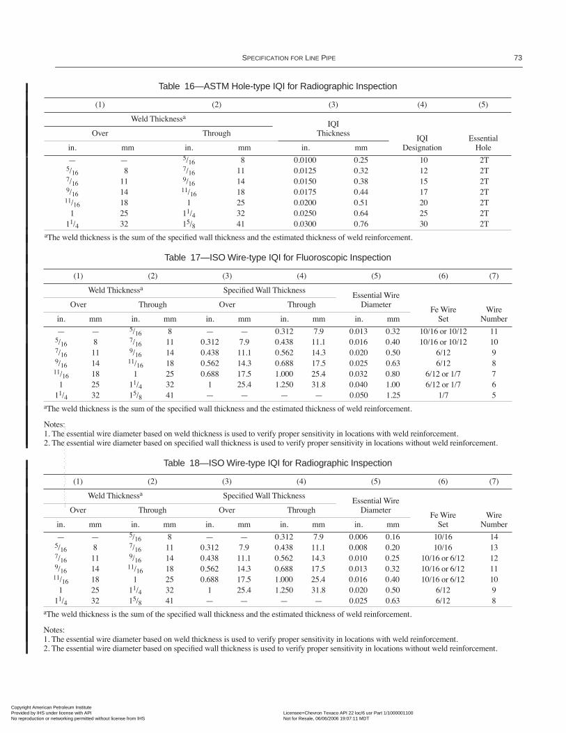
SPECIFICATION FOR LINE PIPE 73
Table 16—ASTM Hole-type IQI for Radiographic Inspection
(1) (2) (3) (4) (5)
Weld ThicknessaIQI
ThicknessIQI
DesignationEssential
Hole
Over Through
in. mm in. mm in. mm
Ñ Ñ 5/16 8 0.0100 0.25 10 2T5/16 8 7/16 11 0.0125 0.32 12 2T7/16 11 9/16 14 0.0150 0.38 15 2T9/16 14 11/16 18 0.0175 0.44 17 2T11/16 18 1 25 0.0200 0.51 20 2T
1 25 11/4 32 0.0250 0.64 25 2T11/4 32 15/8 41 0.0300 0.76 30 2T
aThe weld thickness is the sum of the speciÞed wall thickness and the estimated thickness of weld reinforcement.
Table 17—ISO Wire-type IQI for Fluoroscopic Inspection
(1) (2) (3) (4) (5) (6) (7)
Weld Thicknessa SpeciÞed Wall ThicknessEssential Wire
DiameterFe Wire
SetWire
Number
Over Through Over Through
in. mm in. mm in. mm in. mm in. mm
Ñ Ñ 5/16 8 Ñ Ñ 0.312 7.9 0.013 0.32 10/16 or 10/12 115/16 8 7/16 11 0.312 7.9 0.438 11.1 0.016 0.40 10/16 or 10/12 107/16 11 9/16 14 0.438 11.1 0.562 14.3 0.020 0.50 6/12 99/16 14 11/16 18 0.562 14.3 0.688 17.5 0.025 0.63 6/12 811/16 18 1 25 0.688 17.5 1.000 25.4 0.032 0.80 6/12 or 1/7 7
1 25 11/4 32 1 25.4 1.250 31.8 0.040 1.00 6/12 or 1/7 611/4 32 15/8 41 Ñ Ñ Ñ Ñ 0.050 1.25 1/7 5
aThe weld thickness is the sum of the speciÞed wall thickness and the estimated thickness of weld reinforcement.
Notes: 1. The essential wire diameter based on weld thickness is used to verify proper sensitivity in locations with weld reinforcement.2. The essential wire diameter based on speciÞed wall thickness is used to verify proper sensitivity in locations without weld reinforcement.
Table 18—ISO Wire-type IQI for Radiographic Inspection
(1) (2) (3) (4) (5) (6) (7)
Weld Thicknessa SpeciÞed Wall ThicknessEssential Wire
DiameterFe Wire
SetWire
Number
Over Through Over Through
in. mm in. mm in. mm in. mm in. mm
Ñ Ñ 5/16 8 Ñ Ñ 0.312 7.9 0.006 0.16 10/16 145/16 8 7/16 11 0.312 7.9 0.438 11.1 0.008 0.20 10/16 137/16 11 9/16 14 0.438 11.1 0.562 14.3 0.010 0.25 10/16 or 6/12 129/16 14 11/16 18 0.562 14.3 0.688 17.5 0.013 0.32 10/16 or 6/12 1111/16 18 1 25 0.688 17.5 1.000 25.4 0.016 0.40 10/16 or 6/12 10
1 25 11/4 32 1 25.4 1.250 31.8 0.020 0.50 6/12 911/4 32 15/8 41 Ñ Ñ Ñ Ñ 0.025 0.63 6/12 8
aThe weld thickness is the sum of the speciÞed wall thickness and the estimated thickness of weld reinforcement.
Notes: 1. The essential wire diameter based on weld thickness is used to verify proper sensitivity in locations with weld reinforcement.2. The essential wire diameter based on speciÞed wall thickness is used to verify proper sensitivity in locations without weld reinforcement.
Copyright American Petroleum Institute Provided by IHS under license with API Licensee=Chevron Texaco API 22 loc/6 usr Part 1/1000001100
Not for Resale, 06/06/2006 19:07:11 MDTNo reproduction or networking permitted without license from IHS
--`,``,``,``,`,`,``,`,``,,``,`,-`-`,,`,,`,`,,`---

74 API SPECIFICATION 5L
Table 19—ASTM Wire-type IQI for Fluoroscopic Inspection
(1) (2) (3) (4) (5) (6) (7)
Weld Thicknessa SpeciÞed Wall ThicknessEssential Wire
DiameterWireSet
WireIdentity
Over Through Over Through
in. mm in. mm in. mm in. mm in. mm
Ñ Ñ 5/16 8 Ñ Ñ 0.312 7.9 0.013 0.33 B 75/16 8 7/16 11 0.312 7.9 0.438 11.1 0.016 0.41 B 87/16 11 9/16 14 0.438 11.1 0.562 14.3 0.020 0.51 B 99/16 14 11/16 18 0.562 14.3 0.688 17.5 0.025 0.64 B 1011/16 18 1 25 0.688 17.5 1.000 25.4 0.032 0.81 B or C 11
1 25 11/4 32 1 25.4 1.250 31.8 0.040 1.02 C 1211/4 32 15/8 41 Ñ Ñ Ñ Ñ 0.050 1.27 C 13
aThe weld thickness is the sum of the speciÞed wall thickness and the estimated thickness of weld reinforcement.
Notes: 1. The essential wire diameter based on weld thickness is used to verify proper sensitivity in locations with weld reinforcement.2. The essential wire diameter based on speciÞed wall thickness is used to verify proper sensitivity in locations without weld reinforcement.
Table 20—ASTM Wire-type IQI for Radiographic Inspection
(1) (2) (3) (4) (5) (6) (7)
Weld Thicknessa SpeciÞed Wall ThicknessEssential Wire
DiameterWireSet
WireIdentity
Over Through Over Through
in. mm in. mm in. mm in. mm in. mm
Ñ Ñ 5/16 8 Ñ Ñ 0.312 7.9 0.0063 0.16 A 45/16 8 7/16 11 0.312 7.9 0.438 11.1 0.008 0.20 A 57/16 11 9/16 14 0.438 11.1 0.562 14.3 0.010 0.25 A or B 69/16 14 11/16 18 0.562 14.3 0.688 17.5 0.013 0.33 B 711/16 18 1 25 0.688 17.5 1.000 25.4 0.016 0.41 B 8
1 25 11/4 32 1 25.4 1.250 31.8 0.020 0.51 B 911/4 32 15/8 41 Ñ Ñ Ñ Ñ 0.025 0.64 B 10
aThe weld thickness is the sum of the speciÞed wall thickness and the estimated thickness of weld reinforcement.
Notes: 1. The essential wire diameter based on weld thickness is used to verify proper sensitivity in locations with weld reinforcement.2. The essential wire diameter based on speciÞed wall thickness is used to verify proper sensitivity in locations without weld reinforcement.
Table 21—Elongated Slag-inclusion-type Discontinuitiesa
(1) (2) (3)
Maximum Dimensions Minimum SeparationMaximum Number in any
6 in. (152.4 mm)in. mm in. mm1/16 ´ 1/2 1.6 ´ 12.7 6 152.4 11/6 ´ 1/4 1.6 ´ 6.4 3 76.2 21/16 ´ 1/8 1.6 ´ 3.2 2 50.8 3
Note: See Figure 8.aMaximum accumulated length of discontinuities in any 6 in. (152.4 mm) shall not exceed 1/2 in. (12.7 mm).
Copyright American Petroleum Institute Provided by IHS under license with API Licensee=Chevron Texaco API 22 loc/6 usr Part 1/1000001100
Not for Resale, 06/06/2006 19:07:11 MDTNo reproduction or networking permitted without license from IHS
--`,``,``,``,`,`,``,`,``,,``,`,-`-`,,`,,`,`,,`---

SPECIFICATION FOR LINE PIPE 75
Table 22—Circular Slag-inclusion-type and Gas-pocket-type Discontinuitiesa
(1) (2) (3) (4)
Size Adjacent Size Minimum Separation Maximum Number in any6 in. (152.4 mm)in. mm in. mm in. mm
1/8b 3.2 1/8b 3.2 2 50.8 21/8b 3.2 1/16 1.6 1 25.4 Varies1/8b 3.2 1/32 0.8 1/2 12.7 Varies1/8b 3.2 1/64 0.4 3/8 9.5 Varies1/16 1.6 1/16 1.6 1/2 12.7 41/16 1.6 1/32 0.8 3/8 9.5 Varies1/16 1.6 1/64 0.4 1/4 6.4 Varies1/32 0.8 1/32 0.8 1/4c 6.4 81/32 0.8 1/64 0.4 3/16 4.8 Varies1/64 0.4 1/64 0.4 1/8 3.2 16
Note: See Figure 7.aThe sum of the diameters of all discontinuities in any 6 in. (152.4 mm) not to exceed 1/4 in. (6.4 mm).bMaximum size discontinuity for 0.250 in. (6.4 mm) wall and lighter shall be 3/32 in. (2.4 mm).cTwo discontinuities 1/32 in. (0.8 mm) or smaller may be as close as one diameter apart provided they are separated from any other dis-continuity by at least 1/2 in. (12.7 mm).
Table 23—Acceptance Limits
(1) (2) (3) (4)
Item Notch Type
Hole Size Acceptance Limit Signal, %in. mm
Submerged-arc, gas-metal arc, N5 1/16 1.6 100laser, and repair welds N10 1/8 3.2 331/3
Electric welds N10 1/8 3.2 100
Seamless Pipe N12.5 1/8 3.2 100
Table 24—Pipe Weld Seam Nondestructive Inspection Methods
(1) (2) (3) (4)
Nondestructive Inspection Methods
Weld Seam Type EMI UT RTElectric A A NLaser N R NSubmerged-arc N RU NUGas Metal-arc N R NSkelp End N RU NULegend:
EMI = Electromagnetic inspectionUT = Ultrasonic inspectionRT = Radiographic inspectionA = One method or a combination of methods are requiredN = Not requiredR = RequiredRU = Required, unless RT has been agreed upon between the
purchaser and the manufacturerNU = Not required, unless RT has been agreed upon between
the purchaser and the manufacturer
Notes: 1. This table is applicable to welded pipe in sizes of 23/8 and larger, ingrades higher than Grade A 25. 2. The weld seam at the pipe ends may require additional inspection.(See 9.8.3.1.)
Copyright American Petroleum Institute Provided by IHS under license with API Licensee=Chevron Texaco API 22 loc/6 usr Part 1/1000001100
Not for Resale, 06/06/2006 19:07:11 MDTNo reproduction or networking permitted without license from IHS
--`,``,``,``,`,`,``,`,``,,``,`,-`-`,,`,,`,`,,`---

76 API SPECIFICATION 5L
Table 25—Pipe Body Nondestructive Inspection Methods—Seamless
(1) (2) (3) (4)
Nondestructive Inspection Methods
Item EMI UT MTPSL 2 A A APSL 1 Grade B Q&T A A APSL 1 Other AI AI AILegend:
EMI = Electromagnetic inspectionUT = Ultrasonic inspectionMT = Magnetic particle inspection, circular ÞeldA = One method or a combination of methods are to be usedAI = One method or a combination of methods are to be used if non-
destructive inspection is speciÞed on the purchase order.
Table 26—Reference Indicators
(1) (2) (3) (4) (5) (6) (7) (8) (9)
Item
Reference Indicatorsa
Notch Location
Notch Orientation
Notch Dimensions, Maximum Diameter ofRadially
Drilled Through-wall Holed
Depthb
Lengthc Widthc
OD ID Long. Trans. in. mm in. mm in. r
Electric weld seam R R R N 10.0 2.0 50 0.040 1 1/8 3.2Laser weld seam R R R N 5.0e 2.0 50 0.040 1 1/16e 1.6e
Submerged-arc weld seamf R R R A 5.0e 2.0 50 0.040 1 1/16e 1.6e
Gas metal-arc weld seamf R R R A 5.0e 2.0 50 0.040 1 1/16e 1.6e
Skelp end weld seamf R R R A 5.0e 2.0 50 0.040 1 1/16e 1.6e
Seamless (PSL 2) R R Rg N 12.5 2.0 50 0.040 1 1/8 3.2Seamless (PSL 1 Grade B Q&T) RP RP Rg N 12.5 2.0 50 0.040 1 1/8 3.2Seamless (PSL 1 Other) RP N Rg N 12.5 2.0 50 0.040 1 1/8 3.2aReference indicators need not be located in the weld.bDepth, expressed as a percentage of the speciÞed wall thickness, with a minimum speciÞed notch depth of 0.012 in. (0.3 mm). The depth tolerance shall be±15% of the speciÞed notch depth or ± 0.002 in. (0.05 mm), whichever is the greater. The notch types are designated N5, N10, and N12.5.cAt full depth.dDrilled hole diameters are based upon standard drill bit sizes. A hole is not required if a notch is used to establish the reject threshold.eAt the option of the manufacturer, it shall be permissible for N10 notches or 1/8-in. (3.2-mm) radially drilled holes to be used.fAt the option of the manufacturer, for submerged-arc weld seams and gas metal-arc weld seams it shall be permissible for the reject threshold to be establishedusing weld-edge notches or weld-edge radially drilled holes.gAt the option of the manufacturer, it shall be permissible for the notches to be oriented at such an angle as to optimize the detection of anticipated defects.
Legend:
R = Required if a notch is used to establish the reject threshold.RP = Required for pipe of size 23/8 and larger, if a notch is used to establish the reject threshold.N = Not required.A = Either a transverse notch or a 1/16-in. (1.6-mm) radially drilled hole is required for inspection for transverse imperfections.
Notes:
1. For weld seam inspection, this table is applicable to welded pipe in sizes 23/8 and larger, in a grade higher than Grade A25.2. Notches are rectangular or U-shaped, as shown in Figure 2 of ASTM E 213.3. For electromagnetic inspection, it may be necessary for the reference standard to contain OD notches, ID notches and drilled holes. (See 9.8.5.2.)
04
04
Copyright American Petroleum Institute Provided by IHS under license with API Licensee=Chevron Texaco API 22 loc/6 usr Part 1/1000001100
Not for Resale, 06/06/2006 19:07:11 MDTNo reproduction or networking permitted without license from IHS
--`,``,``,``,`,`,``,`,``,,``,`,-`-`,,`,,`,`,,`---
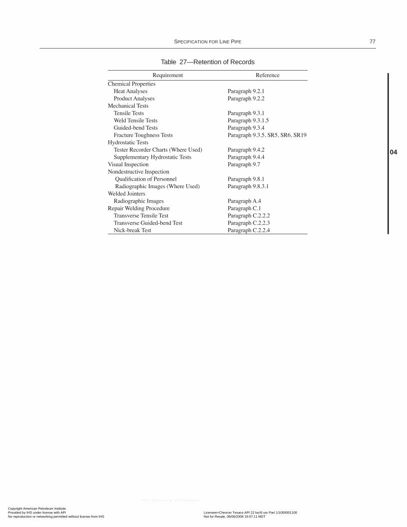
SPECIFICATION FOR LINE PIPE 77
Table 27—Retention of Records
Requirement Reference
Chemical PropertiesHeat Analyses Paragraph 9.2.1Product Analyses Paragraph 9.2.2
Mechanical TestsTensile Tests Paragraph 9.3.1Weld Tensile Tests Paragraph 9.3.1.5Guided-bend Tests Paragraph 9.3.4Fracture Toughness Tests Paragraph 9.3.5, SR5, SR6, SR19
Hydrostatic TestsTester Recorder Charts (Where Used) Paragraph 9.4.2Supplementary Hydrostatic Tests Paragraph 9.4.4
Visual Inspection Paragraph 9.7Nondestructive Inspection
QualiÞcation of Personnel Paragraph 9.8.1 Radiographic Images (Where Used) Paragraph 9.8.3.1
Welded JointersRadiographic Images Paragraph A.4
Repair Welding Procedure Paragraph C.1Transverse Tensile Test Paragraph C.2.2.2Transverse Guided-bend Test Paragraph C.2.2.3Nick-break Test Paragraph C.2.2.4
04
Copyright American Petroleum Institute Provided by IHS under license with API Licensee=Chevron Texaco API 22 loc/6 usr Part 1/1000001100
Not for Resale, 06/06/2006 19:07:11 MDTNo reproduction or networking permitted without license from IHS
--`,``,``,``,`,`,``,`,``,,``,`,-`-`,,`,,`,`,,`---

Copyright American Petroleum Institute Provided by IHS under license with API Licensee=Chevron Texaco API 22 loc/6 usr Part 1/1000001100
Not for Resale, 06/06/2006 19:07:11 MDTNo reproduction or networking permitted without license from IHS
--`,``,``,``,`,`,``,`,``,,``,`,-`-`,,`,,`,`,,`---

79
APPENDIX A—SPECIFICATION FOR WELDED JOINTERS (NORMATIVE)
A.1 Method
Welding of any type that uses deposited Þller metal and isgenerally recognized as sound practice shall be permittedunless the purchaser speciÞes a particular method. Weldingprocedures, welders, and welding machine operators (hereaf-ter called operators) shall be qualiÞed in accordance with APIStandard 1104. Copies of the welding procedure speciÞcationand procedure qualiÞcation record shall be provided to thepurchaser upon request.
A.2 Workmanship
The ends of the pipe to be welded together shall be pre-pared in accordance with the requirements of the procedure tobe used. Pipe weld seams (straight, helical, or skelp end) shallbe staggered between 2 in. and 8 in. (51 mm and 203 mm)unless otherwise speciÞed by the purchaser. The completedjointers shall be straight within the limits of 7.6 of this speci-Þcation. Each weld shall have a substantially uniform crosssection around the entire circumference of the pipe. At no
point shall its crowned surface be below the outside surface ofthe parent metal nor shall it rise above the parent metal bymore than
1
/
8
in. (3.18 mm) if submerged-arc welded, or bymore than
1
/
16
in. (1.59 mm), if welded by another process.
A.3 Marking
Each jointer shall be marked using paint to identify thewelder or operator.
A.4 Nondestructive Testing
The girth welds of jointers shall be 100% radiographed inaccordance with the procedures and standards of acceptabil-ity in API Standard 1104 (see note). Jointer welds failing topass this radiographic testing may be repaired and re-radio-graphed in accordance with the procedures and acceptancecriteria of API Standard 1104. Radiographic images shall betraceable to the pipe identity.
Note: See 7.7 for length requirements on jointers.
Copyright American Petroleum Institute Provided by IHS under license with API Licensee=Chevron Texaco API 22 loc/6 usr Part 1/1000001100
Not for Resale, 06/06/2006 19:07:11 MDTNo reproduction or networking permitted without license from IHS
--`,``,``,``,`,`,``,`,``,,``,`,-`-`,,`,,`,`,,`---

Copyright American Petroleum Institute Provided by IHS under license with API Licensee=Chevron Texaco API 22 loc/6 usr Part 1/1000001100
Not for Resale, 06/06/2006 19:07:11 MDTNo reproduction or networking permitted without license from IHS
--`,``,``,``,`,`,``,`,``,,``,`,-`-`,,`,,`,`,,`---

81
APPENDIX B—REPAIR OF DEFECTS BY WELDING (NORMATIVE)
B.1 Types Of Pipe
B.1.1 SEAMLESS PIPE AND PARENT METAL OF WELDED PIPE
For PSL 1 pipe, the repair of defects in seamless pipe andparent metal of welded pipe is permissible except (a) when thedepth of the defect exceeds 33
1
/
3
% of the speciÞed wall thick-ness of the pipe and the length of that portion of the defect inwhich the depth exceeds 12
1
/
2
% is greater than 25% of thespeciÞed outside diameter of the pipe; or (b) when more thanone repair is required in any length equivalent to 10 times thespeciÞed outside diameter of the pipe. Repairs shall be madein accordance with B.2. Repair welds shall be inspected by themagnetic particle method in accordance with 9.7.5.1 through9.7.5.3; by liquid penetrant; or by other NDT methods asagreed start between purchaser and the manufacturer.
For PSL 2, seamless pipe, the parent metal (body) ofwelded pipe, plate, and skelp shall not be repaired by welding.
B.1.2 WELD SEAM OF WELDED PIPE
B.1.2.1
Defects in Þller metal welds may be repaired at theoption of the manufacturer; such repairs shall be in accor-dance with B.3. All repair welds shall be inspected by ultra-sonic methods in accordance with 9.8.5.1, 9.8.5.2, and 9.8.5.4.,except that the equipment need not be capable of continuousand uninterrupted operation and, at the option of the manu-facturer, repairs made by submerged-arc welding or byshielded metal-arc welding may alternatively be inspected byradiological methods in 9.8.4.
B.1.2.2
For PSL 1 pipe, weld seams made without Þllermetal (electric and laser welds) may be repaired by weldingonly by agreement between the purchaser and the manufac-turer; such repairs shall be in accordance with B.4.
B.1.2.3
For PSL 2 pipe, weld seams made without Þllermetal shall not be repaired by welding.
B.1.3 HEAT TREATED PIPE
When heat treated pipe has been repaired by welding, theneed for and type of reheat treatment shall be based on theeffect of the repair on the structure and properties of the heattreated pipe, by agreement between the purchaser and themanufacturer.
B.2 Procedure for Repair by Welding of Seamless Pipe and Parent Metal of Welded Pipe (PSL 1 Only)
The repair of defects in seamless pipe and parent metal ofwelded pipe shall conform to the requirements listed in B.2.1-
B.2.5. Conformance to the repair procedure is subject toapproval of the purchaserÕs inspector.
B.2.1
The defect shall be removed completely by chippingand/or grinding. The resulting cavity shall be thoroughlycleaned and shall be inspected before welding by magneticparticle methods in accordance with 9.8.6 to ensure completeremoval of the defect.
B.2.2
The minimum length of repair weld shall be 2 in.(50.8 mm). Where the orientation of the defect permits, therepair weld shall be placed in the circumferential direction.
B.2.3
The repair weld shall be made either by automaticsubmerged-arc welding, gas metal-arc welding, or manualshielded metal-arc welding using low-hydrogen electrodes.The metal temperature in the area to be repaired shall be aminimum of 50¡F (10¡C). The welding procedure and perfor-mance shall be qualiÞed in accordance with Appendix C.
B.2.4
The repair weld shall be ground to merge smoothlyinto the original contour of the pipe.
B.2.5
Repaired pipe shall be tested hydrostatically afterrepairing, in accordance with 9.4.
B.3 Procedure for Repair of Submerged-Arc and Gas Metal-Arc Welds
The repair of submerged-arc and gas metal-arc welds shallconform to the requirements listed in B.3.1-B.3.3. Conform-ance is subject to approval of purchaserÕs inspector.
B.3.1
The defect shall be completely removed and the cav-ity thoroughly cleaned. Where multiple pass repairs are used,the size of the cavity shall be sufÞciently large [at least 2 in.(50.8 mm) in length] to avoid coincidence of starts and stopsof individual passes.
B.3.2
The minimum length of each repair weld shall be 2in. (50.8 mm). The repair weld shall be made either by auto-matic submerged-arc welding, gas metal-arc welding, ormanual shielded metal-arc welding using low-hydrogen elec-trodes. The welding procedure and performance shall bequaliÞed in accordance with Appendix C.
B.3.3
Each length of repaired pipe shall be tested hydro-statically in accordance with 9.4.
B.4 Procedure for Repair of Electric and Laser Welds (PSL 1 Only)
The repair of electric and laser welds shall conform to therequirements in B.4.1 through B.4.6 and shall include theweld zone, which is deÞned for the purposes of repair as
1
/
2
in. (12.7 mm) on each side of the fusion line. Conformance to
04
04
04
Copyright American Petroleum Institute Provided by IHS under license with API Licensee=Chevron Texaco API 22 loc/6 usr Part 1/1000001100
Not for Resale, 06/06/2006 19:07:11 MDTNo reproduction or networking permitted without license from IHS
--`,``,``,``,`,`,``,`,``,,``,`,-`-`,,`,,`,`,,`---

82 API S
PECIFICATION
5L
the repair procedure is subject to approval of the purchaserÕsinspector.
B.4.1
The weld zone defect shall be removed completelyby chipping and/or grinding, and the resulting cavity shall bethoroughly cleaned.
B.4.2
The minimum length of repair weld shall be 2 in.(50.8 mm), and individual weld repairs shall be separated byat least 10 ft (3 m).
B.4.3
The repair weld shall be made by either automaticsubmerged-arc welding, gas metal-arc welding, or manualshielded metal-arc welding using low-hydrogen electrodes.The metal temperature in the area to be repaired shall be a
minimum of 50¡F (10¡C). The welding procedure and perfor-mance shall be qualiÞed in accordance with Appendix C.
B.4.4
When a repair weld is made through the full wallthickness, it shall include weld passes made from both the IDand the OD of the pipe. Starts and stops of the ID and ODrepair welds shall not coincide.
B.4.5
The repair shall be ground to merge smoothly intothe original contour of the pipe and shall have a maximumcrown of 0.06 in. (1.52 mm).
B.4.6
Repaired pipe shall be hydrostatically tested afterrepair in accordance with 9.4.
Figure B-1—Resultant Cavity for Undercut Repair (PSL 2 Only)
Weld Reinforcement
Rim of resultant cavity
1/8 in. (3.2 mm) max
Copyright American Petroleum Institute Provided by IHS under license with API Licensee=Chevron Texaco API 22 loc/6 usr Part 1/1000001100
Not for Resale, 06/06/2006 19:07:11 MDTNo reproduction or networking permitted without license from IHS
--`,``,``,``,`,`,``,`,``,,``,`,-`-`,,`,,`,`,,`---

83
APPENDIX C—REPAIR WELDING PROCEDURE (NORMATIVE)
C.1 General
All repair welds shall be made in the ßat position accord-ing to a qualiÞed procedure and by a welding machine opera-tor (hereafter called operator) or repair welder who isqualiÞed in a ßat position as speciÞed in C.3. Repair weldsmay be made by one of the following methods:
a. Automatic submerged arc.b. Automatic or semi-automatic gas metal arc.c. Manual shielded metal arc using low-hydrogen electrodes.
All welding materials shall be properly handled and storedin accordance with the manufacturerÕs recommendations soas to preclude moisture or other contamination. Test weldsmay be made on either plate stock or pipe stock at the optionof the manufacturer.
The manufacturer shall maintain a record of the weldingprocedure and procedure qualiÞcation test results. Copies ofthe welding procedure speciÞcation and procedure qualiÞca-tion record shall be provided to the purchaser upon request.
C.2 Repair Welding Procedure Qualification
Welding procedures shall be qualiÞed by preparing andtesting welds in accordance with this appendix. At the optionof the manufacturer, the tests speciÞed in the ASME Boilerand Pressure Vessel Code, Section IX, may be substitutedherein. For the purpose of this appendix, the term automaticwelding includes both machine welding and automatic weld-ing as deÞned in the ASME Boiler and Pressure Vessel Code,Section IX.
C.2.1 ESSENTIAL VARIABLES
An existing procedure shall not be applicable and new pro-cedure shall be qualiÞed when any of the following essentialvariables is changed beyond the stated limits:
a. Welding process:1. A change in the welding process, such as submergedarc to gas metal arc.2. A change in the method, such as manual to semi-automatic.
b. Pipe material:1. A change in grade category. When different alloyingsystems are used within one grade category, each alloyingcomposition shall be separately qualiÞed. Grade catego-ries are as follows:
£
X42 > X42 and < X65 each grade
³
X65
2. Within each grade category, a thicker material than thematerial qualiÞed.3. Within the grade category and thickness range, a car-bon equivalent, CE (see note), based on product analysisfor the material to be repaired, that is more than 0.04%greater than the CE of the material qualiÞed.
Note:
c. Welding materials:1. A change in Þller metal classiÞcation.2. A change in electrode diameter.3. A change of more than 5% in the composition ofshielding gas.4. A change of more than 10% in the ßow rate of shield-ing gas.5. A change in submerged-arc welding ßux from one des-ignation to another.
d. Welding parameters:1. A change in the type of current (such as AC versus DC).2. A change in polarity.3. For automatic and semi-automatic welding, schedulesof welding current, voltage, and speed may be establishedto cover ranges of wall thicknesses. Within the schedule,appropriately selected points shall be tested to qualify theentire schedule. Thereafter, a new qualiÞcation is requiredif there is a deviation from the qualiÞed schedule greaterthan the following:
10% in amperage 7% in voltage 10% in travel speed for automatic welding
e. Weld bead: For manual and semi-automatic welding, achange in bead width greater than 50%.f. Preheat and post-weld heat treatment:
1. Repair welding at a pipe temperature lower than thepipe temperature of the qualiÞcation test.2. The addition or deletion of post-weld heat treatment.
C.2.2 MECHANICAL TESTING
C.2.2.1 Number of Tests
Two specimens of each type are required from each proce-dure qualiÞcation test.
C.2.2.2 Transverse Tensile Test
The transverse tensile test specimens shall be approxi-mately 1.5 in. (38.1 mm) wide and shall have the transverse
04
CE C Mn6
-------- Cr Mo V+ +5
------------------------------ Ni Cu+15
-------------------+ + += 04
Copyright American Petroleum Institute Provided by IHS under license with API Licensee=Chevron Texaco API 22 loc/6 usr Part 1/1000001100
Not for Resale, 06/06/2006 19:07:11 MDTNo reproduction or networking permitted without license from IHS
--`,``,``,``,`,`,``,`,``,,``,`,-`-`,,`,,`,`,,`---

84 API S
PECIFICATION
5L
butt weld perpendicular to the longitudinal axis at the centerof the test specimen (See Figure C-1 or Figure 4.) The weldreinforcement shall be removed from both faces. The ultimatetensile strength shall be at least equal to the minimum speci-Þed for the pipe grade.
C.2.2.3 Transverse Guided-Bend Test
The transverse guided-bend test specimens shall conformto Figure C-2. The weld shall be made in a groove as shown.Each specimen shall be placed on the die with the weld atmid-span and shall be bent approximately 180¡ in a jig inaccordance with Figure C-3 and Table C-1, with the exposedsurface of the weld in tension. The bend test shall be consid-ered acceptable if no crack or other defect exceeding
1
/
8
in.(3.18 mm) in any direction is present in the weld metal orbase metal after bending. Cracks that both originate along theedges of the specimen during testing and measure less than
1
/
4
in. (6.35 mm) in all directions shall not be considered.
C.2.2.4 Nick-Break Test
The nick-break specimens shall conform to Figure C-4.The weld shall be made in a groove as shown. Each specimenshall be saw-notched from both edges at the center of theweld and shall be broken by pulling or hammer blows at thecenter of one end. The exposed surface of the specimen shallbe visually examined and shall be considered acceptable if itmeets the following criteria:
a. No gas pockets exceeding
1
/
16
in. (1.59 mm) in anydirection.b. Not more than one gas pocket of any size for speciÞedwall thicknesses of 0.250 in. (6.4 mm) and less.c. Not more than two gas pockets of any size for speciÞedwall thicknesses of 0.500 in. (12.7 mm) or less but greaterthan 0.250 in. (6.4 mm).d. Not more than three gas pockets of any size for speciÞedwall thicknesses greater than 0.500 in. (12.7 mm).e. Slag inclusions shall be separated by at least
1
/
2
in. (12.7mm) of sound metal and shall appear no greater than
1
/
16
in.(1.59 mm) in width or 3/16 in. (4.76 mm) in length.
C.3 Welding Personnel Performance Qualification
C.3.1 QUALIFICATION
C.3.1.1 General
Each repair welder and operator is required to qualify. Arepair welder or operator qualiÞed on one grade category isqualiÞed for any lower grade category provided the samewelding process is used.
C.3.1.2 Testing
To qualify, a repair welder or operator shall produce weldsthat are acceptable in the following tests:
a. Film radiographic examination per Section 9 of thisspeciÞcation.b. Two transverse guided-bend tests per C.2.2.3 of thisappendix.c. Two nick-break tests per C.2.2.4 of this appendix.
C.3.1.3 Test Failures
If one or more of the tests in C.3.1.2 fail to meet the speci-Þed requirements, the welder or operator may make one addi-tional qualiÞcation weld. If that weld fails one or more of thetests in C.3.1.2, the welder or operator is disqualiÞed. No fur-ther retests shall be permitted until the welder has completedadditional training.
C.3.2 REQUALIFICATION
RequaliÞcation in accordance with C.3.1 is required underthe following circumstances:
a. One year has elapsed since the last prior applicablequaliÞcation.b. The individual has not been welding using qualiÞed proce-dures for a period of 3 months.c. There is reason to question the individualÕs ability.
Copyright American Petroleum Institute Provided by IHS under license with API Licensee=Chevron Texaco API 22 loc/6 usr Part 1/1000001100
Not for Resale, 06/06/2006 19:07:11 MDTNo reproduction or networking permitted without license from IHS
--`,``,``,``,`,`,``,`,``,,``,`,-`-`,,`,,`,`,,`---

S
PECIFICATION
FOR
L
INE
P
IPE
85
Figure C-1—Transverse Tensile Test Specimen
Figure C-2—Guided-bend Test Specimen
1/16 in. (1.6 mm) max.
11/2 in.(38 mm)
Wall thickness (t)
Specimen edgesshall be machined
6 in. (150 mm) min.
Note: Weld reinforcement shall be removed from both faces.
Weld
1/16 in. (1.6 mm) max.
See C.2.1.b.2
1/8 ± 0.010 in. (3.2 ± 0.2 mm)
Specimen edges may be oxygen cutand may also be machined
6 in. (150 mm) min.
Note: Weld reinforcement shall be removed.
11/2 in.(38 mm)
Copyright American Petroleum Institute Provided by IHS under license with API Licensee=Chevron Texaco API 22 loc/6 usr Part 1/1000001100
Not for Resale, 06/06/2006 19:07:11 MDTNo reproduction or networking permitted without license from IHS
--`,``,``,``,`,`,``,`,``,,``,`,-`-`,,`,,`,`,,`---

86 API S
PECIFICATION
5L
Figure C-3—Jig for Guided-Bend Test
7/8 in. min.(22.2 mm)
As required As required
2 in.(50.8 mm)
1/4 in. (6.4 mm)
1/8 in. (3.2 mm)
18t
2t
2t
5t + 2 in.(5t + 50.8 mm)
Tappedmounting hole 2t
2t
Shoulders hardened andgreased. Hardenedrollers may be substituted. 1/2 in.
(12.7 mm)3t
A
B
2t
3/8 in. (9.5 mm)
3/4 in. (19.0 mm)
RB
RA
20t24t
RA
B3/4 in. min.(19.0 mm)
A
t
Rollert + 1/16 in.
(t + 1.6 mm)
A2
Adjustable Type Wrap-around Type
Alternate Jigs
t = Specified wall thickness of pipe,
Note: See Table C-1.
7t + 1/16 in. max(7t + 1.6 mm)
Copyright American Petroleum Institute Provided by IHS under license with API Licensee=Chevron Texaco API 22 loc/6 usr Part 1/1000001100
Not for Resale, 06/06/2006 19:07:11 MDTNo reproduction or networking permitted without license from IHS
--`,``,``,``,`,`,``,`,``,,``,`,-`-`,,`,,`,`,,`---

S
PECIFICATION
FOR
L
INE
P
IPE
87
Figure C-4—Nick-Break Test Specimen
Table C-1—Guided-bend Test Jig Dimensions
(1) (2) (3) (4) (5) (6)
Pipe Grade
a
Member Dimension A, B, & X42 X46 X52 & X56 X60 & X65 X70 & X80Radius of male member,
R
A
3t 3
1
/
2
t
4
t
4
1
/
2
t
5
t
Radius of female member,
R
B
4t +
1
/
16
in.
1
/
2
t
+
1
/
16
in.(4
t
+ 1.6 mm)(4
1
/
2
t
+ 1.6 mm)5
t
+
1
/
16
in.(5
t
+ 1.6 mm)5
1
/
2
t
+
1
/16 in.(51/2t + 1.6 mm)
6t + 1/16 in.(6t + 1.6 mm)
Width of male member, A 6t 7t 8t 9t 10tWidth of groove in female member, B 8t + 1/8 in.
(8t + 3.2 mm)9t + 1/8 in.
(9t + 3.2 mm)10t + 1/8 in.
(10t + 3.2 mm)11t + 1/8 in.
(11t + 3.2 mm)12t + 1/8 in.
(12t + 3.2 mm)Notes:
1. See Figure C-3.2. t = speciÞed wall thickness of the pipe.
aFor intermediate grades of pipe, the dimensions of the bending jig shall conform to those shown for the next lower grade or shall be proportional thereto.
6 in. (150 mm) min.
1/4 in. (6.4 mm)
1/8 ± 0.010 in. (3.2 ± 0.25 mm)
1/4 in. (6.4 mm)
11/2 in.(38 mm)
Saw cut
Copyright American Petroleum Institute Provided by IHS under license with API Licensee=Chevron Texaco API 22 loc/6 usr Part 1/1000001100
Not for Resale, 06/06/2006 19:07:11 MDTNo reproduction or networking permitted without license from IHS
--`,``,``,``,`,`,``,`,``,,``,`,-`-`,,`,,`,`,,`---

Copyright American Petroleum Institute Provided by IHS under license with API Licensee=Chevron Texaco API 22 loc/6 usr Part 1/1000001100
Not for Resale, 06/06/2006 19:07:11 MDTNo reproduction or networking permitted without license from IHS
--`,``,``,``,`,`,``,`,``,,``,`,-`-`,,`,,`,`,,`---

89
APPENDIX D—ELONGATION TABLE (NORMATIVE)
These minimum elongation values were calculated by the equation in Footnote a of Tables 3A and 3B.
Table D-1—Elongation Table (U.S. Customary Units)
(1) (2) (3) (4) (5) (6) (7) (8) (9) (10) (11) (12) (13) (14)
Tensile Test Specimen Area
(sq. in.)
SpeciÞed Wall Thickness for Strip Specimen Testing (in.)
Elongation in 2 in., Minimum (percent)Grade
A25 A B & X42 X46 X52 X56 X60 X65 X70 X80Strip Specimen SpeciÞed Width SpeciÞed Minimum Ultimate Tensile Strength (psi)
3/4 in. 1 in. 11/2 in. 45,000 48,000 60,000 63,000 66,000 71,000 75,000 77,000 82,000 90,000
0.75 ³ 0.994 ³ 0.746 ³ 0.497 38 36 30 28 27 25 24 24 22 210.74 .980 Ñ .993 .735 Ñ .745 .490 Ñ .496 38 36 29 28 27 25 24 24 22 200.73 .967 Ñ .979 .726 Ñ .734 .484 Ñ .489 38 36 29 28 27 25 24 23 22 200.72 .954 Ñ .966 .715 Ñ .725 .477 Ñ .483 38 36 29 28 27 25 24 23 22 200.71 .941 Ñ .953 .706 Ñ .714 .471 Ñ .476 38 36 29 28 27 25 24 23 22 200.70 .927 Ñ .940 .695 Ñ .705 .464 Ñ .470 38 36 29 28 27 25 24 23 22 200.69 .914 Ñ .926 .686 Ñ .694 .457 Ñ .463 38 36 29 28 27 25 24 23 22 200.68 .900 Ñ .913 .675 Ñ .685 .450 Ñ .456 38 35 29 28 27 25 24 23 22 200.67 .887 Ñ .899 .666 Ñ .674 .444 Ñ .449 37 35 29 28 27 25 24 23 22 200.66 .874 Ñ .886 .655 Ñ .665 .437 Ñ .443 37 35 29 28 26 25 24 23 22 200.65 .861 Ñ .873 .646 Ñ .654 .431 Ñ .436 37 35 29 27 26 25 23 23 22 200.64 .847 Ñ .860 .635 Ñ .645 .424 Ñ .430 37 35 29 27 26 25 23 23 22 200.63 .834 Ñ .846 .626 Ñ .634 .417 Ñ .423 37 35 29 27 26 25 23 23 22 200.62 .820 Ñ .833 .615 Ñ .625 .410 Ñ .416 37 35 28 27 26 24 23 23 21 200.61 .807 Ñ .819 .606 Ñ .614 .404 Ñ .409 37 35 28 27 26 24 23 23 21 200.60 .794 Ñ .806 .595 Ñ .605 .397 Ñ .403 37 35 28 27 26 24 23 23 21 200.59 .781 Ñ .793 .586 Ñ .594 .391 Ñ .396 36 34 28 27 26 24 23 23 21 200.58 .767 Ñ .780 .575 Ñ .585 .384 Ñ .390 36 34 28 27 26 24 23 22 21 190.57 .754 Ñ .766 .566 Ñ .574 .377 Ñ .383 36 34 28 27 26 24 23 22 21 190.56 .740 Ñ .753 .555 Ñ .565 .370 Ñ .376 36 34 28 27 26 24 23 22 21 190.55 .727 Ñ .739 .546 Ñ .554 .364 Ñ .369 36 34 28 27 25 24 23 22 21 190.54 .714 Ñ .726 .535 Ñ .545 .357 Ñ .363 36 34 28 26 25 24 23 22 21 190.53 .701 Ñ .713 .526 Ñ .534 .351 Ñ .356 36 34 28 26 25 24 23 22 21 190.52 .687 Ñ .700 .515 Ñ .525 .344 Ñ .350 36 34 27 26 25 24 22 22 21 190.51 .674 Ñ .686 .506 Ñ .514 .337 Ñ .343 35 33 27 26 25 24 22 22 21 190.50 .660 Ñ .673 .495 Ñ .505 .330 Ñ .336 35 33 27 26 25 23 22 22 21 190.49 .647 Ñ .659 .486 Ñ .494 .324 Ñ .329 35 33 27 26 25 23 22 22 20 190.48 .634 Ñ .646 .475 Ñ .485 .317 Ñ .323 35 33 27 26 25 23 22 22 20 190.47 .621 Ñ .633 .466 Ñ .474 .311 Ñ .316 35 33 27 26 25 23 22 22 20 190.46 .607 Ñ .620 .455 Ñ .465 .304 Ñ .310 35 33 27 26 25 23 22 21 20 190.45 .594 Ñ .606 .446 Ñ .454 .297 Ñ .303 35 33 27 26 24 23 22 21 20 190.44 .580 Ñ .593 .435 Ñ .445 .290Ñ .296 34 32 27 25 24 23 22 21 20 180.43 .567 Ñ .579 .426 Ñ .434 .284 Ñ .289 34 32 26 25 24 23 22 21 20 180.42 .554 Ñ .566 .415 Ñ .425 .277 Ñ .283 34 32 26 25 24 23 22 21 20 180.41 .541 Ñ .553 .406 Ñ .414 .271 Ñ .276 34 32 26 25 24 23 21 21 20 180.40 .527 Ñ .540 .395 Ñ .405 .264 Ñ .270 34 32 26 25 24 22 21 21 20 180.39 .514 Ñ .526 .386 Ñ .394 .257 Ñ .263 34 32 26 25 24 22 21 21 20 180.38 .500 Ñ .513 .375 Ñ .385 .250 Ñ .256 33 32 26 25 24 22 21 21 19 180.37 .487 Ñ .499 .366 Ñ .374 .244 Ñ .249 33 31 26 25 24 22 21 20 19 180.36 .474 Ñ .486 .355 Ñ .365 .237 Ñ .243 33 31 26 24 23 22 21 20 19 180.35 .461 Ñ .473 .346 Ñ .354 .231 Ñ .236 33 31 25 24 23 22 21 20 19 180.34 .447Ñ .460 .335 Ñ .345 .224 Ñ .230 33 31 25 24 23 22 21 20 19 180.33 .434 Ñ .446 .326 Ñ .334 .217 Ñ .223 32 31 25 24 23 22 21 20 19 170.32 420 Ñ .433 .315 Ñ .325 .210 Ñ .216 32 30 25 24 23 21 20 20 19 170.31 .407 Ñ .419 .306 Ñ .314 .204 Ñ .209 32 30 25 24 23 21 20 20 19 170.30 .394 Ñ .406 .295 Ñ .305 .197 Ñ .203 32 30 25 24 23 21 20 20 19 170.29 .381 Ñ .393 .286 Ñ .294 .191 Ñ .196 32 30 24 23 22 21 20 20 18 170.28 .367 Ñ .380 .275 Ñ .285 .184 Ñ .190 31 30 24 23 22 21 20 19 18 170.27 .354 Ñ .366 .266 Ñ .274 .177 Ñ .183 31 29 24 23 22 21 20 19 18 170.26 .340 Ñ .353 .255 Ñ .265 .170 Ñ .176 31 29 24 23 22 21 20 19 18 170.25 .327 Ñ .339 .246 Ñ .254 .164 Ñ .169 31 29 24 23 22 20 19 19 18 16
04
Copyright American Petroleum Institute Provided by IHS under license with API Licensee=Chevron Texaco API 22 loc/6 usr Part 1/1000001100
Not for Resale, 06/06/2006 19:07:11 MDTNo reproduction or networking permitted without license from IHS
--`,``,``,``,`,`,``,`,``,,``,`,-`-`,,`,,`,`,,`---

90 API SPECIFICATION 5L
Tensile Test Specimen Area
(mm2)
Elongation in 50.8 mm, Minimum (percent)SpeciÞed Wall Thickness for Strip
Specimen Testing (mm)Grade
A25 A B & X42 X46 X52 X56 X60 X65 X70 X80Strip Specimen SpeciÞed Width SpeciÞed Minimum Ultimate Tensile Strength (MPa)
19.0 mm 25.4 mm 38.1 mm 310 331 414 434 455 490 517 531 565 6210.24 .314 Ñ .326 .235 Ñ .245 .157 Ñ .163 30 29 24 23 22 20 19 19 18 160.23 .301 Ñ .313 .226 Ñ .234 .151 Ñ .156 30 29 23 22 21 20 19 19 18 160.22 .287 Ñ .300 .215 Ñ .225 .144 Ñ .150 30 28 23 22 21 20 19 18 17 160.21 .274 Ñ .286 .206 Ñ .214 .137 Ñ .143 30 28 23 22 21 20 19 18 17 160.20 .260 Ñ .273 .195 Ñ .205 .130 Ñ .136 29 28 23 22 21 19 19 18 17 160.19 .247 Ñ .259 .186 Ñ .194 .124 Ñ .129 29 27 22 21 21 19 18 18 17 160.18 .234 Ñ .246 .175 Ñ .185 .117 Ñ .123 29 27 22 21 20 19 18 18 17 150.17 .221 Ñ .233 .166 Ñ .174 .111 Ñ .116 28 27 22 21 20 19 18 18 17 150.16 .207 Ñ .220 .155 Ñ .165 .104 Ñ .110 28 27 22 21 20 19 18 17 16 150.15 .194 Ñ .206 .146 Ñ .154 .097 Ñ .103 28 26 21 20 20 18 18 17 16 150.14 .180 Ñ .193 .135 Ñ .145 .090 Ñ .096 27 26 21 20 19 18 17 17 16 150.13 .167 Ñ .179 .126 Ñ .134 .084 Ñ .089 27 25 21 20 19 18 17 17 16 140.12 .154 Ñ .166 .115 Ñ .125 .083 27 25 20 20 19 18 17 16 15 140.11 .141 Ñ .153 .106 Ñ .114 Ñ 26 25 20 19 18 17 16 16 15 140.10 .127 Ñ .140 .095 Ñ .105 Ñ 26 24 20 19 18 17 16 16 15 140.09 .114 Ñ 126 .086 Ñ .094 Ñ 25 24 19 19 18 17 16 15 15 130.08 .100 Ñ .113 .083 Ñ .085 Ñ 24 23 19 18 17 16 15 15 14 130.07 .087 Ñ .099 .Ñ Ñ 24 22 18 18 17 16 15 15 14 130.06 .083 Ñ .086 Ñ Ñ 23 22 18 17 16 15 15 14 13 12
Table D-1—Elongation Table (U.S. Customary Units) (Continued)
(1) (2) (3) (4) (5) (6) (7) (8) (9) (10) (11) (12) (13) (14)
04
Copyright American Petroleum Institute Provided by IHS under license with API Licensee=Chevron Texaco API 22 loc/6 usr Part 1/1000001100
Not for Resale, 06/06/2006 19:07:11 MDTNo reproduction or networking permitted without license from IHS
--`,``,``,``,`,`,``,`,``,,``,`,-`-`,,`,,`,`,,`---

SPECIFICATION FOR LINE PIPE 91
Table D-2—Elongation Table (SI Units)
(1) (2) (3) (4) (5) (6) (7) (8) (9) (10) (11) (12) (13) (14)
Tensile Test
SpecimenArea
(mm2)
SpeciÞed Wall Thickness forStrip Specimen Testing (in.)
Elongation in 50.8 mm, Minimum (%)
Grade
A25 A B & X42 X46 X52 X56 X60 X65 X70 X80
Strip Specimen SpeciÞed Width SpeciÞed Minimum Ultimate Tensile Strength (MPa)
19.0 mm 25.4 mm 38.1 mm 310 331 414 434 455 490 517 531 565 621
485 Ñ ³ 19.1 ³ 12.7 38 36 30 28 27 25 24 24 22 21480 Ñ 1.87 Ð 19.0 12.5 Ð 12.6 38 36 29 28 27 25 24 24 22 20470 Ñ 18.3 Ð 18.6 12.2 Ð 12.4 38 36 29 28 27 25 24 23 22 20460 Ñ 17.9 Ð 18.2 11.9 Ð 12.1 38 36 29 28 27 25 24 23 22 20450 Ñ 17.5 Ð 17.8 11.7 Ð 11.8 38 36 29 28 27 25 24 23 22 20
440 Ñ 17.1 Ð 17.4 11.4 Ð 11.6 38 35 29 28 27 25 24 23 22 20430 Ñ 16.7 Ð 17.0 11.2 Ð 11.3 37 35 29 28 26 25 24 23 22 20420 Ñ 16.3 Ð 16.6 10.9 Ð 11.1 37 35 29 28 26 25 24 23 22 20410 Ñ 15.9 Ð 16.2 10.6 Ð 10.8 37 35 29 27 26 25 23 23 22 20400 Ñ 15.6 Ð 15.8 10.4 Ð 10.5 37 35 28 27 26 24 23 23 21 20
390 Ñ 15.2 Ð 15.5 10.1 Ð 10.3 37 35 28 27 26 24 23 23 21 20380 Ñ 14.8 Ð 15.1 9.8 Ð 10.0 37 34 28 27 26 24 23 22 21 20370 Ñ 14.4 Ð 14.7 9.6 Ð 9.7 36 34 28 27 26 24 23 22 21 19360 Ñ 14.0 Ð 14.3 9.3 Ð 9.5 36 34 28 27 26 24 23 22 21 19350 Ñ 13.6 Ð 13.9 9.1 Ð 9.2 36 34 28 27 25 24 23 22 21 19
340 Ñ 13.2 Ð 13.5 8.8 Ð 9.0 36 34 28 26 25 24 23 22 21 19330 Ñ 12.8 Ð 13.1 8.5 Ð 8.7 35 33 27 26 25 24 22 22 21 19320 Ñ 12.4 Ð 12.7 8.3 Ð 8.4 35 33 27 26 25 23 22 22 21 19310 Ñ 12.0 Ð 12.3 8.0 Ð 8.2 35 33 27 26 25 23 22 22 20 19300 Ñ 11.6 Ð 11.9 7.7 Ð 7.9 35 33 27 26 25 23 22 21 20 19
290 15.0 Ð 15.2 11.2 Ð 11.5 7.5 Ð 7.6 35 33 27 26 24 23 22 21 20 19280 14.5 Ð 14.9 10.8 Ð 11.1 7.2 Ð 7.4 34 32 26 25 24 23 22 21 20 18270 13.9 Ð 14.4 10.4 Ð 10.7 7.0 Ð 7.1 34 32 26 25 24 23 22 21 20 18260 13.4 Ð 13.8 10.0 Ð 10.3 6.7 Ð 6.9 34 32 26 25 24 22 21 21 20 18250 12.9 Ð 13.3 9.6 Ð 9.9 6.4 Ð 6.6 34 32 26 25 24 22 21 21 20 18
240 12.4 Ð 12.8 9.3 Ð 9.5 6.2 Ð 6.3 33 31 26 25 24 22 21 21 19 18230 11.8 Ð 12.3 8.9 Ð 9.2 5.9 Ð 6.1 33 31 25 24 23 22 21 20 19 18220 11.3 Ð 11.7 8.5 Ð 8.8 5.6 Ð 5.8 33 31 25 24 23 22 21 20 19 18210 10.8 Ð 11.2 8.1 Ð 8.4 5.4 Ð 5.5 32 31 25 24 23 21 20 20 19 17200 10.3 Ð 10.7 7.7 Ð 8.0 5.1 Ð 5.3 32 30 25 24 23 21 20 20 19 17
190 9.7 Ð 10.2 7.3 Ð 7.6 4.9 Ð 5.0 32 30 24 23 23 21 20 20 19 17180 9.2 Ð 9.6 6.9 Ð 7.2 4.6 Ð 4.8 31 30 24 23 22 21 20 19 18 17170 8.7 Ð 9.1 6.5 Ð 6.8 4.3 Ð 4.5 31 29 24 23 22 21 20 19 18 17160 8.2 Ð 8.6 6.1 Ð 6.4 4.1 Ð 4.2 31 29 24 23 22 20 19 19 18 16150 7.6 Ð 8.1 5.7 Ð 6.0 3.8 Ð 4.0 30 29 23 22 21 20 19 19 18 16
140 7.1 Ð 7.5 5.3 Ð 5.6 3.5 Ð 3.7 30 28 23 22 21 20 19 18 17 16130 6.6 Ð 7.0 4.9 Ð 5.2 3.3 Ð 3.4 29 28 23 22 21 20 19 18 17 16120 6.1 Ð 6.5 4.5 Ð 4.8 3.0 Ð 3.2 29 27 22 21 21 19 18 18 17 16110 5.5 Ð 6.0 4.1 Ð 4.4 2.8 Ð 2.9 28 27 22 21 20 19 18 18 17 15100 5.0 Ð 5.4 3.7 Ð 4.0 2.5 Ð 2.7 28 26 22 21 20 19 18 17 16 15
90 4.5 Ð 4.9 3.3 Ð 3.6 2.2 Ð 2.4 27 26 21 20 19 18 17 17 16 1580 3.9 Ð 4.4 3.0 Ð 3.2 2.1 27 25 21 20 19 18 17 16 16 1470 3.4 Ð 3.8 2.6 Ð 2.9 Ñ 26 25 20 19 18 17 16 16 15 1460 2.9 Ð 3.3 2.2 Ð 2.5 Ñ 25 24 19 19 18 17 16 16 15 1450 2.4 Ð 2.8 2.1 Ñ 24 23 19 18 17 16 15 15 14 1340 2.1 Ð 2.3 Ñ Ñ 23 22 18 17 16 15 15 14 14 12
04
04
Copyright American Petroleum Institute Provided by IHS under license with API Licensee=Chevron Texaco API 22 loc/6 usr Part 1/1000001100
Not for Resale, 06/06/2006 19:07:11 MDTNo reproduction or networking permitted without license from IHS
--`,``,``,``,`,`,``,`,``,,``,`,-`-`,,`,,`,`,,`---

Copyright American Petroleum Institute Provided by IHS under license with API Licensee=Chevron Texaco API 22 loc/6 usr Part 1/1000001100
Not for Resale, 06/06/2006 19:07:11 MDTNo reproduction or networking permitted without license from IHS
--`,``,``,``,`,`,``,`,``,,``,`,-`-`,,`,,`,`,,`---

93
APPENDIX E—DIMENSIONS, WEIGHTS, AND TEST PRESSURES—SI UNITS (NORMATIVE)
Tables E-6A, E-6B, and E-6C provide the SI unit values fordimensions, weights per unit length, and test pressures, corre-
sponding to the U.S. Customary unit values given in Tables6A, 6B, and 6C.
Table E-6A—Plain-end Line Pipe Dimensions, Weights per Unit Length, and Test Pressures forSizes 0.405 Through 1.900 (SI Units)
(1) (2) (3) (4) (5) (6) (7) (8) (9) (10)
Size
SpeciÞed Outside
DiameterD
(mm)
SpeciÞed Wall Thickness
t(mm)
Plain-end Weight perUnit Length
wpe(kg/m)
Calculated Inside
Diametera
d(mm)
GradeA25
Minimum Test Pressureb (kPa ´ 100)c
Std. Alt. Std. Alt.
0.405 10.3 1.7 0.36 6.9 48 48 Ñ 48 Ñ0.405 10.3 2.4 0.47 5.5 59 59 Ñ 59 Ñ
0.540 13.7 2.2 0.62 9.3 48 48 Ñ 48 Ñ0.540 13.7 3.0 0.79 7.7 59 59 Ñ 59 Ñ
0.675 17.1 2.3 0.84 12.5 48 48 Ñ 48 Ñ0.675 17.1 3.2 1.10 10.7 59 59 Ñ 59 Ñ
0.840 21.3 2.8 1.28 15.7 48 48 Ñ 48 Ñ0.840 21.3 3.7 1.61 13.9 59 59 Ñ 59 Ñ0.840 21.3 7.5 2.55 6.3 69 69 Ñ 69 Ñ
1.050 26.7 2.9 1.70 20.9 48 48 Ñ 48 Ñ1.050 26.7 3.9 2.19 18.9 59 59 Ñ 59 Ñ1.050 26.7 7.8 3.64 11.1 69 69 Ñ 69 Ñ
1.315 33.4 3.4 2.52 26.6 48 48 Ñ 48 Ñ1.315 33.4 4.5 3.21 24.4 59 59 Ñ 59 Ñ1.315 33.4 9.1 5.45 15.2 69 69 Ñ 69 Ñ
1.660 42.2 3.6 3.43 35.0 69 83 Ñ 90 Ñ1.660 42.2 4.9 4.51 32.4 90 124 Ñ 131 Ñ1.660 42.2 9.7 7.77 22.8 96 152 Ñ 158 Ñ
1.900 48.3 3.7 4.07 40.9 69 83 Ñ 90 Ñ1.900 48.3 5.1 5.43 38.1 90 124 Ñ 131 Ñ1.900 48.3 10.2 9.58 27.9 96 152 Ñ 158 Ñ
Note: See Table 6A for U.S. Customary unit values corresponding to the SI unit values given in this table.aThe calculated inside diameters are given here for information (see 7.2).bThe test pressures given in E-6A, E-6B, and E-6C apply to Grades A25, A, B, X42, X46, X52, X56, X60, X65, X70, and X80 only. See 9.4.3 for pressures appli-cable to other grades.c100 kPa = 1 bar.
Grade A Grade B
Copyright American Petroleum Institute Provided by IHS under license with API Licensee=Chevron Texaco API 22 loc/6 usr Part 1/1000001100
Not for Resale, 06/06/2006 19:07:11 MDTNo reproduction or networking permitted without license from IHS
--`,``,``,``,`,`,``,`,``,,``,`,-`-`,,`,,`,`,,`---

94 API SPECIFICATION 5L
Table E-6B—Plain-end Line Pipe Dimensions, Weights per Unit Length, and Test Pressures forSizes 23/8 through 59/16 (SI Units)
(1) (2) (3) (4) (5) (6) (7) (8) (9) (10) (11) (12) (13) (14) (15) (16)
Size
SpeciÞed Outside
DiameterD
(mm)
SpeciÞed Wall
Thicknesst
(mm)
Plain-end Weight perUnit Length
wpe(kg/m)
Calculated Inside
Diametera
d(mm)
GradeA25
GradeA
GradeB
GradeX42
GradeX46
GradeX52
GradeX56
GradeX60
GradeX65
GradeX70
GradeX80
23/8d 60.3 2.1 3.01 56.1 Std. 41 87 101 121 132 150 161 173 187 202 207Alt. Ñ 108 126 151 166 188 202 216 234 252 288
23/8d 60.3 2.8 3.97 54.7 Std. 55 115 134 162 177 200 207 207 207 207 207Alt. Ñ 144 168 202 221 250 269 288 312 336 384
23/8d 60.3 3.2 4.51 53.9 Std. 69 132 153 185 202 207 207 207 207 207 207Alt. Ñ 165 172 231 252 286 307 330 357 384 439
23/8d 60.3 3.6 5.03 53.1 Std. 69 148 172 207 207 207 207 207 207 207 207Alt. Ñ 172 172 260 284 321 346 371 401 433 494
23/8 60.3 3.9 5.42 52.5 Std. 69 161 172 207 207 207 207 207 207 207 207Alt. Ñ 172 172 281 308 348 374 402 435 469 500
23/8 60.3 4.4 6.07 51.5 Std. 76 172 172 207 207 207 207 207 207 207 207Alt. Ñ 172 172 317 347 393 422 453 490 500 500
23/8 60.3 4.8 6.57 50.7 Std. 83 172 172 207 207 207 207 207 207 207 207Alt. Ñ 172 172 346 379 429 461 494 500 500 500
23/8 60.3 5.5 7.43 49.3 Std. 90 172 172 207 207 207 207 207 207 207 207Alt. Ñ 172 172 397 434 491 500 500 500 500 500
23/8 60.3 6.4 8.51 47.5 Std. 96 172 172 207 207 207 207 207 207 207 207Alt. Ñ 172 172 462 500 500 500 500 500 500 500
23/8 60.3 7.1 9.31 46.1 Std. 96 172 172 207 207 207 207 207 207 207 207Alt. Ñ 172 172 500 500 500 500 500 500 500 500
23/8 60.3 11.1 13.47 38.1 Std. 96 172 172 207 207 207 207 207 207 207 207Alt. Ñ 172 172 500 500 500 500 500 500 500 500
27/8d 73.0 2.1 3.67 68.8 Std. 41 71 83 100 109 124 133 143 155 167 191
Alt. Ñ 89 104 125 137 155 167 179 193 208 23827/8d 73.0 2.8 4.85 67.4 Std. 55 95 111 133 146 165 178 191 206 207 207
Alt. Ñ 119 139 167 182 207 222 238 258 278 31827/8d 73.0 3.2 5.51 66.6 Std. 69 109 127 153 167 189 203 207 207 207 207
Alt. Ñ 136 158 191 208 236 254 272 295 318 36327/8d 73.0 3.6 6.16 65.8 Std. 69 122 143 172 188 207 207 207 207 207 207
Alt. Ñ 153 172 215 234 266 286 306 331 357 40827/8 73.0 4.0 6.81 65.0 Std. 69 136 158 191 207 207 207 207 207 207 207
Alt. Ñ 170 172 238 261 295 317 340 368 397 45427/8 73.0 4.4 7.44 64.2 Std. 69 150 172 207 207 207 207 207 207 207 207
Alt. Ñ 172 172 262 287 325 349 374 405 437 49927/8 73.0 4.8 8.07 63.4 Std. 69 163 172 207 207 207 207 207 207 207 207
Alt. Ñ 172 172 286 313 354 381 408 442 476 50027/8 73.0 5.2 8.69 62.6 Std. 69 172 172 207 207 207 207 207 207 207 207
Alt. Ñ 172 172 310 339 384 412 442 479 500 50027/8 73.0 5.5 9.16 62.0 Std. 76 172 172 207 207 207 207 207 207 207 207
Alt. Ñ 172 172 328 358 406 436 468 500 500 50027/8 73.0 6.4 10.51 60.2 Std. 83 172 172 207 207 207 207 207 207 207 207
Alt. Ñ 172 172 381 417 472 500 500 500 500 50027/8 73.0 7.0 11.39 59.0 Std. 90 172 172 207 207 207 207 207 207 207 207
Alt. Ñ 172 172 417 456 500 500 500 500 500 50027/8 73.0 14.0 20.37 45.0 Std. 96 172 172 207 207 207 207 207 207 207 207
Alt. Ñ 172 172 500 500 500 500 500 500 500 500
31/2d 88.9 2.1 4.50 84.7 Std. 41 59 68 82 90 102 109 117 127 137 156Alt. Ñ 73 85 103 112 127 137 147 159 171 196
31/2d 88.9 2.8 5.95 83.3 Std. 55 78 91 110 120 136 146 156 169 183 207Alt. Ñ 98 114 137 150 170 182 196 212 228 261
Minimum Test Pressureb (kPa ´ 100)c
Copyright American Petroleum Institute Provided by IHS under license with API Licensee=Chevron Texaco API 22 loc/6 usr Part 1/1000001100
Not for Resale, 06/06/2006 19:07:11 MDTNo reproduction or networking permitted without license from IHS
--`,``,``,``,`,`,``,`,``,,``,`,-`-`,,`,,`,`,,`---

SPECIFICATION FOR LINE PIPE 95
31/2d 88.9 3.2 6.76 82.5 Std. 69 89 104 125 137 155 167 179 194 207 207Alt. Ñ 112 130 157 171 194 208 224 242 261 298
31/2d 88.9 3.6 7.57 81.7 Std. 69 101 117 141 154 174 188 201 207 207 207Alt. Ñ 126 146 176 193 218 234 251 272 293 335
31/2d 88.9 4.0 8.37 80.9 Std. 69 112 130 157 171 194 207 207 207 207 207Alt. Ñ 140 163 196 214 242 261 279 302 326 373
31/2 88.9 4.4 9.17 80.1 Std. 69 123 143 172 188 207 207 207 207 207 207Alt. Ñ 154 172 215 235 267 287 307 333 359 410
31/2 88.9 4.8 9.95 79.3 Std. 69 134 156 188 205 207 207 207 207 207 207Alt. Ñ 168 172 235 257 291 313 335 363 391 447
31/2 88.9 5.5 11.31 77.9 Std. 69 154 172 207 207 207 207 207 207 207 207Alt. Ñ 172 172 269 294 333 358 384 416 448 500
31/2 88.9 6.4 13.02 76.1 Std. Ñ 172 172 207 207 207 207 207 207 207 207Alt. Ñ 172 172 313 342 388 417 447 484 500 500
31/2 88.9 7.1 14.32 74.7 Std. Ñ 172 172 207 207 207 207 207 207 207 207Alt. Ñ 172 172 347 380 430 462 496 500 500 500
31/2 88.9 7.6 15.24 73.7 Std. 90 172 172 207 207 207 207 207 207 207 207Alt. Ñ 172 172 372 407 460 495 500 500 500 500
31/2 88.9 15.2 27.63 58.5 Std. Ñ 172 172 207 207 207 207 207 207 207 207Alt. Ñ 172 172 500 500 500 500 500 500 500 500
4d 101.6 2.1 5.15 97.4 Std. Ñ 51 60 72 79 89 96 103 111 120 137Alt. Ñ 64 75 90 98 111 120 128 139 150 171
4d 101.6 2.8 6.82 96.0 Std. 41 68 80 96 105 119 128 137 148 160 183Alt. Ñ 86 100 120 131 148 160 171 185 200 228
4d 101.6 3.2 7.76 95.2 Std. Ñ 78 91 110 120 136 146 156 169 183 207Alt. Ñ 98 114 137 150 170 182 196 212 228 261
4d 101.6 3.6 8.70 94.4 Std. 55 88 102 123 135 153 164 176 190 205 207Alt. Ñ 110 128 154 168 191 205 220 238 257 293
4d 101.6 4.0 9.63 93.6 Std. Ñ 98 114 137 150 170 182 196 207 207 207Alt. Ñ 122 142 171 187 212 228 244 265 285 326
4 101.6 4.4 10.55 92.8 Std. 69 108 125 151 165 187 201 207 207 207 207Alt. Ñ 134 157 188 206 233 251 269 291 314 359
4 101.6 4.8 11.46 92.0 Std. 83 117 137 164 180 204 207 207 207 207 207Alt. Ñ 147 171 206 225 254 274 293 317 342 391
4 101.6 5.7 13.48 90.2 Std. 83 139 162 195 207 207 207 207 207 207 207Alt. Ñ 174 193 244 267 302 325 348 377 406 465
4 101.6 6.4 15.02 88.8 Std. Ñ 156 182 207 207 207 207 207 207 207 207Alt. Ñ 193 193 274 300 339 365 391 423 456 500
4 101.6 7.1 16.55 87.4 Std. Ñ 174 193 207 207 207 207 207 207 207 207Alt. Ñ 193 193 304 332 376 405 434 470 500 500
4 101.6 8.1 18.68 85.4 Std. 117 193 193 207 207 207 207 207 207 207 207Alt. Ñ 193 193 347 379 429 462 495 500 500 500
41/2d 114.3 2.1 5.81 110.1 Std. Ñ 46 53 64 70 79 85 91 99 106 122Alt. Ñ 57 66 80 87 99 106 114 123 133 152
41/2d 114.3 3.2 8.77 107.9 Std. 55 70 81 97 106 121 130 139 151 162 185Alt. Ñ 87 101 122 133 151 162 174 188 203 232
41/2d 114.3 3.6 9.83 107.1 Std. Ñ 78 91 110 120 136 146 156 169 183 207Alt. Ñ 98 114 137 150 170 182 196 212 228 261
41/2d 114.3 4.0 10.88 106.3 Std. 69 87 101 122 133 151 162 174 188 203 207Alt. Ñ 109 127 152 166 188 203 217 235 254 290
Table E-6B—Plain-end Line Pipe Dimensions, Weights per Unit Length, and Test Pressures forSizes 23/8 through 59/16 (SI Units) (Continued)
(1) (2) (3) (4) (5) (6) (7) (8) (9) (10) (11) (12) (13) (14) (15) (16)
Size
SpeciÞed Outside
DiameterD
(mm)
SpeciÞed Wall
Thicknesst
(mm)
Plain-end Weight perUnit Length
wpe(kg/m)
Calculated Inside
Diametera
d(mm)
GradeA25
GradeA
GradeB
GradeX42
GradeX46
GradeX52
GradeX56
GradeX60
GradeX65
GradeX70
GradeX80
Minimum Test Pressureb (kPa ´ 100)c
Copyright American Petroleum Institute Provided by IHS under license with API Licensee=Chevron Texaco API 22 loc/6 usr Part 1/1000001100
Not for Resale, 06/06/2006 19:07:11 MDTNo reproduction or networking permitted without license from IHS
--`,``,``,``,`,`,``,`,``,,``,`,-`-`,,`,,`,`,,`---

96 API SPECIFICATION 5L
41/2 114.3 4.4 11.92 105.5 Std. Ñ 96 111 134 146 166 178 191 207 207 207Alt. Ñ 120 139 167 183 207 223 239 259 279 319
41/2 114.3 4.8 12.96 104.7 Std. 83 104 121 146 160 181 195 207 207 207 207Alt. Ñ 130 152 183 200 226 243 261 282 304 348
41/2 114.3 5.2 13.99 103.9 Std. Ñ 113 132 158 173 196 207 207 207 207 207Alt. Ñ 141 164 198 216 245 263 283 306 330 377
41/2 114.3 5.6 15.01 103.1 Std. 83 122 142 170 186 207 207 207 207 207 207Alt. Ñ 152 177 213 233 264 284 304 329 355 406
41/2 114.3 6.0 16.02 102.3 Std. 83 130 152 183 200 207 207 207 207 207 207Alt. Ñ 163 190 228 250 283 304 326 353 380 435
41/2 114.3 6.4 17.03 101.5 Std. Ñ 139 162 195 207 207 207 207 207 207 207Alt. Ñ 174 193 244 266 302 324 348 376 406 464
41/2 114.3 7.1 18.77 100.1 Std. Ñ 154 180 207 207 207 207 207 207 207 207Alt. Ñ 193 193 270 295 335 360 386 417 450 500
41/2 114.3 7.9 20.73 98.5 Std. Ñ 172 193 207 207 207 207 207 207 207 207Alt. Ñ 193 193 301 329 372 400 429 464 500 500
41/2 114.3 8.6 22.42 97.1 Std. 117 187 193 207 207 207 207 207 207 207 207Alt. Ñ 193 193 327 358 405 436 467 500 500 500
41/2 114.3 11.1 28.25 92.1 Std. Ñ 193 193 207 207 207 207 207 207 207 207Alt. Ñ 193 193 422 462 500 500 500 500 500 500
41/2 114.3 13.5 33.56 87.3 Std. Ñ 193 193 207 207 207 207 207 207 207 207Alt. Ñ 193 193 500 500 500 500 500 500 500 500
41/2 114.3 17.1 40.99 80.1 Std. Ñ 193 193 207 207 207 207 207 207 207 207Alt. Ñ 193 193 500 500 500 500 500 500 500 500
59/16d 141.3 2.1 7.21 137.1 Std. Ñ 37 43 52 57 64 69 74 80 86 98
Alt. Ñ 46 54 65 71 80 86 92 100 108 12359/16
d 141.3 3.2 10.90 134.9 Std. 46 56 65 79 86 98 105 113 122 131 150Alt. Ñ 70 82 99 108 122 131 141 152 164 188
59/16d 141.3 4.0 13.54 133.3 Std. 58 70 82 99 108 122 131 141 152 164 188
Alt. Ñ 88 102 123 135 152 164 176 190 205 23459/16 141.3 4.8 16.16 131.7 Std. 70 84 98 118 129 146 157 169 183 197 207
Alt. Ñ 105 123 148 162 183 197 211 228 246 28159/16 141.3 5.6 18.74 130.1 Std. 81 98 115 138 151 171 184 197 207 207 207
Alt. Ñ 123 143 172 188 213 229 246 266 287 32859/16 141.3 6.6 21.92 128.1 Std. 83 116 135 163 178 201 207 207 207 207 207
Alt. Ñ 145 169 203 222 252 270 290 314 338 38759/16 141.3 7.1 23.50 127.1 Std. 105 125 145 175 191 207 207 207 207 207 207
Alt. Ñ 156 182 219 239 271 291 312 338 364 41659/16 141.3 7.9 25.99 125.5 Std. 116 139 162 195 207 207 207 207 207 207 207
Alt. Ñ 174 193 243 266 301 324 347 376 405 46359/16 141.3 8.7 28.45 123.9 Std. 128 153 178 207 207 207 207 207 207 207 207
Alt. Ñ 191 193 268 293 332 356 382 414 446 50059/16 141.3 9.5 30.88 122.3 Std. 139 167 193 207 207 207 207 207 207 207 207
Alt. Ñ 193 193 292 320 362 389 418 452 487 50059/16 141.3 12.7 40.28 115.9 Std. 186 193 193 207 207 207 207 207 207 207 207
Alt. Ñ 193 193 391 427 484 500 500 500 500 50059/16 141.3 15.9 49.17 109.5 Std. 193 193 193 207 207 207 207 207 207 207 207
Alt. Ñ 193 193 489 500 500 500 500 500 500 500
Table E-6B—Plain-end Line Pipe Dimensions, Weights per Unit Length, and Test Pressures forSizes 23/8 through 59/16 (SI Units) (Continued)
(1) (2) (3) (4) (5) (6) (7) (8) (9) (10) (11) (12) (13) (14) (15) (16)
Size
SpeciÞed Outside
DiameterD
(mm)
SpeciÞed Wall
Thicknesst
(mm)
Plain-end Weight perUnit Length
wpe(kg/m)
Calculated Inside
Diametera
d(mm)
GradeA25
GradeA
GradeB
GradeX42
GradeX46
GradeX52
GradeX56
GradeX60
GradeX65
GradeX70
GradeX80
Minimum Test Pressureb (kPa ´ 100)c
Copyright American Petroleum Institute Provided by IHS under license with API Licensee=Chevron Texaco API 22 loc/6 usr Part 1/1000001100
Not for Resale, 06/06/2006 19:07:11 MDTNo reproduction or networking permitted without license from IHS
--`,``,``,``,`,`,``,`,``,,``,`,-`-`,,`,,`,`,,`---

SPECIFICATION FOR LINE PIPE 97
59/16 141.3 19.1 57.56 103.1 Std. 193 193 193 207 207 207 207 207 207 207 207Alt. Ñ 193 193 500 500 500 500 500 500 500 500
Note: See Table 6B for U.S. Customary unit values corresponding to the SI unit values given in this table.aThe calculated inside diameters are given here for information (see 7.2).bThe test pressures given in Tables E-6A, E-6B, and E-6C apply to Grades A25, A, B, X42, X46, X52, X56, X60, X65, X70, and X80 only. See 9.4.3 for pressuresapplicable to other grades.c100 kPa = 1 bar.dPipe that has this combination of speciÞed outside diameter and speciÞed wall thickness is special plain-end pipe; other combinations given in this table are reg-ular plain-end pipe. Pipe that has a combination of speciÞed outside diameter and speciÞed wall thickness that is intermediate to the tabulated values is consideredto be special plain-end pipe if the next lower tabulated value is for special plain-end pipe; other intermediate combinations are considered to be regular plain-endpipe. (See Table 10 for the applicable weight tolerances.)
Table E-6C—Plain-end Line Pipe Dimensions, Weights per Unit Length, and Test Pressures forSizes 65/8 through 80 (SI Units)
(1) (2) (3) (4) (5) (6) (7) (8) (9) (10) (11) (12) (13) (14) (15)
Size
SpeciÞed Outside
DiameterD
(mm)
SpeciÞed Wall
Thicknesst
(mm)
Plain-end Weight perUnit Length
wpe(kg/m)
Calculated Inside
Diametera
d(mm)
GradeA
GradeB
GradeX42
GradeX46
GradeX52
GradeX56
GradeX60
GradeX65
GradeX70
GradeX80
65/8d 168.3 2.1 8.61 164.1 Std. 31 36 54 59 67 72 77 84 90 103Alt. 39 45 54 59 67 72 77 84 90 103
65/8d 168.3 2.8 11.43 162.7 Std. 41 48 72 79 90 96 103 112 121 138Alt. 52 60 72 79 90 96 103 112 121 138
65/8d 168.3 3.2 13.03 161.9 Std. 47 55 83 90 102 110 118 128 138 157Alt. 59 69 83 90 102 110 118 128 138 157
65/8d 168.3 3.6 14.62 161.1 Std. 53 62 93 102 115 124 133 144 155 177Alt. 66 77 93 102 115 124 133 144 155 177
65/8d 168.3 4.0 16.21 160.3 Std. 59 69 103 113 128 138 148 160 172 197Alt. 74 86 103 113 128 138 148 160 172 197
65/8 168.3 4.4 17.78 159.5 Std. 65 76 114 124 141 151 162 176 189 207Alt. 81 95 114 124 141 151 162 176 189 216
65/8 168.3 4.8 19.35 158.7 Std. 71 82 124 136 154 165 177 192 207 207Alt. 89 103 124 136 154 165 177 192 207 236
65/8 168.3 5.2 20.91 157.9 Std. 77 89 134 147 166 179 192 207 207 207Alt. 96 112 134 147 166 179 192 208 224 256
65/8 168.3 5.6 22.47 157.1 Std. 83 96 145 158 179 193 207 207 207 207Alt. 103 120 145 158 179 193 207 224 241 276
65/8 168.3 6.4 25.55 155.5 Std. 94 110 165 181 205 207 207 207 207 207Alt. 118 137 165 181 205 220 236 256 276 315
65/8 168.3 7.1 28.22 154.1 Std. 105 122 184 201 207 207 207 207 207 207Alt. 131 153 184 201 227 244 262 283 306 349
65/8 168.3 7.9 31.25 152.5 Std. 117 136 204 207 207 207 207 207 207 207Alt. 146 170 204 223 253 272 291 315 340 389
65/8 168.3 8.7 34.24 150.9 Std. 128 149 207 207 207 207 207 207 207 207Alt. 161 187 225 246 278 299 321 347 375 428
65/8 168.3 9.5 37.20 149.3 Std. 140 163 207 207 207 207 207 207 207 207Alt. 175 193 246 268 304 327 351 379 409 467
65/8 168.3 11.0 42.67 146.3 Std. 162 189 207 207 207 207 207 207 207 207Alt. 193 193 284 311 352 378 406 439 474 500
Table E-6B—Plain-end Line Pipe Dimensions, Weights per Unit Length, and Test Pressures forSizes 23/8 through 59/16 (SI Units) (Continued)
(1) (2) (3) (4) (5) (6) (7) (8) (9) (10) (11) (12) (13) (14) (15) (16)
Size
SpeciÞed Outside
DiameterD
(mm)
SpeciÞed Wall
Thicknesst
(mm)
Plain-end Weight perUnit Length
wpe(kg/m)
Calculated Inside
Diametera
d(mm)
GradeA25
GradeA
GradeB
GradeX42
GradeX46
GradeX52
GradeX56
GradeX60
GradeX65
GradeX70
GradeX80
Minimum Test Pressureb (kPa ´ 100)c
Minimum Test Pressureb (kPa ´ 100)c
Copyright American Petroleum Institute Provided by IHS under license with API Licensee=Chevron Texaco API 22 loc/6 usr Part 1/1000001100
Not for Resale, 06/06/2006 19:07:11 MDTNo reproduction or networking permitted without license from IHS
--`,``,``,``,`,`,``,`,``,,``,`,-`-`,,`,,`,`,,`---

98 API SPECIFICATION 5L
65/8 168.3 12.7 48.73 142.9 Std. 187 193 207 207 207 207 207 207 207 207Alt. 193 193 328 359 406 437 469 500 500 500
65/8 168.3 14.3 54.31 139.7 Std. 193 193 207 207 207 207 207 207 207 207Alt. 193 193 370 404 458 492 500 500 500 500
65/8 168.3 15.9 59.76 136.5 Std. 193 193 207 207 207 207 207 207 207 207Alt. 193 193 411 449 500 500 500 500 500 500
65/8 168.3 18.3 67.69 131.7 Std. 193 193 207 207 207 207 207 207 207 207Alt. 193 193 473 500 500 500 500 500 500 500
65/8 168.3 19.1 70.27 130.1 Std. 193 193 207 207 207 207 207 207 207 207Alt. 193 193 494 500 500 500 500 500 500 500
65/8 168.3 21.9 79.06 124.5 Std. 193 193 207 207 207 207 207 207 207 207Alt. 193 193 500 500 500 500 500 500 500 500
65/8 168.3 22.2 79.98 123.9 Std. 193 193 207 207 207 207 207 207 207 207Alt. 193 193 500 500 500 500 500 500 500 500
85/8d 219.1 3.2 17.04 212.7 Std. 36 42 64 69 79 85 91 98 106 121Alt. 45 53 64 69 79 85 91 98 106 121
85/8d 219.1 4.0 21.22 211.1 Std. 45 53 79 87 98 106 113 123 132 151Alt. 57 66 79 87 98 106 113 123 132 151
85/8 219.1 4.8 25.37 209.5 Std. 54 63 95 104 118 127 136 147 159 181Alt. 68 79 95 104 118 127 136 147 159 181
85/8 219.1 5.2 27.43 208.7 Std. 59 69 103 113 128 137 147 159 172 197Alt. 74 86 103 113 128 137 147 159 172 197
85/8 219.1 5.6 29.48 207.9 Std. 63 74 111 122 138 148 159 172 185 207Alt. 79 92 111 122 138 148 159 172 185 212
85/8 219.1 6.4 33.57 206.3 Std. 73 84 127 139 157 169 181 196 207 207Alt. 91 106 127 139 157 169 181 196 212 242
85/8 219.1 7.0 36.61 205.1 Std. 79 92 139 152 172 185 198 207 207 207Alt. 99 115 139 152 172 185 198 215 231 265
85/8 219.1 7.9 41.14 203.3 Std. 90 104 157 171 194 207 207 207 207 207Alt. 112 130 157 171 194 209 224 242 261 299
85/8 219.1 8.2 42.65 202.7 Std. 93 108 163 178 202 207 207 207 207 207Alt. 116 135 163 178 202 217 232 252 271 310
85/8 219.1 8.7 45.14 201.7 Std. 99 115 173 189 207 207 207 207 207 207Alt. 123 144 173 189 214 230 247 267 288 329
85/8 219.1 9.5 49.10 200.1 Std. 108 125 189 206 207 207 207 207 207 207Alt. 135 157 189 206 233 251 269 291 314 359
85/8 219.1 11.1 56.94 196.9 Std. 126 147 207 207 207 207 207 207 207 207Alt. 157 183 220 241 273 293 315 340 367 419
85/8 219.1 12.7 64.64 193.7 Std. 144 168 207 207 207 207 207 207 207 207Alt. 180 193 252 276 312 336 360 390 420 480
85/8 219.1 14.3 72.22 190.5 Std. 162 189 207 207 207 207 207 207 207 207Alt. 193 193 284 310 351 378 405 439 473 500
85/8 219.1 15.9 79.67 187.3 Std. 180 193 207 207 207 207 207 207 207 207Alt. 193 193 316 345 391 420 451 488 500 500
85/8 219.1 18.3 90.62 182.5 Std. 193 193 207 207 207 207 207 207 207 207Alt. 193 193 363 397 450 484 500 500 500 500
85/8 219.1 19.1 94.20 180.9 Std. 193 193 207 207 207 207 207 207 207 207Alt. 193 193 379 415 469 500 500 500 500 500
85/8 219.1 20.6 100.84 177.9 Std. 193 193 207 207 207 207 207 207 207 207Alt. 193 193 409 447 500 500 500 500 500 500
Table E-6C—Plain-end Line Pipe Dimensions, Weights per Unit Length, and Test Pressures forSizes 65/8 through 80 (SI Units) (Continued)
(1) (2) (3) (4) (5) (6) (7) (8) (9) (10) (11) (12) (13) (14) (15)
Size
SpeciÞed Outside
DiameterD
(mm)
SpeciÞed Wall
Thicknesst
(mm)
Plain-end Weight perUnit Length
wpe(kg/m)
Calculated Inside
Diametera
d(mm)
GradeA
GradeB
GradeX42
GradeX46
GradeX52
GradeX56
GradeX60
GradeX65
GradeX70
GradeX80
Minimum Test Pressureb (kPa ´ 100)c
Copyright American Petroleum Institute Provided by IHS under license with API Licensee=Chevron Texaco API 22 loc/6 usr Part 1/1000001100
Not for Resale, 06/06/2006 19:07:11 MDTNo reproduction or networking permitted without license from IHS
--`,``,``,``,`,`,``,`,``,,``,`,-`-`,,`,,`,`,,`---

SPECIFICATION FOR LINE PIPE 99
85/8 219.1 22.2 107.79 174.7 Std. 193 193 207 207 207 207 207 207 207 207Alt. 193 193 441 482 500 500 500 500 500 500
85/8 219.1 25.4 121.33 168.3 Std. 193 193 207 207 207 207 207 207 207 207Alt. 193 193 500 500 500 500 500 500 500 500
103/4d 273.1 4.0 26.54 265.1 Std. 36 42 72 79 89 96 103 112 120 137Alt. 45 53 72 79 89 96 103 112 120 137
103/4d 273.1 4.8 31.76 263.5 Std. 44 51 87 95 107 115 124 134 144 165Alt. 55 64 87 95 107 115 124 134 144 165
103/4d 273.1 5.2 34.35 262.7 Std. 47 55 94 103 116 125 134 145 156 179Alt. 59 69 94 103 116 125 134 145 156 179
103/4 273.1 5.6 36.94 261.9 Std. 51 59 101 111 125 135 144 156 168 192Alt. 64 74 101 111 125 135 144 156 168 192
103/4 273.1 6.4 42.09 260.3 Std. 58 68 116 126 143 154 165 178 192 207Alt. 73 85 116 126 143 154 165 178 192 220
103/4 273.1 7.1 46.57 258.9 Std. 65 75 128 140 159 171 183 198 207 207Alt. 81 94 128 140 159 171 183 198 213 244
103/4 273.1 7.8 51.03 257.5 Std. 71 83 141 154 174 187 201 207 207 207Alt. 89 103 141 154 174 187 201 218 235 268
103/4 273.1 8.7 56.72 255.7 Std. 79 92 157 172 194 207 207 207 207 207Alt. 99 115 157 172 194 209 224 243 262 299
103/4 273.1 9.3 60.50 254.5 Std. 85 98 168 184 207 207 207 207 207 207Alt. 106 123 168 184 208 223 240 259 280 320
103/4 273.1 11.1 71.72 250.9 Std. 101 118 200 207 207 207 207 207 207 207Alt. 126 147 200 219 248 267 286 310 334 381
103/4 273.1 12.7 81.55 247.7 Std. 116 134 207 207 207 207 207 207 207 207Alt. 144 168 229 251 284 305 327 354 382 436
103/4 273.1 14.3 91.26 244.5 Std. 130 151 207 207 207 207 207 207 207 207Alt. 163 189 258 282 320 344 369 399 430 491
103/4 273.1 15.9 100.85 241.3 Std. 145 168 207 207 207 207 207 207 207 207Alt. 181 193 287 314 355 382 410 443 478 500
103/4 273.1 18.3 114.99 236.5 Std. 166 193 207 207 207 207 207 207 207 207Alt. 193 193 330 361 409 440 472 500 500 500
103/4 273.1 20.6 128.27 231.9 Std. 187 193 207 207 207 207 207 207 207 207Alt. 193 193 372 406 460 495 500 500 500 500
103/4 273.1 22.2 137.36 228.7 Std. 193 193 207 207 207 207 207 207 207 207Alt. 193 193 401 438 496 500 500 500 500 500
103/4 273.1 23.8 146.32 225.5 Std. 193 193 207 207 207 207 207 207 207 207Alt. 193 193 430 470 500 500 500 500 500 500
103/4 273.1 25.4 155.15 222.3 Std. 193 193 207 207 207 207 207 207 207 207Alt. 193 193 459 500 500 500 500 500 500 500
103/4 273.1 31.8 189.22 209.5 Std. 193 193 207 207 207 207 207 207 207 207Alt. 193 193 500 500 500 500 500 500 500 500
123/4d 323.9 4.4 34.67 315.1 Std. 34 39 67 73 83 89 96 103 112 127
Alt. 42 49 67 73 83 89 96 103 112 127123/4d 323.9 4.8 37.77 314.3 Std. 37 43 73 80 90 97 104 113 122 139
Alt. 46 54 73 80 90 97 104 113 122 139123/4d 323.9 5.2 40.87 313.5 Std. 40 46 79 87 98 105 113 122 132 151
Alt. 50 58 79 87 98 105 113 122 132 151123/4d 323.9 5.6 43.96 312.7 Std. 43 50 85 93 106 113 122 132 142 162
Alt. 54 63 85 93 106 113 122 132 142 162
Table E-6C—Plain-end Line Pipe Dimensions, Weights per Unit Length, and Test Pressures forSizes 65/8 through 80 (SI Units) (Continued)
(1) (2) (3) (4) (5) (6) (7) (8) (9) (10) (11) (12) (13) (14) (15)
Size
SpeciÞed Outside
DiameterD
(mm)
SpeciÞed Wall
Thicknesst
(mm)
Plain-end Weight perUnit Length
wpe(kg/m)
Calculated Inside
Diametera
d(mm)
GradeA
GradeB
GradeX42
GradeX46
GradeX52
GradeX56
GradeX60
GradeX65
GradeX70
GradeX80
Minimum Test Pressureb (kPa ´ 100)c
Copyright American Petroleum Institute Provided by IHS under license with API Licensee=Chevron Texaco API 22 loc/6 usr Part 1/1000001100
Not for Resale, 06/06/2006 19:07:11 MDTNo reproduction or networking permitted without license from IHS
--`,``,``,``,`,`,``,`,``,,``,`,-`-`,,`,,`,`,,`---

100 API SPECIFICATION 5L
123/4 323.9 6.4 50.11 311.1 Std. 49 57 97 106 121 130 139 150 162 185Alt. 61 71 97 106 121 130 139 150 162 185
123/4 323.9 7.1 55.47 309.7 Std. 54 63 108 118 134 144 154 167 180 206Alt. 68 79 108 118 134 144 154 167 180 206
123/4 323.9 7.9 61.56 308.1 Std. 61 71 120 131 149 160 172 186 200 207Alt. 76 88 120 131 149 160 172 186 200 229
123/4 323.9 8.4 65.35 307.1 Std. 64 75 128 140 158 170 183 198 207 207Alt. 81 94 128 140 158 170 183 198 213 243
123/4 323.9 8.7 67.62 306.5 Std. 67 78 132 145 164 176 189 205 207 207Alt. 83 97 132 145 164 176 189 205 221 252
123/4 323.9 9.5 73.65 304.9 Std. 73 85 145 158 179 192 206 207 207 207Alt. 91 106 145 158 179 192 206 223 241 275
123/4 323.9 10.3 79.65 303.3 Std. 79 92 157 171 194 207 207 207 207 207Alt. 99 115 157 171 194 209 224 242 261 298
123/4 323.9 11.1 85.62 301.7 Std. 85 99 169 185 207 207 207 207 207 207Alt. 106 124 169 185 209 225 241 261 281 322
123/4 323.9 12.7 97.46 298.5 Std. 97 113 193 207 207 207 207 207 207 207Alt. 122 142 193 211 239 257 276 299 322 368
123/4 323.9 14.3 109.18 295.3 Std. 110 128 207 207 207 207 207 207 207 207Alt. 137 160 218 238 269 290 311 336 363 414
123/4 323.9 15.9 120.76 292.1 Std. 122 142 207 207 207 207 207 207 207 207Alt. 152 177 242 265 300 322 345 374 403 461
123/4 323.9 17.5 132.23 288.9 Std. 134 156 207 207 207 207 207 207 207 207Alt. 168 193 266 291 330 355 380 411 444 500
123/4 323.9 19.1 143.56 285.7 Std. 146 171 207 207 207 207 207 207 207 207Alt. 183 193 291 318 360 387 415 449 484 500
123/4 323.9 20.6 154.08 282.7 Std. 158 184 207 207 207 207 207 207 207 207Alt. 193 193 314 343 388 417 448 484 500 500
123/4 323.9 22.2 165.17 279.5 Std. 170 193 207 207 207 207 207 207 207 207Alt. 193 193 338 369 418 450 482 500 500 500
123/4 323.9 23.8 176.13 276.3 Std. 183 193 207 207 207 207 207 207 207 207Alt. 193 193 362 396 448 482 500 500 500 500
123/4 323.9 25.4 186.97 273.1 Std. 193 193 207 207 207 207 207 207 207 207Alt. 193 193 387 423 479 500 500 500 500 500
123/4 323.9 27.0 197.68 269.9 Std. 193 193 207 207 207 207 207 207 207 207Alt. 193 193 411 449 500 500 500 500 500 500
123/4 323.9 28.6 208.27 266.7 Std. 193 193 207 207 207 207 207 207 207 207Alt. 193 193 435 476 500 500 500 500 500 500
123/4 323.9 31.8 229.06 260.3 Std. 193 193 207 207 207 207 207 207 207 207Alt. 193 193 484 500 500 500 500 500 500 500
14d 355.6 4.8 41.52 346.0 Std. 34 39 67 73 82 89 95 103 111 127Alt. 42 49 67 73 82 89 95 103 111 127
14d 355.6 5.2 44.93 345.2 Std. 36 42 72 79 89 96 103 111 120 137Alt. 45 53 72 79 89 96 103 111 120 137
14d 355.6 5.3 45.78 345.0 Std. 37 43 73 80 91 98 105 114 122 140Alt. 46 54 73 80 91 98 105 114 122 140
14d 355.6 5.6 48.33 344.4 Std. 39 46 78 85 96 103 111 120 129 148Alt. 49 57 78 85 96 103 111 120 129 148
14d 355.6 6.4 55.11 342.8 Std. 45 52 89 97 110 118 127 137 148 169Alt. 56 65 89 97 110 118 127 137 148 169
Table E-6C—Plain-end Line Pipe Dimensions, Weights per Unit Length, and Test Pressures forSizes 65/8 through 80 (SI Units) (Continued)
(1) (2) (3) (4) (5) (6) (7) (8) (9) (10) (11) (12) (13) (14) (15)
Size
SpeciÞed Outside
DiameterD
(mm)
SpeciÞed Wall
Thicknesst
(mm)
Plain-end Weight perUnit Length
wpe(kg/m)
Calculated Inside
Diametera
d(mm)
GradeA
GradeB
GradeX42
GradeX46
GradeX52
GradeX56
GradeX60
GradeX65
GradeX70
GradeX80
Minimum Test Pressureb (kPa ´ 100)c
Copyright American Petroleum Institute Provided by IHS under license with API Licensee=Chevron Texaco API 22 loc/6 usr Part 1/1000001100
Not for Resale, 06/06/2006 19:07:11 MDTNo reproduction or networking permitted without license from IHS
--`,``,``,``,`,`,``,`,``,,``,`,-`-`,,`,,`,`,,`---

SPECIFICATION FOR LINE PIPE 101
14d 355.6 7.1 61.02 341.4 Std. 50 58 98 108 122 131 141 152 164 187Alt. 62 72 98 108 122 131 141 152 164 187
14 355.6 7.9 67.74 339.8 Std. 55 64 110 120 136 146 156 169 182 207Alt. 69 80 110 120 136 146 156 169 182 208
14 355.6 8.7 74.42 338.2 Std. 61 71 121 132 149 161 172 186 201 207Alt. 76 88 121 132 149 161 172 186 201 230
14 355.6 9.5 81.08 336.6 Std. 66 77 132 144 163 175 188 203 207 207Alt. 83 97 132 144 163 175 188 203 219 251
14 355.6 10.3 87.71 335.0 Std. 72 84 143 156 177 190 204 207 207 207Alt. 90 105 143 156 177 190 204 221 238 272
14 355.6 11.1 94.30 333.4 Std. 78 90 154 168 191 205 207 207 207 207Alt. 97 113 154 168 191 205 220 238 256 293
14 355.6 11.9 100.86 331.8 Std. 83 97 165 180 204 207 207 207 207 207Alt. 104 121 165 180 204 220 236 255 275 314
14 355.6 12.7 107.39 330.2 Std. 89 103 176 192 207 207 207 207 207 207Alt. 111 129 176 192 218 234 251 272 293 335
14 355.6 14.3 120.36 327.0 Std. 100 116 198 207 207 207 207 207 207 207Alt. 125 145 198 217 245 264 283 306 330 377
14 355.6 15.9 133.19 323.8 Std. 111 129 207 207 207 207 207 207 207 207Alt. 139 162 220 241 273 293 315 341 367 420
14 355.6 17.5 145.91 320.6 Std. 122 142 207 207 207 207 207 207 207 207Alt. 153 178 243 265 300 323 346 375 404 462
14 355.6 19.1 158.49 317.4 Std. 133 155 207 207 207 207 207 207 207 207Alt. 167 193 265 289 328 352 378 409 441 500
14 355.6 20.6 170.18 314.4 Std. 144 168 207 207 207 207 207 207 207 207Alt. 180 193 286 312 354 380 408 441 476 500
14 355.6 22.2 182.52 311.2 Std. 155 181 207 207 207 207 207 207 207 207 Alt. 193 193 308 336 381 410 439 475 500 500
14 355.6 23.8 194.74 308.0 Std. 166 193 207 207 207 207 207 207 207 207Alt. 193 193 330 361 408 439 471 500 500 500
14 355.6 25.4 206.83 304.8 Std. 177 193 207 207 207 207 207 207 207 207Alt. 193 193 352 385 436 469 500 500 500 500
14 355.6 27.0 218.79 301.6 Std. 189 193 207 207 207 207 207 207 207 207Alt. 193 193 374 409 463 498 500 500 500 500
14 355.6 28.6 230.63 298.4 Std. 193 193 207 207 207 207 207 207 207 207Alt. 193 193 397 433 491 500 500 500 500 500
14 355.6 31.8 253.92 292.0 Std. 193 193 207 207 207 207 207 207 207 207Alt. 193 193 441 482 500 500 500 500 500 500
16d 406.4 4.8 47.54 396.8 Std. 29 34 58 64 72 78 83 90 97 111Alt. 37 43 58 64 72 78 83 90 97 111
16d 406.4 5.2 51.45 396.0 Std. 32 37 63 69 78 84 90 97 105 120Alt. 40 46 63 69 78 84 90 97 105 120
16d 406.4 5.6 55.35 395.2 Std. 34 40 68 74 84 90 97 105 113 129Alt. 43 50 68 74 84 90 97 105 113 129
16d 406.4 6.4 63.13 393.6 Std. 39 46 78 85 96 103 111 120 129 148Alt. 49 57 78 85 96 103 111 120 129 148
16d 406.4 7.1 69.91 392.2 Std. 43 51 86 94 107 115 123 133 143 164Alt. 54 63 86 94 107 115 123 133 143 164
16 406.4 7.9 77.63 390.6 Std. 48 56 96 105 119 128 137 148 160 182Alt. 60 70 96 105 119 128 137 148 160 182
Table E-6C—Plain-end Line Pipe Dimensions, Weights per Unit Length, and Test Pressures forSizes 65/8 through 80 (SI Units) (Continued)
(1) (2) (3) (4) (5) (6) (7) (8) (9) (10) (11) (12) (13) (14) (15)
Size
SpeciÞed Outside
DiameterD
(mm)
SpeciÞed Wall
Thicknesst
(mm)
Plain-end Weight perUnit Length
wpe(kg/m)
Calculated Inside
Diametera
d(mm)
GradeA
GradeB
GradeX42
GradeX46
GradeX52
GradeX56
GradeX60
GradeX65
GradeX70
GradeX80
Minimum Test Pressureb (kPa ´ 100)c
Copyright American Petroleum Institute Provided by IHS under license with API Licensee=Chevron Texaco API 22 loc/6 usr Part 1/1000001100
Not for Resale, 06/06/2006 19:07:11 MDTNo reproduction or networking permitted without license from IHS
--`,``,``,``,`,`,``,`,``,,``,`,-`-`,,`,,`,`,,`---

102 API SPECIFICATION 5L
16 406.4 8.7 85.32 389.0 Std. 53 62 106 115 131 140 151 163 176 201Alt. 66 77 106 115 131 140 151 163 176 201
16 406.4 9.5 92.98 387.4 Std. 58 68 115 126 143 153 165 178 192 207Alt. 73 85 115 126 143 153 165 178 192 219
16 406.4 10.3 100.61 385.8 Std. 63 73 125 137 155 166 178 193 207 207Alt. 79 92 125 137 155 166 178 193 208 238
16 406.4 11.1 108.20 384.2 Std. 68 79 135 147 167 179 192 207 207 207Alt. 85 99 135 147 167 179 192 208 224 250
16 406.4 11.9 115.77 382.6 Std. 73 85 144 158 179 192 206 207 207 207Alt. 91 106 144 158 179 192 206 223 240 250
16 406.4 12.7 123.30 381.0 Std. 78 90 154 168 191 205 207 207 207 207Alt. 97 113 154 168 191 205 220 238 250 250
16 406.4 14.3 138.27 377.8 Std. 87 102 173 190 207 207 207 207 207 207Alt. 109 127 173 190 215 231 248 250 250 250
16 406.4 15.9 153.11 374.6 Std. 97 113 193 207 207 207 207 207 207 207Alt. 121 141 193 211 239 250 250 250 250 250
16 406.4 17.5 167.83 371.4 Std. 107 125 207 207 207 207 207 207 207 207Alt. 134 156 212 232 250 250 250 250 250 250
16 406.4 19.1 182.42 368.2 Std. 117 136 207 207 207 207 207 207 207 207Alt. 146 170 232 250 250 250 250 250 250 250
16 406.4 20.6 195.98 365.2 Std. 126 147 207 207 207 207 207 207 207 207Alt. 157 183 250 250 250 250 250 250 250 250
16 406.4 22.2 210.33 362.0 Std. 136 158 207 207 207 207 207 207 207 207Alt. 170 193 250 250 250 250 250 250 250 250
16 406.4 23.8 224.55 358.8 Std. 145 169 207 207 207 207 207 207 207 207Alt. 182 193 250 250 250 250 250 250 250 250
16 406.4 25.4 238.64 355.6 Std. 155 181 207 207 207 207 207 207 207 207Alt. 193 193 250 250 250 250 250 250 250 250
16 406.4 27.0 252.61 352.4 Std. 165 192 207 207 207 207 207 207 207 207Alt. 193 193 250 250 250 250 250 250 250 250
16 406.4 28.6 266.45 349.2 Std. 175 193 207 207 207 207 207 207 207 207Alt. 193 193 250 250 250 250 250 250 250 250
16 406.4 30.2 280.17 346.0 Std. 185 193 207 207 207 207 207 207 207 207Alt. 193 193 250 250 250 250 250 250 250 250
16 406.4 31.8 293.76 342.8 Std. 193 193 207 207 207 207 207 207 207 207Alt. 193 193 250 250 250 250 250 250 250 250
18d 457.0 4.8 53.53 447.4 Std. 26 30 52 57 64 69 74 80 86 99Alt. 33 38 52 57 64 69 74 80 86 99
18d 457.0 5.6 62.34 445.8 Std. 30 35 60 66 75 80 86 93 101 115Alt. 38 44 60 66 75 80 86 93 101 115
18d 457.0 6.4 71.12 444.2 Std. 35 41 69 75 85 92 99 107 115 131Alt. 43 51 69 75 85 92 99 107 115 131
18d 457.0 7.1 78.77 442.8 Std. 39 45 77 84 95 102 109 118 128 146Alt. 48 56 77 84 95 102 109 118 128 146
18 457.0 7.9 87.49 441.2 Std. 43 50 85 93 106 113 122 132 142 162Alt. 54 62 85 93 106 113 122 132 142 162
18 457.0 8.7 96.18 439.6 Std. 47 55 94 103 116 125 134 145 156 179Alt. 59 69 94 103 116 125 134 145 156 179
18 457.0 9.5 104.84 438.0 Std. 52 60 102 112 127 136 146 158 171 195Alt. 65 75 102 112 127 136 146 158 171 195
Table E-6C—Plain-end Line Pipe Dimensions, Weights per Unit Length, and Test Pressures forSizes 65/8 through 80 (SI Units) (Continued)
(1) (2) (3) (4) (5) (6) (7) (8) (9) (10) (11) (12) (13) (14) (15)
Size
SpeciÞed Outside
DiameterD
(mm)
SpeciÞed Wall
Thicknesst
(mm)
Plain-end Weight perUnit Length
wpe(kg/m)
Calculated Inside
Diametera
d(mm)
GradeA
GradeB
GradeX42
GradeX46
GradeX52
GradeX56
GradeX60
GradeX65
GradeX70
GradeX80
Minimum Test Pressureb (kPa ´ 100)c
Copyright American Petroleum Institute Provided by IHS under license with API Licensee=Chevron Texaco API 22 loc/6 usr Part 1/1000001100
Not for Resale, 06/06/2006 19:07:11 MDTNo reproduction or networking permitted without license from IHS
--`,``,``,``,`,`,``,`,``,,``,`,-`-`,,`,,`,`,,`---

SPECIFICATION FOR LINE PIPE 103
18 457.0 10.3 113.46 436.4 Std. 56 65 111 121 138 148 159 172 185 207Alt. 70 81 111 121 138 148 159 172 185 211
18 457.0 11.1 122.05 434.8 Std. 60 70 120 131 148 159 171 185 199 207Alt. 75 88 120 131 148 159 171 185 199 228
18 457.0 11.9 130.62 433.2 Std. 65 75 128 140 159 171 183 198 207 207Alt. 81 94 128 140 159 171 183 198 214 244
18 457.0 12.7 139.15 431.6 Std. 69 80 137 150 170 182 196 207 207 207Alt. 86 100 137 150 170 182 196 212 228 250
18 457.0 14.3 156.11 428.4 Std. 78 90 154 169 191 205 207 207 207 207Alt. 97 113 154 169 191 205 220 238 250 250
18 457.0 15.9 172.95 425.2 Std. 86 101 172 187 207 207 207 207 207 207Alt. 108 126 172 187 212 228 245 250 250 250
18 457.0 17.5 189.67 422.0 Std. 95 111 189 206 207 207 207 207 207 207Alt. 119 138 189 206 234 250 250 250 250 250
18 457.0 19.1 206.25 418.8 Std. 104 121 206 207 207 207 207 207 207 207Alt. 130 151 206 225 250 250 250 250 250 250
18 457.0 20.6 221.69 415.8 Std. 112 130 207 207 207 207 207 207 207 207Alt. 140 163 222 243 250 250 250 250 250 250
18 457.0 22.2 238.03 412.6 Std. 121 140 207 207 207 207 207 207 207 207Alt. 151 176 239 250 250 250 250 250 250 250
18 457.0 23.8 254.25 409.4 Std. 129 151 207 207 207 207 207 207 207 207Alt. 162 188 250 250 250 250 250 250 250 250
18 457.0 25.4 270.34 406.2 Std. 138 161 207 207 207 207 207 207 207 207Alt. 173 193 250 250 250 250 250 250 250 250
18 457.0 27.0 286.30 403.0 Std. 147 171 207 207 207 207 207 207 207 207Alt. 183 193 250 250 250 250 250 250 250 250
18 457.0 28.6 302.14 399.8 Std. 155 181 207 207 207 207 207 207 207 207Alt. 193 193 250 250 250 250 250 250 250 250
18 457.0 30.2 317.85 396.6 Std. 164 191 207 207 207 207 207 207 207 207Alt. 193 193 250 250 250 250 250 250 250 250
18 457.0 31.8 333.44 393.4 Std. 173 193 207 207 207 207 207 207 207 207Alt. 193 193 250 250 250 250 250 250 250 250
20d 508.0 5.6 69.38 496.8 Std. 27 32 58 63 71 77 82 89 96 110Alt. 34 40 58 63 71 77 82 89 96 110
20d 508.0 6.4 79.16 495.2 Std. 31 36 66 72 81 88 94 102 110 125Alt. 39 46 66 72 81 88 94 102 110 125
20d 508.0 7.1 87.70 493.8 Std. 35 40 73 80 90 97 104 113 122 139Alt. 43 51 73 80 90 97 104 113 122 139
20 508.0 7.9 97.43 492.2 Std. 39 45 81 89 100 108 116 125 135 155Alt. 48 56 81 89 100 108 116 125 135 155
20 508.0 8.7 107.12 490.6 Std. 43 50 89 98 111 119 128 138 149 170Alt. 53 62 89 98 111 119 128 138 149 170
20 508.0 9.5 116.78 489.0 Std. 46 54 98 107 121 130 139 151 163 186Alt. 58 68 98 107 121 130 139 151 163 186
20 508.0 10.3 126.41 487.4 Std. 50 59 106 116 131 141 151 164 176 201Alt. 63 73 106 116 131 141 151 164 176 201
20 508.0 11.1 136.01 485.8 Std. 54 63 114 125 141 152 163 176 190 207Alt. 68 79 114 125 141 152 163 176 190 217
20 508.0 11.9 145.58 484.2 Std. 58 68 122 134 151 163 175 189 204 207Alt. 73 85 122 134 151 163 175 189 204 233
Table E-6C—Plain-end Line Pipe Dimensions, Weights per Unit Length, and Test Pressures forSizes 65/8 through 80 (SI Units) (Continued)
(1) (2) (3) (4) (5) (6) (7) (8) (9) (10) (11) (12) (13) (14) (15)
Size
SpeciÞed Outside
DiameterD
(mm)
SpeciÞed Wall
Thicknesst
(mm)
Plain-end Weight perUnit Length
wpe(kg/m)
Calculated Inside
Diametera
d(mm)
GradeA
GradeB
GradeX42
GradeX46
GradeX52
GradeX56
GradeX60
GradeX65
GradeX70
GradeX80
Minimum Test Pressureb (kPa ´ 100)c
Copyright American Petroleum Institute Provided by IHS under license with API Licensee=Chevron Texaco API 22 loc/6 usr Part 1/1000001100
Not for Resale, 06/06/2006 19:07:11 MDTNo reproduction or networking permitted without license from IHS
--`,``,``,``,`,`,``,`,``,,``,`,-`-`,,`,,`,`,,`---

104 API SPECIFICATION 5L
20 508.0 12.7 155.12 482.6 Std. 62 72 131 143 162 174 186 202 207 207Alt. 78 90 131 143 162 174 186 202 217 248
20 508.0 14.3 174.10 479.4 Std. 70 81 147 161 182 196 207 207 207 207Alt. 87 102 147 161 182 196 210 227 245 250
20 508.0 15.9 192.95 476.2 Std. 78 91 163 179 202 207 207 207 207 207Alt. 97 113 163 179 202 217 233 250 250 250
20 508.0 17.5 216.34 472.2 Std. 88 102 184 201 207 207 207 207 207 207Alt. 109 127 184 201 228 245 250 250 250 250
20 508.0 19.1 230.27 469.8 Std. 93 109 196 207 207 207 207 207 207 207Alt. 117 136 196 215 243 250 250 250 250 250
20 508.0 20.6 247.60 466.8 Std. 101 117 207 207 207 207 207 207 207 207Alt. 126 147 212 231 250 250 250 250 250 250
20 508.0 22.2 265.95 463.6 Std. 109 126 207 207 207 207 207 207 207 207Alt. 136 158 228 249 250 250 250 250 250 250
20 508.0 23.8 284.18 460.4 Std. 116 135 207 207 207 207 207 207 207 207Alt. 145 169 245 250 250 250 250 250 250 250
20 508.0 25.4 302.28 457.2 Std. 124 145 207 207 207 207 207 207 207 207Alt. 155 181 250 250 250 250 250 250 250 250
20 508.0 27.0 320.26 454.0 Std. 132 154 207 207 207 207 207 207 207 207Alt. 165 192 250 250 250 250 250 250 250 250
20 508.0 28.6 338.11 450.8 Std. 140 163 207 207 207 207 207 207 207 207Alt. 175 193 250 250 250 250 250 250 250 250
20 508.0 30.2 355.83 447.6 Std. 148 172 207 207 207 207 207 207 207 207Alt. 185 193 250 250 250 250 250 250 250 250
20 508.0 31.8 373.43 444.4 Std. 155 181 207 207 207 207 207 207 207 207Alt. 193 193 250 250 250 250 250 250 250 250
20 508.0 33.3 389.81 441.4 Std. 163 190 207 207 207 207 207 207 207 207Alt. 193 193 250 250 250 250 250 250 250 250
20 508.0 34.9 407.17 438.2 Std. 171 193 207 207 207 207 207 207 207 207Alt. 193 193 250 250 250 250 250 250 250 250
22d 559.0 5.6 76.42 547.8 Std. 25 29 52 57 65 70 75 81 87 100Alt. 31 36 52 57 65 70 75 81 87 100
22d 559.0 6.4 87.21 546.2 Std. 28 33 60 65 74 80 85 92 100 114Alt. 36 41 60 65 74 80 85 92 100 114
22d 559.0 7.1 96.63 544.8 Std. 32 37 66 72 82 88 95 102 110 126Alt. 39 46 66 72 82 88 95 102 110 126
22 559.0 7.9 107.36 543.2 Std. 35 41 74 81 91 98 105 114 123 140Alt. 44 51 74 81 91 98 105 114 123 140
22 559.0 8.7 118.06 541.6 Std. 39 45 81 89 101 108 116 126 135 155Alt. 48 56 81 89 101 108 116 126 135 155
22 559.0 9.5 128.73 540.0 Std. 42 49 89 97 110 118 127 137 148 169Alt. 53 61 89 97 110 118 127 137 148 169
22 559.0 10.3 139.37 538.4 Std. 46 53 96 105 119 128 137 149 160 183Alt. 57 67 96 105 119 128 137 149 160 183
22 559.0 11.1 149.97 536.8 Std. 49 57 104 113 128 138 148 160 173 197Alt. 62 72 104 113 128 138 148 160 173 197
22 559.0 11.9 160.55 535.2 Std. 53 62 111 121 138 148 159 172 185 207Alt. 66 77 111 121 138 148 159 172 185 212
22 559.0 12.7 171.09 533.6 Std. 56 66 119 130 147 158 169 183 198 207Alt. 71 82 119 130 147 158 169 183 198 226
Table E-6C—Plain-end Line Pipe Dimensions, Weights per Unit Length, and Test Pressures forSizes 65/8 through 80 (SI Units) (Continued)
(1) (2) (3) (4) (5) (6) (7) (8) (9) (10) (11) (12) (13) (14) (15)
Size
SpeciÞed Outside
DiameterD
(mm)
SpeciÞed Wall
Thicknesst
(mm)
Plain-end Weight perUnit Length
wpe(kg/m)
Calculated Inside
Diametera
d(mm)
GradeA
GradeB
GradeX42
GradeX46
GradeX52
GradeX56
GradeX60
GradeX65
GradeX70
GradeX80
Minimum Test Pressureb (kPa ´ 100)c
Copyright American Petroleum Institute Provided by IHS under license with API Licensee=Chevron Texaco API 22 loc/6 usr Part 1/1000001100
Not for Resale, 06/06/2006 19:07:11 MDTNo reproduction or networking permitted without license from IHS
--`,``,``,``,`,`,``,`,``,,``,`,-`-`,,`,,`,`,,`---

SPECIFICATION FOR LINE PIPE 105
22 559.0 14.3 192.08 530.4 Std. 64 74 134 146 165 178 191 206 207 207Alt. 79 92 134 146 165 178 191 206 222 250
22 559.0 15.9 212.95 527.2 Std. 71 82 148 162 184 198 207 207 207 207Alt. 88 103 148 162 184 198 212 229 247 250
22 559.0 17.5 233.68 524.0 Std. 78 91 163 179 202 207 207 207 207 207Alt. 97 113 163 179 202 218 233 250 250 250
22 559.0 19.1 254.30 520.8 Std. 85 99 178 195 207 207 207 207 207 207Alt. 106 124 178 195 221 237 250 250 250 250
22 559.0 20.6 273.51 517.8 Std. 92 107 192 207 207 207 207 207 207 207Alt. 114 133 192 210 238 250 250 250 250 250
22 559.0 22.2 293.87 514.6 Std. 99 115 207 207 207 207 207 207 207 207Alt. 123 144 207 227 250 250 250 250 250 250
22 559.0 23.8 314.11 511.4 Std. 106 123 207 207 207 207 207 207 207 207Alt. 132 154 222 243 250 250 250 250 250 250
22 559.0 25.4 334.23 508.2 Std. 113 131 207 207 207 207 207 207 207 207Alt. 141 164 237 250 250 250 250 250 250 250
22 559.0 27.0 354.22 505.0 Std. 120 140 207 207 207 207 207 207 207 207Alt. 150 175 250 250 250 250 250 250 250 250
22 559.0 28.6 374.08 501.8 Std. 127 148 207 207 207 207 207 207 207 207Alt. 159 185 250 250 250 250 250 250 250 250
22 559.0 30.2 393.81 498.6 Std. 134 156 207 207 207 207 207 207 207 207Alt. 168 193 250 250 250 250 250 250 250 250
22 559.0 31.8 413.42 495.4 Std. 141 165 207 207 207 207 207 207 207 207Alt. 177 193 250 250 250 250 250 250 250 250
22 559.0 33.3 431.69 492.4 Std. 148 172 207 207 207 207 207 207 207 207Alt. 185 193 250 250 250 250 250 250 250 250
22 559.0 34.9 451.06 489.2 Std. 155 181 207 207 207 207 207 207 207 207Alt. 193 193 250 250 250 250 250 250 250 250
22 559.0 36.5 470.30 486.0 Std. 162 189 207 207 207 207 207 207 207 207Alt. 193 193 250 250 250 250 250 250 250 250
22 559.0 38.1 489.41 482.8 Std. 169 193 207 207 207 207 207 207 207 207Alt. 193 193 250 250 250 250 250 250 250 250
24d 610.0 6.4 95.26 597.2 Std. 26 30 55 60 68 73 78 85 91 104Alt. 33 38 55 60 68 73 78 85 91 104
24d 610.0 7.1 105.56 595.8 Std. 29 34 61 66 75 81 87 94 101 116Alt. 36 42 61 66 75 81 87 94 101 116
24 610.0 7.9 117.30 594.2 Std. 32 37 68 74 84 90 97 104 113 129Alt. 40 47 68 74 84 90 97 104 113 129
24 610.0 8.7 129.00 592.6 Std. 35 41 74 81 92 99 106 115 124 142Alt. 44 52 74 81 92 99 106 115 124 142
24 610.0 9.5 140.68 591.0 Std. 39 45 81 89 101 108 116 126 135 155Alt. 48 56 81 89 101 108 116 126 135 155
24 610.0 10.3 152.32 589.4 Std. 42 49 88 96 109 117 126 136 147 168Alt. 52 61 88 96 109 117 126 136 147 168
24 610.0 11.1 163.93 587.8 Std. 45 53 95 104 118 126 136 147 158 181Alt. 57 66 95 104 118 126 136 147 158 181
24 610.0 11.9 175.51 586.2 Std. 48 56 102 111 126 136 145 157 170 194Alt. 61 71 102 111 126 136 145 157 170 194
24 610.0 12.7 187.06 584.6 Std. 52 60 109 119 135 145 155 168 181 207Alt. 65 75 109 119 135 145 155 168 181 207
Table E-6C—Plain-end Line Pipe Dimensions, Weights per Unit Length, and Test Pressures forSizes 65/8 through 80 (SI Units) (Continued)
(1) (2) (3) (4) (5) (6) (7) (8) (9) (10) (11) (12) (13) (14) (15)
Size
SpeciÞed Outside
DiameterD
(mm)
SpeciÞed Wall
Thicknesst
(mm)
Plain-end Weight perUnit Length
wpe(kg/m)
Calculated Inside
Diametera
d(mm)
GradeA
GradeB
GradeX42
GradeX46
GradeX52
GradeX56
GradeX60
GradeX65
GradeX70
GradeX80
Minimum Test Pressureb (kPa ´ 100)c
Copyright American Petroleum Institute Provided by IHS under license with API Licensee=Chevron Texaco API 22 loc/6 usr Part 1/1000001100
Not for Resale, 06/06/2006 19:07:11 MDTNo reproduction or networking permitted without license from IHS
--`,``,``,``,`,`,``,`,``,,``,`,-`-`,,`,,`,`,,`---

106 API SPECIFICATION 5L
24 610.0 14.3 210.07 581.4 Std. 58 68 122 134 151 163 175 189 204 207Alt. 73 85 122 134 151 163 175 189 204 233
24 610.0 15.9 232.94 578.2 Std. 65 75 136 149 168 181 194 207 207 207Alt. 81 94 136 149 168 181 194 210 227 250
24 610.0 17.5 255.69 575.0 Std. 71 83 150 164 185 199 207 207 207 207Alt. 89 104 150 164 185 199 214 231 249 250
24 610.0 19.1 278.32 571.8 Std. 78 91 163 179 202 207 207 207 207 207Alt. 97 113 163 179 202 218 233 250 250 250
24 610.0 20.6 299.41 568.8 Std. 84 98 176 193 207 207 207 207 207 207Alt. 105 122 176 193 218 235 250 250 250 250
24 610.0 22.2 321.79 565.6 Std. 90 105 190 207 207 207 207 207 207 207Alt. 113 132 190 208 235 250 250 250 250 250
24 610.0 23.8 344.05 562.4 Std. 97 113 204 207 207 207 207 207 207 207Alt. 121 141 204 223 250 250 250 250 250 250
24 610.0 25.4 366.17 559.2 Std. 103 120 207 207 207 207 207 207 207 207Alt. 129 151 217 238 250 250 250 250 250 250
24 610.0 27.0 388.17 556.0 Std. 110 128 207 207 207 207 207 207 207 207Alt. 137 160 231 250 250 250 250 250 250 250
24 610.0 28.6 410.05 552.8 Std. 116 136 207 207 207 207 207 207 207 207Alt. 146 169 245 250 250 250 250 250 250 250
24 610.0 30.2 431.80 549.6 Std. 123 143 207 207 207 207 207 207 207 207Alt. 154 179 250 250 250 250 250 250 250 250
24 610.0 31.8 453.42 546.4 Std. 129 151 207 207 207 207 207 207 207 207Alt. 162 188 250 250 250 250 250 250 250 250
24 610.0 33.3 473.57 543.4 Std. 136 158 207 207 207 207 207 207 207 207Alt. 170 193 250 250 250 250 250 250 250 250
24 610.0 34.9 494.95 540.2 Std. 142 165 207 207 207 207 207 207 207 207Alt. 178 193 250 250 250 250 250 250 250 250
24 610.0 36.5 516.20 537.0 Std. 149 173 207 207 207 207 207 207 207 207Alt. 186 193 250 250 250 250 250 250 250 250
24 610.0 38.1 537.33 533.8 Std. 155 181 207 207 207 207 207 207 207 207Alt. 193 193 250 250 250 250 250 250 250 250
24 610.0 39.7 558.32 530.6 Std. 162 188 207 207 207 207 207 207 207 207Alt. 193 193 250 250 250 250 250 250 250 250
26d 660.0 6.4 103.15 647.2 Std. 24 28 51 55 63 67 72 78 84 96Alt. 30 35 51 55 63 67 72 78 84 96
26d 660.0 7.1 114.31 645.8 Std. 27 31 56 61 70 75 80 87 94 107Alt. 33 39 56 61 70 75 80 87 94 107
26 660.0 7.9 127.04 644.2 Std. 30 35 62 68 77 83 89 97 104 119Alt. 37 43 62 68 77 83 89 97 104 119
26 660.0 8.7 139.73 642.6 Std. 33 38 69 75 85 92 98 106 115 131Alt. 41 48 69 75 85 92 98 106 115 131
26 660.0 9.5 152.39 641.0 Std. 36 42 75 82 93 100 107 116 125 143Alt. 45 52 75 82 93 100 107 116 125 143
26 660.0 10.3 165.02 639.4 Std. 39 45 81 89 101 108 116 126 136 155Alt. 48 56 81 89 101 108 116 126 136 155
26 660.0 11.1 177.62 637.8 Std. 42 49 88 96 109 117 125 136 146 167Alt. 52 61 88 96 109 117 125 136 146 167
26 660.0 11.9 190.19 636.2 Std. 45 52 94 103 117 125 134 145 157 179Alt. 56 65 94 103 117 125 134 145 157 179
Table E-6C—Plain-end Line Pipe Dimensions, Weights per Unit Length, and Test Pressures forSizes 65/8 through 80 (SI Units) (Continued)
(1) (2) (3) (4) (5) (6) (7) (8) (9) (10) (11) (12) (13) (14) (15)
Size
SpeciÞed Outside
DiameterD
(mm)
SpeciÞed Wall
Thicknesst
(mm)
Plain-end Weight perUnit Length
wpe(kg/m)
Calculated Inside
Diametera
d(mm)
GradeA
GradeB
GradeX42
GradeX46
GradeX52
GradeX56
GradeX60
GradeX65
GradeX70
GradeX80
Minimum Test Pressureb (kPa ´ 100)c
Copyright American Petroleum Institute Provided by IHS under license with API Licensee=Chevron Texaco API 22 loc/6 usr Part 1/1000001100
Not for Resale, 06/06/2006 19:07:11 MDTNo reproduction or networking permitted without license from IHS
--`,``,``,``,`,`,``,`,``,,``,`,-`-`,,`,,`,`,,`---

SPECIFICATION FOR LINE PIPE 107
26 660.0 12.7 202.72 634.6 Std. 48 56 100 110 124 134 143 155 167 191Alt. 60 70 100 110 124 134 143 155 167 191
26 660.0 14.3 227.70 631.4 Std. 54 63 113 124 140 151 161 175 188 207Alt. 67 78 113 124 140 151 161 175 188 215
26 660.0 15.9 252.55 628.2 Std. 60 70 126 137 156 167 180 194 207 207Alt. 75 87 126 137 156 167 180 194 209 239
26 660.0 17.5 277.27 625.0 Std. 66 77 138 151 171 184 198 207 207 207Alt. 82 96 138 151 171 184 198 214 231 250
26 660.0 19.1 301.87 621.8 Std. 72 84 151 165 187 201 207 207 207 207Alt. 90 105 151 165 187 201 216 233 250 250
26 660.0 20.6 324.81 618.8 Std. 78 90 163 178 202 207 207 207 207 207Alt. 97 113 163 178 202 217 233 250 250 250
26 660.0 22.2 349.16 615.6 Std. 84 97 176 192 207 207 207 207 207 207Alt. 104 122 176 192 217 234 250 250 250 250
26 660.0 23.8 373.39 612.4 Std. 90 104 188 206 207 207 207 207 207 207Alt. 112 130 188 206 233 250 250 250 250 250
26 660.0 25.4 397.49 609.2 Std. 96 111 201 207 207 207 207 207 207 207Alt. 119 139 201 220 249 250 250 250 250 250
28d 711.0 6.4 111.20 698.2 Std. 22 26 47 51 58 63 67 73 78 89Alt. 28 33 47 51 58 63 67 73 78 89
28d 711.0 7.1 123.24 696.8 Std. 25 29 52 57 65 69 74 81 87 99Alt. 31 36 52 57 65 69 74 81 87 99
28 711.0 7.9 136.97 695.2 Std. 28 32 58 63 72 77 83 90 97 110Alt. 35 40 58 63 72 77 83 90 97 110
28 711.0 8.7 150.67 693.6 Std. 30 35 64 70 79 85 91 99 106 122Alt. 38 44 64 70 79 85 91 99 106 122
28 711.0 9.5 164.34 692.0 Std. 33 39 70 76 86 93 100 108 116 133Alt. 41 48 70 76 86 93 100 108 116 133
28 711.0 10.3 177.98 690.4 Std. 36 42 76 83 94 101 108 117 126 144Alt. 45 52 76 83 94 101 108 117 126 144
28 711.0 11.1 191.58 688.8 Std. 39 45 81 89 101 108 116 126 136 155Alt. 48 56 81 89 101 108 116 126 136 155
28 711.0 11.9 205.15 687.2 Std. 42 48 87 96 108 116 125 135 146 166Alt. 52 61 87 96 108 116 125 135 146 166
28 711.0 12.7 218.69 685.6 Std. 44 52 93 102 115 124 133 144 155 177Alt. 55 65 93 102 115 124 133 144 155 177
28 711.0 14.3 245.68 682.4 Std. 50 58 105 115 130 140 150 162 175 200Alt. 62 73 105 115 130 140 150 162 175 200
28 711.0 15.9 272.54 679.2 Std. 56 65 117 128 145 155 167 180 194 207Alt. 69 81 117 128 145 155 167 180 194 222
28 711.0 17.5 299.28 676.0 Std. 61 71 128 140 159 171 183 198 207 207Alt. 76 89 128 140 159 171 183 198 214 245
28 711.0 19.1 325.89 672.8 Std. 67 78 140 153 174 187 200 207 207 207Alt. 83 97 140 153 174 187 200 217 234 250
28 711.0 20.6 350.72 669.8 Std. 72 84 151 165 187 201 207 207 207 207Alt. 90 105 151 165 187 201 216 234 250 250
28 711.0 22.2 377.08 666.6 Std. 78 90 163 178 202 207 207 207 207 207Alt. 97 113 163 178 202 217 233 250 250 250
28 711.0 23.8 403.32 663.4 Std. 83 97 175 191 207 207 207 207 207 207Alt. 104 121 175 191 216 233 249 250 250 250
Table E-6C—Plain-end Line Pipe Dimensions, Weights per Unit Length, and Test Pressures forSizes 65/8 through 80 (SI Units) (Continued)
(1) (2) (3) (4) (5) (6) (7) (8) (9) (10) (11) (12) (13) (14) (15)
Size
SpeciÞed Outside
DiameterD
(mm)
SpeciÞed Wall
Thicknesst
(mm)
Plain-end Weight perUnit Length
wpe(kg/m)
Calculated Inside
Diametera
d(mm)
GradeA
GradeB
GradeX42
GradeX46
GradeX52
GradeX56
GradeX60
GradeX65
GradeX70
GradeX80
Minimum Test Pressureb (kPa ´ 100)c
Copyright American Petroleum Institute Provided by IHS under license with API Licensee=Chevron Texaco API 22 loc/6 usr Part 1/1000001100
Not for Resale, 06/06/2006 19:07:11 MDTNo reproduction or networking permitted without license from IHS
--`,``,``,``,`,`,``,`,``,,``,`,-`-`,,`,,`,`,,`---

108 API SPECIFICATION 5L
28 711.0 25.4 429.44 660.2 Std. 89 103 186 204 207 207 207 207 207 207Alt. 111 129 186 204 231 248 250 250 250 250
30d 762.0 6.4 119.25 749.2 Std. 21 24 44 48 54 58 63 68 73 83Alt. 26 30 44 48 54 58 63 68 73 83
30d 762.0 7.1 132.17 747.8 Std. 23 27 49 53 60 65 69 75 81 93Alt. 29 34 49 53 60 65 69 75 81 93
30 762.0 7.9 146.91 746.2 Std. 26 30 54 59 67 72 77 84 90 103Alt. 32 37 54 59 67 72 77 84 90 103
30 762.0 8.7 161.61 744.6 Std. 28 33 60 65 74 79 85 92 99 113Alt. 35 41 60 65 74 79 85 92 99 113
30 762.0 9.5 176.29 743.0 Std. 31 36 65 71 81 87 93 101 108 124Alt. 39 45 65 71 81 87 93 101 108 124
30 762.0 10.3 190.93 741.4 Std. 34 39 71 77 87 94 101 109 118 134Alt. 42 49 71 77 87 94 101 109 118 134
30 762.0 11.1 205.54 739.8 Std. 36 42 76 83 94 101 109 117 127 145Alt. 45 53 76 83 94 101 109 117 127 145
30 762.0 11.9 220.12 738.2 Std. 39 45 82 89 101 109 116 126 136 155Alt. 48 56 82 89 101 109 116 126 136 155
30 762.0 12.7 234.67 736.6 Std. 41 48 87 95 108 116 124 134 145 166Alt. 52 60 87 95 108 116 124 134 145 166
30 762.0 14.3 263.67 733.4 Std. 47 54 98 107 121 130 140 151 163 186Alt. 58 68 98 107 121 130 140 151 163 186
30 762.0 15.9 292.54 730.2 Std. 52 60 109 119 135 145 155 168 181 207Alt. 65 75 109 119 135 145 155 168 181 207
30 762.0 17.5 321.29 727.0 Std. 57 66 120 131 148 160 171 185 200 207Alt. 71 83 120 131 148 160 171 185 200 228
30 762.0 19.1 349.91 723.8 Std. 62 72 131 143 162 174 187 202 207 207Alt. 78 91 131 143 162 174 187 202 218 249
30 762.0 20.6 376.63 720.8 Std. 67 78 141 154 175 188 201 207 207 207Alt. 84 98 141 154 175 188 201 218 235 250
30 762.0 22.2 405.00 717.6 Std. 72 84 152 166 188 202 207 207 207 207Alt. 90 105 152 166 188 202 217 235 250 250
30 762.0 23.8 433.26 714.4 Std. 78 90 163 178 202 207 207 207 207 207Alt. 97 113 163 178 202 217 233 250 250 250
30 762.0 25.4 461.38 711.2 Std. 83 96 174 190 207 207 207 207 207 207Alt. 104 121 174 190 215 232 248 250 250 250
30 762.0 27.0 489.38 708.0 Std. 88 102 185 202 207 207 207 207 207 207Alt. 110 128 185 202 229 246 250 250 250 250
30 762.0 28.6 517.25 704.8 Std. 93 109 196 207 207 207 207 207 207 207Alt. 117 136 196 214 243 250 250 250 250 250
30 762.0 30.2 544.99 701.6 Std. 98 115 207 207 207 207 207 207 207 207Alt. 123 143 207 226 250 250 250 250 250 250
30 762.0 31.8 572.61 698.4 Std. 104 121 207 207 207 207 207 207 207 207Alt. 130 151 218 238 250 250 250 250 250 250
32d 813.0 6.4 127.30 800.2 Std. 20 23 41 45 51 55 59 63 68 78Alt. 24 28 41 45 51 55 59 63 68 78
32d 813.0 7.1 141.10 798.8 Std. 22 25 46 50 56 61 65 70 76 87Alt. 27 32 46 50 56 61 65 70 76 87
32 813.0 7.9 156.84 797.2 Std. 24 28 51 55 63 68 72 78 84 97Alt. 30 35 51 55 63 68 72 78 84 97
Table E-6C—Plain-end Line Pipe Dimensions, Weights per Unit Length, and Test Pressures forSizes 65/8 through 80 (SI Units) (Continued)
(1) (2) (3) (4) (5) (6) (7) (8) (9) (10) (11) (12) (13) (14) (15)
Size
SpeciÞed Outside
DiameterD
(mm)
SpeciÞed Wall
Thicknesst
(mm)
Plain-end Weight perUnit Length
wpe(kg/m)
Calculated Inside
Diametera
d(mm)
GradeA
GradeB
GradeX42
GradeX46
GradeX52
GradeX56
GradeX60
GradeX65
GradeX70
GradeX80
Minimum Test Pressureb (kPa ´ 100)c
Copyright American Petroleum Institute Provided by IHS under license with API Licensee=Chevron Texaco API 22 loc/6 usr Part 1/1000001100
Not for Resale, 06/06/2006 19:07:11 MDTNo reproduction or networking permitted without license from IHS
--`,``,``,``,`,`,``,`,``,,``,`,-`-`,,`,,`,`,,`---

SPECIFICATION FOR LINE PIPE 109
32 813.0 8.7 172.56 795.6 Std. 27 31 56 61 69 74 80 86 93 106Alt. 33 39 56 61 69 74 80 86 93 106
32 813.0 9.5 188.24 794.0 Std. 29 34 61 67 76 81 87 94 102 116Alt. 36 42 61 67 76 81 87 94 102 116
32 813.0 10.3 203.88 792.4 Std. 31 37 66 72 82 88 94 102 110 126Alt. 39 46 66 72 82 88 94 102 110 126
32 813.0 11.1 219.50 790.8 Std. 34 39 71 78 88 95 102 110 119 136Alt. 42 49 71 78 88 95 102 110 119 136
32 813.0 11.9 235.09 789.2 Std. 36 42 76 84 95 102 109 118 127 145Alt. 45 53 76 84 95 102 109 118 127 145
32 813.0 12.7 250.64 787.6 Std. 39 45 82 89 101 109 116 126 136 155Alt. 49 56 82 89 101 109 116 126 136 155
32 813.0 14.3 281.65 784.4 Std. 44 51 92 100 114 122 131 142 153 175Alt. 55 64 92 100 114 122 131 142 153 175
32 813.0 15.9 312.54 781.2 Std. 49 57 102 112 126 136 146 158 170 194Alt. 61 71 102 112 126 136 146 158 170 194
32 813.0 17.5 343.30 778.0 Std. 53 62 112 123 139 150 160 174 187 207Alt. 67 78 112 123 139 150 160 174 187 214
32 813.0 19.1 373.93 774.8 Std. 58 68 123 134 152 163 175 189 204 207Alt. 73 85 123 134 152 163 175 189 204 233
32 813.0 20.6 402.54 771.8 Std. 63 73 132 145 164 176 189 204 207 207Alt. 79 92 132 145 164 176 189 204 220 250
32 813.0 22.2 432.93 768.6 Std. 68 79 143 156 176 190 203 207 207 207Alt. 85 99 143 156 176 190 203 220 237 250
32 813.0 23.8 463.19 765.4 Std. 73 85 153 167 189 203 207 207 207 207Alt. 91 106 153 167 189 203 218 236 250 250
32 813.0 25.4 493.32 762.2 Std. 78 90 163 178 202 207 207 207 207 207Alt. 97 113 163 178 202 217 233 250 250 250
32 813.0 27.0 523.33 759.0 Std. 82 96 173 189 207 207 207 207 207 207Alt. 103 120 173 189 215 231 247 250 250 250
32 813.0 28.6 553.22 755.8 Std. 87 102 184 201 207 207 207 207 207 207Alt. 109 127 184 201 227 244 250 250 250 250
32 813.0 30.2 582.98 752.6 Std. 92 107 194 207 207 207 207 207 207 207Alt. 115 134 194 212 240 250 250 250 250 250
32 813.0 31.8 612.61 749.4 Std. 97 113 204 207 207 207 207 207 207 207Alt. 121 141 204 223 250 250 250 250 250 250
34d 864.0 6.4 135.35 851.2 Std. 18 21 39 42 48 51 55 60 64 74Alt. 23 27 39 42 48 51 55 60 64 74
34d 864.0 7.1 150.03 849.8 Std. 20 24 43 47 53 57 61 66 71 82Alt. 26 30 43 47 53 57 61 66 71 82
34 864.0 7.9 166.78 848.2 Std. 23 26 48 52 59 64 68 74 79 91Alt. 28 33 48 52 59 64 68 74 79 91
34 864.0 8.7 183.50 846.6 Std. 25 29 53 57 65 70 75 81 88 100Alt. 31 36 53 57 65 70 75 81 88 100
34 864.0 9.5 200.18 845.0 Std. 27 32 57 63 71 76 82 89 96 109Alt. 34 40 57 63 71 76 82 89 96 109
34 864.0 10.3 216.84 843.4 Std. 30 34 62 68 77 83 89 96 104 118Alt. 37 43 62 68 77 83 89 96 104 118
34 864.0 11.1 233.46 841.8 Std. 32 37 67 73 83 89 96 104 112 128Alt. 40 46 67 73 83 89 96 104 112 128
Table E-6C—Plain-end Line Pipe Dimensions, Weights per Unit Length, and Test Pressures forSizes 65/8 through 80 (SI Units) (Continued)
(1) (2) (3) (4) (5) (6) (7) (8) (9) (10) (11) (12) (13) (14) (15)
Size
SpeciÞed Outside
DiameterD
(mm)
SpeciÞed Wall
Thicknesst
(mm)
Plain-end Weight perUnit Length
wpe(kg/m)
Calculated Inside
Diametera
d(mm)
GradeA
GradeB
GradeX42
GradeX46
GradeX52
GradeX56
GradeX60
GradeX65
GradeX70
GradeX80
Minimum Test Pressureb (kPa ´ 100)c
Copyright American Petroleum Institute Provided by IHS under license with API Licensee=Chevron Texaco API 22 loc/6 usr Part 1/1000001100
Not for Resale, 06/06/2006 19:07:11 MDTNo reproduction or networking permitted without license from IHS
--`,``,``,``,`,`,``,`,``,,``,`,-`-`,,`,,`,`,,`---

110 API SPECIFICATION 5L
34 864.0 11.9 250.05 840.2 Std. 34 40 72 79 89 96 103 111 120 137Alt. 43 50 72 79 89 96 103 111 120 137
34 864.0 12.7 266.61 838.6 Std. 37 43 77 84 95 102 110 119 128 146Alt. 46 53 77 84 95 102 110 119 128 146
34 864.0 14.3 299.64 835.4 Std. 41 48 86 94 107 115 123 133 144 164Alt. 51 60 86 94 107 115 123 133 144 164
34 864.0 15.9 332.53 832.2 Std. 46 53 96 105 119 128 137 148 160 183Alt. 57 67 96 105 119 128 137 148 160 183
34 864.0 17.5 365.31 829.0 Std. 50 59 106 116 131 141 151 163 176 201Alt. 63 73 106 116 131 141 151 163 176 201
34 864.0 19.1 397.95 825.8 Std. 55 64 115 126 143 154 165 178 192 207Alt. 69 80 115 126 143 154 165 178 192 220
34 864.0 20.6 428.44 822.8 Std. 59 69 124 136 154 166 178 192 207 207Alt. 74 86 124 136 154 166 178 192 207 237
34 864.0 22.2 460.85 819.6 Std. 64 74 134 147 166 179 191 207 207 207Alt. 80 93 134 147 166 179 191 207 223 250
34 864.0 23.8 493.12 816.4 Std. 68 80 144 157 178 191 205 207 207 207Alt. 86 100 144 157 178 191 205 222 239 250
34 864.0 25.4 525.27 813.2 Std. 73 85 153 168 190 204 207 207 207 207Alt. 91 106 153 168 190 204 219 237 250 250
34 864.0 27.0 557.29 810.0 Std. 78 90 163 178 202 207 207 207 207 207Alt. 97 113 163 178 202 217 233 250 250 250
34 864.0 28.6 589.19 806.8 Std. 82 96 173 189 207 207 207 207 207 207Alt. 103 120 173 189 214 230 247 250 250 250
34 864.0 30.2 620.96 803.6 Std. 87 101 182 199 207 207 207 207 207 207Alt. 109 126 182 199 226 243 250 250 250 250
34 864.0 31.8 652.60 800.4 Std. 91 106 192 207 207 207 207 207 207 207Alt. 114 133 192 210 238 250 250 250 250 250
36d 914.0 6.4 143.24 901.2 Std. 17 20 37 40 45 49 52 56 61 70Alt. 22 25 37 40 45 49 52 56 61 70
36d 914.0 7.1 158.79 899.8 Std. 19 22 41 44 50 54 58 63 68 77Alt. 24 28 41 44 50 54 58 63 68 77
36 914.0 7.9 176.52 898.2 Std. 21 25 45 49 56 60 64 70 75 86Alt. 27 31 45 49 56 60 64 70 75 86
36 914.0 8.7 194.22 896.6 Std. 24 28 50 54 62 66 71 77 83 95Alt. 30 34 50 54 62 66 71 77 83 95
36 914.0 9.5 211.90 895.0 Std. 26 30 54 59 67 72 77 84 90 103Alt. 32 38 54 59 67 72 77 84 90 103
36 914.0 10.3 229.54 893.4 Std. 28 33 59 64 73 78 84 91 98 112Alt. 35 41 59 64 73 78 84 91 98 112
36 914.0 11.1 247.15 891.8 Std. 30 35 63 69 78 84 91 98 106 121Alt. 38 44 63 69 78 84 91 98 106 121
36 914.0 11.9 264.72 890.2 Std. 32 38 68 74 84 90 97 105 113 129Alt. 40 47 68 74 84 90 97 105 113 129
36 914.0 12.7 282.27 888.6 Std. 35 40 73 79 90 97 104 112 121 138Alt. 43 50 73 79 90 97 104 112 121 138
36 914.0 14.3 317.27 885.4 Std. 39 45 82 89 101 109 117 126 136 155Alt. 49 57 82 89 101 109 117 126 136 155
36 914.0 15.9 352.14 882.2 Std. 43 50 91 99 112 121 130 140 151 173Alt. 54 63 91 99 112 121 130 140 151 173
Table E-6C—Plain-end Line Pipe Dimensions, Weights per Unit Length, and Test Pressures forSizes 65/8 through 80 (SI Units) (Continued)
(1) (2) (3) (4) (5) (6) (7) (8) (9) (10) (11) (12) (13) (14) (15)
Size
SpeciÞed Outside
DiameterD
(mm)
SpeciÞed Wall
Thicknesst
(mm)
Plain-end Weight perUnit Length
wpe(kg/m)
Calculated Inside
Diametera
d(mm)
GradeA
GradeB
GradeX42
GradeX46
GradeX52
GradeX56
GradeX60
GradeX65
GradeX70
GradeX80
Minimum Test Pressureb (kPa ´ 100)c
Copyright American Petroleum Institute Provided by IHS under license with API Licensee=Chevron Texaco API 22 loc/6 usr Part 1/1000001100
Not for Resale, 06/06/2006 19:07:11 MDTNo reproduction or networking permitted without license from IHS
--`,``,``,``,`,`,``,`,``,,``,`,-`-`,,`,,`,`,,`---

SPECIFICATION FOR LINE PIPE 111
36 914.0 17.5 386.88 879.0 Std. 48 55 100 109 124 133 143 154 166 190Alt. 59 69 100 109 124 133 143 154 166 190
36 914.0 19.1 421.50 875.8 Std. 52 60 109 119 135 145 156 169 182 207Alt. 65 76 109 119 135 145 156 169 182 208
36 914.0 20.6 453.84 872.8 Std. 56 65 118 129 146 157 168 182 196 207Alt. 70 81 118 129 146 157 168 182 196 224
36 914.0 22.2 488.22 869.6 Std. 60 70 127 139 157 169 181 196 207 207Alt. 75 88 127 139 157 169 181 196 211 241
36 914.0 23.8 522.47 866.4 Std. 65 75 136 149 168 181 194 207 207 207Alt. 81 94 136 149 168 181 194 210 226 250
36 914.0 25.4 556.59 863.2 Std. 69 80 145 159 180 193 207 207 207 207Alt. 86 100 145 159 180 193 207 224 242 250
36 914.0 27.0 590.58 860.0 Std. 73 85 154 169 191 205 207 207 207 207Alt. 92 107 154 169 191 205 220 238 250 250
36 914.0 28.6 624.45 856.8 Std. 78 90 163 179 202 207 207 207 207 207Alt. 97 113 163 179 202 217 233 250 250 250
36 914.0 30.2 658.19 853.6 Std. 82 96 172 189 207 207 207 207 207 207Alt. 103 119 172 189 214 230 246 250 250 250
36 914.0 31.8 691.81 850.4 Std. 86 101 182 199 207 207 207 207 207 207Alt. 108 126 182 199 225 242 250 250 250 250
38 965.0 7.9 186.46 949.2 Std. 20 24 43 47 53 57 61 66 71 81Alt. 25 30 43 47 53 57 61 66 71 81
38 965.0 8.7 205.17 947.6 Std. 22 26 47 51 58 63 67 73 78 90Alt. 28 33 47 51 58 63 67 73 78 90
38 965.0 9.5 223.84 946.0 Std. 24 28 51 56 64 68 73 79 86 98Alt. 31 36 51 56 64 68 73 79 86 98
38 965.0 10.3 242.49 944.4 Std. 27 31 56 61 69 74 80 86 93 106Alt. 33 39 56 61 69 74 80 86 93 106
38 965.0 11.1 261.11 942.8 Std. 29 33 60 66 74 80 86 93 100 114Alt. 36 42 60 66 74 80 86 93 100 114
38 965.0 11.9 279.69 941.2 Std. 31 36 64 70 80 86 92 99 107 123Alt. 38 45 64 70 80 86 92 99 107 123
38 965.0 12.7 298.24 939.6 Std. 33 38 69 75 85 91 98 106 114 131Alt. 41 48 69 75 85 91 98 106 114 131
38 965.0 14.3 335.25 936.4 Std. 37 43 77 85 96 103 110 119 129 147Alt. 46 54 77 85 96 103 110 119 129 147
38 965.0 15.9 372.14 933.2 Std. 41 48 86 94 106 114 123 133 143 164Alt. 51 60 86 94 106 114 123 133 143 164
38 965.0 17.5 408.89 930.0 Std. 45 52 95 103 117 126 135 146 158 180Alt. 56 66 95 103 117 126 135 146 158 180
38 965.0 19.1 445.52 926.8 Std. 49 57 103 113 128 138 147 160 172 197Alt. 61 72 103 113 128 138 147 160 172 197
38 965.0 20.6 479.75 923.8 Std. 53 62 111 122 138 148 159 172 186 207Alt. 66 77 111 122 138 148 159 172 186 212
38 965.0 22.2 516.14 920.6 Std. 57 67 120 131 149 160 171 186 200 207Alt. 71 83 120 131 149 160 171 186 200 229
38 965.0 23.8 552.40 917.4 Std. 61 71 129 141 159 171 184 199 207 207Alt. 77 89 129 141 159 171 184 199 214 245
38 965.0 25.4 588.53 914.2 Std. 65 76 137 150 170 183 196 207 207 207Alt. 82 95 137 150 170 183 196 212 229 250
Table E-6C—Plain-end Line Pipe Dimensions, Weights per Unit Length, and Test Pressures forSizes 65/8 through 80 (SI Units) (Continued)
(1) (2) (3) (4) (5) (6) (7) (8) (9) (10) (11) (12) (13) (14) (15)
Size
SpeciÞed Outside
DiameterD
(mm)
SpeciÞed Wall
Thicknesst
(mm)
Plain-end Weight perUnit Length
wpe(kg/m)
Calculated Inside
Diametera
d(mm)
GradeA
GradeB
GradeX42
GradeX46
GradeX52
GradeX56
GradeX60
GradeX65
GradeX70
GradeX80
Minimum Test Pressureb (kPa ´ 100)c
Copyright American Petroleum Institute Provided by IHS under license with API Licensee=Chevron Texaco API 22 loc/6 usr Part 1/1000001100
Not for Resale, 06/06/2006 19:07:11 MDTNo reproduction or networking permitted without license from IHS
--`,``,``,``,`,`,``,`,``,,``,`,-`-`,,`,,`,`,,`---

112 API SPECIFICATION 5L
38 965.0 27.0 624.54 911.0 Std. 70 81 146 160 181 194 207 207 207 207Alt. 87 101 146 160 181 194 209 226 243 250
38 965.0 28.6 660.42 907.8 Std. 74 86 155 169 192 206 207 207 207 207Alt. 92 107 155 169 192 206 221 239 250 250
38 965.0 30.2 696.18 904.6 Std. 78 91 163 179 202 207 207 207 207 207Alt. 97 113 163 179 202 217 233 250 250 250
38 965.0 31.8 731.80 901.4 Std. 82 95 172 188 207 207 207 207 207 207Alt. 102 119 172 188 213 229 246 250 250 250
40 1016.0 7.9 196.39 1000.2 Std. 19 22 41 44 50 54 58 63 68 77Alt. 24 28 41 44 50 54 58 63 68 77
40 1016.0 8.7 216.11 998.6 Std. 21 25 45 49 55 59 64 69 74 85Alt. 27 31 45 49 55 59 64 69 74 85
40 1016.0 9.5 235.79 997.0 Std. 23 27 49 53 60 65 70 75 81 93Alt. 29 34 49 53 60 65 70 75 81 93
40 1016.0 10.3 255.45 995.4 Std. 25 29 53 58 66 70 76 82 88 101Alt. 31 37 53 58 66 70 76 82 88 101
40 1016.0 11.1 275.07 993.8 Std. 27 32 57 62 71 76 81 88 95 109Alt. 34 39 57 62 71 76 81 88 95 109
40 1016.0 11.9 294.66 992.2 Std. 29 34 61 67 76 81 87 94 102 116Alt. 36 42 61 67 76 81 87 94 102 116
40 1016.0 12.7 314.22 990.6 Std. 31 36 65 71 81 87 93 101 109 124Alt. 39 45 65 71 81 87 93 101 109 124
40 1016.0 14.3 353.24 987.4 Std. 35 41 73 80 91 98 105 113 122 140Alt. 44 51 73 80 91 98 105 113 122 140
40 1016.0 15.9 392.13 984.2 Std. 39 45 82 89 101 109 117 126 136 155Alt. 49 57 82 89 101 109 117 126 136 155
40 1016.0 17.5 430.90 981.0 Std. 43 50 90 98 111 120 128 139 150 171Alt. 53 62 90 98 111 120 128 139 150 171
40 1016.0 19.1 469.55 977.8 Std. 47 54 98 107 121 131 140 152 163 187Alt. 58 68 98 107 121 131 140 152 163 187
40 1016.0 20.6 505.66 974.8 Std. 50 59 106 116 131 141 151 164 176 201Alt. 63 73 106 116 131 141 151 164 176 201
40 1016.0 22.2 544.06 971.6 Std. 54 63 114 125 141 152 163 176 190 207Alt. 68 79 114 125 141 152 163 176 190 217
40 1016.0 23.8 582.33 968.4 Std. 58 68 122 134 151 163 175 189 204 207Alt. 73 85 122 134 151 163 175 189 204 233
40 1016.0 25.4 620.48 965.2 Std. 62 72 131 143 162 174 186 202 207 207Alt. 78 90 131 143 162 174 186 202 217 248
40 1016.0 27.0 658.50 962.0 Std. 66 77 139 152 172 185 198 207 207 207Alt. 83 96 139 152 172 185 198 214 231 250
40 1016.0 28.6 696.39 958.8 Std. 70 81 147 161 182 196 207 207 207 207Alt. 87 102 147 161 182 196 210 227 245 250
40 1016.0 30.2 734.16 955.6 Std. 74 86 155 170 192 207 207 207 207 207Alt. 92 107 155 170 192 207 222 240 250 250
40 1016.0 31.8 771.80 952.4 Std. 78 91 163 179 202 207 207 207 207 207Alt. 97 113 163 179 202 217 233 250 250 250
42 1067.0 8.7 227.05 1049.6 Std. 20 24 43 47 53 57 61 66 71 81Alt. 25 29 43 47 53 57 61 66 71 81
42 1067.0 9.5 247.74 1048.0 Std. 22 26 46 51 58 62 66 72 77 88Alt. 28 32 46 51 58 62 66 72 77 88
Table E-6C—Plain-end Line Pipe Dimensions, Weights per Unit Length, and Test Pressures forSizes 65/8 through 80 (SI Units) (Continued)
(1) (2) (3) (4) (5) (6) (7) (8) (9) (10) (11) (12) (13) (14) (15)
Size
SpeciÞed Outside
DiameterD
(mm)
SpeciÞed Wall
Thicknesst
(mm)
Plain-end Weight perUnit Length
wpe(kg/m)
Calculated Inside
Diametera
d(mm)
GradeA
GradeB
GradeX42
GradeX46
GradeX52
GradeX56
GradeX60
GradeX65
GradeX70
GradeX80
Minimum Test Pressureb (kPa ´ 100)c
Copyright American Petroleum Institute Provided by IHS under license with API Licensee=Chevron Texaco API 22 loc/6 usr Part 1/1000001100
Not for Resale, 06/06/2006 19:07:11 MDTNo reproduction or networking permitted without license from IHS
--`,``,``,``,`,`,``,`,``,,``,`,-`-`,,`,,`,`,,`---

SPECIFICATION FOR LINE PIPE 113
42 1067.0 10.3 268.40 1046.4 Std. 24 28 50 55 62 67 72 78 84 96Alt. 30 35 50 55 62 67 72 78 84 96
42 1067.0 11.1 289.03 1044.8 Std. 26 30 54 59 67 72 78 84 90 103Alt. 32 38 54 59 67 72 78 84 90 103
42 1067.0 11.9 309.62 1043.2 Std. 28 32 58 64 72 77 83 90 97 111Alt. 35 40 58 64 72 77 83 90 97 111
42 1067.0 12.7 330.19 1041.6 Std. 30 34 62 68 77 83 89 96 103 118Alt. 37 43 62 68 77 83 89 96 103 118
42 1067.0 14.3 371.22 1038.4 Std. 33 39 70 76 87 93 100 108 117 133Alt. 42 48 70 76 87 93 100 108 117 133
42 1067.0 15.9 412.13 1035.2 Std. 37 43 78 85 96 104 111 120 130 148Alt. 46 54 78 85 96 104 111 120 130 148
42 1067.0 17.5 452.91 1032.0 Std. 41 47 86 94 106 114 122 132 143 163Alt. 51 59 86 94 106 114 122 132 143 163
42 1067.0 19.1 493.57 1028.8 Std. 44 52 93 102 116 124 133 144 156 178Alt. 56 65 93 102 116 124 133 144 156 178
42 1067.0 20.6 531.57 1025.8 Std. 48 56 101 110 125 134 144 156 168 192Alt. 60 70 101 110 125 134 144 156 168 192
42 1067.0 22.2 571.98 1022.6 Std. 52 60 109 119 134 145 155 168 181 207Alt. 65 75 109 119 134 145 155 168 181 207
42 1067.0 23.8 612.26 1019.4 Std. 55 65 116 127 144 155 166 180 194 207Alt. 69 81 116 127 144 155 166 180 194 222
42 1067.0 25.4 652.42 1016.2 Std. 59 69 124 136 154 165 177 192 207 207Alt. 74 86 124 136 154 165 177 192 207 237
42 1067.0 27.0 692.45 1013.0 Std. 63 73 132 144 164 176 189 204 207 207Alt. 79 91 132 144 164 176 189 204 220 250
42 1067.0 28.6 732.36 1009.8 Std. 67 78 140 153 173 186 200 207 207 207Alt. 83 97 140 153 173 186 200 216 233 250
42 1067.0 30.2 772.14 1006.6 Std. 70 82 148 162 183 197 207 207 207 207Alt. 88 102 148 162 183 197 211 228 246 250
42 1067.0 31.8 811.79 1003.4 Std. 74 86 156 170 193 207 207 207 207 207Alt. 93 108 156 170 193 207 222 240 250 250
44 1118.0 8.7 237.99 1100.6 Std. 19 23 41 44 50 54 58 63 68 77Alt. 24 28 41 44 50 54 58 63 68 77
44 1118.0 9.5 259.69 1099.0 Std. 21 25 44 48 55 59 63 69 74 84Alt. 26 31 44 48 55 59 63 69 74 84
44 1118.0 10.3 281.35 1097.4 Std. 23 27 48 53 60 64 69 74 80 92Alt. 29 33 48 53 60 64 69 74 80 92
44 1118.0 11.1 302.99 1095.8 Std. 25 29 52 57 64 69 74 80 86 99Alt. 31 36 52 57 64 69 74 80 86 99
44 1118.0 11.9 324.59 1094.2 Std. 26 31 56 61 69 74 79 86 93 106Alt. 33 38 56 61 69 74 79 86 93 106
44 1118.0 12.7 346.16 1092.6 Std. 28 33 59 65 73 79 85 92 99 113Alt. 35 41 59 65 73 79 85 92 99 113
44 1118.0 14.3 389.21 1089.4 Std. 32 37 67 73 83 89 95 103 111 127Alt. 40 46 67 73 83 89 95 103 111 127
44 1118.0 15.9 432.13 1086.2 Std. 35 41 74 81 92 99 106 115 124 141Alt. 44 51 74 81 92 99 106 115 124 141
44 1118.0 17.5 474.92 1083.0 Std. 39 45 82 89 101 109 117 126 136 156Alt. 49 57 82 89 101 109 117 126 136 156
Table E-6C—Plain-end Line Pipe Dimensions, Weights per Unit Length, and Test Pressures forSizes 65/8 through 80 (SI Units) (Continued)
(1) (2) (3) (4) (5) (6) (7) (8) (9) (10) (11) (12) (13) (14) (15)
Size
SpeciÞed Outside
DiameterD
(mm)
SpeciÞed Wall
Thicknesst
(mm)
Plain-end Weight perUnit Length
wpe(kg/m)
Calculated Inside
Diametera
d(mm)
GradeA
GradeB
GradeX42
GradeX46
GradeX52
GradeX56
GradeX60
GradeX65
GradeX70
GradeX80
Minimum Test Pressureb (kPa ´ 100)c
Copyright American Petroleum Institute Provided by IHS under license with API Licensee=Chevron Texaco API 22 loc/6 usr Part 1/1000001100
Not for Resale, 06/06/2006 19:07:11 MDTNo reproduction or networking permitted without license from IHS
--`,``,``,``,`,`,``,`,``,,``,`,-`-`,,`,,`,`,,`---

114 API SPECIFICATION 5L
44 1118.0 19.1 517.59 1079.8 Std. 42 49 89 97 110 119 127 138 149 170Alt. 53 62 89 97 110 119 127 138 149 170
44 1118.0 20.6 557.47 1076.8 Std. 46 53 96 105 119 128 137 149 160 183Alt. 57 67 96 105 119 128 137 149 160 183
44 1118.0 22.2 599.90 1073.6 Std. 49 57 104 113 128 138 148 160 173 197Alt. 62 72 104 113 128 138 148 160 173 197
44 1118.0 23.8 642.19 1070.4 Std. 53 62 111 121 138 148 159 172 185 207Alt. 66 77 111 121 138 148 159 172 185 212
44 1118.0 25.4 684.37 1067.2 Std. 56 66 119 130 147 158 169 183 198 207Alt. 71 82 119 130 147 158 169 183 198 226
44 1118.0 27.0 726.41 1064.0 Std. 60 70 126 138 156 168 180 195 207 207Alt. 75 87 126 138 156 168 180 195 210 240
44 1118.0 28.6 768.33 1060.8 Std. 64 74 134 146 165 178 191 206 207 207Alt. 79 92 134 146 165 178 191 206 222 250
44 1118.0 30.2 810.12 1057.6 Std. 67 78 141 154 175 188 201 207 207 207Alt. 84 98 141 154 175 188 201 218 235 250
44 1118.0 31.8 851.79 1054.4 Std. 71 82 148 162 184 198 207 207 207 207Alt. 88 103 148 162 184 198 212 229 247 250
46 1168.0 8.7 248.72 1150.6 Std. 19 22 39 43 48 52 56 60 65 74Alt. 23 27 39 43 48 52 56 60 65 74
46 1168.0 9.5 271.40 1149.0 Std. 20 24 42 46 53 57 61 66 71 81Alt. 25 29 42 46 53 57 61 66 71 81
46 1168.0 10.3 294.05 1147.4 Std. 22 26 46 50 57 61 66 71 77 88Alt. 27 32 46 50 57 61 66 71 77 88
46 1168.0 11.1 316.67 1145.8 Std. 24 27 50 54 61 66 71 77 83 94Alt. 30 34 50 54 61 66 71 77 83 94
46 1168.0 11.9 339.26 1144.2 Std. 25 29 53 58 66 71 76 82 89 101Alt. 32 37 53 58 66 71 76 82 89 101
46 1168.0 12.7 361.82 1142.6 Std. 27 31 57 62 70 76 81 88 95 108Alt. 34 39 57 62 70 76 81 88 95 108
46 1168.0 14.3 406.84 1139.4 Std. 30 35 64 70 79 85 91 99 106 122Alt. 38 44 64 70 79 85 91 99 106 122
46 1168.0 15.9 451.73 1136.2 Std. 34 39 71 78 88 95 101 110 118 135Alt. 42 49 71 78 88 95 101 110 118 135
46 1168.0 17.5 496.50 1133.0 Std. 37 43 78 85 97 104 112 121 130 149Alt. 47 54 78 85 97 104 112 121 130 149
46 1168.0 19.1 541.14 1129.8 Std. 41 47 85 93 106 114 122 132 142 162Alt. 51 59 85 93 106 114 122 132 142 162
46 1168.0 20.6 582.87 1126.8 Std. 44 51 92 101 114 123 131 142 153 175Alt. 55 64 92 101 114 123 131 142 153 175
46 1168.0 22.2 627.27 1123.6 Std. 47 55 99 108 123 132 142 153 165 189Alt. 59 69 99 108 123 132 142 153 165 189
46 1168.0 23.8 671.54 1120.4 Std. 51 59 106 116 132 142 152 164 177 202Alt. 63 74 106 116 132 142 152 164 177 202
46 1168.0 25.4 715.68 1117.2 Std. 54 63 114 124 141 151 162 175 189 207Alt. 68 79 114 124 141 151 162 175 189 216
46 1168.0 27.0 759.70 1114.0 Std. 57 67 121 132 149 161 172 186 201 207Alt. 72 84 121 132 149 161 172 186 201 230
46 1168.0 28.6 803.59 1110.8 Std. 61 71 128 140 158 170 182 197 207 207Alt. 76 89 128 140 158 170 182 197 213 243
Table E-6C—Plain-end Line Pipe Dimensions, Weights per Unit Length, and Test Pressures forSizes 65/8 through 80 (SI Units) (Continued)
(1) (2) (3) (4) (5) (6) (7) (8) (9) (10) (11) (12) (13) (14) (15)
Size
SpeciÞed Outside
DiameterD
(mm)
SpeciÞed Wall
Thicknesst
(mm)
Plain-end Weight perUnit Length
wpe(kg/m)
Calculated Inside
Diametera
d(mm)
GradeA
GradeB
GradeX42
GradeX46
GradeX52
GradeX56
GradeX60
GradeX65
GradeX70
GradeX80
Minimum Test Pressureb (kPa ´ 100)c
Copyright American Petroleum Institute Provided by IHS under license with API Licensee=Chevron Texaco API 22 loc/6 usr Part 1/1000001100
Not for Resale, 06/06/2006 19:07:11 MDTNo reproduction or networking permitted without license from IHS
--`,``,``,``,`,`,``,`,``,,``,`,-`-`,,`,,`,`,,`---

SPECIFICATION FOR LINE PIPE 115
46 1168.0 30.2 847.36 1107.6 Std. 64 75 135 148 167 180 193 207 207 207Alt. 80 93 135 148 167 180 193 209 225 250
46 1168.0 31.8 890.99 1104.4 Std. 68 79 142 155 176 189 203 207 207 207Alt. 85 98 142 155 176 189 203 220 237 250
48 1219.0 8.7 259.66 1201.6 Std. 18 21 37 41 46 50 53 58 62 71Alt. 22 26 37 41 46 50 53 58 62 71
48 1219.0 9.5 283.35 1200.0 Std. 19 23 41 44 50 54 58 63 68 77Alt. 24 28 41 44 50 54 58 63 68 77
48 1219.0 10.3 307.01 1198.4 Std. 21 24 44 48 55 59 63 68 73 84Alt. 26 31 44 48 55 59 63 68 73 84
48 1219.0 11.1 330.63 1196.8 Std. 23 26 48 52 59 63 68 73 79 90Alt. 28 33 48 52 59 63 68 73 79 90
48 1219.0 11.9 354.23 1195.2 Std. 24 28 51 56 63 68 73 79 85 97Alt. 30 35 51 56 63 68 73 79 85 97
48 1219.0 12.7 377.79 1193.6 Std. 26 30 54 59 67 72 78 84 91 104Alt. 32 38 54 59 67 72 78 84 91 104
48 1219.0 14.3 424.82 1190.4 Std. 29 34 61 67 76 82 87 95 102 117Alt. 36 42 61 67 76 82 87 95 102 117
48 1219.0 15.9 471.73 1187.2 Std. 32 38 68 74 84 91 97 105 113 130Alt. 41 47 68 74 84 91 97 105 113 130
48 1219.0 17.5 518.51 1184.0 Std. 36 42 75 82 93 100 107 116 125 143Alt. 45 52 75 82 93 100 107 116 125 143
48 1219.0 19.1 565.16 1180.8 Std. 39 45 82 89 101 109 117 126 136 156Alt. 49 57 82 89 101 109 117 126 136 156
48 1219.0 20.6 608.78 1177.8 Std. 42 49 88 96 109 117 126 136 147 168Alt. 52 61 88 96 109 117 126 136 147 168
48 1219.0 22.2 655.19 1174.6 Std. 45 53 95 104 118 127 136 147 158 181Alt. 57 66 95 104 118 127 136 147 158 181
48 1219.0 23.8 701.47 1171.4 Std. 48 56 102 111 126 136 145 157 170 194Alt. 61 71 102 111 126 136 145 157 170 194
48 1219.0 25.4 747.63 1168.2 Std. 52 60 109 119 135 145 155 168 181 207Alt. 65 75 109 119 135 145 155 168 181 207
48 1219.0 27.0 793.66 1165.0 Std. 55 64 116 126 143 154 165 179 193 207Alt. 69 80 116 126 143 154 165 179 193 220
48 1219.0 28.6 839.56 1161.8 Std. 58 68 122 134 152 163 175 189 204 207Alt. 73 85 122 134 152 163 175 189 204 233
48 1219.0 30.2 885.34 1158.6 Std. 62 72 129 141 160 172 185 200 207 207Alt. 77 90 129 141 160 172 185 200 215 246
48 1219.0 31.8 930.99 1155.4 Std. 65 75 136 149 169 181 194 207 207 207Alt. 81 94 136 149 169 181 194 210 227 250
52 1321.0 9.5 307.25 1302.0 Std. 18 21 38 41 46 50 54 58 63 71Alt. 22 26 38 41 46 50 54 58 63 71
52 1321.0 10.3 332.92 1300.4 Std. 19 23 41 44 50 54 58 63 68 77Alt. 24 28 41 44 50 54 58 63 68 77
52 1321.0 11.1 358.55 1298.8 Std. 21 24 44 48 54 58 63 68 73 83Alt. 26 30 44 48 54 58 63 68 73 83
52 1321.0 11.9 384.16 1297.2 Std. 22 26 47 51 58 63 67 73 78 90Alt. 28 33 47 51 58 63 67 73 78 90
52 1321.0 12.7 409.74 1295.6 Std. 24 28 50 55 62 67 72 78 84 96Alt. 30 35 50 55 62 67 72 78 84 96
Table E-6C—Plain-end Line Pipe Dimensions, Weights per Unit Length, and Test Pressures forSizes 65/8 through 80 (SI Units) (Continued)
(1) (2) (3) (4) (5) (6) (7) (8) (9) (10) (11) (12) (13) (14) (15)
Size
SpeciÞed Outside
DiameterD
(mm)
SpeciÞed Wall
Thicknesst
(mm)
Plain-end Weight perUnit Length
wpe(kg/m)
Calculated Inside
Diametera
d(mm)
GradeA
GradeB
GradeX42
GradeX46
GradeX52
GradeX56
GradeX60
GradeX65
GradeX70
GradeX80
Minimum Test Pressureb (kPa ´ 100)c
Copyright American Petroleum Institute Provided by IHS under license with API Licensee=Chevron Texaco API 22 loc/6 usr Part 1/1000001100
Not for Resale, 06/06/2006 19:07:11 MDTNo reproduction or networking permitted without license from IHS
--`,``,``,``,`,`,``,`,``,,``,`,-`-`,,`,,`,`,,`---

116 API SPECIFICATION 5L
52 1321.0 14.3 460.79 1292.4 Std. 27 31 57 62 70 75 81 87 94 108Alt. 34 39 57 62 70 75 81 87 94 108
52 1321.0 15.9 511.72 1289.2 Std. 30 35 63 69 78 84 90 97 105 120Alt. 37 44 63 69 78 84 90 97 105 120
52 1321.0 17.5 562.53 1286.0 Std. 33 38 69 76 86 92 99 107 115 132Alt. 41 48 69 76 86 92 99 107 115 132
52 1321.0 19.1 613.20 1282.8 Std. 36 42 75 83 93 100 108 117 126 144Alt. 45 52 75 83 93 100 108 117 126 144
52 1321.0 20.6 660.60 1279.8 Std. 39 45 81 89 101 108 116 126 136 155Alt. 48 56 81 89 101 108 116 126 136 155
52 1321.0 22.2 711.03 1276.6 Std. 42 49 88 96 109 117 125 136 146 167Alt. 52 61 88 96 109 117 125 136 146 167
52 1321.0 23.8 761.34 1273.4 Std. 45 52 94 103 116 125 134 145 157 179Alt. 56 65 94 103 116 125 134 145 157 179
52 1321.0 25.4 811.52 1270.2 Std. 48 56 100 110 124 134 143 155 167 191Alt. 60 70 100 110 124 134 143 155 167 191
52 1321.0 27.0 861.57 1267.0 Std. 51 59 107 117 132 142 152 165 178 203Alt. 63 74 107 117 132 142 152 165 178 203
52 1321.0 28.6 911.50 1263.8 Std. 54 63 113 124 140 150 161 175 188 207Alt. 67 78 113 124 140 150 161 175 188 215
52 1321.0 30.2 961.30 1260.6 Std. 57 66 119 130 148 159 170 184 199 207Alt. 71 83 119 130 148 159 170 184 199 227
52 1321.0 31.8 1010.98 1257.4 Std. 60 70 126 137 156 167 179 194 207 207Alt. 75 87 126 137 156 167 179 194 209 239
56 1422.0 9.5 330.91 1403.0 Std. 17 19 35 38 43 46 50 54 58 66Alt. 21 24 35 38 43 46 50 54 58 66
56 1422.0 10.3 358.57 1401.4 Std. 18 21 38 41 47 50 54 58 63 72Alt. 22 26 38 41 47 50 54 58 63 72
56 1422.0 11.1 386.20 1399.8 Std. 19 23 41 45 50 54 58 63 68 78Alt. 24 28 41 45 50 54 58 63 68 78
56 1422.0 11.9 413.80 1398.2 Std. 21 24 44 48 54 58 62 67 73 83Alt. 26 30 44 48 54 58 62 67 73 83
56 1422.0 12.7 441.37 1396.6 Std. 22 26 47 51 58 62 67 72 78 89Alt. 28 32 47 51 58 62 67 72 78 89
56 1422.0 14.3 496.41 1393.4 Std. 25 29 52 57 65 70 75 81 87 100Alt. 31 36 52 57 65 70 75 81 87 100
56 1422.0 15.9 551.32 1390.2 Std. 28 32 58 64 72 78 83 90 97 111Alt. 35 40 58 64 72 78 83 90 97 111
56 1422.0 17.5 606.11 1387.0 Std. 31 36 64 70 80 86 92 99 107 122Alt. 38 44 64 70 80 86 92 99 107 122
56 1422.0 19.1 660.77 1383.8 Std. 33 39 70 77 87 93 100 108 117 133Alt. 42 49 70 77 87 93 100 108 117 133
56 1422.0 20.6 711.91 1380.8 Std. 36 42 76 83 94 101 108 117 126 144Alt. 45 52 76 83 94 101 108 117 126 144
56 1422.0 22.2 766.32 1377.6 Std. 39 45 81 89 101 108 116 126 136 155Alt. 48 56 81 89 101 108 116 126 136 155
56 1422.0 23.8 820.61 1374.4 Std. 42 48 87 96 108 116 125 135 146 166Alt. 52 61 87 96 108 116 125 135 146 166
56 1422.0 25.4 874.78 1371.2 Std. 44 52 93 102 115 124 133 144 155 177Alt. 55 65 93 102 115 124 133 144 155 177
Table E-6C—Plain-end Line Pipe Dimensions, Weights per Unit Length, and Test Pressures forSizes 65/8 through 80 (SI Units) (Continued)
(1) (2) (3) (4) (5) (6) (7) (8) (9) (10) (11) (12) (13) (14) (15)
Size
SpeciÞed Outside
DiameterD
(mm)
SpeciÞed Wall
Thicknesst
(mm)
Plain-end Weight perUnit Length
wpe(kg/m)
Calculated Inside
Diametera
d(mm)
GradeA
GradeB
GradeX42
GradeX46
GradeX52
GradeX56
GradeX60
GradeX65
GradeX70
GradeX80
Minimum Test Pressureb (kPa ´ 100)c
Copyright American Petroleum Institute Provided by IHS under license with API Licensee=Chevron Texaco API 22 loc/6 usr Part 1/1000001100
Not for Resale, 06/06/2006 19:07:11 MDTNo reproduction or networking permitted without license from IHS
--`,``,``,``,`,`,``,`,``,,``,`,-`-`,,`,,`,`,,`---

SPECIFICATION FOR LINE PIPE 117
56 1422.0 27.0 928.82 1368.0 Std. 47 55 99 108 123 132 141 153 165 189Alt. 59 69 99 108 123 132 141 153 165 189
56 1422.0 28.6 982.73 1364.8 Std. 50 58 105 115 130 140 150 162 175 200Alt. 62 73 105 115 130 140 150 162 175 200
56 1422.0 30.2 1036.52 1361.6 Std. 53 61 111 121 137 148 158 171 185 207Alt. 66 77 111 121 137 148 158 171 185 211
56 1422.0 31.8 1090.18 1358.4 Std. 56 65 117 128 145 155 167 180 194 207Alt. 69 81 117 128 145 155 167 180 194 222
60 1524.0 9.5 354.80 1505.0 Std. 15 18 33 36 40 43 46 50 54 62Alt. 19 23 33 36 40 43 46 50 54 62
60 1524.0 10.3 384.48 1503.4 Std. 17 20 35 39 44 47 50 55 59 67Alt. 21 24 35 39 44 47 50 55 59 67
60 1524.0 11.1 414.12 1501.8 Std. 18 21 38 42 47 51 54 59 63 72Alt. 23 26 38 42 47 51 54 59 63 72
60 1524.0 11.9 443.73 1500.2 Std. 19 23 41 45 50 54 58 63 68 78Alt. 24 28 41 45 50 54 58 63 68 78
60 1524.0 12.7 473.31 1498.6 Std. 21 24 44 48 54 58 62 67 72 83Alt. 26 30 44 48 54 58 62 67 72 83
60 1524.0 14.3 532.38 1495.4 Std. 23 27 49 54 61 65 70 76 82 93Alt. 29 34 49 54 61 65 70 76 82 93
60 1524.0 15.9 591.32 1492.2 Std. 26 30 54 60 67 72 78 84 91 104Alt. 32 38 54 60 67 72 78 84 91 104
60 1524.0 17.5 650.13 1489.0 Std. 29 33 60 66 74 80 86 93 100 114Alt. 36 42 60 66 74 80 86 93 100 114
60 1524.0 19.1 708.82 1485.8 Std. 31 36 65 72 81 87 93 101 109 125Alt. 39 45 65 72 81 87 93 101 109 125
60 1524.0 20.6 763.72 1482.8 Std. 34 39 71 77 87 94 101 109 118 134Alt. 42 49 71 77 87 94 101 109 118 134
60 1524.0 22.2 822.16 1479.6 Std. 36 42 76 83 94 101 109 117 127 145Alt. 45 53 76 83 94 101 109 117 127 145
60 1524.0 23.8 880.48 1476.4 Std. 39 45 82 89 101 109 116 126 136 155Alt. 48 56 82 89 101 109 116 126 136 155
60 1524.0 25.4 938.67 1473.2 Std. 41 48 87 95 108 116 124 134 145 166Alt. 52 60 87 95 108 116 124 134 145 166
60 1524.0 27.0 996.73 1470.0 Std. 44 51 92 101 114 123 132 143 154 176Alt. 55 64 92 101 114 123 132 143 154 176
60 1524.0 28.6 1054.67 1466.8 Std. 47 54 98 107 121 130 140 151 163 186Alt. 58 68 98 107 121 130 140 151 163 186
60 1524.0 30.2 1112.48 1463.6 Std. 49 57 103 113 128 138 148 160 172 197Alt. 62 72 103 113 128 138 148 160 172 197
60 1524.0 31.8 1170.17 1460.4 Std. 52 60 109 119 135 145 155 168 181 207Alt. 65 75 109 119 135 145 155 168 181 207
64 1626.0 9.5 378.70 1607.0 Std. 15 17 30 33 38 41 44 47 51 58Alt. 18 21 30 33 38 41 44 47 51 58
64 1626.0 10.3 410.38 1605.4 Std. 16 18 33 36 41 44 47 51 55 63Alt. 20 23 33 36 41 44 47 51 55 63
64 1626.0 11.1 442.04 1603.8 Std. 17 20 36 39 44 47 51 55 59 68Alt. 21 25 36 39 44 47 51 55 59 68
64 1626.0 11.9 473.66 1602.2 Std. 18 21 38 42 47 51 55 59 64 73Alt. 23 26 38 42 47 51 55 59 64 73
Table E-6C—Plain-end Line Pipe Dimensions, Weights per Unit Length, and Test Pressures forSizes 65/8 through 80 (SI Units) (Continued)
(1) (2) (3) (4) (5) (6) (7) (8) (9) (10) (11) (12) (13) (14) (15)
Size
SpeciÞed Outside
DiameterD
(mm)
SpeciÞed Wall
Thicknesst
(mm)
Plain-end Weight perUnit Length
wpe(kg/m)
Calculated Inside
Diametera
d(mm)
GradeA
GradeB
GradeX42
GradeX46
GradeX52
GradeX56
GradeX60
GradeX65
GradeX70
GradeX80
Minimum Test Pressureb (kPa ´ 100)c
Copyright American Petroleum Institute Provided by IHS under license with API Licensee=Chevron Texaco API 22 loc/6 usr Part 1/1000001100
Not for Resale, 06/06/2006 19:07:11 MDTNo reproduction or networking permitted without license from IHS
--`,``,``,``,`,`,``,`,``,,``,`,-`-`,,`,,`,`,,`---

118 API SPECIFICATION 5L
64 1626.0 12.7 505.26 1600.6 Std. 19 23 41 45 50 54 58 63 68 78Alt. 24 28 41 45 50 54 58 63 68 78
64 1626.0 14.3 568.35 1597.4 Std. 22 25 46 50 57 61 66 71 76 87Alt. 27 32 46 50 57 61 66 71 76 87
64 1626.0 15.9 631.31 1594.2 Std. 24 28 51 56 63 68 73 79 85 97Alt. 30 35 51 56 63 68 73 79 85 97
64 1626.0 17.5 694.15 1591.0 Std. 27 31 56 61 70 75 80 87 94 107Alt. 33 39 56 61 70 75 80 87 94 107
64 1626.0 19.1 756.86 1587.8 Std. 29 34 61 67 76 82 88 95 102 117Alt. 36 42 61 67 76 82 88 95 102 117
64 1626.0 20.6 815.54 1584.8 Std. 31 37 66 72 82 88 94 102 110 126Alt. 39 46 66 72 82 88 94 102 110 126
64 1626.0 22.2 878.00 1581.6 Std. 34 39 71 78 88 95 102 110 119 136Alt. 42 49 71 78 88 95 102 110 119 136
64 1626.0 23.8 940.34 1578.4 Std. 36 42 76 84 95 102 109 118 127 145Alt. 45 53 76 84 95 102 109 118 127 145
64 1626.0 25.4 1002.56 1575.2 Std. 39 45 82 89 101 109 116 126 136 155Alt. 49 56 82 89 101 109 116 126 136 155
64 1626.0 27.0 1064.65 1572.0 Std. 41 48 87 95 107 115 124 134 144 165Alt. 52 60 87 95 107 115 124 134 144 165
64 1626.0 28.6 1126.61 1568.8 Std. 44 51 92 100 114 122 131 142 153 175Alt. 55 64 92 100 114 122 131 142 153 175
64 1626.0 30.2 1188.44 1565.6 Std. 46 54 97 106 120 129 138 150 161 185Alt. 58 67 97 106 120 129 138 150 161 185
64 1626.0 31.8 1250.15 1562.4 Std. 49 57 102 112 126 136 146 158 170 194Alt. 61 71 102 112 126 136 146 158 170 194
68 1727.0 11.9 503.30 1703.2 Std. 17 20 36 39 45 48 51 56 60 68Alt. 21 25 36 39 45 48 51 56 60 68
68 1727.0 12.7 536.89 1701.6 Std. 18 21 38 42 48 51 55 59 64 73Alt. 23 27 38 42 48 51 55 59 64 73
68 1727.0 14.3 603.96 1698.4 Std. 21 24 43 47 54 58 62 67 72 82Alt. 26 30 43 47 54 58 62 67 72 82
68 1727.0 15.9 670.91 1695.2 Std. 23 27 48 53 59 64 69 74 80 91Alt. 29 33 48 53 59 64 69 74 80 91
68 1727.0 17.5 737.73 1692.0 Std. 25 29 53 58 65 70 76 82 88 101Alt. 31 37 53 58 65 70 76 82 88 101
68 1727.0 19.1 804.43 1688.8 Std. 27 32 58 63 71 77 82 89 96 110Alt. 34 40 58 63 71 77 82 89 96 110
68 1727.0 20.6 866.84 1685.8 Std. 30 34 62 68 77 83 89 96 104 119Alt. 37 43 62 68 77 83 89 96 104 119
68 1727.0 22.2 933.30 1682.6 Std. 32 37 67 73 83 89 96 104 112 128Alt. 40 46 67 73 83 89 96 104 112 128
68 1727.0 23.8 999.62 1679.4 Std. 34 40 72 79 89 96 103 111 120 137Alt. 43 50 72 79 89 96 103 111 120 137
68 1727.0 25.4 1065.82 1676.2 Std. 37 43 77 84 95 102 110 119 128 146Alt. 46 53 77 84 95 102 110 119 128 146
68 1727.0 27.0 1131.89 1673.0 Std. 39 45 82 89 101 109 117 126 136 155Alt. 49 57 82 89 101 109 117 126 136 155
68 1727.0 28.6 1197.84 1669.8 Std. 41 48 86 94 107 115 123 134 144 165Alt. 51 60 86 94 107 115 123 134 144 165
Table E-6C—Plain-end Line Pipe Dimensions, Weights per Unit Length, and Test Pressures forSizes 65/8 through 80 (SI Units) (Continued)
(1) (2) (3) (4) (5) (6) (7) (8) (9) (10) (11) (12) (13) (14) (15)
Size
SpeciÞed Outside
DiameterD
(mm)
SpeciÞed Wall
Thicknesst
(mm)
Plain-end Weight perUnit Length
wpe(kg/m)
Calculated Inside
Diametera
d(mm)
GradeA
GradeB
GradeX42
GradeX46
GradeX52
GradeX56
GradeX60
GradeX65
GradeX70
GradeX80
Minimum Test Pressureb (kPa ´ 100)c
Copyright American Petroleum Institute Provided by IHS under license with API Licensee=Chevron Texaco API 22 loc/6 usr Part 1/1000001100
Not for Resale, 06/06/2006 19:07:11 MDTNo reproduction or networking permitted without license from IHS
--`,``,``,``,`,`,``,`,``,,``,`,-`-`,,`,,`,`,,`---

SPECIFICATION FOR LINE PIPE 119
68 1727.0 30.2 1263.66 1666.6 Std. 43 51 91 100 113 121 130 141 152 174Alt. 54 63 91 100 113 121 130 141 152 174
68 1727.0 31.8 1329.36 1663.4 Std. 46 53 96 105 119 128 137 148 160 183 Alt. 57 67 96 105 119 128 137 148 160 183
72 1829.0 12.7 568.83 1803.6 Std. 17 20 36 40 45 48 52 56 60 69Alt. 22 25 36 40 45 48 52 56 60 69
72 1829.0 14.3 639.93 1800.4 Std. 19 23 41 45 51 54 58 63 68 78Alt. 24 28 41 45 51 54 58 63 68 78
72 1829.0 15.9 710.91 1797.2 Std. 22 25 45 50 56 60 65 70 76 86Alt. 27 31 45 50 56 60 65 70 76 86
72 1829.0 17.5 781.75 1794.0 Std. 24 28 50 55 62 66 71 77 83 95Alt. 30 35 50 55 62 66 71 77 83 95
72 1829.0 19.1 852.47 1790.8 Std. 26 30 55 60 67 73 78 84 91 104Alt. 32 38 55 60 67 73 78 84 91 104
72 1829.0 20.6 918.66 1787.8 Std. 28 33 59 64 73 78 84 91 98 112Alt. 35 41 59 64 73 78 84 91 98 112
72 1829.0 22.2 989.14 1784.6 Std. 30 35 63 69 78 84 90 98 106 121Alt. 38 44 63 69 78 84 90 98 106 121
72 1829.0 23.8 1059.49 1781.4 Std. 32 38 68 74 84 90 97 105 113 129Alt. 40 47 68 74 84 90 97 105 113 129
72 1829.0 25.4 1129.71 1778.2 Std. 34 40 72 79 90 96 103 112 121 138Alt. 43 50 72 79 90 96 103 112 121 138
72 1829.0 27.0 1199.81 1775.0 Std. 37 43 77 84 95 103 110 119 128 147Alt. 46 53 77 84 95 103 110 119 128 147
72 1829.0 28.6 1269.78 1771.8 Std. 39 45 82 89 101 109 117 126 136 155Alt. 49 57 82 89 101 109 117 126 136 155
72 1829.0 30.2 1339.62 1768.6 Std. 41 48 86 94 107 115 123 133 144 164Alt. 51 60 86 94 107 115 123 133 144 164
72 1829.0 31.8 1409.34 1765.4 Std. 43 50 91 99 112 121 130 140 151 173Alt. 54 63 91 99 112 121 130 140 151 173
76 1930.0 12.7 600.46 1904.6 Std. 16 19 34 38 43 46 49 53 57 65Alt. 20 24 34 38 43 46 49 53 57 65
76 1930.0 14.3 675.55 1901.4 Std. 18 21 39 42 48 51 55 60 64 74Alt. 23 27 39 42 48 51 55 60 64 74
76 1930.0 15.9 750.51 1898.2 Std. 20 24 43 47 53 57 61 66 72 82Alt. 26 30 43 47 53 57 61 66 72 82
76 1930.0 17.5 825.34 1895.0 Std. 23 26 47 52 59 63 68 73 79 90Alt. 28 33 47 52 59 63 68 73 79 90
76 1930.0 19.1 900.05 1891.8 Std. 25 29 52 56 64 69 74 80 86 98Alt. 31 36 52 56 64 69 74 80 86 98
76 1930.0 20.6 969.97 1888.8 Std. 27 31 56 61 69 74 80 86 93 106Alt. 33 39 56 61 69 74 80 86 93 106
76 1930.0 22.2 1044.43 1885.6 Std. 29 33 60 66 74 80 86 93 100 114Alt. 36 42 60 66 74 80 86 93 100 114
76 1930.0 23.8 1118.76 1882.4 Std. 31 36 64 70 80 86 92 99 107 123Alt. 38 45 64 70 80 86 92 99 107 123
76 1930.0 25.4 1192.97 1879.2 Std. 33 38 69 75 85 91 98 106 114 131Alt. 41 48 69 75 85 91 98 106 114 131
76 1930.0 27.0 1267.06 1876.0 Std. 35 40 73 80 90 97 104 113 122 139Alt. 43 51 73 80 90 97 104 113 122 139
Table E-6C—Plain-end Line Pipe Dimensions, Weights per Unit Length, and Test Pressures forSizes 65/8 through 80 (SI Units) (Continued)
(1) (2) (3) (4) (5) (6) (7) (8) (9) (10) (11) (12) (13) (14) (15)
Size
SpeciÞed Outside
DiameterD
(mm)
SpeciÞed Wall
Thicknesst
(mm)
Plain-end Weight perUnit Length
wpe(kg/m)
Calculated Inside
Diametera
d(mm)
GradeA
GradeB
GradeX42
GradeX46
GradeX52
GradeX56
GradeX60
GradeX65
GradeX70
GradeX80
Minimum Test Pressureb (kPa ´ 100)c
Copyright American Petroleum Institute Provided by IHS under license with API Licensee=Chevron Texaco API 22 loc/6 usr Part 1/1000001100
Not for Resale, 06/06/2006 19:07:11 MDTNo reproduction or networking permitted without license from IHS
--`,``,``,``,`,`,``,`,``,,``,`,-`-`,,`,,`,`,,`---

120 API SPECIFICATION 5L
76 1930.0 28.6 1341.01 1872.8 Std. 37 43 77 85 96 103 110 119 129 147Alt. 46 54 77 85 96 103 110 119 129 147
76 1930.0 30.2 1414.84 1869.6 Std. 39 45 82 89 101 109 117 126 136 155Alt. 49 57 82 89 101 109 117 126 136 155
76 1930.0 31.8 1488.55 1866.4 Std. 41 48 86 94 106 114 123 133 143 164 Alt. 51 60 86 94 106 114 123 133 143 164
80 2032.0 14.3 711.52 2003.4 Std. 17 20 37 40 45 49 52 57 61 70Alt. 22 25 37 40 45 49 52 57 61 70
80 2032.0 15.9 790.50 2000.2 Std. 19 23 41 45 51 54 58 63 68 78Alt. 24 28 41 45 51 54 58 63 68 78
80 2032.0 17.5 869.36 1997.0 Std. 21 25 45 49 56 60 64 69 75 86Alt. 27 31 45 49 56 60 64 69 75 86
80 2032.0 19.1 948.09 1993.8 Std. 23 27 49 54 61 65 70 76 82 93Alt. 29 34 49 54 61 65 70 76 82 93
80 2032.0 20.6 1021.78 1990.8 Std. 25 29 53 58 66 70 76 82 88 101Alt. 31 37 53 58 66 70 76 82 88 101
80 2032.0 22.2 1100.27 1987.6 Std. 27 32 57 62 71 76 81 88 95 109Alt. 34 39 57 62 71 76 81 88 95 109
80 2032.0 23.8 1178.63 1984.4 Std. 29 34 61 67 76 81 87 94 102 116Alt. 36 42 61 67 76 81 87 94 102 116
80 2032.0 25.4 1256.86 1981.2 Std. 31 36 65 71 81 87 93 101 109 124Alt. 39 45 65 71 81 87 93 101 109 124
80 2032.0 27.0 1334.97 1978.0 Std. 33 38 69 76 86 92 99 107 116 132Alt. 41 48 69 76 86 92 99 107 116 132
80 2032.0 28.6 1412.95 1974.8 Std. 35 41 73 80 91 98 105 113 122 140Alt. 44 51 73 80 91 98 105 113 122 140
80 2032.0 30.2 1490.80 1971.6 Std. 37 43 78 85 96 103 111 120 129 148Alt. 46 54 78 85 96 103 111 120 129 148
80 2032.0 31.8 1568.53 1968.4 Std. 39 45 82 89 101 109 117 126 136 155Alt. 49 57 82 89 101 109 117 126 136 155
Note: See Table 6C for U.S. Customary unit values corresponding to the SI unit values given in this table.aThe calculated inside diameters are given here for information (see 7.2).bThe test pressures given in Tables E-6A, E-6B, and E-6C apply to Grades A25, A, B, X42, X46, X52, X56, X60, X65, X70, and X80 only.See 9.4.3 for pressures applicable to other grades.c100 kPa = 1 bar.dPipe that has this combination of speciÞed outside diameter and speciÞed wall thickness is special plain-end pipe; other combinations given inthis table are regular plain-end pipe. Pipe that has a combination of speciÞed outside diameter and speciÞed wall thickness that is intermediate tothe tabulated values is considered to be special plain-end pipe if the next lower tabulated value is for special plain-end pipe; other intermediatecombinations are considered to be regular plain-end pipe. (See Table 10 for the applicable weight tolerances.)
Table E-6C—Plain-end Line Pipe Dimensions, Weights per Unit Length, and Test Pressures forSizes 65/8 through 80 (SI Units) (Continued)
(1) (2) (3) (4) (5) (6) (7) (8) (9) (10) (11) (12) (13) (14) (15)
Size
SpeciÞed Outside
DiameterD
(mm)
SpeciÞed Wall
Thicknesst
(mm)
Plain-end Weight perUnit Length
wpe(kg/m)
Calculated Inside
Diametera
d(mm)
GradeA
GradeB
GradeX42
GradeX46
GradeX52
GradeX56
GradeX60
GradeX65
GradeX70
GradeX80
Minimum Test Pressureb (kPa ´ 100)c
Copyright American Petroleum Institute Provided by IHS under license with API Licensee=Chevron Texaco API 22 loc/6 usr Part 1/1000001100
Not for Resale, 06/06/2006 19:07:11 MDTNo reproduction or networking permitted without license from IHS
--`,``,``,``,`,`,``,`,``,,``,`,-`-`,,`,,`,`,,`---

121
APPENDIX F—SUPPLEMENTARY REQUIREMENTS (NORMATIVE)
When speciÞed on the purchase order, the following sup-plementary requirements (SR) shall apply.
SR3 Color IdentificationSR3.1 For Grades X46 and higher of pipe sizes 41/2 andlarger shall be identiÞed by color in accordance with the colorcode given in SR3.3.
SR3.2 The manufacturer shall apply a 2 in. (50 mm) daub ofpaint of the appropriate color on the inside surface at one endof each length of pipe.
SR3.3 The grade identiÞcation colors are as follows:
Grade ColorX46 BlackX52 GreenX56 BlueX60 RedX65 WhiteX70 PurpleX80 Yellow
SR5 Fracture Toughness Testing (Charpy V-notch) for Pipe of Size 41/2 or Larger
SR5.1 Charpy V-notch tests shall be conducted in accordancewith ASTM A 370, except as modiÞed herein. Either or bothtoughness criteria (SR5AÑShear Area or SR5BÑAbsorbedEnergy) may be speciÞed under this supplementary require-ment.
SR5.2 The following applies to all speciÞed limits andobserved values to be used in connection with this supple-mentary requirement.
For purposes of determining conformance with these sup-plementary requirements, an observed value shall be roundedto the nearest whole number in accordance with the roundingmethod of ASTM E 29. Further, limiting values as speciÞedor calculated under this supplementary requirement shall beexpressed as whole numbers rounded, if necessary.
SR5.3 Except for ßattened specimens, the requirements of thissupplementary requirement are limited to pipe sizes and wallthicknesses from which a 1/2 size specimen may be secured.
The specimen shall be oriented circumferentially from alocation 90¡ from the weld with the axis of the notch orientedthrough the pipe wall thickness as shown in Figure F-3.
SR5.4 Except as limited by item c below, any of the follow-ing Charpy V-notch specimens are permissible by agreementbetween the purchaser and the manufacturer.
a. Full-size specimens. Full-size specimens (10 mm by 10mm) with or without tapered ends may be used (see notebelow and Figure F-2).
b. Subsize specimens. The largest possible subsize specimen(see Table F-1) with or without tapered ends may be used. Alldimensions other than specimen width are the same as thefull-size specimen. Selecting subsize specimens for pipewhose size permits full-size specimens is also permissible byagreement between the purchaser and the manufacturer.
c. Flattened specimens. When because of combinations ofdiameter and wall thickness the use of 2/3 size tapered endspecimens is not practicable (see Table F-1), ßattened speci-mens, 1/2 size conventional specimens, or 1/2 size tapered endspecimens shall be used by agreement between the purchaserand the manufacturer. Flattened specimens may be ßattenedat room temperature in the same manner as transverse tensilestrip specimens are prepared. Hot ßattening, artiÞcial aging,or heat treatment of ßattened specimens is not permitted.
The ßattened specimens shall have OD and ID surfacesmachined no more than sufÞcient to make them parallel, orthe surfaces shall be wire brushed or cleaned without machin-ing. The specimen width shall essentially represent the fullwall thickness of the pipe. All dimensions other than speci-men width shall be the same as full-size specimens. The useris cautioned that results of ßattened specimens and full-sizeor subsize specimens may not be correlated or directly com-pared with one another.
Note: ÒTapered end specimensÓ are designated as Òtubular impactspecimens containing original OD surfaceÓ in ASTM A 370. Thisterminology is not used here because of possible confusion with theßattened specimens permitted in this SR; ßattened specimens mayalso contain the original OD surface (but not curvature), sincemachining of ßattened specimens is not required by this SR.
SR5.5 If any Charpy V-notch test result for a heat of pipefails to conform to the applicable requirements of SR5A orSR5B, the manufacturer may elect to heat treat the heat ofpipe in accordance with the requirements of 5.4, consider it tobe a new heat, test it in accordance with all requirements of6.2, 9.3, SR5, and SR6 that are applicable to the order item,and proceed in accordance with the applicable requirementsof this speciÞcation. After one reprocessing heat treatment,any additional reprocessing heat treatment shall be subject toagreement with the purchaser.
For non-heat treated pipe, any reprocessing heat treatmentshall be subject to agreement with the purchaser. For heattreated pipe, any reprocessing with a different type of heattreatment (see 5.4) shall be subject to agreement with the pur-chaser.
Copyright American Petroleum Institute Provided by IHS under license with API Licensee=Chevron Texaco API 22 loc/6 usr Part 1/1000001100
Not for Resale, 06/06/2006 19:07:11 MDTNo reproduction or networking permitted without license from IHS
--`,``,``,``,`,`,``,`,``,,``,`,-`-`,,`,,`,`,,`---

122 API SPECIFICATION 5L
SR5A Shear Area
SR5A.1 Three transverse specimens shall be taken from onelength of pipe from each heat supplied on the order.
SR5A.2 The specimens shall be tested at 50¡F (10¡C) or at alower temperature as speciÞed by the purchaser. The averageshear value of the fracture appearance of the three specimensshall not be less than 60%, and the all-heat average for eachorder per diameter size and grade shall not be less than 80%.
SR5A.3 If the average of the three specimens from one heatdoes not meet the requirement of 60% shear, the manufacturermay elect to repeat the tests on specimens cut from two addi-tional lengths of pipe from the same heat. If such specimensconform to the speciÞed requirements, all the lengths in theheat shall be accepted except the length initially selected fortest. If any of the retest specimens fail to pass this speciÞedretest requirement, the manufacturer may elect to test speci-mens cut from the individual lengths remaining in the heat.
SR5A.4 The average shear value for a heat shall be the aver-age of the original three specimens if the average is 60% ormore; the combined average of the retest specimens, providedthe average of each group of three specimens is 60% or more;or, in the event individual lengths are tested, the combinedaverage of all groups of three specimens that meet 60%. Theall-heat average value is the combined average of the averageshear value for each of the heats supplied for the order item.
SR5A.5 If the all-heat average of the order does not meet therequirement of 80% shear, the manufacturer shall be respon-sible for replacement of such heats as may be necessary tobring the average shear area up to 80%.
SR5A.6 Alternatively, the manufacturer may elect to testtwo or more additional lengths from one or more of theheats. In determining the new heat average, the original testvalues may be discarded if the pipe length represented isrejected or the three or more individual values are averaged.In any case, the new test values shall be incorporated intothe value for the heat.
SR5A.7 Specimens showing material defects or defectivepreparation, whether observed before or after breaking, maybe discarded and replacements shall be considered as originalspecimens.
SR5A.8 Marking. Pipe tested in accordance with the sheararea requirements of this supplementary requirement shall bemarked to indicate the type of test, the test temperature, and ifßattened specimens are used, the type of specimen. Tempera-tures below zero shall be preceded by the letter M.
Example at + 32¡F: SR5A-32FExample of ßattened specimenat Ð 40¡C: SR5AF-M40C
SR5B Absorbed EnergySR5B.1 The fracture toughness of the pipe shall be deter-mined using Charpy V-notch impact test specimens in accor-dance with ASTM A 370, as modiÞed herein, and therequirements of SR5A.1, except that test frequency shall beas indicated in SR5B.2. The purchaser shall specify, in wholenumbers, both the test temperature and the minimum averageabsorbed energy for full-size specimens.
Specimens used for shear area determination according toSR5A may be additionally used for the determination ofabsorbed energy.
SR5B.2 Three transverse specimens representing one testshall be taken from one length of pipe from each inspectionlot of 100 lengths per heat produced. An inspection lot shallconsist of pipe that is made to the same size and same speci-Þed wall thickness by the same process and under the samemanufacturing conditions.
SR5B.3 For acceptance, the average absorbed energy of thethree individual specimens from a length shall not be less thanthe full-size value speciÞed by the purchaser. In addition, thelowest individual reading of the three specimens shall not beless than 75% of the speciÞed value. When subsize specimensare used, the individual readings and the average of the threereadings are divided by the ratio of the specimen thicknesstested to the full-size specimen thickness and compared withthe full-size acceptance criteria. When ßattened specimens areused, each of the three individual impact energy readings shallbe multiplied by 0.3937 (10), and divided by the actual mea-sured specimen width, in inches (millimeters). These results,and the average of the three results, shall meet the speciÞedabsorbed energy acceptance criteria for full-size specimens.
SR5B.4 Specimens showing material defects or defectivepreparations, whether observed before or after breaking, maybe discarded and replacements shall be considered originalspecimens.
In the event a set of test specimens fails to meet theacceptance criteria, the manufacturer may elect to replacethe lot of material involved or alternatively to test two morelengths from the same lot. If both of the new tests meet theacceptance criteria, then all pipe in that lot with the excep-tion of the original selected length shall be considered tomeet the requirement. Failure of either of the two additionaltests shall require testing of each length in the lot for accep-tance.
SR5B.5 Pipe complying with the absorbed energy require-ments of this supplementary requirement shall be marked toindicate the type of test, the speciÞed [full-size] minimum aver-age absorbed energy, the test temperature, and, if ßattenedspecimens are used, the type of specimen. Temperatures belowzero shall be preceded by the letter M, and absorbed energyspeciÞed in joules shall be followed by the letter J.
Copyright American Petroleum Institute Provided by IHS under license with API Licensee=Chevron Texaco API 22 loc/6 usr Part 1/1000001100
Not for Resale, 06/06/2006 19:07:11 MDTNo reproduction or networking permitted without license from IHS
--`,``,``,``,`,`,``,`,``,,``,`,-`-`,,`,,`,`,,`---

SPECIFICATION FOR LINE PIPE 123
Example for 20 ft-lb at +32¡F: SR5B-20-32F
Example of ßattened specimens for
20 ft-lb at Ð 40¡F: SR5BF-20-M40F
Example of ßattened specimens for
both SR5A and SR5B for 27 joules
at 0¡C: SR5ABF-27J-0C
SR6 Drop-weight Tear Testing on Welded Pipe of Size 20 or Larger, Grade X52 or Higher
SR6.1 Fracture toughness of pipe sizes 20 and larger, GradeX52 and higher, shall be determined by the manufacturerusing drop-weight tear tests in accordance with the followingrequirements in SR6.2 through SR6.8.
SR6.2 Two transverse specimens shall be taken from onelength of pipe from each heat supplied on the order. The spec-imens shall be oriented circumferentially from a location 90¡from the weld with the axis of the notch oriented through thepipe wall thickness as shown in Figure F-3. The specimensshall be tested at 50¡F (10¡C) or at a lower temperature asspeciÞed by the purchaser.
SR6.3 The test specimens, testing procedure, and rating ofthe specimens shall be in accordance with API RP 5L3. Thetype of notch (pressed or chevron) shall be selected by agree-ment between the manufacturer and the purchaser.
SR6.4 At least 80% of the heats shall exhibit a fractureappearance shear area of 40% or more for the speciÞed testtemperature (see note).
Note: Due to manufacturing difÞculties encountered with thickermaterials, pipe manufacturers may not be able to offer pipe in allgrades that meet this requirement.
SR6.5 In the event the average value of the two specimensfrom the length selected to represent the heat is less than40%, the manufacturer may elect to establish the heat averageby testing two specimens from each of two or more additionallengths of pipe in the heat. In establishing the new heat aver-age, the manufacturer may elect (a) to employ the combinedaverage of the three tests or more; or (b) to discard the resultof the Þrst test, reject the pipe from which it was taken, andemploy the combined average of the two or more additionaltests. Alternatively, the manufacturer may elect to test all thepipe in the heat, in which case 80% or more of the lengthstested and applied to the order shall exhibit an average of40% or more shear.
SR6.6 Specimens showing material defects or defectivepreparation, whether observed before or after breaking, maybe discarded, and replacements shall be considered as origi-nal specimens.
SR6.7 The manufacturer shall be responsible for replace-ment of such heats as may be necessary to meet the aboverequirements.
SR6.8 Pipe tested in accordance with SR6 shall be marked toindicate the type of test, the type of notch, and the testingtemperature. Temperatures below zero shall be preceded bythe letter M.
Example for chevron notch at 32¡F: SR6C-32FExample for pressed notch at Ð 10¡C: SR6P-M10C
SR7 Through-the-Flowline (TFL) Pipe
SR7.1 GENERAL
TFL pipe shall comply with all requirements of this speci-Þcation and the additional requirements speciÞed in SR7.2through SR7.6.
SR7.2 DIMENSION AND GRADES
TFL pipe shall be seamless or longitudinal seam pipe inthe outside diameters, wall thicknesses, and grades listed inTable F-2.
SR7.3 LENGTH
Unless otherwise speciÞed, TFL pipe shall be furnishedonly in double random lengths with no jointers (girth welds).
SR7.4 DRIFT TESTS
Each length of TFL pipe shall be tested throughout itsentire length with a cylindrical drift mandrel conforming tothe requirements listed below. The leading edge of the driftmandrel shall be rounded to permit easy entry into the pipe.The drift mandrel shall pass freely through the pipe with areasonable exerted force equivalent to the weight of the man-drel being used for the test. Pipe shall not be rejected until ithas been drift tested when it is free of all foreign matter andproperly supported to prevent sagging.
SR7.5 HYDROSTATIC TESTS
TFL pipe shall be hydrostatically tested in accordance withthe requirements of 9.4, except that the minimum test pres-sures shall be as shown in Table F-2. These test pressures inTable F-2 represent the lesser of 10,000 psi (68 900 kPa) and
Drift Mandrel Size
Length Diam., min.
Size in. mm in. mm
< 31/2 42 1066 d Ð 3/32 d Ð 2.4
³ 31/2 42 1066 d Ð 1/8 d Ð 3.2
Copyright American Petroleum Institute Provided by IHS under license with API Licensee=Chevron Texaco API 22 loc/6 usr Part 1/1000001100
Not for Resale, 06/06/2006 19:07:11 MDTNo reproduction or networking permitted without license from IHS
--`,``,``,``,`,`,``,`,``,,``,`,-`-`,,`,,`,`,,`---

124 API SPECIFICATION 5L
the pressure calculated with the equation given in 9.4.3, usinga Þber stress (S) equal to 80% of the speciÞed minimum yieldstrength.
SR7.6 MARKING
TFL pipe manufactured in accordance with SR7 shall bemarked with the letters TFL in addition to the markingrequired in Section 10 or Appendix I.
SR15 Test Certificates and Traceability for Line Pipe
SR15.1 The manufacturer shall provide the following data,as applicable, for each order item for which this supplemen-tary requirement is speciÞed on the purchase order. The man-ufacturerÕs certiÞcate of compliance shall state the APIspeciÞcation and date of revision to which pipe was manufac-tured. A Material Test Report, CertiÞcate of Compliance, orsimilar document printed from or used in electronic formfrom an electronic data interchange (EDI) transmission shallbe regarded as having the same validity as a counterpartprinted in the manufacturerÕs facility. The content of the EDItransmitted document must meet the requirements of thisspeciÞcation and conform to any existing EDI agreementbetween the purchaser and the manufacturer.
a. SpeciÞed outside diameter, speciÞed wall thickness,grade, process of manufacture, and type of heat treatment.b. Chemical analyses (heat, product, control, and recheck)showing the weight percent of all elements whose limits orreporting requirements are set in this speciÞcation; for PSL 2pipe, carbon equivalent and applicable maximum allowablevalue. If order is for by-agreement Òhigh carbon equivalentpipe,Ó that designation shall be included.c. Test data for all tensile tests required by this speciÞcation,including yield strength, ultimate tensile strength, and elonga-tion. The type, size, and orientation of specimens shall beshown.d. Fracture toughness test results (including test type and cri-teria and the size, location, and orientation of the specimen)where such testing is required.e. Minimum hydrostatic test pressure and duration.f. For welded pipe for which nondestructive inspection ofthe weld seam is required by this speciÞcation, the method ofnondestructive inspection employed (radiological, ultrasonic,electromagnetic, and/or magnetic particle), and the type andsize of all penetrameters and reference standards used.g. For seamless pipe for which nondestructive inspection isrequired, the method of inspection employed (ultrasonic,electromagnetic, or magnetic particle) and the type and sizeof the reference indicators used.h. For electric welded pipe and laser welded pipe, the mini-mum temperature for heat treatment of the weld seam. Where
such heat treatment is not performed, the words ÒNo SeamHeat TreatmentÓ shall be stated on the certiÞcate.i. Results of any supplemental testing required by thepurchaser.
SR15.2 The manufacturer shall establish and follow proce-dures for maintaining heat and lot identity of all pipe coveredby this supplementary requirement. The procedures shall pro-vide means for tracing any length of pipe or coupling to theproper heat and lot and to all applicable chemical andmechanical test results.
SR17 Nondestructive Inspection of Welds in Electric Welded Pipe and Laser Welded Pipe
SR17.1 SUPPLEMENTARY NONDESTRUCTIVE INSPECTION
The weld in electric welded pipe shall be inspected fulllength for surface and subsurface defects by either ultrasonicor electromagnetic methods. The weld in laser-welded pipeshall be inspected full length for surface and subsurfacedefects by ultrasonic methods. The location of the equipmentin the mill shall be at the discretion of the manufacturer. How-ever, the nondestructive inspection shall take place after allheat treating, hydrostatic testing, expansion, and rotarystraightening operations, if performed, but may take placebefore cropping, beveling, and sizing of pipe.
SR17.2 EQUIPMENT AND REFERENCE STANDARDS
The ultrasonic or electromagnetic inspection equipmentrequirements are given in 9.7.4.1, and the reference standardsare described in 9.7.4.2. Details of the speciÞc techniques(such as method, reference indicators, transducer properties,and sensitivity) shall be agreed upon between the purchaserand the manufacturer for the implementation of this supple-mentary requirement.
SR17.3 ACCEPTANCE LIMITS AND EMI INSPECTIONS
Table 21 gives the height of acceptance limit signals in per-cent of height of signals produced by reference standards. Animperfection that produced a signal greater than the acceptancelimit signal given in Table 21 shall be classiÞed as a defect.
SR17.4 DISPOSITION
Disposition of defects shall be in accordance with 9.9, itema, c, or d. Repair by welding is not permitted. If a defect isremoved by grinding, the ground area shall be reinspected bythe same method originally used.
SR17.5 MARKING
Pipe nondestructively inspected in accordance with thissupplementary requirement shall be marked SR17.
04
04
04
Copyright American Petroleum Institute Provided by IHS under license with API Licensee=Chevron Texaco API 22 loc/6 usr Part 1/1000001100
Not for Resale, 06/06/2006 19:07:11 MDTNo reproduction or networking permitted without license from IHS
--`,``,``,``,`,`,``,`,``,,``,`,-`-`,,`,,`,`,,`---

SPECIFICATION FOR LINE PIPE 125
SR18 Carbon EquivalentSR18.1 For pipe grades up to Grade X70 inclusive, thecarbon equivalent, CE, calculated using product analysis andthe following equation shall not exceed 0.43%:
SR18.2 The elements analyzed for product analysis shallinclude all elements contained in the carbon equivalent equa-tion.
SR19 Additional Fracture Toughness Requirements (Transverse Charpy V-notch) for PSL 2 Pipe
SR19.1 Except as allowed by SR19.2, fracture toughnesstesting shall be performed in accordance with the require-ments of 9.3.5.1 and 9.3.5.2, with a test temperature of 32¡F(0¡C) or a lower temperature as speciÞed on the purchaseorder. The required minimum all-heat average full-sizeabsorbed energy value shall be the greater of
a. 30 ft-lb (40 J) for grades below Grade X80, 60 ft-lb (80 J)for Grade X80 pipe; andb. The value obtained from the following equation, using astress factor (F) of 0.72 or a higher value if speciÞed on thepurchase order, and rounding the calculated value to the near-est foot-pound (joule):
U.S. Customary Unit Equation SI Unit Equation
where
CV = minimum all-heat average full-size Charpy V-notch absorbed energy requirement, ft-lb (J),
F = stress factor,
sy = speciÞed minimum yield strength, ksi (MPa),
D = speciÞed outside diameter, in. (mm).
Notes:
1. See Table F-3 for the required minimum all heat-aver-age absorbed energy values for pipe having a standard sizeand grade, and a stress factor of 0.72.2. The above equation is one of a number of such rela-tionships derived from full-scale burst test data for alimited number of sizes and grades (see ASME B31.8). Itis also judged to be conservative for initiation conditionsin pipelines.
SR19.2 Pipe tested at a lower temperature than is required inSR19.1 shall be acceptable if it meets the required absorbedenergy values.
SR19.3 Pipe tested in accordance with SR19 shall bemarked to indicate the speciÞed (full-size) minimum all-heataverage absorbed energy value and the speciÞed test tempera-ture. Temperatures below zero shall be preceded by the letterM, and the absorbed energy speciÞed in joules shall be fol-lowed by the letter J.
Example for 30 ft-lb at + 32¡F: SR19-30-32FExample for 70 J at Ð 5¡C: SR19-70J-M5C
CE C Mn6
-------- Cr Mo V+ +5
------------------------------ Ni Cu+15
-------------------+ + +=
CV 0.0345 Fsy( )32--- D
2----è ø
æ ö12---
= CV 0.000512 Fsy( )32--- D
2----è ø
æ ö12---
=
04
Copyright American Petroleum Institute Provided by IHS under license with API Licensee=Chevron Texaco API 22 loc/6 usr Part 1/1000001100
Not for Resale, 06/06/2006 19:07:11 MDTNo reproduction or networking permitted without license from IHS
--`,``,``,``,`,`,``,`,``,,``,`,-`-`,,`,,`,`,,`---

126 API SPECIFICATION 5L
Figure F-1—Impact Test Specimen Tapered End Allowance
Maximum13.5 mm
Minimum28 mm
Maximum13.5 mm
Minimum1/2 T
T
ODCurvature
04
Copyright American Petroleum Institute Provided by IHS under license with API Licensee=Chevron Texaco API 22 loc/6 usr Part 1/1000001100
Not for Resale, 06/06/2006 19:07:11 MDTNo reproduction or networking permitted without license from IHS
--`,``,``,``,`,`,``,`,``,,``,`,-`-`,,`,,`,`,,`---

SPECIFICATION FOR LINE PIPE 127
Figure F-2—Charpy V-notch and Drop-weight Tear Test Specimen Locations
Table F-1—Minimum Wall Thickness to Obtain Transverse Charpy V-notch Test Specimensa
SpeciÞed Wall Thickness, Minimum, in. (mm)
Size Full Size Specimen 2/3 Size Specimen 1/2 Size Specimen
³ 41/2 and < 59/16 0.495 (12.6) 0.429 (10.9) 0.397 (10.1)³ 59/16 and < 65/8 0.469 (11.9) 0.371 (9.4) 0.338 (8.6)³ 65/8 and < 85/8 0.460 (11.7) 0.334 (8.5) 0.301 (7.6)³ 85/8 and < 103/4 0.450 (11.4) 0.318 (8.1) 0.257 (6.5)³ 103/4 and < 123/4 0.443 (11.3) 0.311 (7.9) 0.246 (6.2)³ 123/4 and < 14 0.438 (11.1) 0.307 (7.638) 0.241 (6.1)³ 14 and < 16 0.436 (11.1) 0.305 (7.7) 0.239 (6.1)³ 16 0.434 (11.0) 0.304 (7.7) 0.237 (6.0)aThis table provides a description of the acceptable specimens and the relationship between pipe dimensionsand acceptable specimens. The size limits shown are based upon the use of tapered end transverse specimens(see Figure F-2). These specimen dimension limits include machining tolerances.
����������������������������������������������������������������������������������������������������������������������������������������������������������������������������������������������������������������������������������
���
����
������
�����
�����
�����
�����
����
������
����
����
����Weld Weld
90¡ 90¡
oror
LONGITUDINAL SEAM PIPE HELICAL SEAM PIPE
04
Copyright American Petroleum Institute Provided by IHS under license with API Licensee=Chevron Texaco API 22 loc/6 usr Part 1/1000001100
Not for Resale, 06/06/2006 19:07:11 MDTNo reproduction or networking permitted without license from IHS
--`,``,``,``,`,`,``,`,``,,``,`,-`-`,,`,,`,`,,`---

128 API SPECIFICATION 5L
Table F-2—Dimensions, Weights per Unit Length, and Test Pressures for TFL Pipe
(1) (2) (3) (4) (5) (6) (7)
Size
SpeciÞedOutside Diameter
D
Grade
SpeciÞedWall Thickness
t
CalculatedPlain-end Weight per Unit Length
wpe
CalculatedInside Diametera
d
MinimumHydrostatic
Test Pressure
in. mm. in. mm lb/ft kg/m in. mm psi 100 kPab
23/8 2.375 60.3 X 56 0.188 4.8 4.40 6.57 1.999 50.7 7090 49227/8 2.875 73.0 X 56 0.438 11.1 11.41 16.94 1.999 50.8 10000 68927/8 2.875 73.0 X 56 0.216 5.5 6.14 9.16 2.443 62.0 6730 46531/2 3.500 88.9 X 56 0.530 13.5 16.83 25.10 2.440 61.9 10000 689
4 4.000 101.6 X 60 0.750 19.1 26.06 38.86 2.500 63.4 10000 6894 4.000 101.6 X 42 0.500 12.7 18.71 27.84 3.000 76.2 8400 5794 4.000 101.6 X 60 0.500 12.7 18.71 27.84 3.000 76.2 10000 6894 4.000 101.6 X 70 0.250 6.4 10.02 15.02 3.500 88.8 7000 486
41/2 4.500 114.3 X 52 0.750 19.1 30.07 44.84 3.000 76.1 10000 68941/2 4.500 114.3 X 70 0.281 7.1 12.67 18.77 3.938 100.1 6990 480
aThe calculated inside diameters are given here for information.b100 kPa = 1 bar.
Table F-3 —Minimum All-heat Average Absorbed Energy Requirements for Stress Factor f of 0.72
(1) (2) (3) (4) (5) (6) (7) (8) (9) (10)
Minimum All-heat Average Absorbed Energy, ft-lb (J)
Grade
B X42 X46 X52 X56 X60 X65 X70 X80
Size ft-lb J ft-lb J ft-lb J ft-lb J ft-lb J ft-lb J ft-lb J ft-lb J ft-lb J
41/2 30 40 30 40 30 40 30 40 30 40 30 40 30 40 30 40 60 8059/16 30 40 30 40 30 40 30 40 30 40 30 40 30 40 30 40 60 8065/8 30 40 30 40 30 40 30 40 30 40 30 40 30 40 30 40 60 8085/8 30 40 30 40 30 40 30 40 30 40 30 40 30 40 30 40 60 80103/4 30 40 30 40 30 40 30 40 30 40 30 40 30 40 30 40 60 80123/4 30 40 30 40 30 40 30 40 30 40 30 40 30 40 31 42 60 80
14 30 40 30 40 30 40 30 40 30 40 30 40 30 40 33 44 60 8016 30 40 30 40 30 40 30 40 30 40 30 40 31 42 35 47 60 8018 30 40 30 40 30 40 30 40 30 40 30 40 33 45 37 50 60 8020 30 40 30 40 30 40 30 40 30 40 31 42 35 47 39 53 60 8022 30 40 30 40 30 40 30 40 30 40 32 44 37 50 41 56 60 8024 30 40 30 40 30 40 30 40 31 41 34 46 38 52 43 58 60 8026 30 40 30 40 30 40 30 40 32 43 35 48 40 54 45 60 60 8028 30 40 30 40 30 40 30 40 33 45 37 50 41 56 46 63 60 8030 30 40 30 40 30 40 31 42 34 46 38 51 43 58 48 65 60 8032 30 40 30 40 30 40 32 43 35 48 39 53 44 60 49 67 60 8234 30 40 30 40 30 40 33 44 36 49 40 55 46 62 51 69 62 8436 30 40 30 40 30 40 34 45 37 51 42 56 47 63 52 71 64 8738 30 40 30 40 30 40 34 47 39 52 43 58 48 65 54 73 66 8940 30 40 30 40 30 40 35 48 40 53 44 59 49 67 55 75 67 9142 30 40 30 40 30 41 36 49 40 55 45 61 51 69 57 77 69 9444 30 40 30 40 31 42 37 50 41 56 46 62 52 70 58 79 71 9646 30 40 30 40 32 43 38 51 42 57 47 64 53 72 59 80 72 9848 30 40 30 40 32 44 39 53 43 59 48 65 54 73 60 82 74 10052 30 40 30 40 34 45 40 55 45 61 50 68 56 76 63 85 77 104
Copyright American Petroleum Institute Provided by IHS under license with API Licensee=Chevron Texaco API 22 loc/6 usr Part 1/1000001100
Not for Resale, 06/06/2006 19:07:11 MDTNo reproduction or networking permitted without license from IHS
--`,``,``,``,`,`,``,`,``,,``,`,-`-`,,`,,`,`,,`---

SPECIFICATION FOR LINE PIPE 129
56 30 40 30 41 35 47 42 57 47 63 52 70 58 79 65 89 80 10860 30 40 31 43 36 49 43 59 48 65 54 73 60 82 68 92 83 11264 30 40 32 44 37 50 45 61 50 68 55 75 62 85 70 95 85 11668 30 40 33 45 38 52 46 63 52 70 57 77 64 87 72 98 88 11972 30 40 34 47 39 53 47 64 53 72 59 80 66 90 74 100 90 12376 30 40 35 48 41 55 49 66 54 74 60 82 68 92 76 103 93 12680 30 40 36 49 42 56 50 68 56 76 62 84 70 95 78 106 95 129
Table F-3 (Continued)—Minimum All-heat Average Absorbed Energy Requirements for Stress Factor f of 0.72
(1) (2) (3) (4) (5) (6) (7) (8) (9) (10)
Minimum All-heat Average Absorbed Energy, ft-lb (J)
Grade
B X42 X46 X52 X56 X60 X65 X70 X80
Size ft-lb J ft-lb J ft-lb J ft-lb J ft-lb J ft-lb J ft-lb J ft-lb J ft-lb J
Copyright American Petroleum Institute Provided by IHS under license with API Licensee=Chevron Texaco API 22 loc/6 usr Part 1/1000001100
Not for Resale, 06/06/2006 19:07:11 MDTNo reproduction or networking permitted without license from IHS
--`,``,``,``,`,`,``,`,``,,``,`,-`-`,,`,,`,`,,`---

Copyright American Petroleum Institute Provided by IHS under license with API Licensee=Chevron Texaco API 22 loc/6 usr Part 1/1000001100
Not for Resale, 06/06/2006 19:07:11 MDTNo reproduction or networking permitted without license from IHS
--`,``,``,``,`,`,``,`,``,,``,`,-`-`,,`,,`,`,,`---

131
APPENDIX G—GUIDED-BEND TEST JIG DIMENSIONS (NORMATIVE)
Table G-1 contains guided-bend test jig dimensions discussed in 9.10.3.
Table G-1—Guided-bend Test Jig Dimensions
(1) (2) (3) (4) (5) (6) (7) (8) (9) (10) (11)
Size
SpeciÞed Wall
Thicknesst
Dimension AGrade
A B & X42 X46 X52 X56 X60 X65 X70 X80in. mm in. mm in. mm in. mm in. mm in. mm in. mm in. mm in. mm in. mm
123/4 0.172 4.4 1.0 25.4 1.4 35.6 1.4 35.6 1.6 40.6 1.6 40.6 1.6 40.6 1.9 48.3 1.9 48.3 2.2 55.9123/4 0.188 4.8 1.2 30.5 1.4 35.6 1.6 40.6 1.6 40.6 1.9 48.3 1.9 48.3 2.2 55.9 2.2 55.9 2.6 66.0123/4 0.203 5.2 Ñ Ñ 1.6 40.6 1.6 40.6 48.3 48.3 1.9 55.9 2.2 55.9 2.2 55.9 2.2 55.9 2.6 66.0123/4 0.219 5.6 1.4 35.6 1.6 40.6 1.9 48.3 1.9 48.3 2.2 55.9 2.2 55.9 2.6 66.0 2.6 66.0 3.1 78.7123/4 0.250 6.4 1.6 40.6 2.2 55.9 2.2 55.9 2.2 55.9 2.6 66.0 2.6 66.0 3.1 78.7 3.1 78.7 3.7 94.0123/4 0.281 7.1 1.9 48.3 2.2 55.9 2.6 66.0 2.6 66.0 3.1 78.7 3.1 78.7 3.7 94.0 3.7 94.0 4.4 111.8123/4 0.312 7.9 2.2 55.9 2.6 66.0 2.6 66.0 3.1 78.7 3.1 78.7 3.7 94.0 3.7 94.0 3.7 94.0 5.2 132.1123/4 0.330 8.4 2.2 55.9 3.1 78.7 3.1 78.7 3.1 78.7 3.7 94.0 3.7 94.0 4.4 111.8 4.4 111.8 5.2 132.1123/4 0.344 8.7 2.2 55.9 3.1 78.7 3.1 78.7 3.7 94.0 3.7 94.0 4.4 111.8 4.4 111.8 5.2 132.1 5.2 132.1123/4 0.375 9.5 2.6 66.0 3.1 78.7 3.7 94.0 3.7 94.0 4.4 111.8 4.4 111.8 5.2 132.1 6.2 157.5 6.2 157.5123/4 0.406 10.3 Ñ Ñ 3.7 94.0 3.7 94.0 111.8 4.4 4.4 111.8 5.2 132.1 6.2 157.5 6.2 157.5 7.4 188.0123/4 0.438 11.1 3.1 78.7 4.4 111.8 4.4 111.8 5.2 132.1 5.2 132.1 6.2 157.5 6.2 157.5 6.2 157.5 8.8 223.5123/4 0.500 12.7 Ñ Ñ 5.2 132.1 5.2 132.1 6.2 157.5 6.2 157.5 7.4 188.0 7.4 188.0 8.8 223.5 10.5 266.7123/4 0.562 14.3 4.4 111.8 6.2 157.5 6.2 157.5 7.4 188.0 7.4 188.0 8.8 223.5 8.8 223.5 10.5 266.7 12.6 320.0123/4 0.625 15.9 5.2 132.1 7.4 188.0 7.4 188.0 8.8 223.5 10.5 266.7 10.5 266.7 10.5 266.7 12.6 320.0 18.1 459.7123/4 0.688 17.5 6.2 157.5 8.8 223.5 8.8 223.5 10.5 266.7 12.6 320.0 12.6 320.0 15.1 383.5 18.1 459.7 26.0 660.4123/4 0.750 19.1 7.4 188.0 10.5 266.7 10.5 266.7 12.6 320.0 15.1 383.5 15.1 383.5 18.1 459.7 21.7 551.2 31.2 792.5123/4 0.812 20.6 8.8 223.5 12.6 320.0 12.6 320.0 15.1 383.5 18.1 459.7 21.7 551.2 21.7 551.2 26.0 660.4 31.2 792.5123/4 0.875 22.2 10.5 266.7 15.1 383.5 18.1 459.7 18.1 459.7 21.7 551.2 26.0 660.4 31.2 792.5 31.2 792.5 31.2 792.5
14 0.188 4.8 1.2 30.5 1.4 35.6 1.6 40.6 1.6 40.6 1.6 40.6 1.9 48.3 1.9 48.3 2.2 55.9 2.6 66.014 0.203 5.2 1.2 30.5 1.6 40.6 Ñ Ñ Ñ Ñ Ñ Ñ Ñ Ñ Ñ Ñ Ñ Ñ 2.6 66.014 0.210 5.3 Ñ Ñ 1.6 40.6 1.6 40.6 1.9 48.3 1.9 48.3 2.2 55.9 2.2 55.9 2.2 55.9 2.6 66.014 0.219 5.6 Ñ Ñ 1.6 40.6 1.9 48.3 1.9 48.3 2.2 55.9 2.2 55.9 2.2 55.9 2.6 66.0 3.1 78.714 0.250 6.4 1.6 40.6 1.9 48.3 2.2 55.9 2.2 55.9 2.6 66.0 2.6 66.0 2.6 66.0 3.1 78.7 3.7 94.014 0.281 7.1 1.9 48.3 2.2 55.9 2.6 66.0 2.6 66.0 2.6 66.0 3.1 78.7 3.1 78.7 3.1 78.7 4.4 111.814 0.312 7.9 1.9 48.3 2.6 66.0 2.6 66.0 3.1 78.7 3.1 78.7 3.7 94.0 3.7 94.0 3.7 94.0 4.4 111.814 0.344 8.7 2.2 55.9 3.1 78.7 3.1 78.7 3.1 78.7 3.7 94.0 3.7 94.0 3.7 94.0 4.4 111.8 5.2 132.114 0.375 9.5 2.6 66.0 3.1 78.7 3.7 94.0 3.7 94.0 4.4 111.8 4.4 111.8 4.4 111.8 5.2 132.1 6.2 157.514 0.406 10.3 Ñ Ñ 3.7 94.0 3.7 94.0 4.4 111.8 4.4 111.8 5.2 132.1 5.2 132.1 5.2 132.1 7.4 188.014 0.438 11.1 3.1 78.7 3.7 94.0 4.4 111.8 4.4 111.8 5.2 132.1 5.2 132.1 5.2 132.1 6.2 157.5 7.4 188.014 0.469 11.9 Ñ Ñ 4.4 111.8 4.4 111.8 5.2 132.1 5.2 132.1 6.2 157.5 6.2 157.5 7.4 188.0 8.8 223.514 0.500 12.7 3.7 94.0 5.2 132.1 5.2 132.1 5.2 132.1 6.2 157.5 6.2 157.5 7.4 188.0 7.4 188.0 10.5 266.714 0.562 14.3 4.4 111.8 6.2 157.5 6.2 157.5 6.2 157.5 7.4 188.0 8.8 223.5 8.8 223.5 8.8 223.5 12.6 320.014 0.625 15.9 5.2 132.1 7.4 188.0 7.4 188.0 8.8 223.5 8.8 223.5 10.5 266.7 10.5 266.7 12.6 320.0 15.1 383.514 0.688 17.5 6.2 157.5 8.8 223.5 8.8 223.5 10.5 266.7 10.5 266.7 12.6 320.0 12.6 320.0 15.1 383.5 18.1 459.714 0.750 19.1 6.2 157.5 8.8 223.5 10.5 266.7 10.5 266.7 12.6 320.0 15.1 383.5 15.1 383.5 18.1 459.7 26.0 660.414 0.812 20.6 7.4 188.0 10.5 266.7 Ñ Ñ Ñ Ñ Ñ Ñ Ñ Ñ Ñ Ñ Ñ Ñ Ñ Ñ14 0.875 22.2 8.8 223.5 12.6 320.0 15.1 383.5 15.1 383.5 18.1 459.7 21.7 551.2 21.7 551.2 31.2 792.5 31.2 792.514 0.938 23.8 10.5 266.7 15.1 383.5 18.1 459.7 21.7 551.2 21.7 551.2 26.0 660.4 31.2 792.5 31.2 792.5 31.2 792.5
16 0.188 4.8 1.2 30.5 1.4 35.6 1.6 40.6 1.6 40.6 1.6 40.6 1.9 48.3 1.9 48.3 2.2 55.9 2.6 66.016 0.203 5.2 1.2 30.5 1.6 40.6 1.6 40.6 1.6 40.6 1.9 48.3 1.9 48.3 1.9 48.3 2.2 55.9 2.6 66.016 0.219 5.6 1.4 35.6 1.6 40.6 1.9 48.3 1.9 48.3 2.2 55.9 2.2 55.9 2.6 55.9 2.6 66.0 3.1 78.716 0.250 6.4 1.6 40.6 1.9 48.3 2.2 55.9 2.2 55.9 2.2 55.9 2.6 66.0 2.6 66.0 2.6 66.0 3.1 78.716 0.281 7.1 1.6 40.6 2.2 55.9 2.2 55.9 2.6 66.0 2.6 66.0 3.1 78.7 3.1 78.7 3.1 78.7 3.7 94.016 0.312 7.9 1.9 48.3 2.6 66.0 2.6 66.0 3.1 78.7 3.1 78.7 3.1 78.7 3.1 78.7 3.7 94.0 4.4 111.816 0.344 8.7 2.2 55.9 2.6 66.0 3.1 78.7 3.1 78.7 3.7 94.0 3.7 94.0 3.7 94.0 4.4 111.8 5.2 132.1
04
Copyright American Petroleum Institute Provided by IHS under license with API Licensee=Chevron Texaco API 22 loc/6 usr Part 1/1000001100
Not for Resale, 06/06/2006 19:07:11 MDTNo reproduction or networking permitted without license from IHS
--`,``,``,``,`,`,``,`,``,,``,`,-`-`,,`,,`,`,,`---

132 API SPECIFICATION 5L
16 0.375 9.5 2.6 66.0 3.1 78.7 3.1 78.7 3.7 94.0 3.7 94.0 4.4 111.8 4.4 111.8 4.4 111.8 6.2 157.516 0.406 10.3 Ñ Ñ 3.7 94.0 3.7 94.0 3.7 94.0 4.4 111.8 4.4 111.8 5.2 132.1 5.2 132.1 6.2 157.516 0.438 11.1 3.1 78.7 3.7 94.0 4.4 111.8 4.4 111.8 5.2 132.1 5.2 132.1 5.2 132.1 6.2 157.5 7.4 188.016 0.469 11.9 Ñ Ñ 4.4 111.8 4.4 111.8 5.2 132.1 5.2 132.1 5.2 132.1 6.2 157.5 6.2 157.5 7.4 188.016 0.500 12.7 3.7 94.0 4.4 111.8 5.2 132.1 5.2 132.1 6.2 157.5 6.2 157.5 6.2 157.5 7.4 188.0 8.8 223.516 0.562 14.3 4.4 111.8 5.2 132.1 6.2 157.5 6.2 157.5 7.4 188.0 7.4 188.0 7.4 188.0 8.8 223.5 10.5 266.716 0.625 15.9 4.4 111.8 6.2 157.5 6.2 157.5 7.4 188.0 8.8 223.5 8.8 223.5 8.8 223.5 10.5 266.7 12.6 320.016 0.688 17.5 5.2 132.1 7.4 188.0 7.4 188.0 8.8 223.5 10.5 266.7 10.5 266.7 10.5 266.7 12.6 320.0 15.1 383.516 0.750 19.1 6.2 157.5 8.8 223.5 8.8 223.5 10.5 266.7 10.5 266.7 12.6 320.0 12.6 320.0 15.1 383.5 21.7 551.216 0.812 20.6 7.4 188.0 10.5 266.7 10.5 266.7 12.6 320.0 12.6 320.0 15.1 383.5 15.1 383.5 18.1 459.7 26.0 660.416 0.875 22.2 7.4 188.0 10.5 266.7 12.6 320.0 12.6 320.0 15.1 383.5 18.1 459.7 18.1 459.7 21.7 551.2 31.2 792.516 0.938 23.8 8.8 223.5 12.6 320.0 15.1 383.5 15.1 383.5 18.1 459.7 21.7 551.2 21.7 551.2 26.0 660.4 31.2 792.516 1.000 25.4 10.5 266.7 15.1 383.5 15.1 383.5 18.1 459.7 21.7 551.2 26.0 564.2 26.0 564.2 31.2 792.5 31.2 792.516 1.062 27.0 10.5 266.7 18.1 459.7 18.1 459.7 21.7 551.2 26.0 564.2 31.2 792.5 31.2 792.5 31.2 792.5 31.2 792.516 1.125 28.6 12.6 320.0 21.7 551.2 21.7 551.2 26.0 564.2 31.2 792.5 31.2 792.5 31.2 792.5 31.2 792.5 31.2 792.5
18 0.188 4.8 1.0 25.4 1.4 35.6 1.4 35.6 1.6 40.6 1.6 40.6 1.9 48.3 1.9 48.3 1.9 48.3 Ñ Ñ18 0.219 5.6 1.4 35.6 1.6 40.6 1.6 40.6 1.9 48.3 1.9 48.3 2.2 55.9 2.2 55.9 2.2 55.9 2.6 66.018 0.250 6.4 1.6 40.6 1.9 48.3 1.9 48.3 2.2 55.9 2.2 55.9 2.6 66.0 2.6 66.0 2.6 66.0 3.1 78.718 0.281 7.1 1.6 40.6 2.2 55.9 2.2 55.9 2.6 66.0 2.6 66.0 2.6 66.0 3.1 78.7 3.1 78.7 3.7 94.018 0.312 7.9 1.9 48.3 2.6 66.0 2.6 66.0 2.6 66.0 3.1 78.7 3.1 78.7 3.1 78.7 3.7 94.0 4.4 111.818 0.344 8.7 2.2 55.9 2.6 66.0 3.1 78.7 3.1 78.7 3.7 94.0 3.7 94.0 3.7 94.0 4.4 111.8 5.2 132.118 0.375 9.5 2.2 55.9 3.1 78.7 3.1 78.7 3.7 94.0 3.7 94.0 3.7 94.0 4.4 111.8 4.4 111.8 5.2 132.118 0.406 10.3 Ñ Ñ 3.1 78.7 3.7 94.0 3.7 94.0 4.4 111.8 4.4 111.8 4.4 111.8 5.2 132.1 6.2 157.518 0.438 11.1 3.1 78.7 3.7 94.0 3.7 94.0 4.4 111.8 4.4 111.8 5.2 132.1 5.2 132.1 5.2 132.1 7.4 188.018 0.469 11.9 Ñ Ñ 4.4 111.8 4.4 111.8 4.4 111.8 5.2 132.1 5.2 132.1 5.2 132.1 6.2 157.5 7.4 188.018 0.500 12.7 3.1 78.7 4.4 111.8 4.4 111.8 5.2 132.1 5.2 132.1 6.2 157.5 6.2 157.5 6.2 157.5 8.8 223.518 0.562 14.3 3.7 94.0 5.2 132.1 5.2 132.1 6.2 157.5 6.2 157.5 7.4 188.0 7.4 188.0 7.4 188.0 10.5 266.718 0.625 15.9 4.4 111.8 6.2 157.5 6.2 157.5 7.4 188.0 7.4 188.0 8.8 223.5 8.8 223.5 8.8 223.5 12.6 320.018 0.688 17.5 5.2 132.1 7.4 188.0 7.4 188.0 7.4 188.0 8.8 223.5 8.8 223.5 10.5 266.7 10.5 266.7 15.1 383.518 0.750 19.1 6.2 157.5 7.4 188.0 8.8 223.5 8.8 223.5 10.5 266.7 10.5 266.7 12.6 320.0 12.6 320.0 18.1 459.718 0.812 20.6 6.2 157.5 8.8 223.5 8.8 223.5 10.5 266.7 12.6 320.0 12.6 320.0 12.6 320.0 15.1 383.5 21.7 551.218 0.875 22.2 7.4 188.0 10.5 266.7 10.5 266.7 12.6 320.0 12.6 320.0 15.1 383.5 15.1 383.5 18.1 459.7 26.1 662.918 0.938 23.8 8.8 223.5 12.6 320.0 12.6 320.0 15.1 383.5 15.1 383.5 18.1 459.7 18.1 459.7 21.7 551.2 31.2 792.518 1.000 25.4 8.8 223.5 12.6 320.0 15.1 383.5 15.1 383.5 18.1 459.7 21.7 551.2 21.7 551.2 26.0 660.4 31.2 792.518 1.062 27.0 10.5 266.7 15.1 383.5 15.1 383.5 18.1 459.7 21.7 551.2 21.7 551.2 26.0 660.4 31.2 792.5 31.2 792.518 1.125 28.6 10.5 266.7 18.1 459.7 18.1 459.7 21.7 551.2 26.0 660.4 26.0 660.4 31.2 782.5 31.2 792.5 31.2 792.518 1.188 30.2 12.6 320.0 18.1 459.7 21.7 551.2 26.0 660.4 31.2 792.5 31.2 792.5 31.2 792.5 31.2 792.5 31.2 792.518 1.250 31.8 15.1 383.5 21.7 551.2 26.0 660.4 26.0 660.4 31.2 792.5 31.2 792.5 31.2 792.5 31.2 792.5 31.2 792.5
20 0.219 5.6 1.2 30.5 1.6 40.6 1.6 40.6 1.9 48.3 1.9 48.3 2.2 55.9 2.2 55.9 2.2 55.9 2.6 66.020 0.250 6.4 1.6 40.6 1.9 48.3 1.9 48.3 2.2 55.9 2.2 55.9 2.6 66.0 2.6 66.0 2.6 66.0 3.1 78.720 0.281 7.1 1.6 40.6 2.2 55.9 2.2 55.9 2.6 66.0 2.6 66.0 2.6 66.0 3.1 78.7 3.1 78.7 3.7 94.020 0.312 7.9 1.9 48.3 2.6 66.0 2.6 66.0 2.6 66.0 3.1 78.7 3.1 78.7 3.1 78.7 3.7 94.0 4.4 111.820 0.344 8.7 2.2 55.9 2.6 66.0 3.1 78.7 3.1 78.7 3.1 78.7 3.7 94.0 3.7 94.0 3.7 94.0 4.4 111.820 0.375 9.5 2.2 55.9 3.1 78.7 3.1 78.7 3.7 94.0 3.7 94.0 3.7 94.0 3.7 94.0 4.4 111.8 5.2 132.120 0.406 10.3 Ñ Ñ 3.1 78.7 3.7 94.0 3.7 94.0 4.4 111.8 4.4 111.8 4.4 111.8 5.2 132.1 6.2 157.520 0.438 11.1 2.6 66.0 3.7 94.0 3.7 94.0 4.4 111.8 4.4 111.8 4.4 111.8 5.2 132.1 5.2 132.1 6.2 157.520 0.469 11.9 Ñ Ñ 3.7 94.0 4.4 111.8 4.4 111.8 5.2 132.1 5.2 132.1 5.2 132.1 6.2 157.5 7.4 188.020 0.500 12.7 3.1 78.7 4.4 111.8 4.4 111.8 5.2 132.1 5.2 132.1 5.2 132.1 6.2 157.5 6.2 157.5 7.4 188.020 0.562 14.3 3.7 94.0 5.2 132.1 5.2 132.1 6.2 157.5 6.2 157.5 6.2 157.5 7.4 188.0 7.4 188.0 8.8 223.520 0.625 15.9 4.4 111.8 6.2 157.5 6.2 157.5 6.2 157.5 7.4 188.0 7.4 188.0 7.4 188.0 8.8 223.5 10.5 266.720 0.688 17.5 5.2 132.1 6.2 157.5 7.4 188.0 7.4 188.0 8.8 223.5 8.8 223.5 8.8 223.5 10.5 266.7 12.6 320.0
Table G-1—Guided-bend Test Jig Dimensions (Continued)
(1) (2) (3) (4) (5) (6) (7) (8) (9) (10) (11)
Size
SpeciÞed Wall
Thicknesst
Dimension AGrade
A B & X42 X46 X52 X56 X60 X65 X70 X80in. mm in. mm in. mm in. mm in. mm in. mm in. mm in. mm in. mm in. mm
Copyright American Petroleum Institute Provided by IHS under license with API Licensee=Chevron Texaco API 22 loc/6 usr Part 1/1000001100
Not for Resale, 06/06/2006 19:07:11 MDTNo reproduction or networking permitted without license from IHS
--`,``,``,``,`,`,``,`,``,,``,`,-`-`,,`,,`,`,,`---

SPECIFICATION FOR LINE PIPE 133
20 0.750 19.1 5.2 132.1 7.4 188.0 7.4 188.0 8.8 223.5 8.8 223.5 10.5 266.7 10.5 266.7 12.6 320.0 15.1 383.520 0.812 20.6 6.2 157.5 8.8 223.5 8.8 223.5 10.5 266.7 10.5 266.7 12.6 320.0 12.6 320.0 15.1 383.5 18.1 459.720 0.875 22.2 7.4 188.0 8.8 223.5 10.5 266.7 10.5 266.7 12.6 320.0 12.6 320.0 15.1 383.5 15.1 383.5 21.7 551.220 0.938 23.8 7.4 188.0 10.5 266.7 10.5 266.7 12.6 320.0 15.1 383.5 15.1 383.5 15.1 383.5 18.1 459.7 26.0 660.420 1.000 25.4 8.8 223.5 12.6 320.0 12.6 320.0 15.1 383.5 15.1 383.5 18.1 459.7 18.1 459.7 21.7 551.2 31.2 792.520 1.062 27.0 8.8 223.5 12.6 320.0 15.1 383.5 15.1 383.5 18.1 459.7 21.7 551.2 21.7 551.2 26.0 660.4 31.2 792.520 1.125 28.6 10.5 266.7 15.1 383.5 15.1 383.5 18.1 459.7 21.7 551.2 21.7 551.2 26.0 660.4 31.2 792.5 31.2 792.520 1.188 30.2 10.5 266.7 18.1 459.7 18.1 459.7 21.7 551.2 26.0 660.4 26.0 660.4 26.0 660.4 31.2 792.5 31.2 792.520 1.250 31.8 12.6 320.0 18.1 459.7 21.7 551.2 21.7 551.2 26.0 660.4 31.2 792.5 31.2 792.5 31.2 792.5 31.2 792.520 1.312 33.3 12.6 320.0 21.7 551.2 21.7 551.2 26.0 660.4 31.2 792.5 31.2 792.5 31.2 792.5 31.2 792.5 31.2 792.520 1.375 34.9 15.1 383.5 21.7 551.2 26.0 660.4 31.2 792.5 31.2 792.5 31.2 792.5 31.2 792.5 31.2 792.5 31.2 792.5
22 0.219 5.6 1.2 30.5 1.6 40.6 1.6 40.6 1.9 48.3 1.9 48.3 2.2 55.9 2.2 55.9 2.2 55.9 2.6 66.022 0.250 6.4 1.4 35.6 1.9 48.3 1.9 48.3 2.2 55.9 2.2 55.9 2.6 66.0 2.6 66.0 2.6 66.0 3.1 78.722 0.281 7.1 1.6 40.6 2.2 55.9 2.2 55.9 2.6 66.0 2.6 66.0 2.6 66.0 2.6 66.0 3.1 78.7 3.7 94.022 0.312 7.9 1.9 48.3 2.6 66.0 2.6 66.0 2.6 66.0 3.1 78.7 3.1 78.7 3.1 78.7 3.7 94.0 4.4 111.822 0.344 8.7 2.2 55.9 2.6 66.0 2.6 66.0 3.1 78.7 3.1 78.7 3.7 94.0 3.7 94.0 3.7 94.0 4.4 111.822 0.375 9.5 2.2 55.9 3.1 78.7 3.1 78.7 3.1 78.7 3.7 94.0 3.7 94.0 3.7 94.0 4.4 111.8 5.2 132.122 0.406 10.3 Ñ Ñ 3.1 78.7 3.7 94.0 3.7 94.0 3.7 94.0 4.4 111.8 4.4 111.8 4.4 111.8 6.2 157.522 0.438 11.1 2.6 66.0 3.7 94.0 3.7 94.0 3.7 94.0 4.4 111.8 4.4 111.8 5.2 132.1 5.2 132.1 6.2 157.522 0.469 11.9 Ñ Ñ 3.7 94.0 4.4 111.8 4.4 111.8 4.4 111.8 5.2 132.1 5.2 132.1 6.2 157.5 7.4 188.022 0.500 12.7 3.1 78.7 4.4 111.8 4.4 111.8 4.4 111.8 5.2 132.1 5.2 132.1 5.2 132.1 6.2 157.5 7.4 188.022 0.562 14.3 3.7 9.0 5.2 132.1 5.2 132.1 5.2 132.1 6.2 157.5 6.2 157.5 6.2 157.5 7.4 188.0 8.8 223.522 0.625 15.9 4.4 111.8 5.2 132.1 6.2 157.5 6.2 157.5 7.4 188.0 7.4 188.0 7.4 188.0 8.8 223.5 10.5 266.722 0.688 17.5 5.2 132.1 6.2 157.5 6.2 157.5 7.4 188.0 7.4 188.0 8.8 223.5 8.8 223.5 10.5 266.7 12.6 320.022 0.750 19.1 5.2 132.1 7.4 188.0 7.4 188.0 8.8 223.5 8.8 223.5 10.5 266.7 10.5 266.7 10.5 266.7 15.1 383.522 0.812 20.6 6.2 157.5 7.4 188.0 8.8 223.5 8.8 223.5 10.5 266.7 10.5 266.7 10.5 266.7 12.6 320.0 15.1 383.522 0.875 22.2 6.2 157.5 8.8 223.5 8.8 223.5 10.5 266.7 12.6 320.0 12.6 320.0 12.6 320.0 15.1 383.5 18.1 459.722 0.938 23.8 7.4 188.0 10.5 266.7 10.5 266.7 12.6 320.0 12.6 320.0 15.1 383.5 15.1 383.5 18.1 459.7 21.7 551.222 1.000 25.4 7.4 188.0 10.5 266.7 12.6 320.0 12.6 320.0 15.1 383.5 15.1 383.5 18.1 459.7 18.1 459.7 26.0 660.422 1.062 27.0 8.8 223.5 12.6 320.0 12.6 320.0 15.1 383.5 15.1 383.5 18.1 459.7 18.1 459.7 21.7 551.2 31.2 792.522 1.125 28.6 10.5 266.7 12.6 320.0 15.1 383.5 15.1 383.5 18.1 459.7 21.7 551.2 21.7 551.2 26.0 660.4 31.2 792.522 1.188 30.2 10.5 266.7 15.1 383.5 15.1 383.5 18.1 459.7 21.7 551.2 21.7 551.2 26.0 660.4 31.2 792.5 31.2 792.522 1.250 31.8 12.6 320.0 18.1 459.7 18.1 459.7 21.7 551.2 21.7 551.2 26.0 660.4 26.0 660.4 31.2 792.5 31.2 792.522 1.312 33.3 12.6 30.0 18.1 459.7 21.7 551.2 21.7 551.2 26.0 660.4 31.2 792.5 31.2 792.5 31.2 792.5 31.2 792.522 1.375 34.9 12.6 320.0 21.7 551.2 21.7 551.2 26.0 660.4 31.2 792.5 31.2 792.5 31.2 792.5 31.2 792.5 31.2 792.522 1.438 36.5 15.1 383.5 21.7 551.2 26.0 660.4 31.2 792.5 31.2 792.5 31.2 792.5 31.2 792.5 31.2 792.5 31.2 792.522 1.500 38.1 15.1 383.5 26.0 660.4 26.0 660.4 31.2 792.5 31.2 792.5 31.2 792.5 31.2 792.5 31.2 792.5 31.2 792.5
24 0.250 6.4 1.4 35.6 1.9 48.3 1.9 48.3 2.2 55.9 2.2 55.9 2.2 55.9 2.6 66.0 2.6 66.0 3.1 78.724 0.281 7.1 1.6 40.6 2.2 55.9 2.2 55.9 2.2 55.9 2.6 66.0 2.6 66.0 2.6 66.0 3.1 78.7 3.7 94.024 0.312 7.9 1.9 48.3 2.2 55.9 2.6 66.0 2.6 66.0 3.1 66.0 3.1 78.7 3.1 78.7 3.7 94.0 4.4 111.824 0.344 8.7 2.2 55.9 2.6 66.0 2.6 66.0 3.1 78.7 3.1 78.7 3.7 94.0 3.7 94.0 3.7 94.0 4.4 111.824 0.375 9.5 2.2 55.9 3.1 78.7 3.1 78.7 3.1 78.7 3.7 94.0 3.7 94.0 3.7 94.0 4.4 111.8 5.2 132.124 0.406 10.3 Ñ Ñ 3.1 78.7 3.1 78.7 3.7 94.0 3.7 94.0 4.4 111.8 4.4 111.8 4.4 111.8 5.2 132.124 0.438 11.1 2.6 66.0 3.7 94.0 3.7 94.0 3.7 94.0 4.4 111.8 4.4 111.8 4.4 111.8 5.2 132.1 6.2 157.524 0.469 11.9 Ñ Ñ 3.7 94.0 3.7 94.0 4.4 111.8 4.4 111.8 5.2 132.1 5.2 132.1 5.2 132.1 6.2 157.524 0.500 12.7 3.1 78.7 4.4 111.8 4.4 111.8 4.4 111.8 5.2 132.1 5.2 132.1 5.2 132.1 6.2 157.5 7.4 188.024 0.562 14.3 3.7 94.0 4.4 111.8 5.2 132.1 5.2 132.1 6.2 157.5 6.2 157.5 6.5 157.5 7.4 188.0 8.8 223.524 0.625 15.9 4.4 111.8 5.2 132.1 6.2 157.5 6.2 157.5 6.2 157.5 7.4 188.0 7.4 188.0 8.8 223.5 10.5 266.724 0.688 17.5 4.4 111.8 6.2 157.5 6.2 157.5 7.4 188.0 7.4 188.0 8.8 223.5 8.8 223.5 8.8 223.5 12.6 320.024 0.750 19.1 5.2 132.1 7.4 188.0 7.4 188.0 7.4 188.0 8.8 223.5 8.8 223.5 8.8 223.5 10.5 266.7 12.6 320.024 0.812 20.6 6.2 157.5 7.4 188.0 8.8 223.5 8.8 223.5 10.5 266.7 10.5 266.7 10.5 266.7 12.6 320.0 15.1 383.5
Table G-1—Guided-bend Test Jig Dimensions (Continued)
(1) (2) (3) (4) (5) (6) (7) (8) (9) (10) (11)
Size
SpeciÞed Wall
Thicknesst
Dimension AGrade
A B & X42 X46 X52 X56 X60 X65 X70 X80in. mm in. mm in. mm in. mm in. mm in. mm in. mm in. mm in. mm in. mm
Copyright American Petroleum Institute Provided by IHS under license with API Licensee=Chevron Texaco API 22 loc/6 usr Part 1/1000001100
Not for Resale, 06/06/2006 19:07:11 MDTNo reproduction or networking permitted without license from IHS
--`,``,``,``,`,`,``,`,``,,``,`,-`-`,,`,,`,`,,`---

134 API SPECIFICATION 5L
24 0.875 22.2 6.2 157.5 8.8 223.5 8.8 223.5 10.5 266.7 10.5 266.7 12.6 320.0 12.6 320.0 12.6 320.0 18.1 459.724 0.938 23.8 7.4 188.0 8.8 223.5 10.5 266.7 10.5 266.7 12.6 320.0 12.6 320.0 12.6 320.0 15.1 383.5 21.7 551.224 1.000 25.4 7.4 188.0 10.5 266.7 10.5 266.7 12.6 320.0 12.6 320.0 15.1 383.5 15.1 383.5 18.1 459.7 21.7 551.224 1.062 27.0 8.8 223.5 12.6 320.0 12.6 320.0 12.6 320.0 15.1 383.5 15.1 383.5 18.1 459.7 18.1 459.7 26.0 660.424 1.125 28.6 8.8 223.5 12.6 320.0 12.6 320.0 15.1 383.5 18.1 459.7 18.1 459.7 18.1 459.7 21.7 551.2 31.2 792.524 1.188 30.2 10.5 266.7 15.1 383.5 15.1 383.5 18.1 459.7 18.1 459.7 21.7 551.2 21.7 551.2 26.0 660.4 31.2 792.524 1.250 31.8 10.5 266.7 15.1 383.5 15.1 383.5 18.1 459.7 21.7 551.2 21.7 551.2 26.0 660.4 26.0 660.4 31.2 792.524 1.312 33.3 12.6 320.0 18.1 459.7 18.1 459.7 21.7 551.2 21.7 551.2 26.0 660.4 26.0 660.4 31.2 792.5 31.2 792.524 1.375 34.9 12.6 320.0 18.1 459.7 21.7 551.2 21.7 551.2 26.0 660.4 31.2 792.5 31.2 792.5 31.2 792.5 31.2 792.524 1.438 36.5 15.1 383.5 21.7 551.2 21.7 551.2 26.0 660.4 31.2 792.5 31.2 792.5 31.2 792.5 31.2 792.5 31.2 792.524 1.500 38.1 15.1 383.5 21.7 551.2 26.0 660.4 26.0 660.4 31.2 792.5 31.2 792.5 31.2 792.5 31.2 792.5 31.2 792.524 1.562 39.7 15.1 383.5 26.0 660.4 26.0 660.4 31.2 792.5 31.2 792.5 31.2 792.5 31.2 792.5 31.2 792.5 31.2 792.5
26 0.250 6.4 1.4 35.6 1.9 48.3 1.9 48.3 2.2 55.9 2.2 55.9 2.2 55.9 2.6 66.0 2.6 66.0 3.1 78.726 0.281 7.1 1.6 40.6 2.2 55.9 2.2 55.9 2.2 55.9 2.6 66.0 2.6 66.0 2.6 66.0 3.1 78.7 3.7 94.026 0.312 7.9 1.9 48.3 2.2 55.9 2.6 66.0 2.6 66.0 2.6 66.0 3.1 78.7 3.1 78.7 3.1 78.7 3.7 94.026 0.344 8.7 2.2 55.9 2.6 66.0 2.6 66.0 3.1 78.7 3.1 78.7 3.1 78.7 3.7 94.0 3.7 94.0 4.4 111.826 0.375 9.5 2.2 55.9 3.1 78.7 3.1 78.7 3.1 78.7 3.7 94.0 3.7 94.0 3.7 94.0 4.4 111.8 5.2 132.126 0.406 10.3 Ñ Ñ 3.1 78.7 3.1 78.7 3.7 94.0 3.7 94.0 4.4 111.8 4.4 111.8 4.4 111.8 5.2 132.126 0.438 11.1 2.6 66.0 3.7 94.0 3.7 94.0 3.7 94.0 4.4 111.8 4.4 111.8 4.4 111.8 5.2 132.1 6.2 157.526 0.469 11.9 Ñ Ñ 3.7 94.0 3.7 94.0 4.4 111.8 4.4 111.8 5.2 132.1 5.2 132.1 5.2 132.1 6.2 157.526 0.500 12.7 3.1 78.7 3.7 94.0 4.4 111.8 4.4 111.8 5.2 132.1 5.2 132.1 5.2 132.1 6.2 157.5 7.4 188.026 0.562 14.3 3.7 94.0 4.4 111.8 5.1 132.1 5.2 132.1 6.2 157.5 6.2 157.5 6.2 157.5 7.4 188.0 8.8 223.526 0.625 15.9 4.4 111.8 5.2 132.1 5.2 132.1 6.2 157.5 6.2 157.5 7.4 188.0 7.4 188.0 7.4 188.0 10.5 266.726 0.688 17.5 4.4 111.8 6.2 157.5 6.2 157.5 7.4 188.0 7.4 188.0 7.4 188.0 8.8 223.5 8.8 223.5 10.5 266.726 0.750 19.1 5.2 132.1 6.2 157.5 7.4 188.0 7.4 188.0 8.8 223.5 8.8 223.5 8.8 223.5 10.5 266.7 12.6 320.026 0.812 20.6 5.2 132.1 7.4 188.0 7.4 188.0 8.8 223.5 8.8 223.5 10.5 266.7 10.5 266.7 12.6 320.0 15.1 383.526 0.875 22.2 6.2 157.5 8.8 223.5 8.8 223.5 8.8 223.5 10.5 266.7 10.5 266.7 12.6 320.0 12.6 320.0 15.1 383.526 0.938 23.8 7.4 188.0 8.8 223.5 10.5 266.7 10.5 266.7 12.6 320.0 12.6 320.0 12.6 320.0 15.1 383.5 18.1 459.726 1.000 25.4 7.4 188.0 10.5 266.7 10.5 266.7 12.6 320.0 12.6 320.0 15.1 383.5 15.1 383.5 15.1 383.5 21.7 551.2
28 0.250 6.4 1.4 35.6 1.9 48.3 1.9 48.3 2.2 55.9 2.2 55.9 2.2 55.9 2.2 55.9 2.6 66.0 3.1 78.728 0.281 7.1 1.6 40.6 2.2 55.9 2.2 55.9 2.2 55.9 2.6 66.0 2.6 66.0 2.6 66.0 3.1 78.7 3.7 94.028 0.312 7.9 1.9 48.3 2.2 55.9 2.6 66.0 2.6 66.0 2.6 66.0 3.1 78.7 3.1 78.7 3.1 78.7 3.7 94.028 0.344 8.7 Ñ Ñ 2.6 66.0 2.6 66.0 3.1 78.7 3.1 78.7 3.1 78.7 3.7 94.0 3.7 94.0 4.4 111.828 0.375 9.5 2.2 55.9 3.1 78.7 3.1 78.7 3.1 78.7 3.7 94.0 3.7 94.0 3.7 94.0 4.4 111.8 5.2 132.128 0.406 10.3 Ñ Ñ 3.1 78.7 3.1 78.7 3.7 94.0 3.7 94.0 3.7 94.0 4.4 111.8 4.4 111.8 5.2 132.128 0.438 11.1 2.6 66.0 3.7 94.0 3.7 94.0 3.7 94.0 4.4 111.8 4.4 111.8 4.4 111.8 5.2 132.1 6.2 157.528 0.469 11.9 Ñ Ñ 3.7 94.0 3.7 94.0 4.4 111.8 4.4 111.8 4.4 111.8 5.2 132.1 5.2 132.1 6.2 157.528 0.500 12.7 3.1 78.7 3.7 94.0 4.4 111.8 4.4 111.8 5.2 132.1 5.2 132.1 5.2 132.1 6.2 157.5 7.4 188.028 0.562 14.3 3.7 94.0 4.4 111.8 5.2 132.1 5.2 132.1 5.2 132.1 6.2 157.5 6.2 157.5 6.2 157.5 8.8 223.528 0.625 15.9 3.7 94.0 5.2 132.1 5.2 132.1 6.2 157.5 6.2 157.5 7.4 188.0 7.4 188.0 7.4 188.0 8.8 223.528 0.688 17.5 4.4 111.8 6.2 157.5 6.2 157.5 6.2 157.5 7.4 188.0 7.4 188.0 7.4 188.0 8.8 223.5 10.5 266.728 0.750 19.1 5.2 132.1 6.2 157.5 7.4 188.0 7.4 188.0 8.8 223.5 8.8 223.5 8.8 223.5 10.5 266.7 12.6 320.028 0.812 20.6 5.2 132.1 7.4 188.0 7.4 188.0 8.8 223.5 8.8 223.5 10.5 266.7 10.5 266.7 10.5 266.7 12.6 320.028 0.875 22.2 6.2 157.5 7.4 188.0 8.8 223.5 8.8 223.5 10.5 266.7 10.5 266.7 10.5 266.7 12.6 320.0 15.1 383.528 0.938 23.8 6.2 157.5 8.8 223.5 8.8 223.5 10.5 266.7 10.5 266.7 12.6 320.0 12.6 320.0 15.1 383.5 18.1 459.728 1.000 25.4 7.4 188.0 10.5 266.7 10.5 266.7 10.5 266.7 12.6 320.0 12.6 320.0 12.6 320.0 15.1 383.5 18.1 459.7
30 0.250 6.4 1.4 35.6 1.9 48.3 1.9 48.3 2.2 55.9 2.2 55.9 2.2 55.9 2.2 55.9 2.6 66.0 3.1 78.730 0.281 7.1 1.6 40.6 2.2 55.9 2.2 55.9 2.2 55.9 2.6 66.0 2.6 66.0 2.6 66.0 3.1 78.7 3.7 94.030 0.312 7.9 1.9 48.3 2.2 55.9 2.6 66.0 2.6 66.0 2.6 66.0 3.1 78.7 3.1 78.7 3.1 78.7 3.7 94.030 0.344 8.7 Ñ Ñ 2.6 66.0 2.6 66.0 3.1 78.7 3.1 78.7 3.1 78.7 3.1 78.7 3.7 94.0 4.4 111.8
Table G-1—Guided-bend Test Jig Dimensions (Continued)
(1) (2) (3) (4) (5) (6) (7) (8) (9) (10) (11)
Size
SpeciÞed Wall
Thicknesst
Dimension AGrade
A B & X42 X46 X52 X56 X60 X65 X70 X80in. mm in. mm in. mm in. mm in. mm in. mm in. mm in. mm in. mm in. mm
Copyright American Petroleum Institute Provided by IHS under license with API Licensee=Chevron Texaco API 22 loc/6 usr Part 1/1000001100
Not for Resale, 06/06/2006 19:07:11 MDTNo reproduction or networking permitted without license from IHS
--`,``,``,``,`,`,``,`,``,,``,`,-`-`,,`,,`,`,,`---

SPECIFICATION FOR LINE PIPE 135
30 0.375 9.5 2.2 55.9 2.6 66.0 3.1 78.7 3.1 78.7 3.7 94.0 3.7 94.0 3.7 94.0 4.4 111.8 5.2 132.130 0.406 10.3 - - 3.1 78.7 3.1 78.7 3.7 94.0 3.7 94.0 3.7 94.0 4.4 111.8 4.4 111.8 5.2 132.130 0.438 11.1 2.6 66.0 3.1 78.7 3.7 94.0 3.7 94.0 4.4 111.8 4.4 111.8 4.4 111.8 5.2 132.1 6.2 157.530 0.469 11.9 Ñ Ñ 3.7 94.0 3.7 94.0 4.4 111.8 4.4 111.8 4.4 111.8 5.2 132.1 5.2 132.1 6.2 157.530 0.500 12.7 3.1 78.7 3.7 94.0 4.4 111.8 4.4 111.8 5.2 132.1 5.2 132.1 5.2 132.1 6.2 157.5 7.4 188.030 0.562 14.3 3.7 94.0 4.4 111.8 4.4 111.8 5.2 132.1 5.2 132.1 6.2 157.5 6.2 157.5 6.2 157.5 7.4 188.030 0.625 15.9 3.7 94.0 5.2 132.1 5.2 132.1 6.2 157.5 6.2 157.5 6.2 157.5 7.4 188.0 7.4 188.0 8.8 223.530 0.688 17.5 4.4 111.8 6.2 157.5 6.2 157.5 6.2 157.5 7.4 188.0 7.4 188.0 7.4 188.0 8.8 223.5 10.5 266.730 0.750 19.1 5.2 132.1 6.2 157.5 6.2 157.5 7.4 188.0 7.4 188.0 8.8 223.5 8.8 223.5 10.5 266.7 12.6 320.030 0.812 20.6 5.2 132.1 7.4 188.0 7.4 188.0 8.8 223.5 8.8 223.5 8.8 223.5 10.5 266.7 10.5 266.7 12.6 320.030 0.875 22.2 6.2 157.5 7.4 188.0 8.8 223.5 8.8 223.5 10.5 266.7 10.5 266.7 10.5 266.7 12.6 320.0 15.1 383.530 0.938 23.8 6.2 157.5 8.8 223.5 8.8 223.5 10.5 266.7 10.5 266.7 12.6 320.0 12.6 320.0 12.6 320.0 18.1 459.730 1.000 25.4 7.4 188.0 8.8 223.5 10.5 266.7 10.5 266.7 12.6 320.0 12.6 320.0 12.6 320.0 15.1 383.5 18.1 459.7
32 0.250 6.4 1.4 35.6 1.9 48.3 1.9 48.3 2.2 55.9 2.2 55.9 2.2 55.9 2.2 55.9 2.6 66.0 3.1 78.732 0.281 7.1 1.6 40.6 2.2 55.9 2.2 55.9 2.2 55.9 2.6 66.0 2.6 66.0 2.6 66.0 3.1 78.7 3.7 94.032 0.312 7.9 1.9 48.3 2.2 55.9 2.6 66.0 2.6 66.0 2.6 66.0 3.1 78.7 3.1 78.7 3.1 78.7 3.7 94.032 0.344 8.7 Ñ Ñ 2.6 66.0 2.6 66.0 3.1 78.7 3.1 78.7 3.1 78.7 3.1 78.7 3.7 94.0 4.4 111.832 0.375 9.5 2.2 55.9 2.6 66.0 3.1 78.7 3.1 78.7 3.7 94.0 3.7 94.0 3.7 94.0 3.7 94.0 5.2 132.132 0.406 10.3 Ñ Ñ 3.1 78.7 3.1 78.7 3.7 94.0 3.7 94.0 3.7 94.0 4.4 111.8 4.4 111.8 5.7 144.832 0.438 11.1 2.6 66.0 3.1 78.7 3.7 94.0 3.7 94.0 4.4 111.8 4.4 111.8 4.4 111.8 5.2 132.1 6.2 157.532 0.469 11.9 Ñ Ñ 3.7 94.0 3.7 94.0 4.4 111.8 4.4 111.8 4.4 111.8 5.2 132.1 5.2 132.1 6.2 157.532 0.500 12.7 3.1 78.7 3.7 94.0 4.4 111.8 4.4 111.8 4.4 111.8 5.2 132.1 5.2 132.1 5.2 132.1 6.2 157.532 0.562 14.3 3.7 94.0 4.4 111.8 4.4 111.8 5.2 132.1 5.2 132.1 6.2 157.5 6.2 157.5 6.2 157.5 7.4 188.032 0.625 15.9 3.7 94.0 5.2 132.1 5.2 132.1 6.2 157.5 6.2 157.5 6.2 157.5 6.2 157.5 7.4 188.0 8.8 223.532 0.688 17.5 4.4 111.8 5.2 132.1 6.2 157.5 6.2 157.5 7.4 188.0 7.4 188.0 7.4 188.0 8.8 223.5 10.5 266.732 0.750 19.1 5.2 132.1 6.2 157.5 6.2 157.5 7.4 188.0 7.4 188.0 8.8 223.5 8.8 223.5 8.8 223.5 10.5 266.732 0.812 20.6 5.2 132.1 7.4 188.0 7.4 188.0 7.4 188.0 8.8 223.5 8.8 223.5 8.8 223.5 10.5 266.7 12.6 320.032 0.875 22.2 6.2 157.5 7.4 188.0 8.8 223.5 8.8 223.5 8.8 223.5 10.5 266.7 10.5 266.7 12.6 320.0 15.1 383.532 0.938 23.8 6.2 157.5 8.8 223.5 8.8 223.5 10.5 266.7 10.5 266.7 10.5 266.7 12.6 320.0 12.6 320.0 15.1 383.532 1.000 25.4 7.4 188.0 8.8 223.5 10.5 266.7 10.5 266.7 12.6 320.0 12.6 320.0 12.6 320.0 15.1 383.5 18.1 459.732 1.062 27.0 7.4 188.0 10.5 266.7 10.5 266.7 10.5 266.7 12.6 320.0 12.6 320.0 15.1 383.5 15.1 383.5 18.1 459.732 1.125 28.6 8.8 223.5 10.5 266.7 10.5 266.7 12.6 320.0 15.1 383.5 15.1 383.5 15.1 383.5 18.1 459.7 21.7 551.232 1.188 30.2 8.8 223.5 12.6 320.0 12.6 320.0 12.6 320.0 15.1 383.5 15.1 383.5 18.1 459.7 18.1 459.7 26.0 660.432 1.250 31.8 8.8 223.5 12.6 320.0 12.6 320.0 15.1 383.5 15.1 383.5 18.1 459.7 18.1 459.7 21.7 551.2 26.0 660.4
34 0.250 6.4 1.4 35.6 1.9 48.3 1.9 48.3 1.9 48.3 2.2 55.9 2.2 55.9 2.2 55.9 2.6 66.0 3.1 78.734 0.281 7.1 1.6 40.6 2.2 55.9 2.2 55.9 2.2 55.9 2.6 66.0 2.6 66.0 2.6 66.0 3.1 78.7 3.7 94.034 0.312 7.9 1.9 48.3 2.2 55.9 2.6 66.0 2.6 66.0 2.6 66.0 3.1 78.7 3.1 78.7 3.1 78.7 3.7 94.034 0.344 8.7 Ñ Ñ 2.6 66.0 2.6 66.0 3.1 78.7 3.1 78.7 3.1 78.7 3.1 78.7 3.7 94.0 4.4 111.834 0.375 9.5 2.2 55.9 2.6 66.0 3.1 78.7 3.1 78.7 3.1 78.7 3.7 94.0 3.7 94.0 3.7 94.0 4.4 111.834 0.406 10.3 Ñ Ñ 3.1 78.7 3.1 78.7 3.7 94.0 3.7 94.0 3.7 94.0 3.7 94.0 4.4 111.8 5.2 132.134 0.438 11.1 2.6 66.0 3.1 78.7 3.7 94.0 3.7 94.0 3.7 94.0 4.4 111.8 4.4 111.8 5.2 132.1 5.2 132.134 0.469 11.9 Ñ Ñ 3.7 94.0 3.7 94.0 3.7 94.0 4.4 111.8 4.4 111.8 4.4 111.8 5.2 132.1 6.2 157.534 0.500 12.7 3.1 78.7 3.7 94.0 3.7 94.0 4.4 111.8 4.4 111.8 5.2 132.1 5.2 132.1 5.2 132.1 6.2 157.534 0.562 14.3 3.7 94.0 4.4 111.8 4.4 111.8 5.2 132.1 5.2 132.1 6.2 157.5 6.2 157.5 6.2 157.5 7.4 188.034 0.625 15.9 3.7 94.0 5.2 132.1 5.2 132.1 5.2 132.1 6.2 157.5 6.2 157.5 6.2 157.5 7.4 188.0 8.8 223.534 0.688 17.5 4.4 111.8 5.2 132.1 6.2 157.5 6.2 157.5 7.4 188.0 7.4 188.0 7.4 188.0 8.8 223.5 10.5 266.734 0.750 19.1 5.2 132.1 6.2 157.5 6.2 157.5 7.4 188.0 7.4 188.0 8.8 223.5 8.8 223.5 8.8 223.5 10.5 266.734 0.812 20.6 5.2 132.1 7.4 188.0 7.4 188.0 7.4 188.0 8.8 223.5 8.8 223.5 8.8 223.5 10.5 266.7 15.0 381.034 0.875 22.2 6.2 157.5 7.4 188.0 7.4 188.0 8.8 223.5 8.8 223.5 10.5 266.7 10.5 266.7 10.5 266.7 15.1 383.534 0.938 23.8 6.2 157.5 8.8 223.5 8.8 223.5 8.8 223.5 10.5 266.7 10.5 266.7 10.5 266.7 12.6 320.0 15.1 383.534 1.000 25.4 7.4 188.0 8.8 223.5 8.8 223.5 10.5 266.7 10.5 266.7 12.6 320.0 12.6 320.0 15.1 383.5 18.1 459.7
Table G-1—Guided-bend Test Jig Dimensions (Continued)
(1) (2) (3) (4) (5) (6) (7) (8) (9) (10) (11)
Size
SpeciÞed Wall
Thicknesst
Dimension AGrade
A B & X42 X46 X52 X56 X60 X65 X70 X80in. mm in. mm in. mm in. mm in. mm in. mm in. mm in. mm in. mm in. mm
Copyright American Petroleum Institute Provided by IHS under license with API Licensee=Chevron Texaco API 22 loc/6 usr Part 1/1000001100
Not for Resale, 06/06/2006 19:07:11 MDTNo reproduction or networking permitted without license from IHS
--`,``,``,``,`,`,``,`,``,,``,`,-`-`,,`,,`,`,,`---

136 API SPECIFICATION 5L
34 1.062 27.0 7.4 188.0 10.5 266.7 10.5 266.7 10.5 266.7 12.6 320.0 12.6 320.0 12.6 320.0 15.1 383.5 18.1 459.734 1.125 28.6 7.4 188.0 10.5 266.7 10.5 266.7 12.6 320.0 12.6 320.0 15.1 383.5 15.1 383.5 18.1 459.7 21.7 551.234 1.188 30.2 8.8 223.5 10.5 266.7 12.6 320.0 12.6 320.0 15.1 383.5 15.1 383.5 15.1 383.5 18.1 459.7 21.7 551.234 1.250 31.8 8.8 223.5 12.6 320.0 12.6 320.0 15.1 383.5 15.1 383.5 18.1 459.7 18.1 459.7 18.1 459.7 26.0 660.4
36 0.250 6.4 1.4 35.6 1.9 48.3 1.9 48.3 1.9 48.3 2.2 55.9 2.2 55.9 2.2 55.9 2.6 66.0 3.1 78.736 0.281 7.1 1.6 40.6 2.2 55.9 2.2 55.9 2.2 55.9 2.6 66.0 2.6 66.0 2.6 66.0 3.1 78.7 3.7 94.036 0.312 7.9 1.9 48.3 2.2 55. 92.2 55.9 2.6 66.0 2.6 66.0 3.1 78.7 3.1 78.7 3.1 78.7 3.7 94.036 0.344 8.7 Ñ Ñ 2.6 66.0 2.6 66.0 2.6 66.0 3.1 78.7 3.1 78.7 3.1 78.7 3.7 94.0 4.4 111.836 0.375 9.5 2.2 55.9 2.6 66.0 3.1 78.7 3.1 78.7 3.1 78.7 3.7 94.0 3.7 94.0 3.7 94.0 4.4 111.836 0.406 10.3 - - 3.1 78.7 3.1 78.7 3.7 94.0 3.7 94.0 3.7 94.0 3.7 94.0 4.4 111.8 5.2 132.136 0.438 11.1 2.6 66.0 3.1 78.7 3.7 94.0 3.7 94.0 3.7 94.0 4.4 111.8 4.4 111.8 4.4 111.8 5.2 132.136 0.469 11.9 Ñ Ñ 3.7 94.0 3.7 94.0 3.7 94.0 4.4 111.8 4.4 111.8 4.4 111.8 5.2 132.1 6.2 157.536 0.500 12.7 3.1 78.7 3.7 94.0 3.7 94.0 4.4 111.8 4.4 111.8 5.2 132.1 5.2 132.1 5.2 132.1 6.2 157.536 0.562 14.3 3.7 94.0 4.4 111.8 4.4 111.8 5.2 132.1 5.2 132.1 5.2 132.1 6.2 157.5 6.2 157.5 7.4 188.036 0.625 15.9 3.7 94.0 5.2 132.1 5.2 132.1 5.2 132.1 6.2 157.5 6.2 157.5 6.2 157.5 7.4 188.0 8.8 223.536 0.688 17.5 4.4 111.8 5.2 132.1 6.2 157.5 6.2 157.5 7.4 188.0 7.4 188.0 7.4 188.0 8.8 223.5 10.5 266.736 0.750 19.1 4.4 111.8 6.2 157.5 6.2 157.5 7.4 188.0 7.4 188.0 8.8 223.5 8.8 223.5 8.8 223.5 10.5 266.736 0.812 20.6 5.2 132.1 6.2 157.5 7.4 188.0 7.4 188.0 8.8 223.5 8.8 223.5 8.8 223.5 10.5 266.7 12.6 320.036 0.875 22.2 6.2 157.5 7.4 188.0 7.4 188.0 8.8 223.5 8.8 223.5 10.5 266.7 10.5 266.7 10.5 266.7 12.6 320.036 0.938 23.8 6.2 157.5 8.8 223.5 8.8 223.5 8.8 223.5 10.5 266.7 10.5 266.7 10.5 266.7 12.6 320.0 15.1 383.536 1.000 25.4 6.2 157.5 8.8 223.5 8.8 223.5 10.5 266.7 10.5 266.7 12.6 320.0 12.6 320.0 12.6 320.0 15.1 383.536 1.062 27.0 7.4 188.0 8.8 223.5 10.5 266.7 10.5 266.7 12.6 320.0 12.6 320.0 12.6 320.0 15.1 383.5 18.1 459.736 1.125 28.6 7.4 188.0 10.5 266.7 10.5 266.7 12.6 320.0 12.6 320.0 15.1 383.5 15.1 383.5 15.1 383.5 21.7 551.236 1.188 30.2 8.8 223.5 10.5 266.7 12.6 320.0 12.6 320.0 15.1 383.5 15.1 383.5 15.1 383.5 18.1 459.7 21.7 551.236 1.250 31.8 8.8 223.5 12.6 320.0 12.6 320.0 15.1 383.5 15.1 383.5 15.1 383.5 18.1 459.7 18.1 459.7 26.0 660.4
38 0.312 7.9 1.9 48.3 2.2 55.9 2.2 55.9 2.6 66.0 2.6 66.0 3.1 78.7 3.1 78.7 3.1 78.7 3.7 94.038 0.344 8.7 1.9 48.3 2.6 66.0 2.6 66.0 2.6 66.0 3.1 78.7 3.1 78.7 3.1 78.7 3.7 94.0 4.4 111.838 0.375 9.5 2.2 55.9 2.6 66.0 3.1 78.7 3.1 78.7 3.1 78.7 3.7 94.0 3.7 94.0 3.7 94.0 4.4 111.838 0.406 10.3 2.2 55.9 3.1 78.7 3.1 78.7 3.1 78.7 3.7 94.0 3.7 94.0 3.7 94.0 4.4 111.8 5.2 132.138 0.438 11.1 2.6 66.0 3.1 78.7 3.7 94.0 3.7 94.0 3.7 94.0 4.4 111.8 4.4 111.8 4.4 111.8 5.2 132.138 0.469 11.9 2.6 66.0 3.7 94.0 3.7 94.0 3.7 94.0 4.4 111.8 4.4 111.8 4.4 111.8 5.2 132.1 6.2 157.538 0.500 12.7 3.1 78.7 3.7 94.0 3.7 94.0 4.4 111.8 4.4 111.8 5.2 132.1 5.2 132.1 5.2 132.1 6.2 157.538 0.562 14.3 3.1 78.7 4.4 111.8 4.4 111.8 5.2 132.1 5.2 132.1 5.2 132.1 6.2 157.5 6.2 157.5 7.4 188.038 0.625 15.9 3.7 94.0 5.2 132.1 5.2 132.1 5.2 132.1 6.2 157.5 6.2 157.5 6.2 157.5 7.4 188.0 8.8 223.538 0.688 17.5 4.4 111.8 5.2 132.1 6.2 157.5 6.2 157.5 6.2 157.5 7.4 188.0 7.4 188.0 7.4 188.0 8.8 223.538 0.750 19.1 4.4 111.8 6.2 157.5 6.2 157.5 7.4 188.0 7.4 188.0 7.4 188.0 8.8 223.5 8.8 223.5 10.5 266.738 0.812 20.6 5.2 132.1 6.2 157.5 7.4 188.0 7.4 188.0 8.8 223.5 8.8 223.5 8.8 223.5 10.5 266.7 12.6 320.038 0.875 22.2 5.2 132.1 7.4 188.0 7.4 188.0 8.8 223.5 8.8 223.5 10.5 266.7 10.5 266.7 10.5 266.7 12.6 320.038 0.938 23.8 6.2 157.1 7.4 188.0 8.8 223.5 8.8 223.5 10.5 266.7 10.5 266.7 10.5 266.7 12.6 320.0 15.1 383.538 1.000 25.4 6.2 157.1 8.8 223.5 8.8 223.5 10.5 266.7 10.5 266.7 10.5 266.7 12.6 320.0 12.6 320.0 15.1 383.538 1.062 27.0 7.4 188.0 8.8 223.5 10.5 266.7 10.5 266.7 12.6 320.0 12.6 320.0 12.6 320.0 15.1 383.5 18.1 459.738 1.125 28.6 7.4 188.0 10.5 266.7 10.5 266.7 12.6 320.0 12.6 320.0 12.6 320.0 15.1 383.5 15.1 383.5 18.1 459.738 1.188 30.2 8.8 223.5 10.5 266.7 10.5 266.7 12.6 320.0 12.6 320.0 15.1 383.5 15.1 383.5 18.1 459.7 21.7 551.238 1.250 31.8 8.8 223.5 12.6 320.0 12.6 320.0 12.6 320.0 15.1 383.5 15.1 383.5 15.1 383.5 18.1 459.7 21.7 551.2
40 0.312 7.9 1.9 48.3 2.2 55.9 2.2 55.9 2.6 66.0 2.6 66.0 3.1 78.7 3.1 78.7 3.1 78.7 3.7 94.040 0.344 8.7 1.9 48.3 2.6 66.0 2.6 66.0 2.6 66.0 3.1 78.7 3.1 78.7 3.1 78.7 3.7 94.0 4.4 111.840 0.375 9.5 2.2 55.9 2.6 66.0 3.1 78.7 3.1 78.7 3.1 78.7 3.7 94.0 3.7 94.0 3.7 94.0 4.4 111.840 0.406 10.3 2.2 55.9 3.1 78.7 3.1 78.7 3.1 78.7 3.7 94.0 3.7 94.0 3.7 94.0 4.4 111.8 5.2 132.140 0.438 11.1 2.6 66.0 3.1 78.7 3.7 94.0 3.7 94.0 3.7 94.0 4.4 111.8 4.4 111.8 4.4 111.8 5.2 132.1
Table G-1—Guided-bend Test Jig Dimensions (Continued)
(1) (2) (3) (4) (5) (6) (7) (8) (9) (10) (11)
Size
SpeciÞed Wall
Thicknesst
Dimension AGrade
A B & X42 X46 X52 X56 X60 X65 X70 X80in. mm in. mm in. mm in. mm in. mm in. mm in. mm in. mm in. mm in. mm
Copyright American Petroleum Institute Provided by IHS under license with API Licensee=Chevron Texaco API 22 loc/6 usr Part 1/1000001100
Not for Resale, 06/06/2006 19:07:11 MDTNo reproduction or networking permitted without license from IHS
--`,``,``,``,`,`,``,`,``,,``,`,-`-`,,`,,`,`,,`---

SPECIFICATION FOR LINE PIPE 137
40 0.469 11.9 2.6 66.0 3.7 94.0 3.7 94.0 3.7 94.0 4.4 111.8 4.4 111.8 4.4 111.8 5.2 132.1 6.2 157.540 0.500 12.7 3.1 78.7 3.7 94.0 3.7 94.0 4.4 111.8 4.4 111.8 5.2 132.1 5.2 132.1 5.2 132.1 6.2 157.540 0.562 14.3 3.1 78.7 4.4 111.8 4.4 111.8 5.2 132.1 5.2 132.1 5.2 132.1 6.2 157.5 6.2 157.5 7.4 188.040 0.625 15.9 3.7 94.0 5.2 132.1 5.2 132.1 5.2 132.1 6.2 157.5 6.2 157.5 6.2 157.4 7.4 188.0 8.8 223.540 0.688 17.5 4.4 111.8 5.2 132.1 6.2 157.5 6.2 157.5 6.2 157.5 7.4 188.0 7.4 188.0 7.4 188.0 8.8 223.540 0.750 19.1 4.4 111.8 6.2 157.5 6.2 157.5 7.4 188.0 7.4 188.0 7.4 188.0 7.4 188.0 8.8 223.5 10.5 266.740 0.812 20.6 5.2 132.1 6.2 157.5 7.4 188.0 7.4 188.0 8.8 223.5 8.8 223.5 8.8 223.5 10.5 266.7 12.6 320.040 0.875 22.2 5.2 132.1 7.4 188.0 7.4 188.0 8.8 223.5 8.8 223.5 8.8 223.5 10.5 266.7 10.5 266.7 12.6 320.040 0.938 23.8 6.2 157.5 7.4 188.0 8.8 223.5 8.8 223.5 10.5 266.7 10.5 266.7 10.5 266.7 12.6 320.0 15.1 383.540 1.000 25.4 6.2 157.5 8.8 223.5 8.8 223.5 10.5 266.7 10.5 266.7 10.5 266.7 12.6 320.0 12.6 320.0 15.1 383.540 1.062 27.0 7.4 188.0 8.8 223.5 10.5 266.7 10.5 266.7 10.5 266.7 12.6 320.0 12.6 320.0 15.1 383.5 18.1 459.740 1.125 28.6 7.4 188.0 10.5 266.7 10.5 266.7 10.5 266.7 12.6 320.0 12.6 320.0 12.6 320.0 15.1 383.5 18.1 459.740 1.188 30.2 8.8 223.5 10.5 266.7 10.5 266.7 12.6 320.0 12.6 320.0 15.1 383.5 15.1 383.5 15.1 383.5 21.7 551.240 1.250 31.8 8.8 223.5 10.5 266.7 12.6 320.0 12.6 320.0 15.1 383.5 15.1 383.5 15.1 383.5 18.1 459.7 21.7 551.2
42 0.344 8.7 1.9 48.3 2.6 66.0 2.6 66.0 2.6 66.0 3.1 78.7 3.1 78.7 3.1 78.7 3.7 94.0 4.4 111.842 0.375 9.5 2.2 55.9 2.6 66.0 3.1 78.7 3.1 78.7 3.1 78.7 3.7 94.0 3.7 94.0 3.7 94.0 4.4 111.842 0.406 10.3 2.2 55.9 3.1 78.7 3.1 78.7 3.1 78.7 3.7 94.0 3.7 94.0 3.7 94.0 4.4 111.8 5.2 132.142 0.438 11.1 2.6 66.0 3.1 78.7 3.1 78.7 3.7 94.0 3.7 94.0 4.4 111.8 4.4 111.8 4.4 111.8 5.2 132.142 0.469 11.9 2.6 66.0 3.7 94.0 3.7 94.0 3.7 94.0 4.4 111.8 4.4 111.8 4.4 111.8 5.2 132.1 6.2 157.542 0.500 12.7 3.1 78.7 3.7 94.0 3.7 94.0 4.4 111.8 4.4 111.8 5.2 132.1 5.2 132.1 5.2 132.1 6.2 157.542 0.562 14.3 3.1 78.7 4.4 111.8 4.4 111.8 5.2 132.1 5.2 132.1 5.2 132.1 5.2 132.1 6.2 157.5 7.4 188.042 0.625 15.9 3.7 94.0 5.2 132.1 5.2 132.1 5.2 132.1 6.2 157.5 6.2 157.5 6.2 157.5 7.4 188.0 8.8 223.542 0.688 17.5 4.4 111.8 5.2 132.1 5.2 132.1 6.2 157.5 6.2 157.5 7.4 188.0 7.4 188.0 7.4 188.0 8.8 223.542 0.750 19.1 4.4 111.8 6.2 157.5 6.2 157.5 6.2 157.5 7.4 188.0 7.4 188.0 7.4 188.0 8.8 223.5 10.5 266.742 0.812 20.6 5.2 132.1 6.2 157.5 7.4 188.0 7.4 188.0 7.4 188.0 8.8 223.5 8.8 223.5 10.5 266.7 10.5 266.742 0.875 22.2 5.2 132.1 7.4 188.0 7.4 188.0 8.8 223.5 8.8 223.5 8.8 223.5 10.5 266.7 10.5 266.7 12.6 320.042 0.938 23.8 6.2 157.5 7.4 188.0 8.8 223.5 8.8 223.5 10.5 266.7 10.5 26637 10.5 266.7 12.6 320.0 15.1 383.542 1.000 25.4 6.2 157.5 8.8 223.5 8.8 223.5 10.5 266.7 10.5 266.7 10.5 266.7 10.5 266.7 12.6 320.0 15.1 383.542 1.062 27.0 7.4 188.0 8.8 223.5 8.8 223.5 10.5 266.7 10.5 266.7 12.6 320.0 12.6 320.0 12.6 320.0 18.1 459.742 1.125 28.6 7.4 188.0 10.5 266.7 10.5 266.7 10.5 266.7 12.6 320.0 12.6 320.0 12.6 320.0 15.1 383.5 18.1 459.742 1.188 30.2 7.4 188.0 10.5 266.7 10.5 266.7 12.6 320.0 12.6 320.0 15.1 383.5 15.1 383.5 15.1 383.5 18.1 459.742 1.250 31.8 8.8 223.5 10.5 266.7 12.6 320.0 12.6 320.0 15.1 383.5 15.1 383.5 15.1 383.5 18.1 459.7 21.7 551.2
44 0.344 8.7 1.9 48.3 2.6 66.0 2.6 66.0 2.6 66.0 3.1 78.7 3.1 78.7 3.1 78.7 3.7 94.0 4.4 111.844 0.375 9.5 2.2 55.9 2.6 66.0 3.1 78.7 3.1 78.7 3.1 78.7 3.7 94.0 3.7 94.0 3.7 94.0 4.4 111.844 0.406 10.3 2.2 55.9 3.1 78.7 3.1 78.7 3.1 78.7 3.7 94.0 3.7 94.0 3.7 94.0 4.4 111.8 5.2 132.144 0.438 11.1 2.6 66.0 3.1 78.7 3.1 78.7 3.7 94.0 3.7 94.0 4.4 111.8 4.4 111.8 4.4 111.8 5.2 132.144 0.469 11.9 2.6 66.0 3.7 94.0 3.7 94.0 3.7 94.0 4.4 111.8 4.4 111.8 4.4 111.8 5.2 132.1 6.2 157.544 0.500 12.7 3.1 78.7 3.7 94.0 3.7 94.0 4.4 111.8 4.4 111.8 5.2 132.1 5.2 132.1 5.2 132.1 6.2 157.544 0.562 14.3 3.1 78.7 4.4 111.8 4.4 111.8 5.2 132.1 5.2 132.1 5.2 132.1 5.2 132.1 6.2 157.5 7.4 188.044 0.625 15.9 3.7 94.0 5.2 132.1 5.2 132.1 5.2 132.1 6.2 157.5 6.2 157.5 6.2 157.5 7.4 188.0 8.8 223.544 0.688 17.5 4.4 111.8 5.2 132.1 5.2 132.1 6.2 157.5 6.2 157.5 7.4 188.0 7.4 188.0 7.4 188.0 8.8 223.544 0.750 19.1 4.4 111.8 6.2 157.5 6.2 157.5 6.2 157.5 7.4 188.0 7.4 188.0 7.4 188.0 8.8 223.5 10.5 266.744 0.812 20.6 5.2 132.1 6.2 157.5 7.4 188.0 7.4 188.0 7.4 188.0 8.8 223.5 8.8 223.5 8.8 223.5 10.5 266.744 0.875 22.2 5.2 132.1 7.4 188.0 7.4 188.0 7.4 188.0 8.8 223.5 8.8 223.5 8.8 223.5 10.5 266.7 12.6 320.044 0.938 23.8 6.2 157.5 7.4 188.0 8.8 223.5 8.8 223.5 8.8 223.5 10.5 266.7 10.5 266.7 10.5 266.7 12.6 320.044 1.000 25.4 6.2 157.5 8.8 223.5 8.8 223.5 8.8 223.5 10.5 266.7 10.5 266.7 10.5 266.7 12.6 320.0 15.1 408.944 1.062 27.0 7.4 188.0 8.8 223.5 8.8 223.5 10.5 266.7 10.5 266.7 12.6 320.0 12.6 320.0 12.6 320.0 15.1 383.544 1.125 28.6 7.4 188.0 10.5 266.7 10.5 266.7 10.5 266.7 12.6 320.0 12.6 320.0 12.6 320.0 15.1 383.5 18.1 459.744 1.188 30.2 7.4 188.0 10.5 266.7 10.5 266.7 12.6 320.0 12.6 320.0 12.6 320.0 15.1 383.5 15.1 383.5 18.1 459.744 1.250 31.8 8.8 223.5 10.5 266.7 12.6 320.0 12.6 320.0 15.1 383.5 15.1 383.5 15.1 383.5 18.1 489.7 21.7 551.2
Table G-1—Guided-bend Test Jig Dimensions (Continued)
(1) (2) (3) (4) (5) (6) (7) (8) (9) (10) (11)
Size
SpeciÞed Wall
Thicknesst
Dimension AGrade
A B & X42 X46 X52 X56 X60 X65 X70 X80in. mm in. mm in. mm in. mm in. mm in. mm in. mm in. mm in. mm in. mm
Copyright American Petroleum Institute Provided by IHS under license with API Licensee=Chevron Texaco API 22 loc/6 usr Part 1/1000001100
Not for Resale, 06/06/2006 19:07:11 MDTNo reproduction or networking permitted without license from IHS
--`,``,``,``,`,`,``,`,``,,``,`,-`-`,,`,,`,`,,`---

138 API SPECIFICATION 5L
46 0.344 8.7 1.9 48.3 2.6 66.0 2.6 66.0 2.6 66.0 3.1 78.7 3.1 78.7 3.1 78.7 3.7 94.0 4.4 111.846 0.375 9.5 2.2 55.9 2.6 66.0 2.6 66.0 3.1 78.7 3.1 78.7 3.7 94.0 3.7 94.0 3.7 94.0 4.4 111.846 0.406 10.3 2.2 55.9 3.1 78.7 3.1 78.7 3.1 78.7 3.7 94.0 3.7 94.0 3.7 94.0 4.4 111.8 5.2 132.146 0.438 11.1 2.6 66.0 3.1 78.7 3.1 78.7 3.7 94.0 3.7 94.0 4.4 111.8 4.4 111.8 4.4 111.8 5.2 132.146 0.469 11.9 2.6 66.0 3.7 94.0 3.7 94.0 3.7 94.0 4.4 111.8 4.4 111.8 4.4 111.8 5.2 132.1 6.2 157.546 0.500 12.7 3.1 78.7 3.7 94.0 3.7 94.0 4.4 111.8 4.4 111.8 4.4 111.8 5.2 132.1 5.2 132.1 6.2 157.546 0.562 14.3 3.1 78.7 4.4 111.8 4.4 111.8 4.4 111.8 5.2 132.1 5.2 132.1 5.2 132.1 6.2 157.5 7.4 188.046 0.625 15.9 3.7 94.0 4.4 111.8 5.2 132.1 5.2 132.1 6.2 157.5 6.2 157.5 6.2 157.5 7.4 188.0 8.8 223.546 0.688 17.5 4.4 111.8 5.2 132.1 5.2 132.1 6.2 157.5 6.2 157.5 7.4 188.0 7.4 188.0 7.4 188.0 8.8 223.546 0.750 19.1 4.4 111.8 6.2 157.5 6.2 157.5 6.2 157.5 7.4 188.0 7.4 188.0 7.4 188.0 8.8 223.5 10.5 266.746 0.812 20.6 5.2 132.1 6.2 157.5 6.2 157.5 7.4 188.0 7.4 188.0 8.8 223.5 8.8 223.5 8.8 223.5 10.5 266.746 0.875 22.2 5.2 132.1 7.4 188.0 7.4 188.0 7.4 188.0 8.8 223.5 8.8 223.5 8.8 223.5 10.5 266.7 12.6 320.046 0.938 23.8 6.2 157.5 7.4 188.0 7.4 188.0 8.8 223.5 8.8 223.5 10.5 266.7 10.5 266.7 10.5 266.7 12.6 320.046 1.000 25.4 6.2 157.5 8.8 223.5 8.8 223.5 8.8 223.5 10.5 266.7 10.5 266.7 10.5 266.7 12.6 320.0 15.1 383.546 1.062 27.0 7.4 188.0 8.8 223.5 8.8 223.5 10.5 266.7 10.5 266.7 12.6 320.0 12.6 320.0 12.6 320.0 15.1 383.546 1.125 28.6 7.4 188.0 8.8 223.5 10.5 266.7 10.5 266.7 12.6 320.0 12.6 320.0 12.6 320.0 15.1 383.5 18.1 459.746 1.188 30.2 7.4 188.0 10.5 266.7 10.5 266.7 12.6 320.0 12.6 320.0 12.6 320.0 15.1 383.5 15.1 383.5 18.1 459.746 1.250 31.8 8.8 223.5 10.5 266.7 12.6 320.0 12.6 320.0 12.6 320.0 15.1 383.5 15.1 383.5 18.1 459.7 21.7 551.2
48 0.344 8.7 1.9 48.3 2.6 66.0 2.6 66.0 2.6 66.0 3.1 78.7 3.1 78.7 3.1 78.7 3.7 94.0 4.4 111.848 0.375 9.5 2.2 55.9 2.6 66.0 2.6 66.0 3.1 78.7 3.1 78.7 3.7 94.0 3.7 94.0 3.7 94.0 4.4 111.848 0.406 10.3 2.2 55.9 3.1 78.7 3.1 78.7 3.1 78.7 3.7 94.0 3.7 94.0 3.7 94.0 4.4 111.8 5.2 132.148 0.438 11.1 2.6 66.0 3.1 78.7 3.1 78.7 3.7 94.0 3.7 94.0 4.4 111.8 4.4 111.8 4.4 111.8 5.2 132.148 0.469 11.9 2.6 66.0 3.7 94.0 3.7 94.0 3.7 94.0 4.4 111.8 4.4 111.8 4.4 111.8 5.2 132.1 6.2 157.548 0.500 12.7 3.1 78.7 3.7 94.0 3.7 94.0 4.4 111.8 4.4 111.8 4.4 111.8 5.2 132.1 5.2 132.1 6.7 170.248 0.562 14.3 3.1 78.7 4.4 111.8 4.4 111.8 4.4 111.8 5.2 132.1 5.2 132.1 5.2 132.1 6.2 157.5 7.4 188.048 0.625 15.9 3.7 94.0 4.4 111.8 5.2 132.1 5.2 132.1 6.2 157.5 6.2 157.5 6.2 157.5 7.4 188.0 8.8 223.548 0.688 17.5 4.4 111.8 5.2 132.1 5.2 132.1 6.2 157.5 6.2 157.5 7.4 188.0 7.4 188.0 7.4 188.0 8.8 223.548 0.750 19.1 4.4 111.8 6.2 157.5 6.2 157.5 6.2 157.5 7.4 188.0 7.4 188.0 7.4 188.0 8.8 223.5 10.5 266.748 0.812 20.6 5.2 132.1 6.2 157.5 6.2 157.5 7.4 188.0 7.4 188.0 8.8 223.5 8.8 223.5 8.8 223.5 10.5 266.748 0.875 22.2 5.2 132.1 7.4 188.0 7.4 188.0 7.4 188.0 8.8 223.5 8.8 223.5 8.8 223.5 10.5 266.7 12.6 320.048 0.938 23.8 6.2 157.5 7.4 188.0 7.4 188.0 8.8 223.5 8.8 223.5 10.5 266.7 10.5 266.7 10.3 266.7 12.6 320.048 1.000 25.4 6.2 157.5 8.8 223.5 8.8 223.5 8.8 223.5 10.5 266.7 10.5 266.7 10.5 266.7 12.6 320.0 15.1 383.548 1.062 27.0 6.2 157.5 8.8 223.5 8.8 223.5 10.5 266.7 10.5 266.7 12.6 320.0 12.6 320.0 12.6 320.0 15.1 383.548 1.125 28.6 7.4 188.0 8.8 223.5 10.5 266.7 10.5 266.7 12.6 320.0 12.6 320.0 12.6 320.0 15.1 383.5 18.1 459.748 1.188 30.2 7.4 188.0 10.5 266.7 10.5 266.7 12.6 320.0 12.6 320.0 12.6 320.0 12.6 320.0 15.1 383.5 18.1 459.748 1.250 31.8 8.8 223.5 10.5 266.7 10.5 266.7 12.6 320.0 12.6 320.0 15.1 383.5 15.1 383.5 15.1 383.5 21.7 551.2
52 0.375 9.5 2.2 55.9 2.6 6.0 2.6 66. 3.1 78.7 3.1 78.7 3.7 94.0 3.7 94.0 3.7 94.0 4.4 111.852 0.406 10.3 2.2 55.9 3.1 78.7 3.1 78.7 3.1 78.7 3.7 94.0 3.7 94.0 3.7 94.0 4.4 111.8 5.2 132.152 0.438 11.1 2.6 66.0 3.1 78.7 3.1 78.7 3.7 94.0 3.4 94.0 4.4 111.8 4.4 111.8 4.4 111.8 5.2 132.152 0.469 11.9 2.6 66.0 3.7 94.0 3.7 94.0 3.7 94.0 4.4 111.8 4.4 111.8 4.4 111.8 5.2 132.1 6.2 157.552 0.500 12.7 3.1 78.7 3.7 94.0 3.7 94.0 4.4 111.8 4.4 111.8 4.4 111.8 5.2 132.1 5.2 132.1 6.2 157.552 0.562 14.3 3.1 78.7 4.4 111.8 4.4 111.8 4.4 111.8 5.2 132.1 5.2 132.1 5.2 132.1 6.2 157.5 7.4 188.052 0.625 15.9 3.7 94.0 4.4 111.8 5.2 132.1 5.2 132.1 6.2 157.5 6.2 157.5 6.2 157.5 6.2 157.5 7.4 188.052 0.688 17.5 4.4 111.8 5.2 132.1 5.2 132.1 6.2 157.5 6.2 157.5 6.2 157.5 7.4 188.0 7.4 188.0 8.8 223.552 0.750 19.1 4.4 111.8 6.2 157.5 6.2 157.5 6.2 157.5 7.4 188.0 7.4 188.0 7.4 188.0 8.8 223.5 10.5 266.752 0.812 20.6 5.2 132.1 6.2 157.5 6.2 157.5 7.4 188.0 7.4 188.0 8.8 223.5 8.8 223.5 8.8 223.5 10.5 266.752 0.875 22.2 5.2 132.1 7.4 188.0 7.4 188.0 7.4 188.0 8.8 223.5 8.8 223.5 8.8 223.5 10.5 266.7 12.6 320.052 0.938 23.8 6.2 157.5 7.4 188.0 7.4 188.0 8.8 223.5 8.8 223.5 10.5 266.7 10.5 266.7 10.5 266.7 12.6 320.052 1.000 25.4 6.2 157.5 7.4 188.0 8.8 223.5 8.8 223.5 10.5 266.7 10.5 266.7 10.5 266.7 12.6 320.0 15.1 383.552 1.062 27.0 6.2 157.5 8.8 223.5 8.8 223.5 10.5 266.7 10.5 266.7 10.5 266.7 12.6 320.0 12.6 320.0 15.1 383.552 1.125 28.6 7.4 188.0 8.8 223.5 10.5 266.7 10.5 266.7 10.5 266.7 12.6 320.0 12.6 320.0 12.6 320.0 18.1 459.7
Table G-1—Guided-bend Test Jig Dimensions (Continued)
(1) (2) (3) (4) (5) (6) (7) (8) (9) (10) (11)
Size
SpeciÞed Wall
Thicknesst
Dimension AGrade
A B & X42 X46 X52 X56 X60 X65 X70 X80in. mm in. mm in. mm in. mm in. mm in. mm in. mm in. mm in. mm in. mm
Copyright American Petroleum Institute Provided by IHS under license with API Licensee=Chevron Texaco API 22 loc/6 usr Part 1/1000001100
Not for Resale, 06/06/2006 19:07:11 MDTNo reproduction or networking permitted without license from IHS
--`,``,``,``,`,`,``,`,``,,``,`,-`-`,,`,,`,`,,`---

SPECIFICATION FOR LINE PIPE 139
52 1.188 30.2 7.4 188.0 10.5 266.7 10.5 266.7 10.5 266.7 12.6 320.0 12.6 320.0 12.6 320.0 15.1 383.5 18.1 459.752 1.250 31.8 8.8 223.6 10.5 266.7 10.5 266.7 12.6 320.0 12.6 320.0 15.1 383.5 15.1 383.5 15.1 383.5 18.1 459.7
56 0.375 9.5 2.2 55.9 2.6 66.0 2.6 66.0 3.1 78.7 3.1 78.7 3.7 94.0 3.7 94.0 3.7 94.0 4.4 111.856 0.406 10.3 2.2 55.9 3.1 78.7 3.1 78.7 3.1 78.7 3.7 94.0 3.7 94.0 3.7 94.0 4.4 111.8 5.2 132.156 0.438 11.1 2.6 66.0 3.1 78.7 3.1 78.7 3.7 94.0 3.7 94.0 3.7 94.0 4.4 111.8 4.4 111.8 5.2 132.156 0.469 11.9 2.6 66.0 3.7 94.0 3.7 94.0 3.7 94.0 4.4 111.8 4.4 111.8 4.4 111.8 5.2 132.1 6.2 157.556 0.500 12.7 3.1 78.7 3.7 94.0 3.7 94.0 4.4 111.8 4.4 111.8 4.4 111.8 4.4 111.8 5.2 132.1 6.2 157.556 0.562 14.3 3.1 78.7 4.4 111.8 4.4 111.8 4.4 111.8 5.2 132.1 5.2 132.1 5.2 132.1 6.2 157.5 7.4 188.056 0.625 15.9 3.7 94.0 4.4 111.8 5.2 132.1 5.2 132.1 5.2 132.1 6.2 157.5 6.2 157.5 6.2 157.5 7.4 188.056 0.688 17.5 4.4 111.8 5.2 132.1 5.2 132.1 6.2 157.5 6.2 157.5 6.2 157.5 7.4 188.0 7.4 188.0 8.8 223.556 0.750 19.1 4.4 111.8 6.2 157.5 6.2 157.5 6.2 157.5 7.4 188.0 7.4 188.0 7.4 188.0 8.8 223.5 10.5 266.756 0.812 20.6 5.2 132.1 6.2 157.5 6.2 157.5 7.4 188.0 7.4 188.0 7.4 188.0 8.8 223.5 8.8 223.5 10.5 266.756 0.875 22.2 5.2 132.1 7.4 188.0 7.4 188.0 7.4 188.0 8.8 223.5 8.8 223.5 8.8 223.5 10.5 266.7 12.6 320.056 0.938 23.8 6.2 157.5 7.4 188.0 7.4 188.0 8.8 223.5 8.8 223.5 8.8 223.5 10.5 266.7 10.5 266.7 12.6 320.056 1.000 25.4 6.2 157.5 7.4 188.0 8.8 223.5 8.8 223.5 10.5 266.7 10.5 266.7 10.5 266.7 12.6 320.0 15.1 383.556 1.062 27.0 6.2 157.5 8.8 223.5 8.8 223.5 10.5 266.7 10.5 266.7 10.5 266.7 10.5 266.7 12.6 320.0 15.1 383.556 1.125 28.6 7.4 188.0 8.8 223.5 8.8 223.5 10.5 266.7 10.5 266.7 12.6 320.0 12.6 320.0 12.6 320.0 15.1 383.556 1.188 30.2 7.4 188.0 10.5 266.7 10.5 266.7 10.5 266.7 12.6 320.0 12.6 320.0 12.6 320.0 15.1 383.5 18.1 459.756 1.250 31.8 7.4 188.0 10.5 266.7 10.5 266.7 12.6 320.0 12.6 320.0 12.6 320.0 15.1 383.5 15.1 383.5 18.1 459.7
60 0.375 9.5 2.2 55.9 2.6 66.0 2.6 66.0 3.1 78.7 3.1 78.7 3.1 78.7 3.7 94.0 3.7 94.0 4.4 111.860 0.406 10.3 2.2 55.9 3.1 78.7 3.1 78.7 3.1 78.7 3.7 94.0 3.7 94.0 3.7 94.0 4.4 111.8 5.2 132.160 0.438 11.1 2.6 66.0 3.1 78.7 3.1 78.7 3.7 94.0 3.7 94.0 3.7 94.0 4.4 111.8 4.4 111.8 5.2 132.160 0.469 11.9 2.6 66.0 3.1 78.7 3.7 94.0 3.7 94.0 4.4 111.8 4.4 111.8 4.4 111.8 5.2 132.1 5.2 132.160 0.500 12.7 3.1 78.7 3.7 94.0 3.7 94.0 4.4 111.8 4.4 111.8 4.4 111.8 4.4 111.8 5.2 132.1 6.2 157.560 0.562 14.3 3.1 78.7 4.4 111.8 4.4 111.8 4.4 111.8 5.2 132.1 5.2 132.1 5.2 132.1 6.2 157.5 7.4 188.060 0.625 15.9 3.7 94.0 4.4 111.8 5.2 132.1 5.2 132.1 5.2 132.1 6.2 157.5 6.2 157.5 6.2 157.5 7.4 188.060 0.688 17.5 3.7 94.0 5.2 132.1 5.2 132.1 6.2 157.5 6.2 157.5 6.2 157.5 6.2 157.5 7.4 188.0 8.8 223.560 0.750 19.1 4.4 111.8 5.2 312.1 6.2 157.5 6.2 157.5 7.4 188.0 7.4 188.0 7.4 188.0 8.8 223.5 8.8 223.560 0.812 20.6 5.2 132.1 6.2 157.5 6.2 157.5 7.4 188.0 7.4 188.0 7.4 188.0 8.8 223.5 8.8 223.5 10.5 266.760 0.875 22.2 5.2 132.1 6.2 157.5 7.4 188.0 7.4 188.0 8.8 223.5 8.8 223.5 8.8 223.5 10.5 266.7 10.5 266.760 0.938 23.8 5.2 132.1 7.4 188.0 7.4 188.0 8.8 223.5 8.8 223.5 8.8 223.5 10.5 266.7 10.5 266.7 12.6 320.060 1.000 25.4 6.2 157.5 7.4 188.0 8.8 223.5 8.8 223.5 8.8 223.5 10.5 266.7 10.5 266.7 10.5 266.7 12.6 320.060 1.062 27.0 6.2 157.5 8.8 223.5 8.8 223.5 8.8 223.5 10.5 266.7 10.5 266.7 10.5 266.7 12.6 320.0 15.1 383.560 1.125 28.6 7.4 188.0 8.8 223.5 8.8 223.5 10.5 266.7 10.5 266.7 12.6 320.0 12.6 320.0 12.6 320.0 15.1 383.560 1.188 30.2 7.4 188.0 10.5 266.7 10.5 266.7 10.5 266.7 12.6 320.0 12.6 320.0 12.6 320.0 15.1 383.5 18.1 459.760 1.250 31.8 7.4 188.0 10.5 266.7 10.5 266.7 12.6 320.0 12.6 320.0 12.6 320.0 12.6 320.0 15.1 383.5 18.1 459.7
64 0.375 9.5 2.2 55.9 2.6 66.0 2.6 66.0 3.1 78.7 3.1 78.7 3.1 78.7 3.7 94.0 3.7 94.0 4.4 111.864 0.406 10.3 2.2 55.9 3.1 78.7 3.1 78.7 3.1 78.7 3.7 94.0 3.7 94.0 3.7 94.0 4.4 111.8 5.2 132.164 0.438 11.1 2.6 66.0 3.1 78.7 3.1 78.7 3.7 94.0 3.7 94.0 3.7 94.0 4.4 111.8 4.4 111.8 5.2 132.164 0.469 11.9 2.6 66.0 3.1 78.7 3.7 94.0 3.7 94.0 4.4 111.8 4.4 111.8 4.4 111.8 5.2 132.1 5.2 132.164 0.500 12.7 3.1 78.7 3.7 94.0 3.7 94.0 4.4 111.8 4.4 111.8 4.4 111.8 4.4 111.8 5.2 132.1 6.2 157.564 0.562 14.3 3.1 78.7 4.4 111.8 4.4 111.8 4.4 111.8 5.2 132.1 5.2 132.1 5.2 132.1 6.2 157.5 7.4 188.064 0.625 15.9 3.7 94.0 4.4 111.8 5.2 132.1 5.2 132.1 5.2 132.1 6.2 157.5 6.2 157.5 6.2 157.5 7.4 188.064 0.688 17.5 3.7 94.0 5.2 132.1 5.2 132.1 6.2 157.5 6.2 157.5 6.2 157.5 6.2 157.5 7.4 188.0 8.8 223.564 0.750 19.1 4.4 111.8 5.2 132.1 6.2 157.5 6.2 157.5 7.4 188.0 7.4 188.0 7.4 188.0 7.4 188.0 8.8 223.564 0.812 20.6 5.2 132.1 6.2 157.5 6.2 157.5 7.4 188.0 7.4 188.0 7.4 188.0 8.8 223.5 8.8 223.5 10.5 266.764 0.875 22.2 5.2 132.1 6.2 157.5 7.4 188.0 7.4 188.0 8.8 223.5 8.8 223.5 8.8 223.5 10.5 266.7 10.5 266.764 0.938 23.8 5.2 132.1 7.4 188.0 7.4 188.0 8.8 223.5 8.8 223.5 8.8 223.5 8.8 223.5 10.5 266.7 12.6 320.064 1.000 25.4 6.2 157.5 7.4 188.0 8.8 223.5 8.8 223.5 8.8 223.5 10.5 266.7 10.5 266.7 10.5 266.7 12.6 320.064 1.062 27.0 6.2 157.5 8.8 223.5 8.8 223.5 8.8 223.5 10.5 266.7 10.5 266.7 10.5 266.7 12.6 320.0 15.1 383.5
Table G-1—Guided-bend Test Jig Dimensions (Continued)
(1) (2) (3) (4) (5) (6) (7) (8) (9) (10) (11)
Size
SpeciÞed Wall
Thicknesst
Dimension AGrade
A B & X42 X46 X52 X56 X60 X65 X70 X80in. mm in. mm in. mm in. mm in. mm in. mm in. mm in. mm in. mm in. mm
04
Copyright American Petroleum Institute Provided by IHS under license with API Licensee=Chevron Texaco API 22 loc/6 usr Part 1/1000001100
Not for Resale, 06/06/2006 19:07:11 MDTNo reproduction or networking permitted without license from IHS
--`,``,``,``,`,`,``,`,``,,``,`,-`-`,,`,,`,`,,`---

140 API SPECIFICATION 5L
64 1.125 28.6 7.4 188.0 8.8 223.5 8.8 223.5 10.5 266.7 10.5 266.7 10.5 266.7 12.6 320.0 12.6 320.0 15.1 383.564 1.188 30.2 7.4 188.0 8.8 223.5 10.5 266.7 10.5 266.7 12.6 320.0 12.6 320.0 12.6 320.0 15.1 383.5 18.1 459.764 1.250 31.8 7.4 188.0 10.5 266.7 10.5 266.7 10.5 266.7 12.6 320.0 12.6 320.0 12.6 320.0 15.1 383.5 18.1 459.7
68 0.469 11.9 2.6 66.0 3.1 78.7 3.7 94.0 3.7 94.0 4.4 111.8 4.4 111.8 4.4 111.8 4.4 111.8 5.2 132.168 0.500 12.7 2.6 66.0 3.7 94.0 3.7 94.0 3.7 94.0 4.4 111.8 4.4 111.8 4.4 111.8 5.2 132.1 6.2 157.568 0.562 14.3 3.1 78.7 4.4 111.8 4.4 111.8 4.4 111.8 5.2 132.1 5.2 132.1 5.2 132.1 6.2 157.5 7.4 188.068 0.625 15.9 3.7 94.0 4.4 111.8 5.2 132.1 5.2 132.1 5.2 132.1 6.2 157.5 6.2 157.5 6.2 157.5 7.4 188.068 0.688 17.5 3.7 94.0 5.2 132.1 5.2 132.1 6.2 157.5 6.2 157.5 6.2 157.5 6.2 157.5 7.4 188.0 8.8 223.568 0.750 19.1 4.4 111.8 5.2 132.1 6.2 157.5 6.2 157.5 6.2 157.5 7.4 188.0 7.4 188.0 7.4 188.0 8.8 223.568 0.812 20.6 5.2 132.1 6.2 157.5 6.2 157.5 7.4 188.0 7.4 188.0 7.4 188.0 7.4 188.0 8.8 223.5 10.5 266.768 0.875 22.2 5.2 132.1 6.2 157.5 7.4 188.0 7.4 188.0 7.4 188.0 8.8 223.5 8.8 223.5 8.8 223.5 10.5 266.768 0.938 23.8 5.2 132.1 7.4 188.0 7.4 188.0 7.4 188.0 8.8 223.5 8.8 223.5 8.8 223.5 10.5 266.7 12.6 320.068 1.000 25.4 6.2 157.5 7.4 188.0 7.4 188.0 8.8 223.5 8.8 223.5 10.5 266.7 10.5 266.7 10.5 266.7 12.6 320.068 1.062 27.0 6.2 157.5 8.8 223.5 8.8 223.5 8.8 223.5 10.5 266.7 10.5 266.7 10.5 266.7 12.6 320.0 15.1 383.568 1.125 28.6 7.4 188.0 8.8 223.5 8.8 223.5 10.5 266.7 10.5 266.7 10.5 266.7 12.6 320.0 12.6 320.0 15.1 383.568 1.188 30.2 7.4 188.0 8.8 223.5 10.5 266.7 10.5 266.7 10.5 266.7 12.6 320.0 12.6 320.0 12.6 320.0 15.1 383.568 1.250 31.8 7.4 188.0 10.5 266.7 10.5 266.7 10.5 266.7 12.6 320.0 12.6 320.0 12.6 320.0 15.1 383.5 18.1 459.7
72 0.500 12.7 2.6 66.0 3.7 94.0 3.7 94.0 3.7 94.0 4.4 111.8 4.4 111.8 4.4 111.8 5.2 132.1 6.2 157.572 0.562 14.3 3.1 78.7 4.4 111.8 4.4 111.8 4.4 111.8 5.2 132.1 5.2 132.1 5.2 132.1 6.2 157.5 6.2 157.572 0.625 15.9 3.7 94.0 4.4 111.8 4.4 111.8 5.2 132.1 5.2 132.1 6.2 157.5 6.2 157.5 6.2 157.5 7.4 188.072 0.688 17.5 3.7 94.0 5.2 132.1 5.2 132.1 5.2 132.1 6.2 157.5 6.2 157.5 6.2 157.5 7.4 188.0 8.8 223.572 0.750 19.1 4.4 111.8 5.2 132.1 6.2 157.5 6.2 157.5 6.2 157.5 7.4 188.0 7.4 188.0 7.4 188.0 8.8 223.572 0.812 20.6 4.4 111.8 6.2 157.5 6.2 157.5 7.4 188.0 7.4 188.0 7.4 188.0 7.4 188.0 8.8 223.5 10.5 266.772 0.875 22.2 5.2 132.1 6.2 157.5 7.4 188.0 7.4 188.0 7.4 188.0 8.8 223.5 8.8 223.5 8.8 223.5 10.5 266.772 0.938 23.8 5.2 132.1 7.4 188.0 7.4 188.0 7.4 188.0 8.8 223.5 8.8 223.5 8.8 223.5 10.5 266.7 12.6 320.072 1.000 25.4 6.2 157.5 7.4 188.0 7.4 188.0 8.8 223.5 8.8 223.5 10.5 266.7 10.5 266.7 10.5 266.7 12.6 320.072 1.062 27.0 6.2 157.7 8.8 223.5 8.8 223.5 8.8 223.5 10.5 266.7 10.5 266.7 10.5 266.7 12.6 320.0 15.1 383.572 1.125 28.6 7.4 188.0 8.8 233.5 8.8 223.5 10.5 266.7 10.5 266.7 10.5 266.7 12.6 320.0 12.6 320.0 15.1 383.572 1.188 30.2 7.4 188.0 8.8 223.5 10.5 266.7 10.5 266.7 10.5 266.7 12.6 320.0 12.6 320.0 12.6 320.0 15.1 383.572 1.250 31.8 7.4 188.0 10.5 266.7 10.5 266.7 10.5 266.7 12.6 320.0 12.6 320.0 12.6 320.0 15.1 383.5 18.1 459.7
76 0.500 12.7 2.6 66.0 3.7 94.0 3.7 94.0 3.7 94.0 4.4 111.8 4.4 111.8 4.4 111.8 5.2 132.1 6.2 157.576 0.562 14.3 3.1 78.7 4.4 111.8 4.4 111.8 4.4 111.8 5.2 132.1 5.2 132.1 5.2 132.1 6.2 157.5 6.2 157.576 0.625 15.9 3.7 94.0 4.4 111.8 4.4 111.8 5.2 132.1 5.2 132.1 6.2 157.5 6.2 157.5 6.2 157.5 7.4 188.076 0.688 17.5 3.7 94.0 5.2 132.1 5.2 132.1 5.2 132.1 6.2 157.5 6.2 157.5 6.2 157.5 7.4 188.0 8.8 223.576 0.750 19.1 4.4 111.8 5.2 132.1 6.2 157.5 6.2 157.5 6.2 157.5 7.4 188.0 7.4 188.0 7.4 188.0 8.8 223.576 0.812 20.6 4.4 111.8 6.2 157.5 6.2 157.5 6.2 157.5 7.4 188.0 7.4 188.0 7.4 188.0 8.8 223.5 10.5 266.776 0.875 22.2 5.2 132.1 6.2 157.5 7.4 188.0 7.4 188.0 7.4 188.0 8.8 223.5 8.8 223.5 8.8 223.5 10.5 266.776 0.938 23.8 5.2 132.1 7.4 188.0 7.4 188.0 7.4 188.0 8.8 223.5 8.8 223.5 8.8 223.5 10.5 266.7 12.6 320.076 1.000 25.4 6.2 157.5 7.4 188.0 7.4 188.0 8.8 223.5 8.8 223.5 10.5 266.7 10.5 266.7 10.5 266.7 12.6 320.076 1.062 27.0 6.2 157.5 8.8 223.5 8.8 223.5 8.8 223.5 10.5 266.7 10.5 266.7 10.5 266.7 12.6 320.0 15.1 383.576 1.125 28.6 6.2 157.5 8.8 223.5 8.8 223.5 10.5 266.7 10.5 266.7 10.5 266.7 10.5 266.7 12.6 320.0 15.1 383.576 1.188 30.2 7.4 188.0 8.8 223.5 10.5 266.7 10.5 266.7 10.5 266.7 12.6 320.0 12.6 320.0 12.6 320.0 15.1 383.576 1.250 31.8 7.4 188.0 10.5 266.7 10.5 266.7 10.5 266.7 12.6 320.0 12.6 320.0 12.6 320.0 15.1 383.5 18.1 459.7
80 0.562 14.3 3.1 78.7 3.7 94.0 4.4 111.8 4.4 111.8 5.2 132.1 5.2 132.1 5.2 132.1 6.2 157.5 6.6 167.680 0.625 15.9 3.7 94.0 4.4 111.8 4.4 111.8 5.2 132.1 5.2 132.1 6.2 157.5 6.2 157.5 6.2 157.5 7.4 188.0
Table G-1—Guided-bend Test Jig Dimensions (Continued)
(1) (2) (3) (4) (5) (6) (7) (8) (9) (10) (11)
Size
SpeciÞed Wall
Thicknesst
Dimension AGrade
A B & X42 X46 X52 X56 X60 X65 X70 X80in. mm in. mm in. mm in. mm in. mm in. mm in. mm in. mm in. mm in. mm
Copyright American Petroleum Institute Provided by IHS under license with API Licensee=Chevron Texaco API 22 loc/6 usr Part 1/1000001100
Not for Resale, 06/06/2006 19:07:11 MDTNo reproduction or networking permitted without license from IHS
--`,``,``,``,`,`,``,`,``,,``,`,-`-`,,`,,`,`,,`---

SPECIFICATION FOR LINE PIPE 141
80 0.688 17.5 3.7 94.0 5.2 132.1 5.2 312.1 5.2 132.1 6.2 157.5 6.2 157.5 6.2 157.5 7.4 188.0 8.8 223.580 0.750 19.1 4.4 111.8 5.2 132.1 6.2 157.5 6.2 157.5 6.2 157.5 7.4 188.0 7.4 188.0 7.4 188.0 8.8 223.580 0.812 20.6 4.4 111.8 6.2 157.5 6.2 157.5 6.2 157.5 7.4 188.0 7.4 188.0 7.4 188.0 8.8 223.5 10.5 266.780 0.875 22.2 5.2 132.1 6.2 157.5 7.4 188.0 7.4 188.0 7.4 188.0 8.8 223.5 8.8 223.5 8.8 223.5 10.5 266.780 0.938 23.8 5.2 132.1 7.4 188.0 7.4 188.0 7.4 188.0 8.8 223.5 8.8 223.5 8.8 223.5 10.5 266.7 12.6 320.080 1.000 25.4 6.2 157.5 7.4 188.0 7.4 188.0 8.8 223.5 8.8 223.5 10.5 266.7 10.5 266.7 10.5 266.7 12.6 320.080 1.062 27.0 6.2 157.5 7.4 188.0 8.8 223.5 8.8 223.5 10.5 266.7 10.5 266.7 10.5 266.7 12.6 320.0 12.6 320.080 1.125 28.6 6.2 157.5 8.8 223.5 8.8 223.5 10.5 266.7 10.5 266.7 10.5 266.7 10.5 266.7 12.6 320.0 15.1 383.580 1.188 30.2 7.4 188.0 8.8 223.5 8.8 223.5 10.5 266.7 10.5 266.7 12.6 320.0 12.6 320.0 12.6 320.0 15.1 383.580 1.250 31.8 7.4 188.0 10.5 266.7 10.5 266.7 10.5 266.7 12.6 320.0 12.6 320.0 12.6 320.0 15.1 383.5 18.1 459.7
Table G-1—Guided-bend Test Jig Dimensions (Continued)
(1) (2) (3) (4) (5) (6) (7) (8) (9) (10) (11)
Size
SpeciÞed Wall
Thicknesst
Dimension AGrade
A B & X42 X46 X52 X56 X60 X65 X70 X80in. mm in. mm in. mm in. mm in. mm in. mm in. mm in. mm in. mm in. mm
Copyright American Petroleum Institute Provided by IHS under license with API Licensee=Chevron Texaco API 22 loc/6 usr Part 1/1000001100
Not for Resale, 06/06/2006 19:07:11 MDTNo reproduction or networking permitted without license from IHS
--`,``,``,``,`,`,``,`,``,,``,`,-`-`,,`,,`,`,,`---

Copyright American Petroleum Institute Provided by IHS under license with API Licensee=Chevron Texaco API 22 loc/6 usr Part 1/1000001100
Not for Resale, 06/06/2006 19:07:11 MDTNo reproduction or networking permitted without license from IHS
--`,``,``,``,`,`,``,`,``,,``,`,-`-`,,`,,`,`,,`---

143
APPENDIX H—PURCHASER INSPECTION (NORMATIVE)
H.1 Inspection Notice
Where the inspector representing the purchaser desires toinspect pipe or witness tests, reasonable notice shall be givenof the time at which the run is to be made.
H.2 Plant Access
The inspector representing the purchaser shall have unre-stricted access, at all times while work on the contract of thepurchaser is being performed, to all parts of the manufac-turerÕs works that will concern the manufacture of the pipeordered. The manufacturer shall afford the inspector all rea-sonable facilities to satisfy the inspector that the pipe is beingmanufactured in accordance with this speciÞcation. Allinspections should be made at the place of manufacture priorto shipment, unless otherwise speciÞed on the purchase order,and shall be so conducted as not to interfere unnecessarilywith the operation of the works.
H.3 Compliance
The manufacturer is responsible for complying with all ofthe provisions of this speciÞcation. The purchaser may makeany investigation necessary to be satisÞed of compliance bythe manufacturer and may reject any material that does notcomply with this speciÞcation.
H.4 Rejection
Unless otherwise provided, material that shows defects oninspection or subsequent to acceptance at the manufacturerÕsworks, or material that proves defective when properlyapplied in service, may be rejected and the manufacturer sonotiÞed. If tests that require the destruction of material aremade, any product proven not to have met the requirements ofthe speciÞcation shall be rejected. Disposition of rejectedproduct shall be a matter of agreement between the manufac-turer and the purchaser.
Copyright American Petroleum Institute Provided by IHS under license with API Licensee=Chevron Texaco API 22 loc/6 usr Part 1/1000001100
Not for Resale, 06/06/2006 19:07:11 MDTNo reproduction or networking permitted without license from IHS
--`,``,``,``,`,`,``,`,``,,``,`,-`-`,,`,,`,`,,`---

Copyright American Petroleum Institute Provided by IHS under license with API Licensee=Chevron Texaco API 22 loc/6 usr Part 1/1000001100
Not for Resale, 06/06/2006 19:07:11 MDTNo reproduction or networking permitted without license from IHS
--`,``,``,``,`,`,``,`,``,,``,`,-`-`,,`,,`,`,,`---

145
APPENDIX I—MARKING INSTRUCTIONS FOR API LICENSEES (NORMATIVE)
I.1 GeneralThe marking requirements in this appendix apply to
licensed manufacturers using the API monogram on productscovered by this speciÞcation.
Pipe and pipe couplings manufactured in conformancewith this speciÞcation may be marked by the licensee as spec-iÞed in Appendix I or Section 10. Products to which themonogram is applied shall be marked as speciÞed in Appen-dix I.
I.1.1 The required marking on pipe shall be as stipulatedhereinafter.
I.1.2 The required marking on couplings shall be diestamped unless otherwise agreed between the purchaser andthe manufacturer, in which case they shall be paint stenciled.
I.1.3 Additional markings, including those for compatiblestandards following the speciÞcation marking, are allowedand may be applied as desired by the manufacturer or asrequested by the purchaser.
I.2 Location of MarkingsThe location of identiÞcation markings shall be as speci-
Þed in I.2.1 Ð I.2.3.
I.2.1 SIZES 1.900 AND SMALLER
The marking is die stamped on a metal tag Þxed to the bun-dle, or may be printed on the straps or banding clips used totie the bundle.
I.2.2 SEAMLESS PIPE IN ALL OTHER SIZES AND WELDED PIPE SMALLER THAN SIZE 16
Paint stencil on the outside surface starting at a pointbetween 18 in. and 30 in. (460 and 760 mm) from the end ofthe pipe, and in the sequence shown in I.3, except whenagreed between the purchaser and the manufacturer, some orall of the markings may be placed on the inside surface in asequence convenient to the manufacturer.
I.2.3 WELDED PIPE SIZES 16 AND LARGER
Paint stencil on the inside surface starting at a point no lessthan 6 in. from the end of the pipe in a sequence convenient tothe manufacturer, unless otherwise speciÞed by the purchaser.
I.3 Sequence of MarkingsThe sequence of identiÞcation markings shall be as speci-
Þed in I.3.1 Ð I.3.10.
I.3.1 MANUFACTURER’S API LICENSE NUMBER
The manufacturerÕs API license number shall be marked.(The manufacturerÕs name or mark is optional.)
I.3.2 API MONOGRAM ( ) AND DATE
The API monogram ( ), immediately followed by thedate of manufacture (deÞned as the month and year when themonogram is applied), shall be applied only to products com-plying with the requirements of the speciÞcation and only byauthorized manufacturers.
I.3.3 COMPATIBLE STANDARDS
Products in compliance with multiple compatible stan-dards may be marked with the name of each standard.
I.3.4 SPECIFIED DIMENSIONS
The speciÞed outside diameter and the speciÞed wall thick-ness shall be marked, except that, for the speciÞed outsidediameter, any ending zero digits to the right of the decimalneed not be included in such markings.
I.3.5 GRADE AND CLASS
The symbols to be used are as follows:Grade (see Note) SymbolGrade A25-Class I A25Grade A25-Class II A25RGrade A AGrade B BGrade X42 X42Grade X46 X46Grade X52 X52Grade X56 X56Grade X60 X60Grade X65 X65Grade X70 X70Grade X80 X80
Note: See 1.3 for limitations on downgrading.
For grades intermediate to X42 and X80, the symbol shallbe X followed by the Þrst two digits of the speciÞed mini-mum yield strength in U.S. Customary units.
By agreement between the purchaser and the manufacturerand when so speciÞed on the purchase order, the grade shallbe identiÞed by color in accordance with SR3.
Copyright American Petroleum Institute Provided by IHS under license with API Licensee=Chevron Texaco API 22 loc/6 usr Part 1/1000001100
Not for Resale, 06/06/2006 19:07:11 MDTNo reproduction or networking permitted without license from IHS
--`,``,``,``,`,`,``,`,``,,``,`,-`-`,,`,,`,`,,`---

146 API SPECIFICATION 5L
I.3.6 PRODUCT SPECIFICATION LEVEL
The symbols to be used are as follows:
a. PSL 1 PSL1b. PSL 2 PSL2
The PSL marking shall be placed immediately after thegrade symbol.
I.3.7 PROCESS OF MANUFACTURE
The symbols to be used are as follows:
a. Seamless pipe Sb. Welded pipe, except continuous E
welded and laser weldedc. Continuous welded pipe Fd. Laser welded pipe L
I.3.8 HEAT TREATMENT
The symbols to be used are as follows:
a. Normalized or normalized HNand tempered
b. Subcritical stress relieved HSc. Subcritical age hardened HAd. Quench and Tempered HQ
I.3.9 TEST PRESSURE
When the speciÞed hydrostatic test pressure is higher thanthe tabulated standard pressure (Tables 4, 5, 6A, 6B, 6C, E-6A, E-6B, or E-6C, whichever is applicable), the wordÒTESTEDÓ shall be marked, immediately followed by thespeciÞed test pressure (in pounds per square inch for pipeordered in U.S. Customary units, or in hundreds of kilopas-cals for pipe ordered in SI units).
I.3.10 SUPPLEMENTARY REQUIREMENTS
See Appendix F for supplementary requirements.
I.3.11 EXAMPLES
a. Size 14, 0.375 in. (9.5 mm) speciÞed wall thickness,Grade B, PSL 2, seamless, plain-end pipe should be paintstenciled as follows, using the values that are appropriate forthe pipe dimensions speciÞed on the purchase order:
5LXXXX.X (MO-YR) 14 0.375 B PSL2 S
or
5LXXXX.X (MO-YR) 355.6 9.5 B PSL2 S
b. Size 65/8, 0.280 in. (7.1 mm) speciÞed wall thickness,Grade B, PSL 1, electric welded, plain-end pipe should be
paint stenciled as follows, using the values that are appropri-ate for the pipe dimensions speciÞed on the purchase order:
5LXXXX.X (MO-YR) 6.625 0.280 B PSL1 Eor
5LXXXX.X (MO-YR) 168.3 7.1 B PSL1 E
c. Size 41/2, 0.237 in. (6.0 mm) speciÞed wall thickness,Grade A25, Class I, continuous welded, threaded-end pipeshould be paint stenciled as follows, using the values that areappropriate for the pipe dimensions speciÞed on the purchaseorder:
5LXXXX.X (MO-YR) 4.5 0.237 A25 PSL1 F
or
5LXXXX.X (MO-YR) 114.3 6.0 A25 PSL1 F
d. Size 14, 0.375 in. (9.5 mm) speciÞed wall thickness,Grade X70, PSL 2, seamless, quenched and tempered, plain-end pipe should be paint stenciled as follows, using the valuesthat are appropriate for the pipe dimensions speciÞed on thepurchase order:
5LXXXX.X (MO-YR) 14 0.375 X70
PSL2 S HQ
or
5LXXXX.X (MO-YR) 355.6 9.5 X70
PSL2 S HQ
e. Size 123/4, 0.330 in. (8.4 mm) speciÞed wall thickness,Grade X42, PSL 1, seamless plain-end pipe should be paintstenciled as follows, using the values that are appropriate forthe pipe dimensions speciÞed on the purchase order:
5LXXXX.X (MO-YR) 12.75 0.330 X42
PSL1 S
or
5LXXXX.X (MO-YR) 323.9 8.4 X42
PSL1 S
f. Size 65/8, 0.216 in. (5.5 mm) speciÞed wall thickness,Grade X42, PSL 1, laser welded, plain-end pipe should bepaint stenciled as follows, using the values that are appropri-ate for the pipe dimensions speciÞed on the purchase order:
5LXXXX.X (MO-YR) 6.625 0.216 X42
PSL1 L
or
5LXXXX.X (MO-YR) 168.3 5.5 X42
PSL1 L
Copyright American Petroleum Institute Provided by IHS under license with API Licensee=Chevron Texaco API 22 loc/6 usr Part 1/1000001100
Not for Resale, 06/06/2006 19:07:11 MDTNo reproduction or networking permitted without license from IHS
--`,``,``,``,`,`,``,`,``,,``,`,-`-`,,`,,`,`,,`---

SPECIFICATION FOR LINE PIPE 147
g. Size 24, 0.406 in. (10.3 mm) speciÞed wall thickness,Grade X42, PSL 2 helical seam submerged-arc welded plain-end pipe should be paint stenciled as follows, using the valuesthat are appropriate for the pipe dimensions speciÞed on thepurchase order:
5LXXXX.X (MO-YR) 24 0.406 X42 PSL2 E
or
5LXXXX.X (MO-YR) 610 10.3 X42 PSL2 E
I.4 Bundle IdentificationFor pipe of size 1.900 or smaller, the identiÞcation markings
speciÞed in I.3 shall be placed on the tag, strap, or clip used totie the bundle. For example, size 1.900, 0.145 in. (3.7 mm)speciÞed wall thickness, Grade B, electric welded, plain-endpipe should be marked as follows, using the values that areappropriate for the pipe dimensions speciÞed on the purchaseorder:
5LXXXX.X (MO-YR) 1.9 0.145 B PSL1 E
or
5LXXXX.X (MO-YR) 48.3 3.7 B PSL1 E
I.5 LengthIn addition to the identiÞcation markings stipulated in I.2,
I.3, and I.4, the length shall be marked as follows, using feetand tenths of a foot for pipe ordered in U.S. Customary units,or meters to two decimal places for pipe ordered in SI units,unless a different measuring and marking format has beenagreed upon by the purchaser and manufacturer:
a. For pipe larger than size 1.900, the length, as measured onthe Þnished pipe, shall be paint stenciled on the outside sur-face at a location convenient to the manufacturer, or byagreement between the purchaser and the manufacturer, onthe inside surface at a convenient location.b. For pipe of size 1.900 or smaller, the total length of pipe inthe bundle shall be marked on the tag, band, or clip.
I.6 CouplingsAll couplings in sizes 23/8 and larger shall be identiÞed
with the manufacturerÕs name or mark and the API mono-gram ( ), immediately followed by the date of manufacture(deÞned as the month and year when the monogram isapplied).
I.7 Die StampingCold die stamping of grades higher than A25 plate or pipe
not subsequently heat treated and all pipe with wall thickness
of 0.156 in. (4.0 mm) and less is prohibited, except that byagreement between the purchaser and the manufacturer andwhen so speciÞed on the purchase order, pipe or plate may becold die stamped. The manufacturer at his option may hot diestamp [200¡F (93¡C) or higher] plate or pipe, cold die stampplate or pipe if it is subsequently heat treated, and cold diestamp couplings. Cold die stamping shall be done withrounded or blunt dies. All die stamping shall be at least 1 in.(25 mm) from the weld for all grades except Grade A25.
I.8 Thread Identification
At the manufacturerÕs option, threaded-end pipe may beidentiÞed by stamping or stenciling the pipe adjacent to thethreaded ends, with the threaderÕs API license number, theAPI monogram ( ), immediately followed by the date ofthreading (deÞned as the month and year the monogram isapplied), the speciÞed outside diameter of the pipe, and LP toindicate the type of thread. The thread marking may beapplied to products that do or do not bear the API monogram.For example, size 65/8 threaded-end pipe may be marked asfollows, using the value that is appropriate for the pipe out-side diameter speciÞed on the purchase order:
5LXXXX.X (MO-YR of threading) 6.625 LP
or
5LXXXX.X (MO-YR of threading) 168.3 LP
If the product is clearly marked elsewhere with the manu-facturerÕs identiÞcation, his license number, as above, may beomitted.
I.9 Thread Certification
The use of the monogram ( ) as provided in I.8 shallconstitute a certiÞcation by the manufacturer that the threadsso marked comply with the requirements stipulated in the lat-est edition of API Std 5B but should not be construed by thepurchaser as a representation that the product so marked is, inits entirety, in accordance with any API speciÞcation. Manu-facturers who use the monogram ( ) for thread identiÞca-tion are required to have access to properly certiÞed APIreference master pipe gages.
I.10 Pipe Processor Markings
Pipe heat treated by a processor other than the original pipemanufacturer shall be marked as stipulated in I.1 Ð I.7. Theprocessor shall remove any identiÞcation that is not indicativeof a new condition of the product as a result of heat treating(such as, prior grade and original pipe manufacturerÕs nameor logo).
Copyright American Petroleum Institute Provided by IHS under license with API Licensee=Chevron Texaco API 22 loc/6 usr Part 1/1000001100
Not for Resale, 06/06/2006 19:07:11 MDTNo reproduction or networking permitted without license from IHS
--`,``,``,``,`,`,``,`,``,,``,`,-`-`,,`,,`,`,,`---

Copyright American Petroleum Institute Provided by IHS under license with API Licensee=Chevron Texaco API 22 loc/6 usr Part 1/1000001100
Not for Resale, 06/06/2006 19:07:11 MDTNo reproduction or networking permitted without license from IHS
--`,``,``,``,`,`,``,`,``,,``,`,-`-`,,`,,`,`,,`---

149
APPENDIX J— SUMMARY OF DIFFERENCES BETWEEN PSL 1 AND PSL 2 (INFORMATIVE)
Parameter PSL 1 PSL 2 Reference
Grade range A25 through X70 B through X80 Table 1
Size range 0.405 through 80 41/2 through 80 Table 1
Type of Pipe Ends Plain-end, threaded-end; belled-end; special coupling pipe
Plain-end Table 1
Seam welding All methods; continuous welding limited to Grade A25
All methods except continuous and laser welding
Table 1
Electric welds: welder frequency No minimum 100 kHz minimum 5.1.3.3.2
Heat treatment of electric welds Required for grades > X42 Required for all grades(B through X80)
5.1.3.3.1; 5.1.3.3.2; 6.2.6
Chemistry: max C for seamless pipe
0.28% for grades ³ B 0.24% Tables 2A, 2B
Chemistry: max C for welded pipe
0.26% for grades ³ B 0.22% Tables 2A, 2B
Chemistry: max P 0.030% for grades ³ A 0.025% Tables 2A, 2B
Chemistry: max S 0.030% 0.015% Tables 2A, 2B
Carbon Equivalent: Only when purchaser speciÞes SR18
Maximum required for each grade 4.2; 4.3; 6.1.3; SR15.1
Yield Strength, Maximum None Maximum for each grade Tables 3A, 3B
UTS, Maximum None Maximum for each grade Tables 3A, 3B
Fracture Toughness None required Required for all grades 6.2.5; 9.3.5; 9.10.4; 9.12.6; Table 14
Repair by welding of pipe body, plate, and skelp
Permitted Prohibited 5.3.2; 9.9; B.1; B.2
Repair by welding of weld seams without Þller metal
Permitted by agreement Prohibited 4.3; 9.8.5.6; 9.9; B.1.2; B.4
CertiÞcation CertiÞcates when speciÞed per SR15
CertiÞcates (SR15.1) mandatory 12.1
Traceability Traceable only until all tests are passed, unless SR 15 is speciÞed
Traceable after completion of tests (SR15.2) mandatory
5.6
04
04
04
Copyright American Petroleum Institute Provided by IHS under license with API Licensee=Chevron Texaco API 22 loc/6 usr Part 1/1000001100
Not for Resale, 06/06/2006 19:07:11 MDTNo reproduction or networking permitted without license from IHS
--`,``,``,``,`,`,``,`,``,,``,`,-`-`,,`,,`,`,,`---

Copyright American Petroleum Institute Provided by IHS under license with API Licensee=Chevron Texaco API 22 loc/6 usr Part 1/1000001100
Not for Resale, 06/06/2006 19:07:11 MDTNo reproduction or networking permitted without license from IHS
--`,``,``,``,`,`,``,`,``,,``,`,-`-`,,`,,`,`,,`---

151
APPENDIX K—END LOAD COMPENSATION FOR HYDROSTATIC TEST PRESSURES IN EXCESS OF 90% OF SPECIFIED MINIMUM YIELD STRENGTH (NORMATIVE)
(By agreement between the purchaser and the manufac-turer, the following method may be used to determine thehydrostatic test pressure.)
K.1 As a measure to prevent distortion when testing at pres-sures equivalent to stresses in excess of 90% of speciÞed min-imum yield strength, the manufacturer may apply acalculation to compensate for the forces applied to the pipeend that produce a compressive longitudinal stress. The cal-culation in this appendix is based on BarlowÕs equation (see9.4.3) modiÞed by a factor based on the Maximum ShearTheory (see note). The calculation may be applied only whentesting in excess of 90% of the speciÞed minimum yieldstrength. In no case may the gage pressure for testing be lessthan that calculated using BarlowÕs equation at 90% of speci-Þed minimum yield strength.
Note: The calculation is an approximation of the effective hoopstress (SE), which is practical for application under mill pipe testingconditions. Other calculations provide closer approximations ofeffective hoop stress but are complex and therefore impractical forapplication.
K.2 The test pressure calculated shall be rounded to thenearest 10 psi (100 kPa).
K.3 The hydrostatic test pressure compensated for pipe endloading shall be calculated according to the following equa-tion:
U.S. Customary Unit Equation:
SI Unit Equation:
where
A1 = internal cross-sectional area of pipe,
AP = cross-sectional area of pipe wall,
AR = cross-sectional area of ram, in.2 (mm2),
P1 = hydrostatic test pressure in psi (kPa),
PR = internal pressure on end-sealing ram, psi (kPa),
SE = effective hoop stress in psi (MPa) equal to a percentage of the speciÞed minimum yield strength,
D = speciÞed outside diameter, in. (mm),
t = speciÞed wall thickness, in. (mm).
K.4 The above equation may be manipulated algebraicallyto provide calculation in other terms appropriate to the manu-facturerÕs testing facility.
K.5 Appropriate techniques for the control of effectivehoop stress based on measurements of internal pipe and rampressures vary according to hydrotester system design. Themanufacturer shall provide a control technique appropriate tohis installation.
P1
SEPRAR
Ap
------------Ð
D2t----
A1
Ap
-----Ð-----------------------=
P1 1000SE
PRAR
Ap
------------Ð
D2t----
A1
Ap
-----Ð-----------------------=
Copyright American Petroleum Institute Provided by IHS under license with API Licensee=Chevron Texaco API 22 loc/6 usr Part 1/1000001100
Not for Resale, 06/06/2006 19:07:11 MDTNo reproduction or networking permitted without license from IHS
--`,``,``,``,`,`,``,`,``,,``,`,-`-`,,`,,`,`,,`---

Copyright American Petroleum Institute Provided by IHS under license with API Licensee=Chevron Texaco API 22 loc/6 usr Part 1/1000001100
Not for Resale, 06/06/2006 19:07:11 MDTNo reproduction or networking permitted without license from IHS
--`,``,``,``,`,`,``,`,``,,``,`,-`-`,,`,,`,`,,`---

153
APPENDIX M—CONVERSION PROCEDURES
The following procedures were used to make the soft met-ric conversions of U.S. Customary units to SI units in themetric conversion of API Spec 5L.
M.1 FractionsFractions and numbers with fractions in U.S. Customary
units were converted to the full decimal equivalent in U.S.Customary units without rounding, and the full decimalequivalents in U.S. Customary units were then converted toSI values using the following formula:
where
Nm = the SI equivalent of dimensions with fractions in U.S. Customary units, mm,
N = the full decimal equivalent of dimensions with fractions without rounding, in.
The SI equivalents of dimensions with fractions in U.S.Customary units were then rounded to the appropriate num-ber of places in mm.
M.2 Outside DiameterThe U.S. Customary values for outside diameters of pipe
and couplings were converted to SI values using the follow-ing formula:
where
Dm = SI outside diameter, mm,
D = outside diameter, in.
The SI outside diameters of pipe and couplings smallerthan size 18 were rounded to the nearest 0.1 mm. The SI out-side diameters of pipe and couplings size 18 and larger wererounded to the nearest 1.0 mm.
M.3 Wall ThicknessThe U.S. Customary values for wall thickness were con-
verted to SI values using the following formula:
where
tm = SI wall thickness, mm,
t = wall thickness, in.
The SI wall thicknesses were rounded to the nearest 0.1 mm.
M.4 Inside DiameterThe SI inside diameters of pipe were calculated (not con-
verted) using the following formula:
where
dm = SI inside diameter, mm,
Dm = SI outside diameter, mm,
tm = SI wall thickness, mm.
The SI inside diameters were rounded to the nearest 0.1 mm.
M.5 Plain-end Mass Per Unit LengthThe SI plain-end mass per unit length were calculated (not
converted) using the following formula:
where
Wpem = SI plain-end mass per unit length, kg/m,
Dm = SI outside diameter, mm,
tm = SI wall thickness, mm.
The SI plain-end mass per unit length were rounded to thenearest 0.01 kg/m.
M.6 Yield Strength and Tensile Strength
The U.S. Customary values for yield strength and tensilestrength were converted to SI values using the following for-mula:
Nm 25.4 N·=
Dm 25.4 D·=
tm 25.4 t·=
dm Dm 2 tm·Ð=
Wpem 0.024 66 Dm tmÐ( )tm=
ysm 0.006 894 76 ys·=
tsm 0.006 894 76 ts·=
Copyright American Petroleum Institute Provided by IHS under license with API Licensee=Chevron Texaco API 22 loc/6 usr Part 1/1000001100
Not for Resale, 06/06/2006 19:07:11 MDTNo reproduction or networking permitted without license from IHS
--`,``,``,``,`,`,``,`,``,,``,`,-`-`,,`,,`,`,,`---

154 API SPECIFICATION 5L
where
ysm = SI yield strength, MPa,
ys = yield strength, psi,
tsm = SI tensile strength, MPa,
ts = tensile strength, psi.
The converted SI strengths were rounded to the nearest 1MPa.
M.7 Hydrostatic Test Pressure
The U.S. Customary values for hydrostatic test pressuresfor all sizes of threaded pipe, all Grade A25 plain-end pipesmaller than size 59/16, and all Grade A and Grade B plain-end pipe smaller than size 23/8 were converted to SI valuesusing the following formula:
The converted hydrostatic test pressures were rounded tothe nearest 100 kPa.
The SI hydrostatic test pressures for plain-end size 59/16,Grade A25 and for sizes 23/8 and larger Grades A and higherwere calculated (not converted) using the following formula:
where
Pm = SI hydrostatic test pressure, kPa,
P = hydrostatic test pressure, psi,
f = stress factor, see table below,
ysm = SI yield strength, MPa,
tm = SI wall thickness, mm,
Dm = SI outside diameter, mm.
The calculated hydrostatic test pressure were rounded tothe nearest 100 kPa, not to exceed 17 200 kPa for sizes 31/2and smaller or 19 300 kPa for sizes larger than 31/2.
The calculated standard hydrostatic test pressures forGrades X42 and higher were rounded to the nearest 100 kPa,not to exceed 20 700 kPa. The calculated alternative hydro-static test pressure for Grades X42 and higher were roundedto the nearest 100 kPa, not to exceed 50 000 kPa for pipessmaller than size 16, or 25 000 kPa for pipes sizes 16 andlarger.
M.8 TemperatureThe U.S. Customary values for temperatures were con-
verted to SI values using the following formula:
¡C = 5/9 (¡F Ð 32)
where
¡C = SI temperature, degrees Celsius,
¡F = temperature, degrees Fahrenheit.
The SI temperatures were rounded to the nearest 1¡C.
M.9 Charpy Impact EnergyThe U.S. Customary values for impact energy were con-
verted to SI values using the following formula:
where
Em = energy, J,
E = energy, ft-lb.
The SI energy values were rounded to the nearest 1 J.
M.10 Minimum Length of CouplingsThe U.S. Customary values for the minimum lengths of
couplings in inches and fractions were converted to full deci-mal equivalents in U.S. Customary units without rounding,and then the full decimal equivalents were converted to SIvalues using the following formula:
where
NLm = SI minimum length of couplings, mm,
NL = the full decimal equivalent, without rounding, of the minimum lengths of couplings, in.
Pm 0.006 894 76 P·=
Pm 2 000 f· ysm· tm Dm¤·=
f Factor
Grade SizeStandard
Test PressureAlternative
Test Pressure
A25 59/16 0.60 ÑA & B ³ 23/8 0.60 0.75
X42 & higher £ 59/16 0.60 0.75> 59/16 and £ 85/8 0.75 0.75 > 85/8 and < 20 0.85 0.85
³ 20 0.90 0.90
Em 1.355 82 E·=
NLm 25.4 NL·=
Copyright American Petroleum Institute Provided by IHS under license with API Licensee=Chevron Texaco API 22 loc/6 usr Part 1/1000001100
Not for Resale, 06/06/2006 19:07:11 MDTNo reproduction or networking permitted without license from IHS
--`,``,``,``,`,`,``,`,``,,``,`,-`-`,,`,,`,`,,`---

SPECIFICATION FOR LINE PIPE 155
The SI minimum lengths of coupling were rounded to thenearest 0.01 mm.
M.11 Diameter of Coupling RecessThe U.S. Customary values for diameters of the coupling
recessÕs were converted to SI values using the following for-mula:
where
Qm = SI diameter of the coupling recess, mm,
Q = diameter of the coupling recess, in.
The SI diameter of the couplings recesses were rounded tothe nearest 0.01 mm.
M.12 Width of the Coupling Bearing Face
The U.S. Customary values for widths of the bearing faceof couplings were converted to SI values using the followingformula:
where
bm = SI width of the coupling bearing face, mm,
b = width of the coupling bearing face, in.
The SI width of the coupling bearing face were rounded tothe nearest 0.1 mm.
M.13 Coupling WeightsThe U.S. Customary values for calculated coupling weights
were converted to SI values using the following formula:
where
Wm = SI calculated coupling weight, kg,
w = calculated coupling weight, lb.
The SI calculated coupling weights were rounded to thenearest 0.01 kg.
Qm 25.4 Q·=
bm 25.4 b·=
Wm 0.453 592 4 w·=
Copyright American Petroleum Institute Provided by IHS under license with API Licensee=Chevron Texaco API 22 loc/6 usr Part 1/1000001100
Not for Resale, 06/06/2006 19:07:11 MDTNo reproduction or networking permitted without license from IHS
--`,``,``,``,`,`,``,`,``,,``,`,-`-`,,`,,`,`,,`---
Copyright American Petroleum Institute Provided by IHS under license with API Licensee=Chevron Texaco API 22 loc/6 usr Part 1/1000001100
Not for Resale, 06/06/2006 19:07:11 MDTNo reproduction or networking permitted without license from IHS
--`,``,``,``,`,`,``,`,``,,``,`,-`-`,,`,,`,`,,`---

12/04
Copyright American Petroleum Institute Provided by IHS under license with API Licensee=Chevron Texaco API 22 loc/6 usr Part 1/1000001100
Not for Resale, 06/06/2006 19:07:11 MDTNo reproduction or networking permitted without license from IHS
--`,``,``,``,`,`,``,`,``,,``,`,-`-`,,`,,`,`,,`---

Additional copies are available through Global EngineeringDocuments at (800) 854-7179 or (303) 397-7956
Information about API Publications, Programs and Services isavailable on the World Wide Web at: http://www.api.org
Product No. G05L43
Copyright American Petroleum Institute Provided by IHS under license with API Licensee=Chevron Texaco API 22 loc/6 usr Part 1/1000001100
Not for Resale, 06/06/2006 19:07:11 MDTNo reproduction or networking permitted without license from IHS
--`,``,``,``,`,`,``,`,``,,``,`,-`-`,,`,,`,`,,`---
Related Documents