SPECIAL PROVISIONS FOR MCKINLEY SAFE ROUTES TO SCHOOL PROJECT “Bid Documents” FEDERAL PROJECT ATPCML 5008(144) CITY PROJECT NO. PW1440 Prepared for City of Stockton Prepared by: Bellecci & Associates, Inc. Dated: June 2016

Welcome message from author
This document is posted to help you gain knowledge. Please leave a comment to let me know what you think about it! Share it to your friends and learn new things together.
Transcript

SPECIAL PROVISIONS
FOR
MCKINLEY SAFE ROUTES TO SCHOOL PROJECT
“Bid Documents”
FEDERAL PROJECT ATPCML 5008(144) CITY PROJECT NO. PW1440
Prepared for City of Stockton
Prepared by: Bellecci & Associates, Inc.
Dated: June 2016

SP2
TABLE OF CONTENTS
Contents SP‐PageTO BIDDERS ...............................................................................................................1 SPECIAL PROVISIONS .............................................................................................3
SECTION 1 - SPECIFICATIONS AND PLANS ...........................................................3 1-1.01 Specifications ................................................................................................... 3 1-1.02 Plans …………………………………………………………………………..3 1-1.03 Terms and Definitions ..................................................................................... 3 1-1.04 Disadvantaged Business Enterprise ................................................................. 4 1-1.05 Proposal Requirements and Conditions ........................................................... 4 1-1.06 Federal Lobbying Restrictions ......................................................................... 5
SECTION 2 – FEDERAL REQUIREMENTS ................................................................5 SECTION 3 – AWARD AND EXECUTION OF CONTRACT ....................................5
3-1.01 Contract Award ................................................................................................ 5 3-1.02 Contract Execution .......................................................................................... 6
SECTION 4 – PROSECUTION AND PROGRESS .......................................................6 4-1.01 Beginning of Work .......................................................................................... 6 4-1.02 Time of Completion ......................................................................................... 7 4-1.03 Liquidated Damages ........................................................................................ 8 4-1.04 Submittals ........................................................................................................ 8 4-1.05 Non-Highway Facilities ............................................................................... 10
SECTION 5 - GENERAL ..............................................................................................10 5-1.01 Contract Bonds .............................................................................................. 10 5-1.02 Project Appearance ........................................................................................ 11 5-1.03 Maintaining Public Convenience and Safety ................................................. 11 5-1.04 Trench Safety ................................................................................................. 11 5-1.05 Public Convenience ....................................................................................... 12 5-1.06 Public Safety .................................................................................................. 12 5-1.07 Sound Control Requirements ......................................................................... 14 5-1.08 Indemnification and Insurance ...................................................................... 15 5-1.09 Rights in Land ............................................................................................... 16 5-1.10 Staging Area .................................................................................................. 16 5-1.11 Construction Staking ..................................................................................... 17 5-1.12 Increased or Decreased Quantities................................................................. 17 5-1.13 Changes and Extra Work ............................................................................... 18 5-1.14 Stop Notice Withholds ................................................................................... 18 5-1.15 Dust Control, Apply Water, Site Maintenance, and Cleanup ........................ 18 5-1.16 Pre-Construction Meeting .............................................................................. 19 5-1.17 Post-Construction Meeting ............................................................................ 19 5-1.18 As-Built/Record Drawings ............................................................................ 19 5-1.19 Maintaining Existing and Temporary Electrical Systems ............................. 20
SP3
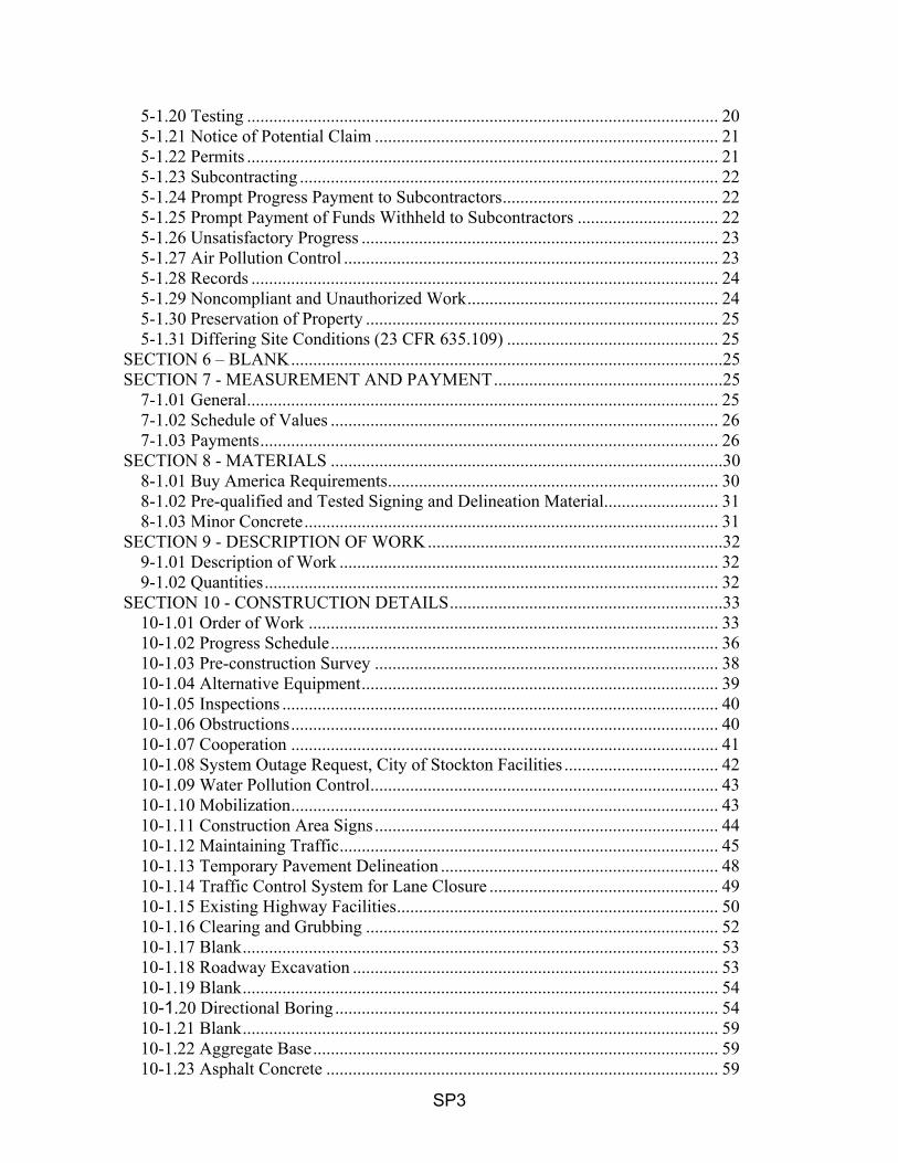
5-1.20 Testing ........................................................................................................... 20 5-1.21 Notice of Potential Claim .............................................................................. 21 5-1.22 Permits ........................................................................................................... 21 5-1.23 Subcontracting ............................................................................................... 22 5-1.24 Prompt Progress Payment to Subcontractors ................................................. 22 5-1.25 Prompt Payment of Funds Withheld to Subcontractors ................................ 22 5-1.26 Unsatisfactory Progress ................................................................................. 23 5-1.27 Air Pollution Control ..................................................................................... 23 5-1.28 Records .......................................................................................................... 24 5-1.29 Noncompliant and Unauthorized Work ......................................................... 24 5-1.30 Preservation of Property ................................................................................ 25 5-1.31 Differing Site Conditions (23 CFR 635.109) ................................................ 25
SECTION 6 – BLANK ..................................................................................................25 SECTION 7 - MEASUREMENT AND PAYMENT ....................................................25
7-1.01 General ........................................................................................................... 25 7-1.02 Schedule of Values ........................................................................................ 26 7-1.03 Payments ........................................................................................................ 26
SECTION 8 - MATERIALS .........................................................................................30 8-1.01 Buy America Requirements ........................................................................... 30 8-1.02 Pre-qualified and Tested Signing and Delineation Material.......................... 31 8-1.03 Minor Concrete .............................................................................................. 31
SECTION 9 - DESCRIPTION OF WORK ...................................................................32 9-1.01 Description of Work ...................................................................................... 32 9-1.02 Quantities ....................................................................................................... 32
SECTION 10 - CONSTRUCTION DETAILS ..............................................................33 10-1.01 Order of Work ............................................................................................. 33 10-1.02 Progress Schedule ........................................................................................ 36 10-1.03 Pre-construction Survey .............................................................................. 38 10-1.04 Alternative Equipment ................................................................................. 39 10-1.05 Inspections ................................................................................................... 40 10-1.06 Obstructions ................................................................................................. 40 10-1.07 Cooperation ................................................................................................. 41 10-1.08 System Outage Request, City of Stockton Facilities ................................... 42 10-1.09 Water Pollution Control ............................................................................... 43 10-1.10 Mobilization ................................................................................................. 43 10-1.11 Construction Area Signs .............................................................................. 44 10-1.12 Maintaining Traffic ...................................................................................... 45 10-1.13 Temporary Pavement Delineation ............................................................... 48 10-1.14 Traffic Control System for Lane Closure .................................................... 49 10-1.15 Existing Highway Facilities ......................................................................... 50 10-1.16 Clearing and Grubbing ................................................................................ 52 10-1.17 Blank ............................................................................................................ 53 10-1.18 Roadway Excavation ................................................................................... 53 10-1.19 Blank ............................................................................................................ 54 10-1.20 Directional Boring ....................................................................................... 54 10-1.21 Blank ............................................................................................................ 59 10-1.22 Aggregate Base ............................................................................................ 59 10-1.23 Asphalt Concrete ......................................................................................... 59

SP4
10-1.24 Construction Site Waste Materials Management ........................................ 60 10-1.25 Concrete Curbs, Sidewalks, and Wheelchair Ramps................................... 62 10-1.27 Blank ............................................................................................................ 64 10-1.28 Blank. ........................................................................................................... 64 10-1.29 Blank ............................................................................................................ 64 10-1.30 Blank ............................................................................................................ 64 10-1.31 Reinforcement ............................................................................................. 64 10-1.32 Miscellaneous Iron and Steel ....................................................................... 64 10-1.33 Blank ............................................................................................................ 64 10-1.34 Surface Restoration ...................................................................................... 64 10-1.35 Traffic Stripes, Pavement Markings, and Pavement Markers ..................... 65 10-1.36 Barricades and Channelizers ....................................................................... 67 10-1.37 Pre-construction Migratory Bird Survey ..................................................... 68 10-2 ELECTRICAL SYSTEMS ......................................................................... 68 10-2.01 Beacon Scope .............................................................................................. 68 10-2.02 Regulations and Code .................................................................................. 69 10-2.03 Certificate of Compliance, Warranties, Guarantees and Instruction Sheets 69 10-2.04 Materials General ........................................................................................ 69 10-2.05 Equipment List and Drawings ..................................................................... 69 10-2.06 Foundations ................................................................................................. 69 10-2.07 Rectangular Rapid Flashing Beacons .......................................................... 70 10-2.08 Accessible Pedestrian Signal ........................................................................72 10-3 SIGNAL AND LIGHTING ......................................................................... 73 10-3.01 Scope .......................................................................................................... 73 10-3.02 Regulations and Code .................................................................................. 73 10-3.03 Certificate of Compliance, Warranties, Guarantees and Instruction Sheets 73 10-3.04 Description ................................................................................................... 73 10-3.05 Materials General ........................................................................................ 74 10-3.06 Equipment List and Drawings ..................................................................... 74 10-3.07 Foundations ................................................................................................. 74 10-3.08 Standards, Steel Pedestals and Posts ........................................................... 75 10-3.09 Conduit ........................................................................................................ 75 10-3.10 Colored Controlled Density Fill (CDF) ....................................................... 76 10-3.11 Pull Boxes .................................................................................................... 77 10-3.11.01 Street Lighting Pull Boxes ...................................................................... 78 10-3.12 Conductors and Wiring ................................................................................ 78 10-3.13 Fused Splice Connectors ............................................................................. 79 10-3.14 Bonding and Grounding .............................................................................. 79 10-3.15 Service ......................................................................................................... 80 10-3.16 Blank ............................................................................................................ 82 10-3.17 Blank ............................................................................................................ 82 10-3.18 Pedestrian Signals - Light Emitting Diode (LED) Pedestrian and Countdown Signal Module ........................................................................................................... 82 10-3.19 Accessible Pedestrian Signal System .......................................................... 85 10-3.20 Blank ............................................................................................................ 86 10-3.21 Solid State Traffic Actuated Controllers ..................................................... 86 10-3.21.1 Solid-State Switching Devices ................................................................. 86 10-3.21.2 Eagle (Siemens) M60 Controllers ........................................................ 87

SP5
10-3.22 Traffic Signal Controller M Cabinet Specifications ............................. 88 10-3.23 Luminaires .......................................................................................... 102 10-3.23.1 Copper and Wire for Street Lighting .................................................. 102 10-3.23.2 Numbering Street Lighting Poles and Traffic Signal poles with ..............
Luminaires ......................................................................................... 102 10-3.24 Fiber Optic Cabling (Existing Locations)........................................... 103 10-3.25 Fiber Optic Cabling (New Locations) ................................................ 103 10-3.25.1 Rack Mount Enclosure: ....................................................................... 103 10-3.25.2 Splice Tray Fiber: ............................................................................... 103 10-3.25.3 Advanced Splice Closure (ASC): ....................................................... 103 10-3.25.4 Small Lightguide Interconnect Units (LIU) Wall Mount Box ........... 104 10-3.25.5 Port Coupler Panels: ........................................................................... 105 10-3.25.6 Single Mode Fiber Patch Cables SC-SC, ST-SC: ............................... 105 10-3.25.7 Fiber Optic Conduits ........................................................................... 106 10-3.25.8 Colored Controlled Density Fill (CDF) ............................................... 106 10-3.25.9 Fiber Optic Pull Boxes ........................................................................ 107 10-3.25.10 Blank ................................................................................................... 108 10-3.25.11 Warning Tape...................................................................................... 108 10-3.25.12 Payments ............................................................................................. 108 10-3.26 Blank ................................................................................................... 108 10-3.27 Traffic Signal Controller Communications and CCTV System: ........ 108 10-3.27.1 Fiber Optic Ethernet Switches ............................................................ 108 10-3.27.2 Fiber Optic Video Data One-Port Modems for Pan/Tilt/Zoom Camera 111 10-3.27.3 Video and Data Digital Networking ....................................................... 112 10-3.27.4 Blank ....................................................................................................... 113 10-3.27.5 Monitoring Camera Cabling (General) ................................................... 113 10-3.27.6 Traffic Monitoring Camera Conductors Field Installation ..................... 113 10-3.27.7 High Speed Dome Pan/Tilt/Zoom Traffic Monitoring Camera ............. 114 10-3.27.8 High Speed Dome Pan/Tilt/Zoom Traffic Monitoring Camera Installation…..……………………………………………………………………..116 10-3.28 Payment .................................................................................................... 116 10-3.29 Removing, Reinstalling or Salvaging Electrical Equipment ..................... 117 10-3.30 Blank .......................................................................................................... 117 10-4 Blank………….. ............................................................................................. 117 10-5 Blank………. .................................................................................................. 117 10-6 STREET LIGHT REMOVAL AND TRAFFIC SIGNAL TURN ON .......... 117 10-6.01 Traffic Signal Turn On and Change Over ................................................. 117 10-6.02 Street Light Removal ................................................................................. 118
SECTION 11 BLANK .................................................................................................119 SECTION 12 BLANK .................................................................................................119 SECTION 13 BLANK .................................................................................................119 SECTION 14 FEDERAL REQUIREMENTS FOR FEDERAL-AID CONSTRUCTION PROJECTS ..................................................................................................................119

SP1
TO BIDDERS
Bids open:
Description of Work The work to be performed shall consist of furnishing all labor, materials, tools, transportation, supplies, equipment, appurtenances, fuel, and power, unless specifically expected, necessary or required for the construction and adjustments of appurtenant facilities on the job site as shown on the plans and described in these Special Provisions and the Caltrans Standard Specifications.
The work shall include, but not be limited to, the following:
1. Removing, constructing and/or reconstructing curb, gutter, sidewalk, asphalt concreteand wheelchair ramps at the locations indicated on the plans.
2. Constructing concrete curb, gutter and sidewalk.3. Constructing Americans with Disabilities Act (ADA) compliant sidewalks and curb
ramps.4. Painting traffic stripes and pavement markings at the locations indicated on the plans.5. Installing new roadside signs and relocating/replacing existing roadway signs.6. Providing traffic control and water pollution (i.e. erosion) control, as required and as
indicated on the plans and in the Caltrans Standard Specifications.7. Installing new pedestrian signal facilities.8. Installing new rumble strips9. Installing new HAWK signal10. Installing new RRFB11. All other work as may be necessary as indicated on the plans and specifications, andas required by the Engineer.
The Department will receive sealed bids for McKinley Safe Routes to School Project
FEDERAL PROJECT ATPCML 5008(144) CITY PROJECT NO. PW1440
The Contractor must have either a Class A license or one of the following Class C licenses: C-10.
The DBE contract goal is _12_ percent.
Bids must be on a unit price basis.
Complete the work within 80 working days.
Liquidated damages $3,200 per calendar day.
The estimated cost of the project is below $300,000

SP2
A mandatory prebid meeting is scheduled for this project. See DBE instruction to Bidders. The City of Stockton will receive bids until 2:00 p.m. on the bid open date at the office of the City Clerk, 425 N. El Dorado Street, Stockton, CA 95202. Bids received after this time will not be accepted. City of Stockton staff will direct the bidders to the bid opening. The City of Stockton will open and publicly read the bids at the above location immediately after the specified closing time. Questions about alleged patent ambiguity of the plans, specifications, or estimate must be asked before bid opening. After bid opening, the City of Stockton does not consider these questions as bid protests. Submit your bid with bidder's security equal to at least 10 percent of the bid. Prevailing wages are required on this Contract. The Director of the California Department of Industrial Relations determines the general prevailing wage rates. Obtain the wage rates at the DIR Web site, http://www.dir.ca.gov, or from the Department's Labor Compliance Office of the district in which the work is located. The federal minimum wage rates for this Contract as determined by the United States Secretary of Labor are available at http://www.dot.ca.gov/hq/esc/oe/federal-wages. If the minimum wage rates as determined by the United States Secretary of Labor differs from the general prevailing wage rates determined by the Director of the California Department of Industrial Relations for similar classifications of labor, the Contractor and subcontractors must not pay less than the higher wage rate. The City of Stockton does not accept lower State wage rates not specifically included in the federal minimum wage determinations. This includes helper, or other classifications based on hours of experience, or any other classification not appearing in the federal wage determinations. Where federal wage determinations do not contain the State wage rate determination otherwise available for use by the Contractor and subcontractors, the Contractor and subcontractors must not pay less than the federal minimum wage rate that most closely approximates the duties of the employees in question.

SP3
SPECIAL PROVISIONS SECTION 1 - SPECIFICATIONS AND PLANS 1-1.01 Specifications The work described herein shall be done in accordance with the current City of Stockton, Department of Public Works Standard Specifications and Plans, and the latest Editions of the State of California, Department of Transportation Standard Specifications and Standard Plans, California MUTCD, as referenced therein, and in accordance with the following Special Provisions. To the extent the California Department of Transportation Standard Specifications implement the STATE CONTRACT ACT, they shall not be applicable since the City of Stockton is not subject to said ACT. In case of conflict or discrepancy between any of the Contract Documents, the order of documents listed below shall be the order of precedence, with the first item listed having the highest precedence. 1. Contract Change Order (changes last in time are first in precedence) 2. Addenda to Contract Agreement 3. Contract Agreement 4. Permits 5. Notice Inviting Bids and Instructions to Bidders 6. Project Drawings 7. City of Stockton Standard Specifications 8. Special Provisions 9. Caltrans Standard Specifications 10. City of Stockton Standard Drawings 11. Caltrans Standard Plans 1-1.02 Plans The bidder's attention is directed to the provisions in Section 1-1.03 ”Definitions”, of the Standard Specifications and Section 1-1.07 ”Definitions”, of the Caltrans Specifications. 1-1.03 Terms and Definitions Wherever in the Standard Specifications, Special Provisions, Notice to Contractors, Proposal, Contract, or other contract documents the following terms are used, the intent and meaning shall be interpreted as follows: City or Owner - City of Stockton
Director - Director of Public Works, City of Stockton
Standard Specifications - Latest City of Stockton, Standard Plans and Specifications, and any amendments and revisions thereto.
Caltrans Specifications - State of California, Department of Transportation,

SP4
Latest Standard Plans and Specifications (2010), and any amendments and revisions thereto.
Laboratory - City of Stockton Department of Public Works Laboratory or consultant's laboratory
Department - Department of Public Works, City of Stockton
Engineer - City Engineer, City of Stockton, acting either directly or through properly authorized Engineer agents and consultants
California MUTCD Latest edition of California Manual on Uniform Traffic
Control Devices (MUTCD), and any amendments and revisions thereto.
1-1.04 Disadvantaged Business Enterprise This project is subject to the Disadvantaged Business Enterprise (DBE) program, Code of Federal Regulations Title 49, Section 26. Refer to the DBE Instructions to Bidders and Federal Aid Contract Bidders Checklist for form submittal timeline. Also refer to Disadvantaged Business Enterprise (DBE) Instructions to Bidders for this project, listed on the City of Stockton’s website on the Bid Flash webpage: http://www.stocktongov.com/services/business/bidflash/default.html If a DBE is decertified before completing its work, the DBE must notify you in writing of the decertification date. If a business becomes a certified DBE before completing its work, the business must notify you in writing of the certification date. On work completion, complete a Disadvantaged Business Enterprises (DBE) Certification Status Change form. Submit the form within 30 days of Contract acceptance. Upon work completion, complete a Final Report – Utilization of Disadvantaged Business Enterprises (DBE), First-Tier Subcontractors form CEM-2402(F) (Exhibit 17-F). Submit it within 90 days from the date of Contract acceptance. The City withholds $10,000 until a satisfactory form is submitted. The City releases the withhold upon submission of the completed form. The contractor shall not terminate or substitute a listed DBE for convenience and perform the work with his own forces or obtain materials from other sources without authorization from the City. 1-1.05 Proposal Requirements and Conditions General The bidder’s attention is directed to the “Notice to Contractors” for the date, time and location of the mandatory job walk/pre-bid meeting, if applicable.
The bidder's attention is directed to the provisions in Section 2, "Proposal Requirements and Conditions," of the Standard Specifications and these special provisions for the requirements and conditions which the bidder must observe in the preparation of the
SP5
proposal form and the submission of the bid.
The Bidder's Bond form mentioned in the last paragraph in Section 2-1.07, "Proposal Guaranty," of the Standard Specifications will be found following the signature page of the Proposal.
In conformance with Public Contract Code Section 7106, a Noncollusion Affidavit is included in the Proposal. Signing the Proposal shall also constitute signature of the Noncollusion Affidavit.
The contractor, sub recipient or subcontractor shall not discriminate on the basis of race, color, national origin, or sex in the performance of this contract. The contractor shall carry out applicable requirements of Title 49 CFR (Code of Federal Regulations) part 26 in the award and administration of US DOT assisted contracts. Failure by the contractor to carry out these requirements is a material breach of this contract, which may result in the termination of this contract or such other remedy, as the recipient deems appropriate. Each subcontract signed by the bidder must include this assurance.
Failure of the bidder to fulfill the requirements of the Special Provisions for submittals required to be furnished after bid opening, including but not limited to escrowed bid documents, where applicable, may subject the bidder to a determination of the bidder's responsibility in the event it is the apparent low bidder on a future public works contracts.
1-1.06 Federal Lobbying Restrictions Refer to Instructions to Bidders. SECTION 2 – FEDERAL REQUIREMENTS The Contractor shall refer to the Instructions to Bidders in these Contract Documents and provisions in Section 14 “Federal Requirements for Federal-Aid Construction Projects” of these Special Provisions for applicable Federal Requirements. SECTION 3 – AWARD AND EXECUTION OF CONTRACT
3-1.01 Contract Award If the City awards the Contract, the award is made to the lowest responsible bidder within 90 days after the day of the bid opening.
Bidders and subcontractors are required to be available the day of bid opening to answer questions.
The award of the contract, if it be awarded, will be to the lowest responsible bidder whose proposal complies with all the requirements prescribed.

SP6
3-1.02 Contract Execution The bidder’s attention is directed to the provisions in Section 3, “Contract Award and Execution,” of the Caltrans Specifications and these Special Provisions for the requirements and conditions concerning award and execution of the contract.
Bid protests are to be delivered to the following address:
Attention: Monique Raqueno
City of Stockton Public Works Department
22 E. Weber Avenue, Room 301 Stockton, CA 95202
The contract shall be executed by the successful bidder and shall be returned, together with the contract bonds, to the City so that it is received within 10 working days after the bidder has received the contract for execution. Failure to do so shall be just cause for forfeiture of the proposal guaranty. The executed contract documents shall be delivered to the address noted above. SECTION 4 – PROSECUTION AND PROGRESS Attention is directed to the provisions in Section 8, “Prosecution and Progress” of the Caltrans Specifications and these Special Provisions. 4-1.01 Beginning of Work Attention is directed to the provisions in Section 8-1.03, "Beginning of Work", of the Standard Specifications and these Special Provisions. At no time shall construction begin without receiving notice that the contract has been approved by the City Attorney or an authorized representative. The Contractor shall follow the sequence of construction and progress of work as specified in Section 10-1.01, "Order of Work", of these Special Provisions. The Contractor shall diligently prosecute all work items to completion. Full compensation for any additional costs occasioned by compliance with the provisions in this section shall be considered as included in the prices paid for the various contract items of work, and no additional work compensation will be allowed therefore. Understanding of Conditions
Bidders will be required to carefully examine these special provisions and attachments to judge for themselves as to the nature of the work to be done and the general conditions relative thereto and the submission of a proposal hereunder shall be considered prima-facie evidence that the bidder has made the necessary investigation and is satisfied with respect to the conditions to be encountered, the character, quantity and quality of the work performed. For work to be completed, contractors are advised to visit and review

SP7
the job site prior to the submission of their bid. Bids not presented on the City forms shall be cause for considering the bid as non-responsive. Bidders must be thoroughly competent and capable of satisfactorily performing the work covered by the proposal, and when requested shall furnish such statements relative to previous experience on similar work, the plan or procedure proposed, and the organization and the equipment available for the contemplated work, and any other as may be deemed necessary by the City Engineer in determining such competence and capability. It shall be understood that the Contractor shall be required to perform and complete the proposed work in a thorough and diligent manner, and to furnish and provide in connection therewith all necessary labor, tools, implements, equipment, materials and supplies. The Contractor is responsible to take all necessary precautions and use best practices in the industry to perform all work require completing the project. 4-1.02 Time of Completion Attention is directed to the provisions in Section 8, "Prosecution and Progress", of the Standard Specifications, Caltrans Specifications, and these Special Provisions. The contract for the performance of the work and the furnishing of materials shall be executed within ten (10) days after the approval thereof by the City Attorney. The City will issue the Notice to Proceed following execution of the contract. Submittals shall be delivered to the Engineer within thirty (30) calendar days of execution of contract. Contract shall not start any work on the job site until the Engineer approves the submittals. Refer to section 4-1.04, “Submittals” of these Special Provisions. The Contractor shall only enter the jobsite prior to approval of the above submittals for purposes of measuring field dimensions and locating utilities. The Contractor shall diligently prosecute the contract work to completion within 80 working days. The days to finish the punch list, provided by the City, are included in the Original Working Days. Notice to Proceed will not be issued until all complete submittals have been reviewed at least once. Correction indicated on submittals shall be considered as changes necessary to meet the requirements of the Contract Documents and shall not be taken as the basis for changes to the contract requirements. The Engineer’s review of Contractor Shop Drawing submittals shall not relieve the contractor of the entire responsibility for the correctness of details and dimensions. The Contractor shall assume all responsibility and risk for any misfits due to error in Contractor submittals. The Contractor shall be responsible for the dimension and the design of adequate connections and details. Prior to Notice to Proceed, the Contractor shall indicate in writing when all the traffic signal hardware and equipment, which makes the traffic signal and communication system operational, will be delivered to the project site. Based on the indicated delivery date, the date to commence the work will be issued by the City. If by any unforeseen action, the

SP8
established delivery date cannot be made, the Contractor shall provide the City with a letter from the manufacturer indicating the reason why the delivery date cannot be met. The letter shall also indicate the revised delivery date. The City reserves the right to either accept the reason or to reject it. A letter from vendor is not acceptable. Should the Contractor choose to work on a Saturday, Sunday, or on a holiday recognized by the labor unions, the Contractor shall reimburse the City of Stockton the actual cost of engineering, inspection, testing, superintendent, and/or other overhead expenses, which are directly chargeable to the contract. Should such work be undertaken at the request of the City, reimbursement will not be required. 4-1.03 Liquidated Damages Attention is directed to the provisions in Section 8-1.10, "Liquidated Damages", of the Caltrans Specifications and these Special Provisions. The Contractor shall pay liquidated damages to the City of Stockton in the amount of $3,200 per day for each and every calendar day that the work, with the exception of the maintenance period, remains incomplete after the expiration of the contract working days specified in these Special Provisions. Full compensation for any costs required to comply with the provisions in this section shall be considered to be included in the prices paid for the various contract items of work, and no additional compensation will be allowed therefore. 4-1.04 Submittals
The following is a list of anticipated submittals for the project. The list is provided to aid the Contractor in determining the scope of work, but is not intended to be all inclusive and additional submittals may be required:
1) Baseline Progress Schedule (Critical Path Method) 2) Storm water Pollution Prevention Plan 3) Approved Notice of Intent from State Water Resources Control Board 4) Funding Sign(s) Installed (if applicable) 5) Pre-construction survey 6) Pre-construction Migratory Bird Survey 7) Temporary Traffic Control (includes Pedestrian Detour Plan) 8) Contractor Safety Plan 9) Portland Cement Concrete Mix Design 10) Staging Agreement with private property owners (if applicable) 11) City of Stockton Encroachment Permit 12) City’s Construction and Demolition Debris Recycling Report 13) List of submittals 14) Product submittals 15) Lead Compliance Plan 16) The certification of the personnel installing fiber
The Contractor shall transmit each submittal to the Engineer for review and approval with

SP9
the submittal form approved by the Engineer. Submittals shall be sequentially numbered on the submittal form. Resubmittals shall be identified with the original number and a sequential resubmittal suffix letter. The original submittal shall be numbered X. The first resubmittal shall be numbered X-a and so on. Identify on the form the date of the submittal, Contractor, Subcontractor or supplier; pertinent drawing and detail number, and/or special provision number, as appropriate. The Contractor shall sign the form certifying that review, approval, verification of Products required, field dimensions, adjacent construction work, and coordination of information is in accordance with the requirements of the work and contract documents. Any incomplete submittals will be returned for resubmittal. Schedule submittals to expedite the Project, and deliver to Engineer at the Engineer’s office, see Section 10-1.01, “Order of Work,” of these Special Provisions.
For each submittal for review, allow 15 calendar days excluding delivery time to and from the Contractor.
Identify variations from Contract Documents and Product or system limitations that may be detrimental to successful performance of the completed Work.
When revised for resubmission, identify all changes made since previous submission.
Distribute copies of reviewed submittals as appropriate. Instruct parties to promptly report any inability to comply with requirements.
Submittals not requested either in the Contract Documents or in writing from the Engineer will not be recognized or processed.
Within 10 calendar days after Notice of Award submit a complete list of all submittals to be submitted and the dates when they will be submitted. All submittals shall be submitted within 30 calendar days from the date the Notice of Award; otherwise project working days will commence, with or without issuance of the Notice to Proceed.
Wherever called for in the Contract Documents, or where required by the Engineer, the Contractor shall furnish to the Engineer for review, 1 set, plus one reproducible copy, of each shop drawing submittal. The term “Shop Drawings” as used herein shall be understood to include detail design calculations, shop drawings, fabrication and installation drawings, erection drawings, list, graphs, catalog sheets, data sheets, and similar items. Whenever the Contractor is required to submit design calculations as part of a submittal, such calculations shall bear the signature and seal of an engineer registered in the appropriate branch and in the state of California, unless otherwise directed.
Normally, a separate submittal form shall be used for each specific item or class of material or equipment for which a submittal is required. Transmittal of a submittal of various items using a single form will be permitted only when the items taken together

SP10
constitute a manufacturer’s “package” or are so functionally related that expediency indicates review of the group or package as a whole. A multi-page submittal shall be collated into sets, and each set shall be stapled or bound, as appropriate, prior to transmittal to the Engineer.
Except as may otherwise be indicated herein, the Engineer will return prints of each submittal to the Contractor with their comments noted on the submittal. The Contractor shall make complete and acceptable submittals to the Engineer by the second submission of a submittal item. The City reserves the right to withhold monies due to the Contractor to cover additional costs of the Engineer’s review beyond the second submittal.
If a submittal is returned to the Contractor marked “NO EXCEPTIONS TAKEN”, formal revision and resubmission of said submittal will not be required.
If a submittal is returned to the Contractor marked “MAKE CORRECTIONS NOTED”, formal revision and resubmission of said submittal will not be required. 4-1.05 Non-Highway Facilities Attention is directed to Section 5-1.30, "Preservation of Property" and Section 5-1.08, "Indemnification and Insurance" of these Special Provisions, Section 7-1.12, “Indemnification and Insurance” of the Standard Specifications, and Section 5-1.36D, “Nonhighway Facilities,” of the Caltrans Specifications. The Contractor shall protect from damage utility and other non-highway facilities that are to remain in place, be installed, relocated or otherwise rearranged. SECTION 5 - GENERAL 5-1.01 Contract Bonds Contract Bonds shall conform to the requirements set forth in Section 3-1.02, "Contract Bonds", of the Standard Specifications, excepting the following: the second paragraph shall be replaced with the following: "The Faithful Performance bond will be retained by the City of Stockton for twelve (12) months following recordation of the Notice of Completion (or partial completion) to guarantee correction of failure attributed to workmanship and materials. Upon recordation of the Notice of Completion (or partial completion), the amount of the Faithful Performance bond may be reduced to ten percent (10%) of the actual cost of the constructed improvements”. Roadway Improvement Bond
As a condition precedent to the completion of this contract, the Contractor shall furnish a Defective Material and Workmanship Bond, of surety company acceptable to the Engineer, and payable to the City of Stockton, in a sum not less than ten percent (10%) of the total construction contract for the roadway improvements, as this sum is set forth in the agreement. This bond shall cover a period of one (1) year from and after the completion and acceptance of the work to protect the City against the results of defective material, workmanship, or equipment which become apparent during that time. This bond shall be delivered to the Engineer before the final payment under this contract will be

SP11
made. 5-1.02 Project Appearance Attention is directed to Section 4-1.13 “Cleanup” of the Caltrans Specifications and these Special Provisions. The Contractor shall maintain a neat appearance to the work. Broken concrete and debris developed during clearing and grubbing shall be disposed of concurrently with its removal. Contractor shall pay to the City of Stockton the sum of Two Hundred Fifty Dollars ($250) for every calendar day where debris has remained on the job site overnight. Full compensation for conforming to the provisions in this section shall be considered as included in the prices paid for the various contract items of work involved, and no additional compensation will be allowed therefore. 5-1.03 Maintaining Public Convenience and Safety Attention is directed to Sections 7-1.03, "Public Convenience", 7-1.04, "Public Safety”, and Section 12, "Temporary Traffic Control", of the Caltrans Specifications. Attention is also directed to Part 6 of the California MUTCD and Sections 7-1.08, "Public Convenience", 7-1.09, "Public Safety", of Standard Specifications, and Section 10-1.12, “Maintaining Traffic” of these Special Provisions. Nothing in these Special Provisions shall be construed as relieving the Contractor from his responsibility as provided in said sections and Part 6 of the California MUTCD. 5-1.04 Trench Safety The Contractor shall furnish all labor, equipment, and materials required to design, construct, and remove all shoring, lagging, cribbing, piling, and/or other types of support for the wall of any open excavation required for the construction of this project. In making excavations for the project, the Contractor shall be fully responsible for providing and installing adequate sheeting, shoring, and bracing, as may be necessary as a precaution against slides or cave-ins and to fully protect all existing improvements of any kind from damage. Wherever applicable, the Contractor shall obtain a permit from the Division of Industrial Safety and shall submit a copy of the approved permit to the Engineer prior to the start of excavations. The cost of the permit shall be included in the total bid costs. The criteria given by the California Department of Industrial Relations are MINIMUM for the conditions shown thereon. In addition to shoring the excavation as specified, it shall be the Contractor's responsibility to provide any and all additional shoring required to support the sides of the excavation against the effects of loads, which may exceed those derived by using the criteria set forth by said governing agency.

SP12
The Contractor shall be solely responsible for any damages which may result from his failure to provide adequate shoring to support the excavations under any or all of the conditions of loading which may exist or which may arise during the construction project. Nothing herein shall be deemed to allow the use of shoring, sloping, or protective system less effective than that required by the Construction Safety Orders of the Division of Industrial Safety. 5-1.05 Public Convenience Contractor's attention is directed to the “Maintaining Traffic” section of these Special Provisions. The Contractor shall notify San Joaquin Regional Transit District (SJRTD) a minimum of five (5) working days prior to beginning work. The Contractor shall coordinate with SJRTD if any bus stops and bus routes are affected. The Contractor shall inform the City Fire Department, City Police Department, City Traffic Department, Municipal Utilities District (MUD), and all affected utilities no later than three (3) working days before work is to begin. The Contractor shall provide the City with the name and telephone number (business, home and mobile) of three (3) representatives available at all times during the duration of the contract. Said names and telephone numbers shall be provided to the City of Stockton Public Works, Fire, and Police Departments. The Contractor shall circulate printed form letters, approved by the Engineer, explaining the project to be done and the length of time inconvenience will be caused by the project and deliver same to the residents and businesses to be affected at least three (3) working days before work is to commence on their street. In addition, the Contractor shall provide temporary "No Parking" signs posted three (3) working days in advance of the work. Such signs shall be placed no further than fifty (50) feet apart. The additional "No Parking" signs shall be removed upon completion of the work and the opening of the street to traffic. It shall be the Contractor's responsibility to remove any vehicles obstructing his operations. Full compensation for conforming to the provisions in this section shall be included in the prices paid for various bid items, and no additional compensation will be made therefore. 5-1.06 Public Safety Contractor's attention is directed to the “Maintaining Traffic” section of these Special Provisions. Nothing in the specifications voids the contractor’s public safety responsibilities. All safety devices, their maintenance, and use shall conform to the latest requirements of OSHA and shall conform to the applicable provisions of the Part 6 "Temporary Traffic Control", of the California MUTCD. It shall be the complete responsibility of the Contractor to protect persons from injury and to avoid property damage. Adequate barricades, construction signs, flashers, and other such safety devices, as required, shall

SP13
be placed and maintained during the progress of the construction work, until the project is completed. Whenever required, flaggers shall be provided to control traffic. The Contractor shall install temporary railing (Type K) between a lane open to public traffic and an excavation, obstacle, or storage area when the following conditions exist:
A. Excavations - the near edge of the excavation is twelve (12) feet or less from the edge of the lane, except:
1. Excavations covered with sheet steel or concrete covers of adequate thickness
to prevent accidental entry by traffic or the public. 2. Excavations less than one (1) foot deep. 3. Trenches less than one (1) foot wide for irrigation pipe or electrical conduit, or
excavations less than one (1) foot in diameter. 4. Excavations parallel to the lane for the purpose of pavement widening or
reconstruction. 5. Excavations in side slopes, where the slope is steeper than 1:4 (vertical:
horizontal). 6. Excavations protected by existing barrier or railing.
B. Temporarily Unprotected Permanent Obstacles - the work includes the installation
of a fixed obstacle together with a protective system, such as a sign structure together with protective railing, and the Contractor elects to install the obstacle prior to installing the protective system; or the Contractor, for the Contractor's convenience and with permission of the Engineer, removes a portion of an existing protective railing at an obstacle and does not replace such railing complete in place during the same day.
C. Storage Areas - material or equipment is stored within twelve (12) feet of the lane
and the storage is not otherwise prohibited by the provisions of the Standard Specifications and these Special Provisions.
The approach end of temporary railing (Type K), installed in conformance with the provisions in this section, "Public Safety", and in Section 7-1.04, "Public Safety", of the Caltrans Specification, shall be offset a minimum of fifteen (15) feet from the edge of the traffic lane open to public traffic. The temporary railing shall be installed on a skew toward the edge of the traffic lane of not more than one (1) foot transversely to ten (10) feet longitudinally with respect to the edge of the traffic lane. If the fifteen (15) feet minimum offset cannot be achieved, the temporary railing shall be installed on the 10 to 1 skew to obtain the maximum available offset between the approach end of the railing and the edge of the traffic lane, and an array of temporary crash cushion modules shall be installed at the approach end of the temporary railing. Type K Temporary Railing shall conform to the provisions in Section 12-3.08, "Type K Temporary Railing", of the Caltrans Specifications. Type K Temporary Railing, conforming to the details shown on 2010 Standard Plan T3A and T3B, may be used.

SP14
The Contractor shall provide for the proper routing of vehicles and pedestrian traffic in a manner that will hold congestion and delay of such traffic to practicable minimum by furnishing, installing, and maintaining all necessary temporary signs, barricades, and other devices and facilities, as approved by the City Traffic Engineer. As the work progresses, the Contractor shall relocate, subject to the City Traffic Engineer's approval, such devices and facilities as necessary to maintain proper routing. The Contractor shall notify the City Traffic Engineer a minimum of three (3) working days prior to the relocation of any traffic control devices. When work is not in progress on a trench or other excavation that requires closure of an adjacent lane, the traffic cones or portable delineators used for the lane closure shall be placed off of and adjacent to the edge of the traveled way. The spacing of the cones or delineators shall be not more than the spacing used for the lane closure. Full compensation for conforming to the provisions in this section, including furnishing and installing Type K Temporary Railing and temporary crash cushion modules wherever required, shall be considered as included in the lump sum price paid for “Traffic Control System”, and no additional compensation will be allowed therefor. Full compensation for furnishing, installing, moving, and removing of all necessary traffic control devices including, but not limited to, Type K Temporary Railing and temporary crash cushion modules, signing, striping, barricades, and flagging shall be included in the bid item for "Traffic Control System", as shown on the bid schedule, and no additional compensation will be allowed therefor. Section 12-1.03, "Flagging Costs", of the Caltrans Specifications is deleted. 5-1.07 Sound Control Requirements The Contractor's attention is directed to Section 14-8.02 “Noise Control” of the Caltrans Specifications and the project specific equipment noise control measures listed in Table 8.1 below. Nothing in the Caltrans Specifications or these Special Provisions voids the Contractor’s public safety responsibilities or relieves the Contractor from the responsibility to comply with other ordinances regulating noise level. The Contractor shall comply with all local sound control and noise level rules, regulations and ordinances which apply to any work performed pursuant to the contract. Each internal combustion engine, used for any purpose on the job or related to the job, shall be equipped with a muffler of a type recommended by the manufacturer. No internal combustion engine shall be operated on the project without the muffler. To minimize the construction impacts to residents, the Contractor is encouraged to select the bore method (directional drilling) over conventional trenching to install new conduits. The noise level requirement shall apply to the equipment on the job or related to the job, including, but not limited to, trucks, transit mixers, or transient equipment that may or may not be owned by the Contractor. All equipment shall have sound-control devices that are no less effective than those provided on the original equipment. The use of loud sound

SP15
signals shall be avoided in favor of light warnings except those required by safety laws for the protection of personnel. Project Specific Equipment Noise Control Table 8-1 summarizes noise levels produced by construction equipment that is commonly used on roadway construction projects. Construction equipment is expected to generate noise levels ranging from 70 to 90 dB at a distance of 50 feet, and noise produced by construction equipment would be reduced over distance at a rate of about 6 dB per doubling of distance. The noise levels generated by the boring machine would be lower than any equipment listed in the table. Table 8-1. Construction Equipment Noise
Equipment Maximum Noise Level (dBA at 50 feet)
Scrapers 89 Bulldozers 85 Heavy Trucks 88 Backhoe 80 Pneumatic Tools 85 Concrete Pump 82 Source: Federal Transit Administration 1995.
Further, implementing the following measures would minimize the temporary noise impacts from construction: All equipment shall have sound-control devices that are no less effective than those provided on the original equipment. No equipment shall have an unmuffled exhaust. As directed by the Engineer, the contractor shall implement appropriate additional noise mitigation measures as warranted. These could include, but are not specifically limited to, changing the location of stationary construction equipment, turning off idling equipment, rescheduling construction activity, notifying adjacent residents in advance of construction work, and installing acoustic barriers around stationary construction noise sources. Full compensation for conforming to the requirements of this section shall be considered as included in the prices paid for the various contract items of work involved, and no additional compensation will be allowed therefore. 5-1.08 Indemnification and Insurance Indemnification and Insurance shall conform to an Exhibit, which is attached to this project bid package and incorporated by this reference and the following:
"The Contractor shall indemnify and hold harmless the City of Stockton and all officers and employees thereof connected with the work, including, but not limited
SP16
to, the Director of Public Works and the City Engineer from all claims, suits, or actions of every name, kind, and description brought forth on account of injuries to or death of any person, including, but not limited to, workmen and the public, or damage to property resulting from the performance of the Contractor, except as otherwise provided by statute. The duty of the Contractor to indemnify and hold harmless includes the duties to defend as set forth in Section 2778 of the Civil Code.
The Contractor waives any and all rights to any type of expressed or implied indemnity against the City, its officers, or employees. It is the intent of the parties that the Contractor shall indemnify and hold harmless the City, its officers, and employees from any and all claims, suits, or actions as set forth above regardless of the existence or degree of fault or negligence on the part of the City, the Contractor, the subcontractor, or employee of any of these, other than the active negligence of the City, its officers, and employees."
Contractor shall at all times maintain at Contractors’ expense liability insurance coverage. Contractor shall provide thirty (30) days written notice to the City prior to canceling or changing the terms of such coverage. Contractor shall comply with the insurance requirements set forth by the City’s Risk Manager. Full compensation for conforming to the requirements of this section shall be considered as included in the prices paid for the various contract items of work involved, and no additional compensation will be allowed therefore. 5-1.09 Rights in Land All work, equipment parking, or any other activity associated with the project shall be confined to the project limits within the street rights-of-way. The Contractor's use of any other property exclusively in connection with this project shall be by a written agreement between the property owner and the Contractor. A certified copy of any such agreement shall be furnished to the Engineer prior to the use of such property by the Contractor. Full compensation for conforming to the provisions in this section shall be considered as included in prices paid for the various contract items of work involved, and no additional compensation will be allowed therefore. 5-1.10 Staging Area The street right-of-way shall be used only for activities that are necessary to perform the required work. The Contractor shall not occupy the right-of-way or allow others to occupy the right-of-way for material storage or other purposes that are not necessary to perform the required work. The Contractor shall secure at his own expense any area required for plant sites, storage of equipment or materials, or for other purposes.

SP17
5-1.11 Construction Staking Section 5-1.07, "Lines and Grades", of the Standard Specifications is deleted, and replaced with the following:
1. The Contractor shall be responsible for all construction survey stakes
necessary to construct the project in accordance to the lines, grades, sections, stage construction/traffic handling, and traffic signalization, pavement delineation plan described in the plans and specifications.
2. Contractor shall be responsible for referencing all existing monumentation
within the limits of the project prior to removal of any existing monuments. Monument referencing shall be reviewed and approved by the engineer prior to commencing of the work.
3. The Contractor shall employ a Land Surveyor registered in the State of
California or an appropriately registered Civil Engineer to perform such survey work. All stakes and marks set by the Contractor's Land Surveyor or Civil Engineer shall be carefully preserved by the Contractor. In case such stakes and marks are destroyed or damaged, they will be promptly replaced, at the direction of the Engineer at no additional cost to the City. Copies of all field notes and cut sheets shall be provided to the City at no additional cost to the City.
4. Full compensation for furnishing all labor, materials, tools, equipment, and
incidentals, and for doing all work involved in establishing the lines and grades, as specified in these Special Provisions, shall be included in the contract lump sum price paid for “Construction Staking” per Sections 7-1.03, “Payments” and 9-1.01, “Description of Work” of these Special Provisions, and no additional compensation will be made therefor.
5-1.12 Increased or Decreased Quantities The City reserves the right to make such alterations, deviations, additions to, or omissions from the plans and specifications, including the right to increase or decrease the quantity of any item or portion of the work or to omit any item or portion of the work, as may be deemed by the Engineer to be necessary or advisable and to require such extra work as may be determined by the Engineer to be required for the proper completion or construction of the whole work contemplated, without adjustment in the unit price as bid. Attention is directed to Section 4-1.03, “Changes,” of the Standard Specifications. Any such changes will be set forth in a contract change order, which will specify the work to be done in connection with the change made, adjustment of contract time, if any, and the basis of compensation for such work. A contract change order will not become effective until approved by the City Manager and / or City Council.
SP18
5-1.13 Changes and Extra Work New and unforeseen work will be classed as extra work when determined by the Engineer that the work is not covered by any of the various items for which there is a bid price or by combinations of those items. In the event portions of this work are determined by the Engineer to be covered by some of the various items for which there is a bid price or combinations of those items, the remaining portion of the work will be classed as extra work. Extra work also includes work specifically designated as extra work in the plans or specifications. The Contractor shall do the extra work and furnish labor, material and equipment therefore upon receipt of an approved contract change order or other written order of the Engineer, and in the absence of an approved contract change order or other written order of the Engineer, the Contractor shall not be entitled to payment for the extra work. If, in the opinion of the Engineer, such work cannot reasonably be performed concurrently with other items of work, and if a controlling item of work is delayed thereby, an adjustment of contract time will be made. Payment for extra work required to be performed pursuant to the provisions in this Section 5-1.13, in the absence of an executed contract change order, will be made by force account as provided in Section 9-1.04 “Force Account” of the Caltrans Specifications; or as agreed to by the Contractor and the Engineer. 5-1.14 Stop Notice Withholds Section 9-1.16E(4) “Stop Notice Withholds” of the Caltrans Specifications is amended to read as follows:
"The City of Stockton, by and through the Department of Public Works, may at its option and at any time retain out of any amounts due the Contractor, sums sufficient to cover claims, filed pursuant to Section 3179 et seq. of the Code of Civil Procedures."
5-1.15 Dust Control, Apply Water, Site Maintenance, and Cleanup Dust control shall conform to any requirements set forth in the San Joaquin Valley Air Pollution Control District Construction Notification Form, the provisions in Section 14-9.03, “Dust Control” of the Caltrans Specifications, and these Special Provisions. Use of water except for recycled, reclaimed, or other non-potable water for the purpose of dust control or other construction uses unless for health or safety purposes is prohibited. All dust control operations shall be performed by the Contractor at the time, location and in the amount ordered by the Engineer. The application of either water or dust palliative shall be under the control of the Engineer at all times." Watering shall conform to the provisions of Section 17 "Watering" of the Caltrans Specifications and these Special Provisions. Attention is also directed to Section 18 “Dust Palliative” of the Caltrans Specifications and these Special Provisions. During construction, the Contractor shall remove all rubbish and debris as it is generated.

SP19
Upon completion of the work, the Contractor shall remove all equipment, debris, and shall leave the site in a neat, clean condition all to the satisfaction of the Engineer. A permit shall be obtained from the Municipal Utilities Department, or California Water Service, as applicable, for construction water obtained from City hydrants. This permit shall be approved by the City of Stockton Fire Department. The Contractor shall conduct and cause all working forces at the site to maintain the site in a neat, orderly manner throughout the construction operations. The work shall be conducted in a manner that will control the dust. When ordered to provide dust control, the Contractor shall use water to reduce the dusty conditions all to the satisfaction of the Engineer. During construction, the Contractor shall remove all rubbish and debris as it is generated. The Contractor shall pay to the City of Stockton the sum of Two Hundred Fifty Dollars ($250) for every calendar day where debris has remained on the job site overnight. Upon completion of the work, the Contractor shall remove all equipment and debris, and shall leave the site in a neat, clean condition all to the satisfaction of the Engineer. 5-1.16 Pre-Construction Meeting The City of Stockton Public Works Department will schedule a pre-construction meeting with the Contractor following award of the contract and prior to commencing work (Contact 209-937-8613). The City will issue the Notice to Proceed following execution of the Contract. This meeting will be held in the City of Stockton, Public Works Department. 5-1.17 Post-Construction Meeting The Contractor shall attend a post-construction meeting that will be arranged by the Public Works Department (Contact 209-937-8613) after completion of work and prior to acceptance and final payment. The project Design Engineer and the project Inspector will also attend this meeting. The purpose of the meeting will be to discuss the project and any related issues that can help improve future Public Works construction projects. This meeting will be held in the City of Stockton, Public Works Department. 5-1.18 As-Built/Record Drawings The Contractor shall maintain a complete set of drawings on-site for the purpose of keeping up to date all field modifications. This plan set shall be available for review by the project Inspector and the Engineer. These plans shall be provided to the Inspector after the completion of construction at the Post-Construction Meeting and prior to the final payment. All revisions, modifications, and/or changes shall be marked clearly. Notes and dimensions shall be in red and be clear and legible. These plans will be used by the Engineer to mark up the original plan sheets with the revisions made during construction. A list shall be maintained of any trees removed during the course of construction by the Contractor or his Subcontractor, identifying the location, size, and species (common name). This list shall be submitted at the Post-Construction Meeting. Full compensation for furnishing the As-Built/Record Drawings shall be considered included in the prices paid for the various bid items of work, and no additional compensation will be considered therefore.

SP20
5-1.19 Maintaining Existing and Temporary Electrical Systems Maintaining existing electrical systems and communication systems shall conform to the provisions of Section 86-1.06, "Maintaining Existing and Temporary Electrical Systems," of the Caltrans Specifications and these Special Provisions. Existing systems and communication systems shall be kept in effective operation for the benefit of the traveling public during the progress of the work, except when shut down is permitted. The existing lighted crosswalk shutdowns shall be limited to the hours of 9:00 a.m. to 2:00 p.m., and shall be permitted only during the switch over from existing to new controller operation, unless prior approval is obtained from the Engineer. Temporary standards with signal equipment may be required during the construction of the new installation. The Contractor shall provide temporary equipment if he or the Engineer deems necessary. The cost of the temporary systems shall be included in the lump sum price paid for “Traffic Signals and Electrical” and no additional compensation shall be allowed therefor. The Contractor shall notify the Engineer and Police Department three (3) working days prior to any operational shutdown of existing signal system. The Contractor shall be responsible for the maintenance of the entire existing at the intersection of El Dorado Street / West Ninth Street from the first day Contractor starts working on it to the final acceptance. The Contractor shall respond to the notice of signal and communication failure form, by the City of Stockton, within two (2) hours and make repairs to the signal and communication systems as necessary. If the contractor fails to respond within the specified time, the City’s maintenance staff will repair the signal and communication systems. Any costs associated with the repairs shall be billed to the contractor. In addition, a penalty in amount equal to $500 shall be charged to the Contractor for each maintenance call-out where the Contractor does not respond within 2 hours of notification. Full compensation for performing the work in these specifications shall be included in the lump sum price paid for “Pedestrian Hybrid Beacon Assembly & Camera” and the lump sum price paid for “Rectangular Rapid Flashing Beacon” no additional compensation will be allowed therefor. 5-1.20 Testing Testing of materials and work shall conform to the provisions in Section 6-3, "Quality," of the Caltrans Specifications and these special provisions. Whenever the provisions of Section 6-3, of the Caltrans Standard Specifications refer to tests or testing, it shall mean tests to assure the quality and to determine the acceptability of the materials and work. Contractor shall hire a certified, independent from contractor’s company, laboratory to conduct compaction and material testing. Testing includes and not limited to compaction testing and material testing. A relative compaction of 95% is expected on AC overlay, roadway sub grade and sidewalk areas.

SP21
Full compensation for performing the work in these specifications shall be included in the prices paid for the various contract items of work, and no additional compensation will be allowed therefore.
5-1.21 Notice of Potential Claim The Contractor shall not be entitled to the payment of any additional compensation for any cause, or for the happening of any event, thing, or occurrence, including any act or failure to act, by the Engineer, unless he has given the Engineer due written notice of potential claim as hereinafter specified. However, compliance with Section 5-1.21 shall not be a prerequisite for matters within the scope of the protest provisions under “Changes” or “Time of Completion” or within the notice provisions in “Liquidated Damages”. The written notice of potential claim shall set forth the items and reasons which the Contractor believes to be eligible for additional compensation, the description of work, the nature of the additional costs and the total amount of the potential claim. If based on an act or failure to act by the Engineer, written notice for potential claim must be given to the Engineer prior to the Contractor commencing work. In all other cases, written notice for potential claims must be given to the Engineer within 15 days after the happening of the event, thing or occurrence giving rise to the potential claim. It is the intention of this Section that potential differences between the parties of this Contract be brought to the attention of the Engineer at the earliest possible time so that appropriate action may be taken and settlement may be reached. The Contractor hereby agrees that he shall have no right to additional compensation for any claim that may be based on any act or failure to act by the Engineer or any event, thing or occurrence for which no written notice of potential claim was filed.
5-1.22 Permits The Contractor shall procure all permits and licenses, pay all charges and fees, and give all notices necessary and incident to the due and lawful prosecution of the work. The Environmental Quality Act (Public Resources Code, Sections 21000 to 21176, inclusive) may be applicable to permits, licenses and other authorizations which the Contractor must obtain from local agencies in connection with performing the work of the contract. The Contractor shall comply with the provisions of those statutes in obtaining the permits, licenses and other authorizations and they shall be obtained in sufficient time to prevent delays to the work. In the event that the City has obtained permits, licenses or other authorizations, applicable to the work, in conformance with the requirements in the Environmental Quality Act, the Contractor shall comply with the provisions of those permits, licenses and other authorizations. The following is a non-inclusive list of the required permits and/or licenses:
Contractor’s License. At a minimum the Contractor shall possess at the time
of bid and maintain throughout the duration of the contract, a valid California Class A or C-10 Contractor License.

SP22
Business License. Contractor shall possess prior to the execution of the contract and maintain throughout the duration of the contract, a valid City of Stockton business license.
City of Stockton Encroachment Permit (no fee)
Stockton Municipal Utilities Department Right-of-Entry Permit (Contractor pays)
State’s Water Resources Control Board Stormwater Construction General Permit (Contractor pays) Less than one acre - Storm Water Pollution Prevention Plan - Notice of Intent (NOI) - Notice of Termination (NOT)
5-1.23 Subcontracting The contractor shall physically attach the FHWA Form 1273 (revised May 1, 2012, which is also included in the Section 14 of these Special Provisions) to all contracts, subcontracts, and lower tier subcontracts. Attention is directed to the provisions in Section 8-1.01 and Section 5-1.13, "Subcontracting," of the Standard Specifications and Caltrans Specifications, respectively. Attention is also directed to Section 1-1.05, "Proposal Requirements and Conditions”, and Section 3, "Award and Execution of Contract," of these special provisions. Pursuant to the provisions of Section 1777.1 of the Labor Code, the Labor Commissioner publishes and distributes a list of contractors ineligible to perform work as a subcontractor on a public works project. This list of debarred contractors is available from the Department of Industrial Relations web site at: http://www.dir.ca.gov/DLSE/Debar.html 5-1.24 Prompt Progress Payment to Subcontractors A prime contractor or subcontractor shall pay any subcontractor not later than 10 days of receipt of each progress payment in accordance with the provision in Section 7108.5 of the California Business and Professions Code concerning prompt payment to subcontractors. The 10 days is applicable unless a longer period is agreed to in writing. Any delay or postponement of payment over 30 days may take place only for good cause and with the agency’s prior written approval. Any violation of Section 7108.5 shall subject the violating contractor or subcontractor to the penalties, sanction and other remedies of that section. This requirement shall not be construed to limit or impair any contractual, administrative, or judicial remedies otherwise available to the contractor or subcontractor in the event of a dispute involving late payment or nonpayment by the prime contractor, deficient subcontract performance, or noncompliance by a subcontractor. This provision applies to both DBE and non-DBE subcontractors.
5-1.25 Prompt Payment of Funds Withheld to Subcontractors The agency shall hold a five-percent (5%) retainage from the prime contractor and shall make prompt and regular incremental acceptances of portions, as determined by the

SP23
agency, of the contract work and pay retainage to the prime contractor based on these acceptances. The prime contractor or subcontractor shall return all monies withheld in retention from a subcontractor within 30 days after receiving payment for work satisfactorily completed and accepted including incremental acceptances of portions of the contract work by the agency. Federal law (49 CFR 26.29) requires that any delay or postponement of payment over 30 days may take place only for good cause and with the agency’s prior written approval. Any violation of this provision shall subject the violating prime contractor or subcontractor to the penalties, sanctions and other remedies specified in Section 7108.5 of the Business and Professions Code. These requirements shall not be construed to limit or impair any contractual, administrative, or judicial remedies otherwise available to the prime contractor or subcontractor, in the event of a dispute involving late payment or nonpayment by the prime contractor, deficient subcontract performance or noncompliance by a subcontractor. This provision applies to both DBE and no-DBE prime contractors and subcontractors.
5-1.26 Unsatisfactory Progress If the number of working days charged to the contract exceeds 75 percent of the working days in the current time of completion and the percent working days elapsed exceeds the percent work completed by more than 15 percentage points, the City will withhold 10 percent of the amount due on the current monthly estimate. The percent working days elapsed will be determined from the number of working days charged to the contract divided by the number of contract working days in the current time of completion, expressed as a percentage. The number of contract working days in the current time of completion shall consist of the original contract working days increased or decreased by time adjustments approved by the Engineer.
The percent work completed will be determined by the Engineer from the sum of payments made to date plus the amount due on the current monthly estimate, divided by the current total estimated value of the work, expressed as a percentage. When the percent of working days elapsed minus the percent of work completed is less than or equal to 15 percentage points, the funds withheld shall be returned to the Contractor with the next monthly progress payment. Funds kept or withheld from payment, due to the failure of the Contractor to comply with the provisions of the contract, will not be subject to the requirements of Public Contract Code 7107 or to the payment of interest pursuant to Public Contract Code Section 10261.5.
5-1.27 Air Pollution Control Attention is direction to Section 14-9.02 “Air Pollution Control” of the Caltrans Specifications. Comply with air pollution control rules, regulations, ordinances, and statutes that apply to work performed under the contract, including air pollution control rules, regulations, ordinances, and statures provided in government code 11017 (Pub Cont Code 10231).

SP24
Do not burn material to be disposed of. Full compensation for conforming to the requirements of this section shall be considered as included in the prices paid for the various contract items of work involved, and no additional compensation will be allowed therefor. 5-1.28 Records
The Contractor shall maintain cost accounting records for the contract pertaining to, and in such a manner as to provide a clear distinction between, the following 6 categories of costs of work during the life of the contract:
A. Direct costs of contract item work. B. Direct costs of changes in character in conformance with Section 4-1.05B and
Section 9-1.15, "Work-Character Changes," of the Caltrans Specifications. C. Direct costs of extra work in conformance with Section 4-1.05, "Changes and
Extra Work," of the Caltrans Specifications. D. Direct costs of work not required by the contract and performed for others. E. Direct costs of work performed under a notice of potential claim in conformance
with the provisions in Section 5-1.43, "Potential Claims and Dispute Resolution," of the Caltrans Specifications and these Special provisions.
F. Indirect costs of overhead.
Cost accounting records shall include the information specified for daily extra work reports in Section 5-1.27, "Records," of the Caltrans Specifications. The requirements for furnishing the Engineer completed daily extra work reports shall only apply to work paid for on a force account basis.
The cost accounting records for the contract shall be maintained separately from other contracts, during the life of the contract, and for a period of not less than 3 years after the date of acceptance of the contract. If the Contractor intends to file claims against the Department, the Contractor shall keep the cost accounting records specified above until complete resolution of all claims has been reached.
5-1.29 Noncompliant and Unauthorized Work
Correct or remove and replace work that does not comply with the Contract, is unauthorized, or both. The City does not pay for any of the following:
1. Corrective, removal, or replacement work
2. Unauthorized work
If ordered, submit a work plan for the corrective, removal, or replacement work. The City may reduce payment for noncompliant work left in place. If the Contractor fails to comply promptly with an order under section 5-1.29, the City may correct, remove, or replace noncompliant or unauthorized work. The City deducts the cost of this work.

SP25
5-1.30 Preservation of Property Attention is directed to Section 7-1.12, "Indemnification and Insurance," of the Standard Specification and to Section 4-1.05, "Non-Highway Facilities" of these Special Provisions. Due care shall be exercised to avoid injury to existing highway improvements or facilities, utility facilities, adjacent property, and roadside trees shrubs and other plants that are not to be removed. Roadside trees, shrubs and other plants that are not to be removed, and pole lines, fences, signs, markers and monuments, buildings and structures, conduits, pipelines under or above ground, sewer and water lines, all highway facilities and any other improvements or facilities within or adjacent to the highway shall be protected from injury or damage, and if ordered by the Engineer, the Contractor shall provide and install suitable safeguards, approved by the Engineer, to protect the objects from injury or damage. If the objects are injured or damaged by reason of the Contractor's operations, the objects shall be replaced or restored at the Contractor's expense. The facilities shall be replaced or restored to a condition as good as when the Contractor entered upon the work, or as good as required by the specifications accompanying the contract, if any of the objects are a part of the work being performed under the contract. The Engineer may make or cause to be made those temporary repairs that are necessary to restore to service any damaged highway facility. The cost of the repairs shall be borne by the Contractor and may be deducted from any moneys due or to become due to the Contractor under the contract. The fact that any underground facility is not shown upon the plans shall not relieve the Contractor of the responsibility under Section 4-1.05, "Non-Highway Facilities" of these Special Provisions. It shall be the Contractor's responsibility, pursuant thereto, to ascertain the location of those underground improvements or facilities which may be subject to damage by reason of the Contractor's operations. Full compensation for furnishing all labor, materials, tools, equipment, and incidentals, and for doing all the work involved in protecting or repairing property as specified in this Section 5-1.30, shall be considered as included in the prices paid for the various contract items of work and no additional compensation will be allowed therefor. 5-1.31 Differing Site Conditions (23 CFR 635.109) Attention is directed to the provisions in Section 4-1.06, "Differing Site Conditions," of the Caltrans Specifications. Contractor shall notify the Engineer if he/she finds physical conditions differing materially from contract documents.
SECTION 6 – BLANK SECTION 7 - MEASUREMENT AND PAYMENT 7-1.01 General Attention is directed to Section 9 “Payment” of the Caltrans Specifications, and these Special Provisions. All measurements and payments for this work shall conform to all applicable provisions on Section 7 of these Special Provisions and Section 9” Payment” of the Caltrans Specifications.

SP26
All materials designated to be removed shall become the property of the Contractor, unless otherwise noted, and shall be disposed in accordance with local, State, and Federal laws and ordinances. Full compensation for disposal of materials and performing the work in these Special Provisions shall be included in the prices paid for the various contract items of work, and no additional compensation will be allowed therefore. 7-1.02 Schedule of Values Submit a schedule of values within 15 days after Contract approval. Value schedules for each lump sum bid item shall be prepared and submitted to the Engineer as set forth in Section 9-1, "Lump Sum Contracts", of the Standard Specifications and Section 9-1.16B, “Schedule of Values,” of the Caltrans Specifications. Unless otherwise approved by the Engineer, materials on hand, but not incorporated into the work, shall not be included for measurement or for purposes of payment. 7-1.03 Payments Attention is directed to Section 9-1.17, "Payment After Contract Acceptance", Section 9-1.16, "Progress Payments", and Section 9-1.17D, "Final Payment and Claims", of the Caltrans Specifications. No partial payment will be made for any materials that are furnished on hand, but not yet installed or incorporated in the work. Upon completion of all of the work included herein, including approved contract change orders as appropriate, the Contractor may request that the Engineer file a Notice of Completion for the purposes of relief of maintenance and release of retention. Schedule of Measurement and Payment:
1. Mobilization a. By lump sum. Includes full compensation for furnishing all labor,
materials, tools, equipment and incidentals for all the work involved in, but not limited to mobilization of Contractor’s operations as described in the Caltrans Specifications.
2. Traffic Control System
a. By lump sum as provided for in Section 12, “Construction Area Traffic Control Devices” of the Caltrans Specifications. Includes full compensation for furnishing all labor, materials, tools, equipment and incidentals for all the work involved in, but not limited to, designing, providing, erecting and maintaining traffic control as indicated on the plans and described in these Special Provisions. Also includes flagging costs, materials (including signs, cones, portable delineators, portable changeable message signs, flashing arrows, and barricades and all other items shown on the traffic handling plans for which there is not a contract item in the estimate), tools, equipment, and incidentals (including overhead lighting, cellular phones and radios), and for doing
SP27
all the work involved in placing, removing, storing, maintaining, moving to new locations, replacing and disposing of the components of the traffic control system shown on the plans, as specified in the Standard Specifications and these special provisions, and as directed by the Engineer, including, but not limited to, preparing traffic control plans and pedestrian access plans, installing: temporary pavement markings (paint), temporary markers, temporary traffic striping (paint), including maintaining, removing and disposing of it and performing the work as indicated on the plans and described in these Special Provisions.
3. Construction Staking a. By lump sum. The Contractor shall provide construction staking as
needed to accurately construct the project improvements. Any additional staking needed for construction not included in this specification section shall be the responsibility of the Contractor and shall be included in the Bid Item list as a lump sum cost.
4. Construction Area Signs
a. By lump sum as provided for in Section 12, “Construction Area Traffic Control Devices” of the Caltrans Specifications. Includes full compensation for furnishing all labor, materials, tools, equipment and incidentals for all the work involved in, but not limited to, providing, installing and maintaining and removing all construction area signs as indicated on the plans and described in these Special Provisions.
5. Water Pollution Control
a. By the lump sum. Includes full compensation for furnishing all labor, materials, tools, equipment and incidentals for all the work involved in, but not limited to, manage the site improvements, provide drainage inlet protection, street sweeping, erosion control, protecting storm drain system from contamination and silt runoff, and other construction BMP’s as required by the Regional Water Board, as indicated on the plans and described in these Special Provisions.
6. Clearing, Grubbing, Demolition & Earthwork
a. By the lump sum and paid as specified in Section 16-1.06, “Payment” of the Caltrans Specifications. Includes full compensation for furnishing all labor, materials, tools, equipment and incidentals for all the work involved in, but not limited to, providing all labor, materials, tools equipment, and incidentals for sawcutting, removing AC paving and base, removing concrete sidewalk and base, removing curb & gutter and base, removing and replacing chain-link fences and posts, removing and installing new foundation for chain-link fence posts, removing signing and striping, removing sign foundation, removing soil, scarifying, and compacting, rough grading and final grading, protecting existing utilities in-place, construction site management, as indicated on the plans, as described in the Standard Specifications and these Special Provisions.
SP28
Includes cutting, removing and sealing roots encountered during this operation. Also, includes removal of existing pavements at crosswalk on El Dorado Street, removal of in-pavement lights, electrical conduits and wires, includes AC grinding and AC replacement according to the plans.
7. PCC Sidewalk & Class 2 AB a. By the square foot. Includes full compensation for furnishing all labor,
materials, tools, equipment and incidentals for all the work involved in, but not limited to, supplying concrete, Class 2 AB to the site, excavating, compacting, forming, reinforcing, Class 2 AB, doweling into existing adjacent concrete, placing concrete, removing forms, curing, finishing, loading and removing waste materials from the site, and constructing the facilities as indicated on the plans and described in these Special Provisions.
8. Curb and Gutter, Class 2 AB and FDAC
a. By the linear foot. Includes full compensation for furnishing all labor, materials, tools, equipment and incidentals for all the work involved in, but not limited to, supplying concrete, AC and AB to the site, excavating, compacting, forming, reinforcing, Class 2 AB, doweling into existing adjacent concrete, placing concrete, installing 10” thick full depth AC (FDAC) in front of gutter - 2’ wide, removing forms, curing, finishing, loading and removing waste materials from the site, and constructing the facilities as indicated on the plans and described in these Special Provisions.
9. Case "A" Curb Ramp, Class 2 AB & FDAC
a. Per Each. Includes full compensation for furnishing all labor, materials, tools, equipment and incidentals for all the work involved in, but not limited to, supplying concrete, AC and AB to the site: excavating, compacting, forming, reinforcing, placing Class 2 AB, doweling into existing adjacent concrete, placing concrete, installing 10” thick full depth AC (FDAC) in front of gutter - 2’ wide, installing truncated domes, conforming to ADA slopes, confirming ADA slopes with city inspector prior to pouring concrete, removing forms, curing, finishing, loading and removing waste materials from the site, and constructing the facilities as indicated on the plans, as per the Caltrans standard plans, and described in these Special Provisions. The limits of Case "A" Curb Ramp, Class 2 AB & FDAC is from the top of ramp slope on both sides; and from back of walk to the outside edge of the AC replacement.
10. Case "C" Curb Ramp, Class 2 AB & FDAC a. Per Each. Includes full compensation for furnishing all labor, materials,
tools, equipment and incidentals for all the work involved in, but not

SP29
limited to, supplying concrete, AC and AB to the site: excavating, compacting, forming, reinforcing, placing Class 2 AB, doweling into existing adjacent concrete, placing concrete, installing 10” thick full depth AC (FDAC) in front of gutter - 2’ wide, installing truncated domes, installing curb in back of ramp, conforming to ADA slopes, confirming ADA slopes with city inspector prior to pouring concrete, removing forms, curing, finishing, loading and removing waste materials from the site, and constructing the facilities as indicated on the plans, as per the Caltrans standard plans, and described in these Special Provisions. The limits of Case "C" Curb Ramp, Class 2 AB & FDAC is from the top of ramp slope on both sides; and from back of walk including any retaining curbs to the outside edge of the AC replacement.
11. Signing and Striping a. By Lump Sum, full compensation for furnishing all labor, materials, tools,
equipment and incidentals for all the work involved in, but not limited to, removing yellow thermoplastic traffic stripes, testing for lead compliance, and hazardous waste, removing white thermoplastic traffic stripes and pavement markings, removing pavement markers, removing roadside sign panels and posts, installing roadside signs, installing pedestrian barricades, installing thermoplastic traffic stripes, thermoplastic pavement markings, and pavement markers as specified in the Caltrans Specifications, these Special Provisions, and on the plans will be considered as included in the contract lump sum price paid for ”Signing and Striping” and no separate payment will be made therefor.
12. Fiber Optic Cable Stub Near AT&T Manhole a. By the lump sum. Includes full compensation for furnishing all labor,
materials, tools, equipment and incidentals for all the work involved in, but not limited to, trenching and installing conduit for fiber optic cables, jacking and boring and installing conduit for fiber optic cables, installing fiber optic cables, pull boxes for the fiber optic system, splice closures, and fiber optic LIU panels and constructing the facilities as indicated on the plans and described in these Special Provisions.
13. Pedestrian Hybrid Beacon Assembly, Cabinet, Controller, & Camera a. By the lump sum. Includes full compensation for furnishing all labor,
materials, tools, equipment and incidentals for all the work involved in, but not limited to, trenching and installing conduit, jacking and boring and installing conduit, installing conductors, controller cabinet - Eagle M60 controller, service equipment enclosure, pull boxes, traffic signal poles, vehicular and pedestrian heads and framework, pedestrian push buttons, signs mounted on traffic signal poles, safety lighting, concrete controller pad, concrete foundations, closed circuit television camera,

SP30
Ethernet switch, video and data field and central modems, encoder and ancillary video and data digital networking equipment, and constructing the facilities as indicated on the plans and described in these Special Provisions.
14. Rectangular Rapid Flashing Beacon (RRFB) a. By the lump sum. Includes full compensation for furnishing all labor,
materials, tools, equipment and incidentals for all the work involved in, but not limited to, trenching and installing conduit, jacking and boring and installing conduit, installing conductors, furnishing and installing RRFB and constructing the facilities as indicated on the plans and described in these Special Provisions.
15. Rumble Strips a. By the lump sum. Includes full compensation for furnishing all labor,
materials, tools, equipment and incidentals for all the work involved in, but not limited to, marking locations for rumble strips, walking site with City to confirm locations for rumble strips, furnishing and installing rumble strips, and constructing the facilities as indicated on the plans and described in these Special Provisions.
SECTION 8 - MATERIALS 8-1.01 Buy America Requirements Attention is directed to the "Buy America" requirements of the Surface Transportation Assistance Act of 1982 (Section 165) and the regulations adopted pursuant thereto. Furnish steel and iron materials to be incorporated into the work with certificates of compliance. Steel and iron materials must be produced in the U.S. except:
1. Foreign pig iron and processed, pelletized, and reduced iron ore may be
used in the domestic production of the steel and iron materials [60 Fed Reg 15478 (03/24/1995)];
2. If the total combined cost of the materials does not exceed the greater
of 0.1 percent of the total bid or $2,500, materials produced outside the U.S. may be used.
Production includes:
1. Processing steel and iron materials, including smelting or other
processes that alter the physical form or shape (such as rolling, extruding, machining, bending, grinding, and drilling) or chemical composition;

SP31
2. Coating application, including epoxy coating, galvanizing, and painting, that protects or enhances the value of steel and iron materials.
8-1.02 Pre-qualified and Tested Signing and Delineation Material The California Department of Transportation maintains the list of Prequalified and Tested signing and delineation materials and products. Approval of pre-qualified and tested products and materials shall not preclude the Engineer from sampling and testing any of the signing and delineation materials or products at any time. None of the listed signing and delineation materials and products shall be used in the work unless such material or product is listed on the California Department of Transportation's List of Approved Traffic Products. A Certificate of Compliance shall be furnished as specified in Section 6-3.05E, "Certificate of Compliance", of the Caltrans Specifications for signing and delineation materials and products. Said certificate shall also certify that the signing and delineation material or product conforms to the pre-qualified testing and approval of the California Department of Transportation, Division of Traffic Operations, and was manufactured in accordance with the approved quality control program. For those categories of materials included on the list of Prequalified and Tested Signing and Delineation Materials, only those products shown within the listing may be used in the work. Other categories of products, not included on the list of Prequalified and Tested Signing and Delineation Materials, may be used in the work provided they conform to the requirements of the Standard Specifications. Materials and products will be considered for addition to said approved pre-qualified and tested list if the manufacturer of the material or product submits to the Division of Traffic Operations of the California Department of Transportation a sample of the material or product. The sample shall be sufficient to permit performance of all required tests. Approval of such materials or products will be dependent upon a determination as to compliance with the Specifications and any test the California Department of Transportation may elect to perform. The list of approved pre-qualified and tested signing and delineation materials and products can be found at the California Department of Transportation Web Site: http://www.dot.ca.gov/hq/esc/approved_products_list/pdf/signing_and_delineation_materials.pdf 8-1.03 Minor Concrete Section 90-2, "Minor Concrete", of the Caltrans Specifications is amended by adding the following: Mineral admixture will be required in the manufacture of concrete containing aggregate that is determined to be "deleterious" or "potentially deleterious" when tested in accordance with ASTM Designation: C 289. The use of mineral admixture in such concrete shall conform to the requirements in Section 90-1.02 of the Caltrans Specifications, "Materials", except the use of Class C mineral admixture will not be permitted.

SP32
SECTION 9 - DESCRIPTION OF WORK
9-1.01 Description of Work The work to be performed consists of furnishing all labor, materials, tools, transportation, supplies, equipment, appurtenances, fuel, and power, unless specifically excepted, necessary, or required to complete the projects, as further delineated on the plans and described in these Special Provisions. The work shall include, but not be limited to, the following items of work: curb ramps, sidewalks, concrete curbs, rectangular rapid flashing beacon, fiber optic cable stub near AT&T manhole, pedestrian hybrid beacon assembly & camera, rectangular rapid flashing beacon, rumble strips, signing and striping, water pollution control, traffic controls, pre-construction Migratory Bird Survey (done by SJCOG, please coordinate), and other items of work necessary to construct the project. All other work as may be necessary as indicated on the plans, in the specifications, and as required by the Engineer. 9-1.02 Quantities The following estimate of the quantities of work to be done and materials to be furnished are approximate only, and are intended as a basis for the comparison of bids. The City does not expressly or by implications agree that the actual amount of work will correspond therewith, but reserves the right to increase or decrease the amount of any class or portion of the work without increase or decrease in the unit price bid or to omit portions of the work that may be deemed necessary or expedient by the Engineer.
ITEM NO.
ITEM DESCRIPTION UNITS ESTIMATED QUANTITY
1 MOBILIZATION LS 1
2 TRAFFIC CONTROL SYSTEM LS 1
3 CONSTRUCTION STAKING LS 1
4 CONSTRUCTION AREA SIGNS LS 1
5 WATER POLLUTION CONTROL LS 1
6 CLEARING, GRUBBING, DEMOLITION & EARTHWORK LS 1
7 PCC SIDEWALK & CLASS 2 AB SF 1070
8 CURB AND GUTTER, CLASS 2 AB & FDAC LF 168
9 CASE "A" CURB RAMP, CLASS 2 AB & FDAC EA 1

SP33
ITEM NO.
ITEM DESCRIPTION UNITS ESTIMATED QUANTITY
10 CASE "C" CURB RAMP, CLASS 2 AB & FDAC EA 4
11 SIGNING AND STRIPING LS 1
12 FIBER OPTIC CABLE STUB NEAR AT&T MANHOLE LS 1
13 PEDESTRIAN HYBRID BEACON ASSEMBLY, CABINET, CONTROLLER, & CAMERA
LS 1
14 RECTANGULAR RAPID FLASHING BEACON (RRFB) LS 1
15 RUMBLE STRIPS LS 1
Each bidder shall bid each item on the Base Bid Schedule. Failure to bid an item shall be just cause for considering the bid as non-responsive. The City reserves the right to include or delete any Schedule or portion thereof, or to reject all bids. Official bid documents, including plans and specifications are available online at http://www.stocktongov.com/services/business/bidflash/pw.html?dept=Public_Works. All bids submitted for this project, must conform to the requirements of the official bid documents, including plans and specifications. SECTION 10 - CONSTRUCTION DETAILS 10-1.01 Order of Work The order of work shall conform to the Contractor's approved project schedule described in Section 10-1.02, "Progress Schedule", of these Special Provisions. As first order of work Contractor will contact AT&T to arrange a site meeting within 2 weeks of the NTP to coordinate the AT&T manhole connection. Contractor to send out a written meeting notice with an Agenda, and the meeting will be arranged at a time when City staff can attend. Contractor will host and lead the AT&T meeting and will provide follow-up meeting minutes to all attendees. Prior to construction the contractor is required to coordinate with San Joaquin Council of Governments in order to provide survey services through the San Joaquin County Multi-Species Habitat Conservation and Open-Space plan (SJMSCP). The pre-construction migratory bird survey will be performed by San Joaquin Council of Government. The survey must be conducted to determine the presence of nesting migratory birds The contractor must coordinate with SJCOG to insure that the survey takes place no more than 14 days prior to any construction activities if construction occurs during the nesting season (February 15 to September 1). If active nests are observed within 0.25 miles of the project, the contractor must coordinate with SJCOG biologist to determine the need and applicability of any temporal restrictions, buffers, or monitoring for construction

SP34
activities and/or consultation with the Department of Fish and Game (CDFG 1994). Contractor must request a copy of preconstruction migratory bird survey report and should keep in a place where it can be available upon request. Contractor's attention is directed to the Public Safety, Public Convenience, and Maintaining Traffic sections of these Special Provisions. Nothing in this section shall be construed as to relieve the Contractor of his/her responsibility to stage the work in a manner which complies with the requirements of these sections. All permits and approvals as may be required for this project shall be secured or ordered immediately after award of the contract or their acquisition timing determined, such that the same is not a cause for delay. The cost of the permits shall be included in the total bid costs. At those locations exposed to public traffic where guard railings or barriers are to be constructed, reconstructed, or removed and replaced, the Contractor shall schedule operations so that at the end of each working day there shall be no post holes open nor shall there be any railing or barrier posts installed without the blocks and rail elements assembled and mounted thereon. Before obliterating any pavement delineation (traffic stripes, pavement markings, and pavement markers) that is to be replaced on the same alignment and location, as determined by the Engineer, the pavement delineation shall be referenced by the Contractor, with a sufficient number of control points to reestablish the alignment and location of the new pavement delineation. The references shall include the limits or changes in striping pattern, including one- and 2-way barrier lines, limit lines, crosswalks and other pavement markings.
The Contractor shall stage and sequence the work as follows:
1. The first order of work shall be the ordering of all items required, after all submittals are approved by the Engineer, for this project which may have long lead times to assure that their acquisition is not the cause for any delays. These items may include, but are not limited to, traffic signal equipment, street lighting, rumble strips, RRFB, Pedestrian Hybrid Beacon Assembly & Camera and related appurtenances. The Contractor shall furnish the Engineer with statements from the vendors that the orders for said equipment has been received and accepted by said vendors. These statements shall be furnished within ten (10) working days of the Notice to Proceed date.
2. Obtain all necessary permits.
3. Prior to the start of construction, the Contractor shall submit to the Engineer for approval a detailed “Traffic Control Plan” which also addresses pedestrian detours. The Traffic Control Plan shall be prepared in accordance with the provisions in

SP35
Section 10-1.12 “Maintaining Traffic”.
4. Traffic signal and lighting standards and other above ground electrical equipment shall not be installed until the Contractor has received delivery of all electrical materials.
5. Prior to the start of construction, the Contractor shall verify the location and depth
of all existing utilities and underground facilities within the project limits. The Contractor shall notify the Engineer of any discrepancies between the conditions in the field and the plans.
6. Portions of existing concrete curbs, gutters and sidewalks that are removed shall be
replaced within 10 working days after removal.
7. Street lighting, traffic signals, including fiber system shall be maintained at all times.
8. The Contractor shall develop and implement an Erosion Control Plan, which specifies Best Management Practices (BMPs) that will prevent all construction pollutants from contacting storm water and with the intent of keeping all products of erosion from moving off site into receiving waters. The Contractor shall inspect and maintain all BMPs.
9. Upon award of the Construction Contract by Stockton’s City Council (Notice of
Award) the Contractor shall prepare all project submittals for City review as set forth in Section 4-1.04, “Submittals” of these Special Provisions.
10. Refer to the plans for additional staging requirements
At the end of each working day if a difference in excess of 2 inches exists between the elevation of the existing pavement and the elevation of excavations within 4 feet of the traveled way, material shall be placed and compacted against the vertical cuts adjacent to the traveled way. During excavation operations, native material may be used for this purpose; however, once placing of the topsoil commences, topsoil material shall be used. The material shall be placed to the level of the elevation of the top of existing pavement and tapered at a slope of 1:4 (vertical:horizontal) or flatter to the bottom of the excavation. Minor deviations from these requirements may be allowed by the Engineer, if in the opinion of the Engineer, the prosecution of the contract will be better served and the work expedited. Any Contractor request for such deviations shall not be adopted without the Engineer's prior written approval. Full compensation for conforming to such requirements will be considered as included in the prices paid for the various contract items of work, and no additional compensation will be allowed therefore.
SP36
10-1.02 Progress Schedule GENERAL
Summary
Comply with Section 8-1.02, “Schedule," of the Caltrans Specifications, except you must:
1. Use computer software to prepare the schedule 2. Furnish compatible software for the Engineer's exclusive possession and use
The Contractor is responsible for assuring that all activity sequences are logical and that each schedule shows a coordinated plan for complete performance of the work.
Definitions
contract completion date: The current extended date for completion of the contract shown on the weekly statement of working days furnished by the Engineer as specified in Section 8-1.05, "Time," of the Caltrans Specifications.
data date: The day after the date through which a schedule is current. Everything occurring earlier than the data date is "as-built" and everything on or after the data date is "planned."
float: The difference between the earliest and latest allowable start or finish times for an activity.
milestone: An event activity that has zero duration and is typically used to represent the beginning or end of a certain stage of the project.
near critical path: A chain of activities with total float exceeding that of the critical path but having no more than 10 working days of total float.
time-scaled network diagram: A graphic depiction of a Critical Path Method (CPM) schedule comprised of activity bars with relationships for each activity represented by arrows. The tail of each arrow connects to the activity bar for the predecessor and points to the successor.
total float: The amount of time that an activity or chain of activities can be delayed before extending the scheduled completion date.
Submittals
General Requirements
Submit to the Engineer baseline, monthly updated, and final updated schedules, each consistent in all respects with the time and order of work requirements of the contract. Perform work in the sequence indicated on the current accepted schedule.
Each schedule must show:
1. Calculations using critical path method to determine controlling activities. 2. Duration activities less than 20 working days. 3. Each required constraint. Constraints other than those required by the special
provisions may be included only if authorized.

SP37
The Engineer's review and acceptance of schedules does not waive any contract requirements and does not relieve the Contractor of any obligation or responsibility for submitting complete and accurate information. Correct rejected schedules and resubmit them within 7 days of notification by the Engineer, at which time a new review period of 7 days will begin.
Errors or omissions on schedules do not relieve the Contractor from finishing all work within the time limit specified for completion of the contract. If, after a schedule has been accepted by the Engineer, either you or the Engineer discovers that any aspect of the schedule has an error or omission, the Contractor must correct it on the next updated schedule.
Baseline Schedule
Submit to the Engineer a baseline schedule within 20 days of approval of the contract. Allow 20 days for the Engineer's review after the baseline schedule and all support data are submitted. Beginning the week the baseline schedule is first submitted, meet with the Engineer weekly to discuss and resolve schedule issues until the baseline schedule is accepted. The baseline schedule must include the entire scope of work and must show how the Contractor is plans to complete all work contemplated. Multiple critical paths and near-critical paths must be kept to a minimum. A total of not more than 50 percent of the baseline schedule activities must be critical or near critical, unless otherwise authorized by the Engineer. The baseline schedule must not extend beyond the number of working days originally provided in these special provisions.
Updated Schedule
Submit an updated schedule and meet with the Engineer to review contract progress on or before the 1st day of each month, beginning one month after the baseline schedule is accepted. Allow 15 days for the Engineer's review after the updated schedule and all support data are submitted, except that the review period will not start until any previous month's required schedule is accepted. Updated schedules that are not accepted or rejected within the review period are considered accepted by the Engineer. The updated schedule must show:
1. Data date of the 21st day of the month or other date established by the
Engineer 2. Changes from approved revised schedules
Final Updated Schedule
Submit a final updated schedule with actual start and finish dates for the activities within 30 days after completion of contract work. Provide a written certificate with this submittal signed by the Contractor’s project manager or an officer of the company stating, "To my knowledge and belief, the enclosed final updated schedule reflects the actual start and finish dates of the actual activities for the project contained herein." An officer of the company may delegate in writing the authority to sign the certificate to a responsible manager.

SP38
10-1.03 Pre-construction Survey The Contractor shall perform a pre-construction survey of all existing structures, pavements, and other aboveground facilities within the project limits prior to beginning any work, noting their condition by means of photographs and video tapes supplemented by written documentation, where applicable. Color photographs shall be taken with a 35-mm camera at locations that are appropriate to show pre-existing conditions. Each photograph shall show the date and time the photograph was taken and clearly labeled showing the location, viewing direction, and any special features noted. Two 4" x 6" copies and digital files of each photograph and a copy of videotapes shall be submitted to the Engineer. The photographs shall be indexed, inserted in plastic viewing folder and submitted in 3-ring binders. Preserving and Perpetuating Survey Monuments
Action by: Action: Contractor's Land Surveyor
1. Identifies existing survey monuments. 2. Lists all existing survey monuments. 3. Ties out / performs construction staking of survey
monuments. 4. Indicates survey monuments on construction
plans. 5. Files all pre-construction Corner Records or
Records of Survey with San Joaquin County. The Corner Records or Record of Survey will show monuments within the area of construction reasonably subject to removal or disturbance not shown on a recent record document (recent record document is a filed survey map or corner record document completed with acceptable modern survey methods that includes survey ties from monuments within the construction area to monuments outside of the construction area).
6. Submits copies of pre-construction Corner Records or Records of Survey filed with San Joaquin County to City Engineer/Project Manager
Contractor 7. Preserves/perpetuates all survey monumentation during construction, including, but not limited to, those listed.
8. Restores survey monuments disturbed by construction.
Contractor's Land Surveyor,
9. Files all post-construction Corner Records and Records of Survey with San Joaquin County for allmonuments disturbed during construction
10. Submits copies of Corner Records or Records of Survey filed with San Joaquin County to City Engineer/Project Manager.

SP39
Monuments set shall be sufficient in number and durability and efficiently placed so as not to be readily disturbed, to assure, together with monuments already existing, the perpetuation or facile reestablishment of any point or line of the survey. When monuments exist that control the location of subdivisions, tracts, boundaries, roads, streets, or highways, or provide horizontal or vertical survey control, the monuments shall be located and referenced by or under the direction of a licensed land surveyor or registered civil engineer prior to the time when any streets, highways, other rights-of-way, or easements are improved, constructed, reconstructed, maintained, resurfaced, or relocated, and a corner record or record of survey of the references shall be filed with the county surveyor. They shall be reset in the surface of the new construction, a suitable monument box placed thereon, or permanent witness monuments set to perpetuate their location if any monument could be destroyed, damaged, covered, or otherwise obliterated, and a corner record or record of survey filed with the county surveyor prior to the recording of a certificate of completion for the project. Sufficient controlling monuments shall be retained or replaced in their original positions to enable property, right-of-way and easement lines, property corners, and subdivision and tract boundaries to be reestablished without devious surveys necessarily originating on monuments differing from those that currently control the area. It shall be the responsibility of the governmental agency or others performing construction work to provide for the monumentation required by this section. It shall be the duty of every land surveyor or civil engineer to cooperate with the governmental agency in matters of maps, field notes, and other pertinent records. Monuments set to mark the limiting lines of highways, roads, streets or right-of-way or easement lines shall not be deemed adequate for this purpose unless specifically noted on the corner record or record of survey of the improvement works with direct ties in bearing or azimuth and distance between these and other monuments of record. The decision to file either the required corner record or a record of survey pursuant to subdivision shall be at the election of the licensed land surveyor or registered civil engineer submitting the document. Full compensation for pre-construction survey shall be included in the contract price for the various items of work involved, and no additional compensation will be allowed therefore. 10-1.04 Alternative Equipment The City reserves the right to order discontinuance of any equipment in use. This will be determined at the discretion of the Engineer on the basis that the use of said equipment would prohibit obtaining the best possible end result. Additional installation equipment may be requested by the Engineer for the above reason. Failure to comply with the Engineer's request concerning equipment use or removal will be deemed sufficient cause for shutting down all work until the requirements are met. Days lost for this type of shutdown will be charged as working days.
SP40
10-1.05 Inspections All work under this contract shall be under the control and inspection of the City Engineer or his appointed representative. The Contractor shall notify of the Public Works Department, at (209) 937-8381, three (3) working days in advance of any construction. 10-1.06 Obstructions Attention is directed to Section 5-1.36, “Property and Facility Preservation” of Caltrans Specifications, Sections 7-1.12, "Indemnification and Insurance”, of the Standard Specifications and Section 10-1.15, "Existing Highway Facilities", of these Special Provisions. The Contractor's attention is directed to the existence of certain underground facilities that may require special precautions be taken by the Contractor to protect the health, safety, and welfare of workers and of the public. Facilities requiring special precautions include, but are not limited to, conductors of petroleum products, oxygen, chlorine, and toxic or flammable gases, natural gas in pipelines six (6) inches or greater in diameter, or pipelines operating at pressures greater than 415 KPa (gage); underground electric supply system conductors or cables with potential to ground of more than 300 V, either directly buried or in duct or conduit, which do not have concentric grounded or other effectively grounded metal shields on sheaths. The Contractor shall notify the Engineer and the appropriate regional notification center for operators of subsurface installations at least two (2) working days, but not more than fourteen (14) calendar days, prior to performing any excavation or other work close to any underground pipeline, conduit, duct, wire, or other structure. Regional notification centers include, but are not limited to, the following:
Notification Center Telephone Number Underground Service Alert – Northern California (USA)
(811) 227-2600 (800) 227-2600
Relocations or repairs necessitated because of existing facilities, which are not shown on the plans or are shown at substantially different locations than existing, may be paid as extra work in accordance with Section 5-1.13 of these Special Provisions, but only if the Engineer rules that the Contractor exercised due diligence in his operation. Due diligence may be determined by the Engineer by reviewing surface and subsurface conditions that were existing prior to exposing the facility and determining the absence of any signs sufficient to warn a diligent Contractor of the possible existence of a facility in the area. Immediately upon encountering unknown existing facilities, the Contractor shall notify the Engineer in writing of the situation, request coverage of the work as extra work, and aid the Engineer in determining due diligence. Failure to do so may result in forfeiture of any rights to receive extra work compensation under Section 8-1.07, "Delays", of the Caltrans
SP41
Specifications. Should the Contractor stop work, no compensation will be made for any "down time" prior to written notifications being received by the Engineer or his representative. Delays due to encountering unexpected facilities shall be determined and compensated in accordance with the provisions of Section 8-1.07, "Delays", of the Caltrans Specifications, and as herein modified. Delays due to encountering unexpected facilities shall be compensated as additional contract working days to the contractor. Contractor shall submit a written request to the Engineer requesting time extension due to the delay. No other compensation is allowed. Payment for complying with this Special Provision shall be included in the various items of work, and no additional compensation will be allowed therefore. 10-1.07 Cooperation Should construction be under way by other forces or by other contractors within or adjacent to the limits of the work specified or should work of any other nature be under way by other forces within or adjacent to those limits, the Contractor shall cooperate with all the other contractors or other forces to the end that any delay or hindrance to their work will be avoided. The right is reserved to perform other or additional work at or near the site (including material sources) at any time, by the use of other forces. When 2 or more contractors are employed on related or adjacent work, or obtain materials from the same material source, as provided in Section 6-2, "Material Source" of the Caltrans Specifications, each shall conduct their operations in such a manner as not to cause any unnecessary delay or hindrance to the other. Each contractor shall be responsible to the other for all damage to work, to persons or property caused to the other by their operations, and for loss caused the other due to unnecessary delays or failure to finish the work within the time specified for completion. The Contractor shall protect from damage any utility facilities that are to remain in place, be installed, relocated, adjusted, or otherwise rearranged. The Contractor should note that the following utility companies and other agencies maintain facilities within the project area and may have forces in the project area or adjacent thereto:
City of Stockton Public Works PG&E AT&T and other phone companies City of Stockton Municipal Utilities Department Comcast Cable Company California Water Service Company
The Contractor shall verify the horizontal and vertical locations of all existing utilities prior to start of construction. The Contractor shall be responsible for the repair and replacement of these or any other facilities damaged during construction. A minimum of

SP42
forty-eight (48) hours or two (2) working days prior to beginning construction, the Contractor shall notify Underground Services Alert (USA), telephone (800) 227-2600, to have existing facilities marked in the field. Installation and/or relocation of the aforementioned utilities and other agencies' facilities will require coordination with the Contractor's operations. The Contractor shall make necessary arrangements with the utility company and other agencies through the Engineer, and shall submit a schedule of work, verified by a representative of the utility company or other agency, to the Engineer. The Contractor shall notify the Engineer in writing one (1) month and again one (1) week prior to preparing the site for the utility relocation work or work to be done by other agencies. The Contractor shall take care to avoid working in any area of the project, which may conflict with the work underway by the utility companies. The Contractor's construction schedule shall be prepared to avoid utility work. The Contractor shall cooperate completely with all utility companies having facilities within the project area. Attention is directed to the possible existence of underground facilities not known to the City or in a location different from that which is shown on the plans or in these Special Provisions. The Contractor shall take steps to ascertain the exact location of all underground facilities prior to doing work that may damage such facilities or interfere with their service. Payment for complying with this Special Provision shall be included in the various items of work, and no additional compensation will be allowed therefore. 10-1.08 System Outage Request, City of Stockton Facilities Modifications to existing facilities, the construction of new facilities, and the connection of new to existing facilities may require the temporary outage or bypass of treatment processes, equipment, utilities, or other facilities. In addition to the Construction Schedule required under these Special Provisions, the Contractor shall submit a System Outage Request (SOR) and a detailed outage plan and time schedule for all construction activities, which will make it necessary to remove a tank, pipeline, channel, electrical circuit, control circuit, equipment, structure, road, or other facilities from service. The SOR and outage plan shall be submitted to the Engineer and other affected utilities for review and acceptance a minimum of two (2) weeks in advance of the time that such outage is needed. The outage plan shall be coordinated with the construction schedule specified in these Special Provisions and shall meet the restrictions and conditions specified in this section. The detailed plan shall describe the Contractor's method for preventing bypassing of other facilities; the length of time required to complete said operation; any necessary temporary power, controls, instrumentation, or alarms required to maintain control, monitoring, and alarms for the affected facilities; and the labor, plant, and equipment which the Contractor shall provide in order to ensure proper operation.

SP43
In addition, the outage plan shall describe the Contractor's contingency plan that shall be initiated in the event that his temporary facilities fail, or it becomes apparent that the time constraints described in the approved outage plan cannot be met. The contingency plan shall conform to all specified outage requirements. All costs for preparing and implementing both the outage and contingency plans shall be borne by the Contractor with no additional compensation therefore. The Contractor shall provide, Monday through Friday, at least three (3) working days prior to the actual shutdown, written confirmation of the shutdown date and time, or written notification that the schedule for performing the work has changed, or revisions to the outage plan are required. Operations of the City's facilities and utilities are critical to the public health and safety of the citizens of Stockton. Sufficient facilities to serve the needs and demands of the City shall remain in service at all times. The City and/or affected utility owner shall be the sole judge of its needs and the facilities that must remain in service to provide adequate service. The Contractor shall coordinate and cooperate with the City and utilities to establish the Contractor's schedule for work at the entire project facilities. The approved project schedule shall be subject to change, as it pertains to site work and shutdowns, when required by the City/utilities to accommodate unforeseen or emergency situations in the operation of the affected facilities. Payment for complying with this Special Provision shall be included in the various other items of work, and no additional compensation will be allowed therefore. 10-1.09 Water Pollution Control Water pollution control shall conform to the requirements in Section 7-1.01G of the Standard Specifications, Section 13, “Water Pollution Control”, of the Caltrans Specifications, these Special Provisions, and as directed by the Engineer. The Contractor shall develop and implement a Storm Water Pollution Prevention Plan (SWPPP), which specifies Best Management Practices (BMPs) that will prevent all construction pollutants from contacting storm water and with the intent of keeping all products of erosion from moving off site into receiving waters. The Contractor shall inspect and maintain all BMPs. Compensation for water pollution control shall be considered as included in the prices paid for various items of work, and no additional compensation will be allowed therefore. 10-1.10 Mobilization Mobilization shall consist of preparatory work and operations, including, but not limited to, those necessary for the movement of personnel, equipment, supplies and incidentals to the project site; for the establishment of all offices, buildings and other facilities necessary for work on the project; and for all other work and operations which must be performed or

SP44
costs incurred prior to beginning work on the various contract items on the project site. Full compensation for mobilization shall be considered as included in the lump sum price paid for Mobilization, and no additional compensation will be allowed therefore. 10-1.11 Construction Area Signs Construction Area signs shall be furnished, installed, maintained, and removed when no longer required in accordance with the provisions in Section 12, "Temporary Traffic Control", of the Caltrans Specifications and these Special Provisions. The Contractor shall at least; install four (4) project informational construction signs; 4’W x 3’H in size with 3” minimum height letters at each approach to the intersections (one at each approach). The signs shall be in accordance with Section 100, “Street Opening and Pavement Restoration Regulations,” of the Standard Specifications. Letters shall be black on white background. Location of the signs shall be determined by the City Inspector. The Contractor shall notify the appropriate regional notification center for operators of subsurface installations at least two (2) working days, but not more than fourteen (14) calendar days, prior to commencing any excavation for construction area sign posts. The regional notification centers include, but are not limited to, the following:
Notification Center Telephone Number
Underground Service Alert – Northern California (USA)
(800) 227-2600
South Shore Utility Coordinating Council (DIGS) (800) 541-3447
All excavations required to install construction area signs shall be performed by hand methods without the use of power equipment, except that power equipment may be used if it is determined there are no utility facilities in the area of the proposed post holes. The post hole diameter, if backfilled with Portland cement concrete shall be at least 4 inches greater than the longer dimension of the post cross section. Sign substrates for stationary mounted construction area signs may be fabricated from fiberglass reinforced plastic, as specified under "Pre-qualified and Tested Signing and Delineation Materials" elsewhere in these Special Provisions. Type IV reflective sheeting for sign panels for portable construction area signs shall conform to the requirements specified under "Pre-qualified and Tested Signing and Delineation Materials" elsewhere in these Special Provisions.

SP45
The Contractor shall maintain accurate information on construction area signs. Signs that are no longer required shall be immediately covered and removed. Signs that convey inaccurate information shall be immediately replaced or the information shall be corrected. Covers shall be replaced when they no longer cover the signs properly. The Contractor shall immediately restore to the original position and location any sign that is displaced or overturned, from any cause during the progress of work. Full compensation for furnishing, installing, maintaining, and removing construction area signs shall be considered as included in the prices paid for in item no. 4, and no additional compensation will be allowed therefore. 10-1.12 Maintaining Traffic Attention is directed to Part 6 of the California MUTCD, Sections 7-1.03, "Public Convenience", 7-1.04, "Public Safety", and 12, "Temporary Traffic Control", of the Caltrans Specifications, and Section 10-1.01, "Order of Work", of these Special Provisions. Nothing in these Special Provisions shall be construed as relieving the Contractor from the responsibilities specified in these sections. Lane closures shall conform to Section 10-1.14, “Traffic Control System for Lane Closure” of these Special Provisions. The Contractor shall furnish, and maintain in good working order, all barricades and flashers, and provide flaggers as necessary to protect pedestrians, bicyclists, and vehicular traffic. The Contractor shall furnish and maintain all barricades, flashers, and any detour signs twenty-four (24) hours a day, including covering or removing signs during non-construction hours. Construction activities shall be limited to the time period between 9:00 a.m. and 5:00 p.m. In addition, Contractor will not block any crosswalks or drop-off / pick-up areas around McKinley School during drop-off and pick-up periods. Contractor will coordinate with school officials every Friday morning to identify the school drop-off and pick-up timeframes for the following week of school. The Contractor shall provide adequate and continuous ingress and egress for all adjacent properties; except for the limited period of time it is necessary to perform work at a specific property. The Contractor shall diligently prosecute all work directly impacting businesses to completion. The Contractor shall coordinate limited closures with tenants or owners, as required by these Special Provisions, and as directed by the Engineer. The Contractor shall cover signal heads with traffic jackets, signs and other traffic control devices that may conflict with any detours. The Contractor shall submit to the City Engineer a detailed "Traffic Control Plan" for review and approval. The "Traffic Control Plan" shall be submitted no later than ten (10) working days following the Notice to Proceed date and at least 3 working days prior to commencing any work which requires implementation of any component of the "Traffic Control Plan". The plan shall be approved by the Engineer prior to its implementation by the Contractor.

SP46
The "Traffic Control Plan" shall conform to the typical traffic control details included in the Caltrans Standard Plans, Part 6 of the California MUTCD, and the requirements of Section 10-1.14, "Traffic Control System for Lane Closure", of these Special Provisions. The Traffic Control Plan shall include, but not be limited to, detailed requirements for the following:
Traffic control devices, including signs and markings. Construction routes, phasing and/or staging of both the roadway and sidewalk
areas. Employee, Customer, and Business/Delivery access to adjacent property. Emergency vehicles access. Bus, refuse collection, and mail delivery access. Any parking zones to be removed on a temporary basis. Pedestrian and bicyclist access. School Access Coordination with school crossing guard
The Traffic Control Plan shall consider the impacts of changes in traffic volumes and capacities related to the construction activities, and their impact on vehicular and bicycle traffic and pedestrian operations, on roadway pavements, including provisions to restore construction-damaged pavements. Traffic Lane and Sidewalk Closures Lanes and sidewalks may be closed only as indicated in this section, "Maintaining Traffic", of these Special Provisions. Except for work required under Section 7-1.03 “Public Convenience” and Section 7-1.04, “Public Safety” of the Caltrans Specifications, work that interferes with public traffic shall be performed only as indicated. Traffic lane and sidewalk closures shall conform to the following requirements: Lane closure, a maximum of one lane in each direction of travel, not less than twelve (12) feet wide, shall be permitted only between the hours of 9:00 a.m. and 3:30 p.m. Any lane closures other than specified shall be approved by the Engineer. Standard working hours shall be 9:00 a.m. to 5:00 p.m. Any extended working hours require the approval of the Engineer. Contractor is notified that the McKinley SRTS project is 100% within an elementary school zone, with high volumes of walking children and parents in the morning and afternoon. Contractor will take necessary precautions to provide for school student safety. As part of the price bid for Traffic Control system, contractor will arrange, host and lead 3 meetings with school officials to specifically discuss pedestrian & school children safety. Safety meeting will include the school representative, school crossing guard, City inspector, City engineer, Contractor project manager, and Contractor foreman. Meeting minutes will be prepared by the contractor and distributed to all attendees. The first meeting will be arranged two weeks prior to beginning of construction. The second meeting will occur 2 days prior to sidewalk demolition. The third

SP47
meeting will be at date recommended by the contractor to be approved by the City. Personal vehicles of the Contractor's employees shall not be parked on the traveled way or shoulders, including any section closed to public traffic. Adequate ingress and egress shall be maintained throughout the project limits for fire, police, and other emergency vehicles. The Contractor shall provide adequate ingress and egress for residences, property owners, and abutting business owners to their respective properties except when performing work at their specific locations. Also, the Contractor shall provide adequate signing, barricades and flashers or portable flashing beacons, flaggers, and other equipment and personnel necessary to adequately control and direct traffic in a safe manner. The Contractor shall maintain all barricades, flashers and detour signs twenty-four (24) hours a day, including covering signs during non-construction hours. The Contractor shall also provide the City with the names and telephone numbers of three (3) representatives available at all times. Except as otherwise allowed by the Engineer, “long term” and temporary closures shall be removed and the full width of the traveled way shall be open for use by public traffic when construction operations are not actively in progress during the working period or successive working periods. The contractor shall provide for pedestrian and wheelchair access to at least one (1) intersection corner within each block and the abutting sidewalk facilities along each block, at all times. Simultaneous closure of both intersection corners to pedestrian traffic within the same block is not allowed. The contractor shall maintain at least one (1) north/south crosswalk and one (1) east/west crosswalk open to pedestrian and wheelchair access, where exists, at each intersection at all times. Temporary crosswalks will be necessary and will be installed per the approved Traffic Control Plan. Payment for temporary crosswalks and temporary ramps shall be considered included in the lump sum bid for Traffic Control System. Whenever Contractor's vehicles or equipment are parked within six (6) feet of a traffic lane, the area shall be closed with fluorescent traffic cones or portable delineators placed on a taper in advance of the parked vehicles or equipment and along the edge of the traffic lane at twenty-five (25) foot intervals to a point not less than twenty-five (25) feet past the last vehicle or piece of equipment. A minimum of nine (9) cones or portable delineators shall be used for the taper. A W20-1 (Road Work Ahead) sign shall be mounted on a portable sign stand with flags. The sign shall be placed where directed by the Engineer. Maintaining Pedestrian Access When a pedestrian circulation path is temporarily closed by construction, alterations, maintenance operations, or other conditions, an alternate pedestrian access route complying with sections 6D.01, 6D.02, and 6G.05 of the MUTCD shall be provided.

SP48
Whenever possible work should be done in a manner that does not create a need to detour pedestrians from existing pedestrian routes. Extra distance and additional pedestrian street crossings add complexity to a trip and increase exposure of risk to accidents. The alternate pedestrian routes shall be accessible and detectable, including warning pedestrians who are blind or have low vision about sidewalk closures. Proximity-actuated audible signs are a preferred means to warn pedestrians who are blind or have low vision about sidewalk closures. The surface shall be skid-resistant and free of irregularities. Pedestrian walkways shall be maintained in good condition, and shall be suitable for wheelchair use. Walkways shall be kept clear of obstructions. The Contractor shall cause the least possible disruption to the affected properties and restore suitable pedestrian access immediately following completion of the active work in progress. At least one (1) continuous walkway along one (1) side of the street shall be available at all times. At locations where work is actively in progress, the pedestrian walkway within a single block may be temporarily closed at one (1) end of the block along one (1) side of the street. Pedestrians shall be rerouted to the walkway on the opposite side of the street. Additional signage will be required for students to be redirected around work areas per the contractors approved traffic control plans; and all pedestrian signage will be in Spanish and English. Minor deviations from the requirements of this section, which do not significantly change the cost of the work, may be permitted upon the written request of the Contractor if, in the opinion of the Engineer, public traffic will be better served and the work expedited. These deviations shall not be adopted by the Contractor until the Engineer has approved them in writing. All other modifications will be made by contract change order. Full compensation for furnishing a traffic control plan, furnishing, installing, maintaining, and removing all components of the required traffic control system, preparing Traffic Control Plan, resubmitting traffic control plan as needed for City approval, showing pedestrian signage on traffic control plan, arranging and documenting meetings with school, traffic lane and sidewalk closures, portable changeable message signs, flagging, temporary pavement delineation, maintaining driveway and pedestrian traffic, and for maintaining traffic as specified in the plans and these Special Provisions, and as directed by the Engineer, shall be included in the lump sum price paid for “Traffic Control System”, and no additional work compensation will be allowed therefor. 10-1.13 Temporary Pavement Delineation Temporary pavement delineation shall be furnished, placed, maintained, and removed in conformance with the provisions in Section 12-3 “Traffic-Handling Equipment and Devices” of the Caltrans Specifications and these Special Provisions. Nothing in these Special Provisions shall be construed as reducing the minimum standards specified in the California MUTCD or as relieving the contractor from the responsibilities specified in Section 7-1.04, “Public Safety”, of the Caltrans Specifications and these Special

SP49
Provisions. Whenever the work causes obliteration of existing pavement delineation, temporary or permanent pavement delineation shall be in place prior to opening the traveled way to public traffic. Lane line or centerline pavement delineation shall be provided at all times for traveled ways open to public traffic. The Contractor shall perform the work necessary to establish the alignment of temporary pavement delineation, including required lines or marks. Surfaces to receive temporary pavement delineation shall be dry and free of dirt and loose material. Temporary pavement delineation shall not be applied over existing pavement delineation or other temporary pavement delineation. Temporary pavement delineation shall be maintained until superseded or replaced with a new pattern of temporary pavement delineation or permanent pavement delineation. Temporary pavement markers, including underlying adhesive and removable traffic tapes which are applied to the final layer of surfacing or existing pavement to remain in place or which conflicts with a subsequent or new traffic pattern for the area, shall be removed when no longer required for the direction of public traffic, as determined by the Engineer. Full compensation for furnishing, placing, maintaining, and removing the temporary pavement delineation and /or pavement markers used for temporary lane line and centerline delineation and for providing equivalent patterns of permanent traffic lines for these areas when required shall be considered as included in the lump sum price paid for “Traffic Control System”, and no additional work compensation will be allowed therefor. 10-1.14 Traffic Control System for Lane Closure A traffic control system shall consist of closing traffic lanes in accordance with the details shown on the plans, the provisions of Section 12, "Temporary Traffic Control", of the Caltrans Specifications, the provisions under Maintaining Traffic", and "Construction Area Signs" elsewhere in these Special Provisions. The provisions in this section will not relieve the Contractor from the responsibility to provide additional devices or take the measures that may be necessary to comply with the provisions in Section 7-1.04, "Public Safety", of the Standard Specifications and these Special Provisions. During traffic striping operations and pavement marker placement operations using bituminous adhesive, traffic shall be controlled, at the option of the Contractor, with either stationary or moving type lane closures. During all other operations, traffic shall be controlled with stationary type lane closures. The Contractor's attention is directed to the provisions in Sections 84-1.03 and 85-1.03, "Construction", of the Caltrans Specifications. If any component in the traffic control system is displaced, or ceases to operate or function as specified, from any cause, during the progress of the work, the Contractor shall immediately repair the component to its original condition or replace the component, and shall restore the component to its original location.
SP50
When lane closures are made for work periods only, at the end of each work period, all components of the traffic control system, except portable delineators placed along open trenches or excavation adjacent to the traveled way shall be removed from the traveled way and shoulder. If the Contractor so elects, the components may be stored at selected central locations, approved by the Engineer, within the limits of the highway right-of-way. Each vehicle used to place, maintain, and remove components of a traffic control system shall be equipped with a Type II flashing arrow sign, which shall be in operation when the vehicle is being used for placing, maintaining, or removing the components. Vehicles equipped with Type II flashing arrow signs not involved in placing, maintaining, or removing the components when operated within a stationary type lane closure shall only display the caution display mode. The sign shall be controllable by the operator of the vehicle while the vehicle is in motion. The flashing arrow sign shown on the plans shall not be used on the vehicles which are doing the placing, maintaining, and removing of components of a traffic control system, and shall be in place before a lane closure requiring its use is completed. The Contractor shall pay fully the cost of furnishing all flaggers, including transporting flaggers, to provide for passage of public traffic. Attention is directed to Part 6 of the California MUTCD. Nothing in these Special Provisions shall be construed as relieving the Contractor from his responsibility as provided in Part 6 of California MUTCD. Full compensation for furnishing all labor (including flagging costs), materials (including signs), tools, equipment, and incidentals, and for doing all the work involved in lane closures, including placing, removing, storing, maintaining, moving to new locations, replacing, and disposing of the components of the traffic control system, as shown on the plans, as specified in the Caltrans Specifications and these Special Provisions, and as directed by the Engineer, shall be included in the lump sum price paid for “Traffic Control System”, and no additional work compensation will be allowed therefor. The adjustment provisions in Section 4-1.03, "Changes", of the Standard Specifications shall not apply to the item of traffic control system. Adjustments in compensation for traffic control system will be made only for increased or decreased traffic control system required by changes ordered by the Engineer and will be made on the basis of the cost of the increased or decreased traffic control necessary. The adjustment will be made on basis as provided in Section 4-1.05, "Changes and Extra Work", of Caltrans Specifications for increased work and estimated on the same basis in the case of decreased work. Traffic control system required by work which is classed as extra work, as provided in Section 4-1.05 of the Caltrans Specifications, will be paid for as a part of the extra work. 10-1.15 Existing Highway Facilities Contractor attention is directed to requirements of Section 5-1.30 “Preservation of
SP51
Property” of these Special provisions, and 7-1.05, "Indemnification” and 7-106 “Insurance", of the Standard Specifications. The work shall be performed in connection with various existing highway facilities (i.e., traffic signals and streetlights, roadway pavement, roadside signs, utility boxes, trees, fences, etc.) shall conform to the provisions in Section 15, "Existing Facilities", of the Caltrans Specifications and these Special Provisions. All traffic control signs shall be maintained. If relocation is necessary to facilitate the construction, the Contractor shall notify the Public Works Department, at (209) 937-8381, three (3) working days prior to said relocation, and request for approval as to where sign is to be temporarily relocated. Full compensation for performing such removal and reinstallation shall be considered as included in the various items of work and no additional compensation will be allowed therefore. Fire hydrants, water valves, curb-stop boxes, and other utility facilities shall be unobstructed and accessible during the construction period. Should the Contractor desire to have any alterations made in any utility or other improvement for Contractor's own convenience in order to facilitate Contractor's construction operations and for Contractor's sole benefit, Contractor shall make all necessary arrangements with the owners and bear all expense in connection therewith. Removed highway facilities that are not to be salvaged shall become the property of the Contractor and shall be disposed of according to these special provisions, Section 15-2.03, “Salvage” of Caltrans specifications, and as indicated on the plans. Items of work under this section, "Existing Highway Facilities", for which specific bid items are not provided, shall be considered as included in the prices paid for the various items of work of the bid schedule, and no additional compensation will be provided therefore. Any contract adjustment that may be warranted due to differing site conditions will be made in accordance with the provisions of Section 4-1.03, "Changes", of the Standard Specifications. Relocations or repairs necessitated because of existing facilities which are not shown on the plans, or are shown at substantially different locations than shown may be paid as extra work in accordance with Section 5-1.13 of these Special Provisions, but only if the Engineer rules that the Contractor exercised due diligence in his operation. Due diligence may be determined by the Engineer by reviewing surface and subsurface conditions that were existing prior to exposing the facility, and determining the absence of any signs sufficient to warn a diligent Contractor of the possible existence of a facility in the area. Utility Facilities Attention is directed to the possible existence of underground utilities not known to the City or in a location different from that which is shown on the plans or in these Special Provisions. The Contractor shall take steps to ascertain the exact location of such
SP52
facilities prior to doing any work that may damage such facilities or interfere with their service. Remove Existing Concrete Existing concrete sidewalk, gutter, curb and gutter, driveways, wheelchair ramps, and other concrete surfacing, where shown on the plans to be removed, shall be removed and disposed of. Sawcut concrete ramps, walks, curbs, and gutters to be removed at the nearest joint or scoreline, at the locations indicated on the plans, and as designated by the Engineer. Remove and Replace Chain-link Fence Contractor shall remove and replace chain-link fence per City of Stockton Std. Dwg 121. Contractor shall coordinate with the School to obtain a permit from school prior to removing and replacing fence. Remove Existing Pavement Asphalt concrete pavement and aggregate base shall be removed by saw-cutting and excavation to the lines, depths, and dimensions indicated on the plans and/or as directed by the Engineer. Roadside Signs Unless otherwise shown on the plans, the Contractor shall maintain existing roadside signs in place. The Contractor shall replace or repair all signs damaged by his operations and under this contract by using new material. Such material shall be a replacement of the original in regards to type of sign, posts, and construction. Relocation of the existing signs shall be done the same day the sign is removed from its original location. At the Contractor's option, existing signs may be temporarily removed in order to facilitate the Contractor's construction of other improvements included under this contract. Any sign which is removed or damaged by the Contractor's shall be reinstalled at its original location using new unistrut posts in conformance with the Standard Specifications. Existing steel pipe sign posts shall be salvaged as directed by the Engineer. Each roadside sign shall be reinstalled on the same day that the sign is removed. All new non-mast arm mounted signs shall be according to City Standard Plans. Compensation for any temporary removal and reinstallation of roadside signs and removing existing concrete and pavement shall be considered included in the lump sum price paid for “Traffic Control System”, and no additional compensation will be allowed therefor. 10-1.16 Clearing and Grubbing Clearing and Grubbing shall conform to the requirements of Section 16, "Clearing and Grubbing", of the Standard Specifications and these Special Provisions. Payment for removal of existing highway facilities for which specific bid items are not provided, shall be considered as included in the contract prices paid for various items of work, and no additional compensation will be provided therefore.

SP53
All materials removed shall be off hauled and disposed of by the Contractor. Attention is directed to Section 19-1.03D, "Buried Man-Made Objects", of the Caltrans Specifications. Existing underground structures, trash, debris, loose fill, tree roots, tree remains, organic surficial soil, and other rubbish shall be removed or otherwise disposed of so as to leave the areas that have been disturbed with a neat and finished appearance, free from debris. Depressions left from any removals shall be properly filled and compacted in accordance with these Special Provisions, and as directed by the Engineer. The methods for removal of subsurface irrigation and utility lines will depend on the depth and location of the line in relation to planned improvement. Unless otherwise specified, remove the pipe and compact the soil in the trench according to the applicable portions of these Special Provisions. Where loose, uncompacted fill occurs at the surface of the site, the materials shall be excavated to expose firm natural ground or previously compacted fill. The exposed surface shall then be prepared to receive fill in accordance with the applicable portions of these Special Provisions. Nothing herein shall be construed as relieving the Contractor of his responsibility for final cleanup of the highway as provided in Section 4-1.02, "Site Maintenance and Final Cleaning Up", of the Standard Specifications. Full compensation for clearing and grubbing shall be considered included in the contract lump sum price paid for Clearing, Grubbing, Demolition and Earthwork and no additional compensation will be allowed. All the work involved in clearing and grubbing, shall include the removal and disposal of all the existing materials as shown on the plans, as specified in the Standard Specifications, these Special Provisions, and as directed by the Engineer. Where it is required the contractor shall test the materials, according to Federal and State guidelines and regulations, before disposal. 10-1.17 Blank 10-1.18 Roadway Excavation Roadway excavation shall conform to the requirements of Section 19, "Earthwork", of the Standard Specifications, Caltrans Specifications, and these Special Provisions. Wherever relative compaction is specified, it shall be determined by ASTM D1557. Surplus excavated material shall become the property of the Contractor and shall be disposed of outside the roadway right-of-way in accordance with the provisions in Section 19-2.03B, "Surplus Material", of the Caltrans Specifications. All excavated material shall be loaded for off-haul from the site as it is generated. Material will not be allowed to accumulate within the right-of-way.
SP54
Contaminated Soil Identify contaminated soil from spills or leaks by noticing discoloration, odors, or differences in soil properties. Soil with evidence of contamination must be sampled and tested by a laboratory certified by Environmental Laboratory Accreditation Program (ELAP). If levels of contamination are found to be hazardous, handle and dispose of the soil as hazardous waste. Prevent the flow of water, including ground water, from mixing with contaminated soil by using one or a combination of the following measures:
1. Berms 2. Cofferdams 3. Grout curtains 4. Freeze walls 5. Concrete seal course
If water mixes with contaminated soil and becomes contaminated, sample and test the water using a laboratory certified by ELAP. If levels of contamination are found to be hazardous, handle and dispose of the water as hazardous waste. Upon completion of underground facilities and backfilling of the trenches in each portion of the work, the sub-grade shall be prepared by compacting to a relative compaction of not less than ninety-five (95) percent for a minimum depth of zero point five (0.5) feet below the grading plane (sub-grade plane) for a total width of the area to be paved. All portland cement concrete flatwork shall be saw-cut a minimum of 3-1/2 inches deep prior to removal. All monolithic portland cement concrete shall be saw-cut a minimum of 8 inches deep prior to removal. Existing asphalt concrete sections to be removed shall be neatly saw cut two and one-half (2-1/2) inches deep and excavated to a depth of fifteen (15) inches. The vertical edges of the pavement shall be neatly trimmed. All debris shall be removed. The top six inches of the sub-grade shall be compacted to 90% of the maximum density at near optimum moisture content. Full compensation for Roadway Excavation shall be considered included in the contract lump sum price paid for Clearing, Grubbing, Demolition and Earthwork for the various items of work and no additional compensation will be allowed. 10-1.19 Blank 10-1.20 Directional Boring Contractor’s attention is directed to the provisions in Section 10-3.09, “Conduit” of these Special Provisions and Section 86-2.05 of the Caltrans Specifications for the installation

SP55
of signal and ITS conduits. Should the contractor desire to use other type(s) of conduit such as HDPE for the ITS conduits then the Contractor should submit the material specifications for the proposed conduit to the Engineer for his review and approval. Contractor’s attention is also directed to the provisions in Section 4-1.04 “Submittals” of these Special Provisions. Directional Boring under railroad tracks shall be a minimum of 3'-6" below the railroad ties. No trenching will be allowed within the railroad right of way. The Contractor shall comply with all requirements set forth by the CPUC and other rail authority. A. General 1. Quality Assurance The requirements set forth in this document specify a wide range of procedural precautions necessary to ensure that the very basic, essential aspects of a proper directional bore installation are adequately controlled. Strict adherence shall be required under specifically covered conditions outlined in this specification. Adherence to the specifications contained herein, or the Engineer's approval of any aspect of any directional bore operation covered by this specification, shall in no way relieve the Contractor of their ultimate responsibility for the satisfactory completion of the work authorized under the Contract. 2. Submittals
a. WORK PLAN: Prior to beginning work, the Contractor must submit to the Engineer a general work plan outlining the procedure and schedule to be used to execute the project. Plan should document the thoughtful planning required to successfully complete the project. b. EQUIPMENT: The Contractor shall submit specifications on directional boring equipment to be used to ensure that the equipment will be adequate to complete the project. Spares inventory shall be included. c. MATERIAL: Specifications on material to be used shall be submitted to the Engineer. Material shall include the conduit, fittings and any other item which is to be an installed component of the project. Contractor’s attention is directed to the provisions in Section 8-1.01, “Buy America requirements” of these Special Provisions for purchase of the signal and ITS conduits. d. PERSONNEL: Documentation of training and relevant experience of personnel shall be submitted.
B. Equipment Requirements 1. General

SP56
The directional boring equipment shall consist of a directional boring rig of sufficient capacity to perform the bore and pullback the conduit, a boring fluid mixing and delivery system of sufficient capacity to successfully complete the boring, a guidance system to accurately guide boring operations and trained and competent personnel to operate the system. All equipment shall be in good, safe operating condition with sufficient supplies, materials and spare parts on hand to maintain the system in good working order for the duration of this project. 2. Boring System
a. BORING RIG: The directional boring machine shall consist of a hydraulically powered system to rotate, push and pull hollow drill conduit into the ground at a variable angle while delivering a pressurized fluid mixture to a guidable drill (bore) head. The machine shall be anchored to the ground to withstand the pulling, pushing and rotating pressure required to complete the directional boring. The hydraulic power system shall be self-contained with sufficient pressure and volume to power boring operations. The hydraulic system shall be free of leaks. The rig shall have a system to monitor and record maximum pull-back pressure during pull-back operations. The rig shall be grounded during boring and pull-back operations. Sufficient spares shall be kept on hand for any break-downs which can be reasonably anticipated. b. BORE HEAD: The bore head shall be steerable by changing its rotation and shall provide the necessary cutting surfaces and boring fluid jets.
3. Guidance System The Guidance System shall be of a proven type and shall be setup and operated by personnel trained and experienced with this system. The Operator shall be aware of any magnetic anomalies and shall consider such influences in the operation of the guidance system if using a magnetic system. C. Operations 1. General The Engineer must be notified 48 hours in advance of starting work. The Directional Bore shall not begin until the Inspector is present at the job site and agrees that proper preparations for the operation have been made. The Inspector’s approval for beginning the installation shall in no way relieve the Contractor of the ultimate responsibility for the satisfactory completion of the work as authorized under the Contract. The conduit shall be installed below the minimum depth of 24" unless directed otherwise by the Engineer. 2. Boring Procedure
a. SITE PREPARATION: Prior to any alterations to the work site, the Contractor shall photograph or video tape the entire work area, including entry and exit points.

SP57
One copy of which shall be given to the Engineer and one copy shall remain with the Contractor for a period of one year following the completion of the project. The work site, as indicated on drawings, within right-of-way, shall be graded or filled to provide a level working area. No alterations beyond what is required for operations are to be made. The Contractor shall confine all activities to designated work areas. b. BORE PATH SURVEY: The entire drill path shall be accurately surveyed with entry and exit stakes placed in the appropriate locations within the areas indicated on the drawings. If the Contractor is using a magnetic guidance system, the drill path shall be surveyed for any surface geo-magnetic variations or anomalies. c. ENVIRONMENTAL PROTECTION: The Contractor shall protect all boring operation areas and any drainage or other area designated for such protection by contract documents and/or state, federal and local regulations. Additional environmental protection necessary to contain any hydraulic or boring fluid spills shall be put in place. The Contractor shall adhere to all applicable environmental regulations. d. UTILITY LOCATES: the Contactor shall notify all companies with underground utilities in the work area via the state or local "one-call" to obtain utility locates. Once the utilities have been located the Contractor shall physically identify the exact location of the utilities by vacuum or hand excavation, when possible, in order to determine the actual location and path of any underground utilities which might be within 4 feet of the bore path. The Contractor shall not commence boring operations until the location of all underground utilities within the work area have been verified. e. SAFETY: The Contractor shall adhere to all applicable state, federal and local safety regulations and all operations shall be conducted in a safe manner. Safety meetings shall be conducted at least weekly with a written record of attendance and topic submitted to the Engineer. f. CONDUIT: Conduit shall be connected together in one length prior to pull-back operations, if space permits. The Contractor’s attention is called to the fact that extreme care will be required when placing the conduit so as to permit the installation of the conduit to the alignment and depth, as shown on the Plans and these Special Provisions. Variations from theoretical grade of the conduit at the time of completion of boring shall not exceed one percent of the distance from the bore pit point.
g. PILOT HOLE: Pilot hole shall be drilled on bore path with no deviations greater than 5% of depth over a length of 100’. h. BORE PIT: Where ground conditions at the face of the bore pit are such that sloughing or caving of ground is likely to occur at the face of the excavation upon

SP58
commencement thereof, the face of the pit shall be made stable so that an excessive void is not carried with the face of the excavation for the length of the casing or conduit. This may be accomplished by solid sheathing at the portal of the bore pit, or excavating and backfilling the face of the bore pit with cohesive material. i. REAMING: Upon successful completion of pilot hole, the Contractor shall ream bore hole to a minimum of 25% greater than outside diameter of conduit using the appropriate tools. The Contractor shall not attempt to ream at one time more than the boring equipment are designed to safely handle. j. PULL-BACK: After successfully reaming the bore hole to the required diameter, the Contractor shall pull the conduit through the bore hole. In front of the conduit shall be a swivel. Once pull-back operations have commenced, operations must continue without interruption until conduit is completely pulled into the bore hole. During pull-back operations the Contractor shall not apply more than the maximum safe conduit pull pressure at any time. In the event that conduit becomes stuck, the Contractor shall cease pulling operations to allow any potential hydro-lock to subside and shall commence pulling operations. If conduit remains stuck, the Contractor shall notify the Engineer. The Engineer and the Contractor shall discuss options and then work shall proceed accordingly. k. EXCAVATED MATERIAL: In general, excavated material shall be removed from the conduit as boring progresses and no accumulation of excavated material within the conduit will be permitted. Should appreciable loss of ground occur in installations where the face of the excavation is accessible, the voids shall be backpacked promptly to the extent practicable with an approved soil cement.
3. Site Restoration Following boring operations, the Contractor shall de-mobilize equipment and restore the work site to its original condition. All excavations shall be backfilled and compacted according to the City of Stockton requirements. 4. Record Keeping, As-Builts The Contractor shall maintain a daily project log of boring operations and a guidance system log with a copy given to the Engineer at the completion of the project. As-built drawings shall be certified as to accuracy by the Contractor. D. Payment Full compensation for furnishing all labor, materials, tools, equipment and incidentals and for doing all the work involved with installing conduits by directional boring methods, including, but not be limited to, excavating, backfilling and compacting the boring and

SP59
receiving pits, boring and tunneling, removing and replacing concrete sidewalk, as shown on the Plans, as set forth in these Special Provisions, and as directed by the Engineer will be considered as included in the contract prices paid for various items of work requiring installation of conduit by directional boring methods, and no additional compensation will be allowed therefor. 10-1.21 Blank 10-1.22 Aggregate Base Unless otherwise indicated in these Special Provisions or indicated on the plans, aggregate base shall conform to the requirements of Section 26, "Aggregate Base", of the Caltrans Specifications for Class 2 aggregate base. Aggregate base shall be placed in lifts no greater than eight (8) inches in loose thickness and in a manner that avoids segregation, moisture conditioned as necessary, and compacted to at least ninety-five percent (95%) relative compaction. Full compensation for furnishing all labor, materials, tools, equipment, and incidentals, and for doing all the work involved in construction of the various depths of aggregate base, complete in place, will be considered as included in the contract prices paid for item no. 7, 8, 9 and 10 requiring aggregate base, and other items of work, and no additional compensation will be allowed therefore. 10-1.23 Asphalt Concrete Asphalt concrete shall be in accordance with the provisions of Section 39, "Hot Mix Asphalt", of the Standard Specifications and these Special Provisions. Asphalt concrete shall be Type B, ½” maximum, coarse aggregate for low or medium volume residential streets and conforming to the Standard Specifications using bituminous binder, viscosity grade PG64-10. Unless otherwise specified or approved by the engineer, asphalt concrete for base and surface course paving for all other streets shall be Type A, ¾” maximum, medium aggregate. Asphalt concrete shall have a viscosity grade of PG_64-16 as specified by Caltrans Standard Specification Section 92. For high traffic streets, PG70-10 or Type B Polymer Modified PG 70-22 or equal may be used. Spreading and compacting of asphalt concrete shall conform to the following provisions: Spreading equipment shall conform to the applicable provisions of Section 39-3.04 “Transporting, Spreading, and Compacting” of the Caltrans Specifications. Nominal thickness of top layer/overlay shall be two (2) inches. Compaction of the asphalt concrete shall conform to the applicable provisions of Section 39-3 “Method Construction Process” of the Caltrans Specifications. Contractor shall use two minimum 10 ton vibratory rollers. Alternate compacting equipment or substitution of a vibratory roller for a pneumatic-tired

SP60
roller will not be permitted or approved. If requested by the Engineer, the Contractor shall provide a ski on the paving machine. If poor quality paving joints show deterioration or open areas that allow water through the paving within one (1) year of paving, the Contractor will be required to fog seal for the full joint length for a minimum six (6) foot wide pass. All costs for seal will be at no additional cost to the City of Stockton. Asphalt concrete shall not be placed adjacent to the curb and gutter until the area behind the curb and gutter is fully backfilled and compacted. It shall be the Contractor's responsibility, based on weather predictions, to schedule his paving operations to avoid paving in the rain or fog. If the day's operations are canceled because of predicted rain or fog, a non-working day will be allowed regardless of actual working conditions. The Engineer will determine whether the day's operation shall be canceled due to predicted rain or fog. Asphalt concrete shall not be placed on any surface, which contains ponded water or excessive moisture in the opinion of the City Engineer. If paving operations are in progress and rain or fog forces a shutdown, loaded trucks in transit shall return to the plant, and no compensation will be allowed therefore. The Contractor shall furnish and use canvas tarpaulins to cover all loads of asphalt from the time that the mixture is loaded until it is discharged from the delivery vehicle, unless otherwise directed in writing by the Engineer. The area to which paint binder has been applied shall be closed to public traffic. Care shall be taken to avoid tracking binder material onto existing pavement surfaces beyond the limits of construction. No traffic shall be allowed on to the area to which paint binder has been applied with the exception of vehicles unloading asphalt concrete. All vehicles involved with the Contractor's operations shall turn around within the road right-of-way. Driveways and other private property shall not be used without prior written consent of the involved property owner, a dated copy of which shall be delivered to the Engineer prior to the use thereof. Full compensation for furnishing all labor, materials, tools, equipment, and incidentals, and for doing all the work involved in constructing asphalt concrete, complete in place, shall be considered as included in the prices paid for item no. 6, 8, 9, and 10 and no additional compensation will be allowed therefore. 10-1.24 Construction Site Waste Materials Management Lead Compliance Plan

SP61
Attention is directed to Section 7-1.02K(6)(j)(ii) “Lead Compliance Plan,” and Section 15-2.02C(2) “Remove Traffic Stripes and Pavement Markings Containing Lead” of the Caltrans Specifications. A lead compliance plan for worker health and safety must be prepared by a Certified Industrial Hygienist (CIH) and must be submitted and implemented prior to the start of construction activities. This plan is needed in order to comply with California Occupational Safety and Health Administration (Cal OSHA) regulations addressing aerially deposited lead for projects involving soil disturbance, and to minimize worker exposure to lead chromate or lead while handling paint and thermoplastic residue. Allow 7 days for the Engineer’s review. Obtain authorization for the plan before starting any activity that presents the potential for lead exposure. The plan shall include items listed in 8 CA of Regs § 1532.1(e)(2)(B). Obtain authorization for the plan before starting any activity that presents the potential for lead exposure. Contractor shall provide a safety training program to employees who have no prior training, including City employees. The safety training program shall comply with 8 CA Code of Regs § 1532.1 and the provided lead compliance plan. Contractor shall submit copies of air monitoring or job site inspection reports made by or under the direction of the CIH under 8 CA Code of Regs § 1532.1 within 10 days after the date of monitoring or inspection. Supply personal protective equipment, training, and washing facilities required by your lead compliance plan for five City employees. Removal of Traffic Stripe and Pavement Marking Removal of existing traffic stripes and marking shall be per Caltrans Standard Specifications Sections 15-2.02B and 15-2.02C. Where grinding or other methods approved by the Engineer are used to remove thermoplastic traffic stripes and pavement markings, the removed residue, including dust, shall be tested for lead and chromium content. If the thermoplastic grindings are found to be hazardous, the materials shall be disposed of at a Class 1 facility. Residue from removing traffic stripes and pavement markings which contains lead from the paint or thermoplastic. The average lead concentrations are less than 1,000 mg/kg total lead and 5 mg/L soluble lead. This residue:
1. Is a nonhazardous waste 2. Does not contain heavy metals in concentrations that exceed thresholds
established by the Health and Safety Code and 22 CA Code of Regs 3. Is not regulated under the Federal Resource Conservation and Recovery Act
(RCRA), 42 USC § 6901 et seq. Submit a lead compliance plan under section 7-1.02K(6)(j)(ii) “Lead Compliance Plan”, of the Caltrans Specifications.

SP62
Earth Material Containing Lead This section includes specifications for handling, removing, and disposing of earth material containing lead. Submit a lead compliance plan. If earth material is disposed of:
1. Disclose the lead concentration of the earth material to the receiving property owner when obtaining authorization for disposal on the property
2. Obtain the receiving property owner's acknowledgment of lead concentration disclosure in the written authorization for disposal
3. You are responsible for any additional sampling and analysis required by the receiving property owner
If you choose to dispose of earth material at a commercial landfill:
1. Transport it to a Class III or Class II landfill appropriately permitted to receive the material
2. You are responsible for identifying the appropriately permitted landfill to receive the earth material and for all associated trucking and disposal costs, including any additional sampling and analysis required by the receiving landfill
Soil Handling Excess soils must be handled as potential hazardous waste, or the excess soils must be tested for concentrations of lead prior to disposal. Payment Full compensation for testing and preparation of lead compliance plan handling material contaminated, or potentially contaminated with aerially deposited lead, except as otherwise provided, shall be considered as included in the prices paid for the various contract items of work involved and no additional compensation will be allowed therefor. Payment for handling, removal, and disposal of pavement residue that is a nonhazardous waste is included in the prices paid for the various contract items of work involved and no additional compensation will be allowed therefor. 10-1.25 Concrete Curbs, Sidewalks, and Wheelchair Ramps Concrete curb, gutter, sidewalk, curb returns, including wheelchair ramps, grooving, driveways, and flat work, shall be in accordance with the provisions of Sections 73, "Concrete Curbs and Sidewalks", and 90, "Concrete”, of the Caltrans Standard Specifications, these Special Provisions, and as shown on the plans. Portland cement concrete shall conform to Section 90-2, "Minor Concrete," of the Caltrans Specifications and shall contain not less than 505 pounds of cementitious material per

SP63
cubic yard for all uses. Certification of the concrete shall be received from the vendor and delivered to the City Inspector at the time the concrete is poured. The Contractor shall sawcut all existing concrete curb, gutter and sidewalks, driveways, and other concrete improvements that will be matched with new improvements at the locations indicated on the plans and where directed by the Engineer. Expansion joints shall be constructed wherever required by the Standard Specifications, at the locations indicated on the plans, and where directed by the Engineer. Expansion joints shall be filled with 3/8"-thick premolded expansion joint filler conforming to ASTM D-1751. Concrete shall be cured using the curing compound method for curb, sidewalks, and gutters. The curing compound shall be the clear or translucent type conforming to the specifications of AASHTO Designation: M148, Type 1, except that the loss of water in the water retention test shall not exceed 0.040 gram per square centimeter or surface. The curing compound shall contain a fugitive dye and shall be applied at the approximate rate of one (1) gallon per one hundred fifty (150) square feet of area. The curing compound shall be applied in a manner that will provide a complete coating of all exposed faces of the concrete surface. Alternate curing methods shall be submitted to the Engineer for approval before use. Reinforcing steel, where required, shall conform to Section 52, "Reinforcement", of the Caltrans Specifications and these Special Provisions. All rebar shall be Grade 60. Full compensation for furnishing all labor, materials, tools, equipment, and incidentals for concrete sidewalks, including ramps, including all grading necessary for installation of concrete sidewalk or concrete ramps, to finished grade, disposal of all excess material, all sawcuts, reinforcements where required, grading under concrete, providing and grading aggregate base subbase, backfill, compaction, watering, expansion joint filler, concrete and curing compound, grooving, and for doing all the work involved in furnishing and placing concrete sidewalks, or ramps, complete in place, as shown on the plans, as specified in the Standard Specifications and these Special Provisions, and as directed by the Engineer shall be included in the prices paid for the item no. 7, 9, and 10, and no additional work compensation will be allowed therefor. Where sidewalk, or driveway is adjacent to curb or curb and gutter, the six (6) inch dimension from face of curb to back of curb shall not be counted. Full compensation for furnishing all labor, materials, tools, equipment, and incidentals for concrete curb and gutter, including all aggregate subbase, reinforcement, sawcuttings, backfill, compaction, watering, expansion joint filler, and concrete curing compound, and for doing all the work involved in furnishing and placing concrete curb and gutter, complete in place, as shown on the plans, as specified in the Standard Specifications and these Special Provisions, and as directed by the Engineer shall be included in the prices paid for the item no. 8, and no additional work compensation will be allowed therefor. Broken pieces of concrete shall be immediately removed from the job site and
SP64
disposed. No portions of broken concrete shall remain on the job site overnight. Contractor shall pay to the City of Stockton the sum of Two Hundred Fifty Dollars ($250) for every calendar day where debris has remained on the job site overnight. 10-1.27 Blank 10-1.28 Blank. 10-1.29 Blank 10-1.30 Blank 10-1.31 Reinforcement Reinforcing steel reinforcement shall conform to the provisions in Section 52, "Reinforcement", of the Caltrans Specifications. All rebar shall be Grade 60. Full compensation for furnishing and installing bar reinforcing steel and mesh reinforcement shall be considered as included in the contract price paid for the various contract items requiring bar reinforcing or mesh reinforcement, and no additional compensation will be allowed therefore. 10-1.32 Miscellaneous Iron and Steel This work shall consist of furnishing and installing metal frames and covers or frames and grates for use in minor structures and shall conform to the provisions in Section 75, "Miscellaneous Metal", of the Standard Specifications. Full compensation for furnishing and installing miscellaneous iron and steel, including metal frames and covers or frames and grates, shall be considered as included in the contract prices paid for the various contract items, and no additional compensation will be allowed therefore. 10-1.33 Blank 10-1.34 Surface Restoration Surface restoration shall consist of restoring all areas within the limits of work to their original existing condition prior to construction or to the condition shown on the plans or specified in the Specifications. The Contractor shall restore all paved areas, such as driveways, curb and gutter, sidewalk, roadway surfaces, ditches, etc., landscaped areas, and all other improvements disturbed or damaged by his operations. Payment for the restoration of damaged areas, for which specific bid items are not provided, shall be included in the prices paid for various items of work and no additional

SP65
compensation will be allowed therefore. 10-1.35 Traffic Stripes, Pavement Markings, and Pavement Markers Traffic stripes and pavement legends, including crosswalks, shall be placed as shown on the plans, as specified in the California MUTCD and Sections 84, “Traffic Stripes and Pavement Markings", and 85, "Pavement Markers", of the Caltrans Specifications, as modified herein, and as directed by the Engineer. All pavement traffic stripes, legends, arrows and crosswalks shall be installed with hot applied thermoplastic pavement material. The thermoplastic material shall be free of lead and chromium and conform to State Specification PTH-02ALKYD (for markings) and PTH-02SPRAY (for stripes). Thermoplastic material shall be applied to the pavement at a minimum thickness of 0.060 inches for long lines (4 inches stripes and 8 inches stripes in width) and 0.100 inches for all legends and arrows. The crosswalk lines and limit lines shall be installed at a minimum thickness of 0.125 inches. A double extruded thermoplastic traffic stripe consisting of two 4-inch wide yellow stripes is measured as 2 traffic stripes. A double thermoplastic traffic stripe consisting of two 4-inch wide yellow stripes is measured as 1 traffic stripe. If the contractor chooses to install stripes by using a cart (extruded) rather than a truck mounted striper, all striping shall be applied to the pavement at a minimum thickness of 0.090 inches. Glass beads shall conform to State Specification 8010-004 dated December 2009 (type II). Thermoplastic pavement markings and stripes shall be free of runs, bubbles, craters, drag marks, stretch marks, and debris. Use appropriate installation procedures according to manufacturer. If pavement markings are applied to existing surface over existing painted legends (arrows and crosswalks), existing pavement legends (arrows and sidewalks) shall be removed before thermoplastic material is applied. For either material, pavement shall be preheated to remove all residual moisture prior to installation. At intersections where existing pavement is removed and replaced, Contractor shall install new crosswalk control points for the City Traffic Engineering Department to review and approve. Configuration of traffic stripes, pavement markings, and crosswalks shall conform to the detail and methods as set forth in the latest issue of the State of California MUTCD and Caltrans Specifications, unless specifically modified on the plans. All existing traffic stripes and pavement markings shall be removed where shown on the plans, where the existing striping conflicts with proposed striping, and as designated by the Engineer.

SP66
Existing pavement markers, including underlying adhesive, when no longer required for traffic lane delineation, as directed by the Engineer, shall be removed and disposed of. Removal of traffic stripes and pavement markings, or the removal of objectionable material, shall be performed using methods approved in advance by the Engineer. All resulting residue and dust shall be removed immediately from the surface being treated. Such removal shall be by a vacuum attachment operating concurrently with the blast cleaning operation. The removal of yellow paint and thermoplastic material shall include testing for lead prior to disposal of the material. Disposal of materials containing lead shall conform to state approved practices. The removal of yellow paint and thermoplastic material shall also conform to the provisions in Section 10-1.24 “Construction Site Waste Materials Management” of these special provisions. The Contractor shall place control points for the Engineer to review and approve. No additional "cat tracks" shall be placed until control points are approved by the Engineer. The Contractor shall obtain approval from the Engineer on all striping cat tracks prior to final application and striping and markers. The Contractor shall place and remove any temporary striping required for routing traffic through the project area. All thermoplastic shall be provided by the Contractor. Manufacturer and specifications shall be submitted for approval and shall conform to the specifications contained herein. All thermoplastic supplied shall conform to the local air pollution regulations. Traffic line markings shall be reflectorized and shall conform to the Caltrans Specifications, Section 84-2, “Thermoplastic Traffic Stripes and Pavement Markings”. Existing surface which is to receive the thermoplastic material shall be mechanically wire brushed to remove all dirt and contaminants. Thermoplastic material shall be applied only to the dry pavement surfaces and only when the pavement surface temperature is above fifty (50°F) degrees Fahrenheit. Thermoplastic shall be applied only on a thoroughly dry surface and during periods of favorable weather. The Contractor shall make all necessary conform striping as required. The completed stripes and markings shall be sharp and clear with clean, well-defined edges. Any damage by the elements to the newly stripe or marking due to the failure of any Contractor to protect his work shall be repaired by him at no additional cost. Any over-spray or tracking of fresh thermoplastic material onto unpainted surfacing shall be removed by any methods to the satisfaction of the Engineer. On one-way streets and median-divided streets, the side of the retroreflective raised pavement markers that is visible to traffic proceeding in the wrong direction shall be red. The other retroreflective side shall be white or yellow as per the detail. This section is applicable to Pavement Markers and Traffic Lines Typical Details 9, 10, 12, 13, 25, 25A, 26 and 27 on State Standard Plans A20A and A20B.

SP67
Blue Raised Pavement Markers shall be installed after any surface treatment (overlay, micro-surfacing, chip-seal, cape-seal, etc.) solely for aiding in locating fire hydrants. (1) Two-Way Streets—Markers should be placed 6 inches from the edge of painted centerline on the side nearest the fire hydrant. If the street has no centerline, the marker should be placed 6 inches from the approximate center of the roadway on the side nearest the hydrant. (2) Streets with Left Turn Lane at Intersection—Markers should be placed 6 inches from the edge of painted white channelizing line on the side nearest the hydrant. (3) Streets with Continuous Two-Way Turn Lane—Markers should be placed 6 inches from the edge of the painted yellow barrier line on the side nearest the fire hydrant. (4) One-way streets and median-divided streets—Markers should be placed 6 inches from the edge of lane line on the side nearest the fire hydrant (at least 12’ from curb or edge of traveled way). Typical marker locations are shown on Figure 3B-102 (CA) of California MUTCD. The contract lump sum price paid for item no. 11 Signing and Striping shall include full compensation for furnishing all labor, materials, tools, equipment, and incidentals, and for doing all the work involved in placing traffic stripes and legends, including any necessary cat tracks, dribble lines, and layout work, placement, removal, and disposal of any and all conflicting striping, pavement markings and pavement markers, painted curbs, complete in place, as shown on the plans, as specified in the Caltrans Specifications and these Special Provisions, and as directed by the Engineer. 10-1.36 Barricades and Channelizers Barricades shall be furnished, placed and maintained at the locations shown on the approved Traffic Control Plan (TCP), specified in Part 6 of the California MUTCD, in the Standard Specifications or in these Special Provisions or where designated by the Engineer. Barricades shall conform to the provisions in Section 12, "Temporary Traffic Control," of the Standard Specifications and these Special Provisions. Attention is directed to Section 8-1.02 "Pre-qualified and Tested Signing and Delineation Material" of these special provisions regarding retroreflective sheeting for barricades. Construction area sign and marker panels conforming to the provisions in Part 6 of the California MUTCD and Section 12-3.06, "Construction Area Signs," and Section 12-3.06B(2), “Stationary-Mounted Signs,” of the Caltrans Specifications shall be installed on barricades in a manner determined by the Engineer at the locations shown on the plans and the TCP. Where provided, pedestrian barricades and channelizing devices shall comply with sections 6F.63, 6F.68, and 6F.71 of the MUTCD. Channelizers shall conform to the provisions in Section 12, "Temporary Traffic Control," of the Caltrans Specifications and these special provisions.

SP68
Channelizers shall conform to the provisions in Section 8-1.02 "Pre-qualified and Tested Signing and Delineation Material" of these Special Provisions. At the time of completion of the project, certain channelizers shall be left in place as determined by the Engineer. When no longer required for the work as determined by the Engineer, channelizers (except channelizers to be left in place) and underlying adhesive used to cement the channelizer bases to the pavement shall be removed. Removed channelizers and adhesive shall become the property of the Contractor and shall be removed from the site of work. Full compensation for furnishing, installing, maintaining, and removing construction area signs and marker panels on barricades, and installing and removing channelizers shall be considered as included in the lump sum price paid for “Traffic Control System”, and no additional work compensation will be allowed therefor. 10-1.37 Pre-construction Migratory Bird Survey
General The pre-construction migratory bird survey will be performed by San Joaquin Council of Government. The survey must be conducted to determine the presence of nesting migratory birds Pre-Construction Survey The contractor must coordinate with SJCOG to insure that the survey takes place no more than 14 days prior to any construction activities if construction occurs during the nesting season (February 15 to September 1). If active nests are observed within 0.25 miles of the project, the contractor must coordinate with SJCOG biologist to determine the need and applicability of any temporal restrictions, buffers, or monitoring for construction activities and/or consultation with the Department of Fish and Game (CDFG 1994). Contractor must request a copy of preconstruction migratory bird survey report and should keep in a place where it can be available upon request. 10-2 ELECTRICAL SYSTEMS – Rectangular Rapid Flashing Beacon 10-2.01 Beacon Scope
a) Work covered under this division shall include furnishing all labor, material, tools, equipment, and incidentals and doing all work involved which is required for the complete installation of the electrical work.
b) Work or equipment not specified or shown on the Plans which is necessary for the
proper operation of the work in this area shall be provided and installed at no additional cost to the City.

SP69
10-2.02 Regulations and Code Regulations and Code shall conform to Section 86-1.02 of the Caltrans Specifications. Nothing in these plans or specifications shall be construed to permit work not conforming to the most stringent of applicable codes. All individuals who perform work as electricians (kind of work apply to electrical connections 100 volt-amperes or more; Commercial and Industrial wiring, underground conduit installation, finish work and fixtures, and fire life safety), for contractors licensed as class A and C-10 electrical contractors, shall be certified according to Assembly Bill AB 931, and Labor Code Sections 3099 and 3099.2. 10-2.03 Certificate of Compliance, Warranties, Guarantees and Instruction Sheets Certificate of Compliance, Warranties, guarantees and instruction sheets for all electrical equipment shall conform to Section 86-1.05 of the Caltrans Specifications and these Special Provisions. All equipment furnished shall be guaranteed to the City by the manufacturers for a period of not less than one- (1) year following the date of acceptance of the project. If any part (or parts) is found to be defective in materials or workmanship within the one year period and it is determined by the Engineer or by an authorized manufacturer's representative that said part (or parts) cannot be repaired on the site, the manufacturer shall provide a replacement part (or parts) of equal kind and/or type during the repair period and shall be responsible for the removal, handling, repair or replacement, and reinstallation of the part (or parts) until such time as the traffic signal equipment is functioning as specified and as intended herein; the repair period shall in no event exceed seventy-two (72) hours, including acquisition of parts. The one- (1) year guarantee on the repaired or replaced parts shall again commence with the date of acceptance of the project. A five- (5) year limited manufacturer warranty shall begin with the date of acceptance of the project. 10-2.04 Materials General Attention is directed to Section 6 of standard specification, except as provided in these Special Provisions, the Contractor shall furnish all materials required to complete the work under this contract.
10-2.05 Equipment List and Drawings Equipment list and drawings shall conform to the provisions in Section 86-1.04 of the Caltrans Specifications, the project plans, and these Special Provisions.
All equipment and materials that the Contractor proposes to install shall conform to these specifications and contract plans. 10-2.06 Foundations Foundations shall conform to the provisions in Section 86-2.03, "Foundations," of the Caltrans Specifications and these Special Provisions.

SP70
Concrete must contain not less than 590 pounds of cementitious material per cubic yard for CIDH concrete pile. Certification of the concrete shall be received from the vendor and delivered to the City Inspector at the time the concrete is poured. Concrete foundations shall be constructed on undisturbed ground, or in material that has been compacted to 95% relative density before excavating for foundation. The foundation shall be cast monolithically up to the top 2 inches which shall be placed after the standards have been plumbed. Construction of Concrete foundations includes placement of reinforcement required per City standards. Poles shall not be set on foundations until a 7-day concrete curing period has passed. Attention is directed to Section 51-1, "General," of the Caltrans Specifications regarding bonding, cold joints and construction preparations for same. 10-2.07 Rectangular Rapid Flashing Beacons Furnishing and installing a solar powered rectangular rapid flashing beacon (RRFB) system consisting of multiple assemblies shall conform to the latest applicable provisions of the Caltrans, California MUTCD, and City of Stockton Standard Specifications and Plans, and the project plans and these Special Provisions.
Each RRFB assembly may consist of, but is not limited to, light indications, wireless communication equipment, solar power equipment, and electrical components (wiring, solid-state circuit boards, etc.). An assembly may include the following items: Light Indications
Each indication shall be a minimum size of approximately 7" wide x 3" high. Two indications shall be installed on an assembly facing each direction of
approaching vehicular traffic. The two indications shall be aligned horizontally, with the longer dimension of the indication horizontal, and a minimum space between the two indications of approximately 7" measured from inside edge of one indication to inside edge of second indication.
A single indication shall be installed on an assembly facing in the direction of approaching pedestrian traffic to serve as a confirmation light for the pedestrian that the system has been activated.
The outside edges of the two indications, including any housing, shall not protrude beyond the outside edges of the integral signage of the assembly.
Light bar shall be waterproof LED indications (NEMA3R) The light intensity of the indications shall meet the minimum specifications of the
Society of Automotive Engineers (SAE) standard J595 (Directional Flashing Optical Warning Devices for Authorized Emergency, Maintenance, and Service Vehicles) dated January 2005. Contractor shall furnish a Certificate of Compliance for this standard. Specifically, the certificate should state that the indications: "Meet photometry of jurisdictional compliance standard(s) identical to: 2 J595 Class 2 Nov08 Yellow Peak Cd and 2 J595 Class 1 Nov08 Yellow Cds/Min.
Each indication shall be located between the bottom of the crossing warning sign

SP71
and the top of the supplemental downward diagonal arrow plaque. All exposed hardware shall be anti-vandal. Shall meet MUTCD IA -11 Flash Pattern
Sign
All signs shall be supplied and installed as part of this bid item. Refer to plan sheet E-2 for size and quantity.
Control Circuit
The control circuit shall have the capability of independently flashing up to two independent outputs. The LED light outputs and flash pattern shall be completely programmable.
The flashing output shall be the wig-wag plus simultaneous (WW+S) pattern in accordance with FHWA official ruling number 4(09)-41 (I).
Flash rates with the frequencies of 5 to 30 flashes/second shall not be used to avoid inducing seizures.
When activated, the RRFB shall operate for a predetermined interval based on MUTCD procedures for timing of pedestrian clearance times for pedestrian signals. Coordinate with the Engineer for this interval.
The control circuit shall be installed in an NEMA 3R (minimum) rated enclosure. All circuit connectors shall be rated dust proof, and protected from temporary
immersion in water.
Battery
Battery unit shall be rated for operation in northern climates and capable of between 200-500 daily actuations.
All batteries shall be sealed in a plastic film to provide moisture corrosion resistance.
All batteries shall operate between the temperatures of -20°C to +60°C. All battery connectors shall be dust proof, and protected from temporary
immersion in water.
Wireless Radio
Radio shall integrate with communication of RRFB system control circuit to activate light indications from pushbutton input.
The Radio shall synchronize all of the remote light indications so they will turn on within 120msec of each other and remain synchronized through-out the duration of the flashing cycle.
Radio systems shall operate from 3.6vdc to 15vdc. Solar Panel
The solar panel shall be size according to the weather and field conditions to maximize performance. Minimum shall be 45 watt high-efficiency photovoltaic cell with bypass diodes.
SP72
The solar panel shall be mounted to an aluminum plate and bracket at an angle of 45°- 60°.
All fasteners used shall be anti-vandal. All solar panel connectors shall be dust proof, and protected from temporary
immersion in water. Pedestal Shaft
The pedestal shaft shall be furnished and installed in accordance to the pertinent provisions in Rectangular Rapid Flashing Beacon Assembly Detail as part of this bid item. 1-B pole shall be a minimum of 14' in height. Refer to detail sheet E-2.
Pedestal Base The pedestal base shall be furnished and installed in accordance to the pertinent
provisions in Rectangular Rapid Flashing Beacon Assembly Detail as part of this bid item. The foundation of the 1-B pole shall be installed per City standard drawing 113. Refer to section 10-3.08 for pole foundation requirements.
Concrete Base The concrete base and anchor bolts shall be furnished and installed in
accordance to the pertinent provisions in Rectangular Rapid Flashing Beacon Assembly Detail as part of this bid item.
Hardware
Furnish all hardware, connections, etc. to make the RRFB system fully operational.
Full compensation for furnishing all labor, materials, tools, equipment, and incidentals, and for doing all the work involved in furnishing and installing a solar powered rectangular rapid flashing beacon (RRFB) system consisting of multiple assemblies, signs and APS shall be considered as included in the contract lump sum prices paid for RRFB system per location as shown on the plans, and no additional compensation will allowed therefor. 10-2.08 Accessible Pedestrian Signal
Furnishing and installing accessible pedestrian signal shall conform to the latest applicable provisions of the Caltrans, California MUTCD, and City of Stockton Standard Specifications and Plans, and the project plans and these Special Provisions.
Push button system shall include voice message, locating tone and in-unit LED indications for visual confirmation of RRFB activation.
Full compensation for furnishing all labor, materials, tools, equipment, and incidentals, and for doing all the work involved in furnishing and installing a solar powered rectangular rapid flashing beacon (RRFB) system consisting of multiple assemblies, signs and APS shall be considered as included in the contract lump sum prices paid for RRFB system per location as shown on the plans, and no additional compensation will allowed therefor.

SP73
10-3 SIGNAL AND LIGHTING 10-3.01 Scope
a. Work covered under this division shall include furnishing all labor, material, tools, equipment, and incidentals and doing all work involved which is required for the complete installation of the electrical work.
b. Work or equipment not specified or shown on the Plans which is necessary for
the proper operation of the work in this area shall be provided and installed at no additional cost to the City.
10-3.02 Regulations and Code Regulations and Code shall conform to Section 86-1.02 of the Caltrans Specifications. Nothing in these plans or specifications shall be construed to permit work not conforming to the most stringent of applicable codes. All individuals who perform work as electricians (kind of work apply to electrical connections 100 volt-amperes or more; Commercial and Industrial wiring, underground conduit installation, finish work and fixtures, and fire life safety), for contractors licensed as class A and C-10 electrical contractors, shall be certified according to Assembly Bill AB 931, and Labor Code Sections 3099 and 3099.2.
10-3.03 Certificate of Compliance, Warranties, Guarantees and Instruction Sheets Certificate of Compliance, Warranties, guarantees and instruction sheets shall conform to Section 86-1.05 of the Caltrans Specifications and these Special Provisions. All equipment furnished shall be guaranteed to the City by the manufacturers for a period of not less than one- (1) year following the date of acceptance of the project. If any part (or parts) is found to be defective in materials or workmanship within the one year period and it is determined by the Engineer or by an authorized manufacturer's representative that said part (or parts) cannot be repaired on the site, the manufacturer shall provide a replacement part (or parts) of equal kind and/or type during the repair period and shall be responsible for the removal, handling, repair or replacement, and reinstallation of the part (or parts) until such time as the traffic signal equipment is functioning as specified and as intended herein; the repair period shall in no event exceed seventy-two (72) hours, including acquisition of parts. The one- (1) year guarantee on the repaired or replaced parts shall again commence with the date of acceptance of the project. 10-3.04 Description Furnishing and installing traffic signals shall conform to the latest applicable provisions of the Caltrans, California MUTCD, and City of Stockton Standard Specifications and Plans and these Special Provisions.
SP74
Traffic signal work is to be performed at the locations shown on the Plans. Work or equipment not specified or shown on the Plans which is necessary for the proper operation of the work in this section shall be provided and installed at no additional cost to the City. Any Contractor-requested change from approved Plans and all Specifications shall be made in writing to the City. No changes shall be made in the field without written approval of requested changes by the City. The contractor is responsible to take all necessary precautions and use best practices in the industry to perform all work require completing the project. 10-3.05 Materials General Attention is directed to Section 6 of standard specification, except as provided under "City-furnished Materials" of these Special Provisions, the Contractor shall furnish all other materials required to complete the work under this contract. 10-3.06 Equipment List and Drawings Equipment list and drawings shall conform to the provisions in Section 86-1.04 of the Caltrans Specifications, and these Special Provisions. All equipment and materials that the Contractor proposes to install shall conform to these specifications and contract plans. A list of substitute equipment and/or materials along with a written descriptive summary, describing the functions of the components, which the Contractor proposes to install, shall be submitted along with his bid proposal. The list shall be complete as to the name of manufacturer, size and identifying number of each item. The list shall be supplemented by such other data as may be required. In all cases, the judgment of the Engineer shall be final as to whether substitute equipment and/or material recommended by the Contractor conform to the intent of these specifications. THE CONTRACTOR SHALL FURNISH FINAL AS-BUILT DRAWINGS AS PART OF THIS PROJECT AT NO ADDITIONAL COST TO THE CITY.
10-3.07 Foundations Foundations shall conform to the provisions in Section 86-2.03, "Foundations," of the Caltrans Specifications and these Special Provisions. Concrete must contain not less than 590 pounds of cementitious material per cubic yard for CIDH concrete pile. Certification of the concrete shall be received from the vendor and delivered to the City Inspector at the time the concrete is poured. Concrete foundations shall be constructed on undisturbed ground, or in material that has been compacted to 95% relative density before excavating for foundation. The foundation shall be cast monolithically up to the top 2 inches which shall be placed after the standards have been plumbed. Construction of Concrete foundations includes placement of reinforcement required per City standards. Poles shall not be set on foundations till a 7-

SP75
day concrete curing period has passed. Attention is directed to Section 51-1, “General,” of the Caltrans Specifications regarding bonding, cold joints and construction preparations for same. Dimensions of concrete footings for City of Stockton signal standards are shown on City of Stockton Standard Plans, Drawings 113 and 116. The 1-B pole foundation shall be installed in conformance with the City of Stockton Standard Drawings number 113. 10-3.08 Standards, Steel Pedestals and Posts Standards, steel pedestals and posts shall conform to the provisions in Section 86-2.04, "Standards, Steel Pedestals and Posts," of the Caltrans Specifications and these Special Provisions. Type 1-B shall have four (4)-bolt foundation, utilizing a cast iron pipe flange with eight (8) holes, with ornamental bolt cover. On Type 1-B poles, the ornamental cover shall rest on grouted surface. The 1-B pole shall be installed in conformance with the City of Stockton Standard Drawings number 113. The contractor shall furnish and install the ornamental cover. The Contractor shall have the Engineer locate the position of mast arm poles to determine if mast arms will be in conflict with existing overhead utilities. If relocation of utilities is required, immediate notification shall be given to the appropriate utility company. All Type 19 and 26 traffic signal mast arms shall be one piece, unsleeved, and shall conform to the latest edition of the State Standard Plans and Specifications. All unused signal head tenons shall be capped. Grout height under poles shall be the height of the leveling nut plus a washer as a minimum and the height of the leveling nut, washer and one half inch as a maximum. This height will be measured from the highest point of grade under the pole. All nuts used to attach standards to foundations and all bolts and nuts used to attach mast arms to standards shall be tightened with the correct size socket or box wrenches. 10-3.09 Conduit Conduit shall conform to the provisions in Section 86-2.05, "Conduit," of the Caltrans Specifications and these Special Provisions. All Conduits shall be Poly Vinyl Chloride (PVC), Schedule 80 with rigid steel sweeps. IMC conduit shall not be accepted. With the exception for bends to and from pull boxes and foundations the conduit shall run straight and true so that cable pulling forces are minimized. There shall be no more than 180 degrees in bends. An intermediate pull box can be installed to relieve the need for additional bends at the Contractor’s cost.

SP76
Insulated bonding bushings will be required on metal conduit. All nonmetallic conduits shall have a No.8 stranded (with green insulation) copper bounded/grounding wire. These bounding/grounding wires shall be connected in the pull box with cable connectors - Burndy-Servit No. KS -15 or an approved equal meeting Caltrans specifications. Conduits into pullboxes and pole foundations shall be rigid metal and have 90-degree sweeps. Plastic pulling bells shall be installed on all conduit ends before conductors are pulled through the conduits. After conductors have been installed, the ends of conduits terminating in pull boxes and/or controller cabinets will be sealed with an approved type of sealing compound. Refer to the City of Stockton Standard Drawing 111 and 111A for conduit/pull box details. Refer to City of Stockton Standard Plan Drawing 50A for trench width and depth. All conduits shall be installed below the existing AC pavement regardless of the depth of the existing AC pavement. All conduits shall be installed at a minimum depth of thirty (30) inches (top of conduit to the finish grade). All excavated areas in the street or sidewalk shall be completely backfilled or covered at the end of each working day and approved by the Engineer. Where existing conduits to be used, as directed by the Engineer, the existing conduit shall be cleaned and both old and new cables shall be pulled into the existing conduit as a unit per Caltrans Specifications in Section 86-2.09B, "Installation”. Fiber Optic Interconnect Conduits The 2.0" rigid metal conduit between #6E pull box and the controller cabinet (for fiber optic interconnect) shall have 90-degree sweep and large radius bend. Conduit sweeps into No. 6E pull boxes on fiber optic interconnect runs shall enter, with rigid sweeps, at 45 degrees (in vertical plane). Sweeps shall be at least 24 inches below finished grade, unless approved by engineer. A pulling bell shall be installed at the end of each conduit. 2.5” PVC Schedule 80 conduit shall be installed between #6E pull boxes on fiber optic interconnect runs. All fiber optic interconnect conduits with fiber cable shall include one 1250Ibf detectable pull tape with 22 AWG wire. A detectable pull tape shall be installed after Fiber Optic cable installation for future detection. 10-3.10 Colored Controlled Density Fill (CDF) The controlled density fill for the installations of all conduits shall be a red color to distinguish the concrete backfill from other concrete and soil. The concrete shall be pigmented by the addition of commercial quality cement pigment to the concrete mix. The red concrete pigment shall be LM Scofield Company; Orange Chromix Colorant; or Davis Colors; or accepted equivalent. A minimum of 5 lbs. of red tint pigment shall be used per cubic yard of the CDF mix.

SP77
10-3.11 Pull Boxes Pull boxes shall conform to the provisions in Section 86-2.06, "Pull Boxes," of the Caltrans Specifications and these Special Provisions.
When a pull box is subjected to vehicular traffic load, the cover shall be steel embossed with a non-skid pattern. Pull boxes shall be placed at same elevation as adjacent standard base, service cabinet base or signal controller cabinet base if not an existing or future sidewalk area and elevation is not shown on plans. Pull boxes shall be five feet (5’) from base or as shown on the plans. Pull boxes in existing or future sidewalk areas shall be placed at sidewalk elevation. The pull box elevation for pull boxes installed in median areas shall match the slope of the two adjacent curbs. The pull box elevation for pull boxes installed in planting areas adjacent to sidewalk or sidewalk area shall be at sidewalk grade. Pull boxes shall not be installed in part of wheelchair ramps, driveways or traveled way. When pull boxes are placed in dirt and planting areas, a concrete collar shall be constructed around the pull box. The concrete collar shall be a minimum 12-inch concrete collar by 4-inch-thick and at least 4 inches along the sides of the pull box to the bottom edge. The top of the pull box shall match slope of the adjacent top of curb. The surface elevation of the collar shall match the surface elevation of the pull box and slope away from the pull box at a rate of 1:50 (2%) slope. The Contractor shall clean all existing pull boxes entered for installation of conduit or wire of all dirt and debris. All pull box lids damaged by Contractor operations shall be replaced at his/her expense. The wiring in these pull boxes shall be neatly bundled, recoiled and reinstalled in the box. Where existing pull boxes are removed and replaced with new larger boxes the existing conduits shall be cut back. When the conduits are cut, the existing conductors must either be removed or well protected. The ends of the cut conduits must have bushings placed on them. Grout in bottom of pull boxes will not be required. Pull boxes shall be set on 6 inches of crushed rock for drainage. The conduits in the pull boxes shall be placed 2” above the crushed rock. Recesses for suspension of ballasts will not be required. All pull boxes shall be No. 5 unless otherwise noted on the plans. All pull boxes shall include copper grounding rods per City Standard 111A. All pull boxes on fiber optic interconnect runs shall be # 6 unless otherwise noted on the plans. All conduit sweeps into No. 6 pull boxes on fiber optic interconnect runs shall be 45 degrees. Contractor shall leave at least 20-foot fiber cable slack in each pull box run, between exiting conduit and entering conduit.

SP78
A State Standard Number 6E pull box with extension (17" x 30" x variable depth (inside dimensions)) shall be installed adjacent to the traffic controller cabinet for fiber optic interconnect cable. The seam between pull box and extension shall be grouted. The optional base slab of the 6 (T) PB shall not be used. Contractor shall leave at least 50-foot fiber cable slack in pull box, between exiting conduit and entering conduit. 10-3.11.01 Street Lighting Pull Boxes All street lighting pull boxes shall have security lids and shall conform to the provisions on Caltrans Standard Plan Drawing ES-8 and these Special Provisions. GENERAL
Must fit flush with pull box edge to avoid creating a trip hazard.
The security lid shall not be labeled.
Cover shall fasten/secure using a minimum of 2 - ½-13 thread by 1-1/2” long security bolts made by Bryce Fasteners or equal. The bolt head must be reverse thread made for City of Stockton Security Key.
Must have embossed non-skid pattern on the surface and ADA compliant.
Must have grounding bolt(s), washer(s), and nut(s) on bottom of cover, for bonding purposes.
Must have “smooth” solid sides and edges to avoid the ability of prying the cover up from the side.
All hardware shall be brass, stainless steel or other non-corroding metal material.
The product must meet the FHWA Buy America Provisions and contractor shall provide a Buy America Certification from the manufacturer.
DIMENSIONS Primarily cover size to fit standard Caltrans standard pull boxes Caltrans Standard
Plan Drawing ES-8. Material: Steel.
Thickness – Minimum ¼ plate steel.
Finish: Hot-dipped, Galvanized.
Security bolts: ½-13 thread by 1-1/2” long made by Bryce Fasteners or equal.
10-3.12 Conductors and Wiring Conductors and wiring shall conform to the provisions in Section 86-2.08, "Conductors and Cables," and Section 86-2.09, "Wiring," of the Caltrans Specifications and these Special Provisions. The Contractor shall install individual conductors type THW Polyvinyl Chloride (600 volt). Signal wires, Street Light wires, and White Neutral wires shall be 14 AWG, 10AWG, 12AWG, respectively. Signal cable shall not be used. Inert lubricant shall be used in placing conductors in the conduit.

SP79
All conductors that are to be spliced together shall be twisted a minimum of 5-turns and soldered. Then, the joint shall be held by mechanical means before insulating in accordance with Method "B." When new conductors are to be added or existing conductors are to be removed from existing conduit, all conductors shall be removed; the conduit shall be cleaned as provided in Section 86-2.05C, “installation”; and both old and new conductors as shown on the plans, shall be pulled into the conduit as a unit. All field wiring terminating in the traffic signal controller cabinet or service cabinet shall be fastened to the termination panels with one-piece copper solderless/crimpless wire lugs. Solderless/crimpless lug shall have offset shank and have a maximum wire size capacity of 6. 10-3.13 Fused Splice Connectors Fused splice connectors as specified in Section 86-2.09F, "Fused Splice Connectors," of the Caltrans Specifications shall be required. Fused splice connectors shall be installed in the base of the poles, next to the inspection plate. No pigtail is allowed on the fuse holders. 10-3.14 Bonding and Grounding Bonding and grounding shall conform to the provisions in Section 86-2.10, "Bonding and Grounding," of the Caltrans Specification and these Special Provisions. Grounding jumper shall be attached by a 3/16 inch or larger brass bolt in the signal standard or controller pedestal and shall be run to the conduit, ground rod or bonding wire in adjacent pull box. In addition, because of past conflict monitor electronic problems associated with grounding, the Contractor shall be required to install a total of four (4) conductors between the service pedestal and the controller cabinet. These conductors shall be installed as followed; Green Conductor - No. 8 stranded conductor from Ground Bus #2 in controller cabinet to ground bus in service pedestal. White Conductor - No. 8 stranded conductor from Ground Bus #1 terminal in the controller cabinet to the neutral bus in the service pedestal. Black Conductor - No. 8 stranded conductor from the power terminal in the controller cabinet (312B) to service breaker. Bare Copper Conductor - No. 10 solid conductor from Ground Bus #2 in controller cabinet to conduit grounding bushing in pull box. Grounding jumper shall be visible after cap has been poured on foundation.

SP80
10-3.15 Service Service shall conform to the provisions in Section 86-2.11, "Service," of the Caltrans Specification and these Special Provisions. Each service shall be suitable for the short circuit current available at its supply terminal. Refer to Type III AF wiring diagram on improvements plans. If service equipment cabinet design deviates in any way from the details shown on the, details of such deviation shall be submitted to the Engineer for review before fabrication of the contract cabinets. If deemed necessary by the Engineer, one complete prototype cabinet shall be delivered to the Engineer for review at least 30 days before fabrication of the contract fixtures. The prototype cabinet will be returned to the Contractor and if permitted by the Engineer, the cabinet may be installed in the work. The Contractor shall furnish and install Type III-AF single meter service equipment. Cabinets (See State of California Standard Plan ES-2C and ES-2D) conforming to City of Stockton Specifications shall be constructed with anodized aluminum and per latest State of California Standard Specification Section 86-3, “Controller Assemblies” and Section 86-3.04A, “Cabinet Construction”. A 40 amp, 120 volt, metered circuit shall be furnished to the controller cabinet for traffic signal operation. The Contractor shall confirm and provide all service requirements with Pacific Gas and Electric Company, and the City of Stockton. Refer to Attachment A (PG&E service confirmation letters). Note: 120/240 volt service houses a 4 jaw meter socket, 120/208 volt service houses a 5 jaw meter socket. Service Cabinet Fabrication:
Maximum width 12", Maximum height 63" with a minimum of 60" maximum depth 9". Minimum opening to control section 8.25" x 39.25".
Cabinet shall be fabricated with anodized aluminum. Internal part shall be fabricated for 14-gauge cold steel. Cabinet shall be welded construction with welding materials specifically
designed for material used. All fasteners, hinges, latches, and hardware shall be of stainless steel and
hinges shall be continuous piano style. There shall be no exposed nuts, bolts, screws, rivets, or other fasteners on the
exterior. Cabinet shall have enclosed swept pull section with removable step. Cabinet shall have fully framed ride hinged outer door with swaged close
tolerance sides for flush fit with top drip lip and closed cell neoprene flange compressed gaskets.
Cabinet door shall have 2,000 LB stress rated stainless hasp, welded to cabinet door.
Base mounting detail shall be identical to existing cabinets for emergency Dead-front Safety Door.
Distribution and control panel shall have separate hinged dead-front panels with 1/4 turn latch and knotted knobs.
Breaker compartment shall be safety barriered from the control compartment.

SP81
Dead front shall be hinged on the same side as the front door and shall open aminimum of 120 degrees.
Removable back-pan shall be mounted on 4 welded 1/4" studs.
Power Distribution Panel:
Main breakers shall be available as 1 pole, 2 pole, 3 pole, or 4 pole. Provide separate metered main, lighting main and disconnects as required. All circuit breakers shall be installed in a vertical position, handle up for "On,"
handle down for "Off". Circuit breaker shall be industrial grade, Westinghouse Quicklag C or equal to
match existing. There shall be no plug-in circuit breakers. All bushing shall be UL approved copper THHN cable bussing, fully rated 125
Amps.
Control Compartment:
There shall be a minimum 25" from base to circuit breakers. All components shall match existing components in use for maintenance of
spare parts and known reliability. Contactors shall be Westinghouse Class A202 or other to match existing. The cabinet shall be wired to include a spare contactor for street lighting (See
the wiring diagram detail). The cabinet shall be completely pre-wired in the factory. Wiring will be to NEMA IIB standards showing external connections and
external equipment. All control wiring shall be 19 strand #14 AWG THHN. All control wires shall be permanently labeled with matching engraved clip-
sleeve nylon markers. All terminals shall be permanently labeled.
Nameplates and Drawings:
The function of all circuit breakers, switches and other components as requiredshall be identified by laminated engraved plastic nameplates with minimum 1/4" letters fastened with minimum of two 1/4", #4-40 machine screws.
Wiring schematics shall be Computer Aided Drafted and include all externalequipment and connections per NEMA IIB.
As built factory drawings shall be enclosed in clear plastic and held inside theouter door by weld hooks.
Certification:
Manufacturers will be required to furnish independent laboratory certification ofmaterial preparation and finish and to confirm that the overall product meetsthese specifications. If this agency wishes to witness this testing, all costs tobe paid by the Contractor.

SP82
Photoelectric Control: Photoelectric control shall be NEMA Type V, three-prong, twist-lock, and
housed inside the service cabinet. Photoelectric control shall have an instant on/delay (5 second) off incorporated as per State Standards, to prevent cycling if struck by vehicle headlights. The photoelectric cell shall be solid-state unit and the photocell sensitivity shall be in compliance with PG&E LS rate requirements. Photocell socket must be made of metal and not plastic.
A secondary photoelectric control system shall be wired from the mast armstreet light to the service cabinet. After testing the secondary, the wire will be disconnected, coiled, and secured in the service cabinet until needed at a future date. The mast arm PEU shall have a north orientation. The photoelectric unit shall be a multi-voltage, instant on/ delay (5 sec) off, and three-prong twist-locking type unit. The photocells sensitivity shall be in compliance with PG&E LS rate requirements.
10-3.16 Blank
10-3.17 Blank
10-3.18 Pedestrian Signals - Light Emitting Diode (LED) Pedestrian and Countdown Signal Module Pedestrian signals shall be State approved and conform to the following provisions:
GENERAL
Pedestrian and countdown LED traffic signals shall be 16” X 18” Type – Full Hand/Full Man Overlay + countdown.
The framework for pedestrian signal indications shall be colored traffic signal green.
Pedestrian and countdown LED traffic signal modules shall be designed as a retrofit replacement for the message bearing surface of a nominal 16” 18” pedestrian and countdown traffic signal housing built to the PTCSI Standard. The message-bearing surface of the module shall be supplied with an overlapping, full “HAND” and “MAN” symbol, that comply with PTCSI standard for these symbols for a message-bearing surface of the size specified. The numbers 00 to 99 on the numerical display shall have 2 rows of LEDs and a minimum height of 9 inches.
1-A INSTALLATION a. LED pedestrian and countdown signal modules shall not require special tools
for installation. b. LED pedestrian and countdown signal modules shall fit into the traffic housings
built to the VTCSH Standard without any modification to the housing. c. LED pedestrian and countdown signal modules shall be weather tight, fit
securely in the housing and shall connect directly to electrical wiring.

SP83
1-B SIGNAL LENS The lens of the LED pedestrian and countdown signal modules shall be polycarbonate UV stabilized and a minimum of ¼” thick.
The exterior of the lens of the LED pedestrian and countdown signal module shall be uniform and frosted to reduce sun phantom effect.
1-C LED PEDESTRIAN AND COUNTDOWN SIGNAL MODULE CONSTRUCTION a. The LED pedestrian and countdown signal module shall be a single, self-
contained device, not requiring on-site assembly for installation into the existingtraffic signal housing and include an installed gasket.
b. All Portland Orange LEDs shall be “AlInGaP” technology or equal, and ratedfor 100,000 hours or more at 25ºC and 20 mA. White LEDs must be InGaNtechnology.
c. All internal LED and electronic components shall be adequately supported towithstand mechanical shock and vibration from high winds and other sources.
d. The signal module shall be made of UL94VO flame-retardant materials. Thelens is excluded from this requirement.
e. Each individual LED traffic module shall be identified for warranty purposeswith the manufacturer’s trade name, serial number and operatingcharacteristics, i.e., rated voltage, power consumption, and volt-ampere.
1-D ENVIRONMENTAL REQUIREMENTS a. The LED pedestrian and countdown signal modules shall be rated for use in
the ambient operating temperature range of -40ºC to +60ºC (-40ºF to +140ºF).b. The LED pedestrian and countdown signal modules, when properly installed
with gasket, shall be protected against dust and moisture intrusion perrequirements of NEMA Standard 250-1991, sections 4.7.2.1 and 4.7.3.2, fortype 4 enclosures to protect all internal LED, electronic, and electricalcomponents.
1-E LUMINOUS INTENSITY a. Pedestrian and countdown LED signal modules shall be designed to operate
over the specified ambient temperature and voltage range, attract the attentionof, and be readable by, a viewer (both day and night) at all distances from 3 mto the full width of the area to be crossed.
b. The luminous intensity of the LED pedestrian and countdown signal moduleshall not vary more than ± 10 % for voltage range of 80 VAC to 135 VAC.
1-F CHROMATICITY The measured chromaticity coordinates of the LED signal modules shall conform to the chromaticity requirements as follows:
“Hand” shall be Portland Orange. not greater than 0.390, nor less than 0.331, nor less than 0.997 – x.

SP84
Walking person shall be lunar white. x: not less than 0.290, nor greater than 0.330 y: not less than 1.5x – 0.175, nor greater than 1.5x – 0.130
1-G ELECTRICAL a. The secured, color coded, 914 mm (36 in) long, 600V, 20 AWG minimum,
jacketed wires, conforming to the National Electrical Code, rated for service at+105ºC, are to be provided for electrical connection.
b. The LED pedestrian and countdown signal module shall operate from a 60 ±3Hz AC line over a voltage range of 80 VAC to 135 VAC. Rated voltage for allmeasurements shall be 120 ±3 volts rms.
c. The LED circuitry shall prevent perceptible flicker over the voltage rangespecified above.
d. The LED pedestrian and countdown signal module circuitry shall includevoltage surge protection against high-repetition noise transients and low-repetition noise transients as stated in Section 2.1.6, NEMA Standard TS-2,1992.
e. Catastrophic failure of one LED light source shall not result in the loss of morethan the light from that one LED.
f. The LED pedestrian and countdown module shall be operationally compatiblewith the currently used controller assemblies. The LED pedestrian andcountdown module shall be operationally compatible with conflict monitors.
g. The LED pedestrian and countdown module including its circuitry must meetFederal Communications Commission (FCC) Title 47, Subpart B, Section 15regulations concerning the emission of noise.
h. The LED pedestrian and countdown module shall provide a power factor of .90or greater over the operating voltage range and temperature range specifiedabove for modules with 6 watts or more.
i. Total harmonic distortion (current and voltage) induced into an AC power lineby an LED pedestrian and countdown module shall not exceed 20% over theoperating voltage range and temperature range specified above.
1-H FUNCTIONS a. Basic operation
The control and regulation module shall be of the “smart” type in order for the countdown displays to be automatically adjusted with the programmed intervals of the traffic controller.
b. Operating ModesThe module shall operate in two different modes:
i. Full Cycle Countdown Mode – The module will start counting when thewalk signal is energized. It will countdown the full walk and flashingclearance signal to reach “0” and turn off when the steady “Don’t Walk”signal turns on.

SP86
latches “ON” to confirm the button has been pushed. PBS shall include frame, sign, ADA compliant push button, and mounting hardware.
By interfacing with the Control Unit that is installed in the pedestrian signal indication housing, the PBS shall provide the following standard features:
- Confirmation of button push via latching LED, sound, and vibrotactile bounce.
- Direction of travel (with extended button push). - Standard locating tone during Don’t Walk (and clearance if desired). - Standard voice messaging during Walk. - Vibrating button during Walk. - Standard locating tone or verbal countdown during clearance. - All sounds automatically adjust to ambient over 60dB range. - All sounds shall be synchronized. - Extended button push shall turn on, boost volumes, and/or mute all sounds
except those on activated crosswalk.
C. Mounting Height and Location. PPB’s Controls shall be located no more than 5 feet offset from the extended crosswalk line, at a height of 42 inches above the finished surface, and at least 10 feet apart. The PPB’s shall also be located adjacent to a paved flat area and there shall be 10 to 24-inch sides reach from the flat area to the PPB.
D. Pedestrian Pushbutton front cover plates shall be international symbol (R10-3b MUTCD sign, dated March 2012) and installed with security screws. The security screws shall be stainless steel, button head socket cap screws #8 diameter, 3/8 inch in length and 32 threads per inch. The socket shall be 3/32 inch Allen.
E. The Contractor shall verify with the City Traffic Engineering the types of verbal message to be programmed in each pedestrian push button.
10-3.20 Blank
10-3.21 Solid State Traffic Actuated Controllers Solid-state traffic actuated controller units, cabinets, and auxiliary equipment shall conform to the provisions in Section 86-3, "Controller Assemblies," of the Caltrans Specifications and these Special Provisions.
10-3.21.1 Solid-State Switching Devices Signal light circuits shall be controlled externally to each controller unit by 3-circuit solid-states switching devices, which shall be plug-in mounted to a base. Each circuit shall have a minimum rating of 1,000 watts for tungsten lamp or gas tubing transformer load at 120 volts, AC. Solid–state switching devices shall be unaffected by transient voltages when tested in accordance with California Test 667. The switching devices shall meet

SP87
the requirements of Section 5, “Solid-State Load Switches” of NEMA Standards Publication No.TS1.
Solid-state switching devices shall be provided with an indicator light for each lamp circuit input. The light shall be visible when viewing the installed switching device. No other equipment within the controller cabinet shall use a socket, which will accept a switching device.
10-3.21.2 Eagle (Siemens) M60 Controllers Solid-state traffic actuated controller units, and auxiliary equipment shall conform to the provisions in Section 86-3, "Controller," of the Standard Specifications and these Special Provisions.
TS-2, Type 2 NEMA controller with auxiliary equipment and cabinet will be furnished and installed by the contractor. The controller shall be in a 16-phase frame assembly with auxiliary equipment housed in a cabinet. Solid-state switching devices shall conform to the provisions in Section 10-3.21.1,"Solid-State Switching Devices," of these Special Provisions, and the following:
The controller unit shall meet the most current Caltrans Transportation Electrical Equipment Specifications (TEES) (prior to the bid date of this special provision). Controller shall have NEMA parallel connections using “A”, “B”, “C” connectors, and a 37-pin D connector. The controller shall be supplied with a 2MB Data Key.
The controller unit shall exceed the requirements of NEMA TS-2 1998 Actuated Controller Unit Standards. It shall also meet TS2 Type 2 requirements. The controller shall be capable of running on both Linux and OS9 operating systems and shall be configurable as a local, master or local/master depending on the local intersection software in use. The controller shall have a removable hand-held front panel with a multi-line alphanumeric 16X40 LCD display. The following port configurations are required:
Central Processor Unit (CPU). Open architecture platform with standard Linux operating system MPC 8270 266MHz processor 512MB FLASH, 64MB DRAM and 2MB SRAM TOD Clock with automatic daylight savings time adjustment Power supply will power the SRAM during power failures
Keyboard and Display Power supply will power the SRAM during power failures Siemens Multiview Display with duel view screens Removable light-emitting diode backlit LCD Display with16 lines of 40 characters
with adjustable contrast setting Emulation of terminal per Joint NEMA/AASHTO/ITE Standard Key quantity and function per Joint NEMA/AASHTO/ITE Standard
Communications Module
SP88
10 Base-T Ethernet with built-in switch and 5 front panel RJ-45 connectors 4 USB 2.0 Ports and a Data key Port Dedicated GPS Port Unique MAC address assigned by the Institute of Electrical and Electronic
Engineers (IEEE) EIA-232 port for uploading/downloading applications software and OS updating Single and multi-mode fiber optic options 1200 bps Frequency Shift Keying (FSK) modem (optional)
Controller Housing 7 expansion slots with card guides for standard size Versa Modules and 2 slots
with card guides for standard Joint NEMA/AASHTO.ITE ATC modems (optional) Polycarbonate construction (excluding back panel), rear mounting tabs and
aluminum power supply mounting plate for electrical grounding Carrying handle
Controller shall be supplied with Siemens Sepac 3.54 firmware, and a 6-foot Cat5e (Yellow Color) cable to communicate with TACTICS central traffic control server. The controller shall be provided with the following items:
1) Quality Control (QC) test sheet2) Vendor’s test report3) One copy of the SEPAC 3.54 user manual
10-3.22 Traffic Signal Controller M Cabinet Specifications City of Stockton traffic signal cabinet specification shall supersede any applicable parts of the State of California, Department of Transportation Standard Specifications and Standard Plans. This specification shall apply to all controller cabinet types with noted exceptions.
All specifications not covered by these specifications shall conform to State of California, Department of Transportation Standard Specifications and Standard Plans. Traffic signal cabinets shall also comply with NEMA specifications where applicable.
The State Specifications referred to in these specifications shall mean the latest State of California, Department of Transportation, Standard Specifications, unless otherwise is indicated.
The controller cabinet shall be furnished and installed by the contractor. The controller cabinet shall be equipped with all auxiliary equipment and plug-ins which are capable of operating 8 vehicle phases and 4 pedestrian phases (NEMA TS-2, Type 2). Solid-state switching devices shall conform to the provisions in Section Solid-State Switching Devices," of these Special Provisions and the following:
The cabinet manufacturer shall have pre-approval by the City of Stockton on any cabinet that they propose to provide to the City. Said pre-approval shall have been
SP89
obtained no less than 30 days prior to the closing date of the bid. The cabinet shall be completely wired and tested to the 2003 NEMA Traffic Controller Assemblies specification with NTCIP Requirements Version 02.06 (as amended here in). In addition, and at a minimum, the following requirements shall be met: City of Stockton traffic signal cabinet specification shall supersede any applicable parts of the State of California, Department of Transportation Standard Specifications and Standard plans. The cabinet shall be wired for up to a minimum of (16) channels of detection and (4) channels of Opticom™ preemption. The use of PC boards shall not be allowed except in detector racks & SDLC interface panels. The use of plug and play modules shall not be allowed, with the exception of detector rack(s). All cabinet 120VAC wires shall be 18AWG or greater, including controller “A” and MMU “A & B” cables. The complete cabinet assembly with electronics shall undergo complete input/output function testing by the manufacturer before being released to the City of Stockton. Cabinet Enclosure At a minimum the cabinets shall meet the following criteria:
1. It shall have nominal dimensions of 56” high x 30” width x 17” depth and meet the footprint dimensions as specified in Section 7.3, Table 7-1 of NEMA TS2 standards for a Type M cabinet. The cabinet base shall have continuously welded interior mounting reinforcement plates with the same anchor bolt hole pattern as the footprint dimensions. There shall be 4-mounting holes on center front, back and side walls.
2. Shall be fabricated from 5052-H32 0.125-inch thick aluminum.
3. The cabinet shall be double-flanged where it meets the cabinet door.
4. The top of the cabinet shall be sloped 1” towards the rear to facilitate water runoff. And shall bend at a 90° angle at the front of the cabinet. Lesser slope angles are not allowed.
5. The inside of the cabinet shall utilize C channel rails. (2) Welded on the back wall on 20” center and (2) welded on each side wall on 08” center. The C channel rails on the back and side walls shall be 41” in length. The C”C” channel on the back wall shall start 3” from the bottom of the cabinet interior. The C channel rails on the side walls shall start 2” from the bottom of the cabinet interior. Adjustable rails are not allowed.

SP90
6. The Cabinet shall be supplied with an anodized finish as per the most current California Standard Specification, Section 86-3.04A, “Cabinet Construction” (prior to the bid date of this special provision). Submit alternative design details for review and approval before manufacturing a cabinet.
7. All external fasteners shall be stainless steel. Pop rivets shall not be allowed on any external surface.
8. The door handle shall be ¾” round stock stainless steel bar.
9. The main door shall contain a police door with a conventional police lock. A key shall be provided for both the cabinet lock and the police door lock. The police door shall be recessed into the main door so that the police door is flush with the main door. A closed-cell, neoprene gasket seal shall be bonded to the enclosure doors. A stiffener plate shall be welded across the width of the inside of the main door to prevent flexing. A main door bar stop shall be a two-position, three-point stop that accommodates open-angles at 90, 125, and 150 degrees. A louvered air entrance located at the bottom of the main door shall satisfy NEMA rod entry test requirements for 3R ventilated enclosures. Bearing rollers shall be applied to ends of door latches to discourage metal-on-metal surfaces from rubbing. The lock assembly shall be positioned so handle does not cause interference with key when opening the door.
10. The cabinet shall be equipped with a universal lock bracket capable of accepting a Best™ style lock and a Corbin #2 tumbler series lock. The cabinet shall come equipped with a Corbin #2 lock.
11. The cabinet shall be supplied with three door switches which control the door open status, the cabinet interior lighting circuits and the MMU override circuit.
12. All exterior seams shall be manufactured with a neatly formed continuously weld construction. The weld for the police box door shall be done on the inside of the cabinet door. All welds shall be free from burrs, cracks, blowholes or other irregularities.
13. The fan baffle panel seams shall be sealed with RTV sealant or equivalent material on the interior of the cabinet.
14. The cabinet shall be UL listed.
15. The cabinet shall come with lifting ears affixed to the upper exterior of the cabinet. These ears shall utilize only one bolt for easy reorientation.
16. The cabinet shall come with one (1) dual-ply Dustlock™ Media polyester, disposable air filter; and the filter performance shall conform to listed UL 900 Class 2 and conform to MERV-8 & ASHRAE Standard 52.2-1999. The filter element shall be secured to louvered entrance on the main door with Velcro type mounting on all four edges. The Velcro adhesive shall be rated for high temperatures.

SP91
17. The door shall be mounted with a single continuous stainless steel piano hinge that runs the length of the door. The hinge shall be attached via stainless steel tamper resistant bolts.
18. The wired cabinet facility shall use the latest technology applicable and shall be 100% compliant with Section 1605 of the American Recovery and Reinvestment Act of 2009, requiring the use of American iron, steel and manufactured goods. The contract shall provide a “Buy America” certificate.
19. Fire Pre-empt: When a fire pre-empt is specified, either by special provisions or noted on plan with requirement of hardwired interconnect to firehouse, a pre-empt isolation relay panel shall be installed. This panel shall be easily installed without extensive modification to cabinet. If the cabinet is replaced, the modular pre-empt panel shall be easily transferred to a standard City of Stockton cabinet.
20. Vehicle Pre-empt: The vehicle pre-empt shall comply with the Section 10-3.30 “Priority Control System” of this special provisions. The Optical detection phase selector shall include the ability to directly sense the green traffic controller signal indications through the use of dedicated sensing circuits and wires connected directly the field wire termination points in the traffic controller cabinet. The phase selector shall be a plug-in, four (4)-channel, multiple-priority device intended to be installed directly into a card rack located within the controller cabinet. The phase selector shall be able to detect encoded infrared as well as other signals and provide coordinated inputs to the controller. The harness wire, which connects to the phase selector, shall be installed in the cabinet prior to shipping the cabinet to the City’s Corporation Yard for testing. Two directions with the same phasing (like; 2-6 and 4-8) shall have separate wiring from cabinet to the proper signal poles. The cabinet shall be wired such that the two phases do not turn green, at the same time, during vehicle pre-emption in only one direction. The following configuration shall be used for detection.
Channel Phases Sepac/M60 D4/M60
A 2 & 5 3 1
B 4 & 7 4 2
C 6 & 1 5 3
D 8 & 3 6 4
A 6-foot Cat5e (Red Color) cable and a SFP-1 Copper 10/100/1000 Mbps RJ45 Small Form-Factor Pluggable module shall be furnished to enable the phase selector to communicate through the Ethernet switch with opticom central software.
21. Railroad Pre-empt: For railroad pre-empt, please refer to plans. The City does not have a standard configuration for railroad pre-empt. Cabinet design engineer shall submit to the City a written schematic of the proposed railroad pre-empt configuration. This schematic design shall be approved by the City prior to the
SP92
construction of the cabinet. If illuminated directional signs required to be installed to restrict turns during railroad pre-emption, sign relay panel shall also be installed as well as pre-empt isolation relay panel in the cabinet.
Labels A permanent printed thermo vinyl, engraved or silk screened label shall be provided for all terminals and sockets. Labels shall be legible and shall not be obstructed by cabinet wiring, panels or cables. All labels shall conform to the designations on the cabinet wiring prints. Labels for all shelf-mounted electronics and equipment shall be on the face of the shelf directly below their placement in the cabinet. Shelves Shall come with two (2) double beveled shelves 10” deep that are reinforced welded with V channel, fabricated from 5052-H32 0.125-inch thick aluminum with double flanged edges rolled front to back. Slotted hole shall be inserted every 7” for the purpose of tying off wire bundles.
Cabinet Layout The shelves shall be populated as follows. The power supply and (1) detector racks shall be placed on the top shelf. The controller and monitor shall be placed on the bottom shelf.
The roll out drawer and LED light shall be mounted under the bottom shelf on center.
The display panel shall be mounted on the door.
Load bay shall be mounted on the back wall with 4” of clearance to the bottom of the cabinet.
The detector panel for all field inputs shall be mounted on the lower left wall.
The “D” panel shall be mounted on the left wall just above the detector panel.
The SDLC and power supply interface panels shall be mounted on the left wall above the top shelf.
The 768 panel shall be mounted on the detector panel.
The power panel shall be mounted on the lower right wall.
The 120VAC video power panel shall be mounted above the power panel.
The 120VAC six position power strip shall be mounted above the video panel.
One 12” x 10” blank panels shall be located on the upper right wall, between the two shelves.
Ventilating Fans The cabinet shall be provided with one (1) finger safe fan mounted on the right side of the cabinet plenum, and shall be thermostatically controlled (adjustable between 4-176° Fahrenheit). The safe touch thermostat and power terminal block(s) shall be din rail mounted on right side of cabinet plenum.

SP93
Computer Shelf A slide-out computer shelf 16” length by 12” width by 2” depth shall be installed below the bottom shelf underneath the controller. The shelf shall be mounted just left of center so that controller cables will not interfere with the operation of the shelf when equipment is installed. The shelf shall have a hinged cover that opens from the front and shall be powder-coated black. It shall be a General Devices Part # VC4080-99-1168. The drawer when fully extended shall hold up to 50lbs. Main Panel Configuration (Load-Bay) The design of the panel shall conform to NEMA TS2 Section 5, Terminals and Facilities, unless modified herein. This panel shall be the termination point for the controller unit (CU) MSA, MSB, MSC, (MMU) MSA, MSB cables and field terminal facilities. The terminal and facilities layout shall be arranged in a manner that allows all equipment in the cabinet and all screw terminals to be readily accessible by maintenance personnel. The load-bay shall be fully wired and meet the following requirements:
The load-bay shall have the following dimensions; constructed from aluminum with a nominal thickness of 0.125 inches, a maximum height of 25 ¼ inches and a maximum width of 23 ½ inches including attached wiring bundles.
The entire assembly shall roll down and provide access to all of the back of panel wiring. All solder terminals shall be accessible when the load-bay is rolled down. The assembly shall be able to roll down without requiring other components, cables or switches to be removed.
The load-bay shall be designed so that all other cabinet screw terminals are accessible without removing cabinet electronics.
All the controller (CU) and malfunction management (MMU) cables shall be routed through the back of the load-bay so that they will not be subject to damage during load-bay roll down.
The top of the load-bay panel shall attach directly to Unistrut™ spring nuts without the use of standoffs and spacers.
The load-bay shall be balanced such that it will not roll down when the Unistrut™ spring nuts are removed, even when fully loaded with load switches, flasher and flash transfer relays.
The load-bay facility shall be wired for 12 channels. Load switch(s) 1-8 shall be vehicle phases 1-8; load switch(s) 9-12 shall be pedestrian phases 2, 4. 6 & 8. All load switches shall be routed through a flash transfer relay.
(12) Load sockets spaced on 2” center per NEMA TS2 section 5.3.1.2, Figure 5-2.
(6) Flash transfer relay sockets. (1) Flasher socket. All load switches and flasher shall be supported by a bracket extending at least
½ the length of the load switch. Wiring for controller A, B & C connectors. All CU wiring shall be soldered to
backside of a load bay screw terminal. The screw terminals provide access to all functions of CU cables. With the exception of the red, yellow & green of channels 13, 14, 15 & 16.

SP94
Wiring for one Type-16 MMU. All MMU wiring shall be soldered to backside of a screw terminal. The screw terminals provide access to all functions of the MMU. With the exception of the red, yellow & green of channels 13, 14, 15 & 16.
All 24 VDC relays shall have the same base socket, but it shall be different from the 115VAC relays.
All 115VAC relays shall have the same base socket, but it shall be different from the 24VDC relays. (not applicable to flash transfer relays)
Shall have a relay that drops +24VDC to load switches when the cabinet is in flash. Relay shall have a test switch for troubleshooting.
There shall be a wire between the pedestrian yellow field terminals and another terminal on the load bay. The MMU channel 9-12 yellows shall terminate next to said pedestrian yellows terminal.
The load-bay shall be silkscreened on both sides. Silkscreen shall be numbers and functions on the front side, and numbers only on the back side.
Field wiring terminations shall be per channel across the bottom of the load-bay. Each channel shall have 3 terminations corresponding to the appropriate vehicle phase Red, Yellow and Green. Default wiring shall be left to right vehicle phases 1-8, pedestrian phases 2, 4, 6 & 8, following the order of the load switches. Field terminals shall be #10 screw terminal and be rated for 600V.
All load bay field terminals shall have a copper wire lug, Blackburn part # L35. All cable wires shall be terminated. No tie-off of unused terminals will be allowed. Shall be 100% manufactured in the United States of America
All wiring shall conform to NEMA TS2 Section 5.2.5 and table 5-1. Conductors shall conform to military specification MIL-W-16878D, Electrical insulated high heat wire, type B. Conductors #14 or larger shall be permitted to be UL type THHN. Main panel wiring shall conform to the following colors and minimum wire sizes:
Vehicle green load switch output 14 gauge brown Vehicle yellow load switch output 14 gauge yellow Vehicle red load switch output 14 gauge red Pedestrian Don’t Walk switch 14 gauge orange Pedestrian Walk switch 14 gauge blue Pedestrian Clearance load switch 14 gauge yellow Vehicle green load switch input 22 gauge brown Vehicle yellow load switch input 22 gauge yellow Vehicle red load switch input 22 gauge red Pedestrian Don’t Walk input 22 gauge orange Pedestrian Walk input 22 gauge blue Pedestrian Clearance input 22 gauge yellow Logic Ground 18 gauge white with red tracer +24V DC 18 gauge red with white tracer +12V DC 18 gauge pink AC+ Line 14 gauge black AC- Line 14 gauge white Earth Ground 16 gauge green

SP95
AC line (load bay) 12/14 gauge black AC neutral (load bay) 12/14 gauge white Controller A cables 22 gauge blue with the exception of
power wires (AC+ Black, AC- White & Earth Ground Green) These wires shall be 18AWG
MMU A & B cables 22 gauge orange with the exception of power wires (AC+ Black, AC- White & Earth Ground Green Start Delay Relay Common Black, Normally open Black & Normally Closed Black) These wires shall be 18AWG
Three conductors will supply alternating current (AC) power to the load switch sockets. The load switch sockets shall be supplied 1-4, 5-8 & 9-12 by each conductor. The field terminal blocks shall have a screw Type No. 10 post capable of accepting no less than 3 No. 12 AWG wires fitted with spade connectors. Three (3) 12-position terminal blocks shall be provided in a single row across the bottom of the main panel. Spade lugs from internal cabinet wiring are not allowed on field terminal screws. There shall be a second row of three (3) 12-position terminal blocks with screw type #10 above the field terminal blocks. These blocks shall operate the flash program. It shall be changeable from the front of the load-bay. The power terminal blocks shall have a screw Type No. 10 post capable of accepting no less than 3 No. 12 AWG wires fitted with spade connectors. One (1) 12-position and one (1) 6-position terminal blocks shall be provided vertically on the right side of the load bay. The placement of the power terminal block on any other panel shall not be allowed. All load switches, flasher, and flash transfer relay sockets shall be marked and mounted with screws. Rivets and clip-mounting is unacceptable.
Wire size 16 AWG or smaller at solder joints shall be hooked or looped around the eyelet or terminal block post prior to soldering to ensure circuit integrity. All wires shall have lugs or terminal fittings when not soldered. Lap joint/tack on soldering is not acceptable. All soldered connections shall be made with 60/40 solder and non-corrosive, non-conductive flux. All wiring shall be run neatly and shall use mechanical clamps and conductors shall not be spliced between terminations. Cables shall be sleeved in braided nylon mesh and wires shall not be exposed.
All field wiring terminating in the traffic signal controller cabinet shall be fastened to the termination panels with one piece copper solderless/crimpless wire lugs. Solderless/crimpless lug shall have a maximum wire size capacity of 6.
SP96
Load-Bay and Panel Wire Termination All wires terminated behind the main panel or on the back side of other panels shall be SOLDERED. No pressure or solder-less connectors shall be used. Printed circuit boards shall not be allowed on the load bay. Cabinet Light Assembly The cabinet shall have an LED lighting fixture with 15 high power LEDs using a cool white color emitting 300Im min @ 12VDC/750mA. The LED shall be a Rodeo Electronics TS-LED-05M02. The LED fixture shall be powered by a Mean Well class 2 power supply LPV-20-12 that shall be mounted on the inside top of the cabinet near the front edge. The cabinet light circuit shall be designed so a second LED fixture will be installed in the cabinet without the need a of a second power supply. It shall be attached under the cabinet drawer so that it remains stationary when drawer is extended. An on/off switch that is turned on when the cabinet door is opened and off when it is closed shall activate the lighting fixture(s) power supply. Convenience Outlet The cabinet shall be wired with one (1) convenience outlet with a ground fault interrupter (GFI) and one (1) six position power strip outlet without ground fault interrupters. The ground fault outlet (GFI) shall be mounted on the right side of the cabinet on or near the power panel. The power strip outlet shall be mounted on the right side, below the bottom shelf. No outlets shall be mounted on the door. The GFI power shall be fed through the auxiliary breaker (CB2). The power strip outlet shall be fed through the ACO breaker (CB3). Auxiliary Panel The cabinet shall include an auxiliary switch panel mounted to the interior side of the police panel compartment on the cabinet door. The panel shall be secured to the police panel compartment by (2) screws and shall be hinged at the bottom to allow access to the soldered side of the switches with the use of only a Phillips screwdriver. Both sides of the panel shall be silkscreened. Silk-screening on the backside of the switch panel shall be upside down so that when the panel is opened for maintenance the silk-screening will be right side up. At a minimum the following switches shall be included;
Controller ON/OFF Switch: There shall be a switch that renders the controller and load-switching devices electrically dead while maintaining flashing operations for purpose of changing the controller or load-switching devices. The switch shall be a general-purpose bat style toggle switch with .688-inch long bat. Signals ON/OFF Switch: There shall be a switch that renders the field signal displays electrically dead while maintaining controller operation for purpose of monitoring controller operations. The switch shall be a general-purpose bat style toggle switch with .688-inch long bat.
SP97
Stop Time Switch: There shall be a 3-position switch labeled “Normal” (up), “Off” (center), and “On” (down). With the switch in the “Normal” position, a stop timing command shall be applied to the controller by the police flash switch or the MMU (Malfunction Management Unit). When the switch is in its “Off” position, stop timing commands shall be removed from the controller. The “On” position shall cause the controller to stop time. The switch shall be a general-purpose bat style toggle switch with .688-inch long bat. MMU Override Switches: There shall be a switch that will allow the MMU to be removed without causing the intersection to go into flashing operation provided the cabinet door is opened. The switch shall be normally off and shall have a flip-up switch cover. This switch cover shall force the switch to the off position when closed. The switch shall be a general-purpose bat style toggle switch with .688-inch long bat. Technician Flash Switch: There shall be a switch that places the field signal displays in flashing operation while the controller continues to operate. This flash shall have no effect on the operation of the controller or MMU. The switch shall be a general-purpose bat style toggle switch with .688-inch long bat.
Preemption Test Switches: Six (6) preempt inputs shall have momentary pushbutton test switches with red caps. These switches shall be labeled 1, 2, 3, 4, 5 & 6.
Police Panel Behind the police panel door there shall be switches for use by emergency personnel. The wiring for these switches shall be accessible when the auxiliary panel is open. The following switches shall be included;
Flash Switch: There shall be a switch for the police that puts the cabinet into flashing operations. The switch shall have two positions, “Auto” (up) and “Flash” (down). The “Auto” position shall allow normal signal operation. The “Flash” position shall immediately cause all signal displays to flash as programmed for emergency flash and apply stop time to the controller. When the police flash switch is returned to “Auto”, the controller shall restart except when the MMU has commanded flash operation. The effect shall be to disable the police panel switch when the MMU has detected a malfunction and all controller and MMU indications shall be available to the technician regardless of the position of the police flash switch. The switch shall be a general-purpose bat style toggle switch with .688-inch long bat. Signals ON/OFF Switch: There shall be a switch that renders the field signal displays electrically dead while maintaining controller operation for purpose of monitoring controller operations. The switch shall be a general-purpose bat style toggle switch with .688-inch long bat.
SP98
Cables All wire cable bundles shall be encased in flex or expandable braided sleeving along their entire free length. All SDLC cables shall be terminated on both ends, securely terminated to the SDLC interface panel with screw type connection and professionally routed in the cabinet interior to easily reach the load bay, controller, malfunction management unit and detector racks. All SDLC connectors shall be fully populated with 15 pins each. Flashing Operation All cabinets shall be wired to flash for all vehicle channels. Flashing operation shall alternate between the used vehicle phases 1,4,5,8, pedestrian phases 2 & 8 and 2,3,6,7, pedestrian phases 4 & 6. Flash programing shall be either red, yellow or no flash simply by changing wires on the front of the load-bay. Cabinet shall be supplied with vehicle phases programed to red flash and pedestrian phases to no flash. Detector Racks At a minimum, the cabinet shall be wired to accommodate (16) channels of detection. One detector rack shall support (16) channels of loop detection, (1) Buss Interface Unit (BIU) and (4) channel of Opticom™. The racks shall be capable of using both two channel or four channel detection devices or Opticom™ cards. The loop cabling shall be connected via a 37 pin DB connector using spring clips. The Opticom cable shall be connected via a 24 pin connector using locking latches. The power cable shall be a 6 pin connector. All power wires shall be 18AWG. The addressing of detector racks shall be accomplished via dipswitches mounted to the PCB. There shall be the capability to turn off the TS2 status to the BIU for the uses of TS1 detector equipment via dipswitches mounted to the PCB. There shall be a 34 pin connector using locking latches that breaks the output from the detector to the input of the BIU, there shall also be +24VDC and logic ground on this connector. All racks shall have space at the bottom front for labeling. All racks shall be designed for horizontal stacking. Separate racks for detection and preemption are not allowed. Auxiliary Interface Panel There shall be an Auxiliary interface panel (AIP) installed in the cabinet. At a minimum it shall be soldered to the load switch green outputs phases 1-8. This panel shall have a protective plastic cover. The panel shall be mounted directly to the detector panel. Detection Panel The detection panel shall support (16) channels of vehicle detection, (4) channels of emergency vehicle preemption detection, (8) channels or pedestrian detection and (8) pedestrian returns on a single panel. The loop wires shall be a 22AWG twisted pair, color coded as follows. Channel one brown, channel two red, channel three orange and channel four yellow. One of the twisted pair wires of all colors shall have a white tracer and land on the second position terminal of each loop. The emergency preempt wires shall be color coded as follows. +24VDC orange, preempt inputs yellow and ground blue. This panel will be mounted on the lower left side of the cabinet.

SP99
Controller “D” Panel The “D” panel shall be a raised panel with a EPAC M type “D” cables. The “D” cable shall be soldered to the backside of the panel. All other wires shall be mounted to the front side. This panel shall be mounted on the left wall of the cabinet above the detector panel. Power Supply Interface Panel The power supply interface panel shall include terminations for all the cabinet power supply inputs and outputs. It shall have a protective plastic cover. This panel shall be mounted on the left wall of the cabinet above the top shelf. SDLC Panel The SDLC panel shall have six 15 socket DB connectors mounted to a PCB. The PCB shall be mounted to an “L” bracket for attaching to cabinet “C” channel. All SDLC cables shall attach with screw type retainers. There shall be one position with latching blocks to mate with latching spring blocks. This panel shall be mounted on the left wall of the cabinet above the top shelf. Video Power Panel The video power panel shall have five (5) din rail mounted terminal blocks, capable of accommodating 4 size #14 wires in each hole. There shall be two (2) for 120 AC+, two (2) for 120 AC- and one (1) for ground. They shall be labeled respectively. This panel shall be mounted on the right wall of the cabinet above the power panel. Spare Panels A sheet metal panel 12” x 10” shall be installed on the right wall of the cabinet between the shelves. Service Surge Suppression The cabinet shall be equipped with an EDCO model SHP300-10 or approved equivalent surge arrestor mounted on the power panel. Power to all cabinet electronics equipment shall come through this surge suppression circuit. Power Panel The power panel shall handle all the power distribution and protection for the cabinet and shall be mounted on the lower right wall of the cabinet. All equipment shall be mounted on a 12” x 17” silkscreened aluminum panel and include at a minimum the following equipment:
A 30-amp main breaker shall be supplied. This breaker shall supply power to the load bay, load switches and auxiliary panel. It shall also power via the EDCO SHP300-10, the controller, MMU, power supply & detector racks.
A 15-amp auxiliary breaker shall supply power to the fans, lights and GFI.
A 15-amp equipment breaker shall supply power to the video power panel and power strip outlet.
A 60-amp, 125 VAC radio interference line filter. A normally open, 50-amp, solid-state relay. The relay shall have a green LED light
that is on when energized. (No Mercury Contactors shall be allowed)

SP100
One see-through Plexiglas cover on stand-offs to protect maintenance personnel from AC line voltages. This shall be removable by loosening screws but without removing screws.
Two (19) position solid aluminum, tin plated neutral buss bar with raised slotted & torque style screw heads.
One (19) position solid aluminum, tin plated ground buss bar with raised slotted & torque style screw heads.
Two MOVs shall be terminated on the 120AC in field terminal. One tied between line and ground, the other between neutral and ground.
Display Panel The display panel shall have LED indicator lights, with appropriate colors for each indication represented. The indicators shall be arranged to reflect a typical 8 phase intersection. The panel shall have 3-position detector switches oriented with each vehicle and pedestrian phase indicator light. The switches shall operate as follows; locking call (up), normal operations (middle), momentary call (down). They shall be labeled for each phase. There shall be a door switch to turn on power to the display when the door is open. When the door is closed the switch will remove all power to the indicators. The display LEDs shall be powered by the input side of the load switches. North orientation shall always be in the up direction. All vehicle and pedestrian phases’ indicator lights and test switches shall be programmable by connectors on the backside of display panel. Manuals & Documentation The cabinet shall be furnished with (3) complete sets of cabinet prints. All cabinet wiring, and layout shall come on (1) E1 size sheet, multiple pages shall not be allowed. Upon request (1) CDROM with AutoCAD v2008 cabinet drawing for the cabinet wiring. The following auxiliary equipment and plug-ins shall be included in the cabinet unless otherwise is noted. Malfunction Management Unit (MMU) The cabinet shall come with a (MMU) Reno A & E 1600 GE. Load Switch The cabinet shall come with (12) load switches. All load switches shall be discrete type and have LED indications for both the input and output side of the load. The load switches shall be PDC model SSS-86I/O or approved equivalent. Unused Red Jumpers The cabinet shall be supplied with (12) unused red jumpers. They shall be made out of .063 inches thick aluminum, 2” x 11/16”. The U-shaped cut-out shall be exposed aluminum with the rest of the jumper covered with red, heat-shrink tubing insulation. Flasher The cabinet shall come with (1) flasher. The flasher shall be discrete type and have LED indications. The flasher shall be PDC model SSF-86-3 or approved equivalent.

SP101
Flasher Transfer Relay The cabinet shall come with (4) heavy duty flash transfer relays. The relays shall be Detrol Controls model 295 or approved equivalent. Bus Interface Unit (BIU) The cabinet shall come with (1) bus interface units (BIU). These shall meet all the requirements of NEMA TS-2 1988 standards. In addition, all BIUs shall provide separate front panel indicator LED’s for DC power status and SDLC Port 1 transmit and receive status. The (BIU)’s shall be Eberle Design, Inc. model BIU700 or approved equivalent. Power Supply (PS) The cabinet shall come with a shelf mounted cabinet power supply meeting at minimum TS 2-2003 standards. It shall be a heavy duty device that provides +12VDC at 5 Amps / +24VDC at 2 Amps / 12VAC at .25 Amp, and line frequency reference at 50 mA. The power supply shall provide a separate front panel indicator LED for each of the four outputs. Front panel banana jack test points for 24VDC and logic ground shall also be provided. The power supply shall provide 5A of power and be able to cover the load of four (4) complete detector racks. The (PS) shall be Eberle Design, Inc. model PS250 or approved equivalent. Loop Amplifiers The cabinet shall come with (4) 4-channel detector amps (Reno ½ width) WS Part # 5620040065 RENO A&E, 4-channel, TS2, 1.12 Wide Faceplate, E/2-1200-SS. Standards for Pre-qualifying Traffic Signal Controllers All local controller equipment shall be submitted to City of Stockton Signal Shop for visual inspection and field-testing (field-testing may take up to 3 weeks) prior to bidding. Only those cabinets, controllers, and modules pre-qualified will be allowed to bid. Prequalification will be based, in part, upon quality of construction, materials used, track density of boards, ability to easily repair boards, overall physical size of controllers, ease of programming, and changes thereto of the total controller for all functions including preemption at each intersection. CONTROLLER CABINET FOUNDATION Type M traffic signal controller foundations shall be 18" above finished grade. All edges and corners of foundations shall be rounded or chamfered 1.5 inches radii to prevent chipping. Top surface of foundation shall have smooth or polished surface. No broom finish allowed. This is to facilitate cleaning in the future. Anchor bolts for the controller cabinet shall extend 1-1/2 inches (plus or minus 1/8 inch) above the top of the foundation. When installing cabinet foundation bolts, install bottom set of nut and washer threaded on the foundation bolts so the nut is embedded in the concrete foundation. The bottom washer shall rest on the top of the concrete foundation. The cabinet then is placed on the washer to prevent direct contact on the concrete
SP102
foundation. Mastix or plumber's tape shall be all along the base of the cabinet between the washers. After the cabinet is installed on the foundation, silicon sealant shall be used along the outside and inside of the cabinet base to ensure waterproofing. The one inch foundation drain pipe in the back of the cabinet shall be fitted with a union fitting, with the union fitting set just below the top of the foundation grade. A 4" piece of 1" pipe shall be placed in the fitting until the concrete is cured. Then the 1" pipe if removed to ensure the drain is the lowest point of the foundation and will drain properly if it becomes necessary. The foundation shall be located on Minor Street nearest approach unless indicated differently. WORKMANSHIP - FIELD CONDUCTOR PLACEMENT Six to eight feet of field wiring, in two to three coils shall be placed in the bottom of the cabinet. These coils shall be neatly bound using tie wraps. Each set of vehicle, pedestrian, pedestrian push button, DLC, common, camera wiring shall be incrementally brought out the coiled bundle depending on it’s connection point in the cabinet. All conductors or groups of conductors shall be labeled appropriately and only long enough to neatly connect to the load bay or terminal inside the cabinet. The fiber optic cable shall be securely attached to the right side of the cabinet. The connecting ends shall be long enough to be neatly placed along the back right corner of the cabinet and brought up to the camera modem or Ethernet switch. Labeling of field conductors shall use plastic labeling tie wrap, using permanent black marker compatible with nylon or plastic ty-wrap style. 10-3.23 Luminaires
10-3.23.1 Copper and Wire for Street Lighting The work shall consist of furnishing and installing street light conductor in conformance with the plans, these Specifications, and as directed by the Engineer. Copper wire shall be UL approved A.W.G. No. 8 Minimum, 7-strand soft copper, type THWN or THHN with minimum of 3/64 in. polyvinyl chloride insulation, unless otherwise noted. No. 10 in pole may be used. Full compensation for furnishing all labor, materials, equipment, tools and incidentals necessary to complete the installation of copper wire as indicated on the plans, in these Special Provisions, and as directed by the Engineer shall be included in the lump sum price paid for “Traffic Signals and Electrical” and no additional compensation shall be allowed therefor. 10-3.23.2 Numbering Street Lighting Poles and Traffic Signal poles with
Luminaires Each street light pole and traffic signal pole with luminaries shall be identified with a PG&E specific pre-determined pole number. The contractor shall obtain the pole number from

SP103
PG&E. The numbers shall be reflective and made according to PG&E specifications. The contractor shall place the number nine (9) feet, on the clean surface, above the grade on street light or traffic signal pole with luminaries. The number shall be installed on the street side of the pole. 10-3.24 Fiber Optic Cabling (Existing Locations) General The contractor is not allowed to perform the connection of the existing fiber optic cable in AT&T’s manhole and other facilities. 10-3.25 Fiber Optic Cabling (New Locations) The contractor is not allowed to perform the connection of the existing fiber optic cable in AT&T’s manhole and other facilities. The contractor shall be responsible for coordinating with AT&T on fiber cable, conduit, and stub out installations.
10-3.25.1 Rack Mount Enclosure: The Rack Mountable Connector Housings shall be mountable in an EIA-310 compatible 465 or 592 mm rack. Housings shall be available in several sizes, including 1U, 2U, 3U and 4U. One EIA rack space or panel height (denoted as 1U) is defined as being 44.45 mm in height. The unit shall meet the design requirements of ANSI/TIA/EIA-568 and the polymer compounds flammability requirements of UL 94 V-0. Manufacturer shall be ISO 9001 and TL 9000 registered. The unit shall be available in different sizes to accommodate different port count requirements. Housings shall be manufactured using 16-gauge aluminum or equivalent for structural integrity and shall be finished with a wrinkled black powder coat for durability. Installation fasteners shall be included and shall be black in color. 10-3.25.2 Splice Tray Fiber: Splice Tray shall be from same manufacturer as the splice closure. Splice only 12 fibers per splice tray and label each tray with a permanent label. The splice tray shall be Wide-Style Splice Tray. Splice Tray shall securely organize and provide physical protection without stress on the fibers for both single-mode and ribbonized fiber splices. Splice Trays shall not induce attenuation of signal at operational wavelengths up to 1550 nm. The splice tray shall be hinged for access to any splices without disturbing other trays. 10-3.25.3 Advanced Splice Closure (ASC): The closures shall be butt style splice closures with gel sealing technologies for cable termination and hinging splice trays. The closure shall be made with thermoplastic outer materials that withstand temperature and contaminate extremes. The closure shall be designed for use with any cable construction in any environment and for numerous splice applications. The closure shall accommodate at least 24 SC/UPC connections with 12 SC/UPC connections per tray. The closure shall have at least one oval cable port to terminate at least two cables. The splice closure shall have; easy-to-use dome-to-base clamping with
SP104
O ring system, and single ended design. The splicing shall be done in accordance to the approved manufacturer’s methods, procedures and instructions to ensure warranty compliance. The splice closure shall have at least six round cable entry ports with multi-cable capacity. This block can be opened and closed repeatedly without the need to remove or replace the gel. With the use of special kits, multiple cables per port shall be installed. The splice trays shall be hinged for access to any splice without disturbing other trays. The closure shall be pre-assembled case with wide-style splice trays suitable for fiber capacity. To seal the cables entering the enclosure; gel sealing process or wrap around style cable seal shall be used. The closure shall have at least one storage slack tray basket for storing slack fiber. To increase splice capacity the closure can be upgraded by just adding an upgrade kit. The fiber cable shall be labeled within six inches of the splice closure and 6” from all conducts and sleeves. Laminated labels shall be installed on the external surface of the outside closures. All optical fiber shall be neatly and efficiently dressed into splice tray management and the contractor is to ensure that splices are accessible without damage to the optical fibers or splices. Contractor shall leave at least 30-foot slack per fiber cable before entering the fiber cable in the enclosure. 10-3.25.4 Small Lightguide Interconnect Units (LIU) Wall Mount Box
Contractor to install one small Lightguide Interconnect Units (LIU) Wall Mount Box in the traffic signal cabinet at each location shown on the plans. The Single Panel housings shall be available for cross-connecting or interconnecting purposes. Two (2) single panel units shall be provided. The units shall provide the means for direct connections for up to 2-12 fibers or as indicated on the plans. The units also shall provide means for pigtail splicing within the housing for at least 12 fibers or as indicated on the plans. The Single Panel housings shall accommodate a single Solutions panel. The housings shall have a small footprint and low profile to minimize the amount of occupied space. The dimensions shall not exceed the 6.3” (height) 5.5” (width), and 2” (depth). Manufacturer shall be ISO 9001 and TL 9000 registered. Housings shall be manufactured using 16-gauge aluminum or equivalent for structural integrity and shall be finished with a wrinkled black powder coat for durability. Assembly hardware and equipment-attaching-machine screws shall be included and shall be black in color. Housing shall include a 0.4” splice holder, which will support up to 12 heat shrink splices. Top and bottom removable cable entry grommets shall be provided to allow for mid-span access and environmental sealing. The housings shall be supplied with pre-drilled holes for surface mounting on the plate in the traffic signal cabinet, but shall have an optional ledge mount bracket available. Each CCH housing should be labeled with Machine labels identifying to/ from destinations and fiber counts. The units shall be installed on a mounting plate in each signal cabinet.

SP105
It is acceptable to use a single wall mountable closet housing (WMC) to fit all 24- strand fiber, where the 2 panels cannot be installed. Laminated labels shall be installed on the external surface of the outside panels. 10-3.25.5 Port Coupler Panels: The Two Closet Connector Housing (Simplex) Panels shall be in 12-fiber versions for use. The panels shall be able to be used with field-installable connectors or in applications where the pre-terminated cables are routed directly from the equipment to the interconnect hardware. The 12-fiber versions shall include in-line SC-SC Compatible Connector. The Closet Connector Housing Panels shall be designed to accommodate applications requiring specified labeling and connector identification. Each CCH housing should be labeled with Machine labels identifying to/ from destinations and fiber counts. The panel shall be attached with two push-pull latches to allow quick installation and removal. Blank connector panels shall be available to fill unused space within the housings. The blank connector panel shall be attached with at least two push-pull latches to allow quick installation and removal. The blank panels shall be manufactured from injection-molded polycarbonate. Panels shall be manufactured from 16-gauge cold rolled steel or injection-molded polycarbonate for structural integrity. 10-3.25.6 Single Mode Fiber Patch Cables SC-SC, ST-SC: Patch Cord connectors shall be measured for insertion loss with the following values for each connector: typical of 0.1 dB and maximum of 0.5 dB and guaranteed reflectance of = -55 dB for UPC. Manufacturer shall be I SO 9001 and TL 9000 registered. Available connectors shall be single-mode SC, ST® Compatible Connector. Patch Cord shall contain standard single-mode fiber and shall comply with TIA/EIA-568-B.3 and applicable TIA/EIA-604 document. Patch Cord jacket color shall be yellow. Patch Cord shall be available in different lengths. The manufacturer shall have an in-depth knowledge, and more than 10-year history, of manufacturing optical fiber patch cords. Manufacturer shall manufacture both cable, fiber, and the connectors. At the signalized intersection, in the Traffic Signal Cabinet
Provide two (2)1m patch cables SC-SC (Duplex) jumpers to connect from fiber
housing to the switch. Provide two (2) 1m patch cable ST-SC (Duplex) jumpers for video connections
to the video/data modem. At Fiber Hub locations/City Hall (TMC)
Provide as many 2m/10m patch cable SC-SC (Duplex) jumpers as fiber strands going in the Fiber Hub/City Hall (TMC).

SP106
Notes: Connector codes available must be inserted into the first four digits and are the following:
72 SC Duplex, 61 = ST Compatible Ultra PC. 10-3.25.7 Fiber Optic Conduits Conduit shall conform to the provisions in Section 86-2.05, "Conduit," of the Caltrans Specifications and these Special Provisions. All Fiber Optic Conduits shall be 2 ½” Poly Vinyl Chloride (PVC), Schedule 80 with rigid steel sweeps. With the exception for bends to and from pull boxes and foundations, the conduit shall run straight and true so that cable pulling forces are minimized. Intermediate pull boxes shall be installed every 500 feet. Conduit sweeps into No. 6 pull boxes on fiber optic interconnect runs shall enter, with rigid sweeps, at 45 degrees (in vertical plane). Plastic pulling bells shall be installed on all conduit ends before conductors are pulled through the conduits. After fiber has been installed, the ends of conduits terminating in pull boxes and/or controller cabinets will be sealed with an approved type of sealing compound. Refer to the City of Stockton Standard Drawing 111 and 111A for conduit/pull box details. Refer to City of Stockton Standard Plan Drawing 50A for trench width and depth. All conduits shall be installed below the existing AC pavement regardless of the depth of the existing AC pavement. All conduits shall be installed at a minimum depth of thirty (30) inches (top of conduit to the finish grade). All excavated areas in the street or sidewalk shall be completely backfilled or covered at the end of each working day and approved by the Engineer. Where existing conduits to be used, as directed by the Engineer, the existing conduit shall be cleaned and both old and new cables shall be pulled into the existing conduit as a unit per Caltrans Specifications in Section 86-2.09B, "Installation”. The 2.0" rigid metal conduit between #6E pull box and the controller cabinet shall have 90-degree sweep and large radius bend. Sweeps shall be at least 24 inches below finished grade, unless approved by engineer. A pulling bell shall be installed at the end of each conduit. All fiber optic interconnect conduits with fiber cable shall include one 1250Ibf detectable pull tape with 22 AWG wire. A detectable pull tape shall be installed after Fiber Optic cable installation for future detection. 10-3.25.8 Colored Controlled Density Fill (CDF) The controlled density fill for the installations of fiber optic conduits shall be a red color to distinguish the concrete backfill from other concrete and soil. The concrete shall be pigmented by the addition of commercial quality cement pigment to the concrete mix.

SP107
The red concrete pigment shall be LM Scofield Company; Orange Chromix Colorant; or Davis Colors; or accepted equivalent. A minimum of 5 lbs. of red tint pigment shall be used per cubic yard of the CDF mix. 10-3.25.9 Fiber Optic Pull Boxes Pull boxes shall conform to the provisions in Section 86-2.06, "Pull Boxes," of the Caltrans Specifications and these Special Provisions.
When a pull box is subjected to vehicular traffic load, the cover shall be steel embossed with a non-skid pattern. Pull boxes shall be placed at same elevation as adjacent standard base, service cabinet base or signal controller cabinet base if not an existing or future sidewalk area and elevation is not shown on plans. Pull boxes shall be five feet (5’) from base or as shown on the plans. Pull boxes in existing or future sidewalk areas shall be placed at sidewalk elevation. The pull box elevation for pull boxes installed in median areas shall match the slope of the two adjacent curbs. The pull box elevation for pull boxes installed in planting areas adjacent to sidewalk or sidewalk area shall be at sidewalk grade. Pull boxes shall not be located within the limits of wheelchair ramps. When pull boxes are placed in dirt and planting areas, a concrete collar shall be constructed around the pull box. The concrete collar shall be a minimum 12 inch concrete collar by 4 inch thick and at least 4 inches along the sides of the pull box to the bottom edge. The top of the pull box shall match slope of the adjacent top of curb. The surface elevation of the collar shall match the surface elevation of the pull box and slope away from the pull box at a rate of 1:50 (2%) slope. The Contractor shall clean all existing pull boxes entered for installation of conduit of all dirt and debris. All pull box lids damaged by Contractor operations shall be replaced at his/her expense. The wiring in these pull boxes shall be neatly bundled, recoiled and reinstalled in the box. Where existing pull boxes are removed and replaced with new larger boxes the existing conduits shall be cut back. When the conduits are cut, the existing conductors must either be removed or well protected. The ends of the cut conduits must have bushings placed on them. Grout in bottom of pull boxes will not be required. Pull boxes shall be set on 6 inches of crushed rock for drainage. The conduits in the pull boxes shall be placed 2” above the crushed rock. All pull boxes on fiber optic interconnect runs shall be # 6 unless otherwise noted on the plans. All conduit sweeps into No. 6 pull boxes on fiber optic interconnect runs shall be 45 degrees. Contractor shall leave at least 20-foot fiber cable slack in each pull box run, between exiting conduit and entering conduit. A State Standard Number 6E pull box with extension (17" x 30" x variable depth (inside dimensions)) shall be installed adjacent to the traffic controller cabinet for fiber optic interconnect cable. The seam between pull box and extension shall be grouted.

SP108
Contractor shall leave at least 50-foot fiber cable slack in pull box, between exiting conduit and entering conduit. 10-3.25.10 Blank 10-3.25.11 Warning Tape Warning tape shall be provided and placed in the trench over conduits containing fiber optic cable as shown on the plans. The warning tape shall be four (4”) inches wide with bold printed black letters of approximately seventy-five (75”) inches on bright orange color background, and contain the printed warning “CAUTION BURIED FIBER OPTlC CABLE” repeated at approximately thirty (30”) inches intervals. The printed warning shall be non-erasable and shall be rated to last with the tape for a minimum of forty (40) years. The construction of the warning tape shall be such that it will not delaminate when it is wet. It shall be resistant to insects, acid, alkaline and other corrosive elements in the soil. It shall have a minimum of 120 Ib tensile strength per four (4”) wide strip and shall have a minimum of seven hundred (700%) percent elongation before breakage. The warning tape shall be the detectable type with a contiguous conductor in the form of a copper wire or aluminized foil, encased in a protective plastic jacket. The aluminized foil shall be approximately 0.01” (inch) thick. Separate rolls of the warning tape shall be electrically connected by corrosion resistant clips or soldering. The ends of warning tape shall extend into pull boxes and splice vaults a minimum of twenty-four (24”) inches for future connection to a warning signal device. The continuity and detestability of the warning tape, for the entire conduit run, shall be demonstrated prior to and again after backfilling each trench to the satisfaction of the Engineer. 10-3.25.12 Payments Full compensation for conforming to the provisions in this section shall be considered as included in the contract price paid for fiber optic interconnect system and no additional compensation will be allowed therefor. 10-3.26 Blank 10-3.27 Traffic Signal Controller Communications and CCTV System:
10-3.27.1 Fiber Optic Ethernet Switches The contractor shall supply and install the following devices in the field controller cabinets and the City’s Traffic Management Center (TMC) to establish communication between the traffic signal controller and the central servers. Each Fiber Optic Ethernet Switch shall consist of the following: 1. GENERAL SPECIFICATIONS

SP109
The Ethernet data switch shall be environmentally hardened Ethernet 8-port unmanaged switch, supports 10/100/1000 Mbps (one for field and one for central control center installation), with manufacture provided lifetime warranty. The module shall support the transmission a total of eight channels of 10 or 100 Mbps over unshielded twisted pair and channels of 100Base FX via single-mode or multimode fiber. The module shall support the Ethernet data IEEE 802.3 protocol using Auto-negotiating and Auto-MDI/MDI-X features. All 8 ports shall be SFP dependent. The module shall require no in-field electrical or optical adjustments or in-line attenuators to ease installation. The module shall provide power, link speed, simplex or duplex transmission, and fiber port status indicating LED’s for monitoring proper system operation. The modules shall provide automatic re-settable solid-state current limiters and independent voltage regulators on each module to reduce the chance of a single point failure of the system. The module shall be hot swappable in a rack mount system to reduce complete system shut down during maintenance or repair. The module shall have a lifetime warranty to reduce system life cycle cost in an event of a module failure. 2. DATA SPECIFICATIONS
Data Interface: Ethernet IEEE802.3 Data Rate: 10/100 Mbps Data Inputs: SFP dependent Operation Mode: Simplex or Duplex
3. OPTICAL SPECIFICATIONS Optical Fiber: 50/125 µm, 62.5/125 µm, or single mode Number of Fibers Required: 1 or 2, SFP dependent Optical Wavelength: SFP-dependent Optical Power Budget: SFP dependent Maximum Distance: SFP dependent
4. STATUS INDICATORS Power: On/Green – Off/Off Link/Speed: 100Mbps/Green – 10 Mbps/Red -No Fiber Connection/Off Simplex/Duplex: Simplex/Off, Duplex/Green.
5. CONNECTORS Optical: SC, SFP dependent Power: Terminal Block with Screw Clamps. Data: RJ-45
6. ELECTRICAL SPECIFICATIONS Power: 12VDC Current Protection: Automatic re-settable solid-state current limiters Voltage Regulation: Solid-state, Independent on each board Circuit Board: UL 94 flame rated and meets all IPC standards.
7. ENVIRONMENTAL SPECIFICATIONS MTBF(Mean time between failures): >100,000 Hours Operating Temp: 0˚ F to +150˚ F
8. REGULATORY AGENCIES/APPROVALS AND LISTINGS Underwriters Laboratory (UL) Listing
SP110
UL 94-flame rated PCB board 9. SMALL FORM-FACTOR PLUGGABLE (SFP) MODULE
All SFPs should come with manufacture provided lifetime warranty. Temperature Requirements: Products shall operate in an environment with an
ambient temperature range of 0˚ F to +150˚ F without the assistance of fan-forced cooling. The modules shall have an MTBF (Mean time between failures) of >100,000 hours.
Provide MSA Compliant one fiber SC Small Form-Factor Pluggable (SFP) Optical Device. The devices shall utilize 1310/1550 nm optics capable of simultaneous bi-directional signal transmission on one single mode optical fiber. The SFPs shall have the same transmitting sensitivities with the matching SFPs upstream or downstream. The SFP modules shall have different wavelengths and optical power to offer distances from 300 meters to 120 kilometers. The module shall require no in-field electrical or optical adjustments or in-line attenuators to ease installation. The module shall be UL listed. The circuit board shall be UL 94 flame rated and meet all IPC standards. Housing shall be of all metal construction. All LED indicators and both electrical and mechanical connections shall be identified with silk-screened labels. In the traffic signal cabinet, the optical SC SFPs should be inserted in port 1 and port 4 on the 8-port unmanaged switch for upstream and downstream data communication respectively.
Copper 10/100/1000 Mbps RJ45 Small Form-Factor Pluggable module. The module shall require no in-field electrical or optical adjustments or in-line attenuators to ease installation. The module shall be UL listed. The circuit board shall be UL 94 flame rated and meet all IPC standards. Housing shall be of all metal construction. All LED indicators and both electrical and mechanical connections shall be identified with silk-screened labels. The Contractor shall insert one copper SFP in port 5 and one in port 6 of the 8-port unmanaged switch in traffic signal cabinet, and deliver the other two for central installations in TMC. Housing shall be of all metal construction.
10. ACCESSARIES 6-foot Cat5e cable (with yellow skin) to connect the traffic signal controller and port
5 of the 8-port switch. 6-foot Cat5e cable (with red skin) to connect the EVP phase selector and port 6 of
the 8-port switch. Associated switch mounting hardware, power supply. Other accessories as required by the manufacturer.
After submitting the Ethernet switch and SFP submittals, under the direction of the Engineer, the Contractor may be required to demonstrate that the proposed switch and SFPs adhere to the requirements of these technical specifications. The demonstration shall take place at a City signalized intersection and at City Hall. The demonstration shall show that the proposed switch and SFPs can transmit and receive data between testing traffic signal controller and City’s existing centralized traffic signal servers, and between other traffic signal controllers in the same communication channel. The switch and SFP modules used in the demonstration shall be the exact make and model of the modules

SP111
that Contractor proposes to install in the field. Satisfactory demonstration of the switch and modules functionality shall be determined by the Engineer. The Contractor shall be responsible arranging the demonstration at no additional charge to the City nor to the project. 10-3.27.2 Fiber Optic Video Data One-Port Modems for Pan/Tilt/Zoom Camera The Contractor shall supply and install two video modems with ST connectors:
1. TMC Video/Data Modem: SM Single-Channel Digital Video Receiver with 2 bi-directional data channels (9/125um).
2. Field Video/Data Modem: SM Single-Channel Digital Video Transmitter with 2 bi-directional data channels (9/125um).
3. Associated modem mounting hardware, power supply and required cables. 4. Other accessories as required by the modem manufacturer. 5. The Pan/Tilt/Zoom control wires should be terminated to transmit the Bi-
phase/RS422 protocol. 6. The City shall be able to directly work with the manufacture on RMA and
warranty/repair related work. The modems shall meet or exceed the following technical specifications: The module shall be capable of transmitting full color video in real time in NTSC, PAL or SECAM formats. The module shall support the transmission RS-232, RS-422, 2-wire and 4-wire RS-485 data, and over-the-coax data. The module shall be transparent to data protocols used by various manufactures, providing for universal compatibility should future system expansion or changes be required. The module shall have AGC (automatic gain control) circuitry to ease operation. The module shall require no in-field electrical or optical adjustments or in-line attenuators to ease installation. The module shall utilize an integrated WDM for increased stability and reliability of system performance. The module shall provide data transmit, video input and AGC (automatic gain control) detect status indicating LED’s for monitoring proper system operation. The modules shall provide automatic re-settable solid-state current limiters and independent voltage regulators on each module to reduce the chance of a single point failure of the system. The module shall be hot swappable in a rack mount system to reduce complete system shut down during maintenance or repair. The module shall have an MTBF (Mean time between failures) of >100,000 hours and operate in an environment of 0˚ F to +150˚ F. The module shall be UL listed. The circuit board shall be UL 94 flame rated and meet all PCI standards. Housing shall be of all metal construction. All LED indicators and both electrical and mechanical connections shall be identified with silk-screened labels. The module shall have a lifetime warranty to reduce system life cycle cost in an event of a module failure.
1. VIDEO SPECIFICATIONS Input Video: 1 volt pk-pk (75 ohms) Bandwidth: 5 Hz – 6.5 MHz Differential Gain: < 4 %. Differential Phase: < 0.7 °.

SP112
Tilt: <1% Signal/Noise Ratio: > 60dB @ max attenuation
2. DATA SPECIFICATIONS Data Interface: EIA RS-232, RS-422, RS-485 (2-wire and 4-wire), over-the-
coax Data Encoding: Unit shall be transparent to data encoding (i.e. NRZ, NRZI,
Manchester, Bi-phase, Pelco Coaxitron, Panasonic over-the-coax data) Data Rate: DC-115 kbps (NRZ)
3. OPTICAL SPECIFICATIONS Optical Fiber: 9/125 micron multimode Number of Fibers Required: 1 Optical Wavelength: 1310/1550nm Optical Emitter Type: 1310/1550nm LASER Transmitter Output Power: 25µw (-16 dB) Optical Detector Type: 1310/1550nm PIN DIODE Receiver Sensitivity: 1µw (-30 dB) Optical Power Budget: 23 dB Optical Attenuation: No manual adjustments required ST connector
The video modems shall meet all federal Buy America provisions. After submitting the video modem submittal, under the direction of the Engineer, the Contractor may be required to demonstrate that the proposed modem adheres to the requirements of these technical specifications. The demonstration shall take place at a City signalized intersection where an existing CCTV camera is installed and at City Hall. The demonstration shall show that the modems can transmit and receive video signals and Pan-Tilt-Zoom data and are fully compatible with City’s video system. The modems used in the demonstration shall be the exact make and model of the modem that Contractor proposes to install in the field and City Hall. Satisfactory demonstration of modems functionality shall be determined by the Engineer. The Contractor shall be responsible arranging the demonstration at no additional charge to the City nor to the project. 10-3.27.3 Video and Data Digital Networking The Contractor shall supply and install a MJPEG encoder at the central control (center installation) for each signal location (per plan sheets):
1. High resolution single-port encoder 2. One camera license certificate from Verint or their distributor, deliver to the City. 3. Factory warranty coverage (hardware & labor). 4. Various mounting hardware, power-supply and cables. 5. Other accessories as required.
The encoder shall be able to perform point-to-point single camera applications with performance up to D1/30 frames per second in a large distributed network. The encoder

SP113
shall provide triple-stream H.264 and single-stream MJPEG video. The devices also include storage on the edge, an RS-232/422/485 serial connection for PTZ support, two alarm inputs/one alarm output, SSL-based authentication, and bi-directional audio. The high resolution single port encoder shall be fully compatible, and shall communicate with the City’s existing Nextiva digital video management system (developed by Verint) without requiring modification or re-configuration of the system. After submitting the encoder submittal, under the direction of the Engineer, the Contractor may be required to demonstrate that the proposed encoder adheres to the requirements of these technical specifications. The demonstration shall take place at a City facility and show that the encoder is compatible with the existing system and City’s communication network, and that a City provided analog Pen-tilt-Zoom camera can be controlled from the City's Nextiva control location. The encoder used in the demonstration shall be the exact make and model, using the exact software, of the encoder that Contractor proposes to install in the field. Satisfactory demonstration of encoder functionality shall be determined by the Engineer. The Contractor shall be responsible arranging the demonstration at no additional charge to the City nor to the project.
10-3.27.4 Blank 10-3.27.5 Monitoring Camera Cabling (General)
Power cable shall be water and sun resistant, 3-#14 AWG, white/green/black, UL Type TC 600V, NEC Type TFN Conductors, IEEE 1202/CSA FT4, IEEE 383, UL Subject 1277, and OSHA acceptable.
Composite Data and Coaxial cable for PTZ control; shall be UL approved, water and sun resistant, 3C18AWG, 75C, E108998, Max operating Voltage 300 V RMS, and CM C(UL) 3098 15:44 ROHS. The Pan/Tilt/Zoom control wires should be terminated to transmit the Bi-phase protocol.
All Coaxial BNC connectors shall be 75 ohm. All cables shall be continuous (no splices) between the controller cabinet and the cameras. 10-3.27.6 Traffic Monitoring Camera Conductors Field Installation The installation of the wiring will require that a hole be drilled into the camera supporting structure for all the camera installations. Prior to drilling this hole the existing wiring inside the pole or mast arm shall be removed or protected such that it is not damage by the drilling operation. The edges of the drilled hole shall be smoothed. The Contractor shall install a watertight gland nut (or grommet) in this hole that securely holds the wiring. All cables shall be:
Installed without damaging the conductors or insulation Installed without kinks Handled in accordance with manufacturers specifications and recommended
bending radius

SP114
Run continuously between terminations without splices Installed with sufficient slack for equipment movement Neatly tagged at the cabinet to indicate which camera it serves Rated for outdoor use and resistant to water and UV radiation Have a watertight, strain relieved plug type connection to the camera housing
The Contractor shall make all connections of this wiring to the camera assembly, the video transmission device, and power. 10-3.27.7 High Speed Dome Pan/Tilt/Zoom Traffic Monitoring Camera The Camera unit shall be an analog Pan/Tilt/Zoom (PTZ) dome camera capable of providing a 360 degree viewing field. Equipment shall include all mounting hardware (pole mount, and/or luminaire arm mount), camera unit, coaxial video and data cable, power cable, field modem, and central office modem to make the installation complete and operational with the existing City traffic management’s video system. The camera shall meet all federal Buy America provisions. The camera shall be fully compatible, and shall communicate with the City’s existing Bosch’ Allegiant Microprocessor Based Switcher/Control System LTC 8903/60, without requiring modification or re-configuration. After submitting the camera submittal, under the direction of the Engineer, the Contractor may be required to demonstrate that the proposed camera adheres to the requirements of these technical specifications. The demonstration shall take place at a City facility and show that the camera is compatible with the existing camera switch, and that the camera can be controlled from the City's central camera control location. The camera used in the demonstration shall be the exact make and model, using the exact software, of the camera that Contractor proposes to install in the field. Satisfactory demonstration of camera functionality shall be determined by the Engineer. The Contractor shall be responsible arranging the demonstration at no additional charge to the City nor to the project. The proposed camera shall have features and functionality that meet or exceed the following specifications:
1. The mounting hardware shall include a mast mount option to be installed on traffic
signal poles, as well as a pipe mount option to be installed on luminaire arms. 2. If it is mast mounted, the arm mount assembly shall provide minimum 14”
clearance between the edge of the pole and the center of the camera. 3. The camera and its housing’s weight shall not exceed 10 lbs. 4. Camera shall have a minimum of 50 preset scenes, which shall be presentable in
a preset tour. 5. Camera assembly shall be housed in an IP66 enclosure. 6. Shall have at a minimum a 36x Optical Zoom, and a minimum 12x Digital Zoom.
The 12x digital zoom shall not cause the image to become unrecognizable. 7. The camera shall be equipped with electronic image stabilization. 8. The camera shall have a horizontal resolution of at least 550 TVL. 9. The zoom lens shall be a variable speed 3mm to 122mm automatic iris.

SP115
10. The camera shall have a wide dynamic range of at least 90 dB 11. The camera shall be capable of the following preset speeds:
a. Pan – 360 degrees per second b. Tilt – 100 degrees per second
12. The camera shall be capable of automatically pivoting the sensor to follow a target that moves underneath the camera.
13. Record and play back minimum two 60-second tours. 14. The lens shall return to a preset scene after a user defined idling time. 15. The pan, tilt, and zoom shall be able to function simultaneously for manually
tracking speeding vehicles. 16. The camera shall be able to be configured remotely without needing to access any
part of the camera equipment locally.
The camera shall meet or exceed the following technical specifications: Construction
Housing: Aluminum Bubble: Acrylic (high-resolution), clear Installation Environment: IP66 Operating Temperature: Maximum 120F
Minimum -20F Electrical
Input Voltage: 21 to 30 VAC, 50/60 Hz Power Consumption: 55W (max) Control Data: Biphase, RS-232 RX/TX, or
RS-485 (optional control data) Video: BNC/UTP Audio: Available
Analog Interface
Camera Protocols: Pelco P, or D American Dynamics Manchester
Testing and Final Acceptance Make proper adjustments to video system devices to for correct operation in accordance with manufacturer’s instructions. Make any adjustment of camera settings that are required in order to meet the operations needs of the City. Demonstrate upon final inspection that the video management system and devices function properly when controlled from Central.
SP116
The Contractor shall be fully responsible for purchasing, assembling, installing, testing, and troubleshooting the camera system and all the corresponding camera mounting hardware at each installation location. 10-3.27.8 High Speed Dome Pan/Tilt/Zoom Traffic Monitoring Camera Installation The Contractor shall install and fully adjust the camera with the associated lens, communication addressing, power supplies, housings, and all-necessary cabling, etc., to make the assembly operational. The Contractor shall firmly attach the dome system to the assigned poles as shown on the Plans. The Contractor shall exercise care to tighten the camera mount within the torque limits specified by the camera manufacturer.
The Contractor shall properly terminate all of the electrical cables to the camera and firmly attach them. The Contractor shall dress and secure the electrical cables inside the dome enclosure and traffic signal cabinet so that they do not interfere with the closing of the cabinet, with the fan, or with any other moving part. Cameras and other video sources where possible, shall use the electrical power supply 60 Hz signal for synchronization. When cameras are initially installed, the camera shall be in a position where its view of the roadway will not be obstructed by the pole it is mounted on. At a 4-leg intersection, the camera shall be capable of seeing all four legs without its view being blocked by the signal pole. After all cameras are installed and central equipment is operational, the Contractor shall arrange an interactive session with the Engineer to fine-tune any adjustments to the camera that require a technician in the field. This session shall enable the Engineer to observe the image at the control room while being in verbal communication with the Contractor at the camera.
10-3.28 Payment Payment for signals, lighting, and interconnect shall conform to the provisions in Section 86-8, "Payment," of the Caltrans Specifications and these Special Provisions. Full compensation for furnishing the labor, materials, tools, equipment, including demonstrating and installing of PTZ cameras, video and data modems, and encoders, hardware, pull boxes, traffic signal pole and foundation, vehicle signal head, pedestrian signal heads, pedestrian push buttons, detectors, controller cabinet and assembly, service cabinet and assembly, luminaires, conduits, and wiring, complete in place as shown on the plans and as specified in the Standard Specifications, these Special Provisions, and as directed by the Engineer, shall be considered as included in the contract lump sum price paid for “Electrical” and no additional compensation will be allowed therefor. Hauling and stockpiling of salvaged material off the right-of-way and delivered to the City Corporation Yard, 1465 South Lincoln Street, will be considered as included in the

SP117
contract prices paid for the various items of work, and no additional payment will be allowed therefor. 10-3.29 Removing, Reinstalling or Salvaging Electrical Equipment Removing, reinstalling or salvaging electrical equipment shall conform to the provisions in Section 86-7, "Removing, Reinstalling or Salvaging. Electrical Equipment," of the Caltrans Specifications and these Special. Provisions. Existing facilities that are removed (i.e., streetlights, electroliers, frames, grates, covers, roadside signs, etc.) shall be salvageable wherever shown on the plans and as determined by the Engineer. Equipment shall be tagged with intersection name from which it was removed. All equipment to be salvaged shall be handled as follows: All signal equipment (signal heads, pedestrian heads, push buttons, etc.) shall be removed from the poles and stacked on pallets. This includes signal hardware, conductors, and terminal compartments. The equipment shall be secured on the pallets and delivered to Corporation Yard. All poles shall be salvaged to the storage yard on Daggett Road. Contact the City’s Operation and Maintenance at (209) -937-8341, giving 72 hours advanced notice prior to delivery. Staff will direct contractor to Daggett Road yard and where to leave signal equipment in the Corp Yard. All conductors shall be removed from abandoned conduits. Otherwise, removed items shall become the property of the Contractor and shall be disposed of as provided in Section 7-1.13 of the Caltrans Specifications. 10-3.30 Blank 10-4 Blank 10-5 Blank
10-6 STREET LIGHT REMOVAL AND TRAFFIC SIGNAL TURN ON 10-6.01 Traffic Signal Turn On and Change Over The Contractor shall be responsible to coordinate the turn on or change-over of any traffic signal operation. He shall notify the Resident Engineer and the City Traffic Engineer of the impending turn on or activation of any traffic signal included in this contract at least three (3) working days in advance of the turn on or change-over. Traffic signal Pedestrian Hybrid Beacon turn on or change over shall occur only on Tuesday and Wednesday, except on holidays. Upon turn on or change-over of any traffic signal, the Contractor shall demonstrate satisfactory compliance with all requirements necessary for the operation of the traffic signal, including, but not limited to, Fiber Optic cabling and communication equipment, PTZ camera and communication equipment, appropriate detection, controller

SP118
response, pedestrian countdown and pedestrian system sound features operating, and the traffic signal response to the various calls. In no case shall the traffic signal be left in operation if any of the design features of the operation are found to be inoperable. All signal and pedestrian heads shall be covered by signal head jackets again and stop signs shall be re-installed. The intersection shall be protected with portable "Stop" signs and certified Flaggers during any traffic signal turn on or change over. Flaggers and stop signs shall remain on site until all attendees to the turn on or change over are satisfied that the traffic signal is functioning appropriately. Mounted "Stop" signs on barricades shall be maintained on site for immediate application to any intersection with traffic signal under construction. The Contractor shall respond to any interruption of normal functioning of a traffic signal within two (2) hours. The Contractor shall be responsible for the coordination of all of the necessary sub-contractors for a successful turn on or change-over of a traffic signal, and to determine that all of the appropriate remedies are in place to return a traffic signal to its prior operation mode should a failure of any of the components necessary for successful operation occur. Full compensation for furnishing all labor, materials, tools, equipment and incidentals for doing the work described in this section shall be included in the pricing paid for various items of work items, and no additional compensation shall be allowed therefor. 10-6.02 Street Light Removal The street lighting system shall fully conform to the National Electrical Code and City of Stockton Standard Specifications and details. The work shall consist of removal of street lights in connection with operating under this contract using new material where necessary. The Contractor shall take care in removing the existing street light and transport to the City corporation yard. When the existing street light is damaged and new material is necessary, such material shall be a replacement of the original and shall be paid for at the Contractor's expense. Existing foundations shall be removed and disposed off-site. Full compensation for furnishing all labor, materials, tools, equipment, and incidentals for doing all work involved in removing existing street lights and foundations, excavating, furnishing new material where necessary, reconnecting to existing street lighting system, complete in place, as shown on the plans, as specified in the Standard Specifications, these Specifications, and as directed by the Engineer shall be included in the lump sum bid item for “Traffic Signal and Electrical”.

SP119
SECTION 11 BLANK SECTION 12 BLANK
SECTION 13 BLANK SECTION 14 FEDERAL REQUIREMENTS FOR FEDERAL-AID CONSTRUCTION PROJECTS Attention is directed to the provisions in Section 7-1.11, “FEDERAL LAWS FOR FEDERAL-AID CONTRACTS of the Caltrans Specifications and these Special Provisions. Form FHWA-1273 will be included with the Contract form in the documents sent to the successful bidder for execution. Comply with its provisions. Interpret the training and promotion section as specified in section 7-1.11.
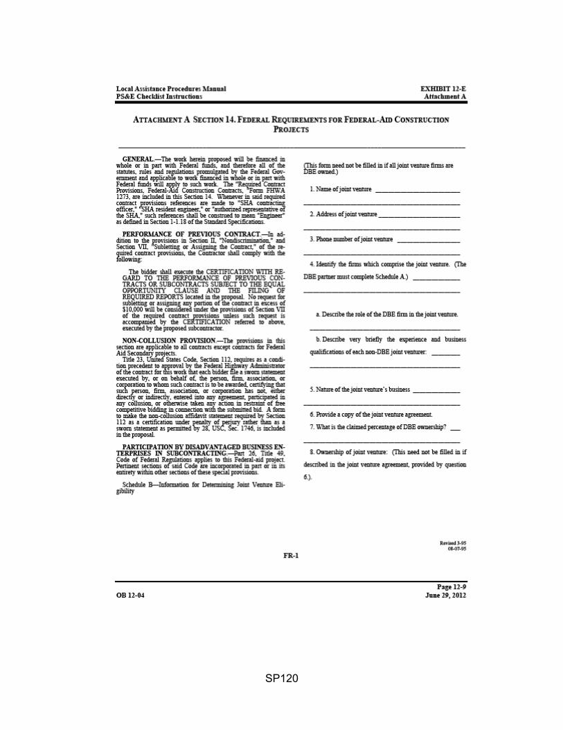
SP120

SP121

SP122

SP123

SP124

SP125
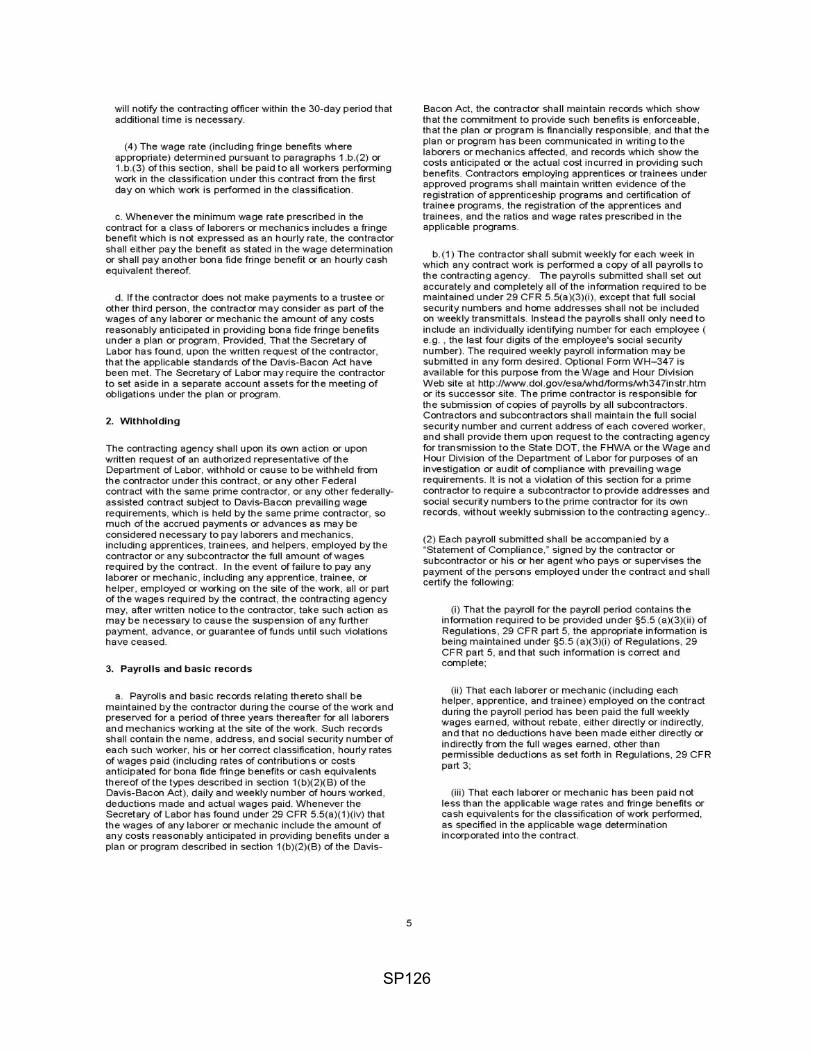
SP126

SP127

SP128

SP129

SP130
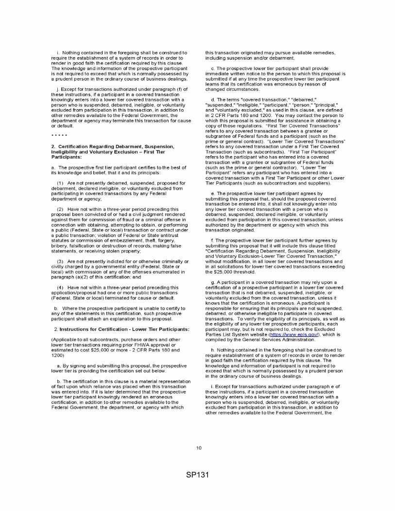
SP131
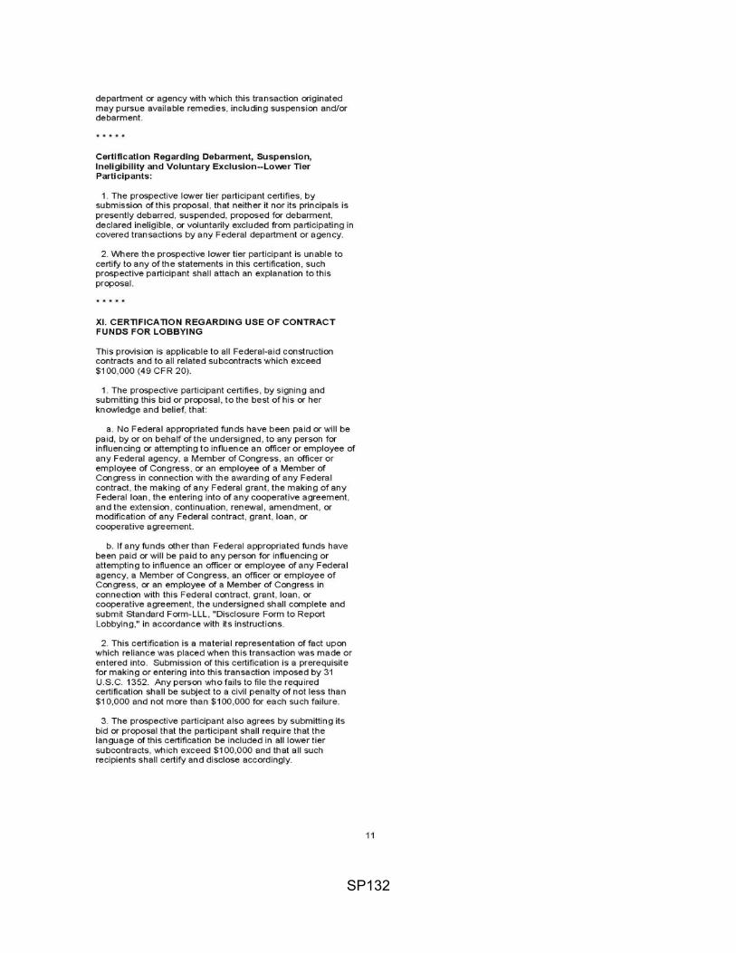
SP132

SP133
SP134
SP135

SP136
Related Documents


