SPEAR: A Monopedal Robot with Switchable Parallel Elastic Actuation Xin Liu, Anthony Rossi and Ioannis Poulakakis Abstract— Inspired by biological systems, compliant elements are introduced in the driving train of legged robots with the purpose of recycling energy. This paper presents the design and control concept of the monopedal robot SPEAR, driven by a novel implementation of a Switchable Parallel Elastic Actuator (S-PEA). At the stance phase, the parallel spring in S-PEA works with the actuator to support body weight and recover energy. The spring is removed from the system at the flight phase to gain precise joint control. The stiffness of the whole leg is also adjustable online either by active control of the motor or by changing the knee angle at touchdown. Experimental results show that the spring recycles part of energy during hopping, reducing the peak torque and peak power of the motor. I. I NTRODUCTION Running robots typically operate in regimes where the natural dynamics of the mechanical system imposes strict limitations on the capability of the motor units to guide the robot’s motion. Furthermore, the pressure for extended power autonomous operation calls for increased energy efficiency, thereby making excessive reliance on the motors even un- desirable. To address these challenges, a series of actuator designs has been introduced; the majority of these actuators combine elastic energy storage elements with motors to generate and sustain highly-dynamic running motions [1]. A widely adopted approach to introducing compliance in the robot’s structure is to insert a spring into the driving train in series with an actuator [1], [2]. An early implementation of series compliance can be found in Raibert’s robots, in which air springs were placed in series with hydraulic actuators [3]. The bipedal robot MABEL [4] is designed with large leaf springs connected in series with the actuators through a transmission system so that compliance is present in the leg length direction [5]. Inspired by the Series Elastic Actuator (SEA) architecture [2], the StarlETH comprises 12 SEAs actuating all of its joints [6]. An advantage of inserting springs in series with the actuators is that they offer protection of the motors and gearboxes by filtering out the instantaneous change in velocity when the a leg impacts with ground. However, SEAs typically increase the number of degrees of freedom (DOF) of the system. Moreover, with the aim to store energy, the springs are usually large and the motors need to produce forces or torques that have similar magnitudes as the ones developed by the springs [7]. An alternative way to introduce compliance is to insert the spring in parallel with the motor. An attractive feature of this This work is supported in part by NSF grant CMMI-1130372 and ARO contract W911NF-12-1-0117. The authors are with the Department of Mechanical Engineer- ing, University of Delaware, DE, USA; {xinliu, avrossi, poulakas}@udel.edu Encoders Cable Drive S 2 Foot Motors S 1 (a) τ Hip Torso S 1 τ Knee Cable S 2 Foot Spacer γ -θ Hip θ Knee (b) Fig. 1. (a) The manufactured leg. A cable-pulley system is used to move the knee actuator more close to the hip axis. (b) The schematic drawing of the robotic leg. One end of the large spring S 1 is attached to the thigh by a steel cable, while the other end first pass through the knee spacer, then pass through the foot (at this part, the cable is replaced by a roller chain), then attached to the shank by the small spring S 2 . configuration is that the spring provides most of the torque required at the joint to maintain a desired motion, while the motor can modify the torque profile as needed to stabilize the system [8]. An example of using Parallel Elastic Actuators (PEA) can be found in [7], where springs are used to improve energy efficiency and safety of known maneuvers in passive- assist devices for active joints. In the context of legged robots, the biped ERNIE utilizes springs in parallel with its knee actuators to generate walking motions [9]. PEAs may reduce both power and torque requirements, as suggested in simulations of bipedal [10], [11] and quadrupedal robot [12] running. The recent results in [13] provide a comparison between SEAs and PEAs in terms of energy efficiency. In general, introducing springs in parallel with the actu- ators may limit joint dexterity in the sense that the actu- ator needs to work against the spring [14]. To overcome the drawback of PEAs, the concept of Switchable Parallel Elastic Actuator (S-PEA) has been suggested in the relevant literature [8]. According to this concept, a switch – which can be a brake, a clutch or a trigger mechanism – is used to engage the spring when energy storage is desired and disengage it to avoid the spring force interfering with the desired joint motions [14]. The case of a knee joint actuated by a S-PEA is considered in [8], where a mechanism with position-dependent clutch function is proposed to engage the spring when it is needed; that is, during the stance phase. A conceptual design of a S-PEA is also proposed in [12]

Welcome message from author
This document is posted to help you gain knowledge. Please leave a comment to let me know what you think about it! Share it to your friends and learn new things together.
Transcript
SPEAR: A Monopedal Robot with Switchable Parallel Elastic Actuation
Xin Liu, Anthony Rossi and Ioannis Poulakakis
Abstract— Inspired by biological systems, compliant elementsare introduced in the driving train of legged robots with thepurpose of recycling energy. This paper presents the design andcontrol concept of the monopedal robot SPEAR, driven by anovel implementation of a Switchable Parallel Elastic Actuator(S-PEA). At the stance phase, the parallel spring in S-PEAworks with the actuator to support body weight and recoverenergy. The spring is removed from the system at the flightphase to gain precise joint control. The stiffness of the whole legis also adjustable online either by active control of the motor orby changing the knee angle at touchdown. Experimental resultsshow that the spring recycles part of energy during hopping,reducing the peak torque and peak power of the motor.
I. INTRODUCTION
Running robots typically operate in regimes where thenatural dynamics of the mechanical system imposes strictlimitations on the capability of the motor units to guide therobot’s motion. Furthermore, the pressure for extended powerautonomous operation calls for increased energy efficiency,thereby making excessive reliance on the motors even un-desirable. To address these challenges, a series of actuatordesigns has been introduced; the majority of these actuatorscombine elastic energy storage elements with motors togenerate and sustain highly-dynamic running motions [1].
A widely adopted approach to introducing compliance inthe robot’s structure is to insert a spring into the driving trainin series with an actuator [1], [2]. An early implementationof series compliance can be found in Raibert’s robots, inwhich air springs were placed in series with hydraulicactuators [3]. The bipedal robot MABEL [4] is designedwith large leaf springs connected in series with the actuatorsthrough a transmission system so that compliance is presentin the leg length direction [5]. Inspired by the Series ElasticActuator (SEA) architecture [2], the StarlETH comprises12 SEAs actuating all of its joints [6]. An advantage ofinserting springs in series with the actuators is that theyoffer protection of the motors and gearboxes by filtering outthe instantaneous change in velocity when the a leg impactswith ground. However, SEAs typically increase the numberof degrees of freedom (DOF) of the system. Moreover, withthe aim to store energy, the springs are usually large and themotors need to produce forces or torques that have similarmagnitudes as the ones developed by the springs [7].
An alternative way to introduce compliance is to insert thespring in parallel with the motor. An attractive feature of this
This work is supported in part by NSF grant CMMI-1130372 and AROcontract W911NF-12-1-0117.
The authors are with the Department of Mechanical Engineer-ing, University of Delaware, DE, USA; {xinliu, avrossi,poulakas}@udel.edu
Encoders
Cable DriveS2
Foot
Motors
S1
(a)
τHipTorso
S1
τKnee
Cable
S2
Foot
Spacer
γ
-θHip
θKnee
(b)
Fig. 1. (a) The manufactured leg. A cable-pulley system is used to movethe knee actuator more close to the hip axis. (b) The schematic drawing ofthe robotic leg. One end of the large spring S1 is attached to the thigh bya steel cable, while the other end first pass through the knee spacer, thenpass through the foot (at this part, the cable is replaced by a roller chain),then attached to the shank by the small spring S2.
configuration is that the spring provides most of the torquerequired at the joint to maintain a desired motion, while themotor can modify the torque profile as needed to stabilize thesystem [8]. An example of using Parallel Elastic Actuators(PEA) can be found in [7], where springs are used to improveenergy efficiency and safety of known maneuvers in passive-assist devices for active joints. In the context of leggedrobots, the biped ERNIE utilizes springs in parallel with itsknee actuators to generate walking motions [9]. PEAs mayreduce both power and torque requirements, as suggestedin simulations of bipedal [10], [11] and quadrupedal robot[12] running. The recent results in [13] provide a comparisonbetween SEAs and PEAs in terms of energy efficiency.
In general, introducing springs in parallel with the actu-ators may limit joint dexterity in the sense that the actu-ator needs to work against the spring [14]. To overcomethe drawback of PEAs, the concept of Switchable Parallel
Elastic Actuator (S-PEA) has been suggested in the relevantliterature [8]. According to this concept, a switch – whichcan be a brake, a clutch or a trigger mechanism – is usedto engage the spring when energy storage is desired anddisengage it to avoid the spring force interfering with thedesired joint motions [14]. The case of a knee joint actuatedby a S-PEA is considered in [8], where a mechanism withposition-dependent clutch function is proposed to engage thespring when it is needed; that is, during the stance phase.A conceptual design of a S-PEA is also proposed in [12]
to reduce the energy requirement of quadrupedal running.However, to the best of the authors’ knowledge, only [14],[15] realized S-PEA designs in hardware, to explore itspotential in terms of energy efficiency. Experiments suggestthat the energy consumption is dropped by 80% and the peaktorque requirement is dropped by about 66%.
In this paper, we investigate how the S-PEA architecturecan be used in the context of dynamic legged locomotion.We present the conceptual design and hardware realizationof the Switchable Parallel Elastic Actuator Robot (SPEAR),a two-DOF leg that employs a S-PEA at its knee joint andis suitable for dynamic locomotion; see Fig. 1(a). SPEARfeatures a mechanical switch at its foot, which engages thespring only when the leg is on the ground, thereby recyclingpart of the energy during the compression and decompressionphases of the stance. During flight, the switch disengagesthe spring and the motor can place the leg at a desired con-figuration in anticipation to touchdown without interferingwith the spring. With this mechanical switch, the S-PEA isautomatically synchronized with the hopping motion, and itrequires no additional actuators to control the switch, therebyresulting in a reliable and compact design. Finally, we designand experimentally implement simple control laws that takeadvantage of the S-PEA to realize stable hopping motions inorder to evaluate the performance of SPEAR in terms of peakpower and peak torque requirements. A video showing theexperimental implementation of hopping motions on SPEARaccompanies this paper.
II. DESIGN OF SPEAR
This section discusses the basic principle that underlies ourSwitchable Parallel Elastic Actuator (S-PEA) design, and thehardware realization of a robot leg, the knee joint of whichis actuated by the S-PEA.
A. Working Principle of S-PEA
Introducing compliance in running robots is a necessary,albeit challenging task [1]. This is primarily due to thedifferent objectives that the mechanical system needs tosatisfy at different phases of the motion. For example, whena leg is in contact with the ground, compliant membersare important in supporting body weight and storing energyduring the initial stages of the stance, which is subsequentlyreleased to prepare the system for takeoff. On the other hand,when the leg is in the air, compliant elements are undesirable,for they may interfere with leg placement in anticipationto touchdown by introducing oscillations that impede jointmotion and precise positioning.
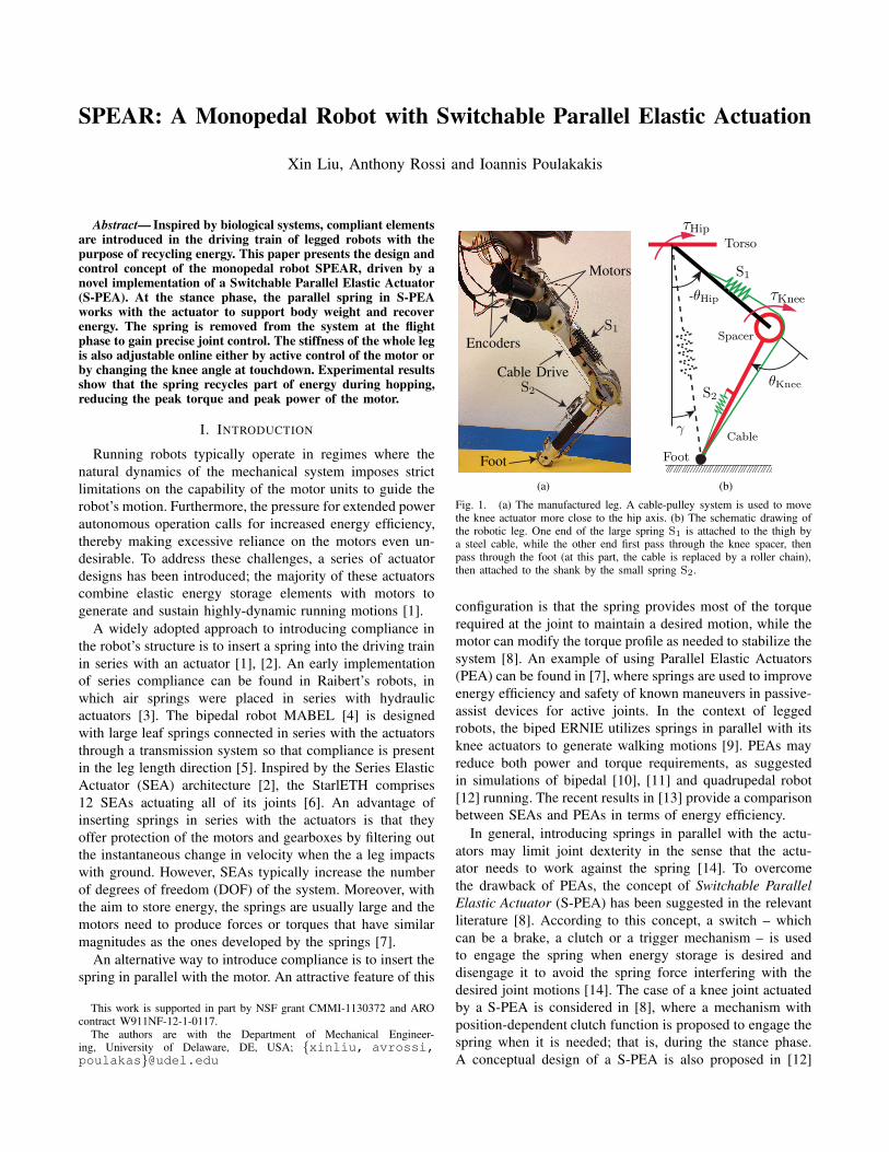
To address this challenge, we propose the S-PEA, a newactuator design that engages compliance in parallel witha motor only when elastic energy storage is needed. Theprinciple that underlies the proposed design is shown inFig. 2(a), in which the joint that connects Link A and LinkB is composed of an actuator and a compliant elementconnected in parallel. The compliant element comprises twosprings S1 and S2 connected through a mechanical switchrealized by a key and a chain as shown in Fig. 2(b)-2(c).
S2 S1
Key
Link BLink A
chainactuator
(a)
Foot(Key)
To S2S3
To S1
GRF
(b)
S3
SwitchContact
(c)Fig. 2. (a) The schematic of the proposed S-PEA design. The stiffness ofthe joint is determined by the status of the Key. (b) The section view of thefoot which functions as the Key in (a). Here the foot is inserted into thechain by the ground reaction force (GRF) and spring S1 is engaged. S3 isa small spring used to keep the foot unplugged from the chain when thereis no GRF. The contact switch is used to determine if the foot is insertedin the chain. (c) The manufactured foot.
The two springs have different stiffnesses; the spring S1has stiffness K1 and the spring S2 has stiffness K2 and ismuch softer than S1; i.e., K1 ≫ K2. The effective stiffnessof the combined springs is determined by the status of thekey. When the key is inserted in the chain, the mechanicalswitch is closed and the hard spring S1 is connected toLink A; in this configuration, the effective stiffness of thejoint is K1, favoring energy storage. When the key is notinserted in the chain, the springs S1 and S2 are connectedin series, and the effective stiffness of the joint is mostlydetermined by the softer spring and is, in fact, smaller thanK2. With K2 negligible, the hard spring S1 is consideredto be “switched off.” As a result, this configuration favorsprecise joint motion control via the actuator. In fact, thesmall spring S2 is used merely to keep the tension in thecompliant element.
B. SPEAR: A leg design that uses the S-PEA
SPEAR is a planar monopedal robot composed of twolinks representing the thigh and the shank of a kneed legthat is terminated at a point foot as shown in Fig. 1(b).The thigh is connected to a torso via the hip joint with arange of motion in [−85◦, 85◦], while the thigh and shankare connected by the knee joint with a range of motion[−10◦, 140◦]. The robot’s torso is rigidly connected to aboom as discussed in Section II-E below.
The knee joint of the SPEAR is driven by the proposedS-PEA, as shown in Fig. 1(b). In our realization, the S-PEAengages the hard spring S1 during the stance phase, therebyharnessing its elastic energy storage capability when it is
needed. During the subsequent flight phase, S1 is disengagedallowing the actuator to shorten or lengthen the leg withoutinterfering with the spring.
In more detail, one end of the hard spring S1 is attachedto the thigh by a steel cable. The other end of S1 first passesthrough the circular knee spacer, which is rigidly attached tothe shank, then passes through the foot and is attached to theother side of the shank by a soft return spring S2. Althougha solenoid could have been used to control the pull/pushreaction of the key in the S-PEA, in our implementation thefoot acts as the key and is used to engage and disengage thespring S1 depending on the state of the leg; see Fig. 2(b)and Fig. 2(c). The foot has a tooth shape at one end, and isconnected to the shank by a prismatic joint which allows thefoot to have a maximum range of motion of 1cm. During thestance phase, when the foot is in contact with the ground,the ground reaction force pushes the key inside the chain,thereby engaging the spring S1 as shown in Fig. 2(b). Duringthe flight phase, an additional small spring S3 is used to pushthe foot outside the chain, thereby disengaging the spring S1.This simple “mechanical” switch does not require additionalcontrol to synchronize the key with the leg state – stance orflight – which could be difficult to implement, particularly inrough-terrain locomotion where touchdown is hard to predict.
The assembled leg is shown in Fig.1(a); see Table II-Bfor parameter values. The thigh comprises two lightweightaluminum plates and the shank is formed by a compositematerial tube to help reduce the weight and the moment ofinertia of the leg. Two brushless motors actuate the assembly;one for the knee and one for the hip joint. With the S-PEAdesign, the knee and hip motors use a 25 : 1 and a 60 : 1gearbox, respectively. The lower gearbox ratio renders theknee joint more back drivable, and it offers some protectionat impacts. To reduce the rotational load on the hip shaft,the knee motor of the S-PEA is placed in proximity to thehip joint, and a cable-pulley system is used to transmit themotion to the knee.
TABLE I
MECHANICAL PARAMETERS OF THE LEG
Parameter Value Units
Torso mass (including boom and CPU) (M) 3.55 kg
Thigh mass (M1) 2.43 kg
Shank mass (M2) 0.73 kg
Thigh inertia (including motor) (J1) 0.06 kg m2
Shank inertia (including motor)(J2) 0.02 kg m2
Thigh length (L1) 0.320 m
Shank length (L2) 0.327 m
Thigh COM to hip distance (Lm,1) 0.092 m
Shank COM to knee distance (Lm,2) 0.097 m
SPEAR is equipped with proprioceptive sensors providinginformation on the state of the leg – stance or flight – and itsmotion. Two incremental encoders with an accuracy of 1024counts per revolution are used to measure the angular dis-placements of the motorshafts. Two potentiometers provideabsolute measurements of hip and knee joint rotation. The
information from the encoders and potentiometers is used toobtain better absolute positions of the joints. Note that sincethe knee and spring are put in parallel, the deflection of thespring can be easily obtained by measuring the change injoint angle. Finally, a snap-acting switch is located at thefoot to detect the state of the leg, stance or flight.
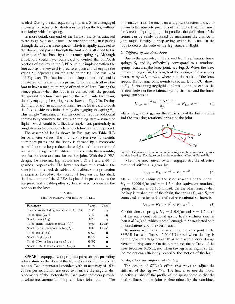
C. Stiffness of the Knee Joint
Due to the geometry of the kneed leg, the prismatic linearsprings S1 and S2 effectively correspond to a rotationalspring located at the knee joint, see Fig. 3. When the kneerotates an angle ∆θ, the length of the spring-cable assemblyincreases by ∆L = r∆θ, where r is the radius of the kneespacer. This change corresponds to the arc length CC′ shownin Fig. 3. Assuming negligible deformation in the cables, therelation between the rotational spring stiffness and the linearspring stiffness is
KRot =(KLin ×∆L)× r
∆L
r
= KLin × r2 , (1)
where KLin and KRot are the stiffnesses of the linear springand the resulting rotational spring at the joint.
A
B C C′
∆θD
D′
Fig. 3. The relation between the linear spring and the corresponding kneerotational spring. The figure depicts the combined effect of S1 and S2.
When the mechanical switch engages S1, the effectiverotational stiffness is given by
KRot = KLin × r2 = K1 × r2 , (2)
where r is the radius of the knee spacer. For the chosenK1 = 39000N/m and r = 1.5in, the equivalent rotationalspring stiffness is 56.67Nm/rad. On the other hand, whenthe key is pushed out of the chain, the springs S1 and S2 areconnected in series and the effective rotational stiffness is
KRot = KLin × r2 < K2 × r2 . (3)
For the chosen springs, K2 = 310N/m and r = 1.5in, sothat the equivalent rotational spring has a stiffness smallerthan 0.3Nm/rad, which is small enough to be neglected bothin simulations and in experiments.
To summarize, due to the switching, the knee joint of theSPEAR has a stiffness of 56.67Nm/rad when the leg ison the ground, acting primarily as an elastic energy storageelement during stance. On the other hand, the stiffness of theknee becomes 0.3Nm/rad when the leg is in flight, so thatthe motors can efficiently prescribe the motion of the leg.
D. Adjusting the Stiffness of the Leg
The design of SPEAR offers two ways to adjust thestiffness of the leg on line. The first is to use the motorto actively “shape” the profile of the spring force so that thetotal stiffness of the joint is determined by the combined
effect of the motor and the passive spring. The secondway to tune the knee stiffness is to utilize the geometryof the segmented leg with the S-PEA. In more detail, thelinear rotational spring at the knee joint can be viewed asa nonlinear virtual spring applied along the line betweenthe hip and foot; see Fig. 1(b). Thus, changing the restangle of the knee spring, changes the stiffness of the virtualspring [16]. Note that the spring is engaged when the foottouches down, hence the touchdown angle determines the restangle of the knee rotational spring. Since the spring S2 has anegligible rotational stiffness – less than 0.3Nm/rad – it isvery easy for the knee motor to reset the touchdown angle inflight. This in turn changes the rest angle, and the effectivestiffness between the hip and the foot varies accordingly. Thevirtual spring force - displacement relationship is shown inFig. 4 for different rest angles of the knee spring.
0 0.1 0.2 0.3 0.40
50
100
150
200
250
300
350
400
Virtual Spring Deformation(m)
Virtu
al S
prin
g Fo
rce(
N)
10°
30°
50°
70°
90°
110°
Fig. 4. Changing the stiffness of the leg by changing the touchdown angleof knee joint. The effect of the linear rotational spring can be viewed as avirtual nonlinear spring applied between the hip and the toe. The x-axis isthe deformation of the virtual spring, while the y-axis is the force of thevirtual spring. As the knee becomes more straight (varing from 130◦ to10◦), the virtual spring is becoming stiffer.
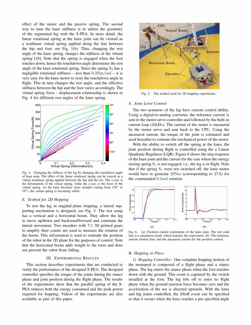
E. Testbed for 2D Hopping
To test the leg in stagittal-plane hopping, a lateral sup-porting mechanism is designed; see Fig. 5. The test setuphas a vertical and a horizontal boom. They allow the legto move up/down and backward/forward and constrain thelateral movement. Two encoders with 7:1 3D printed gearsto amplify their counts are used to measure the rotation ofthe boom. This information is used to estimate the positionof the robot in the 2D plane for the purposes of control. Notethat the horizontal boom adds weight to the torso and doesnot prevent the robot from falling.
III. EXPERIMENTAL RESULTS
This section describes experiments that are conducted toverify the performance of the designed S-PEA. The designedcontroller specifies the torque of the joints during the stancephase and joint position during the flight phase. The resultsof the experiments show that the parallel spring of the S-PEA reduces both the energy consumed and the peak powerrequired for hopping. Videos of the experiments are alsoavailable as part of this paper.
Leg
CPU
Vertical Boom
Horizontal Boom
Encoders
Batteries
Fig. 5. The testbed used for 2D hopping experiments.
A. Joint Level Control
The two actuators of the leg have current control ability.Using a digital-to-analog converter, the reference current issent to the motor servo controller and followed by the built-incurrent loop (20kHz). The current of the motor is measuredby the motor servo and sent back to the CPU. Using themeasured current, the torque of the joint is estimated andused hereafter to estimate the mechanical power of the motor.
With the ability to switch off the spring at the knee, thejoint position during flight is controlled using the a LinearQuadratic Regulator (LQR). Figure 6 shows the step responseof the knee joint and the current for the case where the energystoring spring S1 is not engaged; i.e., the leg is in flight. Notethat if the spring S1 were not switched off, the knee motorwould have to generate 28Nm (corresponding to 27A) forthe commanded 0.5rad rotation.
9.9 10 10.1 10.2 10.3 10.40
0.1
0.2
0.3
0.4
0.5
Time(s)
Knee
Ang
le(ra
d)
(a)
9.9 10 10.1 10.2 10.3 10.4−4
−2
0
2
4
6
8
10
12
Time(s)
Knee
Cur
rent
(Am
p)
(b)
Fig. 6. (a): Position control experiment of the knee joint. The red solidline is a simulation result, which matches the experiment. (b): The referencecurrent (dotted line) and the measured current for the position control.
B. Hopping in Place
1) Hopping Controller: One complete hopping motion ofthe monopod is composed of a flight phase and a stancephase. The leg enters the stance phase when the foot touchesdown with the ground. This event is captured by the switchinstalled at the foot. The leg lifts off to enter its flightphase when the ground reaction force becomes zero and theacceleration of the toe is directed upwards. With the kneeand hip joints controlled, the liftoff event can be specifiedso that it occurs when the knee reaches a pre-specified angle
which is taken equal to the touchdown angle. This way theenergy stored in the spring S1 is returned to the system.
The designed controller has different objectives during thestance and flight phases. During stance, the torques of thehip and knee joints are controlled with the purpose of (i)injecting energy to the system, and (ii) preventing slipping.During flight on the other hand, the angular positions of thehip and knee joints are controlled to stabilize the systemusing a modified version of Raibert’s velocity controller [3].
In more detail, to sustain continuous hopping, the kneemotor compensates during the stance phase for the energylost due to impact and friction as follows. In the first half ofthe stance phase, the motor further compresses the springS1 injecting energy as needed, while in the second half,the motor assists with spring recoil preparing the system fortakeoff. This action is captured by commanding the followingtorque to the knee actuator
τknee[k + 1]=
!
τ∗knee − α1(y∗ − y[k]), if t− tTD < Tst
2
α1(y∗ − y[k])− τ∗knee, if t− tTD ≥ Tst
2(4)
where τ∗knee is a constant corresponding to the nominal kneetorque for a periodic hopping gait with a hip apex height y∗,y[k] is the apex height at the k-th step, tTD is the touchdowninstant, and Tst is the total duration of the stance phase. Notethat (4) ensures that the knee actuator only does positivework during stance. The hip actuator applies a small torque
τHip = τ∗Hip , (5)
which is kept constant throughout the stance phase with thepurpose of reducing the chance of slipping.
During flight, a modified version of Raibert’s velocitycontroller [3] is used to adjust the hip joint angle keepingthe knee angle constant. In more detail, the knee joint iscommanded to a constant, i.e., θKnee = ΘKnee, while the hipangle – which determines the touchdown angle γ in Fig. 1(b)– is adjusted according to the prescription
θHip = θ∗Hip − α2 × xcm , (6)
where α2 is a constant gain, θ∗Hip is the nominal value ofthe hip angle and xcm is the measured horizontal velocityof the leg’s center of mass at flight phase. In implementingthis controller, the angle of rotation of the vertical boom ofFig. 5 is used to estimate the average horizontal velocity bydividing it with the time duration of the step. Note that aswas mentioned in Section II-D, the touchdown angle of theknee determines the stiffness of the leg during the subsequentstance phase and has a great influence both on the stabilityand energy efficiency of hopping. We do not make use ofthis capability here; however, controllers that take advantageof variable stiffness are the subject of ongoing work.
2) Experimental Results: The experimental results of sta-ble hopping are shown in Fig. 7. The hop is initialized att = 20s, by first bending its knee to store energy in thespring S1, and then pushing against the ground when the legis at the bottom of its stance to cause liftoff. After a fewseconds, the leg is stabilized to a periodic hopping motion.
19 20 21 22 23 24 25 26 27
0.4
0.45
0.5
0.55
0.6
0.65
Time(s)
Verti
cal P
ositi
on(m
)
Fig. 7. Vertical displacement of the hip for the hopping in place experiment.
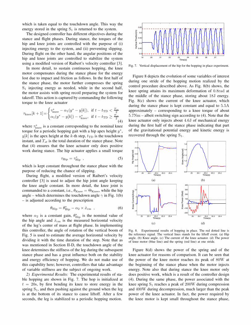
Figure 8 depicts the evolution of some variables of interestduring one stride of the hopping motion realized by thecontrol procedure described above. As Fig. 8(b) shows, theknee spring attains its maximum deformation of 0.8rad atthe middle of the stance phase, storing about 18J energy.Fig. 8(c) shows the current of the knee actuator, whichduring the stance phase is kept constant and equal to 5.5Aapproximately – corresponding to a knee torque of about5.7Nm – albeit switching sign according to (4). Note that theknee actuator only injects about 4.6J of mechanical energyduring the first half of the stance phase indicating that partof the gravitational potential energy and kinetic energy isrecovered through the spring S1.
25 25.1 25.2 25.3 25.4−0.9
−0.8
−0.7
−0.6
−0.5
−0.4
Time(s)
Hip
Ang
le(ra
d)
(a)
25 25.1 25.2 25.3 25.40.8
1
1.2
1.4
1.6
1.8
Time(s)
Knee
Ang
le(ra
d)(b)
25 25.1 25.2 25.3 25.4
−5
0
5
10
Time(s)
Knee
Cur
rent
(Am
p)
(c)
25 25.1 25.2 25.3 25.4
−200
−100
0
100
200
300
400
Time(s)
Knee
Pow
er (W
att)
(d)
Fig. 8. Experimental results of hopping in place. The red dotted line isthe reference signal. The vertical lines stands for the liftoff event. (a) Hipangle. (b) Knee angle. (c) The current of the knee actuator. (d) The powerof knee motor (blue line) and the spring (red line) at one stride.
Figure 8(d) shows the power of the spring and of theknee actuator for reasons of comparison. It can be seen thatthe power of the knee motor reaches its peak of 80W atthe beginning of the stance phase when the motor injectsenergy. Note also that during stance the knee motor onlydoes positive work, which is a result of the controller design(4). During the same phase, the power associated with theknee spring S1 reaches a peak of 200W during compressionand 400W during decompression, much larger than the peakpower of the knee actuator. In fact, the power required bythe knee motor is kept small throughout the stance phase,
owing to the energy recovery offered by the spring.To characterize the mechanical energy storage efficiency,
we adopt the metric defined in [17]; i.e.,
η := 1−
"
Tmax(Pmotor, 0)dt
"
Tmax(Pjoint, 0)dt
, (7)
where T is the duration of the stride, Pmotor is the totalpower of the knee and hip motors, and Pjoint is the me-chanical power of the joints. The coefficient η effectivelymeasures how much of the positive mechanical energy usedin one hopping stride can be provided passively. For thedesigned leg, η = 0.642, indicating that 64% of the positivemechanical energy at one stride is generated by the spring.
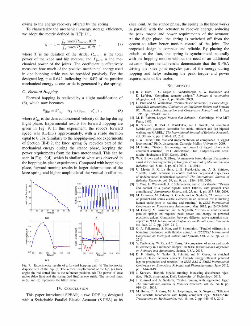
C. Forward Hopping
Forward hopping is realized by a slight modification of(6), which now becomes
θHip = θ∗Hip − α3 × (xcm − x∗
cm) , (8)
where x∗
cm is the desired horizontal velocity of the hip duringflight phase. Experimental results for forward hopping aregiven in Fig. 9. In this experiment, the robot’s forwardspeed was 0.14m/s approximately, with a stride durationequal to 0.58s. Similarly to the hopping-in-place experimentsof Section III-B.2, the knee spring S1 recycles part of themechanical energy during the stance phase, keeping thepower requirements from the knee motor small. This can beseen in Fig. 9(d), which is similar to what was observed inthe hopping-in-place experiments. Compared with hopping inplace, forward running results in larger deformations of theknee spring and higher amplitude of the vertical oscillation.
24 25 26 27 28 29 30 31−1
−0.8
−0.6
−0.4
−0.2
0
Time(s)
Hor
izon
tal P
ositi
on(m
)
(a)
24 25 26 27 28 29 30 31
0.4
0.45
0.5
0.55
0.6
0.65
Time(s)
Verti
cal P
ositi
on(m
)
(b)
25.1 25.2 25.3 25.4 25.5 25.60.8
1
1.2
1.4
1.6
1.8
2
Time(s)
Knee
Ang
le(ra
d)
(c)
25.1 25.2 25.3 25.4 25.5 25.6
−200
−100
0
100
200
300
400
Time(s)
Knee
Pow
er (W
att)
(d)
Fig. 9. Experimental results of a forward hopping gait. (a) The horizontaldisplacement of the hip. (b) The vertical displacement of the hip. (c) Kneeangle; the red dotted line is the reference position. (d) The power of kneemotor (blue line) and the spring (red line) at one stride. The vertical linesin (c) and (d) represents the liftoff event.
IV. CONCLUSION
This paper introduced SPEAR, a two-DOF leg designedwith a Switchable Parallel Elastic Actuator (S-PEA) at its
knee joint. At the stance phase, the spring in the knee worksin parallel with the actuator to recover energy, reducingthe peak torque and power requirements of the actuator.At the flight phase, the spring is switched off from thesystem to allow better motion control of the joint. Theproposed design is compact and reliable. By placing theswitch on the foot, the spring is synchronized naturallywith the hopping motion without the need of an additionalactuator. Experimental results demonstrate that the S-PEAdriving the knee joint recycles part of the energy duringhopping and helps reducing the peak torque and powerrequirements of the motor.
REFERENCES
[1] R. v. Ham, T. G. Sugar, B. Vanderborght, K. W. Hollander, andD. Lefeber, “Compliant actuator designs,” Robotics & AutomationMagazine, vol. 16, no. 3, pp. 81–94, 2009.
[2] G. Pratt and M. Williamson, “Series elastic actuators,” in Proceedings.IEEE/RSJ International Conference on Intelligent Robots and Systems95. ’Human Robot Interaction and Cooperative Robots’, vol. 1, Aug1995, pp. 399–406 vol.1.
[3] M. H. Raibert, Legged Robots that Balance. Cambridge, MA: MITPress, 1986.
[4] K. Sreenath, H. Park, I. Poulakakis, and J. Grizzle, “A complianthybrid zero dynamics controller for stable, efficient and fast bipedalwalking on MABEL,” The International Journal of Robotics Research,vol. 30, no. 9, pp. 1170–1193, 2011.
[5] J. W. Hurst, “The role and implementation of compliance in leggedlocomotion,” Ph.D. dissertation, Carnegie Mellon University, 2008.
[6] M. Hutter, “Starleth & co-design and control of legged robots withcompliant actuation,” Ph.D. dissertation, Diss., Eidgenossische Tech-nische Hochschule ETH Zurich, 2013.
[7] W. R. Brown and A. G. Ulsoy, “A maneuver based design of a passive-assist device for augmenting active joints,” Journal of Mechanisms andRobotics, vol. 5, no. 3, pp. 031 003 1–11, 2013.
[8] U. Mettin, P. X. La Hera, L. B. Freidovich, and A. S. Shiriaev,“Parallel elastic actuators as control tool for preplanned trajectoriesof underactuated mechanical systems,” The International Journal ofRobotics Research, vol. 29, no. 9, pp. 1186–1198, 2009.
[9] T. Yang, E. Westervelt, J. P. Schmiedeler, and R. Bockbrader, “Designand control of a planar bipedal robot ERNIE with parallel kneecompliance,” Autonomous Robots, vol. 25, no. 4, pp. 317–330, 2008.
[10] M. Grimmer, M. Eslamy, S. Gliech, and A. Seyfarth, “A comparisonof parallel-and series elastic elements in an actuator for mimickinghuman ankle joint in walking and running,” in IEEE InternationalConference on Robotics and Automation, May 2012, pp. 2463–2470.
[11] M. Eslamy, M. Grimmer, and A. Seyfarth, “Effects of unidirectionalparallel springs on required peak power and energy in poweredprosthetic ankles: Comparison between different active actuation con-cepts,” in IEEE International Conference on Robotics and Biomimet-ics, Dec. 2012, pp. 2406–2412.
[12] G. A. Folkertsma, S. Kim, and S. Stramigioli, “Parallel stiffness in abounding quadruped with flexible spine,” in IEEE/RSJ InternationalConference on Intelligent Robots and Systems, Oct. 2012, pp. 2210–2215.
[13] Y. Yesilevskiy, W. Xi, and C. Remy, “A comparison of series and paral-lel elasticity in a monoped hopper,” in IEEE International Conferenceon Robotics and Automation, Seattle, USA, 2015.
[14] D. F. Haufle, M. Taylor, S. Schmitt, and H. Geyer, “A clutchedparallel elastic actuator concept: towards energy efficient poweredlegs in prosthetics and robotics,” in IEEE RAS & EMBS InternationalConference on Biomedical Robotics and Biomechatronics, June 2012,pp. 1614–1619.
[15] J. Karssen, “Robotic bipedal running: Increasing disturbance rejec-tion,” Ph.D. dissertation, Delft University of Technology, 2013.
[16] J. Rummel and A. Seyfarth, “Stable running with segmented legs,”The International Journal of Robotics Research, vol. 27, no. 8, pp.919–934, 2008.
[17] M. Hutter, C. D. Remy, M. A. Hoepflinger, and R. Siegwart, “Efficientand versatile locomotion with highly compliant legs,” IEEE/ASMETransactions on Mechatronics, vol. 18, no. 2, pp. 449–458, 2013.
Related Documents